40
Zimmer ® Periarticular Proximal Tibial Locking Plate Surgical Technique The Science of the Landscape
Zimmer® Periarticular
Proximal Tibial Locking Plate
Surgical Technique
The Science of the Landscape

1Zimmer Periarticular Proximal Tibial Locking Plate
Table of Contents
Introduction 2Locking Screw Technology 2Locking Plate Technology 2Plate Features 3Indications 3Fracture Classification 3
Surgical Technique for the Periarticular 5.5mm Proximal Tibial Locking Plate 4
Required Instrumentation 4Preoperative Preparation 4Surgical Approach 4Fracture Reduction 6Plate Positioning 6Screw Trajectory 9Fracture Fixation 9Wound Closure 16Postoperative Treatment 16Implant Removal 16 Instruments and Implants 17Order Information 20
Surgical Technique for the Periarticular 3.5mm Proximal Tibial Locking Plate 21
Required Instrumentation 21Preoperative Preparation 21Surgical Approach 21Fracture Reduction 22Plate Positioning 22Screw Trajectory 24Fracture Fixation 25Wound Closure 30Postoperative Treatment 30Implant Removal 30 Instruments and Implants 31Order Information 34
2 Zimmer Periarticular Proximal Tibial Locking Plate
Introduction
The Zimmer Periarticular Locking Plate System combines locking screw technology with periarticular plates to create fixed-angle constructs for use in comminuted fractures or where deficient bone stock or poor bone quality is encountered. The fixed-angle plate/screw device can be used in osteopenic bone and other areas where traditional screw fixation may be compromised.
The Periarticular Locking Plates will accommodate standard screws, as well as locking screws with threaded heads. When necessary, interfragmentary compression can be achieved using standard screws in the dual compression slots.
Cannulated screws and instruments allow provisional fixation with guide pins in the metaphysis. This helps ensure that the threaded locking screw heads align properly with the threaded plate holes.
All plate configurations contain locking screw holes in the plate head, and alternating locking and compression screw slots in the shaft.
Locking Screw TechnologyThe heads of the locking screws contain male threads while the holes in the plates contain female threads. This allows the screw head to be threaded into the plate hole, locking the screw into the plate. This technical innovation provides the ability to create a fixed-angle construct while using familiar plating techniques.
Locking Plate TechnologyBy using locking screws in a bone plate, a fixed-angle construct is created. In osteopenic bone or fractures with multiple fragments, secure bone purchase with conventional screws may be compromised. The locking screws do not rely on bone/plate compression to resist patient load, but function similarly to multiple small angled blade plates. In osteopenic bone or comminuted fractures, the ability to lock screws into a fixed-angle construct is imperative.
By combining locking screw holes with compression screw slots in the shaft, the plate can be used as both a locking device and a fracture compression device. If compression is desired, it must be achieved first by inserting the standard screws in the compression screw slots before inserting any locking screws.
The locking plate design does not require compression between the plate and bone to accommodate loading. Therefore, purchase of the screws in the bone can be achieved with a thread profile that is shallower than that of traditional screws. The shallow thread profile, in turn, allows for screws with a large core diameter to accommodate loading with improved bending and shear strength.
3Zimmer Periarticular Proximal Tibial Locking Plate
Plate Features • Anatomically contoured plates
are precontoured to create a fit that requires little or no additional bending and helps with metaphyseal/diaphyseal reduction
• The low profile plate facilitates fixation without impinging on soft tissue
• The plate can be used to control a medial fracture fragment
• 3.5mm Proximal Lateral Tibial Locking Plates are available in six lengths, from 6 hole (104mm ) to 16 hole (224mm)
• 5.5mm Proximal Lateral Tibial Locking Plates are available in six lengths, from 4 hole (97mm ) to 14 hole (250mm)
• Dual compression slots will accommodate periarticular screws or conventional stainless steel screws and allow bi-directional compression
• The last diaphyseal plate hole is designed to accommodate the tension device (00-4817-000-05)
IndicationsThe Periarticular Locking Plate System is indicated for temporary internal fixation and stabilization of osteotomies and fractures, including:
• Comminuted fractures
• Supracondylar fractures
• Intra-articular and extra-articular condylar fractures
• Fractures in osteopenic bone
• Nonunions
• Malunions
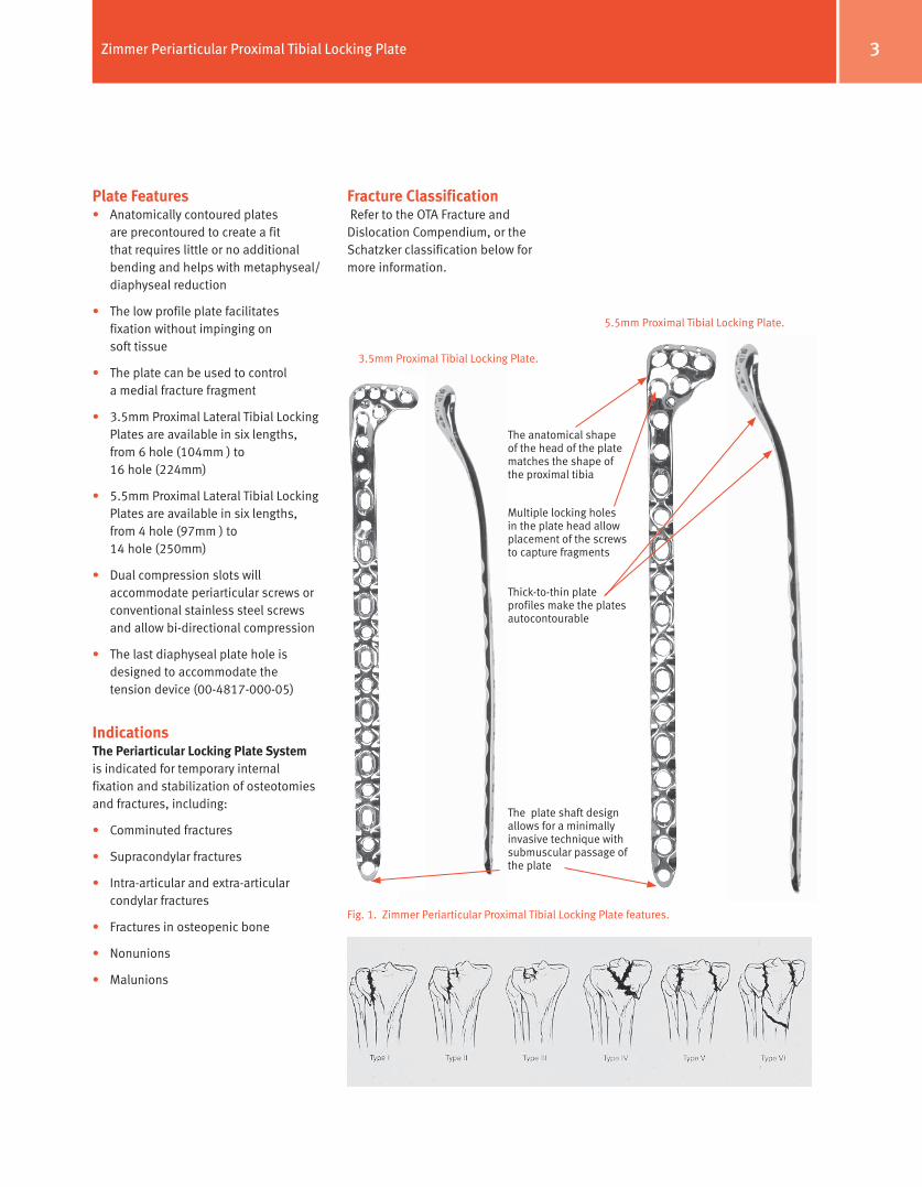
Fracture Classification Refer to the OTA Fracture and Dislocation Compendium, or the Schatzker classification below for more information.
Fig. 1. Zimmer Periarticular Proximal Tibial Locking Plate features.
5.5mm Proximal Tibial Locking Plate.
3.5mm Proximal Tibial Locking Plate.
Thick-to-thin plate profiles make the plates autocontourable
The anatomical shape of the head of the plate matches the shape of the proximal tibia
Multiple locking holes in the plate head allow placement of the screws to capture fragments
The plate shaft design allows for a minimally invasive technique with submuscular passage of the plate
4 Zimmer Periarticular Proximal Tibial Locking Plate
Fig. 2
Fig. 3
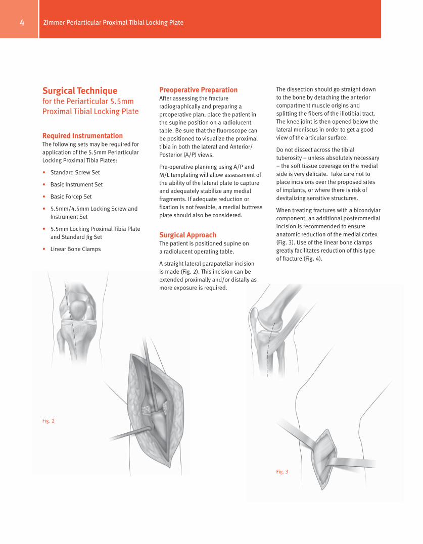
Preoperative PreparationAfter assessing the fracture radiographically and preparing a preoperative plan, place the patient in the supine position on a radiolucent table. Be sure that the fluoroscope can be positioned to visualize the proximal tibia in both the lateral and Anterior/Posterior (A/P) views.
Pre-operative planning using A/P and M/L templating will allow assessment of the ability of the lateral plate to capture and adequately stabilize any medial fragments. If adequate reduction or fixation is not feasible, a medial buttress plate should also be considered.
Surgical ApproachThe patient is positioned supine on a radiolucent operating table.
A straight lateral parapatellar incision is made (Fig. 2). This incision can be extended proximally and/or distally as more exposure is required.
The dissection should go straight down to the bone by detaching the anterior compartment muscle origins and splitting the fibers of the iliotibial tract. The knee joint is then opened below the lateral meniscus in order to get a good view of the articular surface.
Do not dissect across the tibial tuberosity – unless absolutely necessary – the soft tissue coverage on the medial side is very delicate. Take care not to place incisions over the proposed sites of implants, or where there is risk of devitalizing sensitive structures.
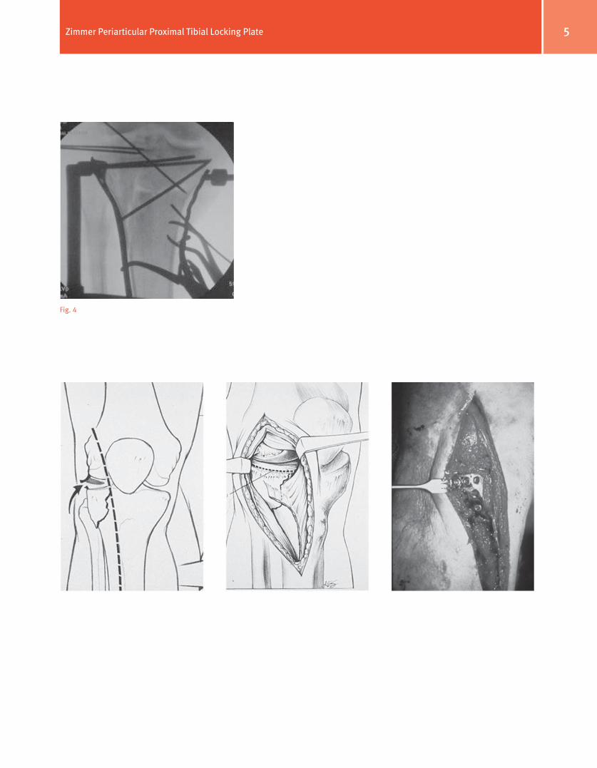
When treating fractures with a bicondylar component, an additional posteromedial incision is recommended to ensure anatomic reduction of the medial cortex (Fig. 3). Use of the linear bone clamps greatly facilitates reduction of this type of fracture (Fig. 4).
Surgical Technique for the Periarticular 5.5mm Proximal Tibial Locking Plate
Required InstrumentationThe following sets may be required for application of the 5.5mm Periarticular Locking Proximal Tibia Plates:
• Standard Screw Set
• Basic Instrument Set
• Basic Forcep Set
• 5.5mm/4.5mm Locking Screw and Instrument Set
• 5.5mm Locking Proximal Tibia Plate and Standard Jig Set
• Linear Bone Clamps
5Zimmer Periarticular Proximal Tibial Locking Plate
Fig. 4
6 Zimmer Periarticular Proximal Tibial Locking Plate
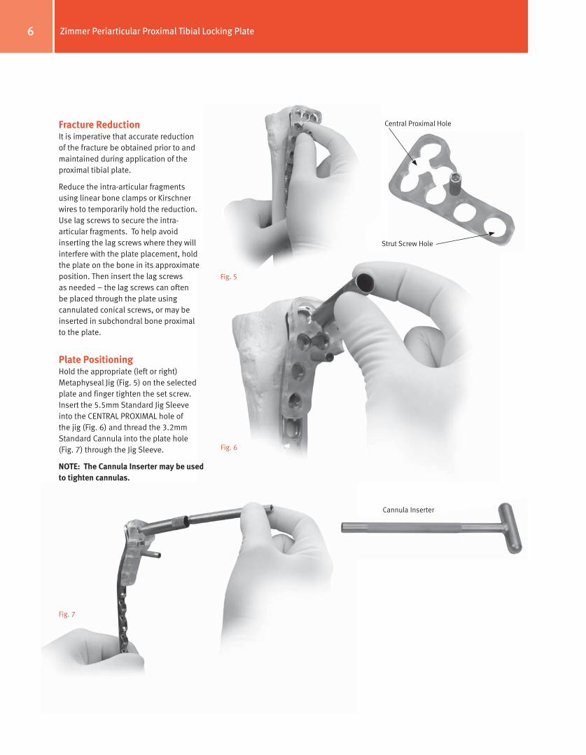
Fracture ReductionIt is imperative that accurate reduction of the fracture be obtained prior to and maintained during application of the proximal tibial plate.
Reduce the intra-articular fragments using linear bone clamps or Kirschner wires to temporarily hold the reduction. Use lag screws to secure the intra-articular fragments. To help avoid inserting the lag screws where they will interfere with the plate placement, hold the plate on the bone in its approximate position. Then insert the lag screws as needed – the lag screws can often be placed through the plate using cannulated conical screws, or may be inserted in subchondral bone proximal to the plate.
Plate PositioningHold the appropriate (left or right) Metaphyseal Jig (Fig. 5) on the selected plate and finger tighten the set screw. Insert the 5.5mm Standard Jig Sleeve into the CENTRAL PROXIMAL hole of the jig (Fig. 6) and thread the 3.2mm Standard Cannula into the plate hole (Fig. 7) through the Jig Sleeve.
NoTe: The Cannula Inserter may be used to tighten cannulas.
Fig. 6
Central Proximal Hole
Strut Screw Hole
Cannula Inserter
Fig. 7
Fig. 5
7Zimmer Periarticular Proximal Tibial Locking Plate
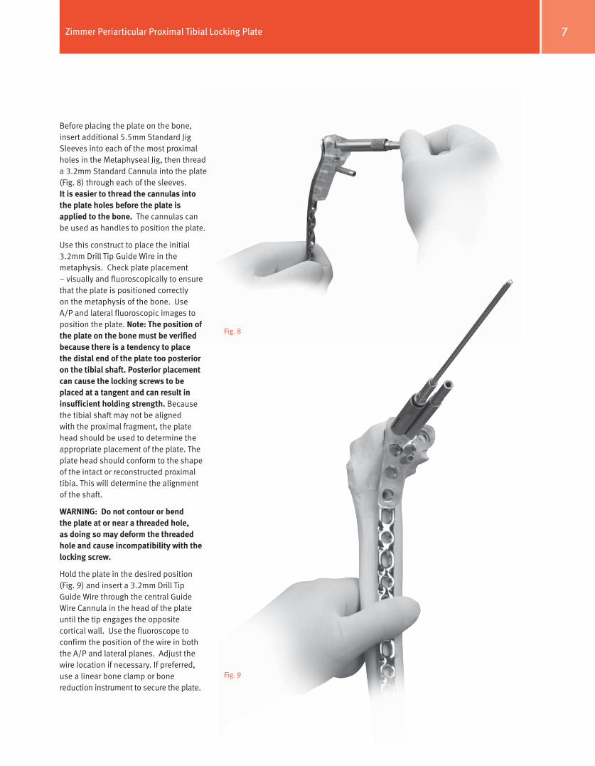
Before placing the plate on the bone, insert additional 5.5mm Standard Jig Sleeves into each of the most proximal holes in the Metaphyseal Jig, then thread a 3.2mm Standard Cannula into the plate (Fig. 8) through each of the sleeves. It is easier to thread the cannulas into the plate holes before the plate is applied to the bone. The cannulas can be used as handles to position the plate.
Use this construct to place the initial 3.2mm Drill Tip Guide Wire in the metaphysis. Check plate placement – visually and fluoroscopically to ensure that the plate is positioned correctly on the metaphysis of the bone. Use A/P and lateral fluoroscopic images to position the plate. Note: The position of the plate on the bone must be verified because there is a tendency to place the distal end of the plate too posterior on the tibial shaft. Posterior placement can cause the locking screws to be placed at a tangent and can result in insufficient holding strength. Because the tibial shaft may not be aligned with the proximal fragment, the plate head should be used to determine the appropriate placement of the plate. The plate head should conform to the shape of the intact or reconstructed proximal tibia. This will determine the alignment of the shaft.
WARNINg: Do not contour or bend the plate at or near a threaded hole, as doing so may deform the threaded hole and cause incompatibility with the locking screw.
Hold the plate in the desired position (Fig. 9) and insert a 3.2mm Drill Tip Guide Wire through the central Guide Wire Cannula in the head of the plate until the tip engages the opposite cortical wall. Use the fluoroscope to confirm the position of the wire in both the A/P and lateral planes. Adjust the wire location if necessary. If preferred, use a linear bone clamp or bone reduction instrument to secure the plate.
Fig. 8
Fig. 9
8 Zimmer Periarticular Proximal Tibial Locking Plate
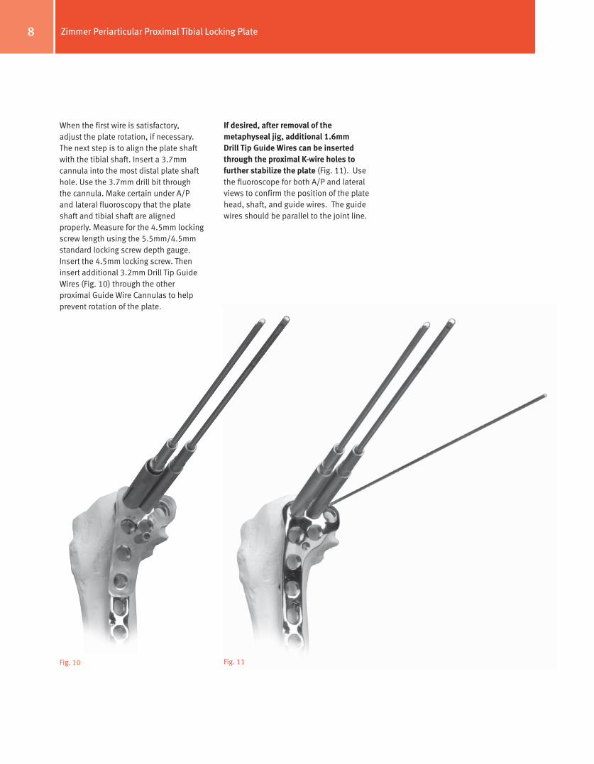
When the first wire is satisfactory, adjust the plate rotation, if necessary. The next step is to align the plate shaft with the tibial shaft. Insert a 3.7mm cannula into the most distal plate shaft hole. Use the 3.7mm drill bit through the cannula. Make certain under A/P and lateral fluoroscopy that the plate shaft and tibial shaft are aligned properly. Measure for the 4.5mm locking screw length using the 5.5mm/4.5mm standard locking screw depth gauge. Insert the 4.5mm locking screw. Then insert additional 3.2mm Drill Tip Guide Wires (Fig. 10) through the other proximal Guide Wire Cannulas to help prevent rotation of the plate.
Fig. 10 Fig. 11
If desired, after removal of the metaphyseal jig, additional 1.6mm Drill Tip guide Wires can be inserted through the proximal K-wire holes to further stabilize the plate (Fig. 11). Use the fluoroscope for both A/P and lateral views to confirm the position of the plate head, shaft, and guide wires. The guide wires should be parallel to the joint line.
9Zimmer Periarticular Proximal Tibial Locking Plate
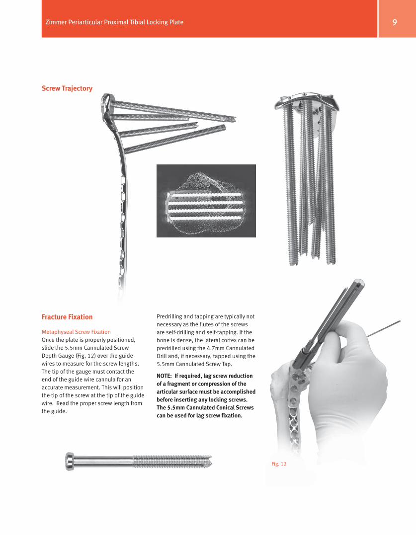
Screw Trajectory
Fracture Fixation
Metaphyseal Screw FixationOnce the plate is properly positioned, slide the 5.5mm Cannulated Screw Depth Gauge (Fig. 12) over the guide wires to measure for the screw lengths. The tip of the gauge must contact the end of the guide wire cannula for an accurate measurement. This will position the tip of the screw at the tip of the guide wire. Read the proper screw length from the guide.
Fig. 12
Predrilling and tapping are typically not necessary as the flutes of the screws are self-drilling and self-tapping. If the bone is dense, the lateral cortex can be predrilled using the 4.7mm Cannulated Drill and, if necessary, tapped using the 5.5mm Cannulated Screw Tap.
NoTe: If required, lag screw reduction of a fragment or compression of the articular surface must be accomplished before inserting any locking screws. The 5.5mm Cannulated Conical Screws can be used for lag screw fixation.
10 Zimmer Periarticular Proximal Tibial Locking Plate
Fig. 14
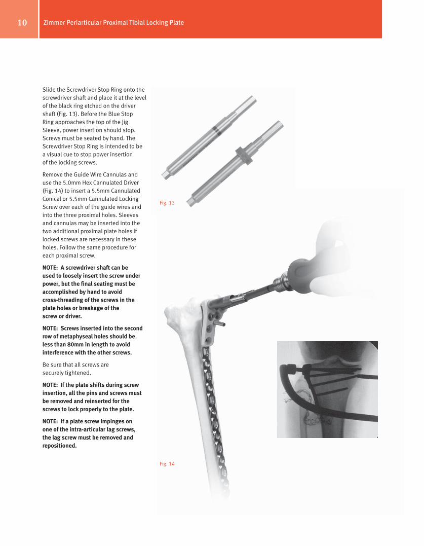
Slide the Screwdriver Stop Ring onto the screwdriver shaft and place it at the level of the black ring etched on the driver shaft (Fig. 13). Before the Blue Stop Ring approaches the top of the Jig Sleeve, power insertion should stop. Screws must be seated by hand. The Screwdriver Stop Ring is intended to be a visual cue to stop power insertion of the locking screws.
Remove the Guide Wire Cannulas and use the 5.0mm Hex Cannulated Driver (Fig. 14) to insert a 5.5mm Cannulated Conical or 5.5mm Cannulated Locking Screw over each of the guide wires and into the three proximal holes. Sleeves and cannulas may be inserted into the two additional proximal plate holes if locked screws are necessary in these holes. Follow the same procedure for each proximal screw.
NoTe: A screwdriver shaft can be used to loosely insert the screw under power, but the final seating must be accomplished by hand to avoid cross-threading of the screws in the plate holes or breakage of the screw or driver.
NoTe: Screws inserted into the second row of metaphyseal holes should be less than 80mm in length to avoid interference with the other screws.
Be sure that all screws are securely tightened.
NoTe: If the plate shifts during screw insertion, all the pins and screws must be removed and reinserted for the screws to lock properly to the plate.
NoTe: If a plate screw impinges on one of the intra-articular lag screws, the lag screw must be removed and repositioned.
Fig. 13
11Zimmer Periarticular Proximal Tibial Locking Plate
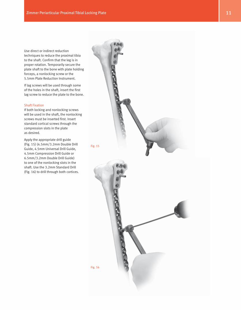
Use direct or indirect reduction techniques to reduce the proximal tibia to the shaft. Confirm that the leg is in proper rotation. Temporarily secure the plate shaft to the bone with plate holding forceps, a nonlocking screw or the 5.5mm Plate Reduction Instrument.
If lag screws will be used through some of the holes in the shaft, insert the first lag screw to reduce the plate to the bone.
Shaft FixationIf both locking and nonlocking screws will be used in the shaft, the nonlocking screws must be inserted first. Insert standard cortical screws through the compression slots in the plate as desired.
Apply the appropriate drill guide (Fig. 15) (4.5mm/3.2mm Double Drill Guide, 4.5mm Universal Drill Guide, 4.5mm Compression Drill Guide or 6.5mm/3.2mm Double Drill Guide) to one of the nonlocking slots in the shaft. Use the 3.2mm Standard Drill (Fig. 16) to drill through both cortices.
Fig. 15
Fig. 16
12 Zimmer Periarticular Proximal Tibial Locking Plate
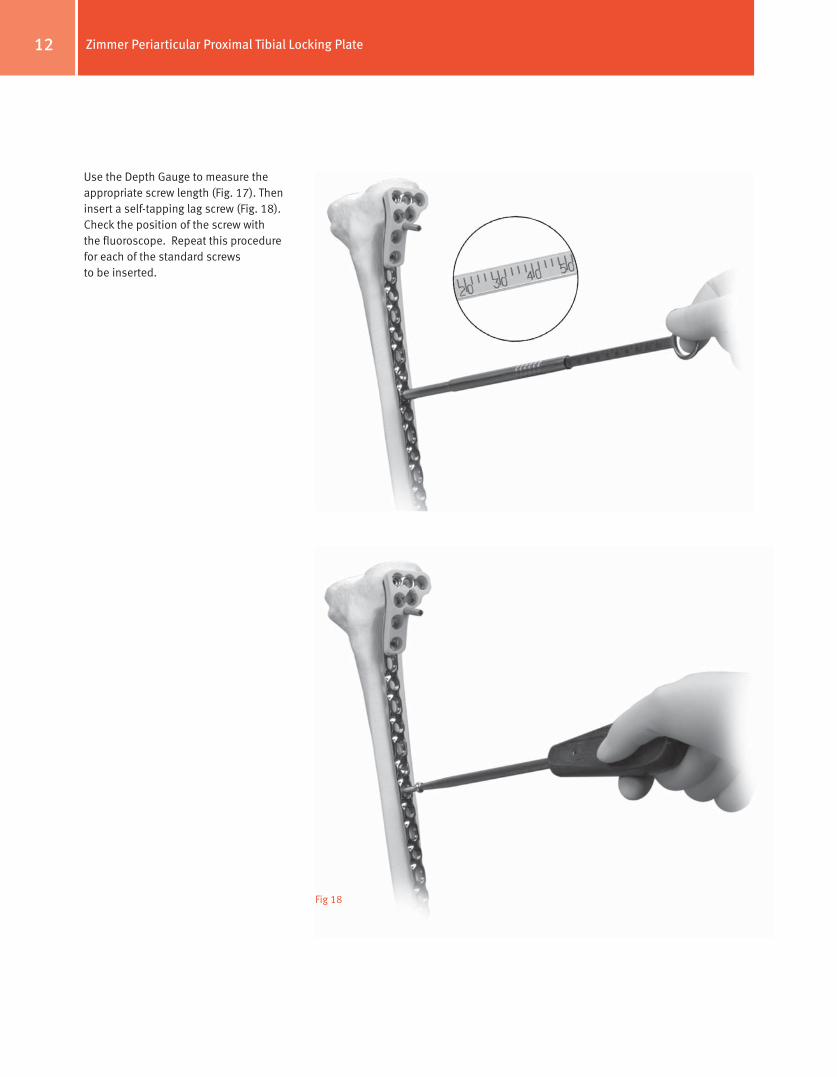
Use the Depth Gauge to measure the appropriate screw length (Fig. 17). Then insert a self-tapping lag screw (Fig. 18). Check the position of the screw with the fluoroscope. Repeat this procedure for each of the standard screws to be inserted.
Fig 17
Fig 18
13Zimmer Periarticular Proximal Tibial Locking Plate
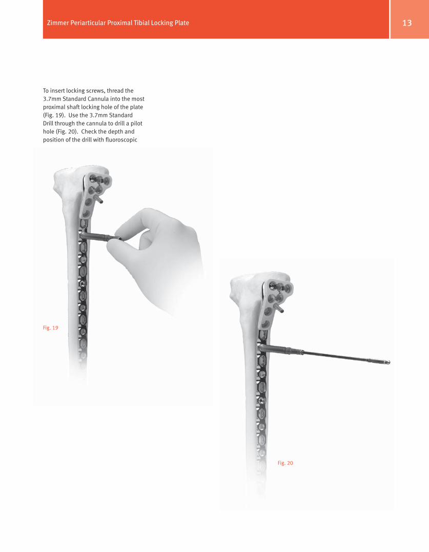
To insert locking screws, thread the 3.7mm Standard Cannula into the most proximal shaft locking hole of the plate (Fig. 19). Use the 3.7mm Standard Drill through the cannula to drill a pilot hole (Fig. 20). Check the depth and position of the drill with fluoroscopic
Fig. 19
Fig. 20
14 Zimmer Periarticular Proximal Tibial Locking Plate
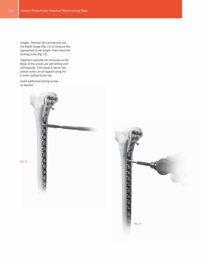
images. Remove the cannula and use the Depth Gauge (Fig. 21) to measure the appropriate screw length. Then insert the locking screw (Fig. 22).
Tapping is typically not necessary as the flutes of the screws are self-drilling and self-tapping. If the bone is dense, the lateral cortex can be tapped using the 4.5mm Locking Screw Tap.
Insert additional locking screws as desired.
Fig. 21
Fig. 22
15Zimmer Periarticular Proximal Tibial Locking Plate
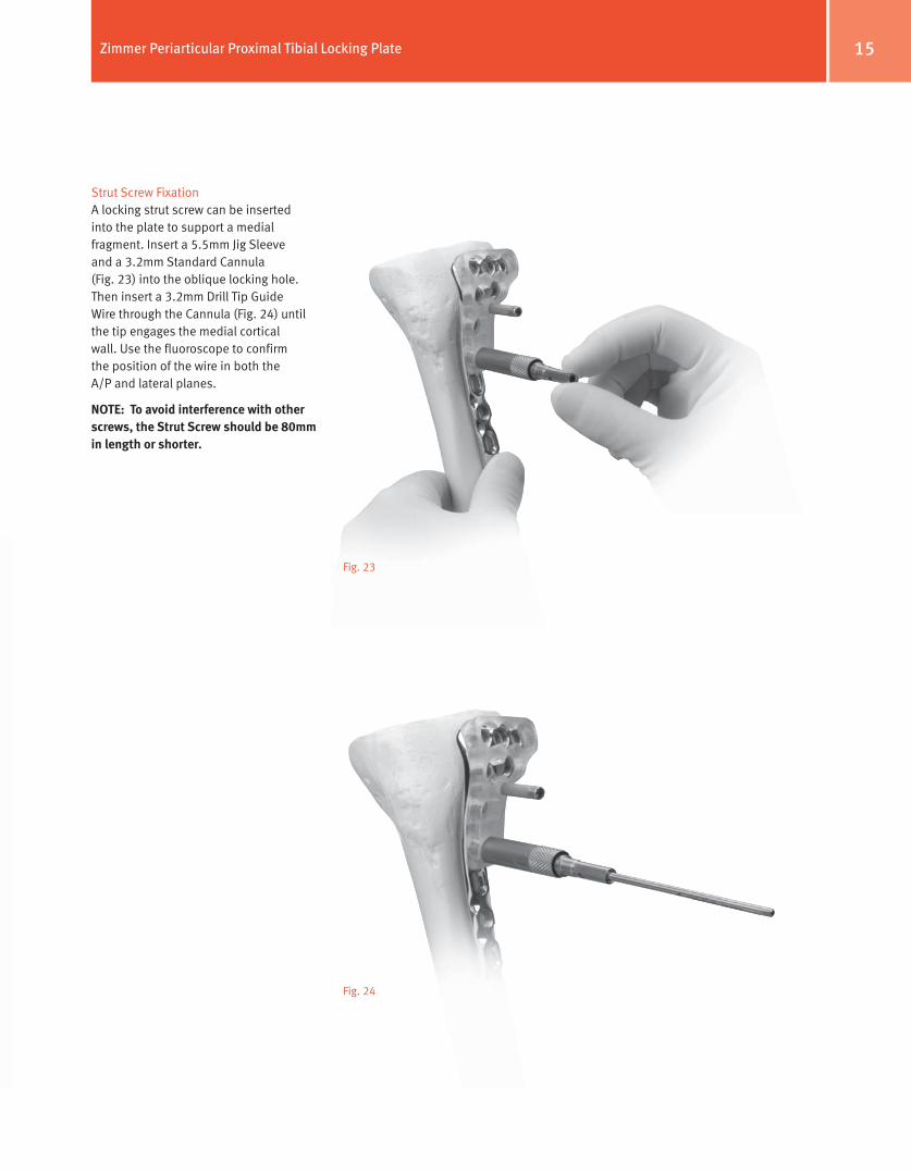
Strut Screw FixationA locking strut screw can be inserted into the plate to support a medial fragment. Insert a 5.5mm Jig Sleeve and a 3.2mm Standard Cannula (Fig. 23) into the oblique locking hole. Then insert a 3.2mm Drill Tip Guide Wire through the Cannula (Fig. 24) until the tip engages the medial cortical wall. Use the fluoroscope to confirm the position of the wire in both the A/P and lateral planes.
NoTe: To avoid interference with other screws, the Strut Screw should be 80mm in length or shorter.
Fig. 23
Fig. 24
16 Zimmer Periarticular Proximal Tibial Locking Plate
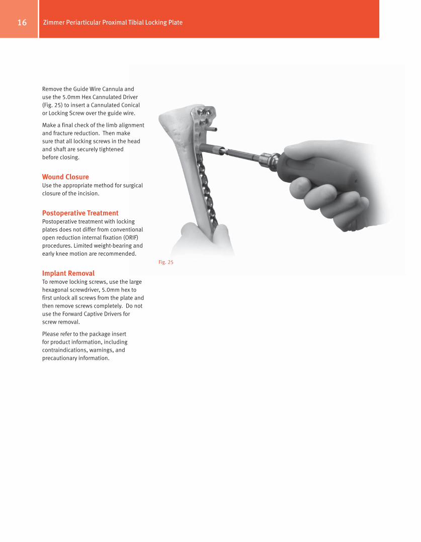
Remove the Guide Wire Cannula and use the 5.0mm Hex Cannulated Driver (Fig. 25) to insert a Cannulated Conical or Locking Screw over the guide wire.
Make a final check of the limb alignment and fracture reduction. Then make sure that all locking screws in the head and shaft are securely tightened before closing.
Wound ClosureUse the appropriate method for surgical closure of the incision.
Postoperative TreatmentPostoperative treatment with locking plates does not differ from conventional open reduction internal fixation (ORIF) procedures. Limited weight-bearing and early knee motion are recommended.
Implant RemovalTo remove locking screws, use the large hexagonal screwdriver, 5.0mm hex to first unlock all screws from the plate and then remove screws completely. Do not use the Forward Captive Drivers for screw removal.
Please refer to the package insert for product information, including contraindications, warnings, and precautionary information.
Fig. 25
17Zimmer Periarticular Proximal Tibial Locking Plate
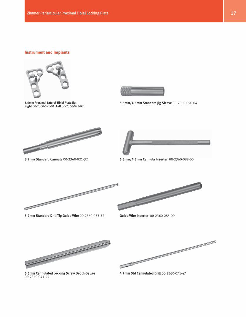
Instrument and Implants
5.5mm Proximal Lateral Tibial Plate Jig, Right 00-2360-091-01, Left 00-2360-091-02
3.2mm Standard Cannula 00-2360-021-32
3.2mm Standard Drill Tip guide Wire 00-2360-033-32
5.5mm Cannulated Locking Screw Depth gauge 00-2360-041-55
4.7mm Std Cannulated Drill 00-2360-071-47
guide Wire Inserter 00-2360-085-00
5.5mm/4.5mm Cannula Inserter 00-2360-088-00
5.5mm/4.5mm Standard Jig Sleeve 00-2360-090-04
18 Zimmer Periarticular Proximal Tibial Locking Plate
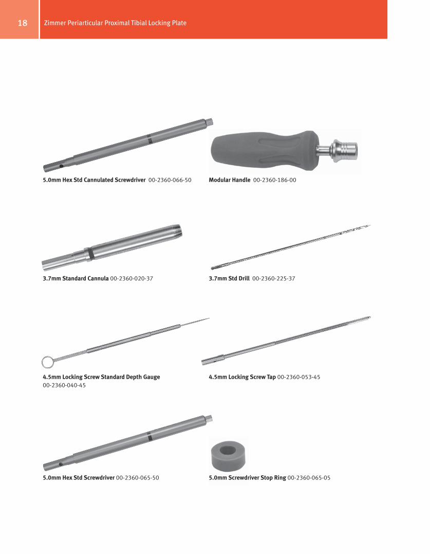
5.0mm Hex Std Screwdriver 00-2360-065-50
4.5mm Locking Screw Standard Depth gauge 00-2360-040-45
3.7mm Standard Cannula 00-2360-020-37
5.0mm Hex Std Cannulated Screwdriver 00-2360-066-50 Modular Handle 00-2360-186-00
3.7mm Std Drill 00-2360-225-37
4.5mm Locking Screw Tap 00-2360-053-45
5.0mm Screwdriver Stop Ring 00-2360-065-05
19Zimmer Periarticular Proximal Tibial Locking Plate
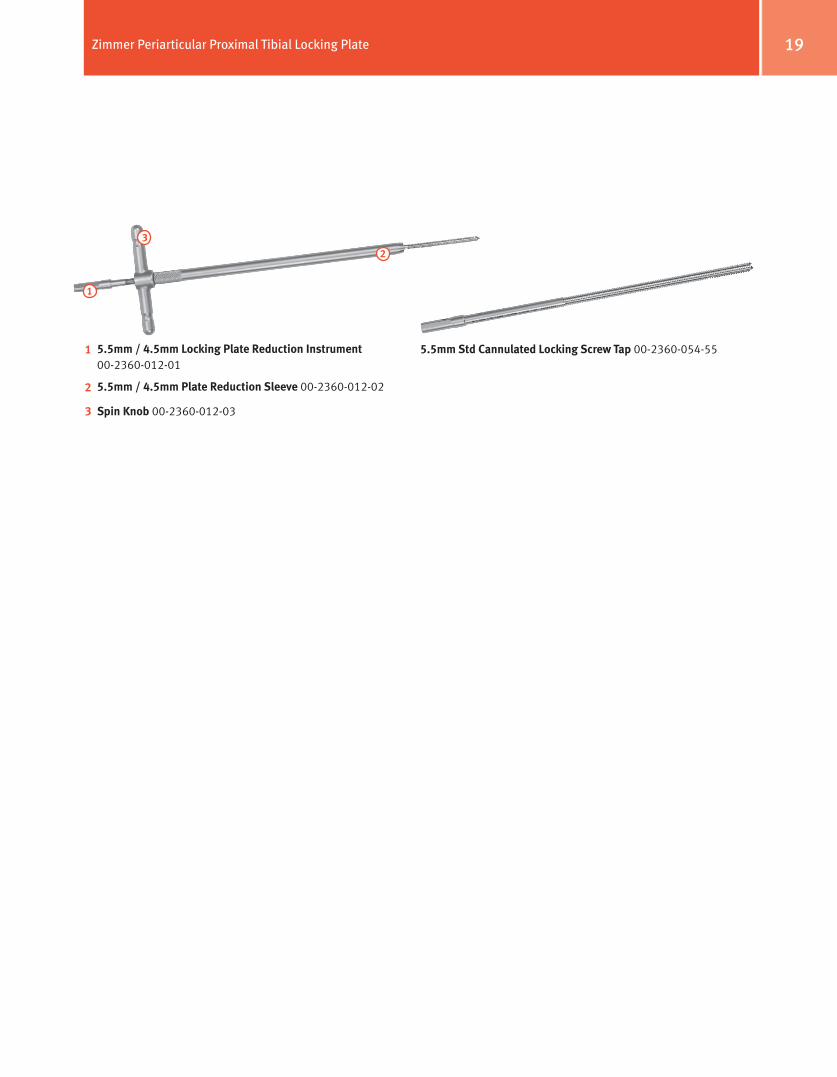
5.5mm / 4.5mm Locking Plate Reduction Instrument 00-2360-012-01
5.5mm / 4.5mm Plate Reduction Sleeve 00-2360-012-02
Spin Knob 00-2360-012-03
1
3
2
1
2
3
5.5mm Std Cannulated Locking Screw Tap 00-2360-054-55

20 Zimmer Periarticular Proximal Tibial Locking Plate
order InformationPart Number Description
00-2360-000-12 5.5mm Proximal Tibial Plate Standard Jig Set00-2360-091-01 5.5mm Proximal Lateral Tibial Plate Jig, Right00-2360-091-02 5.5mm Proximal Lateral Tibial Plate Jig, Left00-2358-015-03 5.5mm Proximal Lateral Tibial Plate/Jig Case00-2360-093-03 Standard Jig Set Screw 2 ea.00-2357-000-08 5.5mm Prox Lat Tib Lck Plt Set00-2357-006-04 5.5mm Proximal Lateral Tibial Locking Plate,
4 Hole, 97mm Long, Left00-2357-006-06 5.5mm Proximal Lateral Tibial Locking Plate,
6 Hole, 128mm Long, Left00-2357-006-08 5.5mm Proximal Lateral Tibial Locking Plate,
8 Hole, 158mm Long, Left00-2357-006-10 5.5mm Proximal Lateral Tibial Locking Plate,
10 Hole, 189mm Long, Left00-2357-006-12 5.5mm Proximal Lateral Tibial Locking Plate,
12 Hole, 219mm Long, Left00-2357-006-14 5.5mm Proximal Lateral Tibial Locking Plate,
14 Hole, 250mm Long, Left00-2357-005-04 5.5mm Proximal Lateral Tibial Locking Plate,
4 Hole, 97mm Long, Right00-2357-005-06 5.5mm Proximal Lateral Tibial Locking Plate,
6 Hole, 128mm Long, Right00-2357-005-08 5.5mm Proximal Lateral Tibial Locking Plate,
8 Hole, 158mm Long, Right00-2357-005-10 5.5mm Proximal Lateral Tibial Locking Plate,
10 Hole, 189mm Long, Right00-2357-005-12 5.5mm Proximal Lateral Tibial Locking Plate,
12 Hole, 219mm Long, Right00-2357-005-14 5.5mm Proximal Lateral Tibial Locking Plate,
14 Hole, 250mm Long, RightAlso available:47-2357-006-18 5.5mm Proximal Lateral Tibial Locking Plate,
18 Hole, 311mm Long, Left, Sterile Only47-2357-006-22 5.5mm Proximal Lateral Tibial Locking Plate,
22 Hole, 372mm Long, Left, Sterile Only47-2357-005-18 5.5mm Proximal Lateral Tibial Locking Plate,
18 Hole, 311mm Long, Right, Sterile Only47-2357-005-22 5.5mm Proximal Lateral Tibial Locking Plate,
22 Hole, 372mm Long, Right, Sterile Only00-2360-000-01 5.5mm/4.5mm Periarticular Locking Screw
and Instrument Set00-1147-073-00 Cleaning Stylet00-1147-078-00 Cleaning Brush00-2358-035-05 5.5mm/4.5mm Locking Screw Instrument Case
00-2360-012-01 5.5mm/4.5mm Plate Reduction Instrument00-2360-012-02 5.5mm/4.5mm Plate Reduction Sleeve00-2360-012-03 Plate Reduction Spin Knob00-2360-020-37 3.7mm Standard Cannula 00-2360-021-32 3.2mm Standard Cannula 00-2360-033-32 3.2mm Standard Drill Tip Guide Wire
(5 per box)00-2360-040-45 4.5mm Locking Screw Standard Depth Gauge 00-2360-041-55 5.5mm Cannulated Locking Screw Depth Gauge 00-2360-053-45 4.5mm Locking Screw Tap 00-2360-054-55 5.5mm Cannulated Locking Screw Tap00-2360-065-50 5.0mm Hex Standard Screwdriver00-2360-066-50 5.0mm Hex Standard Cannulated Screwdriver00-2360-071-47 4.7mm Standard Cannulated Drill00-2360-225-37 3.7mm Standard Drill
00-2360-085-00 Guide Wire Inserter00-2360-186-00 Modular Handle00-2360-088-00 5.5mm/4.5mm Cannula Inserter00-2360-065-05 5.0mm Screwdriver Stop Ring00-2360-080-05 Torque Limiting Attachment00-4812-045-00 Large Hex Screwdriver (1 ea.)00-2360-090-04 5.5mm/4.5mm Standard Jig Sleeve (4 ea.)
00-2359-000-01 5.5mm/4.5mm Locking Screw Set00-2359-030-55 5.5mm Cannulated Locking Screw 30mm Long00-2359-035-55 5.5mm Cannulated Locking Screw 35mm Long00-2359-040-55 5.5mm Cannulated Locking Screw 40mm Long00-2359-045-55 5.5mm Cannulated Locking Screw 45mm Long00-2359-050-55 5.5mm Cannulated Locking Screw 50mm Long00-2359-055-55 5.5mm Cannulated Locking Screw 55mm Long00-2359-060-55 5.5mm Cannulated Locking Screw 60mm Long00-2359-065-55 5.5mm Cannulated Locking Screw 65mm Long00-2359-070-55 5.5mm Cannulated Locking Screw 70mm Long00-2359-075-55 5.5mm Cannulated Locking Screw 75mm Long00-2359-080-55 5.5mm Cannulated Locking Screw 80mm Long00-2359-085-55 5.5mm Cannulated Locking Screw 85mm Long00-2359-090-55 5.5mm Cannulated Locking Screw 90mm Long00-2359-095-55 5.5mm Cannulated Locking Screw 95mm Long00-2359-100-55 5.5mm Cannulated Locking Screw 100mm Long00-2359-050-56 5.5mm Cannulated Conical Screw 50mm Long00-2359-055-56 5.5mm Cannulated Conical Screw 55mm Long00-2359-060-56 5.5mm Cannulated Conical Screw 60mm Long00-2359-065-56 5.5mm Cannulated Conical Screw 65mm Long00-2359-070-56 5.5mm Cannulated Conical Screw 70mm Long00-2359-075-56 5.5mm Cannulated Conical Screw 75mm Long00-2359-080-56 5.5mm Cannulated Conical Screw 80mm Long00-2359-085-56 5.5mm Cannulated Conical Screw 85mm Long00-2359-090-56 5.5mm Cannulated Conical Screw 90mm Long00-2359-012-45 4.5mm Locking Screw 12mm long
00-2359-014-45 4.5mm Locking Screw 14mm long00-2359-016-45 4.5mm Locking Screw 16mm long00-2359-018-45 4.5mm Locking Screw 18mm long00-2359-020-45 4.5mm Locking Screw 20mm long00-2359-022-45 4.5mm Locking Screw 22mm long00-2359-024-45 4.5mm Locking Screw 24mm long00-2359-026-45 4.5mm Locking Screw 26mm long00-2359-028-45 4.5mm Locking Screw 28mm long00-2359-030-45 4.5mm Locking Screw 30mm long00-2359-032-45 4.5mm Locking Screw 32mm long00-2359-034-45 4.5mm Locking Screw 34mm long00-2359-036-45 4.5mm Locking Screw 36mm long00-2359-038-45 4.5mm Locking Screw 38mm long00-2359-040-45 4.5mm Locking Screw 40mm long00-2359-042-45 4.5mm Locking Screw 42mm long00-2359-044-45 4.5mm Locking Screw 44mm long00-2359-046-45 4.5mm Locking Screw 46mm long00-2359-048-45 4.5mm Locking Screw 48mm long00-2359-050-45 4.5mm Locking Screw 50mm long00-2359-055-45 4.5mm Locking Screw 55mm long00-2359-060-45 4.5mm Locking Screw 60mm long00-2359-065-45 4.5mm Locking Screw 65mm long00-2359-070-45 4.5mm Locking Screw 70mm long
21Zimmer Periarticular Proximal Tibial Locking Plate
Surgical Technique for the Periarticular 3.5mm Proximal Tibial Locking Plate
Required InstrumentationThe following sets may be required for application of the 3.5mm Periarticular Locking Proximal Tibia Plate:
• Small Fragment Screw and Instrument Set
• Cannulated Screws
• Basic Forceps Set
• 3.5mm/2.7mm Locking Screw and Instrument Set
• 3.5mm Locking Proximal Tibia Plate and Standard Jig Set
NoTe: The 2.7mm Locking Screws should not be used with the 3.5mm Locking Proximal Tibial Plate.
Fig. 26 Fig. 27
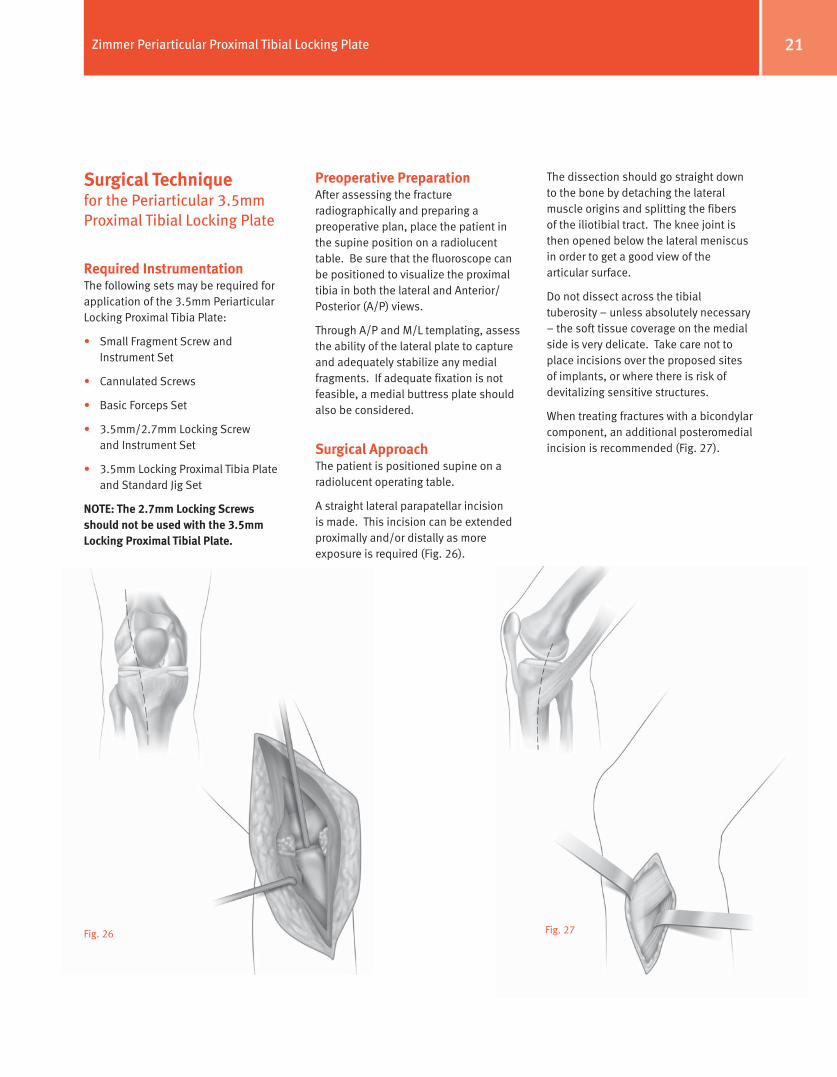
Preoperative PreparationAfter assessing the fracture radiographically and preparing a preoperative plan, place the patient in the supine position on a radiolucent table. Be sure that the fluoroscope can be positioned to visualize the proximal tibia in both the lateral and Anterior/Posterior (A/P) views.
Through A/P and M/L templating, assess the ability of the lateral plate to capture and adequately stabilize any medial fragments. If adequate fixation is not feasible, a medial buttress plate should also be considered.
Surgical ApproachThe patient is positioned supine on a radiolucent operating table.
A straight lateral parapatellar incision is made. This incision can be extended proximally and/or distally as more exposure is required (Fig. 26).
The dissection should go straight down to the bone by detaching the lateral muscle origins and splitting the fibers of the iliotibial tract. The knee joint is then opened below the lateral meniscus in order to get a good view of the articular surface.
Do not dissect across the tibial tuberosity – unless absolutely necessary – the soft tissue coverage on the medial side is very delicate. Take care not to place incisions over the proposed sites of implants, or where there is risk of devitalizing sensitive structures.
When treating fractures with a bicondylar component, an additional posteromedial incision is recommended (Fig. 27).
22 Zimmer Periarticular Proximal Tibial Locking Plate
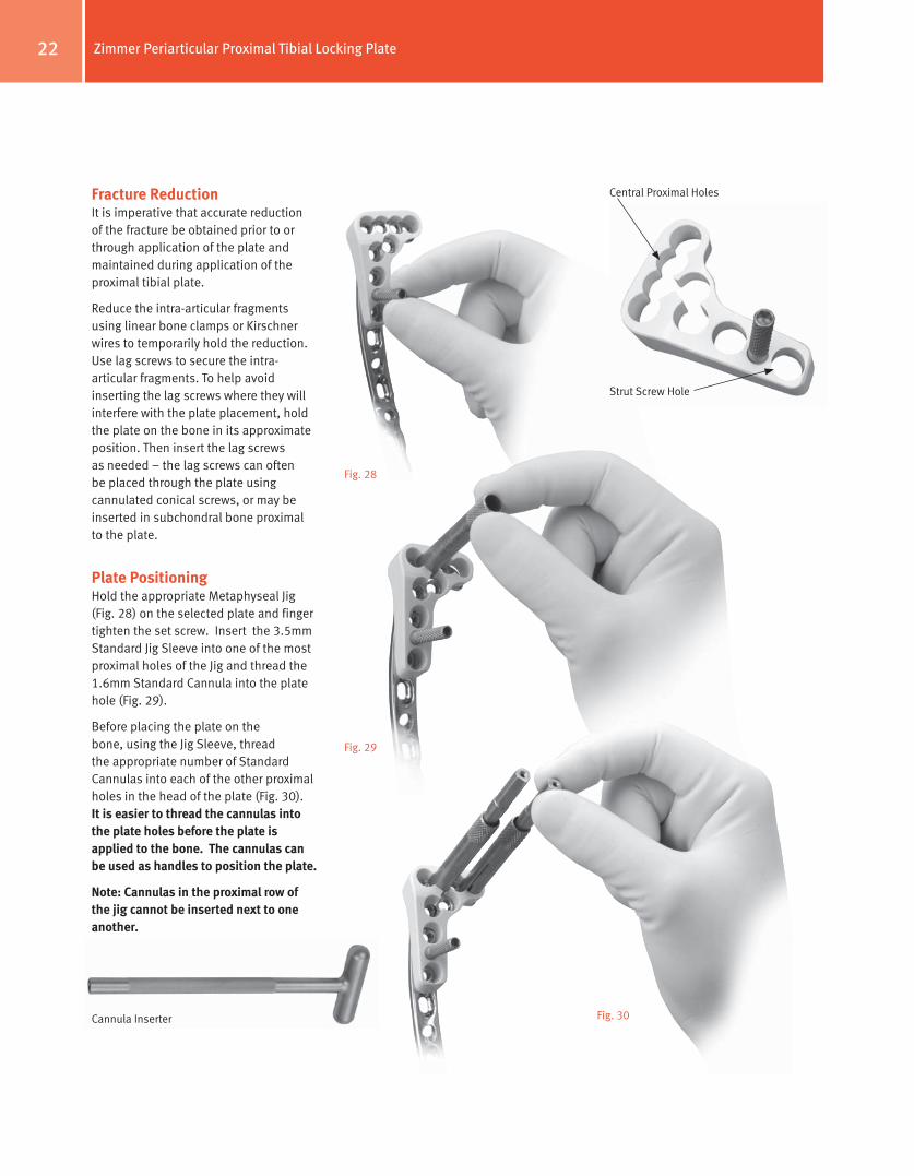
Fracture ReductionIt is imperative that accurate reduction of the fracture be obtained prior to or through application of the plate and maintained during application of the proximal tibial plate.
Reduce the intra-articular fragments using linear bone clamps or Kirschner wires to temporarily hold the reduction. Use lag screws to secure the intra-articular fragments. To help avoid inserting the lag screws where they will interfere with the plate placement, hold the plate on the bone in its approximate position. Then insert the lag screws as needed – the lag screws can often be placed through the plate using cannulated conical screws, or may be inserted in subchondral bone proximal to the plate.
Plate PositioningHold the appropriate Metaphyseal Jig (Fig. 28) on the selected plate and finger tighten the set screw. Insert the 3.5mm Standard Jig Sleeve into one of the most proximal holes of the Jig and thread the 1.6mm Standard Cannula into the plate hole (Fig. 29).
Before placing the plate on the bone, using the Jig Sleeve, thread the appropriate number of Standard Cannulas into each of the other proximal holes in the head of the plate (Fig. 30). It is easier to thread the cannulas into the plate holes before the plate is applied to the bone. The cannulas can be used as handles to position the plate.
Note: Cannulas in the proximal row of the jig cannot be inserted next to one another.
Fig. 28
Central Proximal Holes
Strut Screw Hole
Fig. 29
Fig. 30Cannula Inserter
23Zimmer Periarticular Proximal Tibial Locking Plate
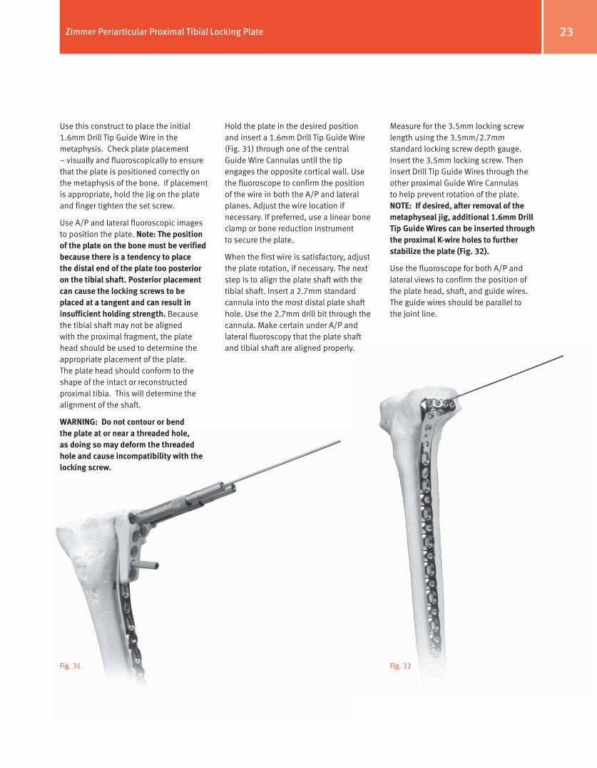
Use this construct to place the initial 1.6mm Drill Tip Guide Wire in the metaphysis. Check plate placement – visually and fluoroscopically to ensure that the plate is positioned correctly on the metaphysis of the bone. If placement is appropriate, hold the Jig on the plate and finger tighten the set screw.
Use A/P and lateral fluoroscopic images to position the plate. Note: The position of the plate on the bone must be verified because there is a tendency to place the distal end of the plate too posterior on the tibial shaft. Posterior placement can cause the locking screws to be placed at a tangent and can result in insufficient holding strength. Because the tibial shaft may not be aligned with the proximal fragment, the plate head should be used to determine the appropriate placement of the plate. The plate head should conform to the shape of the intact or reconstructed proximal tibia. This will determine the alignment of the shaft.
WARNINg: Do not contour or bend the plate at or near a threaded hole, as doing so may deform the threaded hole and cause incompatibility with the locking screw.
Fig. 31
Measure for the 3.5mm locking screw length using the 3.5mm/2.7mm standard locking screw depth gauge. Insert the 3.5mm locking screw. Then insert Drill Tip Guide Wires through the other proximal Guide Wire Cannulas to help prevent rotation of the plate. NoTe: If desired, after removal of the metaphyseal jig, additional 1.6mm Drill Tip guide Wires can be inserted through the proximal K-wire holes to further stabilize the plate (Fig. 32).
Use the fluoroscope for both A/P and lateral views to confirm the position of the plate head, shaft, and guide wires. The guide wires should be parallel to the joint line.
Fig. 32
Hold the plate in the desired position and insert a 1.6mm Drill Tip Guide Wire (Fig. 31) through one of the central Guide Wire Cannulas until the tip engages the opposite cortical wall. Use the fluoroscope to confirm the position of the wire in both the A/P and lateral planes. Adjust the wire location if necessary. If preferred, use a linear bone clamp or bone reduction instrument to secure the plate.
When the first wire is satisfactory, adjust the plate rotation, if necessary. The next step is to align the plate shaft with the tibial shaft. Insert a 2.7mm standard cannula into the most distal plate shaft hole. Use the 2.7mm drill bit through the cannula. Make certain under A/P and lateral fluoroscopy that the plate shaft and tibial shaft are aligned properly.
24 Zimmer Periarticular Proximal Tibial Locking Plate
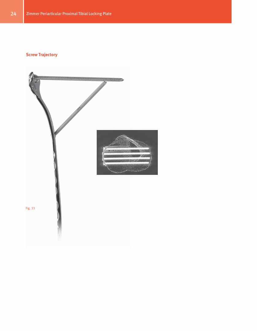
Screw Trajectory
Fig. 33
25Zimmer Periarticular Proximal Tibial Locking Plate
Fracture Fixation
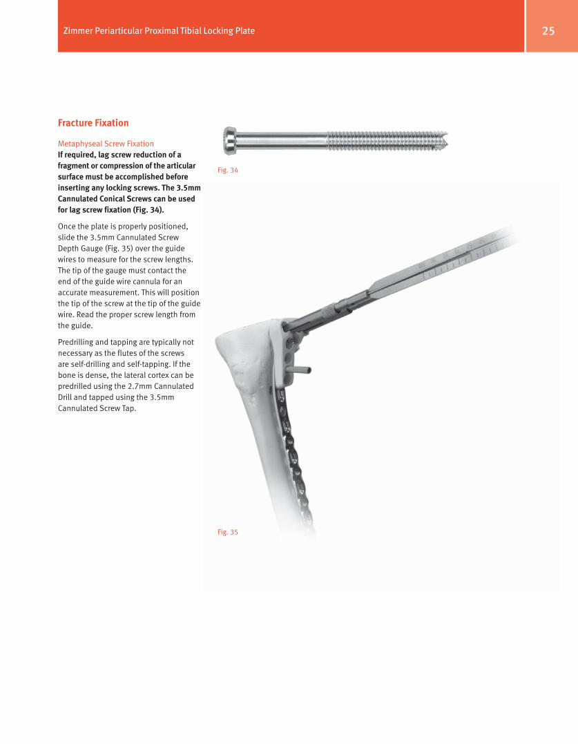
Metaphyseal Screw FixationIf required, lag screw reduction of a fragment or compression of the articular surface must be accomplished before inserting any locking screws. The 3.5mm Cannulated Conical Screws can be used for lag screw fixation (Fig. 34).
Once the plate is properly positioned, slide the 3.5mm Cannulated Screw Depth Gauge (Fig. 35) over the guide wires to measure for the screw lengths. The tip of the gauge must contact the end of the guide wire cannula for an accurate measurement. This will position the tip of the screw at the tip of the guide wire. Read the proper screw length from the guide.
Predrilling and tapping are typically not necessary as the flutes of the screws are self-drilling and self-tapping. If the bone is dense, the lateral cortex can be predrilled using the 2.7mm Cannulated Drill and tapped using the 3.5mm Cannulated Screw Tap.
Fig. 34
Fig. 35
26 Zimmer Periarticular Proximal Tibial Locking Plate
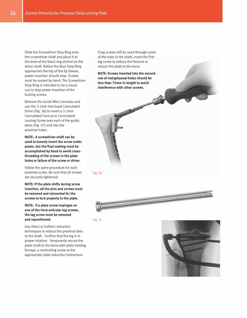
Slide the Screwdriver Stop Ring onto the screwdriver shaft and place it at the level of the black ring etched on the driver shaft. Before the Blue Stop Ring approaches the top of the Jig Sleeve, power insertion should stop. Screws must be seated by hand. The Screwdriver Stop Ring is intended to be a visual cue to stop power insertion of the locking screws.
Remove the Guide Wire Cannulas and use the 2.5mm Hex-head Cannulated Driver (Fig. 36) to insert a 3.5mm Cannulated Conical or Cannulated Locking Screw over each of the guide wires (Fig. 37) and into the proximal holes.
NoTe: A screwdriver shaft can be used to loosely insert the screw under power, but the final seating must be accomplished by hand to avoid cross-threading of the screws in the plate holes or failure of the screw or driver.
Follow the same procedure for each proximal screw. Be sure that all screws are securely tightened.
NoTe: If the plate shifts during screw insertion, all the pins and screws must be removed and reinserted for the screws to lock properly to the plate.
NoTe: If a plate screw impinges on one of the intra-articular lag screws, the lag screw must be removed and repositioned.
Use direct or indirect reduction techniques to reduce the proximal tibia to the shaft. Confirm that the leg is in proper rotation. Temporarily secure the plate shaft to the bone with plate holding forceps, a nonlocking screw or the appropriate plate reduction instrument.
Fig. 37
Fig. 36
If lag screws will be used through some of the slots in the shaft, insert the first lag screw to reduce the fracture or reduce the plate to the bone.
NoTe: Screws inserted into the second row of metaphyseal holes should be less than 75mm in length to avoid interference with other screws.
27Zimmer Periarticular Proximal Tibial Locking Plate
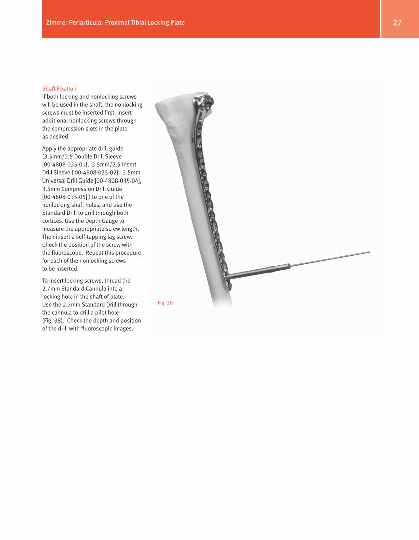
Shaft FixationIf both locking and nonlocking screws will be used in the shaft, the nonlocking screws must be inserted first. Insert additional nonlocking screws through the compression slots in the plate as desired.
Apply the appropriate drill guide (3.5mm/2.5 Double Drill Sleeve [00-4808-035-01], 3.5mm/2.5 Insert Drill Sleeve [ 00-4808-035-02], 3.5mm Universal Drill Guide [00-4808-035-04], 3.5mm Compression Drill Guide [00-4808-035-05] ) to one of the nonlocking shaft holes, and use the Standard Drill to drill through both cortices. Use the Depth Gauge to measure the appropriate screw length. Then insert a self-tapping lag screw. Check the position of the screw with the fluoroscope. Repeat this procedure for each of the nonlocking screws to be inserted.
To insert locking screws, thread the 2.7mm Standard Cannula into a locking hole in the shaft of plate. Use the 2.7mm Standard Drill through the cannula to drill a pilot hole (Fig. 38). Check the depth and position of the drill with fluoroscopic images.
Fig. 38
28 Zimmer Periarticular Proximal Tibial Locking Plate
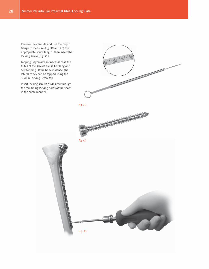
Remove the cannula and use the Depth Gauge to measure (Fig. 39 and 40) the appropriate screw length. Then insert the locking screw (Fig. 41).
Tapping is typically not necessary as the flutes of the screws are self-drilling and self-tapping. If the bone is dense, the lateral cortex can be tapped using the 3.5mm Locking Screw tap.
Insert locking screws as desired through the remaining locking holes of the shaft in the same manner.
Fig. 39
Fig. 40
Fig. 41
29Zimmer Periarticular Proximal Tibial Locking Plate
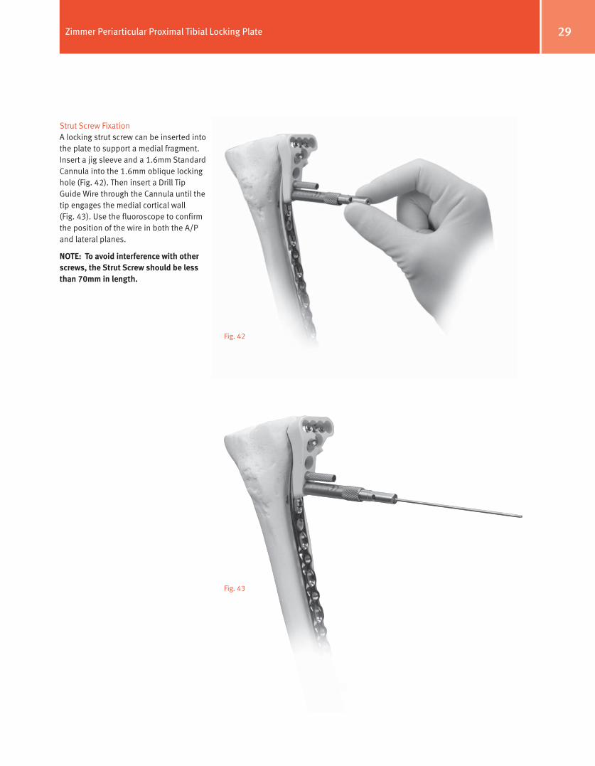
Strut Screw FixationA locking strut screw can be inserted into the plate to support a medial fragment. Insert a jig sleeve and a 1.6mm Standard Cannula into the 1.6mm oblique locking hole (Fig. 42). Then insert a Drill Tip Guide Wire through the Cannula until the tip engages the medial cortical wall (Fig. 43). Use the fluoroscope to confirm the position of the wire in both the A/P and lateral planes.
NoTe: To avoid interference with other screws, the Strut Screw should be less than 70mm in length.
Fig. 42
Fig. 43
30 Zimmer Periarticular Proximal Tibial Locking Plate
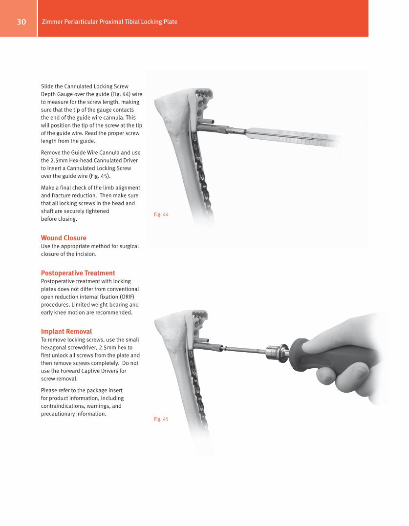
Slide the Cannulated Locking Screw Depth Gauge over the guide (Fig. 44) wire to measure for the screw length, making sure that the tip of the gauge contacts the end of the guide wire cannula. This will position the tip of the screw at the tip of the guide wire. Read the proper screw length from the guide.
Remove the Guide Wire Cannula and use the 2.5mm Hex-head Cannulated Driver to insert a Cannulated Locking Screw over the guide wire (Fig. 45).
Make a final check of the limb alignment and fracture reduction. Then make sure that all locking screws in the head and shaft are securely tightened before closing.
Wound ClosureUse the appropriate method for surgical closure of the incision.
Postoperative TreatmentPostoperative treatment with locking plates does not differ from conventional open reduction internal fixation (ORIF) procedures. Limited weight-bearing and early knee motion are recommended.
Implant RemovalTo remove locking screws, use the small hexagonal screwdriver, 2.5mm hex to first unlock all screws from the plate and then remove screws completely. Do not use the Forward Captive Drivers for screw removal.
Please refer to the package insert for product information, including contraindications, warnings, and precautionary information.
Fig. 44
Fig. 45
31Zimmer Periarticular Proximal Tibial Locking Plate
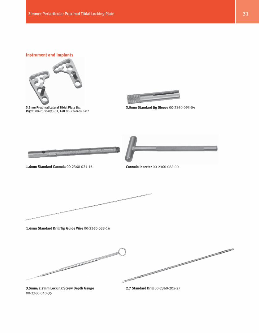
1.6mm Standard Cannula 00-2360-021-16
1.6mm Standard Drill Tip guide Wire 00-2360-033-16
Instrument and Implants
Cannula Inserter 00-2360-088-00
3.5mm Standard Jig Sleeve 00-2360-093-043.5mm Proximal Lateral Tibial Plate Jig, Right, 00-2360-093-01, Left 00-2360-093-02
3.5mm/2.7mm Locking Screw Depth gauge00-2360-040-35
2.7 Standard Drill 00-2360-205-27
32 Zimmer Periarticular Proximal Tibial Locking Plate
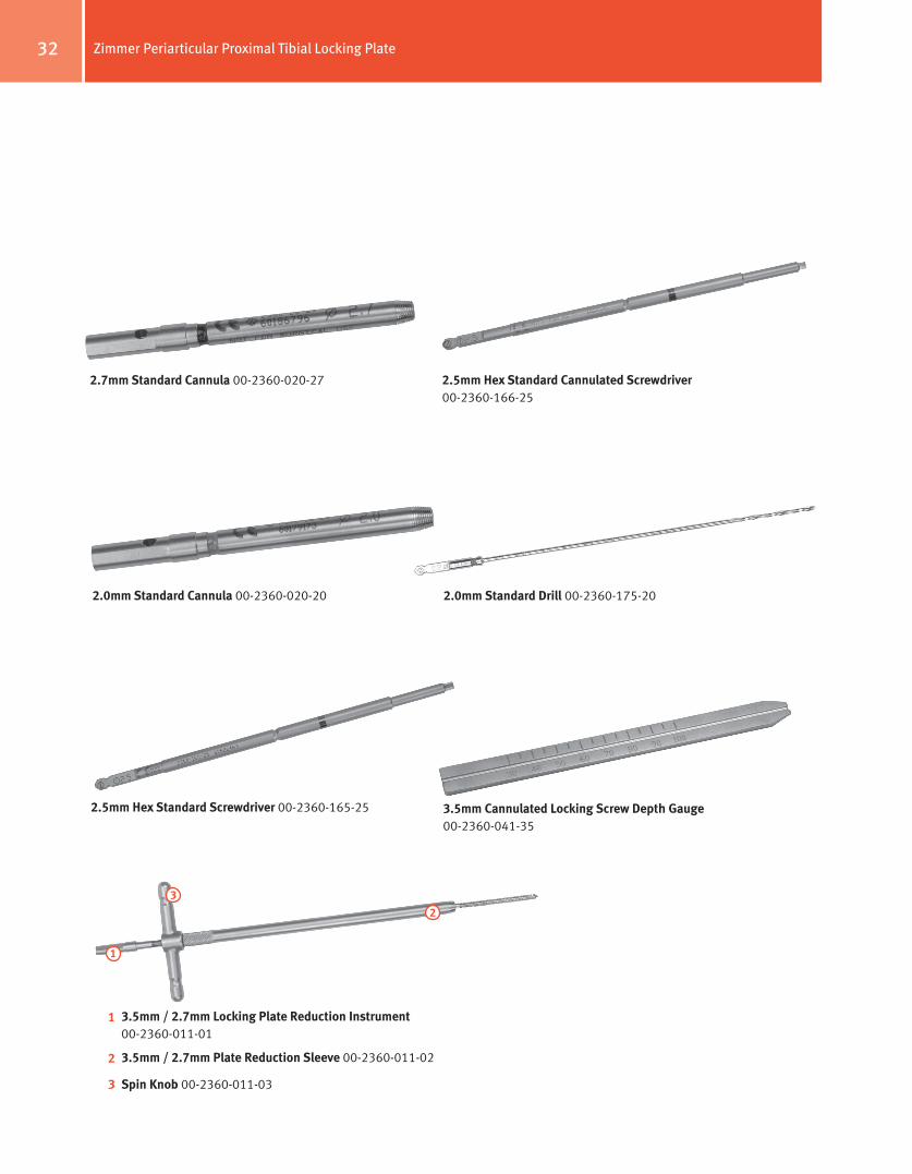
2.5mm Hex Standard Cannulated Screwdriver 00-2360-166-25
2.7mm Standard Cannula 00-2360-020-27
3.5mm Cannulated Locking Screw Depth gauge 00-2360-041-35
2.0mm Standard Drill 00-2360-175-20
3.5mm / 2.7mm Locking Plate Reduction Instrument 00-2360-011-01
3.5mm / 2.7mm Plate Reduction Sleeve 00-2360-011-02
Spin Knob 00-2360-011-03
1
3
2
1
2
3
2.5mm Hex Standard Screwdriver 00-2360-165-25
2.0mm Standard Cannula 00-2360-020-20
33Zimmer Periarticular Proximal Tibial Locking Plate
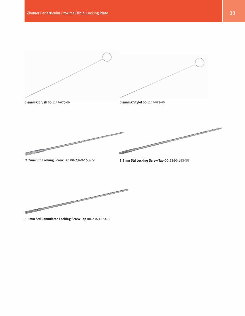
2.7mm Std Locking Screw Tap 00-2360-153-27 3.5mm Std Locking Screw Tap 00-2360-153-35
3.5mm Std Cannulated Locking Screw Tap 00-2360-154-35
Cleaning Brush 00-1147-076-00 Cleaning Stylet 00-1147-071-00

34 Zimmer Periarticular Proximal Tibial Locking Plate
Order InformationPart Number Description
00-2360-000-02 3.5mm/2.7mm Periarticular Locking Screw and Instrument Set
00-1147-053-00 Cannulated Ratchet Handle
00-1147-071-00 Cleaning Stylet
00-1147-076-00 Cleaning Brush
00-2358-040-05 3.5/2.7mm Locking Screw and Instrument Case
00-2360-011-01 3.5mm/2.7mm Plate Reduction Instrument
00-2360-011-02 3.5mm/2.7mm Plate Reduction Sleeve
00-2360-011-03 Plate Reduction Spin Knob
00-2360-020-20 2.0mm Standard Cannula
00-2360-021-16 1.6mm Standard Cannula
00-2360-033-16 1.6mm Standard Drill Tip Guide Wire (5 per box)
00-2360-040-35 3.5mm/2.7mm Locking Screw Standard Depth Gauge
00-2360-041-35 3.5mm Cannulated Locking Screw Depth Gauge
00-2360-065-00 2.5mm Screwdriver Stop Ring
00-2360-080-00 Torque Limiting Attachment
00-2360-088-00 Cannula Inserter
00-2360-093-04 3.5mm Standard Jig Sleeve
00-2360-153-27 2.7mm Locking Screw Tap
00-2360-153-35 3.5mm Locking Screw Tap
00-2360-154-35 3.5mm Cannulated Locking Screw Tap
00-2360-165-25 2.5mm Hex Standard Screwdriver
00-2360-166-25 2.5mm Hex Standard Cannulated Screwdriver
00-2360-171-27 2.7mm Standard Cannulated Drill 1QC
00-2360-175-20 2.0mm Standard Drill
00-2360-205-27 2.7mm Standard Drill
00-4811-035-01 Handle, QC Phenolic
00-4812-035-00 Small Hex Screwdriver
00-4812-045-00 3.5/2.7mm Locking Screw and Instrument Case
00-2360-000-15 3.5mm Proximal Tibial Standard Jig Set
00-2360-093-01 3.5mm Proximal Lateral Tibial Plate Jig, Right
00-2360-093-02 3.5mm Proximal Lateral Tibial Plate Jig, Left
00-2358-050-05 3.5mm Proximal Lateral Tibial Plate/Jig Case
00-2360-093-03 Standard Jig Set Screw (2 ea)
00-2357-000-09 3.5mm Proximal Lateral Tibial Locking Plate Set
00-2357-004-06 3.5mm Proximal Lateral Tibial Locking Plate, 6 Hole, 104mm Long, Left
00-2357-004-08 3.5mm Proximal Lateral Tibial Locking Plate, 8 Hole, 128mm Long, Left
00-2357-004-10 3.5mm Proximal Lateral Tibial Locking Plate, 10 Hole, 152mm Long, Left
00-2357-004-12 3.5mm Proximal Lateral Tibial Locking Plate, 12 Hole, 176mm Long, Left
00-2357-004-14 3.5mm Proximal Lateral Tibial Locking Plate, 14 Hole, 200mm Long, Left
00-2357-004-16 3.5mm Proximal Lateral Tibial Locking Plate, 16 Hole, 224mm Long, Left
00-2357-003-06 3.5mm Proximal Lateral Tibial Locking Plate, 6 Hole, 104mm Long, Right
00-2357-003-08 3.5mm Proximal Lateral Tibial Locking Plate, 8 Hole, 128mm Long, Right
00-2357-003-10 3.5mm Proximal Lateral Tibial Locking Plate, 10 Hole, 152mm Long, Right
00-2357-003-12 3.5mm Proximal Lateral Tibial Locking Plate, 12 Hole, 176mm Long, Right
00-2357-003-14 3.5mm Proximal Lateral Tibial Locking Plate, 14 Hole, 200mm Long, Right
00-2357-003-16 3.5mm Proximal Lateral Tibial Locking Plate, 16 Hole, 224mm Long, Right
00-2359-000-02 3.5mm / 2.7mm Locking Screw Set
00-2359-030-36 3.5mm Cannulated Locking Screw 30mm Long
00-2359-035-36 3.5mm Cannulated Locking Screw 35mm Long
00-2359-040-36 3.5mm Cannulated Locking Screw 40mm Long
00-2359-045-36 3.5mm Cannulated Locking Screw 45mm Long
00-2359-050-36 3.5mm Cannulated Locking Screw 50mm Long
00-2359-055-36 3.5mm Cannulated Locking Screw 55mm Long
00-2359-060-36 3.5mm Cannulated Locking Screw 60mm Long

35Zimmer Periarticular Proximal Tibial Locking Plate
00-2359-065-36 3.5mm Cannulated Locking Screw 65mm Long
00-2359-070-36 3.5mm Cannulated Locking Screw 70mm Long
00-2359-075-36 3.5mm Cannulated Locking Screw 75mm Long
00-2359-080-36 3.5mm Cannulated Locking Screw 80mm Long
00-2359-085-36 3.5mm Cannulated Locking Screw 85mm Long
00-2359-090-36 3.5mm Cannulated Locking Screw 90mm Long
00-2359-030-37 3.5mm Cannulated Conical Screw 30mm Long
00-2359-035-37 3.5mm Cannulated Conical Screw 35mm Long
00-2359-040-37 3.5mm Cannulated Conical Screw 40mm Long
00-2359-045-37 3.5mm Cannulated Conical Screw 45mm Long
00-2359-050-37 3.5mm Cannulated Conical Screw 50mm Long
00-2359-055-37 3.5mm Cannulated Conical Screw 55mm Long
00-2359-060-37 3.5mm Cannulated Conical Screw 60mm Long
00-2359-065-37 3.5mm Cannulated Conical Screw 65mm Long
00-2359-070-37 3.5mm Cannulated Conical Screw 70mm Long
00-2359-012-35 3.5mm Locking Screw 12mm Long
00-2359-014-35 3.5mm Locking Screw 14mm Long
00-2359-016-35 3.5mm Locking Screw 16mm Long
00-2359-018-35 3.5mm Locking Screw 18mm Long
00-2359-020-35 3.5mm Locking Screw 20mm Long
00-2359-022-35 3.5mm Locking Screw 22mm Long
00-2359-024-35 3.5mm Locking Screw 24mm Long
00-2359-026-35 3.5mm Locking Screw 26mm Long
00-2359-028-35 3.5mm Locking Screw 28mm Long
00-2359-030-35 3.5mm Locking Screw 30mm Long
00-2359-032-35 3.5mm Locking Screw 32mm Long
00-2359-034-35 3.5mm Locking Screw 34mm Long
00-2359-036-35 3.5mm Locking Screw 36mm Long
00-2359-038-35 3.5mm Locking Screw 38mm Long
00-2359-040-35 3.5mm Locking Screw 40mm Long
00-2359-042-35 3.5mm Locking Screw 42mm Long
00-2359-044-35 3.5mm Locking Screw 44mm Long
00-2359-046-35 3.5mm Locking Screw 46mm Long
00-2359-048-35 3.5mm Locking Screw 48mm Long
00-2359-050-35 3.5mm Locking Screw 50mm Long
00-2359-052-35 3.5mm Locking Screw 52mm Long
00-2359-054-35 3.5mm Locking Screw 54mm Long
00-2359-056-35 3.5mm Locking Screw 56mm Long
00-2359-058-35 3.5mm Locking Screw 58mm Long
00-2359-060-35 3.5mm Locking Screw 60mm Long
00-2359-065-35 3.5mm Locking Screw 65mm Long
00-2359-070-35 3.5mm Locking Screw 70mm Long
00-2359-075-35 3.5mm Locking Screw 75mm Long
00-2359-080-35 3.5mm Locking Screw 80mm Long
00-2359-085-35 3.5mm Locking Screw 85mm Long
00-2359-090-35 3.5mm Locking Screw 90mm Long
00-2359-010-27 2.7mm Locking Screw 10mm Long
00-2359-012-27 2.7mm Locking Screw 12mm Long
00-2359-014-27 2.7mm Locking Screw 14mm Long
00-2359-016-27 2.7mm Locking Screw 16mm Long
00-2359-018-27 2.7mm Locking Screw 18mm Long
00-2359-020-27 2.7mm Locking Screw 20mm Long
00-2359-022-27 2.7mm Locking Screw 22mm Long
00-2359-024-27 2.7mm Locking Screw 24mm Long
00-2359-026-27 2.7mm Locking Screw 26mm Long
00-2359-028-27 2.7mm Locking Screw 28mm Long
00-2359-030-27 2.7mm Locking Screw 30mm Long
00-2359-032-27 2.7mm Locking Screw 32mm Long
00-2359-034-27 2.7mm Locking Screw 34mm Long
00-2359-036-27 2.7mm Locking Screw 36mm Long
00-2359-038-27 2.7mm Locking Screw 38mm Long
00-2359-040-27 2.7mm Locking Screw 40mm Long
00-2359-042-27 2.7mm Locking Screw 42mm Long
00-2359-044-27 2.7mm Locking Screw 44mm Long
00-2359-046-27 2.7mm Locking Screw 46mm Long
00-2359-048-27 2.7mm Locking Screw 48mm Long
00-2359-050-27 2.7mm Locking Screw 50mm Long
00-2359-052-27 2.7mm Locking Screw 52mm Long
00-2359-054-27 2.7mm Locking Screw 54mm Long
00-2359-056-27 2.7mm Locking Screw 56mm Long
00-2359-058-27 2.7mm Locking Screw 58mm Long
00-2359-060-27 2.7mm Locking Screw 60mm Long

36 Zimmer Periarticular Proximal Tibial Locking Plate

37Zimmer Periarticular Proximal Tibial Locking Plate

Contact your Zimmer representative or visit us at www.zimmer.com
+H124972347042001/$081203R2A09U
97-2347-042-00 Rev.2 3.5ML Printed in USA ©2005, 2007, 2008 Zimmer, Inc.


