Tuned or bandpass amplifier Ref. Sedra and Smith, Microelectronic Circuits, p. 26..
11/21/2003 17EEL5225: Principles of MEMS Transducers (Fall 2003)
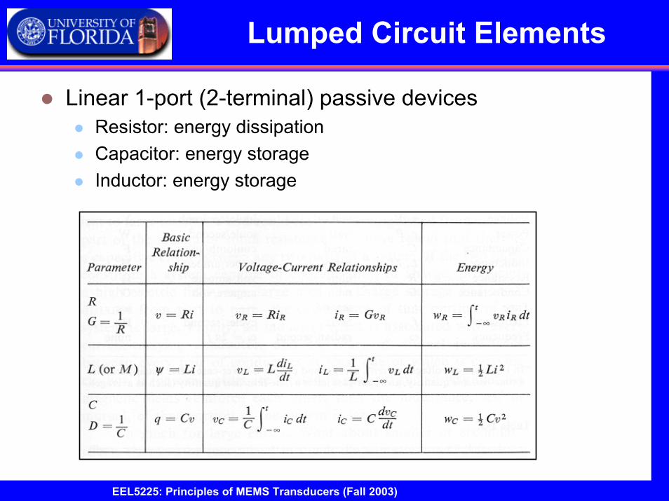
Single Time-Constant Networks
Review of Single Time-Constant Networkscircuits that can be reduced to one reactive component (capacitance or inductance) and one resistive component
High Pass FilterLow Pass Filter
Ref. Sedra and Smith, Microelectronic Circuits, p. 22.
11/21/2003 18EEL5225: Principles of MEMS Transducers (Fall 2003)
Single Time-Constant Networks
Low Pass Filter
0
0
2
0
1
0
Replacing the circuit elements with their impedances,1R R and C
sC( ) 1 1( )( ) 1 1
1 1where . Replacing s with ,
1( )
1
( ) tan
o
i
V sT s
sV s sRC
jRC
T j
T j
ω
ω ωτ
ωωω
ωωω
−
→ →
= = =+ +
= =
=
+
∠ = −
1sC
iV ( )s oV ( )s
Ref. Sedra and Smith, Microelectronic Circuits, p. 22.
11/21/2003 19EEL5225: Principles of MEMS Transducers (Fall 2003)
Single Time-Constant Networks
Magnitude and Phase Response of Low Pass STC Network
01RC
ω ω= =
Ref. Sedra and Smith, Microelectronic Circuits, p. 32.
11/21/2003 20EEL5225: Principles of MEMS Transducers (Fall 2003)
Single Time-Constant Networks
High Pass Filter
0
0
20
1 0
Replacing the circuit elements with their impedances,1R R and C
sC( )
( )( ) 1
1 1where . Replacing s with ,
1( )
1
( ) tan
o
i
V s sRC sT sV s sRC s
jRC
T j
T j
ω
ω ωτ
ωωω
ωω
ω−
→ →
= = =+ +
= =
= +
∠ =
iV ( )s oV ( )s
1sC
Ref. Sedra and Smith, Microelectronic Circuits, p. 22.
11/21/2003 21EEL5225: Principles of MEMS Transducers (Fall 2003)
Single Time-Constant Networks
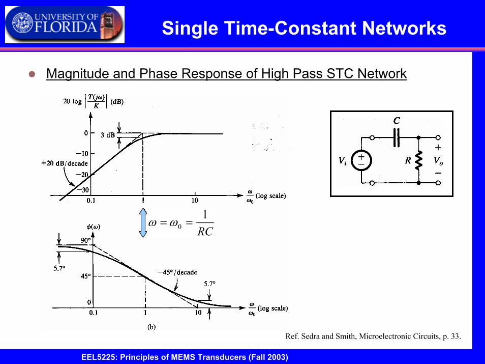
Magnitude and Phase Response of High Pass STC Network
01RC
ω ω= =
Ref. Sedra and Smith, Microelectronic Circuits, p. 33.
11/21/2003 22EEL5225: Principles of MEMS Transducers (Fall 2003)
Single Time-Constant Networks
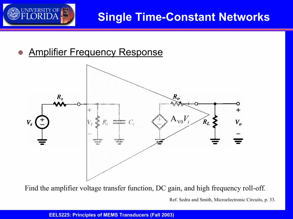
Amplifier Frequency Response
V0A iV
Find the amplifier voltage transfer function, DC gain, and high frequency roll-off.Ref. Sedra and Smith, Microelectronic Circuits, p. 33.
11/21/2003 23EEL5225: Principles of MEMS Transducers (Fall 2003)
Single Time-Constant Networks
Direct-coupled amplifier with input capacitance
Ref. Sedra and Smith, Microelectronic Circuits, p. 22.
( )
0
0
1//( ) ( ) and ( ) ( )
1//
( ) 1 1 1( )( ) 1 //1 1
This voltage transfer function has the same form as the low pass STC network.
DC
iiL
o V i i sL o
i Si
oV
o si i S i
L i
RsCR
V s A V s V s V sR R R R
sC
V sT s A
R RV s sC R RR R
= =+ +
= = + + +
( )
00
0
1 1 gain: T(s)1 1
1 1High frequency rolloff: //
Vso s
L i
i S i
AR RR R
C R Rω
τ
→
= + +
= =
V0A iV
11/21/2003 24EEL5225: Principles of MEMS Transducers (Fall 2003)
Single Time-Constant Networks
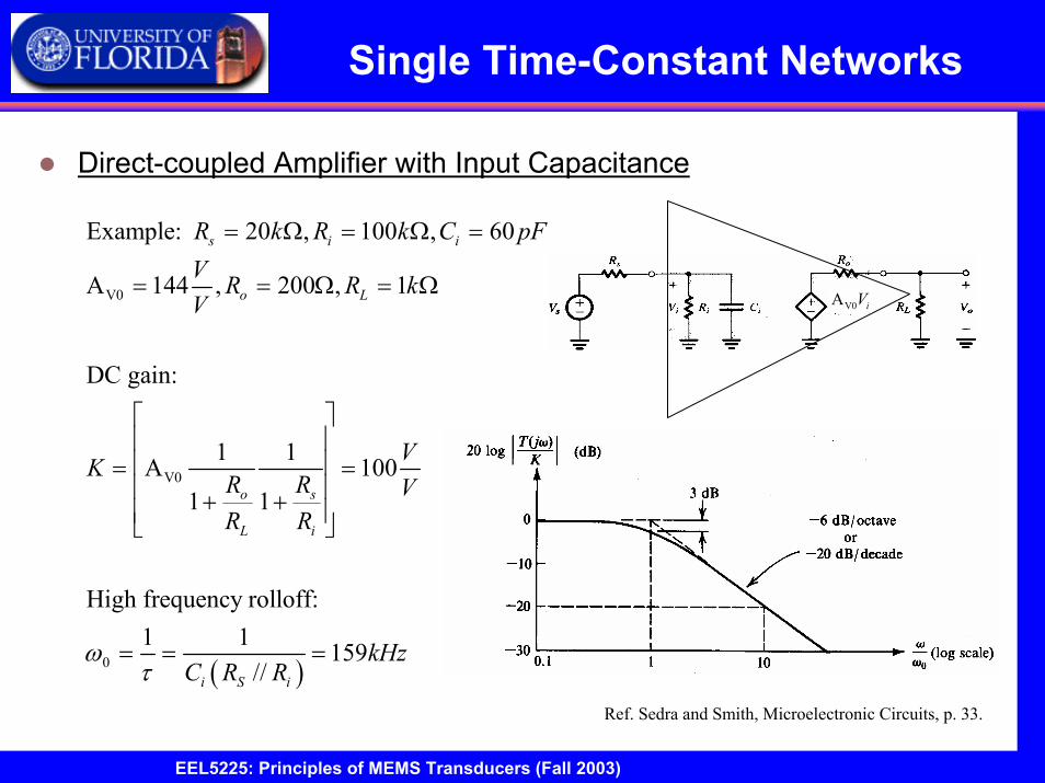
Direct-coupled Amplifier with Input Capacitance
( )
V0
V0
0
Example: 20 , 100 , 60
A 144 , 200 , 1
DC gain:
1 1A 1001 1
High frequency rolloff: 1 1 159
//
s i i
o L
o s
L i
i S i
R k R k C pFV R R kV
VKR R VR R
kHzC R R
ωτ
= Ω = Ω =
= = Ω = Ω
= = + +
= = =
V0A iV
Ref. Sedra and Smith, Microelectronic Circuits, p. 33.
11/21/2003 25EEL5225: Principles of MEMS Transducers (Fall 2003)
Single Time-Constant Networks
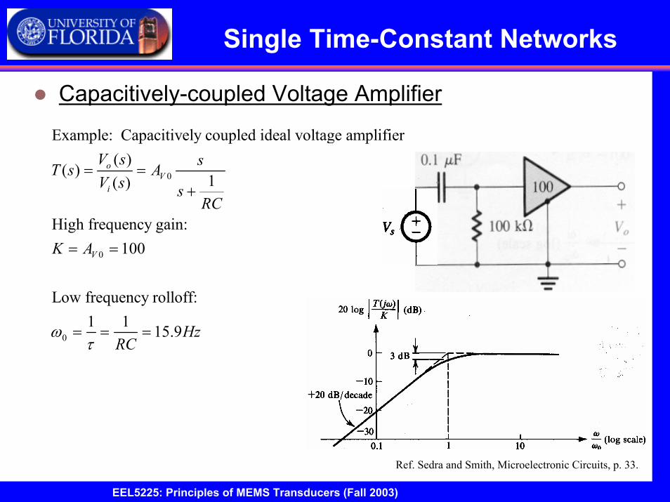
Capacitively-coupled Voltage Amplifier
0
0
0
Example: Capacitively coupled ideal voltage amplifier( )
( )1( )
High frequency gain: 100
Low frequency rolloff: 1 1 15.9
oV
i
V
V s sT s AV s s
RC
K A
HzRC
ωτ
= =+
= =
= = =
Ref. Sedra and Smith, Microelectronic Circuits, p. 33.
11/21/2003 26EEL5225: Principles of MEMS Transducers (Fall 2003)
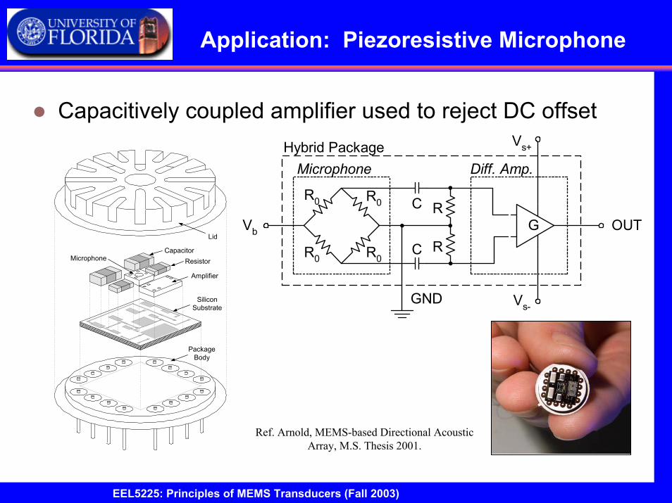
Application: Piezoresistive Microphone
Capacitively coupled amplifier used to reject DC offset
Ref. Arnold, MEMS-based Directional Acoustic Array, M.S. Thesis 2001.
Amplifier
MicrophoneCapacitor
Resistor
Lid
PackageBody
SiliconSubstrate
C
C
R
R
R0 R0
R0R0
G
MicrophoneHybrid Package Vs+
Vs-
OUT
GND
Vb
Diff. Amp.
11/21/2003 27EEL5225: Principles of MEMS Transducers (Fall 2003)
Operational AmplifiersOperational Amplifiers
Basic building block for analog signal processing circuits
First integrated circuit operational amplifier, µ709, made by Fairchild Semiconductor in 1960s followed by the µ741.Consists of active transistors, resistors, and limited number of capacitorsApproximated by single-pole frequency response
Three stagesDifferential amplifier stage
Amplifies difference between two inputs
High-gain amplifier stageOutput amplifier stage
Inverting input
Non-inverting input
Power supply
Power supply
Output
Ref. Senturia, Microsystem Design, p. 382.
11/21/2003 28EEL5225: Principles of MEMS Transducers (Fall 2003)
Operational Amplifiers
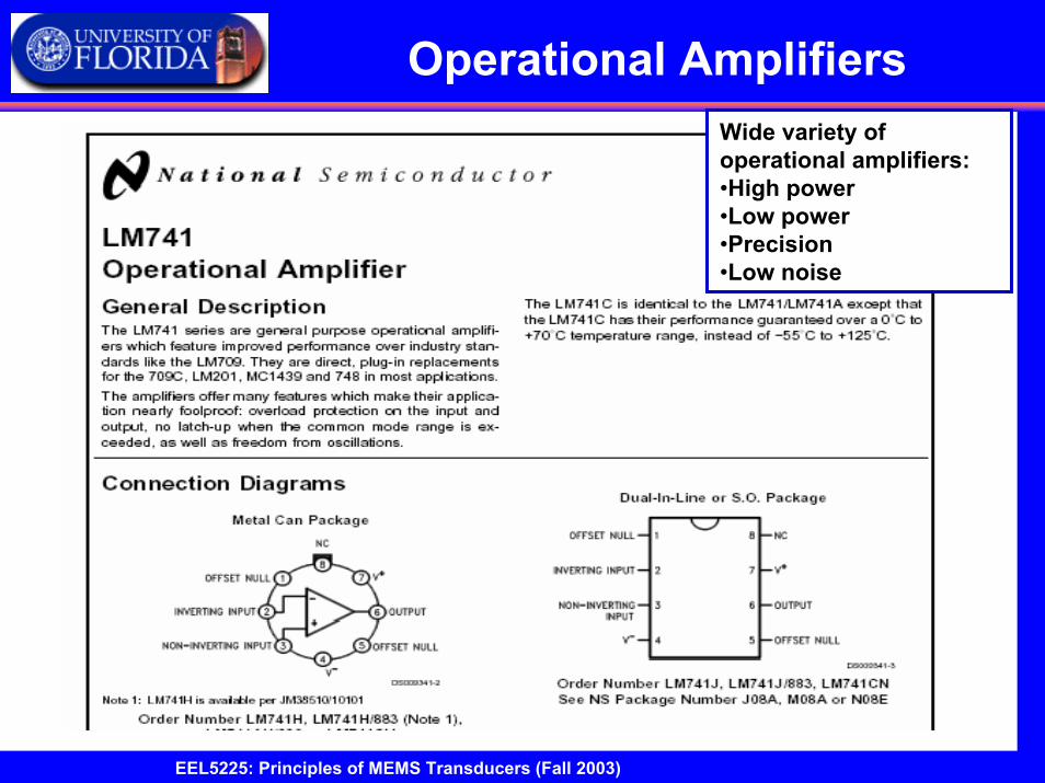
u741 Opamp
11/21/2003 29EEL5225: Principles of MEMS Transducers (Fall 2003)
Operational AmplifiersWide variety of operational amplifiers:•High power•Low power•Precision•Low noise
11/21/2003 30EEL5225: Principles of MEMS Transducers (Fall 2003)
Operational Amplifiers
11/21/2003 31EEL5225: Principles of MEMS Transducers (Fall 2003)
Operational Amplifiers
11/21/2003 32EEL5225: Principles of MEMS Transducers (Fall 2003)
Operational AmplifiersGeneral input signals
Differential signal from transducerCommon mode signal
For example, 60 Hz electromagnetic interference appearing on both inputs
Differential gain
Common-mode gain
dv
2
2
dcm
dcm
vv v
vv v
+
−
= +
= − +
Common Mode Rejection Ratio (CMRR)
or 20log
Actual opamps, CMRR range from1000 to 100,000 (60dB to 100dB)
d d
cm cm
A ACMRR
A A=
( )o o
dd
v vA
v v v+ −
= =−
( ) / 2o o
cmcm
v vA
v v v+ −
= =+
Ref. Senturia, Microsystem Design, p. 382.
11/21/2003 33EEL5225: Principles of MEMS Transducers (Fall 2003)
Operational Amplifiers
Voltage FollowerOutput follows inputVo=Vi
Serves as bufferVery high input impedanceLow output impedance
11/21/2003 34EEL5225: Principles of MEMS Transducers (Fall 2003)
Operational Amplifiers
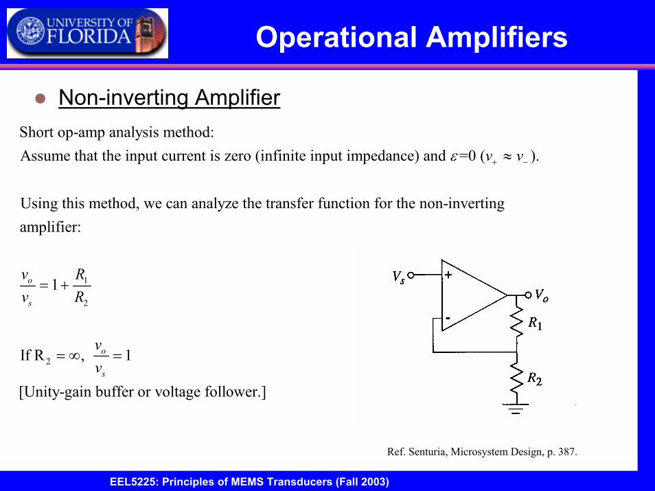
Non-inverting AmplifierShort op-amp analysis method:Assume that the input current is zero (infinite input impedance) and =0 ( ).
Using this method, we can analyze the transfer function for the non-invertingamplifier:
o
v v
vv
ε + −≈
1
2
2
1
If R , 1
[Unity-gain buffer or voltage follower.]
s
o
s
RR
vv
= +
= ∞ =
Ref. Senturia, Microsystem Design, p. 387.
11/21/2003 35EEL5225: Principles of MEMS Transducers (Fall 2003)
Operational Amplifiers
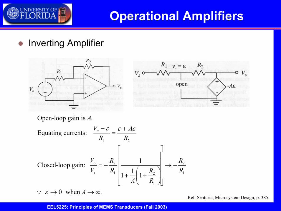
Inverting Amplifier
Ref. Senturia, Microsystem Design, p. 385.
1 2
2 2
1 12
1
Open-loop gain is .
Equating currents:
1Closed-loop gain: 11 1
0 when .
s
o
s
AV AR R
V R RV R RR
A R
A
ε ε ε
ε
− +=
= − → − + +
→ → ∞∵
11/21/2003 36EEL5225: Principles of MEMS Transducers (Fall 2003)
Operational Amplifiers
Inverting Amplifier
0
0
What is the frequency response of this configuration?
Replace A with the STC single-pole response, ( ) .1
AA s
ss
=+
Ref. Senturia, Microsystem Design, p. 387.
( )
0 02 2
1 120 0 0
1
20 0
10
2
1
Substituting the single-pole response for A gives:
R with a DC gain of
R1
1and 3dB frequency determined by the pole at .
1
Note t
o
s
V A sRV R R
A s s sR
RA s
Rs
RR
= −
+ + +
+ +
= −+
0 0hat the gain-bandwith product is preserved: .A s
0ω 0 0A ω
11/21/2003 37EEL5225: Principles of MEMS Transducers (Fall 2003)
Operational Amplifiers
Transimpedance Amplifier
1
Since the input current is negligible,
The transimpedance amplifier (voltage at output proportionalto current at input) is used as a current-to-voltage converter.
o sv R I= −
Ref. Senturia, Microsystem Design, p. 389.
11/21/2003 38EEL5225: Principles of MEMS Transducers (Fall 2003)
Operational Amplifiers
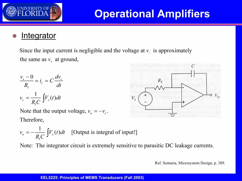
Integrator
1
1
1
Since the input current is negligible and the voltage at is approximatelythe same as at ground,
0
1 ( )
Note that the output voltage, .Therefore,
1 ( ) [
s cc
c s
o c
o s
vv
v dvi C
R dt
v V t dtR C
v v
v V t dtR C
−
+
−= =
=
= −
= −
∫
∫ Output is integral of input!]
Note: The integrator circuit is extremely sensitive to parasitic DC leakage currents.
Ref. Senturia, Microsystem Design, p. 389.
11/21/2003 39EEL5225: Principles of MEMS Transducers (Fall 2003)
Operational Amplifiers
Differentiator
1
Similarly, we find that for the differentiator circuit,
[Output is derivative of input!]
Note: The output of the differentiator is limited by how fast the output of the
op-amp can change
so
dvv R C
dt= −
change in output voltage, defined by the slew rate= .time