20
HBX Control Systems Inc. Installation Manual ZON-0500 Version 2.10 ZON-0500

HBX Control Systems Inc.
Installation Manual
ZON-0500Version 2.10
ZON-0500
�������������

Zone-0500 Manual Page 2
Control Systems Inc.
Comfort Control
Innovation
H B X Z O N - 0 5 0 0 Z o n e C o n t r o lV e r s i o n 2 . 1 0
Tabl
e of
Con
tent
s
TABLE OF CONTENTS
Introduction ............................................................................................ 1-3Safety Symbols & Warnings ................................................................... 1Receipt & Inspection .............................................................................. 1Description .............................................................................................. 2Technical Data and Dimensions ........................................................... 3
Wiring & Installation ............................................................................... 4-10Wiring ....................................................................................................... 4Installation ............................................................................................... 5Priority Selection ..................................................................................... 6-10Application Drawing ............................................................................... 11-16
Warranty Information .............................................................................. 17
H B X Z O N - 0 5 0 0 Z o n e C o n t r o lV e r s i o n 2 . 1 0
Zone-0500 Manual Page 1
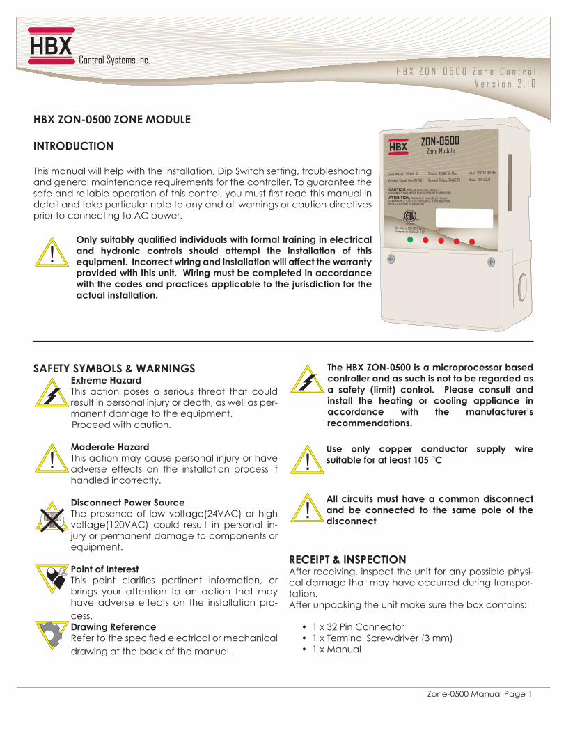
HBX ZON-0500 ZONE MODULE
INTRODUCTION
This manual will help with the installation, Dip Switch setting, troubleshooting and general maintenance requirements for the controller. To guarantee the � ��� ������ ������� ������������������������������ ������� �� �����detail and take particular note to any and all warnings or caution directives prior to connecting to AC power.
������������ ����������������������������������������������� �������� �������� ������� ����� ��� ��������� ��� ���� ��������������������������������������������������������������������������������������������������������������������������������������������������������������������actual installation.
SAFETY SYMBOLS & WARNINGS�!�����"�#���This action poses a serious threat that could result in personal injury or death, as well as per-manent damage to the equipment.
Proceed with caution.
$�������"�#���This action may cause personal injury or have adverse effects on the installation process if handled incorrectly.
%��������'�����(�����The presence of low voltage(24VAC) or high voltage(120VAC) could result in personal in-jury or permanent damage to components or equipment.
'����������������� ����� �� ����� ������� ����� ����� ��brings your attention to an action that may have adverse effects on the installation pro-cess.%������)��������������������������������� �������� ��� ��drawing at the back of the manual.
*���"+,�/�268988����������������������������������������������������������������������� ������ :��;� �������� � '������ ������� ���������� ��� ������ ��� ������� ��������� ������������� ��� ��� �����������<����������������
=��� ����� ������� ��������� ������� ����������������������>89�?@
J���������������������������������������� ��� ��������� �� ��� ����� ����� ��� �����������
)�@��'*�K��2('�@*��2After receiving, inspect the unit for any possible physi-cal damage that may have occurred during transpor-tation.After unpacking the unit make sure the box contains:
���1 x 32 Pin Connector���1 x Terminal Screwdriver (3 mm)���1 x Manual
H B X Z O N - 0 5 0 0 Z o n e C o n t r o lV e r s i o n 2 . 1 0
Zone-0500 Manual Page 2
"+,�/�268988�/�2��$�%=P��%�(@)�'*��2
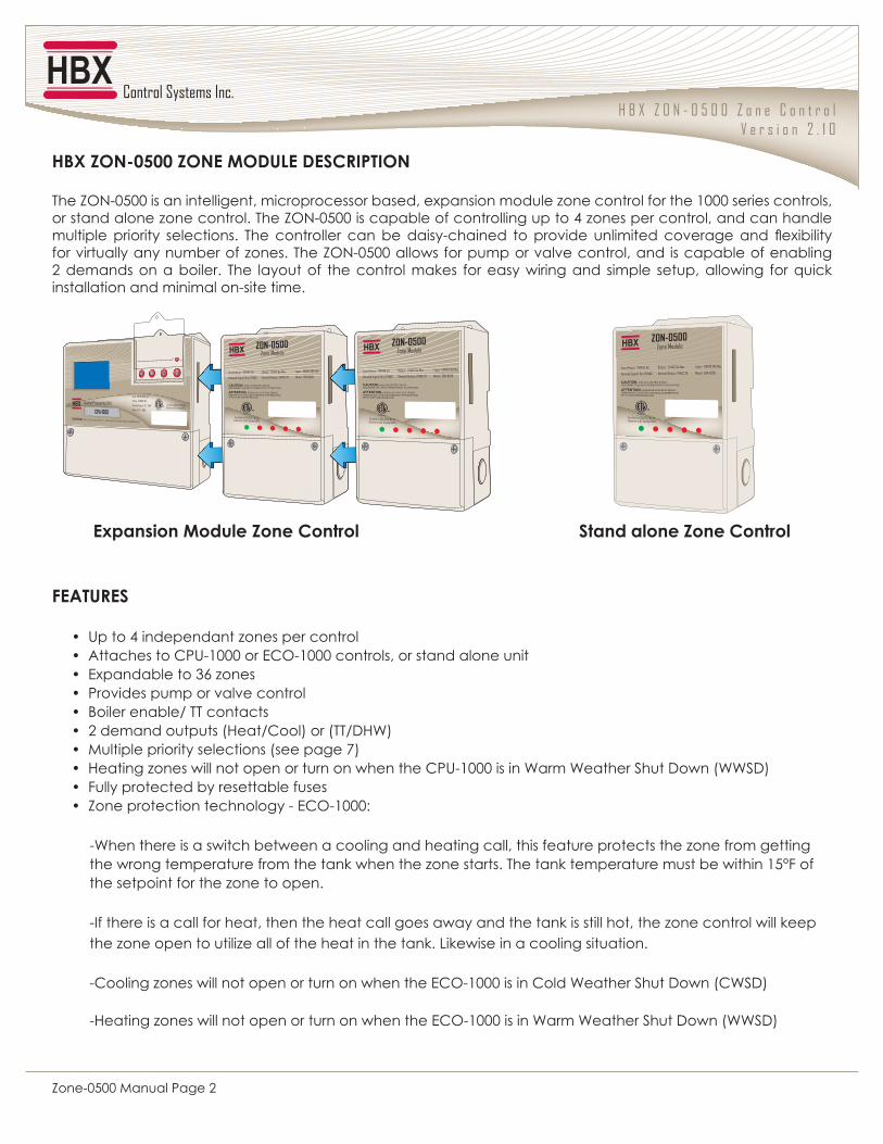
The ZON-0500 is an intelligent, microprocessor based, expansion module zone control for the 1000 series controls, or stand alone zone control. The ZON-0500 is capable of controlling up to 4 zones per control, and can handle �������� ������ ����������� ���� �������� � �� ��� � ������ ����� �� ������� ��������� ���� ��� ��� !�"�������for virtually any number of zones. The ZON-0500 allows for pump or valve control, and is capable of enabling 2 demands on a boiler. The layout of the control makes for easy wiring and simple setup, allowing for quick installation and minimal on-site time.
FEATURES
���Up to 4 independant zones per control���Attaches to CPU-1000 or ECO-1000 controls, or stand alone unit���Expandable to 36 zones���Provides pump or valve control���Boiler enable/ TT contacts���2 demand outputs (Heat/Cool) or (TT/DHW)���Multiple priority selections (see page 7)���Heating zones will not open or turn on when the CPU-1000 is in Warm Weather Shut Down (WWSD)���Fully protected by resettable fuses���Zone protection technology - ECO-1000:
-When there is a switch between a cooling and heating call, this feature protects the zone from getting the wrong temperature from the tank when the zone starts. The tank temperature must be within 15°F of the setpoint for the zone to open.
-If there is a call for heat, then the heat call goes away and the tank is still hot, the zone control will keep the zone open to utilize all of the heat in the tank. Likewise in a cooling situation. -Cooling zones will not open or turn on when the ECO-1000 is in Cold Weather Shut Down (CWSD)
-Heating zones will not open or turn on when the ECO-1000 is in Warm Weather Shut Down (WWSD)
�!�������$������/����@����� (����������/����@�����
H B X Z O N - 0 5 0 0 Z o n e C o n t r o lV e r s i o n 2 . 1 0
Zone-0500 Manual Page 3
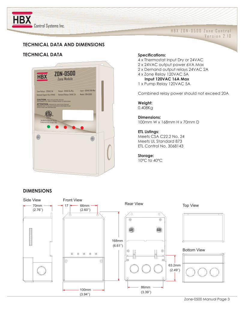
(���������Q4 x Thermostat Input Dry or 24VAC2 x 24VAC output power 6VA Max2 x Demand output relays 24VAC 2A4 x Zone Relay 120VAC 5A �����>V8[J@�>\J�$�!1 x Pump Relay 120VAC 5A
Combined relay power should not exceed 20A
����Q0.408Kg
%�������Q100mm W x 168mm H x 70mm D
�*P�P����QMeets CSA C22.2 No. 24Meets UL Standard 873ETL Control No. 3068143
(�����Q10ºC to 40ºC
on on
70mm(2.76’’)
66mm(2.60’’)
17Side View Front View
Rear View Top View
168mm(6.61’’)
100mm (3.94’’)
63.2mm(2.49’’)
86mm (3.39’’)
Bottom View
TECHNICAL DATA AND DIMENSIONS
TECHNICAL DATA
DIMENSIONS

H B X Z O N - 0 5 0 0 Z o n e C o n t r o lV e r s i o n 2 . 1 0
Zone-0500 Manual Page 4
]��*"�)$�(*J*��2'=*�>�6�^These terminals are used for connecting thermostat inputs, and can be dry contact inputs or 24VAC
WIRINGAll signal wiring must be a minimum of 18AWG wire at a maximum of 500ft
_��(`(*�$�'=$'��=*'=*This is a dry contact output that can be used for a system pump. This contact will activate any time a zone comes on.
V��/�2��>�6�^��=*'=*These are the outputs for the zone device. This can be a pump or a valve depending on what power is supplied to terminals 11-12.
>��%�$J2%��=*'=*(These are the outputs for the demands. These can be a Heating and Cooling demand, 24VAC contact, dry contact TT for a boiler, or DHW demand.
^���2'=*�'���)This input is to power the ZON-0500. 0.5 Amps at 120 VAC is required to power this device.
9��/�2��'���)This input is used to power the zone outputs and is rated for 240VAC, 120VAC or 24VAC.
\��*"�)$�(*J*�'���)These outputs are used to power the thermostats and are rated for 24VAC at 6VA.
Zone 4 ThermostatZone 3 ThermostatZone 2 ThermostatZone 1 ThermostatDemand Output(DHW or Heating)
Demand Output(Boiler TT or Cooling)
24 VAC Power 124 VAC Power 2
Input PowerZone Power
Zone 4 Output
OutputZone 1 OutputZone 2 OutputZone 3 Output
HBX
DO NOT CONNECTPOWER HERE
5A5A5A5A5 A
24 VAC out tothermostats
6VA Max
2
24V AC
1615
2
GR
12015
NL
1413RL
1
RL1211
1
RL
1
RL109
1
RL
1
RL87
1
RL
1
RL65
1
RL
1
RL43
1
RL
1
RL21
1
1
21
1
TT/CD
2
43
2
DHW/HD
1
TH
65
1
TH
2
TH
87
2
TH
3
TH
109
3
TH
4
TH
1211
4
TH
1
24V AC
1413
1
2 3 4
1 2 3 4 5
1
DemandOutputs
ThermostatImputs
ZON-0500 Zone Control
1
7
4
6
52
3
WIRING AND INSTALLATION
H B X Z O N - 0 5 0 0 Z o n e C o n t r o lV e r s i o n 2 . 1 0
Zone-0500 Manual Page 5
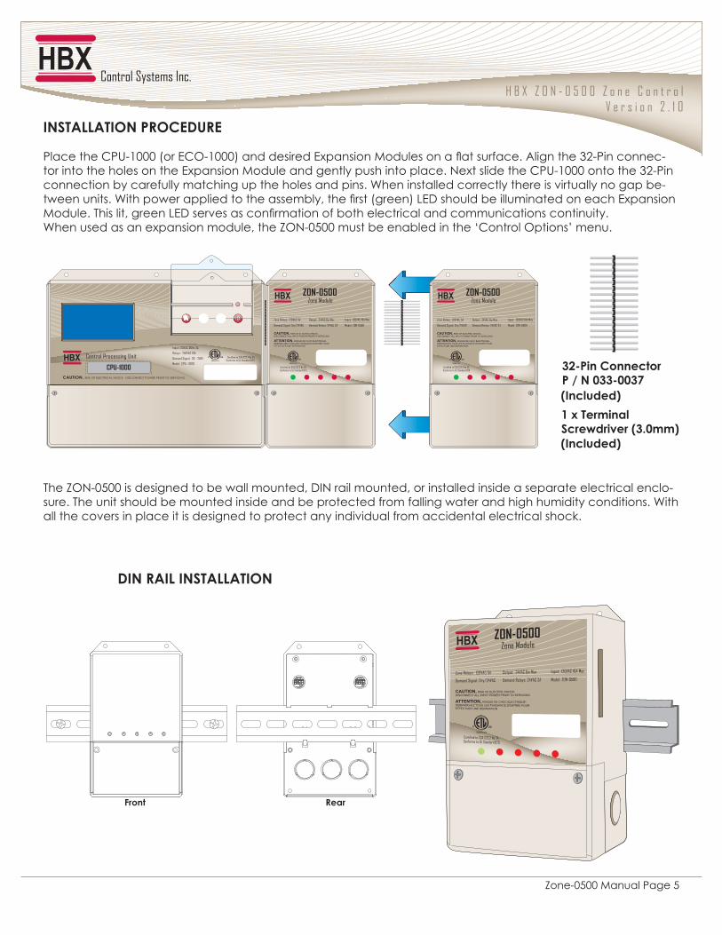
DIN RAIL INSTALLATION
>�!�*�������(����������:_�8��;
The ZON-0500 is designed to be wall mounted, DIN rail mounted, or installed inside a separate electrical enclo-sure. The unit should be mounted inside and be protected from falling water and high humidity conditions. With all the covers in place it is designed to protect any individual from accidental electrical shock.
�2(*JPPJ*��2�')�@�%=)�
#� �������#$�%'''�*��+�9�%''';� ����������+"� ������<���������� �! ���� ����=��������>?�#���������-tor into the holes on the Expansion Module and gently push into place. Next slide the CPU-1000 onto the 32-Pin connection by carefully matching up the holes and pins. When installed correctly there is virtually no gap be-@����������J�����@�� ������������ ���������������*����;�Q+X������������������ ������� ���+"� ������<���������������������Q+X������� ������� ����������������� �� ����������� ���������������When used as an expansion module, the ZON-0500 must be enabled in the ‘Control Options’ menu.
_V6'��@�������'�j�2�8__688_]:��������;
:��������;
Certified to CSA C22.2 No 24 Conforms to UL Standard 873
CAUTION, RISK OF ELECTRICAL SHOCK - DISCONNECT POWER PRIOR TO SERVICING
Relays: 240VAC 10A
Output: 4-20mA/1-10V/PWM
Demand Signal: 20-240V
Model: MOD-0100
MOD-0100 Modulating Module
ZON-0500 Zone Module
ZON-0500
Input: 120VAC 16A MaxOutput: 24VAC 6w MaxZone Relays: 120VAC 5A
Demand Signal: Dry/24VAC Demand Relays: 24VAC 2A
ZON-0500 Zone Module
ZON-0500
Input: 120VAC 16A MaxOutput: 24VAC 6w MaxZone Relays: 120VAC 5A
Demand Signal: Dry/24VAC Demand Relays: 24VAC 2A
on on
Front Rear
H B X Z O N - 0 5 0 0 Z o n e C o n t r o lV e r s i o n 2 . 1 0
Zone-0500 Manual Page 6
%�'�(��*@"�(
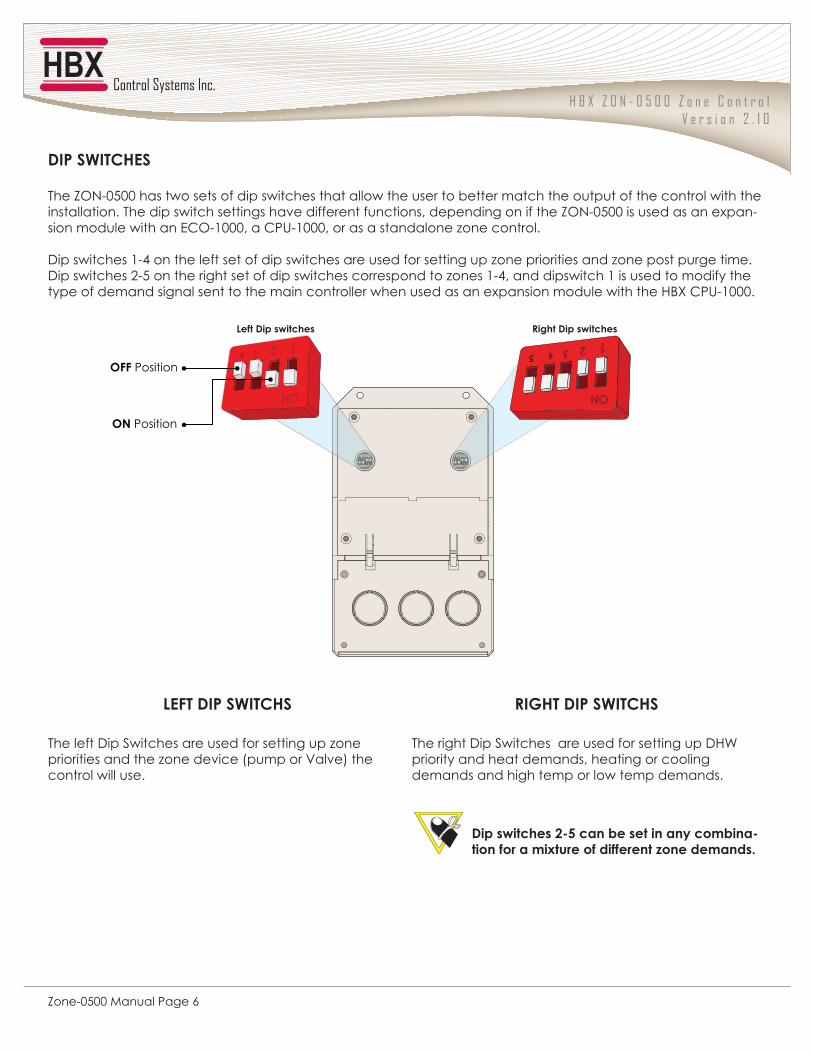
The ZON-0500 has two sets of dip switches that allow the user to better match the output of the control with the installation. The dip switch settings have different functions, depending on if the ZON-0500 is used as an expan-sion module with an ECO-1000, a CPU-1000, or as a standalone zone control.
Dip switches 1-4 on the left set of dip switches are used for setting up zone priorities and zone post purge time.Dip switches 2-5 on the right set of dip switches correspond to zones 1-4, and dipswitch 1 is used to modify the type of demand signal sent to the main controller when used as an expansion module with the HBX CPU-1000.
The left Dip Switches are used for setting up zone priorities and the zone device (pump or Valve) the control will use.
The right Dip Switches are used for setting up DHW priority and heat demands, heating or cooling demands and high temp or low temp demands.
P�p*�%�'�(��*@"( )�q"*�%�'�(��*@"(
on on
Left Dip switches Right Dip switches
on
OFF Position
ON Position
%���������V69�����������������������-����������!���������������#������������
H B X Z O N - 0 5 0 0 Z o n e C o n t r o lV e r s i o n 2 . 1 0
Zone-0500 Manual Page 7
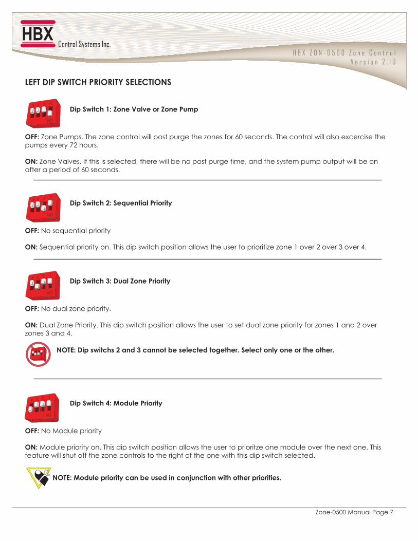
P�p*�%�'�(��*@"�')��)�*`�(�P�@*��2(
%��(����>Q�/����[��������/����'���
%��(����_Q�%����/����'����
%��(����VQ�(� ������'����
%��(����^Q�$������'����
�ppQ�Zone Pumps. The zone control will post purge the zones for 60 seconds. The control will also excercise the pumps every 72 hours.
�2Q�Zone Valves. If this is selected, there will be no post purge time, and the system pump output will be on after a period of 60 seconds.
�ppQ�No dual zone priority.
�2Q�Dual Zone Priority. This dip switch position allows the user to set dual zone priority for zones 1 and 2 over zones 3 and 4.
2�*�Q�%��������V�����_��������������������������(�������������������������
�ppQ�No sequential priority
�2Q�Sequential priority on. This dip switch position allows the user to prioritize zone 1 over 2 over 3 over 4.
�ppQ�No Module priority
�2Q�Module priority on. This dip switch position allows the user to prioritze one module over the next one. This feature will shut off the zone controls to the right of the one with this dip switch selected.
2�*�Q�$���������������������������������������������������
H B X Z O N - 0 5 0 0 Z o n e C o n t r o lV e r s i o n 2 . 1 0
Zone-0500 Manual Page 8
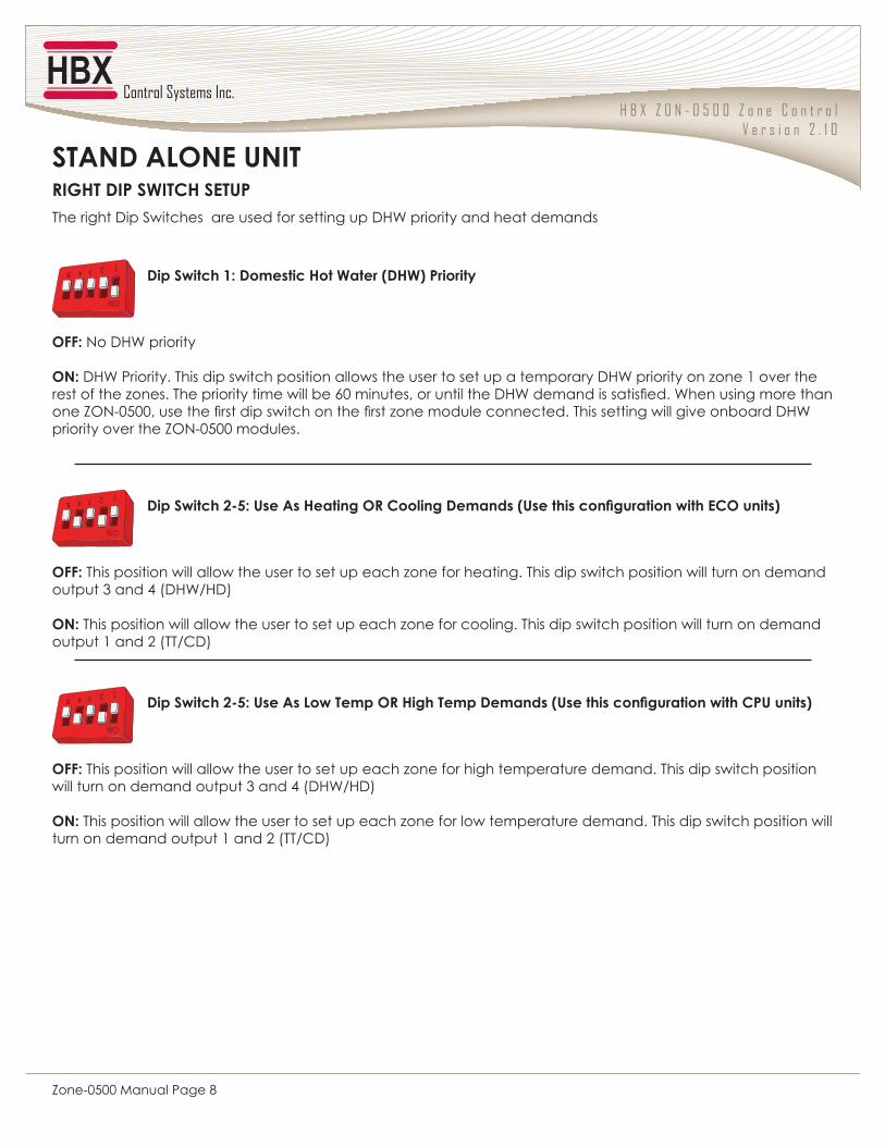
)�q"*�%�'�(��*@"�(�*='STAND ALONE UNIT
on
The right Dip Switches are used for setting up DHW priority and heat demands
%��(����>Q�%������"�������:%"�;�'����
�ppQ�No DHW priority
�2Q�DHW Priority. This dip switch position allows the user to set up a temporary DHW priority on zone 1 over the ���������[��������������������@�������\'�������������������X]J���� ������� �������J��������������� �������9^�'_''�����������������@�������������[��������������������������������@������������� ��X]J�priority over the ZON-0500 modules.
%��(����V69Q�=���J��"������)�@������%�������:=���������������������@�����;
%��(����V69Q�=���J��P���*�����)�"���*����%�������:=��������������������@'=����;
�ppQ�This position will allow the user to set up each zone for heating. This dip switch position will turn on demand output 3 and 4 (DHW/HD)
�2Q�This position will allow the user to set up each zone for cooling. This dip switch position will turn on demand output 1 and 2 (TT/CD)
�ppQ�This position will allow the user to set up each zone for high temperature demand. This dip switch position will turn on demand output 3 and 4 (DHW/HD)
�2Q�This position will allow the user to set up each zone for low temperature demand. This dip switch position will turn on demand output 1 and 2 (TT/CD)
on
on
H B X Z O N - 0 5 0 0 Z o n e C o n t r o lV e r s i o n 2 . 1 0
Zone-0500 Manual Page 9
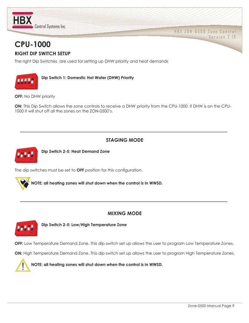
)�q"*�%�'�(��*@"�(�*='@'=6>888
STAGING MODE
MIXING MODE
on
on
on
The right Dip Switches are used for setting up DHW priority and heat demands
%��(����>Q�%������"�������:%"�;�'����
%��(����V69Q�"���%������/���
%��(����V69Q�P��j"���*����������/���
�ppQ�No DHW priority
�2Q�This Dip Switch allows the zone controls to receive a DHW priority from the CPU-1000. If DHW is on the CPU-1000 it will shut off all the zones on the ZON-0500’s.
The dip switches must be set to OFF���������������������� ����
2�*�Q�����������#���������������������������������������(%�
�ppQ�Low Temperature Demand Zone. This dip switch set up allows the user to program Low Temperature Zones.
�2Q�High Temperature Demand Zone. This dip switch set up allows the user to program High Temperature Zones.
2�*�Q�����������#���������������������������������������(%�
H B X Z O N - 0 5 0 0 Z o n e C o n t r o lV e r s i o n 2 . 1 0
Zone-0500 Manual Page 10
)�q"*�%�'�(��*@"�(�*='ECO-1000
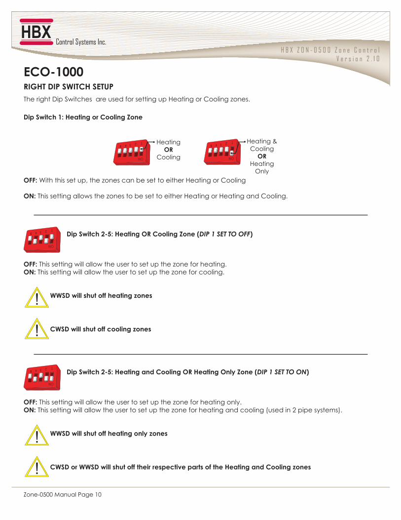
The right Dip Switches are used for setting up Heating or Cooling zones.
%��(����>Q�"��������@������/���
%��(����V69Q�"������)�@������/����:DIP 1 SET TO OFF;
%��(����V69Q�"���������@�������)�"����������/����:DIP 1 SET TO ON;
�ppQ�With this set up, the zones can be set to either Heating or Cooling
�2Q�This setting allows the zones to be set to either Heating or Heating and Cooling.
�ppQ�This setting will allow the user to set up the zone for heating.�2Q�This setting will allow the user to set up the zone for cooling.
��(%�������������������#����
@�(%��������������������#����
�ppQ�This setting will allow the user to set up the zone for heating only.�2Q�This setting will allow the user to set up the zone for heating and cooling (used in 2 pipe systems).
��(%������������������������#����
@�(%������(%�������������������������������������"���������@������#����
on
Heating OR
Cooling on
Heating & Cooling
ORHeating
Only
on
on
H B X Z O N - 0 5 0 0 Z o n e C o n t r o lV e r s i o n 2 . 1 0
Zone-0500 Manual Page 11
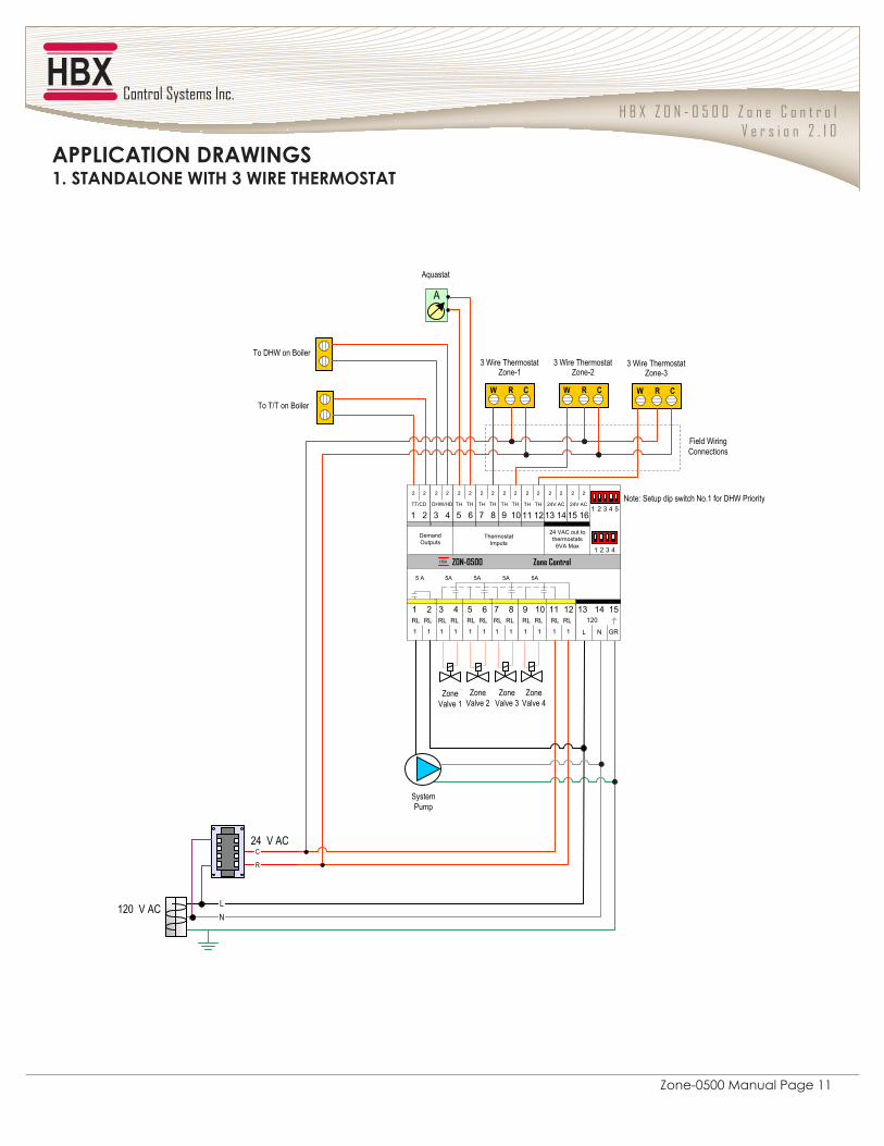
1. STANDALONE WITH 3 WIRE THERMOSTAT
Zone Valve 1
ZON-0500HBX Zone Control
DO NOT CONNECTPOWER HERE
5A5A5A5A5 A
24 VAC out tothermostats
6VA Max
2
24V AC
1615
2
GR
12015
NL
1413RL
1
RL1211
1
RL
1
RL109
1
RL
1
RL87
1
RL
1
RL65
1
RL
1
RL43
1
RL
1
RL21
1
2
21
2
TT/CD
2
43
2
DHW/HD
2
TH
65
2
TH
2
TH
87
2
TH
2
TH
109
2
TH
2
TH
1211
2
TH
2
24V AC
1413
2
2 3 4
1 2 3 4 5
1
DemandOutputs
ThermostatImputs
C
R
LN
120 V AC
24 V AC
Zone Valve 2
Zone Valve 4
Zone Valve 3
System Pump
3 Wire Thermostat
� � �
Zone-13 Wire Thermostat
� � �
Zone-23 Wire Thermostat
� � �
Zone-3
To T/T on Boiler
To DHW on Boiler
Note: Setup dip switch No.1 for DHW Priority
A
Aquastat
Field Wiring Connections
J''P�@J*��2�%)J��2q(
H B X Z O N - 0 5 0 0 Z o n e C o n t r o lV e r s i o n 2 . 1 0
Zone-0500 Manual Page 12
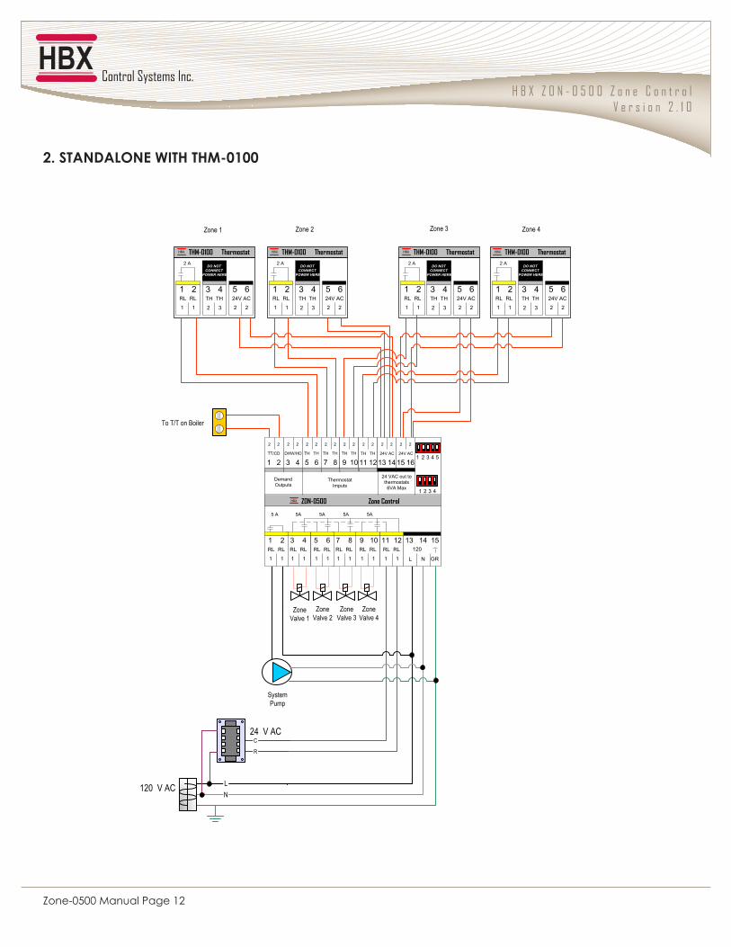
V��(*J2%JP�2����*"�*"$68>88
Zone Valve 1
C
R
LN
120 V AC
24 V AC
Zone Valve 2
Zone Valve 4
Zone Valve 3
THM-0100HBX
2
24V AC65
2
TH
2
TH43
3
Thermostat
RL
1
RL21
1
2 ADO NOT
CONNECTPOWER HERE
THM-0100HBX
2
24V AC65
2
TH
2
TH43
3
Thermostat
RL
1
RL21
1
2 ADO NOT
CONNECTPOWER HERE
THM-0100HBX
2
24V AC65
2
TH
2
TH43
3
Thermostat
RL
1
RL21
1
2 ADO NOT
CONNECTPOWER HERE
THM-0100HBX
2
24V AC65
2
TH
2
TH43
3
Thermostat
RL
1
RL21
1
2 ADO NOT
CONNECTPOWER HERE
System Pump
Zone 1 Zone 2 Zone 3 Zone 4
ZON-0500HBX Zone Control
DO NOT CONNECTPOWER HERE
5A5A5A5A5 A
24 VAC out tothermostats
6VA Max
2
24V AC
1615
2
GR
12015
NL
1413RL
1
RL1211
1
RL
1
RL109
1
RL
1
RL87
1
RL
1
RL65
1
RL
1
RL43
1
RL
1
RL21
1
2
21
2
TT/CD
2
43
2
DHW/HD
2
TH
65
2
TH
2
TH
87
2
TH
2
TH
109
2
TH
2
TH
1211
2
TH
2
24V AC
1413
2
2 3 4
1 2 3 4 5
1
DemandOutputs
ThermostatImputs
To T/T on Boiler
H B X Z O N - 0 5 0 0 Z o n e C o n t r o lV e r s i o n 2 . 1 0
Zone-0500 Manual Page 13
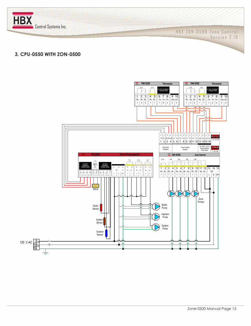
_��@'=68998���*"�/�268988
120 V AC
Zone Pumps
THM-0200HBX
RL
2
RL32
2 2
24V AC109
2TH
2
TH87
3
Thermostat
RL
1
RL54
1
2 ADO NOT CONNECT
POWER HERE
TH
1
6RL1
2 A
1
THM-0200HBX
RL
2
RL32
2 2
24V AC109
2TH
2
TH87
3
Thermostat
RL
1
RL54
1
2 ADO NOT CONNECT
POWER HERE
TH
1
6RL1
2 A
1
ZON-0500HBX Zone Control
DO NOT CONNECT POWER HERE
5A5A5A5A5 A
24 VAC out to thermostats
6VA Max
2
24V AC
1615
2
GR
12015
NL
1413RL
1
RL1211
1
RL
1
RL109
1
RL
1
RL87
1
RL
1
RL65
1
RL
1
RL43
1
RL
1
RL21
1
2
21
2
TT/CD
2
43
2
DHW/HD
2
TH
65
2
TH
2
TH
87
2
TH
2
TH
109
2
TH
2
TH
1211
2
TH
2
24V AC
1413
2
2 3 4
1 2 3 4 5
1
DemandOutputs
ThermostatImputs
LN
������
Outdoor Sensor
Boiler Sensor
System Sensor
10 A
RL
1
RL
1514
1
10 A
RL
2
RL
1716
2
Central Processing UnitCPU-0550HBX
GR
120
13
NL
1211
1 1TM
32
8TM TM
7 9 10BL1
BL65
1
2A
1-10v+ -
DO NOTCONNECT
POWER HERE
1 2DS
12
2DS DS
1 3 4
DO NOTCONNECT
POWER HERE
DS
10 A
RL
2
RL
1918
2
Boiler Pump
Injection Pump
System Pump
H B X Z O N - 0 5 0 0 Z o n e C o n t r o lV e r s i o n 2 . 1 0
Zone-0500 Manual Page 14
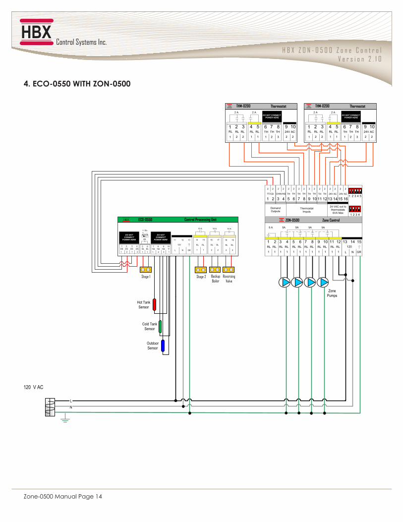
4. ECO-0550 WITH ZON-0500
Zone Pumps
THM-0200HBX
RL
2
RL32
2 2
24V AC109
2
TH
2
TH87
3
Thermostat
RL
1
RL54
1
2 ADO NOT CONNECT
POWER HERE
TH
1
6RL1
2 A
1
THM-0200HBX
RL
2
RL32
2 2
24V AC109
2
TH
2
TH87
3
Thermostat
RL
1
RL54
1
2 ADO NOT CONNECT
POWER HERE
TH
1
6RL1
2 A
1
��� �
Outdoor Sensor
Hot Tank Sensor
Cold Tank Sensor
��� � ����� ������
ZON-0500HBX Zone Control
DO NOT CONNECTPOWER HERE
5A5A5A5A5 A
24 VAC out tothermostats
6VA Max
2
24V AC
1615
2
GR
12015
NL
1413RL
1
RL1211
1
RL
1
RL109
1
RL
1
RL87
1
RL
1
RL65
1
RL
1
RL43
1
RL
1
RL21
1
2
21
2
TT/CD
2
43
2
DHW/HD
2
TH
65
2
TH
2
TH
87
2
TH
2
TH
109
2
TH
2
TH
1211
2
TH
2
24V AC
1413
2
2 3 4
1 2 3 4 5
1
DemandOutputs
ThermostatImputs
LN
120 V AC
10 A
RL
1
RL
1514
1
10 A
RL
2
RL
1716
2
Central Processing UnitECO-0550HBX
GR
120
13
NL
1211
1 1TM
32
8TM TM
7 9 10BL1
BL65
1
2A
1-10v+ -
DO NOTCONNECT
POWER HERE
1 2DS
12
2DS DS
1 3 4
DO NOTCONNECT
POWER HERE
DS
10 A
RL
2
RL
1918
2
��������� ����
H B X Z O N - 0 5 0 0 Z o n e C o n t r o lV e r s i o n 2 . 1 0
Zone-0500 Manual Page 15
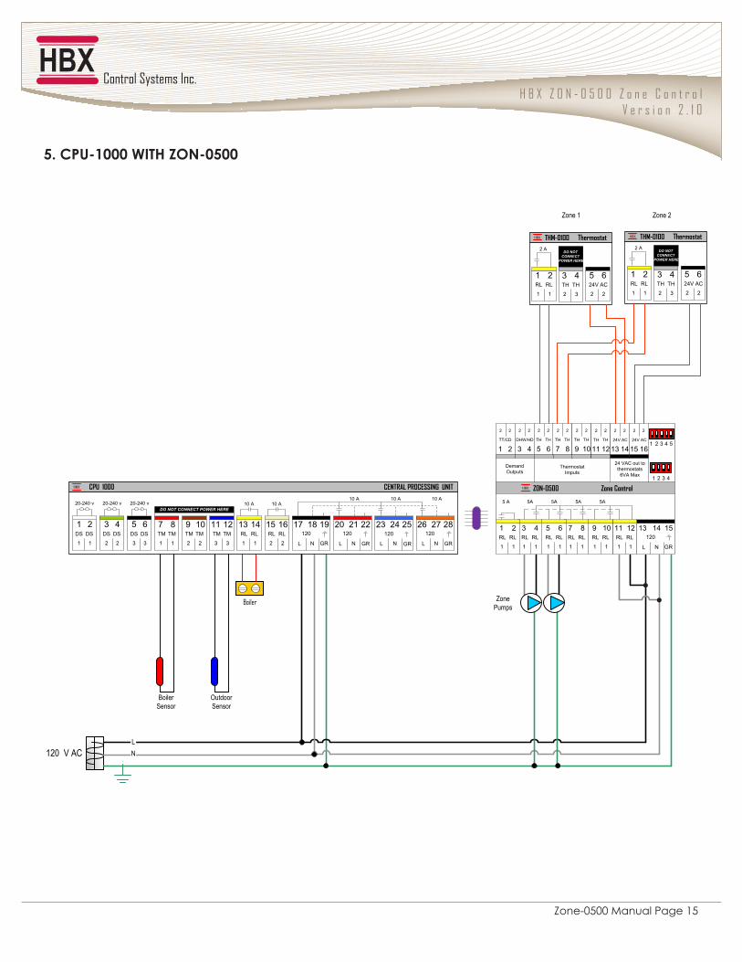
9��@'=6>888���*"�/�268988
120 V AC
Outdoor Sensor
Boiler Sensor
NL
Zone Pumps
������
Zone 1 Zone 2
ZON-0500HBX Zone Control
DO NOT CONNECTPOWER HERE
5A5A5A5A5 A
24 VAC out tothermostats
6VA Max
2
24V AC
1615
2
GR
12015
NL
1413RL
1
RL1211
1
RL
1
RL109
1
RL
1
RL87
1
RL
1
RL65
1
RL
1
RL43
1
RL
1
RL21
1
2
21
2
TT/CD
2
43
2
DHW/HD
2
TH
65
2
TH
2
TH
87
2
TH
2
TH
109
2
TH
2
TH
1211
2
TH
2
24V AC
1413
2
2 3 4
1 2 3 4 5
1
DemandOutputs
ThermostatImputs
1 2DS
1
DS
1
3 4DS
2
DS
2
5 6DS
3
DS
3 GR
12028
NL
2726
GR
12025
NL
2423
GR
12022
NL
2120
GR
12019
NL
1817RL
2
RL1615
2
RL
1
RL1413
1
TM
3
TM1211
3
TM
2
TM109
2
TM
1
TM87
1
20-240 v 20-240 v 20-240 vDO NOT CONNECT POWER HERE
10 A 10 A10 A 10 A 10 A
CPU 1000HBX CENTRAL PROCESSING UNIT
THM-0100HBX
2
24V AC65
2
TH
2
TH43
3
Thermostat
RL
1
RL21
1
2 ADO NOT
CONNECTPOWER HERE
THM-0100HBX
2
24V AC65
2
TH
2
TH43
3
Thermostat
RL
1
RL21
1
2 ADO NOT
CONNECTPOWER HERE

H B X Z O N - 0 5 0 0 Z o n e C o n t r o lV e r s i o n 2 . 1 0
Zone-0500 Manual Page 16
\���@�6>888���*"�/�268988
120 V AC
Outdoor Sensor
Hot Tank Sensor
NL
Zone Pumps
Cold Tank Sensor
����
THM-0200HBX
RL
2
RL32
2 2
24V AC109
2
TH
2
TH87
3
Thermostat
RL
1
RL54
1
2 ADO NOT CONNECT
POWER HERE
TH
1
6RL1
2 A
1
THM-0200HBX
RL
2
RL32
2 2
24V AC109
2
TH
2
TH87
3
Thermostat
RL
1
RL54
1
2 ADO NOT CONNECT
POWER HERE
TH
1
6RL1
2 A
1
Zone 1 Zone 2
8415
91214
13
HBX REL-2120
��������� �����
����
1 2DS
1
DS
1
3 4DS
2
DS
2
5 6DS
3
DS
3 GR
12028
NL
2726
GR
12025
NL
2423
GR
12022
NL
2120
GR
12019
NL
1817RL
2
RL1615
2
RL
1
RL1413
1
TM
3
TM1211
3
TM
2
TM109
2
TM
1
TM87
1
20-240 v 20-240 v 20-240 vDO NOT CONNECT POWER HERE
10 A 10 A10 A 10 A 10 A
ECO-1000HBX CENTRAL PROCESSING UNIT
System Pump
ZON-0500HBX Zone Control
DO NOT CONNECTPOWER HERE
5A5A5A5A5 A
24 VAC out tothermostats
6VA Max
2
24V AC
1615
2
GR
12015
NL
1413RL
1
RL1211
1
RL
1
RL109
1
RL
1
RL87
1
RL
1
RL65
1
RL
1
RL43
1
RL
1
RL21
1
2
21
2
TT/CD
2
43
2
DHW/HD
2
TH
65
2
TH
2
TH
87
2
TH
2
TH
109
2
TH
2
TH
1211
2
TH
2
24V AC
1413
2
2 3 4
1 2 3 4 5
1
DemandOutputs
ThermostatImputs
H B X Z O N - 0 5 0 0 Z o n e C o n t r o lV e r s i o n 2 . 1 0
Zone-0500 Manual Page 17
P�����������HBX Controls warrants each of its products to be free from defects in workmanship and materials under normal use and service for a period of 24 months from date of manufacture or 12 months from date of purchase from an HBX Authorized Dealer, if within the above documented period after date of manufacture.If the product proves to be defective within the applicable warranty period, HBX on its sole discretion will repair or replace � ��������������� ������������� �������@�����������������{��� ����������������� �������� ���������defective product. Replacement product need not be of identical design or model. Any repair or replacement product pursuant to this warranty shall be warranted for not less than 90 days from date of such repair, irrespective of any earlier expiration of original warranty period. When HBX provides replacement, the defective product becomes the property of HBX Controls. J ���|�������@�������� ����� ����@ ����������� ������� ����������� ����������� ���]}~��������������via the original Authorized Agent and requesting a Return Material Authorization Number (RMA #). Proof of purchase in the form a dated invoice/receipt must be provided to expedite the issuance of a Factory RMA.After an RMA number has been issued, the defective product must be packaged securely in the original or other suitable shipping package to ensure that it will not be damaged in transit. The RMA number must be visible on the outside of the package and a copy included inside the package. The package must be mailed or otherwise shipped back to HBX with all costs of mailing/shipping/insurance prepaid by the warranty claimant.Any package/s returned to HBX without an approved and visible RMA number will be rejected and shipped back to purchaser at purchaser’s expense. HBX reserves the right, if deemed necessary, to charge a reasonable levy for costs incurred, additional to mailing or shipping costs.
P����������������If the HBX product does not operate as warranted above the purchasers sole remedy shall be, at HBX’s option, repair or replacement. The foregoing warranties and remedies are exclusive and in lieu of all other warranties, expressed or ������������������ ���������� �������� @��� ���������@���������������@ ������������ � ������ ������������a particular purpose/application. HBX neither assumes nor authorizes any other person to assume for it any other liability in connection with the sale, installation maintenance or use of HBX Controls products.HBX shall not be liable under this warranty; if its testing and examination discloses that the alleged defect in the product does not exist or was caused by the purchasers or third persons misuse, neglect, improper installation or testing, �� ����[��� ��������� ���� �������� �������������� ������������������������� �����������������������other hazard.
Limitation of Liability�����������@����]}~������ ������� ���� � ������������������������ ������������������������������������������ ���consequential or indirect damages arising out of the installation, maintenance, commissioning, performance, failure or interruption of an HBX product, however caused and on any theory of liability. This limitation will apply even if HBX has been advised of the possibility of such damage.
P�����P��������������@ ���� ������������������ �������������� ����������������� ���� �� ����� ������������@�����vary from state to state in the United States, from Province to Province in Canada and from Country to Country elsewhere in the world.�������"�������Q������J ���| �������������������@������ ��� @������� ������� ��������������������������consistent with such local law. Under such local law, certain disclaimers and limitations of this statement may not apply to the purchaser. For example, some states in the United States, as well as some governments outside the United States (including Canadian Provinces), may:Preclude the disclaimers and limitations in this statement from limiting the statutory rights of a consumer (e.g. United Kingdom);Otherwise restrict the ability of a manufacturer to enforce such disclaimers or limitations; or Grant the purchaser additional warranty rights which the manufacturer cannot disclaim, or not allow limitations on the duration of implied warranties.

© HBX Control Systems Inc. 2013
Phone: +1 (403) 720-0029 Fax: +1 (403) 720-0054 Email: inf o @ hbxcontrols.com Web: www.hbxcontrols.com
HBX Control Systems Inc.4516 - 112th Avenue SECalgary, AB Canada T2C 2K2


