+ All Categories
Home > Documents > ZULU MZULU M Radio MODEM Module Radio MODEM Module · • Intelligent RF Modem Module ... When High...

ZULU MZULU M Radio MODEM Module Radio MODEM Module · • Intelligent RF Modem Module ... When High...

Date post: 28-Aug-2018
Category:
Upload: tranliem
View: 220 times
Download: 0 times
Share this document with a friend
16
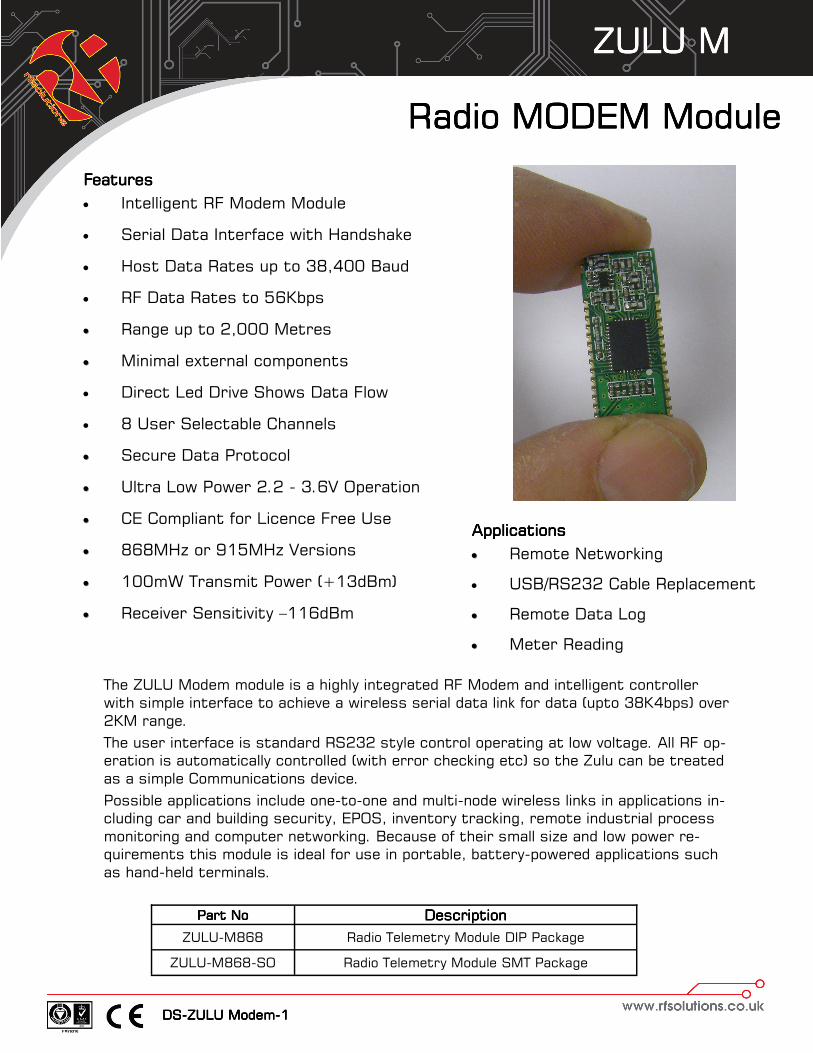
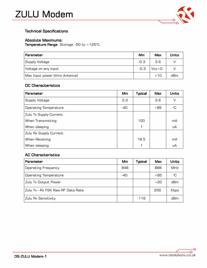
ZULU M ZULU M ZULU M ZULU M DS-ZULU Modem-1 Radio MODEM Module Radio MODEM Module Radio MODEM Module Radio MODEM Module Applications Applications Applications Applications Remote Networking USB/RS232 Cable Replacement Remote Data Log Meter Reading The ZULU Modem module is a highly integrated RF Modem and intelligent controller with simple interface to achieve a wireless serial data link for data (upto 38K4bps) over 2KM range. The user interface is standard RS232 style control operating at low voltage. All RF op- eration is automatically controlled (with error checking etc) so the Zulu can be treated as a simple Communications device. Possible applications include one-to-one and multi-node wireless links in applications in- cluding car and building security, EPOS, inventory tracking, remote industrial process monitoring and computer networking. Because of their small size and low power re- quirements this module is ideal for use in portable, battery-powered applications such as hand-held terminals. Part No Part No Part No Part No Description Description Description Description ZULU-M868 Radio Telemetry Module DIP Package ZULU-M868-SO Radio Telemetry Module SMT Package Features Features Features Features Intelligent RF Modem Module Serial Data Interface with Handshake Host Data Rates up to 38,400 Baud RF Data Rates to 56Kbps Range up to 2,000 Metres Minimal external components Direct Led Drive Shows Data Flow 8 User Selectable Channels Secure Data Protocol Ultra Low Power 2.2 - 3.6V Operation CE Compliant for Licence Free Use 868MHz or 915MHz Versions 100mW Transmit Power (+13dBm) Receiver Sensitivity –116dBm
Transcript

ZULU MZULU MZULU MZULU M

DDDDSSSS----ZZZZUUUULLLLUUUU MMMMooooddddeeeemmmm----1111

Radio MODEM Module Radio MODEM Module Radio MODEM Module Radio MODEM Module

ApplicationsApplicationsApplicationsApplications

•• Remote Networking

• USB/RS232 Cable Replacement

•• Remote Data Log

•• Meter Reading

The ZULU Modem module is a highly integrated RF Modem and intelligent controller

with simple interface to achieve a wireless serial data link for data (upto 38K4bps) over

2KM range.

The user interface is standard RS232 style control operating at low voltage. All RF op-

eration is automatically controlled (with error checking etc) so the Zulu can be treated

as a simple Communications device.

Possible applications include one-to-one and multi-node wireless links in applications in-

cluding car and building security, EPOS, inventory tracking, remote industrial process

monitoring and computer networking. Because of their small size and low power re-

quirements this module is ideal for use in portable, battery-powered applications such

as hand-held terminals.

Part NoPart NoPart NoPart No DescriptionDescriptionDescriptionDescription

ZULU-M868 Radio Telemetry Module DIP Package

ZULU-M868-SO Radio Telemetry Module SMT Package

FeaturesFeaturesFeaturesFeatures

• Intelligent RF Modem Module

• Serial Data Interface with Handshake

• Host Data Rates up to 38,400 Baud

• RF Data Rates to 56Kbps

•• Range up to 2,000 Metres

•• Minimal external components

• Direct Led Drive Shows Data Flow

• 8 User Selectable Channels

•• Secure Data Protocol

•• Ultra Low Power 2.2 - 3.6V Operation

•• CE Compliant for Licence Free Use

•• 868MHz or 915MHz Versions

•• 100mW Transmit Power (+13dBm)

•• Receiver Sensitivity –116dBm

ZULU ModemZULU ModemZULU ModemZULU Modem

DDDDSSSS----ZZZZUUUULLLLUUUU MMMMooooddddeeeemmmm----1111

PinoutPinoutPinoutPinout

Pin DescriptionPin DescriptionPin DescriptionPin Description

Pin NoPin NoPin NoPin No NameNameNameName DirectionDirectionDirectionDirection DescriptionDescriptionDescriptionDescription

1 ANT In Antenna Input / Output 50ohm Impedance

2, 15 GND In Connect to Ground

3-5,

11,

13-14,

20-24

N/C N/A Unused Leave Disconnected.

6 RX In (Low Level RS232) Data in

7 TX Out Low Level RS232 Data Out

8 LINK In Connect to LINK on Pin 28

9 CTS Out Low Level RS232 CTS

10 RTS In Low Level RS232 RTS

12 RESET In Device Reset Input (Tie High via 10K Resistor)

16 Vcc In +2.2-3.6v

17-18 DR1-DR2 In Host Data Rate selection.

19 WRE In

When High configuration data is held in EEPROM.

When Low configuration data is held in volatile memory

and lost on power cycle.

25 PD In Power down mode. Take low to enter Sleep mode

26 TX LED Out RF TX LED indicator

27 RX LED Out RF RX LED indicator

28 LINK Out Connect to LINK on Pin 8

29-30 XTAL1-2 In Connect 30MHz XTAL here to drive RF Circuit

ZULU ModemZULU ModemZULU ModemZULU Modem

DDDDSSSS----ZZZZUUUULLLLUUUU MMMMooooddddeeeemmmm----1111

Pin Descriptions:Pin Descriptions:Pin Descriptions:Pin Descriptions:

RX, TX RX, TX RX, TX RX, TX

This is the Data Input / Output. Data is transmitted and received at the low voltage level

(dependant on Vcc being used).

Serial Data FormatSerial Data FormatSerial Data FormatSerial Data Format

Baud Rate: Defined by DR1 and DR2 Pins

Data Bits: 8

Parity: None

Stop Bits: 1

Flow Control: Hardware CTS / RTS

CTS, RTSCTS, RTSCTS, RTSCTS, RTS

Clear to Send and Request to Send are standard data flow control as use in RS232 systems,

these are standard but operate at the Zulu Vcc low level voltage.

RESETRESETRESETRESET

Connection to GND Resets the Zulu Module. Zulu Modem starts up when this input is taken

from GND to Vcc.

Normal operation: connect to Vcc through a 10Kohm Resistor

Vcc:Vcc:Vcc:Vcc:

Supply Voltage (2.2—3.6V)

DR1 DR1 DR1 DR1 ---- DR2 DR2 DR2 DR2

These inputs define the host interface Baud Rate. They are read when RESET pin goes high.

Tip: It is good practice to operate the host interface at half the speed of the RF data rate (set

by Register R5

PDPDPDPD

This input enables ‘Sleep’ Mode. For normal operation connect to Vcc. No RF packets will be

received by the module when it is in sleep mode.

WREWREWREWRE

Controls where the User configuration parameters are saved in EEPROM (Non-Volatile) or

RAM (Volatile) Un-used.

Tx / Rx LEDTx / Rx LEDTx / Rx LEDTx / Rx LED

Direct LED Drive which operates whenever there is RF activity.

XTAL1, XTAL2 XTAL1, XTAL2 XTAL1, XTAL2 XTAL1, XTAL2

The Zulu module requires a 30MHz drive Crystal to be connected between XTAL1-2

Any standard crystal +/-10ppm ~20pF such as FEC 184-2247.

DR1DR1DR1DR1 DR2DR2DR2DR2 Host Baud RateHost Baud RateHost Baud RateHost Baud Rate

Open Open 4,800

Fitted Open 9,600

Open Fitted 19,200

Fitted Fitted 38,400

ZULU ModemZULU ModemZULU ModemZULU Modem

DDDDSSSS----ZZZZUUUULLLLUUUU MMMMooooddddeeeemmmm----1111

Operation OverviewOperation OverviewOperation OverviewOperation Overview

The ZULU MODEM Module provides a simple Modem interface to the host controller. It han-

dles all RF data communications automatically and without any requirement from the user (RF

packetising , Preamble, Encoding, CRC Check etc).

With this powerful high-speed Radio link. The following networks can be realised;

OneOneOneOne----totototo----One operation; One operation; One operation; One operation; for point to point data communication

OneOneOneOne----totototo----ManyManyManyMany; A network consisting a master and many slaves (the receivers all have the same

address)

ManyManyManyMany----totototo----One; One; One; One; where the transmitters all send to a single receiver address.

Because each ZULU MODEM can contain a unique address, multiple ZULU networks can co-

exist in the same area.

Broadcast operation; Broadcast operation; Broadcast operation; Broadcast operation; where a single master Zulu MODEM addresses many ZULU MODEMS

concurrently. (using many ZULU MODEM modules set to the same address),

Operating ModesOperating ModesOperating ModesOperating Modes

Configuration Mode: Configuration Mode: Configuration Mode: Configuration Mode: In Configuration mode the Zulu MODEM can receive a number of com-

mands and the internal registers can be preset to control its operation. In this mode the Zulu

MODEM is ‘Offline’ and cannot send or receive RF data.

Normal Operation : Normal Operation : Normal Operation : Normal Operation : ZULU MODEM is ’Online’ automatically transmitting and receiving data

from its host and across the RF network.

Each ZULU MODEM has its own preset address. This is user set during configuration. Any

data received is examined and the address header embedded within the data packet is com-

pared with its address. Only data received with matching address will be processed and out-

put to the host, all other data will be discarded.

All ZULU MODEM modules are shipped with a default address of 7E7E7E.

The ZULU MODEM contains an on-board data buffer equal to two data packets. Therefore if

RTS is asserted (then the host is unable to receive data) the module will store a max of two

data packets, all further data packets received will be discarded.

ZULU ModemZULU ModemZULU ModemZULU Modem

DDDDSSSS----ZZZZUUUULLLLUUUU MMMMooooddddeeeemmmm----1111

Configuration Mode (offline)Configuration Mode (offline)Configuration Mode (offline)Configuration Mode (offline)

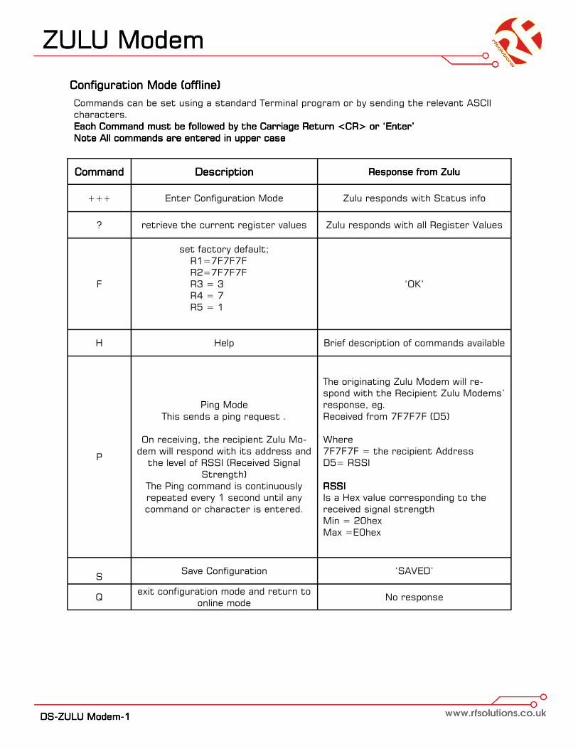
Commands can be set using a standard Terminal program or by sending the relevant ASCII

characters.

Each Command must be followed by the Carriage Return <CR> or ‘Enter’Each Command must be followed by the Carriage Return <CR> or ‘Enter’Each Command must be followed by the Carriage Return <CR> or ‘Enter’Each Command must be followed by the Carriage Return <CR> or ‘Enter’

Note All commands are entered in upper caseNote All commands are entered in upper caseNote All commands are entered in upper caseNote All commands are entered in upper case

Command Command Command Command DescriptionDescriptionDescriptionDescription

+++ Enter Configuration Mode

? retrieve the current register values

F

set factory default;

R1=7F7F7F

R2=7F7F7F

R3 = 3

R4 = 7

R5 = 1

H Help

S Save Configuration

Q exit configuration mode and return to

online mode

Response from ZuluResponse from ZuluResponse from ZuluResponse from Zulu

Zulu responds with Status info

Zulu responds with all Register Values

‘OK’

Brief description of commands available

‘SAVED’

No response

P

Ping Mode

This sends a ping request .

On receiving, the recipient Zulu Mo-

dem will respond with its address and

the level of RSSI (Received Signal

Strength)

The Ping command is continuously

repeated every 1 second until any

command or character is entered.

The originating Zulu Modem will re-

spond with the Recipient Zulu Modems’

response, eg.

Received from 7F7F7F (D5)

Where

7F7F7F = the recipient Address

D5= RSSI

RSSI RSSI RSSI RSSI

Is a Hex value corresponding to the

received signal strength

Min = 20hex

Max =E0hex

ZULU ModemZULU ModemZULU ModemZULU Modem

DDDDSSSS----ZZZZUUUULLLLUUUU MMMMooooddddeeeemmmm----1111

Register Setting (Configuration Mode)Register Setting (Configuration Mode)Register Setting (Configuration Mode)Register Setting (Configuration Mode)

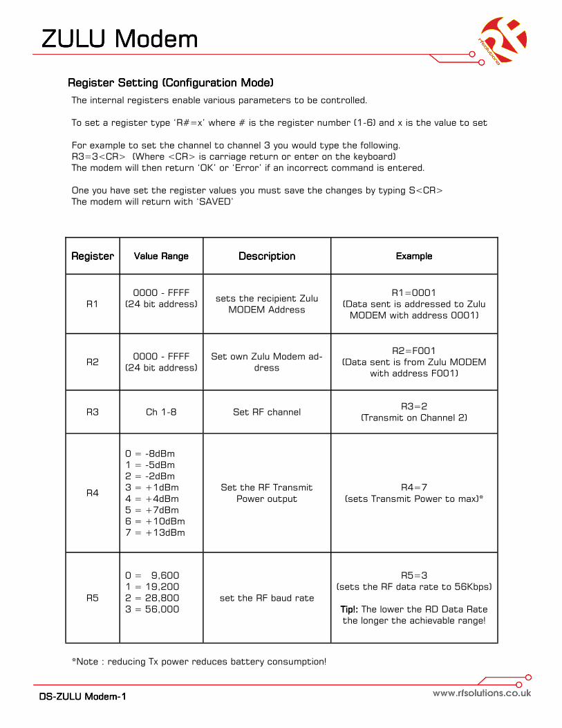
The internal registers enable various parameters to be controlled.

To set a register type ‘R#=x’ where # is the register number (1-6) and x is the value to set

For example to set the channel to channel 3 you would type the following.

R3=3<CR> (Where <CR> is carriage return or enter on the keyboard)

The modem will then return ‘OK’ or ‘Error’ if an incorrect command is entered.

One you have set the register values you must save the changes by typing S<CR>

The modem will return with ‘SAVED’

RegisterRegisterRegisterRegister Value RangeValue RangeValue RangeValue Range DescriptionDescriptionDescriptionDescription ExampleExampleExampleExample

R1

0000 - FFFF

(24 bit address)

sets the recipient Zulu

MODEM Address

R1=0001

(Data sent is addressed to Zulu

MODEM with address 0001)

R2 0000 - FFFF

(24 bit address)

Set own Zulu Modem ad-

dress

R2=F001

(Data sent is from Zulu MODEM

with address F001)

R3 Ch 1-8 Set RF channel R3=2

(Transmit on Channel 2)

R4

0 = -8dBm

1 = -5dBm

2 = -2dBm

3 = +1dBm

4 = +4dBm

5 = +7dBm

6 = +10dBm

7 = +13dBm

Set the RF Transmit

Power output

R4=7

(sets Transmit Power to max)*

R5

0 = 9,600

1 = 19,200

2 = 28,800

3 = 56,000

set the RF baud rate

R5=3

(sets the RF data rate to 56Kbps)

Tip!: Tip!: Tip!: Tip!: The lower the RD Data Rate

the longer the achievable range!

*Note : reducing Tx power reduces battery consumption!

ZULU ModemZULU ModemZULU ModemZULU Modem

DDDDSSSS----ZZZZUUUULLLLUUUU MMMMooooddddeeeemmmm----1111

Application CircuitApplication CircuitApplication CircuitApplication Circuit

Connection of the ZULU Modem to an RS232 or USB host terminal device such as a PC serial

port may easily be achieved using the Application Schematic below.

The 9 way ‘D’ socket (J1) provides the standard pin out required to connect directly to the serial

port of any std PC using a 9 way male/female cable. The MAX3232 (a low voltage RS232 line

driver) provides level conversion between the RS232 levels on the serial port and the logic levels

pins of the ZULU Modem module.

Alternatively the same can be achieved using the ZULU Eval Boards

ZULU ModemZULU ModemZULU ModemZULU Modem

DDDDSSSS----ZZZZUUUULLLLUUUU MMMMooooddddeeeemmmm----1111

RangeRangeRangeRange The antenna choice and position directly controls the system range. Keep it clear of other

metal in the system. The best position by far, is protruding vertically from the top of the prod-

uct. This is often not desirable for practical reasons and thus a compromise may be needed.

Note that the space around the antenna is as important as the antenna itself. All radio sys-

tems are dependant on a radio signal being received through airspace.

The range quoted is the optimal in direct line of sight without obstacles and in good atmos-

pheric conditions.

Range is affected by many things, for example local environmental conditions, atmospheric

conditions, interference from other radio transmitters. For evaluating the local environment

please see our RF Meter (DS006)

In very worse case applications the range quoted may be reduced below 30% of the optimal

range stated.

Mechanical DimensionsMechanical DimensionsMechanical DimensionsMechanical Dimensions

Recommended AntennaRecommended AntennaRecommended AntennaRecommended Antenna The BEAD Antenna provides a Miniature PCB mounting solution

where a high performance is required from a small space .

Available as straight or 90 degree mount this antenna is a gen-

eral purpose omni-directional. It measures 8.5mm long, Dia 7.

Please see Datasheet ANT-BEAD-868

ZULU ModemZULU ModemZULU ModemZULU Modem

DDDDSSSS----ZZZZUUUULLLLUUUU MMMMooooddddeeeemmmm----1111

Technical SpecificationsTechnical SpecificationsTechnical SpecificationsTechnical Specifications

Absolute MaximumsAbsolute MaximumsAbsolute MaximumsAbsolute Maximums:::: Temperature RangeTemperature RangeTemperature RangeTemperature Range: Storage –50 to +125oC.

DC CharacteristicsDC CharacteristicsDC CharacteristicsDC Characteristics

ParameterParameterParameterParameter MinMinMinMin MaxMaxMaxMax UnitsUnitsUnitsUnits

Supply Voltage -0.3 3.6 V

Voltage on any Input -0.3 Vcc+0. V

Max Input power (thro Antenna) +10 dBm

ParameterParameterParameterParameter MinMinMinMin TypicalTypicalTypicalTypical MaxMaxMaxMax UnitsUnitsUnitsUnits

Supply Voltage 2.2 3.6 V

Operating Temperature -40 +85 oC

Zulu Tx Supply Current:

When Transmitting

When sleeping

100

1

mA

uA

Zulu Rx Supply Current:

When Receiving

When sleeping

18.5

1

mA

uA

AC CharacteristicsAC CharacteristicsAC CharacteristicsAC Characteristics

ParameterParameterParameterParameter MinMinMinMin TypicalTypicalTypicalTypical MaxMaxMaxMax UnitsUnitsUnitsUnits

Operating Frequency 848 888 MHz

Operating Temperature -40 +85 oC

Zulu Tx Output Power +20 dBm

Zulu Tx—Rx FSK Raw RF Data Rate 256 Kbps

Zulu Rx Sensitivity -116 dBm

ZULU ModemZULU ModemZULU ModemZULU Modem

DDDDSSSS----ZZZZUUUULLLLUUUU MMMMooooddddeeeemmmm----1111

Intentionally Blank

ZULU ModemZULU ModemZULU ModemZULU Modem

DDDDSSSS----ZZZZUUUULLLLUUUU MMMMooooddddeeeemmmm----1111

Zulu Evaluation BoardZulu Evaluation BoardZulu Evaluation BoardZulu Evaluation Board

FeaturesFeaturesFeaturesFeatures

•• Easy assemble Projects;

• Watchdog Feature

•• Direct Antenna Connection

• 9-12Vdc Power in Screw Term

• LED Indication of

• Power

• Transmit / Receiver

• RF Error

•• All Thro Hole Components

ZULU Telemetry ZULU Telemetry ZULU Telemetry ZULU Telemetry

• 10 Channel Telemetry

• 10 LED Outputs

• 2 Analogue RF Links

• 2 Analogue Outputs

ZULU ModemZULU ModemZULU ModemZULU Modem

• RS232 Modem

• USB Modem

The ZULU EVAL Boards provide a ready made platform which can be used to

build several projects which demonstrate the capabilities of ZULU Modules

providing ready made Telemetry and Modem Solutions.

The Evaluation boards are sold as a TX and RX PCB pair, ready for component population.

Schematics are shown below, not all components are fitted for each of the projects.

Part NoPart NoPart NoPart No DescriptionDescriptionDescriptionDescription

ZULU-EVAL Tx and RX PCB Pair

PSU-12V1-UK Plugtop Power Supply 12V 100mA

ZULU ModemZULU ModemZULU ModemZULU Modem

DDDDSSSS----ZZZZUUUULLLLUUUU MMMMooooddddeeeemmmm----1111

Zulu Evaluation Board Transmitter SchematicZulu Evaluation Board Transmitter SchematicZulu Evaluation Board Transmitter SchematicZulu Evaluation Board Transmitter Schematic

ZULU ModemZULU ModemZULU ModemZULU Modem

DDDDSSSS----ZZZZUUUULLLLUUUU MMMMooooddddeeeemmmm----1111

Zulu Evaluation Board Transmitter PCB LayoutZulu Evaluation Board Transmitter PCB LayoutZulu Evaluation Board Transmitter PCB LayoutZulu Evaluation Board Transmitter PCB Layout

QTY Reference Part Name Description Farnell Part

1 ANT1 ANT_SCRTM4RA,ANTENNA FEC109-6142

6 C1-6 CAP_254MM_RAD,100n FEC114-1775

2 C7,9 CAP-254-TH FEC171-2584

1 C8 CAP-254-TH FEC969-3238

4 C10-13 CAP_254MM_RAD,100n FEC114-1775

1 C14 CAP_254MM_RAD,1u FEC969-3238

1 C15 CAP_254MM_RAD,33pF FEC114-1761

1 C16 CAP_254MM_RAD,100pF FEC114-1775

1 C17 CAP_254MM_RAD,2.2uF FEC184-8563

2 C18-19 CAP_254MM_RAD,10pF FEC114-1756

2 D1,D3 LED3MM-TH,RED LIGHT EMITTING DIODE FEC100-3390

1 D2 LED3MM-TH,GREEN LIGHT EMITTING DIODE FEC100-3199

1 D4 1N4007-DO-41 FEC165-1091

1 IC1 LM3940IT-3.3-TO-220 FEC949-4553

1 IC2 FT232RL-SSOP-28 FEC114-6032

1 J1 DCON9F 9 PIN D-TYPE FEMALE FEC109-9294

4 LK1-4 HEADER-1X2PIN 1 X 2 PIN HEADER, 0.1" CENTERS FEC182-2168

2 LK5-6 SIP-3P 1 X 3 PIN HEADER FEC182-2168

2 LK10-11 HEADER_8_2X4_TH 2 X 2 PIN HEADER FEC124-8134

1 M1 ZULU-M or ZULU-T

1 M2 MAX232-PDIP-16 MAX232 RS 232 Driver IC FEC938-6904

1 R1-2 RES-1/4W,2k2 RES BODY:100 CENTERS:500 FEC934-1536

11 R3-12,15 RES-1/4W,10K RES BODY:100 CENTERS:500 FEC934-1110

3 R16-18 RES-1/4W,360R RES BODY:100 CENTERS:500 FEC934-1790

10 S1-10 LRN_BTN_TH

1 S13 LRN_BTN_TH

1 SK1 USB_"B"_CON_TH,USB USB 'B' CON.

3 TB1-3 SCR_TER2W 2 Way Screw Terminal 5mm pitch

2 VR1-2 VRES-TOP-ADJ-TH-3306F 10kR FEC168-9844

1 Y1 XTAL1,30MHZ 30MHZ FEC184-2247

ZULU ModemZULU ModemZULU ModemZULU Modem

DDDDSSSS----ZZZZUUUULLLLUUUU MMMMooooddddeeeemmmm----1111

Zulu Evaluation Board Receiver SchematicZulu Evaluation Board Receiver SchematicZulu Evaluation Board Receiver SchematicZulu Evaluation Board Receiver Schematic

ZULU ModemZULU ModemZULU ModemZULU Modem

DDDDSSSS----ZZZZUUUULLLLUUUU MMMMooooddddeeeemmmm----1111

Zulu Evaluation Board Receiver PCB LayoutZulu Evaluation Board Receiver PCB LayoutZulu Evaluation Board Receiver PCB LayoutZulu Evaluation Board Receiver PCB Layout

QTY Reference Part Name Description Farnell Part

1 ANT1 SCRTM4RA Antenna Mount FEC109-6142

11 C1-6,C10-13,C16 CAP-1uFX7R 0.1uF, 25V FEC114-1775

2 C7,9 CAP-47uF25V-EL 47uF, 25Vdc FEC171-2584

1 C8,14 CAP-1uF250V-EL 1uF 35V FEC969-3238

1 C15 CAP-33pF-CER 33pF FEC114-1761

1 C17 CAP-2UF2-160VEL 2.2uF FEC184-8563

2 C18-19 CAP-10PF-CERA 10pF FEC114-1756

13 D1-10, 14-15 LED3LP-GRN LED FEC100-3199

1 D13 LED-3-LP-RED LED FEC100-3390

1 D16 1N4007 FEC165-1091

1 IC1 LM3940IT-3.3-TO-220 FEC949-4553

1 IC2 IC-RT232RL FT232RL-SSOP-28 FEC114-6032

1 J7 CON-DB9F 9 PIN D-TYPE FEMALE FEC109-9294

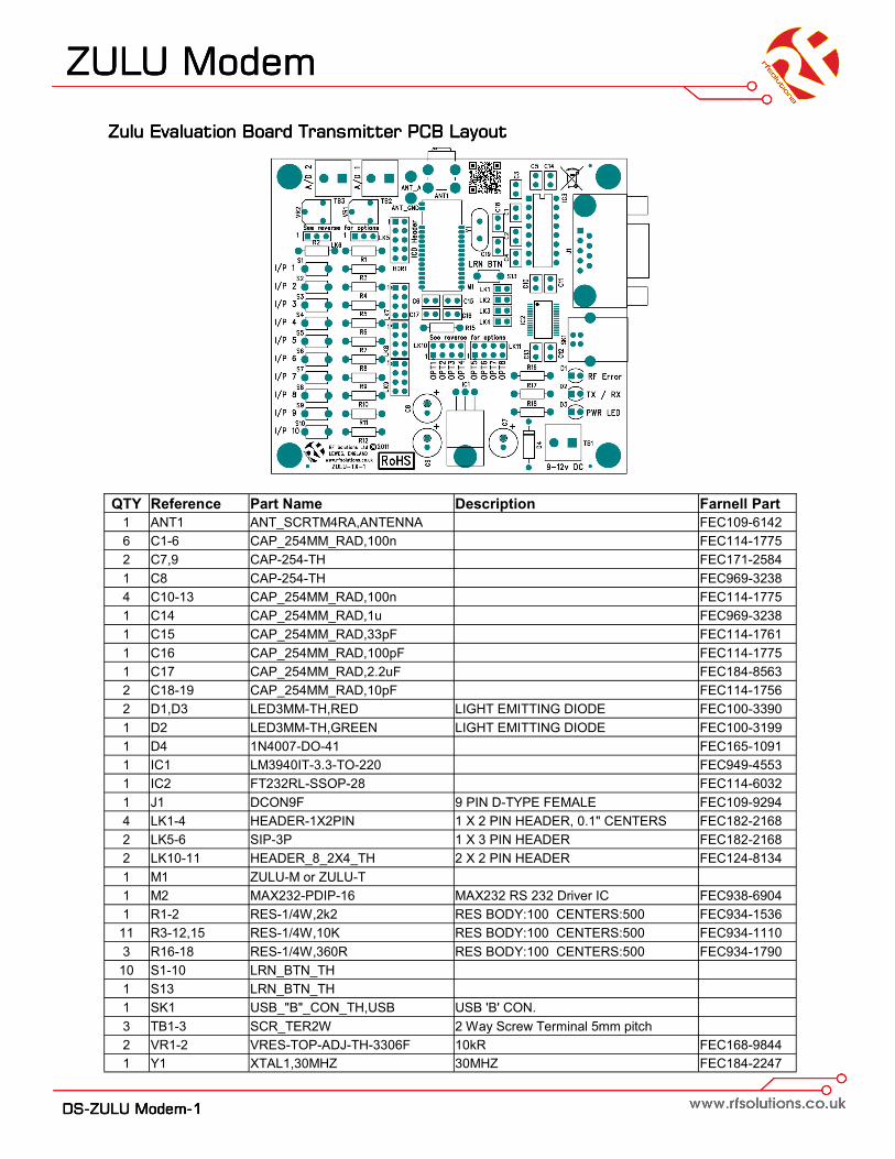
4 LK1-4 HEADER-1X2PIN 1 X 2 PIN HEADER, 0.1" CEN-TERS

FEC182-2168

1 LK5 SIP-3P 1 X 3 PIN HEADER FEC182-2168

1 LK10-11 HEADER_8_2X4_TH 2 X 2 PIN HEADER FEC124-8134

1 M1 ZULU-M or ZULU-T

1 M2 MAX232-PDIP-16 MAX232 RS 232 Driver IC FEC938-6904

1 Q1-2 TIP122 NPN DARLINGTON,TO220AB FEC980-4021

3 R1-3 RES-FR4-10K-1 10K FEC934-1110

13 R4-13, 16-18 RES-1/4W,360R 360R FEC934-1790

1 S1 LRN_BTN_TH Learn Button

1 SK1 USB_"B"_CON_TH,USB USB 'B' CON.

3 TB1-3 SCR_TER2W 2 Way Screw Terminal 5mm Pitch

1 Y1 XTAL1,30MHZ CRYSTAL FEC1842247 FEC184-2247

ZULU ModemZULU ModemZULU ModemZULU Modem

Whilst the information in this document is believed to be correct at the time of issue, RF Solutions Ltd does not accept any liability whatsoever for its accuracy,

adequacy or completeness. No express or implied warranty or representation is given relating to the information contained in this document. RF Solutions Ltd

reserves the right to make changes and improvements to the product(s) described herein without notice. Buyers and other users should determine for them-

selves the suitability of any such information or products for their own particular requirements or specification(s). RF Solutions Ltd shall not be liable for any loss

or damage caused as a result of user’s own determination of how to deploy or use RF Solutions Ltd’s products. Use of RF Solutions Ltd products or components

in life support and/or safety applications is not authorised except with express written approval. No licences are created, implicitly or otherwise, under any of RF

Solutions Ltd’s intellectual property rights. Liability for loss or damage resulting or caused by reliance on the information contained herein or from the use of the

product (including liability resulting from negligence or where RF Solutions Ltd was aware of the possibility of such loss or damage arising) is excluded. This will not

operate to limit or restrict RF Solutions Ltd’s liability for death or personal injury resulting from its negligence.

Reader ResponseReader ResponseReader ResponseReader Response It is our intention to provide you with the best documentation possible to ensure successful

use of your RF Solutions product.

If you wish to provide your comments on organization, clarity, subject matter, and ways in

which our documentation can better serve you, please email us your comments to the Tech-

nical Publications Manager

Application:

Would you like a reply? Y / N

Datasheet: DS-ZULUModem-1

Questions:

1. What are the best features of this document?

2. How does this document meet your hardware and software development needs?

3. Do you find the organization of this document easy to follow? If not, why?

4. What additions to the document do you think would enhance the structure and subject?

5. What deletions from the document could be made without affecting the usefulness?

6. Is there any incorrect or misleading information (what and where)?

7. How would you improve this document?

R F Solutions Ltd.,R F Solutions Ltd.,R F Solutions Ltd.,R F Solutions Ltd.,

Unit 21, Cliffe Industrial Estate,Unit 21, Cliffe Industrial Estate,Unit 21, Cliffe Industrial Estate,Unit 21, Cliffe Industrial Estate,

Lewes, E. Sussex. BN8 6JL. England.Lewes, E. Sussex. BN8 6JL. England.Lewes, E. Sussex. BN8 6JL. England.Lewes, E. Sussex. BN8 6JL. England.

Email : Email : Email : Email : [email protected]@[email protected]@rfsolutions.co.uk http://www.rfsolutions.co.ukhttp://www.rfsolutions.co.ukhttp://www.rfsolutions.co.ukhttp://www.rfsolutions.co.uk

Tel Sales: Tel Sales: Tel Sales: Tel Sales: 01273 898 02001273 898 02001273 898 02001273 898 020

Tel Technical: Tel Technical: Tel Technical: Tel Technical: 01273 898 00701273 898 00701273 898 00701273 898 007

Tel Gen Enq: Tel Gen Enq: Tel Gen Enq: Tel Gen Enq: 01273 898 00001273 898 00001273 898 00001273 898 000

RF Solutions Ltd. Recycling NoticeRF Solutions Ltd. Recycling NoticeRF Solutions Ltd. Recycling NoticeRF Solutions Ltd. Recycling Notice

Meets the following EC Directives:

DO NOT DO NOT DO NOT DO NOT Discard with normal waste, please recycle.

ROHS Directive 2002/95/ECROHS Directive 2002/95/ECROHS Directive 2002/95/ECROHS Directive 2002/95/EC

Specifies certain limits for hazardous substances.

WEEE Directive 2002/96/ECWEEE Directive 2002/96/ECWEEE Directive 2002/96/ECWEEE Directive 2002/96/EC

Waste electrical & electronic equipment. This product must be disposed of through a licensed

WEEE collection point. RF Solutions Ltd., fulfils its WEEE obligations by membership of an ap-

proved compliance scheme.


Recommended