16
.,;- .,;- , _I ’ , _I ’ _ I, \_. _ I, \_. ,, ,,, z/y https://ntrs.nasa.gov/search.jsp?R=19930092008 2018-09-19T05:44:51+00:00Z
| Date post: | 19-Sep-2018 |
| Category: |
Documents |
| Upload: | trinhnguyet |
| View: | 214 times |
| Download: | 0 times |

.,;- .,;- , _I ’ , _I ’
_ I, \_. _ I, \_. ,, ,,, z/y
https://ntrs.nasa.gov/search.jsp?R=19930092008 2018-09-19T05:44:51+00:00Z

--- ,i .
/‘- . ’
,. _’ --

REPORT'943
A SIMPLIFIED METHOD FOR THE DETERMINATION
AND ANALYSIS OF THE NEUTRAL-LATERAL-
OSCILLATORY-STABILITY BOUNDARY
By LEONARD STERNFIELD and ORDWAY B. GATES, Jr.
Langley Aeronautical Laboratory Langley Air Force Base, Va.
-_ I

National Advisory Committee for Aeronautics Headpuurters, 17.24 F Street NW., Washington 25, D. C.
Created by act of Congress approved March 3, 1915, for the supervision and direction of the scientific study of the problems of flight (U. S. Code, title 50, sec. 151). Its membership was increased from 12 to 15 by act approved March 2, 1929, and to 17 by act approved May 25, 1948. The members are appointed by the President, and serve as such without compensation.
JEROME C. HUNSAKER, SC. D., Massachusetts Institute of Technology, Chairman
ALEXANDER WETMORE, SC. D., Secretary, Smithsonian Institution, l&e Chairman
HON. JOHN R. ALISON, Assistant Secretary of Commerce. DETLEV W. BRONK, PH. D., President, Johns Hopkins University. KARL T. COMPTON, PH. D., Chairman, Research and Development
Board, Department of Defense. EDWARD U. CONDON, PH. D., Director, National Bureau of
Standards. JAMES H. DOOLITTLE, SC. D., Vice President, Shell Union Oil
Corp. R. M. HAZEN, B. S., Director of Engineering, Allison Division,
General Motors Corp.
TIIEO~ORE C. LONNQUEST, Rear Admiral, United States Navy, Deputy and Assistant Chief of the Bureau of Aeronautics.
WILLIAM LITTLEM’OOD, M. E., Vice President, Engineering, American Airlines, Inc.
DONALD L. PUTT, Major General, United States Air Force, Director of Research and Development, Office of the Chief of Staff, Materiel.
JOHN D. PRICE, Vice Admiral, United States Navy, Vice Chief of Naval Operations.
ARTHUR E. RAYMOND, SC. D., Vice President, Engineering, Douglas Aircraft Co., Inc.
FRANCIS W. REICHELDERFER, SC. D., Chief, United States Weather Bureau.
THEODORE P. WRIGHT, SC. D., Vice President for Research, Cornell University.
HON. DELOS W. RENTZEL, Administrator of Civil Aeronautics, Department of Commerce.
HOYT S. VANDENBERQ, General, Chief of Staff, United States Air Force.
HUGH L. DRYDEN, PH. D., Director
JOHN W. CROWLEY, JR., B. S., Associate Director for Research
JOHN F. VICTORY, LL. M., Executive Secretary
E. H. CHAMBERLIN, Executive Oficer
HENRY J. REID, D. Eng., Director, Langley Aeronautical Laboratory, Langley Field, Va.
SMITH J. DEFRANCE, B. S., Director, Ames Aeronautical Laboratory, Moffett Field, Calif.
EDWARD R. SHARP, SC. D., Director, Lewis Flight Propulsion Laboratory, Cleveland Airport, Cleveland, Ohio
TECHNICAL COMMITTEES
AERODYNAMICS OPERATING PROBLEMS POWER PLANTS FOR AIRCRAFT INDUSTRY CONSULTING AIRCRAFT CONSTRUCTION
Coordination of Research Needs of Military and Civil Aviation Preparation of Reseal ch Progf ams
Allocation of Probkms Prevention of Duplication
Consideration of Inuentions
LANGLEY AERONAUTICAL LABORATORY LEWIS FLIGHT PROPULSION LABORATORY AMES AERONAUTICAL LABORATOKV Langley Field, Va. Cleveland Airport, Cleveland, Ohio Moffett Field, Calif.
Conduct, under unified conf.rol, for all agencies of scientijk research on th,e fundamental problems of fright
OFFICE OF AERONAUTICAL INTELLIGENCE Washington, D. C.
Collection., classijicntion, compilation, and dissemination of scienti$c and technical information on aeronautics
II

P --
REPORT 943
A SIMPLIFIED METHOD FOR THE DETERMINATION AND ANALYSIS OF THE NEUTRAL-LATERAL-OSCILLATORY-STABILITY BOUNDARY
By LEONARD STERNFIELD and ORDWAY B. GATES, Jr.
SUMMARY
A necessary condition for neutral oscillatory stability is that Routh’s discriminant R, form.ed -from the coe$kients qf the stability equation, is equal to zero. The expression for R is D(BC-AD) - B’E where A, B, C, D, and E are the coescients gf the lateral-stability equation. In a large number qf the cases considered in this study, it has been-found that the term B2E may be neglected. Routh’s discriminant is then -factorable into two simplified expressions, that is, BC-AD= R, and D; and either RI=0 or D=O, or both, ‘may constitute a condition of neutral stability. Test ficnctions h,aue been derived which, if satis$ed, indicate that the simplij%ed expressions may be used to approximate R=O. .“lf R,=O and D=O satisfy the necessary and su$icien.t conditions for a neutral-oscillatory-stability boundary, D=O represents the boundaty for the oscillation which has a period comparatiuely longer thalb the period of oscillation for which RI=0 is the boundary.
In ge,neral, the results qf the computations obtained -from RI=0 and D=O show ‘very good agreement with the results ca.lculated by the exact expression for X=0. The nature of the modes of motion as a function of th.e directional-stability deriu- ative and the effective-dihedral derivative is discussed in detail.
INTRODUCTION
The results of recent investigations (references 1 and 2 and unpublished results of lateral-stability analyses fol several experimental high-speed airplanes) have indicated that small variations in some of the airplane mass and aerodynamic parameters may cause a pronounced change in the oscillatory stability of the airplane. It has been difficult to explain the reasons for such pronounced changes because of the complexity of the expression for neutral oscillatory stabil- ity. This expression, based on the lateral-stability equations with three degrees of freedom, involves a large number of combinations of the mass and aerodynamic parameters. In order to predict the stability of the lateral oscillation, there- fore, it appears necessary to make a separate stability analysis for each airplane.
The simplified expressions derived for the ncutral- oscillatory-stability boundary in the present theoretical inves- tigation simplify thecalculationsrequired toobtain the bound- ary in the analysis essential for each airplane. Because of the comparative simplicity of these expressions, an insight into
860769-50
the important combinations of mass and aerodynamic parameters that affect the lateral oscillatory stability is also provided. Through further investigation and analysis of the effects of these major parameters, the necessity of malting separate calculations for each airplane might possibly be eliminated. Te6t functions are given which, if satisfied, inclicate that the simplified expressions may be used.
The nature of the modes of motion as a function of CSs and CL,, the directional-st,ability derivative and efl’cctive- dihedral derivative, respect,ively, is shown to depend upon the location of the stability boundaries plott,rd as a function of Cns and C1,.
The results of the calculations based on the simplificcl expressions are presented for comparison with the results obtained by the complete expression for the neutral- oscillatory-stability boundary.
P V V P
SYMBOLS AND COEFFICIENTS
angle of bank, radians angle of azimuth, radians angle of sideslip, radians cu/V) sicleslip velocity along the Y-axis, feet per second airspeed, feet per second mass density of air, slugs per cubic foot
dynamic pressure, pounds per square foot ( >
; pv2
wing span, feet wing area, square feet weight of airplane, pounds mass of airplane, slugs (W/g) acceleration due to gravity, feet per second per second relative-density factor (m/pSb) inclination of principal longitudinal axis of airplane
with respect to flight path, positive when principal axis is above flight path at the nose, degrees (see fig. 1)
angle between reference axis and horizontal axis, positive when reference axis is above horizontal axis, degrees (see fig. 1)
angle between reference axis and principal axis, positive when reference axis is above principal axis, degrees (see fig. 1)
1

2
Y
k x0
k zo
KXO
Kzo
Kx
Kz
Kxz
CL
CL
G
CY
c!ls
REPORT 943-NATIONAL ADVISORY COMMITTEE FOR AERONAUTICS
angle of flight path to horizontal axis, positive in a climb, degrees (see fig. I)
radius of gyration in roll about principal longitudinal axis, feet
radius of gyration in yaw about principal vertical axis, feet
nondimensional radius of gyration in roll about principal longitudinal axis (k=,/b)
nondimensional radius of gyration m yaw about principal vertical axis (k,,Jb)
nondimensional radius of gyration in roll about longitudina1 stability axis ( 1’KAy,2 cos”+KzO’sin’~)
nondimensional radius of gyration in yaw about vertical stability axis ( ,‘Kz02 cos2 q+K-\oz sinz 7)
nondimensional product-of-incll.tia paramctci ((Kz,2--Kxo’) sin 11 cos 7)
trim lift coeficicn t (?$y-?)
rolling-moment cocfficicnt (
Rolling moment ----i@-- >
( Yawinv momcnt
yawing-moment cocfficicnt - m-b_ -- qSb >
lateral-force coefficient (
Lateral force _.--~~.-~ ClS >
cficctive-dihedral derivative, rate of change of rolling- moment, cocfficicnt with angle of sideslip, per radian @C&P)
tlircctionaI-sl ability dcrivativc, rate of change of yawing-moment corfficirnt with angle of sidrslip, per radian (W&B)
lateral-force tlcrivativr, ratr of change of Iaferal- forcr corfficicnt with angle of sitlcslip, per radian WY/W)
(lamping-in-yn\\. dcrivativr, rate of change of yawing- moment cocfficirnt with ya\~ing-ang:ulaI~-~~(~Io(~itg
factor, per radian (W,!/a i!)
raIc of cliangc of yawing-momrnt corflicien t with rolling-angular-velocity factor, prr radiall
(wa g) damping-in-roll derivativr, rate of change of rolling-
momrnt, cocfficirnt with rolling-ang:ulal,-~re1ocit.y
fact or, per radian (b@Jd $b)
rate of cliangc of rolling-moment coefficient wi-ith yang-ing-angular-velocity factor, per radian
(XV $)
rntc of change of latrral-force corffic~ic~nt with rolling-
angular-vrlocity factor, per radian (awa $$)
rate of change of lateral-force cocfficicnt. with yawing-
angular-vc1ocit.y factor, per radian (aW ;b)
time, srcontls nontIimcnsio~~:~l time p;*amcter hasrtl OH span (Vt/b)
tIifTcrential operator J?- ( > Ch
Routh’s tliscriminant
\ \ \ \ ‘\ Reference axis \ \
\ ‘\ Pri-rlpd ax;s I?-, \
\ ‘1.
z’ FIGIRE I.-System of axes and mgular relationshilx in flight. Arrows indicate positiw
dirrction of anglrs. 7=0--y--E.
x complex root of stability equation A~-‘+Bx~+CX~+DX+E=O (X=[fiw)
A’ complrx root of stability equation Ax’“+~ZBXIS+FX’z+~XI+~=O (A’ = (’ Irt id)
I’ period of oscillation, seconds ir, /” time for amplitude of oscillation to change by facto1
of 2 (positive value indicates a decrease to half- amplitude, negative value indicates an increase to double amplitude)
A, R, C, D, E coefficients of lateral-st,ability equation
EQUATIONS OF MOTION
Tlit~ nontlinirnsional linearized rquations of motion, re- fcrrctl to the stability axes, usecl to calculate the spiral- stability and oscillatory-stability boundaries for any flight condition arc:
Rolling
2dKx2Dh26+KxzDb2#) =c,Bi-; CrpD,++; C,JM
Yawing
%(Kz2Db2~+KxzDh?& =C,&; CnJM+; G$W
S&slipping
2~*(n,P+r),*)=C,-gP-t f C,nD,~+C,~+~C,,D,l+(C~ tall-h4
When &exQ is substituted for 4, &exsb for fi, poexs~~ for /3 in tlx equations written in determinant form, X must be a root of tlir stability equation
Ax”+Bx3+C~2+D~+E=~ (1)
wherr
A=Qp~b3(K~2Kz2-Kxz2)
B= -2~,‘(2K,?K,2C,a+Kx2C,r+1(,2C~p-2K~~2C~~8-
KxzCr,-KxzCn,)
I

SIMPLIFIED METHOD FOR DETERMINATION AND ANALYSIS OF NEUTRAL-OSCILLATORY-STABILITY BOUNDARY 3
Multiplying equation (1) by Pb and substituting h=cf results in the stability equation
where
g=B pb2
B=D
E=,,,E
The damping and period of the lateral oscillation in seconds are given rcspcctivcly by the equations
T =-!?.ssI*,b 112 r;’ v
p-6.28 be WI v
where 5’ and W’ are the real and imaginary parts of the complex root of stability equation (2).
ANALYSIS
The necessary and sufficient conditions for neutral oscilla- tory stability, as shown in reference 3, are that the coeffi- cients of the stability equation satisfy Routh’s discriminant set equal to zero
R=BCD-AD?-B2E=0 (3)
and that B and D have the same sign. The espression for R=O can be derived hy assuming that the stability equation has two roots A= fiw, where w is the angular frequency of the neutrally stable oscillation. This assumption is based on the fact that for the condition of neutl.al oscillatory stability the real part of the complex root must be zero.
If X=iw is substituted in the stability equation, the following two equations are obtained:
Aw4- Cwz+ E= 0 (4)
-Bw3+Dw=0 (5)
Solving equation (5) for w2 and then substituting the result D
( > w*=B in equation (4) results in Routh’s discriminant
BCD- ADZ- B2E=0
It is seen from equation (5) that w= -\i
0. Z is the angular fre-
quency of the neutrally stable oscillation only when R and D are of the same sign since w must have a real value if the root X= f,iw is to represent an oscillation. If R ancl D are of opposite sign and X=0 is satisfied, the two roots of the stabi1it.y equation given by A= fiw are real, one positive and one negative. It is important to note that the A, C, and E cocfficicnts may be of opposite sign to the R and D cocflicicnts, and neutral oscillatory stability will still occur as long as Routh’s tliscriminant is equal to zero and thr D and R cocfficicnts arc’ of the same sign.
In general, the R=O boundary in the C,,,,C,, plane has two branches. The two branches result from the fact that R=O is a quadratic equation in P1,+ and thus has two C,, roots for every value of CnP. Usually, the two branches can be approximated by simplified expressions for R=O. In certain cases, however, which arc discussecl in t)he section entitled “Test Functions,” cithcr one or none of the branches may bc approsimutcd.
Nom, the condition R=O is a necessary but insufficient condition for nrutral oscillatory stability. The simplifiitd cxprcssions, therefore, which approximate R=O do not necessarily reprcscnt bomltlarirs of nrutral oscillatory stability. Other conditions, rlaboratctl on in the sclction “Validity of D=O and RI=0 as Neutral-Oscillatory-Stability Boundaries,” must bc satisfied before either expression represents a valid boundary.
There are, thcreforc, two kinds of tests that must be made: First, tests to clctcrminc whet&r R=O may be approximated by simplified expressions; and, seconcl, tests to determine which of these expressions represents a bounclary of neutral oscillatory stability. The significance of the lateral-stability boundarics is indicated by a cliscussion of the modes of motion in the C,,,CL plane.
DERIVATION OF SIMPLIFIED EXPRESSIONS
Two of the most important stability derivatives affecting lateral oscillatory stability are the directional-stability derivative CnP a.nd the effective-dihedral derivative c’,,. The boundary for neutral oscillatory stability is usually plotted as a function of these two derivatives with Cns as the ordinate and C,, as t)he abscissa. The method used t,o obtain the neutral oscillatory stability bounclary is first to substitute the values of the mass and aerodynamic param- eters of a specific airplane in the coefficients of the stability equation while maintaining Cns and CZ, as variables and then to calculate the Cl, roots of equation (3) for several
4 REPORT 943-NATIONAL ADVISORY COMMITTEE FOR AERONAUTICS
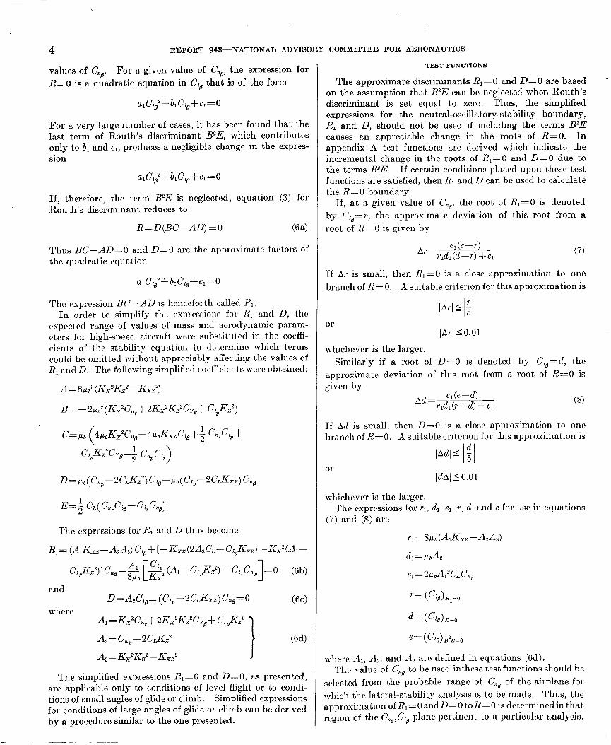
values of CnO. For a given value of CnP, the expression for R=O is a quadratic equation in CZB that is of the form
alC~a2+hC~s+c~=0
For a very large number of cases, it has been found that the last term of Routh’s discriminant B2E, which contributes only to b1 and cl, produces a negligible change in the expres- sion
alCz~2+bICz~+~l=0
If, therefore, the term B2E is neglected, equation (3) for Routh’s discriminant reduces to
R=D(BC-AD)=0 &'a>
Thus BC-AD=0 and D=O are the approximate factors of the quadratic equation
alC~B2+b~C~B+c~=0
The expression BC-AD is henceforth called R,. In order to simplify the expressions for RI and D, the
expect,ed range of values of mass and aerodynamic param- eters for high-speed aircraft were substituted in the coeffi- cients of the stability equation to determine which terms could be omitted without appreciably affecting the values of R, and D. The following simplified coefficients were obtained:
A=8p,3(K,2K,"-K,z2)
c= pb (
4/*bKx2Cno- 4~,&.&& “&,+
CzpK,G~-; c&z, >
D=ELb(~,~l,-2~~~Kz2)~z/4-~b(~zp-2c~~~)c~g
E=$ CL( c7,p,- CZ,G@)
The expressions for RI and D thus become
RI= (A,Kxz-AA,&) C,,+[-K,,(2A,C,+ClpKXZ) -Kx2(Al-
C,,Kz2Wn,-~~ g2 (A,-CC,,K,2) -c&c,,, 1 =O (6b)
and (6~)
where A,=K.~'C,,f2K,2K,2C,,SClpKZ2
-I (64
The simplified expressions RI=0 and D=O, as presented, are applicable only to conditions of level flight or to condi- tions of small angles of glide or climb. Simplified expressions for conditions of large angles of glide or climb can be derived by a procedure similar to the one presented.
TEST FUNCTIONS
The approximate discriminants RI=0 and D=O are based on the assumption that B2E can be neglected when Routh’s discriminant is set equal to zero. Thus, the simplified expressions for the neutral-oscillatory-stability boundary, R, and D, should not be used if including the terms B2E causes an appreciable change in the roots of R=O. In appendix A test functions are derived which indicate the incremental change in the roots of RI=0 and D=O clue to the terms B2E. If certain conditions placed upon these test functions are satisfied, then R, and D can be used to calculate the R=O boundary.
If, at a given value of Cns, the root of RI=0 is denoted by C,@=r, the approximate deviation of this root from a root of R=O is given by
(7)
If Ar is small, then RI=0 is a close approximation t.o one branch of X=0. A suitable criterion for this approximation is
or IArlS 0.01
whichever is the larger. Similarly if a root of D=O is denoted by CZ,=cl, the
approximate deviation of this root from a root of R=O is given by
03)
If Ad is small, then D=O is a close approximation to one branch of R=O. A suitable criterion for this approximation is
01 !dAj 5 0.01
whichever is the larger. The expressions for r,, d,, e,, r, (1, and e for use in equations
(7) and (8) are
&=wh
7’= (CzB)R1’0
d= (C,),=,
e= (+9)I?2EdJ
&cre A,, AS, and A, are defined in equations (6d). The value of CnB to be used inthese test functions should be
selected from the probable range of Cn8 of the airplane for which the lateral-stability analysis is to be made. Thus, the approximation of RI=0 and D=O to R=O is determinedin that region of the C,,,C1, plane pertinent to a particular analysis.

. .-. --
SIMPLIFIED METHOD FOR DETERMINATION AND ANALYSIS OF NEUTRAL-OSCILLATORY-STABILITY BOUNDARY 5
VALIDITY OF D=O AND R,=O AS NEUTRAL-OSCILLATORY-STABILITY BOUNDARIES
As mentioned previously, for R=O to be a boundary for neutral oscillatory stability, the coefficients B and D must be of the same sign. The three predominant terms of B con- tain the factors --I?,+, -CYB, and -C+ respectively. For positive damping in roll, Clp is negative; and for positive weathercock stability (C& positive), CYB and C,, are negative. Thus, B is positive in the usual case where there is weather- cock stability and damping in roll. Therefore, D must gen- erally be positive in order that R=O be a neutral-stability boundary. If the exact boundary R= 0 has been calculated, it is merely necessary to plot D=O and R=O and note whether R=O is located on the side of D=O where D is positive. A primary purpose of the present report, however, is to obviate calculation of the exact boundary by the use of simplified boundaries together with test functions. A method to determine the sign of D from the results of the simplified expressions is therefore presented in the following paragraph.
For a given value of Cnfl (selected from the probable range of C& of the airplane for which the lateral-stabilit,y analysis is to be made) let d be a value of C,, for which D=O and d’ be a slightly different value for which
R=R,D-B=E=o
The substitution of Ci,=d’ gives
D(d’) =B2W’) R, (0
The sign of D at the R=O boundary (C,,=d’) is therefore dctermincd by the. signs of E and R, at d’. But since d differs little from d’, the signs of E(d) arid K,(d) will bc the same as the signs of E(d’) and II, (d’), rc>spect,ively. Hence the sign of D at R=O is the same as the sign of EJR, at D=O (fig. 2); that is,
E(d) DC”) =R,j
If the signs of E and I?, arc the same, D is positive and repre- sents a neutral-oscillatory-stability boundary; if E and R1 are of opposite sign, D is negative and then represents a boundary for which the roots of the stability equation arc equal and opposite in sign.
.20
.I6 R, = 0 E=O 21
, R=O D=O Ii I I I/ I
.08
'-.I6 -.I2 -.08 -.04 .04 .08 .I2 ./fi ?O
FIGURE Z.-Validity of D=O as a neutral-oscillatory-stability boundary.
The preceding analysis is applicable for the large majority of cases where E (d’) and Rl(d’) are of the same sign as E(d) and R,(d), respectively. For these cases, the D curve is widely separated from the E and R1 curves. If the D curve is close to either the E or R, curve, the signs of E and R1 should be determined at Cz,=d’. However, a very good approximation to the~value of d’ can be obtained by adding to d the value of Ad calculated in the previous section entitled “Test Functions.” Hence, the sign of D is determined from the signs of E and R, at C,=d+Ad.
If the value of Cl, at which RI=0 is substituted in D and the resultant sign is positive, RI=0 is a neutral-oscillatory- stability boundary.
It is interesting to note that for some aircraft, the D=O curve, which approximates one branch of the R=O curve, is a neutral-oscillatory-stability boundary over one section of the curve and a boundary for equal and opposite real roots over the remaining section. This division of the D=O curve into two distinct parts is caused by a change in sign of the D coefficient at some point on the curve. If, as has been found in a large number of cases, R1 is positive for all values of Cza and C,, on the D=O curve, the sign of the D coefficient de- pcnds only on the sign of E at these points. As shown in figure 3, therefore, the point of intersection of the curves D=O and E=O is the point of separation of the D=O curve into two characteristically different sect.ions. For points on the hatched sicle of E=O, the E coefficient is negative and, there- fore, the clashed part of D=O is a boundary of equal and opposite real roots. Conversely, on the unhatched side of E’=O, the E coefficient is positive ancl the solid part of D=O approximates a boundary of neutral oscillatory stability.
For small positive or negative values of Cna and negative damping in roll, it is possible for H to be ncgativc. A similar analysis is applicable to this cast where now D must be nega- tive to satisfy the necessary condition that R=O is a boundary of neutral oscillatory stability.
In general, when the simplified expressions arc used to obtain a neutral-oscillatory-stability boundary, the procedure to be used is as follows:
(1) For a given value of Cm@, selected from the probable range of C,, of the airplane for which the lateral-stability analysis is to be made, calculate T ancl d, the Cl8 roots of R, = 0 and D=O, respectively.
16
08 ' ' ' '*I ' ' ' " ' ' h' '
.04 *. I - 2.
I I 'I- t /' / / .'
O- -.f6 -./2 -.08 -.04 0 .04 .08 .I: -G”
FIGURE 3.-Effect of the position of the E=O boundary on the validity mate neutral-oscillatory-stability bourn
of D=O as an approx
by.

6 REPORT 943--NATIONAL ADVISORY COMMITTEE FOR AERONAUTICS
(2) Determine the value of Ar and Ad by substituting the results into the test functions.
(3) If the criterions for Ar and Ad as set forth in appendix A are satisfied, consider R, =0 and D=O close approximations to the R=O boundary.
(4) In order to determine the validity of X1=0 as a bounclary of neutral oscillatory stability, substitute the given value of C$ and Czs=r into the D coefficient. (If the resulting sign is positive, RI = 0 approximates a branch of the neutral-oscillatory-stability boundary.)
(5) In order to determine the va1idit.y of D=O as a boundary of neutral oscillatory stability, substituk t.he given
E value of P,,, and Cz,=d int,o r. (If the resulting sign
is posit.ive, D=O approximates i branch of the neutral- oscillatory-stability boundary; if t,he resulting sign is ncga- tive, D=O approximates a boundary of equal and opposite real roots.)
NATURE OF MODES OF MOTION IN THE C,&$ PLANE
In this section, t,he changes in the roots of the lateral- stability equation, which occur upon crossing the various stability boundaries, arc discussed according to the principles of t,lie t~heory of equations as given in rcfcrcncrs 3 and 4. The solution of the lateral-stability equation gives four ro.ots which may be four real roots, two pairs of conjugate complex roots, or two real root,s and. one conjugate complex pair. A pair of complex roots indicates an oscillatory mode and a real root. indicates an aperiodic mode. If t,he airplane is disturbed from its trimmed condition by an arbitrary dis- t,urbance, the subsequent motion is compounded of these modes in different proportions. The method of calculating the different proportions of the modes is presented, for cx- ample, in references 5 and 6. Such calculations of the motion for uumcrous points throughout the C,,,C,, plane would be
very laborious. It is more practical, thrrcforc, to investigate merely the t,ypes of modes that may he expected throughout~ the Cna,Cza plane as indicated by the stability boundaries.
The calculation of the motion could then be limited to several points of interest.
Consider a case where the neuiral-oscillatory-stability boundary RI=0 and the spiral-stability boundary E=O are located in the first quadrant of figure 4 (a). The RIYH. between the two boundaries is a region of complete stability. The roots of the stability equation for combinations of Cns and Cc, in this region, such as point -4 in figure 4 (a), are two negative real roots and one conjugate complex pair with the real part, negative. One of the real roots which is numerically small corresponcls to the spirally stable motion of the airplane. The other real root corresponds to the heavy damping of the pure rolling motion. The complex roots with the real part negative show that the so-called Dutch roll oscillation is stable. Passing through the E=O boundary from point A to point B causes the spiral mode to become unstable, and crossing through the RI=0 boundary
from point A to point C causes the oscillatory mode to become unstable. The second branch of the R=O boundary plotted in the second quadrant as D=O is not a neutral- oscillatory-stability boundary but rather a boundary for equal and opposite roots as determined by the analysis presented in the section entitled “Validity of D=O and R, =0 as Neutral-Oscillatory-Stability Boundaries.” The roots of the stability equation for combinations of Cna and C!, on this boundary are two equal and opposite real roots and a pair of complex roots with the real part negative. The positive real root is the spirally unstable mode, and the negative real root is the clamping-in-roll mode. The oscillation continues to remain stable even though the D coefficient is negative.
For the case where one oscillatory-stability boundary n=O appears in the first quadrant and another oscillat,ory stability boundary RI=0 is in the second quadrant. (fig. 4 (b)), the period of the neutrally stable oscillation is much greater on D=O than OD R1=O. This fact can be shown to br true by investigat,ing the angular frequency of the neutrally stable oscillation for points located on the RI=0 and n=O boundaries. As shown previously, the angular frequency o is equal to ,/Dp; and, therefore, since the boundary n=O approximates one branch of R=O, the angular frequency for points on that branch is very small. For combinations of Cna and CL8 on R,=O, the angular frequency is much greater. In general, D=O is a neutral- oscillatory-stability boundary for a long-period oscillation.
-.I2 -.08 -.04 0 .08 .I2 .I6 -Czfi
FIC~KE 4.-Satwe of root,s of stability equation in Cna,Cl:‘a plane.

SIMPLIFIED METHOD FOR DETERMINATION AND ANALYSIS OF NEUTRAL-OSCILLATORY-STABILITY BOUNDARY 7
The roots at point A of figure 4 (b) have the same character as the roots at point A of figure 4 (a), that is, two negative real roots and one pair of conjugate complex roots. At point B the roots of the lateral-stability equation are two pairs of conjugate complex roots. It is interesting to note that the boundary for two equal roots occurs between point A and point B and can be considered the boundary beyond which two pairs of complex roots exist. Reference 4 shows that for a quartic equation
AX4+BX3+CkZ+DX+E=o
the boundary for equal roots is obtained by setting the discriminant
-4P3-27&” equal to zero, where
P=BD-&L&.:
and
Bctwccn this boundary ant1 D=O, tllc pcariod of the stahlc oscillation which corresponds to tlic newly formed pair of c~omplcs roots is longer than the period of the oscillation which corresponds to the other pair of c*omplts roots. As (‘lB is incrcascd to point C on the unstable side of D=O, the newly formed long-pclriocl oscillation is the one that bccomcs unstable, wherras the short-period oscillation remains stable. At point D the roots consist of a spirally unstable mode, a stable mode due to the derivative Pip, sud a stable oscillation which bcctomc>s unstable in passing through RI=0 to point E.
Figurr 4 (c) rcprcscuts the case mhcrc both RI=0 and D=O appclar in the first quadrant but ouly R, is a nctutral- oscillatory-stability boundary. The curve D=O is the boundary for two equal and opposite real roots. Point A once again has two rcal negative roots and a pair of complex roots with the real part ncgat,ivc. At point B, on the unstable siclc of R,=O, the real part of the complrs roots is positive and indicates an unstable oscillation, whereas the two real roots are still negative. The boundary for C=O is between RI=0 and D=O. Some investigators of lateral stability have thought that a radical change occurs in the roots upon crossing through this boundary. The calcula- tions inclicate, however, that the roots clo not vary appre- ciably upon passing through C=O. At D=O, however, there must exist two equal and opposite real roots; this condition is possible only if the complex roots divide into real roots since the other two real roots are negative in sign. The calculation of roots at point C indicate that the complex roots had divicled into two real positive roots, one of which was exactly equal in magnitude to one of the negative roots. Again, the boundary for two equal roots, located between C=O and point C, would determine the combinations of
C,,@ and CZ, where the complex roots divide into two real roots.
There have been several cases for which a neutral-oscilla- tory-stability boundary did not exist in the CZP,Cls plane. An analysis of these cases indicated that the boundary for equal rocts was in the oscillatorily stable region and had divided the stable oscillation into- two subsiding modes. The neutral-oscillatory-stability boundary, therefore, would not have any significance.
RESULTS AND DISCUSSION
The simplified expressions were used to calculate R, - 0 and D=O, and the results are compared with the results of the calculation of R=O based on the complete expression. Not only do RI=0 and D=O show good agreement with R=O (figs. 5 to 13) but the comparative simplicity of the RI and D expressions allows identification of the major parameters that affect the stability bounclarics.
EFFECT OF Cn,-2C~Kza ON THE BRANCH OF H=U APPROXIMATED BY D=O
Rcfcrcncc 2 shows that a stabili.t.ing shift in the R=O boundary is obtained when C,+, is incrcasccl in a positivr tlircction up to a certain value, but further increases in thr positive clirection cause a destabilizing shift in R=O. ‘I‘hc cflclct of varying C,!, on the R=O curve is presented in figure 5 for a model trstecl in the Langley free-flight tunnel. ‘I‘hc figure illustrates very good agrccmcnt bctwccn R=O and the simplified expressions RI=0 and D=O. The expression for D=O is
which indicates that for positive Cns when the numerator is negative in sign the D=O boundary is in the srcontl quad- rant for negative values of Cnl,-2CLKZP=A2 and in the first quadrant for positive valurs of A,. For the cases of negative A, presrntcd in figure 5, the D=O boundary would appear in the second quadrant. It can be shown, however, by the method clescribed in the section “Validity of D=O ancl RI=0 as Neutral-Oscillatory-Stability Boundaries” that D=O in the second quadrant is not a neutral-oscillatory-stability boundary and hence is not plotted in figure 5. However, as C np is increased in a positive direction, where now A, is posi- tive, an increase in the positive value of A2 causes the D=O boundary to shift upward in the first quadrant in a destab- ilizing direction.
From the results shown in figure 5, it is seen that for the cases of Cn, equal to 0.30 and 0.40 only the solid-line part of the R=O curve in the first quadrant (the branch which may be approximated by D=O) is a neutral-oscillatory-stability boundary. The short-dash-line part of R=O is a boundary of equal and opposite real roots. The reason for this division of the R=G curve into two parts is discussed in the section

8 REPORT 943--NATIONAL ADVISORY COMMITTEE FOR AERONAUTICS
, .28
0 fl-
-.24 -.20 -./6 -. I2 -.08 -.04 -c; .04 .08 .I2 .I6 .20 .24 .28 .32
FIGLIKE 5.-Effect of C,,p and -.I2 on the nrutral-oscillatory-stabilitg boundary.
entitled “Validity of D=O and RI=0 as Neutral-Oscillatory- Stability Boundaries” and is illustrated in figure 3.
EFFECT OF CnI-2CrKz3 ON THE BRANCH OF R=O
APPROXIMATED BY R,=O
The important effect of C?(,, on RI=0 occurs only in the coefficient of the C,, term, AIKAyz-A2A3, in which CnI, affects only the factor A,. The sign of A, is always posit,ivc and the sign of A, is negative for positive Cna. By definition, K,-, is positive if the principal axis is above t,he flight path at, the nose of the airplane as is the case for the curves presented in figure 5. ,,In general, for positive CTI,, the expression of RI=0 which does not include any Cl, terms is positive and, except for one term, is independent of C,,,. If, thrrcforc, the coefficient of C,, is positive, RI=0 is in the first quadrant; whereas if the coefficient of C,, is negative, RI=0 is in the second quadrant. As C,p increases in a positive direction and A2 becomes more positive, the coefficient of Cl, becomes more negative and RI=0 in the second quadrant shifts upward in a destabilizing direction. If A, is negative but the absolute value of A, increases, as in going from C,j,=0.15 to C,P=-O.10 in figure 5, the coefficient of Cl, becomes more positive and RI in the first quadrant also shifts upward in a destabilizing direction. Thus the results indicate that increasing the absolute value of A, has a destabilizing effect on the neutral-oscillatory-stability boundary.
According to a previous discussion herein, variations in Cn, that maintain A, constant cause no shift in the D=O boundary. When, therefore, R=O is approximated by D=O, such changes in Cn, and Kz should have a negligible effect on the R=O boundary. In order to test this point,
calculations were made for a free-flight, airplane model for Cm, varying from 0.30 to 0.63 while simultaneously varying Kz2 in order to maintain t.hc same positive value of A,. The results showed t,he expected insensitivity of the R=O boundary to these changes.
It should bc remembered that D=O in the first quadrant. is the neutral-oscillatory-stabi1it.y bounclary for the long- period oscillation; and if instability were to occur, the pilot might not find this type of instability difficult to control.
EFFECT OF Cn,, Cyb. AND Kx ON THE BRANCH OF R=O APPROXIMATED BY D=O
The D expression indicates that the D=O boundary is independent of the derivatives C,+ and C, and the mass parameter Kx. Figures 6 and 7 show a comparison of the results obtained by the complete calculations with D=O for t,hc cases in which C,+ and CY,, rrspcctivcly, were arbi- trarily doubled in value. As noted in tht figures, Cnr and C,.@ have a ncgligiblc effect on the bounda.ry. The effect of KS on the branch of R=O which may bc approximated by D=O is shown in figure 8. Complctc calculations were made to obtain the R=O curves for the previously discussed free-flight airplane model. The value of A, used in these calculations was 0.17. For purposes of comparison, Kdy was arbitrarily increased by a factor of 2.5. Again the results show practically no effect of Kx on this branch of R=O, as is indicated by the simplified expression D=O. For the case discussed in figures 6 to 8, the branch of R=O approxi- mated by RI=0 is in the second quadrant and has little practical importance. Hence, the effect of these parameters on R, wa,s not cleterminecl for this pa,rticular case.

SIMPLIFIED METHOD FOR DETERMINATION AND ANALYSIS OF NEUTRAL-OSCILLATORY-STABILITY BOUNDARY 9
I -..
.I2
c,
.08
0 .04 .08 .I2 .I6 .20 .24 .28 .32 -Gp
FIGURE &-Effect of Cnr on the neut~nl-oscillatory-stability boundary.
.J6
0 .04 .08 .J2 .J6 .20 .24 .28 .32 - clp
PIGCRE Il.-EfTwt of C’ys on the neutml-oscillatory-stshility boundary.
0 .04 .08 .I2 .I6 .PO .24 .28 .32 -G/J
FIGURE 8.-Effect of Kx on the neutral-oscillatory-stability boundary.
EFFECT OF PRODUCT OF INERTIA ON THE BRANCHES OF R=O APPROXIMATED BY R,=O AND E=O
The product of inertia has been shown to have a very pronounced effect on the lateral stability of present-day airplanes designed for high-speed high-altitude flight (refer- ences 1 and 7). The importance of the product of inertia is illustrated in figure 9 (a), which presents the R=O boundaries of the hypothetical airplane discussed in reference 1 for two angles of inclination of the principal axis relative to the flight path, q=O” and ~=2’. Calculations were also made for these cases using R1=O; and the results presented in figure 9 (a) show the same marked stabilizing shift in the boundary, caused by the 2’ inclination of the principal axis above the flight path, as obtained by the complete calcula- tions. The value of A, for the RI=0 calculations was -0.18. The value of CnP was then increased so that A, was equal to 0.13 (fig. 9 (b)). In this case, D=O appears in the first quadrant and RI=0 is in the second quadrant. Although both D=O and R,=O are valid boundaries, the results are discussed only for the effect of product of inertia on D=O since only the c7,,,C,, combinations in the first quadrant arc usually of practical significance. Calculations for q=O” and 7=2' wcrc made using D=O ancl R=O. Although the product-of-inertia factor K. YZ does appear in the D expression (in the term -2C,K,,), an examination of D indicates that this term could have only a nrgligible effect on D=O when
.I2 c Y
.08
.I6
./2 c ?6
.08
0 .04 .08 ./2 ./6 .20 .24 .28 .32 -Gp
(a) Negative AZ. (b) Positive AZ.
FIGURE S.-Effect of Kxz on the neutral-oscillatory-stability boundary.
I___k ” ,

I--
10 REPORT 943--NATIONAL ADVISORY COMMITTEE FOR AERONAUTICS
C,, is much greater than 2C.J&, as is usually the case. Figure 9 (b) shows that the results predicted from D=O agree very well with the results obtained from the complete calculations.
EFFECT OF RADII OF GYRATION. ON THE BRANCH OF H=O APPROXIMATED BY R,=O
Figures 10 to 12 are presented for the purpose of showing the close agreement between results obtained by using RI=0 and results obtained from reference 1. The three figures illustrate the effect of the raclii of gyration in roll and yaw ho and ho, respectively, on the neutral-oscillatory-stability boundary. Figure 12 emphasizes the fact t.hat the simplified expression is sufficiently accurate to predict the effect of k,, on the oscillatory-stability boundary throughout the entire range of variation of k,.
EFFECT OF WING LOADING AND ALTITUDE ON THE BRANCHES OF R=O APPROXIMATED BY R,=O AND D=O
The efl’ects of wing loading and altitude on the neutral- oscillatory-stability boundaries were determined simul- taneously by considering variations in the relative density
./6
.I2
.08
.04 c,
0
-.04
706; .04 .08 ./2 ./6 .20 .24 .28 .32
.I6
0 .04 .08 .I2 20 .24 28 .32
.I2
c&l .08
0 .04 .08 ./2 ./CT .PO .24 .28 .32 -$
factor p* because p,, varies directly with both wing loading and altitude. An examination of the expressions R, =0 and D=O indicated that increasing CL?, causes a slight destab- ilizing shift in RI=0 but does not aflect D=O since pb cloes not appear in the expression for D=O. The trend shown by these results agrees with the results found in rcfcrcncc 1 concerning the cffcct of p* on the neu trai-oscillatory-stability boundary.
COMPARISON BETWEEN NEUTRAL-OSCILLATORY-STABILITY BOUNDARIES OBTAINED BY EXACT AND SIMPLIFIED EXPRESSIONS FOR A HIGH-SPEED EXPERIMENTAL AIRPLANE
Some of the neutral-oscillatory-stability bounda.rics ob- tained from recent calculations for scvera.1 experimental high-speed airplanes have appeared much different from the conventional stability boundaries. Because of the com- plexity of the complete expression for R=O, it is diflicult to dctcrminc~ the reasons for such unusual looking curves and the signifi;cance of the boundaries. From the simplified expressions, however, ,a complrtc analysis of the boundaries can bc easily obtained. The I?=0 boundaries of an experi- mental airplane are shown in figure 13 (a). In addition to the X=0 boundaries, the D=O boundaries are also plotted in the figure. As mentioned at the outset of this report, X=0 is a neutral-oscillatory-stability boundary only if D is posit,ivc. The I?=0 boundaries on the hatched side of D=O arc not thercforc neutral-oscillatory-stabilitv bound- aries. The boundaries for the same experimental airplanr calculated from the simplified expressions are plotted in figure 13 (b). The R, =0 and D= 0 boundaries which arc not neutral-oscillatory-stability boundaries, as determined by the analysis presented in the section entitled “Validity of D= 0 and RI = 0 as Neutral-Oscillatory-Stability Bound- aries,” are shown as clash-line curves in the figure. In D=O, the coefficient of CL, becomes zero at C,,=O.O56 and, therefore, t,hc D=O boundary approaches positive infinity in the second quadrant at (‘,,,=0.056. As C,,a increases above 0.056, n=O r&urns from negative infinity and appears in the first quadrant. Similarly, R, = 0 ap- proaches negative infinity when P,SB is approximately equal

SIMPLIFIED METHOD FOR DETERMINATION AND ANALYSIS OF NEUTRAL-OSCILLATORY-STABILITY BOUNDARY 11
.48
c ".24
./6
.08
.32
.24
*08
-.08 -,24 Pd
96 -.08 2 .08 .I6 ,247 .32 .40 .48 -c,
(n) R=R,D--BgE=il .
(h)R,=O and I)=O.
t.0 0.25 since the coefficient of (r/0 in R1=O, il,K,-,-fl,il,, is zero at, this vnluc of C,,,. Above C’,,$ of 0.25, RI=0 returns from positive infinity nnd nppmrs in the sccon(l qusdmnt. It is nc~ccssnry to not,c that in figure I3 (a) the neutral-oscillatory-stability boundary is one continuous curvr; whereas in figure 13 (b) this boundary is composed of two sections, one section of I<,=0 and the other section of D=O. The lat.ter fact provides the important information that the periocl of the oscillation which becomes unstable upon passing through the D=O boundary is comparatively longer than the period of the oscillation which becomes unstable upon passing through the I?, = 0 hou~~la~~y.
CONCLUSIONS
The following conclusions were reached from a theoretical investigation of a simplified method for obtaining and analyzing the neutral-lateral-oscillatory-stability boundary:
1. A necessary condition for the lateral-neutral-oscillatory- stability boundary is that R=D(BC-AD)-BZE=O, where A, B, C, D, and E are the coefficients of the lateral-stability equation. The expression for R=Q is approximated by the expressions D=O and R1=BC-AD=O. Criterions are de- rived which, if satisfied, indicate that the approximat,e expressions satisfy the necessary and sufficient conditions for a neutral-oscillatory-stability boundary.
2. If D=O and RI=0 approximate R=O, the curve D=O represents the neutral-oscillatory-stability boundary for the oscillation which has a period comparatively longer than the period of the oscillation for which RI = 0 is the boundary.
3. In general, the results of the computations obtained from RI=0 and D=O show very good agreement with the results calculated by the exact expression for R=O. Specifi- cally, the results of the investigation inclicatcd:
(a) An increase in the absolute due of the parameter A*, which is equal to f’,,,-2C,K,’ (where c’,, P is the yawing- moment c~ocfhcicnt due to rolling-angular-velocity factor, (i is the trim lift coefficient, and Kz is the radius of gyration in yaw), causes a dcstabilizin, v shift in the branches of R=O approximated by D=O and R1=O.
(b) The branch of R=O approximated by D=O mainly depends upon the parameter A, and the damping-in-roll derivative (‘,P. The product-of-inertia term Kxz also appears in D, but it has a negligible effect on the branch of R=O apl~roximatcd by D=O.
(c) An increase in the rclativc-density factor pb causes a destabilizing shift on the branch of R=O approsimatrd by X,=0 but does not affect the branch of R=O approsimatcd by D=O.
4. The neutral-oscillatory-stability boundaries computed from the simplified cxprcssions show cscellent agrccmcnt with the corresponding boundaries prcsentrcl in NACA TN 1282.
LANGLEY AERONAUTICAL LABORATORY, NATIONAL ADVISORY COMMITTEE FOR AERONAUTICS,
LANGLXY FIELD, VA., August 4, 1948.

APPENDIX A
DERIVATION OF TEST FUNCTIONS Ar AND Ad
For a given value of Cns, selected from the probable range of CnB of the airplane for which the lateral-stability analysis is to be made, let
Bs shown in figure 14 the exact roots of R=R,D-B2E=0 occur at the intersection of the straight line B2E with the parabola RID. In the vicinity of the point CLp=r, at which R1=O, the curve RID is approximated well by a. straight, line tangent to the curve at C,=r, tha,t is,
If there is a root of R=R,D-B2E=0 near R,=O (that is, if B2E intersects RID near the point T in fig. 14), then
R= (-r2dl+r1d2) (Clo-r) -e,C5e-e2=0
Thus, the approximat,e deviation of a. root of R=O from R, =0 is given by
(Al)
If this deviation, Ar, is small, then RI=0 is a close approxi- mation t(o one branch of R=O. A suitable criterion for this approximation is
01
I I Ar _IO.Ol
whichever is the larger. In the case of D=O, a similar anal\-sis results in the test
function
042)
If Ad is small, D=O may then be considered a close approxi- mation to the other branch of R=O. A suitable criterion for this approximat,ion is
I Ad 5 $ I Ii 12
-.008 /I I I I I I I I I I\1 I I I I I -.32 -.24 -.f6 -.08 0 .08 ./6 24 .32 .40 .48
-Cl"
01’
I I Ad SO.01
whichever is the larger.
The expressions for rl, cl,, and el for USC in equations (Al) and (A2) are
4=Cl*A2
where
REFERENCES
1. Sternfield, Leonard: Some Considerations of the Lateral Stability of High-Speed Aircraft. NACA TN 1282, 1947.
2. Johnson, Joseph L., and Sternfield, Leonard: A Theoretical In- vestigation of the Effect of Yawing Moment Due to Rolling on Lateral Oscillatory Stability. NACA TS 1723, 1948.
3. Routh, Edward John: Dynamics of a System of Rigid Bodies. Part II. Sixth ed., rev. and enl., Macmillan and Co., Ltd., 1905, p. 223.
4. Dickson, Leonard Eugene: Elementary Theory of Equations. John Wiley and Sons, Inc., 1917, pp. 38-45.
5. Jones, Robert T.: A Simplified Application of the Method of Op- erators to the Calculation of Disturbed Motions of an Airplane. NACA Rep. 560, 1936.
6. Jones, Robert T.: Calculation of the &Iotion of an Airplane Under the Influence of Irregular Disturbances. Jour. Aero. Sci., vol. 3, no. 12, Oct. 1936, pp. 419-425.
7. Sternfield, Leonard: Effect of Product of Inertia on Lateral Sta- hility. NACA TN 1193, 1947.
u. 5. GOYERNMENT PRINTING OFFICE: ,950
I


