Perception, 1995, volume 24, pages 215-235 Binocular correspondence and visual direction Wim A van de Grind, Casper J ErkelensIT, Alfons C Laan Helmholtz Institute and Department of Comparative Physiology, Padualaan 8, 3584 CH Utrecht, The Netherlands H Helmholtz Institute and Department of Physics of Man, Utrecht University, Princetonplein 5, 3584 CC Utrecht, The Netherlands Based on paper presented at the Conference on Binocular Stereopsis and Optic Flow, Toronto, Canada, 22-26 June 1993 Abstract. Two classic theories of direction vision, one by Hering, the other by Wells, are expressed in mathematical form and compared. The Hering disparity field differs considerably from the Wells disparity field, but if both are scaled for the change of acuity with eccentricity their differences are much more subtle. This explains why it is hard to determine which theory predicts direction perception best, although the tests favour Hering's theory. It is proved that Wells's construction (his rule 3) follows directly from his first two rules and Aguillonius's assumption that the horopter in the fixation plane is a frontoparallel line. Wells's theory is clearly outdated and does not mesh well with modern three-dimensional geometry of binocular vision, which Hering's theory does. Moreover, Wells inextricably mixes distance and direction vision right from the start, whereas Hering properly treats the two-dimensional manifold of directions and the depth-gauging principles separately. The use of terms such as 'Wells-Hering' rules should be discouraged and both Wells and Hering should be remembered separately for their clearly distinct and independent contributions. The work of Hering is still relevant to modern theory and praxis of binocular vision. The extension of Hering's approach to vertical disparities is treated for stimuli in frontoparallel planes. It is shown that acuity-scaled vertical- disparity information sampled at a single glance is below resolution beyond about arm's length. It can only be used if eye movements are allowed. Throughout, the simplest derivations of the geometrical relations that it was possible to find are given, so that the review of binocular geometry might also be of some didactical use. Finally it is indicated in which direction it might be necessary to modernise the concept of binocular correspondence. 1 Introduction Binocular single vision requires that information about left-eye and right-eye oculo- centric directions be combined into a single binocular visual direction. If this combination fails, a single visual element might get two visual-direction labels, a result called diplopia. Single vision might result if the two oculocentric directions are equal [that is, the two-dimensional (2-D) local signs correspond] or if they are only slightly different so that 'fusion' is possible [the three-dimensional (3-D) local signs correspond]. Here we will consider directional vision, as far as possible without delving too much into problems of depth, fusion, rivalry, and the like. Like Ono (1981, 1991) and Ono and Mapp (1995) we also reconsider well-known 'classic' theories on binocular visual direction, namely those of Hering and of Wells, but we plan to deduce mathematical predictions from these theories. Unfortunately both classic theories and most of their modern reformulations confound the 2-D problem of visual direction with depth gauging, although this is much less severe in Hering's theory (1879/1942) than in that of Wells (1792). The theory propounded by Wells was still cited occasionally in the early part of this century (eg Rohr 1923), but it was virtually unknown to modern visual scientists until Ono (1981) revitalised it. It remains to be established whether this was more than an act of historical justice. Was it also a blessing to modern theory formation or is the theory of Wells as outdated as so many others (eg those by Aguillonius and Kepler)? Wells not only developed an
Transcript
Perception, 1995, volume 24, pages 215-235
Binocular correspondence and visual direction
W i m A van de Grind, Casper J ErkelensIT, Alfons C Laan Helmholtz Institute and Department of Comparative Physiology, Padualaan 8, 3584 CH Utrecht, The Netherlands H Helmholtz Institute and Department of Physics of Man, Utrecht University, Princetonplein 5, 3584 CC Utrecht, The Netherlands Based on paper presented at the Conference on Binocular Stereopsis and Optic Flow, Toronto, Canada, 22-26 June 1993
Abstract. Two classic theories of direction vision, one by Hering, the other by Wells, are expressed in mathematical form and compared. The Hering disparity field differs considerably from the Wells disparity field, but if both are scaled for the change of acuity with eccentricity their differences are much more subtle. This explains why it is hard to determine which theory predicts direction perception best, although the tests favour Hering's theory. It is proved that Wells's construction (his rule 3) follows directly from his first two rules and Aguillonius's assumption that the horopter in the fixation plane is a frontoparallel line. Wells's theory is clearly outdated and does not mesh well with modern three-dimensional geometry of binocular vision, which Hering's theory does. Moreover, Wells inextricably mixes distance and direction vision right from the start, whereas Hering properly treats the two-dimensional manifold of directions and the depth-gauging principles separately. The use of terms such as 'Wells-Hering' rules should be discouraged and both Wells and Hering should be remembered separately for their clearly distinct and independent contributions. The work of Hering is still relevant to modern theory and praxis of binocular vision. The extension of Hering's approach to vertical disparities is treated for stimuli in frontoparallel planes. It is shown that acuity-scaled vertical-disparity information sampled at a single glance is below resolution beyond about arm's length. It can only be used if eye movements are allowed. Throughout, the simplest derivations of the geometrical relations that it was possible to find are given, so that the review of binocular geometry might also be of some didactical use. Finally it is indicated in which direction it might be necessary to modernise the concept of binocular correspondence.
1 Introduction Binocular single vision requires that information about left-eye and right-eye oculo-centric directions be combined into a single binocular visual direction. If this combination fails, a single visual element might get two visual-direction labels, a result called diplopia. Single vision might result if the two oculocentric directions are equal [that is, the two-dimensional (2-D) local signs correspond] or if they are only slightly different so that 'fusion' is possible [the three-dimensional (3-D) local signs correspond]. Here we will consider directional vision, as far as possible without delving too much into problems of depth, fusion, rivalry, and the like.
Like Ono (1981, 1991) and Ono and Mapp (1995) we also reconsider well-known 'classic' theories on binocular visual direction, namely those of Hering and of Wells, but we plan to deduce mathematical predictions from these theories. Unfortunately both classic theories and most of their modern reformulations confound the 2-D problem of visual direction with depth gauging, although this is much less severe in Hering's theory (1879/1942) than in that of Wells (1792). The theory propounded by Wells was still cited occasionally in the early part of this century (eg Rohr 1923), but it was virtually unknown to modern visual scientists until Ono (1981) revitalised it. It remains to be established whether this was more than an act of historical justice. Was it also a blessing to modern theory formation or is the theory of Wells as outdated as so many others (eg those by Aguillonius and Kepler)? Wells not only developed an
interesting theory on binocular vision long before Hering's time, he also preceded Darwin in formulating (in 1813) the principle of natural selection (Gould 1985, chapter 22). With all due respect for his genius, the latter fact is not in itself sufficient to speak of the Wells-Darwin theory, since Wells—unlike Darwin—did not prove his point with extensive data and solid arguments. Similarly one has to consider carefully the possible injustice to Hering if it were to become popular to speak of the 'Wells -Hering' rules of visual direction, as is sometimes done in the literature. Among other things we will show that the geometries underlying the two theories are so different that it prevents confusion to keep the Wells theory clearly separate from the Hering theory of binocular direction vision. It will be shown that Wells's theory is based on the assumption by Aguillonius that the horopter (here, the theoretical locus of single vision for a Panum area going to zero) is a frontoparallel line in the fixation plane. Moreover Wells's theory cannot in any natural way be generalised to 3-D situations, whereas this is easy for the Hering theory. Wells's theory deserves an honourable place in the history of binocular-vision research, but from our analysis presented here we conclude that it is in no way a useful basis for modern theory formation.
The two theories (Wells's and Hering's) will first be summarised in terms of rules and then be translated into formulae from plane geometry. This mathematical reformulation is necessary if one wants to derive quantitative predictions to be tested in experiments. The Wells and Hering theories are formulated in terms of Euclidean geometry. Whether or not the implicit geometry and the postulated rules are useful descriptions and, if they are, to what quantitative precision is a problem of interest to visual scientists. Qualitative tests of the ideas of Hering and recently of Wells abound but mathematical and quantitative approaches are peculiarly scarce. Here we first present the necessary theoretical preliminaries to such a quantitative approach. After a discussion of the 2-D situation in the fixation plane we turn to the 3-D situation, especially for a frontoparallel plane, and study the influence of acuity scaling on the disparity fields. It is shown that vertical disparities for a frontoparallel plane are smaller than one acuity unit for viewing distances exceeding about 60-100 cm. This emphasises the importance of eye movements to sample vertical disparities for distances beyond arm's length, unless it can be shown empirically that such disparities are sampled by a hyperacuity mechanism.
2 Hering rules and Wells rules in the horizontal plane 2.1 The geometrical relations underlying Hering's theory Since the original formulation by Hering (1879/1942) the ruminations of many prominent scientists have led to a mature modern synthesis in the form of a series of rules (sometimes called laws) admirably summarised by Ono (1991). His summary is based on other relatively recent versions by Ono (1979) and Howard (1982). We follow Ono's (1991) numbering, but we will adapt the phrasing slightly. In addition it is felt necessary to caution in brief comments that several implicit assumptions are still hidden in these modern reformulations. We follow Howard (1982) and Ono (1991) in using the term 'visual line' for a line drawn from any point on the retina through the eye's nodal point towards the visual environment, and one of these lines, the one originating in the very centre of the fovea, will be called the visual axis.
It is not a trivial matter to know (measure) where in the environment the visual axes from left and right eye cross, or even whether they cross. This problem will be neglected and we will assume that there is a unique point in space where the two visual axes cross, called the fixation point F. Thus any vertical or horizontal fixation disparities are neglected. Because we only need a first-order description to start with, the customary assumption will also be adopted that the centres of rotation of the eyes are fixed in the head and on the visual axes (for a discussion of the deviations see
Binocular correspondence and visual direction 217
chapter 14 in LeGrand and ElHage 1980). For the same reason the nodal point and centre of rotation are assumed to coincide on the visual axis of each eye. If empirical results are sufficiently close to the expectations derived from this first-order description, one can calculate how much of the remaining deviations can be explained from the fact that the nodal point is situated at about 17 mm and the centre of rotation at about 11 mm in front of the foveal part of the retina (Gulick and Lawson 1976). An alternative view on these simplifications as put forward by Helmholtz (1864) is that we merely describe the available information in geometric terms, irrespective of the precise morphology and functional properties of the eye or perceiver. First we summarise Hering's theory, following mainly Ono (1991).
Rule HI. (a) Visual elements on a given visual line appear to be aligned, that is, appear to have the same oculocentric direction, (b) Visual elements mapping on non-coincident retinal regions give rise to judgments of spatial separation, that is, of different oculocentric directions. Comments. Strictly speaking, visual elements (Ono speaks of 'objects') on a given visual line will usually be occluded by the most proximal element. They would have to be transparent for the rule to be applicable in its literal form. One therefore usually applies this rule in the sloppier sense of left-right alignment for elements of different elevation or up-down alignment for elements of different azimuth. This begs the question of whether or not environmental points of equal subjective elevation image on a horizontal retinal meridian and those for equal subjective azimuth on a vertical retinal meridian (with the eye in primary position). There is also a kind of circularity in rule Hlb , because it is hard to think of an operational definition of 'noncoincident retinal regions' other than 'regions giving rise to judgments of spatial separateness'. Hering's point of departure that each retinal point capable of eliciting a separate sensation has a separate and unique direction label is certainly not inferior to the modern reformulation.
Rule H2. (a) Binocular visual directions are judged as if we do this from a 'cyclopean' eye in the midsagittal plane, (b) The cyclopean eye is situated on the Vieth-Muller (VM) circle, which is a circle through the nodal points L and R of the left and right eyes, respectively, and the fixation point F. Comment: We have added rule H2b, which is also assumed by Ono (1991) and Hering (1879/1942), but not reflected explicitly in the rules as formulated by Ono.
Rule H3. In monocular viewing, monocular visual lines have unique visual directions, but all these direction lines appear to point to (radiate from) the same cyclopean eye.
Rule H4. (a) Visual elements on the visual axes of either or both eyes are judged to be on the common axis, which is the visual axis of the cyclopean eye. (b) A visual element in the fixation plane (this is the plane through the two nodal points and the fixation point) projected under (azimuth) angle a with the visual axis in either eye has the cyclopean visual direction a relative to the common axis (in this same plane). This also holds if both eyes see the visual element (under azimuth angles aL and aR) unless there is a binocular interaction (see rule H5).
Rule H5. (a) Every visual line of one eye in the region of binocular vision has a corresponding line in the other eye, with identical apparent visual direction, (b) The visual directions of slightly disparate (within Panum's fusional region) fused images of visual elements is the average of the visual direction of their monocular visual lines. (c)The visual direction of visual elements in binocular competition or rivalry is that of the visual line of the dominant element. (d)In the case of diplopia, rule H4b takes effect.
218 W A van de Grind, C J Erkelens, A C Laan
A theory of direction vision is a theory on the structure of a 2-D manifold. It should not rely on distance (third-dimension) judgments. These five Hering rules do a marvellous job in this respect. Of course, this means that they need extension to explain stereopsis, 3-D vision, and Hering indeed went further. Here we first concentrate on direction vision, as defined in the first five rules. In the last rule we already see a slight anomaly under (c), where a dependence creeps in on what we see. All other rules strictly deal only with where we see things, ie in which direction. This even holds for rule 5b as long as Panum's fusional area is merely regarded as an angular resolution limit on diplopia. To the extent that Panum's area is a function of what we see we have two points, (b) and (c), in rule 5 where the local layout of the environment codetermines the resulting visual direction. With the above principles Hering has reached the maximum decoupling of where we see things in terms of a 2-D manifold of directions from what we see and at what relative or absolute distance. He succeeded in this where predecessors, including Wells, failed. Hering's above rules have become the habitual basis of virtually all modern mathematical approaches to binocular vision. Before turning to the theory of Wells we will translate the first four rules of Hering into mathematical statements.
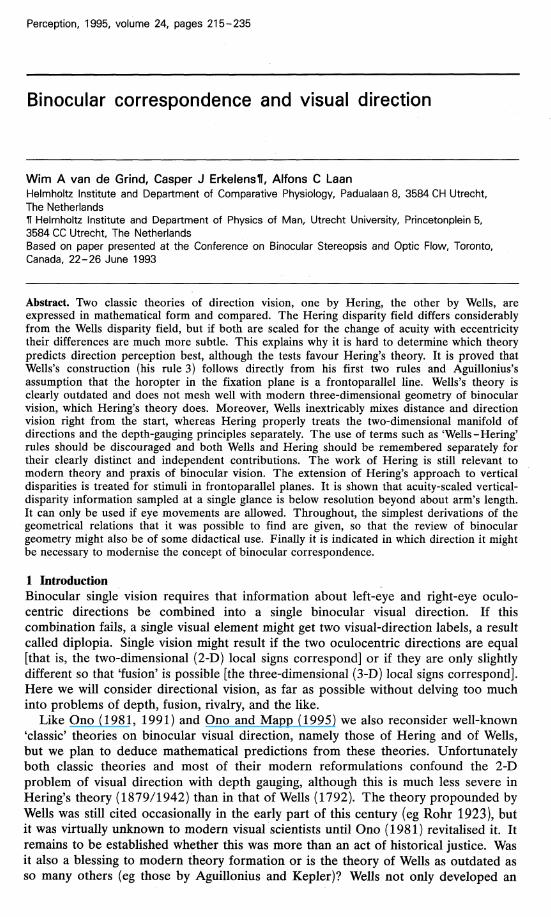
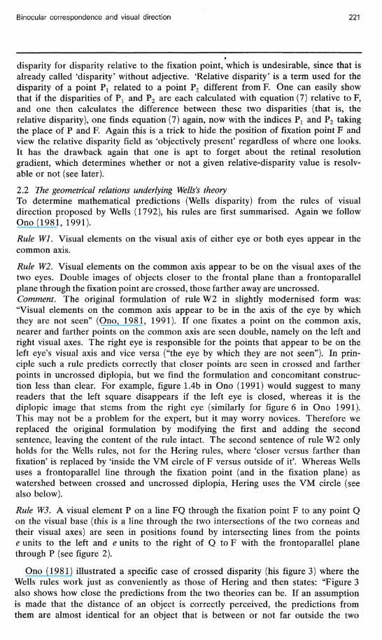
Figure 1 illustrates the application of rule H4b to diplopic images (PL and PR) of a given element P inside the VM circle for a given fixation point F. The images PL and PR are assumed to be farther apart than Panum's fusional range and not to be suppressed. Although the double images are drawn on the VM circle, the above five Hering rules only define their cyclopean visual directions (along lines radiating from C under angles aR and aL with the cyclopean fixation direction cp) not their apparent distance from the nodal point C of the cyclopean eye. Left-eye and right-eye nodal
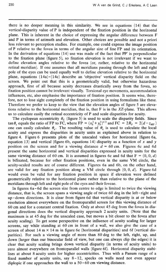
Figure 1. Geometry of Hering's rules of visual direction. Point F is bifixated, point P is a fiducial point inside (as drawn) or outside the Vieth-Muller (VM) circle through the nodal points of the right eye, R, and the left eye, L. The centre of the VM circle is M (0, zF), its radius RF, C is the cyclopean vantage point, e is half the interocular distance, cp the cyclopean fixation direction, aL and aR are the monocular directions of P relative to F that are transferred to the cyclopean eye. Hering disparity, A a, is the difference between these monocular directions. Other symbols are explained in the text.
Binocular correspondence and visual direction 219
points, L and R, are situated at ( - e , 0) and [e, 0), respectively. The coordinates of the fixation point F, (%, zF ), and of some arbitrary visual element P, {xF, zF), are assumed to be given. The coordinates of the nodal point of the cyclopean eye C can be seen to be (0, Z M F ~ ^ F ), where zMF is the coordinate of the centre of the VM circle (on the Z-axis) and RF is the radius of the VM circle through fixation point F (figure 1). Since the angle CMR equals 2yF (like CFR it spans arc CR but from the centre of the circle rather than from its circumference) one easily verifies that
ZMF = ̂ kr (1)
We then find from the circle equation xF+(zF-zMF)2 = RF and the Pythagorean relation RF = e2 + ZMF
Zu* = Z*+f~e\ (2) lZF
so with equation (1)
2#z tan(2yF) = 2 * 2. (3)
Zp • XF €
Note that if we draw a circle through P, L, and R we can write the same three relations with the index P rather than F. This will prove useful below. Angles are represented by Greek letters, line lengths and distances by small roman letters, points by capital letters, and lines connecting point A and B as AB.
The common axis, that is, the visual axis of the cyclopean eye, CF, then makes an angle cp with the Z-axis. If one draws a line from M to F in figure 1, the angle between this line and the positive Z-axis equals 2 cp (it spans the same arc as between CF and the Z-axis, but from the centre of the circle rather than from its circumference). Thus tan(2<p) can directly be seen to equal xFj{zF-zMF), which together with equation (2) leads to
tan(2y) - 2 2X\Z* 2 • (4)
zF-xF + e Equation (3) for yF constant is the equation of the VM circle, the locus of constant vergence, equation (4) with cp constant describes the Hillebrand hyperbolae, loci of constant cyclopean direction. Equations (3) and (4) also give us the transformation from Cartesian coordinates xF, ZF to angular (Hering) coordinates y and cp.
The visual directions of PL and PR can be determined with Hering's rule 4b by measuring the angles between the visual axes LF or RF and the visual lines LP in the left eye and RP in the right eye, respectively. These angles, aL and aR respectively, are then transferred to the cyclopean eye to predict the directions of the double images PL and PR. The lines CPR and CPL are the predicted direction lines according to Hering's theory and for this arbitrary configuration of F and P we get the general prediction of visual directions relative to the fixation direction cp from Hering's rules as:
lxF + e\ xF + e\ ,_x
aL = arctan - arctan (5) \ z* \ Z* I
aR = arctan - arctan — J (6)
The angular distance between the two images, Aa, is of course a very important variable, usually called the disparity. This 'disparity' can be viewed as a direct measure of the 'amount of diplopia' that would be experienced if Panum's fusional
220 W A van de Grind, C J Erkelens, A C Laan
limit were zero. Binocular disparity is a relevant concept independent of fusion, depth perception, and stereopsis; it was originally a concept of direction vision! According to Hering the disparity must be the difference between the angles of equations (5) and (6). This Hering disparity will be called AaH and we will proceed to compare it with the amount of diplopia according to Wells, Aa w (Wells disparity). Hering disparity conforms to the usual definition of disparity, Wells disparity does not (see below). As a final point, note that the right-eye image is seen to the left and vice versa (crossed disparity) if P is situated inside the VM-circle, as drawn, and that there is a conjugated point outside the VM circle leading to the same double image position if the values of aL and aR are interchanged. In that case closing the right (left) eye eliminates the right (left) image of the pair: uncrossed disparity. To give the disparity AaH the proper sign (by convention, negative for crossed disparity) one has to subtract the larger from the smaller angle if point P is inside the VM circle. One can just as well define the disparity of P relative to F as the difference between the top angles at F andP between each of the pairs of heavy lines in figure 1. Since the opposite angles at point H of the triangles PHL and FHR are equal, we see that aL + 2yP = aR + 2yF or AaH = aL~ aR = 2yF-2yF. This redefinition of disparity as a difference of top angles always has the proper sign. It is convenient to work with the notation as indicated, with half the interocular distance and half the mentioned top angles as units, since it simplifies most formulae on bicentric perspective (eg Koenderink 1992). In our opinion the most convenient way to express horizontal disparity, which is the Hering disparity, is as follows:
AaH = arctan (7a)
2 2 2
xF+zF-e *MF = Z , ( 7 b )
2zF
ZMP = z , (7c)
where zMF and zMP denote the z-coordinates of the centres of VM circles through F and through P, respectively (compare with equation 2). Note that the VM circles are in general not treated as 'horopters' (loci of single vision) in our exposition, merely as circles through an external point (here either P or F) and the nodal points of the eyes. Let us call such a circle through an arbitrary point P the VM circle ofP and the one through F (fixation point) the VM-fixation circle or simply the VM-circle of F. Equation 7a follows from tan(AaH) = tan(2yF-2yP) , by writing this in terms of the separate tangents, which can be determined directly from the figure as tan(2yF) = e/zMF and tan(2yP) = e/zMF. This straightforward derivation of a formula for disparity is in our view simpler than the one given by Cormack and Fox (1985).
When zF goes to infinity (JCF finite), that is, in practice, while one looks at the horizon, the second terms in the expressions (5) and (6) go to zero and the remaining terms are the monocular directions of P relative to straight ahead. The difference of these two angles is sometimes called the 'absolute' disparity of fiducial element P. In terms of equation (7) we then see that zMF goes to infinity, so that the absolute disparity of P equals arctan( - e/zMJ>). At infinity the absolute disparity of a point is zero. We are not too fond of the concept of absolute disparity, since it invites one to forget about the position of the eyes and the retinal distance from the fovea of the image of the fiducial visual element. This distance has very important consequences for vision, since acuity changes drastically with distance from the fovea. The eye carries with it a 'resolution' gradient field and it is important how this field is positioned relative to our fiducial points. Other authors have used the term 'absolute'
disparity for disparity relative to the fixation point, which is undesirable, since that is already called 'disparity' without adjective. 'Relative disparity' is a term used for the disparity of a point F1 related to a point P2 different from F. One can easily show that if the disparities of Px and P2 are each calculated with equation (7) relative to F, and one then calculates the difference between these two disparities (that is, the relative disparity), one finds equation (7) again, now with the indices P t and P2 taking the place of P and F. Again this is a trick to hide the position of fixation point F and view the relative disparity field as 'objectively present' regardless of where one looks. It has the drawback again that one is apt to forget about the retinal resolution gradient, which determines whether or not a given relative-disparity value is resolvable or not (see later).
2.2 The geometrical relations underlying Wells's theory To determine mathematical predictions (Wells disparity) from the rules of visual direction proposed by Wells (1792), his rules are first summarised. Again we follow Ono(1981, 1991).
Rule Wl. Visual elements on the visual axis of either eye or both eyes appear in the common axis.
Rule W2. Visual elements on the common axis appear to be on the visual axes of the two eyes. Double images of objects closer to the frontal plane than a frontoparallel plane through the fixation point are crossed, those farther away are uncrossed. Comment. The original formulation of rule W2 in slightly modernised form was: "Visual elements on the common axis appear to be in the axis of the eye by which they are not seen" (Ono, 1981, 1991). If one fixates a point on the common axis, nearer and farther points on the common axis are seen double, namely on the left and right visual axes. The right eye is responsible for the points that appear to be on the left eye's visual axis and vice versa ("the eye by which they are not seen"). In principle such a rule predicts correctly that closer points are seen in crossed and farther points in uncrossed diplopia, but we find the formulation and concomitant construction less than clear. For example, figure 1.4b in Ono (1991) would suggest to many readers that the left square disappears if the left eye is closed, whereas it is the diplopic image that stems from the right eye (similarly for figure 6 in Ono 1991). This may not be a problem for the expert, but it may worry novices. Therefore we replaced the original formulation by modifying the first and adding the second sentence, leaving the content of the rule intact. The second sentence of rule W2 only holds for the Wells rules, not for the Hering rules, where 'closer versus farther than fixation' is replaced by 'inside the VM circle of F versus outside of it'. Whereas Wells uses a frontoparallel line through the fixation point (and in the fixation plane) as watershed between crossed and uncrossed diplopia, Hering uses the VM circle (see also below).
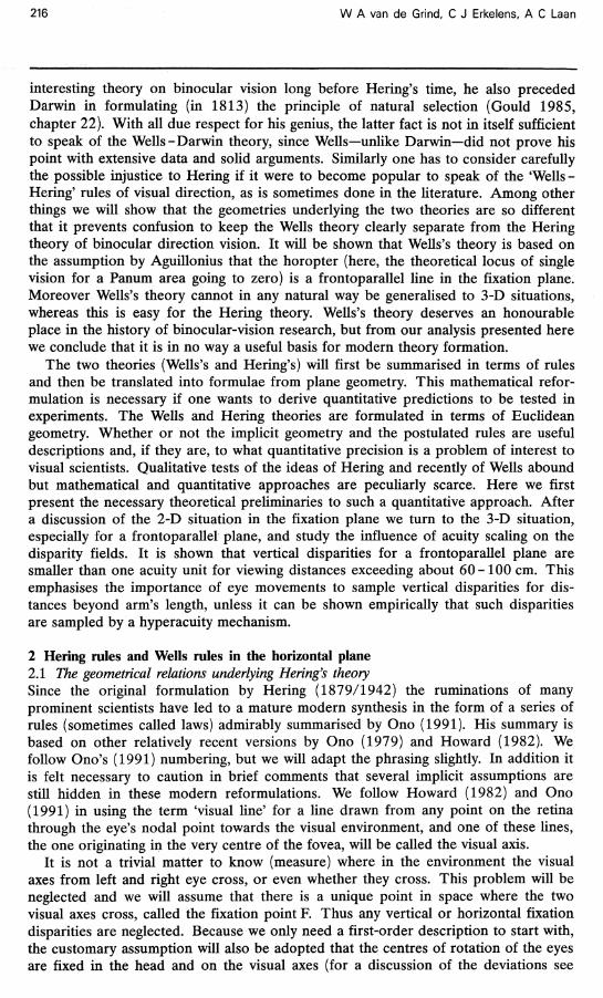
Rule W3. A visual element P on a line FQ through the fixation point F to any point Q on the visual base (this is a line through the two intersections of the two corneas and their visual axes) are seen in positions found by intersecting lines from the points e units to the left and e units to the right of Q to F with the frontoparallel plane through P (see figure 2).
Ono (1981) illustrated a specific case of crossed disparity (his figure 3) where the Wells rules work just as conveniently as those of Hering and then states: "Figure 3 also shows how close the predictions from the two theories can be. If an assumption is made that the distance of an object is correctly perceived, the predictions from them are almost identical for an object that is between or not far outside the two
optic axes. They differ, however, in that Hering used hypothetical constructs, whereas Wells did not" (page 404). The latter statement is a matter of taste, of course. One does not need to accept the metaphorical language of Hering to use his rules. Obviously, terminology apart (cyclopean eye!), Hering's rules are merely ruler and compass instructions, just like the rules of Wells. Wells sticks to the stimulus domain and only allows the visual base, a line touching the corneas, to represent the subject. However, to get away with this he needs the hidden assumption that double images are always seen at the same specific z-distance as the visual element that gives rise to them. In the above citation Ono correctly recognises this problem, but then unjustly adds this awkward assumption to Hering's theory. It is precisely this kind of assumption that does not fit into a theory of direction vision, and it was correctly avoided by Hering. Another subltety in the citation from Ono is hidden in the word 'can'. As we will see below, the predictions can just as well be called 'clearly different in most cases'. For example, the positions of Hering's double images are always strongly different (even in the situation illustrated in figure 3 of Ono 1981) if the double images determined with Hering's rules are placed on the VM circle of F, rather than on a frontoparallel line through P. Placing diplopic images on the VM circle of F is more in line with the interpretation of this circle as a binocular reference line, at the 'default distance', and fits with the rest of Hering's theory of binocular vision (not included in rules H 1 - H 5 , but expounded in Hering's book). We do not assume a specific distance for Hering's double images and since the rules are about direction vision we will only use the angular predictions mentioned above.
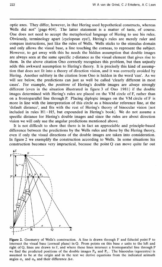
It is not difficult to show that there is in fact an appreciable and principle-based difference between the predictions by the Wells rules and those by the Hering theory, even if only the visual directions of the double images are taken into consideration. In figure 2 we exemplify the construction according to Wells. In some situations his construction becomes very impractical, because the point Q can move quite far out
Figure 2. Geometry of Wells's construction. A line is drawn through F and fiducial point P to intersect the visual base (corneal plane) in Q. From points on this base e units to the left and right of Q, lines are drawn to F, and where these lines intersect a frontoparallel line through P we find the predicted positions of the double images PR and PL . The binoculus (egocentre) is assumed to be at the origin and in the text we derive equations from the indicated azimuth angles aL and aR and their difference Aa.
Binocular correspondence and visual direction 223
along the visual base to the right or left if P and F are almost equally far from the observer. It is in fact much simpler to describe his construction in terms of plane analytic geometry than to carry it out for other than the simplest of choices for P and F.
One of the obvious shortcomings of the rules by Wells is the lack of a clear definition of an egocentric position. We have followed Ono (1981, 1991) in assuming that it is the point midway between the nodal points of the two eyes and in neglecting the slight difference between the positions of Hering's X-axis (through the nodal points) and Wells's X-axis (through the points on the corneae where they are pierced by the visual axes). Hering was much more explicit in positioning his cyclopean eye on the VM circle as drawn in figure 1. With the position of the Wells binoculus as in figure 2 it becomes easy to see how Wells might have intuited his third rule from the first two, an outdated horopter assumption, and a geometric invariance. With F ' and P' the projections on the Z-axis of F and P respectively (figure 2) we see that as long as F and P stay on the same frontoparallel lines we will always have the following invariant equality of ratios (line PRP):e = (lineFP'):zF, and the same holds for line PPL. Thus if we define
A = ^ ^ , (8)
where A < 0 corresponds to Wells 'crossed' disparity and A > 0 to Wells uncrossed disparity, we see immediately that the distance between PR and PL always equals 2\A\e and that P is always in the middle between the double images. As a consequence we have the x-coordinates of the double images as x? + Ae (for PR in figure 2) and xv — Ae (for PL in figure 2), respectively. This makes it possible to determine the direction angles from inspection of figure 2 as
cp = arctan — , (9)
/ xP + Ae \ aR = -w + arctan ,
( xP - Ae | .
z? I
(10)
(11)
If desired, these formulae can be corrected for the original choice of X-axis as defined in Wells's rule 3 as just touching the corneae. In that case one calculates the upward shift of the X-axis according to Wells and subtracts this z-shift from the values of zF
and zP in the above formulae. As already mentioned, Wells disparity Aaw is defined as the difference between the two angles of equations (10) and (11), respectively. After combining the arctangents and some rearrangement one then arrives at the following expression for Wells disparity:
Aaw = arctan 2 2 _ 2 2 . (12) \ Xp i £p J\. £ J
For infinite fixation distance cp — 0 and A -+ - 1 , so equations (10) and (11) give the same limiting result as equations (5) and (6). The 'absolute' Wells disparity of a single fiducial element P thus equals the 'absolute' Hering disparity of that same element.
Equation (12) shows that Wells disparity is independent of %, and that A, the 'depth modulation' of P relative to the fixation point [equation (8)] is the most important parameter. For zp < zF parameter^ is negative and thus Wells disparity is negative, for zP = zF the depth modulation A is zero, so Aa w = 0. According to Wells there can be no diplopia in a frontoparallel line through the fixation point.
In fact the Wells construction of rule 3 will now be shown to follow directly from his first two rules and the assumption that the horopter is a frontoparallel line. The simple geometric invariance explained above, that the distance between the double images is constant for a constant A, namely equal to 2\A\e, if the fixation point F and the fiducial point P each stay on their own frontoparallel lines, makes this clear. To see this even more vividly assume for a moment that F' on the Z-axis is fixated and that P', also on the Z-axis (figure 2) is the fiducial point. Then PL and PR
are on the frontoparallel line /p, through P, where this line intersects the visual axes (LF' and RF'), as follows from rule W2. However, as we have just seen, wherever one chooses F in /F (the frontoparallel line through F' andF), PL and PR will always be on /P and ±Ae units from P. Moreover, one can bodily shift the whole construction of figure 2 to the right or left away from the Z-axis without changing these relations. This simple geometric consideration and the a priori assumption of the frontoparallel horopter may have given Wells the idea for his third rule, which would otherwise seem like a rather weird ad hoc proposal. The a priori assumption that the 'horopter' in the fixation plane is a frontoparallel line was the preconception at least from Aguillonius onward (Rohr 1923), and together with rules Wl and W2 it necessarily— for geometric reasons—leads to Wells's third rule.
Thus we have just shown that the first two rules of Wells, plus the assumption that the horopter is a frontoparallel line must lead to the third rule of Wells, because of the described simple geometric invariant. Wells was therefore not much ahead of Aguillonius! His theory, as described by Ono (1981), rests on two new explicit rules (rule 1 and 2). Wells's third rule rests on the same (wrong) assumption of a frontoparallel horopter that was so eloquently described by Aguillonius at the beginning of the seventeenth century (see Rohr 1923). Hering (1879/1942) treats rules similar to rules Wl and W2 (eg rule H4a above) without citing Wells, but also without claiming authorship or originality in this respect. It may be worthwhile to analyse the origin of these two assumptions. Ono (1981, page 405), for example, states that Smith (1738) had already shown that an elongated object positioned on the common axis appears on the visual axes (rule W2!). Wells's work should therefore be viewed as a continuation of the strong tradition of Aguillonius and Smith.
2.3 Comparison of the Hering and Wells geometries of direction vision If the reader wants to check that the horopter (here, the locus of absence of diplopia) is not a frontoparallel line we recommend the following experiment. Place two pins in a support, one straight ahead viewed from about 15 cm and the other about 10 cm from the first in a frontoparallel line. One will probably see the latter pin double if the contrast between pins and background is sufficient and if the observer is practised in noticing diplopia. Although this qualitatively falsifies one prediction from the third rule of Wells, the discrepancy is subjectively difficult to see and thus appears small, perhaps even as small as the potential deviations from Hering's theory. Thus we need to probe deeper and ask why the differences in the geometric predictions, which can be substantial as we will illustrate below, are less than obvious perceptually.
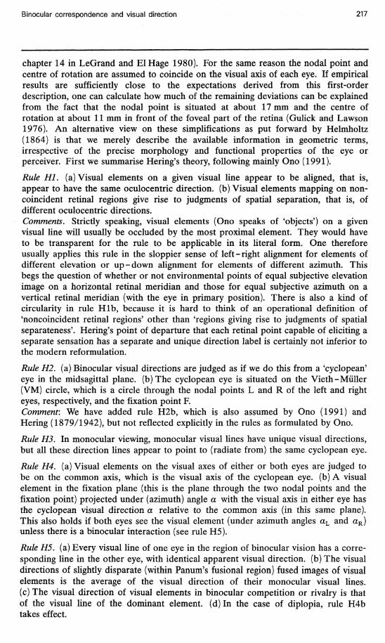
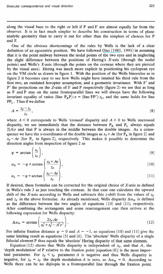
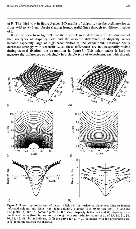
Figure 3 illustrates the differences between predictions based on Wells's theory, which we called 'Wells disparity' and predictions from Hering's theory. The left-hand column shows a Hering disparity field, calculated for a fixation position xF = 0 cm, zF = 30 cm, and a value for half the interocular distance, e = 3.25 cm. The right-hand column gives corresponding views of the Wells disparity field for the same parameters. The x-coordinate of point P, xP, varies from - 4 5 to +45 cm in all six panels, the z-coordinate from 15 to 60 cm in the 3-D plot (figures 3a and 3b) and from 15 to 105 cm in the contour plots (figures 3c and 3d). The latter choice makes it easier to see that equidisparity lines are circles according to Hering, the VM circles
of P. The third row in figure 3 gives 2-D graphs of disparity (on the ordinate) for xP
from - 4 5 to +45 cm (abscissa) along frontoparallel lines through ten different values of zP.
It can be seen from figure 3 that there are clearcut differences in the structure of the two types of disparity field and the absolute differences in disparity values become especially large at high eccentricities in the visual field. However acuity decreases strongly with eccentricity, so these differences are not necessarily visible during central fixation, the assumption in figure 3. This might make it hard to measure the differences convincingly in a simple type of experiment, say with threads
Figure 3. Three representations of disparity fields in the horizontal plane according to Hering (left-hand column) and Wells (right-hand column). Fixation is at 30 cm (see text), (a) and (b) 3-D plots; (c) and (d) contour plots of the same disparity fields; (e) and (f) disparity as a function of the xP (from bottom to top along the central axis) for values of zP of 15, 18, 21, 24, 30, 36, 42, 48, 54, and 60 cm. In (f) the curve for zP = 30 coincides with the horizontal axis, in (e) it merely touches the abscissa.
W A van de Grind, C J Erkelens, A C Laan
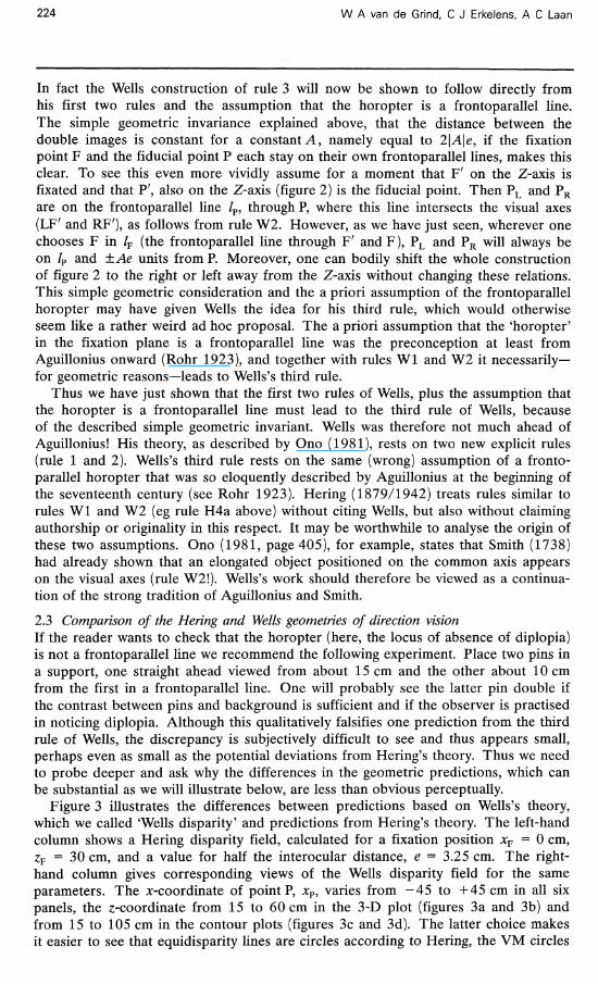
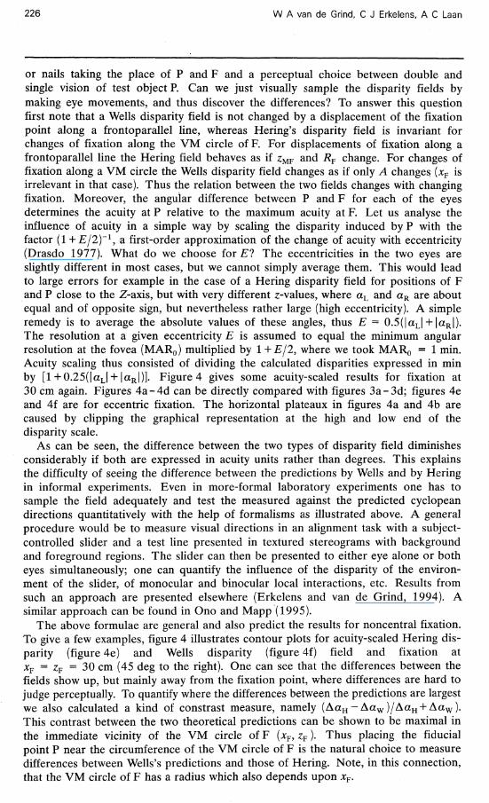
or nails taking the place of P and F and a perceptual choice between double and single vision of test object P. Can we just visually sample the disparity fields by making eye movements, and thus discover the differences? To answer this question first note that a Wells disparity field is not changed by a displacement of the fixation point along a frontoparallel line, whereas Hering's disparity field is invariant for changes of fixation along the VM circle of F. For displacements of fixation along a frontoparallel line the Hering field behaves as if zMF and RF change. For changes of fixation along a VM circle the Wells disparity field changes as if only A changes (% is irrelevant in that case). Thus the relation between the two fields changes with changing fixation. Moreover, the angular difference between P and F for each of the eyes determines the acuity at P relative to the maximum acuity at F. Let us analyse the influence of acuity in a simple way by scaling the disparity induced byP with the factor (1 + E/2)'1, ^ first-order approximation of the change of acuity with eccentricity (Drasdo 1977). What do we choose for El The eccentricities in the two eyes are slightly different in most cases, but we cannot simply average them. This would lead to large errors for example in the case of a Hering disparity field for positions of F and P close to the Z-axis, but with very different z-values, where aL and aR are about equal and of opposite sign, but nevertheless rather large (high eccentricity). A simple remedy is to average the absolute values of these angles, thus E = 0.5(|aL| + |aR |). The resolution at a given eccentricity E is assumed to equal the minimum angular resolution at the fovea (MAR0) multiplied by 1 +E/2, where we took MAR0 = 1 min. Acuity scaling thus consisted of dividing the calculated disparities expressed in min by [1+ 0.25(|aL| +1aR|)]. Figure 4 gives some acuity-scaled results for fixation at 30 cm again. Figures 4a -4d can be directly compared with figures 3a-3d; figures 4e and 4f are for eccentric fixation. The horizontal plateaux in figures 4a and 4b are caused by clipping the graphical representation at the high and low end of the disparity scale.
As can be seen, the difference between the two types of disparity field diminishes considerably if both are expressed in acuity units rather than degrees. This explains the difficulty of seeing the difference between the predictions by Wells and by Hering in informal experiments. Even in more-formal laboratory experiments one has to sample the field adequately and test the measured against the predicted cyclopean directions quantitatively with the help of formalisms as illustrated above. A general procedure would be to measure visual directions in an alignment task with a subject-controlled slider and a test line presented in textured stereograms with background and foreground regions. The slider can then be presented to either eye alone or both eyes simultaneously; one can quantify the influence of the disparity of the environment of the slider, of monocular and binocular local interactions, etc. Results from such an approach are presented elsewhere (Erkelens and van de Grind, 1994). A similar approach can be found in Ono and Mapp (1995).
The above formulae are general and also predict the results for noncentral fixation. To give a few examples, figure 4 illustrates contour plots for acuity-scaled Hering disparity (figure 4e) and Wells disparity (figure 4f) field and fixation at xF = zF = 30 cm (45 deg to the right). One can see that the differences between the fields show up, but mainly away from the fixation point, where differences are hard to judge perceptually. To quantify where the differences between the predictions are largest we also calculated a kind of constrast measure, namely ( A a H - Aa w ) /Aa H + Aa w ) . This contrast between the two theoretical predictions can be shown to be maximal in the immediate vicinity of the VM circle of F (%, zF). Thus placing the fiducial point P near the circumference of the VM circle of F is the natural choice to measure differences between Wells's predictions and those of Hering. Note, in this connection, that the VM circle of F has a radius which also depends upon xF.
We have conducted many experiments with nails and needles placed at several positions along such a circle, and found that the results are always close to the predictions from Hering's approach, also in the monocular regions blocked from contralateral viewing by the bridge of the nose (Mapp and Ono 1986). This should not be construed as definitive support for Hering's theory as a description of perception.
(e) Xp/cm (f) Xp/cm
Figure 4. Acuity-scaled disparity fields according to Hering (left-hand column) and Wells (right-hand column), (a) and (b) are the acuity-scaled versions (disparity in acuity units) of figures 3a and 3b. It can be seen that scaling eliminates resolvable disparity almost everywhere except close to a central ridge/valley. The horizontal plateaus are merely due to clipping of the range of the vertical axis, (c) and (d) are the corresponding contour plots. It is clear that the difference between the Hering field [(a), (c), and (e)] and the Wells field [(b), (d), and (f)] is much more subtle once the retinal acuity gradient has been taken into account, (e) and (f) show the situation for noncentral fixation, viz at 45 deg to the right. Fixation (in cm) is at (0, 30) in (a)-(d), but at (30, 30) in (e) and (f).
Many deviations are known and several will no doubt be quantified in the years to come (eg Erkelens and van de Grind 1994). However, the geometrical description that flows from Hering's rules is the most useful and convenient first-order description available today. It enables one to define and quantify 'deviations' conveniently, that is, differences between perceptual findings and expectations based on this geometry. Hering's theory, unlike the one by Wells, easily allows extension to the 3-D situation (see below), and as such it is the modern 'default' description implicit in most literature on the subject. Any mixture with the theory of Wells can only confuse the issue. They are clearly separate theories with different underlying ideas and geometries.
3 Critical assessment of the Wells theory Wells's theory of binocular direction vision makes the wrong prediction that there cannot be diplopia in a frontoparallel plane and it leads to wrong predictions of mislocalisations of points, for example, chosen along a VM circle. In rule 3 of Wells it is assumed that double images are seen in a frontoparallel line through the target, whereas in most literature on the matter it is suggested that double images are seen on or close to the VM circle, if their distance can be estimated at all. Wells's theory leads to an unconventional definition of horizontal disparity and thus does not easily connect with the rest of the literature on binocular vision, double, single, or otherwise. The direction of double images can only be determined from an inherent assumption about their distance in Wells's theory, which thus does not adequately decouple distance and direction vision. Wells failed to indicate clearly the position of the egocentre from which direction lines appear to point outwards, like the cyclopean eye in Hering's theory. The Wells approach does not allow easy generalisation to elevations other than zero, while the Hering ideas blend in naturally with any general geometric approach (see below). Thus it seems reasonable to conclude that Wells's theory, however impressive in its time, is now exclusively of historical interest.
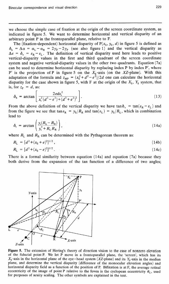
4 On vertical disparities in a frontoparallel plane and visual resolution The beauty of the Helmholtz - Hering approach lies in the vantage-point-centered geometry, with a clear definition of the egocentre for direction vision and a decoupling of direction vision and depth vision. All this is missing in the Wells approach, which must have already seemed old-fashioned 150 years ago, by the time of the rising popularity of the Vieth-Muller construction. The definition of geometric correspondence in terms of equal oculocentric directions in a fixation plane allows a simple generalisation to the 3-D situation. Helmholtz (1864) did just that, by using equal elevation and equal azimuth as his geometric-correspondence criterion and calculating the locus of nondiplopic vision from that assumption (in fact he also took into account the empirically discovered shear in retinal correspondence, but we neglect such second-order effects here). Here we consider the special case of fiducial elements P in a frontoparallel plane, since such planes are so often used in experimental studies of binocular vision. With the help of figure 5 one can easily analyse the geometry of the situation.
We have chosen an Xs, Ys coordinate system on the screen in such a way that its origin is on the observer's Z-axis (head in primary position, XZ-plane horizontal) at a distance d (figure 5). Since the point P' of the vertical from P on the fixation plane is used to calculate horizontal disparity (see below), figure 1 can be used (with P' replacing?) to treat the general case of fixation F anywhere in the horizontal plane and P anywhere on a vertical plane, placed at any distance d. The determination of vertical disparity is also simple for the general case of arbitrary fixation position in the horizontal plane. However, since we also want to scale for the retinal acuity gradient,
Binocular correspondence and visual direction 229
we choose the simple case of fixation at the origin of the screen coordinate system, as indicated in figure 5. We want to determine horizontal and vertical disparity of an arbitrary point P in the frontoparallel plane, relative to F.
The (fixation-dependent) horizontal disparity of P(xs, ys, d) in figure 5 is defined as dh = A a = aL-aR = 2yF-2yF (see also figure 1) and the vertical disparity as As = dy = £ R - £ L . The definition of vertical disparity used here leads to positive vertical-disparity values in the first and third quadrant of the screen coordinate system and negative vertical-disparity values in the other two quadrants. Equation (7a) can be used to determine horizontal disparity by replacing index P by index P', where P' is the projection ofP in figure 5 on the Xs-axis (on the XZ-plane). With this adaptation of the formula and zMP = (x$+ d2-e2)j2d one can calculate the horizontal disparity for the case shown in figure 5, with F at the origin of the Xs, YS system, that is, for zF = d, as:
dh = arctan ledx:
x2Ad2- •el) + (dz + ezY (13)
From the above definition of the vertical disparity we have tan5v = tan(£R-£L) and from the figure we see that taneR = ys/RR and tan(eL) = )>S/^L> which in combination lead to
(1 = arctan y s ( # L - # R )
where RL and RR can be determined with the Pythagorean theorem as:
RL ={d2 + (xs + ef]1/2,
RL =[d2 + (xs-ef] ,211/2
(14a)
(1.4b)
(14c)
There is a formal similarity between equation (14a) and equation (7a) because they both derive from the expansion of the tan function of a difference of two angles;
X-axis
Figure 5. The extension of Hering's theory of direction vision to the case of nonzero elevation of the fiducial point P. We let P move in a frontoparallel plane, the 'screen', which has its Xs-axis in the horizontal plane of the eye-head system (ZZ-plane) and its Ys-axis in the median plane, and determine the vertical disparity (difference of the monocular elevation angles) and horizontal disparity field as a function of the position of P. Bifixation is at F, the average retinal eccentricity of the image of point P relative to the fovea is the cyclopean eccentricity 0C, used for purposes of acuity scaling. The other symbols are explained in the text.
230 W A van de Grind, C J Erkelens, A C Laan
there is no deeper meaning in this similarity. We see in equations (14) that the vertical-disparity value of P is independent of the fixation position in the horizontal plane. This is inherent in the choice of expressing the angular difference between F and P in terms of azimuth and elevation. Other choices are possible and not a priori less relevant to perception studies. For example, one could express the image position of P relative to the fovea in terms of the angular size of line FP and its orientation. In the derivation of equations (14) use was made of the fact that PP' is perpendicular to the fixation plane (figure 5), so fixation elevation is not irrelevant if we want to define elevation angles relative to the fovea (or, rather, relative to the horizontal retinal meridian). If one assumes that all meridians passing through the left and right pole of the eyes can be used equally well to define elevation relative to the horizontal plane, equations (14a)-(14c) describe an 'objective' vertical disparity field on the screen. We point out that this is a geometrically valid, but otherwise hazardous approach, first of all because acuity decreases drastically away from the fovea, so fixation position cannot be irrelevant visually. Torsional eye movements, accommodation influences, etc, also emphasise the importance of fixation position. It seems wise, therefore, not to lose sight completely of the fixation position in using formalisms like these. Therefore we prefer to keep to the view that the elevation angles of figure 5 are elevations relative to the horizontal meridian, that is, that F is in the XZ-plane. This allows us to calculate easily the retinal eccentricity of P and scale disparities for acuity.
The cyclopean eccentricity 0C (figure 5) is used to scale the disparity fields. Since tan0c equals the ratio of FP to FC, where FP = (xs
2 + ys2)1/2 and FC = 2RF = 2(d~zMF)
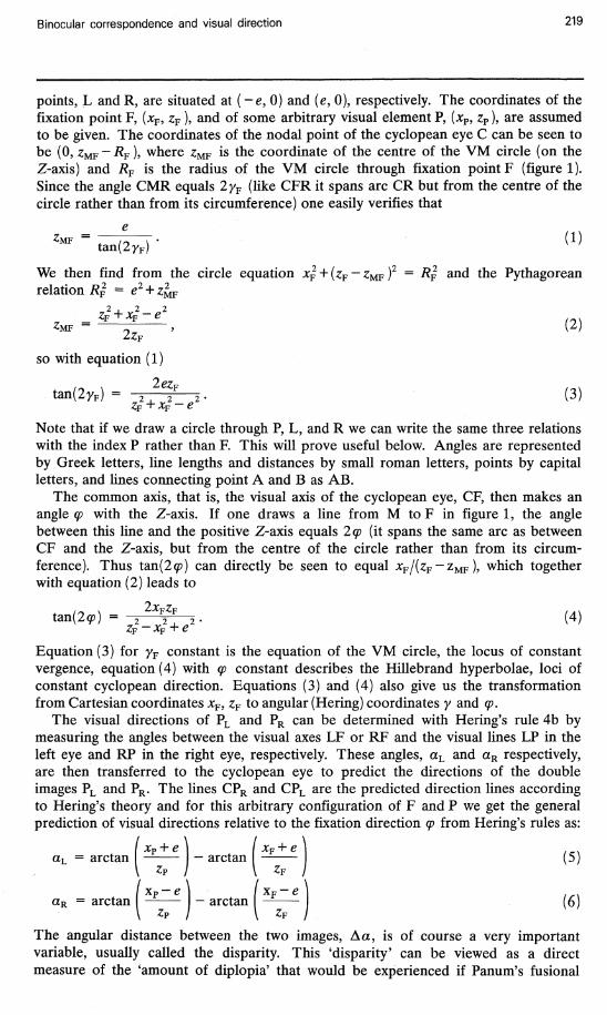
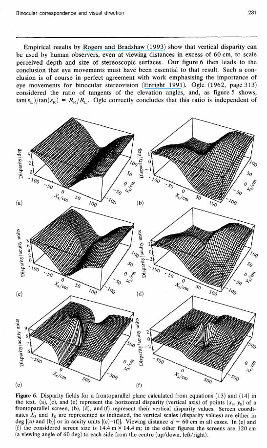
one can easily calculate 0C. The resulting value of 0C is used to calculate the local acuity and express the disparities in acuity units as explained above in relation to figure 4. Figure 6 presents plots of the unsealed values for horizontal (figure 6a, equation 13) and vertical (figure 6b, equations 14) disparity as a function of x and y position on the screen and for a viewing distance d = 60 cm. Figures 6c and 6d present the same horizontal and vertical disparities expressed in acuity units for the same viewing distance of 60 cm. It is assumed in figures 6c and 6d that F = (0, 0, d) is bifixated, because for other fixation positions, even in the same VM circle, the acuity-scaled results are of course different. Figures 6a and 6b, on the other hand, are valid for any fixation position along a VM circle through (0, 0, d). Figure 6d would even be valid for any fixation position in space if elevation were defined geometrically relative to the horizontal plane rather than relative to the plane of the meridians through left and right pole of the eyes and their foveae.
In figures 6a-6d the screen size from centre to edge is limited to twice the viewing distance, that is, the screen spans a viewing angle of twice 60 deg in the left-right and up - down directions. It is clear from figure 6d that vertical disparity is at or below resolution almost everywhere on the frontoparallel screen for this viewing distance of 60 cm and for a constant central fixation. Only at about 45 deg from the fovea in diagonal directions does the vertical disparity approach 2 acuity units. (Note that the maximum is at 45 deg for the unsealed case, but moves a bit closer to the fovea after acuity scaling). To get some perspective on the influence of acuity scaling for larger screens, say while standing at 60 cm in front of a wall, we also give the case of a screen of about 14 m x 14 m in figure 6e (horizontal disparities) and 6f (vertical disparities). For such a viewing angle of more than 80 deg to the left, right, up, and down (larger than our binocular field of view, but one can always clip the edges) it is clear that acuity scaling brings down vertical disparity (in terms of acuity units) to zero almost everywhere on frontoparallel walls (figure 6f). Horizontal disparity stabilises at about 8 acuity units for higher eccentricities. Thus with a Panum range of a fixed number of acuity units, say 8-12, specks on walls need not even appear diplopic if one approaches the wall to a 50-60 cm viewing distance.
Binocular correspondence and visual direction 231
Empirical results by Rogers and Bradshaw (1993) show that vertical disparity can be used by human observers, even at viewing distances in excess of 60 cm, to scale perceived depth and size of stereoscopic surfaces. Our figure 6 then leads to the conclusion that eye movements must have been essential to that result. Such a conclusion is of course in perfect agreement with work emphasising the importance of eye movements for binocular stereovision (Enright 1991). Ogle (1962, page 313) considered the ratio of tangents of the elevation angles, and, as figure 5 shows, tan(eL)/tan(eR) = RR/RL. Ogle correctly concludes that this ratio is independent of
(e) (f)
Figure 6. Disparity fields for a frontoparallel plane calculated from equations (13) and (14) in the text, (a), (c), and (e) represent the horizontal disparity (vertical axis) of points (xs,ys) of a frontoparallel screen, (b), (d), and (f) represent their vertical disparity values. Screen coordinates Xs and Ys are represented as indicated, the vertical scales (disparity values) are either in deg [(a) and (b)] or in acuity units [(c)-(f)]. Viewing distance d = 60 cm in all cases. In (e) and (f) the considered screen size is 14.4 m x 14.4 m; in the other figures the screens are 120 cm (a viewing angle of 60 deg) to each side from the centre (up/down, left/right).
the distance of the fiducial point P above the horizontal plane (figure 5). Rogers and Bradshaw (1993) independently introduced Ogle's ratio and called it the 'vertical size ratio'. To see how their formula follows from Ogle's ratio, RQ, use equations (14b) and (14c), define angle a with Rogers and Bradshaw as the angle between the Z-axis and a line from the origin (of the XYZ-system) to P', so that xs = d tan(a), and one gets by using l+ tan 2 (a ) = l/cos2(a):
2 _ e2 + 2detan(a) + d /cos (a)
e —2detan(a) + d /cos (a)
(Rogers and Bradshaw call azimuth e rather than a, 2e is called IOD, and d is called D). One should be careful in using this ratio, because it is independent of the values of ys and only depends on xs, as Ogle (1962) and Rogers and Bradshaw (1993) state explicitly and as the derivation in combination with figure 5 clarifies. This means that the ratio can be equally large for a nanometer-sized object and a kilometer-sized object at equal viewing distance. In view of the importance of acuity in resolving details of images we recommend the use of the 'raw' vertical disparity rather than the vertical size ratio, and a definition of elevation relative to the plane of the horizontal retinal meridian, rather than relative to a reference plane defined independent of eye position. This idea is of course not original to us. Ogle (1962, page 313) calculates vertical disparity values (his table III), notes that vertical disparities increase very rapidly with horizontal distance from fixation, and then clearly warns us that the resolution gradient and the increase of Panum's area with eccentricity (relative to the fovea) should be taken into account. Technical progress since Ogle's time has made it possible to visualise these insights in a more attractive way (figure 6) with less effort, but obviously we do not wish to claim originality with respect to the underlying geometric insights.
This section was meant to indicate how easily the Helmholtz-Hering approach generalises to cases including elevation differences. It is much harder to see how Wells's ideas might be generalised to such cases. If one assumed in the spirit of Wells that the whole frontoparallel plane has zero (horizontal and vertical) disparity one would be left with a rather complicated definition of retinal correspondence (we think in this respect of blob-like receptive fields). Interestingly such an assumption comes close to the horopter definition that Hering proposed to extend his above theory of direction vision. He defined frontoparallelism as the criterion to determine "the empirical horopter", while calling the VM circle the "theoretical horopter". This led to the studies by Helmholtz, Hering, and Hering's pupils of the 'longitudinal' horopter. They placed threads or rods in an apparently frontoparallel plane and called the resulting curve (through the intersection points of the vertical targets and the horizontal fixation plane), the empirical horopter. Helmholtz was of the opinion that vertical disparity mattered to the result, Hering and Hillebrand defended the idea that it does not. Ogle (1962) has reviewed some of this work and his own, and Tyler (1983) has reviewed Helmholtz's geometrical analysis, which led to his view that vertical disparity should matter. This is not the place to delve into these matters, since they are more about depth vision than about direction vision.
The topic of the (or 'a') horopter is rife with confusion and controversy. For example, Linksz (1954) gives a nice clear analysis and then concludes rather militantly "subjective frontoparallelness is no criterion of the horopter". He prefers to define 'the' horopter as "the sum of all those loci in visual space one can bifixate while maintaining a constant angle 6 of convergence" (page 945). From this definition he rightly concludes that the (Linksz)horopter is a torus. Ogle (1962, page 325) retorts "Nor is there justification for the declaration that the longitudinal horopter does not exist (Linksz 1954) and is only a geometric concept". Tyler (1983) states "Linksz (1954)
has suggested that the fusion horopter has the form of a torus ..." (our italics). The horopter concept probably leads to this type of debate and confusion because it mixes direction vision and depth vision. It would be well to separate these uses explicitly. Helmholtz's point horopter is about single versus double vision, that is, about direction vision. The same holds for the concept of disparity as used above in theories of direction vision. However, since it is known that disparity information is also sufficient to see relative depth and solid form, it is clear that monocular resolution is not the only limit to discrimination of the two directions specified by the two eyes for single visual elements. There is a range of disparity values, up to eg a dozen times the monocular resolution (Panum's fusional range), where binocular parallax can be used to see relative depth and to see elements 'single' or 'fused'. There is a larger range of disparities compatible with relative-depth perception but not fusion (qualitative stere-opsis), etc. Depth vision and stereopsis, equidistance rules, rivalry, and fusion are different topics, not to be confused with direction vision. Nevertheless, the geometry of direction vision, as expounded above, is such an essential backbone of theories of binocular vision that it is also indispensible for studies of stereovision.
5 Discussion We have shown that Wells's theory of binocular direction vision must have been derived from the wrong preconception that the horopter (as locus of nondiplopic vision) is a frontoparallel line, an idea already proposed by Aguillonius (Rohr 1923). Several disadvantages of the Wells approach and the conflict with empirical findings have been briefly summarised, after which we have illustrated how naturally the Hering-type approach generalises to 3-D situations as Helmholtz (1864) showed. Hering and Helmholtz did much to develop as general an approach as possible, founded on a wealth of observations and formal measurements. Modern theory is squarely based on the Hering-Helmholtz tradition.
We have also developed some easy formulae to calculate several geometric quantities of interest and showed that one gets somewhat unexpected results if disparity values are expressed in acuity units rather than degrees. It was shown that vertical disparity is below resolution almost everywhere on a frontoparallel plane during central fixation at 60 cm viewing distance or beyond. To the extent that vertical disparity is used in certain tasks at larger viewing distances, either eye movements are required or single fixations of the more informative parts of the scene where vertical disparity is above threshold (see figures 6d and 6f), or one would have to claim hyperacuity for such tasks. In any case it is important to take the change of acuity with eccentricity into account in binocular-vision experiments and theory formation. Eccentricity scaling of Wells disparity and Hering disparity fields showed that the predicted perceptual differences are relatively small, despite the rather obvious and large differences between these fields in the unsealed case. This explains why it is not trivial to falsify the Wells theory experimentally, even though it can be done. Hering's theory in its uncorrected form also leads to errors of prediction, so its practical advantage in simple 2-D cases over Wells's theory is not impressive. The main problems with Wells's theory, apart from the fact that it lacks a clear definition of the egocentre, are: (i) that the underlying assumption of the Aguillonius horopter is outdated and wrong; (ii) that the theory does not blend well with modern approaches (notably lacking is an obvious way to extend it to the 3-D case); and (iii) that it confuses direction and distance or depth vision right from the start.
Finally a few words about the concept of 'correspondence' that we have used without explanation. Helmholtz and Hering used it in the sense of equal azimuth and elevation (Helmholtz) or points falling on top of each other if the two retinae were to be put on top of each other with the main meridians aligned (Hering).
Moreover, Hering assumed fixed inborn local signs (directional signs) attached to each retinal point capable of eliciting a separate visual sensation. From a modern point of view it seems more attractive to think of the original meaning of the word to correspond, namely to 'co' -respond, to respond together. We now know that our visual system has many parallel channels looking at the world through sets of front-end receptive fields of a range of sizes, sensitive to 'blob'-like structures, or to elongated elements, or to moving elements, or to moving textures, and so on.
Perhaps if one fuses two lines presented in a stereogram, one does this with line-like cortical receptive fields, so that it is senseless to attempt to draw conclusions from this about the interaction or co-response of blob-like receptive fields. A famous case in point is Wheatstone's stereogram with a thin vertical and thick oblique line shown to one eye and only a thick, but vertical, line to the other (see figure 18 in Ono 1991). Wheatstone concluded from the fact that one then sees the thick line fused and running obliquely in depth, whereas the thin line is seen in the plane of the stereogram frame, that "there is no necessary physiological connection between the corresponding points of the two retinae" (as cited in Ono 1991). Here line-like receptive fields might co-respond, whereas the blob-like fields that Hering talked about do not, meaning that Wheatstone's test might be invalid with regard to the idea of fixed local signs for corresponding 'points'. To be sure, there may be a lot of other and valid evidence against the idea of the fixed inborn local sign, we only use this example to illustrate that the concept of 'co-response' of cells, of binocular correspondence, needs to be updated. The insight that the visual system is a parallel processor should be taken into account.
Gaussian-derivative receptive fields of a range of size classes (eg Koenderink 1990; Koenderink and van Doom 1990) might very well be amongst the monocular sets of fields that can co-respond by setting off common binocular channels if certain topographic constraints are met. The different channels might have different 'fusional ranges'. In summary, the concept of 'binocular correspondence' needs an update to take parallelism into account, but this does not necessarily invalidate the classic ideas on geometric correspondence (for blob-like features) and directional vision. Some care is needed, however, in applying the classic theories and simple geometry to complex feature-matching phenomena.
References Cormack R, Fox R, 1985 "The computation of retinal disparity" Perception & Psychophysics 37
176-178 Drasdo N, 1977 "The neural representation of visual space" Nature (London) 266 554 - 556 Enright J T, 1991 "Exploring the third dimension with eye movements: better than stereopsis"
Vision Research 31 1549-1562 Erkelens C J, Grind W A van de, 1994 "Binocular visual direction" Vision Research 34
2963-2969 Gould S J, 1985 The Flamingo's Smile (New York: W W Norton) Gulick W L, Lawson R B, 1976 Human Stereopsis: A Psychophysical Analysis (New York: Oxford
University Press) Helmholtz H von, 1864 "Ueber den Horopter" Archivfur Ophthalmologic X 1 - 60 Hering E, 1879/1942 Spatial Sense and Movements of the Eye English translation by A Radde
(Baltimore, MD: American Academy of Optometry, 1942) of "Der Raumsinn und die Bewegung des Auges", in Handbuch der Physiologie Ed. L Hermann, Band 3, Teil 1 (Leipzig: Vogel, 1879)
Howard IP, 1982 Human Visual Orientation (Chichester, Sussex: John Wiley) Koenderink J J, 1990 "The brain as a geometry engine" Psychological Research 52 122 -127 Koenderink J J, 1992 "Fundamentals of bicentric perspective", in Future Tendencies in Computer
Science, Control and Applied Mathematics (Berlin: Springer) pp 233-251 Koenderink J J, Doom A J van, 1990 "Receptive field families" Biological Cybernetics 63
291-297 LeGrand Y, El Hage S G, 1980 Physiological Optics (Berlin: Springer)
Linksz A, 1954 "The horopter: an analysis" Transactions of the American Ophthalmological Society 52 877-946
Mapp A P, Ono H, 1986 "The rhino-optical phenomenon: Ocular parallax and the visible field beyond the nose" Vision Research 26 1163-1165
Ogle K N, 1962 "The optical space sense", in The Eye Volume 4 (part II) Ed. H Davson (New York: Academic Press) pp 209-417
Ono H, 1979 "Axiomatic summary and deductions from Hering's principles of visual direction" Perception & Psychophysics 25 473-477
Ono H, 1981 "On Wells's (1792) law of visual direction" Perception & Psychophysics 30 403-406
Ono H, 1991 "Binocular visual directions of an object when seen as single or double", in Binocular Vision Ed. D Regan, Volume 9 of Vision and Visual Dysfunction Ed. J R Cronly-Dillon (London: Macmillan) pp 1-18
Ono H, Mapp A P, 1995 "A restatement and modification of Wells - Hering's laws of visual direction" Perception 24 237-252
Rogers B J, Bradshaw M F, 1993 "Vertical disparities, differential perspective and binocular stereopsis" Nature (London) 361 253-255
Rohr M von, 1923 "Auswahl aus der Behandlung des Horopters bei Fr. Aguillonius um 1613" Zeitschrift fur ophthalmologische Optik 11 41-59
Smith R A, 1738 A Compleat System of Opticks in Four Books (Cambridge) Tyler C W, 1983 "Sensory processing of binocular disparity", in Vergence Eye Movements:
Basic and Clinical Aspects Eds C M Schor, K J Ciuffreda (Newton, MA: Butterworth) pp 199-295
Wells W C, 1792 An Essay upon Single Vision with Two Eyes: Together with Experiments and Observations on Several Other Subjects in Optics (London: Cadell)