Calculation of dike trajectories from volcanic centers Catherine Me ´riaux 1 and John R. Lister Institute of Theoretical Geophysics, Department of Applied Mathematics and Theoretical Physics, University of Cambridge, Cambridge, UK Received 11 May 2000; revised 13 August 2001; accepted 18 August 2001; published 26 April 2002 [1] Patterns of dike swarms around volcanic centers or above mantle plumes are interpreted by a mechanical analysis of regional and dike-induced stresses, in which dike emplacement is controlled and guided by the stress state. Comparisons of dike patterns with patterns of principal-stress trajectories caused by a source and a regional stress system are commonly used to infer paleostresses. However, dike trajectories are determined by a complex interaction between dike-induced stresses and the source/ regional stress system. We present numerical calculations based on a novel boundary-integral formulation, which examines the simultaneous effects of regional stresses, magma pressure, and dike injection on the local stress state around a continuously curving dike. Dike paths are calculated from the condition that dikes propagate by mode I failure. Our results suggest that the magnitude of the regional stresses would be 2 – 5 times higher than previous estimates based on principal-stress trajectory analysis. INDEX TERMS: 8010 Structural Geology: Fractures and faults; 8020 Structural Geology: Mechanics; 8164 Tectonophysics: Stresses—crust and lithosphere; 8434 Volcanology: Magma migration; KEYWORDS: Dike swarm, propagation, dike path, principal-stress trajectory, regional stress 1. Introduction [2] For many years, simple explanations of the mechanics and paths of dike intrusions have been developed from two basic statements [Anderson, 1951, pp. 21–25]. First, dikes open as a result of tensile loading exerted at the tip. Second, they select the orientation of ‘‘least resistance’’ by opening along planes across which the confining pressure is least. These statements established a connection between dike geometries and the ambient stress field [e.g., Stevens, 1911; Anderson, 1936, 1938; Ode ´ , 1957] and led to the idea that dike paths simply trace trajectories perpendicular to the minimum compressive principal stress of the ambient stress field, i.e., the stress field present before dike propagation. [3] This concept of principal-stress trajectories has been applied to dike swarms, which form characteristic geometrical patterns [e.g., Ode ´ , 1957; Muller and Pollard, 1977; Baer and Reches, 1991; McKenzie et al., 1992; Koenig and Pollard, 1998]. These patterns are observed on both Earth and Venus and are considered to be the result of subhorizontal propagation in different directions from a shallow source region (see Ernst et al. [1995] for a review). Maps of such dike swarms often show a systematic change in propagation direction with distance from a radial to a subparallel geometry. If the equivalence of dike paths and principal-stress trajectories is assumed, then the simple stress field due to a pressurized hole in an otherwise unstressed elastic body produces only a radial pattern. Thus the swarm patterns exhibiting a transition from radial to subparallel propagation suggest that a regional stress field existed in the crust at the time the dikes were injected. For example, calculations considering the superposition of the stress field due to a pressurized source and a biaxial regional stress field showed that reasonable agreement in pattern could be obtained by judicious choice of the relative magnitudes of the stresses [Baer and Reches, 1991; McKenzie et al., 1992; Koenig and Pollard, 1998]. The transition from radial to subparallel geometry is located where the regional stress field begins to dominate that due to the pressurized source. Since reasonable geometrical fits and estimates of the remote shear stress can be obtained from such comparisons, the method has been considered reliable. [4] However, these analysis are open to serious theoretical question because they ignore the fact that dikes radically alter the surrounding stress field as they propagate. The actual state of stress during propagation results from a complex interaction between the dike and its environment, in which both externally and internally generated stresses matter: the dike generates its own stress field through the distribution of magma pressure, which is related to the viscous pressure drop along its length; moreover, the presence of the dike (as a new internal structure) induces large changes in the local effects of the externally generated stresses. McKenzie et al. [1992] note that it is surprising that principal-stress trajectories give good agreement with observed patterns despite the neglect of these problems. Here we show that the full calculation gives at least as good qualitative agreement in pattern but sub- stantially different estimates of the stresses. [5] In the context of the mechanical interaction between neighboring joints or en echelon fractures, it has long been realized that crack-generated stresses change crack propagation paths from those predicted from remote stresses. Various studies have considered how the presence of one or more neighboring cracks influences the stress field near another and hence the propagation path [e.g., Pollard et al., 1982; Sempere and Mac- donald, 1986; Olson and Pollard, 1989; Cruikshank et al., 1991; Olson, 1993; Thomas and Pollard, 1993]. These analyses largely focus on crack curvature as a crack-crack interaction effect caused by the approach and overlap of echelon segments. Here we apply similar considerations to the curvature of a single dike in an ambient stress field and show that the curvature is strongly influenced by the dike’s self-interaction. Though we illustrate our analysis by application to radial dike swarms, we wish to emphasize the underlying concepts since these will also deter- mine dike paths in other settings. [6] Calculation of the effects of a propagating crack in an ambient stress field requires solution of an elastic problem in which the crack geometry is generally not a simple straight line or circular arc but an arbitrary continuously curving path. Several straight cracks can be dealt with by reflection techniques [Pollard et al., 1982] and small deflections from a straight path can be dealt JOURNAL OF GEOPHYSICAL RESEARCH, VOL. 107, NO. B4, 2077, 10.1029/2001JB000436, 2002 1 Now at Research School of Earth Sciences, Australian National University, Canberra, ACT, Australia. Copyright 2002 by the American Geophysical Union. 0148-0227/02/2001JB000436$09.00 ETG 10 - 1
Transcript
Calculation of dike trajectories from volcanic centers
Catherine Meriaux1 and John R. ListerInstitute of Theoretical Geophysics, Department of Applied Mathematics and Theoretical Physics, University of Cambridge,Cambridge, UK
Received 11 May 2000; revised 13 August 2001; accepted 18 August 2001; published 26 April 2002
[1] Patterns of dike swarms around volcanic centers or above mantle plumes are interpreted by amechanical analysis of regional and dike-induced stresses, in which dike emplacement is controlledandguidedby the stress state. Comparisons of dike patternswith patterns of principal-stress trajectoriescaused by a source and a regional stress system are commonly used to infer paleostresses. However,dike trajectories are determinedbyacomplex interaction betweendike-induced stresses and the source/regional stress system. We present numerical calculations based on a novel boundary-integralformulation, which examines the simultaneous effects of regional stresses, magma pressure, and dikeinjection on the local stress state around a continuously curvingdike.Dike paths are calculated from thecondition that dikes propagate bymode I failure. Our results suggest that themagnitude of the regionalstresses would be 2–5 times higher than previous estimates based on principal-stress trajectoryanalysis. INDEX TERMS: 8010 Structural Geology: Fractures and faults; 8020 Structural Geology:Mechanics; 8164 Tectonophysics: Stresses—crust and lithosphere; 8434 Volcanology: Magmamigration; KEYWORDS:Dike swarm, propagation, dike path, principal-stress trajectory, regional stress
1. Introduction
[2] For many years, simple explanations of the mechanics andpaths of dike intrusions have been developed from two basicstatements [Anderson, 1951, pp. 21–25]. First, dikes open as aresult of tensile loading exerted at the tip. Second, they select theorientation of ‘‘least resistance’’ by opening along planes acrosswhich the confining pressure is least. These statements establisheda connection between dike geometries and the ambient stress field[e.g., Stevens, 1911; Anderson, 1936, 1938; Ode, 1957] and led tothe idea that dike paths simply trace trajectories perpendicular tothe minimum compressive principal stress of the ambient stressfield, i.e., the stress field present before dike propagation.[3] This concept of principal-stress trajectories has been applied
to dike swarms, which form characteristic geometrical patterns[e.g., Ode, 1957; Muller and Pollard, 1977; Baer and Reches,1991; McKenzie et al., 1992; Koenig and Pollard, 1998]. Thesepatterns are observed on both Earth and Venus and are considered tobe the result of subhorizontal propagation in different directionsfrom a shallow source region (see Ernst et al. [1995] for a review).Maps of such dike swarms often show a systematic change inpropagation direction with distance from a radial to a subparallelgeometry. If the equivalence of dike paths and principal-stresstrajectories is assumed, then the simple stress field due to apressurized hole in an otherwise unstressed elastic body producesonly a radial pattern. Thus the swarm patterns exhibiting a transitionfrom radial to subparallel propagation suggest that a regional stressfield existed in the crust at the time the dikes were injected. Forexample, calculations considering the superposition of the stressfield due to a pressurized source and a biaxial regional stress fieldshowed that reasonable agreement in pattern could be obtained byjudicious choice of the relative magnitudes of the stresses [Baer andReches, 1991; McKenzie et al., 1992; Koenig and Pollard, 1998].The transition from radial to subparallel geometry is located wherethe regional stress field begins to dominate that due to the
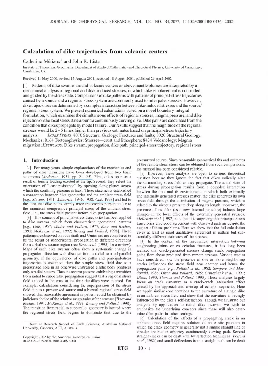
pressurized source. Since reasonable geometrical fits and estimatesof the remote shear stress can be obtained from such comparisons,the method has been considered reliable.[4] However, these analysis are open to serious theoretical
question because they ignore the fact that dikes radically alterthe surrounding stress field as they propagate. The actual state ofstress during propagation results from a complex interactionbetween the dike and its environment, in which both externallyand internally generated stresses matter: the dike generates its ownstress field through the distribution of magma pressure, which isrelated to the viscous pressure drop along its length; moreover, thepresence of the dike (as a new internal structure) induces largechanges in the local effects of the externally generated stresses.McKenzie et al. [1992] note that it is surprising that principal-stresstrajectories give good agreement with observed patterns despite theneglect of these problems. Here we show that the full calculationgives at least as good qualitative agreement in pattern but sub-stantially different estimates of the stresses.[5] In the context of the mechanical interaction between
neighboring joints or en echelon fractures, it has long beenrealized that crack-generated stresses change crack propagationpaths from those predicted from remote stresses. Various studieshave considered how the presence of one or more neighboringcracks influences the stress field near another and hence thepropagation path [e.g., Pollard et al., 1982; Sempere and Mac-donald, 1986; Olson and Pollard, 1989; Cruikshank et al., 1991;Olson, 1993; Thomas and Pollard, 1993]. These analyses largelyfocus on crack curvature as a crack-crack interaction effectcaused by the approach and overlap of echelon segments. Herewe apply similar considerations to the curvature of a single dikein an ambient stress field and show that the curvature is stronglyinfluenced by the dike’s self-interaction. Though we illustrate ouranalysis by application to radial dike swarms, we wish toemphasize the underlying concepts since these will also deter-mine dike paths in other settings.[6] Calculation of the effects of a propagating crack in an
ambient stress field requires solution of an elastic problem inwhich the crack geometry is generally not a simple straight line orcircular arc but an arbitrary continuously curving path. Severalstraight cracks can be dealt with by reflection techniques [Pollardet al., 1982] and small deflections from a straight path can be dealt
using the analysis of Cotterell and Rice [1980] [Cruikshank et al.,1991]. However, previous calculations of propagation along moregeneral curving trajectories [e.g., Olson and Pollard, 1989; Olson,1993; Thomas and Pollard, 1993] have largely been based on theboundary element method of Crouch and Starfield [1983]. Thismethod employs a simple discretization in which the dike shape isapproximated by elements consisting of straight-line segments andthe wall displacement on each element is taken to be constant.Thus there are discontinuities in both the crack direction and thewall displacement at the joins between the elements, and prop-agation proceeds in a series of small kinks. We have reformulatedthe problem in terms of a boundary integral equation and devel-oped a smoother and much more accurate representation in whichthe boundary elements are circular arcs and the boundary displace-ment is piecewise linear (see Appendix A). This allows the dikeorientation and wall displacement to be continuous along the dikelength and the propagation direction to change continously.[7] We start by discussing the principles determining dike paths.
We then illustrate our ideas by applying them to model patterns ofdike swarms from a volcanic center.
2. Criteria for a Dike Path
[8] In theoretical mechanics, crack propagation is usually ana-lyzed in terms of three basic modes, which are distinguished by thetype of loading exerted at the crack tip: mode I, or opening mode,refers to purely tensile loading of the crack tip; mode II, or slidingmode, andmode III, or tearingmode, refer to pure shear loading of thecrack tip, respectively, perpendicular to and parallel to the front. Asuperposition ofmore than one typeof loading is termedmixed-modepropagation. In linear elastic fracture mechanics, these three modesare associated with stress intensity factors,KI,KII, andKIII, which aredefined by the form of the near-tip stress and displacement fields
sij � r�1=2XIIIm¼I
Km fmij qð Þ ð1Þ
ui � r1=2XIIIm¼I
Kmgmi qð Þ; ð2Þ
where r is the radial distance from the crack tip and f (q) and g (q)are functions of angle q [Lawn, 1993, p. 26].[9] If a crack tip is subject to mixed-mode loading, then its
incremental direction of propagation will make a nonzero angle, orkink, with the tangent direction at the previous tip position[Erdogan and Sih, 1963]. The kink angle is determined by therequirement that the loading of the incremented tip is mode I(equivalently, by the maximum circumferential stress criterion).Moreover, it follows that if the subsequent propagation path curvessmoothly (without further kinks), then the tip loading must be suchthat fracture proceeds in pure mode I [Cotterell and Rice, 1980],and this determines the curvature. Thus smoothly curving dikespropagate along the path for which the only nonzero stressintensity factor is KI. The stress intensity factors, and hence this‘‘mode I path,’’ are determined by the integrated effects of theloading of the dike walls by both internal and remote stresses. Theloading can be resolved into normal and tangential components,
sn ¼ Pm � sin2asxx þ cos2asyy�
�2sinacosasxy�
ð3aÞst ¼ � sin2a� cos2a
� �sxy
��cosa sina syy � sxx
� ��; ð3bÞ
where a is the angle between the tangent to the crack and the x axis;sxx, syy, and sxy are the components of the background remote stressfield (with tension positive); Pm is the magmatic pressure, whichdecreases along the dike due to the viscous resistance to flow whichdetermines the propagation rate [Lister, 1990;Lister andKerr, 1991].[10] To illustrate the difference between a principal-stress path
and the mode I path, we begin with the very simple analytic example
of a straight crack starting to extend in an ambient stress field ofuniform far-field stress. We suppose that the crack is initially alignedwith the x axis with constant internal pressure P, that the far-fieldstresses are sxx
1, syy1, and sxy
1 and that sxy1 6¼ 0 so that the crack will
deviate from the x axis as it starts to propagate (Figure 1).[11] To make a point, we define the principal-stress trajectories
in terms of the ambient far-field stresses and think of the initialcrack as the result of more recent propagation whose effects on thepreexisting stress are ignored. The principal-stress trajectories arethen straight lines at an angle �a to the x axis, where
tan 2�að Þ ¼2s1xy
s1xx � s1yy: ð4Þ
Thus the principal-stress approach predicts that the dike kinks andthen propagates in a straight line at this angle, which depends onlyon the far-field stresses and not on the orientation or internalpressure of the original crack.[12] The mode I path can be calculated using results from
equation (31) of Cotterell and Rice [1980], who considered acrack subjected to a combination of mode I and mode II loading atthe initial tip; if the local stress field at the incremented tip positionis required to be purely mode I (i.e., KII
inc = 0) then the crack mustkink by an angle �a, where
sin �a=2ð Þ þ sin 3�a=2ð Þcos �a=2ð Þ þ 3 cos 3�a=2ð Þ ¼ �K0
II
K0I
ð5Þ
and KI0 and KII
0 are the stress intensity factors at the tip of theinitial crack. Equation (5) depends explicitly on KI
0 and KII0, since
it is the dominant r�1/2 near-tip stress field (equation (2)) thatdetermines the path. For the initially straight crack with constantfar-field stresses, KI
0 = snffiffiffiffiffipl
pand KII
0 = stffiffiffiffiffipl
p[Lawn, 1993],
where sn = syy1 � P and st = sxy
1, and l is the crack half length.Thus equation (5) can be rewritten as
sin �að Þ3cos �að Þ � 1
¼s1xy
P � s1yyð6Þ
Figure 1. Initial extension and kink at angle �a of a preexistingtwo-dimensional straight crack aligned with the x axis withconstant internal pressure P in the presence of constant far-fieldstresses sxx
1, syy1, and sxy
1.
ETG 10 - 2 MERIAUX AND LISTER: DIKE TRAJECTORIES FROM VOLCANIC CENTERS
which coincides with the maximum-stress criterion of Erdoganand Sih [1963]. It should be noted that after the initial kink thecrack propagates along a curved trajectory, since the extension ofthe crack modifies the near-tip field and hence the direction ofpropagation for the next increment. This curvature is in agreementwith observations in mechanical samples [Lawn, 1993].[13] Comparison of equations (4) and (6) shows that the principal-
stress and mode I paths are significantly different for the straight-forward reason that the principal-stress criterion is based entirelyon the orientation of the stresses that would be at the position ofthe crack tip if there were no crack present. However, theintroduction of the crack as an internal surface free of shear stresscompletely changes the stresses at the location of the tip from aconstant background stress to the singular stress concentration ofequation (2). An improved principal-stress prediction could beobtained if the stress field around the initial crack were consideredpart of the ambient stress field when calculating the trajectories forthe subsequent propagation. However, the method would still beincreasingly inaccurate as the crack propagates from its originalposition and changes the stress field from the initial stress fieldused to calculate the trajectories. In contrast, the mode I criteriondefines the crack path in terms of the actual stresses at thepropagating tip and is clearly much more physically reasonable.
3. Example: Propagation From a Volcanic Center
[14] In order to illustrate the geological significance of the differ-ence between principal-stress predictions and mode I paths, we nowfocus on the pattern of dike swarms radiating from a volcanic center.
3.1. Regional Stress Field
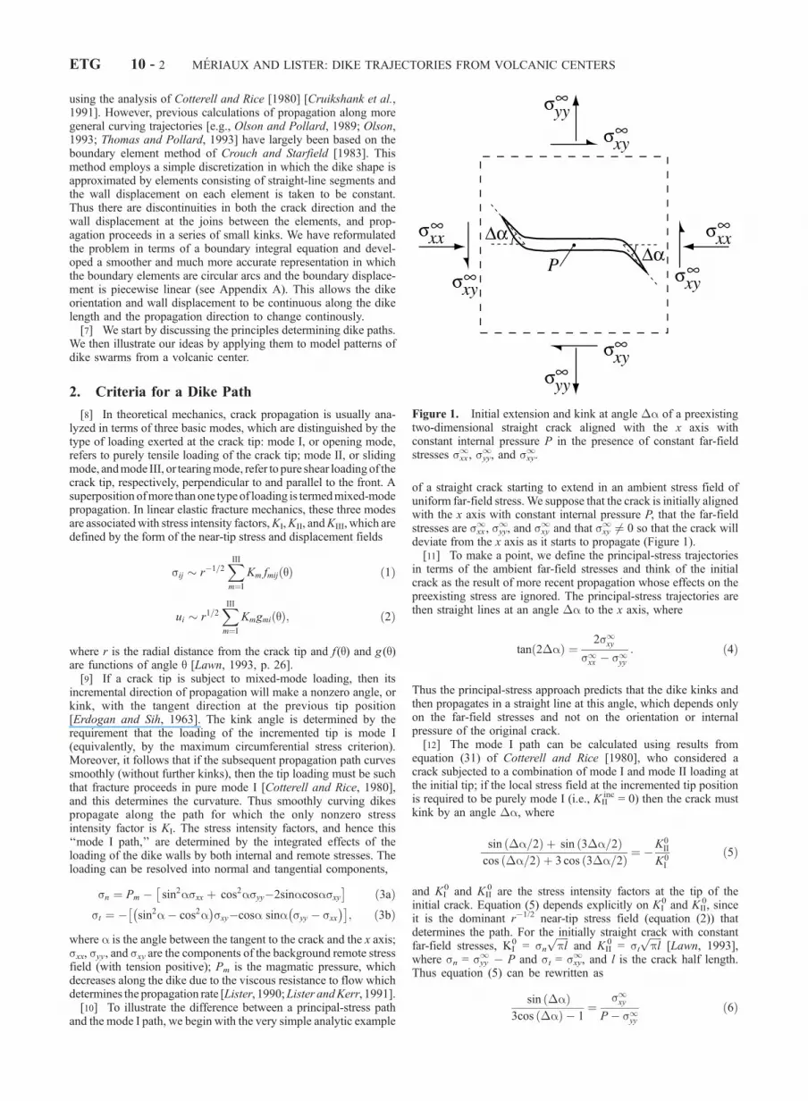
[15] Models of the stress field around a volcanic center havepreviously been used to predict principal-stress trajectories and thento infer the regional stress field from the observed dike paths. Thecommon parameterization of the stress field is based on the two-dimensional problem of a pressurized circular hole, representing themagmatic source, in an elastic body subject to a constant far-fieldbiaxial stress, representing the regional stresses (Figure 2). For ahole of internal pressure P and a biaxial far-field stress composed ofan isotropic mean stress M and a differential stress 2S (with tensionagain positive), the analytic solutions [Kirsch, 1898; Jaeger andCook, 1979] for the stresses in Cartesian coordinates are
sxx ¼ M � S � P þM � 2S½ � R
r
� �2
cos2q
�S 3R
r
� �4
�2R
r
� �2" #
cos4q; ð7aÞ
syy ¼ M þ S þ P þM þ 2S½ � R
r
� �2
cos2q
þS 3R
r
� �4
�2R
r
� �2" #
cos4q; ð7bÞ
sxy ¼ � P þM½ � R
r
� �2
sin2q � S 3R
r
� �4
�2R
r
� �2" #
sin4q; ð7cÞ
where r =ffiffiffiffiffiffiffiffiffiffiffiffiffiffix2 þ y2
p, cosq = x/r, sinq = y/r, and R is the radius of
the hole. The far-field stresses are sxx1 = M � S, syy
1 = M + S,and sxy
1 = 0; the terms involving P are just isotropic dilation froma source with overpressure P + M (which take the simple formsrr = �(P + M )(R/r)2, sqq = (P + M )(R/r)2, sr q = 0 in cylindricalcoordinates); the remaining terms involving S represent theperturbation to the far-field stress due to the presence of the holeand are required to satisfy the constant-pressure boundaryconditions srr = �P and sr q = 0 on r = R. Koenig and Pollard[1998] calculate their principal-stress trajectories from equation (7).
[16] In simplified versions of equation (7) [Ode, 1957; Mullerand Pollard, 1977; Baer and Reches, 1991; McKenzie et al., 1992]the stresses are approximated by
sxx � �S ��PR
r
� �2
cos2q; ð8aÞ
syy � S þ�PR
r
� �2
cos2q; ð8bÞ
sxy � ��PR
r
� �2
sin2q; ð8cÞ
as discussed below.[17] In moving from equation (7) to equation (8), two simpli-
fications are made. First, addition of a uniform isotropic stress doesnot affect the principal-stress trajectories, and so the uniform far-field mean stress M can be subtracted from sxx and syy. It is
Figure 2. (top) Circular hole of radius R and internal pressure Pin an elastic body subject to a biaxial stress at infinity split into anisotropic mean stress field M and a deviatoric stress field ofmagnitude S. (bottom) Circular hole of overpressure �P in anelastic body subject to a deviatoric remote stress of magnitude S.
MERIAUX AND LISTER: DIKE TRAJECTORIES FROM VOLCANIC CENTERS ETG 10 - 3
important then to remember both that the stresses sij in equation (8)denote the deviations from the mean compression and not the truestresses of equation (7) and that the source pressure �P is thesource overpressure P + M and not the actual source pressure P.Koenig and Pollard [1998] criticize McKenzie et al. [1992] forsetting the remote mean stress equal to zero by using (8) and thusignoring the effect of mean stress on trajectories. In fact, there is noproblem here provided the pressure P in McKenzie et al. [1992] isunderstood to be the overpressure relative to the mean stress andnot the actual pressure (the paper does not explicitly define P).Thus equation (7) can be rewritten as
�sxxS
¼ �1� �P
S� 2
� R
r
� �2
cos2q� 3R
r
� �4
�2R
r
� �2" #
cos4q;
ð9aÞ
�syyS
¼ 1þ �P
Sþ 2
� R
r
� �2
cos2qþ 3R
r
� �4
�2R
r
� �2" #
cos4q;
ð9bÞ
�sxyS
¼ ��P
S
R
r
� �2
sin2q� 3R
r
� �4
�2R
r
� �2" #
sin4q; ð9cÞ
showing that the problem only depends on R and the relativemagnitudes of the remote stress S and the overpressure �P; here Sis taken to be positive by choice of the x and y axes, and �P isassumed to be positive since we are interested in radial near-fieldtrajectories. (Negative �P produces circumferential propagationand ring dikes.)[18] The second simplification rests on an implicit assumption
that S �P. If this is the case, then the stresses due to the holeoverpressure�P are dominant in the near field (r� R) and the near-field perturbation to the ambient differential stress caused by thepresence of the hole (i.e., terms in equation (7) proportional toS(R/r)m
cos(nq) withm, n = 2 or 4) can be neglected to reduce equation (9) toequation (8). The dominant stresses due to the hole overpressureproduce radial propagation in the near field. These stressesdecrease with radial distance and are equal to the ambient biaxialstress at radius r*, where r* = R(�P/S)1/2. It is thus to beexpected that the dike swarm will curve toward a subparallelgeometry at this sort of radius. The assumption that S �P couldbe justified either from observations that the dike swarm curves on alonger length scale than the source dimensions (for example, onVenus [Grosfils and Head, 1994]) or from modeling the swarmpattern and checking, a posteriori, that the best fit gives S �P. Itseems to be a reasonable approximation in previous studies ofvolcanic centers [Ode, 1957; Muller and Pollard, 1977; Baer andReches, 1991; McKenzie et al., 1992] but would not be appropriatein tectonically active regions, like Iceland, where there are relativelylarge differential stresses and dike swarms are closely subparallel.[19] For simplicity, we will also restrict our attention to cases
in which the stress field can be approximated by equation (8) andnote, for example, that the principal-stress trajectories are notmuch affected by the approximation even for values of S/�P aslarge as 0.5 (Figure 3). The field examples described in section 5have S/�P � 0.25.
3.2. Nondimensionalization
[20] The simplified stresses in equation (8) can conveniently bemade dimensionless by defining
~s ¼ s=S ð10Þ
~r ¼ r=r*; ð11Þ
where the length scale r* = R(�P/S)1/2 is the radius at which the
hole and biaxial stress fields have equal magnitude. Thedimensionless stress field is then given by
~sxx ¼ �1� 1
~r2cos2q; ð12aÞ
~syy ¼ 1þ 1
~r2cos2q; ð12bÞ
~sxy ¼ � 2
~r2sin2q ð12cÞ
in ~r > ~R, where ~r = R/r* = (S/�P)1/2 is the dimensionless holediameter. Alternatively, ~R2 can be thought of as the ratio of theregional differential stress to the source overpressure. This is theonly parameter in the dimensionless problem, and we are interestedin ~R 1 (i.e., R r*).
3.3. Chamber Conditions
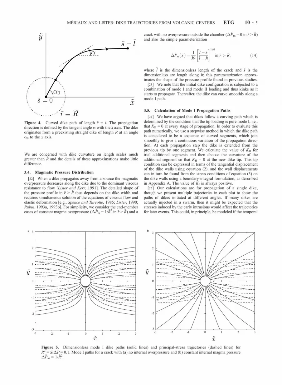
[21] The stress field in equation (12) is that appropriate forpropagation from a pressurized source, or magma chamber, ofdimensionless radius ~R. Though it would be possible to extendour calculations to include the chamber wall as an internalboundary with constant-pressure boundary conditions, it issimpler, and consistent with the approximations already madefor ~R 1 (i.e., S �P), to model the chamber by makingthe following approximations for ~r < ~R. We assume an initialstate in which there is a straight dike of length ~R at an angle a0 to thex axis and extending from the origin to ~r = ~R (Figure 4). We assumefurther that in ~r < ~R the dike has a constant internal magmaticoverpressure �~Pm = 1/~R2 and there is a constant stress field
~sxx ¼ �1� 1
~R2cos2q; ð13aÞ
~syy ¼ 1þ 1
~R2cos2q; ð13bÞ
~sxy ¼ � 2
~R2sin2q: ð13cÞ
Figure 3. Some principal-stress trajectories calculated for theexact stress field (equation (7)) (dashed lines) and approximatestress field (equation (8)) (solid lines). Four trajectories areshown for each case corresponding to initial angles 35� and 75�and S/�P = 0.02 and 0.5.
ETG 10 - 4 MERIAUX AND LISTER: DIKE TRAJECTORIES FROM VOLCANIC CENTERS
We are concerned with dike curvature on length scales muchgreater than ~R and the details of these approximations make littledifference.
3.4. Magmatic Pressure Distribution
[22] When a dike propagates away from a source the magmaticoverpressure decreases along the dike due to the dominant viscousresistance to flow [Lister and Kerr, 1991]. The detailed shape ofthe pressure profile in ~r > ~R thus depends on the dike width andrequires simultaneous solution of the equations of viscous flow andelastic deformation [e.g., Spence and Turcotte, 1985; Lister, 1990;Rubin, 1993a, 1993b]. For simplicity, we consider the end-membercases of constant magma overpressure (�~Pm = 1/~R2 in ~r > ~R) and a
crack with no overpressure outside the chamber (�~Pm = 0 in ~r > ~R)and also the simple parameterization
�~Pm ~sð Þ ¼ 1
~R2
~l � ~s~l � ~R
" #1=4
in ~r > ~R; ð14Þ
where ~l is the dimensionless length of the crack and ~s is thedimensionless arc length along it; this parameterization approx-imates the shape of the pressure profile found in previous studies.[23] We note that the initial dike configuration is subjected to a
combination of mode I and mode II loading and thus kinks as itstarts to propagate. Thereafter, the dike can curve smoothly along amode I path.
3.5. Calculation of Mode I Propagation Paths
[24] We have argued that dikes follow a curving path which isdetermined by the condition that the tip loading is pure mode I, i.e.,that KII = 0 at every stage of propagation. In order to evaluate thispath numerically, we use a stepwise method in which the dike pathis considered to be a sequence of curved segments, which joinsmoothly to give a continuous variation of the propagation direc-tion. At each propagation step the dike is extended from theprevious tip by one segment. We calculate the value of KII fortrial additional segments and then choose the curvature of theadditional segment so that KII = 0 at the new dike tip. This tipcondition can be expressed in terms of the tangential displacementof the dike walls using equation (2), and the wall displacementscan in turn be found from the stress conditions of equation (3) onthe dike walls using a boundary-integral formulation, as describedin Appendix A. The value of KI is always positive.[25] Our calculations are for propagation of a single dike,
though we present multiple trajectories in each plot to show thepaths of dikes initiated at different angles. If many dikes areactually injected in a swarm, then it might be expected that thestresses induced by the early intrusions would affect the trajectoriesfor later events. This could, in principle, be modeled if the temporal
a b
Figure 5. Dimensionless mode I dike paths (solid lines) and principal-stress trajectories (dashed lines) for~R2 = S/�P = 0.1. Mode I paths for a crack with (a) no internal overpressure and (b) constant internal magma pressure�~Pm = 1/~R2.
Figure 4. Curved dike path of length ~s = l. The propagationdirection is defined by the tangent angle a with the x axis. The dikeoriginates from a preexisting straight dike of length ~R at an anglea0 to the x axis.
MERIAUX AND LISTER: DIKE TRAJECTORIES FROM VOLCANIC CENTERS ETG 10 - 5
order of the sequence of intrusions were known, together with theinitial angle, volume, and propagation distance of each dike.However, the good agreement in pattern between the observedswarms and the multiple trajectories for a single dike suggests thatthe crustal stresses around each dike might relax sufficiently afterintrusion not to affect subsequent intrusions.
4. Results
[26] In section 2 we showed analytically that the direction ofextension of a straight crack in a regional stress field is predictedquite differently by principal-stress and mode I criteria. The sameprinciple also applies to dike propagation from a volcanic center,but the mode I path can no longer be found analytically andnumerical calculation is required. We explore the difference fromprincipal-stress trajectories and the effects of the pressure distribu-tion in the dike and of the parameter ~R.[27] Figure 5 shows clearly that mode I dike paths, which are
based on the actual near-tip stress fields, are significantly differentfrom the principal-stress trajectories for the same regional stressfield (equation (12)) with a given value of ~R. Even for a dike inwhich there is no magma overpressure on the dike walls in ~r > ~Rand the tip loading is due entirely to the applied regional stress andthe chamber pressure, the mode I path propagates further in a radialdirection before curving to be subparallel to the remote extension(Figure 5a). The effect is very much more marked for a dike loadedwith uniform magma overpressure �~Pm (Figure 5b), for which thecurvature toward subparallel orientation occurs on a much longerscale than in the corresponding principal-stress trajectory.[28] The dependence of the mode I dike paths on the distribu-
tion of magma overpressure is shown in Figure 6. Dikes with eitheruniform internal overpressure or with the simple parameterizationin equation (14) of a viscous pressure drop propagate radially formuch greater distances than the corresponding unpressurizedcracks. The reason is simply that transmission of a magmaticoverpressure from the source toward the dike tip provides a large
tensile loading ahead of the tip; only a small curvature is thenrequired to convert some of this tensile loading to sufficient shearloading to counterbalance the regional shear loading and maintainmode I propagation. For the same reason, uniformly loaded dikestend to propagate with less curvature than those with a viscouspressure drop. The difference, however, is relatively small, sug-gesting that the parameterization in equation (14) is probablysufficient to get reasonable results without having to model thefull details of the viscous flow in a curved dike of variable width.[29] While mode I paths curve much less than principal-stress
trajectories for a given stress field, it should not be thought thatlarge curvatures are not possible with mode I paths. Figure 7shows the effects of varying ~R for the most realistic pressuredistribution in equation (14). An increase in ~R produces mode Ipaths that curve more rapidly toward the principal direction ofminimum compression since this corresponds to an increase inthe remote differential stress relative to the overpressure in thesource and propagating dike. Calculations with even larger valuesof ~R = (S/�P)1/2 should use a dimensionless version of the fullstress field equation (7) rather than equation (12).
5. Application
[30] Studies of principal-stress trajectories were motivated bythe idea that the remote differential stress could be estimated fromfits between the principal-stress trajectories and the observed dikepatterns. In practice, estimates of S are derived using the dimen-sionless parameter ~R from
S ¼ ~R2 �P; ð15Þ
where ~R is determined by the best fit between calculated trajectoriesand observed dike patterns and �P is estimated by other means.Larger curvatures correspond to larger values of ~R and hence largervalues of S for given �P. Since mode I paths curve less thanprincipal-stress trajectories for a given ~R, the best fit mode I pathwill have a larger value of ~R and hence give a larger value of S.[31] For example,Muller and Pollard [1977] used the principal-
stress trajectory approach on the West Peak intrusion, Colorado, to
Figure 6. Dimensionless mode I dike paths for ~R2 = 0.25 withthree magmatic pressure distributions (see section 3.4): nomagmatic overpressure outside the chamber (dashed lines), constantmagmatic pressure (solid lines), and the simple parameterization inequation (14) of the viscous pressure drop (dotted lines).
Figure 7. Dimensionless mode I dike paths for ~R2 = 0.1 (solidlines) and ~R2 = 0.5 (dashed lines), both with the simpleparameterization (equation (14)) of the viscous pressure drop.
ETG 10 - 6 MERIAUX AND LISTER: DIKE TRAJECTORIES FROM VOLCANIC CENTERS
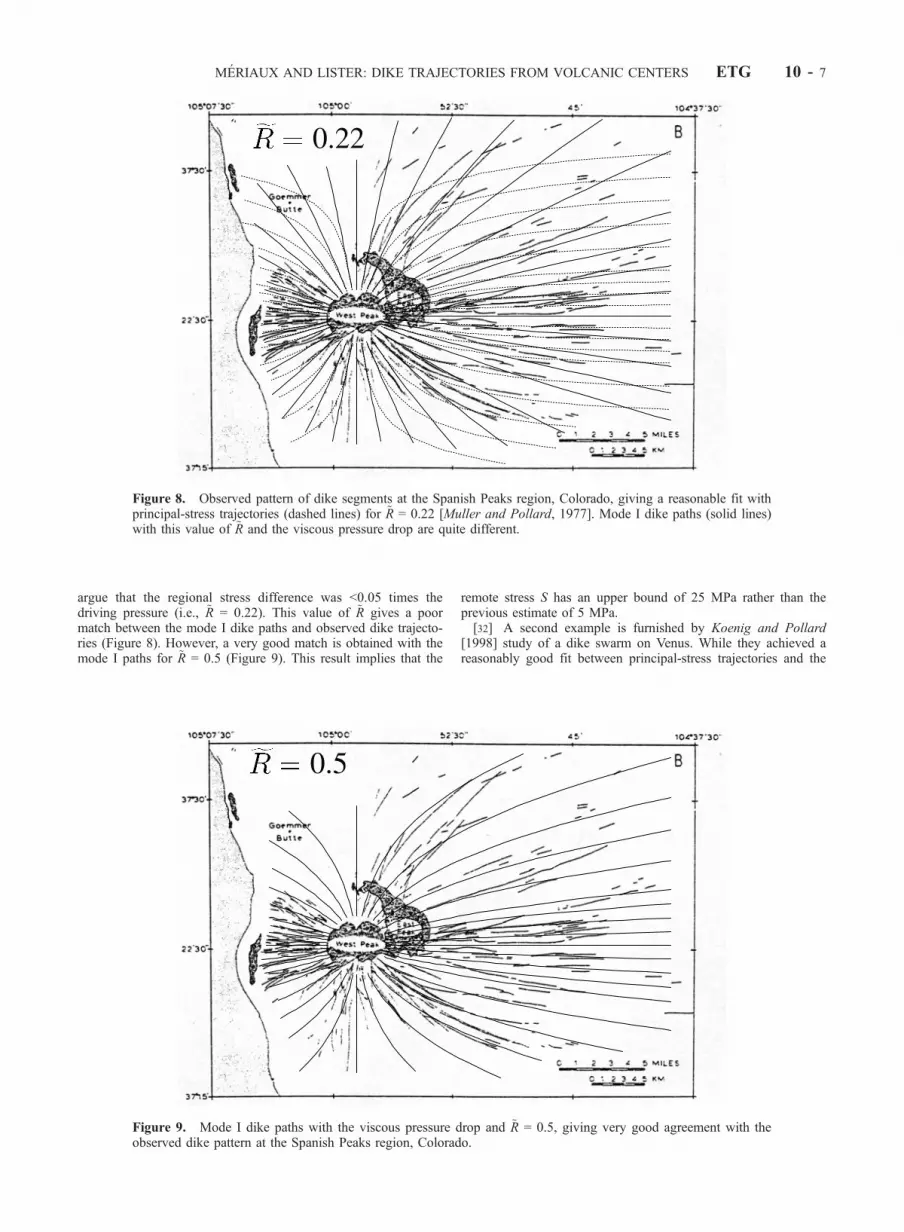
argue that the regional stress difference was <0.05 times thedriving pressure (i.e., ~R = 0.22). This value of ~R gives a poormatch between the mode I dike paths and observed dike trajecto-ries (Figure 8). However, a very good match is obtained with themode I paths for ~R = 0.5 (Figure 9). This result implies that the
remote stress S has an upper bound of 25 MPa rather than theprevious estimate of 5 MPa.[32] A second example is furnished by Koenig and Pollard
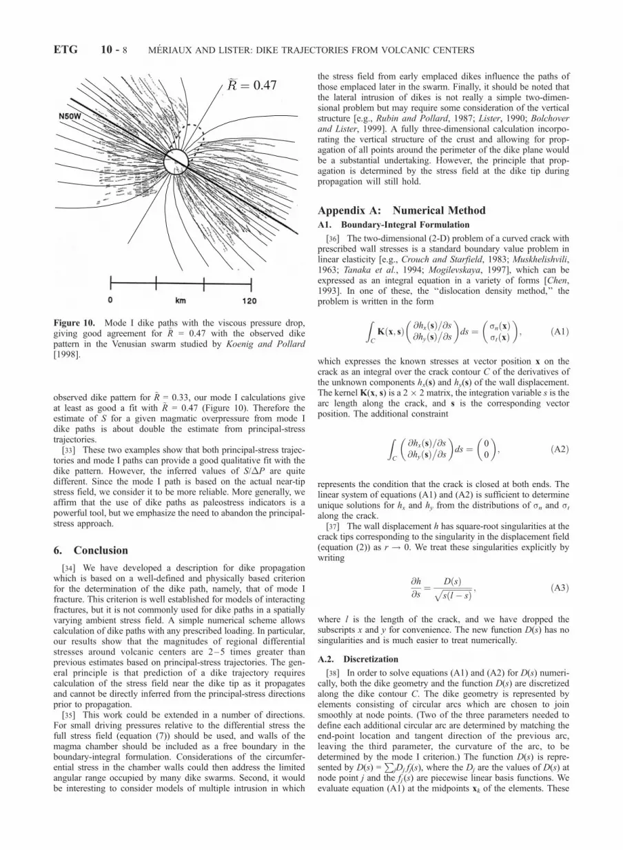
[1998] study of a dike swarm on Venus. While they achieved areasonably good fit between principal-stress trajectories and the
Figure 8. Observed pattern of dike segments at the Spanish Peaks region, Colorado, giving a reasonable fit withprincipal-stress trajectories (dashed lines) for ~R = 0.22 [Muller and Pollard, 1977]. Mode I dike paths (solid lines)with this value of ~R and the viscous pressure drop are quite different.
Figure 9. Mode I dike paths with the viscous pressure drop and ~R = 0.5, giving very good agreement with theobserved dike pattern at the Spanish Peaks region, Colorado.
MERIAUX AND LISTER: DIKE TRAJECTORIES FROM VOLCANIC CENTERS ETG 10 - 7
observed dike pattern for ~R = 0.33, our mode I calculations giveat least as good a fit with ~R = 0.47 (Figure 10). Therefore theestimate of S for a given magmatic overpressure from mode Idike paths is about double the estimate from principal-stresstrajectories.[33] These two examples show that both principal-stress trajec-
tories and mode I paths can provide a good qualitative fit with thedike pattern. However, the inferred values of S/�P are quitedifferent. Since the mode I path is based on the actual near-tipstress field, we consider it to be more reliable. More generally, weaffirm that the use of dike paths as paleostress indicators is apowerful tool, but we emphasize the need to abandon the principal-stress approach.
6. Conclusion
[34] We have developed a description for dike propagationwhich is based on a well-defined and physically based criterionfor the determination of the dike path, namely, that of mode Ifracture. This criterion is well established for models of interactingfractures, but it is not commonly used for dike paths in a spatiallyvarying ambient stress field. A simple numerical scheme allowscalculation of dike paths with any prescribed loading. In particular,our results show that the magnitudes of regional differentialstresses around volcanic centers are 2–5 times greater thanprevious estimates based on principal-stress trajectories. The gen-eral principle is that prediction of a dike trajectory requirescalculation of the stress field near the dike tip as it propagatesand cannot be directly inferred from the principal-stress directionsprior to propagation.[35] This work could be extended in a number of directions.
For small driving pressures relative to the differential stress thefull stress field (equation (7)) should be used, and walls of themagma chamber should be included as a free boundary in theboundary-integral formulation. Considerations of the circumfer-ential stress in the chamber walls could then address the limitedangular range occupied by many dike swarms. Second, it wouldbe interesting to consider models of multiple intrusion in which
the stress field from early emplaced dikes influence the paths ofthose emplaced later in the swarm. Finally, it should be noted thatthe lateral intrusion of dikes is not really a simple two-dimen-sional problem but may require some consideration of the verticalstructure [e.g., Rubin and Pollard, 1987; Lister, 1990; Bolchoverand Lister, 1999]. A fully three-dimensional calculation incorpo-rating the vertical structure of the crust and allowing for prop-agation of all points around the perimeter of the dike plane wouldbe a substantial undertaking. However, the principle that prop-agation is determined by the stress field at the dike tip duringpropagation will still hold.
Appendix A: Numerical Method
A1. Boundary-Integral Formulation
[36] The two-dimensional (2-D) problem of a curved crack withprescribed wall stresses is a standard boundary value problem inlinear elasticity [e.g., Crouch and Starfield, 1983; Muskhelishvili,1963; Tanaka et al., 1994; Mogilevskaya, 1997], which can beexpressed as an integral equation in a variety of forms [Chen,1993]. In one of these, the ‘‘dislocation density method,’’ theproblem is written in the form
ZC
K x; sð Þ @hx sð Þ=@s@hy sð Þ
�@s
� �ds ¼ sn xð Þ
st xð Þ
� �; ðA1Þ
which expresses the known stresses at vector position x on thecrack as an integral over the crack contour C of the derivatives ofthe unknown components hx(s) and hy(s) of the wall displacement.The kernel K(x, s) is a 2 � 2 matrix, the integration variable s is thearc length along the crack, and s is the corresponding vectorposition. The additional constraint
ZC
@hx sð Þ=@s@hy sð Þ
�@s
� �ds ¼ 0
0
� �; ðA2Þ
represents the condition that the crack is closed at both ends. Thelinear system of equations (A1) and (A2) is sufficient to determineunique solutions for hx and hy from the distributions of sn and stalong the crack.[37] The wall displacement h has square-root singularities at the
crack tips corresponding to the singularity in the displacement field(equation (2)) as r ! 0. We treat these singularities explicitly bywriting
@h
@s¼ D sð Þffiffiffiffiffiffiffiffiffiffiffiffiffiffiffi
s l � sð Þp ; ðA3Þ
where l is the length of the crack, and we have dropped thesubscripts x and y for convenience. The new function D(s) has nosingularities and is much easier to treat numerically.
A.2. Discretization
[38] In order to solve equations (A1) and (A2) for D(s) numeri-cally, both the dike geometry and the function D(s) are discretizedalong the dike contour C. The dike geometry is represented byelements consisting of circular arcs which are chosen to joinsmoothly at node points. (Two of the three parameters needed todefine each additional circular arc are determined by matching theend-point location and tangent direction of the previous arc,leaving the third parameter, the curvature of the arc, to bedetermined by the mode I criterion.) The function D(s) is repre-sented by D(s) =
PjDj fj(s), where the Dj are the values of D(s) at
node point j and the fj (s) are piecewise linear basis functions. Weevaluate equation (A1) at the midpoints xk of the elements. These
Figure 10. Mode I dike paths with the viscous pressure drop,giving good agreement for ~R = 0.47 with the observed dikepattern in the Venusian swarm studied by Koenig and Pollard[1998].
ETG 10 - 8 MERIAUX AND LISTER: DIKE TRAJECTORIES FROM VOLCANIC CENTERS
representations reduce the problem to a linear system of algebraicequations
Xj
Dj
Zfj sð Þffiffiffiffiffiffiffiffiffiffiffiffiffiffiffis l � sð Þ
p K xk ; sð Þds ¼ sk ðA4Þ
Xj
Dj
Zfj sð Þffiffiffiffiffiffiffiffiffiffiffiffiffiffiffis l � sð Þ
p ds ¼ 0 ðA5Þ
for the unknown displacements Dj in terms of the known midpointstresses sk = s(xk).
A.3. Numerical Procedure
[39] The numerical code has three main parts. The first partconsists of calculations of the integrals of the basis functions inequations (A4) and (A5) for a given geometry C. This requirescareful treatment of the singularity at the pole of the Cauchy-typekernel K, using singularity removal techniques [Tanaka et al.,1994; Pozrikidis, 1992]. The second part constructs and inverts thematrix representing the linear system of equations to obtain thesolution for D with this geometry and loading. In the third part,these two subroutines are nested within a root-finding algorithmwhich finds the curvature of the next circular arc to be added as thecrack propagates from the condition that the tangential componentDt = 0 at the new tip; this corresponds to ensuring that KII = 0.
A.4. Verification and Accuracy
[40] The numerical scheme was tested by comparison with theexact solution for a crack forming a circular arc subtending anangle 2a under uniform far-field tension [Muskhelishvili, 1963, p.524]. The displacements and stress intensities obtained numericallyagreed with the exact solution to within �1.7% for N = 10elements and within �0.1% for N = 40 elements. In fact, thenumerical error in the present scheme is proportional to N�2. Directimplementation of the Crouch and Starfield [1983] scheme giveserrors in displacement h proportional to N�1/2 and overestimates
the stress intensities by �25% even if N ! 1. The correctionfactor 0.806 used by Thomas and Pollard [1993] (0.798 is actuallybetter) removes this leading-order error but still leaves numericalerrors that are much greater than the present scheme (Figure A1).Thus fewer elements are needed in the present scheme for the sameaccuracy, or much greater accuracy can be achieved for the same N.
[41] Acknowledgments. We are very grateful to Richard Ernst, JonOlson, and Allan Rubin for thorough and constructive reviews, whichhelped us improve the manuscript in many ways. This research has beensupported by an EU Marie Curie Fellowship.
ReferencesAnderson, E. M., The dynamics of the formation of cone-sheets ring-dykesand cauldron subsidences, Proc. R. Soc. Edinburgh, 56, 128–157, 1936.
Anderson, E. M., The dynamics of sheet intrusion, Proc. R. Soc. Edinburgh,58, 242–251, 1938.
Anderson, E. M., The Dynamics of Faulting and Dyke Formation WithApplications to Britain, Oliver and Boyd, White Plains, N. Y., 1951.
Baer, G., and Z. Reches, Mechanics of emplacement and tectonic implica-tions of the Ramon dike systems, Israel, J. Geophys. Res., 96, 11,895–11,910, 1991.
Bolchover, P., and J. R. Lister, The effects of solidification on fluid-drivenfracture, with application to bladed dykes, Proc. R. Soc. London, Ser. A,455, 2389–2409, 1999.
Chen, Y. Z., Numerical solution of a curved crack problem by using hy-persingular integral equation approach, Eng. Fract. Mech., 46, 275–283,1993.
Cotterell, B., and J. R. Rice, Slightly curved or kinked cracks, Int. J. Fract.,16, 155–169, 1980.
Crouch, S. L., and A. M. Starfield, Boundary Element Methods in SolidMechanics, Allen and Unwin, Concord, Mass., 1983.
Cruikshank, K. M., G. Zhao, and A. M. Johnson, Analysis of minor frac-tures associated with joints and faulted joints, J. Struct. Geol., 13, 865–886, 1991.
Erdogan, F., and G. C. Sih, On the crack extension in plates under planeloading and transverse shear, Trans. Am. Soc. Mech. Eng., 85, 519–527,1963.
Ernst, R. E., J. W. Head, E. Parfitt, E. Grosfils, and L. Wilson, Giant radiat-ing dyke swarms on Earth and Venus, Earth Sci. Rev., 39, 1–58, 1995.
Grosfils, E., and J. W. Head, The global distribution of giant radiating dikeswarms on Venus: Implications for the global stress state, Geophys. Res.Lett., 21, 701–704, 1994.
Jaeger, J. C., and N. G.W. Cook, Fundamentals of Rock Mechanics, 593 pp.,Chapman and Hall, New York, 1979.
Kirsch, G. L., Die theorie der elastizitat und die bedurfnisse der festigkeit-slehre, Veit. Ver. Deut. Ing., 42, 797–807, 1898.
Koenig, E., and D. D. Pollard, Mapping and modeling of radial fracturepatterns, J. Geophys. Res., 103, 15,183–15,202, 1998.
Lawn, B. R., Fracture of Brittle Solids 2nd ed., Cambridge Univ. Press,New York, 1993.
Lister, J. R., Buoyancy-driven fluid fracture: Similarity solutions for thehorizontal and vertical propagation of fluid-filled cracks, J. Fluid. Mech.,217, 213–239, 1990.
Lister, J. R., and R. C. Kerr, Fluid-mechanical models of cracks propagationand their applications to magma-transport in dikes, J. Geophys. Res., 96,10,049–10,077, 1991.
McKenzie, D., J. M. McKenzie, and R. S. Saunders, Dike Emplacement onVenus and on Earth, J. Geophys. Res., 97, 15,977–15,990, 1992.
Mogilevskaya, S. G., Numerical modeling of 2-D smooth crack growth, Int.J. Fract., 87, 389–405, 1997.
Muller, O. H., and D. D. Pollard, Stress state near Spanish Peaks, PureAppl. Geophys., 115, 69–86, 1977.
Muskhelishvili, N. I., Some Basic Problems in the Mathematical Theory ofElasticity, Wolters-Noordhoff, Groningen, Netherlands, 1963.
Ode, H., Mechanical analysis of the dike pattern of the Spanish Peaks area,Colorado, Geol. Soc. Am. Bull., 68, 567–576, 1957.
Olson, J. E., Joint pattern development: Effects of subcritical crack growthand mechanical crack interaction, J. Geophys. Res., 98, 12,251–12,265,1993.
Olson, J., and D. D. Pollard, Inferring paleostresses from natural fracturepatterns: A new method, Geology, 17, 345–348, 1989.
Pollard, D. D., P. Segall, and P. T. Delaney, Formation and interpretation ofdilatant echelon cracks, Geol. Soc. Am. Bull., 93, 1291–1303, 1982.
Pozrikidis, C., Boundary Integral and Singularity Methods for LinearizedViscous Flow, Cambridge Univ. Press, New York, 1992.
Rubin, A. M., Dikes vs. diapirs in viscoelastic rock, Earth Planet. Sci. Lett.,119, 641–659, 1993a.
Figure A1. Relative error e = |Knum � Kexact|/Kexact in thenumerically determined stress intensities KI and KII at the tips ofa circular arc crack of angle 2a subject to uniform far-fieldtension for a = 45� (thin lines) and a = 90� (thick lines) as afunction of the number of boundary elements N. The presentscheme (solid lines) is much more accurate than that of Crouchand Starfield [1983] as described by Thomas and Pollard [1993](dashed lines).
MERIAUX AND LISTER: DIKE TRAJECTORIES FROM VOLCANIC CENTERS ETG 10 - 9
Rubin, A. M., Tensile fracture of rock at high confining pressure: Implica-tions for dike propagation, J. Geophys. Res., 98, 15,919–15,939, 1993b.
Rubin, A. M., and D. D. Pollard, Origins of blade-like dikes in volcanic riftzones, U.S. Geol. Surv. Prof. Pap., 1350, 1449–1470, 1987.
Sempere, J.-C., and K. C. Macdonald, Overlapping spreading centers: Im-plications from crack growth simulation by the displacement discontinu-ity method, Tectonics, 5, 151–163, 1986.
Spence, D. A., and D. L. Turcotte, Magma-driven propagation of cracks,J. Geophys. Res., 90, 575–580, 1985.
Stevens, B., The laws of intrusions, Bull. Am. Inst. Min. Eng., 41, 1–23,1911.
Tanaka, M., V. Sladek, and J. Sladek, Regularization techniques applied toboundary element methods, Appl. Mech. Rev., 47, 457–499, 1994.
Thomas, A. L., and D. D. Pollard, The geometry of echelon fractures inrock: Implications from laboratory and numerical experiments, J. Struct.Geol., 15, 323–334, 1993.
�����������J. R. Lister, Institute of Theoretical Geophysics, Department of Applied
Mathematics and Theoretical Physics, University of Cambridge, SilverStreet, Cambridge CB3 9EW, UK. ([email protected])C. Meriaux, Research School of Earth Sciences, Australian National