CommCenter VERSATILE MULTI-THREAD SERVER/CLIENT COMMUNICATION CENTER Version 1.5.09 - May 2009 Distributed By: ENVITECH Ltd. – Environmental Data Management Systems P.O.Box 1689 Ramat Gan 52116 ISRAEL. Tel. 972-3-5731944, 5732310 Fax 972-3-7310221 E-Mail- [email protected]URL: http://www.envitech.co.il/
Transcript
CommCenter
VERSATILE MULTI-THREAD SERVER/CLIENT COMMUNICATION CENTER
Version 1.5.09 - May 2009
Distributed By:
ENVITECH Ltd. – Environmental Data Management Systems P.O.Box 1689 Ramat Gan 52116 ISRAEL. Tel. 972-3-5731944, 5732310 Fax 972-3-7310221
This manual provides documentation on the use of Communication Center. Reference may be made to manuals for other components of the Communication Center system. Please consult the manual for the specific component for detailed information.
Copyright notice This documentation and the software routines contained in the Communication Center CD are copyrighted 2005, by Envitech Ltd.. All rights are reserved. Envitech reserves the right to make improvements to the products described in this manual at any time without notice. No part of this manual may be reproduced, copied, translated or transmitted, in any form or by any means without the prior written permission of Envitech. Information provided in this manual is intended to be accurate and reliable. However, Envitech assumes no responsibility for its use; nor for any infringement of rights of third parties that may result from its use.
Acknowledgments
• Communication Center, Import Export FTP, Enview 2000 Software Manager, Enview 2000, CommServ, EnvGIS, Enview for Windows, EnviDAS, EnviDAS for Windows and MaintainView are trademarks of Envitech.
• IBM and PC are trademarks of International Business Machine Corporation.
• MS-DOS and MS-Windows are trademarks of Microsoft Corporation.
Envitech Ltd. Environmental Data Management Systems Envitech is active in the field of environmental monitoring and data acquisition systems for air, water, toxic gas, and radiation and noise applications. Monitoring stations, established to provide continuous measurements, use a data acquisition and control unit to control sample and calibration systems, log data values and determine data quality measurements such as calibration results. For this purpose Envitech provides a PC-based Environmental Data Acquisition System – EnviDAS and EnviDAS for Windows. Normally a central administrative site communicates with a network of monitoring stations for supervisory control and to retrieve data values to a central database for storage and subsequent analysis. Envitech provides ENVIEW 2000 for supervisory control and data acquisition. ENVIEW 2000’s graphical user interface is easy to learn and use. This software package provides data collection, analysis, and display, archiving, and reporting. One software component of ENVIEW 2000 is "Software Manager Setup" which enables to create and manage the Enview database.
CommCenter Ver 1.6.249 Page 3 May 2009
Contents
Chapter 1 – Introduction 1.1 Communication Center Overview 1.2 Setup Station Communication Parameters 1.3 Installation
Chapter 2 – File 2.1 Log In\Log Out 2.2 Open Log 2.3 Exit
Chapter 3 – View 3.1 Toolbar 3.2 Open All Trace or Leased/Modem Traces 3.3 Viewing The Trace
Chapter 4 – Utilities 4.1 On Demand 4.2 Start/Stop 4.3 Start Auto Poll/Stop Auto Poll 4.4 Start/Stop Communication 4.5 Refresh
Chapter 5 – Properties 5.1 Data Base 5.2 Communication 5.3 misc. 5.4 Groups 5.5 Communication Backup 5.6 Dynamic IP
Chapter 6 – Window 6.1 Switching between Trace windows 6.2 Cascading and Tiling 6.3 Close All
Chapter 7 – Help 7.1 Help and Manual 7.2 About
CommCenter Ver 1.6.249 Page 4 May 2009
Chapter 8 – Language
Chapter 9 – The Toolbar
Appendix A - Guide to DAS Types A.1 Introduction A.2 Communication Tab A.3 DAS Types
CommCenter Ver 1.6.249 Page 5 May 2009
Guide Revision History
Nr Date Description 70 14 May 2009 Changes in the Manual:
• Chapter 5.3 "Misc" added the feature "Limit The Number Of Simultaneously Open IP Clients"
• Add Appendix A "Guide to DAS Types" 69 22 Mar 2009 Changes in the Manual:
68 17 Mar 2009 Echotech Xmodem Add support for collecting PREC in calibration
67 15 Mar 2009 Add Mier Protocol add TCP ,Verewa and calibration 66 12 Mar 2009 Add protection and show error in on demand poll dialog when
the dates are not good: in case the start date is bigger than the current /end
65 11 Mar 2009 Added support for vista pro hasp key 64 8 Mar 2009 TC65 ENVIDAC Set value added 63 2 Mar 2009 Met One BAM1020 digital monitor status collection added. 62 12 Feb 2009 Add ECOTECH_XMODEM.NET protocol 61 12 Feb 2009 Added TC65_ENVIDAS.NET protocol 60 1 Feb 2009 Add Combo Box list in the user name for login dialog-Box 59 14 Jan 2009 on demand poll dialog should remember last selection 58 12 Jan 2009 change the amount of time waiting for the AT command 57 12 Jan 2009 Sort the on- Demand Station List Alpha and remember last
selected combo 56 11 Jan 2009 Added option to poll logbook form ultimate (need to update
ultimate also in order to poll log book) 55 11 Jan 2009 Add EFW ,Ultimate EMC plc address feature 54 8 Jan 2009 Add Data taker protocol 53 6 Jan 2009 When CommCenter start it will change the last receive to X hour
back 52 6 Jan 2009 Added plc address for Envidas Ultimate, EFW and EMC protocol
51 30 Nov 2008 Changes in the Manual:
• Changes in the "On Demand Poll" sub-chapters (4.1.1, 4.1.2 and 4.1.3)
• Add Sub-chapter 5.6 "Dynamic IP"
• Update Chapter 10 50 27 Nov 2008 Changes in the Manual:
• Add "guide Revision History"
• Changes in Chapter 1.2 related to the "Envista/Enview Setup" program
• Chapter 3.2 Changed its name and including the "Open All Leased/Modem Traces" command.
49 24 Nov 2008 Add BABUC protocol 48 17 Sep 2008 Add Teom 1405 protocol 47 1 Sep 2008 Fix – Recollect bug when using Commcenter ID not polling
station
CommCenter Ver 1.6.249 Page 6 May 2009
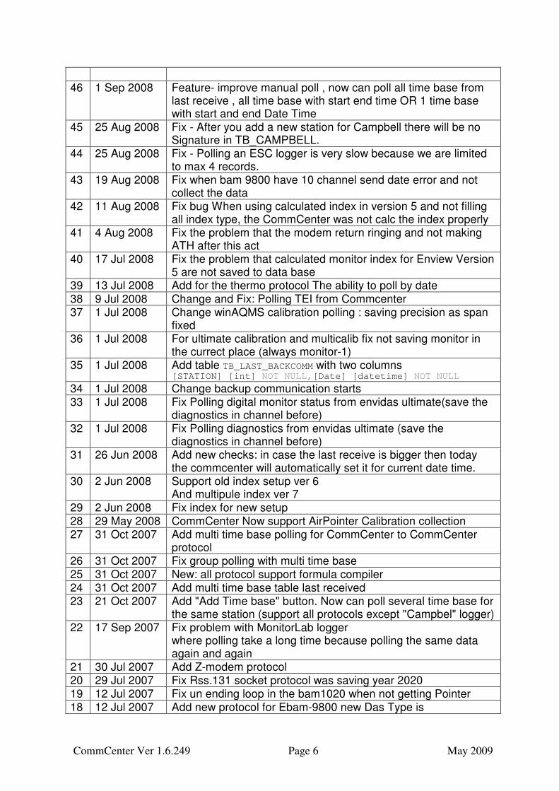
46 1 Sep 2008 Feature- improve manual poll , now can poll all time base from
last receive , all time base with start end time OR 1 time base with start and end Date Time
45 25 Aug 2008 Fix - After you add a new station for Campbell there will be no Signature in TB_CAMPBELL.
44 25 Aug 2008 Fix - Polling an ESC logger is very slow because we are limited to max 4 records.
43 19 Aug 2008 Fix when bam 9800 have 10 channel send date error and not collect the data
42 11 Aug 2008 Fix bug When using calculated index in version 5 and not filling all index type, the CommCenter was not calc the index properly
41 4 Aug 2008 Fix the problem that the modem return ringing and not making ATH after this act
40 17 Jul 2008 Fix the problem that calculated monitor index for Enview Version 5 are not saved to data base
39 13 Jul 2008 Add for the thermo protocol The ability to poll by date 38 9 Jul 2008 Change and Fix: Polling TEI from Commcenter 37 1 Jul 2008 Change winAQMS calibration polling : saving precision as span
fixed 36 1 Jul 2008 For ultimate calibration and multicalib fix not saving monitor in
the currect place (always monitor-1) 35 1 Jul 2008 Add table TB_LAST_BACKCOMM with two columns
[STATION] [int] NOT NULL,[Date] [datetime] NOT NULL
34 1 Jul 2008 Change backup communication starts 33 1 Jul 2008 Fix Polling digital monitor status from envidas ultimate(save the
diagnostics in channel before) 32 1 Jul 2008 Fix Polling diagnostics from envidas ultimate (save the
diagnostics in channel before) 31 26 Jun 2008 Add new checks: in case the last receive is bigger then today
the commcenter will automatically set it for current date time. 30 2 Jun 2008 Support old index setup ver 6
And multipule index ver 7 29 2 Jun 2008 Fix index for new setup 28 29 May 2008 CommCenter Now support AirPointer Calibration collection 27 31 Oct 2007 Add multi time base polling for CommCenter to CommCenter
protocol 26 31 Oct 2007 Fix group polling with multi time base 25 31 Oct 2007 New: all protocol support formula compiler 24 31 Oct 2007 Add multi time base table last received 23 21 Oct 2007 Add "Add Time base" button. Now can poll several time base for
the same station (support all protocols except "Campbel" logger) 22 17 Sep 2007 Fix problem with MonitorLab logger
where polling take a long time because polling the same data again and again
21 30 Jul 2007 Add Z-modem protocol 20 29 Jul 2007 Fix Rss.131 socket protocol was saving year 2020 19 12 Jul 2007 Fix un ending loop in the bam1020 when not getting Pointer 18 12 Jul 2007 Add new protocol for Ebam-9800 new Das Type is
CommCenter Ver 1.6.249 Page 7 May 2009
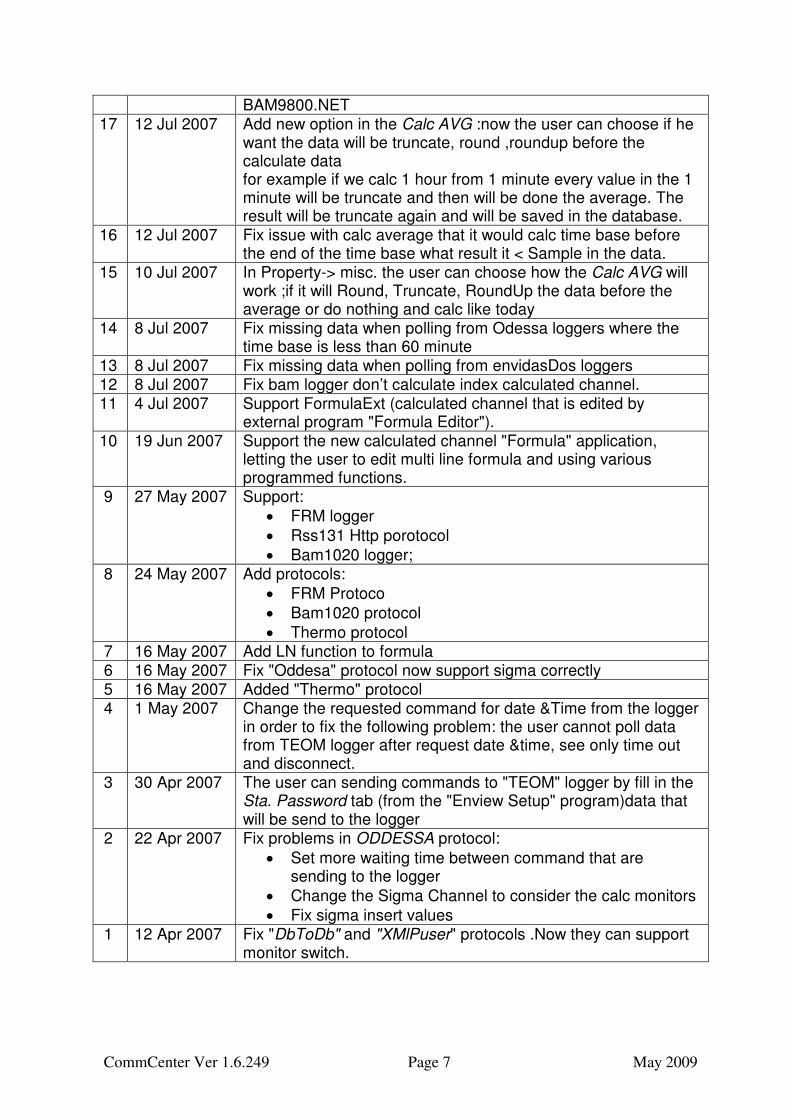
BAM9800.NET 17 12 Jul 2007 Add new option in the Calc AVG :now the user can choose if he
want the data will be truncate, round ,roundup before the calculate data for example if we calc 1 hour from 1 minute every value in the 1 minute will be truncate and then will be done the average. The result will be truncate again and will be saved in the database.
16 12 Jul 2007 Fix issue with calc average that it would calc time base before the end of the time base what result it < Sample in the data.
15 10 Jul 2007 In Property-> misc. the user can choose how the Calc AVG will work ;if it will Round, Truncate, RoundUp the data before the average or do nothing and calc like today
14 8 Jul 2007 Fix missing data when polling from Odessa loggers where the time base is less than 60 minute
13 8 Jul 2007 Fix missing data when polling from envidasDos loggers 12 8 Jul 2007 Fix bam logger don’t calculate index calculated channel. 11 4 Jul 2007 Support FormulaExt (calculated channel that is edited by
external program "Formula Editor"). 10 19 Jun 2007 Support the new calculated channel "Formula" application,
letting the user to edit multi line formula and using various programmed functions.
9 27 May 2007 Support:
• FRM logger
• Rss131 Http porotocol
• Bam1020 logger; 8 24 May 2007 Add protocols:
• FRM Protoco
• Bam1020 protocol
• Thermo protocol 7 16 May 2007 Add LN function to formula 6 16 May 2007 Fix "Oddesa" protocol now support sigma correctly 5 16 May 2007 Added "Thermo" protocol 4 1 May 2007 Change the requested command for date &Time from the logger
in order to fix the following problem: the user cannot poll data from TEOM logger after request date &time, see only time out and disconnect.
3 30 Apr 2007 The user can sending commands to "TEOM" logger by fill in the Sta. Password tab (from the "Enview Setup" program)data that will be send to the logger
2 22 Apr 2007 Fix problems in ODDESSA protocol:
• Set more waiting time between command that are sending to the logger
• Change the Sigma Channel to consider the calc monitors
• Fix sigma insert values 1 12 Apr 2007 Fix "DbToDb" and "XMlPuser" protocols .Now they can support
monitor switch.
CommCenter Ver 1.6.249 Page 8 May 2009
Page intentionally blank
CommCenter Ver 1.6.249 Page 9 May 2009
Chapter 1
Introduction
1.1 Communication Center Overview A versatile multi-thread communications Server/Client called "Communication Center" is available with the "Software Manager Setup" (or "EnvistaARM Setup") system. Communication Center is designed to communicate with other Centers by Serial (RS232), Modem and IP technologies. The data received from stations can be dynamically changed, evaluated and flagged with status codes while being inserted into the data tables of the SQL or Oracle database. Communication Center can act as a data server, receiving requests for information from other Communication Center programs. In this way, several “regional” Comm Center programs can collect data from each other and a “central” system’s Communication Center can then poll the “regional” data. Communication Center also offers a backup servers that will poll data in case of failure in the original server. This manual section describes the setup and operation of the Communication Center program. It also presents the relationship of Communication Center to the database tables and other system programs such as the Software Manager setup. The "Communication Center" program is used to poll for averages, digital input status, digital monitor status , edit history status, calibrations, multi calibration, power fail messages, diagnostics. It can also synchronize the clock.
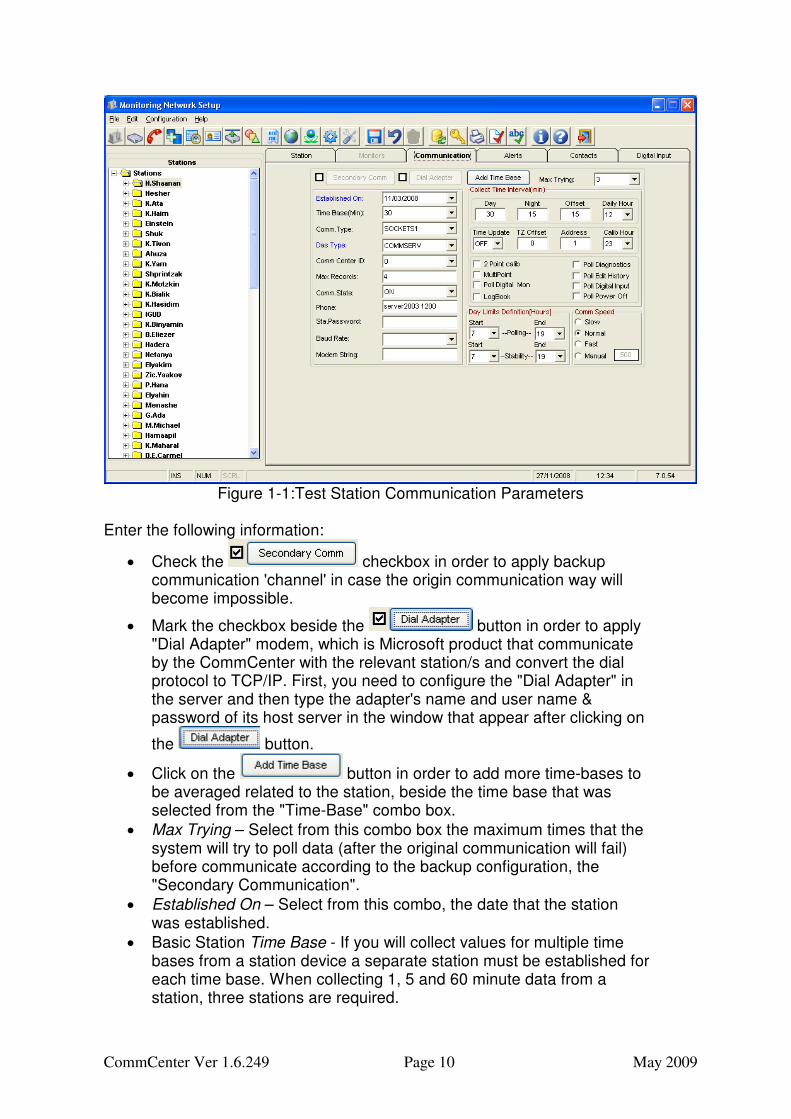
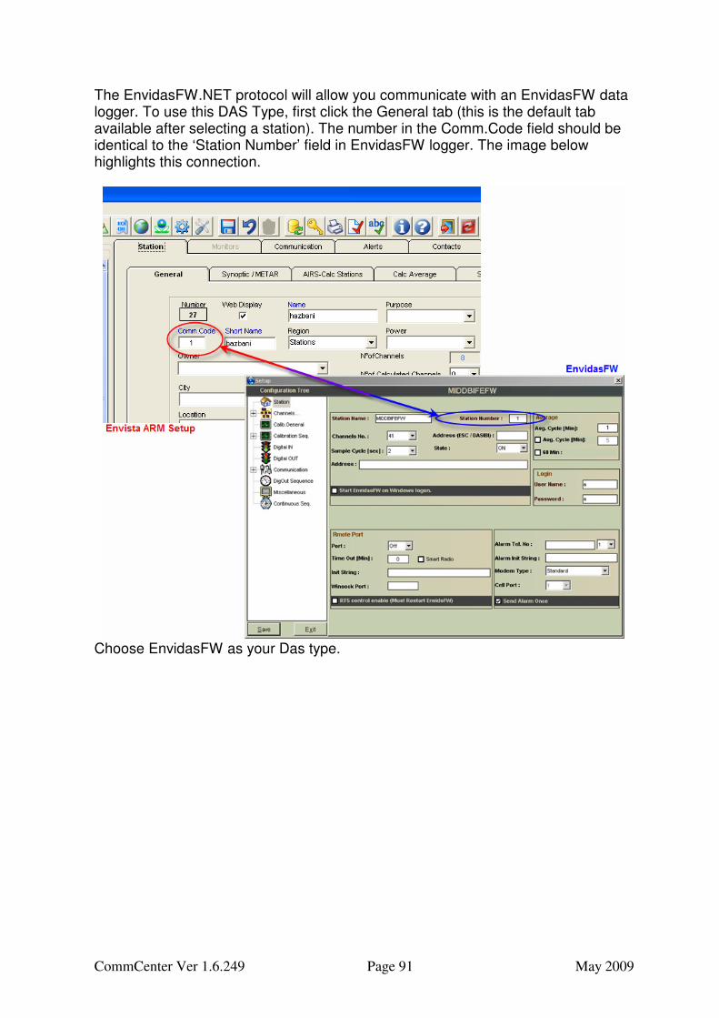
1.2 Setup Station Communication Parameters Before we start using the Communication Center, we may pay attention to the communication parameters which should be set up, in order to poll them later. Those parameters have to be set up for each station in the "Software Manager Setup" ("Evaluation Monitoring Network setup" in its new name) application (Version 3,4,5 or 6) that supports monitoring network configuration. Note! The "Software Manager Setup" supports also "ENVIEW2000", and "ENVIDAS FW", so there may be parameters there that are unnecessary or invalid in "Communication Center". To set up the Station Communication Parameters select the "Communication" Tab. The screen like the example in Figure 1-1(which reflects an example for version 6) will appear:
CommCenter Ver 1.6.249 Page 10 May 2009
Figure 1-1:Test Station Communication Parameters
Enter the following information:
• Check the checkbox in order to apply backup communication 'channel' in case the origin communication way will become impossible.
• Mark the checkbox beside the button in order to apply "Dial Adapter" modem, which is Microsoft product that communicate by the CommCenter with the relevant station/s and convert the dial protocol to TCP/IP. First, you need to configure the "Dial Adapter" in the server and then type the adapter's name and user name & password of its host server in the window that appear after clicking on
the button.
• Click on the button in order to add more time-bases to be averaged related to the station, beside the time base that was selected from the "Time-Base" combo box.
• Max Trying – Select from this combo box the maximum times that the system will try to poll data (after the original communication will fail) before communicate according to the backup configuration, the "Secondary Communication".
• Established On – Select from this combo, the date that the station was established.
• Basic Station Time Base - If you will collect values for multiple time bases from a station device a separate station must be established for each time base. When collecting 1, 5 and 60 minute data from a station, three stations are required.
CommCenter Ver 1.6.249 Page 11 May 2009
• Comm. Type - These are selected from the Ports created with the General Communication settings.
• DAS Type – Select the Data Acquisition System Model installed in the station.
• Comm Center ID – Select the relevant Id in order to poll data with the "Communication Center" program.
• Max Records – Specify the maximum number of data periods to be collected in a single block during a communication. If you needed to obtain 48 hours of hourly data and set the max to 10 there will be 5 blocks requested. For noisy phone lines reduce the maximum until there is only a small chance an error will occur during the block transmission. When errors occur a block must be retransmitted and large block have a higher probability that an error will occur sometime during the transmission. In sever noise conditions and large block sizes successful communication may be impossible until the max is reduced.
• Comm. State – Select On for automatic data collection.
• Phone – Insert either the telephone number or the TCP/IP address and TCP/IP port number. Include all the dialing prefix strings to access lines in the telephone string. For example: 9,15122345678 will dial a 9 to access an outside line, pause a second and then dial a long distance call in the USA. For Sockets communications enter an IP address like 192.1.1.134 443 where the address is 192.1.1.134 and the port to use is 443. The IP address and port must be separated only by a single space.
• Sta. Password – Insert a Station Password if necessary. In the case of "Envidas" and "EnvidasFW" loggers the Password must be Blank or ENVI. With these loggers any other text is considered a string to be sent to a switching device, not a password for the logger. The user can sending commands to "TEOM" logger (in the future for the rest of the loggers) by fill in the Sta. Password tab data that will be send to the logger in this form:
o Use “,” to separate command o Use “[“ “]” to set time between command o Use “^” to set control key
Example: [2],PM25@%J,[3],^T,[0.5],2 . o [2] = wait 2 second after connection. o PM25@%J = the password itself o [3] = wait for 3 second. o ^T= send CONTROL T (^T must use capital T. o [0.5] = wait for 500 mili-second, o 2= send “2”
The CommCenter Will not notice any response from the logger for the command that it send. After this sequence is finish, the CommCenter will clean the receive buffer before continuing to the protocol Now the password filed is 20 char in order to make it longer you need to get lat setup manager update (will set to 50 char).
CommCenter Ver 1.6.249 Page 12 May 2009
• Baud Rate – Enter a station specific communication Baud Rate. If left empty the rate for the port will be used.
• Modem Init. String – Enter a station modem initialization string. If left empty the string for the port will be used. The string &FE0&N6 would set the modem to factory defaults and then turn Echo off and force the modem to connect only at 9600 baud. AT is added by the program at the beginning of the string before transmission to the modem.
• Collect Time Interval (in minutes) during Daylight and Nighttime hours. Often stations are polled at one interval during the day and less frequently at night. For Daily polling set both values to 1440.
• Define an Offset in minutes to delay data collection. If the poll interval is 60 minutes and the offset is 5 minutes polling will occur starting a 5 minutes after each hour.
• Time Update – Select On or Off for Automatic Time Synchronization of the station devices to the time of the communication computer.
• Address – Logger ID, This field is used to specify the logger ID. It must be used for all logger types. Note ESC IDs are two characters alphanumeric. Enter 01 not 1 for the ESC ID. For Odessa DSM loggers enter a 0 if Multi-Unit Operations is not enabled. Legal addresses for DSMs are 1 through 9. For Dasibi loggers, the address is 6 characters.
• Poll Calibration – Select Calibration record collection to on for automatic collection.
• Calibration Hour – Set the time at which Calibration records will be collected when polling is done only once a day. For smaller intervals calibration records will be requested every poll.
• Poll Dig. Input - specifies whether digital input data records are to be retrieved.
• Poll Dig. Mon. –Select ON to receive Digital Monitor Status Information for each digital monitor instrument in the station.
• Edit History– Select ON to receive Edit History Information for each Digital Monitor in the station.
• Multi Calib – For Multi Calibration enable for each digital monitor in the station, select ON.
• Power Off – Select ON to receive Power Off status for each digital monitor in the station.
• Diagnostics- In order to receive Diagnostics status for each digital monitor in the station, select ON.
• Day Limit’s – Specify a Day beginning hour and a Day ending hour for the polling schedule and for automatic atmospheric stability calculations.. In the example above the Day is 12 hours long starting at 7 Am and ending at 7 PM.
• Comm Speed – Select Slow, Normal or Fast speed of response time. Alternatively, you can select Manual and choose the exact response time (in mSec) by yourself.
CommCenter Ver 1.6.249 Page 13 May 2009
1.3 Installation 1.3.1 Installation from the CD The Communication Center program can be installed from its installation CD into C:\Program Files\Envitech LTD\Communication Center. Click on Communication Center folder, then the setup folder and from this folder click on "CommunicationCenter.msi" like in Figure 1-2.
Figure 1-2
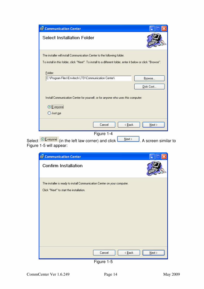
A window similar to Figure 1-3 will appear:
Figure 1-3
Click and you will see the window similar to Figure 1-4:
CommCenter Ver 1.6.249 Page 14 May 2009
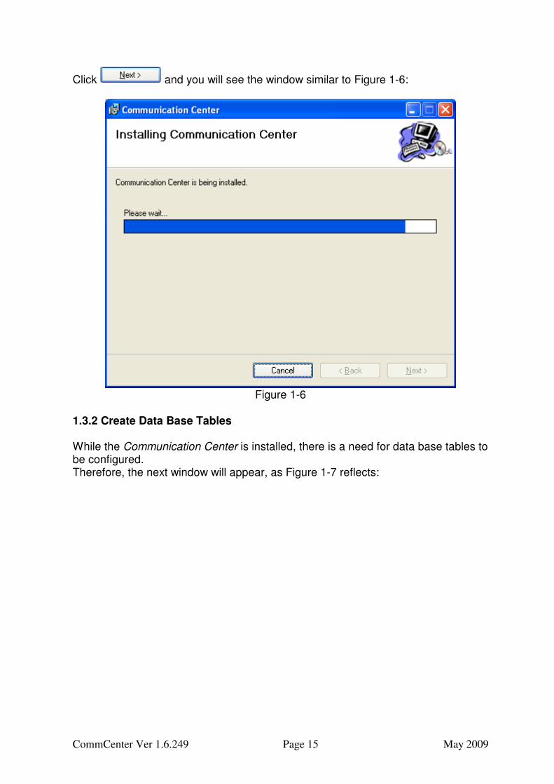
Figure 1-4
Select (in the left law corner) and click . A screen similar to Figure 1-5 will appear:
Figure 1-5
CommCenter Ver 1.6.249 Page 15 May 2009
Click and you will see the window similar to Figure 1-6:
Figure 1-6
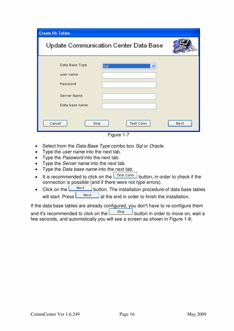
1.3.2 Create Data Base Tables While the Communication Center is installed, there is a need for data base tables to be configured. Therefore, the next window will appear, as Figure 1-7 reflects:
CommCenter Ver 1.6.249 Page 16 May 2009
Figure 1-7
• Select from the Data Base Type combo box Sql or Oracle.
• Type the user name into the next tab.
• Type the Password into the next tab.
• Type the Server name into the next tab.
• Type the Data base name into the next tab.
• It is recommended to click on the button, in order to check if the connection is possible (and if there were not type errors).
• Click on the button. The installation procedure of data base tables
will start. Press at the end in order to finish the installation.
If the data base tables are already configured, you don't have to re-configure them
and it's recommended to click on the button in order to move on, wait a few seconds, and automatically you will see a screen as shown in Figure 1-8:
CommCenter Ver 1.6.249 Page 17 May 2009
Figure 1-8
Click "Close" and the setup are finished. Communication Center is ready to work with and there is a shortcut icon in your desktop as shown in Figure 1-9:
Figure 1-9
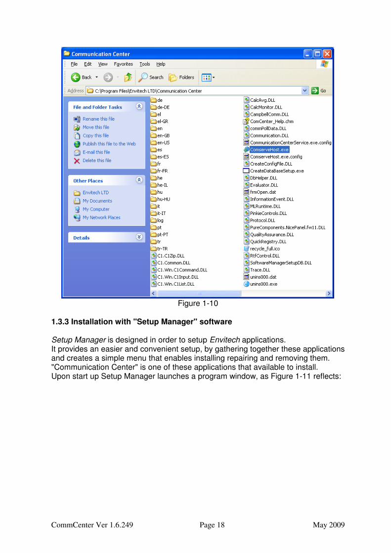
Click on this icon (that shown above) or open it from the C:\Program Files\Envitech LTD\Communication Center path ,as shown in Figure 1-10( the blue lightened file):
CommCenter Ver 1.6.249 Page 18 May 2009
Figure 1-10
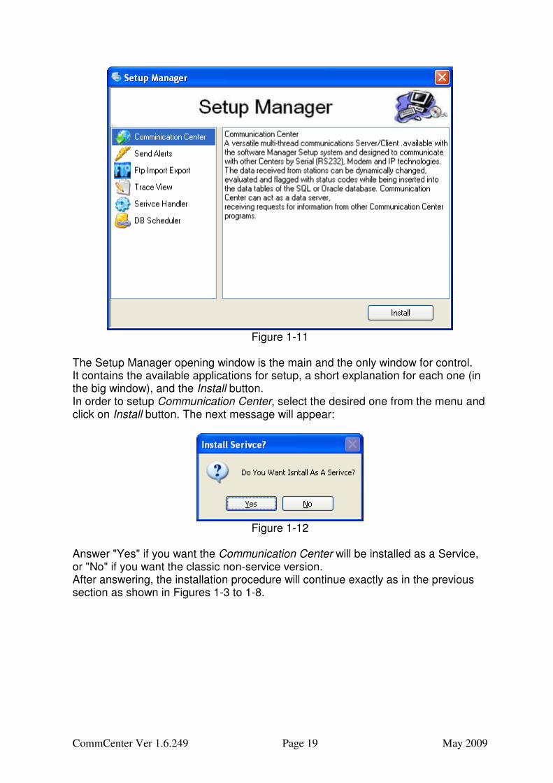
1.3.3 Installation with "Setup Manager" software Setup Manager is designed in order to setup Envitech applications. It provides an easier and convenient setup, by gathering together these applications and creates a simple menu that enables installing repairing and removing them. "Communication Center" is one of these applications that available to install. Upon start up Setup Manager launches a program window, as Figure 1-11 reflects:
CommCenter Ver 1.6.249 Page 19 May 2009
Figure 1-11
The Setup Manager opening window is the main and the only window for control. It contains the available applications for setup, a short explanation for each one (in the big window), and the Install button. In order to setup Communication Center, select the desired one from the menu and click on Install button. The next message will appear:
Figure 1-12
Answer "Yes" if you want the Communication Center will be installed as a Service, or "No" if you want the classic non-service version. After answering, the installation procedure will continue exactly as in the previous section as shown in Figures 1-3 to 1-8.
CommCenter Ver 1.6.249 Page 20 May 2009
Page intentionally blank
CommCenter Ver 1.6.249 Page 21 May 2009
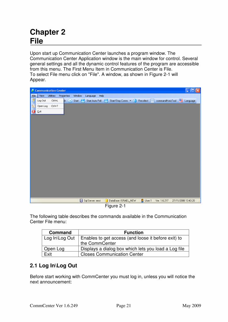
Chapter 2 File Upon start up Communication Center launches a program window. The Communication Center Application window is the main window for control. Several general settings and all the dynamic control features of the program are accessible from this menu. The First Menu Item in Communication Center is File. To select File menu click on "File". A window, as shown in Figure 2-1 will Appear.
Figure 2-1
The following table describes the commands available in the Communication Center File menu:
Command Function Log In\Log Out Enables to get access (and loose it before exit) to
the CommCenter Open Log Displays a dialog box which lets you load a Log file Exit Closes Communication Center
2.1 Log In\Log Out Before start working with CommCenter you must log in, unless you will notice the next announcement:
CommCenter Ver 1.6.249 Page 22 May 2009
Figure 2-2
In order to log in follow the next steps:
• Select "Log In" from the "File" menu, and the following window will appear:
Figure 2-3
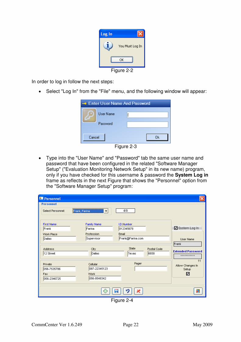
• Type into the "User Name" and "Password" tab the same user name and password that have been configured in the related "Software Manager Setup" ("Evaluation Monitoring Network Setup" in its new name) program, only if you have checked for this username & password the System Log in frame as reflects in the next Figure that shows the "Personnel" option from the "Software Manager Setup" program:
Figure 2-4
CommCenter Ver 1.6.249 Page 23 May 2009
The example in Figure 2-4 reflects a configuration of "Frank" as a user name and an extended password that the "Allow changes in Setup" checkbox has been checked. Therefore Frank has a permission to log in (with the same username and password) to the CommCenter by fill the same username and password to the log in window as was shown in Figure 2-3.
• Click and now you will be able to work with CommCenter.
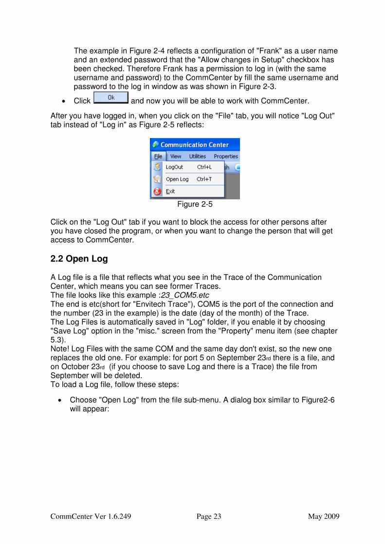
After you have logged in, when you click on the "File" tab, you will notice "Log Out" tab instead of "Log in" as Figure 2-5 reflects:
Figure 2-5
Click on the "Log Out" tab if you want to block the access for other persons after you have closed the program, or when you want to change the person that will get access to CommCenter.
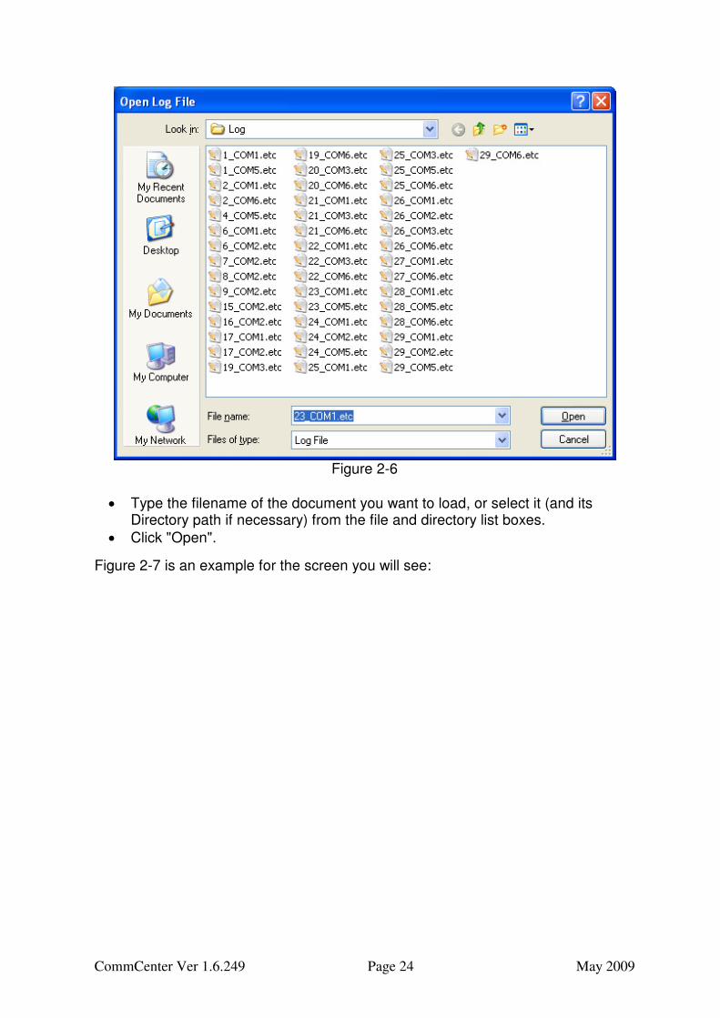
2.2 Open Log A Log file is a file that reflects what you see in the Trace of the Communication Center, which means you can see former Traces. The file looks like this example :23_COM5.etc The end is etc(short for "Envitech Trace"), COM5 is the port of the connection and the number (23 in the example) is the date (day of the month) of the Trace. The Log Files is automatically saved in "Log" folder, if you enable it by choosing "Save Log" option in the "misc." screen from the "Property" menu item (see chapter 5.3). Note! Log Files with the same COM and the same day don't exist, so the new one replaces the old one. For example: for port 5 on September 23rd there is a file, and on October 23rd (if you choose to save Log and there is a Trace) the file from September will be deleted. To load a Log file, follow these steps:
• Choose "Open Log" from the file sub-menu. A dialog box similar to Figure2-6 will appear:
CommCenter Ver 1.6.249 Page 24 May 2009
Figure 2-6
• Type the filename of the document you want to load, or select it (and its Directory path if necessary) from the file and directory list boxes.
• Click "Open".
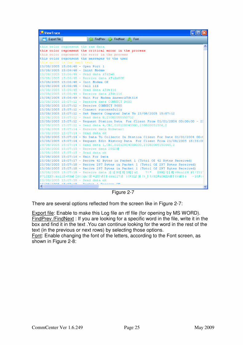
Figure 2-7 is an example for the screen you will see:
CommCenter Ver 1.6.249 Page 25 May 2009
Figure 2-7
There are several options reflected from the screen like in Figure 2-7:
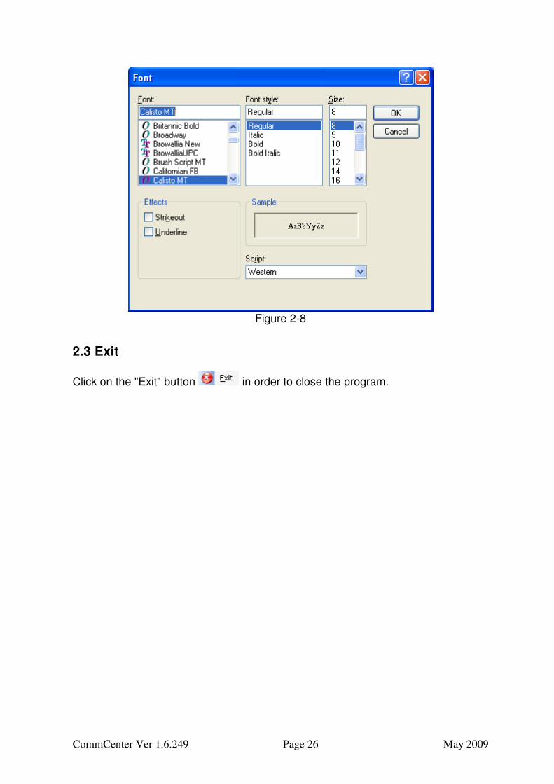
Export file: Enable to make this Log file an rtf file (for opening by MS WORD). FindPrev /FindNext : If you are looking for a specific word in the file, write it in the box and find it in the text .You can continue looking for the word in the rest of the text (in the previous or next rows) by selecting those options. Font: Enable changing the font of the letters, according to the Font screen, as shown in Figure 2-8:
CommCenter Ver 1.6.249 Page 26 May 2009
Figure 2-8
2.3 Exit
Click on the "Exit" button in order to close the program.
CommCenter Ver 1.6.249 Page 27 May 2009
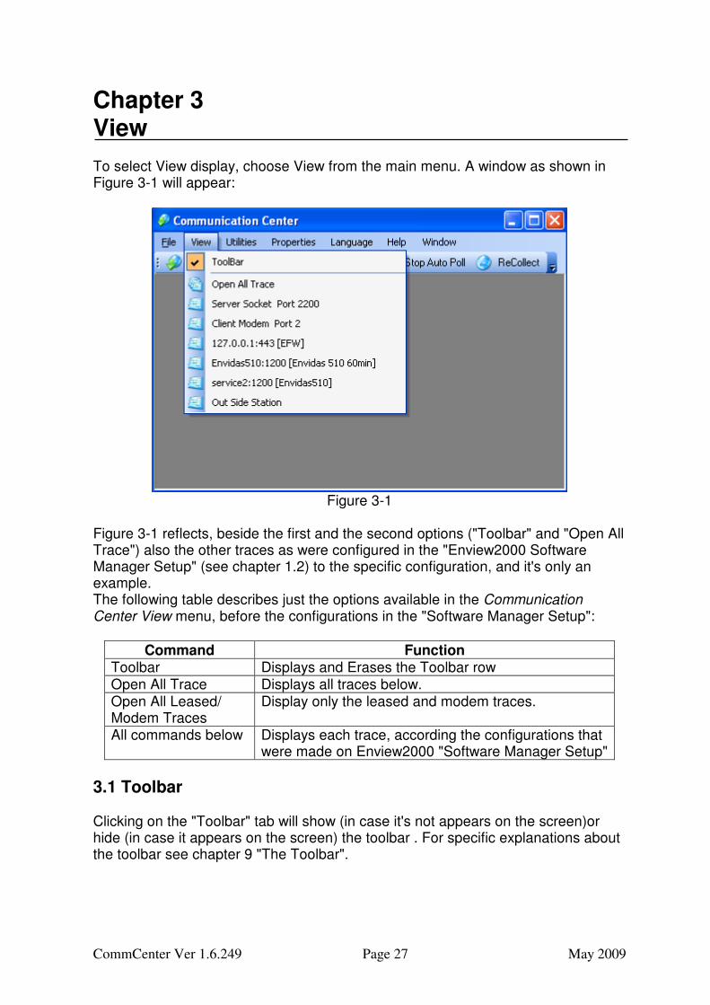
Chapter 3 View To select View display, choose View from the main menu. A window as shown in Figure 3-1 will appear:
Figure 3-1
Figure 3-1 reflects, beside the first and the second options ("Toolbar" and "Open All Trace") also the other traces as were configured in the "Enview2000 Software Manager Setup" (see chapter 1.2) to the specific configuration, and it's only an example. The following table describes just the options available in the Communication Center View menu, before the configurations in the "Software Manager Setup":
Command Function Toolbar Displays and Erases the Toolbar row Open All Trace Displays all traces below. Open All Leased/ Modem Traces
Display only the leased and modem traces.
All commands below Displays each trace, according the configurations that were made on Enview2000 "Software Manager Setup"
3.1 Toolbar Clicking on the "Toolbar" tab will show (in case it's not appears on the screen)or hide (in case it appears on the screen) the toolbar . For specific explanations about the toolbar see chapter 9 "The Toolbar".
CommCenter Ver 1.6.249 Page 28 May 2009
3.2 Open All Trace or Leased/Modem Traces
Clicking on the tab display all the screens of Trace that you set up in the "Software Manager Setup" application (see chapter 1.2), practically the next Traces in this chapter.
Clicking on the tab will display not all the traces but only the leased and modem traces.
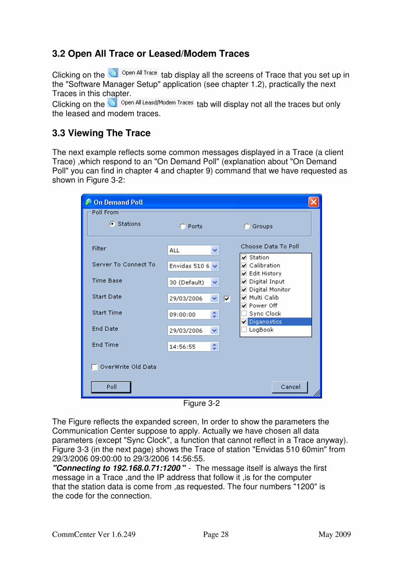
3.3 Viewing The Trace The next example reflects some common messages displayed in a Trace (a client Trace) ,which respond to an "On Demand Poll" (explanation about "On Demand Poll" you can find in chapter 4 and chapter 9) command that we have requested as shown in Figure 3-2:
Figure 3-2
The Figure reflects the expanded screen, In order to show the parameters the Communication Center suppose to apply. Actually we have chosen all data parameters (except "Sync Clock", a function that cannot reflect in a Trace anyway). Figure 3-3 (in the next page) shows the Trace of station "Envidas 510 60min" from 29/3/2006 09:00:00 to 29/3/2006 14:56:55. "Connecting to 192.168.0.71:1200 " - The message itself is always the first message in a Trace ,and the IP address that follow it ,is for the computer that the station data is come from ,as requested. The four numbers "1200" is the code for the connection.
CommCenter Ver 1.6.249 Page 29 May 2009
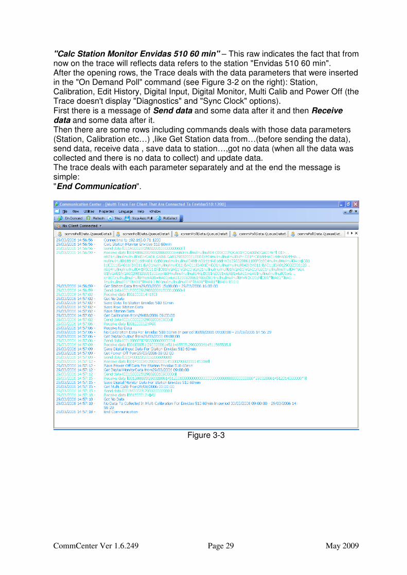
"Calc Station Monitor Envidas 510 60 min" – This raw indicates the fact that from now on the trace will reflects data refers to the station "Envidas 510 60 min". After the opening rows, the Trace deals with the data parameters that were inserted in the "On Demand Poll" command (see Figure 3-2 on the right): Station, Calibration, Edit History, Digital Input, Digital Monitor, Multi Calib and Power Off (the Trace doesn't display "Diagnostics" and "Sync Clock" options). First there is a message of Send data and some data after it and then Receive data and some data after it. Then there are some rows including commands deals with those data parameters (Station, Calibration etc…) ,like Get Station data from…(before sending the data), send data, receive data , save data to station…,got no data (when all the data was collected and there is no data to collect) and update data. The trace deals with each parameter separately and at the end the message is simple: "End Communication".
Figure 3-3
CommCenter Ver 1.6.249 Page 30 May 2009
Page intentionally blank
CommCenter Ver 1.6.249 Page 31 May 2009
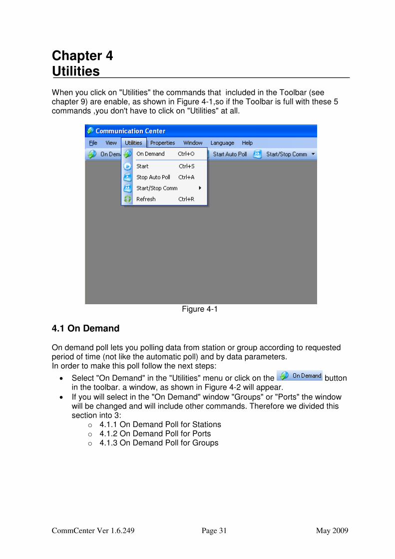
Chapter 4 Utilities When you click on "Utilities" the commands that included in the Toolbar (see chapter 9) are enable, as shown in Figure 4-1,so if the Toolbar is full with these 5 commands ,you don't have to click on "Utilities" at all.
Figure 4-1
4.1 On Demand On demand poll lets you polling data from station or group according to requested period of time (not like the automatic poll) and by data parameters. In order to make this poll follow the next steps:
• Select "On Demand" in the "Utilities" menu or click on the button in the toolbar. a window, as shown in Figure 4-2 will appear.
• If you will select in the "On Demand" window "Groups" or "Ports" the window will be changed and will include other commands. Therefore we divided this section into 3:
o 4.1.1 On Demand Poll for Stations o 4.1.2 On Demand Poll for Ports o 4.1.3 On Demand Poll for Groups
CommCenter Ver 1.6.249 Page 32 May 2009
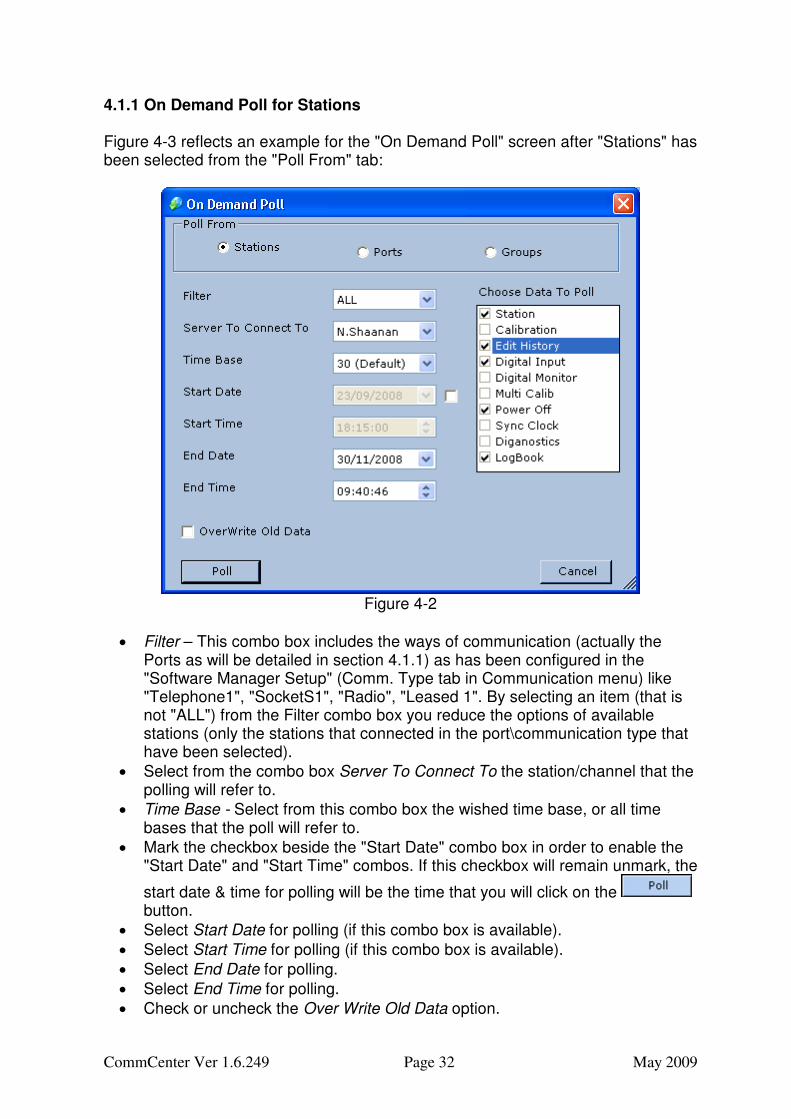
4.1.1 On Demand Poll for Stations Figure 4-3 reflects an example for the "On Demand Poll" screen after "Stations" has been selected from the "Poll From" tab:
Figure 4-2
• Filter – This combo box includes the ways of communication (actually the Ports as will be detailed in section 4.1.1) as has been configured in the "Software Manager Setup" (Comm. Type tab in Communication menu) like "Telephone1", "SocketS1", "Radio", "Leased 1". By selecting an item (that is not "ALL") from the Filter combo box you reduce the options of available stations (only the stations that connected in the port\communication type that have been selected).
• Select from the combo box Server To Connect To the station/channel that the polling will refer to.
• Time Base - Select from this combo box the wished time base, or all time bases that the poll will refer to.
• Mark the checkbox beside the "Start Date" combo box in order to enable the "Start Date" and "Start Time" combos. If this checkbox will remain unmark, the
start date & time for polling will be the time that you will click on the button.
• Select Start Date for polling (if this combo box is available).
• Select Start Time for polling (if this combo box is available).
• Select End Date for polling.
• Select End Time for polling.
• Check or uncheck the Over Write Old Data option.
CommCenter Ver 1.6.249 Page 33 May 2009
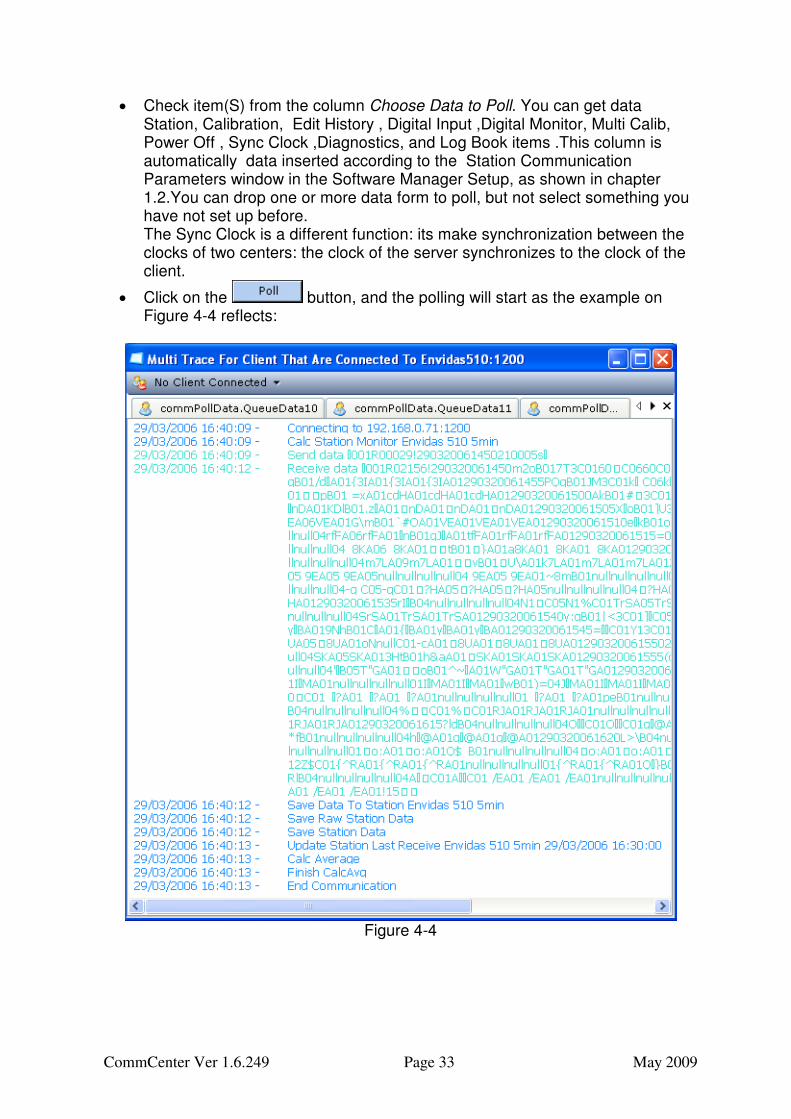
• Check item(S) from the column Choose Data to Poll. You can get data Station, Calibration, Edit History , Digital Input ,Digital Monitor, Multi Calib, Power Off , Sync Clock ,Diagnostics, and Log Book items .This column is automatically data inserted according to the Station Communication Parameters window in the Software Manager Setup, as shown in chapter 1.2.You can drop one or more data form to poll, but not select something you have not set up before. The Sync Clock is a different function: its make synchronization between the clocks of two centers: the clock of the server synchronizes to the clock of the client.
• Click on the button, and the polling will start as the example on Figure 4-4 reflects:
Figure 4-4
CommCenter Ver 1.6.249 Page 34 May 2009
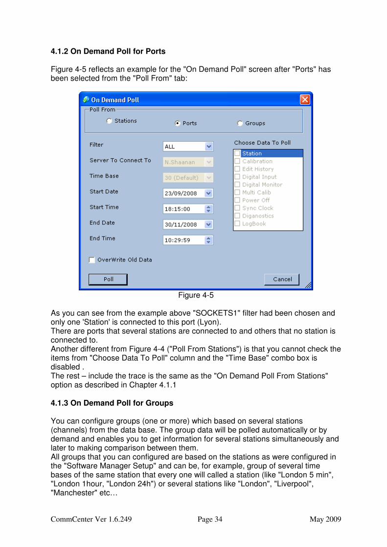
4.1.2 On Demand Poll for Ports Figure 4-5 reflects an example for the "On Demand Poll" screen after "Ports" has been selected from the "Poll From" tab:
Figure 4-5
As you can see from the example above "SOCKETS1" filter had been chosen and only one 'Station' is connected to this port (Lyon). There are ports that several stations are connected to and others that no station is connected to. Another different from Figure 4-4 ("Poll From Stations") is that you cannot check the items from "Choose Data To Poll" column and the "Time Base" combo box is disabled . The rest – include the trace is the same as the "On Demand Poll From Stations" option as described in Chapter 4.1.1 4.1.3 On Demand Poll for Groups You can configure groups (one or more) which based on several stations (channels) from the data base. The group data will be polled automatically or by demand and enables you to get information for several stations simultaneously and later to making comparison between them. All groups that you can configured are based on the stations as were configured in the "Software Manager Setup" and can be, for example, group of several time bases of the same station that every one will called a station (like "London 5 min", "London 1hour, "London 24h") or several stations like "London", "Liverpool", "Manchester" etc…
CommCenter Ver 1.6.249 Page 35 May 2009
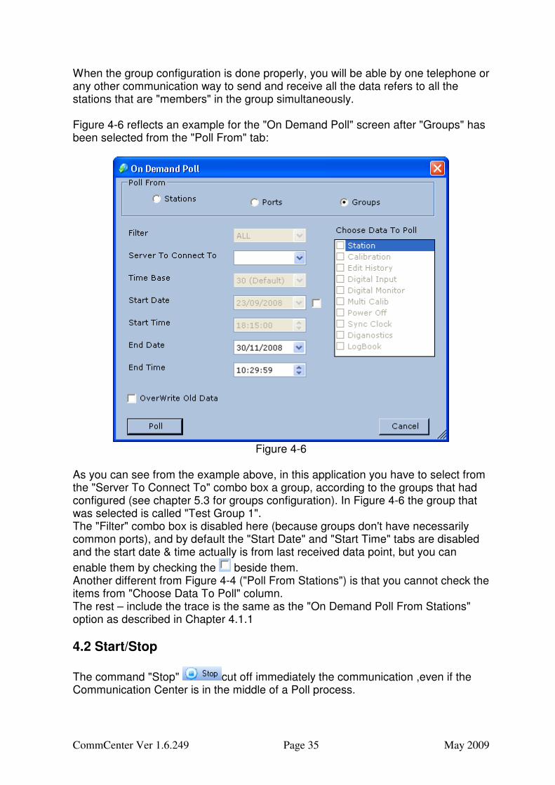
When the group configuration is done properly, you will be able by one telephone or any other communication way to send and receive all the data refers to all the stations that are "members" in the group simultaneously. Figure 4-6 reflects an example for the "On Demand Poll" screen after "Groups" has been selected from the "Poll From" tab:
Figure 4-6
As you can see from the example above, in this application you have to select from the "Server To Connect To" combo box a group, according to the groups that had configured (see chapter 5.3 for groups configuration). In Figure 4-6 the group that was selected is called "Test Group 1". The "Filter" combo box is disabled here (because groups don't have necessarily common ports), and by default the "Start Date" and "Start Time" tabs are disabled and the start date & time actually is from last received data point, but you can
enable them by checking the beside them. Another different from Figure 4-4 ("Poll From Stations") is that you cannot check the items from "Choose Data To Poll" column. The rest – include the trace is the same as the "On Demand Poll From Stations" option as described in Chapter 4.1.1
4.2 Start/Stop
The command "Stop" cut off immediately the communication ,even if the Communication Center is in the middle of a Poll process.
CommCenter Ver 1.6.249 Page 36 May 2009
If you click "Start" (when you are in a stop mode) the communication will restart, you will be able to request manual poll, and auto poll mode will be possible. If you try to demand poll, when Communication Center is in "Stop All" state, you will see no sign of communication, and if you will try to Start Auto Poll (as detailed in chapter 4.3) you will notice the message as shown in Figure 4-7:
Figure 4-7
4.3 Start Auto Poll/Stop Auto Poll This is also a change state function, which means that one click it starts the auto poll and the next click it stops the poll.
When the Communication Center is in "Start Auto Poll" state, the poll will be automatically according to the Station Communication Parameters window in the Software Manager Setup, (see separate manual), for example if there is one station with Collect Time Interval of 5 minutes and offset 0 minute, so there will be a poll automatically every 5 minute: …15:00,15:05,15:10 etc. In order to stop auto poll click again on the same icon , that now looks like this:
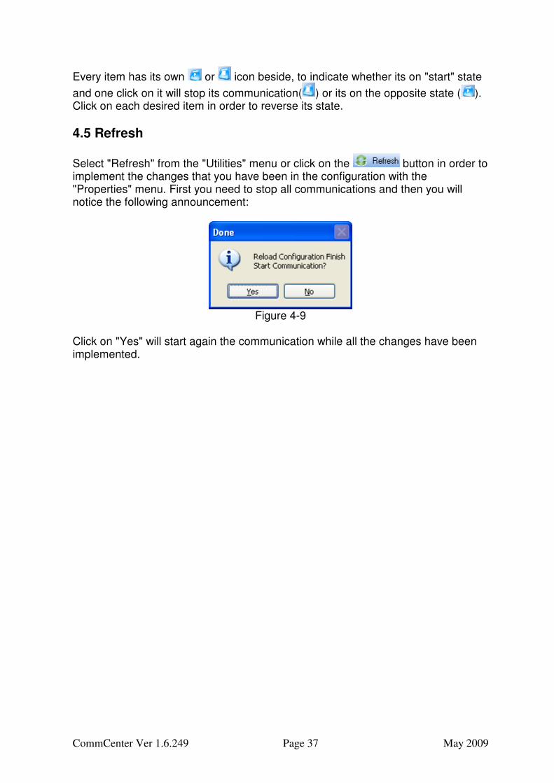
4.4 Start/Stop Communication This utility is meant for start or stop communication for selected port. In order to
select the port click on the sign beside the icon, or on the sign beside the tab in the menu , and the list of the ports will be open, as shown in the following figure:
Figure 4-8
CommCenter Ver 1.6.249 Page 37 May 2009
Every item has its own or icon beside, to indicate whether its on "start" state
and one click on it will stop its communication( ) or its on the opposite state ( ). Click on each desired item in order to reverse its state.
4.5 Refresh
Select "Refresh" from the "Utilities" menu or click on the button in order to implement the changes that you have been in the configuration with the "Properties" menu. First you need to stop all communications and then you will notice the following announcement:
Figure 4-9
Click on "Yes" will start again the communication while all the changes have been implemented.
CommCenter Ver 1.6.249 Page 38 May 2009
Page intentionally blank
CommCenter Ver 1.6.249 Page 39 May 2009
Chapter 5 Properties The Properties menu is meant for configuring all the parameters that you need in order to work with the "Communication Center", include the communication parameters, the groups setup, the data base setup etc. When you click on "Property" the Communication Center displays a screen that have 6 commands, tabs ,each with a sub-screen .The following sub-chapters include details about each tab\screen items.
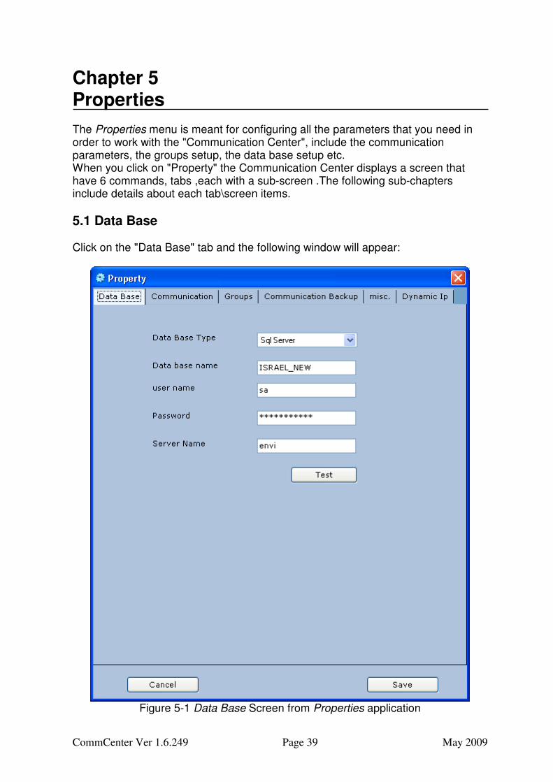
5.1 Data Base Click on the "Data Base" tab and the following window will appear:
Figure 5-1 Data Base Screen from Properties application
CommCenter Ver 1.6.249 Page 40 May 2009
• Select from the Data Base Type combo box Sql Server or Oracle.
• Type the Data Base Name into the next tab.
• Type the user name into the next tab.
• Type the Password into the next tab.
• Type the Server Name into the next tab.
• It is recommended to click on the button, in order to check if the connection is possible (and if there were not type errors).In case of success you may continue to the next step.
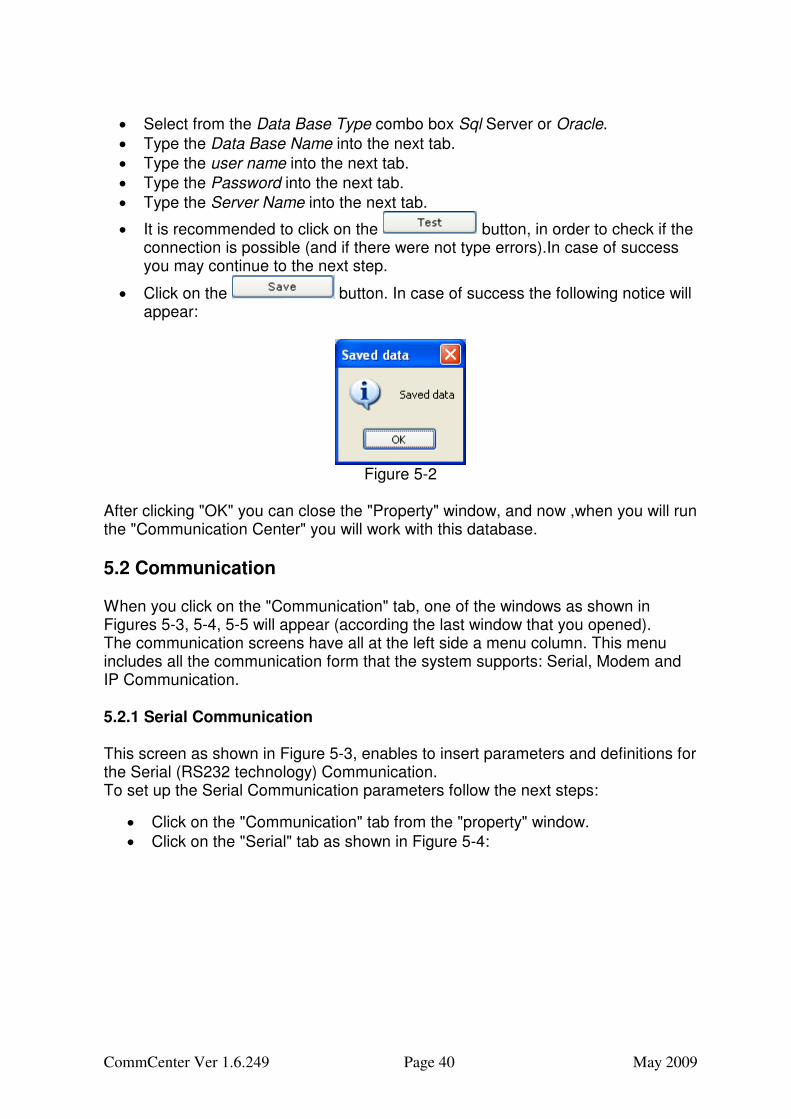
• Click on the button. In case of success the following notice will appear:
Figure 5-2
After clicking "OK" you can close the "Property" window, and now ,when you will run the "Communication Center" you will work with this database.
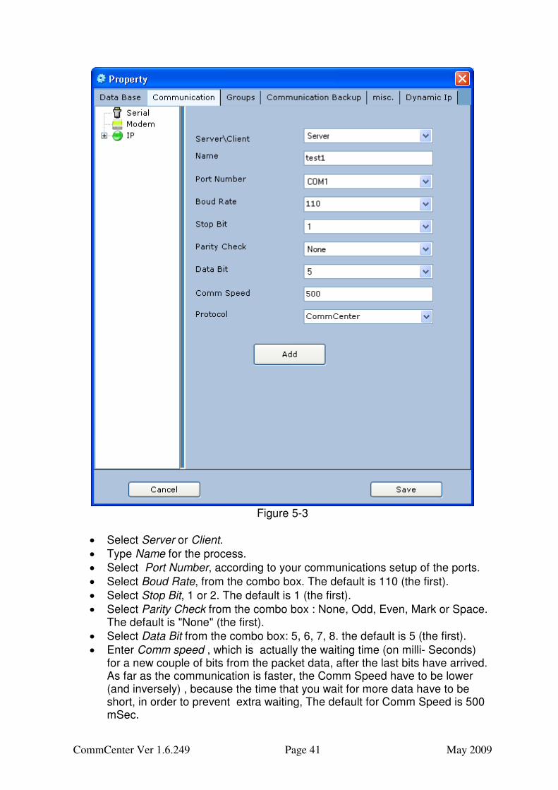
5.2 Communication When you click on the "Communication" tab, one of the windows as shown in Figures 5-3, 5-4, 5-5 will appear (according the last window that you opened). The communication screens have all at the left side a menu column. This menu includes all the communication form that the system supports: Serial, Modem and IP Communication. 5.2.1 Serial Communication This screen as shown in Figure 5-3, enables to insert parameters and definitions for the Serial (RS232 technology) Communication. To set up the Serial Communication parameters follow the next steps:
• Click on the "Communication" tab from the "property" window.
• Click on the "Serial" tab as shown in Figure 5-4:
CommCenter Ver 1.6.249 Page 41 May 2009
Figure 5-3
• Select Server or Client.
• Type Name for the process.
• Select Port Number, according to your communications setup of the ports.
• Select Boud Rate, from the combo box. The default is 110 (the first).
• Select Stop Bit, 1 or 2. The default is 1 (the first).
• Select Parity Check from the combo box : None, Odd, Even, Mark or Space. The default is "None" (the first).
• Select Data Bit from the combo box: 5, 6, 7, 8. the default is 5 (the first).
• Enter Comm speed , which is actually the waiting time (on milli- Seconds) for a new couple of bits from the packet data, after the last bits have arrived. As far as the communication is faster, the Comm Speed have to be lower (and inversely) , because the time that you wait for more data have to be short, in order to prevent extra waiting, The default for Comm Speed is 500 mSec.
CommCenter Ver 1.6.249 Page 42 May 2009
• Select from the "Protocol" combo box one of the 3 protocols: CommCenter, Envidas Dos/FW or Envidas Alerts.
• Click on .The left combo box with the "Serial" icon will include a new item ,named after the Port Number you've selected, as shown in Figure 5-4 (called "Port 1").If you want to remove this item press "Delete".
• Press button when you are done, If you don't press "Save", all changes will be lost.
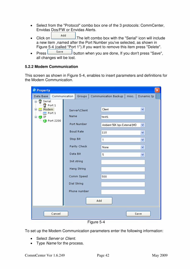
5.2.2 Modem Communication This screen as shown in Figure 5-4, enables to insert parameters and definitions for the Modem Communication.
Figure 5-4
To set up the Modem Communication parameters enter the following information:
• Select Server or Client.
• Type Name for the process.
CommCenter Ver 1.6.249 Page 43 May 2009
• Select Port Number, according to your communications setup of the ports.
• Select Boud Rate, from the combo box. The default is 110 (the first).
• Select Stop Bit, 1 or 2. The default is 1 (the first).
• Select Parity Check from the combo box : None, Odd, Even, Mark or Space. The default is "None" (the first).
• Select Data Bit from the combo box: 5, 6, 7, 8. the default is 5 (the first).
• For the Modem, Insert Init String (usually it's "AT&F").
• For the Modem, Insert Hang String (usually it's "ATH").
• Insert Comm Speed, which is actually the waiting time (on milli- Seconds) for a new couple of bits from the packet data, after the last bits have arrived. As far as the communication is faster, the Comm Speed have to be lower (and inversely) , because the time that you wait for more data have to be short, in order to prevent extra waiting, The default for Comm Speed is 500 mSec.
• Insert Dial String.
• Insert Phone Number.
• Click on .The left combo box with the "Modem" icon will include a new item ,named after the Port Number you've selected, as shown in Figure 5-4 (called "Port 1").If you want to remove this item press "Delete".
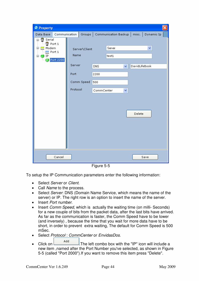
• Press button when you are done. 5.2.3 IP Communication This screen as shown in Figure 5-5, enables to insert parameters and definitions for the IP Communication (which mean ,communicate by the Internet Web). After you will set the parameters in this screen you will notice the number of the port that will reveal when you will click on the "+" sign beside the "IP" tab. In Figure 5-5 it’s the "Port 2000" tab that was configured and therefore appears on the screen below the "IP" tab:
CommCenter Ver 1.6.249 Page 44 May 2009
Figure 5-5
To setup the IP Communication parameters enter the following information:
• Select Server or Client.
• Call Name to the process.
• Select Server: DNS (Domain Name Service, which means the name of the server) or IP. The right row is an option to insert the name of the server.
• Insert Port number.
• Insert Comm Speed, which is actually the waiting time (on milli- Seconds) for a new couple of bits from the packet data, after the last bits have arrived. As far as the communication is faster, the Comm Speed have to be lower (and inversely) , because the time that you wait for more data have to be short, in order to prevent extra waiting, The default for Comm Speed is 500 mSec.
• Select Protocol : CommCenter or EnvidasDos.
• Click on .The left combo box with the "IP" icon will include a new item ,named after the Port Number you've selected, as shown in Figure 5-5 (called "Port 2000").If you want to remove this item press "Delete".
CommCenter Ver 1.6.249 Page 45 May 2009
• Press button when you are done.
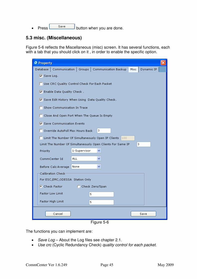
5.3 misc. (Miscellaneous) Figure 5-6 reflects the Miscellaneous (misc) screen. It has several functions, each with a tab that you should click on it , in order to enable the specific option.
Figure 5-6
The functions you can implement are:
• Save Log – About the Log files see chapter 2.1.
• Use crc (Cyclic Redundancy Check) quality control for each packet.
CommCenter Ver 1.6.249 Page 46 May 2009
• Enable Data Quality Check ( a parameter from "Software Manager Setup" that changes the data if it falls in a specific ranges).
• Save Edit History When Using Data Quality Check - Mark this checkbox in order to activate this topic.
• Show Communication In Trace - Mark this checkbox in order to activate this topic.
• Close And Open Port When The Queue Is Empty - Mark this checkbox in order to activate this topic.
• Save Communication Events - Mark this checkbox in order to activate this topic.
• Limit The Number Of Simultaneously Open IP Clients - Mark this checkbox and type the wished number.
• Override Auto Poll Max Hours Back - Mark this checkbox and type the number of hours (back) to be the period you wish to override auto poll max related to.
• Limit The Number Of Simultaneously Open Client to – If there are several stations as client and an automatic poll is running, there is a kind of "heavy traffic" on the system. Type a number, as lower as possible in order to limit it and enable all the stations data to be polled, even if it takes more time.
• Select from Priority combo box 1 (for Supervisor) or 2 (for Editor) or 0 (for technician).
• CommCenter ID – This ID is a number (from 0 to 10) that you can set in the "Enview setup" program (see separate manual). This is one of the communication parameters that meant for categorized the station, according to the selected number. From the "CommCenter ID" combo box, select if you want to poll data only for stations that their ID was set to one of the numbers (from 0 to 10) or to poll from all of them (by selecting "All").
• Before Calc Average - In order to round the values before calc average select "Round" (round up if the last digit is >5 and round down if the last digit is <5) or "Round Up" (round always up, for example: 6.321 will be rounded to 6.33) or "Truncate" (cut the last digit) or select "None" in order not to round at all the value.
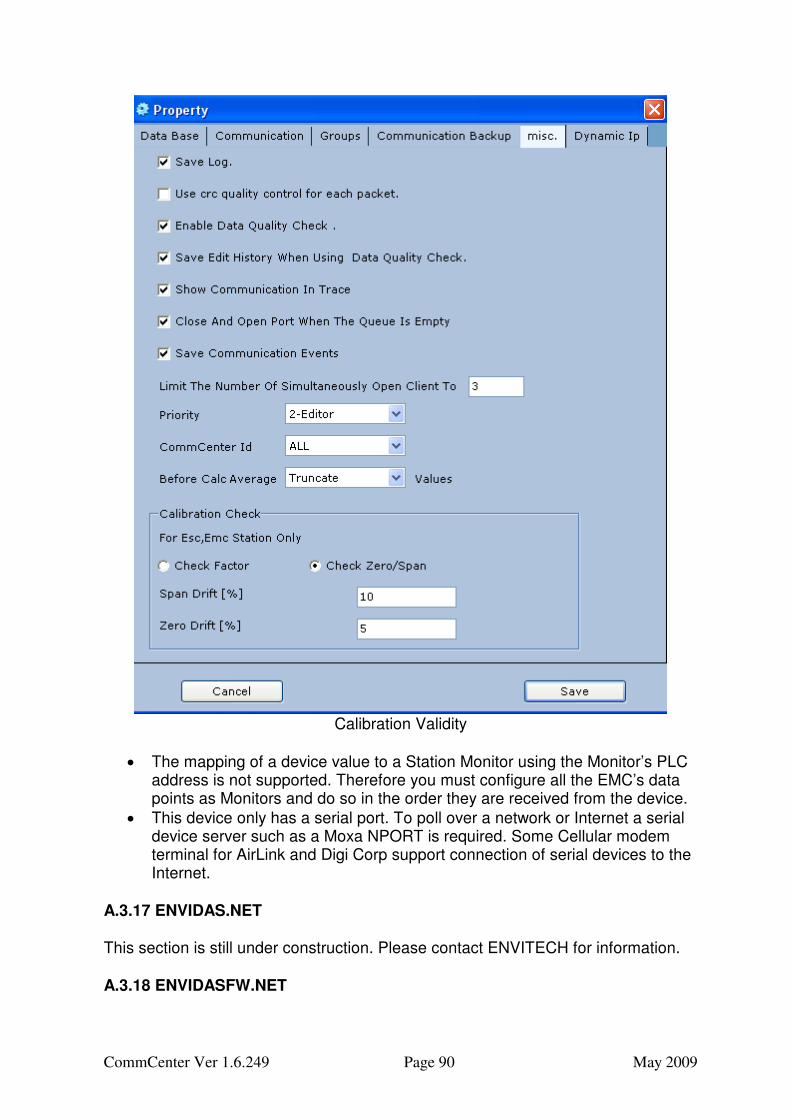
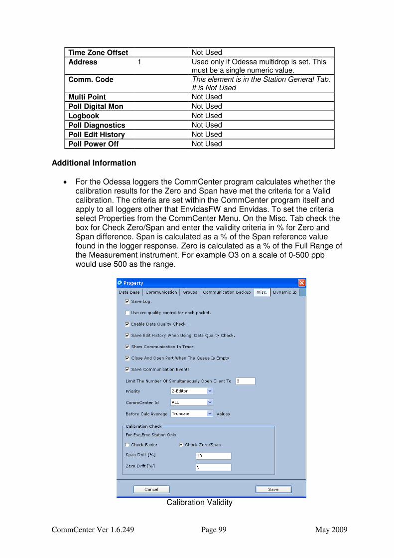
• From Calibration window, that meant only for Emc and Esc stations Check select Check factor and then insert Factor Low Limit and Factor High Limit or select Check Zero/Span and then insert Span Drift [%] and Zero Drift [%]
• Press "Save" button when you are done.
5.4 Groups You can configure groups (one or more) which based on several stations (channels) from the data base. The group data will be polled automatically or by demand and enables you to get information for several stations simultaneously and later to making comparison between them. All groups that you can configured are based on the stations as were configured in the "Software Manager Setup" and can be, for example, group of several time bases of the same station that every one will called a station (like "London 5 min", "London 1hour, "London 24h") or several stations like "London", "Liverpool", "Manchester" etc…
CommCenter Ver 1.6.249 Page 47 May 2009
When the group configuration is done properly, you will be able by one telephone or any other communication way to send and receive all the data refers to all the stations that are "members" in the group simultaneously.
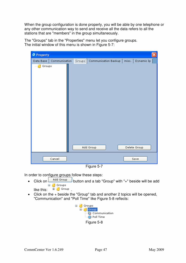
The "Groups" tab in the "Properties" menu let you configure groups. The initial window of this menu is shown in Figure 5-7:
Figure 5-7
In order to configure groups follow these steps:
• Click on button and a tab "Group" with "+" beside will be add
like this: .
• Click on the + beside the "Group" tab and another 2 topics will be opened, "Communication" and "Poll Time" like Figure 5-8 reflects:
Figure 5-8
CommCenter Ver 1.6.249 Page 48 May 2009
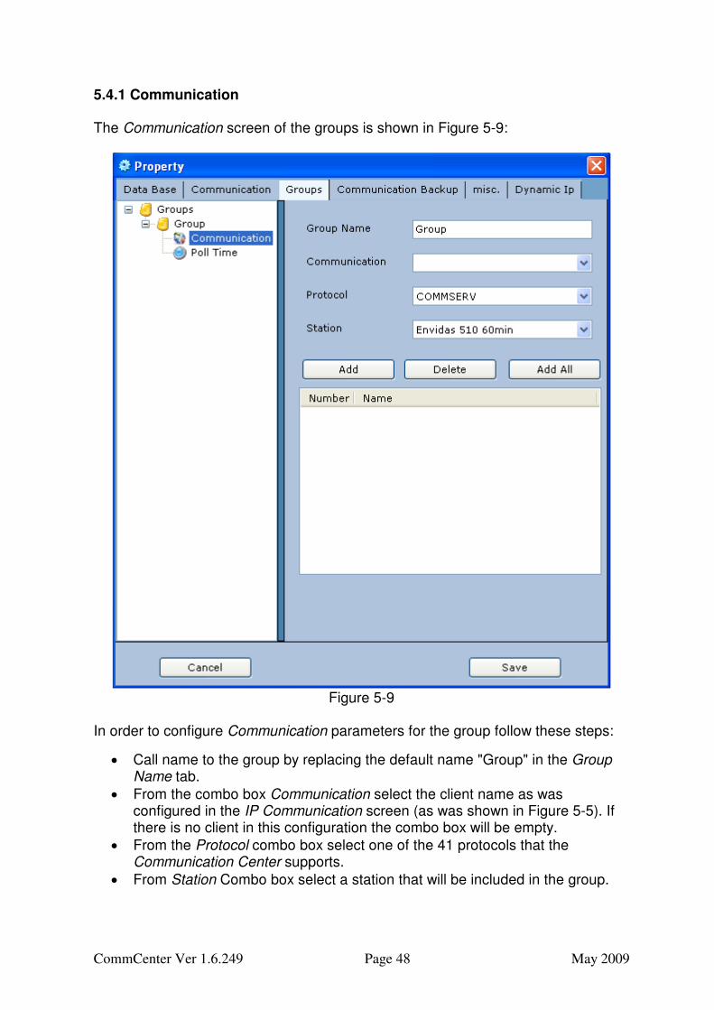
5.4.1 Communication The Communication screen of the groups is shown in Figure 5-9:
Figure 5-9
In order to configure Communication parameters for the group follow these steps:
• Call name to the group by replacing the default name "Group" in the Group Name tab.
• From the combo box Communication select the client name as was configured in the IP Communication screen (as was shown in Figure 5-5). If there is no client in this configuration the combo box will be empty.
• From the Protocol combo box select one of the 41 protocols that the Communication Center supports.
• From Station Combo box select a station that will be included in the group.
CommCenter Ver 1.6.249 Page 49 May 2009
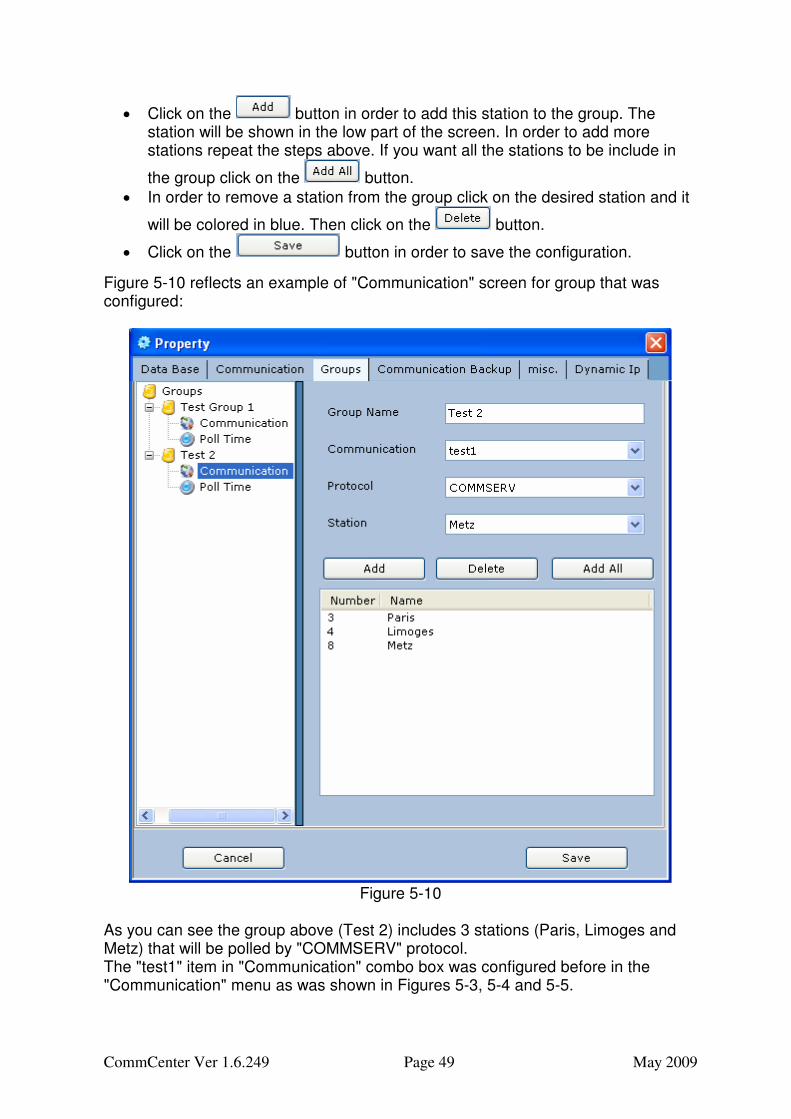
• Click on the button in order to add this station to the group. The station will be shown in the low part of the screen. In order to add more stations repeat the steps above. If you want all the stations to be include in
the group click on the button.
• In order to remove a station from the group click on the desired station and it
will be colored in blue. Then click on the button.
• Click on the button in order to save the configuration.
Figure 5-10 reflects an example of "Communication" screen for group that was configured:
Figure 5-10
As you can see the group above (Test 2) includes 3 stations (Paris, Limoges and Metz) that will be polled by "COMMSERV" protocol. The "test1" item in "Communication" combo box was configured before in the "Communication" menu as was shown in Figures 5-3, 5-4 and 5-5.
CommCenter Ver 1.6.249 Page 50 May 2009
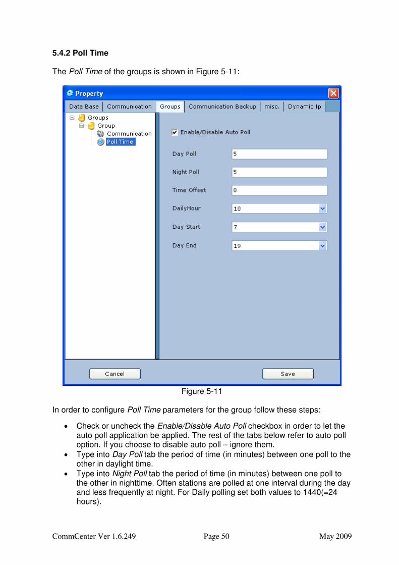
5.4.2 Poll Time The Poll Time of the groups is shown in Figure 5-11:
Figure 5-11
In order to configure Poll Time parameters for the group follow these steps:
• Check or uncheck the Enable/Disable Auto Poll checkbox in order to let the auto poll application be applied. The rest of the tabs below refer to auto poll option. If you choose to disable auto poll – ignore them.
• Type into Day Poll tab the period of time (in minutes) between one poll to the other in daylight time.
• Type into Night Poll tab the period of time (in minutes) between one poll to the other in nighttime. Often stations are polled at one interval during the day and less frequently at night. For Daily polling set both values to 1440(=24 hours).
CommCenter Ver 1.6.249 Page 51 May 2009
• Define a Time Offset in minutes to delay data collection. If the poll interval is 60 minutes and the offset is 5 minutes polling will occur starting a 5 minutes after each hour.
• Daily Hour – When the time interval for day and night is not divided on 60 or larger than 60, select from Daily Hour combo box the hour that the collection will begin at. For example: if the collection is supposed to be every 5 minutes at day and at night. The Daily Hour is 12 (=12:00 in the noun). In that case this information is unnecessary because 5 is divided on 60 and the polls will be at 12:05, 12:10,…13:00,…14:00 and so on, but if the time was 50 minutes, the first poll would be on 12:00, the second in 12:50 , the third on 13:40 and so on. This makes the Daily hour a useful detail, because if it was 11:00 the polls were on 11:50, 12:40, 13:30 and so on.
• Specify a day beginning hour (Day Start) and a day ending (Day End) hour for the polling schedule and for automatic atmospheric stability calculations. In the example above the Day is 12 hours long starting at 7 Am and ending at 7 PM.
• Click on button.
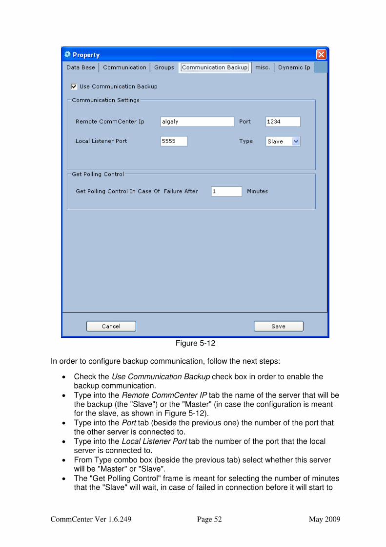
5.5 Communication Backup Communication backup (Secondary Communications) offers a second path to collect the data. When configured, the secondary path is attempted only in the case where the primary connection fails. For sockets this means that the sockets connection fails indicating the IP device (cellular or DSL or satellite modem) is not reachable. For telephone this means that the phone modem does not answer or the connection fails. If the sockets connect but the communications with the device fails, secondary communications is not attempted. If the modem answers and connects but there is no response from the logger, again the secondary communications is not attempted. Secondary Communications works with both demand and auto polling schedules. However the secondary will only be attempted if the data collection needs to occur. If the data is up to date, secondary polling is not attempted. For example if you do a demand poll at 9:30 for hourly data that was collected successfully for the hour ending at 9 am there is no new data to collect. However if the auto poll at 10 AM were to fail to connect on the primary the secondary will happen because there would now be new hourly data to collect. In order to configure the communication backup, you have to set up the parameters (as shown in the following figure) in both servers: in the "Master" and in the "Slave". Figure 5-12 reflects an example for the "Communication Backup" screen in the point of view of the "Slave" (the master is exactly opposite, as you will notice from the figure and from the follows explanations):
CommCenter Ver 1.6.249 Page 52 May 2009
Figure 5-12
In order to configure backup communication, follow the next steps:
• Check the Use Communication Backup check box in order to enable the backup communication.
• Type into the Remote CommCenter IP tab the name of the server that will be the backup (the "Slave") or the "Master" (in case the configuration is meant for the slave, as shown in Figure 5-12).
• Type into the Port tab (beside the previous one) the number of the port that the other server is connected to.
• Type into the Local Listener Port tab the number of the port that the local server is connected to.
• From Type combo box (beside the previous tab) select whether this server will be "Master" or "Slave".
• The "Get Polling Control" frame is meant for selecting the number of minutes that the "Slave" will wait, in case of failed in connection before it will start to
CommCenter Ver 1.6.249 Page 53 May 2009
communicate instead of the "Master". Type the number of minutes in the "Get Polling Control In Case of Failure After _ Minutes" tab.
• Click "Save".
The example on Figure 5-12 reflects, as said a "Slave" server, which communicate in port number 5555, and the "Master" server ,named "algaly" and communicate threw port 1234. The "Slave" will takeover the "Master" after 1 minutes of failure in communication.
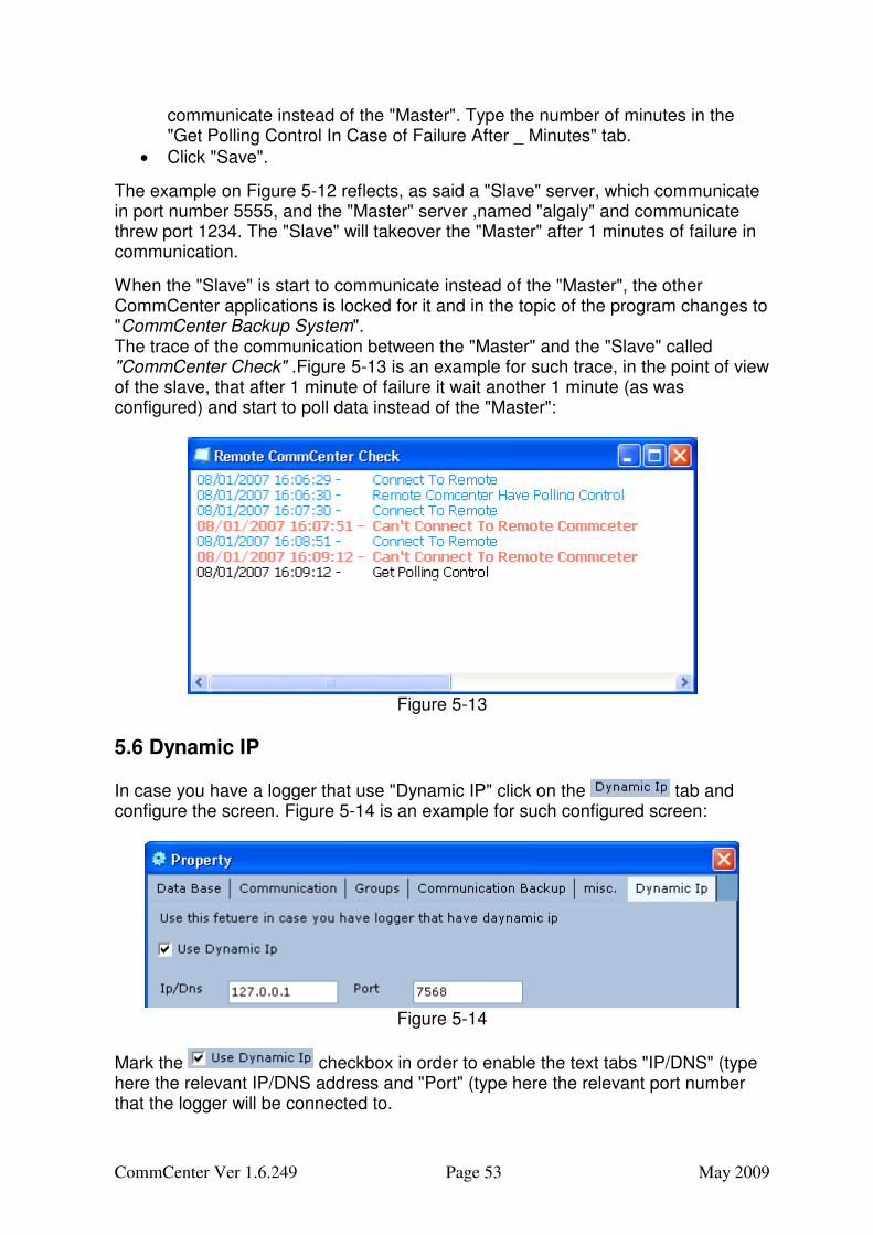
When the "Slave" is start to communicate instead of the "Master", the other CommCenter applications is locked for it and in the topic of the program changes to "CommCenter Backup System". The trace of the communication between the "Master" and the "Slave" called "CommCenter Check" .Figure 5-13 is an example for such trace, in the point of view of the slave, that after 1 minute of failure it wait another 1 minute (as was configured) and start to poll data instead of the "Master":
Figure 5-13
5.6 Dynamic IP
In case you have a logger that use "Dynamic IP" click on the tab and configure the screen. Figure 5-14 is an example for such configured screen:
Figure 5-14
Mark the checkbox in order to enable the text tabs "IP/DNS" (type here the relevant IP/DNS address and "Port" (type here the relevant port number that the logger will be connected to.
CommCenter Ver 1.6.249 Page 54 May 2009
Page intentionally blank
CommCenter Ver 1.6.249 Page 55 May 2009
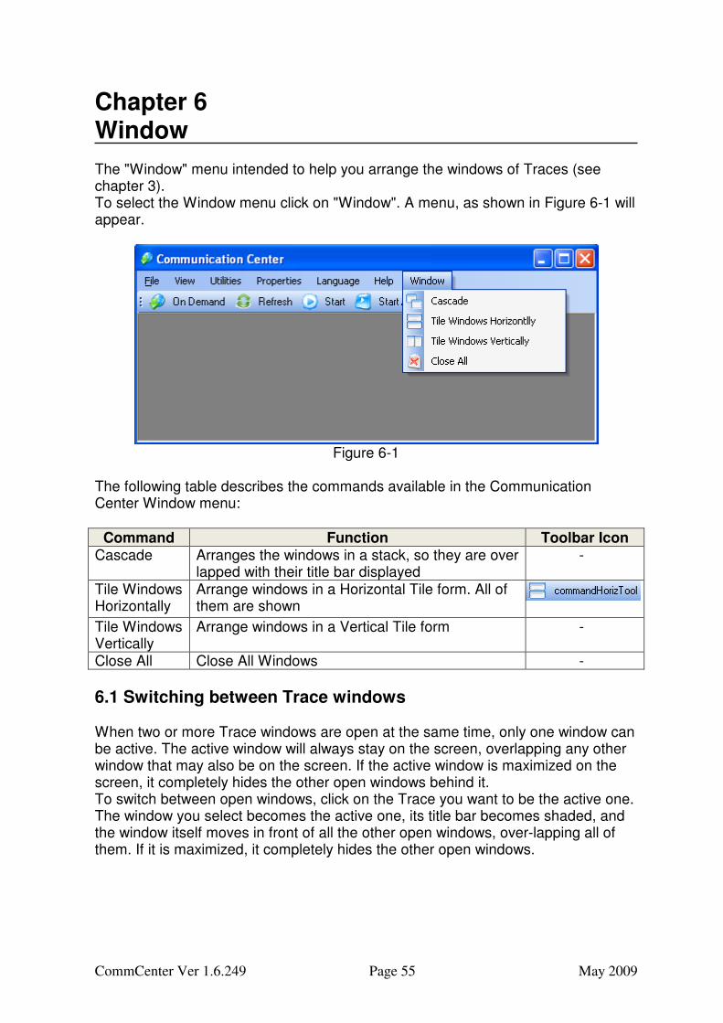
Chapter 6 Window The "Window" menu intended to help you arrange the windows of Traces (see chapter 3). To select the Window menu click on "Window". A menu, as shown in Figure 6-1 will appear.
Figure 6-1
The following table describes the commands available in the Communication Center Window menu:
Command Function Toolbar Icon Cascade Arranges the windows in a stack, so they are over
lapped with their title bar displayed -
Tile Windows Horizontally
Arrange windows in a Horizontal Tile form. All of them are shown
Tile Windows Vertically
Arrange windows in a Vertical Tile form -
Close All Close All Windows -
6.1 Switching between Trace windows When two or more Trace windows are open at the same time, only one window can be active. The active window will always stay on the screen, overlapping any other window that may also be on the screen. If the active window is maximized on the screen, it completely hides the other open windows behind it. To switch between open windows, click on the Trace you want to be the active one. The window you select becomes the active one, its title bar becomes shaded, and the window itself moves in front of all the other open windows, over-lapping all of them. If it is maximized, it completely hides the other open windows.
CommCenter Ver 1.6.249 Page 56 May 2009
6.2 Cascading and Tiling When you have two or more opened Trace windows, you can manually re-size and move them, so that you can view all of them at once. However, it is easier to let "Window" menu to do it for you. You can cascade the windows, or line them up like cards in a stack, with just the title bars showing. You can also tile the windows. Tiling arranges the windows edge-to-edge, so you can see the contents of each of them. Use of the tile and cascade features is described below:
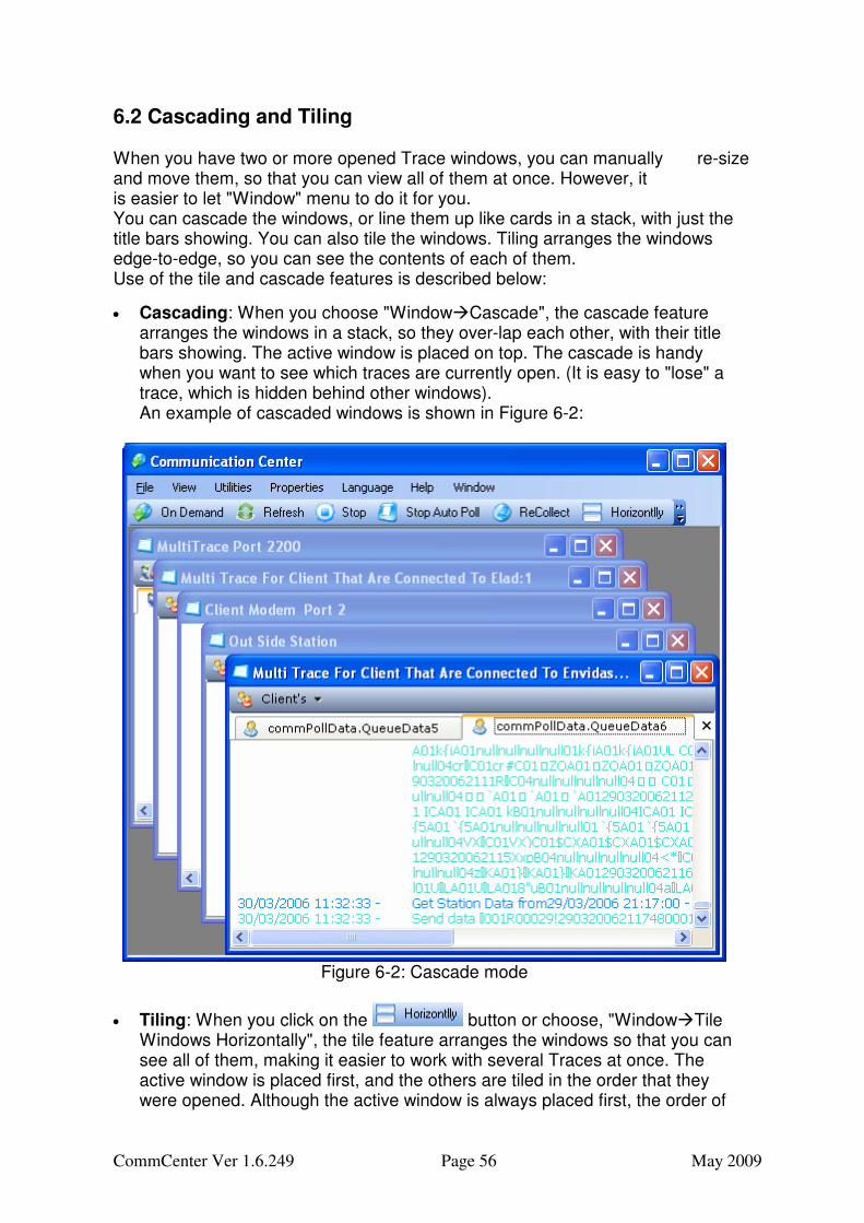
• Cascading: When you choose "Window�Cascade", the cascade feature arranges the windows in a stack, so they over-lap each other, with their title bars showing. The active window is placed on top. The cascade is handy when you want to see which traces are currently open. (It is easy to "lose" a trace, which is hidden behind other windows). An example of cascaded windows is shown in Figure 6-2:
Figure 6-2: Cascade mode
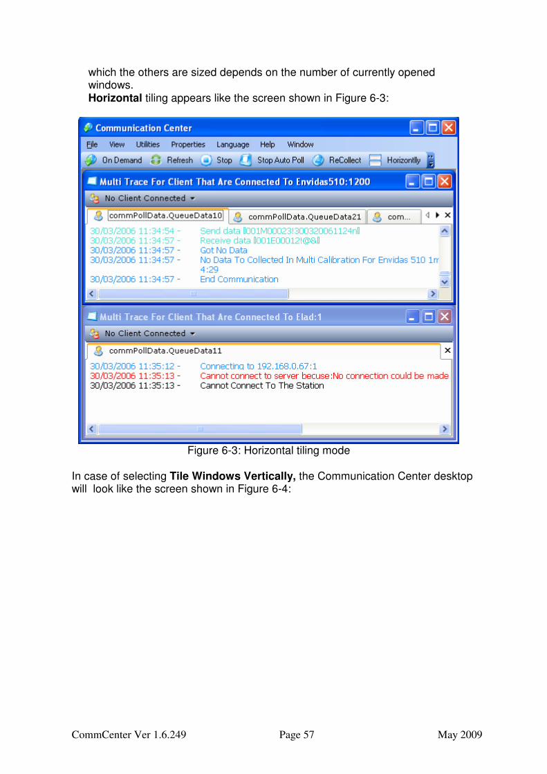
• Tiling: When you click on the button or choose, "Window�Tile Windows Horizontally", the tile feature arranges the windows so that you can see all of them, making it easier to work with several Traces at once. The active window is placed first, and the others are tiled in the order that they were opened. Although the active window is always placed first, the order of
CommCenter Ver 1.6.249 Page 57 May 2009
which the others are sized depends on the number of currently opened windows. Horizontal tiling appears like the screen shown in Figure 6-3:
Figure 6-3: Horizontal tiling mode
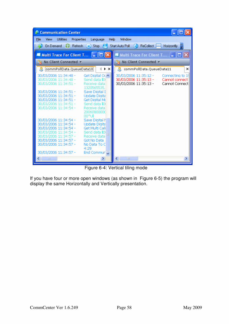
In case of selecting Tile Windows Vertically, the Communication Center desktop will look like the screen shown in Figure 6-4:
CommCenter Ver 1.6.249 Page 58 May 2009
Figure 6-4: Vertical tiling mode
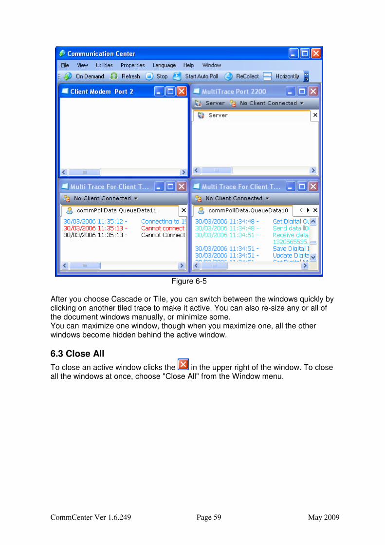
If you have four or more open windows (as shown in Figure 6-5) the program will display the same Horizontally and Vertically presentation.
CommCenter Ver 1.6.249 Page 59 May 2009
Figure 6-5
After you choose Cascade or Tile, you can switch between the windows quickly by clicking on another tiled trace to make it active. You can also re-size any or all of the document windows manually, or minimize some. You can maximize one window, though when you maximize one, all the other windows become hidden behind the active window.
6.3 Close All
To close an active window clicks the in the upper right of the window. To close all the windows at once, choose "Close All" from the Window menu.
CommCenter Ver 1.6.249 Page 60 May 2009
Page intentionally blank
CommCenter Ver 1.6.249 Page 61 May 2009
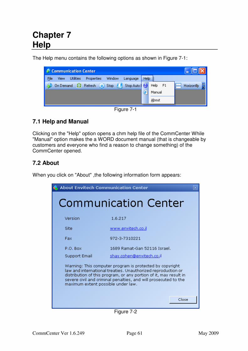
Chapter 7 Help The Help menu contains the following options as shown in Figure 7-1:
Figure 7-1
7.1 Help and Manual Clicking on the "Help" option opens a chm help file of the CommCenter While "Manual" option makes the a WORD document manual (that is changeable by customers and everyone who find a reason to change something) of the CommCenter opened.
7.2 About When you click on "About" ,the following information form appears:
Figure 7-2
CommCenter Ver 1.6.249 Page 62 May 2009
Page intentionally blank
CommCenter Ver 1.6.249 Page 63 May 2009
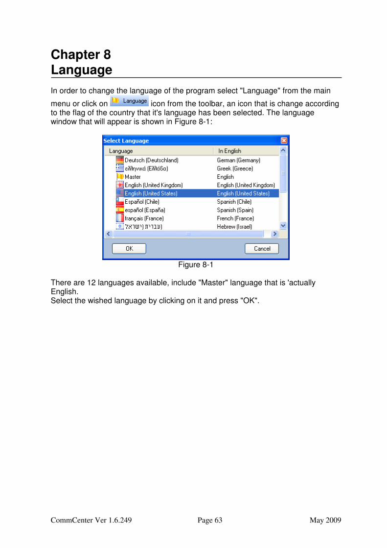
Chapter 8 Language In order to change the language of the program select "Language" from the main
menu or click on icon from the toolbar, an icon that is change according to the flag of the country that it's language has been selected. The language window that will appear is shown in Figure 8-1:
Figure 8-1
There are 12 languages available, include "Master" language that is 'actually English. Select the wished language by clicking on it and press "OK".
CommCenter Ver 1.6.249 Page 64 May 2009
Page intentionally blank
CommCenter Ver 1.6.249 Page 65 May 2009
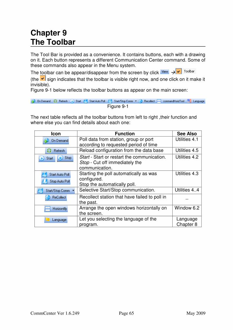
Chapter 9 The Toolbar The Tool Bar is provided as a convenience. It contains buttons, each with a drawing on it. Each button represents a different Communication Center command. Some of these commands also appear in the Menu system.
The toolbar can be appear/disappear from the screen by click �
(the sign indicates that the toolbar is visible right now, and one click on it make it invisible). Figure 9-1 below reflects the toolbar buttons as appear on the main screen:
Figure 9-1
The next table reflects all the toolbar buttons from left to right ,their function and where else you can find details about each one:
Icon Function See Also
Poll data from station, group or port according to requested period of time
Utilities 4.1
Reload configuration from the data base Utilities 4.5
Start - Start or restart the communication. Stop - Cut off immediately the communication.
Utilities 4.2
Starting the poll automatically as was configured. Stop the automatically poll.
Recollect station that have failed to poll in the past.
_
Arrange the open windows horizontally on the screen.
Window 6.2
Let you selecting the language of the program.
Language Chapter 8
CommCenter Ver 1.6.249 Page 66 May 2009
Page intentionally blank
CommCenter Ver 1.6.249 Page 67 May 2009
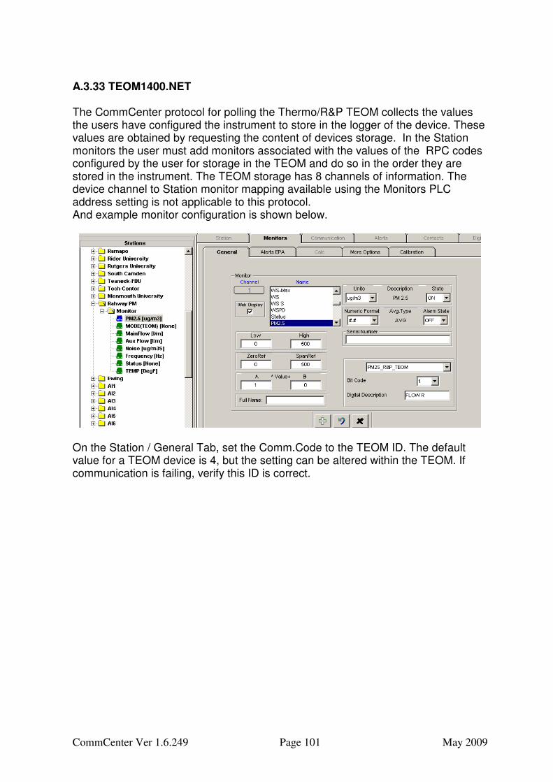
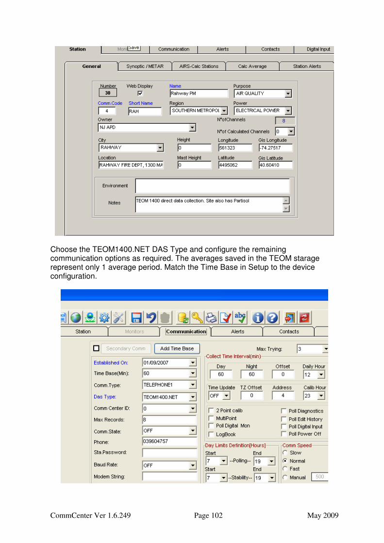
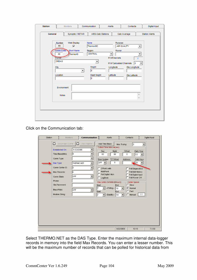
Appendix A Guide to DAS Types Purpose: To guide a user on the details required to configure stations, station communications and monitor for stations using various types of devices for data collection. Each device is identified generically as a data acquisition systems DAS type. Wide varieties are available in Envista ARM for use with CommCenter. Some devices are data-loggers and other are instruments with data logging capability built in to the device.
A.1 Introduction To communicate with the various devices (loggers, instruments, etc) that CommCenter supports, a Station must be added in the Envista ARM Setup program. For each Station there is a Communication Tab where you must select a DAS Type. This will specify to the CommCenter program what protocols to use when communicating with the device. Because each device has its own protocols and the differences between devices range from very similar to profoundly different, there are a number of additional configurations that may need to be performed in order to effectively communicate with your device. This guide will highlight and guide you through the setup of your device in Envista ARM Setup for use with CommCenter. For more general Station setup information, please see the Envista ARM Setup manual. The DAS Types supported by CommCenter are discussed in this appendix. Your database may contain DAS Types not used with CommCenter. These are listed in this document but not discussed. Instead consult the referenced manual or Tech support at Envitech Ltd.
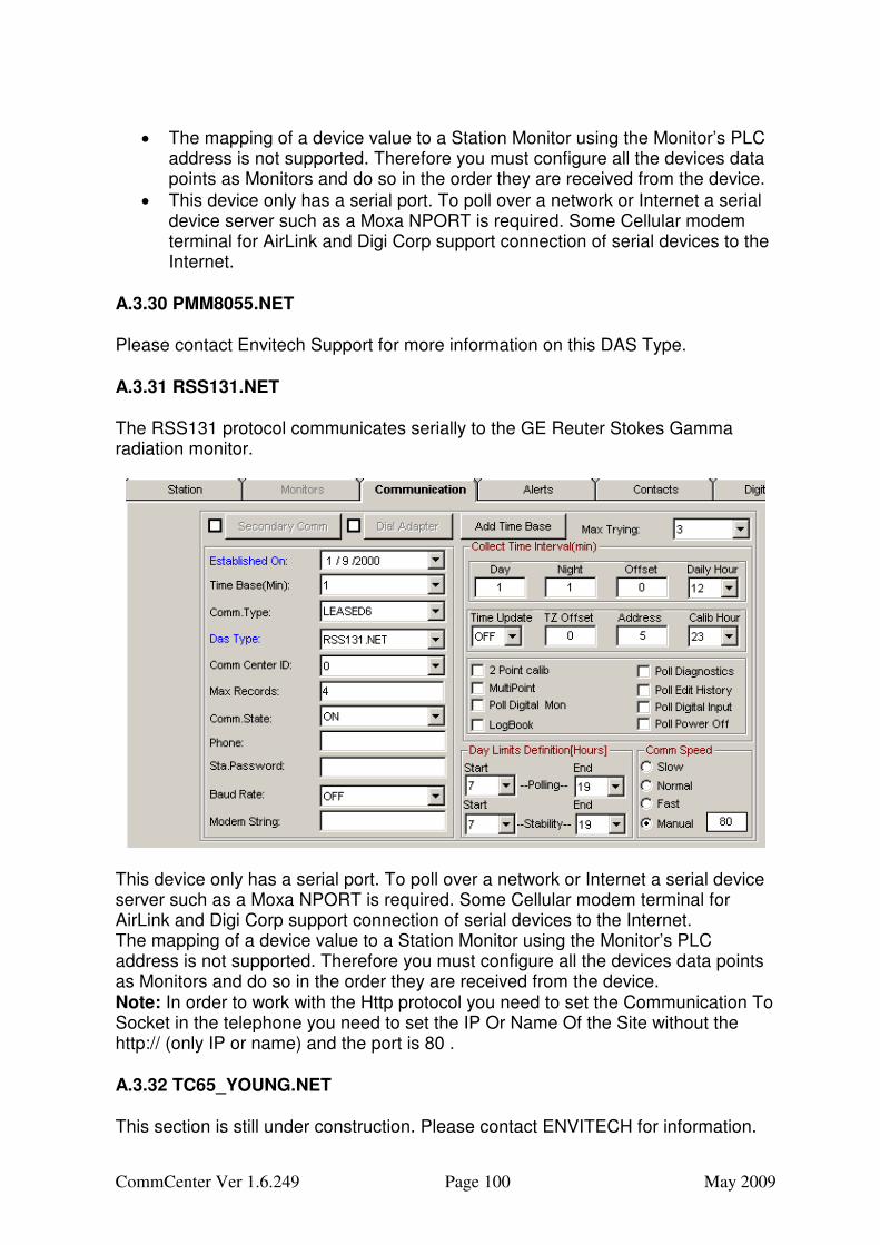
A.2 Communications Tab The following table lists the configuration elements available for editing on the Communications Tab of Envista ARM Setup. This is where the bulk of the configuration related to device communication must be entered. This table only highlights the generic purposes for each field. Some fields have altered purposes or are simply not used in a particular protocol. Some protocols have extended configuration elements to further define the communication and data extraction method. A table similar to this will appear in each protocol that highlights the functionality enhancements used to make the CommCenter software compatible with the device from which you are collecting data. Be sure to consult the device specific table for additional notes.
Communication Element
Example Purpose/Use
Established On 09/29/2008 Date the Station was added to the Network.
Time Base 60 The base time (minutes) that the data represents. When this form is saved the system checks and makes Raw and S database tables for this time base. Note the CommState must be ON for the tables to be created. Tables already created will not
CommCenter Ver 1.6.249 Page 68 May 2009
be removed if the Time Base or Comm State is changed.
Comm. Type SOCKETS1 Identifies the communication method to be used. Available selections must be added in the Setup from the Communication form (Red Telephone Icon on main menu), and can be either Leased lines, Modem (Telephone), or TCP (Sockets).
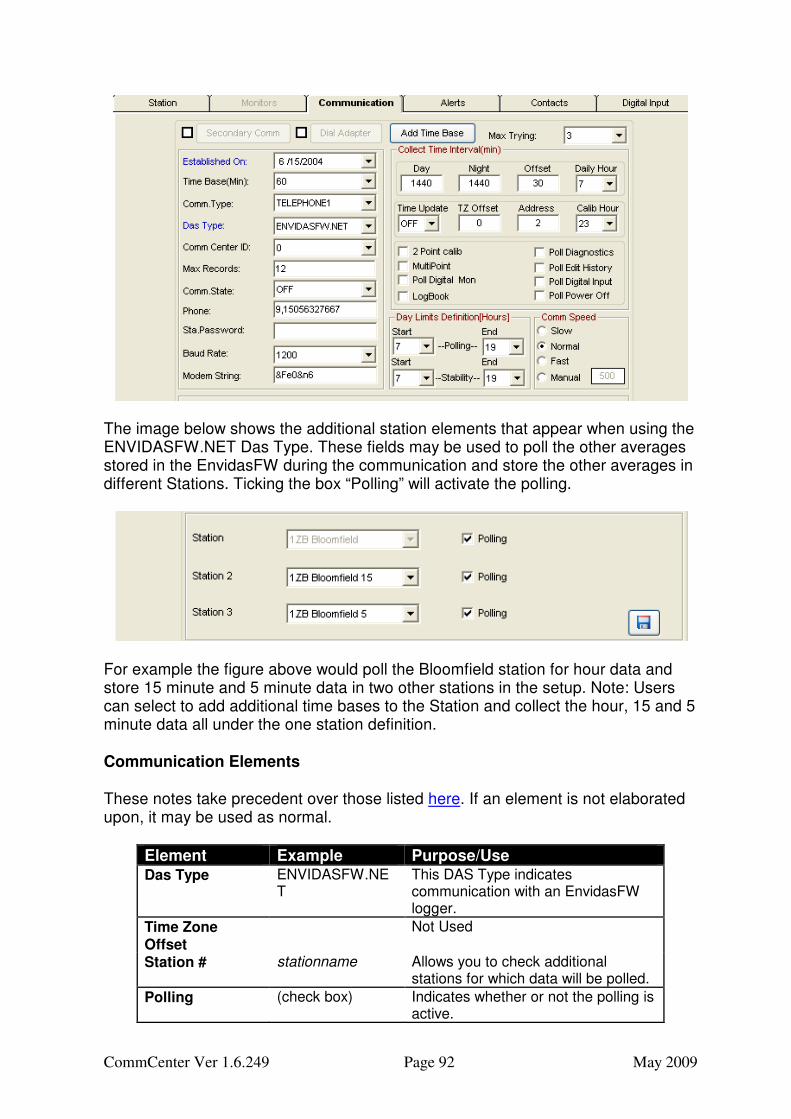
Das Type ENVIDASFW.NET Specifies the protocol by which communications are directed to a device. Depending on the selection, other configuration elements on the Station’s Communication Tab may be displayed or hidden.
Max Records 24 The largest size data request that can be made.
Comm. State ON Indicates whether automatic polling is ON or OFF.
Phone 9,19865472161,,*3 104.168.1.100 443
Enter the telephone number or IP address and port for communication. For direct serial communication (Leased) this may be left empty. Telephone numbers can include commas for pauses and other characters needed for control of telephone system navigation. Note that the port for a SOCKETS type communication is separated from the IP Address by a space, not a colon.
Sta. Password ENVI Password field if device or modem is secured.
Baud Rate 9600 Normally left at OFF. Set to a baud rate only if the station needs to use a different rate than that included in the standard communications parameters as set by the selected Comm Type. Never used with TCP/IP communication.
Modem String AT&FE0&N6 Normally left blank. String included only if the modem needs to use different communications methods than those included in the standard communications parameters as set by the selected Comm Type. Never used with TCP/IP communication. This example is US Robotics specific: The &N6 sets the maximum connection speed to 9600 baud.
Collect Time Day 60 The intervals, in minutes, at which polling will occur during hours considered as day. For example set to 180 polling would occur every 3 hours.
Collect Time Night 120 The intervals, in minutes, at which polling will occur during hours considered as night. For example set to 180 polling would occur every 3 hours.
Offset 12 The offset, in minutes, from the interval at which the poll will start. If set to 3 the poll would be delayed to 3 minutes after the day or night interval.
Daily Hour 13 The hour of the 24 hour day in which the once a day poll will occur. Note: This is only functional when both the Collect Time Day and Collect Time Night elements are set to 1440.
Time Update OFF Indicates whether the device’s clock should be set to the time of the machine polling the device. Time is only reset when the time difference exceeds 1 minute.
Time Zone Offset 1 Used to offset the polling time and time sets when a station is in a different time zone than the polling machine. If a station is 3 hours ahead enter a 3. This would apply if polling New York from San Francisco. Currently this setting has been implemented with only a few devices. These are EMC.NET, ADAM6501.NET, RSS131.NET,
CommCenter Ver 1.6.249 Page 69 May 2009
TEOM1400.NET and TEOM1405.NET
Address 42 Most commonly used to indicate the communications address for a device but also has special purpose uses depending on the Das Type.
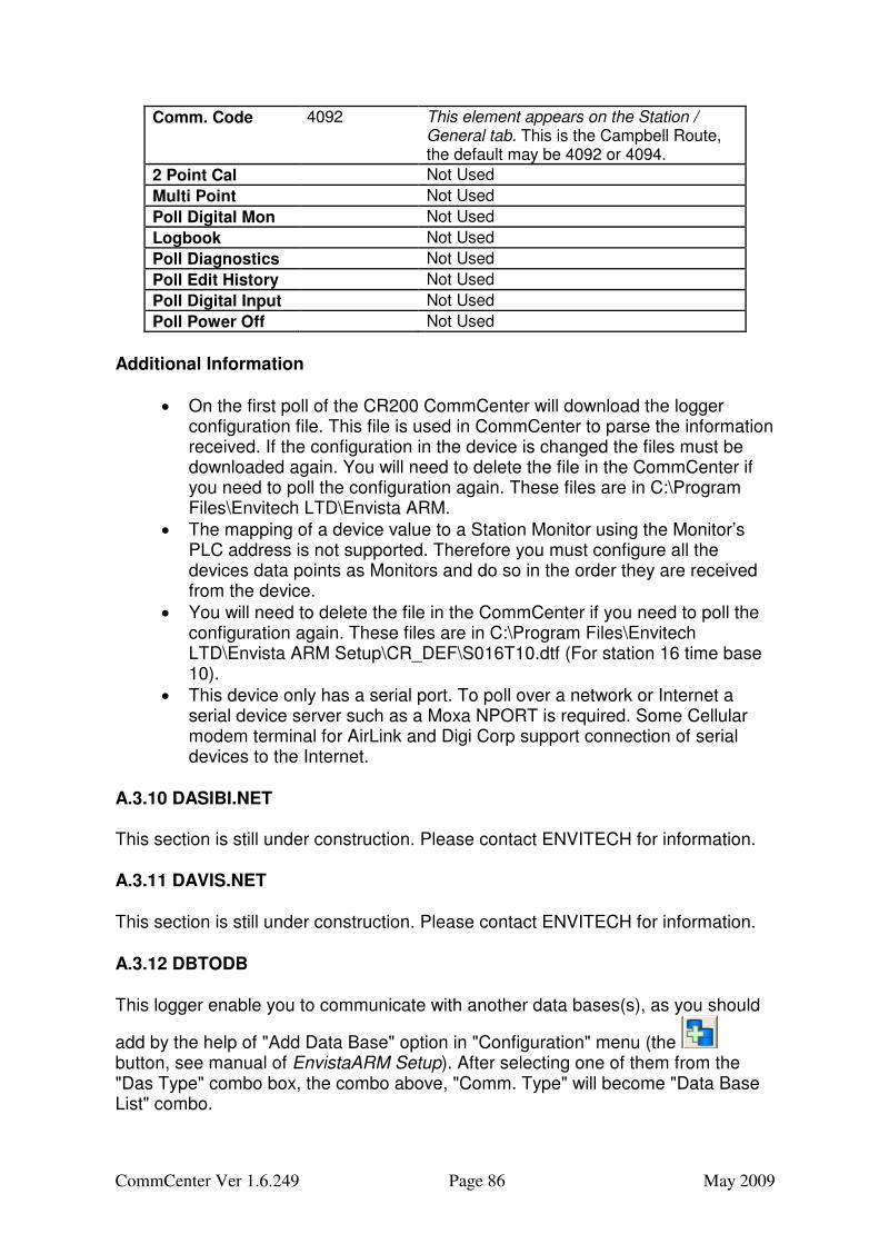
2 Point Cal (check box) Poll for calibrations consisting of Zero and Span (2 point) with or without a third “precision” point.
Multi Point (check box) Poll for multipoint calibrations consisting of 1 to 9 points.
Poll Digital Mon (check box) Poll for the status flags that are available from some instruments and EnvidasFW program
Logbook (check box) Poll for EnvidasFW program Logbook entries
Poll Diagnostics (check box) Poll for instrument diagnostics collected by the EnvidasFW logger.
Poll Edit History (check box) Poll for edits performed locally on an EnvidasFW logger
Poll Digital Input (check box) Poll for the state of digital inputs recorded by some dataloggers
Poll Power Off (check box) Poll the EnvidasFW to get periods of time when power and or the EnvidasFW program was off.
Day Limits - Polling
7, 19 Sets the beginning and the end of the Day period used by the Collect Time Day setting
Day Limits - Stability
7, 19 Sets the beginning and the end of the Day period used by CommCenter to calculate atmospheric stability when stability is configured in the calculated channels of a station.
Comm Speed Slow Sets the wait time in millisecs used by the CommCenter program when determining if there is a timeout when waiting for a response to a command. For some devices and especially on cellular and satellite connections a manual setting of up to 9000 can be used.
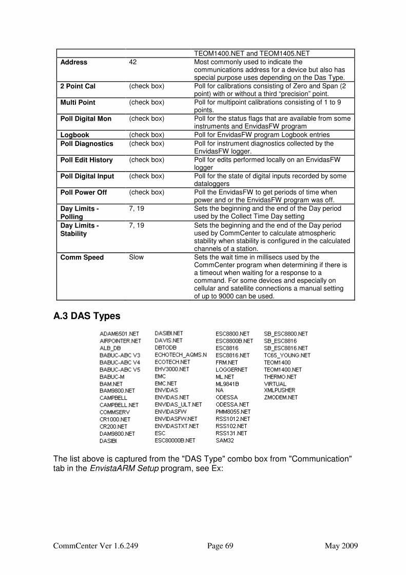
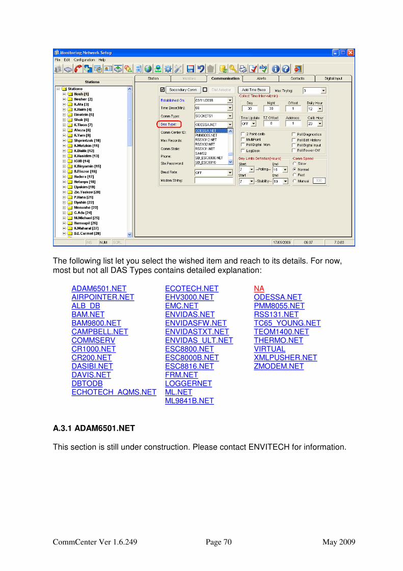
A.3 DAS Types
The list above is captured from the "DAS Type" combo box from "Communication" tab in the EnvistaARM Setup program, see Ex:
CommCenter Ver 1.6.249 Page 70 May 2009
The following list let you select the wished item and reach to its details. For now, most but not all DAS Types contains detailed explanation:
NA ODESSA.NET PMM8055.NET RSS131.NET TC65_YOUNG.NET TEOM1400.NET THERMO.NET VIRTUAL XMLPUSHER.NET ZMODEM.NET
A.3.1 ADAM6501.NET This section is still under construction. Please contact ENVITECH for information.
CommCenter Ver 1.6.249 Page 71 May 2009
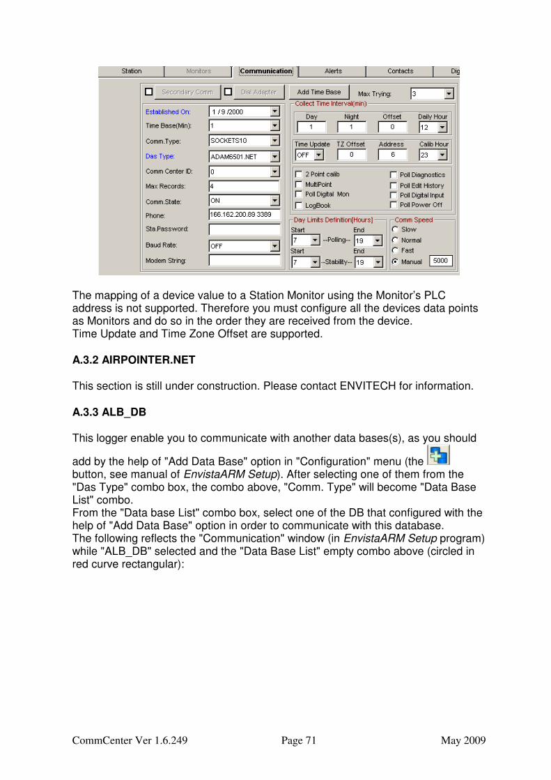
The mapping of a device value to a Station Monitor using the Monitor’s PLC address is not supported. Therefore you must configure all the devices data points as Monitors and do so in the order they are received from the device. Time Update and Time Zone Offset are supported. A.3.2 AIRPOINTER.NET This section is still under construction. Please contact ENVITECH for information. A.3.3 ALB_DB This logger enable you to communicate with another data bases(s), as you should
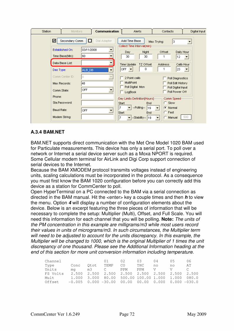
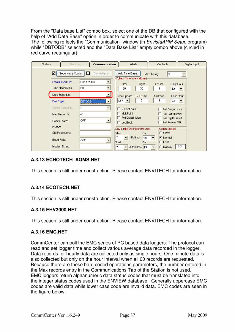
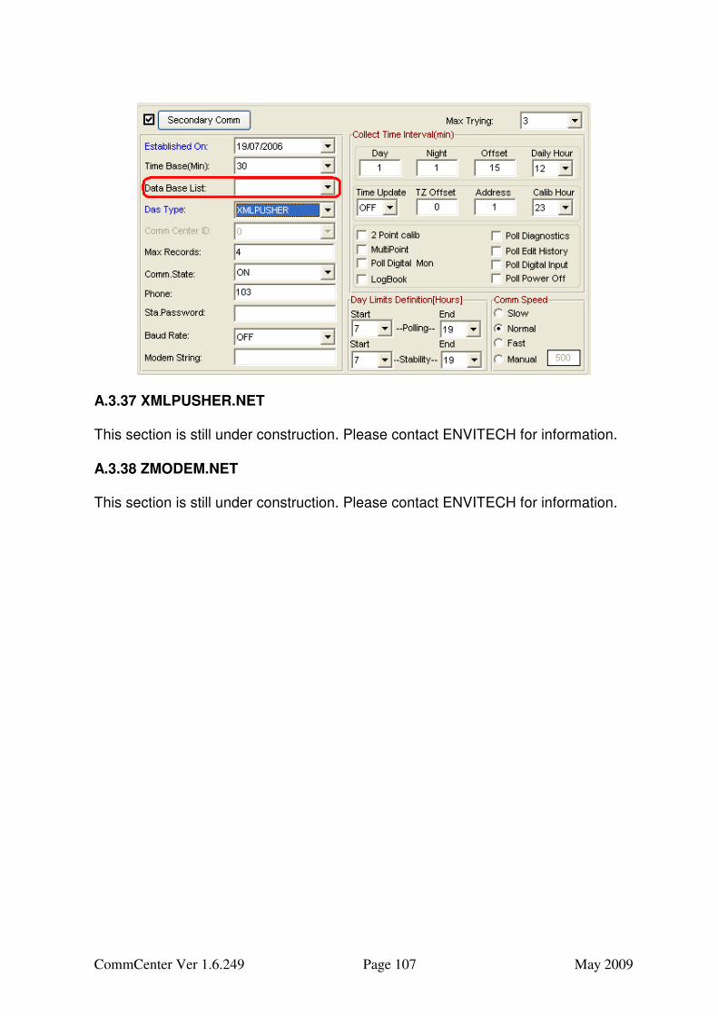
add by the help of "Add Data Base" option in "Configuration" menu (the button, see manual of EnvistaARM Setup). After selecting one of them from the "Das Type" combo box, the combo above, "Comm. Type" will become "Data Base List" combo. From the "Data base List" combo box, select one of the DB that configured with the help of "Add Data Base" option in order to communicate with this database. The following reflects the "Communication" window (in EnvistaARM Setup program) while "ALB_DB" selected and the "Data Base List" empty combo above (circled in red curve rectangular):
CommCenter Ver 1.6.249 Page 72 May 2009
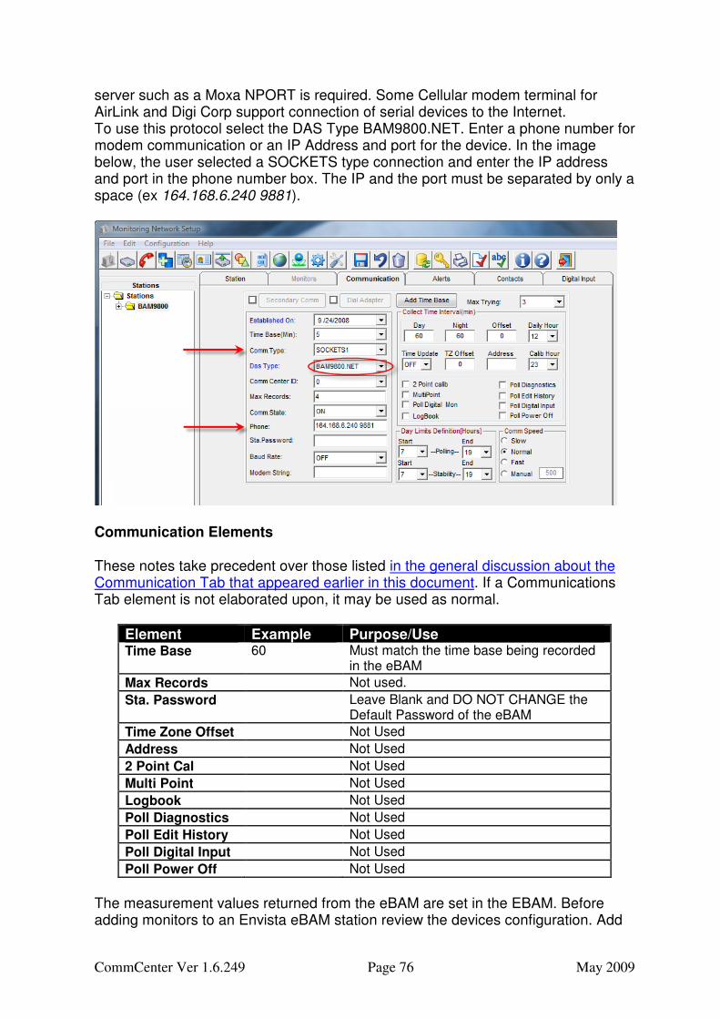
A.3.4 BAM.NET BAM.NET supports direct communication with the Met One Model 1020 BAM used for Particulate measurements. This device has only a serial port. To poll over a network or Internet a serial device server such as a Moxa NPORT is required. Some Cellular modem terminal for AirLink and Digi Corp support connection of serial devices to the Internet. Because the BAM XMODEM protocol transmits voltages instead of engineering units, scaling calculations must be incorporated in the protocol. As a consequence you must first know the BAM 1020 configuration before you can correctly add this device as a station for CommCenter to poll. Open HyperTerminal on a PC connected to the BAM via a serial connection as directed in the BAM manual. Hit the <enter> key a couple times and then h to view the menu. Option 4 will display a number of configuration elements about the device. Below is an excerpt featuring the three pieces of information that will be necessary to complete the setup: Multiplier (Multi), Offset, and Full Scale. You will need this information for each channel that you will be polling. Note: The units of the PM concentration in this example are milligrams/m3 while most users record their values in units of micrograms/m3. In such circumstances, the Multiplier term will need to be adjusted to account for the units discrepancy. In this example, the Multiplier will be changed to 1000, which is the original Multiplier of 1 times the unit discrepancy of one thousand. Please see the Additional Information heading at the end of this section for more unit conversion information including temperature.
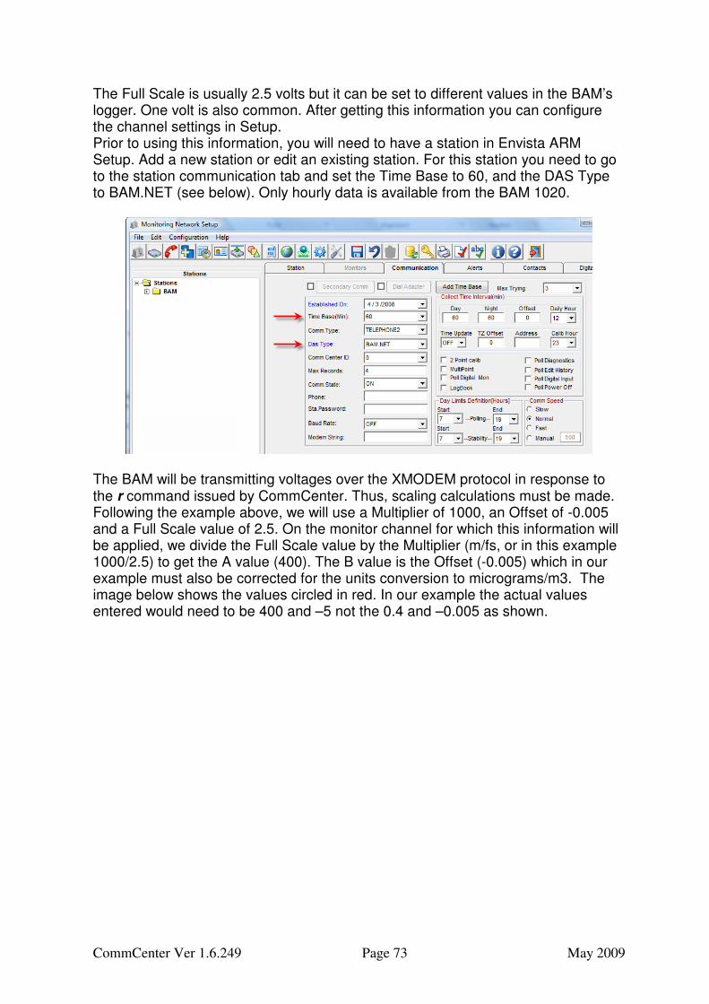
The Full Scale is usually 2.5 volts but it can be set to different values in the BAM’s logger. One volt is also common. After getting this information you can configure the channel settings in Setup. Prior to using this information, you will need to have a station in Envista ARM Setup. Add a new station or edit an existing station. For this station you need to go to the station communication tab and set the Time Base to 60, and the DAS Type to BAM.NET (see below). Only hourly data is available from the BAM 1020.
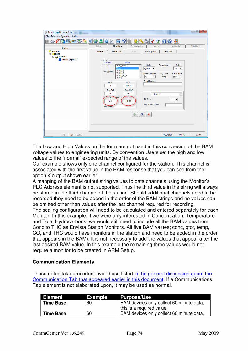
The BAM will be transmitting voltages over the XMODEM protocol in response to the r command issued by CommCenter. Thus, scaling calculations must be made. Following the example above, we will use a Multiplier of 1000, an Offset of -0.005 and a Full Scale value of 2.5. On the monitor channel for which this information will be applied, we divide the Full Scale value by the Multiplier (m/fs, or in this example 1000/2.5) to get the A value (400). The B value is the Offset (-0.005) which in our example must also be corrected for the units conversion to micrograms/m3. The image below shows the values circled in red. In our example the actual values entered would need to be 400 and –5 not the 0.4 and –0.005 as shown.
CommCenter Ver 1.6.249 Page 74 May 2009
The Low and High Values on the form are not used in this conversion of the BAM voltage values to engineering units. By convention Users set the high and low values to the “normal” expected range of the values. Our example shows only one channel configured for the station. This channel is associated with the first value in the BAM response that you can see from the option 4 output shown earlier. A mapping of the BAM output string values to data channels using the Monitor’s PLC Address element is not supported. Thus the third value in the string will always be stored in the third channel of the station. Should additional channels need to be recorded they need to be added in the order of the BAM strings and no values can be omitted other than values after the last channel required for recording. The scaling configuration will need to be calculated and entered separately for each Monitor. In this example, if we were only interested in Concentration, Temperature and Total Hydrocarbons, we would still need to include all the BAM values from Conc to THC as Envista Station Monitors. All five BAM values; conc, qtot, temp, CO, and THC would have monitors in the station and need to be added in the order that appears in the BAM). It is not necessary to add the values that appear after the last desired BAM value. In this example the remaining three values would not require a monitor to be created in ARM Setup.
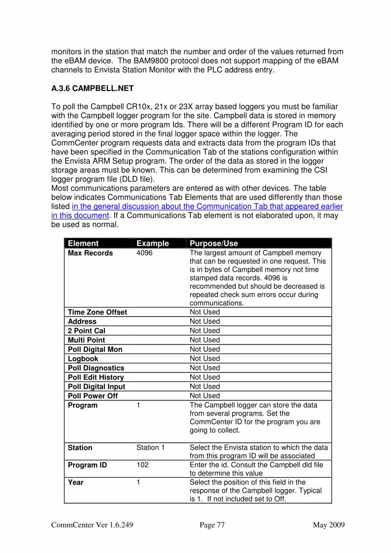
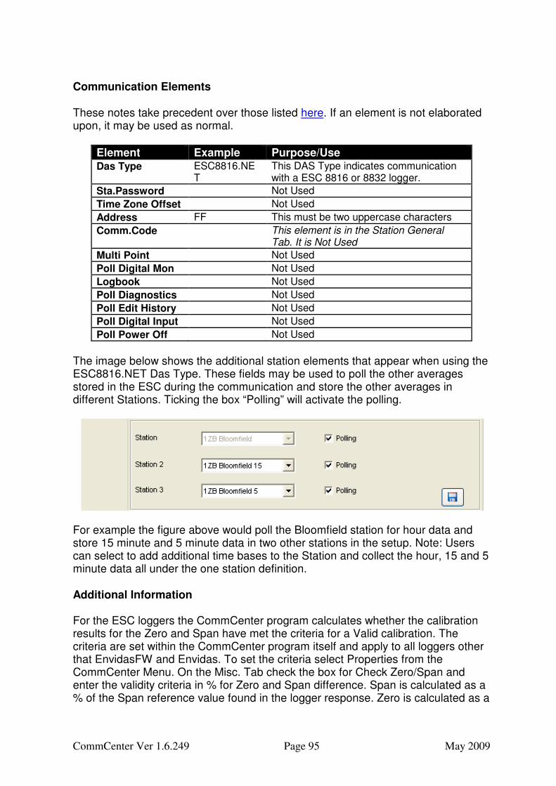
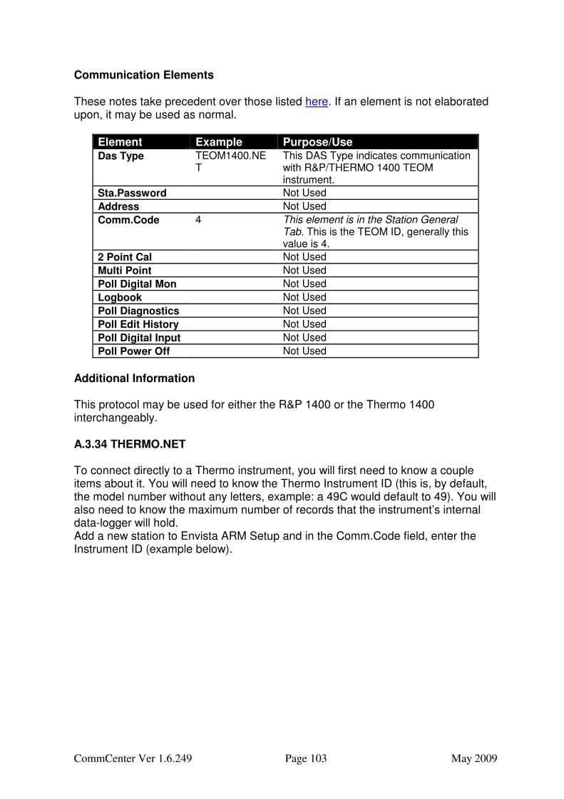
Communication Elements These notes take precedent over those listed in the general discussion about the Communication Tab that appeared earlier in this document. If a Communications Tab element is not elaborated upon, it may be used as normal.
Element Example Purpose/Use Time Base 60 BAM devices only collect 60 minute data,
this is a required value. Time Base 60 BAM devices only collect 60 minute data,
CommCenter Ver 1.6.249 Page 75 May 2009
this is a required value.
Max Records Not used.
Sta. Password Leave Blank and DO NOT CHANGE the Default Password of the BAM
Time Update Not Used
Time Zone Offset Not Used
Address Not Used
2 Point Cal Not Used
Multi Point Not Used
Poll Digital Mon Not Used
Logbook Not Used
Poll Diagnostics Not Used
Poll Edit History Not Used
Poll Digital Input Not Used
Poll Power Off Not Used
Monitor Configuration Elements
Monitor Element
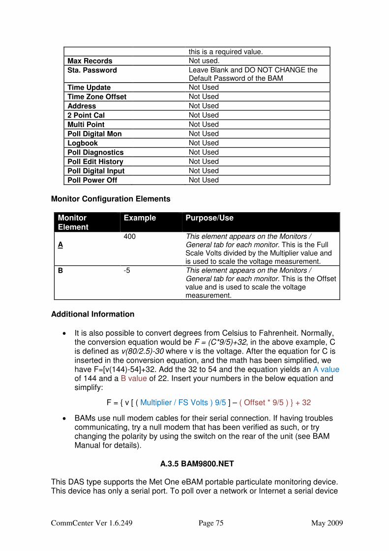
Example Purpose/Use
A 400 This element appears on the Monitors /
General tab for each monitor. This is the Full Scale Volts divided by the Multiplier value and is used to scale the voltage measurement.
B -5 This element appears on the Monitors / General tab for each monitor. This is the Offset value and is used to scale the voltage measurement.
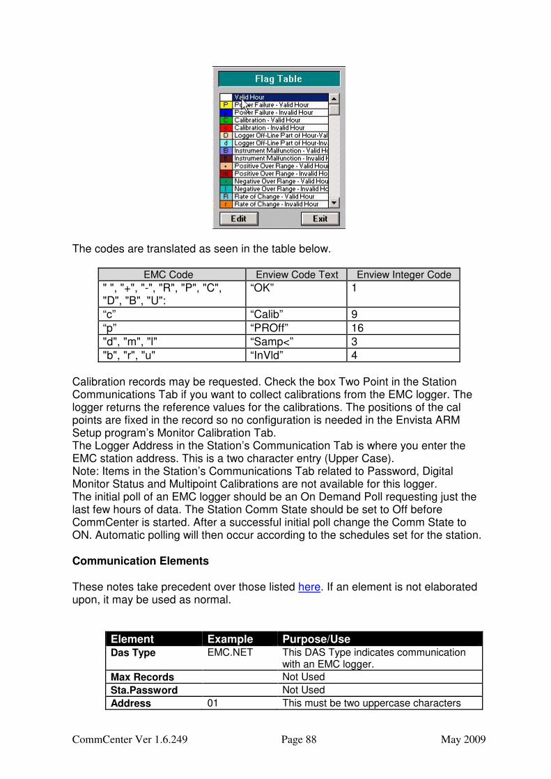
Additional Information
• It is also possible to convert degrees from Celsius to Fahrenheit. Normally, the conversion equation would be F = (C*9/5)+32, in the above example, C is defined as v(80/2.5)-30 where v is the voltage. After the equation for C is inserted in the conversion equation, and the math has been simplified, we have F=[v(144)-54]+32. Add the 32 to 54 and the equation yields an A value of 144 and a B value of 22. Insert your numbers in the below equation and simplify:
• BAMs use null modem cables for their serial connection. If having troubles communicating, try a null modem that has been verified as such, or try changing the polarity by using the switch on the rear of the unit (see BAM Manual for details).
A.3.5 BAM9800.NET
This DAS type supports the Met One eBAM portable particulate monitoring device. This device has only a serial port. To poll over a network or Internet a serial device
CommCenter Ver 1.6.249 Page 76 May 2009
server such as a Moxa NPORT is required. Some Cellular modem terminal for AirLink and Digi Corp support connection of serial devices to the Internet. To use this protocol select the DAS Type BAM9800.NET. Enter a phone number for modem communication or an IP Address and port for the device. In the image below, the user selected a SOCKETS type connection and enter the IP address and port in the phone number box. The IP and the port must be separated by only a space (ex 164.168.6.240 9881).
Communication Elements These notes take precedent over those listed in the general discussion about the Communication Tab that appeared earlier in this document. If a Communications Tab element is not elaborated upon, it may be used as normal.
Element Example Purpose/Use Time Base 60 Must match the time base being recorded
in the eBAM
Max Records Not used.
Sta. Password Leave Blank and DO NOT CHANGE the Default Password of the eBAM
Time Zone Offset Not Used
Address Not Used
2 Point Cal Not Used
Multi Point Not Used
Logbook Not Used
Poll Diagnostics Not Used
Poll Edit History Not Used
Poll Digital Input Not Used
Poll Power Off Not Used
The measurement values returned from the eBAM are set in the EBAM. Before adding monitors to an Envista eBAM station review the devices configuration. Add
CommCenter Ver 1.6.249 Page 77 May 2009
monitors in the station that match the number and order of the values returned from the eBAM device. The BAM9800 protocol does not support mapping of the eBAM channels to Envista Station Monitor with the PLC address entry. A.3.6 CAMPBELL.NET To poll the Campbell CR10x, 21x or 23X array based loggers you must be familiar with the Campbell logger program for the site. Campbell data is stored in memory identified by one or more program Ids. There will be a different Program ID for each averaging period stored in the final logger space within the logger. The CommCenter program requests data and extracts data from the program IDs that have been specified in the Communication Tab of the stations configuration within the Envista ARM Setup program. The order of the data as stored in the logger storage areas must be known. This can be determined from examining the CSI logger program file (DLD file). Most communications parameters are entered as with other devices. The table below indicates Communications Tab Elements that are used differently than those listed in the general discussion about the Communication Tab that appeared earlier in this document. If a Communications Tab element is not elaborated upon, it may be used as normal.
Element Example Purpose/Use Max Records 4096 The largest amount of Campbell memory
that can be requested in one request. This is in bytes of Campbell memory not time stamped data records. 4096 is recommended but should be decreased is repeated check sum errors occur during communications.
Time Zone Offset Not Used
Address Not Used
2 Point Cal Not Used
Multi Point Not Used
Poll Digital Mon Not Used
Logbook Not Used
Poll Diagnostics Not Used
Poll Edit History Not Used
Poll Digital Input Not Used
Poll Power Off Not Used
Program 1 The Campbell logger can store the data from several programs. Set the CommCenter ID for the program you are going to collect.
Station Station 1 Select the Envista station to which the data from this program ID will be associated
Program ID 102 Enter the id. Consult the Campbell dld file to determine this value
Year 1 Select the position of this field in the response of the Campbell logger. Typical is 1. If not included set to Off.
CommCenter Ver 1.6.249 Page 78 May 2009
Day 2 Select the position of this field in the response of the Campbell logger. Typical is 2 if year is present.
Time 3 Select the position of this field in the response of the Campbell logger. Typical is 2 if year is present.
First Channel 5 Select the position of this field in the response of the Campbell logger. Typical is 2 if year is present.
On Signature Fail Check All Buffer or enter a value like 20480
Action to take if the signature (last memory location in the logger that was polled) is absent or corrupt. Can be either Poll All the memory Buffer of just Go Back the last N bytes.
As noted in the table above, when CAMPBELL.NET is selected as the DAS Type additional fields become visible in the Communications Tab. These fields allow the user to enter information for up to 4 program IDs and to specify the station definition under which the data is to be stored. Note: entries in these additional areas of the form have a separate small save button. Save each Program before configuring the next. In the example discussed below we will illustrate collection of multiple program Ids and storage in several Envista station definitions: Assume the station being configured has a Time Base of 60 and hourly data is stored in the logger’s program ID 105. In addition Program ID 106 has 15-minute data and ID 107 has 5-minute data. On the Communications tab of the 60 minute station set Program 1 to have a Program ID as 105. Then fill in the order of the fields, after the program ID, for the Year, Julian Day, Time and First data value. Enter the first data value in the program even if you do not want to collect it. In most logger configurations the Year will be the first field followed by Date as 2, Time as 3 and First Channel as 5. Some programs omit the Year. If so set the Year to Off. If the year was omitted, the Day will be 1 (first field after the program ID), Time 2 and First Channel 4 Example File Fields:
1 200 - Program ID
2 Year This is the first field after the program ID.
3 Day
4 Hour_Minute
5 __Stn_ID_ L
6 Battery_V_AVG L First Channel This is the 5th field after
Program ID
7 RH_percnt_AVG L
8 AirTemp_C_STD L
9 RH_percnt_STD L
10 W_Spd_kmh_S_WVT L
11 W_Spd_kmh_U_WVT L
12 WD_degs_N_DU_WVT L
13 WD_degs_N_SDU_WVT L
If you intend to collect other Program ID data, i.e. other averaging periods in the same connection add additional Programs (up to 4) with their associated program Ids. These additional program Id’s data need to be stored under separate station definitions. Select the station to which programs 2, 3 and 4 would be assigned.
CommCenter Ver 1.6.249 Page 79 May 2009
Example configurations from Envista ARM Setup are illustrated below. The first is for the case where the year is not present.
Year not Present
Year Present
CommCenter Ver 1.6.249 Page 80 May 2009
The CommCenter program uses the information on the Communication tab to know how to communicate with the Campbell logger and what data to get from the encoded data stream from the logger. The program looks for the Program ID to find the beginning of a time stamped record and then parses the response into year, day, time and value fields. As the stream is processed the program takes each monitor configured in the Setup for the station and determines if the system should store the value and if so in which station channel within the Station table. To map the order of the values coming from the logger to the Station monitor the Campbell field order number is entered into the PLC Address field of the Monitor. The entry defaults to “Not Req”. Change it to the position of the channel in the Campbell, starting with 1 as the position of the first channel. In our example Battery was the first monitor and is also the first value in the Campbell data response stream. Of course, the Campbell value you want could have been in position 5 so you would have entered 5 in the PLC Address field.
The initial poll of a Campbell logger should be an On Demand Poll. After you have configured the Envista Setup fully, set the CommState to “Off” to prevent CommCenter from trying to collect data with a setup that has not yet been tested. After a successful initial poll change the CommState to “On.” Automatic polling will then occur according to the schedules set for the station. By default the first poll of the system will automatically request either the buffer or the value set in the Go Back setting. This is because not signature has yet been recorded. This could be a large amount of data and the poll could take up to an hour at slower communication rates. If after the first poll you desire to poll the whole memory buffer or the Go Back amount of memory of a Campbell you can do so by requesting an On Demand Poll through CommCenter or through the Envista ARM Tools Menu item “On Demand Poll”. These devices only have a serial port. To poll over a network or Internet a serial device server such as a Moxa NPORT is required. Some Cellular modem terminal for AirLink and Digi Corp support connection of serial devices to the Internet.
Additional Information
If you are not familiar with the Campbell program that you will be running, it is possible to find the information that you need to enter into Envista ARM Setup by using Hyper Terminal. Hyper Terminal is a Windows program found by clicking Start->All Programs->Accessories->Communication. From here, you may set up a connection to your Campbell unit and follow these steps:
1. Turn caps lock on 2. After a connection is established, press Enter several times until… 3. You get * from Campell
CommCenter Ver 1.6.249 Page 81 May 2009
4. Press A and Enter 5. You will get string from Campbell. 6. Press B and Enter 7. You will get string from Campbell. 8. Press D and Enter 9. You will get string from Campbell.
After these steps your screen will appear similar to this:
The string after the D entry will be our main focus. The example above has several values, 01+0104 … 07+15.82; your Campbell may have more values. The value following the 01+ will be the program ID. You will then look for the year, this example had 2005. When entering this into Envista ARM Setup, it will be set to “1” This may seem counter intuitive, but remember that Setup will not count the program ID as a field, for this reason, each of the date fields will have their location number subtracted by one. 03+ is the date, in days from the first of the year. 04+ is the time, and 05+ is the first field. The example below illustrates how this example will look when configured in Envista ARM Setup.
A.3.7 COMMSERV This DAS Type is used to poll another database that uses CommCenter for communications. When the master CommCenter requests data from the slave CommCenter program, the slave get data from its database and returns it to the CommCenter on the requesting system.
A.3.8 CR1000.NET If you are attempting to connect to a Campbell CR1000, use this protocol. If you are attempting to connect to a Campbell CR200, see the appropriate protocol below. For older Campbell loggers (10x, 21x, 23x) see the CAMPBELL.NET protocol. Before starting obtain detailed information about the configuration of the Campbell device. There are a number of settings you will need to match. First, set up a station as usual. Then, set the new stations’ Comm.Code to the Campbell Route (Source Address / Physical Address). Default value may be one of
CommCenter Ver 1.6.249 Page 82 May 2009
the following: 4092, 4094. This depends on the configuration done in the Campbell logger. See image below.
Choose CR1000.NET as the DAS Type. In the Sta.Password field type the Campbell’s name for the data table you want to poll.
In the Address field set Campbell PakBus Address. This address is three numbers separated by commas. They are used to determine where the Campbell device is within Campbell communications networks using the PakBus Protocol. The first
CommCenter Ver 1.6.249 Page 83 May 2009
number is the logger ID. If you are directly connected to the Campbell, this is the only required number. The second number is the router ID. The third number is the Hop Count (i.e.; How many routers are in between the CommCenter computer and the logger?). If no value is given, Hop count is assumed to be one. See the example below:
1,8,1 (1=logger ID, 8 = router ID, 1 = Hop Count)
1,8 (1=logger ID, 8 = router ID, 1 = Hop Count) 1 (1=logger ID; direct connection)
Communication Elements These notes take precedent over those listed here. If an element is not elaborated upon, it may be used as normal.
Element Example Purpose/Use Das Type CR1000.NET This DAS Type indicates communication
with a Campbell CR1000 logger.
Sta.Password Table1 This field stores the table name from which data will be polled.
Time Zone Offset Not Used
Address 1,8,1 This string will help the protocol find the logger on a network. The first item is the logger ID, the second is the router ID, and the third is the Hop Count. They are separated by commas.
Comm.Code 4092 This element appears on the Station / General tab. This is the Campbell Route, the default may be 4092 or 4094.
2 Point Cal Not Used
Multi Point Not Used
Poll Digital Mon Not Used
Logbook Not Used
Poll Diagnostics Not Used
Poll Edit History Not Used
Poll Digital Input Not Used
Poll Power Off Not Used
Additional Information
• On the first poll of the CR1000 CommCenter will download the loggers configuration file. This file is used in CommCenter to parse the information received. If the configuration in the device is changed the files must be downloaded again. You will need to delete the file in the CommCenter if you need to poll the configuration again. These files are in C:\Program Files\Envitech LTD\Envista ARM Setup\CR_DEF\S016T10.dtf (For station 16 time base 10).
• The mapping of a device value to a Station Monitor using the Monitor’s PLC address is not supported. Therefore you must configure all the devices data points as Monitors and do so in the order they are received from the device.
CommCenter Ver 1.6.249 Page 84 May 2009
• This device only has a serial port. To poll over a network or Internet a serial device server such as a Moxa NPORT is required. Some Cellular modem terminal for AirLink and Digi Corp support connection of serial devices to the Internet.
A.3.9 CR200.NET If you are attempting to connect to a Campbell CR200, use this protocol. If you are attempting to connect to a Campbell CR200, see the appropriate protocol below. For older Campbell loggers (10x, 21x, 23x) see the CAMPBELL.NET protocol. Before starting obtain detailed information about the configuration of the Campbell device. There are a number of settings you will need to match. First, set up a station as usual. Then, set the new stations’ Comm.Code to the Campbell Route (Source Address / Physical Address). Default value may be one of the following: 4092, 4094. This depends on the configuration done in the Campbell logger. See image below.
Choose CR200.NET as the DAS Type. In the Sta.Password field type the Campbell’s name for the data table you want to poll.
CommCenter Ver 1.6.249 Page 85 May 2009
In the Address field set Campbell PakBus Address. This address is three numbers separated by commas. They are used to determine where the Campbell device is within Campbell communications networks using the PakBus Protocol. The first number is the logger ID. If you are directly connected to the Campbell, this is the only required number. The second number is the router ID. The third number is the Hop Count (i.e.; How many routers are in between the CommCenter computer and the logger?). If no value is given, Hop count is assumed to be one. See the example below:
1,8,1 (1=logger ID, 8 = router ID, 1 = Hop Count)
1,8 (1=logger ID, 8 = router ID, 1 = Hop Count) 2 (1=logger ID; direct connection)
Communication Elements These notes take precedent over those listed here. If an element is not elaborated upon, it may be used as normal.
Element Example Purpose/Use Das Type CR200.NET This DAS Type indicates communication
with a Campbell CR200 logger.
Sta.Password Table1 This field stores the table name from which data will be polled.
Time Zone Offset Not Used
Address 1,8,1 This string will help the protocol find the logger on a network. The first item is the logger ID, the second is the router ID, and the third is the Hop Count. They are separated by commas.
CommCenter Ver 1.6.249 Page 86 May 2009
Comm. Code 4092 This element appears on the Station / General tab. This is the Campbell Route, the default may be 4092 or 4094.
2 Point Cal Not Used
Multi Point Not Used
Poll Digital Mon Not Used
Logbook Not Used
Poll Diagnostics Not Used
Poll Edit History Not Used
Poll Digital Input Not Used
Poll Power Off Not Used
Additional Information
• On the first poll of the CR200 CommCenter will download the logger configuration file. This file is used in CommCenter to parse the information received. If the configuration in the device is changed the files must be downloaded again. You will need to delete the file in the CommCenter if you need to poll the configuration again. These files are in C:\Program Files\Envitech LTD\Envista ARM.
• The mapping of a device value to a Station Monitor using the Monitor’s PLC address is not supported. Therefore you must configure all the devices data points as Monitors and do so in the order they are received from the device.
• You will need to delete the file in the CommCenter if you need to poll the configuration again. These files are in C:\Program Files\Envitech LTD\Envista ARM Setup\CR_DEF\S016T10.dtf (For station 16 time base 10).
• This device only has a serial port. To poll over a network or Internet a serial device server such as a Moxa NPORT is required. Some Cellular modem terminal for AirLink and Digi Corp support connection of serial devices to the Internet.
A.3.10 DASIBI.NET This section is still under construction. Please contact ENVITECH for information. A.3.11 DAVIS.NET This section is still under construction. Please contact ENVITECH for information. A.3.12 DBTODB This logger enable you to communicate with another data bases(s), as you should
add by the help of "Add Data Base" option in "Configuration" menu (the button, see manual of EnvistaARM Setup). After selecting one of them from the "Das Type" combo box, the combo above, "Comm. Type" will become "Data Base List" combo.
CommCenter Ver 1.6.249 Page 87 May 2009
From the "Data base List" combo box, select one of the DB that configured with the help of "Add Data Base" option in order to communicate with this database. The following reflects the "Communication" window (in EnvistaARM Setup program) while "DBTODB" selected and the "Data Base List" empty combo above (circled in red curve rectangular):
A.3.13 ECHOTECH_AQMS.NET This section is still under construction. Please contact ENVITECH for information. A.3.14 ECOTECH.NET This section is still under construction. Please contact ENVITECH for information. A.3.15 EHV3000.NET This section is still under construction. Please contact ENVITECH for information. A.3.16 EMC.NET CommCenter can poll the EMC series of PC based data loggers. The protocol can read and set logger time and collect various average data recorded in the logger. Data records for hourly data are collected only as single hours. One minute data is also collected but only on the hour interval when all 60 records are requested. Because there are these hard coded operations parameters, the number entered in the Max records entry in the Communications Tab of the Station is not used. EMC loggers return alphanumeric data status codes that must be translated into the integer status codes used in the ENVIEW database. Generally uppercase EMC codes are valid data while lower case code are invalid data. EMC codes are seen in the figure below:
CommCenter Ver 1.6.249 Page 88 May 2009
The codes are translated as seen in the table below.
EMC Code Enview Code Text Enview Integer Code
" ", "+", "-", "R", "P", "C", "D", "B", "U":
“OK” 1
“c” “Calib” 9
“p” “PROff” 16
"d", "m", "l" “Samp<” 3
"b", "r", "u" “InVld” 4
Calibration records may be requested. Check the box Two Point in the Station Communications Tab if you want to collect calibrations from the EMC logger. The logger returns the reference values for the calibrations. The positions of the cal points are fixed in the record so no configuration is needed in the Envista ARM Setup program’s Monitor Calibration Tab. The Logger Address in the Station’s Communication Tab is where you enter the EMC station address. This is a two character entry (Upper Case). Note: Items in the Station’s Communications Tab related to Password, Digital Monitor Status and Multipoint Calibrations are not available for this logger. The initial poll of an EMC logger should be an On Demand Poll requesting just the last few hours of data. The Station Comm State should be set to Off before CommCenter is started. After a successful initial poll change the Comm State to ON. Automatic polling will then occur according to the schedules set for the station. Communication Elements These notes take precedent over those listed here. If an element is not elaborated upon, it may be used as normal.
Element Example Purpose/Use Das Type EMC.NET This DAS Type indicates communication
with an EMC logger.
Max Records Not Used
Sta.Password Not Used
Address 01 This must be two uppercase characters
CommCenter Ver 1.6.249 Page 89 May 2009
Comm.Code This element is in the Station General Tab. It is Not Used
Multi Point Not Used
Poll Digital Mon Not Used
Logbook Not Used
Poll Diagnostics Not Used
Poll Edit History Not Used
Poll Digital Input Not Used
Poll Power Off Not Used
The image below shows the additional station elements that appear when using the EMC.NET Das Type. These fields may be used to poll the other averages stored in the EMC during the communication and store the other averages in different Stations. Ticking the box “Polling” will activate the polling.
For example the figure above would poll the Bloomfield station for hour data and store 15 minute and 5 minute data in two other stations in the setup. Note: For EMC.Net users do not have the option to add additional time bases to the Station and collect the hour, 15 and 5 minute data all under the one station definition. Separate stations are required. Additional Information
• The CommCenter program calculates whether the calibration results for the Zero and Span have met the criteria for a Valid calibration. The criteria are set within the CommCenter program itself and apply to all loggers other that EnvidasFW and Envidas. To set the criteria select Properties from the CommCenter Menu. On the Misc. Tab check the box for Check Zero/Span and enter the validity criteria in % for Zero and Span difference. Span is calculated as a % of the Span reference value found in the logger response. Zero is calculated as a % of the Full Range of the Measurement instrument. For example O3 on a scale of 0-500 ppb would use 500 as the range.
CommCenter Ver 1.6.249 Page 90 May 2009
Calibration Validity
• The mapping of a device value to a Station Monitor using the Monitor’s PLC address is not supported. Therefore you must configure all the EMC’s data points as Monitors and do so in the order they are received from the device.
• This device only has a serial port. To poll over a network or Internet a serial device server such as a Moxa NPORT is required. Some Cellular modem terminal for AirLink and Digi Corp support connection of serial devices to the Internet.
A.3.17 ENVIDAS.NET This section is still under construction. Please contact ENVITECH for information. A.3.18 ENVIDASFW.NET
CommCenter Ver 1.6.249 Page 91 May 2009
The EnvidasFW.NET protocol will allow you communicate with an EnvidasFW data logger. To use this DAS Type, first click the General tab (this is the default tab available after selecting a station). The number in the Comm.Code field should be identical to the ‘Station Number’ field in EnvidasFW logger. The image below highlights this connection.
Choose EnvidasFW as your Das type.
CommCenter Ver 1.6.249 Page 92 May 2009
The image below shows the additional station elements that appear when using the ENVIDASFW.NET Das Type. These fields may be used to poll the other averages stored in the EnvidasFW during the communication and store the other averages in different Stations. Ticking the box “Polling” will activate the polling.
For example the figure above would poll the Bloomfield station for hour data and store 15 minute and 5 minute data in two other stations in the setup. Note: Users can select to add additional time bases to the Station and collect the hour, 15 and 5 minute data all under the one station definition.
Communication Elements These notes take precedent over those listed here. If an element is not elaborated upon, it may be used as normal.
Element Example Purpose/Use Das Type ENVIDASFW.NE
T This DAS Type indicates communication with an EnvidasFW logger.
Time Zone Offset
Not Used
Station # stationname Allows you to check additional stations for which data will be polled.
Polling (check box) Indicates whether or not the polling is active.
CommCenter Ver 1.6.249 Page 93 May 2009
Comm.Code 1 This element appears on the Station / General tab. This item corresponds to the Station Number in EnvidasFW.
Additional Information
• The mapping of a device value to a Station Monitor using the Monitor’s PLC address is not supported. Therefore you must configure all the devices data points as Monitors and do so in the order they are received from the device.
A.3.19 ENVIDASTXT.NET This section is still under construction. Please contact ENVITECH for information. A.3.20 ENVIDAS_ULT.NET This section is still under construction. Please contact ENVITECH for information. A.3.21 ESC8800.NET This section is still under construction. Please contact ENVITECH for information. A.3.22 ESC8000B.NET This section is still under construction. Please contact ENVITECH for information. A.3.23 ESC8816.NET (Also used for ESC Model 8832 loggers) CommCenter can poll the ESC 8816 and 8832 series of data loggers. The protocol can read and set logger time and collect various average data recorded in the logger. Data records are requested is blocks up to the number entered in the Max records entry in the Communications Tab of the Station. ESC loggers are limited in the size of the block they can send in one response. Thus the logger may send multiple responses if the Max records value is high and the logger is polled for more than the current values. ESC uses a continuation mechanism when it sends data in multiple responses. This continuation mechanism is supported in the CommCenter program. ESC loggers return two byte alphanumeric data status codes that must be translated into the integer status codes used in the ENVIEW database. The first byte of an ESC code is the validity byte. If it is a < the data is invalid. If it is > the data is valid. The second byte indicates any condition that existed. A “<C” would be invalid due to calibration. A “>C” status would indicate that some samples during the average period were calibration status but that the value computed, excluding any calibration status samples, was still valid. ESC codes and their translation to the Enview status codes is seen in the table below.
CommCenter Ver 1.6.249 Page 94 May 2009
ESC Code Enview Code Text
Enview Integer Code
If validity byte = “>” “OK” 1
If validity byte = “<” and condition byte is
“C” “Calib” 9
“B” “Invalid” 4
"M", "D" “OffScan” 2
"P"
“PowerOff”
16
Any other condition “Invalid 4
The Logger Address in the Communications Tab for a Station is where you enter the ESC station address. This is a two character entry (Upper Case). The initial poll of an ESC8816 or 8832 logger should be an On Demand Poll requesting just the last few hours of data. Thus the Station Comm State should be set to OFF before CommCenter is started. After a successful initial poll change the Comm State to ON. Automatic polling will then occur according to the schedules set for the station. Calibration records may be requested. Check the box Two Point in the Station Communications Tab. The logger returns the reference values for the calibrations. These models use user defined names for the Sequences and Steps of a calibration. To be able to detect what part of the response is a Zero, Span, or Span1(Precision) for a particular monitor the Step name must be entered in the monitor configuration. To enter the names select the monitor within a station and then the Calibration Tab. Entries are only required for the Zero, Span and optionally the Span1 Source fields. Assume that the SO2 zero point comes from a Step named SO2Z, the Span from SO2S and the Span1 from SO2P. Enter these names as seen in the figure below:
Communication Elements These notes take precedent over those listed here. If an element is not elaborated upon, it may be used as normal.
Element Example Purpose/Use Das Type ESC8816.NE
T This DAS Type indicates communication with a ESC 8816 or 8832 logger.
Sta.Password Not Used
Time Zone Offset Not Used
Address FF This must be two uppercase characters
Comm.Code This element is in the Station General Tab. It is Not Used
Multi Point Not Used
Poll Digital Mon Not Used
Logbook Not Used
Poll Diagnostics Not Used
Poll Edit History Not Used
Poll Digital Input Not Used
Poll Power Off Not Used
The image below shows the additional station elements that appear when using the ESC8816.NET Das Type. These fields may be used to poll the other averages stored in the ESC during the communication and store the other averages in different Stations. Ticking the box “Polling” will activate the polling.
For example the figure above would poll the Bloomfield station for hour data and store 15 minute and 5 minute data in two other stations in the setup. Note: Users can select to add additional time bases to the Station and collect the hour, 15 and 5 minute data all under the one station definition. Additional Information For the ESC loggers the CommCenter program calculates whether the calibration results for the Zero and Span have met the criteria for a Valid calibration. The criteria are set within the CommCenter program itself and apply to all loggers other that EnvidasFW and Envidas. To set the criteria select Properties from the CommCenter Menu. On the Misc. Tab check the box for Check Zero/Span and enter the validity criteria in % for Zero and Span difference. Span is calculated as a % of the Span reference value found in the logger response. Zero is calculated as a
CommCenter Ver 1.6.249 Page 96 May 2009
% of the Full Range of the Measurement instrument. For example O3 on a scale of 0-500 ppb would use 500 as the range.
Calibration Validity
A.3.24 FRM.NET
CommCenter Ver 1.6.249 Page 97 May 2009
FRM does not set time and does not use Time Zone Offset. The mapping of a device value to a Station Monitor using the Monitor’s PLC address is not supported. Therefore you must configure all the devices data points as Monitors and do so in the order they are received from the device. Note: If you choose time base of 5 minute it will download the interval data if you set it to 30 minute time base it will download the digital input data from the logger the Filter data will always download to the TB_FRM table. A.3.25 LOGGERNET This section is still under construction. Please contact ENVITECH for information. A.3.26 ML.NET This section is still under construction. Please contact ENVITECH for information. A.3.27 ML9841B.NET This section is still under construction. Please contact ENVITECH for information. A.3.28 NA This section is still under construction. Please contact ENVITECH for information. A.3.29 ODESSA.NET CommCenter polls the Odessa Engineering loggers. If the Odessa logger has been given a multidrop ID enter it in the Address element. The ID is a single numeric value 1 through 8. Values returned from the Odessa are in counts. Channel values return 2000 counts for the full scale value. The Odessa also can record Sigma Theta and Sigma W values. These values are also returned in counts. To convert the counts the Low and High range values must be set for each monitor. In the example below for CO a count of 1000 would be converted to 25 PPM.
CommCenter Ver 1.6.249 Page 98 May 2009
The Odessa data is parsed and will be stored in the monitors configured for the station. The response from the Odessa determines if there are any sigma Theta and Sigma W values returned. If there are the last channels configured for the station will be considered as sigma channels. For example if the logger returns 2 Sigma Theta channels and 1 Sigma W channel the last 3 monitors configured for the station will have sigma values stored as there values. If you are not using Sigma values remove them from the Odessa logger configuration or add dummy channels to the end of you station. Otherwise you could get useless sigma data stores in a monitor designated for SO2. The Odessa protocol does not support mapping of the Odessa channels to Envista Station Monitor with the PLC address entry. The initial poll of an Odessa logger should be an On Demand Poll. After you have configured the Envista Setup fully, set the Comm State to “Off” to prevent CommCenter from trying to collect data with a setup that has not yet been tested. After a successful initial poll change the Comm State to “On.” Automatic polling will then occur according to the schedules set for the station. Communication Elements These notes take precedent over those listed here. If an element is not elaborated upon, it may be used as normal.
Element Example Purpose/Use Das Type ODESSA.NE
T This DAS Type indicates communication with an Odessa logger.
Sta. Password Not Used
CommCenter Ver 1.6.249 Page 99 May 2009
Time Zone Offset Not Used
Address 1 Used only if Odessa multidrop is set. This must be a single numeric value.
Comm. Code This element is in the Station General Tab. It is Not Used
Multi Point Not Used
Poll Digital Mon Not Used
Logbook Not Used
Poll Diagnostics Not Used
Poll Edit History Not Used
Poll Power Off Not Used
Additional Information
• For the Odessa loggers the CommCenter program calculates whether the calibration results for the Zero and Span have met the criteria for a Valid calibration. The criteria are set within the CommCenter program itself and apply to all loggers other that EnvidasFW and Envidas. To set the criteria select Properties from the CommCenter Menu. On the Misc. Tab check the box for Check Zero/Span and enter the validity criteria in % for Zero and Span difference. Span is calculated as a % of the Span reference value found in the logger response. Zero is calculated as a % of the Full Range of the Measurement instrument. For example O3 on a scale of 0-500 ppb would use 500 as the range.
Calibration Validity
CommCenter Ver 1.6.249 Page 100 May 2009
• The mapping of a device value to a Station Monitor using the Monitor’s PLC address is not supported. Therefore you must configure all the devices data points as Monitors and do so in the order they are received from the device.
• This device only has a serial port. To poll over a network or Internet a serial device server such as a Moxa NPORT is required. Some Cellular modem terminal for AirLink and Digi Corp support connection of serial devices to the Internet.
A.3.30 PMM8055.NET Please contact Envitech Support for more information on this DAS Type. A.3.31 RSS131.NET The RSS131 protocol communicates serially to the GE Reuter Stokes Gamma radiation monitor.
This device only has a serial port. To poll over a network or Internet a serial device server such as a Moxa NPORT is required. Some Cellular modem terminal for AirLink and Digi Corp support connection of serial devices to the Internet. The mapping of a device value to a Station Monitor using the Monitor’s PLC address is not supported. Therefore you must configure all the devices data points as Monitors and do so in the order they are received from the device. Note: In order to work with the Http protocol you need to set the Communication To Socket in the telephone you need to set the IP Or Name Of the Site without the http:// (only IP or name) and the port is 80 . A.3.32 TC65_YOUNG.NET This section is still under construction. Please contact ENVITECH for information.
CommCenter Ver 1.6.249 Page 101 May 2009
A.3.33 TEOM1400.NET The CommCenter protocol for polling the Thermo/R&P TEOM collects the values the users have configured the instrument to store in the logger of the device. These values are obtained by requesting the content of devices storage. In the Station monitors the user must add monitors associated with the values of the RPC codes configured by the user for storage in the TEOM and do so in the order they are stored in the instrument. The TEOM storage has 8 channels of information. The device channel to Station monitor mapping available using the Monitors PLC address setting is not applicable to this protocol. And example monitor configuration is shown below.
On the Station / General Tab, set the Comm.Code to the TEOM ID. The default value for a TEOM device is 4, but the setting can be altered within the TEOM. If communication is failing, verify this ID is correct.
CommCenter Ver 1.6.249 Page 102 May 2009
Choose the TEOM1400.NET DAS Type and configure the remaining communication options as required. The averages saved in the TEOM starage represent only 1 average period. Match the Time Base in Setup to the device configuration.
CommCenter Ver 1.6.249 Page 103 May 2009
Communication Elements These notes take precedent over those listed here. If an element is not elaborated upon, it may be used as normal.
Element Example Purpose/Use Das Type TEOM1400.NE
T This DAS Type indicates communication with R&P/THERMO 1400 TEOM instrument.
Sta.Password Not Used
Address Not Used
Comm.Code 4 This element is in the Station General Tab. This is the TEOM ID, generally this value is 4.
2 Point Cal Not Used
Multi Point Not Used
Poll Digital Mon Not Used
Logbook Not Used
Poll Diagnostics Not Used
Poll Edit History Not Used
Poll Digital Input Not Used
Poll Power Off Not Used
Additional Information This protocol may be used for either the R&P 1400 or the Thermo 1400 interchangeably. A.3.34 THERMO.NET To connect directly to a Thermo instrument, you will first need to know a couple items about it. You will need to know the Thermo Instrument ID (this is, by default, the model number without any letters, example: a 49C would default to 49). You will also need to know the maximum number of records that the instrument’s internal data-logger will hold. Add a new station to Envista ARM Setup and in the Comm.Code field, enter the Instrument ID (example below).
CommCenter Ver 1.6.249 Page 104 May 2009
Click on the Communication tab:
Select THERMO.NET as the DAS Type. Enter the maximum internal data-logger records in memory into the field Max Records. You can enter a lesser number. This will be the maximum number of records that can be polled for historical data from
CommCenter Ver 1.6.249 Page 105 May 2009
the instrument. For example the instrument may store 720 records of hourly data. If you only need to go back 24 hours, you could enter 24. Enter in the Address text box the string that designates the pattern by which records will be pulled. You will enter two numbers separated by a comma into the Address field. The first number will be the number of records to poll (a max of 10). The second will be how they are polled; 0=by record, 1=by date. The recommended entry is 10,1 (to poll ten records at a time by date). The system only asks for the data not yet retrieved, example: assuming your polling is up to date the system would just ask for the last hours data. If you were 24 hours behind it would ask for data 3 times. Twice it would ask for 10 values and the last request would be for 4 values. It is recommended that records always be collected by date. If polled by record you can get gaps in the data retrieval. If CommCenter requests 10 one minute records 32 – 23, and the process takes longer than a minute a new first record will be recorded in the Thermo device while the polling was occurring. This will bump all records up one number in the record order. CommCenter will get record 23 but now record 22 is now record 22 so the next request for 10 records, asking for 22 through 13 will be missing one minute of data and a gap will be evident in your Envista system data table.
Communication Elements These notes take precedent over those listed here. If an element is not elaborated upon, it may be used as normal.
Element Example Purpose/Use Das Type THERMO.NE
T This DAS Type indicates communication with a Thermo brand device (42, 43, 48 and 49 C or I)
Sta.Password Not Used
Time Zone Offset Not Used
Address 10,1 This string will show how the data will be polled. The first number indicates how many records will be attempted, the second indicates method (0=by record, 1= by date)
Comm.Code 48 This element appears on the Station / General tab. This is the Thermo ID, generally it is the model number without any letters (a 43 C would be 43)
2 Point Cal Not Used
Multi Point Not Used
Poll Digital Mon Not Used - Planned for Addition
Logbook Not Used
Poll Diagnostics Not Used
Poll Edit History Not Used
Poll Digital Input Not Used
Poll Power Off Not Used
CommCenter Ver 1.6.249 Page 106 May 2009
Additional Information
• CommCenter collects Thermo records using the srec command. This will display a short record. It is required that the format for this is configured in the THERMO instrument as ASCII plus text. Consult the Thermo instrument manual for instructions to set the srec format. Records returned without text will not be collected.
• Thermo instruments store data in a single time base / averaging period. The instrument and CommCenter must be set for the same period to collect accurate data. Additional averaging periods in CommCenter are not supported, however you may use the Calc Average feature to obtain an additional average (the average must be for a greater period of time that the collected data).
• Only THERMO models 42, 43, 48 and 49 C or I series are supported.
• Older C series models will require a firmware update to display full date information (i.e. dd-mm-yy instead of the old Thermo standard of dd-mm). In the past, this full date was required for data collection, if the full year is not reported no data was collected. Models with a firmware update since 2003 should display the full date. In addition old firmware will not support polling by date which is the only reliable method.
• Now, from version 1.6.218 of the CommCenter - the standard of dd-mm date is enough.
• I series instruments are supported with both serial and TCP/IP polling. To poll C series instruments over a LAN/WAN/Internet you need to add a serial port server (for example a MOXA N Port, Airlink Raven or Digi cellular modem) at the device.
• This protocol supports collection of the averages. All values are considered valid data. Note: The protocol retrieves the flags from the instrument but does not evaluate the flags to set an Enview status condition. Neither is the data stored as Digital Monitor Status.
• The default value for Max records is 4096. Users can set a value from 4096 to as low a 100. A value of < 100 will be ignored and 4096 will be used.
A.3.35 VIRTUAL Please contact Envitech Support for more information on this DAS Type. A.3.36 XMLPUSHER XML Pusher enable you to communicate with another data bases(s), as you should
add by the help of "Add Data Base" option in "Configuration" menu (the button, see manual of EnvistaARM Setup). After selecting one of them from the "Das Type" combo box, the combo above, "Comm. Type" will become "Data Base List" combo. From the "Data base List" combo box, select one of the DB that configured with the help of "Add Data Base" option in order to communicate with this database. The following figure reflects the "Communication" window (from EnvistaARM Setup program) while "XMLPUSHER" selected and the "Data Base List" empty combo above (circled in red curve rectangular):
CommCenter Ver 1.6.249 Page 107 May 2009
A.3.37 XMLPUSHER.NET This section is still under construction. Please contact ENVITECH for information. A.3.38 ZMODEM.NET This section is still under construction. Please contact ENVITECH for information.