Page 1
CONTENTS
Technical Tips 3 Cross Reference Table 10
Application Cautionary Statements 6 Regeneration Outline Drawings and Performance Curves 14
Pressure Sensitive Regeneration Assemblies Table 7 Full Time Regeneration 14
Full Time Regeneration Assemblies Pressure Sensitive Regeneration 46 Table 8
Assembly Model Code Index 116Sun Regeneration Circuit Using Other Sun Cartridge Valves 9
Intl. Regeneration Valve Assemblies #999-901-219 -1-
Page 2
Intl. Regeneration Valve Assemblies #999-901-219 -2-
Specifications, descriptions and illustrative material contained herein were accurate as known
at the time this publication was approved for printing.
Sun Hydraulics Corporation reserves the right to discontinue models at any time, or change prices,
specifications or designs without notice or incurring obligation.
This New Product Solutions: Regeneration Valve Assemblies and Optional Circuit Methods
is published by Sun Hydraulics Corporation,
1500 West University Parkway, Sarasota, FL 34243 USA.
All rights reserved. This book, or any part thereof, may not be reproduced or transmitted in any form
or by any means, electronic or mechanical, including photocopying, recording,
or information storage and retrieval systems, for any purpose
without the express written permission of Sun Hydraulics Corporation.
© 2000 Sun Hydraulics Corporation
Sarasota, FL 34243 USA
Printed in England
Int'l_Ver 4/23/01 11:05 AM Page 2
Page 3
Intl. Regeneration Valve Assemblies #999-901-219 -3-
TECHNICAL TIPS
Regenerative circuits are used to provide faster cylinder
extension speeds by taking the oil from the rod end and
diverting it to the head end of the cylinder. This means that
the effective area during extension is the rod area that will
give a faster speed but also a reduced force. This means
that by using a cylinder with a 2:1 area ratio between
piston and rod, equal speeds and forces can be obtained in
both directions without using a double rod.
Two Types of Sun Regeneration Valve Assemblies
Sun Hydraulics manufactures two types of regeneration
valve assemblies:
��The full time regeneration assembly uses a pilot-
to-close check valve and a standard check valve to
provide continuous regeneration with the reduced
output force from the cylinder. It has a limited
number of applications and is most commonly
used for providing fast extension speeds with low
force.
��The pressure sensitive regeneration assembly
uses a pilot-to-close check valve and a
counterbalance valve to provide a regeneration
function. This is used on many applications such
as compacting machines. The first part of the
cylinder extension occurs when there is very little
load (for example during initial compaction) and
regeneration provides a fast extension speed.
When the load resistance increases, the pressure
on the full-bore side starts to increase and will
pilot open a counterbalance valve connecting the
rod side to tank and take the circuit out of
regeneration. This then provides a slower speed as
it is now operating on the full-bore area but also a
corresponding increase in force. Regenerative
circuits do not affect the retraction speed of the
cylinder.
Hydraulic Cylinder Ratio
The choice of hydraulic cylinder ratio will have a
significant effect on the performance of your system.
��Cylinders are manufactured in an almost unlimited
combination of ratios. These ratios affect the speed
of extension and retraction of the cylinders. With a
2:1 ratio cylinder, extend speed will equal the
retract speed.
��Another issue is the pressure required to move the
cylinder as the ratio varies. In machines that
require large diameter cylinder rods for column
strength, the ratio is larger and oil for regeneration
is reduced.
�� Small diameter cylinder rods provide a larger oil
supply due to the small cylinder ratio.
��Low ratios will require more pressure to move
even the cylinder alone and in a pressure sensitive
regeneration assembly, the regeneration function
may cease too soon or never function.
The following examples show the basic calculations used
to determine the speed of extension of the cylinder in
regeneration.
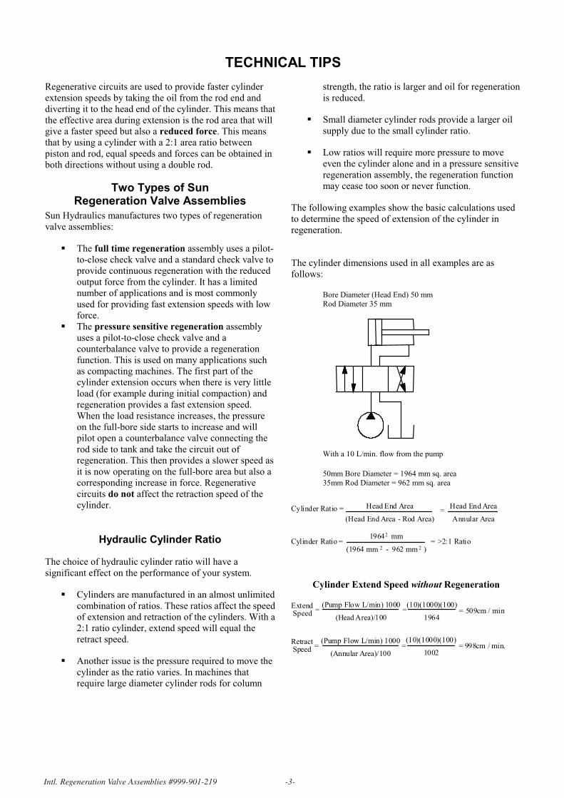
The cylinder dimensions used in all examples are as
follows:
Bore Diameter (Head End) 50 mm
Rod Diameter 35 mm
With a 10 L/min. flow from the pump
50mm Bore Diameter = 1964 mm sq. area
35mm Rod Diameter = 962 mm sq. area
Cylinder Ratio = Head End Area
(Head End Area - Rod Area)=
Head End Area
Annular Area
Cylinder Ratio = = >2:1 Ratio1964 mm
(1964 mm - 962 mm )
2
2 2
Cylinder Extend Speed without Regeneration
(10)(1000)(100)
1002
(Pump Flow L/min) 1000
(Head Area)/100
ExtendSpeed = = 509cm / min.=
(Pump Flow L/min) 1000
(Annular Area)/100
RetractSpeed = = 998cm / min.=
(10)(1000)(100)
1964
Int'l_Ver 4/23/01 11:05 AM Page 3
Page 4
Intl. Regeneration Valve Assemblies #999-901-219 -4-
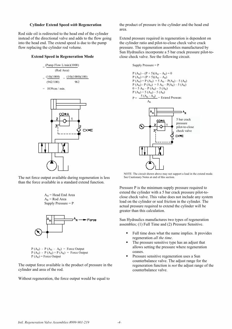
Cylinder Extend Speed with Regeneration
Rod side oil is redirected to the head end of the cylinder
instead of the directional valve and adds to the flow going
into the head end. The extend speed is due to the pump
flow replacing the cylinder rod volume.
Extend Speed in Regeneration Mode
=(Pump Flow L/min)(1000)
(Rod Area)
(10)(1000)
(962/100)=
= 1039cm / min.
=(10)(1000)(100)
962
The net force output available during regeneration is less
than the force available in a standard extend function.
AH = Head End Area
AR = Rod Area
Supply Pressure = P
P (AH) - P (AH – AR) = Force Output
P (AH) - P (AH) + P (AR) = Force Output
P (AR) = Force Output
The output force available is the product of pressure in the
cylinder and area of the rod.
Without regeneration, the force output would be equal to
the product of pressure in the cylinder and the head end
area.
Extend pressure required in regeneration is dependent on
the cylinder ratio and pilot-to-close check valve crack
pressure. The regeneration assemblies manufactured by
Sun Hydraulics incorporate a 5 bar crack pressure pilot-to-
close check valve. See the following circuit.
Supply Pressure = P
P (AH) – (P + 5)(AH – AR) = 0
P (AH) = (P + 5)(AH – AR)
P (AH) = P (AH) + 5 AH – P(AR) – 5 (AR)
P (AH) - P (AH) = 5 AH – P(AR) – 5 (AR)
0 = 5 AH – P (AR) – 5 (AR)
P (AR) = 5 (AH) – 5 (AR)
P =5 (A - A )
A
H R
R
= Extend Pressure
NOTE: The circuit shown above may not support a load in the extend mode. See Cautionary Notes at end of this section.
Pressure P is the minimum supply pressure required to
extend the cylinder with a 5 bar crack pressure pilot-to-
close check valve. This value does not include any system
load on the cylinder or seal friction in the cylinder. The
actual pressure required to extend the cylinder will be
greater than this calculation.
Sun Hydraulics manufactures two types of regeneration
assembles; (1) Full Time and (2) Pressure Sensitive.
�� Full time does what the name implies. It provides
regeneration all the time.
��The pressure sensitive type has an adjust that
allows setting the pressure where regeneration
ceases.
�� Pressure sensitive regeneration uses a Sun
counterbalance valve. The adjust range for the
regeneration function is not the adjust range of the
counterbalance valve.
5 bar crack
pressure
pilot-to-close
check valve
Int'l_Ver 4/23/01 11:05 AM Page 4
Page 5
Intl. Regeneration Valve Assemblies #999-901-219 -5-
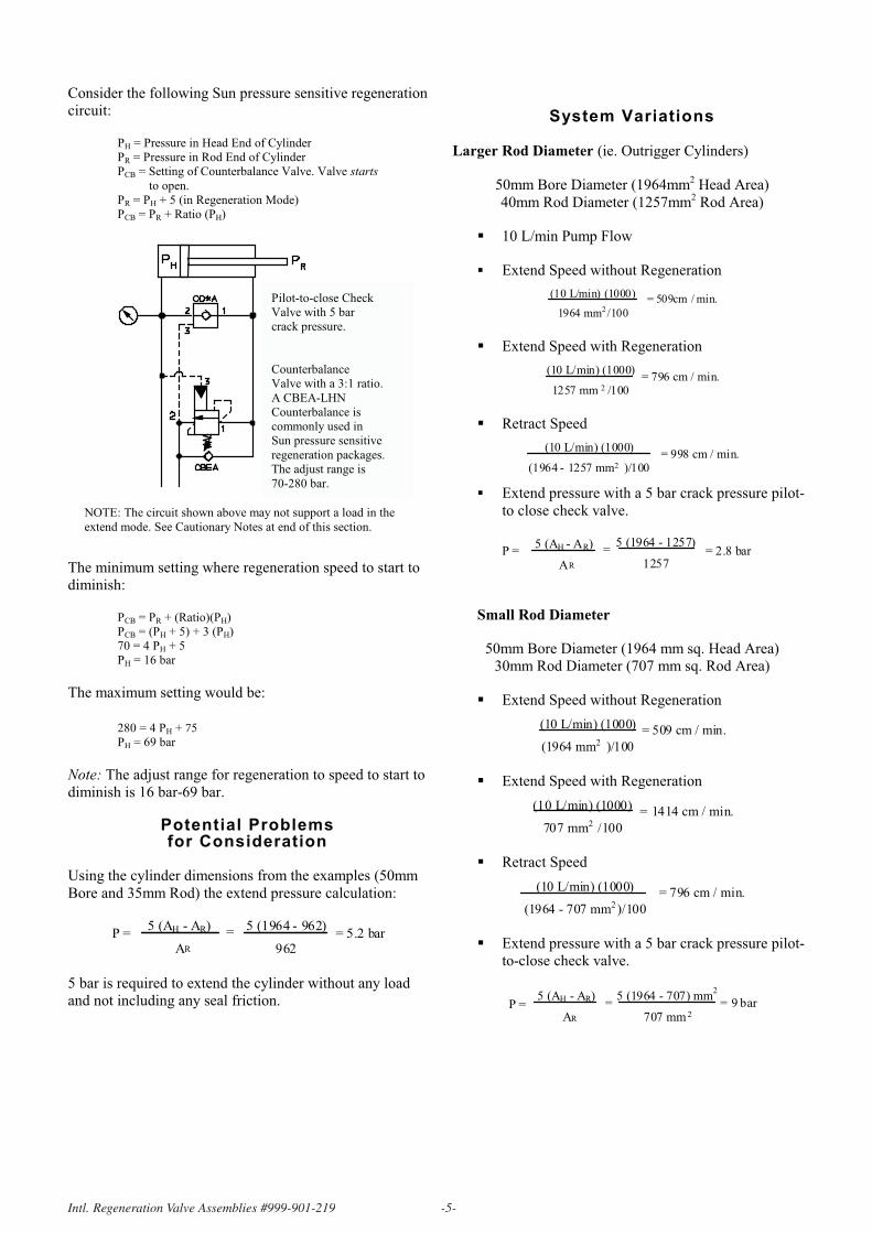
Consider the following Sun pressure sensitive regeneration
circuit:
PH = Pressure in Head End of Cylinder
PR = Pressure in Rod End of Cylinder
PCB = Setting of Counterbalance Valve. Valve starts
to open.
PR = PH + 5 (in Regeneration Mode)
PCB = PR + Ratio (PH)
NOTE: The circuit shown above may not support a load in the
extend mode. See Cautionary Notes at end of this section.
The minimum setting where regeneration speed to start to
diminish:
PCB = PR + (Ratio)(PH)
PCB = (PH + 5) + 3 (PH)
70 = 4 PH + 5
PH = 16 bar
The maximum setting would be:
280 = 4 PH + 75
PH = 69 bar
Note: The adjust range for regeneration to speed to start to
diminish is 16 bar-69 bar.
Potential Problems for Consideration
Using the cylinder dimensions from the examples (50mm
Bore and 35mm Rod) the extend pressure calculation:
P =5 (A - A )
A= 5.2 barH R
R
5 (1964 - 962)
962
=
5 bar is required to extend the cylinder without any load
and not including any seal friction.
System Variations
Larger Rod Diameter (ie. Outrigger Cylinders)
50mm Bore Diameter (1964mm2 Head Area)
40mm Rod Diameter (1257mm2 Rod Area)
�� 10 L/min Pump Flow
�� Extend Speed without Regeneration
= 509cm / min.(10 L/min) (1000)
1964 mm /1002
��Extend Speed with Regeneration
= 796 cm / min.(10 L/min) (1000)
1257 mm /1002
��Retract Speed
= 998 cm / min.(10 L/min) (1000)
(1964 - 1257 mm )/1002
�� Extend pressure with a 5 bar crack pressure pilot-
to close check valve.
P =5 (A - A )
A= 2.8 barH R
R
5 (1964 - 1257)
1257=
Small Rod Diameter
50mm Bore Diameter (1964 mm sq. Head Area)
30mm Rod Diameter (707 mm sq. Rod Area)
��Extend Speed without Regeneration
= 509 cm / min.(10 L/min) (1000)
(1964 mm )/1002
��Extend Speed with Regeneration
= 1414 cm / min.(10 L/min) (1000)
707 mm /1002
��Retract Speed
= 796 cm / min.(10 L/min) (1000)
(1964 - 707 mm )/1002
��Extend pressure with a 5 bar crack pressure pilot-
to-close check valve.
P =5 (A - A )
A= 9 barH R
R
5 (1964 - 707) mm
707 mm
2
2
=
Pilot-to-close Check
Valve with 5 bar
crack pressure.
Counterbalance
Valve with a 3:1 ratio.
A CBEA-LHN
Counterbalance is
commonly used in
Sun pressure sensitive
regeneration packages.
The adjust range is
70-280 bar.
Int'l_Ver 4/23/01 11:05 AM Page 5
Page 6
Intl. Regeneration Valve Assemblies #999-901-219 -6-
R i V l A bli #999 901 219 6
Regeneration Features Summary
Large Rod Diameter
��Reduced Regeneration Speed Advantage
��High Retract Speed
��Lower Extend Pressure
��Higher Force Output in Regeneration
Small Rod Diameter
�� Increased Regeneration Speed Advantage
��Lower Retract Speed
��Higher Extend Pressure
��Lower Force Output in Regeneration
Worst case example with a cylinder ration of 1.16:1 and a
5 bar crack pressure pilot-to-close check.
Cylinder Ratio =A
(A - A )
H
RH
= 1.16:1
If: A = 1.16 (A - A ) = 1
Then A = 0.16
H R
R
Pressure to Extend P =5 (A - A )
A= 31.2 barH R
R
5 (1)
0.16=
H
(Very Small RodDiameter inrelation to Bore)
In this example, depending on the setting of the
counterbalance valve, regeneration may cease upon
application of flow due to the high extend pressure without
external load.
Formulas
Formulas for calculation of flow rates in regeneration
circuits.
(D - D )
D
b2
r2
b2
Combined Flow =(Pump Flow plusRegenerative Flow)
Retraction Flow =(Flow out ofBlind End duringRetraction)
D
D
b2
r2( ) x Pump Flow
D
(D - D )b2
r2
b2
x Pump Flow
Flow out of Rod End = x Pump Flow
Db = Blind End Cylinder Bore Diameter
Dr = Rod Diameter
Application Cautionary Statements
Full Time Regeneration Assemblies
��Regeneration does not cease at any time during the
cycle.
��Extreme cylinder ratios may prevent the system
from moving. Heat may be a problem when
regeneration occurs but system pressure is high
and oil is flowing through the system relief valve.
��Cylinder force is reduced at all times.
Pressure Sensitive Regeneration Assemblies
��Regeneration may cease too soon or never occur
due to system pressure required.
��The assumption that the adjust range of the
regeneration package is the same as the
counterbalance valve is incorrect.
�� Extreme cylinder ratios may prevent the
regeneration package from operating at all.
General Issues for both
Types of Sun Regeneration Packages
1. It is important to remember to size hydraulic
lines correctly to allow for the increase flow
going into the full bore side of the cylinder.
2. The pilot-to-close check valve has a 5 bar crack
pressure. A rod down cylinder application or a
load on the cylinder that would tend to extend the
rod is extremely dangerous. A rod down
application could suddenly fall as the rod oil flows
through the pilot-to-close check valve to the blind
end of the cylinder. The blind end of the cylinder
would cavitate but could not hold the load.
3. To prevent the problem of unexpected rod motion,
a load control valve must be installed in the rod
port. A Sun vented pilot-to-open check valve or
vented counterbalance valve can provide load
locking or load control and locking. Only vented
versions of those cartridges must be used to have a
functional system.
4. The effective adjustment range for the pressure
sensitive regeneration assembly is not the same as
the adjustment range of the counterbalance valve
used in the assembly. Refer to the previous pages
of technical tips to determine the regeneration
adjust range for the specific counterbalance valve.
Int'l_Ver 4/23/01 11:05 AM Page 6
Page 7
Intl. Regeneration Valve Assemblies #999-901-219 -7-
Pressure Sensitive Regeneration Assemblies
Line Mounted Assemblies Sandwich Mounted Assemblies
12 GPM / 45 L/min. 10 GPM / 40 L/min.
SERIES 1 CARTRIDGES D03/CETOP 3
YDCC-LHN-A* YDCA-LHN-AA
YDCD-LHN-A* YDCG-LHN-B*
25 GPM / 95 L/min. 25 GPM / 95 L/min.
SERIES 2 CARTRIDGES D05/CETOP 5
YDEK-LHN-A* YDEM-LHN-B*
YDEG-LHN-A* YDEH-LHN-AK
YDEF-LHN-A* YDES-LHN-BA
YDEC-LHN-A* YDER-LHN-BA
YDED-LHN-A* YDEE-LHN-BA
50 GPM / 190 L/min. 25 GPM / 95 L/min.
SERIES 3 CARTRIDGES D05 X, Y/CETOP 5 X, Y
YDGC-LHN-A* YDEL-LHN-BB
YDGC-LHN-AP
YDGD-LHN-A*
YDGD-LHN-AP
YDGD-LHN-AQ
YDGL-LHN-AP
YDGL-LHN-AQ
YDGL-LHN-A4
YDGL-LHN-A5
100 GPM / 380 L/min. 50 GPM / 190 L/min.
SERIES 4 CARTRIDGES D07/CETOP 7
YDHC-LHN-A5 YDFE-LHN-AB
120 GPM / 450 L/min. YDFG-LHN-AB
YDJC-LHN-AN 40 GPM / 150 L/min.
240 GPM / 910 L/min. D08/CETOP 8
YDJC-LHN-A6
Dual Cartridges
YDFF-LHN-CA
Dual Cartridges
YDJC-LHN-AS
Dual Cartridges
60 GPM / 230 L/min.
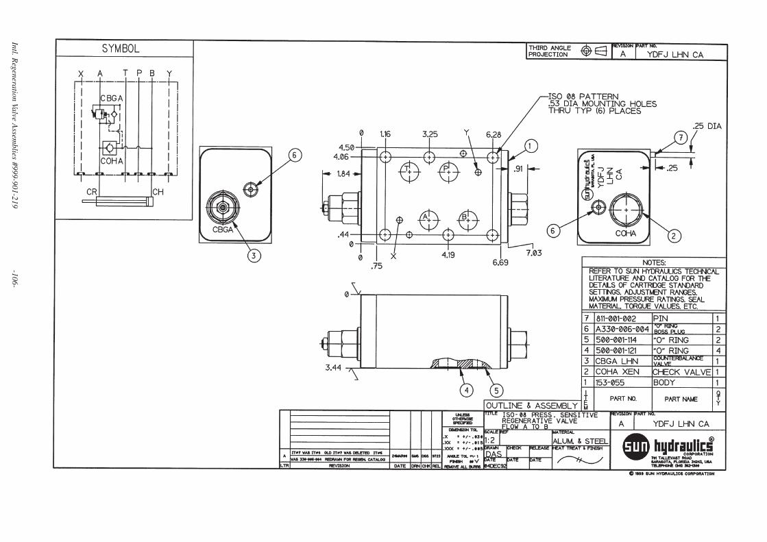
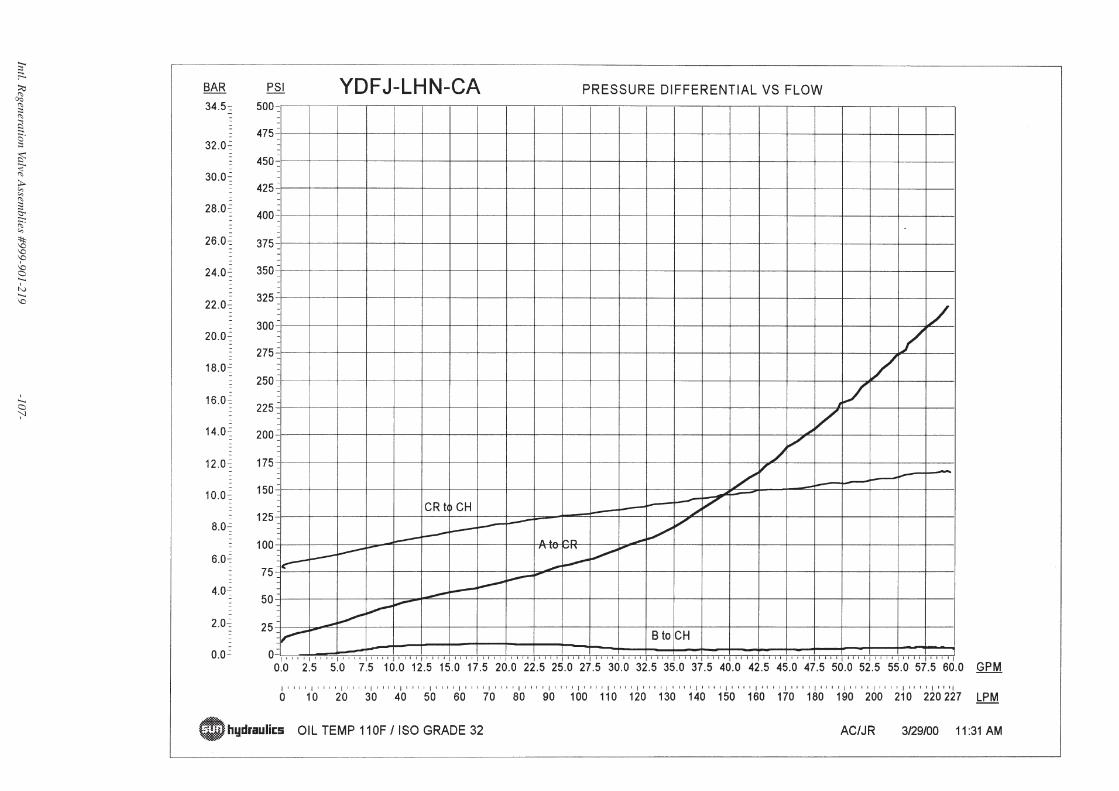
YDFJ-LHN-CA
YDFK-LHN-CA
80 GPM/300 L/min.
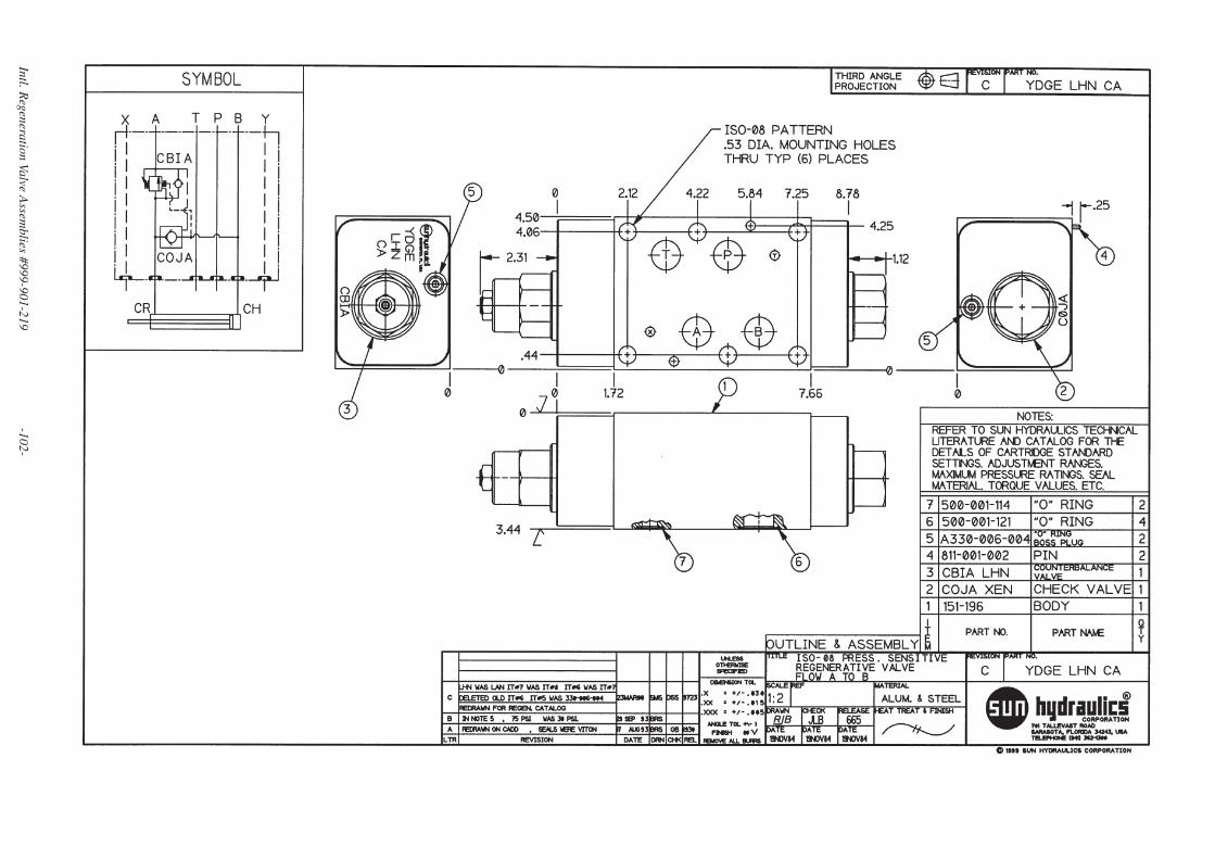
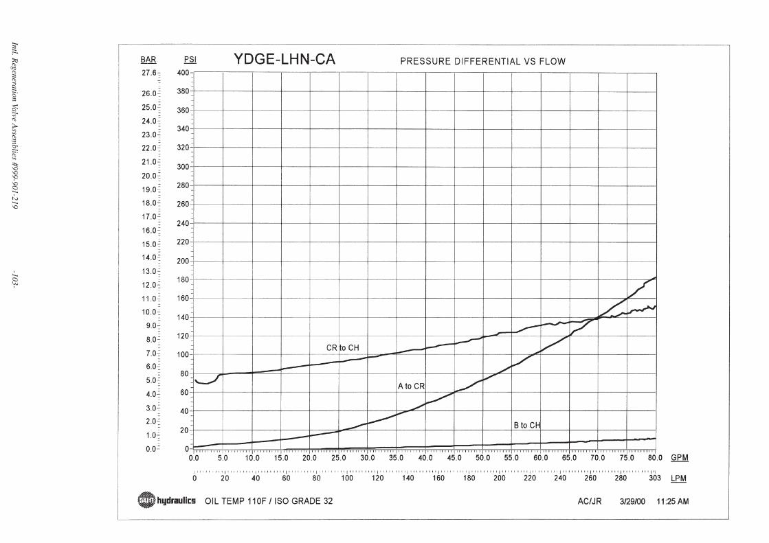
YDGE-LHN-CA
YDGF-LHN-CA
Flow ratings are nominal.
See performance curves on following page for detailed pressure flow characteristics.
* Indicates optional port types available.
Int'l_Ver 4/23/01 11:05 AM Page 7
Page 8
Intl. Regeneration Valve Assemblies #999-901-219 -8-
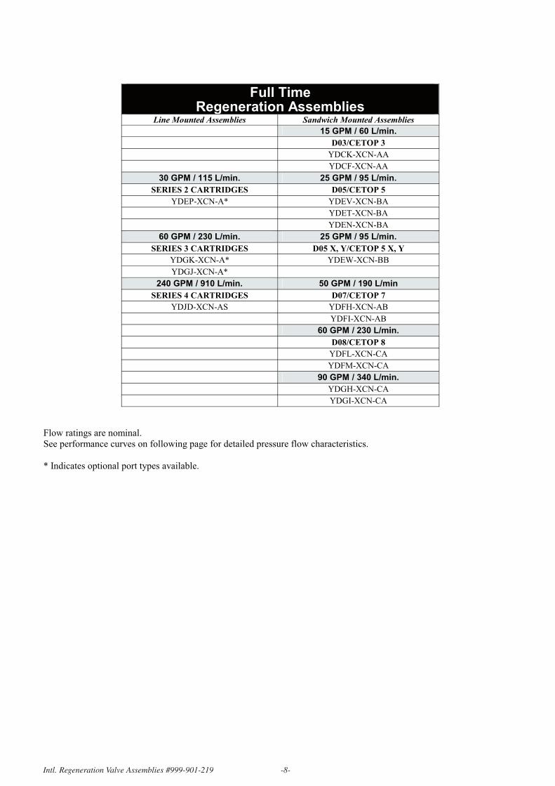
Full Time Regeneration Assemblies
Line Mounted Assemblies Sandwich Mounted Assemblies
15 GPM / 60 L/min.
D03/CETOP 3
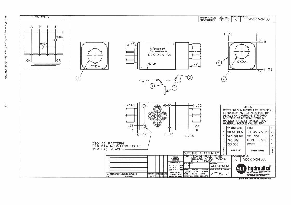
YDCK-XCN-AA
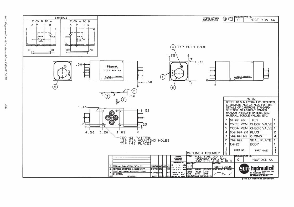
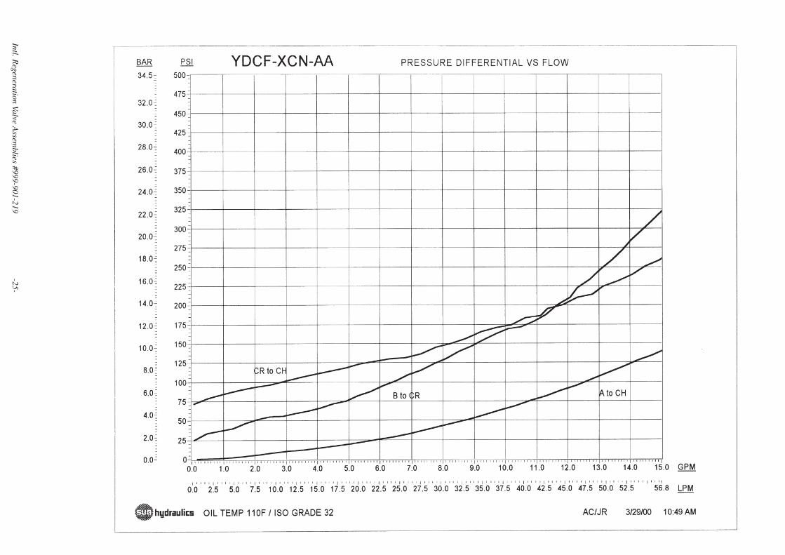
YDCF-XCN-AA
30 GPM / 115 L/min. 25 GPM / 95 L/min.
SERIES 2 CARTRIDGES D05/CETOP 5
YDEP-XCN-A* YDEV-XCN-BA
YDET-XCN-BA
YDEN-XCN-BA
60 GPM / 230 L/min. 25 GPM / 95 L/min.
SERIES 3 CARTRIDGES D05 X, Y/CETOP 5 X, Y
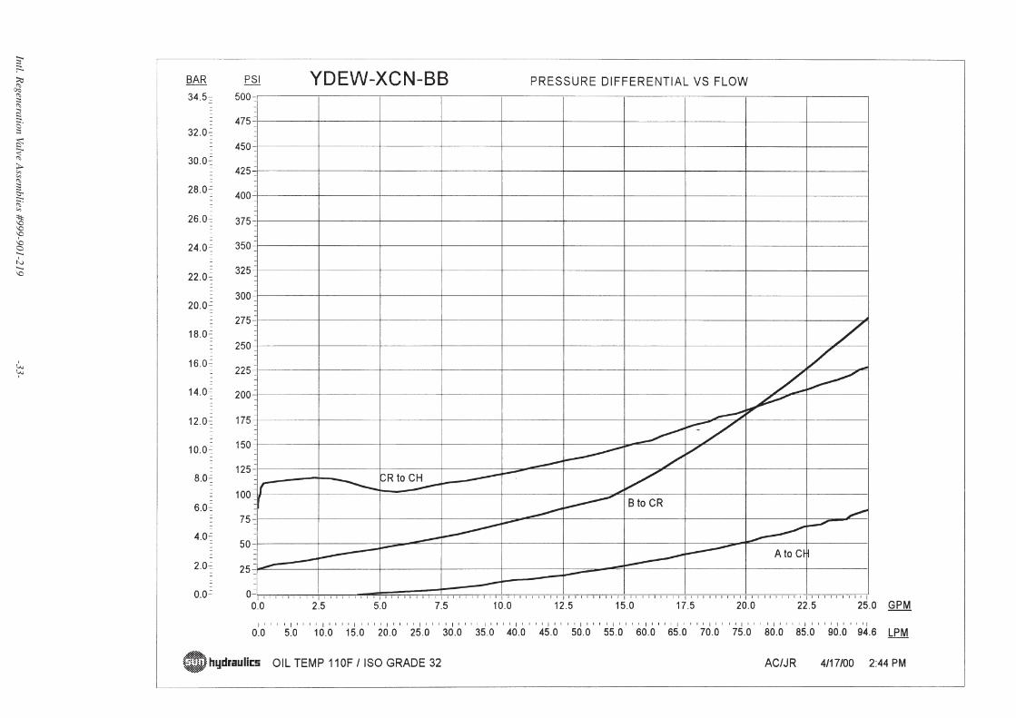
YDGK-XCN-A* YDEW-XCN-BB
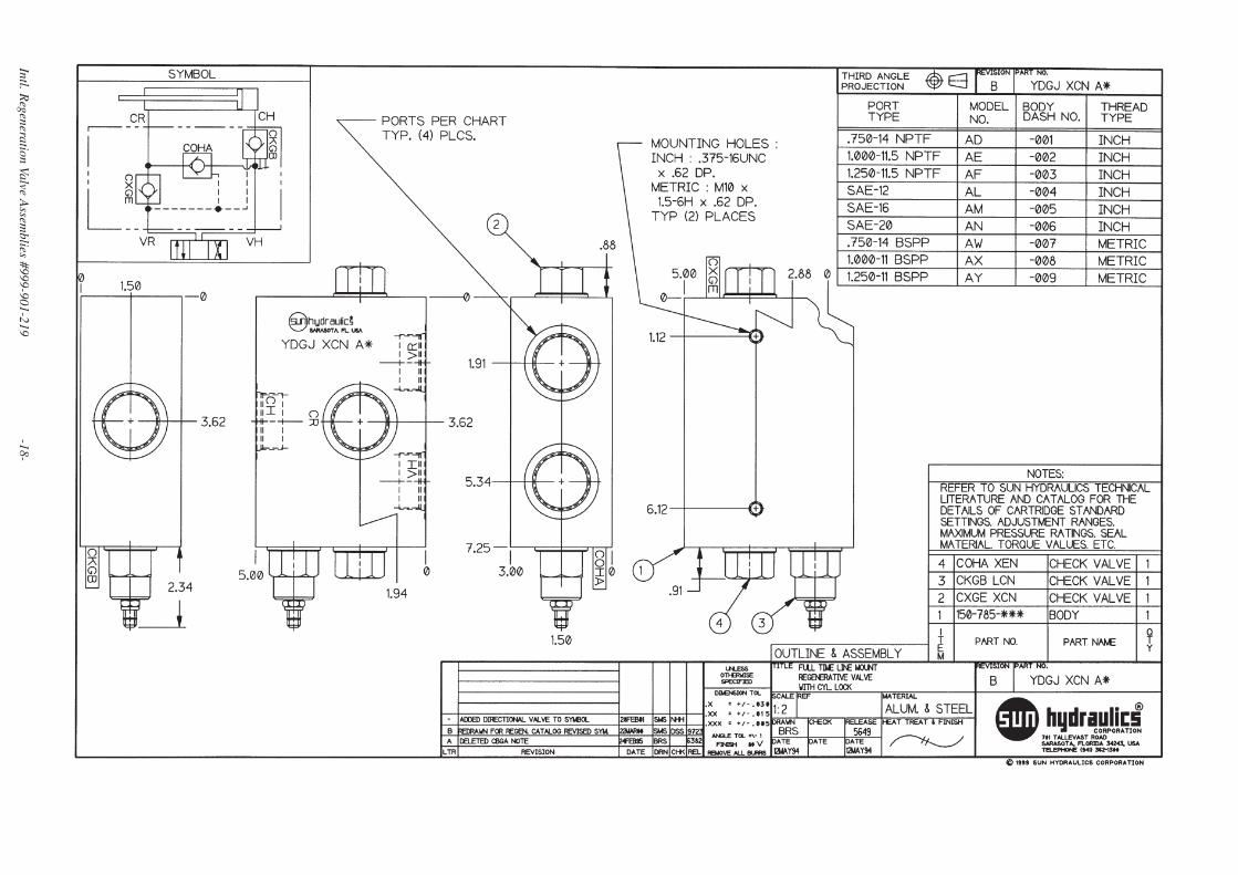
YDGJ-XCN-A*
240 GPM / 910 L/min. 50 GPM / 190 L/min
SERIES 4 CARTRIDGES D07/CETOP 7
YDJD-XCN-AS YDFH-XCN-AB
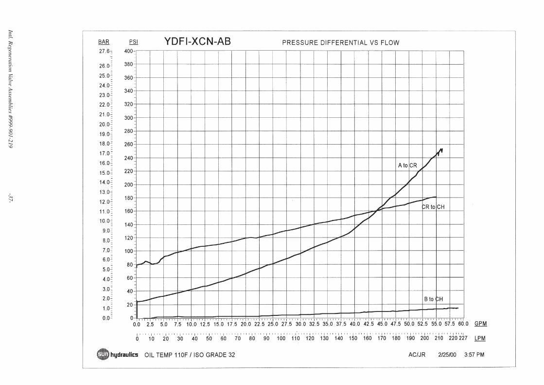
YDFI-XCN-AB
60 GPM / 230 L/min.
D08/CETOP 8
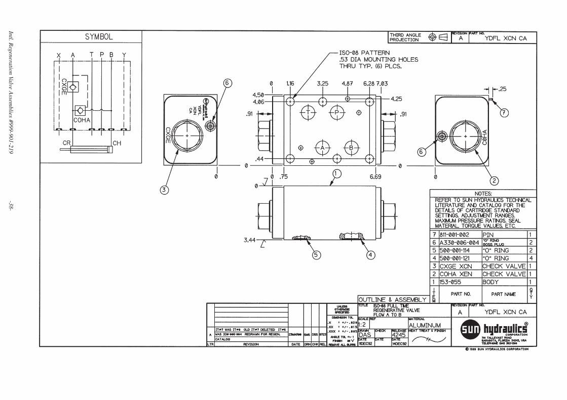
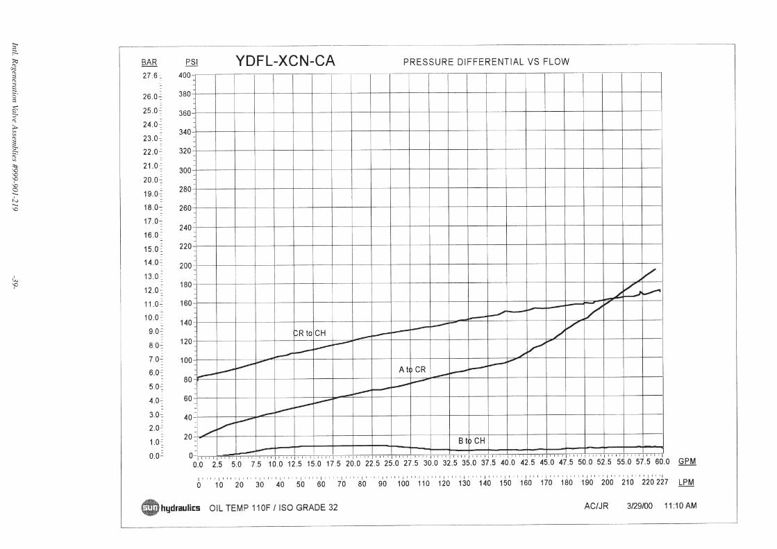
YDFL-XCN-CA
YDFM-XCN-CA
90 GPM / 340 L/min.
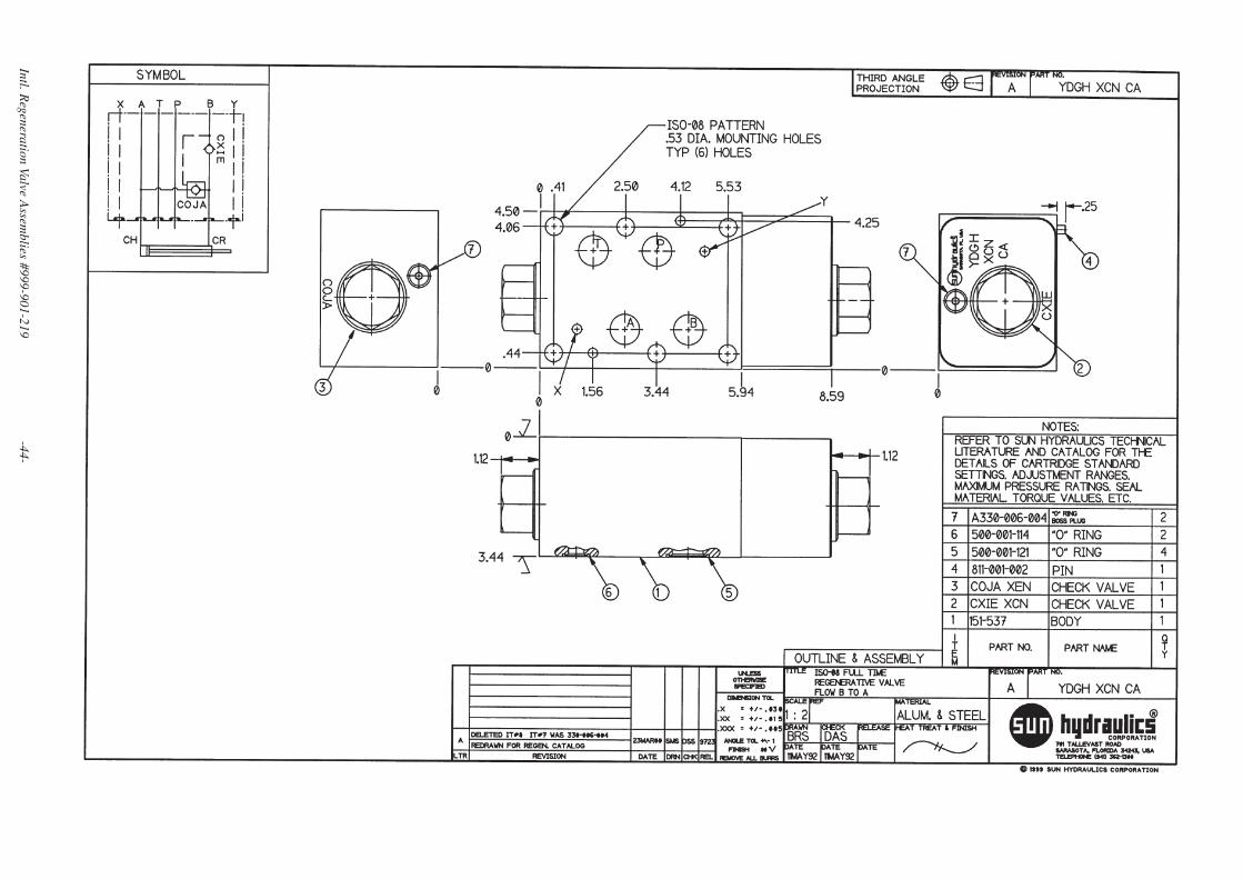
YDGH-XCN-CA
YDGI-XCN-CA
Flow ratings are nominal.
See performance curves on following page for detailed pressure flow characteristics.
* Indicates optional port types available.
Int'l_Ver 4/23/01 11:05 AM Page 8
Page 9
Sun Regeneration CircuitUsing Other Sun Cartridge Valves
Regeneration Circuit with Pressure Unloading and Load Holding in both Extend and Retract Mode
(This example circuit demonstates another method of Regeneration, but is not available asa pre-packaged assembly.)
This concept can be used where the load may tend to extend the cylinder as well as causing it to retract.
Pressure sensitive regeneration system provides regeneration with progressive unloading up to full force operation.
Both counterbalances to be sized for appropriate flows (i.e. cap end counterbalance must be sized for pump plus rod end flow, while rod end counterbalance is sized for rod end flow only.)
With work ports drained and counterbalance valves adjusted to appropriate pressure settings, cylinder should not move in either direction.
•
•
•
•
U.S. Regeneration Valve Assemblies #999-901-217 -9-
CB** Counterbalance ValveCW** Vented Counterbalance ValveCO*A Pilot-to-close Check Valve
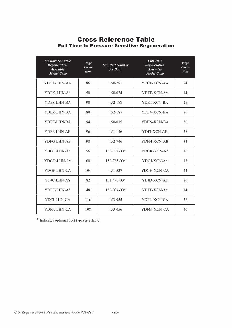
Page 10
Pressure Sensitive Regeneration
Assembly Model Code
PageLoca-tion
Sun Part Number for Body
Full TimeRegeneration
AssemblyModel Code
Page Loca-tion
YDCA-LHN-AA 86 150-281 YDCF-XCN-AA 24
YDEK-LHN-A* 50 150-034 YDEP-XCN-A* 14
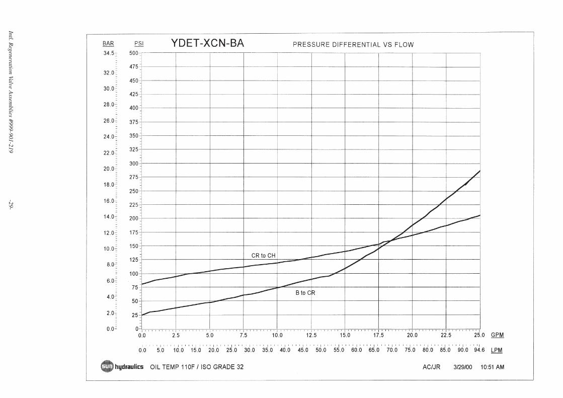
YDES-LHN-BA 90 152-188 YDET-XCN-BA 28
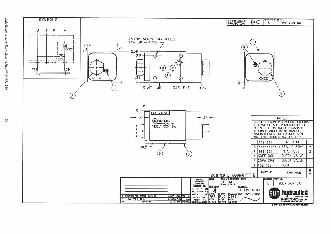
YDER-LHN-BA 88 152-187 YDEV-XCN-BA 26
YDEE-LHN-BA 94 150-015 YDEN-XCN-BA 30
YDFE-LHN-AB 96 151-146 YDFI-XCN-AB 36
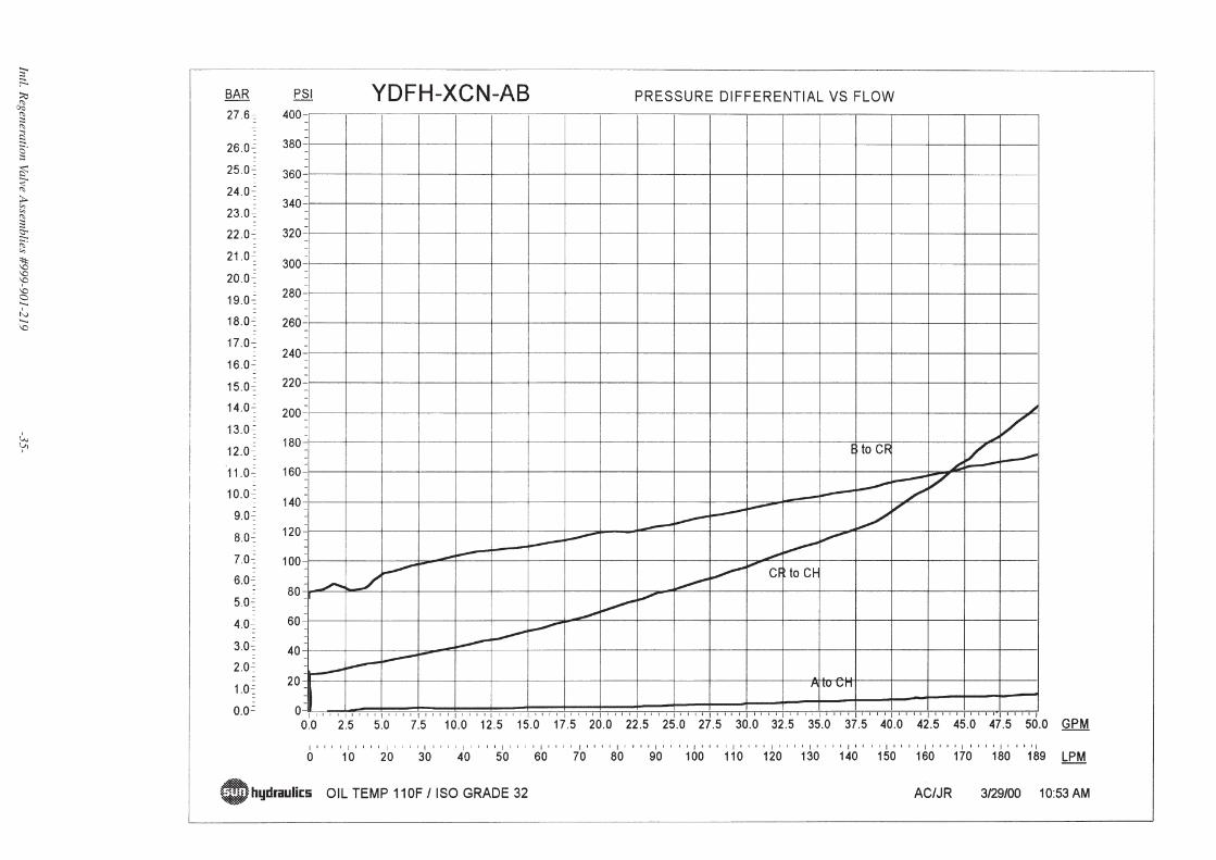
YDFG-LHN-AB 98 152-746 YDFH-XCN-AB 34
YDGC-LHN-A* 56 150-784-00* YDGK-XCN-A* 16
YDGD-LHN-A* 60 150-785-00* YDGJ-XCN-A* 18
YDGF-LHN-CA 104 151-537 YDGH-XCN-CA 44
YDJC-LHN-AS 82 151-496-00* YDJD-XCN-AS 20
YDEC-LHN-A* 48 150-034-00* YDEP-XCN-A* 14
YDFJ-LHN-CA 116 153-055 YDFL-XCN-CA 38
YDFK-LHN-CA 108 153-056 YDFM-XCN-CA 40
* Indicates optional port types available.
Cross Reference TableFull Time to Pressure Sensitive Regeneration
U.S. Regeneration Valve Assemblies #999-901-217 -10-
Page 11
U.S. Regeneration Valve Assemblies #999-901-217 -11-
NOTES
Page 12
U.S. Regeneration Valve Assemblies #999-901-217 -12-
NOTES
Page 13
U.S. Regeneration Valve Assemblies #999-901-217 -13-
NOTES
Page 14
Intl. Regeneration Valve A
ssemblies #999-901-219
-14-
Int'l_Ver 4
/23/01 1
1:05 AM P
age 14
Page 15
Intl. Regeneration Valve A
ssemblies #999-901-219
-15-
Int'l_Ver 4
/23/01 1
1:05 AM P
age 15
Page 16
Intl. Regeneration Valve A
ssemblies #999-901-219
-16-
Int'l_Ver 4
/23/01 1
1:05 AM P
age 16
Page 17
Intl. Regeneration Valve A
ssemblies #999-901-219
-17-
Int'l_Ver 4
/23/01 1
1:05 AM P
age 17
Page 18
Intl. Regeneration Valve A
ssemblies #999-901-219
-18-
Int'l_Ver 4
/23/01 1
1:06 AM P
age 18
Page 19
Intl. Regeneration Valve A
ssemblies #999-901-219
-19-
Int'l_Ver 4
/23/01 1
1:06 AM P
age 19
Page 20
Intl. Regeneration Valve A
ssemblies #999-901-219
-20-
Int'l_Ver 4
/23/01 1
1:06 AM P
age 20
Page 21
Intl. Regeneration Valve A
ssemblies #999-901-219
-21-
Int'l_Ver 4
/23/01 1
1:06 AM P
age 21
Page 22
Intl. Regeneration Valve A
ssemblies #999-901-219
-22-
Int'l_Ver 4
/23/01 1
1:06 AM P
age 22
Page 23
Intl. Regeneration Valve A
ssemblies #999-901-219
-23-
Int'l_Ver 4
/23/01 1
1:06 AM P
age 23
Page 24
Intl. Regeneration Valve A
ssemblies #999-901-219
-24-
Int'l_Ver 4
/23/01 1
1:06 AM P
age 24
Page 25
Intl. Regeneration Valve A
ssemblies #999-901-219
-25-
Int'l_Ver 4
/23/01 1
1:06 AM P
age 25
Page 26
Intl. Regeneration Valve A
ssemblies #999-901-219
-26-
Int'l_Ver 4
/23/01 1
1:06 AM P
age 26
Page 27
Intl. Regeneration Valve A
ssemblies #999-901-219
-27-
Int'l_Ver 4
/23/01 1
1:06 AM P
age 27
Page 28
Intl. Regeneration Valve A
ssemblies #999-901-219
-28-
Int'l_Ver 4
/23/01 1
1:06 AM P
age 28
Page 29
Intl. Regeneration Valve A
ssemblies #999-901-219
-29-
Int'l_Ver 4/23/01 11:06 AM Page 29
Page 30
Intl. Regeneration Valve A
ssemblies #999-901-219
-30-
Int'l_Ver 4
/23/01 1
1:06 AM P
age 30
Page 31
Intl. Regeneration Valve A
ssemblies #999-901-219
-31-
Int'l_Ver 4
/23/01 1
1:06 AM P
age 31
Page 32
Intl. Regeneration Valve A
ssemblies #999-901-219
-32-
Int'l_Ver 4
/23/01 1
1:07 AM P
age 32
Page 33
Intl. Regeneration Valve A
ssemblies #999-901-219
-33-
Int'l_Ver 4
/23/01 1
1:07 AM P
age 33
Page 34
Intl. Regeneration Valve A
ssemblies #999-901-219
-34-
Int'l_Ver 4
/23/01 1
1:07 AM P
age 34
Page 35
Intl. Regeneration Valve A
ssemblies #999-901-219
-35-
Int'l_Ver 4
/23/01 1
1:07 AM P
age 35
Page 36
Intl. Regeneration Valve A
ssemblies #999-901-219
-36-
Int'l_Ver 4
/23/01 1
1:07 AM P
age 36
Page 37
Intl. Regeneration Valve A
ssemblies #999-901-219
-37-
Int'l_Ver 4
/23/01 1
1:07 AM P
age 37
Page 38
Intl. Regeneration Valve A
ssemblies #999-901-219
-38-
Int'l_Ver 4
/23/01 1
1:07 AM P
age 38
Page 39
Intl. Regeneration Valve A
ssemblies #999-901-219
-39-
Int'l_Ver 4
/23/01 1
1:07 AM P
age 39
Page 40
Intl. Regeneration Valve A
ssemblies #999-901-219
-40-
Int'l_Ver 4
/23/01 1
1:07 AM P
age 40
Page 41
Intl. Regeneration Valve A
ssemblies #999-901-219
-41-
Int'l_Ver 4
/23/01 1
1:07 AM P
age 41
Page 42
Intl. Regeneration Valve A
ssemblies #999-901-219
-42-
Int'l_Ver 4
/23/01 1
1:07 AM P
age 42
Page 43
Intl. Regeneration Valve A
ssemblies #999-901-219
-43-
Int'l_Ver 4
/23/01 1
1:07 AM P
age 43
Page 44
Intl. Regeneration Valve A
ssemblies #999-901-219
-44-
Int'l_Ver 4
/23/01 1
1:07 AM P
age 44
Page 45
Intl. Regeneration Valve A
ssemblies #999-901-219
-45-
Int'l_Ver 4
/23/01 1
1:07 AM P
age 45
Page 46
Intl. Regeneration Valve A
ssemblies #999-901-219
-46-
Int'l_Ver 4
/23/01 1
1:07 AM P
age 46
Page 47
Intl. Regeneration Valve A
ssemblies #999-901-219
-47-
Int'l_Ver 4
/23/01 1
1:07 AM P
age 47
Page 48
Intl. Regeneration Valve A
ssemblies #999-901-219
-48-
Int'l_Ver 4
/23/01 1
1:07 AM P
age 48
Page 49
Intl. Regeneration Valve A
ssemblies #999-901-219
-49-
Int'l_Ver 4
/23/01 1
1:08 AM P
age 49
Page 50
Intl. Regeneration Valve A
ssemblies #999-901-219
-50-
Int'l_Ver 4
/23/01 1
1:08 AM P
age 50
Page 51
Intl. Regeneration Valve A
ssemblies #999-901-219
-51-
Int'l_Ver 4
/23/01 1
1:08 AM P
age 51
Page 52
Intl. Regeneration Valve A
ssemblies #999-901-219
-52-
Int'l_Ver 4
/23/01 1
1:08 AM P
age 52
Page 53
Intl. Regeneration Valve A
ssemblies #999-901-219
-53-
Int'l_Ver 4
/23/01 1
1:08 AM P
age 53
Page 54
Intl. Regeneration Valve A
ssemblies #999-901-219
-54-
Int'l_Ver 4
/23/01 1
1:08 AM P
age 54
Page 55
Intl. Regeneration Valve A
ssemblies #999-901-219
-55-
Int'l_Ver 4
/23/01 1
1:08 AM P
age 55
Page 56
Intl. Regeneration Valve A
ssemblies #999-901-219
-56-
Int'l_Ver 4
/23/01 1
1:08 AM P
age 56
Page 57
Intl. Regeneration Valve A
ssemblies #999-901-219
-57-
Int'l_Ver 4
/23/01 1
1:08 AM P
age 57
Page 58
Intl. Regeneration Valve A
ssemblies #999-901-219
-58-
Int'l_Ver 4
/23/01 1
1:08 AM P
age 58
Page 59
Intl. Regeneration Valve A
ssemblies #999-901-219
-59-
Int'l_Ver 4
/23/01 1
1:08 AM P
age 59
Page 60
Intl. Regeneration Valve A
ssemblies #999-901-219
-60-
Int'l_Ver 4
/23/01 1
1:08 AM P
age 60
Page 61
Intl. Regeneration Valve A
ssemblies #999-901-219
-61-
Int'l_Ver 4
/23/01 1
1:08 AM P
age 61
Page 62
Intl. Regeneration Valve A
ssemblies #999-901-219
-62-
Int'l_Ver 4
/23/01 1
1:08 AM P
age 62
Page 63
Intl. Regeneration Valve A
ssemblies #999-901-219
-63-
Int'l_Ver 4
/23/01 1
1:08 AM P
age 63
Page 64
Intl. Regeneration Valve A
ssemblies #999-901-219
-64-
Int'l_Ver 4
/23/01 1
1:08 AM P
age 64
Page 65
Intl. Regeneration Valve A
ssemblies #999-901-219
-65-
Int'l_Ver 4
/23/01 1
1:08 AM P
age 65
Page 66
Intl. Regeneration Valve A
ssemblies #999-901-219
-66-
Int'l_Ver 4
/23/01 1
1:08 AM P
age 66
Page 67
Intl. Regeneration Valve A
ssemblies #999-901-219
-67-
Int'l_Ver 4
/23/01 1
1:09 AM P
age 67
Page 68
Intl. Regeneration Valve A
ssemblies #999-901-219
-68-
Int'l_Ver 4
/23/01 1
1:09 AM P
age 68
Page 69
Intl. Regeneration Valve A
ssemblies #999-901-219
-69-
Int'l_Ver 4
/23/01 1
1:09 AM P
age 69
Page 70
Intl. Regeneration Valve A
ssemblies #999-901-219
-70-
Int'l_Ver 4
/23/01 1
1:09 AM P
age 70
Page 71
Intl. Regeneration Valve A
ssemblies #999-901-219
-71-
Int'l_Ver 4
/23/01 1
1:09 AM P
age 71
Page 72
Intl. Regeneration Valve A
ssemblies #999-901-219
-72-
Int'l_Ver 4
/23/01 1
1:09 AM P
age 72
Page 73
Intl. Regeneration Valve A
ssemblies #999-901-219
-73-
Int'l_Ver 4
/23/01 1
1:09 AM P
age 73
Page 74
Intl. Regeneration Valve A
ssemblies #999-901-219
-74-
Int'l_Ver 4
/23/01 1
1:09 AM P
age 74
Page 75
Intl. Regeneration Valve A
ssemblies #999-901-219
-75-
Int'l_Ver 4
/23/01 1
1:09 AM P
age 75
Page 76
Intl. Regeneration Valve A
ssemblies #999-901-219
-76-
Int'l_Ver 4
/23/01 1
1:09 AM P
age 76
Page 77
Intl. Regeneration Valve A
ssemblies #999-901-219
-77-
Int'l_Ver 4
/23/01 1
1:09 AM P
age 77
Page 78
Intl. Regeneration Valve A
ssemblies #999-901-219
-78-
Int'l_Ver 4
/23/01 1
1:09 AM P
age 78
Page 79
Intl. Regeneration Valve A
ssemblies #999-901-219
-79-
Int'l_Ver 4
/23/01 1
1:09 AM P
age 79
Page 80
Intl. Regeneration Valve A
ssemblies #999-901-219
-80-
Int'l_Ver 4
/23/01 1
1:09 AM P
age 80
Page 81
Intl. Regeneration Valve A
ssemblies #999-901-219
-81-
Int'l_Ver 4
/23/01 1
1:09 AM P
age 81
Page 82
Intl. Regeneration Valve A
ssemblies #999-901-219
-82-
Int'l_Ver 4
/23/01 1
1:09 AM P
age 82
Page 83
Intl. Regeneration Valve A
ssemblies #999-901-219
-83-
Int'l_Ver 4
/23/01 1
1:09 AM P
age 83
Page 84
Intl. Regeneration Valve A
ssemblies #999-901-219
-84-
Int'l_Ver 4
/23/01 1
1:10 AM P
age 84
Page 85
Intl. Regeneration Valve A
ssemblies #999-901-219
-85-
Int'l_Ver 4
/23/01 1
1:10 AM P
age 85
Page 86
Intl. Regeneration Valve A
ssemblies #999-901-219
-86-
Int'l_Ver 4/23/01 11:10 AM Page 86
Page 87
Intl. Regeneration Valve A
ssemblies #999-901-219
-87-
Int'l_Ver 4
/23/01 1
1:10 AM P
age 87
Page 88
Intl. Regeneration Valve A
ssemblies #999-901-219
-88-
Int'l_Ver 4
/23/01 1
1:10 AM P
age 88
Page 89
Intl. Regeneration Valve A
ssemblies #999-901-219
-89-
Int'l_Ver 4
/23/01 1
1:10 AM P
age 89
Page 90
Intl. Regeneration Valve A
ssemblies #999-901-219
-90-
Int'l_Ver 4
/23/01 1
1:10 AM P
age 90
Page 91
Intl. Regeneration Valve A
ssemblies #999-901-219
-91-
Int'l_Ver 4
/23/01 1
1:10 AM P
age 91
Page 92
Intl. Regeneration Valve A
ssemblies #999-901-219
-92-
Int'l_Ver 4
/23/01 1
1:10 AM P
age 92
Page 93
Intl. Regeneration Valve A
ssemblies #999-901-219
-93-
Int'l_Ver 4
/23/01 1
1:10 AM P
age 93
Page 94
Intl. Regeneration Valve A
ssemblies #999-901-219
-94-
Int'l_Ver 4
/23/01 1
1:10 AM P
age 94
Page 95
Intl. Regeneration Valve A
ssemblies #999-901-219
-95-
Int'l_Ver 4
/23/01 1
1:10 AM P
age 95
Page 96
Intl. Regeneration Valve A
ssemblies #999-901-219
-96-
Int'l_Ver 4
/23/01 1
1:10 AM P
age 96
Page 97
Intl. Regeneration Valve A
ssemblies #999-901-219
-97-
Int'l_Ver 4
/23/01 1
1:10 AM P
age 97
Page 98
Intl. Regeneration Valve A
ssemblies #999-901-219
-98-
Int'l_Ver 4
/23/01 1
1:10 AM P
age 98
Page 99
Intl. Regeneration Valve A
ssemblies #999-901-219
-99-
Int'l_Ver 4
/23/01 1
1:11 AM P
age 99
Page 100
Intl. Regeneration Valve A
ssemblies #999-901-219
-100-
Int'l_Ver 4
/23/01 1
1:11 AM P
age 100
Page 101
Intl. Regeneration Valve A
ssemblies #999-901-219
-101-
Int'l_Ver 4
/23/01 1
1:11 AM P
age 101
Page 102
Intl. Regeneration Valve A
ssemblies #999-901-219
-102-
Int'l_Ver 4
/23/01 1
1:11 AM P
age 102
Page 103
Intl. Regeneration Valve A
ssemblies #999-901-219
-103-
Int'l_Ver 4
/23/01 1
1:11 AM P
age 103
Page 104
Intl. Regeneration Valve A
ssemblies #999-901-219
-104-
Int'l_Ver 4
/23/01 1
1:11 AM P
age 104
Page 105
Intl. Regeneration Valve A
ssemblies #999-901-219
-105-
Int'l_Ver 4
/23/01 1
1:11 AM P
age 105
Page 106
Intl. Regeneration Valve A
ssemblies #999-901-219
-106-
Int'l_Ver 4
/23/01 1
1:11 AM P
age 106
Page 107
Intl. Regeneration Valve A
ssemblies #999-901-219
-107-
Int'l_Ver 4
/23/01 1
1:11 AM P
age 107
Page 108
Intl. Regeneration Valve A
ssemblies #999-901-219
-108-
Int'l_Ver 4
/23/01 1
1:11 AM P
age 108
Page 109
Intl. Regeneration Valve A
ssemblies #999-901-219
-109-
Int'l_Ver 4
/23/01 1
1:11 AM P
age 109
Page 110
Intl. Regeneration Valve A
ssemblies #999-901-219
-110-
Int'l_Ver 4
/23/01 1
1:11 AM P
age 110
Page 111
Intl. Regeneration Valve A
ssemblies #999-901-219
-111-
Int'l_Ver 4
/23/01 1
1:11 AM P
age 111
Page 112
Intl. Regeneration Valve A
ssemblies #999-901-219
-112-
Int'l_Ver 4
/23/01 1
1:11 AM P
age 112
Page 113
Intl. Regeneration Valve A
ssemblies #999-901-219
-113-
Int'l_Ver 4
/23/01 1
1:11 AM P
age 113
Page 114
Intl. Regeneration Valve A
ssemblies #999-901-219
-114-
Int'l_Ver 4
/23/01 1
1:11 AM P
age 114
Page 115
Intl. Regeneration Valve A
ssemblies #999-901-219
-115-
Int'l_Ver 4
/23/01 1
1:11 AM P
age 115
Page 116
Intl. Regeneration Valve Assemblies #999-901-219 -116-
Int'l_Ver 4/23/01 11:11 AM Page 116