Safety, Operation, & Maintenance Manual WARNING Warning: If incorrectly used, this machine can cause severe injury. Those who use and maintain this machine should be trained in its proper use, warned of its dangers, and must read the entire manual before attempting to set up, operate, adjust, or service the machine. When Performance Matters. ™ GB ECLIPSE 360 RIDING GREENS MOWER LITHIUM BATTERY POWER Product Code: 10029194 Series: CAG 10014566-A
Transcript
Safety, Operation, & Maintenance Manual
WARNINGWarning: If incorrectly used, this machine can
cause severe injury. Those who use and maintainthis machine should be trained in its proper use,warned of its dangers, and must read the entire
manual before attempting to set up, operate, adjust,or service the machine.
When Performance Matters.™GB
ECLIPSE 360 RIDING GREENS MOWERLITHIUM BATTERY POWER
WARNINGThe engine exhaust from this product contains
chemicals known to the State of California to cause cancer, birth defects and other reproductive harm.
!
FOREWORD
This manual contains adjustment, maintenance, troubleshooting instructions, and parts list for your new machine. Thismanual should be stored with the equipment for reference during operation.Before you operate your machine, you and each operator you employ should read the manual carefully in its entirety. Byfollowing the safety, operating, and maintenance instructions, you will prolong the life of your equipment and maintain itsmaximum efficiency.If additional information is needed, contact dealer.The serial plate is located on the rear frame rail. The manufacturer recommends you record these numbers below foreasy reference.
HOW TO OPERATE SAFELY____________________________________________________________
Safe Operation• Read the Operator’s Manual and other training material. If the operator or technician can not read this manual, the
owner is responsible to describe this material to the operators and technicians. Manuals in additional languages maybe available on the Jacobsen or Ransomes Jacobsen website.
• Read all of the instructions for this mower carefully. Know the controls and the correct operation of the equipment.• Children or persons who do not understand these instructions must not use the mower. The local regulations can
limit the age of the operator.• Never use a mower near persons, including children or animals.• Remember that the operator or owner is responsible for accidents or hazards that occur to other persons or their
property.• Never carry passengers.• Never allow persons to operate or service the mower or its attachments without correct instructions.• Do not operate equipment while tired, sick or after you use alcohol or drugs.
Preparation• When you operate the mower, wear correct clothing, slip resistant work shoes or boots, work gloves, hard hat, safety
glasses and hearing protection. Long hair, loose clothing or jewelry can be caught in moving parts.• Do not operate the equipment with the Interlock System disconnected or the system does not operate correctly. Do
not disconnect or prevent the operation of any switch.• Never operate equipment that is not in correct order or without decals, guards, shields, deflectors or other protective
devices fastened.• Inspect the mower before you operate the mower. Check the tire pressure, engine oil level, the radiator coolant level
and the air cleaner indicator. Fuel is flammable. Use caution when you add the fuel to the mower.• Operate the mower in daylight or in good artificial light. Use caution when you operate the mower during bad
weather. Never operate the mower with lightning in the area.• Inspect the area to select the accessories and attachments that are needed to correctly and safely do the job. Only
use parts, accessories and attachments approved by Jacobsen.• Be careful of holes in the terrain and other hazards that are not visible.• Inspect the area where the equipment is operated. Remove all objects you can find before you operate. Be careful of
obstructions above the ground (low tree limbs, electrical wires) and also underground obstacles (sprinklers, pipes,tree roots). Enter a new area carefully. Look for possible hazards.
• Inspect the cutting system before you start the mower. Make sure the blades are free to rotate. When you rotate oneblade, other blades can rotate.
WARNINGEQUIPMENT OPERATED INCORRECTLY OR WITHOUT TRAINING CAN BE DANGEROUS. Know the location and correct operation of controls. Operators without experience must
receive instruction from another person that knows the correct operation of the equipment before you operate the mower.
Only use parts, accessories and attachments approved by Jacobsen.
Operation• Never operate the engine without enough ventilation or in an enclosed area. The carbon monoxide in the exhaust
fumes can increase to dangerous levels.• Never carry passengers. Keep other persons or animals away from the mower.• Disengage all drives and engage the parking brake before you start the engine. Only start the engine with the opera-
tor in the seat. Never start the engine with persons near the mower.• Keep your legs, arms and body inside the operator compartment while the mower is in operation. Keep your hands
and feet away from the cutting units.• Do not use on the slopes greater than the safe slope limit for the equipment.• To guard against over turning or loss of control:
• Operate the mower up and down on the face of slopes (vertically), but not across the face (horizontally).• Do not start or stop suddenly on slopes.• Decrease the speed when you operate on slopes or when you must turn. Use caution when you change direc-
tion. Turf condition can change the mower stability.• Use caution when you operate the mower near drop-offs, ditches or embankments.• Be careful of holes in the terrain and other hazards that are not visible.
• When you drive in the reverse direction, look behind you and down to make sure the path is clear. Do not operate thecutting units when you drive in the reverse direction.
• Use caution when you go near corners, trees or other objects that can prevent a clear view.• Equipment must meet the current regulations to be driven on the public roads.• Before you move across or operate on the paths or roads, turn off the PTO switch, lift the mowers and travel at
decreased speed. Look for traffic.• Stop the blades when the mower is on any surface that is not grass.• Do not release the cut grass in the direction of persons or allow persons near the mower while in operation.• Do not operate the mower with damaged guards or without safety devices in position.• Do not change the engine governor setting or over-speed the engine. Never change or tamper with adjusters that
are closed with a seal for the engine speed control.• Before you leave the operator compartment, for any reason:
• Disengage all the drives and lower attachments to the ground.• Engage the parking brake.• Stop the engine and remove the key.
• When you hit an object or mower starts to cause the vibration that is not normal, inspect the mower for damage andmake repairs.
• Decrease the throttle setting before you stop the engine.• Do not use this equipment for uses that the mower was not made for.
ROPS• The ROPS is a safety device. Keep the ROPS in the vertical and locked position. Always use the seat belt when you
operate the mower. Make sure the seat belt can be released quickly in an emergency.• Only operate the mower with the ROPS in the folded position on flat and level surfaces when necessary. Do not
operate the mower with the ROPS in the folded position on slopes, near sharp edges or near water. There is no rollover protection with the ROPS in the folded position.
• Check for clearance before you drive below objects. Do not contact tree branches, electrical wires or other objectswith the ROPS.
• Do not use the seat belt with the ROPS in the folded position.• Inspect the ROPS for damage. Keep the ROPS hardware fastened.• Do not weld, drill, change or bend the ROPS. Replace a damaged ROPS. Do not try to correct a damaged ROPS.• Do not remove the ROPS from the mower.• Jacobsen must approve any changes to the ROPS.
Maintenance and Storage• Before you clean, adjust or repair this equipment, push PTO switch to the OFF position, lower the cutting unit to the
ground, engage the parking brake, stop the engine and remove the key.• Make sure the mower is parked on a solid and level surface.• Never work on a mower that is lifted only by the jack. Always use the jack stands.• Never allow persons to service the mower or its attachments without correct instructions.• When the mower is parked, put into storage or left without an operator, lower the cutting device unless a positive
mechanical lock is used.• When you put the mower on a trailer or put the mower in storage, close the fuel valve. Do not keep fuel near flames
or drain the fuel inside a building.• Disconnect the battery before you service the mower. Always disconnect the negative battery cable before the posi-
tive battery cable. Always connect the positive battery cable before the negative battery cable.• Charge the battery in an area with good airflow. The battery can release hydrogen gas that is explosive. To prevent
an explosion, keep any device that can cause sparks or flames away from the battery.• Disconnect the battery charger from the power supply before you connect or disconnect the battery charger to the
battery. Wear protective clothing and use insulated tools when you service the battery.• Be careful and wear gloves when you check or service the cutting unit blades. Replace any damaged blades, do not
try to correct a damaged blade.• Keep your hands and feet away from parts that move. Do not adjust the mower with the engine in operation, unless
the adjustment needs the engine in operation.• Carefully release the pressure from components with stored energy.• Keep the mower and the engine clean.• Allow the engine to become cool before storage and always remove the ignition key.• Keep all nuts, bolts and screws tight to make sure the equipment is in safe condition.• Replace worn or damaged parts for safety. Replace damaged or worn decals. Only use parts, accessories and
attachments approved by Jacobsen.• To decrease the fire hazard, remove materials that burn from the engine, muffler, battery tray and fuel tank area.• Disconnect the battery and controller connectors before you weld on this mower.
When you Put the mower on a trailer• Be careful when you load or unload the mower on a trailer. Trailer must be wider than the mower and can carry the
weight of the mower.• Use a full-width ramp to load or unload the mower on a trailer.
• Use straps, chains, cables or ropes to fasten the mower to the trailer. Both front and rear straps must be sent downand toward sides of trailer.
• Make sure that all latches are correctly fastened.
IMPORTANT SAFETY NOTES __________________________________________This safety alert symbol is used to alert you to potential hazards.
• Indicates an imminently hazardous situation which, if not avoided, WILL result in death or serious injury.WARNING - Indicates a potentially hazardous situation which, if not avoided, COULD result in death or seri-
ous injury.
CAUTION - Indicates a potentially hazardous situation which, if not avoided, MAY result in minor or moder-ate injury and property damage. It may also be used to alert against unsafe practices.
Indicates a potentially hazardous situation which, if not avoided, MAY result in property damage. It may also be used to alert against unsafe practices.
For pictorial clarity, some illustrations in this manual may show shields, guards or plates open or removed. Under no circumstances should this equipment be operated without these devices securely fastened in place.
By following all instructions in this manual, you will prolong the life of your mower and maintain its maximum efficiency.Adjustments and maintenance should always be performed by a qualified technician.If additional information or service is needed, contact your Authorized Jacobsen Dealer who is kept informed of the latestmethods to service this equipment and can provide prompt and efficient service.
WARNINGThe Interlock System on this mower prevents the mower from energizing unless the operator is in the seat, mow switch is OFF, and traction pedal is in Neutral. The mow, traction, and steering system will be disabled if
the operator leaves the seat.NEVER operate mower unless the Interlock System is working.
WARNING• Before leaving the operator’s position for any reason:
• Disengage mow switch.• Return traction pedal to Neutral until unit comes to a complete
stop. • Engage the parking brake. Parking brake light on LDU should be on.• Lower all implements to the ground.• Shut down unit and remove the ignition key.
• Keep hands, feet, and clothing away from moving parts. Wait for allmovement to stop before you clean, adjust or service the mower.
• Keep the area of operation clear of all bystanders and pets.• Never carry passengers, unless a seat is provided for them.• Never operate mowing equipment without the discharge deflector
10009945G01................Eclipse® 360,2WD, 48 volt battery power module.
Always provide the serial number of the unit when ordering replacement parts or requesting service information.
BATTERY POWER MODULESTo ensure the longest battery life possible, the batteries are not fully charged when the machine is shipped. Fully chargethe batteries prior to the first use for optimum range and performance.
System Voltage .............48 Volt DCBatteries .......................(5) 48 volt lithium ion battery modules.Charger .........................27.5 Amp, 48 Volt DC, input voltage 85-270 Volt AC, 50-60Hz.
CUTTING UNITSReel...............................3 Reels, 22 in. (55.9 cm) wide.Reel Diameter ...............5 in. (12.7 cm)Blade Options................ 7, 9, 11, or 15 bladesCutting Width.................62 in. (157.5 cm)Cutting Frequency.........Variable, See See Frequency of Cut on page 34.Height of Cut Range......1/16 to 7/16 in. (0.16 to 1.11 cm)
MOWERTires ..............................18 x 10.5 - 8 tubeless
WARNINGEQUIPMENT OPERATED INCORRECTLY OR WITHOUT TRAINING CAN BE DANGEROUS.
Know the location and correct operation of controls. Operators without experience must receive instruction from another person that knows the correct operation of the equipment before you operate the mower.
Only use parts, accessories and attachments approved by Jacobsen.
WARNINGEQUIPMENT OPERATED INCORRECTLY OR WITHOUT TRAINING CAN BE DANGEROUS. Know the location and correct operation of controls. Operators without experience must
receive instruction from another person that knows the correct operation of the equipment before you operate the mower.
Only use parts, accessories and attachments approved by Jacobsen.
!
!
1451 MARVIN GRIFFIN RD, AUGUSTA, GA, U.S.A.PRODUCT OF THE U.S.A. WWW.JACOBSEN.COM
VIBRATION LEVEL___________________________________________________The mower was tested for hand and arm vibration levels. The operator was in the normal position to drive the vehicle,with two hands on the steering mechanism. The engine was in operation and the cutting device was in rotation, while themower was not moving.The Machinery Safety Directive 2006/42/ECBy compliance to:The Lawnmower Standard BS EN ISO 5395-3Referenced to Hand/Arm: BS EN ISO20643:2008Information Supplied for Physical Agents Directive 2002/44/ECBy reference to:Hand/Arm Standards: BS EN ISO 5349-1 (2001)BS EN ISO 5349-2 (2001)
The mower was tested for Whole Body vibration levels. The operator was in the normal position to drive the vehicle, withtwo hands on the steering mechanism. The cutting device was in rotation with the mower driven in a straight line at 6Km/hr on a level and cut lawn.The Machinery Safety Directive 2006/42/ECBy compliance to:Whole Body EN1032:2003Information Supplied for Physical Agents Directive 2002/44/ECBy reference to:Whole Body Standards BS EN ISO 2631-1 (1997)
Eclipse 360Hand/Arm
Acceleration LevelMaximum Left Hand or Right Hand Accelerations m/s2
Mean Value of X, Y, Z AeqBattery Powered Mowers 0.75 ± 0.6
Eclipse 360Whole Body
Acceleration LevelMaximum Seat Pad Accelerations m/s2
Mean Value of X, Y, Z AeqBattery Powered Mowers .341 ± 0.056
ACCESSORIES & SUPPORT LITERATURE _______________________________Contact your area Jacobsen Dealer for a complete listing of accessories and attachments.
Familiarize yourself with the following decals. They are critical to the safe operation of the mower. REPLACE DAMAGED DECALS IMMEDIATELY.
• Read operator's manual. Do not allow untrained operators to use machine.• Keep shields in place and hardware securely fastened.• Keep hands, feet, and clothing away from moving parts.• Before you clean, adjust, or repair this equipment, disengage all drives, engage parking brake, and stop engine.• Never carry passengers.• Keep bystanders away.• Do not use on slopes greater than 17°.
WARNINGEQUIPMENT OPERATED INCORRECTLY OR WITHOUT TRAINING CAN BE DANGEROUS. Know the location and correct operation of controls. Operators without experience must
receive instruction from another person that knows the correct operation of the equipment before you operate the mower.
Only use parts, accessories and attachments approved by Jacobsen.
!
4181865
B
en-16 Safety, Operation, & Maintenance Manual
DECALS
Lithium
DangerTo avoid injury when working with battery:1.Always connect the black (-) ground last and remove it first.2.Keep sparks and flames away, and avoid contact with acid.To avoid injury when jumping battery:1.Connect positive (+) terminal to positive (+) terminal.2.Connect negative (-) terminal on good battery to frame of vehi-cle that has dead battery.
Familiarize yourself with the following decals. They are critical to the safe operation of the mower. REPLACE DAMAGED DECALS IMMEDIATELY.
DANGERTo prevent injury, disengage all drives, engageparking brake, stop engine, and remove key beforeworking on machine or emptying grass catchers.
DANGER•1. Keep a safe distance from the machine.Keep bystanders away.•2. Properly dispose of components fromthis machine. Refer to local regulations forwaste disposal and recycling.•3. Refer to the manual for maintenanceand service procedures.•4. Do not spray water at electrical connec-tors, motors or controllers. Remove batterypack before pressure washing unit.
WARNINGRead all mower manuals before operating or per-forming any maintenance.
IMPORTANTDO NOT USE STARTING ASSIST FLUIDSUse of starting assist fluids in the air intake system may be potentially explosive orcause a “runaway” engine condition. This could result in serious engine damage.
Familiarize yourself with the following decals. They are critical to the safe operation of the mower. REPLACE DAMAGED DECALS IMMEDIATELY.
HOW TO OPERATE SAFELY____________________________________________________________
ICONS
WARNINGEQUIPMENT OPERATED INCORRECTLY OR WITHOUT TRAINING CAN BE DANGEROUS. Know the location and correct operation of controls. Operators without experience must
receive instruction from another person that knows the correct operation of the equipment before you operate the mower.
Only use parts, accessories and attachments approved by Jacobsen.
!
48 V
!
Read Manual
Horn LightsReel
SystemOff On Energize
Mow Switch
LDU LightSystem Power Parking Brake System Fault
LDU LightLDU Light
48 VDC BatteryLDU Light
Surface may be hot Joystick
Raise Lower
B
en-20 Safety, Operation, & Maintenance Manual
CONTROLS
Lithium
INSTRUMENT PANEL
LCD Display Unit (LDU)Used to display and set operating conditions. See LCD Display Unit (LDU) on page 25.
Mow Switch (B)Enables and disables the three reel switches (C, D and E), and switches lift system between service Mode andmow Mode. Push the rocker switch forward to enable the mowers, lower the reels to the one-touch position, andchange the lift system to Mow Mode. Push down on the rear of the rocker switch to disable the mowers, raise reelsto transport position, and change lift system to Service Mode. See Lift System on page 43 for lift system operation.
NOTE: Mower will not start with mow switch in the ON position.
Left Reel Switch (C)Used to engage and disengage the left reel. Mow switch (B) must be in the ON (Push front of switch) position forswitch to function. When left reel switch is moved to the OFF position, left reel will stop and raise to the crosscutposition.
Center Reel Switch (D)Used to engage and disengage the center reel. Mow switch (B) must be in the ON (Push front of switch) position forswitch to function. When center reel switch is moved to the OFF position, center reel will stop and raise to thecrosscut position.
Right Reel Switch (E)Used to engage and disengage the right reel. Mow switch (B) must be in the ON (Push front of switch) position forswitch to function. When right reel switch is moved to the OFF position, right reel will stop and raise to the crosscutposition.
Horn Switch (F)Used to sound the audible alarm. Switch is not active if system power switch is not in RUN position.
WARNINGNever attempt to drive the mower unless you have read the Safety and Operation Man-
ual and know how to operate all controls correctly.Familiarize yourself with the icons shown above and what they represent. Learn the location and purpose of all of the controls and gauges before operating this mower.
Light Switch (G)Controls operation of the work lights. Press front of switch to turn lights ON. Press rear of switch to turn lights OFF.Switch is not active if system power switch is not in RUN position.
System Power Switch (H)Used to energize the electrical system and start the hybrid engine if installed. Power switch has three positions, OFF,RUN, and START.• OFF Position - Power to mower is turned off.• RUN Position - Controllers active, normal operating mode. Traction controller does not activate until switch is moved
to START position and returned to RUN.• START Position - Used to activate the mow and traction system and start the hybrid engine if installed. See Starting
on page 47
Parking Brake Switch (I)Used to engage the electric motor brake. Rock the switch forward to engage the parking brake. Rock the switch rearwardto release the parking brake.
Reel Raise/Lower Joystick (J)Used to raise and lower the three reels. Lift system operates in two modes, service mode and mow mode. Individualreels will not lower if the corresponding reel switch is in the OFF position. See Lift System on page 43 for lift systemoperation.
Fig. 1
48 V
12 V
!
Electric
Gas/DieselB
C
D
E
F
G
G
H
HJ
I
B
en-22 Safety, Operation, & Maintenance Manual
CONTROLS
Lithium
OPERATOR CONTROLS
Forward Traction Pedal (K)Press forward traction pedal down to move the mower forward. The further the pedal is pressed, the faster the mower willtravel.
Reverse Traction Pedal (L)Press reverse traction pedal down to move the mower in reverse. The further the pedal is pressed, the faster the mowerwill travel.
Steering Wheel Tilt Lever (M)Push lever down to release steering column. Tilt column up or down to position desired. Release lever to lock steeringcolumn in place.
Seat Adjustment Lever (N)Pull lever up and slide seat forward or backward. Release lever to lock seat in place.
Fig. 2
CAUTIONNever adjust tilt steering while mower is moving.
Stop unit before adjusting.
CAUTIONNever adjust seat while mower is moving. Stop unit
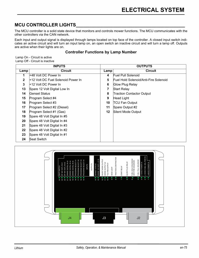
MCU Access Panel (R)Remove thumbscrew and lift up on front of access panel to view MCU diagnostic lights. Always secure access panel withthumbscrew when operating.
Cup Holder (S)Used to hold a beverage cup for the operator or may be used as additional storage pocket. Rubber portion of cup holderis removable for cleaning purposes.
Storage Compartment (T)Used to store gloves and other necessary protective items for the operator.
Step (U)Used to assist operator entering or exiting the operator’s area.
Headlight (V)Used to provide light when operating in the early morning or late evening. Light direction can be adjusted by the operator.
Pivoting Armrest (X)Used to position armrest for operator comfort. Armrest will also pivot out of the way for entering or exiting on the rightside of the mower. Armrest can also be adjusted to three different heights.
Center Reel Swing Arm Service Latch (Y)Used to secure center reel swing arm in service position.
Center Reel Swing Arm Handle (AA)Used to move center reel out from under mower for servicing. Raise center mower, remove grass catcher, unlatch arm toswing center reel out, and latch arm in service position (Y). Do not operate mower without swing out arm securely latchedin closed position.
Running Light (AB)Light located under operator seat to provide illumination of center mower and floorboard. Light is always on with the sys-tem power switch (H) in the RUN position
Hood Latch (AC)Lift handle up and rotate handle 180° counter-clockwise to unlatch hood. With hood closed rotate handle 180° clockwiseto latch hood. Keep hood latched when operating mower.
B
en-24 Safety, Operation, & Maintenance Manual
CONTROLS
Lithium
Tie Down (AD)Used to secure mower to trailer for transport.
LCD DISPLAY UNIT (LDU)_____________________________________________The LDU displays current functional values for the operation of the Eclipse mower, has indicator lights, and sounds audi-ble warning alerts. The LDU operates in one of two modes, Operator Mode (Default) and Maintenance Mode. Use ofMaintenance Mode requires a four digit pin number.Press either of the orange buttons (AM or AN) to change screen display or change values. Push the right orange button(AN) to go forward in the display list or increase setting value, and push the left orange button (AM) to go back in the dis-play list or decrease setting value. The black button (AL) is used to select, reset or change values.
Fig. 4
Indicator LightsThe LDU has eight indicator lights to indicate system functions.
Power On Light: Green Power On light located on left side of the LDU indicates the controller system haspower. A flashing Power On Light indicates controller systems has not been energized (started). A solid lightindicates the unit is energized and in normal operation mode.
48V Light: Red 48V light located on left side of the LDU indicates system voltage is below 42 VDC or flasheswhen system voltage is above 59 VDC. Charge batteries or check generator output. LCD display will show cor-responding message.
Parking Brake Light: Red parking brake light located on left side of the LDU indicates the parking brake sys-tem is engaged or brake pedal is fully pressed.
Fault Light: Yellow fault light located on left side of the LDU indicates the controller system has detected afault. See fault message displayed on LCD.
!
JACOBSENVERSION X.XX
ALAM AN
48 V
12 V
48 V
!
B
en-26 Safety, Operation, & Maintenance Manual
CONTROLS
Lithium
DISPLAY OPERATING HOURS _________________________________________To check operating hours when system power switch is in theOFF position, press the center (Black) button. Operatinghours will be displayed for 1 minute.
START UP SCREEN __________________________________________________The Jacobsen start up screen will display for 5 seconds whenthe system power switch is turned from the OFF to the RUNposition. The software version of the controllers is displayedunder Jacobsen.
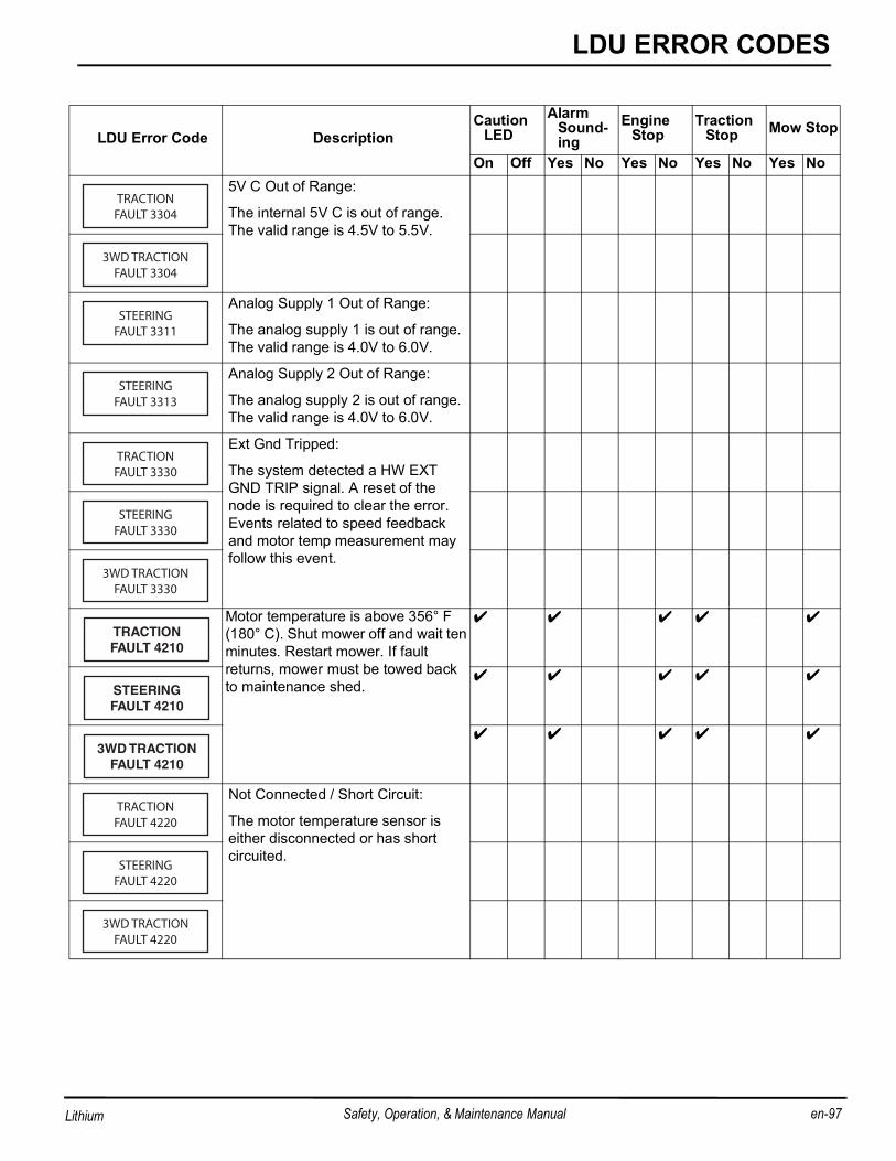
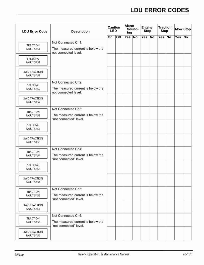
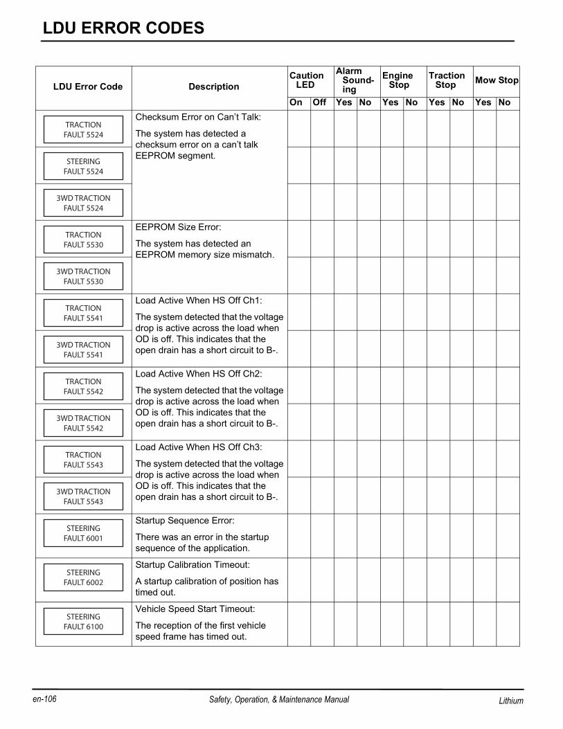
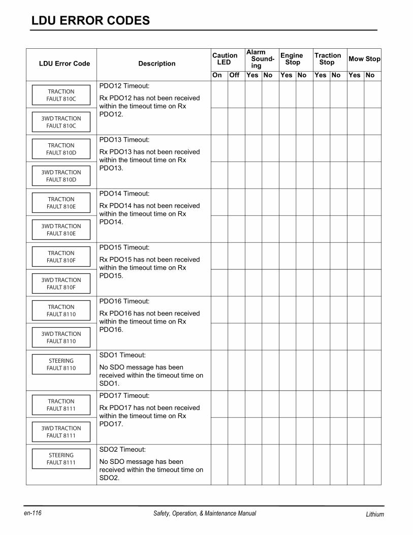
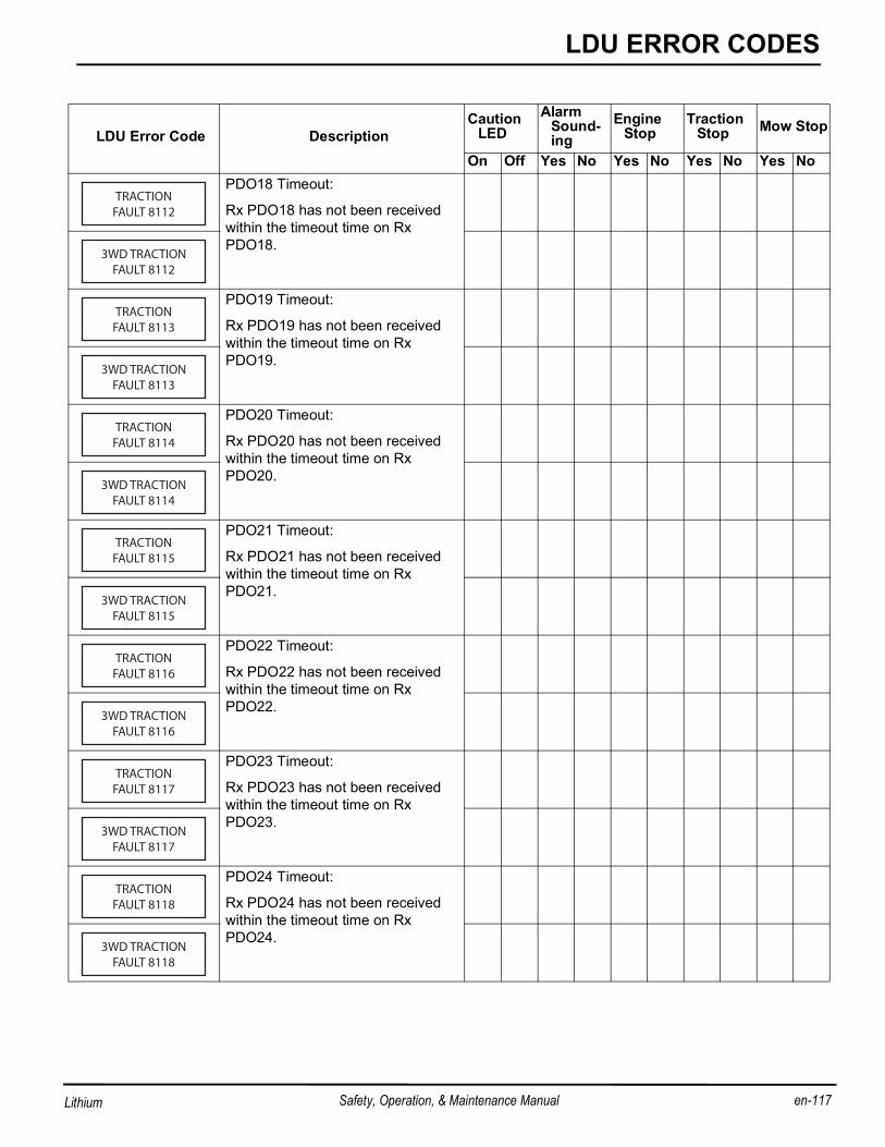
ALARM CODES _____________________________________________________Refer to See LDU ERROR CODES on page 89 for a complete list of Eclipse error codes.
MOWER ATTACHMENT MODES________________________________________The Eclipse mower, when in Operator Mode, has six mower attachment sub-modes for operation.The values listed below for each mode are the defaults, but they can be changed if desired in the Maintenance Mode.Any changes made, will replace the defaults saved for each mode, until a factory reset is selected.The six modes are:
Mode 1 - 11 Blade ReelUse this mode when 11 blade reels are installed. Reel motor operation is enabled, number of reel blades are set to 11,reel speed is set to 2200 rpm, and FOC is set to 0.16 in. (0.4064 cm).
Mode 2 - 9 Blade ReelUse this mode when 9 blade reels are installed. Reel motor operation is enabled, number of reel blades are set to 9, reelspeed is set to 2200 rpm, and FOC is set to 0.196 in. (0.4967 cm).
Mode 3 - RollerThis mode is used when the reels are removed and the optional Quick Roll™ greens rollers are installed. Reel motoroperation is disabled.
Mode 4 - VerticutThis mode is used when optional verticut mowers are installed. Reel motor operation is enabled, 1800 rpm reel speed,and FOC is set to 0.
Mode 5 - SpikerThis mode is used when the reels are removed and optional spiker attachments are installed. Reel motor operation is dis-abled.
Mode 6 - OtherThis mode is used when 7 blade reels, or an attachment other than those listed above are installed. Reel motor operationis enabled, reel speed is set to 2200 rpm, and FOC is set to 0. Number of reel blades, and FOC must be set manually.
Display Units English English English English English English
s This setting can not be changed in the maintenance mode. Another mower attachment mode must be selectedto enable or disable reel motors. See Maintenance mode for changing mower attachment mode.
B
en-28 Safety, Operation, & Maintenance Manual
CONTROLS
Lithium
OPERATOR MODE ___________________________________________________Operator mode is used by the opera-tor to view attachment mode, systemvoltage information, travel speed,reel motor current, reel motor speed,switch status, operation hours, andstored alarms. Press the orange but-tons (AM and AN) on the LDU totoggle between the different dis-plays. Mower Attachment Mode: Displayscurrent mower attachment mode.Reel Motor On/Off: Allows reel motoroperation to be disabled for trainingpurposes or practice cutting. Mowand lift system will function normally,with the exception of the reel motorsoperating. Press black button (AL) totoggle between reel on and off. LDUscreen will be locked on REELMOTORS OFF screen until reelmotors are turned back on. Reelmotors will also be enabled bycycling the system power switch.NOTE: Enabling reel motors on thisscreen will not enable reel motors inMode 3 Roller or Mode 5 Spiker.System Volts: Displays the systemvoltage. Normal operating voltage isbetween 43 and 60.5 volts, depend-ing on the power module installed. High or low voltage faults may occur of system voltage goes above 60.5 volts for 5seconds or drops below 43 volts for ten seconds. Some machine functions may be disabled in cases of high or low sys-tem voltage.Travel Speed: Displays speed mower is traveling. Travel speed may be limited due to Maximum Mow Speed and TravelSpeed values set in Maintenance Mode, or to meet current FOC setting. Reel Motor Current: The reel motor current screen is provided for the operator and mechanic to help identify problemsbefore damage to the reel motor occurs. Notify maintenance personnel if one reel motor is drawing a higher current loadthan the other two motors. The screen displays the reel motor current for all three reels. The number in the upper left cor-ner of the screen is for the left reel motor, the number in the upper right corner of the screen is for the right reel motor, andthe number on the second row of the screen is for the center reel motor. A fault will occur if reel motor current is over 35amps for 30 seconds.Reel Motor Screen: The reel motor speed screen displays the reel motor speed for all three reels. The number in theupper left corner of the screen is for the left reel motor, the number in the upper right corner of the screen is for the rightreel motor, and the number on the second row of the screen is for the center reel motor. All three reel motors should beoperating within 50 rpm of each other.Enter Pin? Screen: Used to enter Maintenance Mode. Enter the four digit pin number to access Maintenance Mode.Alarms Screens: Used to view alarms stored in system memory. Alarm message will appear on the screen as theyoccur for a few seconds, and a beep may sound, depending on the fault encountered. The alarm is then stored in systemmemory until key switch is turned to off position.
MAINTENANCE MODE________________________________________________Maintenance Mode is used by the superintendent to set and adjust all functional values for the Eclipse Mower. LCD dis-plays available in Maintenance Mode are, mower attachment mode, system voltage, travel speed, reel motor current,reel motor speed, total hours on machine, actuator motor current, reel motor temperature, TCU/traction motor tempera-ture, traction motor current, select display units, calibrate actuators, configure reel motor direction, software code revisionlevels, CAN status, switch status, maximum mow and travel speed, number of blades, fixed FOC, backlap, factory resetand alarm screens.
To enter Maintenance Mode, press either orange buttons (AM or AN) until ENTER PIN? screen is on the display andpress the black button. Use the orange buttons (AM or AN) to select and the black button (AL) to enter the digits for theMaintenance Mode PIN.
NOTE: The PIN for Maintenance Mode is 0000.
NOTE: The Maintenance Mode PIN can be customized to a setting of your choice. Please contact your Jacob-sen Dealer or Jacobsen Technical Support for complete instructions.
System voltage, travel speed, reel motor current draw and reel motor speed screens are the same as for Operator Mode.See Operator Mode on page 28.For actuator calibration screens, See Lift Actuator Calibration on page 67.For backlap screens, See Backlapping and Grinding on page 68.
Fixed Reel SpeedTo set the fixed reel speed, the FOC setting must be set to 0, then press either of the orange buttons (AM or AN) on theLDU until the SET REEL SPEED screen is on the LCD display. Press the black button (AL) to enter set mode. Use theorange buttons to raise (AN) or lower (AM) the reel speed to the desired setting.Fixed reel speed must be set between 1000 and 2200 rpm.
Actuator Motor CurrentDisplays the current draw for each actuator motor. The first number is for the left actuator motor, the second number is forthe center actuator mower, and the third number is for the right actuator motor.
Reel TemperatureDisplays the temperature for each reel motor. The number in the upper left corner of the screen is for the left reel motor,the number in the upper right corner of the screen is for the right reel motor, and the number on the second row of thescreen is for the center reel motor.
TCU/Traction Motor TemperatureDisplays the temperature of the TCU case and traction motor.
Traction Motor CurrentDisplays the traction motor current draw.
NOTICEAny changes made to settings in the Maintenance Mode will not be active until the mower is powered
off and restarted.Changes made will also save settings in current mower attachment mode, unless factory reset is
selected.
B
en-30 Safety, Operation, & Maintenance Manual
CONTROLS
Lithium
Maintenance HoursTo display maintenance hours, press either of the orange buttons (AM or AN) on the LDU until the maintenance hoursscreen is on the LCD display. To reset maintenance hours, press the black button (AL).
Select UnitsTo set the display units, press either of the orange buttons (AM or AN) on the LDU until the SELECT UNITS? screen ison the LCD display. Press the black button (AL) to enter set mode. Use the orange buttons to select the desired setting.• Units must be set to either English or metric.
CFG Reel DirectionTo set reel rotation direction, press either of the orange buttons (AM or AN) on the LDU until the reel direction screen ison the LCD display. Press the black button (AL) to enter set mode. Set reel direction for each reel, pressing black buttonto change between each reel. Direction is viewed from front of motor shaft• ReelCounter-Clockwise (CCW)• Vertical MowerClockwise (CW) or CCW
Software Code Revision LevelDisplays the revision level for software loaded for each controller. This information is shown on two screens. The soft-ware revision levels may be an aid for service technicians working on the mower.• The first screen displays the software revision levels for the 3WD (If installed), TCU, and SCU.• The second screen displays the software revision levels for the MCU, RCU, and LDU.
CAN Network StatusDisplays the CAN (Controller Area Network) status for each of the controllers. A steady (non flashing) controller nameindicates CAN traffic has been detected from controller within the last two seconds. A flashing controller name indicatesCAN traffic has not been detected from controller.
Switch StatusDisplays the current switch settings, and is used to diagnose switch problems. A status of 0 indicates the switch is in theOFF position. A status of 1 indicates the switch is in the ON position. Check the wiring and operation of any switch that isnot displaying the correct status.The switches are broken up into three sets of numbers, with a gap between each set.• The first set of numbers displays the status of the left, center, and right reel switches (C, D, and E) on the instrument
panel.• The second set of numbers displays the status of the mow switch (B), light switch (F), horn switch (G), and system
power switch in start position (H).• The third set of numbers displays the status of the lower and raise switches that are part of the joystick (J), and the
seat switch.
Maximum Mow SpeedTo set the maximum mow speed, press either of the orange buttons (AM or AN) on the LDU until the set MAX MOWSPEED screen is on the LCD display. Press the black button (AL) to enter set mode. Use the orange buttons to raise(AN) or lower (AM) the maximum mow speed to the desired speed. press the black button to set speed.• Maximum mow speed must be between 1.0 and 5.0 mph (1.6 and 8.0 kph), and is adjustable in 0.5 mph (0.8 kph)
Maximum Transport SpeedTo set the maximum transport speed, press either of the orange buttons (AM or AN) on the LDU until the set MAXSPEED screen is on the LCD display. Press the black button (AL) to enter set mode. Use the orange buttons to raise(AN) or lower (AM) the maximum transport speed to the desired speed. press the black button to set speed.
• Maximum transport speed must be between 1.0 and 9 mph (1.6 and 14.5 kph), and is adjustable in 0.5 mph (0.8kph) increments.
Number of Reel BladesTo set the number of blades on each reel, press either of the orange buttons (AM or AN) on the LDU until the reel bladesscreen is on the LCD display. Press the black button (AL) to enter set mode. Use the orange buttons to raise (AN) orlower (AM) the number of reel blades. press the black button to set speed. Entering the wrong number of blades willaffect the fixed FOC setting.The only reels currently available are 7, 9, 11, or 15 blade reels.
2WD/3WD Modepressing black button (AL) toggles mower between 2WD and 3WD modes. Do not set mower to 3WD if the 3WD systemis not installed.
Fixed FOC SettingTo set the fixed FOC, press either of the orange buttons (AM or AN) on the LDU until the FOC x.xxx CHANGE? screenis on the LCD display. Press the black button (AL) to enter set mode. Use the orange buttons to raise (AN) or lower (AM)the FOC value to the desired setting. press the black button to set speed. The minimum and maximum fixed FOC settingvaries, depending on the number of blades. See Frequency of Cut on page 34.
Factory ResetTo reset controller to factory default values, press either of the orange buttons (AM or AN) on the LDU until the FactoryReset screen is on the LCD display. Press the black button (AL) to reset values back to factory default settings. All val-ues saved in mower attachment modes will also revert to their original factory default settings.
Mower Attachment ModeTo set the mower attachment mode, press either of the orange buttons (AM or AN) until the MODE CHANGE? screen ison the lcd display. Press the back button (AL) to enter set mode. Press the right orange button until the desired mode ison the screen, then press the black button to select it. See Mower Attachment Modes on page 26 for default values.
NOTICEIf a mower attachment mode change is required,
change mower attachment mode first before setting other values. Values stored in new mode will over-ride previous settings for reel speed, FOC, maxi-mum mow and travel speeds, reel direction, and
FREQUENCY OF CUT ________________________________________________The FOC (Frequency of Cut) is the distance, in inches (cm), the machine travels forward between reel blades contactingthe bedknife. The FOC can be adjusted either by changing the Fixed FOC setting or by changing the maximum mowspeed and the fixed reel speed on the LCD display.
Adjust FOC with Fixed FOC settingChanging the FOC setting to a value other than 0 will enable the fixed FOC mode and overrides the reel speed setting.As mower travel speed increases or decreases, reel speed will automatically adjust as required to maintain set FOC.
Adjust FOC with Reel Speed Setting1. Using the FOC charts, determine the maximum mow speed and fixed reel speed required for the desired FOC.2. Switch to Maintenance Mode. See Maintenance Mode on page 29.3. Set fixed FOC setting to 0.4. Set desired Maximum Mow Speed.5. Set desired Fixed Reel Speed.
NOTICEWhen using a fixed FOC setting, the reels will not
turn if the mower is not moving.Maximum mow speed may be lower than what is
ELECTRONIC TRACTION CONTROL SYSTEM ____________________________The Eclipse is equipped with an electronic traction control system which utilizes a controller and software to regulatespeed and optimize the driveability of the unit. A speed sensor in the drive motor reports the exact vehicle speed to thecontroller which electronically controls the drive motor to maintain a smooth and constant speed whether the unit is goinguphill or downhill.When the direction/speed pedal is returned to Neutral, the controller uses regenerative braking by essentially turning thedrive motor into a generator and putting energy back into the battery pack or automatically adjusting the engine throttleon hybrid powered mowers to control proper generator output.To prevent an over-voltage condition, any excess power created by the regenerative action is sent through the resistorbanks located on the right side of the machine. System voltage over 60 VDC could cause damage to the controllers.
PARKING BRAKE____________________________________________________The Eclipse mower is equipped with a parking brake. When the parking brake is applied, the parking brake light on theLDU will be lit. The parking brake is applied whenever the parking brake switch is ON.To disengage parking brake: The parking brake will disengage when the parking brake switch is in the OFF position.To engage parking brake: To engage the parking brake, move the parking brake switch on the console to the ON posi-tion.
LIFT SYSTEM _______________________________________________________The Eclipse 360 lift system operates in one of two modes, service mode and mow mode, depending on the position ofthe mow switch (B).Service Mode - Service mode is active with mow switch (B) in OFF (down) position and parking brake engaged. Servicemode is used to raise or lower the individual reels for servicing, without activating reel motors. Push forward on joystick(J) to lower reels, or pull back on joystick to raise reels. Only reels with corresponding reel switches (C, D, or E) in theON position will lower.If reels are lowered or in the crosscut position, mow switch is off, and mower starts moving, reels will automatically raiseto the transport position.
Mow Mode - Mow mode is active with mow switch (B) in ON (up) position. Reels will automatically lower to crosscutposition when mow switch is turned ON. Push forward and release joystick (J) to fully lower reels and activate reelmotors. Pull back on joystick and release to raise reels to crosscut position and deactivate reel motors. Pull back andrelease a second time to fully raise reels to transport position.Only reels with corresponding reel switches (C, D, or E) in the ON position will lower and activate reel motors. Thisallows operation of one, two, or all three reels, depending on area to be cut or operation being performed (clean up pass,etc.).NOTE: When operating, depending on mower speed, there will be up to a two second delay before center reel
raises or lowers. See Center Reel Delay on page 49.
If reel(s) fail to raise in mow mode, or an error code appears in the LDU, stop mower, push down on mow switch (B), andtry to raise the reel in service mode. Return mower to the service area to have the lift system inspected.
NOTICEA ratcheting sound will come from the lift actuators if joystick (J) is pulled back with reels fully raised. The sound is produced by a clutch in the actuator, and is designed to prevent damage to the actuator.
1. Perform a visual inspection of the entire unit, look for signs of wear, loose hardware, and missing or damaged com-ponents. Check for fuel or oil leaks to ensure connections are tight and hoses and tubes are in good condition.
2. Make sure all mowers are adjusted to the same cutting height.3. Check tires for proper inflation.4. Test the Interlock System.
NOTICE: For more detailed maintenance information, adjustments and maintenance/lube charts, see the Parts & Maintenance manual.
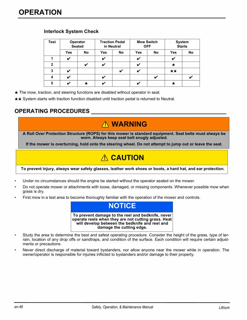
INTERLOCK SYSTEM ________________________________________________1. The Interlock System prevents the mower from starting unless the operator is in the seat, mow switch is OFF, and
the traction pedal is in Neutral. The system also disables the mow, traction, and steering functions without the oper-ator in the seat.
2. Perform each of the following tests to insure the Interlock System is functioning properly. Stop the test and have thesystem inspected and repaired if any of the tests fail as listed below:• lthe system does not start in test 1;• lthe system does start in test 4;• lthe traction function is not disabled in test 3;• lthe mow, traction, and steering functions are not disabled during test 2 and 5.
3. Refer to the chart below for each test and follow the check (4) marks across the chart. Shut engine off between eachtest.a. Test 1: Represents normal starting procedure. The operator is seated, mow switch is OFF, and the traction
pedal is in Neutral. The mower should start.b. Test 2: The mower must start with mow, traction, and steering functions disabled if operator is not in the seat.c. Test 3: The mower must start with traction function disabled if the traction pedal is not in Neutral. Traction func-
tion will be disabled until traction pedal is returned to Neutral.d. Test 4: The mower must not start if the mow switch is ON.e. Test 5: Start the mower in the normal manner then lift your weight off the seat. Mow, traction, and steering func-
tions should be disabled until operator sits back in seat.
CAUTIONThe daily inspection should be performed only when the system power is off. Turn mow switch
OFF, lower reels to the ground, turn system power switch to OFF position, and remove the key.
WARNINGNever operate equipment with the Interlock System disconnected or malfunctioning. Do not disconnect
or bypass any switch.
!
!
B
en-46 Safety, Operation, & Maintenance Manual
OPERATION
Lithium
The mow, traction, and steering functions are disabled without operator in seat. System starts with traction function disabled until traction pedal is returned to Neutral.
• Under no circumstances should the engine be started without the operator seated on the mower.• Do not operate mower or attachments with loose, damaged, or missing components. Whenever possible mow when
grass is dry.• First mow in a test area to become thoroughly familiar with the operation of the mower and controls.
• Study the area to determine the best and safest operating procedure. Consider the height of the grass, type of ter-rain, location of any drop offs or sandtraps, and condition of the surface. Each condition will require certain adjust-ments or precautions.
• Never direct discharge of material toward bystanders, nor allow anyone near the mower while in operation. Theowner/operator is responsible for injuries inflicted to bystanders and/or damage to their property.
Interlock System Check
Test Operator Seated
Traction Pedalin Neutral
Mow SwitchOFF
System Starts
Yes No Yes No Yes No Yes No1
2
3
4
5
WARNINGA Roll Over Protection Structure (ROPS) for this mower is standard equipment. Seat belts must always be
worn. Always keep seat belt snugly adjusted. If the mower is overturning, hold onto the steering wheel. Do not attempt to jump out or leave the seat.
CAUTION To prevent injury, always wear safety glasses, leather work shoes or boots, a hard hat, and ear protection.
NOTICETo prevent damage to the reel and bedknife, never operate reels when they are not cutting grass. Heat
will develop between the bedknife and reel and damage the cutting edge.
• Use discretion when mowing near gravel areas (roadway, parking areas, cart paths, etc.). Stones discharged fromthe implement may cause serious injuries to bystanders and/or damage the equipment.
• Always turn mow switch OFF to stop blades when not mowing.• Turn mow switch OFF and raise the reels when crossing paths or roadways. Look out for traffic.• Stop and inspect the equipment for damage immediately after striking an obstruction or if the mower begins to
vibrate abnormally. Have the equipment repaired before resuming operation.
• Slow down and use extra care on hillsides. See Hillside Operation on page 51. Use caution when operating neardrop offs.
• Look behind and down before backing up to be sure the path is clear. Use care when approaching blind corners,shrubs, trees, or other objects that may obscure vision.
• Never use your hands to clean reels. Use a brush to remove grass clippings from blades. Blades are extremelysharp and can cause serious injuries.
STARTING__________________________________________________________1. Sit in operator’s seat, make sure mow switch is OFF, and traction pedal is in Neutral. See INSTRUMENT PANEL on
page 20, See OPERATOR CONTROLS on page 22.2. Turn system power switch to RUN. Steering controller will initialize, LDU will display Jacobsen start up screen, and
all lights on LDU will be on for two seconds.
• After LDU initializes, green power light will be flashing two times per second and parking brake light will be on.Engine oil pressure light will be on for diesel and gas power modules.
3. Turn system power switch to START position.• Battery Power Module: Release key, green power light will be solid on and traction and mow systems will be active.
CAUTIONBefore mowing, pick up all debris such as rocks, toys, sticks, and wire which can be thrown by the mower. Enter a new area cautiously. Always oper-ate at speeds that allow you to have complete con-
trol of the mower.
WARNINGBefore you clean, adjust, or repair this equipment, always disengage all drives, lower implements to
the ground, turn system power switch to OFF posi-tion, and remove key to prevent injuries.
WARNINGWhen steering controller initializes, the rear steering motor will turn slightly. To prevent injury, do not turn power switch to RUN with hood open or performing
work on steering system.
!
!
!
B
en-48 Safety, Operation, & Maintenance Manual
OPERATION
Lithium
Fig. 1
STOPPING / PARKING ________________________________________________To stop:Remove your foot from traction pedal, regen braking will start, bringing the mower to a complete stop. When mowerstops, move the parking brake switch to the ON position. The parking brake will engage and the parking brake light on theLDU will turn on.To park the mower under normal conditions:1. Disengage the mow switch, raise the implements, and move away from the area of operation.2. Select a flat and level area to park.• Release traction pedal to bring the mower to a complete stop. • Move the parking brake switch to the ON position The parking brake light should come on.• Disengage all drives, lower reels to the ground.3. Turn system power switch to OFF position, and always remove key.If an emergency arises and the mower must be parked in the area of operation, follow the guidelines outlined by thegrounds superintendent. If the mower is parked on an incline, chock or block the wheels.
TO DRIVE / TRANSPORT______________________________________________Read and follow all safety notes contained in this manual when driving or transporting mower. See Operating Proce-dures on page 46 for general operating instructions. When operating in reverse, look behind you to ensure you have aclear path.
Important: If this mower is driven on public roads, it must comply with federal, state, and local ordinances. Contact local authorities for regulations and equipment requirements.
1. Disengage mow switch. Reels will automatically raise to the transport position once mower starts moving.2. Depress traction pedal slowly.3. Move the parking brake switch to the OFF position. The parking brake should disengage and mower will start mov-
ing.
CENTER REEL DELAY _______________________________________________The raising and lowering of the center reel is slightly delayed from the front reels. When mowing, this allows the centerreel to contact the ground at the same location as the front reels, resulting in an accurate cut.The length of delay is automatically adjusted for any change in vehicle speed, which is determined by the speed sensorin the drive motor. If the unit is not in motion or if there is no speed sensor signal, the center reel delay will default to atime of approximately 2 seconds. There is no delay when lift system is in service mode (Mow switch is OFF).
OVERLOAD PROTECTION ____________________________________________The reel drive motors and lift actuators are controlled by the RCU. The RCU has built–in overload protection and will dis-able the motor or actuator if it is drawing too much electrical current.If there is an overload on a reel drive motor, the circuit breaker will trip, the motor will be disabled, the reel will raise to theup position and the fault light on the LDU will flash two times per second.If there is an overload on a lift actuator, the actuator will be disabled and the fault light on the LDU will flash two times persecond.To reset an overload fault condition, the mower must be shut down and re-started. If the problem persists, inspect thedevice and the electrical system to determine the cause of the overload or contact an authorized Jacobsen dealer.
CAUTIONTo prevent tipping or loss of control, travel at
reduced speed when making turns.
WARNINGTo prevent serious injuries, keep hands, feet, and
clothing away from reel when the blades are moving. NEVER use your hands to clean reels. Use a brush to remove grass clippings from blades. Blades can
be sharp and could cause injuries. To clear obstructions from reel, turn mow switch
OFF, stop the mower, turn system power switch to OFF, and remove key, then remove obstruction.
!
!
B
en-50 Safety, Operation, & Maintenance Manual
OPERATION
Lithium
Operators should practice mowing in a clear area to become familiar with raising and lowering the reels. Practicing, byturning reel motors off (See Operator Mode on page 28), will help the operator become proficient at starting and stop-ping each pass within a foot or two of the edge of the green. Then only one final pass around the green will be required tofinish the operation.
Several factors may determine the direction of the mowing pattern. Sand traps or other hazards near the green and treesor other objects can restrict where turns are made. The terrain of the green may also be a factor, but if conditions allow,always try to mow the green in a different direction than the last time it was mowed.1. Stop the unit just before reaching the green and raise the reels. Set the mow switch to ON.2. Proceed toward the green at mowing speed. See Frequency of Cut on page 34 for matching mowing speed to
desired Frequency of Cut. 3. Lower the reels as the front grass catchers cross the edge of the green. At the end of the pass, raise the reels as the
just before grass catchers cross the edge of the green.4. Always make mowing passes across the green in a straight line. Do NOT start to make the turn for the next pass
until the center wheel is off the green, this will eliminate the possibility of the tires tearing the turf during the turn.5. Each successive pass should overlap the previous one by a few inches.6. After all of the straight passes have been made, make one final pass around the outer edge of the green. This final
pass should always be in the opposite direction from the last time the green was mowed.7. Empty the grass catchers before proceeding to the next green. To remove or install the grass catchers, turn mow
switch OFF, lower the reels to the ground, and shut off the unit. Tilt the grass catcher body so the front edge clearsthe mower frame, and slide the catcher onto or off the catcher frame.
8. Stop and raise the mowers to the transport position when crossing paths or roadways. Look out for traffic.
NOTICETo prevent damage to the reel and bedknife, never
operate reels when they are not cutting grass.
NOTICEAlways remove the flag and inspect the green
before mowing. Remove debris or other objects that may damage the reels and/or bedknives.
NOTICETo avoid damage to the green, NEVER stop the for-ward motion of the mower while on the green with
the reels turning. Stopping the mower on a wet green may cause wheel indentations.
NOTICEWhen verticutting with the Eclipse 360 Jacobsen
recommends setting the reel speed at 1800 rpm. If the reel motor temperature or current exceeds lim-
its, reduce ground speed of mower, reduce reel speed, or adjust verticutter depth.
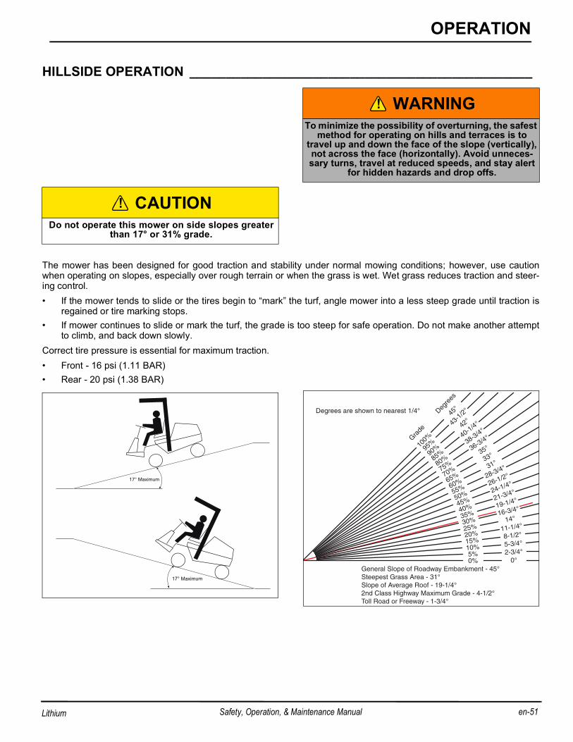
The mower has been designed for good traction and stability under normal mowing conditions; however, use cautionwhen operating on slopes, especially over rough terrain or when the grass is wet. Wet grass reduces traction and steer-ing control.• If the mower tends to slide or the tires begin to “mark” the turf, angle mower into a less steep grade until traction is
regained or tire marking stops.• If mower continues to slide or mark the turf, the grade is too steep for safe operation. Do not make another attempt
to climb, and back down slowly.Correct tire pressure is essential for maximum traction.• Front - 16 psi (1.11 BAR)• Rear - 20 psi (1.38 BAR)
WARNINGTo minimize the possibility of overturning, the safest
method for operating on hills and terraces is to travel up and down the face of the slope (vertically), not across the face (horizontally). Avoid unneces-sary turns, travel at reduced speeds, and stay alert
for hidden hazards and drop offs.
CAUTIONDo not operate this mower on side slopes greater
than 17° or 31% grade.
!
!
0°
Degrees are shown to nearest 1/4°
General Slope of Roadway Embankment - 45°Steepest Grass Area - 31°Slope of Average Roof - 19-1/4°2nd Class Highway Maximum Grade - 4-1/2°Toll Road or Freeway - 1-3/4°
0%2-3/4°5%5-3/4°
10%
8-1/2°15%
11-1/4°20%
14°
25%
16-3/4°
30%
19-1/4°
35%
21-3/4°
40%
24-1/4°
45%
26-1/2°
50%
28-3/4°
55%
31°
60%
33°
65%
35°
70%
36-3/4°
75%
38-3/4°
80%
40-1/4°
85%
42°
90%
43-1
/2°
95%
45°
100%
Degre
es
Grade
17° Maximum
17° Maximum
B
en-52 Safety, Operation, & Maintenance Manual
OPERATION
Lithium
How to calculate a slopeTools Required:Level (A), either ....................... 1 yard, or 1 meter long.Tape measure (B).......................................................1.1. With the level (A) positioned horizontally, measure the distance (C) with tape measure (B).2. Use the chart to calculate either the slope angle or the % grade of the slope (D).
Fig. 2
Height (C) Result (D)
Inches with 1 Yard Level (A) Millimeters with 1 Meter Level (A) Slope in Degrees Slope Grade %
LOADING MOWER ON TRAILER _______________________________________Use care when loading and unloading mower onto trailer. Fasten mower to trailer, using tie downs on left and right sideand rear of mower, to prevent mower from rolling or shifting during transport.If the mower experiences problems and must be shut down and removed from the area, it should be towed back to themaintenance area, or loaded onto a trailer for transport. See Towing Mower on page 54 for towing instructions.Fully raise reels before driving up trailer ramp. Lift arms must be in lift locks and bumpers properly adjusted to preventdamage to reels, mower, or other objects.If the mower is to be trailered on the highway, before strapping to trailer, inflate tires to 22 psi (1.5 BAR). After unloadingmower, reduce tire pressure to normal operating pressure. See Tires on page 69.Always secure armrest cover in closed position with a strap when transporting.
Make certain key switch is in OFF position and key removed.If mower is unable to drive onto trailer on its own power, follow this procedure:1. Follow procedure for disengaging parking brake. See Towing Mower on page 54.2. Make sure reels are raised. If they cannot be raised, remove them from the mower.3. Make certain key switch is in OFF position and key removed.4. Use a winch or other device to load mower onto trailer. Mower must be moved in a straight line to prevent damage to
steering system.5. Use tie down at rear of mower for attaching winch. If front tie downs must be used, winch must be connected to both
the left and right tie downs.6. With mower strapped down to trailer, remove brake release harness. Brake must be disengaged again before
unloading mower.7. Carefully unload mower from trailer using a winch or other device to slowly get mower down trailer ramp. Mower
brakes have been disabled and are not able to stop mower.
600 31.0 60.025 34.8 69.4
800 38.7 80.030 39.8 83.3
900 42.0 9036 1000 45.0 100
NOTICEFailure to properly secure armrest cover in the
closed position when transporting may result in armrest cover damage.
Height (C) Result (D)
Inches with 1 Yard Level (A) Millimeters with 1 Meter Level (A) Slope in Degrees Slope Grade %
B
en-54 Safety, Operation, & Maintenance Manual
OPERATION
Lithium
8. After unloading mower, remove brake release harness.NOTICE: Do Not operate mower with parking brake disabled or removed.
TOWING MOWER ____________________________________________________If the mower experiences problems and a trailer is not available, the unit can be towed slowly for short distances. 1. The parking brake must be disengaged.
• Disconnect battery pack electrical connector.• Disconnect brake electrical connector (ZX).• Connect brake release harness to battery pack and brake. The parking brake should disengage.• If the battery pack does not have enough power to disengage the brake, remove three screws (ZY) and remove the
parking brake (ZZ) from the drive motor.2. Open hood, remove four thumbscrews (ZU), and lift steering cover (ZV) off mower.3. Remove steering chain master link (ZW). Remove chain from steering motor.4. Attach tow bar accessory, Part No. 62811, to rear steering yoke (Refer to tow bar instruction sheet). Do not use tow
strap to tow mower. Connect other end of tow bar to towing vehicle equipped with 1-7/8 in. ball hitch and vehicle towbar 10-15 in. (25.4 - 38.1cm) from ground.
5. Before towing make sure reels are raised. If they cannot be raised, remove them from the mower.6. Make certain key switch is in off position and key is removed.
• Use caution when towing. Avoid steep inclines. Steep inclines may cause tow bar to contact and damage hood andhood hinges. To prevent damage to steering yoke, avoid turns that will cause rear wheel to turn more than 55° ineither direction.
WARNINGTo prevent injury, keep bystanders away when load-ing or unloading a disabled mower on trailer. Mower brakes have been disabled and may not be used to
stop mower.Do not attempt to roll mower down trailer ramp with-out use of winch or similar device to restrain mower.
WARNINGIf mower is on an incline, chock or block the wheels before manually disengaging parking brake. Mower
will roll with parking brake disengaged.Towing vehicle must be capable of stopping mower
without assistance from mower brakes.
WARNINGTo prevent injury or damage to mower, do not tow mower with system power switch in RUN position.
NOTICEDo not exceed 2 MPH (3.2 KPH) while towing. Long
• After towing mower, remove tow bar accessory, attach steering chain, remove brake release harness, connect brakeelectrical connector (ZX), and connect battery pack connector.
Fig. 3
Fig. 4
WARNINGDo Not operate mower with parking brake manually
disengaged.Remove brake release harness and connect steer-ing chain before returning mower to normal opera-
tion.
NOTICEIf brake electrical connector is disconnected, and mower is started, then brake light will turn off, and
mower will not move under traction power.
!
ZZ
ZY
ZX
ZU
ZV
ZW
B
en-56 Safety, Operation, & Maintenance Manual
OPERATION
Lithium
DAILY MAINTENANCE________________________________________________IMPORTANT: For more detailed maintenance information, adjustments and maintenance/lubrication charts,
see the Parts & Maintenance manual.
1. Park the mower on a flat, level surface. Fully lower the reels to the ground, stop the engine and remove key fromignition switch.
2. Grease and lubricate all points if required. Lubricate with grease that meets or exceeds NLGI Grade 2 LB specifica-tions. Apply grease with a manual grease gun and fill slowly until grease begins to seep out. Do not use compressedair.
3. To prevent fires, clean the reels and mower after each use.• Whenever possible, use compressed air to clean mower.• Use only fresh water for cleaning your equipment.
• Do not pressure wash mower.• Do not spray water directly at instrument panel, electrical connectors, generator, controllers, motors, or any other
electrical components.• Do not spray water into the cooling air intake or the engine air intake.
• Clean all plastic or rubber components with a mild soap solution and warm water, or use commercially availablevinyl/rubber cleaners.
4. Remove any dirt or other debris from both steering proximity switches.Battery Powered Mowers:• Disconnect power connector and connect battery pack to charger.
NOTICETo prevent damage to reel motor, do not over-
grease reel bearings. Damage of this nature is not covered by the factory warranty.
NOTICEUse of salt water or effluent water has been known
to encourage rust and corrosion of metal parts resulting in premature deterioration or failure. Dam-age of this nature is not covered by the factory war-
ranty.
NOTICEDo not use high pressure spray.
NOTICEDo not wash a hot or running engine. Use com-
pressed air to clean the mower, engine and radiator fins to reduce the potential for corrosion and mois-
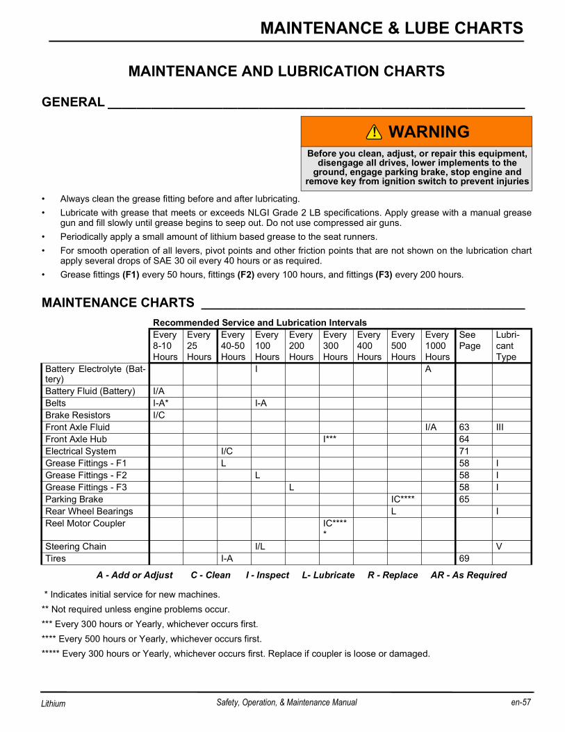
GENERAL __________________________________________________________
• Always clean the grease fitting before and after lubricating.• Lubricate with grease that meets or exceeds NLGI Grade 2 LB specifications. Apply grease with a manual grease
gun and fill slowly until grease begins to seep out. Do not use compressed air guns.• Periodically apply a small amount of lithium based grease to the seat runners.• For smooth operation of all levers, pivot points and other friction points that are not shown on the lubrication chart
apply several drops of SAE 30 oil every 40 hours or as required.• Grease fittings (F1) every 50 hours, fittings (F2) every 100 hours, and fittings (F3) every 200 hours.
A - Add or Adjust C - Clean I - Inspect L- Lubricate R - Replace AR - As Required
* Indicates initial service for new machines.** Not required unless engine problems occur.*** Every 300 hours or Yearly, whichever occurs first.**** Every 500 hours or Yearly, whichever occurs first.***** Every 300 hours or Yearly, whichever occurs first. Replace if coupler is loose or damaged.
WARNINGBefore you clean, adjust, or repair this equipment,
disengage all drives, lower implements to the ground, engage parking brake, stop engine and
remove key from ignition switch to prevent injuries
Recommended Service and Lubrication IntervalsEvery8-10Hours
Every 25 Hours
Every40-50Hours
Every100Hours
Every200Hours
Every 300 Hours
Every 400 Hours
Every500Hours
Every1000 Hours
See Page
Lubri-cantType
Battery Electrolyte (Bat-tery)
I A
Battery Fluid (Battery) I/ABelts I-A* I-ABrake Resistors I/CFront Axle Fluid I/A 63 IIIFront Axle Hub I*** 64Electrical System I/C 71Grease Fittings - F1 L 58 IGrease Fittings - F2 L 58 IGrease Fittings - F3 L 58 IParking Brake IC**** 65Rear Wheel Bearings L IReel Motor Coupler IC****
*Steering Chain I/L VTires I-A 69
!
B
en-58 Safety, Operation, & Maintenance Manual
MAINTENANCE & LUBE CHARTS
Lithium
Note: Loose fitting reel motor couplers will damage the motor shaft and this will not be covered under war-ranty after 1 year or 300 hours whichever occurs first.
• Manual grease gun with NLGI Grade 2 (Service Class LB).• Mobilfluid 424 or SAE 30 wt.
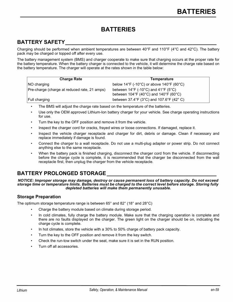
BATTERY SAFETY___________________________________________________Charging should be performed when ambient temperatures are between 40°F and 110°F (4°C and 42°C). The batterypack may be charged or topped off after every use. The battery management system (BMS) and charger cooperate to make sure that charging occurs at the proper rate forthe battery temperature. When the battery charger is connected to the vehicle, it will determine the charge rate based onthe battery temperature. The charger will operate at the rates shown in the table below:
• The BMS will adjust the charge rate based on the temperature of the batteries.• Use only the OEM approved Lithium-Ion battery charger for your vehicle. See charge operating instructions
for use.• Turn the key to the OFF position and remove it from the vehicle.• Inspect the charger cord for cracks, frayed wires or loose connections. If damaged, replace it.• Inspect the vehicle charger receptacle and charger for dirt, debris or damage. Clean if necessary and
replace immediately if damage is found.• Connect the charger to a wall receptacle. Do not use a multi-plug adapter or power strip. Do not connect
anything else to the same receptacle. • When the battery pack is finished charging, disconnect the charger cord from the vehicle. If disconnecting
before the charge cycle is complete, it is recommended that the charger be disconnected from the wallreceptacle first, then unplug the charger from the vehicle receptacle.
BATTERY PROLONGED STORAGE_____________________________________NOTICE: Improper storage may damage, destroy or cause permanent loss of battery capacity. Do not exceed storage time or temperature limits. Batteries must be charged to the correct level before storage. Storing fully
depleted batteries will make them permanently unusable.
Storage PreparationThe optimum storage temperature range is between 65° and 82° (18° and 28°C)
• Charge the battery module based on climate during storage period. • In cold climates, fully charge the battery module. Make sure that the charging operation is complete and
there are no faults displayed on the charger. The green light on the charger should be on, indicating thecharge cycle is complete.
• In hot climates, store the vehicle with a 30% to 50% charge of battery pack capacity.• Turn the key to the OFF position and remove it from the key switch.• Check the run-tow switch under the seat, make sure it is set in the RUN position. • Turn off all accessories.
Charge Rate Temperature
NO charging below 14°F (-10°C) or above 140°F (60°C)Pre-charge (charge at reduced rate, 21 amps) between 14°F (-10°C) and 41°F (5°C)
between 104°F (40°C) and 140°F (60°C)Full charging between 37.4°F (3°C) and 107.6°F (42° C)
B
en-60 Safety, Operation, & Maintenance Manual
BATTERIES
Lithium
The storage time for properly charged Lithium-Ion batteries supplied with this vehicle varies based on the ambient tem-perature.
Setting State of Charge (SOC)The SOC meter or the hand held programmer may be used to determine the state of charge of the battery module. If theSOC is below 30%, charge the battery module until the state of charge reaches 50%. The charge cycle may be inter-rupted by disconnecting the charger from the AC power source first, then from the charging receptacle on the vehicle. Ifthe SOC is above 50%, operate the vehicle until the SOC is below 50%.
During StorageCheck the state of charge every 30 days. If the SOC is below 30%, charge the battery module until the state of chargereaches 50%.
Extreme Low Temperature StorageIf the ambient temperature is below -4°F (-20°C) DO NOT:
• turn the vehicle key to the ON position• drive the vehicle• tow the vehicle• charge the vehicle• operate accessories• turn the lights on (if equipped)
Returning Vehicle to ServiceAt the end of the storage period, charge the battery module to 100% before operating the vehicle.Before charging the vehicle be sure that the ambient temperature is between 14°F (-10°C) and 113°F (45°C) and thevehicle has had time to adjust to the temperature.
Battery DisposalLithium-Ion batteries are recyclable:
•Contact the distributor or manufacturer for information on returning or recycling used or damagedbattery packs.•Contact local or state environmental department for disposal information.•Refer to the MAINTENANCE section for additional information.
Temperature Length of Storage Time
-22°F to -4°F (-30°C to -20°C) One month at 100% battery charge, all accessories turned off.-4°F to 113°F (-20°C to 45°C) Six months at 100% battery charge, all accessories turned off.113°F to 140°F (45°C to 60°C) One month at 30% - 50% charge, all accessories turned off.
BATTERY CHARGING AND MAINTENANCE______________________________The charger should be operated in accordance with the charger manufacturer’s instructions. Never charge batteries in ahazardous environment.
Risk of electric shock. Connect the charger power cord to an outlet that is correctly installed and connected to an electrical ground according to all codes and regulations. A
grounded outlet is necessary to decrease the risk of electric shock-do not use ground adapters or replace the plug. Do not touch parts of output connector or battery terminals
that do have insulation.
Disconnect the AC plug before you make or break the connections to a battery that is charging. Do not open or disas-semble the charger. Do not operate the charger if the AC cord is damaged. Make sure qualified personnel does all repairwork to the charger.Refer to the charger manufacturer’s User’s Guide for operating instructions, maintenance instructions and troubleshoot-ing instructions.The battery charger will test the temperature of the battery pack, if the temperature is too hot or too cold the charger willshutdown. If the battery pack temperature is within the safe-to-charge range, the charger will operate.
Do not attempt to start the vehicle or charge the battery pack if the vehicle has been stored at or below freezing temperatures.
NOTICE: Do not spray the battery module with water.
Do not charge the batteries if the is below -4° F(-20°C) or above 113°F (45°C). Before connecting the battery charger:
• Park the vehicle, turn the key switch to OFF and remove the key.• Inspect the charging receptacle for dirt or debris. Remove dirt or debris if found.• Inspect the charger cords and plugs for cracks or damage. replace any damaged cords before use.• Plug the charger into a receptacle on a dedicated circuit. Do not connect any other devices to the recepta-
cle. • Connect the charger to the vehicle.
Battery ChargingThe battery charger is designed to completely charge the battery set. If the batteries are severely deep cycled the char-ger will indicate a fault. The automatic charger determines the correct length of charge for the battery set and turns offwhen the batteries are charged. Always refer to the instruction supplied with the charger.
AC VoltageThe battery charger output voltage is directly related to the input voltage. If the vehicle receives an incomplete charge inan normally adequate time period, low AC voltage can be the cause. Consult an electrician if necessary.
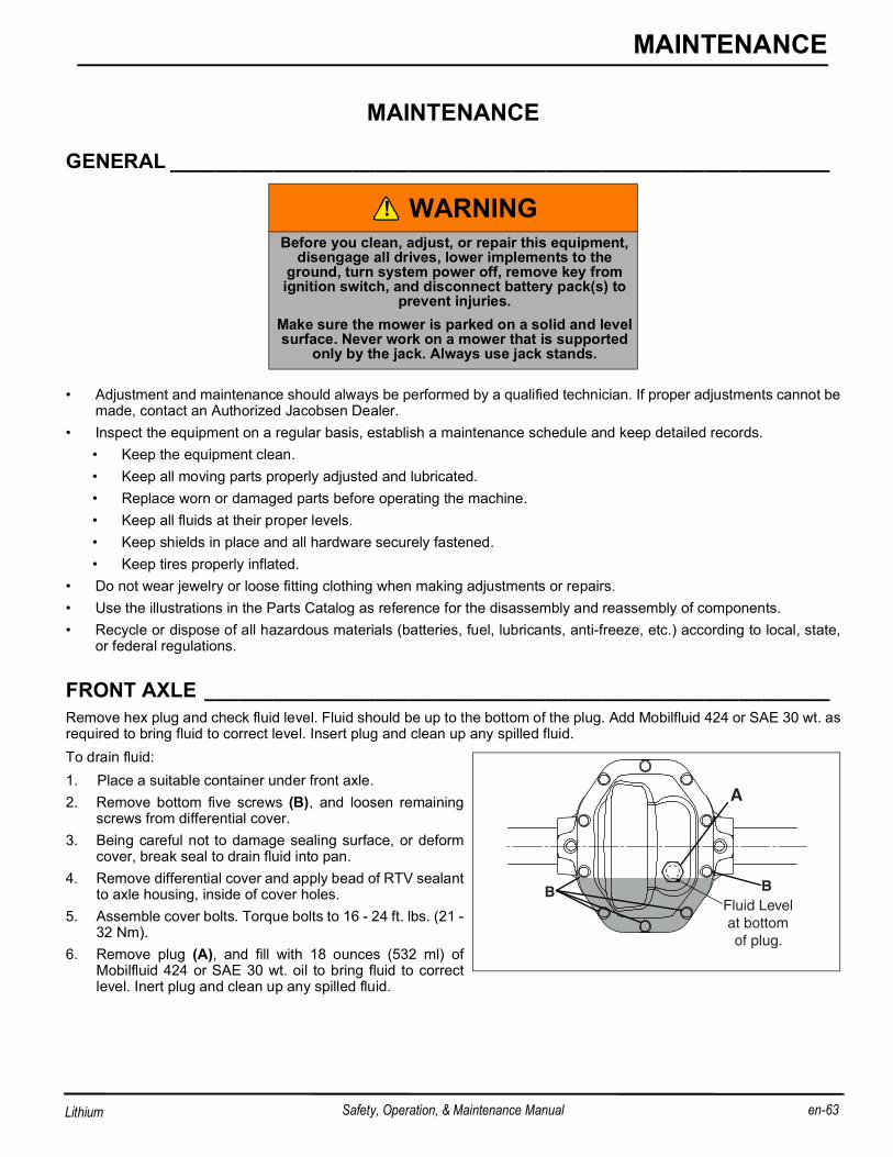
GENERAL __________________________________________________________
• Adjustment and maintenance should always be performed by a qualified technician. If proper adjustments cannot bemade, contact an Authorized Jacobsen Dealer.
• Inspect the equipment on a regular basis, establish a maintenance schedule and keep detailed records.• Keep the equipment clean.• Keep all moving parts properly adjusted and lubricated.• Replace worn or damaged parts before operating the machine.• Keep all fluids at their proper levels.• Keep shields in place and all hardware securely fastened.• Keep tires properly inflated.
• Do not wear jewelry or loose fitting clothing when making adjustments or repairs.• Use the illustrations in the Parts Catalog as reference for the disassembly and reassembly of components.• Recycle or dispose of all hazardous materials (batteries, fuel, lubricants, anti-freeze, etc.) according to local, state,
or federal regulations.
FRONT AXLE _______________________________________________________Remove hex plug and check fluid level. Fluid should be up to the bottom of the plug. Add Mobilfluid 424 or SAE 30 wt. asrequired to bring fluid to correct level. Insert plug and clean up any spilled fluid.To drain fluid:1. Place a suitable container under front axle.2. Remove bottom five screws (B), and loosen remaining
screws from differential cover.3. Being careful not to damage sealing surface, or deform
cover, break seal to drain fluid into pan.4. Remove differential cover and apply bead of RTV sealant
to axle housing, inside of cover holes.5. Assemble cover bolts. Torque bolts to 16 - 24 ft. lbs. (21 -
32 Nm).6. Remove plug (A), and fill with 18 ounces (532 ml) of
Mobilfluid 424 or SAE 30 wt. oil to bring fluid to correctlevel. Inert plug and clean up any spilled fluid.
WARNINGBefore you clean, adjust, or repair this equipment,
disengage all drives, lower implements to the ground, turn system power off, remove key from ignition switch, and disconnect battery pack(s) to
prevent injuries.Make sure the mower is parked on a solid and level surface. Never work on a mower that is supported
only by the jack. Always use jack stands.
!
Fluid Levelat bottomof plug.
A
B B
B
en-64 Safety, Operation, & Maintenance Manual
MAINTENANCE
Lithium
AXLE HUB INSPECTION ______________________________________________The following procedure must be performed once a year or every 300 hours, whichever comes first.1. Remove and discard cotter pin (A) from the axle.2. With tire on ground, break castle nut (B) free. Do not fully remove the castle nut.3. Raise the mower and support front axle on jack stands. Remove lug nuts and wheel.
4. Remove castle nut (B), washer (C) and hub (D).5. Inspect the both ends of hub splines for wear or damage.
Refer to Figure 9B for examples of hub wear. • If no wear to light wear is present, hub can be used.• If medium to extreme wear is present, hub must be
replaced. Do not operate mower until hub isreplaced.
6. Apply anti-seize to axle shafts.7. Slide hubs (D) onto axle shafts.8. Assemble washers (C) and castle nuts (B) to axle shafts.9. Torque castle nut (Item 2) to 125-140 ft. lb. (170-190
Nm). Tighten nut as required to align cotter pin hole withslot in nut.
10. Install new cotter pin (A).11. Assemble tire and lug nuts. Lower mower to the ground.12. Repeat procedure on opposite side of the mower.
WARNINGMake sure the mower is parked on a solid and level surface. Never work on a mower that is supported
only by the jack. Always use jack stands.If only the front or rear of the mower is raised, place
chocks in front of and behind the wheels that are not raised.
PARKING BRAKE INSPECTION ________________________________________Refer to the parts catalog as an aid for the removal and assembly of components.
NOTE: The motor brake may be removed with the front axle motor in the vehicle.
Use a dust mask and gloves to protect lungs and hands from brake dust.
1. Disconnect the main power connector.2. Remove the traction pedal sensor.
• Remove the right fender and the screws securing thefloor mat to the floor.
• Remove hardware (A) securing traction pedal to thesensor bracket.
• Remove hardware (B) securing traction pedal to thesensor shaft.
• Remove the traction pedal (C).• Raise the mower and support front axle on jack
stands.
• Disconnect the traction pedal sensor electrical con-nector.
• Remove hardware (D). Remove the traction pedal sensor (E).3. Make alignment marks (F) on parking brake and motor.4. Disconnect the parking brake electrical connector (G).5. Remove three screws and lock washers (H) securing
parking brake to the motor. Remove the parkingbrake.Put the parking brake, brake disk side up, on aworkbench.
6. Extend the alignment marks onto the cover plate (J).Remove two screws (K), cover plate and brake disk/hub(L). Inspect both o-rings (M) for damage.
7. Extend the alignment marks onto the pressure plate (N).Remove the pressure plate, and eleven clutch springs(P) from the brake housing (R).
8. Clean and inspect all components.a. Thoroughly clean all debris and corrosion from all
components. Replace components as required.
b. Check for approximately 25 ohms at the brake coil. If the coil resistance is out of range, the entire parking brakeassembly must be replaced.
c. If the brake assembly must be replaced, proceed with Step 14. If brake will be reused, proceed with Step 9.
WARNINGMake sure the mower is parked on a solid and level surface. Never work on a mower that is supported
only by the jack. Always use jack stands.If only the front or rear of the mower is raised, place
chocks in front of and behind the wheels that are not raised.
ABC
D
D
ED
D
!
G
F
HH
H
B
en-66 Safety, Operation, & Maintenance Manual
MAINTENANCE
Lithium
9. Install the eleven clutch springs (P) into the brake hous-ing (R).
10. Assemble the pressure plate (N) into the brake housing(R). Align marks (F).
11. Place brake disk and hub (L) on the pressure plate (N).Brake disk should be centered on the pressure plate.
12. Assemble one o-ring (M) into groove in brake housing(R).
13. Assemble cover plate (J) onto brake housing (R) usingtwo screws (K). Alternate tightening the screws a little ata time to compress the brake springs. Torque the screwsto 35 in. lbs. (3.9 Nm).
14. Clean the parking brake mounting area of the front axlemotor and clean the motor shaft.
15. Apply a thin film of high temperature anti-seize to themotor shaft.
16. Assemble one o-ring (M) into groove in cover plate (J).17. Slide the parking brake onto the motor shaft.18. Connect brake release harness to brake connector and
battery pack connectors. Adjust parking brake on motoruntil mounting hardware (H) can be assembled.
19. Torque the three screws (H) evenly and in small incre-ments to 53-71 in. lb. (6-8 Nm).
20. Remove brake release harness.21. Apply dielectric grease and connect the brake electrical
connector.22. Assemble the traction pedal sensor in reverse order of
removal.23. Connect main power connector. Test the operation of the
LIFT ACTUATOR CALIBRATION _______________________________________The actuators need to be calibrated at initial setup, whenever an actuator or the RCU was replaced, or when switchingfrom reels to vertical mowers.
Before calibrating, reels or vertical mowers must be properly set-up with rollers, and installed on the Eclipse mower.To calibrate the actuators: 1. Park the mower on a flat and level surface.2. Enter Maintenance Mode. See Maintenance Mode on
page 29.. 3. Press either of the orange buttons (AM or AN) on the
LDU until the ACTUATOR CALIBRATE? screen is onthe LCD display. Press the black button (AL) to enter setmode.
4. With mow switch off, all three mower switches on, andparking brake engaged, raise or lower all three reels untilthe left reel is at the desired crosscut position. Crosscutposition may be measured by the distance actuator isextended, or by measuring the distance from the groundto the reel.
a. Press the left orange button (AN) on the LDU to savethe crosscut position for the left reel.
b. Raise or lower the center reel as required to match the crosscut position of the left reel. Press the left orange button (AN) on the LDU to save the crosscut position for the center reel. Repeat for the right reel.
c. Lower all three reels until the left reel actuator pin (D) is centered in the lift arm slot (C). Save the lowered position for the left reel.
d. Raise or lower the center reel as required until the center reel actuator pin (D) is centered in the lift yoke bracket slot (C). Press the left orange button (AN) on the LDU to save the lowered position for the center reel. Repeat for the right reel.
NOTICEAny changes made to settings in the Maintenance Mode will not be active until the mower is powered
down and restarted.
NOTICETo ensure all three reels lower and start cutting at the same point, the crosscut position should be the
same distance from the ground for each reel.
!
JACOBSENVERSION X.XX
ALAM AN
48 V
12 V
L CROSSCUT
SAVE QUIT SKIP
C CROSSCUT
SAVE QUIT SKIP
R CROSSCUT
SAVE QUIT SKIP
LEFT DOWN
SAVE QUIT SKIP
CENTER DOWN
SAVE QUIT SKIP
RIGHT DOWN
SAVE QUIT SKIP
ACTUATORCALIBRATE?
Set actuatorcalibration
Set L actuatorone touch liftpoint
Set C actuatorone touch liftpoint
Set L Acuatorlowered point
Set C actuatorlowered point
Set R actuatorlowered point
Set R actuatorone touch liftpoint
B
en-68 Safety, Operation, & Maintenance Manual
MAINTENANCE
Lithium
BACKLAPPING AND GRINDING ________________________________________To backlap:1. Park the mower on a flat and level surface.2. Enter Maintenance Mode. See Maintenance Mode on
page 29.. 3. Press either of the orange buttons (AM or AN) on the
LDU until the BACKLAP ENABLE? screen is on theLCD display. Press the black button (AL) to enter backlapmode.
4. If reels are not lowered, the LOWER ALL ACTUATORSwill display on the LDU. Lower reels to the ground. Press-ing any of the three buttons (AL, AM, or AN) withLOWER ALL ACTUATORS on the display will cancelbacklap mode.
5. Use orange buttons (AM and AN) to adjust timer. Pressblack button (AL) to start backlapping. Selected motorswill start rotating and horn will periodically chirp.
6. Turn mow switch (E) and desired reel switches (F, G, andH) to ON position.
7. Adjust reel speed between 150 and 400 rpm using theorange buttons (AM or AN).
8. Apply lapping compound with a long handle brush alongthe entire length of the reel.
9. Continue lapping and at the same time make a fineadjustment on the reel and bedknife until there is a uni-form clearance along the full length of the cutting edges.
10. Exit backlap mode by allowing the timer to end, or press-ing the black button (AL) to select QUIT.
11. Turn key switch to off position.12. Carefully and thoroughly remove all lapping compound
from reel and bedknife before running the reel in forwarddirection.
TIRES _____________________________________________________________1. Keep tires properly inflated to prolong tire life. Check inflation pressure while the tires are cool. Inspect tread wear.
2. Check the pressure with an accurate, low pressure tire gauge.
3. Keep tires inflated to:
Front ......................... 16 psi (1.1 BAR)Rear.......................... 20 psi (1.3 BAR)
1. Remove dirt, grease and oil from stud thread. Do not lubricate threads.2. Position wheel on hub and inspect to insure full contact between mounting surface of wheel and hub or brake drum.3. Finger tighten all hardware then torque hardware in criss-cross order; always tighten nuts in the top position.4. Check and retorque daily until torque is maintained, 85-95 ft.lbs. (115-128 Nm)
CARE AND CLEANING _______________________________________________Clean the mower and implements after each use. Keep the equipment clean. Whenever possible, use compressed air toclean mower.
• Use compressed air to clean engine and radiator fins (30 psi (2.1 BAR) maximum).
NOTICEUnder inflated tires may leave tire marks in turf. For
soft turf, tire inflation pressure may need to be increased to 22 psi (1.5 BAR).
CAUTIONUnless you have the proper training, tools and
experience, DO NOT attempt to mount a tire on a rim. Improper mounting can produce an explosion
which may result in serious injury.
WARNINGMake sure the mower is parked on a solid and level surface. Never work on a mower that is supported
only by the jack. Always use jack stands.If only the front or rear of the mower is raised, place chocks in front of and behind the wheels that are not
raised.
NOTICEDo not wash any portion of the equipment while it is hot. Do not use high pressure spray or steam.
Use cold water and automotive cleaners.
!
!
B
en-70 Safety, Operation, & Maintenance Manual
MAINTENANCE
Lithium
• Use only fresh water for cleaning your equipment.
• Do not spray water directly at the instrument panel, ignition switch, controller, or any other electrical components, orat bearing housings and seals.
• Clean all plastic or rubber components with a mild soap solution and warm water, or use commercially availablevinyl/rubber cleaners.
• Repair damaged metal surfaces and use Jacobsen touch-up paint. Wax the equipment for maximum paint protec-tion.
General1. Clean the mower thoroughly and lubricate. Repair and paint damaged or exposed metal.2. Inspect the mower, tighten all hardware, replace worn or damaged components.3. Clean the tires thoroughly and store the mower so the load is off the tires. If mower is not on jack stands, check tires
at regular intervals and re-inflate as necessary.4. Keep the machine and all its accessories clean, dry and protected from the elements during storage.
Cutting Units1. Wash the cutting units thoroughly, then repair and paint any damaged or exposed metal.2. Lubricate all fittings and friction points.3. Backlap the reels then back the reel away from the bedknife. Apply a light coat of rust preventative oil to the sharp-
ened edges of the reel and bedknife.
NOTICEUse of salt water or affluent water has been known
to encourage rust and corrosion of metal parts resulting in premature deterioration or failure. Dam-age of this nature is not covered by the factory war-
ranty.
CAUTIONClean grass and debris from cutting units, drives,
muffler, and engine to prevent fires.
WARNINGNEVER use your hands to clean cutting units. Use a
brush to remove grass clippings from blades. Blades are extremely sharp and can cause serious
GENERAL INFORMATION_____________________________________________
General precautions that can be taken to reduce electrical problems are listed below.• Make certain all terminals and connections are clean and properly secured.• Check the interlock system, fuses, and circuit breakers regularly.• If the interlock does not function properly and the problem cannot be corrected, contact an authorized Jacobsen
Dealer.• Keep the wire harness and all individual wires away from moving parts to prevent damage. • Make sure the seat switch harness is connected to the main wire harness.• Check the battery and battery charging circuit.• Do not wash or pressure spray around electrical connections and components.The electrical system is monitored and controlled by the multiple controllers. The controllers are equipped with LED’swhich can be used when troubleshooting the electrical system.
CAUTIONAlways turn the system power switch off, remove key, and disconnect battery connector(s), before inspecting or working on the electrical system.
Controller Location/Function
Traction Controller(TCU)
Located to the right of the operator seat, under the right cowling. Traction controller is used to control the operation of the traction drive motor. The traction controller has one green light for diagnostics.
Steering Controller(SCU)
Located at the rear of the unit below the hood. Steering controller is used to control the power steering system. The steering controller has one green light for diagnos-tics.
Main Controller Unit(MCU)
Located to the left of the operator seat, under the left cowling. MCU is used to con-trol communications between the different controllers. The MCU has diagnostic lights to help troubleshoot controller functions. See MCU Controller Lights on page 75.
Reel Controller Unit(RCU)
Located on the right side of the steering column, under the steering column cover. RCU is used to control the operation of the reel motors and the lift/lower actuators. The RCU has diagnostic lights to help troubleshoot controller functions. See RCU Controller Lights on page 74.
LCD Display Unit(LDU)
Located on the instrument panel. Used to display and set functions. See LCD Dis-play Unit (LDU) on page 25.
Braking Resistor Controller (BRC)
Located on side of TCU. BRC controller is used to energize the four over-voltage resistors on the side of the machine.
Power Distribution Unit(PDU)
Located to the left of the operator seat, under the MCU. PDU is used to switch 48V and 12V motor/controller outputs on or off. Three circuit breakers are located on the rear of the PDU.
!
B
en-72 Safety, Operation, & Maintenance Manual
ELECTRICAL SYSTEM
Lithium
PDU AND CONTROLLER LOCATIONS___________________________________
Power Distribution Unit (PDU) Circuit BreakersUsed to protect electrical system. Three manual reset circuit breakers located on the PDU are accessible by opening thehood and looking towards the left ROPS post. Push down on rubber boot to reset circuit breaker.
Main Controller Unit (MCU) Diagnostic LightsTwenty four lights are used to indicate active MCU functions. Lift MCU access panel to access MCU.
Reel Controller Unit (RCU) Diagnostic LightsEighteen lights are used to indicate active RCU functions. Remove access plug from right side of steering column to viewRCU diagnostic lights.
Braking Resistor Controller (BRC)Remove right side operator platform cover to access BRC.
Traction Controller Diagnostic LightSingle green light on traction controller indicates power and faults. A steady light indicates the controller is active. A flash-ing light indicates a traction system fault/error has occurred. Remove right side operator platform cover to access tractioncontroller.
Steering Controller Diagnostic LightSingle green light on steering controller indicates power and faults. A steady light indicates the controller is active. Aflashing light indicates a steering system fault/error has occurred. Open the hood and remove controller cover to accessthe steering controller.
3WD Controller Diagnostic LightSingle green light on 3WD controller indicates power and faults. A steady light indicates the controller is active. A flashinglight indicates a 3WD system fault/error has occurred. Open the hood and remove controller cover to access the 3WDcontroller.
3WD Controller(3WD)
Located at the rear of the unit below the hood. 3WD controller is used to control the rear wheel motor. The 3WD controller has one green light for diagnostics.
RCU CONTROLLER LIGHTS ___________________________________________The RCU controller is a solid state device that monitors and controls reel and lift electrical functions. The RCU communi-cates with the MCU via the CAN network.Each input and output signal is displayed through lamps located on front face of the controller. An active circuit will turnan input lamp on, an inactive circuit will turn a lamp off. Outputs are active when their lights are on.
Controller Functions by Lamp NumberLamp On - Circuit is active Lamp Off - Circuit is inactive
INPUTS OUTPUTSLamp Circuit Lamp Circuit
1 CAN Low 3 Left Reel Clockwise/Counter-Clockwise2 CAN High 4 Left Reel Forward/Reverse9 48 Volt DC 5 Left Reel Raise
6 Left Reel Lower7 Right Reel Motor8 Left Reel Motor10 Right Reel Clockwise/Counter-Clockwise11 Right Reel Forward/Reverse12 Right Reel Lower13 Right Reel Raise14 Center Reel Motor15 Center Reel Lower16 Center Reel Raise17 Center Reel Clockwise/Counter-Clockwise18 Center Reel Forward/Reverse
MCU CONTROLLER LIGHTS___________________________________________The MCU controller is a solid state device that monitors and controls mower functions. The MCU communicates with theother controllers via the CAN network.Each input and output signal is displayed through lamps located on top face of the controller. A closed input switch indi-cates an active circuit and will turn an input lamp on, an open switch an inactive circuit and will turn a lamp off. Outputsare active when their lights are on.
Controller Functions by Lamp Number Lamp On - Circuit is active Lamp Off - Circuit is inactive
INPUTS OUTPUTSLamp Circuit Lamp Circuit
1 +48 Volt DC Power In 4 Fuel Pull Solenoid2 +12 Volt DC Fuel Solenoid Power In 5 Fuel Hold Solenoid/Anti-Fire Solenoid3 +12 Volt DC Power In 6 Glow Plug Relay13 Spare 12 Volt Digital Low In 7 Start Relay14 Genset Status 8 Traction Contactor Output15 Program Select #4 9 Head Light16 Program Select #3 10 TCU Fan Output17 Program Select #2 (Diesel) 11 Spare Output #218 Program Select #1 (Gas) 12 Silent Mode Output19 Spare 48 Volt Digital In #520 Spare 48 Volt Digital In #421 Spare 48 Volt Digital In #322 Spare 48 Volt Digital In #223 Spare 48 Volt Digital In #124 Seat Switch
SPA
RE
12V
DG
TL
LO IN
GE
NS
ET
STA
TU
S
PR
OG
RA
M S
ELE
CT
#4
INP
UT
S
PR
OG
RA
M S
ELE
CT
#3
PR
OG
RA
M S
ELE
CT
#2
PR
OG
RA
M S
ELE
CT
#1
SPA
RE
DIG
ITA
L IN
#5
SPA
RE
DIG
ITA
L IN
#4
SPA
RE
DIG
ITA
L IN
#3
SP
48V
DG
TL
IN #
2
SP
48V
DG
TL
IN #
1
SE
AT S
WIT
CH
OU
TP
UT
S
+48
VD
C P
OW
ER
IN
+12
VD
C F
UE
L S
OL
PW
R IN
+12
VD
C P
OW
ER
IN
FU
EL
PU
LL S
OLE
NO
ID
FU
EL
HO
LD S
OLE
NO
ID/
AN
TI-
FIR
E S
OLE
NO
ID
GLO
W P
LUG
RE
LAY
STA
RT
RE
LAY
TR
AC
TIO
N C
ON
TR
AC
TOR
HE
AD
LIG
HT
TC
U F
AN
OU
TP
UT
SPA
RE
OU
TP
UT
#2
SIL
EN
T M
OD
E O
UT
PU
T
131415161718192021222324 123456789101112
J2J3J4
B
en-76 Safety, Operation, & Maintenance Manual
ELECTRICAL SYSTEM
Lithium
PDU _______________________________________________________________The PDU is located to the left of the operator seat, under the MCU, and is used to switch 48V and 12V motor/controlleroutputs on or off. Three circuit breakers are located on the rear of the PDU.Before working on, or opening the PDU, shut mower off, remove key, disconnect 48 volt battery connector, and discon-nect 12 volt battery connector (Hybrid mowers). Use caution to prevent shorting between PDU input, output, and groundcable studs.Inside the PDU are the following components:• Traction Contactor - Used to control 48 volt power out-
put to TCU and OLM.• 48 Volt Contactor - Used to control 48 volt power output
to MCU, RCU, SCU, and other components.• 12 Volt Relay - Used to control 12 volt power output to
MCU, 12 volt lights, and engine components.• 150 Amp Fuse - Used to provide circuit protection for 48
volt contactor.• 300 Amp Fuse - Used to provide circuit protection for
traction contactor.• 12 Amp Circuit Breaker - Used to provide circuit protect
for 48 volt contactor output except for RCU and SCU.• 30 Amp Circuit Breaker - Used to provide circuit protec-
tion for SCU.• 50 Amp Circuit Breaker - Used to provide circuit protec-
tion for 12 volt contactor.• Printed Circuit Board - Used for controlling PDU inputs
and outputs.••
TRACTION PEDAL TEST ______________________________________________Check traction pedal adjustment if mower is not maintaining correct speeds.1. Obtain optional pedal test connector (AS) (Part Number
4225240). Connect test connector to main harness andtraction pedal.
2. Turn mow switch to RUN position. Do not start mower.3. Measure voltage using White and Black wires on test
connector (AS). If test connector is not used, measuredirectly at Orange and Black wires in pedal connector,pins 2 and 3.
4. Press pedal for full forward movement. The voltageshould read 4.5V.
5. Press the pedal for full rear movement. The voltageshould read 0.5V.
6. Move the pedal to the neutral location. The voltage should read 2.5V.7. Remove test connector (AS).
GENERAL __________________________________________________________
• Adjustments and maintenance should always be performed by a qualified technician. If proper adjustment cannot bemade, contact an authorized Jacobsen Dealer.
• Replace, do not adjust, worn or damaged components.• Long hair, jewelry or loose fitting clothing may get tangled in moving parts.
• Do not change speed limit settings or overspeed the drive motors.
(Pre-adjustment Check)• Check the reel bearings for end play or radial play. There should be no end play or radial play. See Torque Specifica-
tion on page 86.
• Inspect the reel blades and bedknife to insure goodsharp edges without bends or nicks.
• The leading edge of the reel blades must be sharp,free of burrs and show no signs of rounding off.
• The bedknife and bedknife backing must be securelytightened. The bedknife must be straight and sharp.
WARNINGBefore you clean, adjust, or repair this equipment,
disengage all drives, lower implements to the ground, turn system power off, remove key from ignition switch, and disconnect battery pack(s) to
prevent injuriesMake sure the mower is parked on a solid and level surface. Never work on a mower that is supported
only by the jack. Always use jack stands.
CAUTIONBe careful to prevent entrapment of the hands and fingers between moving and fixed components of
the machine.
CAUTIONTo prevent personal injury and damage to the cut-ting edges, wear gloves and handle the reel and
bedknife with extreme care.
!
!
!
°
° 1/32”(0.08 cm)
B
en-78 Safety, Operation, & Maintenance Manual
ADJUSTMENTS
Lithium
• A flat surface of at least 1/32 in. (0.08 cm) minimummust be maintained on the front face of the bedknife.Use a standard flat file to dress the bedknife.
• If wear or damage is beyond the point where the reel orbedknife can be corrected by the lapping process, theymust be reground.
• Proper reel-to-bedknife adjustment is critical. A gap of0.001 to 0.003” (0.0025 to 0.0076 cm) must be main-tained across the entire length of the reel and bedknife.
• The reel must be parallel to the bedknife. An improperlyadjusted reel will lose its sharp edges prematurely andmay result in serious damage to the reel and bedknife.
• Grass conditions will also affect the adjustment.• Dry, sparse conditions will require a wider gap to prevent heat buildup and damage to the reel and bedknife.• High quality grass with a good moisture content requires a closer gap (near zero).
BEDKNIFE ADJUSTMENT _____________________________________________• See Bedknife-To-Reel on page 77 before making the
adjustment.• Start adjustment at the leading end of the reel, followed by
the trailing end. The leading end of the reel blades is thatend which passes over the bedknife first during normalreel rotation.
• Use adjusters (B and C), to adjust gap. Rotate adjusters(Clockwise) to close gap. Each click of the adjuster movesthe bedknife 0.001” (0.0025 cm) closer to the reel.• Slide a feeler gauge or shim stock 0.001” - 0.003”
(0.0025 - 0.0075 cm) between the reel blade and thebedknife. Do not turn the reel.
• Adjust the trailing end of the reel to the same gap in asimilar manner then recheck the adjustment at theleading end.
• When the reel is properly adjusted to the bedknife, thereel will spin freely and you should be able to cut apiece of newspaper, along the full length of the reel,when the paper is held at 90° to the bedknife.
NOTICEAvoid excessive tightening or serious damage may result to bedknife and reel blades. Reels must turn
CUTTING HEIGHT ___________________________________________________Note: Always make the reel to bedknife adjustment before adjusting height of cut. See Bedknife-To-Reel on
page 77 and See Bedknife Adjustment on page 78.
1. Set desired cutting height on the gauge (E).• Measure distance between the underside of screw
head and gauge block surface (F).• Adjust screw (H) to obtain desired height then tighten
the wing nut.2. Loosen the nuts on the front roller brackets (G) just
enough to allow the adjuster knob (K) to raise or lowerthe front roller.
3. Place gauge (E) across bottom of front and rear rollersnear one end of roller.
4. Slide the head of gauge screw (H) over the bedknife (L)and adjust the knob (K) to close the gap between thescrew head and bedknife. Then tighten locknut (G).
5. Repeat Steps 4 and 5 on opposite end. Complete adjust-ment to one end before adjusting opposite end.
6. Tighten nuts (G) and recheck each end.
REEL ASSEMBLY ___________________________________________________1. Slide coupler onto reel motor shaft. Check that reel motor shaft engages the coupler without excess play.NOTE: Loose fitting reel motor couplers will damage the motor shaft. Damage to the motor shaft due to loose
or worn couplers will not be covered under warranty after 1 year or 300 hours whichever occurs first.
2. Slide splined end of coupler (AC) onto reel shaft.3. Assemble o-ring (AD) onto motor adapter on reel.4. Insert key (AE) into motor shaft.5. Slide motor (AF) into coupler (AC) and secure to reel
using three 1/4-20 x 1-3/4” socket head screws (AG).Torque hardware to 75 in. lbs. (8.5 Nm).
6. Assemble lift yoke (AH) to reel, using shoulder bolts (AJ)included with reel.
7. Start mower, and lower lift arms. Shut mower off.8. Move reel into position, lift up on lift arms, and slide lift
yoke shaft into lift pivot. Secure with lock pin (AP), andassemble cap (AR).
9. Route right front reel motor harnesses along lift yoke tolift arm. Open connector cover (AU) and assemble motorharness to mower harness. Check to be certain harnessdoes not contact moving parts, and secure harness to liftarm using one cable tie (AW) and lift yoke using twocable ties (AV).
FK
G
E
H
J
ADACAG
AE
AF
W
ATAP
AR
AJ
AH
AS
B
en-80 Safety, Operation, & Maintenance Manual
ADJUSTMENTS
Lithium
10. Route left front reel motor harness along lift yoke andunder lift arm. Open connector cover (AU) and assemblemotor harness to mower harness. Check to be certainharness does not contact moving parts, and secure har-ness to lift arm using one cable tie (AW) and lift yokeusing two cable ties (AV).
11. Route center reel motor harness along lift yoke andunder lift arm. Open connector cover (AU) and assemblemotor harness to mower harness. Check to be certainharness does not contact moving parts, and secure har-ness to lift yoke using three cable ties (AV).
12. Assemble harness clips (AX) onto back of connectorassemblies and press clips into holes in lift arm brack-etss.
13. Place grass catchers (AS) in place on all three reels.14. Center Reel Only: Connect centering spring (AT) to pin
on lift yoke.
REEL BEARING _____________________________________________________Any radial play or excessive end play indicates bad bearings,a weak tension spring or a backed off nut.1. Check bearing housing mounting hardware. Tighten or
replace components as required. Carefully clean threadswith degreaser.
2. Apply a medium strength grade of Loctite to nut (P), thenthread nut onto the reel shaft until the nut is 1-27/32” (4.6cm) from the end of the reel shaft.
3. Fill reel bearing housings with NLGI - Grade O greaseafter adjusting spring.
REEL STABILIZER RODS _____________________________________________The reel stabilizer rods help keep the reels level when raising or lowering reels or making turns.
Pre-AdjustmentOn the end of the reel stabilizer rod with the springs and lock collar, the adjustment is set at the factory, and should notneed to be changed. To set adjustment after replacement of components, use the following procedure.1. Lower reels to the ground, and disconnect pin (T). from lift arm.2. Measure distance from end of rod (CA) to face of collar (CB). if required, loosen set screw (CC) and adjust position
of collar to achieve a dimension of 5-1/4 in. (13.33 cm). Tighten set screw.3. Measure distance from end of rod (CA) to face of nut (CD). Adjust position of nut as required to achieve a dimension
of 1/8 in. (0.32 cm).
Adjustment1. Lower reels to one-touch position. Shut mower off.2. Loosen hex nut (S).3. Turn stabilizer rod (U) in or out of connecting pin (T) as required until reel is leveled. Tighten hex nut (S).4. Repeat for remaining reels.
BEDKNIFE ADJUSTER SPRING ________________________________________• For proper operation, bedknife adjuster spring should be
compressed to a dimension of 1-7/16 - 1-1/2 in. (3.65-3.8cm).
• To adjust spring compression, loosen or tighten nut (R) toobtain a distance of 1-7/16 - 1-1/2 in. (3.65-3.8 cm).
• After adjusting spring, check reel to bedknife adjustment.
1. Remove cotter pin (U) and fully loosen, then tighten slot-ted nut (S) to remove clearance (no end play) betweencomponents. Continue to tighten nut until next slot in nutaligns with hole in bedknife adjuster rod (T). Install newcotter pin.
2. Check torque required to rotate adjuster rod (T). Maxi-mum torque should be 24 in. lb. (2 ft. lb.) (2.7 Nm).
3. After adjusting nut, check reel to bedknife adjustment.
GRINDING BEDKNIFEBedknife can be lowered out of the reel for grinding without completely removing the bedknife assembly.1. Remove cotter pin (U), slotted nut (S), belleville washer (V), shim washer (W-If required), and half trunnion (X).2. Press down on adjuster end of rod (T) to rotate other end of the adjuster out of the bedknife finger.3. Rotate bedknife backing to access the reel and bedknife for grinding.4. After grinding, assemble bedknife using reverse order of removal. Check adjustment of bedknife adjuster tension
(See Bedknife Adjuster Tension on page 82), and reel to bedknife adjustment (See Bedknife Adjustment onpage 78).
STEERING CHAIN TENSION ___________________________________________1. Loosen hardware (Y).2. Adjust steering motor position to obtain 1/16 to 1/4 in.
(0.15 to 0.6 cm) deflection, with 2 to 10 lb. (9 to 45 N)push at mid span of chain.
NOTICEOver tightening slotted nut (S) will make bedknife
ARMREST HEIGHT ADJUSTMENT______________________________________The armrest has three available height settings for operatorconvenience. To adjust armrest height:1. Shut mower off and remove key.2. Remove three bolts (V) from bracket on right side of seat.3. Raise or lower armrest as needed until another set of
holes in armrest bracket line up with seat bracket.Assemble hardware (V).
4. After adjusting height, check three armrest wire harnessconnectors for a tight connection to main harness.
ARMREST PIVOT ____________________________________________________1. Tighten or loosen pivot plunger (W) as required so
plunger button stops the armrest at both ends of armrestpivot slots, and plunger body does not contact armrestpivot. Do not use plunger to increase pivot tension.
2. Adjust hardware (X) as required to obtain 2 to 6 lbs (9 to26.7 N) of force required, at visor end of armrest, to pivotarmrest. Do not overtighten pivot hardware or leave tooloose.
GRASS CATCHER YOKE ADJUSTMENT1. Loosen hardware (AT).2. Adjust yoke (AU) as required so lip of grass catcher is
resting on reel crossbar (AV).3. Tighten hardware (AT).
V
V
WX
AU
AU
AT
AT
AT
AT
AV
B
en-84 Safety, Operation, & Maintenance Manual
ADJUSTMENTS
Lithium
HOOD STOPS _______________________________________________________1. Adjust position of hood stop bumpers (Z) as required so
hood contacts bumpers with approximately 1/8 in. (0.3cm) clearance between hood and cowlings.
2. Adjust left and right side bumpers as required so hood islevel.
3. Test operation of hood latch. Hood latch must be able tolatch hood.
4.
LIFT STOPS ________________________________________________________If the lift actuators make a ratcheting sound when being raised, lift stop adjustment may be required. Lift stops must beadjusted with lift system in Mow Mode. See Lift System on page 43.1. Loosen left and right reel stop hardware (AA).2. Start mower, turn mow switch on, and fully raise reels.
Shut off mower.3. Adjust left reel stop bracket (AB) so reel stop pin (AC) is
resting in bracket slot. Tighten hardware (AA). If addi-tional adjustment is needed, adjust position of stop pin(AC).
4. Repeat for right reel stop bracket.5. Loosen hardware (AD). Adjust left reel bumper and
bracket (AE) to contact left reel in fully raised position.6. Repeat bumper adjustment for right reel bumper.7. Loosen hardware (AF). Adjust left side bumper (AG) to contact center reel in fully raised position. Hardware (AF) is
located on battery tray on battery power modules and buffer battery tray on hybrid power modules.8. Loosen hardware (AJ). Adjust right side center reel bumper (AH) to contact center reel. Adjust center bumper (AK)
HEADLIGHT ADJUSTMENT ___________________________________________Headlight has four adjustment positions to change distance head light beam lights up. To Adjust headlight:1. Remove access plug (AM) from left side of steering col-
umn.2. Raise or lower adjustment tab (AN) until headlight
latches in desired detent position.3. Insert access plug.
STEERING SENSOR ADJUSTMENT
1. Open hood and remove controller cover.2. Loosen controller brace hardware (ZA).3. Adjust position of controller brace (ZD) as required to
allow an air gap of 1/8 to 3/16 in. (0.32 to 0.48 cm)between magnetic portion of sensor (ZB) and sensorbody (ZC). Torque hardware (ZA) to 53 in. lb. (6 Nm).
Jacobsen uses Grade 5 Plated bolts as standard unless otherwise noted. For tightening plated bolts use the value givenfor lubricated.
NOTICE All torque values included in these charts are approximate and are for reference only. Use of these torque values is at your sole risk. Jacobsen is not responsible for any loss, claim, or damage arising from the use
of these charts. Extreme caution should always be used when using any torque value.
AMERICAN NATIONAL STANDARD FASTENERS
SIZE UNITS GRADE 5 GRADE 8 SIZE UNITS GRADE 5 GRADE 8
SPECIFIC TORQUE __________________________________________________Rear Axle Shaft .............150 ft. lbs. (203 Nm)Tire Lug Nuts.................85-95 ft. lbs (115-128 Nm)T890 Battery Posts........95-120 in. lbs. (10.7-13.5 Nm)12 Volt Battery Posts.....80 in. lbs. (9 Nm)
GENERAL INFORMATION_____________________________________________When the Eclipse mower encounters an error or fault in one of the controllers, an error code will display on the LDU, andcertain machine functions may shut down.Record any error codes that appear on the LDU, and notify maintenance at the end of the day.Refer to the following list for LDU error codes and machine functions.
SYSTEM ERROR CODES _____________________________________________
LDU Error Message Error DescriptionCaution
LEDAlarm
Sound-ing
Engine Stop
Traction Stop Mow Stop
On Off Yes No Yes No Yes No Yes NoEngine oil pressure low. Return mower to maintenance shed. Trans-port speed will be limited to 3 mph (4.8 kph).
Diesel engine coolant above 230°vF. (110° C). Return mower to mainte-nance shed. Transport speed will be limited to 3 mph (4.8 kph).
12 VDC system below 12.5 VDC. Return mower to maintenance shed.
System voltage drops below 43 VDC for 10 seconds or more. Return mower to maintenance shed. Trans-port speed will be limited to 4 mph (6.4 kph).
System voltage above 60 VDC. Return mower to maintenance shed. Transport speed will be limited to 3 mph (4.8 kph).
Fuel level in tank is low. Less than 2 qts (1.9 l) fuel remaining in tank. Return to fueling area. Do not allow tank to completely empty.
OIL PRESSUREALARM
TEMPERATUREHIGH ALARM
12 VOLTSYSTEM LOW
48 VOLTSYSTEM LOW
48 VOLTSYSTEM HIGH
LOW FUELWARNING
B
en-90 Safety, Operation, & Maintenance Manual
LDU ERROR CODES
Lithium
REEL CONTROL UNIT ERROR CODES __________________________________RCU error codes are displayed on the LDU as a message.
LDU Error Message Error DescriptionCaution
LEDAlarm
Sound-ing
Engine Stop
Traction Stop Mow Stop
On Off Yes No Yes No Yes No Yes NoLeft Reel Motor Temperature above 266° F (130° C).
Center Reel Motor Temperature above 266° F (130° C).
Right Reel Motor Temperature above above 266° F (130° C).
Left Reel Motor Short Circuit. Shut mower off, and remove key. Check reel for blockage. Restart mower. If fault returns, return mower to mainte-nance shed.
Center Reel Motor Short Circuit. Shut mower off, and remove key. Check reel for blockage. Restart mower. If fault returns, return mower to mainte-nance shed.
Right Reel Motor Short Circuit. Shut mower off, and remove key. Check reel for blockage. Restart mower. If fault returns, return mower to mainte-nance shed.
Left Reel Motor current over 35 Amps for 30 seconds. Shut mower off, and remove key. Check reel for blockage. Restart mower. If fault returns, return mower to maintenance shed. Exces-sive grass height being mowed.
Center Reel Motor current over 35 Amps for 30 seconds. Shut mower off, and remove key. Check reel for blockage. Restart mower. If fault returns, return mower to maintenance shed. Excessive grass height being mowed.
l If fault returns after shutting down and restarting mower, mowing can continue with other reels if reel enable switch for indicated reel is turned OFF.
Right Reel Motor current over 35 Amps for 30 seconds. Shut mower off, and remove key. Check reel for blockage. Restart mower. If fault returns, return mower to maintenance shed. Excessive grass height being mowed.
Left Reel Motor fuse blown. Return mower to maintenance shed. Check 150 amp fuse in PDU.
Center Reel Motor fuse blown. Return mower to maintenance shed. Check 150 amp fuse in PDU.
Right Reel Motor fuse blown. Return mower to maintenance shed. Check 150 amp fuse in PDU.
Left Reel Motor RPM is not within the range of the set point. Shut mower off, and remove key. Check reel for blockage. Restart mower. If fault returns, return mower to maintenance shed. Excessive grass height being mowed.
Center Reel Motor RPM is not within the range of the set point. Shut mower off, and remove key. Check reel for blockage. Restart mower. If fault returns, return mower to mainte-nance shed. Excessive grass height being mowed.
Right Reel Motor RPM is not within the range of the set point. Shut mower off, and remove key. Check reel for blockage. Restart mower. If fault returns, return mower to mainte-nance shed. Excessive grass height being mowed.
Left Actuator Overcurrent. Shut mower off, and remove key. Check grass catcher for excessive weight. Restart mower. If fault returns, return mower to maintenance shed.
l If fault returns after shutting down and restarting mower, mowing can continue with other reels if reel enable switch for indicated reel is turned OFF.
LDU Error Message Error DescriptionCaution
LEDAlarm
Sound-ing
Engine Stop
Traction Stop Mow Stop
On Off Yes No Yes No Yes No Yes No
RIGHT REELOVERCURRENT
LEFT REELVOLTS LOW
CENTER REELVOLTS LOW
RIGHT REELVOLTS LOW
CHECKLEFT REEL
CHECKCENTER REEL
CHECKRIGHT REEL
L ACTUATOROVERCURRENT
B
en-92 Safety, Operation, & Maintenance Manual
LDU ERROR CODES
Lithium
Center Actuator Overcurrent. Shut mower off, and remove key. Check grass catcher for excessive weight. Restart mower. If fault returns, return mower to maintenance shed.
Right Actuator Overcurrent. Shut mower off, and remove key. Check grass catcher for excessive weight. Restart mower. If fault returns, return mower to maintenance shed.
Left Actuator or wiring Short Circuit. Shut off mower and remove key. Check both actuator connectors for a tight connection. Check visible portion of wire harness for damage. Restart mower. If fault returns, return mower to maintenance shed.
Center Actuator or wiring Short Cir-cuit. Shut off mower and remove key. Check both actuator connectors for a tight connection. Check visible portion of wire harness for damage. Restart mower. If fault returns, return mower to maintenance shed.
Right Actuator or wiring Short Circuit. Shut off mower and remove key. Check both actuator connectors for a tight connection. Check visible portion of wire harness for damage. Restart mower. If fault returns, return mower to maintenance shed.
Left actuator did not reach position within 6 seconds. Shut mower off, and remove key. Check grass catcher for excessive weight. Restart mower. If fault returns, return mower to mainte-nance shed.
Center actuator did not reach position within 6 seconds. Shut mower off, and remove key. Check grass catcher for excessive weight. Restart mower. If fault returns, return mower to mainte-nance shed.
l If fault returns after shutting down and restarting mower, mowing can continue with other reels if reel enable switch for indicated reel is turned OFF.
TRACTION & STEERING CONTROLLER ERROR CODES ___________________Traction and steering controller error/fault codes display on the LDU as a four digit error code.
Right actuator did not reach position within 6 seconds. Shut mower off, and remove key. Check grass catcher for excessive weight. Restart mower. If fault returns, return mower to mainte-nance shed.
LDU Error Code DescriptionCaution
LEDAlarm
Sound-ing
Engine Stop
Traction Stop Mow Stop
On Off Yes No Yes No Yes No Yes NoSoftware detected short circuit in con-troller, cabling to motor or in motor. Measured current is 50% above the 2 min., rating current. Shut mower off, then restart. If fault returns, mower must be towed back to maintenance shed.
Over Current Glitch:
The system detected that the current is over voltage in any of the U, V, or W phases.
DC Over Current Error:The DC current is too high. Two Con-secutive measurements must be above in order to set the event.
Phase UV Not Connected A startup check of the motor connec-tions measured current i phase U to be under the defined limit.
LDU Error Message Error DescriptionCaution
LEDAlarm
Sound-ing
Engine Stop
Traction Stop Mow Stop
On Off Yes No Yes No Yes No Yes No
CHECK RIGHTACTUATOR
TRACTIONFAULT 2310
STEERINGFAULT 2310
3WD TRACTIONFAULT 2310
STEERINGFAULT 2311
3WD TRACTIONFAULT 2311
TRACTIONFAULT 2315
3WD TRACTIONFAULT 2315
TRACTIONFAULT 2316
3WD TRACTIONFAULT 2316
B
en-94 Safety, Operation, & Maintenance Manual
LDU ERROR CODES
Lithium
Phase UW Not Connected:A startup check of the motor connec-tions measured current i phase U to be under the defined limit.
Phase VW Not Connected:A startup check of the motor connec-tions measured current i phase V to be under the defined limit.
Drive Not Disable:A startup check of the motor connec-tions detected that the drive is not dis-abled.
Rotor Rotation Too High:A startup check of the motor connec-tions detected that the rotor rotation is too high.
Hardware detected short circuit in controller, cabling to motor or in motor. Shut mower off, then restart. If fault returns, mower must be towed back to maintenance shed.
Short Circuit Glitch:
The system has detected a short circuit in the hardware. Shut mower off, then restart. If fault returns, mower must be towed back to maintenance shed.
The power stage was unexpectedly turned off but restarted successfully.
Supervision PWM Disable:The supervision CPU has disabled PWM.
DC Short Circuit:The system has detected a short cir-cuit in the hardware. Shut mower off, then restart. If fault returns, mower must be towed back to maintenance shed.
DC Unexpected Off:The power stage was unexpectedly turned off.
The DC Bus charging is not finished within 10 seconds. Shut mower off, then restart. If fault returns, mower must be towed back to maintenance shed.
LDU Error Code DescriptionCaution
LEDAlarm
Sound-ing
Engine Stop
Traction Stop Mow Stop
On Off Yes No Yes No Yes No Yes No
TRACTIONFAULT 2360
STEERINGFAULT 2360
3WD TRACTIONFAULT 2360
TRACTIONFAULT 2361
STEERINGFAULT 2361
3WD TRACTIONFAULT 2361
TRACTIONFAULT 2370
3WD TRACTIONFAULT 2370
TRACTIONFAULT 2410
3WD TRACTIONFAULT 2410
TRACTIONFAULT 2412
3WD TRACTIONFAULT 2412
TRACTIONFAULT 3120
STEERINGFAULT 3120
3WD TRACTIONFAULT 3120
B
en-96 Safety, Operation, & Maintenance Manual
LDU ERROR CODES
Lithium
DC Voltage is above the High Trip level. Shut mower off, then restart. If fault returns, mower must be towed back to maintenance shed.
DC Voltage is above the hardware defined trip level. Shut mower off, then restart. If fault returns, mower must be towed back to maintenance shed.
DC Bus voltage is below the Low Trip Level. Shut mower off, then restart. If fault returns, mower must be towed back to maintenance shed.
15V Out of Range:
The internal 15V supply is out of range. The valid range is 13.0V to 16.0V.
5V Out of Range / 3V3 Low:
Either the internal 5V supply is out of range or the internal 3.3V supply is too low. The valid range is 4.5V to 5.5V.for the 5V supply. The 3.3V supply low limit is 2.9V.
The internal 5V C is out of range. The valid range is 4.5V to 5.5V.
Analog Supply 1 Out of Range:
The analog supply 1 is out of range. The valid range is 4.0V to 6.0V.
Analog Supply 2 Out of Range:
The analog supply 2 is out of range. The valid range is 4.0V to 6.0V.
Ext Gnd Tripped:
The system detected a HW EXT GND TRIP signal. A reset of the node is required to clear the error. Events related to speed feedback and motor temp measurement may follow this event.
Motor temperature is above 356° F (180° C). Shut mower off and wait ten minutes. Restart mower. If fault returns, mower must be towed back to maintenance shed.
Not Connected / Short Circuit:
The motor temperature sensor is either disconnected or has short circuited.
LDU Error Code DescriptionCaution
LEDAlarm
Sound-ing
Engine Stop
Traction Stop Mow Stop
On Off Yes No Yes No Yes No Yes No
TRACTIONFAULT 3304
3WD TRACTIONFAULT 3304
STEERINGFAULT 3311
STEERINGFAULT 3313
TRACTIONFAULT 3330
STEERINGFAULT 3330
3WD TRACTIONFAULT 3330
TRACTIONFAULT 4210
STEERINGFAULT 4210
3WD TRACTIONFAULT 4210
TRACTIONFAULT 4220
STEERINGFAULT 4220
3WD TRACTIONFAULT 4220
B
en-98 Safety, Operation, & Maintenance Manual
LDU ERROR CODES
Lithium
Heatsink temperature is above 185° F (85° C). Shut mower off and wait ten minutes. Restart mower. If fault returns, mower must be towed back to maintenance shed.
Not Connected / Short Circuit:
The internal power stage is either not connected or has short circuited. This fault is triggered when the sensor measures above 130°C or below -50°C.
High:The internal DC power stage tem-perature is above the predefined level.
Not Connected / Short Circuit:The internal DC motor power stage temperature sensor is either not con-nected or has short circuited.
The offset in the current measure-ment is too high. The offset is adjusted during power-up of the drive. Shut mower off, then restart. If fault returns, mower must be towed back to maintenance shed.
DC Sensor Offset:
The system detected that the offset is too high. Offset is calibrated when drive is disabled.
The vehicle speed counter value has not been updated.
Zero Speed Error:
The received vehicle speed is greater than zero when it should have been zero.
Vehicle Slow Down Too Slow:
The vehicle is not decreasing speed fast enough when the system has been set to monitor vehicle speed.
Vehicle Speed Value Error:
The received vehicle speed value was equal to the indicator value. This indicates that there was an error in the speed measurement in the traction controller.
Speed Set Act Error:
The difference between the main CPU steer (speed) and motor (act) speed has exceeded the error limit.
Speed Steer Cross Error:
The difference between the main CPU and supervision CPU steer speed has exceeded the error limit.
Motor Speed Cross Error:
The difference between the main CPU and supervision CPU motor speed has exceeded the error limit.Direction Error.Traction fault: Shut mower off, then restart. If fault returns, mower must be towed back to maintenance shed.Steering fault: Shut mower off. Check steering proximity switches for debris or obstruction. Restart mower. If fault returns, mower must be towed back to maintenance shed.
LDU Error Code DescriptionCaution
LEDAlarm
Sound-ing
Engine Stop
Traction Stop Mow Stop
On Off Yes No Yes No Yes No Yes No
STEERINGFAULT 6101
STEERINGFAULT 6102
STEERINGFAULT 6103
STEERINGFAULT 6104
STEERINGFAULT 6200
STEERINGFAULT 6201
STEERINGFAULT 6202
TRACTIONFAULT 6210
STEERINGFAULT 6210
B
en-108 Safety, Operation, & Maintenance Manual
LDU ERROR CODES
Lithium
Throttle Sensor Error. Shut mower off, then restart, making certain traction pedal is in neutral. If fault returns, mower must be towed back to mainte-nance shed.
BRC Timeout / BRC On Failure / BRC Off Failure:BRC failure. Shut mower off, then restart. If fault returns, mower must be towed back to maintenance shed.
Start Up Procedure Failed. Shut mower off, then restart. If fault returns, mower must be towed back to maintenance shed.
Brake sensor error. Shut mower off, then restart. If fault returns, mower must be towed back to maintenance shed.
Dynamic Reference Ratio Error:This indicates that a dynamic refer-ence ratio below the allowable level has been detected.Signal 1 Gain Out of Range:The adapted gain is too low or too high.
Signal 2 Gain Out of Range:The adapted gain is too low or too high.
Signal 1 Offset Out of Range:The adapted offset is too high or too low/
Signal 2 Offset Out of Range:The adapted offset is too high or too low.
Signal 1 Saturated High:The signal 1 raw AD value saturate is high. This indicates a short circuit.
Signal 1 Saturated Low:The signal 1 saturated is low. This indicates a short circuit.
Signal 2 Saturated High:The signal 2raw AD value saturate is high. This indicates a short circuit.
Signal 2 Saturated Low:The signal 2saturated is low. This indicates a short circuit.
SIN COS Sensor Not Connected:Check that the unit circle is consis-tent. This will detect one broken sig-nal even if the sensor is not rotating.
Sensor Supply SHC:The sensor supply current is too high. The limit is 0.068 A.
LDU Error Code DescriptionCaution
LEDAlarm
Sound-ing
Engine Stop
Traction Stop Mow Stop
On Off Yes No Yes No Yes No Yes No
STEERINGFAULT 7213
3WD TRACTIONFAULT 7213
STEERINGFAULT 7214
3WD TRACTIONFAULT 7214
STEERINGFAULT 7215
3WD TRACTIONFAULT 7215
STEERINGFAULT 7216
3WD TRACTIONFAULT 7216
STEERINGFAULT 7217
3WD TRACTIONFAULT 7217
STEERINGFAULT 7218
3WD TRACTIONFAULT 7218
TRACTIONFAULT 7220
STEERINGFAULT 7220
3WD TRACTIONFAULT 7220
B
en-110 Safety, Operation, & Maintenance Manual
LDU ERROR CODES
Lithium
Sensor Supply Not Connected:The sensor supply current is too low. The limit is 0.000 A
Sensor Supply Reference Range:The sensor supply reference voltage is out of range. The valid range is 10.0V to 16.0V.
Sensor Supply Range:The sensor supply voltage is out of range. The valid range is 10.0V to 16.0V.
Dec Too High:The change of sensor speed is too high.Wrong Direction / Plausibility Error:The sensor and stator frequency have different signs. Either the sensor sig-nals need to be inverted or the motor phase cables are connected incor-rectly.The sensor speed is too high, i.e. not plausible/possible.
No Rotation:The motor does not accelerate to the target speed within the specified time. Possible causes could be inertia is too high, friction is too high, DC volt-age too low, an error condition, or cur-rent reduction. If the motor rotates but not fast enough, attempt increasing acceleration current or timeout.Low DC BUS Voltage:The motor has gone into field weak-ening before the desired AC voltage was reached. The most likely cause is a weak battery or power supply.
Sensor Supply 2 SHC / Dec Too High Glitch:The sensor supply 2 current is too high. The limit is 0.068 A.Intermittent change of sensor speed is too high.
Sensor Supply 2 Not Connected:The sensor supply is too low. The limit is 0.003A.
Sensor Supply 2 Reference Range / Sensor Supply 1 Output Voltage Out of Range:The sensor supply 2 reference volt-age is out of of range. The valid range is 4.60V to 8.30V. Alternately, the internal sensor supply 1 output volt-age The valid range is 10.80V to 13.20V.Sensor Supply 2 Range / Sensor Supply 2 Output Voltage Out of Range:The sensor supply 2 voltage is out of range. The valid range is 4.60V to 8.30V. Alternately, the internal sensor supply 2 output voltage is out of range. The valid range is 4.50V to 5.50V.
LDU Error Code DescriptionCaution
LEDAlarm
Sound-ing
Engine Stop
Traction Stop Mow Stop
On Off Yes No Yes No Yes No Yes No
STEERINGFAULT 7251
3WD TRACTIONFAULT 7251
STEERINGFAULT 7252
3WD TRACTIONFAULT 7252
TRACTIONFAULT 7260
3WD TRACTIONFAULT 7260
TRACTIONFAULT 7261
3WD TRACTIONFAULT 7261
TRACTIONFAULT 7270
3WD TRACTIONFAULT 7270
TRACTIONFAULT 7271
3WD TRACTIONFAULT 7271
B
en-112 Safety, Operation, & Maintenance Manual
LDU ERROR CODES
Lithium
Bad or Shorted Inputs:Bad state machine transition. This can idicate shorted inputs.Loss of Ch A:Only Ch B is toggling and Ch A is not.
Loss of Ch B:Only Ch A is toggling and Ch B is not.
Cross Monitoring Error:The error between sensor speeds in each CPU has been larger than the allowed error for a specified time.Cross Monitoring Communication Error.There is a fault on the communication link or the transmitting CPU from either timeout, faulty CRC, or counter.This can also be triggered if the value from either side is invalid.Loss of Ch A:Loss of channel A signal or too noisy.
Loss of Ch B:Loss of Ch B or too noisy.
Angle Error:The difference reported by channel A and B is greater than 25°.Speed Limit / High Speed:The system has detected that the motor speed is above a ramped speed limit or the predefined level.
Slip In Wrong Direction:The detected slip speed is wrong compared to the expected slip speed.
Tool High Zero Speed Slip:The slip speed is too high compared to the expected slip speed at zero sensor speed. The typical cause of this error is that the sensor is mechanically separated from the motor.AC Current Control Error:The system has detected that the expected AC current and the mea-sured AC current is too high. This indicates a faulty current measure-ment sensor or poorly tuned current controller.
AC Current Meas Plausibility Error:The reference AC voltage is higher than what the measured AC current indicates. This indicates that one or more motor phase cables are not con-nected properly or that there is a faulty current measurement sensor.
Frequency Above 599 Hz:The electric frequency is evaluated to be above 599Hz.
Controller has not received an expected CANopen message within the time out time. Shut mower off, then restart. If fault returns, mower must be towed back to maintenance shed.
LDU Error Code DescriptionCaution
LEDAlarm
Sound-ing
Engine Stop
Traction Stop Mow Stop
On Off Yes No Yes No Yes No Yes No
TRACTIONFAULT 8071
TRACTIONFAULT 8090
STEERINGFAULT 8090
3WD TRACTIONFAULT 8090
TRACTIONFAULT 80A0
STEERINGFAULT 80A0
3WD TRACTIONFAULT 80A0
TRACTIONFAULT 80B0
STEERINGFAULT 80B0
3WD TRACTIONFAULT 80B0
TRACTIONFAULT 8100
STEERINGFAULT 8100
3WD TRACTIONFAULT 8100
B
en-114 Safety, Operation, & Maintenance Manual
LDU ERROR CODES
Lithium
PDO1 Timeout:
Rx PDO1 has not been received within the timeout time on Rx PDO1.
PDO2 Timeout:
Rx PDO2 has not been received within the timeout time on Rx PDO2.
PDO3 Timeout:
Rx PDO3 has not been received within the timeout time on Rx PDO3.
PDO4 Timeout:
Rx PDO4 has not been received within the timeout time on Rx PDO4.
PDO5 Timeout:
Rx PDO1 has not been received within the timeout time on Rx PDO5.
An internal error occurred in boot. It may occur if an incompatible application is running with the boot code.
Speed Set Act Error:
The difference between the supervision CPU (steer (set) and motor (act) speed has exceeded the error limit.
Steer Speed Cross Error:
The difference between the main CPU and supervision steer speed has exceeded the error limit.
Motor Speed Cross Error:
The difference between the main CPU and supervision motor speed has exceeded the error limit.
Position set act Error:
The difference between the supervision CPU (steer (set) and motor (act) speed has exceeded the error limit.
PWM Unexpected Off:
The power stage was unexpectedly turned off. The most likely occurred as a result of a hardware detected short circuit or a hardware detected over-voltage.
No Position:
The supervision CPU did not receive the position (for position synchronize) from the main CPU.
Other Side Fail:
This indicates that the two CPUs are not in the same device state. Most likely one CPU has unexpectedly entered the end state.
LDU Error Code DescriptionCaution
LEDAlarm
Sound-ing
Engine Stop
Traction Stop Mow Stop
On Off Yes No Yes No Yes No Yes No
TRACTIONFAULT 8452
3WD TRACTIONFAULT 8452
STEERINGFAULT F000
STEERINGFAULT F001
STEERINGFAULT F002
STEERINGFAULT F003
STEERINGFAULT F004
STEERINGFAULT F005
STEERINGFAULT F006
B
en-126 Safety, Operation, & Maintenance Manual
LDU ERROR CODES
Lithium
CRC Error:
The system has received a message with a CRC error.
Sequence Error:
CRC Error:
The system has received a message with a sequence number error.
Rx Timeout:
CRC Error:
The system did not receive a message within the time limit.
Bad Function Argument:
An internal communication API function was called with wrong arguments.
Inv State Change:
The two CPU device state machines are not in synchronization.
Tx Overflow:
An attempt to send an internal message failed due to no room in FIFO.
Unknown Rx Frame:
An internal communication message was received with unknown information.
CMD Busy:
An attempt was made to issue a new command before a previous command has finished.
Pro Ver Mismatch:
The internal communication revisions in the two CPUs are not compatible.
Vehicle Speed Start Timeout:
The reception of the first vehicle speed frame has timed out.
The received speed counter counter value has not been updated.
Speed Fit Error:
The speed value in the received message for vehicle speed does not fit as considered.
Speed Unknown Bit Error:
The configured number of bits for speed in the received message for vehicle speed is unknown.
Counter Fit Error:
The counter value in the received message for vehicle speed does not fit as configured.
Overlap Error:
The counter and speed values in the received message overlap each other.
Counter Unknown Bit Ranking:
The speed value in the received message for vehicle does not fit as configured.
Message Timeout Error:
The reception of the vehicle speed message timed out.
Zero Speed Error:
The received vehicle speed value is not considered to be zero when it should have been.
Vehicle Slow down Too Slow:
The monitored vehicle speed is not decreasing fast enough when the system is set to monitor vehicle speed.
LDU Error Code DescriptionCaution
LEDAlarm
Sound-ing
Engine Stop
Traction Stop Mow Stop
On Off Yes No Yes No Yes No Yes No
STEERINGFAULT F021
STEERINGFAULT F022
STEERINGFAULT F023
STEERINGFAULT F024
STEERINGFAULT F025
STEERINGFAULT F026
STEERINGFAULT F027
STEERINGFAULT F028
STEERINGFAULT F029
B
en-128 Safety, Operation, & Maintenance Manual
LDU ERROR CODES
Lithium
Vehicle Speed Value Error:
The received vehicle speed was equal to the error indicator value. This indicates that there was an error in the speed measurement in the traction controller.
PDO1 Timeout:
No Rx PDO1 was received within the timeout time.
PDO2 Timeout:
No Rx PDO2 was received within the timeout time.
PDO3 Timeout:
No Rx PDO3 was received within the timeout time.
PDO4 Timeout:
No Rx PDO4 was received within the timeout time.
Sync Timeout:
No sync was received within the timeout time.
Map Error:
Any PDO map has an invalid configuration.
SDO1 Timeout:
No SDO1 message was received within the timeout time.
SDO2 Timeout:
No SDO2 message was received within the timeout time.
SDO1 Session Busy:
An SDO1 request was not finished and a new SDO1 request was received.
SDO Session Busy:
An SDO2 request was not finished and a new SDO2 request was received.
Check that the unit circle vector is constant. The system will detect a broken signal even if the motor is not rotating.
Speed Error:
The speed calculated from the sensor signals is not valid.
Negative Positive Limit:
The calculation of the positive start of the slow down position resulted in a negative value which is not allowed.
Positive Negative Limit:
The calculation of the negative start of the slow down position resulted in a positive value which is not allowed.
Dynamic Reference Ration Error:
The monitoring of the dynamic reference ration has detected an error. This indicates that a dynamic reference ratio value below the dynamic reference ratio minimum limit has been detected when not allowed.
Stepper Signal1 High:
The filtered stepper signal1 is above 4000mV.
Stepper Signal1 Low:
The filtered stepper signal1 is below 1000mV.
LDU Error Code DescriptionCaution
LEDAlarm
Sound-ing
Engine Stop
Traction Stop Mow Stop
On Off Yes No Yes No Yes No Yes No
STEERINGFAULT F0B1
STEERINGFAULT F0B2
STEERINGFAULT F0B3
STEERINGFAULT F0B4
STEERINGFAULT F0B5
STEERINGFAULT F0C0
STEERINGFAULT F0C1
STEERINGFAULT F0C2
STEERINGFAULT F0D0
STEERINGFAULT F0D1
B
en-134 Safety, Operation, & Maintenance Manual
LDU ERROR CODES
Lithium
Stepper Signal2 High:
The filtered stepper signal1 is above 4000mV.
Stepper Signal2 Low:
The filtered stepper signal1 is below 1000mV.
Ch A Signal Loss:
The sensor signal is suddenly lost.
Ch A Low Update Rate:
The sensor update rate is considered to be too low.
Ch A FIFO Overrun:
The first in first out buffer was full.
Ch B Signal Loss:
The sensor signal is suddenly lost.
Ch B Low Update Rate:
The sensor update rate is considered to be too low.
Ch B FIFO Overrun:
The first in first out buffer was full.
Wrong AB Difference:
The angle difference between channel A and B was larger than 90°.
TROUBLE SHOOTING ________________________________________________Problem Possible Cause/Items to Check Additional Items to Check
Key switch ON - No power to LDU
48VDC Battery or 48VDC Buffer Battery not connected or discharged.
Check battery connections and voltage.
No 12V power to LDU. Overcurrent protec-tion device in PDU may be tripped. Check for open connection or shorted wire to GND for LDU 48V power.
Cycle power once corrected.
Key switch ON - No power to MCU or RCU
Main Contactor not on due to circuit breaker tripped.
Check to see if circuit breaker 4 is tripped.
Fault Code on LDU Review any fault codes and take appropriate action.
Overcurrent protection device in LDU tripped. Check for open connection or shorted wire to battery for main contactor coil power.
No Traction Movement Ensure Machine was started. Check LDU Green Lightning Bolt for steady on.
If flashing initiate start sequence.
Fault Code on LDU Review any fault codes and take appropriate action.
Traction Contactor is off. Check MCU LED # 8 should be on when contactor is on. If off see next item.
Overcurrent protection device in MCU tripped. Check for open connection or shorted wire to battery for traction contactor power.
Check if Seat Switch is functioning. Check MCU LED #24 should be on when on seat and off when off seat.
Check switch and harness connection.
No CAN communication. Check connections.Parking Brake not releasing Manually release parking brake, then
remove release screws. Cycle power.Overcurrent protection device in PDU tripped. Check for open connection or shorted wire to GND for throttle pedal power, TCU logic power, and park brake power.
Cycle power once corrected.
Overcurrent protection device in MCU tripped. Check for open connection or shorted wire to battery for traction contactor coil power.
B
en-136 Safety, Operation, & Maintenance Manual
TROUBLESHOOTING
Lithium
No steering (Electric steer-ing system)
Check if Seat Switch is functioning. Check MCU LED #24 should be on when on seat and off when off seat.
Check switch and harness connection.
SCU does not have power. Check to see if circuit breaker 5 is tripped.Fault Code on LDU Review any fault codes and take appropriate
action.Overcurrent protection device in PDU tripped. Check for open connection or shorted wire to GND for SCU logic power.
Cycle power once corrected.
Proximity switches dirty. Clean all dirt or debris from proximity switch. Check for obstructions that may interfere with switch operations.
Manual Actuator Mode not working
Park brake off. Check LDU Park Brake LED should be on.
Cycle power.
No CAN communication. Check connections.Fault Code on LDU Review any fault codes and take appropriate
action.Mow switch is in ON position. Ensure Mow switch is in OFF position.
One or more reel motors won't run
Mow switch is in OFF position. Ensure Mow switch is in ON position.Reel enable switches are in OFF position. Ensure to enable reels.Machine not moving. (applicable if FOC is not zero)
Reel motors should come on when machine starts moving forward.
Fault Code on LDU Review any fault codes and take appropriate action.
No power to reels. When actuators are down check RCU LED's #8 for Left, #14 for Cen-ter, #7 for right should be on.
Check PDU circuit breakers for tripped: CB3 for left, CB2 for center, CB1 for right.
Reel motor temperature or current high when mowing.
Excessive amount of grass being cut. Reduce mower speed, increase FOC, or change height of cut.
Actuators raise and motors shut off while mowing
Low Battery Power. LDU-Red 48V Battery LED will be on.
Recharge Batteries.
Reel or Actuator Fault. LDU-Yellow Caution LED will be on.
Review fault codes to determine which reel or actuator is faulted.
Steering wheel has no resistance
Overcurrent protection device in PDU tripped. Check for open connection or shorted wire to GND for Lord brake, Lord protection diode.
Cycle power once corrected.
Headlights don't turn on Overcurrent protection device in PDU tripped. Check for open connection or shorted wire to GND for headlight(s).
QUALITY OF CUT TROUBLESHOOTING _________________________________It is recommended that a “test cut” be performed to evaluate the mower’s performance before beginning repairs.An area should be available where “test cuts” can be made. This area should provide known and consistent turf condi-tions to allow accurate evaluation of the mower’s performance.Another “test cut” should be performed after the completion of the repairs and/or adjustments to verify the mower’s per-formance.Before performing a “test cut” to diagnose cut appearance and mower performance, the following items should be veri-fied to ensure an accurate “test cut.”• Mowing (Ground) Speed. See Operator Mode on page 28..• Reel Bearing Condition and Pre-Load (End Play) Adjustment.• Reel and Bedknife Sharpness• Bedknife Alignment to Reel.• Reel-to-Bedknife Contact.• Height-of-Cut (HOC). • Roller and Roller Bearing Condition• Reel Speed.
Washboarding is a cyclical pattern of varying cuttingheights, resulting in a wave-like cut appearance. In mostcases, the wave tip-to-tip distance is approximately 6—8 in. (15—20 cm). Color variation (light-to-dark) mayalso be noticed.This condition is usually caused by a rocking motion inthe cutting unit(s). This condition is found mostly on mow-ers with multiple (suspended) cutting units, but othercauses can produce the same result.Washboarding may also be caused by variations in theturf.
Probable Cause Remedy
Mowing (ground) speed is too fast. Reduce mowing (ground) speed.
Grass build-up on roller. Clean the roller and use scrapers or brushes.
Roller is out of round. Replace roller.
Mowing in the same direction. Change mowing direction regularly.
Use of a groomer on cleanup pass. Groomers should be used only in a straight line.
Reel drive motor performance is reduced. Check LDU for excessive reel motor current and/or tem-perature. Check/remove cutting reel movement obstruc-tion.
Marcelling, like washboarding, is a cyclical pattern ofvarying cutting heights, resulting in a wave-like cutappearance. In most cases, the wave tip-to-tip distance is2 in. (5 cm) or less.
Probable Cause Remedy
Mowing (ground) speed is too fast. Reduce mowing (ground) speed.
HOC (height-of-cut) setting is too low for turf condi-tions.
Check/adjust HOC to turf conditions.
Cutting reel diameter is worn. Check cutting reel diameter and replace if worn.
Reel drive motor performance is reduced. Check LDU for excessive reel motor current and/or tem-perature. Check/remove cutting reel movement obstruc-tion.
Step cutting occurs when grass is cut taller on one side ofa reel than the other or one cutting unit to another. This isusually caused by mechanical wear or an incorrect rolleror HOC (height-of-cut) adjustment.
Probable Cause Remedy
HOC (height-of-cut) settings are different from one side of a reel to the other or from one cutting unit to another.
Check HOC adjustment of cutting units.
Worn front roller bearings. Check/replace front roller bearings.
Reel-to-bedknife contact is different from one side of the cutting unit to the other or from one cutting unit to another.
Check reel-to-bedknife contact.
Cutting reel movement is restricted. Check/remove cutting reel movement obstruction.
Variations in turf density. Change mowing direction.
Machine weight distribution is uneven. Check/adjust tire inflation pressure.
Scalping is a condition in which areas of grass are cutnoticeably shorter than the surrounding areas, resulting ina light green or even brown patch. This is usually causedby an excessively low height-of-cut (HOC) setting and/oruneven turf.
Probable Cause Remedy
HOC (height-of-cut) settings are lower than normal. Check/adjust the HOC settings.
Improper reel-to-bedknife adjustment. Adjust reel-to-bedknife setting for desired HOC.
Turf too uneven for the mower to follow. Change mowing direction.
Cutting too much grass at one time. Mow more often.
Mowing (ground) speed is too fast. Reduce mowing (ground) speed.
Windrowing is the deposit of clippings concentrated atone end of cutting unit(s) or between two cutting units,forming a line in the direction of travel.
Probable Cause Remedy
Grass is too tall. Mow more often.
Mowing while grass is wet. Mow when grass is dry.
Grass built up on roller(s). Clean roller(s) and scraper(s).
Grass collecting on bedknife. Adjust reel-to-bedknife setting.
RIFLING OR TRAMLINING_____________________________________________
MISMATCHED CUTTING UNITS ________________________________________
NOTE: Arrow indicates direction of travel.
Rifling or tramlining is a pattern of varying cutting heights,resulting in a wave-like cut appearance, usually due toheavy contact points across a reel and/or bedknife.
Probable Cause Remedy
Reel and/or bedknife unevenly worn. Inspect bedknife and reel. Sharpen or replace reel and bedknife as necessary.
Missing, loose, or overtorqued bedknife screws. Install, replace or tighten bedknife screws to proper torque setting.
Mowing (ground) speed is too fast. Reduce mowing (ground) speed.
NOTE: Arrow indicates direction of travel.
Mismatched cutting units is a pattern of varying cuttingheights, resulting in a stepped cut appearance, usuallydue to mismatched HOC (height-of-cut) adjustment fromone cutting unit to another.
Probable Cause Remedy
HOC inconsistent from one cutting unit to another. Check/adjust HOC on cutting units.
Difference in mower ride height side to side. Check/adjust tire inflation pressure.