Electrical properties of slow-spreading ridge gabbros from ODP Hole l105A, SW Indian Ridge
F. EINAUDI 1'2, P. A. PEZARD 3, B. ILDEFONSE 3 & P. GLOVER 4
l Laboratoire de G~ophysique et d'Hydrodynamique en Forage, ODP-NEB, ISTEEM,
cc 056, Universit~ de Montpellier II, 34095 Montpellier, Cedex 05, France
(e-mail: einaudi @ dstu.univ-montp2.fr) 2Laboratoire de P~trologie Magmatique, Universiti d'Aix Marseille III, Facultd des Sciences de
Saint Jdr&ne, 13397 Marseille Cedex 20, France 3Laboratoire de Tectonophysique, ISTEEM, CNRS UMR5568, Universit~ de Montpellier II,
34095 Montpellier, Cedex 5, France 4Ddpartement de gdologie et de gdnie giologique, Facultd des sciences et de gdnie, Universitd
Laval, Sainte-Foy, GIK 7P4, Quebec, Canada
Abstract" Physical properties of gabbroic samples from Ocean Drilling Program Hole 1105A were measured in the laboratory, with a particular emphasis on the analysis of elec- trical properties. This data-set includes the major lithologies sampled in ODP Hole 1105A: gabbros, olivine gabbros, oxide-rich gabbros, and, for all rock types, different ranges of alteration were sampled: from flesh to highly altered. All these lithologies correspond to the seismic Layer 3 layer of the oceanic crust, and large-scale geophysical data interpret- ation requires a complete understanding of the physical properties of rocks in this section. Electrical conductivities measured on brine-saturated gabbros reveal strong excess conduc- tivity for samples rich in oxide minerals and, to a lesser extent, for altered samples. However, the classical models do not explain the excess conductivity reported in the oxide-rich samples when saturated with brine. The electrical conduction via electronic pro- cesses in metallic minerals has been taken into account in our analysis of the electrical prop- erties. The oxide minerals' contribution has been independently estimated through measuring dry electrical resistivity. These measurements allowed quantification of the elec- tronic conduction, which can reach 80% of the full conductivity for the most oxide-rich gabbros.
Through the last three decades, the Deep Sea Drilling Project (DSDP) and Ocean Drilling Program (ODP) have provided a unique opportu- nity to study the composition and structure of the oceanic crust. Our knowledge of the in situ struc- ture of lower oceanic crust has largely been based on geophysical and ophiolite studies. Deep drilling investigations of lower oceanic crust have been achieved in several locations, taking advantage of tectonic exposure, e.g. Hess Deep (ODP Leg 147; Mdvel et al. 1996), the Mid-Atlantic Ridge (ODP Leg 153 at Mark Area; Karson et al. 1997) and the SW Indian Ridge (ODP Legs 118, 176 and 179; Von Herzen et al. 1991; Dick et al. 1999; Pettigrew et al. 1999). Boreholes drilled on the SW Indian Ridge have allowed study of lower- crustal rocks analogous to ophiolitic sequences, and assessment of the seismic nature of oceanic
Layer 3. The analysis of geophysical data requires a complete understanding of the phys- ical properties of the investigated section. For this purpose, laboratory measurements of the physical properties of oceanic samples provide direct insights into the physical structure of the oceanic crust. These measurements can be com- pared with in situ down-hole measurements. In this paper, we present a petrophysical study of gabbroic samples from ODP Hole I I05A, located 1.5 km from the reference ODP Site 735. The physical properties are investigated at room pressure and temperature in order to characterize the penetrated massif, as well as to determine the influence of alteration due to fluid circulation on rock properties.
have been measured on a set of 34 samples col- lected during ODP Leg 179. Electlical properties of gabbros have been investigated in detail by Pezard et al. (1991) and lldefonse & Pezard (2001) in ODP Hole 735B, to identify down- hole changes in electrical properties, porosity structure and alteration. An important result is a change in porosity as a function of depth. These works also highlighted the importance of oxide minerals in the measured electrical resis- tivity. In the oxide-mineral-rich samples, it was pointed out from saturated measurements that oxide ionic conductivity was involved. Unfortu- nately, the 735B mini-cores were lost, and further investigation of complementary measurements such as oxide content, magnetic susceptibility and dry resistivity were not possible. Our data-set, however, does allow a full investigation of the pet- rophysical properties in such oxide-rich gabbros.
Due to extreme sensitivity, and in spite of complexity, electrical methods are among the most precise indirect tools for the analysis of rock structures. At low frequencies (< 1 kHz), electrical properties of saturated rocks are influ- enced by the nature of the rock matrix; the chemical composition and salinity of the saturat- ing fluid; the cation-exchange processes along pore surfaces, and/or the movement of fluids in the porous medium (e.g. Waxman & Smits 1968; Olhoeft 1981; Walsh & Brace 1984; Katsube & Hume 1987; Pezard 1990; Pezard et al. 1991; Revil et al. 1998). Rock-forming
minerals are mostly silicates, having a high resis- tivity (106 to 1014 ohm m), but, when the rock matrix contains conductive minerals (Ti -Fe oxide in gabbros), the conduction current through the matrix may be appreciable as oxides reach a resistivity of 10 -6 ohm m (Olhoeft 1981; Gu6guen & Palciauskas 1992). The influence of the oxide minerals on the various physical proper- ties are investigated in this paper.
Geological setting: the Atlantis II Bank
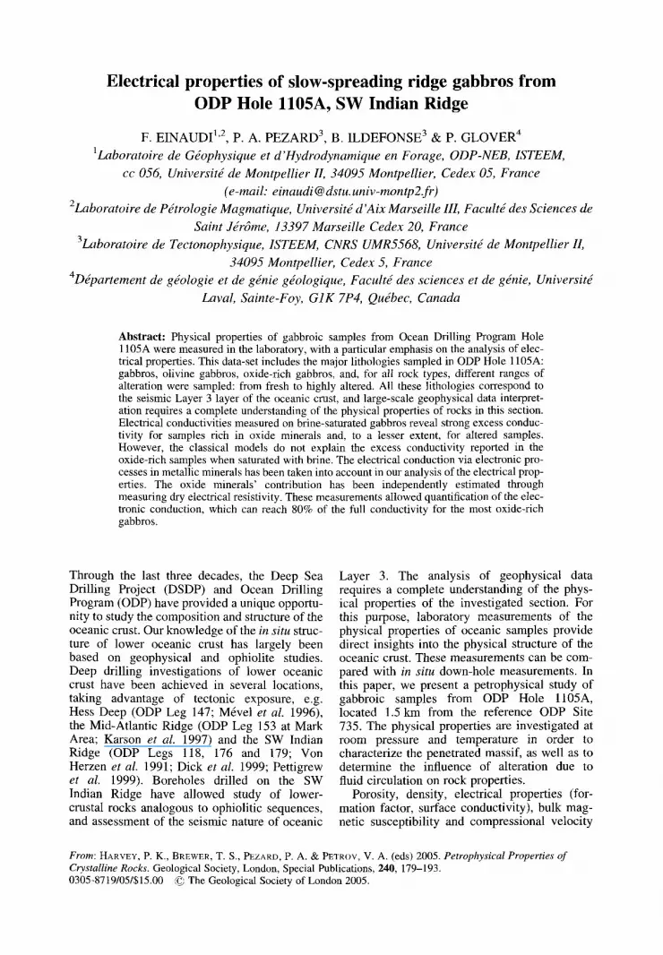
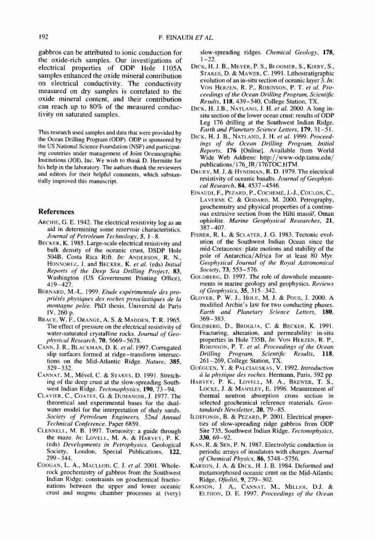
ODP Hole 1105A is located on top of the shallow Atlantis Bank (720 m below sea-level), about 18 km east of the active Atlantis transform fault and 93 km south of the present-day ridge axis (Fig. 1). The Atlantis Bank is the shallowest and largest (c. 35 km 2) of a series of north-south aligned fiat-topped platforms (Dick et al. 1999). This shallow structure is interpreted as the result of progressive unroofing along a north- dipping low-angle detachment fault (Karson & Dick 1984; Cannat et al. 1991; Dick et al. 1991), in a tectonic situation similar to that of the inside-corner highs of the Mid-Atlantic Ridge (Tucholke & Lin 1994; Cann et al. 1997; Tucholke et al. 1998; Ranero & Reston 1999).
The SW Indian Ridge (SWIR) is one of the slowest spreading sections of the mid-ocean ridge system, with a full spreading rate of 16 m m / a (Fisher & Sclater 1983; Dick et al. 1991). Slow-spreading ridges are characterized
20 ° S
30 ° S
40 ° S
50 o S
600 S
0 10 ° E 200 E 300 E 40 ° E 50 o E 60 ° E 70 a E
I
Unit 1
Un A II
UBt 11
Unit IlI
] G a b b r o s
I O x i d e r i c h g a b b r o s
Fig. 1. ODP (Ocean Drilling Program) Hole 1105A and 735B location. ODP Hole 1105A, reaches a depth of 158 mbsf (metres below the sea-floor) and ODP Hole 735B - a total depth of 1507 mbsf. Schematic diagrams of showing the lithostratigraphy of ODP Holes 735B (modified from Dick et al. 1999) and 1105A (from Pettigrew et al. 1999) Hole 735B as a function of depth. Oxide gabbro intervals are coloured black.
ELECTRICAL PROPERTIES OF GABBROS 181
by a low magma budget, and extension appears to be accommodated by a pervasive deformation. About 50% of the dredged rocks along the Atlantis II Fracture zone are peridotites and gabbros (Fisher & Sclater 1983; Dick et al. 1991; MacLeod et al. 1998). The Atlantis Bank itself mostly consists of outcropping gabbro. Models proposed to explain the exposure of gabbros at the sea-floor involve large-scale normal faulting of the newly created oceanic crust. The gabbroic crust was accreted about 11.5 Ma ago at the SWIR axis (Dick et al. 1991).
ODP Hole 1105A is located at 1.3 km from the reference Hole 735B, which penetrates 1508 metres below the sea-floor (mbsf), following two ODP drilling cruises: ODP Leg 118 (Von Herzen et aL 1991) and ODP Leg 176 (Dick et al. 1999, 2000). The exceptionally high core recovery makes of these two boreholes quasi-continuous sample of the in situ gabbroic crust.
B a s e m e n t s trat igraphy
In Hole 1105A, a sequence of gabbroic rocks was drilled to a total depth of 158 mbsf. Core recov- ery in such an environment is very high and reaches 82.8% for the whole section - similar to core recovery obtained in ODP Hole 735B (Dick et al. 1999). The recovered rocks in Hole 1105A are divided into four main rock types, ranging from gabbro (36%), olivine gabbro (43%), oxide gabbro (17%), and olivine oxide gabbro (4%). The full section is presented in detail in Pettigrew et al. (1999). It is composed of 54 lithological units on the basis of variation in rock type, mineral abundances and grain size. On a broader scale, four major lithological units have been determined from petrological description (Fig. 1; Pettigrew et al. 1999). Hole 1105A lithology consists of:
(1) a gabbroic unit (15-48 mbsf) characterized by more primitive rock types and by a scar- city of oxide gabbro;
(2) a gabbroic unit (48-136 mbsf) character- ized by a high abundance of oxide gabbro and oxide-bearing gabbro;
(3) a gabbroic unit (136-150 mbsf) character- ized by a lack of oxide gabbros; and finally,
(4) an oxide-rich gabbro and oxide-bearing gabbro unit (150-157 mbsf). In oxide-rich rocks, oxide content reaches up to 20-25% modal Fe-Ti minerals.
Sampling This study includes a series of 34 samples from ODP Hole l105A. All minicores were drilled
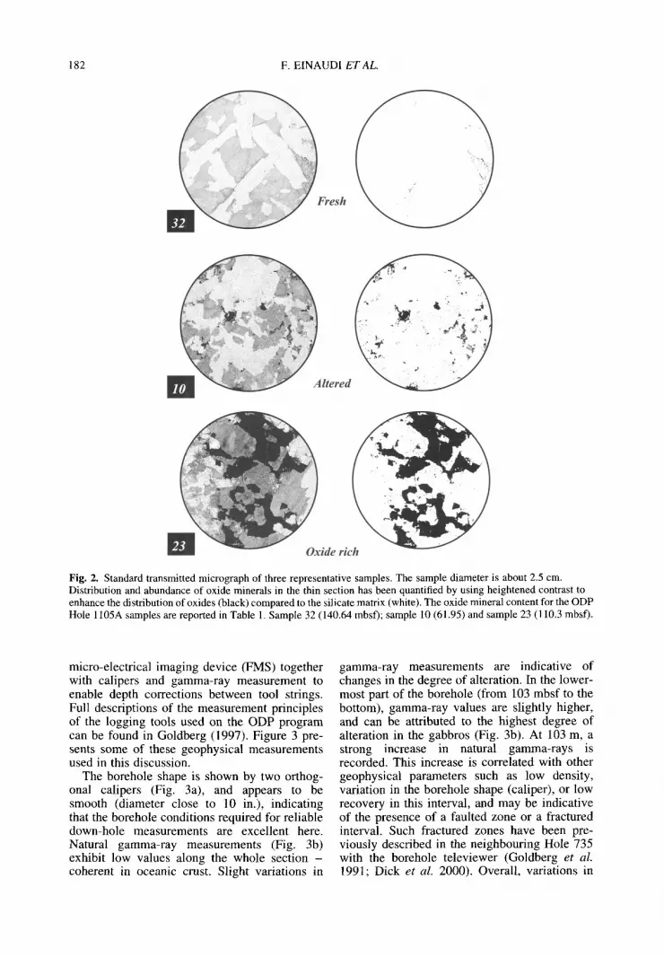
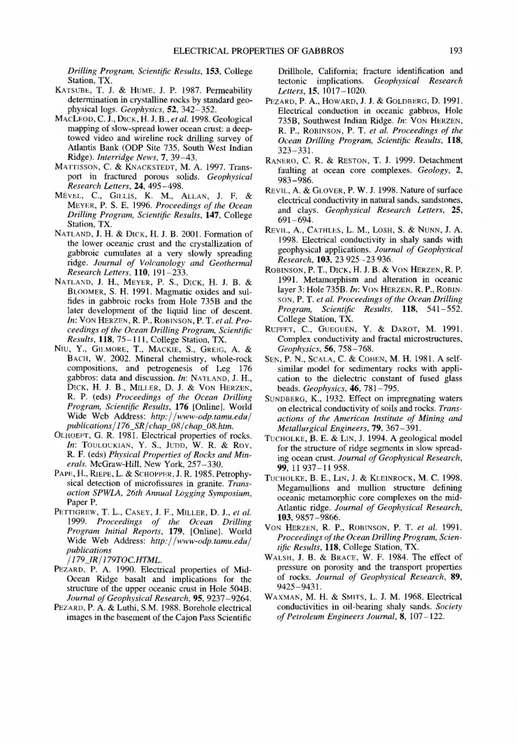
vertically into the core after splitting. The samples include all the major lithologies iden- tified (gabbros, oxide-rich gabbros, olivine gabbros: Pettigrew et al. 1999) and different states of secondary alteration, from unaltered to highly altered. The samples are located along the whole section, and have been characterized according to their oxide mineral abundance and degree of alteration, from thin-section analysis. Three distinctive groups have been identified in order to allow petrographical characterization of each gabbro type, related to the objective of this paper: fresh, altered and oxide rich (Fig. 2). Distribution and abundance of oxide minerals in the thin section as shown in Figure 2 were determined by using heightened contrast to enhance the distribution of oxides (black) com- pared to the silicate matrix (white). Oxide mineral abundances determined by image analy- sis vary from 0.2 to 31.2%. Microprobe analyses obtained from ODP Hole 735B oxide minerals (Natland et al. 1991; Niu et al. 2002) show that the oxides are dominated by ilmenite and ilmenite-hematite-magnetite solid solution. For the following discussion, they will be referred to the oxide rich category. In this study, the notion of alteration is related to the surface electrical properties of alteration phases in gabbros, such as smectites, illites or zeolites (Robinson et al. 1991; Dick et aL 1999; Pettigrew et aL 1999).
Furthermore, petrophysical measurements from Pezard et al. (1991) and Ildefonse & Pezard (2001) obtained from ODP Hole 735B samples are integrated in the following discus- sion and compared to the l105A analyses. Most of these measurements have been made fol- lowing the same analytical procedure. This data- set does not represent the entire set of lithologies, since the primary criterion for choosing the samples was the freshness of the core. It results in a rather homogeneous sampling, without strongly altered or Fe-Ti oxide-rich samples.
Petrophys ica l proper t ies f r o m down-ho le
m e a s u r e m e n t s
Physical properties were measured in situ using down-hole tools at Hole 1105A (Pettigrew et al. 1999). Wireline logging provides a continuous geophysical characterization of the penetrated formations, and is a good indicator of the lithol- ogy distribution. The Triple Combo (resistivity, porosity, density, natural radioactivity and temperature measurements) and the FMS-Sonic tool strings were deployed (Pettigrew et al. 1999). The FMS-Sonic tool string provides a measurement of sonic velocity, and includes a
182 F. EINAUDI ET AL.
Fresh
L lltered
k uxide rictt
Fig. 2. Standard transmitted micrograph of three representative samples. The sample diameter is about 2.5 cm. Distribution and abundance of oxide minerals in the thin section has been quantified by using heightened contrast to enhance the distribution of oxides (black) compared to the silicate matrix (white). The oxide mineral content for the ODP Hole 1105A samples are reported in Table 1. Sample 32 (140.64 mbsf); sample 10 (61.95) and sample 23 (110.3 mbsf).
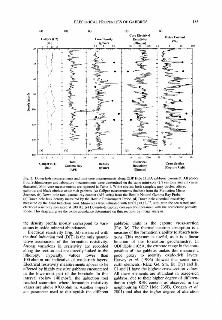
micro-electrical imaging device (FMS) together with calipers and gamma-ray measurement to enable depth corrections between tool strings. Full descriptions of the measurement principles of the logging tools used on the ODP program can be found in Goldberg (1997). Figure 3 pre- sents some of these geophysical measurements used in this discussion.
The borehole shape is shown by two orthog- onal calipers (Fig. 3a), and appears to be smooth (diameter close to 10 in.), indicating that the borehole conditions required for reliable down-hole measurements are excellent here. Natural gamma-ray measurements (Fig. 3b) exhibit low values along the whole section - coherent in oceanic crust. Slight variations in
gamma-ray measurements are indicative of changes in the degree of alteration. In the lower- most part of the borehole (from 103 mbsf to the bottom), gamma-ray values are slightly higher, and can be attributed to the highest degree of alteration in the gabbros (Fig. 3b). At 103 m, a strong increase in natural gamma-rays is recorded. This increase is correlated with other geophysical parameters such as low density, variation in the borehole shape (caliper), or low recovery in this interval, and may be indicative of the presence of a faulted zone or a fractured interval. Such fractured zones have been pre- viously described in the neighbouring Hole 735 with the borehole televiewer (Goldberg et al. 1991; Dick et al. 2000). Overall, variations in
ELECTRICAL PROPERTIES OF GABBROS 183
8O
100
140
160
(a)
Caliper (C2) (in.)
7 9 11 13
(b) (c) (d) Core Electrical
Core Density Resistivity (g / cm 3) ( O h m . m )
2.9 3.1 3.3 10 100 1000
( - ~ S (a) (b) (d) ~"
13 11 9 7 0 5 10 2.9 3.1 3.3 10 100 1000
Total Electrical Caliper (C1) Density Gamma Ray Resistivity
(in.) ( g / c m 3) (API) (Ohm.m)
(e)
Oxide Content (%)
1 10
@ (e)
10 20 30 40
Cross Section (Capture Uni t )
100
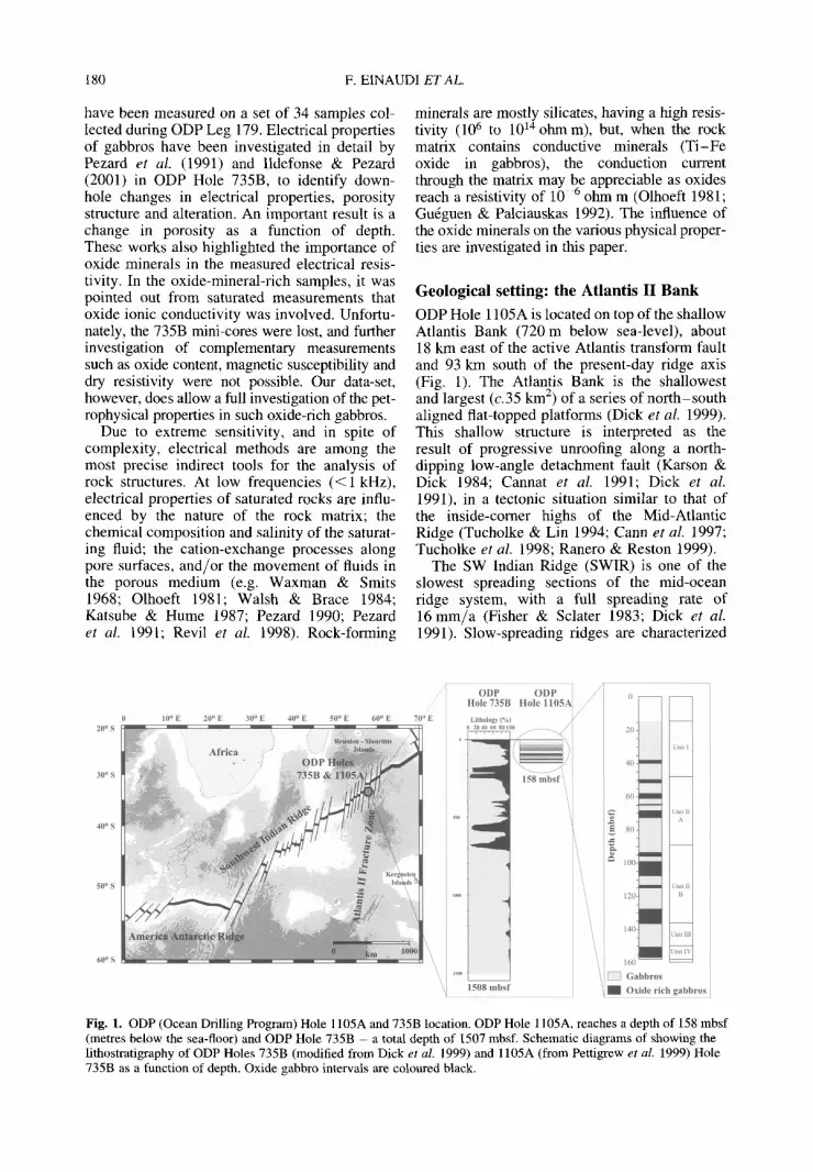
Fig. 3. Down-hole measurements and mini-core measurements along ODP Hole 1105A gabbroic basement. All probes from Schlumberger and laboratory measurements were determined on the same mini-core (1.7 cm long and 2.5 cm in diameter). Mini-core measurements are reported in Table 1. White circles: fresh samples; grey circles: altered gabbros; and black circles: oxide-rich gabbros. (a) Caliper measurements (inches) from the Formation Micro Scanner. (b) Down-hole total gamma-ray content (API units) from the Hostile Natural Gamma Ray Probe. (e) Down-hole bulk density measured by the Hostile Environment Probe. (d) Down-hole electrical resistivity measured by the Dual Induction Toot. Mini-cores were saturated with NaC1 (30 g L- 1, similar to the sea-water) and electrical resistivity measured at 100 Hz. (e) Down-hole capture cross-section measured with the accelerator porosity sonde. This diagram gives the oxide abundance determined on thin sections by image analysis.
the density profile mostly correspond to vari- ations in oxide mineral abundances.
Electrical resistivity (Fig. 3d) measured with the dual induction tool (DIT) is the only quanti- tative assessment of the formation resistivity. Strong variations in resistivity are recorded along the section and are directly linked to the lithology. Typically, values lower than 100 ohm m are indicative of oxide-rich layers. Electrical resistivity measurements appear to be affected by highly resistive gabbros encountered in the lowermost part of the borehole. In this interval (below 140 mbsf), the induction tool reached saturation where formation resistivity values are above 9700 ohm m. Another import- ant parameter used to distinguish the different
gabbroic units is the capture cross-section (Fig. 3e). The thermal neutron absorption is a measure of the formation's ability to absorb neu- trons. This measure is useful, as it is a linear function of the formation geochemistry. In ODP Hole 1105A, the extreme range in the com- position of the gabbros makes this measure a good proxy to identify oxide-rich layers. Harvey et aL (1996) showed that some rare earth elements (REE: Gd, Sm, Eu, Dy) and B, C1 and H have the highest cross-section values. All these elements are abundant in oxide-rich gabbros, due to their higher degree of differen- tiation (high REE content as observed in the neighbouring ODP Hole 735B, Coogan et al. 2001) and also the higher degree of alteration
184 F. EINAUDI ET AL.
(corresponding to the highest H content due to hydrous minerals). High values of the capture cross-section are well correlated with oxide mineral abundance measured in thin sections.
All down-hole measurements highlight the fact that oxide-rich layers are not negligible along the whole section. Good agreement is observed between the down-hole measurements and laboratory measurements presented in the following section.
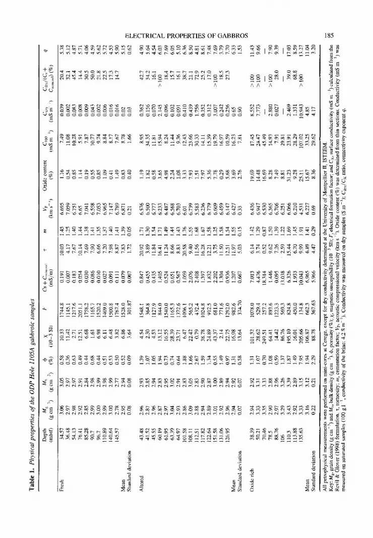
Physical properties of minicores Measurements of physical properties have been performed on 25-mm-diameter mini-cores sampled along the drilled section. For each sample, porosity, grain density, compressional velocity, magnetic susceptibility and electrical resistivity at different salinities were measured at laboratory temperature and atmospheric press- ure. The results are presented in Table 1. A par- ticular emphasis has been placed on electrical measurements, in order to investigate changes in pore-space morphology and alteration, as well as the influence of oxide minerals on electri- cal properties.
Porosity and grain density
The porosity and density were determined by the standard immersion method corresponding to a triple weighing (with dry, saturated and immersed samples). This method allows direct computation of porosity and grain density, inde- pendently of sample size and shape, with:
( W ~ , - Wdry) = 100 x ' (1)
(Wsat -- Wi)
where Wdry is the dry weight, Wsat is the saturated weight; Wi is the immersed weight, and • the porosity.
The grain density (pg) is calculated as the following:
Wdry pg -- (Wsat_ Wi) x Pw (2)
where Pw is the saturating fluid density. Porosity, bulk density, and grain density are
summarized in Table 1. For rocks with porosities lower than 1%, as in most of the samples in this study, the absolute computed error is lower than 2% for densities (i.e. about 0.06 g cm-3), and about 15% for porosities (i.e. _<0.1%). Values of porosity are generally low in most samples (Table 1). The highest porosities (Fig. 4c) corre- spond to the altered and oxide-rich samples
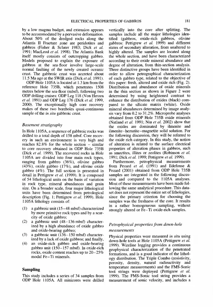
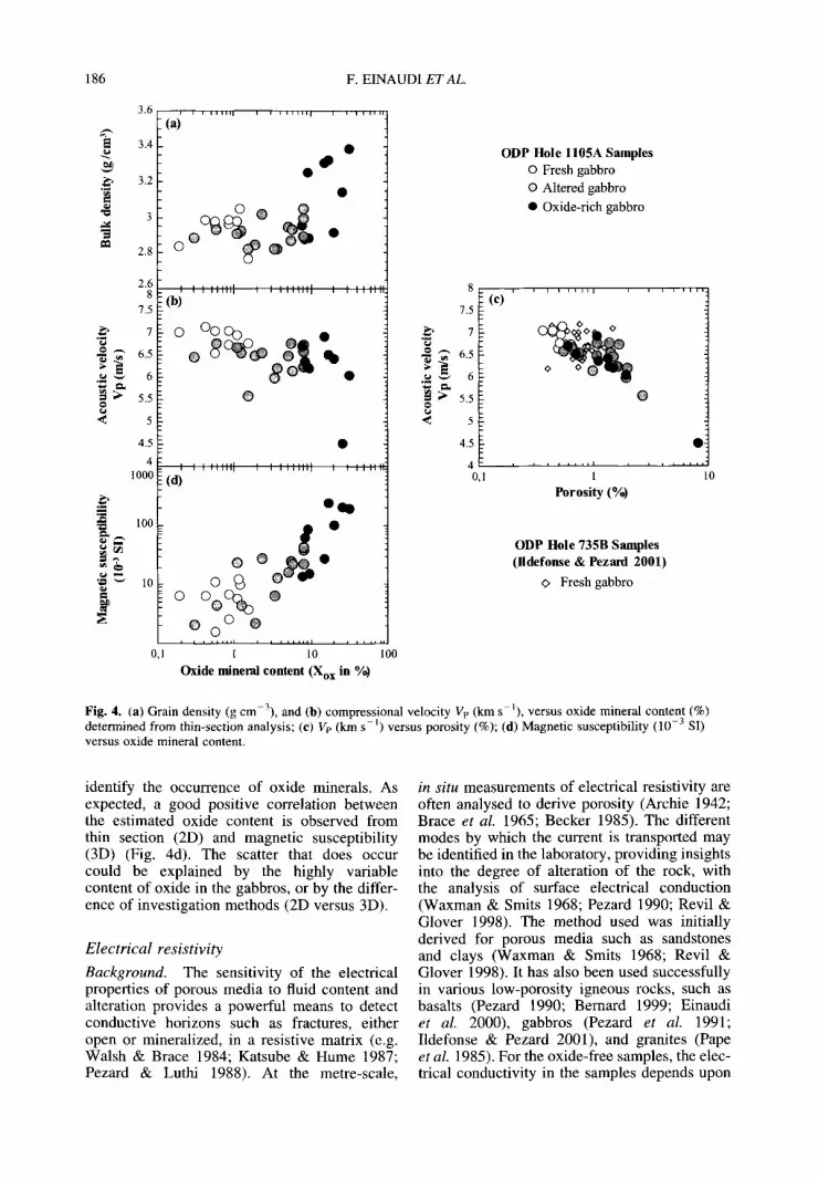
(respectively 1.31% and 1.94% on average). Bulk density (Fig. 4a) is more variable, with an average of 2.95 g cm -3 in fresh and altered samples, although it increases to 3.43 g cm-3 in oxide-rich samples.
Acoustic compressional velocity
Compressional velocity (P-wave velocities: Vp) measurements were performed for each samples at 2.25MHz, using a Panametrics Epoch III-2300 device. The Teflon jacket used for the electrical measurements was kept in place, in order to reduce the influence of desa- turation during the measurements. Ve was measured on saturated samples with a 30 g 1-1 NaC1 brine. The precision of these measurements was determined as better than 1%, i.e. of the order of 50 ms- ~, determined by repeat measure- ments and standard measurements. The measured velocities (Vp) values range from 6.0 to 7.1 km s -1 (Fig. 4b) and are comparable to the values for gabbroic rocks measured on Hole 735B (Leg 118:6.713 + 0 .383kms -1 (Von Herzen et al. 1991); Leg 176: 6.777 _ 0.292 km s -1, Dick et al. 1999), and are then representative of seismic Layer 3. The highest values were measured in fresh samples (with a mean Vp of 6.871 km s-l) , and a slight decrease is observed in the altered samples (with a mean Vp of 6.427 km s-l) . Oxide-rich samples have markedly lower Vp values with a large game of value (from 4.530 to 4.5 km s-1). These lowest velocity values can be attributed to the abun- dance of Fe-Ti oxide minerals, and the higher variability is likely to be caused by the variable degree of alteration and porosity (Fig. 4c) and variation in modal oxide abundance in these samples.
Magnetic susceptibility
A Kappabridge was used under the scalar mode for measuring the bulk magnetic susceptibility (Table 1). This measurement proved to be par- ticularly useful on board to detect the presence of thin metallic oxide seams, as the magnetic sus- ceptibility was measured on continuous cores recovered (Pettigrew et al. 1999; Natland & Dick 2001). The magnetic susceptibility is an intrinsic material property related to the induced magnetization intensity that may be measured on a sample. The magnetic suscepti- bility is a function of the nature, concentration and grain size of magnetic minerals within the sample. As a consequence, magnetic suscepti- bility data may be used as a proxy to clearly
Ta
ble
1,
P
hys
ica
l p
rop
erti
es o
f th
e O
DP
Hol
e l1
05
A
gabb
roic
sam
ples
Dep
th
Mg
Mb
dO
X
F
Cs
+ C
mi ..
... i
r m
V
e O
xide
-con
tent
Cl
°° 1
) C
dry
Cdr
y/(C
s +
q (m
bsf)
(g
cm
3)
(g
cm
-3)
(%)
(10
-3 S
I)
(mS
/m)
(km
s-L
) (%
) (m
S m
- (m
S m
-l)
Cm
i ....
1) (
%)
Fre
sh
34.5
7 3.
06
3.05
0.
58
10.3
3 17
44.8
0.
191
10.0
3 1.
45
6.69
5 1.
16
7.49
0.
039
20.4
5.
38
36.4
8 2.
97
2.97
0.
36
11.4
2 11
45.1
0.
007
4.17
1.
25
7.05
9 0.
54
11.0
8 0.
002
32.1
5.
12
54.1
3 2.
98
2.97
0.
63
2.71
12
17.6
0.
183
7.67
1.
40
6.75
1 0.
85
10.2
8 0.
083
45.4
4.
87
76.4
1 2.
92
2.91
0.
49
12.5
1 20
51.1
0.
054
10.1
4 1.
44
6.65
1.
14
5.91
0.
008
14.4
5.
71
85.2
8 2.
85
2.84
0.
44
6.68
17
58.2
0.
030
7.69
1.
38
7.04
1 0.
19
7.87
0.
009
30.5
4.
06
90.7
2.
99
2.98
0.
68
1.6
1
1165
.7
0.08
6 7.
90
1.41
6.
558
0.55
10
.77
0.04
3 50
.0
4.59
96
.7
3.00
2.
99
0.44
6.
98
1520
.2
0.01
0 6.
66
1.35
7.
053
0.85
9.
74
0.00
2 21
.8
5.62
11
0.89
2.
99
2.98
0.
51
6.11
14
09.0
0.
027
7.20
1.
37
6.96
5 1.
09
8.84
0.
006
22.5
5.
72
140.
64
3.00
2.
99
0.53
6.
48
1500
.8
0.09
1 7.
98
1.40
7.
147
0.41
8.
17
0.01
6 17
.3
4.53
14
5.57
2.
78
2.77
0.
50
3.82
17
67.4
0.
111
8.87
1.
41
6.78
9 1.
49
7.67
0.
016
14.7
5.
90
2.95
2.
94
0.52
6.
86
1528
.0
0.07
9 7.
83
1.39
6.
871
0.83
8.
78
0.02
5.
15
0.08
0.
08
0.09
3.
64
301.
87
0.06
7 1.
72
0.05
0.
21
0.40
1.
66
0.03
0.
62
u~
¢3
8.95
0.
362
42.7
4.
90
34.3
5 0.
156
34.2
5.
64
7:~
11.8
1 0.
070
16.1
4.
54
Mea
n S
tand
ard
devi
atio
n
Alt
ered
Mea
n S
tand
ard
devi
atio
n
43.4
8 2.
96
2.93
1.
39
4.54
1
54
8.1
0.
847
20.9
2 1.
71
6.57
6 1.
19
41.5
2 2.
87
2.85
1.
07
2.30
36
4.8
0.45
5 3.
89
1.30
6.
500
1.82
45
.55
2.96
2.
94
1.05
4.
53
1127
.9
0.43
5 11
.84
1.54
6.
777
0.58
60
.19
2.87
2.
83
1.94
13
.12
844.
0 1.
405
16.4
1 1.
71
6.23
3 3.
65
15.9
4 2.
145
>1
00
6.
03
t"
61.9
5 2.
97
2.95
0.
73
16.5
5 15
40.0
0.
524
11.2
4 1.
49
6.48
7 4.
98
8.24
0.
096
18.4
7.
69
63.3
9 3.
04
3.02
0.
74
28.3
9 11
65.3
0.
651
8.66
1.
44
6.56
8 2.
24
11,4
4 0.
102
15.7
6.
05
64.9
7 2.
93
2.91
0.
64
23.7
1 13
72.6
0.
567
8.83
1.
43
6.70
3 1.
08
9.36
0.
091
16.1
5.
10
O
101.
58
2.86
2.
83
1.88
6.
47
1096
.1
1.05
9 20
.58
1.76
6.
01
3.33
12
.43
0.41
0 38
.7
6.36
10
8.11
3.
09
3.05
1.
66
22.4
2 56
5.2
2.07
6 9.
40
1.55
6.
739
7.93
23
.66
0.43
9 21
.1
8.50
11
2.51
2.
88
2.83
2.
67
0.79
43
2.4
2.40
8 11
.56
1.68
5.
583
1.51
30
.33
1.75
6 72
.9
4.81
*-
* 11
7.82
2.
94
2.90
1.
59
38.7
8 10
24.8
1.
397
16.2
8 1.
67
6.23
6 7.
97
14.1
1 0.
352
25.2
8.
61
~,~
122.
64
2.89
2.
87
1.34
24
.89
912.
5 1.
832
12.2
1 1.
58
6.77
9 5.
36
15.3
9 0.
312
17.0
7.
48
O
151.
58
3.01
3.
00
0.55
43
.37
681.
0 2.
202
3.75
1.
25
6.60
9 7.
78
19.7
9 3.
007
>1
00
7.
69
*~
131.
06
2.92
2.
89
1.49
2.
14
771.
6 1.
304
11.5
0 1.
58
6.45
9 0.
29
16.9
7 0.
242
18.5
3.
79
126.
95
2.96
2.
94
0.97
22
.75
1292
.0
0.93
6 12
.51
1.54
6.
147
5.68
10
.59
0.25
6 27
.3
7.70
~
2.94
2.
92
1.31
16
.98
982.
6 1.
207
11.9
7 1.
55
6.42
7 3.
69
16.2
3 0.
65
6.33
0.
07
0.07
0.
58
13.6
4 37
4.70
0.
667
5.03
0.
15
0.33
2.
76
7.81
0.
90
1.53
Oxi
de r
ich
38.3
9 2.
94
2.92
1
.31
10
1.32
10
78.0
7.
013
6.14
1.
42
6.43
6 19
.69
17.4
5 8.
552
>1
00
11
.43
50.2
1 3.
33
3.31
1.
07
28.6
2 52
9.4
4.47
6 3.
74
1.29
6.
947
14.4
8 24
.47
7.77
3 >
100
9.
66
70.4
6 3.
35
3.33
0.
70
249.
51
257.
2 18
.314
0.
52
0.87
6.
530
16.6
9 45
.49
--
--
--
78.5
2.
90
2,88
1.
08
64.4
1 89
3.6
1.44
6 9.
62
1.50
6.
365
8.28
14
.93
2.88
0 >
100
7.
90
88.7
6 2.
97
2.96
0.
59
14.4
2 12
23.3
0.
095
7.26
1.
39
6.70
6 7.
49
7.91
0.
027
28.0
9.
39
106
3.29
3.
26
1.37
86
.76
569.
3 13
.038
2.
59
1.22
6.
251
8.81
29
.81
--
--
--
110.
3 3.
43
3.39
1.
87
195.
10
824.
8 6.
326
15.4
4 1.
69
6.06
6 31
.23
23.9
1 2.
469
39.0
17
.03
113.
88
2.92
2.
89
1.49
16
.01
450.
0 1.
933
6.70
1.
45
6.21
0 9.
28
28.2
9 1.
331
68.8
8.
59
135.
63
3.33
3.
15
7.95
20
5.66
13
4.8
10.0
43
9.99
1.
91
4.53
1 25
.11
107.
02
10.9
43
>1
00
13
.27
Mea
n 3.
16
3.12
1.
94
106.
87
662,
3 6.
965
6.89
1.
41
6.22
7 15
.67
33.2
5 4.
85
11.0
4 S
tand
ard
devi
atio
n 0.
22
0.21
2.
29
88.7
8 36
7.63
5.
966
4.47
0.
29
0.69
8.
36
29.6
2 4.
17
3.20
All
pet
roph
ysic
al m
easu
rem
ents
wer
e pe
rfor
med
on
min
i-co
res
at C
ereg
e, e
xcep
t fo
r dr
y co
nduc
tivi
ty d
eter
min
ed a
t th
e U
nive
rsit
y of
Mon
tpel
lier
II,
IST
EE
M.
Key
: Mg,
gra
in d
ensi
ty (g
cm
-3)
and
Mb,
bu
lk d
ensi
ty (g
cm
-3).
4),
poro
sity
(%
); X
, mag
neti
c su
scep
tibi
lity
(10
3 S
I); F
, el
ectr
ical
form
atio
n fa
ctor
; an
d C
x, s
urfa
ce c
ondu
ctiv
ity
(mS
m -
j) c
alcu
late
d fr
om th
e ~c
~ R
evil
& G
love
r (1
998)
for
mul
atio
n. "
r, to
rtuo
sity
; m
, ce
men
tati
on f
acto
r; V
e, a
cous
tic
com
pres
sion
a] v
eloc
ity
(km
s-l
). O
xide
con
tent
(%
) w
as d
eter
min
ed f
rom
thi
n se
ctio
ns.
Con
duct
ivit
y (m
S m
1)
was
m
easu
red
on s
atur
ated
sam
ples
(10
0 g
1 1,
con
duct
ivit
y of
the
bri
ne:
4.2
S m
-l).
Con
duct
ivit
y w
as m
easu
red
on d
ry s
ampl
es (
S m
-1);
Cdr
y/C
x ra
tio,
con
nect
ivit
y ex
pone
nt q
.
186 F. E I N A U D I ET AL.
3.6
~ 3.4
.~ 3.2
"~ 3
2.8
2.6 8
7.5
.~ 7
~ " 6.5
< 5
4.5
4 1000
m ° , , . d~ 100
0,1
i i i i i i 1 [ i i i i , i i i i I i , , i i i i i
Fig. 4. (a) Grain density (g cm-3), and (b) compressional velocity Vr, (km s i), versus oxide mineral content (%) determined from thin-section analysis; (e) Ve (km s - i ) versus porosity (%); (d) Magnetic susceptibility (10 -3 SI) versus oxide mineral content.
identify the occurrence of oxide minerals. As expected, a good positive correlation between the estimated oxide content is observed from thin section (2D) and magnetic susceptibility (3D) (Fig. 4d). The scatter that does occur could be explained by the highly variable content of oxide in the gabbros, or by the differ- ence of investigation methods (2D versus 3D).
Electr ical resistivity
Background. The sensitivity of the electrical properties of porous media to fluid content and alteration provides a powerful means to detect conductive horizons such as fractures, either open or mineralized, in a resistive matrix (e.g. Walsh & Brace 1984; Katsube & Hume 1987; Pezard & Luthi 1988). At the metre-scale,
in situ measurements of electrical resistivity are often analysed to derive porosity (Archie 1942; Brace et al. 1965; Becker 1985). The different modes by which the current is transported may be identified in the laboratory, providing insights into the degree of alteration of the rock, with the analysis of surface electrical conduction (Waxman & Smits 1968; Pezard 1990; Revil & Glover 1998). The method used was initially derived for porous media such as sandstones and clays (Waxman & Smits 1968; Revil & Glover 1998). It has also been used successfully in various low-porosity igneous rocks, such as basalts (Pezard 1990; Bernard 1999; Einaudi et al. 2000), gabbros (Pezard et al. 1991; Ildefonse & Pezard 2001), and granites (Pape et al. 1985). For the oxide-free samples, the elec- trical conductivity in the samples depends upon
ELECTRICAL PROPERTIES OF GABBROS 187
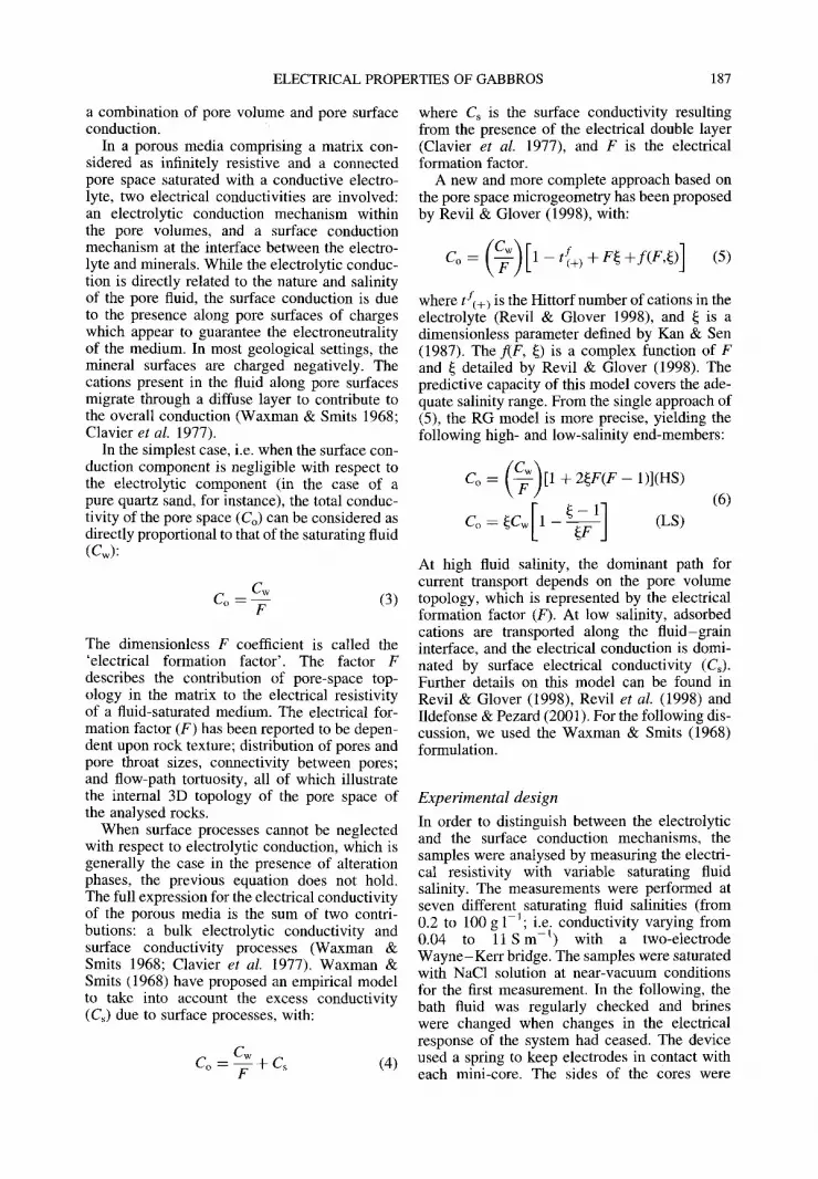
a combination of pore volume and pore surface conduction.
In a porous media comprising a matrix con- sidered as infinitely resistive and a connected pore space saturated with a conductive electro- lyte, two electrical conductivities are involved: an electrolytic conduction mechanism within the pore volumes, and a surface conduction mechanism at the interface between the electro- lyte and minerals. While the electrolytic conduc- tion is directly related to the nature and salinity of the pore fluid, the surface conduction is due to the presence along pore surfaces of charges which appear to guarantee the electroneutrality of the medium. In most geological settings, the mineral surfaces are charged negatively. The cations present in the fluid along pore surfaces migrate through a diffuse layer to contribute to the overall conduction (Waxman & Smits 1968; Clavier et al. 1977).
In the simplest case, i.e. when the surface con- duction component is negligible with respect to the electrolytic component (in the case of a pure quartz sand, for instance), the total conduc- tivity of the pore space (Co) can be considered as directly proportional to that of the saturating fluid (Cw):
Cw Co =-V- (3)
The dimensionless F coefficient is called the 'electrical formation factor'. The factor F describes the contribution of pore-space top- ology in the matrix to the electrical resistivity of a fluid-saturated medium. The electrical for- mation factor (F) has been reported to be depen- dent upon rock texture; distribution of pores and pore throat sizes, connectivity between pores; and flow-path tortuosity, all of which illustrate the internal 3D topology of the pore space of the analysed rocks.
When surface processes cannot be neglected with respect to electrolytic conduction, which is generally the case in the presence of alteration phases, the previous equation does not hold. The full expression for the electrical conductivity of the porous media is the sum of two contri- butions: a bulk electrolytic conductivity and surface conductivity processes (Waxman & Smits 1968; Clavier et al. 1977). Waxman & Smits (1968) have proposed an empirical model to take into account the excess conductivity (C~) due to surface processes, with:
Cw Co = ~ - + C ~ (4)
where Cs is the surface conductivity resulting from the presence of the electrical double layer (Clavier et al. 1977), and F is the electrical formation factor.
A new and more complete approach based on the pore space microgeometry has been proposed by Revil & Glover (1998), with:
where t f+) is the Hittorf number of cations in the electrolyte (Revil & Glover 1998), and ~ is a dimensionless parameter defined by Kan & Sen (1987). The flF, ~) is a complex function of F and ~ detailed by Revil & Glover (1998). The predictive capacity of this model covers the ade- quate salinity range. From the single approach of (5), the RG model is more precise, yielding the following high- and low-salinity end-members:
Co = ( - ~ ) [ I + 2~F(F-1)](HS) (6)
Co= ~ C w [ 1 - ~ - ~ ] (LS)
At high fluid salinity, the dominant path for current transport depends on the pore volume topology, which is represented by the electrical formation factor (F). At low salinity, adsorbed cations are transported along the fluid-grain interface, and the electrical conduction is domi- nated by surface electrical conductivity (Cs). Further details on this model can be found in Revil & Glover (1998), Revil et al. (1998) and Ildefonse & Pezard (2001). For the following dis- cussion, we used the Waxman & Smits (1968) formulation.
Experimental design
In order to distinguish between the electrolytic and the surface conduction mechanisms, the samples were analysed by measuring the electri- cal resistivity with variable saturating fluid salinity. The measurements were performed at seven different saturating fluid salinities (from 0.2 to 100 g 1-1; i.e. conductivity varying from 0.04 to 11 S m - l ) with a two-electrode Wayne-Kerr bridge. The samples were saturated with NaC1 solution at near-vacuum conditions for the first measurement. In the following, the bath fluid was regularly checked and brines were changed when changes in the electrical response of the system had ceased. The device used a spring to keep electrodes in contact with each mini-core. The sides of the cores were
188 F. EINAUDI ET AL.
wrapped in insulating Teflon tape to restrict the current from passing down the sides of the mini-core. A 10mV signal was applied to -3 perform each of the measurements at seven
-4 frequencies. Only measurements realized at 100 Hz are presented in this study. This fre- ~ -5 quency value was chosen to be similar to that used for down-hole measurements. -6
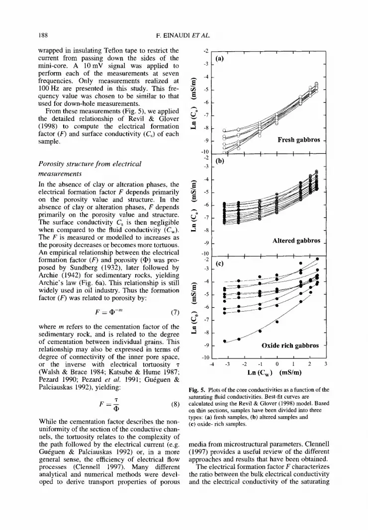
From these measurements (Fig. 5), we applied -7 the detailed relationship of Revil & Glover (1998) to compute the electrical formation ,~ -8 factor (F) and surface conductivity (Cs) of each sample. -9
-10 -2 -3 Porosity structure f rom electrical
measurements -4
In the absence of clay or alteration phases, the electrical formation factor F depends primarily ~ -5 on the porosity value and structure. In the
-6 absence of clay or alteration phases, F depends ,-, primarily on the porosity value and structure. ~ -7 The surface conductivity Cs is then negligible when compared to the fluid conductivity (Cw). ~ -8 The F is measured or modelled to increases as the porosity decreases or becomes more tortuous. -9 An empirical relationship between the electrical -10 formation factor (F) and porosity (~) was pro- -2 posed by Sundberg (1932), later followed by -3 Archie (1942) for sedimentary rocks, yielding Archie's law (Fig. 6a). This relationship is still widely used in oil industry. Thus the formation factor (F) was related to porosity by:
F : ¢ -m (7)
where m refers to the cementation factor of the sedimentary rock, and is related to the degree of cementation between individual grains. This relationship may also be expressed in terms of degree of connectivity of the inner pore space, or the inverse with electrical tortuosity -r (Walsh & Brace 1984; Katsube & Hume 1987; Pezard 1990; Pezard et al. 1991; Gurguen & Palciauskas 1992), yielding:
T F : -- (8)
-2
While the cementation factor describes the non- uniformity of the section of the conductive chan- nels, the tortuosity relates to the complexity of the path followed by the electrical current (e.g. Gurguen & Palciauskas 1992) or, in a more general sense, the efficiency of electrical flow processes (Clennell 1997). Many different analytical and numerical methods were devel- oped to derive transport properties of porous
,_, -4
-5
-6
-7
-8
-9
-10 -4
I (a)
(b)
Altered gabbros
Oxide rich gabbros
I I I I I I
-3 -2 - 1 0 I 2
Ln (Cw) (mS/m)
Fig. 5. Plots of the core conductivities as a function of the saturating fluid conductivities. Best-fit curves are calculated using the Revil & Glover (1998) model. Based on thin sections, samples have been divided into three types: (a) fresh samples, (b) altered samples and (c) oxide- rich samples.
media from microstructural parameters. Clennell (1997) provides a useful review of the different approaches and results that have been obtained.
The electrical formation factor F characterizes the ratio between the bulk electrical conductivity and the electrical conductivity of the saturating
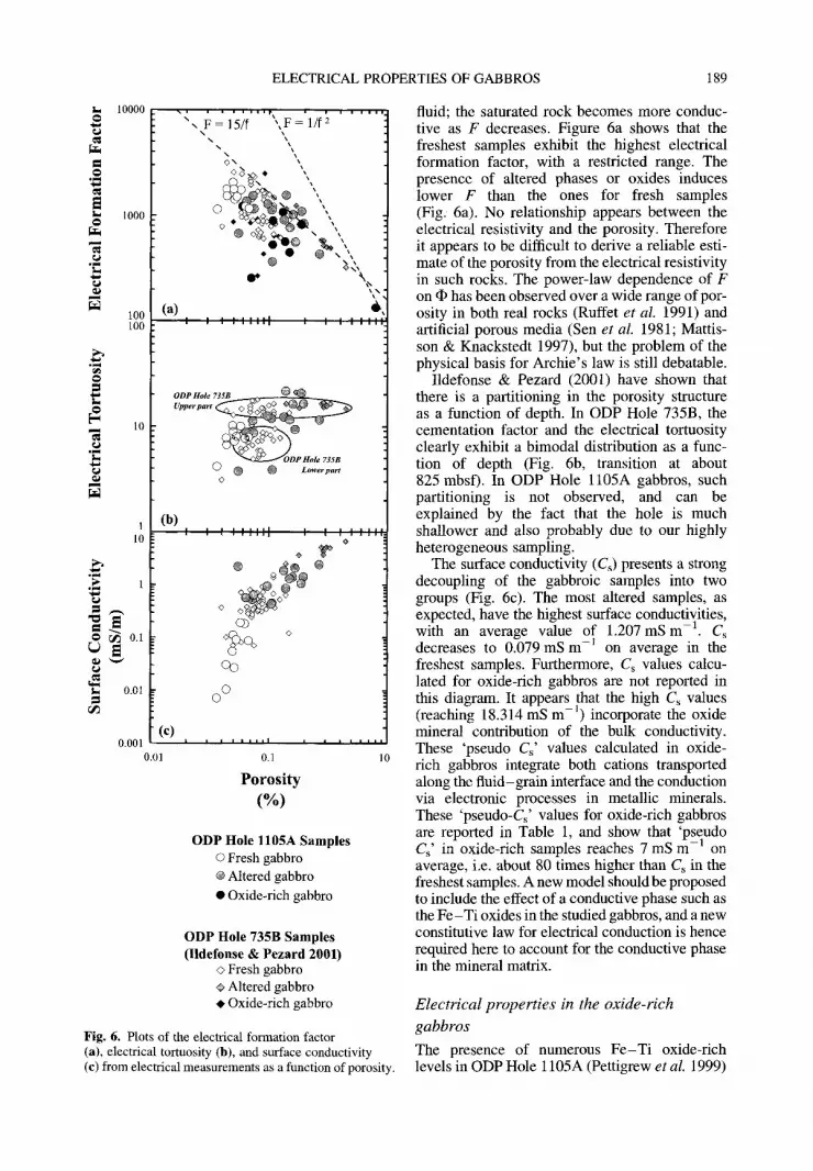
Fig. 6. Plots o f the electrical format ion factor (a), electrical tortuosity (b), and surface conduct ivi ty (c) f rom electrical measurements as a funct ion o f porosity.
fluid; the saturated rock becomes more conduc- tive as F decreases. Figure 6a shows that the freshest samples exhibit the highest electrical formation factor, with a restricted range. The presence of altered phases or oxides induces lower F than the ones for fresh samples (Fig. 6a). No relationship appears between the electrical resistivity and the porosity. Therefore it appears to be difficult to derive a reliable esti- mate of the porosity from the electrical resistivity in such rocks. The power-law dependence of F on • has been observed over a wide range of por- osity in both real rocks (Ruffet et al. 1991) and artificial porous media (Sen et al. 1981; Mattis- son & Knackstedt 1997), but the problem of the physical basis for Archie's law is still debatable.
Ildefonse & Pezard (2001) have shown that there is a partitioning in the porosity structure as a function of depth. In ODP Hole 735B, the cementation factor and the electrical tortuosity clearly exhibit a bimodal distribution as a func- tion of depth (Fig. 6b, transition at about 825 mbsf). In ODP Hole 1105A gabbros, such partitioning is not observed, and can be explained by the fact that the hole is much shallower and also probably due to our highly heterogeneous sampling.
The surface conductivity (Cs) presents a strong decoupling of the gabbroic samples into two groups (Fig. 6c). The most altered samples, as expected, have the highest surface conductivities, with an average value of 1.207 mS m -1. Cs decreases to 0.079 mS m -1 on average in the freshest samples. Furthermore, Cs values calcu- lated for oxide-rich gabbros are not reported in this diagram. It appears that the high Cs values (reaching 18.314 mS m -1) incorporate the oxide mineral contribution of the bulk conductivity. These 'pseudo C~' values calculated in oxide- rich gabbros integrate both cations transported along the fluid-grain interface and the conduction via electronic processes in metallic minerals. These 'pseudo-Cs' values for oxide-rich gabbros are reported in Table 1, and show that 'pseudo Cs' in oxide-rich samples reaches 7 mS m -1 on average, i.e. about 80 times higher than Cs in the freshest samples. A new model should be proposed to include the effect of a conductive phase such as the Fe-Ti oxides in the studied gabbros, and a new constitutive law for electrical conduction is hence required here to account for the conductive phase in the mineral matrix.
Electrical properties in the oxide-rich
gabbros
The presence of numerous Fe-Ti oxide-rich levels in ODP Hole 1105A (Pettigrew et al. 1999)
190 F. EINAUDI ET AL.
leads to a more complex conduction mechanism for the transport of electrical charges in the rock. Matrix conduction mechanisms via electronic processes in metallic oxide grains may then become significant (Drury & Hyndman 1979; Pezard 1990; Pezard et al. 1991). As pointed out above, the conduction via electronic processes in metallic minerals is not taken into account in these formulations of the electrical properties. No model includes the effect of a conductive phase such as the oxides present in the studied gabbros, and a new constitutive law for electrical conduction is hence required to account for the conductive phase in the mineral matrix. Pezard et al. (1991), from ODP Hole 735B gabbros, proposed:
Cw Co = ~ - -t- [Cs n t- Cmineral] (9)
The Cmi . . . . 1 term is a constant related to the oxide content for a given sample, which does not depend on the salinity of the saturating fluid. Thus, the different contributions to the electrical conduction are identified, and estimated. The oxide contribution to the measured electrical res- istivity is achieved through dry resistivity measurements.
D r y m e a s u r e m e n t s
The measurements of dry sample conductivity were made in a two-electrode cell with an exper- imental device which allows multi-frequency measurements. The signal measured on a dry sample is a complex impedance (Z) characterized by two components: an in-phase R (or resistive) signal, and an out-of-phase X (or reactive) signal. The complex impedance can be expressed as follows:
show a large distribution, with five-order maag- nitudes from 2.3 x 10 -6 to 1.9 x 10 -1 S m -~. For comparison, saturated measurements at 100 g 1-1 vary over only one order of magnitude (from5.9 x 10-3to 1.1 x 10 -~ S m- l , Table 1), since electrical conductivity is here dominated by electrolytic processes. In a general sense, the difference between these two measurements represents the conductivity of surface and min- erals. In the range 0 -2% of oxide mineral abun- dance (fresh gabbros), their contribution to measured conductivity is about 26%; between 2 and 15% (altered gabbros), the contribution is about 37%; and for oxide contents above 15% (oxide-rich gabbros), the oxide mineral contri- bution reaches 82%. In some cases, particularly for oxide-rich samples, the ratio between the dry conductivity and the saturated conductivity is higher than one (Table 1). Several expla- nations may be involved, such as the accuracy of the electrical measurements; or the accuracy of oxide content determination (2D versus 3D); or the quality of desaturation of each sample.
In the case of multi-phase conducting porous systems, a mixing model such as:
N
Co = ~ G(Xi) i=1
(12)
can be used (Gurguen & Palciauskas 1992; Glover et al. 2000). This applies to the case of a mineral, solid-phase conducting current is par- allel to the more usual fluid-related phases described by Waxman & Smits (1968) or Revil & Glover (1998). Gurguen & Palciauskas (1992) and Glover et al. (2000) have proposed a modified relationship for a two conducting phases medium:
Z = R + iX (10)
where i is the complex operator (i 2 = - 1). The complex electrical resistivity is calculated from the Z measurements by:
p = Z * ( A / L ) = p' + ip" (11)
where A is the cross-sectional area of the mini- core and L is its length. The P' and p" are respect- ively the real and imaginary parts of the complex resistivity. The electrical resistivity is the value corresponding to the measured real part of z at the frequency where p" equals zero.
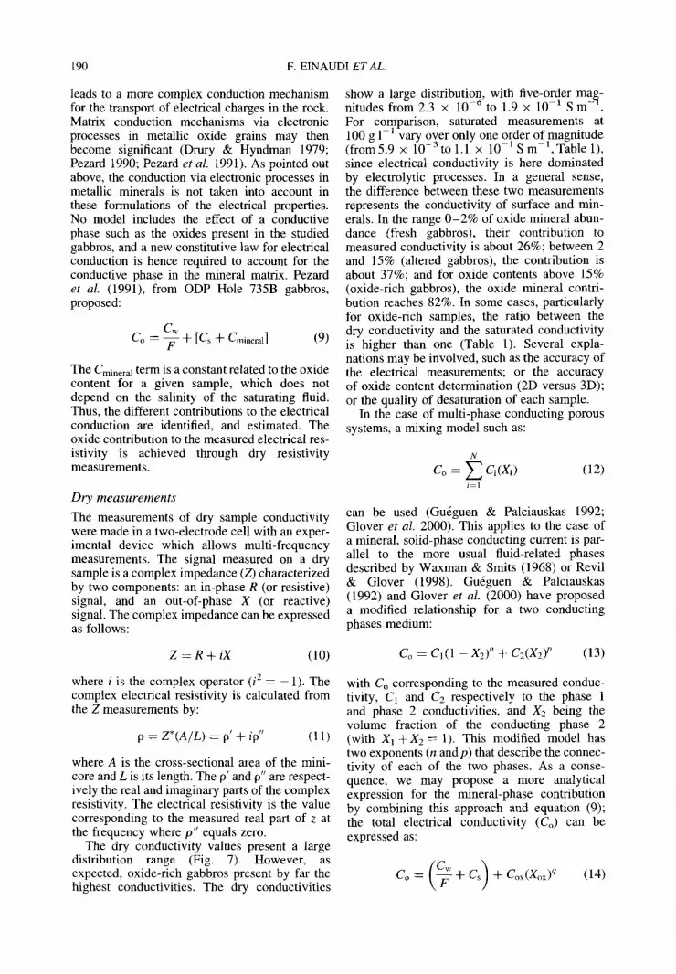
The dry conductivity values present a large distribution range (Fig. 7). However, as expected, oxide-rich gabbros present by far the highest conductivities. The dry conductivities
Co = c1(1 - x2 )" + c2(x2) p (13)
with Co corresponding to the measured conduc- tivity, C1 and C 2 respectively to the phase 1 and phase 2 conductivities, and X2 being the volume fraction of the conducting phase 2 (with XI + X 2 = 1). This modified model has two exponents (n and p) that describe the connec- tivity of each of the two phases. As a conse- quence, we may propose a more analytical expression for the mineral-phase contribution by combining this approach and equation (9); the total electrical conductivity (Co) can be expressed as:
Co = (~-~q- Cs) -~- fox(Xox) q (14)
ELECTRICAL PROPERTIES OF GABBROS 191
- . . . . . l
£
100
10
1
0.1
0.01
0.001 100
1 1000
100
i i i i i i i i I
(a)
1 0.1
i i i i 1 1 1 1 :
@ • • •
• @ • @@
0 0 o @
O 0 i i i [ i i i i I i i i i i l l l ] i i i i i i i i .
(b)
o ® o6 @ lp
I I ; i l ; ; i l I I I I I I r l l I I I I II (c)
Fig. 7. Plots of (a) dry electrical conductivity; (b) electrical connectivity exponent q, and (c) magnetic susceptibility . . . . . . . . . . 3 I versus oxide mineral content (Xo). (d) Electrical connectivity exponent versus magnetic susceptlblhty (10 " S ).
with Cox being the intrinsic electrical conduc- tivity of the oxide minerals, and Xox their volume fraction determined from thin section; q corresponds to the connectivity exponent of the oxide phase. In the case of dry conductivity measurements, the measured electrical conduc- tivity (C,~y) is only related to the conductivity of oxide minerals, and can be expressed as:
Cdry = Cox(Xox) q ( 1 5 )
with Cox equal to 106 S m - 1 (order of magnitude for magnetite after Olhoeft 1981; Gu~guen & Palciauskas 1992). From equation 14, we can calculate the solid-phase q exponent referred to as the 'solid connectivity exponent'. The q expo- nent is a function of the fractional volumes of each phase, because low phase connectivities
are associated with small volume fractions and high phase connectivities are associated with large volume fractions.
C o n c l u s i o n s
The physical properties of a set of 34 gabbroic samples from ODP Hole l105A (SWIR), have been measured in the laboratory, with a particu- lar emphasis on the analysis of electrical proper- ties. The electrical 'formation factor' F of each sample, as well as a pseudo-surface conductivity (Cs) have been extracted from the gabbros; there is evidence of three conducting phases (matrix, surface conductivity and fluid conductivity). Dry measurements clearly show that most of the excess conductivity evident in brine-saturated
192 F. EINAUDI ET AL
gabbros can be attributed to ionic conduct ion for the oxide-rich samples. Our investigations of electrical properties of ODP Hole l105A samples enhanced the oxide mineral contribution on electrical conductivity. The conduct ivi ty measured on dry samples is correlated to the oxide mineral content, and their contribution can reach up to 80% of the measured conduc- tivity on saturated samples.
This research used samples and data that were provided by the Ocean Drilling Program (ODP). ODP is sponsored by the US National Science Foundation (NSF) and participat- ing countries under management of Joint Oceanographic Institutions (JOI), Inc. We wish to thank D. Hermitte for his help in the laboratory. The authors thank the reviewers and editors for their helpful comments, which substan- tially improved this manuscript.
R e f e r e n c e s
ARCHIE, G. E. 1942. The electrical resistivity log as an aid in determining some reservoir characteristics. Journal of Petroleum Technology, 5, 1 - 8.
BECKER, K. 1985. Large-scale electrical resistivity and bulk density of the oceanic crust, DSDP Hole 504B, Costa Rica Rift. In: ANDERSON, R. N., HONNOREZ, J. and BECKER, K. et al. (eds) Initial Reports of the Deep Sea Drilling Project, 83, Washington (US Government Printing Office), 419-427.
BERNARD, M.-L. 1999. Etude expdrimentale des pro- pridtrs physiques des roches pyroclastiques de la montagne pelde. PhD thesis, Universit6 de Paris IV, 260 p.
BRACE, W. F., ORANGE, A. S. & MADDEN, T. R. 1965. The effect of pressure on the electrical resistivity of water-saturated crystalline rocks. Journal of Geo- physical Research, 70, 5669-5678.
CANN, J. R., BLACKMAN, D. K. et al. 1997. Corrugated slip surfaces formed at ridge-transform intersec- tions on the Mid-Atlantic Ridge. Nature, 385, 329-332.
CANNAT, M., Mrvel, C. & STAKES, D. 1991. Stretch- ing of the deep crust at the slow-spreading South- west Indian Ridge. Tectonophysics, 190, 73-94.
CLAVIER, C., COATES, G. & DUMANOIR, J. 1977. The theoretical and experimental bases for the dual- water model for the interpretation of shaly sands. Society of Petroleum Engineers, 52nd Annual Technical Conference. Paper 6859.
CLENNELL, M. B. 1997. Tortuosity: a guide through the maze. In: LOVELL, M. A. & HARVEY, P. K. (eds) Developments in Petrophysics. Geological Society, London, Special Publications, 122, 299-344.
COOGAN, L. A., MACLEOD, C. J. et al. 2001. Whole- rock geochemistry of gabbros from the Southwest Indian Ridge: constraints on geochemical fractio- nations between the upper and lower oceanic crust and magma chamber processes at (very)
slow-spreading ridges. Chemical Geology, 178, 1-22.
DICK, H. J. B., MEYER, P. S., BLOOMER, S., KIRBY, S., STAKES, D. & MAWER, C. 1991. Lithostratigraphic evolution of an in-situ section of oceanic layer 3. In: VON HERZEN, R. P., ROBINSON, P. T. et al. Pro- ceedings of the Ocean Drilling Program, Scientific Results, 118, 439-540, College Station, TX.
DICK, H. J.B., NATLAND, J. H. et al. 2000. A long in- situ section of the lower ocean crust: results of ODP Leg 176 drilling at the Southwest Indian Ridge. Earth and Planetary Science Letters, 179, 31-51.
DICK, H. J. B., NATLAND, J. H. et al. 1999. Proceed- ings of the Ocean Drilling Program, Initial Reports, 176 [Online]. Available from World Wide Web Address: http://www-odp.tamu.edu/ publications/176_IR/176TOC.HTM.
DRURY, M. J. & HYNDMAN, R. D. 1979. The electrical resistivity of oceanic basalts. Journal of Geophysi- cal Research, 84, 4537-4546.
EINAUDI, F., PEZARD, P., COCHEMt~, J.-J., COULON, C., LAVERNE C. & GODARD, M. 2000. Petrography, geochemistry and physical properties of a continu- ous extrusive section from the Hilti massif, Oman ophiolite. Marine Geophysical Researches, 21, 387-407.
FISHER, R. L. & SCLATER, J. G. 1983. Tectonic evol- ution of the Southwest Indian Ocean since the mid-Cretaceous: plate motions and stability of the pole of Antarctica~Africa for at least 80 Myr. Geophysical Journal of the Royal Astronomical Society, 73, 553-576.
GOLDBERG, D. 1997. The role of downhole measure- ments in marine geology and geophysics. Reviews of Geophysics, 35, 315-342.
GLOVER, P. W. J., HOLE, M. J. & POUS, J. 2000. A modified Archie's law for two conducting phases. Earth and Planetary Science Letters, 180, 369-383.
GOLDBERG, D., BROGLIA, C. & BECKER, K. 1991. Fracturing, alteration, and permeability: in-situ properties in Hole 735B, In: VON HERZEN, R. P., ROBINSON, P. T. et al. Proceedings of the Ocean Drilling Program, Scientific Results, 118, 261-269, College Station, TX.
GUI~GUEN, Y. & PALCIAUSKAS, V. 1992. Introduction b la physique des roches. Hermann, Paris, 392 pp.
HARVEY, P. K., LOVELL, M. A,, BREWER, T. S., LOCKE, J. & MANSLEY, E. 1996. Measurement of thermal neutron absorption cross section in selected geochemical reference materials. Geos- tandards Newsletter, 20, 79-85.
ILDEFONSE, B. & PEZARD, P. 2001. Electrical proper- ties of slow-spreading ridge gabbros from ODP Site 735, Southwest Indian Ridge. Tectonophysics, 330, 69-92.
KAN, R. & SEN, P. N. 1987. Electrolytic conduction in periodic arrays of insulators with charges. Journal of Chemical Physics, 86, 5748-5756.
KARSON, J. A. & DICK, H. J. B. 1984. Deformed and metamorphosed oceanic crust on the Mid-Atlantic Ridge, Ofioliti, 9, 279-302.
KARSON, J. A., CANNAT, M., MILLER, D.J. & ELTHON, D. E. 1997. Proceedings of the Ocean
ELECTRICAL PROPERTIES OF GABBROS 193
Drilling Program, Scientific Results', 153, College Station, TX.
KATSUBE, T. J. & HUME, J. P. 1987. Permeability determination in crystalline rocks by standard geo- physical logs. Geophysics, 52, 342-352.
MACLEOD, C. J., DICK, H. J. B., et al. 1998. Geological mapping of slow-spread lower ocean crust: a deep- towed video and wireline rock drilling survey of Atlantis Bank (ODP Site 735, South West Indian Ridge). Interridge News, 7, 39-43.
MATT1SSON, C. & KNACKSTEDT, M. A. 1997. Trans- port in fractured porous solids. Geophysical Research Letters, 24, 495-498.
MI~VEL, C., GILL1S, K. M., ALLAN, J. F. 8¢ MEYER, P. S. E. 1996. Proceedings of the Ocean Drilling Program, Scientific Results, 147, College Station, TX.
NATLAND, J. H. & DICK, H. J. B. 2001. Formation of the lower oceanic crust and the crystallization of gabbroic cumulates at a very slowly spreading ridge. Journal of Volcanology and Geothermal Research Letters, 110, 191-233.
NATLAND, J. H., MEYER, P. S., DICK, H. J. B. & BLOOMER, S. H. 1991. Magmatic oxides and sul- fides in gabbroic rocks from Hole 735B and the later development of the liquid line of descent. In: VON HERZEN, R. P., ROBINSON, P. T. et al. Pro- ceedings of the Ocean Drilling Program, Scientific Results, 118, 75-111, College Station, TX.
NIu, Y., GILMORE, T., MACKIE, S., GREIG, A. & BACH, W. 2002. Mineral chemistry, whole-rock compositions, and petrogenesis of Leg 176 gabbros: data and discussion. In: NATLAND, J. H., DICK, H. J. B., MILLER, D. J. & VON HERZEN, R. P. (eds) Proceedings of the Ocean Drilling Program, Scientific Results, 176 [Online]. World Wide Web Address: http://www-odp.tamu.edu/ publications/176_SR/chap_O8/chap_O8.htm.
OLHOEVT, G. R. 1981. Electrical properties of rocks. In: TOULOUKIAN, Y. S., JUDD, W. R. & ROY, R. F. (eds) Physical Properties of Rocks and Min- erals. McGraw-Hill, New York, 257-330.
PAPE, H., RIEPE, L. & SCHOPPER, J. R. 1985. Petrophy- sical detection of microfissures in granite. Trans- action SPWLA, 26th Annual Logging Symposium, Paper P.
PEa'T1GREW, T. L., CASEY, J. F., MILLER, D. J., et al. 1999. Proceedings of the Ocean Drilling Program Initial Reports, 179, [Online]. World Wide Web Address: http://www-odp.tamu.edu/ publications / 179_IR/179TOC.HTML.
PEZARD, P. A. 1990. Electrical properties of Mid- Ocean Ridge basalt and implications for the structure of the upper oceanic crust in Hole 504B. Journal of Geophysical Research, 95, 9237-9264.
PEZARD, P. A. & Luthi, S.M. 1988. Borehole electrical images in the basement of the Cajon Pass Scientific
Drillhole, California; fracture identification and tectonic implications. Geophysical Research Letters, 15, 1017-1020.
PEZARD, P. A., HOWARD, J. J. • GOLDBERG, D. 1991. Electrical conduction in oceanic gabbros, Hole 735B, Southwest Indian Ridge. In: VON HERZEN, R. P., ROBINSON, P. T. et al. Proceedings of the Ocean Drilling Program, Scientific Results, 118, 323-331.
RANERO, C. R. & RESTON, T. J. 1999. Detachment faulting at ocean core complexes. Geology, 2, 983 -986.
R_EVIL, A. & GLOVER, P. W. J. 1998. Nature of surface electrical conductivity in natural sands, sandstones, and clays. Geophysical Research Letters, 25, 691-694.
REVIL, A., CATHLES, L. M., LOSH, S. & NUNN, J. A. 1998. Electrical conductivity in shaly sands with geophysical applications. Journal of Geophysical Research, 103, 23 925-23 936.
ROBINSON, P. T., DICK, H. J. B. & VON HERZEN, R. P. 1991. Metamorphism and alteration in oceanic layer 3: Hole 735B. In: VoN HERZEN, R. P., ROBIN- SON, P. T. et al. Proceedings of the Ocean Drilling Program, Scientific Results, 118, 541-552. College Station, TX.
RUFFET, C., GUEGUEN, Y. & DAROT, M. 1991. Complex conductivity and fractal microstructures, Geophysics, 56, 758-768.
SEN, P. N., SCALA, C. & COHEN, M. H. 1981. A self- similar model for sedimentary rocks with appli- cation to the dielectric constant of fused glass beads. Geophysics, 46, 781-795.
SUNDBERG, K., 1932. Effect on impregnating waters on electrical conductivity of soils and rocks. Trans- actions of the American Institute of Mining and Metallurgical Engineers, 79, 367-391.
TUCHOLKE, B. E. & LIN, J. 1994. A geological model for the structure of ridge segments in slow spread- ing ocean crust. Journal of Geophysical Research, 99, 11 937-11 958.
TUCHOLKE, B. E., LIN, J. & KLEINROCK, M. C. 1998. Megamullions and mullion structure defining oceanic metamorphic core complexes on the mid- Atlantic ridge. Journal of Geophysical Research, 103, 9857-9866.
VON HERZEN, R. P., ROBINSON, P. T. et al. 1991. Proceedings of the Ocean Drilling Program, Scien- tific Results, 118, College Station, TX.
WAnS~i, J. B. & BRACE, W. F. 1984. The effect of pressure on porosity and the transport properties of rocks. Journal of Geophysical Research, 89, 9425-9431.
WAXMAN, M. H. 8¢ SMITS, L. J. M. 1968. Electrical conductivities in oil-bearing shaly sands. Society of Petroleum Engineers Journal, 8, 107-122.