80
| Date post: | 13-Mar-2023 |
| Category: |
Documents |
| Upload: | khangminh22 |
| View: | 0 times |
| Download: | 0 times |
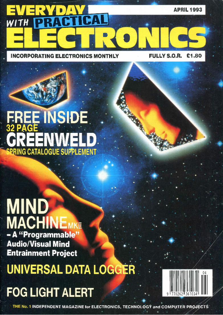
EVERYDAY WIT PRACTICAL
INCORPORATING ELECTRONICS MONTHLY
.FREE] SIDE. . • 32 PAGE • .•
..GREENWELD ING CATALOGUE SUPPLEMENT
.
MIND MACH - A "Programmable" Audio/Visual Mind Entrainment Project
• UNIVERSAL DATA LO AVII
FOG LIGHT ALERT
APRIL 1993
•
THE No. 1 INDEPENDENT MAGAZINE for ELECTRONICS, TECHNOLOGY and COMPUTER PROJECT.
7",/'

1
MICROWAVE CONTROL PANEL Mains operated, with touch switches Complete with 4 digit display, digital clock, and 2 relay outputs one for power and one for pulsed power (programmable) Ideal for all sorts of precision Omer apphcat ons etc Now only £4.00 ref 4P151. Good experimenters board FIBRE OPTIC CABLEStranded optcal fibres sheathed in black PVC Five metre length £7.00 ref 7P29R or £2 a metre 12V SOLAR CELL200mA output ideal for tnckle charging etc. 300 mm square Our price £15.00 ref 15P42R. Gives up to 15v. PASSIVE INFRA-RED MOTION SENSOR. Complete with dayhght sensor, adjustable lights on timer (8 secs -15 mins). 50' range with a 90 deg coverage Manual ovende faality Complete with wall brackets, bulb hokiers etc. Brand new and guar-anteed Now only £19.00 ref 19P29 Pack of two PAR38 bulbs for above unit £1 200 ref 12P43R VIDEO SENDER UNIT Transmit both audio and video signals from either a video camera, video recorder or computer to any standard TV set within a 100' range! (tune TV to a spare channel). 12v DC op. £1500 ref 15P39R Suitable mains adaptor £5 00 ref 5P191R Turn your camcorder into a cordless camera! FM TRANSMITTER Housed in a standard working 13A adapter (bug is mains dnven) £26 00 ref 26P2R Good range device MINATURE RADIO TRANSCEIVERS A per of walk° i9,4 raises with a range of up to 2 kilometres Units measure !' 22a52x155mm Complete with cases and earpieces 10 £30.00 ref 30P12R FM CORDLESS MICROPHONE.Smaii hand held unit with a 500* range! 2 transmit power levels Rags PP3 battery Tuneable to any FM receiver. Our pace £15 ref 15P42AR 12 BAND COMMUNICATIONS RECEIVER. 9 short ra tt bands, FM, AM and LW OX/local switch. tuning 'eye' mains or •••••:-: battery Complete with shoulder strap and mains lead £19 ref 19P14R Ideal for hstening all over the world CAR STEREO AND FM RADIO.Low cost stereo system giving 5 watts per channel. Signal to noise ratio better than 45db, j
‘,1 wow and flutter less than .35% Neg earth £19.00ref 19P30 LOW COST WAUKIE TALKIESPar of battery operated
I
units with a range of about 200 Our price £8.00 a pair ref • t it, 8P5OR Ideal for garden use or as an educational toy 7 CHANNEL GRAPHIC EOUAUZERAus a 60 watt power amp! 20-211<142 4-8R I2-14v DC negative earth. Cased. £25 ref 25P14R. NICAD BATTERIES. Brand new top quahty 4 x AA's £4.00 ref 4P44R 20 C's f4.00 ref 4P73R, 4 x D's £900 ref 9P12R, 1 x PP3 £6.00 ref 6P35R Pack e 10 AAA.5 £4.00 ref 4P92R TOWERS INTERNATIONAL TRANSISTOR SELECTOR GUIDE. The u mate equiva lents book. New ad £20.03 ref 20P32R. GEIGER COUNTER KIT.Complete with tube, PCB and all compo-nents to build a battery operated gager counter. £39.03 ref 39P1R FM BUG KIT.New design with PCB embedded cod. Transmits to any FM radio 9v battery req'd £500 ref 5P1 58R. 35rnm square FM BUG Built and tested supenor 9v operation £14.00 ref 14P3R COMPOSITE VIDEO KITS.These convert composite video into separate H sync, V sync and video 12v DC £8.00 ref 8P39R. SINCLAIR CS MOTORS 12v 29A (full load) 3300 rpm 6"x4" 114" 0/P shaft. New £20.00 ref 20P22R. Limited stocks As above but with fitted 4 to 1 i nine reduction box (800rpm) and toothed nylon belt dnve cog £40.00 ref 40P8R 800 rpm ELECTRONIC SPEED CONTROL KITfor C5 motor PCB and all components to build a speed controller (0-95% of speed) Uses pulse width modulation £17.00 ref 17P311 Potentiometer control. SOLAR POWERED NICAD CHARGER.Charges 4 AA nicads in 8 hcurs. Brand new and cased £600 ref 6P3R.2xC cell model £6 00 ACORN DATA RECORDER ALF503 Made for BBC computer but suitable for others Includes mains adapter, leads and book £1500 ref 15P43R VIDEO TAPES. Three hour supenor quakty tapes made under hcence from the famous JVC company Pack 01 10 tapes New low price £15.00 ref J15P4 PHIUPS LASER. 2MW HELIUM NEON LASER TUBE, BRAND NEW FULL SPEC £4000 REF 40P1 0R. MAINS POWER SUPPLY KIT £20.00 REF 20P33R READY BUILT AND TESTED LASER IN ONE CASE £75.00 REF 75P4R. 12 TO 220V INVERTER KITAs suppled it will handle up to about 15 w at 220v but with a larger tra nsforme r it will handle 80 watts Basic kit £12.00 ref 12P17R. Larger transformer £12.00 ref 12P41R VERO EAS1 WIRE PROTOTYPING SYSTEMideai for design-ing projects on etc. Complete with tools, wire and reusable board New low bargain price only £2.00 ref B2P1 25 WATT STEREO AMPLIFIER IC. STK043. With the addition of a handful of components you can build a 25 was amplifier £4 00 ref 4P69R (Circuit dm included) BARGAIN NICADS AAA SIZE 200MAH 1.2V PACK OF 10 £4.00 REF 4P92R, PACK OF 100 £30.00 REF 30P16R
FRESNEL MAGNIFYING LENS 83 a 52mm £1 00 ref 80827R 12V 19A TRANSFORMER Ex equipment £20 but OK. ULTRASONIC ALARM SYSTEM. Onree agan In stork tiran.. units consist of a detector that plugs into a 13A socket in the area to protect The receiver plugs into a 13A socket anywhere else on the same supply Ideal for protecting garages, sheds etc Complete system now only £19 !!! POWER SUPPUES Made for the Spectrum plus 3 give +518) 2A, +12 0700rnA & -12 @ 50mA £8 ref 08P3 UNIVERSAL BATTERY CHARGER.Takes AA's, C's, D's and PP3 nicads Holds up to 5 batteries at once. New and cased, mans operated. £6 00 ref 6P36R IN CAR POWER SUPPLY.Piugs into agar socket and gives 3,4,5,6,7 5,9, and 12v outputs at 800mA Complete with universal spider plug. £5.00 ref 5P167R. RESISTOR PACK.10 x 50 values (500 resistors) all 1/4 watt 2% metal film. £5.00 ref 5P170R. QUICK CUPPA7 12v immersion heater with lead and cigar hg hter plug £300 ref 3P92R. Ideal for tea on the move! LED PACK .513 red. 50 green. 50 yellow all 5mm £8.00 ref 8P52 IBM PRINTER LEAD. (025 to centronics plug) 2 metre parallel £500 ref 5P186R 3 metre version £6.00 ref 6P50. COPPER CLAD STRIP BOARD17" x 4" of .1" pitch "veto" board. £4 00 a sheet ref 4P62R or 2 sheets for E7.03 ref 7P22R. STRIP BOARD CUTTING TOOL£2.00 ref 2P352R.
WINDUP SOLAR POWERED RADIO! FM AM radio takes re-chargeable banenes Complete with hand charger 8 solar panel 14P2OOR Set of 2 AA wads £2 ref L2P9 PC STYLE POWER SUPPLY Made by AZTEC 110v or 240vinput +5 (§)15A,+12@ 5A,-12@ 5A,-5 @ 3A Fully cased with fan. " -
on/Off switch, iEC inlet and standard PC fly leads £1500 ref F15P4 TELEPHONE HANDSETS10 brand new handsets with mic and speaker only £300 for 10 ref 3P1 46R BENCH POWER SUPPLIES Superbly made fully cased (metal) giving 12v at 2A plus a 6V supply Fused and short circuit protected For sale at less than the cost of the case' Our pnce is £4.00 ref 4P1 03R SPEAKER WIRE Brown twin core 100 feet for £200 REF 2P 79R MICROSCOPE 1200X MAGNIFICATION Brand new complete with shnmp hatchery, shnmps. prepared slides, light etc. £29.00 ref J29P4 UGHT ALARM SYSTEM Small cased alarms that monitor a narrow beam area for sudden changes in kohl level Complete with siren that sounds for a preset time when unit is tnggered £700 ref J7P1 720K 3112' DISC DRIVE FOR E93rand new units made by JVC complete with tech info just £9 0011 they have a metal tab instead of a button and you may want to fit an led. Combined power and data cable easily modified to IBM standard ref L9P. MONO VGA MONITORS £59 Standard IBM compatible monitor rnade by Amstrad New Our price just £59. Ref 59P4RB. CAR BATTERY CHARGER Brand new units complete with panel meter and leads. 6 or 12v output £700 ref J7P2. CUSTOMER RETURNED SPECTRUM +2 Complete but sold as seen so may need attention £25.00 ref J25PI or 2 for £40.00 ref .140P4 CUSTOMER RETURNED SPECTRUM +3 Complete but sold as seen so may need attention £2500 ref J25P2 or 2 for £4000 ref J40P5
AMSTRAD 1640DD BASE UNITS
BRAND NEW AND CASED
TWO BUILT IN 5 1,4" DRIVES
MOTHER BOARD WITH 640K MEMORY
KEYBOARD, MOUSE & MANUAL
OUR PRICE JUST
£79 !! ! ! SCART TO D TYPE LEADS Standard Scan on one end, HI density D type (standard VGA connector) on the other. Pack of ten leads only £700 ref 7P2R OZONE FRIENDLY LATEX 250n1 bottle of hquid lubber sets in 2 hours Ideal for mountng PCB's fixing wires etc £2 00 each ref 2P379R VIEWDATA SYSTEMS Brand new units made by TANDATA complete with 1200,75 built in modem infra red remote controlled qwerty keyboard BT appproved Prestel compatible. Centronics printer port ROB colour and compos-ite output (works with ordinary television) complete with power supply and fully cased Our once is only £2000 ref 20PI R COMMODORE 64 COMPENDIUM Pack consisting of a Corn-modore 64 computer, power supply, data recorder and software All for £69 ref 069P1 PPC MODEM CARDS Made for the Amstrad PPC1640i1512 range these are plug in modules that operate at 2400 baud No data £15 ref 015P5 AMSTRAD L03500 PRINTER ASSEMBLIES Entire mechani-cal assembles including print head, platen, cables, stepper motors etc etc intact everything bar the electronics and case! Ou r price just f 10 ref 010P3 AMSTRAD DMP4000 PRINTER ASSEMBLIES Entire printer assemblies including print head, platen, cables, stepper motors etc Everything bar the electronics and case Our pnce just £20 ref 020P2 TOROIDAL TRANSFORMER 146VA with tappings at 8v, 10v and 32v will give 50v at 3A or 32 at 4A etc. Centre tapped pnmary. £9 ref 09P2 Fixing kit is £2 ref 02P1 AERIAL BRACKETS Wall plate 7 5" sq complete with rawl 10' stand off brackets with standard tube clamps Will take up to 2" mast Substantial bracket (would take body weight). £7 ref 07P1 TV SOUND RECEIVERS Popular units that with the addition of a speaker act as a tv sound receiver Ideal as a stand alone unit or for
.S . SAS. reek. connecting into HI Fl I. £12 ref 012P4 2,000 COMPONENTS FOR £3 Yesthats nghtllust send us £3 and you can have 1,000 resistors plus 1,000 capacitors! Our choice of value Order rel 03P1 ETRI FANS Mains, 11 watt 80mm diameter. £6. Ref 06P3. UGHTGUNS Onginady made for the Spectrum+2 but may have other uses (good stripper). £2 Ref 02P3 GX4000 GAMES CONSOL ES C omplete with motor racing game. psu and joystick £15 ref 015P3 Extra 4 games £12 ref 012P2 VCR RABBIT SYSTEM Lets you control your VCR from a second set using the VCR remote control Retail £99 ours £39111
BULL ELECTRICAL 250 PORTLAND ROAD HOVE SUSSEX BN3 50T 'TELEPHONE 0273 203500
MAIL ORDER TERMS: CASH PO OR CHEQUE WITH ORDER PLUS 0.00 POST PLUS VAT.
PLEASE ALLOW 7 - 10 DAYS FOR DELIVERY
FAX 0273 323077
M IS vflA
CAMERAS Customer returned units 3 for EIO ref LI OP2 STEAM ENGINE Standard Marnod 1332 engine complete with boiler piston etc £30 ref 30P200 TALKING CLOCK LCD display, alarm, battery operated Clock will announce the time at the push of a button and when the alarm is due The alarm is matchable from voice to a cock crowingl£14.00 ref 14P200.R HANDHELD TONE DIALLERS Small units that are designed to hold over the mouth piece of a telephone to send MF dialling tones Ideal for the remote control of answer machines £50) ref 5P209R AMAZING TALKING COINBOX! Fully programmable talking, lockable coinbox BT approved, retail price is £79 curs is just £291 ref J29P2 ANSWER PHONES £15 Customer returned units with 2 faults one we tell you how to fix the other you do your self! £18 ref J18P2 or 4 for £60 ref J60P3 BT approved (rated price E79.95!! each) COMMODORE 64 IAICRODRIVE SYSTEM Complete cased brand new drives with cartndge and software 10 times faster than tape machines works with any Commodore 64 setup The orgi nal price for these was £49.00 but we can offer them to you at only E25.00! Ref 25P1R 90 WATT MAINS MOTORS Ex equipment but oh Good general pupose unit £900 ref F9P1 HI Fl SPEAKER BARGAIN Onginalry made for TV sets they consist of a 4" 10 watt4R speaker and a 2-140R tweeter. It you want two of each plus 2 of our crossovers you can have the lot for £500 ref F5P2 EMERGENCY LIGHTING SYSTEM Fully cased complete with 2 adjustable flood kg hts All you need is a standard 6v lead acid battery Our price is just £10 ref J10P29 AMSTRAD 464 COMPUTERS Customer returned units complete with a monitor for just £35' These units are sold as faulty and are not returnable WOLSEY DMAC DECODERS Made for installation in hotels etc as the main sat receiver no data but fully cased quaity unit £20 ref K20P1. Suitable psu £8 ref K8P3. REMOTE CONTROLS Brand new infra red CONTROLS originally made for controlling WOLSEY satellite receivers £2 ea ref K2P1 or 20 for £19 ref K19P1. TELEPHONES Modem 1 piece phones BT approved. Last no radial. £8 ref K8P1. 386 TOWER SYSTEMS lowercase 52CMX40cMx20Crn 2 fans, speaker, 275w psu, !EC M and 0/1_ 386 rniboard with onboard disc controller, ethernet, display dnver, parallel and sena! ports. There are several IC's missing from the m/board plus no data! £79 ref K79P1. DOS PACKS Complete set of PC discs with MS DOS 32, Locomotive basic, gemdesktop and gent paint No manuals, 51/4" discs £10 ref 1<1 0P2 CORDLESS TIE CUP MICROPHONE transmits between 88-108MHZ FM 5 2cm x 2cm, uses LR44 watch battery Complete with wire aerial & battery. £16 ref K16P CHASSIS MOUNT TRANSFORMERS 240v primary, 12v secondary 20VA £2 ref K2P2 240v primary. 16v secondary 10A (split winding) £10 ref L10P1 100 RED LED PACK (5MM) £5 REF K5P2 12V STEPPER MOTOR Ideal for modeb etc 3" dia £2 ref J2P1 4 INFRA RED BEAM SWITCH 24v DC 5m range source & sensor housed in plastic case £12 ref J12P1 CAPACITOR BARGAIN PACK 100 CERAMICS £2 REF J2P2. SPECTRUM JOYSTICKS TWO FOR £5 REF J5P2.
AMSTRAD PC CASE, POWER SUPPLY AND 720k FLOPP DRIVE ALL THIS FOR £30 REF030P1 5
BUMPER PACK N01 10 of our popular £1 packs for Just £5 our choice of contents BUMPER PACK NO 2 25 of our popular £1 packs for just £12 Our choice of contents LCD 1 X 32 DISPLAY Bargain once of just £3 complete with loads of data bra similar display £3 ref L3P1. USEFUL POWER SUPPUES. 18v 900mA dc output (regulated) fully cased with mains cable and DC out cable. £6 ref K6P1 UNCASED PC POWER SUPPUES. Standard PC psi without case, fan etc Good for spare or low cost PCI. £4 ref L4P6. RADAR DETECTORS. Detects X and K bands speed traps). Not legal In the UK so only available If you intend to'exporrit. C59 ref J59P I. 100 WATT MOSFET PAIR.Same spec as 286343 and 25J413 (84,140v. 100w) 1 N channel and 1 P channel. £3 a per ref J3P9. LOW COST CAPS. 1.000 capacitors £3 (33uf,25v) ref J3P10. VELCRO. 1 metre length 20mm wide, blue £2 ref J2P16 JUG KETTLE ELEMENTS. Good general purpose heating ale-
VERY BIG MOTOR. 200v induction 1.1kw 1410 rpm 10"x7" GEC 1" keyed shaft Brand new. £95 ref J95P1. BIG MOTOR. 220-240v1425fprn 2 BA Seth" keyed shaft GEC 6 5" x 8" comp4ete Nth mounting plate £38 ref J38P1. SMALL MOTOR. Electrolux 160 watt 3,000 rpm, 220-240v 5/8" shaft precision built £18 ref J18P1. EPROMS 27C64 PACK OF 10 E7 REF M7P1. EPROMS 27C256 PACK OF 10 £9 REF M9P1. EPROMS 27C512 PACK OF 10 El 0 REF 1110P1, MODEMS FOR £1.25? These modems are suitable for stripping only hence they are only 4 for £5 ref J5P3. SOLAR POWERED WOODEN MODELS. Complete with solar panel, motor and full instructions. £9 ref J9P2. 3 duff £20 ref J20P3. SOUND OPERATED LIGHT. Clap your hanus and light comes on. Turns after preset delay. (4 AA's req'd). £2 ref J2P3. FERGUSON SRB1 REMOTE CONTROLS. Brand new units ideal for a spare or have two remotes! £4 each. 5 1/4" 360K DISC DRIVE Made for AMSTRAD 1640/1512 ma-chines White front Our price just £9 ref 09P1. 1 993 CATALOGUE AVAILABLE WITH ALL ORDERS IF RE-QUESTED OTHERWISE A4 SAE FOR FREE COPY.
IN SUSSEX? CALL IN AND SEE US!
SOME OF OUR PRODUCTS MAY BE UNLICENSABLE IN THE UK
VOL. 22 No. 4 APRIL 1993
EVERYDAY WITH PRAC iar.
ELECTRONICS INCORPORATING ELECTRONICS MONTHLY
The No. 1 Independent Magazine for Electronics, Technology and Computer Projects
ISSN 0262 3617 PROJECTS ...THEORY ... NE WS... COM MENT ... POPULAR FEATURES...
Wi mborne Publishing Ltd 1993. Copyright in
all dra wings, photographs and articles published
in EVERYDAY with PRACTICAL ELECTRONICS is
fully protected, and reproduction or imitations in
whole or in part are expressly forbidden.
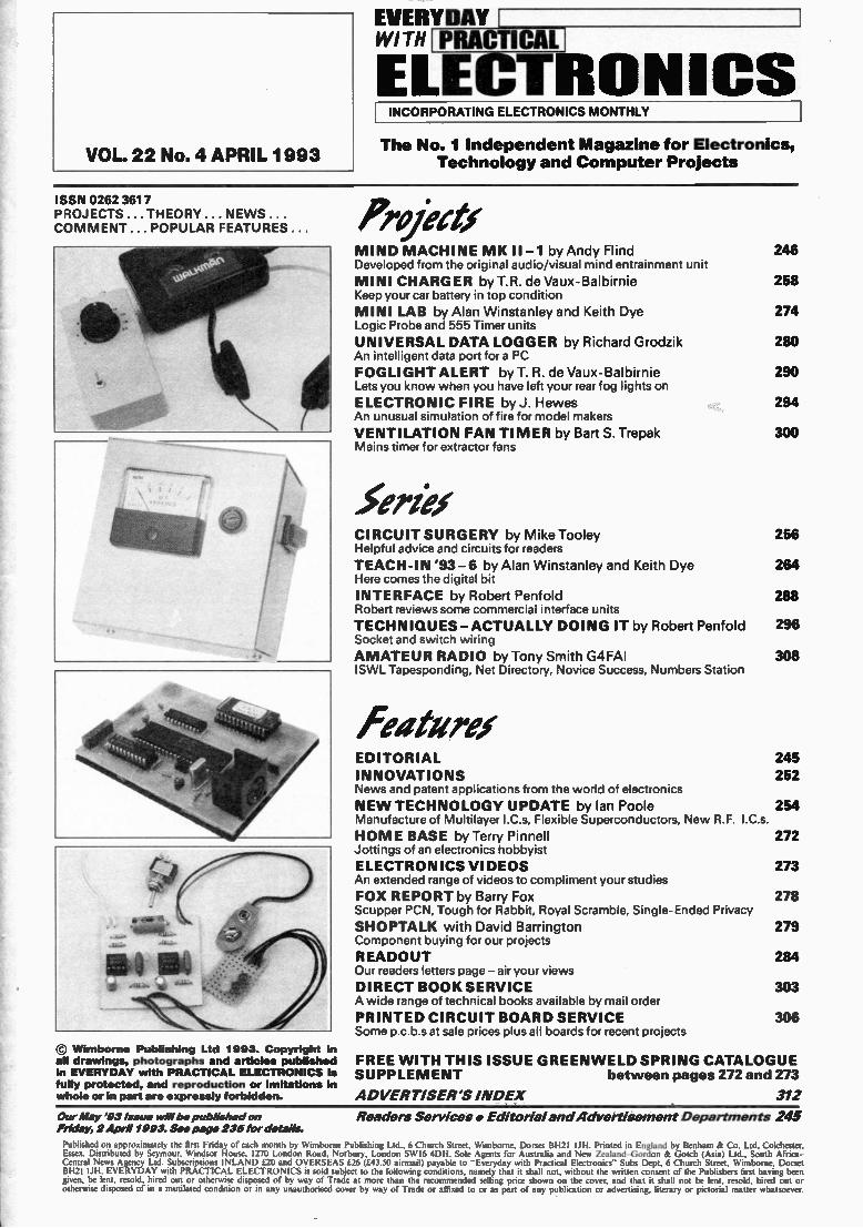
Projertx MIND MACHINE MK II -1 by Andy Flind Developed from the original audio/visual mind entrainment unit
MINI CHARGER by T.R. de Vaux-Balbirnie Keep your car battery in top condition
MINI LAB by Alan Winstanley and Keith Dye Logic Probe and 555 Timer units
UNIVERSAL DATA LOGGER by Richard Grodzik An intelligent data port for a PC
FOGLIGHT ALERT by T. R. de Vaux-Balbirnie Lets you know when you have left your rear fog lights on
ELECTRONIC FIRE by J. Hewes An unusual simulation of fire for model makers
VENTILATION FAN TI MER by Bart S. Trepak Mains timer for extractor fans
5torlex CIRCUIT SURGERY by Mike Tooley Helpful advice and circuits for readers
TEACH-IN '93 -6 by Alan Winstanley and Keith Dye Here comes the digital bit
INTERFACE by Robert Penfold Robert reviews some commercial interface units
TECHNIQUES —ACTUALLY DOING IT by Robert Penfold Socket and switch wiring
AMATEUR RADIO by Tony Smith G4FAI ISWL Tapesponding, Net Directory, Novice Success, Numbers Station
leaturex
246
258
274
280
290
294
300
256
264
288
296
308
EDITORIAL 245 INNOVATIONS 252 News and patent applications from the world of electronics
NE W TECHNOLOGY UPDATE by Ian Poole 254 Manufacture of Multilayer I.Cs, Flexible Superconductors, New R.F. I.Cs.
HO ME BASE by Terry Pinnell 272 Jottings of an electronics hobbyist
ELECTRONICS VIDEOS 273 An extended range of videos to compliment your studies
FOX REPORT by Barry Fox 278 Scupper PCN, Tough for Rabbit, Royal Scramble, Single-Ended Privacy SHOPTALK with David Barrington 279 Component buying for our projects
READOUT 284 Our readers letters page - air your views DIRECT BOOK SERVICE 303 A wide range of technical books available by mail order
PRINTED CIRCUIT BOARD SERVICE 306 Some p.c.b.s at sale prices plus all boards for recent projects
FREE WITH THIS ISSUE GREEN WELD SPRING CATALOGUE SUPPLE MENT between pages 272 and 273
ADVERTISER'S INDEX 312
Our May '93 Issue will he published on
Friday, 2 April 1993. See page 235 for details. Published on approximately the first Friday of each month by Wimborne Publishing Ltd., 6 Church Street, Wimborne, Dorset BH21 IJH. Printed in England by Benham & Co. Ltd. Cokhester, Essex. Distributed by Seymour, Windsor House, 1270 London Road, Norbury, London SWI6 4DH. Sole Agents for Australia and New Zealand-Gordon & Gotch (Asia) Ltd.. South Africa-Central News Agency Ltd. Subscriptions INLAND £20 and OVERSEAS £26 (£43.50 airmail) payable to "Everyday with Practical Electronics" Subs Dept, 6 Church Street. Wimborne Dorset BH2I IJH. EVERYDAY with PRACTICAL ELECTRONICS is sold subject to the following conditions, namely that it shall not, without the written consent of the Publishers first having been given, be lent, resold, hired out or otherwise disposed of by way of Trade at more than the recommended selling price shown on the cover, and that it shall not be lent, resold, hired out or otherwise disposed of in a mutilated condition or in any unauthorised cover by way of Trade or affixed to or as part of any publication or advertising, literary or pictorial matter whatsoever.
Readers Services • Editorial and Advertisement Departments 245
Surplus always wanted for cash! THE ORIGINAL SURPLUS WONDERLAND! Surplus always
wanted for cash!,
LOW COST PC SPECIALISTS - ALL EXPANDABLE - ALL PC COMPATIBLE
8088 XT - PC99
W WI
• 256k RAM - expandable to 640k
• 4.7 Mhz speed
• 360k 5-1/4" floppy
• 2 serial & 1 parallel ports
• MS-DOS 4.01
• Factory burnt-in
• Standard 84 key keyboard
• 12" green screen included
• In good used condition
Optional FITTED extras: 6401< RAM £39. 12* CGA colour monitor with card £39. 2nd 5-1/4 3601< floppy £29.95. 20 mbyte MFM hard drive £99.
Only £99 0 0 • _ _ (F)
FLOPPY DISK DRIVES 51/4 "from £22.95- 31/2 " from £21.95!
Massive purchases of standard 51/4' and 31/2 ' drives enables us to present prime product at industry beating low prices! All units (unless stated) are removed from often brand new equipment and are fully tested, aligned and shipped to you with a 90 day guarantee and operate from standard voltages and are of stand-ard size. All are IBM-PC compatible (if 31,2' supported).
3.5" Panasonic JU363/4 720K or equivalent £29.95(B) 3.5" Mitsubishi MF355C-L. 1.4 Meg. Laptops only' £29.95(B) 3.5" Mitsubishi MF355C-D. 1.4 Meg. Non laptop £29.95(B) 5.25" EXTRA SPECIAL BRAND NEW Mitsubishi MF501B
360K. Absolutely standard fits roost computers £22.95(B) • Data cable included in price.
Shugart 800/801 SS refurbished & tested £175.00(E) Shugart 851 double sided refurbished & tested £275.00(E) Mitsubishi M2894-63 double sided switchable hard or soft sectors- BRAND NEW £250.00(E) Dual 8" drives with 2 mbyte capacity housed in a smart case with built in power supply! Ideal as exterior drives! £499.00(F) End of line purchase scoop! Brand new NEC D2246 8' 85 megabyte of hard disk storage! Full CPU control and industry standard SMD interface. Ultra hi speed transfer and access time leaves the good old S1506 interface standing. In mint condition and comes complete with manual. On! £299 E
286AT - PC286
•• .
• 640k RAM expandable • 2 serial & 1 parallel with standard SIMMS ports
• 12 Mhz Landmark speed • MS-DOS 4.01
• 20 meg hard disk • Co-processor socket
• 1.2 meg 5-1/4" floppy • Enhanced 102 key
• 1.4 meg 3-1/2" floppy keyboard
• Clock & calendar • EGA driver on board withbattery back up
BRAND NE W AND BOXED!
ordYE249.00 (F)
'The Philips 9CM073 is suggested for the PC286 and the\ CM8873 for the PC386. Either may use the SVGA MTS-9600 if a suitable card is installed. We can fit this at a cost of £49.00 \f.or the PC286 and £39.00 for the PC386.
POWER SUPPLIES Power One SPL200-5200P 200 watt (250 w peak).Semi open frame giving +5v 35a, -5v 1.5a, +12v 4a (8a peak), -12v 1.5a, +24v 4a (6a peak). All outputs fully regulated with over voltage protection on the +5v output. AC input selectable for 110/240 vac. Dims13' x 5 x 2.5'. Fully guaranteed RFE. £85.00 (B)
Power One SPL130. 130 watts. Selectable for 12v (4A) or 24 v (2A). 5v ft 20A. ± 12v @ 1.5A. Switch mode. New. £59.95(B) Astec AC-8151 40 wafts. Switch mode. +5v @ 2.5a. +12v 0 2a. -12v @ 0.1a. 6-1/4' x4" x 1-3/4'.New £22.95(B) Greendale 19ABOE 60 watts switch mode.+5v @ 6a,612v 1a,+15v 0 la. R FE and fully tested.11 x20 x5.5cms. £24.95(C) Conver AC130. 130 watt hi-grade VDE spec.Switch mode.+5v 15a,-5v 0 1a,±12v 0 6a.27 x 12.5 x 6.5cms.New. £49.95(C)
Boshert 13090.Switch mode.Ideal for drives & system. +Sy@ 6a, +12v 0 2.5a, -12v 0 0.5a, -5v 0 0.5a. £29.95(B) Famell G6/40A. Switch mode. 5v 0 40a.Encased £95.00(C) Famell G24/5S. As above but 24v 0 5a. £65.00(C)
THE AMAZING TELEBOX! Converts your colour monitor into a
QUALITY COLOUR TV!!
TV SOUND & VIDEO TUNER!
The TELEBOX Consists of an attractive fully cased mains powered unit, containing all electronics ready to plug into a host of video monitors made by manufacturers such as MICROVITEC, ATARI, SANYO, SONY, COMMODORE, PHILIPS, TATUNG, AMSTRAD and many more. The composite video output will also plug directly into most video recorders, allowing reception of TV channels not normally receivable on most television receivers (TELEBOX MB). Push button controls on the front panel allow reception of 8 fully tuneable 'off air' UHF colour television or video channels. TELEBOX MB covers vir-tually all television frequencies VHF and UHF including the HYPERBAND as used by most cable TV operators. Composite and RGB video outputs are located on the rear panel for direct connection to most makes of monitor. For complete compatibility - even for monitors without sound - an integral 4 watt audio amplifier and low level Hi Fi audio output are provided as standard. Telebox ST for composite video input monitors £32.95 Telebox STL as ST but with integral speaker £36.50 Telebox MB as ST with Multiband tuner VHF-UHF-Cable.
& hyperband For overseas PAL versions stale 5.5 or 6mhz sound specification. £69.95
Telebox RGB for analogue RGB monitors (15khz) £69.95 Shipping code on all Teleboxes is (B)
RGB Telebox also suitable for IBM multisync monitors with RGB analog and composite sync. Overseas versions VHF 8 UHF call.
SECAM / NTSC not available.
No Break Uninterruptable PSU's Brand new and boxed 230 volts uninterruptable power supplies from Dense!. Model MUK 0565-AUAF is 0.5 kva and MUD 1085-AHBH is 1 kva. Both have sealed lead acid batteries. MUK are internal, MUD has them in a matching case. Times from interrupt are 5 and 15 minutes respectively. Complete with full operation manuals............MUK £249 ( MUD......£525 (0)
1992 Winter Issue of Display News
BBC Model B APM Board £100 CASH FOR THE MOST NOVEL
DEMONSTRATABLE APPLICATION!
BBC Model B type computer on a board. A major purchase allows us to offer you the PROFESSIONAL version of the BBC computer at a parts only price. Used as a front end graphics system on large networked systems the architecture of the BBC board has so many similarities to the regular BBC model B that we are sure that with a bit of experimentation and ingenuity many useful applications will be found for this board!! It is supplied complete with a connector panel which brings all the I/O to 'D' and BNC type connectors - all you have to do is provide +5 and ± 12 v DC. The APM consists of a single PCB with most major ic's socketed. The ic's are too numerous to list but include a 6502, RAM and an SAA5050 teletext chip. Three 27128 EPROMS contain the custom operating system on which we have no data, On application of DC power the system boots and provides diagnostic information on the video output. On board DIP switches and jumpers select the ECONET address and enable the four extra EPROM sockets for user software. Appx. dims: main board 13' x 10'. I/O board 14' x 3'. Supplied tested with circuit diagram, data and competition entry form.
Only £29.95 or 2 for £53 (B)
SPECIAL INTEREST
Trio 0-18 vdc bench PSU. 30 amps. New Fujitsu M3041 600 LPM band printer DEC LS/02 CPU board Rhode & Schwarz SBUF TV test transmitter 25-1000mhz. Complete with SBTF2 Modulator £6500
Calcomp 1036 large drum 3 pen plotter £ 650 Thurlby LA 160B logic analyser £ 375 1.5inv 115v 60hz power source £ 950 Anton Pillar 400 Hz 3 phase frequency converter 75Kw POA Newton Derby 400 Hz 70 Kw converter POA Nikon PL-2 Projection lens meter/scope £750 Sekonic SD 150H 18 channel Hybrid recorder £2000 HP 7580A Al 8 pen high speed drum plotter £1850 Kemvood DA-3501 CD tester, laser pickup simulator
386AT - PC386
• 2 meg RAM expanded by slots
• 20 Mhz with 32k cache. Expandable to 64k
• 40 meg hard disk
• 1.2 meg 5-1/4" floppy
• VGA card installed
BRAND NE W
.••°. • :•••. I I I *--.. • • • • • • 0000 • ••• • :0000
000.
00 4 . 0:0.
• • • •
-ELECTRON/CC-
BRAND NEW PRINTERS
lro
418161111881C:--
• 2 serial & 1 parallel ports
• MS-DOS 4.01
• Co-processor socket
• Enhanced 102 keyboard
• Kwik Disk Accelerator Software - FREE
AND BOXED!
onlyE425.00,F, MONITORS
14" Forefront Model MTS-9600 SVGA multisync with resolution of 1024 x 768.0.28 pitch. 'Text' switch for word processing etc. Overscan switch included. Ideal for the PC-386 or PC-286 with SVGA card added. Also compatibe with BBC, Amiga, Atari (including the monochrome high resolution mode). Ar-
chimedes etc. In good used condition (possible minor screen bums). 90 day guarantee. 15' x 14" x 12". Only £159(E)
14" Philips Model CM8873 VGA muftisync - ' with 640 x 480 resolution. CGA, EGA or ii
VGA, digitaVanalog, switch selectable. Sound with volume control. There is also a special 'Text' switch for word processing, spreadsheets and the like. Compatible with
'.-4,4 1001010 " 1".. IBM PC's, Amiga, Atari (excluding the monochrome high resolution mode), BBC,
Archimedes etc. Good used condition (possible minor screen bums) 90 day guarantee. 15"s 14' x 12. Only £139(E)
Philips 9CM073 similar (not identical) to above for EGA/CGA PC and compats. 640 x 350 resolution. With Text switch with amber or green screen selection. 14' it 12' x 13-1/2'... ..... £99(E) KIAE 10" high definition colour monitors. Nice tight 0.28' dot pitch for superb clarity and ' modem styling. Operates from any 15.625 khz sync RGB video source, with RGB analog and composite sync such as Atari, Commodore Amiga, Acorn Archimedes & BBC. Measures only 13.5' x 12' ), 11'. Also works as quality Tv vein our Htx8 Telebox. Good used condition. 90 day guarantee. Only £125 (E) KME as above for PC EGA standard f145 (E) Brand new Centronic 14' monitor for IBM PC and compatibles at a lower than ever price! Completely CGA equivalent. Hi-res Mitsubishi 0.42 dot pitch giving 669 x 507 pixels. Big 28 Mhz bandwidth. A super monitor in attractive style moulded case.Full 90 day guarantee. Only £129 (E) NEC CGA 12' IBM-PC compatible. High quality ex-equipment fully tested with a 90 day guarantee. In an attractive two tone ribbed grey plastic case measuring 15'L x 13'W x 12 H. The front cosmetic bezel has been removed for contractualEcn reasons. Only ou (E)
20" 22" and 26" AV SPECIALS Superbly made 'UK manufacture. PIL all solid state colour monitors, complete with composite video & sound inputs. Affrac-tive teak style case. Perfect for Schools,Shops,Disco, Clubs. In EXCELLENT little used condition with full 90 day guarantee.
20"....£135 22"....£155 26"...1185 (9 CALL FOR PRICING ON NTSC VERSIONS!
Superb Quality 6 foot 40u
19" Rack Cabinets Massive Reductions
Virtually New, Ultra Smart! Less Than Half Price!
Top quality 19' rack cabinets made in UK by Optima Enclosures Ltd. Units feature designer, smoked acrylic lockable front door, full height lockable half louvered back door and removable side panels. Fully ad-justable internal fixing struts, ready
E 350 punched for any configuration of equipment mounting plus ready mounted integral 12 way 13 amp socket switched mains distribu-tion strip make these racks some of the most versatile we have
Microline 183. NLO 17x17 dot matrix. Full width. £139 (D) ever sold. Racks may be stacked side by side and therefore Hyundai HDP-920. NLO 24x18 dot matrix full width. £149 (D) require only two side panels or stand singly. Overall dimensions Oume LetterPro 20 daisy. Oume 0S-3 interface. £39.95 (D) are 77-1/2'H x 32-1/2'D x 22'W. Order as: Centronics 152-2 9 x 7 dot matrix. Full width. £149 (D) Rack 1 Complete with removable side panels £275.00 (0) Centronics 159-4 9 x 7 dot matrix.Serial. 9-1/2" width 99 )0) Rack 2 Less side panels £145.00 (G)
large SAE - PACKED with bargain:I now available - send MAIL ORDER & OFFICES Open Mon-Fri 9.00-5.30 Dept EE. 32 Biggin Way.
Upper Norwood. London SE19 3XF.
LONDON SHOP Open Mon-Sat 9-5.30 Thursday till 9.00pm 215 Whitehorse Lane. South Norwood. London. SE25 .
£ 470 £2950 £ 150
ODISTEL 0 The Original Free dial-up database!
1000's of items+info on line V21. V22 & V22 bis
081-679-1888
ALL ENQUIRIES
081167914414 Fax- 081-679-1927
Visa
All prices for UK Mainland. UK customers add 17.5% VAT to TOTAL order amount. Minimum order £10. PO orders from Govemment,Universities,Schools it Local Authonties welcome-minimum account order E30. Carriage charges (A)=E2.00. (A1)=E3.75. (B)=£5.50. (C)=E8.50. (0).C11.50. (E)=E14.00 (F)=EI8.00 (G)=CM . Scotland surcharge, call. All goods supplied subject to our standard Condtions of Sale and unless otherwise stated guaranteed for 90 days. All guarantees on a return to base basis.Rights reserved to change prices 8 specifications without phor notice. Orders subject to stock. Quotations willingly oven for higher quantities than those stated. Bulk surplus always wanted for cash.
234 Everyday with Practical Electronics, April 1993
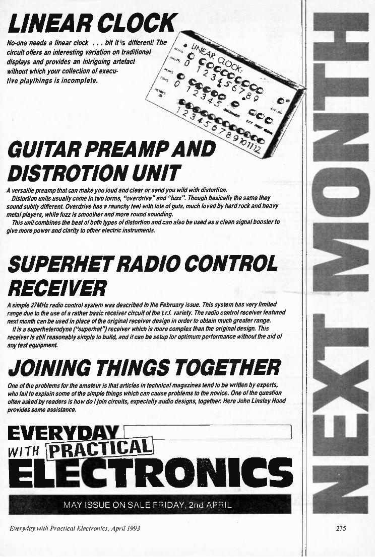
LINEAR CLOCK No-one needs a linear clock . . . bit it is different! The /
circuit offers an interesting variation on traditional displays and provides an intriguing artefact / ,4„,.,„ C ...., 0 gp e e() without which your collection of execu-
tive playthings is incomplete. / / -''v- oe !to it , 3 Ite f c ce,_
/ _7 -0. 0.- lei 0 0
-- - ..D
C i ‘rftt,,,,,,
4
\ ‘leT C ....,.., ,S .•
'NW
GUITAR PREAMP AND DISTROTION UNIT A versatile preamp that can make you loud and clear or send you wild with distortion. Distortion units usually come in two forms, "overdrive" and "fuzz". Though basically the same they sound subtly different. Overdrive has a raunchy feel with lots of guts, much loved by hard rock and heavy metal players, while fuzz is smoother and more round sounding. This unit combines the best of both types of distortion and can also be used as a clean signal booster to
give more power and clarity to other electric instruments.
SUPERHET RADIO CONTROL RECEIVER A simple 27MHz radio control system was described in the February issue. This system has very limited range due to the use of a rather basic receiver circuit of the tr.,. variety. The radio control receiver featured next month can be used in place of the original receiver design in order to obtain much greater range. It is a superheterodyne ("superhet") receiver which is more complex than the original design. This receiver is still reasonably simple to build, and it can be setup for optimum performance without the aid of any test equipment.
JOINING THINGS TOGETHER One of the problems for the amateur is that articles in technical magazines tend to be written by experts,
who fail to explain some of the simple things which can cause problems to the novice. One of the question often asked by readers is how do I join circuits, expecially audio designs, together. Here John Linsley Hood provides some assistance.
EVERYD WITH PRACTICAL
TRONICS EL MAY ISSUE ON SALE FRIDAY, 2nd APRIL
Everyday with Practical Electronics, April 1993

S U RV EI L L A N C E PROFESSIONAL OIJALITY KITS
No. II for Kits Whether your requirement for surveillance equipment is amateur, professional or you are just fascinated by this unique area of electronics SUMA DESIGNS has a kit to fit the bill. We have been designing electronic surveillance equipment for over 12 years and you can be sure that all of our kits are very well tried, tested and proven and come complete with full instructions, circuit diagrams, assembly details and all high quality components including fibreglass PCB. Unless otherwise stated all transmitters are tuneable and can be received on an ordinary VHF FM radio.
UTX Ultra-miniature Room Transmitter Smallest room transmitter kit in the world! Incredible 10mm x 20mm including mic. 3-12V operation. 500m range £16.45
IATX Micro-miniature Ra w Transmitter Best-selling micro-miniature Room Transmitter Just 17mm x 17mm including mic. 3-12V operation. 1000m range £13.45
SIX High-perfonnance Room Transmitter Hi performance transmitter with a buffered output stage for greater stability and range. Measures 22mm x 22mm including mic. 6-12V operation, 1500m range £15.45
V1500 Nigh-power Room Transmitter Powerful 250mW output providing excellent range and performance. Size 20mm x 40mm. 9-12V operation. 3000m range £16.45
VXT Voice Activated Transmitter Triggers only when sounds are detected. Very low standby current. Variable sensitivity and delay with LED indicator. Size 20mm x 67mm. W operation. 1000m range £19.45
HVX400 Mains Powered Room Transmitter Connects directly to 240V AC supply for long-term monitoring. Size 30mm x 35mm. 500m range £19.45
SCRX Wearier Scrambled Room Transmitter
Scrambled output from this transmitter cannot be monitored without the SCDM decoder connected to the receiver. Size 20mm x 67mm. W operation. 1000m range £22.95 SCLX &Murder Telepheee Transmitter Connects to telephone line anywhere, requires no batteries. Output scrambled so requires SCUM connected to receiver. Size 32mm x 37mm. 1000m range £23.95
SCDM Subcarrler Decoder Unit for SCRX Connects to receiver earphone socket and provides decoded audio output to headphones. Size 32mm x 70mm. 9-12V operation £22.95
ATR2 Micro Size Telephone Recording Interface Connects between telephone line (anywhere) and cassette recorder. Switches tape automatically as phone is used. All conversations recorded. Size 16mm x 32mm. Powered from line £13.45
*** Specials *** IILTX/BLRX Radio Castel Switch Remote control anything around your home or garden, outside lights, alarms, paging system etc. System consists of a small VHF transmitter with digital encoder and receiver unit with decoder and relay output, momentary or alternate, 8-way dil switches on both boards set your own unique security code. TX size 45mm x 45mm. RX size 35mm x 90mm. Both 9V operation. Range up to 200m. Complete System (2 kits) £50.95 Individual Transmitter DLTX £19.95 Individual Receiver DLRX £37.95
1111X-1 Micro Broadcaster Not technically a surveillance device but a great idea! Connects to the headphone output of your Hi-F), tape or CD and transmits Hi-Fi quality to a nearby radio. Listen to your favourite music anywhere around the house, garden, in the bath or in the garage and you don't have to put up with the DJ's choice and boring waffle. Size 27mm x 60mm. 9V operation. 250m range £20.95
SU MA DESIGNS
UTLX Ultra-miniature Telephone Transmitter Smallest telephone transmitter kit available. Incredible size of 10mm x 20mm1 Connects to line (anywhere) and switches on and off with phone use. All conversation transmitted. Powered from line. 500m range £15.95
TU(700 Micro-miniature Telephone Transmitter Best-selling telephone transmitter. Being 20mm x 20mm it is easier to assemble than UTLX. Connects to line (anywhere) and switches on and off with phone use. All conversations transmitted. Powered from line. 1000m range £13.45
STU( High-performance Telephone Transmitter High performance transmitter with buffered output stage providing excellent stability and performance. Connects to line (anywhere) and switches on and off with phone use. All conversations transmitted. Powered from line. Size 22mm x 22mm. 1500m range £16.45
TKX900 Signalling/Tracking Transmitter Transmits a continous stream of audio pulses with variable tone and rate. Ideal for signalling or tracking purposes. High power output giving range up to 3000m. Size 25mm x 63mm. 9V operation £22.95
C0400 Pocket Bug Detector/Locator LED and piezo bleeper pulse slowly, rate of pulse and pitch of tome increase as you approach signal. Gain control allows pinpointing of source. Size 45mm x 54mm. 9V operation £30.95
CDMKI Professional Bug Detector/Locator Multicolour readout of signal strength with variable rate bleeper and variable sensitivity used to detect and locate hidden transmitters. Switch to AUDIO CONFORM mode to distinguish between localised bug transmission and normal legitimate signals such as pagers, cellular, taxis etc. Size 70mm x 100mm. 9V operation £50.95
OTX180 Crystal Controlled Room Transmitter Narrow band FM transmitter for the ultimate in privacy. Operates on 180 MHz and requires the use of a scanner receiver or our QRX180 kit (see catalogue). Size 20mm x 67mm. 9V operation. 1000m range £40.95
OLX180 Crystal Controlled Telephone Transmitter As per QTX180 but connects to telephone line to monitor both sides of conversat-tions. 20mm x 67mm. 9V operation. 1000m range £40.95
OSX1B0 Line Powered Crystal Controlled Phone Tranvia', As per OLX180 but draws power requirements from line. No batteries required. Size 32mm x 37mm. Range 500m £35.95
(IRX180 Crystal Controlled FM Receiver For monitoring any of the '0' range transmitters. High sensitivity unit. All RF section supplied as a pre-built and aligned module ready to connect on board so no difficulty setting up. Outpt to headphones. 60mm x 75mm. 9V operation £60.95
A build-up service is available on all our kits it required. UK customers please send cheques, POs or registered cash. Please add £1.50 per order for P&P. Goods despatched ASAP allowing for cheque clearance. Overseas customers send sterling bank draft and add £5.00 per order for shipment. Credit card orders welcomed on 0827 714476.
OUR LATEST CATALOGUE CONTAINING MANY MORE NEW SURVEILLANCE KITS NOW AVAILABLE. SEND TWO FIRST CLASS STAMPS OR OVERSEAS SEND TWO IRCS.
DEPT. EE
THE W ORKSHOPS, 95 MAIN ROAD,
BAXTERLEY. NEAR ATHERSTONE,
W ARWICKSHIRE CV9 2 LE
VISITORS STRICTLY BY APPOINTMENT ONLY
Tel/Fax: 0827 714476
236 Everyday with Practical Electronics, April 1993
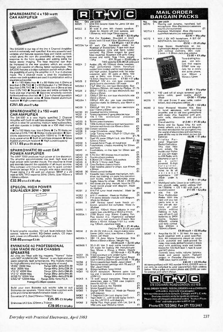
SPARKOMATIC 4 x 150 watt CAR AMPLIFIER
M AIL O R DER B AR G AI N PACKS
The SA3200 is our top of the line 4 Channel Amplifier which is extremely well specified It is very powerful and versatile and features separate bass and treble controls which gives the user the possibility of reducing bass response to the front speakers and adding treble for better stereo imaging The bass response can then be increased to the rear speakers which are usually larger and capable of offering better reproduction. The SA3200 features a bridge operation switch which offers the possiblity of using the amplifier in 4, 3 or 2 channel mode. The 3 channel mode is ideal for installations where rear deck speakers are used in combination with a separate subwoofer • 4x 150 Watts max • 4 x 80 Watts into 4 Ohms at
less than 0.5% THD • 2 x 80 Watts plus 1 x 160 Watts at less than 05% THD • 2 x 160 Watts into 4 Ohms at less than 05% THD • Separate bass and treble controls for front and rear channels • Separate sensitivity controls for front and rear channels • 2, 3 or 4 channel operation • Heavy duty power wires • Glass blasted aluminium heatsink • High current capacility
£251.65 plus £1 p&p
SPARKOMATIC 2 x 150 watt CAR AMPLIFIER The SA1500 is a very highly specified 2 Channel Amplifier with built-in sub bass crossover The SA 1500. which is ideal for powering medium sized subwoofers, will also operate in bridge mode as a 150 Watt mono amplifier • 2 x 150 Watts max. into 4 Ohms • 2 x 70 Watts per
channel at 0.5% THD • Bridge mode operation • Sen-sitivity adjustment ranging from 100mV to 1V • Heavy duty power wires • Built-in sub bass crossover • Glass blasted aluminium heatsink S High current capacity
£117.65 plus £6.50 p&p
SPARKOMATIC 80 watt CAR PO WER AMPLIFIER The AMP 7000 produces high power at low distortion. The amplifier accommodates low level, high level and high power radio speaker inputs The response is linear and extends beyond the capability of all music sources. This compact unit mounts easily and its quick connect terminals accept RCA or straight wire input terminals. Power rating 2 x 40 watt per channel. M MP 2 x 20 watt at 10% THD response 20Hz-20kHz. Size 160mm x 130mm x 45mm
£32.95 plus £3.50 p&p
EPSILON, HIGH PO WER EQUALIZER 30 W+ 30 W
5 band graphic equalizer, 10 I e.d. level indicator, fader control, volume control, Ea- Defeat switch, CD input jack, power on/off switch, night slide led
£56.65 postage £3.65
EMINENCE 4.0 PROFESSIONAL USA MADE IN CAR CHASSIS SPEAKERS All units are fitted with big magents "Nomex - Voice coils NOT ALU MINIUM. "Nomex- is very light and can stand extremely high temperatures, this mixture makes for high efficiency and long lasting quality of sound V6 6%- 200W Max Range 50Hz-3kHz £34.40 V6 8300W Max Range 45Hz-3kHz £39.35 V10 10- 400W Max Range 33Hz-4kHz £44.45 V12 12- 400W Max Range 35Hz-3kHz £45.95 BOSS 15- 800W Max Range 35Hz-4kHz 09.90 KING 18- 1200W Max Range 20Hz-lkHz P.O .A
Postage £3.85per speaker.
Build your own Bazooka sub woofer tube to sun Eminence car speakers lOmm thick fibre supplied with grille and clamp terminals finished in black vinyl
Eminence U10, Size 270mm x 700mm
£25.95 £350 p&p Eminence U12 Size 320mm x 710mm
£29.95 £3.50 p&p
No Qty. per pack M021 1 60W Hifi tweeter made for Jamo UK size
90mm sq , £1 M022 2 30 watt 8 ohm Hifi chassis speakers.
Made for Hitachi UK midi systems, size 125mm sq with large 70mm magnet
£9.00 + £2.00 p&p M023 2 Pod Car Speakers. Moulded in black
plastic with 15 watt 10cm Goodmans unit fitted £3.95 pair -£2.50 p&p
M023A 1pr 40 watt Car Speakers made for Roadstar of Switzerland. Fitted with dual polypropylene cone and foam rubber surround. Big 70mm magent for good base response. Supplied with grills fixing screws and cable Size 13cm, weight 1 5Kg £11.70 pair - £3.65 p&p or
TWO pairs for £25.00 UK post paid M024 2 Audax JBL 40-100watt dome tweeters.
High performance lOmm Ferrofluid cooled horn loaded unit for load distortion and high output. Supplied with 1st order crossover, spec. 40 watts at 3kHz, 100 watt at 8kHz, size 51 mm x 51mm x 16 5mm Ideal for car use £7.50 + £1 p&p
M025 2 33000uF 10V d.c. can type computer grade quality electrolytic UK made
M025A 1 47uF 385V cf.c. can type electrolytic. Size 350mm x 250mm. UK made by Phillips £1.75
M026 2 680uF 100V d.c can type electrolytic size 45mm x 25mm El
M027 3 2200uF 25V d.c. can type electrolytic size 45mm x 25mm Cl
M028A 1 2200uF 40V d c. can type electrolytic capacitor made by Seimans, size 48mm x 30mm £1
M029 1 330001rF 16V 27A can type electrolytic size 113mm x 50mm £1
M030 20 Assorted Variable trimmers £1 M031 4 Tuning capacitors 2-gang dielectric type £1 M032 2 10k 10k wirewound precision
potentiometer El M033 8 Rotary potentiometers £1 M034 5 100k multiturn Vancap type tuning poten-
tiometer with knob size 45mm x 5mm £1 M035 200 Carbon resistors £1 M036 2 Large VU meters Japan Made £1 M037 1 Large Tuning meter 125µA-0-125uA size
55mm x 47mm £1 .75 M038 1 Dual VU meter 280pA f.s.d.. size 80mm x
42mm x 15mm £1.50 M039 5 Coaxial Aerial Plugs, all metal type £1 M040 6 Fuseholders, chassis mounting for 20mm
size fuses £1 M041 4 Fuseholders, in-line type for 20mm size
fuses Cl M042 20 5 Pin Din 180°chassis mount sockets £1 M043 6 Double phono sockets £1 M044 5 6.35mm (%") Stereo Jack sockets M045 4 635 (%-) Mono Jack Plugs f1 M046 12 Coax Sockets chassis mount Cl M047 2 Case handles plated U -shape, size 97mm
x 50mm £1 M048 30 Mixed control knobs £1 M049 1 Cassette tape transport mechanism, belt-
drive, top loading, six piano key operation with knobs, stereo record/replay erase heads, heavy fly-wheel £5.50 £2.65 p&p
M050 1 Hifi stereo pre-amp. module. Input for CD Tuner record player with diagram. Made by Mu/lard £1
M051 2 AM/FM tuner head modules'. Made by Mu/lard £1
M052 3 AM I.F. modules'. Made by Mu/lard £1 M053 1 FM stereo decoder module with diagram.
Made by Mu/lard £1 M054 3 UHF Varicap tuned tuner heads un-
boxed, untested but complete Made by Mu/lard Cl
M055 1 25V d.c. 150mA Mains adaptor in neat plastic box, size 80mm x 55mm x 47mm f1
M055A 1 E R/ Brand new 80mm Cooling Fan. Five bladed A C impedance corrected motor on a cast aluminium chassis. Size 80mm x 40mm. Voltage 115V a.c. work-ing, 130mA. Japanese made
£5.95 + £1.40 p&p. TWO for £11.20 UK post paid
M056 2 6V-0V-6V 4VA p c.b mount mains trans-former 240V input, size 42mm x 33mm x 35mm. UK Made Cl
M056A 1 28V 15 Amp Mains Transformer Size 80mm x 55mm x 65mm Weight 1Kg
£3.00 each + £2.50 p&p M056B 1 30-0-30 Volt 3 amp mains transformer
UK made for leading Hifi manufacturer Size 96mm x 90mm x 80mm. Weight 2.8Kg £7.00 each + £3.75 p&p
M057 25 4 Volt miniature wire-ended bulbs £1 M057A 1 SRBP Copper Clad Printed Circuit Board
Size 410mm x 360mm x2mm £3.65 + 75 p&p M058 2 Mono cassene tape heads. Japan Made £1 M059 2 Sonotone stereo cartridge with 78 and LP
Sty' Japan Made El M060 8 Bridge rectifiers lamp 24 Volt £1 M061 10 0C44 transistors. Remove paint from
top and it becomes a photo electric cell (ORP12) El
M063 6 14 watt output transistors. Three com-plimentary pairs in T066 case (replace-ment for AD161 + 1621 Cl
M064 5 5 watt Audio i.c. No. TBA800 Cl M065 5 Motor Speed Control i.c. £1 M066 1 Digital DVM Meter i.c. Made by Plessey,
with diagram £1 M067 4 7-Segment 0.3in led, display (red) £1 M068 1 Tape Deck i.c • with record replay switch-
ing. No. LM1818, with diagram Cl M069 2 Ferrite Rod. High grade with LW, SW &
M W coils, size 140mm x lOmm Cl
No. Qty. per pack M070 1 Moving coil dynamic. handheld, ball
microphone Ross Electronics customers returns ( no warrantee) Et
M071A 1 Analogue Multimeter Ross Electronics customers returns (no warrantee)
£3.90 + 90p p&p M072 1 W W II EX WD headphone. A BIT OF
NOSTALGIA, low impedance £3.50 + £1.20 p&p
M073 1 Koss Stereo Headphones on ear. Lightweight design, van-fitting ear-cups with contour cushions, 36in cord 3 5mm - 6.35mm Jack plug adaptor
£3.50 f1 p&p
M074A 1 Tone dialling key-pad, use serv-ices that require DTMF tone sig-nals for a rotary dial pulse phone, size 90mm x 55mm x 12mm
£6.95 70p p&p
M075 100 yard roll of single screened quick splice cable, good quality British Made £4.50 E2 p&p
M076 100 yard 3-core 3 amp cable, coded brown, blue and green/yellow
£4.20 - £2 p&p M080 2 Solar Powered Wooden Kits. Easy
to build aeroplane, with revolving propeller, and an old time gramophone with music chip Supplied with glue, solar cells, electronics and pre-cut panels. One of each for £12.00 + £1.50 p&p
M081 Bump and Go Space Ship Kit with motor, wheels, p c.b. wire and diagram. An ideal introduction for youngsters into the world of electronics and mechanics; goes all the way to the moon on two AA batteries £8.95 • El p&p
M082 Filofax Per-sonal Organiser Radio/Calculator. This neat little unit simply fits inside your filofax so you can listen to AM Radio with earphone or use it as a solar powered 8-digit calculator Punched with six holes to fit all per s o n al organisers. UK Made under % price £7.20 Cl p&p
M084 1 Multiband radio. Listen to air traffic con-trol. aircraft, radar, public utilities VHF 54-176MHz CB 1-80 with built in squelch control £17.95 - £2 p&p
M086 1 AM, FM LW Ross Pushbutton Radio. With this ,- - neat unit you can !! easily tune in to five pre-set sta-tions of your ,I choice without: 1 fiddling or fuss, [1 runs off six C-cell 1 batteries or 240V mains. Output 400mW. volume and tone control. Size 230mm x 150mm x 65mm
£9.95 each + £2.95 p&p M087 1 Amplifier Kit 30 4- 30 Watt An easy to
build amplifier with a good specifica-tion. All components mount on single p.c.b punched and back-printed for ease, case ready drilled finished in black vinyl with matching scale and knobs. Inputs for: CD/AUX tape 1, tape II, tuner and MC phono Controls: bass, treble, volume; balance, mode and power switch Featured project in Everyday Electronics, April 1989 issue, reprint with kit
f40.00 + £3.65 p&p All items prefixed with MO number MAIL ORDER only or can only be collected by prior appointment from address below Where p&p not stated please add £3.65 per order for postage and carton charge.
1
1
15 MS I 1E1 376 EDGWARE ROAD LONDON W2 1Ep.
MAIL ORDER TERMS, POSTAL ORDERS and or CHEQUES with orders Access & Visa accepted.
Nett monthly accounts to Schools, Colleges and P.1 C. only Overseas readers write for quote on delivery.
Please cross all cheques and postal orders "Account Payee Only - and make payable to RTVC Ltd
Phone 071 723 3462 Fax 071 723 3467
Everyday with Practical Electronics, April 1993 237
HART AUDIO KITS-YOUR VALUE FOR MONEY ROUTE TO ULTI MATE HI-Fl
HART KITS give you the opportunity to build the very best engineered hifi equipment there is, designed by the leaders in their field, using the best components that are available. Every HART KIT is not just a new equipment ac-quisition but a valuable investment in knowledge. giving you guided hands-on experience of modern electronic techniques. In short HART is your 'friend in the trade' giving you, as a knowledgeable constructor, access to better equipment at lower prices than the man in the street. You can buy the reprints and construction manual for any kit to see how easy it is to build your own equipment the HART way. The FULL cost can be credited against your subsequent kit purchase. Our list will give you fuller details of all our Audio Kits, components and special offers.
AUDIO DESIGN 80 WATT POWER AMPLIFIER.
This fantastic John Linsley Hood designed amplifier is the flagship of our range, and the ideal powerhouse for your ultimate hifi system. This kit is your way to get £K performance for a few tenths of the cost!. Featured on the front cover of 'Electronics Today International' this complete stereo power amplifier offers World Class perfor-mance allied to the famous HART quality and ease of construction. John Linsley Hood's comments on seeing a complete unit were enthusiastic:- "The external view is that of a thoroughly professional piece of audio gear, neat elegant and functional. This impression is greatly reinforced by the internal appearance, which is redolent of quality, both in components and in layout." Options include a stereo LED power meter and a versatile passive front end giving switched inputs using ALPS precision, low-noise volume and balance controls. A new relay switched front end option also gives a tape input and output facility so that for use with tuners, tape and CD players, or indeed any other 'flat' inputs the power amplifier may be used on its own, without the need for any external signal handling stages. 'Slave' and 'monobloc' versions without the passive input stage and power meter are also available. All versions fit within our standard 420 x 260 x 75mm case to match our 400 Series Tuner range. ALL six power supply rails are fully stabilised, and the complete power supply, using a toroidal trans-former, is contained within a heavy gauge aluminium chassis/heatsink fitted with IEC mains input and output sockets. All the circuitry is on professional grade printed circuit boards with roller tinned finish and green solder resist on the component ident side, the power amplifiers feature an advanced double sided layout for maximum performance. All wiring in this kit is pre-terminated, ready for instant use! RLHIl Reprints of latest articles £1.80 K1100CM HART Construction Manual £5.50
LINSLEY HOOD 1400 SERIES ULTRA HIGH-QUALITY PREAMP
Joining our magnificent 80 Watt power amplifier now is the most advanced preamplifier ever of-fered on the kit, or indeed made-up marketplace. Facilities include separate tape signal selection to enable you to listen to one programme while recording another, up to 7 inputs, cross record-ing facilities, class A headphone amplifier, can-cellable 3-level tone controls and many other use-ful functions, all selected by high quality relays. For full details see our list.
LINSLEY HOOD 'SHUNT FEEDBACK' R.I.A.A. MOVING COIL & MOVING MAGNET
PICKUP PREAMPLIFIERS
Modern, ultimate sound systems are evolving towards built-in preamplifiers within or near the turntable unit. This keeps noise pickup and treble loss to a minimum. We now offer two units, both having the sonically preferred shunt feedback configuration to give an accurate and musical sound, and both having the ability to use both moving magnet and moving coil cartridges. Kit K1500 uses modern integrated circuits to achieve outstanding sound quality at minimal cost. The very low power requirements enable this unit to be operated from dry batteries and the kit comes with very detailed instructions making it ideal for the beginner. K1500 Complete kit with all components, printed circuit board, full instructions and fully finished case £67.99 Instructions only £2.80 Kit K1450 is a fully discrete component implementa-tion of the shunt feedback concept and used with the right cartridge offers the discerning user the ul-timate in sound quality from vinyl disks. Can be fitted inside our 1400 Preamp, used externally or as a standalone unit. It has a higher power require-ment and needs to be powered from our 1400 Series preamplifier or its own dedicated power supply. K1450 Complete kit of board mounting parts for discrete component RIAA preamplifier £61.06 1500/2-8 Case to suit, including Hardware £39.52 K1565 Power Supply in matching case. Features shielded toroidal transformer and upgrade path to full preamp power supply £79.42
LINSLEY-HOOD SERIES SUPER HIGH QUALITY FM TUNER
This ultra high quality, fully analogue, tuner system is the ideal companion to the 80W Audio Design Amplifier in any ultimate hi-fi setup, with case size, front plate layout and even control pitches unified for stacking. Like the 80W Audio Design Amplifier this is your route to ultimate performance at in-credibly modest cost! Novel circuit features include ready built pre-aligned front end, phase locked loop signal demodulation. with a response down to DC, and advanced sample and hold stereo decoder. Together these features make a tuner which sounds better than the best of the high-priced exotica but, thanks to HART engineering, remains very easy to build and set up. If you want the very best in real Hi-Fi listening then this is the tuner for you All components are selected to give the very best sound quality so this tuner is not cheap, but in terms of its sheer sound quality it is incredible value for money. Further details are in our fully illustrated lists. K400FM, total cost of all parts is £211.90, Our Spe-cial Discount Price for complete Kit only £169.52 Don't forget you can buy the construction manual and reprints to see how easy it is and the cost will be credited IN FULL when you buy your kit. RLH8 Reprints of 3 articles covering the FM tuner £2.70 INS400 Construction Manual £4.90
SANYO DENKI 'Step-Syn' STEPPER MOTORS 1.8 Deg 3.3V 1.1A 4-wire Type 103-775-2040. Size 56.5mm Dia. 40mm long with 0.9" x 3/4 " shaft. Ex new equipment only 0.00
TOKO N13302 MANUAL FM TUNERHEAD A very compact and economically priced capacitor tuned Fm front end with AM tuning capacitors and trimmers incorporated. A current consumption of less than 18mA at 9V makes it suitable for static or
Send or phone for your copy of our List (50p) of these and many other Kits & Components Enquiries from Overseas customers are equally welcome, but PLEASE send 2 IRCs if you want a list sent surface post, or 5 for Airmail
Ordering is easy Just write or telephone your requirements to sample the friendly and efficient HART 1101 service Payment by cheque, cash or credit card A telephoned order with your credit card number will get your order on its way to you THAT DAY Please add part cost of carnage and insurance as follows -INLAND Orders up to £26- £1 .50 Orders over £20- f3.50 Express Courier, next working day. £10 (For safety all computer parts are only sent by courier) OVERSEAS - Please see the ordering information with our lists.
QUALITY AUDIO KITS
24 hr. SALES LINE (0691) 652894
portable uses. RF stage is mosfet with bipolar oscil-lator and mixer. Power gain is 25dB, Image rejec-tion 45dB. Overall size, excluding tuning shaft and gears is 67 x 51 9 overall height is 55.7, tuning shaft is 32.7 above PCB surface when unit is mounted. Toko NT3302 Variable Capacitor tuned Front End £2.99 INF315 Data Sheet with full spec. and circuit diagram 35p
STUART REEL-TO-REEL TAPE RECORDER CIRCUITS
Complete stereo record, replay and bias circuit system for reel-to-reel recorders. These circuits will give studio quality with a good tape deck. Separate sections for record and replay give optimum perfor-mance and allows a third head monitoring system to be used where the deck has this fitted. Standard 250mV input and output levels. Ideal for bring-ing that old valve tape recorder back to life. Suitable stereo heads are in our head list. This basic kit is suitable for advanced constructors only.K900W Stereo Kit with Wound Coils and Twin Meter Drive £123.93 RJS1 Reprints of Original Descriptive Articles, .C3.60
LINSLEY-HOOD CASSETTE RECORDER CIRCUITS
Complete record and replay circuits for very high quality low noise stereo cassette recorder. Circuits are suitable for use with any high quality cas-sette deck. Switched bias and equalisation to cater for chrome and ferric tapes. Very versatile, with separate record and play circuits and easy to as-semble on plug-in PCBs. Complete with full instruc-tions. Complete Stereo Record/Play Kit £62.58 VU Meters to suit (Each) £3.99 RLHI & 2 Reprints of original Articles £2.70
HIGH QUALITY REPLACEMENT CASSETTE HEADS
Do your tapes lack treble? A worn head could be the problem. For top performance cassette recorder heads should be replaced every 1.500 hours. Fitting one of our high quality replacement heads could restore performance to better than new!. Standard inductances and mountings make fitting easy on nearly all machines (Sony are special dimensions, we do not stock) and our TC1 Test Cassette helps you set the azimuth spot on. As we are the actual importers you get prime parts at lower prices, com-pare our prices with other suppliers and see! All our heads are suitable for use with any Dolby system and are normally available ex stock. We also stock a wide range of special heads for home construction and industrial users. HC80 NEW RANGE High Beta Permalloy Stereo head. Modern space saver design for easy fitting and lower cost. Suitable for chrome metal and ferric tapes, truly a universal replacement head for every-thing from hi-fi decks to car players and at an incredible price tool £11.70 HRP373 Downstream Monitor Stereo Combination Head £53.90 HC15 Special Offer of Standard Quality Stereo R/P Head with slight face scratches 3 for Only £4.80 H0551A 4-Track RECORD & Play Permalloy Head for auto-reverse car players or quadraphonic recording £8.75 HM120 Standard Mono R/P Head £3.44 H524 Standard Erase Head £1.90 H561 Hi Field Erase Head for METAL Tapes £3.49 5M150 2/2 (Double Mono) DC Erase Head £5.20 HQ751E 4/4 True 4-Track Erase Head £57.06
REEL TO REEL HEADS 999R 2/4 Record/Play 110mH. Suits Stuart Tape Circuits £13.34 998E 2/4 Erase Head 1mH. Universal Mount. Suits Stuart £11.96
TAPE RECORDER CARE PRODUCTS DEMI Mains Powered Tape Head Demagnetizer, prevents noise on playback due to residual head magnetisation £4.08 DEM115 Electronic, Cassette Type, demagnetizer £8.61
ALL PRICES INCLUDE VAT AT 17.5%
clotst.10
2 3 S

IP SERVICE MANUALS III Available for most equipment, TV, Video, Audio, vysA Test. Amateur Radio, Kitchen, Computers etc. etc.
We have probably the largest range of Service Information available anywhere. If you need a manual give us a call.
Originals or photostats supplied as available.
MAURITRON SERVICES (EE) 8 Cherry Tree Road, Chinnor, Oxfordshire, 0X9 4QY.
Tel:- (0844) 351694. Fax:- (0844) 352554.
i A selection from our vast range of Technical Books -.
Video Recorder Faults - Repair Guide for Beginners £1.95 VHS Video Recorder Principles £1.95 Transistor Equivalents and Testing Manual £2.95 Transistor Radio Repair Guide £1.50 Switch Mode PSU IC Type TDA-4600 Repair Guide £4.95 Teletext Repair Manual for SAA range of IC's £5.95 Citizens Band Radio Circuits Manual £6.95 Power Supplies, Voltage Regulators & Stabilisers £2.95 Telephone Code Reverse STD Location Guide £3.95 Military Surplus Equipment. Giant 5 Volume Set £39.95 Record Player Speed Disc £0.95 SCART Euroconnector System £1.49
Lots more shown in our FREE Catalogue including ...... Valve Data, Military Circuits, Babani Books. Video Fault Guides etc. 2
SPECIAL OFFER The Full Set of Books Shown Above for just £49.95. A MASSIVE saving of £25.54
over the individual price. Use Order Code MPTVSET.
TV & VIDEO TRADE REFERENCE MANUALS VIDEO RECORDER EQUIVALENTS. O NLY Lists ail known models 8 their alternatives r5.00 Fully Cross referenced for fast and easy use Order MP143
each. TELEVISION CHASSIS GUIDE Listing thousands of Models (Colour 8 Mono) 8 their Chassis Designators Enables you to identify any chassis for any TV from the model number. Order MP18
The above 2 books contain the most COMPREHENSIVE REFERENCE DATA available anywhere for the TV & Video Trade. Order yours today.
Hundreds of other Technical Guides and Repair books available Send AS size SAE for your FREE l i catalogue today
All orders please add £2.35 post & packing. 1 11
Low cost data acquisition for IBM PCs & compatibles
All our products are easy to install • they conned &fitly to either the printer or serial port and require no power supply. They are supplied with easy to use software which collets data for either display or print-out.
ADC- 1 6
• - bit resolotion • one channel • 10-25K samples per second • Osallosope/Voltmeter software • 0-5V input range • Caaseerts to printer port
• 10 - bit resolution • II channel • 5-I OK samples per second • Data logger software • 0-2.5V input range • Commis to printer port
• 8,12,16. bit resolution - sign • 85 ear 4 differential inputs .216 or 300 8-bit samples per second • 2.5V input range •Data logger software • Connects to serial port
.E99 PICO TECHNOLOGY LTD Broadway House, 749- 1S1 St Heats hat Hardwick, Cambridge C113 7Q.1
I N VISA TEL: 0954 • 211716 FAX: 0954 • 211880
Electronic Designs Right First Time
Schematic Design and Capture
Speedy Schematic design thanks to the use of standard and optional libraries. With EASY-PC Professional, areas of the circuit can be selected, captured and simulated directly using our analogue and digital simulation programs ANALYSER Ill and PULSAR.
I I ✓
Digital and Analogue Simulation
Dit t
Modify the configuration and change co mponent values until the required performance is achieved.
PCB Design Back in EASY-PC Professional the design, complete with connectivity, can then be translated to PCB. To route the PCB, the components are located in the required positions and the "Rats Nest" converted into tracks. The connectivity and design rules can be checked automatically to ensure that the PCB matches the schematic.
M ibTa' i I Ng' I PI gif. : I 1 7 f Fig1l61 eq t r• idyl'
Affordable Electronics CAD EASY- PC: Low cost PCB and Schematic CAD £911.00
EASY- PC Professional: Schematic Capture and PCB CAD. Links to ANALYSER Ill and PULSAR
£196 .00
PULSAR: Low cost Digital Circuit Simulator - 1500 gate capacity.
CU M
PULSAR Professional: Digital Circuit Simulator - 50,000 gate capacity.
C196.00
ANALYSER Ill: Low cost Linear Analogue Circuit Simulator - 130 nodes
EN .00
ANALYSER Ill Professional: Linear Analogue Circuit Simulator - 750 nodes
£196 .00
No penalty upgrade policy. Prices exclude P&P and VAT.
Number One Systems Ltd. Harding Way, St. Ives, Huntingdon,
Cambs. PE17 4WR, UK.
For Full Information Please Write. Phone. or Fax.
Tel: 0480 61778 Fax: 0480 494042
Everyday with Practical Electronics, April 1993
OMNI ELECTRONICS 174 Dalkeith Road. Edinburgh EH16 5DX * 031 667 2611
The
*COMPONENTS , *COMPETITIVE
-cvic
\ \ kO)
III
ill
.. OPT1714' MAIL
\
supplier to use if you're looking for:-
A WIDE RANGE OF AIMED AT
o ti HOBBYIST kt ec VAT INCLUSIVE*
oitStiff PRICES . -11 _,z ORDER -generally RETURN OF POST * FRIENDLY SERVICE*
THE \ i ----by*
'5' *
Monday p ri g
OPEN:
-Thursday 9.15 - 6.00 Friday 9.15-5.00
VISA Saturday 9.30-5.00
VARIABLE VOLTAGE TRANSFOR MERS
0.5KVA 2 5 amp max
1KVA 5 amp max
2KVA 10 amp max
(E72.62 inc VAT) 3KVA 15 amp max £71.50 £7.80
(E93.18 inc VAT) 5KVA 25 amp max f126.50
(Plus Carriage) Buy direct from the Importers Keenest pnces in the country
COMPREHENSIVE RANGE OF TRANSFORMERS-LT-ISOLATION & AUTO
(110-2401/ Auto transfer either cued with Armors, socket and mains kola open frame type Avadable for immediate delivery
INPUT 220/240V AC 50/60 OUTPUT 0-260V
Price P&P £29.00 £4.65
(E39 54 inc VAT)
£37.40 £6.25 (E51.29 Inc VAT)
£54.00 £7.80
ULTRA VIOLET BLACK LIGHT FLOURESCENT TUBES
Oft 40 wart f12.00 (callers only) (C14.10 inc VAT) 25 20 wan C7.44 +CI 25 p&p (C10.21 inc VAT) 13in10 wan f5.110 + 75p p&p (C7.70 Mc VAT) 12in 8 wan E4.130. 75p p&p (€6.52 inc VAT) An Swan £3.96. 50p p&p (C5.24 int VAT) 6in 4 wart C3.96 + 50p p&p ([5.24 inc VAT)
230V AC BALLAST KIT For either 6in, Snot 12in tubas E5.60+ f1.15 P&P ((781 Inc VAT) For 13in tubes £8.00. C1.35 p&p
(f8.64 inc VAT) 400 WATT UV LAMP
Only f 3E100+ f4.00 p&p (€4935 inc VAT) 160 WATT SELF BALLASTED BLACK
UGHT MERCURY BULB Available with B.0 or ES. fitting. Price inc VAT & p&p f25.55
12V D.C. BILGE PU MPS 500 GPH 155 head 3 amp f18.21 1750 G PH 155 head 9 amp £3173 Also now available: 24V D.C. 1750 GPH 15ft head bum p f 32 90 All designed rob. used submerged PRICES INCLUDE P&P & VAT
EPROM ERASURE KIT Build you own EPROM ERASURE for a fraction of the price of a made-up unit kit of parts less case includes 12in 8 wan 2537 Angst Tube Ballast unit, pair of bi.pin leads, neon indicator, on/oH switch. safety microsentch and Clf allt [14.00+ f 2 00 p&p (€18 80 Inc VA1'1
SUPER HY-UGHT STROBE KIT Designed for Disco, Theatrical use etc.
Approx 16 pules Adjustable speed £50.00 + C3 00 p&p
Case and reflector f24.00+ f 3 00 p&p (((€3612 8 '' 723incVVAATT)) SAE for funher details including Hy-Light and in. dustral Strobe Kits
"BOFFINS SPECIAL" -
UNIQUE OFFER Surplus Precision Medical Unit, internally in excel-lent condition Designed primarily to erect a precise controllable amount of fluid from a medical syringe (latter not supplied) Contains the following remov-able components Dual Micro Processor Boards and EPROMS Escap Precision 12V DC Motor with 300.1 Gear Box and optical encoder coupled to a precision threaded drive mechanism Mains supply with 6 x 1 5V Ni-Cad A A cells back-up L C D Digital read-out 17rnm high with legends Audible warning These are sold for the dismantling of the exceptional quality components Regret no Circuits available Ridiculously low once (1 6. 00 + £4.00 p&p
(C23.50 end VAT).
WIDE RANGE OF XENON RASFITUBES WrIts/Phone your enquines
12V D.C. GEARED MOTOR 12V DC Reversible precision•built Motor Output speeds no load approx 12V-26 rpm. 9V.20 rpm. 65-12 rpm Will work at lower voltages and still retain a reasonable torque Ideal for robotics etc Size L 40mrn W 29 mm H 39mm Shah 3rnin dia 1 Omm long. Price £8. 00-c 50p p&p ((10 00 inc VAT)
TORIN CENTRIFUGAL BLO WER 230V AC. 2.800 RPM. 0.9 amp. 13Ornin diameter. irn-pallor outlet 63 x 37mm, overall size 195 x 160 x 150mm long Price £17.50+ f 2 50 p&p (f 23 50 inn VAT)
SOUD STATE RELAY 7 amp 240V AC wnen mounted on suitable Heat - snk Can he driven from T T L or Computer output be. tween 3-10V D.0 Sim 24mm x 17rnm a 15mm high Fixing centres 30mm (TO -3) Price £3.00 + 40p p&p (C4 00 inc VAT)
GEARED MOTORS 71 RPM 20Ib inch torque revermbie 115V AC in-put including capacitor and transformer for 240V AC operation Price inc VAT & p&p £27.73.
SOUD STATE EHT UNIT Input 230/240V AC. Output approx 15KV. Producing 1 Ornm spark Built-in 10 sec tuner. Easily modified for 20 sec. 30 sec to continuous Designed for boiler ignition Dozens of uses in the field of physics and electronics rig supplying neon or argon tubes etc Price less case £8.513+ f 2 40 p&p (f 1 2 81 Inc VAT) NMS
S AVE P O U N DS !!! Build your own forged bark note detector Can detect counterfeits amongst a quantity of notes Complete kit of parts leas case. 240V an. includ-ing V riV black light tube, starter and holder, a pair bl -pin tube holders Total price including p&p & VAT only C13.06.
RHEOSTAT 50W 2 ohm 5 amp ceramic power rheostat price Inc VAT & p&p £10.61
MICROS W ITCH Pye 15 amp changeover lever mcroswitch. type 51 71 Brand new price 5 for £7 05 inc VAT & p&p
SERVICE TR 57 BRIDG MAN ROAD, CHI
ShO W100177 open TEL: 081-9951560 Monday Fnddk ACCOUNT CUSTO M E
ADING CO S WICK, LON DON W 4 588
FAX: 081 -995 0549 RS MIN ORDER €10
visA Anrple Padryng Space
LOW-COST RANGER1 PCB DESIGN FROM SEETRAX
• 4 .
•
•---•
-•, -•/,411-
*A'
Circuit Schematic-/,='. Circuit Capture PCB Design
• Host Of Outputs
REDUCED
PRICE!
dr- • e
• -• All-In-One Design System •.. ••.• * * * O OOO O • • • • •
• • _ g l o o • • IT - \ • o• •-4/,
Fully Integrated Auto Router • • • £50
T • - --
Ask Us About Trade-In Deals 'Practical ziectranics
Call Now For Demo Disk on 0705 591037
Seetrax CAE • Hinton Daubnay House
Broadway Lane • Lovedean • Hants • P08 OSG
Tel: 0705 591037 • Fax: 0705 599036
I • •
. • ia a
Wha t The Pres s Said
Se F most small users, et orrax Rangerj provides a
sophisticated system at affordable price. it is b an
etter than EasyPC or Tsi Boardmaker since it en's takes provides a lot more automation and
th desi packages gn all the way
capture.
from sch e eMatic to PCB - other
for both, that's. n separateo schedesigns
matic It is but the abili more expensive
ty to dr circuit diagram aw in the
and quickly turn it into a board design easily makes up for this. Source JUNE 199/
About RANGER1
4
-*
4-• 5,6
Pay by Visa or Access71. /
At\
240 Everyday with Practical Electronics, April 1993

SYSTEM 200 DEVICE PROGRAMMER
SYSTEM: Programs 24, 28, 32 pin EPROMS, EE-PROMS, FLASH and Emulators as standard, quickly, reliably and at low cost.
Expandable to cover virtually any programmable part including serial E2, PALS, GALS, EPLD's and microcontrollers
from all manufacturers.
DESIGN: Not a plug in card but connects to the PC serial or parallel port; it comes complete with powerful yet easy to control software.
cable and manual.
SUPPORT: UK design, manufacture and support. Same day dispatch, 12 month warranty. 10 day money back guarantee.
V A\
ASK FOR FREE INFORMATION
PACK
ITI MOP ELECTRONICS Ltd. Unit 2, Park Road Centre,
Malmesbury, Wiltshire, SN16 OBX UK TEL. 0666 825146 FAX. 0666 825141
101 VISA
GERMANY 089/4602071 NORWAY 071-17890 ITALY 02 92 10 3554 FRANCE (1)69.41.28.01 Also from VEROSPEED UK
Metal detector boards with Data has tuner, mode, discriminate, headphone Jack, on/off volume & push button facilities £7.95 ea
35mm Camera returns with auto flash, wind on etc., £6ea or 2for £10
100k Lin, Joystick, mech E1 * Dictaphone cassette, mech/record erase playback heads, 6V solenoid, motor, hall effect switch f2.00 ea •
TV , Printer stands Bicc-Vero Easiwire construction kit
E3.95 ea
£4.95 ea •
Dot matrix LCD 10x2 lines £3.75 ea 40 characters x 1 line dot matrix LCD with data £6.95 .
2 digit 16 segment VF display with data £2.95 ea •
4 digit intelligent dot matrix display £3.50 ea • 17 segment V F display with driver board and data £2.99 ea *
8 digit liquid crystal display £1.75 ea • 4 digit LCD with 7211 driver chip £3.50 ea • Digital clock display £2,50. 11 key membrane keypad .£1.50 ea • Keyboard 392mm x 180mm/100 keys on board LCD + 74H C05/80C49 easily removable £4.95
19' 3U sub rack enclosures . £8.95 1 2V stepper motor, 48 steps per rev, 7.3° step angle .£3.95 ea •
Stepper motor board with 2 slotted opto - 2 mercury tilt switches £3.95 ea .
1000 mixed % watt 1% resistors £4.95 ea 250 electrolyic axial + radial caps £4.95 ea 200 off mixed polyester caps £7.95. 100 Mixed trimmer caps popular values £4.95• 100 off Phono plugs (red/black/grey) £3.50•
50 Mixed terminal blocks £2.95
25 off asst buzzers & sounders £4.95• Cable box UHF modulator/video preamp/transformer/R's + C's/leads £6.95
1000 off mixed Multilayer Ceramic Caps £7.95
B BC Micro to disc drive lead £1.50
Car Burglar alarm vibration auto entry/exit delay £5.95 ea .
Single zone alarm panel auto entry, exit delay housed in domestic light socket £9,95 ea •
SM P.S.U.115-240V input + 5V 5 5A - 12V 1 5A -12V 0.3A - 5V 0.3A with IEC inlet and outlet, fully cased £6.95 ea
UM1233 Video Modulators £3.50 a
STC P.S U 240V input 5V 6A output (converts to 12V 3A details available) £5.95 ea
240V input 5V 10A output (converts to 12V 5A no details) £5.95 el
6005/ line output transformers £1.25 ea 240V in 012V 0.75A out transformer £1.75 *
240V in 0-28V 62VA out transformer .£2.75 Transformer + PCB gives 2x7.5V 32VA with skt for 5 or 12V regulator, will power floppy drive £3.75 ea
Ultrasonic transducers (transmit + receive) £1.50 pail
3 to 16V Piezoelectric sounders 50p . 9VDC electromechanical sounder 50p 24V DC electromechanical sounder 50p • OIL switches PCB MT 3/4/6 way 35p . 5V SPCO SI L reed relay 40p 5V 2PCO DIL miniature relay 60p * 12V 2PCO or 4PCO continental relay 60p * 1 2V 10A PCB MT (to make contact) relay 95p •
3 to 1 2V electro magnetic acoustic transducer with data 75p •
2.4576/8.8329/21.10 MHz crystals 50p ea
Bridges 25A 200V £1 .00, 2A 100V 50p •
3Ib Mixed components pack £4.95 25 off mixed relays £5.95 . 40 off mixed toggle switches 0.95 . 50 off mixed switches, toggle, rocker. slide, micro £9.95
Miniature axial chokes 0.1, 0.18, 0.1 2, 0.33, 0.39, 0.15, 1, 3.3UH
10p ea., 100 for £7.50 • 250 off 16/22/24/40 way IC Skts....£4.95 . Crystal Oscillators 10/24/48 MHz....£1 ea • Spider Plug Leads 75p ea •
QUANTITY DISCOUNTS AVAILABLE PLEASE RING
We also buy all forms of electronic components, p s u's, disk drives etc
Lists to below address
ALL PRICES INCLUDE VA T. PLEASE ADD £2.00 p&p EXCEPT
ITE MS MARKED* WHICH ARE 50P SAE FOR BULK BUYING LIST PAY MENT WITH ORDER TO
Dept EE, CO MPELEC, 14 Constable Road, St. Ives, Huntingdon, Cambs PE17 6EQ
Tel/Fax: 0480 300819
Everyday with Practical Electronics, April 1993
OUT NOW!
The Brand New Cirkit Electronic Constructors Catalogue
Winter 92/93 • 192 pages • £££'s worth discount vouchers • 100s new products Books - the latest titles. Capacitors - new range ceramic discs, extended ranges electrolytic and polyester types. Computers - new CAD PCB layout software. Connectors - extended ranges of BNC, Jacks, XLR and PCB types. Filters - new narrow band ceramic and low pass TV filters. Hardware - additions include new range control knobs, cabinet hardware and heatsinks. Inductors - more additions to our already extensive range. Kits - new additions to the Velleman range. Rigs - handheld 'CB' transceiver, wavemeters and scanning receiver accessories. Semis - new linear ICs, transistors and a complete new range of LEDs including blue types. Speakers - new radio mic systems. Test Equipment - new hand-held frequency meter and satellite TV dish alignment system. And much more besides
Send for your copy today!
C l CIRKIT DISTRIBUTION LTD
0.g _5439‘38.043,
Cirkit Access I vil ni ri ffA ... \
Park Lane • Broxbourne • Hertfordshire • EN10 7NQ
Telephone (0992) 444111 • Fax (0992) 464457 }
241

G E NIA 135 Hunter Street Burton - on - Trent Staffs. DE14 2ST
ELECTRONICS a LTD el 0283 65435 Fax 46932
NSA
All Prices include V.A.T. Add £2.00 per
EE130 order p &p
AN "
SWITC-Pr
SHOP OPEN 9-5 Mon-Fri 9-2 Sat--- OFFICIAL ORDERS WELCOME --- KIT LIST - S.A.E
VERSATILE BBC INTERFACE A comprehensive interface which allows the BBC computer to to be connected safely to a wide range of input and output devices. Two leads connect the interface to the User Port and the Printer port. The interface connects to the 'real world" via standard screw terminal blocks. Up to 16 outputs (all via plug-in single pole change over relays - 8 supplied) and 8 fully protected inputs L e.d status monitoring is provided on all input and output lines. The inter-face requires an independent 12 Volt supply
KIT 844 £51.95
STEPPING MOTOR DRIVER & INTERFACE A single board stand-alone stepping motor driver with built in oscillator and speed control circuits. A computer is not required with this board which will drive most unipolar 4 phase motors Variable Ac-celeration, Speed, and Direction, may be controlled in HALF STEP, FULL STEP, and ONE PHASE modes. Up to 35V and 1 5A per phase L e d mimic display. Connector is provided for a computer port The Kit includes our M035 motor
KIT 843 £29.95 - BUILT £44.95
DIGITAL LCD THERMOSTAT A versatile thermostat using a thermistor probe and having an I c.d. display MIN/MAX memories. -10 to 110 degrees celsius, or can be set to read in Fahrenheit. Individually senable upper and lower switching temperatures allow close control, or alter-natively allow a wide 'dead band to be set which can result in substantial energy savings when used with domestic hot water systems Ideal for green-house ventilation or heating control, aquaria, home brewing, etc Mains powered, 10A SPCO relay out-put. Punched and printed case.
KIT 841 £29.95
4 CHANNEL LIGHT CHASER A 1000W per channel chaser with Zero Volt Switch-ing, Hard Drive. and full inductive load capability
mic. and sophisticated 'Beat Seeker' circuit - chase steps to music, or auto when silent. Variable speed and mic sensitivity control, I e d mimic on front panel. Switchable for 3 or 4 channels. P552 output socket. Suits Rope Lights, Pin Spots, Disco. and Display lighting.
KIT 833 £32.13
SUPERHET LW MW RADIO At last an easy to build SUPERHET AM radio kit Covers Long and Medium waves Built in loudspeaker with 1 Watt output Excellent sen-sitivity and selectivity provided by ceramic IF fil-ter Simple alignment and tuning without special equipment Supplied with pre-drilled transparent front panel and dial, for interesting see-through appearance
KIT 835 £17.16
ACOUSTIC PROBE A very popular project which picks up vibrations by means of a contact probe and passes them on to a pair of headphones or an amplifier. Sounds from engines, watches, and speech travelling through walls can be amplified and heard clearly. Useful for mechanics, instrument engineers, and nosey pa rkers!
KIT 740 £19.98
PEsT SCARER Produces high power ultrasound pulses L e d flashes to indicate power output Battery powered 9- 12V, or mains adaptor £2.00 EXTRA.
KIT812 £14.81
KIT HIGHLIGHT DIGITAL CAPACITANCE METER KIT 493 This has been one of Megenta's best ever kits. It provides clear readings of capacitance values from a few pF up to thousands of µF. It is ideal for beginners as there is no confusion over the placing of the decimal point, and it allows obscurely marked components to be identified quickly and easily Quartz controlled accuracy of 1%, large clear 5 digit display and high speed operation make it a very useful instrument for production and testing departments. The kit is now supplied with a punched and printed front panel as well as the case, all components and top quality printed circuit board When assembled it looks a really professional job. For a limited time this kit is of-fered at a new low price.
SPECIAL KIT PRICE £34.95 (reduced from 149 95)
MOSFET VARIABLE BENCH SUPPLY 25V 2.5A Our own high performance design Variable output Voltage from 0 to 25V and Current limit from 0 to 2.5A. Capable of powering almost anything. Two panel meters indicate Voltage and Current Fully protected against short-circuits The variable Current limit con-trol makes this supply ideal for constant current charging of NICAD cells and batteries A Power MOSFET handles the output for exceptional rugged-ness and reliability. Uses a toroidal mains transformer.
POWER
KIT 769 £56.82
DIGITAL CAPACITANCE METER Provides clear readings of capacitance values from a few pF up to thousands of µF. Ideal for beginners. It allows obscurely marked components to be identified quickly and easily. Quartz controlled accuracy of 1%, and large clear 5 digit dis-play. Kit is now supplied with a punched and printed front panel, case, all com-ponents and top quality printed circuit board New low price
KIT 493 £34.95
BAT DETECTOR An excellent circuit which reduces ultrasound frequencies between 20 and 100 kHz to the normal (human) audible range. Operating rather like a radio receiver the circuit allows the listner to tune-in to the ultrasonic frequencies of interest. Listening to Bats is fascinating, and it is possible to identify various different types using this project. Other uses have been found in industry for vibration monitoring etc.
KIT 814 £21.44
QUICK CAPACITANCE TESTER A low cost hand-held audio/visual unit which can identify short, open and working capacitors quickly and with a minimum of fuss. Also gives indication of leakage current . An ideal kit for beginners, built on a single printed circuit board which has large copper areas used as test pads. Only a minimum of wiring is needed. 2 I e.d s and a piezo transducer provide the output indication.
KIT 834 £10.34
IONISER A highly efficient mains powered Negative Ion Generator that clears the air by neutralising excess positive tons. Many claimed health benefits due to the ioniser removing dust and pollen from the air and clearing smoke particles. Costs virtually nothing to run and is completely safe in operation Uses five point emitters.
KIT 707 £17.75
ACTIVE I.R. BURGLAR ALARM This alarm is useful where ordinary 'passive' (pir) detectors are not suitable It works by detecting disturbances to its own short wave infra-red beam Output is via mains rated relay contacts Built in timer, and mains transformer
KIT 700 £40.74
12V EPROM ERASER A safe low cost eraser for up to 4 EPROMS at a time in less than 20 m, ,iutes Operates from a 12V supply (400mA). Used extensively for mobile work - up-dating equipment in the field etc Also in educa-tional situations where mains supplies are not al-lowed Safety interlock prevents contact with UV.
KIT 79C £2851
EE TREASURE HUNTER Our own widely acclaimed design. This sensitive Pulse Induction metal detector picks up coins and rings etc up to 20cm deep. Negligible 'ground ef-fect 'means that the detector can even be used with the head immersed in sea water. Easy to use. cir-cuit requires only a minimum of setting up as a Quartz crystal provides all of the critical timing Kit includes search-head, handle. case. PCB and all components.
KIT 815 £45.95
INSULATION TESTER A reliable and neat electronic tester which checks insulation resistance of wiring and appliances etc., at 500 Volts. The unit is battery powered, simple and safe to operate Leakage resistance of up to 100 Megohms can be read easily A very popular college project
KIT 444 £22.37
3 BAND SHORT WAVE RADIO Covers 1 6 to 30MHz in three bands using modern miniature plug-in coils Audio output is via a built-in loudspeaker Advanced stable design gives ex-cellent stability, sensitivity and selectivity. Simple to build battery powered circuit. Receives a vast number of stations at all times of the day.
KIT 718 £30.30
DIGITAL COMBINATION LOCK Digital lock with 12 key keypad Entering a four digit code operates a 250V 16A relay A special anti-tamper circuit permits the relay board to be mounted remotely Ideal car immobiliser, operates from 12V Drilled case, brushed aluminium keypad
KIT 840 £19.86
PORTABLE ULTRASONIC PEsT SCARER A powerful 23kHz ultrasound generator in a com-pact hand-held case MOSFET output drives a spe-cial sealed transducer with intense pulses via a spe-cial tuned transformer Sweeping frequency output is designed to give maximum output without any special setting up
K11842 £22.56
LIGHT RIDER DISCO LIGHTS A six channel light driver that scans from left to right and back continuously Variable speed con-trol Up to 500 watts per channel Housed in a plastic box for complete safety Built on a single printed circuit board
KIT 560 £22.41
LIGHT RIDER 9-12V CHASER LIGHTS A low voltage DC powered end-to-end type chaser that can be set for any number of lights between 3 and 16. The kit is Kupplied with 16 I.e.d.s but by adding power transistors it is possible to drive filament bulbs for a larger brighter display. Very popular with car custornisers and modellers. L.e.d.s can be randomly positioned and paired to give twinkling effects.
KIT 559 £15.58
SEE OUR FULL RANGE OF KITS, BOOKS, TOOLS, AND COMPONENTS IN OUR CATALOGUE
HAMEG HM203-7 20 MHz DUAL TRACE OSCILLOSCOPE & COMPONENT TESTER Western Europe's best selling oscilloscope - It is RELI-ABLE, HIGH PERFOR MANCE, & EASY TO USE. Sharp bright display on 8 x 10cm screen with internal graticule. A special extra feature is the built-in com-ponent tester which allows capacitors, resistors, transis-tors, diodes and many other components to be checked The quality of this instrument is outstanding, and is sup-ported by a two year parts and labour warranty If you are buying an oscilloscope - this is the one It costs a fraction more than some other 20 MHz 'scopes but ins far far superior. Supplied with test probes, mains lead, and manual.
£338.00 + £59.15 VAT Includes FREE Next-day delivery
(Cheques must be cleared)
EDUCATIONAL BOOKS & PACKS
ADVENTURES WITH ELECTR ONICS The classic book by Tom Duncan used throughout schools. Very well illustrated, ideal first book for age 10 on No soldering. Uses an S DEC breadboard Book &Components 128.95, Book only £6.25
FUN WITH ELECTRONICS An Usborne book, wonderfully illustrated in colour. Com-ponent pack allows 6 projects to be built and kept Sol-dering is necessary Age 12 on, or younger with adult help Book & Components £20.88, Book only £2.95
30 SOLDERLESS BREADBOARD PROJECTS A more advanced book to follow the others No soldering Circuits cover a wide range of interests Book & Components £30.69, Book only £2.95
DC MOTOR/GEARBOXES Ideal for robots, buggies, and many other mechanical projects Min plastic gearbox with 1.5-4 5V DC motor 6 ratios can be set up Small type MGS E4.77 Large type MGI_ . 15 58
STEPPING MOTORS
For computer control via MD35' - standard 48 standard 4 pole unipolar steps per rev £12.99 drivers M038 - miniature 48 MD200 - miniature 200 steps per rev £9.15 steps per rev £17.10
242 Everyday with Practical Electronics, April 1993
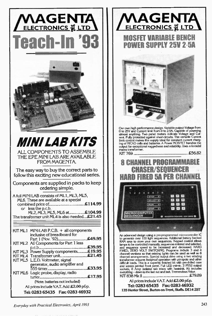
M AG ENTA ELECTRONICS LTD 1, Teach-In '93
MINI LAB KITS ALL COMPONENTS TO ASSEMBLE THE EPE MINI LAB ARE AVAILABLE
FROM MAGENTA.
The easy way to buy the correct parts to follow this exciting new educational series.
Components are supplied in packs to keep ordering simple.
A full MINI LAB consists of ML1, ML3, ML5, ML6. These are available at a special combined price of £114.99 or less the p.c.b.
ML2, ML3, ML5, ML6 at £104.99 The transformer unit ML4 is also needed....E21.45
KIT ML I MINI-LAB P.C.B. + all components inclusive of breadboard for Part 1 (Nov. '92) £49.95
KIT ML2 All Components for Part 1 less p.c.b £39.95
KIT ML3 Power Supply components £19.95 KIT ML4 Transformer unit £21.45 KIT ML5 L.E.D. Voltmeter, signal
generator, audio amplifier and 555 timer £33.95
KIT ML6 Logic probe, display, radio tuner £17.95 (Note: batteries not included)
All prices include VAT. Add £2.00 p&p.
Tel: 0283 65435 Fax: 0283 46932
M AGENTA / ELECTRONICS it LTD I
MOSFET VARIABLE BENCH POWER SUPPLY 25V 2.5A
Our own high performance design. Variable output Voltage from 0 to 25V and Current limit from 0 to 2.5A. Capable of powering almost anything. Two panel meters indicate Voltage and Cur-rent. Fully protected against short-circuits. The variable Current limit control makes this supply ideal for constant current charg-ing of NICAD cells and batteries. A Power MOSFET handles the output for exceptional ruggedness and reliability. Uses a toroidal mains transformer.
KIT 769 £56.82
8 CHANNEL PROGRAMMABLE CHASER/SEQUENCER
HARD FIRED 5A PER CHANNEL
1 Z 3 4 5 • 7 8
1 STEP 91
f SELECT rt1
1 RUN *1
STOP 01
!MICROCOMPUTER SEQUENCER • M AGENTA DESIGNS 116636 1111
An advanced design using a pre-programmed microcontroller IC to generate over 100 light sequences. Additional battery backed RANI area to store your own sequences. Keypad control allows lamps to be controlled manually, sequences entered and selected, and sequence speed to be increased and decreased. HARD FIRED, ZERO VOLT SWITCHING. Programs include 3 and 4 channel versions so that existing lights can be used as well as 8 channel arrangements. Special output drive using a two winding transformer ensures foolproof operation with pin-spots and other difficult loads. This is a superbly finished kit with pre-drilled case and screen printed front panel. Full LED mimic. 2 P552 output sockets, 8 Amp isolated tab triacs with heatsink. Kit includes everything — down to the last nut and bolt. Tremendous Value.
KIT 838 Mk ll £79.89 All prices include V.A.T. Add £2.00 p&p. Tel: 0283 65435 Fax: 0283 46932
135 Hunter Street, Burton-on-Trent, Staffs. DE14 2ST
Everyday with Practical Electronics, April 1993 '43
74 LS-Series.
74LSOO 74LSO1 74LSO2 74LSO3 74LSO4 74LSO5 74LSO8 74LSO9 74LSIO 74LS107 74LS109 74LS11 74LS112 74LSI13 74LS114 74LS12 74LS122 74LS123 74LS125 74LS126 74LS13 74LS132 74LS133 74LS136 74LS138 74LS139 74LS14 74LS145 74LS147 74LS148 74LS15 74LS151 74LS153 74LS154 74L5155 74L51 56 74LS157 74LS158 74LS160 74LS161 74LS162 74LS163 74LS164 74LS165 74LS170 74LS173 74LS174 74LS175 74LS190 74LS191 74LS192 74LS193 74LS195 74LS196 74LS197 74LS20 74LS21 74LS22 74LS221 74LS240 74LS241 74LS242 74LS243 74LS244 74LS245 74LS247 74LS251 74LS257 74LS258 741.526 74LS266 74LS27 741_5273 74LS279 74LS30 74LS32 74LS365 74LS367 74LS368 741_537 74LS373 741.5374 74LS375 74LS377 74L5378 74LS38 74LS390 74LS393 74LS395 74LS399 74LS40 741.542 74LS47 74LS51 74LS670 74LS73 74LS74 74LS75 74LS76 74LS83 741_585 74L586 74LS90 74LS92 74LS93
CO 14 £014 £0.14 £0.14 £014 £0.14 £0.14 £0.14 £0.14 £023 £0.21 £0.17 £0.21 £0.21 £0.21 £0.14 £0.31 £0.31 f0.21 £0.21 £014 £0.21 £0.18 £0.16 £0.24 £0.25 f0.18 £0.56 £1.26 £070 £0.14 £0.25 £0.25 £0.70 £0.25 C0.25 £0.25 £025 £0.32 £0.32 £0.32 £032 £0.26 £0.48 £030 £0.24 £0.24 £024 £0.25 £024 £0.24 £0.24 £0.24 £0.24 £024 £016 £0.14 £0.14 f0.36 £0.32 £0.32 £0.32 £0.32 £0.3.2 £0.33 £0.3.2 £0.24 £0.24 £0.24 £0.14 £0.14 £0.14 £0.32 £0.25 £0.14 £0.14 £0.21 £0.21 £0.21 £0.14 £0.32 £032 f0.34 £0.32 £0.62 £0.14 £0.25 £0.24 £0.26 £0.62 £0.14 f0.25 £0.42 £0.14 £068 £0.17 £0.19 £0.19 £0 25 £0.31 £0.35 £0.20 £0.23 f0.35 £0.25
ENA MELLE D COPPER WIRE
All 20z Reels 14 SWG £0.63 16 SWG £0.67 18 SWG £0.67
22 SWG 24 SWG 26 SWG 28 SWG 30 SWG 32 SWG 34 SWG 36 SWG 38 SWG 40 SWG
£0 76 £0 80 £089 £0 91 £093 f0.93 £099 £1 04 £1 10 £1 22
4000 S ,,
4000 4001 4002 4006 4007 4008 4009 4010 4011 4012 4013 4014 4015 4016 4017 4018 4019 4020 4021 4022 4023 4024 4025 4026 4027 4028 4029 4030 4031 4033 4034 4035 4040 4041 4042 4043 4044 4046 4047 4048 4049 4050 4051 4052 4053 4054 4055 4060 4063 4066 4067 4068 4069 4070 4071 4072 4073 4075 4076 4077 4081 4082 4085 4686 4089 4093 4094 4095 4097 4098 4099 4502 4503 4508 4510 4511 4512 4514 4515 4516 4518 4520 4521 4526 4527 4528 4529 4532 4534 4536 4538 4541 4543 4555 4556 4560 4566 4572 4584 4585 4724 40106 40109 40163 40174 40175 40193
£0.17 COI 7 C0.17 £0.32 £0.17 £0.31 £019 £0.23 £0.16 £016 £0.17 £0.30 f0.31 £0.18 £025 £0.27 £0.19 £0.31 £0.31 £0.32 £0.16 £0.21 £0.15 £0.40 £0 18 £0.22 f0.27 £0.17 £0.70 £0.56 Cl .24 £0.31 £0.29 £031 £0.22 £0.28 £0.31 £031 f0.25 £0.31 £0.20 £020 £0.25 £0.25 £025 £066 £0.30 £0.31 £0.29 £018 £1 .91 £0.16 £020 £0.17 f0.20 £0.17 £0.17 £0.17 £030 £0.17 £0.14 £017 £028 £026 £0.55 £015 £0.31 £0.56 ft 20 £0.31 £0.38 £0.38 £0.31 £0.90 £0.26 £0.29 £0.31 £0.73 £0.78 £0.31 £027 £0.26 £0.62 £13.40 £039 £040 f0.44 £0.32 E2.24 £1 .00 £0.37 £0.31 f0.46 £0.34 £0.34 £1.18 E1 .96 £0.25 £0.24 £0.32 £070 £0.31 £050 £0.46 E0.34 £0.36 £060
2N1613 2N1711 2N1893 2N221 8A 2N221 9A 2N2222A 2N2646 2 N2904A 2N2905A 2N2907 2N2926 2N3053 2N3054 2N3055 2N3440 2N3702 2N3703 2N3704 2N3705 2N3706 2N3771 2N3772 2N3773 2N3819 2N3820 2N3904 2N3905 2N3906 2N4036 2N5296 2N5321 2N6107 AC126 AC127 Ad 28 AC187 AC188 ACY17 AD149 AD161 AD162 BC107 BC10713 BC108 BC108A BC108C BC109 BC109C BC114 BC115 8C116 BC118 BC132 BC134 BC135 BC140 BC141 BC142 BC143 BC149 BC154 BC157 BC159 BC160 BC170 BC1708 BC171 BC1718 BC172 BC172B BC177 BC178 BC179 BC182 BC182L BC182LB BC183 BC183L BC183LB BC184 BC184L
£0.31 £0.26 £029 £0.28 £0.25 £0.16 £0.80 £0.25 £023 £020 £016 £0.27 £0.90 £0.62 £0.50 £0.09 £13.10 £0.10 £0.10 £0.10 C1.44 £1 51 £1 .79 £0.40 £0.58 £0.10 £0.10 £0.10 £031 £0.67 £0.57 £0.60 £0.30 £0.30 £0.28 £0.37 £0.37 £3.84 CT 67 £0.92 £0.92 £0.14 £0.15 £0.12 £014 £0.14 £0.14 £0.15 £041 £0.41 £041 £0.41 £036 £038 £036 £025 £0.27 f0.31 £0.34 £0.12 C0.36 f0.12 £0.12 £028 £13.16 £0.16 £011 £0.115 £0.13 £0.13 £0.17 C0.17 £0.17 £0.08 £0.08 £006 f0.08 £008 £008 £008 £0.08
TRIACS
20105DA £0.42 1IC2060 £0 65 TIC2260 £0 73 BTA08.6008 £0.84 1IC236D £096 DIAC £0.20
VOLTAGE RE GULATORS
78L05 78L12 7815 79L05 79L12 79L15 7805 7812 7815 7905 7912 7915 LM317T LM723 L200CV LM323K LM3313K
°PTO DEVICES
5rnrn Red LED 5rnm Green LED
Stern Yellow LED Stern Orange LED 3mm Red LED 3rnm Green LED
3mm Yellow LED 3rnm Orange LED 5mrn Flashing Red 5rnm Flashing Green 5mm Bi Colour 5rnm Tri Colour 5rnm Plastic Bezel 3rnm Plastic Bezel 0 3 7 Segment Display Red common anode common cathode
£0.24 £0.24 £024 £0.28 f0.28 £0.28 £028 C0.28 f0.28 CO 38 £0.38 £0.38 £0.44 £0.29 £1 .16 E2.70 £5.52
f0.09 £0.10 £010 C0.10 £008 £0.12 £0.13 £013 £0.50 £0.54 £0.36 E0.48 £0.04 £0.06
E1.14 £1.14
047 10 22
107 22 47 100 220 470 1000 2200 4700
TRANSISTORS
BC186 BC264C 8C206B BC207C BC208 BC209A 8C212 8C21 2L BC212LB BC213 BC213LC BC214 BC214L BC237B BC238C BC239C BC251 BC252 BC261B BC262B BC267B BC307 BC308 BC327 BC328 BC337 BC338 8C414C 8C441 8C461 BC463 8C478 8C479 BC490 BC516 8C517 BC527 BC528 BC 537 BC546C 8C547C BC548C BC549C BC550C 8C556A BC557C BC558C BC559C BC560B 8C637 8C638 BC639 BC640 BCY70 BCY71 BCY72 80135 BD136 BD137 80138 60139 60140 BD150C 50165 80166 80187 80201 B0202 BD203 80204 BD222 80225 BD232 BD237 80238 E1024013 802438 BD244A 130246 8 0441 80442
E0 33 £0.72 £0.72 f0.72 £0.72 £0.72 £0.08 £008 £0.08 £0.08 f0.08 £0.08 £0.08 £0.09 £0.09 £0.10 COI 3 £013 £0.24 £0.24 f0.30 COI 0 £010 £0.10 £0.10 COTO £010 £0.13 £0.40 £0.40 £0.29 £0.32 £0.32 £0.24 £0.22 £0 20 £0.20 f0.20 £0.20 £0.08 £009 £0.08 £0.10 £0.08 £0.08 £008 £0.08 £0.08 f0.09 £0.21 £0.21 £0.21 f0.21 £0.21 £0.20 £0.20 £020 £0.20 £0.22 £0.22 f0.23 £024 £0.82 £0.42 f0.35 £0.39 f0.40 £040 £0.40 £0.40 £0.40 £0.42 £0.38 £0.32 £032 f0.37 £050 £0.53 £1.06 £0.41 £0.41
80534 80535 80536 B0646 80648 80650 50707 00807 B0X32 80033C BDX34C BDX53C EIDX54C 8F180 0E182 8E185 8E194 8F195 8E244 8F257 8E259 8E337 6E355 BF423 8E451 8E459 BF469 BF029 BFX84 13E685 13FY50 BFY51 BEY52 BS107 85170 BSW66 BU126 80205 BU208A BU3264 BU500 BU508A BU526 BU806 BUX84 IRF540 IRF740 MJ11015 MJ11016 MJ2501 MJ3001 MJE340 MJE350 MPSA13 MPSA42 MR P475 TI P121 TIP122 T1P125 TI P127 TIP132 TIP137 TIP142 TI P147 TI P2955 TIP29C TI P3055 TIP30C TIP31C TIP32C TIP33C TIP41A T1P42C TI P47 T1P48 TI P50 VN1OKM VN66AF ZTX300 ZTX500
THYRISTORS
P0102AA TIC106D TIC 116D T1C1260
f0.30 £0.40 f0.66 £0 77
HARD WARE
T2 Box 75 x 56 x 25mm T3 Box 75 x 51 x 25mm T4 Box 111 x 57 x 22mrn MB1 Box 79 x 61 x 40mm M82 Box 100, 76 x 41 mm M83 Box 118 x 98 x 45rnm MB5 Box 1500 100 x 60mm
uF 047 10 22 47 10 22 47 100 220 470 1000 2200 4700
£047 £0.48 £0.65 f0.52 C0.52 £0 53 £0 42 £0 80 Cl .78 £0.46 CO 50 £0.47 £0.50 El).31 £0.31 C0.31 £0.19 £0.19 CO 35 f0.33 CO 33 f0.36 f0.38 f0.13 f0.19 £0.29 £0.36 £0.29 £0.31 £0.31 £0.29 £0.26 £028 £021 £0.21 Cl .35 Cl 70 £1 82 C1.73 Cl .80 f2.32 fl 76 £2.24 Cl .36 CO 77 Cl 60 £1.63 £2.11 £2.11 Cl .60 Cl 52 £036 £0.42 f0.12 £0.17 £6.21 £035 £0.37 £037 £0.37 £0.46 £0.46 C1.06 £112 £0.63 £0.31 £0.63 £031 £0.32 £0.32 £072 £038 £0.38 £048 f0.62 £0.53 £0.44 Cl .50 f0.16 £0.16
E0.82 £0.82 £098 £1.44 £1 56 £1.82 £2.50
ESR ELECTRONIC CO MPONENTS Station Road, Cullercoats, Tyne & Wear NE30 4PQ Tel. 091 251 4363 Fax 091 252 2296
LINEAR IC,
CA311E CA324 CA555 CA7410E CA747CE CA3046 CA3080 CA3130 CA3130E CA3140 CA3240 ICL7621 ICM7555 ICM7556 LM301A LM348N LF351N LF353 LM358N LM377 LM380N LM381 LM386 LM387 LM392N LM393N LM748CN LM1458 LM3900 LM3914 LM3915 MC3340 MC4558 NE531 NE556N NE567N NE5532 NE5534 TBA1205 TBA8105 TBA820M TDA2030 TL061 TL062 TL064 TL071CP TL072CP TL074CN TL081 TL082CP TL084CN UA733 ULN2004 ZN414Z ZN425E ZN426E ZN427E ZN428E ZN435E 0144488
£0.28 £023 f0.22 £0.18 £039 E0.37 E0.72 £0.98 £0.98 £0.56 £1.22 EI .70 £0.43 £0.96 f0.25 f0.31 f0.38 f0.41 f0.27 £2 57 £112 E2.70 £0.48
£0.79 £0.28 £0.31 f0.26 CO 72 E2.70 E2 70 Cl 60 C0.36 Cl 56 f0.36 £0.36 f0.80 COBS £0.77 £0 68 f0.39 C1.35 f0.35 £0.42 f0.46 f0.32 CO 34 f0.48 £0.33 £0.34 £0.46 £0.64 £0.48 Cl .04 £4.68 £2.61 £8.82 £612 CS 31 £7 92
EPR O MS & RA MS
2716 2732 2764-25 27C64-25 21728-20 27C128-20 27256-20
27C256-20 27512 27C512 27C010 6116-10 6264-10 62256-10 4164-15 41256-10 511000-8 514256.8
E4.19
£4.19 E3.00 f2.75 £315 £2.88 £315 £288 £3.70 £3.40 £4.60 Cl .25 £2 75 £460 Cl .60 £1.60 £4.20
£4.20
DIE SOCKETS
8 Pin 14 Pin 16 Pin 18 Pin 20 Pin 24 Pin 28 Pin 40 Pin
ELECTR OLYTIC RADIAL CAPACITORS
160
£0.05 C0.05 £0.06 £006 £0.09 £0.15 £022 £0.37
25V
£0.05 £0.05 £006 £009 £0.12 CO 19 f0.29 f0.57 El 11
63V £005 £0.05 £0.06 £0.05 £0.06 £009 £0.11 £011 £0.31 CO 57
100y f0.07 f0.06 f0.06 £0.08 E0.08
£0.07 £0.11 £0.15 £0.15 £0.16 £0.19 £0.22 £0.25
450V
£0.15 £0.18 £0.30 £0.48
ELECTROLYTIC AXIAL CAPACITORS
uP 160 250 630
£010 £0.10
£0.09 £0.10 £0.12 £0.12 £0.09 £0.13
COTO f0.11 £0.16 £0.10 £0.13 f0.21 f0.13 £018 £0.42 £0.21 £024 £0.69 £0.33 £0.40 £1.05 £0.52 £0.64 £0.90
1000 4500
£0.15 £0 10 £0 10 £0.10 £0.12 f0.17 £0.20
f0.19 f0.22 £0.34 f0.48 Cl .06 El .33 £2 46
SOLDERING IR ONS
AntexSoldermgrrons M 12 Wan C 15Watt G 18Watt CS 17Watt XS 25Watt ST4 STAND 35Watt Gas Iron Desolder Pump Antistatic Pump 22SWG 0 5Kg Solder 18SWG 0 5Kg Solder lmm 3 yds Solder Desolder Braid
C775 £778 f7 96 C788 E7 96 C285 £11 58 £300 C430 E7 40 C660 CO 62 £087
RF CONNECTORS
BNC Solder Plug SOS BNC Solder Plug 75R BNC Crimp Plug 508 BNC Crimp Plug 758 EINC Solder Skt BNC Chassis Ski PL259 5 2mm PL259 11 rem RND UHF socket SCIR UHF socket F Plug RG58 F Plug RG6 N Plug RG8 N Socket ROB BNC Crimp Pliers
PCB EQUIP MENT
UV EXPOSURE UNIT PLASTIC DEVELOPING TRAY PHOTO RESIST AEROSOL SPRAY (100m11 FERRIC CHLORIDE CRYSTALS 10 5Kg) TIN PLATING PO WDER (909) ETCH RESIST PEN PCB POLISHING BLOCK Cl 84
STRIPBOARD 0-1 PITCH BREADBOARD 64mrn x 25rnm £0.27 81rnm x 60mm £3.06 64mrn x 95mrn £0.90 175rnm x 42mrn £3.74 64rnm x 431rnrn £3.22 175rnm x 67mrn £5.56 95rnm x 127rnm Cl .50 203rnm x 75mm includes 95mm x 95mm £1 .10 mounting plate & posts £7.36 95rnm x 431mm £4.80 COPPER BOARD (G. Fibre) 100mm x 16Ornm £1.60 100mm x 160mm £0.90 119mrn x 454rnm £820 110/nm x 220mm £1.24
PHOTO RESIST BOARD PHOTO RESIST BOARD (G Fibre) (Paper)
EO M £13.67 4 r o6- £1 62 4 r6 Cl 24 4' e8 ' £2.09 4o8 £1.58 6' o6' £241 5- x 101 £463
CO 93 £0.96 £068 £0 68 £1.08 £080 £0.68 £0.62 £0.68 £0.45 f0.30 E0.27 £1.60 Cl .40 £15.50
CAPACITORS
Ceramic Mini Disc 100 & 63V 1 OpF to 100nF 1pF-11-1F f0.06, 1n2-2n7 £0.07 3n3-4n7 f 0.12. 10n 8112n f0.07
Polystyrene 160V5% 47pF to lOnF 47p-2n2 £0.09 2n7-10n £0.12
D CONNECTORS
Plug Socket 9 Pin £0 29 £0 30 15 Pin £0 39 £0 35 15 Pin H D £081 £0 90 23 Pm £0 40 £0 49 25 Pin £048 £0 50 9 Way plastic cover £0 .30 15 Way plastoc cover £0 .33 23 Way plastic covet £0.36 25 Way plastic cove! £0. 38
BRIDGE
RECTIFIERS
W005 1 5A 50V WO2 1 5A 200V 8R32 3A 200V
8R62 6A 2000 1004 10A 4000
£0.19 [0.20 £0.36 £0.64 £1.39
£67.38 Cl 35 £3.90 £2.45 E10.80 CO 72
S WITCHES
3amp 250v 6 4mm o rnountrnd SPOT Toggle £0 58 SPDT Toggle £0. 60 SPDT CO Tog DPDT Toggle DPDT CO Toggle DPDT CO Toggle (biased) Cl 20 DPDT CO Toggle (biased 1 way) £1.20 DPDT mini slide £0.15 Rotary Wafer 1P•12W. 2P-6W. 3P-4W, 4P-3W Key Switch SPST Push to make Push to break Latching Push Syr PCB Tact 6 x 6mm
RESISTORS
£0 64 £068 £0 76
C078 E2.70 f0.25 E028 0 63 £025
025W 5% CF 812 Series £0.60 100 0 5W 5% CF El 2 Series E0.95 100 0 25W 1% MF E24 Senes £1.72100 POTS Log or Lin 470R - IMO 25rnm die 0 25in shah £0.42
PRESETS Enclosed Nor, orVen 100R-1 M0 015W £0.15
PRESETS Skeleton Horz orVert100R- 1M001 W £0.11 • PLEASE STATE VALUE RFC:RAPED •
CO MPUTER ACCESSORIES
Parallel Printer Lead 2m RS232 Lead (all pins) Male Male R5232 Lead (all pins) Female Male Centronics 36 Way Lead Male Male
Gender Changers 9 Way D Mini Female to Female 9 Way D Mini Male to Male 25 Way D Mini Female to Female 25 Way D Mini Male to Male 9 Way D Female to Female 9 Way D Male to Male 25 Way D Female to Female 25 Way 0 Male to Male
Adaptors 9 Way Male to 25 Way Female 25 Way Male to 9 Way Female 25 Way D Male 10 36 Way Centronic 25 Way Null Modem Female Female 25 Way Null Modern Male to Female 25 Way Null Modern Male to Male RS232 Surge Protector Male Female R5232 Jumper Box Male to Female R5232 Tester (7 LEDs) Male Female
Data Switch Boxes Serial Switch box - 2 Way Serial Switch box -3 Way A/B/C Serial Switch box -4 Way A/B/C/D Serial Switch box - Cross over Parallel box -2 Way A/B Parallel box -3 Way A/B/C) Parallel box - 4 Way A/13/C/D Parallel box - Cross over
£6.90 £3.60 £3.60 £4.78
Cl .81 £1.98 E2.23 £2.23 E2 33 E2. 33 £2.71 £2.71
f2 33 E2 33 E3.56 £3.02 £3.02 £302 £612 £3.02 £659
£9.20 £13.16 £15.15 E19.69 E11.84 £17.11 £18.43 £20 42
DIODES
Zener Diodes 207 330 BZY88400Mw £0 09 BZX85 1 3W £0.14 1N4001
1N4002 154003 1N4004
1144005 1N4006 1144007
1N5400 I N5401
1N5402 1 N5404 I N5406 1N5407
1N 5408 1N914 1N916 1N4148 13Y133
0A47 0A90 0A91 04202 BA157 BA158
BA159 1144149
0A200
ORDERING INFOR MATION
£0.06 £0.07 £007 £0.07 £0.07 £0.08 £0.08 £0.09 £0.09 £0.09 CO M C0.11 £0.14 f0.15 f0.06 £0.06 £005 C0.13 £0.28 £0.07
£0.10 £0.27 £0.10 £0.10 £0.10 £0.06 £0.10
All prices exclude VAT. Please add £1.25 carriage to all orders and VAT (17.5%).
No minimum order charge. Free Computer listing with all orders over £5.00.
Please send payment with your order.
EN PO/Cheques made payable to ESR Electronic Components VISA Access & Visa cards accepted
Offical orders from schools & colleges welcome
CALL IN -OPEN: MON-FRI 8.30-5.00 SAT 10.00-5.00
244 Everyday with Practical Electronics, April 1993
EVERYDAY WITH PRACTICAL
ELECTRONICS INCORPORATING ELECTRONICS MONTHLY
VOL. 22 No. 4 APRIL '93
Editorial Offices: EVERYDAY with PRACTICAL ELECTRONICS EDITORIAL, 6 CHURCH STREET, WIMBORNE, DORSET BH21 1JH Phone: Wimborne (0202) 881749
Fax: (0202) 841692. DX: Wimborne 45314. See notes on Readers' Enquiries below - we regret that lengthy technical enquiries cannot be answered over the telephone.
Advertisement Offices: EVERYDAY with PRACTICAL ELECTRONICS ADVERTISEMENTS, HOLLAND WOOD HOUSE, CHURCH LANE, GREAT HOLLAND, ESSEX C013 OJS. Phone/Fax: (0255) 850596
POST AND PACKING A reader's letter published last month has resulted in some comments from
advertisers to the editorial office and in a letter from Greenweld, one of the major players in mail order component supplies — see Readout this month. It is under-standable that readers feel post and packing charges are high when they receive a small package with less than fifty pence worth of stamps on. However when one stops to consider the work behind getting that small package to you, including the back up necessary to get the items in stock in the first place, it is perhaps "a
bargain" as Greenweld put it. The letter from Greenweld puts the points very well and also indicates that
charges in our "industry" are much lower than in many other mail order areas of operation. The alternative is obviously to increase the price of components so that mail order costs are hidden. In my view this would not help anyone, least of all the constructor who can get to one of the suppliers and buy components over the
counter.
NO OVERHEADS Some of the smaller "one man band" suppliers are able to keep costs to an
absolute minimum but most suppliers in this area are operating a mail order business as a side line, they have virtually no overheads and no staff salaries to pay. Many such companies grow into larger businesses — it was in just this way
that Maplin started not so very long ago. No doubt we will hear more on this subject and well considered views would be
welcome. It is no good just shouting "rip off— without thinking through what is actually happening to your order. One final point, it pleases me that our advertisers in general are happy to explain
why they have to make such charges. I visit many of them and know that in general they run complex operations in efficient and cost effective ways, they try hard to keep customers happy in an effort to make sure you come back for more. The very nature of the industry means that there is strong competition between suppliers, and components in the UK are available, in relative terms, as cheaply as
they are nearly anywhere in the world. AJ Ii
SUBSCRIPTIONS Annual subscriptions for delivery direct to any address in the UK: £20. Overseas £26 (E43.50 airmail). Cheques or bank drafts (in £ sterling only) payable to Everyday with Practical Electronics and sent to EPE Subscriptions Dept., 6 Church Street, Wimborne, Dorset BH21 1JH. Tel 0202 881749. Subscriptions start with the next available issue. We accept Access (MasterCard) or Visa pay-ments, minimum credit card order £5.
r/T ar rINIMI =19
E L E C T R O NI C S
DIGITAL AUDIO BROADCASTING Future transmissions should match dinital mfi quality
SIMPLIFO A jOystidl to mouse interface CAR ELECTRIC WINDOW ENHANCER MICROPHONE COMPRESSOR
BACK ISSUES Certain back issues of EVERYDAY ELECTRONICS and PRACTICAL ELECTRONICS are available price £2.00 (£2.50 overseas surface mail) inclusive of postage and packing per copy - £ sterling only please, Visa and Access (MasterCard) accepted, minimum credit card order £5. Enquiries with remit-tance, made payable to Everyday with Practical Electronics, should be sent to Post Sales Department, Everyday with Practical Electronics, 6 Church Street, Wimborne, Dorset BH21 1JH Tel: 0202 881749. In the event of non-availability one article can be photostatted for the same price. Normally sent within seven days but please allow 28 days for delivery We have sold out of Jan, Feb, Mar, Apr, May, June, Oct, & Dec 88, Mar & May 89, Mar 90 & Sept 91 Everyday Electronics, and can only supply back issues from Jan 92 to Oct 92 (excluding Mar 92) of Practical Electronics.
BINDERS New style binders to hold one volume (12 issues) are now available from the above address for £4.95 plus £3.00 post and packing (for overseas readers the postage is £6.00 to everywhere except Australia and Papua New Guinea which cost £10.50). Normally sent within seven days but please allow 28 days for delivery.
Payment in £ sterling only please. Visa and Access (MasterCard) accepted, minimum credit card order £5. Send card number and card expiry date with your name and address etc.
Editor: MIKE KEN WARD
Secretary: PAM BROWN
Deputy Editor: DAVID BARRINGTON
Business Manager: DAVID J. LEAVER
Subscriptions: MARILYN GOLDBERG
Editorial: Wimborne (0202) 881749
Advertisement Manager: PETER J. MEW, Frinton (0255) 850596
Advertisement Copy Controller: DEREK NEW, Wimborne (0202) 882299
READERS' ENQUIRIES We are unable to offer any advice on
the use, purchase, repair or modification of commercial equipment or the incor-poration or modification of designs pub-lished in the magazine. We regret that we cannot provide data or answer queries on articles or projects that are more than five years old. Letters requiring a per-sonal reply must be accompanied by a stamped seff ddressed envelope or a self addressed envelope and interna-tional reply coupons. All reasonable precautions are taken to
ensure that the advice and data given to readers is reliable. We cannot however guarantee it and we cannot accept legal responsibility for it.
CO MPONENT SUPPLIES We do not supply electronic com-
ponents or kits for building the projects featured, these can be supplied by adver-tisers. We advise readers to check that all parts
are still available before commencing any project in a back-dated issue. We regret that we cannot provide data
or answer queries on projects that are more than five years old.
ADVERTISEMENTS Although the proprietors and staff of
EVERYDAY with PRACTICAL ELEC-TRONICS take reasonable precautions to protect the interests of readers by ensuring as far as practicable that advertisements are bona fide, the magazine and its Publishers cannot give any undertakings in respect of statements or claims made by advertisers, whether these advertisements are printed as part of the magazine, or are in the form of inserts. The Publishers regret that under no
circumstances will the magazine accept liability for non-receipt of goods ordered, or for late delivery, or for faults in manufac-ture. Legal remedies are available in respect of some of these circumstances, and readers who have complaints should first address them to the advertiser.
TRANS MITTERS/BUGS/TELEPHONE EQUIP MENT We would like to advise readers that cer-
tain items of radio transmitting and tele-phone equipment which may be advertised in our pages cannot be legally used in the UK. Readers should check the law before using any transmitting or telephone equip-ment as a fine, confiscation of equipment and/or imprisonment can result from illegal use. The laws vary from country to country; overseas readers should check local laws.
Everyday vith Practical Electronics, April 1993 245
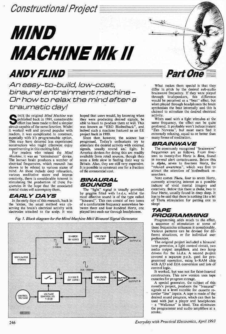
Constructional Project
MIND MACHINE Mk II ANDY FUND Part One An easy-to-build, lo w-cost, binaural entrain ment machine - Or ho w to relax the mind after a trau matic day!
SINCE the original Mind Machine was published back in 1991, considerable effort has been made to find a simpler
circuit capable of the same function. Whilst it worked well and proved popular with readers, it was complicated to construct, especially with it's programmable option. This may have deterred less experienced constructors who might otherwise enjoy experimenting in this exciting field. For readers who missed the Mind
Machine, it was an "entrainment" device. The human brain produces a number of electrical frequencies, which research has shown to be related to various states of mind. As these include deep relaxation, various meditative states and intense creativity, there is considerable interest in stimulating the production of these fre-quencies in the hope that the associated mental states will accompany them.
EA RL Y D A YS In the early days of this research, back in
the 'sixties, the usual method was ob-serving the brain's electrical activity with electrodes attached to the scalp. It was
hoped that users would, by knowing when they were producing desired signals, be able to learn to produce them at will. This was known as "EEG Biofeedback", and indeed such a machine featured as an EE project back in 1989. Since then however, the science has
progressed. Today's enthusiasts try to stimulate the desired activity with external signals, usually sound an light. In America devices for doing this are readily available from retail sources, though they seem a little slow in finding their way to Britain. Also, they are still very expensive. It is possible to construct one for a fraction of the commercial cost.
BI NALIRAI-S OU NDS The "light" signal is usually provided
by goggles fitted with 1.e.d.s, whilst the most effective sound is of the type called "binaural". This can consist of two tones of a comfortable frequency somewhere be-tween three and four hundred Hertz, one played into each ear through headphones.
Fig 1. Block diagram for the Mind Machine Mk11 Binaural Signal Generator.
OSCILLATOR 1.5MHz
CONTROL VOLTAGE
VOLTAGE CONTROLLED
TIMER
DIVIDER
1130 40961
D I VIDE R BY 40961
LOW-PASS FILTER
LOW-PASS Fl LTER
BUFFER AMP
BUFFER AMP
What makes them special is that they differ in pitch by the desired sub-audio brainwave frequency. If they were played through loudspeakers, this difference would be perceived as a "beat" effect, but when played through headphones the brain synthesises the beat internally and this is claimed to stimulate the desired electrical activity. When used with a light stimulus at the
same frequency, the effect can be quite profound. It probably won't induce instant "Zen Nirvana", but most users find it extremely relaxing, equal to or better than many forms of meditation.
B RAI N WA VE The commonly recognised "brainwave"
frequencies are as follows. From four-teen to twenty-five Hertz is Beta, found in normal alert consciousness. Below this is Alpha, seven to fourteen Hertz, for "relaxed awareness", which was first to attract the attention of biofeedback re-searchers. Next comes Theta, four to seven Hertz,
currently attracting interest as a possible inducer of vivid mental imagery and creativity. Below this there is Delta, two to four Hertz, usually found in deep sleep. It has to be said that there is nothing like a bit of Theta stimulation for putting one to sleep!
TA PE P ROGRA M MI NG Programming adds much to the effect,
a sequence of stimulation at some of these frequencies enhances it considerably. Various patterns can be devised for dif-ferent situations, or for individual user preferences. The original project included a binaural
tone generator, a light control circuit, two audio output amplifiers, and two lamp drivers for the 1.e.d.s. A second project covered a separate p.c.b. used for pro-grammed operation, using it-- RAM chip with AID and D/A conversion and lots of control logic. It worked, but was not for faint-hearted
constructors. This new version uses tape cassettes for program storage. A special generator, the subject of this
month's project, produces the "binaural" signals at a level suitable for cassette re-corder "line" inputs. A tape is made of the desired sound program, which can then be used with just a player and headphones — a "Walkman" is ideal. This eliminates the programmer and audio amplifiers at a stroke.
246 Everyday with Practical Electronics, April 1993
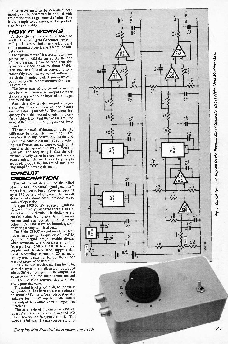
A separate unit, to be described next month, can be connected in parallel with the headphones to generate the lights. This is also simple to construct, and is pocket-sized for portability.
H O W IT W ORKS A block diagram of the Mind Machine
MkII, Binaural Signal Generator, appears in Fig. 1 . It is very similar to the front-end of the original project, apart from the out-put stages. The "prime mover" is a crystal oscillator
generating a 1-5MHz signal. At the top of the diagram, it can be seen that this is simply divided down to about 366Hz, then low-pass filtered to convert it to a reasonably pure sine-wave, and buffered to match the intended load. A sine-wave out-put is preferable to a squarewave for listen-ing comfort. The lower part of the circuit is similar save for one difference. An output from the divider is applied to the input of a voltage-controlled timer. Each time the divider output changes
state, this timer is triggered and blocks the oscillator signal briefly. The output fre-quency from this second divider is there-fore slightly lower that that of the first, the exact difference depending upon the timer period. The main benefit of this circuit is that the
difference between the two output fre-quencies is easily controlled, stable and repeatable. Most other methods of produc-ing two frequencies so close to each other would be drift-prone and very difficult to calibrate. The only snag is that the dif-ference actually varies in steps, and to keep these small a high initial clock frequency is required, though the integrated oscillator chip simplifies this requirement.
CIRCUIT D ESCRIPTIO N The full circuit diagram of the Mind
Machine Mk11 "binaural signal generator" stages is shown in Fig.2. Power is supplied by a PP3 battery which, since the overall drain is only about 5mA, provides many hours of operation. A type LP2950 5V positive regulator ICI, with decoupling capacitors Cl to C4, feeds the entire circuit. It is similar to the 78L05 series, but draws less quiescent current and can operate with an input below 5.5V. This saves on batteries, soon offsetting it's higher initial cost. The 8-pin CMOS crystal oscillator, IC2, has a fundamental frequency of 12MHz, but the integral programmable divider when connected as shown gives an output from pin 2 of 1.5MHz. It MUST have a 5V supply, and the data sheet suggests that local decoupling capacitor C5 is man-datory too. It may not be, but the author was not prepared to find out! IC3 is the first divider, dividing by 4096,
with the input to pin 10, and an output of about 366Hz from pin I. The output is a squarewave but the filter circuit around RI, Cl and IC4a converts this to a rela-tively pure sinewave. The initial level is too high, so the value of resistor RI has been chosen to reduce it to about 0.35V r.m.s. (one volt peak-peak), suitable for "line" inputs. IC4b buffers the output to ensure correct impedance matching. The other side of the circuit is identical apart from the timer circuit around IC5 which lowers the frequency a little. This works as follows. IC5 is a comparator, not
Everyday with Practical Electronics, April 1993
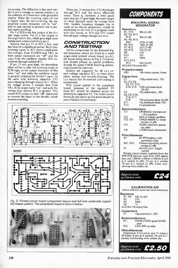
an op-amp. The difference is that each out-put is not a voltage or current source, it is the collector of a transistor with grounded emitter. When the inverting input of one is higher than the non-inverting, the ap-propriate output transistor will be "on", able to sink current to ground, but it can-not supply anything. Pin 1 of IC6 is the last output of the div-
ider, stage twelve. Pin 15 is the output of the stage before this, which goes high twice during each output cycle from pin I. Assume that pin 15 of IC6 is low, and
has been for a significant period. Both non-inverting inputs to IC5 receive small posi-tive voltages, from R13/R14 and VR I, so both output transistors are "off" and the input from the oscillator reaches IC6 un-hindered through resistor RI 5. If pin 15 now goes high, the immediate
effect will be to take the inverting input of IC5b high, so the output transistor of this turns "on" and sinks the oscillator signal to ground, stopping the divider's input. At the same time however, capacitor C12 starts charging through resistor R11. When the voltage across it exceeds that from VR I , IC5a output turns "on" and pulls the voltage from resistor R12 to ground. This causes IC5b output to turn "off" again and so restores the input to the divider, which resumes counting.
When pin 15 returns low, C12 discharges through R11 and the circuit effectively resets. There is, therefore, a brief pause each time pin 15 goes high, the exact length of which depends upon the voltage from VR1. Sudden frequency changes, due to noise or an abrupt adjustment, would be distracting to the user of a program made with this circuit, so RIO and C11 ensure that all input voltage changes are slow.
C O NSTR UCTIOAI A ND TESTI NG All the components for the Binaural Sig-
nal Generator circuit are fitted to a small single-sided printed circuit board (p.c.b.), the layout being shown in Fig.3. Construc-tion should present no special problems, though the usual CMOS handling precau-tions should be observed. Sockets are suggested for all i.c.s ex-
cept voltage regulator ICI, as these allow easier testing and trouble-shooting. The i.c.s should not be inserted until testing is commenced. With power applied to the completed
board, presence of the regulated 5V from ICI should be checked across the electrolytic capacitor C4. The total current drawn by the circuit at this point should be just a fraction of a milliamp.
C6
.1_, e 0 •-1 li)
* , R17
tale/ .1.- R19
C15 O6 OUT
Lir 0 g I
R8 ell
IC3 •,t. g 5( P 0 1- .
IN -
- R15
1_
-ir c- T I T C17
-5-R2 _t_ 1
R20
522 ' 0 e‘j
C18
1*
C4 .4 " •
Out
• co
PI 0 i R2
Iv I 0 __.si
r—_,t VR I 1--
T
-l....), 0
g I
511
C12
is
R14
R15 L.
L'
:IP
IC6
•) .2
' J
I
1
.1- ce
Ri.
g 0
*
IC4 E DT
10 1..
. Ict s®
® 81-
R9
fo x 1 3)1Y,12_,i_ci - C1 R3 _._
6 C9
ris• R6 [941C10
-E-
lc alop, .C1 so UT
C 11
( EE 4059 6
•
. . •
-
4 2 anl. rt li
• a
1 0. 0
e— ii—
r g ").
•
a
a
\
1...4• 0
0 ..... :_l....... : i" .
824 oci
a
•
O
a I ' O 0 O o N a 14. 41 .: 1... ? a II
o l
• i
Fig. 3. Printed circuit board component layout and full size underside copper foil master pattern. The completed board is shown below.
• •;
• -i 7 t ' 4 1
I 14" a, 6s44,0,
V
- • I i ,7 ' I I I
A ;..
At T
COMPONENTS BINAURAL SIGNAL GENERATOR
Resistors R1, R16 68k (2 off) R2, R3, R17, R18 39k (4 off) R4, R5, R19, R20 270k (4 off) R6, R21 150k (2 off) R7, R22 2k2 (2 off) R8, R15 10k (2 off R9 1k5 R10 1M R11 100k R12, R13, R14 22k (3 off)
All 0.6W 1% metal film
Potentiometer VR1 10k rotary carbon, linear
Capacitors C1 100µ radial elect., 10V C2, C3, C5, C6, C7, C13, C14, C15 100n polyester layer
(8 off) C4 47µ radial elect., 25V C8, C9, C10, C16, C17, C18 10n polyester layer (6 off) C11 10µ tantalum bead, 16V C12 in polystyrene
Semiconductors IC1 LP2950CZ, micropower
+5V regulator IC2 EXO-3 crystal oscillator IC3, IC6 CMOS 4040B 12-stage
divider (2 off) IC4 TL064 quad low-power
op. amp. IC5 LM393 dual comparator
Miscellaneous B1 9V PP3 battery, with
connector clips Ski, SK2 Chassis mounting phono
socket (2 off) Si On/off s.p.s.t. toggle
switch Printed circuit board available from the EPE PCB Service, code 824; ABS plastic box, size 120mm x 65mm x 40mm; 8-pin d.i.l. socket (2 off); 14-pin d.i.l. socket; 16-pin d.i.l. socket (2 off); knob; con-necting wire; solder, etc.
Approx cost guidance only £24
CALIBRATION AID (check with text, some may not be necessary)
Resistors R1, R3 10k (2 off) R2 27k R4 100k R5 1k All 0.6W 1% metal film
Capacitors C1 101.1axial elect., 25V
Semiconductors IC1 4011B CMOS quad NAND
gate IC2 CA3140E op.amp
Miscellaneous Stripboard, Olin pitch, size 11 stops x 26 holes; 8-pin d.i.l. socket; 14-pin di!. socket; connecting wire: solder, etc.
Approx cost guidance only C2.50
248 Everyday with Practical Electronics, April 1993
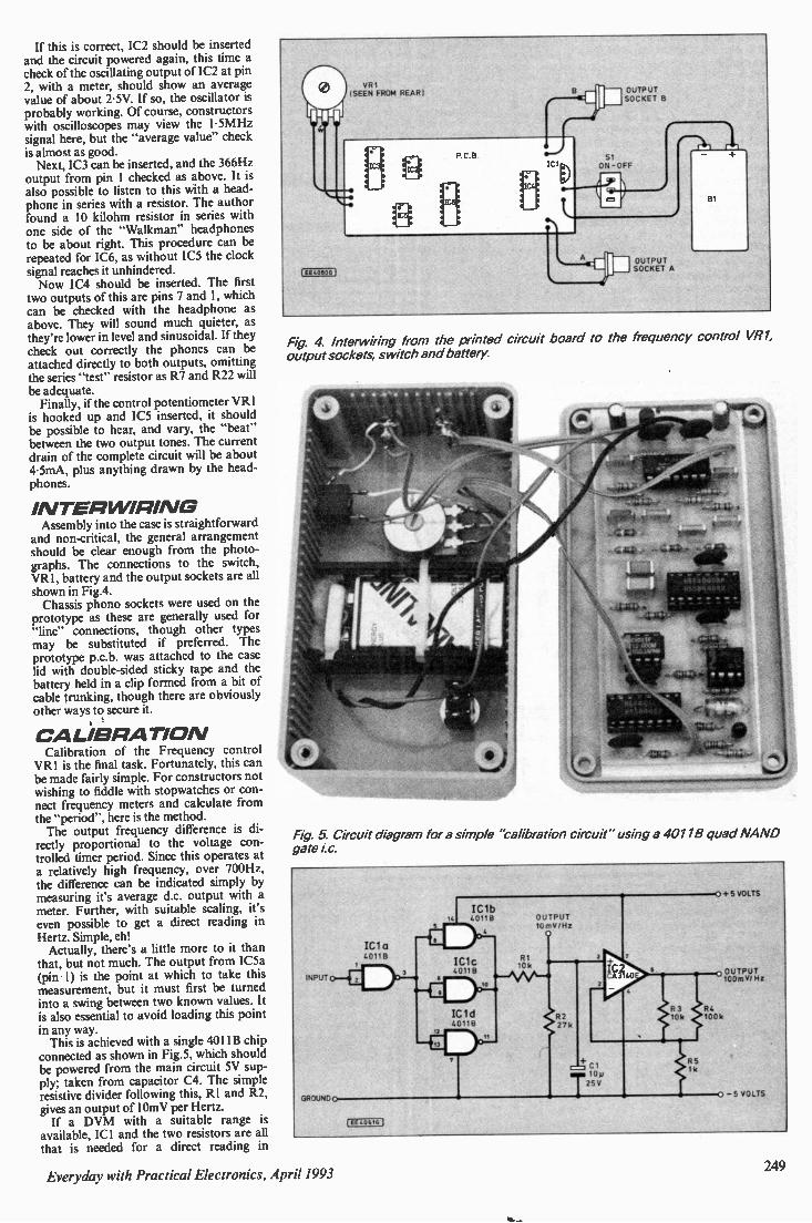
If this is correct, IC2 should be inserted and the circuit powered again, this time a check of the oscillating output of IC2 at pin 2, with a meter, should show an average value of about 2.5V. If so, the oscillator is probably working. Of course, constructors with oscilloscopes may view the 1.5MHz signal here, but the "average value" check is almost as good. Next, IC3 can be inserted, and the 366Hz
output from pin I checked as above. It is also possible to listen to this with a head-phone in series with a resistor. The author found a 10 kilohm resistor in series with one side of the "Walkman" headphones to be about right. This procedure can be repeated for IC6, as without IC5 the clock signal reaches it unhindered. Now IC4 should be inserted. The first
two outputs of this are pins 7 and 1, which can be checked with the headphone as above. They will sound much quieter, as they're lower in level and sinusoidal. If they check out correctly the phones can be attached directly to both outputs, omitting the series "test" resistor as R7 and R22 will be adequate. Finally, if the control potentiometer VR I
is hooked up and IC5 inserted, it should be possible to hear, and vary, the "beat" between the two output tones. The current drain of the complete circuit will be about 4.5mA, plus anything drawn by the head-phones.
IAITER WIRIAIG Assembly into the case is straightforward
and non-critical, the general arrangement should be clear enough from the photo-graphs. The connections to the switch, VR1, battery and the output sockets are all shown in Fig.4. Chassis phono sockets were used on the
prototype as these are generally used for "line" connections, though other types may be substituted if preferred. The prototype p.c.b. was attached to the case lid with double-sided sticky tape and the battery held in a clip formed from a bit of cable trunking, though there are obviously other ways to secure it.
C ALIBRATIOAI Calibration of the Frequency control VR I is the final task. Fortunately, this can be made fairly simple. For constructors not wishing to fiddle with stopwatches or con-nect frequency meters and calculate from the "period", here is the method. The output frequency difference is di-rectly proportional to the voltage con-trolled timer period. Since this operates at a relatively high frequency, over 700Hz, the difference can be indicated simply by measuring it's average d.c. output with a meter. Further, with suitable scaling, it's even possible to get a direct reading in Hertz. Simple, eh! Actually, there's a little more to it than
that, but not much. The output from IC5a (pin 1) is the point at which to take this measurement, but it must first be turned into a swing between two known values. It is also essential to avoid loading this point in any way. This is achieved with a single 4011B chip
connected as shown in Fig.5, which should be powered from the main circuit 5V sup-ply; taken from capacitor C4. The simple resistive divider following this, RI and R2, gives an output of 10mV per Hertz. If a DVM with a suitable range is
available, ICI and the two resistors are all that is needed for a direct reading in
VR I (SEEN FROM REAR(
IEELD6OG
OUTPUT SOCKET B
Si ON
OUTPUT SOCKET A
Fig 4. lnterwiring from the printed circuit board to the frequency control VR1, output sockets, switch and battery.
Fig 5. Circuit diagram for a simple "calibration circuit" using a 40118 quad NAND gate
Everyday with Practical Electronics, April 1993 249
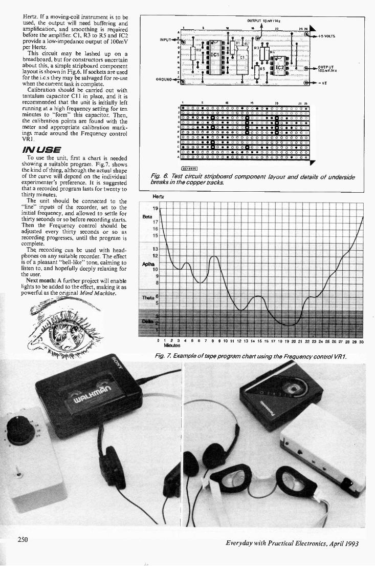
Hertz. If a moving-coil instrument is to be used, the output will need buffering and amplification, and smoothing is required before the amplifier. Cl, R3 to R5 and IC2 provide a low-impedance output of 100mV per Hertz. This circuit may be lashed up on a
breadboard, but for constructors uncertain about this, a simple stripboard component layout is shown in Fig.6. If sockets are used for the i.c.s they may be salvaged for re-use when the current task is complete. Calibration should be carried out with
tantalum capacitor CI 1 in place, and it is recommended that the unit is initially left running at a high frequency setting for ten minutes to "form" this capacitor. Then, the calibration points are found with the meter and appropriate calibration mark-ings made around the Frequency control VR I.
/A/ U SE To use the unit, first a chart is needed
showing a suitable program. Fig.7. shows the kind of thing, although the actual shape of the curve will depend on the individual experimenter's preference. It is suggested that a recorded program lasts for twenty to thirty minutes. The unit should be connected to the
"line" inputs of the recorder, set to the initial frequency, and allowed to settle for thirty seconds or so before recording starts. Then the Frequency control should be adjusted every thirty seconds or so as recording progresses, until the program is complete. The, recording can be used with head-
phones on any suitable recorder. The effect is of a pleasant "bell-like" tone, calming to listen to, and hopefully deeply relaxing for the user. Next month: A further project will enable
lights to be added to the effect, making it as powerful as the original Mind Machine.
—
250
A
INPUT
GROUND
A
10
OUTPUT 10 mV / H
20 211
VOLTS
1$ 20
0 0 0 0 0 0 0 0 0 0 . 0 0 . 0
0 0 • 0 • • • 0 • • 0 0 0 • 0 0 0 • • • 0 • 0 0 0 0
• 0 0 0 • 0 0 • • 0 0 0 • 0 0 0 • 0 • O • 0 •
• 0 • • 0 0 0 0 • • 0 0 0
0 0 0 0 0 • 0 0 • • • 0 0 0 0 0 0 • 0 • 0 0 0 0
• • 0 • • 0 0 0. 0 0 0 0 0 0 0 0 0 0 0 0
0 0 0 • • 0 • • 0 0 0 • 0 0 • • 0 0 0 0 0 • 0 0
0 0 • 0 0 0 0 0 0 0 • 0 • 0 • • 0 0 0 0 0 0 0 0 0 0
OUTPUT 100 mV /Hz
VE
EE40620
Fig 6. Test circuit stripboard component layout and details of underside breaks in the copper tracks.
Hertz
19
Beta 17
16
15
13
12
Aolha to 9
8
Theta 6 5
Olga 2 I
1
—r
i I 0 1 2 3 4 5 6 7 8 9 10 11 12 13 14 15 16 17 18 19 20 21 22 23 24 25 26 27 28 29
Minutes
Fig 7 Example of tape program chart using the Frequency control VI? 1,
Everyday with Practical Electronics, April 1993
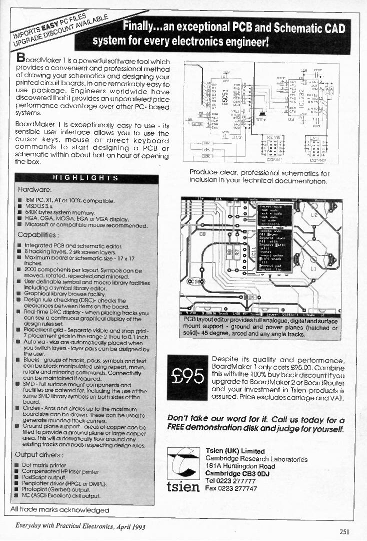
\tfip°' \S Finally...an exceptional PCB and Schematic CAD
system for every electronics engineer!
BoardMaker 1 is a powerful software tool which provides a convenient and professional method of drawing your schematics and designing your printed circuit boards, in one remarkably easy to use package. Engineers worldwide have discovered that it provides an unparalleled price performance advantage over other PC- based systems.
BoardMaker 1 is exceptionally easy to use - its sensible user interface allows you to use the cursor keys, mouse or direct keyboard commands to start designing a PCB or schematic within about half an hour of opening the box.
HI G HLI G HTS
Hardware:
• IBM PC, XT, AT or 100% compatible, • MSDOS 3.x. • 640K bytes system memory. • HGA, CGA, MCGA, EGA or VGA display. • Microsoft or compatible mouse recommended.
Capabilities:
• Integrated PCB and schematic editor. • 8 tracking layers, 2 silk screen layers. II Maximum board or schematic size - 17 x 17 inches.
• 2000 components per layout. Symbols can be moved, rotated, repeated and mirrored.
▪ User definable symbol and macro library facilities including a symbol library editor.
• Graphical library browse facility. • Design rule checking (DRC)- checks the clearances between items on the board.
• Real-time DRC display - when placing tracks you can see a continuous graphical display of the design rules set.
III Placement grid - Separate visible and snap grid - 7 placement grids in the range 2 thou to 0.1 inch.
• Auto via - vias are automatically placed when you switch layers - layer pairs can be assigned by the user.
• Blocks - groups of tracks, pads, symbols and text can be block manipulated using repeat, move, rotate and mirroring commands. Connectivity can be maintained if required.
• SMD - full surface mount components and facilities are catered for, including the use of the some SMD library symbols on both sides of the board.
• Circles - Arcs and circles up to the maximum board size can be drawn. These can be used to generate rounded track corners.
• Ground plane support - areas of copper can be filled to provide a ground plane or large copper area. This will automatically flow around any existing tracks and pads respecting design rules.
Output drivers:
• Dot matrix printer • Compensated HP laser printer • PostScript output. • Penplotter driver (HPGL or DMPL). • Photoplot (Gerber) output. • NC (ASCII Excellon) drill output.
1.0
110
110,1
1 ( 10K
Produce clear, professional schematics for
'1"%0 ROD
V$5
U 1 2
20mr
U3
tCC +201) U OUT
-10w
RS232
R7CS'
2
2211r
E R S o
eg o les co 0 S-%
o ol0
2-0 4-0
.114N2
inclusion in your technical documentation.
,le ,lit del 001- • •
I u I I I
' Cc
MENI•11•1111 =10
•
• • •
o
insert/Move ome node ack a node ext. node WI lade rc/circle urrent node elete iwde All Inger Segment aver All 111th Segment lidth plit epeat nvert order Wirt track
learest pad Assist lip
0.]o
tion • onTi
•
ibra
Li
9.238, 9.8801M Track 1/88 Zoom2 Lauer Width- ( I Mode
_
PCB layout editor provides full analogue, digital and surface mount support - ground and power planes (hatched or solid)- 45 degree, arced and any angle tracks.
£95 Despite its quality and performance, BoardMaker 1 only costs £95.00. Combine this with the 100% buy back discount if you upgrade to BoardMaker 2 or Board Router and your investment in Tsien products is assured. Price excludes carriage and VAT.
Don't take our word for it. Call us today for a FREE demonstration disk and judge for yourself.
tsien
Tsien (UK) Limited Cambridge Research Laboratories 181A Huntingdon Road Cambridge CB3 ODJ Tel 0223 277777 Fax 0223 277747
All trade marks acknowledged
Everyday with Practical Electronics, April 1993 251
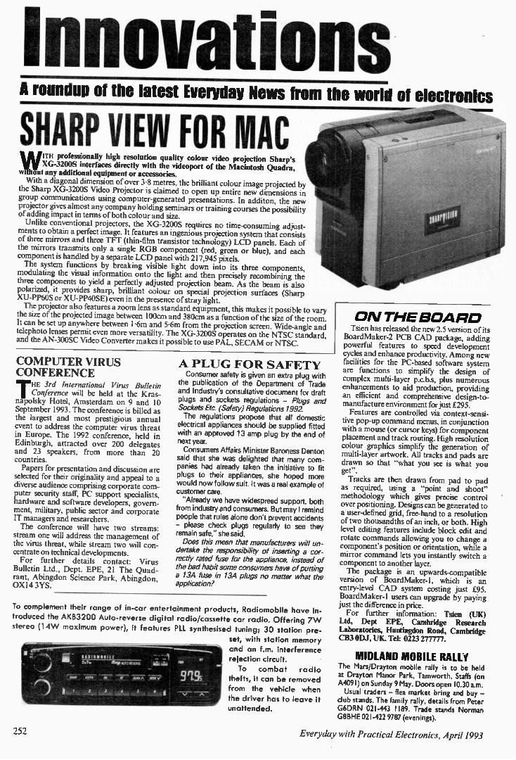
Innovations A roundup of the latest Everyday News from the world of electronics
SHARP VIEW FOR MAC wiWITH professionally high resolution qua lity co lour video projection Sharp 's
XG-3200S interfaces directly with the videoport of the M ac intosh Quadra, out any additional equipment or accessories.
With a diagonal dimension of over 3.8 metres, the brilliant colour image projected by the Sharp XG-3200S Video Projector is claimed to open up entire new dimensions in group communications using computer-generated presentations. In additon, the new projector gives almost any company holding seminars or training courses the possibility of adding impact in terms of both colour and size. Unlike conventional projectors, the XG-3200S requires no time-consuming adjust-
ments to obtain a perfect image. It features an ingenious projection system that consists of three mirrors and three TFT (thin-film transistor technology) LCD panels. Each of the mirrors transmits only a single RGB component (red, green or blue), and each component is handled by a separate LCD panel with 217,945 pixels. The system functions by breaking visible light down into its three components, modulating the visual information onto the light and then precisely recombining the three components to yield a perfectly adjusted projection beam. As the beam is also polarized, it provides sharp, brilliant colour on special projection surfaces (Sharp XU-PP6OS or XU-PP4OSE) even in the presence of stray light. The projector also features a zoom lens as standard equipment, this makes it possible to vary the size of the projected image between 100cm and 380cm as a function of the size of the room. It can be set up anywhere between I -6m and 5.6m from the projection screen. Wide-angle and telephoto lenses permit even more versatility. The XG-3200S operates on the NTSC standard, and the AN-300SC Video Converter makes it possible to use PAL, SECAM or NTSC.
COMPUTER VIRUS CONFERENCE
THE 3rd International Virus Bulletin Conference will be held at the Kras-
napolsky Hotel, Amsterdam on 9 and 10 September 1993. The conference is billed as the largest and most prestigious annual event to address the computer virus threat in Europe. The 1992 conference, held in Edinburgh, attracted over 200 delegates and 23 speakers, from more than 20 countries. Papers for presentation and discussion are
selected for their originality and appeal to a diverse audience comprising corporate com-puter security staff, PC support specialists, hardware and software developers, govern-ment, military, public sector and corporate IT managers and researchers. The conference will have two streams:
stream one will address the management of the virus threat, while stream two will con-centrate on technical developments. For further details contact: Virus Bulletin Ltd., Dept. EPE, 21 The Quad-rant, Abingdon Science Park, Abingdon, OXI4 3YS.
A PLUG FOR SAFETY Consumer safety is given an extra plug with
the publication of the Department of Trade and Industry's consultative document for draft plugs and sockets regulations - Plugs and Sockets Etc. (Safety) Regulations 1992 The regulations propose that all domestic electrical appliances should be supplied fitted with an approved 13 amp plug by the end of next year. Consumers Affairs Minister Baroness Denton said that she was delighted that many com-panies had already taken the initiative to fit plugs to their appliances, she hoped more would now follow suit. It was a real example of customer care. "Already we have widespread support, both from industry and consumers. But may I remind people that rules alone don't prevent accidents -please check plugs regularly to see they remain safe," she said. Does this mean that manufacturers will un-dertake the responsibility of inserting a cor-rectly rated fuse for the appliance, instead of the bad habit some consumers have of putting a 13A fuse in 13A plugs no matter what the application?
To complement their range of in-car entertainment products, Radiomobile have in-troduced the AKB3200 Auto-reverse digital radio/cassette car radio. Offering 7W stereo (14 W maximum power), it features PLL synthesised tuning; 30 station pre-
set, with station memory
and an f.m. interference rejection circuit.
To combat radio thefts, it can be removed from the vehicle when the driver has to leave it unattended.
252
O N THE BOARD Tsien has released the new 2.5 version of its
BoardMaker-2 PCB CAD package, adding powerful features to speed development cycles and enhance productivity. Among new facilities for the PC-based software system are functions to simplify the design of complex multi-layer p.c.b.s, plus numerous enhancements to aid production, providing an efficient and comprehensive design-to-manufacture environment for just £295. Features are controlled via context-sensi-
tive pop-up command menus, in conjunction with a mouse (or cursor keys) for component placement and track routing. High resolution colour graphics simplify the generation of multi-layer artwork. All tracks and pads are drawn so that "what you see is what you get". Tracks are then drawn from pad to pad
as required, using a "point and shoot" methodology which gives precise control over positioning. Designs can be generated to a user-defined grid, free-hand to a resolution of two thousandths of an inch, or both. High level editing features include block edit and rotate commands allowing you to change a component's position or orientation, while a mirror command lets you instantly switch a component to another layer. The package is an upwards-compatible
version of BoardMaker-1, which is an entry-level CAD system costing just £95. Board Maker-1 users can upgrade by paying just the difference in price. For further information: Tsien (UK)
Ltd, Dept EPE, Cambridge Research Laboratories, Huntingdon Road, Cambridge CB3 ODJ, UK. Tel: 0223 277777.
MIDLAND MOBILE RALli The Mars/Drayton mobile rally is to be held at Drayton Manor Park, Tamworth, Staffs (on A4091) on Sunday 9 May. Doors open 10.30 a.m. Usual traders - flea market bring and buy - club stands. The family rally, details from Peter G6DRN 021-443 1189. Trade stands Norman G8BHE 021-422 9787 (evenings).
Everyday, with Practical Electronics, April 1993
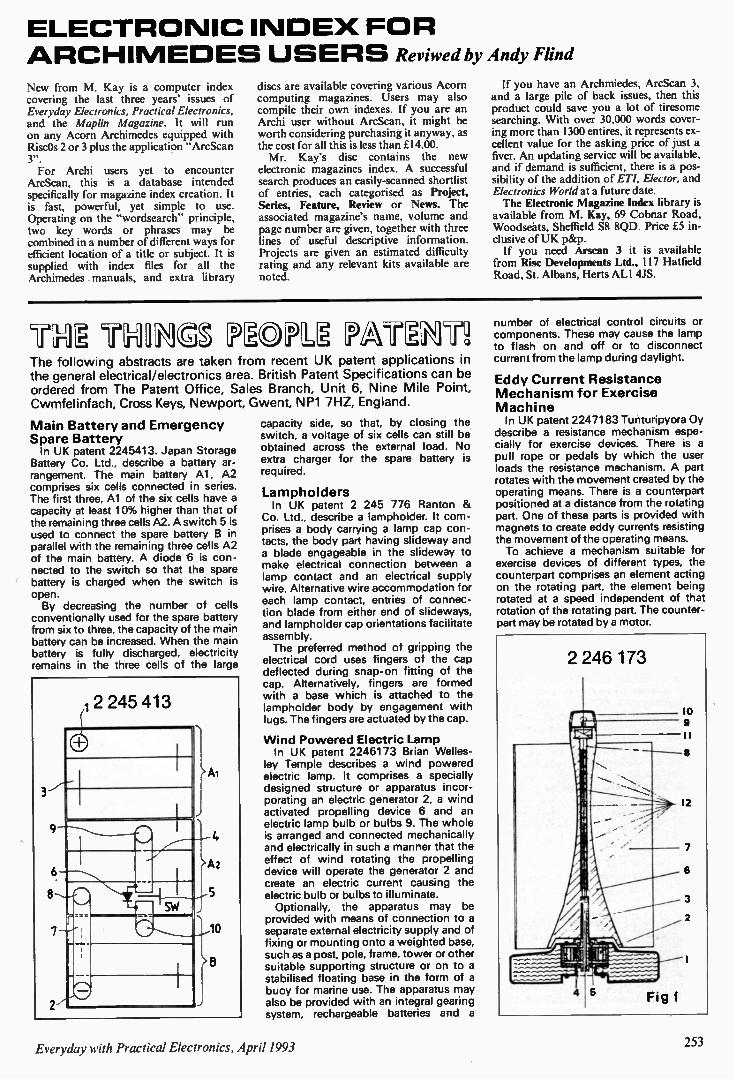
ELECTRO NIC IN DE X FOR A RCHI MEDES U SERS Reviwed by Andy Flind New from M. Kay is a computer index covering the last three years' issues of Everyday Electronics, Practical Electronics, and the Maplin Magazine. It will run on any Acorn Archimedes equipped with RiscOs 2 or 3 plus the application "ArcScan 3". For Archi users yet to encounter
ArcScan, this is a database intended specifically for magazine index creation. It is fast, powerful, yet simple to use. Operating on the "wordsearch" principle, two key words or phrases may be combined in a number of different ways for efficient location of a title or subject. It is supplied with index files for all the Archimedes manuals, and extra library
discs are available covering various Acorn computing magazines. Users may also compile their own indexes. If you are an Archi user without ArcScan, it might be worth considering purchasing it anyway, as the cost for all this is less than £14.00. Mr. Kay's disc contains the new
electronic magazines index. A successful search produces an easily-scanned shortlist of entries, each categorised as Project, Series, Feature, Review or News. The associated magazine's name, volume and page number are given, together with three lines of useful descriptive information. Projects are given an estimated difficulty rating and any relevant kits available are noted.
If you have an Archmiedes. ArcScan 3, and a large pile of back issues, then this product could save you a lot of tiresome searching. With over 30,000 words cover-ing more than 1300 entires, it represents ex-cellent value for the asking price of just a fiver. An updating service will be available, and if demand is sufficient, there is a pos-sibility of the addition of ET!, Elector, and Electronics World at a future date. The Electronic Magazine Index library is
available from M. Kay, 69 Cobnar Road, Woodseats, Sheffield S8 8QD. Price £5 in-clusive of UK p&p. If you need Arscan 3 it is available
from Risc Developments Ltd., 117 Hatfield Road, St. Albans, Herts ALI 4JS.
TN TNN LPOPU PA nN'n The following abstracts are taken from recent UK patent applications in the general electrical/electronics area. British Patent Specifications can be ordered from The Patent Office, Sales Branch, Unit 6, Nine Mile Point, Cwmfelinfach, Cross Keys, Newport, Gwent, NP1 7HZ, England.
Main Battery and Emergency Spare Battery In UK patent 2245413. Japan Storage
Battery Co. Ltd., describe a battery ar-rangement. The main battery Al, A2 comprises six cells connected in series. The first three, Al of the six cells have a capacity at least 10% higher than that of the remaining three cells A2. A switch 5 is used to connect the spare battery B in parallel with the remaining three cells A2 of the main battery. A diode 6 is con-nected to the switch so that the spare battery is charged when the switch is open. By decreasing the number of cells
conventionally used for the spare battery from six to three, the capacity of the main battery can be increased. When the main battery is fully discharged, electricity remains in the three cells of the large
capacity side, so that, by closing the switch, a voltage of six cells can still be obtained across the external load. No extra charger for the spare battery is required.
Lampholders In UK patent 2 245 776 Ranton &
Co. Ltd., describe a lampholder. It com-prises a body carrying a lamp cap con-tacts, the body part having slideway and a blade engageable in the slideway to make electrical connection between a lamp contact and an electrical supply wire. Alternative wire accommodation for each lamp contact, entries of connec-tion blade from either end of slideways, and lampholder cap orientations facilitate assembly. The preferred method of gripping the
electrical cord uses fingers of the cap deflected during snap-on fitting of the cap. Alternatively, fingers are formed with a base which is attached to the lampholder body by engagement with lugs. The fingers are actuated by the cap.
Wind Po wered Electric Lamp In UK patent 2246173 Brian Welles-
ley Temple describes a wind powered electric lamp. It comprises a specially designed structure or apparatus incor-porating an electric generator 2, a wind activated propelling device 6 and an electric lamp bulb or bulbs 9. The whole is arranged and connected mechanically and electrically in such a manner that the effect of wind rotating the propelling device will operate the generator 2 and create an electric current causing the electric bulb or bulbs to illuminate. Optionally, the apparatus may be
provided with means of connection to a separate external electricity supply and of fixing or mounting onto a weighted base, such as a post, pole, frame, tower or other suitable supporting structure or on to a stabilised floating base in the form of a buoy for marine use. The apparatus may also be provided with an integral gearing system, rechargeable batteries and a
number of electrical control circuits or components. These may cause the lamp to flash on and off or to disconnect current from the lamp during daylight.
Eddy Current Resistance Mechanism for Exercise Machine In UK patent 2247183 Tunturipyora Oy
describe a resistance mechanism espe-cially for exercise devices. There is a pull rope or pedals by which the user loads the resistance mechanism. A part rotates with the movement created by the operating means. There is a counterpart positioned at a distance from the rotating part. One of these parts is provided with magnets to create eddy currents resisting the movement of the operating means. To achieve a mechanism suitable for
exercise devices of different types, the counterpart comprises an element acting on the rotating part, the element being rotated at a speed independent of that rotation of the rotating part. The counter-part may be rotated by a motor.
Everyday with Practical Electronics, April 1993 253

New Technology Update 0 NE of the keys to achieving greater
density on i.c. chips is the ability to make metal interconnections between dif-ferent parts of the circuit on the chip. With integrated circuits now becoming increas-ingly complicated this is not always as simple as it may seem. In fact similar problems are also encoun-
tered on printed circuit boards. As the complexity increased it was found increas-ingly difficult to route the tracks around the boards. To overcome the problem the numbers of layers on the boards were increased. Nowadays it is not uncommon for processor boards to have eight and sometimes even more layers.
Multi Layer I.C.s A similar approach is used in integrated
circuits. Different interconnecting layers are separated with layers of insulating silicon dioxide, and conductors via holes are used to make the connections where necessary. Although quite complicated to implement, the use of multiple layers greatly shortens the lengths of any interconnections. This gives a number of advantages. It
reduces the amount of unwanted resistance and capacitance, and it releases more space on the chip for additional components. These two improvements enable the perfor-mance of the chip to be improved and more functionality to be added to it. The idea of multi-level connections on a
chip is not new. However to enable the chip performance to be improved the techniques need to be developed further. Currently only a few layers are used, but it is anticipated that in about ten or twelve years time it might be necessary to use up to eight layers of metallisation. In order that this number of levels of
metallisation can be achieved it is n - sary to be able to keep the surface of the silicon used for the i.c. as flat as possible. Even minute irregularities can cause major problems. This is because the photolithographic images used to define the various areas of the i.c. cannot be focused sufficiently well if there are any irregularities. Many of these irregularities are produced when the silicon wafers are sliced off the original crystal.
Optically Flat Normally the wafer is polished or lapped
to remove the irregularities. This uses a very fine abrasive which produces a flat sur-face, albeit with some microscopic scratches caused by the abrasive. Chemical etching may seem to be a bet-ter alternative because it will give a better finish. However it is not used at this stage because the irregularities penetrate some dis-tance into the surface of the silicon and the
Ian Poole reports on techniques for manufacture of multilayer i.c.s, flexible superconductors and new r.f. i.c.s.
chemical action will actually increase these irregularities. To overcome this problem a new tech-
nique for polishing or lapping the silicon blanks has been devised. It involves a mechanical/chemical process. The wafer is mounted on an arm suspended over a polishing disc. A slurry consisting of an exceedingly fine abrasive and some chemi-cal etchant is added and the wafer is then polished or lapped to an optically flat finish. To ensure that the finish is com-pletely perfect a final stage of etching may then be used. By very carefully controlling all the
stages of the process and using exceedingly high standards it has been possible to achieve much better standards than any which were obtained before. During the development of this process a
number of problems were encountered in ensuring that the surface was completely flat. Now that they have been overcome some i.c.s are actually being manufactured using the process. This means that the way is open for much wider use of the process and improvements in i.c. characteristics.
Flexible Superconductors Superconductors have been available for
many years. However they are seldom used, despite the enormous advantages they offer. The reason for this is the very low temperatures which they have required for operation, typically only a few degrees above absolute zero. Whilst it is possible to obtain these very low temperatures for experimental purposes they are not com-mercially viable. To overcome this problem tremendous
efforts have been made to develop new super-conducting materials which will be able to operate at much higher tempera-tures, possibly even at normal external temperatures. There is much more work to be done but the work has been very successful. A number of substances have been discovered which support the phenomenon at temperatures which are much more practicable to maintain. Despite this success the next major
hurdle was to make these new materials in a form which could be easily used. One of the major disadvantages has been that any wires made from the new materials are very brittle, so brittle that they snap easily. It has now been reported that a team of researchers has developed a technique which is able to produce wires which are five times more flexible than before. To form the wires the super-conducting
material is heated up to above its melt-ing point. It is then passed through a small nozzle under high pressure so that it
emerges very quickly. This thin wire is then cooled down very rapidly, solidifying into long fibres. Several of these thin fibres are then used to form a single wire. It is hoped that this technique will at last
help to enable superconductors to become a more attractive proposition for commer-cial projects. If this is so then it is likely that superconductors will start to appear in a wide variety of applications.
New R.F. I.C.s Radio communications is an ever grow-
ing section of the electronics industry. Driven by the need for improved com-munications, the telecommunications in-dustry is turning to radio for personal communications far more now than it ever used to. This is demonstrated by the high number of mobile and portable cellular phones in use these days. In addition to this there are cordless phones and radio pagers which are being used increasingly. Designers of equipment for these ap-
plications find there are many challenges to be met. With frequencies of up to 1GHz being used and very low current consump-tions needed to conserve batteries, the circuit design is not easy — particularly the r.f. sections. Until recently much of the r.f. circuitry
required the use of many discrete com-ponents as the level of integration of many of the r.f. circuits was relatively low. Whilst some amplifier i.c.s were available for use up to these frequencies the level of integra-tion did not extend to other circuit blocks. Now this is changing as more i.c.s designed to reduce the cost of cellular phones are being introduced.
Front End Chip One of these i.c.s has recently been in-
troduced by GEC Plessey Semiconductors. The new chip is the 5L6444 and it is a radio receiver front end containing a low noise amplifier and mixer. All of this is housed within a 14-pin small outline surface mount package which is ideal for modern produc-tion techniques. The chip has many advantages for the r.f.
designer. Both sections of the circuit can be used either independently or together to produce a receiver front end. In addition to this the chip operates over a wide voltage range (2-7 to 6 volts). The current consump-tion is also low, typically just over 9mA, and there is a battery saving standby mode to further reduce battery consumption. With i.c.s like these appearing on the
market, the shape of r.f. circuit design is set to change in the near future. Not only should performance improve, but it should be possible to reduce the size of circuits as well.
254 Everyday with Practical Electronics, April 1993
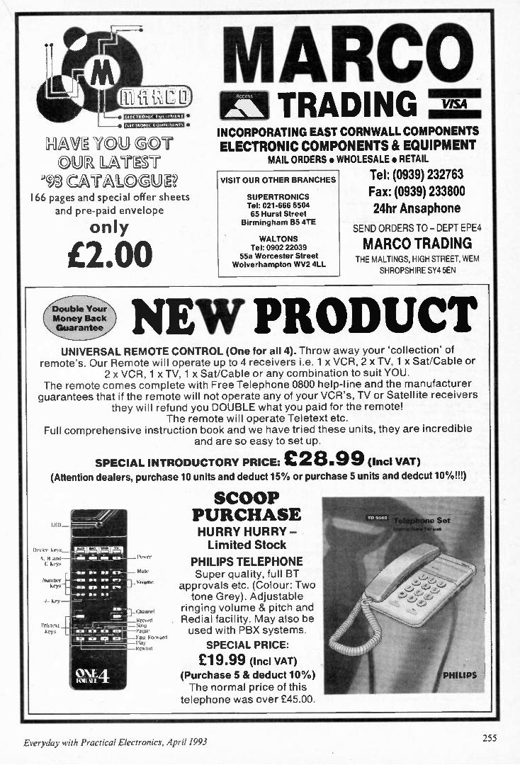
11331:11 =1• 617111112=1:1 =1•
AAV. YOU C)71 OVA LAT T
9,A CATALCAUS 166 pages and special offer sheets
and pre-paid envelope
only
£2.00 Double Your Money Back Guarantee
MARCO Alk TRADING VISA
INCORPORATING EAST CORNWALL COMPONENTS ELECTRONIC COMPONENTS & EQUIPMENT
MAIL ORDERS • WHOLESALE • RETAIL
Tel: (0939) 232763 Fax: (0939) 233800 24hr Ansaphone
SEND ORDERS TO - DEPT EPE4
MARCO TRADING
VISIT OUR OTHER BRANCHES
SUPERTRONICS Tel: 021-666 6504 65 Hurst Street
Birmingham B5 4TE
WALTONS Tel: 0902 22039
55a Worcester Street Wolverhampton WV2 4LL
THE MALTINGS, HIGH STREET. WEM SHROPSHIRE SY4 5EN
NEW PRODUCT UNIVERSAL REMOTE CONTROL (One for all 4). Throw away your 'collection' of
remote's. Our Remote will operate up to 4 receivers i.e. 1 x VCR, 2 x TV, 1 x Sat/Cable or 2 x VCR, 1 x TV, 1 x Sat/Cable or any combination to suit YOU.
The remote comes complete with Free Telephone 0800 help-line and the manufacturer guarantees that if the remote will not operate any of your VCR's, TV or Satellite receivers
they will refund you DOUBLE what you paid for the remote! The remote will operate Teletext etc.
Full comprehensive instruction book and we have tried these units, they are incredible and are so easy to set up.
SPECIAL INTRODUCTORY PRICE: £28.99 (Incl VAT)
(Attention dealers, purchase 10 units and deduct 15% or purchase 5 units and dedcut 10%!!!)
li n ni ke ,
1. B and C
\ umbel
Ko
Teltlekt Ke,)s
/ /
The- -.1."- -
7 m411AI M
2, -as m mm am ma _ OM 116111
• 7:'— • &=.. -
E
O NF A 10111.11
Mule
Volume.
Channel
Kenn.' Stop l'ause Vase Foruitnl
Kt %Ind
SCOOP PURCHASE HURRY HURRY - Limited Stock
PHILIPS TELEPHONE Super quality, full BT
approvals etc. (Colour: Two tone Grey). Adjustable
ringing volume & pitch and Redial facility. May also be used with PBX systems.
SPECIAL PRICE:
£19.99 (Ind VAT) (Purchase 5 & deduct 10%) The normal price of this telephone was over £45.00.
Everyday with Practical Electronics, April 1993 155
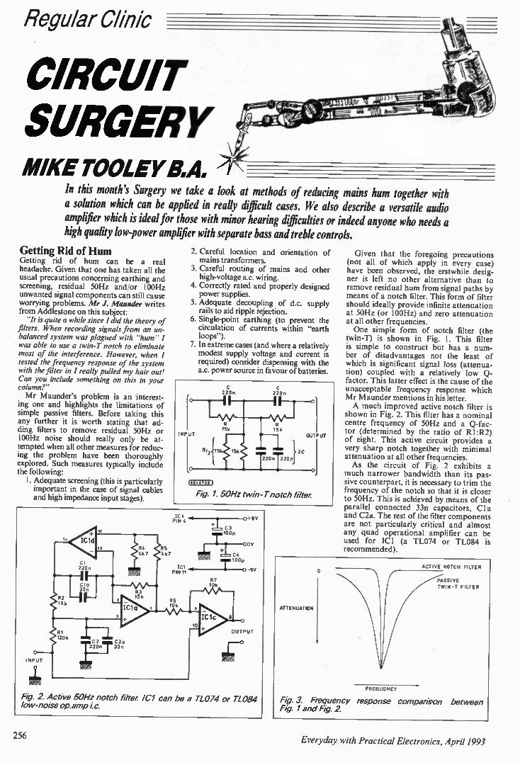
Regular Clthic
=Dun-SURGERY MIKE TOOLEY 111,A,
In this month's Surgery we take a look at methods of reducing mains hum together with a solution which can be applied in really difficult cases. We also describe a versatile audio amplifier which is ideal for those with minor hearing difficulties or indeed anyone who needs a high quality low-power amplifier with separate bass and treble controls.
Getting Rid of Hum Getting rid of hum can be a real headache. Given that one has taken all the usual precautions concerning earthing and screening, residual 50Hz and/or 100Hz unwanted signal components can still cause worrying problems. Mr J. Maunder writes from Addlestone on this subject: "It is quite a while since I did the theory of
filters. When recording signals from an un-balanced system was plagued with "hum" I was able to use a twin-T notch to eliminate most of the interference. However, when I tested the frequency response of the system with the filter in I really pulled my hair out! Can you include something on this in your column?" Mr Maunder's problem is an interest-
ing one and highlights the limitations of simple passive filters. Before taking this any further it is worth stating that ad-ding filters to remove residual 50Hz or 100Hz noise should really only be at-tempted when all other measures for reduc-ing the problem have been thoroughly explored. Such measures typically include the following: I. Adequate screening (this is particularly important in the case of signal cables and high impedance input stages).
2. Careful location and orientation of mains transformers.
3. Careful routing of mains and other high-voltage ac. wiring.
4. Correctly rated and properly designed power supplies.
5. Adequate decoupling of d.c. supply rails to aid ripple rejection.
6. Single-point earthing (to prevent the circulation of currents within "earth loops").
7. In extreme cases (and where a relatively modest supply voltage and current is required) consider dispensing with the a.c. power source in favour of batteries.
IEE40705 I
Fig. 1. 50Hz twin-T notch filter
Fig. 2 Active 50Hz notch filter IC1 can be a TL074 or TL084 low-noise op.amp ic.
ATTENUATION
Given that the foregoing precautions (not all of which apply in every case) have been observed, the erstwhile desig-ner is left no other alternative than to remove residual hum from signal paths by means of a notch filter. This form of filter should ideally provide infinite attenuation at 50Hz (or 100Hz) and zero attenuation at all other frequencies. One simple form of notch filter (the
twin-T) is shown in Fig. I. This filter is simple to construct but has a num-ber of disadvantages not the least of which is significant signal loss (attenua-tion) coupled with a relatively low Q-factor. This latter effect is the cause of the unacceptable frequency response which Mr Maunder mentions in his letter. A much improved active notch filter is
shown in Fig. 2. This filter has a nominal centre frequency of 50Hz and a Q-fac-tor (determined by the ratio of R 1 :R2) of eight. This active circuit provides a very sharp notch together with minimal attenuation at all other frequencies. As the circuit of Fig. 2 exhibits a
much narrower bandwidth than its pas-sive counterpart, it is necessary to trim the frequency of the notch so that it is closer to 50Hz. This is achieved by means of the parallel connected 33n capacitors, CI a and C2a. The rest of the filter components are not particularly critical and almost any quad operational amplifier can be used for ICI (a TL074 or TL084 is recommended).
ACTIVE NOTCH FILTER
PASSIVE
TWIN -T FILTER
FREQUENCY
Fig 3. Frequency response comparison between Fig 1 and Fig. 2
256 Everyday with Practical Electronics, April 1993
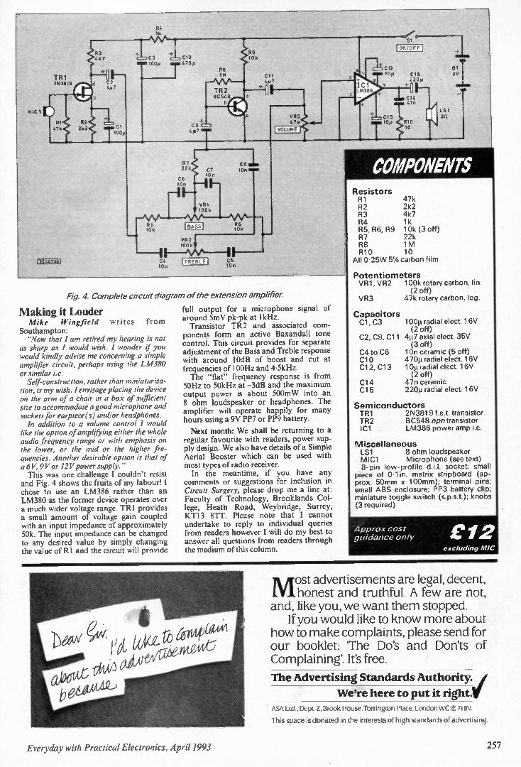
04 1k
C
TR I 20 3819
R1 02 47k 2k2
I EE CO73 0
03 4k? C3
e mil00p
C2 4 p7
99 10 10k
470p
•
TR2 BC 548
C VC=:$ 447
C 11
VR3 47k VOLUME •
MC12 Id 1 LM 86
10p
Cl 10p
Si
I ON/OFF I
C15 220p F-a m C14
4711
RIO 10 ( 1St an
P 22k
CE 107
R5 10k
C8 C7 104 lOr
VR1 100k
BASS 06 10k
VR2 look?
1.-- -" \A / .."--- 1 I C4 TREBLE C5 10n 10n
Fig. 4. Complete circuit diagram of the extension amplifier
Making it Louder Mike Wingfield writes from
Southampton: "Now that I am retired my hearing is not
as sharp as I would wish. I wonder if you would kindly advise me concerning a simple amplifier circuit, perhaps using the LM380 or similar i.c. Self-construction, rather than miniaturisa-tion, is my wish. I envisage placing the device on the arm of a chair in a box of sufficient size to accommodate a good microphone and sockets for earpiece( s) and/or headphones. In addition to a volume control I would
like the option of amplifying either the whole audio frequency range or with emphasis on the lower, or the mid or the higher fre-quencies. Another desirable option is that of a 6V, 9V or 12V power supply." This was one challenge I couldn't resist
and Fig. 4 shows the fruits of my labour! I chose to use an LM386 rather than an LM380 as the former device operates over a much wider voltage range. TRI provides a small amount of voltage gain coupled with an input impedance of approximately 50k. The input impedance can be changed to any desired value by simply changing the value of RI and the circuit will provide
full output for a microphone signal of around 5mV pk-pk at IkHz. Transistor TR2 and associated com-
ponents form an active Baxandall tone control. This circuit provides for separate adjustment of the Bass and Treble response with around 10dB of boost and cut at frequencies of 100Hz and 4.5kHz. The "flat" frequency response is from 50Hz to 50kHz at —3dB and the maximum output power is about 500mW into an 8 ohm loudspeaker or headphones. The amplifier will operate happily for many hours using a 9V PP7 or PP9 battery.
Next month: We shall be returning to a regular favourite with readers, power sup-ply design. We also have details of a Simple Aerial Booster which can be used with most types of radio receiver. In the meantime, if you have any
comments or suggestions for inclusion in Circuit Surgery, please drop me a line at: Faculty of Technology, Brooklands Col-lege, Heath Road, Weybridge, Surrey, KT13 8TT. Please note that I cannot undertake to reply to individual queries from readers however I will do my best to answer all questions from readers through the medium of this column.
COMPONENTS Resistors R1 47k R2 2k2 R3 4k7 R4 1k R5, R6, R9 10k (3 off) R7 22k R8 1M R10 10 All 0.25W 5% carbon film
Potentiometers VR1, VR2 100k rotary carbon, lin
(2 off) VR3 47k rotary carbon, log
Capacitors Cl, C3 10011 radial elect. 16V
(2 off) C2, C9, C11 4µ7 axial elect. 35V
(3 off) C4 to C8 10n ceramic (5 off) C10 470µ radial elect. 16V C12, C13 10µ radial elect. 16V
(2 off) C14 47n ceramic C15 220µ radial elect. 16V
Semiconductors TR1 2N3819 f.e.t. transistor TR2 8C548 npn transistor ICI LM386 power amp i.c
Miscellaneous LS1 8 ohm loudspeaker MIC1 Microphone (see text) 8-pin low-profile d.i.l. socket; small piece of Olin. matrix stripboard (ap-prox. 50mm x 100mm); terminal pins; small ABS enclosure; PP3 battery clip; miniature toggle switch (s.p.s.t.); knobs (3 required)
Approx cost guidance only £12
excluding MIC
Most advertisements are legal, decent, honest and truthful. A few are not,
and, like you, we want them stopped. If you would like to know more about
how to make complaints, please send for our booklet: The Do's and Don'ts of Complaining'. It's free.
The Advertising Standards Authority.
We're here to put it right. ASA Ltd., Dept. Z. Brook House.Tomngton Place. London WC IE 7H N.
This space is donated in the interests of high standards of advertising.
Everyday with Practical Electronics, April 1993 257
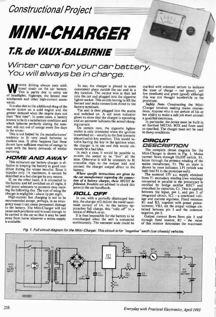
Constructional Project
MINI-CHARGER ER de VALIX-BALBIRNIE
Winter care for your car battery. You will always be in charge.
WINTER driving always puts addi-tional strain on the car battery. This is partly due to extra use
of headlights, foglamps, the heated rear windscreen and other high-current acces-sories. It is also due to the additional drag of the
starter motor on a cold engine and the greater demand when the engine does not start "first time". In some cases, a battery known to be in a satisfactory condition and which behaves perfectly during the sum-mer, will run out of energy every few days in the winter. This is not helped by the manufacturers'
tendency to fit very small batteries to modern cars. It often happens that these do not have sufficient reserves of energy to cope with the heavy demands of winter motoring.
H O ME A A/0 A WA Y This miniature car battery charger is ef-
fective in keeping the battery in good con-dition during the winter months. Since it supplies only IA maximum, it cannot be described as a fast charger by any means. If, on the other hand, it is connected to
the battery and left switched on all night, it will prove adequate to promote easy start-ing the following day. The cost of using the charger is negligible — about 1p per night. High-current fast charging is not to be
recommended except, perhaps, in an emer-gency since it can cause permanent damage to the battery. The Mini-Charger will not cause such problems and is small enough to be carried in the car so that it may be used away from home wherever a mains supply is available.
In use, the charger is placed in some convenient place outside the car and in a dry location. The output wire is then led into the car and plugged into the cigarette lighter socket. This avoids having to lift the bonnet and make connections direct to the battery terminals. The unit is then plugged into the mains
and switched on. A red neon indicator glows to show that the charger is operating and an ammeter indicates the actual charg-ing current. On certain cars, the cigarette lighter
socket is only connected when the ignition is switched on — usually to the first (cassette player/radio) key position. This would in-volve leaving the key in the ignition when the charger is in use and this would ob-viously be a bad idea. In such a case, it would be possible to
re-wire the socket to be "live" all the time. Otherwise it will be necessary to fit crocodile clips to the output lead and connect the charger output direct to the battery. Where specific instructions are given by
the car manufacturer regarding the connec-tion of a battery charger, these MUST be followed. Readers are advised to check this point in the car handbook.
R OLL O FF In use, with a partially discharged bat-
tery, the charger will deliver the rated maxi-mum current of IA. As the battery ap-proaches full charge, this "rolls off" to a trickle of 400mA or so. It is thus impossible for the battery to be
overcharged when the unit is connected continuously. The ammeter scale could be
marked with coloured sectors to indicate the state of charge — red (poor), yel-low (medium) and green (good) although this was not thought worthwhile in the prototype. Safety Note: Constructing the Mini-
Charger involves making mains connec-tions. Anyone who is not certain of his or her ability to make a safe job must consult a qualified electrician. In particular, the device must be built in
an Earthed METAL BOX and fuses used as specified. The charger must not be used in damp conditions.
CIRC UIT O ESCRIPITIOAI The complete circuit diagram for the
Mini-Charger is shown in Fig. I. Mains current flows through On/Off switch, SI, hence through the primary winding of the mains transformer, TI. The on state is shown by neon indicator, LP1 (which was built into SI in the prototype unit). The nominal 15V a.c. supply obtained
from T1 secondary winding (two windings connected in parallel in the prototype) is rectified by bridge rectifier REC1 and smoothed by capacitor, Cl. This is applied between the input, pin I, and pin 3 of integrated circuit, ICI — a combined volt-age and current regulator. Fixed resistors RI and R3, together with preset poten-tiometer, VR1, set the output voltage ob-tained between pin 5 and the common negative, pin 3. Output current flows from pin 5 and
through fixed resistor, R2 — the value of this resistor determines the maximum
Fig. 1. Full circuit diagram for the Mini-Charger This circuit IS for 'negative" earth (car chassis) vehicles.
2400 A.S. MAINS INPUT
1 C,
oc, Kz.
15
'Cl
+ Cl 220081
C2 220n
820
2 0047 2.5W
83 2k 7
VR1 2 k 2
MEI 01 0 -1A
1N4001 loik
M N C3 T 100n
F51 1.2SA CP OD
P L1
1
-I-128 CAR BATTERY I
) T fEE4WMG]
258 Everyday with Practical Electronics, April 1993
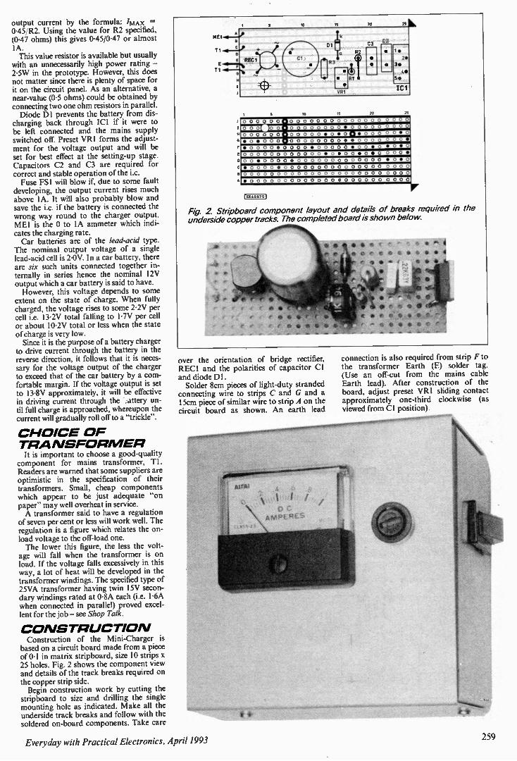
output current by the formula: 'M AX =
0.45/R2. Using the value for R2 specified, (0.47 ohms) this gives 045/047 or almost 1A. This value resistor is available but usually with an unnecessarily high power rating — 2.5W in the prototype. However, this does not matter since there is plenty of space for it on the circuit panel. As an alternative, a near-value (0-5 ohms) could be obtained by connecting two one ohm resistors in parallel. Diode DI prevents the battery from dis-
charging back through ICI if it were to be left connected and the mains supply switched off. Preset VR1 forms the adjust-ment for the voltage output and will be set for best effect at the setting-up stage. Capacitors C2 and C3 are required for correct and stable operation of the i.c. Fuse FS! will blow if, due to some fault
developing, the output current rises much above IA. It will also probably blow and save the i.c. if the battery is connected the wrong way round to the charger output. MEI is the 0 to IA ammeter which indi-cates the charging rate. Car batteries are of the lead-acid type.
The nominal output voltage of a single lead-acid cell is 2.0V. In a car battery, there are six such units connected together in-ternally in series hence the nominal 12V output which a car battery is said to have. However, this voltage depends to some
extent on the state of charge. When fully charged, the voltage rises to some 2.2V per cell i.e. 13.2V total falling to 1-7V per cell or about I 0-2V total or less when the state of charge is very low. Since it is the purpose of a battery charger
to drive current through the battery in the reverse direction, it follows that it is neces-sary for the voltage output of the charger to exceed that of the car battery by a com-fortable margin. If the voltage output is set to 13.8V approximately, it will be effective in driving current through the . attery un-til full charge is approached, whereupon the current will gradually roll off to a "trickle".
C HOICE O F TRA NSFOR MER It is important to choose a good-quality
component for mains transformer, TI. Readers are warned that some suppliers are optimistic in the specification of their transformers. Small, cheap components which appear to be just adequate "on paper" may well overheat in service. A transformer said to have a regulation
of seven per cent or less will work well. The regulation is a figure which relates the on-load voltage to the off-load one. The lower this figure, the less the volt-
age will fall when the transformer is on load. If the voltage falls excessively in this way, a lot of heat will be developed in the transformer windings. The specified type of 25VA transformer having twin 15V secon-dary windings rated at 0.8A each (i.e. 1.6A when connected in parallel) proved excel-lent for the job — see Shop Talk.
C O NSTR UCTIO N Construction of the Mini-Charger is based on a circuit board made from a piece of 0.1 in matrix stripboard, size 10 strips x 25 holes. Fig. 2 shows the component view and details of the track breaks required on the copper strip side. Begin construction work by cutting the
stripboard to size and drilling the single mounting hole as indicated. Make all the underside track breaks and follow with the soldered on-board components. Take care
ME1.1 -L, E
TI•01 - e
E REC 1 E
T1
10
15
15
20
20
•
2•
3•
45
55
25
0 0 0 0 0 0 0 0 0 0 0 0 0 0 0 0 • O 0oivEnt• 0 • 0 0 00000.00 0
• 0 • 0 0 0 • 0 0 0 0 0 0 0 0 • • 0 0 0 0 0 0 •
• 0 0 0 0 • 0 0 0 0 • 0 0 0 0 0 • 0 0 • 0 • 0 • 0
O 0 0 0 0 0 0 0 0 0 0 0 • 0 • 0 0 • 0 • 0 0 0 0 •
O 0 • 0 0 0 0 • 0 0 0 0 0 0 0 0 0 0 0 0 0 • 0 • 0
• 0 0 0 0 • 0 0 0 0 0 0 0 0 0 0 0 0 0 0 0 0 0 0 0
0 0 0 0 0 0 0 0 0 0 0 0 0 0 0 0 0 0 0 0 0 0 0 0 0
• 0 0 0 0 0 0 0 0 0 0 0 0 0 • 0 0 0 0 0 0 0 0 0 0
1EE406701
Fig 2 Stripboard component layout and details of breaks required in the underside copper tracks. The completed board is shown below.
over the orientation of bridge rectifier, REC1 and the polarities of capacitor Cl and diode DI. Solder 8cm pieces of light-duty stranded
connecting wire to strips C and G and a 15cm piece of similar wire to strip A on the circuit board as shown. An earth lead
connection is also required from strip F to the transformer Earth (E) solder tag. (Use an off-cut from the mains cable Earth lead). After construction of the board, adjust preset VR I sliding contact approximately one-third clockwise (as viewed from Cl position)
Ever_vday with Practical Electronics, April 1993 259
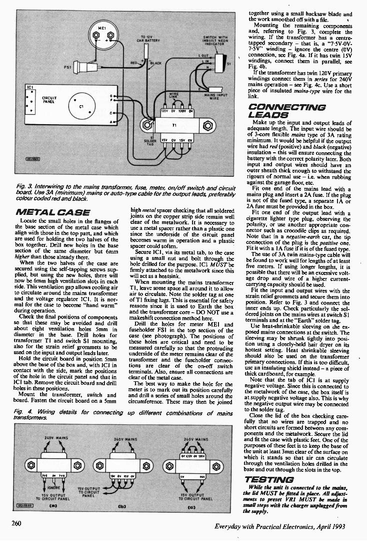
PSI
TO 12Y CAR BATTERY
IC I
CIRCUIT PANEL F •
cti.ossol
El SOLACE TAG
CE
WIRE LINK
CV 120V V
SWITCH WITH INBUILT NEON INDICATOR
MAINS INPUT WIRE
TI
15V OR 15V OR
Fig. 3. Interwiring to the mains transformer, fuse, meter; on/off switch and circuit board Use 3A (minimum) mains or auto-type cable for the output leads, preferably colour coded red and black.
M ETAL C A SE Locate the small holes in the flanges of
the base section of the metal case which align with those in the top part, and which are used for holding the two halves of the box together. Drill new holes in the base section of the same diameter but 6mm higher than those already there. When the two halves of the case are
secured using the self-tapping screws sup-plied, but using the new holes, there will now be 6mm high ventilation slots in each side. This ventilation gap allows cooling air to circulate around the mains transformer and the voltage regulator ICI. It is nor-mal for the case to become "hand warm" during operation. Check the final positions of components
so that these may be avoided and drill about eight ventilation holes 5mm in diameter in the base. Drill holes for transformer TI and switch SI mounting, also for the strain relief grommets to be used on the input and output leads later. Hold the circuit board in position 5mm
above the base of the box and, with ICI in contact with the side, mark the positions of the hole in the circuit panel and that in ICI tab. Remove the circuit board and drill holes in these positions. Mount the transformer, switch and
board. Fasten the circuit board on a 5mm
high metal spacer checking that all soldered joints on the copper strip side remain well clear of the metalwork. It is necessary to use a metal spacer rather than a plastic one since the underside of the circuit panel becomes warm in operation and a plastic spacer could soften. Secure ICI , via its metal tab, to the case
using a small nut and bolt through the hole drilled for the purpose. ICI MUST be firmly attached to the metalwork since this will act as a heatsink. When mounting the mains transformer
T1, leave some space all around it to allow air to circulate. Note the solder tag at one of T1 fixing lugs. This is essential for safety reasons since it is used to Earth the box and the transformer core — DO NOT use a makeshift connection method here. Drill the holes for meter MEI and
fuseholder FS I in the top section of the case (see photograph). The positions of these holes are critical and need to be measured carefully so that the protruding underside of the meter remains clear of the transformer and the fuseholder connec-tions are clear of the on-off switch terminals. Also, ensure all connections are clear of the metal case. The best way to make the hole for the
meter is to mark out its position carefully and drill a series of small holes around the circumference. These may then be joined
Fig. 4. Ming details for connecting up different combinations of mains transformers.
f EV-0600j
24011 MAINS
IGNORE
15V OUTPUT TO CIRCUIT PANEL
ca3
1511 OUTPUT TO CIRCUIT PANEL
240V MAINS 240V MAINS
15V OUTPUT TO CIRCUIT PANEL
CC)
together using a small hacksaw blade and the work smoothed off with a file. Mounting the remaining components
and, referring to Fig. 3, complete the wiring. If the transformer has a centre-tapped secondary — that is, a "7-5V-0V-75V" winding — ignore the centre (OV) connection, see Fig. 4a. If it has twin 15V windings, connect them in parallel, see Fig. 4b. If the transformer has twin 120V primary
windings connect them in series for 240V mains operation — see Fig. 4c. Use a short piece of insulated mains-type wire for the link.
C O N NECTI NG LEA DS Make up the input and output leads of
adequate length. The input wire should be of 3-core flexible mains type of 3A rating minimum. It would be helpful if the output wire had red (positive) and black (negative) insulation — this will ensure connecting the battery with the correct polarity later. Both input and output wires should have an outer sheath thick enough to withstand the rigours of normal use — i.e. when rubbing against the garage floor, etc. Fit one end of the mains lead with a
mains plug and insert a 2A fuse. If the plug is not of the fused type, a separate IA or 2A fuse must be provided in the box. Fit one end of the output lead with a
cigarette lighter type plug, observing the polarity, or use another appropriate con-nector such as crocodile clips as required. Note that in a negative-earth car, the tip connection of the plug is the positive one. Fit it with a IA fuse if it is of the fused type. The use of 3A twin mains-type cable will
be found to work well for lengths of at least five metres. If using longer lengths, it is possible that there will be an excessive volt-age drop and wire of a higher current-carrying capacity should be used. Fit the input and output wires with the
strain relief grommets and secure them into position. Refer to Fig. 3 and connect the inner ends up. Check particularly the sol-dered joints on the mains wires at switch SI terminals and at the "Earth" solder tag. Use heat-shrinkable sleeving on the ex-
posed mains connections at the switch. The sleeving may be shrunk tightly into posi-tion using a closely-held hair dryer on its hottest setting. Heat shrinkable sleeving should also be used on the transformer primary connections. If this is too difficult, use an insulating shield instead — a piece of thick cardboard, for example. Note that the tab of ICI is at supply
negative voltage. Since this is connected to the metalwork of the case, the box itself is at supply negative voltage also. This is why the negative output wire may be connected to the solder tag. Close the lid of the box checking care-
fully that no wires are trapped and no short circuits are formed between any com-ponents and the metalwork. Secure the lid and fit the case with plastic feet. One of the purposes of these feet is to keep the base of the unit at least 3mm clear of the surface on which it stands so that air can circulate through the ventilation holes drilled in the base and out through the slots in the top.
TESTI NG While the unit is connected to the mains,
the lid MUST be fitted in place. All adjust-ments to preset VRI MUST be made in small steps with the charger unplugged from the supply.
260 Everyday with Practical Electronics, April 1993
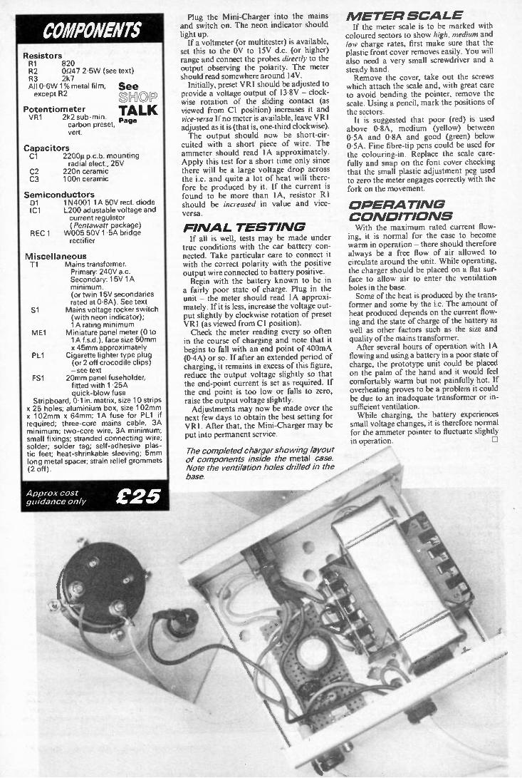
COMPONENTS Resistors R1 820 R2 0047 2.5W (see text) R3 2k7 All 0.6W 1% metal film, except R2
Potentiometer V R 1 2k2 sub-min.
carbon preset, ven.
See SH© TALK Page
Capacitors Cl 2200n p.c.b. mounting
radial elect., 25V C2 220n ceramic C3 100n ceramic
Semiconductors D1 1N4001 lA 50V rect. diode IC1 L200 adustable voltage and
current regulator (Pentawatt package)
R EC 1 W005 50V 1.5A bridge rectifier
Miscellaneous Ti Mains transformer.
Primary: 240V a.c. Secondary: 15V lA minimum. (or twin 15V secondaries rated at 0.8A). See text
Si Mains voltage rocker switch (with neon indicator); 1A rating minimum
ME1 Miniature panel meter (0 to lA f.s.d.), face size 50mm x 45mm approximately
PL1 Cigarette lighter type plug (or 2 off crocodile clips) - see text
FS1 20mm panel fuseholder, fitted with 1.25A quick-blow fuse
Stripboard, Olin. matrix, size 10 strips x 25 holes; aluminium box, size 102mm x 102mm x 64mm; 1A fuse for PL1 if required; three-core mains cable, 3A minimum; two-core wire, 3A minimum; small fixings; stranded connecting wire; solder; solder tag; self-adhesive plas-tic feet; heat-shrinkable sleeving; 5mm long metal spacer; strain relief grommets (2 off).
Approx cost guidance only
M ETER S CAL E If the meter scale is to be marked with
coloured sectors to show high, medium and low charge rates, first make sure that the plastic front cover removes easily. You will also need a very small screwdriver and a steady hand. Remove the cover, take out the screws
which attach the scale and, with great care to avoid bending the pointer, remove the scale. Using a pencil, mark the positions of the sectors. It is suggested that poor (red) is used
above 0.8A, medium (yellow) between 0•5A and 0.8A and good (green) below 0.5A. Fine fibre-tip pens could be used for the colouring-in. Replace the scale care-fully and snap on the font cover checking that the small plastic adjustment peg used to zero the meter engages correctly with the fork on the movement.
O PERATI NG C O NDITIO NS ith the maximum rated current flow-
ing, it is normal for the case to become warm in operation - there should therefore always be a free flow of air allowed to circulate around the unit. While operating, the charger should be placed on a flat sur-face to allow air to enter the ventilation holes in the base. Some of the heat is produced by the trans-former and some by the i.c. The amount of heat produced depends on the current flow-ing and the state of charge of the battery as well as other factors such as the size and quality of the mains transformer. After several hours of operation with IA flowing and using a battery in a poor state of charge, the prototype unit could be placed on the palm of the hand and it would feel comfortably warm but not painfully hot. If overheating proves to be a problem it could be due to an inadequate transformer or in-sufficient ventilation. While charging, the battery experiences
small voltage changes, it is therefore normal for the ammeter pointer to fluctuate slightly in operation.
£25
Plug the Mini-Charger into the mains and switch on. The neon indicator should light up. If a voltmeter (or multitester) is available,
set this to the OV to 15V d.c. (or higher) range and connect the probes directly to the output observing the polarity. The meter should read somewhere around 14V. Initially, preset VR1 should be adjusted to
provide a voltage output of 13.8V - clock-wise rotation of the sliding contact (as viewed from Cl position) increases it and vice-versa If no meter is available, leave VR I adjusted as it is (that is, one-third clockwise). The output should now be short-cir-cuited with a short piece of wire. The ammeter should read IA approximately. Apply this test for a short time only since there will be a large voltage drop across the i.c. and quite a lot of heat will there-fore be produced by it. If the current is found to be more than 1A, resistor RI should be increased in value and vice-versa.
FI NAL TESTI NG If all is well, tests may be made under
true conditions with the car battery con-nected. Take particular care to connect it with the correct polarity with the positive output wire connected to battery positive. Begin with the battery known to be in
a fairly poor state of charge. Plug in the unit - the meter should read IA approxi-mately. If it is less, increase the voltage out-put slightly by clockwise rotation of preset VR1 (as viewed from Cl position). Check the meter reading every so often
in the course of charging and note that it begins to fall with an end point of 400mA (0.4A) or so. If after an extended period of charging, it remains in excess of this figure, reduce the output voltage slightly so that the end-point current is set as required. If the end point is too low or falls to zero, raise the output voltage slightly. Adjustments may now be made over the
next few days to obtain the best setting for VR1. After that, the Mini-Charger may be put into permanent service.
The completed charger showing layout of components inside the metal case. Note the ventilation holes drilled in the base.

11• ••••• M O M
• •••• • W O MB M MOM M = MO M
M M . = ••••••• 4 •1 1• 1 M MO M MI •• •• • • •• • • • OD MI M OM • • MO M • M O
•
• M OM OM OM IMMO
A M M EM • • • M I M EM = • •• • M M. • = MO • . 1•1 m MO/ • = MD •IM = OM om m• rM • • ••••
••••• • ••• • IM MI •• M EM M I MMMIMI
M O M OIRM = MI MO M M MO,
M OM O
IO W •••• OMI M MO M, .r 11 11 = 0
411•1
W W1 MIRO M EN r/•=1/1.
11• =1, emin 0161•• m oo
= MD
,IM • O MB • •• 4011 O M, a m el m om ••
mo m OD = MI M M. OE M IM O
▪ W WI • •11,
410 MEM.
• M▪ O am m•
M O M
O MR
M OO
O M, •• • OM NI
MOOD OMOD M O,
• • ••••••
M O M 1111• ••
• MIMEO MO ...MOO
OP III • ••1 eil MO • ••1
MIMEO MO M
I= MEMO
• OM dO1•111 • = MD
• •••
IMMO
M O =
MOO
O M am.
••• • ••
IM MO ME M
MO M M OM
MM. = MO M
MOOD Mi •
M OND ••••
11• •••• • •• MIMM••• • • •• •MOD •• •
41•011
1 •1 fle •IP
I SO •••••6 •••• 4=11 0
M M. miM m
010 • •••
ELECTRONIC COMPONENTS MAINS TRANSFORMER Pri. 120V-0V, 120V-OV. Sec. OV-12V, OV-12V, at 3VA £2.62 each
PROJECT BOXES A range of high quality boxes moulded in black high
impact ABS, easily drilled or punched to produce a professional looking end product TYPE W L H PRICE T2 75 56 25 £0.77 T4 111 57 22 £0.92 MB1 79 61 40 £1.35 MB2 100 76 41 £1.47 M83 118 98 45 £1.71 MB4 216 130 85 £5.19 MB5 150 100 60 £2.35 M B6 220 150 64 £3.95 MB 7 177 120 83 £3.42 MB8 150 80 50 £2.22
All sizes are in millimetres
SPECIAL OFFER - PROJECT BOX
As above boxes 50 x 70 x 25mm
60p each 10 for £5.00
KEY SWITCH 3 Position keyswitch £2.35
CRYSTAL OSCILLATORS 4.0 mhz 7.5 mhz 12.0 mhz 18.432 mhz 33.33 mhz
ALL £1.50 each
OR 4 FOR £5.00
MICRO SWITCH roller arm operation spdt 40p each MINIATURE TOGGLE SWITCHES
spdt 60p each spdt 3 position c/off 70p each dpdt 70p each dpdt 3 position c/off 80p each spdt biased 60p each spdt 3 position c/off biased both ways 70p each
dpdt 3 position c/off biased one way 80p each
MINIATURE TOGGLE SWITCH pcb mounting 3pdt 50p each 10 for £4.00 MINIATURE PUSH TO MAKE SWITCH 50p each OIL RELAYS 5 volt dp/changeover 60p 10 for £5.00
12 volt dp/changeover 80p 10 for £6.00 RELAY 10 amp contacts sp/changeover 12 volt coil £1.20 each CAR HORN RELAY in metal can with fixing lug, s/pole on
10 amp contacts £1.00 each 6 for £5.00 20 AMP RELAY dp on 12 volt coil £1.50 each 4 for £5.00 REED RELAY 12 volt 50p each 10 for £4.00 240 VOLT AC RELAY. 3-pole c/o 10 amp contacts £1.50 each 4 for £5.00
OIL SKTS 8 pin 10 for £0.60 14 pin 10 for £0.90 9 pin 16 pin 10 for £1.00 15 pin 18 pin 10 for £1.00 25 pin 20 pin 8 for £1.00 24 pin 8 tor £1.00 28 pin 6 for £1.00 40 pin 5 for £1.00
'D' CONNECTORS plug socket 30p 30p 40p 40p 50p 50p
cover 35p 35p 40p
ALL COMPONENTS FULL SPECIFICATION DEVICES
1
SEMICONDUCTORS - TRANSISTORS - ICS - DIODES - REGULATORS - ETC
VOLTAGE REGS TIP31B 30p each 7812/7805/7912/7905 TIP 3055 90p each all 35p each, any 4 for £1.20 2N3055H 60p each AD592An Temperature Sensor i.c. 2N3771 £1.20 each mounted on 1.5m screened 741 op-amp 25p each lead complete with data and 555 timer ic 30p each application notes £1.50 each LM324 quad op-amp 30p each LM3914/LM3915 Bargraph ics £2.95 each
MICRO IC'S -Z80A CPU £1.20; Z80A PIO £1.50; Z8OB S10-1 £4.00
OPTO DEVICES - LEDS - ETC 5mm rnd red/yellow/green/amber 10p each 12 for £1.00 any mix 5mm rnd high brightness red/green 20p each 6 for £1.00 any mix 5mm rnd flashing red 60p each, yellow/green 70p each 5mm rnd bi-colour 35p each, tri-colour 45p each LED mounted in chrome bezel red, yellow or green 30p each, 4 for £1 LED mounted in a black bezel red only 25p each, 5 for £1.00 PLASTIC BEZEL for 5mm rnd leds 10 for 40p High brightness bi-colour I.e.d., rectangular, red/green, two leads 40p each
LCD DOT MATRIX GRAPHICS DISPLAY made by Hitachi part No. LM225 module size
270w x 150h x 13t (mm) display area 239w x 104h 640 x 200 dots
data sheet supplied ONLY £23.50
COOLING FANS - BRAND NEW! 230V a.c. 50/60Hz impedance protected 80mm x 80mm x 25mm £6.96 each 115V a.c. 50/60Hz impedance protected 92mm x 92mm x 25mm £5.25 each 24V d.c. brushless fan motor 2.9 watt 80mm x 80mm x 25mm
£5.25 each 12V d.c. brushless fan motor 0.15 amp 60mm x 60mm x 25mm
£6.96 each
SIREN AND ZENON STROBE PCB 12V d.c supply, on board Ni-Cad battery, anti-tamper connection + ve or - ve triggering re-quires a 8ohm speaker for the siren output. £8.75 each.
RESET TIMER PCB Gives a timed relay closure following a momen-tary input. Requires 12V d.c. supply SP c/o relay output LED indication. 19 different time intervals from 255ec to 35min 20sec. £5.98 each.
ALARM CONTROL UNIT Single zone alarm control unit built into a domestic light switch box. Ideal for home, caravan, boat, garage, shed etc. Facilities: - Normally closed loop for pir sensors, door/window contacts etc. Normally open loop for pressure mats. 24-hour loop for personal attack button Visual indication that the system is operational. Automatic entry/exit delay. Automatic system reset. Alarm output cmos logic level.
SIREN 12 volt dc for external use 115db £8.95
BELL BOX A plastic bell box cover supplied with backplate. Red/yellow/white
£8.99 each
PRICE COMPLETE WITH FULL INSTRUCTIONS BELL/SIREN INTERFACE BOARD COMPLETE
PASSIVE INFRA-RED ALARM SENSORS SUB-MINIATURE PASSIVE INFRA-RED SENSOR ONLY £5.95 Brand new passive in-fra-red sensor, measures only 33mmW x 24mmH x 29mmD. Logic level output. Full data and application notes supplied. EX INSTALLATION SENSORS tested working. Type 1. Measures 180 x 112 x 70mm with walk test led, relay output and tamper protection. 12 volt dc supply required £8.50 each Type 2. As above but a smaller unit 123 x 62 x 50mm £11.75 each Type 3. Ceiling mounting passive, infra red sensor 360° detection, 12V d.c. supply relay output, tamper circuit and pulse count option. Data supplied. £15.70 each
DOOR/WINDOW CONTACTS
Surface or flush mounting, white £1.10 each
JUNCTION BOX white 6 way 60p
£8.95 £3.95
Please note.' There may be variations in the size of the above passive infra red sensors depending on stock at the time of ordering. But the unit will certainly be within the stated sizes.
DUAL TECH SENSOR Microwave and passive infra-red combined. Separate led indication for each function. Measures 120 x 75 x 50mm. 12 volt d.c. supply, Relay output. Tamper protection. £29.95 each
BREADBOARDS - CAPACITORS - SOLAR CELLS - HEATSHRINK - ETC
SOLAR CELL 2 volt 150mA max, size 60 x 100mm £1.35 each 5 for £6 BNC SOCKETS 50 ohm single hole fixing 50p each 10 for £4.00 MIN BNC PLUG AND SOCKET 2 pairs for £1.50
MERCURY TILT SWITCH Standard onioff £1 00 each
4 Contact (Directional) £1.50 each
PIEZO VIBRATION SENSOR with data sheet f1 00 each
BREADBOARD 173 X 65mm 840TP £5.25 each TEXTOOL ZIF SOCKET
28 pin zero insertion socket £5.95 each SOLID STATE RELAY
Switch mains up to 7 amp 12 volt control voltage. Data supplied. £2.95 each
6 VOLT NI-CAD PACK 5AA NI-CADS, fast charge type £3.95 CAPACITOR 10,000 mfd 25 volt with fixing clip 60p each CAPACITOR 470 mfd 400 volt £1.50 each 4 for £5.00 EPROMS 27C256 - 30 27C512 - 25. Once programmed but never used eprom. Mounted on a plastic carrier, can easily be removed from the carrier or used with a low insertion force socket. 27C256 £1.00 each 6 for £5.00 27C512 £1.20 each 5 for £5.00 Suitable low insertion force socket 28 pin 40p each 3 for £1.00 MULTITURN PRESETS 20mm RECT, 500R, 1K, 5K, 10K, 20K, 50K, 100K W O. 40p each, 3 for £1.00 CAR CIGAR LIGHTER ADAPTER (DUAL SIZE) mounted on two metres of cable £2.00 each 100db PIEZO SOUNDER 2KHz note, 3-12V d.c. 40Ma, 45mm dia. x 26mm £1.76 each VIBRATION SENSITIVE ALARM BOARD WITH PIEZO SOUNDER Originally a bike alarm. There is a short delay after activation then the piezo sounder operates for a preset period £3.76 each or the above alarm board with custom designed case, fixing clip and keyswitch £9.95 ENCAPSULATED TOROIDAL TRANSFORMER prim, 0-120, 0-120 V: sec. 0-15, 0-15 V 50VA £7.85 INFRA-RED BREAK BEAM Transmitter and receiver p.c.b. with 2 lens assemblies. 12V d.c. supply. These are ex-installation units and are not guaranteed to be working. £4.96 pair ALUMINIUM DIE-CAST BOX 220mm x 145mm x 105mm deep
£7.64 each RECHARGEABLE BATTERIES AA (HP7) 600 mAH £1.02 each C (HP11) 1200 mAH £2.29 each D (HP2) 1200 mAH £2.40 each PP3 8.4V 100 mAH £4.77 each
262 Everyday with Practical Electronics, April 1993
£1 .0 0 BARGAIN PAC KS
SUB-MINIATURE TOGGLE SWITCHES PC .B Mounting
B01 Sc' on 4 tor E1.00 B02 D.P. on 3 for £1.00 B03 3 x D.P. 3 pos, centre off 13004 DIL SWITCHES 4-way S.P. on 3 for £1.00 B006 OIL SWITCHES 8-way SR on 2 for £1.00 E3006 OIL SWITCHES 12-way 90 sp on 2 for £1.00 B007 12 x PP3 BATTERY SNAPS B008 1 x CAPACITOR 1 FARAD 5.5 VOLT 20mm dia. x 7mm high B009 INSTRUMENT KNOBS (0.25" SHAFT) High quality grey
plastic knob, collet fixing 15mm dia, 5 for £1.00 8010 as above but 29mm dia. 3 for £1.00 B011 4 x MAGNETIC EARPIECE 8 ohm with 3.5mm plug B012 4 x 28-WAY TURNED PIN OIL SOCKET 8013 15 x 12 VOLT WIRE-ENDED LAMPS 8014 8 x 2 PIN DIN PLUGS screw terminal connection B015 2 x LIGHT DEPENDENT RESISTOR Less than 200 ohms in
daylight, greater than 10 megohms in darkness 8016 1 x KEYPAD 20-key in 5 x 4 matrix bubble type switch contacts B017 2 x PIEZO BUZZERS approx 3 to 20 volt d.c. B018 5 x 78M12 VOLTAGE REGULATORS positive 12V 500mA B019 4 x TL082CP bi-fet op-amps 8020 20 x ASSORTED LEDS full spec various shapes and sizes B021 3 x INFRA-RED DIODE TX/RX PAIRS made by Honeywell
(no info) 8022 4 x CONSTANT CURRENT LED 5mm round, red 2-18V d.c. or
a.c. nominal 14mA B023 50 x IN4148 diode B024 2 x INFRA-RED TRANSISTOR FPT5133 B025 5 x DIACS B026 3 BDX33C 10 amp 100V npn transistor 6027 12 x 2N3702 Transistor 8028 12 x 2N3904 Transistor B029 12 x BC337 Transistor 173030 4 x LM3177 Variable regulator mounted on a small heatsink 8031 2 x MAN6610 2 digit 0.6- 7 segment display Com anode, amber B032 3 x PHONO TO PHONO LEAD 63cm long B033 15 x RECTANGULAR RED LEDs 6 x 6 x 2mm stackable 8034 1 x PHOTO SENSITIVE SCR mounted on a PCB. data sheet
supplied B035 4 x IEC Panel Mounting Mains Plug Snap fix 8036 5 x ASSORTED PIEZO TRANSDUCERS B037 5 LENGTHS OF HEATSHRINK SLEEVING 8mm dia. 400mm
long 6038 25 x CERAMIC DISC CAPACITORS 0.1 mfd 63V B039 15 x MONOLITHIC CERAMIC CAPACITORS 0.1 mfd 63V, in a
dil package 8040 25 x ASSORTED ELECTROLYTIC CAPACITORS PCB
mounting useful values B041 25 ASSORTED PRE-SET RESISTORS 8042 8 x 3.5mm LINE JACK SOCKETS (mono) B043 8 x 3.5mm JACK PLUG (mono) B044 8 x 3.5mm CHASSIS SOCKET (mono) 6045 2 x TRIACS 800 volt 8 amp B046 12 x BC213L Transistor B047 12 x MIN SLIDE SWITCH dpdt 8048 15 x MIN CERMET TRIMMER POTS (good range of values) B049 1 x PCB WITH TWO LARGE LEDS 15mm square, one red and
one green B050 1 x 12V DC RELAY 4-pole c/o with plug in base B051 4 x LM324 quad op-amps B052 4 x 555 Timer 8053 5 x 741 op-amp 6054 25 x IN4001 diode B055 20 x IN4007 diode 8056 1 x SLOTTED OPTO B057 1 x DAC08 Digital to analogue convertor with data B058 4 x OPTO ISOLATOR B059 20 ASSORTED 74LS IC'S
Please use order code when ordering the bargain packs. Please make cheques and postal orders payable to Mailtech.
All prices include VAT. Please add 75p postage to all orders.
At the moment it is not possible to have a full telephone answering service. But we will have the phone definitely manned on Tuesdays, Wednesdays and Thursdays between 10am and 5pm.
Dept EE, Mailtech PO Box 16 Ludlo w Shropshire SY8 4N A
Tel: 0 58 47 4475
Type Height Ul 1 (44mm) U2 3'f (88mm) U3 5' (133mm) U4 7' (178mml
ENGINEERING -GRAPHICS - BUSINESS - PC-TUTORIALS - CALCULATIONS- SCIENCE - EDUCATION
Can you imagine shopping for expensive shoes, only to be told you cannot even open the box to look at a pair unless you have already bought them? Yet this is exactly how software has traditionally
been sold! SHAREWARE is a TRY.BEFORE.YOU-BUY APPROACH TO SOFTWARE:
You pay a nominal charge for program distribution to cover disks, copying, carriage, etc. ONLY IF YOU FIND A PACKAGE USEFUL ARE YOU THEN REQUIRED TO PAY A REGISTRATION FEE (to the software author), which allows you to continue using it. THIS CAN WORK OUT CONSIDERABLY LESS EXPENSIVE THAN BUYING SIMILAR SOFTWARE IN THE
CONVENTIONAL WAY.
Electronics on your PC, made simple- and AFFORDABLE! Choosing from the many 1000's of excellent Shareware & Public Domain programs on offer
can be a daunting task for anyone outside the "initiated" fraternity of computer programmers, bulletin board users, etc. To simplify evaluation we have grouped together sets of distribution disks according to function, e.g. Electronics Design & Simulation, Wordprocessing, Printing Utilities, etc. In this way we are also able to keep costs down, allowing us to offer HIGH QUALITY DISKS AT THE LOWEST DISTRIBUTION
PRICES AROUND.
Ask for our free Shareware' PD guide TODAY- BEFORE YOU SPEND I(Y's ELSEWHERE'
CAD/CAM -PCB DESIGN - CIRCUIT ENRIATION & TEST- PC-ENGINEERING - RADIO- COMM'S
Profile Electronics (EPE) "Your APPROACHABLE supplier." 100-102 Woodhouse Road, Leytonstone, London, El 1 3NA. Telephone 081-4702038
19" RACK MOUNTING EQUIPMENT CASES This range of 19' rack cases features satin black finished 16SWG (15mm) steel front panels no fixing holes visible with the mar box assembly constructed from 20SWG 9mm) steel The standard units are 10" (254mm) deep 19" protect cases only 4' 1101mml deep and are evadable in the following popular sizes
PROJECT CASES Type Height Price PU1 Ur' (44mm) £1802 PU2 3'2' (88mm) £2007 P03 5' (133mm) £2211 PU4 7' (178mm) £2416 PU6 10'1' { 266mm) £2825 EQUIPMENT CASES
Price £2233 £2585 £2938 131 72
Delivery included (UK only) All prices inciude VAT BLANKING PANELS, RACKING CONSOLES and RACK CABINETS are also available Please send SAE for details Tel 0272 373983 for Access 'Visa Sales or cheque with order to
RACKZ PRODUCTS PO Box 1402 Mangotsfield, Bristol, England,
PU1
BS17 3RY
eiectronfre electronic kits TOTAL ENERGY 0/SCHAROE ELECTRON/C /6W/770N A unique extended CDI system gives a super high power spark under conditions where the standard system lust cannot cope. The contact breaker is retained for ease of fitting but operates only at low power EXTENDED CD! /GN MON parts klt £22.75 assembled £28.45
MCRO-PRESSURE CAR ALARM A unique air pressure sensing system operates automatically without door switches etc. and Is disarmed with the Ignition key. Provides exit and entry delays with audible warning when triggered. Easily fined with only three leads. A Power MOSFET output drives a seen or the car horn MICRO-PRESSURE CAR ALARM parts klt £15.95 assembled £22.35
VOLT DROP OPERATED CAR ALARM A similar unit to the above but relying on the courtesy light operation and the well known volt drop detection system. VOLT DROP CAR ALARM parts kit £14.90 assem bled £20.95
MICRO PRESSURE TRIGGER A small module to up-grade any volt drop alarm to Micro-Pressure sensing or combine the benefits of both systems. MICRO PRESSURE TRIGGER partiklt £10.95 assembled £14.95
120d17 PIEZO SIREN A high intensity vehicle alarm siren for use with the above alarms. 120dB PIEZO SIREN assembled only £11.95
CODED INFRARED RECEIVER A dash top mounted unit gives coded remote control of the above alarms. Includes a security chip with anti-scanning and 59,046 customer selectable combinations. Also has "Mega Bright" flashing LED to warn off intruders. CODED IR RECEIVER parts kit £21.35 assembled £26.55
CODED INFRARED TRANSMITTER A key ring code transmitter for the above with a range up to 5 metre. CODED IR, TRANSMITTER parts kft £13.95 assembled £17.95
All the above include cable, connectors and clear easy to foitow instructions. All kits include case, PCB, everything down to the last washer, even solder. Prices are mall order discount, fully inclusive and apply for U.K and export Telephone orders accepted wRh VISA or ACCESS payment. Ask for detailed brochures or order direct (please quote EE4) Iron'.-
EL ECTRON/ZE DESIGN Tel. 021 308 5877 2 Hillside Road, Four Oaks, Sutton Coldfield, B74 400
Everyday with Practical Electronics, April 1993 263
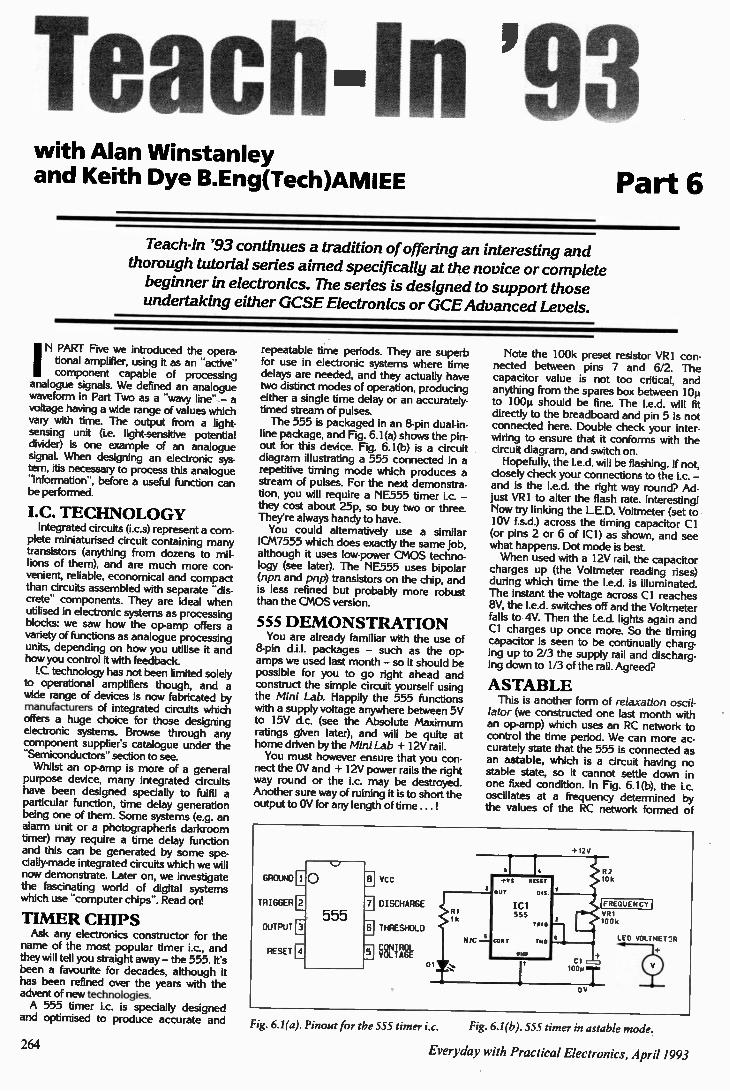
Teach-In '93 with Alan Winstanley and Keith Dye B.Eng(Tech)AMIEE Part 6
Teach-In '93 continues a tradition of offering an interesting and thorough tutorial series aimed specifically at the novice or complete beginner in electronics. The series is designed to support those undertaking either GCSE Electronics or GCE Advanced Levels.
IN PART Five we introduced the opera-tional amplifier, using it as an -active" component capable of processing
analogue signals. We defined an analogue waveform in Part Two as a "wavy line" - a voltage having a wide range of values which vary with time. The output from a light. sensing unit (i.e. light-sensitive potential divider) is one example of an analogue signal. When designing an electronic sys-tern, its necessary to process this analogue -information", before a useful function can be performed.
I.C. TECHNOLOGY Integrated circuits (i.c.$) represent a com-
plete miniaturised circuit containing many transistors (anything from dozens to mil-lions of them), and are much more con-venient, reliable, economical and compact than circuits assembled with separate -dis-crete- components. They are ideal when utilised in electronic systems as processing blocks: we saw how the op-amp offers a variety of functions as analogue processing units, depending on how you utilise it and how you control it with feedback. I.C. technology has not been limited solely
to operational amplifiers though, and a wide range of devices is now fabricated by manufacturers of integrated circuits which offers a huge choice for those designing electronic systems. Browse through any component supplier's catalogue under the "Semiconductors" section to see. Whilst an op-amp is more of a general
purpose device, many integrated circuits have been designed specially to fulfil a particular function, time delay generation being one of them. Some systems (e.g. an alarm unit or a photographeris darkroom timer) may require a time delay function and this can be generated by some spe-cially-made integrated circuits which we will now demonstrate. Later on, we investigate the fascinating world of digital systems which use "computer chips-. Read on!
TIMER CHIPS Ask any electronics constructor for the
name of the most popular timer i.c., and they will tell you straight away - the 555. It's been a favourite for decades, although it has been refined over the years with the advent of new technologies. A 555 timer i.c. is specially designed
and optimised to produce accurate and
repeatable time periods. They are superb for use in electronic systems where time delays are needed, and they actually have two distinct modes of operation, producing either a single time delay or an accurately-timed stream of pulses. The 555 is packaged in an 8-pin dual-in-
line package, and Fig. 6.1(a) shows the pin. out for this device. Fig. 6.1(b) is a circuit diagram illustrating a 555 connected in a repetitive timing mode which produces a stream of pulses. For the next demonstra-tion, you will require a NE555 timer i.c. - they cost about 25p, so buy two or three. They're always handy to have. You could alternatively use a similar
ICM7555 which does exactly the same job, although it uses low-power CMOS techno-logy (see later). The NE555 uses bipolar (npn and pnp) transistors on the chip, and is less refined but probably more robust than the CMOS version.
555 DE MONSTRATION You are already familiar with the use of
8-pin d.i.l. packages - such as the op. amps we used last month - so it should be possible for you to go right ahead and construct the simple circuit yourself using the Mini Lab. Happily the 555 functions with a supply voltage anywhere between 5V to 15V d.c. (see the Absolute Maximum ratings given later), and will be quite at home driven by the Mini Lab + 12V rail. You must however ensure that you con-
nect the OV and + 12V power rails the right way round or the i.c. may be destroyed. Another sure way of ruining it is to short the output to OV for any length of time ... !
GROUND
TRIGGER
OUTPUT
RESET
Vcc
DISCHARGE
THRESHOLD
CONTROL VOLTAGE
Note the 100k preset resistor VR I con-nected between pins 7 and 6/2. The capacitor value is not too critical, and anything from the spares box between 10µ to 100µ should be fine. The I.e.d, will fit directly to the breadboard and pin 5 is not connected here. Double check your inter-wiring to ensure that it conforms with the circuit diagram, and switch on. Hopefully, the I.e.d, will be flashing. If not,
closely check your connections to the i.c. - and is the I.e.d, the right way round? Ad-just VR1 to alter the flash rate. Interesting! Now try linking the LED. Voltmeter (set to 10V f.s.d.) across the timing capacitor CI (or pins 2 or 6 of ICI) as shown, and see what happens. Dot mode is best. When used with a 12V rail, the capacitor
charges up (the Voltmeter reading rises) during which time the led. is illuminated. The instant the voltage across Cl reaches 8V, the I.e.d, switches off and the Voltmeter falls to 4V. Then the I.e.d, lights again and Cl charges up once more. So the timing capacitor is seen to be continually charg-ing up to 2/3 the supply rail and discharg-ing down to 1/3 of the rail. Agreed?
ASTABLE This is another form of relaxation oscil-
lator (we constructed one last month with an op-amp) which uses an RC network to control the time period. We can more ac-curately state that the 555 is connected as an astable, which is a circuit having no stable state, so it cannot settle down in one fixed condition. In Fig. 6.1(b), the i.c. oscillates at a frequency determined by the values of the RC network formed of
+12V
OV
!FREQUENCY 1
LED VOLTMET:Ft
Fig. 6.1(a). Pinout for the 555 timer i.c. Fig. 6.1(b). 555 timer in astable mode.
264 Everyday with Practical Electronics, April 1993
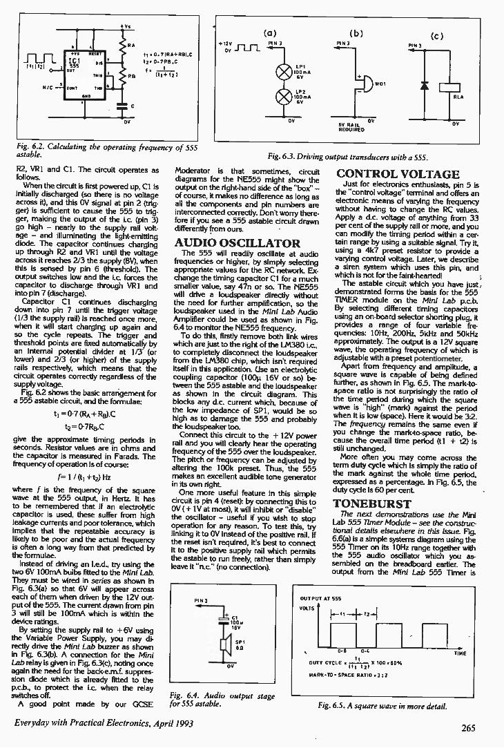
t = 0. 7IRA+RB) :C
t2= 0.7REI.0
f = 1 111 +12 1
Fig. 6.2. Calculating the operating frequency of 555 astable.
R2, VR1 and CI. The circuit operates as follows. When the circuit is first powered up, Cl is
initially discharged (so there is no voltage across it), and this OV signal at pin 2 (trig-ger) is sufficient to cause the 555 to trig-ger, making the output of the i.c. (pin 3) go high — nearly to the supply rail volt-age — and illuminating the light-emitting diode. The capacitor continues charging up through R2 and VR1 until the voltage across it reaches 2/3 the supply (8V), when this is sensed by pin 6 (threshold). The output switches low and the i.c. forces the capacitor to discharge through VR1 and into pin 7 (discharge). Capacitor Cl continues discharging
down into pin 7 until the trigger voltage (1/3 the supply rail) is reached once more, when it will start charging up again and so the cycle repeats. The trigger ,and threshold points are fixed automatically by an internal potential divider at 1/3 (or lower) and 2/3 (or higher) of the supply rails respectively, which means that the circuit operates correctly regardless of the supply voltage. Fig. 6.2 shows the basic arrangement for
a 555 astable circuit, and the formulae:
ti = 0-7 (RA +128).0
t2 = 0.7RB.0
give the approximate timing periods in seconds. Resistor values are in ohms and the capacitor is measured in Farads. The frequency of operation is of course:
f= 1 / (ti +t2) Hz
where f is the frequency of the square wave at the 555 output, in Hertz. It has to be remembered that if an electrolytic capacitor is used, these suffer from high leakage currents and poor tolerance, which implies that the repeatable accuracy is likely to be poor and the actual frequency is often a long way from that predicted by the formulae. Instead of driving an Led., try using the
two 6V 100mA bulbs fitted to the Mini Lab. They must be wired in series as shown in Fig. 6.3(a) so that 6V will appear across each of them when driven by the 12V out-put of the 555. The current drawn from pin 3 will still be 100mA which is within the device ratings. By setting the supply rail to + 6V using
the Variable Power Supply, you may di-rectly drive the Mini Lab buzzer as shown in Fig. 6.3(b). A connection for the Mini Lab relay is given in Fig. 6.3(c), noting once again the need for the back-e.m.f. suppres-sion diode which is already fitted to the p.c.b., to protect the i.c. when the relay switches off. A good point made by our GCSE
Fig. 6.3. Driving output transducers with a 555.
Moderator is that sometimes, circuit diagrams for the NE555 might show the output on the right-hand side of the -box- — of course, it makes no difference as long as all the components and pin numbers are interconnected correctly. Don't worry there-fore if you see a 555 astable circuit drawn differently from ours.
AUDIO OSCILLATOR The 555 will readily oscillate at audio
frequencies or higher, by simply selecting appropriate values for the RC network. Ex-change the timing capacitor CI for a much smaller value, say 47n or so. The NE555 will drive a loudspeaker directly without the need for further amplification, so the loudspeaker used in the Mini Lab Audio Amplifier could be used as shown in Fig. 6.4 to monitor the NE555 frequency. To do this, firstly remove both link wires
which are just to the right of the LM380 i.c., to completely disconnect the loudspeaker from the LM380 chip, which isn't required itself in this application. Use an electrolytic coupling capacitor (100µ 16V or so) be-tween the 555 astable and the loudspeaker as shown in the circuit diagram. This blocks any d.c. current which, because of the low impedance of SP1, would be so high as to damage the 555 and probably the loudspeaker too. Connect this circuit to the + 12V power
rail and you will clearly hear the operating frequency of the 555 over the loudspeaker. The pitch or frequency can be adjusted by altering the 100k preset. Thus, the 555 makes an excellent audible tone generator in its own right. One more useful feature in this simple
circuit is pin 4 (reset): by connecting this to OV ( + IV at most), it will inhibit or -disable" the oscillator — useful if you wish to stop operation for any reason. To test this, try linking it to OV instead of the positive rail. If the reset isn't required, its best to connect it to the positive supply rail which permits the astable to run freely, rather than simply leave it 'nc.- (no connection).
PIN]
OV
Fig. 6.4. Audio output stage for 555 astable.
CONTROL VOLTAGE Just for electronics enthusiasts, pin 5 is
the -control voltage" terminal and offers an electronic means of varying the frequency without having to change the RC values. Apply a d.c. voltage of anything from 33 per cent of the supply rail or more, and you can modify the timing period within a cer-tain range by using a suitable signal. Try it, using a 4k7 preset resistor to provide a varying control voltage. Later, we describe a siren system which uses this pin, and which is not for the faint-hearted! The astable circuit which you have just
demonstrated forms the basis for the 555 TIMER module on the Mini Lab p.c.b. By selecting different timing capacitors using an on-board selector shorting plug, it provides a range of four variable fre-quencies: 10Hz, 200Hz, 5kHz and 50kHz approximately. The output is a 12V square wave, the operating frequency of which is adjustable with a preset potentiometer. Apart from frequency and amplitude, a
square wave is capable of being defined further, as shown in Fig. 6.5. The mark-to-space ratio is not surprisingly the ratio of the time period during which the square wave is -high- (mark) against the period when it is low (space). Here it would be 3:2. The frequency remains the same even if you change the mark-to-space ratio, be-cause the overall time period (t 1 + t2) is still unchanged. More often you may come across the
term duty cycle which is simply the ratio of the mark against the whole time period, expressed as a percentage. In Fig. 6.5, the duty cycle is 60 per cent.
TONEBURST The next demonstrations use the Mini
Lab 555 Timer Module — see the construc-tional details elsewhere in this issue. Fig. 6.6(a) is a simple systems diagram using the 555 Timer on its 10Hz range together with the 555 audio oscillator which you as-sembled on the breadboard earlier. The output from the Mini Lab 555 Timer is
OUTPUT AT 555
VOLTS
0.6 0.4
DUTY CYCLE - X I00 60 % t t 21
MARK-TO - SPACE RATIO = 3:2
Fig. 6.5. A square wave in more detail.
TIME
Everyday with Practical Electronics, April 1993 265
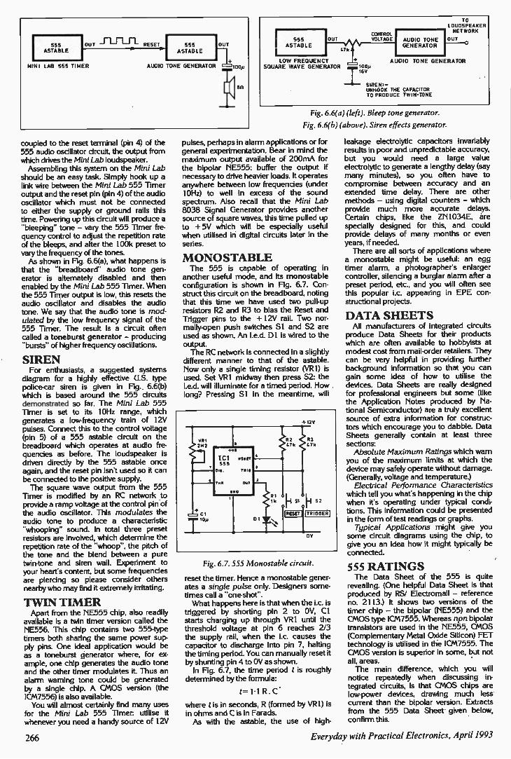
TO LOUDSPEAKER NETWORK 555 ASTABLE RESET
MINI LAB 555 TIMER AUDIO 555 ASTABLE laT+ TONE GENERATOR 00p
coupled to the reset terminal (pin 4) of the 555 audio oscillator circuit, the output from which drives the Mini Lab loudspeaker. Assembling this system on the Mini Lab
should be an easy task. Simply hook up a link wire between the Mini Lab 555 Timer output and the reset pin (pin 4) of the audio oscillator which must not be connected to either the supply or ground rails this time. Powering up this circuit will produce a -bleeping- tone - vary the 555 Timer fre-quency control to adjust the repetition rate of the bleeps, and alter the 100k preset to vary the frequency of the tones. As shown in Fig. 6.6(a), what happens is
that the -breadboard- audio tone gen-erator is alternately disabled and then enabled by the Mini Lab 555 Timer. When the 555 Timer output is low, this resets the audio oscillator and disables the audio tone. We say that the audio tone is mod-ulated by the low frequency signal of the 555 Timer. The result is a circuit often called a toneburst generator - producing -bursts- of higher frequency oscillations.
SIREN For enthusiasts, a suggested systems
diagram for a highly effective U.S. type police-car siren is given in Fig. 6.6(b) which is based around the 555 circuits demonstrated so far. The Mini Lab 555 Timer is set to its 10Hz range, which generates a low-frequency train of 12V pulses. Connect this to the control voltage (pin 5) of a 555 astable circuit on the breadboard which operates at audio fre-quencies as before. The loudspeaker is driven directly by the 555 astable once again, and the reset pin isn't used so it can be connected to the positive supply. The square wave output from the 555
Timer is modified by an RC network to provide a ramp voltage at the control pin of the audio oscillator. This modulates the audio tone to produce a characteristic -whooping- sound. In total three preset resistors are involved, which determine the repetition rate of the -whoop-, the pitch of the tone and the blend between a pure twin-tone and siren wail. Experiment to your heart's content, but some frequencies are piercing so please consider others nearby who may find it extremely irritating.
TWIN TIMER Apart from the NE555 chip, also readily
available is a twin timer version called the NE556. This chip contains two 555-type timers both sharing the same power sup-ply pins. One ideal application would be as a toneburst generator where, for ex-ample, one chip generates the audio tone and the other timer modulates it. Thus an alarm warning tone could be generated by a single chip. A CMOS version (the ICM7556) is also available. You will almost certainly find many uses
for the Mini Lab 555 Timer: utilise it whenever you need a handy source of 12V
555 OUT ASTABLE 47k CONTROL VOLTAGE
LOW FREQUENCY SQUARE WAVE GENERATOR '100y I6V AUDIO TONE GENERATOR OUT 0 AUDIO TONE GENERATOR
SIREN:-UNHOOK THE CAPACITOR TO PRODUCE TWIN-TONE Fig. 6.6(a) (left). Bleep tone generator.
Fig. 6.6(b) (above). Siren effects generator.
pulses, perhaps in alarm applications or for general experimentation. Bear in mind the maximum output available of 200mA for the bipolar NE555: buffer the output if necessary to drive heavier loads. It operates anywhere between low frequencies (under 10Hz) to well in excess of the sound spectrum. Also recall that the Mini Lab 8038 Signal Generator provides another source of square waves, this time pulled up to + 5V which will be especially useful when utilised in digital circuits later in the series.
MONOSTABLE The 555 is capable of operating in
another useful mode, and its monostable configuration is shown in Fig. 6.7. Con-struct this circuit on the breadboard, noting that this time we have used two pull-up resistors R2 and R3 to bias the Reset and Trigger pins to the + 12V rail. Two nor-mally-open push switches S1 and S2 are used as shown. An led. DI is wired to the output. The RC network is connected in a slightly
different manner to that of the astable. Now only a single timing resistor (VR1) is used. Set VR1 midway then press S2: the I.e.d, will illuminate for a timed period. How long? Pressing Si in the meantime, will
Fig. 6.7. 555 Monostable circuit.
reset the timer. Hence a monostable gener-ates a single pulse only. Designers some-times call a "one-shot-. What happens here is that when the i.c. is
triggered by shorting pin 2 to OV, Cl starts charging up through VR1 until the threshold voltage at pin 6 reaches 2/3 the supply rail, when the i.c. causes the capacitor to discharge into pin 7, halting the timing period. You can manually reset it by shunting pin 4 to OV as shown. In Fig. 6.7, the time period t is roughly
determined by the formula:
t= 1.1 R . C
where t is in seconds, R (formed by VR I) is in ohms and C is in Farads. As with the astable, the use of high-
leakage electrolytic capacitors invariably results in poor and unpredictable accuracy, but you would need a large value electrolytic to generate a lengthy delay (say many minutes), so you often have to compromise between accuracy and an extended time delay. There are other methods - using digital counters - which provide much more accurate delays. Certain chips, like the ZN1034E, are specially designed for this, and could provide delays of many months or even years, if needed. There are all sorts of applications where
a monostable might be useful: an egg timer alarm, a photographer's enlarger controller, silencing a burglar alarm after a preset period, etc., and you will often see this popular i.c. appearing in EPE con-structional projects.
DATA SHEETS All manufacturers of integrated circuits
produce Data Sheets for their products which are often available to hobbyists at modest cost from mail-order retailers. They can be very helpful in providing further background information so that you can gain some idea of how to utilise the devices. Data Sheets are really designed for professional engineers but some (like the Application Notes produced by Na-tional Semiconductor) are a truly excellent source of extra information for construc-tors which encourage you to dabble. Data Sheets generally contain at least three sections: Absolute Maximum Ratings which warn
you of the maximum limits at which the device may safely operate without damage. (Generally, voltage and temperature.) Electrical Performance Characteristics
which tell you what's happening in the chip when it's operating under typical condi-tions. This information could be presented in the form of test readings or graphs. Typical Applications might give you
some circuit diagrams using the chip, to give you an idea how it might typically be connected.
555 RATINGS The Data Sheet of the 555 is quite
revealing. (One helpful Data Sheet is that produced by RS/ Electromail - reference no. 2113.) It shows two versions of the timer chip - the bipolar (NE555) and the CMOS type ICM7555. Whereas npn bipolar transistors are used in the NE555, CMOS (Complementary Metal Oxide Silicon) FET technology is utilised in the ICM7555. The CMOS version is superior in some, but not all, areas. The main difference, which you will
notice repeatedly when discussing in-tegrated circuits, is that CMOS chips are low-power devices, drawing much less current than the bipolar version. Extracts from the 555 Data Sheet given below, confirm this.
266 Everyday with Practical Electronics, April 1993
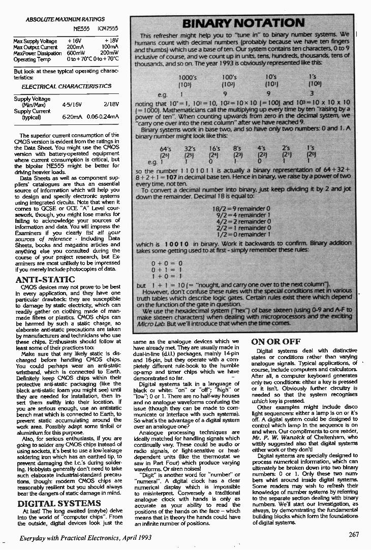
ABSOLUTE MAXIMUM RATINGS
NE555 ICM7555 BINARY NOTATION
Max Supply Voltage + 16V + I8V Max Output Current 200mA 100mA MaxPower Dissipation 600mW 200mW Operating Temp 0 to + 70*C 0 to ± 70*C
But look at these typical operating charac-teristics:
ELECTRICAL CHARACTERISTICS
Supply Voltage (Min/Max)
Supply Current (typical)
4:5/16V 2/18V
6-20mA 0.06-0.24mA
The superior current consumption of the CMOS version is evident from the ratings in the Data Sheet. You might use the CMOS version with battery-operated equipment where current consumption is critical, but the bipolar NE555 might be better for driving heavier loads. Data Sheets as well as component sup-
pliers' catalogues are thus an essential source of information which will help you to design and specify electronic systems using integrated circuits. Note that when it comes to GCSE or GCE "A" Level cour-sework, though, you might lose marks for failing to acknowledge your sources of information and data. You will impress the Examiners if you clearly list all your sources of reference - including Data Sheets, books and magazine articles and anything else you consulted during the course of your project research, but Ex-aminers are most unlikely to be impressed if you merely include photocopies of data.
ANTI-STATIC CMOS devices may not prove to be best
in every application, and they have one particular drawback: they are susceptible to damage by static electricity, which can readily gather on clothing made of man-made fibres or plastics. CMOS chips can be harmed by such a static charge, so elaborate anti-static precautions are taken by manufacturers and technicians who use these chips. Enthusiasts should follow at least some of their practices too: Make sure that any likely static is dis-
charged before handling CMOS chips. You could perhaps wear an anti-static wristband, which is connected to Earth. Definitely keep CMOS chips within their protective anti-static packaging (like the black anti-static foam you might see) until they are needed for installation, then in-sert them swiftly into their location. If you are serious enough, use an antistatic bench mat which is connected to Earth, to prevent static accumulating around the work area. Possibly adapt some tinfoil or aluminium for this purpose. Also, for serious enthusiasts, if you are
going to solder any CMOS chips instead of using sockets, it's best to use a low-leakage soldering iron which has an earthed tip, to prevent damaging the i.c.'s during solder-ing. Hobbyists generally don't need to take such elaborate industrial-standard precau-tions, though: modern CMOS chips are reasonably resilient but you should always bear the dangers of static damage in mind.
DIGITAL SYSTEMS At last! The long awaited (maybe) delve
into the world of "computer chips". From the outside, digital devices look just the
This refresher might help you to "tune in" to binary number systems. We humans count with decimal numbers (probably because we have ten fingers
and thumbs) which use a base often, Our system contains ten characters, 0 to 9
inclusive of course, and we count up in units, tens, hundreds, thousands, tens of thousands, and so on. The year 1993 is obviously represented like this:
1000's 100's 10's l's
(103) (102) (101) (100)
e.g. 1 9 9 3
noting that 10° = 1, 10 1= 10, 102= 10 x 10 ( =100) and 103=10 x 10 x 10 ( = 1000). Mathematicians call the multiplying up every time by ten "raising by a power often". When counting upwards from zero in the decimal system, we "carry one over into the next column" after we have reached 9. Binary systems work in base two, and so have only two numbers: 0 and 1. A
binary number might look like this:
64's (26)
e.g. 1
so the number 1 1 0 1 0 1 1 is actually a binary representation of 64 + 32 + 8 + 2 + 1 = 107 in decimal base ten. Hence in binary, we raise by a power of two every time, not ten. To convert a decimal number into binary, just keep dividing it by 2 and jot
down the remainder. Decimal 18 is equal to:
18/2 = 9 remainder 0 9/2 = 4 remainder 1 4/2 = 2 remainder 0 2/2 = 1 remainder 0 1/2 = 0 remainder 1
which is 1 00 1 0 in binary. Work it backwards to confirm, Binary addition takes some getting used to at first - simply remember these rules:
0 + 0 = 0 0 + 1 = 1 1 + 0 = 1
but 1 + 1 = 10 ( "nought, and carry one over to the next column"). However, don't confuse these rules with the special conditions met in various
truth tables which describe logic gates. Certain rules exist there which depend
on the function of the gate in question. We use the hexadecimal system ("hex") of base sixteen (using 0-9 and A-F to
make sixteen characters) when dealing with microprocessors and the exciting Micro Lab. But we'll introduce that when the time comes.
32's (25) 1
16's 8's (24) (23) 0
4's (22) 0
2's l's (2 1) (20) 1 1
same as the analogue devices which we have already met. They are usually made in dual-in-line (d.i.I.) packages, mainly 14-pin and 16-pin, but they operate with a com-pletely different rule-book to the humble op-amp and timer chips which we have demonstrated so far. Digital systems talk in a language of
black or white: "on" or "off': "high" or "low-: 0 or 1. There are no half-way houses and no analogue waveforms confusing the issue (though they can be made to com-municate or interface with such systems). So what's the advantage of a digital system over an analogue one? Analogue processing techniques are
ideally matched for handling signals which continually vary. These could be audio or radio signals, or light-sensitive or heat-dependent units (like the thermostat we saw in Part Four) which produce varying waveforms. Or siren noises! -Digit" is another word for "number" or
"numeral". A digital clock has a clear numerical display which is impossible to misinterpret. Conversely a traditional analogue clock with hands is only as accurate as your ability to read the positions of the hands on the face - which means that in theory the hands could have an infinite number of positions.
ON OR OFF Digital systems deal with distinctive
states or conditions rather than varying analogue signals. Typical applications, of course, include computers and calculators. After all, a computer keyboard generates only two conditions: either a key is pressed or it isn't. Obviously further circuitry is needed so that the system recognises which key is pressed. Other examples might include disco
light sequencers: either a lamp is on or it's off. A digital system could be designed to control which lamp in the sequence is on and when. Our compliments to one reader, Mr. P. W. Warwick of Cheltenham, who wittily suggested also that digital systems either work or they don't! Digital systems are specially designed to
process numerical information, which can ultimately be broken down into two binary numbers: 0 or 1. Only these two num-bers whirl around inside digital systems. Some readers may wish to refresh their knowledge of number systems by referring to the separate section dealing with binary numbers. We'll start our investigation, as always, by demonstrating the fundamental building blocks which form the foundations of digital systems.
Everyday with Practical Electronics, April 1993 267
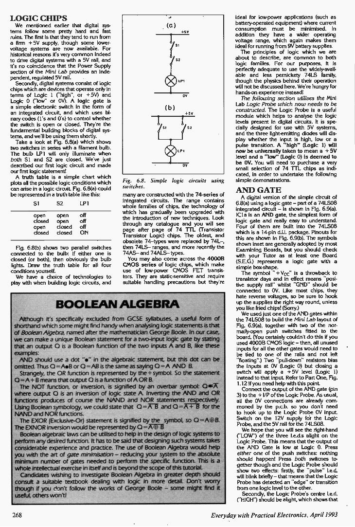
LOGIC CHIPS We mentioned earlier that digital sys-
tems follow some pretty hard and fast rules. The first is that they tend to run from a firm + 5V supply, though some lower-voltage systems are now available. For historical reasons its very common indeed to drive digital systems with a 5V rail, and ifs no coincidence that the Power Supply section of the Mini Lab provides an inde-pendent, regulated 5V rail. Secondly, digital systems consist of logic
chips which are devices that operate only in terms of Logic 1 (-high", or + 5V) and Logic 0 ("low" or OV). A logic gate is a simple electronic switch in the form of an integrated circuit, and which uses bi-nary codes (I's and 0.$) to control whether the switch is open or closed. They're the fundamental building blocks of digital sys-tems, and we'll be using them shortly. Take a look at Fig. 6.8(a) which shows
two switches in series with a filament bulb. The bulb LP1 will only illuminate when both S I and S2 are closed. We've just described our first logic circuit and made our first logic statement! A truth table is a simple chart which
plots all the possible logic conditions which can arise in a logic circuit. Fig. 6.8(a) could be represented in a truth table like this:
S I S2 LP1
open closed open closed
open open closed closed
off off off ON
Fig. 6.8(b) shows two parallel switches connected to the bulb: if either one is closed (or both), then obviously the bulb lights. Draw the truth table for all four conditions yourself. We have a choice of technologies to
play with when building logic circuits, and
Fig. 6.8. Simple logic circuits using switches.
many are constructed with the 74-series of integrated circuits. The range contains whole families of chips, the technology of which has gradually been upgraded with the introduction of new techniques. Look through any catalogue and you will see page after page of 74 TTL (Transistor Transistor Logic) chips. The oldest, and obsolete 74—types were replaced by 74L—, then 74LS— ranges, and more recently the 74AS— and 74ALS— types. You may also come across the 4000B
CMOS series of logic chips, which make use of low-power CMOS FET transis-tors. They are static-sensitive and require suitable handling precautions but they're
BOOLEAN ALGEBRA Although it's specifically excluded from GCSE syllabuses, a useful form of
shorthand which some might find handy when analysing logic statements is that
of Boolean Algebra, named after the mathematician George Boole. In our case, we can make a unique Boolean statement for a two-input logic gate by stating that an output 0 is a Boolean function of the two inputs A and B, like these
examples: AND should use a dot "s" in the algebraic statement but this dot can be
omitted. Thus 0 = A•B or 0 =AB is the same as saying 0 =A AND B. Strangely, the OR function is represented by the + symbol. So the statement
o —A + B means that output 0 is a function of A OR B. The NOT function, or inversion, is signified by an overbar symbol: OagT
where output 0 is an inversion of logic state A Inverting the AND and OR
functions produces of course the NAND and NOR statements respectively.
Using Boolean symbology, we could state that 0 =Ail and 0 =A + 8 for the
NAND and NOR functions. The EXOR (Exclusive-Or) statement is signified by the symbol, so 0 =A+8.
The EXNOR inversion would be represented by 0 =A-713 Boolean algebraic laws can be utilised to help in the design of logic systems to
perform any desired function. It has to be said that designing such systems takes considerable experience and practice. The use of Boolean Algebra would help
you with the art of gate minimisation — reducing your system to the absolute
minimum number of gates needed to perform the specific function. This is a
whole intellectual exercise in itself and is beyond the scope of this tutorial. Candidates wishing to investigate Boolean Algebra in greater depth should
consult a suitable textbook dealing with logic in more detail. Don't worry though if you don't follow the works of George Boole — some might find it
useful, others won'tl
ideal for low-power applications (such as battery-operated equipment) where current consumption must be minimised. In addition they have a wider operating voltage range, which again makes them ideal for running from 9V battery supplies. The principles of logic which we are
about to describe, are common to both logic families. For our purposes, it is perfectly adequate to use the widely-avail-able and less pernickety 74L5 family, though the physics behind their operation will not be discussed here. Were hungry for hands-on experience instead! The following section utilises the Mini
Lab Logic Probe which now needs to be constructed. The Logic Probe is a useful module which helps to analyse the logic levels present in digital circuits. It is spe-cially designed for use with 5V systems, and the three light-emitting diodes will dis-play whether the input is high, low or a pulse transition. A "high" (Logic 1) will now be universally taken to mean a + 5V level and a "low" (Logic 0) is deemed to be OV. You will need to purchase a very small selection of 74 TTL chips as indi-cated, in order to undertake the following simple demonstrations.
AND GATE A digital version of the simple circuit of
6.8(a) using a logic gate — part of a 74LS08 integrated circuit — is shown in Fig. 6.9(a). ICI a is an AND gate, the simplest form of logic gate and really easy to understand. Four of them are built into the 74LS08 which is a 14-pin d.i.l. package. Pinouts for this are shown in Fig. 6.9(b). The symbols shown inset are generally adopted by most Examining Boards, but you should check with your Tutor as at least one Board (S.E.G.) represents a logic gate with a simple box-shape. The symbol " + Vcc" is a throwback to
transistor days and in effect means "posi-tive supply rail" whilst "GND" should be connected to OV. Like most chips, they hate reverse voltages, so be sure to hook up the supplies the right way round, unless you like fried chips! (Sorry.) We used just one of the AND gates within
the 74LS08 to build the Mini Lab layout of Fig. 6.9(a), together with two of the nor-mally-open push switches fitted to the board. (You certainly couldn't do this if you used 4000B CMOS logic — then, all unused inputs for all the other gates would need to be tied to one of the rails and not left -floating") Two "pull-down" resistors bias the inputs at OV (Logic 0) but closing a switch will apply a + 5V level (Logic 1) instead to that input. Refer to Part One, Fig. 1.12 if you need help with this point. Connect the output of the AND gate (pin
3) to the + I/P of the Logic Probe. As usual, all the OV connections are already corn-moned by the p.c.b. so you don't need to hook up to the Logic Probe OV input. Switch on the 12V supply for the Logic Probe, and the 5V rail for the 74LS08. We hope that you will see the right-hand
("LOW") of the three I.e.d.s alight on the Logic Probe. This means that the output of the AND Gate is low at Logic 0. Press either one of the push switches: nothing should happen! Press both switcnes to-gether though and the Logic Probe should show two effects: firstly, the "pulse" led. will blink briefly — that means that the Logic Probe has detected an "edge" or transition from one logic level to the other. Secondly, the Logic Probe's centre led.
("HIGH") should be alight, which shows that •
26S Everyday with Practical Electronics, April 1993
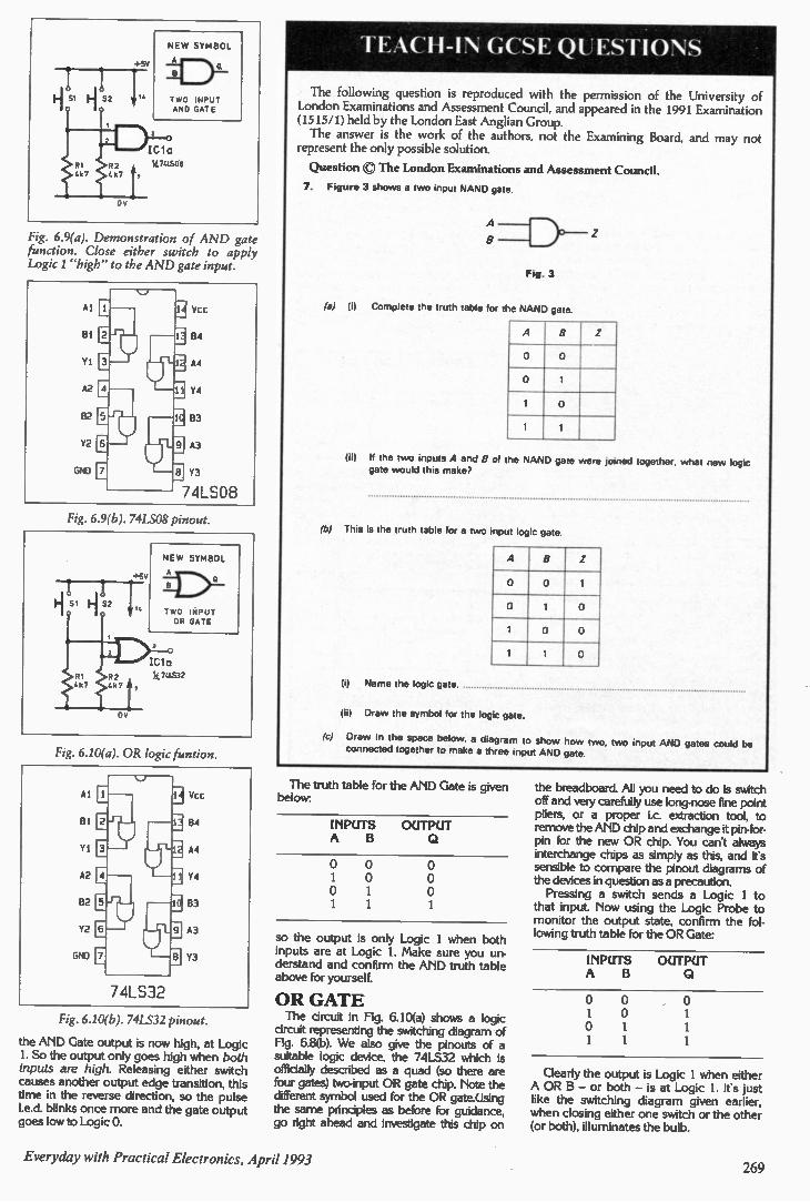
Fig. 6.9(a). Demonstration of AND gate function. Close either switch to apply Logic I "high" to the AND gate input.
Fig. 6.9(6). 74LS08 pinout.
Fig. 6.10(a). OR logic funtion.
Fig. 6.10(6). 74LS32 pinout.
the AND Gate output is now high, at Logic 1. So the output only goes high when both inputs are high. Releasing either switch causes another output edge transition, this time in the reverse direction, so the pulse Led. blinks once more and the gate output goes low to Logic 0.
TEACH-IN GCSE QUESTIONS
The following question is reproduced with the permission of the University of London Examinations and Assessment Council, and appeared in the 1991 Examination (1515/1) held by the London East Anglian Group.
The answer is the work of the authors, not the Examining Board, and may not represent the only possible solution.
Question The London Examinations and Assessment Council.
7. Figure 3 shows a two input NAND gate.
A
Fig. 3
(a) (I) Complete the truth table for the NAND gate
A a z
o o
0 1
1 0
1 1
(ii) If the two inputs A and B of the NAND gate were joined together, what new logic gate would this make?
(b) This is the truth table for a two input logic gate.
A B z
o o 1
0 1 0
1 0 0
1 1 0
(i) Name the logic gate.
(ii) Draw the symbol for the logic gate.
("c) Draw in the space below, a diagram to show how two, two input AND gates could be connected together to make a three input AND gate
The truth table for the AND Gate is given below:
INPUTS A B
OUTPUT
so the output is only Logic 1 when both inputs are at Logic 1. Make sure you un-derstand and confirm the AND truth table above for yourself.
OR GATE The circuit in Fig. 6.10(a) shows a logic
circuit representing the switching diagram of Fig. 6.8(b). We also give the pinouts of a suitable logic device, the 74LS32 which is officially described as a quad (so there are four gates) two-input OR gate chip. Note the different symbol used for the OR gate.Using the same principles as before for guidance, go right ahead and investigate this chip on
the breadboard. All you need to do is switch off and very carefully use long-nose fine point pliers, or a proper i.c. extraction tool, to remove the AND chip and exchange it pin-for-pin for the new OR chip. You can't always interchange chips as simply as this, and it's sensible to compare the pinout diagrams of the devices in question as a precaution. Pressing a switch sends a Logic 1 to
that input. Now using the Logic Probe to monitor the output state, confirm the fol-lowing truth table for the OR Gate:
INPUTS A B
OUTPUT
Clearly the output is Logic 1 when either A OR B — or both — is at Logic 1. It's just like the switching diagram given earlier, when closing either one switch or the other (or both), illuminates the bulb.
Everyday with Practical Electronics, April 1993 269
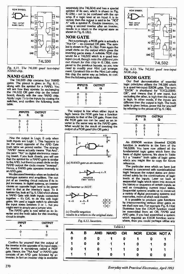
NE W SYMBOL
A a
TWO INPUT NAND GATE
74LSOO
Fig. 6.11. The 74LS00 quad two-input NAND chip.
NAND GATE The 74LS00 chip contains four NAND
gates. The pinout is given in Fig. 6.11, along with the symbol for a NAND. You will see how they operate by exchanging the 74LS32 OR gate chip on the bread-board, directly with the new NAND chip. Apply Logic Is to the inputs by closing the switches, and confirm the following truth table.
INPUTS OUTPUT A B
Now the output is Logic 0 only when both inputs are Logic I. This happens to be the exact opposite of the AND Gate truth table we proved earlier. The strange -NAND" name actually means Not And", the term -Not" in digital electronics mean-ing invert. If you look closely, you will see that the symbol for a NAND gate is similar to the AND, but there's a small circle on the NAND output: the circle means -inverted". Hence, a NAND gate operates inversely to an AND gate. We discussed inversion when we looked at
analogue systems and amplifiers. The out-put of an inverting circuit reduces if its in-put increases. In digital systems, an inverter causes an opposite logic level to be gener-ated to that at the inverter's input. To il-lustrate this, look at Fig. 6.12(a) which shows a NAND Gate with both inputs connected together — it's O.K. to do this with logic gates. We used a toggle switch to altemate the input states between 0 or 1, but you might want to simply use a jumper wire. The NAND gate is now wired as an in-
verter and the truth table for this inverting circuit is simple:
INPUT A
OUTPUT
1
Confirm for yourself that the output of the inverter is the opposite of its input state. An inverter is sometimes called a NOT gate. Hence, the -Not And" or NAND gate consists of an AND gate followed by an inverter. In fact an inverter chip is available
separately (the 74LS04) and has a special symbol of its own, which is shown in Fig. 6.12(b) — not to be confused with the op. amp, If a logic level at an input A is in-verted, then the oulput is said to be -NOT A" with a symbol A. Double inversion, i.e. using a second inverter after an inverter, results in a return to the original state as shown in Fig. 6.12(c).
NOR GATE Not surprisingly, a NOR gate is actually a
-Not Or" — an inverted OR gate. The sym-bol is shown in Fig. 6.13(a). Note again the small circle on the output which gives the inverting game away. A suitable NOR chip would be a 74LS02 which is a quad two-input circuit, though note the different pin-out shown for this chip in 6.13(b), com-pared to the previous layouts, so you now need to modify your Mini Lab arrange-ment. Construct this on the Mini Lab using this chip the same way as before, to con-firm the following truth table.
INPUTS OUTPUT A B
The output is low when either input is high: hence the NOR gate has a function opposite to that of the OR gate. Prove that the NOR gate too can be used as an in-verter in the same way as the NAND gate. What would be the result of inverting the output of a NOR gate? (An OR gate.)
-4-5V
en •
(a) NAND gate as an inverter.
0 - 2-1 >0 .0 0
IN NOT GATE I
(6) Inverter or NOT.
A 0 R
0. A Rm ar A
zA
A
t7
a
ON
(c) Double negation results in a return to the original state.
Fig. 6.12. Inverters.
Fig. 6.13. The 74LS02 quad two-input NOR chip.
EXOR GATE Our final demonstration of essential
logic principles utilises the 74LS86 which is a quad two-input EXOR gate. The term -EXOR" is shorthand for "EXCLUSIVE-OR", and means that if one input, but excluding the other, is high then the output is high. In other words, if the inputs are different then the output is high. The truth table is given below, prove this for yourself by referring to the pinout of Fig. 6.14(b).
INPUTS OUTPUT A B
An EXNOR version (inverted EXOR) function is available in the form of the 74LS266. You have now utilised all the fundamental logic gates which form the basis of digital systems. We show in Table 6.1 a -master" truth table of logic gates which you might like to copy for future reference. The particular area which we have just
covered is concerned with combinational logic because the output states are deter-mined solely by the combinations of logic levels at the inputs. Later we look at sequential logic which takes into account the history or sequence of certain inputs, as well as considering current input states. Sequential systems enable us to construct a variety of digital processing systems and memories, more of which next month. It is possible to produce gate functions
by interconnecting various other gates as we shall now see. For example Fig. 6.15(a) illustrates how the EXOR function could be assembled from an OR, NAND and AND gate. If you had assembled a system which required an EXOR function some-where, then you could perhaps utilise any
Table 6.1
A B AND NAND OR NOR EXOR NOT A
0 0 0 1 0 1 0 1
1 0 0 1 1 0 1 0
0 1 0 1 1 0 1 1
1 1 1 0 1 0 0 0
270 Everyday with Practical Electronics, April 1993
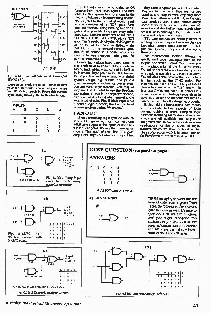
Fig. 6.14. The 74LS86 quad two-input EXOR chip.
spare gates available in the circuit to fulfil your requirements, instead of purchasing an EXOR chip specially. Prove this system by following through the truth table below.
INPUTS A
NAND EXOR EQUIVALENT
Fig. 6.15(b). OR function created with NAND gates.
NOT/ INVERTER
(a)
Fig. 6.15(b) shows how to realise an OR function from three NAND gates. The truth table for this system is also shown in the diagram. Adding an inverter (using another NAND gate) to the output Q would result in the creation of a NOR gate func-tion. Interestingly, using nothing but NAND gates, it is possible to create every other logic gate function described so far: AND, OR, NOR, EXOR and EXNOR, plus a NOT gate. That's probably why the NAND gate is at the top of the 74-series listing — the 74LS00 — its a general-purpose gate, though of course it is often more con-venient to use purpose-made gates for particular functions. Combining various logic gates together
also enables us to construct logic systems having truth tables which cannot be fulfilled by individual logic gates alone. This takes a lot of practice and experience with digital system design. Fig. 6.15(c) and (d) are given as simple exercises for you to prac-tice analysing logic systems. You may or may not find it useful to use the Boolean expressions shown in the separate section, as a form of shorthand when analysing the suggested circuits. Fig. 6.15(d) represents a certain logic function, the truth table of which was given earlier. Which one?
FAN OUT When assembling logic systems with 74
series TTL gates, you can connect one 74LS gate output to the inputs of up to ten subsequent gates. We say that these gates have a -fan out- of ten. The TTL gate output circuitry is not what you might think
C: A-I- B D A.B = C.D =A C B
Fig. 6.15(a). Using logic gates to create more complex functions.
(c)
C A.B a D
o .ceD EXOR
ABC D 0
0
1 NON STANDARD LOGIC FUNCTION USING GATES
Fig. 6.15(c) Example analysis circuit.
— they contain a push-pull output and when they are high at +5V they are not very good at sourcing current. Anything more than a few milliamps is difficult, so if a logic gate needs to drive a load, almost always some form of buffer is needed. We will examine suitable buffers next month when we discuss interfacing of logic systems with loads and output transducers. TTL gate outputs are actually better at
sinking current; they do this when they are low, when current sinks into the TTL out-put pin. Typically they could sink up to 8mA or so. We recommend looking through a
quality mail order catalogue such as the Maplin one which, unlike most, gives you all the pinouts for all the 74 series chips. You will see that there is a bewildering array of solutions available to circuit designers. You will also come across other technology families such as the 74HC series. For instance, the 74HCI33 is a 13-input NAND device (not made in the -LS- family — in fact it's a CMOS chip not a TTL device). It is often possible to interface these chips in advanced designs so that different families can be made to function together properly. Having laid the foundations, next month
we investigate further aspects of logic design, looking at more complex logic functions including memories and registers which are all available on easy-to-use integrated circuits. We will also show some applications for the principles of digital systems which we have outlined so far. Plenty of practical work is in store — join us for Part Seven of Teach-In next month!
GCSE QUESTION (see previous page)
ANS WERS
(A) (i) A B Z 0 0 1 0 1 1 1 0 1 1 1 0
(ii) A NOT gate or inverter.
(B) (i) A NOR gate.
(a)
AC BO.
TIP When trying to work out the type of gate from a given Truth Table, try looking at the inverted gate function as well. It's easy to spot AND or an OR function, and you might recognise this straight away if you look at the inverted output function. NAND and NOR are then simply inver-sions of AND and OR gates.
(d)
1 •114 1 1 1 1 11..
ABCDE F 1 1 0 1 1 0
1 0 0
Fig. 6.15(d) Example analysis circuit.
0
M D •
Everyday with Practical Electronics, April 1993 271
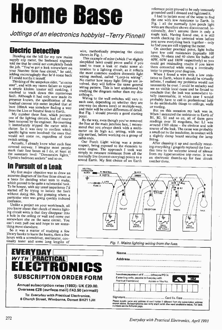
Home Base Jottings of an electronics hobbyist-Terry Pinnell
Electric Detective Handing me the bill for my new mains
supply trip meter, the Seeboard engineer told me that he could not completely finish the job. "You've got a leak somewhere on your Number three fuse circuit," he said, adding encouragingly that he'd come back ill could not fix it myself. Thinking of the unspoken rider, "at extra
cost", and with my recent failure to repair a simple kitchen toaster still rankling, I resolved to track down this mysterious fault. Although it had only now made its presence known, the specification of the residual current trip meter implied that at least 100mA was somehow finding a way from the Live or Neutral lines to Earth. My number three fuse, which protects
one of the lighting circuits, had of course been removed by the engineer. Re-inserting it immediately tripped the meter with a clatter. So it was easy to confirm which specific lights were involved: the ones that would not come on, regardless of their switch setting. Actually, I already knew what each fuse
covered anyway. I imagine most people mark their fuse boxes as I do, at least at the summary level: "Downstairs lights," Upstairs bedroom sockets" and so on.
In Pursuit of a Leak My first major objective was to draw an
accurate diagram of the fuse three circuit as a basis for deciding what tests to make, which proved to be quite a substantial task. To be honest, with my usual impatience I'd started off by trying to isolate the fault without doing this. But guessing where a particular wire was going quickly induced confusion. Unlike a project on your workbench, all
you know about that clutch of mains light-ing circuit wires is that they disappear into a hole in the ceiling or wall and come out somewhere else on the same circuit. You can't even pull one and hope to see some-thing move elsewhere. So it was a matter of studying a few
library books to learn the basics, then a few hours with a screwdriver, multimeter, con-tinuity tester and some long lengths of
EVERYDAY WITH ELECTRONICS
wire, methodically preparing the circuit shown in Fig. I. This example of mine (which I've slightly
simplified here) could prove useful if you need to trace a leak or make some al-teration to a lighting circuit, as it reflects the most common modern domestic light wiring method, called "Loop-in wiring". No matter how many light fittings are in-volved, they will follow the same general wiring pattern. This is best understood by studying the diagram rather than my des-cribing it. Wiring to the wall switches will vary in
each case, depending on whether they are one-way (as shown here) or multiple-way, and there will be other differences of detail. But Fig. I should provide a good starting point. By the way, even though you've removed
the fuse at the main junction box, I recom-mend that you always check with a multi-meter on its high a.c. setting, with one clip earthed, before working on a group of cable ends. Our Porch Light wiring was a prime
suspect, being exposed to the elements to some degree. The approach I took was simply to measure resistance from all the normally live (current-carrying) points to a sound Earth. My first choice of an Earth
NEUTRAL CONNECTOR ILOCK N NEUTRAL
E EARTH
L LIVE / r•••
FUSE 2
, . , , , , , ,
CLACK
OREEN
CEO -\\
, ,
TOILET
reference point proved to be only tenuously grounded until I cleaned and tightened it. I had to isolate most of the wires to find
the one with low resistance to Earth. In Fig. 1 all the normally Live porch light wires are therefore shown disconnected. In-cidentally, don't assume there is only a single leak. Having foun d one , it is still worth checking the untested wires before you screw everything back together — only to find you are still tripping the meter. On another practical point, light bulbs
have low cold resistances (typically 100 ohms, 70 ohms and 40 ohms for bulbs of 40W, 60W and 100W respectively) so you could get misleading results if you leave them connected while using a continuity tester to prepare your diagram. When I found a wire with a low resis-
tance to Earth, where it should be virtually infinite, I realised my problems would not necessarily be over. I could be unlucky and see no visible local cause and be forced to conclude that the leak was somewhere to-tally inaccessible, in which case I would probably have to call in professional help to do unthinkable things to ceilings, walls or roofing. But on this occasion my luck was in.
When I measured the res istance to Eart h of B1, B2, SI and so on, all of them gave readings over 10 megohms, but L I was around 1500 ohms — the obvious and sole source of the leak. The cause was probably a small cut in the insulation, in contact with a slightly damp board securing the lamp fitting. After cleaning it up and carefully retest-
ing everything I gingerly replaced the fuse — this time to the welcome sound of silence from my hypersensitive trip meter. It was an electronic thumbs-up for fuse circuit number three.
/ NI
'yi:
T RTILI Ar ;
RECEPTION
I
I Er
/
L S WALL SWITCH IIN HALL I
,LI L2. • li
PORCH
2
HALL
SUBSCRIPTION ORDER FORM Annual subscription rates (1993): UK £20.00.
Overseas £26 (surface mail) £43.50 (airmail)
To: Everyday with Practical Electronics, 6 Church Street, Wimborne, Dorset BH21 1 JH
Fig. 1. Mains lighting wiring from the fuse.
Name
Address
I enclose payment of (cheque/PO in
sterling only, payable to Everyday with Practical Electronics) Access or V sa No.
Signature Card Ex. Date
Please supply name and address of card-holder if different from the subscription address shown above. Subscriptions can only start with the next available issue. For back numbers see the Editorial page.
272 Everyday with Practical Electronics, Apri11993

VIDEOS ON ELECTRONICS Everyday with Practical Electronics is pleased to announce the availability of a range of videos designed to provide instruction on electronics theory. Each video gives a sound introduction and grounding in a specialised area of the subject. The tapes make learning both easier and more enjoyable than pure textbook or magazine study. They should prove particularly useful in schools, colleges, training departments and electronics clubs as well as to general hobbyists and those following distance learning courses etc.
VT201 to V206 is a basic electronics course and is designed to be used as a complete series, if required.
VT201 54 minutes. Part one; D.C. Circuits. This video is an absolute must for the beginner. Series circuits, parallel circuits. Ohms law, how to use the digital multimeter and much more.
Order Code V1201
V1202 62 minutes. Part two; A.C. Circuits. This is your next step in understanding the basics of electronics. You will learn about how coils, transformers, capacitors, etc are used in common circuits. Order Code VT202
VT203 57 minutes. Part three; Semiconductors. Gives you an excit-ing look into the world of semiconductors. With basic semiconductor theory. Plus 15 different semiconductor devices explained.
Order Code 111203
VT204 56 minutes. Part four; Power Supplies. Guides you step by step through different sections of a power supply. Order Code VT204
111205 57 minutes. Part five; Amplifiers. Shows you how amplifiers work as you have never seen them before. Class A, class B, class C. op.amps. etc. Order Code V1205
V1-206 56 minutes. Part six; Oscillators. Oscillators are found in both linear and digital circuits. Gives a good basic background in oscillator circuits. Order Code VT206
By the time you have completed 11I206 you have completed the basic electronics course and should have a good understanding of the operation of basic circuit elements.
Each video uses a mixture of animated current flow in circuits plus text, plus cartoon instruction etc., and a very full commentary to get the points across. The tapes are imported by us and originate from
VCR Educational Products Co, an American supplier.
Now for the new digital series of six videos. This series is designed to provide a good grounding in computer technology.
VI301 56 minutes. Digital One begins with the basics as you learn about seven of the most common gates which are used in almost every digital circuit, plus Binary notation. Order Code VT301
VT302 55 minutes. Digital Two will further enhance your knowledge of digital basics. You will learn about Octal and Hexadecimal notation groups, flip-flops, counters, etc. Order Code VT302
111303 56 minutes. Digital Three is your next step in obtaining a solid understanding of the basic circuits found in todays digital design. Gets into multiplexers, registers, display devices, etc.
Order Code 111303
111304 57 minutes. Digital Four shows you how the computer is able to communicate with the real world. You will learn about digital to analogue and analogue to digital converter circuits.
Order Code VF304
V1105 56 minutes. Digital Five introduces you to the technology used in many of todays memory devices. You will learn all about ROM devices and then proceed into PROM, EPROM, EEPROM, SRAM, DRAM, and MBM devices. Order Code V1305
111306 56 minutes. Digital Six gives you a thorough understanding in the basics of the central processing unit and the input/output circuits used to make the system work. Order Code V1306
By now you should have a good understanding of computer tech-nology and what makes computers work. This series is also invaluable to the computer technician to understand the basics and thus aid troubleshooting.
ORDERING To order see our Direct Book Service "Ordering Details" — the postage for tapes is the same as for our range of books and you can order tapes and books at the same time and pay only one lot of postage. Each video costs £29.95 inc. VAT. If ordering any six together we will
give you an extra video FREE, just indicate on your order which extra one you would like.
(All videos are to the UK PAL standard on VHS tapes)
Everyday with Practical Electronics, April 1993 273
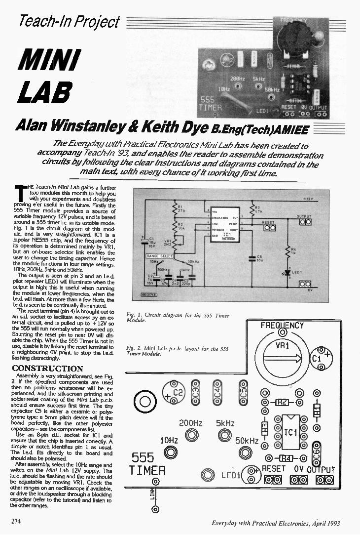
leach-In Project
MINI LAB Alan Winstonley if Keith Dye B.Eng(Tech)AMIEE
The Everyday with Practical E/ectrorilcs Lab has been createa' to accompany Teach-/n :93, and enables the reader to assemble demonstration circuits by to/locoing the clear Instructions and diagrams contained th the
math text, lath every chance of ft working first time.
THE Teach-In Mini Lab gains a further two modules this month to help you with your experiments and doubtless
proving e'er useful in the future. Firstly the 555 Timer module provides a source of variable frequency I 2V pulses, and is based around a 555 timer i.c. in its astable mode. Fig. 1 is the circuit diagram of this mod-ule, and is very straightforward. 1C1 is a bipolar NE555 chip, and the frequency of its operation is determined mainly by VRI, but an on-board selector link enables the user to change the timing capacitor. Hence the module functions in four range settings, 10Hz, 200Hz, 5kHz and 50kHz. The output is seen at pin 3 and an led.
pilot repeater LED] will illuminate when the output is high: this is useful when running the module at lower frequencies, when the I.e.d, will flash. At more than a few Hertz, the I.e.& is seen to be continually illuminated. The reset terminal (pin 4) is brought out to
an s.i.l, socket to facilitate access by an ex-ternal circuit, and is pulled up to + 12V so the 555 will run normally when powered up. Shunting the reset pin to near OV will dis-able the chip. When the 555 Timer is not in use, disable it by linking the reset terminal to a neighbouring OV point, to stop the led. flashing distractingly.
CONSTRUCTION Assembly is very straightforward, see Fig.
2. If the specified components are used then no problems whatsoever will be ex-perienced, and the silk-screen printing and solder-resist coating of the Mini Lab p.c.b. should ensure success first time. The tiny capacitor C5 is either a ceramic or polys-tyrene type: a 5mm pitch device will fit the board perfectly, like the other polyester capacitors — see the components list Use an 8-pin d.i.l, socket for ICI and
ensure that the chip is inserted correctly. A dimple or notch identifies pin 1 as usual. The I.e.d, fits directly to the board and should also be polarised. After assembly, select the 10Hz range and
switch on the Mini Lab 12V supply. The led. should be flashing and the rate should be adjustable by moving VR1. Check the other ranges on an oscilloscope if available, or drive the loudspeaker through a blocking capacitor (refer to the tutorial) and listen to the other ranges.
M O M VR 1
ilaRANG SELECri 1 0 H
Cr 10p 1611
2142
1 11 1 111 " . .'" DISCHARGE OUT. " THE RESET
TRIGGER CONE Gom IC1
NE555N
50k Hz
+2.°Hz. j:Hz C2 Lil&.,,Tc,3,7r2C,r,T2coST
IEE4074111 I
+12
63 47k
RESET
C6 10 n
Ce2E
E L11
Fig. 1. Circuit diagram for the 555 Timer Module.
Fig. 2. Mini Lab p.c.b. layout for the 555 Timer Module.
FREQUENCY
L.) © ©© 00 0-1R2F-© ® 0 8 0 ®
10Hz 0 0 50kHz
®, 200Hz 5kHz
@ ® 0 0 .1®
555 0 0 (--) to
TIMER 0 LED1 0
RESET OV 0 PUT rote rd'iyil
L W/1111 !a
In? rite
274 Everyday with Practical Electronics, April 1993
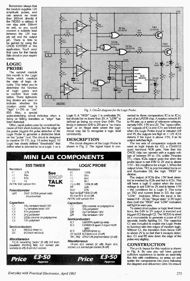
Remember always that the module supplies 12V amplitude pulses, and can source no more than 200mA directly if the NE555 is utilised. It can also sink 200mA as well, so you could connect a suitable load between the 12V sup-ply rail and the output pin. There is little to be gained by using the CMOS ICM7555 in this application. You'll soon find uses for this handy little circuit in your experi-ments.
LOGIC PROBE The second module
this month is the Logic Probe which monitors the state of logic cir-cuitry. This helps you to determine the function of logic gates and to confirm their truth tables. Three light-emit-ting diodes are used to indicate whether the location under test is -high" ( + 5V) or -low-
(OV). Also, a special pulse-stretching circuit indicates when a rising or falling transition or -edge- has been detected. Often, rapid pulses pass by unnoticed be-
cause of their short duration, but the edge of the pulse triggers the pulse stretcher of the Logic Probe to generate a distinctive blink on the -pulse" led. The circuit is designed to monitor 5V TTL (e.g. 74 series logic). 5V Logic has clearly defined -thresholds- that define what is deemed to be a Logic 1 or a
INPUT
R1 • Of k
R5 100k
02 5k 6
R6 100k
R3 6 k B
3
IC1C L813390
LC1 8152
I.7p
Eft. 7501
9
R7 00k
R8 100k
IC2d
IC2a CD4001B
IC2b CO4001B
IC2c
R11 100k
R12 CD400113
100k
TR1 0T 0212B
+12V
R9 C R10 22 47k
C?
TE -GE
O IC3 NES55N
co 0
DISC . 0
R13 1k
Fig. 3. Circuit diagram for the Logic Probe.
Logic 0. A -HIGH" Logic 1 is preferably 5V, but should be no lower than 2V. A -LOW- is defined as being no more than 0-8V. The levels in between (0-8 to 21v) are a -no mans land" or an illegal state where the logic circuit may fail to recognise a logic level consistently.
DESCRIPTION The circuit diagram of the Logic Probe is
shown in Fig. 3. The signal input is con-
MINI LAB COMPONENTS
555 TIMER Resistors R) 27k R2 56k R3 47k R4 1k
Ai! 5% 1/4W carbon film
LOGIC PROBE Resistors
See R I S H O P R2
TALK Page
Potentiometer VRI 2M2 0.25 W preset with
thumbwheel
Capacitors Cl I Op tantalum bead I6V C2 1m tantalum bead 16V C3 47n polyester C4 2n2 polyester C5 220p ceramic or polystyrene C6 10n polyester
Semiconductors ICI NE555 timer i.c. DI 0.2 inch red led.
Miscellaneous P.C.B. mounting 'jacks" (5 off); 0-5 inch
:nsulated shorting link; s.1.1. turned pin sockets (6 off); 8-pin d.i.l. socket.
Price £3.50 Approx
100k 5k6 6kE 8k2
,to R8 100k (4 off) R9 22k RIO 47k
to10-2100k (2 off) R13 toR15 lk (3 off)
All 5% 1/4W carbon film
Capacitors I 47p ceramic or polystyrene
C2 10n polyester 42 tantalum 16V 10µ tantalum 16V
Semiconductors ICI LM339N quad op-amp IC2 CD4001B quad 2-input NOR
gate IC3 NE555 timer i.c. DI to D3 0.2 inch led. (3 off) TRI, TR2 ZTX2I2B pop transistor (2 off)
Miscellaneous 14-pin d.1.1. socket (2 off); 8-pin d.1.1.
socket; s.i.l. turned pin socket (4 off).
Price £3•50 Approx
nected to three comparators ICI a to IC1 c, part of an LM339 chip. A resistor network R1 to R4 sets up a series of reference voltages. namely 0-8V, 1-5V and 2V. The -open-collec-tor" outputs of IC I a and IC1c are linked and when the Logic Probe input is between 0-8 and 2V, the outputs are high at + 12V. IC1b detects if the input is above 1-5V, if so its output switches high. The two sets of comparator outputs are
used as logic inputs for IC2, a CD4001B quad two-input NOR gate. Note that this CMOS chip can operate with a supply volt-age of between 5V to 15V, unlike 74-series TTL chips. IC2a output goes low when the probe input is not 0-8V to 2V and is above I -5V — the conditions for a logic I. When the output is low, TR1 (a pnp transistor) turns on and illuminates D2, the logic -HIGH" in-dicator. The output of IC1b (the 1-5V level detec-
tor) is inverted by IC2b and fed to IC2c. This will have a logic 0 output when the input voltage is not 0.8V to 2V and is below 1-5V — the conditions for a Logic 0. This turns on TR2 and current flows in D3, the logic -LO W' indicator. When the input is be-tween 0-8 — 2V (an -illegal state" in 5V logic) then both the -HIGH" and -LO W' indicators will light to warn you. To detect short pulses or logic level transi-
tions, the 0-8V to 2V output is inverted and triggers IC3 through C2. The NE555 is wired as a monostable to generate a pulse of 0.5 seconds, briefly lighting DI. The capacitor CI was included to enable the Logic Probe to function with fast edges of modern logic. Without Cl, the transition from below 0.8V to above 2V is so fast that it escapes detec-tion. CI and R5 slow down the edge of the pulse very slightly.
CONSTRUCTION The p.c.b. layout for this module is shown
in Hg. 4. By now you will have gained sufficient experience to tackle an assembly like this with confidence, so press on and solder the components into place following the diagram and silk-screen print. Do ensure
175 Everyday with Practical Electronics , April 1993
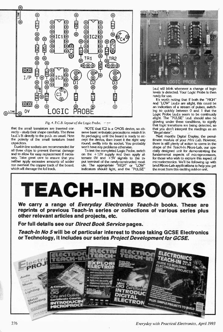
I/P 0®0 8
LI
N./
'Cl
IC3
102
® © @© @ 0 ®
OV @LOGIC 6ROB?
Di 02 03
Fig. 4. P.C.B. layout of the Logic Probe. - -
that the small transistors are inserted cor-rectly — study their shape carefully. The three I.e.d.'s fit directly to the p.c.b. as usual. Note the polarity of the small tantalum bead capacitors. Dual-in-line sockets are recommended for
all three chips to prevent thermal damage and to allow for easy replacement if neces-sary. Take great care to ensure that you neither apply excessive amounts of solder nor overheat the copper track of the board, which will damage the foil track.
NOTE that IC2 is a CMOS device, so ob-serve basic anti-static precautions: retain it in its packaging until the board is ready to ac-cept the device, then insert it the right way round, swiftly into its socket. You probably won't have any problems otherwise. To test the completed Logic Probe, switch
on the + 12V supply and then apply al-ternate OV and + 5V signals to the in-put terminal of the newly-constructed mod-ule. The appropriate "HIGH" or "LOW' indicators should light, and the "PULSE"
I.e.d will blink whenever a change of logic levels is detected. Your Logic Probe is then ready for use. It's worth noting that if both the "HIGH"
and "LOW' I.e.d.s are alight, this could be an indication of a stream of pulses, switch-ing so quickly between 0 and 1 that the Logic Probe I.e.d.s seem to be continually alight. The "PULSE" I.e.d, should also be glowing under these conditions, to signify that logic transitions are being detected, so that you don't interpret the readings as an "illegal state". Next month: Digital Display, the penul-
timate module of your Mini Lab. However, there is still plenty of action to come in the shape of the Teach-In Micro-Lab, our spe-cially designed unit for demonstrating the fundamental aspects of microprocessors, for those who wish to explore this aspect of microelectronics. We'll be following up with brief Micro-Lab applications to help you get the most from this exciting add-on unit.
TEACH-IN BOOKS We carry a range of Everyday Electronics Teach-In books. These are reprints of previous Teach-In series or collections of various series plus other relevant articles and projects, etc.
For full details see our Direct Book Service pages.
Teach-In No 5 will be of particular interest to those taking GCSE Electronics or Technology, it includes our series Project Development for GCSE.
• E xi:Sagas the workings
Orel citetets by ',lychee •fl mexpeneive exporter
• ASslenee no peek's',
• Spilt into 29 easily,
dillsilaibie section, • Contains rawly i;iatu
,sitit"10
vet RON IMPL
276
EASY FAST & POWERFUL CAD SOFTWARE THAT GIVES YOU THE EDGE
ISIS - SCHEMATIC CAPTURE
Easy to use yet extremely powerful schematic entry system with all the features you need to create input for ARES or other CAD software. Now available in a super-fast 32 bit version capable of handling huge designs even on AO-s ed sheets.
• Graphical User Interface gives
exceptional ease of use - two mouse
clicks will place & route a wire
• Automatic wire routing, dot
placement, label generation.
in 2D drawing capability with symbol library.
• Comprehensive device libraries. • Heterogeneous devices (e.g. relay
and coil) allowed in different places on the schematic.
• Special support for connector pins -
put each pin just where you want it. • Output to printers, plotters, Postscript.
• Export designs to DTP and WP
packages.
• Netlist formats for most popular PCB
& simulation software.
• Bill of Materials and Electrical Rules
Check reports.
• Multi-sheet and hierarchical design support.
• Automatic annotation/packaging.
• ASCII data import database facility.
from
£275
liallfrorirwm
ARES - PCB DESIGN
Advanced netlist based PCB layout software newly updated to version 2.5. Major new features include SMT library, real time snap (for those tricky SMT spacings), thermal relief power planes and enhanced autorouting.
I WI M MICISIOMMISIHNI MIC 11111116101 lak:
• Graphical User Interface. Real time snap.
• Auto track necking.
• Curved, 45/90 or any angle tracks. • Extensive through hole and SMT
package libraries as standard.
• 2Ddrawing capability with symbol library
si Connectivity highlight.
• Output to printers, plotters,
Postscript, Gerber and NC drill. • Gerber View facility.
• Graphics export for DTP etc.
• Advanced netlist management with
forward design modification.
is Component renumber and
back-annotate to ISIS. • Full physical and electrical design
rule checks.
• Autorouter handles single, double or
multi-layer boards.
• Power plane generator.
• Strategy & DRC information
loadable from ISIS.
• Gerber import utility available.
from
£275
ISIS ILLUSTRATOR
Schematic drawing for MS Windows 3.X - produces high
quality schematics like you see in the magazines with your choice of line thicknesses, fill styles, fonts, colours etc. Once
entered, drawings can be copied to most Windows software through the clipboard.
New version 1.10 includes library browser and export to WMF and EPS files.
M EP CADPAK - BUDGET PRICE CAD
Two programs - ISIS SUPERSKETCH and PCB II - for the price of one.
CADPAK has everything you need to produce circuit diagrams and PCBs on your PC and is exceptionally easy to use. It also has many advanced features from ISIS
& ARES, not normally found in entry level products.
Call us today on 0274 542868 or kix 0274 481078 for a da m pack
Ccrnbinalicri multi-copy card earational
& aunts avaiatie. Prices exc P&P and VAT
14 Marriner's Drive. Bradford, BD9 4JT
Everyday with Practical Electronics, April 1993 277
4 1 1:: :11 k Ad O XF'
)) by Barry Fox
SCUPPER PCN Both Cellnet and Vodafone are now
offering cut-price cellphone tariffs for low users. Despite much grand talk about opening up the market to a wider public, their driving motive is clearly to try and scupper Mercury's launch of a PCN (Per-sonal Communications Network) service this summer. First, Mercury had promised smaller
phones for PCN. The network uses smaller cells so battery drain is less. But conventional cellphones are now so small that there is little need for anything smaller. And working with smaller cells means building more base stations, which puts up the cost of the network and limits its area of coverage. Despite this, Mercury also talked about
lower costs for PCN. Now that edge has gone, too. Cellnet and Vodafone have built their networks and are creaming profit from around 40 million calls a week, each. Mercury is now publicising the security
of PCN. Because PCN is a digital system, calls cannot be intercepted with a simple analogue scanner. But PCN is a standard. How long before we see digital scanners? In any case Vodafone is soon to offer a service which uses the pan-European, GSM, cellular system which works very much like PCN. And Cellnet will soon launch secure scrambling for analogue calls. This leaves Mercury's PCN service with no discernible user-benefit. Why con-tinue to promise it? Could it be because PCN began life as the dream of Lord Young, when he was at the DTI, and is now top dog at Cable and Wireless, Mercury's parent?
TOUGH FOR RABBIT Whatever the reason, the price cuts by Cellnet and Vodafone and the promise of Mercury's PCN, makes life even more dif-ficult for Hutchison's Rabbit. This CT2 telepoint service is now rolling out. Rabbit offers only one way com-
munication. Subscribers can only make calls. To "take" a call, you need to subscribe also to a paging service, and then look for a Rabbit base station to return whatever call the pager instructs. It's a very clumsy proceedure, compared to a two-way cellphone. Why not just use a pager and look for one of the many card or cash payphones which both BT and Mercury have peppered round the country? I went recently to buy a cordless phone
and wondered about buying a Rabbit, for use at home and perhaps later with
telepoints if and when Hutchison puts enough of them where there are no payphones. I like the idea of digital security but at £200 the Rabbit was around four times the price of an analogue phone. I bought neither and will wait until Hutchison is reduced to flogging them off for half price.
80's PROFIT IDEA Or will Hutchinson perhaps unearth a
clever idea for telepoint that was sug-gested in the mid-80s when CT2 was first planned, but seems to have been long since forgotten? The idea was to let homes and offices re-sell telepoint air time. It would work like this. People would install a home or office
CT2 system for use either as a domestic cordless phone or cordless switchboard exchange. Normally, of course, the base station only works with its own hand-sets. But for airtime re-sale, the base sta-tion is programmed to let anyone with an authorised handset, and within the hundred metres range of the base station, make a call. So anyone in the street or parked car outside an office or home with a base station, would be able to make a call. Authorisation would involve paying a one-off fee for a digital code which would be recognised by any base station whose owner wanted to earn a little easy money. The authorisation code would charge
the call to the owner of the handset, not the base station, but the owner of base station would get a small reward e.g. as credit from the next quarter's bill. In other words any home or office
becomes a temporary telepoint. In sub-urban streets this would not happen very often, but an office, or cafe in the city centre could turn an easy un-earned profit. And owners of authorised handsets would have a better chance of making calls than if they have to search for a public telepoint. Thus, although the service operator
does not have to invest money in installing dedicated public base sta-tions, the telepoint network would very quickly expand. Eventually there would be so many private base stations in homes, offices, cafes, garages and so on, that the telepoint service would offer coverage almost as wide as a cellphone service. But somehow, this clever idea for tele-
point seems to have got lost in the mess created by the offer and failure of rival CT2 services from Mercury, British Tele-com and Ferranti, and the launch now of Hutchison's Rabbit.
ROYAL SCRAMBLE I mentioned Cellnet's plan to of-
fer a scrambling system for analogue cellphones. This is not, repeat not, the system which so-called "experts" keep demonstrating on TV when talking about the tapes of the Royals on their mobile phones. These "experts" are usually in the nicely self-perpetuating business of selling both bugging and anti-bugging equipment and they conveniently neglect to explain what is wrong with their scamblers. What is wrong is actually quite simple. Existing phone scramblers are double-ended devices. The phone making the call scrambles the speech, and the phone receiving the call descrambles it. So the system can only be used if the two parties know in advance that they are going to talk to each other and have each spent several hundred, or thousand, pounds on electronic equipment. Many of the existing sytems scramble
speech by simple "inversion". The analogue speech frequency band is split into two halves, high and low, and the high band is converted into low frequencies, with the low band converted into high frequencies. The unit at the other end turns the frequency bands upside down again. Interceptors hear a fuzzy sound, but
a dedicated eavesdropper can learn to recognise speech. Or the eavesdropper can buy or steal a matching descrambler. As I said, the same people are often selling both bugging and anti-bugging devices.
SINGLE-ENDED PRIVACY Cellnet has now done a deal with GEC-
Marconi Secure Systems of Liverpool, on a single-ended system. There is no need for the other party to use a matching des-crambler. The CPU-100 is small black box, which
connects between the handset of a car or transportable cellphone, and the transceiver. The box scrambles the signal before it is sent by radio to the telephone network. Scrambling is by Variable Split Band Inversion. The sound spectrum is split into two bands (as with existing systems) but the frequency at which the split occurs continually changes, several times a second, between 32 different values, and with no regular time pattern for the changes. If the radio signal is picked up on an unauthorised radio receiver or "scanner" of the type currently used by eavesdroppers, it sounds like the warble of a fax machine and is .wholly unintelligible.
278 Everyday with Practical Electronics, Apri11993
The computer "switches" which Cellnet uses to route incoming radio phone calls into BT's telephone network are equipped with matching decramblers. So when the call leaves the switch to go to its destination in an office or home phone, it is "clear". The called phone thus needs no extra electronics, unless of course it is another cellphone. Then it needs its own CPU-100. The descrambler in the network
switch must of course change its band-splitting circuits in synchronism with the circuits in the cellphone scrambler. This is done by making the cellphone send digital control signals along with the scrambled speech. The control signals are encrypted to stop an eavesdropper using them to switch a pirate descrambler. GEC claims the encryption is so secure that only someone prepared to work for months on a recording of the call, with a
bank of parallel processors, can crack the code. Cellnet began testing the system early
this year and plans a commerical launch in the spring. The scrambler will cost around £600 and calls that are routed through the network descrambler will be charged at around twice the current cellphone premium rate of 33p per minute. Cellnet does not expect many cus-
tomers, but I am sure we can all guess who the first will be.
TALK with David Baffhwton
Mind Machine Mk II The 5V positive voltage regulator type
LP2950CZ, called-up in the Mind Machine Mk II project, was chosen in preference to one of the more popular 78L05 series because of it's improved specification. It draws less quiescent current and can operate from an input voltage below 5.5V; prolonging the operating "life" of the battery. At present, the LP2950CZ only appears to be listed by Electromail (ink 0538204555), code 648-567. The CMOS crystal oscillator (type num-
ber EXO-3), with programmable frequency divider is another device which can only be found listed by the above mentioned com-pany. The 12MHz version is required and the code 296-879 should be quoted when ordering. The Binaural Signal Generator printed
circuit board is available from the EPE PCB Service, code 824. All components for the "calibration aid" are standard items and should not cause any sourcing problems. You will, of course, require a personal stereo to record your chosen "relaxation program" tape.
Mini Lab (Teach-In '93) This month the Mini Lab (Teach-In '93)
"test-bed" gains a further two modules, namely a single 555 Timer module and a Logic Probe to help in defining the function status of logic gates and to confirm their -truth tables". There should be no com-ponent buying problems for the two circuits as all parts should be readily available from our mail order component advertisers. For best results, ensure that components
align with the hole pitches of the Mini Lab p.c.b., capacitors are 5mm lead pitch types, and make certain the specified transistors are used. If you have not already purchased the Mini Lab printed circuit board it can be obtained from the EPE PCB Service, code MIN LAB (see page 307). A selection of kits for the Mini Lab
has been put together by Magenta Elec-tronics (ip 0283 85435). These include the single Eurobreadboard which replaces the two original Veroblocs (discontinued).
Universal Data Logger Some of the components required to
build the Universal Data Logger may prove difficult to locate locally. Also, to avoid any possible programming problems of the EPROM IC4, a preprogrammed chip is being made available by the author. The multiturn preset is the "cermet" type
and should be generally available. Some readers may have trouble locating a suitable 11MHz crystal. These are usually to be found under the "microprocessor crystals" sections in catalogues and are currently being listed by Cricklewood and Cirkit (see "Advertiser's Index" page 312). The only source we have been able to
find for the 6-way DIN p.c.b. socket, used
on the model, is from Farnell (lip 0532 838311). This is listed under their "DIN Audio Connectors" section, code 148-507. We cannot give an up to date indication of price, as we have been unable to obtain a "current" catalogue for some time now! The PC data acquisition software (3%in.
disc) and a preprogrammed EPROM for the microcontroller board is available from: Mr. R. Grodzik, 53 Chelmsford Road, Bradford, BD3 8QN. 0274 882085). The price is £20, inclusive of post and packing. The printed circuit board for the data log-
ger is available from the EPE PCB Service, code 826 (see page 307).
Mini Charger The only really "special" item that needs
extra attention when constructing the Mini Charger is the mains transformer. The panel meter is one of the standard miniature 51mm x 45mm moving coil types ob-tainable from most of our advertisers. The 25VA mains transformer, having
twin 15V secondary windings rated at 0.8A each (1.6A when wired in parallel), used in the prototype charger was pur-chased, some time ago, from Rapid Elec-tronics (ir 0208 751188), code 88-0300. This transformer also has two inde-pendent 120V primary windings, rated at 12.5VA each, and is wired in series for 240V a.c. operation. Once again no current components catalogue has been received in the office. Other mains transformers will operate in
this circuit and one of the excellent range supplied by Jaytee Electronic Services will certainly "foot-the-bill." Give them a ring on 0227 375254for their latest listings. Although a 2.5W resistor is specified for
R2, the 3W version seems to be more readily available. These resistors are the vitreous enamel or wirwound types. Finally, make sure you use heavy-duty
cable wherever specified and that plenty of "vent" holes are drilled in the Metal box.
Fog Light Alert The 12V 15mA "pulse-tone" buzzer used
in the Fog Light Alert model was ob-tained from Maplin, code 8Z55K (Pulse-tone Buzzer). Do not buy a buzzer that requires external drive circuitry since this will not work in this circuit. You must use heavy-duty auto-type wire
and connectors where indicated. If there is any doubt about wiring the unit into the car, then you should seek the advice of a lo-cal garage workshop and also consult the vehicle workshop manual.
Electronic Fire We do not expect any component buying
problems to be encountered by anyone who wishes to construct the Electronic Fire
to add that touch of realism to their model setups. All components are "off-the-shelf" items
and the small printed circuit board is ob-tainable from the EPE PCB Service, code 820 (see page 307).
Ventilation Fan Timer We cannot forsee any component pur-
chasing trouble ahead for readers tackling the Ventilation Fan Timer The miniature printed circuit board is available from the EPE PCB Service, code 825 (see page 307). However, we should like to add a word
of caution. Due to the presence of MAINS voltages on and around the p.c.b., anyone tackling a mains project should have a good understanding of what they are doing. Also, the fan circuit must be fused. The
rating will, of course, depend on the final application of the timer module.
Going Active The X03 Programmable 3-way Active
Crossover module is the latest addition to BK Electronics excellent range of OMP
audio products. The X03 is a high quality stereo crossover unit, housed in an in-dustry-standard 19in. rack mounting case. A removable front panel fascia allows
access to a bank of d.i.l. switches for programming the module's crossover fre-quency points. Levels for bass, mid and top response are fully adjustable, with phase invert switches on the bass channels. The unit is claimed to be capable of achieving a 24dB per octave crossover slope. The X03 Programmable 3-way Active
Crossover module costs £116.33 (includ-ing VAT), plus £7 delivery charge, and is obtainable from: B.K. Electronics, Dept. EPE, Units 1 & 5 Comet Way, Southend-on-Sea, Essex, SS2 6TR. 11/6 0702 527572.
Stop Press ,SALE! We have just received news of Maplin's
Shop Sale. This year they claim it is their biggest ever, with hundreds of selected products being marked down; some being knocked down to half-price! Special products on offer at their twenty-
one stores include: R.F. Power Meters; Hammer Drills;
Answerphones; 2-Way Speaker Systems; Car CD Multiplay; Amplifier Kits; 3-Channel f.m. Intercom; Probe Meters; Compact Toolboxes; Casio 2.7in. LCD Colour TV; Floppy Disks; Digital Head-phones; Ni-Cad Charges; and many more.
PLEASE TAKE NOTE
TV/U.H.F, Filtered Aerial Amplifier (January 1993).
Readers experiencing difficulty with the operation of this unit should insert a 4p7 ceramic capacitor between the junction of C1/L2 and pin 1 of IC1. This can be done by cutting the under-side p.c.b. track in the vertical section just above Cl (Fig. 2) and soldering the capacitor across the cut.
Everyday with Practical Electronics, April 1993 279
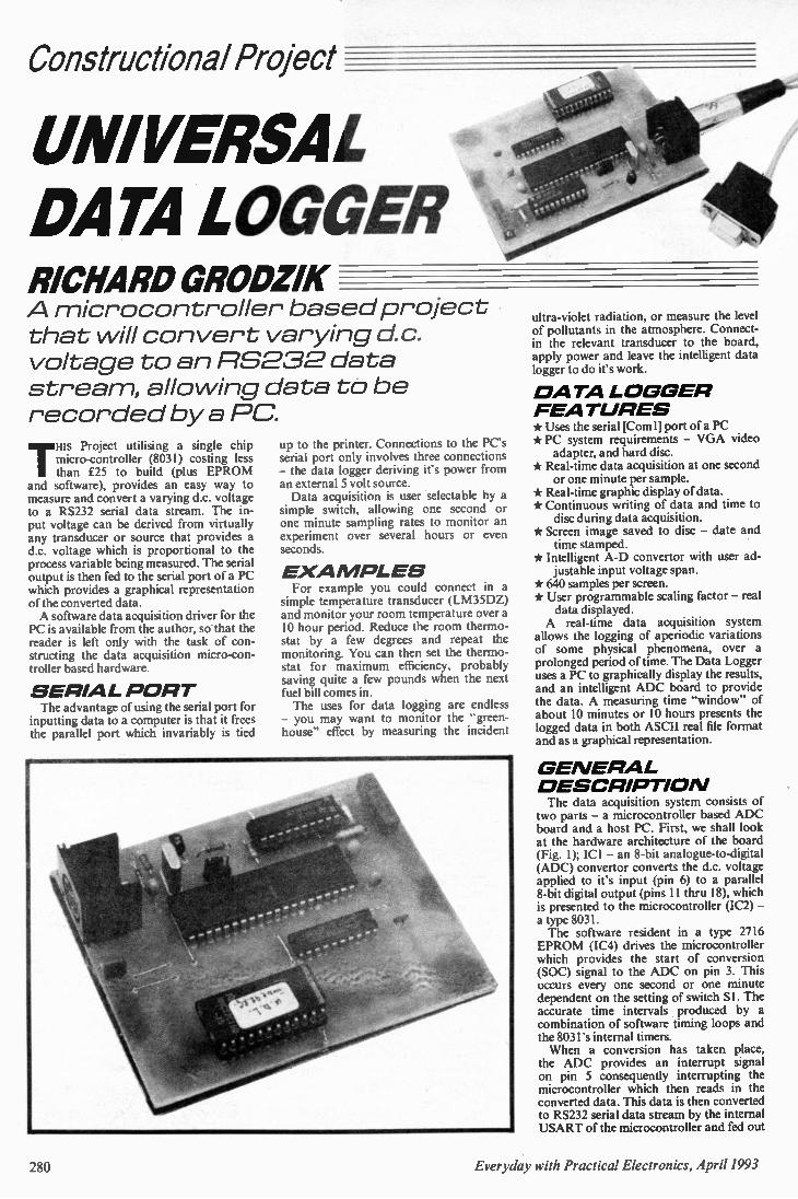
Constructional Project
UNIVERSAL DATA LOGGER RICHARD ORODZIK A microcontroller based project that will convert varying d.c. voltage to an RS232 data strea m, allo wing data to be recorded by a PC.
THIS Project utilising a single chip micro-controller (8031) costing less than £25 to build (plus EPROM
and software), provides an easy way to measure and convert a varying d.c. voltage to a RS232 serial data stream. The in-put voltage can be derived from virtually any transducer or source that provides a d.c. voltage which is proportional to the process variable being measured. The serial output is then fed to the serial port of a PC which provides a graphical representation of the converted data. A software data acquisition driver for the
PC is available from the author, so that the reader is left only with the task of con-structing the data acquisition micro-con-troller based hardware.
S ERIAL P ORT The advantage of using the serial port for
inputting data to a computer is that it frees the parallel port which invariably is tied
up to the printer. Connections to the PC's serial port only involves three connections -the data logger deriving it's power from an external 5 volt source. Data acquisition is user selectable by a
simple switch, allowing one second or one minute sampling rates to monitor an experiment over several hours or even seconds.
E XA MPLES For example you could connect in a
simple temperature transducer (LM35DZ) and monitor your room temperature over a 10 hour period. Reduce the room thermo-stat by a few degrees and repeat the monitoring. You can then set the thermo-stat for maximum efficiency, probably saving quite a few pounds when the next fuel bill comes in. The uses for data logging are endless
- you may want to monitor the -green-house" effect by measuring the incident
ultra-violet radiation, or measure the level of pollutants in the atmosphere. Connect-in the relevant transducer to the board, apply power and leave the intelligent data logger to do it's work.
D ATA LOGGER FEATURES * Uses the serial [Corn I] port of a PC * PC system requirements - VGA video adapter, and hard disc.
* Real-time data acquisition at one second or one minute per sample.
* Real-time graphic display of data. * Continuous writing of data and time to disc during data acquisition.
* Screen image saved to disc - date and time stamped.
* Intelligent A-D convertor with user ad-justable input voltage span.
* 640 samples per screen. * User programmable scaling factor - real data displayed. A real-time data acquisition system
allows the logging of aperiodic variations of some physical phenomena, over a prolonged period of time. The Data Logger uses a PC to graphically display the results, and an intelligent ADC board to provide the data. A measuring time "window" of about 10 minutes or 10 hours presents the logged data in both ASCII real file format and as a graphical representation.
G E NERAL D ESCRIPTIO N The data acquisition system consists of
two parts - a microcontroller based ADC board and a host PC. First, we shall look at the hardware architecture of the board (Fig. 1); ICI - an 8-bit analogue-to-digital (ADC) convertor converts the d.c. voltage applied to it's input (pin 6) to a parallel 8-bit digital output (pins 11 thru 18), which is presented to the microcontroller (IC2) - a type 8031. The software resident in a type 2716 EPROM (IC4) drives the microcontroller which provides the start of conversion (SOC) signal to the ADC on pin 3. This occurs every one second or one minute dependent on the setting of switch SI . The accurate time intervals produced by a combination of software timing loops and the 8031's internal timers. When a conversion has taken place,
the ADC provides an interrupt signal on pin 5 consequently interrupting the microcontroller which then reads in the converted data. This data is then converted to RS232 serial data stream by the internal USART of the microcontroller and fed out
2S0 Everyday with Practical Electronics, April 1993
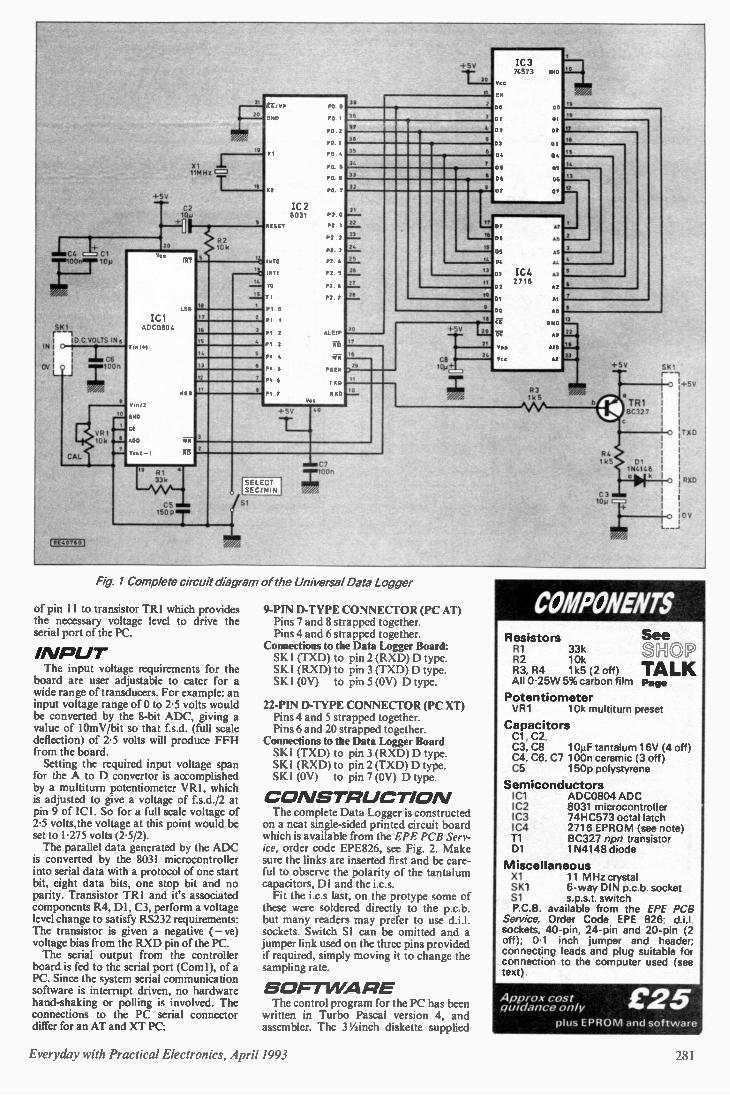
+5V —•—
20
11MHz =
C2
SN 1
IN II I D C VOLTS IN 6
O-1 = 1 OV I 0 I ; 1000 LJ
CAL
9
VR1 " 10k arl
EE 4076 G I
'Cl ACCOSOC
/2
GNO
•00
VI
R2 10k
14
'S
/7 2
6 3
3
En/ VP
2
IC2 8031
RESET
NTO
Nti
0
P1 2
PI 3
s
Vt.
PO 5
P 2 0
P2
P2 2
82
P1 4
P2 5
P2 6
82 7
AL E/P
E D
P006
TA O
30
+5V IC 3 74573
vcc
U/A E
•
• 6
2
21
22
23
24
25
15
27
28
17
16
600
17
111
15
13
05
10
38
17
16
) 29
-I-5V 40
" 81 33k
CS mom 150 P T
SELECT SEC/MIN
Si
C7 100 ,,
20
3 IC 4 27l6
7
OE
3
A7
.„ .
A
•1
A5
12
5
83 1k5
Fig. 1 Complete circuit diagram of the Universal Data Logger
of pin 11 to transistor TR1 which provides the necessary voltage level to drive the serial port of the PC.
INPUT The input voltage requirements for the
board are user adjustable to cater for a wide range of transducers. For example: an input voltage range of 0 to 2-5 volts would be converted by the 8-bit ADC, giving a value of 10mV/bit so that f.s.d. (full scale deflection) of 2.5 volts will produce FFH from the board. Setting the required input voltage span
for the A to D convertor is accomplished by a multiturn potentiometer VR1, which is adjusted to give a voltage of f.s.d./2 at pin 9 of ICI. So for a full scale voltage of 2.5 volts,the voltage at this point would be set to 1.275 volts (2.5/2). The parallel data generated by the ADC
is converted by the 8031 microcontroller into serial data with a protocol of one start bit, eight data bits, one stop bit and no parity. Transistor TR1 and it's associated components R4, DI, C3, perform a voltage level change to satisfy RS232 requirements: The transistor is given a negative ( — ye) voltage bias from the RXD pin of the PC. The serial output from the controller
board is fed to the serial port (Corn!), of a PC. Since the system serial communication software is intemipt driven, no hardware hand-shaking or polling is involved. The connections to the PC serial connector differ for an AT and XT PC:
9-PIN D-TYPE CONNECTOR (PC AT) Pins 7 and 8 strapped together. Pins 4 and 6 strapped together.
Connections to the Data Logger Board: SKI (TXD) to pin 2 (RXD) D type. SKI (RXD) to pin 3 (TXD) D type. SKI (OV) to pin 5 (OV) D type.
22-PIN D-TYPE CONNECTOR (PC XT) Pins 4 and 5 strapped together. Pins 6 and 20 strapped together.
Connections to the Data Logger Board SKI (TXD) to pin 3 (RXD) D type. SKI (RXD) to pin 2 (TXD) D type. SKI (OV) to pin 7 (OV) D type.
C O NSTR UCTIO N The complete Data Logger is constructed
on a neat single-sided printed circuit board which is available from the EPE PCB Serv-ice, order code EPE826, see Fig. 2. Make sure the links are inserted first and be care-ful to observe the polarity of the tantalum capacitors, DI and the i.c.s. Fit the i.c.s last, on the protype some of
these were soldered directly to the p.c.b. but many readers may prefer to use d.i.l. sockets. Switch SI can be omitted and a jumper link used on the three pins provided if required, simply moving it to change the sampling rate.
S OFT WA RE The control program for the PC has been
written in Turbo Pascal version 4, and assembler. The 31/2inch diskette supplied
2
23
+5V
R4 1235
C3
TR1 BC327
01 1N4148
k
1017 -3
0
1-°
+5V
TAD
RXD
CV
COMPONENTS Resistors R1 33k R2 10k R3, R4 1k5 (2 off) All 0.25W 5% carbon film
Potentiometer V R 1 10k multiturn preset
Capacitors Cl, C2, C3, C8 10j,tF tantalum 16V (4 off) C4, C6, C7 100n ceramic (3 off) C5 150p polystyrene
Semiconductors IC1 ADC0804 ADC 1C2 8031 microcontroller IC3 74HC573 octal latch IC4 2716 EPROM (see note) Ti BC327 npn transistor D1 1N4148 diode
Miscellaneous X1 11 MHz crystal SK1 6-way DIN p.c.b. socket Si s.p.s.t switch P.C.B. available from the EPE PCB
Service, Order Code EPE 826; d.i.l. sockets, 40-pin, 24-pin and 20-pin (2 off); 0.1 inch jumper and header; connecting leads and plug suitable for connection to the computer used (see text).
Approx cost guidance only
See SHOP TALK Page
£25 plus EPROM and software
Everyday with Practical Electronics, April 1993 28 1
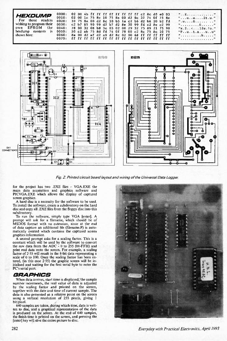
0000: 02 00 4b ff ff ff ff ff If ff ff c2 Sc d5 e0 03 " K 0010: 02 00 lc 75 Sc 10 75 8a 00 d2 8c 32 74 Of 75 Sc
H EXOUNIP " "...u..u....2t.u "
For those readers 0020: 10 75 8a 00 d2 Sc 30 b3 la c2 b6 d2 b6 20 b2 fd ".u....0 ...... " wishingtoprogram their 0030: c2 b7 85 90 99 d2 b7 d2 8e 30 99 fd c2 8e c2 99 II 0
own EPRO M the 0040: 78 00 32 08 b8 3c 03 02 00 29 32 75 89 21 75 98 "x.2..<...)2u.!u." hexdump contents is 0050: 50 c2 ab 75 8d fd 74 Of 78 00 c2 8c 75 Sc 10 75 "P..u..t.x...u..u" shown here: 0060: 8a 00 d2 af d2 a9 d2 Sc 02 00 68 ff ff ff ff ff h
0070: ff ff ff ff ff ff ff ff ff ff ff ff ff ff ff ff II
t.... SKI ......... ..C.V
CONNECTIONS ..
Fig 2 Printed circuit board layout and wiring of the Universal Data Logger
for the project has two .EXE files — VGA.EXE the main data acquisition and graphics software and PICVGA.EXE which allows the display of captured screen graphics. A hard disc is a necessity for the software to be used.
To install the software, create a subdirectory on the hard disc and copy all .EXE files from the floppy disc into this subdirectory. To run the software, simply type VGA [enter]. A
prompt will ask for a filename, which should be of MSDOS format with no extension, since at the end of data capture an additional file (filename.P) is auto-matically created which contains the captured screen graphics information. A second prompt asks for a scaling factor. This is a
constant which will be used by the software to convert the raw data from the ADC - 0 to 255 (00-FFH) and print real data onto the screen. For example, a scaling factor of 2-55 will result in the 8-bit data representing a scale of 0 to 100. Once the scaling factor has been en-tered, (in this case 2-55) the graphic screen will be in-itialised and waiting for the first serial byte to enter the PC's serial port.
G RA PHICS When data arrives, start time is displayed, the sample
number increments, the real value of data is adjusted by the scaling factor and printed on the screen, together with the date and time of current sample. The data is also presented as a relative point on the screen using a vertical resolution of 255 pixels, giving 1 bit/pixel. 640 samples are taken, during which time, data is writ-
ten to disc, and a graphical representation of the data is produced on the screen. At the end of 640 samples, the finish time is printed on the screen, and pressing the [enter] key will save the entire picture to disc.
282 Everyday with Practical Electronics, April 1993
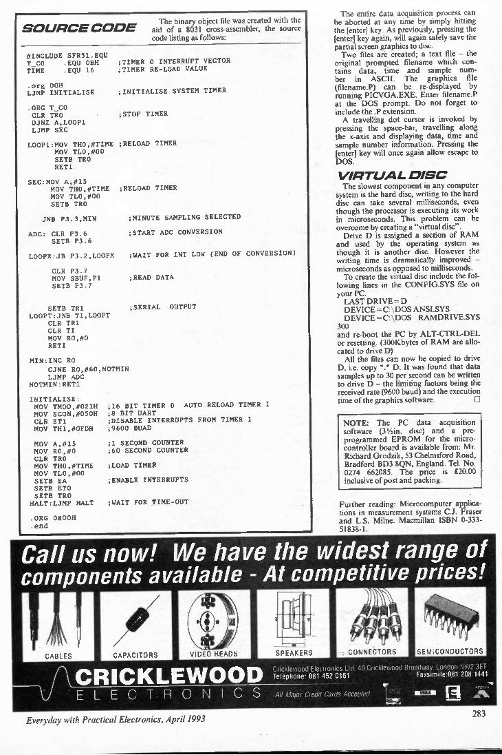
S OURCE C OVE The binary object file was created with the
aid of a 8031 cross-assembler, the source code listing as follows:
#INCLUDE 5FR51.EQU T_CO .EQU OBH TIME .EQU 16 ;TIMER RE-LOAD VALUE
.org 00H LJMP INITIALISE
.ORG T_CO CLR TRO DJNZ A,LOOP1 LJMP SEC
;TIMER 0 INTERRUPT VECTOR
;INITIALISE SYSTEM TIMER
;STOP TIMER
LOOP1:MOV THO,#TIME ;RELOAD TIMER MOV TLO,#00 SETS TRO RETI
SEC:MOV A,#15 MOV THO,#TIME ;RELOAD TIMER NOV TLO,#00 SETT TRO
JNB P3.3,MIN
ADC: CLR P3.6 SETB P3.6
LOOPX:JB P3.2,LOOPX
CLR P3.7 NOV SBUF,P1 SETB P3.7
SETB TR1 LOOPT:JNB TI, LOOPT
CLR TR1 CLR TI NOV RO,#0 RETI
MIN:INC RO
CJNE RO,#60,NOTMIN LJMP ADC
NOTMIN:RETI
INITIALISE: MOV TMOD,#021H MOV SCON,#050H CLR ET1 MOV TH1,#OFDH
MOV A,#15 NOV RO,#0 CLR TRO MOV THO,#TIME MOV TLO,#00 SETS EA SETS ETO SETB TRO HALT:LJMP HALT
ORG 0800H . end
;MINUTE SAMPLING SELECTED
;START ADC CONVERSION
;WAIT FOR INT LOW (END OF CONVERSION)
;READ DATA
;SERIAL OUTPUT
;16 BIT TIMER 0 AUTO RELOAD TIMER 1
;8 BIT UART ;DISABLE INTERRUPTS FROM TIMER 1
;9600 BUAD
;1 SECOND COUNTER ;60 SECOND COUNTER
;LOAD TIMER
;ENABLE INTERRUPTS
;WAIT FOR TIME-OUT
The entire data acquisition process can be aborted at any time by simply hitting the [enter] key. As previously, pressing the [enter] key again, will again safely save the partial screen graphics to disc. Two files are created: a text file — the
original prompted filename which con-tains data, time and sample num-ber in ASCII. The graphics file (filename.P) can be re-displayed by running PICVGA.EXE. Enter filename.P at the DOS prompt. Do not forget to include the .P extension. A travelling dot cursor is invoked by
pressing the space-bar, travelling along the x-axis and displaying data, time and sample number information. Pressing the [enter] key will once again allow escape to DOS.
VIRTUAL DISC The slowest component in any computer
system is the hard disc, writing to the hard disc can take several milliseconds, even though the processor is executing its work in microseconds. This problem can be overcome by creating a "virtual disc". Drive D is assigned a section of RAM
and used by the operating system as though it is another disc. However the writing time is dramatically improved — microseconds as opposed to milliseconds. To create the virtual disc include the fol-lowing lines in the CONFIG.SYS file on your PC. LAST DRIVE = D DEVICE = C: \ DOS ANSI.SYS DEVICE = C: \ DOS RAMDRIVE.SYS
300 and re-boot the PC by ALT-CTRL-DEL or resetting. (300Kbytes of RAM are allo-cated to drive D) All the files can now be copied to drive
D, i.e. copy *.* D: It was found that data samples up to 30 per second can be written to drive D — the limiting factors being the received rate (9600 baud) and the execution time of the graphics software.
NOTE: The PC data acquisition software (3 1/2 in. disc) and a pre-programmed EPROM for the micro-controller board is available from: Mr. Richard Grodzik, 53 Chelmsford Road, Bradford BD3 8QN, England. Tel. No. 0274 662085. The price is £20.00 inclusive of post and packing.
Further reading: Microcomputer applica-tions in measurement systems C.J. Fraser and L.S. Milne. Macmillan ISBN 0-333-51838-1.
Call us now! We have the widest range of components available - At competitive prices!
CABLES CAPACITORS
CRICKLE WOOD EL E C T R O NI C S
Cricklewood Electronics Ltd. 40 Cricklewood Broadway. London NW2 3ET Telephone: 081 452 0161 Faxsimile:081 208 1441
All Major Credit Cards Accepted
181
Everyday with Practical Electronics, April 1993

READOUT SORRY... Whilst readers and critics have the
luxury of hindsight, we're limited by a hectic publishing timetable and oc-casionally some matters do not receive the depth of consideration they probably merit. The Teach-In mnemonic which caused all the stir ( Readout Dec. '92, Jan and March '93) was in fact a late addition to the manuscript because I had gained the impression that it was in fairly com-mon use in this area of teaching. It was offered "nervously" which was a way of apologising in advance in the hope that this slightly risque item would not offend. Although I feel therefore that it has
readily and repeatedly been taken out of context, I was dismayed to learn that some readers (and non-readers) had indeed taken offence at this aide-memoire. In retrospect it is now agreed that the rules have changed and its use is no longer appropriate in today's en-lightened times. I am genuinely sorry for any indignation and embarrassment caused. I was however encouraged that many
of our readers and friends involved in education managed to treat the expres-sion with a great deal of sense and diplomacy, having tactfully questioned (quite rightly) the suitably of this item. Most seem to have taken the rhyme for what it is - a simple suggestion for a memory aide. A clear and simple error of judgment, we would all now agree - but certainly nothing more than that. Apart from a storm in a teacup?
Alan Winstanley.
NOT WORTH IT Dear Ed., While I was having an amusing browse
through your pages of non-risque colour code mnemonics, I was led to wonder, are mnemonics in general really worth the trouble? Surely, usage and a bit of hands-on experience enables things like reading colour code to become as commonplace as reading these words. In my own experience, I have always
found it more difficult to wean some stu-dents away from the use of mnemonics than to get them to make a conscious effort to "see" the colours as plainly as a printed number. Mnemonics, in other words, can often be an impediment rather than a help because they make their ad-dicted users completely dependent upon them. When I was on a radar course at Bury
during the war I knew a lad who had twelve mnemonics allegedly covering all possible circuit relationship for negative-feedback analysis. As I remember (with-out a mnemonic) there were four cover-ing current and voltage feedback, four more interlocking into these for input and output impedance variations, and four more entwined with the first eight for series and parallel arrangements of feed-back.
While he was reciting the mnemonics and trying to choose which of the per-mutations on these suited the problem in hand, the rest of the class had usually finished. His ability to remember the twelve mnemonics as though they were Holy writ seemed completely at variance with his inability to remember the circuit systems directly, and I think this was because his enchantment with the first closed his mind to the possibilities of the second. To tell the truth, I have never found
mnemonics of any value at all. In ex-aminations, questions can be phrased so that the information that mnemonics are supposed to provide, like a legal crib sheet, turn out to be no help at all. It would be interesting to know how many people agree with this, or how many can provide an instance where a mnemonic has definitely got them out of a scrape - and what that mnemonic was. I think this might make for some intriguing cor-respondence.
Steve Knight Market Harborough
Although we might hesitate to publish some of them the idea is interesting. I certainly still use one for the colour code. - Ed
AMSTRAD FX9600AT Dear Ed., I read with much interest you editorial
in Volume 22 No. 1 regarding the Amstrad Fax. Having been told by my local dealer
that it would cost me about £250 plus labour to fix mine (approximately the same as ours - Ed) after a storm last spring, I decided to purchase an alterna-tive machine. I had the option to claim on my in-
surance to get the repair done but it was felt that the value of the fax did not warrant the full pay out. We therefore "scrapped" the Amstrad and the money I am still hoping to obtain from my insurers nearly covers a replacement kit involving a Samsung fax and a BT answerphone. Two points need further consideration: Firstly, this was my second machine to be wrecked in a storm. The first went down about two months
after I purchased it from Dixons and they eventually gave me a new one as "the repair cost was too great". I assume now that the main board was involved al-though the people in the shop at that time were not aware of the details. Secondly, on the plus side, the com-
bination I now have does not give me the flexibility of the Amstrad. I have used several types of fax and answerphone and the capabilities of the FX9600AT far exceed the price tag (if one ignores minor problems of the damn thing packing up!). I now have a machine which I would
love to repair as I had in mind giving it to a local school. In fact, if I could get it working again, I would keep it and pass
on the Samsung which, whilst reliable (so far), is nothing like as much use. If you are getting anywhere in your
crusade, please let me know so that I can assist with (and benefit from) your efforts.
Bill Spears Sittingbourne
NOTORIOUS Dear Ed., With regard to your editorial note about
the Amstrad FX9600, these machines are notorious for their unreliability. They are always being sold off at computer auc-tions, in faulty condition. Having owned one I must say that I wouldn't touch another one, even a new one, with a barge pole!
Terry Blay Romford
ANYBODY OUT THERE? Dear Ed. Please excuse any typing errors as I am
totally blind. Until I became blind in 1986 I was an avid fan of your magazine and in fact I had bound volumes of every issue from number four. I made up many of your projects and as
a professional organist I was particularly interested in musical items like the String Machine and Clef Rhythm Box designed by Alan Boothman, which I still use. At that time I lived in the Manchester
area and Alan Boothman and I became firm friends as fellow committee mem-bers on the Electronic Organ Construc-tors Society NW branch. However since moving to Norfolk I have not met a single person of like interest and I would love you to publish this letter as I have many ideas for blind projects and I need help.
Don McIntosh 19 Parklands Way
Harleston Norfolk
IP20 9DR 0379 852644
RAILWAY CONTROL Dear Ed., As part of my teaching of Technology, I
am starting to use a model railway as a basis for the teaching of various aspects of the syllabus. I would be interested to hear from any
of your readers who are involved in controlling models either using electronic circuits or computer control especially with BBC's. I am looking for ideas at all levels, but
especially for simple circuits which are suitable for younger pupils controlling perhaps one signal (either designed for stripboard or p.c.b. etching). The one published a few months ago is excellent but it is useful to have alternatives for pupils to compare or use in different applications. I am planning to involve pupils in
building three tracks and eventually each pupil would have their own item to control with projects easily removable to allow the next protect to use the same piece of track. This will apply to electronic and computer control. We have several BBC's with interfaces
and a general control program (written by an ex. 6th former) for controlling Lego models etc., and this works quite well, but I would be very interested if anyone has a program which they use to control their own layout. I am not too hot at
284 Everyday with Practical Electronics, April 1993
programming and to see how someone else has gone about it might allow us to modify our existing program. Of course if there are any companies out
there who can offer expertise or sponsor-ship I would love to hear from you!
Graham Long St. Birinus School Mereland Road
Didcot Oxon
OX11 8AZ A BARGAIN Dear Ed., I do take exception to readers like P.
McBeath (Readout March '93) suggest-ing mail order companies' make a profit out of their post and packing charges. The fact of the matter is, if all costs are taken into consideration we probably make a loss overall! You may be able to send 200g for 41p,
but you first have to buy the padded bags (and all the boxes and infill material) and allocate storage space to them; pay someone to pack the goods; record the details for the Post Office and file the order away in case of any query. This is, of course, after you've paid
someone to open the envelope contain-ing the order in the first place; checked the contents (surprising how many people forget to sign their cheques or omit their address and have to be written to); record payment details and bank the cheque (hoping it won't bounce). Then there are the charges for the
franking machine, scales and other equipment; the cost of stationary used exclusively for mail order and the charge the PO makes for collecting mail from our premises. Don't forget also the bounced cheques, returned parcels, unauthorized credit card transactions ... I could go on, but there wouldn't be room for any more letters! All this for just £2.75 per order,
wherever you live in the UK - it's an absolute bargain! Remember, these costs are additional
to a customer who walks into our shop and pays exactly the same amount in cash for their bits and pieces! Anyone fancy running a mail order
company for 41p a parcel? Peter Green
Managing Director Greenweld Electronics Ltd
RAE • Lui's letter continues from last month. Dear Ed., Recently I became aware of Packet
Radio. At last - I thought - worldwide communication on a Class B so I started a course at the local college. Unlike me most people were not Everyday with Practical Electronics readers, in fact most people knew nothing about electronics. Having spoken to them I am also of the opinion that for most people the electronic and mathematical content of the course (as well as the Morse) was what had put them off taking the Radio Amateurs Examination for years. As most people, on passing the test,
just go and buy a ready made Icon Yaesu, Kenwood etc. what is the point in torturing them with the electronics and maths? As an aside. I would like to draw your
attention to the RSGB publication How to pass the RAE- my comment would be don't buy this book! It is supposed to
contain sample exam papers - I have to say that the RAE I sat bore little rela-tion to be simplicity of the RSGB book. I think the RSGB should be reprimanded for misleading people. So what is the solution to attracting
people to the hobby. 1. For people who buy readymade equipment built to the required standards - Cut out the unnecessary parts of the exams i.e. the Morse and a lot of the electronics and maths. What they require are the rules, regulations, some EMC information and some practical training on the setting up and use of a station. This would then be examined. I know exams in themselves are off-putting but a least they would be relevant. 2. For people who wish to build and use their own transceivers - A separate exam in electronics would be required. 3. If you want to use Morse - go ahead - feel free! But don't make everyone else suffer. I know I've gone on a bit but you did
ask. It has annoyed me for some time now that what should be an enjoyable hobby for many people is denied them because of so many irrelevant barriers. Publish and damn me!
Lui Giacomello Edinburgh
The need for a Morse test is the big debate within amateur radio at present, and the Radio Society of Great Britain is currently seeking the views of both licensed amateurs and shortwave listeners on the desirability or otherwise of a no-code licence for operation below 30MHz ie., on the main international bands. I will pass Mr Giacomell's letter on
to the RSGB, together with any others received, to seek their comments on the points he makes. I will report any feedback in my Reporting Amateur radio column.
Tony Smith, G4FAI
CLIQUEY Dear Ed., In my early teenage years I was in-
troduced to radio construction when I bought from a school friend a simple one valve radio kit. Without any help I even-tually pieced it together and got it work-ing. After a couple of years experiment-ing in radio other attractions loomed and raising a family completely took over. My interest, however, never totally left
me. It surfaced years later when I decided to study part-time for a degree. Part of my course included electronics and before I knew it the old excitement came flooding back. A change of career followed my
graduation and I now teach secondary technology in a local comprehensive school. I consider myself very fortunate in that after 25 years in sales and distribu-tion management I can now follow my re-discovered interest through my work. I am now again an avid electronics
hobbyist with particular interest in radio. I have taken to h.f., v.h.f, and uhf. listen-ing and subscribe to any magazine which makes any mention of radio. I am in fact a perfect candidate to join the ranks of radio amateurs but as yet I have not gone down that road. I listen to many amateur conversations, I
read all about their activities yet I still can-not bring myself to join them. The ex-amination for the licence does not deter me, apart from the Morse code I probably
already know the rest, but what does put me off is the apparent cliquey nature of the hobby. Hidden behind their walls of jar-gon they seem not to want strangers to join in. Locally everyone knows everyone else.
They chat for hours on first name terms and I feel that even if I had a licence to transmit I could no more join in than I could break into a private conversation accidentally broken into on a telephone crossed line. If radio amateurs are really serious
about new entrants to their hobby then they need to be much more welcoming. An open night at the local club for
example, an advice desk at the annual rally or an exhibition and demonstration of equipment in the village hall are just three examples of how the gap between those on the inside and people, like me, on the outside could be bridged.
S. G. Solomon North Humberside
HAM STRUNG Dear Ed. and Tony, I sympathise totally with the views and
frustrations expressed by Lui Giacomello (Ham Fisted - Readout March '93) on the subject of the Morse Exam. I too am a keen h.f. listener and have
often heard Hams bubbling with self-righteousness on the virtues of Morse as a means of keeping the "Cowboy" ele-ment off the bands. I get the impression that the majority are ex-military who have learnt their Morse probably after endless sessions in some establishment, at the taxpayers expense. Those of us in the real world, with its
many occupational and/or social pres-sures, are unable for reasons of access, time or expense to persue a subject which although laudable, is nevertheless irrelevant to verbal communication over the airwaves. Surely, the time and effort necessary to obtain the "B" licence, to-gether with the considerable investment in the equipment required to participate in h.f. radio, should be sufficient in itself to filter out any "Cowboy" element. My view is that we are really up against
that peculiarly British "Club" syndrome, where the established members on the one had proclaim the need for new members, for reasons of continuity and finance, and on the other deliberately obstruct this hap-pening due to an overriding fear of diluting their elitism and status as members. We have all probably either witnessed or ex-perienced this pathetic attitude in our Ten-nis and Golf clubs. I am sure there are many people like
myself with the competence and means to become creditable radio Hams who sadly will be lost to this great hobby which as a result will continue to decline until the Morse obstruction is finally removed.
Philip Hall Chichester
INGENUITY Dear Ed. and Tony, I am inspired to write to you after your
comments about weakened interest in Ham Radio. I used to work with ZB1ZR in Malta in
the 1950s and have followed a career in electronics. I perceive that the decline in availability
of Government Surplus radio equipment and the ascendance of kits which demand no technical knowledge or
Everyday with Practical Electronics, April 1993 285
ingenuity for assembly, plus the TV led entertainment culture has robbed youngsters of the incentive to attempt to experiment with receiving and transmit-ting electronics hardware. In addition computer advances have
enabled a new generation of hobbyists to play about with software in com-plete ignorance of electronics and com-munications fundamentals. When I was a child, I could buy an 18
set receiver for 15 shillings (75p now - Ed.). An RF27 unit cost about the same and I could buy an 1154 transmitter for perhaps £5 and an 1155 receiver for £8. HRO, Collins and AR88 receivers were abundantly available for a few pounds. A single 807, a PI network and a screen grid modulator could get you all over the world on 25 watts anode power. Almost any component could be
stripped from surplus equipment and such components as coils required to be re-wound to cover the amateur bands. Ingenuity was the name of the game
and the test of ones skill. The odd 500 volts across the fingers soon engendered respect. Basic fundamental theory was required
every step of the way and supported by the Radio Amateur's Handbook, Scroggie's Foundations of Wireless and indeed the Journals Practical Wireless and Practical Television. Wireless World offered access to short wave receivers, transmitters and surplus radar systems. Companies like Henry's Radio provided kits which required some technical skill to complete and allign. A walk down Tottenham Court Road,
and Lisle Street provided for every need. Youngsters interested in computing
and digital electronics have lost the "green fingers" of the analogue ex-perimenter. I have seen highly qualified technicians wondering why their p.c.b. prototype fails to work through ignor-ance of the LC and R fundamentals. Ham radio now employs sophisticated
transmitters and receivers which may be bought "off the shelf" and which use as-sembly techniques which are not com-patible with the domestic "radio shack". Technical training now appears to be
too specialised to encourage individual freedom of decision and the easy availability of components and electronic sub-assemblies has made it unnecessary to find unorthodox solutions to problems. Any yet the opportunities for the home
constructor are immense. Computers facilitate p.c.b. layout. Analogue elec-tronics may be cheaply simulated before assembly. Combinations of hardware and software solutions may still be worked out on the "kitchen table". As an employer I would rush for the
technician with a Ham radio background but they have "melted like snow off a dyke". I suggest that the war and immediate
post war period because of privations and access to war surplus electronic equipment brought out much ingenuity which attracted teenagers in the past. No longer is such a scope of technology at their behest which might be safely sacrificed in order to find out about the fundamental nature of the communica-tions challenge.
I write to you simply because a gener-ation now seems bo be missing the chal-lenge of trying to "get things to work" and are so missing out on an important
survival instinct in a technical career. As a colleague put it, "what do you do in the desert when spares run out?"
Dr Colin Watson Edinburgh
RICH MAN'S HOBBY Dear Ed., Reading your article about inviting com-
ments regarding the R.A.E. and the falling numbers of amateurs to the hobby. This letter is to give you my opinion of the situation and what might be the cause. As you see I am a "B" license holder. Previous to this I was an ardent S.W.L. with some electrical/electronic knowledge. However when I seriously decided I would like to become an amateur my first enquiry was is there an R.A.E. course running in my vicinity. There was!! But the cost of the course put me off: Thinking along the lines that the C.B.
fraternity don't require to pass exams to get on the air almost put paid to my idea of becoming an amateur. However I have always felt that if I only become a "C.B."er, my ambitions wouldn't be ful-filled. So I approached the problem from another angle. I decided to purchase the R.A.E.
examination handbook by the R.S.G.B. Studied this over a few months at home. Then applied to take the exam about four weeks before it was due to take place at the local technical school. The exam cost far less than the course!! Now looking at the price of equipment
and transcievers etc. even for the "B" licensed amateur bands was somewhat off putting to say the least whilst h.f. equip-ment would almost cost an arm and a leg. Even a simple QRP rig makes one think twice about purchasing, of course the argument could be buy secondhand. Even this can be expensive and being on a limited income as many people are these days one has to think twice as the saying goes about purchasing such apparatus. So personally I think it is heading into a
rich-man's hobby which will contribute to the decline of the number of people taking up the hobby, or is it some other underlying cause which nobody has yet discovered?
Edgar Powell, GW1 TDW South Wales
It is not often that a subject raised in one of our regular items has resulted in such a range of well written and interest-ing letters. There is certainly some food for thought in the above. These and others have been passed to Tony Smith. Watch his column for comments. - Ed
NOT TOO OPTIMISTIC Dear Ed., I am a subscriber to your magazine and
also a keen and active electronics con-structor. I am retired and have limited funds for use in this hobby. I tend to construct projects only if they
meet two criteria. The cost must be no more, and preferably significantly less than an equivalent ready made item. Alternatively the constructed item must provide some particular feature which I cannot obtain from an economically priced commercially available product. On this basis I was very disappointed to
see six pages of the Feb issue devoted to the conversion of a hand lamp to lead acid battery power at a materials only cost of £35! It is possible to buy a ready made unit for under £20.
Similarly the 5% page project on a simple radio control produces a very limited range and application unit, with-out even having a relay circuit which toggles off/on. Estimated cost £30. For £8, advertised in your pages a 200ft range walkie talkie pair is available which would not be difficult to modify for relay as opposed to speech operation. Finally on the plant watering system,
assuming a double wound transformer, adequate earthing, and preferably an earth leakage trip why limit the unit to battery only operation. The cost of eight Duracells would go a long way towards component costs. Since this letter is critical of your
magazine and in general you tend to be (usually justifiably) fairly self praising, I am not too optimistic about publication, but you do now know one readers views. As too whether I remain a reader if this months issue becomes the "norm" that's another matter.
I. M Tasker Grantham
P.S. I note from the front cover the magazine is "Fully SOR" interesting but meaningless!
There are a number of published projects which simply cannot be built for less than the cost of commercial units, but for many readers this is not the main criteria. Electronic construction is after all a hobby with a great deal of satisfaction coming from the construction work and the "I built it myself element." I should also make the point that our
Radio Control Unit could easily use a latching relay for the output and that the cheap walkie talkies are not usually licenceable for use in the UK. The "Fully SO.R" on our front cover IS
for the newsagents benefit, it tells him the magazine is on sale or return. Other readers opinions would be wel-
come. - Ed
PATENT ABSTRACTS Dear Ed., I was delighted to see the above item in
the latest issue of Everyday with Practical Electronics referring to patent literature. This is a much neglected source of infor-mation for electronics enthusiasts. There are a couple of points which I
feel should be made clear to readers in future issues. First of all, none of the documents referred to were patents; they were all unexamined patent applications. A published patent application is the text as filed by an applicant before any ex-amination. The grant of a patent, if ever, involves
careful examination of a patent applica-tion which takes place in the years fol-lowing publication; many applications fall by the wayside. The records show that all the documents to which the article refers were published early in 1992 and no patent has been granted on any of them. Some time ago the Patent Office was
relocated in Wales. The correct address for obtaining copies of British patent applications is now: The Patent Office, Sales Branch, Unit 6, Nine Mile Point, Cwmfelinfach, Cross Keys, Newport, Gwent. NP1 7HZ
Guy Selby-Lowndes Billingshurst
Thank you for the information we have now changed our introduction to this item. - Ed
286 Everyday with Practical Electronics, April 1993
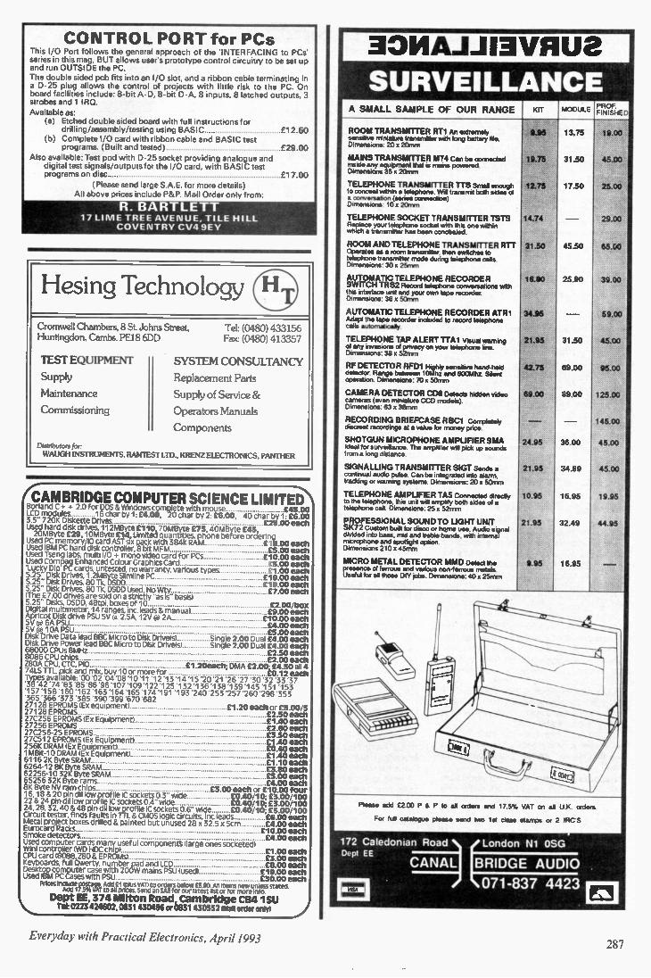
CONTROL PORT for PCs This I/O Port follows the general approach of the 'INTERFACING to PCs' series in this mag, BUT allows user's prototype control circuitry to be set up and run OUTSIDE the PC. The double sided pcb fits into an I/O slot, and a ribbon cable terminating in a D-25 plug allows the control of projects with little risk to the PC. On board facilities include: 8-bit A- ID, 8-bit D-A, 8 inputs, 8 latched outputs, 3 strobes and 1 IRO.
Available as: (a) Etched double sided board with full instructions for
drilling/assembly/testing using BASIC £12.50 (b) Complete I/O card with ribbon cable and BASIC test
programs. (Built and tested) £29.00
Also available: Test pod with D-25 socket providing analogue and digital test signals/outputs for the I/O card, with BASIC test programs on disc £17.00
(Please send large S.A.E. for more details) All above prices include P&P. Mail Order only from:
R. BARTLETT 17 LI ME TREE AVENUE, TILE HILL
COVENTRY CV4 9EY
Hesing Technology Cromwell Chambers. 8 St Johns Street. Tel: (0480) 433156 Huntingdon. Cambs PE18 6DD
TEST EQUIPMENT
Supply
Maintenance
Commissioning
Fax: (0480) 413357
SYSTEM CONSULTANCY
Replacement Parts
Supply of Service &
Operators Manuals
Components
Distributors for
W AUGH INSTRUMENTS, RAMTEST LTD.. KRENZ ELECTRONICS. PANTHER
lCAMBRIDGE COMPUTER SCIENCE LIMITE Borland C + + 2.0 for DOS & Windows complete with mouse £45.00 LCD modules 16 char by 1: £4.00, 20 char by 2: £6.00, 40 char by 1: £6.00 3.5- 720K Diskette Drives £25.00 each Used hard disk drives. 112MByte f110. 70MByte £75, 40MByte £45 20MByte £29, 10MByte £14r Limited quantities, phone before ordering
Used PC memory/I0 card AST six pack with 384k RAM £15.00 each Used IBM PC hard disk controller, 8 bit MFM £5.00 each Used Tseng labs, multi I/O + mono video card for PCs £10.00 each Used Compaq Enhanced Colour Graphics Card £5.00 each 'Lucky Dip PC cards, untested, no warranty, various tV09% £1. 00 each 5.25" Disk Drives, 1.2MByte Slimline PC £19.00 each 5.25" Disk Drives, 80 11, DSDD £19.00 each 5.25" Disk Drives, 801k. DSDD Used, No Wty £7.00 each (The £7.00 drives are sold on a strictly "as is" basis) 5.25" Disks, DSDD, 48tpi, boxes of 10 £2.00 box Digital multimeter, 14 ranges, inc. leads & manual £9.00 each Apricot Disk drive PSU 5V @ 2.5A, 12V 0: 2A £10.00 each 5V ,. 6A PSU £4.00 each 5V (,, 10A PSU £5.00 each Disk Drive Data lead BBC Micro to Disk Drive(s) Single 2.00 Dual £4.00 each Disk Drive Power lead BBC Micro to Disk Drive(s) Single 2.00 Dual f4.00 each 68000 CPUs 8MHz £2.50 each 8086 CPU chips £2.00 each Z80A CPU, CTC, PIO £1.20196 ft DMA C2.00-. _E4.50 all 4 74LS TTL, pick and mix. buy 10 or more for E0.12 each Types available: '00 02 tiull D8 10 11 '12 1 3 14 15 '20 '21 '26 '27 '30 '32 33 37 '38 '42 '74 '83 '85 '86 '96 '107'109'122 '125 '132 '136 '138 '139 '145 '151 '153 '157 '158 '160 '162 '163'164 '165'174 '191 '193 '240 '253 '257 '260 '298 '353 '365 366 373 385 390 399 670'682 27128 EPROMS x equipment) £1.20 each or £5.00/5 27128 EPROMS £2.50 each 27C256 EPROMS (Ex Equipment) £1.40 each 27256 EPROMS £2.50 each 27C256-25 EPROMS £3.50 each 27C512 EPROMS (Ex Equipment) £1.40 each 256K DRAM (Ex Equipment) £0.40 each 1MBit-10 DRAM (Ex Equipment) £1.40 each 6116 2K Byte SRAM £1.10 each 6264-12 8K Byte SRAM £3.80 each 62256-10 32K Byte SRAM £5.00 each 65256 32K Byte rams £4.00 each 8K Byte NV ram chips £3.00 each or £10.00 four 16.18 & 20 pin dl) low profile IC sockets 0.3" wide £0.40/10;£3.00/ 100 22 & 24 pIn dil low profile IC sockets 0.4" wide £0.40/10; £3.001100 24, 28, 2, 40 & 48 pin dl) low profile IC sockets 0.6" wide £0.40/10; £3.00/100 Circuit tester, finds faults in flL & CMOS logic circuits, inc leads ...£6.00 each Metal project boxes drilled & painted but unused 28 x 32.5 x 5cm .. .14.00 each Eurocard Racks £10.00 each Smoke detectors £4.00 each Used computer cards many useful component% (large ones socketed) Wini controller (WD HOC chi ) £1.130 each CPU card 18088, Z80 & EP s) £3.00 each Keyboards, full Owerty, number pad and LCD £13.00 each Desktop computer case with 200W mains PSU (used) £19.00 each Used IBM PC Cases with PSU £30.00 each
Prices Inoue* postage. Add VI (plus VAT) to orders below £5.00. Al) Items new unless stater' Acid 17 5% VAT to all prices. send an SAE for our latest Ott or for more info
Dept EE, 374 Milton Road, Cambridge CB4 1SU Tel:0223 424602, 0831430496 or 0831 430552 Mall order only) }
301VIAJJ13VEIU8
SURVEILLANCE A SMALL SAMPLE OF OUR RANGE OCT MODULE
PROF. FINISHED
ROOM TRANSMITTER RT1 An extremely sensitive miniature transmitter with long battery lie Dimensions 20 x 2Ornm
MAINS TRANSMITTER MT4 Can be oonnected mode any equipment thefts mans powered Dimensions 35 x 20mm
TELEPHONE TRANSMITTER TTS Small enough to conceal within • telephone WI transmit both sides of a conversation (sense connecbon) Dimensions 10 x 20mm
TELEPHONE SOCKET TRANSMITTER TSTS Replace your telephone socket ter, the one within whch a transmitter has been concealed
ROOM AND TELEPHONE TRANSMITTER FITT Operates as a room transmitter, then switches lo telephone transmitter mode dunng telephone cals Di mensions 30x 25mm
AUTOMATIC TELEPHONE RECORDER SWITCH TRS2 Record telephone conversations with the interlace u,,• and your own tape recorder Dimensions 360 50mm
AUTOMATIC TELEPHONE RECORDER ATR1 Adapt the tape recorder inciuded to record telephone calk automats:ally
TELEPHONE TAP ALERT TTA1 Vsual warning of any invasiore of pnvacy on your telephone hire Dimensions 380 52mm
RF DETECTOR RFIDi Hghly sensarve hand-held detector Range between 1010,10z and 600Mhz Sient operation Dimensions 70 x 5Ornm
CAMERA DETECTOR CDS Delsots htdden video carneras (even miniature CCD models) Dimensions 63 x 38rnm
RECORDING BRIEFCASE R BC1 Completely discreet recordings at a value tor money once
SHOTGUN MICROPHONE A MPUFIER SMA !deal for surveillance The arrplier we pick ib sounds from a long distance
SIGNALLING TRANSMITTER SIGT Sends a continual audio pulse Can be integrated into alarm, tracking Of warning systems Dimensions 20x 50mm
TELEPHONE AMPUFIER 1A5 Connected directly to the telephone, this unit wil amplify both sides of a telephone call Dimensions 25 x 52mm
PROFESSIONAL SOUND TO UGHT UNIT SK72 Custom built for disco or hqme use Audio %gnat dwded into bass. rid and treble bands, with internal microphone and spodsght option Dimensions 210 x 45rtirn
MICRO METAL DETECTOR MMD Detect the presence at ferrous and venous non-ferrous metals Useful for al those DIY tote Dimensions 40 x 25rnm
19.75
12.75
14./4
31.50
16.00
24.95
21.95
42.75
69.00
24.95
21.95
10.95
21.95
1.15
13.75
31.50
17.50
45.50
25.90
31.50
69.00
89.00
36.00
34.89
16.95
32.49
16.95
19.00
45.00
25.00
29.00
65.60
39.00
59.00
45.00
95.00
125.00
145.00
45.00
45.00
19.95
44.95
Please add E200 P P io all orders and 17 5% VAT on all U K orders
For Nil catalogue pleas* send two let class steeps or 2 RC'S
172 Caledonian Road London Ni OSG CANAL) (London
AUDIO Dept EE
071-837 4423 lerSol
N M . 101
Everyday with Practical Electronics, April 1993 287
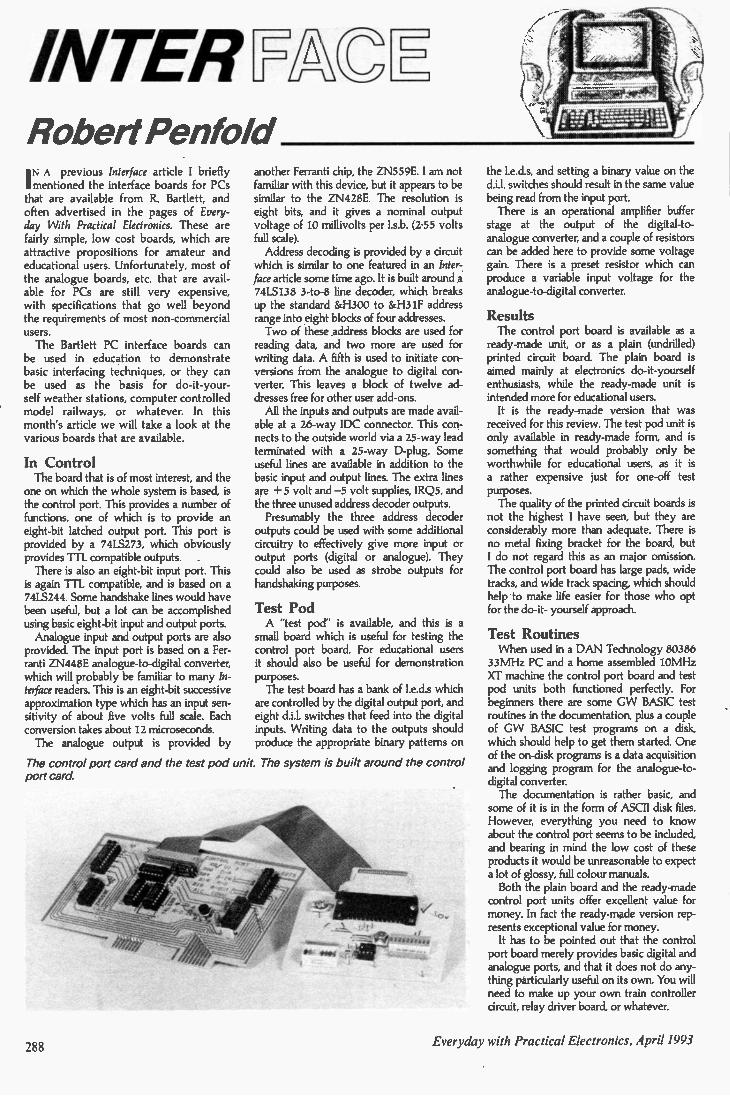
INTER _F C 1
.. Robert Penfold I N A previous Interface article I briefly mentioned the interface boards for PCs that are available from R. Bartlett, and often advertised in the pages of Every-day With Practical Electronics. These are fairly simple, low cost boards, which are attractive propositions for amateur and educational users. Unfortunately, most of the analogue boards, etc. that are avail-able for PCs are still very expensive, with specifications that go well beyond the requirements of most non-commercial users. The Bartlett PC interface boards can
be used in education to demonstrate basic interfacing techniques, or they can be used as the basis for do-it-your-self weather stations, computer controlled model railways, or whatever. In this month's article we will take a look at the various boards that are available.
In Control The board that is of most interest, and the
one on which the whole system is based, is the control port. This provides a number of functions, one of which is to provide an eight-bit latched output port. This port is provided by a 74L5273, which obviously provides TTL compatible outputs. There is also an eight-bit input port. This is again TTL compatible, and is based on a 74LS244. Some handshake lines would have been useful, but a lot can be accomplished using basic eight-bit input and output ports. Analogue input and output ports are also provided. The input port is based on a Fer-ranti ZN448E analogue-to-digital converter, which will probably be familiar to many In-terface readers. This is an eight-bit successive approximation type which has an input sen-sitivity of about five volts full scale. Each conversion takes about 12 microseconds. The analogue output is provided by
another Ferranti chip, the ZN559E. I am not familiar with this device, but it appears to be similar to the ZN428E. The resolution is eight bits, and it gives a nominal output voltage of 10 millivolts per 1.s.b. (2.55 volts full scale). Address decoding is provided by a circuit
which is similar to one featured in an Inter-face article some time ago. It is built around a 74LS138 3-to-8 line decoder, which breaks up the standard &H300 to &H31F address range into eight blocks of four addresses. Two of these address blocks are used for
reading data, and two more are used for writing data. A fifth is used to initiate con-versions from the analogue to digital con-verter. This leaves a block of twelve ad-dresses free for other user add-ons. All the inputs and outputs are made avail-
able at a 26-way IDC connector. This con-nects to the outside world via a 25-way lead terminated with a 25-way D-plug. Some useful lines are available in addition to the basic input and output lines. The extra lines are + 5 volt and —5 volt supplies, IRQ5, and the three unused address decoder outputs. Presumably the three address decoder
outputs could be used with some additional circuitry to effectively give more input or output ports (digital or analogue). They could also be used as strobe outputs for handshaking purposes.
Test Pod A "test pod" is available, and this is a small board which is useful for testing the control port board. For educational users it should also be useful for demonstration purposes. The test board has a bank of 1.e.d.s which
are controlled by the digital output port, and eight d.i.l. switches that feed into the digital inputs. Writing data to the outputs should produce the appropriate binary patterns on
The control port card and the test pod unit. The system is built around the control port card.
0v
the 1.e.d.s, and setting a binary value on the di]. switches should result in the same value being read from the input port. There is an operational amplifier buffer
stage at the output of the digital-to-analogue converter, and a couple of resistors can be added here to provide some voltage gain. There is a preset resistor which can produce a variable input voltage for the analogue-to-digital converter.
Results The control port board is available as a
ready-made unit, or as a plain (undrilled) printed circuit board. The plain board is aimed mainly at electronics do-it-yourself enthusiasts, while the ready-made unit is intended more for educational users. It is the ready-made version that was
received for this review. The test pod unit is only available in ready-made form, and is something that would probably only be worthwhile for educational users, as it is a rather expensive just for one-off test purposes. The quality of the printed circuit boards is not the highest I have seen, but they are considerably more than adequate. There is no metal fixing bracket for the board, but I do not regard this as an major omission. The control port board has large pads, wide tracks, and wide track spacing, which should help to make life easier for those who opt for the do-it- yourself approach.
Test Routines When used in a DAN Technology 80386
33MHz PC and a home assembled 10MHz XT machine the control port board and test pod units both functioned perfectly. For beginners there are some GW BASIC test routines in the documentation, plus a couple of GW BASIC test programs on a disk, which should help to get them started. One of the on-disk programs is a data acquisition and logging program for the analogue-to-digital converter. The documentation is rather basic, and some of it is in the form of ASCII disk files. However, everything you need to know about the control port seems to be included, and bearing in mind the low cost of these products it would be unreasonable to expect a lot of glossy, full colour manuals. Both the plain board and the ready-made
control port units offer excellent value for money. In fact the ready-made version rep-resents exceptional value for money. It has to be pointed out that the control
port board merely provides basic digital and analogue ports, and that it does not do any-thing particularly useful on its own. You will need to make up your own train controller circuit, relay driver board, or whatever.
288 Everyday with Practical Electronics, April 1993
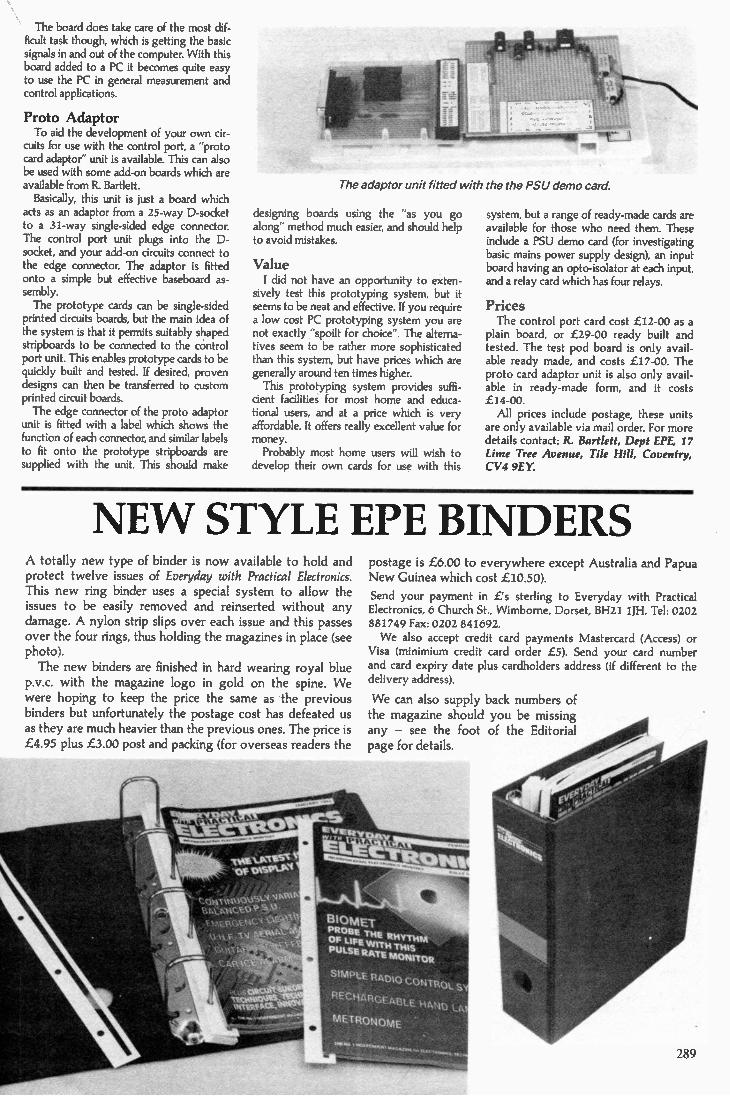
The board does take care of the most dif-ficult task though, which is getting the basic signals in and out of the computer. With this board added to a PC it becomes quite easy to use the PC in general measurement and control applications.
Proto Adaptor To aid the development of your own cir-
cuits for use with the control port, a "proto card adaptor" unit is available. This can also be used with some add-on boards which are available from R. Bartlett. Basically, this unit is just a board which
acts as an adaptor from a 25-way D-socket to a 31-way single-sided edge connector. The control port unit plugs into the D-socket, and your add-on circuits connect to the edge connector. The adaptor is fitted onto a simple but effective baseboard as-sembly. The prototype cards can be single-sided
printed circuits boards, but the main idea of the system is that it permits suitably shaped stripboards to be connected to the control port unit. This enables prototype cards to be quickly built and tested. If desired, proven designs can then be transferred to custom printed circuit boards. The edge connector of the proto adaptor
unit is fitted with a label which shows the function of each connector, and similar labels to fit onto the prototype stripboards are supplied with the unit. This should make
The adaptor unit fitted with the the PSU demo card.
designing boards using the "as you go along" method much easier, and should help to avoid mistakes.
Value I did not have an opportunity to exten-
sively test this prototyping system, but it seems to be neat and effective. If you require a low cost PC prototyping system you are not exactly "spoilt for choice". The alterna-tives seem to be rather more sophisticated than this system, but have prices which are generally around ten times higher. This prototyping system provides suffi-
cient facilities for most home and educa-tional users, and at a price which is very affordable. It offers really excellent value for money. Probably most home users will wish to
develop their own cards for use with this
system, but a range of ready-made cards are available for those who need them. These include a PSU demo card (for investigating basic mains power supply design), an input board having an opto-isolator at each input, and a relay card which has four relays.
Prices The control port card cost £12-00 as a
plain board, or £29-00 ready built and tested. The test pod board is only avail-able ready made, and costs £17-00. The proto card adaptor unit is also only avail-able in ready-made form, and it costs £14-00. All prices include postage, these units
are only available via mail order. For more details contact: R. Bartlett, Dept EPE, 17 Lime Tree Avenue, Tile Hill, Coventry, CV4 9EY.
NE W STYLE EPE BINDERS A totally new type of binder is now available to hold and protect twelve issues of Everyday with Practical Electronics. This new ring binder uses a special system to allow the issues to be easily removed and reinserted without any damage. A nylon strip slips over each issue and this passes over the four rings, thus holding the magazines in place (see photo).
The new binders are finished in hard wearing royal blue p.v.c. with the magazine logo in gold on the spine. We were hoping to keep the price the same as the previous binders but unfortunately the postage cost has defeated us as they are much heavier than the previous ones. The price is £4.95 plus £3.00 post and packing (for overseas readers the
IO W Y4RA•Pa SS1 OVSEI VO
,t Nt (•YoSA.:4 S,
‘1(..
,
. " 4107i,*
postage is £6.00 to everywhere except Australia and Papua New Guinea which cost £10.50).
Send your payment in L's sterling to Everyday with Practical Electronics, 6 Church St., Wimborne, Dorset, BH21 11H. Tel: 0202 881749 Fax: 0202 841692.
We also accept credit card payments Mastercard (Access) or Visa (minimium credit card order £5). Send your card number and card expiry date plus cardholders address (if different to the delivery address).
We can also supply back numbers of the magazine should you be missing any — see the foot of the Editorial page for details.
BI O ME-1.
PROBE THE RHYTHM OF LIFE WITH THIS PULSE RATE MONITOR
SIMPLE RADIO CONTROL S
NEC,I1ARGE ABLE HANt) LA.
METRONOME
289
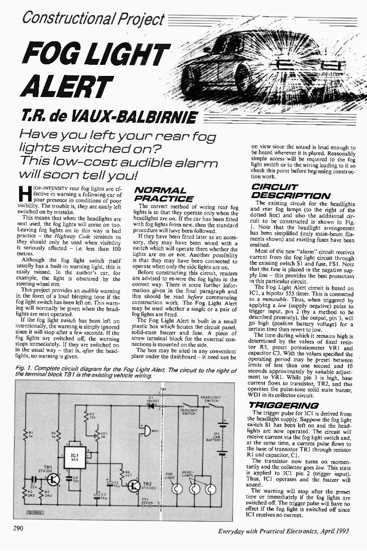
Constructional Project
FOG LIGHT ALERT
- 7".R. de VAUX-BALBIRNIE Have you left your rear fog lights switched on? This lo w-cost audible alar m will soon tell you!
HIGH-INTENSITY rear fog lights are ef-fective in warning a following car of your presence in conditions of poor
visibility. The trouble is, they are easily left switched on by mistake. This means that when the headlights are
next used, the fog lights will come on too. Leaving fog lights on in this way is bad practice — the Highway Code reminds us they should only be used when visibility is seriously affected — i.e. less than 100 metres. Although the fog light switch itself
usually has a built-in warning light, this is easily missed. In the author's car, for example, the light is obscured by the steering wheel rim. This project provides an audible warning
in the form of a loud bleeping tone if the fog light switch has been left on. This warn-ing will normally be given when the head-lights are next operated. If the fog light switch has been left on
intentionally, the warning is simply ignored since it will stop after a few seconds. If the fog lights are switched off, the warning stops immediately. If they are switched on in the usual way — that is, after the head-lights, no warning is given.
N OR MAL P RA CTICE The correct method of wiring rear fog
lights is so that they operate only when the headlights are on. If the car has been fitted with fog lights from new, then the standard procedure will have been followed. If they have been fitted later as an acces-
sory, they may have been wired with a switch which will operate them whether the lights are on or not. Another possibility is that they may have been connected to operate when only the side lights are on. Before constructing this circuit, readers
are advised to re-wire the fog lights in the correct way. There is some further infor-mation given in the final paragraph and this should be read before commencing construction work. The Fog Light Alert may be used whether a single or a pair of fog lights are fitted. The Fog Light Alert is built in a small
plastic box which houses the circuit panel, solid-state buzzer and fuse. A piece of screw terminal block for the external con-nections is mounted on the side. The box may be sited in any convenient
place under the dashboard — it need not be
Fig 1. Complete circuit diagram for the Fog Light Alert The circuit to the right of the terminal block T81 is the existing vehicle wiring.
RI 1k
CI 22n
R1 2142
R4 1k
TA 1 ZT X 300
( Et 40436 J
R3 2142
RS 10k
VR 1M
'Cl 555
01 tOn C=7 C4
m aI0y
C3
T'"
R6 4k 7
TB1
DI Cr 1114001
14 0 20 10
WDI
1R2 210 300
FS1 200mA 31 azr• 0*3
FOG LIGHT
HEADLIGHT SWITCH
O....4 1:1 a •
FOGLIGHT SWITCH
HEAD - LAMPS
125 CAR
BATTERY
MIR
on view since the sound is loud enough to be heard wherever it is placed. Reasonably simple access will be required to the fog light switch or to the wiring leading to it so check this point before beginning construc-tion work.
CIRC UIT D ESCRIPTIO N The existing circuit for the headlights
and rear fog lamps (to the right of the dotted line) and also the additional cir-cuit to be constructed is shown in Fig. I. Note that the headlight arrangement has been simplified (only main-beam fila-ments shown) and existing fuses have been omitted. Most of the new "alarm" circuit receives
current from the fog light circuit through the existing switch SI and fuse, FS1. Note that the fuse is placed in the negative sup-ply line — this provides the best protection in this particular circuit. The Fog Light Alert circuit is based on
ICI, a bipolar 555 timer. This is connected as a monstable. Thus, when triggered by applying a low (supply negative) pulse to trigger input, pin 2 (by a method to be described presently), the output, pin 3, will go high (positive battery voltage) for a certain time then revert to low. The time during which it remains high is
determined by the values of fixed resis-tor R5, preset potentiometer VR1 and capacitor C3. With the values specified the operating period may be preset between limits of less than one second and 10 seconds approximately by suitable adjust-ment to VR1. While pin 3 is high, base current flows to transistor, TR2, and this operates the pulse-tone solid state buzzer, WD1 in its collector circuit.
TRIGGERI NG The trigger pulse for ICI is derived from
the headlight supply. Suppose the fog light switch SI has been left on and the head-lights are now operated. The circuit will receive current via the fog light switch and, at the same time, a current pulse flows to the base of transistor TR1 through resistor RI and capacitor, Cl. The transistor now turns on momen-
tarily and the collector goes /ow. This state is applied to ICI pin 2 (trigger input). Thus, ICI operates and the buzzer will sound. The warning will stop after the preset
time or immediately if the fog lights are switched off. The trigger pulse will have no effect if the fog light is switched off since IC1 receives no current.
290 Everyday with Practical Electronics, April 1993
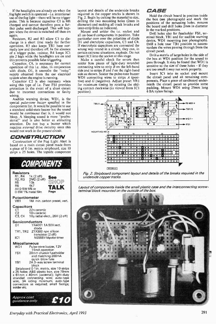
If the headlights are already on when the fog light switch is operated — i.e. intentional use of the fog light — there will be no trigger pulse. This is because capacitor Cl is left charged and cannot therefore pass a fur-ther pulse until discharged. This will hap-pen when the circuit is switched off then on again. Resistors, R2 and R3 allow Cl to dis-
charge in a short time ready for further operation. R3 also keeps TR1 base nor-mally low and therefore off. In the absence of a trigger pulse, resistor, R4 keeps ICI pin 2 high while the headlights are on and this prevents possible false triggering. Capacitor. C4. is necessary for correct
operation of this i.c. Also, in conjunction with diode, DI, it smooths the "noisy" supply obtained from the car electrical system when the engine is running. Capacitor C2 is also necessary when
using this type of i.c. Fuse FS1 provides protection in the event of a short circuit due to incorrect connections or faulty wiring. Audible warning device, WD I, is the
special pulse-tone buzzer specified in the components list. It would be possible to use a standard solid-state buzzer but the sound would be continuous that is, it would not bleep. A bleeping sound is more "profes-sional" and is also better at attracting attention. Do not buy a buzzer which requires external drive circuitry since this would not work in the present circuit.
C O NSTRUCTIO N Construction of the Fog Light Alert is
based on a main circuit panel made from a piece of 01 in. matrix stripboard, size 10 strips x 25 holes. The topside component
COMPONENTS Resistors R1, R4 1k (2 off) R2, R3 2M2 (2 off) R5 10k R6 4k7 All 0.5W 5% or 0-6W 1% metal film
See S[f-TALK Page
Potentiometer VR1 1M min. carbon preset, vert
Capacitors Cl 22n ceramic C2 10n ceramic C3, C4 10µ radial elect., 25V (2 off)
Semiconductors D1 1N4001 1A 50V rect.
diode TR1, TR2 ZTX300 npn silicon
transistor (2 off) IC1 NE555V bipolar timer
Miscellaneous WD1 Pulse-tone buzzer, 12V
15mA operation FS1 20mm chassis fuseholder
and matching 200mA quick-blow fuse
TB1 2A 3-way screw terminal block
Stripboard Olin. matrix, size 10 strips x 25 holes; ABS plastic box, size 79mm x 61mm x 40mm (external); light-duty stranded connecting wire; auto-type wire, 3A rating minimum; auto-type connectors as required; small fixings; solder etc.
Approx cost guidance only £10
layout and details of the underside breaks required in the copper tracks is shown in Fig. 2. Begin by cutting the material to size, drilling the two mounting holes (2mm in diameter) and making all track breaks and inter-strip links as indicated. Mount and solder the i.c. socket and
all on-board components in position. Take particular care over the polarities of diode DI and electolytic capacitors, C3 and C4. If electrolytic capacitors are connected the wrong way round in a circuit, they can, in certain extreme situations, explode. Do not insert ICI into the socket at this stage. Make a careful check for errors then
solder 8cm pieces of light-duty stranded connecting wire to strip B on the left-hand side and to strips B and Ion the right-hand side as shown. Solder the pulse-tone buzzer WD1 connecting wires to strips A (posi-tive) and G (negative). Adjust preset VR1 for minimum timing by rotating the slid-ing contact clockwise (as viewed from ICI position).
MOUNTING HO E
C A SE Hold the circuit board in position inside
the box (see photograph) and mark the positions of the mounting holes. remove the board and drill holes 2mm in diameter in the marked positions. Drill holes also for fuseholder FS1, ter-
minal block. TB1 and for audible warning device, WD1 mounting (see photograph). Drill a hole near TB I position to accom-modate the wires passing through from the circuit panel. Drill a matrix of large holes in the side of
the box at WD1 position for the sound to pass through. It may be found that WD I is sensitive to the size of these holes — if they are too small it may not work properly. Insert ICI into its socket and mount
the circuit panel and all remaining com-ponents. Place a piece of cardboard under-neath the circuit panel to provide some padding. Mount WD1 using 25mm long 6 BA nylon fixings.
EE4064G
Fig 2 Stripboard component layout and details of the breaks required in the underside copper tracks.
Layout of components inside the small plastic case and the interconnecting screw-terminal block mounted on the outside of the box.
Everyday with Practical Electronics, April 1993 291
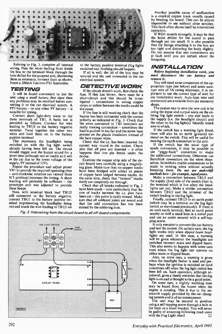
e • 6 • 0
• * 6 6 • •
• 0 6
Refering to Fig. 3, complete all internal wiring. Pass the wires leading from inside the box to the terminal block through the hole drilled for the purpose and, shortening them as necessary, connect them as shown. Insert a 200mA fuse into FSI fuseholder.
TESTI NG It will be found convenient to test the
unit using a small battery first since then any problems may be resolved before con-necting it to the car electrical system. A PP3 battery — or any other 9V battery — is suitable for testing. Connect short light-duty wires to the
three terminals of TB1. A basic test is provided as follows. Connect the wire leading to TB1 /3 to the battery negative terminal. Twist together the other two wires and hold them on to the battery positive terminal. This represents the headlights being
switched on with the fog light switch already having been left on. The circuit should trigger and the buzzer sound for a short time (although not as loudly as it will in the car due to the lower voltage of the supply, 9V instead of 12V). Repeat the procedure and adjust preset
VR1 to provide the required operating time — anti-clockwise rotation (as viewed from ICI position) increases the timing. A short warning will probably be sufficient — the prototype unit was adjusted to provide three bleeps. Now, with terminal block lead TBI /3
still connected to the battery negative, connect TB1 /1 to the battery positive ter-minal (representing the headlights being on) and touch the wire leading to TBI /2 on
to the battery positive terminal (fog lights switched on). Nothing should happen. If all is well, the lid of the box may be
secured and the unit connected to the car electrical system.
D ETECTI VE W ORK If the circuit doesn't work, first check the
fuse. If this has blown, there must be a short-circuit and this should be inves-tigated — connections to wrong copper strips or debris between the tracks could be the cause. If the fuse is still working check that the
buzzer has been connected with the correct polarity as indicated in Fig. 3. Check that the wires connected to TB1 terminals are really making connection — sometimes the lead is pushed in too far and the screw base presses on the plastic insulation instead of the bare copper wires. Check that the i.c. has been inserted the
correct way round in the socket. Check also that all pins are inserted — it often happens that one pin bends under the device. Examine the copper strip side of the cir-
cuit board very carefully using a magnify-ing glass. Make sure that no copper tracks have been bridged with solder or pieces of copper have lodged between tracks. At the same time, check that "broken" tracks really are completely cut through. Check that all breaks indicated in Fig. 2
have been made — note particularly that the row of tracks between the i.c. pins have been cut — this point is easily missed. Make sure that all soldered joints are sound and that the odd connection has not been missed by the soldering iron.
Fig. 3. Interwiring from the circuit board to all off-board components.
FOG LIGHT SWITCH
FS I
Another possible cause of malfunction is a cracked copper track usually caused by bending the board. This can be almost impossible to see without close scrutiny. This fault often shows itself by intermittent operation. If WD1 sounds strangely, it may be that
the holes drilled for the sound to pass through are too small. It is also possible that the fixings attaching it to the box are too tight and distorting the body slightly. Do not assume that any components are at fault until you are certain about the foregoing.
INSTALLATIOAI Before beginning installation work, you
must disconnect the car battery and remove it. You will need some connectors of the ap-
propriate type (see below) and some auto-type wire of 3A rating minimum. It is im-portant to use the correct type of wire for car installation work. Auto-type wire and connectors are available from car accessory shops. The easiest way to wire the new unit is by
using the input and output wires on the ex-isting fog light switch — one side leads to the supply (i.e. the headlight circuit) and the other to the fog light(s). Identify which wire is which. If the switch has a warning light fitted,
there will also be an earth (ground) ter-minal on the switch. This will be useful for making the earth connection to the unit. If the switch has the usual type of
spade connectors, it may be possible to use "piggy-back" convertors to make the additional connections. Otherwise use Scotchlok connectors on the wires them-selves. Scotchloks enable connections to be made to existing wires without actually breaking them. Do not use makeshift methods here —for example, taped joints. Make a connection between TB1 /1 and
the supply (live) side of the switch (that is, the terminal which is live when the head-lights are on). Make a similar connection between TB1 /2 and the terminal of the switch leading to the fog light. Finally, connect TB1/3 to an earth point
(which may be a terminal on the fog light switch as mentioned previously). If there is no such earth terminal, find an earth point nearby or drill a small hole in a metal part and use an eyelet secured with a self-tap-ping screw. It only remains to connect the car battery
and test the system. On certain cars, the fog light works only when dipped beam head-lights are used. In this case, a warning will be given whenever the headlights are switched between main and dipped beam. This also seems to happen with some cars even where the fog light can operate on either main or dipped-beam. Also, on some cars, a warning is given
when the headlight flasher is used and per-haps when the ignition is switched on (and sometimes oil) when the fog light switch has been left on. Such operation, although ac-cidental, gives a timely reminder that the fog light is on and is thought to be a good point. On some cars, a slightly warbling tone
may be heard from the buzzer when the engine is running. This is due to the un-smooth supply provided by the car charg-ing system and is of no consequence. The unit may be secured in position using a self-tapping screw through a hole in the back or a small bracket. You will never be guilty of annoying following road users with the Fog Light Alert! 0
Everyday with Practical Electronics, April 1993

BARGAINS - Many New Ones This Month SCREWDRIVERS - pocket sized Will save you having to worry where you left the last one 10 for £1, Order Ref. 909 INTERESTED IN STARS 8 PLANETS? If so, here is your opportunity to acquire a very comprehensive set of parts which will enable you to make several models of astronomical telescopes as well as terrestrial telescopes. The kit comes complete with a 28 page manual. Price £15, Order Ref. 15P48. STEPPER MOTOR BARGAIN. This is just a mini motor, 12V operated and 7.5' step angle. Offered at the very low price of only £1, Order Ref. 910. STANDARD CASSETTE MOTOR for 9V recorder players. This is brush-less and has internal electronics to facilitate speed change and reverse. £1.50 each, Order Ref. 1.5P14. MINI CASSETTE MOTOR but will operate from 1V upwards as it is so well made Speed, of course, increases with voltage and is speed regulated at 91. Et Order Ref. 540 STOP THOSE PEAKS as they come through the mains, they can damage your equip-ment. 2A unit is a combination of cores and caps gives complete protection. £2, Order Ref. 2P315. SOLAR KIT BARGAIN. A recent lucky purchase enables us to offer 2 solar models at approximately half price. The Aeroplane kit comprises all the parts to make a model aeroplane, solar cell and solar motor to drive its propellor. The kit was 7 50 but can be yours for only £3.75, Order Ref. 3 75P1 The second one is the Vintage Gramophone. Again, all the parts to make the model, the solar cell which drives the module which plays the tune. Again, the kit was £7 50, now only £3.75, Order Ref. 3.75P2. INSULATION TAPE S rolls of assorted colours, only £1, Order Ref. 911. GENERAL PURPOSE FAN KIT comprises beautifully made "Boxer" fan, transformer and switch to give dual speed and off from the mains. Complete with perforated front panel which, if bent, could make a suitable stand for a desk fan. etc. Or, it could be used as a general purpose blower or for fume extraction in cooker hood, etc. Complete kit £6, Order Ref. 6P28 DOUBLE HEADPHONE OUTLET. A standard type stereo plug with 2 leads coming out, each terminating with a standard size stereo socket thus enabling 2 people to listen from the one outlet Very well made Price £2, Order Ref 2P312. 12V POWER SUPPLY. Plugs into 13A socket and gives 200mA cl,c, out. Price £2, Order Ref 2P313 ASTEC 135W PSU. Mains input, 3 outputs:- • 12V at 4A. + 5V at 16A. and - 12V at 1/4 A In plated steel case, brand new, £9.50, Order Ref 9.5P4 DIMMER SWITCH on standard electrical plate to replace normal wall switch 500W. slightly coloured but takes emulsion. Only £2, Order Ref. 2P309 INFRA RED RECEIVER CONTROLLER made by Thorn to channel switch their T.V. receivers Mounted on panel with luminous channel indicator, mains on/off switch, leads and plugs all yours for £2, Order Ref. 2P304. HIGH QUALITY KEY SWITCH single pole on/off or changeover through panel mounted by hexagonal nut. Complete with 2 keys. Regular price £3, our price £1.50, Order Ref. 1.5P12. DIGITAL MULTI TESTER M3800 single switching covers 32 ranges including 20A a,c and dc. 10 meg input impedence, 31/4 LCD display. Complete with carrying case and lead. Currently advertised by many dealers at nearly £40. our price only £25, Order Ref. 25P14. ANALOGUE TESTER. Input impedence 2K ohms per volt, It has 14 ranges, ac. volts 0-500, d.c. volts 0-500. d.c. current 500 micro amps at 250 milliamp, resistance 0-1 meg-ohm, decibels 20 - 56d8. Fitted diode protection, overall size 90 x 60 x 30mm. Complete with test prods. price £7.50, Order Ref. 7.5P8. 2" 50 OHM LOUDSPEAKER replacement for pocket radio, baby alarm. etc. Also makes good pillow 'phone 2 for f1, Order Ref 905, 13A SWITCHED SOCKETS on standard switch plates but coloured. Ideal in workshop. cellar, etc. British made Twin switched, £1.50, Order Ref. 1.5P13, single switched 75p, Order Ref ..75P1 LCD CLOCK MODULE 1.5V battery-operated, fits nicely into our 50p project box, Order Ref 876. Only £2, Order Ref. 2P307. OPTICAL INSTRUMENTS KIT makes microscope and six other optical instruments. £1 5, Order Ref. 15P28 SINTINEL COMPONENT BOARD amongst hunders of other parts, this has 151Cs all plug in so don't need de-soldering. Cost well over £100. yours for £4 Order Ref. 4P67. 9V 2.1A POWER SUPPLY made for Sinclair to operate their 128K Spectrum Plus 2 £3, Order Ref. 3P151 LINEAR HEATING TUBES. Quartz glass. 360W 110V so you need 2 in series which would give you 720W 2 for f1, Order Ref 907. 12V 250 MILLIAMP SOLAR POWER. Could keep that 12V battery charged where there Is no access la the mains f15, Order Ref. 15P47 EXTRA LIGHTWEIGHT STEREO HEADPHONES. Adjustable headband. Suitable for use with all types of cassette players and radios. only £1 business, unused and in perfect order but less PSU, only f19.50, per pair. Order Ref. 898 Order Ref. 19.5P/5B. 6-12V AXIAL FAN. Japanese-made 12V d.c. battery operated. brushless axial fan. 93mm 80W MAINS TRANSFORMERS two available, good quality, both with normal primaries square, its optimum is 12V but it performs equally well at only 6V and its current then is and upright mounting. one is 20V 4A, Order Ref. 3P106 the other 40V 2A, Order Ref only 100mA. price only £4, Order Ref, 4P65 Mains power unit to operate this at variable 3P107. only £3 each. speeds £2, Order Ref. 2P3 ELECTRONIC BUMP 8 GO SPACESHIP sound and impact controlled responds to claps and shouts and reverses or diverts should it hit anything! Kit with really detailed in-structions, will make ideal present for budding young electrician. Should be able to assemble but you may have to help with the soldering of the components on the PCB. Complete kit, £8.95, Order Ref. 9P9. 20W 4 OHM SPEAKER made by Goodmans for Ford. this is mounted on a panel and has an anodized cone protector cover but can be easily removed from this. Its a beautiful reproducer and the replacement price is nearly £20. Yours for only £3, Order Ref. 3P145 20W 4 OHM TWEETER also made by Goodmans for Ford, mounted on a baffle but easily unscrewed from this Yours for £1.50, Order Ref.1,5P9. 1KW BLOW HEATER. Only 6" wide so ideal where space is limited - under a desk or similar-or can be made into a portable heater for defrosting pipes. etc, Complete little unit, although motorized. is virtually silent in operation. Price £5, Order Ref. 5P23, WHERE YOU UNLUCKY during any of the cold spells? Did any of the pipes in your loft freeze and then burst? Some friends of ours were away at the time and had ceilings come down. It could be just as cold this winter but you can avoid pipes freezing by winding our waterproof heating wire around them. Operating cost, even without thermostat, is only a few pence per week, 15m length consumes about 25 watts. This is the length we recommend for the normal house and the
cost is £5.00, Order Ref. 5P109 Or, if you want specified length, send 35p per metre AMSTRAD KEYBOARD MODEL KB5. This is a most comprehensive keyboard, having over 100 keys including, of course full numerical and qwerty. Brand new, still in maker's packing, £5, Order Ref. 5P202. F.M. CORDLESS RADIO MIKE hand-held battery-operated professional model, has usual shaped body and head and is tuneable to transmit and be picked up on the F.M, band of any radio, Yours for only £8.50, Order Ref. 8,5P1.
4 MORE SPEAKERS: Order Re. 1.5P11 is Japanese-made 6'!,", 8 ohm, rated at 12W may This is a very fine reproducer. The makers are SANYO. Yours for £1.50. Order Ref. 900 is another Far East made 61/4 ". 4 ohm, 12W max speaker. Very nicely made using Japanese Hitachi tools and technique, only ft Order Ref. 896 is 61/4 !, 6 ohm. 10W, exceptionally good sounder and yours for only ft
Order Ref. 897 is another 8 ohm speaker rated at 5W but its unusual
LIMITED SUPPLY ITEMS are only described in our newsletter.
Many appear in our current issue.
If you order something this month you
will receive this and the next issue
posted to you.
P.C. OPERATING SYSTEMS Fully user documented and including
software. MS-DOS 3,20, £5, Order Ref. 5P207: MS-DOS 3.3. £5, Order Ref. 5P208. MS-DOS 4.01. £10, Order Ref. 10P99.
feature is that it has a built-in tweeter. Price still only Et MOVEMENT ALARM goes off with slightest touch, ideal to protect car, cycle. doorway, window. stairway, etc etc. Complete with Piezo 2sph2he2ker, ready to use Only £2 (PP3 battery not supplied). Order Ref. 8
SOLAR ENERGY EDUCATIONAL KIT an ideal present for electronics students. Kit comprises 8 solar cells, one solar motor, fan blades to fit motor and metal frame to hold it to complete a free-standing
electric fan A really well written instruction manual makes this a lovely little present. Price £8, Order Ref, 8P12B PROJECT BOX a first-class, Japanese two-part moulding size 95mm x 66mm x 23mm. Will hold a PP3 battery and a PCB and is ideal for many projects. nicely finished and very substantial. 2 for £1, Order Ref 876. 12V 2A MAINS TRANSFORMER upright mounting with mounting clamp. Price f1.50, Order Ref. 1.5P8 AM/FM RADIO CHASSIS with separate LCD clock module, complete with loudspeaker and ready logo, price is £3.50, Order Ref. 3.5P5. 2, 3 AND 4 WAY TERMINAL BLOCKS the usual grub screw types. Parcel containing a mixture of the 3 types, giving you 100 ways for tt, Order Ref. 875. 12/24V DC SOLENOID. The construction of this is such that it will push or pull as the plunger is a combined rod and piston. With 24V this is terrifically powerful but is still quite good at 12V and. of course, it can be operated by any intermediate voltage. Price El, Order Ref. 877. 2M 3-CORE LEAD terminating with flat pin instrument socket. £1, Order Ref 879 Ditto bu1 with plug on the other end so that you could use this to extend an instrument lead. £1.50, Order Ref 1.5P10. SAFETY LEADS curly so they contract but don't hang down, Could easily save a child from being scalded. 2 core, 5A, extends to 3m, VI, Order Ref. 846,3 core, 13A, extends to 1m, Et each. Order Ref. 847.3 core. 13A, extends to 3m, £2 each. Order Ref. 2P290. ULTRA SONIC TRANSDUCERS 2 metal cased units, one transmits, one receives. Built o operate around 40kHz. Price £1.50 the pair, Order Ref. 1.5P/4. 100W MAINS TRANSFORMERS normal primaries 20-0-20 at 2.5A or 30V at 3.5A. £4,
Order Ref 4P24 40V at 2.5A, DS, Order Ref. 4P59. 50V at 2A, £4, Order Ref 4P60 PHILIPS 9" HIGH RESOLUTION MONITOR black 8 white in metal frame for easy mounting, brand new still in maker's packing, offered at less than price of tube alone. only £15, Order Ref. 15P1. 16 CHARACTER 2-LINE DISPLAY screen size 85mm x 36mm, Alpha-numeric LCD dot matrix module with integral micro processor made by Epaon, their Ref. 16027AR, £8, Order Ref. 8P48
INSULATION TESTER WITH MULTIMETER internally generates voltages which enables you to read insulation directly in megohms. The multimeter has four ranges. AC/DC volts. 3 ranges DC milliamps. 3 ranges resistance and 5 amp range. These instruments are ex British Telecom but in very good condition, tested and guaranteed OK, probably cost at least £50 each. yours for only £7.50, with leads, carrying case £2 extra, Order Ref. 7.5P/4 MAINS 230V FAN best make "PAPST" 41/2 " square. metal blades. £8, Order Ref 8P8. 2MW LASER Helium neon by Philips, full spec £30, Order Ref. 30P1 Power supply for this in kit form with case is £15, Order Ref 15P16. Olin larger case to house tube as well f18, Order Ref. 18P2. The larger unit. made up, tested and ready to use, complete with laser tube £69, Order Ref. 69P1. 1/3 HP 12V MOTOR - THE FAMOUS SINCLAIR C5 brand new, £15, Order Ref. 15P8. SOLAR CHARGER holds 4 AA nicads and recharges these in 8 hours, in very neat plastic case. £6, Order Ref 6P3. AIR SPACED TRIMMER CAPS 2-20 pt ideal for precision tuning UHF circuits, 4 for £1, Order Ref 81811 FIELD TELEPHONES just right for building sites, rallies, horse shows, etc., just in two by twin wire and you have two way calling and talking and you can join into regular phone lines if you want to. Ex British Telecom in very good condition, powered by batteries not included) complete with shoulder slung carrying case. £9.50, Order Ret 9 5P/2. MAINS ISOLATION TRANSFORMER stops you getting to earth'' shocks. 230V in and 230V out. 150watt upright mounting, £7.50, Order Ref. 7.5P/5 and a 250W version is 00, Order Ref 10P79. MINI MONO AMP on PCB. Size 4" x 2" with front panel holding volume control and with
spare hole for switch or tone control Output Is 4 watt into 4 ohm JUS
35mm Ballrac but this can
Or
T ARRIVED e. complete with spindle be removed. 4 for £1 der Ref. 912.
speaker using 12V or 1 watt into 8 ohm using 9V. Brand new and perfect, only £1 each, Order Rel. 495 ATARI 65XE at 65K this is quite powerful so suitable for home or
PROJECT BOX size approx 8- x 4" s4¼" metal, sprayed grey, louvred ends for ventilation otherwise un!'rilled. Made for GPO so best quality. only £3 each. Order Ref. 3P74. EXPERIMENTING WITH VALVES don't spend a fortune on a mains transformer, we can supply one with standard mains input and secs. of 250-0-250V at 75mA and 6.3V at 3A f5, Order Ref 5P167 15W 8 OHM 8" SPEAKER & 3" TWEETER made for a discontinued high quality music centre, gives real hi-fi. and only £4 per pair, Order ref. 4P57. WATER PUMP very powerful with twin outlets, an ideal shower controller, mains operated. £10, Order Ref. 10P74. Ditto but with a single outlet, Same price 8 order ref Please specify which one you require 0-1MA FULL VISION PANEL METER 2;" square, scaled 0-100 but scale easily removed for re-writing. El each. Order Ref. 756. PCB DRILLS 12 assorted sizes between .75 and 1.5mm. El the lot. Order Ref. 128.
Prices include V.A.T. Send cheque/postal order or ring and quote credit
card nu mber. Add £3 post and packing.
Orders over £50 post free.
If intending to call please phone first.
M & B ELECTRICAL SUPPLIES LTD Pilgrim Works (Dept. E.E.)
Stairbridge Lane
Bolney, Sussex RH17 5PA
Telephone or Fax: 0444 881965
Everyday with Practical Electronics, April 1993 293
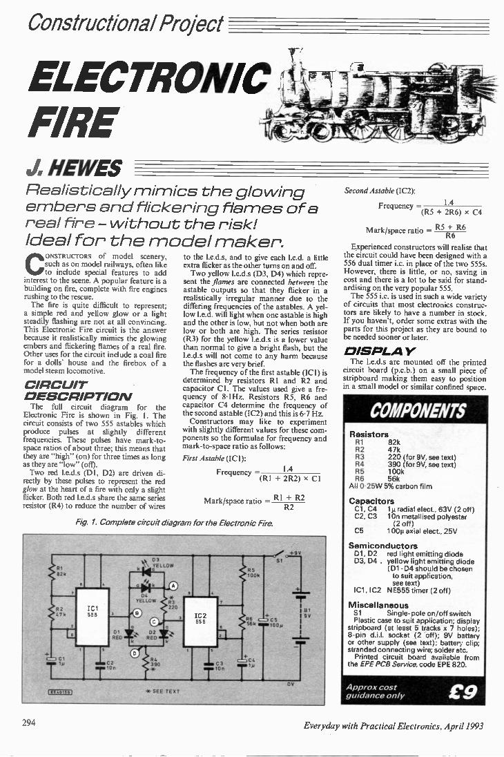
Constructional Project
ELECTRONIC FIRE J. HEWES Realistically mi mics the glo wing embers and flickering fla mes of a real fire - without the risk! Ideal for the model maker'.
CONSTRUCTORS of model scenery, such as on model railways, often like to include special features to add
interest to the scene. A popular feature is a building on fire, complete with fire engines rushing to the rescue. The fire is quite difficult to represent;
a simple red and yellow glow or a light steadily flashing are not at all convincing. This Electronic Fire circuit is the answer because it realistically mimics the glowing embers and flickering flames of a real fire. Other uses for the circuit include a coal fire for a dolls' house and the firebox of a model steam locomotive.
CIRCUIT D ESCRIPTIO N The lull circuit diagram for the
Electronic Fire is shown in Fig. I. The circuit consists of two 555 astables which produce pulses at slightly different frequencies. These pulses have mark-to-space ratios of about three; this means that they are "high" (on) for three times as long as they are "low" (off). Two red I.e.d.s (DI, D2) are driven di-rectly by these pulses to represent the red glow at the heart of a fire with only a slight flicker. Both red I.e.d.s share the same series resistor (R4) to reduce the number of wires
to the 1.e.d.s, and to give each I.e.d. a little extra flicker as the other turns on and off. Two yellow 1.e.d.s (D3, D4) which repre-
sent the flames are connected between the astable outputs so that they flicker in a realistically irregular manner due to the differing frequencies of the astables. A yel-low 1.e.d. will light when one astable is high and the other is low, but not when both are low or both are high. The series resistor (R3) for the yellow 1.e.d.s is a lower value than normal to give a bright flash, but the 1.e.d.s will not come to any harm because the flashes are very brief. The frequency of the first astable (ICI) is
determined by resistors RI and R2 and capacitor CI. The values used give a fre-quency of 81 Hz. Hz. Resistors R5, R6 and capacitor C4 determine the frequency of the second astable (IC2) and this is 6.7 Hz. Constructors may like to experiment
with slightly different values for these com-ponents so the formulae for frequency and mark-to-space ratio as follows:
First Astable (ICI):
Frequency — 1.4 (R1 + 2R2) x Cl
Mark/space ratio = RI + R2
Fig. 1. Complete circuit diagram for the Electronic Fire.
R2
81 82k
62 ICI 07k
+o r Ci 17 1 C2
1$j
et..0.551
8
D1 RED
‘!''‘ 3 YELLOW
* SEE TEXT
IC2 -55
; RE C5 56k i mi loo m
B1 I 9V
R5 100k
r Tip
0,/ +9V
SI
OV
-r
Second Astable (IC2):
Frequency = 1.4 (R5 + 2R6) x C4
R6 Mark/space ratio — R5+ R6
Experienced constructors will realise that the circuit could have been designed with a 556 dual timer i.c. in place of the two 555s. However, there is little, or no, saving in cost and there is a lot to be said for stand-ardising on the very popular 555. The 555 i.c. is used in such a wide variety
of circuits that most electronics construc-tors are likely to have a number in stock. If you haven't, order some extras with the parts for this project as they are bound to be needed sooner or later.
The I.e.d.s are mounted off the printed circuit board (p.c.b.) on a small piece of stripboard making them easy to position in a small model or similar confined space.
Resistors R1 82k R2 47k R3 220 (for 9V, see text) R4 390 (for 9V, see text) R5 100k R6 56k All 0.25W 5% carbon film
Capacitors Cl, C4 1µ radial elect., 63V (2 off) C2. C3 10n metallised polyester
(2 off) C5 100µ axial elect., 25V
Semiconductors D1, D2 red light emitting diode 03, D4 . yellow light emitting diode
(Di-04 should be chosen to suit application, see text)
IC1, 1C2 NE555 timer (2 off)
Miscellaneous Si Single-pole on/off switch Plastic case to suit application; display stripboard (at least 5 tracks x 7 holes); 8-pin d.i.l. socket (2 -off); 9V battery or other supply (see text); battery clip; stranded connecting wire; solder etc. Printed circuit board available from
the EPE PCB Service, code EPE 820
Approx cost guidance only £9
294 Everyday with Practical Electronics, April 1993
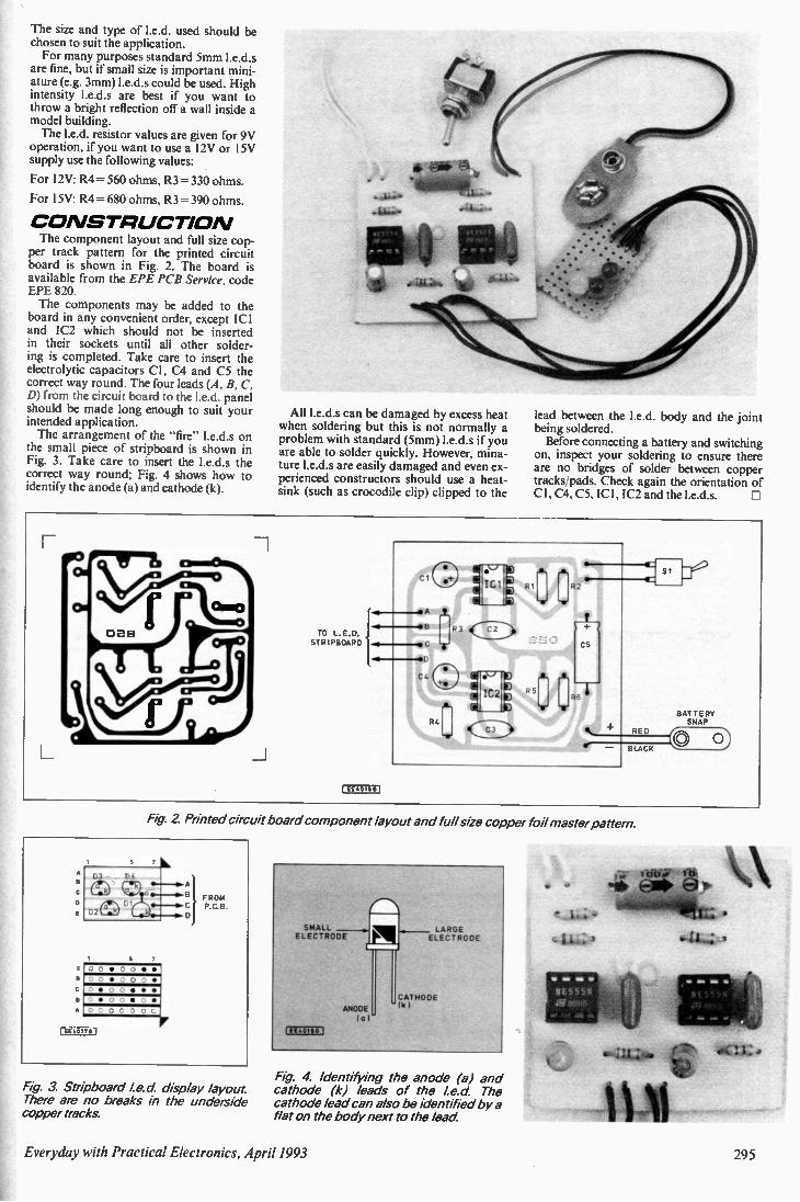
The size and type of I.e.d. used should be chosen to suit the application. For many purposes standard 5mm I.e.d.s
are fine, but if small size is important mini-ature (e.g. 3mm) I.e.d.s could be used. High intensity 1.e.d.s are best if you want to throw a bright reflection off a wall inside a model building. The I.e.d, resistor values are given for 9V
operation, if you want to use a 12V or 15V supply use the following values:
For 12V: R4 = 560 ohms, R3 =330 ohms.
For I 5V: R4 = 680 ohms. R3 = 390 ohms.
C O NSTRUCTIO N The component layout and 1611 size cop-
per track pattern for the printed circuit board is shown in Fig. 2. The board is available from the EPE PCB Service, code EPE 820. The components may be added to the
board in any convenient order, except ICI and IC2 which should not be inserted in their sockets until all other solder-ing is completed. Take care to insert the electrolytic capacitors Cl, C4 and C5 the correct way round. The four leads (A, B, C, D) from the circuit board to the I.e.d. panel should be made long enough to suit your intended application. The arrangement of the "fire" 1.e.d.s on
the small piece of stripboard is shown in Fig. 3. Take care to insert the I.e.d.s the correct way round; Fig. 4 shows how to identify the anode (a) and cathode (k).
All I.e.d.s can be damaged by excess heat when soldering but this is not normally a problem with standard (5mm) I.e.d.s if you are able to solder quickly. However, mina-ture I.e.d.s are easily damaged and even ex-perienced constructors should use a heat-sink (such as crocodile clip) clipped to the
lead between the 1.e.d, body and the joint being soldered. Before connecting a battery and switching
on, inspect your soldering to ensure there are no bridges of solder between copper tracks/pads. Check again the orientation of Cl, C4, C5, ICI, IC2 and the I.e.d.s.
TO L.E.D. SIR IPBOARD
•A
•B R3
•C -r SC
Cc
,a-
R4 RED
BLACK
EE40156 I
BATTERY SNAP
A
A
Fig. 2. Printed circuit board component layout and full size copper foil master pattern.
5 ,
03 z c s04
FROM D I C P.0 B
02 L: D
5 0 0 • 0 0 • O 0 • 0 0 0 0 • 0 0 • • • • 0 0 • 0 O0 0 0 0 0
1E040176 L
Fig. 3 Stripboard le.d display layout There are no breaks in the underside copper tracks.
SMALL ELECTRODE
(6E40166
P' - - ELLEACR4E0 DE
ANODE fa r
CATHODE - 161
Fig. 4. Identifying the anode (a) and cathode (k) leads of the le.d The cathode lead can also be identified by a flat on the body next to the lead
06‘1 1.,
Everyday with Practical Electronics, April 1993 295
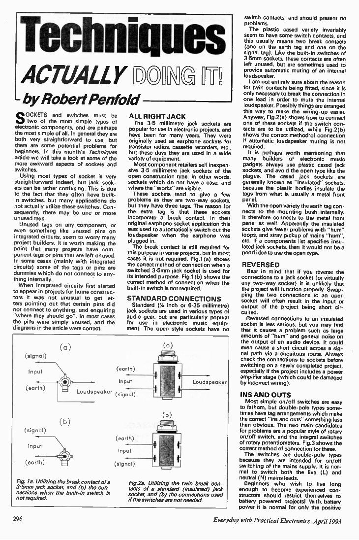
Techniques ACTUALLY OIU I". - by Robert Penfold eOCKETS and switches must be
two of the most simple types of electronic components, and are perhaps the most simple of all. In general they are both very straightforward to use, but there are some potential problems for beginners. In this month's Techniques article we will take a look at some of the more awkward aspects of sockets and switches. Using most types of socket is very
straightforward indeed, but jack sock-ets can be rather confusing. This is due to the fact that they often have built-in switches, but many applications do not actually utilize these switches. Con-sequently, there may be one or more unused tags. Unused tags on any component, or
even something like unused pins on integrated circuits, seem to worry many project builders. It is worth making the point that many projects have com-ponent tags or pins that are left unused. In some cases (mainly with integrated circuits) some of the tags or pins are dummies which do not connect to any-thing internally. When integrated circuits first started
to appear in projects for home construc-tors it was not unusual to get let-ters pointing out that certain pins did not connect to anything, and enquiring "where they should go". In most cases the pins were simply unused, and the diagrams in the article were correct.
(a)
(signal)
Input
(earth) Loudspeaker
( b )
(signal)
Input
(earth)
Fig. la. Utilizing the break contact of a 3.5mm jack socket, and (b) the con-nections when the built-in switch is not required.
ALL RIGHT JACK The 3.5 millimetre jack sockets are
popular for use in electronic projects, and have been for many years. They were originally used as earphone sockets for transistor radios, cassette recorders, etc., but these days they are used in a wide variety of equipment. Most component retailers sell inexpen-
sive 3.5 millimetre jack sockets of the open construction type. In other words, sockets which do not have a case, and where the "works" are visible. These sockets tend to give a few
problems as they are two-way sockets, but they have three tags. The reason for the extra tag is that these sockets incorporate a break contact. In their original earphone socket application this was used to automatically switch out the loudspeaker when the earphone was plugged in. The break contact is still required for
this purpose in some projects, but in most cases it is not required. Fig.1 (a) shows the correct method of connection when a switched 3.5mm jack socket is used for its intended purpose. Fig.1(b) shows the correct method of connection when the built-in switch is not required.
STANDARD CONNECTIONS Standard ('4 inch or 6.35 millimetre)
jack sockets are used in various types of audio gear, but are particularly popular for use in electronic music equip-ment. The open style sockets have no
(a)
(earth)
Input
(signal)
(b)
(earth)
Input
(signal)
Loudspeaker
Fig.2a. Utilizing the twin break con-tacts of a standard (insulated) jack socket, and (b) the connections used if the switches are not needed.
switch contacts, and should present no problems. The plastic cased variety invariably
seem to have some switch contacts, and this usually means two break contacts (one on the earth tag and one on the signal tag). Like the built-in switches of 3.5mm sockets, these contacts are often left unused, but are sometimes used to provide automatic muting of an internal loudspeaker. I am not entirely sure about the reason
for twin contacts being fitted, since it is only necessary to break the connection in one lead in order to mute the internal loudspeaker. Possibly things are arranged this way to make the wiring-up easier. Anyway, Fig.2(a) shows how to connect one of these sockets if the switch con-tacts are to be utilized, while Fig.2(b) shows the correct method of connection if automatic loudspeaker muting is not required. It is perhaps worth mentioning that
many builders of electronic music gadgets always use plastic cased jack sockets, and avoid the open type like the plague. The cased jack sockets are generally known as "insulated" sockets, because the plastic bodies insulate the tags from what is usually a metal front panel. With the open variety the earth tag con-
nects to the mounting bush internally. It therefore connects to the metal front panel as well. Apparently the insulated sockets give fewer problems with "hum" loops, and stray pickup of mains "hum", etc. If a components list specifies insu-lated jack sockets, then it would not be a good idea to use the open type.
REVERSED Bear in mind that if you reverse the
connections to a jack socket (or virtually any two-way socket) it is unlikely that the project will function properly. Swap-ping the two connections to an open socket will often result in the input or output of the project being short cir-cuited. Reversed connections to an insulated
socket is less serious, but you may find that it causes a problem such as large amounts of "hum" and general noise on the output of an audio device. It could even cause a short circuit across a sig-nal path via a circuitous route. Always check the connections to sockets before switching on a newly completed project, especially if the project includes a power amplifier stage (which could be damaged by incorrect wiring).
INS AND OUTS Most simple on/off switches are easy
to fathom, but double-pole types some-times have tag arrangements which make the correct "ins and outs" something less than obvious. The two main candidates for problems are a popular style of rotary on/off switch, and the integral switches of rotary potentiometers. Fig.3 shows the correct method of connection for these. The switches are double-pole types
because they are intended for on/off switching of the mains supply. It is nor-mal to switch both the live (L) and neutral (N) mains leads. Beginners who wish to live long
enough to become experienced con-structors should restrict themselves to battery powered projects! With battery power it is normal for only the positive
296 Everyday with Practical Electronics, April 1993

WHETHER ELECTRONICS IS YOUR HOBBY OR YOUR LIVELIHOOD • • •
YOU NE THE MODERN ELECTRONICS MANUAL
The modem Amateur. ElectrontCS Manual
w
"••••
1.14 0 Itraf
'••••
EVERYTHING YOU NEED TO KNO W ABOUT ELECTRONICS!
The essential reference Work • Easy-to-use format
• Clear and simple layout
• Regular updates
• Sturdy ring-binder
• News of latest developments
• Full components checklist
• Extensive data tables
• Detailed supply information
• Ready-to-transfer PCBs
• Comprehensive subject range
• Accurate assembly instructions
• Concise repair procedures
If the fascinating and fast-changing world of electronics is your livelihood, your study subject or simply your passion, the revised edition of THE MODERN ELECTRONICS MANUAL is the reference work for you to have at your side.
The base manual contains information on the following subjects:
BASIC PRINCIPLES: symbols, components and their characteristics, passive component circuits, power supplies, acoustics and electroacoustics, the workshop, principles of metrology, measuring instruments, digital electronics, operational amplifiers, timers, physics for electronics.
CIRCUITS TO BUILD: construction techniques, radio, telephony, microcomputing, measuring instruments, vehicle electronics, security, audio, power supplies, electronic music (over 25 different projects).
REPAIRS AND MAINTENANCE: radio, television, audio/hi-fi, telephones.
DATA: d iodes, transistors, thyristors and triacs, digital and linear i.c.s, microprocessors.
The manual also covers Safety, Specialist Vocabulary with Abbreviations and Suppliers.
OVER 1,000 pages, A4 format weighing over 3.5kg.
Now — at last — the most comprehensive reference work ever produced at a price you can afford, the revised edition of THE MODERN ELECTRONICS MANUAL
provides you with all the essential information you need.
Everyday with Practical Electronics, April 1993
Over 1,000 pages of well-oi ganised and clearly explained information is brought to you by an expert editorial team whose combined experience ensures the widest coverage.
Regular supplements to this unique publication, each around 160 pages, mean that you will always be kept abreast of the latest developments from around the world as they occur
ALL-1N-ONE AND EASY-TO-USE
A sturdy ring-binder allows you to use the manual on your workbench. The looseleaf format also means you can slot in the regular updates as they arrive — so all your information is there at a glance.
EXTENSIVE GLOSSARY
Should you come across a technical word, phrase or abbreviation you're not familiar with — simply turn to the glossary included in the manual and you'll find a comprehensive definition in plain English.
REGULAR UPDATES
Unlike a book or encyclopedia, the manual is a living work —continuously updated by new material. Recent or upcoming supplements include radio, superconductors, electric motors, basic electronic building blocks for beginners which can be joined together to construct elaborate circuits, filters, IBM PC and compatibles (including use of PC cards). Supplements are sent to you approximately every two months.
Each supplement contains approxi-mately 160 pages — all for only £23.50 + £2.50 p&p. You can of course return any supplement which you feel is superfluous to your needs.
RESPONDING TO YOUR NEEDS
We are able to provide you w...1 the most important and popular articles in our updating supplements. Our unique updating system is based on answers from readers request questionnaires. Through this service you are able to let us know exactly what information you require in your manual. You can also contact the editor directly in writing if you have a specific technical request or query relating to the manual.
ASSEMBLING ...
There's nothing to beat the satisfaction of creating your own project. From basic principles to circuit-building, the manual describes clearly, with appropriate diagrams, how to assemble radios, loudspeakers, amplifiers, micro-computers and measuring instruments.
The revised edition of The Modern Electronics Manual contains practical, easy-to-follow instructions for building and programming your own computer. It shows you how to make fun gadgets such as a remote control door opener and a digital rev, counter for your car. It also tells you how to construct useful devices like test gear, security and baby alarms — plus — many more popular devices. Wimborne Publishing Ltd., 6 Church St, Wimborne, Dorset BH21 1JH
Tel: 0202 881749 Fax: 0202 841692
THE MODERN ELECTRONICS MANUAL Revised Edition of Basic Work: Now contains over 1,000 pages of information. Regular Updates: Approximately 160-page supplements of additional information which are forwarded to you immediately on publication. These are billed separately and can be discontinued at any time. Presentation: Durable looseleaf system in large A4 format (297mm x 210mm) Price of the Basic Work: £39.95 + £5.50 p&p (to include a recent supplement).
• YES please send me on 10 days free approval THE MODERN
ELECTRONICS MANUAL. If I decide to keep the manual, I shall then I pay only £39.95 plus £5.50 postage and packing at the end of the 10 days
I approval period. I shall also receive the appropriate Updating Supplements several
'times a year. These are billed separately and can be discontinued at any time.
I FULL NAME I (PLEASE PRINT)
I ADDRESS
POSTCODE
I inmovER
I SIGNATURE
I April 1993 1
(Parent or guardian must sign if under 18)
ORDER FOR M Simply complete and return the order form to the
following address.
Wimborne Publishing Ltd, 6 Church Street Wimborne Dorset 8H21 1JH
Manuals on 10 days approval may be subject to delay in dispatch, if you require a manual quickly please pay in
advance - we offer a 30 day money back guarantee.
OVERSEAS ORDERS: All overseas orders must be prepaid but are supplied under a money-back guarantee of satisfaction. If you are not entirely happy with the manual return it within a month for a refund of the purchase price (you do have to pay the postage). Add the following amounts to the price of the manual to cover postage:
EIRE £10.50 (air mail only) EUROPE (including C.I.S.) f21.00 lair mail only) MIDDLE EAST/FAR EAST/INDIA AFRICA/SOUTH AFRICA £20 surface SOUTH AMERICA £37 air
REST OF THE WORLD £25 surface, f31 air Note surface mail can take around 8 weeks to some parts of the world. Each manual weighs about 4.5kg when packed.
All payments must be made in Cs Sterling payable to Wimborne Publishing Ltd. We accept Mastercard (Access) and Visa credit cards.
Everyday with Practical Electronics, April 1993 299
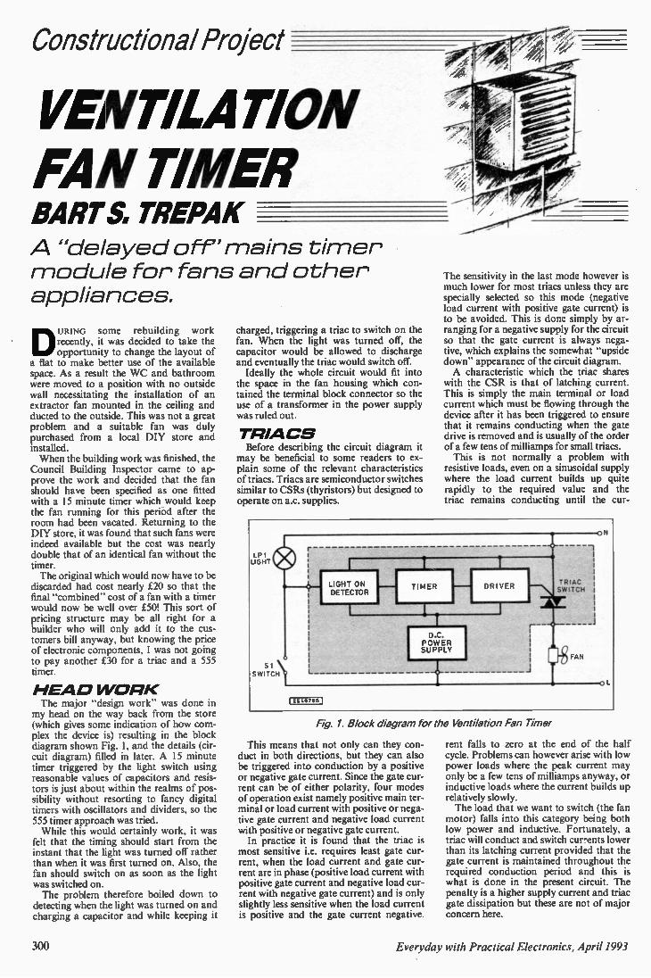
Constructional Project
VENTILAnoN FAN TIMER BART S, TREPAK A "delayed off" mains timer module for fans and other appliances.
DURING some rebuilding work recently, it was decided to take the opportunity to change the layout of
a flat to make better use of the available space. As a result the WC and bathroom were moved to a position with no outside wall necessitating the installation of an extractor fan mounted in the ceiling and ducted to the outside. This was not a great problem and a suitable fan was duly purchased from a local DIY store and installed. When the building work was finished, the
Council Building Inspector came to ap-prove the work and decided that the fan should have been specified as one fitted with a 15 minute timer which would keep the fan running for this period after the room had been vacated. Returning to the DIY store, it was found that such fans were indeed available but the cost was nearly double that of an identical fan without the timer. The original which would now have to be
discarded had cost nearly £20 so that the final "combined" cost of a fan with a timer would now be well over £50! This sort of pricing structure may be all right for a builder who will only add it to the cus-tomers bill anyway, but knowing the price of electronic components, I was not going to pay another £30 for a triac and a 555 timer.
H EA D W ORK The major "design work" was done in my head on the way back from the store (which gives some indication of how com-plex the device is) resulting in the block diagram shown Fig. 1, and the details (cir-cuit diagram) filled in later. A 15 minute timer triggered by the light switch using reasonable values of capacitors and resis-tors is just about within the realms of pos-sibility without resorting to fancy digital timers with oscillators and dividers, so the 555 timer approach was tried. While this would certainly work, it was
felt that the timing should start from the instant that the light was turned off rather than when it was first turned on. Also, the fan should switch on as soon as the light was switched on. The problem therefore boiled down to
detecting when the light was turned on and charging a capacitor and while keeping it
charged, triggering a triac to switch on the fan. When the light was turned off, the capacitor would be allowed to discharge and eventually the triac would switch off. Ideally the whole circuit would fit into
the space in the fan housing which con-tained the terminal block connector so the use of a transformer in the power supply was ruled out.
TRIA CS Before describing the circuit diagram it
may be beneficial to some readers to ex-plain some of the relevant characteristics of triacs. Triacs are semiconductor switches similar to CSRs (thyristors) but designed to operate on a.c. supplies.
The sensitivity in the last mode however is much lower for most triacs unless they are specially selected so this mode (negative load current with positive gate current) is to be avoided. This is done simply by ar-ranging for a negative supply for the circuit so that the gate current is always nega-tive, which explains the somewhat "upside down" appearance of the circuit diagram. A characteristic which the triac shares
with the CSR is that of latching current. This is simply the main terminal or load current which must be flowing through the device after it has been triggered to ensure that it remains conducting when the gate drive is removed and is usually of the order of a few tens of milliamps for small triacs. This is not normally a problem with
resistive loads, even on a sinusoidal supply where the load current builds up quite rapidly to the required value and the triac remains conducting until the cur-
Fig. 1. Block diagram for the Ventilation Fan Timer
This means that not only can they con-duct in both directions, but they can also be triggered into conduction by a positive or negative gate current. Since the gate cur-rent can be of either polarity, four modes of operation exist namely positive main ter-minal or load current with positive or nega-tive gate current and negative load current with positive or negative gate current. In practice it is found that the triac is
most sensitive i.e. requires least gate cur-rent, when the load current and gate cur-rent are in phase (positive load current with positive gate current and negative load cur-rent with negative gate current) and is only slightly less sensitive when the load current is positive and the gate current negative.
rent falls to zero at the end of the half cycle. Problems can however arise with low power loads where the peak current may only be a few tens of milliamps anyway, or inductive loads where the current builds up relatively slowly. The load that we want to switch (the fan
motor) falls into this category being both low power and inductive. Fortunately, a triac will conduct and switch cur-ents lower than its latching current provided that the gate current is maintained throughout the required conduction period and this is what is done in the present circuit. The penalty is a higher supply current and triac gate dissipation but these are not of major concern here.
300 Everyday with Practical Electronics, April 1993
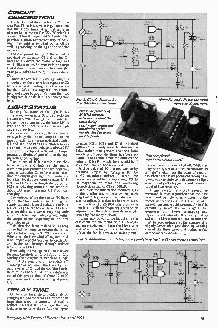
CIRC UIT D ESCRIPTIO N The final circuit diagram for the Ventila-
tion Fan Timer is shown in Fig. 2 and does not use a 555 timer at all but an even cheaper i.c., namely a CMOS 4093 which is a quad Schmitt trigger NAND gate. This provides a more convenient way of sens-ing if the light is switched on or off as well as providing the timing and triac drive circuits. The d.c. power supply to the circuit is
provided by capacitor C3 and diodes DI and D2. C3 drops the mains voltage and works like a mains dropper resistor except that it does not dissipate any heat and this voltage is limited to 12V by the Zener diode Dl. Diode D2 rectifies this voltage which is
smoothed by the electrolytic capacitor C2 to produce a d.c. voltage which is slightly less than 12V. This voltage is not well stabi-lised and drops to about 5V when the triac is triggered but this is of no consequence here.
LIG HT S TATUS Sensing the status of the light is ac-
complished using gate ICI a and resistors RI and R2. When the light is off, switch Si is open, the voltage across the lamp LP1 is zero and the input of ICI a remains high and its output low. As soon as SI is closed, the a.c. mains
voltage is applied to the lamp and to the input of gate IC I a, via the potential divider RI and R2. The values are chosen to en-sure that the applied voltage is about 15V a.c. and this is clipped by the internal input protection diodes of gate ICI a to the sup-ply voltage of the chip. The output of ICI a therefore switches
between low and high as the mains waveform goes positive and then negative, causing capacitor CI to be charged each time the output goes high. Cl maintains a logic high level at the inputs to gates IC lb. ICI c and 'Cid even though the output of ICI a is switching because of the action of diode D3 which prevents Cl from dis-charging. The outputs of the three gates (ICI b, c,
d) are therefore switched to the negative supply rail and trigger the triac, via resistor R4, causing the fan to switch on. The triac is a sensitive gate device requiring only about 5mA to trigger which is well within the output current capability of the three paralleled gates. This situation is maintained for as long
as the light remains on causing the fan to operate for as long as the WC is occupied. When the light is switched off, capacitor CI is no longer kept charged, via the diode D3, and begins to discharge through resistor R3 and preset VR1. Eventually the voltage on Cl falls below
the logic threshold of IC1b, IC lc and ICId causing their outputs to switch to a logic high and the triac and fan to switch off. The length of time which this takes depends on the value of Cl and the combined resis-tance of R3 and VR I . With the values sug-gested this gives a time of about 10 to 20 minutes depending on the setting of preset VR1.
0 EI-A Y TI ME Unlike most timer circuits which rely on
charging a capacitor through a resistor, this timer discharges the capacitor through a resistor. This has the advantage that any leakage currents in diode D3, the inputs
160
LP I LIGHT
Id a 4093
\si
[EE40790
Fig 2. Circuit diagram for the Ventilation Fan Timer
Due to the presence of MAINS voltages, extreme care should be taken during construction, testing and installation of this module. The fan circuit must be fused.
D3 194148 0 4k ..
Cl .2n 470p. m
to gates IC1b, 1C1c and ICI d or indeed within Cl will only serve to shorten the delay rather than prevent the triac from switching off once the timer has been ac-tivated. Thus there is not the limit on the value of R3/VR1 which there would be if say a 555 timer i.c. had been used. A time delay of 30 minutes was easily
obtained simply by replacing R3 by a 4.7 megohms resistor. Longer time delays are possible by increasing R3 to 10 megohms or more and increasing electrolytic capacitor CI to 1000µF. But unless the time period required is, as
in this application, not too critical, such long time delays require the patience of a saint to adjust. It is then far better to use a timer such as the ZN1034 where only the time base oscillator frequency needs to be adjusted and the actual time delay is ob-tained by frequency division. Purists may object to the fact that in the
case of the fan, the mains Neutral (N) con-nection is switched and not the Live (L) as is standard practice, and it is therefore not safe as the fan is always at mains poten-
IC1b 4093
IC1C 4093
421 BZ X 5542 by
44., C2 Min 47 y
422 194148
'IN 1 5 1k
C3 Op, T4.
N
971
CSR1 TIC 2060
AFT2
FAN
Note: Si, and LP1 are the room light switch and light.
The completed Fan Timer circuit board
tial even when it is switched off. While this may be true, a triac cannot be regarded as a "safe" switch from the point of view of isolation as the leakage current through the device can certainly be high enough to light a neon and probably give a nasty shock if touched inadvertently. In any event, the circuit should be
mounted in such a position that the user would not be able to gain access to the motor connections without the use of a screwdriver and would presumably in this eventuality switch the mains off at the consumer unit before attempting any repairs or adjustments. If it is required to switch the Live motor connection then this may be accomplished at the expense of a slightly lower triac gate drive by utilising one of the three gates and adding a few components as shown in Fig. 3.
Fig. 3. Alternative circuit diagram for switching the five (L) fan motor connection.
CSRI 71C2050
TO
Everyday with Practical Electronics, April 1993 301
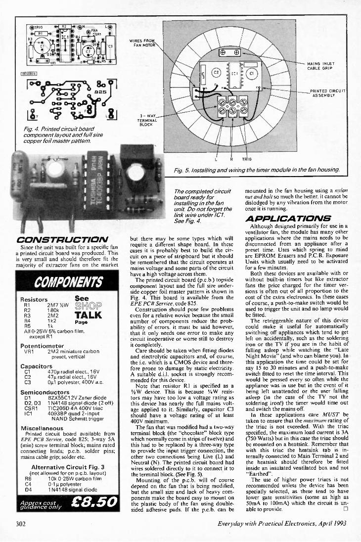
®TRIG a •4 RI
R3 II a ;
D3 111
I VRI
(EE4011261
(DN L 0 B ° FAN 124 r—IP—ICSRi
k ID I G C3
D2 Le° ois- CD-• 05 6
Fig 4. Printed circuit board component layout and full size copper foil master pattern.
C OAISTFIUCTIOAI Since the unit was built for a specific fan
a printed circuit board was produced. This is very small and should therefore fit the majority of extractor fans on the market
COMPONENTS Resistors R1 2M7 6W R2 180k R3 2M2 R4 1k2 R5 1k All 0-25W 5% carbon film, except R1
Potentiometer VR1 2M2 miniature carbon
preset, vertical
Capacitors C1 470p radial elect., 16V C2 47µ radial elect., 16V C3 0tt1 polyester, 400V a.c
Semiconductors D1 BZX55C12V Zener diode D2, D3 1N4148 signal diode (2 off) CSR1 TIC206D 4A 400V triac IC1 4093BP quad 2-input
NAND Schmitt trigger
Miscellaneous Printed circuit board available from EPE PCB Service, code 825; 3-way 5A (min) screw terminal block; mains rated connecting leads: p.c.b. solder pins: mains cable grip; solder etc.
Alternative Circuit Fig. 3 (not allowed for on p.c.b. layout) R6 10k 0.25W carbon film C4 0.111 polyester D4 1N4148 signal diode
See
TALK Page
Aoprox cost guidance only £8.50 guidance
WIRES FROM FAN MOTOR
3- WAY TERMINAL BLOCK
MAINS INLET CABLE GRIP
PRINTED CIRCUIT ASSEMBLY
N TRIG
Fig 5. Installing and wiring the timer module in the fan housing.
The completed circuit board ready for installing in the fan unit. Do not forget the link wire under IC1. See Fig 4.
but there may be some types which will require a different shape board. In these cases it is probably best to build the cir-cuit on a piece of stripboard but it should be remembered that the circuit operates at mains voltage and some parts of the circuit have a high voltage across them. The printed circuit board (p.c.b.) topside
component layout and the full size under-side copper foil master pattern is shown in Fig. 4. This board is available from the EPE PCB Service, code 825. Construction should pose few problems
even for a relative novice because the small number of components reduce the prob-ability of errors. it must be said however, that it only needs one error to make any circuit inoperative or worse still to destroy it completely. Care should be taken when fitting diodes
and electrolytic capacitors and, of course, the i.c. which is a CMOS device and there-fore prone to damage by static electricity. A suitable d.j.!. socket is strongly recom-mended for this device. Note that resistor RI is specified as a
1/4 W device. This is because 1/4 W resis-tors may have too low a voltage rating as this device has nearly the full mains volt-age applied to it. Similarly, capacitor C3 should have a voltage rating of at least 400V minimum. The fan that was modified had a two-way
terminal block (the "chocolate" block type which normally come in strips of twelve) and this had to be replaced by a three-way type to provide the input trigger connection, the other two connections being Live (L) and Neutral (N). The printed circuit board had wires soldered directly to it to connect it to the terminal block. (See Fig. 5). Mounting of the p.c.b. will of course
depend on the fan that is being modified, but the small size and lack of heavy com-ponents make the board easy to mount on the plastic body of the fan using double-sided adhesive pads. If the p.c.b. can be
mounted in the fan housing using a nylon nut and bolt so much the better, it cannot be dislodged by any vibration from the motor once it is running.
A FJPI-ICATIOAIS Although designed primarily for use in a
ventilator fan, the module has many other applications where the mains needs to be disconnected from an appliance after a preset time. Uses which spring to mind are EPROM Erasers and P.C.B. Exposure Units which usually need to be activated for a few minutes. Both these devices are available with or
without built-in timers but like extractor fans the price charged for the timer ver-sions is often out of all proportion to the cost of the extra electronics. In these cases of course, a push-to-make switch would be used to trigger the unit and no lamp would be fitted. The retriggerable nature of this device
could make it useful for automatically switching off appliances which tend to get left on accidentally, such as the soldering iron or the TV if you are in the habit of falling asleep while watching the "Late Night Movie" (and who can blame you). In this application the time could be set for say 15 to 30 minutes and a push-to-make switch fitted to reset the time interval. This would be pressed every so often while the appliance was in use but in the event of it being left unattended or the user falling asleep (in the case of the TV not the soldering iron!) the timer would time out and switch the mains off. In these applications care MUST be
taken to ensure that the maximum rating of the triac is not exceeded. With the triac specified, the maximum load current is 3A (750 Watts) but in this case the triac should be mounted on a heatsink. Remember that with this triac the heatsink tab is in-ternally connected to Main Terminal 2 and the heatsink should therefore be fitted inside an insulated ventilated box and not "Earthed". The use of higher power triacs is not recommended unless the device has been specially selected, as these tend to have lower gate sensitivities (some as high as 50mA to 100mA) which the circuit is un-able to provide.
302 Everyday with Practical Electronics, April 1993

DIRECT BOOK SERVICE The books listed have been selected by Everyday with Practical Electronics editorial staff as being of special in-terest to everyone involved in electronics and computing. They are supplied by mail order direct to your door. Full order-ing details are given on the last book page. For another selec-tion of books see next month's issue.
EVERYDAY ELECTRONICS DATA BOOK Mike Tooley BA (published by EE in association with PC Publishing) This book is an invaluable source of information of everyday relevance in the world of electronics It contains not only sections which deal with the essential theory of electronic circuits, but also deals with a wide range of practical electronic applications, It is ideal for the hobbyist, student, technician and en-
gineer. The information is presented in the form of a basic electronic recipe book with numerous examples showing how theory can be put into practice using a range of commonly available "industry standard" components and devices A must for everyone involved in electronics' 256 pages D MEI =Llij £8.95
ELECTRONICS TEACH-IN No, 3-EXPLORING ELECTRONICS (published by Everyday Electronics) Owen Bishop Another EE value for money publication aimed at students of electronics. The course is designed to explain the work-ings of electronic components and circuits by involving the reader in experimenting with them The book does not contain masses of theory or formulae but straightforward explanations and circuits to build and experiment with, Exploring Electronics contains more than 25 useful
projects, assumes no previous knowledge of electronics and is split into 28 easily digestible sections. 88 pages (A4 size) ra m mg/tritin £2.45
Elficriv Terac w
Special Everyday Electronics Books
ELECTRONICS TEACH-IN No.4 INTRODUCING DIGITAL ELECTRONICS (published by Everyday Electronics) Michael J. Cockcroft Although this book is primarily a City & Guilds Introduc-tory level course (726/301), approximately 80% of the in-formation forms a very basic introduction to electronics in general, it therefore provides an excellent introductory text for beginners and a course and reference book for GCSE students Full details on registering for C&G assessment, details of
assessment centres, components required and information on the course in general are given The City & Guilds introduction to module 726/301
reads: "A candidate who satisfactorily completes this module will have a competence to identify basic com-ponents and digital integrated circuits and connect them together to form simple working circuits and logic units" This provides an excellent introduction to the book. 112 pages (A4 size) Foralrenralja £2.95
ELECTRONIC PROJECTS - BOOK 1 Published by Everyday Electronics in association with Magenta Electronics. Contains twenty of the best projects from previous issues of EE each backed with a kit of components. The projects are. Seashell Sea Synthesiser, EE Treasure Hunter, Mini Strobe, Digital Capacitance Meter, Three Channel Sound to Light, BBC 16K Sideways Ram, Simple Short Wave Radio, Insulation Tester. Stepper Motor interface, Eprom Eraser, 200MHz Digital Frequency Meter, Infra Red Alarm, EE Equaliser Ioniser, Bat Detector, Acoustic Probe. Mains Tester and Fuse Finder, Light Rider - (Lapel Badge, Disco Lights, Chaser Light). Musical Doorbell, Function Gener-ator, Tilt Alarm, 10W Audio Amplifier, EE Buccaneer In-duction Balance Metal Detector, BBC Midi Interface, Vari-able Bench Power Supply, Pet Starer, Audio Signal Gen-erator. 128 pages (A4 size) e ngS EEM ILU £2.45
xpt.Oft--
off •
A a5i9 a 1 ' Corounr ani
14542
0 0 10 v....." • • :110# . 9111:*
City and Guilds tertitksite course INTRAXXXIMG MICROPRCKESS01:" „
S
ELECTRONICS TEACH-IN No.5 GUIDE TO BUILDING ELECTRONIC PROJECTS Published by EVERYDAY ELECTRONICS Due to the demand from students, teachers and hobbyists we have put together a range of articles from past issues of Everyday Electronics that will assist those involved with the construction of electronic projects The book contains the complete Project Development
for GCSE series Contents: Features - First Steps in Project Building,
Building with Vero; Project Development for GCSE: Get-ting your Project Working; Guide to Printed Circuit Boards; Choosing and Using Test Equipment - The Multimeter, The Oscilloscope, PS U.s, Logic Probes, Digital Fre-quency Meters, Signal Generators, etc; Data - Circuit Symbols; Component Codes; Resistors; Identifying Com-ponents; Capacitors; Actually Doing It - Understanding the Circuit Diagram, Component Codes, Mounting circuit boards and controls, Understanding Capacitors; Projects - Lie Detector; Personal Stereo Amplifier; Digital Ex-perimentsr's Unit; Quizmaster; Siren Effects Unit; UV Exposure Unit, Low-cost Capacitance Meter: Personal Radio 88 pages (A4 size) re m mg m-gli £2.95
ELECTRONICS TEACH-IN 88/89 - INTRODUCING MICROPROCESSORS Mike Tooley BA (published by Everyday Electronics) A complete course that can lead successful readers to the award of a City and Guilds Certificate in Introductory Microprocessors (726/303). The book contains every-thing you need to know including full details on register-ing for assessment, etc, Starting with basic terminology, integrated circuits, logic families and numbering systems the text builds in stages, with revision and assessments built in, up to programming, languages, flow charts, etc The course is ideal for the newcomer to the subject. 80 pages (A4 size) reme mmrifil.:1:1M1 £2.45
6.1§..CTINCAIIIC ELECTRONICS arICK-0 11' Tancimiln Ni T E A C N A
GLU/DE TO BUILDING 95
L ESTRONIC PROJECT: fro m the PLORKINITS of EVERYDAY ELECTRONICS
Ell""nors"LNe :". 4 7 A Co
0.0 Certiticatetq INTRODUCIN Crane men
DIGITAL t PLUS: SIMPLE PROM ELECTRONIC?
Co mputers and Co mputing HO W TO CHOOSE A SMALL BUSINESS CO MPUTER SYSTE M D. Weale This book is for anyone intending to buy an IBM com-patible computer system, whether it is their first system or a replacement There are sections on hardware, applica-tion and systems programs and how to actually make your choice as well as sections on the law, ergonomics and a glossary of common terms. The text contains many useful tips and some warnings (which could save much effort and expense) 174 pages • rder code B • £4.95
UNDERSTANDING PC SPECIFICATIONS R. A. Penfold If you require a microcomputer for business applications, or a high quality home computer, an IBM PC or compatible is often the obvious choice They are competitively priced, and are backed up by an enormous range of applications programs, hardware add-ons, etc. The main difficulty for the uninitiated is deciding on the specification that will best suit his or her needs PCs range from simple systems of limited capabilities up to complex systems that can happily run applications that would have been considered beyond the abilities of a microcomputer not so long ago. It would be very easy to choose a PC system that is inade-quate to run your applications efficiently, or one which goes beyond your needs and consequently represents poor value for money. This book explains PC specifications in detail, and the
subjects covered include the following: Differences between types of PC (XT, AT. 80386, etc); Maths co-processors, Input devices (keyboards, mice, and digitisers); Memory, including both expanded (EMS) and extended RAM RAM disks and disk caches; Floppy disk drive formats and compatibility, Hard disk drives (includ-ing interleave factors and access times); Display adaptors, including all standard PC types (CGA, Hercules, Super VGA, etc), Contains everything you need to know if you can't tell your EMS from your EGA! 104 pages Enal nall ait al £3.95
AN INTRODUCTION TO 68000 ASSE MBLY LANGUAGE R. A. & J. W. Penf old Obtain a vast increase in running speed by writing pro-grams for 6800 based micros such as the Commodore Amiga, Atari ST range or Apple Macintosh range etc., in assembly language It is not as difficult as one might think and this book covers the fundamentals 112 pages 5 ram code : '184 £2.95
THE ART OF PROGRA M MING THE ZX SPECTRU M M. James, B.Sc., M.B.C.S. It is one thing to have learnt how to use all the Spectrum's commands and functions, but a very different one to be able to combine them into programs that do exactly what you want them to. This is just what this book is all about - teaching you the art of effective programming with your Spectrum. 144 pages gorrrirm mulil £2.50
A CONCISE INTRODUCTION TO MS-DOS N. Kantaris This guide is written with the non-expert, busy person in mind and, as such, it has an underlying structure based on "what you need to know first, appears first". Nonetheless, the guide is also designed to be circular, which means that you don't have to start at the beginning and go to the end. The more experienced user can start from any section. The guide covers versions 3.0, 3.1 and 3.2 of both PC-
DOS and MS-DOS as implemented by IBM and other manufacturers of "compatible" microcomputers, including the AMSTRAD PC's. It covers both floppy disc-based systems and hard disc-based systems. 64 pages Srdei code 8P2 2 £2.95
A 280 W ORKSHOP MANUAL E. A. Parr, B.Sc., DC.Eng., M.I.E.E. This book is intended for people who wish to progress beyond the stage of BASIC programming to topics such as machine code and assembly language programming, or need hardware details of a Z80 based computer 192 pages Temporarily out of print
MAKING MS-DOS W ORK
FOR YOU N. Kantanis & P. R. M. Oliver
Make
This book was written with the busy person in mind and, as such, it has an underlying structure based on "what you need to know first, appears first". Nonetheless, the book has also been designed to be circular, which means that you don't have to start at the beginning and go to the end, The book explains: How to write customised batch
files which allow you to display what you want on your screen, and in the form and order you want it, instead of being forced to use the DOS prompt on a blank screen How to design and set up a fast interactive and profes-sional looking menu system, so that you or anyone else can run utility applications or commercial software packages easily. How the ANSLSYS display and key-board commands can be used to position the cursor on any part of the screen, change the intensity of the displayed characters or change their colour. How the Edit screen editor or the Edlin line editor can be used to enter ESCape (ANSI.SYS) commands into simple ASCII files to allow control of both your screen display and your printer. How to control the operation of the two main types of printers in use today. Epson com-patible dot matrix and HP compatible laser printers How to use several useful routines, such as moving and finding files, protecting files from accidental erasure, a simplified backup process, a screen saver, and a disc cataloguing system. The Debug program and how it can be used to create,
see and change the contents of any file, including those of programs written in assembler code This includes how to find your way around the names and tasks of the CPU registers and the meaning of some simple assembler mnemonics The book is relevant to all versions of both MS-DOS
and PC-DOS as implemented on IBM and other IBM - compatible PCs
181 pages ozat z m u zi u £4.95
Everyday with Practical Electronics, April 1993 303

Audio and M usic Project Building
ACOUSTIC FEEDBACK - HO W TO AVOID IT Feedback is the bane of all public address systems While feedback cannot be completely eliminated, many things can be done to reduce it to a level at which it is no longer a problem. Much of the trouble is often the hall itself, not the equip-
ment but there is a simple and practical way of greatly improving acoustics Some microphones are prone to feed-back while others are not. Certain loudspeaker systems are much better than others, and the way the units are positioned can produce or reduce feedback All these matters are fully explored as well as electronic aids such as equalizers, fre-quency-shifters and notch filters. The special requirements of live group concerts are con-
sidered, and also the related problem of instability that is sometimes encountered with large set-ups We even take a look at some unsuccessful attempts to cure feedback so as to save readers wasted time and effort duplicating them. Also included is the circuit and layout of an inexpensive but highly successful twin-notch filter, and how to operate it 92 pages •Ric., code 6P310 £3.95
PRACTICAL MIDI HANDBOOK R. A. Penfold The Musical Instrument Digital Interface (MIDI) is sur-rounded by a great deal of misunderstanding, and many of the user manuals that accompany MIDI equipment are quite incomprehensible to the reader, The Practical MIDI Handbook is aimed primarily at
musicians, enthusiasts and technicians who want to exploit the vast capabilities of MIDI, but who have no previous knowledge of electronics or computing The majority of the book is devoted to an explanation of what MIDI can do and how to exploit it to the full, with practical advice on connecting up a MIDI system and getting it to work, as well as deciphering the technical information in those manuals. 128 pages M BEIBEr mau m £6.95
PREAMPLIFIER AND FILTER CIRCUITS R. A. Penfold This book provides circuits and background information for a range of preamplifiers, plus tone controls, filters, mixers, etc, The use of modern low noise operational amplifiers and a specialist high performance audio preamplifier re. results in circuits that have excellent performance, but which are still quite simple All the circuits featured can be built at quite low cost (just a few pounds in most cases). The preamplifier circuits featured include- Microphone preamplifiers (low impendance, high impedance, and crys-tal). Magnetic cartridge pick-up preamplifiers with R.I.A.A equalisation. Crystal/ceramic pick-up preamplifier Guitar pick-up preamplifier Tape head preamplifier (for use with compact cassette systems). Other circuits include:- Audio limiter to prevent overload-
ing of power amplifiers Passive tone controls. Active tone controls. PA filters (highpass and lowpass). Scratch and rumble filters Loudness filter. Audio mixers. Volume and balance controls 92 pages code BP 9 £3.95
AN INTRODUCTION TO LOUDSPEAKERS AND ENCLOSURE DESIGN V. Cape! This book explores the various features, good points and snags of speaker designs, It examines the whys and wherefores so that the reader can understand the principles involved and so make an informed choice of design, or even design loudspeaker enclosures for him or herself Crossover units are also explained, the various types, how they work, the distortions they produce and how to avoid them Finally there is a step-by-step description of the construction of the Kapellmeister loudspeaker enclosure 148 pages 'der code BP 56 £2.95
CO MPUTERS AND MUSIC-AN INTRODUCTION R. A. Penfold Computers are playing an increasingly important part in the world of music, and the days when computerised music was strictly for the fanatical few are long gone. If you are more used to the black and white keys of a
synth keyboard than the OWERTY keyboard of a computer, you may be understandably confused by the jargon and terminology bandied about by computer buffs. But fear not, setting up and using a computer-based music making system is not as difficult as you might think. This book will help you learn the basics of computing,
running applications programs, wiring up a MIDI sys-tem and using the system to good effect, in fact just about everything you need to know about hardware and the programs, with no previous knowledge of computing needed or assumed This book will help you to choose the right components for a system to suit your personal needs, and equip you to exploit that system fully. 174 pages Mil al a mi um £8.95
ELECTRONIC PROJECTS FOR GUITAR R. A. Penfold This book contains a collection of guitar effects and some general purpose effects units, many of which are suitable for beginners to project building. An introductory chapter gives guidance on construction Each project has an introduction, an explanation of how
it works, a circuit diagram, complete instructions on strip-board layout and assembly, as well as notes on setting up and using the units. Contents include, Guitar tuner, Guitar preamplifier, Guitar headphone amplifier, Soft distortion unit Compressor: Envelope waa via& Phaser. Dual tracking ef-fects unit: Noise gate/expander, Treble booster: Dynamic treble booster; Envelope modifier: Tremelo unit, DI box 110 pages raar imm i u m £8.95
HIGH PO WER AUDIO AMPLIFIER CONSTRUCTION R. A. penfold Practical constructional details of how to build a number of audio power amplifiers ranging from about 50 to 300/400 watts r. ms. Includes MOSFET and bipolar transistor designs 96 pages S rder r:ocle BP 77 £3.95
Theory and Reference
ELECTRONIC HOBBYISTS HANDBOOK R. A. Penfold Provides an inexpensive single source of easily lo-cated information that the amateur electronics en-thusiast is likely to need for the day-to-day pursuance of this fascinating hobby. Covers common component colour codes Details the characteristics and pinouts of many popular seimiconductor devices, including various types of logic ICs, operational amplifiers, transistors, FETs, ungunctions, diodes, rectifiers, SCRs, diaes, m-acs, regulators and SMDs. etc. Illustrates many useful types of circuits, such as timers and oscillators, audio amplifiers and filters, as well as including a separate section on power supplies. Also contains a multitude of other useful data. 88 pages Order code BP 3 £4.95
NE WNES ELECTRONICS POCKET BOOK E. A. Parr Newnes Electronics Pocket Book has been in print for over twenty years and has covered the development of electronics from valve to semiconductor technology and from transistors to LSI integrated circuits and micro-processors. To keep up to date with the rapidly chang-ing world of electronics, continuous revision has been necessary. This new Fifth Edition takes account of recent changes and includes material suggested by readers of previous editions. New descriptions of op amp applica-tions and the design of digital circuits have been added, along with a totally new chapter on computing, plus other revisions throughout 315 pages (hard cover) (111111761111PI M f10.95
ELECTRONIC MODULES AND SYSTE MS FOR BEGINNERS Owen Bishop This book descrbes over 60 modular electronic circuits - how they work, how to build them, and how to use them The modules may be wired together to make hundreds of different electronic systems, both analogue and digital. To show the reader how to begin building systems from mod-ules, a selection of over 25 electronic systems are des-cribed in detail, covering such widely differing applica-tions as timing, home security, measurement, audio (in-cluding a simple radio receiver), games and remote con-trol.
200 pages 0, nI 'iii, l, BP26. £3.95
FRO M ATO MS TO AMPERES F. A. Wilson Explains in crystal clear terms the absolute fundamentals behind electricity and electronics Really helps you to dis-cover and understand the subject, perhaps for the first time ever Have you ever Wondered about the true link between
electricity and magnetism? Felt you could never under-stand the work of Einstein, Newton, Boltzmann, Planck and other early scientists? Just accepted that an electron is like a little black ball? Got mixed up with e m.f and pd.? Thought the idea of holes in semiconductors is a bit much? Then help is at hand with this inexpensive book, in as
simple a way as possible and without too much complex mathematics and formulae 244 pages Order code 8P254 f3.50
PRACTICAL DIGITAL ELECTRONICS HANDBOOK Mike Tooley (Published in association with Everyday Electronics) The vast majority of modern electronic systems rely heavily on the application of digital electronics, and the Practical Digital Electronics Handbook aims to provide readers with a practically based introduction to this subject, The book will prove invaluable to anyone involved with the design, manufacture or servicing of digital circuitry, as well as to those wishing to update their knowledge of modern digi-tal devices and techniques. Contents, Introduction to in-tegrated circuits; basic logic gates; monostable and bistable deviceb, timers, microprocessors, memories, input and out-put devices; interfaces; microprocessor buses. Appendix 1 Data Appendix 2. Digital test gear projects; tools and text equipment regulated bench power supply; logic pulser. verstaile pulse generator; digital IC tester; current tracer, audio logic tracer; RS-232C breakout box; versatile digital counter/frequency meter Appendix 3: The oscilloscope Appendix 4. Suggested reading. Appendix 5: Further study. 208 pages = LI M £6.95
ELECTRONICS - A "MADE SI MPLE" BOOK G. H. Olsen This book provides excellent background reading for our Introducing Digital Electronics Teach-Inn Book and will be of interest to everyone studying electronics. The subject is simply explained and well illustrated and the book as-sumes only a very basic kno,vledge of electricity. 330 pages LIEDE MEL Mi £5.95
HO W TO GET YOUR ELECTRONIC PROJECTS W ORKING A. A. Penfold We have all built projects only to find that they did not work correctly, or at all, when first switched on The aim of this book is to help the reader overcome just these problems by indicating how and where to start looking for many of the common faults that can occur when building up projects. 96 pages • rder co de BP11 1 £2.95
HO W TO DESIGN AND MAKE YOUR OWN P.C.B.s R. A. Penfold Deals with the simple methods of copying printed cir-cuit board designs from magazines and books and covers all aspects of simple p.c b construction including photo-graphic methods and designing your own p.c b s 80 pages ra ;II mom mu m £2.50
How to Get Your Electronic Projects Working
A BEGINNERS GUIDE TO MODERN ELECTRONIC CO MPONENTS R. A. Penfold The purpose of this book is to provide practical information to help the reader sort out the bewildering array of com-ponents currently on offer. An advanced knowledge of the theory of electronics is not needed, and this book is not intended to be a course in electronic theory. The main aim is to explain the differences between components of the same basic type (e g carbon, carbon film, metal film, and wire-wound resistors) so that the right component for a given application can be selected. A wide range of com-ponents are included. with the emphasis firmly on those components that are used a great deal in projects for the home constructor 166 pages • tder code BP :5 £3.95
BEGINNER'S GUIDE TO BUILDING ELECTRONIC PROJECTS R. A. Penfold Shows the complete beginner how to tackle the practi-cal side of electronics, so that he or she can confidently build the electronic projects that are regularly featured in magazines and books. Also include examples in the form of simple projects /12 pages £1.95
ELECTRONICS SI MPLIFIED- CRYSTAL SET CONSTRUCTION F. A. Wilson, C.G.I.A.. C.Eng., F.I.E.E., F.I.E.R.E.. F.B.I. M. Especially written for those who wish to participate in the intricacies of electronics more through practical con-struction than by theoretical study. It is designed for all ages upwards from the day one can read intelligently and handle simple tools. 80 pages • rcle, code BP • £1.75
GUIDE TO BUILDING ELECTRONIC PROJECTS Published by Everyday Electronics See the first page of books - ELECTRONICS TEACH-IN No .5 - for full details
ELECTRONICS PROJECT BOOK Published by Everyday Electronics in association with Magenta Electronics. See the first page of books for full details
Testing and Test Gear
HO W TO USE OSCILLOSCOPES AND OTHER TEST EQUIPMENT R A. Penfold This book explains the basic function of an oscilloscope, gives a detailed explanation of all the standard controls, and provides advice on buying A separate chapter deals with using an oscilloscope for fault finding on linear and logic circuits plenty of example waveforms help to illustrate the control functions and the effects of various fault conditions. The function and use of various other pieces of test equipment are also covered, including signal generators, logic probes, logic pulsers, and crystal calibrators 104 pages irder code BP 7 £3.50
304 Everyday with Practical Electronics, April 1993
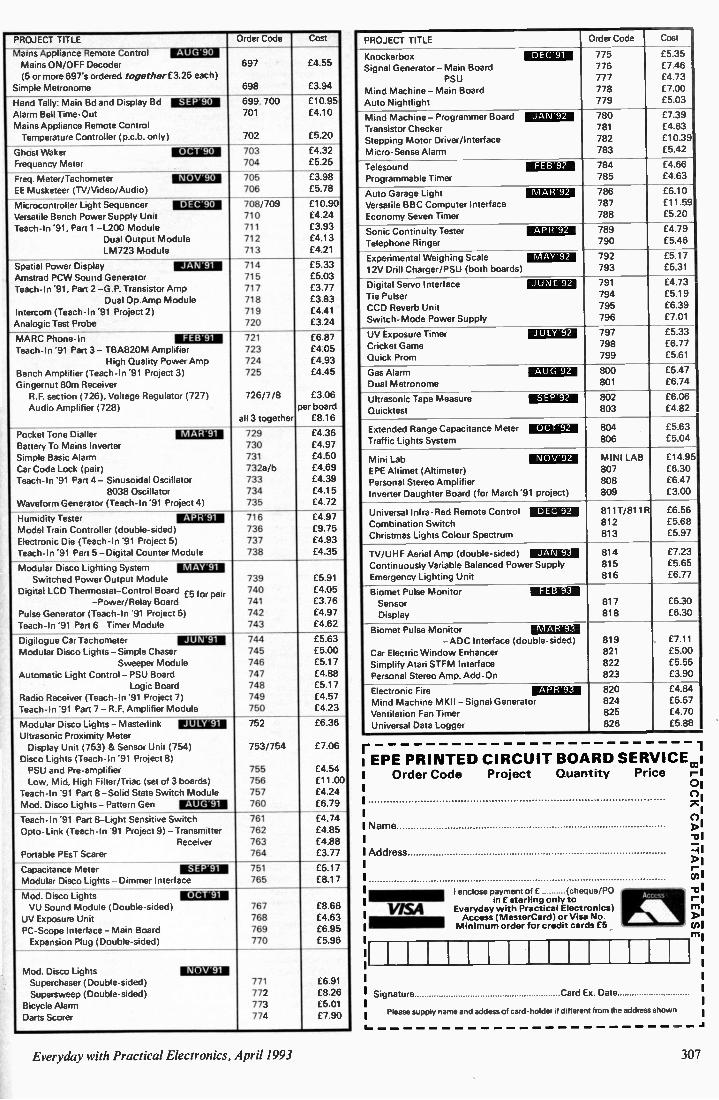
PROJECT TITLE Order Code Cost
Mains Appliance Remote Control AUG 90 Mains ON/OFF Decoder 697 £4.55
(5 or more 697's ordered together £3.25 each) Simple Metronome 698 £3.94
Hand Tally: Main Bd and Display Bd SEP 90 699,700 £10.95
Alarm Bell Time-Out 701 f4.10
Mains Appliance Remote Control Temperature Controller (p.c.b. only) 702 £5.20
Ghost Waker OCT 90 703 £4.32
Frequency Meter 704 £5.25
Freq. Meter/Tachometer NOV 90 705 f3.98
EE Musketeer (TV/Video/Audio) 706 £5.78
Microcontroller Light Sequencer DEC 90 708/709 f10.90
Versatile Bench Power Supply Unit 710 £4.24
Teach-In '91, Part 1 -L200 Module 711 £3.93
Dual Output Module 712 f4.13
LM723 Module 713 £4.21
Spatial Power Display RU ME N 714 £5.33
Amstrad PCW Sound Generator 715 £5.03
Teach-In '91, Part 2 -G.P. Transistor Amp 717 £3.77
Dual Op.Amp Module 718 £3.83
Intercom (Teach-In '91 Project 2) 719 £4.41
Analogic Test Probe 720 £3.24
MARC Phone-In FEBr91 721 £6.87
Teach-In '91 Part 3- TBA820M Amplifier 723 £4.05
High Quality Power Amp 724 £4.93
Bench Amplifier (Teach-In '91 Project 3) 725 £4.45
Gingernut 80m Receiver R.F. section (726), Voltage Regulator (727) 726/7/8 £3.06
Audio Amplifier (728) per board
all 3 together £8.16
Pocket Tone Dialler MAR 91 729 £4.36
Battery To Mains Inverter 730 £4.97
Simple Basic Alarm 731 f4.50
Car Code Lock (pair) 732a/b £4.69
Teach-In '91 Part 4- Sinusoidal Oscillator 733 f4.39
8038 Oscillator 734 £4.15
Waveform Generator (Teach-In '91 Project 4) 735 £4.72
Humidity Tester APR 91 716 £4.97
Model Train Controller (double-sided) 736 £9.75
Electronic Die (Teach-In '91 Project 5) 737 £4.93
Teach-In '91 Part 5 -Digital Counter Module 738 f4.35
Modular Disco Lighting System MAY'91 739 f5.91 Switched Power Output Module
Digital LCD Thermostat-Control Board £5 for 740 £4.05 pair -Power/Relay Board 741 £3.76
Pulse Generator (Teach-In '91 Project 6) 742 £4.97
Teach-In '91 Part 6- Timer Module 743 f4.62
Digilogue Car Tachometer JUN 91 744 £5.63
Modular Disco Lights- Simple Chaser 745 £5.00
Sweeper Module 746 £5.17
Automatic Light Control - PSU Board 747 £4.88
Logic Board 748 £5.17
Radio Receiver (Teach-In '91 Project 7) 749 £4.57
Teach-In '91 Part 7- R.F. Amplifier Module 750 £4.23
Modular Disco Lights - Masterlink J U l Y 91 752 £6.36
Ultrasonic Proximity Meter Display Unit (753) & Sensor Unit (754) 753/754 £7.06
Disco Lights (Teach-In '91 Project 8) PSU and Pre-amplifier 755 £4.54
Low, Mid, High Filter/Triac (set of 3 boards) 756 £11.00
Teach-In '91 Part 8 -Solid State Switch Module 757 £4.24
Mod. Disco Lights- Pattern Gen AUG 91 760 £6.79
Teach-In '91 Part 8-Light Sensitive Switch 761 £4.74
Opto-Link (Teach-In '91 Project 9) - Transmitter 762 £4.85
Receiver 763 £4.88
Portable PEsT Scarer 764 £3.77
Capacitance Meter .14:11:Ial 751 f5.17
Modular Disco Lights- Dimmer Interface 765 £8.17
Mod. Disco Lights W a al VU Sound Module (Double-sided) 767 £8.68
UV Exposure Unit 768 £4.63
PC-Scope Interface- Main Board 769 £6.95
Expansion Plug (Double-sided) 770 £5.96
Mod. Disco Lights M E M Superchaser (Double-sided) 771 £6.91
Supersweep (Double-sided) 772 £8.26
Bicycle Alarm 773 £5.01
Darts Scorer 774 £7.90
PROJECT TITLE Order Code Cost
Knockerbox DEC'91 775 £5.35
Signal Generator - Main Board 776 £7.46
PSU 777 £4.73
Mind Machine- Main Board 778 £7.00
Auto Nightlight 779 £5.03
Mind Machine - Programmer Board JAN 92 780 £7.39
Transistor Checker 781 £4.63
Stepping Motor Driver/Interface 782 £10.39
Micro-Sense Alarm 783 £5.42
Telesound FEB 92 784 £4.66
Programmable Timer 785 £4.63
Auto Garage Light MAR 92 786 £6.10
Versatile BBC Computer Interface 787 £11.59
Economy Seven Timer 788 £5.20
Sonic Continuity Tester APR 92 789 £4.79
Telephone Ringer 790 £5.46
Experimental Weighing Scale MAY 92 792 f5.17
12V Drill Charger/PSU (both boards) 793 £5.31
Digital Servo Interface JUNE 92 791 £4.73
Tie Pulser 794 £5.19
CCD Reverb Unit 795 £6.39
Switch-Mode Power Supply 796 f7.01
UV Exposure Timer JUEY 92 797 £5.33
Cricket Game 798 £6.77
Quick Prom 799 £5.61
Gas Alarm ii Migin 800 £5.47
Dual Metronome 801 £6.74
Ultrasonic Tape Measure M LLE. 802 £6.06
Quicktest 803 £4.82
804 £5.63 Extended Range Capacitance Meter E M U§
Traffic Lights System 806 £5.04
MINI LAB £14.95 Mini Lab LI A M EPE Altimet (Altimeter) 807 £6 30
Personal Stereo Amplifier 808 £6 47
Inverter Daughter Board (for March '91 project) 809 £3.00
811T/811 ft £6.56 Universal Infra-Red Remote Control D EC 92
Combination Switch 812 £5.68
Christmas Lights Colour Spectrum 813 £5.97
814 £7.23 TV/UHF Aerial Amp (double-sided) JAN'93 Continuously Variable Balanced Power Supply 815 £5.65
Emergency Lighting Unit 816 £6.77
Biomet Pulse Monitor FEB'93
Sensor 817 £6.30
Display 818 £6.30
Biomet Pulse Monitor IVIAR'93 - ADC Interface (double-sided) 819 f7.11
Car Electric Window Enhancer 821 £5.00
Simplify Atari STFM Interface 822 £5.55
Personal Stereo Amp. Add-On 823 £3.90
Electronic Fire APR'93 820 £4.84
Mind Machine MKII - Signal Generator 824 £5.57
Ventilation Fan Timer 825 £4.70
Universal Data Logger 826 £5.88
r 1 1 EPE PRINTED CIRCUIT BOARD SERVICEcoi i Order Code Project Quantity Price r-I I 01
0 XI
I Name
I Address
VISA
I Signature Card Ex. Date
Please supply name and addess of card-holder it different from the address shown
I enclose payment of e (cheque/PO in £ sterling only to
Everyday wi h Practical Electronics) Access (MasterCard) or Visa No. Minimum o der for credit cards £5
I
-ol 1111 Di
Everyday with Practical Electronics, April 1993 307

REPORTING n
, Tony Smith G4FAI IS WL TAPESPON DING Last month I mentioned the Interna-
tional Short Wave League but had insuf-ficient space to mention that, among its varied activities, it has a Tape Sec-tion that enaoles like-minded members to keep in touch with each other. As in amateur radio contacts, controver-sial topics like politics or religion are avoided, but otherwise virtually any-thing can be discussed. Additionally, a news tape goes to
all participating members containing a variety of material with contributions from other tapesponders, "from train or bird sounds to the latest Dx news or broadcast station identification, or talks and reminiscences of the old days". Membership information can be ob-
tained from ISWL HQ, Dept. EPE, 10 Clyde Crescent, Wharton, Winsford, Cheshire, and a sample copy of the League's monthly journal, Monitor, costs 60p. Cheques or P.O.'s should be payable to "ISWL" but stamps are acceptable.
NET DIRECTORY Apart from individual contacts on the
amateur bands, "nets" are a popular activity. These are gatherings of radio amateurs on the same frequency, with a "net-control" station in charge calling in participants in turn to make their own contribution to whatever topic is under discussion. Although popular with many amateurs I actually prefer to listen to nets rather than take part in them. There is limited time available for each participant but listening to the whole can be most inter-esting. The number and variety of nets is surprising and over 900 are listed in The World Ham Net Directory, edited by Mike Witkowski and published in the USA. Some are restricted to members of
particular organisations, and others are open to all. Among many specialised subjects, there are nets for enthusiasts for individual aspects of amateur radio itself, the armed services, police, missionaries, railway enthusiasts, stamp collectors, farmers, Scouts, fire fighters, novices, seafarers and virtually anyone else you can think of! The directory is in three sections, listing nets by name, by frequency, and by time of operation. It is of value to both licensed amateurs who wish to find other amateurs with similar interests and to shortwave listeners who wish to ex-pand their listening activities. For award hunters or QSL card collectors, it offers the opportunity of adding more Dx sta-tions to their totals. The World Ham Net Directory is
available from Tiare Publications, PO Box 493, Lake Geneva, WI 53147, USA, price US$9.95, plus $3.00 foreign postage (Visa or Mastercard accepted).
NOVICE SUCCESS The first ever UK Class "A" Novice,
has become the first UK Novice to receive the G-QRP Club's Class "A" CW Novice Award. Created to encourage an interest in CW (Morse) operating among beginners, this award is open to any amateur who, during the first twelve months of holding a licence, contacts 50 different stations while using CW. Class "A" is for contacts using up to 5 watts output and for Class "B" any power may be used. Twelve-year old Keith Goodwin,
2MOACT, used 3 watts of power (just about enough to light a flashlamp bulb) to make his first fifty contacts. These included seven with USA/Canada, two with Indonesia, and twelve separate countries in all. His father Stuart, GMOCAG, says that Keith is getting a great thrill from the hobby and that many of his contacts have helped him relate to his school geography and French lessons. Dave Gosling GONEZ, G -QRP Novice
Services Manager, reports that other Club Novices are also achieving high stan-dards of operating ability and has asked all operators to encourage and help them when they hear them on the air. Membership of the G-QRP Club,
which is devoted to low-power operat-ing, is open to both licensed amateurs and shortwave listeners. It has an excellent quarterly journal, SPRAT which includes a column for novices of all ages and is full of projects, often suitable for beginners, for transmitters, receivers, and many station accessories. A sample copy can be obtained by
sending a stamped addressed C5 en-velope to the Club Secretary, Rev George Dobbs G3RJV, St. Aidans Vicarage, 498 Manchester Road, Rochdale, OL11 3HE. Tell him you read about the club in G4FAI's column in EPE. I am a long-time member, and like to keep in with the guv'nor!
NU MBERS STATIONS Shortwave listeners around the world
have been puzzled for years by the "numbers stations" which broadcast groups of coded numbers - and nothing else. According to in article by Nils Schiffhauer DK8OK, in Monitoring Times last September, although it was widely thought these mysterious transmissions came from behind the Iron Curtain some were, in fact, broadcast by BND, West Germany's CIA, to agents in eastern Europe. The transmissions could be received on
a domestic shortwave receiver and, in the seventies, Grundig's Ocean Boy was widely used for this purpose. The strange thing is, even though the country is now re-united, Germany's numbers stations are still on the air as if nothing has happened on the political scene!
SPY NET WORK The authority responsible for these
transmissions is "BFST", the Federal Service for Telecommunications Statis-tics which, according to Nils, provides telecommunications for the German in-telligence services. There are stations all over Germany and he found one near Husum in Schleswig-Holstein, on two sites, bristling with antennas capable of transmitting signals near and far. In his words, "it looked as though some ham operator's dream had come true!" The numbers broadcasts are by voice,
but on this occasion he verified CW (Morse) numbers on 9161 kHz, "only ten metres away" from the antenna, with the signal overmodulating his car radio. The callsign was EC3Y. As a dedicated shortwave listener he
then sent what was probably the first ever reception report to a German numbers station - and to the right address, know-ing exactly where the transmission came from!
ON-THE-AIR QSL The answer was short but polite. "On
principle" they did not verify reception reports. He hadn't really expected any answer at all so was quite pleased to receive this letter, although a small mys-tery remained. Inexplicably, this German station was using a Spanish callsign. Nils checked, and discovered that EC3Y was a call for an amateur novice licence in Madrid. The Deutsche Bundespost was ac-
tively cracking down on the illegal use of scanners at the time (subsequently legalised mid-1992) so he wrote to ask them to investigate the apparent illegal use of a foreign callsign by a govern-ment agency which he understood was responsible for enforcing international treaties! Within a week he received a phone
call from the PTT informing him that BFST used the callsign EC3Y for transmissions towards Spain but would change the call to a legal one that very day. He switched on his receiver to check, and they really had changed the call! Since 20th January, 1992, there-fore, the call for the BFST transmissions on 9161 kHz has not been EC3Y but DEA47, which complies with the in-ternational regulations. He sent another reception report, and
again they declined to verify it. He didn't mind. He thought their change of callsign was one of his best ever QSLs - even though it was only "on-the-air"! Out of curiosity, I have been tuning
9161 kHz from time to time, but have not yet heard DEA47. Nils suggests "Maybe they closed down. Maybe they switched to another (winter?) frequency." If any SWL readers do hear them, please let me know.
308 Everyday with Practical Electronics, April 1993

WE HAVE THE WIDEST CHOICE OF USED OSCILLOSCOPES IN THE COUNTRY
108150167 2336 Ia. Trace 100M9 Degy Sweet) Pmedisect RION
MUPS 3070 Dual Trace 130u10 Delay Sweep Trg Veer Ciever Cor m Loud Oystal Dscray £900
WADI VI 050F Dual Trace 1001442 Dual TB 'nth 4 Chn Mc £450 SCFLUMBERGER 5218 Goal Trace 2001412 Delay Sweep with Trg ve* £375
IFKIRONO 475 0431 Tram 2001/8 OW) Sneev 1350 HP 1715A Dual Trace 2008112 DelaV %Tee £500 TEKTECOM 4E814D4 Trace100MHz DNA, Sweet) SuCOecl wry, 2 Tenrceet P6104 PrOtift Unused £600
31K11010 4658 Duaarace 100Iett %SS SneeD £500 MIC MAC( 465 Gual Trace 1001.112 DeLay Sweet) £450 HAI G 1005 Tr fie Trace 10341200rtal Tmebase £525 HP 17408 Dua Trace 1001&128086y Sweet) ENO 1E0IPot452225Dual Tram 501A2 Alternate TO Vag ,cator EIS° TEKTRC M 2213Da Trace 601.12 0350 RIPS r4A3217Da Trace 501&12 Delay Stivec DIGO 67S0486500E401 Trace 60110 Delay Sweep £400 0010 053002* Dtal Trace 4E4112 Delay 5seec £202 KIKUSUI 5530 021Trace 30842 £200 CMG 051100 Dual Trace 301480 £160 GOULD 05300 Gual Trace 201412 GOULD 052508 DWI Trace 150/2 £125
11119 SUMS - MANY 0111815 AvALAIStE
N M P16393 Rograninable synthesizer functIce generate( 0 11112-501812.1118418. ness _....E1930
VAKCN zec AM, Fkl Sro Gen 80021040MHz £2450 1.0680004 2018 Sr meszel AV FM 5g Gen 80812-5201.40 £950 1.150 00 2017 Stage Low nose AM/FM Sc Cen 10812-1024)412 GP113
SIP 545 Lecrowaie Frecuency Counter 1021802 H P 539 0004Dce Measumg Set 10)2110102 PAGAUDANA 1991 Nan0secon4 Onverssi Counter RACAL 9302 RF Iliksitnteter True RAC 101061 KHz RACAL 93014 Ff lairgetneter True PUS 101024 5GHz ZACAL9C01 Autteglic IA31 Meter 10).82 1 Sat VA0e
HP Rise Cenerabcr trCe 2146 JOINS PC73)1Ptise Gen PPF 110201.440 MARCONI 2610 True WS Vdtmeter :010 BIOLIATCN 1(5000109c Analyser KE MILEY 224 Progammatie Current Source
454,,SERS
MERCK( 494AP 10318-2204 HP 141385554 F 1034019CW HP 1417 set 855488 85528 500kl40-1250Mh2 HP 140T A11 855400 8552A 500k)212501.112 HP 141T with 8556A 8 8552820Hz-300102 HP 140T with 85556 & 8552A 1E02-1 100.62 8*15CONi TF2370 1112-11301112 HP 1820 wth 85588 1030-15001.112
E2000 01400 E1500 09:0 0450 BCC
0250 0750 £150 MOO 1300 E1000
NOS E1802 01300 01000 01000 0800 £1800 £1588
DATRON 1071 -7 5 Cot PAROCal DC Wattmeter itith True ROA AC/ReaStIncelCurrent £1750
561808 15018 4 5 cbgt Aatccal Iturbrneter oat True Kt AC/Current . £1250
DA MN 1065 -5 5 diart Autccal Multimeter wit ACIDC Gems Wall IEEE £600
860.5411 PACI(APD 34908 Bench Mulometer 5 Crot P.: DElOhMS EXO PelLIPS 002534 Mut Functce CAW 3 5-6 5 dot with GPIBAFF only 0450
ISAPCOMpgrtal FreckenCv Meter 243081 00-50(80 0125 WPC:9101903 Freouency Meter 24519100-2300880 0150 0600061 Ani mal Canter Timer 2437 30-130(10 0175 mAPCONi unnersal Counter Timer 2438 20-5204480 £225 "P 3311A FundOn Gererator 0112-11412541e ftTri £125 .., .- vTEPES HANG ifiD1,4235532 rarges ADDIC 10 Amps :,.-Ce 'ransn-tcr Tester. Freoctungr £3230
FANIEL M UNK LOAD1111050451KW
,...AAL, GAM Syn Gen 9048001-104)&2 MOO PACALIDANARF Poser Meter 9104 MOO FACAL/DANA 9341 Databrdge Automatic measurements Of LC.12,80. £350
vonyttE KERR 8424 Fla Meter LCD Disgay 0125 WAYNE KEPR 4210 0 Meter Accuracy 0 1% £600 AVOACIDC Breakdown Leakage 8 lonsataan Tester RIM?' I.. £600 F1404:11. P5U 195701,42. 709 5A/30910A C300 FA04E10301160125 6609; 0-25 angs Metered ESCO FARELL PSU LSE& 030V, 0-5 amps Metered
racer E250 I4*5CON172700 Onsersall(328rilat Battery from £125 MARCONI TF2337A Ault/ Mart meter 41)0Hr 1 no 0 01%, £175 VO valve agractensoc meter V04163 ENO
FARNELL 556520 Syretaeseed Sg Gen IC. 7221A82 EOM FARNEU. 735520 Trannnittelcst Set Cassung of RF,IA Canter, Rf Mod Meter. RF Poser Meter, AP Ildoneter.AF 04004 509 488 AF Synthesaer HOO SODA arrarforONLy £750
1 11:0 =2: 11
46IEG 050105COPE HMI 005 TPA Trace 1001/6 D .01 olden £847
RWEG0OLLM M161604 Dual Trace 60142 Delay 5wee0 £653 RA W OSCIU.05COFf 11112057 (5467r30e 20412
C362 HAS,C= C 7PE HM2056 Canarace2CIAH2 No storage £653 w eer mons mime - al melb a/s miled non 2 °robe<
NACISTAIIIIIIPIEMPAP al urrts 051 nPolLO 10.18148 Counter Tiny Ritio/PenoOttime nte-• etc
FP04101011001488sabon wen max functo, s 1. 61045 1120 FREOUENCY COLIMIR1003112 REIEOR 600 FfiglIESCY 03100586003116 MEIE451020F800088CYC0UN1801G*2 AMOR 509 FUNCIICH GES1 0 1H750C1065ne COON COLOUR 8Aft GENERATOR Pai TVMae.
Allother8lact , :
OSCILLOSCOPE PROBES Svirtchen t" x"
0222 E325 E109 0135 E178 0110 E229
Used Equiprnern-guarerdeed Man uals supplied II pessible. Thrs ,s a VERY SMALL SAMPLE OF STOCK. SAE or telephone for lists Please check aye, iability before
ordering CARRIAGE all units £16 VAT to be added to total of goods and carriage
STE WART O F R E A DI N G 110 WYKEHAM ROAD, READING, BERKE RO6 1 PL
Tat 0734 268041 Fax: 0734 351696 Callers neicomegam io 530pm MON-FRI (UNTIL 8pm 'Hu; _
VISA
LEDs 3mm or 5rnin red or green Op each yellow lip each High intensity red. green or yellow, 5mrn 30p each.
Cable ties 1p each. £5.95 per 1000. 04450 per 10,000
Steping motor 4 phase 12v 7.5' step 50 ohms £8.95
SAA1027 stepping motor driver chip £3.95 FM Transmitter kit good quality sound £8.60
High quality photo resist copper clad epoxy glass boards
Dimensions single sided double sided 3x4 inches £0.95 f1.07 403 inches £2.40 f2.68 6,12 nches £5.37 12x12 inches £10.66
Rechargeable Batteries AA (HP?) 500mAH £0.99 AA 700mAH El .95 C 2AH with solder tags £3.60 D 4AH with solder tags £4.88 1 /2AA with solder tags £1.55 AAA (HP16) 18OrnAH £1.75 AA 500mAH with solder tags f1.55 C (HP11)1 8AH £220 D (H02) 1 2AH £2. 60 P P3 8 4V 110mAH f 4 95 Sub C with solder tags £2. 50 1/3 AA with tags (Philips CTIV ) f1.95 Standard charger, charges 4 AA cells in 5 hours or 4Cs or [Ism 12.14 hours - 1 xPP3 (1 2. 3 or 4 cells may be charged at a time). f 5.95
High power charger, as above but charges the Cs and Ds in 5 hours; .1.1*, Cs and Ds must be charged in 2s or 4s £10.95
Special offers - please check for availability F cells 324ia x 87min f 3.95 F cell with solder tags. 1.2V.. ES 30 42rnm x 16rnm dia. 1.23.1. £1 45 Stick of 4 171mm x 16mm dia . with red & black leads 4 8v £595
4 cell battery 94mm x 25mm dia. (1 /2C cells) f3.50
Computer grade capacitors with screw terminals. 380000 20V £2.60; 870000 10V £1.95: 68000015V C2.95; 10000pf 16V C1.50
7 seg ment common anode led display, 12nun £0.45
1M2931A1 5.0 low drop out by regulator 70220 package £0.85
7812 and 7912 12V 1A regulators..020.00 per 100 LM 337k 703 case variable regulator £1.60
100+ £1.10 85250 P channel mosfet 45p. B C 559 transistor
per 100 03 95 74LS06 hex invert°, ... . f10.00 per 100 Used 8748 Microcontroller 0.50 S1962 UHF Limiting amplifier LC 16 surface mounting package with data sheet C1.95
AM27502 CI .26 each: 90p 100 . CD4007U 8 100100+. 601000 • TV Mains switch. 4A double pole with mornentor contacts for remote control, pack of 1003. 95
box of 60 £19.95 DC-DC convertor. Reliability model. VT 2P5. 12V in 5V 200mA out. 300V input to output. Isolation with data, £4.95 each or pack of 1 0 - £39 50
Hour counter used? digit 240V ac 50Hr £1.45 Resistor pack 2500 resistors 1/8-2W 50 different values £11.96
Resistor Jumbo pack 25000, 1/4 and 1/2W resistors our choice of values and size, will be mainly in boxes or rolls of 1000. 2000 and 5000 of one type £25.00
Owerty keyboard, 58 key good quality switches. new £5.00
Qwerty keyboard with serial output no data (used) £8.00
Polyester capacitors, box type. 22.5mrn lead pitch 1p1 250V dc 2004 each. 15p 100+,10p 1000* 2.2p1250V dc 30p each, 20p 100+. 15p 1000+ 3.3p8 100V dc 30p each. 200100+. 115p 1000+
1pf 50V bipolar electrolytic axial leads, 15p each. 7.5p 1000+
0.22pf 250e polyester axial leads, 15p each. 100+ 7.50 each
Philips 123 series solid aluminium axial leads. 33pf 10V & 2.2p140V 40p each, 25p I 00+
Multilayer AVX cerami capacitors, all 5mm pitch. 100V 100p1, 15001. 220pf. 10,000pf (10n) 10p each. 5p 100+. 3.5p 1000+
Wel wyn W23 9W 120 ohm 3.5p each. 20p 100 + 680 ohm 2W metal film resistor, dp 100+.
2p 1000+ Solid carbon resistors. very low inductance, ideal for FiFcircu its 270hm 2W, 68ohm 2W 25p each, 15p each 100 - . we have a range of 025W. 0 5* lw and 2w solid carbon resistors - please send SAE for 1101
Intelegent 4 digit alphanumeric (5x7 dot 0 145") red LED display. 12 pin 06 inch wide package. Siemens type 0LR1414 E2.50 each, U M 30 data sheets £1 .00
AMO 27256 • 3 Eproms £2.00 each. £I.26 100+ DIP switch 3PCO 12 pin (ERG SOC-3-023) 60p each. 40p 100 •
Disk Drive Bones for a 525 disk drive with room for a power supply light. grey plastic 67nwn 268rnm 247rnm £7.95 or £49.60 for 10
Hand Held Ultrasonic remote control £3.96 Computer grade 58000pf 60V capacitors with screw terminals £4.95
CV2486 gas relay 30mm x lOrnm die with 3 wire terminals. will also work as a neon light 20p each £7.50 per 100
123 12V car alarm remote control and lighter battery 75p each, 050.00 100
40pf 370V a c motor start capacitor (dielectrol type containing no PCBs) £5.95 each
£49.50 for 10
All products advertised are new and
unused unless otherwise stated.
Wide range of CMOS TTL 74HC 746 Linear
Transistors kits, rechargeable batteries, capacitors, tools etc always in stock
Please add 95p to wards P&P VAT included In all prices
JPG ELECTRONICS 276-278 Chats worth Road Chesterfield S40 2BH Access Visa Orders
( 0246 ) 211 202 Callers welco me
N. R. BARD WELL LTD (EPE) 200 Signal diodes 1N4148 El 00 75 Rectifier Diodes 1N4001 El 00 50 Rectifier Diodes 1N4007 £1.00 56 Rectifier Diodes 1N5401 £1.00 100 Asstd. Zeners £1 .00 10 NE555 Timer ICS £1.00 8 C106D 400V 6 amp thyriStors £1.130 8 8FY51 Transistors E1.00 30 BC478 TransiStors £1.00 30 MPSA42 Transistors VI .00 30 5mm red I.e.d.s £1.03 25 Asstd. high brightness I.e.d.s £190 24 Miniature red I.e.d.s 3mm die £1. 00 50 Axial 1.e.d.s (Diode package) wide
angle I.e.d.s £1. 00 12 Asstd seven segment displays E I .00 30 Asstd. IF transformers El .00 48 Asstd coil formers O M 100 Asstd. RF chokes (inductors) £1.00 30 Asstd connectors edge-dil-sil e1 E1.00 10 4P 3W MBB min. rotary switches £1. 00 20 1 inch Glass reed switches £1. 00 20 Magnetic ear pips plus lead & ptug f 1.00 20 Min SF/CO slide switches £1. 00 30 Asstd. d . i .1 . sockets up 10 40 pin £1.80
20 24-way turned pin IC sockets £1.00 16 40 pin d.i.l. wire wrap IC sockets £1 .00 2 ORP12 light dependant resistors 0.00
200 Printed circuit board 20mm fuse clips E1.00
200 Asstd. disc ceramic capacitors ..01.00 80 Asstd. capacitors 1nf to 1 ul £1 .03 80 Asstd electrolytic capacitors _01.00 80 4.7UF 16V Radial electrolytics ..E1.00 75 4.7UF 63V Radial electrolytics 80 10UF 16V Radial electrolytics ..E1.130 50 IOUF 50V Radial electrolytes ..E1.00 80 22UF 25V Radial electrolytes £1.00 60 33UF 16V Radial electrolytes £1.00 50 47UF 50V Radial electrolytes £1.00 80 100UF 10V Radial eletrolytics £1.00 50 220UF 16V Radial electrolytics £1.00 60 470UF 10V Radial electrolytics £1.00 40 1000UF 10V Radial electrolytics £1.00 12 1000UF 25V Axial electronics £1.00 1 1 Farad 5.5V memory back up
capacitor £1.00 1 Peltier effect heat pump £1.95 1 10 watt Stereo amplifier, 4 controls
plus data £2.95
Prices include VAT postage £7.25 Stamp or Lists
288 Abbeydale Road. Sheffield Si 1FL Phone (0742) 552886 Fax (0742) 500689
Millions of quality co mponents at lo west ever prices!
Plus Tools, Watches, Fancy Goods, Toys. Mail order UK only.
All inclusive prices-NO post, or VAT etc to add on.
Send 34p stamped self addressed label or envelope for catalogue/clearance list.
At least 2,100 offers to amaze you.
Brian J Reed 6 Queensmead Avenue, East Ewell
Epsom, Surrey KT1 7 3E0 Tel: 081-393 9055
CID IL 1112 TRANSFORMERS FROM
r/e The UK Distributor for
Standard Toroidal Transformers 106 types available from stock 8, Sizes from 15VA to 625VA
STEEL DISHED WASHER
OUTER INSULATION
SECONDARY WINDING
INSULATION -
PRIMARY WINDING
COPE
END CAPS
NEOPRENE WASHERS
Write or phone for free Data Pack
Jaytee Electronic Services 143 Reculver Road, Beltinge, Herne Bay, Kent CT6 6PL
Telephone. (0227) 375254
Everyday with Practical Electronics, April 1993 309

EVERYDAY WITH PRAM]
ELECT' ONICS CLASSIFIED Everyday with Practical Electronics reaches twice
as many UK readers as any other independent monthly hobby electronics magazine, our audited sales figures prove it. We have been the leading independent monthly magazine in this market for
the last eight years
If you want your advertisements to be seen by the largest readership at the most economical price our classified and semi-display pages offer the best value. The prepaid rate for semi-display space is £8 ( + VAT) per single column centimetre (minimum 2.5cm). The prepaid rate for classified adverts is 30p ( + VAT) per word (minimum 12 words).
All cheques, postal orders, etc., to be made payable to Everyday with Practical Electronics. VAT must be added. Advertise-ments, together with remittance, should be sent to Advertisements, Everyday with Practical Electronics, Holland Wood House, Church Lane, Great Holland, Essex C013 OJS. Phone/Fax (0255) 850596. For rates and information on display and classified advertising please contact our Advertisement Manager, Peter Mew as above.
1993 Electronics Design Competition Entry deadline has now been extended to Friday 29th October, allowing late entries from schools 8 colleges
to be considered. Ask for an entry form.
HURRY, our clearance semiconductors are selling fast, e.g. 27C1001A-15 £3.45,
CA3140E £0.22 INCLUDING VAT! Extensive lists £1.
Profile Electronics (EPE) 100-102 Woodhouse Rd, Leytonstone, London Ell 3NA. Tel: 081-470 2038 Are you getting all you can from your
IBM-Compatible PC? - See our main advertisement for details!
STUDY ELECTRONICS ON A PC Over 80 fully interactive, menu driven, graphics screens, containing charts, graphs, circuit diagrams, formulae and theory. With user inputs and calculated outputs. Covers subjects from electron flow, through analysis of AC and DC
circuits, to semi-conductors. Send cheque or postal order for
£39.95 + £2.00 P&P SAE for details:
or £5 for demonstration disc.
E.P.T. Educational Software Pump House, Lockram Lane
Witham, Essex CM8 28J. Tel. 0376 514008
Typefit The Typesetting programme for all your Typesetting needs.
If you need typesetting for your Adverts, Brochures, etc. Typefit can help you. Please telephone
0202 882299
PC TECHNICAL SHAREWARE %mild you like to Yee die best range of low cost technical and scleatific public domain & shareware for IBM PC in the UK? HUGE RANGE insludes PACKET. FAX. RX TX control. PCB design. ( is_uit and ANTENNA analysis. QS0 logging.
CAD VI FCTItONIC & MECH engineering. SCIENTIFIC. MATHS & STA I s MEDICAL. PROGRAMMING. SOURCE CODE. DATA.
II CATIONAL. WINDOWS. BUSINESS and lots more Vs toe phone or fan today for your free 124 page printed ctualogue
i l l The Pa & Domain Software Liberty
MEMO Wirseorthe Horse, & wow Road
Crowborosqrk, Sussex TN6 It'L
m o n TrI08926632911, Fez 0892667473
.1.>•••••••••
ASP Appinuel Vatic*
RCS VARIABLE VOLTAGE D.C. BENCH POWER SUPPLY 1 to 24 volts to • , amp • •o 20 voits up to 1 amp tlo tecoits uptolv. amps do Fuliy Stabilised Twin panel meters for instant voltage and cur-rent readings Overload protection Folly variable E4c inc. Operatestmm wit VAT 1405 a c Compact Unit + Post and Sue 9 a 3in insurance £4 NEW MODEL. Up to 38v011s do at 6 amps 10 amps peak Fully variable Twin panel meters Sae 14X a 11 z inc VAT Cart f 6
RADIO. COMPONENT SPECIALISTS 337 WHITEHORSE ROAD. CROYDON ci
PISA SURREY. U.K. Tel. 081-684 1665 List Large SAE Deliver, 7 days Callers welcome Closed Wednesday
BTEC ELECTRONICS TECHNICIAN
FULL-TIME TRAINING THOSE ELIGIBLE CAN APPLY FORE T GRANT SUPPORT
AN EQUAL OPPORTUNITIES PROGRAMME
0.N.C., O.N.O. and H.N.C.
Next course commences Monday 26th April 1993 FULL PROSPECTUS FROM
LONDON ELECTRONICS COLLEGE (Dept EE) 20 PENYWERN ROAD EARLS COURT, LONDON SW5 9SU
TEL: 071-373 8721
SOLAR PANELS Special offer 12V nom (20V o/c) 80mA. 12"x6" pre-wired Amorphous Silicon panel £4.50 (5 for £18) plus 0.50 p&p per order. Many other sizes, wind generators and other products. Orders to (Catalogue 2 x 1st class stamps)
Keysolar Systems. 4 Glanmor Crescent Newport, Gwent NP9 8AX
IT PAYS TO ADVERTISE IN
EVERYDAY with PRACTICAL ELECTRONICS
Your advert will reach twice as many
UK readers than with any other independent monthly hobby electronics magazine
N. R. BARDWELL LTD (EPE) COMPONENT PACKS
Over 400 types of Capacitor packs Over 150 types of Semiconductor packs
Over 40 types of LED packs Over 40 types of Resistor packs
Over 115 types of Component packs MANY OTHER ITEMS LARGE S A.E FOR LISTS
288 Abbeydale Road, Sheffield S7 1FL Phone (0742) 552886. Fax (0742) 500689
THE BRITISH AMATEUR ELECTRONICS CLUB
exists to help electronics enthusiasts by personal contact and through a quarterly Newsletter. For membership details, write to the Secretary
Mr J. S. Hind,? Carlyle Road
West Bridgford, Nottingham NG2 7NS Space donated by Everyday with Practical Electronics
NEW VHF MICROTRANSMITTER KIT Tuneable 80-135MHz, 500 metre range, sensitive
electret microphone, high quality PCB. SPECIAL OFFER complete kit ONLY £5.95
Assembled and ready to use £9.95 post free. Credit card orders telephone 021 411 1821 Fan 021 411 2355
Send 2c1st class stamps for Catalogue Cheques/P Os payable to
QUANTEK ELECTRONICS Kits Dept. (EE), 3 Houldey Road, West Heath,
Birmingham B31 3HL SHOP NO W OPEN - CALLERS WELCOME
This 3cm space in
Everyday with Practical Electronics
Will ONLY cost you
£24 +VAT
Miscellaneous
G.C.S.E. ELECTRONICS KITS at pocket money prices. S.A.E. for FREE catalogue. SIR-KIT ELECTRONICS, 70 Oxford Road, Clacton C015 3TE. PROTOTYPE PRINTED CIRCUIT BOARDS one offs and quantities, for details send s.a.e. to B. M. Ansbro, 38 Poynings Drive, Sussex BN3 8GR. or phone Brighton 883871. THE HOMEBUILT DYNAMO (Plans). Reviewed 1989 in PE January and Model Engineer December 15th. Price £42 post paid airmail from Alfred Forbes, PO Box 3919, Auckland. New Zealand. Tel (09) 818-8967. V-U METERS, one 65mm high. 85mm wide; one 80mm high, 1 1 Omm wide, £7.50 the two. (40 components) potentiometers, switches and coloured knobs, £7.50. General purpose op-amp VA748C, 8 pin, 50 for £7.50. Bridge rectifiers, 200V. 35 amp. 5 for £7.50. Low noise op-amp. TL071C. 8 pin. 50 for £7.50. Payable to G. Hannington, Surplectronics, 216 Leagrave Road, Luton. Beds LU3 1JD. SOLAR POWER PRODUCTS. Portable lamps and torches, garden lights, security lights, water fountains, construction sets, radios, clocks, watches, solar cells and panels, inverters, battery chargers. Tried and tested in Britain's first solar power catalogue. Send £5 for your copy, includes £3 refund voucher on first order and quar-terly newsletter (overseas addresses £10). Solar Products International Ltd, Dept. EE, PO Box 438, Harrow, Middlesex HA2 9UT. ELECTRONIC KITS, Consultancy & Design: Kits £4: UK; £6: Overseas (NOTES ONLY), For list & 44 Unusual Circuits, Send A4 Addressed Envelope: Mr. Lucas P.O. Box 755. Saint Helier, Jersey JE4 8ZZ Channel Islands. PROFESSIONAL ELECTRONIC ASSEMBLY/PCB population, at competitive rates. Tel. Julian Wright (AV Electronic Services) 0932 565657. NEW FROM THE USA an Electronics must, two fully illustrated and priced catalogues from "Information Unlimited" & "Amazing Con-cepts". Terrific, new, plans, kits and units, Send £1 for both. UK Dealership, "First Line Systems". 32 Fairfield Approach, Wraysbury, Nr. Staines, Middlexsex, TW19 5DS. BACK ISSUES Practical Electronics, Practical Wireless, Everday Electronics, from 1960's to 1980's. Many complete years/part years and odd issues. For complete list. send AS SAE to: Vic Garvey, I Broadmead Avenue, Tunbridge Wells, Kent TN2 5PG. PALs, PLDs & EPROMs programmed. Very competitive rates. Send SAE for details to PO Box 1561 Bath or phone 0225 444467. PROTECT YOURSELF from Computers/T.V.s with our Energy Harmonisers, £12.85p incl. Future Concepts, 19 Wellfield Avenue, London, NIO 2EA. Tel: 081-8830767. SAE for leaflet. FOR SALE. Everyday Electronics, November 1971 to January 1985, in binders, with indexes. Offers 0332-703996.
310 Everyday with Practical Electronics, April 1993
COMPONENTS For TV * Video
Audio * Compute!
VIDEO BELT KITS AMSTRAD VCR4600/4700/5200 £3 19 FISHER FVHP905/906/908 £3.03 JVC 993300/3330/3660 £330 Large range at Pinch Rollers. Idlers. Heads. etc. from stock.
SERVICE MANUALS PHILIPS CST427 £4.50 TOSH,BA STU2/1_ Tuner £6.99 Many other Manuals available.
SEMICONDUCTORS 9U506A £150 0064601 £3.25 BUV48A . . £499 UC3E184 .C8 95 LM733CN £2.43 UM6522 £6.99 P8255A £285 UPC1378H £282 510414111 ..... .0.79 UPC1397C £434 767280P £698 UPD8039LC £12 9 TA8213H . £8.52 27C256-203 £2 00 This is lust a very small sample of our stock
Send £1.25 tor our Selected Spares CATALOGUE Includes voucher spendable on future Orders
WE CAN SUPPLY A VAST RANGE OF SPARES for many makes of TV Video Computer & Audio Equipment WRITE (End sac please) or PHONE FOR A 'PRICE & AVAILABILITY' on your requirements 0452 526883
C O MPUTER SPARES
PHILIPS MONITORS ATARI 9M7513 Sery Manual E3.49 CO25913 DMA (ST) £3324 CM8833 Se, Manual £4.71 Se,/ Manual (ST520)--E13 75 CM8833 Line 0/P Tx . £24.94 PC900V/H11L3 (ST) £2.88 CM11342 Line 0/P Tx .. E28.51 ROM Basic (XE/L) £4.58
AMSTRAD/SINCLAIR THERMISTOR (ST-PSUI-E1.37 CPC464 User Manual. ..E10.95 PC713V 1STE-PSU) f2.94 PCW 9512 Serv. Manual L14.99 2SC2331 (ST-PSU) £159 AY38912 E7.06 COMMODORE SED9420CAC £14.93 17 7344MH0 Xtal £499 S1K7356 £13.81 C64C User Manual £439 TEA2000 £563 064 User Manual £4 25 TM54532-NLI E 1.72 C64/C Service Manual C15.00 2TX650 £0.49 6510 CPU El 1.04 Z08302(0L) £10.98 6526C16 £12.22 Z08401 £7.94 6569 SIC £19.95 Spec , 2 ROM £16.69 8520 Amiga £12.35 Spec /OL Modulator £7.36 8565 SIC. £23.96 Spec 481< Speaker Et 74 906114-01 PLA £924 Spectrum 481< 'Rubber 251641-02 PLA £491 Keys Membrane £5.33 MB81416-12 DRAM (C16) £4.99
Order by Post or Phone We accept payment by VISA. ACCESS, DELTA, SWITCH. Cheg e or PO Post & Packing is £1 20 No VAT o add on All items subject to availability Prices can change W M ., 1101/CV
VlSA
.4
MARAPET (EED) 1 HORNBEAM ME WS GLOUCESTER G L2 OUE
SHERVVOOD ELECTRONICS 9 Lower Birchwood, Somercotes, Derbyshire DE55 4NG
1 Special Packs - select 1 pack FREE for every 10 purchased
SP1 150 5mm Red Leds SP2 15 x 5mm Green Leds SP3 12 o 5rnrn Yellow Leds SP6 15 x 3mrn Red Leds SP7 12 a 3mm Green Leds SP8 10 a 3mm Yellow Leds SPIO 100 x 1N4148 diodes SPI 1 30 a 1N4001 diodes SP12 30 a 1N4002 diodes SP18 20 x 8C182 transistors SP20 20 a BC184 transistors SP23 20 a 6C549 transistors S1025 5 a 555 timers SP26 5 x 741 Op-amps SP28 6 n Cmos 4011 SP36 25 a 10/25V radial elect caps SP37 20 x 100/40V radial elect caps
5P42 200 e Mixed 025W C Film resistors SP47 5 a Min push button switches SP102 20 x Spin DIL sockets SP103 15 a 14 pin OIL sockets SP104 15 x 16 pin OIL sockets SP112 6 x Cmos 4093 SP113 12 a 1N5400 diodes SP125 10 a 10000/16V radial elect caps SP129 5 x 5mm cylindrical Red Leds SPI 30 100 a Mixed 0.5W C Film resistors 5P131 2 x TL071 Op-amps SP132 2 x TL082 Op-amps SP133 20 a 1N4004 diodes SP134 15 a 1N4007 diodes SP135 6 a Miniature slide switches SP136 10 x 0A90 diodes SPI 37 4 a W005 1 5A 50V bridge rect
RESISTOR PACKS - 0.25W C Film
RP3 5 each value - total 365 RP7 10 each value -10141730 RPIO 1000 popular values
C275 £425 £5'5
1993 Catalogue now available £1
or FREE with first order over £5
Cheques or P.O. to NO VAT Pleas* add £1 PE P to all orders
S H ER W O O D ELE CTR O NI CS
Technical Information Services 76 CHURCH STREET, LARKFIALL, LANARKSHIRE, MI.9 I HE
Tel. (0698)884585 Mon-Fri 8.30em - 5.00pm
Tel. (0698)883334 Outuith business hours
FAX facility available all day on both lines
Write now with an SAE for your WSA
FREE QUOTE FREE VOUCHERS ci FREE CATALOGUE
Remeinber, not only do we have EVERY servIce sheet ever produced.
but we also have
THE WORLDS LARGEST COLLECTION OF
SERVICE MANUALS & WE ARE SOLE SUPPLIERS OF VARIOUS FAULT-FINDING GUIDES
REPAIR MANUALS & TECHNICAL MANUALS
CTV, Video. CD. Hi-Fl. Camcorder. Satellites, Computers, Domestic Equip', _etc
DATA REFERENCE MANUAL" essential for the serious electrician" FREE updating and a 10 % discount voucher only 5.95 Incorporates Unique Model Identification and Chassis Data
[ MAKE YOUR INTERESTS PAY! Over the past 100 years more than 10 million students throughout the world nave found it worth their while. An ICS home-study course can help you get a better 100, make more money and have more fun out of life! ICS has over 100 years experience in ho me-Study
courses and is the largest correspondence school in the world You learn at your owr pace when and where you want under the guidance of expert personal' tutors Find out Sow we can help YOU. POST or phone today for FREE INFORMATION on the course of your choice. mck one box oniyii
MI IMO MI all Ell NM ME MB NE MI =I NM MI
Electronics • IBasic Electronic
Engineering iCity & Guilt%) 0 I Electrical Engineering 0 I I
TV, video & Hi-Fl Servicing
Refrigeration & Air Conditioning
Car Mechanics
Electrical Contracting/ Computer Installation Program ming
GCSE/GCE/SCE over 40 exa mination subjects to choose from
I Name Aggress
1 O I 0 1 O I 1
International Correspondence Schools Dept ECS 43 312/314 High Street, Sutton. Surrey SM1 1PR or 041-221 7373 124 hours/ III
Mil EN NM MI Eli . . . . .
s
N A T C O L L E G E O F T E C H N O L O G Y
DISTANCE LEARNING COURSES
The National College of Technology offer a range of packaged learning short courses for study at home or in an industrial training environment which carry national BTEC awards. Study can commence at any time and at any level enabling you to create a study routine to fit around existing commitments. Courses on offer include:
Analogue Electronics Digital Electronics
Fibre/Optoelectronics Programmable Logic Controllers
Tutor support and BTEC certification are available as options with no travelling or college attendance re-quired. These very popular courses which are ideal for vocational training contain workbooks, audio cassette lecturettes, PCB's, instruments, tools, components and leads as necessary to support the theoretical and prac-tical training. Whether you are a newcomer to elec-tronics or have some experience and simply need an update or certification, there is probably a distance learning course ready for you. Write or telephone for details to:
National College of Technology NCT Ltd., PO Box 11 Wendover, Bucks Tel: (0296) 624270
ci FROM rafff
UK DISTRIBUTOR AND STOCKIST FOR THE COMPLETE
ILP RANGE
* AMPLIFIER MODULES * PRE-AMPLIFIERS * 100V LINE TRANSFORMERS * TOROIDAL TRANSFORMERS * LIGHTING TRANSFORMERS
Write, phone or fax for data and prices
Jaytee Electronic Services 143 Reculver Road, Beltinge, Herne Bay, Kent CT6 6PL
Telephone: (0227) 375254. Fax: (0227) 365104
Everyday with Practical Electronics, April 1993 311
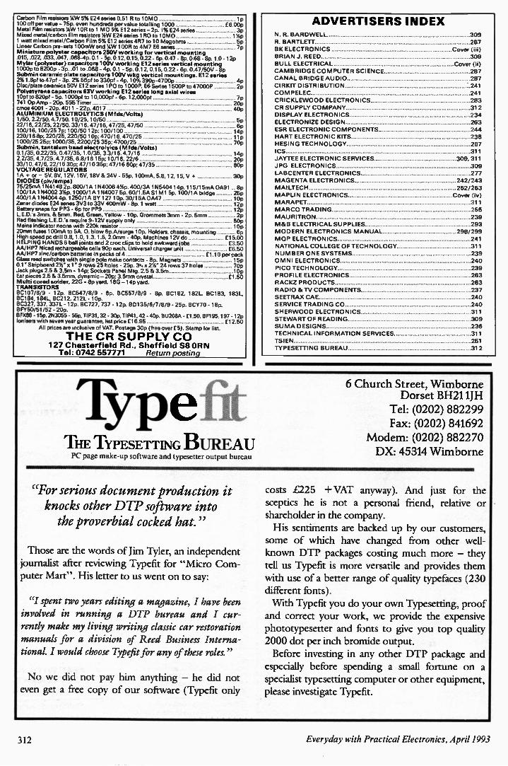
Carbon Film resistors 14W 5% E24 series 0.51 R to 10M0 1p 100 off per value - 75p. even hundreds per value totalling 1000 £6.00p Metal Film resistors 14W lOR to 1 MO 5% El 2 series - 2p. I% E24 series 3p Mixed metal/carbon film resistors 14W E24 series 1R0 to 10M0 114p 1 watt mixed metal/Carbon Film 5% El 2 series 4R7 to 10 Megohms 5p Linear Carbon pre-sets 100mW and Y.W 100R to 4M7 E6 series 7p Miniature polyster capacitors 250V working for vertical mounting .015, .022, .033..047, .068-4p. 0.1 - 5p 0.12, 0.15, 0.22 - 6o 047- 8o 0.68- 8p. 1.0- 12p Mylar (polyester) capacitors 100V working E12 series vertical mounting 1000p to 8200p - 3p. .01 to .068 - 4p. 0.1 - 5p. 0.12. 0.15, 0.22 - 6p. 0.47/50V - 8p Submin ceramic plate capacitors 100V wkg vertical mountings. E12 series 2% 1.8pf to 47pf. - 3p. 2% 56pf to 330pf - 4p. 10%390p-4700p 4p Disc/plate ceramics 50V El 2 series 1P0 to 1000P, E6 Series 1500P to 47000P 2p Polystyrene capacitors 63V working 512 series long axial wires 10pf to 820pf - 5p. 1000pf to 10,000pf - 6p. 12,000pf 7p 741 Op Amp - 20p. 555 Timer 20p cmos 4001 - 20p. 4011 - 22p. 4017 40p ALUMINIUM ELECTROLYTICS (Mfds/Volts) 1/50, 2.2/50, 4.7/50. 10/25, 10/50 5p 22/16, 22/25, 22/50, 33/16, 47/16, 47/25, 47/50 6p 100/16.100/25 7p; 100/50 12p; 100/100 14p 220/16 8p; 220/25.220/50 10p; 470/16.470/25 lip 1000/25 25p; 1000/35,2200/25 35p; 4700/25 70p Submin, tantalum bead electrolyics (Mfds/Volts) 0.1/35. 0.22/35, 0.47/35, 1.0/35, 3.3/16. 4.7/16 14p 2.2/35, 4.7/25, 4.7/35. 6.8/16 15p; 10/16.22/6 20p 33/10, 47/6, 22/16 30p; 47/10 35p; 47/16 60p; 47/35 80p VOLTAGE REGULATORS 1A + or - 5V, 8V, 12V, 15V, 18V & 24V - 55p. 100mA. 5.8,12, 15, V + 30p DIODES (piv/amps) 75/25mA 1N4148 2p. 800/1A 1 N4006 414p. 400/3A 1N5404 14p. 115/15mA 0A91 .. 8p 100/1A 1N4002 314p. 1000/1A I N4007 5p. 60/1.5A Si Ml 5p. 100/1A bridge 25 400/1A 1N4004 4p. 1250/1A BY 127 10p. 30/15A 0A47 10p Zener diodes E24 series 3V3 to 33V 400mW - 8p. 1 watt 12p Battery snaps for PP3 - 6p for PP9 12p LED's 3mm. & 5mm. Red, Green, Yellow - 10p. Grommets 3mm - 2p 5mm 2p Red flashing LED's require 9-12V supply only 50p Mains indicator neons with 220k resistor 10p 20mm fuses 100mA to 5A. 0. blow 6p.A/surge 10p. Holders, chassis, mounting 6p High speed pc drill 0.8. 1.0, 1.3, 1.5, 2.0mm - 40p. Machines 12V dc £15.00 HELPING HANDS 6 ball joints and 2 croc clips to hold awkward jobs £3.50 AA/HP7 Nicad rechargeable cells 90p each. Universal charger unit £6.50 AA/HP7 zinc/carbon batteries in packs of 4 £1.10 per pack Glass reed switches with single pole make contacts - 8p. Magnets 15p 0.1 Stripboard 2%" x 1" 9 rows 25 holes - 25p. 33/4 x214" 24 rows 37 holes 70p Jack plugs 2.5 & 3.5m - 14p; Sockets Panel Mtg. 2.5 & 3.5m 10p Ear pieces 2.5 & 3.5mm, dynamic - 20p; 3.5mm crystal £1.50 Mufti cored solder. 22G - 8p yard. 18G - 14p yard. TRANSISTORS BC107/8/9 - 12p. BC547/8/9 - 8p. BC557/8/9 - 8p. BC182, 182L, BC183, 183L, 8C184, 184L, BC212, 212L - 10p. BC327, 337, 337L- 12p. BC727, 737. 12p. 8D135/6/7/8/9 - 25p. BCY70 - 18p. BFY50/51/52 - 20p. BFXI38 - 15p. 2N3055 - 55p, TIP31, 32 - 30p. TIP41, 42 - 40p. BU208A - £1.50, 8F1 95, 197- 12p Ionisers with seven year guarantee, list price £16.95 El 2.50
All prices are inclusive of VAT. Postage 30p (free over £5). Stamp for list.
THE CR SUPPLY CO 127 Chesterfield Rd., Sheffield S8 OR N Tel: 0742 557771 Return posting
Type THE TYPESETTING BUREAU PC page make-up software and typesetter output bureau
ADVERTISERS INDEX N. R. BAR DWELL 309 R. BARTLETT 287
BK ELECTRONICS Cover (iii) BRIAN J. REED 309
BULL ELECTRICAL Cover (ii) CAMBRIDGE COMPUTER SCIENCE 287
CANAL BRIDGE AUDIO 287 CIRKIT DISTRIBUTION 241 COM PELEC 241
CRICKLE WOOD ELECTRONICS 283 CR SUPPLY CO MPANY 312 DISPLAY ELECTRONICS 234 ELECTRONIZE DESIGN 263
ESR ELECTRONIC COMPONENTS 244 HART ELECTRONIC KITS 238
HESING TECHNOLOGY 287 ICS 311
JAYTEE ELECTRONIC SERVICES 309.311
JPG ELECTRONICS 309 LABCENTER ELECTRONICS 277 MAGENTA ELECTRONICS 242/243
MAI LTECH 262/263 MAPLIN ELECTRONICS Cover (iv)
MARAPET 311 MARCO TRADING 255
MAURITRON 239 M&B ELECTRICAL SUPPLIES 293 MODERN ELECTRONICS MANUAL 298/299
M OP ELECTRONICS 241
NATIONAL COLLEGE OF TECHNOLOGY 311 NU MBER ONE SYSTEMS 239 OMNI ELECTRONICS 240 PICO TECHNOLOGY 239 PROFILE ELECTRONICS 263 RACKZ PRODUCTS 263 RADIO & TV COMPONENTS 237
SEETRAX CAE 240 SERVICE TRADING CO 240
SHER WOOD ELECTRONICS 311 STE WART OF READING 309 SU MA DESIGNS 236
TECHNICAL INFOR MATION SERVICES 311 TSI EN 251 TYPESETTING BUREAU 312
6 Church Street, Wimborne Dorset BH211JH
Tel: (0202) 882299 Fax: (0202) 841692
Modem: (0202) 882270 DX: 45314 Wimborne
"For serious document production it knocks other DTP software into the proverbial cocked hat."
Those are the words of Jim Tyler, an independent journalist after reviewing Typefit for "Micro Com-puter Mart". His letter to us went on to say:
"I spent two years editing a magazine, I have been involved in running a DTP bureau and I cur-rently make my living writing classic car restoration manuals for a division of Reed Business Interna-tional. I would choose Typefit for any of these roles."
No we did not pay him anything - he did not even get a free copy of our software (Typefit only
costs £225 + VAT anyway). And just for the sceptics he is not a personal friend, relative or shareholder in the company. His sentiments are backed up by our customers,
some of which have changed from other well-known DTP packages costing much more - they tell us Typefit is more versatile and provides them with use of a better range of quality typefaces (230 different fonts). With Typefit you do your own Typesetting, proof and correct your work, we provide the expensive phototypesetter and fonts to give you top quality 2000 dot per inch bromide output.
Before investing in any other DTP package and especially before spending a small fortune on a specialist typesetting computer or other equipment, please investigate Typefit.
312 Everyday with Practical Electronics, April 1993

P O W E R A M P LI FI E R M O D U L E S- T U R N T A B L E S- DI M M E R S-
L O U D S P E A K E R S-1 9 IN C H S T E R E O R A C K A M P LI FI E R S
. * • - is •
SERVICE* LARGE (A4) S.A.E. 50 STA MPED FOR C ATALOGUE*
,i1,1 [43.1J 4I LL•171,.:11.1.',11111JI= X,L•1•111115.-S SUPPLIED READY BUILT AND TESTED.
I. V - • • •
O M P M OS-FET P O W ER A M PLI FI E RS
HIGH PO WER. TWO CHANNEL 19 INCH RACK
T H O U S A N DS P U R C H AS E D
B Y PR OFESSI O N AL U S ERS
T H E R E N O W N E D M X F S E RI E S O F P O W E R A M P LI FI E R S
FO U R M O DELS:- M X F 2 0 0 (100 W • 100 W) M X F 4 0 0 (200 W 200 W)
M X F6 0 0 (300 W • 300 W) M X F 9 0 0 (450 W 450 W)
ALL PO WER RATINGS R.M.S. INTO 4 OHMS, BOTH CHANNELS DRIVEN
FEATURES: *Independent power supplies with two toroidal transformers * Twin L.E.D. Vu meters * Level controls * Illuminated on/off switch * XLR connectors * Standard 775mV inputs * Open and short circuit proof * Latest Mos-Fels for stress free power delivery into virtually any load * High slew rate * Very low distortion * Aluminium cases * MXF600 & MXF900 tan cooled with DC. loudspeaker and thermal protection.
USED THE WORLD OVER IN CLUBS, PUBS, CINEMAS, DISCOS ETC.
SIZES:- MXF200 W19 xH3 ,x" (2U)xD11" MXF400 W19 x115',..' (3U)aD12" MXF600 W19 xH5',.." (3U)x1D13" MXF900 W19 icH5' ." (3U)x1314..."
PRICES:- MXF200 £1 75.00 M XF400 £233.85
M XF600 £329.00 M XF900 £449.1 5 SPECIALIST CARRIER DEL E12.50 EACH
.•1;',1: W/.1:11-1114. .1111 11:1:11(1-1 114•CT I-1-1E-'
* Manual arm * Steel chassis * Electronic speed
control 33 8 45 R.P.M. * Van i pitch control * High
torque servo driven DC motor * Transit screws *
12 die cast platter * Neon strobe * Calibrated
balance weight * Removable head shell * ' r
cartridge fixings * Cue lever* 220/240V 50/60Hz
* 390x305mm * Supplied with mounting cut-out
template -•••
PRI CE £61.30 £3.7 0 P& P
pilaiDkri n,,rTei,14Iireff•LIA LIIDIel*- STA NT O N AL500mkii G OL D RI N G G 9 50 PRICE C16.95 50P P&P PRICE C7.15 - 50P P&P
-
STEREO DISCO MIXER with 2 z 7 band L & R graphic equalisers with bar graph LED Vu meters MANY OUTSTANDING FEATURES:- including Echo with repeat & speed control, DJ Mic with tone control & talk-over switch, 7 Channels with individual faders plus cross fade, Cue Headphone Monitor. Useful combination of the following inputs:- 3 turntables (wag), 3 mics, 5 Line for CD, Tape, Video etc.
Price £1 3 4.99 £5.00 P & P
* WIT H E C H O *
SIZE: 482 x 240 x 120 m m
• •II B].IB
Join the Piezo revolution! The low dynamic mass (no voice coil) of a Piezo tweeter produces an improved transient response with a lower distortion level than ordinary dynamic tweeters. As a crossover is not required these units can be added to existing speaker systems of up to 100 watts (more if two are put in series FREE EXPLANATORY LEAFLETS ARE SUPPLIED WITH EACH TWEETER.
TYPE 'A' (KSH1036A) 3 round with protective wire mesh. Ideal for
.1 bookshelf and medium sized Hi-Fi apeakers. Price £4.90 • 50p P&P.
TYPE 'B' (KSN1005A) 3V," super horn for general purpose speakers.
disco and P.A. systems etc. Price £5.99 - 50p P&P.
TYPE 'C' (KSN1016A) 2"x5" wide dispersion horn for quality Hi-Fl sys-
tems and quality discos etc. Price £6.99 • 50p P&P.
TYPE 'D' (KSN1025A) 2 x6 wide dispersion horn. Upper frequency
response retained extending down to mid-range (2KHz). Suitable for high
quality Hi-Fi systems and quality discos. Price £9.99 • 50p P&P.
TYPE 'E' (KSN1038A) 34, horn tweeter with attractive silver finish trim.
Suitable for Hi-Fi monitor systems etc. Price £5.99 - 50p P&P.
LEVEL CONTROL Combines, on a recessed mounting plate, level control
and cabinet input jack socket. 85x85mm. Price £4.10 - 50p P&P.
'YPE
-yPE C
TYPE
AK•111.1-1:1 1,.1
THE VERY BEST IN QUALITY AND VALUE
Made especially to suit today s need for compactness with high output sound levels, finished in hard wearing black vynide with protective corners grille and carrying handle Each unit incorporates a 12" driver plus high frequency horn lot- a lull frequency range of 45Hz-20KHz. Both models are 8 Ohm impedance. Size: H20" x W15" x D12".
CHOICE OF TWO MODELS
PO WER RATINGS QUOTED IN WATTS RMS FOR EACH CABINET
OMP 12-100 WATTS (100dB) PRICE £163.50 PER PAIR OMP 12-200 WATTS (200dB) PRICE C214.55 PER PAIR
SPECIALIST CARRIER DEL £12.50 PER PAIR
These modules now enjoy a world-wide reputation for quality, reliability and performance at a realistic price Four models are available to suit the needs of the professional and hobby market i.e Industry. Leisure, Instrumental and Hi-Fl etc When comparing prices. NOTE that all models include toroidal power supply. integral heat sink, glass fibre PC B and drive circuits to power a compatible Vu meter All models are open and short circuit proof
T H O US A N DS O F M O D UL ES P U R C H AS E D B Y P R OFESSI O N AL U SERS
O MP/ MF 100 Mos-Fet Output power 110 watts
R. M.S. into 4 oh ms. frequency response 1Hz- 100KHz
-3dB. Da mping Factor 300, Slew Rate 45V/uS.
T.H.D. typical 0.002 %. Input Sensitivity 500 mV. S.N.R.
-110 dB. Size 300 x 123 x 60 m m.
PRICE £40.85 • £3.50 P&P
O MP/ MF 200 Mos-Fet Output power 200 watts
R. M.S. into 4 oh ms, frequency response 1Hz- 100KHz
-3dB. Da mping Factor 300, Slew Rate 50V/uS.
T.H.D. typical 0.001 %. Input Sensitivity 500 mV. S.N.R.
-110 dB. Size 300 x 155 x 100 m m.
PRICE £64.35 - £4.00 P&P
O MP/ MF 300 Mos-Fet Output power 300 watts
R. M.S. into 4 oh ms. frequency response 1Hz - 100KHz
o -3dB, Da mping Factor 300, Slew Rate 60V/uS.
T.H.D. typical 0.001 %, Input Sensitivity 500 mV, S.N.R.
-110 dB. Size 330 x 175 x 100 m m.
PRICE £81.75 • £5.00 P&P
O MP/ MF 450 Mos-Fet Output power 450 watts
R. M.S. into 4 oh ms, frequency response 1Hz - 100KHz
-3dB. Da mping Factor 300. Slew Rate 75V/uS.
T.H.D. typical 0.001 %. Input Sensitivity 500 mV. S.N.R.
-110 dB. Fan Cooled. D.C. Loudspeaker Protection. 2
Second Anti-Thu mp Delay. Size 385 x 210 x 105m m.
PRICE £1 32.85 • £5.00 P&P NOTE: MOS-FET MODULES ARE AVAILABLE IN TWO VERSIONS: STANDARD. INPUT SENS 500mV, BAND WIDTH 100KHc. PEC (PROFESSIONAL EQUIPMENT COMPATIBLE) - INPUT SENS 775m1/, BAND WIDTH 50KI-Ic. ORDER STANDARD OR PEC.
Vu METER Compatible with our four amplifiers detailed above. A very accurate visual display employing 11 L.E.D.s (7 green. 4 red) plus an additional on/off indicator. Sophisticated logic control for very last rise and decay times. Tough moulded plastic case, with acrylic tinted front. Size 84 27 45mm.
PRICE £8.70 50p P&P
LARGE SELECTI ON OF SPECIALIST LOU DSPEAKERS
AVAILABLE, INCLU DIN G CABINET FITTIN GS, SPEAKER
GRILLES, CROSS OVERS AN D HIGH PO WER, HIGH
FREQUENCY BULLETS AN D HORNS, LARGE (A4) S.A.E.
(50p STA MPED) FOR C O MPLETE LIST.
P - From McKenzie Professional Series S- From McKenzie Studio Series
ALL McKENZIE UNITS 8 OHMS IMPEDANCE 8 100 WATT P C8-100GP GEN. PURPOSE. LEAD GUITAR. EXCELLENT MID, DISCO. RES. FREQ. 80Hz, FREQ, REAP. TO 7KHz. SENS 96dB. PRICE £31.45 • £2.00 P&P 10 100 WATT SC10-100GP GUITAR. VOICE. KEYBOARD, DISCO, EXCELLENT MID. RES. FREQ. 72Hz. FREQ. REAP. TO 6KHz, SENS97dB. PRICE £38.89 • £2.50 P&P 10 200 WATT SC10-200GP GUITAR, KEYB'D, DISCO. EXCELLENT HIGH POWER MID. RES. FREO. 69Hz, FREQ. REAP. TO 5KHz. SENS 97dB. PRICE £53.21 £2.50 P&P 12 100 WATT C12-100GP HIGH POWER GEN. PURPOSE, LEAD GUITAR, DISCO. RES.FREQ. 49H FREC). RESP. TO 7KHz. SENS 98dB. PRICE £40.35 - £3.50 P&P 12 100 WATT p C12-100TC (TWIN CONE) HIGH POWER. WIDE RESPONSE. P.A.. VOICE. DISCO. RES FREO 45Hz FREC1. RESP. TO 12KHz, SENS 97d8 PRICE £41.39 - £3.50 P&P 12 200 WATT p C12-2008 HIGH POWER BASS, KEYBOARDS. DISCO, P.A. RES. FREO, 45Hz, FREQ. RESP. TO 5KHz, SENS 99dB. PRICE £71.91 - £3.50 P&P 12 300 WATT SC12-3000P HIGH POWER BASS, LEAD GUITAR. KEYBOARDS. DISCO ETC. RES. FREO. 49Hz, FREO. RESP. TO 7KHz, SENS 100dB, PRICE £95.66 - £3.50 P&P 15 100 WATE PC15-100BS BASS GUITAR. LOW FREQUENCY. P.A., DISCO. RES. FREC). 40Hz, FREQ. RESP. TO 5KHz. SENS 98dB. PRICE £59.05 £4.00 P&P 15 200 WATT PC15-200BS VERY HIGH POWER BASS. RES. FREQ. 40Hz, FREQ. RESP. TO 3KHz, SENS 98dB. PRICE £80.57 £4.00 P&P 15 250 WATT S C15-250135 VERY HIGH POWER BASS. RES. FREQ. 39Hz, FREQ. RESP. TO 4KHz, SENS 99dB. PRICE £90.23 £4.50 P&P 15 400 WAT7 PC15-400BS VERY HIGH POWER. LOW FREQUENCY BASS. RES. FREQ. 40Hz, FREQ. RESP. TO 4 KHz, SENS 100dB, PRICE £105.46 £4.50 P&P 18 500 WATT PC18-500BS EXTREMELY HIGH POWER, LOW FREQUENCY BASS. RES. FREQ. 27Hz, FREQ. RESP. TO 2KHz, SENS. 98dB, PRICE £174.97 £5.00 P&P
'II.
ALL EARBENDER UNITS 8 OHMS (Except EB8-50 & EB10-50 which are dual impedance lapped a 41 0 ohm) BASS, SINGLE CONE, HIGH COMPLIANCE, ROLLED SURROUND 8 50watt EB8-50 DUAL IMPEDENCE, TAPPED 4/8 OHM BASS. HI-Fl. IN-CAR. RES. FREQ. 40Hz, FREO. RESP. TO 7KHz SENS 97dB. PRICE £8.90 - £2.00 P&P 10 50 WATT EB10-50 DUAL IMPEDENCE, TAPPED 4/8 OHM BASS, HI-Fl. IN-CAR. RES. FREQ. 40Hz, FREO. RESP. TO 5KHz. SENS. 99dB. PRICE £13.65 £2.50 P&P 10 100 WATT EB10-100 BASS, HI-Fl. STUDIO, RES, FREQ. 35Hz. FREO. RESP. TO 3KHz, SENS 96dB. PRICE £30.39 £3.50 P&P 12 100 WATT EB12-100 BASS, STUDIO, HI-Fl. EXCELLENT DISCO RES. FREQ. 26Hz, FREO. RESP. TO 3 KHz, SENS 93dB. PRICE £42.12 £3.50 P&P FULL RANGE TWIN CONE, HIGH COMPLIANCE, ROLLED SURROUND 5' . 60 WATT EB5-60TC (TWIN CONE) HI-Fl. MULTI-ARRAY DISCO ETC. RES. FREO. 63Hz, FREQ. RESP. TO 20KHz. SENS 92dB. PRICE £9.99 £1.50 P&P 6' a 60 WATT EB6-60TC (TWIN CONE) HI-Fl. MULTI-ARRAY DISCO ETC. RES. FREQ. 38Hz, FREQ. RESP. TO 20KHz, SENS 94dB. PRICE £10.99 1.50 P&P 8 60 WATT EBB-60TC (TWIN CONE) HI-Fl. MILTI-ARRAY DISCO ETC. RES. FREO. 40Hz, FREO. RESP. TO 18KHz. SENS 89dB, PRICE £12.99 £1.50 P&P 10 60 WATT EB10-60TC (TWIN CONE) HI-Fl, MULTI ARRAY DISCO ETC RES. FREQ. 35Hz, FREQ. REAP. TO 12KHz. SENS 98dB, PRICE C16.49 £2.00 P&P
PRICES: 150 W £49.99 250 W £99.99 400 W £109.95 P&P £2.00 EACH
THREE SUPERB HIGH PO WER CAR STEREO BOOSTER AMPLIFIERS 150 WATTS (75 - 75) Stereo, 150W Bridged Mono 250 WATTS (125 • 1251 Stereo. 250W Bridged Mono 400 WATTS (200 • 2001 Stereo, 400W Bridged Mono ALL PO WERS INTO 4 OHMS Features: * Stereo, bridgable mono * Choice of high & low level inputs * L & R level controls * Remote on-off * Speaker thermal Protection.
PROVEN TRANSMITTER DESIGNS INCLUDING GLASS FIBRE PRINTED CIRCUIT BOARD AND HIGH QUALITY COMPONENTS
COMPLETE WITH CIRCUIT AND INSTRUCTIONS
3W TRANSMITTER 80.108MHz VARICAP CONTROLLED PROFESSIONAL PERFORMANCE RANGE UP TO] MILES. SIZE 38 x 123mm SUPPLY 125 ,-., OSAMP
PRICE £14.85 £1.00 P&P
FM MICRO TRANSMITTER 100-108MHz, VARICAP TUNED. COMPLETE WITH VERY SENS FET MIC.RANGE100-300m, SIZE 56 x 46mm, SUPPLY W BATTERY.
PHOTO: 3W FM TRANSMITTER
B.K. ELECTRO NICS I E 3 POSTALE CHARGESFpom SCHOOLS, P f)ORLDLEERG COLLEGES,
. Ig 2 MINIMU M.B,DDIEs , OFFICIALpLce ETC.
PRICES INCLUSIVE OF V AT, SALES COUNTER, VISA AND ACCESS ACCEPTED BY POST, PHONE OP FAX. Ir•-•.7 77 1
VISA
U NI T SIl & 5 C O M E T W A Y, S O U T H E N D- O N- S E A,
E S S E X. S S 2 6 T R.
T el.: 0 7 0 2 - 5 2 7 5 7 2 F a x.: 0 7 0 2 - 4 2 0 2 4 3


