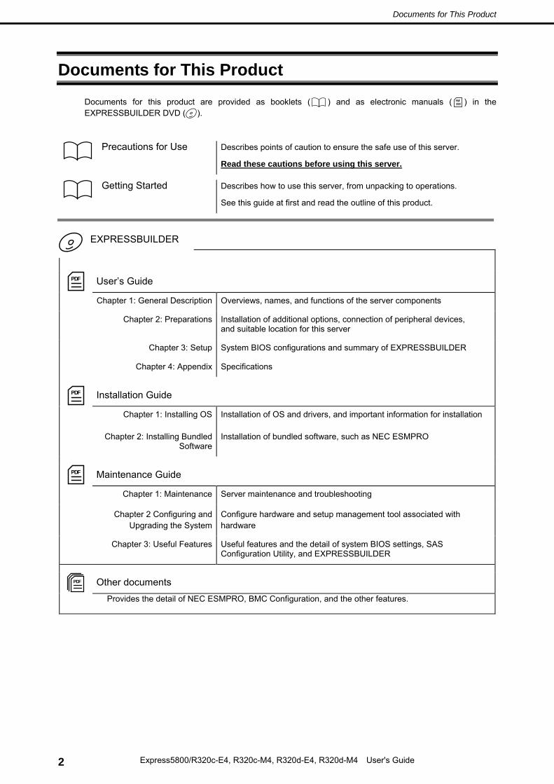
Documents for This Product .................................................................................................................................. 2
Notations Used in This Document ......................................................................................................................... 5 Notations used in the text .............................................................................................................................. 5 Optical disk drive ........................................................................................................................................... 5 Removable media ......................................................................................................................................... 5 Abbreviations of Operating Systems (Windows) ........................................................................................... 6 POST ........................................................................................................................................................... 6 BMC ........................................................................................................................................................... 6
Warnings and Additions to This Document .......................................................................................................... 12 Latest editions ............................................................................................................................................. 12
Precautions for Use (Be Sure to Read) ............................................................................................................... 13 Safety precautions ...................................................................................................................................... 13 Symbols used in this document and on warning labels ............................................................................... 14 Safety notes ................................................................................................................................................ 15
Safety Instructions ........................................................................................................................... 15 General ........................................................................................................................................... 15 Rack installation ............................................................................................................................... 16 Power supply and power cord use ................................................................................................... 17 Installation, relocation, storage, and connection .............................................................................. 18 Cleaning and working with internal devices ..................................................................................... 19 During operation .............................................................................................................................. 20
Mesures de sécurité - il est recommandé de bien lire ces instructions - .............................................................. 21 INDICATIONS SUR LA SÉCURITÉ ............................................................................................................ 21 Symboles utilisés dans ce document et sur les étiquettes de mise en garde .............................................. 22 CONSIGNES DE SÉCURITÉ ..................................................................................................................... 23
Installation du rack ........................................................................................................................... 23 Sources d'énergie multiples ............................................................................................................. 23
Chapter 1 General Description.......................................................................................................................... 37
3. Standard Features .......................................................................................................................................... 40 3.1 Features of the Server ......................................................................................................................... 40 3.2 Fault-Tolerant Features ........................................................................................................................ 42 3.3 Management Features ......................................................................................................................... 45 3.4 Firmware and Software Version Management for Windows ................................................................. 46
4. Names and Functions of Components ............................................................................................................ 47 4.1 Front View ............................................................................................................................................ 47 4.2 Front View Without Front Bezel ........................................................................................................... 48 4.3 Rear View ............................................................................................................................................ 49 4.4 External View ....................................................................................................................................... 51 4.5 Optical Disk Drive ................................................................................................................................ 52 4.6 CPU/IO Module .................................................................................................................................... 53 4.7 CPU/IO Board ...................................................................................................................................... 55 4.8 LEDs .................................................................................................................................................... 56
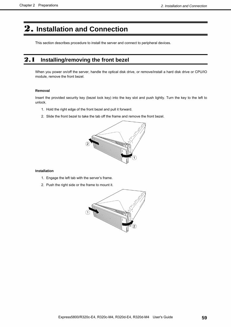
2. Installation and Connection ............................................................................................................................. 59 2.1 Installing/removing the front bezel ....................................................................................................... 59 2.2 Rack ..................................................................................................................................................... 60
2.2.1 Installing Rack ......................................................................................................................... 60 2.2.2 Installing the server to the rack................................................................................................ 62 2.2.3 Removing the device from the rack ......................................................................................... 69
2.3 Tower Conversion Kit (N8843-004) ...................................................................................................... 70 2.3.1 Installing the Tower Conversion Kit ......................................................................................... 70 2.3.2 Installing the Rack-mount Model to the Tower Conversion Kit ................................................ 72
2.4 Connection ........................................................................................................................................... 77 2.4.1 Connecting to a uninterruptible power supply (UPS) ............................................................... 79
1. Power ON ....................................................................................................................................................... 81 1.1 POST Check ........................................................................................................................................ 83
1.1.1 Flow of POST .......................................................................................................................... 83 1.1.2 POST Error Messages ............................................................................................................ 84 1.1.3 Behavior at Occurrence of Error .............................................................................................. 85
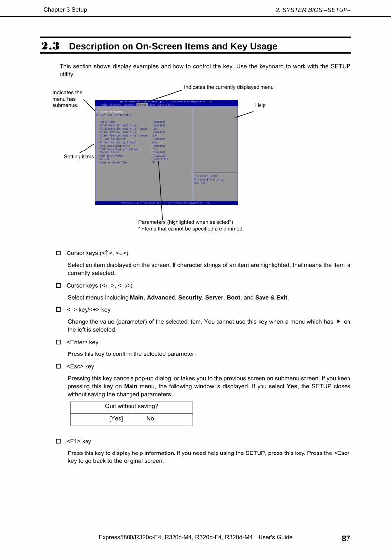
2. SYSTEM BIOS –SETUP– ............................................................................................................................... 86 2.1 Overview .............................................................................................................................................. 86 2.2 Starting and Exiting SETUP Utility ....................................................................................................... 86
6. Power OFF ..................................................................................................................................................... 95
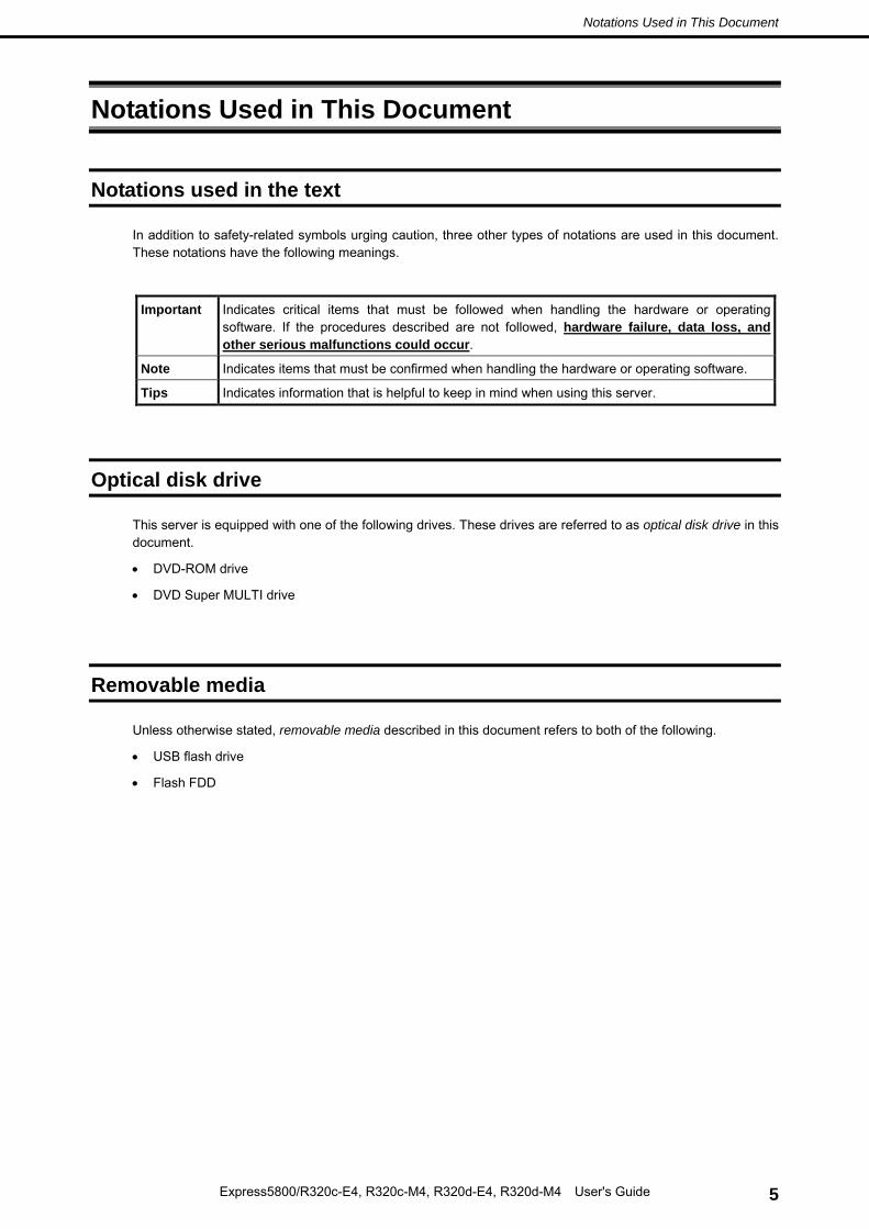
In addition to safety-related symbols urging caution, three other types of notations are used in this document. These notations have the following meanings.
Important Indicates critical items that must be followed when handling the hardware or operating software. If the procedures described are not followed, hardware failure, data loss, and other serious malfunctions could occur.
Note Indicates items that must be confirmed when handling the hardware or operating software.
Tips Indicates information that is helpful to keep in mind when using this server.
Optical disk drive
This server is equipped with one of the following drives. These drives are referred to as optical disk drive in this document.
• DVD-ROM drive
• DVD Super MULTI drive
Removable media
Unless otherwise stated, removable media described in this document refers to both of the following.
This equipment has been tested and found to comply with the limits for a Class A digital device, pursuant to Part 15 of the FCC Rules. These limits are designed to provide reasonable protection against harmful interference when the equipment is operated in a commercial environment. This equipment generates, uses, and can radiate radio frequency energy and, if not installed and used in accordance with the instruction manual, may cause harmful interference to radio communications. Operation of this equipment in a residential area is likely to cause harmful interference in which case the user will be required to correct the interference at his own expense.
Industry Canada Class A Emission Compliance Statement / Avis de conformité à la réglementation d'Industrie Canada:
CAN ICES-3(A) / NMB-3(A)
CE / Australia and New Zealand Statement
This is a Class A product. In domestic environment this product may cause radio interference in which case the user may be required to take adequate measures (EN55022).
BSMI Statement
Korean KC Standards
Registration NO. : MSIP-REM-NEC-EXP320Q Basic Model Number : EXP320Q Trade Name or Registrant : NEC CORPORATION : Equipment Name : FT Server Manufacturer : NEC CORPORATION
Turkish RoHS information relevant for Turkish market
with the requirements of Technical Regulation on the Restriction Of the use of certain Hazardous Substances in Electrical and Electronic Equipment
(adopted by Order №1057 of Cabinet of Ministers of Ukraine)
The Product is in conformity with the requirements of Technical Regulation on the Restriction Of the use of certain Hazardous Substances in electrical and electronic equipment (TR on RoHS).
The content of hazardous substance with the exemption
of the applications listed in the Annex №2 of TR on RoHS:
1. Lead (Pb) – not over 0,1wt % or 1000wt ppm;
2. Cadmium (Cd) – not over 0,01wt % or 100wt ppm;
3. Mercury (Hg) – not over 0,1wt % or 1000wt ppm;
4. Hexavalent chromium (Cr6+) – not over 0,1wt % or 1000wt ppm;
5. Polybrominated biphenyls (PBBs) – not over 0,1wt % or 1000wt ppm;
6. Polybrominated diphenyl ethers (PBDEs) – not over 0,1wt % or 1000wt ppm.
Ukrainian Декларація про Відповідність
Вимогам Технічного Регламенту Обмеження Використання деяких Небезпечних Речовин в електричному та електронному обладнанні
(затвердженого Постановою №1057 Кабінету Міністрів України)
Виріб відповідає вимогам Технічного Регламенту Обмеження Використання деяких Небезпечних Речовин в електричному та електронному обладнанні (ТР ОВНР).
Вміст небезпечних речовин у випадках, не обумовлених в Додатку №2 ТР ОВНР, :
1. свинець(Pb) – не перевищує 0,1 % ваги речовини або в концентрації до 1000 частин на мільйон;
2. кадмій (Cd)– не перевищує 0,01 % ваги речовини або в концентрації до 100 частин на мільйон;
3. ртуть(Hg) – не перевищує 0,1 % ваги речовини або в концентрації до 1000 частин на мільйон;
4. шестивалентний хром (Cr6+ ) – не перевищує 0,1 % ваги речовини або в концентрації до 1000 частин на мільйон;
5. полібромбіфеноли (PBB) – не перевищує 0,1% ваги речовини або в концентрації до 1000 частин на мільйон;
6. полібромдефенілові ефіри (PBDE) – не перевищує 0,1 % ваги речовини або в концентрації до 1000 частин на мільйон.
Russian Декларация о Соответствии
Требованиям Технического Регламента об Ограничении Использования некоторых Вредных Веществ в электрическом и электронном оборудовании
(утверждённого Постановлением №1057 Кабинета Министров Украины)
Изделие соответствует требованиям Технического Регламента об
Ограничении Использования некоторых Вредных Веществ в электрическом и электронном оборудовании (ТР ОИВВ).
Содержание вредных веществ в случаях, не предусмотренных Дополнением №2 ТР ОИВВ:
1. свинец (Pb) – не превышает 0,1 % веса вещества или в концентрации до 1000 миллионных частей;
2. кадмий (Cd) – не превышает 0,01 % веса вещества или в концентрации до 100 миллионных частей;
3. ртуть (Hg) – не превышает 0,1 % веса вещества или в концентрации до 1000 миллионных частей;
4. шестивалентный хром (Cr6+)– не превышает 0,1 % веса вещества или в концентрации до 1000 миллионных частей;
5. полибромбифенолы (PBB) – не превышает 0,1 % веса вещества или в концентрации до 1000 миллионных частей;
6. полибромдифеноловые эфиры (PBDE) – не превышает 0,1 % веса вещества или в концентрации до 1000 миллионных частей.
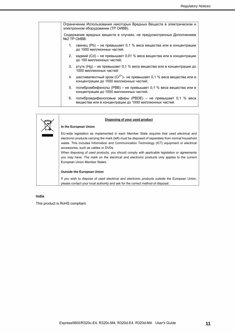
Disposing of your used product
In the European Union
EU-wide legislation as implemented in each Member State requires that used electrical and electronic products carrying the mark (left) must be disposed of separately from normal household waste. This includes Information and Communication Technology (ICT) equipment or electrical accessories, such as cables or DVDs. When disposing of used products, you should comply with applicable legislation or agreements you may have. The mark on the electrical and electronic products only applies to the current European Union Member States. Outside the European Union
If you wish to dispose of used electrical and electronic products outside the European Union, please contact your local authority and ask for the correct method of disposal.
1. Unauthorized reproduction of the contents of this document, in part or in its entirety, is prohibited.
2. This document is subject to change at any time without notice.
3. Do not make copies or alter the document content without permission from NEC Corporation.
4. If you have any concerns, or discover errors or omissions in this document, contact your sales
representative.
5. Regardless of article 4, NEC Corporation assumes no responsibility for effects resulting from your
operations.
6. The sample values used in this document are not the actual values.
Keep this document for future use.
Latest editions
This document was created based on the information available at the time of its creation. The screen images, messages and procedures are subject to change without notice. Substitute as appropriate when content has been modified.
The most recent version of the guide, as well as other related documents, is also available for download from the following website.
The following provides information required to use your server safely and properly. For details of names in this section, see Chapter 1 (4. Names and Functions of Components) in this document.
Safety precautions
Follow the instructions in this document for the safe use of NEC Express server.
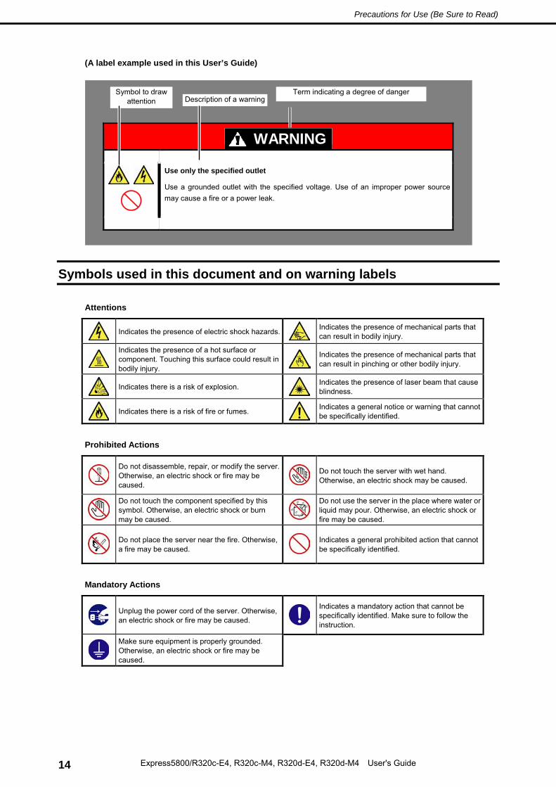
This User’s Guide describes hazardous parts of the server, possible hazards, and how to avoid them. Server components with possible danger are indicated with a warning label placed on or around them (or, in some cases, by printing the warnings on the server).
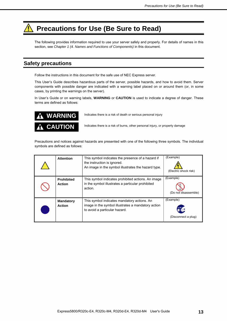
In User’s Guide or on warning labels, WARNING or CAUTION is used to indicate a degree of danger. These terms are defined as follows:
WARNING
Indicates there is a risk of death or serious personal injury
CAUTION
Indicates there is a risk of burns, other personal injury, or property damage
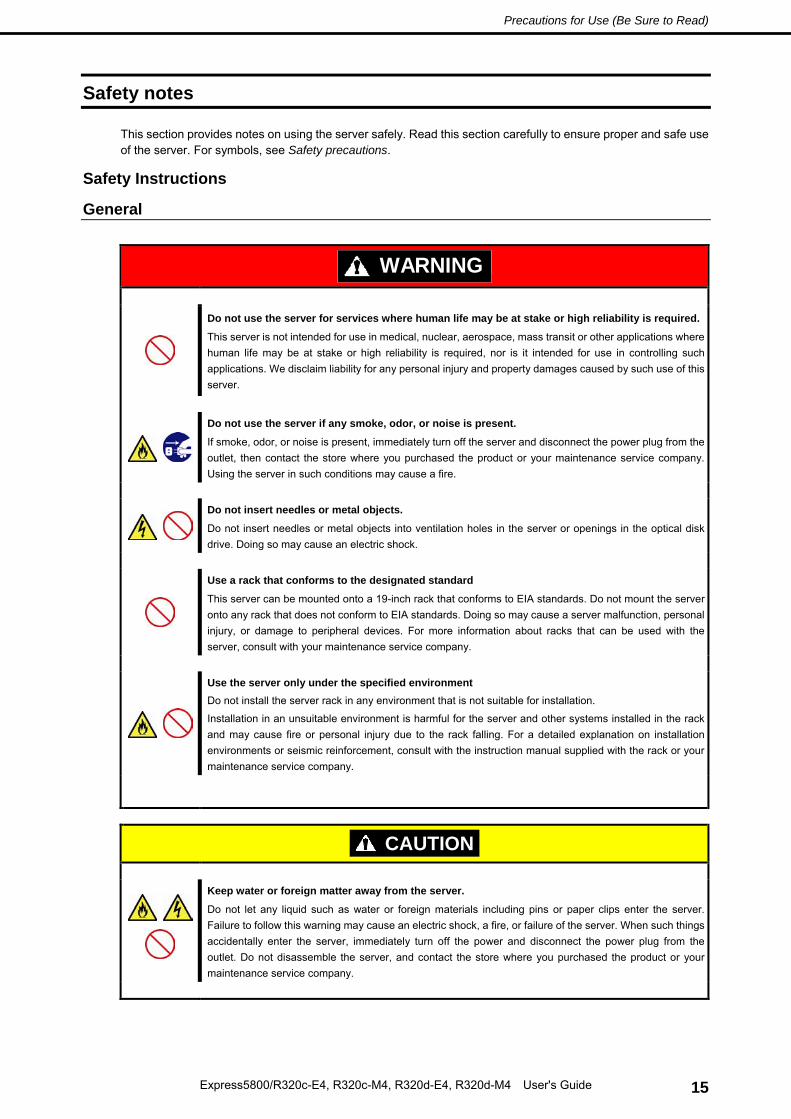
Precautions and notices against hazards are presented with one of the following three symbols. The individual symbols are defined as follows:
Attention This symbol indicates the presence of a hazard if the instruction is ignored. An image in the symbol illustrates the hazard type.
Prohibited Action
This symbol indicates prohibited actions. An image in the symbol illustrates a particular prohibited action.
Mandatory Action
This symbol indicates mandatory actions. An image in the symbol illustrates a mandatory action to avoid a particular hazard.
This section provides notes on using the server safely. Read this section carefully to ensure proper and safe use of the server. For symbols, see Safety precautions.
Safety Instructions
General
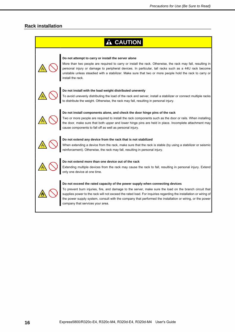
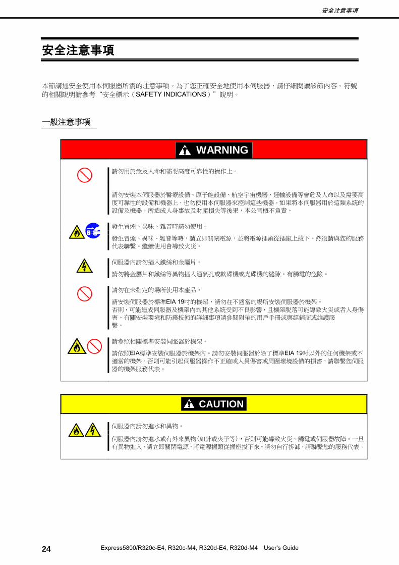
WARNING
Do not use the server for services where human life may be at stake or high reliability is required.
This server is not intended for use in medical, nuclear, aerospace, mass transit or other applications where human life may be at stake or high reliability is required, nor is it intended for use in controlling such applications. We disclaim liability for any personal injury and property damages caused by such use of this server.
Do not use the server if any smoke, odor, or noise is present.
If smoke, odor, or noise is present, immediately turn off the server and disconnect the power plug from the outlet, then contact the store where you purchased the product or your maintenance service company. Using the server in such conditions may cause a fire.
Do not insert needles or metal objects.
Do not insert needles or metal objects into ventilation holes in the server or openings in the optical disk drive. Doing so may cause an electric shock.
Use a rack that conforms to the designated standard
This server can be mounted onto a 19-inch rack that conforms to EIA standards. Do not mount the server onto any rack that does not conform to EIA standards. Doing so may cause a server malfunction, personal injury, or damage to peripheral devices. For more information about racks that can be used with the server, consult with your maintenance service company.
Use the server only under the specified environment Do not install the server rack in any environment that is not suitable for installation.
Installation in an unsuitable environment is harmful for the server and other systems installed in the rack and may cause fire or personal injury due to the rack falling. For a detailed explanation on installation environments or seismic reinforcement, consult with the instruction manual supplied with the rack or your maintenance service company.
CAUTION
Keep water or foreign matter away from the server.
Do not let any liquid such as water or foreign materials including pins or paper clips enter the server. Failure to follow this warning may cause an electric shock, a fire, or failure of the server. When such things accidentally enter the server, immediately turn off the power and disconnect the power plug from the outlet. Do not disassemble the server, and contact the store where you purchased the product or your maintenance service company.
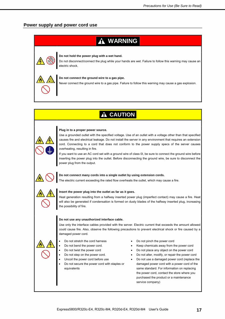
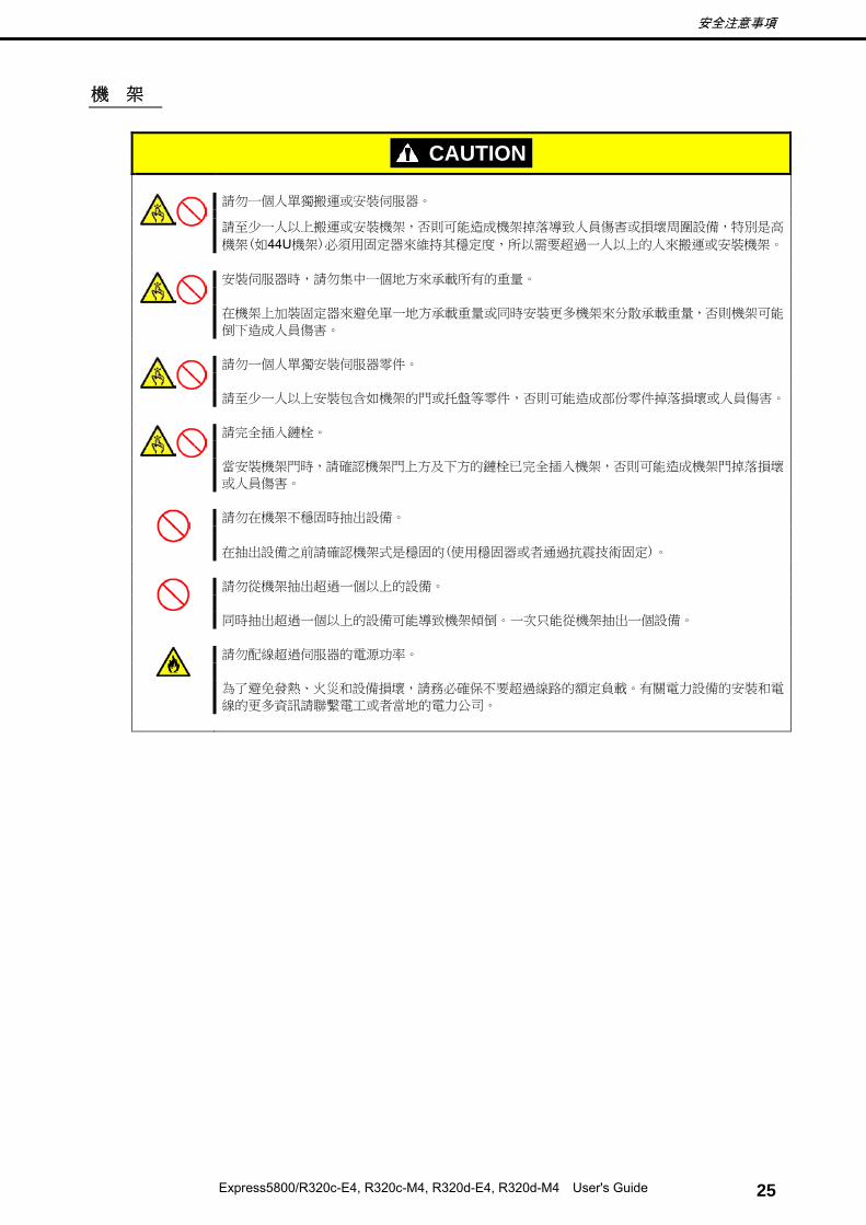
Do not attempt to carry or install the server alone
More than two people are required to carry or install the rack. Otherwise, the rack may fall, resulting in personal injury or damage to peripheral devices. In particular, tall racks such as a 44U rack become unstable unless steadied with a stabilizer. Make sure that two or more people hold the rack to carry or install the rack.
Do not install with the load weight distributed unevenly
To avoid unevenly distributing the load of the rack and server, install a stabilizer or connect multiple racks to distribute the weight. Otherwise, the rack may fall, resulting in personal injury.
Do not install components alone, and check the door hinge pins of the rack
Two or more people are required to install the rack components such as the door or rails. When installing the door, make sure that both upper and lower hinge pins are held in place. Incomplete attachment may cause components to fall off as well as personal injury.
Do not extend any device from the rack that is not stabilized
When extending a device from the rack, make sure that the rack is stable (by using a stabilizer or seismic reinforcement). Otherwise, the rack may fall, resulting in personal injury.
Do not extend more than one device out of the rack
Extending multiple devices from the rack may cause the rack to fall, resulting in personal injury. Extend only one device at one time.
Do not exceed the rated capacity of the power supply when connecting devices
To prevent burn injuries, fire, and damage to the server, make sure the load on the branch circuit that supplies power to the rack will not exceed the rated load. For inquiries regarding the installation or wiring of the power supply system, consult with the company that performed the installation or wiring, or the power company that services your area.
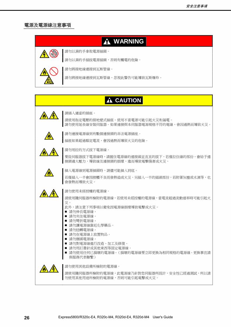
Do not disconnect/connect the plug while your hands are wet. Failure to follow this warning may cause an electric shock.
Do not connect the ground wire to a gas pipe.
Never connect the ground wire to a gas pipe. Failure to follow this warning may cause a gas explosion.
CAUTION
Plug in to a proper power source. Use a grounded outlet with the specified voltage. Use of an outlet with a voltage other than that specified causes fire and electrical leakage. Do not install the server in any environment that requires an extension cord. Connecting to a cord that does not conform to the power supply specs of the server causes overheating, resulting in fire.
If you want to use an AC cord set with a ground wire of class 0I, be sure to connect the ground wire before inserting the power plug into the outlet. Before disconnecting the ground wire, be sure to disconnect the power plug from the output.
Do not connect many cords into a single outlet by using extension cords.
The electric current exceeding the rated flow overheats the outlet, which may cause a fire.
Insert the power plug into the outlet as far as it goes.
Heat generation resulting from a halfway inserted power plug (imperfect contact) may cause a fire. Heat will also be generated if condensation is formed on dusty blades of the halfway inserted plug, increasing the possibility of fire.
Do not use any unauthorized interface cable.
Use only the interface cables provided with the server. Electric current that exceeds the amount allowed could cause fire. Also, observe the following precautions to prevent electrical shock or fire caused by a damaged power cord.
• Do not stretch the cord harness • Do not bend the power cord. • Do not twist the power cord • Do not step on the power cord. • Uncoil the power cord before use • Do not secure the power cord with staples or
equivalents
• Do not pinch the power cord • Keep chemicals away from the power cord • Do not place any object on the power cord • Do not alter, modify, or repair the power cord • Do not use a damaged power cord (replace the
damaged power cord with a power cord of the same standard. For information on replacing the power cord, contact the store where you purchased the product or a maintenance service company)
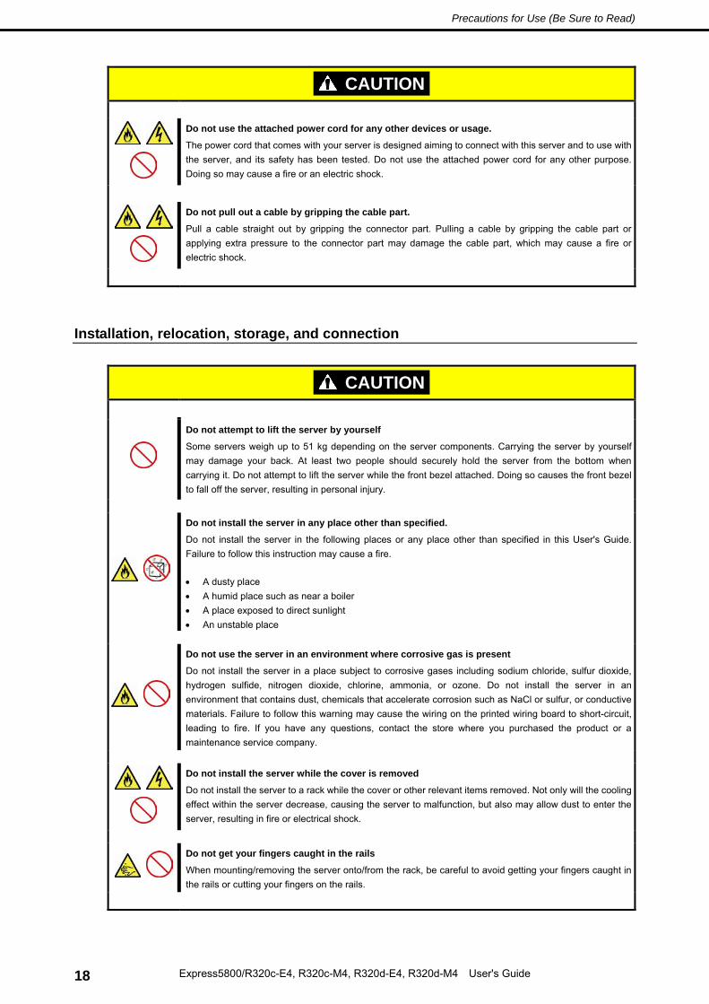
Do not use the attached power cord for any other devices or usage.
The power cord that comes with your server is designed aiming to connect with this server and to use with the server, and its safety has been tested. Do not use the attached power cord for any other purpose. Doing so may cause a fire or an electric shock.
Do not pull out a cable by gripping the cable part.
Pull a cable straight out by gripping the connector part. Pulling a cable by gripping the cable part or applying extra pressure to the connector part may damage the cable part, which may cause a fire or electric shock.
Installation, relocation, storage, and connection
CAUTION
Do not attempt to lift the server by yourself
Some servers weigh up to 51 kg depending on the server components. Carrying the server by yourself may damage your back. At least two people should securely hold the server from the bottom when carrying it. Do not attempt to lift the server while the front bezel attached. Doing so causes the front bezel to fall off the server, resulting in personal injury.
Do not install the server in any place other than specified.
Do not install the server in the following places or any place other than specified in this User's Guide. Failure to follow this instruction may cause a fire. • A dusty place • A humid place such as near a boiler • A place exposed to direct sunlight • An unstable place
Do not use the server in an environment where corrosive gas is present
Do not install the server in a place subject to corrosive gases including sodium chloride, sulfur dioxide, hydrogen sulfide, nitrogen dioxide, chlorine, ammonia, or ozone. Do not install the server in an environment that contains dust, chemicals that accelerate corrosion such as NaCl or sulfur, or conductive materials. Failure to follow this warning may cause the wiring on the printed wiring board to short-circuit, leading to fire. If you have any questions, contact the store where you purchased the product or a maintenance service company.
Do not install the server while the cover is removed
Do not install the server to a rack while the cover or other relevant items removed. Not only will the cooling effect within the server decrease, causing the server to malfunction, but also may allow dust to enter the server, resulting in fire or electrical shock.
Do not get your fingers caught in the rails
When mounting/removing the server onto/from the rack, be careful to avoid getting your fingers caught in the rails or cutting your fingers on the rails.
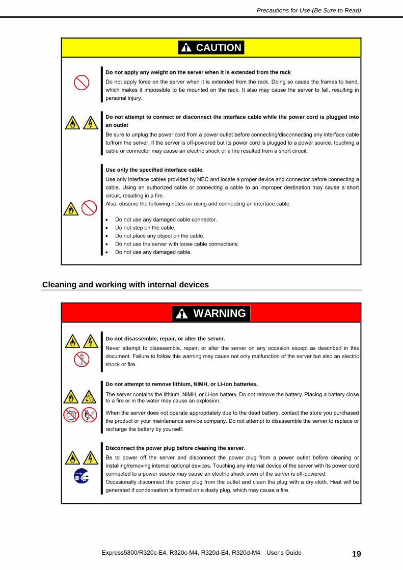
Do not apply any weight on the server when it is extended from the rack
Do not apply force on the server when it is extended from the rack. Doing so cause the frames to bend, which makes it impossible to be mounted on the rack. It also may cause the server to fall, resulting in personal injury.
Do not attempt to connect or disconnect the interface cable while the power cord is plugged into an outlet
Be sure to unplug the power cord from a power outlet before connecting/disconnecting any interface cable to/from the server. If the server is off-powered but its power cord is plugged to a power source, touching a cable or connector may cause an electric shock or a fire resulted from a short circuit.
Use only the specified interface cable.
Use only interface cables provided by NEC and locate a proper device and connector before connecting a cable. Using an authorized cable or connecting a cable to an improper destination may cause a short circuit, resulting in a fire. Also, observe the following notes on using and connecting an interface cable. • Do not use any damaged cable connector. • Do not step on the cable. • Do not place any object on the cable. • Do not use the server with loose cable connections. • Do not use any damaged cable.
Cleaning and working with internal devices
WARNING
Do not disassemble, repair, or alter the server.
Never attempt to disassemble, repair, or alter the server on any occasion except as described in this document. Failure to follow this warning may cause not only malfunction of the server but also an electric shock or fire.
Do not attempt to remove lithium, NiMH, or Li-ion batteries.
The server contains the lithium, NiMH, or Li-ion battery. Do not remove the battery. Placing a battery close to a fire or in the water may cause an explosion.
When the server does not operate appropriately due to the dead battery, contact the store you purchased the product or your maintenance service company. Do not attempt to disassemble the server to replace or recharge the battery by yourself.
Disconnect the power plug before cleaning the server.
Be to power off the server and disconnect the power plug from a power outlet before cleaning or installing/removing internal optional devices. Touching any internal device of the server with its power cord connected to a power source may cause an electric shock even of the server is off-powered. Occasionally disconnect the power plug from the outlet and clean the plug with a dry cloth. Heat will be generated if condensation is formed on a dusty plug, which may cause a fire.
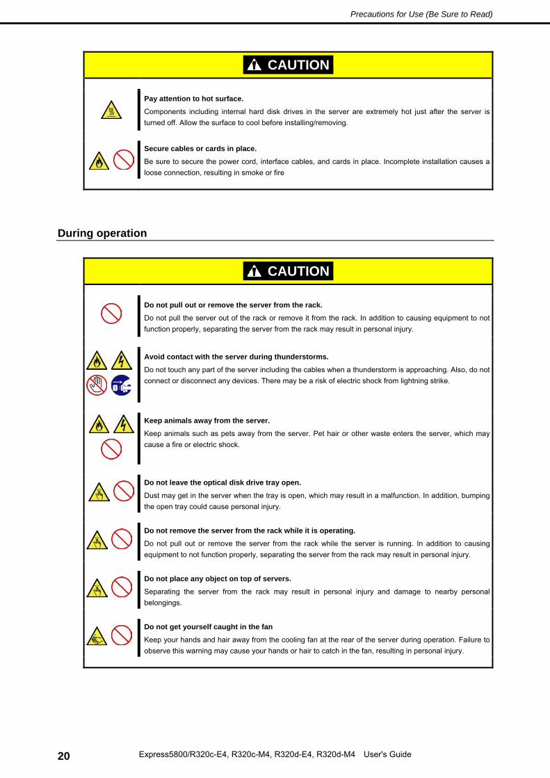
Components including internal hard disk drives in the server are extremely hot just after the server is turned off. Allow the surface to cool before installing/removing.
Secure cables or cards in place.
Be sure to secure the power cord, interface cables, and cards in place. Incomplete installation causes a loose connection, resulting in smoke or fire
During operation
CAUTION
Do not pull out or remove the server from the rack.
Do not pull the server out of the rack or remove it from the rack. In addition to causing equipment to not function properly, separating the server from the rack may result in personal injury.
Avoid contact with the server during thunderstorms.
Do not touch any part of the server including the cables when a thunderstorm is approaching. Also, do not connect or disconnect any devices. There may be a risk of electric shock from lightning strike.
Keep animals away from the server.
Keep animals such as pets away from the server. Pet hair or other waste enters the server, which may cause a fire or electric shock.
Do not leave the optical disk drive tray open.
Dust may get in the server when the tray is open, which may result in a malfunction. In addition, bumping the open tray could cause personal injury.
Do not remove the server from the rack while it is operating.
Do not pull out or remove the server from the rack while the server is running. In addition to causing equipment to not function properly, separating the server from the rack may result in personal injury.
Do not place any object on top of servers.
Separating the server from the rack may result in personal injury and damage to nearby personal belongings.
Do not get yourself caught in the fan
Keep your hands and hair away from the cooling fan at the rear of the server during operation. Failure to observe this warning may cause your hands or hair to catch in the fan, resulting in personal injury.
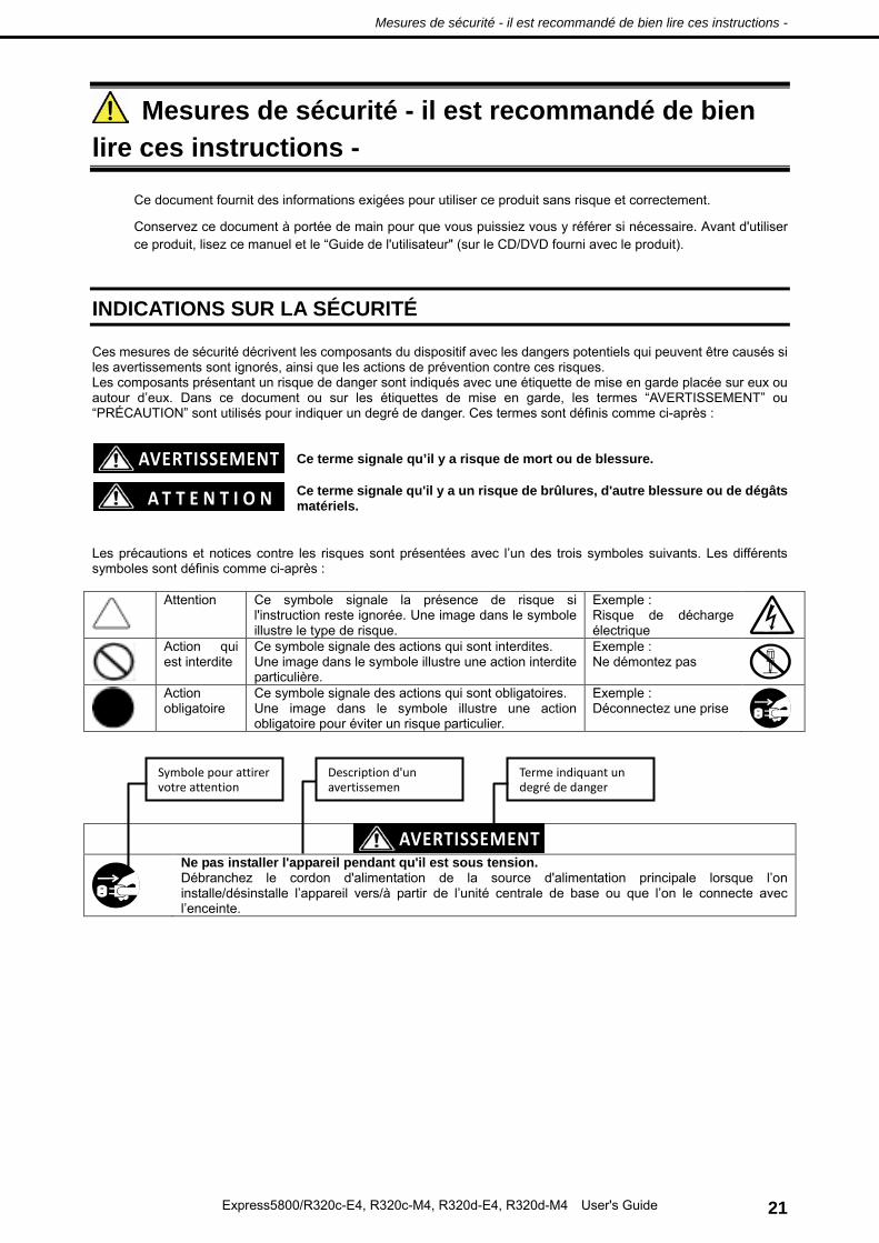
Mesures de sécurité - il est recommandé de bien lire ces instructions -
Mesures de sécurité - il est recommandé de bien lire ces instructions -
Ce document fournit des informations exigées pour utiliser ce produit sans risque et correctement.
Conservez ce document à portée de main pour que vous puissiez vous y référer si nécessaire. Avant d'utiliser ce produit, lisez ce manuel et le “Guide de l'utilisateur" (sur le CD/DVD fourni avec le produit).
INDICATIONS SUR LA SÉCURITÉ
Ces mesures de sécurité décrivent les composants du dispositif avec les dangers potentiels qui peuvent être causés si les avertissements sont ignorés, ainsi que les actions de prévention contre ces risques. Les composants présentant un risque de danger sont indiqués avec une étiquette de mise en garde placée sur eux ou autour d’eux. Dans ce document ou sur les étiquettes de mise en garde, les termes “AVERTISSEMENT” ou “PRÉCAUTION” sont utilisés pour indiquer un degré de danger. Ces termes sont définis comme ci-après :
Ce terme signale qu’il y a risque de mort ou de blessure.
Ce terme signale qu'il y a un risque de brûlures, d'autre blessure ou de dégâts matériels.
Les précautions et notices contre les risques sont présentées avec l’un des trois symboles suivants. Les différents symboles sont définis comme ci-après :
Attention Ce symbole signale la présence de risque si l'instruction reste ignorée. Une image dans le symbole illustre le type de risque.
Exemple : Risque de décharge électrique
Action qui est interdite
Ce symbole signale des actions qui sont interdites. Une image dans le symbole illustre une action interdite particulière.
Exemple : Ne démontez pas
Action obligatoire
Ce symbole signale des actions qui sont obligatoires. Une image dans le symbole illustre une action obligatoire pour éviter un risque particulier.
Exemple : Déconnectez une prise
Ne pas installer l'appareil pendant qu'il est sous tension. Débranchez le cordon d'alimentation de la source d'alimentation principale lorsque l’on installe/désinstalle l’appareil vers/à partir de l’unité centrale de base ou que l’on le connecte avec l’enceinte.
Mesures de sécurité - il est recommandé de bien lire ces instructions -
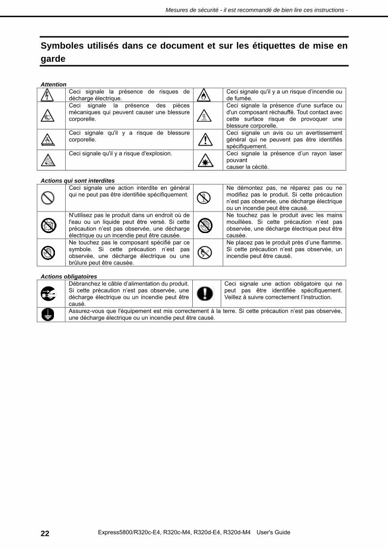
Symboles utilisés dans ce document et sur les étiquettes de mise en garde
Attention
Ceci signale la présence de risques de décharge électrique.
Ceci signale qu'il y a un risque d’incendie ou de fumée.
Ceci signale la présence des pièces mécaniques qui peuvent causer une blessure corporelle.
Ceci signale la présence d'une surface ou d'un composant réchauffé. Tout contact avec cette surface risque de provoquer une blessure corporelle.
Ceci signale qu'il y a risque de blessure corporelle.
Ceci signale un avis ou un avertissement général qui ne peuvent pas être identifiés spécifiquement.
Ceci signale qu'il y a risque d'explosion.
Ceci signale la présence d’un rayon laser pouvant causer la cécité.
Actions qui sont interdites
Ceci signale une action interdite en général qui ne peut pas être identifiée spécifiquement.
Ne démontez pas, ne réparez pas ou ne modifiez pas le produit. Si cette précaution n’est pas observée, une décharge électrique ou un incendie peut être causé.
N'utilisez pas le produit dans un endroit où de l'eau ou un liquide peut être versé. Si cette précaution n’est pas observée, une décharge électrique ou un incendie peut être causée.
Ne touchez pas le produit avec les mains mouillées. Si cette précaution n’est pas observée, une décharge électrique peut être causée.
Ne touchez pas le composant spécifié par ce symbole. Si cette précaution n’est pas observée, une décharge électrique ou une brûlure peut être causée.
Ne placez pas le produit près d’une flamme. Si cette précaution n’est pas observée, un incendie peut être causé.
Actions obligatoires
Débranchez le câble d’alimentation du produit. Si cette précaution n’est pas observée, une décharge électrique ou un incendie peut être causé.
Ceci signale une action obligatoire qui ne peut pas être identifiée spécifiquement. Veillez à suivre correctement l’instruction.
Assurez-vous que l'équipement est mis correctement à la terre. Si cette précaution n’est pas observée, une décharge électrique ou un incendie peut être causé.
Mesures de sécurité - il est recommandé de bien lire ces instructions -
CONSIGNES DE SÉCURITÉ
Installation du rack
Environnement d'exploitation élevé Si l’appareil est installé dans un ensemble de rack fermé ou de plusieurs unités, la température ambiante de fonctionnement peut être supérieure à la température ambiante de la salle. Par conséquent, vous devez installer l'équipement dans un environnement compatible avec la température ambiante maximale (Tma) spécifiée par le constructeur.
Débit d'air réduit L'installation de l'équipement dans un rack doit être telle que la quantité de débit d'air nécessaire pour un fonctionnement sûr de l'appareil ne soit pas compromise.
Charge mécanique Le montage de l'équipement dans le rack doit être effectué de telle manière qu'une situation dangereuse ne se produise pas en raison d’une charge inégale mécanique.
Surcharge du circuit Il faudrait prendre en considération la connexion de l’équipement à l'alimentation du circuit et l'effet que la surcharge des circuits pourrait avoir sur la protection contre les surintensités et les câbles d'alimentation. Il faudrait également prendre en considération les valeurs nominales indiquées sur la plaque de signalisation de l’équipement concernant ce problème.
Mise à la terre fiable Une mise à la terre fiable de l’équipement monté sur rack devrait être fournie. Vous devez porter une attention particulière aux connexions de l'alimentation, à l'exception des connexions directes au circuit de dérivation (par exemple, utilisation de multiprises).
Sources d'énergie multiples
« Pour mettre l’unité entièrement hors tension, débrancher les deux cordons d’alimentation » ou leur équivalent.
Rayonnement laser (invisible) si ouvert (et verrouillage défait) NE PAS REGARDER LE RAYONNEMENT.
Risque d’explosion si les piles sont remplacées par d’autres de type incorrect. Jeter les piles usées conformément aux instructions. »
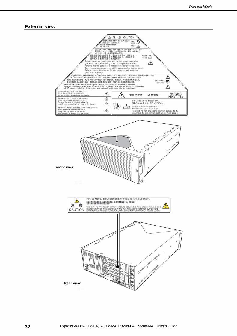
Warning label are attached on or near the components with potential hazards to draw attention from users to potential hazards involved in handling the server. This label is either attached or printed on the component. Do not remove or black out this label and keep it clean. If no label is attached or printed on the server, or if there is a label coming off or stained, contact your sales representative.
Be sure to observe the following precautions for the proper functioning of the server. Ignoring the precautions may cause server malfunction or failure.
Installation site
Install the server in an appropriate place. See Chapter 2 Preparations (2. Installation and Connection).
Do not use any cell phone or PHS and switch off them near the server. Electric waves from such devices can cause server to malfunction.
Regularly clean the server to prevent various types of failure. Refer to Chapter 1 Maintenance (2. Daily Maintenance) in "Maintenance Guide" for details about cleaning.
When you store the server for a long time period, keep it under storage environment conditions (Temperature: –10 to 55°C, Humidity: 20 to 80%, non-condensing).
Turn off the server and unplug the power cord before moving it.
In the following cases, check and adjust the system clock before operation.
― After transportation
― After storage
― After the server is used following a period of disuse, in which storage conditions did not conform to
those that guarantee server operations (temperature 10 to 35°C, humidity 20 to 80%) Check the system clock approximately once per month. Use of a time server (NTP server) is recommended
if high accuracy timing is required by the system.
Power supply
Connect the provided power cord to a 100 VAC outlet.
Connect the dedicated power cord to a 200 VAC outlet.
Uninterruptible Power Supply (UPS) is used for preventing the momentary voltage drop. The server does not support UPS connection through the serial port (RS-232C) and power control by PowerChute Plus.
Power-on/Power-off
Wait for at least 30 seconds before turning on the server after connecting the power cord to the outlet.
If UPS is connected, set the schedule to wait for at least 30 seconds before turning on the server.
Do not press POWER Switch to turn on the server while POWER LED lights amber.
Do not power off or reset the server, nor disconnect the power cord before POST completes.
Make sure that the access LED is off before turning off the power or ejecting an optical disk.
Wait for at least 30 seconds before turning on the server after turning off the server.
When disconnecting power cord from outlet, wait at least 30 seconds before connecting the power cord.
For stable operation, it is recommended to restart OS after the system has been duplexed.
If this server, internal optional devices, and media set for the backup devices (tape cartridges) are moved from a cold place to a warm place in a short time, condensation will occur and cause malfunctions and failures when these are used in such state. To protect important stored data and property, make sure to wait for a sufficient period to use the server and components in the operating environment.
Reference: Time effective at avoiding condensation in winter (more than 10C differences between the room temperature and atmospheric temperature) Disk devices: Approximately 2 to 3 hours Tape media: Approximately 1 day
For optional devices, we recommend you use our NEC products. Even if they are successfully installed or connected, installation of unsupported devices can cause the server to malfunction or even failure. You will be charged to repair failure or damage caused by use of such products even within warranty period.
The server contains electronic components sensitive to static electricity. Observe the following precautions to avoid failures caused by static electricity when installing or removing any optional devices.
Wearing Anti-static Wrist Strap or Anti-static Gloves
Wear an anti-static wrist strap or anti-static gloves before starting work. If no wrist strap is available, discharge static electricity from your body by touching an unpainted metal part of the chassis which is grounded. Touch a metal part regularly when working with the server to discharge static electricity.
Checking the Workplace
― Work with the server on the anti-static or concrete floor.
― If you work with the server on a carpet where static electricity is likely to be generated, be sure to take anti-static measures beforehand.
Using the Work Table
Place the server on an anti-static mat to work with.
Clothing
― Do not wear wool or synthetic clothes.
― Wear anti-static shoes.
― Take off any jewels, a ring, bracelet, or wrist watch before working with the server.
Handling of components
― Keep any component in an anti-static bag until the installation.
― Hold any component by its edge to avoid touching any terminals or parts.
― To store or carry any component, place it in an anti-static bag.
Handling of cable
Discharge the static electricity of cables, such as LAN cable, before connecting to the server by using ionizer or the like. Consult with your sales representative for apparatus to discharge static electricity.
Installing/removing optional devices
Optional devices also contain electronic components sensitive to static electricity. To avoid malfunction of the device, discharge static electricity from your body.
Express5800/ft series is a "fault-tolerant (ft)" server focusing on "high reliability" in terms of fault-tolerance, in addition to "high performance", "scalability", and "general versatility" provided by Express5800 series.
In the event of trouble, its dual configuration will allow the system to instantaneously isolate the failed parts to assure non-stop running; operation will be moved smoothly from one module to the other, minimizing damage to it. You can use this Express5800/ft series in a mission-critical system where high availability is required. By the use of Windows/VMware operating system, it also provides outstanding openness for general-purpose applications, etc.
To make the best use of these features, read this User's Guide thoroughly to understand how to operate Express5800/ft series.
The carton box contains various accessories which are required for setup or maintenance. Make sure you have them all for future use.
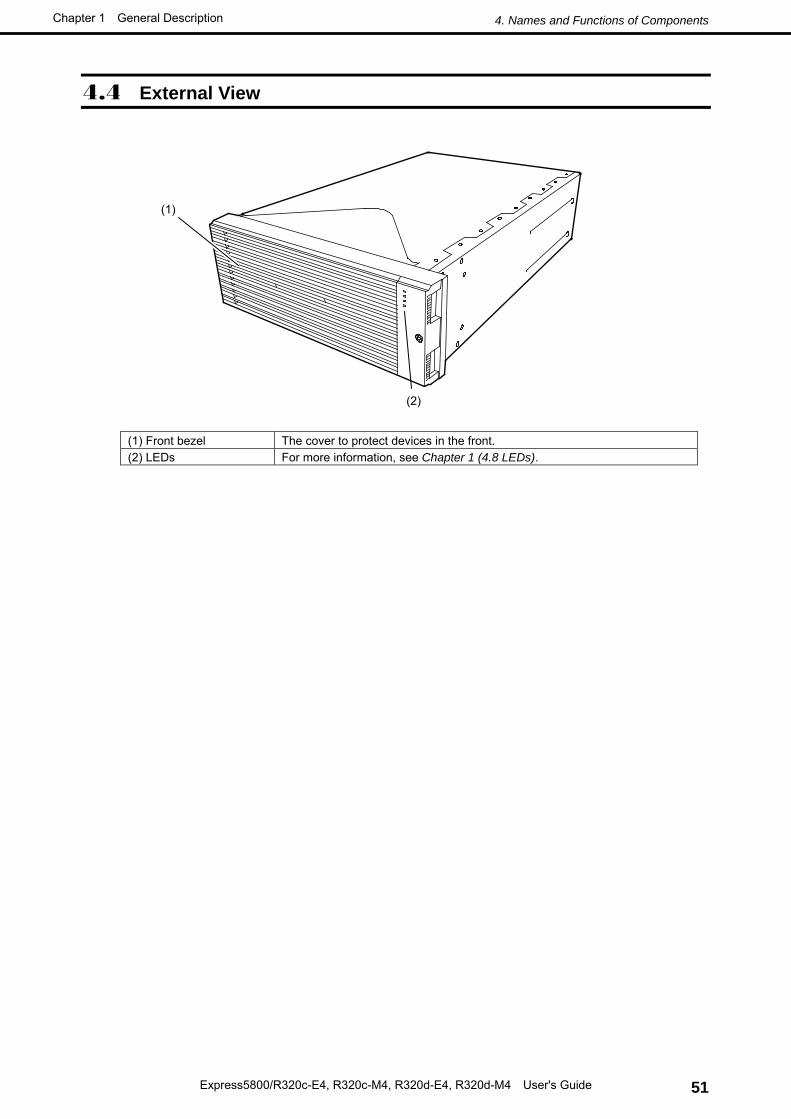
• Front bezel
• Bezel lock key (attached to front bezel)
• EXPRESSBUILDER *1
• Getting Started
*1 Documents are stored in EXPRESSBUILDER. Adobe Reader is required to read the documents so make sure you have it installed in your PC.
Make sure you have all accessories and inspect them. If an accessory is missing or damaged, contact your sales representative.
Important The chassis serial number plate and maintenance label is located on the server. If the serial number does not match the number on the warranty, you may not be guaranteed against failure even within the warranty period. Contact your sales representative if they do not match.
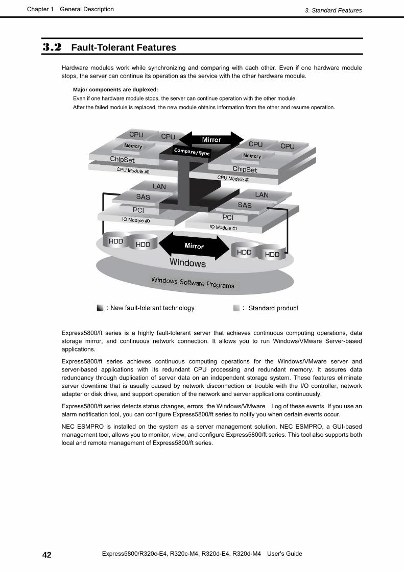
Hardware modules work while synchronizing and comparing with each other. Even if one hardware module stops, the server can continue its operation as the service with the other hardware module.
Express5800/ft series is a highly fault-tolerant server that achieves continuous computing operations, data storage mirror, and continuous network connection. It allows you to run Windows/VMware Server-based applications.
Express5800/ft series achieves continuous computing operations for the Windows/VMware server and server-based applications with its redundant CPU processing and redundant memory. It assures data redundancy through duplication of server data on an independent storage system. These features eliminate server downtime that is usually caused by network disconnection or trouble with the I/O controller, network adapter or disk drive, and support operation of the network and server applications continuously.
Express5800/ft series detects status changes, errors, the Windows/VMware Log of these events. If you use an alarm notification tool, you can configure Express5800/ft series to notify you when certain events occur.
NEC ESMPRO is installed on the system as a server management solution. NEC ESMPRO, a GUI-based management tool, allows you to monitor, view, and configure Express5800/ft series. This tool also supports both local and remote management of Express5800/ft series.
Major components are duplexed: Even if one hardware module stops, the server can continue operation with the other module. After the failed module is replaced, the new module obtains information from the other and resume operation.
• Highly fault-tolerant processing and I/O subsystems
Express5800/ft series use redundant hardware and software to assure server operation even if one module suffers trouble with its processor, memory, I/O (including trouble related to the I/O controller), disk drive, or network adapter.
• Continuous network connection
Express5800/ft series maintains continuous network connection by detecting any trouble with the network adapter, connection, etc. If trouble occurs, the standby network connection will take over all network traffic processing and thus securely maintain the network system connection of Express5800/ft series without losing network traffic or client connection.
• Support of multiple network connections
Since Express5800/ft series can support multiple network connections, you can add network redundant control or network traffic control.
• No need to modify applications
You can run Windows/VMware-compliant applications on Express5800/ft series. Thus, unlike other highly fault-tolerant products, special API or scripts are not necessary.
• Automatic mirroring
Express5800/ft series automatically maintains data as the current data.
• Transparent migration
Express5800/ft series constantly monitors events. If trouble occurs on Express5800/ft series server module, it will transparently use a redundant module of the failed module. This feature maintains data and user access without stopping application service.
• Automatic reconfiguration
When the failed module restarts after the trouble is corrected, Express5800/ft series will perform reconfiguration
automatically, and if necessary, resynchronize the affected modules. Reconfiguration can include CPU processing (e.g., CPU memory), server's operating system (and related applications), and system data stored on the hard disk drives. In most cases, Express5800/ft series automatically restores redundancy of the server modules after recovery.
• Event notification function for Windows
When trouble or other events are detected on Express5800/ft series, they will be notified to Windows Event Log and saved. Therefore, you can view the log items locally or remotely by a usual Windows procedure. Since an Express5800/ft series events use unique IDs, they are easy to distinguish. In addition, you can use alert notification software such as Express Report Service or Express Report Service (HTTPS) to manage the server. It is recommended to use such software to cope with system failure quickly. Ask your service representative for details.
• Event notification function for VMware
When trouble or other events are detected on Express5800/ft series, they will be notified to syslog and saved. In addition, you can use alert notification software such as Express Report Service to manage the server. It is recommended to use such software to cope with system failure quickly. Ask your service representative for details.
• In-service repairing
You can repair or replace a failed module even if Express5800/ft series is operating.
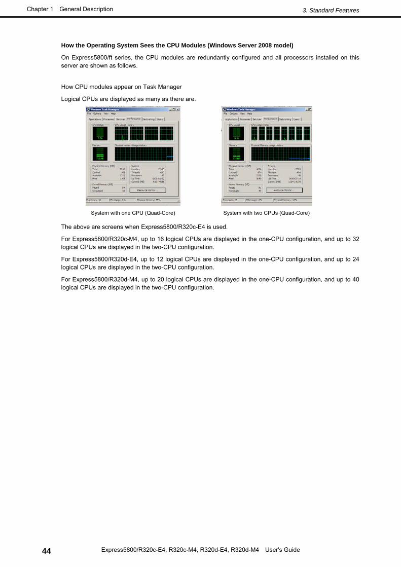
How the Operating System Sees the CPU Modules (Windows Server 2008 model) On Express5800/ft series, the CPU modules are redundantly configured and all processors installed on this server are shown as follows.
How CPU modules appear on Task Manager
Logical CPUs are displayed as many as there are.
System with one CPU (Quad-Core) System with two CPUs (Quad-Core)
The above are screens when Express5800/R320c-E4 is used.
For Express5800/R320c-M4, up to 16 logical CPUs are displayed in the one-CPU configuration, and up to 32 logical CPUs are displayed in the two-CPU configuration.
For Express5800/R320d-E4, up to 12 logical CPUs are displayed in the one-CPU configuration, and up to 24 logical CPUs are displayed in the two-CPU configuration.
For Express5800/R320d-M4, up to 20 logical CPUs are displayed in the one-CPU configuration, and up to 40 logical CPUs are displayed in the two-CPU configuration.
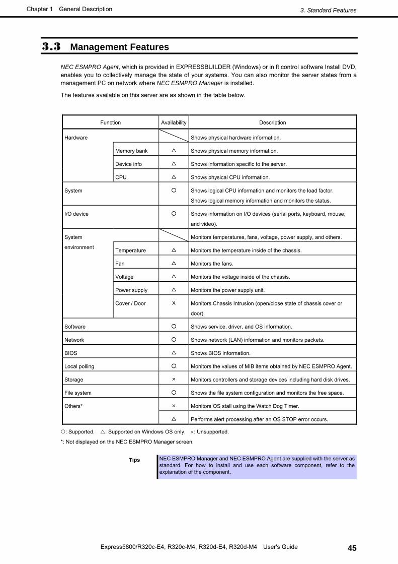
NEC ESMPRO Agent, which is provided in EXPRESSBUILDER (Windows) or in ft control software Install DVD, enables you to collectively manage the state of your systems. You can also monitor the server states from a management PC on network where NEC ESMPRO Manager is installed.
The features available on this server are as shown in the table below.
Function Availability Description
Hardware Shows physical hardware information.
Memory bank △ Shows physical memory information.
Device info △ Shows information specific to the server.
CPU △ Shows physical CPU information.
System ○ Shows logical CPU information and monitors the load factor.
Shows logical memory information and monitors the status.
I/O device ○ Shows information on I/O devices (serial ports, keyboard, mouse,
and video).
System
environment
Monitors temperatures, fans, voltage, power supply, and others.
Temperature △ Monitors the temperature inside of the chassis.
Fan △ Monitors the fans.
Voltage △ Monitors the voltage inside of the chassis.
Power supply △ Monitors the power supply unit.
Cover / Door X Monitors Chassis Intrusion (open/close state of chassis cover or
door).
Software ○ Shows service, driver, and OS information.
Network ○ Shows network (LAN) information and monitors packets.
BIOS △ Shows BIOS information.
Local polling ○ Monitors the values of MIB items obtained by NEC ESMPRO Agent.
Storage × Monitors controllers and storage devices including hard disk drives.
File system ○ Shows the file system configuration and monitors the free space.
Others* × Monitors OS stall using the Watch Dog Timer.
△ Performs alert processing after an OS STOP error occurs.
: Supported. : Supported on Windows OS only. ×: Unsupported.
*: Not displayed on the NEC ESMPRO Manager screen.
Tips NEC ESMPRO Manager and NEC ESMPRO Agent are supplied with the server as
standard. For how to install and use each software component, refer to the explanation of the component.
3.4 Firmware and Software Version Management for Windows
Use of NEC ESMPRO Manager and ExpressUpdate Agent allows you to manage versions of firmware and software as well as update them by applying update packages.
This feature automatically updates modules without stopping the system just by specifying the updating packages from NEC ESMPRO Manager.
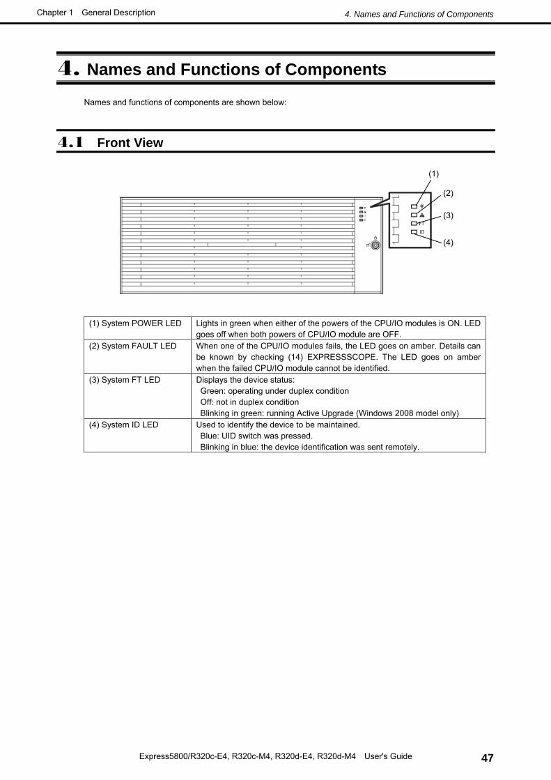
Names and functions of components are shown below:
4.1 Front View
(1) System POWER LED Lights in green when either of the powers of the CPU/IO modules is ON. LED goes off when both powers of CPU/IO module are OFF.
(2) System FAULT LED When one of the CPU/IO modules fails, the LED goes on amber. Details can be known by checking (14) EXPRESSSCOPE. The LED goes on amber when the failed CPU/IO module cannot be identified.
(3) System FT LED Displays the device status: Green: operating under duplex condition Off: not in duplex condition Blinking in green: running Active Upgrade (Windows 2008 model only)
(4) System ID LED Used to identify the device to be maintained. Blue: UID switch was pressed. Blinking in blue: the device identification was sent remotely.
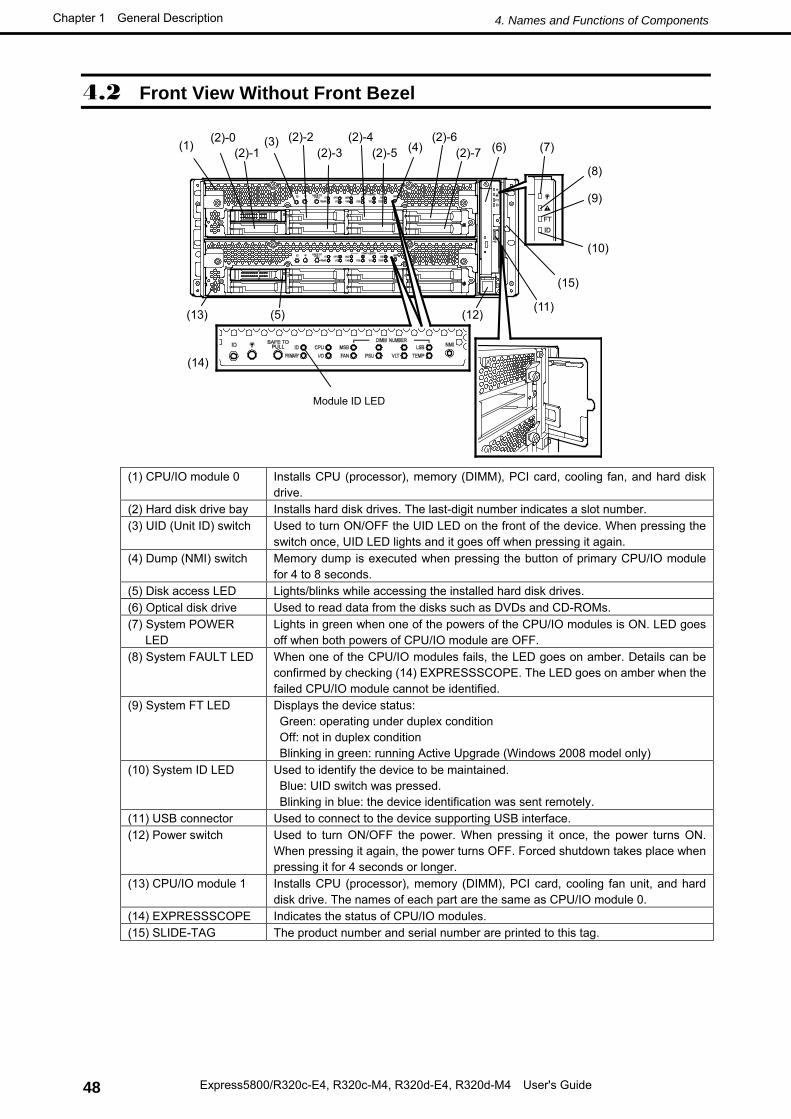
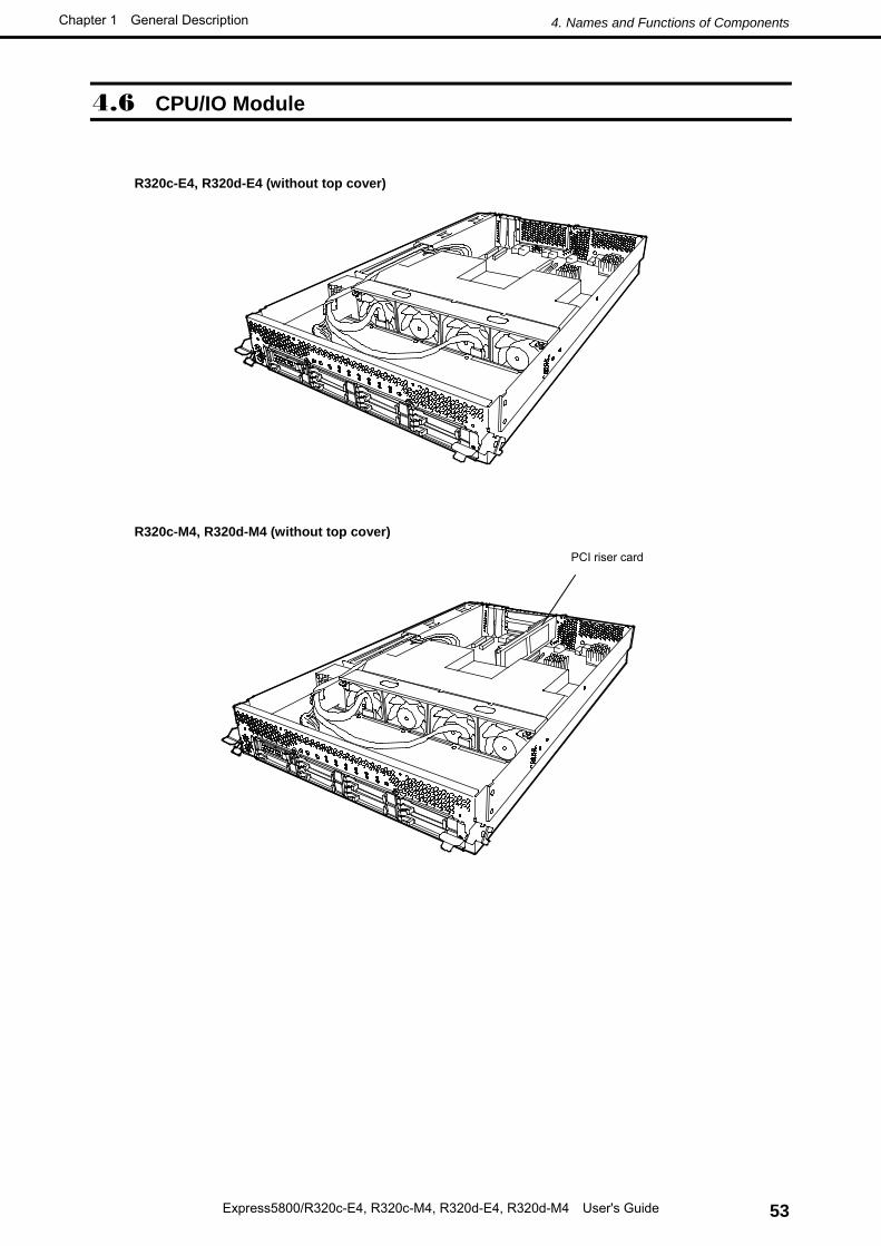
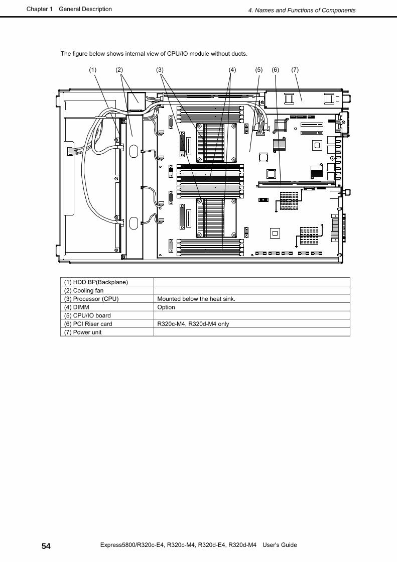
(1) CPU/IO module 0 Installs CPU (processor), memory (DIMM), PCI card, cooling fan, and hard disk drive.
(2) Hard disk drive bay Installs hard disk drives. The last-digit number indicates a slot number. (3) UID (Unit ID) switch Used to turn ON/OFF the UID LED on the front of the device. When pressing the
switch once, UID LED lights and it goes off when pressing it again. (4) Dump (NMI) switch Memory dump is executed when pressing the button of primary CPU/IO module
for 4 to 8 seconds. (5) Disk access LED Lights/blinks while accessing the installed hard disk drives. (6) Optical disk drive Used to read data from the disks such as DVDs and CD-ROMs. (7) System POWER
LED Lights in green when one of the powers of the CPU/IO modules is ON. LED goes off when both powers of CPU/IO module are OFF.
(8) System FAULT LED When one of the CPU/IO modules fails, the LED goes on amber. Details can be confirmed by checking (14) EXPRESSSCOPE. The LED goes on amber when the failed CPU/IO module cannot be identified.
(9) System FT LED Displays the device status: Green: operating under duplex condition Off: not in duplex condition Blinking in green: running Active Upgrade (Windows 2008 model only)
(10) System ID LED Used to identify the device to be maintained. Blue: UID switch was pressed. Blinking in blue: the device identification was sent remotely.
(11) USB connector Used to connect to the device supporting USB interface. (12) Power switch Used to turn ON/OFF the power. When pressing it once, the power turns ON.
When pressing it again, the power turns OFF. Forced shutdown takes place when pressing it for 4 seconds or longer.
(13) CPU/IO module 1 Installs CPU (processor), memory (DIMM), PCI card, cooling fan unit, and hard disk drive. The names of each part are the same as CPU/IO module 0.
(14) EXPRESSSCOPE Indicates the status of CPU/IO modules. (15) SLIDE-TAG The product number and serial number are printed to this tag.
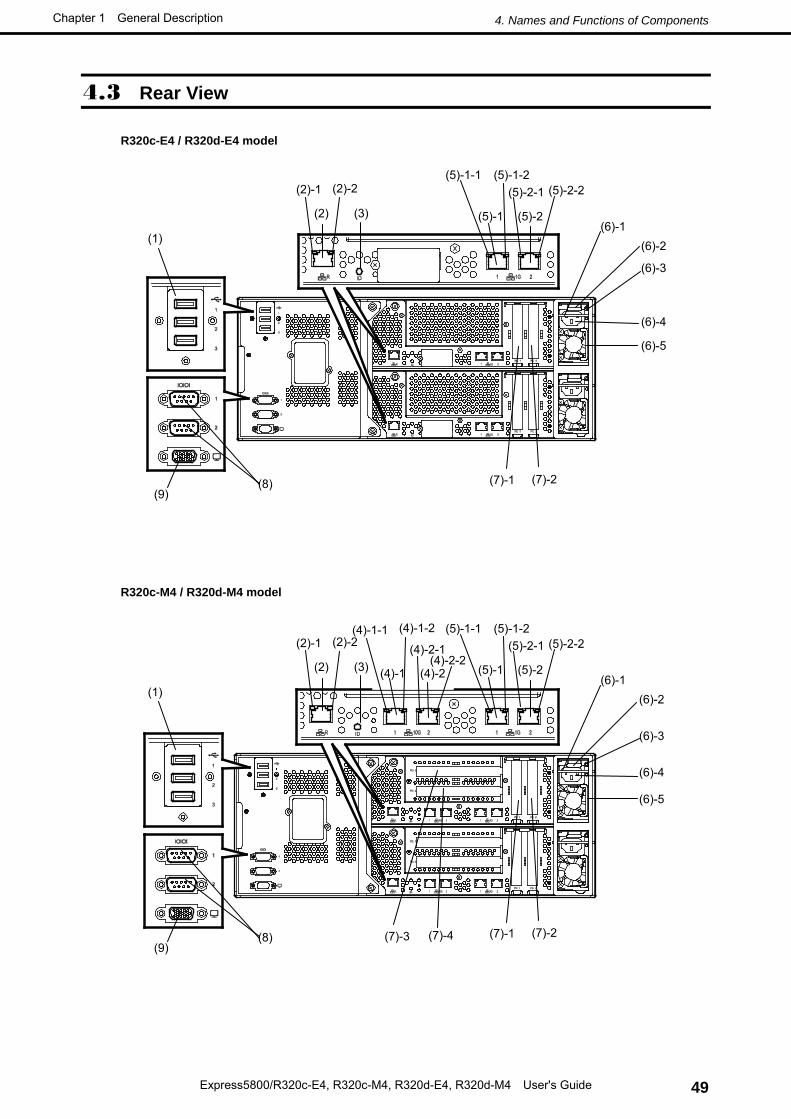
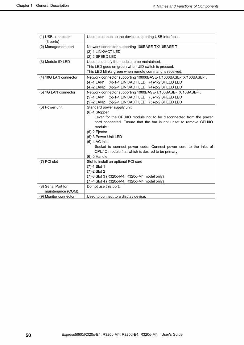
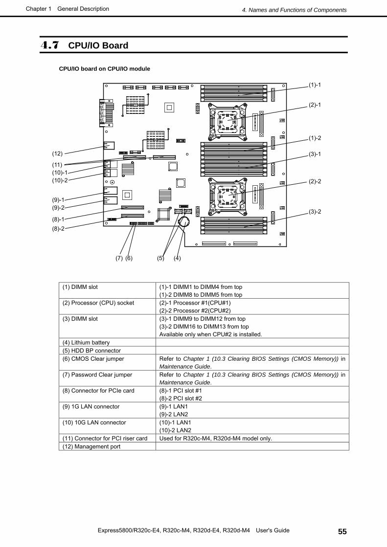
Used to connect to the device supporting USB interface.
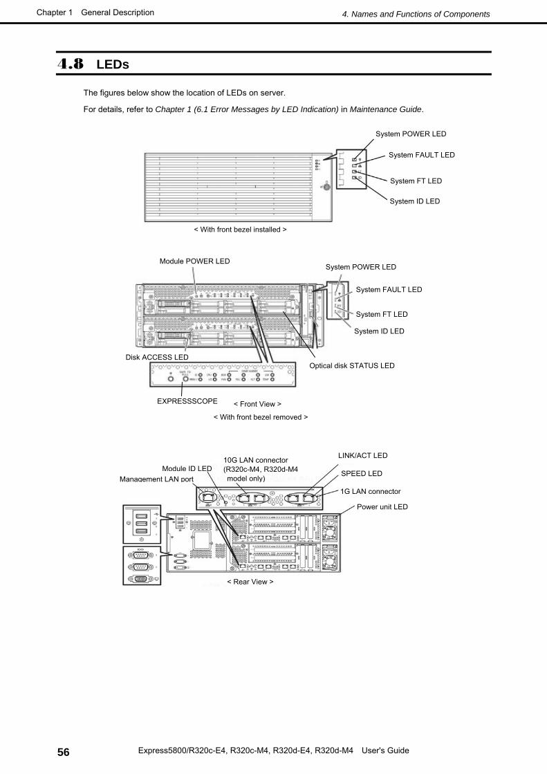
(2) Management port Network connector supporting 100BASE-TX/10BASE-T. (2)-1 LINK/ACT LED (2)-2 SPEED LED
(3) Module ID LED Used to identify the module to be maintained. This LED goes on green when UID switch is pressed. This LED blinks green when remote command is received.
(4) 10G LAN connector Network connector supporting 10000BASE-T/1000BASE-TX/100BASE-T. (4)-1 LAN1 (4)-1-1 LINK/ACT LED (4)-1-2 SPEED LED (4)-2 LAN2 (4)-2-1 LINK/ACT LED (4)-2-2 SPEED LED
(5) 1G LAN connector Network connector supporting 1000BASE-T/100BASE-TX/10BASE-T. (5)-1 LAN1 (5)-1-1 LINK/ACT LED (5)-1-2 SPEED LED (5)-2 LAN2 (5)-2-1 LINK/ACT LED (5)-2-2 SPEED LED
(6) Power unit Standard power supply unit (6)-1 Stopper
Lever for the CPU/IO module not to be disconnected from the power cord connected. Ensure that the bar is not unset to remove CPU/IO module.
(6)-2 Ejector (6)-3 Power Unit LED (6)-4 AC inlet
Socket to connect power code. Connect power cord to the inlet of CPU/IO module first which is desired to be primary.
(6)-5 Handle (7) PCI slot Slot to install an optional PCI card
(7)-1 Slot 1 (7)-2 Slot 2 (7)-3 Slot 3 (R320c-M4, R320d-M4 model only) (7)-4 Slot 4 (R320c-M4, R320d-M4 model only)
(8) Serial Port for maintenance (COM)
Do not use this port.
(9) Monitor connector Used to connect to a display device.
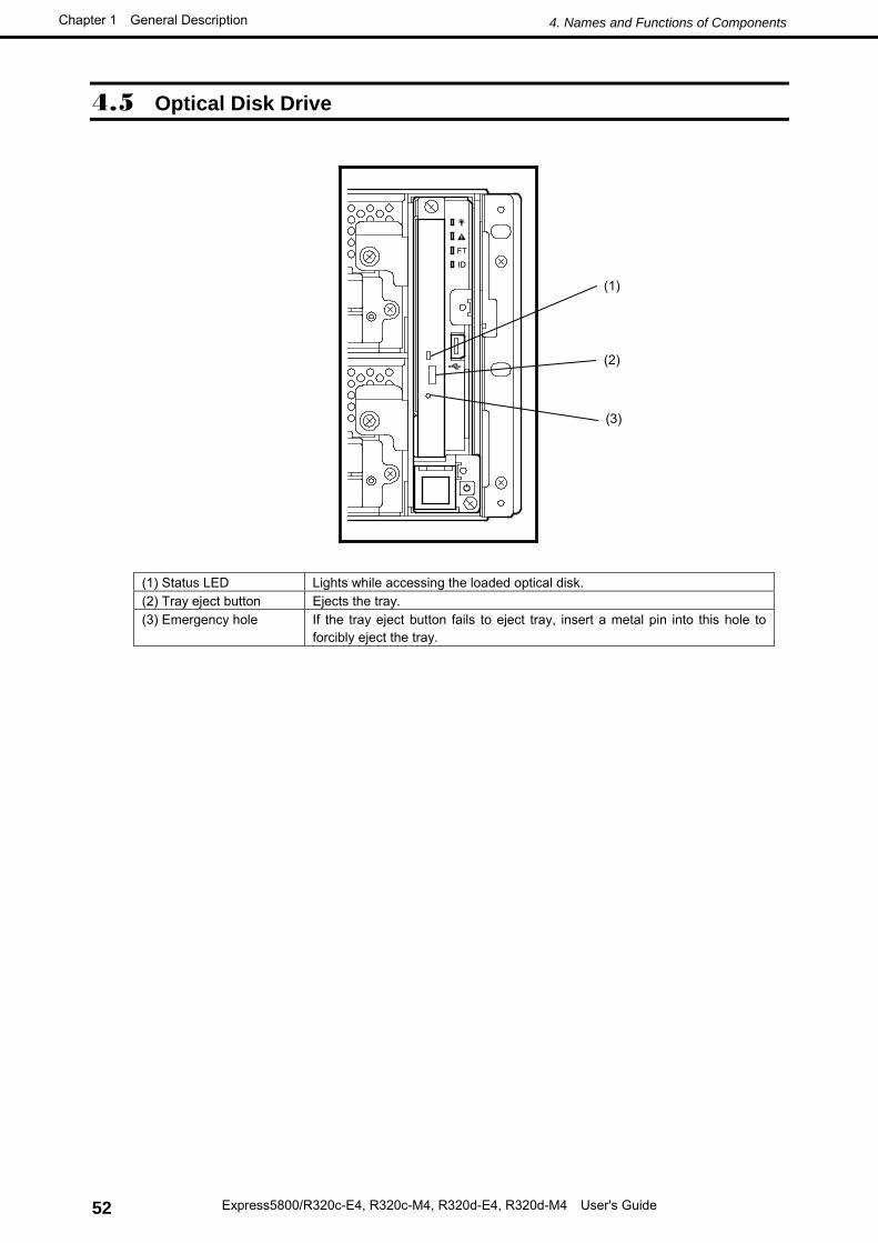
(1) Status LED Lights while accessing the loaded optical disk. (2) Tray eject button Ejects the tray. (3) Emergency hole If the tray eject button fails to eject tray, insert a metal pin into this hole to
Refer to Chapter 2 (6. Installing Optional Devices) in Maintenance Guide for how to install internal option devices.
You do not need to provide any settings for software.
If you did not purchase any optional device requiring installation, you may skip this section.
Important • We recommend that optional devices be installed by a maintenance service staff from your maintenance service company authorized by NEC.
• Use only the devices and cables specified by NEC. You will be charged to repair damages, malfunctions, and failures caused by the use of any devices or cables not specified for use with this server even within the warranty period.
This server must be mounted to a rack which conforms to EIA standards.
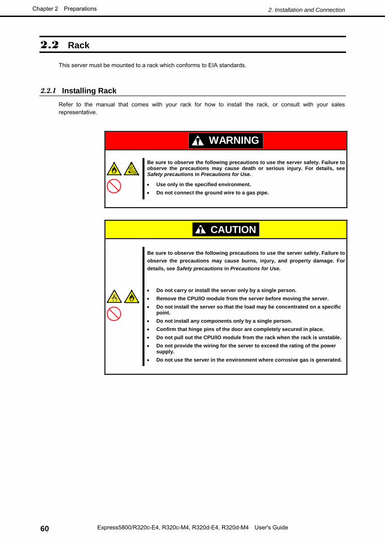
2.2.1 Installing Rack Refer to the manual that comes with your rack for how to install the rack, or consult with your sales representative.
WARNING
Be sure to observe the following precautions to use the server safety. Failure to observe the precautions may cause death or serious injury. For details, see Safety precautions in Precautions for Use.
• Use only in the specified environment. • Do not connect the ground wire to a gas pipe.
CAUTION
Be sure to observe the following precautions to use the server safely. Failure to observe the precautions may cause burns, injury, and property damage. For details, see Safety precautions in Precautions for Use.
• Do not carry or install the server only by a single person. • Remove the CPU/IO module from the server before moving the server. • Do not install the server so that the load may be concentrated on a specific
point. • Do not install any components only by a single person. • Confirm that hinge pins of the door are completely secured in place. • Do not pull out the CPU/IO module from the rack when the rack is unstable. • Do not provide the wiring for the server to exceed the rating of the power
supply. • Do not use the server in the environment where corrosive gas is generated.
Do not install the rack or server under the following environment. Doing so may cause malfunction of the server.
• Narrow space from which devices cannot be pulled out from the rack completely
• Place that cannot bear the total weights of the rack and devices mounted on the rack
• Place where stabilizers cannot be installed or where the rack can be installed only after the practice of proper earthquake-resistant construction
• Place of uneven or slanting floor
• Place of drastic temperature change (near a heater, air conditioner, or refrigerator)
• Place where intense vibration may be generated
• Place where corrosive gases (sulfur dioxide, hydrogen sulfide, nitrogen dioxide, chlorine, ammonia, ozone, etc) exist Place where the air (or dust) includes components accelerating corrosion (ex. sulfur, sodium chloride) or conductive metals
• Place where chemicals may be accidentally sprayed over
• Place where a carpet not subject to anti-static process is laid
• Place where some objects may be fallen on the rack
• Place near a device generating intense magnetic field (such as TVs, radios, broadcast/communication antennas, power transmission wires, and electromagnetic cranes) is placed (If unavoidable, contact your maintenance service company for proper shield construction.)
• Place where the power cord of the server must be connected to an AC outlet that shares the outlet of another device with large power consumption
• Place near equipment that generates power noise (e.g., contact spark at power-on/power-off of commercial power supply through a relay). If you must install the server close to such equipment, have your maintenance service company separate power cables or install noise filter.
• Environment where operation of the server is not guaranteed (e.g., power supply, ambient temperature, and/or humidity)
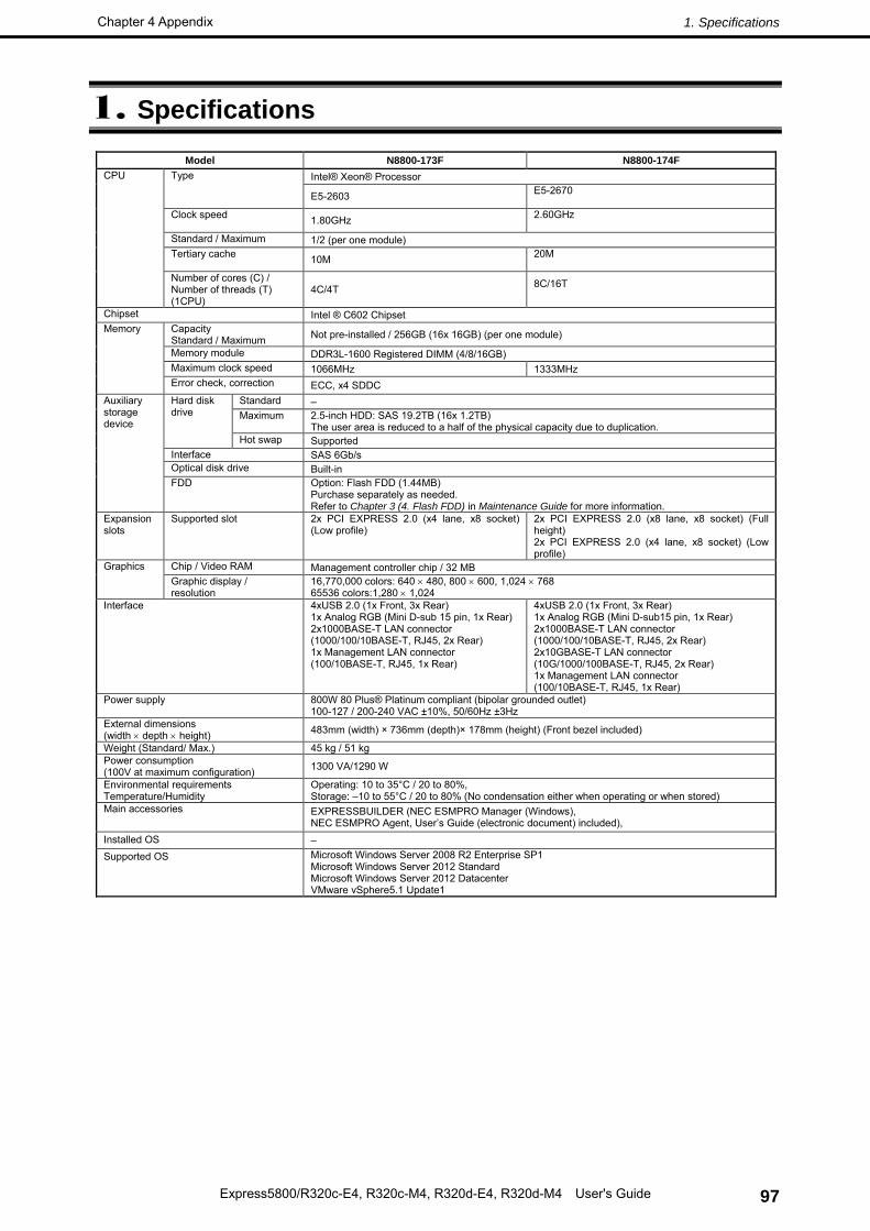
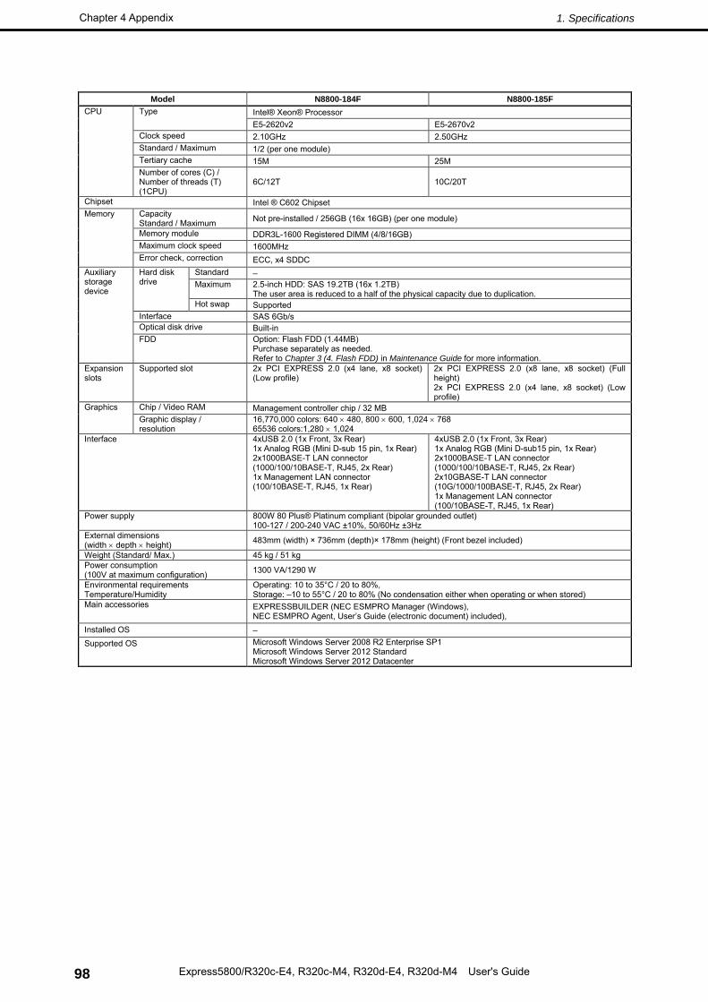
Tips See Appendix (1. Specifications) for details.
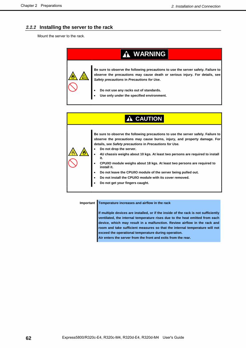
2.2.2 Installing the server to the rack Mount the server to the rack.
WARNING
Be sure to observe the following precautions to use the server safety. Failure to observe the precautions may cause death or serious injury. For details, see Safety precautions in Precautions for Use.
• Do not use any racks out of standards. • Use only under the specified environment.
CAUTION
Be sure to observe the following precautions to use the server safely. Failure to observe the precautions may cause burns, injury, and property damage. For details, see Safety precautions in Precautions for Use. • Do not drop the server. • 4U chassis weighs about 10 kgs. At least two persons are required to install
it. • CPU/IO module weighs about 18 kgs. At least two persons are required to
install it. • Do not leave the CPU/IO module of the server being pulled out. • Do not install the CPU/IO module with its cover removed. • Do not get your fingers caught.
Important Temperature increases and airflow in the rack If multiple devices are installed, or if the inside of the rack is not sufficiently ventilated, the internal temperature rises due to the heat emitted from each device, which may result in a malfunction. Review airflow in the rack and room and take sufficient measures so that the internal temperature will not exceed the operational temperature during operation. Air enters the server from the front and exits from the rear.
This server can be mounted to a rack made by NEC or other companies. Mount the server to a rack in the following procedure.
Checking accessories
The following are the required accessories. Check if you have them all.
– Bracket: 2
– Washer for panhead screw: 4
– Flat-head screw: 8
– Panhead screw: 8
Core nuts (4 pieces) are not included. Use the core nuts provided with the rack.
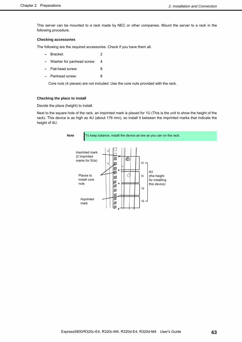
Checking the place to install
Decide the place (height) to install.
Next to the square hole of the rack, an imprinted mark is placed for 1U (This is the unit to show the height of the rack). This device is as high as 4U (about 176 mm), so install it between the imprinted marks that indicate the height of 4U.
Note To keep balance, install the device as low as you can on the rack.
Follow the steps below to set the 4U chassis to the rack.
1. If the rack has front and rear doors, open them.
Tips Refer to the instruction manual that comes with the rack.
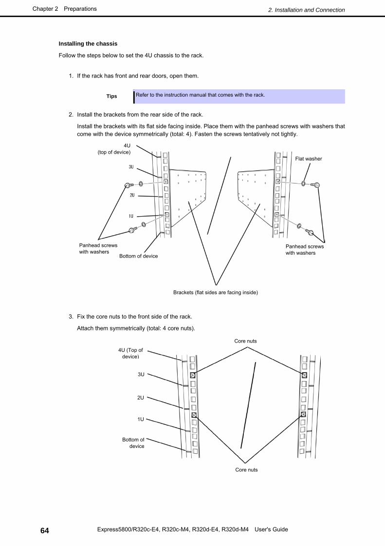
2. Install the brackets from the rear side of the rack.
Install the brackets with its flat side facing inside. Place them with the panhead screws with washers that come with the device symmetrically (total: 4). Fasten the screws tentatively not tightly.
3. Fix the core nuts to the front side of the rack.
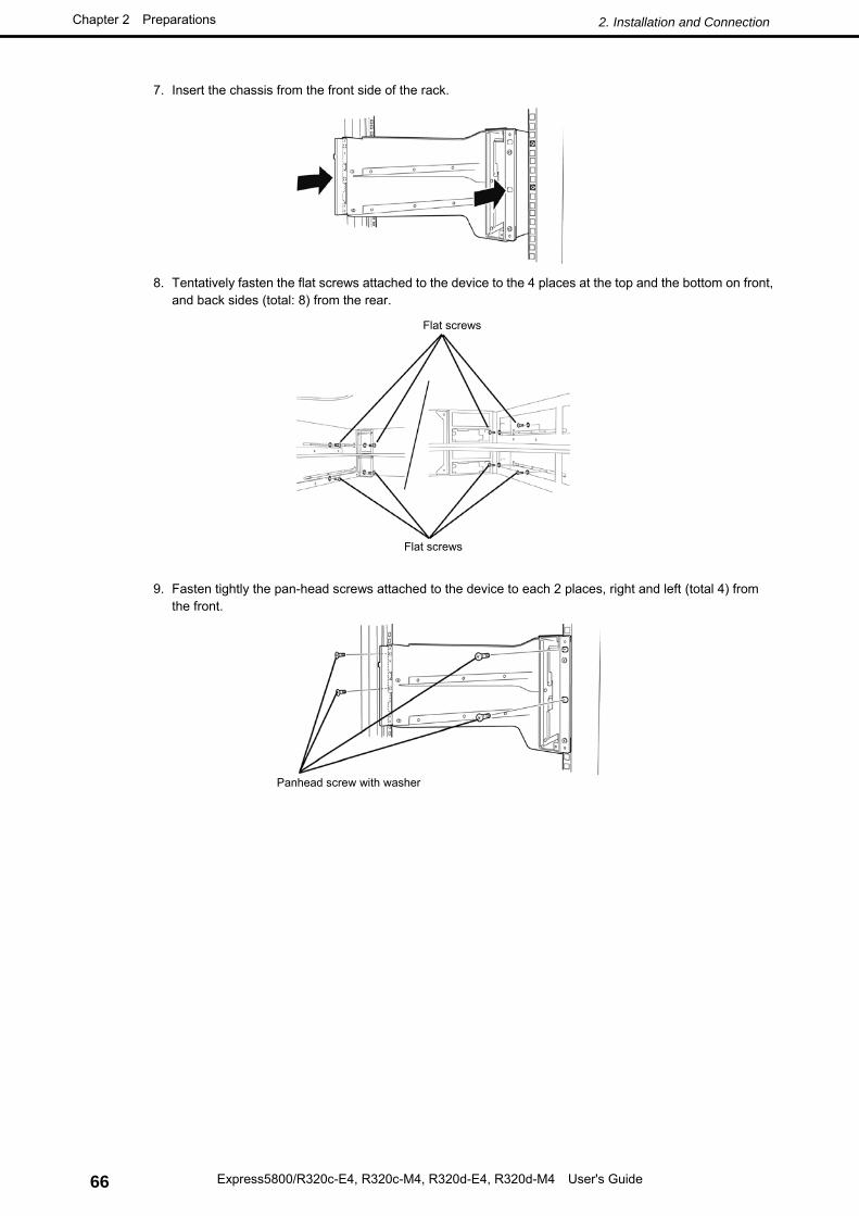
7. Insert the chassis from the front side of the rack.
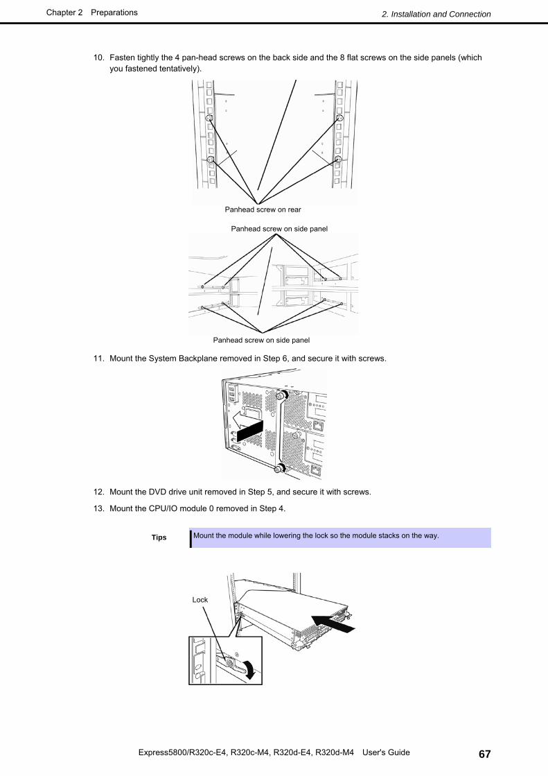
8. Tentatively fasten the flat screws attached to the device to the 4 places at the top and the bottom on front, and back sides (total: 8) from the rear.
9. Fasten tightly the pan-head screws attached to the device to each 2 places, right and left (total 4) from the front.
2.2.3 Removing the device from the rack Remove the server from the rack in the following procedure.
CAUTION
Be sure to observe the following precautions to use the server safely. Failure to observe the precautions may cause burns, injury, and property damage. For details, see Safety precautions in Precautions for Use. • Do not drop the server. • 4U chassis weighs about 10 kgs. At least two persons are required to install
it. • CPU/IO module weighs about 18 kgs. At least two persons are required to
install it. • Do not leave the CPU/IO module of the server being pulled out. • Do not get your fingers caught.
Follow the steps below and unmount the device from the rack.
1. Check that the server is powered off, and remove all the power cords and interface cables from the server.
2. Remove the front bezel.
3. Loosen the screws on the left and right sides of the front panel of the CPU/IO module and release the lock by pulling the ejector toward you.
4. Pull out the CPU/IO module carefully from the rack.
Important • When you pull out the device, do not load anything on its top. It is dangerous, since the device becomes unstable and it may fall.
• Do not hold the handle on the front side or the convex part on the back side. To move the device, hold the bottom.
• Since the device is locked and cannot be pulled out, pull it out after releasing the lock by lowering the lock on the side of the CPU/IO module.
5. Hold firmly the chassis and remove it from the rack,
Tips To remove the mechanical component of the rack, see Chapter 2 (2.2.2 Installing the server to the rack).
By using the tower conversion kit N8843-003, you can install the rack-mount model of NEC Express5800/ft series without using the dedicated rack.
2.3.1 Installing the Tower Conversion Kit You may ask your maintenance personnel to install the tower conversion kit.
WARNING
Be sure to observe the following precautions to use the server safety. Failure to observe the precautions may cause death or serious injury. For details, see Safety precautions in Precautions for Use.
• Use only under the specified environment. • Do not connect the ground wire to a gas pipe
CAUTION
Be sure to observe the following precautions to use the server safely. Failure to observe the precautions may cause burns, injury, and property damage. For details, see Safety precautions in Precautions for Use.
• Do not carry or install the server only by a single person. • Remove the CPU/IO module from the server before moving the server. • Do not install the server so that the load may be concentrated on a specific
point. • Do not install any components only by a single person. • Do not pull out the CPU/IO module from the rack when the tower conversion
kit is unstable. • Do not leave the CPU/IO module of the server being pulled out from tower
conversion kit. • Do not provide the wiring for the server to exceed the rating of the power
supply. • Do not use the server in the environment where corrosive gas is generated.
Do not install the tower conversion kit in such places as listed below. Otherwise, the server may malfunction.
• Narrow space from which devices cannot be pulled out from the tower conversion kit completely
• Place that cannot bear the total weights of the devices mounted on tower conversion kit
• Place where stabilizers cannot be installed or where the tower conversion kit can be installed only after the practice of proper earthquake-resistant construction
• Place of uneven or slanting floor
• Place where temperatures change widely (near a heater, air conditioner, or refrigerator).
• Place that is subject to intense vibration.
• Place where corrosive gas (sodium chloride, sulfur dioxide, hydrogen sulfide, nitrogen dioxide, or ozone) is generated, or a place that is close to chemicals or exposed to chemicals.
• Place where chemicals may be accidentally sprayed over
• Place whose floor is covered with non-antistatic carpet.
• Place that may be subject to falling objects.
• Place that is close to some equipment that generates intense magnetic field (e.g., TV set, radio, broadcasting/communications antenna, power transmission wire, and electromagnetic crane). (If unavoidable, contact your sales agent to request proper shield construction.)
• Place where the power cord of the server must be connected to an AC outlet that shares the outlet of another device with large power consumption.
• Place that is close to some equipment that causes power noises (e.g., sparks caused by power-on/off using a relay). If you must install the server close to such equipment, request your sales agent for separate power cabling or noise filter installation.
• Environment where operation of the server is not guaranteed
When you have selected a site, carry the tower conversion kit to the site, then place it slowly and gently.
Important Do not hold the tower conversion kit by its front door to lift it. The front door may be disengaged and damage the device.
After placing the tower conversion kit, lock its two rear wheels out of four.
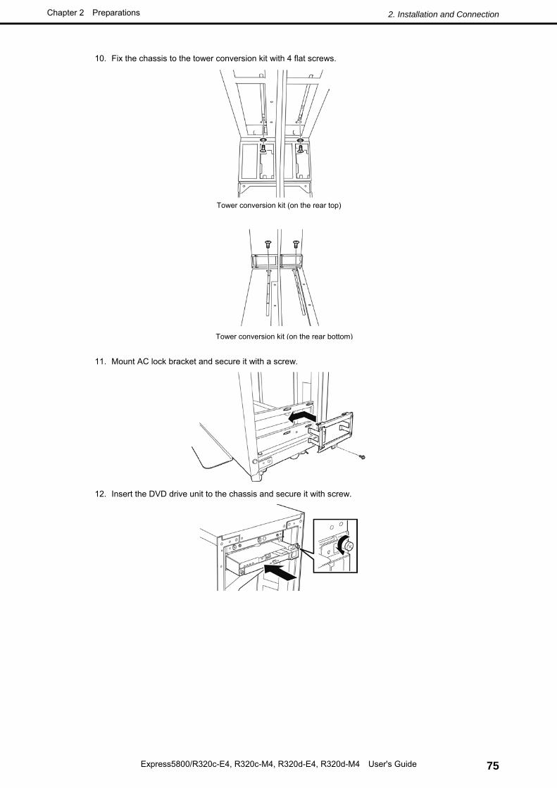
2.3.2 Installing the Rack-mount Model to the Tower Conversion Kit Follow the procedure below to install the devices to the tower conversion kit.
CAUTION
Be sure to observe the following precautions to use the server safely. Failure to observe the precautions may cause burns, injury, and property damage. For details, see Safety precautions in Precautions for Use. • Do not drop the server. • 4U chassis weighs about 10 kgs. At least two persons are required to install
it. • CPU/IO module weighs about 18 kgs. At least two persons are required to
install it. • Do not leave the CPU/IO module of the server being pulled out. • Do not install the CPU/IO module with its cover removed. • Do not get your fingers caught.
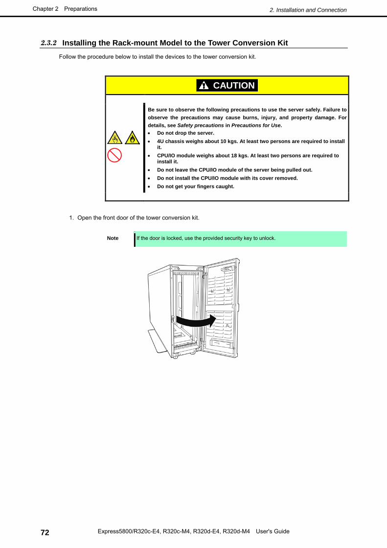
1. Open the front door of the tower conversion kit.
Note If the door is locked, use the provided security key to unlock.
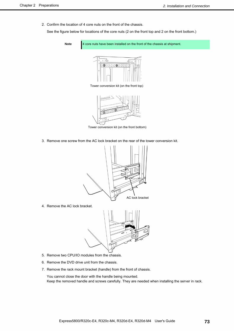
2. Confirm the location of 4 core nuts on the front of the chassis.
See the figure below for locations of the core nuts (2 on the front top and 2 on the front bottom.)
Note 4 core nuts have been installed on the front of the chassis at shipment.
3. Remove one screw from the AC lock bracket on the rear of the tower conversion kit.
4. Remove the AC lock bracket.
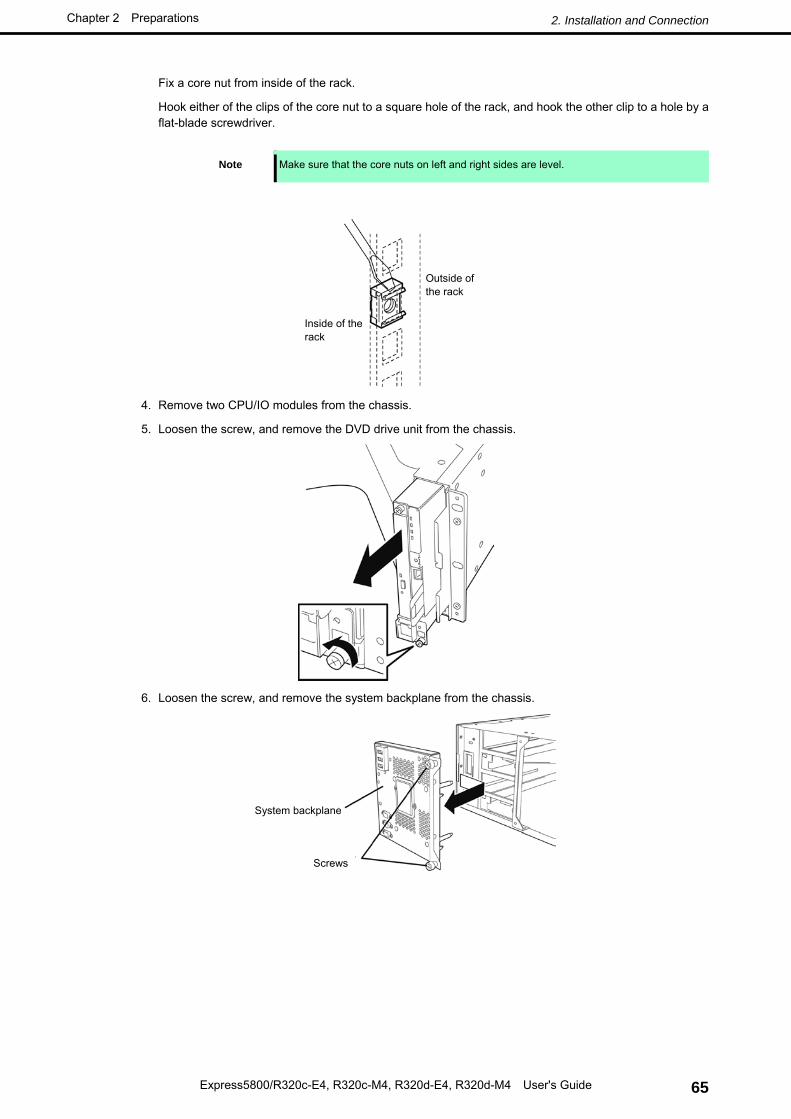
5. Remove two CPU/IO modules from the chassis.
6. Remove the DVD drive unit from the chassis.
7. Remove the rack mount bracket (handle) from the front of chassis.
You cannot close the door with the handle being mounted. Keep the removed handle and screws carefully. They are needed when installing the server in rack.
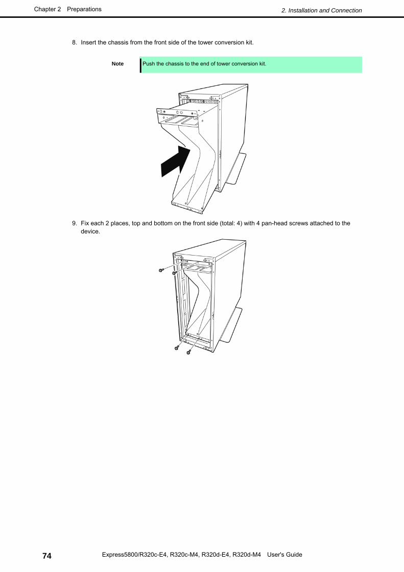
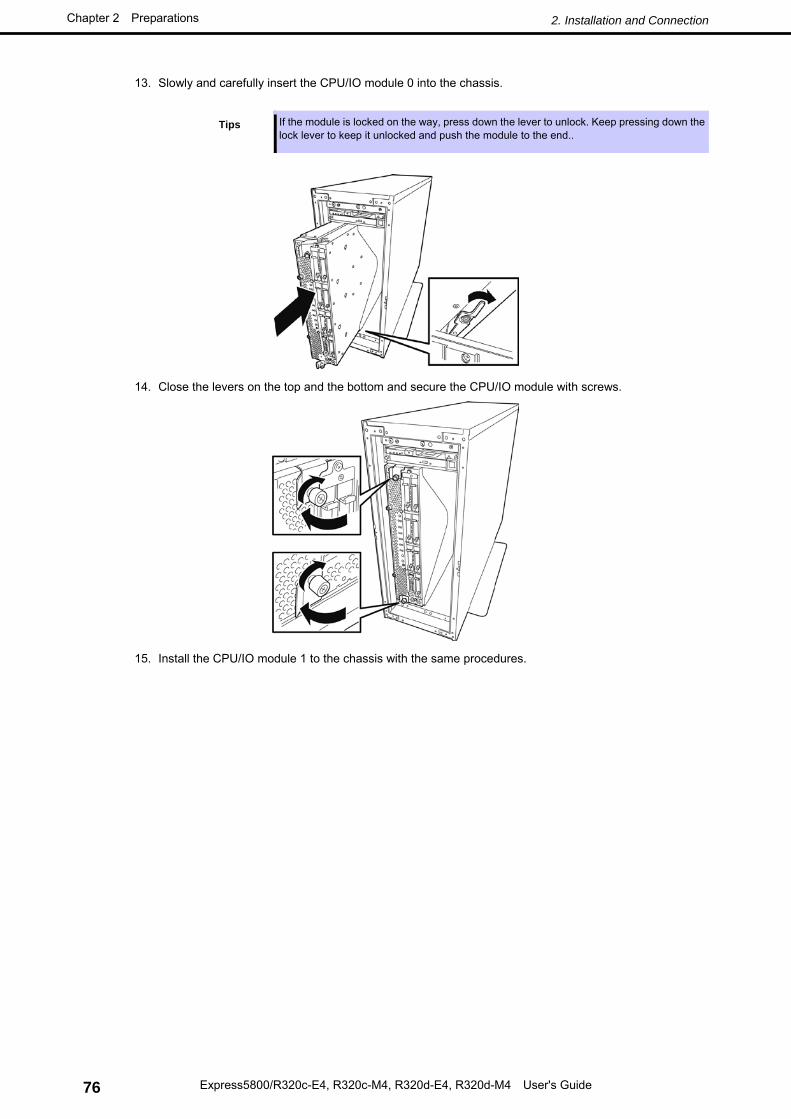
13. Slowly and carefully insert the CPU/IO module 0 into the chassis.
Tips If the module is locked on the way, press down the lever to unlock. Keep pressing down the lock lever to keep it unlocked and push the module to the end..
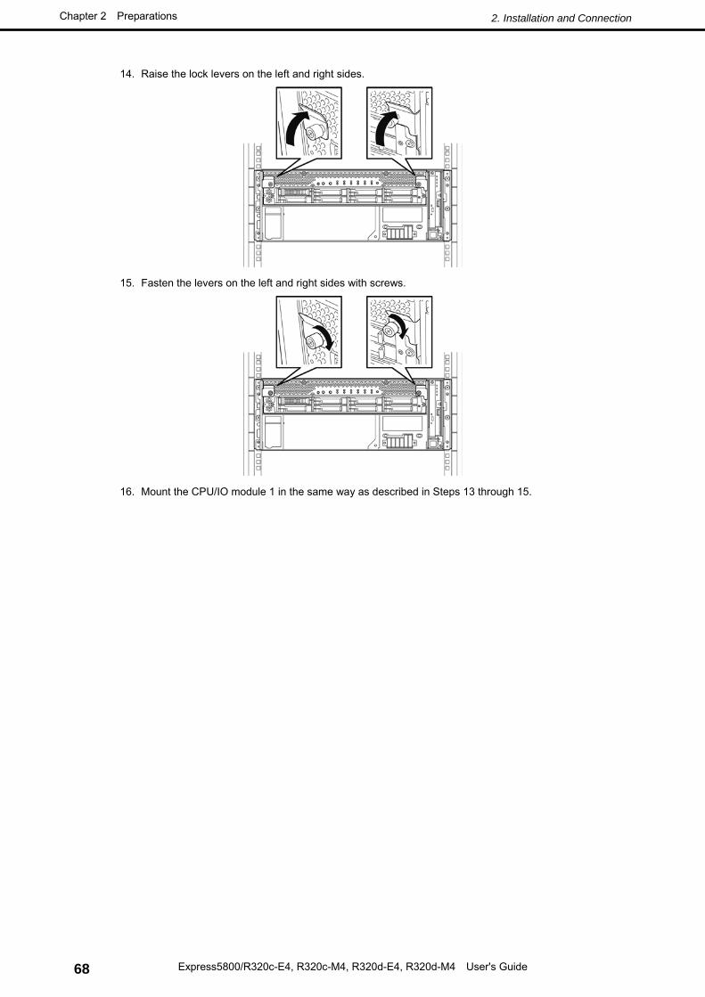
14. Close the levers on the top and the bottom and secure the CPU/IO module with screws.
15. Install the CPU/IO module 1 to the chassis with the same procedures.
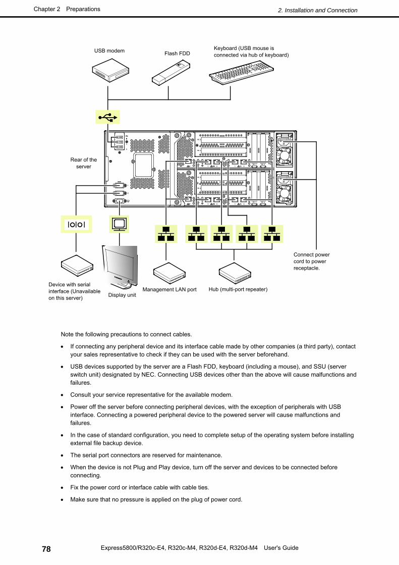
Connectors that allow a variety of peripheral devices to be connected are provided at the front and rear of the server. Images on the following pages show the peripheral devices that can be connected in their standard state and their respective connector positions.
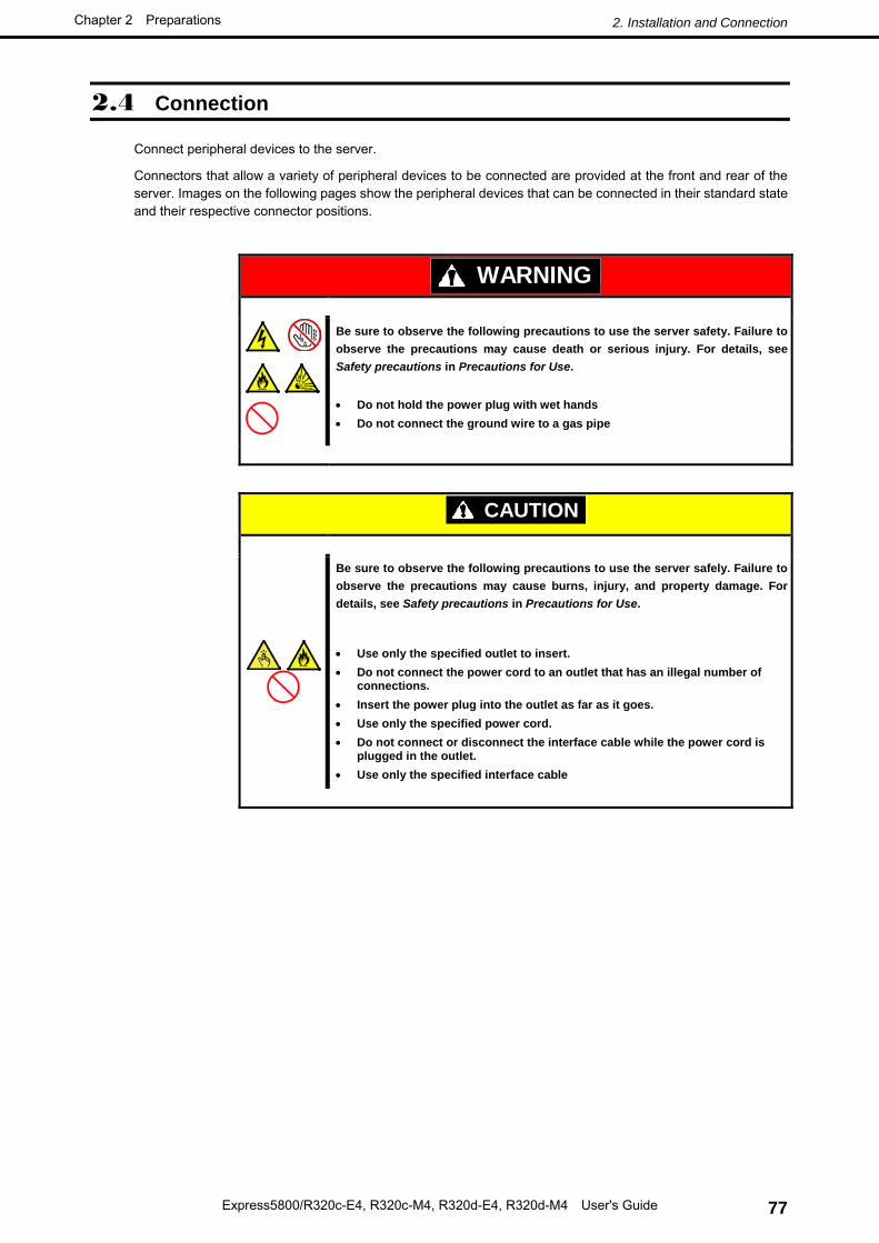
WARNING
Be sure to observe the following precautions to use the server safety. Failure to observe the precautions may cause death or serious injury. For details, see Safety precautions in Precautions for Use.
• Do not hold the power plug with wet hands • Do not connect the ground wire to a gas pipe
CAUTION
Be sure to observe the following precautions to use the server safely. Failure to observe the precautions may cause burns, injury, and property damage. For details, see Safety precautions in Precautions for Use.
• Use only the specified outlet to insert. • Do not connect the power cord to an outlet that has an illegal number of
connections. • Insert the power plug into the outlet as far as it goes. • Use only the specified power cord. • Do not connect or disconnect the interface cable while the power cord is
plugged in the outlet. • Use only the specified interface cable
• If connecting any peripheral device and its interface cable made by other companies (a third party), contact your sales representative to check if they can be used with the server beforehand.
• USB devices supported by the server are a Flash FDD, keyboard (including a mouse), and SSU (server switch unit) designated by NEC. Connecting USB devices other than the above will cause malfunctions and failures.
• Consult your service representative for the available modem.
• Power off the server before connecting peripheral devices, with the exception of peripherals with USB interface. Connecting a powered peripheral device to the powered server will cause malfunctions and failures.
• In the case of standard configuration, you need to complete setup of the operating system before installing external file backup device.
• The serial port connectors are reserved for maintenance.
• When the device is not Plug and Play device, turn off the server and devices to be connected before connecting.
• Fix the power cord or interface cable with cable ties.
• Make sure that no pressure is applied on the plug of power cord.
Connect power cord to power receptacle.
Hub (multi-port repeater) Management LAN port Display unit
Device with serial interface (Unavailable on this server)
Rear of the server
USB modem Flash FDD Keyboard (USB mouse is connected via hub of keyboard)
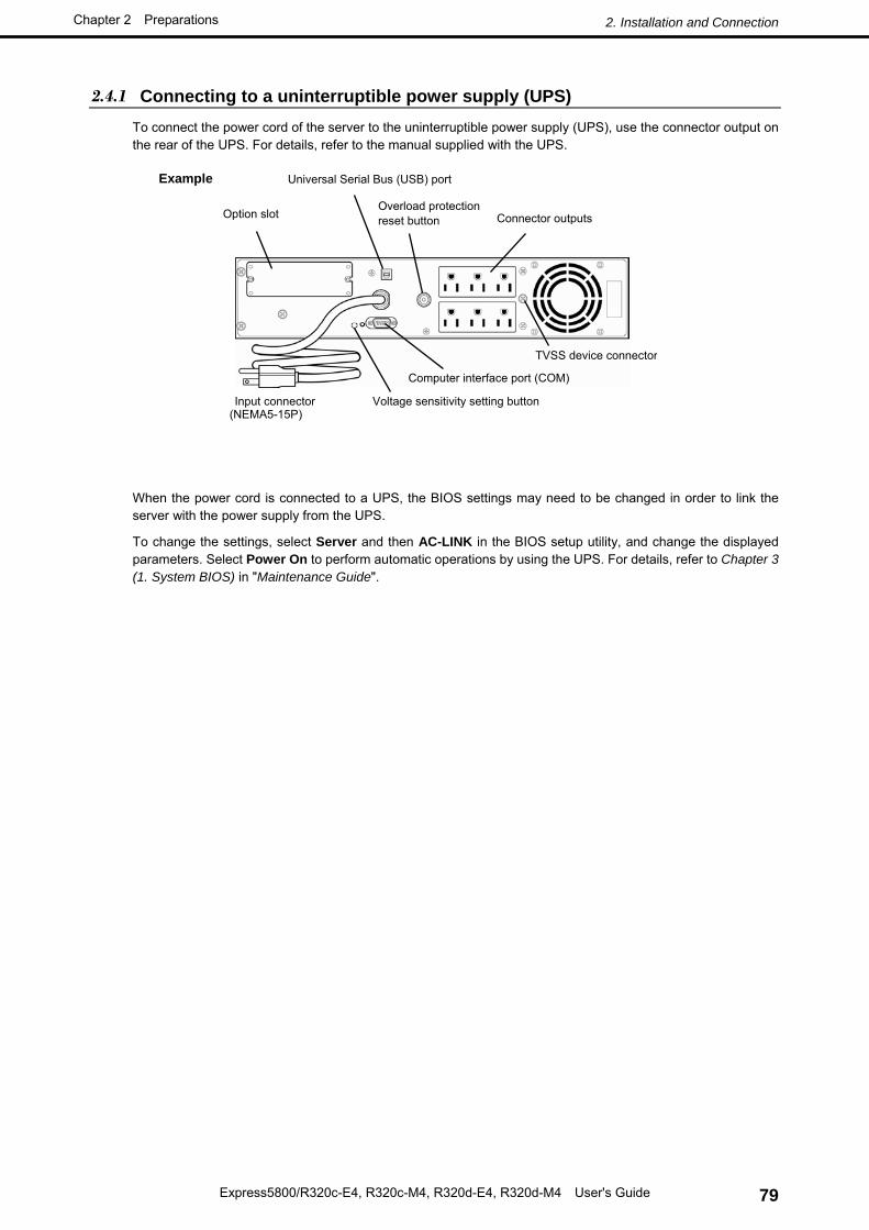
2.4.1 Connecting to a uninterruptible power supply (UPS) To connect the power cord of the server to the uninterruptible power supply (UPS), use the connector output on the rear of the UPS. For details, refer to the manual supplied with the UPS.
When the power cord is connected to a UPS, the BIOS settings may need to be changed in order to link the server with the power supply from the UPS.
To change the settings, select Server and then AC-LINK in the BIOS setup utility, and change the displayed parameters. Select Power On to perform automatic operations by using the UPS. For details, refer to Chapter 3 (1. System BIOS) in "Maintenance Guide".
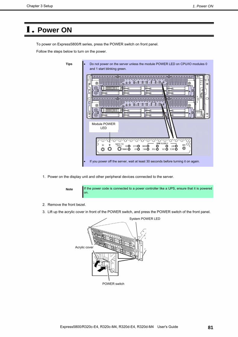
The System POWER LED goes on green. After a while, the "NEC" logo will appear on the screen.
Important • Do not connect or disconnect USB device while POST is running.
• Do not power off the server while POST is running.
While the "NEC" logo is displayed on the screen, Express5800/ft series executes a power-on self test (POST) to check hardware. For details, see Chapter 3 (1.1 POST Check).
Power-On Self Test (POST) is a self-test feature stored on the motherboard of Express5800/ft series. When you power on the server, POST will start automatically to check the motherboard, DIMM, and processor (CPU) and others. It also displays startup messages for various utilities.
You do not always need to check POST details. You will need to check messages when:
• You install a new Express5800/ft series.
• A failure is suspected.
• The display unit shows an error message.
1.1.1 Flow of POST This section walks you through how POST is performed.
1. When you power on the system, one CPU/IO module is selected as primary, and it will start up.
POST will be performed on this selected CPU/IO module.
According to the factory default settings, the logo appears on the display while POST is running.
Note Keyboard becomes operable after the logo appears.
2. If Enabled is specified for Password On Boot in Security menu of SETUP, you will be prompted to
enter password after the logo is displayed. If you enter the incorrect password three times consecutively, POST aborts. (You can no longer proceed.)
In this case, power off the server, and power it on.
Important Do not set a password before installing an OS.
3. If <Esc> key is pressed, the logo disappears and the details of POST are displayed.
Tips If Quiet Boot is Disabled on Boot menu in BIOS SETUP, the details of POST is displayed without displaying the logo.
4. POST displays several types of message. These messages let you know that the installed CPU or
memory capacity.
5. After a while, the following message is displayed on the screen.
Press <F2> SETUP, <F4> ROM Utility, <F12> Network
By pressing the designated function key following messages, you can call the functions below upon completion of POST.
<F2> key: Run BIOS Setup Utility (SETUP). For information on the SETUP, refer to Chapter 3 (1. System BIOS) in "Maintenance Guide".
<F4> key: Run Offline Tools. For information on Offline Tools, refer to Chapter 1 (12. Offline Tools) in "Maintenance Guide".
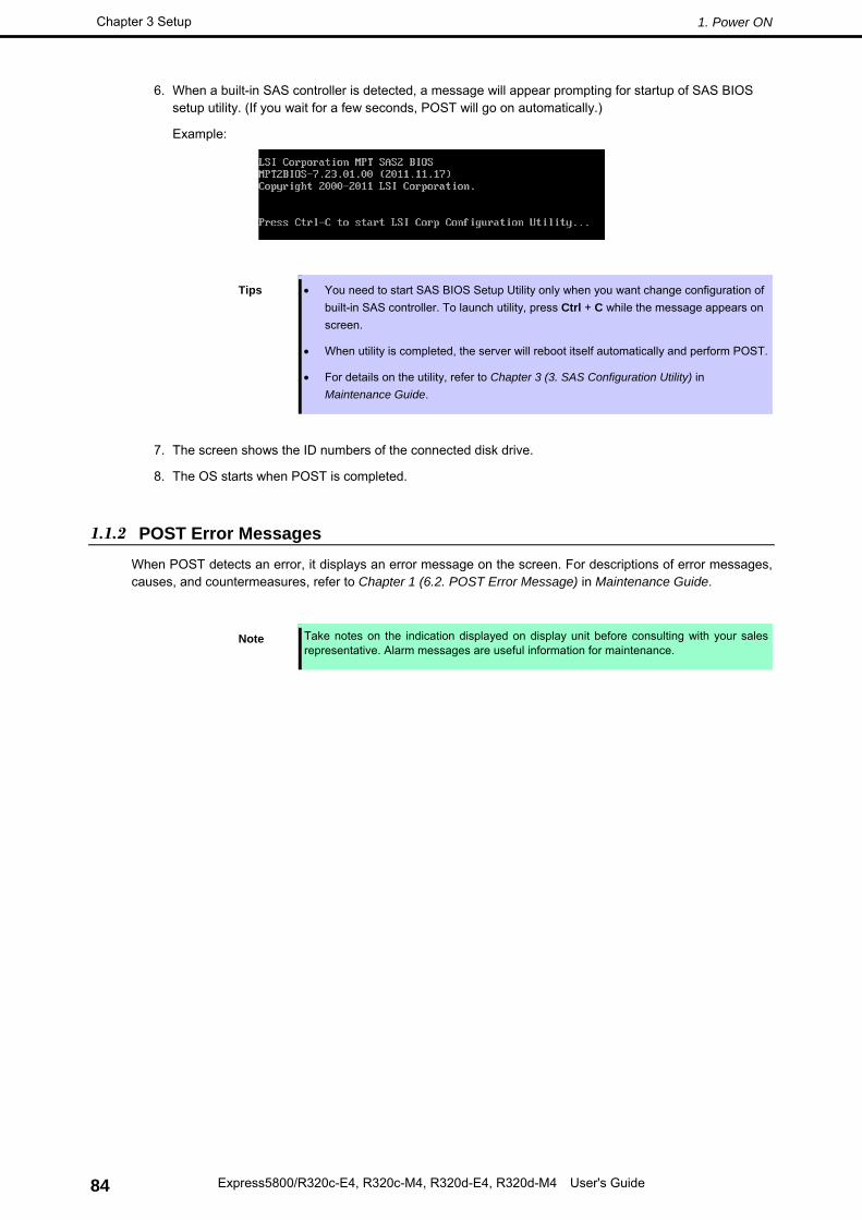
6. When a built-in SAS controller is detected, a message will appear prompting for startup of SAS BIOS setup utility. (If you wait for a few seconds, POST will go on automatically.)
Example:
Tips • You need to start SAS BIOS Setup Utility only when you want change configuration of built-in SAS controller. To launch utility, press Ctrl + C while the message appears on screen.
• When utility is completed, the server will reboot itself automatically and perform POST.
• For details on the utility, refer to Chapter 3 (3. SAS Configuration Utility) in Maintenance Guide.
7. The screen shows the ID numbers of the connected disk drive.
8. The OS starts when POST is completed.
1.1.2 POST Error Messages When POST detects an error, it displays an error message on the screen. For descriptions of error messages, causes, and countermeasures, refer to Chapter 1 (6.2. POST Error Message) in Maintenance Guide.
Note Take notes on the indication displayed on display unit before consulting with your sales representative. Alarm messages are useful information for maintenance.
1.1.3 Behavior at Occurrence of Error The CPU/IO module to be started first is determined depending on the primary/secondary status of modules when the server was shutdown the last time.
At the first startup after AC OFF, the CPU/IO module (0 or 1) powered on first is managed as primary, and the module powered on later is managed as secondary.
If POST or OS startup does not complete normally, the server will reboot itself automatically.
At the time of reboot, the CPU/IO module that was secondary before reboot is determined as primary module, and POST or OS runs on that module (switching of boot pair).
If POST does not complete normally on both CPU/IO modules, the server will stop with the state of DC OFF or POST halts with an error message displayed.
The following devices are connected to the primary CPU/IO module. When one CPU/IO module is disconnected because of a failure, the remaining module is selected automatically to continue operating.
• VGA (display)
• USB device (keyboard, mouse, server switch unit, Flash FDD, optical disk drive)
Important • If the Flash FDD is connected, the drive letter may change from A to B by switching CPU/IO modules. Changing of the drive letter does not affect the operation of the server. If the drive letter is changed, access the Flash FDD with the changed drive letter.
• The drive letter of the optical disk drive is re-assigned automatically. The unused letter is assigned to the drive in the order of D to Z. If you want to set the fixed drive letter to the optical disk drive, specify the letter which is not assigned in the order of D to Z after setting the hard disk drive letter.
This section describes how to configure Basic Input Output System (BIOS).
Before you install the server and add or remove optional devices, make sure you have read and understood this section to configure properly.
2.1 Overview
The SETUP utility is provided to make basic hardware configuration for the server. This utility is pre-installed in the flash memory of the server and ready to run.
SETUP was configured for optimal performance before the server was shipped. Therefore, in most of cases, you do not need to use the SETUP utility. Use only when the case applies to any of cases described in Chapter 3 (2.4 Cases that Require Configuration).
2.2 Starting and Exiting SETUP Utility
2.2.1 Starting SETUP Run POST following Chapter 3 (1.1.1 Flow of POST).
After a while, the following message will be displayed on the lower left of the screen. (The on-screen message depends on your system environment.)
Press <F2> SETUP, <F4> ROM Utility, <F12> Network
If you press <F2> key at this time, SETUP runs and displays Main menu upon completion of POST. (You can also press <F2> key to display Main menu while option ROM is expanded.)
Password
If password is set, you will be prompted to enter password.
Enter Password [ ]
Up to three password entries are accepted. If you enter incorrect password consecutively three times, the system halts (you can no longer proceed). In this case, power off the server once, then power it on.
2.2.2 Exiting SETUP To exit SETUP after saving parameters, select Save & Exit → Save Changes and Exit.
To exit SETUP without saving parameters, select Save & Exit → Discard Changes and Exit.
Tips To restore the default value, select Save & Exit → Load Setup Defaults. (The default value might be different from the factory setting.)
This section shows display examples and how to control the key. Use the keyboard to work with the SETUP utility.
□ Cursor keys (<↑>, <↓>)
Select an item displayed on the screen. If character strings of an item are highlighted, that means the item is currently selected.
□ Cursor keys (<←>, <→>)
Select menus including Main, Advanced, Security, Server, Boot, and Save & Exit.
□ <−> key/<+> key
Change the value (parameter) of the selected item. You cannot use this key when a menu which has on the left is selected.
□ <Enter> key
Press this key to confirm the selected parameter.
□ <Esc> key
Pressing this key cancels pop-up dialog, or takes you to the previous screen on submenu screen. If you keep pressing this key on Main menu, the following window is displayed. If you select Yes, the SETUP closes without saving the changed parameters.
Quit without saving?
[Yes] No
□ <F1> key
Press this key to display help information. If you need help using the SETUP, press this key. Press the <Esc> key to go back to the original screen.
Indicates the currently displayed menu
Help
Parameters (highlighted when selected*) *: Items that cannot be specified are dimmed. *
If you press this key, the following window appears. If you select Yes, the previous parameter(s) are restored. If the value has been saved with Save & Changes, the stored values are restored.
Load Previous Values?
[Yes] No
□ <F3> key
If you press this key, the following window appears. If you select Yes, restore the parameters of the currently selected item to the default setting. (This might be different from the parameters configured before shipment.)
Load Setup Defaults?
[Yes] No
□ <F4> key
If you press this key, the following window appears. If you select Yes, the parameter you configured is saved and SETUP closes.
Only if a case applies to any of following cases, use the SETUP utility to change a parameter which was configured as factory setting. Other than cases described below, do not change the settings. A list of SETUP parameters and factory settings are described in Chapter 3 (1. System BIOS) in "Maintenance Guide".
Category Description To be changed Remark
Basic Change date and time Main → System Date Main → System Time
Configurable on OS
On/Off NumLock at power ON Boot → Bootup Numlock State → ON
Hide the logo during POST Boot → Quite Boot → Disabled Pressing the <Esc> key hide the logo tentatively.
Option board
Enable Option ROM Scan of installed option board
Advanced → PCI Configuration → PCI Slot X Option ROM → Enabled
X is PCI slot number of the option board
Boot Change the boot order of devices
Boot → Boot Option Priorities → Change the boot priority
When you use EXPRESSBUILDER, set the highest priority to CD/DVD .
Use remote wake-up feature (via LAN)
Advanced → Advanced Chipset Configuration → Wake On LAN/PME → Enabled
Security Set a password Security → Administrator Password → Set a password
Security → User Password → Set a password
If password is set, a message to require password is displayed at next time SETUP is launched.
Restrict bootup by entering password
Security → Password on Boot → Enabled
Can be selected when password is set.
UPS Power link
When the server is supplied with power from UPS, always turn on the power.
Server → AC-LINK → Power On
If the server is turned off by using POWER switch, leave it OFF even when UPS supplies power.
EXPRESSSCOPE Engine 3 provides a variety of features using Baseboard Management Controller (BMC) .
Refer to "EXPRESSSCOPE Engine 3 User's Guide" for more information.
EXPRESSSCOPE Engine 3 monitors the power unit, fans, temperature, and voltage of the server. If you have the management LAN port connected to the network, you can remotely perform the following over a web browser or SSH client:
• Manage the server
• Remotely control the keyboard, video, and mouse (KVM)
• Remotely access a CD/DVD/floppy disk/ISO image/USB memory.
To actualize these functions, virtual USB mass storage (Remote FD, Remote CD/DVD, Remote USB Memory, or Virtual Flash) is always connected as USB mass storage.
Tips Use Offline Tools of the server to reset BMC.
Refer to Chapter 3 (2. BMC Configuration) in Maintenance Guide for more information.
Below is an example of the configuration procedure which enables EXPRESSSCOPE Engine 3 to be used via a
web browser.
1. Run POST according to Chapter 3 (1.1.1 Flow of POST). After a while, the following message appears on the lower left of the screen.
Press <F2> SETUP, <F4> ROM Utility, <F12> Network
2. Press the <F4> key to launch Off-line TOOL while the message is displayed.. You can also press the <F4> key while the message is being displayed to open the Off-line TOOL MENU screen.
3. Select your keyboard type on keyboard selection screen.
4. When the Off-line TOOL MENU appears, select BMC Configuration, BMC Configuration, Network: CPU/IO module 0/1, and then Property.
5. When Property is displayed, enable or disable DHCP or specify IP Address/Subnet Mask.
6. Connect the LAN cable to the management LAN connector in order to connect to the network. It will be available for use if you access EXPRESSSCOPE Engine 3 via Web browser from management PC according to the setting made in Step 5.
EXPRESSBUILDER helps you to install Windows or maintain the server.
4.1 Features of EXPRESSBUILDER
EXPRESSBUILDER provides the following features.
Feature Description
Setup
(Windows reinstallation)
Installs Windows on your server. Easily completes the process to installation of applications. To use this feature, choose OS installation in Boot Selection Menu.
Bundled software Stores various bundled software, such as NEC ESMPRO Agent.
Maintenance Diagnoses your server system. To use this feature, choose Tool menu in Boot Selection Menu.
Instruction manuals Stores various manuals, such as "User’s Guide", "Installation Guide" and "Maintenance Guide".
4.2 Usage of EXPRESSBUILDER
Use EXPRESSBUILDER to install operating system or diagnose your system.
Start EXPRESSBUILDER in either of the following procedure.
• Insert the DVD into the server, and then restart the system. (Cycle the power of server, or press <Ctrl> + <Alt> + <Delete> keys.)
• Insert the DVD into a computer running Windows. Autorun menu appears automatically. The autorun menu is disabled by factory default. Launch the menu by running ¥autorun¥dispatcher_x64.exe.
If the menu does not appear, double-click the icon of optical disk drive.
Refer to Chapter 3 (5. Details of EXPRESSBUILDER) in Maintenance Guide for more information.
Follow the steps below to turn off the power. If Express5800/ft series is connected to a UPS, refer to manuals provided with the UPS or the application that controls the UPS.
1. Shut down the OS.
2. The server automatically turns off after the OS shuts down. The Module POWER LED on each CPU/IO module will be blinking while AC power is supplied.
3. Power off all peripheral devices.
Tips Hibernate feature of Windows Server cannot be used. Do not set Hibernate at Windows shutdown.
Model N8800-184F N8800-185F CPU Type Intel® Xeon® Processor
E5-2620v2 E5-2670v2 Clock speed 2.10GHz 2.50GHz Standard / Maximum 1/2 (per one module) Tertiary cache 15M 25M Number of cores (C) / Number of threads (T) (1CPU)
6C/12T 10C/20T
Chipset Intel ® C602 Chipset Memory Capacity
Standard / Maximum Not pre-installed / 256GB (16x 16GB) (per one module)