532
μFalcon-S & Falcon-S series User Guide i μFalcon-S & Falcon-S series User Guide Revision: 6.4.10A Software Version 6.4.10 June-2017
| Date post: | 26-Feb-2023 |
| Category: |
Documents |
| Upload: | khangminh22 |
| View: | 0 times |
| Download: | 0 times |

µFalcon-S & Falcon-S series User Guide i
µFalcon-S & Falcon-S series User Guide
Revision: 6.4.10A
Software Version 6.4.10
June-2017

µFalcon-S & Falcon-S series User Guide i
Proprietary Information
This document contains information, which is proprietary to Fibrolan Ltd.
No part of its contents may be used, copied, disclosed or conveyed to a third party in
any manner whatsoever without prior written permission from Fibrolan Ltd.
Special Notes: please refer to the Alphabetical Glossary of terms. for any terminology
explanation or clarification is found in the User Guide.
All the features and characteristics described in this User Guide are common to all
µFalcon series, and Falcon-S series
The Falcon-S series includes the Falcon-S, Falcon-STA and Falcon-MTS series
µFalcon S series: µFalcon S/SE, µFalcon ST, uFalcon-SG, µFalcon-ST/G, µFalcon-ST/F,
µFalcon SL and uFalcon-SP with the following exceptions:
TDM Functionality is applicable only to µFalcon-ST, µFalcon-ST/G, µFalcon-ST/F, and
Falcon-MTS (partial functionality)
IEEE1588-2008 (PTP) is applicable to µFalcon S series (except µFalcon SL) and Falcon-S
series
Synchronous Ethernet (SyncE) is applicable to µFalcon S /SE, µFalcon ST, uFalcon-SG,
µFalcon-ST/G, µFalcon-ST/F, uFalcon-SP, and to Falcon-S series
For a detailed information regarding Fibrolan products software features,
refer to the document Fibrolan Falcon products Matrix 2016
The Matrix will help you to find out which features belong to the various Falcon devices


µFalcon-S & Falcon-S series User Guide i
Table of Contents
1 Introduction ...................................................................................................................... 1-21
1.1 µFalcon-S & Falcon-S series Overview ................................................................................... 1-2
1.1.1 µFalcon-S series ...................................................................................................... 1-2
1.1.2 Falcon-S series ........................................................................................................ 1-4
1.1.3 Interfaces ............................................................................................................... 1-5
1.1.4 Front Panel LED indicators ....................................................................................... 1-9
1.1.5 µFalcon-S models list ............................................................................................. 1-10
1.1.6 Falcon-S models list ............................................................................................... 1-12
1.1.7 Fibrolan μFalcon-S Product Matrix 2016 .................................................................. 1-14
1.1.8 Fibrolan Falcon Product Matrix 2016 ....................................................................... 1-18
1.1.9 Typical Applications ............................................................................................... 1-22
1.1.10 Scalability .............................................................................................................. 1-27
1.2 About this Manual.............................................................................................................. 1-28
1.3 Document Symbols ............................................................................................................ 1-29
2 System Description ............................................................................................................. 2-1
2.1 Block Diagrams ................................................................................................................... 2-2
2.1.1 µFalcon-S series Key Features .................................................................................. 2-5
2.1.2 Falcon-S series Key Features .................................................................................... 2-6
2.1.3 Falcon STA Features ................................................................................................ 2-6
2.1.4 Falcon-MTS Features ............................................................................................... 2-7
2.1.5 Management ........................................................................................................... 2-9
2.2 µFalcon-S & Falcon-S series ports features .......................................................................... 2-10
3 Getting Started ................................................................................................................... 3-1
3.1 Quick Setup Outline ............................................................................................................. 3-2
3.2 Console Connection and Configuration .................................................................................. 3-3
3.2.1 Initial Configuration ................................................................................................. 3-4
3.2.2 Web management initial display ............................................................................... 3-5
4 Functional Description ....................................................................................................... 4-1
4.1 Overview ............................................................................................................................ 4-2
4.2 Frame Processing Overview ................................................................................................. 4-2
4.3 System Information ............................................................................................................. 4-3
4.3.1 System Information Configuration ............................................................................ 4-3
4.3.2 IP Configuration ...................................................................................................... 4-4
4.3.3 IP Interfaces ........................................................................................................... 4-5
4.3.4 IP Routes ................................................................................................................ 4-6
4.3.5 NTP Configuration ................................................................................................... 4-7
4.3.6 Time Zone ............................................................................................................... 4-8
4.3.7 System Log Configuration ...................................................................................... 4-10
4.3.8 Dying Gasp Configuration ....................................................................................... 4-11
4.3.9 Events .................................................................................................................. 4-12
4.4 DHCP (Dynamic Host Configuration Protocol) ...................................................................... 4-13
4.5 Ports Configuration and Monitoring ..................................................................................... 4-14
4.5.1 Port State .............................................................................................................. 4-17
4.5.2 SFP Information .................................................................................................... 4-18
Table of Contents
ii µFalcon-S & Falcon-S series User Guide
4.5.3 SFP Operational Range .......................................................................................... 4-19
4.5.4 SFP Monitoring ...................................................................................................... 4-20
4.5.5 Traffic Overview .................................................................................................... 4-21
4.5.6 QoS Statistics ........................................................................................................ 4-22
4.5.7 QoS Control List Status .......................................................................................... 4-23
4.5.8 Detailed Port Statistics ........................................................................................... 4-25
4.5.9 Green Ethernet ...................................................................................................... 4-28
4.5.10 Thermal Protection ................................................................................................ 4-28
4.6 Learn MAC Table ............................................................................................................... 4-29
4.6.1 Configuring the MAC Address Table ........................................................................ 4-29
4.6.2 Monitoring the MAC Address Table ......................................................................... 4-31
4.6.3 Navigating the MAC Table ...................................................................................... 4-32
4.7 VLANs and Provider Bridges ............................................................................................... 4-33
4.7.1 VLAN Configuration ................................................................................................ 4-34
4.7.1.1 VLAN Port Configuration .......................................................................... 4-35
4.7.1.2 VLAN Membership Status and VLAN Name configuration ............................ 4-38
4.7.1.3 VLAN Port Status for Combined users ....................................................... 4-40
4.7.2 VLAN Membership Status for Combined users ......................................................... 4-42
4.7.3 `VLAN Translation ................................................................................................. 4-44
4.7.3.1 VLAN Translation Port Configuration ......................................................... 4-44
4.7.3.2 VLAN Translation Mapping Table .............................................................. 4-46
4.7.4 Provider Bridges (QinQ) ......................................................................................... 4-48
4.7.5 Private VLANs (PVLANs) ......................................................................................... 4-49
4.7.5.1 Private VLAN Membership Configuration ................................................... 4-49
4.7.5.2 Port Isolation Configuration ...................................................................... 4-51
4.7.5.3 VCL ........................................................................................................ 4-52
4.7.5.4 MAC-based VLAN Membership Configuration ............................................. 4-52
4.7.5.5 Protocol based VLAN ............................................................................... 4-53
4.7.5.6 Group Name to VLAN mapping Table ........................................................ 4-55
4.7.5.7 IP Subnet based VLAN Memebership Configuration .................................... 4-56
4.7.6 Voice VLAN ........................................................................................................... 4-58
4.7.6.1 Voice VLAN Configuration ........................................................................ 4-58
4.7.6.2 Port Configuration ................................................................................... 4-59
4.7.6.3 Voice VLAN OUI Table ............................................................................. 4-60
4.7.7 Multicast VLAN Registration (MVR) ......................................................................... 4-61
4.7.7.1 MVR Configurations ................................................................................. 4-61
4.7.7.2 VLAN Interface Setting ............................................................................ 4-62
4.7.7.3 Immediate Leave Setting ......................................................................... 4-63
4.7.7.4 MVR Statistics ......................................................................................... 4-65
4.7.7.5 MVR Channels (Groups) Information ......................................................... 4-66
4.7.7.6 MVR SFM Information .............................................................................. 4-67
4.8 Quality of Service (QoS) ..................................................................................................... 4-68
4.8.1 QoS Ingress Port Classification ............................................................................... 4-68
4.8.2 QoS Ingress Port Policers ....................................................................................... 4-70
4.8.3 QoS Ingress Queue Policers ................................................................................... 4-71
4.8.4 QoS Egress Port Schedulers ................................................................................... 4-72
4.8.5 QoS Egress Port Shapers ........................................................................................ 4-75
4.8.6 QoS Egress Port Tag Remarking ............................................................................. 4-78
4.8.7 Qos Port DSCP Configuration .................................................................................. 4-79
Table of Contents
µFalcon-S & Falcon-S series User Guide iii
4.8.8 DSCP Based QoS Ingress Classification ................................................................... 4-80
4.8.9 DSCP Translation ................................................................................................... 4-82
4.8.10 DSCP Classification ................................................................................................ 4-85
4.8.11 QoS Control List Configuration ................................................................................ 4-86
4.8.12 QCE Configuration ................................................................................................. 4-87
4.8.13 Rate Limiters ......................................................................................................... 4-90
4.8.13.1 Leaky Bucket ........................................................................................... 4-90
4.8.14 Global Storm Policer Configuration .......................................................................... 4-92
4.9 Ethernet Services .............................................................................................................. 4-93
4.9.1 EVC Port Configuration ........................................................................................... 4-93
4.9.2 L2CP Port Configuration ......................................................................................... 4-94
4.9.3 Bandwidth Profiles Configuration ............................................................................ 4-96
4.9.4 EVC Control List Configuration ................................................................................ 4-98
4.9.5 EVC Configuration ................................................................................................. 4-100
4.9.6 ECE Control List Configuration ............................................................................... 4-102
4.9.7 ECE Configuration ................................................................................................. 4-104
4.9.8 EVC Statistics ....................................................................................................... 4-107
4.10 Security Features .............................................................................................................. 4-108
4.10.1 Switch .................................................................................................................. 4-108
4.10.1.1 User Configuration .................................................................................. 4-108
4.10.1.2 Privilege Level Configuration ................................................................... 4-110
4.10.1.3 Authentication Method Configurations ...................................................... 4-112
4.10.1.4 SSH Configuration .................................................................................. 4-114
4.10.1.5 HTTPS Configuration .............................................................................. 4-115
4.10.1.6 Access Management Configuration .......................................................... 4-117
4.10.1.7 Access Management Statistics ................................................................. 4-118
4.10.2 Network Security .................................................................................................. 4-119
4.10.2.1 MAC Limit Configuration .......................................................................... 4-119
4.10.2.2 Port Security Switch Status ..................................................................... 4-122
4.10.2.3 Port Security Port Status ......................................................................... 4-124
4.10.2.4 Network Access Server Configuration ....................................................... 4-125
4.10.2.5 Network Access Server Switch Status ....................................................... 4-133
4.10.2.6 NAS Port Statistics .................................................................................. 4-135
4.10.2.7 ACL Ports Configuration .......................................................................... 4-140
4.10.2.8 ACL Rate Limiter Configuration ................................................................ 4-142
4.10.2.9 Access Control List Configuration ............................................................. 4-143
4.10.2.10 ACE Configuration .................................................................................. 4-145
4.10.2.11 ACL Status ............................................................................................. 4-148
4.10.2.12 IP Source Guard Configuration ................................................................ 4-150
4.10.2.13 Static IP Source Guard Table ................................................................... 4-151
4.10.2.14 Dynamic IP Source Guard Table .............................................................. 4-152
4.10.3 Address Resolution Protocol .................................................................................. 4-153
4.10.3.1 ARP Inspection Configuration .................................................................. 4-153
4.10.3.2 VLAN Mode Configuration ....................................................................... 4-155
4.10.3.3 Static ARP Inspection Table..................................................................... 4-156
4.10.3.4 Dynamic ARP Inspection Table ................................................................ 4-157
4.10.4 Authentication Server Configuration (AAA) ............................................................. 4-158
4.10.4.1 Radius Server Configuration .................................................................... 4-158
4.10.4.2 Radius Server Status Overview ................................................................ 4-160
Table of Contents
iv µFalcon-S & Falcon-S series User Guide
4.10.4.3 TACACS+ Sever Configuration ................................................................. 4-161
4.10.4.4 RADIUS Auth.Statistics for Server ............................................................ 4-163
4.11 TDM Functionality ............................................................................................................. 4-167
4.11.1 TDM General Configuration ................................................................................... 4-168
4.11.2 TDM Ports Configuration ....................................................................................... 4-169
4.11.3 TDM Port Timing Configuration .............................................................................. 4-172
4.11.4 TDM Circuits ......................................................................................................... 4-174
4.11.5 TDM Circuit Overview ........................................................................................... 4-174
4.11.6 TDM Circuit Configuration ..................................................................................... 4-176
4.11.6.1 Circuit Admin Configuration ..................................................................... 4-177
4.11.6.2 TDM Interface Configuration ................................................................... 4-178
4.11.6.3 Network Packet Configuration ................................................................. 4-178
4.11.6.4 RTP Header ............................................................................................ 4-179
4.11.6.5 Jitter Buffer Configuration ....................................................................... 4-181
4.11.7 Timing in TDM ...................................................................................................... 4-182
4.11.8 TDM Port Status ................................................................................................... 4-183
4.11.9 TDM Circuit Status ................................................................................................ 4-184
4.11.10 TDM Circuit Packet Statistics ................................................................................. 4-185
4.11.11 TDM Port Status: Debug Info ................................................................................ 4-186
4.12 SyncCenter Configuration .................................................................................................. 4-187
4.12.1 SyncCenter ........................................................................................................... 4-187
4.12.2 Sync Source ......................................................................................................... 4-188
4.12.3 Sync Center Configuration ..................................................................................... 4-189
4.12.4 Sync Output ......................................................................................................... 4-190
4.12.5 SyncCenter Status ................................................................................................ 4-190
4.12.6 Time .................................................................................................................... 4-191
4.12.7 Event Configuration and Status ............................................................................. 4-192
4.13 SyncCenter Monitoring ...................................................................................................... 4-193
4.13.1 SyncCenter ........................................................................................................... 4-194
4.13.2 Sync Source Status ............................................................................................... 4-194
4.13.3 SyncCenter Configuration ...................................................................................... 4-195
4.13.4 Time .................................................................................................................... 4-196
4.13.5 SyncCenter Status ................................................................................................ 4-196
4.13.6 Event Configuration and Status ............................................................................. 4-197
4.13.7 Sync Output ......................................................................................................... 4-198
4.13.8 SyncCenter Statistics............................................................................................. 4-199
4.14 External Configuration ...................................................................................................... 4-200
4.15 GPS Receiver .................................................................................................................... 4-201
4.15.1 GPS Displays ........................................................................................................ 4-201
4.15.2 GPS Antenna Cable Configuration .......................................................................... 4-202
4.15.3 GPS Status ........................................................................................................... 4-203
4.15.4 GPS Alarms .......................................................................................................... 4-204
4.15.5 Satellite Status ..................................................................................................... 4-205
4.15.6 GPS Antenna Cable Status ..................................................................................... 4-206
4.15.7 GPS Info .............................................................................................................. 4-206
4.15.8 Sky View .............................................................................................................. 4-207
4.15.9 Satellite Count ...................................................................................................... 4-208
4.15.10 Rubidium module ................................................................................................. 4-209
4.16 IEEE1588 Precision Time Protocol ...................................................................................... 4-211
Table of Contents
µFalcon-S & Falcon-S series User Guide v
4.16.1 PTP External Clock Mode ....................................................................................... 4-213
4.16.2 PTP Clock Configuration ........................................................................................ 4-214
4.16.3 PTP Monitoring ..................................................................................................... 4-217
4.16.3.1 PTP External Clock Mode ......................................................................... 4-217
4.16.3.2 PTP Clock Status .................................................................................... 4-218
4.16.3.3 PTP Slave Table ..................................................................................... 4-219
4.17 Synchronous Ethernet (SyncE) .......................................................................................... 4-220
4.17.1 SyncE Ethernet Port Configuration ......................................................................... 4-221
4.18 Spanning Tree .................................................................................................................. 4-223
4.18.1 Understanding RSTP and MSTP ............................................................................. 4-223
4.18.2 STP Bridge settings ............................................................................................... 4-226
4.18.3 MSTI Configuration ............................................................................................... 4-228
4.18.4 MSTI Priority Configuration ................................................................................... 4-229
4.18.6 CIST Port Configuration ........................................................................................ 4-230
4.18.7 MSTI Port Configuration ........................................................................................ 4-232
4.18.8 Spanning Tree Monitoring ..................................................................................... 4-233
4.18.8.1 STP Bridges Status ................................................................................. 4-233
4.18.8.2 STP Detailed Bridge Status ...................................................................... 4-234
4.18.8.3 STP Port Status ...................................................................................... 4-236
4.18.8.4 STP Port Statistics .................................................................................. 4-237
4.19 IP Multicast ...................................................................................................................... 4-238
4.19.1 IGMP Snooping Configuration ................................................................................ 4-239
4.19.2 IGMP Snooping VLAN Configuration ....................................................................... 4-241
4.19.3 IGMP Snooping Port Group Filtering Configuration .................................................. 4-243
4.19.4 IGMP Snooping Status .......................................................................................... 4-244
4.19.5 IGMP Snooping Groups Information ....................................................................... 4-245
4.19.6 IGMP SFM Information .......................................................................................... 4-246
4.19.7 MLD Snooping Configuration ................................................................................. 4-248
4.19.8 MLD Snooping VLAN Configuration ........................................................................ 4-250
4.19.9 MLD Snooping Port Group Filtering Configuration ................................................... 4-252
4.19.10 MLD Snooping Status ............................................................................................ 4-253
4.19.11 MLD Snooping Groups Information ........................................................................ 4-254
4.19.12 MLD SFM Information ........................................................................................... 4-255
4.20 Link Aggregation .............................................................................................................. 4-257
4.20.1 Static Link Aggregation ......................................................................................... 4-258
4.20.2 LACP Port Configuration ........................................................................................ 4-260
4.20.3 LACP Monitoring ................................................................................................... 4-262
4.20.3.1 LACP System Status ................................................................................ 4-262
4.20.3.2 LACP Port Status .................................................................................... 4-263
4.20.3.3 LACP Statistics ....................................................................................... 4-264
4.21 LLDP-Link Discovery ......................................................................................................... 4-265
4.21.1 LLDP Configuration ............................................................................................... 4-266
4.21.2 LLDP-MED Configuration ....................................................................................... 4-269
4.21.3 LLDP Monitoring ................................................................................................... 4-276
4.21.3.1 LLDP Neighbour Information ................................................................... 4-276
4.21.3.2 LLDP-MED Neighbour Information ........................................................... 4-277
4.21.3.3 LLDP Neighbours EEE Information ........................................................... 4-281
4.21.3.4 LLDP Port Statistics ................................................................................. 4-283
4.22 Link OAM ......................................................................................................................... 4-285
Table of Contents
vi µFalcon-S & Falcon-S series User Guide
4.22.1 Link OAM Port Configuration.................................................................................. 4-286
4.22.2 Link Event Configuration for selected Port .............................................................. 4-287
4.22.3 Detailed Link OAM Statistics for selected port ......................................................... 4-289
4.22.4 Detailed Link OAM Status for selected port ............................................................. 4-291
4.22.5 Detailed Link OAM Link Events Status for selected port ........................................... 4-293
4.23 Service OAM Standards ..................................................................................................... 4-296
4.23.1 OAM Service Multi-Domain Levels .......................................................................... 4-297
4.23.2 Ethernet Connectivity Fault Management ............................................................... 4-298
4.23.2.1 Maintenance Domain .............................................................................. 4-300
4.23.2.2 Maintenance Point: MPE/MIP ................................................................... 4-301
4.23.2.3 OAM Messages ....................................................................................... 4-303
4.23.2.4 MEP/MIP Hierarchical View ...................................................................... 4-304
4.23.3 MEP Configuration Management ............................................................................ 4-305
4.23.3.1 Maintenance Entity Point ......................................................................... 4-305
4.23.4 MEP Configuration Displays ................................................................................... 4-307
4.23.4.1 Instance Data ........................................................................................ 4-308
4.23.4.2 Instance Configuration ............................................................................ 4-308
4.23.4.3 Peer MEP Configuration .......................................................................... 4-310
4.23.4.4 Functional Configuration ......................................................................... 4-311
4.23.4.5 TLV Configuration ................................................................................... 4-312
4.23.4.6 TLV Status ............................................................................................. 4-313
4.23.4.7 Link State Tracking ................................................................................. 4-313
4.23.5 Ethernet Continuity Check ..................................................................................... 4-314
4.23.6 Continuity Check Messages with Network Fault....................................................... 4-315
4.23.7 Fault Detection Management ................................................................................. 4-316
4.23.7.1 Ethernet Loop back ................................................................................ 4-317
4.23.7.2 Ethernet Link Trace ................................................................................ 4-319
4.23.7.3 Ethernet Test Signal ............................................................................... 4-322
4.23.7.4 Client Configuration ................................................................................ 4-324
4.23.7.5 Ethernet Alarm Indicator Signal (IAS) ...................................................... 4-325
4.23.7.6 Ethernet Locked Signal ........................................................................... 4-326
4.23.8 Performance Monitor ............................................................................................ 4-327
4.23.8.1 Performance Monitoring Data Set ............................................................ 4-328
4.23.8.2 Loss Measurement LM ............................................................................ 4-328
4.23.8.3 Delay Measurement ................................................................................ 4-331
4.23.8.4 One way frame delay measurement ........................................................ 4-331
4.23.8.5 Two way frame delay measurement ........................................................ 4-331
4.23.9 Delay Measurements Bins ..................................................................................... 4-334
4.23.10 Delay Measurements Bins forFD ............................................................................ 4-335
4.23.11 Delay Measurements Bins for IFDV ........................................................................ 4-335
4.24 RMON (Remote Network Monitoring) ................................................................................. 4-336
4.24.1 RMON Alarm Configuration .................................................................................... 4-336
4.24.2 RMON Event Configuration .................................................................................... 4-337
4.24.3 RMON Statistics Configuration ............................................................................... 4-338
4.24.4 RMON History Configuration .................................................................................. 4-339
4.25 Loop Guard ...................................................................................................................... 4-340
4.25.1 Loop Guard Status ................................................................................................ 4-341
4.26 EPS (Ethernet Protection Switching) .................................................................................. 4-342
4.27 Ethernet Ring Protection Switching .................................................................................... 4-343
Table of Contents
µFalcon-S & Falcon-S series User Guide vii
4.28 Loopback Configuration .................................................................................................... 4-344
4.29 Micro-Burst Detection ....................................................................................................... 4-345
4.29.1 MBD Statistics ...................................................................................................... 4-346
4.29.2 Micro Burst List ..................................................................................................... 4-347
4.30 Link Protection ................................................................................................................. 4-348
4.30.1 Link Protection Configuration ................................................................................. 4-348
4.30.2 Link Protection Status ........................................................................................... 4-349
4.31 GVRP Configuration .......................................................................................................... 4-350
4.31.1 GVRP Port Configuration ....................................................................................... 4-351
4.32 sFlow Consideration .......................................................................................................... 4-352
4.32.1 sFlow Configuration displays.................................................................................. 4-352
4.32.2 sFlow Statistics ..................................................................................................... 4-354
4.33 UPnP Configuration ........................................................................................................... 4-356
4.34 UDLD Configuration .......................................................................................................... 4-357
4.34.1 UDLD Port Configuration ....................................................................................... 4-357
4.34.2 Detailed UDLD Status forPort 1 .............................................................................. 4-358
4.34.2.1 Neighbour Status .................................................................................... 4-358
5 Management ........................................................................................................................ 5-1
5.1 General Introduction ............................................................................................................ 5-2
5.1.1 System Information ................................................................................................. 5-2
5.1.2 System Status ......................................................................................................... 5-3
5.1.3 CPU Load ................................................................................................................ 5-5
5.1.4 IP Status ................................................................................................................. 5-6
5.1.5 System Log Information ........................................................................................... 5-7
5.1.6 Detailed System Log Information .............................................................................. 5-9
5.2 DHCP (Dynamic Host Configuration Protocol) ...................................................................... 5-10
5.2.1 DHCP Server Mode Configuration ............................................................................ 5-10
5.2.2 DHCP ServerExcluded IP Configuration ................................................................... 5-11
5.2.3 DHCP Server Pool Configuration ............................................................................. 5-12
5.2.4 DHCP Snooping Configuration ................................................................................ 5-13
5.2.5 Dynamic DHCP Snooping Table .............................................................................. 5-14
5.2.6 DHCP Relay Configuration ...................................................................................... 5-15
5.2.7 DHCP Relay Statistics Configuration ........................................................................ 5-16
5.2.8 DHCP Server Statistics ........................................................................................... 5-17
5.2.9 DCHP Server Binding IP ......................................................................................... 5-19
5.2.10 DHCP Server Declined IP ........................................................................................ 5-20
5.2.11 DHCP Detailed Statistics Port 1 ............................................................................... 5-20
5.3 Green Ethernet and Thermal Protection .............................................................................. 5-22
5.3.1 Port Power Savings Configuration ........................................................................... 5-22
5.3.1.1 Green Ethernet Status ............................................................................. 5-24
5.3.2 Thermal Protection Configuration............................................................................ 5-25
5.3.2.1 Thermal Protection Status ........................................................................ 5-26
5.4 Dying Gasp Configuration................................................................................................... 5-27
5.5 Simple Network Management Protocol (SNMP) .................................................................... 5-28
5.5.1 SNMP System Configuration ................................................................................... 5-28
5.5.2 Trap Configuration ................................................................................................. 5-29
5.5.3 SNMPv3 Community Configuration .......................................................................... 5-31
5.5.4 SNMPv3 User Configuration .................................................................................... 5-32
Table of Contents
viii µFalcon-S & Falcon-S series User Guide
5.5.5 SNMPv3 Group Configuration ................................................................................. 5-34
5.5.6 SNMPv3 View Configuration ................................................................................... 5-35
5.5.7 SNMPv3 Access Configuration ................................................................................. 5-36
5.6 Supported SNMP MIBs ....................................................................................................... 5-37
5.7 Command Line Interface (CLI) ........................................................................................... 5-38
5.7.1 SSH Configuration ................................................................................................. 5-38
5.7.2 HTTP Secure (HTTPS) ............................................................................................ 5-38
5.8 Events Configuration.......................................................................................................... 5-39
5.8.1 Events Configuration table ..................................................................................... 5-39
5.9 Web Interface ................................................................................................................... 5-41
5.9.1 Port Configuration ................................................................................................. 5-43
5.9.2 User Configuration & Edit User ............................................................................... 5-43
5.9.3 Authentication Method Configuration ...................................................................... 5-45
5.9.4 Authentication Servers Configuration ...................................................................... 5-46
5.9.5 Access Management Configuration.......................................................................... 5-46
5.10 RMON Configuration .......................................................................................................... 5-47
5.10.1 RMON Alarm Configuration ..................................................................................... 5-47
5.10.2 RMON Event Overview ........................................................................................... 5-48
5.10.3 RMON History Overview ......................................................................................... 5-49
5.10.4 RMON Statistics Status Overview ............................................................................ 5-50
6 Maintenance ........................................................................................................................ 6-1
6.1 Diagnostics ......................................................................................................................... 6-2
6.1.1 ICMP Ping ............................................................................................................... 6-2
6.1.2 Ping 6 ..................................................................................................................... 6-3
6.1.3 Link OAM MIB Retrieval ............................................................................................ 6-4
6.1.4 VeriPHY Cable Diagnostics ........................................................................................ 6-4
6.2 RFC2544 ............................................................................................................................. 6-6
6.2.1 Test Configuration ................................................................................................... 6-7
6.2.2 RFC2544 Test. ......................................................................................................... 6-9
6.3 Falcon Report Configuration ............................................................................................... 6-10
6.4 Mirroring ........................................................................................................................... 6-11
6.5 Maintenance ..................................................................................................................... 6-14
6.5.1 Restart Device ....................................................................................................... 6-14
6.5.2 Factory Defaults .................................................................................................... 6-15
6.5.3 Software ............................................................................................................... 6-16
6.5.3.1 Software Image Select ............................................................................. 6-17
6.5.4 Configuration ........................................................................................................ 6-19
6.5.4.1 Save startup configuration ....................................................................... 6-19
6.5.4.2 Download Configuration ........................................................................... 6-20
6.5.4.3 Upload Configuration ............................................................................... 6-20
6.5.4.4 Activate .................................................................................................. 6-21
6.5.4.5 Delete ..................................................................................................... 6-21
6.6 Power Supply Overview ..................................................................................................... 6-22
6.6.1 AC Power Supply ................................................................................................... 6-22
6.6.2 DC Power Supplies ................................................................................................. 6-23
6.7 Laser Safety ...................................................................................................................... 6-25
7 Warranty Information ........................................................................................................ 7-1
7.1 Warranty Limitation ............................................................................................................. 7-2

Table of Contents
µFalcon-S & Falcon-S series User Guide ix
8 Glossary of Terms ............................................................................................................... 8-1
8.1 General Glossary of Terms ................................................................................................... 8-2
8.2 Alphabetical Glossary of Terms ............................................................................................. 8-9

Table of Contents
x µFalcon-S & Falcon-S series User Guide
List of Figures
Figure 1-1: µFalcon-S Interface Capacity .................................................................................................. 1-5 Figure 1-2: µFalcon-S/SE Interface Capacity ............................................................................................. 1-5 Figure 1-3: µFalcon-ST,uFalcon-SG, uFalcon-ST/G, uFalcon-ST/F Interface Capacity .................................... 1-6 Figure 1-4: µFalcon-SL Interface Capacity ................................................................................................ 1-6 Figure 1-5: µFalcon-SP Interface Capacity ................................................................................................ 1-7 Figure 1-6: Falcon-S Interface Capacity .................................................................................................... 1-7 Figure 1-7: Falcon-STA Interface Capacity ................................................................................................ 1-7 Figure 1-8: Falcon-MTS Interface Capacity ............................................................................................... 1-8 Figure 1-9: Application Diagram - Business and Mobile Backhaul Network ................................................. 1-22 Figure 1-10: Application Diagram – Multi-generation Wireless Backhaul (uFalcon-S, S/SE, ST) .................... 1-23 Figure 1-11: Application Diagram – Metro Ethernet Access....................................................................... 1-23 Figure 1-12: Application Diagram – Street Small Cell Backhaul ................................................................. 1-24 Figure 1-13:: Application Diagram – Falcon-S/208 Metro Access Ethernet Network ..................................... 1-24 Figure 1-14: Application Diagram – Falcon-STA TDM Pseudowire Aggregation Network .............................. 1-25 Figure 1-15: Application Diagram – Falcon-MTS Multi-Generation Mobile Network Timing ........................... 1-25 Figure 1-16: Application Diagram – Link Protection (Redundancy ............................................................. 1-26 Figure 2-1: µFalcon-S series (S, S/SE, SL models) Functional Block Diagram................................................ 2-2 Figure 2-2: µFalcon-ST, uFalcon-ST/G,and uFalcon-ST/F Functional Block Diagram ...................................... 2-2 Figure 2-3: Falcon-STA Functional Block Diagram ...................................................................................... 2-3 Figure 2-4: Falcon-MTS Functional Block Diagram ..................................................................................... 2-4 Figure 3-1: µFalcon-S console connection ................................................................................................. 3-3 Figure 3-2: Port State Overview .............................................................................................................. 3-5 Figure 4-1: Frame Forwarding Diagram .................................................................................................... 4-2 Figure 4-2: System Information Configuration .......................................................................................... 4-3 Figure 4-3: IP Configuration .................................................................................................................... 4-4 Figure 4-4: IPv6 Configuration ................................................................................................................ 4-5 Figure 4-5: IP Routes ............................................................................................................................. 4-6 Figure 4-6: NTP Server and Client Configuration ....................................................................................... 4-7 Figure 4-7: Time Zone Configuration display ............................................................................................. 4-8 Figure 4-8: Daylight Saving Time Configuration ........................................................................................ 4-8 Figure 4-9: Time Settings displays ........................................................................................................... 4-9 Figure 4-10: System Log Configuration displays ...................................................................................... 4-10 Figure 4-11: Dying Gasp Configuration ................................................................................................... 4-11 Figure 4-12: Events Configuration ......................................................................................................... 4-12 Figure 4-13: Port Configuration ............................................................................................................. 4-14 Figure 4-14: Port State ......................................................................................................................... 4-17 Figure 4-15: SFP information ................................................................................................................. 4-18 Figure 4-16: Operational Range ............................................................................................................. 4-19 Figure 4-17: SFP Monitoring .................................................................................................................. 4-20 Figure 4-18: Port Statistics .................................................................................................................... 4-21 Figure 4-19: Queuing Counters Display .................................................................................................. 4-22 Figure 4-20: QoS Control List Status ...................................................................................................... 4-23 Figure 4-21: Detailed Port Statistics Display ............................................................................................ 4-25 Figure 4-22: MAC Address Table Configuration displays ........................................................................... 4-29 Figure 4-23: Monitoring MAC Address Table ........................................................................................... 4-31 Figure 4-24: Global VLAN Configuration ................................................................................................ 4-34 Figure 4-25: VLAN Port Configuration .................................................................................................... 4-35 Figure 4-26: VLAN Membership Status and VLAN Name configuration ....................................................... 4-38 Figure 4-27: VLAN Port Status for Combined Users ............................................................................... 4-40 Figure 4-28: VLAN Membership Status for Combined Users ...................................................................... 4-42 Figure 4-29: VLAN Translation Port Configuration.................................................................................... 4-44 Figure 4-30: VLAN Translation Mapping Table ......................................................................................... 4-46

Table of Contents
µFalcon-S & Falcon-S series User Guide xi
Figure 4-31: Mapping Configuration display ............................................................................................ 4-47 Figure 4-32: Private VLAN Membership Configuration display ................................................................... 4-49 Figure 4-33: Private VLAN Port Isolation Configuration ............................................................................ 4-51 Figure 4-34: MAC based VLAN Membership Configuration display ............................................................. 4-52 Figure 4-35: Protocol to Group Mapping Table display ............................................................................. 4-53 Figure 4-36: Group Name to VLAN Mapping Table display ........................................................................ 4-55 Figure 4-37: IP Subnet based VLAN Membership Configuration display ..................................................... 4-56 Figure 4-38: Voice VLAN Configuration display ........................................................................................ 4-58 Figure 4-39: Port Configuration display .................................................................................................. 4-59 Figure 4-40: Voice VLAN OUI Table display ............................................................................................ 4-60 Figure 4-41: MVR Configurations ........................................................................................................... 4-61 Figure 4-42: VLAN Interface Setting display ............................................................................................ 4-62 Figure 4-43: Immediate Leave Setting display ........................................................................................ 4-63 Figure 4-44: MVR Statistics display ........................................................................................................ 4-65 Figure 4-45: MVR Channels (Group) Information display .......................................................................... 4-66 Figure 4-46: MVR SFM Information display ............................................................................................. 4-67 Figure 4-47: QoS Ingress Port Classification display................................................................................. 4-68 Figure 4-48: QoS Ingress Port Policers ................................................................................................... 4-70 Figure 4-49: QoS Ingress Queue Policers display..................................................................................... 4-71 Figure 4-50: QoS Egress Port Schedulers................................................................................................ 4-72 Figure 4-51: QoS Egress Port Schedulers and Shapers ............................................................................. 4-73 Figure 4-52: QoS Egress Port Shapers display ......................................................................................... 4-75 Figure 4-53: QoS Egress Port Scheduler and Shapers Configuration .......................................................... 4-76 Figure 4-54: QoS Egress Port Tag Remarking ......................................................................................... 4-78 Figure 4-55: QoS Port DSCP Configuration ............................................................................................. 4-79 Figure 4-56: DSCP Based QoS Ingress Classification ................................................................................ 4-80 Figure 4-57: DSCP Translation ............................................................................................................... 4-83 Figure 4-58: DSCP Classification display ................................................................................................. 4-85 Figure 4-59: Quality of Service Control List Configuration ......................................................................... 4-86 Figure 4-60: QCE Configuration Parameters displays ............................................................................... 4-87 Figure 4-61: Dual Leaky Bucket ............................................................................................................. 4-91 Figure 4-62: Global Storm Policer Configuration ...................................................................................... 4-92 Figure 4-63: EVC Port Configuration ...................................................................................................... 4-93 Figure 4-64: LC2P Port Configuration display .......................................................................................... 4-94 Figure 4-65: Bandwidth Profiles Configuration display.............................................................................. 4-96 Figure 4-66: EVC Control List Configuration ........................................................................................... 4-98 Figure 4-67: EVC Configuration displays ............................................................................................... 4-100 Figure 4-68: ECE Control List Configuration .......................................................................................... 4-102 Figure 4-69: ECE Configuration ........................................................................................................... 4-104 Figure 4-70: EVC Statistics display ....................................................................................................... 4-107 Figure 4-71: User Configuration ........................................................................................................... 4-108 Figure 4-72: Add/Edit User Configurations ............................................................................................ 4-109 Figure 4-73: Privilege Level Configuration............................................................................................. 4-110 Figure 4-74: Authentication Method Configurations displays ................................................................... 4-112 Figure 4-75: SSH Configuration ........................................................................................................... 4-114 Figure 4-76: HTTPS Configuration ....................................................................................................... 4-115 Figure 4-77: Access Management Configuration display ......................................................................... 4-117 Figure 4-78: Access Management Statistics display ............................................................................... 4-118 Figure 4-79: MAC Limit Control Configuration ....................................................................................... 4-119 Figure 4-80: Port Security Switch Status............................................................................................... 4-122 Figure 4-81: Port Security Port Status .................................................................................................. 4-124 Figure 4-82: Network Access Server Configuration ................................................................................ 4-125 Figure 4-83: Network Access Server Switch Status ................................................................................ 4-133 Figure 4-84: NAS Port Statistics ........................................................................................................... 4-135 Figure 4-85: ACL Port Configuration ..................................................................................................... 4-140
Table of Contents
xii µFalcon-S & Falcon-S series User Guide
Figure 4-86: ACL Rate Limiter Configuration ......................................................................................... 4-142 Figure 4-87: Access Control List Configuration ...................................................................................... 4-143 Figure 4-88: ACE Configuration displays ............................................................................................... 4-145 Figure 4-89: ACL Status ...................................................................................................................... 4-148 Figure 4-90: IP Source Guard Configuration.......................................................................................... 4-150 Figure 4-91: Static IP Source Guard Table ............................................................................................ 4-151 Figure 4-92: Dynamic IP Source Guard Table........................................................................................ 4-152 Figure 4-93 : ARP Configurations displays ............................................................................................ 4-153 Figure 4-94: VLAN Mode Configurations display .................................................................................... 4-155 Figure 4-95: Static ARP Inspection Table display ................................................................................... 4-156 Figure 4-96: Dynamic ARP Inspection Table display .............................................................................. 4-157 Figure 4-97: Radius: Server Configuration ............................................................................................ 4-158 Figure 4-98: RADIUS: Server Status Overview ...................................................................................... 4-160 Figure 4-99: TACACS+ Server Configuration ......................................................................................... 4-161 Figure 4-100: RADIUS Statistics for Server ........................................................................................... 4-163 Figure 4-101: TDM General Configuration ............................................................................................. 4-168 Figure 4-102: TDM Port Configuration .................................................................................................. 4-169 Figure 4-103: TDM Port Timing Configuration Displays .......................................................................... 4-172 Figure 4-104: TDM Circuit Overview .................................................................................................... 4-174 Figure 4-105: TDM Circuit Configuration displays .................................................................................. 4-176 Figure 4-106: Circuit Admin Configuration ............................................................................................ 4-177 Figure 4-107: TDM Interface Configuration ........................................................................................... 4-178 Figure 4-108: Network Packet Configuration \ ....................................................................................... 4-178 Figure 4-109: RTP Header display ........................................................................................................ 4-180 Figure 4-110: Jitter Buffer Configuration .............................................................................................. 4-181 Figure 4-111: Loop timing in TDM Networks ......................................................................................... 4-182 Figure 4-112: Clock Recovery mode in TDM Networks ........................................................................... 4-182 Figure 4-113: TDM Port Status Configuration ........................................................................................ 4-183 Figure 4-114: TDM Circuit Status ......................................................................................................... 4-184 Figure 4-115: TDM Circuit Packet Statistics ........................................................................................... 4-185 Figure 4-116: TDM Port Status: Debug Info .......................................................................................... 4-186 Figure 4-117: Sync Center displays ...................................................................................................... 4-187 Figure 4-118: Sync Source display ....................................................................................................... 4-188 Figure 4-119: SyncCenter Configuration ............................................................................................... 4-189 Figure 4-120: Sync Output .................................................................................................................. 4-190 Figure 4-121: Sync Center Status ........................................................................................................ 4-190 Figure 4-122: Time Display ................................................................................................................. 4-191 Figure 4-123: Event Configuration ....................................................................................................... 4-192 Figure 4-124: Monitoring Sync Center Status displays ............................................................................ 4-193 Figure 4-125: Sync Source Status ........................................................................................................ 4-194 Figure 4-126: SyncCenter Configuration ............................................................................................... 4-195 Figure 4-127: Time display.................................................................................................................. 4-196 Figure 4-128: SyncCenter Status ......................................................................................................... 4-196 Figure 4-129:Event Configuration and Status ........................................................................................ 4-197 Figure 4-130: Sync Output Status ........................................................................................................ 4-198 Figure 4-131:SyncCenter Statistics display ............................................................................................ 4-199 Figure 4-132: External Clock Configuration ........................................................................................... 4-200 Figure 4-133: GPS Displays ................................................................................................................. 4-201 Figure 4-134: GPS Antenna Cable Configuration .................................................................................... 4-202 Figure 4-135: GPS Status .................................................................................................................... 4-203 Figure 4-136: GPS Alarm .................................................................................................................... 4-204 Figure 4-137: Satellite Status .............................................................................................................. 4-205 Figure 4-138: GPS Antenna Cable Status .............................................................................................. 4-206 Figure 4-139: GPS Info displays ........................................................................................................... 4-206 Figure 4-140: Sky view display ............................................................................................................ 4-207
Table of Contents
µFalcon-S & Falcon-S series User Guide xiii
Figure 4-141: Satellite Count display .................................................................................................... 4-208 Figure 4-142: Rubidium module displays .............................................................................................. 4-209 Figure 4-143: PTP External Clock Mode ................................................................................................ 4-213 Figure 4-144: PTP Clock Configuration ................................................................................................. 4-214 Figure 4-145: PTP Clock expanded Configuration display ....................................................................... 4-214 Figure 4-146: PTP External Clock Mode ................................................................................................ 4-217 Figure 4-147: PTP Clock Configuration ................................................................................................. 4-218 Figure 4-148: PTP Slave Table............................................................................................................. 4-219 Figure 4-149: SyncE Ethernet Port Configuration-first display ................................................................. 4-221 Figure 4-150: SyncE Ethernet Port Configuration- second display ........................................................... 4-222 Figure 4-151: STP Bridge Configuration................................................................................................ 4-226 Figure 4-152: MSTI Configuration ........................................................................................................ 4-228 Figure 4-153: STP MSTI Priority Configuration ...................................................................................... 4-229 Figure 4-154: CIST Port Configuration displays ..................................................................................... 4-230 Figure 4-155: MSTI Port Configuration ................................................................................................. 4-232 Figure 4-156: STP Bridges .................................................................................................................. 4-233 Figure 4-157: STP Detailed Bridge Status ............................................................................................. 4-234 Figure 4-158: STP Port Status ............................................................................................................. 4-236 Figure 4-159: STP Statistics ................................................................................................................ 4-237 Figure 4-160: IGMP Snooping Configurations ........................................................................................ 4-239 Figure 4-161: IGMP Snooping VLAN Configuration ................................................................................ 4-241 Figure 4-162: IGMP Snooping Port Group Filtering Configuration ............................................................ 4-243 Figure 4-163: IGMP Snooping Status ................................................................................................... 4-244 Figure 4-164: IGMP Snooping Groups Information ................................................................................ 4-245 Figure 4-165: IGMP SFM Information ................................................................................................... 4-246 Figure 4-166: MLD Snooping Configurations ......................................................................................... 4-248 Figure 4-167: MLD Snooping VLAN Configurations ................................................................................ 4-250 Figure 4-168: MLD Snooping Port Group Filtering Configuration ............................................................. 4-252 Figure 4-169: MLD Snooping Port Group Filtering Configuration ............................................................. 4-253 Figure 4-170: MLD Snooping Groups Information .................................................................................. 4-254 Figure 4-171: MLD SFM Information .................................................................................................... 4-255 Figure 4-172: Aggregation Mode and Aggregation Group ....................................................................... 4-258 Figure 4-173: LACP Port Configuration ................................................................................................. 4-260 Figure 4-174: LACP System Status ....................................................................................................... 4-262 Figure 4-175: LACP Status .................................................................................................................. 4-263 Figure 4-176: LACP Statistics .............................................................................................................. 4-264 Figure 4-177: LLDP Configuration ........................................................................................................ 4-266 Figure 4-178: LLDP-MED Configuration displays .................................................................................... 4-269 Figure 4-179: LLDP – Neighbor Information .......................................................................................... 4-276 Figure 4-180: LLDP MED - Neighbour Information ................................................................................. 4-277 Figure 4-181: LLDP Neighbors EEE Information .................................................................................... 4-281 Figure 4-182: LLDP Traffic Statistics .................................................................................................... 4-283 Figure 4-183: Sample Network with OAM functionality ........................................................................... 4-285 Figure 4-184: Link OAM Port Configuration ........................................................................................... 4-286 Figure 4-185: Link Event Configuration for selected port ........................................................................ 4-287 Figure 4-186: Detailed Link OAM Statistics for selected port ................................................................... 4-289 Figure 4-187: Detailed Link OAM Status for selected port ....................................................................... 4-291 Figure 4-188: Detailed Link OAM Link Status Events for selected port ..................................................... 4-293 Figure 4-189: MEG Levels in the Network ............................................................................................. 4-297 Figure 4-190: Customer PTP Service Instance ....................................................................................... 4-298 Figure 4-191: Customer MP2MP Service Instance .................................................................................. 4-299 Figure 4-192: Service OAM Maintenance Domains ................................................................................. 4-300 Figure 4-193: Maintenance Association ................................................................................................ 4-302 Figure 4-194: Typical MEP/MIP Hierarchical View .................................................................................. 4-304 Figure 4-195: Maintenance Entity Point display .................................................................................... 4-305

Table of Contents
xiv µFalcon-S & Falcon-S series User Guide
Figure 4-196: Adding a New MEP ........................................................................................................ 4-306 Figure 4-197: MEP Configuration Displays ............................................................................................ 4-307 Figure 4-198: Instance Data ............................................................................................................... 4-308 Figure 4-199: Instance Configuration ................................................................................................... 4-308 Figure 4-200: Peer MEP Configuration .................................................................................................. 4-310 Figure 4-201: Functional Configuration ................................................................................................. 4-311 Figure 4-202: TLV Configuration .......................................................................................................... 4-312 Figure 4-203: TLV Status .................................................................................................................... 4-313 Figure 4-204: Link State Tracking ........................................................................................................ 4-313 Figure 4-205: MEP Configuration displays ............................................................................................. 4-314 Figure 4-206: Continuity Check Messages ............................................................................................. 4-315 Figure 4-207: Continuity Check Messages with Network Fault ................................................................ 4-315 Figure 4-208: Fault Management displays ............................................................................................ 4-316 Figure 4-209: Loop Back displays ........................................................................................................ 4-317 Figure 4-210: Connectivity check to a MIP and MEP using Loopback function .......................................... 4-319 Figure 4-211: Link Trace display .......................................................................................................... 4-319 Figure 4-212: Link Trace operation ...................................................................................................... 4-321 Figure 4-213: Test Signal display ......................................................................................................... 4-322 Figure 4-214: Client Configurationl display............................................................................................ 4-324 Figure 4-215: MEP generating AIS on detecting loss of CCMs ................................................................. 4-325 Figure 4-216: AIS Display ................................................................................................................... 4-325 Figure 4-217: LOCK Display ................................................................................................................ 4-326 Figure 4-218: Performance Monitor Displays ......................................................................................... 4-328 Figure 4-219: Loss Measurement Displays ............................................................................................ 4-329 Figure 4-220: Loss Measurement Calculation ........................................................................................ 4-330 Figure 4-221: Delay Measurement ....................................................................................................... 4-332 Figure 4-222: Delay Measurement Bins ................................................................................................ 4-334 Figure 4-223: Delay Measurement Bins for FD ...................................................................................... 4-335 Figure 4-224: Delay Measurement Bins for IFDV ................................................................................... 4-335 Figure 4-225: RMON Alarm Configuration ............................................................................................. 4-336 Figure 4-226: RMON Event Configuration ............................................................................................. 4-337 Figure 4-227: RMON Statistics Configuration......................................................................................... 4-338 Figure 4-228: RMON History Configuration ........................................................................................... 4-339 Figure 4-229: Loop Guard Configuration ............................................................................................... 4-340 Figure 4-230: Loop Guard Status ......................................................................................................... 4-341 Figure 4-231: Ethernet Protection Switching ......................................................................................... 4-342 Figure 4-232: Ethernet Ring Protection Switching .................................................................................. 4-343 Figure 4-233: Loopback configuration .................................................................................................. 4-344 Figure 4-234: MBD Configuration ......................................................................................................... 4-345 Figure 4-235: MBD Statistics ............................................................................................................... 4-346 Figure 4-236: Micro Burst List ............................................................................................................. 4-347 Figure 4-237: Link Protection Configuration .......................................................................................... 4-348 Figure 4-238: Link Protection Status .................................................................................................... 4-349 Figure 4-239: GVRP Configuration display ............................................................................................ 4-350 Figure 4-240:GVRP Port Configuration ................................................................................................. 4-351 Figure 4-241: sFlow Configuration displays ........................................................................................... 4-352 Figure 4-242: sFlow Statistics displays ................................................................................................. 4-354 Figure 4-243: UPnP Configuration display ............................................................................................. 4-356 Figure 4-244: UDLD Port Configuration display ..................................................................................... 4-357 Figure 4-245: UDLD Status for Port 1 ................................................................................................... 4-358 Figure 4-246: Neighbour Status ........................................................................................................... 4-358 Figure 5-1: System Information ............................................................................................................... 5-2 Figure 5-2: System Status ....................................................................................................................... 5-3 Figure 5-3: CPU Load ............................................................................................................................. 5-5 Figure 5-4: IP Status displays .................................................................................................................. 5-6
Table of Contents
µFalcon-S & Falcon-S series User Guide xv
Figure 5-5: System log information .......................................................................................................... 5-7 Figure 5-6: Detailed system log information ............................................................................................. 5-9 Figure 5-7: DHCP Server Mode Configuration .......................................................................................... 5-10 Figure 5-8: DHCP Server Excluded IP Configuration ............................................................................... 5-11 Figure 5-9: DHCP Server Pool Configuration .......................................................................................... 5-12 Figure 5-10: DHCP Server Pool Configuration.......................................................................................... 5-13 Figure 5-11: Dynamic DHCP Snooping Table ......................................................................................... 5-14 Figure 5-12: DHCP Relay Configuration................................................................................................. 5-15 Figure 5-13: DHCP Relay Statistics ......................................................................................................... 5-16 Figure 5-14: DHCP Server Statistics ...................................................................................................... 5-17 Figure 5-15: DHCP Server Binding IP .................................................................................................... 5-19 Figure 5-16: DHCP Server Declined IP .................................................................................................. 5-20 Figure 5-17: DHCP Detailed Statistics Port 1 .......................................................................................... 5-20 Figure 5-18: Port Power Savings Configuration display ............................................................................ 5-22 Figure 5-19: Port Power Savings Status display ....................................................................................... 5-24 Figure 5-20: Thermal Protection Configuration display ............................................................................. 5-25 Figure 5-21: Thermal Protection Port Status display ................................................................................ 5-26 Figure 5-22: Dying Gasp Configuration ................................................................................................... 5-27 Figure 5-23: SNMP System Configuration display .................................................................................... 5-28 Figure 5-24: SNMP Trap Configuration display ........................................................................................ 5-29 Figure 5-25: SNMPv3 Community Configuration ...................................................................................... 5-31 Figure 5-26: SNMPv3 User Configuration ................................................................................................ 5-32 Figure 5-27: SNMPv3 Group Configuration .............................................................................................. 5-34 Figure 5-28: SNMPv3 View Configuration ............................................................................................... 5-35 Figure 5-29: SNMPv3 Access Configuration ............................................................................................. 5-36 Figure 5-30: Events Configuration ......................................................................................................... 5-39 Figure 5-31: Port State Overview ........................................................................................................... 5-41 Figure 5-32: µFalcon-S series Web management front panel overview ...................................................... 5-42 Figure 5-33: Users Configuration ........................................................................................................... 5-43 Figure 5-34: Edit User Configuration ...................................................................................................... 5-43 Figure 5-35: Add User Configuration ...................................................................................................... 5-44 Figure 5-36: Authentication Method Configuration ................................................................................... 5-45 Figure 5-37: Rmon Alarm Configuration ................................................................................................. 5-47 Figure 5-38: Rmon Event Overview........................................................................................................ 5-48 Figure 5-39: Rmon History Overview ...................................................................................................... 5-49 Figure 5-40: Rmon Statistics Status Overview ......................................................................................... 5-50 Figure 6-1: ICMP PING Configuration ....................................................................................................... 6-2 Figure 6-2: ICMPv6 PING Configuration.................................................................................................... 6-3 Figure 6-3 :Link OAM MIB Retrieval display .............................................................................................. 6-4 Figure 6-4: Copper Link Test Cable Status Diagnostics ............................................................................... 6-4 Figure 6-5: RFC2544 Test Configuration ................................................................................................... 6-7 Figure 6-6: RFC2544 Test ....................................................................................................................... 6-9 Figure 6-7: RFC2544 Test Result ............................................................................................................. 6-9 Figure 6-8: Falcon Report Configuration ................................................................................................. 6-10 Figure 6-9: Mirroring displays ................................................................................................................ 6-11 Figure 6-10: Restart Device Screen ........................................................................................................ 6-14 Figure 6-11: Restore to Factory Defaults Screen ..................................................................................... 6-15 Figure 6-12: Software Upload ................................................................................................................ 6-16 Figure 6-13: Software Image Selection .................................................................................................. 6-17 Figure 6-14: Save Configuration display ................................................................................................. 6-19 Figure 6-15: Download Configuration ..................................................................................................... 6-20 Figure 6-16: Upload Configuration ......................................................................................................... 6-20 Figure 6-17: µFalcon-S front panel ........................................................................................................ 6-22 Figure 6-18: µFalcon-S AC rear panel connector ..................................................................................... 6-22 Figure 6-19: µFalcon-S series rear panel 125VDC connector ..................................................................... 6-23

Table of Contents
xvi µFalcon-S & Falcon-S series User Guide
Figure 6-20: µFalcon-S series DC PS rear panel ST connector ................................................................... 6-23
List of Tables
Table 1-1: µFalcon-S Interface Capacity ................................................................................................... 1-5 Table 1-2: µFalcon-S/SE Interface Capacity .............................................................................................. 1-5 Table 1-3: µFalcon-ST, uFalcon-ST/G, uFalcon-ST/F Interface Capacity ....................................................... 1-6 Table 1-4: µFalcon-S SL Interface Capacity .............................................................................................. 1-6 Table 1-5: µFalcon-SP Interface Capacity ................................................................................................. 1-7 Table 1-6: Falcon-S Interface Capacity ..................................................................................................... 1-7 Table 1-7: Falcon-STA Interface Capacity ................................................................................................. 1-8 Table 1-8: Falcon-MTS Interface Capacity ................................................................................................ 1-8 Table 1-9: Front Panel LED Indicators ...................................................................................................... 1-9 Table 1-10: µFalcon-S and µFalcon-S/SE models list ................................................................................ 1-10 Table 1-11: µFalcon-ST models list ........................................................................................................ 1-10 Table 1-12: µFalcon-SL models list ........................................................................................................ 1-11 Table 1-13: µFalcon-SP models list ........................................................................................................ 1-11 Table 1-14: Falcon-S models list ............................................................................................................ 1-12 Table 1-15: Falcon-STA models list ........................................................................................................ 1-12 Table 4-1: System Information Configuration Parameters .......................................................................... 4-3 Table 4-2: IP Configuration Parameters .................................................................................................... 4-4 Table 4-3: IP Interfaces Parameters ........................................................................................................ 4-5 Table 4-4: IP Routes Parameters ............................................................................................................. 4-6 Table 4-5: NTP Configuration Parameters ................................................................................................. 4-7 Table 4-6: Time Zone Configuration Parameters ....................................................................................... 4-8 Table 4-7: Daylight Saving Time Configuration Parameters ........................................................................ 4-8 Table 4-8: Time Settings Parameters ....................................................................................................... 4-9 Table 4-9: System Log Configuration Parameters .................................................................................... 4-10 Table 4-10: Dying Gasp Configuration Parameters .................................................................................. 4-11 Table 4-11: Events Configuration Parameters ......................................................................................... 4-12 Table 4-12: Port Configuration Parameters ............................................................................................. 4-14 Table 4-13: SFP Information Parameters ................................................................................................ 4-18 Table 4-14: SFP Operational Range Parameters ...................................................................................... 4-19 Table 4-15: SFP Monitoring Parameters.................................................................................................. 4-20 Table 4-16: Port Statistics Overview Parameters ..................................................................................... 4-21 Table 4-17: Queuing Counters Parameters ............................................................................................. 4-22 Table 4-18: QoS Control List Status Parameters ...................................................................................... 4-23 Table 4-19: Detailed Port Statistics Parameters ....................................................................................... 4-26 Table 4-20: MAC Address Table Configuration Parameters ....................................................................... 4-30 Table 4-21: MAC Address Table Configuration Parameters ....................................................................... 4-32 Table 4-22: Global VLAN Configuration Parameters ................................................................................. 4-34 Table 4-23: VLAN Port Configuration Table Parameters ........................................................................... 4-35 Table 4-24: VLAN Membership Status and VLAN Name configuration Parameters ....................................... 4-39 Table 4-25: VLAN Port Status for Combined Users Parameters ................................................................. 4-41 Table 4-26: VLAN Membership Status for Combined usersParameters ....................................................... 4-42 Table 4-27: Port to Group mapping Table Parameters ............................................................................. 4-44 Table 4-28: VLAN Translation Mapping Table parameters ........................................................................ 4-46 Table 4-29: Mapping Configuration parameters ....................................................................................... 4-47 Table 4-30: Private VLAN Membership Configuration Parameters .............................................................. 4-50 Table 4-31: Private VLAN Port Isolation Configuration Parameters ............................................................ 4-51 Table 4-32: MAC based VLAN Membership Configuration parameters ........................................................ 4-52 Table 4-33: Protocol to Group Mapping Table parameters ........................................................................ 4-53
Table of Contents
µFalcon-S & Falcon-S series User Guide xvii
Table 4-34: Group Name to VLAN Mapping Table parameters .................................................................. 4-55 Table 4-35: IP Subnet based VLAN Membership Configuration parameters ................................................ 4-56 Table 4-36: Voice VLAN Configuration parameters .................................................................................. 4-58 Table 4-37: Port Configuration parameters ............................................................................................. 4-59 Table 4-38: Voice VLAN OUI Table parameters ....................................................................................... 4-60 Table 4-39: MVR Configuration parameters ............................................................................................ 4-61 Table 4-40: VLAN Interface Setting parameters ...................................................................................... 4-62 Table 4-41: VLAN Interface Setting parameters ...................................................................................... 4-64 Table 4-42: MVR Statistics parameters ................................................................................................... 4-65 Table 4-43: MVR Channels (Group) Information parameters .................................................................... 4-66 Table 4-44: MVR SFM Information parameters ........................................................................................ 4-67 Table 4-45: QoS Ingress Port Classification parameters ........................................................................... 4-69 Table 4-46: QoS Ingress Port Policers Parameters ................................................................................... 4-70 Table 4-47: QoS Ingress Queue PolicersConfig parameters ...................................................................... 4-71 Table 4-48: QoS Egress Port Schedulers Parameters ............................................................................... 4-72 Table 4-49: QoS Egress Port Schedulers and Shapers Parameters ............................................................ 4-73 Table 4-50: QoS EgressPort Shapers parameters .................................................................................... 4-75 Table 4-51: QoS Egress Port Scheduler & Shapers Parameters ................................................................. 4-76 Table 4-52: QoS Egress Port Tag Remarking Parameters ......................................................................... 4-78 Table 4-53: QoS Port DSCP Configuration Parameters ............................................................................. 4-79 Table 4-54: DSCP Based QoS Ingress Classification Parameters ................................................................ 4-81 Table 4-55: DSCP Translation Parameters .............................................................................................. 4-84 Table 4-56: DSCP Classification parameters ............................................................................................ 4-85 Table 4-57: Quality of Service Control List Configuration Parameters ........................................................ 4-86 Table 4-58: QCE Configuration Parameters ............................................................................................. 4-88 Table 4-59: Global Storm Policer Configuration Parameters ...................................................................... 4-92 Table 4-60: EVC Port Configuration parameters ...................................................................................... 4-93 Table 4-61: LCP2 Port Configuration parameters ..................................................................................... 4-95 Table 4-62: Bandwidth Profiles Configuration parameters ........................................................................ 4-97 Table 4-63: EVC Control List Configuration Parameters ..................................................................... 4-99 Table 4-64: EVC Parameters .............................................................................................................. 4-100 Table 4-65: ECE Control List Parameters .............................................................................................. 4-102 Table 4-66: ECE Configuration Parameters ........................................................................................... 4-105 Table 4-67: EVC Statistics Parameters .............................................................................................. 4-107 Table 4-68: User Configuration Parameters ...................................................................................... 4-108 Table 4-69: Add/Edit User Configuration Parameters ......................................................................... 4-109 Table 4-70: Privilege Configuration Level Parameters ............................................................................ 4-111 Table 4-71: Authentication Method Configurations Parameters ............................................................... 4-113 Table 4-72: Authentication Method Configuration Parameters ................................................................ 4-114 Table 4-73: HTTPS Configuration Parameters ....................................................................................... 4-115 Table 4-74: Access Management Configuration parameters.................................................................... 4-117 Table 4-75: Access Management Statistics Parameters .......................................................................... 4-118 Table 4-76: System and Port Configuration Parameters ......................................................................... 4-120 Table 4-77: System and Port Configuration Parameters ......................................................................... 4-123 Table 4-78: Port Security Port Status Parameters .................................................................................. 4-124 Table 4-79: Network Access Server Configuration Parameters ................................................................ 4-126 Table 4-80: Network Access Server Switch Status Parameters ................................................................ 4-133 Table 4-81: NAS Port Parameters ........................................................................................................ 4-135 Table 4-82: ACL Port Configuration Parameters ................................................................................... 4-140 Table 4-83: ACL Rate Limiter Parameters ............................................................................................ 4-142 Table 4-84: ACL Configuration Parameters .......................................................................................... 4-143 Table 4-85: ACL Configuration Parameters .......................................................................................... 4-146 Table 4-86: ACL Status Parameters .................................................................................................... 4-148 Table 4-87: IP Source Guard Configuration Parameters ......................................................................... 4-150 Table 4-88: IP Source Guard Table Parameters .................................................................................... 4-151
Table of Contents
xviii µFalcon-S & Falcon-S series User Guide
Table 4-89: Dynamic IP Source Guard Table Parameters ....................................................................... 4-152 Table 4-90::ARP Configuration displays Parameters .............................................................................. 4-154 Table 4-91: VLAN Mode Configuration Parameters ................................................................................ 4-155 Table 4-92: Static ARP Inspection Table parameters ............................................................................. 4-156 Table 4-93: Dynamic ARP Inspection Table parameters ......................................................................... 4-157 Table 4-94: Radius: Server Configuration Parameters ........................................................................... 4-158 Table 4-95: RADIUS: Server Status Overview parameters ...................................................................... 4-160 Table 4-96: TACACS+ Server Configuration Parameters ........................................................................ 4-161 Table 4-97: RADIUS Statistics for Server Parameters ........................................................................... 4-164 Table 4-98: TDM General Configuration Parameters.............................................................................. 4-168 Table 4-99: TDM Port Configuration Parameters ................................................................................... 4-169 Table 4-100: TDM Port Timing Configuration Parameters ...................................................................... 4-173 Table 4-101: TDM Circuit Overview Parameters .................................................................................... 4-175 Table 4-102: Circuit Admin Configuration Parameters .......................................................................... 4-177 Table 4-103: TDM Interface Configuration Parameters ......................................................................... 4-178 Table 4-104: Network Packet Configuration Parameters ........................................................................ 4-178 Table 4-105: RTP Header Parameters ................................................................................................. 4-180 Table 4-106: Jitter Buffer Configuration Parameters .............................................................................. 4-181 Table 4-107: TDM Port Status Parameters ........................................................................................... 4-183 Table 4-108: TDM Circuit Status Parameters ........................................................................................ 4-184 Table 4-109: TDM Circuit Packet Statistics parameter ............................................................................ 4-185 Table 4-110:TDM Port Status: Debug Info parameters .......................................................................... 4-186 Table 4-111: Sync Center parameters .................................................................................................. 4-187 Table 4-112: Sync Source parameters .................................................................................................. 4-188 Table 4-113: SyncCenter Configuration parameters ............................................................................... 4-189 Table 4-114: Sync Output parameters .................................................................................................. 4-190 Table 4-115: Sync Center Status parameters ....................................................................................... 4-190 Table 4-116:Time Display parameters .................................................................................................. 4-191 Table 4-117: Event Configuration parameters ....................................................................................... 4-192 Table 4-118: SyncCenter parameters ................................................................................................... 4-194 Table 4-119: Sync Source status parameters ........................................................................................ 4-194 Table 4-120: SyncCenter parameters ................................................................................................... 4-195 Table 4-121: Time Display parameters ................................................................................................. 4-196 Table 4-122: SyncCenter Status parameters ......................................................................................... 4-197 Table 4-123: Event Configuration and Status parameters ....................................................................... 4-197 Table 4-124: Sync Output parameters .................................................................................................. 4-198 Table 4-125:SyncCenter Statistics parameters ...................................................................................... 4-199 Table 4-126: External Clock Configuration parameters ........................................................................... 4-200 Table 4-127: GPS Antenna Cable Configuration parameters ................................................................... 4-202 Table 4-128: GPS Status parameters ................................................................................................... 4-203 Table 4-129: GPS Alarm parameters .................................................................................................... 4-204 Table 4-130: Satellite Staus parameters ............................................................................................... 4-205 Table 4-131: GPS Antenna Cable parameters ........................................................................................ 4-206 Table 4-132: Sky View parameters ...................................................................................................... 4-207 Table 4-133 Satellite Count parameters ............................................................................................... 4-208 Table 4-134 Rubidium module displays parameters ............................................................................... 4-209 Table 4-135: PTP External Clock Configuration Parameters .................................................................... 4-213 Table 4-136: PTP Clock Configuration Parameters (for both above displays) ............................................ 4-214 Table 4-137: PTP External Clock mode parameters ............................................................................... 4-217 Table 4-138: PTP Clock Configuration Parameters ................................................................................. 4-218 Table 4-139: PTP Slave Table Parameters ............................................................................................ 4-219 Table 4-140: PTP Clock Configuration Parameters ................................................................................. 4-222 Table 4-141: STP Bridge Configuration Parameters ............................................................................... 4-226 Table 4-142: MSTI Configuration Parameters ........................................................................................ 4-228 Table 4-143: STP MSTI Priority Configuration Parameters ...................................................................... 4-229
Table of Contents
µFalcon-S & Falcon-S series User Guide xix
Table 4-144: CIST Port Configuration displays Parameters ..................................................................... 4-230 Table 4-145: MSTI Port Configuration Parameters ................................................................................. 4-232 Table 4-146: STP Bridges Parameters .................................................................................................. 4-233 Table 4-147: STP Detailed Bridge Status Parameters ............................................................................. 4-234 Table 4-148: STP Port Status Parameters ............................................................................................. 4-236 Table 4-149: STP Statistics Parameters ................................................................................................ 4-237 Table 4-150: IGMP Snooping Configuration Parameters ......................................................................... 4-240 Table 4-151: IGMP Snooping VLAN Configuration Parameters ................................................................ 4-241 Table 4-152: IGMP Snooping Port Group Filtering Configuration Parameters ............................................ 4-243 Table 4-153: IGMP Snooping Status Parameters ................................................................................... 4-244 Table 4-154: IGMP Snooping Groups Parameters .................................................................................. 4-245 Table 4-155: IGMP SFM Information Parameters ................................................................................... 4-247 Table 4-156: MLD Snooping Configurations Parameters ......................................................................... 4-249 Table 4-157: MLD Snooping VLAN Configurations Parameters ................................................................ 4-250 Table 4-158: MLD Snooping Port Group Filtering Configuration Parameters ............................................. 4-252 Table 4-159 MLD Snooping Status Parameters ...................................................................................... 4-253 Table 4-160: MLD Snooping Groups Information Parameters ................................................................. 4-255 Table 4-161: MLD SFM Information Parameters .................................................................................... 4-256 Table 4-162: Mode and Group Aggregation Configuration Parameters ..................................................... 4-259 Table 4-163: LACP Port Configuration Parameters ................................................................................. 4-261 Table 4-164: LACP System Status Parameters....................................................................................... 4-262 Table 4-165: LACP Status Parameters .................................................................................................. 4-263 Table 4-166: LACP Statistics Parameters .............................................................................................. 4-264 Table 4-167: LLDP Configuration Parameters ........................................................................................ 4-266 Table 4-168: LLDP MED Configuration Parameters ................................................................................ 4-270 Table 4-169: LLDP Neighbor Information Parameters ............................................................................ 4-276 Table 4-170: LLDP MED Neighbour Parameters ..................................................................................... 4-277 Table 4-171: LLDP Neighbors EEE Parameters ...................................................................................... 4-281 Table 4-172: LLDP Traffic Statistic Parameters ...................................................................................... 4-283 Table 4-173: Link OAM Port Configuration Parameters ........................................................................... 4-286 Table 4-174: Link Event Configuration for selected port Parameters ....................................................... 4-287 Table 4-175: Detailed Link OAM Statistics for selected port Parameters ................................................... 4-289 Table 4-176: Detailed Link OAM Status for selected port Parameters ...................................................... 4-291 Table 4-177: Detailed Link OAM Link Status Events for selected port Parameters ..................................... 4-293 Table 4-178: Maintenance Entity Point commands ................................................................................ 4-305 Table 4-179: Instance Data Parameters ............................................................................................... 4-308 Table 4-180: Instance Configuration Parameters ................................................................................... 4-308 Table 4-181: Peer MEP e Configuration Parameters ............................................................................... 4-310 Table 4-182: Functional Configuration Parameters ................................................................................ 4-311 Table 4-183: TLV Configuration Parameters .......................................................................................... 4-312 Table 4-184: TLV Status Parameters .................................................................................................... 4-313 Table 4-185: Link State Tracking Parameters ........................................................................................ 4-313 Table 4-186: Loop-Back Parameters .................................................................................................... 4-317 Table 4-187: Link Trace Parameters .................................................................................................... 4-319 Table 4-188: Test Signal Parameters ................................................................................................... 4-322 Table 4-189: Client Configuration parameters ....................................................................................... 4-324 Table 4-190: AIS Configuration Parameters .......................................................................................... 4-325 Table 4-191: LOCK Configuration Parameters ....................................................................................... 4-326 Table 4-192: Loss Measurement Parameters ......................................................................................... 4-329 Table 4-193: Delay Measurement Parameters ....................................................................................... 4-332 Table 4-194: Delay Measurement Bins Parameters ................................................................................ 4-334 Table 4-195: RMON Alarm Configuration Parameters ............................................................................. 4-336 Table 4-196: RMON Event Configuration Parameters ............................................................................. 4-337 Table 4-197: RMON Statistics Configuration Parameters ........................................................................ 4-338 Table 4-198: RMON History Configuration Parameters ........................................................................... 4-339

Table of Contents
xx µFalcon-S & Falcon-S series User Guide
Table 4-199: Loop Guard Configuration Parameters .............................................................................. 4-340 Table 4-200: Loop Guard Status Parameters ......................................................................................... 4-341 Table 4-201: Ethernet Protection Switching Parameters ......................................................................... 4-342 Table 4-202: Ethernet Ring Protection Switching Parameters ................................................................. 4-343 Table 4-203: Loopback configuration Parameters .................................................................................. 4-344 Table 4-204: MBD Configuration Parameters ........................................................................................ 4-345 Table 4-205: MBD Statistics Parameters ............................................................................................... 4-346 Table 4-206: Micro Burst List Parameters ............................................................................................. 4-347 Table 4-207: Link Protection Configuration Parameters .......................................................................... 4-348 Table 4-208: Link Protection Status Parameters .................................................................................... 4-349 Table 4-209: GVRP Configuration parameters ....................................................................................... 4-350 Table 4-210:GVRP Port Configuration parameters ................................................................................. 4-351 Table 4-211: sFlow Configuration displays parameters ........................................................................... 4-353 Table 4-212: sFlow Statistics parameters.............................................................................................. 4-355 Table 4-213: UPnP Configuration parameters ....................................................................................... 4-356 Table 4-214: UDLD Port Configuration parameters ................................................................................ 4-357 Table 4-215: UDLD Status for Port 1 parameters .................................................................................. 4-358 Table 4-216: Neighbour Status parameters .......................................................................................... 4-359 Table 5-1: System Information Parameters............................................................................................... 5-3 Table 5-2: System Status Parameters ...................................................................................................... 5-4 Table 5-3: IP Status displays Parameters.................................................................................................. 5-6 Table 5-4: System Log Information Parameters ........................................................................................ 5-7 Table 5-5: Detailed System Log Information Parameters............................................................................ 5-9 Table 5-6: DHCP Server Mode Configuration Parameters ........................................................................ 5-10 Table 5-7: DHCP Server Excluded IP Configuration Parameters ............................................................... 5-11 Table 5-8: DHCP Server Pool Configuration Parameters ......................................................................... 5-12 Table 5-9: DHCP Server Pool Configuration Parameters ......................................................................... 5-13 Table 5-10: Dynamic DHCP Snooping Table Parameters ......................................................................... 5-14 Table 5-11: DHCP Relay Configuration Parameters ................................................................................ 5-15 Table 5-12: DHCP Relay Statistics Parameters ....................................................................................... 5-16 Table 5-13: DHCP Server Statistics Parameters ..................................................................................... 5-18 Table 5-14: DHCP Server Binding IP Parameters .................................................................................... 5-19 Table 5-15: DHCP Server Declined IP Parameters .................................................................................. 5-20 Table 5-16: DHCP Detailed Statistics Port 1 ........................................................................................... 5-21 Table 5-17: Port Power Savings Configuration Parameters ....................................................................... 5-22 Table 5-18: Port Power Savings Configuration Parameters ....................................................................... 5-23 Table 5-19: Port Power Savings Status Parameters ................................................................................. 5-24 Table 5-20: Thermal Protection Configuration Parameters........................................................................ 5-25 Table 5-21: Thermal Protection Port Status Parameters ........................................................................... 5-26 Table 5-22: Dying Gasp configuration parameters Parameters .................................................................. 5-27 Table 5-23: SNMP System Configuration Parameters ............................................................................... 5-28 Table 5-24: SNMP Trap Configuration Parameters ................................................................................... 5-30 Table 5-25: SNMPv3 Community Configuration Parameters ...................................................................... 5-31 Table 5-26: SNMPv3 User Configuration Parameters ................................................................................ 5-32 Table 5-27: SNMPv3 Group Configuration Parameters ............................................................................. 5-34 Table 5-28: SNMPv3 View Configuration Parameters ............................................................................... 5-35 Table 5-29: SNMPv3 Access Configuration Parameters ............................................................................ 5-36 Table 5-30 Events Configuration Parameters .......................................................................................... 5-40 Table 5-31: Port State Overview ............................................................................................................ 5-41 Table 5-32: Users Configuration Parameters ....................................................................................... 5-43 Table 5-33: Edit Users Configuration Parameters .................................................................................... 5-44 Table 5-34: Rmon Alarm Configuration Parameters ................................................................................. 5-47 Table 5-35: Rmon Alarm Overview Parameters ....................................................................................... 5-48 Table 5-36: Rmon History Overview Parameters ..................................................................................... 5-49 Table 5-37: Rmon Statistics Status Overview Parameters ......................................................................... 5-51

Table of Contents
µFalcon-S & Falcon-S series User Guide xxi
Table 6-1: ICMP PING Parameters ........................................................................................................... 6-3 Table 6-2: Copper Link Test Cable Diagnostics Parameters ........................................................................ 6-5 Table 6-3: RFC2544 Test Configuration Parameters ................................................................................... 6-8 Table 6-4: RFC2544 Test Parameters ....................................................................................................... 6-9 Table 6-5: Falcon Report Configuration Parameters ................................................................................. 6-10 Table 6-6: Mirroring displays parameters ................................................................................................ 6-12 Table 6-7: Restart Device Parameters .................................................................................................... 6-14 Table 6-8: Restore to Factory Defaults Parameters .................................................................................. 6-15 Table 6-9: Software Upload Parameters ................................................................................................. 6-16 Table 6-10: Software Image Selection Parameters .................................................................................. 6-18
1 1 Introduction
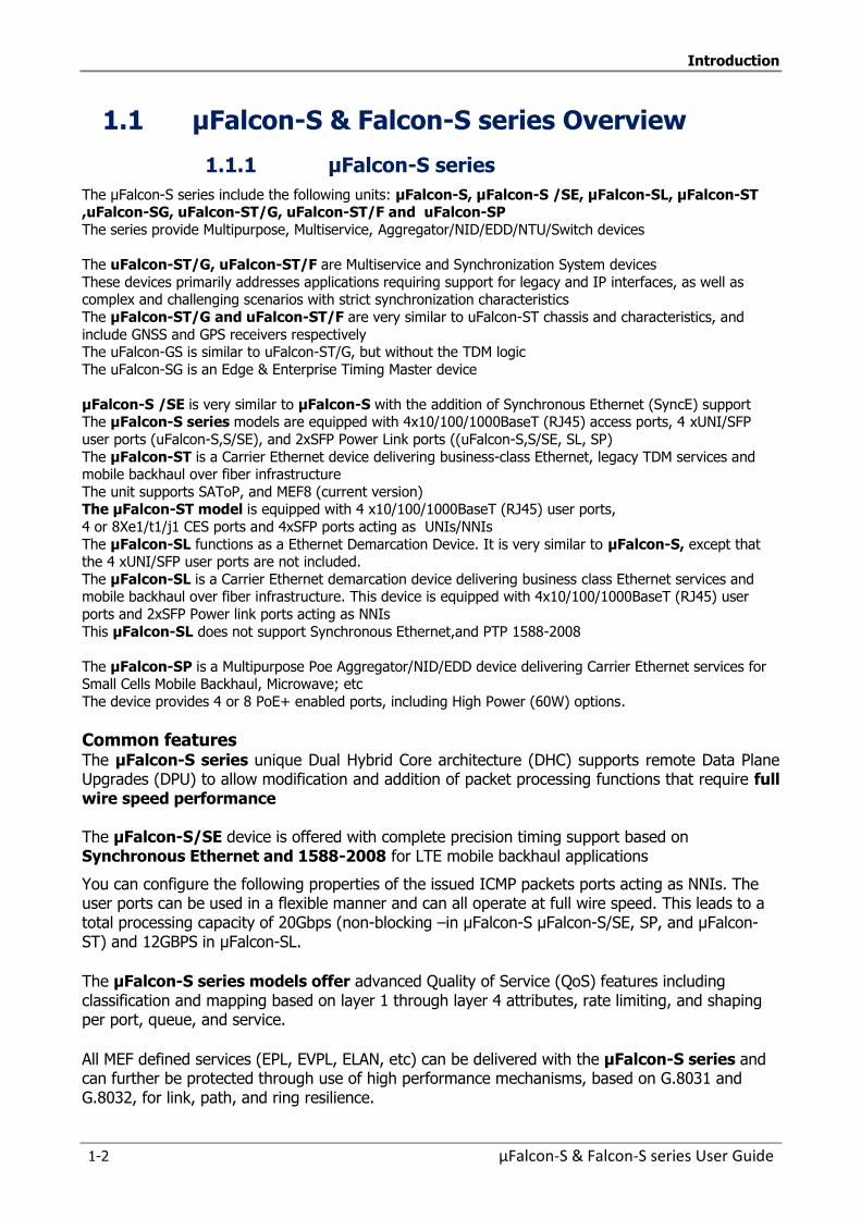
Introduction
1-2 µFalcon-S & Falcon-S series User Guide
1.1 µFalcon-S & Falcon-S series Overview
1.1.1 µFalcon-S series
The µFalcon-S series include the following units: µFalcon-S, µFalcon-S /SE, µFalcon-SL, µFalcon-ST ,uFalcon-SG, uFalcon-ST/G, uFalcon-ST/F and uFalcon-SP
The series provide Multipurpose, Multiservice, Aggregator/NID/EDD/NTU/Switch devices
The uFalcon-ST/G, uFalcon-ST/F are Multiservice and Synchronization System devices
These devices primarily addresses applications requiring support for legacy and IP interfaces, as well as complex and challenging scenarios with strict synchronization characteristics
The µFalcon-ST/G and uFalcon-ST/F are very similar to uFalcon-ST chassis and characteristics, and
include GNSS and GPS receivers respectively The uFalcon-GS is similar to uFalcon-ST/G, but without the TDM logic
The uFalcon-SG is an Edge & Enterprise Timing Master device
µFalcon-S /SE is very similar to µFalcon-S with the addition of Synchronous Ethernet (SyncE) support The µFalcon-S series models are equipped with 4x10/100/1000BaseT (RJ45) access ports, 4 xUNI/SFP
user ports (uFalcon-S,S/SE), and 2xSFP Power Link ports ((uFalcon-S,S/SE, SL, SP)
The µFalcon-ST is a Carrier Ethernet device delivering business-class Ethernet, legacy TDM services and mobile backhaul over fiber infrastructure
The unit supports SAToP, and MEF8 (current version) The µFalcon-ST model is equipped with 4 x10/100/1000BaseT (RJ45) user ports,
4 or 8Xe1/t1/j1 CES ports and 4xSFP ports acting as UNIs/NNIs
The µFalcon-SL functions as a Ethernet Demarcation Device. It is very similar to µFalcon-S, except that the 4 xUNI/SFP user ports are not included.
The µFalcon-SL is a Carrier Ethernet demarcation device delivering business class Ethernet services and mobile backhaul over fiber infrastructure. This device is equipped with 4x10/100/1000BaseT (RJ45) user
ports and 2xSFP Power link ports acting as NNIs
This µFalcon-SL does not support Synchronous Ethernet,and PTP 1588-2008
The µFalcon-SP is a Multipurpose Poe Aggregator/NID/EDD device delivering Carrier Ethernet services for Small Cells Mobile Backhaul, Microwave; etc
The device provides 4 or 8 PoE+ enabled ports, including High Power (60W) options.
Common features The µFalcon-S series unique Dual Hybrid Core architecture (DHC) supports remote Data Plane Upgrades (DPU) to allow modification and addition of packet processing functions that require full wire speed performance The µFalcon-S/SE device is offered with complete precision timing support based on Synchronous Ethernet and 1588-2008 for LTE mobile backhaul applications
You can configure the following properties of the issued ICMP packets ports acting as NNIs. The user ports can be used in a flexible manner and can all operate at full wire speed. This leads to a total processing capacity of 20Gbps (non-blocking –in µFalcon-S µFalcon-S/SE, SP, and µFalcon-ST) and 12GBPS in µFalcon-SL.
The µFalcon-S series models offer advanced Quality of Service (QoS) features including classification and mapping based on layer 1 through layer 4 attributes, rate limiting, and shaping per port, queue, and service.
All MEF defined services (EPL, EVPL, ELAN, etc) can be delivered with the µFalcon-S series and can further be protected through use of high performance mechanisms, based on G.8031 and G.8032, for link, path, and ring resilience.
Introduction
µFalcon-S & Falcon-S series User Guide 1-3
These features, combined with a highly flexible fault propagation mechanism and unique fast failure detection algorithms yield a comprehensive and sophisticated device that can handle virtually any network topology µFalcon-S series models implement current OAM standards (802.3ah, 802.1ag, Y.1731) with HW assist as well as proactive measurements and alarming facilities. To complete the OAM toolset, the µFalcon-S series devices have a built in packet generator and analyzer to implement RFC2544 for quick service turn-up and verification. A unique Microburst Detection (MBD) technology for microsecond granular SLA monitoring is incorporated in the system, helping to detect, alert, and report nearly invisible traffic anomalies, which is essential in highly QoS-sensitive applications, such as financial, healthcare, etc.
The µFalcon-S series models are MEF compliant (MEF8, MEF9, MEF14, MEF20, MEF22)
The µFalcon-S series models are MEF CE 2.0 certified.
Each µFalcon-S series device is housed in a highly compact, half-19”, 1U chassis (150mm deep only), and has an integrated internal, wide range AC or DC power supply.
All the above result in a market leading systems with small form factor dimensions.
Internal power supply: AC/DC: 100-240VAC, 50/60Hz, or 125VDC DC: 20-60VDC, ST connector
All the features and characteristics described in this User Guide are common to all µFalcon-S series
with the following exceptions (for the present release)
TDM Functionality is applicable to µFalcon-ST, uFalcon-ST/G, and uFalcon-ST/F
Partially in Falcon-MTS
IEEE1588-2008 (PTP) is applicable to µFalcon-S series except µFalcon-SL and
Synchronous Ethernet (Sync-E) is applicable to µFalcon-S/SE, µFalcon-ST,ufalcon-SG,
uFalcon-ST/G, uFalcon-ST/F, uFalcon-SP.and in Falcon-MTS.
µFalcon-SL (Ethernet Demarcation Device) does not support SyncE, and PTP
The listed features represent the actual status. It is expected that further features will be
added in future System Software releases
Introduction
1-4 µFalcon-S & Falcon-S series User Guide
1.1.2 Falcon-S series
The Falcon-series include Falcon-S ,Falcon-STA and Falcon-STM
The Falcon –S has the same key features and characteristics as the µFalcon-S and µFalcon-S/SE
devices.
It is housed in a 19" 1/RU chassis to provide the installation of dual redundancy AC or DC power
supplies
The Falcon-STA unit is a Carrier Ethernet TDM Pseudowire Aggregation of up to 252XE1s or
336xT1 into channelized 4xSTM1/1x STM4 or 4xOC3/1xOC12. The STA is also equipped with
advanced Carrier Ethernet capabilities along with service monitoring tools.
The Falcon-STA includes most of the uFalcon-S series key features along with the additional
characteristics which are reported at Falcon-STA Key Features
The Falcon-STM is a Master Timing & Synchronization System device.
It is suitable for any application requiring accurate timing and synchronization
The Falcon-STM includes most of the uFalcon-S series key features along with the additional
characteristics which are reported at FalconSTM key features
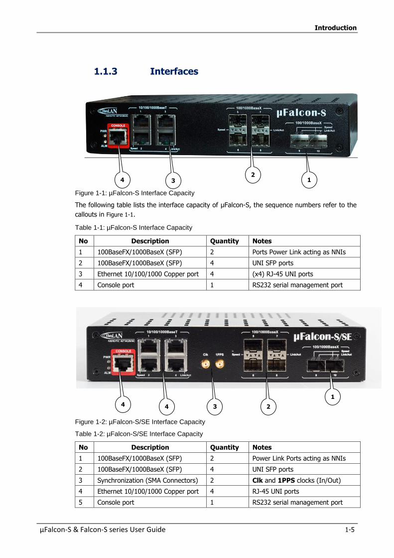
Introduction
µFalcon-S & Falcon-S series User Guide 1-5
1.1.3 Interfaces
Figure 1-1: µFalcon-S Interface Capacity
The following table lists the interface capacity of µFalcon-S, the sequence numbers refer to the
callouts in Figure 1-1.
Table 1-1: µFalcon-S Interface Capacity
No Description Quantity Notes
1 100BaseFX/1000BaseX (SFP) 2 Ports Power Link acting as NNIs
2 100BaseFX/1000BaseX (SFP) 4 UNI SFP ports
3 Ethernet 10/100/1000 Copper port 4 (x4) RJ-45 UNI ports
4 Console port 1 RS232 serial management port
Figure 1-2: µFalcon-S/SE Interface Capacity
Table 1-2: µFalcon-S/SE Interface Capacity
No Description Quantity Notes
1 100BaseFX/1000BaseX (SFP) 2 Power Link Ports acting as NNIs
2 100BaseFX/1000BaseX (SFP) 4 UNI SFP ports
3 Synchronization (SMA Connectors) 2 Clk and 1PPS clocks (In/Out)
4 Ethernet 10/100/1000 Copper port 4 RJ-45 UNI ports
5 Console port 1 RS232 serial management port
1 2 4 3
1
2
3 4
0
40
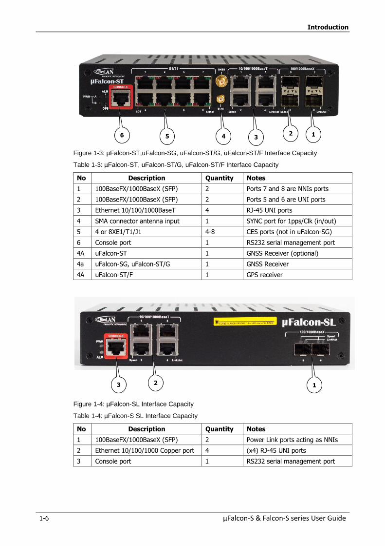
Introduction
1-6 µFalcon-S & Falcon-S series User Guide
Figure 1-3: µFalcon-ST,uFalcon-SG, uFalcon-ST/G, uFalcon-ST/F Interface Capacity
Table 1-3: µFalcon-ST, uFalcon-ST/G, uFalcon-ST/F Interface Capacity
No Description Quantity Notes
1 100BaseFX/1000BaseX (SFP) 2 Ports 7 and 8 are NNIs ports
2 100BaseFX/1000BaseX (SFP) 2 Ports 5 and 6 are UNI ports
3 Ethernet 10/100/1000BaseT 4 RJ-45 UNI ports
4 SMA connector antenna input 1 SYNC port for 1pps/Clk (in/out)
5 4 or 8XE1/T1/J1 4-8 CES ports (not in uFalcon-SG)
6 Console port 1 RS232 serial management port
4A uFalcon-ST 1 GNSS Receiver (optional)
4a uFalcon-SG, uFalcon-ST/G 1 GNSS Receiver
4A uFalcon-ST/F 1 GPS receiver
Figure 1-4: µFalcon-SL Interface Capacity
Table 1-4: µFalcon-S SL Interface Capacity
No Description Quantity Notes
1 100BaseFX/1000BaseX (SFP) 2 Power Link ports acting as NNIs
2 Ethernet 10/100/1000 Copper port 4 (x4) RJ-45 UNI ports
3 Console port 1 RS232 serial management port
5
4
3
2
1
1
2
3
6
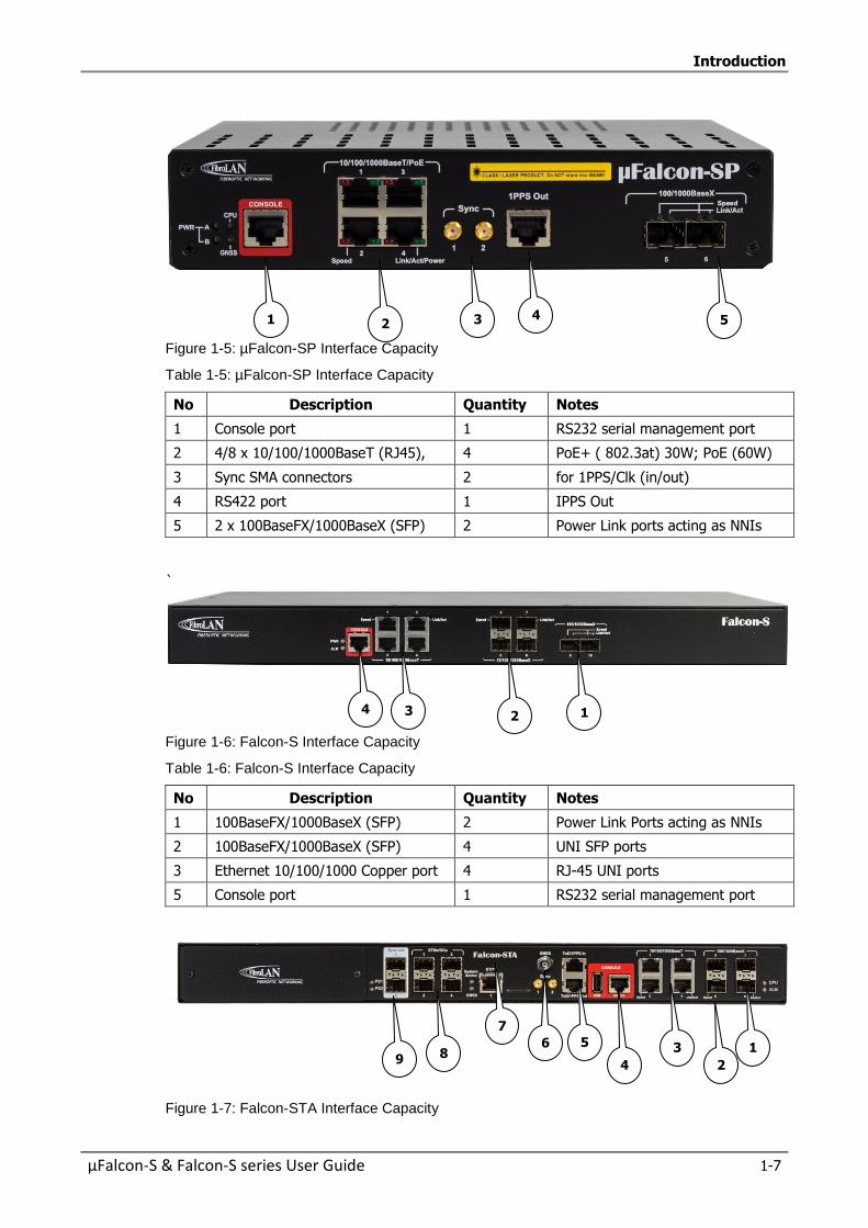
Introduction
µFalcon-S & Falcon-S series User Guide 1-7
Figure 1-5: µFalcon-SP Interface Capacity
Table 1-5: µFalcon-SP Interface Capacity
No Description Quantity Notes
1 Console port 1 RS232 serial management port
2 4/8 x 10/100/1000BaseT (RJ45), 4 PoE+ ( 802.3at) 30W; PoE (60W)
3 Sync SMA connectors 2 for 1PPS/Clk (in/out)
4 RS422 port 1 IPPS Out
5 2 x 100BaseFX/1000BaseX (SFP) 2 Power Link ports acting as NNIs
`
Figure 1-6: Falcon-S Interface Capacity
Table 1-6: Falcon-S Interface Capacity
No Description Quantity Notes
1 100BaseFX/1000BaseX (SFP) 2 Power Link Ports acting as NNIs
2 100BaseFX/1000BaseX (SFP) 4 UNI SFP ports
3 Ethernet 10/100/1000 Copper port 4 RJ-45 UNI ports
5 Console port 1 RS232 serial management port
Figure 1-7: Falcon-STA Interface Capacity
8
6
3
111444444444
1
7
5
1
2
2
3
4
2
3
4
9
51
2114444
4444
4
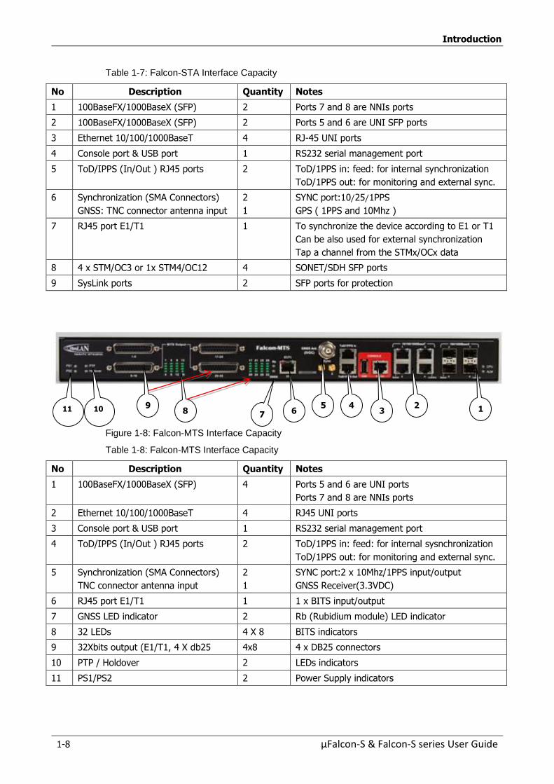
Introduction
1-8 µFalcon-S & Falcon-S series User Guide
Table 1-7: Falcon-STA Interface Capacity
No Description Quantity Notes
1 100BaseFX/1000BaseX (SFP) 2 Ports 7 and 8 are NNIs ports
2 100BaseFX/1000BaseX (SFP) 2 Ports 5 and 6 are UNI SFP ports
3 Ethernet 10/100/1000BaseT 4 RJ-45 UNI ports
4 Console port & USB port 1 RS232 serial management port
5 ToD/IPPS (In/Out ) RJ45 ports 2 ToD/1PPS in: feed: for internal synchronization
ToD/1PPS out: for monitoring and external sync.
6 Synchronization (SMA Connectors)
GNSS: TNC connector antenna input
2
1
SYNC port:10/25/1PPS
GPS ( 1PPS and 10Mhz )
7 RJ45 port E1/T1 1 To synchronize the device according to E1 or T1
Can be also used for external synchronization
Tap a channel from the STMx/OCx data
8 4 x STM/OC3 or 1x STM4/OC12 4 SONET/SDH SFP ports
9 SysLink ports 2 SFP ports for protection
Figure 1-8: Falcon-MTS Interface Capacity
Table 1-8: Falcon-MTS Interface Capacity
No Description Quantity Notes
1 100BaseFX/1000BaseX (SFP) 4 Ports 5 and 6 are UNI ports
Ports 7 and 8 are NNIs ports
2 Ethernet 10/100/1000BaseT 4 RJ45 UNI ports
3 Console port & USB port 1 RS232 serial management port
4 ToD/IPPS (In/Out ) RJ45 ports 2 ToD/1PPS in: feed: for internal sysnchronization
ToD/1PPS out: for monitoring and external sync.
5 Synchronization (SMA Connectors)
TNC connector antenna input
2
1
SYNC port:2 x 10Mhz/1PPS input/output
GNSS Receiver(3.3VDC)
6 RJ45 port E1/T1 1 1 x BITS input/output
7 GNSS LED indicator 2 Rb (Rubidium module) LED indicator
8 32 LEDs 4 X 8 BITS indicators
9 32Xbits output (E1/T1, 4 X db25 4x8 4 x DB25 connectors
10 PTP / Holdover 2 LEDs indicators
11 PS1/PS2 2 Power Supply indicators
1
1144444444444444444444
2
3
41
5
6
8
9
10
11
7
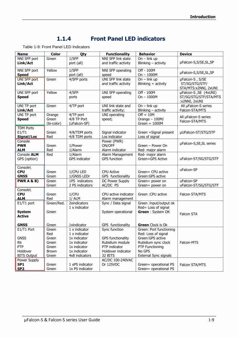
Introduction
µFalcon-S & Falcon-S series User Guide 1-9
1.1.4 Front Panel LED indicators
Table 1-9: Front Panel LED Indicators
Name Color Qty Functionality Behavior Device
NNI SFP port Link/Act
Green 1/SFP port (all)
NNI SFP link state and traffic activity
On – link up Blinking – activity µFalcon-S,S/SE,SL,SP
NNI SFP port Speed
Yellow 1/SFP port (all)
NNI SFP operating speed
Off - 100M On – 1000M
µFalcon-S,S/SE,SL,SP
UNI SFP port Link/Act
Green 4/SFP ports UNI SFP link state and traffic activity
On – link up Blinking = activity
µFalcon-S , S/SE ST/SG/STG/STF/ STA/MTS:x2NNI, 2xUNI
UNI SFP port Speed
Yellow 4/SFP ports
UNI SFP operating speed
Off - 100M On – 1000M
µFalcon-S ,SE (4xUNI) ST/SG/STG/STF/STA/MTS :x2NNI, 2xUNI
UNI TP port Link/Act
Green 4/TP port UNI link state and traffic activity;
On – link up Blinking – activity
All µFalcon-S series Falcon-STA/MTS
UNI TP port Speed
Orange Green (bi-color)
4/TP port 4/8 TP Port (uFalcon-SP)
UNI operating speed;
Off = 10M Orange – 100M/ Green = 1000M
All µFalcon-S series Falcon-STA/MTS
TDM Ports E1/T1 Signal/Los
Green Red
4/8/TDM ports 4/8 TDM ports
Signal indicator Los indicator
Green =Signal present Loss of signal
µUFalcon-ST/STG/STF
Console PWR ALM
Green Red
1/Power 1/Alarm
Power (PWR) ON/OFF Alarm indicator
Green – Power On Red- major alarm
µFalcon-S,SE,SL series
Console ALM GPS (option)
Red
1/Alarm GPS indicator
Alarm Management GPS function
Red- major alarm Green=GPS Active uFalcon-ST/SG/STG/STF
Console\ CPU GNSS
Green Green
1/CPU LED 1/GNSS LEDr
CPU Active GPS functionality
Green= CPU active Green:GPS active
uFalcon-SP
PWR A & B) Green Green
1 PS indicators 2 PS indicators
DC Power Supply AC/DC PS
Green= power on Green= power on
uFalcon-SP uFalcon-ST/SG/STG/STF
Console\ CPU ALM
Green Red
1/CPU 1/ ALM
CPU active indicator Alarm management
Green :CPU active
Falcon STA/MTS
E1/T1 port System Active GNSS
Green/Red. Green Green
2xindicators 1 x indicator 1xindicator
Sync / Data signal System operational GPS functionality
Green :input/output ok Red= Loss of signal Green : System OK Green Clock is Ok
Falcon STA
E1/T1 Port GNSS Rb PTP
Holdover BITS Output
Green Red Green Green Green
Brown Green
1 x indicator 1 x indicator 1x indicator 1x indicator 1x indicator
1x indicator 4x8 indicators
Sync function GPS functionality Rubidium module PTP indicator
Holdover indicator 32 BITS
Green: Port functioning Red: Loss of signal Green:GPS active Rubidium sync clock PTP Functioning
No GPS External Sync signals
Falcon-MTS
Power Supply SP1 SP2
Green Green
1 xPS indicator 1x PS indicator
AC/DC 100-240VAC Or 125VDC
Green= operational PS Green= operational PS
Falcon STA/MTS
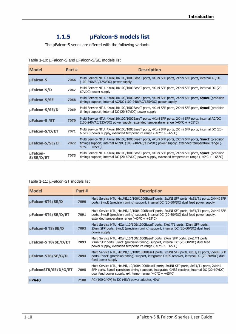
Introduction
1-10 µFalcon-S & Falcon-S series User Guide
1.1.5 µFalcon-S models list
The µFalcon-S series are offered with the following variants.
Table 1-10: µFalcon-S and µFalcon-S/SE models list
Model Part # Description
µFalcon-S 7066 Multi Service NTU, 4Xuni,10/100/1000BaseT ports, 4Xuni SFP ports, 2Xnni SFP ports, internal AC/DC (100-240VAC/125VDC) power supply
µFalcon-S/D 7067 Multi Service NTU, 4Xuni,10/100/1000BaseT ports, 4Xuni SFP ports, 2Xnni SFP ports, internal DC (20-60VDC) power supply
µFalcon-S/SE 7068 Multi Service NTU, 4Xuni,10/100/1000BaseT ports, 4Xuni SFP ports, 2Xnni SFP ports, SyncE (precision timing) support, internal AC/DC (100-240VAC/125VDC) power supply
µFalcon-S/SE/D 7069 Multi Service NTU, 4Xuni,10/100/1000BaseT ports, 4Xuni SFP ports, 2Xnni SFP ports, SyncE (precision timing) support, internal DC (20-60VDC) power supply
µFalcon-S /ET 7070 Multi Service NTU, 4Xuni,10/100/1000BaseT ports, 4Xuni SFP ports, 2Xnni SFP ports, internal AC/DC (100-240VAC/125VDC) power supply, extended temperature range (-40°C ÷ +65°C)
µFalcon-S/D/ET 7071 Multi Service NTU, 4Xuni,10/100/1000BaseT ports, 4Xuni SFP ports, 2Xnni SFP ports, internal DC (20-60VDC) power supply, extended temperature range (-40°C ÷ +65°C)
µFalcon-S/SE/ET 7072 Multi Service NTU, 4Xuni,10/100/1000BaseT ports, 4Xuni SFP ports, 2Xnni SFP ports, SyncE (precision timing) support, internal AC/DC (100-240VAC/125VDC) power supply, extended temperature range (-40°C ÷ +65°C)
µFalcon-S/SE/D/ET
7073 Multi Service NTU, 4Xuni,10/100/1000BaseT ports, 4Xuni SFP ports, 2Xnni SFP ports, SyncE (precision timing) support, internal DC (20-60VDC) power supply, extended temperature range (-40°C ÷ +65°C)
Table 1-11: µFalcon-ST models list
Model Part # Description
μFalcon-ST4/SE/D 7090 Multi Service NTU, 4xUNI,10/100/1000BaseT ports, 2xUNI SFP ports, 4xE1/T1 ports, 2xNNI SFP ports, SyncE (precision timing) support, internal DC (20-60VDC) dual feed power supply
μFalcon-ST4/SE/D/ET 7091 Multi Service NTU, 4xUNI,10/100/1000BaseT ports, 2xUNI SFP ports, 4xE1/T1 ports, 2xNNI SFP ports, SyncE (precision timing) support, internal DC (20-60VDC) dual feed power supply, extended temperature range (-40°C ÷ +65°C)
µFalcon-S T8/SE/D 7092 Multi Service NTU, 4Xuni,10/100/1000BaseT ports, 8Xe1/T1 ports, 2Xnni SFP ports, 2Xuni SFP ports, SyncE (precision timing) support, internal DC (20-60VDC) dual feed power supply
µFalcon-S T8/SE/D/ET 7093 Multi Service NTU, 4Xuni,10/100/1000BaseT ports, 2Xuni SFP ports, 8Xe1/T1 ports, 2Xnni SFP ports, SyncE (precision timing) support, internal DC (20-60VDC) dual feed power supply, extended temperature range (-40°C ÷ +65°C)
µFalcon-ST8/SE/G/D 7094 Multi Service NTU, 4xUNI,10/100/1000BaseT ports, 2xUNI SFP ports, 8xE1/T1 ports, 2xNNI SFP ports, SyncE (precision timing) support, integrated GNSS receiver, internal DC (20-60VDC) dual feed power supply
µFalconST8/SE/D/G/ET 7095 Multi Service NTU, 4xUNI, 10/100/1000BaseT ports, 2xUNI SFP ports, 8xE1/T1 ports, 2xNNI SFP ports, SyncE (precision timing) support, integrated GNSS receiver, internal DC (20-60VDC) dual feed power supply, ext. temp. range (-40°C ÷ +65°C)
FPA40 7108 AC (100-240V) to DC (48V) power adapter, 40W
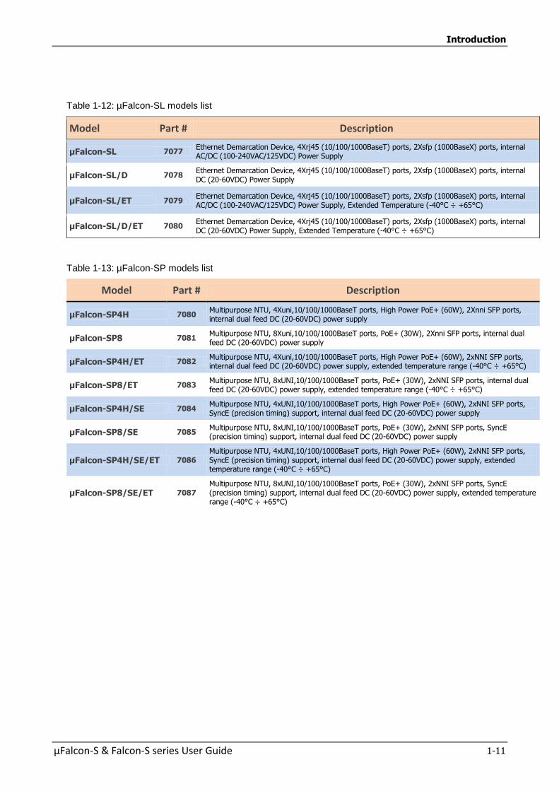
Introduction
µFalcon-S & Falcon-S series User Guide 1-11
Table 1-12: µFalcon-SL models list
Model Part # Description
µFalcon-SL 7077 Ethernet Demarcation Device, 4Xrj45 (10/100/1000BaseT) ports, 2Xsfp (1000BaseX) ports, internal AC/DC (100-240VAC/125VDC) Power Supply
µFalcon-SL/D 7078 Ethernet Demarcation Device, 4Xrj45 (10/100/1000BaseT) ports, 2Xsfp (1000BaseX) ports, internal DC (20-60VDC) Power Supply
µFalcon-SL/ET 7079 Ethernet Demarcation Device, 4Xrj45 (10/100/1000BaseT) ports, 2Xsfp (1000BaseX) ports, internal AC/DC (100-240VAC/125VDC) Power Supply, Extended Temperature (-40°C ÷ +65°C)
µFalcon-SL/D/ET 7080 Ethernet Demarcation Device, 4Xrj45 (10/100/1000BaseT) ports, 2Xsfp (1000BaseX) ports, internal DC (20-60VDC) Power Supply, Extended Temperature (-40°C ÷ +65°C)
Table 1-13: µFalcon-SP models list
Model Part # Description
µFalcon-SP4H 7080 Multipurpose NTU, 4Xuni,10/100/1000BaseT ports, High Power PoE+ (60W), 2Xnni SFP ports, internal dual feed DC (20-60VDC) power supply
µFalcon-SP8 7081 Multipurpose NTU, 8Xuni,10/100/1000BaseT ports, PoE+ (30W), 2Xnni SFP ports, internal dual feed DC (20-60VDC) power supply
µFalcon-SP4H/ET 7082 Multipurpose NTU, 4Xuni,10/100/1000BaseT ports, High Power PoE+ (60W), 2xNNI SFP ports, internal dual feed DC (20-60VDC) power supply, extended temperature range (-40°C ÷ +65°C)
µFalcon-SP8/ET 7083 Multipurpose NTU, 8xUNI,10/100/1000BaseT ports, PoE+ (30W), 2xNNI SFP ports, internal dual feed DC (20-60VDC) power supply, extended temperature range (-40°C ÷ +65°C)
µFalcon-SP4H/SE 7084 Multipurpose NTU, 4xUNI,10/100/1000BaseT ports, High Power PoE+ (60W), 2xNNI SFP ports, SyncE (precision timing) support, internal dual feed DC (20-60VDC) power supply
µFalcon-SP8/SE 7085 Multipurpose NTU, 8xUNI,10/100/1000BaseT ports, PoE+ (30W), 2xNNI SFP ports, SyncE (precision timing) support, internal dual feed DC (20-60VDC) power supply
µFalcon-SP4H/SE/ET 7086 Multipurpose NTU, 4xUNI,10/100/1000BaseT ports, High Power PoE+ (60W), 2xNNI SFP ports, SyncE (precision timing) support, internal dual feed DC (20-60VDC) power supply, extended temperature range (-40°C ÷ +65°C)
µFalcon-SP8/SE/ET 7087 Multipurpose NTU, 8xUNI,10/100/1000BaseT ports, PoE+ (30W), 2xNNI SFP ports, SyncE (precision timing) support, internal dual feed DC (20-60VDC) power supply, extended temperature range (-40°C ÷ +65°C)
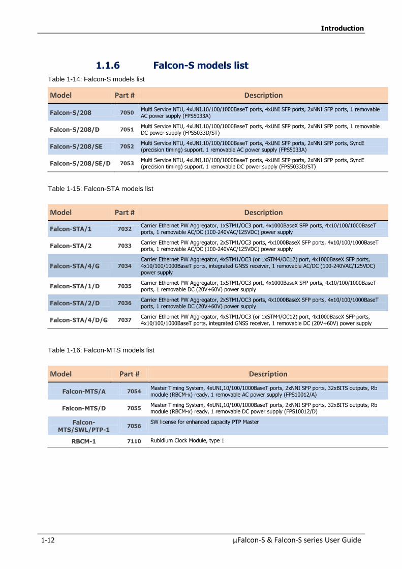
Introduction
1-12 µFalcon-S & Falcon-S series User Guide
1.1.6 Falcon-S models list
Table 1-14: Falcon-S models list
Model Part # Description
Falcon-S/208 7050 Multi Service NTU, 4xUNI,10/100/1000BaseT ports, 4xUNI SFP ports, 2xNNI SFP ports, 1 removable AC power supply (FPS5033A)
Falcon-S/208/D 7051 Multi Service NTU, 4xUNI,10/100/1000BaseT ports, 4xUNI SFP ports, 2xNNI SFP ports, 1 removable DC power supply (FPS5033D/ST)
Falcon-S/208/SE 7052 Multi Service NTU, 4xUNI,10/100/1000BaseT ports, 4xUNI SFP ports, 2xNNI SFP ports, SyncE (precision timing) support, 1 removable AC power supply (FPS5033A)
Falcon-S/208/SE/D 7053 Multi Service NTU, 4xUNI,10/100/1000BaseT ports, 4xUNI SFP ports, 2xNNI SFP ports, SyncE (precision timing) support, 1 removable DC power supply (FPS5033D/ST)
Table 1-15: Falcon-STA models list
Model Part # Description
Falcon-STA/1 7032 Carrier Ethernet PW Aggregator, 1xSTM1/OC3 port, 4x1000BaseX SFP ports, 4x10/100/1000BaseT ports, 1 removable AC/DC (100-240VAC/125VDC) power supply
Falcon-STA/2 7033 Carrier Ethernet PW Aggregator, 2xSTM1/OC3 ports, 4x1000BaseX SFP ports, 4x10/100/1000BaseT ports, 1 removable AC/DC (100-240VAC/125VDC) power supply
Falcon-STA/4/G 7034 Carrier Ethernet PW Aggregator, 4xSTM1/OC3 (or 1xSTM4/OC12) port, 4x1000BaseX SFP ports, 4x10/100/1000BaseT ports, integrated GNSS receiver, 1 removable AC/DC (100-240VAC/125VDC) power supply
Falcon-STA/1/D 7035 Carrier Ethernet PW Aggregator, 1xSTM1/OC3 port, 4x1000BaseX SFP ports, 4x10/100/1000BaseT ports, 1 removable DC (20V÷60V) power supply
Falcon-STA/2/D 7036 Carrier Ethernet PW Aggregator, 2xSTM1/OC3 ports, 4x1000BaseX SFP ports, 4x10/100/1000BaseT ports, 1 removable DC (20V÷60V) power supply
Falcon-STA/4/D/G 7037 Carrier Ethernet PW Aggregator, 4xSTM1/OC3 (or 1xSTM4/OC12) port, 4x1000BaseX SFP ports, 4x10/100/1000BaseT ports, integrated GNSS receiver, 1 removable DC (20V÷60V) power supply
Table 1-16: Falcon-MTS models list
Model Part # Description
Falcon-MTS/A 7054 Master Timing System, 4xUNI,10/100/1000BaseT ports, 2xNNI SFP ports, 32xBITS outputs, Rb module (RBCM-x) ready, 1 removable AC power supply (FPS10012/A)
Falcon-MTS/D 7055 Master Timing System, 4xUNI,10/100/1000BaseT ports, 2xNNI SFP ports, 32xBITS outputs, Rb module (RBCM-x) ready, 1 removable DC power supply (FPS10012/D)
Falcon-MTS/SWL/PTP-1
7056 SW license for enhanced capacity PTP Master
RBCM-1 7110 Rubidium Clock Module, type 1
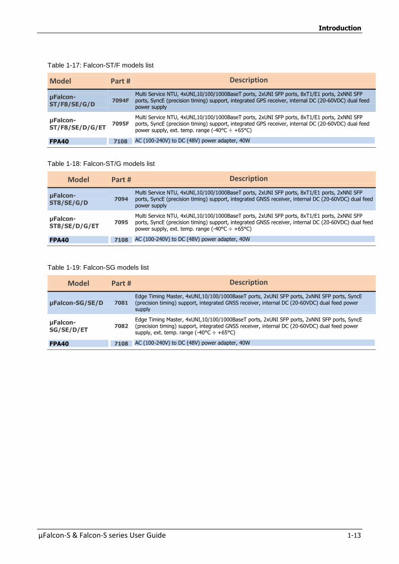
Introduction
µFalcon-S & Falcon-S series User Guide 1-13
Table 1-17: Falcon-ST/F models list
Model Part # Description
µFalcon-ST/F8/SE/G/D
7094F Multi Service NTU, 4xUNI,10/100/1000BaseT ports, 2xUNI SFP ports, 8xT1/E1 ports, 2xNNI SFP ports, SyncE (precision timing) support, integrated GPS receiver, internal DC (20-60VDC) dual feed power supply
µFalcon-ST/F8/SE/D/G/ET
7095F Multi Service NTU, 4xUNI,10/100/1000BaseT ports, 2xUNI SFP ports, 8xT1/E1 ports, 2xNNI SFP ports, SyncE (precision timing) support, integrated GPS receiver, internal DC (20-60VDC) dual feed power supply, ext. temp. range (-40°C ÷ +65°C)
FPA40 7108 AC (100-240V) to DC (48V) power adapter, 40W
Table 1-18: Falcon-ST/G models list
Model Part # Description
µFalcon-ST8/SE/G/D
7094 Multi Service NTU, 4xUNI,10/100/1000BaseT ports, 2xUNI SFP ports, 8xT1/E1 ports, 2xNNI SFP ports, SyncE (precision timing) support, integrated GNSS receiver, internal DC (20-60VDC) dual feed power supply
µFalcon-ST8/SE/D/G/ET
7095 Multi Service NTU, 4xUNI,10/100/1000BaseT ports, 2xUNI SFP ports, 8xT1/E1 ports, 2xNNI SFP ports, SyncE (precision timing) support, integrated GNSS receiver, internal DC (20-60VDC) dual feed power supply, ext. temp. range (-40°C ÷ +65°C)
FPA40 7108 AC (100-240V) to DC (48V) power adapter, 40W
Table 1-19: Falcon-SG models list
Model Part # Description
µFalcon-SG/SE/D 7081 Edge Timing Master, 4xUNI,10/100/1000BaseT ports, 2xUNI SFP ports, 2xNNI SFP ports, SyncE (precision timing) support, integrated GNSS receiver, internal DC (20-60VDC) dual feed power supply
µFalcon-SG/SE/D/ET
7082 Edge Timing Master, 4xUNI,10/100/1000BaseT ports, 2xUNI SFP ports, 2xNNI SFP ports, SyncE (precision timing) support, integrated GNSS receiver, internal DC (20-60VDC) dual feed power supply, ext. temp. range (-40°C ÷ +65°C)
FPA40 7108 AC (100-240V) to DC (48V) power adapter, 40W
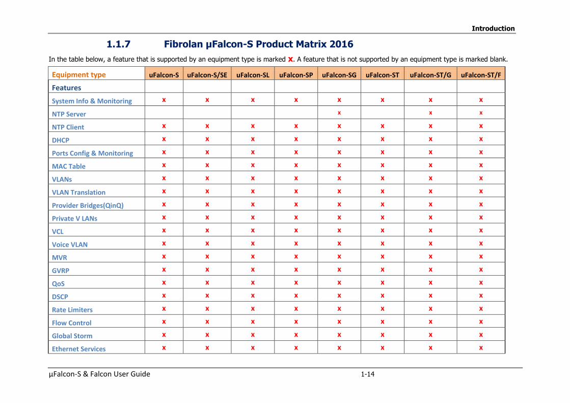
Introduction
µFalcon-S & Falcon User Guide 1-14
1.1.7 Fibrolan μFalcon-S Product Matrix 2016
In the table below, a feature that is supported by an equipment type is marked x. A feature that is not supported by an equipment type is marked blank.
Equipment type uFalcon-S uFalcon-S/SE uFalcon-SL uFalcon-SP uFalcon-SG uFalcon-ST uFalcon-ST/G uFalcon-ST/F
Features
System Info & Monitoring x x x x x x x x
NTP Server x x x
NTP Client x x x x x x x x
DHCP x x x x x x x x
Ports Config & Monitoring x x x x x x x x
MAC Table x x x x x x x x
VLANs x x x x x x x x
VLAN Translation x x x x x x x x
Provider Bridges(QinQ) x x x x x x x x
Private V LANs x x x x x x x x
VCL x x x x x x x x
Voice VLAN x x x x x x x x
MVR x x x x x x x x
GVRP x x x x x x x x
QoS x x x x x x x x
DSCP x x x x x x x x
Rate Limiters x x x x x x x x
Flow Control x x x x x x x x
Global Storm x x x x x x x x
Ethernet Services x x x x x x x x

Introduction
µFalcon-S & Falcon-S series User Guide 1-15
Equipment type uFalcon-S uFalcon-S/SE uFalcon-SL uFalcon-SP uFalcon-SG uFalcon-ST uFalcon-ST/G uFalcon-ST/F
Security Features x x x x x x x x
Switch Features x x x x x x x x
Network Security x x x x x x x x
ARP x x x x x x x x
Auth Server Configuration x x x x x x x
TDM Functionality x x x
TDM Circuit x x x
Sync Center Configuration x x x x x
Sync Center Monitor x x x x x
External Configuration x x x x x
GNSS Ant (5VDC)
GNSS Ant (3VDC) x x option x
GPS Receiver x
GPS Status x
Sync x x x x
Sync 1 , and 2
Clk and 1PPS x
Rubidium module
IEEE 1588 PTP x x x x x x x
SyncE x x x x x x
Spanning Tree x x x x x x x x
IP Multicast x x x x x x x x
Link Aggregation x x x x x x x x
LLDP Link Discovery x x x x x x x x
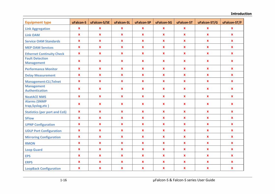
Introduction
1-16 µFalcon-S & Falcon-S series User Guide
Equipment type uFalcon-S uFalcon-S/SE uFalcon-SL uFalcon-SP uFalcon-SG uFalcon-ST uFalcon-ST/G uFalcon-ST/F
Link Aggregation x x x x x x x x
Link OAM x x x x x x x x
Service OAM Standards x x x x x x x x
MEP OAM Services x x x x x x x x
Ethernet Continuity Check x x x x x x x x
Fault Detection Management
x x x x x x x x
Performance Monitor x x x x x x x x
Delay Measurement x x x x x x x x
Management:CLI,Telnet x x x x x x x x
Management Authentication
x x x x x x x x
NeatACE NMS x x x x x x x x
Alarms (SNMP trap,Syslog,etc )
x x x x x x x x
Statistics (per port and CoS) x x x x x x x x
SFlow x x x x x x x x
UPNP Configuration x x x x x x x x
UDLP Port Configuration x x x x x x x x
Mirroring Configuration x x x x x x x x
RMON x x x x x x x x
Loop Guard x x x x x x x x
EPS x x x x x x x x
ERPS x x x x x x x x
LoopBack Configuration x x x x x x x x
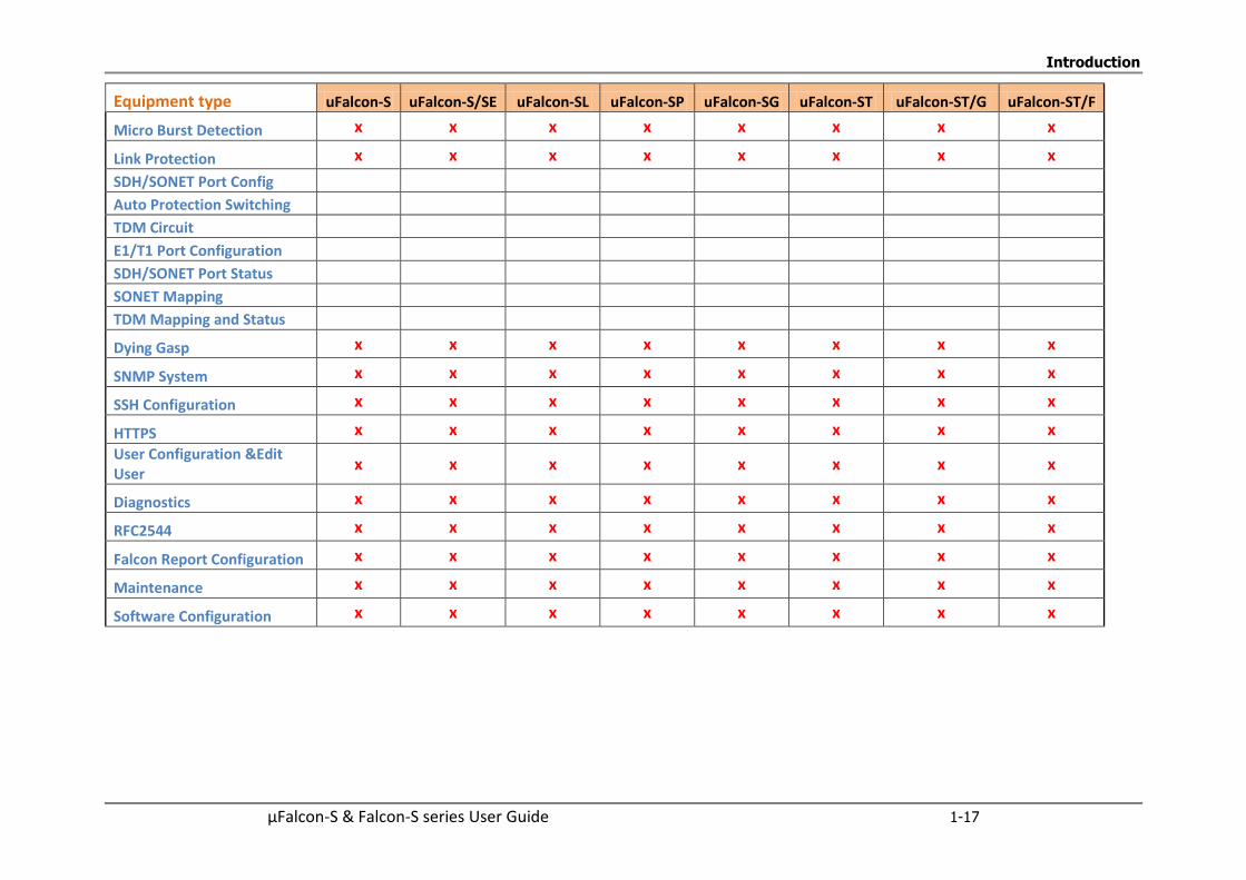
Introduction
µFalcon-S & Falcon-S series User Guide 1-17
Equipment type uFalcon-S uFalcon-S/SE uFalcon-SL uFalcon-SP uFalcon-SG uFalcon-ST uFalcon-ST/G uFalcon-ST/F
Micro Burst Detection x x x x x x x x
Link Protection x x x x x x x x
SDH/SONET Port Config
Auto Protection Switching
TDM Circuit
E1/T1 Port Configuration
SDH/SONET Port Status
SONET Mapping
TDM Mapping and Status
Dying Gasp x x x x x x x x
SNMP System x x x x x x x x
SSH Configuration x x x x x x x x
HTTPS x x x x x x x x
User Configuration &Edit User
x x x x x x x x
Diagnostics x x x x x x x x
RFC2544 x x x x x x x x
Falcon Report Configuration x x x x x x x x
Maintenance x x x x x x x x
Software Configuration x x x x x x x x

Introduction
1-18 µFalcon-S & Falcon-S series User Guide
1.1.8 Fibrolan Falcon Product Matrix 2016
In the table below, a feature that is supported by an equipment type is marked x. A feature that is not supported by an equipment type is marked blank.
Equipment type Falcon-X Falcon-S Falcon-STA Falcon-MTS
Features
System Info & Monitoring x x x x
NTP Server x
NTP Client x x x x
DHCP x x x x
Ports Configuration & Monitoring x x x x
MAC Table x x x x
VLANs x x x x
VLAN Translation x x x x
Provider Bridges(QinQ) x x x x
Private V LANs x x x x
VCL x x x x
Voice VLAN x x x x
MVR x x x x
GVRP x x x x
QoS x x x x
DSCP x x x x
Rate Limiters x x x x
Flow Control x x x x
Global Storm x x x x
Ethernet Services x x x x

Introduction
µFalcon-S & Falcon-S series User Guide 1-19
Equipment type Falcon-X Falcon-S Falcon-STA Falcon-MTS
Security Features x x x x
Switch Features x x x x
Network Security x x x x
ARP x x x x
Authentication Server Configuration
x x x x
TDM Functionality x partial
TDM Circuit
Sync Center Configuration x
Sync Center Monitor x
External Configuration x
GNSS Ant (5VDC) x x
GNSS Ant (3VDC)
GPS Receiver
GPS Status
Sync
Sync 1 , and 2 x x
Clk and 1PPS x
Rubidium module x option
IEEE 1588 PTP x x x x
SyncE x x x x
Spanning Tree x x x x
IP Multicast x x x x
Link Aggregation x x x x
LLDP Link Discovery x x x x
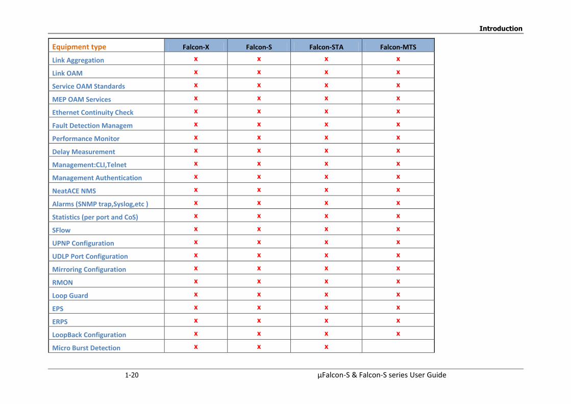
Introduction
1-20 µFalcon-S & Falcon-S series User Guide
Equipment type Falcon-X Falcon-S Falcon-STA Falcon-MTS
Link Aggregation x x x x
Link OAM x x x x
Service OAM Standards x x x x
MEP OAM Services x x x x
Ethernet Continuity Check x x x x
Fault Detection Managem x x x x
Performance Monitor x x x x
Delay Measurement x x x x
Management:CLI,Telnet x x x x
Management Authentication x x x x
NeatACE NMS x x x x
Alarms (SNMP trap,Syslog,etc ) x x x x
Statistics (per port and CoS) x x x x
SFlow x x x x
UPNP Configuration x x x x
UDLP Port Configuration x x x x
Mirroring Configuration x x x x
RMON x x x x
Loop Guard x x x x
EPS x x x x
ERPS x x x x
LoopBack Configuration x x x x
Micro Burst Detection x x x
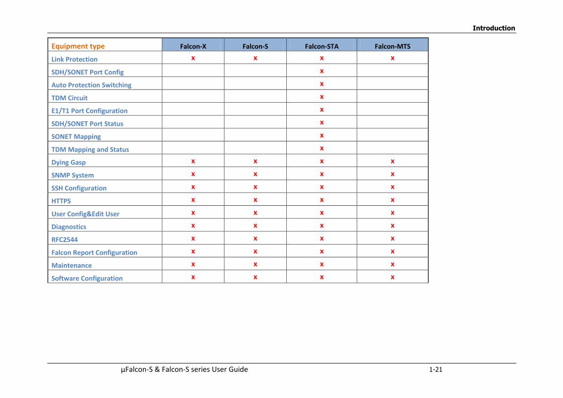
Introduction
µFalcon-S & Falcon-S series User Guide 1-21
Equipment type Falcon-X Falcon-S Falcon-STA Falcon-MTS
Link Protection x x x x
SDH/SONET Port Config x
Auto Protection Switching x
TDM Circuit x
E1/T1 Port Configuration x
SDH/SONET Port Status x
SONET Mapping x
TDM Mapping and Status x
Dying Gasp x x x x
SNMP System x x x x
SSH Configuration x x x x
HTTPS x x x x
User Config&Edit User x x x x
Diagnostics x x x x
RFC2544 x x x x
Falcon Report Configuration x x x x
Maintenance x x x x
Software Configuration x x x x

Introduction
µFalcon-S & Falcon User Guide 1-22
1.1.9 Typical Applications
The µFalcon and Falcon-series support various different applications for changing demands,
multipurpose and multiservice requirements. The application diagrams below illustrate typical
applications.
Business Network and Mobile Backhaul
In this application the µFalcon-S series. (uFalcon-S and uFalcon-S/SE)
operate as NTU for Business Enterprise Customers and for Mobile Backhaul Network
Figure 1-9: Application Diagram - Business and Mobile Backhaul Network
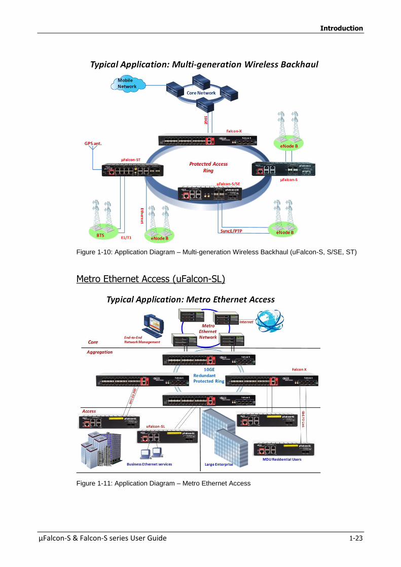
Introduction
µFalcon-S & Falcon-S series User Guide 1-23
Figure 1-10: Application Diagram – Multi-generation Wireless Backhaul (uFalcon-S, S/SE, ST)
Metro Ethernet Access (uFalcon-SL)
Figure 1-11: Application Diagram – Metro Ethernet Access
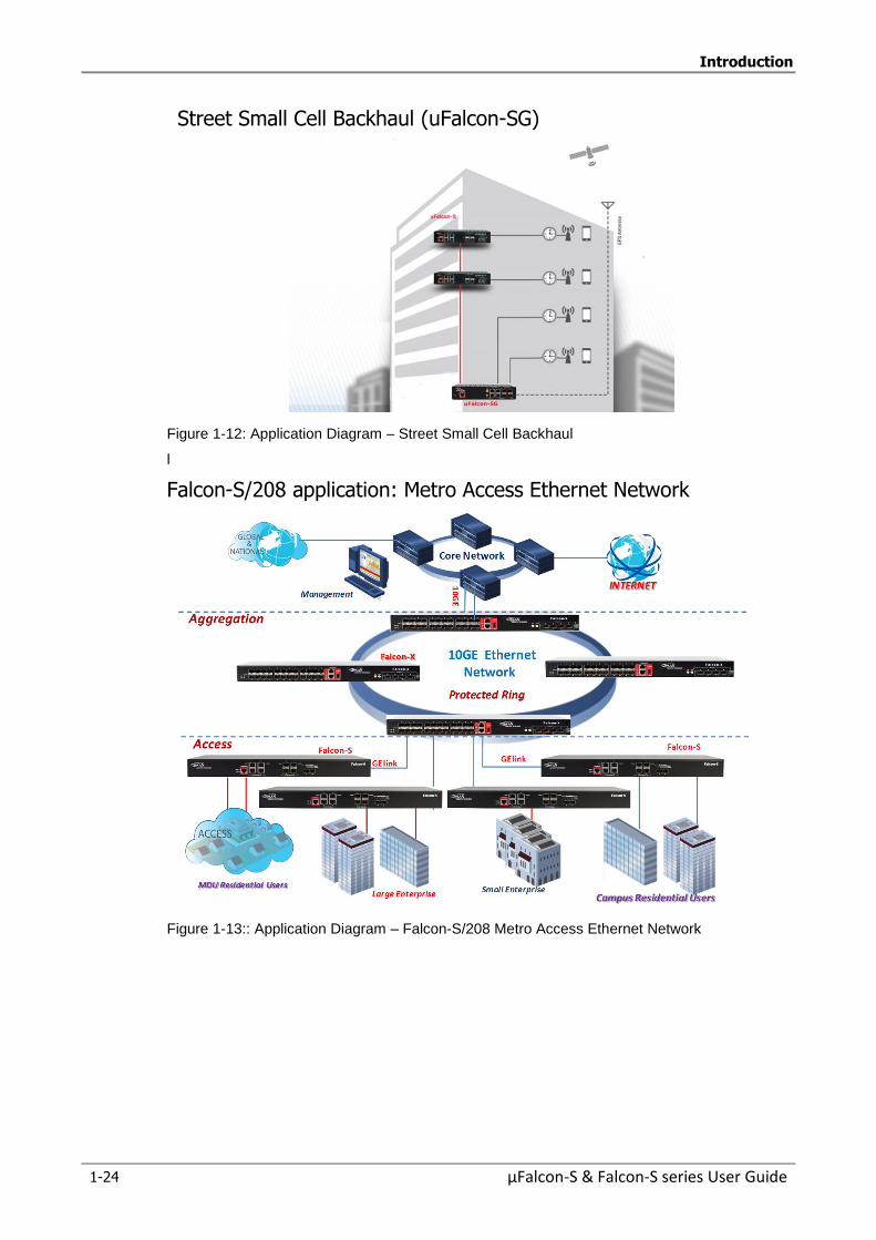
Introduction
1-24 µFalcon-S & Falcon-S series User Guide
Street Small Cell Backhaul (uFalcon-SG)
Figure 1-12: Application Diagram – Street Small Cell Backhaul
l
Falcon-S/208 application: Metro Access Ethernet Network
Figure 1-13:: Application Diagram – Falcon-S/208 Metro Access Ethernet Network
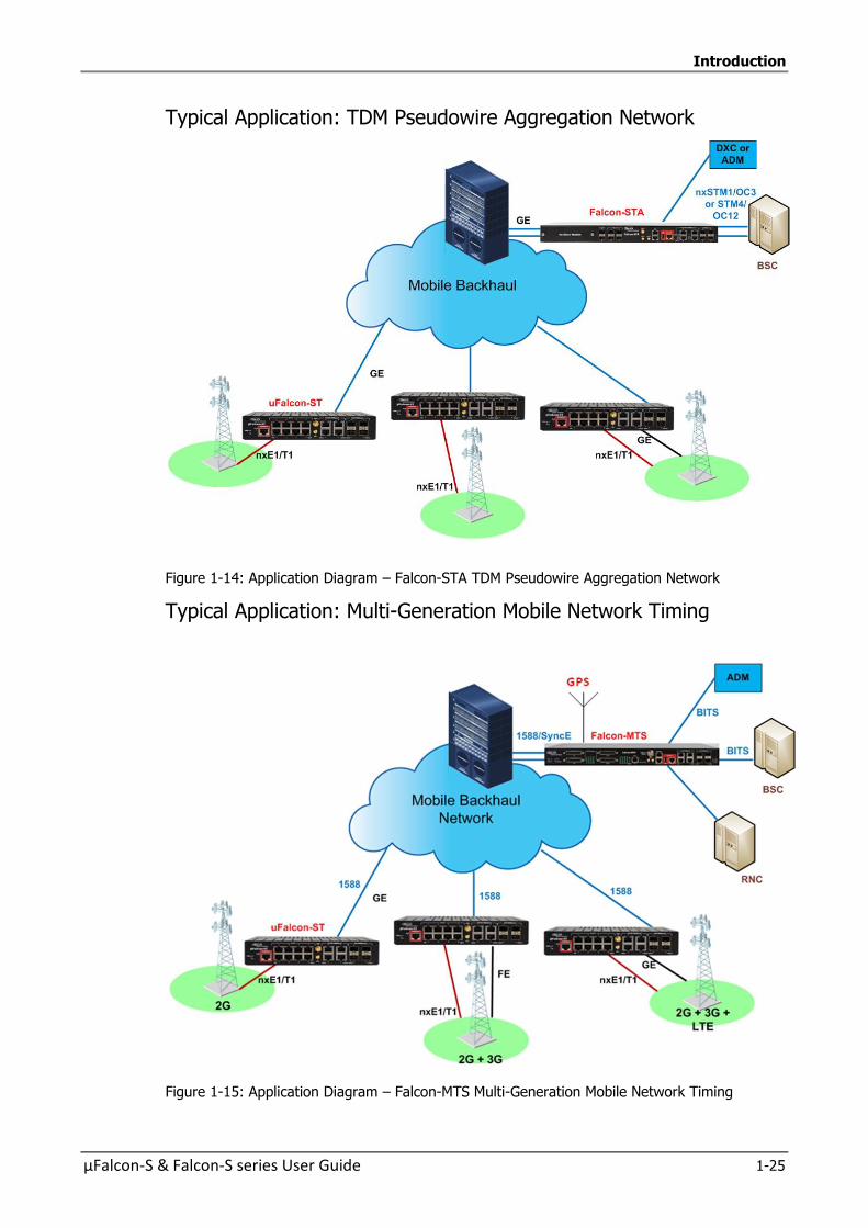
Introduction
µFalcon-S & Falcon-S series User Guide 1-25
Typical Application: TDM Pseudowire Aggregation Network
Figure 1-14: Application Diagram – Falcon-STA TDM Pseudowire Aggregation Network
Typical Application: Multi-Generation Mobile Network Timing
Figure 1-15: Application Diagram – Falcon-MTS Multi-Generation Mobile Network Timing
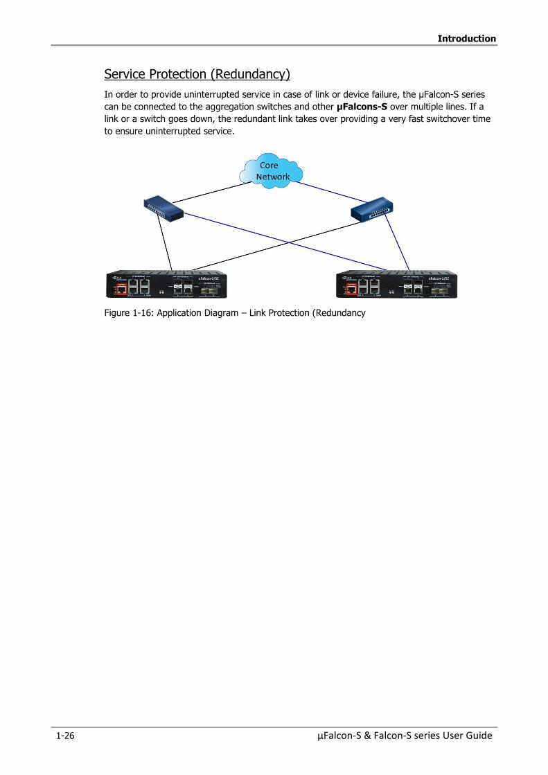
Introduction
1-26 µFalcon-S & Falcon-S series User Guide
Service Protection (Redundancy)
In order to provide uninterrupted service in case of link or device failure, the µFalcon-S series
can be connected to the aggregation switches and other µFalcons-S over multiple lines. If a
link or a switch goes down, the redundant link takes over providing a very fast switchover time
to ensure uninterrupted service.
Figure 1-16: Application Diagram – Link Protection (Redundancy
Introduction
µFalcon-S & Falcon-S series User Guide 1-27
1.1.10 Scalability
The µFalcon-S & Falcon-S series provide multiple means of remote field upgrades that result in
high levels of scalability, flexibility and future proofing:
Upgrades for enhancements and new features both on the management and
control level, and wire speed packet processing level.
Scalable and field-upgradable PowerLink ports.
These field upgrades enable:
Support for future standards.
Support for enhanced and tailored services.
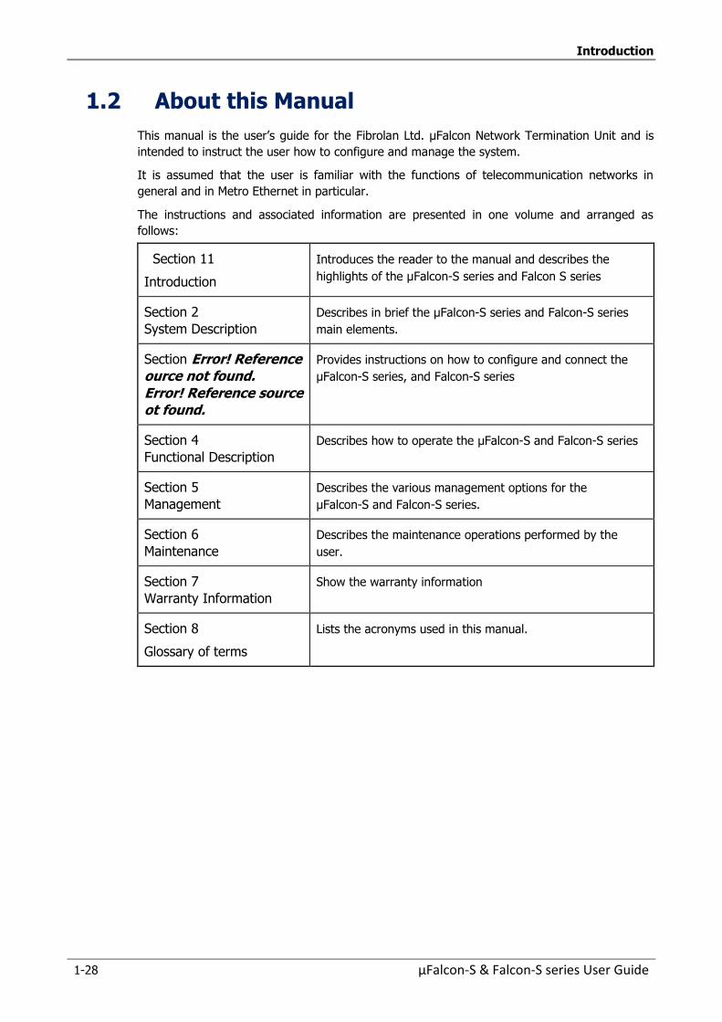
Introduction
1-28 µFalcon-S & Falcon-S series User Guide
1.2 About this Manual
This manual is the user’s guide for the Fibrolan Ltd. µFalcon Network Termination Unit and is
intended to instruct the user how to configure and manage the system.
It is assumed that the user is familiar with the functions of telecommunication networks in
general and in Metro Ethernet in particular.
The instructions and associated information are presented in one volume and arranged as
follows:
Section 11
Introduction
Introduces the reader to the manual and describes the
highlights of the µFalcon-S series and Falcon S series
Section 2
System Description
Describes in brief the µFalcon-S series and Falcon-S series
main elements.
Section Error! Reference ource not found. Error! Reference source ot found.
Provides instructions on how to configure and connect the
µFalcon-S series, and Falcon-S series
Section 4
Functional Description
Describes how to operate the µFalcon-S and Falcon-S series
Section 5
Management
Describes the various management options for the
µFalcon-S and Falcon-S series.
Section 6
Maintenance
Describes the maintenance operations performed by the
user.
Section 7
Warranty Information
Show the warranty information
Section 8
Glossary of terms
Lists the acronyms used in this manual.
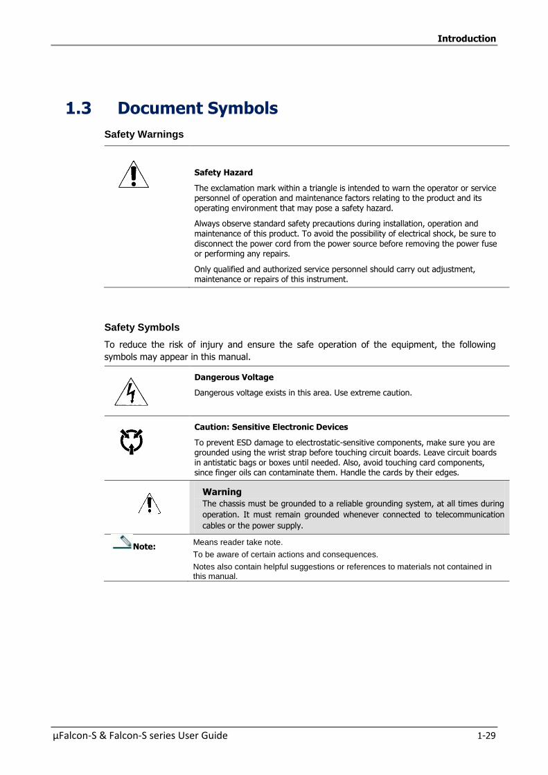
Introduction
µFalcon-S & Falcon-S series User Guide 1-29
1.3 Document Symbols
Safety Warnings
Safety Hazard
The exclamation mark within a triangle is intended to warn the operator or service personnel of operation and maintenance factors relating to the product and its operating environment that may pose a safety hazard.
Always observe standard safety precautions during installation, operation and maintenance of this product. To avoid the possibility of electrical shock, be sure to
disconnect the power cord from the power source before removing the power fuse or performing any repairs.
Only qualified and authorized service personnel should carry out adjustment, maintenance or repairs of this instrument.
Safety Symbols
To reduce the risk of injury and ensure the safe operation of the equipment, the following
symbols may appear in this manual.
Dangerous Voltage
Dangerous voltage exists in this area. Use extreme caution.
Caution: Sensitive Electronic Devices
To prevent ESD damage to electrostatic-sensitive components, make sure you are grounded using the wrist strap before touching circuit boards. Leave circuit boards in antistatic bags or boxes until needed. Also, avoid touching card components, since finger oils can contaminate them. Handle the cards by their edges.
Warning
The chassis must be grounded to a reliable grounding system, at all times during
operation. It must remain grounded whenever connected to telecommunication
cables or the power supply.
Note: Means reader take note.
To be aware of certain actions and consequences.
Notes also contain helpful suggestions or references to materials not contained in this manual.


µFalcon-S & Falcon-S series User Guide 2-1
2 2 System
Description
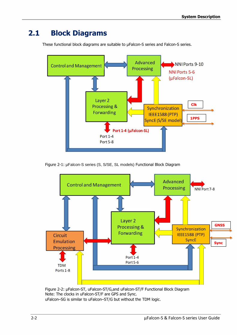
System Description
2-2 µFalcon-S & Falcon-S series User Guide
2.1 Block Diagrams
These functional block diagrams are suitable to µFalcon-S series and Falcon-S series.
Figure 2-1: µFalcon-S series (S, S/SE, SL models) Functional Block Diagram
Figure 2-2: µFalcon-ST, uFalcon-ST/G,and uFalcon-ST/F Functional Block Diagram
Note: The clocks in uFalcon-ST/F are GPS and Sync.
uFalcon–SG is similar to uFalcon–ST/G but without the TDM logic.
Clk
1PPS
Sync
GNSS
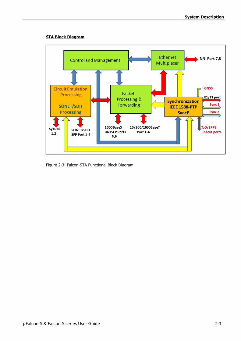
System Description
µFalcon-S & Falcon-S series User Guide 2-3
STA Block Diagram
Figure 2-3: Falcon-STA Functional Block Diagram
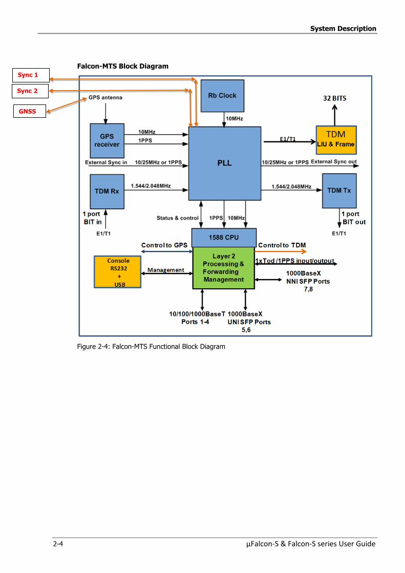
System Description
2-4 µFalcon-S & Falcon-S series User Guide
Falcon-MTS Block Diagram
Figure 2-4: Falcon-MTS Functional Block Diagram
GNSS
Sync 1
Sync 2
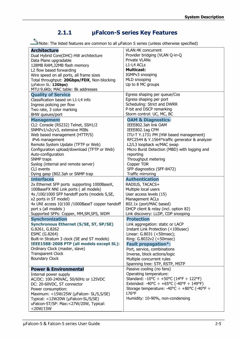
System Description
µFalcon-S & Falcon-S series User Guide 2-5
2.1.1 µFalcon-S series Key Features
Note: The listed features are common to all µFalcon S series (unless otherwise specified)
Architecture Dual Hybrid Core(DHC) HW architecture Data Plane upgradable
128MB RAM,32MB flash memory L2 flow based forwarding
Wire speed on all ports, all frame sizes
Total throughput: 20Gbps/FDX, Non-blocking (µFalcon SL: 12Gbps) MTU:9,6Kb; MAC table: 8k addresses
VLAN:4K concurrent
Provider bridging (VLAN Q-in-Q Private VLANs
L1-L4 ACLs Multicast:
IGMPv3 snooping
MLD snooping Up to 8 MC groups
Quality of Service Classification based on L1-L4 info
Ingress policing per flow Two rate, 3 color marking
8HW queues/port
Egress shaping per queue/Cos Egress shaping per port
Scheduling: Strict and DWRR P-bit and DSCP remarking
Storm control: UC, MC, BC
Management
CLI: Console (RS232) Telnet, SSH1/2
SNMPv1/v2c/v3, extensive MIBs
Web based management (HTTP/S) iPv6 management
Remote System Update (TFTP or Web) Configuration upload/download (TFTP or Web)
Auto-configuration SNMP traps
Syslog (internal and remote server)
CLI events Dying gasp (802.3ah or SNMP trap
OAM & Diagnostics-
IEEE802.3ah link OAM
IEEE802.1ag CFM
ITU-T Y.1731 PM (HW based management) RFC2544 & Y.1564*traffic generator & analyzer
L2/L3 loopback w/MAC swap Micro Burst Detection (MBD) with logging and
reporting Throughput metering
Copper TDR
SFP diagnostics (SFF-8472) Traffic mirroring
Interfaces
2x Ethernet SFP ports supporting 1000BaseX, 100BaseFX NNI Link ports ( all models)
4x /100/1000 SFP handoff ports (models S,SE, x2 ports in ST model)
4x UNI access 10/100 /1000BaseT copper handoff
port s (all models ) Supported SFPs: Copper, MM,SM,SFS, WDM
Authentication
RADIUS, TACACS+ Multiple local users
User access levels (15) Management ACLs
802.1x (port/MAC based)
DHCP client & relay (incl. option 82) Link discovery: LLDP, CDP snooping
Synchronization Synchronous Ethernet (S/SE, ST, SP/SE) G.8261, G.8262
ESMC (G.8264) Built-in Stratum 3 clock (SE and ST models)
IEEE1588-2008 PTP (all models except SL): Ordinary Clock (master, slave)
Transparent Clock
Boundary Clock
Protection Link aggregation: static or LACP Instant Link Protection (<100usec)
Linear: G.8031 (<50msec); Ring: G.8032v2 (<50msec)
Fault propagation*: Port, service, combinations
Inverse, block actions/logic
Multiple concurrent rules Spanning tree: STP, RSTP, MSTP
Power & Environmental Internal power supply AC/DC: 100-240VAC, 50/60Hz or 125VDC
DC: 20-60VDC, ST connector Power consumption:
Maximum: <15W/25W (µFalcon- SL/S,S/SE)
Typical: <12W20W (µFalcon-SL/S/SE) uFalcon-ST/SP: Max:<27W/20W, Typical:
<20W/15W
Passive cooling (no fans)
Operating temperature: Standard: -10°C ÷ +50°C (14°F ÷ 122°F)
Extended: -40°C ÷ +65°C (-40°F ÷ 149°F) Storage temperature: -40°C ÷ +80°C (-40°F ÷
176°F
Humidity: 10-90%, non-condensing
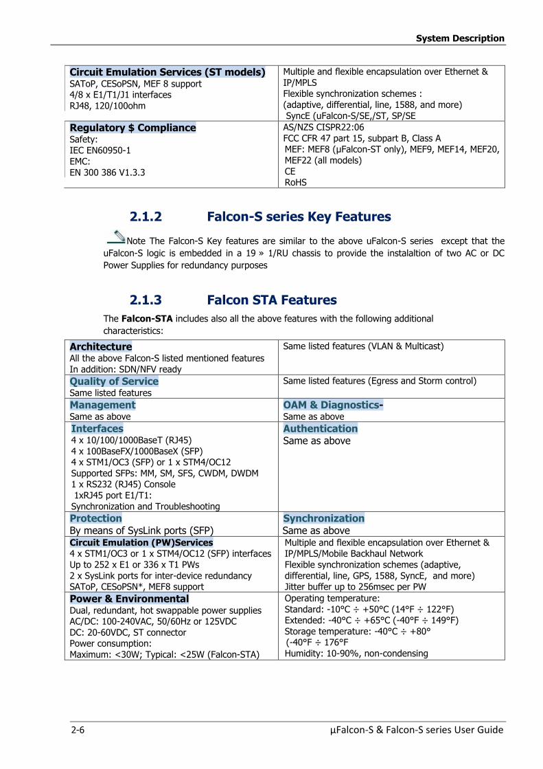
System Description
2-6 µFalcon-S & Falcon-S series User Guide
Circuit Emulation Services (ST models) SAToP, CESoPSN, MEF 8 support 4/8 x E1/T1/J1 interfaces
RJ48, 120/100ohm
Multiple and flexible encapsulation over Ethernet &
IP/MPLS Flexible synchronization schemes :
(adaptive, differential, line, 1588, and more)
SyncE (uFalcon-S/SE,/ST, SP/SE
Regulatory $ Compliance Safety: IEC EN60950-1
EMC:
EN 300 386 V1.3.3
AS/NZS CISPR22:06
FCC CFR 47 part 15, subpart B, Class A MEF: MEF8 (µFalcon-ST only), MEF9, MEF14, MEF20,
MEF22 (all models)
CE RoHS
2.1.2 Falcon-S series Key Features
Note The Falcon-S Key features are similar to the above uFalcon-S series except that the
uFalcon-S logic is embedded in a 19 » 1/RU chassis to provide the instalaltion of two AC or DC
Power Supplies for redundancy purposes
2.1.3 Falcon STA Features
The Falcon-STA includes also all the above features with the following additional
characteristics:
Architecture All the above Falcon-S listed mentioned features
In addition: SDN/NFV ready
Same listed features (VLAN & Multicast)
Quality of Service Same listed features
Same listed features (Egress and Storm control)
Management Same as above
OAM & Diagnostics- Same as above
Interfaces 4 x 10/100/1000BaseT (RJ45)
4 x 100BaseFX/1000BaseX (SFP) 4 x STM1/OC3 (SFP) or 1 x STM4/OC12
Supported SFPs: MM, SM, SFS, CWDM, DWDM 1 x RS232 (RJ45) Console
1xRJ45 port E1/T1:
Synchronization and Troubleshooting
Authentication Same as above
Protection By means of SysLink ports (SFP)
Synchronization Same as above
Circuit Emulation (PW)Services 4 x STM1/OC3 or 1 x STM4/OC12 (SFP) interfaces
Up to 252 x E1 or 336 x T1 PWs
2 x SysLink ports for inter-device redundancy SAToP, CESoPSN*, MEF8 support
Multiple and flexible encapsulation over Ethernet & IP/MPLS/Mobile Backhaul Network
Flexible synchronization schemes (adaptive,
differential, line, GPS, 1588, SyncE, and more) Jitter buffer up to 256msec per PW
Power & Environmental Dual, redundant, hot swappable power supplies AC/DC: 100-240VAC, 50/60Hz or 125VDC
DC: 20-60VDC, ST connector Power consumption:
Maximum: <30W; Typical: <25W (Falcon-STA)
Operating temperature:
Standard: -10°C ÷ +50°C (14°F ÷ 122°F) Extended: -40°C ÷ +65°C (-40°F ÷ 149°F)
Storage temperature: -40°C ÷ +80° (-40°F ÷ 176°F
Humidity: 10-90%, non-condensing
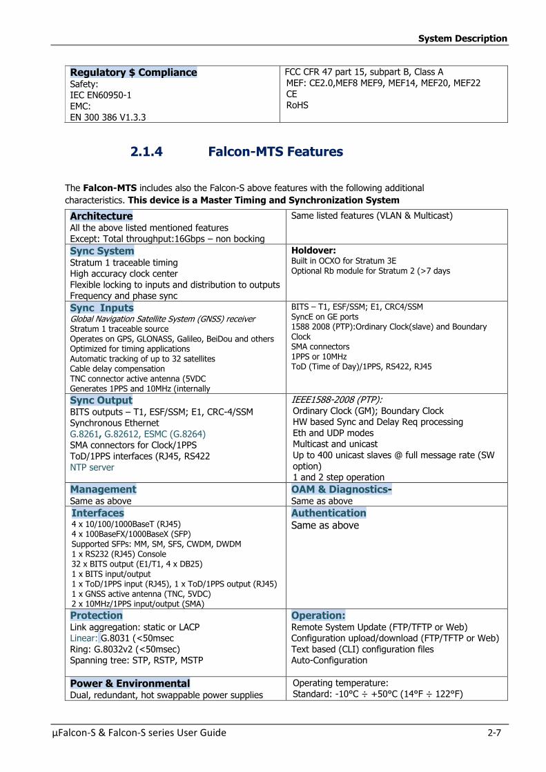
System Description
µFalcon-S & Falcon-S series User Guide 2-7
Regulatory $ Compliance Safety: IEC EN60950-1
EMC:
EN 300 386 V1.3.3
FCC CFR 47 part 15, subpart B, Class A
MEF: CE2.0,MEF8 MEF9, MEF14, MEF20, MEF22 CE
RoHS
2.1.4 Falcon-MTS Features
The Falcon-MTS includes also the Falcon-S above features with the following additional
characteristics. This device is a Master Timing and Synchronization System
Architecture All the above listed mentioned features Except: Total throughput:16Gbps – non bocking
Same listed features (VLAN & Multicast)
Sync System Stratum 1 traceable timing High accuracy clock center
Flexible locking to inputs and distribution to outputs Frequency and phase sync
Holdover: Built in OCXO for Stratum 3E Optional Rb module for Stratum 2 (>7 days
Sync Inputs Global Navigation Satellite System (GNSS) receiver Stratum 1 traceable source Operates on GPS, GLONASS, Galileo, BeiDou and others Optimized for timing applications Automatic tracking of up to 32 satellites Cable delay compensation TNC connector active antenna (5VDC Generates 1PPS and 10MHz (internally
BITS – T1, ESF/SSM; E1, CRC4/SSM SyncE on GE ports 1588 2008 (PTP):Ordinary Clock(slave) and Boundary Clock SMA connectors 1PPS or 10MHz ToD (Time of Day)/1PPS, RS422, RJ45
Sync Output BITS outputs – T1, ESF/SSM; E1, CRC-4/SSM Synchronous Ethernet
G.8261, G.82612, ESMC (G.8264) SMA connectors for Clock/1PPS
ToD/1PPS interfaces (RJ45, RS422
NTP server
IEEE1588-2008 (PTP): Ordinary Clock (GM); Boundary Clock HW based Sync and Delay Req processing
Eth and UDP modes Multicast and unicast
Up to 400 unicast slaves @ full message rate (SW
option) 1 and 2 step operation
Management Same as above
OAM & Diagnostics- Same as above
Interfaces 4 x 10/100/1000BaseT (RJ45) 4 x 100BaseFX/1000BaseX (SFP) Supported SFPs: MM, SM, SFS, CWDM, DWDM 1 x RS232 (RJ45) Console 32 x BITS output (E1/T1, 4 x DB25)
1 x BITS input/output 1 x ToD/1PPS input (RJ45), 1 x ToD/1PPS output (RJ45) 1 x GNSS active antenna (TNC, 5VDC) 2 x 10MHz/1PPS input/output (SMA)
Authentication Same as above
Protection Link aggregation: static or LACP Linear: G.8031 (<50msec
Ring: G.8032v2 (<50msec) Spanning tree: STP, RSTP, MSTP
Operation: Remote System Update (FTP/TFTP or Web) Configuration upload/download (FTP/TFTP or Web)
Text based (CLI) configuration files Auto-Configuration
Power & Environmental Dual, redundant, hot swappable power supplies
Operating temperature: Standard: -10°C ÷ +50°C (14°F ÷ 122°F)

System Description
2-8 µFalcon-S & Falcon-S series User Guide
AC/DC: 100-240VAC, 50/60Hz or 125VDC
DC: 20-60VDC, ST connector Power consumption:
Maximum: <45W; (including RBCM)
Typical: <30W
Extended: -25°C ÷ +60°C (-13°F ÷ 140°F)
Storage temperature: -40°C ÷ +80° (-40°F ÷ 176°F
Humidity: 10-90%, non-condensing
Regulatory $ Compliance
Safety: IEC EN60950-1
EMC:
EN 300 386 V1.3.3:05
FCC CFR 47 part 15, subpart B, Class A
MEF: CE2.0, MEF9, MEF14, MEF20, MEF22 CE
RoHS
System Description
µFalcon-S & Falcon-S series User Guide 2-9
2.1.5 Management
The µFalcon-S and Falcon-S series models can be remotely managed via a variety of
mechanisms/ platforms at virtually no integration efforts:
IP Based (in-band): SNMP (v1/v2/v3), Telnet, SSH, Web (HTTP, HTTPS).
Console (RJ-45): RS-232 (115,200Bd), CLI (Cisco like).
OAM/IEEE802.3ah: when connected to third party edge switch that supports the standard.
Management integration: OAM Management,and NetACE Service Lifecycle Orchestration.
Other Standards: NTPV4, SYSLOG, RADIUS, DHCP, LACP, LLDP.
OAM & Diagnostics:
IEEE802.3ah link OAM
IEEE802.1ag CFM
ITU-T Y.1731 PM (HW based measurements)
RFC2544 traffic generator & analyzer (up to wire speed)
L2 & L3 loopback w/ MAC swap
Micro Burst Detection (MBD) with logging and reporting
Throughput metering
Copper TDR
SFP diagnostics (SFF-8472)
Traffic mirroring
TDM and CES Configuration
NetACE – Key features and benefits:
Fibrolan offers the NetACE platform along with dedicated integrated tools for managing its
products (e.g. Falcon) within a complex network
The NetACE Orchestrator is a NetOps-driven Service Lifecycle Orchestration, well-known, widely
spread platform
for managing various networks.
The NetACE manages network elements of practically any vendor and therefore enables the
operator to manage all devices on the network through a single generic interface, eliminating the
need to purchase and maintain different system for each vendor's products
Main platform modules:
NetACE Orchestrator: Lifecycle Service Orchestration, Automation and Assurance
NetACE Analytics: An extension module for SLA Management, Service Analytics and Business
Support
NetACE Multi-tenant SLA Portal: An extension module for transparent visualization of Service
Performance, SLA Assurance and B2C Communication
System Description
2-10 µFalcon-S & Falcon-S series User Guide
2.2 µFalcon-S & Falcon-S series ports features
The µFalcon-S and Falcon-S models ports can be configured to support special data-plain
functions. extended traffic handling capabilities, more functionality and processing power. These
capabilities are Software and Firmware based and therefore field upgradeable and configurable.
µFalcon-S, µFalcon-S/SE ports 9 and 10 are considered PowerLink ports due to their extended
capabilities (applicable also to µFalcon-ST’s ports 7, 8 and to µFalcon-SL and SP’s ports 5-6)
The following special features are supported by the µFalcon-S and Falcon-S series models ports:
MEF9 EVPL support – S-tag assignment based on C-tag (can be extended to other types of
classifications for S-tag assignment). Per port + VLAN (C-tag) double tagging (S-tag assignment)
are supported. Such functionality enables full compliance with the MEF9 standard (including EVPL).
Refer to Provider Bridges (QinQ)
access ports - support service based policing with dual leaky bucket per service
MEF8: Emulation of PDH Circuits over Metro Ethernet Networks (µFalcon ST & STA only)
MEF14 EVPL support – C-tag classification enables per service.
MEF 20: specifies an Implementation Agreement (IA) for MEF User to Network
Interface (UNI) Type 2.
MEF 22.1 :Mobile Backhaul Phase 2
Service Accounting
Service accounting is realized using service frame and byte counters
Per Service Counters: The µFalcon-S series models support frame and byte
counters per service basis. Link OAM (IEEE802.3ah) and Service OAM (based on IEEE 802.1ag, ITU-T
Y.1731)
ITU Y.1731 data-plane support– several functions of this standard requires HW based
support These functions are: Loss measurement
Delay measurement
Delay variation measurement
Synchronous Ethernet and 1588-2008 for LTE mobile backhaul applications.
Linear (G.8031) and Ring (G.8032v2) Ethernet Protection Switching
Power Link ports support the implementation of the following:
RFC2544 traffic generator & analyzer Micro-Burst Detection (MBD) with logging and reporting
Dying-Gasp – Power Link ports can send a Dying-Gasp frame upon power failure. The Dying-Gasp frames are SNMP trap frames
L2&L3 Loopback (port or VLAN based)
Automatic Protection Switching (Falcon-STA)
Note: The above feature list represents the current status. It is expected that further features will be
added in future System Software releases

µFalcon-S & Falcon-S series User Guide 3-1
3 3 Getting
Started
Getting Started
3-2 µFalcon-S & Falcon-S series User Guide
3.1 Quick Setup Outline
To set up the µFalcon-S and Falcon-S series models carry out the following steps:
1. Mount the device at its location (rack or desktop).
2. Install the SFP transceivers if required.
3. Connect the unit to a console and a power source.
4. Verify that the PWR (Power, or PS1,PS2)) LED is green lit.
5. Connect required cables to ports: twisted pair (Ethernet) and fiber (Ethernet SFPs).
6. Verify that the Link and Speed LEDs ports are lit according to connected ports.
7. Configure the selected device via the console if required - the µFalcon-S and Falcon-S series
units are already set with the default configuration.
8. Access the installed device via one of the management options (RS232, CLI, Telnet or
Web management)
9. For a general configuration procedure please refer to the Quick Guide located at Fibrolan Web site ( Support/Knowledgebase/Quick Guides)
Note: Remote management requires basic IP configuration.
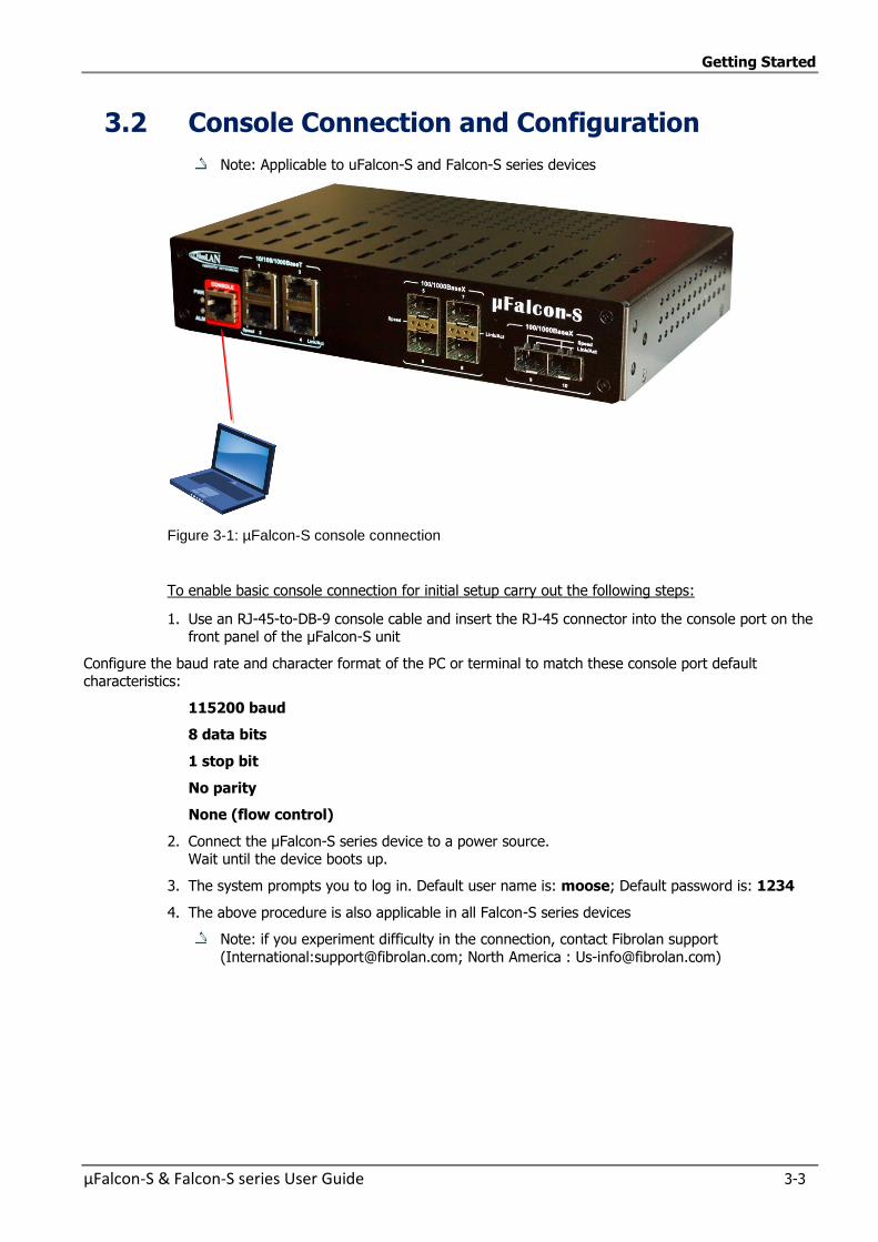
Getting Started
µFalcon-S & Falcon-S series User Guide 3-3
3.2 Console Connection and Configuration
Note: Applicable to uFalcon-S and Falcon-S series devices
Figure 3-1: µFalcon-S console connection
To enable basic console connection for initial setup carry out the following steps:
1. Use an RJ-45-to-DB-9 console cable and insert the RJ-45 connector into the console port on the front panel of the µFalcon-S unit
Configure the baud rate and character format of the PC or terminal to match these console port default characteristics:
115200 baud
8 data bits
1 stop bit
No parity
None (flow control)
2. Connect the µFalcon-S series device to a power source. Wait until the device boots up.
3. The system prompts you to log in. Default user name is: moose; Default password is: 1234
4. The above procedure is also applicable in all Falcon-S series devices
Note: if you experiment difficulty in the connection, contact Fibrolan support
(International:[email protected]; North America : [email protected])
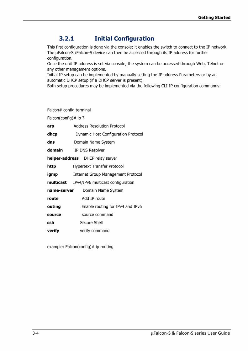
Getting Started
3-4 µFalcon-S & Falcon-S series User Guide
3.2.1 Initial Configuration
This first configuration is done via the console; it enables the switch to connect to the IP network.
The µFalcon-S /Falcon-S device can then be accessed through its IP address for further
configuration.
Once the unit IP address is set via console, the system can be accessed through Web, Telnet or
any other management options.
Initial IP setup can be implemented by manually setting the IP address Parameters or by an
automatic DHCP setup (if a DHCP server is present).
Both setup procedures may be implemented via the following CLI IP configuration commands:
Falcon# config terminal
Falcon(config)# ip ?
arp Address Resolution Protocol
dhcp Dynamic Host Configuration Protocol
dns Domain Name System
domain IP DNS Resolver
helper-address DHCP relay server
http Hypertext Transfer Protocol
igmp Internet Group Management Protocol
multicast IPv4/IPv6 multicast configuration
name-server Domain Name System
route Add IP route
outing Enable routing for IPv4 and IPv6
source source command
ssh Secure Shell
verify verify command
example: Falcon(config)# ip routing
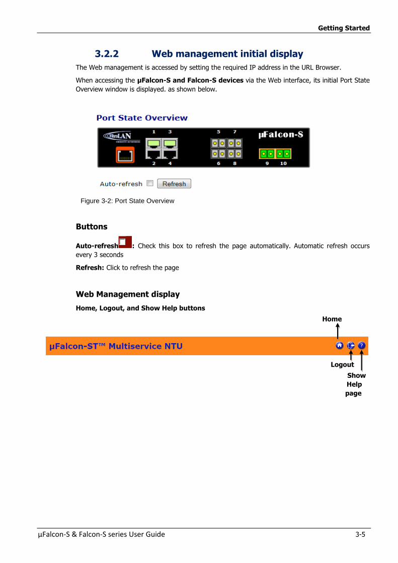
Getting Started
µFalcon-S & Falcon-S series User Guide 3-5
3.2.2 Web management initial display
The Web management is accessed by setting the required IP address in the URL Browser.
When accessing the µFalcon-S and Falcon-S devices via the Web interface, its initial Port State
Overview window is displayed. as shown below.
Figure 3-2: Port State Overview
Buttons
Auto-refresh : Check this box to refresh the page automatically. Automatic refresh occurs
every 3 seconds
Refresh: Click to refresh the page
Web Management display
Home, Logout, and Show Help buttons
Home
Logout
Show
Help
page

µFalcon-S & Falcon-S series User Guide 4-1
4 4 Functional
Description
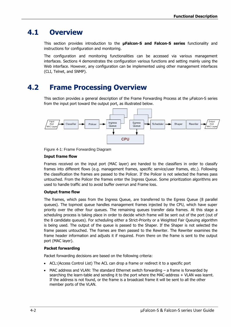
Functional Description
4-2 µFalcon-S & Falcon-S series User Guide
4.1 Overview
This section provides introduction to the µFalcon-S and Falcon-S series functionality and
instructions for configuration and monitoring.
The configuration and monitoring functionalities can be accessed via various management
interfaces. Sections 4 demonstrates the configuration various functions and setting mainly using the
Web interface. However, any configuration can be implemented using other management interfaces
(CLI, Telnet, and SNMP).
4.2 Frame Processing Overview
This section provides a general description of the Frame Forwarding Process at the µFalcon-S series
from the input port toward the output port, as illustrated below.
Figure 4-1: Frame Forwarding Diagram
Input frame flow
Frames received on the input port (MAC layer) are handed to the classifiers in order to classify
frames into different flows (e.g. management frames, specific service/user frames, etc.). Following
the classification the frames are passed to the Policer. If the Policer is not selected the frames pass
untouched. From the Policer the frames enter the Ingress Queue. Some prioritization algorithms are
used to handle traffic and to avoid buffer overrun and Frame loss.
Output frame flow
The frames, which pass from the Ingress Queue, are transferred to the Egress Queue (8 parallel
queues). The topmost queue handles management frames injected by the CPU, which have super
priority over the other four queues. The remaining queues transfer data frames. At this stage a
scheduling process is taking place in order to decide which frame will be sent out of the port (out of
the 8 candidate queues). For scheduling either a Strict-Priority or a Weighted Fair Queuing algorithm
is being used. The output of the queue is passed to the Shaper. If the Shaper is not selected the
frame passes untouched. The frames are then passed to the Rewriter. The Rewriter examines the
frame header information and adjusts it if required. From there on the frame is sent to the output
port (MAC layer).
Packet forwarding
Packet forwarding decisions are based on the following criteria:
ACL:(Access Control List) The ACL can drop a frame or redirect it to a specific port
MAC address and VLAN: The standard Ethernet switch forwarding – a frame is forwarded by
searching the learn-table and sending it to the port where the MAC-address + VLAN was learnt.
If the address is not found, or the frame is a broadcast frame it will be sent to all the other member ports of the VLAN.
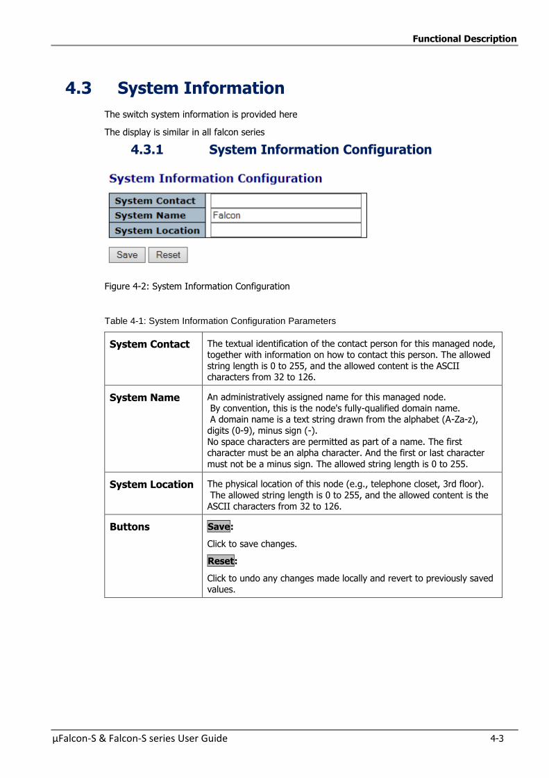
Functional Description
µFalcon-S & Falcon-S series User Guide 4-3
4.3 System Information
The switch system information is provided here
The display is similar in all falcon series
4.3.1 System Information Configuration
Figure 4-2: System Information Configuration
Table 4-1: System Information Configuration Parameters
System Contact The textual identification of the contact person for this managed node, together with information on how to contact this person. The allowed
string length is 0 to 255, and the allowed content is the ASCII characters from 32 to 126.
System Name An administratively assigned name for this managed node.
By convention, this is the node's fully-qualified domain name. A domain name is a text string drawn from the alphabet (A-Za-z),
digits (0-9), minus sign (-).
No space characters are permitted as part of a name. The first character must be an alpha character. And the first or last character
must not be a minus sign. The allowed string length is 0 to 255.
System Location The physical location of this node (e.g., telephone closet, 3rd floor).
The allowed string length is 0 to 255, and the allowed content is the
ASCII characters from 32 to 126.
Buttons Save:
Click to save changes.
Reset:
Click to undo any changes made locally and revert to previously saved values.
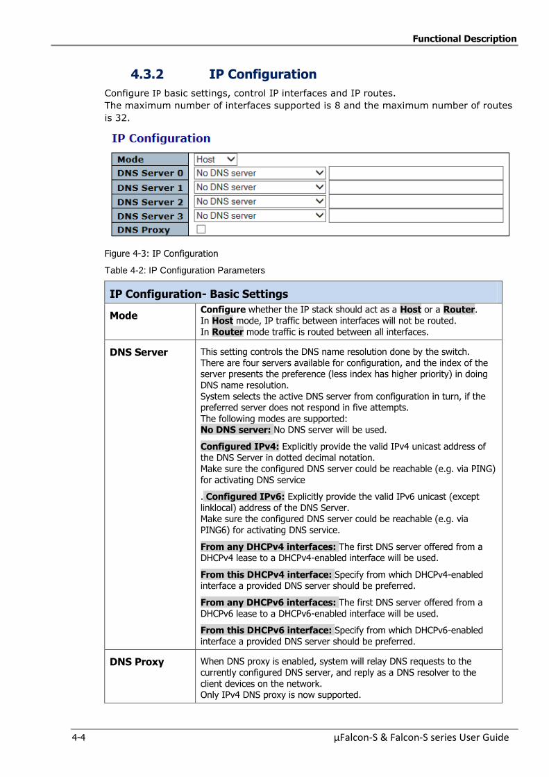
Functional Description
4-4 µFalcon-S & Falcon-S series User Guide
4.3.2 IP Configuration
Configure IP basic settings, control IP interfaces and IP routes.
The maximum number of interfaces supported is 8 and the maximum number of routes
is 32.
Figure 4-3: IP Configuration
Table 4-2: IP Configuration Parameters
IP Configuration- Basic Settings
Mode Configure whether the IP stack should act as a Host or a Router.
In Host mode, IP traffic between interfaces will not be routed.
In Router mode traffic is routed between all interfaces.
DNS Server This setting controls the DNS name resolution done by the switch.
There are four servers available for configuration, and the index of the server presents the preference (less index has higher priority) in doing
DNS name resolution.
System selects the active DNS server from configuration in turn, if the preferred server does not respond in five attempts.
The following modes are supported: No DNS server: No DNS server will be used.
Configured IPv4: Explicitly provide the valid IPv4 unicast address of
the DNS Server in dotted decimal notation. Make sure the configured DNS server could be reachable (e.g. via PING)
for activating DNS service
. Configured IPv6: Explicitly provide the valid IPv6 unicast (except
linklocal) address of the DNS Server. Make sure the configured DNS server could be reachable (e.g. via
PING6) for activating DNS service.
From any DHCPv4 interfaces: The first DNS server offered from a DHCPv4 lease to a DHCPv4-enabled interface will be used.
From this DHCPv4 interface: Specify from which DHCPv4-enabled interface a provided DNS server should be preferred.
From any DHCPv6 interfaces: The first DNS server offered from a
DHCPv6 lease to a DHCPv6-enabled interface will be used.
From this DHCPv6 interface: Specify from which DHCPv6-enabled
interface a provided DNS server should be preferred.
DNS Proxy When DNS proxy is enabled, system will relay DNS requests to the
currently configured DNS server, and reply as a DNS resolver to the
client devices on the network. Only IPv4 DNS proxy is now supported.

Functional Description
µFalcon-S & Falcon-S series User Guide 4-5
4.3.3 IP Interfaces
Figure 4-4: IPv6 Configuration
Table 4-3: IP Interfaces Parameters
Delete Select this option to delete an existing IP interface
VLAN The VLAN associated with the IP interface. Only ports in this VLAN will be
able to access the IP interface. This field is only available for input when creating a new interface.
IPv4 DHCP Enabled
Enable the DHCPv4 client by checking this box. If this option is enabled, the system will configure the IPv4 address and mask of the interface using the
DHCPv4 protocol. The DHCPv4 client will announce the configured System
Name as hostname to provide DNS lookup
IPv4 DHCP Fallback Timeout
The number of seconds for trying to obtain a DHCP lease.
After this period expires, a configured IPv4 address will be used as IPv4
interface address. A value of zero disables the fallback mechanism, such that DHCP will keep retrying until a valid lease is obtained. Legal values are 0 to
4294967295 seconds.
IPv4 DHCP Current Lease
For DHCP interfaces with an active lease, this column show the current
interface address, as provided by the DHCP server.
IPv4 Address The IPv4 address of the interface in dotted decimal notation.
If DHCP is enabled, this field configures the fallback address. The field may be left blank if IPv4 operation on the interface is not desired - or no DHCP
fallback address is desired.
IPv4 Mask Length
The IPv4 network mask, in number of bits (prefix length). Valid values are
between 0 and 30 bits for a IPv4 address.
If DHCP is enabled, this field configures the fallback address network mask. The field may be left blank if IPv4 operation on the interface is not desired -
or no DHCP fallback address is desired.
DHCPv6 Enable
Enable the DHCPv6 client by checking this box. If this option is enabled, the system will configure the IPv6 address of the interface using the DHCPv6
protocol.
DHCPv6 Rapid Commit
Enable the DHCPv6 Rapid-Commit option by checking this box. If this option
is enabled, the DHCPv6 client terminates the waiting process as soon as a
Reply message with a Rapid Commit option is received. This option is only manageable when DHCPv6 client is enabled.
DHCPv6 Current Lease
For DHCPv6 interface with an active lease, this column shows the interface address provided by the DHCPv6 server.
IPv6 Address The IPv6 address of the interface. A IPv6 address is in 128-bit records
represented as eight fields of up to four hexadecimal digits with a colon
separating each field (:). For example, fe80::215:c5ff:fe03:4dc7. The symbol :: is a special syntax that can be used as a shorthand way of
representing multiple 16-bit groups of contiguous zeros; but it can appear only once. System accepts the valid IPv6 unicast address only, except IPv4-
Compatible address and IPv4-Mapped address.
The field may be left blank if IPv6 operation on the interface is not desired.
IPv6 Mask The IPv6 network mask, in number of bits (prefix length). Valid values are
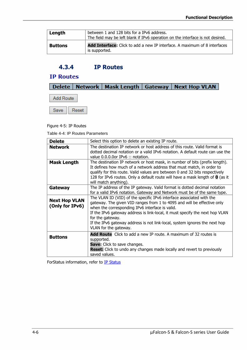
Functional Description
4-6 µFalcon-S & Falcon-S series User Guide
Length between 1 and 128 bits for a IPv6 address.
The field may be left blank if IPv6 operation on the interface is not desired.
Buttons Add Interface: Click to add a new IP interface. A maximum of 8 interfaces is supported.
4.3.4 IP Routes
Figure 4-5: IP Routes
Table 4-4: IP Routes Parameters
Delete Select this option to delete an existing IP route.
Network The destination IP network or host address of this route. Valid format is
dotted decimal notation or a valid IPv6 notation. A default route can use the value 0.0.0.0or IPv6 :: notation.
Mask Length The destination IP network or host mask, in number of bits (prefix length).
It defines how much of a network address that must match, in order to qualify for this route. Valid values are between 0 and 32 bits respectively
128 for IPv6 routes. Only a default route will have a mask length of 0 (as it
will match anything).
Gateway The IP address of the IP gateway. Valid format is dotted decimal notation
for a valid IPv6 notation. Gateway and Network must be of the same type.
Next Hop VLAN (Only for IPv6)
The VLAN ID (VID) of the specific IPv6 interface associated with the gateway. The given VID ranges from 1 to 4095 and will be effective only
when the corresponding IPv6 interface is valid. If the IPv6 gateway address is link-local, it must specify the next hop VLAN
for the gateway.
If the IPv6 gateway address is not link-local, system ignores the next hop VLAN for the gateway.
Buttons Add Route Click to add a new IP route. A maximum of 32 routes is
supported. Save: Click to save changes.
Reset: Click to undo any changes made locally and revert to previously saved values.
ForStatus information, refer to IP Status
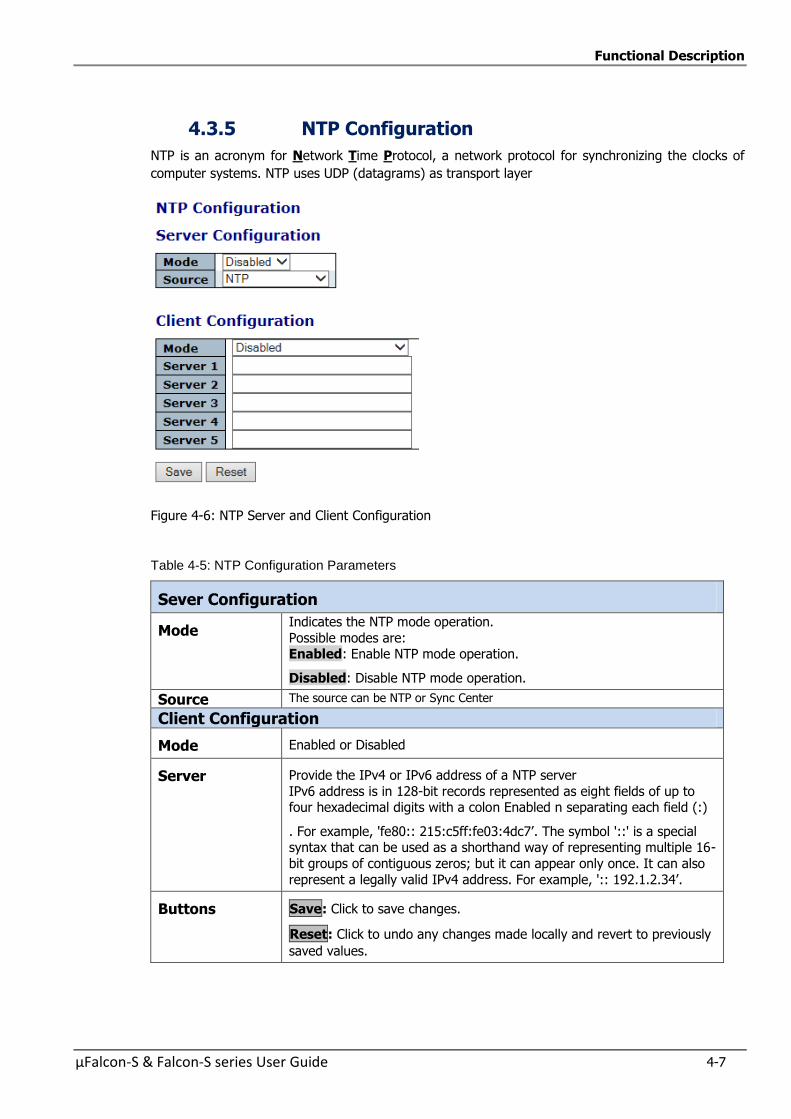
Functional Description
µFalcon-S & Falcon-S series User Guide 4-7
4.3.5 NTP Configuration
NTP is an acronym for Network Time Protocol, a network protocol for synchronizing the clocks of
computer systems. NTP uses UDP (datagrams) as transport layer
Figure 4-6: NTP Server and Client Configuration
Table 4-5: NTP Configuration Parameters
Sever Configuration
Mode Indicates the NTP mode operation.
Possible modes are: Enabled: Enable NTP mode operation.
Disabled: Disable NTP mode operation.
Source The source can be NTP or Sync Center
Client Configuration
Mode Enabled or Disabled
Server Provide the IPv4 or IPv6 address of a NTP server
IPv6 address is in 128-bit records represented as eight fields of up to four hexadecimal digits with a colon Enabled n separating each field (:)
. For example, 'fe80:: 215:c5ff:fe03:4dc7’. The symbol '::' is a special syntax that can be used as a shorthand way of representing multiple 16-
bit groups of contiguous zeros; but it can appear only once. It can also
represent a legally valid IPv4 address. For example, ':: 192.1.2.34’.
Buttons Save: Click to save changes.
Reset: Click to undo any changes made locally and revert to previously
saved values.
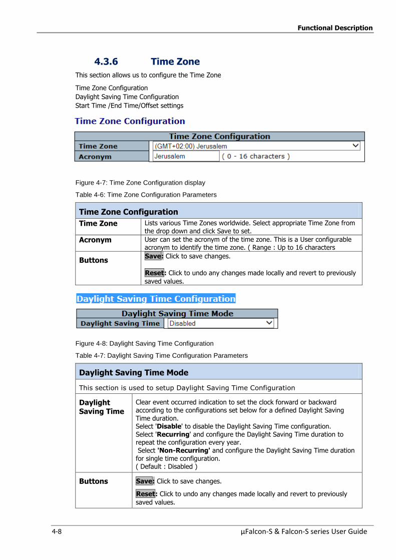
Functional Description
4-8 µFalcon-S & Falcon-S series User Guide
4.3.6 Time Zone
This section allows us to configure the Time Zone
Time Zone Configuration
Daylight Saving Time Configuration
Start Time /End Time/Offset settings
Figure 4-7: Time Zone Configuration display
Table 4-6: Time Zone Configuration Parameters
Time Zone Configuration
Time Zone Lists various Time Zones worldwide. Select appropriate Time Zone from
the drop down and click Save to set.
Acronym User can set the acronym of the time zone. This is a User configurable acronym to identify the time zone. ( Range : Up to 16 characters
Buttons Save: Click to save changes.
Reset: Click to undo any changes made locally and revert to previously
saved values.
Figure 4-8: Daylight Saving Time Configuration
Table 4-7: Daylight Saving Time Configuration Parameters
Daylight Saving Time Mode
This section is used to setup Daylight Saving Time Configuration
Daylight Saving Time
Clear event occurred indication to set the clock forward or backward
according to the configurations set below for a defined Daylight Saving
Time duration. Select 'Disable' to disable the Daylight Saving Time configuration.
Select 'Recurring' and configure the Daylight Saving Time duration to repeat the configuration every year.
Select 'Non-Recurring' and configure the Daylight Saving Time duration
for single time configuration. ( Default : Disabled )
Buttons Save: Click to save changes.
Reset: Click to undo any changes made locally and revert to previously
saved values.

Functional Description
µFalcon-S & Falcon-S series User Guide 4-9
Time Settings
Figure 4-9: Time Settings displays
Table 4-8: Time Settings Parameters
Recurring Configurations
Start time settings Week - Select the starting week number.
Day - Select the starting day. Month - Select the starting month.
Hours - Select the starting hour. Minutes - Select the starting minute.
End time settings Week - Select the ending week number.
Day - Select the ending day. Month - Select the ending month.
Hours - Select the ending hour.
Minutes - Select the ending minute.
Offset settings Offset: Enter the number of minutes to add during Daylight Saving
Time. ( Range: 1 to 1440 )
Non Recurring Configurations
Start time settings Month - Select the starting month. Date - Select the starting date.
Year - Select the starting year. Hours - Select the starting hour.
Minutes - Select the starting minute.
End time settings Month - Select the ending month. Date - Select the ending date.
Year - Select the ending year. Hours - Select the ending hour.
Minutes - Select the ending minute.
Offset settings Offset: Enter the number of minutes to add during Daylight Saving Time. ( Range: 1 to 1440 )
Buttons Save: Click to save changes.
Reset: Click to undo any changes made locally and revert to
previously saved values.
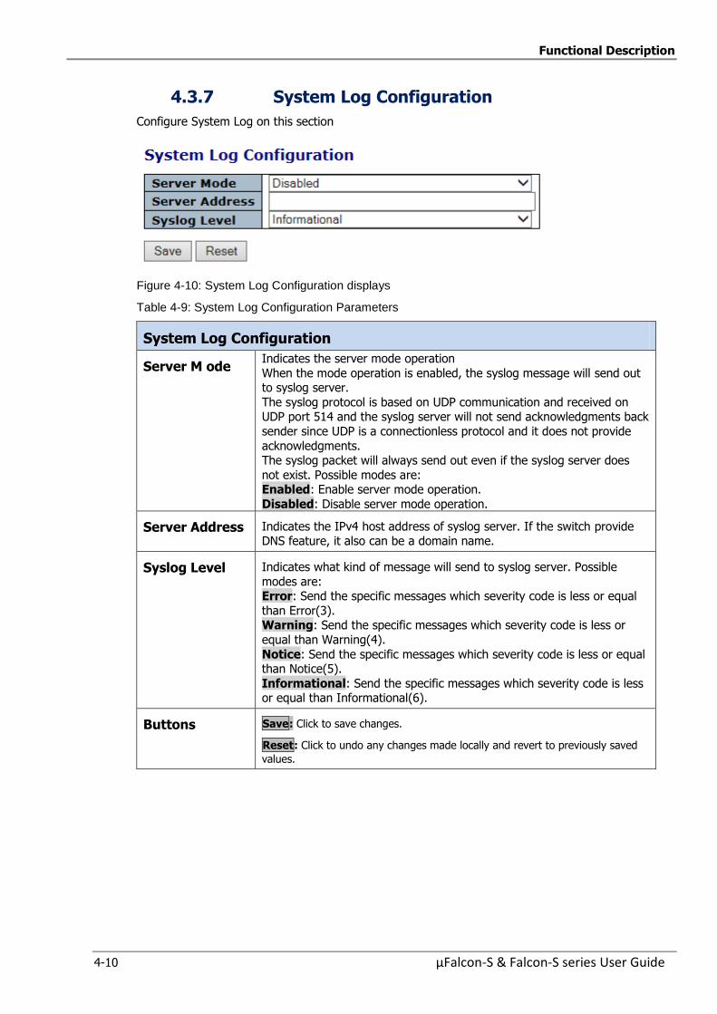
Functional Description
4-10 µFalcon-S & Falcon-S series User Guide
4.3.7 System Log Configuration
Configure System Log on this section
Figure 4-10: System Log Configuration displays
Table 4-9: System Log Configuration Parameters
System Log Configuration
Server M ode Indicates the server mode operation
When the mode operation is enabled, the syslog message will send out to syslog server.
The syslog protocol is based on UDP communication and received on UDP port 514 and the syslog server will not send acknowledgments back
sender since UDP is a connectionless protocol and it does not provide
acknowledgments. The syslog packet will always send out even if the syslog server does
not exist. Possible modes are: Enabled: Enable server mode operation.
Disabled: Disable server mode operation.
Server Address Indicates the IPv4 host address of syslog server. If the switch provide DNS feature, it also can be a domain name.
Syslog Level Indicates what kind of message will send to syslog server. Possible
modes are: Error: Send the specific messages which severity code is less or equal
than Error(3). Warning: Send the specific messages which severity code is less or
equal than Warning(4).
Notice: Send the specific messages which severity code is less or equal than Notice(5).
Informational: Send the specific messages which severity code is less or equal than Informational(6).
Buttons Save: Click to save changes.
Reset: Click to undo any changes made locally and revert to previously saved
values.

Functional Description
µFalcon-S & Falcon-S series User Guide 4-11
4.3.8 Dying Gasp Configuration
This section configures dying gasp parameters.
Figure 4-11: Dying Gasp Configuration
Table 4-10: Dying Gasp Configuration Parameters
System Log Configuration
Port Select the port to which the Dying Gasp is applied
Mode Enable or disable dying gasp functionality for a port
Frame Type Select the sending frame format during dying gasp.
SNMP or Link OAM
Tx Frames Indicates the number of frames to transmit during dying gasp
Tx Frames can be set between 1 to 5 frames
Buttons Save: Click to save changes.
Reset: Click to undo any changes made locally and revert to previously
saved values.
Refresh:
Click to refresh the screen; any changes made locally will be undone
Auto-refresh : Check this box to refresh the page automatically.
Automatic refresh occurs every 3 seconds

Functional Description
4-12 µFalcon-S & Falcon-S series User Guide
4.3.9 Events
This page allows the user to change (enable/disable) and their corresponding interfaces
to the current events configuration
Figure 4-12: Events Configuration
Table 4-11: Events Configuration Parameters
# Event Index
Event Unique Name of the Event.
Severity Indicates the severity of the event (Notice, Info.Warning)
Enable Disable/Enable Event (Change will take effect on all checked interfaces: snmp,
syslog, cli).
Interface Distribute event on a give interface: SNMP, Syslog, CLI .Flash
Status Indication whether an event occurred or not .
Clear Clear event occurred indication
Buttons Save: Click to save changes.
Reset: Click to undo any changes made locally and revert to previously saved
values.
Clear All: Click to clear ALL event occurred indications.
Functional Description
µFalcon-S & Falcon-S series User Guide 4-13
4.4 DHCP (Dynamic Host Configuration Protocol)
DHCP is an acronym for Dynamic Host Configuration Protocol. It is a protocol used for assigning
dynamic IP addresses to devices on a network.
DHCP used by networked computers (clients) to obtain IP addresses and other parameters such as
the default gateway, subnet mask, and IP addresses of DNS servers from a DHCP server.DHCP used
by networked computers (clients) to obtain IP addresses and other parameters such as the default
gateway, subnet mask, and IP addresses of DNS servers from a DHCP server.
The DHCP server ensures that all IP addresses are unique, for example, no IP address is assigned to a second client while the first client's assignment is valid (its lease has not expired). Therefore, IP
address pool management is done by the server and not by a human network administrator.
Dynamic addressing simplifies network administration because the software keeps track of IP
addresses rather than requiring an administrator to manage the task. This means that a new computer can be added to a network without the hassle of manually assigning it a unique IP
address.
DHCP includes the following sections:
To refer to “DHCP Server Mode Configuration”
To refer to “DHCP Server excluded IP Configuration”
To refer to “DHCP Server Pool Configuration”
To refer to “DHCP Snooping Configuration”
To refer to “Dynamic DHCP Snooping Table”
To refer to “DHCP Relay Configuration”
To refer to “DHCP Relay Statistics”
To refer to “DHCP Server Statistics”
To refer to “DHCP Server Binding IP”
To refer to “DHCP Server Declined IP”
To refer to “DHCP Detatiled Statistics Port 1”
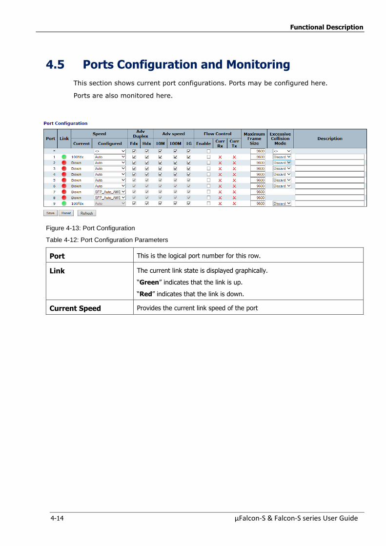
Functional Description
4-14 µFalcon-S & Falcon-S series User Guide
4.5 Ports Configuration and Monitoring
This section shows current port configurations. Ports may be configured here.
Ports are also monitored here.
Figure 4-13: Port Configuration
Table 4-12: Port Configuration Parameters
Port This is the logical port number for this row.
Link The current link state is displayed graphically.
“Green” indicates that the link is up.
“Red” indicates that the link is down.
Current Speed Provides the current link speed of the port

Functional Description
µFalcon-S & Falcon-S series User Guide 4-15
Configured
Speed
Selects any available link speed for the given switch port. Only speeds
supported by the specific port are shown. Possible speeds are: Disabled - Disables the switch port operation.
Auto - Cu port auto negotiating speed with the link partner and selects the
highest speed that is compatible with the link partner. 10Mbps HDX - Forces the cu port in 10Mbps half duplex mode.
10Mbps FDX - Forces the cu port in 10Mbps full duplex mode. 100Mbps HDX - Forces the cu port in 100Mbps half duplex mode.
100Mbps FDX - Forces the cu port in 100Mbps full duplex mode. 1Gbps FDX - Forces the cu port in 1Gbps full duplex mode.
SFP_Auto_AMS - Automatically determines the speed of the SFP. Note:
There is no standardized way to do SFP auto detect, so here it is done by reading the SFP rom. Due to the missing standardized way of doing SFP auto
detect some SFPs might not be detectable. The port is set in AMS mode with SFP preferred. Cu port is set in Auto mode.
100-FX - SFP port in 100-FX speed. Cu port disabled.
100-FX_AMS - Port in AMS mode with SFP preferred. SFP port in 100-FX speed. Cu port in Auto mode.
1000-X - SFP port in 1000-X speed. Cu port disabled. 100-X_AMS - Port in AMS mode with SFP preferred. SFP port in 1000-X
speed. Cu port in Auto mode.
Note: AMS is an acronym for Auto Media Select. AMS is used for dual media
ports (ports supporting both copper (cu) and fiber (SFP) cables. AMS
automatically determines if a SFP or a CU cable is inserted and switches to the corresponding media. If both SFP and cu cables are inserted, the port will
select the preferred media.
Adverise Duplex
When duplex is set as auto i.e auto negotiation, the port will only advertise the specified duplex as either Fdx or Hdx to the link partner. By default port
will advertise all the supported duplexes if the Duplex is Auto.
Advertise Speed
WhenSpeed is set as auto i.e auto negotiation, the port will only advertise
the specified speeds (10M 100M 1G) to the link partner.
By default port will advertise all the supported speeds if speed is set as Auto.
Flow Control When “AutoSpeed” is selected for a port, this section indicates the flow
control capability that is advertised to the link partner.
When a fixed speed setting is selected, traffic that is what is selected. Current Rx: This column indicates whether pause frames on the port are
obeyed. Current Tx: This column indicates whether pause frames on the port are
transmitted.
The Rx and Tx settings are determined by the result of the last Auto-Negotiation.
Configured: Check the configured column to use flow control; this setting is related to the setting for Configured Link Speed
NOTICE: The 100FX standard doesn't support Auto Negotiation, so when in 100FX mode the flow control capabilities will always be shown as "disabled".
PFC When PFC (802.1Qbb Priority Flow Control) is enabled on a port then flow
control on a priority level is enabled. Through the Priority field, range (one or more) of priorities can be configured, e.g. '0-3,7' which equals '0,1,2,3,7'.
PFC is not supported through auto negotiation. PFC and Flowcontrol cannot
both be enabled on the same port.
Maximum Frame Size Enter the maximum frame size allowed for the switch port, including FCS.
The range is 1518-9600 bytes.

Functional Description
4-16 µFalcon-S & Falcon-S series User Guide
Excessive Collision Mode
Configure port transmit collision behavior:
“Discard”: Discards frame after 16 collisions (default). “Restart”: Restarts backoff algorithm after 16 collisions.
Description Indicates the description of the port. Maximum length of the Port description
String is 64. Port description can be null. When port description is not null, it can not contain space.
Buttons Save:
Click to save changes.
Reset:
Click to undo any changes made locally and revert to previously saved values.
Refresh:
Click to refresh the screen; any changes made locally will be undone.
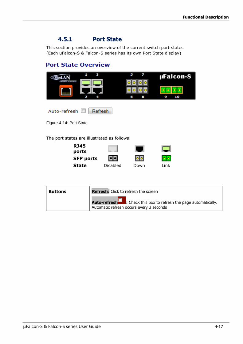
Functional Description
µFalcon-S & Falcon-S series User Guide 4-17
4.5.1 Port State
This section provides an overview of the current switch port states
(Each uFalcon-S & Falcon-S series has its own Port State display)
Figure 4-14: Port State
The port states are illustrated as follows:
RJ45 ports
SFP ports
State Disabled Down Link
Buttons Refresh: Click to refresh the screen
Auto-refresh : Check this box to refresh the page automatically. Automatic refresh occurs every 3 seconds
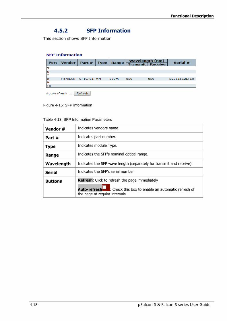
Functional Description
4-18 µFalcon-S & Falcon-S series User Guide
4.5.2 SFP Information
This section shows SFP Information
Figure 4-15: SFP information
Table 4-13: SFP Information Parameters
Vendor # Indicates vendors name.
Part # Indicates part number.
Type Indicates module Type.
Range Indicates the SFP's nominal optical range.
Wavelength Indicates the SFP wave length (separately for transmit and receive).
Serial Indicates the SFP's serial number
Buttons Refresh: Click to refresh the page immediately
Auto-refresh : Check this box to enable an automatic refresh of the page at regular intervals
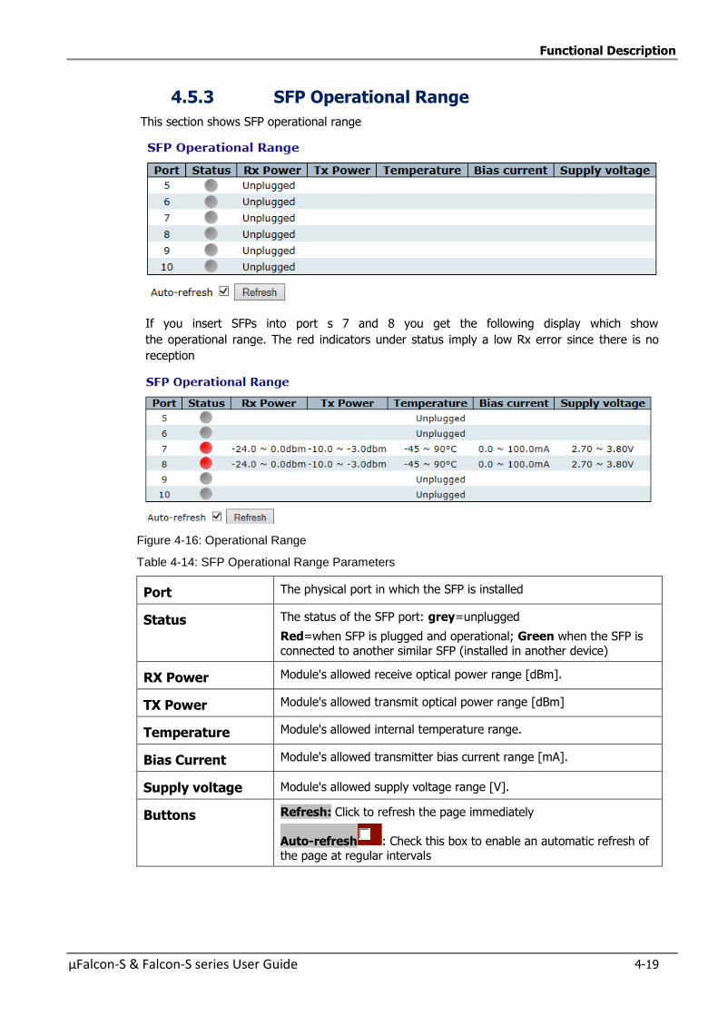
Functional Description
µFalcon-S & Falcon-S series User Guide 4-19
4.5.3 SFP Operational Range
This section shows SFP operational range
If you insert SFPs into port s 7 and 8 you get the following display which show
the operational range. The red indicators under status imply a low Rx error since there is no
reception
Figure 4-16: Operational Range
Table 4-14: SFP Operational Range Parameters
Port The physical port in which the SFP is installed
Status The status of the SFP port: grey=unplugged
Red=when SFP is plugged and operational; Green when the SFP is
connected to another similar SFP (installed in another device)
RX Power Module's allowed receive optical power range [dBm].
TX Power Module's allowed transmit optical power range [dBm]
Temperature Module's allowed internal temperature range.
Bias Current Module's allowed transmitter bias current range [mA].
Supply voltage Module's allowed supply voltage range [V].
Buttons Refresh: Click to refresh the page immediately
Auto-refresh : Check this box to enable an automatic refresh of the page at regular intervals
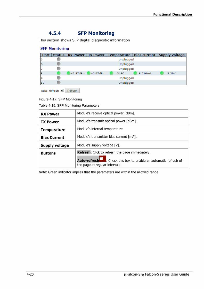
Functional Description
4-20 µFalcon-S & Falcon-S series User Guide
4.5.4 SFP Monitoring
This section shows SFP digital diagnostic information
Figure 4-17: SFP Monitoring
Table 4-15: SFP Monitoring Parameters
RX Power Module's receive optical power [dBm].
TX Power Module's transmit optical power [dBm].
Temperature Module's internal temperature.
Bias Current Module's transmitter bias current [mA].
Supply voltage Module's supply voltage [V].
Buttons Refresh: Click to refresh the page immediately
Auto-refresh : Check this box to enable an automatic refresh of
the page at regular intervals
Note: Green indicator implies that the parameters are within the allowed range
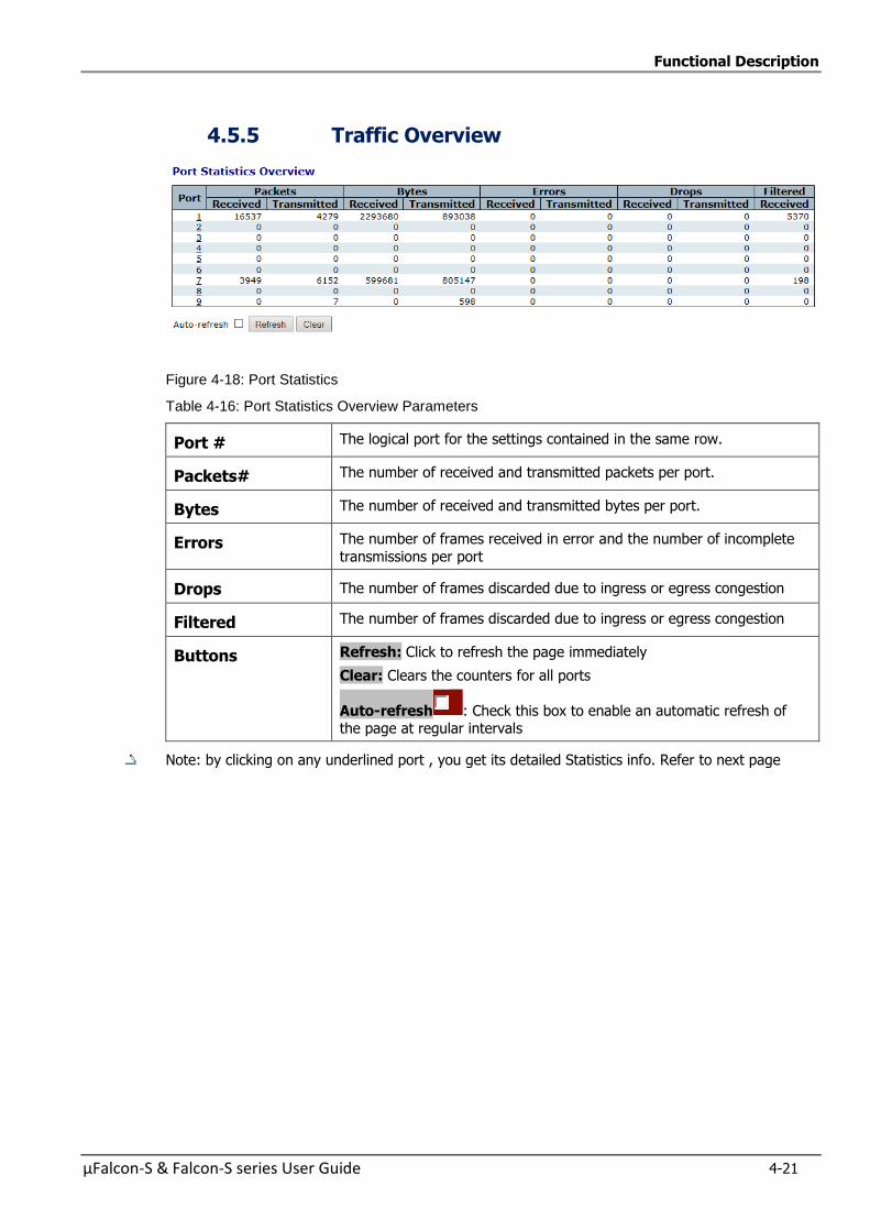
Functional Description
µFalcon-S & Falcon-S series User Guide 4-21
4.5.5 Traffic Overview
Figure 4-18: Port Statistics
Table 4-16: Port Statistics Overview Parameters
Port # The logical port for the settings contained in the same row.
Packets# The number of received and transmitted packets per port.
Bytes The number of received and transmitted bytes per port.
Errors The number of frames received in error and the number of incomplete
transmissions per port
Drops The number of frames discarded due to ingress or egress congestion
Filtered The number of frames discarded due to ingress or egress congestion
Buttons Refresh: Click to refresh the page immediately
Clear: Clears the counters for all ports
Auto-refresh : Check this box to enable an automatic refresh of the page at regular intervals
Note: by clicking on any underlined port , you get its detailed Statistics info. Refer to next page
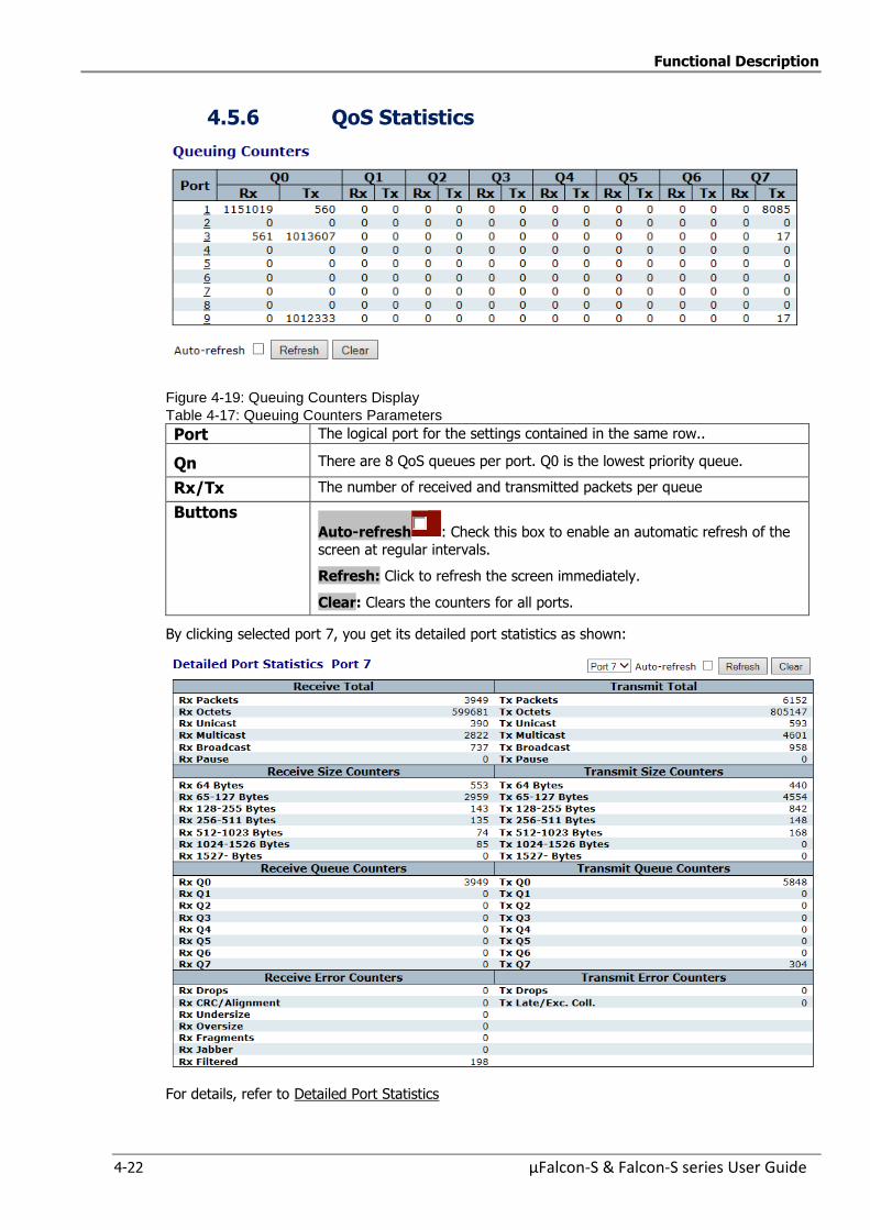
Functional Description
4-22 µFalcon-S & Falcon-S series User Guide
4.5.6 QoS Statistics
Figure 4-19: Queuing Counters Display
Table 4-17: Queuing Counters Parameters
Port The logical port for the settings contained in the same row..
Qn There are 8 QoS queues per port. Q0 is the lowest priority queue.
Rx/Tx The number of received and transmitted packets per queue
Buttons Auto-refresh : Check this box to enable an automatic refresh of the
screen at regular intervals.
Refresh: Click to refresh the screen immediately.
Clear: Clears the counters for all ports.
By clicking selected port 7, you get its detailed port statistics as shown:
For details, refer to Detailed Port Statistics
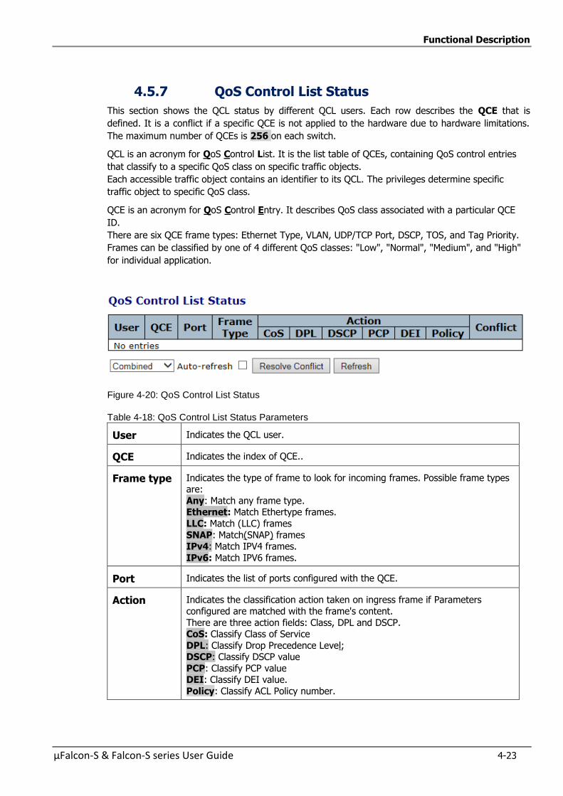
Functional Description
µFalcon-S & Falcon-S series User Guide 4-23
4.5.7 QoS Control List Status
This section shows the QCL status by different QCL users. Each row describes the QCE that is
defined. It is a conflict if a specific QCE is not applied to the hardware due to hardware limitations.
The maximum number of QCEs is 256 on each switch.
QCL is an acronym for QoS Control List. It is the list table of QCEs, containing QoS control entries
that classify to a specific QoS class on specific traffic objects.
Each accessible traffic object contains an identifier to its QCL. The privileges determine specific
traffic object to specific QoS class.
QCE is an acronym for QoS Control Entry. It describes QoS class associated with a particular QCE
ID.
There are six QCE frame types: Ethernet Type, VLAN, UDP/TCP Port, DSCP, TOS, and Tag Priority.
Frames can be classified by one of 4 different QoS classes: "Low", "Normal", "Medium", and "High"
for individual application.
Figure 4-20: QoS Control List Status
Table 4-18: QoS Control List Status Parameters
User Indicates the QCL user.
QCE Indicates the index of QCE..
Frame type Indicates the type of frame to look for incoming frames. Possible frame types are:
Any: Match any frame type. Ethernet: Match Ethertype frames.
LLC: Match (LLC) frames
SNAP: Match(SNAP) frames IPv4: Match IPV4 frames.
IPv6: Match IPV6 frames.
Port Indicates the list of ports configured with the QCE.
Action Indicates the classification action taken on ingress frame if Parameters
configured are matched with the frame's content.
There are three action fields: Class, DPL and DSCP. CoS: Classify Class of Service
DPL: Classify Drop Precedence Level; DSCP: Classify DSCP value
PCP: Classify PCP value DEI: Classify DEI value.
Policy: Classify ACL Policy number.
Functional Description
4-24 µFalcon-S & Falcon-S series User Guide
Conflict Displays Conflict status of QCL entries. As H/W resources are shared by
multiple applications. It may happen that resources required to add a QCE may not be available, in that case it shows conflict status as 'Yes', otherwise it
is always 'No'. Please note that conflict can be resolved by releasing the H/W
resources required to add QCL entry on pressing 'Resolve Conflict' button.
Buttons Combined: Select the QCL status from this drop down list
Auto-refresh : Check this box to refresh the page automatically. Automatic refresh occurs every 3 seconds
Resolve Conflict: Click to release the resources required to add QCL entry, in case the conflict status for any QCL entry is 'yes'
Refresh:
Click to refresh the screen; any changes made locally will be undone.

Functional Description
µFalcon-S & Falcon-S series User Guide 4-25
4.5.8 Detailed Port Statistics
This section provides detailed traffic statistics for a specific switch port. Use the port select box to
select which switch port details to display
The displayed counters are the totals for receive and transmit, the size counters for receive and
transmit, and the error counters for receive and transmit
Figure 4-21: Detailed Port Statistics Display
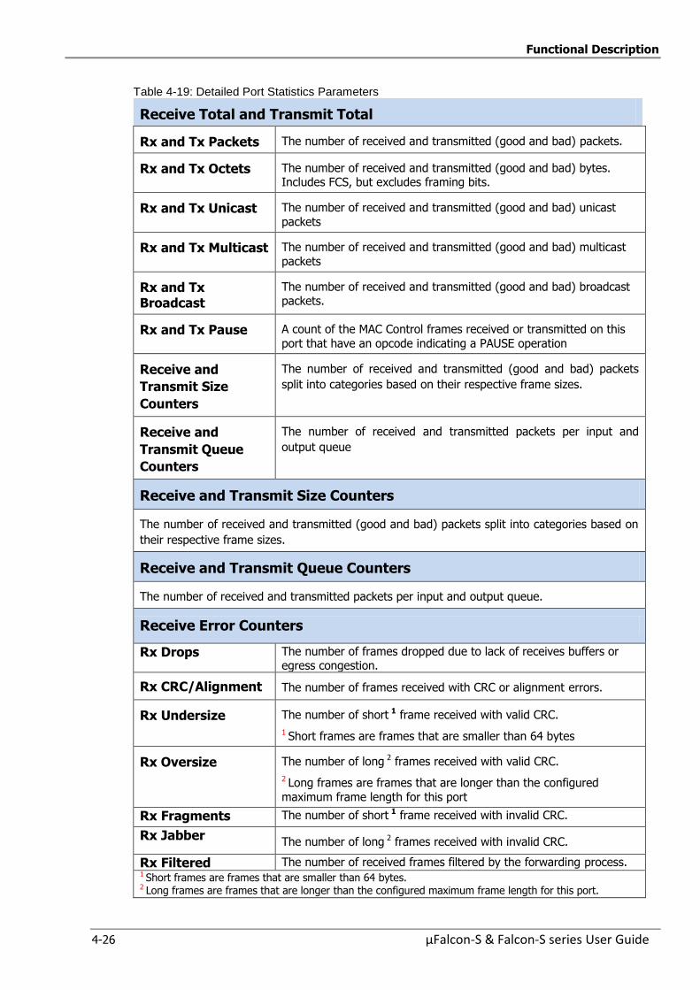
Functional Description
4-26 µFalcon-S & Falcon-S series User Guide
Table 4-19: Detailed Port Statistics Parameters
Receive Total and Transmit Total
Rx and Tx Packets The number of received and transmitted (good and bad) packets.
Rx and Tx Octets The number of received and transmitted (good and bad) bytes. Includes FCS, but excludes framing bits.
Rx and Tx Unicast The number of received and transmitted (good and bad) unicast
packets
Rx and Tx Multicast The number of received and transmitted (good and bad) multicast
packets
Rx and Tx Broadcast
The number of received and transmitted (good and bad) broadcast packets.
Rx and Tx Pause A count of the MAC Control frames received or transmitted on this
port that have an opcode indicating a PAUSE operation
Receive and
Transmit Size
Counters
The number of received and transmitted (good and bad) packets
split into categories based on their respective frame sizes.
Receive and
Transmit Queue
Counters
The number of received and transmitted packets per input and
output queue
Receive and Transmit Size Counters
The number of received and transmitted (good and bad) packets split into categories based on
their respective frame sizes.
Receive and Transmit Queue Counters
The number of received and transmitted packets per input and output queue.
Receive Error Counters
Rx Drops The number of frames dropped due to lack of receives buffers or egress congestion.
Rx CRC/Alignment The number of frames received with CRC or alignment errors.
Rx Undersize The number of short 1 frame received with valid CRC.
1 Short frames are frames that are smaller than 64 bytes
Rx Oversize The number of long 2 frames received with valid CRC.
2 Long frames are frames that are longer than the configured
maximum frame length for this port
Rx Fragments The number of short 1 frame received with invalid CRC.
Rx Jabber The number of long 2 frames received with invalid CRC.
Rx Filtered The number of received frames filtered by the forwarding process. 1 Short frames are frames that are smaller than 64 bytes. 2 Long frames are frames that are longer than the configured maximum frame length for this port.
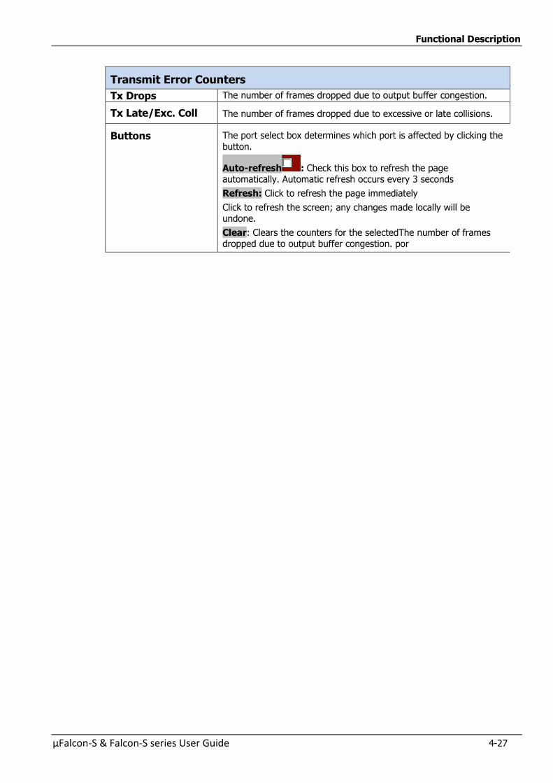
Functional Description
µFalcon-S & Falcon-S series User Guide 4-27
Transmit Error Counters
Tx Drops The number of frames dropped due to output buffer congestion.
Tx Late/Exc. Coll The number of frames dropped due to excessive or late collisions.
Buttons The port select box determines which port is affected by clicking the
button.
Auto-refresh : Check this box to refresh the page automatically. Automatic refresh occurs every 3 seconds
Refresh: Click to refresh the page immediately
Click to refresh the screen; any changes made locally will be undone.
Clear: Clears the counters for the selectedThe number of frames dropped due to output buffer congestion. por
Functional Description
4-28 µFalcon-S & Falcon-S series User Guide
4.5.9 Green Ethernet
This page allows the user to configure the port power savings features.
EEE is an abbreviation for Energy Efficient Ethernet defined in IEEE 802.3az. EEE is a power saving option that reduces the power usage when there is low or no traffic
utilization.
EEE works by powering down circuits when there is no traffic. When a port gets data to be
transmitted all circuits are powered up. The time it takes to power up the circuits is named wakeup time. The default wakeup time is 17 us for 1Gbit links and 30 us for other link speeds. EEE devices
must agree upon the value of the wakeup time in order to make sure that both the receiving and
transmitting device has all circuits powered up when traffic is transmitted. The devices can exchange wakeup time information using the LLDP protocol.
EEE works for ports in auto-negotiation mode, where the port is negotiated to either 1G or 100 Mbit
full duplex mode.
For ports that are not EEE-capable the corresponding EEE checkboxes are grayed out and thus impossible to enable EEE for.
The EEE port settings relate to the currently selected stack unit, as reflected by the page header. When a port is powered down for saving power, outgoing traffic is stored in a buffer until the port is
powered up again. Because there are some overhead in turning the port down and up, more power can be saved if the traffic can be buffered up until a large burst of traffic can be transmitted.
Buffering traffic will give some latency in the traffic.
NOTES:
For Port Power Savings refer to “Port Power Savings Configuration”
For Port Power Savings Status, refer to “Port Power Saving Status”
4.5.10 Thermal Protection
For Thermal Protection Configuration, refer to ”Thermal Protection Configuration”
For Thermal Protection Status, refer to “Thermal Protection Status”

Functional Description
µFalcon-S & Falcon-S series User Guide 4-29
4.6 Learn MAC Table
This section details the MAC Learn Table functionality.
Switching of frames is based upon the DMAC address contained in the frame.
The switch builds up a table that maps MAC addresses to switch ports for knowing which ports the
frames should be delivered to ( based upon the DMAC address in the frame )
This table contains both static and dynamic entries. The static entries are configured by the network
administrator if the administrator wants to do a fixed mapping between the DMAC address and
switch ports.
The frames also contain a MAC address ( SMAC address ), which shows the MAC address of the
equipment sending the frame. The SMAC address is used by the switch to automatically update the
MAC table with these dynamic MAC addresses. Dynamic entries are removed from the MAC table if
no frame with the corresponding SMAC address has been seen after a configurable age time.
The µFalcon-S series MAC address space is up to 8K addresses.
4.6.1 Configuring the MAC Address Table
The MAC Address Table is configured on this section. Set timeouts for entries in the dynamic MAC
Table and configure the static MAC table
By default the µFalcon-S series is configured for automatic learning on all ports. The table is sorted
first by VLAN ID, then by MAC address.
Timeouts are set for entries in the dynamic MAC address and Configuration is performed in the static
MAC table.
Figure 4-22: MAC Address Table Configuration displays
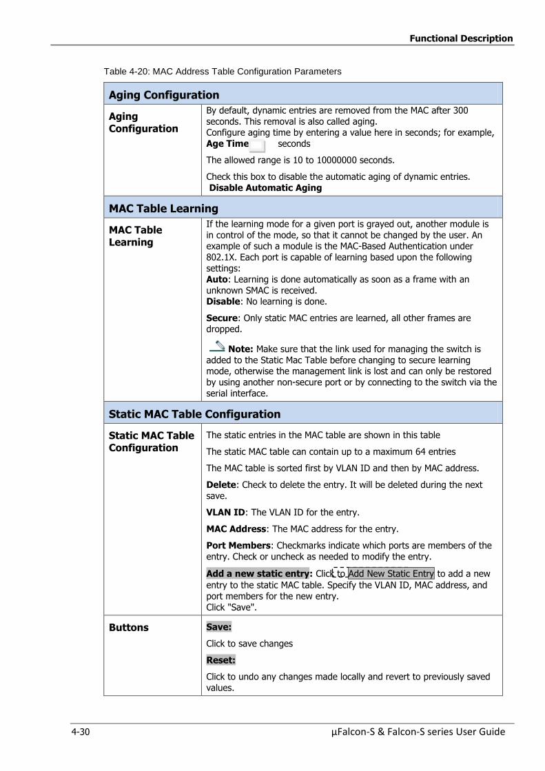
Functional Description
4-30 µFalcon-S & Falcon-S series User Guide
Table 4-20: MAC Address Table Configuration Parameters
Aging Configuration
Aging Configuration
By default, dynamic entries are removed from the MAC after 300
seconds. This removal is also called aging. Configure aging time by entering a value here in seconds; for example,
Age Time: seconds
The allowed range is 10 to 10000000 seconds.
Check this box to disable the automatic aging of dynamic entries.
Disable Automatic Aging
MAC Table Learning
MAC Table Learning
If the learning mode for a given port is grayed out, another module is
in control of the mode, so that it cannot be changed by the user. An example of such a module is the MAC-Based Authentication under
802.1X. Each port is capable of learning based upon the following
settings: Auto: Learning is done automatically as soon as a frame with an
unknown SMAC is received. Disable: No learning is done.
Secure: Only static MAC entries are learned, all other frames are dropped.
Note: Make sure that the link used for managing the switch is
added to the Static Mac Table before changing to secure learning mode, otherwise the management link is lost and can only be restored
by using another non-secure port or by connecting to the switch via the
serial interface.
Static MAC Table Configuration
Static MAC Table Configuration
The static entries in the MAC table are shown in this table
The static MAC table can contain up to a maximum 64 entries
The MAC table is sorted first by VLAN ID and then by MAC address.
Delete: Check to delete the entry. It will be deleted during the next
save.
VLAN ID: The VLAN ID for the entry.
MAC Address: The MAC address for the entry.
Port Members: Checkmarks indicate which ports are members of the
entry. Check or uncheck as needed to modify the entry.
Add a new static entry: Click to Add New Static Entry to add a new
entry to the static MAC table. Specify the VLAN ID, MAC address, and
port members for the new entry.
Click "Save".
Buttons Save:
Click to save changes
Reset:
Click to undo any changes made locally and revert to previously saved
values.

Functional Description
µFalcon-S & Falcon-S series User Guide 4-31
4.6.2 Monitoring the MAC Address Table
Entries in the MAC Table are shown in the below figure. The MAC Table contains up to 8192 entries,
and is sorted first by VLAN ID, then by MAC address.
Figure 4-23: Monitoring MAC Address Table
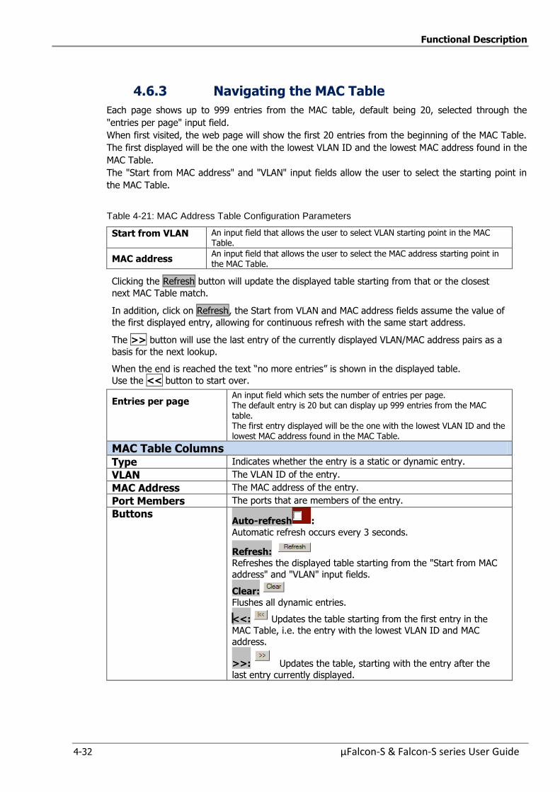
Functional Description
4-32 µFalcon-S & Falcon-S series User Guide
4.6.3 Navigating the MAC Table
Each page shows up to 999 entries from the MAC table, default being 20, selected through the
"entries per page" input field.
When first visited, the web page will show the first 20 entries from the beginning of the MAC Table.
The first displayed will be the one with the lowest VLAN ID and the lowest MAC address found in the
MAC Table.
The "Start from MAC address" and "VLAN" input fields allow the user to select the starting point in
the MAC Table.
Table 4-21: MAC Address Table Configuration Parameters
Start from VLAN An input field that allows the user to select VLAN starting point in the MAC Table.
MAC address An input field that allows the user to select the MAC address starting point in the MAC Table.
Clicking the Refresh button will update the displayed table starting from that or the closest
next MAC Table match.
In addition, click on Refresh, the Start from VLAN and MAC address fields assume the value of
the first displayed entry, allowing for continuous refresh with the same start address.
The >> button will use the last entry of the currently displayed VLAN/MAC address pairs as a
basis for the next lookup.
When the end is reached the text “no more entries” is shown in the displayed table.
Use the << button to start over.
Entries per page An input field which sets the number of entries per page. The default entry is 20 but can display up 999 entries from the MAC
table. The first entry displayed will be the one with the lowest VLAN ID and the lowest MAC address found in the MAC Table.
MAC Table Columns
Type Indicates whether the entry is a static or dynamic entry.
VLAN The VLAN ID of the entry.
MAC Address The MAC address of the entry.
Port Members The ports that are members of the entry.
Buttons Auto-refresh :
Automatic refresh occurs every 3 seconds.
Refresh: Refreshes the displayed table starting from the "Start from MAC
address" and "VLAN" input fields.
Clear: Flushes all dynamic entries.
<<: Updates the table starting from the first entry in the
MAC Table, i.e. the entry with the lowest VLAN ID and MAC address.
>>: Updates the table, starting with the entry after the
last entry currently displayed.

Functional Description
µFalcon-S & Falcon-S series User Guide 4-33
4.7 VLANs and Provider Bridges
Virtual LAN, commonly known as VLAN, is a group of hosts with a common set of requirements that
communicate as if they were attached to the same LAN, regardless of their physical location. A VLAN
has the same attributes as a physical LAN, but allows for end stations to be grouped together even if
they are not located on the same LAN segment. Network reconfiguration can be done through
software instead of physically relocating devices.
A VLAN can be thought of as a broadcast domain that exists within a defined set of switches. Ports
on a switch can be grouped into VLANs in order to limit traffic flooding since it is limited to ports
belonging to that VLAN and its ports. Any switch port can belong to a VLAN. Frames are forwarded
and flooded only to ports in the same VLAN. Each VLAN is a logical network, and packets destined
for stations that do not belong to the same VLAN must be forwarded through a router.
VLANs are essentially Layer 2 constructs, whereas IP subnets are Layer 3 constructs. In a LAN
employing VLANs, a one-to-one relationship often exists between VLANs and IP subnets, although it
is possible to have multiple subnets on one VLAN or have one subnet spread across multiple VLANs.
Virtual LANs and IP subnets provide independent Layer 2 and Layer 3 constructs that map to one
another and this correspondence is useful during the network design process.
In Metro-Ethernet applications VLANs are being used to enable service separation: each VLAN
relates to a different service while disallowing different services/users to communicate with each
other. The usage of VLANs to enable Metro Ethernet services is further enhanced by the Provider
Bridges approach which uses QinQ capabilities as described in Section Provider Bridges (QinQ).

Functional Description
4-34 µFalcon-S & Falcon-S series User Guide
4.7.1 VLAN Configuration
This section allows for controlling VLAN configuration on the switch.
The section includes Global VLAN Configuration and –Port VLAN configurations
Figure 4-24: Global VLAN Configuration
Table 4-22: Global VLAN Configuration Parameters
Global VLAN Configuration
Allowed Access VLANs
This field shows the allowed Access VLANs, i.e. it only affects ports
configured as Access ports (the default port mode) Ports in other modes are members of all VLANs specified in the Allowed
VLANs field.( Ports in Trunk and Hybrid mode) By default, only VLAN 1 is enabled
More VLANs may be created by using a list syntax where the individual elements are separated by commas.
Ranges are specified with a dash separating the lower and upper bound.
The following example will create VLANs 1, 10, 11, 12, 13, 200, and 300: 1,10-13,200,300. Spaces are allowed in between the delimiters
Ethertype for Custom S ports
This field specifies the ethertype/TPID (specified in hexadecimal) used
for Custom S-ports. The setting is in force for all ports whose Port Type is set to S-Custom-
Port.
S-Custom-Port:
On ingress, frames with a VLAN tag with a TPID = 0x8100 or equal to the Ethertype configured for Custom-S ports get classified to the VLAN ID
embedded in the tag. If a frame is untagged or priority tagged, the frame
is classified to the Port VLAN. If frames must be tagged on egress, they will be tagged with the custom S-tag.
Buttons Save
Click to save changes.
Reset:
Click to undo any changes made locally and revert to previously saved
values.
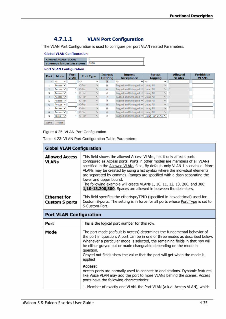
Functional Description
µFalcon-S & Falcon-S series User Guide 4-35
4.7.1.1 VLAN Port Configuration
The VLAN Port Configuration is used to configure per port VLAN related Parameters.
Figure 4-25: VLAN Port Configuration
Table 4-23: VLAN Port Configuration Table Parameters
Global VLAN Configuration
Allowed Access VLANs
This field shows the allowed Access VLANs, i.e. it only affects ports
configured as Access ports. Ports in other modes are members of all VLANs
specified in the Allowed VLANs field. By default, only VLAN 1 is enabled. More VLANs may be created by using a list syntax where the individual elements
are separated by commas. Ranges are specified with a dash separating the lower and upper bound.
The following example will create VLANs 1, 10, 11, 12, 13, 200, and 300: 1,10-13,200,300. Spaces are allowed in between the delimiters.
Ethernet for Custom S ports
This field specifies the ethertype/TPID (specified in hexadecimal) used for
Custom S-ports. The setting is in force for all ports whose Port Type is set to S-Custom-Port.
Port VLAN Configuration
Port This is the logical port number for this row.
Mode The port mode (default is Access) determines the fundamental behavior of the port in question. A port can be in one of three modes as described below.
Whenever a particular mode is selected, the remaining fields in that row will
be either grayed out or made changeable depending on the mode in question.
Grayed out fields show the value that the port will get when the mode is applied
Access:
Access ports are normally used to connect to end stations. Dynamic features like Voice VLAN may add the port to more VLANs behind the scenes. Access
ports have the following characteristics:
1. Member of exactly one VLAN, the Port VLAN (a.k.a. Access VLAN), which

Functional Description
4-36 µFalcon-S & Falcon-S series User Guide
by default is 1
2.Accepts untagged and C-tagged frames 3.Discards all frames that are not classified to the Access VLAN
4.On egress all frames are transmitted untagged
Trunk:
Trunk ports can carry traffic on multiple VLANs simultaneously, and are
normally used to connect to other switches. Trunk ports have the following characteristics:
1. By default, a trunk port is member of all VLANs (1-4095) 2.The VLANs that a trunk port is member of may be limited by the use of
Allowed VLANs
3.Frames classified to a VLAN that the port is not a member of are discarded 4.By default, all frames but frames classified to the Port VLAN (a.k.a. Native
VLAN) get tagged on egress. Frames classified to the Port VLAN do not get C-tagged on egress
5.Egress tagging can be changed to tag all frames, in which case only tagged
frames are accepted on ingress
Hybrid:
Hybrid ports resemble trunk ports in many ways, but adds additional port configuration features. In addition to the characteristics described for trunk
ports, hybrid ports have these abilities: 1.Can be configured to be VLAN tag unaware or, C-tag aware, S-tag aware,
or S-custom-tag aware
2.Ingress filtering can be controlled 3.Ingress acceptance of frames and configuration of egress tagging can be
configured independently
Port VLAN Determines the port's VLAN ID (a.k.a. PVID). Allowed VLANs are in the range 1 through 4095, default being 1.
On ingress, frames get classified to the Port VLAN if the port is configured as VLAN unaware, the frame is untagged, or VLAN awareness is enabled on the
port, but the frame is priority tagged (VLAN ID = 0). On egress, frames classified to the Port VLAN do not get tagged if Egress
Tagging configuration is set to untag Port VLAN.
The Port VLAN is called an "Access VLAN" for ports in Access mode and Native VLAN for ports in Trunk or Hybrid mode.
Port Type Ports in hybrid mode allow for changing the port type, that is, whether a
frame's VLAN tag is used to classify the frame on ingress to a particular VLAN, and if so, which TPID it reacts on. Likewise, on egress, the Port Type
determines the TPID of the tag, if a tag is required. Unaware:
On ingress, all frames, whether carrying a VLAN tag or not, get classified to
the Port VLAN, and possible tags are not removed on egress C-Port:
On ingress, frames with a VLAN tag with TPID = 0x8100 get classified to the VLAN ID embedded in the tag. If a frame is untagged or priority tagged, the
frame gets classified to the Port VLAN. If frames must be tagged on egress, they will be tagged with a C-tag.
S-Port: On ingress, frames with a VLAN tag with TPID = 0x8100 or 0x88A8 get
classified to the VLAN ID embedded in the tag. If a frame is untagged or priority tagged, the frame gets classified to the Port VLAN. If frames must be
tagged on egress, they will be tagged with an S-tag.
Functional Description
µFalcon-S & Falcon-S series User Guide 4-37
S-Custom-Port:
On ingress, frames with a VLAN tag with a TPID = 0x8100 or equal to the Ethertype configured for Custom-S ports get classified to the VLAN ID
embedded in the tag. If a frame is untagged or priority tagged, the frame
gets classified to the Port VLAN. If frames must be tagged on egress, they will be tagged with the custom S-tag.
Ingress Filtering
Hybrid ports allow for changing ingress filtering. Access and Trunk ports always have ingress filtering enabled.
If ingress filtering is enabled (checkbox is checked), frames classified to a
VLAN that the port is not a member of get discarded. If ingress filtering is disabled, frames classified to a VLAN that the port is not
a member of are accepted and forwarded to the switch engine. However, the port will never transmit frames classified to VLANs that it is not a member of.
Ingress Acceptance
Hybrid ports allow for changing the type of frames that are accepted on
ingress. Tagged and Untagged
Both tagged and untagged frames are accepted. Tagged Only
Only tagged frames are accepted on ingress. Untagged frames are discarded
Untagged Only Only untagged frames are accepted on ingress. Tagged frames are
discarded.
Egress Tagging Ports in Trunk and Hybrid mode may control the tagging of frames on egress.
Untag Port VLAN Frames classified to the Port VLAN are transmitted untagged. Other frames
are transmitted with the relevant tag. Tag All
All frames, whether classified to the Port VLAN or not, are transmitted with a
tag. Untag All
All frames, whether classified to the Port VLAN or not, are transmitted without a tag.
This option is only available for ports in Hybrid mode.
Allowed VLANs Ports in Trunk and Hybrid mode may control which VLANs they are allowed to become members of. Access ports can only be member of one VLAN, the
Access VLAN.
The field's syntax is identical to the syntax used in the Enabled VLANs field. By default, a Trunk or Hybrid port will become member of all VLANs, and is
therefore set to 1-4095. The field may be left empty, which means that the port will not become
member of any VLANs.
Forbidden VLANs
A port may be configured to never be member of one or more VLANs. This is particularly useful when dynamic VLAN protocols like MVRP and GVRP must
be prevented from dynamically adding ports to VLANs. The trick is to mark such VLANs as forbidden on the port in question. The
syntax is identical to the syntax used in the Enabled VLANs field.
By default, the field is left blank, which means that the port may become a member of all possible VLANs.
Buttons Save: Click to save changes.
Reset: Click to undo any changes made locally and revert to previously
saved values.
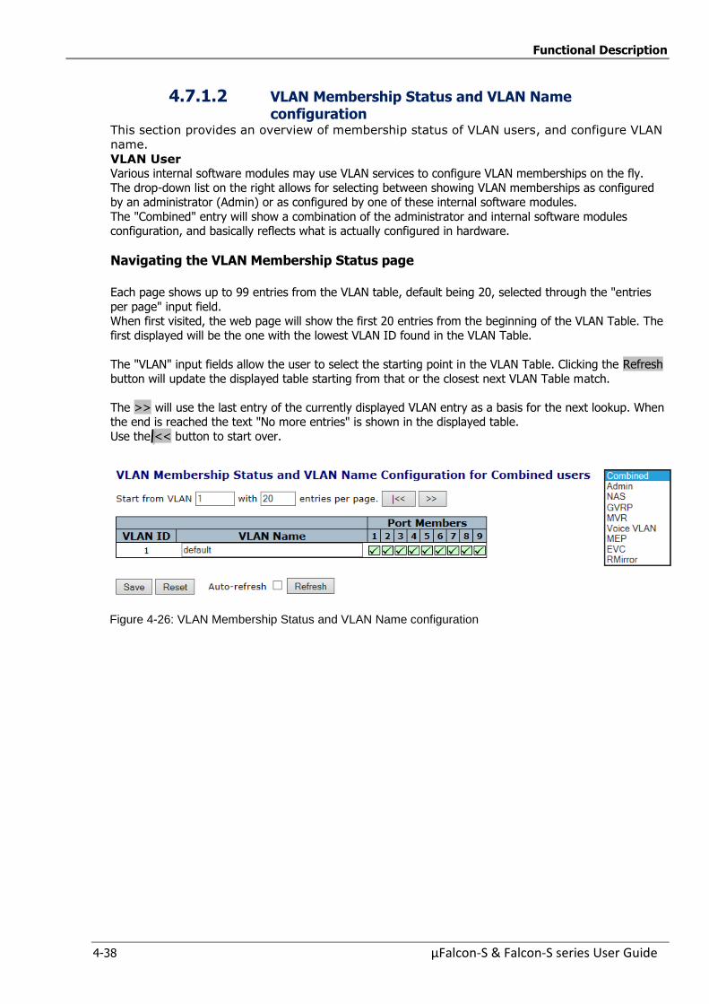
Functional Description
4-38 µFalcon-S & Falcon-S series User Guide
4.7.1.2 VLAN Membership Status and VLAN Name configuration
This section provides an overview of membership status of VLAN users, and configure VLAN
name.
VLAN User Various internal software modules may use VLAN services to configure VLAN memberships on the fly.
The drop-down list on the right allows for selecting between showing VLAN memberships as configured by an administrator (Admin) or as configured by one of these internal software modules.
The "Combined" entry will show a combination of the administrator and internal software modules configuration, and basically reflects what is actually configured in hardware.
Navigating the VLAN Membership Status page
Each page shows up to 99 entries from the VLAN table, default being 20, selected through the "entries
per page" input field. When first visited, the web page will show the first 20 entries from the beginning of the VLAN Table. The
first displayed will be the one with the lowest VLAN ID found in the VLAN Table.
The "VLAN" input fields allow the user to select the starting point in the VLAN Table. Clicking the Refresh
button will update the displayed table starting from that or the closest next VLAN Table match.
The >> will use the last entry of the currently displayed VLAN entry as a basis for the next lookup. When the end is reached the text "No more entries" is shown in the displayed table.
Use the << button to start over.
Figure 4-26: VLAN Membership Status and VLAN Name configuration
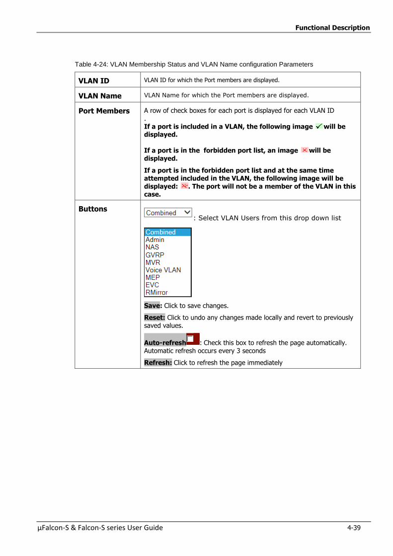
Functional Description
µFalcon-S & Falcon-S series User Guide 4-39
Table 4-24: VLAN Membership Status and VLAN Name configuration Parameters
VLAN ID VLAN ID for which the Port members are displayed.
VLAN Name VLAN Name for which the Port members are displayed.
Port Members A row of check boxes for each port is displayed for each VLAN ID
.
If a port is included in a VLAN, the following image will be displayed.
If a port is in the forbidden port list, an image will be
displayed.
If a port is in the forbidden port list and at the same time attempted included in the VLAN, the following image will be
displayed: . The port will not be a member of the VLAN in this case.
Buttons : Select VLAN Users from this drop down list
Save: Click to save changes.
Reset: Click to undo any changes made locally and revert to previously
saved values.
Auto-refresh : Check this box to refresh the page automatically.
Automatic refresh occurs every 3 seconds
Refresh: Click to refresh the page immediately
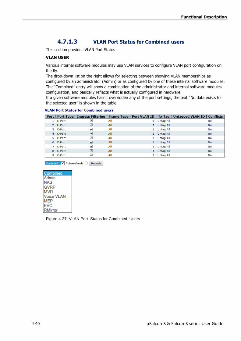
Functional Description
4-40 µFalcon-S & Falcon-S series User Guide
4.7.1.3 VLAN Port Status for Combined users
This section provides VLAN Port Status
VLAN USER
Various internal software modules may use VLAN services to configure VLAN port configuration on
the fly.
The drop-down list on the right allows for selecting between showing VLAN memberships as
configured by an administrator (Admin) or as configured by one of these internal software modules.
The “Combined” entry will show a combination of the administrator and internal software modules
configuration, and basically reflects what is actually configured in hardware.
If a given software modules hasn’t overridden any of the port settings, the text “No data exists for
the selected user” is shown in the table.
Figure 4-27: VLAN Port Status for Combined Users
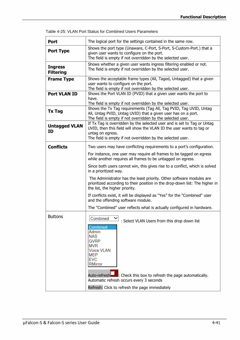
Functional Description
µFalcon-S & Falcon-S series User Guide 4-41
Table 4-25: VLAN Port Status for Combined Users Parameters
Port The logical port for the settings contained in the same row.
Port Type Shows the port type (Unaware, C-Port, S-Port, S-Custom-Port.) that a
given user wants to configure on the port. The field is empty if not overridden by the selected user.
Ingress Filtering
Shows whether a given user wants ingress filtering enabled or not.
The field is empty if not overridden by the selected user.
Frame Type Shows the acceptable frame types (All, Taged, Untagged) that a given
user wants to configure on the port.
The field is empty if not overridden by the selected user.
Port VLAN ID Shows the Port VLAN ID (PVID) that a given user wants the port to
have. The field is empty if not overridden by the selected user.
Tx Tag Shows the Tx Tag requirements (Tag All, Tag PVID, Tag UVID, Untag
All, Untag PVID, Untag UVID) that a given user has on a port. The field is empty if not overridden by the selected user.
Untagged VLAN ID
If Tx Tag is overridden by the selected user and is set to Tag or Untag
UVID, then this field will show the VLAN ID the user wants to tag or untag on egress.
The field is empty if not overridden by the selected user.
Conflicts Two users may have conflicting requirements to a port’s configuration.
For instance, one user may require all frames to be tagged on egress
while another requires all frames to be untagged on egress.
Since both users cannot win, this gives rise to a conflict, which is solved
in a prioritized way.
The Administrator has the least priority. Other software modules are prioritized according to their position in the drop-down list: The higher in
the list, the higher priority.
If conflicts exist, it will be displayed as “Yes” for the “Combined" user
and the offending software module.
The "Combined" user reflects what is actually configured in hardware.
Buttons : Select VLAN Users from this drop down list
Auto-refresh : Check this box to refresh the page automatically. Automatic refresh occurs every 3 seconds
Refresh: Click to refresh the page immediately
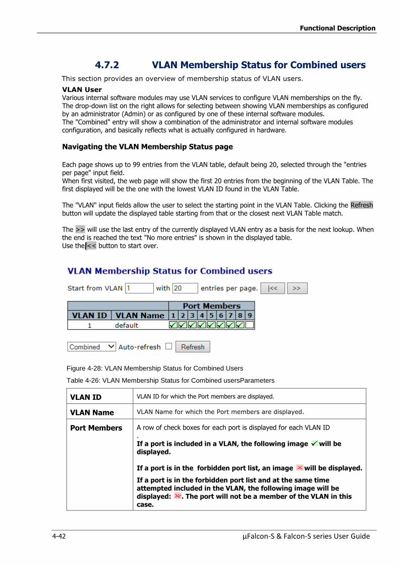
Functional Description
4-42 µFalcon-S & Falcon-S series User Guide
4.7.2 VLAN Membership Status for Combined users
This section provides an overview of membership status of VLAN users.
VLAN User Various internal software modules may use VLAN services to configure VLAN memberships on the fly.
The drop-down list on the right allows for selecting between showing VLAN memberships as configured by an administrator (Admin) or as configured by one of these internal software modules.
The "Combined" entry will show a combination of the administrator and internal software modules configuration, and basically reflects what is actually configured in hardware.
Navigating the VLAN Membership Status page
Each page shows up to 99 entries from the VLAN table, default being 20, selected through the "entries
per page" input field.
When first visited, the web page will show the first 20 entries from the beginning of the VLAN Table. The first displayed will be the one with the lowest VLAN ID found in the VLAN Table.
The "VLAN" input fields allow the user to select the starting point in the VLAN Table. Clicking the Refresh
button will update the displayed table starting from that or the closest next VLAN Table match.
The >> will use the last entry of the currently displayed VLAN entry as a basis for the next lookup. When
the end is reached the text "No more entries" is shown in the displayed table. Use the << button to start over.
Figure 4-28: VLAN Membership Status for Combined Users
Table 4-26: VLAN Membership Status for Combined usersParameters
VLAN ID VLAN ID for which the Port members are displayed.
VLAN Name VLAN Name for which the Port members are displayed.
Port Members A row of check boxes for each port is displayed for each VLAN ID
. If a port is included in a VLAN, the following image will be
displayed.
If a port is in the forbidden port list, an image will be displayed.
If a port is in the forbidden port list and at the same time
attempted included in the VLAN, the following image will be
displayed: . The port will not be a member of the VLAN in this case.
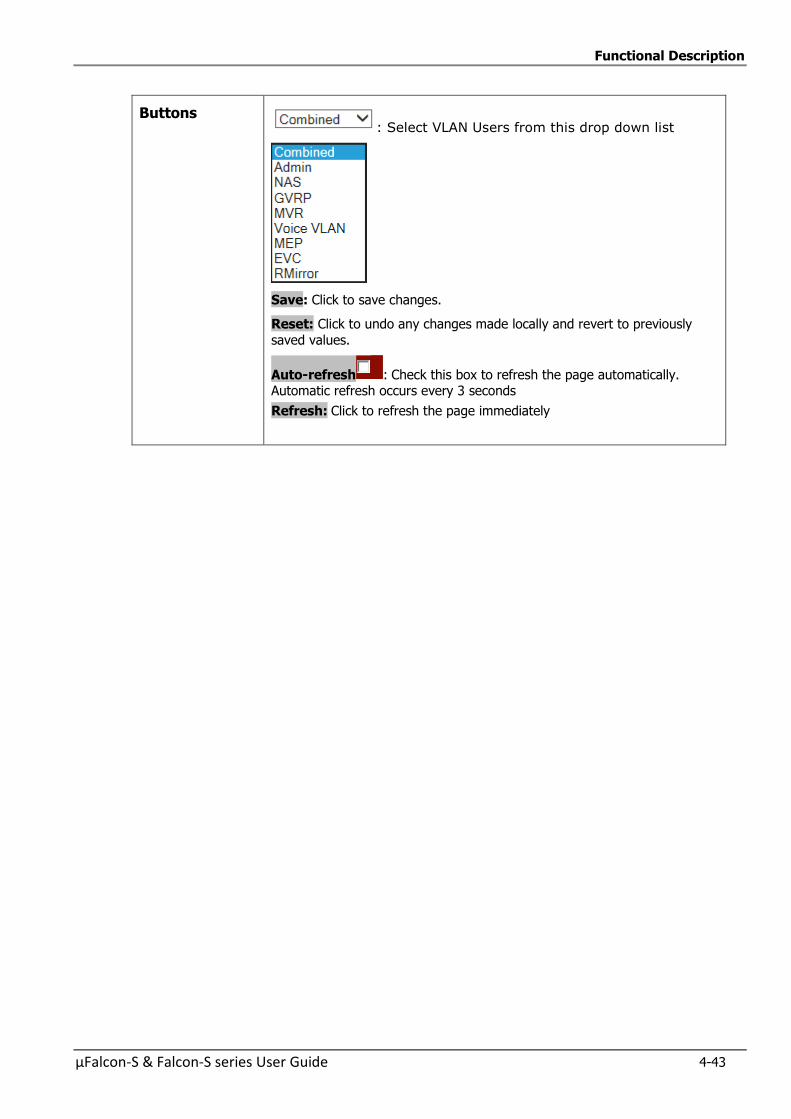
Functional Description
µFalcon-S & Falcon-S series User Guide 4-43
Buttons : Select VLAN Users from this drop down list
Save: Click to save changes.
Reset: Click to undo any changes made locally and revert to previously
saved values.
Auto-refresh : Check this box to refresh the page automatically. Automatic refresh occurs every 3 seconds
Refresh: Click to refresh the page immediately
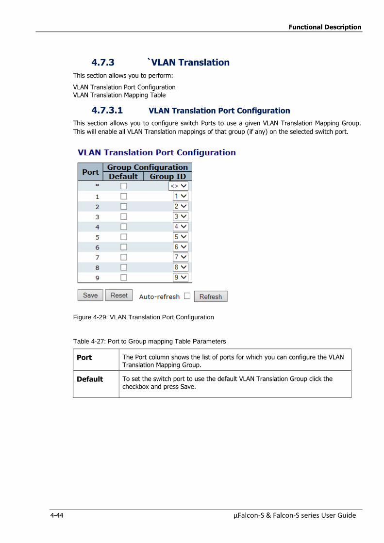
Functional Description
4-44 µFalcon-S & Falcon-S series User Guide
4.7.3 `VLAN Translation
This section allows you to perform:
VLAN Translation Port Configuration
VLAN Translation Mapping Table
4.7.3.1 VLAN Translation Port Configuration
This section allows you to configure switch Ports to use a given VLAN Translation Mapping Group.
This will enable all VLAN Translation mappings of that group (if any) on the selected switch port.
Figure 4-29: VLAN Translation Port Configuration
Table 4-27: Port to Group mapping Table Parameters
Port The Port column shows the list of ports for which you can configure the VLAN
Translation Mapping Group.
Default
To set the switch port to use the default VLAN Translation Group click the
checkbox and press Save.
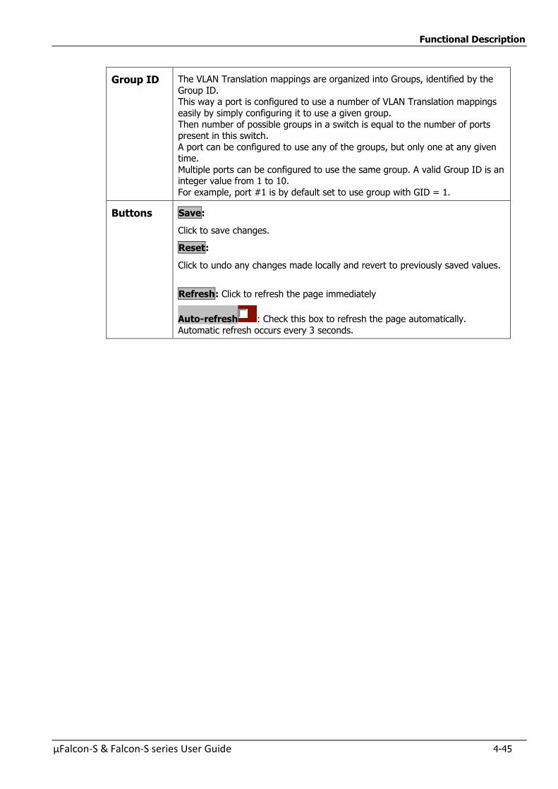
Functional Description
µFalcon-S & Falcon-S series User Guide 4-45
Group ID The VLAN Translation mappings are organized into Groups, identified by the
Group ID. This way a port is configured to use a number of VLAN Translation mappings
easily by simply configuring it to use a given group.
Then number of possible groups in a switch is equal to the number of ports present in this switch.
A port can be configured to use any of the groups, but only one at any given time.
Multiple ports can be configured to use the same group. A valid Group ID is an integer value from 1 to 10.
For example, port #1 is by default set to use group with GID = 1.
Buttons Save:
Click to save changes.
Reset:
Click to undo any changes made locally and revert to previously saved values.
Refresh: Click to refresh the page immediately
Auto-refresh : Check this box to refresh the page automatically.
Automatic refresh occurs every 3 seconds.
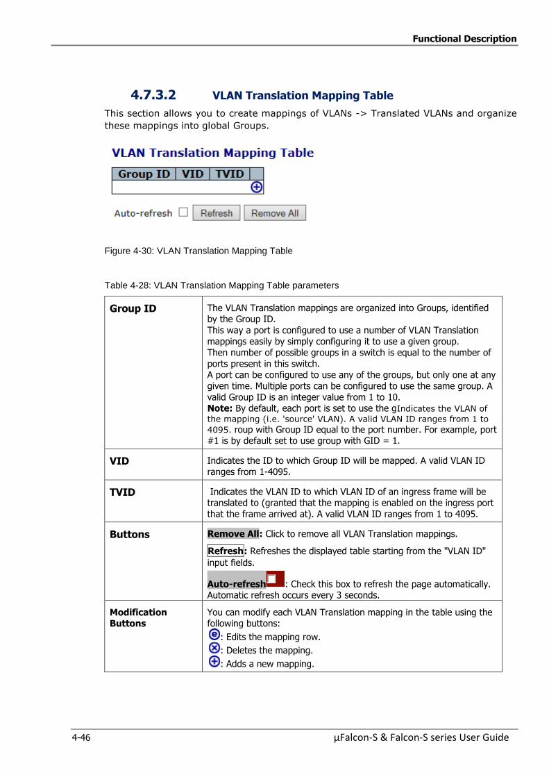
Functional Description
4-46 µFalcon-S & Falcon-S series User Guide
4.7.3.2 VLAN Translation Mapping Table
This section allows you to create mappings of VLANs -> Translated VLANs and organize
these mappings into global Groups.
Figure 4-30: VLAN Translation Mapping Table
Table 4-28: VLAN Translation Mapping Table parameters
Group ID The VLAN Translation mappings are organized into Groups, identified by the Group ID.
This way a port is configured to use a number of VLAN Translation
mappings easily by simply configuring it to use a given group. Then number of possible groups in a switch is equal to the number of
ports present in this switch. A port can be configured to use any of the groups, but only one at any
given time. Multiple ports can be configured to use the same group. A
valid Group ID is an integer value from 1 to 10. Note: By default, each port is set to use the gIndicates the VLAN of
the mapping (i.e. 'source' VLAN). A valid VLAN ID ranges from 1 to
4095. roup with Group ID equal to the port number. For example, port #1 is by default set to use group with GID = 1.
VID Indicates the ID to which Group ID will be mapped. A valid VLAN ID
ranges from 1-4095.
TVID
Indicates the VLAN ID to which VLAN ID of an ingress frame will be translated to (granted that the mapping is enabled on the ingress port
that the frame arrived at). A valid VLAN ID ranges from 1 to 4095.
Buttons Remove All: Click to remove all VLAN Translation mappings.
Refresh: Refreshes the displayed table starting from the "VLAN ID"
input fields.
Auto-refresh : Check this box to refresh the page automatically. Automatic refresh occurs every 3 seconds.
Modification Buttons
You can modify each VLAN Translation mapping in the table using the following buttons:
: Edits the mapping row.
: Deletes the mapping.
: Adds a new mapping.
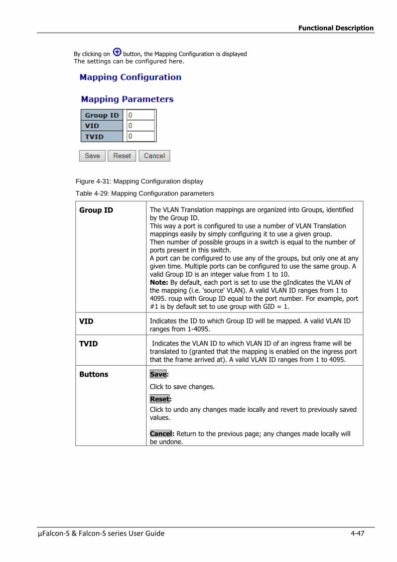
Functional Description
µFalcon-S & Falcon-S series User Guide 4-47
By clicking on button, the Mapping Configuration is displayed
The settings can be configured here.
Figure 4-31: Mapping Configuration display
Table 4-29: Mapping Configuration parameters
Group ID The VLAN Translation mappings are organized into Groups, identified
by the Group ID.
This way a port is configured to use a number of VLAN Translation mappings easily by simply configuring it to use a given group.
Then number of possible groups in a switch is equal to the number of ports present in this switch.
A port can be configured to use any of the groups, but only one at any given time. Multiple ports can be configured to use the same group. A
valid Group ID is an integer value from 1 to 10.
Note: By default, each port is set to use the gIndicates the VLAN of the mapping (i.e. 'source' VLAN). A valid VLAN ID ranges from 1 to
4095. roup with Group ID equal to the port number. For example, port #1 is by default set to use group with GID = 1.
VID Indicates the ID to which Group ID will be mapped. A valid VLAN ID
ranges from 1-4095.
TVID
Indicates the VLAN ID to which VLAN ID of an ingress frame will be
translated to (granted that the mapping is enabled on the ingress port
that the frame arrived at). A valid VLAN ID ranges from 1 to 4095.
Buttons Save:
Click to save changes.
Reset:
Click to undo any changes made locally and revert to previously saved values.
Cancel: Return to the previous page; any changes made locally will be undone.
Functional Description
4-48 µFalcon-S & Falcon-S series User Guide
4.7.4 Provider Bridges (QinQ)
The use of an extra VLAN header (service provider tag) as part of the Ethernet frame header
to provide differentiation between traffic flows (whether a separate service, or a separate
customer) is common in service provider networks. It extends the notion of bridging from that
of bridging between LAN segments or virtual LANs (defined by traditional VLAN tags), to
bridging between customers or services.
Providers can use the service provider VLAN tag to identify Ethernet traffic that belongs to a
specific Service, and give it the correct treatment (e.g. if the service is more important or time
sensitive than others it can get the right QoS handling).
The µFalcon S is designed to serve as an NTU for Metro-Ethernet access applications. Such
applications use the Provider Bridges (802.1ad) standard to enable Ethernet services
implementation.
The Provider Edge Bridge inserts a Service Tag (S-Tag) on all frames received from the
Customer network.
This enables implementation of transparent L2 service for high numbers of customers.
Determination of which service to assign a frame to can be based on:
1. Ingress port – All frames received on a specific ingress port will be assigned to a single
service (encapsulated with the same S-Tag). Such functionality when used for point-to-point service is defined as EPL (Ethernet Private
Line) in MEF specs.
2. Ingress port + C-Tag – A frame received on a specific ingress port will be assigned to a
service based on the port and a table that maps the VLAN tag, on the incoming frame (C-
Tag) to the service tag (S-Tag). Such functionality, when used for point-to-point service, is defined as EVPL (Ethernet
Virtual Private Line) in MEF specs.
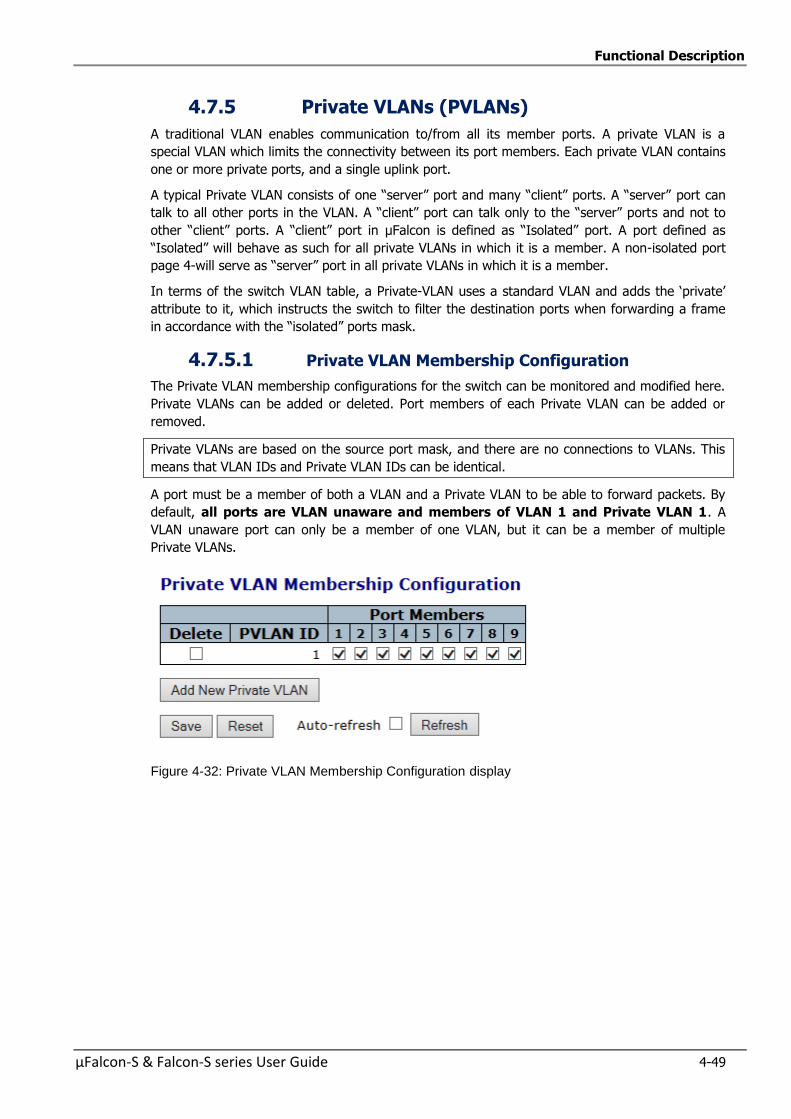
Functional Description
µFalcon-S & Falcon-S series User Guide 4-49
4.7.5 Private VLANs (PVLANs)
A traditional VLAN enables communication to/from all its member ports. A private VLAN is a
special VLAN which limits the connectivity between its port members. Each private VLAN contains
one or more private ports, and a single uplink port.
A typical Private VLAN consists of one “server” port and many “client” ports. A “server” port can
talk to all other ports in the VLAN. A “client” port can talk only to the “server” ports and not to
other “client” ports. A “client” port in µFalcon is defined as “Isolated” port. A port defined as
“Isolated” will behave as such for all private VLANs in which it is a member. A non-isolated port
page 4-will serve as “server” port in all private VLANs in which it is a member.
In terms of the switch VLAN table, a Private-VLAN uses a standard VLAN and adds the ‘private’
attribute to it, which instructs the switch to filter the destination ports when forwarding a frame
in accordance with the “isolated” ports mask.
4.7.5.1 Private VLAN Membership Configuration
The Private VLAN membership configurations for the switch can be monitored and modified here.
Private VLANs can be added or deleted. Port members of each Private VLAN can be added or
removed.
Private VLANs are based on the source port mask, and there are no connections to VLANs. This
means that VLAN IDs and Private VLAN IDs can be identical.
A port must be a member of both a VLAN and a Private VLAN to be able to forward packets. By
default, all ports are VLAN unaware and members of VLAN 1 and Private VLAN 1. A
VLAN unaware port can only be a member of one VLAN, but it can be a member of multiple
Private VLANs.
Figure 4-32: Private VLAN Membership Configuration display
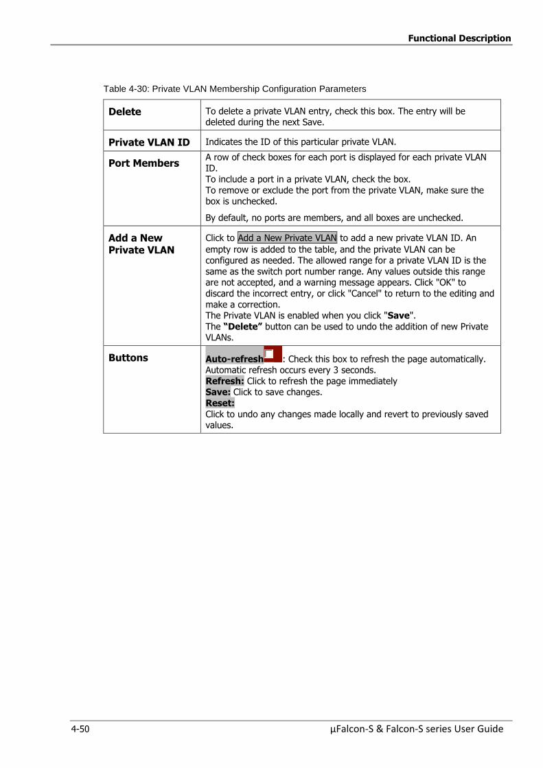
Functional Description
4-50 µFalcon-S & Falcon-S series User Guide
Table 4-30: Private VLAN Membership Configuration Parameters
Delete To delete a private VLAN entry, check this box. The entry will be deleted during the next Save.
Private VLAN ID Indicates the ID of this particular private VLAN.
Port Members A row of check boxes for each port is displayed for each private VLAN
ID. To include a port in a private VLAN, check the box.
To remove or exclude the port from the private VLAN, make sure the box is unchecked.
By default, no ports are members, and all boxes are unchecked.
Add a New Private VLAN
Click to Add a New Private VLAN to add a new private VLAN ID. An
empty row is added to the table, and the private VLAN can be configured as needed. The allowed range for a private VLAN ID is the
same as the switch port number range. Any values outside this range are not accepted, and a warning message appears. Click "OK" to
discard the incorrect entry, or click "Cancel" to return to the editing and
make a correction. The Private VLAN is enabled when you click "Save".
The “Delete” button can be used to undo the addition of new Private VLANs.
Buttons Auto-refresh : Check this box to refresh the page automatically. Automatic refresh occurs every 3 seconds.
Refresh: Click to refresh the page immediately Save: Click to save changes.
Reset:
Click to undo any changes made locally and revert to previously saved values.

Functional Description
µFalcon-S & Falcon-S series User Guide 4-51
4.7.5.2 Port Isolation Configuration
This section is used for enabling or disabling port isolation for ports in a Private VLAN.
A port member of a VLAN can be isolated to other isolated ports on the same VLAN and Private
VLAN.
Figure 4-33: Private VLAN Port Isolation Configuration
Table 4-31: Private VLAN Port Isolation Configuration Parameters
Port Members
A check box is provided for each port of a private VLAN. When checked, port isolation is enabled for that port.
When unchecked, port isolation is disabled for that port. By default, port isolation is disabled for all ports.
Buttons Auto-refresh : Check this box to refresh the page automatically. Automatic refresh occurs every 3 seconds.
Refresh: Click to refresh the page immediately
Save: Click to save changes.
Reset: Click to undo any changes made locally and revert to previously
saved values.
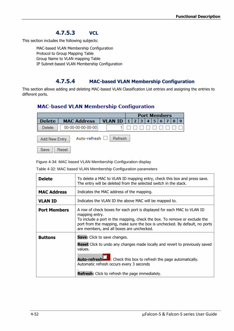
Functional Description
4-52 µFalcon-S & Falcon-S series User Guide
4.7.5.3 VCL
This section includes the following subjects:
MAC-based VLAN Membership Configuration
Protocol to Group Mapping Table
Group Name to VLAN mapping Table
IP Subnet-based VLAN Membership Configuration
4.7.5.4 MAC-based VLAN Membership Configuration
This section allows adding and deleting MAC-based VLAN Classification List entries and assigning the entries to
different ports.
Figure 4-34: MAC based VLAN Membership Configuration display
Table 4-32: MAC based VLAN Membership Configuration parameters
Delete To delete a MAC to VLAN ID mapping entry, check this box and press save.
The entry will be deleted from the selected switch in the stack.
MAC Address Indicates the MAC address of the mapping.
VLAN ID Indicates the VLAN ID the above MAC will be mapped to.
Port Members A row of check boxes for each port is displayed for each MAC to VLAN ID
mapping entry. To include a port in the mapping, check the box. To remove or exclude the
port from the mapping, make sure the box is unchecked. By default, no ports are members, and all boxes are unchecked.
Buttons Save: Click to save changes.
Reset Click to undo any changes made locally and revert to previously saved values.
Auto-refresh : Check this box to refresh the page automatically. Automatic refresh occurs every 3 seconds
. Refresh: Click to refresh the page immediately.
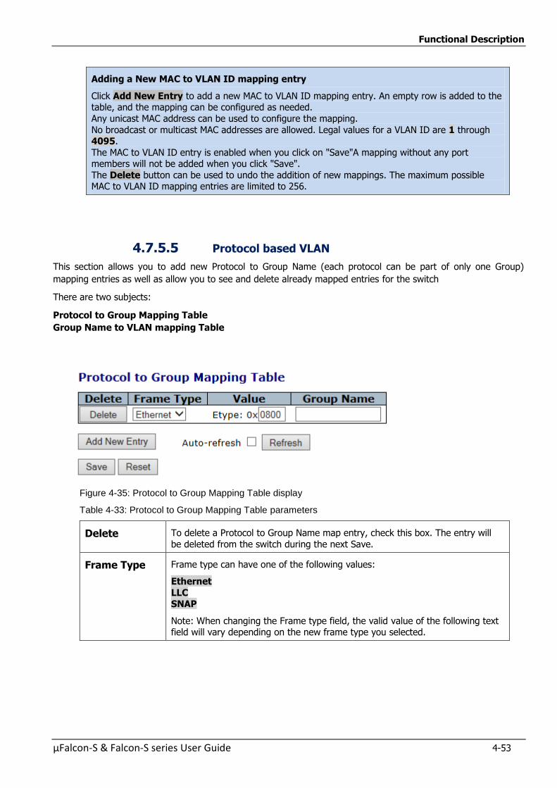
Functional Description
µFalcon-S & Falcon-S series User Guide 4-53
Adding a New MAC to VLAN ID mapping entry
Click Add New Entry to add a new MAC to VLAN ID mapping entry. An empty row is added to the table, and the mapping can be configured as needed.
Any unicast MAC address can be used to configure the mapping.
No broadcast or multicast MAC addresses are allowed. Legal values for a VLAN ID are 1 through 4095.
The MAC to VLAN ID entry is enabled when you click on "Save"A mapping without any port members will not be added when you click "Save".
The Delete button can be used to undo the addition of new mappings. The maximum possible MAC to VLAN ID mapping entries are limited to 256.
4.7.5.5 Protocol based VLAN
This section allows you to add new Protocol to Group Name (each protocol can be part of only one Group)
mapping entries as well as allow you to see and delete already mapped entries for the switch
There are two subjects:
Protocol to Group Mapping Table
Group Name to VLAN mapping Table
Figure 4-35: Protocol to Group Mapping Table display
Table 4-33: Protocol to Group Mapping Table parameters
Delete To delete a Protocol to Group Name map entry, check this box. The entry will
be deleted from the switch during the next Save.
Frame Type Frame type can have one of the following values:
Ethernet
LLC SNAP
Note: When changing the Frame type field, the valid value of the following text field will vary depending on the new frame type you selected.
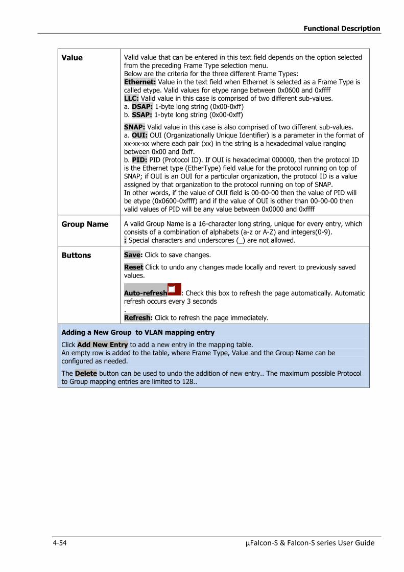
Functional Description
4-54 µFalcon-S & Falcon-S series User Guide
Value Valid value that can be entered in this text field depends on the option selected
from the preceding Frame Type selection menu. Below are the criteria for the three different Frame Types:
Ethernet: Value in the text field when Ethernet is selected as a Frame Type is
called etype. Valid values for etype range between 0x0600 and 0xffff LLC: Valid value in this case is comprised of two different sub-values.
a. DSAP: 1-byte long string (0x00-0xff) b. SSAP: 1-byte long string (0x00-0xff)
SNAP: Valid value in this case is also comprised of two different sub-values. a. OUI: OUI (Organizationally Unique Identifier) is a parameter in the format of
xx-xx-xx where each pair (xx) in the string is a hexadecimal value ranging
between 0x00 and 0xff. b. PID: PID (Protocol ID). If OUI is hexadecimal 000000, then the protocol ID
is the Ethernet type (EtherType) field value for the protocol running on top of SNAP; if OUI is an OUI for a particular organization, the protocol ID is a value
assigned by that organization to the protocol running on top of SNAP.
In other words, if the value of OUI field is 00-00-00 then the value of PID will be etype (0x0600-0xffff) and if the value of OUI is other than 00-00-00 then
valid values of PID will be any value between 0x0000 and 0xffff
Group Name A valid Group Name is a 16-character long string, unique for every entry, which
consists of a combination of alphabets (a-z or A-Z) and integers(0-9).
: Special characters and underscores (_) are not allowed.
Buttons Save: Click to save changes.
Reset Click to undo any changes made locally and revert to previously saved
values.
Auto-refresh : Check this box to refresh the page automatically. Automatic refresh occurs every 3 seconds
.
Refresh: Click to refresh the page immediately.
Adding a New Group to VLAN mapping entry
Click Add New Entry to add a new entry in the mapping table. An empty row is added to the table, where Frame Type, Value and the Group Name can be
configured as needed.
The Delete button can be used to undo the addition of new entry.. The maximum possible Protocol to Group mapping entries are limited to 128..
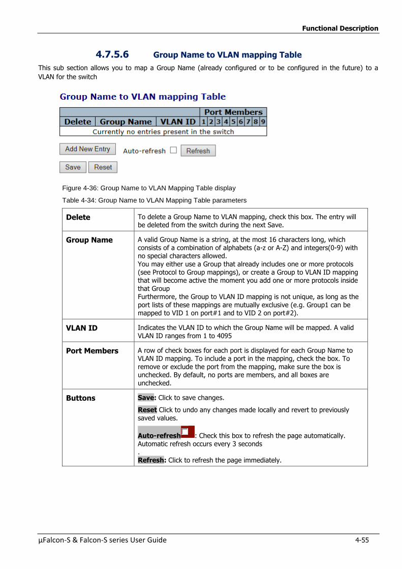
Functional Description
µFalcon-S & Falcon-S series User Guide 4-55
4.7.5.6 Group Name to VLAN mapping Table
This sub section allows you to map a Group Name (already configured or to be configured in the future) to a
VLAN for the switch
Figure 4-36: Group Name to VLAN Mapping Table display
Table 4-34: Group Name to VLAN Mapping Table parameters
Delete To delete a Group Name to VLAN mapping, check this box. The entry will be deleted from the switch during the next Save.
Group Name A valid Group Name is a string, at the most 16 characters long, which
consists of a combination of alphabets (a-z or A-Z) and integers(0-9) with no special characters allowed.
You may either use a Group that already includes one or more protocols
(see Protocol to Group mappings), or create a Group to VLAN ID mapping that will become active the moment you add one or more protocols inside
that Group Furthermore, the Group to VLAN ID mapping is not unique, as long as the
port lists of these mappings are mutually exclusive (e.g. Group1 can be mapped to VID 1 on port#1 and to VID 2 on port#2).
VLAN ID Indicates the VLAN ID to which the Group Name will be mapped. A valid
VLAN ID ranges from 1 to 4095
Port Members A row of check boxes for each port is displayed for each Group Name to VLAN ID mapping. To include a port in the mapping, check the box. To
remove or exclude the port from the mapping, make sure the box is unchecked. By default, no ports are members, and all boxes are
unchecked.
Buttons Save: Click to save changes.
Reset Click to undo any changes made locally and revert to previously
saved values.
Auto-refresh : Check this box to refresh the page automatically.
Automatic refresh occurs every 3 seconds .
Refresh: Click to refresh the page immediately.
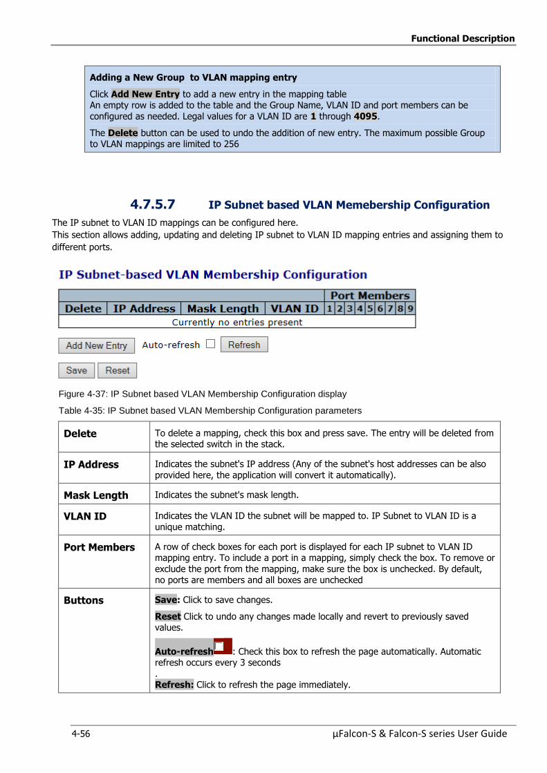
Functional Description
4-56 µFalcon-S & Falcon-S series User Guide
Adding a New Group to VLAN mapping entry
Click Add New Entry to add a new entry in the mapping table An empty row is added to the table and the Group Name, VLAN ID and port members can be
configured as needed. Legal values for a VLAN ID are 1 through 4095.
The Delete button can be used to undo the addition of new entry. The maximum possible Group to VLAN mappings are limited to 256
4.7.5.7 IP Subnet based VLAN Memebership Configuration
The IP subnet to VLAN ID mappings can be configured here.
This section allows adding, updating and deleting IP subnet to VLAN ID mapping entries and assigning them to
different ports.
Figure 4-37: IP Subnet based VLAN Membership Configuration display
Table 4-35: IP Subnet based VLAN Membership Configuration parameters
Delete To delete a mapping, check this box and press save. The entry will be deleted from the selected switch in the stack.
IP Address Indicates the subnet's IP address (Any of the subnet's host addresses can be also
provided here, the application will convert it automatically).
Mask Length Indicates the subnet's mask length.
VLAN ID Indicates the VLAN ID the subnet will be mapped to. IP Subnet to VLAN ID is a
unique matching.
Port Members A row of check boxes for each port is displayed for each IP subnet to VLAN ID mapping entry. To include a port in a mapping, simply check the box. To remove or
exclude the port from the mapping, make sure the box is unchecked. By default, no ports are members and all boxes are unchecked
Buttons Save: Click to save changes.
Reset Click to undo any changes made locally and revert to previously saved values.
Auto-refresh : Check this box to refresh the page automatically. Automatic refresh occurs every 3 seconds
. Refresh: Click to refresh the page immediately.
Functional Description
µFalcon-S & Falcon-S series User Guide 4-57
Adding a New IP subnet based VLAN
Click Add New Entry: to add a new IP subnet to VLAN ID mapping entry. An empty row is added to the table, and the mapping can be configured as needed. Any IP address/mask can be configured for the mapping. Legal values for the VLAN ID are 1 to 4095. The IP subnet to VLAN ID mapping entry is enabled when you click on "Save".
The Delete button can be used to undo the addition of new mappings The maximum possible IP subnet to VLAN ID mappings are limited 128
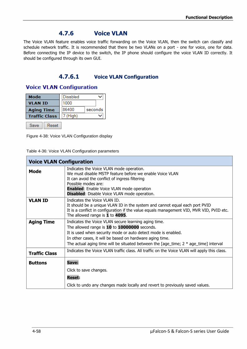
Functional Description
4-58 µFalcon-S & Falcon-S series User Guide
4.7.6 Voice VLAN
The Voice VLAN feature enables voice traffic forwarding on the Voice VLAN, then the switch can classify and
schedule network traffic. It is recommended that there be two VLANs on a port - one for voice, one for data.
Before connecting the IP device to the switch, the IP phone should configure the voice VLAN ID correctly. It
should be configured through its own GUI.
4.7.6.1 Voice VLAN Configuration
Figure 4-38: Voice VLAN Configuration display
Table 4-36: Voice VLAN Configuration parameters
Voice VLAN Configuration
Mode Indicates the Voice VLAN mode operation. We must disable MSTP feature before we enable Voice VLAN
It can avoid the conflict of ingress filtering
Possible modes are: Enabled: Enable Voice VLAN mode operation
Disabled: Disable Voice VLAN mode operation.
VLAN ID Indicates the Voice VLAN ID. It should be a unique VLAN ID in the system and cannot equal each port PVID
It is a conflict in configuration if the value equals management VID, MVR VID, PVID etc. The allowed range is 1 to 4095.
Aging Time Indicates the Voice VLAN secure learning aging time.
The allowed range is 10 to 10000000 seconds.
It is used when security mode or auto detect mode is enabled.
In other cases, it will be based on hardware aging time.
The actual aging time will be situated between the [age_time; 2 * age_time] interval
Traffic Class Indicates the Voice VLAN traffic class. All traffic on the Voice VLAN will apply this class.
Buttons Save:
Click to save changes.
Reset:
Click to undo any changes made locally and revert to previously saved values.
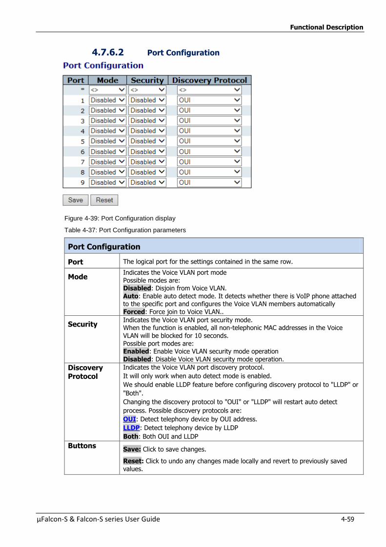
Functional Description
µFalcon-S & Falcon-S series User Guide 4-59
4.7.6.2 Port Configuration
Figure 4-39: Port Configuration display
Table 4-37: Port Configuration parameters
Port Configuration
Port The logical port for the settings contained in the same row.
Mode Indicates the Voice VLAN port mode
Possible modes are: Disabled: Disjoin from Voice VLAN.
Auto: Enable auto detect mode. It detects whether there is VoIP phone attached to the specific port and configures the Voice VLAN members automatically
Forced: Force join to Voice VLAN..
Security Indicates the Voice VLAN port security mode. When the function is enabled, all non-telephonic MAC addresses in the Voice
VLAN will be blocked for 10 seconds.
Possible port modes are: Enabled: Enable Voice VLAN security mode operation
Disabled: Disable Voice VLAN security mode operation.
Discovery Protocol
Indicates the Voice VLAN port discovery protocol.
It will only work when auto detect mode is enabled.
We should enable LLDP feature before configuring discovery protocol to "LLDP" or
"Both".
Changing the discovery protocol to "OUI" or "LLDP" will restart auto detect
process. Possible discovery protocols are:
OUI: Detect telephony device by OUI address.
LLDP: Detect telephony device by LLDP
Both: Both OUI and LLDP
Buttons Save: Click to save changes.
Reset: Click to undo any changes made locally and revert to previously saved
values.

Functional Description
4-60 µFalcon-S & Falcon-S series User Guide
4.7.6.3 Voice VLAN OUI Table Configure VOICE VLAN OUI table on this page. The maximum number of entries is 16.
Modifying the OUI table will restart auto detection of OUI process
OUI is the organizationally unique identifier. An OUI address is a globally unique identifier assigned to a vendor by IEEE. You can determine which vendor a device belongs to according to the OUI address
which forms the first 24 bits of a MAC address.
Figure 4-40: Voice VLAN OUI Table display
Table 4-38: Voice VLAN OUI Table parameters
Delete Check to delete the entry. It will be deleted during the next save.
Telephony
OUI
A telephony OUI address is a globally unique identifier assigned to a vendor by
IEEE.
It must be 6 characters long and the input format is "xx-xx-xx" (x is a hexadecimal digit).
Description
The description of OUI address. Normally, it describes which vendor telephony
device it belongs to. The allowed string length is 0 to 32.
Buttons Add New Entry: Click to add a new access management entry.
Save:
Click to save changes.
Reset:
Click to undo any changes made locally and revert to previously saved values.

Functional Description
µFalcon-S & Falcon-S series User Guide 4-61
4.7.7 Multicast VLAN Registration (MVR)
This section provides MVR related configurations.
The MVR feature enables multicast traffic forwarding on the Multicast VLANs.
In a multicast television application, a PC or a network television or a set-top box can receive the multicast
stream. Multiple set-top boxes or PCs can be connected to one subscriber port, which is a switch port
configured as an MVR receiver port. When a subscriber selects a channel, the set-top box or PC sends an
IGMP/MLD report message to Switch A to join the appropriate multicast group address. Uplink ports that send
and receive multicast data to and from the multicast VLAN are called MVR source ports.
It is allowed to create at maximum 4 MVR VLANs with corresponding channel profile for each Multicast VLAN.
The channel profile is defined by the IPMC Profile, which provides the filtering conditions.
The MVR includes the following subjects:
MVR Configuration
VLAN Interface Setting
Immediate Leave Setting
MVR Statistics
MVR Channels (Groups) Information
MVR SFM Information
4.7.7.1 MVR Configurations
Figure 4-41: MVR Configurations
Table 4-39: MVR Configuration parameters
MVR Mode
Enable/Disable the Global MVR
. The Unregistered Flooding control depends on the current configuration in IGMP/MLD Snooping.
It is suggested to enable Unregistered Flooding control when the MVR group table is
full.
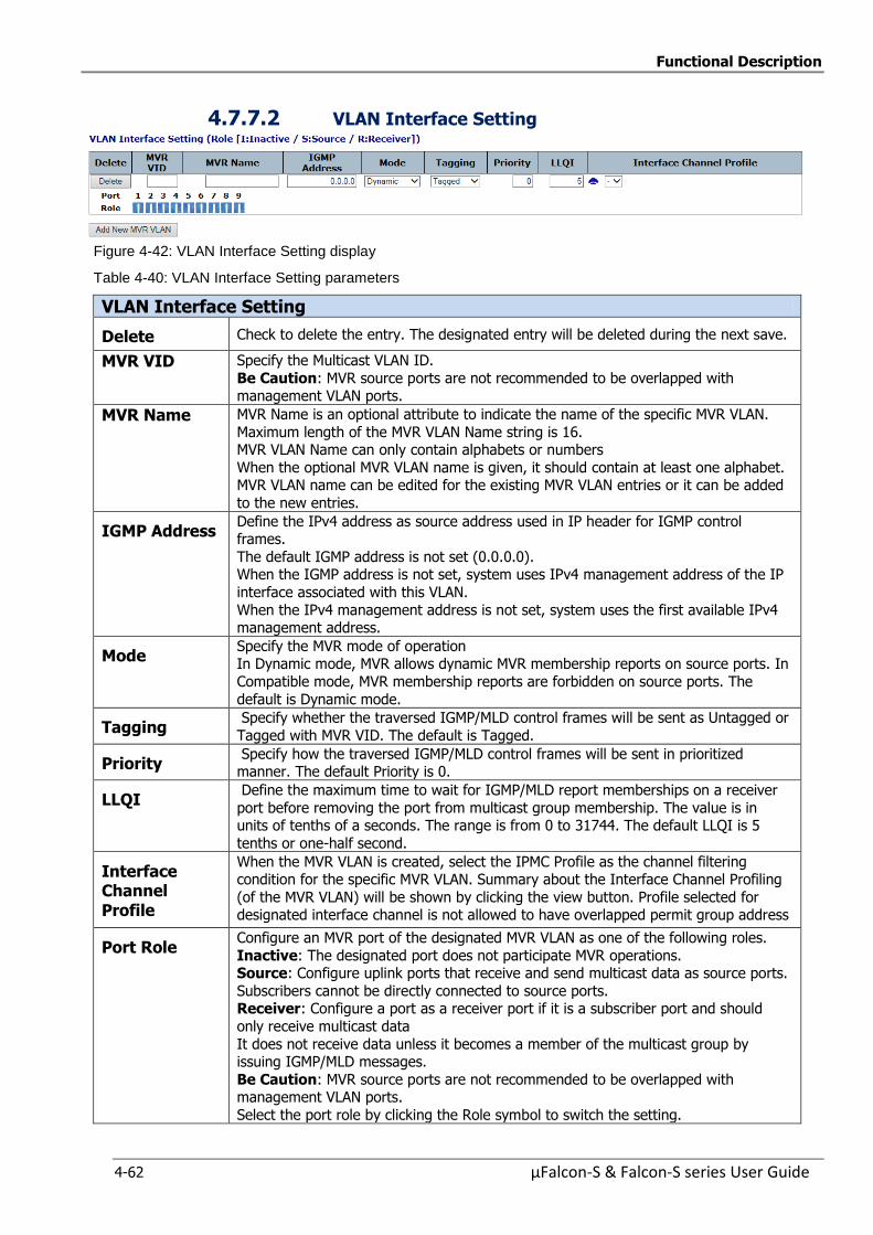
Functional Description
4-62 µFalcon-S & Falcon-S series User Guide
4.7.7.2 VLAN Interface Setting
Figure 4-42: VLAN Interface Setting display
Table 4-40: VLAN Interface Setting parameters
VLAN Interface Setting
Delete Check to delete the entry. The designated entry will be deleted during the next save.
MVR VID Specify the Multicast VLAN ID.
Be Caution: MVR source ports are not recommended to be overlapped with management VLAN ports.
MVR Name MVR Name is an optional attribute to indicate the name of the specific MVR VLAN.
Maximum length of the MVR VLAN Name string is 16. MVR VLAN Name can only contain alphabets or numbers
When the optional MVR VLAN name is given, it should contain at least one alphabet. MVR VLAN name can be edited for the existing MVR VLAN entries or it can be added
to the new entries.
IGMP Address Define the IPv4 address as source address used in IP header for IGMP control frames.
The default IGMP address is not set (0.0.0.0). When the IGMP address is not set, system uses IPv4 management address of the IP
interface associated with this VLAN.
When the IPv4 management address is not set, system uses the first available IPv4 management address.
Mode Specify the MVR mode of operation In Dynamic mode, MVR allows dynamic MVR membership reports on source ports. In
Compatible mode, MVR membership reports are forbidden on source ports. The
default is Dynamic mode.
Tagging Specify whether the traversed IGMP/MLD control frames will be sent as Untagged or
Tagged with MVR VID. The default is Tagged.
Priority Specify how the traversed IGMP/MLD control frames will be sent in prioritized manner. The default Priority is 0.
LLQI Define the maximum time to wait for IGMP/MLD report memberships on a receiver
port before removing the port from multicast group membership. The value is in units of tenths of a seconds. The range is from 0 to 31744. The default LLQI is 5
tenths or one-half second.
Interface Channel Profile
When the MVR VLAN is created, select the IPMC Profile as the channel filtering condition for the specific MVR VLAN. Summary about the Interface Channel Profiling
(of the MVR VLAN) will be shown by clicking the view button. Profile selected for designated interface channel is not allowed to have overlapped permit group address
Port Role Configure an MVR port of the designated MVR VLAN as one of the following roles.
Inactive: The designated port does not participate MVR operations. Source: Configure uplink ports that receive and send multicast data as source ports.
Subscribers cannot be directly connected to source ports. Receiver: Configure a port as a receiver port if it is a subscriber port and should
only receive multicast data
It does not receive data unless it becomes a member of the multicast group by issuing IGMP/MLD messages.
Be Caution: MVR source ports are not recommended to be overlapped with management VLAN ports.
Select the port role by clicking the Role symbol to switch the setting.

Functional Description
µFalcon-S & Falcon-S series User Guide 4-63
I indicates Inactive; S indicates Source; R indicates Receiver
The default Role is Inactive.
Buttons Add New Click MVR VLAN: Click to add new MVR VLAN. Specify the VID and configure the new entry. Click "Save".
Save: Click to save changes.
Reset: Click to undo any changes made locally and revert to previously saved
values.
4.7.7.3 Immediate Leave Setting
Figure 4-43: Immediate Leave Setting display
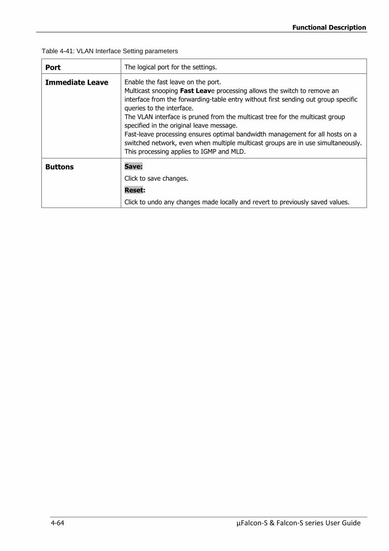
Functional Description
4-64 µFalcon-S & Falcon-S series User Guide
Table 4-41: VLAN Interface Setting parameters
Port The logical port for the settings.
Immediate Leave Enable the fast leave on the port.
Multicast snooping Fast Leave processing allows the switch to remove an
interface from the forwarding-table entry without first sending out group specific
queries to the interface.
The VLAN interface is pruned from the multicast tree for the multicast group
specified in the original leave message.
Fast-leave processing ensures optimal bandwidth management for all hosts on a
switched network, even when multiple multicast groups are in use simultaneously.
This processing applies to IGMP and MLD.
Buttons Save:
Click to save changes.
Reset:
Click to undo any changes made locally and revert to previously saved values.
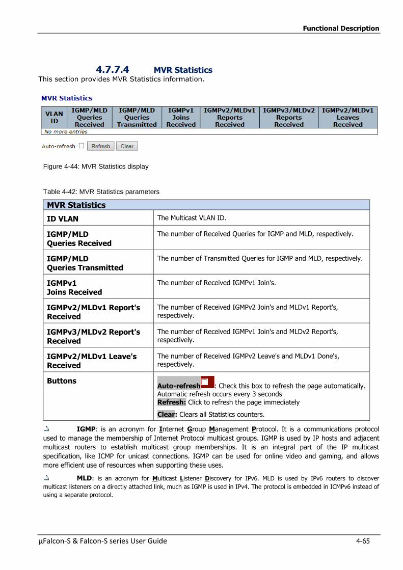
Functional Description
µFalcon-S & Falcon-S series User Guide 4-65
4.7.7.4 MVR Statistics This section provides MVR Statistics information.
Figure 4-44: MVR Statistics display
Table 4-42: MVR Statistics parameters
MVR Statistics
ID VLAN The Multicast VLAN ID.
IGMP/MLD Queries Received
The number of Received Queries for IGMP and MLD, respectively.
IGMP/MLD Queries Transmitted
The number of Transmitted Queries for IGMP and MLD, respectively.
IGMPv1 Joins Received
The number of Received IGMPv1 Join's.
IGMPv2/MLDv1 Report's Received
The number of Received IGMPv2 Join's and MLDv1 Report's, respectively.
IGMPv3/MLDv2 Report's Received
The number of Received IGMPv1 Join's and MLDv2 Report's,
respectively.
IGMPv2/MLDv1 Leave's Received
The number of Received IGMPv2 Leave's and MLDv1 Done's, respectively.
Buttons Auto-refresh : Check this box to refresh the page automatically. Automatic refresh occurs every 3 seconds
Refresh: Click to refresh the page immediately
Clear: Clears all Statistics counters.
IGMP: is an acronym for Internet Group Management Protocol. It is a communications protocol
used to manage the membership of Internet Protocol multicast groups. IGMP is used by IP hosts and adjacent
multicast routers to establish multicast group memberships. It is an integral part of the IP multicast
specification, like ICMP for unicast connections. IGMP can be used for online video and gaming, and allows
more efficient use of resources when supporting these uses.
MLD: is an acronym for Multicast Listener Discovery for IPv6. MLD is used by IPv6 routers to discover
multicast listeners on a directly attached link, much as IGMP is used in IPv4. The protocol is embedded in ICMPv6 instead of
using a separate protocol.
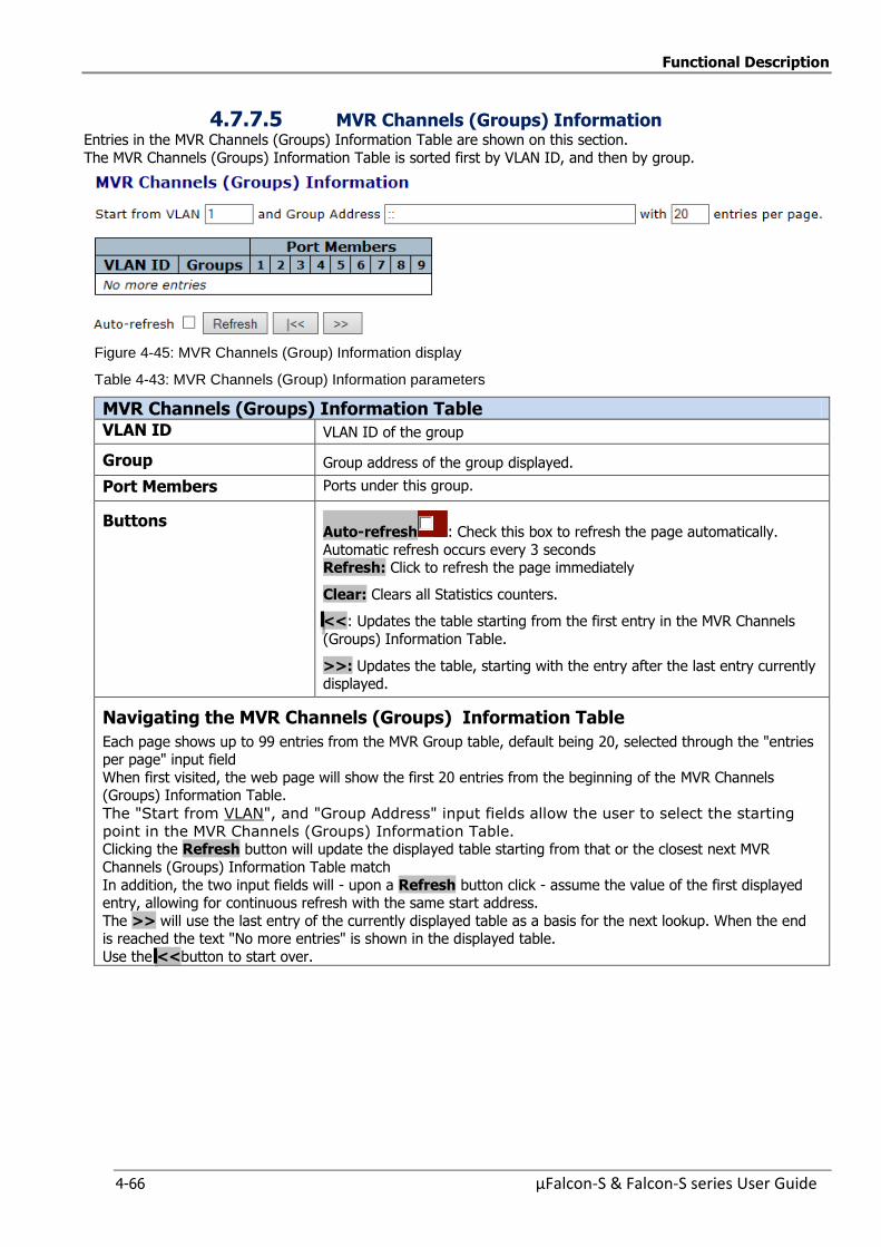
Functional Description
4-66 µFalcon-S & Falcon-S series User Guide
4.7.7.5 MVR Channels (Groups) Information Entries in the MVR Channels (Groups) Information Table are shown on this section.
The MVR Channels (Groups) Information Table is sorted first by VLAN ID, and then by group.
Figure 4-45: MVR Channels (Group) Information display
Table 4-43: MVR Channels (Group) Information parameters
MVR Channels (Groups) Information Table VLAN ID VLAN ID of the group
Group Group address of the group displayed.
Port Members Ports under this group.
Buttons Auto-refresh : Check this box to refresh the page automatically.
Automatic refresh occurs every 3 seconds Refresh: Click to refresh the page immediately
Clear: Clears all Statistics counters.
<<: Updates the table starting from the first entry in the MVR Channels
(Groups) Information Table.
>>: Updates the table, starting with the entry after the last entry currently displayed.
Navigating the MVR Channels (Groups) Information Table
Each page shows up to 99 entries from the MVR Group table, default being 20, selected through the "entries per page" input field
When first visited, the web page will show the first 20 entries from the beginning of the MVR Channels (Groups) Information Table.
The "Start from VLAN", and "Group Address" input fields allow the user to select the starting
point in the MVR Channels (Groups) Information Table. Clicking the Refresh button will update the displayed table starting from that or the closest next MVR
Channels (Groups) Information Table match
In addition, the two input fields will - upon a Refresh button click - assume the value of the first displayed entry, allowing for continuous refresh with the same start address.
The >> will use the last entry of the currently displayed table as a basis for the next lookup. When the end is reached the text "No more entries" is shown in the displayed table.
Use the <<button to start over.

Functional Description
µFalcon-S & Falcon-S series User Guide 4-67
4.7.7.6 MVR SFM Information
Entries in the MVR SFM Information Table are shown on this page. The MVR SFM (Source-Filtered
Multicast) Information Table also contains the SSM (Source-Specific Multicast) information. This
table is sorted first by VLAN ID, then by group, and then by Port. Different source addresses belong
to the same group are treated as single entry.
Figure 4-46: MVR SFM Information display
Table 4-44: MVR SFM Information parameters
MVR SFM) Information Table ID VLAN VLAN ID of the group
Groups Group address of the group displayed
Port Switch port number.
Mode Indicates the filtering mode maintained per (VLAN ID, port number, Group Address)
basis. It can be either Include or Exclude.
Source Adress IP Address of the source
Currently, the maximum number of IP source address for filtering (per group) is 8
When there is no any source filtering address, the text "None" is shown in the Source Address field.
Type Indicates the Type. It can be either Allow or Deny.
Hardware Filter Switch
Indicates whether data plane destined to the specific group address from the source IPv4/IPv6 address could be handled by the chip or not.
Buttons Auto-refresh : Check this box to refresh the page automatically. Automatic refresh occurs every 3 seconds
. Refresh: Click to refresh the page immediately
Clear: Clears all Statistics counters.
<<: Updates the table starting from the first entry in the MVR Channels (Groups)
Information Table.
>>: Updates the table, starting with the entry after the last entry currently
displayed.
Navigating the MVR SFM Information Table
Each page shows up to 99 entries from the MVR SFM Information table, default being 20, selected
through the "entries per page" input field
When first visited, the web page will show the first 20 entries from the beginning of the MVR SFM Information table.
Clicking the Refresh button will update the displayed table starting from that or the closest next MVR SFM Information Table match
In addition, the two input fields will - upon a Refresh button click - assume the value of the first
displayed entry, allowing for continuous refresh with the same start address. The >> will use the last entry of the currently displayed table as a basis for the next lookup. When the
end is reached the text "No more entries" is shown in the displayed table. Use the << button to start over.
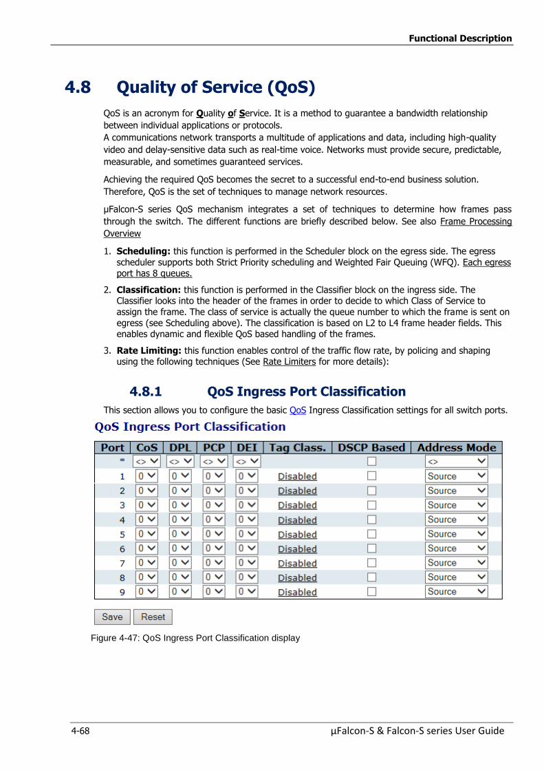
Functional Description
4-68 µFalcon-S & Falcon-S series User Guide
4.8 Quality of Service (QoS)
QoS is an acronym for Quality of Service. It is a method to guarantee a bandwidth relationship
between individual applications or protocols.
A communications network transports a multitude of applications and data, including high-quality
video and delay-sensitive data such as real-time voice. Networks must provide secure, predictable,
measurable, and sometimes guaranteed services.
Achieving the required QoS becomes the secret to a successful end-to-end business solution.
Therefore, QoS is the set of techniques to manage network resources.
µFalcon-S series QoS mechanism integrates a set of techniques to determine how frames pass
through the switch. The different functions are briefly described below. See also Frame Processing
Overview
1. Scheduling: this function is performed in the Scheduler block on the egress side. The egress
scheduler supports both Strict Priority scheduling and Weighted Fair Queuing (WFQ). Each egress port has 8 queues.
2. Classification: this function is performed in the Classifier block on the ingress side. The Classifier looks into the header of the frames in order to decide to which Class of Service to
assign the frame. The class of service is actually the queue number to which the frame is sent on
egress (see Scheduling above). The classification is based on L2 to L4 frame header fields. This enables dynamic and flexible QoS based handling of the frames.
3. Rate Limiting: this function enables control of the traffic flow rate, by policing and shaping using the following techniques (See Rate Limiters for more details):
4.8.1 QoS Ingress Port Classification
This section allows you to configure the basic QoS Ingress Classification settings for all switch ports.
Figure 4-47: QoS Ingress Port Classification display
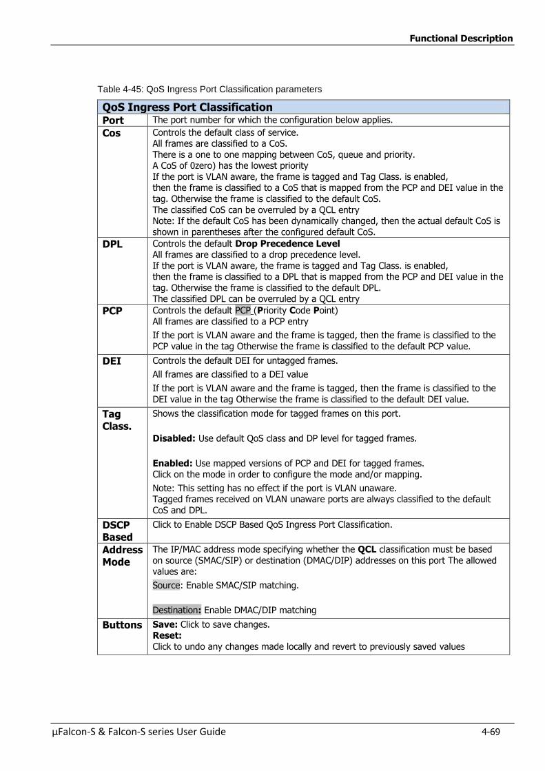
Functional Description
µFalcon-S & Falcon-S series User Guide 4-69
Table 4-45: QoS Ingress Port Classification parameters
QoS Ingress Port Classification Port The port number for which the configuration below applies.
Cos Controls the default class of service. All frames are classified to a CoS.
There is a one to one mapping between CoS, queue and priority. A CoS of 0zero) has the lowest priority
If the port is VLAN aware, the frame is tagged and Tag Class. is enabled, then the frame is classified to a CoS that is mapped from the PCP and DEI value in the
tag. Otherwise the frame is classified to the default CoS.
The classified CoS can be overruled by a QCL entry Note: If the default CoS has been dynamically changed, then the actual default CoS is
shown in parentheses after the configured default CoS.
DPL Controls the default Drop Precedence Level All frames are classified to a drop precedence level.
If the port is VLAN aware, the frame is tagged and Tag Class. is enabled, then the frame is classified to a DPL that is mapped from the PCP and DEI value in the
tag. Otherwise the frame is classified to the default DPL. The classified DPL can be overruled by a QCL entry
PCP Controls the default PCP (Priority Code Point)
All frames are classified to a PCP entry
If the port is VLAN aware and the frame is tagged, then the frame is classified to the
PCP value in the tag Otherwise the frame is classified to the default PCP value.
DEI Controls the default DEI for untagged frames.
All frames are classified to a DEI value
If the port is VLAN aware and the frame is tagged, then the frame is classified to the
DEI value in the tag Otherwise the frame is classified to the default DEI value.
Tag Class.
Shows the classification mode for tagged frames on this port.
Disabled: Use default QoS class and DP level for tagged frames.
Enabled: Use mapped versions of PCP and DEI for tagged frames. Click on the mode in order to configure the mode and/or mapping.
Note: This setting has no effect if the port is VLAN unaware. Tagged frames received on VLAN unaware ports are always classified to the default
CoS and DPL.
DSCP Based
Click to Enable DSCP Based QoS Ingress Port Classification.
Address Mode
The IP/MAC address mode specifying whether the QCL classification must be based
on source (SMAC/SIP) or destination (DMAC/DIP) addresses on this port The allowed values are:
Source: Enable SMAC/SIP matching.
Destination: Enable DMAC/DIP matching
Buttons Save: Click to save changes. Reset:
Click to undo any changes made locally and revert to previously saved values

Functional Description
4-70 µFalcon-S & Falcon-S series User Guide
4.8.2 QoS Ingress Port Policers
This section allows you to configure the Policer settings for all switch ports.
A policer can limit the bandwidth of received frames. It is located in front of the ingress queue.
Figure 4-48: QoS Ingress Port Policers
Table 4-46: QoS Ingress Port Policers Parameters
Port The port number for which the configuration below applies.
Enabled Controls whether the policer is enabled on this switch port.
Rate Controls the rate for the policer. The default value is 500. This value is
restricted to 100-1000000 when the "Unit" is "kbps" or "fps", and it is restricted to 1-3300 when the "Unit" is "Mbps" or "kfps
Unit Controls the unit of measure for the policer rate as kbps, Mbps, fps or kfps . The default value is "kbps".
Flow Control If flow control is enabled and the port is in flow control mode, then
pause frames are sent instead of discarding frames.
Buttons Save:
Click to save changes.
Reset:
Click to undo any changes made locally and revert to previously saved
values.
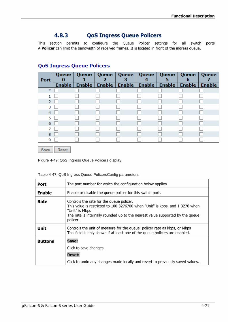
Functional Description
µFalcon-S & Falcon-S series User Guide 4-71
4.8.3 QoS Ingress Queue Policers
This section permits to configure the Queue Policer settings for all switch ports
A Policer can limit the bandwidth of received frames. It is located in front of the ingress queue.
Figure 4-49: QoS Ingress Queue Policers display
Table 4-47: QoS Ingress Queue PolicersConfig parameters
Port The port number for which the configuration below applies.
Enable Enable or disable the queue policer for this switch port.
Rate Controls the rate for the queue policer.
This value is restricted to 100-3276700 when "Unit" is kbps, and 1-3276 when "Unit" is Mbps
The rate is internally rounded up to the nearest value supported by the queue policer.
Unit Controls the unit of measure for the queue policer rate as kbps, or Mbps
This field is only shown if at least one of the queue policers are enabled.
Buttons Save:
Click to save changes.
Reset:
Click to undo any changes made locally and revert to previously saved values.
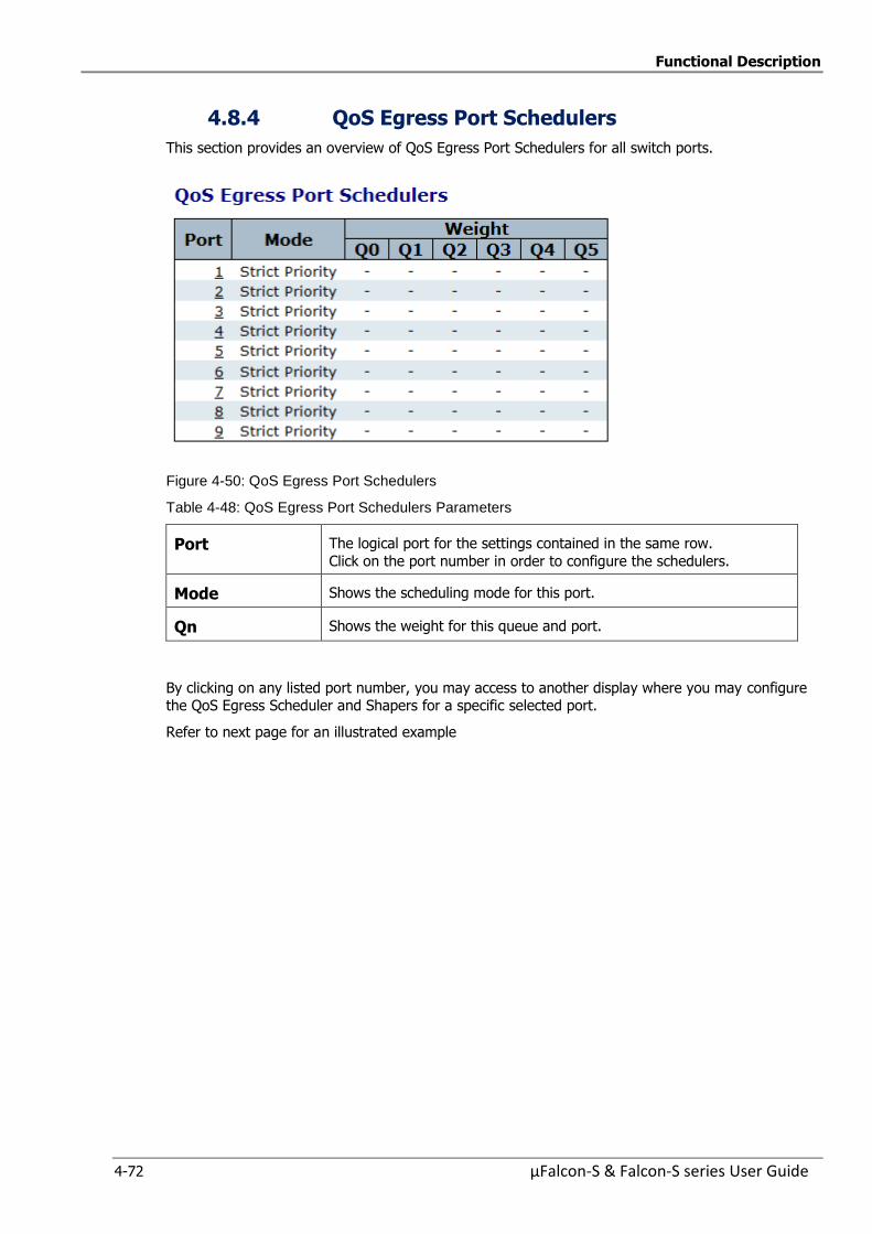
Functional Description
4-72 µFalcon-S & Falcon-S series User Guide
4.8.4 QoS Egress Port Schedulers
This section provides an overview of QoS Egress Port Schedulers for all switch ports.
Figure 4-50: QoS Egress Port Schedulers
Table 4-48: QoS Egress Port Schedulers Parameters
Port The logical port for the settings contained in the same row.
Click on the port number in order to configure the schedulers.
Mode Shows the scheduling mode for this port.
Qn Shows the weight for this queue and port.
By clicking on any listed port number, you may access to another display where you may configure the QoS Egress Scheduler and Shapers for a specific selected port.
Refer to next page for an illustrated example
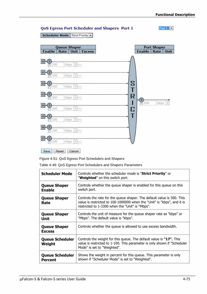
Functional Description
µFalcon-S & Falcon-S series User Guide 4-73
Figure 4-51: QoS Egress Port Schedulers and Shapers
Table 4-49: QoS Egress Port Schedulers and Shapers Parameters
Scheduler Mode Controls whether the scheduler mode is "Strict Priority" or
"Weighted" on this switch port.
Queue Shaper Enable
Controls whether the queue shaper is enabled for this queue on this
switch port.
Queue Shaper Rate
Controls the rate for the queue shaper. The default value is 500. This
value is restricted to 100-1000000 when the "Unit" is "kbps", and it is restricted to 1-3300 when the "Unit" is "Mbps".
Queue Shaper Unit
Controls the unit of measure for the queue shaper rate as "kbps" or "Mbps". The default value is "kbps".
Queue Shaper Excess
Controls whether the queue is allowed to use excess bandwidth.
Queue Scheduler Weight
Controls the weight for this queue. The default value is "17". This value is restricted to 1-100. This parameter is only shown if "Scheduler
Mode" is set to "Weighted".
Queue Scheduler Percent
Shows the weight in percent for this queue. This parameter is only shown if "Scheduler Mode" is set to "Weighted".
Functional Description
4-74 µFalcon-S & Falcon-S series User Guide
Port Shaper Enable
Controls whether the port shaper is enabled for this switch port.
Port Shaper Rate Controls the rate for the port shaper. The default value is 500. This value is restricted to 100-1000000 when the "Unit" is "kbps", and it is
restricted to 1-3300 when the "Unit" is "Mbps".
Port Shaper Unit Controls the unit of measure for the port shaper rate as "kbps" or "Mbps". The default value is "kbps".
Buttons Save:
Click to save changes.
Reset:
Click to undo any changes made locally and revert to previously saved values.
Cancel: Click to undo any changes made locally and return to the previous page.
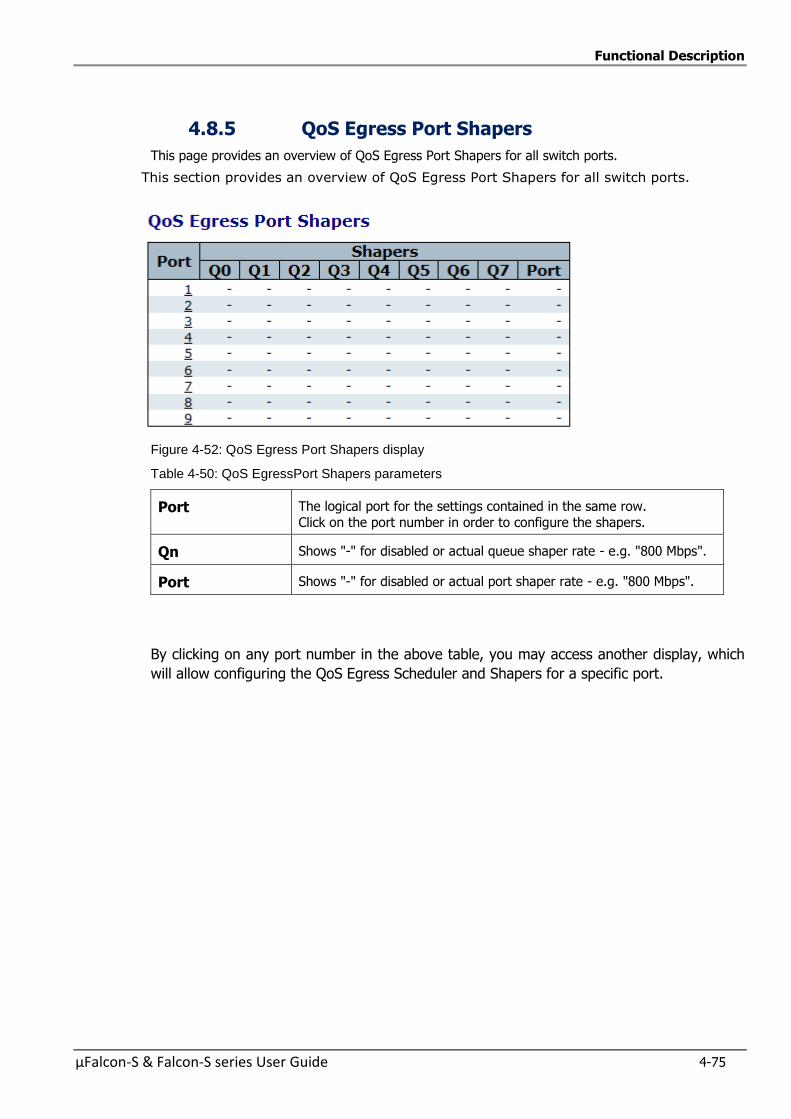
Functional Description
µFalcon-S & Falcon-S series User Guide 4-75
4.8.5 QoS Egress Port Shapers
This page provides an overview of QoS Egress Port Shapers for all switch ports.
This section provides an overview of QoS Egress Port Shapers for all switch ports.
Figure 4-52: QoS Egress Port Shapers display
Table 4-50: QoS EgressPort Shapers parameters
Port The logical port for the settings contained in the same row.
Click on the port number in order to configure the shapers.
Qn Shows "-" for disabled or actual queue shaper rate - e.g. "800 Mbps".
Port Shows "-" for disabled or actual port shaper rate - e.g. "800 Mbps".
By clicking on any port number in the above table, you may access another display, which
will allow configuring the QoS Egress Scheduler and Shapers for a specific port.
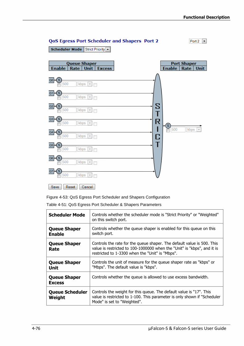
Functional Description
4-76 µFalcon-S & Falcon-S series User Guide
Figure 4-53: QoS Egress Port Scheduler and Shapers Configuration
Table 4-51: QoS Egress Port Scheduler & Shapers Parameters
Scheduler Mode Controls whether the scheduler mode is "Strict Priority" or "Weighted"
on this switch port.
Queue Shaper Enable
Controls whether the queue shaper is enabled for this queue on this switch port.
Queue Shaper Rate
Controls the rate for the queue shaper. The default value is 500. This
value is restricted to 100-1000000 when the "Unit" is "kbps", and it is restricted to 1-3300 when the "Unit" is "Mbps".
Queue Shaper Unit
Controls the unit of measure for the queue shaper rate as "kbps" or
"Mbps". The default value is "kbps".
Queue Shaper Excess
Controls whether the queue is allowed to use excess bandwidth.
Queue Scheduler Weight
Controls the weight for this queue. The default value is "17". This
value is restricted to 1-100. This parameter is only shown if "Scheduler Mode" is set to "Weighted".
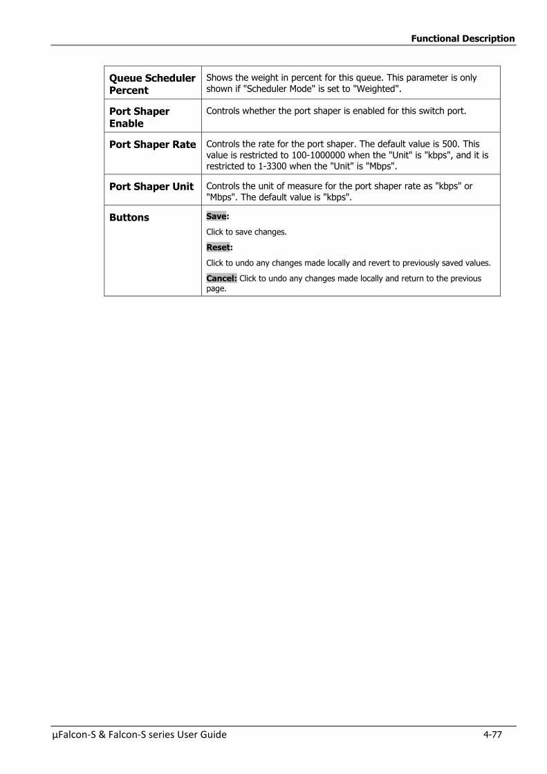
Functional Description
µFalcon-S & Falcon-S series User Guide 4-77
Queue Scheduler Percent
Shows the weight in percent for this queue. This parameter is only
shown if "Scheduler Mode" is set to "Weighted".
Port Shaper Enable
Controls whether the port shaper is enabled for this switch port.
Port Shaper Rate Controls the rate for the port shaper. The default value is 500. This
value is restricted to 100-1000000 when the "Unit" is "kbps", and it is restricted to 1-3300 when the "Unit" is "Mbps".
Port Shaper Unit Controls the unit of measure for the port shaper rate as "kbps" or
"Mbps". The default value is "kbps".
Buttons Save:
Click to save changes.
Reset:
Click to undo any changes made locally and revert to previously saved values.
Cancel: Click to undo any changes made locally and return to the previous page.
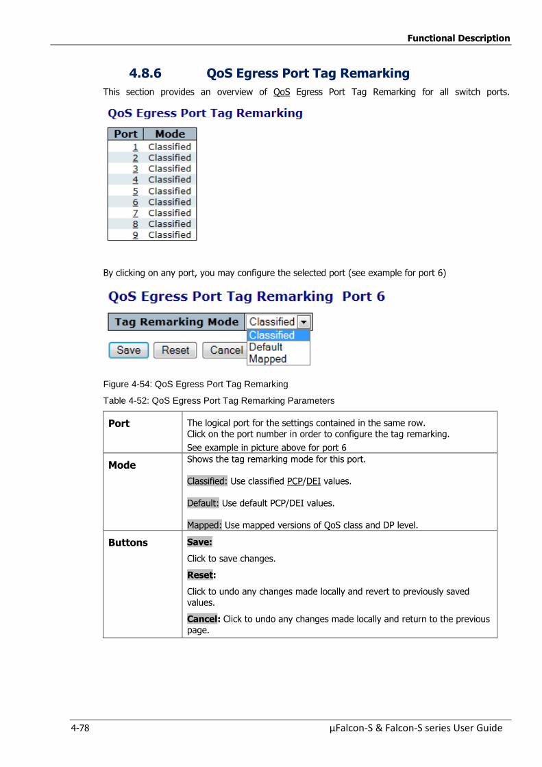
Functional Description
4-78 µFalcon-S & Falcon-S series User Guide
4.8.6 QoS Egress Port Tag Remarking
This section provides an overview of QoS Egress Port Tag Remarking for all switch ports.
By clicking on any port, you may configure the selected port (see example for port 6)
Figure 4-54: QoS Egress Port Tag Remarking
Table 4-52: QoS Egress Port Tag Remarking Parameters
Port The logical port for the settings contained in the same row.
Click on the port number in order to configure the tag remarking.
See example in picture above for port 6
Mode Shows the tag remarking mode for this port.
Classified: Use classified PCP/DEI values.
Default: Use default PCP/DEI values.
Mapped: Use mapped versions of QoS class and DP level.
Buttons Save:
Click to save changes.
Reset:
Click to undo any changes made locally and revert to previously saved
values.
Cancel: Click to undo any changes made locally and return to the previous
page.
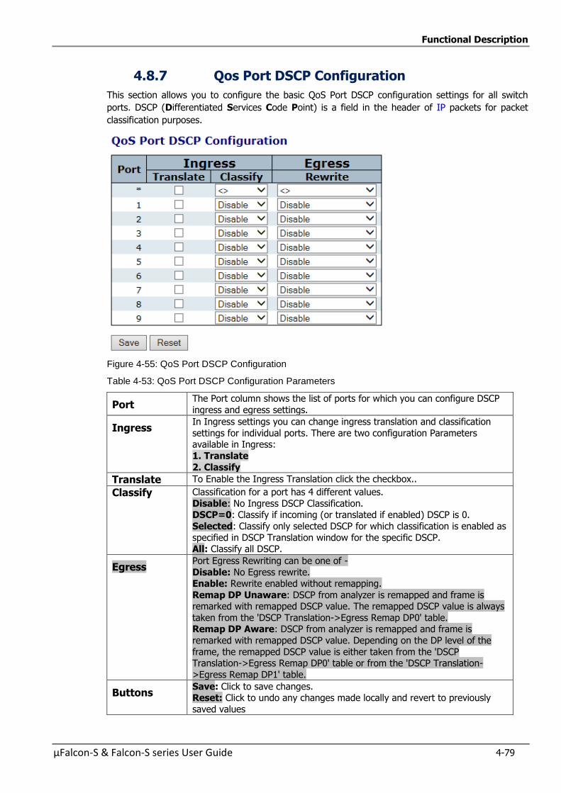
Functional Description
µFalcon-S & Falcon-S series User Guide 4-79
4.8.7 Qos Port DSCP Configuration
This section allows you to configure the basic QoS Port DSCP configuration settings for all switch
ports. DSCP (Differentiated Services Code Point) is a field in the header of IP packets for packet
classification purposes.
Figure 4-55: QoS Port DSCP Configuration
Table 4-53: QoS Port DSCP Configuration Parameters
Port The Port column shows the list of ports for which you can configure DSCP
ingress and egress settings.
Ingress In Ingress settings you can change ingress translation and classification
settings for individual ports. There are two configuration Parameters available in Ingress:
1. Translate
2. Classify
Translate To Enable the Ingress Translation click the checkbox..
Classify Classification for a port has 4 different values.
Disable: No Ingress DSCP Classification. DSCP=0: Classify if incoming (or translated if enabled) DSCP is 0.
Selected: Classify only selected DSCP for which classification is enabled as
specified in DSCP Translation window for the specific DSCP. All: Classify all DSCP.
Egress Port Egress Rewriting can be one of -
Disable: No Egress rewrite. Enable: Rewrite enabled without remapping.
Remap DP Unaware: DSCP from analyzer is remapped and frame is remarked with remapped DSCP value. The remapped DSCP value is always
taken from the 'DSCP Translation->Egress Remap DP0' table. Remap DP Aware: DSCP from analyzer is remapped and frame is
remarked with remapped DSCP value. Depending on the DP level of the
frame, the remapped DSCP value is either taken from the 'DSCP Translation->Egress Remap DP0' table or from the 'DSCP Translation-
>Egress Remap DP1' table.
Buttons Save: Click to save changes. Reset: Click to undo any changes made locally and revert to previously
saved values
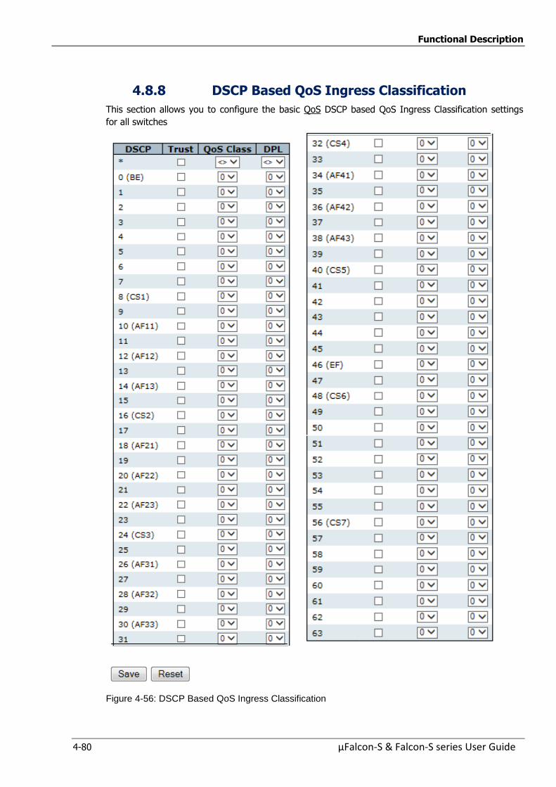
Functional Description
4-80 µFalcon-S & Falcon-S series User Guide
4.8.8 DSCP Based QoS Ingress Classification
This section allows you to configure the basic QoS DSCP based QoS Ingress Classification settings
for all switches
Figure 4-56: DSCP Based QoS Ingress Classification

Functional Description
µFalcon-S & Falcon-S series User Guide 4-81
Table 4-54: DSCP Based QoS Ingress Classification Parameters
DSCP DSCP is an acronym for Differentiated Services Code Point. It is a field in the header of IP packets for packet classification purposes
Maximum number of supported DSCP values is 64.
Trust Controls whether a specific DSCP value is trusted.
Only frames with trusted DSCP values are mapped to a specific QoS class and
Drop Precedence Level. Frames with untrusted DSCP values are treated as a non-IP frame.
QoS Class QoS class value can be any of (0-7)
DPL Drop Precedence Level (0-1)
Every incoming frame is classified to a Drop Precedence Level (DP level),
which is used throughout the device for providing congestion control
guarantee to the frame according to what was configured for that specific DP level.
A DP level of 0 (zero) corresponds to 'Committed' (Green) frames and a DP level of 1 or higher corresponds to 'Discard Eligible' (Yellow) frames.
Buttons Save: Click to save changes.
Reset:
Click to undo any changes made locally and revert to previously saved values
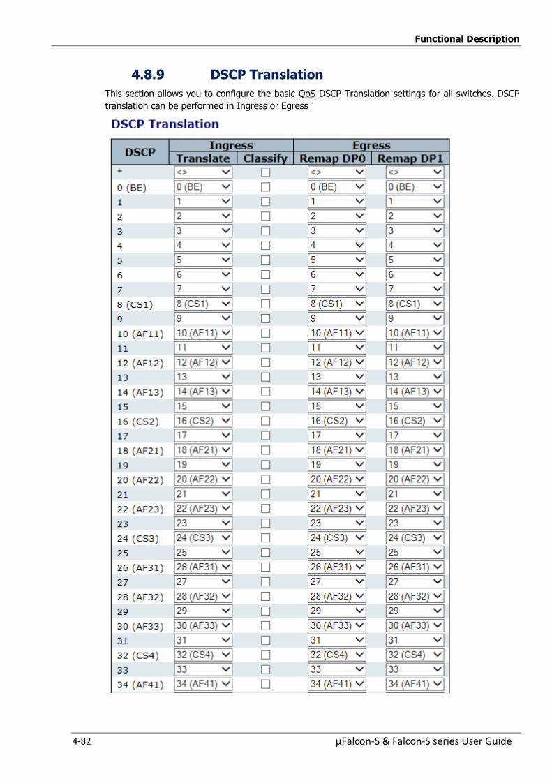
Functional Description
4-82 µFalcon-S & Falcon-S series User Guide
4.8.9 DSCP Translation
This section allows you to configure the basic QoS DSCP Translation settings for all switches. DSCP
translation can be performed in Ingress or Egress
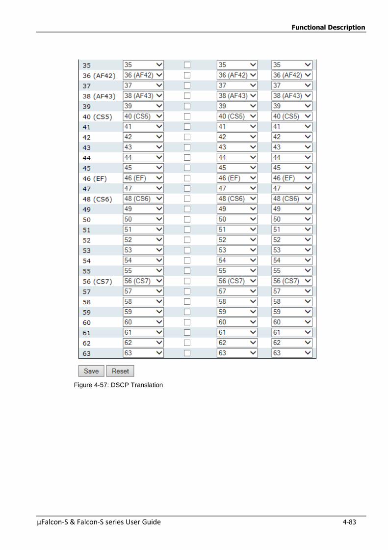
Functional Description
µFalcon-S & Falcon-S series User Guide 4-83
Figure 4-57: DSCP Translation
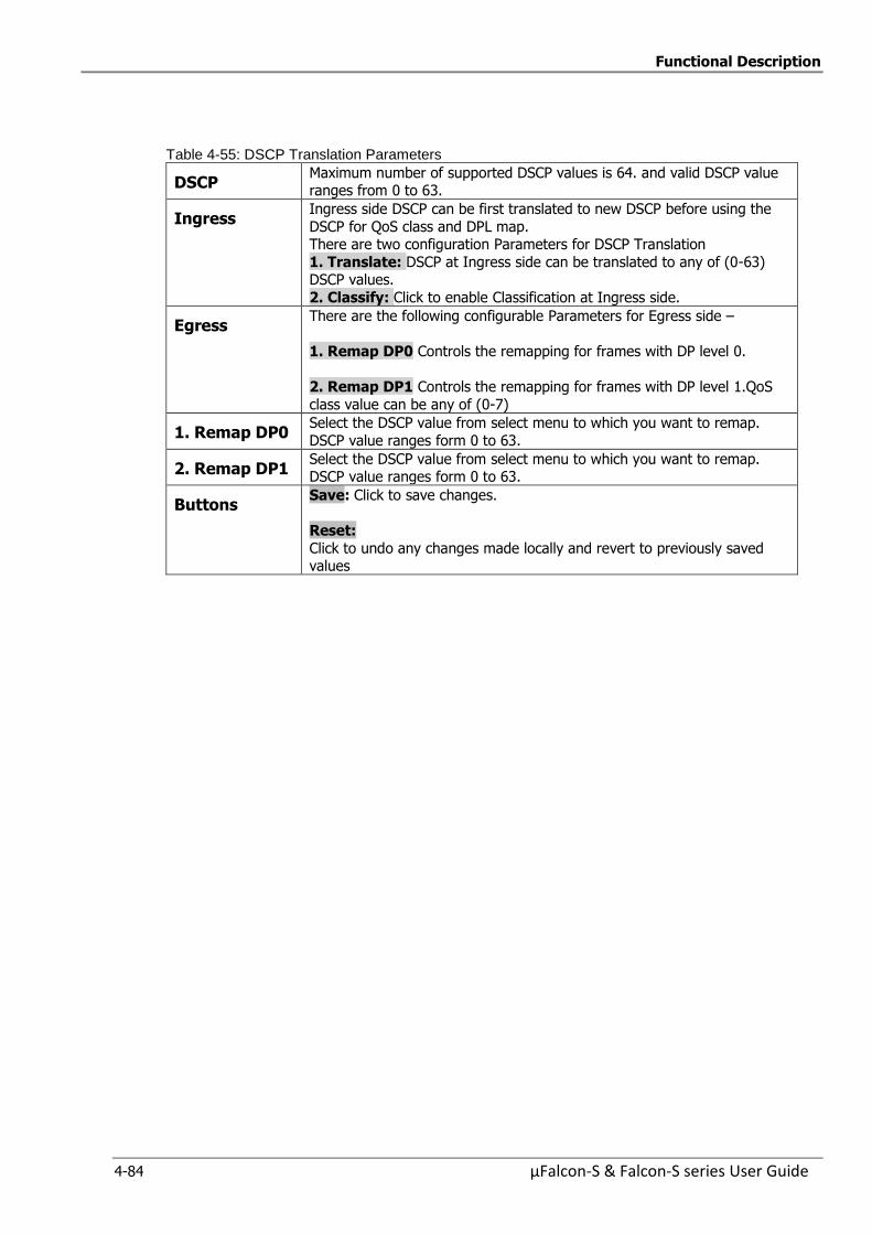
Functional Description
4-84 µFalcon-S & Falcon-S series User Guide
Table 4-55: DSCP Translation Parameters
DSCP Maximum number of supported DSCP values is 64. and valid DSCP value ranges from 0 to 63.
Ingress Ingress side DSCP can be first translated to new DSCP before using the
DSCP for QoS class and DPL map. There are two configuration Parameters for DSCP Translation
1. Translate: DSCP at Ingress side can be translated to any of (0-63) DSCP values.
2. Classify: Click to enable Classification at Ingress side.
Egress There are the following configurable Parameters for Egress side –
1. Remap DP0 Controls the remapping for frames with DP level 0.
2. Remap DP1 Controls the remapping for frames with DP level 1.QoS
class value can be any of (0-7)
1. Remap DP0 Select the DSCP value from select menu to which you want to remap.
DSCP value ranges form 0 to 63.
2. Remap DP1 Select the DSCP value from select menu to which you want to remap. DSCP value ranges form 0 to 63.
Buttons Save: Click to save changes.
Reset:
Click to undo any changes made locally and revert to previously saved values
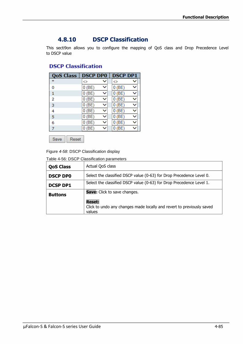
Functional Description
µFalcon-S & Falcon-S series User Guide 4-85
4.8.10 DSCP Classification
This secti9on allows you to configure the mapping of QoS class and Drop Precedence Level
to DSCP value
Figure 4-58: DSCP Classification display
Table 4-56: DSCP Classification parameters
QoS Class Actual QoS class
DSCP DP0 Select the classified DSCP value (0-63) for Drop Precedence Level 0.
DCSP DP1 Select the classified DSCP value (0-63) for Drop Precedence Level 1.
Buttons Save: Click to save changes.
Reset:
Click to undo any changes made locally and revert to previously saved values
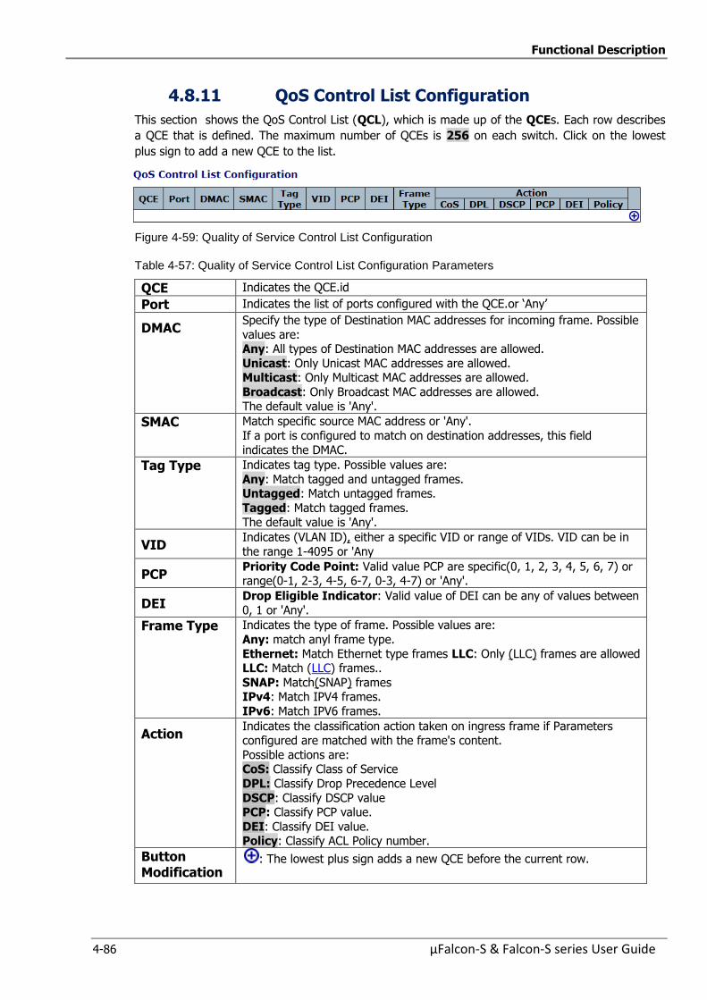
Functional Description
4-86 µFalcon-S & Falcon-S series User Guide
4.8.11 QoS Control List Configuration
This section shows the QoS Control List (QCL), which is made up of the QCEs. Each row describes
a QCE that is defined. The maximum number of QCEs is 256 on each switch. Click on the lowest
plus sign to add a new QCE to the list.
Figure 4-59: Quality of Service Control List Configuration
Table 4-57: Quality of Service Control List Configuration Parameters
QCE Indicates the QCE.id
Port Indicates the list of ports configured with the QCE.or ‘Any’
DMAC Specify the type of Destination MAC addresses for incoming frame. Possible
values are: Any: All types of Destination MAC addresses are allowed.
Unicast: Only Unicast MAC addresses are allowed. Multicast: Only Multicast MAC addresses are allowed.
Broadcast: Only Broadcast MAC addresses are allowed.
The default value is 'Any'.
SMAC Match specific source MAC address or 'Any'.
If a port is configured to match on destination addresses, this field
indicates the DMAC.
Tag Type Indicates tag type. Possible values are:
Any: Match tagged and untagged frames. Untagged: Match untagged frames.
Tagged: Match tagged frames.
The default value is 'Any'.
VID Indicates (VLAN ID), either a specific VID or range of VIDs. VID can be in
the range 1-4095 or 'Any
PCP Priority Code Point: Valid value PCP are specific(0, 1, 2, 3, 4, 5, 6, 7) or range(0-1, 2-3, 4-5, 6-7, 0-3, 4-7) or 'Any'.
DEI Drop Eligible Indicator: Valid value of DEI can be any of values between
0, 1 or 'Any'.
Frame Type Indicates the type of frame. Possible values are:
Any: match anyl frame type.
Ethernet: Match Ethernet type frames LLC: Only (LLC) frames are allowed LLC: Match (LLC) frames..
SNAP: Match(SNAP) frames IPv4: Match IPV4 frames.
IPv6: Match IPV6 frames.
Action Indicates the classification action taken on ingress frame if Parameters configured are matched with the frame's content.
Possible actions are: CoS: Classify Class of Service
DPL: Classify Drop Precedence Level
DSCP: Classify DSCP value PCP: Classify PCP value.
DEI: Classify DEI value. Policy: Classify ACL Policy number.
Button Modification
: The lowest plus sign adds a new QCE before the current row.
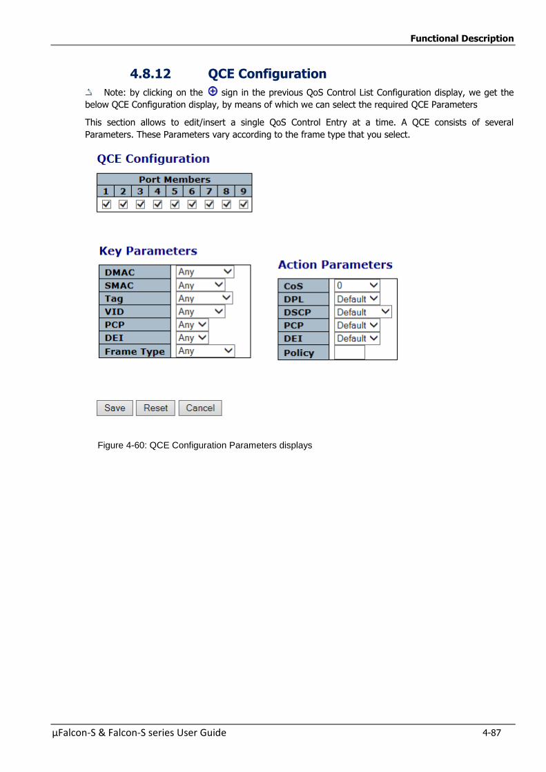
Functional Description
µFalcon-S & Falcon-S series User Guide 4-87
4.8.12 QCE Configuration
Note: by clicking on the sign in the previous QoS Control List Configuration display, we get the
below QCE Configuration display, by means of which we can select the required QCE Parameters
This section allows to edit/insert a single QoS Control Entry at a time. A QCE consists of several
Parameters. These Parameters vary according to the frame type that you select.
Figure 4-60: QCE Configuration Parameters displays
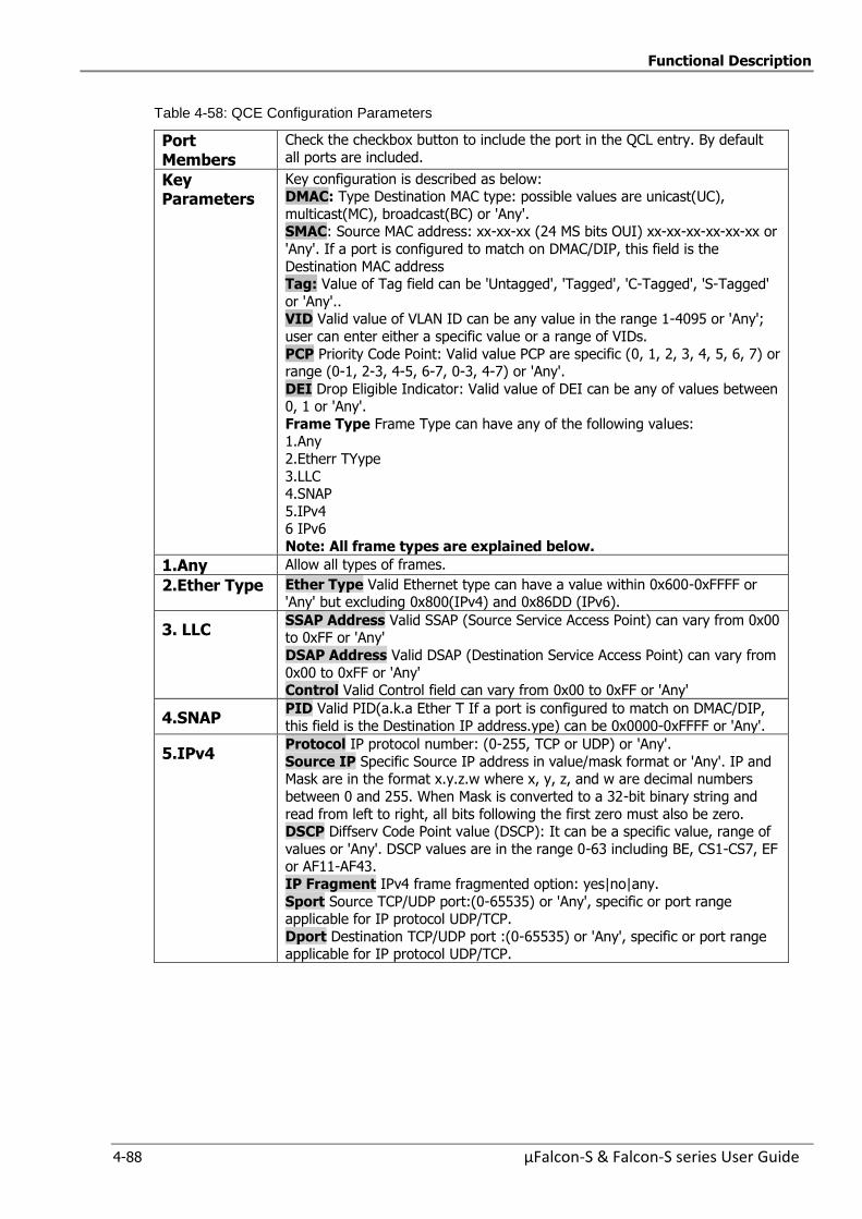
Functional Description
4-88 µFalcon-S & Falcon-S series User Guide
Table 4-58: QCE Configuration Parameters
Port Members
Check the checkbox button to include the port in the QCL entry. By default
all ports are included.
Key Parameters
Key configuration is described as below: DMAC: Type Destination MAC type: possible values are unicast(UC),
multicast(MC), broadcast(BC) or 'Any'. SMAC: Source MAC address: xx-xx-xx (24 MS bits OUI) xx-xx-xx-xx-xx-xx or
'Any'. If a port is configured to match on DMAC/DIP, this field is the
Destination MAC address Tag: Value of Tag field can be 'Untagged', 'Tagged', 'C-Tagged', 'S-Tagged'
or 'Any'.. VID Valid value of VLAN ID can be any value in the range 1-4095 or 'Any';
user can enter either a specific value or a range of VIDs.
PCP Priority Code Point: Valid value PCP are specific (0, 1, 2, 3, 4, 5, 6, 7) or range (0-1, 2-3, 4-5, 6-7, 0-3, 4-7) or 'Any'.
DEI Drop Eligible Indicator: Valid value of DEI can be any of values between 0, 1 or 'Any'.
Frame Type Frame Type can have any of the following values: 1.Any
2.Etherr TYype
3.LLC 4.SNAP
5.IPv4 6 IPv6
Note: All frame types are explained below.
1.Any Allow all types of frames.
2.Ether Type Ether Type Valid Ethernet type can have a value within 0x600-0xFFFF or 'Any' but excluding 0x800(IPv4) and 0x86DD (IPv6).
3. LLC SSAP Address Valid SSAP (Source Service Access Point) can vary from 0x00 to 0xFF or 'Any'
DSAP Address Valid DSAP (Destination Service Access Point) can vary from
0x00 to 0xFF or 'Any' Control Valid Control field can vary from 0x00 to 0xFF or 'Any'
4.SNAP PID Valid PID(a.k.a Ether T If a port is configured to match on DMAC/DIP,
this field is the Destination IP address.ype) can be 0x0000-0xFFFF or 'Any'.
5.IPv4 Protocol IP protocol number: (0-255, TCP or UDP) or 'Any'.
Source IP Specific Source IP address in value/mask format or 'Any'. IP and Mask are in the format x.y.z.w where x, y, z, and w are decimal numbers
between 0 and 255. When Mask is converted to a 32-bit binary string and
read from left to right, all bits following the first zero must also be zero. DSCP Diffserv Code Point value (DSCP): It can be a specific value, range of
values or 'Any'. DSCP values are in the range 0-63 including BE, CS1-CS7, EF or AF11-AF43.
IP Fragment IPv4 frame fragmented option: yes|no|any.
Sport Source TCP/UDP port:(0-65535) or 'Any', specific or port range applicable for IP protocol UDP/TCP.
Dport Destination TCP/UDP port :(0-65535) or 'Any', specific or port range applicable for IP protocol UDP/TCP.
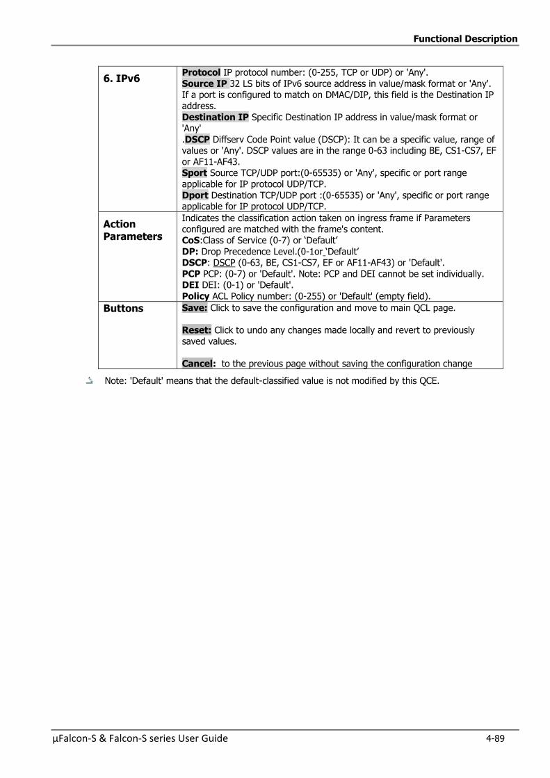
Functional Description
µFalcon-S & Falcon-S series User Guide 4-89
6. IPv6 Protocol IP protocol number: (0-255, TCP or UDP) or 'Any'.
Source IP 32 LS bits of IPv6 source address in value/mask format or 'Any'. If a port is configured to match on DMAC/DIP, this field is the Destination IP
address.
Destination IP Specific Destination IP address in value/mask format or 'Any'
.DSCP Diffserv Code Point value (DSCP): It can be a specific value, range of values or 'Any'. DSCP values are in the range 0-63 including BE, CS1-CS7, EF
or AF11-AF43. Sport Source TCP/UDP port:(0-65535) or 'Any', specific or port range
applicable for IP protocol UDP/TCP.
Dport Destination TCP/UDP port :(0-65535) or 'Any', specific or port range applicable for IP protocol UDP/TCP.
Action Parameters
Indicates the classification action taken on ingress frame if Parameters
configured are matched with the frame's content. CoS:Class of Service (0-7) or ‘Default’
DP: Drop Precedence Level.(0-1or ‘Default’ DSCP: DSCP (0-63, BE, CS1-CS7, EF or AF11-AF43) or 'Default'.
PCP PCP: (0-7) or 'Default'. Note: PCP and DEI cannot be set individually. DEI DEI: (0-1) or 'Default'.
Policy ACL Policy number: (0-255) or 'Default' (empty field).
Buttons Save: Click to save the configuration and move to main QCL page.
Reset: Click to undo any changes made locally and revert to previously
saved values.
Cancel: to the previous page without saving the configuration change
Note: 'Default' means that the default-classified value is not modified by this QCE.
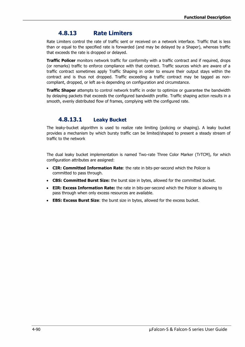
Functional Description
4-90 µFalcon-S & Falcon-S series User Guide
4.8.13 Rate Limiters
Rate Limiters control the rate of traffic sent or received on a network interface. Traffic that is less
than or equal to the specified rate is forwarded (and may be delayed by a Shaper), whereas traffic
that exceeds the rate is dropped or delayed.
Traffic Policer monitors network traffic for conformity with a traffic contract and if required, drops
(or remarks) traffic to enforce compliance with that contract. Traffic sources which are aware of a
traffic contract sometimes apply Traffic Shaping in order to ensure their output stays within the
contract and is thus not dropped. Traffic exceeding a traffic contract may be tagged as non-
compliant, dropped, or left as-is depending on configuration and circumstance.
Traffic Shaper attempts to control network traffic in order to optimize or guarantee the bandwidth
by delaying packets that exceeds the configured bandwidth profile. Traffic shaping action results in a
smooth, evenly distributed flow of frames, complying with the configured rate.
4.8.13.1 Leaky Bucket
The leaky-bucket algorithm is used to realize rate limiting (policing or shaping). A leaky bucket
provides a mechanism by which bursty traffic can be limited/shaped to present a steady stream of
traffic to the network
The dual leaky bucket implementation is named Two-rate Three Color Marker (TrTCM), for which
configuration attributes are assigned:
CIR: Committed Information Rate: the rate in bits-per-second which the Policer is
committed to pass through.
CBS: Committed Burst Size: the burst size in bytes, allowed for the committed bucket.
EIR: Excess Information Rate: the rate in bits-per-second which the Policer is allowing to
pass through when only excess resources are available.
EBS: Excess Burst Size: the burst size in bytes, allowed for the excess bucket.
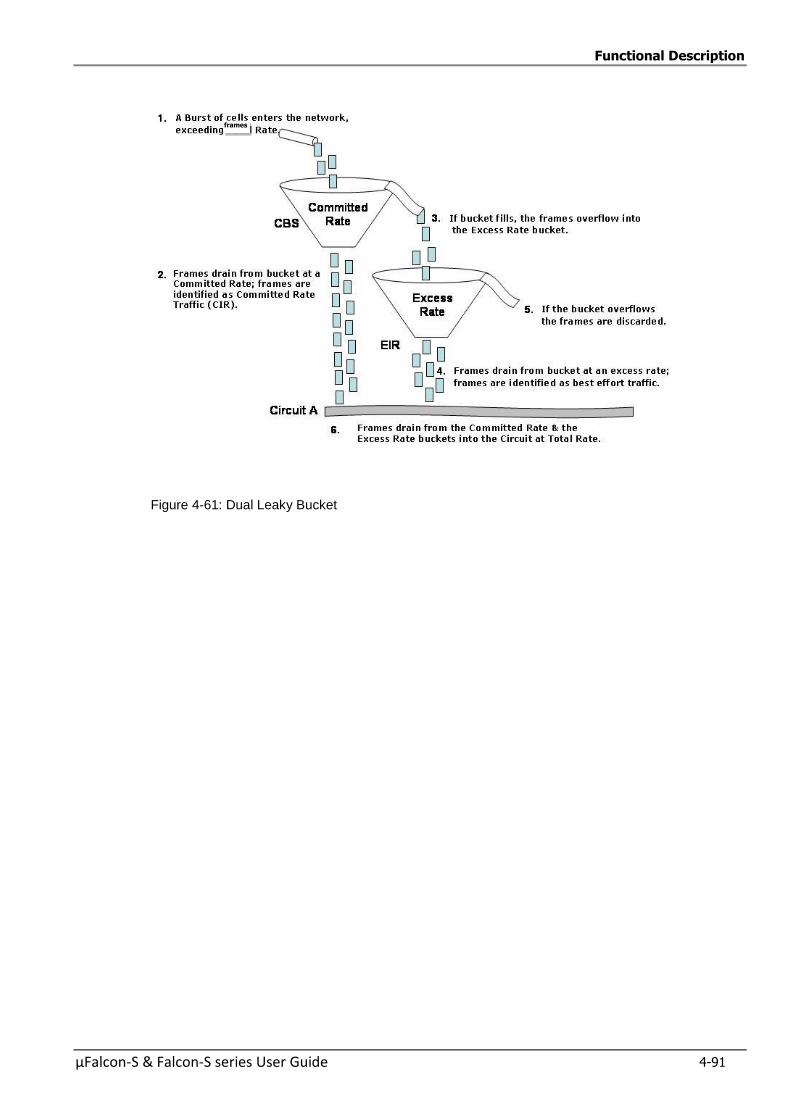
Functional Description
µFalcon-S & Falcon-S series User Guide 4-91
Figure 4-61: Dual Leaky Bucket
frames
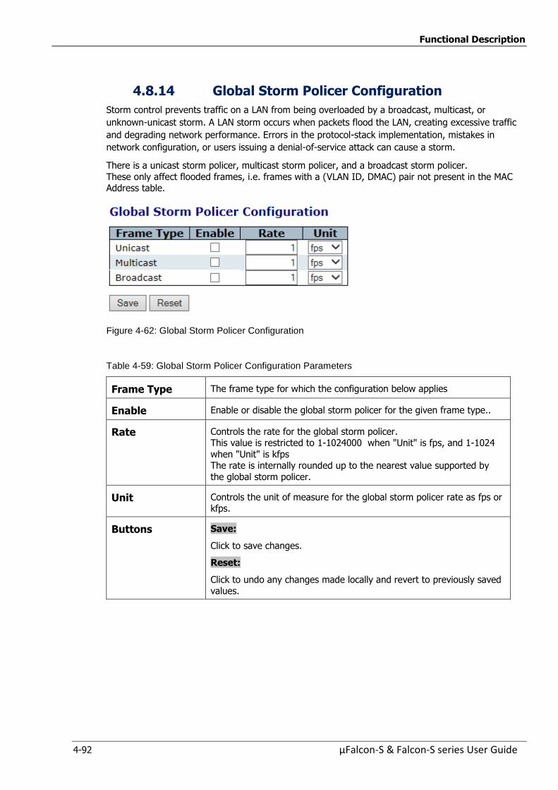
Functional Description
4-92 µFalcon-S & Falcon-S series User Guide
4.8.14 Global Storm Policer Configuration
Storm control prevents traffic on a LAN from being overloaded by a broadcast, multicast, or
unknown-unicast storm. A LAN storm occurs when packets flood the LAN, creating excessive traffic
and degrading network performance. Errors in the protocol-stack implementation, mistakes in
network configuration, or users issuing a denial-of-service attack can cause a storm.
There is a unicast storm policer, multicast storm policer, and a broadcast storm policer.
These only affect flooded frames, i.e. frames with a (VLAN ID, DMAC) pair not present in the MAC Address table.
Figure 4-62: Global Storm Policer Configuration
Table 4-59: Global Storm Policer Configuration Parameters
Frame Type The frame type for which the configuration below applies
Enable Enable or disable the global storm policer for the given frame type..
Rate Controls the rate for the global storm policer. This value is restricted to 1-1024000 when "Unit" is fps, and 1-1024
when "Unit" is kfps The rate is internally rounded up to the nearest value supported by
the global storm policer.
Unit Controls the unit of measure for the global storm policer rate as fps or kfps.
Buttons Save:
Click to save changes.
Reset:
Click to undo any changes made locally and revert to previously saved values.
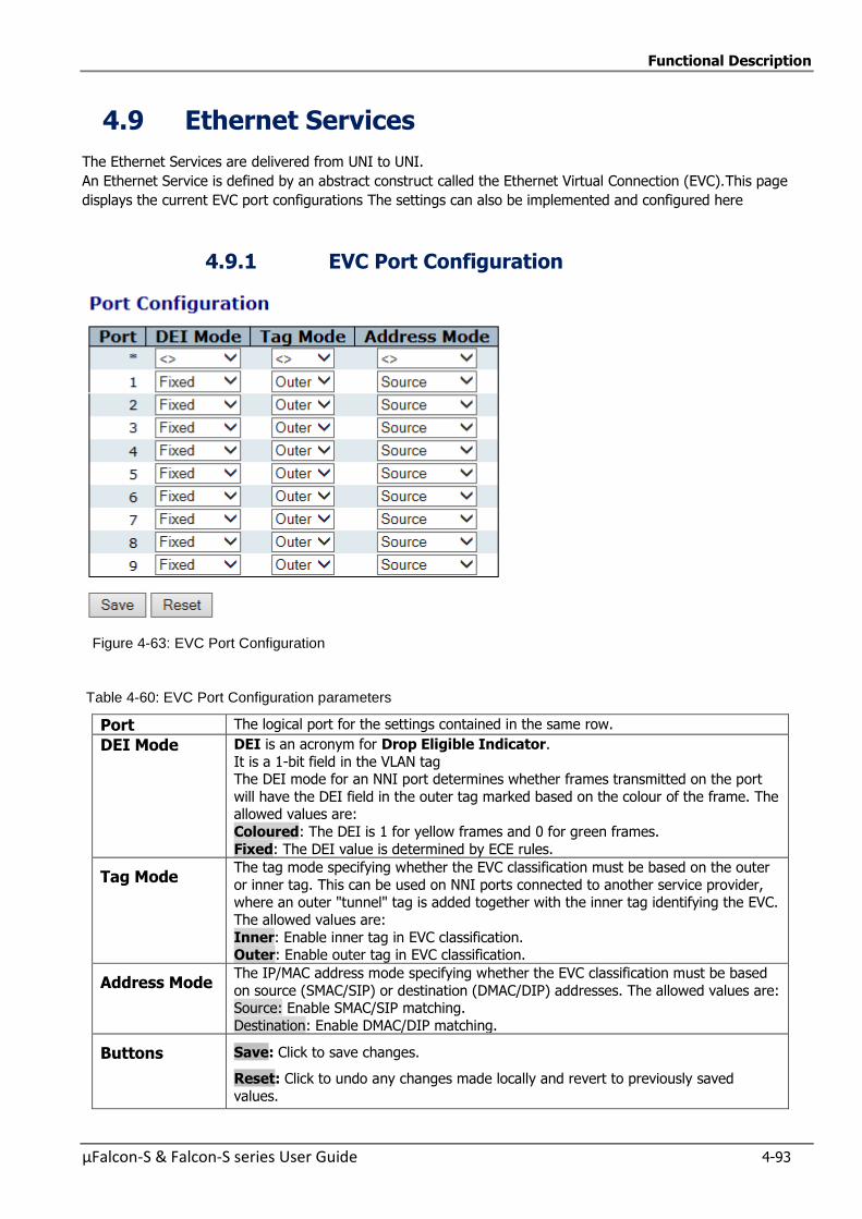
Functional Description
µFalcon-S & Falcon-S series User Guide 4-93
4.9 Ethernet Services
The Ethernet Services are delivered from UNI to UNI.
An Ethernet Service is defined by an abstract construct called the Ethernet Virtual Connection (EVC).This page
displays the current EVC port configurations The settings can also be implemented and configured here
4.9.1 EVC Port Configuration
Figure 4-63: EVC Port Configuration
Table 4-60: EVC Port Configuration parameters
Port The logical port for the settings contained in the same row.
DEI Mode DEI is an acronym for Drop Eligible Indicator.
It is a 1-bit field in the VLAN tag The DEI mode for an NNI port determines whether frames transmitted on the port
will have the DEI field in the outer tag marked based on the colour of the frame. The allowed values are:
Coloured: The DEI is 1 for yellow frames and 0 for green frames.
Fixed: The DEI value is determined by ECE rules.
Tag Mode The tag mode specifying whether the EVC classification must be based on the outer
or inner tag. This can be used on NNI ports connected to another service provider, where an outer "tunnel" tag is added together with the inner tag identifying the EVC.
The allowed values are:
Inner: Enable inner tag in EVC classification. Outer: Enable outer tag in EVC classification.
Address Mode The IP/MAC address mode specifying whether the EVC classification must be based
on source (SMAC/SIP) or destination (DMAC/DIP) addresses. The allowed values are: Source: Enable SMAC/SIP matching.
Destination: Enable DMAC/DIP matching.
Buttons Save: Click to save changes.
Reset: Click to undo any changes made locally and revert to previously saved
values.
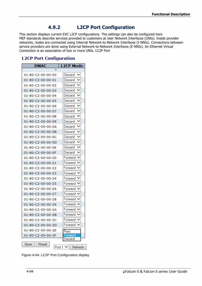
Functional Description
4-94 µFalcon-S & Falcon-S series User Guide
4.9.2 L2CP Port Configuration
This section displays current EVC L2CP configurations. The settings can also be configured here MEF standards describe services provided to customers at User Network Interfaces (UNIs). Inside provider
networks, nodes are connected using Internal Network-to-Network Interfaces (I-NNIs). Connections between
service providers are done using External Network-to-Network Interfaces (E-NNIs). An Ethernet Virtual Connection is an association of two or more UNIs. LC2P Port
Figure 4-64: LC2P Port Configuration display
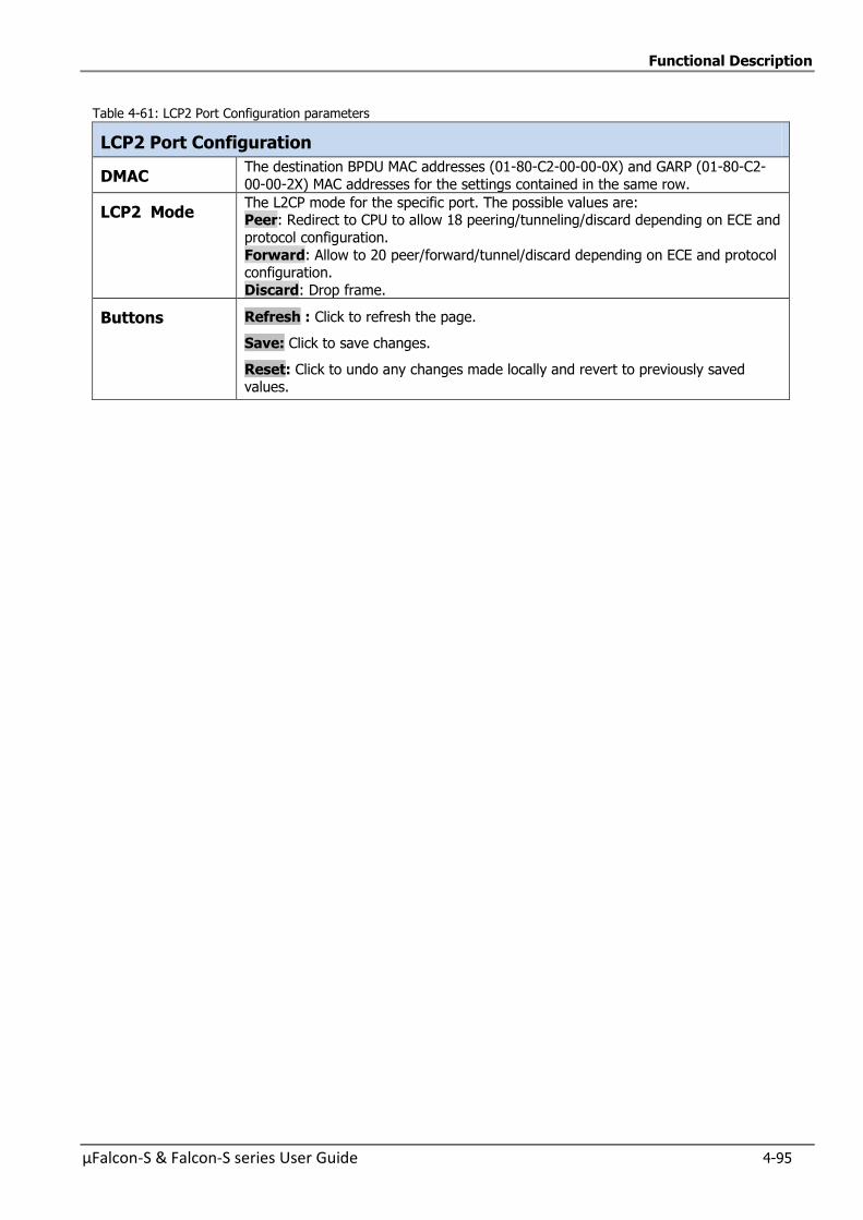
Functional Description
µFalcon-S & Falcon-S series User Guide 4-95
Table 4-61: LCP2 Port Configuration parameters
LCP2 Port Configuration
DMAC The destination BPDU MAC addresses (01-80-C2-00-00-0X) and GARP (01-80-C2-
00-00-2X) MAC addresses for the settings contained in the same row.
LCP2 Mode The L2CP mode for the specific port. The possible values are: Peer: Redirect to CPU to allow 18 peering/tunneling/discard depending on ECE and
protocol configuration.
Forward: Allow to 20 peer/forward/tunnel/discard depending on ECE and protocol configuration.
Discard: Drop frame.
Buttons Refresh : Click to refresh the page.
Save: Click to save changes.
Reset: Click to undo any changes made locally and revert to previously saved values.
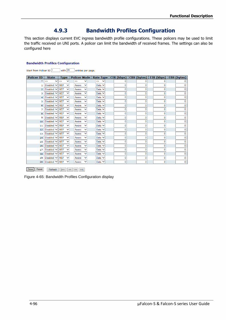
Functional Description
4-96 µFalcon-S & Falcon-S series User Guide
4.9.3 Bandwidth Profiles Configuration
This section displays current EVC ingress bandwidth profile configurations. These policers may be used to limit
the traffic received on UNI ports. A policer can limit the bandwidth of received frames. The settings can also be
configured here
Figure 4-65: Bandwidth Profiles Configuration display
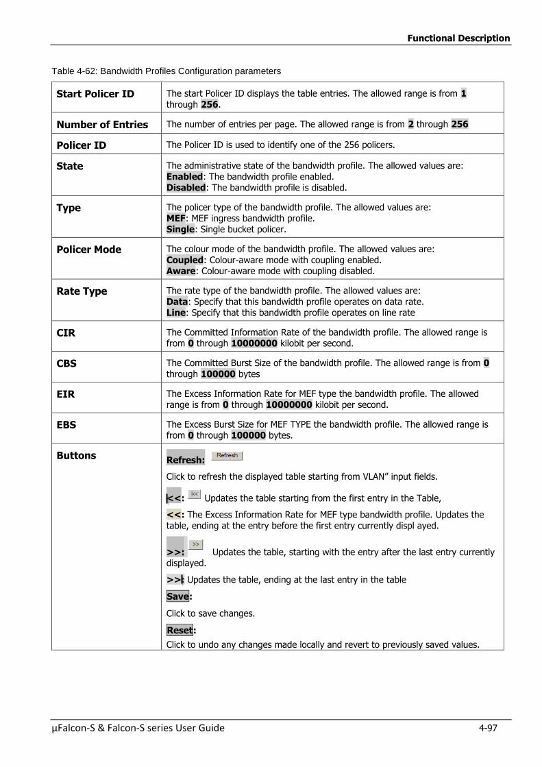
Functional Description
µFalcon-S & Falcon-S series User Guide 4-97
Table 4-62: Bandwidth Profiles Configuration parameters
Start Policer ID The start Policer ID displays the table entries. The allowed range is from 1
through 256.
Number of Entries The number of entries per page. The allowed range is from 2 through 256
Policer ID The Policer ID is used to identify one of the 256 policers.
State The administrative state of the bandwidth profile. The allowed values are:
Enabled: The bandwidth profile enabled. Disabled: The bandwidth profile is disabled.
Type The policer type of the bandwidth profile. The allowed values are:
MEF: MEF ingress bandwidth profile. Single: Single bucket policer.
Policer Mode The colour mode of the bandwidth profile. The allowed values are:
Coupled: Colour-aware mode with coupling enabled. Aware: Colour-aware mode with coupling disabled.
Rate Type The rate type of the bandwidth profile. The allowed values are:
Data: Specify that this bandwidth profile operates on data rate. Line: Specify that this bandwidth profile operates on line rate
CIR The Committed Information Rate of the bandwidth profile. The allowed range is from 0 through 10000000 kilobit per second.
CBS The Committed Burst Size of the bandwidth profile. The allowed range is from 0
through 100000 bytes
EIR The Excess Information Rate for MEF type the bandwidth profile. The allowed range is from 0 through 10000000 kilobit per second.
EBS The Excess Burst Size for MEF TYPE the bandwidth profile. The allowed range is from 0 through 100000 bytes.
Buttons Refresh:
Click to refresh the displayed table starting from VLAN” input fields.
<<: Updates the table starting from the first entry in the Table,
<<: The Excess Information Rate for MEF type bandwidth profile. Updates the
table, ending at the entry before the first entry currently displ ayed.
>>: Updates the table, starting with the entry after the last entry currently displayed.
>>: Updates the table, ending at the last entry in the table
Save:
Click to save changes.
Reset:
Click to undo any changes made locally and revert to previously saved values.
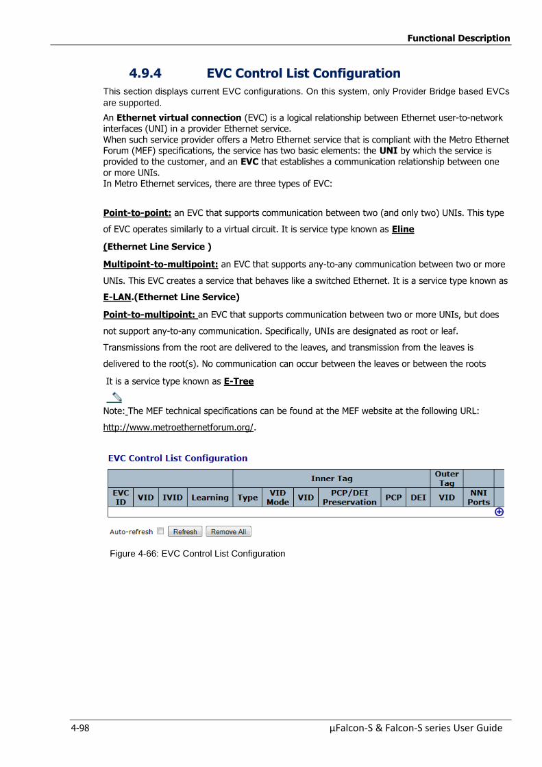
Functional Description
4-98 µFalcon-S & Falcon-S series User Guide
4.9.4 EVC Control List Configuration
This section displays current EVC configurations. On this system, only Provider Bridge based EVCs
are supported.
An Ethernet virtual connection (EVC) is a logical relationship between Ethernet user-to-network interfaces (UNI) in a provider Ethernet service.
When such service provider offers a Metro Ethernet service that is compliant with the Metro Ethernet Forum (MEF) specifications, the service has two basic elements: the UNI by which the service is
provided to the customer, and an EVC that establishes a communication relationship between one
or more UNIs. In Metro Ethernet services, there are three types of EVC:
Point-to-point: an EVC that supports communication between two (and only two) UNIs. This type
of EVC operates similarly to a virtual circuit. It is service type known as Eline
(Ethernet Line Service )
Multipoint-to-multipoint: an EVC that supports any-to-any communication between two or more
UNIs. This EVC creates a service that behaves like a switched Ethernet. It is a service type known as
E-LAN.(Ethernet Line Service)
Point-to-multipoint: an EVC that supports communication between two or more UNIs, but does
not support any-to-any communication. Specifically, UNIs are designated as root or leaf.
Transmissions from the root are delivered to the leaves, and transmission from the leaves is
delivered to the root(s). No communication can occur between the leaves or between the roots
It is a service type known as E-Tree
Note: The MEF technical specifications can be found at the MEF website at the following URL:
http://www.metroethernetforum.org/.
Figure 4-66: EVC Control List Configuration

Functional Description
µFalcon-S & Falcon-S series User Guide 4-99
Table 4-63: EVC Control List Configuration Parameters
EVC ID The EVC ID identifies the EVC. The range is from 1 through 128.
VID The VLAN ID in the PB network. It may be inserted in a C-tag, S-tag
or S-custom tag depending on the NNI port VLAN configuration. The range is from 1 through 4095.
IVID The Internal/classified VLAN ID in the PB network. The range is from
1 through 4095.
Learning The learning mode for the EVC controls whether source MAC
addresses are learned for frames matching the EVC. Learning may be disabled if the EVC only includes two UNI/NNI ports. The possible
values are:
Enabled: Learning is enabled (MAC addresses are learned). Disabled: Learning is disabled (MAC addresses are not learned).
Inner Tag Type The inner tag type is used to determine whether an inner tag is
inserted in frames forwarded to NNI ports. The possible values are: None: An inner tag is not inserted.
C-tag: An inner C-tag is inserted. S-tag: An inner S-tag is inserted.
S-custom-tag: An inner tag is inserted and the tag type is determined by the VLAN port configuration of the NNI
Inner VID Mode The inner VID Mode affects the VID in the inner and outer tag. The
possible values are: Normal: The VID of the two outer tags aren't swapped.
Tunnel: The VID of the two outer tags are swapped, so that the VID
of the outer tag is taken from the Inner Tag configuration and the VID of the inner tag is the EVC VID. In this mode, the NNI ports are
normally configured to do EVC classification based on the inner tag.
Inner Tag VID The Inner tag VLAN ID. The allowed range is from 0 through 4095.
Inner Tag PCP/DEI Preservation
The inner tag PCP and DEI preservation. The possible values are:
Preserved: The inner tag PCP and DEI is preserved. Fixed: The inner tag PCP and DEI is fixed.
Inner Tag PCP The inner tag PCP value. The allowed range is from 0 through 7.
Inner Tag DEI The inner tag DEI value. The allowed value is 0 or 1
Outer Tag VID The EVC outer tag VID for UNI ports. The allowed range is from 0
through 4095
NNI Ports The list of Network to Network Interfaces for the EVC.
Modification Button
You can modify each EVC in the table using the following button
: Adds new EVC.
Buttons Refresh:
Click to refresh the displayed table starting from the “Start from the MAC address” and “VLAN” input fields.
Auto-refresh : Check this box to refresh the page automatically. Automatic refresh occurs every 3 seconds.
Remove All: Click to remove all ECEs.
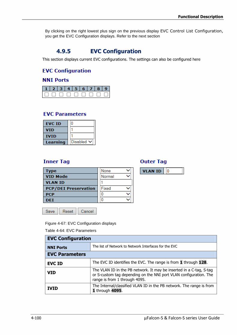
Functional Description
4-100 µFalcon-S & Falcon-S series User Guide
By clicking on the right lowest plus sign on the previous display EVC Control List Configuration,
you get the EVC Configuration displays. Refer to the next section
4.9.5 EVC Configuration
This section displays current EVC configurations. The settings can also be configured here
Figure 4-67: EVC Configuration displays
Table 4-64: EVC Parameters
EVC Configuration
NNI Ports The list of Network to Network Interfaces for the EVC
EVC Parameters
EVC ID The EVC ID identifies the EVC. The range is from 1 through 128.
VID The VLAN ID in the PB network. It may be inserted in a C-tag, S-tag or S-custom tag depending on the NNI port VLAN configuration. The
range is from 1 through 4095.
IVID The Internal/classified VLAN ID in the PB network. The range is from
1 through 4095.
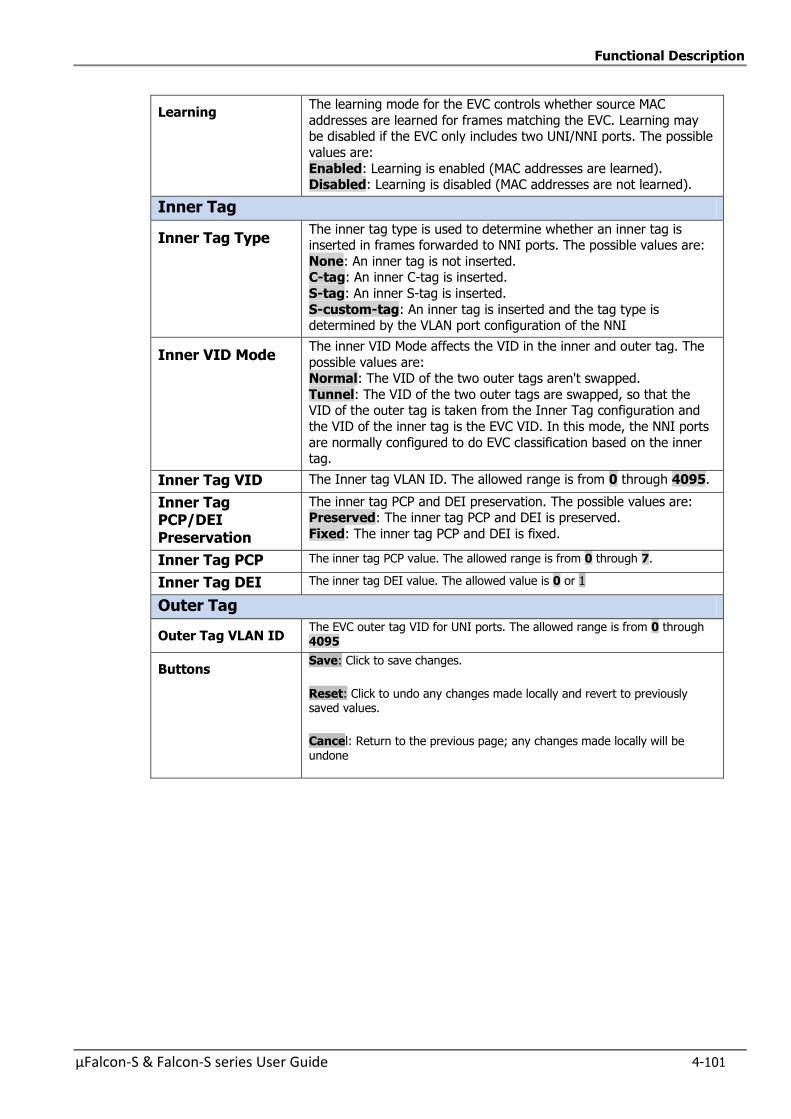
Functional Description
µFalcon-S & Falcon-S series User Guide 4-101
Learning The learning mode for the EVC controls whether source MAC
addresses are learned for frames matching the EVC. Learning may be disabled if the EVC only includes two UNI/NNI ports. The possible
values are:
Enabled: Learning is enabled (MAC addresses are learned). Disabled: Learning is disabled (MAC addresses are not learned).
Inner Tag
Inner Tag Type The inner tag type is used to determine whether an inner tag is inserted in frames forwarded to NNI ports. The possible values are:
None: An inner tag is not inserted. C-tag: An inner C-tag is inserted.
S-tag: An inner S-tag is inserted.
S-custom-tag: An inner tag is inserted and the tag type is determined by the VLAN port configuration of the NNI
Inner VID Mode The inner VID Mode affects the VID in the inner and outer tag. The
possible values are: Normal: The VID of the two outer tags aren't swapped.
Tunnel: The VID of the two outer tags are swapped, so that the VID of the outer tag is taken from the Inner Tag configuration and
the VID of the inner tag is the EVC VID. In this mode, the NNI ports
are normally configured to do EVC classification based on the inner tag.
Inner Tag VID The Inner tag VLAN ID. The allowed range is from 0 through 4095.
Inner Tag PCP/DEI Preservation
The inner tag PCP and DEI preservation. The possible values are: Preserved: The inner tag PCP and DEI is preserved.
Fixed: The inner tag PCP and DEI is fixed.
Inner Tag PCP The inner tag PCP value. The allowed range is from 0 through 7.
Inner Tag DEI The inner tag DEI value. The allowed value is 0 or 1
Outer Tag
Outer Tag VLAN ID The EVC outer tag VID for UNI ports. The allowed range is from 0 through 4095
Buttons Save: Click to save changes.
Reset: Click to undo any changes made locally and revert to previously saved values.
Cancel: Return to the previous page; any changes made locally will be undone
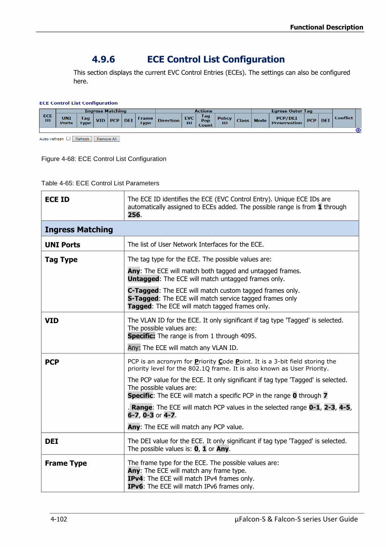
Functional Description
4-102 µFalcon-S & Falcon-S series User Guide
4.9.6 ECE Control List Configuration
This section displays the current EVC Control Entries (ECEs). The settings can also be configured
here.
Figure 4-68: ECE Control List Configuration
Table 4-65: ECE Control List Parameters
ECE ID The ECE ID identifies the ECE (EVC Control Entry). Unique ECE IDs are automatically assigned to ECEs added. The possible range is from 1 through
256.
Ingress Matching
UNI Ports The list of User Network Interfaces for the ECE.
Tag Type The tag type for the ECE. The possible values are:
Any: The ECE will match both tagged and untagged frames.
Untagged: The ECE will match untagged frames only.
C-Tagged: The ECE will match custom tagged frames only.
S-Tagged: The ECE will match service tagged frames only Tagged: The ECE will match tagged frames only.
VID The VLAN ID for the ECE. It only significant if tag type 'Tagged' is selected.
The possible values are: Specific: The range is from 1 through 4095.
Any: The ECE will match any VLAN ID.
PCP PCP is an acronym for Priority Code Point. It is a 3-bit field storing the priority level for the 802.1Q frame. It is also known as User Priority.
The PCP value for the ECE. It only significant if tag type 'Tagged' is selected. The possible values are:
Specific: The ECE will match a specific PCP in the range 0 through 7
. Range: The ECE will match PCP values in the selected range 0-1, 2-3, 4-5, 6-7, 0-3 or 4-7.
Any: The ECE will match any PCP value.
DEI The DEI value for the ECE. It only significant if tag type 'Tagged' is selected. The possible values is: 0, 1 or Any.
Frame Type The frame type for the ECE. The possible values are: Any: The ECE will match any frame type.
IPv4: The ECE will match IPv4 frames only.
IPv6: The ECE will match IPv6 frames only.
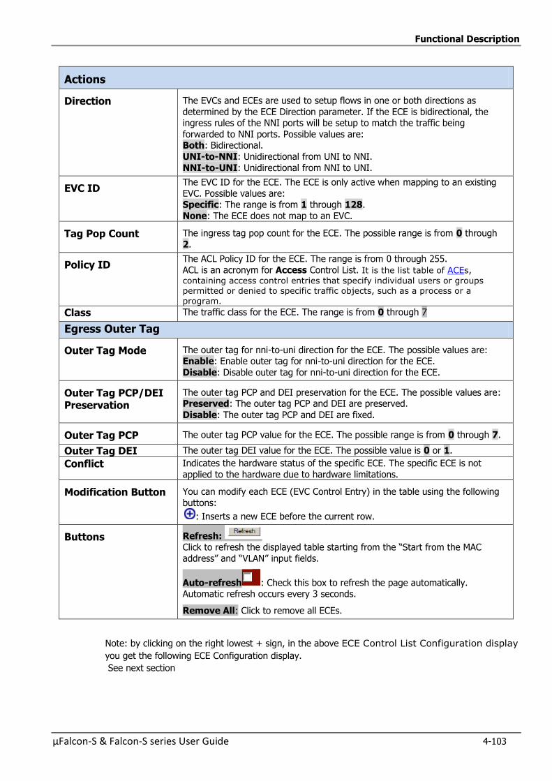
Functional Description
µFalcon-S & Falcon-S series User Guide 4-103
Actions
Direction The EVCs and ECEs are used to setup flows in one or both directions as
determined by the ECE Direction parameter. If the ECE is bidirectional, the ingress rules of the NNI ports will be setup to match the traffic being
forwarded to NNI ports. Possible values are: Both: Bidirectional.
UNI-to-NNI: Unidirectional from UNI to NNI.
NNI-to-UNI: Unidirectional from NNI to UNI.
EVC ID The EVC ID for the ECE. The ECE is only active when mapping to an existing
EVC. Possible values are: Specific: The range is from 1 through 128.
None: The ECE does not map to an EVC.
Tag Pop Count The ingress tag pop count for the ECE. The possible range is from 0 through 2.
Policy ID The ACL Policy ID for the ECE. The range is from 0 through 255.
ACL is an acronym for Access Control List. It is the list table of ACEs,
containing access control entries that specify individual users or groups permitted or denied to specific traffic objects, such as a process or a
program.
Class The traffic class for the ECE. The range is from 0 through 7
Egress Outer Tag
Outer Tag Mode The outer tag for nni-to-uni direction for the ECE. The possible values are: Enable: Enable outer tag for nni-to-uni direction for the ECE.
Disable: Disable outer tag for nni-to-uni direction for the ECE.
Outer Tag PCP/DEI Preservation
The outer tag PCP and DEI preservation for the ECE. The possible values are: Preserved: The outer tag PCP and DEI are preserved.
Disable: The outer tag PCP and DEI are fixed.
Outer Tag PCP The outer tag PCP value for the ECE. The possible range is from 0 through 7.
Outer Tag DEI The outer tag DEI value for the ECE. The possible value is 0 or 1.
Conflict Indicates the hardware status of the specific ECE. The specific ECE is not
applied to the hardware due to hardware limitations.
Modification Button You can modify each ECE (EVC Control Entry) in the table using the following
buttons:
: Inserts a new ECE before the current row.
Buttons Refresh: Click to refresh the displayed table starting from the “Start from the MAC
address” and “VLAN” input fields.
Auto-refresh : Check this box to refresh the page automatically. Automatic refresh occurs every 3 seconds.
Remove All: Click to remove all ECEs.
Note: by clicking on the right lowest + sign, in the above ECE Control List Configuration display
you get the following ECE Configuration display.
See next section
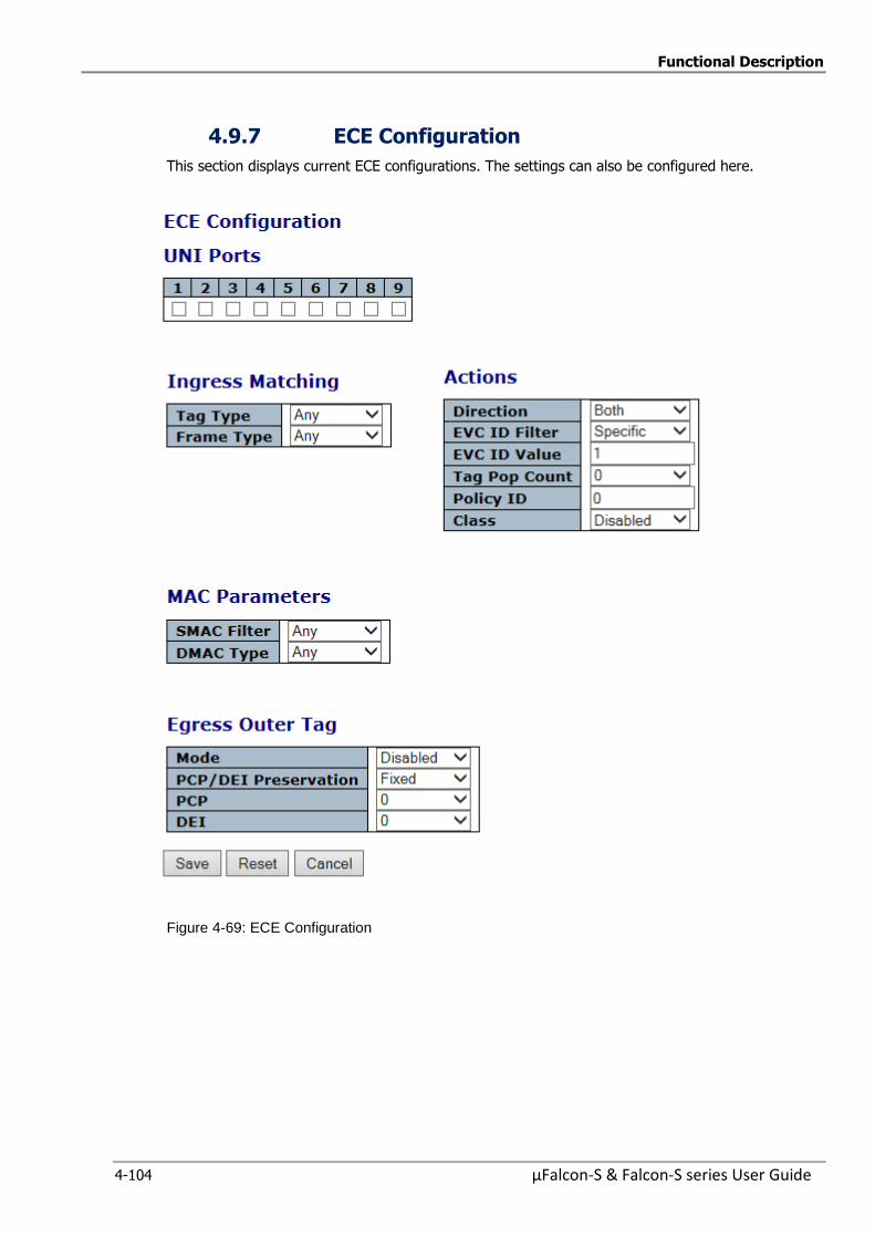
Functional Description
4-104 µFalcon-S & Falcon-S series User Guide
4.9.7 ECE Configuration
This section displays current ECE configurations. The settings can also be configured here.
Figure 4-69: ECE Configuration
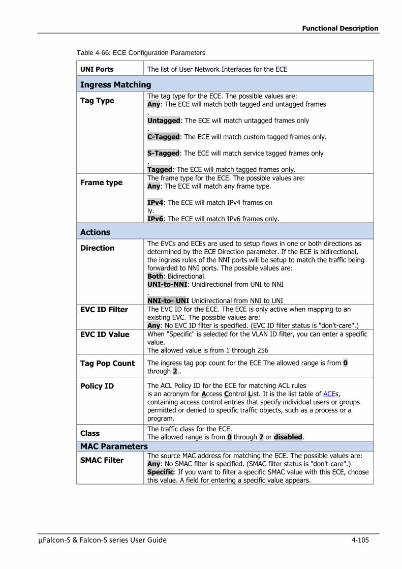
Functional Description
µFalcon-S & Falcon-S series User Guide 4-105
Table 4-66: ECE Configuration Parameters
UNI Ports The list of User Network Interfaces for the ECE
Ingress Matching
Tag Type The tag type for the ECE. The possible values are: Any: The ECE will match both tagged and untagged frames
.
Untagged: The ECE will match untagged frames only .
C-Tagged: The ECE will match custom tagged frames only.
S-Tagged: The ECE will match service tagged frames only
. Tagged: The ECE will match tagged frames only.
Frame type The frame type for the ECE. The possible values are: Any: The ECE will match any frame type.
IPv4: The ECE will match IPv4 frames on ly.
IPv6: The ECE will match IPv6 frames only.
Actions
Direction The EVCs and ECEs are used to setup flows in one or both directions as
determined by the ECE Direction parameter. If the ECE is bidirectional,
the ingress rules of the NNI ports will be setup to match the traffic being forwarded to NNI ports. The possible values are:
Both: Bidirectional. UNI-to-NNI: Unidirectional from UNI to NNI
.
NNI-to- UNI Unidirectional from NNI to UNI
EVC ID Filter The EVC ID for the ECE. The ECE is only active when mapping to an
existing EVC. The possible values are: Any: No EVC ID filter is specified. (EVC ID filter status is "don't-care".)
EVC ID Value When "Specific" is selected for the VLAN ID filter, you can enter a specific
value. The allowed value is from 1 through 256
Tag Pop Count The ingress tag pop count for the ECE The allowed range is from 0
through 2..
Policy ID The ACL Policy ID for the ECE for matching ACL rules
is an acronym for Access Control List. It is the list table of ACEs,
containing access control entries that specify individual users or groups permitted or denied to specific traffic objects, such as a process or a
program.
Class The traffic class for the ECE. The allowed range is from 0 through 7 or disabled.
MAC Parameters
SMAC Filter The source MAC address for matching the ECE. The possible values are: Any: No SMAC filter is specified. (SMAC filter status is "don't-care".)
Specific: If you want to filter a specific SMAC value with this ECE, choose
this value. A field for entering a specific value appears.
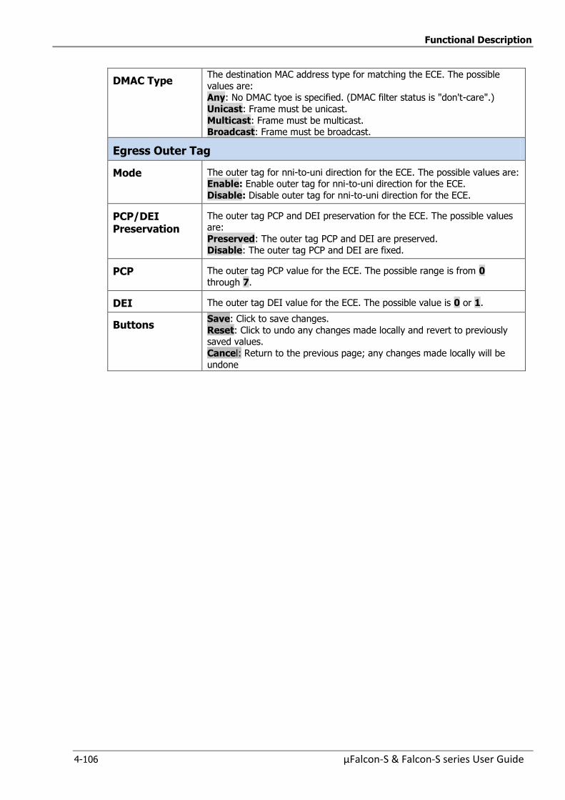
Functional Description
4-106 µFalcon-S & Falcon-S series User Guide
DMAC Type The destination MAC address type for matching the ECE. The possible
values are: Any: No DMAC tyoe is specified. (DMAC filter status is "don't-care".)
Unicast: Frame must be unicast.
Multicast: Frame must be multicast. Broadcast: Frame must be broadcast.
Egress Outer Tag
Mode The outer tag for nni-to-uni direction for the ECE. The possible values are: Enable: Enable outer tag for nni-to-uni direction for the ECE.
Disable: Disable outer tag for nni-to-uni direction for the ECE.
PCP/DEI Preservation
The outer tag PCP and DEI preservation for the ECE. The possible values are:
Preserved: The outer tag PCP and DEI are preserved. Disable: The outer tag PCP and DEI are fixed.
PCP The outer tag PCP value for the ECE. The possible range is from 0
through 7.
DEI The outer tag DEI value for the ECE. The possible value is 0 or 1.
Buttons Save: Click to save changes.
Reset: Click to undo any changes made locally and revert to previously saved values.
Cancel: Return to the previous page; any changes made locally will be
undone
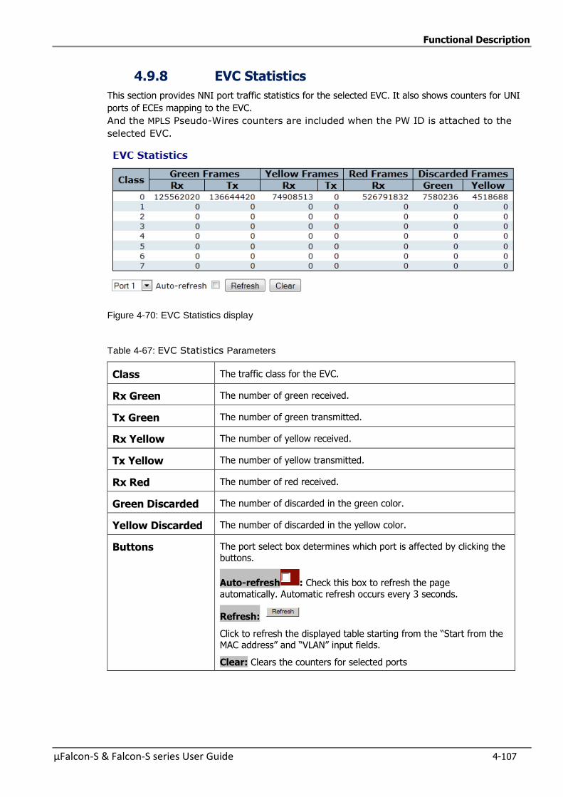
Functional Description
µFalcon-S & Falcon-S series User Guide 4-107
4.9.8 EVC Statistics
This section provides NNI port traffic statistics for the selected EVC. It also shows counters for UNI
ports of ECEs mapping to the EVC.
And the MPLS Pseudo-Wires counters are included when the PW ID is attached to the
selected EVC.
Figure 4-70: EVC Statistics display
Table 4-67: EVC Statistics Parameters
Class The traffic class for the EVC.
Rx Green The number of green received.
Tx Green The number of green transmitted.
Rx Yellow The number of yellow received.
Tx Yellow The number of yellow transmitted.
Rx Red The number of red received.
Green Discarded The number of discarded in the green color.
Yellow Discarded The number of discarded in the yellow color.
Buttons The port select box determines which port is affected by clicking the
buttons.
Auto-refresh : Check this box to refresh the page automatically. Automatic refresh occurs every 3 seconds.
Refresh:
Click to refresh the displayed table starting from the “Start from the MAC address” and “VLAN” input fields.
Clear: Clears the counters for selected ports

Functional Description
4-108 µFalcon-S & Falcon-S series User Guide
4.10 Security Features
µFalcon-S series enables a set of security features. Security is realized by several different
mechanisms included in the Switch and Network sections
4.10.1 Switch
The Switch section contains the following sub-sections:
1. User Configuration
2. Privilege Level Configuration
3. Authentication Method Configuration
4. SSH Configuration
5. HTTPS Configurations
6. Access Management Configuration
7. Access Management Statistics
4.10.1.1 User Configuration
This subsection provides an overview of the current users.
Currently the only way to login as another user on the web server is to close and reopen
the browser.
Figure 4-71: User Configuration
Table 4-68: User Configuration Parameters
User Name The name identifying the user.
Privilege level The privilege level of the user. The allowed range is 1 to 15. If the privilege level value is 15, it can access all groups, i.e. that is granted
the fully control of the device. But others value need to refer to each group privilege level. User's privilege should be same or greater than
the group privilege level to have the access of that group. By default
setting, most groups privilege level 5 has the read-only access and privilege level 10 has the read-write access. And the system
maintenance (software upload, factory defaults and etc.) need user privilege level 15. Generally, the privilege level 15 can be used for an
administrator account, privilege level 10 for a standard user account and privilege level 5 for a guest account.
Buttons Add New User : Click to add a new user
Marcello is a new added User with privilege level 10
By clicking on “Marcello” user you get the following edit display which can be modified:
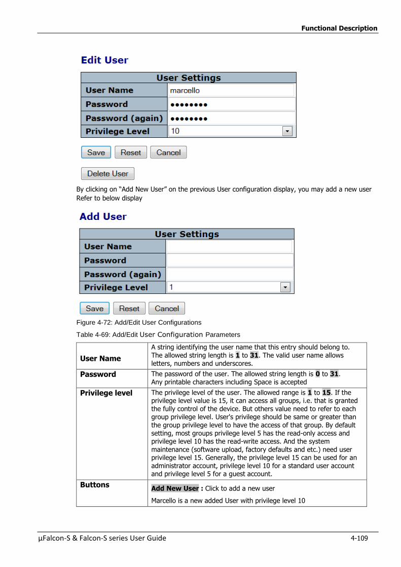
Functional Description
µFalcon-S & Falcon-S series User Guide 4-109
By clicking on “Add New User” on the previous User configuration display, you may add a new user
Refer to below display
Figure 4-72: Add/Edit User Configurations
Table 4-69: Add/Edit User Configuration Parameters
User Name
A string identifying the user name that this entry should belong to.
The allowed string length is 1 to 31. The valid user name allows
letters, numbers and underscores.
Password The password of the user. The allowed string length is 0 to 31.
Any printable characters including Space is accepted
Privilege level The privilege level of the user. The allowed range is 1 to 15. If the privilege level value is 15, it can access all groups, i.e. that is granted
the fully control of the device. But others value need to refer to each group privilege level. User's privilege should be same or greater than
the group privilege level to have the access of that group. By default
setting, most groups privilege level 5 has the read-only access and privilege level 10 has the read-write access. And the system
maintenance (software upload, factory defaults and etc.) need user privilege level 15. Generally, the privilege level 15 can be used for an
administrator account, privilege level 10 for a standard user account and privilege level 5 for a guest account.
Buttons Add New User : Click to add a new user
Marcello is a new added User with privilege level 10

Functional Description
4-110 µFalcon-S & Falcon-S series User Guide
4.10.1.2 Privilege Level Configuration
This subsection provides an overview of the privilege levels.
Privilege Level Configuration
Figure 4-73: Privilege Level Configuration
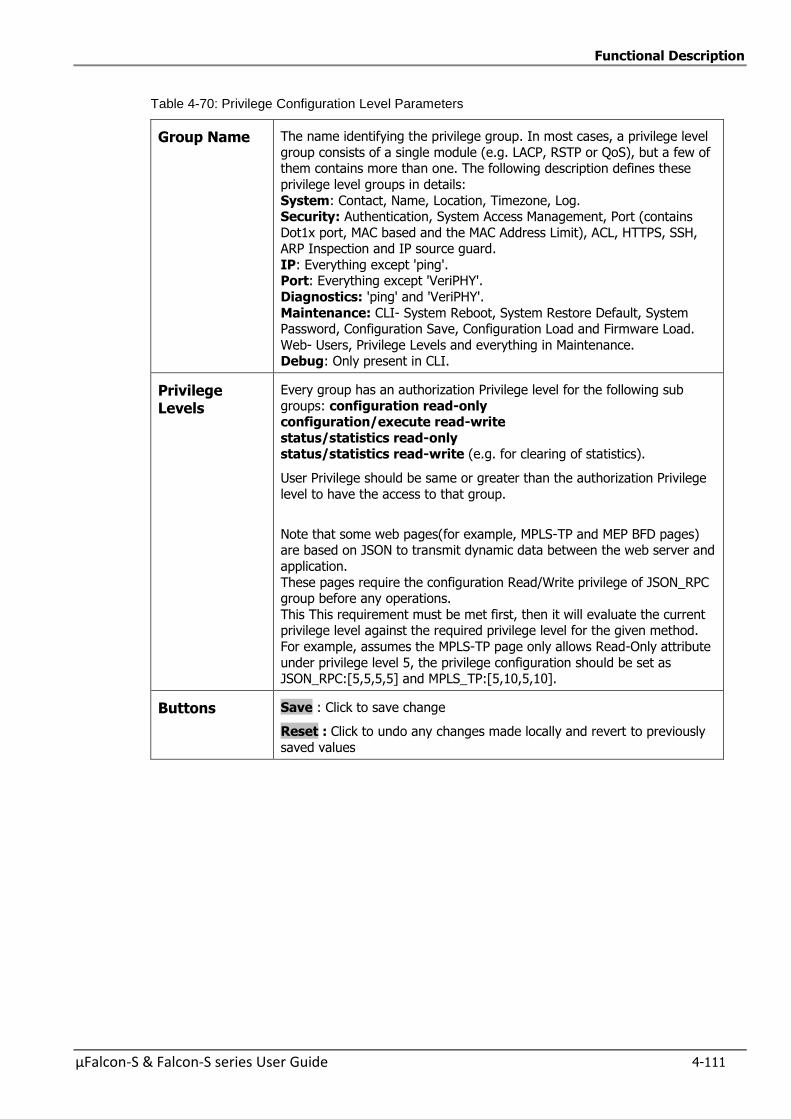
Functional Description
µFalcon-S & Falcon-S series User Guide 4-111
Table 4-70: Privilege Configuration Level Parameters
Group Name The name identifying the privilege group. In most cases, a privilege level
group consists of a single module (e.g. LACP, RSTP or QoS), but a few of them contains more than one. The following description defines these
privilege level groups in details:
System: Contact, Name, Location, Timezone, Log. Security: Authentication, System Access Management, Port (contains
Dot1x port, MAC based and the MAC Address Limit), ACL, HTTPS, SSH, ARP Inspection and IP source guard.
IP: Everything except 'ping'. Port: Everything except 'VeriPHY'.
Diagnostics: 'ping' and 'VeriPHY'.
Maintenance: CLI- System Reboot, System Restore Default, System Password, Configuration Save, Configuration Load and Firmware Load.
Web- Users, Privilege Levels and everything in Maintenance. Debug: Only present in CLI.
Privilege Levels
Every group has an authorization Privilege level for the following sub
groups: configuration read-only configuration/execute read-write
status/statistics read-only status/statistics read-write (e.g. for clearing of statistics).
User Privilege should be same or greater than the authorization Privilege
level to have the access to that group.
Note that some web pages(for example, MPLS-TP and MEP BFD pages) are based on JSON to transmit dynamic data between the web server and
application.
These pages require the configuration Read/Write privilege of JSON_RPC group before any operations.
This This requirement must be met first, then it will evaluate the current privilege level against the required privilege level for the given method.
For example, assumes the MPLS-TP page only allows Read-Only attribute
under privilege level 5, the privilege configuration should be set as JSON_RPC:[5,5,5,5] and MPLS_TP:[5,10,5,10].
Buttons Save : Click to save change
Reset : Click to undo any changes made locally and revert to previously
saved values
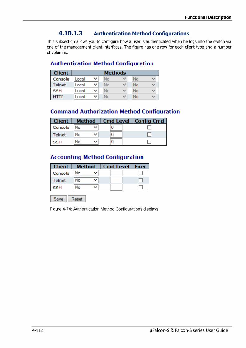
Functional Description
4-112 µFalcon-S & Falcon-S series User Guide
4.10.1.3 Authentication Method Configurations
This subsection allows you to configure how a user is authenticated when he logs into the switch via
one of the management client interfaces. The figure has one row for each client type and a number
of columns.
Figure 4-74: Authentication Method Configurations displays
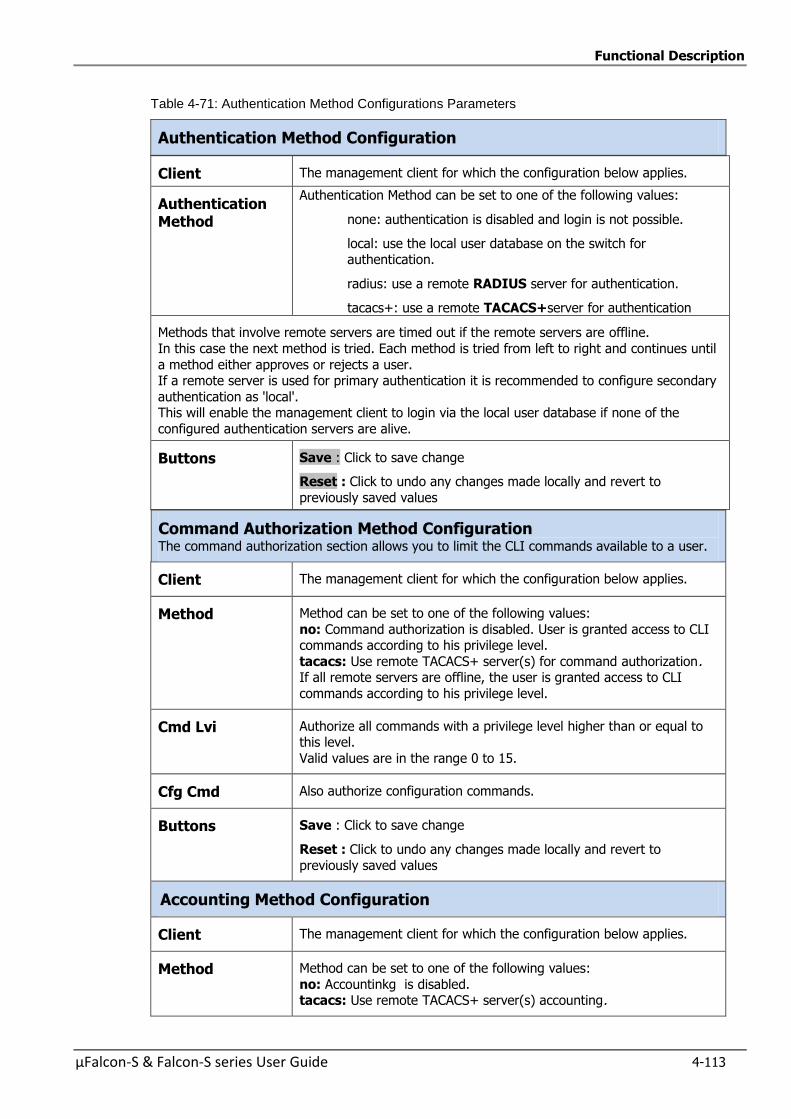
Functional Description
µFalcon-S & Falcon-S series User Guide 4-113
Table 4-71: Authentication Method Configurations Parameters
Authentication Method Configuration
Client The management client for which the configuration below applies.
Authentication Method
Authentication Method can be set to one of the following values:
none: authentication is disabled and login is not possible.
local: use the local user database on the switch for authentication.
radius: use a remote RADIUS server for authentication.
tacacs+: use a remote TACACS+server for authentication
Methods that involve remote servers are timed out if the remote servers are offline.
In this case the next method is tried. Each method is tried from left to right and continues until
a method either approves or rejects a user. If a remote server is used for primary authentication it is recommended to configure secondary
authentication as 'local'. This will enable the management client to login via the local user database if none of the
configured authentication servers are alive.
Buttons Save : Click to save change
Reset : Click to undo any changes made locally and revert to
previously saved values
Command Authorization Method Configuration The command authorization section allows you to limit the CLI commands available to a user.
Client The management client for which the configuration below applies.
Method Method can be set to one of the following values:
no: Command authorization is disabled. User is granted access to CLI commands according to his privilege level.
tacacs: Use remote TACACS+ server(s) for command authorization. If all remote servers are offline, the user is granted access to CLI
commands according to his privilege level.
Cmd Lvi Authorize all commands with a privilege level higher than or equal to this level.
Valid values are in the range 0 to 15.
Cfg Cmd Also authorize configuration commands.
Buttons Save : Click to save change
Reset : Click to undo any changes made locally and revert to
previously saved values
Accounting Method Configuration
Client The management client for which the configuration below applies.
Method Method can be set to one of the following values:
no: Accountinkg is disabled. tacacs: Use remote TACACS+ server(s) accounting.
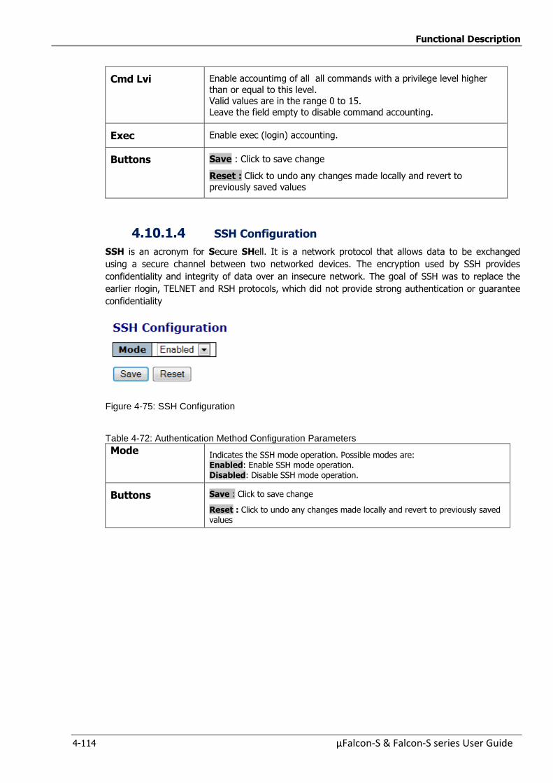
Functional Description
4-114 µFalcon-S & Falcon-S series User Guide
Cmd Lvi Enable accountimg of all all commands with a privilege level higher
than or equal to this level. Valid values are in the range 0 to 15.
Leave the field empty to disable command accounting.
Exec Enable exec (login) accounting.
Buttons Save : Click to save change
Reset : Click to undo any changes made locally and revert to
previously saved values
4.10.1.4 SSH Configuration
SSH is an acronym for Secure SHell. It is a network protocol that allows data to be exchanged
using a secure channel between two networked devices. The encryption used by SSH provides
confidentiality and integrity of data over an insecure network. The goal of SSH was to replace the
earlier rlogin, TELNET and RSH protocols, which did not provide strong authentication or guarantee
confidentiality
Figure 4-75: SSH Configuration
Table 4-72: Authentication Method Configuration Parameters
Mode Indicates the SSH mode operation. Possible modes are: Enabled: Enable SSH mode operation. Disabled: Disable SSH mode operation.
Buttons Save : Click to save change
Reset : Click to undo any changes made locally and revert to previously saved values
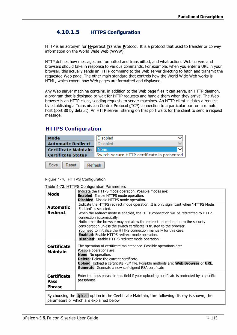
Functional Description
µFalcon-S & Falcon-S series User Guide 4-115
4.10.1.5 HTTPS Configuration
HTTP is an acronym for Hypertext Transfer Protocol. It is a protocol that used to transfer or convey
information on the World Wide Web (WWW).
HTTP defines how messages are formatted and transmitted, and what actions Web servers and browsers should take in response to various commands. For example, when you enter a URL in your
browser, this actually sends an HTTP command to the Web server directing to fetch and transmit the
requested Web page. The other main standard that controls how the World Wide Web works is HTML, which covers how Web pages are formatted and displayed.
Any Web server machine contains, in addition to the Web page files it can serve, an HTTP daemon,
a program that is designed to wait for HTTP requests and handle them when they arrive. The Web
browser is an HTTP client, sending requests to server machines. An HTTP client initiates a request by establishing a Transmission Control Protocol (TCP) connection to a particular port on a remote
host (port 80 by default). An HTTP server listening on that port waits for the client to send a request message.
Figure 4-76: HTTPS Configuration
Table 4-73: HTTPS Configuration Parameters
Mode Indicate the HTTPS mode operation. Possible modes are: Enabled: Enable HTTPS mode operation. Disabled: Disable HTTPS mode operation.
Automatic Redirect
Indicate the HTTPS redirect mode operation. It is only significant when "HTTPS Mode Enabled" is selected. When the redirect mode is enabled, the HTTP connection will be redirected to HTTPS connection automatically. Notice that the browser may not allow the redirect operation due to the security consideration unless the switch certificate is trusted to the browser. You need to initialize the HTTPS connection manually for this case. Enabled: Enable HTTPS redirect mode operation. Disabled: Disable HTTPS redirect mode operation
Certificate Maintain
The operation of certificate maintenance. Possible operations are:
Possible operations are: None: No operation. Delete: Delete the current certificate. Upload: Upload a certificate PEM file. Possible methods are: Web Browser or URL. Generate: Generate a new self-signed RSA certificate
Certificate Pass Phrase
Enter the pass phrase in this field if your uploading certificate is protected by a specific passphrase.
By choosing the Upload option in the Ceetificate Maintain, thre following display is shown, the parameters of which are explained below
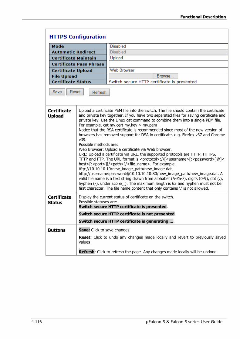
Functional Description
4-116 µFalcon-S & Falcon-S series User Guide
Certificate Upload
Upload a certificate PEM file into the switch. The file should contain the certificate and private key together. If you have two separated files for saving certificate and
private key. Use the Linux cat command to combine them into a single PEM file.
For example, cat my.cert my.key > my.pem Notice that the RSA certificate is recommended since most of the new version of
browsers has removed support for DSA in certificate, e.g. Firefox v37 and Chrome v39.
Possible methods are:
Web Browser: Upload a certificate via Web browser. URL: Upload a certificate via URL, the supported protocols are HTTP, HTTPS,
TFTP and FTP. The URL format is <protocol>://[<username>[:<password>]@]< host>[:<port>][/<path>]/<file_name>. For example,
tftp://10.10.10.10/new_image_path/new_image.dat, http://username:[email protected]:80/new_image_path/new_image.dat. A
valid file name is a text string drawn from alphabet (A-Za-z), digits (0-9), dot (.),
hyphen (-), under score(_). The maximum length is 63 and hyphen must not be first character. The file name content that only contains '.' is not allowed.
Certificate Status
Display the current status of certificate on the switch.
Possible statuses are: Switch secure HTTP certificate is presented.
Switch secure HTTP certificate is not presented.
Switch secure HTTP certificate is generating ....
Buttons Save: Click to save changes.
Reset: Click to undo any changes made locally and revert to previously saved values
. Refresh: Click to refresh the page. Any changes made locally will be undone.
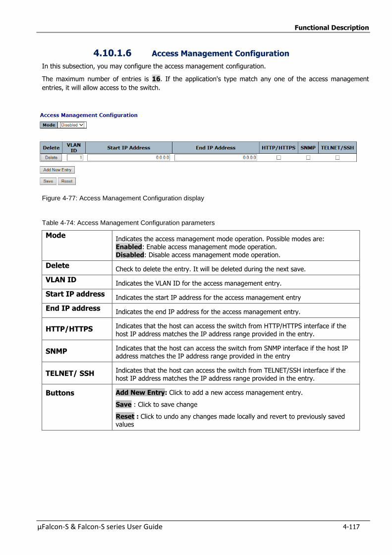
Functional Description
µFalcon-S & Falcon-S series User Guide 4-117
4.10.1.6 Access Management Configuration
In this subsection, you may configure the access management configuration.
The maximum number of entries is 16. If the application's type match any one of the access management
entries, it will allow access to the switch.
Figure 4-77: Access Management Configuration display
Table 4-74: Access Management Configuration parameters
Mode Indicates the access management mode operation. Possible modes are:
Enabled: Enable access management mode operation.
Disabled: Disable access management mode operation.
Delete Check to delete the entry. It will be deleted during the next save.
VLAN ID Indicates the VLAN ID for the access management entry.
Start IP address Indicates the start IP address for the access management entry
End IP address Indicates the end IP address for the access management entry.
HTTP/HTTPS Indicates that the host can access the switch from HTTP/HTTPS interface if the
host IP address matches the IP address range provided in the entry.
SNMP Indicates that the host can access the switch from SNMP interface if the host IP address matches the IP address range provided in the entry
TELNET/ SSH Indicates that the host can access the switch from TELNET/SSH interface if the
host IP address matches the IP address range provided in the entry.
Buttons Add New Entry: Click to add a new access management entry.
Save : Click to save change
Reset : Click to undo any changes made locally and revert to previously saved values
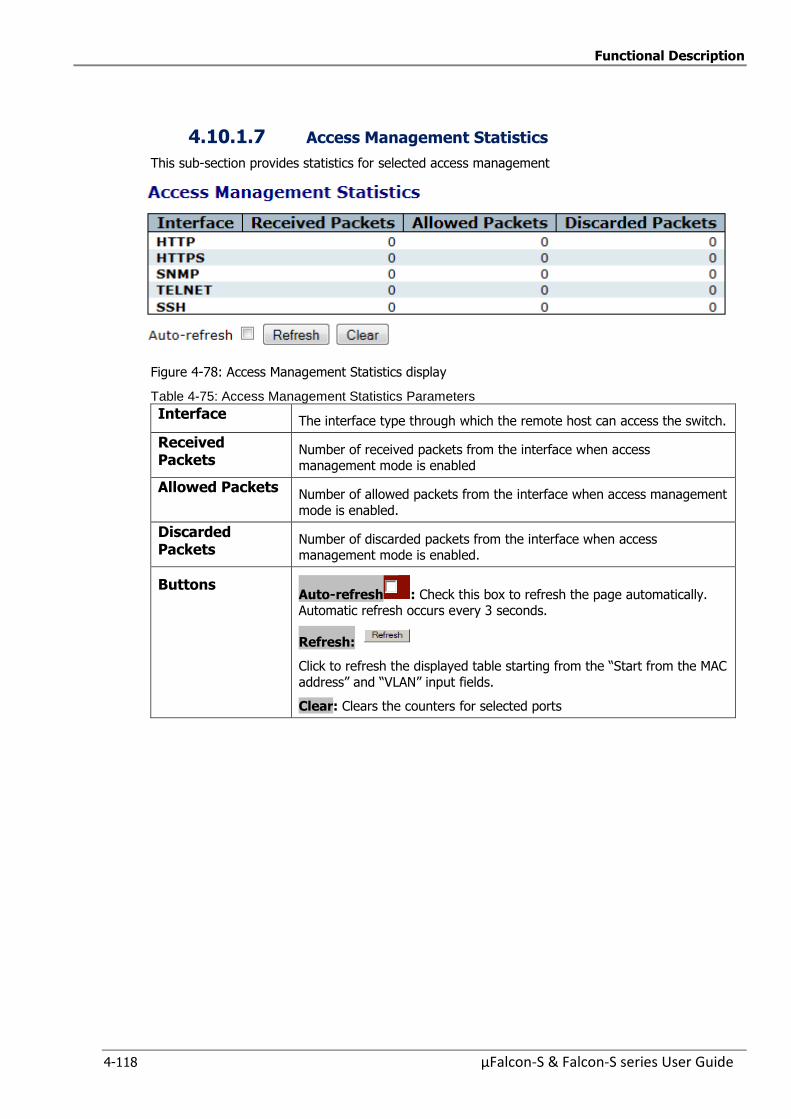
Functional Description
4-118 µFalcon-S & Falcon-S series User Guide
4.10.1.7 Access Management Statistics
This sub-section provides statistics for selected access management
Figure 4-78: Access Management Statistics display
Table 4-75: Access Management Statistics Parameters
Interface The interface type through which the remote host can access the switch.
Received Packets
Number of received packets from the interface when access management mode is enabled
Allowed Packets Number of allowed packets from the interface when access management
mode is enabled.
Discarded Packets
Number of discarded packets from the interface when access management mode is enabled.
Buttons Auto-refresh : Check this box to refresh the page automatically. Automatic refresh occurs every 3 seconds.
Refresh:
Click to refresh the displayed table starting from the “Start from the MAC
address” and “VLAN” input fields.
Clear: Clears the counters for selected ports
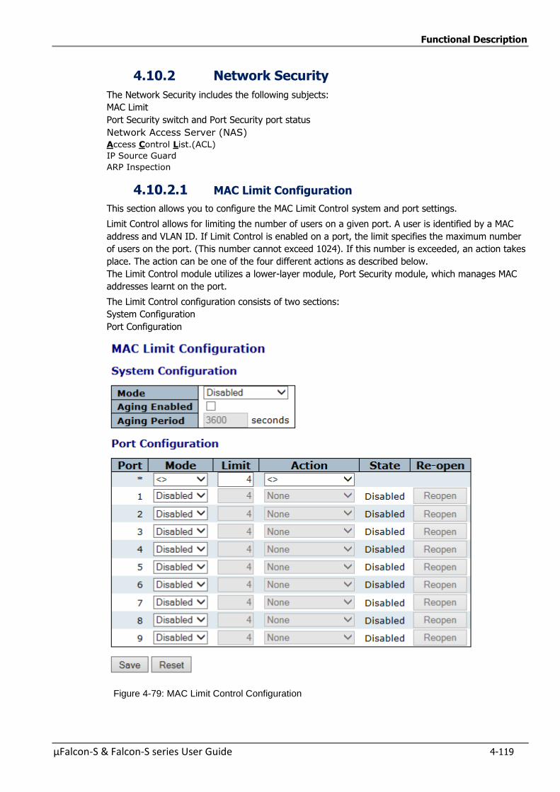
Functional Description
µFalcon-S & Falcon-S series User Guide 4-119
4.10.2 Network Security
The Network Security includes the following subjects:
MAC Limit
Port Security switch and Port Security port status
Network Access Server (NAS)
Access Control List.(ACL)
IP Source Guard
ARP Inspection
4.10.2.1 MAC Limit Configuration
This section allows you to configure the MAC Limit Control system and port settings.
Limit Control allows for limiting the number of users on a given port. A user is identified by a MAC
address and VLAN ID. If Limit Control is enabled on a port, the limit specifies the maximum number
of users on the port. (This number cannot exceed 1024). If this number is exceeded, an action takes
place. The action can be one of the four different actions as described below.
The Limit Control module utilizes a lower-layer module, Port Security module, which manages MAC
addresses learnt on the port.
The Limit Control configuration consists of two sections:
System Configuration
Port Configuration
Figure 4-79: MAC Limit Control Configuration
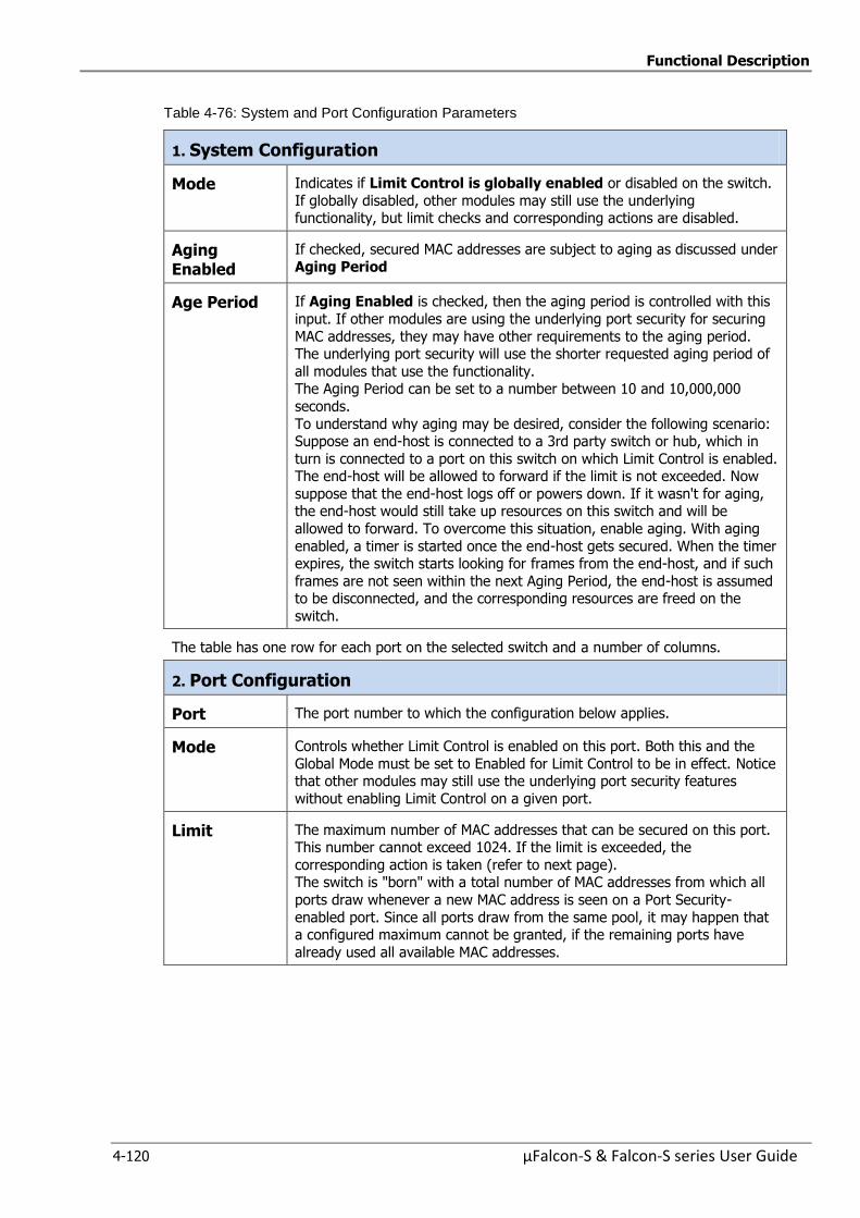
Functional Description
4-120 µFalcon-S & Falcon-S series User Guide
Table 4-76: System and Port Configuration Parameters
1. System Configuration
Mode Indicates if Limit Control is globally enabled or disabled on the switch.
If globally disabled, other modules may still use the underlying functionality, but limit checks and corresponding actions are disabled.
Aging Enabled
If checked, secured MAC addresses are subject to aging as discussed under
Aging Period
Age Period If Aging Enabled is checked, then the aging period is controlled with this
input. If other modules are using the underlying port security for securing
MAC addresses, they may have other requirements to the aging period. The underlying port security will use the shorter requested aging period of
all modules that use the functionality. The Aging Period can be set to a number between 10 and 10,000,000
seconds.
To understand why aging may be desired, consider the following scenario: Suppose an end-host is connected to a 3rd party switch or hub, which in
turn is connected to a port on this switch on which Limit Control is enabled. The end-host will be allowed to forward if the limit is not exceeded. Now
suppose that the end-host logs off or powers down. If it wasn't for aging, the end-host would still take up resources on this switch and will be
allowed to forward. To overcome this situation, enable aging. With aging
enabled, a timer is started once the end-host gets secured. When the timer expires, the switch starts looking for frames from the end-host, and if such
frames are not seen within the next Aging Period, the end-host is assumed to be disconnected, and the corresponding resources are freed on the
switch.
The table has one row for each port on the selected switch and a number of columns.
2. Port Configuration
Port The port number to which the configuration below applies.
Mode Controls whether Limit Control is enabled on this port. Both this and the
Global Mode must be set to Enabled for Limit Control to be in effect. Notice that other modules may still use the underlying port security features
without enabling Limit Control on a given port.
Limit The maximum number of MAC addresses that can be secured on this port. This number cannot exceed 1024. If the limit is exceeded, the
corresponding action is taken (refer to next page). The switch is "born" with a total number of MAC addresses from which all
ports draw whenever a new MAC address is seen on a Port Security-
enabled port. Since all ports draw from the same pool, it may happen that a configured maximum cannot be granted, if the remaining ports have
already used all available MAC addresses.

Functional Description
µFalcon-S & Falcon-S series User Guide 4-121
Action
If Limit is reached, the switch can take one of the following actions:
None: Do not allow more than Limit MAC addresses on the port, but take no further action.
Trap: If Limit + 1 MAC addresses is seen on the port send an SNMP trap. If
Aging is disabled, only one SNMP trap will be sent, but with Aging enabled, new SNMP traps will be sent every time the limit gets exceeded.
Shutdown: If Limit + 1 MAC addresses is seen on the port, shut down the port. This implies that all secured MAC addresses will be removed from the
port, and no new address will be learned. Even if the link is physically disconnected and reconnected on the port (by disconnecting the cable),
the port will remain shut down. There are three ways to re-open the port:
1) Boot the stack or elect a new master the switch, 2) Disable and re-enable Limit Control on the port or the switch,
3) Click the Reopen button. Trap & Shutdown: If Limit + 1 MAC addresses is seen on the port, both the
"Trap" and the "Shutdown" actions described above will be taken.
State This column shows the current state of the port as seen from the Limit Control's point of view. The state takes one of four values:
Disabled: Limit Control is either globally disabled or disabled on the port. Ready: The limit is not yet reached. This can be shown for all actions.
Limit Reached: Indicates that the limit is reached on this port. This state
can only be shown if Action is set to None or Trap. Shutdown: Indicates that the port is shut down by the Limit Control
module. This state can only be shown if Action is set to Shutdown or Trap & Shutdown
Re-open Button
If a port is shutdown by this module, you may reopen it by clicking this
button, which will only be enabled if this is the case. For other methods, refer to Shutdown in the Action section.
Note that clicking the reopen button causes the page to be refreshed, so non-committed changes will be lost.
Buttons Refresh:
Click to refresh the screen.
Save:
Click to save changes.
Reset:
Click to undo any changes made locally and revert to previously saves
values.
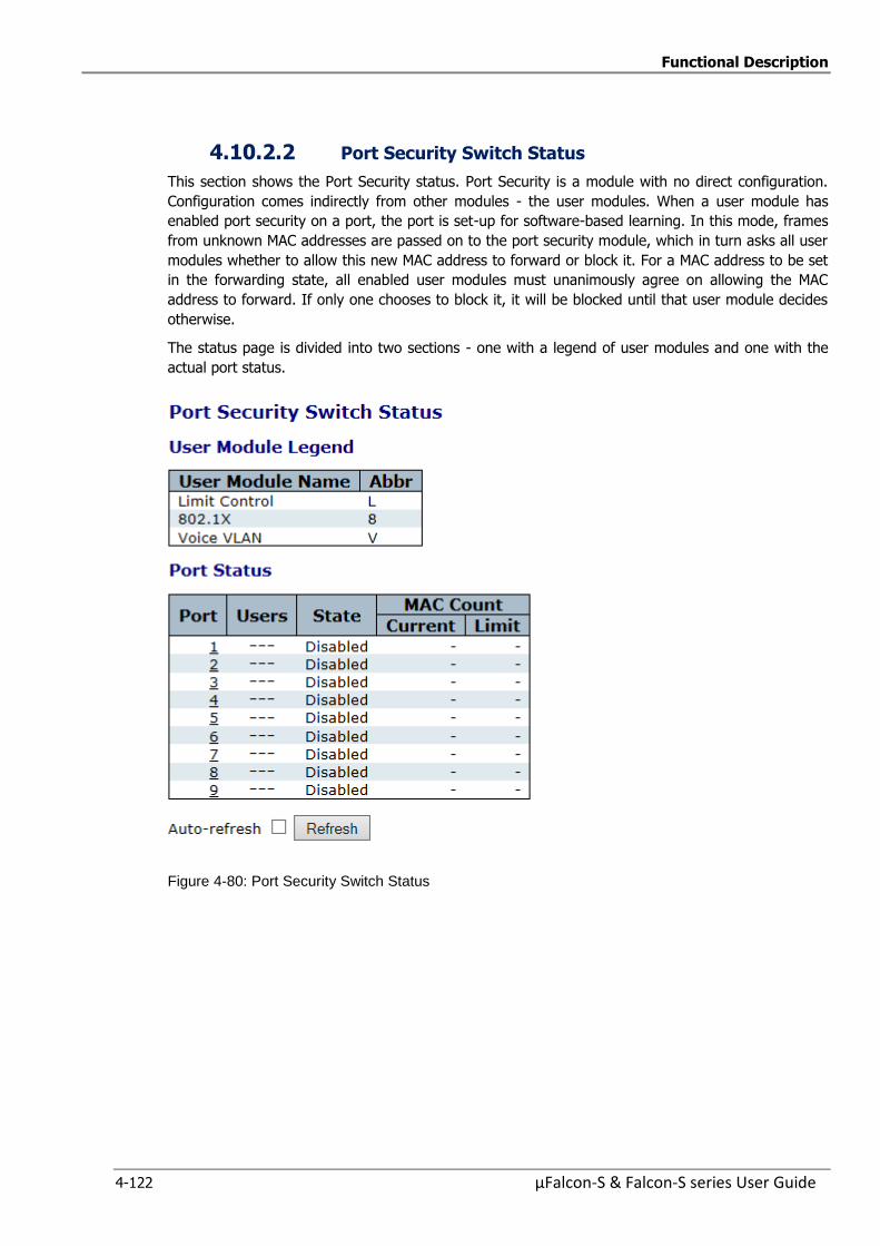
Functional Description
4-122 µFalcon-S & Falcon-S series User Guide
4.10.2.2 Port Security Switch Status
This section shows the Port Security status. Port Security is a module with no direct configuration.
Configuration comes indirectly from other modules - the user modules. When a user module has
enabled port security on a port, the port is set-up for software-based learning. In this mode, frames
from unknown MAC addresses are passed on to the port security module, which in turn asks all user
modules whether to allow this new MAC address to forward or block it. For a MAC address to be set
in the forwarding state, all enabled user modules must unanimously agree on allowing the MAC
address to forward. If only one chooses to block it, it will be blocked until that user module decides
otherwise.
The status page is divided into two sections - one with a legend of user modules and one with the
actual port status.
Figure 4-80: Port Security Switch Status
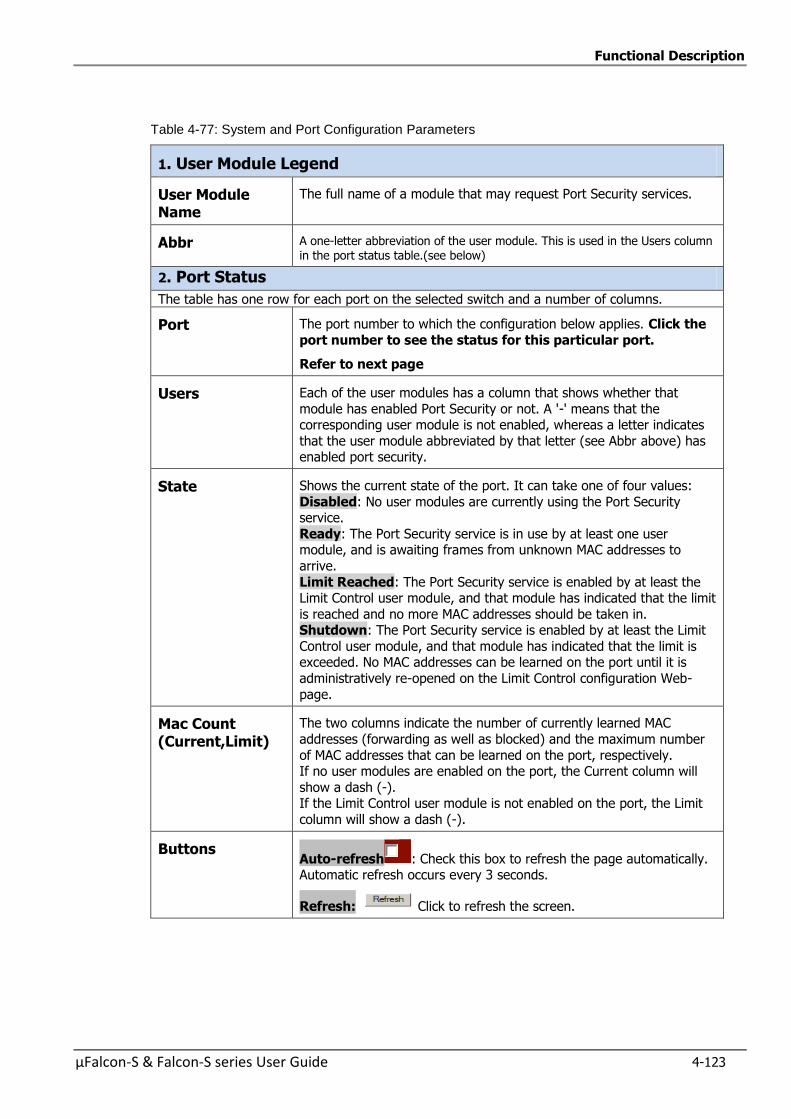
Functional Description
µFalcon-S & Falcon-S series User Guide 4-123
Table 4-77: System and Port Configuration Parameters
1. User Module Legend
User Module Name
The full name of a module that may request Port Security services.
Abbr A one-letter abbreviation of the user module. This is used in the Users column in the port status table.(see below)
2. Port Status
The table has one row for each port on the selected switch and a number of columns.
Port The port number to which the configuration below applies. Click the
port number to see the status for this particular port.
Refer to next page
Users Each of the user modules has a column that shows whether that
module has enabled Port Security or not. A '-' means that the corresponding user module is not enabled, whereas a letter indicates
that the user module abbreviated by that letter (see Abbr above) has enabled port security.
State Shows the current state of the port. It can take one of four values:
Disabled: No user modules are currently using the Port Security service.
Ready: The Port Security service is in use by at least one user module, and is awaiting frames from unknown MAC addresses to
arrive.
Limit Reached: The Port Security service is enabled by at least the Limit Control user module, and that module has indicated that the limit
is reached and no more MAC addresses should be taken in. Shutdown: The Port Security service is enabled by at least the Limit
Control user module, and that module has indicated that the limit is exceeded. No MAC addresses can be learned on the port until it is
administratively re-opened on the Limit Control configuration Web-
page.
Mac Count (Current,Limit)
The two columns indicate the number of currently learned MAC
addresses (forwarding as well as blocked) and the maximum number
of MAC addresses that can be learned on the port, respectively. If no user modules are enabled on the port, the Current column will
show a dash (-). If the Limit Control user module is not enabled on the port, the Limit
column will show a dash (-).
Buttons Auto-refresh : Check this box to refresh the page automatically. Automatic refresh occurs every 3 seconds.
Refresh: Click to refresh the screen.
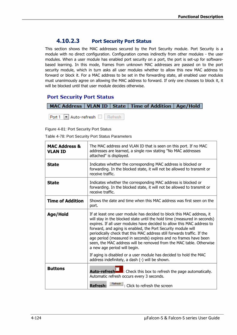
Functional Description
4-124 µFalcon-S & Falcon-S series User Guide
4.10.2.3 Port Security Port Status
This section shows the MAC addresses secured by the Port Security module. Port Security is a
module with no direct configuration. Configuration comes indirectly from other modules - the user
modules. When a user module has enabled port security on a port, the port is set-up for software-
based learning. In this mode, frames from unknown MAC addresses are passed on to the port
security module, which in turn asks all user modules whether to allow this new MAC address to
forward or block it. For a MAC address to be set in the forwarding state, all enabled user modules
must unanimously agree on allowing the MAC address to forward. If only one chooses to block it, it
will be blocked until that user module decides otherwise.
Figure 4-81: Port Security Port Status
Table 4-78: Port Security Port Status Parameters
MAC Address & VLAN ID
The MAC address and VLAN ID that is seen on this port. If no MAC addresses are learned, a single row stating "No MAC addresses
attached" is displayed.
State Indicates whether the corresponding MAC address is blocked or forwarding. In the blocked state, it will not be allowed to transmit or
receive traffic.
State Indicates whether the corresponding MAC address is blocked or forwarding. In the blocked state, it will not be allowed to transmit or
receive traffic.
Time of Addition Shows the date and time when this MAC address was first seen on the port.
Age/Hold If at least one user module has decided to block this MAC address, it
will stay in the blocked state until the hold time (measured in seconds) expires. If all user modules have decided to allow this MAC address to
forward, and aging is enabled, the Port Security module will periodically check that this MAC address still forwards traffic. If the
age period (measured in seconds) expires and no frames have been seen, the MAC address will be removed from the MAC table. Otherwise
a new age period will begin.
If aging is disabled or a user module has decided to hold the MAC address indefinitely, a dash (-) will be shown.
Buttons Auto-refresh : Check this box to refresh the page automatically. Automatic refresh occurs every 3 seconds.
Refresh: : Click to refresh the screen

Functional Description
µFalcon-S & Falcon-S series User Guide 4-125
4.10.2.4 Network Access Server Configuration
This page allows you to configure the IEEE 802.1X and MAC-based authentication system and port
settings.
The IEEE 802.1X standard defines a port-based access control procedure that prevents unauthorized
access to a network by requiring users to first submit credentials for authentication. One or more
central servers, the backend servers, determine whether the user is allowed access to the network.
These backend (RADIUS) servers are configured on the "Configuration→Security→AAA" section. The
IEEE802.1X standard defines port-based operation, but non-standard variants overcome security
limitations as shall be explored below
MAC-based authentication allows for authentication of more than one user on the same port, and
doesn't require the user to have special 802.1X supplicant software installed on his system. The
switch uses the user's MAC address to authenticate against the backend server. Intruders can create
counterfeit MAC addresses, which makes MAC-based authentication less secure than 802.1 X
authentications
The NAS configuration consists of two sections, System and Port Configurations.
Figure 4-82: Network Access Server Configuration
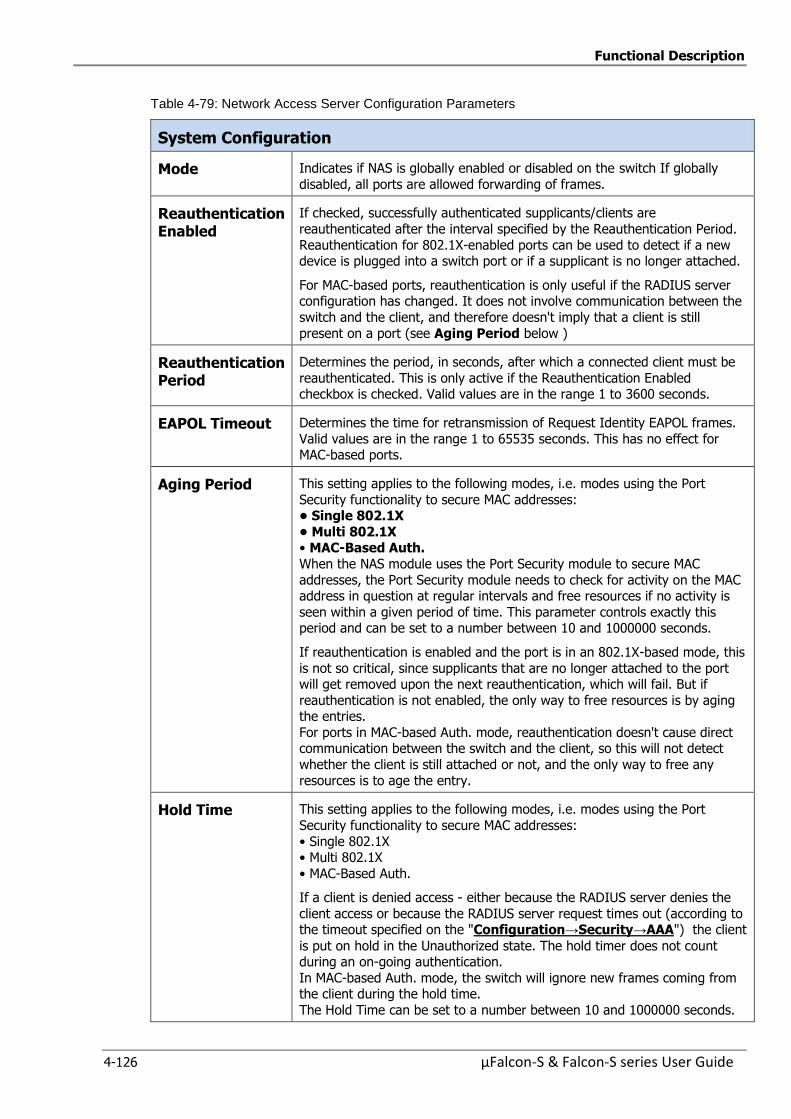
Functional Description
4-126 µFalcon-S & Falcon-S series User Guide
Table 4-79: Network Access Server Configuration Parameters
System Configuration
Mode Indicates if NAS is globally enabled or disabled on the switch If globally
disabled, all ports are allowed forwarding of frames.
Reauthentication Enabled
If checked, successfully authenticated supplicants/clients are
reauthenticated after the interval specified by the Reauthentication Period.
Reauthentication for 802.1X-enabled ports can be used to detect if a new device is plugged into a switch port or if a supplicant is no longer attached.
For MAC-based ports, reauthentication is only useful if the RADIUS server configuration has changed. It does not involve communication between the
switch and the client, and therefore doesn't imply that a client is still
present on a port (see Aging Period below )
Reauthentication Period
Determines the period, in seconds, after which a connected client must be
reauthenticated. This is only active if the Reauthentication Enabled checkbox is checked. Valid values are in the range 1 to 3600 seconds.
EAPOL Timeout Determines the time for retransmission of Request Identity EAPOL frames.
Valid values are in the range 1 to 65535 seconds. This has no effect for MAC-based ports.
Aging Period This setting applies to the following modes, i.e. modes using the Port
Security functionality to secure MAC addresses: •Single802.1X
•Multi802.1X • MAC-Based Auth.
When the NAS module uses the Port Security module to secure MAC
addresses, the Port Security module needs to check for activity on the MAC address in question at regular intervals and free resources if no activity is
seen within a given period of time. This parameter controls exactly this period and can be set to a number between 10 and 1000000 seconds.
If reauthentication is enabled and the port is in an 802.1X-based mode, this
is not so critical, since supplicants that are no longer attached to the port will get removed upon the next reauthentication, which will fail. But if
reauthentication is not enabled, the only way to free resources is by aging the entries.
For ports in MAC-based Auth. mode, reauthentication doesn't cause direct communication between the switch and the client, so this will not detect
whether the client is still attached or not, and the only way to free any
resources is to age the entry.
Hold Time This setting applies to the following modes, i.e. modes using the Port
Security functionality to secure MAC addresses:
• Single 802.1X • Multi 802.1X
• MAC-Based Auth.
If a client is denied access - either because the RADIUS server denies the
client access or because the RADIUS server request times out (according to the timeout specified on the "Configuration→Security→AAA") the client
is put on hold in the Unauthorized state. The hold timer does not count during an on-going authentication.
In MAC-based Auth. mode, the switch will ignore new frames coming from the client during the hold time.
The Hold Time can be set to a number between 10 and 1000000 seconds.
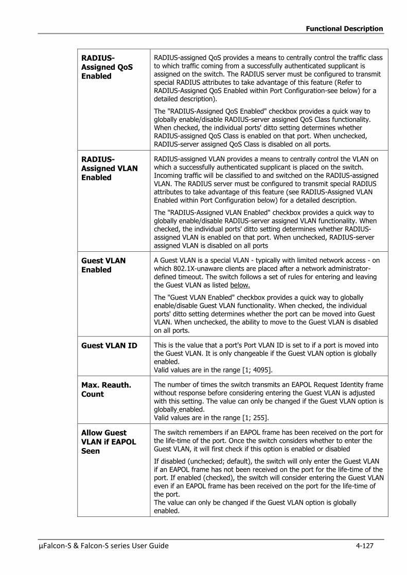
Functional Description
µFalcon-S & Falcon-S series User Guide 4-127
RADIUS-Assigned QoS Enabled
RADIUS-assigned QoS provides a means to centrally control the traffic class
to which traffic coming from a successfully authenticated supplicant is assigned on the switch. The RADIUS server must be configured to transmit
special RADIUS attributes to take advantage of this feature (Refer to
RADIUS-Assigned QoS Enabled within Port Configuration-see below) for a detailed description).
The "RADIUS-Assigned QoS Enabled" checkbox provides a quick way to globally enable/disable RADIUS-server assigned QoS Class functionality.
When checked, the individual ports' ditto setting determines whether RADIUS-assigned QoS Class is enabled on that port. When unchecked,
RADIUS-server assigned QoS Class is disabled on all ports.
RADIUS-Assigned VLAN Enabled
RADIUS-assigned VLAN provides a means to centrally control the VLAN on which a successfully authenticated supplicant is placed on the switch.
Incoming traffic will be classified to and switched on the RADIUS-assigned
VLAN. The RADIUS server must be configured to transmit special RADIUS attributes to take advantage of this feature (see RADIUS-Assigned VLAN
Enabled within Port Configuration below) for a detailed description.
The "RADIUS-Assigned VLAN Enabled" checkbox provides a quick way to
globally enable/disable RADIUS-server assigned VLAN functionality. When checked, the individual ports' ditto setting determines whether RADIUS-
assigned VLAN is enabled on that port. When unchecked, RADIUS-server
assigned VLAN is disabled on all ports
Guest VLAN Enabled
A Guest VLAN is a special VLAN - typically with limited network access - on
which 802.1X-unaware clients are placed after a network administrator-
defined timeout. The switch follows a set of rules for entering and leaving the Guest VLAN as listed below.
The "Guest VLAN Enabled" checkbox provides a quick way to globally enable/disable Guest VLAN functionality. When checked, the individual
ports' ditto setting determines whether the port can be moved into Guest VLAN. When unchecked, the ability to move to the Guest VLAN is disabled
on all ports.
Guest VLAN ID This is the value that a port's Port VLAN ID is set to if a port is moved into the Guest VLAN. It is only changeable if the Guest VLAN option is globally
enabled.
Valid values are in the range [1; 4095].
Max. Reauth. Count
The number of times the switch transmits an EAPOL Request Identity frame
without response before considering entering the Guest VLAN is adjusted
with this setting. The value can only be changed if the Guest VLAN option is globally enabled.
Valid values are in the range [1; 255].
Allow Guest VLAN if EAPOL Seen
The switch remembers if an EAPOL frame has been received on the port for
the life-time of the port. Once the switch considers whether to enter the
Guest VLAN, it will first check if this option is enabled or disabled
If disabled (unchecked; default), the switch will only enter the Guest VLAN
if an EAPOL frame has not been received on the port for the life-time of the port. If enabled (checked), the switch will consider entering the Guest VLAN
even if an EAPOL frame has been received on the port for the life-time of
the port. The value can only be changed if the Guest VLAN option is globally
enabled.
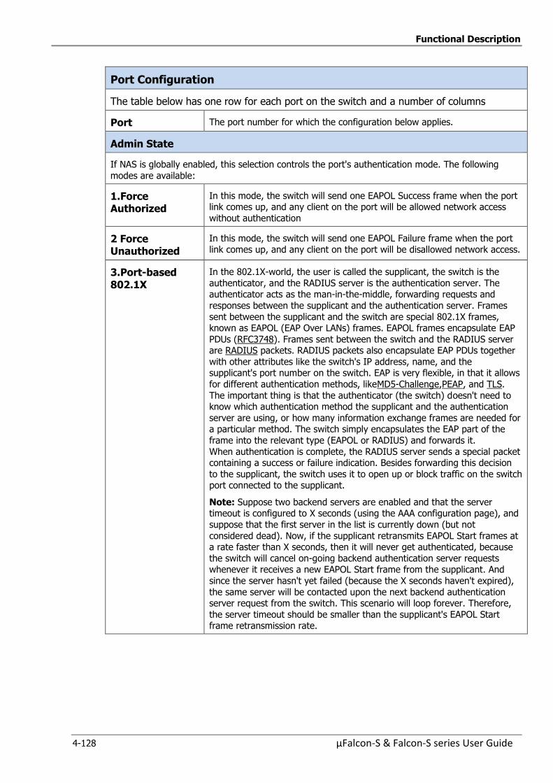
Functional Description
4-128 µFalcon-S & Falcon-S series User Guide
Port Configuration
The table below has one row for each port on the switch and a number of columns
Port The port number for which the configuration below applies.
Admin State
If NAS is globally enabled, this selection controls the port's authentication mode. The following
modes are available:
1.Force Authorized
In this mode, the switch will send one EAPOL Success frame when the port link comes up, and any client on the port will be allowed network access
without authentication
2 Force Unauthorized
In this mode, the switch will send one EAPOL Failure frame when the port link comes up, and any client on the port will be disallowed network access.
3.Port-based 802.1X
In the 802.1X-world, the user is called the supplicant, the switch is the
authenticator, and the RADIUS server is the authentication server. The authenticator acts as the man-in-the-middle, forwarding requests and
responses between the supplicant and the authentication server. Frames
sent between the supplicant and the switch are special 802.1X frames, known as EAPOL (EAP Over LANs) frames. EAPOL frames encapsulate EAP
PDUs (RFC3748). Frames sent between the switch and the RADIUS server are RADIUS packets. RADIUS packets also encapsulate EAP PDUs together
with other attributes like the switch's IP address, name, and the supplicant's port number on the switch. EAP is very flexible, in that it allows
for different authentication methods, likeMD5-Challenge,PEAP, and TLS.
The important thing is that the authenticator (the switch) doesn't need to know which authentication method the supplicant and the authentication
server are using, or how many information exchange frames are needed for a particular method. The switch simply encapsulates the EAP part of the
frame into the relevant type (EAPOL or RADIUS) and forwards it.
When authentication is complete, the RADIUS server sends a special packet containing a success or failure indication. Besides forwarding this decision
to the supplicant, the switch uses it to open up or block traffic on the switch port connected to the supplicant.
Note: Suppose two backend servers are enabled and that the server timeout is configured to X seconds (using the AAA configuration page), and
suppose that the first server in the list is currently down (but not
considered dead). Now, if the supplicant retransmits EAPOL Start frames at a rate faster than X seconds, then it will never get authenticated, because
the switch will cancel on-going backend authentication server requests whenever it receives a new EAPOL Start frame from the supplicant. And
since the server hasn't yet failed (because the X seconds haven't expired),
the same server will be contacted upon the next backend authentication server request from the switch. This scenario will loop forever. Therefore,
the server timeout should be smaller than the supplicant's EAPOL Start frame retransmission rate.
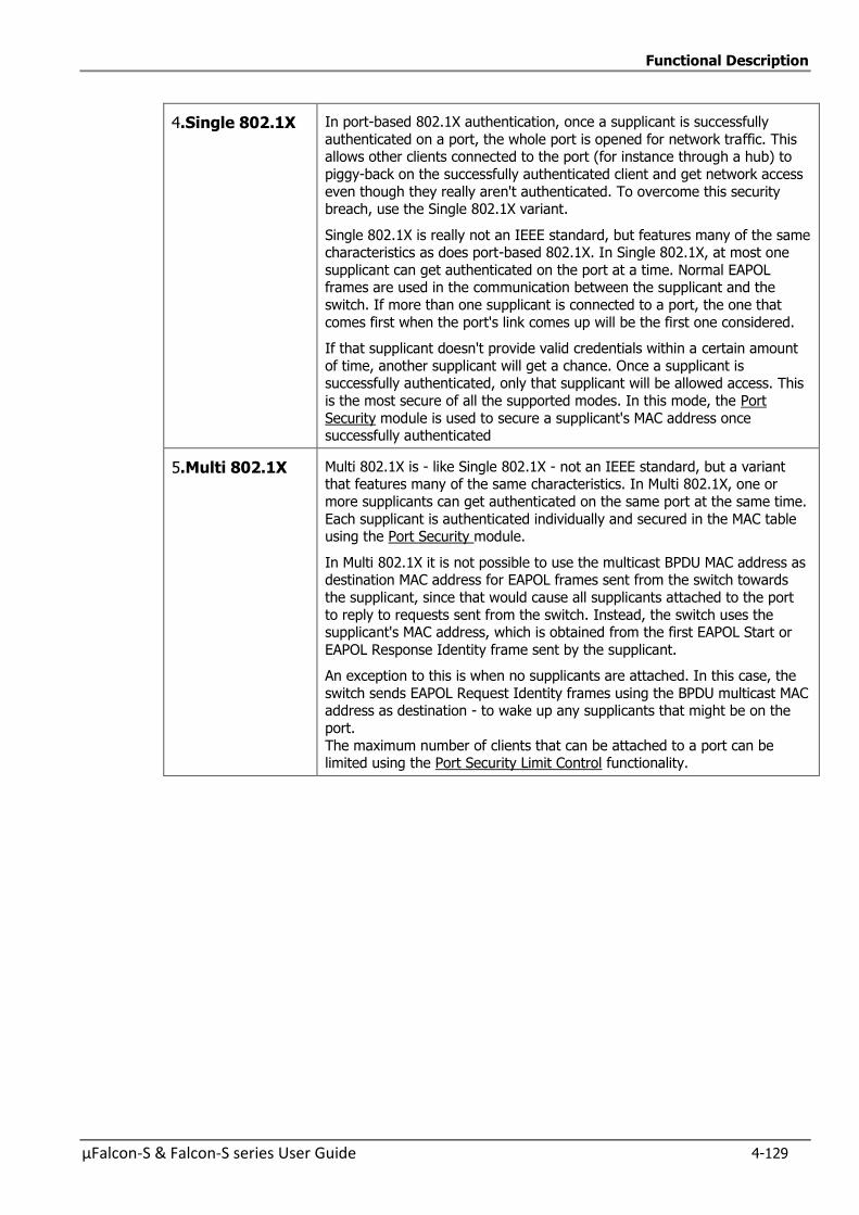
Functional Description
µFalcon-S & Falcon-S series User Guide 4-129
4.Single 802.1X In port-based 802.1X authentication, once a supplicant is successfully
authenticated on a port, the whole port is opened for network traffic. This allows other clients connected to the port (for instance through a hub) to
piggy-back on the successfully authenticated client and get network access
even though they really aren't authenticated. To overcome this security breach, use the Single 802.1X variant.
Single 802.1X is really not an IEEE standard, but features many of the same characteristics as does port-based 802.1X. In Single 802.1X, at most one
supplicant can get authenticated on the port at a time. Normal EAPOL frames are used in the communication between the supplicant and the
switch. If more than one supplicant is connected to a port, the one that
comes first when the port's link comes up will be the first one considered.
If that supplicant doesn't provide valid credentials within a certain amount
of time, another supplicant will get a chance. Once a supplicant is successfully authenticated, only that supplicant will be allowed access. This
is the most secure of all the supported modes. In this mode, the Port
Security module is used to secure a supplicant's MAC address once successfully authenticated
5.Multi 802.1X Multi 802.1X is - like Single 802.1X - not an IEEE standard, but a variant that features many of the same characteristics. In Multi 802.1X, one or
more supplicants can get authenticated on the same port at the same time.
Each supplicant is authenticated individually and secured in the MAC table using the Port Security module.
In Multi 802.1X it is not possible to use the multicast BPDU MAC address as destination MAC address for EAPOL frames sent from the switch towards
the supplicant, since that would cause all supplicants attached to the port
to reply to requests sent from the switch. Instead, the switch uses the supplicant's MAC address, which is obtained from the first EAPOL Start or
EAPOL Response Identity frame sent by the supplicant.
An exception to this is when no supplicants are attached. In this case, the
switch sends EAPOL Request Identity frames using the BPDU multicast MAC address as destination - to wake up any supplicants that might be on the
port.
The maximum number of clients that can be attached to a port can be limited using the Port Security Limit Control functionality.
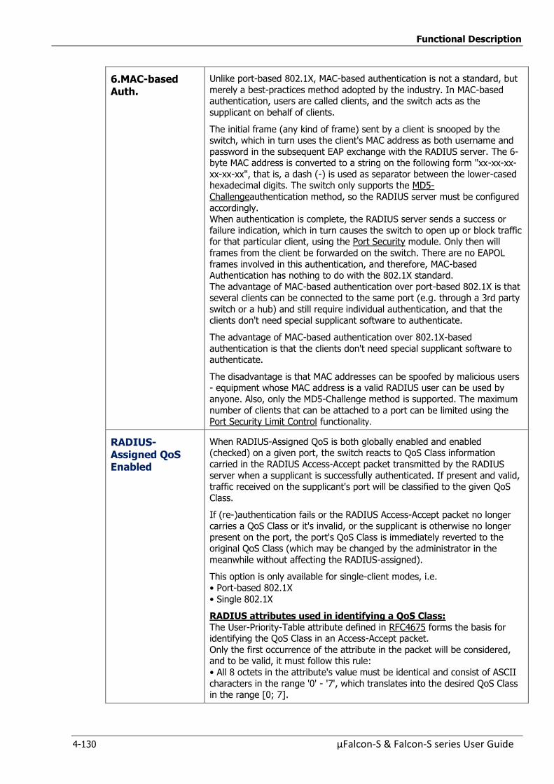
Functional Description
4-130 µFalcon-S & Falcon-S series User Guide
6.MAC-based Auth.
Unlike port-based 802.1X, MAC-based authentication is not a standard, but
merely a best-practices method adopted by the industry. In MAC-based authentication, users are called clients, and the switch acts as the
supplicant on behalf of clients.
The initial frame (any kind of frame) sent by a client is snooped by the switch, which in turn uses the client's MAC address as both username and
password in the subsequent EAP exchange with the RADIUS server. The 6-byte MAC address is converted to a string on the following form "xx-xx-xx-
xx-xx-xx", that is, a dash (-) is used as separator between the lower-cased hexadecimal digits. The switch only supports the MD5-
Challengeauthentication method, so the RADIUS server must be configured
accordingly. When authentication is complete, the RADIUS server sends a success or
failure indication, which in turn causes the switch to open up or block traffic for that particular client, using the Port Security module. Only then will
frames from the client be forwarded on the switch. There are no EAPOL
frames involved in this authentication, and therefore, MAC-based Authentication has nothing to do with the 802.1X standard.
The advantage of MAC-based authentication over port-based 802.1X is that several clients can be connected to the same port (e.g. through a 3rd party
switch or a hub) and still require individual authentication, and that the clients don't need special supplicant software to authenticate.
The advantage of MAC-based authentication over 802.1X-based
authentication is that the clients don't need special supplicant software to authenticate.
The disadvantage is that MAC addresses can be spoofed by malicious users - equipment whose MAC address is a valid RADIUS user can be used by
anyone. Also, only the MD5-Challenge method is supported. The maximum
number of clients that can be attached to a port can be limited using the Port Security Limit Control functionality.
RADIUS-Assigned QoS Enabled
When RADIUS-Assigned QoS is both globally enabled and enabled (checked) on a given port, the switch reacts to QoS Class information
carried in the RADIUS Access-Accept packet transmitted by the RADIUS
server when a supplicant is successfully authenticated. If present and valid, traffic received on the supplicant's port will be classified to the given QoS
Class.
If (re-)authentication fails or the RADIUS Access-Accept packet no longer
carries a QoS Class or it's invalid, or the supplicant is otherwise no longer
present on the port, the port's QoS Class is immediately reverted to the original QoS Class (which may be changed by the administrator in the
meanwhile without affecting the RADIUS-assigned).
This option is only available for single-client modes, i.e.
• Port-based 802.1X
• Single 802.1X
RADIUS attributes used in identifying a QoS Class:
The User-Priority-Table attribute defined in RFC4675 forms the basis for identifying the QoS Class in an Access-Accept packet.
Only the first occurrence of the attribute in the packet will be considered, and to be valid, it must follow this rule:
• All 8 octets in the attribute's value must be identical and consist of ASCII
characters in the range '0' - '7', which translates into the desired QoS Class in the range [0; 7].
Functional Description
µFalcon-S & Falcon-S series User Guide 4-131
RADIUS-Assigned VLAN Enabled
When RADIUS-Assigned VLAN is both globally enabled and enabled
(checked) for a given port, the switch reacts to VLAN ID information carried in the RADIUS Access-Accept packet transmitted by the RADIUS server
when a supplicant is successfully authenticated. If present and valid, the
port's Port VLAN ID will be changed to this VLAN ID, the port will be set to be a member of that VLAN ID, and the port will be forced into VLAN
unaware mode. Once assigned, all traffic arriving on the port will be classified and switched on the RADIUS-assigned VLAN ID.
If (re-)authentication fails or the RADIUS Access-Accept packet no longer carries a VLAN ID or it's invalid, or the supplicant is otherwise no longer
present on the port, the port's VLAN ID is immediately reverted to the
original VLAN ID (which may be changed by the administrator in the meanwhile without affecting the RADIUS-assigned).
This option is only available for single-client modes, i.e. • Port-based 802.1X
• Single 802.1X
For trouble-shooting VLAN assignments, use the " VLANs→VLAN
Membership Status and VLAN Port Status pages. These pages show which modules have (temporarily) overridden the current Port VLAN configuration.
RADIUS attributes used in identifying a VLAN ID:
RFC2868 and RFC3580 form the basis for the attributes used in identifying
a VLAN ID in an Access-Accept packet. The following criteria are used:
The Tunnel-Medium-Type, Tunnel-Type, and Tunnel-Private-Group-IDattributes must all be present at least once in the Access-Accept packet.
The switch looks for the first set of these attributes that have the same Tag value and fulfil the following requirements (if Tag == 0 is used, the Tunnel-
Private-Group-IDdoes not need to include a Tag): - Value of Tunnel-Medium-Type must be set to "IEEE-802" (ordinal 6).
- Value of Tunnel-Type must be set to "VLAN" (ordinal 13).
- Value of Tunnel-Private-Group-ID must be a string of ASCII chars in the range '0' - '9', which is interpreted as a decimal string representing the
VLAN ID. Leading '0's are discarded. The final value must be in the range [1; 4095].
Functional Description
4-132 µFalcon-S & Falcon-S series User Guide
Guest VLAN Enabled
When Guest VLAN is both globally enabled and enabled (checked) for a
given port, the switch considers moving the port into the Guest VLAN according to the rules outlined below.
This option is only available for EAPOL-based modes, i.e.:
• Port-based 802.1X • Single 802.1X
• Multi 802.1X For trouble-shooting VLAN assignments, use the " →VLANs→VLAN
Membership Status and VLAN Port Status" pages. These pages show which
modules have (temporarily) overridden the current Port VLAN configuration.
Guest VLAN Operation:
When a Guest VLAN enabled port's link comes up, the switch starts
transmitting EAPOL Request Identity frames. If the number of transmissions of such frames exceeds Max. Reauth. Count (refer to System Configuration
above) and no EAPOL frames have been received in the meanwhile, the switch considers entering the Guest VLAN. The interval between
transmission of EAPOL Request Identity frames is configured with EAPOL
Timeout. If Allow Guest VLAN if EAPOL Seen (refer to System Configuration above ) is enabled, the port will now be placed in the Guest VLAN. If
disabled, the switch will first check its history to see if an EAPOL frame has previously been received on the port (this history is cleared if the port link
goes down or the port's Admin State is changed -Refer to Port
Configuration), and if not, the port will be placed in the Guest VLAN. Otherwise it will not move to the Guest VLAN, but continue transmitting
EAPOL Request Identity frames at the rate given by EAPOL Timeout.
Once in the Guest VLAN, the port is considered authenticated, and all
attached clients on the port are allowed access on this VLAN. The switch will not transmit an EAPOL Success frame when entering the Guest VLAN.
While in the Guest VLAN, the switch monitors the link for EAPOL frames,
and if one such frame is received, the switch immediately takes the port out of the Guest VLAN and starts authenticating the supplicant according to the
port mode. If an EAPOL frame is received, the port will never be able to go back into the Guest VLAN if the "Allow Guest VLAN if EAPOL Seen" is
disabled.
Port State The current state of the port. It can undertake one of the following values: Globally Disabled: NAS is globally disabled.
Link Down: NAS is globally enabled, but there is no link on the port. Authorized: The port is in Force Authorized (Refer to Port Configuration
above) or a single-supplicant mode and the supplicant is authorized.
Unauthorized: The port is in Force Unauthorized ((Refer to Port Configuration above) or a single-supplicant mode and the supplicant is not
successfully authorized by the RADIUS server. X Auth/Y Unauth: The port is in a multi-supplicant mode. Currently X
clients are authorized and Y are unauthorized

Functional Description
µFalcon-S & Falcon-S series User Guide 4-133
Restart Two buttons are available for each row. The buttons are only enabled when
authentication is globally enabled and the port's Admin State (Refer to beginning of Port Configuration above)is in an EAPOL-based or MAC-based
mode.( Refer to f Port Configuration above)
Clicking these buttons will not cause settings changed on the page to take effect.
Reauthenticate: Schedules a reauthentication whenever the quiet-period of the port runs out(EAPOL-based authentication).For MAC-based
authentication, reauthentication will be attempted immediately. The button only has effect for successfully authenticated clients on the port
and will not cause the clients to get temporarily unauthorized
Reinitialize: Forces a reinitialization of the clients on the port and thereby a reauthentication immediately. The clients will transfer to the unauthorized
state while the reauthentication is in progress.
Buttons Refresh: Click to refresh the page.
Click to refresh the screen immediately
Save: Click to save changes.
Reset: Click to undo any changes made locally and revert to previously
saved values
4.10.2.5 Network Access Server Switch Status
This section provides an overview of the current NAS port states for the selected switch.
Figure 4-83: Network Access Server Switch Status
Table 4-80: Network Access Server Switch Status Parameters
Port The switch port number. Click to navigate to detailed NAS statistics for this port. Refer to next section
Admin State The port's current administrative state. Refer to NAS Admin State for a description of possible values Network Access Server Configuration
Port State The current state of the port. Refer to NAS Port State for a description
of the individual states. Network Access Server Configuration
Functional Description
4-134 µFalcon-S & Falcon-S series User Guide
Last Source The source MAC address carried in the most recently received EAPOL
frame for EAPOL-based authentication, and the most recently received frame from a new client for MAC-based authentication
Last ID The user name (supplicant identity) carried in the most recently received
Response Identity EAPOL frame for EAPOL-based authentication, and the source MAC address from the most recently received frame from a
new client for MAC-based authentication
QoS Class QoS Class assigned to the port by the RADIUS server if enabled.
Port VLAN ID The VLAN ID that NAS has put the port in. The field is blank, if the Port
VLAN ID is not overridden by NAS.
If the VLAN ID is assigned by the RADIUS server, "(RADIUS-assigned)" is appended to the VLAN ID. (Read more about RADIUS-assigned VLANs
at previous section. System Configuration). If the port is moved to the Guest VLAN, "(Guest)" is appended to the
VLAN ID. Read more about Guest VLANs (previous section System Configuration).
Buttons Auto-refresh : Check this box to refresh the page automatically. Automatic refresh occurs every 3 seconds
Refresh: Click to refresh the page; any changes made locally will be
undone
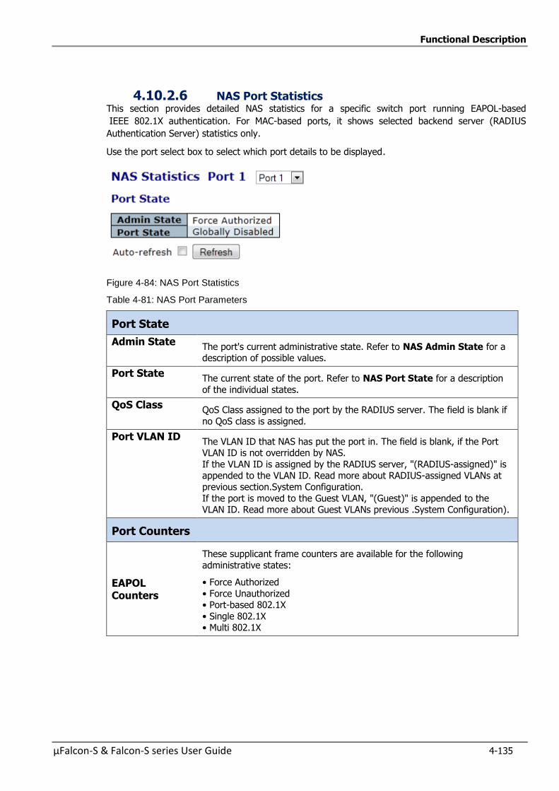
Functional Description
µFalcon-S & Falcon-S series User Guide 4-135
4.10.2.6 NAS Port Statistics This section provides detailed NAS statistics for a specific switch port running EAPOL-based
IEEE 802.1X authentication. For MAC-based ports, it shows selected backend server (RADIUS
Authentication Server) statistics only.
Use the port select box to select which port details to be displayed.
Figure 4-84: NAS Port Statistics
Table 4-81: NAS Port Parameters
Port State
Admin State The port's current administrative state. Refer to NAS Admin State for a description of possible values.
Port State The current state of the port. Refer to NAS Port State for a description
of the individual states.
QoS Class QoS Class assigned to the port by the RADIUS server. The field is blank if
no QoS class is assigned.
Port VLAN ID The VLAN ID that NAS has put the port in. The field is blank, if the Port VLAN ID is not overridden by NAS.
If the VLAN ID is assigned by the RADIUS server, "(RADIUS-assigned)" is appended to the VLAN ID. Read more about RADIUS-assigned VLANs at
previous section.System Configuration.
If the port is moved to the Guest VLAN, "(Guest)" is appended to the VLAN ID. Read more about Guest VLANs previous .System Configuration).
Port Counters
EAPOL Counters
These supplicant frame counters are available for the following
administrative states:
• Force Authorized
• Force Unauthorized • Port-based 802.1X
• Single 802.1X • Multi 802.1X
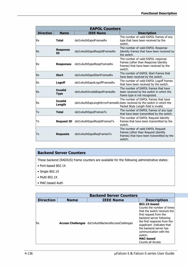
Functional Description
4-136 µFalcon-S & Falcon-S series User Guide
EAPOL Counters Direction Name IEEE Name Description
Rx Total dot1xAuthEapolFramesRx The number of valid EAPOL frames of any type that have been received by the switch.
Rx Response ID
dot1xAuthEapolRespIdFramesRx The number of valid EAPOL Response Identity frames that have been received by the switch.
Rx Responses dot1xAuthEapolRespFramesRx
The number of valid EAPOL response frames (other than Response Identity frames) that have been received by the switch.
Rx Start dot1xAuthEapolStartFramesRx The number of EAPOL Start frames that have been received by the switch.
Rx Logoff dot1xAuthEapolLogoffFramesRx The number of valid EAPOL Logoff frames
that have been received by the switch.
Rx Invalid Type
dot1xAuthInvalidEapolFramesRx The number of EAPOL frames that have been received by the switch in which the frame type is not recognized.
Rx Invalid Length
dot1xAuthEapLengthErrorFramesRx The number of EAPOL frames that have been received by the switch in which the Packet Body Length field is invalid.
Tx Total dot1xAuthEapolFramesTx The number of EAPOL frames of any type that have been transmitted by the switch.
Tx Request ID dot1xAuthEapolReqIdFramesTx The number of EAPOL Request Identity frames that have been transmitted by the switch.
Tx Requests dot1xAuthEapolReqFramesTx
The number of valid EAPOL Request frames (other than Request Identity frames) that have been transmitted by the switch.
Backend Server Counters
These backend (RADIUS) frame counters are available for the following administrative states:
• Port-based 802.1X
• Single 802.1X
• Multi 802.1X
• MAC-based Auth
Backend Server Counters
Direction Name IEEE Name Description
Rx Access Challenges dot1xAuthBackendAccessChallenges
802.1X-based: Counts the number of times that the switch receives the first request from the backend server following the first response from the supplicant. Indicates that the backend server has communication with the switch. MAC-based: Counts all Access
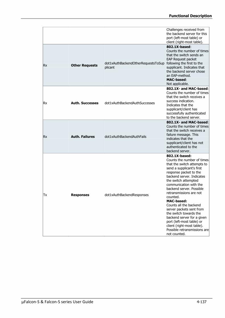
Functional Description
µFalcon-S & Falcon-S series User Guide 4-137
Challenges received from
the backend server for this port (left-most table) or client (right-most table).
Rx Other Requests dot1xAuthBackendOtherRequestsToSupplicant
802.1X-based: Counts the number of times that the switch sends an EAP Request packet following the first to the supplicant. Indicates that the backend server chose an EAP-method. MAC-based: Not applicable.
Rx Auth. Successes dot1xAuthBackendAuthSuccesses
802.1X- and MAC-based: Counts the number of times that the switch receives a
success indication. Indicates that the supplicant/client has successfully authenticated to the backend server.
Rx Auth. Failures dot1xAuthBackendAuthFails
802.1X- and MAC-based: Counts the number of times that the switch receives a failure message. This indicates that the supplicant/client has not authenticated to the backend server.
Tx Responses dot1xAuthBackendResponses
802.1X-based: Counts the number of times that the switch attempts to send a supplicant's first response packet to the backend server. Indicates the switch attempted communication with the backend server. Possible retransmissions are not counted. MAC-based: Counts all the backend server packets sent from the switch towards the backend server for a given port (left-most table) or client (right-most table). Possible retransmissions are not counted.

Functional Description
4-138 µFalcon-S & Falcon-S series User Guide
Last Supplicant/ Client Info
Last Supplicant/Client Info
Information about the last supplicant/client that attempted to authenticate. This information is
available for the following administrative states: (Refer to section 4.9.2.2 Port Configuration)
• Port-based 802.1X
• Single 802.1X
• Multi 802.1X
• MAC-based Auth
Last Supplicant/Client Info Name IEEE Name Description
MAC Address
dot1xAuthLastEapolFrameSource The MAC address of the last supplicant/client.
VLAN ID - The VLAN ID on which the last frame from the last supplicant/client was received.
Version dot1xAuthLastEapolFrameVersion
802.1X-based:
The protocol version number carried in the most
recently received EAPOL frame. MAC-based:
Not applicable.
Identity -
802.1X-based:
The user name (supplicant identity) carried in the most recently received Response Identity
EAPOL frame. MAC-based:
Not applicable.
Selected Counters
The Selected Counters table is visible when the port is in one of the following administrative
states:
• Multi 802.1X
• MAC-based Auth.
The table is identical to and is placed next to the above Port Counters table, and will be empty if
no MAC address is currently selected.
To populate the table, select one of the attached MAC Addresses from the table below.
Attached MAC Addresses
Identity Shows the identity of the supplicant, as received in the Response
Identity EAPOL frame.
Clicking the link causes the supplicant's EAPOL and Backend Server counters to be shown in the Selected Counters table. If no supplicants
are attached, it shows No supplicants attached. This column is not available for MAC-based Auth.
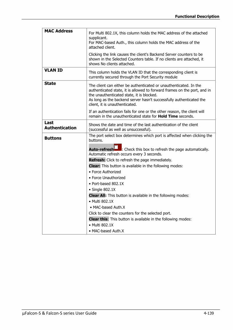
Functional Description
µFalcon-S & Falcon-S series User Guide 4-139
MAC Address For Multi 802.1X, this column holds the MAC address of the attached
supplicant. For MAC-based Auth., this column holds the MAC address of the
attached client.
Clicking the link causes the client's Backend Server counters to be shown in the Selected Counters table. If no clients are attached, it
shows No clients attached.
VLAN ID This column holds the VLAN ID that the corresponding client is
currently secured through the Port Security module
State The client can either be authenticated or unauthenticated. In the authenticated state, it is allowed to forward frames on the port, and in
the unauthenticated state, it is blocked.
As long as the backend server hasn't successfully authenticated the client, it is unauthenticated.
If an authentication fails for one or the other reason, the client will remain in the unauthenticated state for Hold Time seconds.
Last Authentication
Shows the date and time of the last authentication of the client
(successful as well as unsuccessful).
Buttons The port select box determines which port is affected when clicking the
buttons.
Auto-refresh : Check this box to refresh the page automatically. Automatic refresh occurs every 3 seconds.
Refresh: Click to refresh the page immediately.
Clear: This button is available in the following modes:
• Force Authorized
• Force Unauthorized
• Port-based 802.1X
• Single 802.1X
Clear All: This button is available in the following modes:
• Multi 802.1X
• MAC-based Auth.X
Click to clear the counters for the selected port.
Clear this: This button is available in the following modes:
• Multi 802.1X
• MAC-based Auth.X
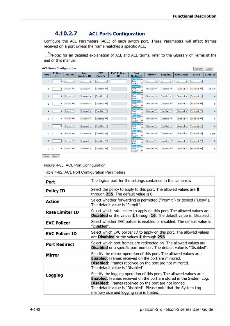
Functional Description
4-140 µFalcon-S & Falcon-S series User Guide
4.10.2.7 ACL Ports Configuration
Configure the ACL Parameters (ACE) of each switch port. These Parameters will affect frames
received on a port unless the frame matches a specific ACE.
Note: for an detailed explanation of ACL and ACE terms, refer to the Glossary of Terms at the
end of this manual
Figure 4-85: ACL Port Configuration
Table 4-82: ACL Port Configuration Parameters
Port The logical port for the settings contained in the same row.
Policy ID Select the policy to apply to this port. The allowed values are 0
through 255. The default value is 0.
Action Select whether forwarding is permitted ("Permit") or denied ("Deny").
The default value is "Permit".
Rate Limiter ID Select which rate limiter to apply on this port. The allowed values are Disabled or the values 1 through 16. The default value is "Disabled".
EVC Policer Select whether EVC policer is enabled or disabled. The default value is
"Disabled".
EVC Policer ID Select which EVC policer ID to apply on this port. The allowed values
are Disabled or the values 1 through 256
Port Redirect Select which port frames are redirected on. The allowed values are Disabled or a specific port number. The default value is "Disabled".
Mirror Specify the mirror operation of this port. The allowed values are:
Enabled: Frames received on the port are mirrored. Disabled: Frames received on the port are not mirrored.
The default value is "Disabled".
Logging Specify the logging operation of this port. The allowed values are: Enabled: Frames received on the port are stored in the System Log.
Disabled: Frames received on the port are not logged. The default value is "Disabled". Please note that the System Log
memory size and logging rate is limited.
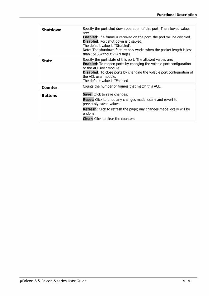
Functional Description
µFalcon-S & Falcon-S series User Guide 4-141
Shutdown Specify the port shut down operation of this port. The allowed values
are: Enabled: If a frame is received on the port, the port will be disabled.
Disabled: Port shut down is disabled.
The default value is "Disabled". Note: The shutdown feature only works when the packet length is less
than 1518(without VLAN tags).
State Specify the port state of this port. The allowed values are:
Enabled: To reopen ports by changing the volatile port configuration
of the ACL user module. Disabled: To close ports by changing the volatile port configuration of
the ACL user module. The default value is "Enabled
Counter Counts the number of frames that match this ACE.
Buttons Save: Click to save changes.
Reset: Click to undo any changes made locally and revert to previously saved values
Refresh: Click to refresh the page; any changes made locally will be undone.
Clear: Click to clear the counters.
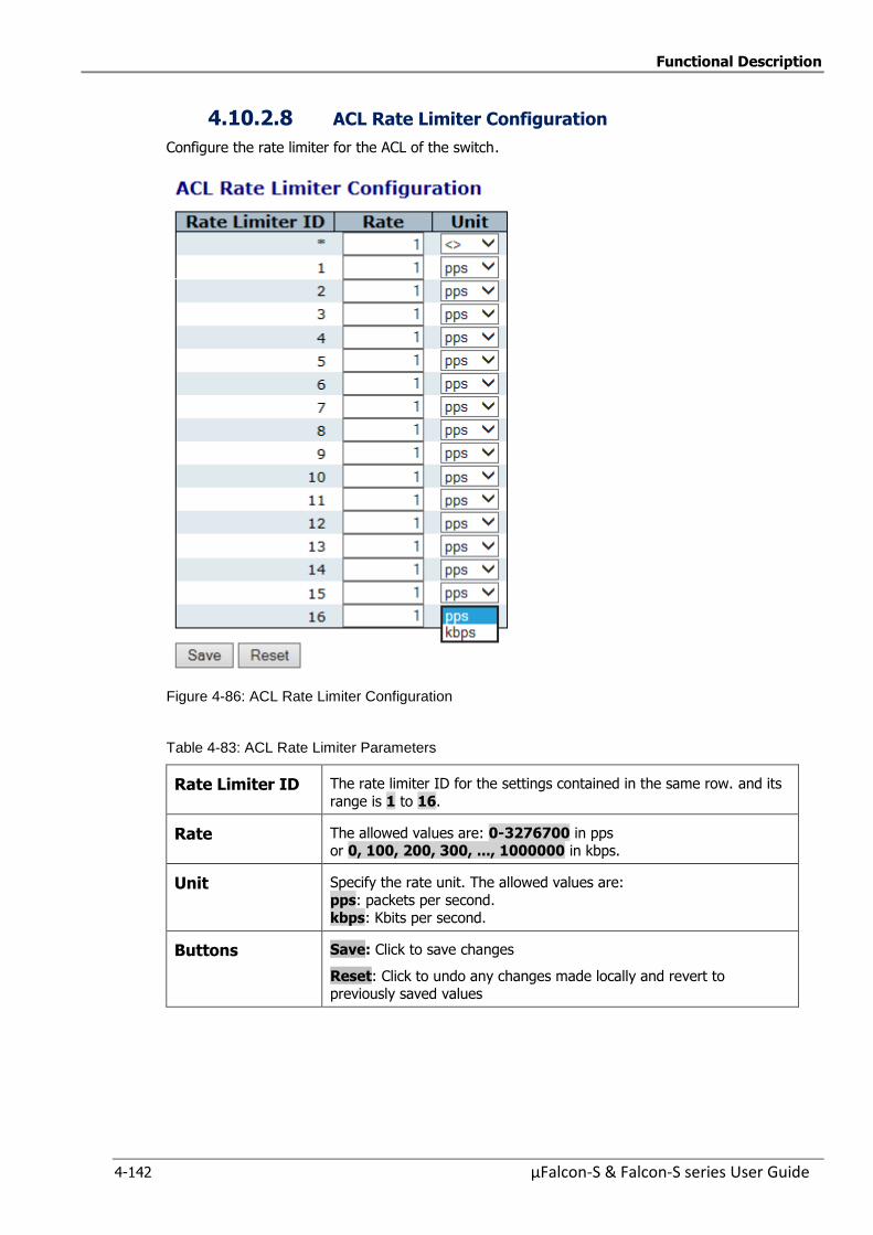
Functional Description
4-142 µFalcon-S & Falcon-S series User Guide
4.10.2.8 ACL Rate Limiter Configuration
Configure the rate limiter for the ACL of the switch.
Figure 4-86: ACL Rate Limiter Configuration
Table 4-83: ACL Rate Limiter Parameters
Rate Limiter ID The rate limiter ID for the settings contained in the same row. and its
range is 1 to 16.
Rate The allowed values are: 0-3276700 in pps or 0, 100, 200, 300, ..., 1000000 in kbps.
Unit Specify the rate unit. The allowed values are:
pps: packets per second. kbps: Kbits per second.
Buttons Save: Click to save changes
Reset: Click to undo any changes made locally and revert to previously saved values
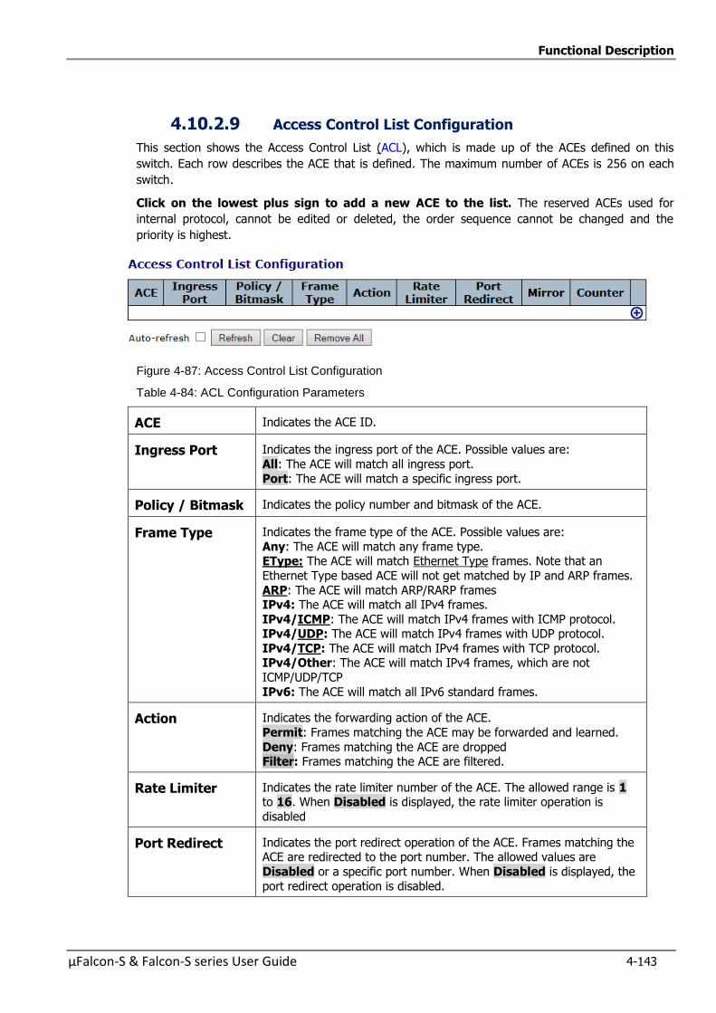
Functional Description
µFalcon-S & Falcon-S series User Guide 4-143
4.10.2.9 Access Control List Configuration
This section shows the Access Control List (ACL), which is made up of the ACEs defined on this
switch. Each row describes the ACE that is defined. The maximum number of ACEs is 256 on each
switch.
Click on the lowest plus sign to add a new ACE to the list. The reserved ACEs used for
internal protocol, cannot be edited or deleted, the order sequence cannot be changed and the
priority is highest.
Figure 4-87: Access Control List Configuration
Table 4-84: ACL Configuration Parameters
ACE Indicates the ACE ID.
Ingress Port Indicates the ingress port of the ACE. Possible values are:
All: The ACE will match all ingress port.
Port: The ACE will match a specific ingress port.
Policy / Bitmask Indicates the policy number and bitmask of the ACE.
Frame Type Indicates the frame type of the ACE. Possible values are:
Any: The ACE will match any frame type. EType: The ACE will match Ethernet Type frames. Note that an
Ethernet Type based ACE will not get matched by IP and ARP frames.
ARP: The ACE will match ARP/RARP frames IPv4: The ACE will match all IPv4 frames.
IPv4/ICMP: The ACE will match IPv4 frames with ICMP protocol. IPv4/UDP: The ACE will match IPv4 frames with UDP protocol.
IPv4/TCP: The ACE will match IPv4 frames with TCP protocol. IPv4/Other: The ACE will match IPv4 frames, which are not
ICMP/UDP/TCP
IPv6: The ACE will match all IPv6 standard frames.
Action Indicates the forwarding action of the ACE.
Permit: Frames matching the ACE may be forwarded and learned.
Deny: Frames matching the ACE are dropped Filter: Frames matching the ACE are filtered.
Rate Limiter Indicates the rate limiter number of the ACE. The allowed range is 1 to 16. When Disabled is displayed, the rate limiter operation is
disabled
Port Redirect Indicates the port redirect operation of the ACE. Frames matching the ACE are redirected to the port number. The allowed values are
Disabled or a specific port number. When Disabled is displayed, the
port redirect operation is disabled.
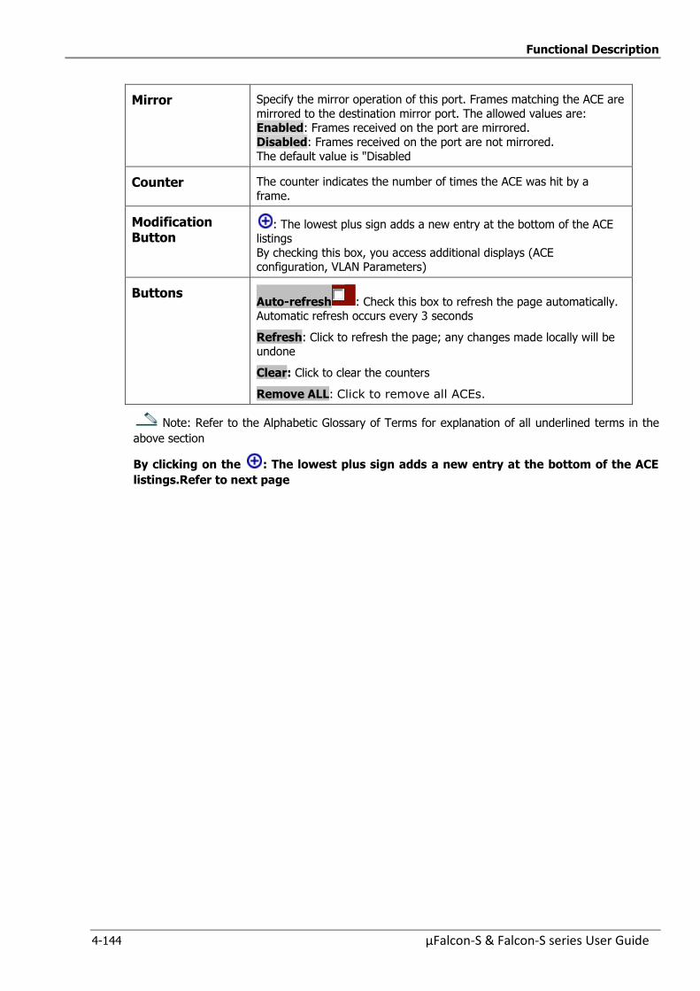
Functional Description
4-144 µFalcon-S & Falcon-S series User Guide
Mirror Specify the mirror operation of this port. Frames matching the ACE are
mirrored to the destination mirror port. The allowed values are: Enabled: Frames received on the port are mirrored.
Disabled: Frames received on the port are not mirrored.
The default value is "Disabled
Counter The counter indicates the number of times the ACE was hit by a
frame.
Modification Button
: The lowest plus sign adds a new entry at the bottom of the ACE listings
By checking this box, you access additional displays (ACE configuration, VLAN Parameters)
Buttons Auto-refresh : Check this box to refresh the page automatically. Automatic refresh occurs every 3 seconds
Refresh: Click to refresh the page; any changes made locally will be undone
Clear: Click to clear the counters
Remove ALL: Click to remove all ACEs.
Note: Refer to the Alphabetic Glossary of Terms for explanation of all underlined terms in the
above section
By clicking on the : The lowest plus sign adds a new entry at the bottom of the ACE
listings.Refer to next page
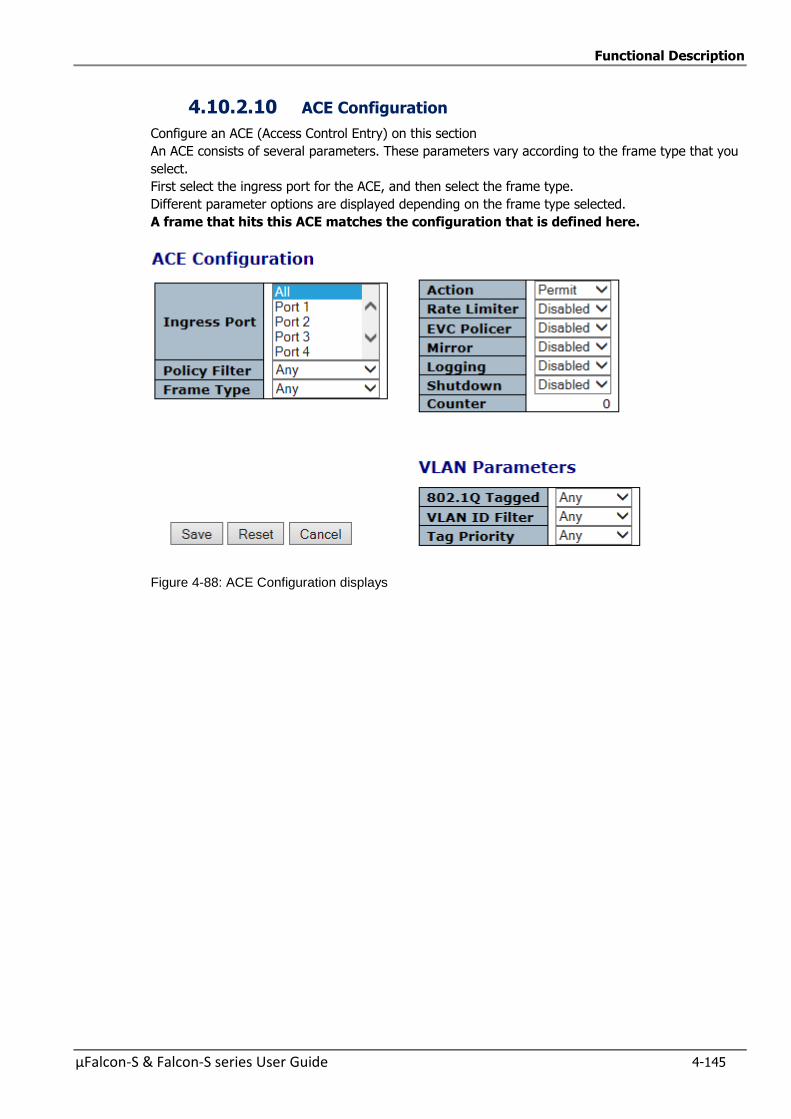
Functional Description
µFalcon-S & Falcon-S series User Guide 4-145
4.10.2.10 ACE Configuration
Configure an ACE (Access Control Entry) on this section
An ACE consists of several parameters. These parameters vary according to the frame type that you
select.
First select the ingress port for the ACE, and then select the frame type.
Different parameter options are displayed depending on the frame type selected.
A frame that hits this ACE matches the configuration that is defined here.
Figure 4-88: ACE Configuration displays
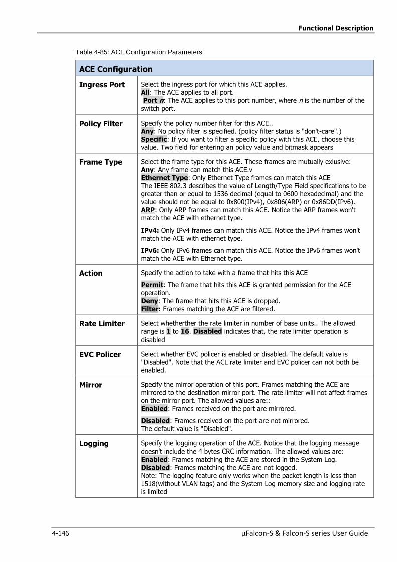
Functional Description
4-146 µFalcon-S & Falcon-S series User Guide
Table 4-85: ACL Configuration Parameters
ACE Configuration
Ingress Port Select the ingress port for which this ACE applies.
All: The ACE applies to all port. Port n: The ACE applies to this port number, where n is the number of the
switch port.
Policy Filter Specify the policy number filter for this ACE.. Any: No policy filter is specified. (policy filter status is "don't-care".)
Specific: If you want to filter a specific policy with this ACE, choose this value. Two field for entering an policy value and bitmask appears
Frame Type Select the frame type for this ACE. These frames are mutually exlusive:
Any: Any frame can match this ACE.v Ethernet Type: Only Ethernet Type frames can match this ACE
The IEEE 802.3 describes the value of Length/Type Field specifications to be greater than or equal to 1536 decimal (equal to 0600 hexadecimal) and the
value should not be equal to 0x800(IPv4), 0x806(ARP) or 0x86DD(IPv6).
ARP: Only ARP frames can match this ACE. Notice the ARP frames won't match the ACE with ethernet type.
IPv4: Only IPv4 frames can match this ACE. Notice the IPv4 frames won't match the ACE with ethernet type.
IPv6: Only IPv6 frames can match this ACE. Notice the IPv6 frames won't
match the ACE with Ethernet type.
Action Specify the action to take with a frame that hits this ACE
Permit: The frame that hits this ACE is granted permission for the ACE operation.
Deny: The frame that hits this ACE is dropped.
Filter: Frames matching the ACE are filtered.
Rate Limiter Select whetherther the rate limiter in number of base units.. The allowed
range is 1 to 16. Disabled indicates that, the rate limiter operation is
disabled
EVC Policer Select whether EVC policer is enabled or disabled. The default value is
"Disabled". Note that the ACL rate limiter and EVC policer can not both be enabled.
Mirror Specify the mirror operation of this port. Frames matching the ACE are
mirrored to the destination mirror port. The rate limiter will not affect frames on the mirror port. The allowed values are::
Enabled: Frames received on the port are mirrored.
Disabled: Frames received on the port are not mirrored. The default value is "Disabled".
Logging Specify the logging operation of the ACE. Notice that the logging message
doesn't include the 4 bytes CRC information. The allowed values are: Enabled: Frames matching the ACE are stored in the System Log.
Disabled: Frames matching the ACE are not logged. Note: The logging feature only works when the packet length is less than
1518(without VLAN tags) and the System Log memory size and logging rate is limited
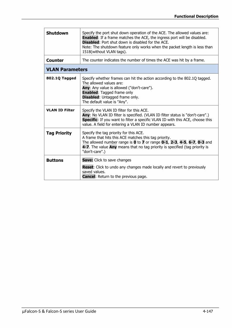
Functional Description
µFalcon-S & Falcon-S series User Guide 4-147
Shutdown Specify the port shut down operation of the ACE. The allowed values are:
Enabled: If a frame matches the ACE, the ingress port will be disabled. Disabled: Port shut down is disabled for the ACE.
Note: The shutdown feature only works when the packet length is less than
1518(without VLAN tags).
Counter The counter indicates the number of times the ACE was hit by a frame.
VLAN Parameters
802.1Q Tagged Specify whether frames can hit the action according to the 802.1Q tagged.
The allowed values are: Any: Any value is allowed ("don't-care").
Enabled: Tagged frame only Disabled: Untagged frame only.
The default value is "Any".
VLAN ID Filter Specify the VLAN ID filter for this ACE. Any: No VLAN ID filter is specified. (VLAN ID filter status is "don't-care".)
Specific: If you want to filter a specific VLAN ID with this ACE, choose this value. A field for entering a VLAN ID number appears.
Tag Priority Specify the tag priority for this ACE.
A frame that hits this ACE matches this tag priority. The allowed number range is 0 to 7 or range 0-1, 2-3, 4-5, 6-7, 0-3 and
4-7. The value Any means that no tag priority is specified (tag priority is "don't-care".)
Buttons Save: Click to save changes
Reset: Click to undo any changes made locally and revert to previously saved values.
Cancel: Return to the previous page.
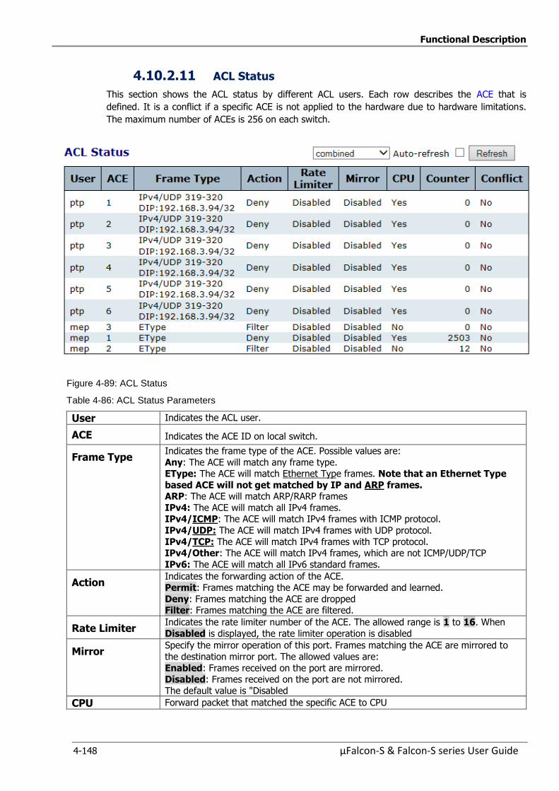
Functional Description
4-148 µFalcon-S & Falcon-S series User Guide
4.10.2.11 ACL Status
This section shows the ACL status by different ACL users. Each row describes the ACE that is
defined. It is a conflict if a specific ACE is not applied to the hardware due to hardware limitations.
The maximum number of ACEs is 256 on each switch.
Figure 4-89: ACL Status
Table 4-86: ACL Status Parameters
User Indicates the ACL user.
ACE Indicates the ACE ID on local switch.
Frame Type Indicates the frame type of the ACE. Possible values are:
Any: The ACE will match any frame type. EType: The ACE will match Ethernet Type frames. Note that an Ethernet Type
based ACE will not get matched by IP and ARP frames. ARP: The ACE will match ARP/RARP frames
IPv4: The ACE will match all IPv4 frames. IPv4/ICMP: The ACE will match IPv4 frames with ICMP protocol.
IPv4/UDP: The ACE will match IPv4 frames with UDP protocol.
IPv4/TCP: The ACE will match IPv4 frames with TCP protocol. IPv4/Other: The ACE will match IPv4 frames, which are not ICMP/UDP/TCP
IPv6: The ACE will match all IPv6 standard frames.
Action Indicates the forwarding action of the ACE. Permit: Frames matching the ACE may be forwarded and learned.
Deny: Frames matching the ACE are dropped Filter: Frames matching the ACE are filtered.
Rate Limiter Indicates the rate limiter number of the ACE. The allowed range is 1 to 16. When
Disabled is displayed, the rate limiter operation is disabled
Mirror Specify the mirror operation of this port. Frames matching the ACE are mirrored to
the destination mirror port. The allowed values are:
Enabled: Frames received on the port are mirrored. Disabled: Frames received on the port are not mirrored.
The default value is "Disabled
CPU Forward packet that matched the specific ACE to CPU
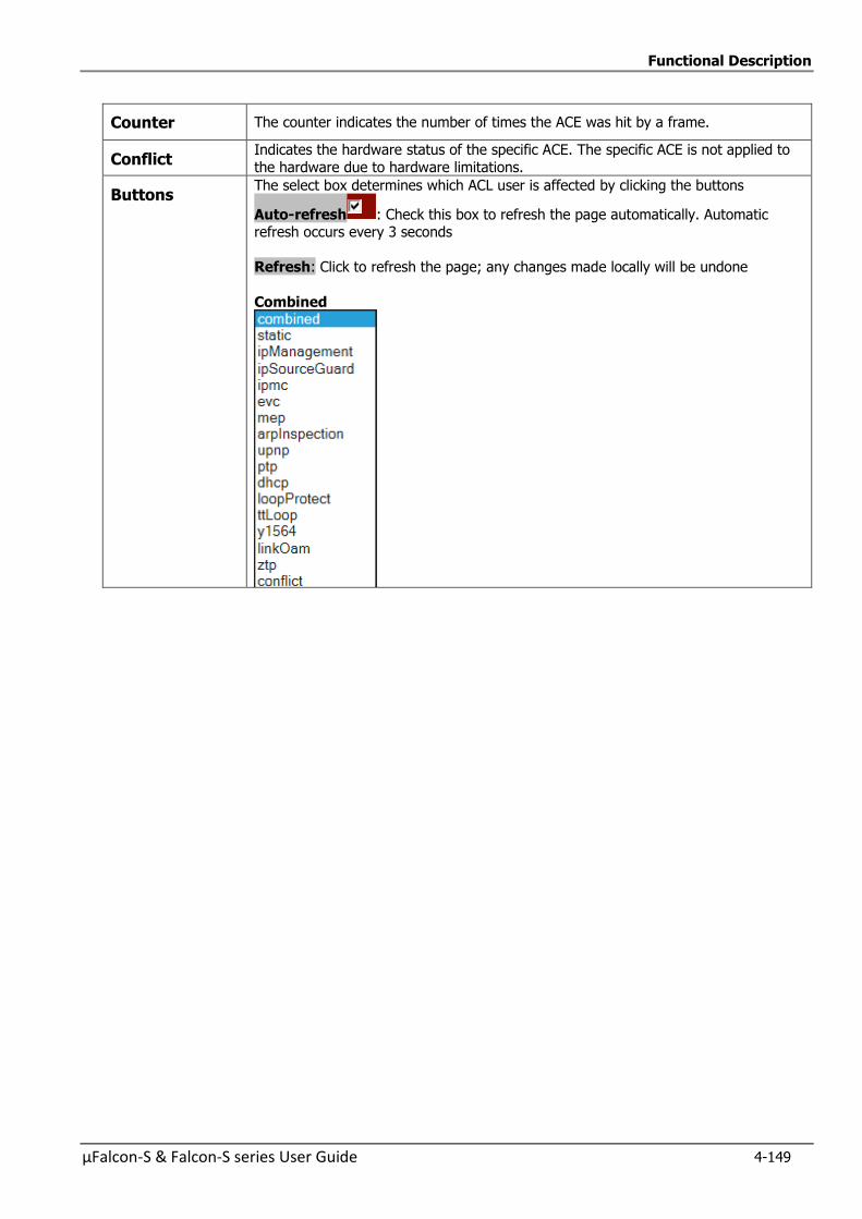
Functional Description
µFalcon-S & Falcon-S series User Guide 4-149
Counter The counter indicates the number of times the ACE was hit by a frame.
Conflict Indicates the hardware status of the specific ACE. The specific ACE is not applied to
the hardware due to hardware limitations.
Buttons The select box determines which ACL user is affected by clicking the buttons
Auto-refresh : Check this box to refresh the page automatically. Automatic refresh occurs every 3 seconds
Refresh: Click to refresh the page; any changes made locally will be undone
Combined
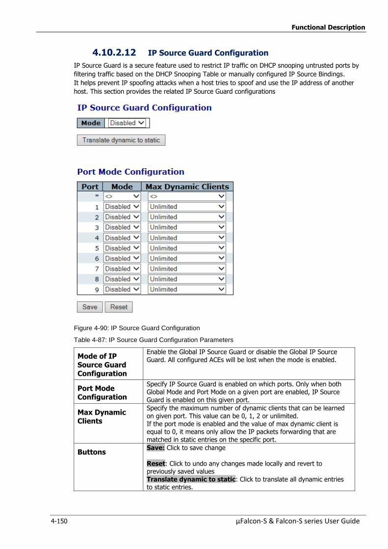
Functional Description
4-150 µFalcon-S & Falcon-S series User Guide
4.10.2.12 IP Source Guard Configuration
IP Source Guard is a secure feature used to restrict IP traffic on DHCP snooping untrusted ports by
filtering traffic based on the DHCP Snooping Table or manually configured IP Source Bindings.
It helps prevent IP spoofing attacks when a host tries to spoof and use the IP address of another
host. This section provides the related IP Source Guard configurations
Figure 4-90: IP Source Guard Configuration
Table 4-87: IP Source Guard Configuration Parameters
Mode of IP Source Guard Configuration
Enable the Global IP Source Guard or disable the Global IP Source
Guard. All configured ACEs will be lost when the mode is enabled.
Port Mode Configuration
Specify IP Source Guard is enabled on which ports. Only when both
Global Mode and Port Mode on a given port are enabled, IP Source
Guard is enabled on this given port.
Max Dynamic Clients
Specify the maximum number of dynamic clients that can be learned
on given port. This value can be 0, 1, 2 or unlimited.
If the port mode is enabled and the value of max dynamic client is equal to 0, it means only allow the IP packets forwarding that are
matched in static entries on the specific port.
Buttons Save: Click to save change
Reset: Click to undo any changes made locally and revert to previously saved values
Translate dynamic to static: Click to translate all dynamic entries to static entries.

Functional Description
µFalcon-S & Falcon-S series User Guide 4-151
4.10.2.13 Static IP Source Guard Table
Figure 4-91: Static IP Source Guard Table
Table 4-88: IP Source Guard Table Parameters
Delete Check to delete the entry. It will be deleted during the next save.
Port The logical port for the settings.
VLAN ID The vlan id for the settings.
IP Address Allowed Source IP address
MAC address Allowed Source MAC address
Buttons Add New Entry: Click to add a new entry to the Static IP Source Guard
table
Save: Click to save changes
Reset: Click to undo any changes made locally and revert to previously
saved values

Functional Description
4-152 µFalcon-S & Falcon-S series User Guide
4.10.2.14 Dynamic IP Source Guard Table
Entries in the Dynamic IP Source Guard Table are shown on this page. The Dynamic IP Source
Guard Table is sorted first by port, then by VLAN ID, then by IP address, and then by MAC address
Navigating the IP Source Guard Table
Each page shows up to 99 entries from the Dynamic IP Source Guard table, default being 20,
selected through the "entries per page" input field. When first visited, the web page will show the
first 20 entries from the beginning of the Dynamic IP Source Guard Table.
The "Start from port address", "VLAN" and "IP address" input fields allow the user to select the
starting point in the Dynamic IP Source Guard Table.
Clicking the Refresh button will update the displayed table starting from that or the closest next
Dynamic IP Source Guard Table match. In addition, the two input fields will - upon a Refresh
button click - assume the value of the first displayed entry, allowing for continuous refresh with the
same start address.
The will >> use the last entry of the currently displayed table as a basis for the next lookup. When
the end is reached the text "No more entries" is shown in the displayed table. Use the << button to
start over.
Figure 4-92: Dynamic IP Source Guard Table
Table 4-89: Dynamic IP Source Guard Table Parameters
Port Switch Port Number for which the entries are displayed.
VLAN ID VLAN-ID in which the IP traffic is permitted.
IP Address User IP address of the entry
MAC address Source MAC address
Buttons Auto-refresh : Check this box to refresh the page automatically. Automatic refresh occurs every 3 seconds.
Refresh: Refreshes the displayed table starting from the input
fields.
Clear: Flushes all dynamic entries
<<: Updates the table starting from the first entry in the
Dynamic IP Source Guard Table
>>: Updates the table, starting with the entry after the last
entry currently displayed
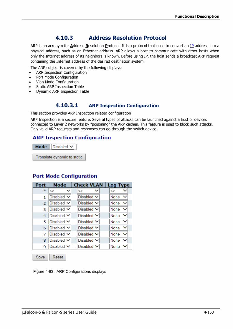
Functional Description
µFalcon-S & Falcon-S series User Guide 4-153
4.10.3 Address Resolution Protocol
ARP is an acronym for Address Resolution Protocol. It is a protocol that used to convert an IP address into a
physical address, such as an Ethernet address. ARP allows a host to communicate with other hosts when
only the Internet address of its neighbors is known. Before using IP, the host sends a broadcast ARP request
containing the Internet address of the desired destination system.
The ARP subject is covered by the following displays:
ARP Inspection Configuration
Port Mode Configuration
Vlan Mode Configuration
Static ARP Inspection Table
Dynamic ARP Inspection Table
4.10.3.1 ARP Inspection Configuration
This section provides ARP Inspection related configuration
ARP Inspection is a secure feature. Several types of attacks can be launched against a host or devices
connected to Layer 2 networks by "poisoning" the ARP caches. This feature is used to block such attacks. Only valid ARP requests and responses can go through the switch device.
Figure 4-93 : ARP Configurations displays
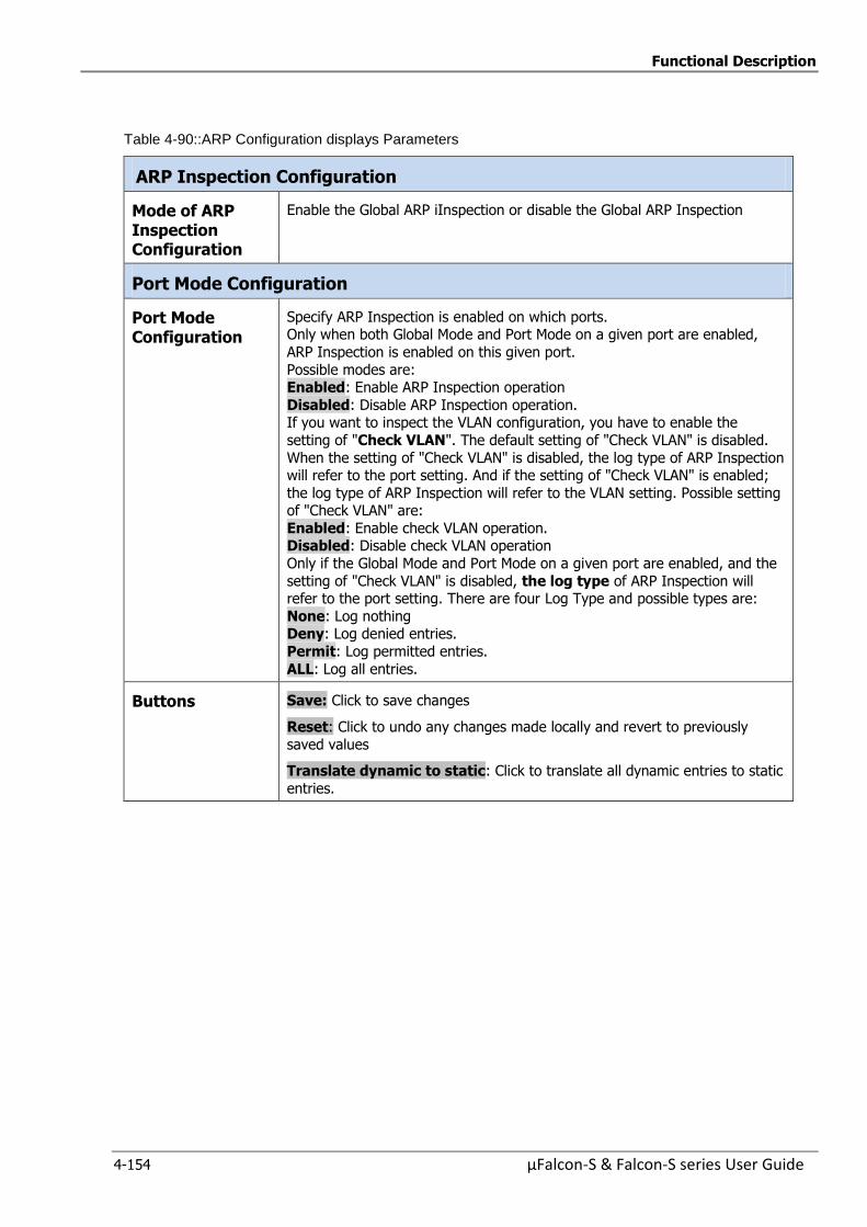
Functional Description
4-154 µFalcon-S & Falcon-S series User Guide
Table 4-90::ARP Configuration displays Parameters
ARP Inspection Configuration
Mode of ARP Inspection Configuration
Enable the Global ARP iInspection or disable the Global ARP Inspection
Port Mode Configuration
Port Mode Configuration
Specify ARP Inspection is enabled on which ports. Only when both Global Mode and Port Mode on a given port are enabled,
ARP Inspection is enabled on this given port.
Possible modes are: Enabled: Enable ARP Inspection operation
Disabled: Disable ARP Inspection operation. If you want to inspect the VLAN configuration, you have to enable the
setting of "Check VLAN". The default setting of "Check VLAN" is disabled.
When the setting of "Check VLAN" is disabled, the log type of ARP Inspection will refer to the port setting. And if the setting of "Check VLAN" is enabled;
the log type of ARP Inspection will refer to the VLAN setting. Possible setting of "Check VLAN" are:
Enabled: Enable check VLAN operation. Disabled: Disable check VLAN operation
Only if the Global Mode and Port Mode on a given port are enabled, and the
setting of "Check VLAN" is disabled, the log type of ARP Inspection will refer to the port setting. There are four Log Type and possible types are:
None: Log nothing Deny: Log denied entries.
Permit: Log permitted entries.
ALL: Log all entries.
Buttons Save: Click to save changes
Reset: Click to undo any changes made locally and revert to previously
saved values
Translate dynamic to static: Click to translate all dynamic entries to static
entries.
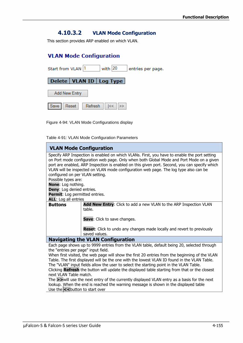
Functional Description
µFalcon-S & Falcon-S series User Guide 4-155
4.10.3.2 VLAN Mode Configuration
This section provides ARP enabled on which VLAN.
Figure 4-94: VLAN Mode Configurations display
Table 4-91: VLAN Mode Configuration Parameters
VLAN Mode Configuration
Specify ARP Inspection is enabled on which VLANs. First, you have to enable the port setting on Port mode configuration web page. Only when both Global Mode and Port Mode on a given
port are enabled, ARP Inspection is enabled on this given port. Second, you can specify which VLAN will be inspected on VLAN mode configuration web page. The log type also can be
configured on per VLAN setting.
Possible types are: None: Log nothing.
Deny: Log denied entries. Permit: Log permitted entries.
ALL: Log all entries
Buttons Add New Entry: Click to add a new VLAN to the ARP Inspection VLAN table.
Save: Click to save changes.
Reset: Click to undo any changes made locally and revert to previously saved values.
Navigating the VLAN Configuration Each page shows up to 9999 entries from the VLAN table, default being 20, selected through the "entries per page" input field.
When first visited, the web page will show the first 20 entries from the beginning of the VLAN
Table. The first displayed will be the one with the lowest VLAN ID found in the VLAN Table. The "VLAN" input fields allow the user to select the starting point in the VLAN Table.
Clicking Refresh the button will update the displayed table starting from that or the closest next VLAN Table match.
The >>will use the next entry of the currently displayed VLAN entry as a basis for the next lookup. When the end is reached the warning message is shown in the displayed table
Use the <<button to start over
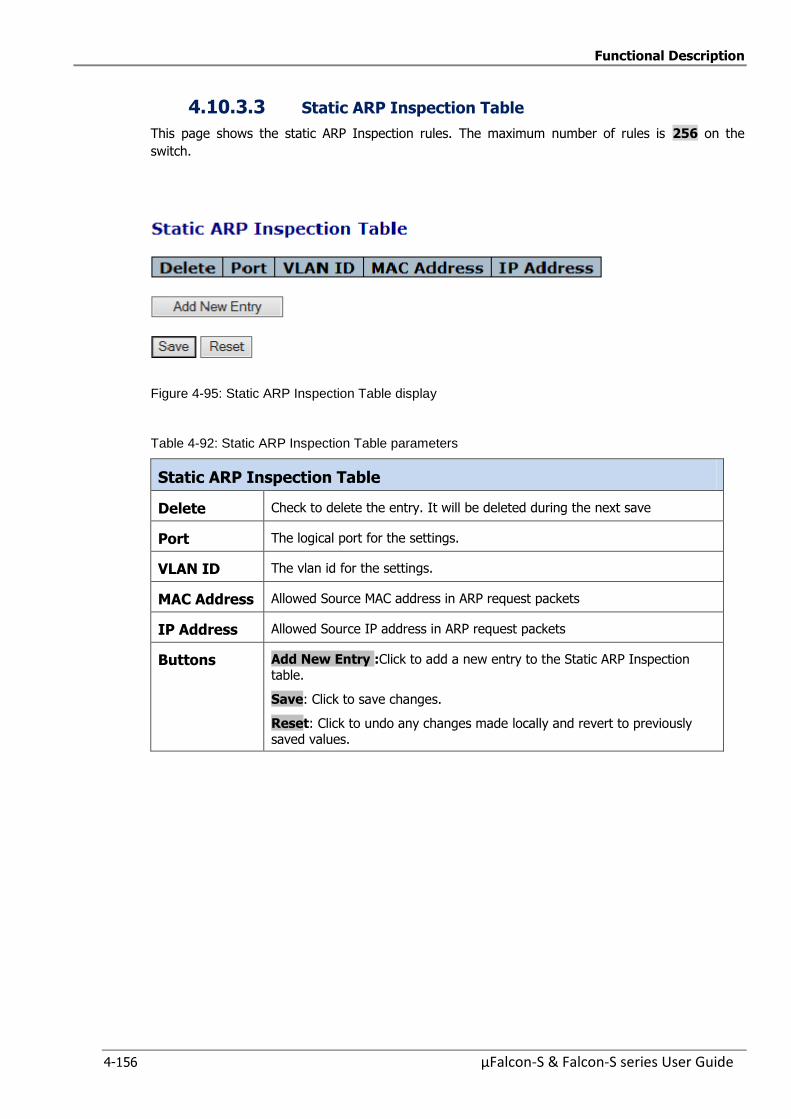
Functional Description
4-156 µFalcon-S & Falcon-S series User Guide
4.10.3.3 Static ARP Inspection Table
This page shows the static ARP Inspection rules. The maximum number of rules is 256 on the
switch.
Figure 4-95: Static ARP Inspection Table display
Table 4-92: Static ARP Inspection Table parameters
Static ARP Inspection Table
Delete Check to delete the entry. It will be deleted during the next save
Port The logical port for the settings.
VLAN ID The vlan id for the settings.
MAC Address Allowed Source MAC address in ARP request packets
IP Address Allowed Source IP address in ARP request packets
Buttons Add New Entry :Click to add a new entry to the Static ARP Inspection table.
Save: Click to save changes.
Reset: Click to undo any changes made locally and revert to previously saved values.
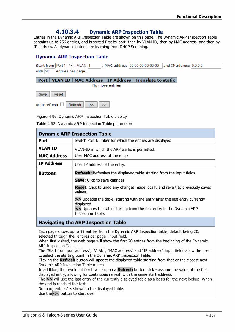
Functional Description
µFalcon-S & Falcon-S series User Guide 4-157
4.10.3.4 Dynamic ARP Inspection Table Entries in the Dynamic ARP Inspection Table are shown on this page. The Dynamic ARP Inspection Table
contains up to 256 entries, and is sorted first by port, then by VLAN ID, then by MAC address, and then by
IP address. All dynamic entries are learning from DHCP Snooping.
Figure 4-96: Dynamic ARP Inspection Table display
Table 4-93: Dynamic ARP Inspection Table parameters
Dynamic ARP Inspection Table
Port Switch Port Number for which the entries are displayed
VLAN ID VLAN-ID in which the ARP traffic is permitted.
MAC Address User MAC address of the entry
IP Address User IP address of the entry.
Buttons Refresh: Refreshes the displayed table starting from the input fields.
Save: Click to save changes.
Reset: Click to undo any changes made locally and revert to previously saved
values.
>> Updates the table, starting with the entry after the last entry currently
displayed. << Updates the table starting from the first entry in the Dynamic ARP
Inspection Table.
Navigating the ARP Inspection Table
Each page shows up to 99 entries from the Dynamic ARP Inspection table, default being 20, selected through the "entries per page" input field.
When first visited, the web page will show the first 20 entries from the beginning of the Dynamic ARP Inspection Table.
The "Start from port address", "VLAN", "MAC address" and "IP address" input fields allow the user
to select the starting point in the Dynamic ARP Inspection Table. Clicking the Refresh button will update the displayed table starting from that or the closest next
Dynamic ARP Inspection Table match. In addition, the two input fields will - upon a Refresh button click - assume the value of the first
displayed entry, allowing for continuous refresh with the same start address.
The >> will use the last entry of the currently displayed table as a basis for the next lookup. When the end is reached the text.
No more entries" is shown in the displayed table. Use the << button to start over
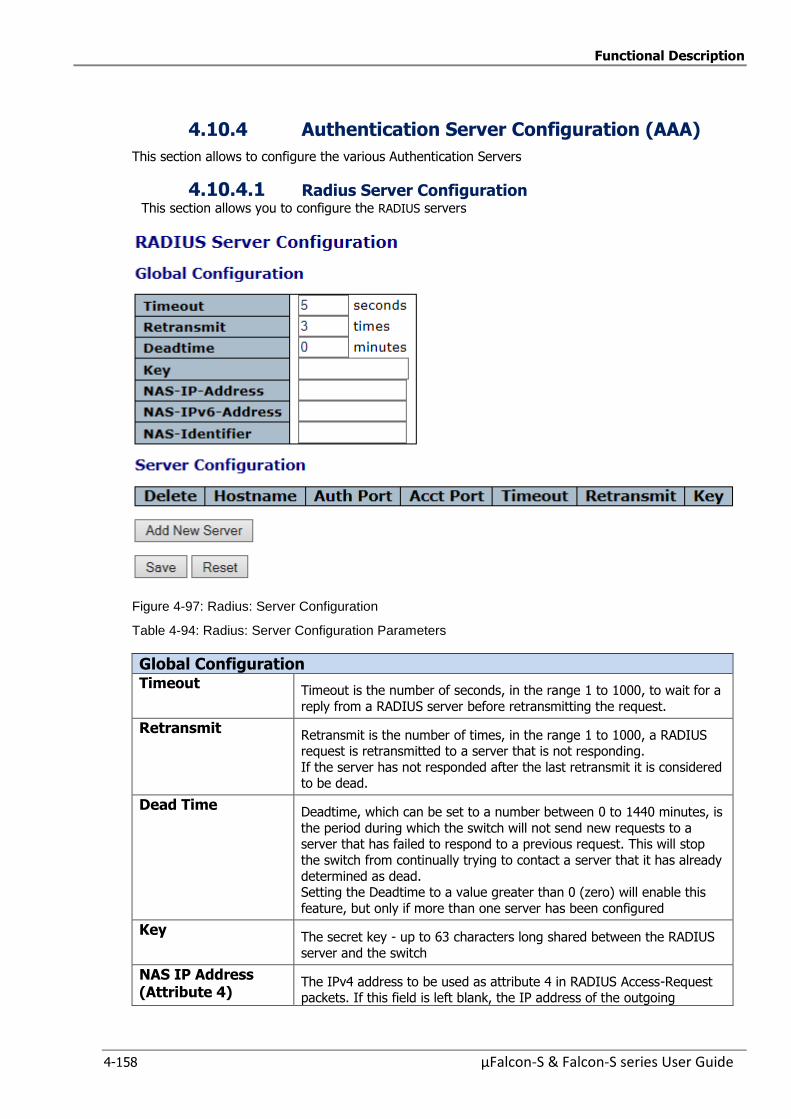
Functional Description
4-158 µFalcon-S & Falcon-S series User Guide
4.10.4 Authentication Server Configuration (AAA)
This section allows to configure the various Authentication Servers
4.10.4.1 Radius Server Configuration This section allows you to configure the RADIUS servers
Figure 4-97: Radius: Server Configuration
Table 4-94: Radius: Server Configuration Parameters
Global Configuration
Timeout Timeout is the number of seconds, in the range 1 to 1000, to wait for a
reply from a RADIUS server before retransmitting the request.
Retransmit Retransmit is the number of times, in the range 1 to 1000, a RADIUS request is retransmitted to a server that is not responding.
If the server has not responded after the last retransmit it is considered to be dead.
Dead Time Deadtime, which can be set to a number between 0 to 1440 minutes, is
the period during which the switch will not send new requests to a server that has failed to respond to a previous request. This will stop
the switch from continually trying to contact a server that it has already
determined as dead. Setting the Deadtime to a value greater than 0 (zero) will enable this
feature, but only if more than one server has been configured
Key The secret key - up to 63 characters long shared between the RADIUS
server and the switch
NAS IP Address (Attribute 4)
The IPv4 address to be used as attribute 4 in RADIUS Access-Request packets. If this field is left blank, the IP address of the outgoing
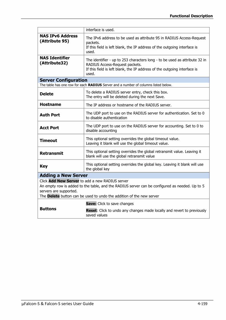
Functional Description
µFalcon-S & Falcon-S series User Guide 4-159
interface is used.
NAS IPv6 Address (Attribute 95)
The IPv6 address to be used as attribute 95 in RADIUS Access-Request
packets. If this field is left blank, the IP address of the outgoing interface is
used.
NAS Identifier (Attribute32)
The identifier - up to 253 characters long - to be used as attribute 32 in
RADIUS Access-Request packets.
If this field is left blank, the IP address of the outgoing interface is used.
Server Configuration The table has one row for each RADIUS Server and a number of columns listed below.
Delete To delete a RADIUS server entry, check this box.
The entry will be deleted during the next Save.
Hostname The IP address or hostname of the RADIUS server.
Auth Port The UDP port to use on the RADIUS server for authentication. Set to 0
to disable authentication
Acct Port The UDP port to use on the RADIUS server for accounting. Set to 0 to disable accounting
Timeout This optional setting overrides the global timeout value.
Leaving it blank will use the global timeout value.
Retransmit This optional setting overrides the global retransmit value. Leaving it
blank will use the global retransmit value
Key This optional setting overrides the global key. Leaving it blank will use the global key
Adding a New Server
Click Add New Server to add a new RADIUS server
An empty row is added to the table, and the RADIUS server can be configured as needed. Up to 5
servers are supported.
The Delete button can be used to undo the addition of the new server
Buttons
Save: Click to save changes
Reset: Click to undo any changes made locally and revert to previously
saved values
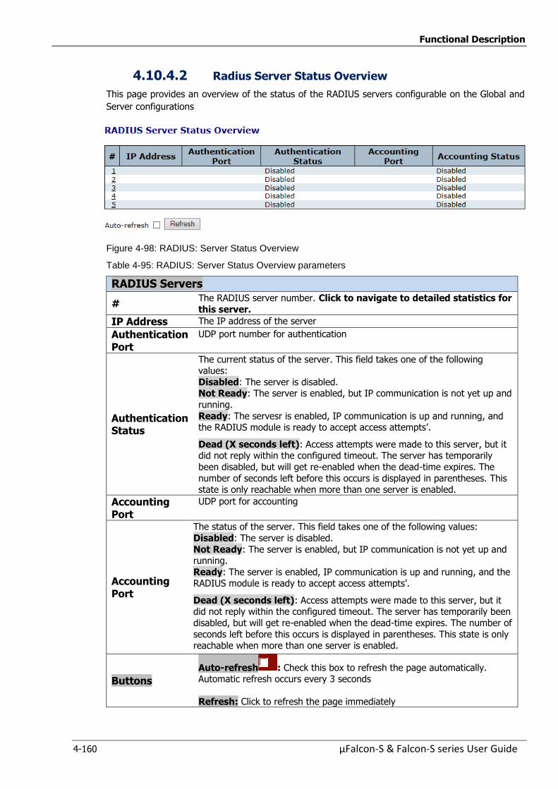
Functional Description
4-160 µFalcon-S & Falcon-S series User Guide
4.10.4.2 Radius Server Status Overview
This page provides an overview of the status of the RADIUS servers configurable on the Global and
Server configurations
Figure 4-98: RADIUS: Server Status Overview
Table 4-95: RADIUS: Server Status Overview parameters
RADIUS Servers
# The RADIUS server number. Click to navigate to detailed statistics for
this server.
IP Address The IP address of the server
Authentication Port
UDP port number for authentication
Authentication Status
The current status of the server. This field takes one of the following values:
Disabled: The server is disabled. Not Ready: The server is enabled, but IP communication is not yet up and
running.
Ready: The servesr is enabled, IP communication is up and running, and the RADIUS module is ready to accept access attempts’.
Dead (X seconds left): Access attempts were made to this server, but it did not reply within the configured timeout. The server has temporarily
been disabled, but will get re-enabled when the dead-time expires. The
number of seconds left before this occurs is displayed in parentheses. This state is only reachable when more than one server is enabled.
Accounting Port
UDP port for accounting
Accounting Port
The status of the server. This field takes one of the following values:
Disabled: The server is disabled.
Not Ready: The server is enabled, but IP communication is not yet up and running.
Ready: The server is enabled, IP communication is up and running, and the RADIUS module is ready to accept access attempts’.
Dead (X seconds left): Access attempts were made to this server, but it did not reply within the configured timeout. The server has temporarily been
disabled, but will get re-enabled when the dead-time expires. The number of
seconds left before this occurs is displayed in parentheses. This state is only reachable when more than one server is enabled.
Buttons
Auto-refresh : Check this box to refresh the page automatically. Automatic refresh occurs every 3 seconds
Refresh: Click to refresh the page immediately
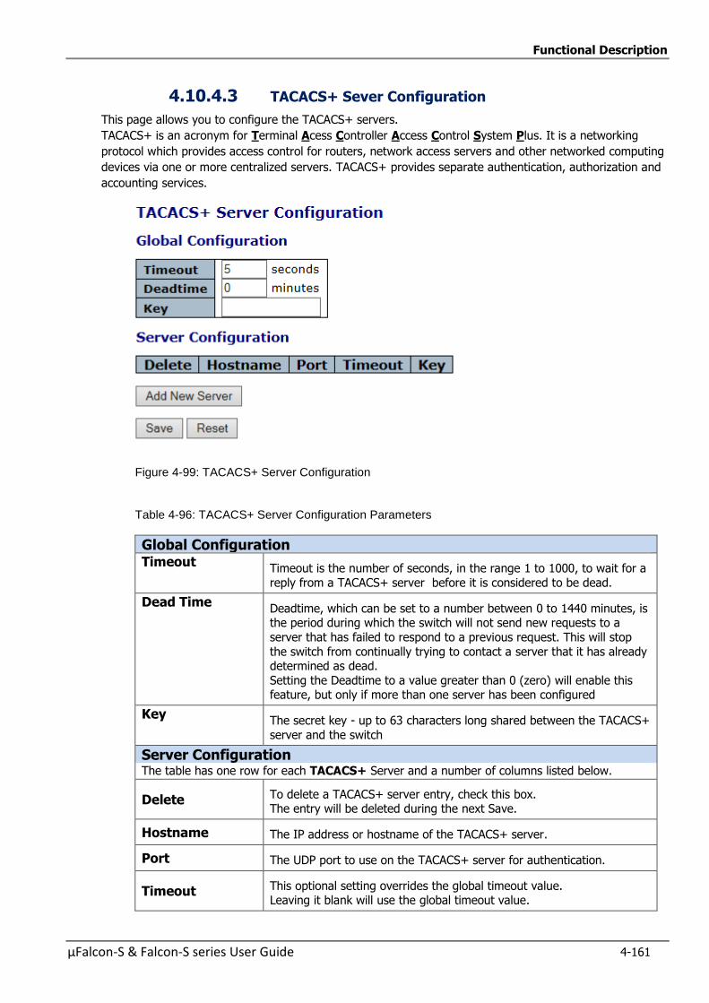
Functional Description
µFalcon-S & Falcon-S series User Guide 4-161
4.10.4.3 TACACS+ Sever Configuration
This page allows you to configure the TACACS+ servers.
TACACS+ is an acronym for Terminal Acess Controller Access Control System Plus. It is a networking
protocol which provides access control for routers, network access servers and other networked computing
devices via one or more centralized servers. TACACS+ provides separate authentication, authorization and
accounting services.
Figure 4-99: TACACS+ Server Configuration
Table 4-96: TACACS+ Server Configuration Parameters
Global Configuration
Timeout Timeout is the number of seconds, in the range 1 to 1000, to wait for a
reply from a TACACS+ server before it is considered to be dead.
Dead Time Deadtime, which can be set to a number between 0 to 1440 minutes, is the period during which the switch will not send new requests to a
server that has failed to respond to a previous request. This will stop
the switch from continually trying to contact a server that it has already determined as dead.
Setting the Deadtime to a value greater than 0 (zero) will enable this feature, but only if more than one server has been configured
Key The secret key - up to 63 characters long shared between the TACACS+
server and the switch
Server Configuration The table has one row for each TACACS+ Server and a number of columns listed below.
Delete To delete a TACACS+ server entry, check this box. The entry will be deleted during the next Save.
Hostname The IP address or hostname of the TACACS+ server.
Port The UDP port to use on the TACACS+ server for authentication.
Timeout This optional setting overrides the global timeout value. Leaving it blank will use the global timeout value.

Functional Description
4-162 µFalcon-S & Falcon-S series User Guide
Key This optional setting overrides the global key. Leaving it blank will use
the global key
Adding a New Server
Click Add New Server to add a new TACACS+ server
An empty row is added to the table, and the TACACS+ server can be configured as needed. Up
to 5 servers are supported.
The Delete button can be used to undo the addition of the new server
Buttons
Save: Click to save changes
Reset: Click to undo any changes made locally and revert to previously saved values
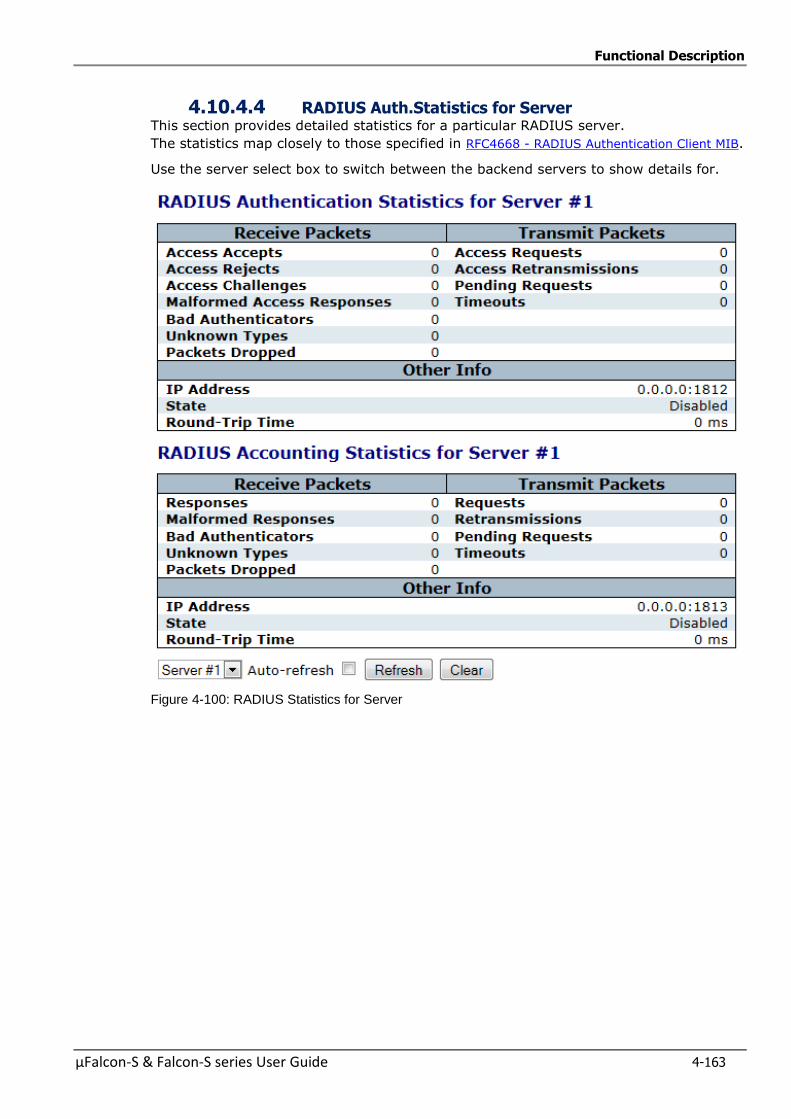
Functional Description
µFalcon-S & Falcon-S series User Guide 4-163
4.10.4.4 RADIUS Auth.Statistics for Server This section provides detailed statistics for a particular RADIUS server.
The statistics map closely to those specified in RFC4668 - RADIUS Authentication Client MIB.
Use the server select box to switch between the backend servers to show details for.
Figure 4-100: RADIUS Statistics for Server
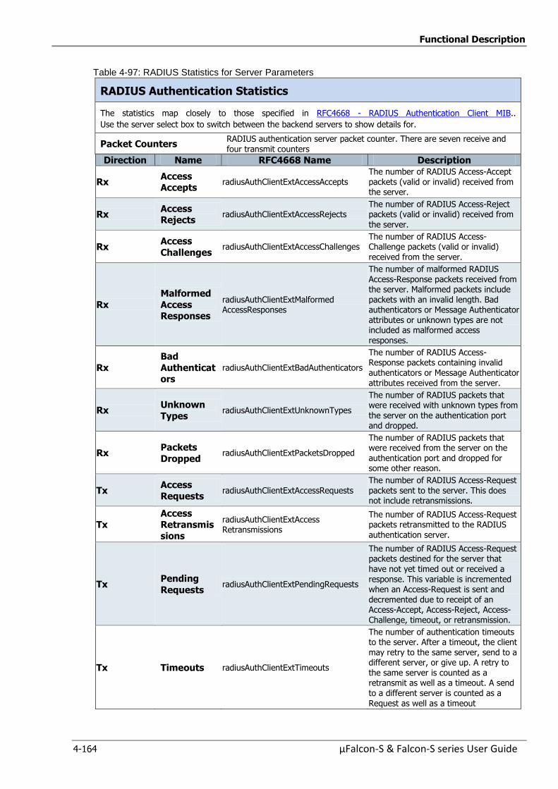
Functional Description
4-164 µFalcon-S & Falcon-S series User Guide
Table 4-97: RADIUS Statistics for Server Parameters
RADIUS Authentication Statistics
The statistics map closely to those specified in RFC4668 - RADIUS Authentication Client MIB..
Use the server select box to switch between the backend servers to show details for.
Packet Counters RADIUS authentication server packet counter. There are seven receive and four transmit counters
Direction Name RFC4668 Name Description
Rx Access Accepts
radiusAuthClientExtAccessAccepts The number of RADIUS Access-Accept packets (valid or invalid) received from the server.
Rx Access Rejects
radiusAuthClientExtAccessRejects The number of RADIUS Access-Reject packets (valid or invalid) received from the server.
Rx Access
Challenges radiusAuthClientExtAccessChallenges
The number of RADIUS Access-Challenge packets (valid or invalid)
received from the server.
Rx
Malformed
Access Responses
radiusAuthClientExtMalformed AccessResponses
The number of malformed RADIUS Access-Response packets received from the server. Malformed packets include packets with an invalid length. Bad authenticators or Message Authenticator attributes or unknown types are not included as malformed access responses.
Rx
Bad
Authenticators
radiusAuthClientExtBadAuthenticators
The number of RADIUS Access-Response packets containing invalid authenticators or Message Authenticator attributes received from the server.
Rx Unknown
Types radiusAuthClientExtUnknownTypes
The number of RADIUS packets that were received with unknown types from
the server on the authentication port and dropped.
Rx Packets
Dropped radiusAuthClientExtPacketsDropped
The number of RADIUS packets that were received from the server on the authentication port and dropped for some other reason.
Tx Access
Requests radiusAuthClientExtAccessRequests
The number of RADIUS Access-Request packets sent to the server. This does not include retransmissions.
Tx Access Retransmis
sions
radiusAuthClientExtAccess Retransmissions
The number of RADIUS Access-Request packets retransmitted to the RADIUS authentication server.
Tx Pending
Requests radiusAuthClientExtPendingRequests
The number of RADIUS Access-Request packets destined for the server that have not yet timed out or received a response. This variable is incremented when an Access-Request is sent and decremented due to receipt of an Access-Accept, Access-Reject, Access-Challenge, timeout, or retransmission.
Tx Timeouts radiusAuthClientExtTimeouts
The number of authentication timeouts to the server. After a timeout, the client may retry to the same server, send to a different server, or give up. A retry to the same server is counted as a retransmit as well as a timeout. A send to a different server is counted as a Request as well as a timeout
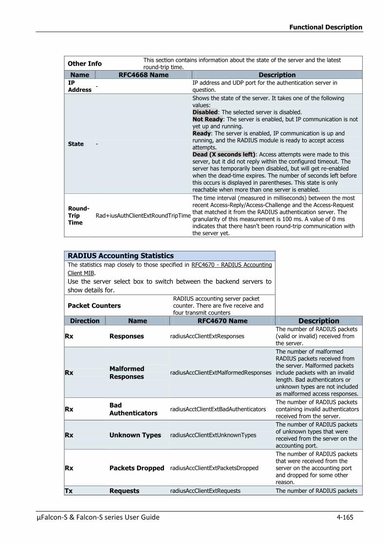
Functional Description
µFalcon-S & Falcon-S series User Guide 4-165
Other Info This section contains information about the state of the server and the latest round-trip time.
Name RFC4668 Name Description IP Address
- IP address and UDP port for the authentication server in question.
State -
Shows the state of the server. It takes one of the following values: Disabled: The selected server is disabled. Not Ready: The server is enabled, but IP communication is not yet up and running. Ready: The server is enabled, IP communication is up and running, and the RADIUS module is ready to accept access attempts. Dead (X seconds left): Access attempts were made to this server, but it did not reply within the configured timeout. The server has temporarily been disabled, but will get re-enabled
when the dead-time expires. The number of seconds left before this occurs is displayed in parentheses. This state is only reachable when more than one server is enabled.
Round-Trip Time
Rad+iusAuthClientExtRoundTripTime
The time interval (measured in milliseconds) between the most recent Access-Reply/Access-Challenge and the Access-Request that matched it from the RADIUS authentication server. The granularity of this measurement is 100 ms. A value of 0 ms indicates that there hasn't been round-trip communication with the server yet.
RADIUS Accounting Statistics The statistics map closely to those specified in RFC4670 - RADIUS Accounting
Client MIB.
Use the server select box to switch between the backend servers to
show details for.
Packet Counters RADIUS accounting server packet counter. There are five receive and four transmit counters
Direction Name RFC4670 Name Description
Rx Responses radiusAccClientExtResponses The number of RADIUS packets (valid or invalid) received from the server.
Rx Malformed
Responses radiusAccClientExtMalformedResponses
The number of malformed RADIUS packets received from the server. Malformed packets include packets with an invalid length. Bad authenticators or unknown types are not included as malformed access responses.
Rx Bad
Authenticators radiusAcctClientExtBadAuthenticators
The number of RADIUS packets containing invalid authenticators received from the server.
Rx Unknown Types radiusAccClientExtUnknownTypes
The number of RADIUS packets of unknown types that were received from the server on the accounting port.
Rx Packets Dropped radiusAccClientExtPacketsDropped
The number of RADIUS packets that were received from the server on the accounting port and dropped for some other reason.
Tx Requests radiusAccClientExtRequests The number of RADIUS packets
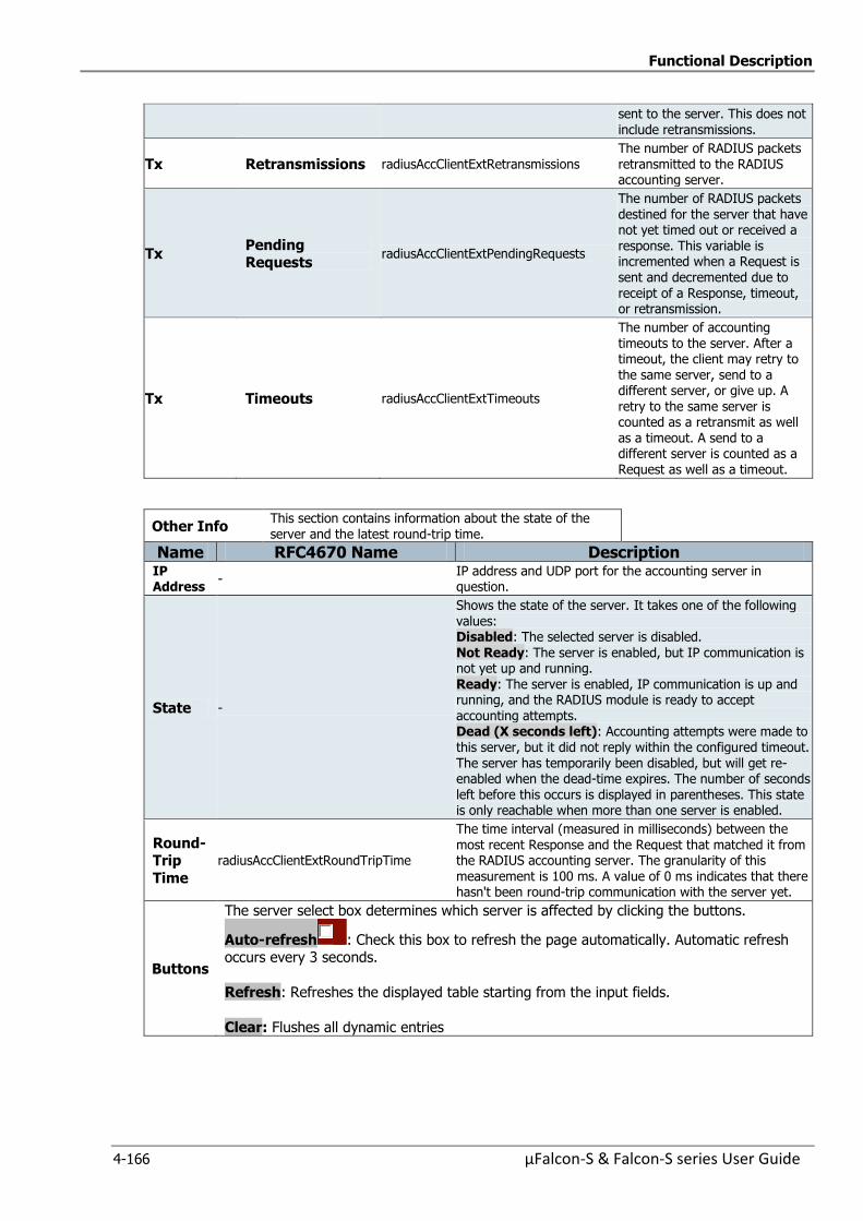
Functional Description
4-166 µFalcon-S & Falcon-S series User Guide
sent to the server. This does not
include retransmissions.
Tx Retransmissions radiusAccClientExtRetransmissions The number of RADIUS packets retransmitted to the RADIUS accounting server.
Tx Pending Requests
radiusAccClientExtPendingRequests
The number of RADIUS packets destined for the server that have not yet timed out or received a response. This variable is incremented when a Request is sent and decremented due to receipt of a Response, timeout, or retransmission.
Tx Timeouts radiusAccClientExtTimeouts
The number of accounting timeouts to the server. After a timeout, the client may retry to the same server, send to a different server, or give up. A retry to the same server is counted as a retransmit as well as a timeout. A send to a different server is counted as a Request as well as a timeout.
Other Info This section contains information about the state of the server and the latest round-trip time.
Name RFC4670 Name Description IP Address
- IP address and UDP port for the accounting server in question.
State -
Shows the state of the server. It takes one of the following values: Disabled: The selected server is disabled.
Not Ready: The server is enabled, but IP communication is not yet up and running. Ready: The server is enabled, IP communication is up and running, and the RADIUS module is ready to accept accounting attempts. Dead (X seconds left): Accounting attempts were made to this server, but it did not reply within the configured timeout. The server has temporarily been disabled, but will get re-enabled when the dead-time expires. The number of seconds left before this occurs is displayed in parentheses. This state is only reachable when more than one server is enabled.
Round-Trip
Time
radiusAccClientExtRoundTripTime
The time interval (measured in milliseconds) between the most recent Response and the Request that matched it from the RADIUS accounting server. The granularity of this measurement is 100 ms. A value of 0 ms indicates that there hasn't been round-trip communication with the server yet.
Buttons
The server select box determines which server is affected by clicking the buttons.
Auto-refresh : Check this box to refresh the page automatically. Automatic refresh occurs every 3 seconds.
Refresh: Refreshes the displayed table starting from the input fields.
Clear: Flushes all dynamic entries

Functional Description
µFalcon-S & Falcon-S series User Guide 4-167
4.11 TDM Functionality
With the advent of mobile backhaul transition to packetized networks, it is very important to
carry efficiently TDM signals over packet switched network.
Packet –switched networks are not designed to transport TDM data and have no related clock
distribution mechanism. TDM requires accurate synchronization, low latency and jitter for
reliable transmission, and to accurately reconstruct the TDM service clock(s)
Packet based multimedia services form a large proportion of traffic carried on 3G/4G networks.
but still there is a definite requirement to carry TDM services and voice over 2G base stations
Fibrolan µFalcon ST is a Carrier Ethernet device delivering business-class Ethernet, legacy TDM
services and mobile backhaul over fiber infrastructure.
The µFalcon-ST unit includes a multiport TDM over packet (TDMoP) technology and 4 or 8
E1/T1/J1 ports to allow for TDM and Ethernet integration.
The uFalcon-ST/G and uFalcon-ST/F are Carrier Ethernet devices delivering Multiservice, legacy
TDM services and Synchronization System
The TDMoP core supports circuit emulation function (CESoETH) and TDM over Packet mapping
(SAToP)
CESoETH provides a mechanism to carry TDM traffic over Metro Ethernet networks. This
function is implemented in accordance with MEF8 CES definitions and requirements.
SAToP stands for Structure-Agnostic Time Division Multiplexing (TDM) over Packet.
SAToP is an encapsulation method to transparently carry TDM s bit-streams (T1, E1, T3, E3)
disregarding any TDM structure This emulation is suitable to applications where the provider
devices do not need to interpret TDM data and signaling.
To transport TDM data through packet switched networks, the TDMoP logic encapsulates the
TDM data into Ethernet frames.
RTP (Real Time Transport) protocol, when enabled, allows the insertion of timestamps and
sequence numbers in each frame
Timestamps are for synchronization and sequence numbers are used to detect packet loss and
restore packets sequence.
The following displays show the implementation of TDM configuration and circuit.
Note: refer to “Fibrolan Falcon Products Matrix” to find out which Fibrolan devices support TDM
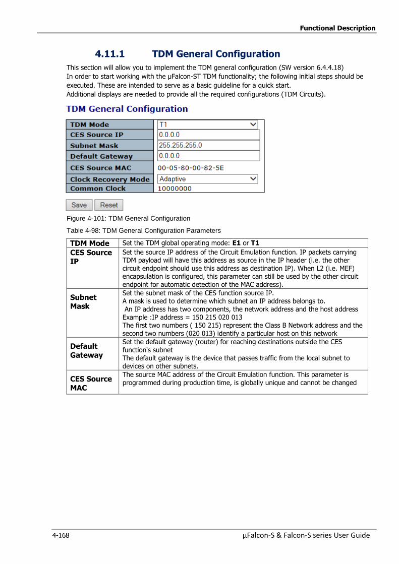
Functional Description
4-168 µFalcon-S & Falcon-S series User Guide
4.11.1 TDM General Configuration
This section will allow you to implement the TDM general configuration (SW version 6.4.4.18)
In order to start working with the µFalcon-ST TDM functionality; the following initial steps should be
executed. These are intended to serve as a basic guideline for a quick start.
Additional displays are needed to provide all the required configurations (TDM Circuits).
Figure 4-101: TDM General Configuration
Table 4-98: TDM General Configuration Parameters
TDM Mode Set the TDM global operating mode: E1 or T1
CES Source IP
Set the source IP address of the Circuit Emulation function. IP packets carrying TDM payload will have this address as source in the IP header (i.e. the other
circuit endpoint should use this address as destination IP). When L2 (i.e. MEF) encapsulation is configured, this parameter can still be used by the other circuit
endpoint for automatic detection of the MAC address).
Subnet Mask
Set the subnet mask of the CES function source IP. A mask is used to determine which subnet an IP address belongs to.
An IP address has two components, the network address and the host address
Example :IP address = 150 215 020 013 The first two numbers ( 150 215) represent the Class B Network address and the
second two numbers (020 013) identify a particular host on this network
Default Gateway
Set the default gateway (router) for reaching destinations outside the CES
function's subnet
The default gateway is the device that passes traffic from the local subnet to devices on other subnets.
CES Source MAC
The source MAC address of the Circuit Emulation function. This parameter is
programmed during production time, is globally unique and cannot be changed
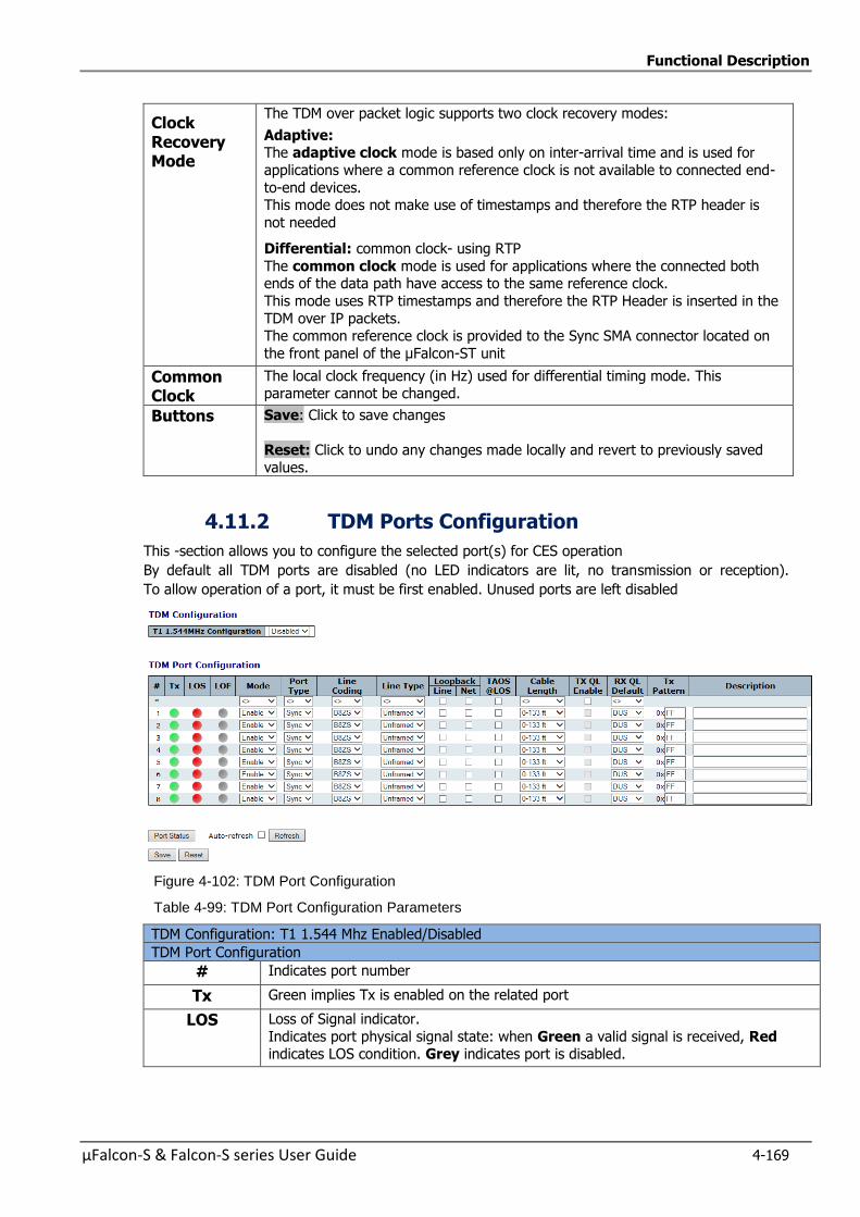
Functional Description
µFalcon-S & Falcon-S series User Guide 4-169
Clock Recovery Mode
The TDM over packet logic supports two clock recovery modes:
Adaptive: The adaptive clock mode is based only on inter-arrival time and is used for
applications where a common reference clock is not available to connected end-
to-end devices. This mode does not make use of timestamps and therefore the RTP header is
not needed
Differential: common clock- using RTP
The common clock mode is used for applications where the connected both ends of the data path have access to the same reference clock.
This mode uses RTP timestamps and therefore the RTP Header is inserted in the
TDM over IP packets. The common reference clock is provided to the Sync SMA connector located on
the front panel of the µFalcon-ST unit
Common Clock
The local clock frequency (in Hz) used for differential timing mode. This parameter cannot be changed.
Buttons Save: Click to save changes
Reset: Click to undo any changes made locally and revert to previously saved
values.
4.11.2 TDM Ports Configuration
This -section allows you to configure the selected port(s) for CES operation
By default all TDM ports are disabled (no LED indicators are lit, no transmission or reception).
To allow operation of a port, it must be first enabled. Unused ports are left disabled
Figure 4-102: TDM Port Configuration
Table 4-99: TDM Port Configuration Parameters
TDM Configuration: T1 1.544 Mhz Enabled/Disabled
TDM Port Configuration
# Indicates port number
Tx Green implies Tx is enabled on the related port
LOS Loss of Signal indicator.
Indicates port physical signal state: when Green a valid signal is received, Red indicates LOS condition. Grey indicates port is disabled.
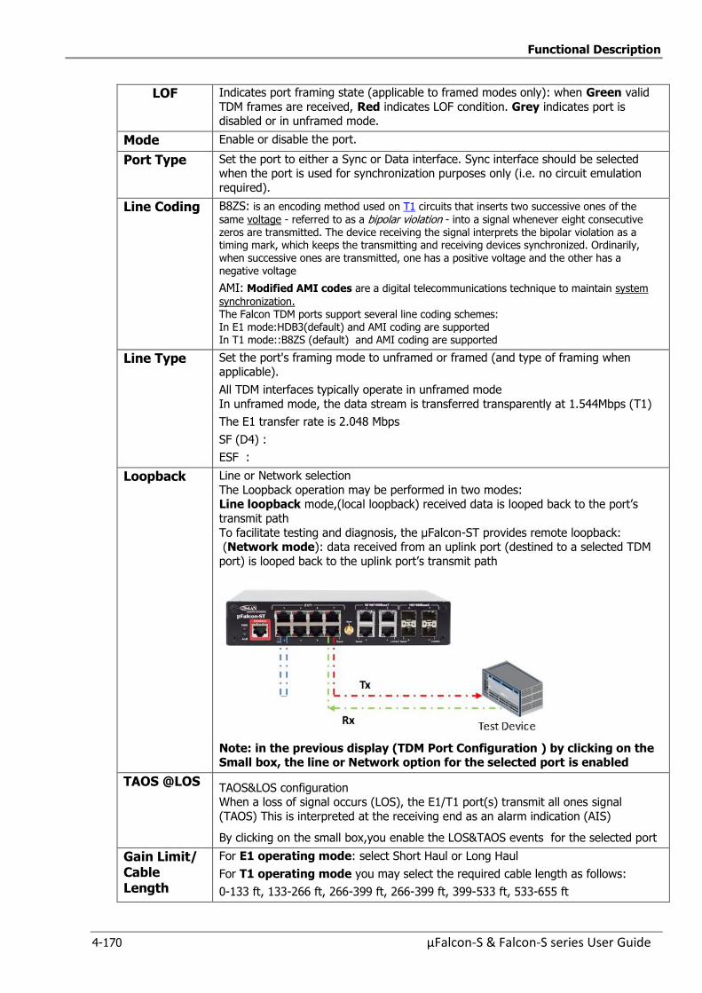
Functional Description
4-170 µFalcon-S & Falcon-S series User Guide
LOF Indicates port framing state (applicable to framed modes only): when Green valid
TDM frames are received, Red indicates LOF condition. Grey indicates port is disabled or in unframed mode.
Mode Enable or disable the port.
Port Type Set the port to either a Sync or Data interface. Sync interface should be selected when the port is used for synchronization purposes only (i.e. no circuit emulation
required).
Line Coding B8ZS: is an encoding method used on T1 circuits that inserts two successive ones of the
same voltage - referred to as a bipolar violation - into a signal whenever eight consecutive zeros are transmitted. The device receiving the signal interprets the bipolar violation as a timing mark, which keeps the transmitting and receiving devices synchronized. Ordinarily, when successive ones are transmitted, one has a positive voltage and the other has a negative voltage
AMI: Modified AMI codes are a digital telecommunications technique to maintain system
synchronization. The Falcon TDM ports support several line coding schemes: In E1 mode:HDB3(default) and AMI coding are supported In T1 mode::B8ZS (default) and AMI coding are supported
Line Type Set the port's framing mode to unframed or framed (and type of framing when applicable).
All TDM interfaces typically operate in unframed mode
In unframed mode, the data stream is transferred transparently at 1.544Mbps (T1)
The E1 transfer rate is 2.048 Mbps
SF (D4) :
ESF :
Loopback Line or Network selection
The Loopback operation may be performed in two modes: Line loopback mode,(local loopback) received data is looped back to the port’s
transmit path
To facilitate testing and diagnosis, the µFalcon-ST provides remote loopback: (Network mode): data received from an uplink port (destined to a selected TDM
port) is looped back to the uplink port’s transmit path
Note: in the previous display (TDM Port Configuration ) by clicking on the Small box, the line or Network option for the selected port is enabled
TAOS @LOS TAOS&LOS configuration When a loss of signal occurs (LOS), the E1/T1 port(s) transmit all ones signal
(TAOS) This is interpreted at the receiving end as an alarm indication (AIS)
By clicking on the small box,you enable the LOS&TAOS events for the selected port
Gain Limit/ Cable Length
For E1 operating mode: select Short Haul or Long Haul
For T1 operating mode you may select the required cable length as follows:
0-133 ft, 133-266 ft, 266-399 ft, 266-399 ft, 399-533 ft, 533-655 ft
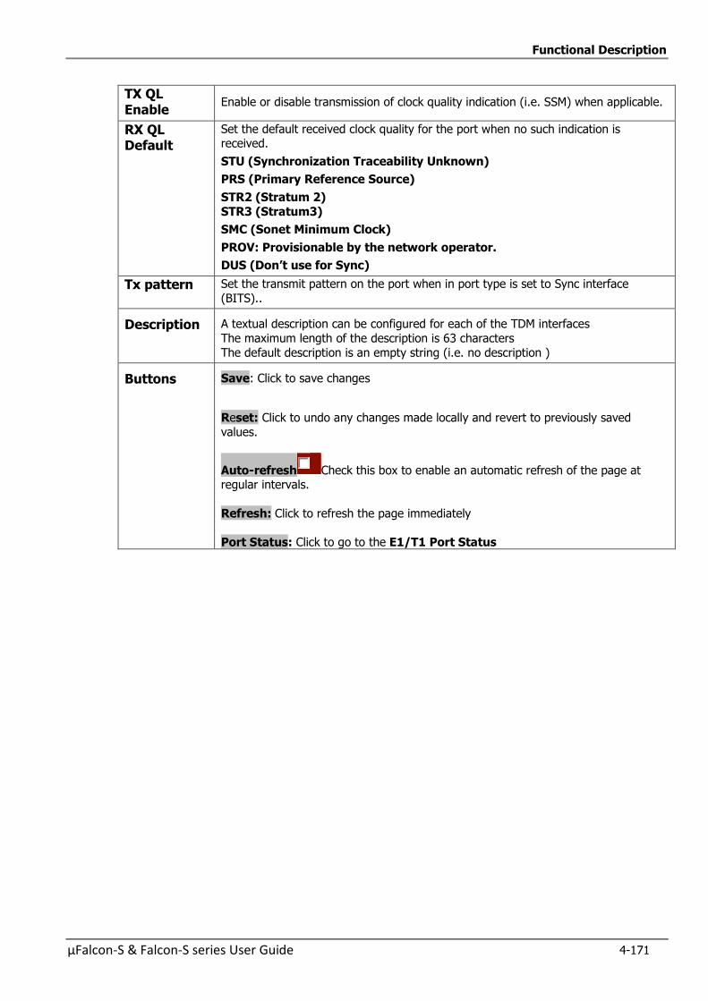
Functional Description
µFalcon-S & Falcon-S series User Guide 4-171
TX QL Enable
Enable or disable transmission of clock quality indication (i.e. SSM) when applicable.
RX QL Default
Set the default received clock quality for the port when no such indication is received.
STU (Synchronization Traceability Unknown)
PRS (Primary Reference Source)
STR2 (Stratum 2)
STR3 (Stratum3)
SMC (Sonet Minimum Clock)
PROV: Provisionable by the network operator.
DUS (Don’tuseforSync)
Tx pattern Set the transmit pattern on the port when in port type is set to Sync interface
(BITS)..
Description A textual description can be configured for each of the TDM interfaces
The maximum length of the description is 63 characters
The default description is an empty string (i.e. no description )
Buttons Save: Click to save changes
Reset: Click to undo any changes made locally and revert to previously saved
values.
Auto-refresh Check this box to enable an automatic refresh of the page at regular intervals.
Refresh: Click to refresh the page immediately
Port Status: Click to go to the E1/T1 Port Status
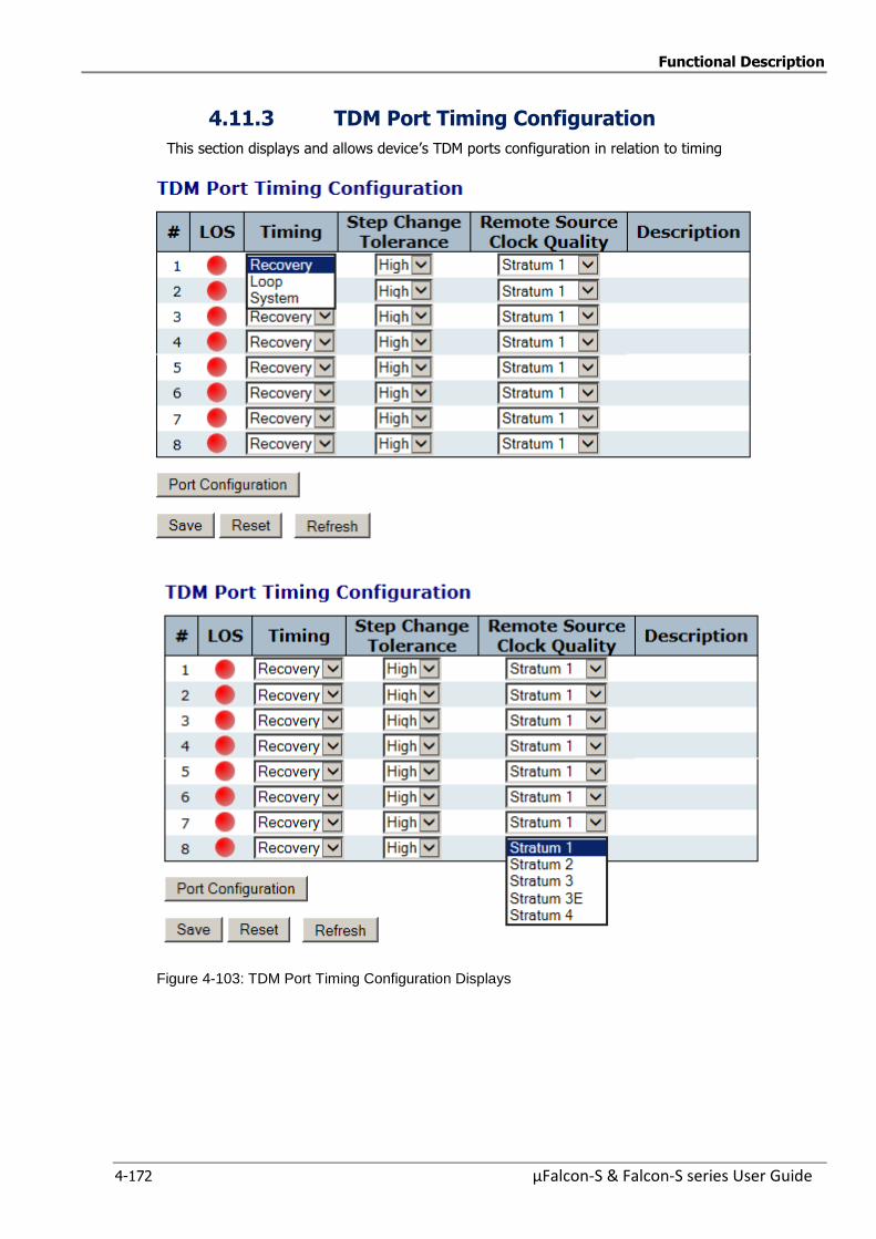
Functional Description
4-172 µFalcon-S & Falcon-S series User Guide
4.11.3 TDM Port Timing Configuration
This section displays and allows device’s TDM ports configuration in relation to timing
Figure 4-103: TDM Port Timing Configuration Displays
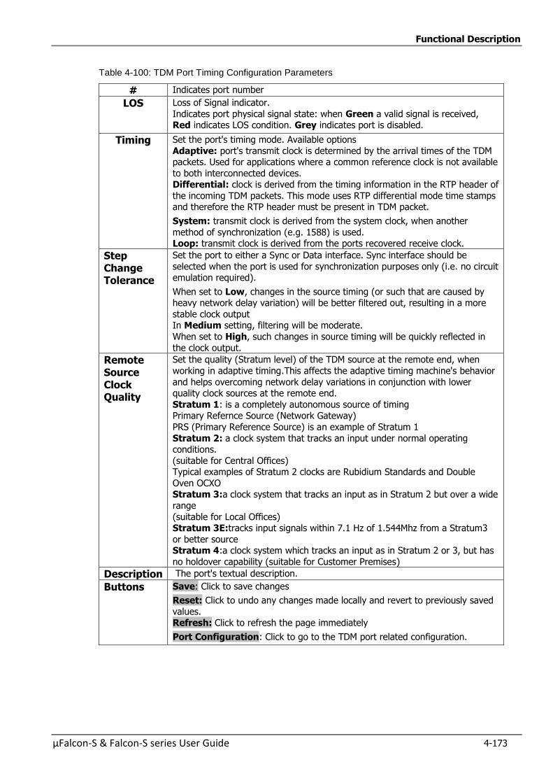
Functional Description
µFalcon-S & Falcon-S series User Guide 4-173
Table 4-100: TDM Port Timing Configuration Parameters
# Indicates port number
LOS Loss of Signal indicator.
Indicates port physical signal state: when Green a valid signal is received, Red indicates LOS condition. Grey indicates port is disabled.
Timing Set the port's timing mode. Available options
Adaptive: port's transmit clock is determined by the arrival times of the TDM packets. Used for applications where a common reference clock is not available
to both interconnected devices. Differential: clock is derived from the timing information in the RTP header of
the incoming TDM packets. This mode uses RTP differential mode time stamps and therefore the RTP header must be present in TDM packet.
System: transmit clock is derived from the system clock, when another
method of synchronization (e.g. 1588) is used. Loop: transmit clock is derived from the ports recovered receive clock.
Step Change Tolerance
Set the port to either a Sync or Data interface. Sync interface should be
selected when the port is used for synchronization purposes only (i.e. no circuit emulation required).
When set to Low, changes in the source timing (or such that are caused by heavy network delay variation) will be better filtered out, resulting in a more
stable clock output In Medium setting, filtering will be moderate.
When set to High, such changes in source timing will be quickly reflected in
the clock output.
Remote Source Clock Quality
Set the quality (Stratum level) of the TDM source at the remote end, when
working in adaptive timing.This affects the adaptive timing machine's behavior
and helps overcoming network delay variations in conjunction with lower quality clock sources at the remote end.
Stratum 1: is a completely autonomous source of timing Primary Refernce Source (Network Gateway)
PRS (Primary Reference Source) is an example of Stratum 1
Stratum 2: a clock system that tracks an input under normal operating conditions.
(suitable for Central Offices) Typical examples of Stratum 2 clocks are Rubidium Standards and Double
Oven OCXO Stratum 3:a clock system that tracks an input as in Stratum 2 but over a wide
range
(suitable for Local Offices) Stratum 3E:tracks input signals within 7.1 Hz of 1.544Mhz from a Stratum3
or better source Stratum 4:a clock system which tracks an input as in Stratum 2 or 3, but has
no holdover capability (suitable for Customer Premises)
Description The port's textual description.
Buttons Save: Click to save changes
Reset: Click to undo any changes made locally and revert to previously saved
values. Refresh: Click to refresh the page immediately
Port Configuration: Click to go to the TDM port related configuration.
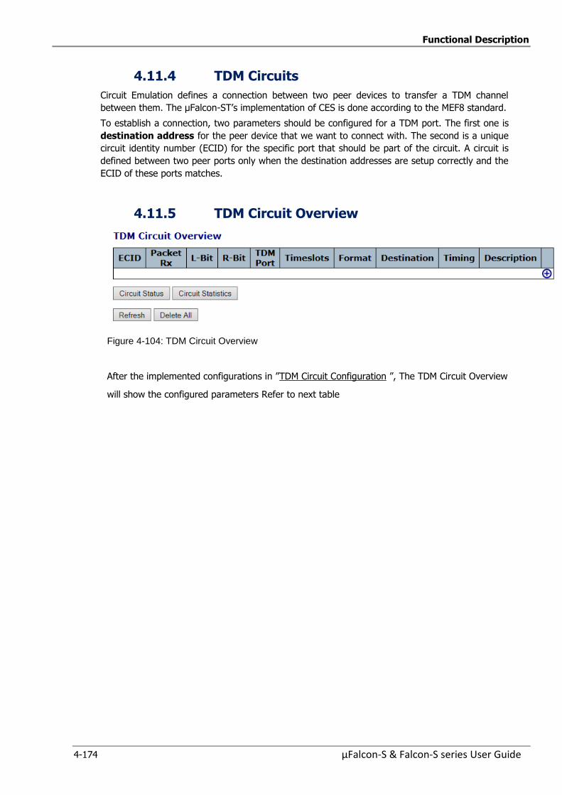
Functional Description
4-174 µFalcon-S & Falcon-S series User Guide
4.11.4 TDM Circuits
Circuit Emulation defines a connection between two peer devices to transfer a TDM channel
between them. The µFalcon-ST’s implementation of CES is done according to the MEF8 standard.
To establish a connection, two parameters should be configured for a TDM port. The first one is
destination address for the peer device that we want to connect with. The second is a unique
circuit identity number (ECID) for the specific port that should be part of the circuit. A circuit is
defined between two peer ports only when the destination addresses are setup correctly and the
ECID of these ports matches.
4.11.5 TDM Circuit Overview
Figure 4-104: TDM Circuit Overview
After the implemented configurations in ”TDM Circuit Configuration ”, The TDM Circuit Overview
will show the configured parameters Refer to next table
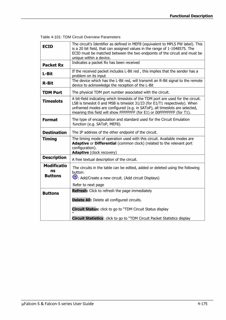
Functional Description
µFalcon-S & Falcon-S series User Guide 4-175
Table 4-101: TDM Circuit Overview Parameters
ECID The circuit's Identifier as defined in MEF8 (equivalent to MPLS PW label). This is a 20 bit field, that can assigned values in the range of 1-1048575. The
ECID must be matched between the two endpoints of the circuit and must be
unique within a device.
Packet Rx Indicates a packet Rx has been received
L-Bit If the received packet includes L-Bit red , this implies that the sender has a
problem on its input
R-Bit The device which has the L-Bit red, will transmit an R-Bit signal to the remote device to acknowledge the reception of the L-Bit
TDM Port The physical TDM port number associated with the circuit.
Timeslots A bit-field indicating which timeslots of the TDM port are used for the circuit. LSB is timeslot 0 and MSB is timeslot 31/23 (for E1/T1 respectively). When
unframed modes are configured (e.g. in SAToP), all timeslots are selected, meaning this field will show FFFFFFFF (for E1) or 00FFFFFFFF (for T1).
Format The type of encapsulation and standard used for the Circuit Emulation
function (e.g. SAToP, MEF8).
Destination The IP address of the other endpoint of the circuit.
Timing The timing mode of operation used with this circuit. Available modes are
Adaptive or Differential (common clock) (related to the relevant port configuration).
Adaptive (clock recovery)
Description A free textual description of the circuit.
Modifications
Buttons
The circuits in the table can be edited, added or deleted using the following button:
: Add/Create a new circuit. (Add circuit Displays)
Refer to next page
Buttons Refresh: Click to refresh the page immediately
Delete All: Delete all configured circuits.
Circuit Status: click to go to “TDM Circuit Status display ”
Circuit Statistics: click to go to “TDM Circuit Packet Statistics display

Functional Description
4-176 µFalcon-S & Falcon-S series User Guide
4.11.6 TDM Circuit Configuration
Clicking on button on the previous display, allows you to show the following add circuit displays: Circuit Admin Configuration
TDM Interface Configuration Network Packet Configuration
RTP Header (Differential mode) Jitter Buffer Configuration
This section allows detailed configuration of a TDM circuit.
Figure 4-105: TDM Circuit Configuration displays
The following sub-sections describe the above different displays

Functional Description
µFalcon-S & Falcon-S series User Guide 4-177
4.11.6.1 Circuit Admin Configuration
Figure 4-106: Circuit Admin Configuration
Table 4-102: Circuit Admin Configuration Parameters
ECID ECID selection The circuit's Identifier as defined in MEF8 (equivalent to MPLS PW label).
This is a 20 bit field, that can assigned values in the range of 1-1048575. The ECID must be matched between the two endpoints of the circuit and
must be unique within a device.
Enter the ECID value
Enable Enable or disable the circuit. This is useful in cases where a circuit needs to
be temporarily disabled, without having to reconfigure it later.
Description A free textual description of the circuit (up to 63 characters).
Buttons Save: Click to save changes
Reset: Click to undo any changes made locally and revert to previously
saved values.
Cancel : Click to cancel changes
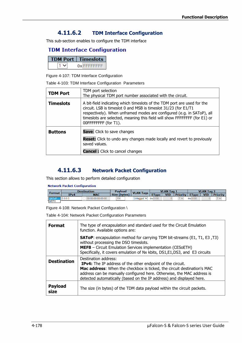
Functional Description
4-178 µFalcon-S & Falcon-S series User Guide
4.11.6.2 TDM Interface Configuration
This sub-section enables to configure the TDM interface
Figure 4-107: TDM Interface Configuration
Table 4-103: TDM Interface Configuration Parameters
TDM Port TDM port selection
The physical TDM port number associated with the circuit.
Timeslots A bit-field indicating which timeslots of the TDM port are used for the circuit. LSB is timeslot 0 and MSB is timeslot 31/23 (for E1/T1
respectively). When unframed modes are configured (e.g. in SAToP), all timeslots are selected, meaning this field will show FFFFFFFF (for E1) or
00FFFFFFFF (for T1).
Buttons Save: Click to save changes
Reset: Click to undo any changes made locally and revert to previously
saved values.
Cancel : Click to cancel changes
4.11.6.3 Network Packet Configuration
This section allows to perform detailed configuration
Figure 4-108: Network Packet Configuration \
Table 4-104: Network Packet Configuration Parameters
Format The type of encapsulation and standard used for the Circuit Emulation
function. Available options are:
SAToP: encapsulation method for carrying TDM bit-streams (E1, T1, E3 ,T3) without processing the DSO timeslots.
MEF8 – Circuit Emulation Services implementation (CESoETH) Specifically, it covers emulation of Nx kbits, DS1,E1,DS3, and E3 circuits
Destination Destination address:
IPv4: The IP address of the other endpoint of the circuit. Mac address: When the checkbox is ticked, the circuit destination's MAC
address can be manually configured here. Otherwise, the MAC address is
detected automatically (based on the IP address) and displayed here.
Payload size
The size (in bytes) of the TDM data payload within the circuit packets.
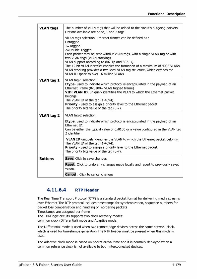
Functional Description
µFalcon-S & Falcon-S series User Guide 4-179
VLAN tags The number of VLAN tags that will be added to the circuit's outgoing packets.
Options available are none, 1 and 2 tags.
VlLAN tags selection. Ethernet frames can be defined as :
Untagged
1=Tagged 2=Double Tagged
Each packet may be sent without VLAN tags, with a single VLAN tag or with two VLAN tags (VLAN stacking)
VLAN support according to 802.1p and 802.1Q. The 12 bit VLAN idertifier enables the formation of a maximum of 4096 VLANs.
VLAN stacking provides a two level VLAN tag structure, which extends the
VLAN ID space to over 16 million VLANs
VLAN tag 1 VLAN tag-1 selection:
Etype- used to indicate which protocol is encapsulated in the payload of an
Ethernet Frame (0x8100= VLAN tagged frame) VID: VLAN ID, uniquely identifies the VLAN to which the Ethernet packet
belongs. The VLAN ID of the tag (1-4094).
Priority - used to assign a priority level to the Ethernet packet The priority bits value of the tag (0-7).
VLAN tag 2 VLAN tag-2 selection:
Etype: used to indicate which protocol is encapsulated in the payload of an Ethernet ID:
Can be either the typical value of 0x8100 or a value configured in the VLAN tag
2 identifier
VLAN ID uniquely identifies the VLAN to which the Ethernet packet belongs
The VLAN ID of the tag (1-4094). Priority - used to assign a priority level to the Ethernet packet.
The priority bits value of the tag (0-7).
Buttons Save: Click to save changes
Reset: Click to undo any changes made locally and revert to previously saved
values.
Cancel : Click to cancel changes
4.11.6.4 RTP Header
The Real Time Transport Protocol (RTP) is a standard packet format for delivering media streams
over Ethernet The RTP protocol includes timestamps for synchronization, sequence numbers for
packet loss compensation and handling of reordering packets
Timestamps are assigned per frame
The TDM logic circuits supports two clock recovery modes:
common clock (Differential) mode and Adaptive mode.
The DIfferential mode is used when two remote edge devices access the same network clock,
which is used for timestamps generation.The RTP header must be present when this mode is
used.
The Adaptive clock mode is based on packet arrival time and it is normally deployed when a
common reference clock is not available to both intercoonected devices.
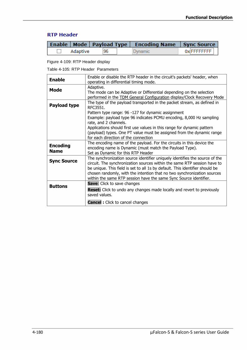
Functional Description
4-180 µFalcon-S & Falcon-S series User Guide
Figure 4-109: RTP Header display
Table 4-105: RTP Header Parameters
Enable Enable or disable the RTP header in the circuit's packets' header, when operating in differential timing mode.
Mode Adaptive.
The mode can be Adaptive or Differential depending on the selection performed in the TDM General Configuration display/Clock Recovery Mode
Payload type The type of the payload transported in the packet stream, as defined in
RFC3551. Pattern type range: 96 -127 for dynamic assignment
Example: payload type 96 indicates PCMU encoding, 8,000 Hz sampling rate, and 2 channels.
Applications should first use values in this range for dynamic pattern (payload) types. One PT value must be assigned from the dynamic range
for each direction of the connection
Encoding Name
The encoding name of the payload. For the circuits in this device the encoding name is Dynamic (must match the Payload Type).
Set as Dynamic for this RTP Header
Sync Source The synchronization source identifier uniquely identifies the source of the circuit. The synchronization sources within the same RTP session have to
be unique. This field is set to all 1s by default. This identifier should be chosen randomly, with the intention that no two synchronization sources
within the same RTP session have the same Sync Source identifier.
Buttons Save: Click to save changes
Reset: Click to undo any changes made locally and revert to previously
saved values.
Cancel : Click to cancel changes
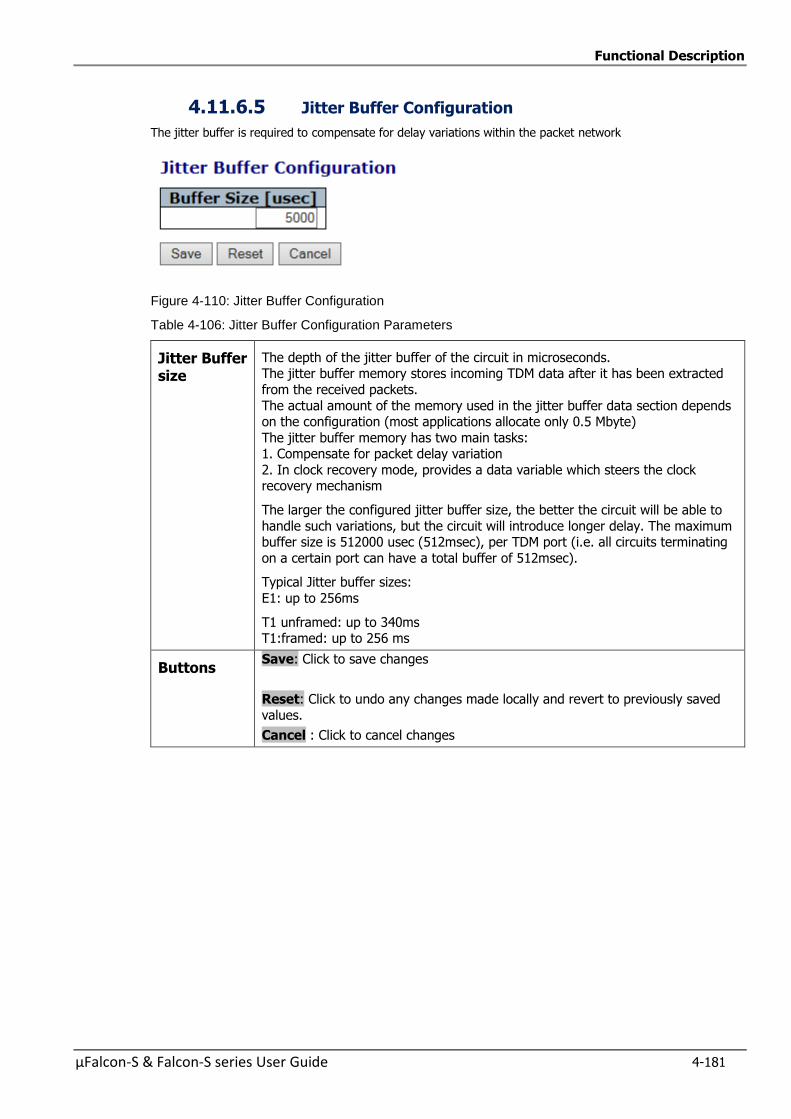
Functional Description
µFalcon-S & Falcon-S series User Guide 4-181
4.11.6.5 Jitter Buffer Configuration
The jitter buffer is required to compensate for delay variations within the packet network
Figure 4-110: Jitter Buffer Configuration
Table 4-106: Jitter Buffer Configuration Parameters
Jitter Buffer size
The depth of the jitter buffer of the circuit in microseconds. The jitter buffer memory stores incoming TDM data after it has been extracted
from the received packets.
The actual amount of the memory used in the jitter buffer data section depends on the configuration (most applications allocate only 0.5 Mbyte)
The jitter buffer memory has two main tasks: 1. Compensate for packet delay variation
2. In clock recovery mode, provides a data variable which steers the clock recovery mechanism
The larger the configured jitter buffer size, the better the circuit will be able to
handle such variations, but the circuit will introduce longer delay. The maximum buffer size is 512000 usec (512msec), per TDM port (i.e. all circuits terminating
on a certain port can have a total buffer of 512msec).
Typical Jitter buffer sizes:
E1: up to 256ms
T1 unframed: up to 340ms T1:framed: up to 256 ms
Buttons Save: Click to save changes
Reset: Click to undo any changes made locally and revert to previously saved
values.
Cancel : Click to cancel changes
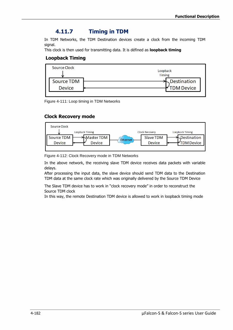
Functional Description
4-182 µFalcon-S & Falcon-S series User Guide
4.11.7 Timing in TDM
In TDM Networks, the TDM Destination devices create a clock from the incoming TDM
signal.
This clock is then used for transmitting data. It is défined as loopback timing
Loopback Timing
Figure 4-111: Loop timing in TDM Networks
Clock Recovery mode
Figure 4-112: Clock Recovery mode in TDM Networks
In the above network, the receiving slave TDM device receives data packets with variable
delays.
After processing the input data, the slave device should send TDM data to the Destination
TDM data at the same clock rate which was originally delivered by the Source TDM Device
The Slave TDM device has to work in “clock recovery mode” in order to reconstruct the
Source TDM clock
In this way, the remote Destination TDM device is allowed to work in loopback timing mode
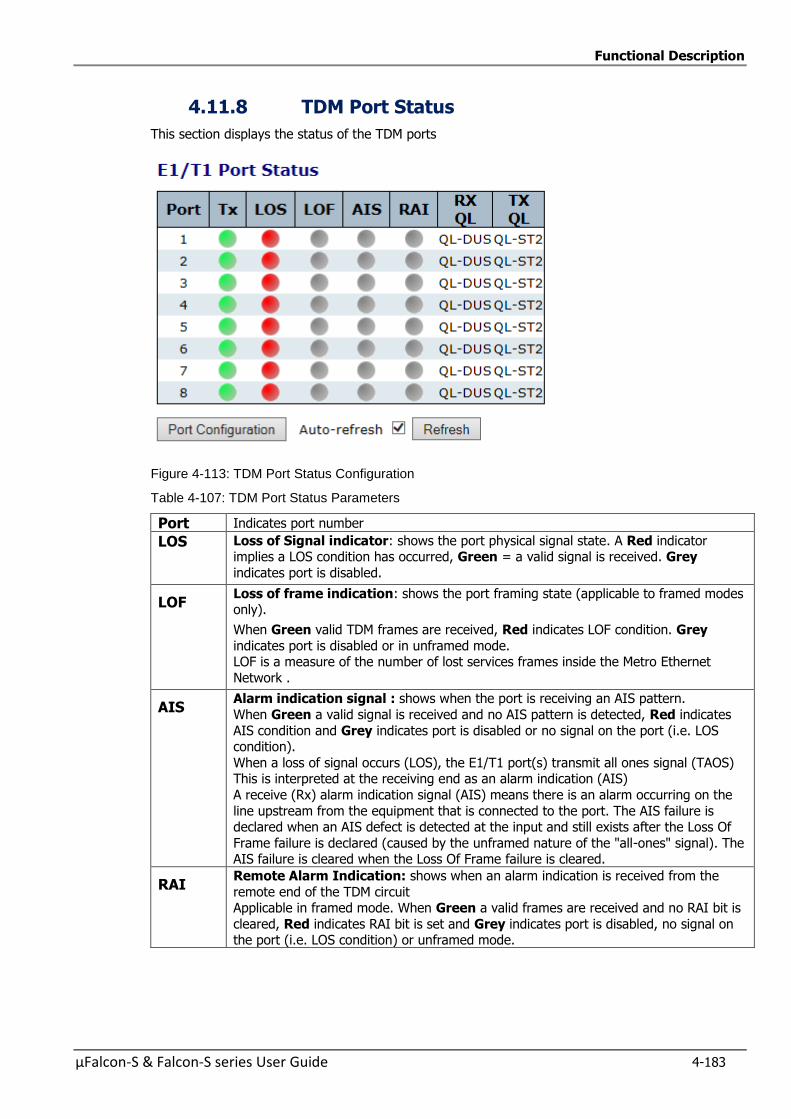
Functional Description
µFalcon-S & Falcon-S series User Guide 4-183
4.11.8 TDM Port Status
This section displays the status of the TDM ports
Figure 4-113: TDM Port Status Configuration
Table 4-107: TDM Port Status Parameters
Port Indicates port number
LOS Loss of Signal indicator: shows the port physical signal state. A Red indicator implies a LOS condition has occurred, Green = a valid signal is received. Grey
indicates port is disabled.
LOF Loss of frame indication: shows the port framing state (applicable to framed modes only).
When Green valid TDM frames are received, Red indicates LOF condition. Grey
indicates port is disabled or in unframed mode. LOF is a measure of the number of lost services frames inside the Metro Ethernet
Network .
AIS Alarm indication signal : shows when the port is receiving an AIS pattern.
When Green a valid signal is received and no AIS pattern is detected, Red indicates
AIS condition and Grey indicates port is disabled or no signal on the port (i.e. LOS condition).
When a loss of signal occurs (LOS), the E1/T1 port(s) transmit all ones signal (TAOS) This is interpreted at the receiving end as an alarm indication (AIS)
A receive (Rx) alarm indication signal (AIS) means there is an alarm occurring on the
line upstream from the equipment that is connected to the port. The AIS failure is declared when an AIS defect is detected at the input and still exists after the Loss Of
Frame failure is declared (caused by the unframed nature of the "all-ones" signal). The AIS failure is cleared when the Loss Of Frame failure is cleared.
RAI Remote Alarm Indication: shows when an alarm indication is received from the
remote end of the TDM circuit Applicable in framed mode. When Green a valid frames are received and no RAI bit is
cleared, Red indicates RAI bit is set and Grey indicates port is disabled, no signal on the port (i.e. LOS condition) or unframed mode.

Functional Description
4-184 µFalcon-S & Falcon-S series User Guide
RX QL Indicates the current clock quality as received on the port via SSM. Applicable to T1
framed modes. When no quality indication is received (e.g. no SSM), the quality will be the port's
default (configurable) and will appear in parentheses ().
TX QL Indicates the current clock quality that is transmitted on the port via SSM. Applicable to T1 framed modes.
Buttons
Auto-refresh :Check this box to enable an automatic refresh of the page at regular intervals.
Refresh: Click to refresh the page
Port Configuration click to go to Port Configuration
4.11.9 TDM Circuit Status
This section displays the packet statistics of the configured circuits.
Figure 4-114: TDM Circuit Status
Table 4-108: TDM Circuit Status Parameters
ECID The circuit's Identifier as defined in MEF8 (equivalent to MPLS PW label).
Packet Rx Indicates current circuit status (i.e. correct packets are received and processed). Green means circuit is up, Red indicates a circuit failure.
L-Bit Alarm bit from the network Rx packets that indicate the remote device has LOS in
the related TDM port.
R-Bit Alarm bit from the network Rx packets that indicate the remote device has no Rx
frames from the network related to the current circuit.
Status Indicates current circuit status (i.e. correct packets are received and processed). Green means circuit is upRed indicates a circuit failure.
JB Level Indicates the fill level of the Jitter Buffer. Includes the current level and the
minimum and maximum levels (since last clear).
ADCL State State of ADCL
SeqNum Drop
The number of events where packets were dropped due to a sequence number
error.
Misorder Discard
(disordered packet)
The number of events where packets were discarded due to disordering (i.e. beyond the device capability to handle such events).
Underrun Events
The number of jitter buffer underrun events since last clear. Underrun occurs when the jitter buffer becomes empty.
Overrun Events
The number of jitter buffer overrun events since last clear.
Overrun occurs when the jitter buffer is full and there is no room for new data to enter.When the jitter buffer level reaches the value of Rx max buffer size, an
overrun situation is announced.
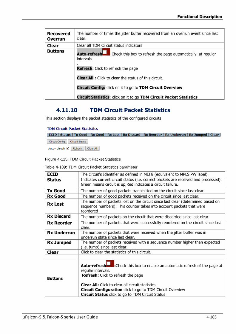
Functional Description
µFalcon-S & Falcon-S series User Guide 4-185
Recovered Overrun
The number of times the jitter buffer recovered from an overrun event since last
clear.
Clear Clear all TDM Circuit status indicators
Buttons Auto-refresh :Check this box to refresh the page automatically. at regular
intervals .
Refresh: Click to refresh the page
Clear All : Click to clear the status of this circuit.
Circuit Config: click on it to go to TDM Circuit Overview
Circuit Statistics: click on it to go TDM Circuit Packet Statistics
4.11.10 TDM Circuit Packet Statistics
This section displays the packet statistics of the configured circuits
Figure 4-115: TDM Circuit Packet Statistics
Table 4-109: TDM Circuit Packet Statistics parameter
ECID The circuit's Identifier as defined in MEF8 (equivalent to MPLS PW label).
Status Indicates current circuit status (i.e. correct packets are received and processed).
Green means circuit is up,Red indicates a circuit failure.
Tx Good The number of good packets transmitted on the circuit since last clear.
Rx Good The number of good packets received on the circuit since last clear.
Rx Lost The number of packets lost on the circuit since last clear (determined based on
sequence numbers). This counter takes into account packets that were reordered
Rx Discard The number of packets on the circuit that were discarded since last clear.
Rx Reorder The number of packets that were successfully reordered on the circuit since last clear.
Rx Underrun The number of packets that were received when the jitter buffer was in
underrun state since last clear.
Rx Jumped The number of packets received with a sequence number higher than expected
(i.e. jump) since last clear.
Clear Click to clear the statistics of this circuit.
Buttons
Auto-refresh :Check this box to enable an automatic refresh of the page at
regular intervals. Refresh: Click to refresh the page
Clear All: Click to clear all circuit statistics.
Circuit Configuration click to go to TDM Circuit Overview Circuit Status click to go to TDM Circuit Status

Functional Description
4-186 µFalcon-S & Falcon-S series User Guide
4.11.11 TDM Port Status: Debug Info
This section provides Debug info to TDM Port Status
Figure 4-116: TDM Port Status: Debug Info
Table 4-110:TDM Port Status: Debug Info parameters
Port
ADCL State
Fifo Level
DPLL OOverflow
CDC Detected
SDTST Failed
SDTTO Expired
JAF Overflow
JTB Overrun
Clock Stability
Freeze State
Clear
Buttons Refresh: Click to refresh the page immediately
Auto-refresh :Check this box to enable an automatic refresh of the page at regular intervals.
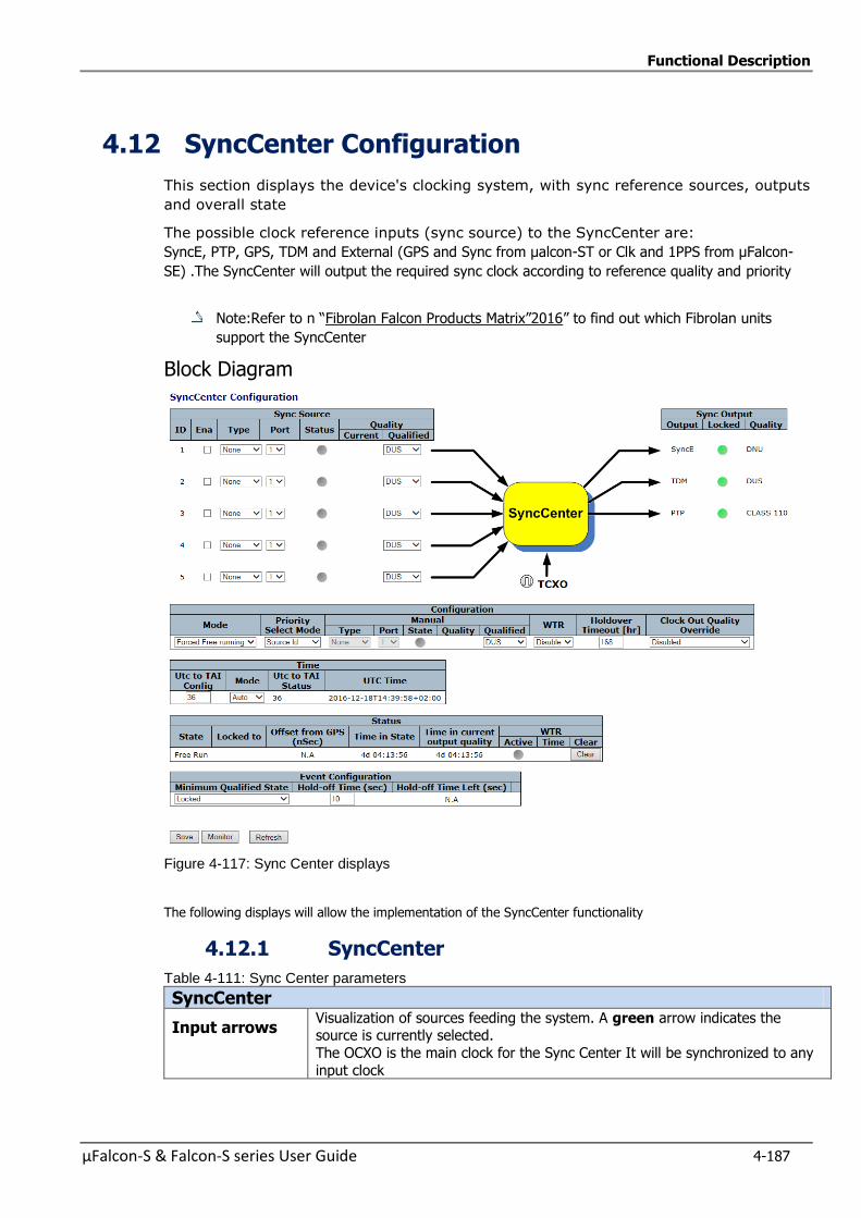
Functional Description
µFalcon-S & Falcon-S series User Guide 4-187
4.12 SyncCenter Configuration
This section displays the device's clocking system, with sync reference sources, outputs
and overall state
The possible clock reference inputs (sync source) to the SyncCenter are:
SyncE, PTP, GPS, TDM and External (GPS and Sync from µalcon-ST or Clk and 1PPS from µFalcon-
SE) .The SyncCenter will output the required sync clock according to reference quality and priority
Note:Refer to n “Fibrolan Falcon Products Matrix”2016” to find out which Fibrolan units
support the SyncCenter
Block Diagram
Figure 4-117: Sync Center displays
The following displays will allow the implementation of the SyncCenter functionality
4.12.1 SyncCenter
Table 4-111: Sync Center parameters
SyncCenter
Input arrows Visualization of sources feeding the system. A green arrow indicates the source is currently selected.
The OCXO is the main clock for the Sync Center It will be synchronized to any
input clock
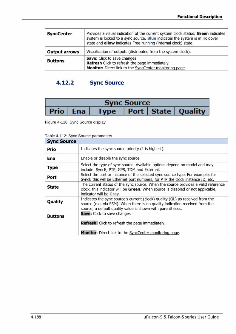
Functional Description
4-188 µFalcon-S & Falcon-S series User Guide
SyncCenter Provides a visual indication of the current system clock status: Green indicates
system is locked to a sync source, Blue indicates the system is in Holdover state and ellow indicates Free-running (internal clock) state.
Output arrows Visualization of outputs (distributed from the system clock).
Buttons Save: Click to save changes Refresh Click to refresh the page immediately.
Monitor: Direct link to the SyncCenter monitoring page.
4.12.2 Sync Source
Figure 4-118: Sync Source display
Table 4-112: Sync Source parameters
Sync Source
Prio Indicates the sync source priority (1 is highest).
Ena Enable or disable the sync source.
Type Select the type of sync source. Available options depend on model and may
include: SyncE, PTP, GPS, TDM and External.
Port Select the port or instance of the selected sync source type. For example: for SyncE this will be Ethernet port numbers, for PTP the clock instance ID, etc.
State The current status of the sync source. When the source provides a valid reference
clock, this indicator will be Green. When source is disabled or not applicable, indicator will be Grey.
Quality Indicates the sync source’s current (clock) quality (QL) as received from the
source (e.g. via SSM). When there is no quality indication received from the source, a default quality value is shown with parentheses.
Buttons Save: Click to save changes
Refresh: Click to refresh the page immediately.
Monitor: Direct link to the SyncCenter monitoring page.
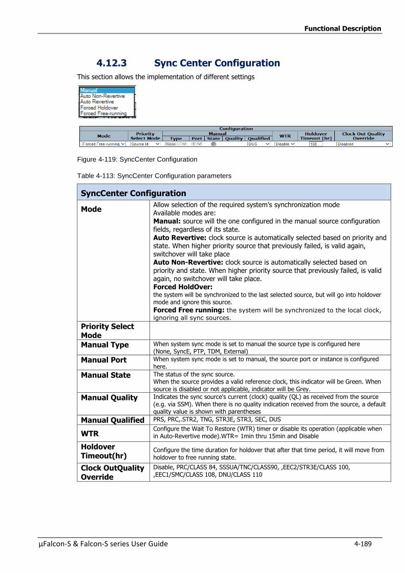
Functional Description
µFalcon-S & Falcon-S series User Guide 4-189
4.12.3 Sync Center Configuration
This section allows the implementation of different settings
Figure 4-119: SyncCenter Configuration
Table 4-113: SyncCenter Configuration parameters
SyncCenter Configuration
Mode Allow selection of the required system’s synchronization mode
Available modes are: Manual: source will the one configured in the manual source configuration
fields, regardless of its state.
Auto Revertive: clock source is automatically selected based on priority and state. When higher priority source that previously failed, is valid again,
switchover will take place Auto Non-Revertive: clock source is automatically selected based on
priority and state. When higher priority source that previously failed, is valid again, no switchover will take place.
Forced HoldOver: the system will be synchronized to the last selected source, but will go into holdover mode and ignore this source. Forced Free running: the system will be synchronized to the local clock,
ignoring all sync sources.
Priority Select Mode
Manual Type When system sync mode is set to manual the source type is configured here (None, SyncE, PTP, TDM, External)
Manual Port When system sync mode is set to manual, the source port or instance is configured here.
Manual State The status of the sync source. When the source provides a valid reference clock, this indicator will be Green. When source is disabled or not applicable, indicator will be Grey.
Manual Quality Indicates the sync source's current (clock) quality (QL) as received from the source (e.g. via SSM). When there is no quality indication received from the source, a default quality value is shown with parentheses
Manual Qualified PRS, PRC,.STR2, TNG, STR3E, STR3, SEC, DUS
WTR Configure the Wait To Restore (WTR) timer or disable its operation (applicable when in Auto-Revertive mode).WTR= 1min thru 15min and Disable
Holdover Timeout(hr)
Configure the time duration for holdover that after that time period, it will move from holdover to free running state.
Clock OutQuality Override
Disable, PRC/CLASS 84, SSSUA/TNC/CLASS90, ,EEC2/STR3E/CLASS 100, ,EEC1/SMC/CLASS 108, DNU/CLASS 110
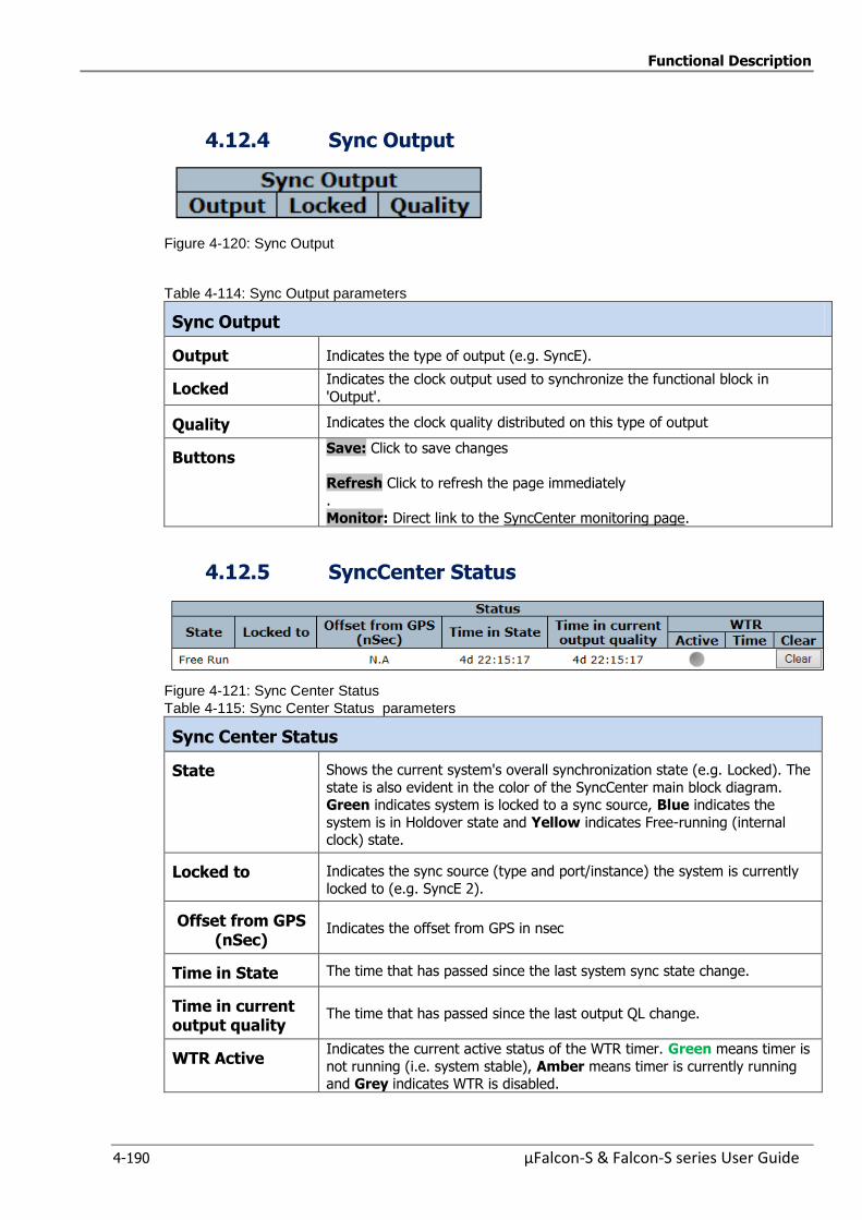
Functional Description
4-190 µFalcon-S & Falcon-S series User Guide
4.12.4 Sync Output
Figure 4-120: Sync Output
Table 4-114: Sync Output parameters
Sync Output
Output Indicates the type of output (e.g. SyncE).
Locked Indicates the clock output used to synchronize the functional block in
'Output'.
Quality Indicates the clock quality distributed on this type of output
Buttons Save: Click to save changes
Refresh Click to refresh the page immediately .
Monitor: Direct link to the SyncCenter monitoring page.
4.12.5 SyncCenter Status
Figure 4-121: Sync Center Status
Table 4-115: Sync Center Status parameters
Sync Center Status
State Shows the current system's overall synchronization state (e.g. Locked). The
state is also evident in the color of the SyncCenter main block diagram. Green indicates system is locked to a sync source, Blue indicates the
system is in Holdover state and Yellow indicates Free-running (internal clock) state.
Locked to Indicates the sync source (type and port/instance) the system is currently
locked to (e.g. SyncE 2).
Offset from GPS (nSec)
Indicates the offset from GPS in nsec
Time in State The time that has passed since the last system sync state change.
Time in current output quality
The time that has passed since the last output QL change.
WTR Active Indicates the current active status of the WTR timer. Green means timer is
not running (i.e. system stable), Amber means timer is currently running and Grey indicates WTR is disabled.
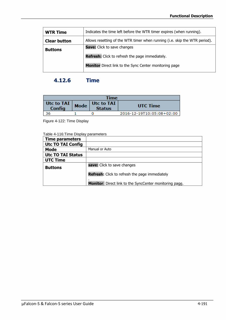
Functional Description
µFalcon-S & Falcon-S series User Guide 4-191
WTR Time Indicates the time left before the WTR timer expires (when running).
Clear button Allows resetting of the WTR timer when running (i.e. skip the WTR period).
Buttons Save: Click to save changes
Refresh: Click to refresh the page immediately.
Monitor Direct link to the Sync Center monitoring page
4.12.6 Time
Figure 4-122: Time Display
Table 4-116:Time Display parameters
Time parameters
Utc TO TAI Config
Mode Manual or Auto
Utc TO TAI Status
UTC Time
Buttons save: Click to save changes
Refresh: Click to refresh the page immediately
.
Monitor: Direct link to the SyncCenter monitoring page.
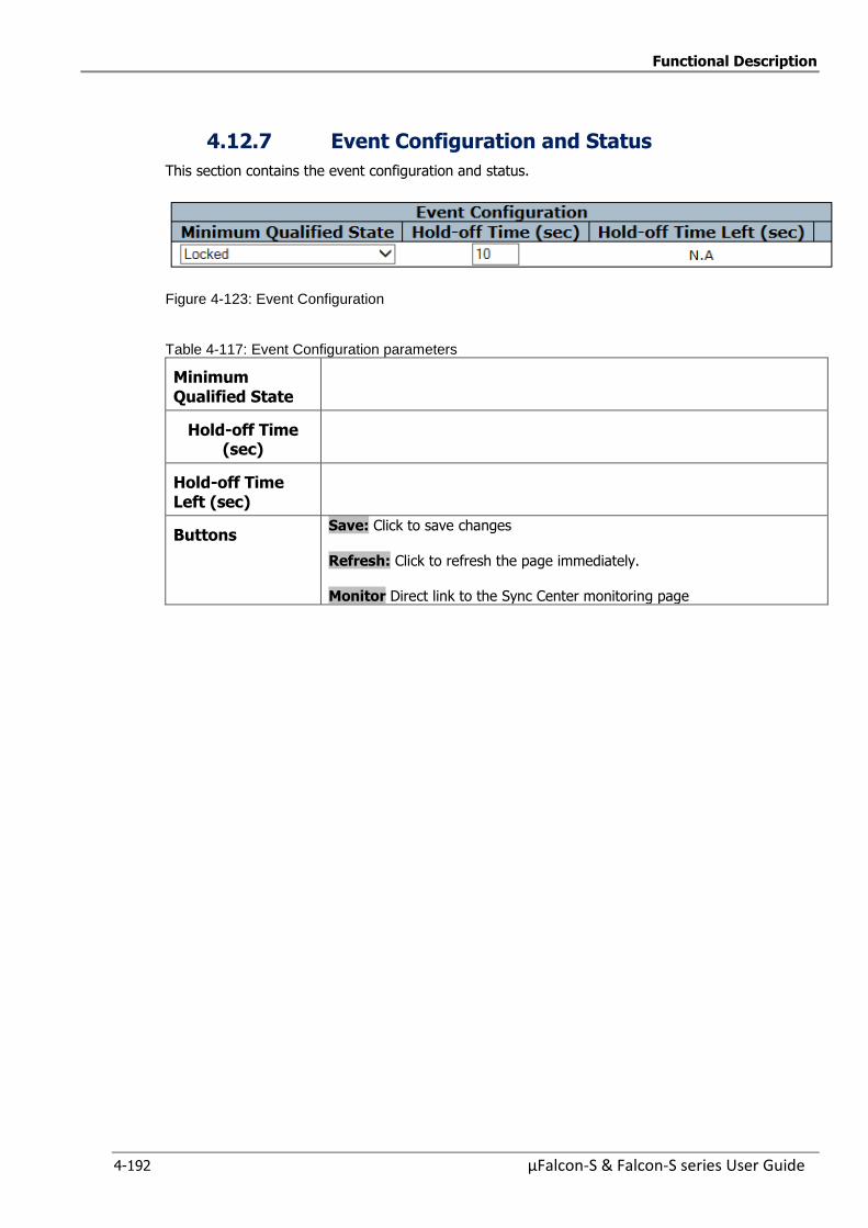
Functional Description
4-192 µFalcon-S & Falcon-S series User Guide
4.12.7 Event Configuration and Status
This section contains the event configuration and status.
Figure 4-123: Event Configuration
Table 4-117: Event Configuration parameters
Minimum Qualified State
Hold-off Time (sec)
Hold-off Time Left (sec)
Buttons Save: Click to save changes
Refresh: Click to refresh the page immediately.
Monitor Direct link to the Sync Center monitoring page
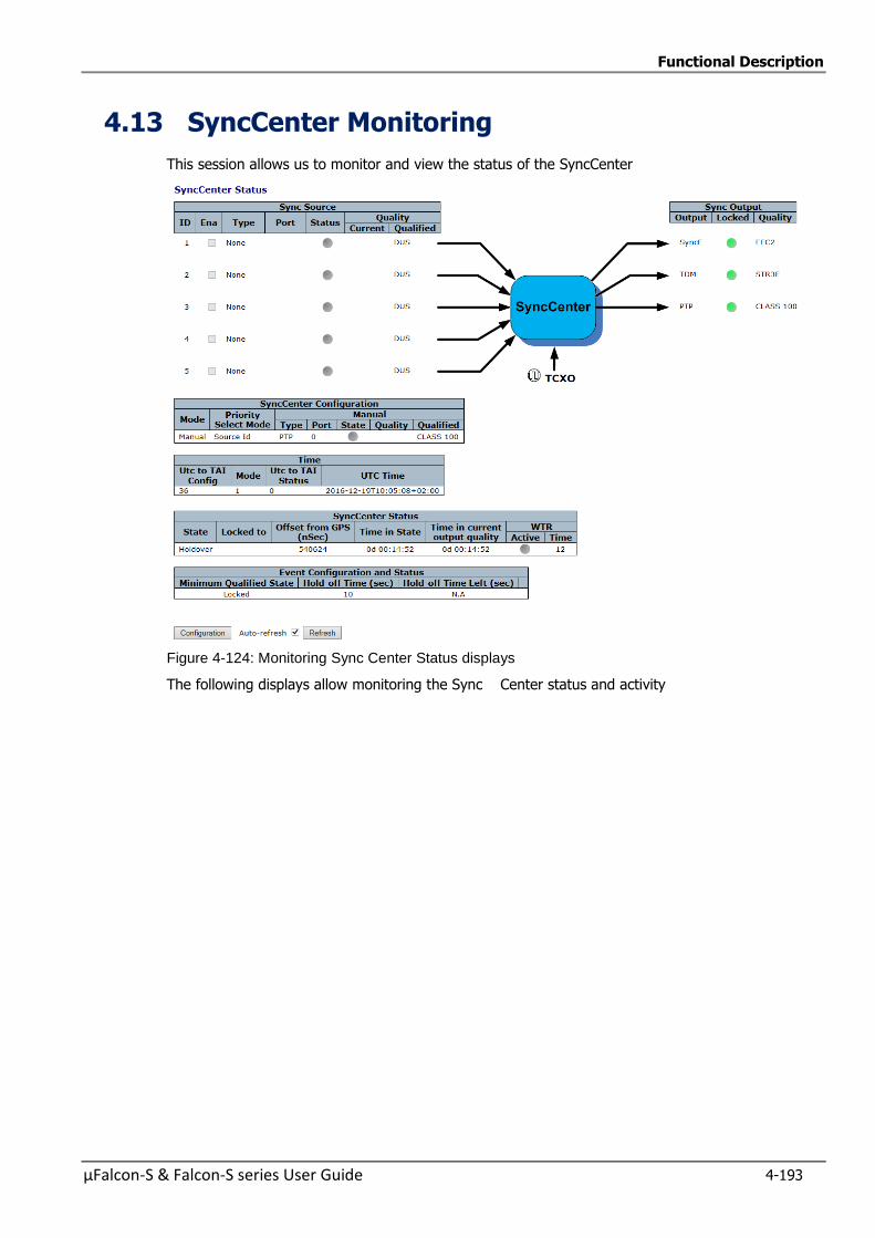
Functional Description
µFalcon-S & Falcon-S series User Guide 4-193
4.13 SyncCenter Monitoring
This session allows us to monitor and view the status of the SyncCenter
Figure 4-124: Monitoring Sync Center Status displays
The following displays allow monitoring the Sync Center status and activity
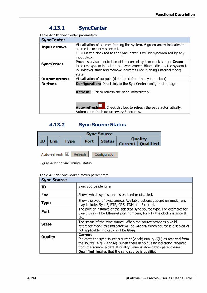
Functional Description
4-194 µFalcon-S & Falcon-S series User Guide
4.13.1 SyncCenter
Table 4-118: SyncCenter parameters
SyncCenter
Input arrows Visualization of sources feeding the system. A green arrow indicates the source is currently selected.
OCXO is the clock fed to the SyncCenter.It will be synchronized by any
input clock
SyncCenter Provides a visual indication of the current system clock status: Green
indicates system is locked to a sync source, Blue indicates the system is
in Holdover state and Yellow indicates Free-running (internal clock) state.
Output arrows Visualization of outputs (distributed from the system clock).
Buttons Configuration: Direct link to the SyncCenter configuration page
Refresh: Click to refresh the page immediately.
Auto-refresh :Check this box to refresh the page automatically.
Automatic refresh occurs every 3 seconds.
4.13.2 Sync Source Status
Figure 4-125: Sync Source Status
Table 4-119: Sync Source status parameters
Sync Source
ID Sync Source identifier
Ena Shows which sync source is enabled or disabled.
Type Show the type of sync source. Available options depend on model and
may include: SyncE, PTP, GPS, TDM and External.
Port The port or instance of the selected sync source type. For example: for SyncE this will be Ethernet port numbers, for PTP the clock instance ID,
etc.
State The status of the sync source. When the source provides a valid reference clock, this indicator will be Green. When source is disabled or
not applicable, indicator will be Grey.
Quality Current
Indicates the sync source's current (clock) quality (QL) as received from
the source (e.g. via SSM). When there is no quality indication received from the source, a default quality value is shown with parentheses.
Qualified implies that the sync source is qualified
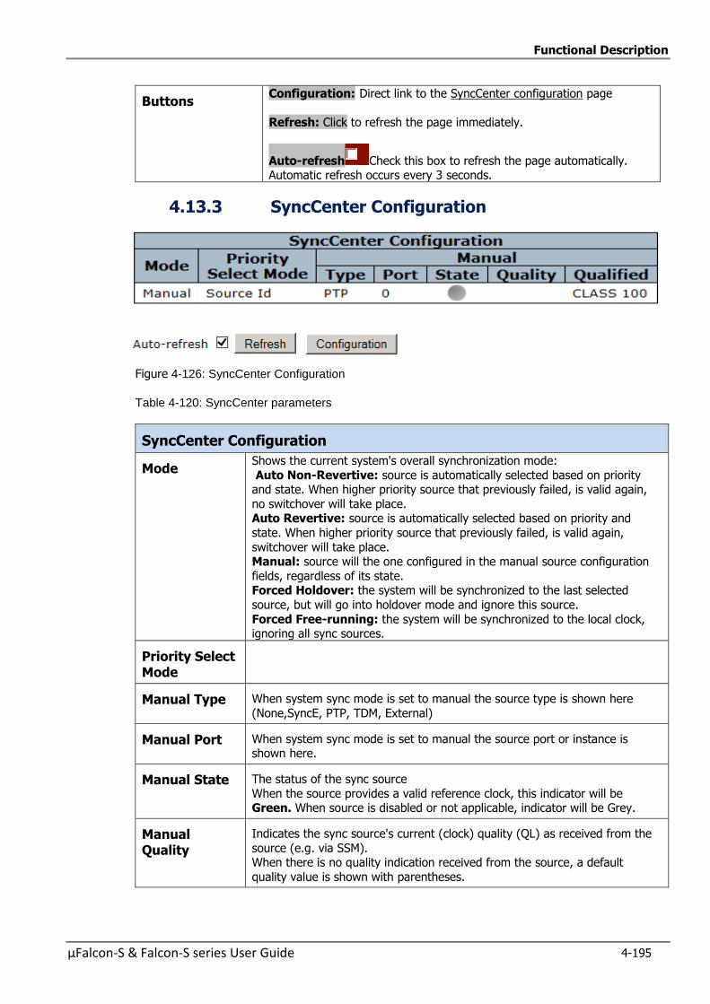
Functional Description
µFalcon-S & Falcon-S series User Guide 4-195
Buttons Configuration: Direct link to the SyncCenter configuration page
Refresh: Click to refresh the page immediately.
Auto-refresh Check this box to refresh the page automatically. Automatic refresh occurs every 3 seconds.
4.13.3 SyncCenter Configuration
Figure 4-126: SyncCenter Configuration
Table 4-120: SyncCenter parameters
SyncCenter Configuration
Mode Shows the current system's overall synchronization mode:
Auto Non-Revertive: source is automatically selected based on priority and state. When higher priority source that previously failed, is valid again,
no switchover will take place. Auto Revertive: source is automatically selected based on priority and
state. When higher priority source that previously failed, is valid again,
switchover will take place. Manual: source will the one configured in the manual source configuration
fields, regardless of its state. Forced Holdover: the system will be synchronized to the last selected
source, but will go into holdover mode and ignore this source.
Forced Free-running: the system will be synchronized to the local clock, ignoring all sync sources.
Priority Select Mode
Manual Type When system sync mode is set to manual the source type is shown here
(None,SyncE, PTP, TDM, External)
Manual Port When system sync mode is set to manual the source port or instance is shown here.
Manual State The status of the sync source
When the source provides a valid reference clock, this indicator will be Green. When source is disabled or not applicable, indicator will be Grey.
Manual Quality
Indicates the sync source's current (clock) quality (QL) as received from the
source (e.g. via SSM). When there is no quality indication received from the source, a default
quality value is shown with parentheses.
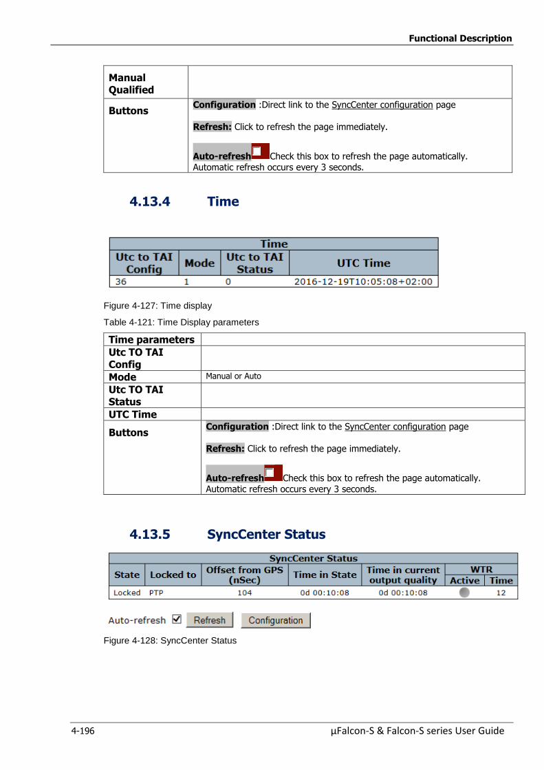
Functional Description
4-196 µFalcon-S & Falcon-S series User Guide
Manual Qualified
Buttons Configuration :Direct link to the SyncCenter configuration page
Refresh: Click to refresh the page immediately.
Auto-refresh Check this box to refresh the page automatically. Automatic refresh occurs every 3 seconds.
4.13.4 Time
Figure 4-127: Time display
Table 4-121: Time Display parameters
Time parameters
Utc TO TAI Config
Mode Manual or Auto
Utc TO TAI Status
UTC Time
Buttons Configuration :Direct link to the SyncCenter configuration page
Refresh: Click to refresh the page immediately.
Auto-refresh Check this box to refresh the page automatically. Automatic refresh occurs every 3 seconds.
4.13.5 SyncCenter Status
Figure 4-128: SyncCenter Status
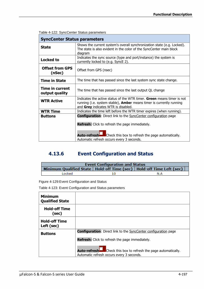
Functional Description
µFalcon-S & Falcon-S series User Guide 4-197
Table 4-122: SyncCenter Status parameters
SyncCenter Status parameters
State Shows the current system's overall synchronization state (e.g. Locked). The state is also evident in the color of the SyncCenter main block
diagram
Locked to Indicates the sync source (type and port/instance) the system is currently locked to (e.g. SyncE 2).
Offset from GPS (nSec)
Offset from GPS (nsec)
Time in State The time that has passed since the last system sync state change.
Time in current output quality
The time that has passed since the last output QL change
WTR Active Indicates the active status of the WTR timer. Green means timer is not running (i.e. system stable), Amber means timer is currently running
and Grey indicates WTR is disabled.
WTR Time Indicates the time left before the WTR timer expires (when running).
Buttons Configuration: Direct link to the SyncCenter configuration page
Refresh: Click to refresh the page immediately.
Auto-refresh Check this box to refresh the page automatically. Automatic refresh occurs every 3 seconds.
4.13.6 Event Configuration and Status
Figure 4-129:Event Configuration and Status
Table 4-123: Event Configuration and Status parameters
Minimum Qualified State
Hold-off Time (sec)
Hold-off Time Left (sec)
Buttons Configuration: Direct link to the SyncCenter configuration page
Refresh: Click to refresh the page immediately.
Auto-refresh Check this box to refresh the page automatically. Automatic refresh occurs every 3 seconds.
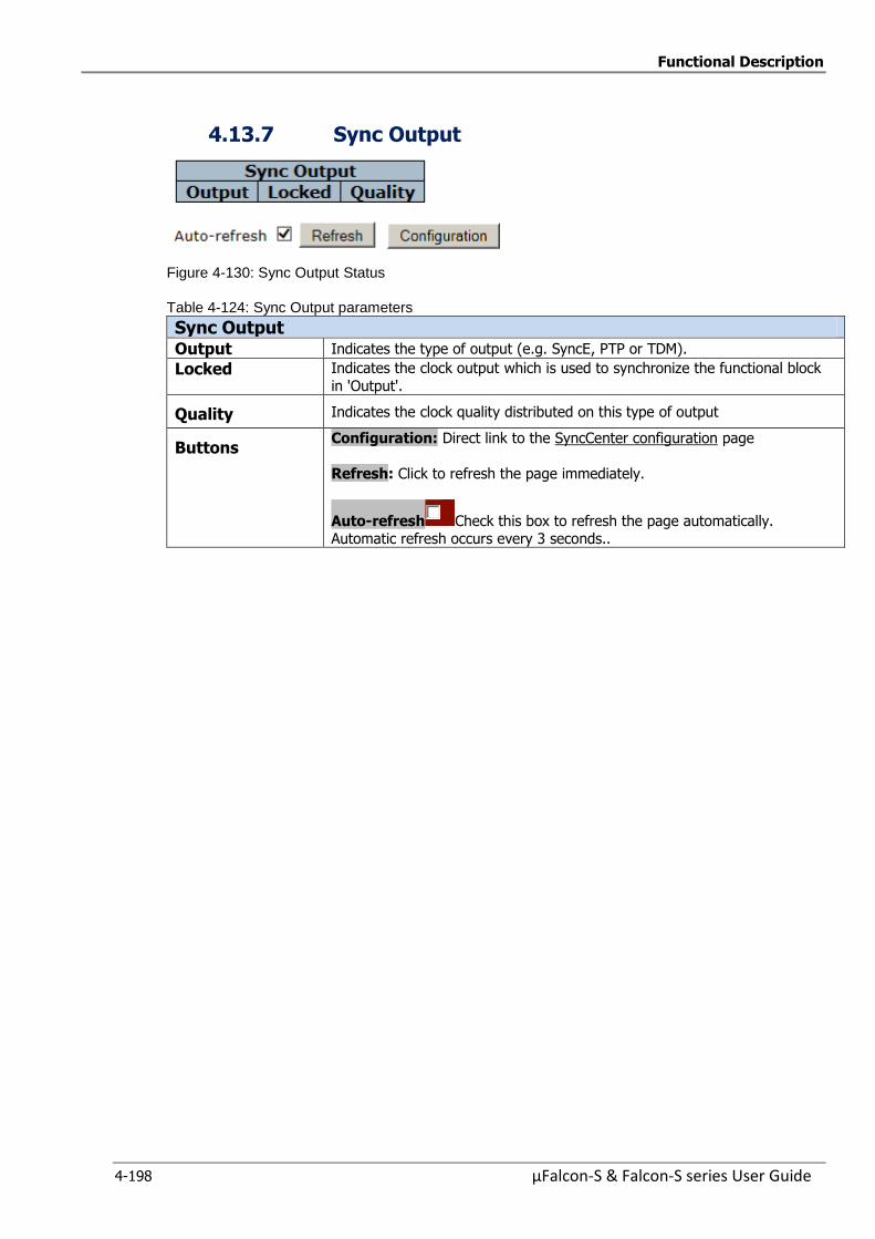
Functional Description
4-198 µFalcon-S & Falcon-S series User Guide
4.13.7 Sync Output
Figure 4-130: Sync Output Status
Table 4-124: Sync Output parameters
Sync Output Output Indicates the type of output (e.g. SyncE, PTP or TDM).
Locked Indicates the clock output which is used to synchronize the functional block
in 'Output'.
Quality Indicates the clock quality distributed on this type of output
Buttons Configuration: Direct link to the SyncCenter configuration page
Refresh: Click to refresh the page immediately.
Auto-refresh Check this box to refresh the page automatically. Automatic refresh occurs every 3 seconds..
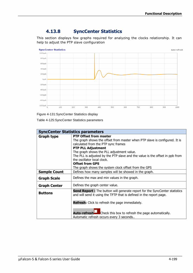
Functional Description
µFalcon-S & Falcon-S series User Guide 4-199
4.13.8 SyncCenter Statistics
This section displays few graphs required for analyzing the clocks relationship. It can
help to adjust the PTP slave configuration
Figure 4-131:SyncCenter Statistics display
Table 4-125:SyncCenter Statistics parameters
SyncCenter Statistics parameters Graph type PTP Offset from master
The graph shows the offset from master when PTP slave is configured. It is
calculated from the PTP sync frames PTP PLL Adjustment
The graph shows the PLL adjustment value. The PLL is adjusted by the PTP slave and the value is the offset in ppb from
the oscillator local clock. Offset from GPS
The graph shows the system clock offset from the GPS
Sample Count Defines how many samples will be showed in the graph.
Graph Scale Defines the max and min values in the graph.
Graph Center Defines the graph center value.
Buttons Send Report : The button will generate report for the SyncCenter statistics
and will send it using the TFTP that is defined in the report page.
Refresh: Click to refresh the page immediately.
Auto-refresh Check this box to refresh the page automatically. Automatic refresh occurs every 3 seconds..
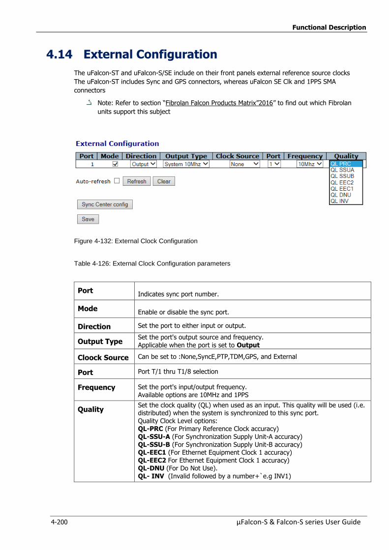
Functional Description
4-200 µFalcon-S & Falcon-S series User Guide
4.14 External Configuration
The uFalcon-ST and uFalcon-S/SE include on their front panels external reference source clocks
The uFalcon-ST includes Sync and GPS connectors, whereas uFalcon SE Clk and 1PPS SMA
connectors
Note: Refer to section “Fibrolan Falcon Products Matrix”2016” to find out which Fibrolan
units support this subject
Figure 4-132: External Clock Configuration
Table 4-126: External Clock Configuration parameters
Port Indicates sync port number.
Mode Enable or disable the sync port.
Direction Set the port to either input or output.
Output Type Set the port's output source and frequency.
Applicable when the port is set to Output
Cloock Source Can be set to :None,SyncE,PTP,TDM,GPS, and External
Port Port T/1 thru T1/8 selection
Frequency Set the port's input/output frequency.
Available options are 10MHz and 1PPS
Quality Set the clock quality (QL) when used as an input. This quality will be used (i.e. distributed) when the system is synchronized to this sync port.
Quality Clock Level options: QL-PRC (For Primary Reference Clock accuracy)
QL-SSU-A (For Synchronization Supply Unit-A accuracy)
QL-SSU-B (For Synchronization Supply Unit-B accuracy) QL-EEC1 (For Ethernet Equipment Clock 1 accuracy)
QL-EEC2 For Ethernet Equipment Clock 1 accuracy) QL-DNU (For Do Not Use).
QL- INV (Invalid followed by a number+`e.g INV1)
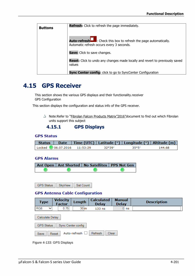
Functional Description
µFalcon-S & Falcon-S series User Guide 4-201
Buttons Refresh: Click to refresh the page immediately.
Auto-refresh : Check this box to refresh the page automatically. Automatic refresh occurs every 3 seconds.
Save: Click to save changes.
Reset: Click to undo any changes made locally and revert to previously saved values
Sync Center config: click to go to SyncCenter Configuration
4.15 GPS Receiver
This section shows the various GPS displays and their functionality.receiver
GPS Configuration
This section displays the configuration and status info of the GPS receiver.
Note:Refer to “Fibrolan Falcon Products Matrix”2016”document to find out which Fibrolan
units support this subject
4.15.1 GPS Displays
Figure 4-133: GPS Displays
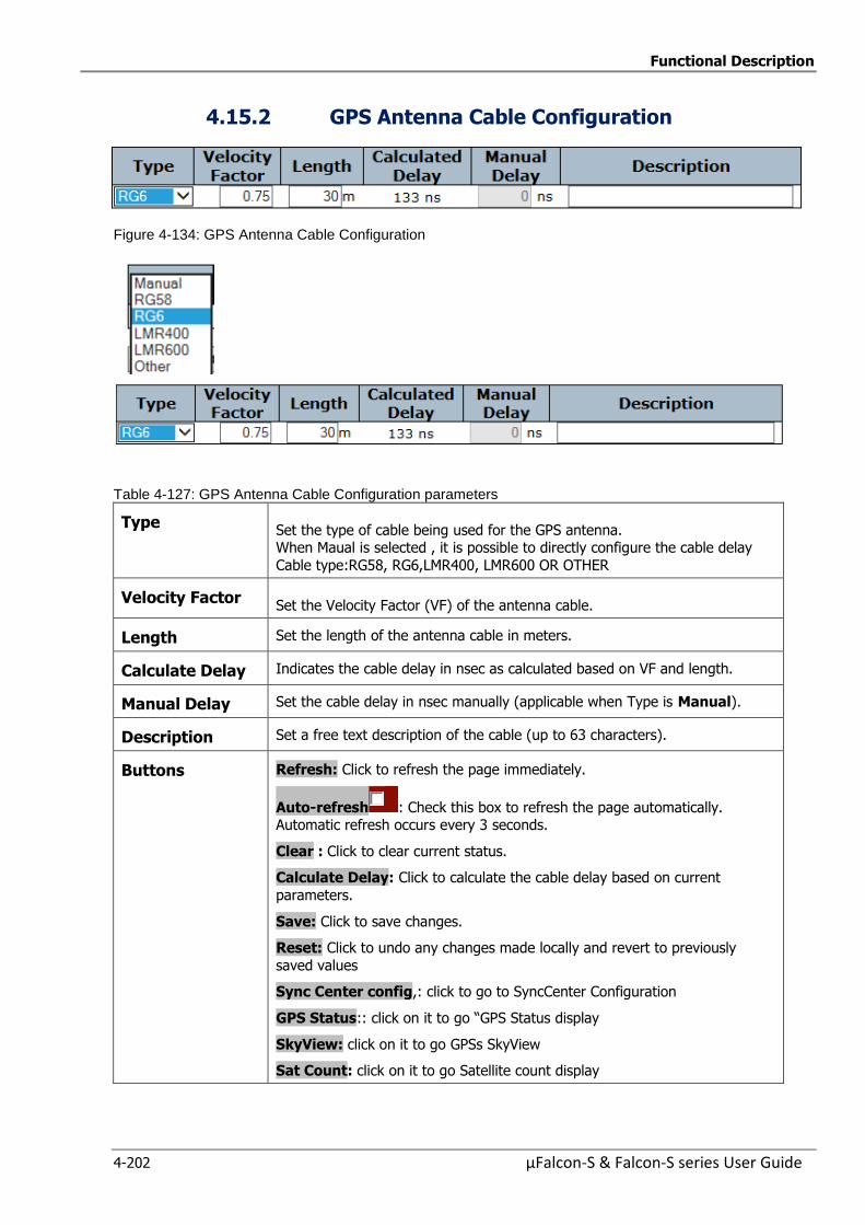
Functional Description
4-202 µFalcon-S & Falcon-S series User Guide
4.15.2 GPS Antenna Cable Configuration
Figure 4-134: GPS Antenna Cable Configuration
Table 4-127: GPS Antenna Cable Configuration parameters
Type Set the type of cable being used for the GPS antenna. When Maual is selected , it is possible to directly configure the cable delay
Cable type:RG58, RG6,LMR400, LMR600 OR OTHER
Velocity Factor Set the Velocity Factor (VF) of the antenna cable.
Length Set the length of the antenna cable in meters.
Calculate Delay Indicates the cable delay in nsec as calculated based on VF and length.
Manual Delay Set the cable delay in nsec manually (applicable when Type is Manual).
Description Set a free text description of the cable (up to 63 characters).
Buttons Refresh: Click to refresh the page immediately.
Auto-refresh : Check this box to refresh the page automatically. Automatic refresh occurs every 3 seconds.
Clear : Click to clear current status.
Calculate Delay: Click to calculate the cable delay based on current
parameters.
Save: Click to save changes.
Reset: Click to undo any changes made locally and revert to previously
saved values
Sync Center config,: click to go to SyncCenter Configuration
GPS Status:: click on it to go “GPS Status display
SkyView: click on it to go GPSs SkyView
Sat Count: click on it to go Satellite count display
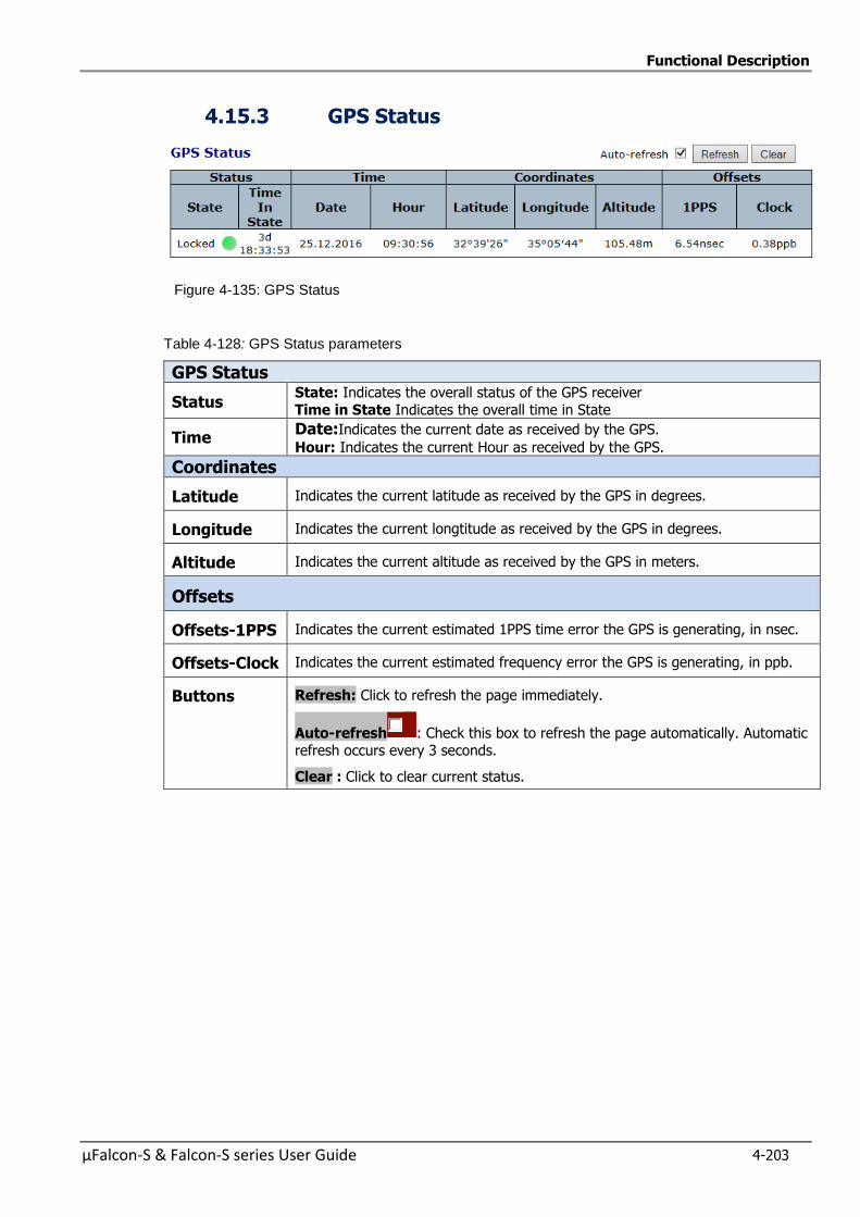
Functional Description
µFalcon-S & Falcon-S series User Guide 4-203
4.15.3 GPS Status
Figure 4-135: GPS Status
Table 4-128: GPS Status parameters
GPS Status
Status State: Indicates the overall status of the GPS receiver Time in State Indicates the overall time in State
Time Date:Indicates the current date as received by the GPS.
Hour: Indicates the current Hour as received by the GPS.
Coordinates
Latitude Indicates the current latitude as received by the GPS in degrees.
Longitude Indicates the current longtitude as received by the GPS in degrees.
Altitude Indicates the current altitude as received by the GPS in meters.
Offsets
Offsets-1PPS Indicates the current estimated 1PPS time error the GPS is generating, in nsec.
Offsets-Clock Indicates the current estimated frequency error the GPS is generating, in ppb.
Buttons Refresh: Click to refresh the page immediately.
Auto-refresh : Check this box to refresh the page automatically. Automatic refresh occurs every 3 seconds.
Clear : Click to clear current status.
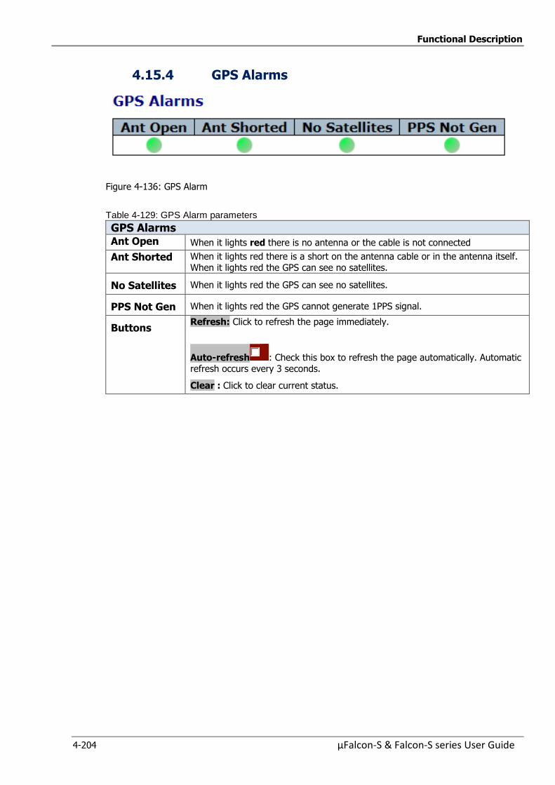
Functional Description
4-204 µFalcon-S & Falcon-S series User Guide
4.15.4 GPS Alarms
Figure 4-136: GPS Alarm
Table 4-129: GPS Alarm parameters
GPS Alarms Ant Open When it lights red there is no antenna or the cable is not connected
Ant Shorted When it lights red there is a short on the antenna cable or in the antenna itself. When it lights red the GPS can see no satellites.
No Satellites When it lights red the GPS can see no satellites.
PPS Not Gen When it lights red the GPS cannot generate 1PPS signal.
Buttons Refresh: Click to refresh the page immediately.
Auto-refresh : Check this box to refresh the page automatically. Automatic refresh occurs every 3 seconds.
Clear : Click to clear current status.
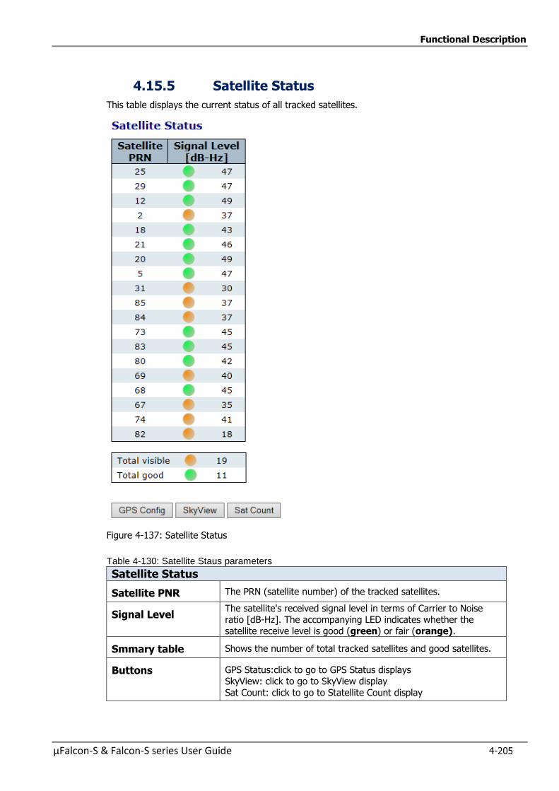
Functional Description
µFalcon-S & Falcon-S series User Guide 4-205
4.15.5 Satellite Status
This table displays the current status of all tracked satellites.
Figure 4-137: Satellite Status
Table 4-130: Satellite Staus parameters
Satellite Status
Satellite PNR The PRN (satellite number) of the tracked satellites.
Signal Level The satellite's received signal level in terms of Carrier to Noise ratio [dB-Hz]. The accompanying LED indicates whether the
satellite receive level is good (green) or fair (orange).
Smmary table Shows the number of total tracked satellites and good satellites.
Buttons GPS Status:click to go to GPS Status displays
SkyView: click to go to SkyView display
Sat Count: click to go to Statellite Count display
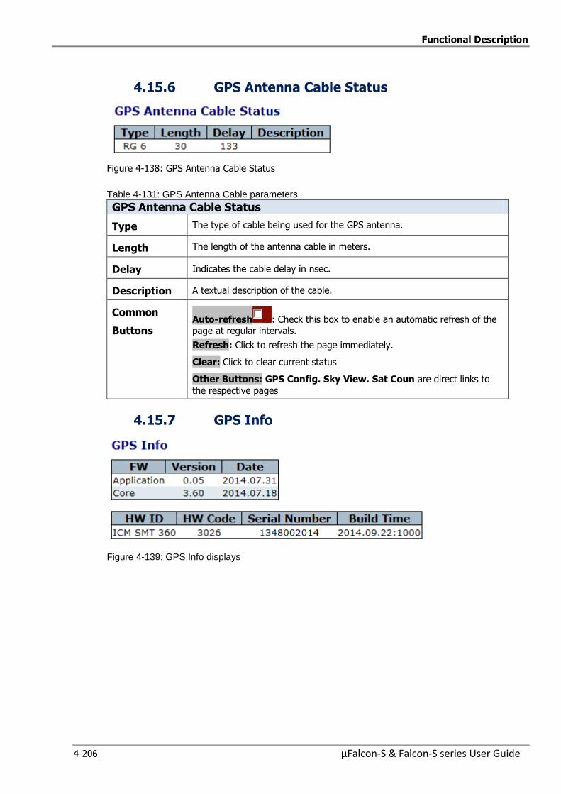
Functional Description
4-206 µFalcon-S & Falcon-S series User Guide
4.15.6 GPS Antenna Cable Status
Figure 4-138: GPS Antenna Cable Status
Table 4-131: GPS Antenna Cable parameters
GPS Antenna Cable Status
Type The type of cable being used for the GPS antenna.
Length The length of the antenna cable in meters.
Delay Indicates the cable delay in nsec.
Description A textual description of the cable.
Common
Buttons Auto-refresh : Check this box to enable an automatic refresh of the page at regular intervals.
Refresh: Click to refresh the page immediately.
Clear: Click to clear current status
Other Buttons: GPS Config. Sky View. Sat Coun are direct links to
the respective pages
4.15.7 GPS Info
Figure 4-139: GPS Info displays
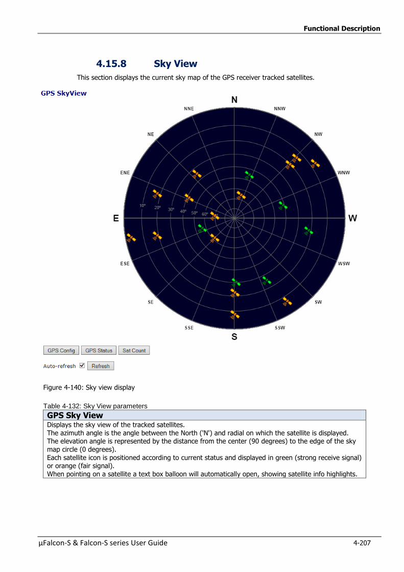
Functional Description
µFalcon-S & Falcon-S series User Guide 4-207
4.15.8 Sky View
This section displays the current sky map of the GPS receiver tracked satellites.
Figure 4-140: Sky view display
Table 4-132: Sky View parameters
GPS Sky View Displays the sky view of the tracked satellites.
The azimuth angle is the angle between the North ('N') and radial on which the satellite is displayed. The elevation angle is represented by the distance from the center (90 degrees) to the edge of the sky
map circle (0 degrees).
Each satellite icon is positioned according to current status and displayed in green (strong receive signal) or orange (fair signal).
When pointing on a satellite a text box balloon will automatically open, showing satellite info highlights.

Functional Description
4-208 µFalcon-S & Falcon-S series User Guide
Buttons Auto-refresh : Check this box to enable an automatic refresh of the page at regular intervals.
Refresh
Direct links: GHPConfig,GPS Status , Sat Count
4.15.9 Satellite Count
This section displays a graph of the tracked satellites count.
Figure 4-141: Satellite Count display
Table 4-133 Satellite Count parameters
GPS Satellite Count
Satellite Count The graph shows the number of tracked satellite by the GPS receiver over time, according to the selected type below.
Graph type Selection of type of graph to show:
Time axis duration can be 15 minutes (1 minute resolution) or 24 hours (15
minutes resolution- Show only good (above threshold) satellites or all visible (tracked)ones.
Common
Buttons Auto-refresh : Check this box to enable an automatic refresh of the page at regular intervals.
Refresh: click to refresh the page
Send Report:send report yo your computer if you have set the required parameter in the Falcon report Configuration
Direct Buttons: GPS Config, GPS Status, Sky View, are direct links to the respective pages
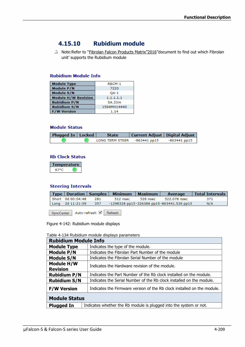
Functional Description
µFalcon-S & Falcon-S series User Guide 4-209
4.15.10 Rubidium module
Note:Refer to “Fibrolan Falcon Products Matrix”2016”document to find out which Fibrolan
unit’ supports the Rubidium module
Figure 4-142: Rubidium module displays
Table 4-134 Rubidium module displays parameters
Rubidium Module Info Module Type Indicates the type of the module.
Module P/N Indicates the Fibrolan Part Number of the module
Module S/N Indicates the Fibrolan Serial Number of the module
Module H/W Revision
Indicates the Hardware revision of the module.
Rubidium P/N Indicates the Part Number of the Rb clock installed on the module.
Rubidium S/N Indicates the Serial Number of the Rb clock installed on the module.
F/W Version Indicates the Firmware version of the Rb clock installed on the module.
Module Status
Plugged In Indicates whether the Rb module is plugged into the system or not.

Functional Description
4-210 µFalcon-S & Falcon-S series User Guide
Locked Indicates whether the Rb clock has achieved an internal atomic locked
state (different than system lock to GPS).
State Indicates the current state of the Rb module
Current Adjust
Indicates the current adjustment applied to the Rb clock (in pp15: 1E-15
units), for tracking the GPS.
Digital Adjust
A read-back from the Rb clock that allows cross-check of the clock adjustment value
Rb Clock Status
Temperature Indicates the internal temperature of the Rb Clock.
Steering Intervals Type The type of steering interval: Short or Long.
Duration The elapsed duration of the interval since it started, in seconds.
Samples The number of measured samples (of the GPS) within the interval since it
started (typically a little lower than duration).
Minimum
In Short term intervals: the minimum 1PPS difference within the interval (in nsec
). In Long term intervals: the minimum clock adjustment value applied within the interval (in pp15).
Maximum In Short term intervals: the maximum 1PPS difference within the interval
(in nsec). In Long term intervals: the maximum clock adjustment value applied within the interval (in pp15).
Average In Short term intervals: the average 1PPS difference over the interval so
far (in nsec). In Long term intervals: the average clock adjustment value applied over the interval so far (in pp15).
Total Intervals
The total number of intervals elapsed so far, since Rb module was
plugged in.
Buttons
Auto-refresh :Check this box to enable an automatic refresh of the
page at regular intervals.
Refresh: Click to refresh the page
SyncCenter : direct link to the relevant page
Functional Description
µFalcon-S & Falcon-S series User Guide 4-211
4.16 IEEE1588 Precision Time Protocol
PTP is an acronym for Precision Time Protocol, a network protocol for synchronizing the clocks of Network systems. Regarding Ethernet Backhaul, PTP is considered the technology of choice to deliver
clock synchronization to remote telecom base stations. PTP defines synchronization message used between a Master and Slave clock.
The Master provides the time and the slave synchronizes to the Master
Multiple slaves can synchronize to a single Master The Master clock provides synchronization message that the slaves use to correct their local clocks
This section allows the user to configure and inspect the current PTP Clock settings
In Synchronous mode of operation, the Synchronous Ethernet interface processes the SSM
(Synchronization Status Messages) and recovers the clock quality level information.
The ESMC channel is a logical communication channel which transmits SSM information that is the quality
level of the transmitting synchronous Ethernet equipment clock
When a Synchronous Ethernet port is selected, the SSM are transmitted through this port, indicating the
quality level of the clock it is able to drive. The messages are received (if the other remote unit supports
SyncE) with the quality level of the transmitting clock.
The remote end unit receiving the messages on its configured Synchronous Ethernet port extracts the
clock quality level and transmits it to the Clock Master Unit.
The Clock Master Unit receives the SSM data from many Synchronous Ethernet ports and establishes the
clock sources. The device internal state logic (clock selector) monitors all reference clocks and
automatically selects the best available reference clock based on configured priority and revertive
priorities.
There are different synchronization methods as described below
The Auto-Revertive is the default mode of operation. This mode includes two functions: automatic
reference clock selection (the highest priority qualified clock is selected) and the occurrence of the
Revertive function when needed.
The clock selection process supports revertive and non-revertive modes of operation.
If the Auto- revertive mode is enabled: when the clock selection process has selected -a primary clock,
and the active primary clock source has failed o degraded over a period of time and then is later
recovered, this primary clock source becomes again the active clock source.
If Auto non-revertive mode is selected and a secondary clock source is active (due to a previous
degradation of the primary clock source), the primary clock source is not reactivated even after its quality
has been improved.
Note:Refer to “Fibrolan Falcon Products Matrix”2016” document to find out which Fibrolan
units support this subject
Functional Description
4-212 µFalcon-S & Falcon-S series User Guide
Methods of Operation
Note: the following modes of operation can be selected under SyncCenter Configuration
Auto Revertive: In this mode, the highest priority qualified reference clock is selected. If this selected
clock fails or it is degraded, the next priority qualified clock is selected and the lock acquisition will begin. If the previous primary clock is restored and qualified, then the revertive function will compel the
previous primary clock to become again the active clock source.
Auto Non Revertive: Clock Selection of the best clock source is only done when the selected clock fails.
The primary clock source is not reactivated in this case.
Free-Run mode
The free-run mode occurs immediately, after a reset, or when the timing synchronization logic has not
yet been synchronized to a reference clock input. In this mode the frequency accuracy of the clock
outputs is equal to the frequency accuracy of the input master clock.
Manual: The user may select the clock source (None, SyncE, PTP, TDM, External) If this manually selected clock source is failing, the clock selector will go into holdover state
Normal (Locked mode)
The input clock references are monitored for frequency accuracy and phase correctness.
If at least one is of the clock reference inputs is qualified, then the logic will start the lock acquisition of
that clock input. And the device logic will enter into the normal locked mode.
During the normal locked operation, the time synchronization logic phase locks to the qualified reference
clock and generates output clocks and frame pulses with a frequency accuracy equal to the frequency
accuracy of the input reference clock.
The generated clock and frames pulse outputs comply with specifications as described in Telecordia and
ITU-T Telecommunication standard
Holdover state
When the timing synchronization logic loses its reference input clock or becomes degraded, and no other
qualified clock references are available, it will enter in holdover mode and continue to create output
clocks based on the reference frequency data collected during the synchronization process.
PTP Messages
PTP defines the following messages for synchronization and control between devices:
Event message (timing message)
Types of event messages: Sync, Delay_Req, Pdelay_Req, Pdelay_Req.
General messages: Announce, Follow-Up. Delay_Resp, Pdelay_Resp_Follow_Up, Management,
Signaling. (Pdelay=Peer delay)
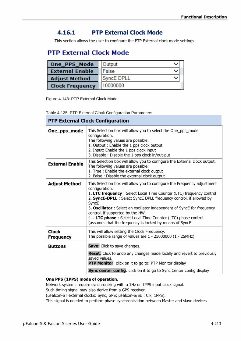
Functional Description
µFalcon-S & Falcon-S series User Guide 4-213
4.16.1 PTP External Clock Mode
This section allows the user to configure the PTP External clock mode settings
Figure 4-143: PTP External Clock Mode
Table 4-135: PTP External Clock Configuration Parameters
PTP External Clock Configuration
One_pps_mode This Selection box will allow you to select the One_pps_mode configuration.
The following values are possible:
1. Output : Enable the 1 pps clock output 2. Input: Enable the 1 pps clock input
3. Disable : Disable the 1 pps clock in/out-put
External Enable This Selection box will allow you to configure the External clock output. The following values are possible:
1. True : Enable the external clock output 2. False : Disable the external clock output
Adjust Method This Selection box will allow you to configure the Frequency adjustment
configuration. 1. LTC frequency : Select Local Time Counter (LTC) frequency control
2. SyncE-DPLL : Select SyncE DPLL frequency control, if allowed by SyncE
3. Oscillator : Select an oscillator independent of SyncE for frequency
control, if supported by the HW 4. . LTC phase : Select Local Time Counter (LTC) phase control
(assumes that the frequency is locked by means of SyncE
Clock Frequency
This will allow setting the Clock Frequency. The possible range of values are 1 - 25000000 (1 - 25MHz)
Buttons Save: Click to save changes.
Reset: Click to undo any changes made locally and revert to previously saved values.
PTP Monitor: click on it to go to: PTP Monitor display
Sync center config: click on it to go to Sync Center config display
One PPS (1PPS) mode of operation.
Network systems require synchronizing with a 1Hz or 1PPS input clock signal.
Such timing signal may also derive from a GPS receiver.
(µFalcon-ST external clocks: Sync, GPS; µFalcon-S/SE : Clk, 1PPS).
This signal is needed to perform phase synchronization between Master and slave devices
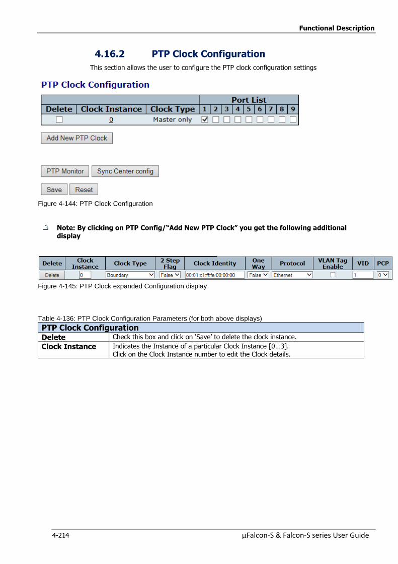
Functional Description
4-214 µFalcon-S & Falcon-S series User Guide
4.16.2 PTP Clock Configuration
This section allows the user to configure the PTP clock configuration settings
Figure 4-144: PTP Clock Configuration
Note: By clicking on PTP Config/“AddNewPTPClock” you get the following additional display
Figure 4-145: PTP Clock expanded Configuration display
Table 4-136: PTP Clock Configuration Parameters (for both above displays)
PTP Clock Configuration Delete Check this box and click on ‘Save’ to delete the clock instance.
Clock Instance Indicates the Instance of a particular Clock Instance [0…3].
Click on the Clock Instance number to edit the Clock details.
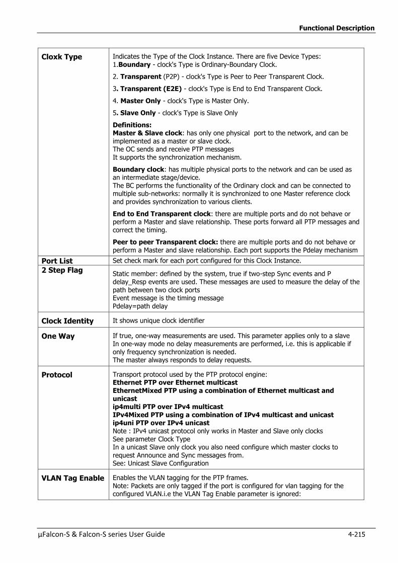
Functional Description
µFalcon-S & Falcon-S series User Guide 4-215
Cloxk Type Indicates the Type of the Clock Instance. There are five Device Types:
1.Boundary - clock's Type is Ordinary-Boundary Clock.
2. Transparent (P2P) - clock's Type is Peer to Peer Transparent Clock.
3. Transparent (E2E) - clock's Type is End to End Transparent Clock.
4. Master Only - clock's Type is Master Only.
5. Slave Only - clock's Type is Slave Only
Definitions: Master & Slave clock: has only one physical port to the network, and can be
implemented as a master or slave clock. The OC sends and receive PTP messages
It supports the synchronization mechanism.
Boundary clock: has multiple physical ports to the network and can be used as an intermediate stage/device.
The BC performs the functionality of the Ordinary clock and can be connected to multiple sub-networks: normally it is synchronized to one Master reference clock
and provides synchronization to various clients.
End to End Transparent clock: there are multiple ports and do not behave or perform a Master and slave relationship. These ports forward all PTP messages and
correct the timing.
Peer to peer Transparent clock: there are multiple ports and do not behave or
perform a Master and slave relationship. Each port supports the Pdelay mechanism
Port List Set check mark for each port configured for this Clock Instance.
2 Step Flag Static member: defined by the system, true if two-step Sync events and P
delay_Resp events are used. These messages are used to measure the delay of the
path between two clock ports Event message is the timing message
Pdelay=path delay
Clock Identity It shows unique clock identifier
One Way If true, one-way measurements are used. This parameter applies only to a slave
In one-way mode no delay measurements are performed, i.e. this is applicable if
only frequency synchronization is needed. The master always responds to delay requests.
Protocol Transport protocol used by the PTP protocol engine: Ethernet PTP over Ethernet multicast
EthernetMixed PTP using a combination of Ethernet multicast and
unicast ip4multi PTP over IPv4 multicast
IPv4Mixed PTP using a combination of IPv4 multicast and unicast ip4uni PTP over IPv4 unicast
Note : IPv4 unicast protocol only works in Master and Slave only clocks
See parameter Clock Type In a unicast Slave only clock you also need configure which master clocks to
request Announce and Sync messages from. See: Unicast Slave Configuration
VLAN Tag Enable Enables the VLAN tagging for the PTP frames.
Note: Packets are only tagged if the port is configured for vlan tagging for the configured VLAN.i.e the VLAN Tag Enable parameter is ignored:
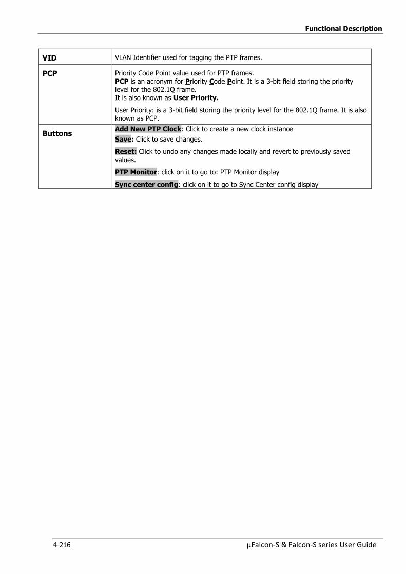
Functional Description
4-216 µFalcon-S & Falcon-S series User Guide
VID VLAN Identifier used for tagging the PTP frames.
PCP Priority Code Point value used for PTP frames.
PCP is an acronym for Priority Code Point. It is a 3-bit field storing the priority level for the 802.1Q frame.
It is also known as User Priority.
User Priority: is a 3-bit field storing the priority level for the 802.1Q frame. It is also
known as PCP.
Buttons Add New PTP Clock: Click to create a new clock instance
Save: Click to save changes.
Reset: Click to undo any changes made locally and revert to previously saved values.
PTP Monitor: click on it to go to: PTP Monitor display
Sync center config: click on it to go to Sync Center config display
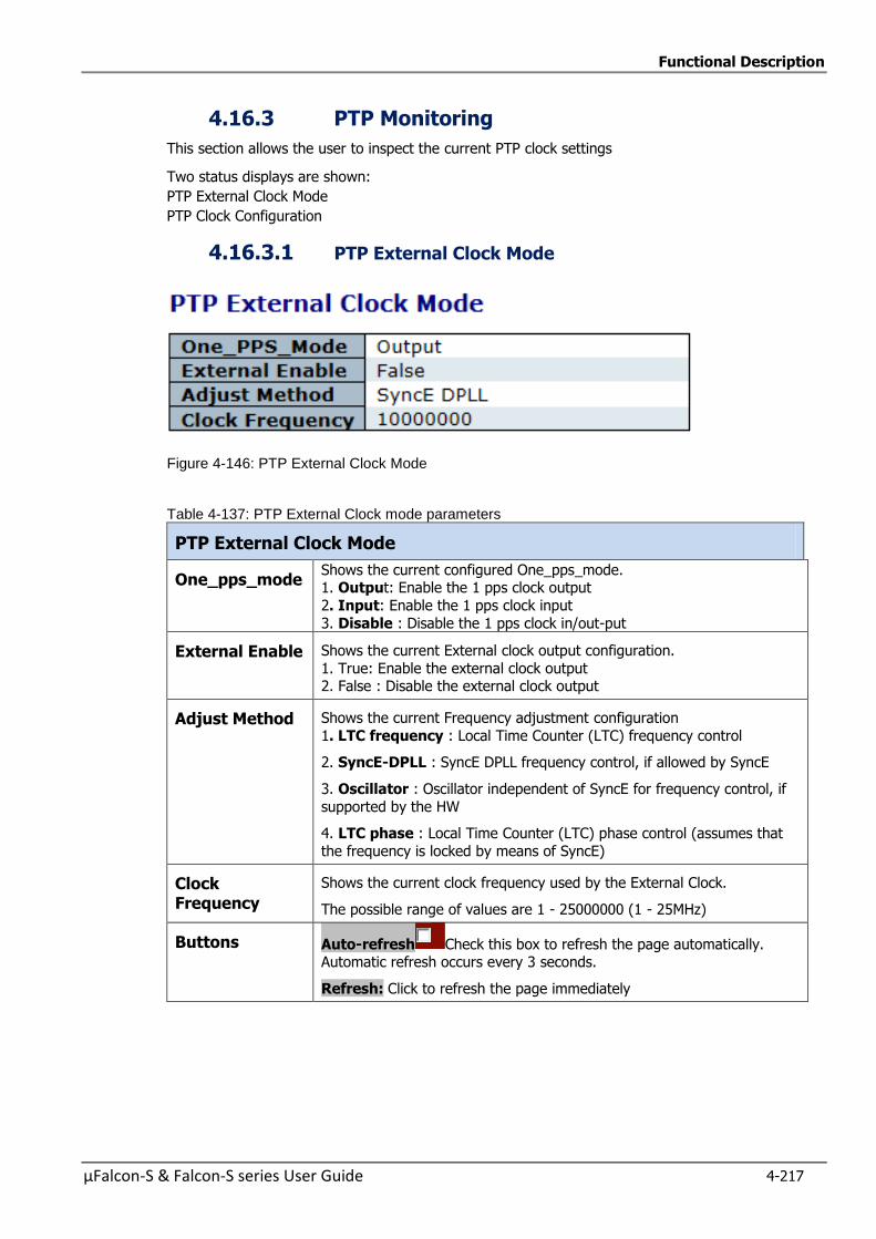
Functional Description
µFalcon-S & Falcon-S series User Guide 4-217
4.16.3 PTP Monitoring
This section allows the user to inspect the current PTP clock settings
Two status displays are shown:
PTP External Clock Mode
PTP Clock Configuration
4.16.3.1 PTP External Clock Mode
Figure 4-146: PTP External Clock Mode
Table 4-137: PTP External Clock mode parameters
PTP External Clock Mode
One_pps_mode Shows the current configured One_pps_mode. 1. Output: Enable the 1 pps clock output
2. Input: Enable the 1 pps clock input
3. Disable : Disable the 1 pps clock in/out-put
External Enable Shows the current External clock output configuration.
1. True: Enable the external clock output 2. False : Disable the external clock output
Adjust Method Shows the current Frequency adjustment configuration
1. LTC frequency : Local Time Counter (LTC) frequency control
2. SyncE-DPLL : SyncE DPLL frequency control, if allowed by SyncE
3. Oscillator : Oscillator independent of SyncE for frequency control, if
supported by the HW
4. LTC phase : Local Time Counter (LTC) phase control (assumes that
the frequency is locked by means of SyncE)
Clock Frequency
Shows the current clock frequency used by the External Clock.
The possible range of values are 1 - 25000000 (1 - 25MHz)
Buttons Auto-refresh Check this box to refresh the page automatically. Automatic refresh occurs every 3 seconds.
Refresh: Click to refresh the page immediately
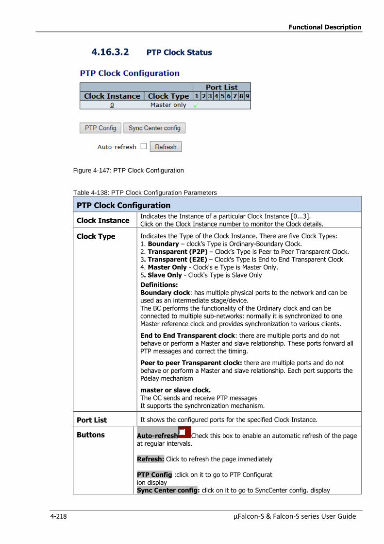
Functional Description
4-218 µFalcon-S & Falcon-S series User Guide
4.16.3.2 PTP Clock Status
Figure 4-147: PTP Clock Configuration
Table 4-138: PTP Clock Configuration Parameters
PTP Clock Configuration
Clock Instance Indicates the Instance of a particular Clock Instance [0...3].
Click on the Clock Instance number to monitor the Clock details.
Clock Type Indicates the Type of the Clock Instance. There are five Clock Types:
1. Boundary – clock’s Type is Ordinary-Boundary Clock.
2. Transparent (P2P) – Clock’s Type is Peer to Peer Transparent Clock. 3. Transparent (E2E) – Clock's Type is End to End Transparent Clock
4. Master Only - Clock's e Type is Master Only. 5. Slave Only - Clock's Type is Slave Only
Definitions:
Boundary clock: has multiple physical ports to the network and can be used as an intermediate stage/device.
The BC performs the functionality of the Ordinary clock and can be connected to multiple sub-networks: normally it is synchronized to one
Master reference clock and provides synchronization to various clients.
End to End Transparent clock: there are multiple ports and do not behave or perform a Master and slave relationship. These ports forward all
PTP messages and correct the timing.
Peer to peer Transparent clock: there are multiple ports and do not
behave or perform a Master and slave relationship. Each port supports the Pdelay mechanism
master or slave clock.
The OC sends and receive PTP messages It supports the synchronization mechanism.
Port List It shows the configured ports for the specified Clock Instance.
Buttons Auto-refresh Check this box to enable an automatic refresh of the page at regular intervals.
Refresh: Click to refresh the page immediately
PTP Config :click on it to go to PTP Configurat
ion display Sync Center config: click on it to go to SyncCenter config. display
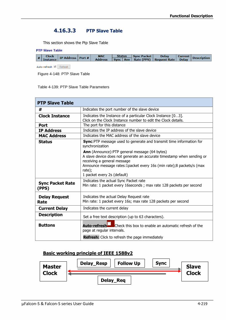
Functional Description
µFalcon-S & Falcon-S series User Guide 4-219
4.16.3.3 PTP Slave Table
This section shows the Ptp Slave Table
Figure 4-148: PTP Slave Table
Table 4-139: PTP Slave Table Parameters
PTP Slave Table
# Indicates the port number of the slave device
Clock Instance Indicates the Instance of a particular Clock Instance [0…3].
Click on the Clock Instance number to edit the Clock details.
Port The port for this distance
IP Address Indicates the IP address of the slave device
MAC Address Indicates the MAC address of the slave device
Status Sync:PTP message used to generate and transmit time information for synchronization
Ann (Announce):PTP general message (64 bytes)
A slave device does not generate an accurate timestamp when sending or receiving a general message
Announce message rates:1packet every 16s (min rate);8 packets/s (max rate);
1 packet every 2s (default)
Sync Packet Rate (PPS)
Indicates the actual Sync Packet rate Min rate: 1 packet every 16seconds ; max rate 128 packets per second
Delay Request Rate
Indicates the actual Delay Request rate
Min rate: 1 packet every 16s; max rate 128 packets per second
Current Delay Indicates the current delay
Description Set a free text description (up to 63 characters).
Buttons Auto-refresh Check this box to enable an automatic refresh of the page at regular intervals.
Refresh: Click to refresh the page immediately
Basic working principle of IEEE 1588v2
Master Clock
Slave Clock
Sync Follow Up Delay_Resp
Delay_Req
Functional Description
4-220 µFalcon-S & Falcon-S series User Guide
4.17 Synchronous Ethernet (SyncE)
Overview This section allows the user to inspect and configure the current SyncE port settings.
SyncE is used to make a Ethernet network 'clock frequency' synchronized.
Mobile network operators have started to deploy 4GLTE networks
Ethernet has become the logical choice for mobile backhaul.
These operators would like to deploy voice over Ethernet.
Ethernet networks must provide timing and synchronization in order to support mobile voice.
The µfalcon-S and Falcon-S devices are offered with complete precision timing support based on
Synchronous Ethernet and 1588-2008 (PTP) for LTE mobile backhaul applications.
The aim of Synchronous Ethernet is to provide a synchronous signal to network resources that may need
such frequency synchronization signal.
SyncE was standardized by the ITU-T and supports the following recommendations:
ITU-T G8261 standard that defines aspects regarding the architecture and performance of SyncE networks
ITU-T G8262 standard which specifies SyncE slave clocks.
ITU-T G8264 standard that describes the specifications of Ethernet Synchronization Messaging Channel
(ESMC)
In Synchronous mode of operation, the Synchronous Ethernet interface processes the SSM
(Synchronization Status Messages) and recovers the clock quality level information.
The ESMC channel is a logical communication channel which transmits SSM information, that is the quality
level of the transmitting synchronous Ethernet equipment clock
When a Synchronous Ethernet port is selected, the SSM are transmitted through this port, indicating the
quality level of the clock it is able to drive. The messages are received (if the other remote unit supports
SyncE) with the quality level of the transmitting clock.
The remote end unit receiving the messages on its configured Synchronous Ethernet port extracts the clock
quality level and transmits it to the Clock Master Unit.
The Clock Master Unit receives the SSM data from many Synchronous Ethernet ports and establishes the
clock sources. The device internal state logic (clock selector) monitors all reference clocks and automatically
selects the best available reference clock based on configured priority and revertive priorities.
Note:Refer to section “Fibrolan Falcon Products Matrix”2016” to find out which Fibrolan units
support this subject
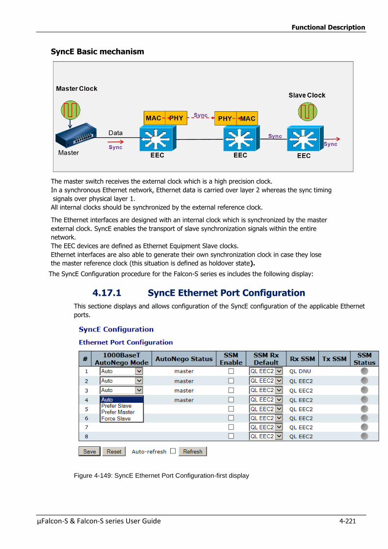
Functional Description
µFalcon-S & Falcon-S series User Guide 4-221
SyncE Basic mechanism
The master switch receives the external clock which is a high precision clock.
In a synchronous Ethernet network, Ethernet data is carried over layer 2 whereas the sync timing
signals over physical layer 1.
All internal clocks should be synchronized by the external reference clock.
The Ethernet interfaces are designed with an internal clock which is synchronized by the master
external clock. SyncE enables the transport of slave synchronization signals within the entire
network.
The EEC devices are defined as Ethernet Equipment Slave clocks.
Ethernet interfaces are also able to generate their own synchronization clock in case they lose
the master reference clock (this situation is defined as holdover state).
The SyncE Configuration procedure for the Falcon-S series es includes the following display:
4.17.1 SyncE Ethernet Port Configuration
This sectione displays and allows configuration of the SyncE configuration of the applicable Ethernet
ports.
Figure 4-149: SyncE Ethernet Port Configuration-first display
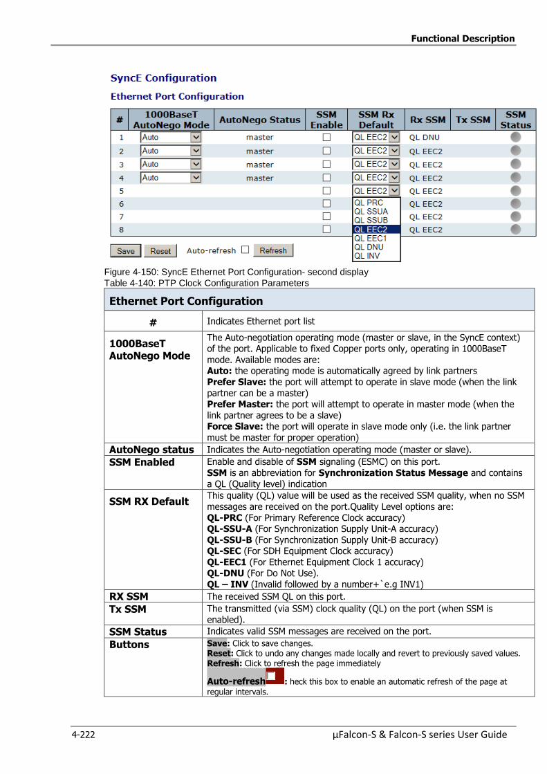
Functional Description
4-222 µFalcon-S & Falcon-S series User Guide
Figure 4-150: SyncE Ethernet Port Configuration- second display
Table 4-140: PTP Clock Configuration Parameters
Ethernet Port Configuration
# Indicates Ethernet port list
1000BaseT AutoNego Mode
The Auto-negotiation operating mode (master or slave, in the SyncE context) of the port. Applicable to fixed Copper ports only, operating in 1000BaseT
mode. Available modes are: Auto: the operating mode is automatically agreed by link partners
Prefer Slave: the port will attempt to operate in slave mode (when the link
partner can be a master) Prefer Master: the port will attempt to operate in master mode (when the
link partner agrees to be a slave) Force Slave: the port will operate in slave mode only (i.e. the link partner
must be master for proper operation)
AutoNego status Indicates the Auto-negotiation operating mode (master or slave).
SSM Enabled Enable and disable of SSM signaling (ESMC) on this port.
SSM is an abbreviation for Synchronization Status Message and contains
a QL (Quality level) indication
SSM RX Default This quality (QL) value will be used as the received SSM quality, when no SSM
messages are received on the port.Quality Level options are:
QL-PRC (For Primary Reference Clock accuracy) QL-SSU-A (For Synchronization Supply Unit-A accuracy)
QL-SSU-B (For Synchronization Supply Unit-B accuracy) QL-SEC (For SDH Equipment Clock accuracy)
QL-EEC1 (For Ethernet Equipment Clock 1 accuracy) QL-DNU (For Do Not Use).
QL – INV (Invalid followed by a number+`e.g INV1)
RX SSM The received SSM QL on this port.
Tx SSM The transmitted (via SSM) clock quality (QL) on the port (when SSM is enabled).
SSM Status Indicates valid SSM messages are received on the port.
Buttons Save: Click to save changes. Reset: Click to undo any changes made locally and revert to previously saved values. Refresh: Click to refresh the page immediately
Auto-refresh : heck this box to enable an automatic refresh of the page at
regular intervals.
Functional Description
µFalcon-S & Falcon-S series User Guide 4-223
4.18 Spanning Tree
Spanning Tree Protocol was developed in order to protect Ethernet networks from the bad effects of
network loops: a loop is a circular path in the network which causes frame storms that overloads the
Ethernet network.
Spanning Tree Protocol creates a spanning tree within a mesh network of connected Ethernet
bridges and disables the links which are not part of that tree, leaving a single active path between
any two network nodes.
Note: Spanning Tree is available in all uFalcon and Falcon S devices
Spanning Tree Versions:
802.1d Legacy Spanning Tree
802.1w Rapid Spanning Tree
Faster topology conversion by:
— A faster method for temporary loop prevention: STP waits for the new topology to
stabilize while RSTP makes the new root port forwarding immediately once all prior root
ports have been made blocking, and then uses handshaking (on point-to-point links) to make designated ports forwarding as well.
— Improvements in topology change detection, notification, and flushing of the learn tables.
802.1s Multiple-Instance Spanning Tree
— A newer version supporting more than a single topology: each instance (group of VLANs)
can have its own topology.
—
4.18.1 Understanding RSTP and MSTP
Understanding RSTP
STP provides basic loop prevention functionality with slow network convergence when topology
changes occur.
RSTP converges faster because a handshake mechanism is deployed, based on P2P links instead of
the timer based process used by STP.
Under RTSP, port assignments change through exchanged messages RSTP device generates
configuration messages once every hello time interval.
An RTSP device will respond to BPDUs sent from the root bridge. The RSTP device will propose its
spanning tree information to its designated ports.
If another RSTP device receives this information and determines that this is the superior root
information, it starts a synchronizing operation to ensure all of its ports are in sync with the new
information. This device may send an “agreement” to the first RSTP device confirming its superior
spanning tree information.
The first RSTP device, upon receiving this agreement, knows now that it can rapidly change that
port to the forwarding state.
Similar proposal agreement handshake messages propagate within the network, restoring the
connectivity very quickly after a topology change, bypassing the traditional listening/learning state
transition process.
Functional Description
4-224 µFalcon-S & Falcon-S series User Guide
Therefore a cascading effect is created away from the RSTP root where each designated port
proposes to its neighbors to determine if a rapid transition is possible. In this way RSTP achieves
faster convergence times than STP.
RSTP device port roles:
Root – A forwarding port that is the best port from no root-bridge to Root bridge
Designated –A forwarding port for every LAN segment
Alternate – An alternate port to the root bridge
Disabled – A network administrator can manually disable a port
Backup – provides an alternate designated port
Understanding MSTP
RSTP does not solve the problem inherent in STP: all VLANs within a LAN must share the
same spanning tree topology. An STP or RSTP network has only one spanning tree instance for the
entire network and includes all VLANs in the network.
µFalcon switches utilize the Multiple Spanning Tree protocol (MSTP, 802.1s) to ensure that only one
active path exists between any two nodes in a spanning tree instance.
An instance includes a unique set of VLANs, belongs to a specific spanning tree region and creates
a separate per instance forwarding topology.
A region may comprise multiple spanning tree instances (each with a different set of VLANs)
Each spanning tree instance is independent of other instances. Each region can support up to 16
spanning tree instances.
MSTP region: a group of interconnected switches that share the same attributes is defined as an
MST region. An MST region includes multiple spanning tree instances (MSTI) which provide
different paths for different VLAN. Each MSTI can have its own independent topology.
Note that MSTP recognizes an STP or RSTP LAN as a distinct spanning tree region.
A region can include two types of STP instances:
Internal Spanning Tree Instance (IST instance). This is the default spanning tree instance
in any MST region.IST provides the root switch for the region and by default comprises all
VLANs in the region except those VLANs assigned to MSTI.
In all µFalcon models, the IST instance is not supported. The CISTI performs the functions
of the IST instance
Multiple Spanning Tree Instance (MSTI). This type of configurable STP instance includes
assigned VLANs which operate as part of the same single spanning tree topology. IST
instance is defined as Instance 0 whereas all other MST instances are numbered from 1 to
15.
All MST instances within the same region share the same protocol timers , each MST
instance has its own topology Parameters, such root switch ID, root path cost and additional
selected Parameters.
Common and Internal Spanning Tree (CSTI): is a collection of the IST in each region and the
Common Spanning Tree (CST) which interconnects the various MST regions and STP LANs, and
RSTP LANs in a switched network.
The CIST is created as a result of the STP algorithm running between switches that support the
802.1w, and the 802.ID protocols. MSTP allows for rapid port state transition just like RSTP. MSTP is
compatible to STP and RSTP
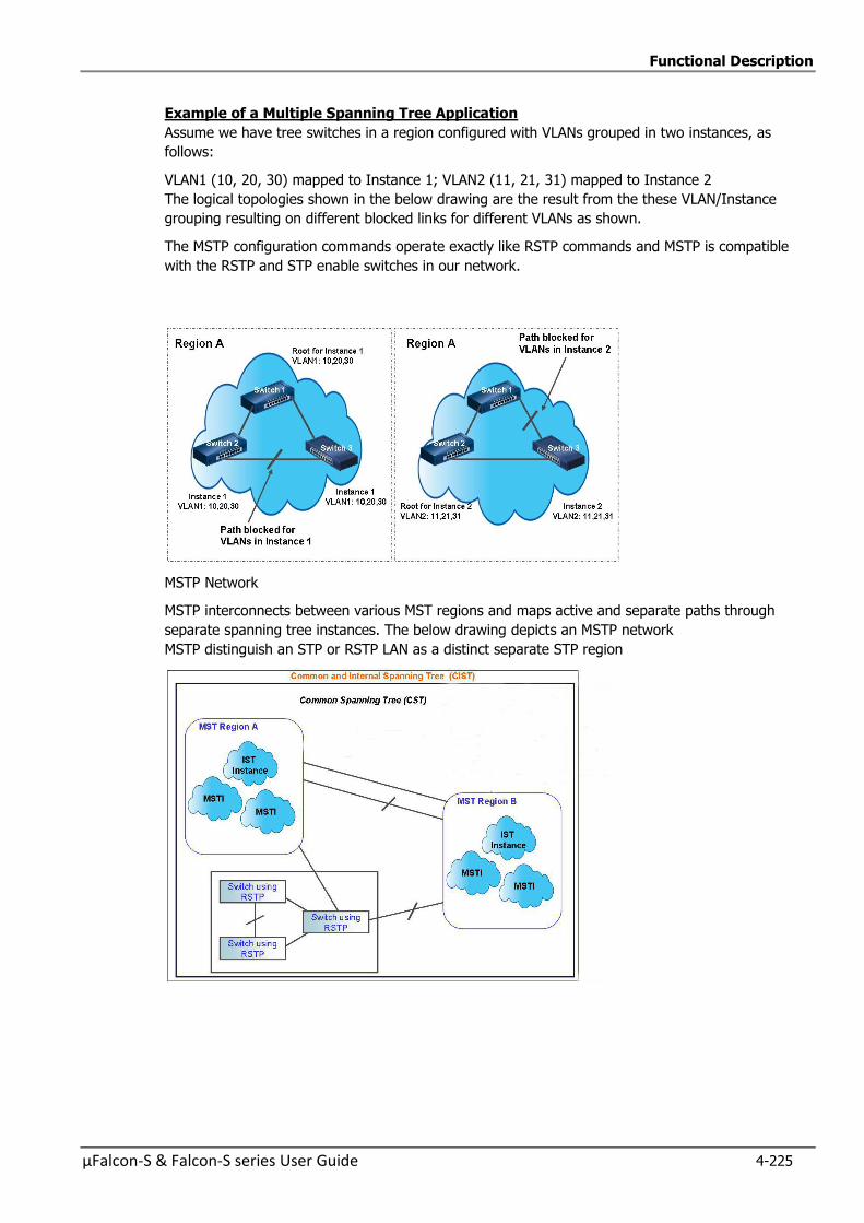
Functional Description
µFalcon-S & Falcon-S series User Guide 4-225
Example of a Multiple Spanning Tree Application
Assume we have tree switches in a region configured with VLANs grouped in two instances, as
follows:
VLAN1 (10, 20, 30) mapped to Instance 1; VLAN2 (11, 21, 31) mapped to Instance 2
The logical topologies shown in the below drawing are the result from the these VLAN/Instance
grouping resulting on different blocked links for different VLANs as shown.
The MSTP configuration commands operate exactly like RSTP commands and MSTP is compatible
with the RSTP and STP enable switches in our network.
MSTP Network
MSTP interconnects between various MST regions and maps active and separate paths through
separate spanning tree instances. The below drawing depicts an MSTP network
MSTP distinguish an STP or RSTP LAN as a distinct separate STP region
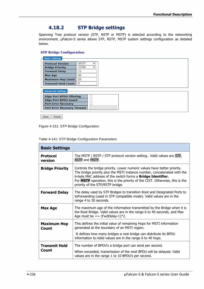
Functional Description
4-226 µFalcon-S & Falcon-S series User Guide
4.18.2 STP Bridge settings
Spanning Tree protocol version (STP, RSTP or MSTP) is selected according to the networking
environment. µFalcon-S series allows STP, RSTP, MSTP system settings configuration as detailed
below.
Figure 4-151: STP Bridge Configuration
Table 4-141: STP Bridge Configuration Parameters
Basic Settings
Protocol version
The MSTP / RSTP / STP protocol version setting.. Valid values are STP, RSTP and MSTP.
Bridge Priority Controls the bridge priority. Lower numeric values have better priority.
The bridge priority plus the MSTI instance number, concatenated with the 6-byte MAC address of the switch forms a Bridge Identifier.
For MSTP operation, this is the priority of the CIST. Otherwise, this is the
priority of the STP/RSTP bridge.
Forward Delay The delay used by STP Bridges to transition Root and Designated Ports to
toForwarding (used in STP compatible mode). Valid values are in the range 4 to 30 seconds.
Max Age The maximum age of the information transmitted by the Bridge when it is
the Root Bridge. Valid values are in the range 6 to 40 seconds, and Max Age must be <= (FwdDelay-1)*2.
Maximum Hop Count
This defines the initial value of remaining Hops for MSTI information
generated at the boundary of an MSTI region.
It defines how many bridges a root bridge can distribute its BPDU
information to.Valid values are in the range 6 to 40 hops.
Transmit Hold Count
The number of BPDU's a bridge port can send per second.
When exceeded, transmission of the next BPDU will be delayed. Valid
values are in the range 1 to 10 BPDU's per second.
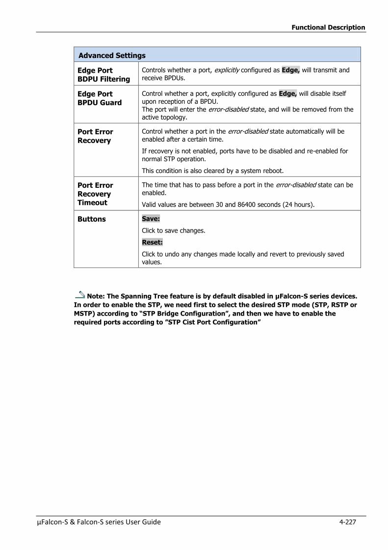
Functional Description
µFalcon-S & Falcon-S series User Guide 4-227
Advanced Settings
Edge Port BDPU Filtering
Controls whether a port, explicitly configured as Edge, will transmit and
receive BPDUs.
Edge Port BPDU Guard
Control whether a port, explicitly configured as Edge, will disable itself
upon reception of a BPDU.
The port will enter the error-disabled state, and will be removed from the active topology.
Port Error Recovery
Control whether a port in the error-disabled state automatically will be
enabled after a certain time.
If recovery is not enabled, ports have to be disabled and re-enabled for
normal STP operation.
This condition is also cleared by a system reboot.
Port Error Recovery Timeout
The time that has to pass before a port in the error-disabled state can be
enabled.
Valid values are between 30 and 86400 seconds (24 hours).
Buttons Save:
Click to save changes.
Reset:
Click to undo any changes made locally and revert to previously saved values.
Note: The Spanning Tree feature is by default disabled in µFalcon-S series devices.
In order to enable the STP, we need first to select the desired STP mode (STP, RSTP or
MSTP) according to “STP Bridge Configuration”, and then we have to enable the
required ports according to ”STP Cist Port Configuration”
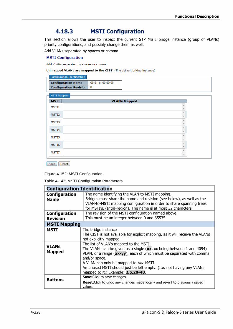
Functional Description
4-228 µFalcon-S & Falcon-S series User Guide
4.18.3 MSTI Configuration
This section allows the user to inspect the current STP MSTI bridge instance (group of VLANs)
priority configurations, and possibly change them as well.
Add VLANs separated by spaces or comma.
Figure 4-152: MSTI Configuration
Table 4-142: MSTI Configuration Parameters
Configuration Identification Configuration Name
The name identifying the VLAN to MSTI mapping. Bridges must share the name and revision (see below), as well as the
VLAN-to-MSTI mapping configuration in order to share spanning trees
for MSTI's. (Intra-region). The name is at most 32 characters
Configuration Revision
The revision of the MSTI configuration named above.
This must be an integer between 0 and 65535.
MSTI Mapping MSTI The bridge instance
The CIST is not available for explicit mapping, as it will receive the VLANs
not explicitly mapped.
VLANs Mapped
The list of VLAN's mapped to the MSTI. The VLANs can be given as a single (xx, xx being between 1 and 4094)
VLAN, or a range (xx-yy), each of which must be separated with comma and/or space.
A VLAN can only be mapped to one MSTI.
An unused MSTI should just be left empty. (I.e. not having any VLANs mapped to it.) Example: 2,5,20-40.
Buttons Save:Click to save changes.
Reset:Click to undo any changes made locally and revert to previously saved values.
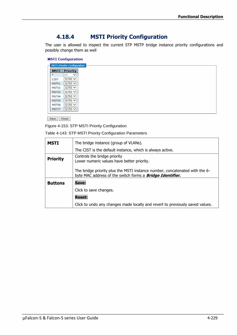
Functional Description
µFalcon-S & Falcon-S series User Guide 4-229
4.18.4 MSTI Priority Configuration
The user is allowed to inspect the current STP MSTP bridge instance priority configurations and
possibly change them as well
Figure 4-153: STP MSTI Priority Configuration
Table 4-143: STP MSTI Priority Configuration Parameters
MSTI The bridge instance (group of VLANs).
The CIST is the default instance, which is always active.
Priority Controls the bridge priority
Lower numeric values have better priority.
The bridge priority plus the MSTI instance number, concatenated with the 6-byte MAC address of the switch forms a Bridge Identifier.
Buttons Save:
Click to save changes.
Reset:
Click to undo any changes made locally and revert to previously saved values.
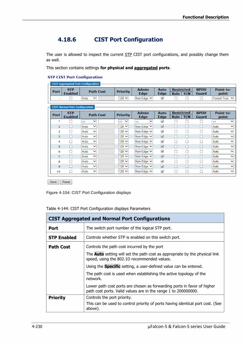
Functional Description
4-230 µFalcon-S & Falcon-S series User Guide
4.18.6 CIST Port Configuration
The user is allowed to inspect the current STP CIST port configurations, and possibly change them
as well.
This section contains settings for physical and aggregated ports.
Figure 4-154: CIST Port Configuration displays
Table 4-144: CIST Port Configuration displays Parameters
CIST Aggregated and Normal Port Configurations
Port The switch port number of the logical STP port.
STP Enabled Controls whether STP is enabled on this switch port.
Path Cost Controls the path cost incurred by the port
The Auto setting will set the path cost as appropriate by the physical link
speed, using the 802.1D recommended values.
Using the Specific setting, a user-defined value can be entered.
The path cost is used when establishing the active topology of the
network.
Lower path cost ports are chosen as forwarding ports in favor of higher
path cost ports. Valid values are in the range 1 to 200000000.
Priority Controls the port priority.
This can be used to control priority of ports having identical port cost. (See
above).
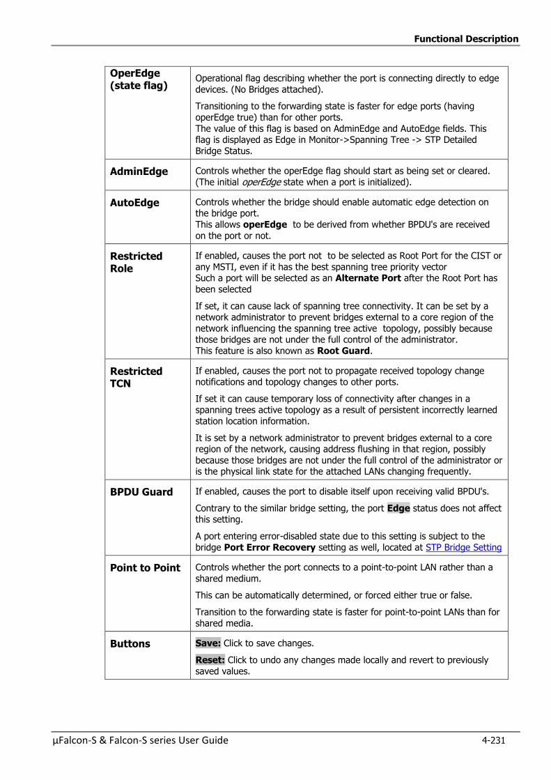
Functional Description
µFalcon-S & Falcon-S series User Guide 4-231
OperEdge (state flag)
Operational flag describing whether the port is connecting directly to edge
devices. (No Bridges attached).
Transitioning to the forwarding state is faster for edge ports (having
operEdge true) than for other ports.
The value of this flag is based on AdminEdge and AutoEdge fields. This flag is displayed as Edge in Monitor->Spanning Tree -> STP Detailed
Bridge Status.
AdminEdge Controls whether the operEdge flag should start as being set or cleared.
(The initial operEdge state when a port is initialized).
AutoEdge Controls whether the bridge should enable automatic edge detection on the bridge port.
This allows operEdge to be derived from whether BPDU's are received
on the port or not.
Restricted Role
If enabled, causes the port not to be selected as Root Port for the CIST or
any MSTI, even if it has the best spanning tree priority vector Such a port will be selected as an Alternate Port after the Root Port has
been selected
If set, it can cause lack of spanning tree connectivity. It can be set by a network administrator to prevent bridges external to a core region of the
network influencing the spanning tree active topology, possibly because those bridges are not under the full control of the administrator.
This feature is also known as Root Guard.
Restricted TCN
If enabled, causes the port not to propagate received topology change notifications and topology changes to other ports.
If set it can cause temporary loss of connectivity after changes in a spanning trees active topology as a result of persistent incorrectly learned
station location information.
It is set by a network administrator to prevent bridges external to a core region of the network, causing address flushing in that region, possibly
because those bridges are not under the full control of the administrator or is the physical link state for the attached LANs changing frequently.
BPDU Guard If enabled, causes the port to disable itself upon receiving valid BPDU's.
Contrary to the similar bridge setting, the port Edge status does not affect this setting.
A port entering error-disabled state due to this setting is subject to the
bridge Port Error Recovery setting as well, located at STP Bridge Setting
Point to Point Controls whether the port connects to a point-to-point LAN rather than a
shared medium.
This can be automatically determined, or forced either true or false.
Transition to the forwarding state is faster for point-to-point LANs than for
shared media.
Buttons Save: Click to save changes.
Reset: Click to undo any changes made locally and revert to previously
saved values.
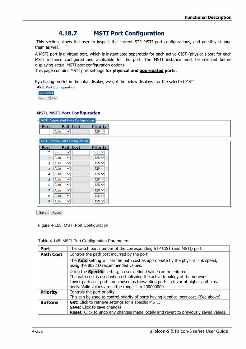
Functional Description
4-232 µFalcon-S & Falcon-S series User Guide
4.18.7 MSTI Port Configuration
This section allows the user to inspect the current STP MSTI port configurations, and possibly change
them as well.
A MSTI port is a virtual port, which is instantiated separately for each active CIST (physical) port for each
MSTI instance configured and applicable for the port. The MSTI instance must be selected before
displaying actual MSTI port configuration options.
This page contains MSTI port settings for physical and aggregated ports.
By clicking on Get in the intial display, we get the below displays for the selected MSTI
Figure 4-155: MSTI Port Configuration
Table 4-145: MSTI Port Configuration Parameters
Port The switch port number of the corresponding STP CIST (and MSTI) port.
Path Cost Controls the path cost incurred by the port
The Auto setting will set the path cost as appropriate by the physical link speed, using the 802.1D recommended values.
Using the Specific setting, a user-defined value can be entered. The path cost is used when establishing the active topology of the network.
Lower path cost ports are chosen as forwarding ports in favor of higher path cost
ports. Valid values are in the range 1 to 200000000.
Priority Controls the port priority.
This can be used to control priority of ports having identical port cost. (See above).
Buttons Get: Click to retrieve settings for a specific MSTI. Save: Click to save changes
Reset: Click to undo any changes made locally and revert to previously saved values.

Functional Description
µFalcon-S & Falcon-S series User Guide 4-233
4.18.8 Spanning Tree Monitoring
This section provides various STP monitoring displays
4.18.8.1 STP Bridges Status
This display provides a status overview of all STP bridge instances
Figure 4-156: STP Bridges
Table 4-146: STP Bridges Parameters
MSTI The Bridge Instance. CIST also a link to the STP Detailed Bridge Status
Bridge ID The Bridge ID of this Bridge instance..
Root ID The Bridge ID of the currently elected root bridge.
Root Port The switch port currently assigned the root port role.
Root Cost Root Path Cost. For the Root Bridge it is zero. For all other Bridges, it is
the sum of the Port Path Costs on the least cost path to the Root Bridge
Topology Flag The current state of the Topology Change Flag of this Bridge instance.
Topology Change Last
The time since last Topology Change occurred.
Buttons Refresh: Click to refresh the page immediately
Auto-refresh : Check this box to refresh the page automatically.
Automatic refresh occurs every 3 seconds
By clicking on CIST on above display, an additional display is shown below
(STP Detailed Bridge Status) This display provides detailed information on a single STP bridge
instance, along with port state for all active associated ports
Refer to next sub-section for more details
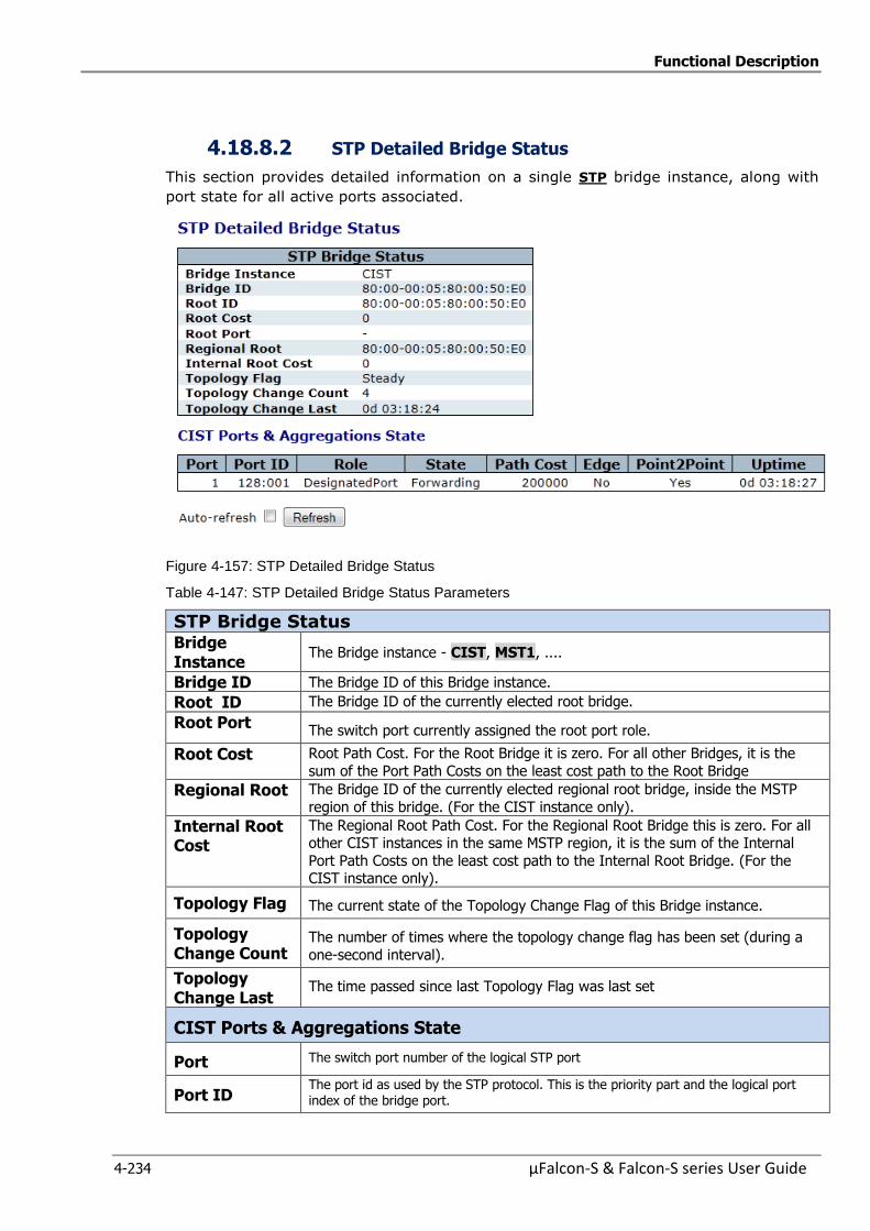
Functional Description
4-234 µFalcon-S & Falcon-S series User Guide
4.18.8.2 STP Detailed Bridge Status
This section provides detailed information on a single STP bridge instance, along with
port state for all active ports associated.
Figure 4-157: STP Detailed Bridge Status
Table 4-147: STP Detailed Bridge Status Parameters
STP Bridge Status Bridge Instance
The Bridge instance - CIST, MST1, ....
Bridge ID The Bridge ID of this Bridge instance.
Root ID The Bridge ID of the currently elected root bridge.
Root Port The switch port currently assigned the root port role.
Root Cost Root Path Cost. For the Root Bridge it is zero. For all other Bridges, it is the
sum of the Port Path Costs on the least cost path to the Root Bridge
Regional Root The Bridge ID of the currently elected regional root bridge, inside the MSTP
region of this bridge. (For the CIST instance only).
Internal Root Cost
The Regional Root Path Cost. For the Regional Root Bridge this is zero. For all other CIST instances in the same MSTP region, it is the sum of the Internal
Port Path Costs on the least cost path to the Internal Root Bridge. (For the CIST instance only).
Topology Flag The current state of the Topology Change Flag of this Bridge instance.
Topology Change Count
The number of times where the topology change flag has been set (during a
one-second interval).
Topology Change Last
The time passed since last Topology Flag was last set
CIST Ports & Aggregations State
Port The switch port number of the logical STP port
Port ID The port id as used by the STP protocol. This is the priority part and the logical port index of the bridge port.
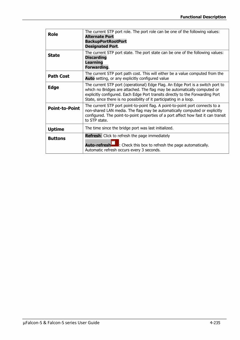
Functional Description
µFalcon-S & Falcon-S series User Guide 4-235
Role The current STP port role. The port role can be one of the following values:
Alternate Port BackupPortRootPort
Designated Port.
State The current STP port state. The port state can be one of the following values: Discarding
Learning Forwarding.
Path Cost The current STP port path cost. This will either be a value computed from the
Auto setting, or any explicitly configured value
Edge The current STP port (operational) Edge Flag. An Edge Port is a switch port to which no Bridges are attached. The flag may be automatically computed or
explicitly configured. Each Edge Port transits directly to the Forwarding Port State, since there is no possibility of it participating in a loop.
Point-to-Point The current STP port point-to-point flag. A point-to-point port connects to a
non-shared LAN media. The flag may be automatically computed or explicitly configured. The point-to-point properties of a port affect how fast it can transit
to STP state.
Uptime The time since the bridge port was last initialized.
Buttons Refresh: Click to refresh the page immediately
Auto-refresh : Check this box to refresh the page automatically. Automatic refresh occurs every 3 seconds.
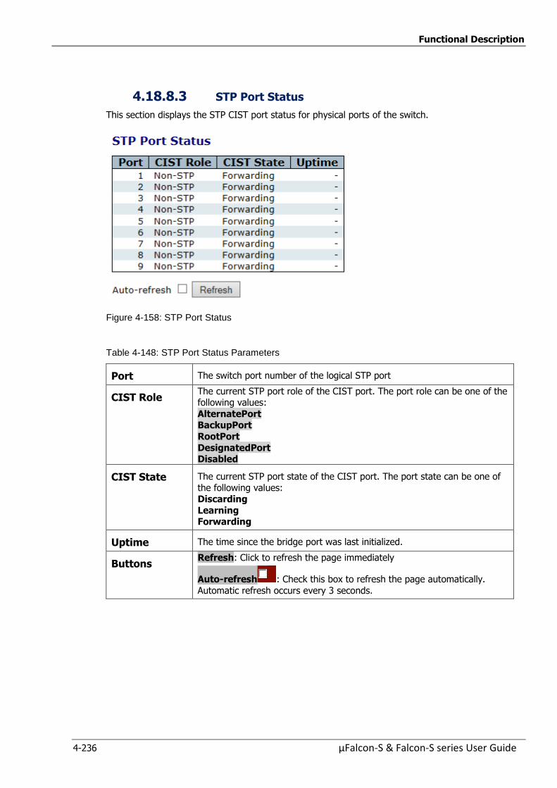
Functional Description
4-236 µFalcon-S & Falcon-S series User Guide
4.18.8.3 STP Port Status
This section displays the STP CIST port status for physical ports of the switch.
Figure 4-158: STP Port Status
Table 4-148: STP Port Status Parameters
Port The switch port number of the logical STP port
CIST Role The current STP port role of the CIST port. The port role can be one of the following values:
AlternatePort BackupPort
RootPort
DesignatedPort Disabled
CIST State The current STP port state of the CIST port. The port state can be one of
the following values: Discarding
Learning Forwarding
Uptime The time since the bridge port was last initialized.
Buttons Refresh: Click to refresh the page immediately
Auto-refresh : Check this box to refresh the page automatically.
Automatic refresh occurs every 3 seconds.
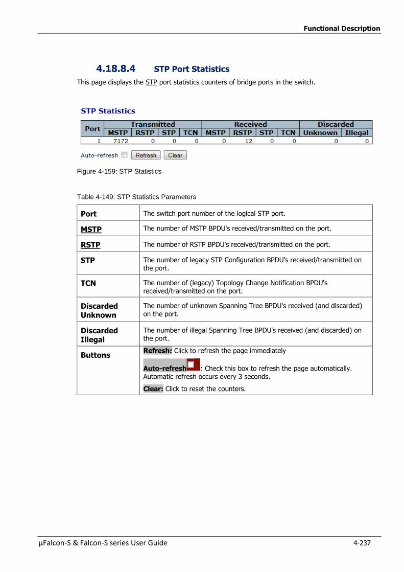
Functional Description
µFalcon-S & Falcon-S series User Guide 4-237
4.18.8.4 STP Port Statistics
This page displays the STP port statistics counters of bridge ports in the switch.
Figure 4-159: STP Statistics
Table 4-149: STP Statistics Parameters
Port The switch port number of the logical STP port.
MSTP The number of MSTP BPDU's received/transmitted on the port.
RSTP The number of RSTP BPDU's received/transmitted on the port.
STP The number of legacy STP Configuration BPDU's received/transmitted on
the port.
TCN The number of (legacy) Topology Change Notification BPDU's received/transmitted on the port.
Discarded Unknown
The number of unknown Spanning Tree BPDU's received (and discarded)
on the port.
Discarded Illegal
The number of illegal Spanning Tree BPDU's received (and discarded) on the port.
Buttons Refresh: Click to refresh the page immediately
Auto-refresh : Check this box to refresh the page automatically. Automatic refresh occurs every 3 seconds.
Clear: Click to reset the counters.
Functional Description
4-238 µFalcon-S & Falcon-S series User Guide
4.19 IP Multicast
Multicast is the delivery of information to a group of destinations simultaneously using the most
efficient strategy to deliver the messages over each link of the network only once, creating copies
only when the links to the destinations split.
Internet Group Management Protocol (IGMP) is an IP (Layer 3) protocol used for signaling of
multicast group membership (adding or removing clients to/from a multicast group)
IGMP snooping analyze all IGMP packets between hosts connected to the µFalcon-S series and
multicast routers in the network. When the µFalcon-S series snoops an IGMP Join or IGMP Report
from a host for a given multicast group, it adds the host's port number to the multicast list for that
group. When the µFalcon-S series snoops an IGMP Leave, it removes the host's port from the table
entry.
The following sections explain and demonstrate in detail IGMP snooping support using the Web
screens description.

Functional Description
µFalcon-S & Falcon-S series User Guide 4-239
4.19.1 IGMP Snooping Configuration
IGMP is an acronym for Internet Group Management Protocol. It is a communications protocol used
to manage the membership of Internet Protocol multicast groups. IGMP is used by IP hosts and
adjacent multicast routers to establish multicast group memberships. It is an integral part of the IP
multicast specification, like ICMP for unicast onnections. IGMP can be used for online video and
gaming, and allows more efficient use of resources when supporting these uses.
IPMC is an acronym for IP MultiCast.
IPMC supports IPv4 and IPv6 multicasting. IPMCv4 denotes multicast for IPv4. IPMCv6 denotes
multicast for IPv6.
This section enables IGMP Snooping related configuration.
Figure 4-160: IGMP Snooping Configurations

Functional Description
4-240 µFalcon-S & Falcon-S series User Guide
Table 4-150: IGMP Snooping Configuration Parameters
Global Configuration
Snooping Enabled
Enables the Global IGMP Snooping.
Unregistered IPMCv4 Flooding enabled
Enables unregistered IPMCv4 traffic flooding. The flooding control takes effect only when IGMP Snooping is enabled.
When IGMP Snooping is disabled, unregistered IPMCv4 traffic flooding is always active in spite of this setting
IGMP SSM Range
SSM (Source-Specific Multicast) Range allows the SSM-aware hosts and
routers run the SSM service model for the groups in the address range.
Leave Proxy Enabled
Enables IGMP Leave Proxy.
This feature can be used to avoid forwarding unnecessary leave
messages to the router side.
Proxy Enabled Enable IGMP Proxy. This feature can be used to avoid forwarding
unnecessary join and leave messages to the router side.
Port Related Configuration
Router Port Specify which ports act as router ports. A router port is a port on the Ethernet switch that leads towards the Layer 3 multicast device or
IGMP querier. If an aggregation member port is selected as a router port, the whole
aggregation will act as a router port.
Fast Leave Enables the fast leave on the port Multicast snooping Fast Leave processing allows the switch to remove
an interface from the forwarding-table entry without first sending out group specific queries to the interface
The VLAN interface is pruned from the multicast tree for the multicast
group specified in the original leave message. Fast-leave processing ensures optimal bandwidth management for all hosts on a switched
network, even when multiple multicast groups are in use simultaneously
This processing applies to IGMP and MLD.
Throttling Enable to limit the number of multicast groups to which a switch port can belong.
Buttons
Save: Click to save changes.
Reset: Click to undo any changes made locally and revert to previously saved values.
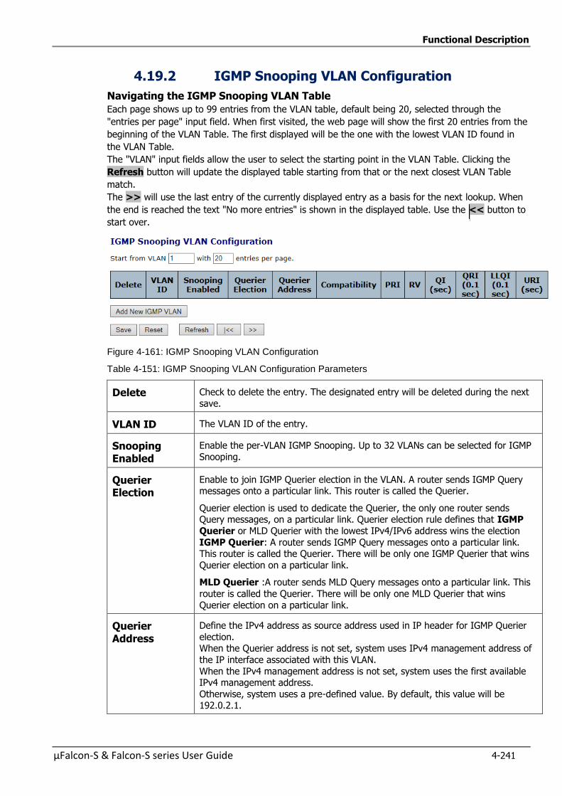
Functional Description
µFalcon-S & Falcon-S series User Guide 4-241
4.19.2 IGMP Snooping VLAN Configuration
Navigating the IGMP Snooping VLAN Table
Each page shows up to 99 entries from the VLAN table, default being 20, selected through the
"entries per page" input field. When first visited, the web page will show the first 20 entries from the
beginning of the VLAN Table. The first displayed will be the one with the lowest VLAN ID found in
the VLAN Table.
The "VLAN" input fields allow the user to select the starting point in the VLAN Table. Clicking the
Refresh button will update the displayed table starting from that or the next closest VLAN Table
match.
The >> will use the last entry of the currently displayed entry as a basis for the next lookup. When
the end is reached the text "No more entries" is shown in the displayed table. Use the << button to
start over.
Figure 4-161: IGMP Snooping VLAN Configuration
Table 4-151: IGMP Snooping VLAN Configuration Parameters
Delete Check to delete the entry. The designated entry will be deleted during the next
save.
VLAN ID The VLAN ID of the entry.
Snooping Enabled
Enable the per-VLAN IGMP Snooping. Up to 32 VLANs can be selected for IGMP
Snooping.
Querier Election
Enable to join IGMP Querier election in the VLAN. A router sends IGMP Query messages onto a particular link. This router is called the Querier.
Querier election is used to dedicate the Querier, the only one router sends Query messages, on a particular link. Querier election rule defines that IGMP
Querier or MLD Querier with the lowest IPv4/IPv6 address wins the election
IGMP Querier: A router sends IGMP Query messages onto a particular link. This router is called the Querier. There will be only one IGMP Querier that wins
Querier election on a particular link.
MLD Querier :A router sends MLD Query messages onto a particular link. This
router is called the Querier. There will be only one MLD Querier that wins
Querier election on a particular link.
Querier Address
Define the IPv4 address as source address used in IP header for IGMP Querier
election. When the Querier address is not set, system uses IPv4 management address of
the IP interface associated with this VLAN.
When the IPv4 management address is not set, system uses the first available IPv4 management address.
Otherwise, system uses a pre-defined value. By default, this value will be 192.0.2.1.
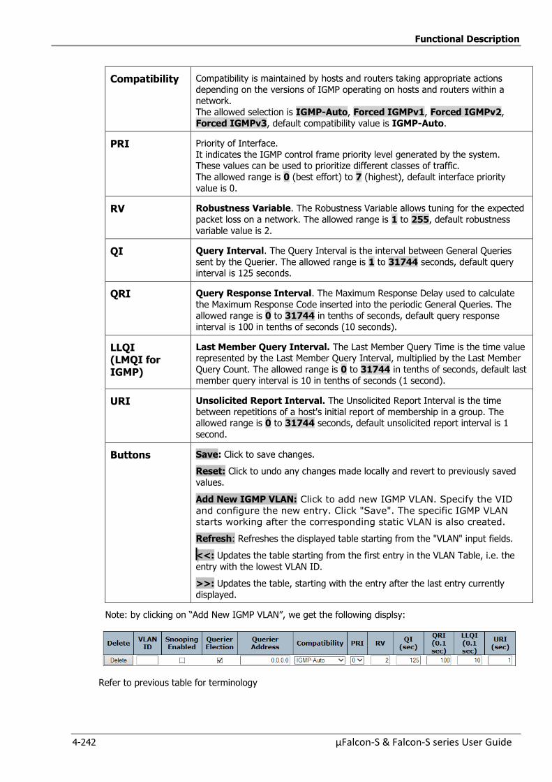
Functional Description
4-242 µFalcon-S & Falcon-S series User Guide
Compatibility Compatibility is maintained by hosts and routers taking appropriate actions
depending on the versions of IGMP operating on hosts and routers within a network.
The allowed selection is IGMP-Auto, Forced IGMPv1, Forced IGMPv2,
Forced IGMPv3, default compatibility value is IGMP-Auto.
PRI Priority of Interface.
It indicates the IGMP control frame priority level generated by the system. These values can be used to prioritize different classes of traffic.
The allowed range is 0 (best effort) to 7 (highest), default interface priority
value is 0.
RV Robustness Variable. The Robustness Variable allows tuning for the expected
packet loss on a network. The allowed range is 1 to 255, default robustness
variable value is 2.
QI Query Interval. The Query Interval is the interval between General Queries
sent by the Querier. The allowed range is 1 to 31744 seconds, default query interval is 125 seconds.
QRI Query Response Interval. The Maximum Response Delay used to calculate
the Maximum Response Code inserted into the periodic General Queries. The allowed range is 0 to 31744 in tenths of seconds, default query response
interval is 100 in tenths of seconds (10 seconds).
LLQI (LMQI for IGMP)
Last Member Query Interval. The Last Member Query Time is the time value represented by the Last Member Query Interval, multiplied by the Last Member
Query Count. The allowed range is 0 to 31744 in tenths of seconds, default last member query interval is 10 in tenths of seconds (1 second).
URI Unsolicited Report Interval. The Unsolicited Report Interval is the time
between repetitions of a host's initial report of membership in a group. The allowed range is 0 to 31744 seconds, default unsolicited report interval is 1
second.
Buttons
Save: Click to save changes.
Reset: Click to undo any changes made locally and revert to previously saved
values.
Add New IGMP VLAN: Click to add new IGMP VLAN. Specify the VID
and configure the new entry. Click "Save". The specific IGMP VLAN
starts working after the corresponding static VLAN is also created.
Refresh: Refreshes the displayed table starting from the "VLAN" input fields.
<<: Updates the table starting from the first entry in the VLAN Table, i.e. the
entry with the lowest VLAN ID.
>>: Updates the table, starting with the entry after the last entry currently
displayed.
Note: by clicking on “Add New IGMP VLAN”, we get the following displsy:
Refer to previous table for terminology

Functional Description
µFalcon-S & Falcon-S series User Guide 4-243
4.19.3 IGMP Snooping Port Group Filtering Configuration
Figure 4-162: IGMP Snooping Port Group Filtering Configuration
Table 4-152: IGMP Snooping Port Group Filtering Configuration Parameters
Port The logical port for the settings.
Filtering Profile Select the IPMC Profile as the filtering condition for the specific port. Summary about the designated profile will be shown by clicking the view
button.
IP Multicast Profile is an acronym for IP MultiCast Profile.
IP Multicast Profile is used to deploy the access control on IP multicast
streams
Profile Management Button
You can inspect the rules of the designated profile by using the following
button:
: List the rules associated with the designated profile.
Buttons Save:
Click to save changes.
Reset:
Click to undo any changes made locally and revert to previously saved
values.
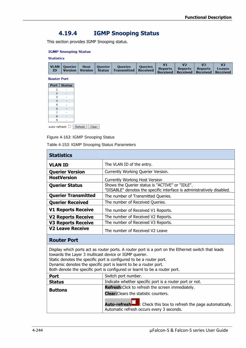
Functional Description
4-244 µFalcon-S & Falcon-S series User Guide
4.19.4 IGMP Snooping Status
This section provides IGMP Snooping status.
Figure 4-163: IGMP Snooping Status
Table 4-153: IGMP Snooping Status Parameters
Statistics
VLAN ID The VLAN ID of the entry.
Querier Version Currently Working Querier Version.
HostVersion Currently Working Host Version
Querier Status Shows the Querier status is "ACTIVE" or "IDLE". "DISABLE" denotes the specific interface is administratively disabled.
Querier Transmitted The number of Transmitted Queries.
Querier Received The number of Received Queries.
V1 Reports Receive The number of Received V1 Reports.
V2 Reports Receive The number of Received V2 Reports.
V3 Reports Receive The number of Received V3 Reports.
V2 Leave Receive The number of Received V2 Leave
Router Port
Display which ports act as router ports. A router port is a port on the Ethernet switch that leads towards the Layer 3 multicast device or IGMP querier.
Static denotes the specific port is configured to be a router port. Dynamic denotes the specific port is learnt to be a router port.
Both denote the specific port is configured or learnt to be a router port.
Port Switch port number.
Status Indicate whether specific port is a router port or not.
Buttons Refresh:Click to refresh the screen immediately.
Clear:Clears the statistic counters.
Auto-refresh : Check this box to refresh the page automatically. Automatic refresh occurs every 3 seconds.
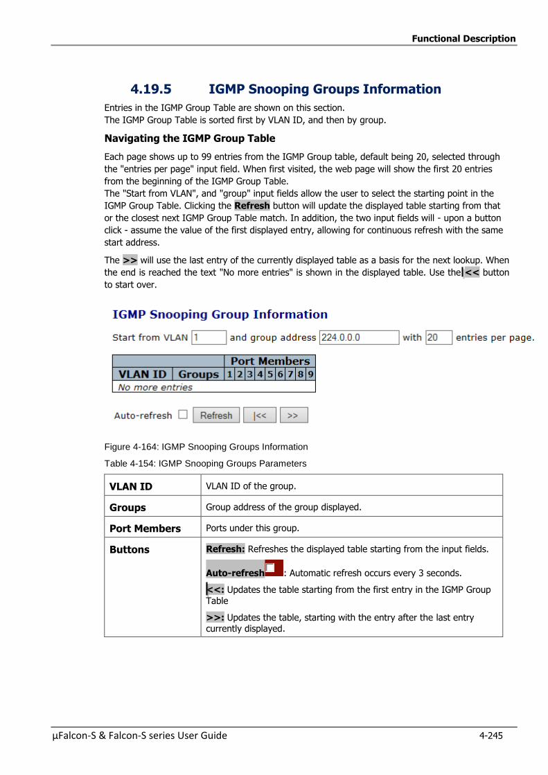
Functional Description
µFalcon-S & Falcon-S series User Guide 4-245
4.19.5 IGMP Snooping Groups Information
Entries in the IGMP Group Table are shown on this section.
The IGMP Group Table is sorted first by VLAN ID, and then by group.
Navigating the IGMP Group Table
Each page shows up to 99 entries from the IGMP Group table, default being 20, selected through
the "entries per page" input field. When first visited, the web page will show the first 20 entries
from the beginning of the IGMP Group Table.
The "Start from VLAN", and "group" input fields allow the user to select the starting point in the
IGMP Group Table. Clicking the Refresh button will update the displayed table starting from that
or the closest next IGMP Group Table match. In addition, the two input fields will - upon a button
click - assume the value of the first displayed entry, allowing for continuous refresh with the same
start address.
The >> will use the last entry of the currently displayed table as a basis for the next lookup. When
the end is reached the text "No more entries" is shown in the displayed table. Use the << button
to start over.
Figure 4-164: IGMP Snooping Groups Information
Table 4-154: IGMP Snooping Groups Parameters
VLAN ID VLAN ID of the group.
Groups Group address of the group displayed.
Port Members Ports under this group.
Buttons Refresh: Refreshes the displayed table starting from the input fields.
Auto-refresh : Automatic refresh occurs every 3 seconds.
<<: Updates the table starting from the first entry in the IGMP Group
Table
>>: Updates the table, starting with the entry after the last entry currently displayed.
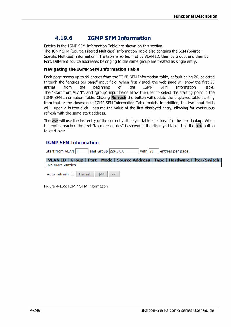
Functional Description
4-246 µFalcon-S & Falcon-S series User Guide
4.19.6 IGMP SFM Information
Entries in the IGMP SFM Information Table are shown on this section.
The IGMP SFM (Source-Filtered Multicast) Information Table also contains the SSM (Source-
Specific Multicast) information. This table is sorted first by VLAN ID, then by group, and then by
Port. Different source addresses belonging to the same group are treated as single entry.
Navigating the IGMP SFM Information Table
Each page shows up to 99 entries from the IGMP SFM Information table, default being 20, selected
through the "entries per page" input field. When first visited, the web page will show the first 20
entries from the beginning of the IGMP SFM Information Table.
The "Start from VLAN", and "group" input fields allow the user to select the starting point in the
IGMP SFM Information Table. Clicking Refresh the button will update the displayed table starting
from that or the closest next IGMP SFM Information Table match. In addition, the two input fields
will - upon a button click - assume the value of the first displayed entry, allowing for continuous
refresh with the same start address.
The >> will use the last entry of the currently displayed table as a basis for the next lookup. When
the end is reached the text "No more entries" is shown in the displayed table. Use the << button
to start over
Figure 4-165: IGMP SFM Information

Functional Description
µFalcon-S & Falcon-S series User Guide 4-247
Table 4-155: IGMP SFM Information Parameters
VLAN ID VLAN ID of the group.
Group Group address of the group displayed.
Port Switch port number.
Mode Indicates the filtering mode maintained per (VLAN ID, port number, Group Address) basis. It can be either Include or Exclude
Source Address IP Address of the source. Currently, system limits the total number
of IPv4 source addresses for filtering (per group) is 8 When there is no any source filtering address, the text "None" is
shown in the Source Address field..
Type Indicates the Type. It can be either Allow or Deny.
Hardware Filter/Switch
Indicates whether data plane destined to the specific group address
from the source IPv4 address could be handled by chip or not.
Buttons Refresh: Refreshes the displayed table starting from the input fields.
Auto-refresh : Automatic refresh occurs every 3 seconds.
<<: Updates the table starting from the first entry in the IGMP
Group Table
>>: Updates the table, starting with the entry after the last entry
currently displayed.
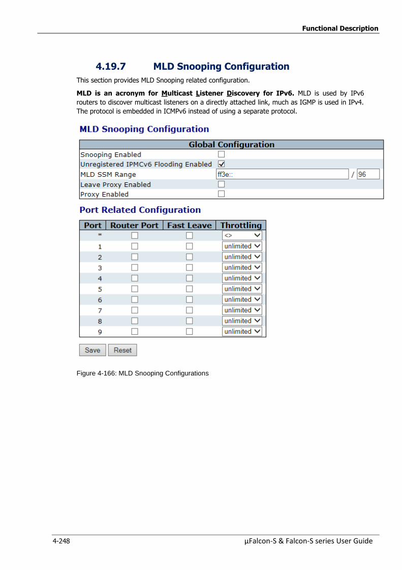
Functional Description
4-248 µFalcon-S & Falcon-S series User Guide
4.19.7 MLD Snooping Configuration
This section provides MLD Snooping related configuration.
MLD is an acronym for Multicast Listener Discovery for IPv6. MLD is used by IPv6
routers to discover multicast listeners on a directly attached link, much as IGMP is used in IPv4.
The protocol is embedded in ICMPv6 instead of using a separate protocol.
Figure 4-166: MLD Snooping Configurations
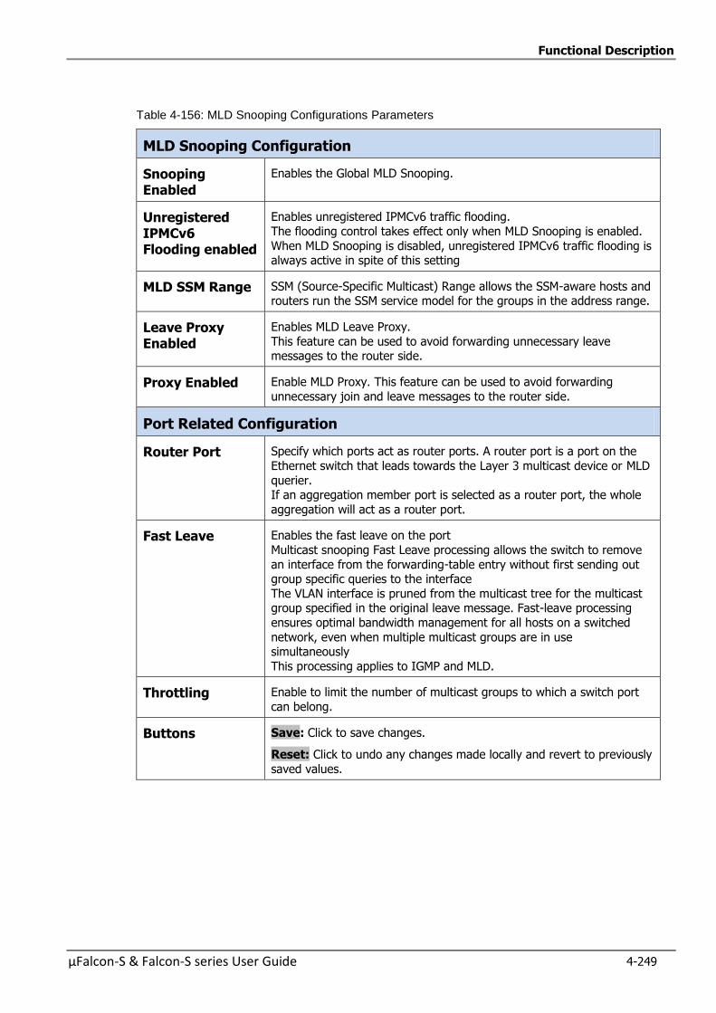
Functional Description
µFalcon-S & Falcon-S series User Guide 4-249
Table 4-156: MLD Snooping Configurations Parameters
MLD Snooping Configuration
Snooping Enabled
Enables the Global MLD Snooping.
Unregistered IPMCv6 Flooding enabled
Enables unregistered IPMCv6 traffic flooding.
The flooding control takes effect only when MLD Snooping is enabled.
When MLD Snooping is disabled, unregistered IPMCv6 traffic flooding is always active in spite of this setting
MLD SSM Range SSM (Source-Specific Multicast) Range allows the SSM-aware hosts and routers run the SSM service model for the groups in the address range.
Leave Proxy Enabled
Enables MLD Leave Proxy.
This feature can be used to avoid forwarding unnecessary leave messages to the router side.
Proxy Enabled Enable MLD Proxy. This feature can be used to avoid forwarding
unnecessary join and leave messages to the router side.
Port Related Configuration
Router Port Specify which ports act as router ports. A router port is a port on the
Ethernet switch that leads towards the Layer 3 multicast device or MLD
querier. If an aggregation member port is selected as a router port, the whole
aggregation will act as a router port.
Fast Leave Enables the fast leave on the port
Multicast snooping Fast Leave processing allows the switch to remove
an interface from the forwarding-table entry without first sending out group specific queries to the interface
The VLAN interface is pruned from the multicast tree for the multicast group specified in the original leave message. Fast-leave processing
ensures optimal bandwidth management for all hosts on a switched
network, even when multiple multicast groups are in use simultaneously
This processing applies to IGMP and MLD.
Throttling Enable to limit the number of multicast groups to which a switch port
can belong.
Buttons
Save: Click to save changes.
Reset: Click to undo any changes made locally and revert to previously
saved values.
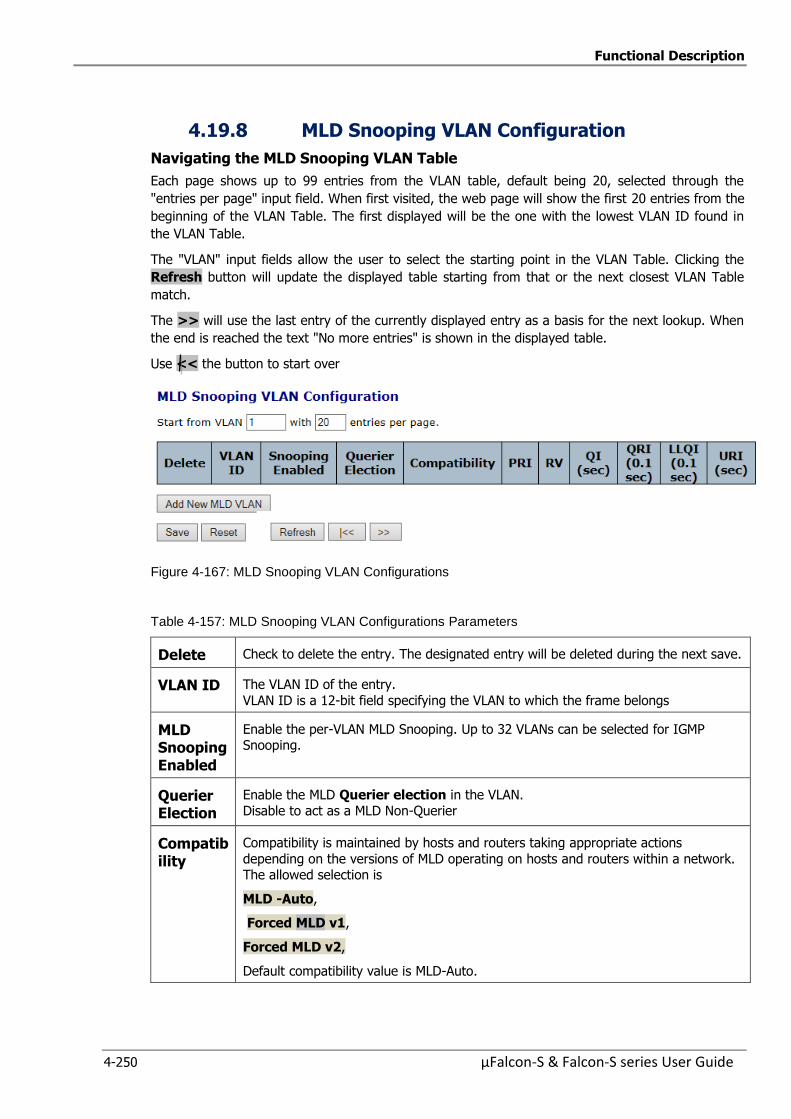
Functional Description
4-250 µFalcon-S & Falcon-S series User Guide
4.19.8 MLD Snooping VLAN Configuration
Navigating the MLD Snooping VLAN Table
Each page shows up to 99 entries from the VLAN table, default being 20, selected through the
"entries per page" input field. When first visited, the web page will show the first 20 entries from the
beginning of the VLAN Table. The first displayed will be the one with the lowest VLAN ID found in
the VLAN Table.
The "VLAN" input fields allow the user to select the starting point in the VLAN Table. Clicking the
Refresh button will update the displayed table starting from that or the next closest VLAN Table
match.
The >> will use the last entry of the currently displayed entry as a basis for the next lookup. When
the end is reached the text "No more entries" is shown in the displayed table.
Use << the button to start over
Figure 4-167: MLD Snooping VLAN Configurations
Table 4-157: MLD Snooping VLAN Configurations Parameters
Delete Check to delete the entry. The designated entry will be deleted during the next save.
VLAN ID The VLAN ID of the entry.
VLAN ID is a 12-bit field specifying the VLAN to which the frame belongs
MLD Snooping Enabled
Enable the per-VLAN MLD Snooping. Up to 32 VLANs can be selected for IGMP Snooping.
Querier Election
Enable the MLD Querier election in the VLAN. Disable to act as a MLD Non-Querier
Compatibility
Compatibility is maintained by hosts and routers taking appropriate actions
depending on the versions of MLD operating on hosts and routers within a network. The allowed selection is
MLD -Auto,
Forced MLD v1,
Forced MLD v2,
Default compatibility value is MLD-Auto.
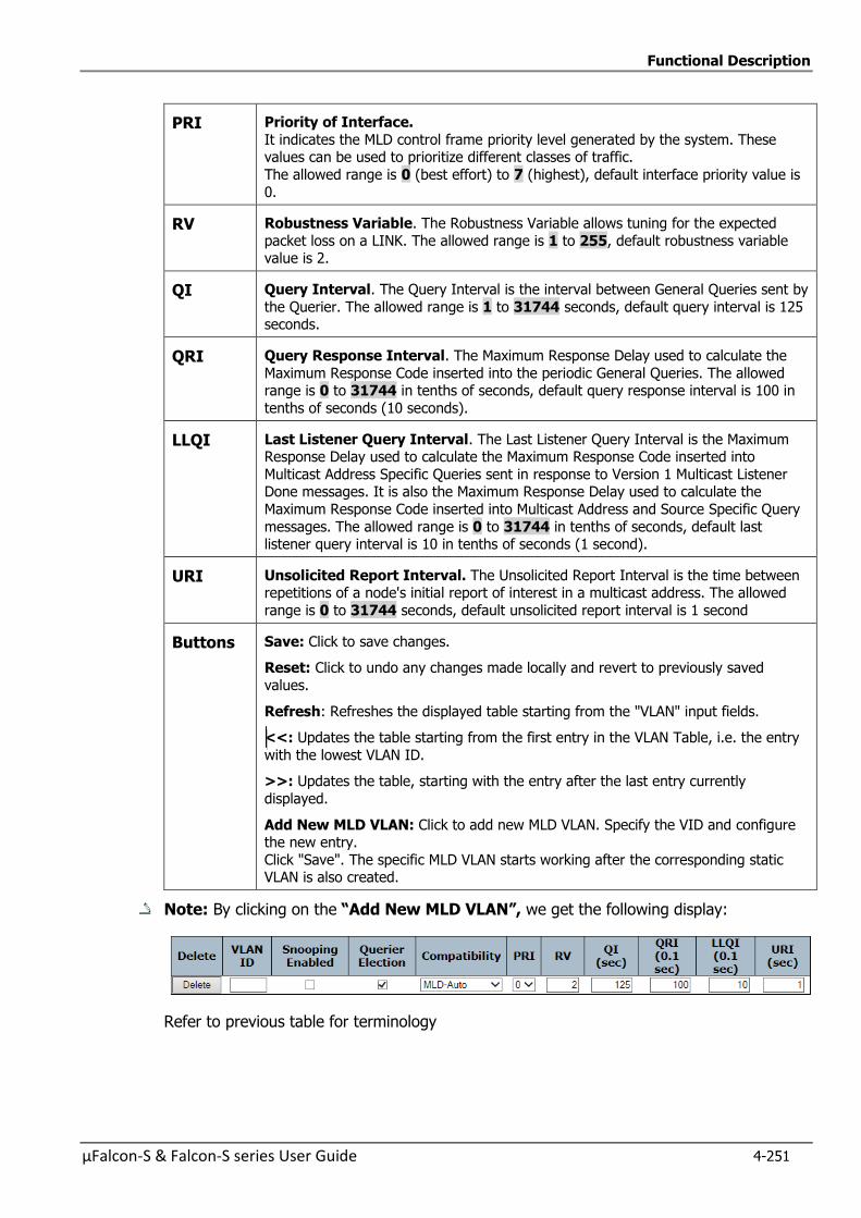
Functional Description
µFalcon-S & Falcon-S series User Guide 4-251
PRI Priority of Interface.
It indicates the MLD control frame priority level generated by the system. These values can be used to prioritize different classes of traffic.
The allowed range is 0 (best effort) to 7 (highest), default interface priority value is
0.
RV Robustness Variable. The Robustness Variable allows tuning for the expected
packet loss on a LINK. The allowed range is 1 to 255, default robustness variable value is 2.
QI Query Interval. The Query Interval is the interval between General Queries sent by
the Querier. The allowed range is 1 to 31744 seconds, default query interval is 125 seconds.
QRI Query Response Interval. The Maximum Response Delay used to calculate the
Maximum Response Code inserted into the periodic General Queries. The allowed range is 0 to 31744 in tenths of seconds, default query response interval is 100 in
tenths of seconds (10 seconds).
LLQI Last Listener Query Interval. The Last Listener Query Interval is the Maximum Response Delay used to calculate the Maximum Response Code inserted into
Multicast Address Specific Queries sent in response to Version 1 Multicast Listener Done messages. It is also the Maximum Response Delay used to calculate the
Maximum Response Code inserted into Multicast Address and Source Specific Query
messages. The allowed range is 0 to 31744 in tenths of seconds, default last listener query interval is 10 in tenths of seconds (1 second).
URI Unsolicited Report Interval. The Unsolicited Report Interval is the time between repetitions of a node's initial report of interest in a multicast address. The allowed
range is 0 to 31744 seconds, default unsolicited report interval is 1 second
Buttons
Save: Click to save changes.
Reset: Click to undo any changes made locally and revert to previously saved
values.
Refresh: Refreshes the displayed table starting from the "VLAN" input fields.
<<: Updates the table starting from the first entry in the VLAN Table, i.e. the entry
with the lowest VLAN ID.
>>: Updates the table, starting with the entry after the last entry currently
displayed.
Add New MLD VLAN: Click to add new MLD VLAN. Specify the VID and configure the new entry.
Click "Save". The specific MLD VLAN starts working after the corresponding static VLAN is also created.
Note: By clicking on the “AddNewMLDVLAN”,we get the following display:
Refer to previous table for terminology
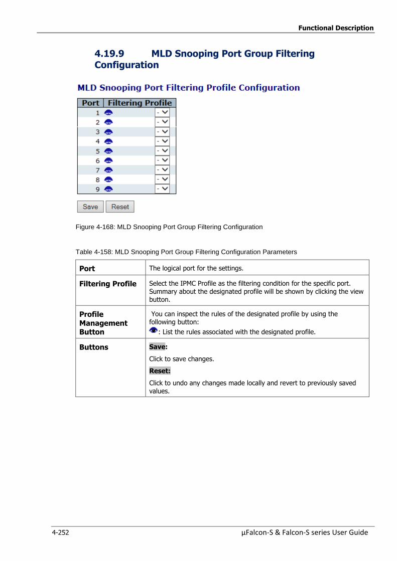
Functional Description
4-252 µFalcon-S & Falcon-S series User Guide
4.19.9 MLD Snooping Port Group Filtering Configuration
Figure 4-168: MLD Snooping Port Group Filtering Configuration
Table 4-158: MLD Snooping Port Group Filtering Configuration Parameters
Port The logical port for the settings.
Filtering Profile Select the IPMC Profile as the filtering condition for the specific port.
Summary about the designated profile will be shown by clicking the view button.
Profile Management Button
You can inspect the rules of the designated profile by using the
following button:
: List the rules associated with the designated profile.
Buttons Save:
Click to save changes.
Reset:
Click to undo any changes made locally and revert to previously saved
values.
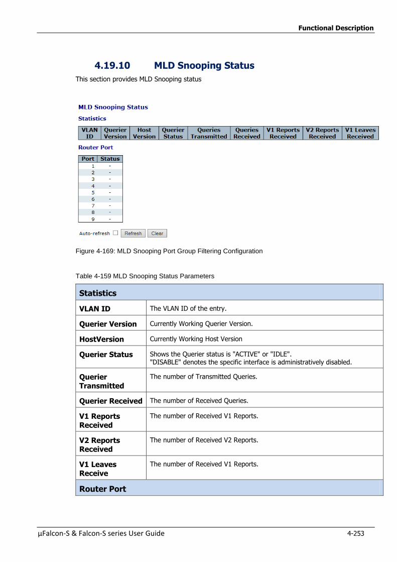
Functional Description
µFalcon-S & Falcon-S series User Guide 4-253
4.19.10 MLD Snooping Status
This section provides MLD Snooping status
Figure 4-169: MLD Snooping Port Group Filtering Configuration
Table 4-159 MLD Snooping Status Parameters
Statistics
VLAN ID The VLAN ID of the entry.
Querier Version Currently Working Querier Version.
HostVersion Currently Working Host Version
Querier Status Shows the Querier status is "ACTIVE" or "IDLE". "DISABLE" denotes the specific interface is administratively disabled.
Querier Transmitted
The number of Transmitted Queries.
Querier Received The number of Received Queries.
V1 Reports Received
The number of Received V1 Reports.
V2 Reports Received
The number of Received V2 Reports.
V1 Leaves Receive
The number of Received V1 Reports.
Router Port
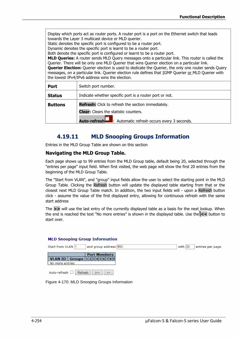
Functional Description
4-254 µFalcon-S & Falcon-S series User Guide
Display which ports act as router ports. A router port is a port on the Ethernet switch that leads
towards the Layer 3 multicast device or MLD querier. Static denotes the specific port is configured to be a router port.
Dynamic denotes the specific port is learnt to be a router port.
Both denote the specific port is configured or learnt to be a router port. MLD Queries: A router sends MLD Query messages onto a particular link. This router is called the
Querier. There will be only one MLD Querier that wins Querier election on a particular link. Querier Election: Querier election is used to dedicate the Querier, the only one router sends Query
messages, on a particular link. Querier election rule defines that IGMP Querier or MLD Querier with the lowest IPv4/IPv6 address wins the election.
Port Switch port number.
Status Indicate whether specific port is a router port or not.
Buttons Refresh: Click to refresh the section immediately.
Clear: Clears the statistic counters.
Auto-refresh : Automatic refresh occurs every 3 seconds.
4.19.11 MLD Snooping Groups Information
Entries in the MLD Group Table are shown on this section
Navigating the MLD Group Table.
Each page shows up to 99 entries from the MLD Group table, default being 20, selected through the
"entries per page" input field. When first visited, the web page will show the first 20 entries from the
beginning of the MLD Group Table.
The "Start from VLAN", and "group" input fields allow the user to select the starting point in the MLD
Group Table. Clicking the Refresh button will update the displayed table starting from that or the
closest next MLD Group Table match. In addition, the two input fields will - upon a Refresh button
click - assume the value of the first displayed entry, allowing for continuous refresh with the same
start address
The >> will use the last entry of the currently displayed table as a basis for the next lookup. When
the end is reached the text "No more entries" is shown in the displayed table. Use the << button to
start over.
Figure 4-170: MLD Snooping Groups Information
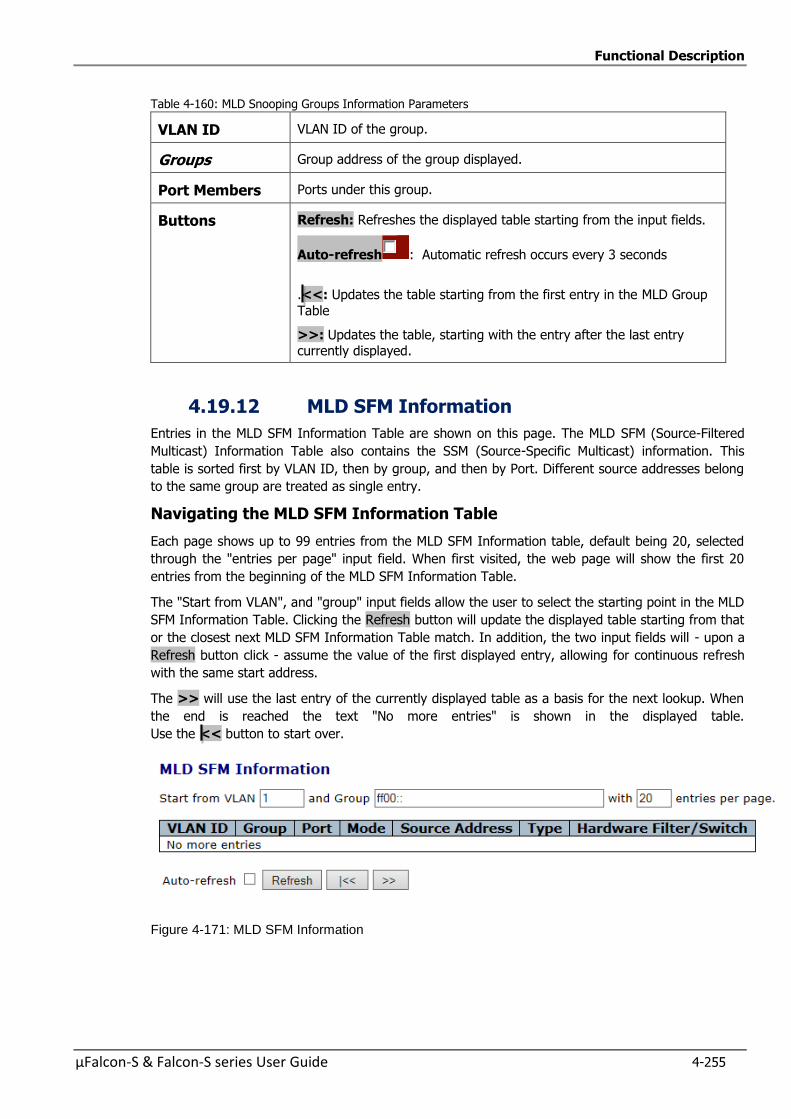
Functional Description
µFalcon-S & Falcon-S series User Guide 4-255
Table 4-160: MLD Snooping Groups Information Parameters
VLAN ID VLAN ID of the group.
Groups Group address of the group displayed.
Port Members Ports under this group.
Buttons Refresh: Refreshes the displayed table starting from the input fields.
Auto-refresh : Automatic refresh occurs every 3 seconds
.<<: Updates the table starting from the first entry in the MLD Group
Table
>>: Updates the table, starting with the entry after the last entry currently displayed.
4.19.12 MLD SFM Information
Entries in the MLD SFM Information Table are shown on this page. The MLD SFM (Source-Filtered
Multicast) Information Table also contains the SSM (Source-Specific Multicast) information. This
table is sorted first by VLAN ID, then by group, and then by Port. Different source addresses belong
to the same group are treated as single entry.
Navigating the MLD SFM Information Table
Each page shows up to 99 entries from the MLD SFM Information table, default being 20, selected
through the "entries per page" input field. When first visited, the web page will show the first 20
entries from the beginning of the MLD SFM Information Table.
The "Start from VLAN", and "group" input fields allow the user to select the starting point in the MLD
SFM Information Table. Clicking the Refresh button will update the displayed table starting from that
or the closest next MLD SFM Information Table match. In addition, the two input fields will - upon a
Refresh button click - assume the value of the first displayed entry, allowing for continuous refresh
with the same start address.
The >> will use the last entry of the currently displayed table as a basis for the next lookup. When
the end is reached the text "No more entries" is shown in the displayed table.
Use the << button to start over.
Figure 4-171: MLD SFM Information
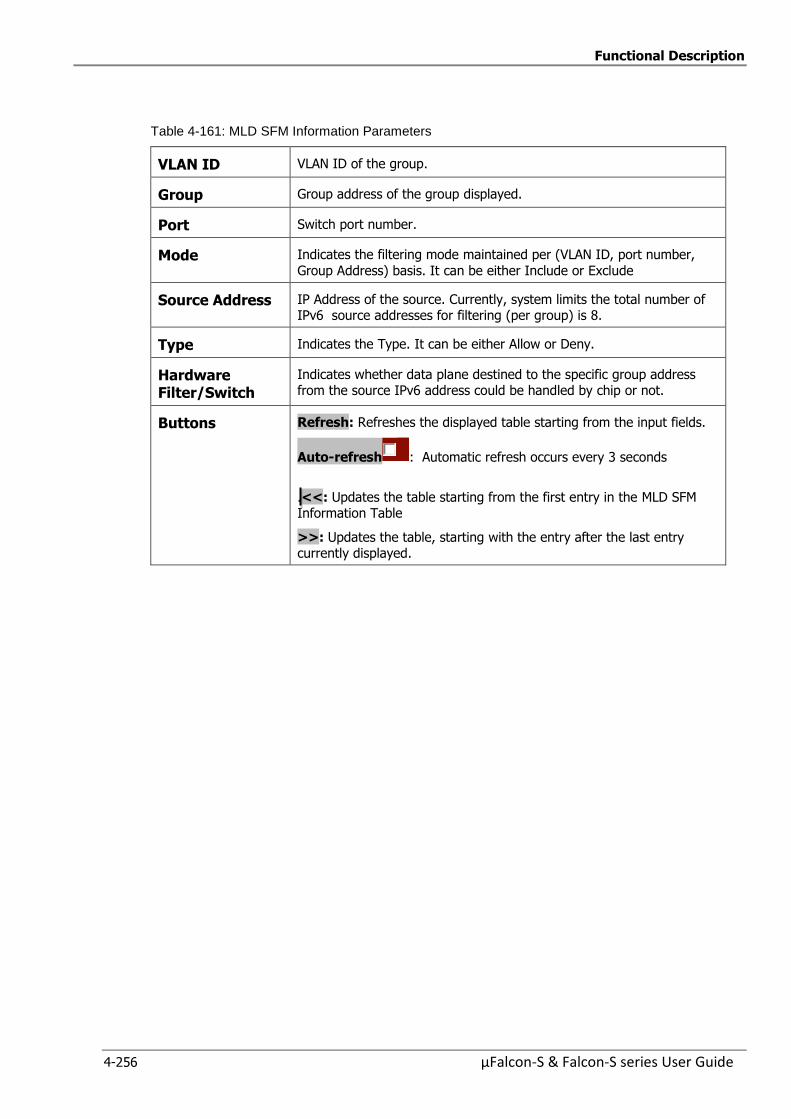
Functional Description
4-256 µFalcon-S & Falcon-S series User Guide
Table 4-161: MLD SFM Information Parameters
VLAN ID VLAN ID of the group.
Group Group address of the group displayed.
Port Switch port number.
Mode Indicates the filtering mode maintained per (VLAN ID, port number,
Group Address) basis. It can be either Include or Exclude
Source Address IP Address of the source. Currently, system limits the total number of IPv6 source addresses for filtering (per group) is 8.
Type Indicates the Type. It can be either Allow or Deny.
Hardware Filter/Switch
Indicates whether data plane destined to the specific group address from the source IPv6 address could be handled by chip or not.
Buttons Refresh: Refreshes the displayed table starting from the input fields.
Auto-refresh : Automatic refresh occurs every 3 seconds
.<<: Updates the table starting from the first entry in the MLD SFM Information Table
>>: Updates the table, starting with the entry after the last entry currently displayed.
Functional Description
µFalcon-S & Falcon-S series User Guide 4-257
4.20 Link Aggregation
LACP is an IEEE 802.3ad standard protocol. The Link Aggregation Control Protocol, allows bundling
several physical ports together to form a single logical port.
Link aggregation bundles multiple ports (member ports) together into a single logical link. It is
primarily used to increase available bandwidth without introducing loops in the network and to
improve resiliency against faults. A link aggregation group (LAG) can be established with individual
links being added or removed. This enables bandwidth to be incrementally scaled based on changing
requirements. A link aggregation group can be quickly reconfigured if faults are identified.
Link aggregation (or IEEE 802.3ad) uses multiple Ethernet network links/ports in parallel to increase
the link speed beyond the limits of any one single port, and to increase the redundancy for higher
availability.
Two switches directly connected over several links can negotiate as to which ports should be
selected as active members of an aggregation group.
A group of ports is selected to belong to a specific group ID (trunk) in order to generate an
aggregated link.
Typically, the ports used in an aggregated link should be of the same type.
Link aggregation configuration is performed in two variants.
Static – This mode is used to manually select the ports of the group.
Link Aggregation Control Protocol (LACP) – In this mode two switches which are directly
connected over several physical links, can negotiate which ports should be selected as active
members of a group.
LACP works by sending frames (LACPDUs) down all links which have the protocol enabled.
If it finds a device on the other end of the link which has also the LACP enabled, it will also
independently send frames along the same links enabling the two devices to detect multiple links
between themselves and the combine them into a single logical link.
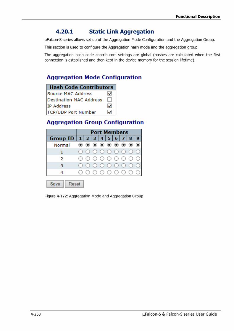
Functional Description
4-258 µFalcon-S & Falcon-S series User Guide
4.20.1 Static Link Aggregation
µFalcon-S series allows set up of the Aggregation Mode Configuration and the Aggregation Group.
This section is used to configure the Aggregation hash mode and the aggregation group.
The aggregation hash code contributors settings are global (hashes are calculated when the first
connection is established and then kept in the device memory for the session lifetime).
Figure 4-172: Aggregation Mode and Aggregation Group
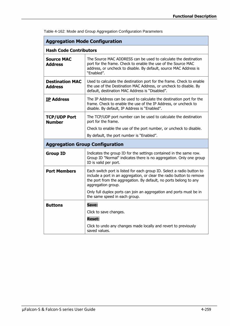
Functional Description
µFalcon-S & Falcon-S series User Guide 4-259
Table 4-162: Mode and Group Aggregation Configuration Parameters
Aggregation Mode Configuration
Hash Code Contributors
Source MAC Address
The Source MAC ADDRESS can be used to calculate the destination port for the frame. Check to enable the use of the Source MAC
address, or uncheck to disable. By default, source MAC Address is
“Enabled”.
Destination MAC Address
Used to calculate the destination port for the frame. Check to enable
the use of the Destination MAC Address, or uncheck to disable. By
default, destination MAC Address is “Disabled”.
IP Address The IP Address can be used to calculate the destination port for the
frame. Check to enable the use of the IP Address, or uncheck to disable. By default, IP Address is “Enabled”.
TCP/UDP Port Number
The TCP/UDP port number can be used to calculate the destination
port for the frame.
Check to enable the use of the port number, or uncheck to disable.
By default, the port number is “Enabled”.
Aggregation Group Configuration
Group ID Indicates the group ID for the settings contained in the same row. Group ID "Normal" indicates there is no aggregation. Only one group
ID is valid per port.
Port Members Each switch port is listed for each group ID. Select a radio button to include a port in an aggregation, or clear the radio button to remove
the port from the aggregation. By default, no ports belong to any aggregation group.
Only full duplex ports can join an aggregation and ports must be in the same speed in each group.
Buttons Save:
Click to save changes.
Reset:
Click to undo any changes made locally and revert to previously
saved values.
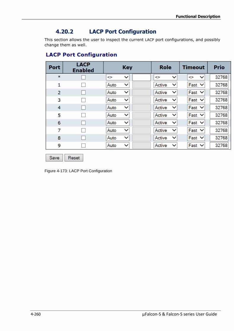
Functional Description
4-260 µFalcon-S & Falcon-S series User Guide
4.20.2 LACP Port Configuration
This section allows the user to inspect the current LACP port configurations, and possibly
change them as well.
Figure 4-173: LACP Port Configuration

Functional Description
µFalcon-S & Falcon-S series User Guide 4-261
Table 4-163: LACP Port Configuration Parameters
Port The switch port number.
LACP Enabled Controls LACP is enabled on this switch port.
LACP will form an aggregation when two (2) or more ports are connected to the same partner.
Key This value, incurred by the port, ranges from 1 to 65535.
Enter “Auto” or “Specific Key” value settings in the drop-down list.
“Auto”:Sets the key as appropriate by the physical link speed; 10Mb =
1, 100Mb = 2, 1Gb = 3.
“Specific”:Enter a user-defined value.
Ports with the same Key value can participate in the same aggregation group, while ports with different keys cannot.
Role The “Role” Shows the LACP activity status.
“Active” transmits LACP packets each second.
“Passive” will wait for a LACP packet from a partner (speak if spoken to).
Timeout The Timeout controls the period between BPDU transmissions.
Fast will transmit LACP packets each second, while Slow will wait for 30 seconds before sending a LACP packet.
Prio The Prio controls the priority of the port, range 1-65535.
If the LACP partner wants to form a larger group than is supported by this device then this parameter will control which ports will be active and
which ports will be in a backup role. Lower number means greater priority.
Buttons Save:
Click to save changes.
Reset:
Click to undo any changes made locally and revert to previously saved values.
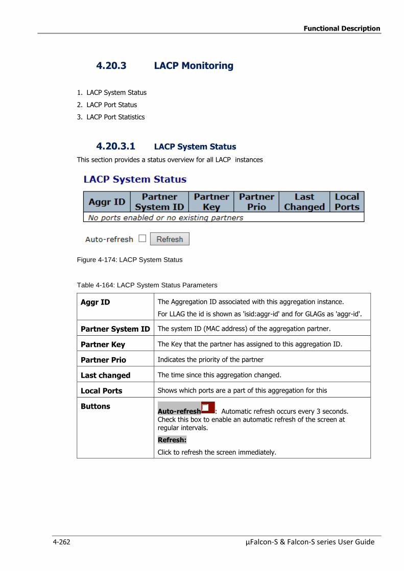
Functional Description
4-262 µFalcon-S & Falcon-S series User Guide
4.20.3 LACP Monitoring
1. LACP System Status
2. LACP Port Status
3. LACP Port Statistics
4.20.3.1 LACP System Status
This section provides a status overview for all LACP instances
Figure 4-174: LACP System Status
Table 4-164: LACP System Status Parameters
Aggr ID The Aggregation ID associated with this aggregation instance.
For LLAG the id is shown as 'isid:aggr-id' and for GLAGs as 'aggr-id'.
Partner System ID The system ID (MAC address) of the aggregation partner.
Partner Key The Key that the partner has assigned to this aggregation ID.
Partner Prio Indicates the priority of the partner
Last changed The time since this aggregation changed.
Local Ports Shows which ports are a part of this aggregation for this
Buttons Auto-refresh : Automatic refresh occurs every 3 seconds. Check this box to enable an automatic refresh of the screen at
regular intervals.
Refresh:
Click to refresh the screen immediately.
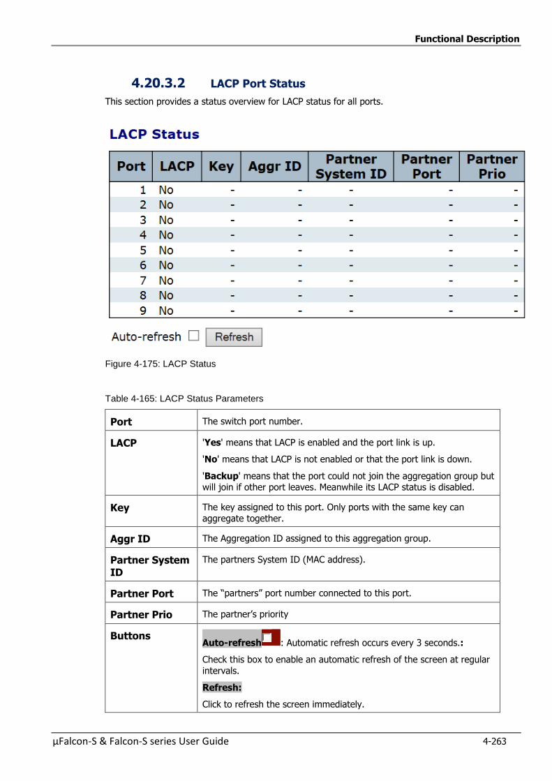
Functional Description
µFalcon-S & Falcon-S series User Guide 4-263
4.20.3.2 LACP Port Status
This section provides a status overview for LACP status for all ports.
Figure 4-175: LACP Status
Table 4-165: LACP Status Parameters
Port The switch port number.
LACP 'Yes' means that LACP is enabled and the port link is up.
'No' means that LACP is not enabled or that the port link is down.
'Backup' means that the port could not join the aggregation group but will join if other port leaves. Meanwhile its LACP status is disabled.
Key The key assigned to this port. Only ports with the same key can
aggregate together.
Aggr ID The Aggregation ID assigned to this aggregation group.
Partner System ID
The partners System ID (MAC address).
Partner Port The “partners” port number connected to this port.
Partner Prio The partner’s priority
Buttons Auto-refresh : Automatic refresh occurs every 3 seconds.:
Check this box to enable an automatic refresh of the screen at regular
intervals.
Refresh:
Click to refresh the screen immediately.
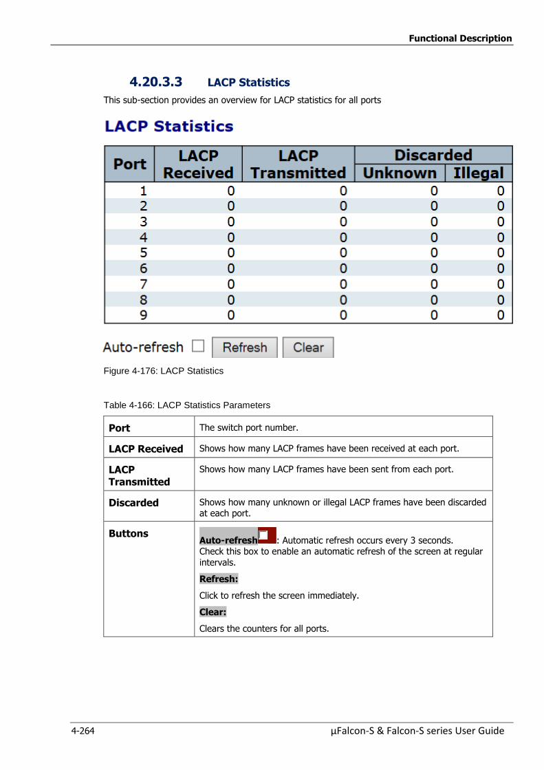
Functional Description
4-264 µFalcon-S & Falcon-S series User Guide
4.20.3.3 LACP Statistics
This sub-section provides an overview for LACP statistics for all ports
Figure 4-176: LACP Statistics
Table 4-166: LACP Statistics Parameters
Port The switch port number.
LACP Received Shows how many LACP frames have been received at each port.
LACP Transmitted
Shows how many LACP frames have been sent from each port.
Discarded Shows how many unknown or illegal LACP frames have been discarded at each port.
Buttons Auto-refresh : Automatic refresh occurs every 3 seconds. Check this box to enable an automatic refresh of the screen at regular
intervals.
Refresh:
Click to refresh the screen immediately.
Clear:
Clears the counters for all ports.
Functional Description
µFalcon-S & Falcon-S series User Guide 4-265
4.21 LLDP-Link Discovery
LLDP is an IEEE 802.1ab standard protocol. The Link Layer Discovery Protocol is used for network
discovery, and works by having the units in the network exchanging information with their neighbors
using LLDP frames.
Link discovery specifies a method and associated procedures that automatically discover
transmission links and paths between network devices.
Unlike more traditional centralized polling techniques rooted in a management plane, autonomous
link discovery procedures are rooted in and triggered by network elements composing the transport
plane. As such, autonomous link discovery procedures may be event driven and executed in a
coordinated, distributed fashion to automatically detect new link connectivity associations and
correlate link endpoint attributes between these network elements.
Once successful link correlations have been determined, autonomous notifications of these
correlated link associations are sent to management elements and/or control elements residing in
their respective management and control plane domains.
Link Layer Discovery Protocol (LLDP) is a media independent protocol allowing the LLDP agent to
learn higher-level management reach-ability and connection, and point information from neighboring
devices. Each configured device is an active LLDP agent that sends periodic messages to all physical
interfaces that listen for LLDP messages.
LLDP monitoring is implemented by collecting both LLDP neighbor information and LLDP statistics.
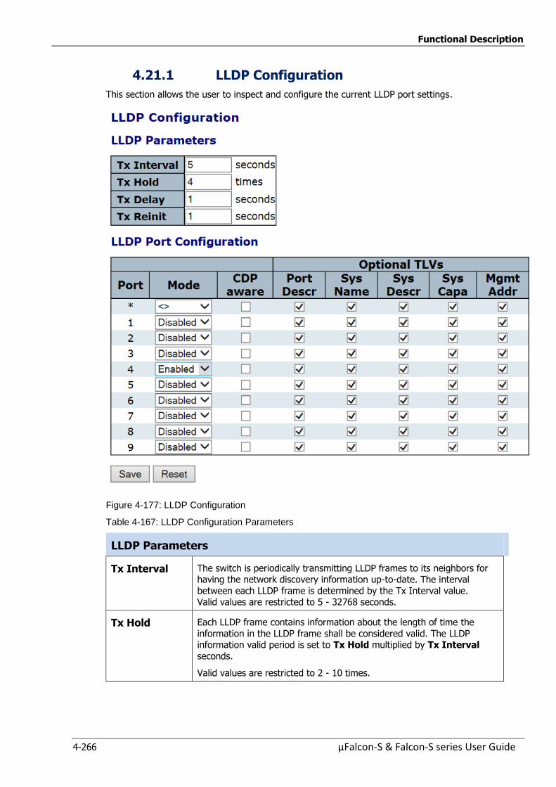
Functional Description
4-266 µFalcon-S & Falcon-S series User Guide
4.21.1 LLDP Configuration
This section allows the user to inspect and configure the current LLDP port settings.
Figure 4-177: LLDP Configuration
Table 4-167: LLDP Configuration Parameters
LLDP Parameters
Tx Interval The switch is periodically transmitting LLDP frames to its neighbors for having the network discovery information up-to-date. The interval
between each LLDP frame is determined by the Tx Interval value. Valid values are restricted to 5 - 32768 seconds.
Tx Hold Each LLDP frame contains information about the length of time the
information in the LLDP frame shall be considered valid. The LLDP information valid period is set to Tx Hold multiplied by Tx Interval
seconds.
Valid values are restricted to 2 - 10 times.

Functional Description
µFalcon-S & Falcon-S series User Guide 4-267
Tx Delay If some configuration is changed (e.g., the IP address) a new LLDP
frame is transmitted, but the time between the LLDP frames will always be at least the value of Tx Delay in seconds.
Tx Delay cannot be larger than a 1/4 of the Tx Interval value.
Valid values are restricted to 1 - 8192 seconds.
Tx Reinit When an interface is disabled, LLDP is disabled or if the switch is
rebooted, a LLDP shutdown frame is transmitted to the neighbor units for signaling that the LLDP information is not valid anymore. Tx Reinit
controls the amount of seconds between the shutdown frame and a new
LLDP initialization.
Valid values are restricted to 1 – 10 seconds.
LLDP Port Configuration
Port The switch port number of the logical LLDP port.
Mode Select the LLDP mode.
Rx only
The switch will not send out LLDP information, but LLDP information from neighbor units is analyzed.
Tx only
The switch will drop LLDP information received from neighbors, but will send out LLDP information.
Disabled The switch will not send out LLDP information, and will drop LLDP
information received from neighbors.
Enabled The switch will send out LLDP information, and will analyze LLDP
information received from neighbors.
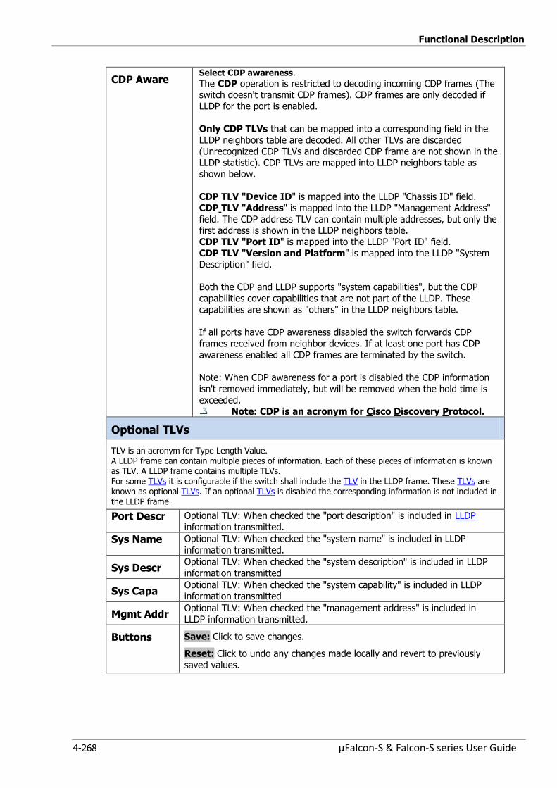
Functional Description
4-268 µFalcon-S & Falcon-S series User Guide
CDP Aware Select CDP awareness.
The CDP operation is restricted to decoding incoming CDP frames (The switch doesn't transmit CDP frames). CDP frames are only decoded if
LLDP for the port is enabled.
Only CDP TLVs that can be mapped into a corresponding field in the
LLDP neighbors table are decoded. All other TLVs are discarded (Unrecognized CDP TLVs and discarded CDP frame are not shown in the
LLDP statistic). CDP TLVs are mapped into LLDP neighbors table as shown below.
CDP TLV "Device ID" is mapped into the LLDP "Chassis ID" field. CDP TLV "Address" is mapped into the LLDP "Management Address"
field. The CDP address TLV can contain multiple addresses, but only the first address is shown in the LLDP neighbors table.
CDP TLV "Port ID" is mapped into the LLDP "Port ID" field. CDP TLV "Version and Platform" is mapped into the LLDP "System
Description" field.
Both the CDP and LLDP supports "system capabilities", but the CDP
capabilities cover capabilities that are not part of the LLDP. These capabilities are shown as "others" in the LLDP neighbors table.
If all ports have CDP awareness disabled the switch forwards CDP frames received from neighbor devices. If at least one port has CDP
awareness enabled all CDP frames are terminated by the switch.
Note: When CDP awareness for a port is disabled the CDP information
isn't removed immediately, but will be removed when the hold time is exceeded.
Note: CDP is an acronym for Cisco Discovery Protocol.
Optional TLVs
TLV is an acronym for Type Length Value. A LLDP frame can contain multiple pieces of information. Each of these pieces of information is known as TLV. A LLDP frame contains multiple TLVs. For some TLVs it is configurable if the switch shall include the TLV in the LLDP frame. These TLVs are known as optional TLVs. If an optional TLVs is disabled the corresponding information is not included in the LLDP frame.
Port Descr Optional TLV: When checked the "port description" is included in LLDP information transmitted.
Sys Name Optional TLV: When checked the "system name" is included in LLDP
information transmitted.
Sys Descr Optional TLV: When checked the "system description" is included in LLDP
information transmitted
Sys Capa Optional TLV: When checked the "system capability" is included in LLDP information transmitted
Mgmt Addr Optional TLV: When checked the "management address" is included in
LLDP information transmitted.
Buttons Save: Click to save changes.
Reset: Click to undo any changes made locally and revert to previously
saved values.
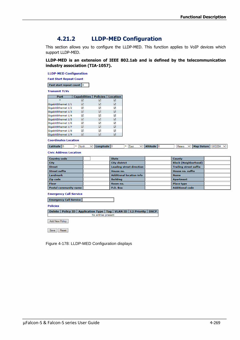
Functional Description
µFalcon-S & Falcon-S series User Guide 4-269
4.21.2 LLDP-MED Configuration
This section allows you to configure the LLDP-MED. This function applies to VoIP devices which
support LLDP-MED.
LLDP-MED is an extension of IEEE 802.1ab and is defined by the telecommunication
industry association (TIA-1057).
Figure 4-178: LLDP-MED Configuration displays
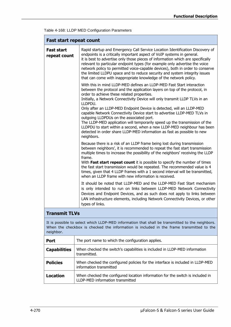
Functional Description
4-270 µFalcon-S & Falcon-S series User Guide
Table 4-168: LLDP MED Configuration Parameters
Fast start repeat count
Fast start
repeat count
Rapid startup and Emergency Call Service Location Identification Discovery of
endpoints is a critically important aspect of VoIP systems in general. it is best to advertise only those pieces of information which are specifically
relevant to particular endpoint types (for example only advertise the voice network policy to permitted voice-capable devices), both in order to conserve
the limited LLDPU space and to reduce security and system integrity issues
that can come with inappropriate knowledge of the network policy.
With this in mind LLDP-MED defines an LLDP-MED Fast Start interaction
between the protocol and the application layers on top of the protocol, in order to achieve these related properties.
Initially, a Network Connectivity Device will only transmit LLDP TLVs in an
LLDPDU. Only after an LLDP-MED Endpoint Device is detected, will an LLDP-MED
capable Network Connectivity Device start to advertise LLDP-MED TLVs in outgoing LLDPDUs on the associated port.
The LLDP-MED application will temporarily speed up the transmission of the
LLDPDU to start within a second, when a new LLDP-MED neighbour has been detected in order share LLDP-MED information as fast as possible to new
neighbors.
Because there is a risk of an LLDP frame being lost during transmission
between neighbors’, it is recommended to repeat the fast start transmission multiple times to increase the possibility of the neighbors’ receiving the LLDP
frame.
With Fast start repeat count it is possible to specify the number of times the fast start transmission would be repeated. The recommended value is 4
times, given that 4 LLDP frames with a 1 second interval will be transmitted, when an LLDP frame with new information is received.
It should be noted that LLDP-MED and the LLDP-MED Fast Start mechanism
is only intended to run on links between LLDP-MED Network Connectivity
Devices and Endpoint Devices, and as such does not apply to links between
LAN infrastructure elements, including Network Connectivity Devices, or other
types of links.
Transmit TLVs
It is possible to select which LLDP-MED information that shall be transmitted to the neighbors.
When the checkbox is checked the information is included in the frame transmitted to the
neighbor.
Port The port name to which the configuration applies.
Capabilities When checked the switch's capabilities is included in LLDP-MED information
transmitted.
Policies When checked the configured policies for the interface is included in LLDP-MED
information transmitted
Location When checked the configured location information for the switch is included in LLDP-MED information transmitted
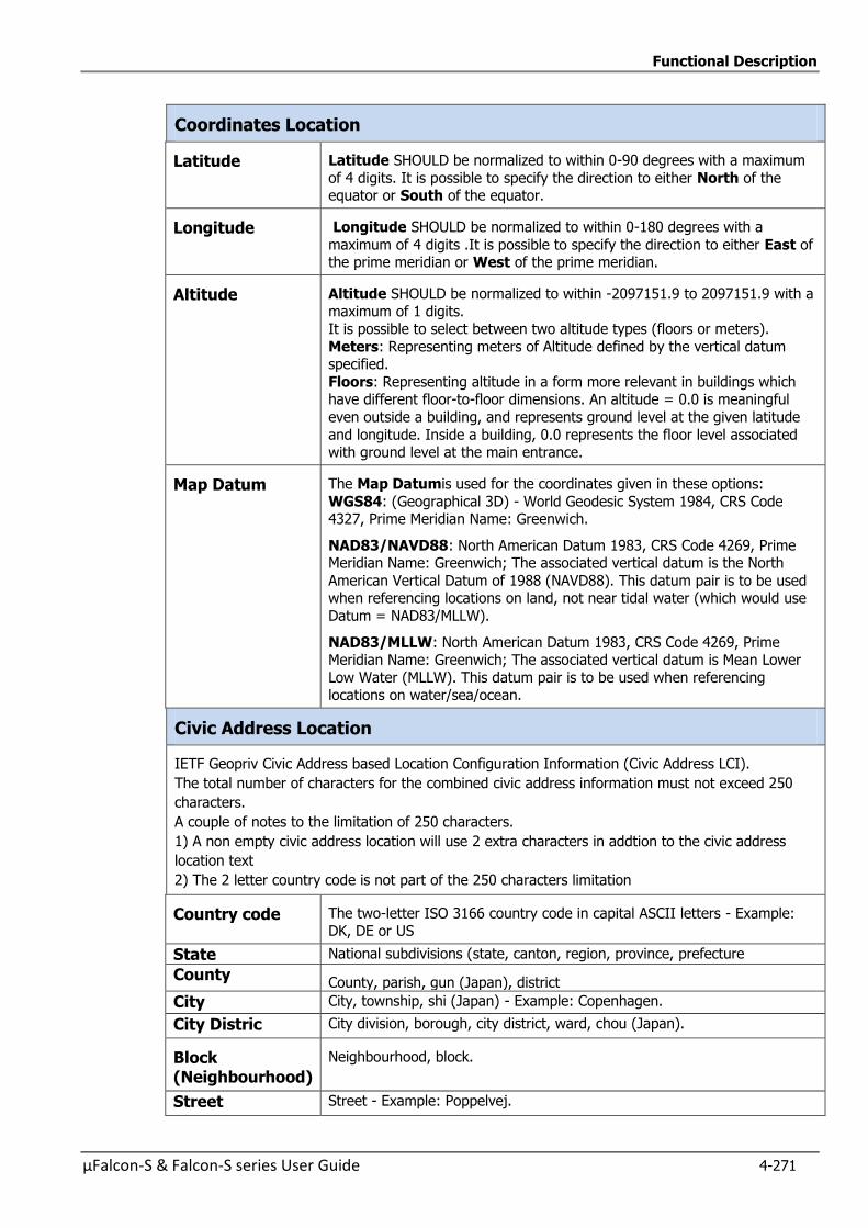
Functional Description
µFalcon-S & Falcon-S series User Guide 4-271
Coordinates Location
Latitude Latitude SHOULD be normalized to within 0-90 degrees with a maximum
of 4 digits. It is possible to specify the direction to either North of the equator or South of the equator.
Longitude Longitude SHOULD be normalized to within 0-180 degrees with a
maximum of 4 digits .It is possible to specify the direction to either East of the prime meridian or West of the prime meridian.
Altitude Altitude SHOULD be normalized to within -2097151.9 to 2097151.9 with a
maximum of 1 digits. It is possible to select between two altitude types (floors or meters).
Meters: Representing meters of Altitude defined by the vertical datum specified.
Floors: Representing altitude in a form more relevant in buildings which have different floor-to-floor dimensions. An altitude = 0.0 is meaningful
even outside a building, and represents ground level at the given latitude
and longitude. Inside a building, 0.0 represents the floor level associated with ground level at the main entrance.
Map Datum The Map Datumis used for the coordinates given in these options:
WGS84: (Geographical 3D) - World Geodesic System 1984, CRS Code 4327, Prime Meridian Name: Greenwich.
NAD83/NAVD88: North American Datum 1983, CRS Code 4269, Prime Meridian Name: Greenwich; The associated vertical datum is the North
American Vertical Datum of 1988 (NAVD88). This datum pair is to be used when referencing locations on land, not near tidal water (which would use
Datum = NAD83/MLLW).
NAD83/MLLW: North American Datum 1983, CRS Code 4269, Prime Meridian Name: Greenwich; The associated vertical datum is Mean Lower
Low Water (MLLW). This datum pair is to be used when referencing locations on water/sea/ocean.
Civic Address Location
IETF Geopriv Civic Address based Location Configuration Information (Civic Address LCI).
The total number of characters for the combined civic address information must not exceed 250
characters.
A couple of notes to the limitation of 250 characters.
1) A non empty civic address location will use 2 extra characters in addtion to the civic address
location text
2) The 2 letter country code is not part of the 250 characters limitation
Country code The two-letter ISO 3166 country code in capital ASCII letters - Example: DK, DE or US
State National subdivisions (state, canton, region, province, prefecture
County County, parish, gun (Japan), district
City City, township, shi (Japan) - Example: Copenhagen.
City Distric City division, borough, city district, ward, chou (Japan).
Block (Neighbourhood)
Neighbourhood, block.
Street Street - Example: Poppelvej.
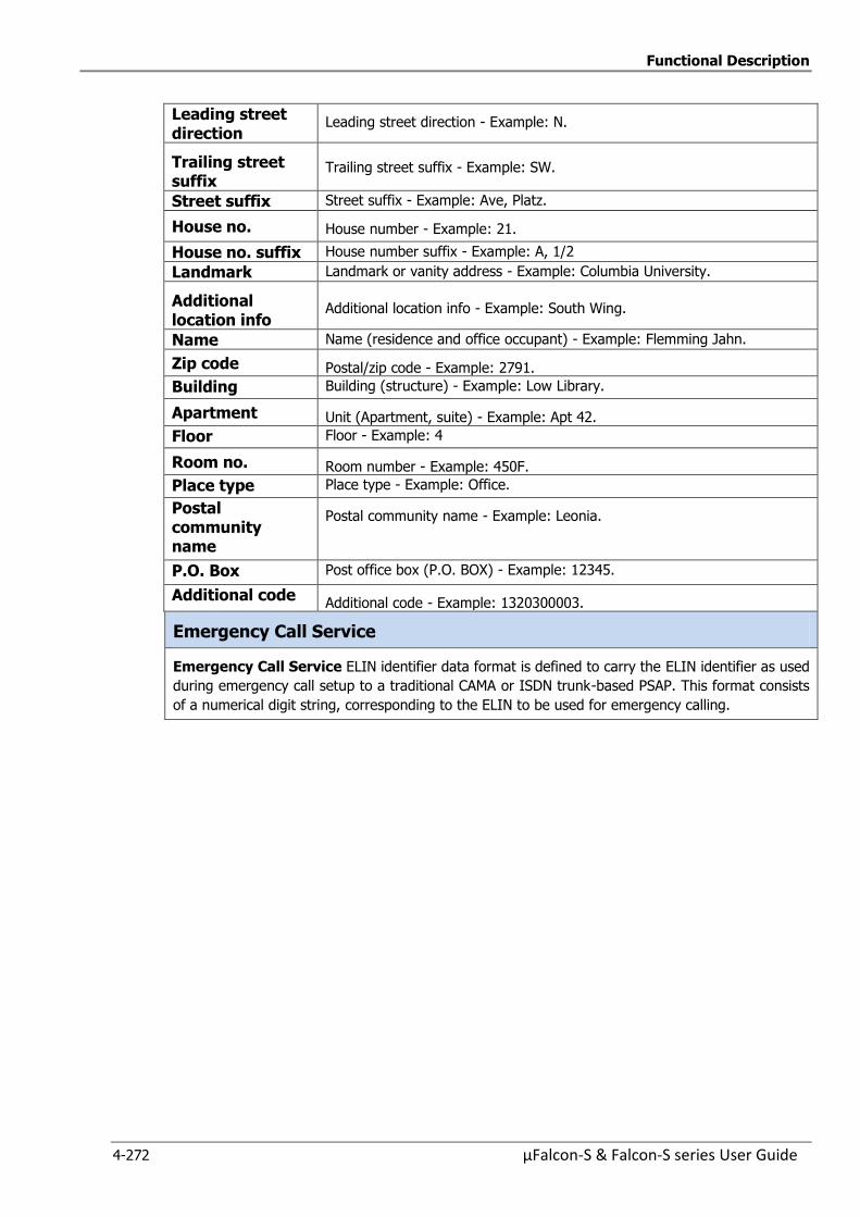
Functional Description
4-272 µFalcon-S & Falcon-S series User Guide
Leading street direction
Leading street direction - Example: N.
Trailing street suffix
Trailing street suffix - Example: SW.
Street suffix Street suffix - Example: Ave, Platz.
House no. House number - Example: 21.
House no. suffix House number suffix - Example: A, 1/2
Landmark Landmark or vanity address - Example: Columbia University.
Additional location info
Additional location info - Example: South Wing.
Name Name (residence and office occupant) - Example: Flemming Jahn.
Zip code Postal/zip code - Example: 2791.
Building Building (structure) - Example: Low Library.
Apartment Unit (Apartment, suite) - Example: Apt 42.
Floor Floor - Example: 4
Room no. Room number - Example: 450F.
Place type Place type - Example: Office.
Postal community name
Postal community name - Example: Leonia.
P.O. Box Post office box (P.O. BOX) - Example: 12345.
Additional code Additional code - Example: 1320300003.
Emergency Call Service
Emergency Call Service ELIN identifier data format is defined to carry the ELIN identifier as used
during emergency call setup to a traditional CAMA or ISDN trunk-based PSAP. This format consists
of a numerical digit string, corresponding to the ELIN to be used for emergency calling.
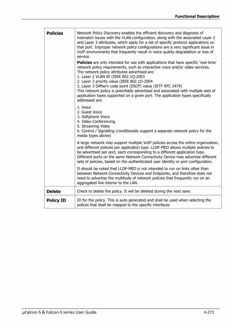
Functional Description
µFalcon-S & Falcon-S series User Guide 4-273
Policies Network Policy Discovery enables the efficient discovery and diagnosis of
mismatch issues with the VLAN configuration, along with the associated Layer 2 and Layer 3 attributes, which apply for a set of specific protocol applications on
that port. Improper network policy configurations are a very significant issue in
VoIP environments that frequently result in voice quality degradation or loss of service.
Policies are only intended for use with applications that have specific 'real-time' network policy requirements, such as interactive voice and/or video services.
The network policy attributes advertised are: 1. Layer 2 VLAN ID (IEEE 802.1Q-2003
2. Layer 2 priority value (IEEE 802.1D-2004
3. Layer 3 Diffserv code point (DSCP) value (IETF RFC 2474) This network policy is potentially advertised and associated with multiple sets of
application types supported on a given port. The application types specifically addressed are:
1. Voice
2. Guest Voice 3. Softphone Voice
4. Video Conferencing 5. Streaming Video
6. Control / Signalling (conditionally support a separate network policy for the media types above)
A large network may support multiple VoIP policies across the entire organization,
and different policies per application type. LLDP-MED allows multiple policies to be advertised per port, each corresponding to a different application type.
Different ports on the same Network Connectivity Device may advertise different sets of policies, based on the authenticated user identity or port configuration.
It should be noted that LLDP-MED is not intended to run on links other than
between Network Connectivity Devices and Endpoints, and therefore does not need to advertise the multitude of network policies that frequently run on an
aggregated link interior to the LAN.
Delete Check to delete the policy. It will be deleted during the next save.
Policy ID ID for the policy. This is auto generated and shall be used when selecting the
polices that shall be mapped to the specific interfaces
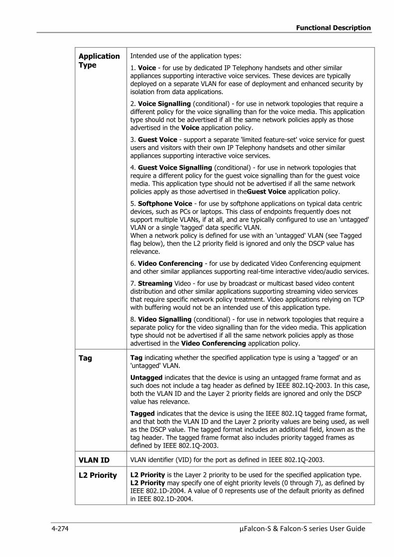
Functional Description
4-274 µFalcon-S & Falcon-S series User Guide
Application Type
Intended use of the application types:
1. Voice - for use by dedicated IP Telephony handsets and other similar appliances supporting interactive voice services. These devices are typically
deployed on a separate VLAN for ease of deployment and enhanced security by
isolation from data applications.
2. Voice Signalling (conditional) - for use in network topologies that require a
different policy for the voice signalling than for the voice media. This application type should not be advertised if all the same network policies apply as those
advertised in the Voice application policy.
3. Guest Voice - support a separate 'limited feature-set' voice service for guest
users and visitors with their own IP Telephony handsets and other similar
appliances supporting interactive voice services.
4. Guest Voice Signalling (conditional) - for use in network topologies that
require a different policy for the guest voice signalling than for the guest voice media. This application type should not be advertised if all the same network
policies apply as those advertised in theGuest Voice application policy.
5. Softphone Voice - for use by softphone applications on typical data centric devices, such as PCs or laptops. This class of endpoints frequently does not
support multiple VLANs, if at all, and are typically configured to use an 'untagged' VLAN or a single 'tagged' data specific VLAN.
When a network policy is defined for use with an 'untagged' VLAN (see Tagged flag below), then the L2 priority field is ignored and only the DSCP value has
relevance.
6. Video Conferencing - for use by dedicated Video Conferencing equipment and other similar appliances supporting real-time interactive video/audio services.
7. Streaming Video - for use by broadcast or multicast based video content distribution and other similar applications supporting streaming video services
that require specific network policy treatment. Video applications relying on TCP
with buffering would not be an intended use of this application type.
8. Video Signalling (conditional) - for use in network topologies that require a
separate policy for the video signalling than for the video media. This application type should not be advertised if all the same network policies apply as those
advertised in the Video Conferencing application policy.
Tag Tag indicating whether the specified application type is using a 'tagged' or an 'untagged' VLAN.
Untagged indicates that the device is using an untagged frame format and as such does not include a tag header as defined by IEEE 802.1Q-2003. In this case,
both the VLAN ID and the Layer 2 priority fields are ignored and only the DSCP
value has relevance.
Tagged indicates that the device is using the IEEE 802.1Q tagged frame format,
and that both the VLAN ID and the Layer 2 priority values are being used, as well as the DSCP value. The tagged format includes an additional field, known as the
tag header. The tagged frame format also includes priority tagged frames as
defined by IEEE 802.1Q-2003.
VLAN ID VLAN identifier (VID) for the port as defined in IEEE 802.1Q-2003.
L2 Priority L2 Priority is the Layer 2 priority to be used for the specified application type.
L2 Priority may specify one of eight priority levels (0 through 7), as defined by IEEE 802.1D-2004. A value of 0 represents use of the default priority as defined
in IEEE 802.1D-2004.
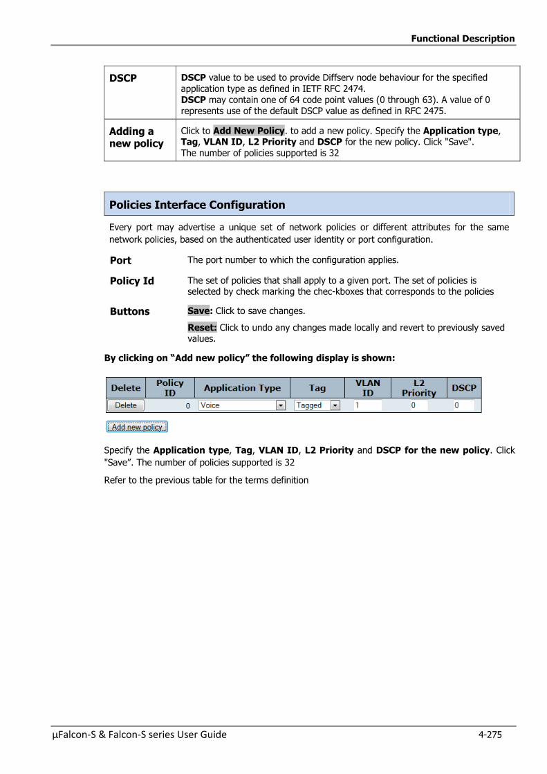
Functional Description
µFalcon-S & Falcon-S series User Guide 4-275
DSCP DSCP value to be used to provide Diffserv node behaviour for the specified
application type as defined in IETF RFC 2474. DSCP may contain one of 64 code point values (0 through 63). A value of 0
represents use of the default DSCP value as defined in RFC 2475.
Adding a new policy
Click to Add New Policy. to add a new policy. Specify the Application type, Tag, VLAN ID, L2 Priority and DSCP for the new policy. Click "Save".
The number of policies supported is 32
Policies Interface Configuration
Every port may advertise a unique set of network policies or different attributes for the same
network policies, based on the authenticated user identity or port configuration.
Port The port number to which the configuration applies.
Policy Id The set of policies that shall apply to a given port. The set of policies is selected by check marking the chec-kboxes that corresponds to the policies
Buttons Save: Click to save changes.
Reset: Click to undo any changes made locally and revert to previously saved values.
Byclickingon“Addnewpolicy”thefollowingdisplay is shown:
Specify the Application type, Tag, VLAN ID, L2 Priority and DSCP for the new policy. Click
"Save”. The number of policies supported is 32
Refer to the previous table for the terms definition
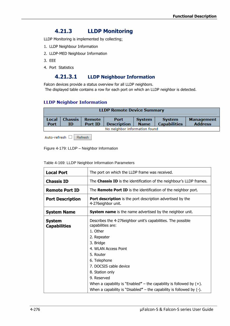
Functional Description
4-276 µFalcon-S & Falcon-S series User Guide
4.21.3 LLDP Monitoring
LLDP Monitoring is implemented by collecting:
1. LLDP Neighbour Information
2. LLDP-MED Neighbour Information
3. EEE
4. Port Statistics
4.21.3.1 LLDP Neighbour Information
Falcon devices provide a status overview for all LLDP neighbors.
The displayed table contains a row for each port on which an LLDP neighbor is detected.
Figure 4-179: LLDP – Neighbor Information
Table 4-169: LLDP Neighbor Information Parameters
Local Port The port on which the LLDP frame was received.
Chassis ID The Chassis ID is the identification of the neighbour’s LLDP frames.
Remote Port ID The Remote Port ID is the identification of the neighbor port.
Port Description Port description is the port description advertised by the
4-276eighbor unit.
System Name System name is the name advertised by the neighbor unit.
System Capabilities
Describes the 4-276eighbor unit’s capabilities. The possible
capabilities are:
1. Other
2. Repeater
3. Bridge
4. WLAN Access Point
5. Router
6. Telephone
7. DOCSIS cable device
8. Station only
9. Reserved
When a capability is “Enabled” – the capability is followed by (+).
When a capability is “Disabled” – the capability is followed by (-).
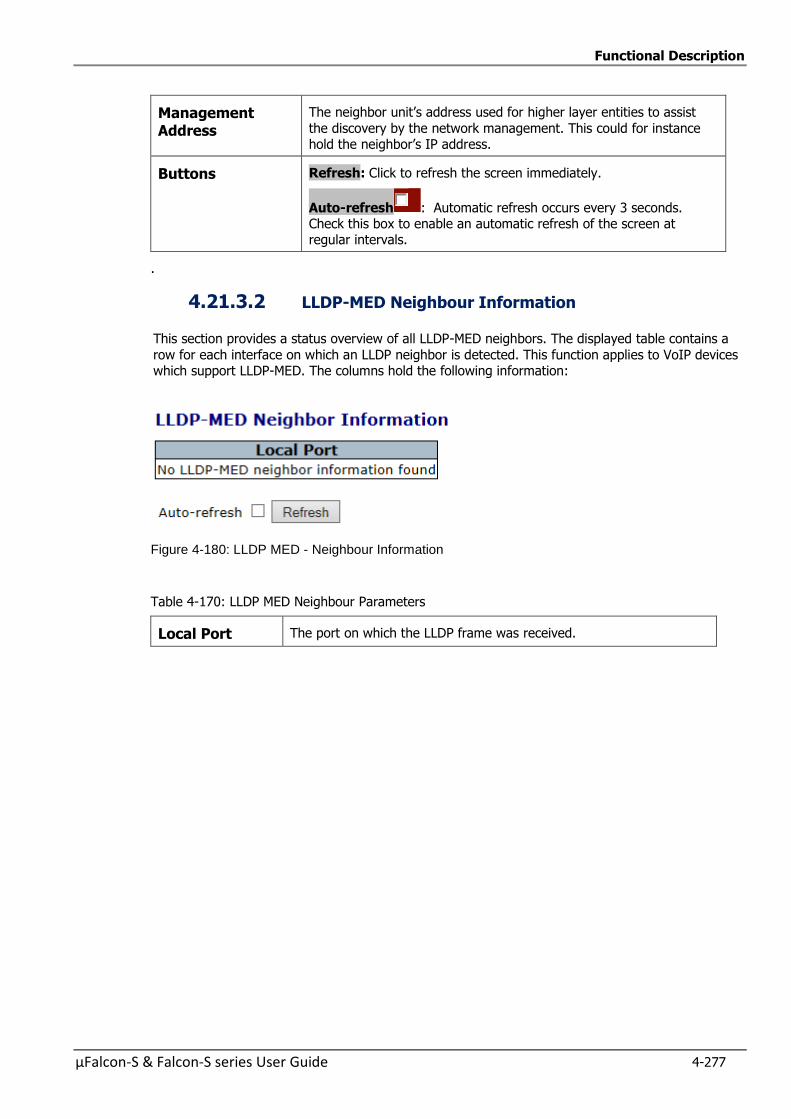
Functional Description
µFalcon-S & Falcon-S series User Guide 4-277
Management Address
The neighbor unit’s address used for higher layer entities to assist
the discovery by the network management. This could for instance hold the neighbor’s IP address.
Buttons Refresh: Click to refresh the screen immediately.
Auto-refresh : Automatic refresh occurs every 3 seconds. Check this box to enable an automatic refresh of the screen at regular intervals.
.
4.21.3.2 LLDP-MED Neighbour Information
This section provides a status overview of all LLDP-MED neighbors. The displayed table contains a
row for each interface on which an LLDP neighbor is detected. This function applies to VoIP devices which support LLDP-MED. The columns hold the following information:
Figure 4-180: LLDP MED - Neighbour Information
Table 4-170: LLDP MED Neighbour Parameters
Local Port The port on which the LLDP frame was received.
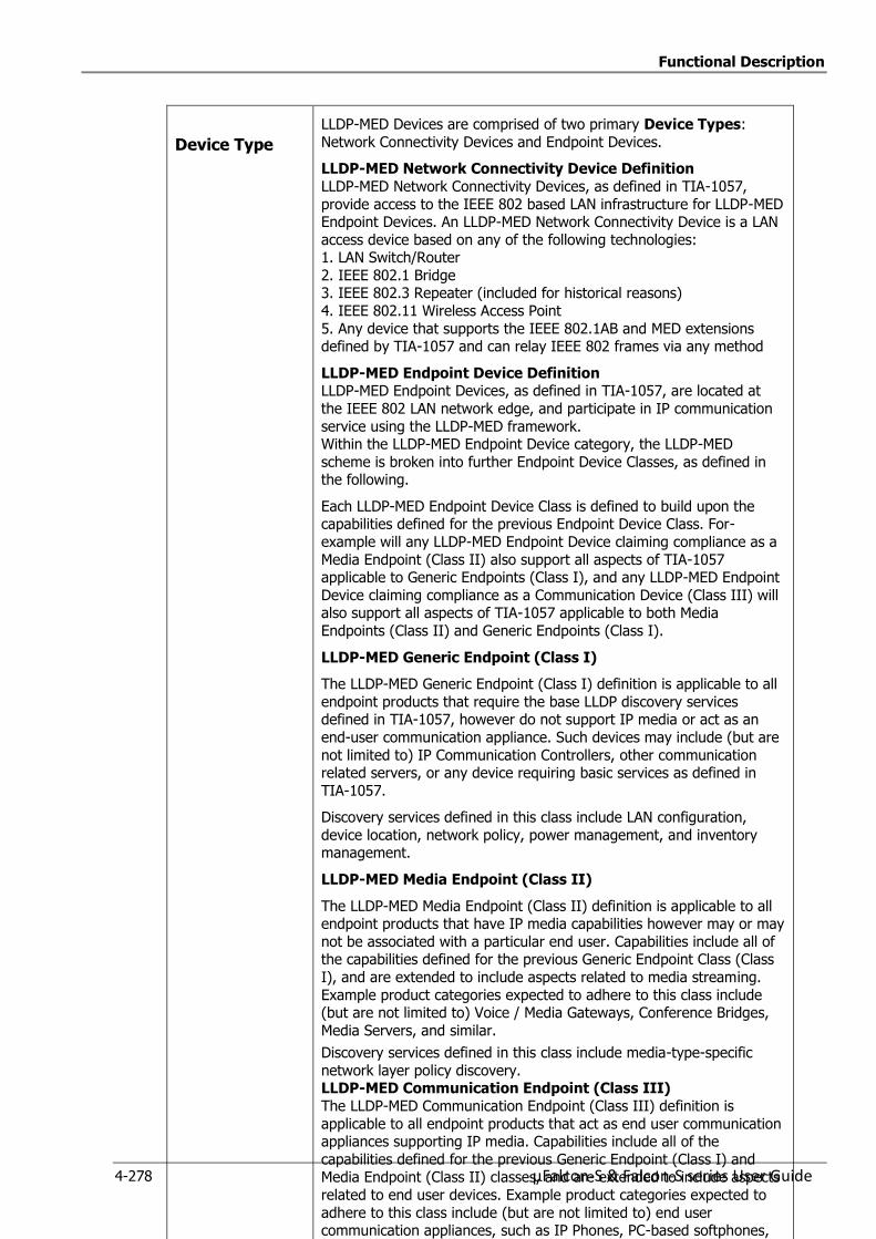
Functional Description
4-278 µFalcon-S & Falcon-S series User Guide
Device Type
LLDP-MED Devices are comprised of two primary Device Types:
Network Connectivity Devices and Endpoint Devices.
LLDP-MED Network Connectivity Device Definition
LLDP-MED Network Connectivity Devices, as defined in TIA-1057,
provide access to the IEEE 802 based LAN infrastructure for LLDP-MED Endpoint Devices. An LLDP-MED Network Connectivity Device is a LAN
access device based on any of the following technologies: 1. LAN Switch/Router
2. IEEE 802.1 Bridge 3. IEEE 802.3 Repeater (included for historical reasons)
4. IEEE 802.11 Wireless Access Point
5. Any device that supports the IEEE 802.1AB and MED extensions defined by TIA-1057 and can relay IEEE 802 frames via any method
LLDP-MED Endpoint Device Definition LLDP-MED Endpoint Devices, as defined in TIA-1057, are located at
the IEEE 802 LAN network edge, and participate in IP communication
service using the LLDP-MED framework. Within the LLDP-MED Endpoint Device category, the LLDP-MED
scheme is broken into further Endpoint Device Classes, as defined in the following.
Each LLDP-MED Endpoint Device Class is defined to build upon the capabilities defined for the previous Endpoint Device Class. For-
example will any LLDP-MED Endpoint Device claiming compliance as a
Media Endpoint (Class II) also support all aspects of TIA-1057 applicable to Generic Endpoints (Class I), and any LLDP-MED Endpoint
Device claiming compliance as a Communication Device (Class III) will also support all aspects of TIA-1057 applicable to both Media
Endpoints (Class II) and Generic Endpoints (Class I).
LLDP-MED Generic Endpoint (Class I)
The LLDP-MED Generic Endpoint (Class I) definition is applicable to all
endpoint products that require the base LLDP discovery services defined in TIA-1057, however do not support IP media or act as an
end-user communication appliance. Such devices may include (but are
not limited to) IP Communication Controllers, other communication related servers, or any device requiring basic services as defined in
TIA-1057.
Discovery services defined in this class include LAN configuration,
device location, network policy, power management, and inventory management.
LLDP-MED Media Endpoint (Class II)
The LLDP-MED Media Endpoint (Class II) definition is applicable to all endpoint products that have IP media capabilities however may or may
not be associated with a particular end user. Capabilities include all of the capabilities defined for the previous Generic Endpoint Class (Class
I), and are extended to include aspects related to media streaming.
Example product categories expected to adhere to this class include (but are not limited to) Voice / Media Gateways, Conference Bridges,
Media Servers, and similar.
Discovery services defined in this class include media-type-specific
network layer policy discovery. LLDP-MED Communication Endpoint (Class III)
The LLDP-MED Communication Endpoint (Class III) definition is
applicable to all endpoint products that act as end user communication appliances supporting IP media. Capabilities include all of the
capabilities defined for the previous Generic Endpoint (Class I) and Media Endpoint (Class II) classes, and are extended to include aspects
related to end user devices. Example product categories expected to
adhere to this class include (but are not limited to) end user communication appliances, such as IP Phones, PC-based softphones,
or other communication appliances that directly support the end user.
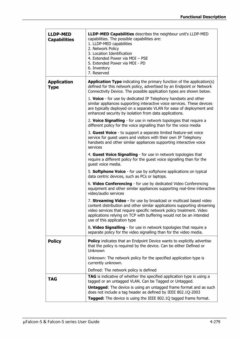
Functional Description
µFalcon-S & Falcon-S series User Guide 4-279
LLDP-MED Capabilities
LLDP-MED Capabilities describes the neighbour unit's LLDP-MED
capabilities. The possible capabilities are: 1. LLDP-MED capabilities
2. Network Policy
3. Location Identification 4. Extended Power via MDI – PSE
5. Extended Power via MDI - PD 6. Inventory
7. Reserved
Application Type
Application Type indicating the primary function of the application(s) defined for this network policy, advertised by an Endpoint or Network
Connectivity Device. The possible application types are shown below.
1. Voice - for use by dedicated IP Telephony handsets and other
similar appliances supporting interactive voice services. These devices
are typically deployed on a separate VLAN for ease of deployment and enhanced security by isolation from data applications.
2. Voice Signalling - for use in network topologies that require a different policy for the voice signalling than for the voice media
3. Guest Voice - to support a separate limited feature-set voice service for guest users and visitors with their own IP Telephony
handsets and other similar appliances supporting interactive voice
services
4. Guest Voice Signalling - for use in network topologies that
require a different policy for the guest voice signalling than for the guest voice media.
5. Softphone Voice - for use by softphone applications on typical
data centric devices, such as PCs or laptops.
6. Video Conferencing - for use by dedicated Video Conferencing
equipment and other similar appliances supporting real-time interactive video/audio services
7. Streaming Video - for use by broadcast or multicast based video content distribution and other similar applications supporting streaming
video services that require specific network policy treatment. Video
applications relying on TCP with buffering would not be an intended use of this application type
8. Video Signalling - for use in network topologies that require a separate policy for the video signalling than for the video media.
Policy Policy indicates that an Endpoint Device wants to explicitly advertise
that the policy is required by the device. Can be either Defined or Unknown
Unknown: The network policy for the specified application type is
currently unknown.
Defined: The network policy is defined
TAG TAG is indicative of whether the specified application type is using a tagged or an untagged VLAN. Can be Tagged or Untagged.
Untagged: The device is using an untagged frame format and as such
does not include a tag header as defined by IEEE 802.1Q-2003
Tagged: The device is using the IEEE 802.1Q tagged frame format.
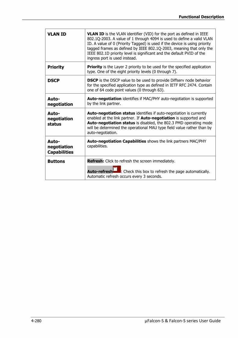
Functional Description
4-280 µFalcon-S & Falcon-S series User Guide
VLAN ID VLAN ID is the VLAN identifier (VID) for the port as defined in IEEE
802.1Q-2003. A value of 1 through 4094 is used to define a valid VLAN ID. A value of 0 (Priority Tagged) is used if the device is using priority
tagged frames as defined by IEEE 802.1Q-2003, meaning that only the
IEEE 802.1D priority level is significant and the default PVID of the ingress port is used instead.
Priority Priority is the Layer 2 priority to be used for the specified application type. One of the eight priority levels (0 through 7).
DSCP DSCP is the DSCP value to be used to provide Diffserv node behavior
for the specified application type as defined in IETF RFC 2474. Contain one of 64 code point values (0 through 63).
Auto-negotiation
Auto-negotiation identifies if MAC/PHY auto-negotiation is supported
by the link partner.
Auto-negotiation status
Auto-negotiation status identifies if auto-negotiation is currently enabled at the link partner. If Auto-negotiation is supported and
Auto-negotiation status is disabled, the 802.3 PMD operating mode will be determined the operational MAU type field value rather than by
auto-negotiation.
Auto-negotiation Capabilities
Auto-negotiation Capabilities shows the link partners MAC/PHY capabilities.
Buttons Refresh: Click to refresh the screen immediately.
Auto-refresh : Check this box to refresh the page automatically.
Automatic refresh occurs every 3 seconds.
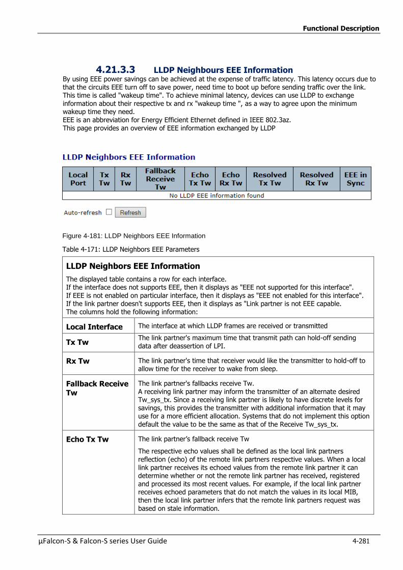
Functional Description
µFalcon-S & Falcon-S series User Guide 4-281
4.21.3.3 LLDP Neighbours EEE Information By using EEE power savings can be achieved at the expense of traffic latency. This latency occurs due to
that the circuits EEE turn off to save power, need time to boot up before sending traffic over the link. This time is called "wakeup time". To achieve minimal latency, devices can use LLDP to exchange
information about their respective tx and rx "wakeup time ", as a way to agree upon the minimum wakeup time they need.
EEE is an abbreviation for Energy Efficient Ethernet defined in IEEE 802.3az.
This page provides an overview of EEE information exchanged by LLDP
Figure 4-181: LLDP Neighbors EEE Information
Table 4-171: LLDP Neighbors EEE Parameters
LLDP Neighbors EEE Information
The displayed table contains a row for each interface. If the interface does not supports EEE, then it displays as "EEE not supported for this interface".
If EEE is not enabled on particular interface, then it displays as "EEE not enabled for this interface". If the link partner doesn't supports EEE, then it displays as "Link partner is not EEE capable.
The columns hold the following information:
Local Interface The interface at which LLDP frames are received or transmitted
Tx Tw The link partner's maximum time that transmit path can hold-off sending
data after deassertion of LPI.
Rx Tw The link partner's time that receiver would like the transmitter to hold-off to allow time for the receiver to wake from sleep.
Fallback Receive Tw
The link partner's fallbacks receive Tw.
A receiving link partner may inform the transmitter of an alternate desired Tw_sys_tx. Since a receiving link partner is likely to have discrete levels for
savings, this provides the transmitter with additional information that it may use for a more efficient allocation. Systems that do not implement this option
default the value to be the same as that of the Receive Tw_sys_tx.
Echo Tx Tw The link partner’s fallback receive Tw
The respective echo values shall be defined as the local link partners
reflection (echo) of the remote link partners respective values. When a local
link partner receives its echoed values from the remote link partner it can determine whether or not the remote link partner has received, registered
and processed its most recent values. For example, if the local link partner receives echoed parameters that do not match the values in its local MIB,
then the local link partner infers that the remote link partners request was
based on stale information.
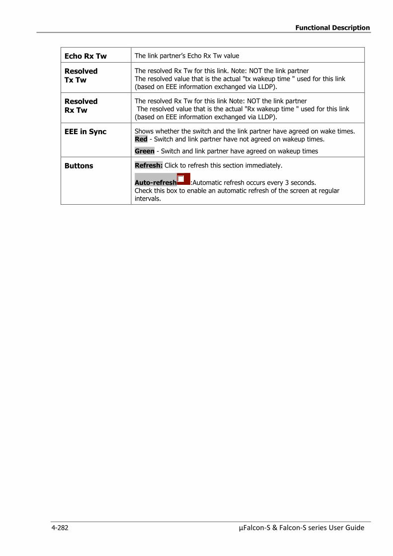
Functional Description
4-282 µFalcon-S & Falcon-S series User Guide
Echo Rx Tw The link partner’s Echo Rx Tw value
Resolved Tx Tw
The resolved Rx Tw for this link. Note: NOT the link partner
The resolved value that is the actual "tx wakeup time " used for this link (based on EEE information exchanged via LLDP).
Resolved Rx Tw
The resolved Rx Tw for this link Note: NOT the link partner The resolved value that is the actual "Rx wakeup time " used for this link
(based on EEE information exchanged via LLDP).
EEE in Sync Shows whether the switch and the link partner have agreed on wake times. Red - Switch and link partner have not agreed on wakeup times.
Green - Switch and link partner have agreed on wakeup times
Buttons Refresh: Click to refresh this section immediately.
Auto-refresh :Automatic refresh occurs every 3 seconds.
Check this box to enable an automatic refresh of the screen at regular intervals.
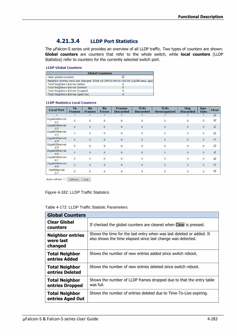
Functional Description
µFalcon-S & Falcon-S series User Guide 4-283
4.21.3.4 LLDP Port Statistics
The µFalcon-S series unit provides an overview of all LLDP traffic. Two types of counters are shown:
Global counters are counters that refer to the whole switch, while local counters (LLDP
Statistics) refer to counters for the currently selected switch port.
Figure 4-182: LLDP Traffic Statistics
Table 4-172: LLDP Traffic Statistic Parameters
Global Counters
Clear Global counters
If checked the global counters are cleared when Clear is pressed.
Neighbor entries were last changed
Shows the time for the last entry when was last deleted or added. It
also shows the time elapsed since last change was detected.
Total Neighbor entries Added
Shows the number of new entries added since switch reboot.
Total Neighbor entries Deleted
Shows the number of new entries deleted since switch reboot.
Total Neighbor entries Dropped
Shows the number of LLDP frames dropped due to that the entry table
was full.
Total Neighbor entries Aged Out
Shows the number of entries deleted due to Time-To-Live expiring.
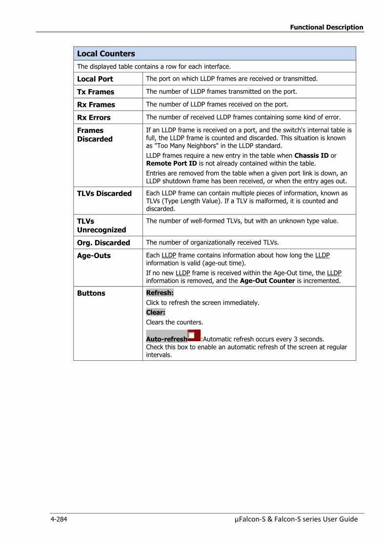
Functional Description
4-284 µFalcon-S & Falcon-S series User Guide
Local Counters
The displayed table contains a row for each interface.
Local Port The port on which LLDP frames are received or transmitted.
Tx Frames The number of LLDP frames transmitted on the port.
Rx Frames The number of LLDP frames received on the port.
Rx Errors The number of received LLDP frames containing some kind of error.
Frames Discarded
If an LLDP frame is received on a port, and the switch's internal table is
full, the LLDP frame is counted and discarded. This situation is known as "Too Many Neighbors" in the LLDP standard.
LLDP frames require a new entry in the table when Chassis ID or Remote Port ID is not already contained within the table.
Entries are removed from the table when a given port link is down, an
LLDP shutdown frame has been received, or when the entry ages out.
TLVs Discarded Each LLDP frame can contain multiple pieces of information, known as
TLVs (Type Length Value). If a TLV is malformed, it is counted and discarded.
TLVs Unrecognized
The number of well-formed TLVs, but with an unknown type value.
Org. Discarded The number of organizationally received TLVs.
Age-Outs Each LLDP frame contains information about how long the LLDP
information is valid (age-out time).
If no new LLDP frame is received within the Age-Out time, the LLDP information is removed, and the Age-Out Counter is incremented.
Buttons Refresh:
Click to refresh the screen immediately.
Clear:
Clears the counters.
Auto-refresh :Automatic refresh occurs every 3 seconds.
Check this box to enable an automatic refresh of the screen at regular intervals.
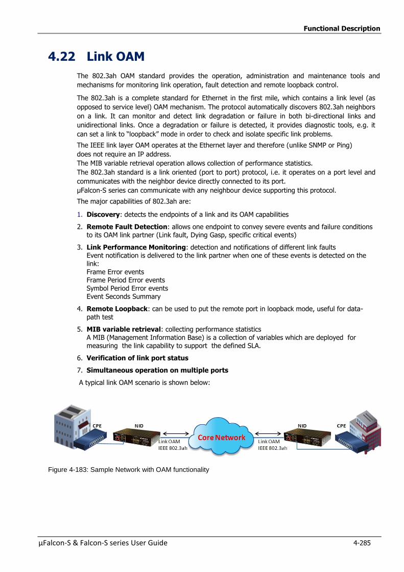
Functional Description
µFalcon-S & Falcon-S series User Guide 4-285
4.22 Link OAM
The 802.3ah OAM standard provides the operation, administration and maintenance tools and
mechanisms for monitoring link operation, fault detection and remote loopback control.
The 802.3ah is a complete standard for Ethernet in the first mile, which contains a link level (as
opposed to service level) OAM mechanism. The protocol automatically discovers 802.3ah neighbors
on a link. It can monitor and detect link degradation or failure in both bi-directional links and
unidirectional links. Once a degradation or failure is detected, it provides diagnostic tools, e.g. it
can set a link to “loopback” mode in order to check and isolate specific link problems.
The IEEE link layer OAM operates at the Ethernet layer and therefore (unlike SNMP or Ping)
does not require an IP address.
The MIB variable retrieval operation allows collection of performance statistics.
The 802.3ah standard is a link oriented (port to port) protocol, i.e. it operates on a port level and
communicates with the neighbor device directly connected to its port.
µFalcon-S series can communicate with any neighbour device supporting this protocol.
The major capabilities of 802.3ah are:
1. Discovery: detects the endpoints of a link and its OAM capabilities
2. Remote Fault Detection: allows one endpoint to convey severe events and failure conditions to its OAM link partner (Link fault, Dying Gasp, specific critical events)
3. Link Performance Monitoring: detection and notifications of different link faults Event notification is delivered to the link partner when one of these events is detected on the
link:
Frame Error events Frame Period Error events
Symbol Period Error events Event Seconds Summary
4. Remote Loopback: can be used to put the remote port in loopback mode, useful for data-
path test
5. MIB variable retrieval: collecting performance statistics
A MIB (Management Information Base) is a collection of variables which are deployed for measuring the link capability to support the defined SLA.
6. Verification of link port status
7. Simultaneous operation on multiple ports
A typical link OAM scenario is shown below:
Figure 4-183: Sample Network with OAM functionality
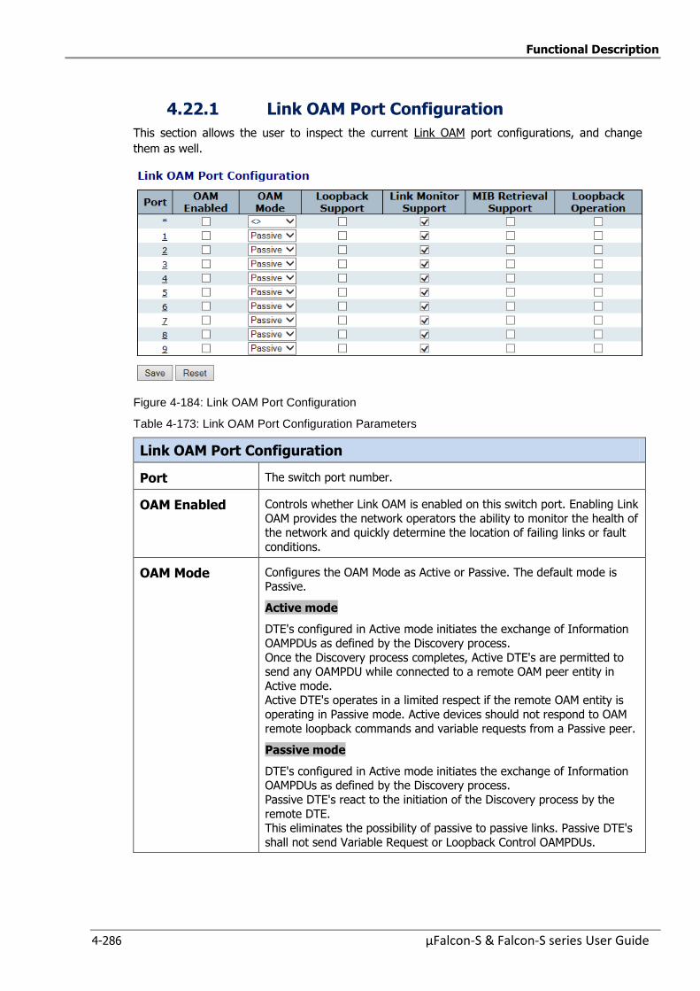
Functional Description
4-286 µFalcon-S & Falcon-S series User Guide
4.22.1 Link OAM Port Configuration
This section allows the user to inspect the current Link OAM port configurations, and change
them as well.
Figure 4-184: Link OAM Port Configuration
Table 4-173: Link OAM Port Configuration Parameters
Link OAM Port Configuration
Port The switch port number.
OAM Enabled Controls whether Link OAM is enabled on this switch port. Enabling Link
OAM provides the network operators the ability to monitor the health of the network and quickly determine the location of failing links or fault
conditions.
OAM Mode Configures the OAM Mode as Active or Passive. The default mode is Passive.
Active mode
DTE's configured in Active mode initiates the exchange of Information
OAMPDUs as defined by the Discovery process.
Once the Discovery process completes, Active DTE's are permitted to send any OAMPDU while connected to a remote OAM peer entity in
Active mode. Active DTE's operates in a limited respect if the remote OAM entity is
operating in Passive mode. Active devices should not respond to OAM
remote loopback commands and variable requests from a Passive peer.
Passive mode
DTE's configured in Active mode initiates the exchange of Information OAMPDUs as defined by the Discovery process.
Passive DTE's react to the initiation of the Discovery process by the
remote DTE. This eliminates the possibility of passive to passive links. Passive DTE's
shall not send Variable Request or Loopback Control OAMPDUs.
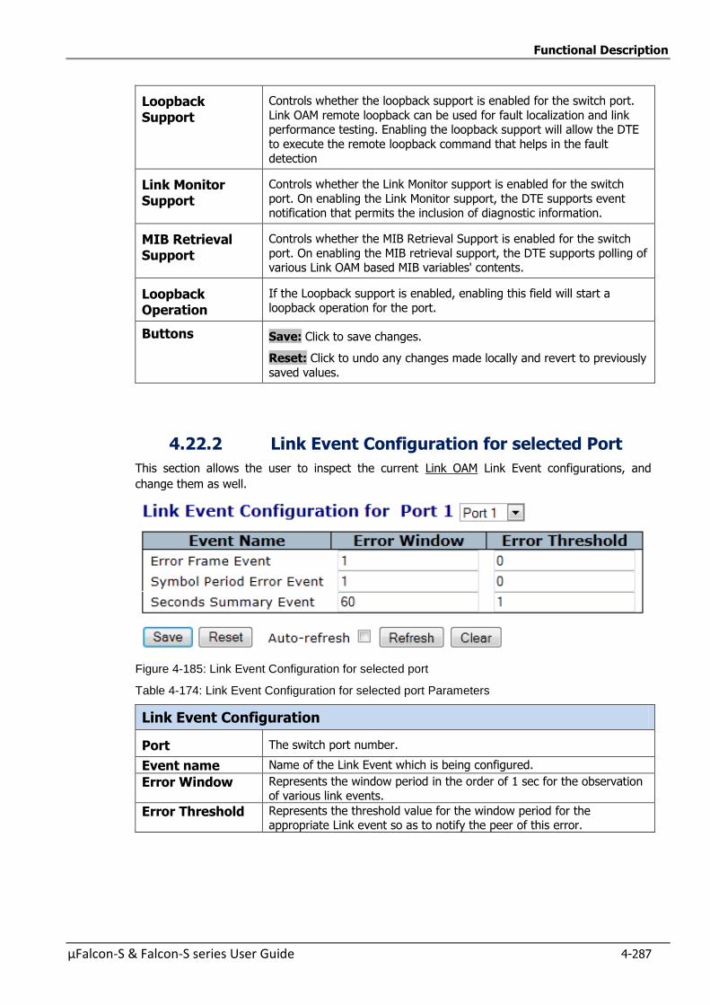
Functional Description
µFalcon-S & Falcon-S series User Guide 4-287
Loopback Support
Controls whether the loopback support is enabled for the switch port.
Link OAM remote loopback can be used for fault localization and link performance testing. Enabling the loopback support will allow the DTE
to execute the remote loopback command that helps in the fault
detection
Link Monitor Support
Controls whether the Link Monitor support is enabled for the switch
port. On enabling the Link Monitor support, the DTE supports event notification that permits the inclusion of diagnostic information.
MIB Retrieval Support
Controls whether the MIB Retrieval Support is enabled for the switch
port. On enabling the MIB retrieval support, the DTE supports polling of various Link OAM based MIB variables' contents.
Loopback Operation
If the Loopback support is enabled, enabling this field will start a
loopback operation for the port.
Buttons Save: Click to save changes.
Reset: Click to undo any changes made locally and revert to previously
saved values.
4.22.2 Link Event Configuration for selected Port
This section allows the user to inspect the current Link OAM Link Event configurations, and
change them as well.
Figure 4-185: Link Event Configuration for selected port
Table 4-174: Link Event Configuration for selected port Parameters
Link Event Configuration
Port The switch port number.
Event name Name of the Link Event which is being configured.
Error Window Represents the window period in the order of 1 sec for the observation of various link events.
Error Threshold Represents the threshold value for the window period for the appropriate Link event so as to notify the peer of this error.

Functional Description
4-288 µFalcon-S & Falcon-S series User Guide
Error Frame Event
The Errored Frame Event counts the number of errored frames
detected during the specified period. The period is specified by a time interval (Window in order of 1 sec). This event is generated if the
errored frame count is equal to or greater than the specified threshold
for that period (Period Threshold).
Errored frames are frames that had transmission errors as detected at
the Media Access Control sublayer. Error Window for 'Error Frame Event' must be an integer value between 1-60 and its default value is
'1'. Whereas Error Threshold must be between 0-0xffffffff and its default value is '0'.
Symbol Period Error Event
Controls whether the MIB Retrieval Support is enabled for the switch
port. On enabling the MIB retrieval support, the DTE supports polling of various Link OAM based MIB variables' contents.
Seconds Summary Event
The Errored Frame Seconds Summary Event TLV counts the number of
errored frame seconds that occurred during the specified period. The period is specified by a time interval. This event is generated if the
number of errored frame seconds is equal to or greater than the specified threshold for that period.
An errored frame second is a one second interval wherein at least one
frame error was detected. Errored frames are frames that had transmission errors as detected at the Media Access Control sublayer.
Error Window for 'Seconds Summary Event' must be an integer value between 10-900 and its default value is '60'. Whereas Error Threshold
must be between 0-0xffff and its default value is '1'.
Buttons The port select box determines which port is affected by clicking the buttons.
Save: Click to save changes.
Reset:
Click to undo any changes made locally and revert to previously saved
values.
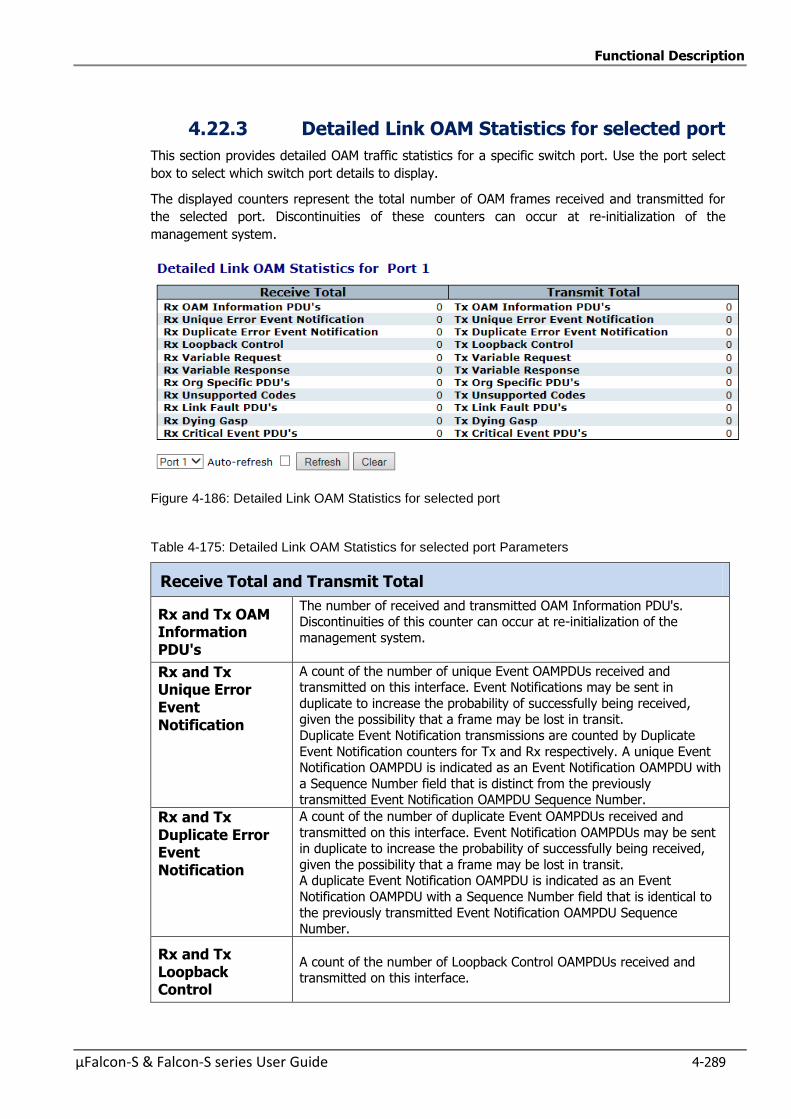
Functional Description
µFalcon-S & Falcon-S series User Guide 4-289
4.22.3 Detailed Link OAM Statistics for selected port
This section provides detailed OAM traffic statistics for a specific switch port. Use the port select
box to select which switch port details to display.
The displayed counters represent the total number of OAM frames received and transmitted for
the selected port. Discontinuities of these counters can occur at re-initialization of the
management system.
Figure 4-186: Detailed Link OAM Statistics for selected port
Table 4-175: Detailed Link OAM Statistics for selected port Parameters
Receive Total and Transmit Total
Rx and Tx OAM Information PDU's
The number of received and transmitted OAM Information PDU's. Discontinuities of this counter can occur at re-initialization of the
management system.
Rx and Tx Unique Error Event Notification
A count of the number of unique Event OAMPDUs received and transmitted on this interface. Event Notifications may be sent in
duplicate to increase the probability of successfully being received, given the possibility that a frame may be lost in transit.
Duplicate Event Notification transmissions are counted by Duplicate
Event Notification counters for Tx and Rx respectively. A unique Event Notification OAMPDU is indicated as an Event Notification OAMPDU with
a Sequence Number field that is distinct from the previously transmitted Event Notification OAMPDU Sequence Number.
Rx and Tx Duplicate Error Event Notification
A count of the number of duplicate Event OAMPDUs received and
transmitted on this interface. Event Notification OAMPDUs may be sent in duplicate to increase the probability of successfully being received,
given the possibility that a frame may be lost in transit. A duplicate Event Notification OAMPDU is indicated as an Event
Notification OAMPDU with a Sequence Number field that is identical to
the previously transmitted Event Notification OAMPDU Sequence Number.
Rx and Tx Loopback Control
A count of the number of Loopback Control OAMPDUs received and transmitted on this interface.
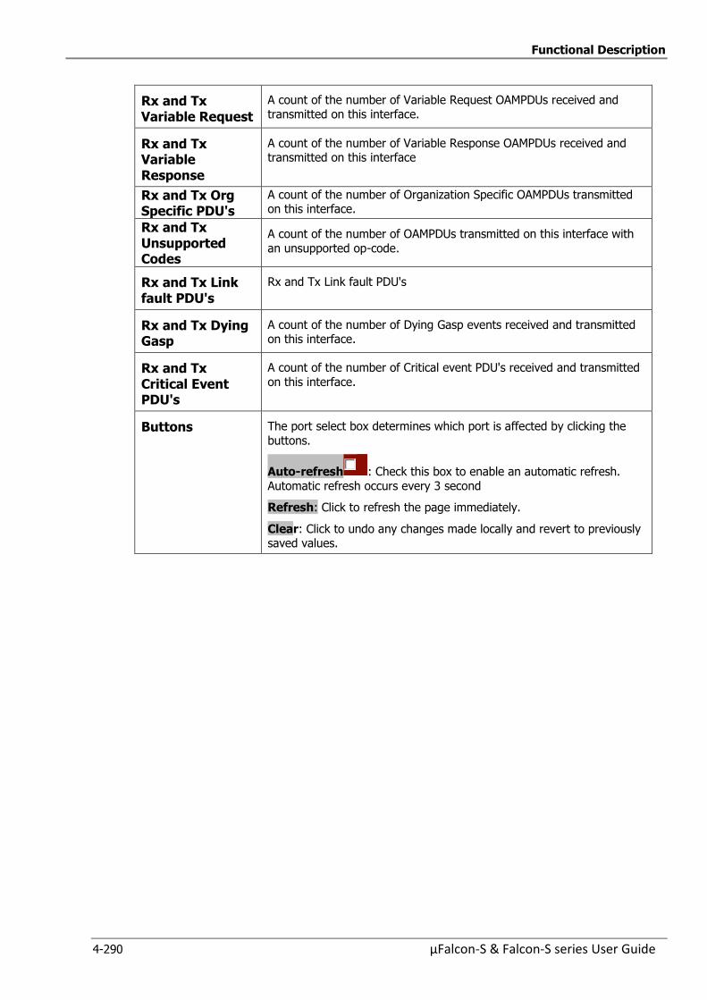
Functional Description
4-290 µFalcon-S & Falcon-S series User Guide
Rx and Tx Variable Request
A count of the number of Variable Request OAMPDUs received and transmitted on this interface.
Rx and Tx Variable Response
A count of the number of Variable Response OAMPDUs received and transmitted on this interface
Rx and Tx Org Specific PDU's
A count of the number of Organization Specific OAMPDUs transmitted on this interface.
Rx and Tx Unsupported Codes
A count of the number of OAMPDUs transmitted on this interface with
an unsupported op-code.
Rx and Tx Link fault PDU's
Rx and Tx Link fault PDU's
Rx and Tx Dying Gasp
A count of the number of Dying Gasp events received and transmitted on this interface.
Rx and Tx Critical Event PDU's
A count of the number of Critical event PDU's received and transmitted
on this interface.
Buttons The port select box determines which port is affected by clicking the
buttons.
Auto-refresh : Check this box to enable an automatic refresh.
Automatic refresh occurs every 3 second
Refresh: Click to refresh the page immediately.
Clear: Click to undo any changes made locally and revert to previously saved values.
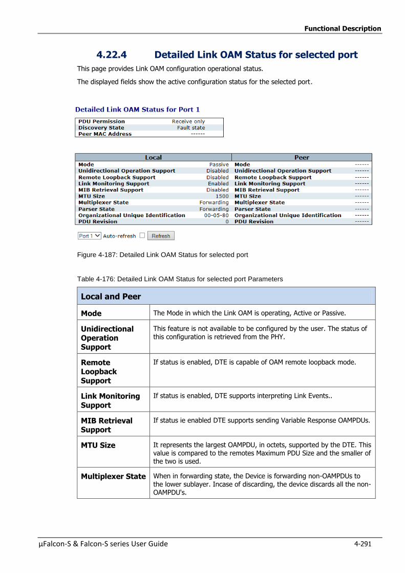
Functional Description
µFalcon-S & Falcon-S series User Guide 4-291
4.22.4 Detailed Link OAM Status for selected port
This page provides Link OAM configuration operational status.
The displayed fields show the active configuration status for the selected port.
Figure 4-187: Detailed Link OAM Status for selected port
Table 4-176: Detailed Link OAM Status for selected port Parameters
Local and Peer
Mode The Mode in which the Link OAM is operating, Active or Passive.
Unidirectional Operation Support
This feature is not available to be configured by the user. The status of
this configuration is retrieved from the PHY.
Remote Loopback Support
If status is enabled, DTE is capable of OAM remote loopback mode.
Link Monitoring Support
If status is enabled, DTE supports interpreting Link Events..
MIB Retrieval Support
If status ie enabled DTE supports sending Variable Response OAMPDUs.
MTU Size It represents the largest OAMPDU, in octets, supported by the DTE. This
value is compared to the remotes Maximum PDU Size and the smaller of the two is used.
Multiplexer State When in forwarding state, the Device is forwarding non-OAMPDUs to
the lower sublayer. Incase of discarding, the device discards all the non-OAMPDU's.
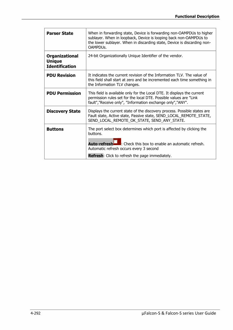
Functional Description
4-292 µFalcon-S & Falcon-S series User Guide
Parser State When in forwarding state, Device is forwarding non-OAMPDUs to higher
sublayer. When in loopback, Device is looping back non-OAMPDUs to the lower sublayer. When in discarding state, Device is discarding non-
OAMPDUs.
Organizational Unique Identification
24-bit Organizationally Unique Identifier of the vendor.
PDU Revision It indicates the current revision of the Information TLV. The value of this field shall start at zero and be incremented each time something in
the Information TLV changes.
PDU Permission This field is available only for the Local DTE. It displays the current permission rules set for the local DTE. Possible values are "Link
fault","Receive only", "Information exchange only","ANY".
Discovery State Displays the current state of the discovery process. Possible states are Fault state, Active state, Passive state, SEND_LOCAL_REMOTE_STATE,
SEND_LOCAL_REMOTE_OK_STATE, SEND_ANY_STATE.
Buttons The port select box determines which port is affected by clicking the buttons.
Auto-refresh : Check this box to enable an automatic refresh. Automatic refresh occurs every 3 second
Refresh: Click to refresh the page immediately.
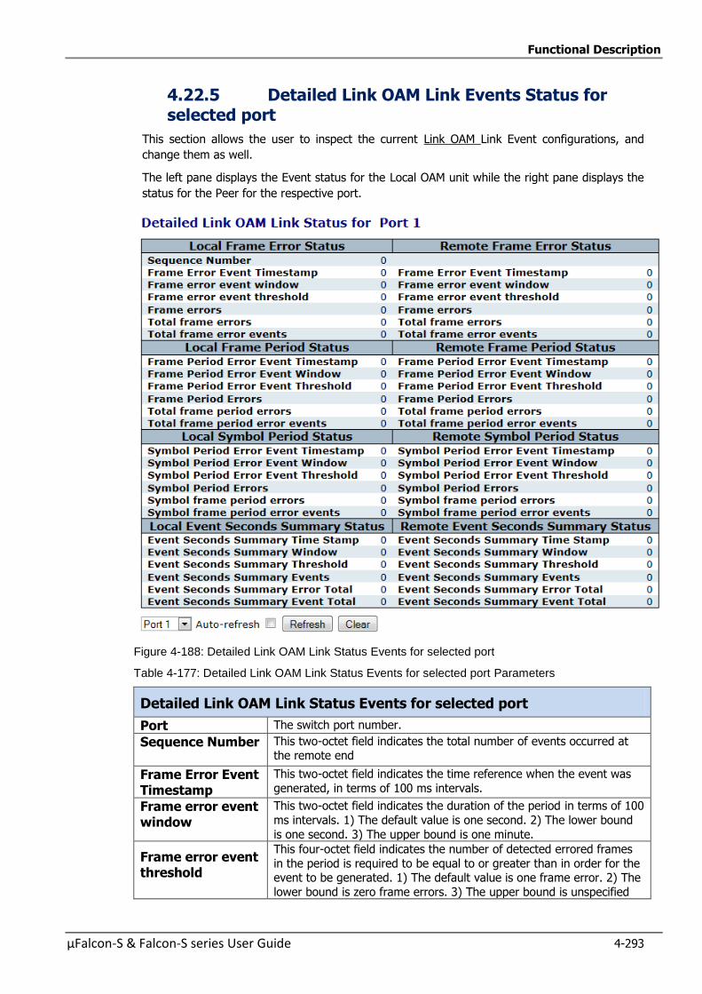
Functional Description
µFalcon-S & Falcon-S series User Guide 4-293
4.22.5 Detailed Link OAM Link Events Status for selected port
This section allows the user to inspect the current Link OAM Link Event configurations, and
change them as well.
The left pane displays the Event status for the Local OAM unit while the right pane displays the
status for the Peer for the respective port.
Figure 4-188: Detailed Link OAM Link Status Events for selected port
Table 4-177: Detailed Link OAM Link Status Events for selected port Parameters
Detailed Link OAM Link Status Events for selected port
Port The switch port number.
Sequence Number This two-octet field indicates the total number of events occurred at the remote end
Frame Error Event Timestamp
This two-octet field indicates the time reference when the event was
generated, in terms of 100 ms intervals.
Frame error event window
This two-octet field indicates the duration of the period in terms of 100
ms intervals. 1) The default value is one second. 2) The lower bound
is one second. 3) The upper bound is one minute.
Frame error event threshold
This four-octet field indicates the number of detected errored frames
in the period is required to be equal to or greater than in order for the event to be generated. 1) The default value is one frame error. 2) The
lower bound is zero frame errors. 3) The upper bound is unspecified
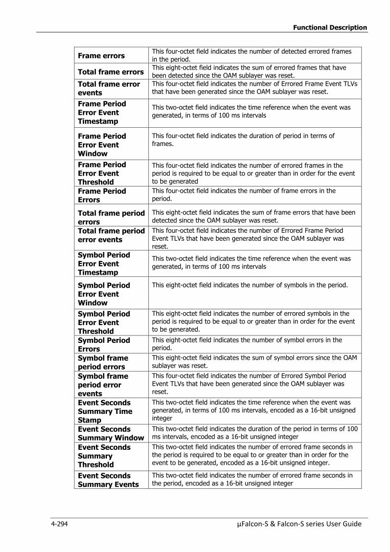
Functional Description
4-294 µFalcon-S & Falcon-S series User Guide
Frame errors This four-octet field indicates the number of detected errored frames
in the period.
Total frame errors This eight-octet field indicates the sum of errored frames that have been detected since the OAM sublayer was reset.
Total frame error events
This four-octet field indicates the number of Errored Frame Event TLVs that have been generated since the OAM sublayer was reset.
Frame Period Error Event Timestamp
This two-octet field indicates the time reference when the event was
generated, in terms of 100 ms intervals
Frame Period Error Event Window
This four-octet field indicates the duration of period in terms of
frames.
Frame Period Error Event Threshold
This four-octet field indicates the number of errored frames in the period is required to be equal to or greater than in order for the event
to be generated
Frame Period Errors
This four-octet field indicates the number of frame errors in the period.
Total frame period errors
This eight-octet field indicates the sum of frame errors that have been
detected since the OAM sublayer was reset.
Total frame period error events
This four-octet field indicates the number of Errored Frame Period
Event TLVs that have been generated since the OAM sublayer was
reset.
Symbol Period Error Event Timestamp
This two-octet field indicates the time reference when the event was
generated, in terms of 100 ms intervals
Symbol Period Error Event Window
This eight-octet field indicates the number of symbols in the period.
Symbol Period Error Event Threshold
This eight-octet field indicates the number of errored symbols in the period is required to be equal to or greater than in order for the event
to be generated.
Symbol Period Errors
This eight-octet field indicates the number of symbol errors in the period.
Symbol frame period errors
This eight-octet field indicates the sum of symbol errors since the OAM
sublayer was reset.
Symbol frame period error events
This four-octet field indicates the number of Errored Symbol Period
Event TLVs that have been generated since the OAM sublayer was
reset.
Event Seconds Summary Time Stamp
This two-octet field indicates the time reference when the event was generated, in terms of 100 ms intervals, encoded as a 16-bit unsigned
integer
Event Seconds Summary Window
This two-octet field indicates the duration of the period in terms of 100 ms intervals, encoded as a 16-bit unsigned integer
Event Seconds Summary Threshold
This two-octet field indicates the number of errored frame seconds in
the period is required to be equal to or greater than in order for the event to be generated, encoded as a 16-bit unsigned integer.
Event Seconds Summary Events
This two-octet field indicates the number of errored frame seconds in
the period, encoded as a 16-bit unsigned integer

Functional Description
µFalcon-S & Falcon-S series User Guide 4-295
Event Seconds Summary Error Total
This four-octet field indicates the sum of errored frame seconds that
have been detected since the OAM sublayer was reset.
Event Seconds Summary Event Total
This four-octet field indicates the number of Errored Frame Seconds
Summary Event TLVs that have been generated since the OAM sublayer was reset, encoded as a 32bit unsigned integer.
Buttons The port select box determines which port is affected by clicking the
buttons.
Auto-refresh : Check this box to enable an automatic refresh. Automatic refresh occurs every 3 second Refresh: Click to refresh the page immediately.
Clear: Click to clear the data
Functional Description
4-296 µFalcon-S & Falcon-S series User Guide
4.23 Service OAM Standards
Service OAM” is a common term for the ITU-T Y.1731, IEEE802.1ag, all covering Operation,
Administration and Maintenance These standards cover monitoring and error detection functionalities, which are key weaknesses in the standard Ethernet.
Service Level Agreement (SLA) Management is a necessary tool for carriers, required to ensure that customers are getting the service they have purchased. It is valuable to manage services from the
perspective of the end-user in addition to providing element and network management capabilities.
The correlation and tracking of QoS per service allow the network operator to offer end-users active reports on the health, status and SLA adherence of their service over time.
Planned network maintenance, active outage detection and identification of users or services affected by network events are facilitated across all network layers and allow operators to detect,
diagnose and prioritize failure or degradation events with network active monitor, and mitigate
problems.
Fault Management implements a service-layer OAM based on the IEEE 802.1ag protocol and the ITU
Y.1731 protocol, which complement each other and enable full service OAM.
Service OAM contains a suite of OAM functionalities which can be divided into two main groups:
Fault management and Performance Management.
OAM functions for Fault Management Ethernet Continuity Check (ETH-CC)
Ethernet Loopback (ETH-LB) Ethernet Link Trace (ETH-LT)
Ethernet Alarm Indication Signal (ETH-AIS)
Ethernet Remote Defect Indication (ETH-RDI) Ethernet Locked Signal (ETH-LCK)
Ethernet Test Signal (ETH-Test) Ethernet Automatic Protection Switching (ETH-APS)
OAM Functions for Performance Monitoring (Y.1731 Only) Frame Loss Measurement (ETH-LM)
Frame Delay Measurement (ETH-DM) Throughput Measurement
The “Service OAM” allows an operator to detect, locate and verify faults for an Ethernet service. The
Connectivity Check protocol allows the operator to monitor the services continuously through data-
path. Once a failure is detected, the Loopback and Link trace protocols are used on-demand to further diagnose the failure. The Service OAM is useful for multipoint as well as point-to-point
Ethernet services.
Scalability of the Service OAM is accomplished via the use of maintenance domains. A maintenance
domain is defined by the network operator as a network area with its own management and
administration requirements. Maintenance domains can be defined in hierarchical order to distinguish between different types of network users (e.g. Customer Domain, Service-provider
Domain, Operator Domain, etc.).
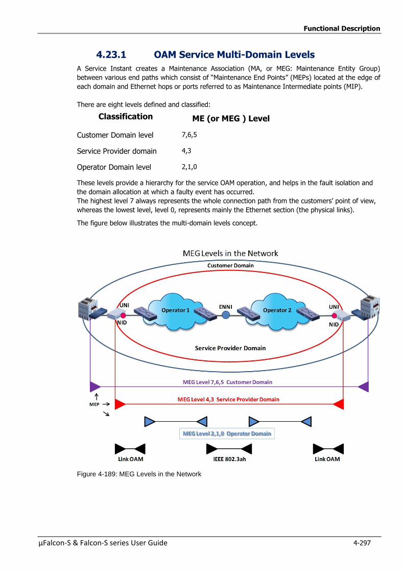
Functional Description
µFalcon-S & Falcon-S series User Guide 4-297
4.23.1 OAM Service Multi-Domain Levels
A Service Instant creates a Maintenance Association (MA, or MEG: Maintenance Entity Group)
between various end paths which consist of “Maintenance End Points” (MEPs) located at the edge of
each domain and Ethernet hops or ports referred to as Maintenance Intermediate points (MIP).
There are eight levels defined and classified:
Classification ME (or MEG ) Level
Customer Domain level 7,6,5
Service Provider domain 4,3
Operator Domain level 2,1,0
These levels provide a hierarchy for the service OAM operation, and helps in the fault isolation and
the domain allocation at which a faulty event has occurred.
The highest level 7 always represents the whole connection path from the customers’ point of view,
whereas the lowest level, level 0, represents mainly the Ethernet section (the physical links).
The figure below illustrates the multi-domain levels concept.
Figure 4-189: MEG Levels in the Network

Functional Description
4-298 µFalcon-S & Falcon-S series User Guide
4.23.2 Ethernet Connectivity Fault Management
Ethernet Fault Management is an end-to-end per-service Ethernet layer OAM protocol that includes
proactive connectivity monitoring, fault verification, and fault isolation.
Monitoring and troubleshooting carrier networks offering Ethernet Layer 2 services is challenging.
Customers contract with service providers for end-to-end Ethernet service, and service providers
may subcontract with operators to provide equipment and networks. Compared to enterprise
networks, where Ethernet traditionally has been implemented, these constituent networks belong to
distinct organizations or departments, are substantially larger and more complex, and have a wider
user base.
Ethernet Fault Management provides a competitive advantage to service providers, for whom the
operational management of service uptime and timeliness of isolating and responding to failures is
crucial to daily operations.
The following sections explain and illustrate the basic terms of Fault Management functions.
Customer Service Instance
A customer service instance is an Ethernet Virtual Connection (EVC), which is identified by an
S-VLAN within an Ethernet provider network, and is recognized by a globally unique service ID
(which is the S-VLAN tag). A customer service can be either Point-to-Point (PTP) or Multipoint-to-
Multipoint (MPTMP). See the following figures
Figure 4-190: Customer PTP Service Instance

Functional Description
µFalcon-S & Falcon-S series User Guide 4-299
Figure 4-191: Customer MP2MP Service Instance
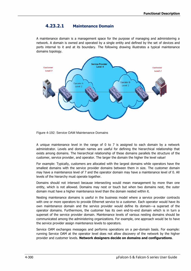
Functional Description
4-300 µFalcon-S & Falcon-S series User Guide
4.23.2.1 Maintenance Domain
A maintenance domain is a management space for the purpose of managing and administering a
network. A domain is owned and operated by a single entity and defined by the set of devices and
ports internal to it and at its boundary. The following drawing illustrates a typical maintenance
domains topology.
Figure 4-192: Service OAM Maintenance Domains
A unique maintenance level in the range of 0 to 7 is assigned to each domain by a network
administrator. Levels and domain names are useful for defining the hierarchical relationship that
exists among domains. The hierarchical relationship of these domains parallels the structure of the
customer, service provider, and operator. The larger the domain the higher the level value!
For example: Typically, customers are allocated with the largest domains while operators have the
smallest domains with the service provider domains between them in size. The customer domain
may have a maintenance level of 7 and the operator domain may have a maintenance level of 0. All
levels of the hierarchy must operate together.
Domains should not intersect because intersecting would mean management by more than one
entity, which is not allowed. Domains may nest or touch but when two domains nest, the outer
domain must have a higher maintenance level than the domain nested within it.
Nesting maintenance domains is useful in the business model where a service provider contracts
with one or more operators to provide Ethernet service to a customer. Each operator would have its
own maintenance domain and the service provider would define its domain—a superset of the
operator domains. Furthermore, the customer has its own end-to-end domain which is in turn a
superset of the service provider domain. Maintenance levels of various nesting domains should be
communicated among the administering organizations. For example, one approach would be to have
the service provider assign maintenance levels to operators.
Service OAM exchanges messages and performs operations on a per-domain basis. For example:
running Service OAM at the operator level does not allow discovery of the network by the higher
provider and customer levels. Network designers decide on domains and configurations.
Functional Description
µFalcon-S & Falcon-S series User Guide 4-301
4.23.2.2 Maintenance Point: MPE/MIP
A maintenance point is a demarcation point on a port that participates in Service OAM within a
maintenance domain. Maintenance points on device ports act as filters that confine Service OAM
frames within the bounds of a domain by dropping frames that do not belong to the correct level (domain). Maintenance points must be explicitly configured on µFalcon devices.
Two classes of maintenance communication points exist:
1. Maintenance Endpoints (MEPs)
2. Maintenance Intermediate Points (MIPs)
Maintenance Endpoints (MEPs)
Maintenance Endpoints (MEPs) have the following characteristics:
Per maintenance domain (level) and service provider VLAN (S-VLAN).
At the edge of a domain, define the boundary.
Within the bounds of a maintenance domain, confine Service OAM messages.
When configured to do so, proactively transmit Service OAM continuity check messages
(CCMs).
At the request of an administrator, transmit Link trace and loopback messages.
Maintenance Endpoints communicate through the Bridge Relay function (Inward Facing – the switch
performs forwarding and sends it to the destination port) or the wire (Outward Facing – sent directly
out of the port).
Inward Facing MEPs
Inward facing means the MEP communicates through the Bridge Relay function and uses the Bridge-
Brain MAC address. An inward facing MEP performs the following functions:
Sends and receives CFM frames at its level through the relay function, not via the wire
connected to the port on which the MEP is configured.
Drops all Service OAM frames at its level (or lower level) that come from the wire side.
Processes all Service OAM frames at its level coming from the direction of the relay function.
Drops all Service OAM frames at a lower level coming from the direction of the relay function.
Transparently forwards all Service OAM frames at a higher level, independent of whether they
come in from the relay function side or the wire side.
If the port on which the inward MEP is configured is blocked by Spanning-Tree Protocol, the
MEP can no longer transmit or receive Service OAM messages.
Outward Facing MEPs
Outward facing means that the MEP communicates through the wire. Outward facing MEPs use the
port MAC address, not the Bridge-Brain MAC address used by inward facing MEPs. An outward facing
MEP performs the following functions:
Sends and receives Service OAM frames at its level via the wire connected to the port where
the MEP is configured.
Drops all Service OAM frames at its level (or at a lower level) that come from the relay
function side.
Processes all Service OAM frames at its level coming from the direction of the wire.
Drops all Service OAM frames at a lower level coming from the direction of the wire.
Transparently forwards all Service OAM frames at levels higher than the level of the outward
facing MEP, independent of whether they come in from the relay function side or the wire side. Not applicable to routed ports.
If the port on which the outward MEP is configured is blocked by Spanning-Tree Protocol, the
MEP can still transmit and receive Service OAM messages via the wire.
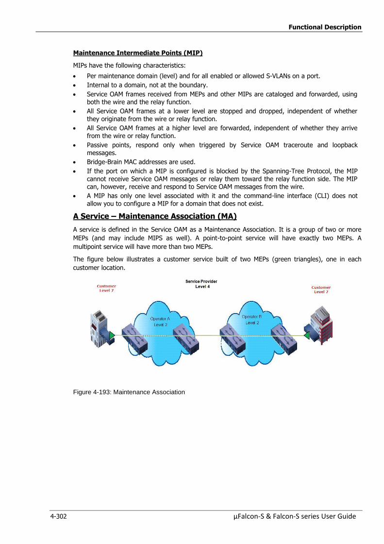
Functional Description
4-302 µFalcon-S & Falcon-S series User Guide
Maintenance Intermediate Points (MIP)
MIPs have the following characteristics:
Per maintenance domain (level) and for all enabled or allowed S-VLANs on a port.
Internal to a domain, not at the boundary.
Service OAM frames received from MEPs and other MIPs are cataloged and forwarded, using
both the wire and the relay function.
All Service OAM frames at a lower level are stopped and dropped, independent of whether
they originate from the wire or relay function.
All Service OAM frames at a higher level are forwarded, independent of whether they arrive
from the wire or relay function.
Passive points, respond only when triggered by Service OAM traceroute and loopback
messages.
Bridge-Brain MAC addresses are used.
If the port on which a MIP is configured is blocked by the Spanning-Tree Protocol, the MIP
cannot receive Service OAM messages or relay them toward the relay function side. The MIP can, however, receive and respond to Service OAM messages from the wire.
A MIP has only one level associated with it and the command-line interface (CLI) does not
allow you to configure a MIP for a domain that does not exist.
A Service – Maintenance Association (MA)
A service is defined in the Service OAM as a Maintenance Association. It is a group of two or more
MEPs (and may include MIPS as well). A point-to-point service will have exactly two MEPs. A
multipoint service will have more than two MEPs.
The figure below illustrates a customer service built of two MEPs (green triangles), one in each
customer location.
Figure 4-193: Maintenance Association
Functional Description
µFalcon-S & Falcon-S series User Guide 4-303
4.23.2.3 OAM Messages
Service OAM uses standard Ethernet frames Service OAM frames are distinguishable by Ether Type and for multicast messages by MAC address. Service OAM frames are sourced, terminated,
processed, and relayed by bridges. Routers can support only limited Service OAM functions. Bridges
that cannot interpret Service OAM messages forward them as normal data frames. All Service OAM messages are confined to a maintenance domain and to an S-VLAN (PE-VLAN or Provider-VLAN) and
support three types of messages:
1. Continuity Check
2. Loopback
3. Link Trace
Continuity Check Messages (CCM)
CFM Continuity Check Messages (CCMs) are multicast heartbeat messages exchanged periodically among MEPs. They allow MEPs to discover other MEPs within a domain and allow MIPs to discover
MEPs. CCMs are confined to a domain and S-VLAN. Service OAM CCMs have the following
characteristics:
Transmitted at a configurable periodic interval by MEPs. The interval is defined in milliseconds
and can be set to values from 10 milliseconds to 10 minutes (600000 mS), the default is 1 second (1000 mS).
Contain a configurable hold-time value to indicate to the receiver the validity of the message.
The default is 2.5 times the transmit interval.
Catalogued by MIPs at the same maintenance level.
Terminated by remote MEPs at the same maintenance level.
Unidirectional and do not solicit a response.
Carry the status of the port on which the MEP is configured.
Loopback Messages
Service OAM loopback messages are unicast frames that a MEP transmits, at the request of an administrator, to verify connectivity to a particular maintenance point. A reply to a loopback
message indicates whether a destination is reachable but does not allow hop-by-hop discovery of the path. A loopback message is similar in concept to an Internet Control Message Protocol (ICMP)
Echo (ping) message.
A Service OAM loopback message can be generated on demand using the CLI. The source of a
loopback message must be a MEP; the destination may be a MEP or a MIP. Service OAM loopback
messages are unicast; replies to loopback messages also are unicast. Service OAM loopback messages specify the destination MAC address, VLAN, and maintenance domain.
Link Trace Messages
Link trace is used to discover and monitor the path from one MEP to another MEP or MIP by its MAC address, and to all MIPs at the same domain level
A MEP sends link trace frames (LTM) and when received by a MIP, the MIP responds to the transmitting MEP and forwards the link trace frame. The receiving MEP will also send a
link trace reply (LTR), so the transmitting MEP is able to build a list of MAC addresses of the MIPs and MEP reached.
When there is a network fault, the Link Trace may be used to isolate the specific location of the
fault.
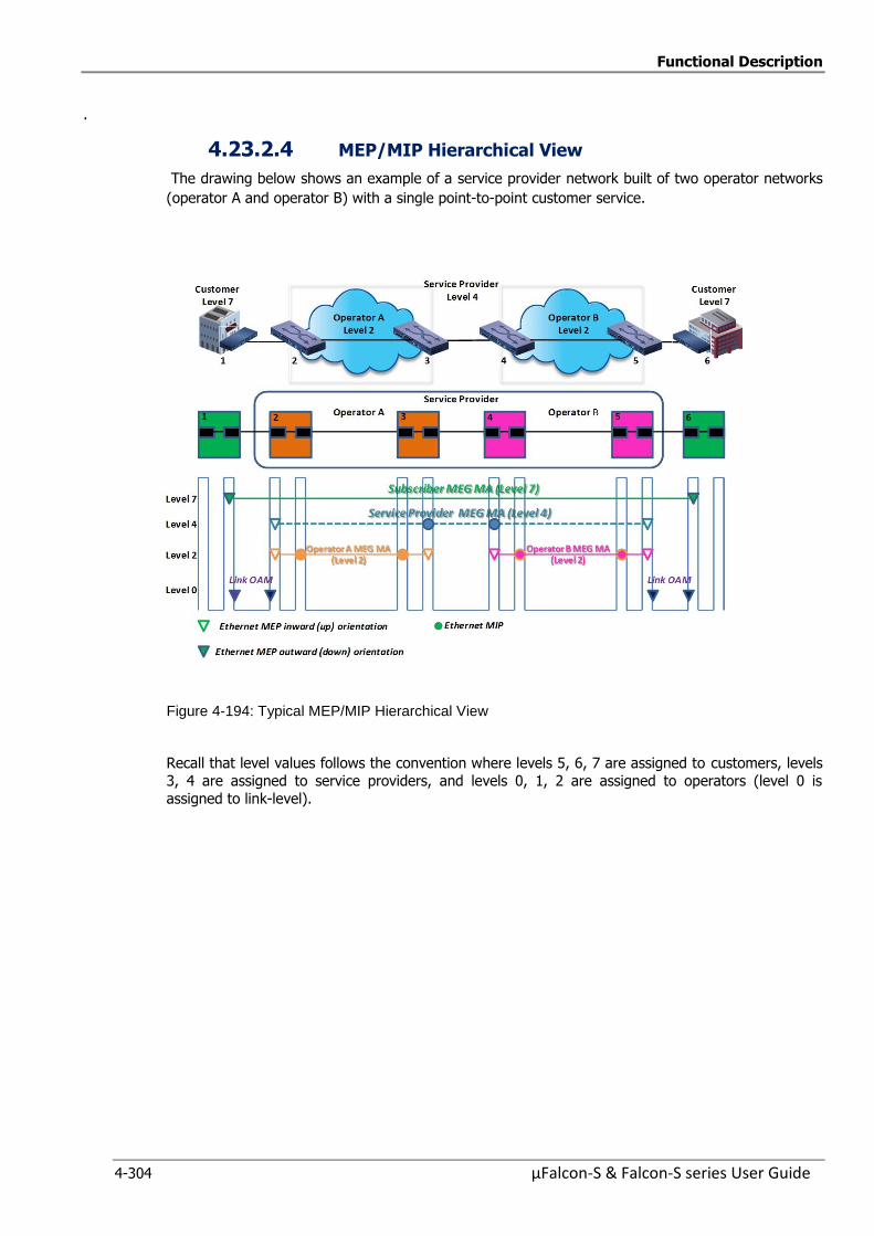
Functional Description
4-304 µFalcon-S & Falcon-S series User Guide
.
4.23.2.4 MEP/MIP Hierarchical View
The drawing below shows an example of a service provider network built of two operator networks
(operator A and operator B) with a single point-to-point customer service.
Figure 4-194: Typical MEP/MIP Hierarchical View
Recall that level values follows the convention where levels 5, 6, 7 are assigned to customers, levels
3, 4 are assigned to service providers, and levels 0, 1, 2 are assigned to operators (level 0 is
assigned to link-level).

Functional Description
µFalcon-S & Falcon-S series User Guide 4-305
4.23.3 MEP Configuration Management
The following functions are described in this section:
Maintenance Entity Point
MEP Configuration which includes the following displays
Instance Data
Instance Configuration
Peer MEP Configuration
Functional Configuration
TLV Configuration
TLV Status
Link State Tracking
4.23.3.1 Maintenance Entity Point
The Maintenance Entity Point instances are configured here.
Figure 4-195: Maintenance Entity Point display
Table 4-178: Maintenance Entity Point commands
Maintenance Entity Point
Delete This box is used to mark a MEP for deletion in the next Save operation.
MEP is an acronym for Maintenance Entity Endpoint and is an endpoint in a Maintenance Entity Group (ITU-T Y.1731).
Instance The ID of the MEP. Click on the ID of a MEP to enter the configuration
page.The range is from 1 through 100
Domain Port: This is a MEP in the Port Domain.
EVC: This is a MEP in the EVC Domain. 'Flow Instance' is a EVC.The EVC
must be created
VLAN: This is a MEP in the VLAN Domain. 'Flow Instance' is a VLAN. In
case of Up-MEP the VLAN must be created
Mode MEP: This is a Maintenance Entity End Point. MIP: This is a Maintenance Entity Intermediate Point.
Direction Down This is a Down MEP - monitoring ingress traffic on 'Residence Port'
Up: This is a Up MEP - monitoring egress traffic on 'Residence Port'
Residence Port The port where MEP is monitoring - see 'Direction'.
For a EVC MEP the port must be a port in the EVC. For a VLAN MEP the port must be a VLAN member.
Level The MEG level of this MEP.
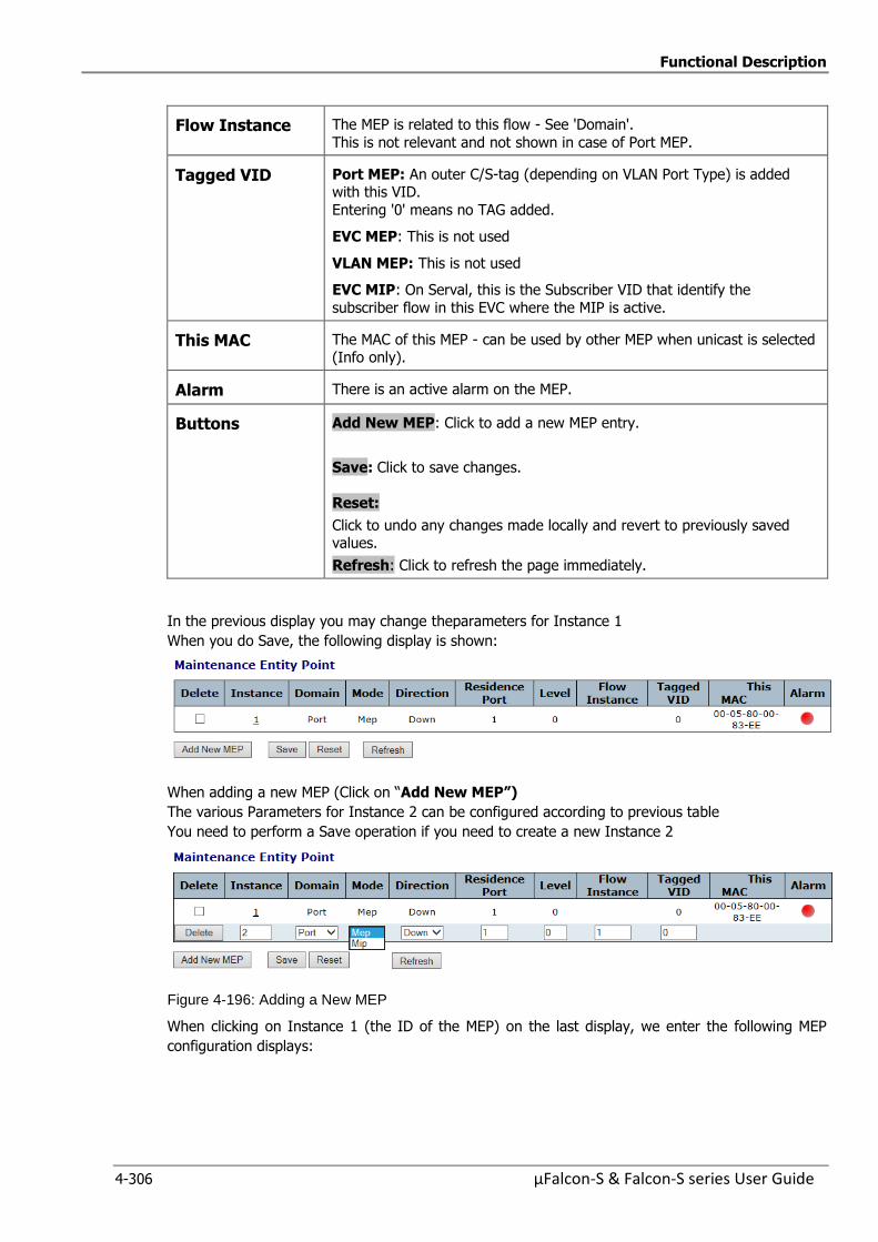
Functional Description
4-306 µFalcon-S & Falcon-S series User Guide
Flow Instance The MEP is related to this flow - See 'Domain'.
This is not relevant and not shown in case of Port MEP.
Tagged VID Port MEP: An outer C/S-tag (depending on VLAN Port Type) is added with this VID.
Entering '0' means no TAG added.
EVC MEP: This is not used
VLAN MEP: This is not used
EVC MIP: On Serval, this is the Subscriber VID that identify the
subscriber flow in this EVC where the MIP is active.
This MAC The MAC of this MEP - can be used by other MEP when unicast is selected (Info only).
Alarm There is an active alarm on the MEP.
Buttons Add New MEP: Click to add a new MEP entry.
Save: Click to save changes.
Reset:
Click to undo any changes made locally and revert to previously saved values.
Refresh: Click to refresh the page immediately.
In the previous display you may change theparameters for Instance 1
When you do Save, the following display is shown:
When adding a new MEP (Click on “Add New MEP”)
The various Parameters for Instance 2 can be configured according to previous table
You need to perform a Save operation if you need to create a new Instance 2
Figure 4-196: Adding a New MEP
When clicking on Instance 1 (the ID of the MEP) on the last display, we enter the following MEP
configuration displays:
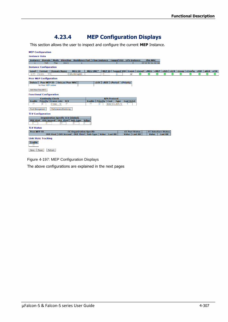
Functional Description
µFalcon-S & Falcon-S series User Guide 4-307
4.23.4 MEP Configuration Displays
This section allows the user to inspect and configure the current MEP Instance.
Figure 4-197: MEP Configuration Displays
The above configurations are explained in the next pages
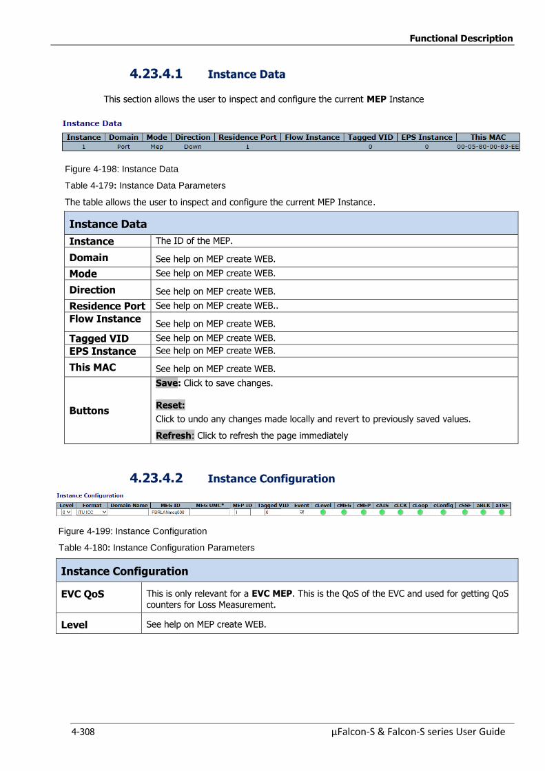
Functional Description
4-308 µFalcon-S & Falcon-S series User Guide
4.23.4.1 Instance Data
This section allows the user to inspect and configure the current MEP Instance
Figure 4-198: Instance Data
Table 4-179: Instance Data Parameters
The table allows the user to inspect and configure the current MEP Instance.
Instance Data
Instance The ID of the MEP.
Domain See help on MEP create WEB.
Mode See help on MEP create WEB.
Direction See help on MEP create WEB.
Residence Port See help on MEP create WEB..
Flow Instance See help on MEP create WEB.
Tagged VID See help on MEP create WEB.
EPS Instance See help on MEP create WEB.
This MAC See help on MEP create WEB.
Buttons
Save: Click to save changes.
Reset:
Click to undo any changes made locally and revert to previously saved values.
Refresh: Click to refresh the page immediately
4.23.4.2 Instance Configuration
Figure 4-199: Instance Configuration
Table 4-180: Instance Configuration Parameters
Instance Configuration
EVC QoS This is only relevant for a EVC MEP. This is the QoS of the EVC and used for getting QoS
counters for Loss Measurement.
Level See help on MEP create WEB.
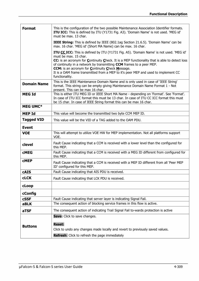
Functional Description
µFalcon-S & Falcon-S series User Guide 4-309
Format This is the configuration of the two possible Maintenance Association Identifier formats.
ITU ICC: This is defined by ITU (Y1731 Fig. A3). 'Domain Name' is not used. 'MEG id' must be max. 13 char.
IEEE String: This is defined by IEEE (802.1ag Section 21.6.5). 'Domain Name' can be
max. 16 char. 'MEG id' (Short MA Name) can be max. 16 char.
ITU CC ICC: This is defined by ITU (Y1731 Fig. A5). 'Domain Name' is not used. 'MEG id'
must be max. 15 char. CC: is an acronym for Continuity Check. It is a MEP functionality that is able to detect loss
of continuity in a network by transmitting CCM frames to a peer MEP. CCM: is an acronym for Continuity Check Message.
It is a OAM frame transmitted from a MEP to it's peer MEP and used to implement CC
functionality.
Domain Name This is the IEEE Maintenance Domain Name and is only used in case of 'IEEE String'
format. This string can be empty giving Maintenance Domain Name Format 1 - Not
present. This can be max 16 char.
MEG Id This is either ITU MEG ID or IEEE Short MA Name - depending on 'Format'. See 'Format'.
In case of ITU ICC format this must be 13 char. In case of ITU CC ICC format this must be 15 char. In case of IEEE String format this can be max 16 char.
MEG UMC*
MEP Id This value will become the transmitted two byte CCM MEP ID.
Tagged VID This value will be the VID of a TAG added to the OAM PDU.
Event
VOE This will attempt to utilize VOE HW for MEP implementation. Not all platforms support
VOE.
clevel Fault Cause indicating that a CCM is received with a lower level than the configured for this MEP.
cMEG Fault Cause indicating that a CCM is received with a MEG ID different from configured for
this MEP.
cMEP Fault Cause indicating that a CCM is received with a MEP ID different from all 'Peer MEP
ID' configured for this MEP.
cAIS Fault Cause indicating that AIS PDU is received.
cLCK Fault Cause indicating that LCK PDU is received.
cLoop
cConfig
cSSF Fault Cause indicating that server layer is indicating Signal Fail.
aBLK The consequent action of blocking service frames in this flow is active.
aTSF The consequent action of indicating Trail Signal Fail to-wards protection is active
Buttons
Save: Click to save changes.
Reset:
Click to undo any changes made locally and revert to previously saved values.
Refresh: Click to refresh the page immediately

Functional Description
4-310 µFalcon-S & Falcon-S series User Guide
4.23.4.3 Peer MEP Configuration
Figure 4-200: Peer MEP Configuration
Table 4-181: Peer MEP e Configuration Parameters
PeerMEP Configuration
Delete This box is used to mark a Peer MEP for deletion in next Save operation
Peer MEP ID
This value will become an expected MEP ID in a received CCM - see 'cMEP'.
Unicast Peer MAC
This MAC will be used when unicast is selected with this peer MEP. Also this MAC is used to create HW checking of receiving CCM PDU (LOC
detection) from this MEP.
LOC: is an acronym for Loss Of Connectivity and is detected by a MEP and is
indicating lost connectivity in the network.
cLOC Fault Cause indicating that no CCM has been received (in 3,5 periods) - from this peer MEP.
cRDI Fault Cause indicating that a CCM is received with Remote Defect Indication -
from this peer MEP.
cPeriod Fault Cause indicating that a CCM is received with a period different what is
configured for this MEP - from this peer MEP.
cPriority Fault Cause indicating that a CCM is received with a priority different what is configured for this MEP - from this peer MEP.
Buttons Add New Peer MEP: Click to add a new peer MEP
Save: Click to save changes.
Reset:
Click to undo any changes made locally and revert to previously saved values.
Refresh: Click to refresh the page immediately

Functional Description
µFalcon-S & Falcon-S series User Guide 4-311
4.23.4.4 Functional Configuration
Figure 4-201: Functional Configuration
Table 4-182: Functional Configuration Parameters
Functional Configuration
Continuity Check
Enable Continuity Check based on transmitting/receiving CCM PDU can be
enabled/disabled. The CCM PDU is always transmitted as Multi-cast Class 1.
Priority The priority to be inserted as PCP bits in TAG (if any). In case of enable of Continuity Check and Loss Measurement both implemented on SW based CCM,
'Priority' has to be the same.
Frame rate Selecting the frame rate of CCM PDU. This is the inverse of transmission period as described in Y.1731. This value has the following uses:
* The transmission rate of the CCM PDU * Fault Cause cLOC is declared if no CCM PDU has been received within 3.5
periods - see 'cLOC'.
* Fault Cause cPeriod is declared if a CCM PDU has been received with different period - see 'cPeriod'
Selecting 300f/sec or 100f/sec will configure HW based CCM (if possible). Selecting other frame rates will configure SW based CCM. In case of enable of
Continuity Check and Loss Measurement both implemented on SW based CCM,
'Frame Rate' has to be the same.
TLV Enable/disable of TLV insertion in the CCM PDU.
TLV: is an acronym for Type Length Value. A LLDP frame can contain multiple pieces of information. Each of these pieces of information is known as TLV.
APS Protocol Enable Automatic Protection Switching protocol information transportation based on
transmitting/receiving R-APS/L-APS PDU can be enabled/disabled. Must be enabled to support ERPS/ELPS implementing APS. This is only valid with one
Peer MEP configured.
Priority The priority to be inserted as PCP bits in TAG (if any).
Cast Selection of APS PDU transmitted unicast or multi-cast. The unicast MAC will be
taken from the 'Unicast Peer MAC' configuration. Unicast is only valid for L-APS -
see 'Type'. The R-APS PDU is always transmitted with multi-cast MAC described in G.8032.
Type R-APS: APS PDU is transmitted as R-APS - this is for ERPS. L-APS: APS PDU is transmitted as L-APS - this is for ELPS.
Last Octet This is the last octet of the transmitted and expected RAPS multi-cast MAC.
In G.8031 (03/2010) a RAPS multi-cast MAC is defined as 01-19-A7-00-00-XX. In current standard the value for this last octet is '01' and the usage of other values
is for further study.

Functional Description
4-312 µFalcon-S & Falcon-S series User Guide
Buttons Fault Management: Click to go to Fault Management page
Performance Monitoring: Click to go to Performance Monitor page.
Refresh: Click to refresh the page immediately
Save: Click to save changes
Reset: Click to undo any changes made locally and revert to previous saved
4.23.4.5 TLV Configuration
TLV is an acronym for Type Length Value. A LLDP frame can contain multiple pieces of information. Each of these pieces of information is known as TLV.
Configuration of the OAM PDU TLV. Currently only TLV in the CCM is supported.
Figure 4-202: TLV Configuration
Table 4-183: TLV Configuration Parameters
TLV Configuration
OUI First The transmitted first value in the OS TLV OUI field.
OUI Second The transmitted second value in the OS TLV OUI field.
OUI Third The transmitted third value in the OS TLV OUI field.
Sub Type The transmitted value in the OS TLV Sub-Type field.
Value The transmitted value in the OS TLV Value field.
Buttons Refresh: Click to refresh the page immediately
Save: Click to save changes
Reset: Click to undo any changes made locally and revert to previous saved
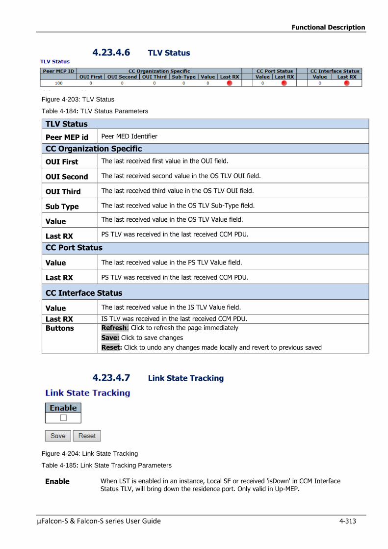
Functional Description
µFalcon-S & Falcon-S series User Guide 4-313
4.23.4.6 TLV Status
Figure 4-203: TLV Status
Table 4-184: TLV Status Parameters
TLV Status
Peer MEP id Peer MED Identifier
CC Organization Specific
OUI First The last received first value in the OUI field.
OUI Second The last received second value in the OS TLV OUI field.
OUI Third The last received third value in the OS TLV OUI field.
Sub Type The last received value in the OS TLV Sub-Type field.
Value The last received value in the OS TLV Value field.
Last RX PS TLV was received in the last received CCM PDU.
CC Port Status
Value The last received value in the PS TLV Value field.
Last RX PS TLV was received in the last received CCM PDU.
CC Interface Status
Value The last received value in the IS TLV Value field.
Last RX IS TLV was received in the last received CCM PDU.
Buttons Refresh: Click to refresh the page immediately
Save: Click to save changes
Reset: Click to undo any changes made locally and revert to previous saved
4.23.4.7 Link State Tracking
Figure 4-204: Link State Tracking
Table 4-185: Link State Tracking Parameters
Enable When LST is enabled in an instance, Local SF or received 'isDown' in CCM Interface Status TLV, will bring down the residence port. Only valid in Up-MEP.
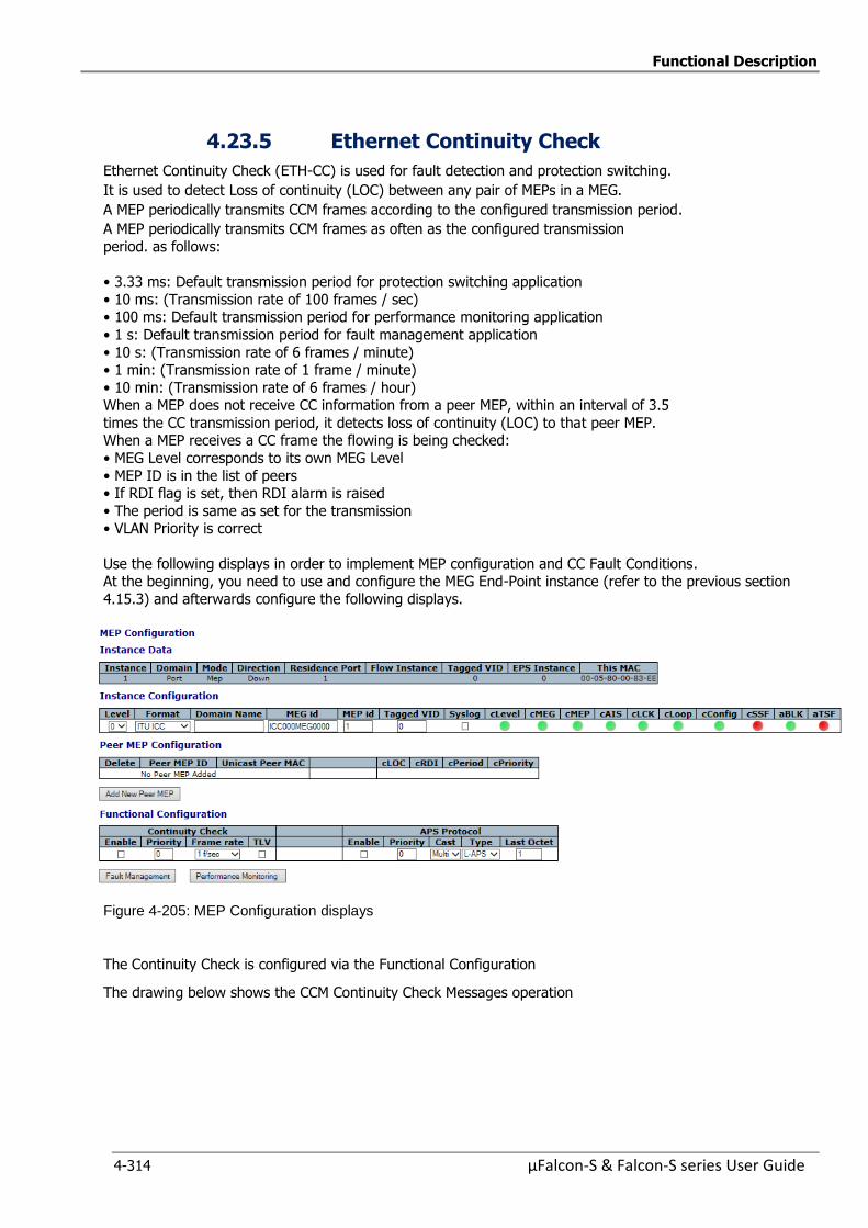
Functional Description
4-314 µFalcon-S & Falcon-S series User Guide
4.23.5 Ethernet Continuity Check
Ethernet Continuity Check (ETH-CC) is used for fault detection and protection switching.
It is used to detect Loss of continuity (LOC) between any pair of MEPs in a MEG.
A MEP periodically transmits CCM frames according to the configured transmission period.
A MEP periodically transmits CCM frames as often as the configured transmission
period. as follows:
• 3.33 ms: Default transmission period for protection switching application
• 10 ms: (Transmission rate of 100 frames / sec) • 100 ms: Default transmission period for performance monitoring application
• 1 s: Default transmission period for fault management application
• 10 s: (Transmission rate of 6 frames / minute) • 1 min: (Transmission rate of 1 frame / minute)
• 10 min: (Transmission rate of 6 frames / hour) When a MEP does not receive CC information from a peer MEP, within an interval of 3.5
times the CC transmission period, it detects loss of continuity (LOC) to that peer MEP. When a MEP receives a CC frame the flowing is being checked:
• MEG Level corresponds to its own MEG Level
• MEP ID is in the list of peers • If RDI flag is set, then RDI alarm is raised
• The period is same as set for the transmission • VLAN Priority is correct
Use the following displays in order to implement MEP configuration and CC Fault Conditions. At the beginning, you need to use and configure the MEG End-Point instance (refer to the previous section
4.15.3) and afterwards configure the following displays.
Figure 4-205: MEP Configuration displays
The Continuity Check is configured via the Functional Configuration
The drawing below shows the CCM Continuity Check Messages operation
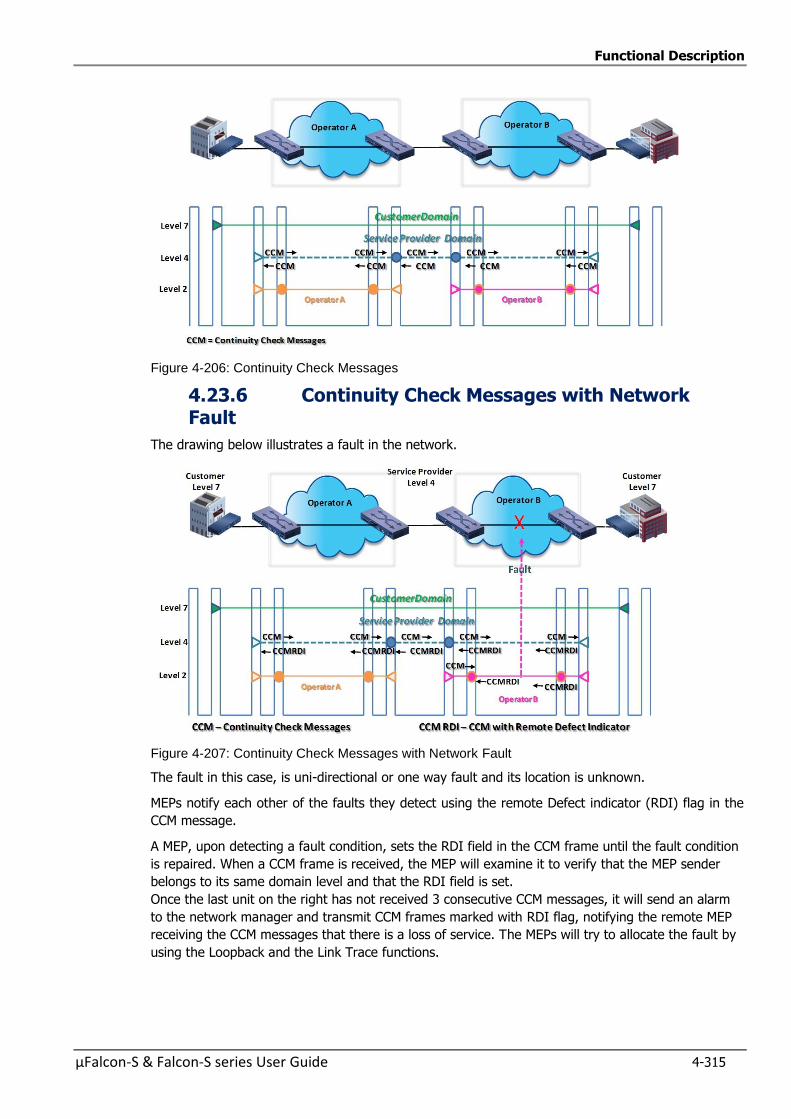
Functional Description
µFalcon-S & Falcon-S series User Guide 4-315
Figure 4-206: Continuity Check Messages
4.23.6 Continuity Check Messages with Network Fault
The drawing below illustrates a fault in the network.
Figure 4-207: Continuity Check Messages with Network Fault
The fault in this case, is uni-directional or one way fault and its location is unknown.
MEPs notify each other of the faults they detect using the remote Defect indicator (RDI) flag in the
CCM message.
A MEP, upon detecting a fault condition, sets the RDI field in the CCM frame until the fault condition
is repaired. When a CCM frame is received, the MEP will examine it to verify that the MEP sender
belongs to its same domain level and that the RDI field is set.
Once the last unit on the right has not received 3 consecutive CCM messages, it will send an alarm
to the network manager and transmit CCM frames marked with RDI flag, notifying the remote MEP
receiving the CCM messages that there is a loss of service. The MEPs will try to allocate the fault by
using the Loopback and the Link Trace functions.
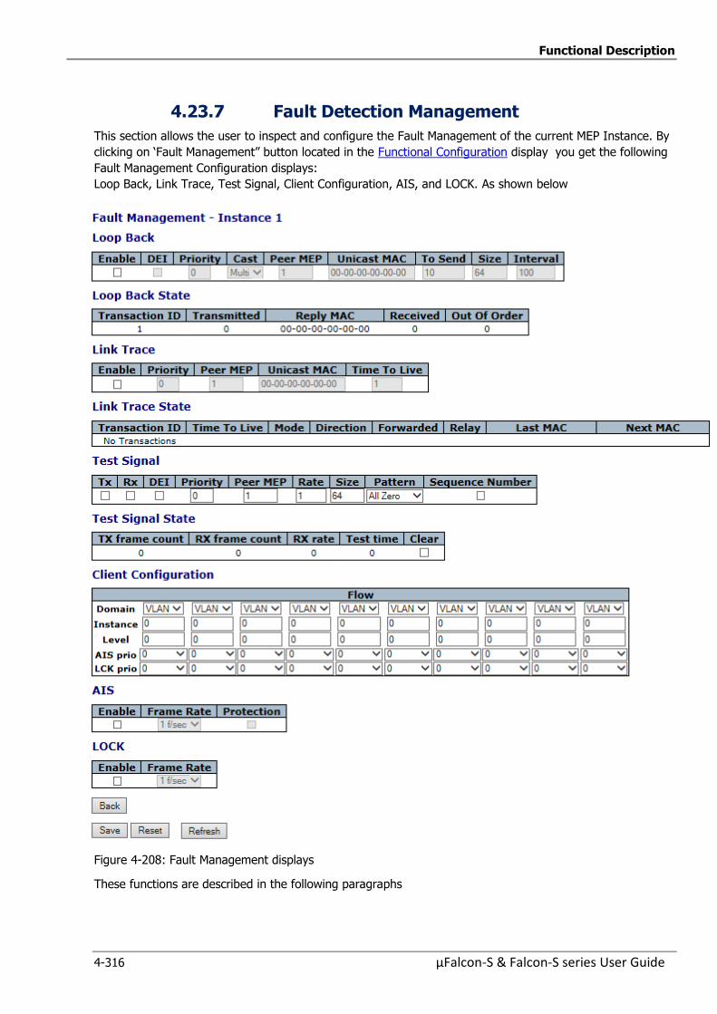
Functional Description
4-316 µFalcon-S & Falcon-S series User Guide
4.23.7 Fault Detection Management
This section allows the user to inspect and configure the Fault Management of the current MEP Instance. By
clicking on ‘Fault Management” button located in the Functional Configuration display you get the following
Fault Management Configuration displays:
Loop Back, Link Trace, Test Signal, Client Configuration, AIS, and LOCK. As shown below
Figure 4-208: Fault Management displays
These functions are described in the following paragraphs
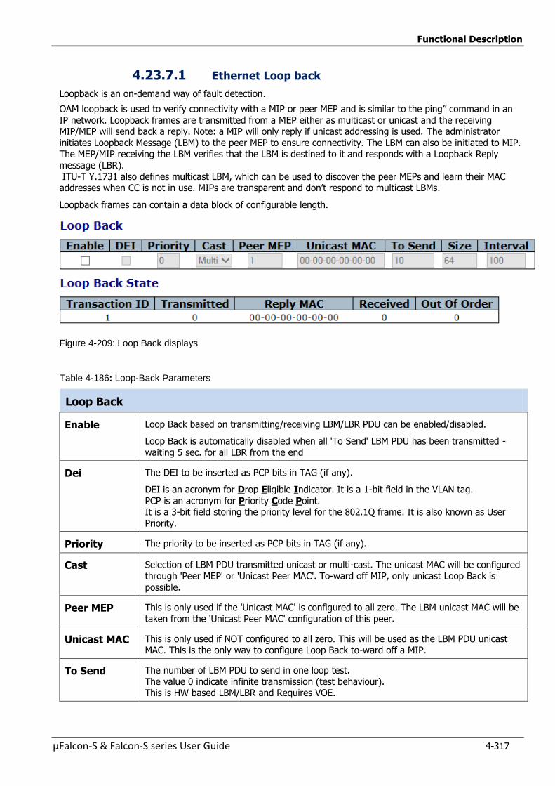
Functional Description
µFalcon-S & Falcon-S series User Guide 4-317
4.23.7.1 Ethernet Loop back
Loopback is an on-demand way of fault detection.
OAM loopback is used to verify connectivity with a MIP or peer MEP and is similar to the ping” command in an
IP network. Loopback frames are transmitted from a MEP either as multicast or unicast and the receiving MIP/MEP will send back a reply. Note: a MIP will only reply if unicast addressing is used. The administrator
initiates Loopback Message (LBM) to the peer MEP to ensure connectivity. The LBM can also be initiated to MIP. The MEP/MIP receiving the LBM verifies that the LBM is destined to it and responds with a Loopback Reply
message (LBR).
ITU-T Y.1731 also defines multicast LBM, which can be used to discover the peer MEPs and learn their MAC addresses when CC is not in use. MIPs are transparent and don’t respond to multicast LBMs.
Loopback frames can contain a data block of configurable length.
Figure 4-209: Loop Back displays
Table 4-186: Loop-Back Parameters
Loop Back
Enable Loop Back based on transmitting/receiving LBM/LBR PDU can be enabled/disabled.
Loop Back is automatically disabled when all 'To Send' LBM PDU has been transmitted -
waiting 5 sec. for all LBR from the end
Dei The DEI to be inserted as PCP bits in TAG (if any).
DEI is an acronym for Drop Eligible Indicator. It is a 1-bit field in the VLAN tag.
PCP is an acronym for Priority Code Point. It is a 3-bit field storing the priority level for the 802.1Q frame. It is also known as User
Priority.
Priority The priority to be inserted as PCP bits in TAG (if any).
Cast Selection of LBM PDU transmitted unicast or multi-cast. The unicast MAC will be configured
through 'Peer MEP' or 'Unicast Peer MAC'. To-ward off MIP, only unicast Loop Back is
possible.
Peer MEP This is only used if the 'Unicast MAC' is configured to all zero. The LBM unicast MAC will be
taken from the 'Unicast Peer MAC' configuration of this peer.
Unicast MAC This is only used if NOT configured to all zero. This will be used as the LBM PDU unicast MAC. This is the only way to configure Loop Back to-ward off a MIP.
To Send The number of LBM PDU to send in one loop test.
The value 0 indicate infinite transmission (test behaviour). This is HW based LBM/LBR and Requires VOE.
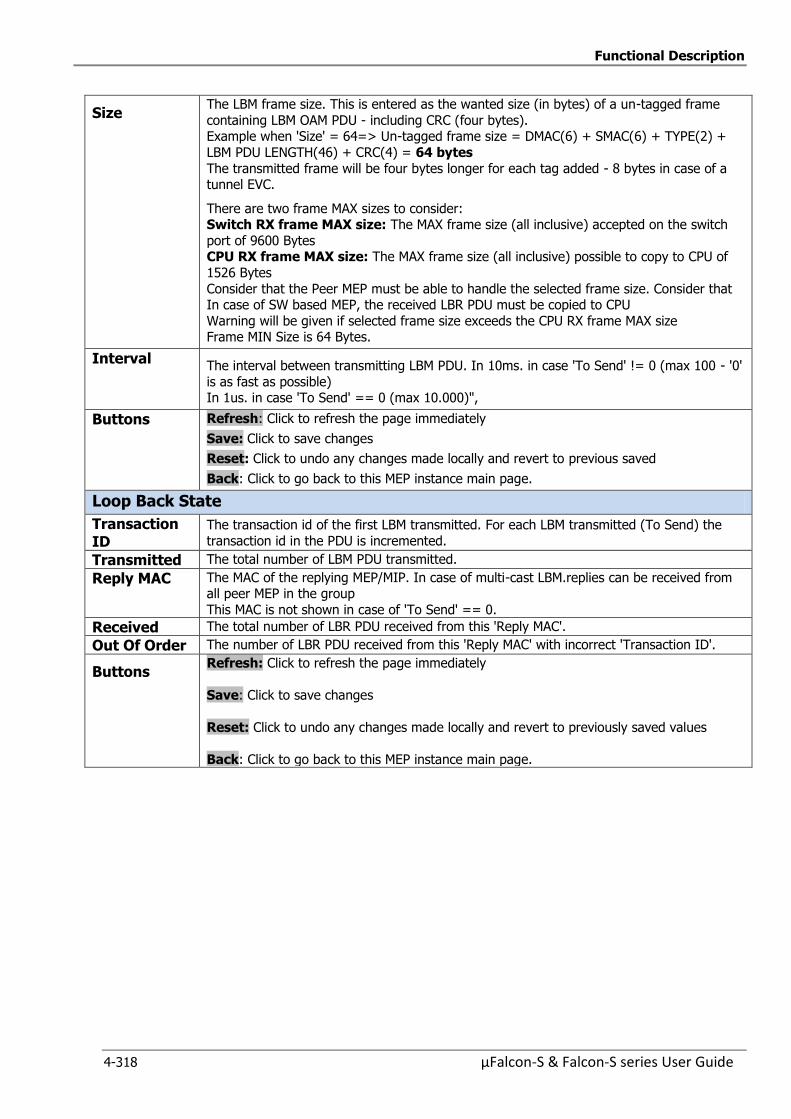
Functional Description
4-318 µFalcon-S & Falcon-S series User Guide
Size The LBM frame size. This is entered as the wanted size (in bytes) of a un-tagged frame
containing LBM OAM PDU - including CRC (four bytes). Example when 'Size' = 64=> Un-tagged frame size = DMAC(6) + SMAC(6) + TYPE(2) +
LBM PDU LENGTH(46) + CRC(4) = 64 bytes
The transmitted frame will be four bytes longer for each tag added - 8 bytes in case of a tunnel EVC.
There are two frame MAX sizes to consider: Switch RX frame MAX size: The MAX frame size (all inclusive) accepted on the switch
port of 9600 Bytes CPU RX frame MAX size: The MAX frame size (all inclusive) possible to copy to CPU of
1526 Bytes
Consider that the Peer MEP must be able to handle the selected frame size. Consider that In case of SW based MEP, the received LBR PDU must be copied to CPU
Warning will be given if selected frame size exceeds the CPU RX frame MAX size Frame MIN Size is 64 Bytes.
Interval The interval between transmitting LBM PDU. In 10ms. in case 'To Send' != 0 (max 100 - '0'
is as fast as possible) In 1us. in case 'To Send' == 0 (max 10.000)",
Buttons Refresh: Click to refresh the page immediately
Save: Click to save changes
Reset: Click to undo any changes made locally and revert to previous saved
Back: Click to go back to this MEP instance main page.
Loop Back State
Transaction ID
The transaction id of the first LBM transmitted. For each LBM transmitted (To Send) the
transaction id in the PDU is incremented.
Transmitted The total number of LBM PDU transmitted.
Reply MAC The MAC of the replying MEP/MIP. In case of multi-cast LBM.replies can be received from all peer MEP in the group
This MAC is not shown in case of 'To Send' == 0.
Received The total number of LBR PDU received from this 'Reply MAC'.
Out Of Order The number of LBR PDU received from this 'Reply MAC' with incorrect 'Transaction ID'.
Buttons Refresh: Click to refresh the page immediately
Save: Click to save changes
Reset: Click to undo any changes made locally and revert to previously saved values
Back: Click to go back to this MEP instance main page.
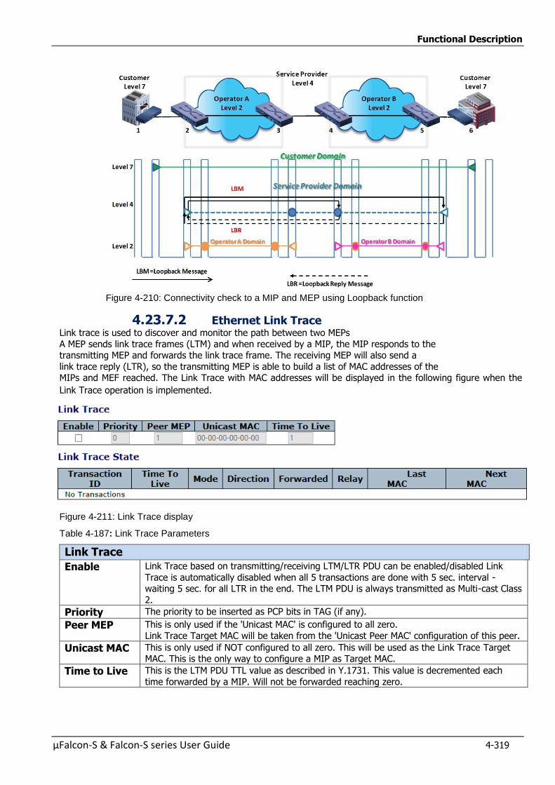
Functional Description
µFalcon-S & Falcon-S series User Guide 4-319
Figure 4-210: Connectivity check to a MIP and MEP using Loopback function
4.23.7.2 Ethernet Link Trace Link trace is used to discover and monitor the path between two MEPs
A MEP sends link trace frames (LTM) and when received by a MIP, the MIP responds to the transmitting MEP and forwards the link trace frame. The receiving MEP will also send a
link trace reply (LTR), so the transmitting MEP is able to build a list of MAC addresses of the MIPs and MEF reached. The Link Trace with MAC addresses will be displayed in the following figure when the
Link Trace operation is implemented.
Figure 4-211: Link Trace display
Table 4-187: Link Trace Parameters
Link Trace
Enable Link Trace based on transmitting/receiving LTM/LTR PDU can be enabled/disabled Link
Trace is automatically disabled when all 5 transactions are done with 5 sec. interval - waiting 5 sec. for all LTR in the end. The LTM PDU is always transmitted as Multi-cast Class
2.
Priority The priority to be inserted as PCP bits in TAG (if any).
Peer MEP This is only used if the 'Unicast MAC' is configured to all zero.
Link Trace Target MAC will be taken from the 'Unicast Peer MAC' configuration of this peer.
Unicast MAC This is only used if NOT configured to all zero. This will be used as the Link Trace Target MAC. This is the only way to configure a MIP as Target MAC.
Time to Live This is the LTM PDU TTL value as described in Y.1731. This value is decremented each
time forwarded by a MIP. Will not be forwarded reaching zero.
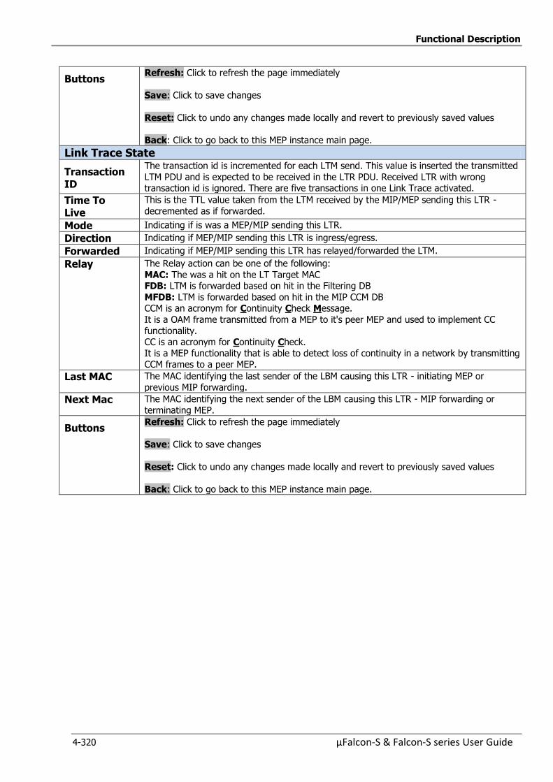
Functional Description
4-320 µFalcon-S & Falcon-S series User Guide
Buttons Refresh: Click to refresh the page immediately
Save: Click to save changes
Reset: Click to undo any changes made locally and revert to previously saved values
Back: Click to go back to this MEP instance main page.
Link Trace State
Transaction ID
The transaction id is incremented for each LTM send. This value is inserted the transmitted
LTM PDU and is expected to be received in the LTR PDU. Received LTR with wrong transaction id is ignored. There are five transactions in one Link Trace activated.
Time To Live
This is the TTL value taken from the LTM received by the MIP/MEP sending this LTR -
decremented as if forwarded.
Mode Indicating if is was a MEP/MIP sending this LTR.
Direction Indicating if MEP/MIP sending this LTR is ingress/egress.
Forwarded Indicating if MEP/MIP sending this LTR has relayed/forwarded the LTM.
Relay The Relay action can be one of the following:
MAC: The was a hit on the LT Target MAC FDB: LTM is forwarded based on hit in the Filtering DB
MFDB: LTM is forwarded based on hit in the MIP CCM DB CCM is an acronym for Continuity Check Message.
It is a OAM frame transmitted from a MEP to it's peer MEP and used to implement CC
functionality. CC is an acronym for Continuity Check.
It is a MEP functionality that is able to detect loss of continuity in a network by transmitting CCM frames to a peer MEP.
Last MAC The MAC identifying the last sender of the LBM causing this LTR - initiating MEP or
previous MIP forwarding.
Next Mac The MAC identifying the next sender of the LBM causing this LTR - MIP forwarding or
terminating MEP.
Buttons Refresh: Click to refresh the page immediately
Save: Click to save changes
Reset: Click to undo any changes made locally and revert to previously saved values
Back: Click to go back to this MEP instance main page.

Functional Description
µFalcon-S & Falcon-S series User Guide 4-321
Link Trace Operation diagram
Figure 4-212: Link Trace operation
In the above example, the last MIP to respond with a LTR is at the edge of the Operator B.
Therefore the network manager can isolate the location of the fault to the Operator B The Operator B can also initiate a Link Trace operation from the MEP at the edge of his MEP to isolate
the fault within the network. As already mentioned, the Link Trace can also be used to determine a physical network path during service initialization by identifying relationships between remote MEPs and
MIPs at the same domain level.
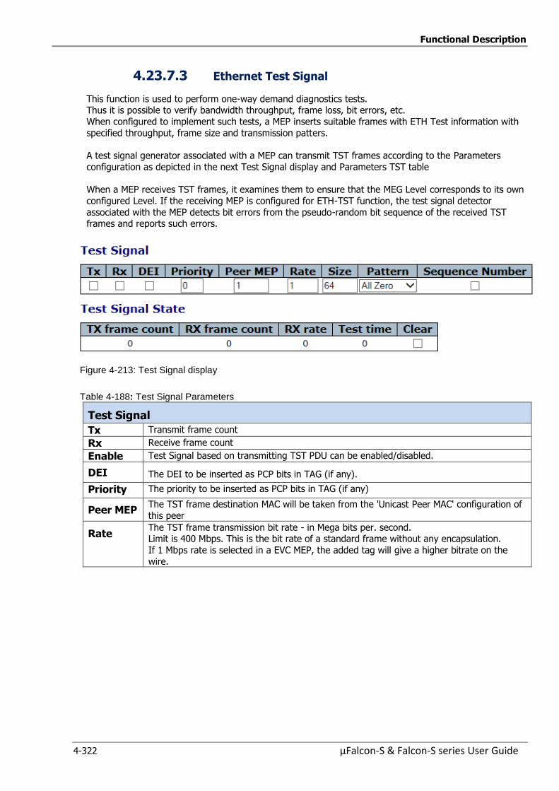
Functional Description
4-322 µFalcon-S & Falcon-S series User Guide
4.23.7.3 Ethernet Test Signal
This function is used to perform one-way demand diagnostics tests. Thus it is possible to verify bandwidth throughput, frame loss, bit errors, etc.
When configured to implement such tests, a MEP inserts suitable frames with ETH Test information with
specified throughput, frame size and transmission patters.
A test signal generator associated with a MEP can transmit TST frames according to the Parameters
configuration as depicted in the next Test Signal display and Parameters TST table
When a MEP receives TST frames, it examines them to ensure that the MEG Level corresponds to its own
configured Level. If the receiving MEP is configured for ETH-TST function, the test signal detector
associated with the MEP detects bit errors from the pseudo-random bit sequence of the received TST frames and reports such errors.
Figure 4-213: Test Signal display
Table 4-188: Test Signal Parameters
Test Signal
Tx Transmit frame count
Rx Receive frame count
Enable Test Signal based on transmitting TST PDU can be enabled/disabled.
DEI The DEI to be inserted as PCP bits in TAG (if any).
Priority The priority to be inserted as PCP bits in TAG (if any)
Peer MEP The TST frame destination MAC will be taken from the 'Unicast Peer MAC' configuration of
this peer
Rate The TST frame transmission bit rate - in Mega bits per. second. Limit is 400 Mbps. This is the bit rate of a standard frame without any encapsulation.
If 1 Mbps rate is selected in a EVC MEP, the added tag will give a higher bitrate on the
wire.
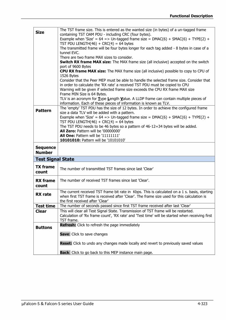
Functional Description
µFalcon-S & Falcon-S series User Guide 4-323
Size The TST frame size. This is entered as the wanted size (in bytes) of a un-tagged frame
containing TST OAM PDU - including CRC (four bytes). Example when 'Size' = 64 => Un-tagged frame size = DMAC(6) + SMAC(6) + TYPE(2) +
TST PDU LENGTH(46) + CRC(4) = 64 bytes
The transmitted frame will be four bytes longer for each tag added - 8 bytes in case of a tunnel EVC.
There are two frame MAX sizes to consider. Switch RX frame MAX size: The MAX frame size (all inclusive) accepted on the switch
port of 9600 Bytes CPU RX frame MAX size: The MAX frame size (all inclusive) possible to copy to CPU of
1526 Bytes
Consider that the Peer MEP must be able to handle the selected frame size. Consider that in order to calculate the 'RX rate' a received TST PDU must be copied to CPU
Warning will be given if selected frame size exceeds the CPU RX frame MAX size Frame MIN Size is 64 Bytes.
TLV is an acronym for Type Length Value. A LLDP frame can contain multiple pieces of
information. Each of these pieces of information is known as TLV.
Pattern The 'empty' TST PDU has the size of 12 bytes. In order to achieve the configured frame
size a data TLV will be added with a pattern. Example when 'Size' = 64 => Un-tagged frame size = DMAC(6) + SMAC(6) + TYPE(2) +
TST PDU LENGTH(46) + CRC(4) = 64 bytes
The TST PDU needs to be 46 bytes so a pattern of 46-12=34 bytes will be added. All Zero: Pattern will be '00000000'
All One: Pattern will be '11111111' 10101010: Pattern will be '10101010'
Sequence Number
Test Signal State
TX frame count
The number of transmitted TST frames since last 'Clear'
RX frame count
The number of received TST frames since last 'Clear'.
RX rate The current received TST frame bit rate in Kbps. This is calculated on a 1 s. basis, starting
when first TST frame is received after 'Clear'. The frame size used for this calculation is
the first received after 'Clear'
Test time The number of seconds passed since first TST frame received after last 'Clear'
Clear This will clear all Test Signal State. Transmission of TST frame will be restarted.
Calculation of 'Rx frame count', 'RX rate' and 'Test time' will be started when receiving first TST frame.
Buttons Refresh: Click to refresh the page immediately
Save: Click to save changes
Reset: Click to undo any changes made locally and revert to previously saved values
Back: Click to go back to this MEP instance main page.
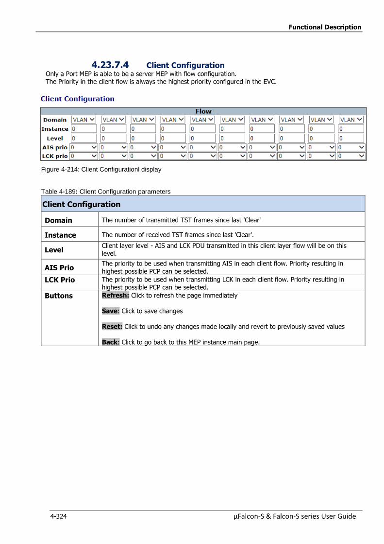
Functional Description
4-324 µFalcon-S & Falcon-S series User Guide
4.23.7.4 Client Configuration Only a Port MEP is able to be a server MEP with flow configuration. The Priority in the client flow is always the highest priority configured in the EVC.
Figure 4-214: Client Configurationl display
Table 4-189: Client Configuration parameters
Client Configuration
Domain The number of transmitted TST frames since last 'Clear'
Instance The number of received TST frames since last 'Clear'.
Level Client layer level - AIS and LCK PDU transmitted in this client layer flow will be on this
level.
AIS Prio The priority to be used when transmitting AIS in each client flow. Priority resulting in
highest possible PCP can be selected.
LCK Prio The priority to be used when transmitting LCK in each client flow. Priority resulting in highest possible PCP can be selected.
Buttons Refresh: Click to refresh the page immediately
Save: Click to save changes
Reset: Click to undo any changes made locally and revert to previously saved values
Back: Click to go back to this MEP instance main page.

Functional Description
µFalcon-S & Falcon-S series User Guide 4-325
4.23.7.5 Ethernet Alarm Indicator Signal (IAS) It is important for the customer/service provider to know if a fault has occurred in his domain or it is
due to a fault that has occurred in another domain
Let us assume that a fault has occurred in the operator’s domain, which also results in service
provider domain MEPs detecting faults. For the administrator of the service provider domain, he has
no knowledge of the fault that has occurred in the operator’s domain unless he coordinates with the
operator. AIS signal will notify the higher layer MEPs of the fault that has occurred in the lower level.
The MEP on detecting a fault raises alarm indications using the Alarm Indication Signal (AIS)
message2 to notify about the fault to its higher level MEPs. The MEPs receiving AIS should suppress
any alarms, since the fault reported is due to side effect of a fault in the lower level.
Figure 4-215: MEP generating AIS on detecting loss of CCMs
Figure 4-216: AIS Display
Table 4-190: AIS Configuration Parameters
Ethernet Alarm Indicator Signal (IAS)
Enable Insertion of AIS signal (AIS PDU transmission) in client layer flows, can be enable/disabled.
Frame Rate Selecting the frame rate of AIS PDU. This is the inverse of transmission period as described in Y.1731.:
Protection Selecting this means that the first 3 AIS PDU is transmitted as fast as possible -
in case of using this for protection in the end point.
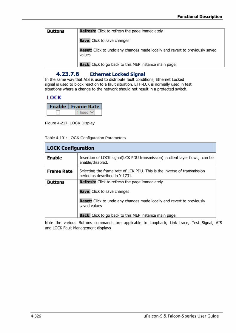
Functional Description
4-326 µFalcon-S & Falcon-S series User Guide
Buttons Refresh: Click to refresh the page immediately
Save: Click to save changes
Reset: Click to undo any changes made locally and revert to previously saved values
Back: Click to go back to this MEP instance main page.
4.23.7.6 Ethernet Locked Signal In the same way that AIS is used to distribute fault conditions, Ethernet Locked
signal is used to block reaction to a fault situation. ETH-LCK is normally used in test
situations where a change to the network should not result in a protected switch.
Figure 4-217: LOCK Display
Table 4-191: LOCK Configuration Parameters
LOCK Configuration
Enable Insertion of LOCK signal(LCK PDU transmission) in client layer flows, can be
enable/disabled.
Frame Rate Selecting the frame rate of LCK PDU. This is the inverse of transmission period as described in Y.1731.
Buttons Refresh: Click to refresh the page immediately
Save: Click to save changes
Reset: Click to undo any changes made locally and revert to previously
saved values
Back: Click to go back to this MEP instance main page.
Note the various Buttons commands are applicable to Loopback, Link trace, Test Signal, AIS
and LOCK Fault Management displays
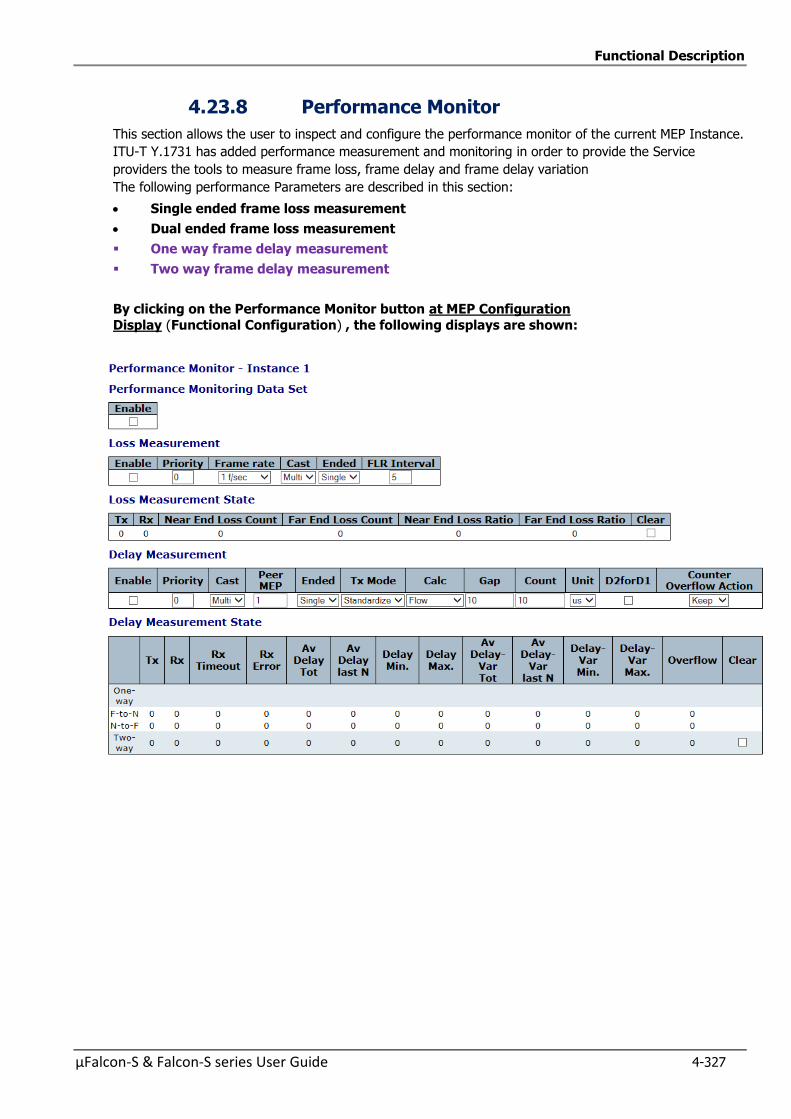
Functional Description
µFalcon-S & Falcon-S series User Guide 4-327
4.23.8 Performance Monitor
This section allows the user to inspect and configure the performance monitor of the current MEP Instance.
ITU-T Y.1731 has added performance measurement and monitoring in order to provide the Service
providers the tools to measure frame loss, frame delay and frame delay variation
The following performance Parameters are described in this section:
Single ended frame loss measurement
Dual ended frame loss measurement
One way frame delay measurement
Two way frame delay measurement
By clicking on the Performance Monitor button at MEP Configuration
Display (Functional Configuration) , the following displays are shown:
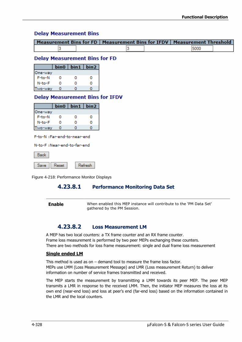
Functional Description
4-328 µFalcon-S & Falcon-S series User Guide
Figure 4-218: Performance Monitor Displays
4.23.8.1 Performance Monitoring Data Set
Enable When enabled this MEP instance will contribute to the 'PM Data Set' gathered by the PM Session.
4.23.8.2 Loss Measurement LM
A MEP has two local counters: a TX frame counter and an RX frame counter.
Frame loss measurement is performed by two peer MEPs exchanging these counters.
There are two methods for loss frame measurement: single and dual frame loss measurement
Single ended LM
This method is used as on – demand tool to measure the frame loss factor.
MEPs use LMM (Loss Measurement Message) and LMR (Loss measurement Return) to deliver
information on number of service frames transmitted and received.
The MEP starts the measurement by transmitting a LMM towards its peer MEP. The peer MEP
transmits a LMR in response to the received LMM. Then, the initiator MEP measures the loss at its
own end (near-end loss) and loss at peer’s end (far-end loss) based on the information contained in
the LMR and the local counters.
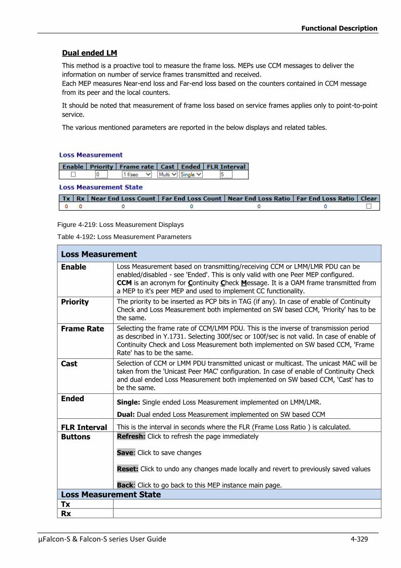
Functional Description
µFalcon-S & Falcon-S series User Guide 4-329
Dual ended LM
This method is a proactive tool to measure the frame loss. MEPs use CCM messages to deliver the
information on number of service frames transmitted and received.
Each MEP measures Near-end loss and Far-end loss based on the counters contained in CCM message
from its peer and the local counters.
It should be noted that measurement of frame loss based on service frames applies only to point-to-point
service.
The various mentioned parameters are reported in the below displays and related tables.
Figure 4-219: Loss Measurement Displays
Table 4-192: Loss Measurement Parameters
Loss Measurement
Enable Loss Measurement based on transmitting/receiving CCM or LMM/LMR PDU can be
enabled/disabled - see 'Ended'. This is only valid with one Peer MEP configured. CCM is an acronym for Continuity Check Message. It is a OAM frame transmitted from
a MEP to it's peer MEP and used to implement CC functionality.
Priority The priority to be inserted as PCP bits in TAG (if any). In case of enable of Continuity
Check and Loss Measurement both implemented on SW based CCM, 'Priority' has to be
the same.
Frame Rate Selecting the frame rate of CCM/LMM PDU. This is the inverse of transmission period
as described in Y.1731. Selecting 300f/sec or 100f/sec is not valid. In case of enable of
Continuity Check and Loss Measurement both implemented on SW based CCM, 'Frame Rate' has to be the same.
Cast Selection of CCM or LMM PDU transmitted unicast or multicast. The unicast MAC will be taken from the 'Unicast Peer MAC' configuration. In case of enable of Continuity Check
and dual ended Loss Measurement both implemented on SW based CCM, 'Cast' has to
be the same.
Ended Single: Single ended Loss Measurement implemented on LMM/LMR.
Dual: Dual ended Loss Measurement implemented on SW based CCM
FLR Interval This is the interval in seconds where the FLR (Frame Loss Ratio ) is calculated.
Buttons Refresh: Click to refresh the page immediately
Save: Click to save changes
Reset: Click to undo any changes made locally and revert to previously saved values
Back: Click to go back to this MEP instance main page.
Loss Measurement State
Tx
Rx
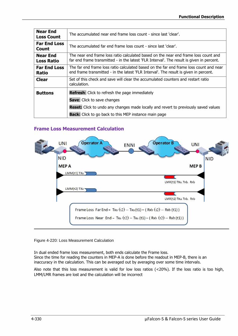
Functional Description
4-330 µFalcon-S & Falcon-S series User Guide
Near End Loss Count
The accumulated near end frame loss count - since last 'clear'.
Far End Loss Count
The accumulated far end frame loss count - since last 'clear'.
Near End Loss Ratio
The near end frame loss ratio calculated based on the near end frame loss count and
far end frame transmitted - in the latest 'FLR Interval'. The result is given in percent.
Far End Loss Ratio
The far end frame loss ratio calculated based on the far end frame loss count and near end frame transmitted - in the latest 'FLR Interval'. The result is given in percent.
Clear Set of this check and save will clear the accumulated counters and restart ratio
calculation.
Buttons Refresh: Click to refresh the page immediately
Save: Click to save changes
Reset: Click to undo any changes made locally and revert to previously saved values
Back: Click to go back to this MEP instance main page
Frame Loss Measurement Calculation
Figure 4-220: Loss Measurement Calculation
In dual ended frame loss measurement, both ends calculate the Frame loss. Since the time for reading the counters in MEP-A is done before the readout in MEP-B, there is an
inaccuracy in the calculation. This can be averaged out by averaging over some time intervals.
Also note that this loss measurement is valid for low loss ratios (<20%). If the loss ratio is too high,
LMM/LMR frames are lost and the calculation will be incorrect
Functional Description
µFalcon-S & Falcon-S series User Guide 4-331
4.23.8.3 Delay Measurement
Frame Delay (FD) and Frame Delay Variation (FDV) are important factors in QoS.
The FD and FDV requirements will be different for each service>
Frame Delay is defined as the time elapsed since the start of transmission of the first bit from the
source until the reception of last bit of the frame at the destination.
Frame Delay Variation is the difference in the Frame Delay between two successive frames. . The
following methods are defined to measure the FD and FDV:
One way frame delay measurement
Two away frame delay measurement
4.23.8.4 One way frame delay measurement
Used to measure the frame delay and delay variation in one-direction. The MEP transmits 1DM
frame. It carries the timestamp at the time of transmission of 1DM. The MEP receiving the 1DM
frame timestamps the reception time and measures the delay by calculating the elapsed time
between the transmission and reception of the 1DM frame.
Frame delay=RxTimeStamp — TxTimeStamp
To use this method, the clocks on both the ends need to be synchronized by IEEE1588 PTP
protocol.
4.23.8.5 Two way frame delay measurement
Used to measure the round-trip delay and delay variation of the frame. This is obtained using the
DMM and DMR frames. Timestamp of DMM transmission is carried in the DMM frame which is
reflected back in the DMR frame.
If not possible to have the two MEPs synchronized, a two-way delay measurement can be used. Here the MEP sends ETH-DM request with TxTimeStampf to the peer MEP
which replies with the time of the request arrival (RxTimeStampf) and the transmission time of the reply (TxTimeStampb). With the recording of the arrival time of the reply
the frame delay is calculated as:
Frame Delay = (RxTimeb–TxTimeStampf) – (TxTimeStampb–RxTimeStampf)
The following display and related table include the required Parameters and statuses of both
operations.
Delay Measurement and Delay Measurement State displays are shown on next page
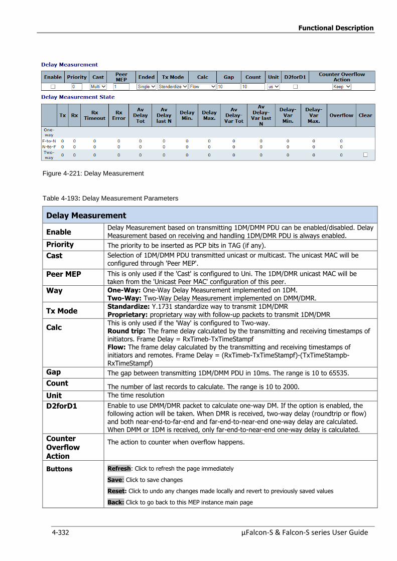
Functional Description
4-332 µFalcon-S & Falcon-S series User Guide
Figure 4-221: Delay Measurement
Table 4-193: Delay Measurement Parameters
Delay Measurement
Enable Delay Measurement based on transmitting 1DM/DMM PDU can be enabled/disabled. Delay
Measurement based on receiving and handling 1DM/DMR PDU is always enabled.
Priority The priority to be inserted as PCP bits in TAG (if any).
Cast Selection of 1DM/DMM PDU transmitted unicast or multicast. The unicast MAC will be
configured through 'Peer MEP'.
Peer MEP This is only used if the 'Cast' is configured to Uni. The 1DM/DMR unicast MAC will be taken from the 'Unicast Peer MAC' configuration of this peer.
Way One-Way: One-Way Delay Measurement implemented on 1DM.
Two-Way: Two-Way Delay Measurement implemented on DMM/DMR.
Tx Mode Standardize: Y.1731 standardize way to transmit 1DM/DMR
Proprietary: proprietary way with follow-up packets to transmit 1DM/DMR
Calc This is only used if the 'Way' is configured to Two-way. Round trip: The frame delay calculated by the transmitting and receiving timestamps of
initiators. Frame Delay = RxTimeb-TxTimeStampf Flow: The frame delay calculated by the transmitting and receiving timestamps of
initiators and remotes. Frame Delay = (RxTimeb-TxTimeStampf)-(TxTimeStampb-
RxTimeStampf)
Gap The gap between transmitting 1DM/DMM PDU in 10ms. The range is 10 to 65535.
Count The number of last records to calculate. The range is 10 to 2000.
Unit The time resolution
D2forD1 Enable to use DMM/DMR packet to calculate one-way DM. If the option is enabled, the following action will be taken. When DMR is received, two-way delay (roundtrip or flow)
and both near-end-to-far-end and far-end-to-near-end one-way delay are calculated. When DMM or 1DM is received, only far-end-to-near-end one-way delay is calculated.
Counter Overflow Action
The action to counter when overflow happens.
Buttons Refresh: Click to refresh the page immediately
Save: Click to save changes
Reset: Click to undo any changes made locally and revert to previously saved values
Back: Click to go back to this MEP instance main page
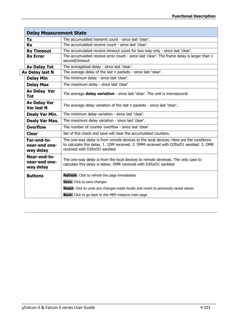
Functional Description
µFalcon-S & Falcon-S series User Guide 4-333
Delay Measurement State
Tx The accumulated transmit count - since last 'clear'.
Rx The accumulated receive count - since last 'clear'.
Rx Timeout The accumulated receive timeout count for two-way only - since last 'clear'.
Rx Error The accumulated receive error count - since last 'clear'. The frame delay is larger than 1
second(timeout
Av Delay Tot The averagetoal delay - since last 'clear'.
Av Delay last N The average delay of the last n packets - since last 'clear'.
Delay Min The minimum delay - since last 'clear'.
Delay Max The maximum delay - since last 'clear'
Av Delay Var Tot
The average delay variation - since last 'clear'. The unit is microsecond.
Av Delay Var Var last N
The average delay variation of the last n packets - since last 'clear'..
Dealy Var Min. The minimum delay variation - since last 'clear'.
Dealy Var Max. The maximum delay variation - since last 'clear'.
Overflow The number of counter overflow - since last 'clear'.
Clear Set of this check and save will clear the accumulated counters.
Far-end-to-near-end one-way delay
The one-way delay is from remote devices to the local devices. Here are the conditions
to calculate this delay. 1. 1DM received. 2. DMM received with D2forD1 eanbled. 3. DMR received with D2forD1 eanbled
Near-end-to-near-end one-way delay
The one-way delay is from the local devices to remote devieces. The only case to calculate this delay is below. DMR received with D2forD1 eanbled
Buttons Refresh: Click to refresh the page immediately
Save: Click to save changes
Reset: Click to undo any changes made locally and revert to previously saved values
Back: Click to go back to this MEP instance main page
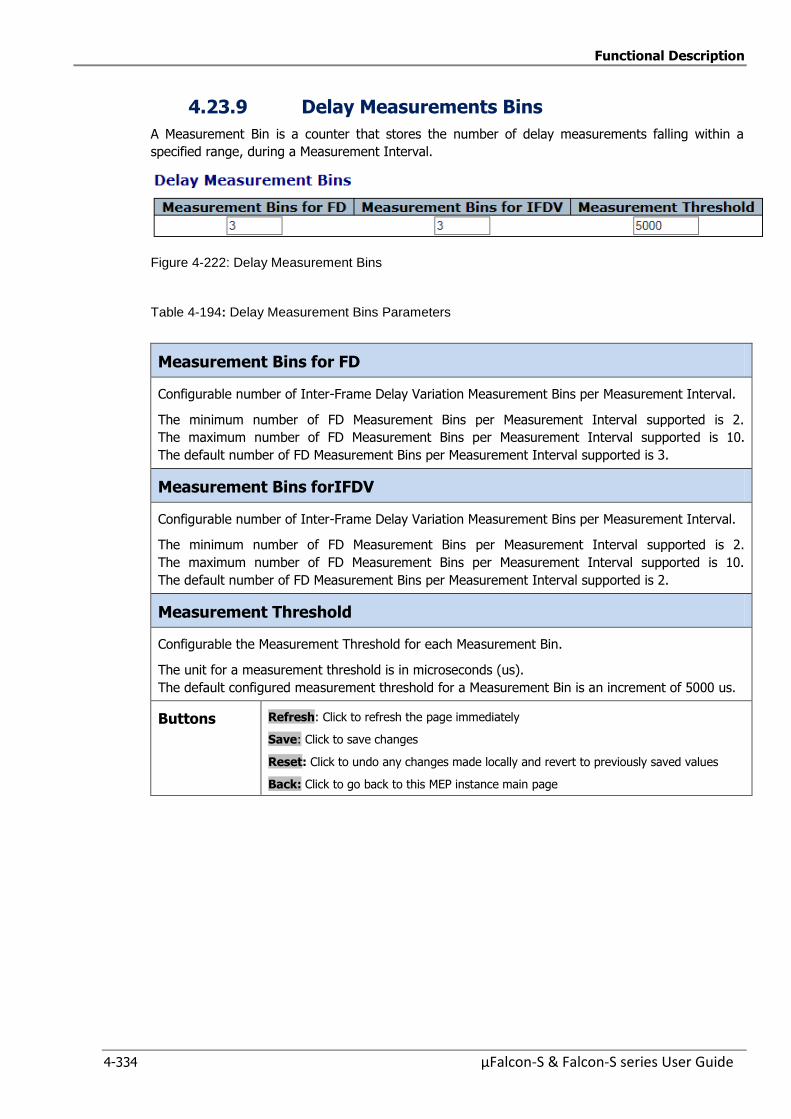
Functional Description
4-334 µFalcon-S & Falcon-S series User Guide
4.23.9 Delay Measurements Bins
A Measurement Bin is a counter that stores the number of delay measurements falling within a
specified range, during a Measurement Interval.
Figure 4-222: Delay Measurement Bins
Table 4-194: Delay Measurement Bins Parameters
Measurement Bins for FD
Configurable number of Inter-Frame Delay Variation Measurement Bins per Measurement Interval.
The minimum number of FD Measurement Bins per Measurement Interval supported is 2.
The maximum number of FD Measurement Bins per Measurement Interval supported is 10.
The default number of FD Measurement Bins per Measurement Interval supported is 3.
Measurement Bins forIFDV
Configurable number of Inter-Frame Delay Variation Measurement Bins per Measurement Interval.
The minimum number of FD Measurement Bins per Measurement Interval supported is 2.
The maximum number of FD Measurement Bins per Measurement Interval supported is 10.
The default number of FD Measurement Bins per Measurement Interval supported is 2.
Measurement Threshold
Configurable the Measurement Threshold for each Measurement Bin.
The unit for a measurement threshold is in microseconds (us).
The default configured measurement threshold for a Measurement Bin is an increment of 5000 us.
Buttons Refresh: Click to refresh the page immediately
Save: Click to save changes
Reset: Click to undo any changes made locally and revert to previously saved values
Back: Click to go back to this MEP instance main page

Functional Description
µFalcon-S & Falcon-S series User Guide 4-335
4.23.10 Delay Measurements Bins forFD
A Measurement Bin is a counter that stores the number of delay measurements falling within a
specified range, during a Measurement Interval.
Figure 4-223: Delay Measurement Bins for FD
Bin Threshold Range Bin0 0 us 0 us <= measurement < 5,000 us
Bin1 5,000 us 5,000 us <= measurement < 10,000 us
Bin2 10,000 us 10,000 us <= measurement < 15,000 us
Bin3 15,000 us 15,000 us <= measurement < infinite us
4.23.11 Delay Measurements Bins for IFDV
A Measurement Bin is a counter that stores the number of delay measurements falling within a
specified range, during a Measurement Interval
Figure 4-224: Delay Measurement Bins for IFDV
Bin Threshold Range Bin0
0 us 0 us <= measurement < 5,000 us
Bin1 5,000 us 5,000 us <= measurement < 10,000 us
Bin2 10,000 us 10,000 us <= measurement < 15,000 us
Bin3 15,000 us 15,000 us <= measurement < infinite us
F-to-N :Far-end-to-near-end
N-to-F :Near-end-to-far-end
Buttons Refresh: Click to refresh the page immediately
Save: Click to save changes
Reset: Click to undo any changes made locally and revert to previously saved values
Back: Click to go back to this MEP instance main page
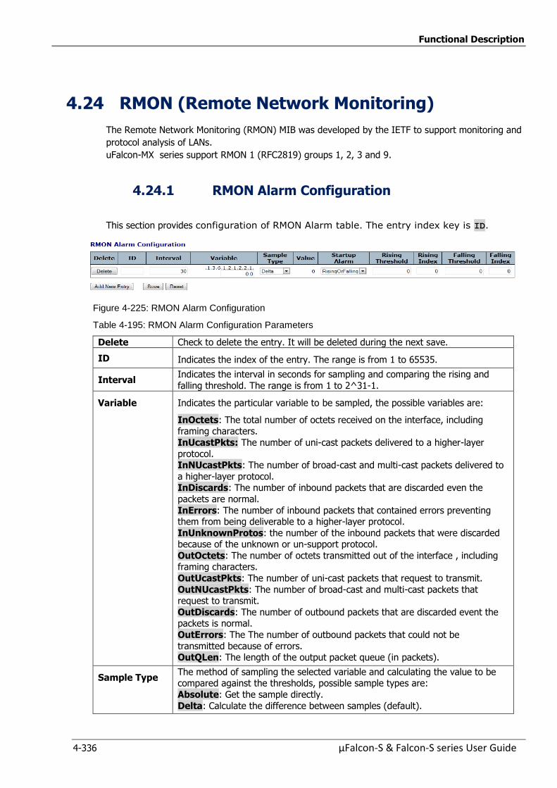
Functional Description
4-336 µFalcon-S & Falcon-S series User Guide
4.24 RMON (Remote Network Monitoring)
The Remote Network Monitoring (RMON) MIB was developed by the IETF to support monitoring and
protocol analysis of LANs.
uFalcon-MX series support RMON 1 (RFC2819) groups 1, 2, 3 and 9.
4.24.1 RMON Alarm Configuration
This section provides configuration of RMON Alarm table. The entry index key is ID.
Figure 4-225: RMON Alarm Configuration
Table 4-195: RMON Alarm Configuration Parameters
Delete Check to delete the entry. It will be deleted during the next save.
ID Indicates the index of the entry. The range is from 1 to 65535.
Interval Indicates the interval in seconds for sampling and comparing the rising and
falling threshold. The range is from 1 to 2^31-1.
Variable Indicates the particular variable to be sampled, the possible variables are:
InOctets: The total number of octets received on the interface, including framing characters.
InUcastPkts: The number of uni-cast packets delivered to a higher-layer
protocol. InNUcastPkts: The number of broad-cast and multi-cast packets delivered to
a higher-layer protocol. InDiscards: The number of inbound packets that are discarded even the
packets are normal.
InErrors: The number of inbound packets that contained errors preventing them from being deliverable to a higher-layer protocol.
InUnknownProtos: the number of the inbound packets that were discarded because of the unknown or un-support protocol.
OutOctets: The number of octets transmitted out of the interface , including framing characters.
OutUcastPkts: The number of uni-cast packets that request to transmit.
OutNUcastPkts: The number of broad-cast and multi-cast packets that request to transmit.
OutDiscards: The number of outbound packets that are discarded event the packets is normal.
OutErrors: The The number of outbound packets that could not be
transmitted because of errors. OutQLen: The length of the output packet queue (in packets).
Sample Type The method of sampling the selected variable and calculating the value to be compared against the thresholds, possible sample types are:
Absolute: Get the sample directly.
Delta: Calculate the difference between samples (default).
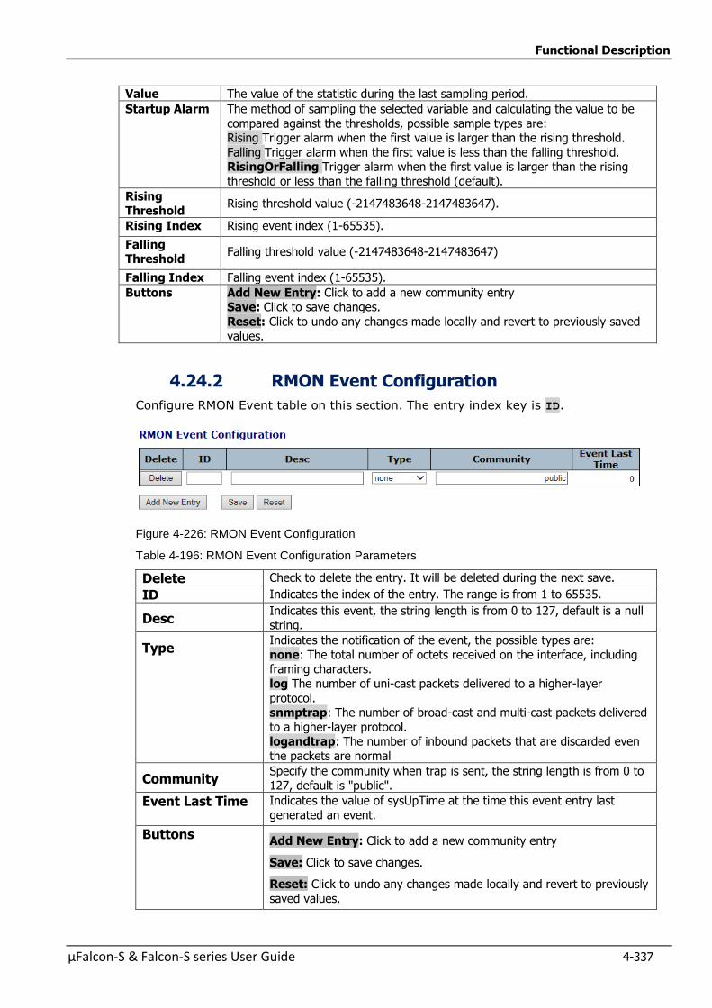
Functional Description
µFalcon-S & Falcon-S series User Guide 4-337
Value The value of the statistic during the last sampling period.
Startup Alarm The method of sampling the selected variable and calculating the value to be
compared against the thresholds, possible sample types are: Rising Trigger alarm when the first value is larger than the rising threshold.
Falling Trigger alarm when the first value is less than the falling threshold. RisingOrFalling Trigger alarm when the first value is larger than the rising
threshold or less than the falling threshold (default).
Rising Threshold
Rising threshold value (-2147483648-2147483647).
Rising Index Rising event index (1-65535).
Falling Threshold
Falling threshold value (-2147483648-2147483647)
Falling Index Falling event index (1-65535).
Buttons
Add New Entry: Click to add a new community entry Save: Click to save changes.
Reset: Click to undo any changes made locally and revert to previously saved
values.
4.24.2 RMON Event Configuration
Configure RMON Event table on this section. The entry index key is ID.
Figure 4-226: RMON Event Configuration
Table 4-196: RMON Event Configuration Parameters
Delete Check to delete the entry. It will be deleted during the next save.
ID Indicates the index of the entry. The range is from 1 to 65535.
Desc Indicates this event, the string length is from 0 to 127, default is a null string.
Type Indicates the notification of the event, the possible types are:
none: The total number of octets received on the interface, including framing characters.
log The number of uni-cast packets delivered to a higher-layer
protocol. snmptrap: The number of broad-cast and multi-cast packets delivered
to a higher-layer protocol. logandtrap: The number of inbound packets that are discarded even
the packets are normal
Community Specify the community when trap is sent, the string length is from 0 to 127, default is "public".
Event Last Time Indicates the value of sysUpTime at the time this event entry last
generated an event.
Buttons Add New Entry: Click to add a new community entry
Save: Click to save changes.
Reset: Click to undo any changes made locally and revert to previously
saved values.
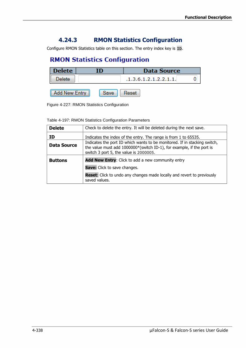
Functional Description
4-338 µFalcon-S & Falcon-S series User Guide
4.24.3 RMON Statistics Configuration
Configure RMON Statistics table on this section. The entry index key is ID.
Figure 4-227: RMON Statistics Configuration
Table 4-197: RMON Statistics Configuration Parameters
Delete Check to delete the entry. It will be deleted during the next save.
ID Indicates the index of the entry. The range is from 1 to 65535.
Data Source Indicates the port ID which wants to be monitored. If in stacking switch,
the value must add 1000000*(switch ID-1), for example, if the port is switch 3 port 5, the value is 2000005.
Buttons Add New Entry: Click to add a new community entry
Save: Click to save changes.
Reset: Click to undo any changes made locally and revert to previously
saved values.
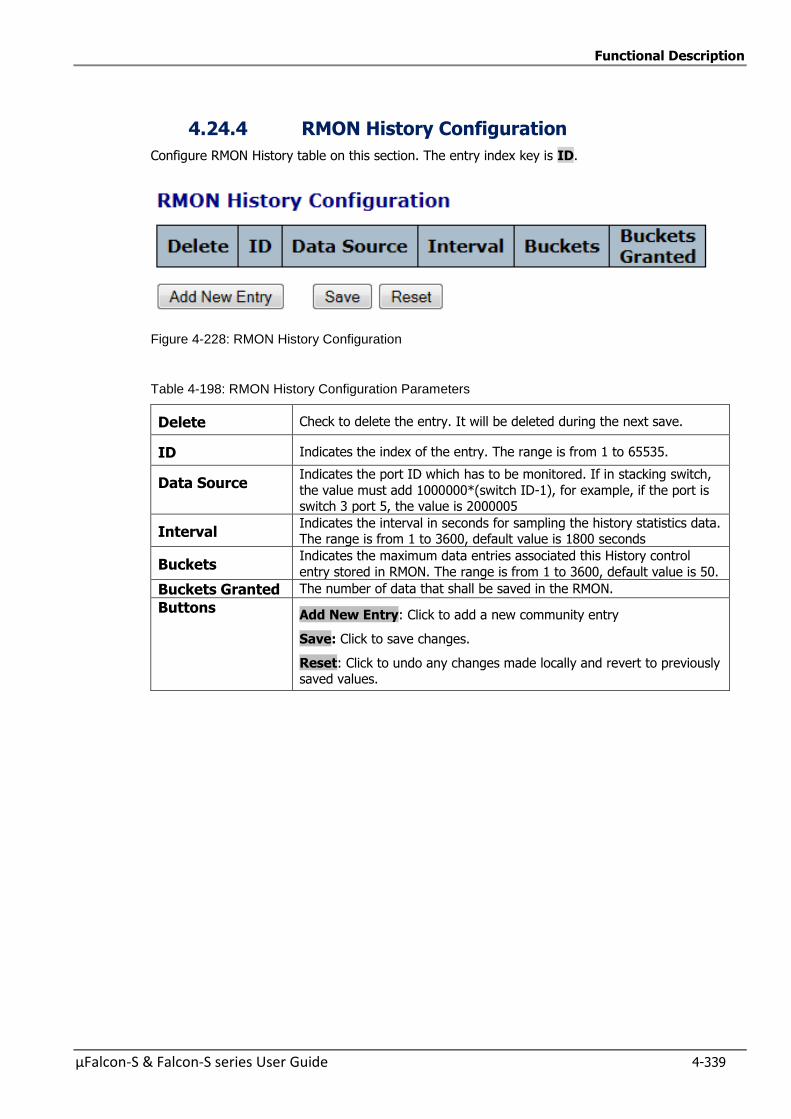
Functional Description
µFalcon-S & Falcon-S series User Guide 4-339
4.24.4 RMON History Configuration
Configure RMON History table on this section. The entry index key is ID.
Figure 4-228: RMON History Configuration
Table 4-198: RMON History Configuration Parameters
Delete Check to delete the entry. It will be deleted during the next save.
ID Indicates the index of the entry. The range is from 1 to 65535.
Data Source Indicates the port ID which has to be monitored. If in stacking switch,
the value must add 1000000*(switch ID-1), for example, if the port is switch 3 port 5, the value is 2000005
Interval Indicates the interval in seconds for sampling the history statistics data. The range is from 1 to 3600, default value is 1800 seconds
Buckets Indicates the maximum data entries associated this History control
entry stored in RMON. The range is from 1 to 3600, default value is 50.
Buckets Granted The number of data that shall be saved in the RMON.
Buttons Add New Entry: Click to add a new community entry
Save: Click to save changes.
Reset: Click to undo any changes made locally and revert to previously saved values.
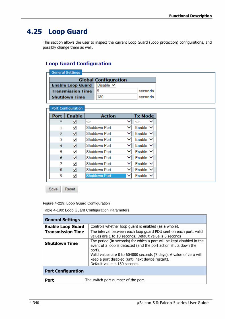
Functional Description
4-340 µFalcon-S & Falcon-S series User Guide
4.25 Loop Guard
This section allows the user to inspect the current Loop Guard (Loop protection) configurations, and
possibly change them as well.
Figure 4-229: Loop Guard Configuration
Table 4-199: Loop Guard Configuration Parameters
General Settings
Enable Loop Guard Controls whether loop guard is enabled (as a whole).
Transmission Time The interval between each loop guard PDU sent on each port. valid
values are 1 to 10 seconds. Default value is 5 seconds
Shutdown Time The period (in seconds) for which a port will be kept disabled in the event of a loop is detected (and the port action shuts down the
port). Valid values are 0 to 604800 seconds (7 days). A value of zero will
keep a port disabled (until next device restart).
Default value is 180 seconds.
Port Configuration
Port The switch port number of the port.
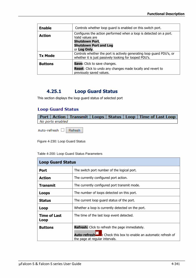
Functional Description
µFalcon-S & Falcon-S series User Guide 4-341
Enable Controls whether loop guard is enabled on this switch port.
Action Configures the action performed when a loop is detected on a port.
Valid values are Shutdown Port,
Shutdown Port and Log or Log Only.
Tx Mode Controls whether the port is actively generating loop guard PDU's, or
whether it is just passively looking for looped PDU's.
Buttons Save: Click to save changes.
Reset: Click to undo any changes made locally and revert to
previously saved values.
4.25.1 Loop Guard Status
This section displays the loop guard status of selected port
Figure 4-230: Loop Guard Status
Table 4-200: Loop Guard Status Parameters
Loop Guard Status
Port The switch port number of the logical port.
Action The currently configured port action.
Transmit The currently configured port transmit mode.
Loops The number of loops detected on this port.
Status The current loop guard status of the port.
Loop Whether a loop is currently detected on the port.
Time of Last Loop
The time of the last loop event detected.
Buttons Refresh: Click to refresh the page immediately.
Auto-refresh : Check this box to enable an automatic refresh of the page at regular intervals.
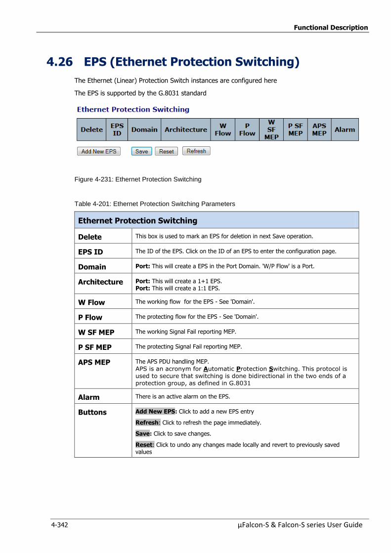
Functional Description
4-342 µFalcon-S & Falcon-S series User Guide
4.26 EPS (Ethernet Protection Switching)
The Ethernet (Linear) Protection Switch instances are configured here
The EPS is supported by the G.8031 standard
Figure 4-231: Ethernet Protection Switching
Table 4-201: Ethernet Protection Switching Parameters
Ethernet Protection Switching
Delete This box is used to mark an EPS for deletion in next Save operation.
EPS ID The ID of the EPS. Click on the ID of an EPS to enter the configuration page.
Domain Port: This will create a EPS in the Port Domain. 'W/P Flow' is a Port.
Architecture Port: This will create a 1+1 EPS. Port: This will create a 1:1 EPS.
W Flow The working flow for the EPS - See 'Domain'.
P Flow The protecting flow for the EPS - See 'Domain'.
W SF MEP The working Signal Fail reporting MEP.
P SF MEP The protecting Signal Fail reporting MEP.
APS MEP The APS PDU handling MEP.
APS is an acronym for Automatic Protection Switching. This protocol is used to secure that switching is done bidirectional in the two ends of a protection group, as defined in G.8031
Alarm There is an active alarm on the EPS.
Buttons Add New EPS: Click to add a new EPS entry
Refresh: Click to refresh the page immediately.
Save: Click to save changes.
Reset: Click to undo any changes made locally and revert to previously saved values
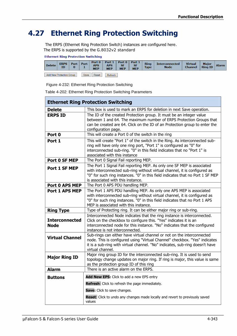
Functional Description
µFalcon-S & Falcon-S series User Guide 4-343
4.27 Ethernet Ring Protection Switching
The ERPS (Ethernet Ring Protection Switch) instances are configured here.
The ERPS is supported by the G.8032v2 standard
Figure 4-232: Ethernet Ring Protection Switching
Table 4-202: Ethernet Ring Protection Switching Parameters
Ethernet Ring Protection Switching
Delete This box is used to mark an ERPS for deletion in next Save operation.
ERPS ID The ID of the created Protection group. It must be an integer value between 1 and 64. The maximum number of ERPS Protection Groups that
can be created are 64. Click on the ID of an Protection group to enter the configuration page.
Port 0 This will create a Port 0 of the switch in the ring
Port 1 This will create "Port 1" of the switch in the Ring. As interconnected sub-ring will have only one ring port, "Port 1" is configured as "0" for
interconnected sub-ring. "0" in this field indicates that no "Port 1" is
associated with this instance
Port 0 SF MEP The Port 0 Signal Fail reporting MEP.
Port 1 SF MEP The Port 1 Signal Fail reporting MEP. As only one SF MEP is associated
with interconnected sub-ring without virtual channel, it is configured as "0" for such ring instances. "0" in this field indicates that no Port 1 SF MEP
is associated with this instance.
Port 0 APS MEP The Port 0 APS PDU handling MEP.
Port 1 APS MEP The Port 1 APS PDU handling MEP. As only one APS MEP is associated with interconnected sub-ring without virtual channel, it is configured as
"0" for such ring instances. "0" in this field indicates that no Port 1 APS MEP is associated with this instance.
Ring Type Type of Protecting ring. It can be either major ring or sub-ring.
Interconnected Node
Interconnected Node indicates that the ring instance is interconnected. Click on the checkbox to configure this. "Yes" indicates it is an
interconnected node for this instance. "No" indicates that the configured
instance is not interconnected.
Virtual Channel Sub-rings can either have virtual channel or not on the interconnected
node. This is configured using "Virtual Channel" checkbox. "Yes" indicates
it is a sub-ring with virtual channel. "No" indicates, sub-ring doesn't have virtual channel.
Major Ring ID Major ring group ID for the interconnected sub-ring. It is used to send topology change updates on major ring. If ring is major, this value is same
as the protection group ID of this ring
Alarm There is an active alarm on the ERPS.
Buttons Add New EPS: Click to add a new EPS entry
Refresh: Click to refresh the page immediately.
Save: Click to save changes.
Reset: Click to undo any changes made locally and revert to previously saved values
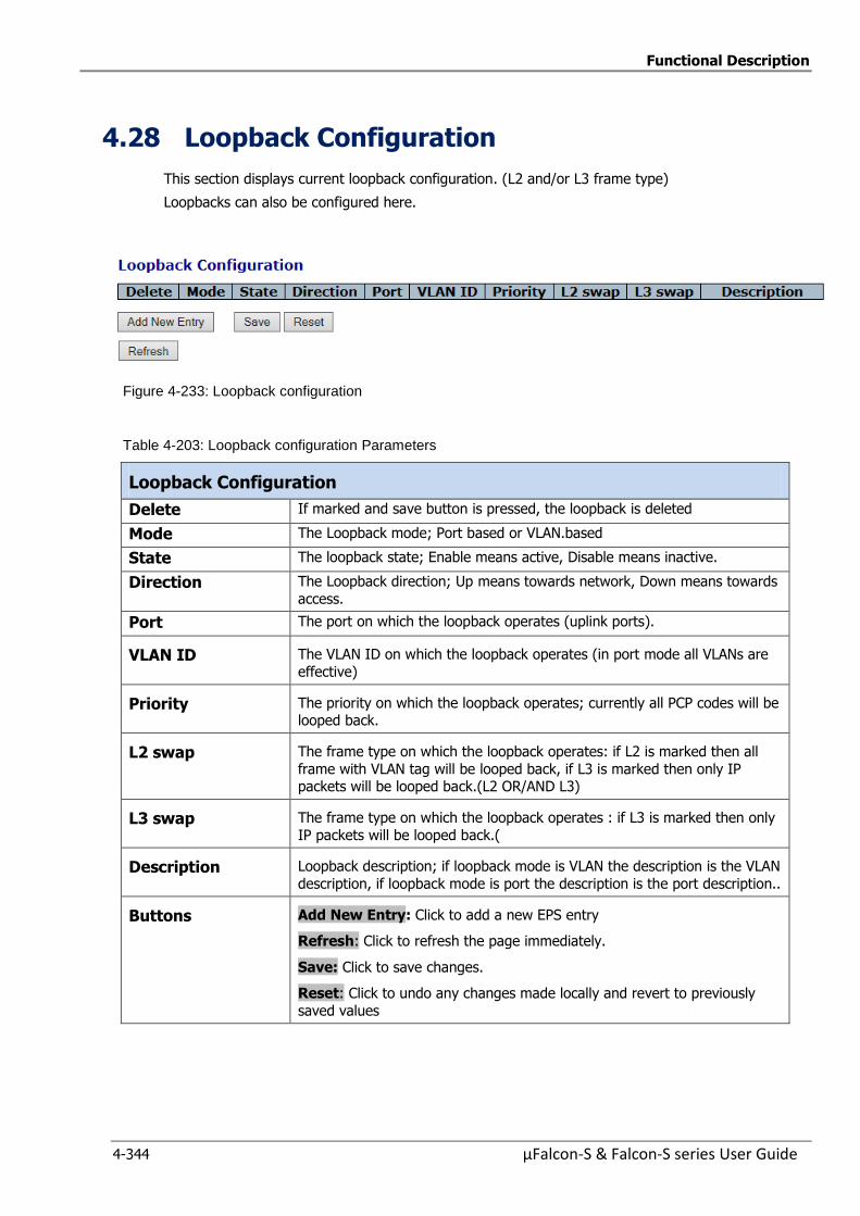
Functional Description
4-344 µFalcon-S & Falcon-S series User Guide
4.28 Loopback Configuration
This section displays current loopback configuration. (L2 and/or L3 frame type)
Loopbacks can also be configured here.
Figure 4-233: Loopback configuration
Table 4-203: Loopback configuration Parameters
Loopback Configuration
Delete If marked and save button is pressed, the loopback is deleted
Mode The Loopback mode; Port based or VLAN.based
State The loopback state; Enable means active, Disable means inactive.
Direction The Loopback direction; Up means towards network, Down means towards
access.
Port The port on which the loopback operates (uplink ports).
VLAN ID The VLAN ID on which the loopback operates (in port mode all VLANs are
effective)
Priority The priority on which the loopback operates; currently all PCP codes will be looped back.
L2 swap The frame type on which the loopback operates: if L2 is marked then all
frame with VLAN tag will be looped back, if L3 is marked then only IP packets will be looped back.(L2 OR/AND L3)
L3 swap The frame type on which the loopback operates : if L3 is marked then only
IP packets will be looped back.(
Description Loopback description; if loopback mode is VLAN the description is the VLAN
description, if loopback mode is port the description is the port description..
Buttons Add New Entry: Click to add a new EPS entry
Refresh: Click to refresh the page immediately.
Save: Click to save changes.
Reset: Click to undo any changes made locally and revert to previously
saved values
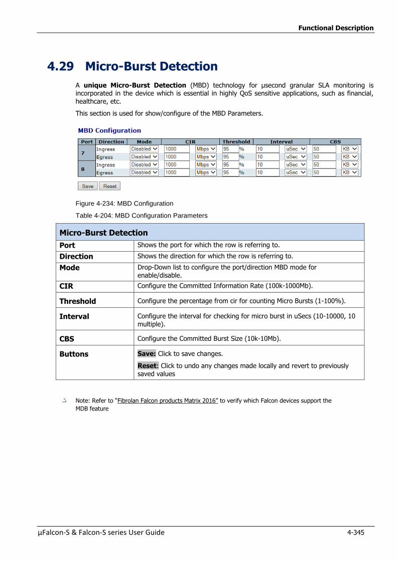
Functional Description
µFalcon-S & Falcon-S series User Guide 4-345
4.29 Micro-Burst Detection
A unique Micro-Burst Detection (MBD) technology for µsecond granular SLA monitoring is incorporated in the device which is essential in highly QoS sensitive applications, such as financial,
healthcare, etc.
This section is used for show/configure of the MBD Parameters.
Figure 4-234: MBD Configuration
Table 4-204: MBD Configuration Parameters
Micro-Burst Detection
Port Shows the port for which the row is referring to.
Direction Shows the direction for which the row is referring to.
Mode Drop-Down list to configure the port/direction MBD mode for
enable/disable.
CIR Configure the Committed Information Rate (100k-1000Mb).
Threshold Configure the percentage from cir for counting Micro Bursts (1-100%).
Interval Configure the interval for checking for micro burst in uSecs (10-10000, 10
multiple).
CBS Configure the Committed Burst Size (10k-10Mb).
Buttons Save: Click to save changes.
Reset: Click to undo any changes made locally and revert to previously
saved values
Note: Refer to “Fibrolan Falcon products Matrix 2016” to verify which Falcon devices support the
MDB feature
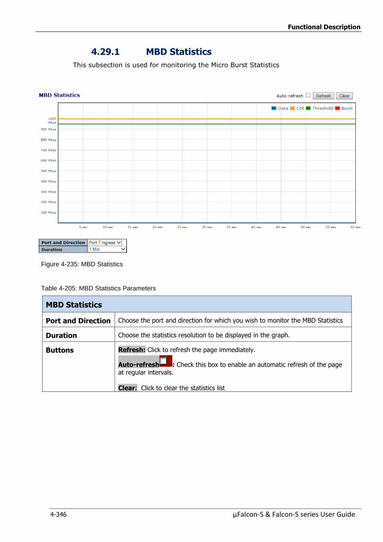
Functional Description
4-346 µFalcon-S & Falcon-S series User Guide
4.29.1 MBD Statistics
This subsection is used for monitoring the Micro Burst Statistics
Figure 4-235: MBD Statistics
Table 4-205: MBD Statistics Parameters
MBD Statistics
Port and Direction Choose the port and direction for which you wish to monitor the MBD Statistics
Duration Choose the statistics resolution to be displayed in the graph.
Buttons Refresh: Click to refresh the page immediately.
Auto-refresh : Check this box to enable an automatic refresh of the page at regular intervals.
Clear: Click to clear the statistics list
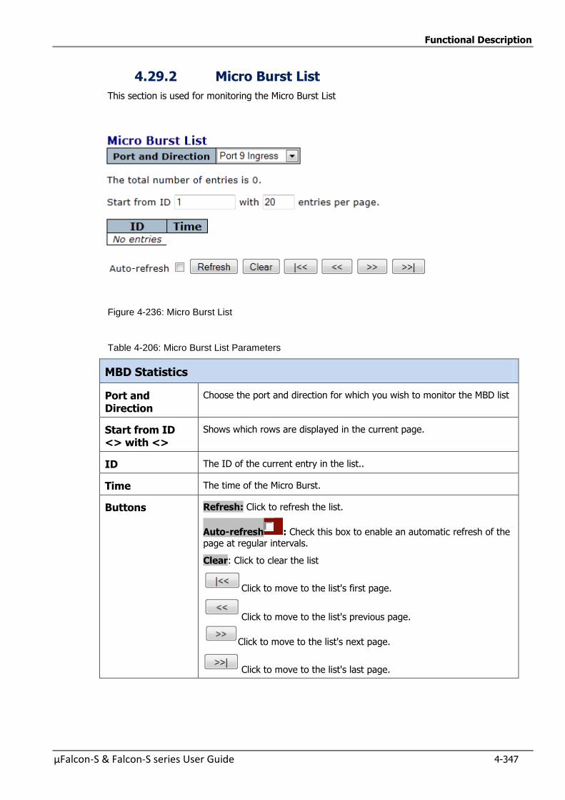
Functional Description
µFalcon-S & Falcon-S series User Guide 4-347
4.29.2 Micro Burst List
This section is used for monitoring the Micro Burst List
Figure 4-236: Micro Burst List
Table 4-206: Micro Burst List Parameters
MBD Statistics
Port and Direction
Choose the port and direction for which you wish to monitor the MBD list
Start from ID <> with <>
Shows which rows are displayed in the current page.
ID The ID of the current entry in the list..
Time The time of the Micro Burst.
Buttons Refresh: Click to refresh the list.
Auto-refresh : Check this box to enable an automatic refresh of the page at regular intervals.
Clear: Click to clear the list
Click to move to the list's first page.
Click to move to the list's previous page.
Click to move to the list's next page.
Click to move to the list's last page.

Functional Description
4-348 µFalcon-S & Falcon-S series User Guide
4.30 Link Protection
This section allows the user to configure the Link Protection Parameters and check the status
4.30.1 Link Protection Configuration
Figure 4-237: Link Protection Configuration
Table 4-207: Link Protection Configuration Parameters
Link Protection Configuration
Mode Enable or Disable the Link Protection function.
Main Port Select the uplink port that will serve as main (the other will be
automatically assigned as backup).
Revertive Enable or Disable revertive operation. When enabled, main connection will
be restored after a previous failure on that link has been fixed. The Wait To Restore (WTR) timer will be triggered when main is back online.
WTR Set the Wait To Restore timer (in seconds), which will be triggered when
main link is restored after failure.
Buttons Refresh: Click to refresh the page immediately.
Auto-refresh : Check this box to enable an automatic refresh of the page at regular intervals.
Clear: Click to clear the list
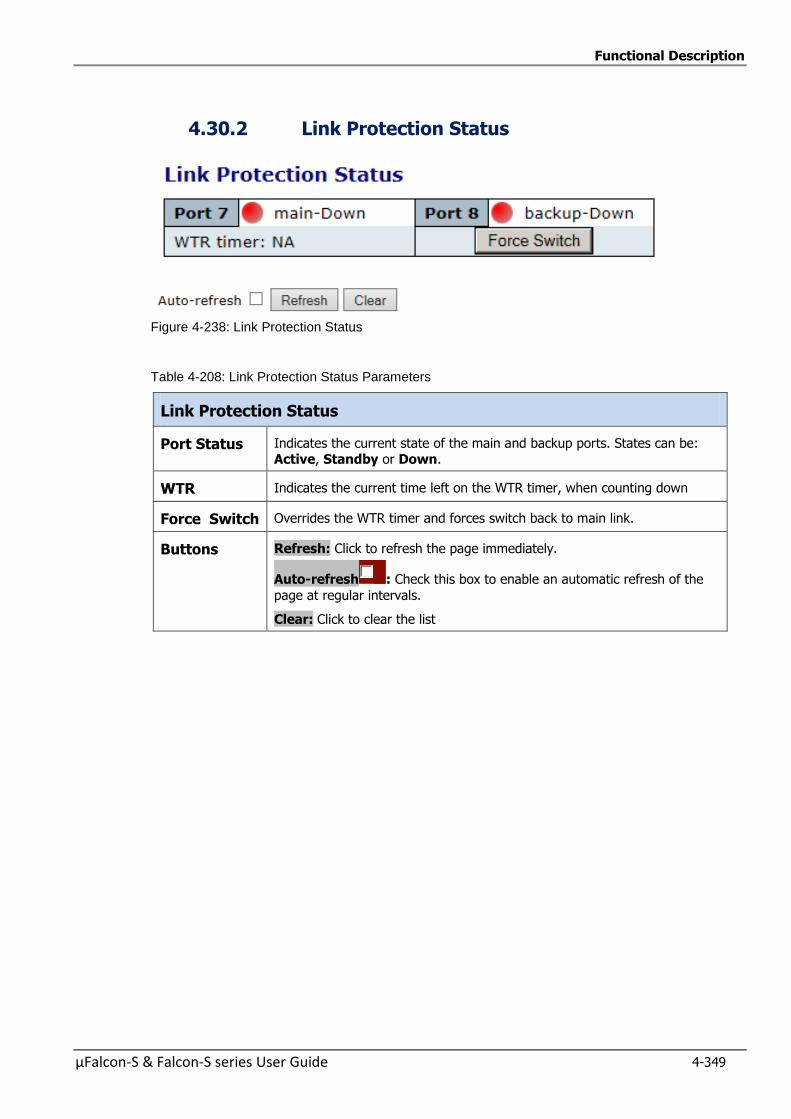
Functional Description
µFalcon-S & Falcon-S series User Guide 4-349
4.30.2 Link Protection Status
Figure 4-238: Link Protection Status
Table 4-208: Link Protection Status Parameters
Link Protection Status
Port Status Indicates the current state of the main and backup ports. States can be: Active, Standby or Down.
WTR Indicates the current time left on the WTR timer, when counting down
Force Switch Overrides the WTR timer and forces switch back to main link.
Buttons Refresh: Click to refresh the page immediately.
Auto-refresh : Check this box to enable an automatic refresh of the
page at regular intervals.
Clear: Click to clear the list
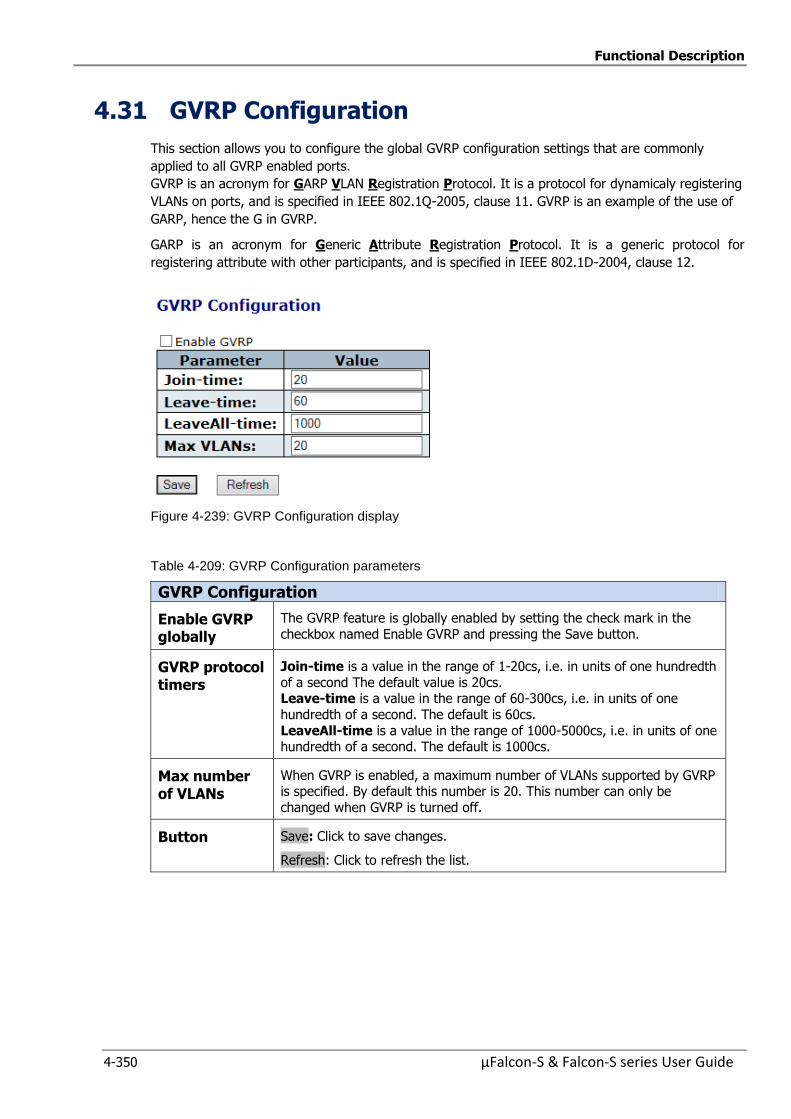
Functional Description
4-350 µFalcon-S & Falcon-S series User Guide
4.31 GVRP Configuration
This section allows you to configure the global GVRP configuration settings that are commonly
applied to all GVRP enabled ports.
GVRP is an acronym for GARP VLAN Registration Protocol. It is a protocol for dynamicaly registering
VLANs on ports, and is specified in IEEE 802.1Q-2005, clause 11. GVRP is an example of the use of
GARP, hence the G in GVRP.
GARP is an acronym for Generic Attribute Registration Protocol. It is a generic protocol for
registering attribute with other participants, and is specified in IEEE 802.1D-2004, clause 12.
Figure 4-239: GVRP Configuration display
Table 4-209: GVRP Configuration parameters
GVRP Configuration
Enable GVRP globally
The GVRP feature is globally enabled by setting the check mark in the
checkbox named Enable GVRP and pressing the Save button.
GVRP protocol timers
Join-time is a value in the range of 1-20cs, i.e. in units of one hundredth
of a second The default value is 20cs. Leave-time is a value in the range of 60-300cs, i.e. in units of one
hundredth of a second. The default is 60cs.
LeaveAll-time is a value in the range of 1000-5000cs, i.e. in units of one hundredth of a second. The default is 1000cs.
Max number of VLANs
When GVRP is enabled, a maximum number of VLANs supported by GVRP is specified. By default this number is 20. This number can only be
changed when GVRP is turned off.
Button Save: Click to save changes.
Refresh: Click to refresh the list.
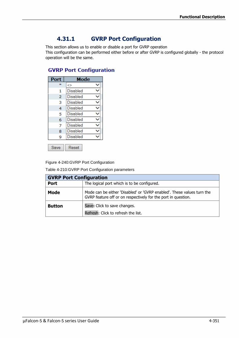
Functional Description
µFalcon-S & Falcon-S series User Guide 4-351
4.31.1 GVRP Port Configuration
This section allows us to enable or disable a port for GVRP operation
This configuration can be performed either before or after GVRP is configured globally - the protocol
operation will be the same.
Figure 4-240:GVRP Port Configuration
Table 4-210:GVRP Port Configuration parameters
GVRP Port Configuration Port The logical port which is to be configured.
Mode Mode can be either 'Disabled' or 'GVRP enabled'. These values turn the
GVRP feature off or on respectively for the port in question.
Button Save: Click to save changes.
Refresh: Click to refresh the list.

Functional Description
4-352 µFalcon-S & Falcon-S series User Guide
4.32 sFlow Consideration
SFlow is an industry standard technology for monitoring switched networks through random sampling
of packets on switch ports and time-based sampling of port counters.
The sampled packets and counters (referred to as flow samples and counter samples, respectively)
are sent as sFlow UDP datagrams to a central network traffic monitoring server.
This central server is called an sFlow receiver or sFlow collector.
Additional information can be found at http://sflow.org.
4.32.1 sFlow Configuration displays
This sub-section allows configuring sFlow. The configuration is divided into two parts: Configuration of
the sFlow receiver (a.k.a. sFlow collector) and configuration of per-port flow and counter samplers.
sFlow configuration is not persisted to non-volatile memory, which means that a reboot or master
change will disable sFlow sampling.
Figure 4-241: sFlow Configuration displays
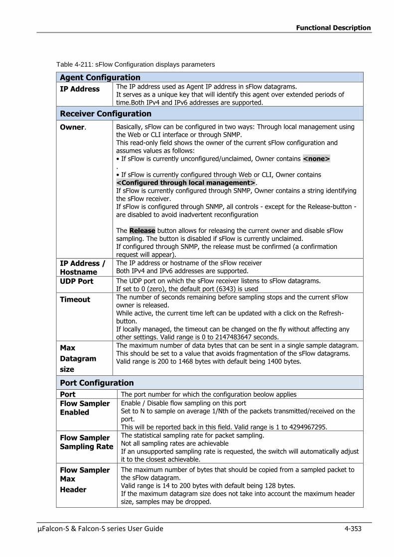
Functional Description
µFalcon-S & Falcon-S series User Guide 4-353
Table 4-211: sFlow Configuration displays parameters
Agent Configuration
IP Address The IP address used as Agent IP address in sFlow datagrams. It serves as a unique key that will identify this agent over extended periods of
time.Both IPv4 and IPv6 addresses are supported.
Receiver Configuration
Owner. Basically, sFlow can be configured in two ways: Through local management using the Web or CLI interface or through SNMP.
This read-only field shows the owner of the current sFlow configuration and assumes values as follows:
• If sFlow is currently unconfigured/unclaimed, Owner contains <none> .
• If sFlow is currently configured through Web or CLI, Owner contains
<Configured through local management>. If sFlow is currently configured through SNMP, Owner contains a string identifying
the sFlow receiver. If sFlow is configured through SNMP, all controls - except for the Release-button -
are disabled to avoid inadvertent reconfiguration
The Release button allows for releasing the current owner and disable sFlow
sampling. The button is disabled if sFlow is currently unclaimed. If configured through SNMP, the release must be confirmed (a confirmation
request will appear).
IP Address / Hostname
The IP address or hostname of the sFlow receiver Both IPv4 and IPv6 addresses are supported.
UDP Port The UDP port on which the sFlow receiver listens to sFlow datagrams.
If set to 0 (zero), the default port (6343) is used
Timeout The number of seconds remaining before sampling stops and the current sFlow
owner is released.
While active, the current time left can be updated with a click on the Refresh-button.
If locally managed, the timeout can be changed on the fly without affecting any other settings. Valid range is 0 to 2147483647 seconds.
Max
Datagram
size
The maximum number of data bytes that can be sent in a single sample datagram.
This should be set to a value that avoids fragmentation of the sFlow datagrams. Valid range is 200 to 1468 bytes with default being 1400 bytes.
Port Configuration
Port The port number for which the configuration beolow applies
Flow Sampler Enabled
Enable / Disable flow sampling on this port Set to N to sample on average 1/Nth of the packets transmitted/received on the
port.
This will be reported back in this field. Valid range is 1 to 4294967295.
Flow Sampler Sampling Rate
The statistical sampling rate for packet sampling.
Not all sampling rates are achievable
If an unsupported sampling rate is requested, the switch will automatically adjust it to the closest achievable.
Flow Sampler Max
Header
The maximum number of bytes that should be copied from a sampled packet to
the sFlow datagram. Valid range is 14 to 200 bytes with default being 128 bytes.
If the maximum datagram size does not take into account the maximum header size, samples may be dropped.
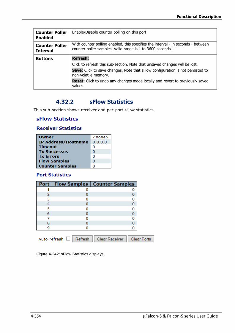
Functional Description
4-354 µFalcon-S & Falcon-S series User Guide
Counter Poller Enabled
Enable/Disable counter polling on this port
Counter Poller Interval
With counter polling enabled, this specifies the interval - in seconds - between counter poller samples. Valid range is 1 to 3600 seconds.
Buttons Refresh:
Click to refresh this sub-section. Note that unsaved changes will be lost.
Save: Click to save changes. Note that sFlow configuration is not persisted to
non-volatile memory.
Reset: Click to undo any changes made locally and revert to previously saved
values.
4.32.2 sFlow Statistics
This sub-section shows receiver and per-port sFlow statistics
Figure 4-242: sFlow Statistics displays
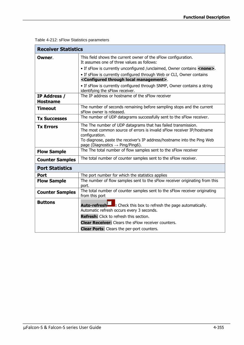
Functional Description
µFalcon-S & Falcon-S series User Guide 4-355
Table 4-212: sFlow Statistics parameters
Receiver Statistics
Owner. This field shows the current owner of the sFlow configuration. It assumes one of three values as follows:
• If sFlow is currently unconfigured /unclaimed, Owner contains <none>.
• If sFlow is currently configured through Web or CLI, Owner contains
<Configured through local management>.
• If sFlow is currently configured through SNMP, Owner contains a string identifying the sFlow receiver.
IP Address / Hostname
The IP address or hostname of the sFlow receiver
Timeout The number of seconds remaining before sampling stops and the current
sFlow owner is released.
Tx Successes The number of UDP datagrams successfully sent to the sFlow receiver.
Tx Errors The The number of UDP datagrams that has failed transmission. The most common source of errors is invalid sFlow receiver IP/hostname
configuration. To diagnose, paste the receiver's IP address/hostname into the Ping Web
page (Diagnostics → Ping/Ping6).
Flow Sample The The total number of flow samples sent to the sFlow receiver
Counter Samples The total number of counter samples sent to the sFlow receiver.
Port Statistics
Port The port number for which the statistics applies
Flow Sample The number of flow samples sent to the sFlow receiver originating from this
port.
Counter Samples The total number of counter samples sent to the sFlow receiver originating from this port
Buttons Auto-refresh : Check this box to refresh the page automatically. Automatic refresh occurs every 3 seconds.
Refresh: Click to refresh this section.
Clear Receiver: Clears the sFlow receiver counters.
Clear Ports: Clears the per-port counters.
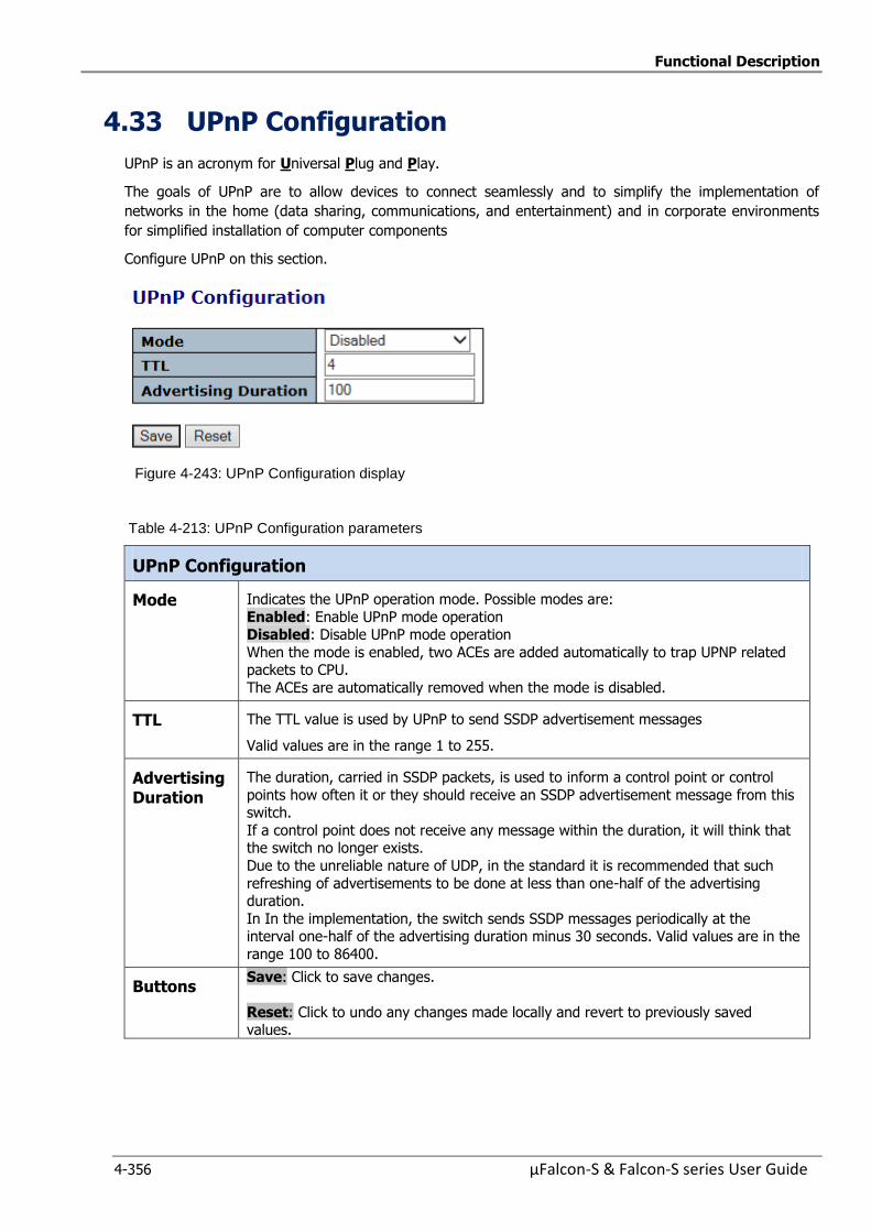
Functional Description
4-356 µFalcon-S & Falcon-S series User Guide
4.33 UPnP Configuration
UPnP is an acronym for Universal Plug and Play.
The goals of UPnP are to allow devices to connect seamlessly and to simplify the implementation of
networks in the home (data sharing, communications, and entertainment) and in corporate environments
for simplified installation of computer components
Configure UPnP on this section.
Figure 4-243: UPnP Configuration display
Table 4-213: UPnP Configuration parameters
UPnP Configuration
Mode Indicates the UPnP operation mode. Possible modes are:
Enabled: Enable UPnP mode operation Disabled: Disable UPnP mode operation
When the mode is enabled, two ACEs are added automatically to trap UPNP related packets to CPU.
The ACEs are automatically removed when the mode is disabled.
TTL The TTL value is used by UPnP to send SSDP advertisement messages
Valid values are in the range 1 to 255.
Advertising Duration
The duration, carried in SSDP packets, is used to inform a control point or control
points how often it or they should receive an SSDP advertisement message from this switch.
If a control point does not receive any message within the duration, it will think that the switch no longer exists.
Due to the unreliable nature of UDP, in the standard it is recommended that such
refreshing of advertisements to be done at less than one-half of the advertising duration.
In In the implementation, the switch sends SSDP messages periodically at the interval one-half of the advertising duration minus 30 seconds. Valid values are in the
range 100 to 86400.
Buttons Save: Click to save changes.
Reset: Click to undo any changes made locally and revert to previously saved values.
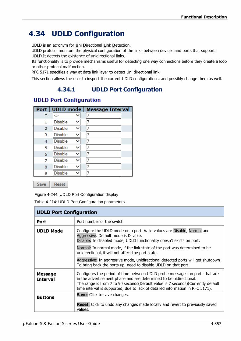
Functional Description
µFalcon-S & Falcon-S series User Guide 4-357
4.34 UDLD Configuration
UDLD is an acronym for Uni Directional Link Detection.
UDLD protocol monitors the physical configuration of the links between devices and ports that support
UDLD.It detects the existence of unidirectional links.
Its functionality is to provide mechanisms useful for detecting one way connections before they create a loop
or other protocol malfunction.
RFC 5171 specifies a way at data link layer to detect Uni directional link.
This section allows the user to inspect the current UDLD configurations, and possibly change them as well.
4.34.1 UDLD Port Configuration
Figure 4-244: UDLD Port Configuration display
Table 4-214: UDLD Port Configuration parameters
UDLD Port Configuration
Port Port number of the switch
UDLD Mode Configure the UDLD mode on a port. Valid values are Disable, Normal and
Aggressive. Default mode is Disable.
Disable: In disabled mode, UDLD functionality doesn't exists on port.
Normal: In normal mode, if the link state of the port was determined to be
unidirectional, it will not affect the port state.
Aggressive: In aggressive mode, unidirectional detected ports will get shutdown
To bring back the ports up, need to disable UDLD on that port.
Message Interval
Configures the period of time between UDLD probe messages on ports that are in the advertisement phase and are determined to be bidirectional.
The range is from 7 to 90 seconds(Default value is 7 seconds)(Currently default time interval is supported, due to lack of detailed information in RFC 5171).
Buttons Save: Click to save changes.
Reset: Click to undo any changes made locally and revert to previously saved
values.
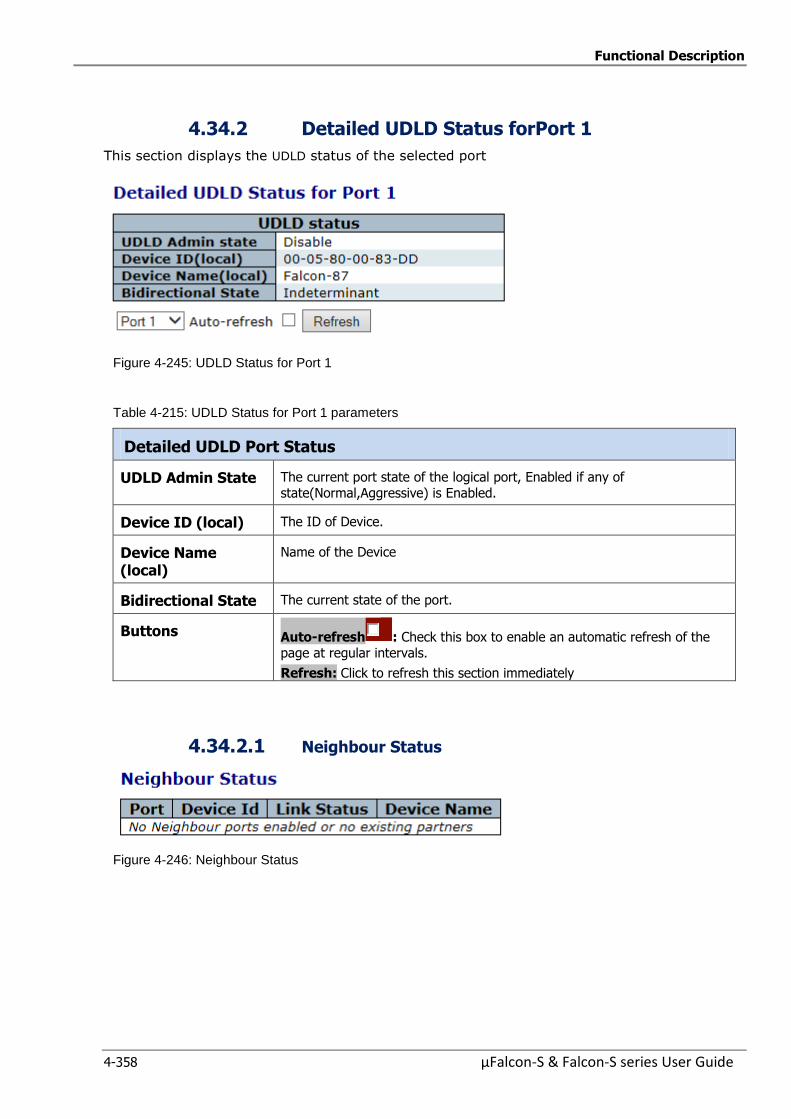
Functional Description
4-358 µFalcon-S & Falcon-S series User Guide
4.34.2 Detailed UDLD Status forPort 1
This section displays the UDLD status of the selected port
Figure 4-245: UDLD Status for Port 1
Table 4-215: UDLD Status for Port 1 parameters
Detailed UDLD Port Status
UDLD Admin State The current port state of the logical port, Enabled if any of state(Normal,Aggressive) is Enabled.
Device ID (local) The ID of Device.
Device Name (local)
Name of the Device
Bidirectional State The current state of the port.
Buttons Auto-refresh : Check this box to enable an automatic refresh of the page at regular intervals.
Refresh: Click to refresh this section immediately
4.34.2.1 Neighbour Status
Figure 4-246: Neighbour Status

Functional Description
µFalcon-S & Falcon-S series User Guide 4-359
Table 4-216: Neighbour Status parameters
Neighbour Status
Port The current port of neighbour device.
Device ID The current ID of neighbour device.
Link Status The current link status of neighbour port.
Device Name Name of the Neighbour Device.
Buttons Auto-refresh : Check this box to enable an automatic refresh of the page at regular intervals.
Refresh: Click to refresh this section immediately


µFalcon-S & Falcon-S series User Guide 5-1
5 5 Management
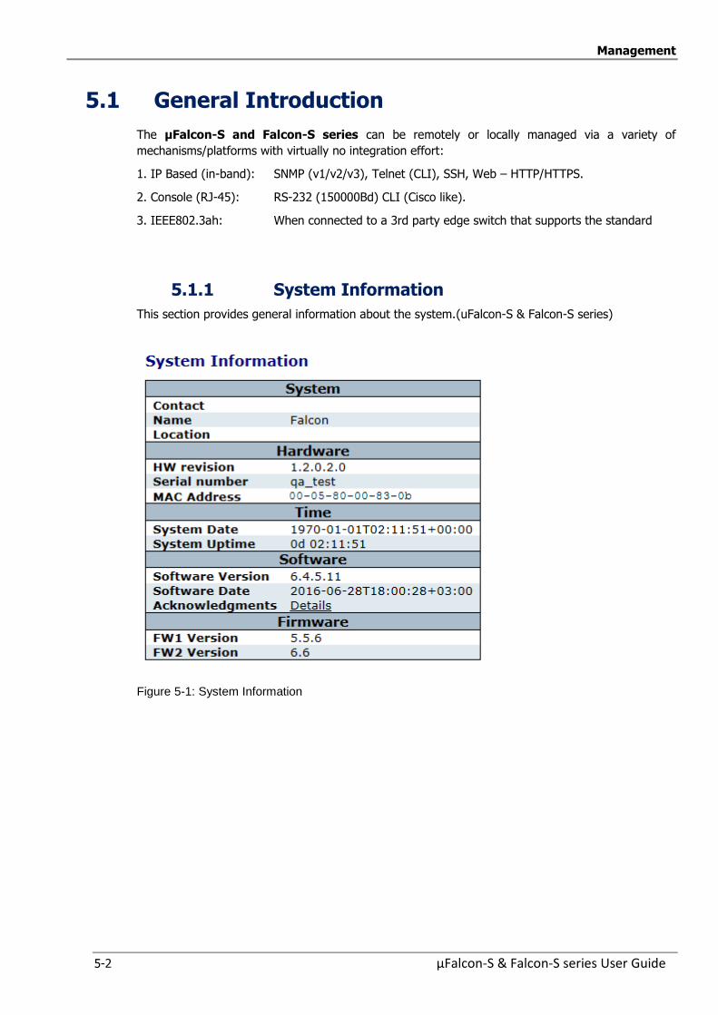
Management
5-2 µFalcon-S & Falcon-S series User Guide
5.1 General Introduction
The µFalcon-S and Falcon-S series can be remotely or locally managed via a variety of
mechanisms/platforms with virtually no integration effort:
1. IP Based (in-band): SNMP (v1/v2/v3), Telnet (CLI), SSH, Web – HTTP/HTTPS.
2. Console (RJ-45): RS-232 (150000Bd) CLI (Cisco like).
3. IEEE802.3ah: When connected to a 3rd party edge switch that supports the standard
5.1.1 System Information
This section provides general information about the system.(uFalcon-S & Falcon-S series)
Figure 5-1: System Information
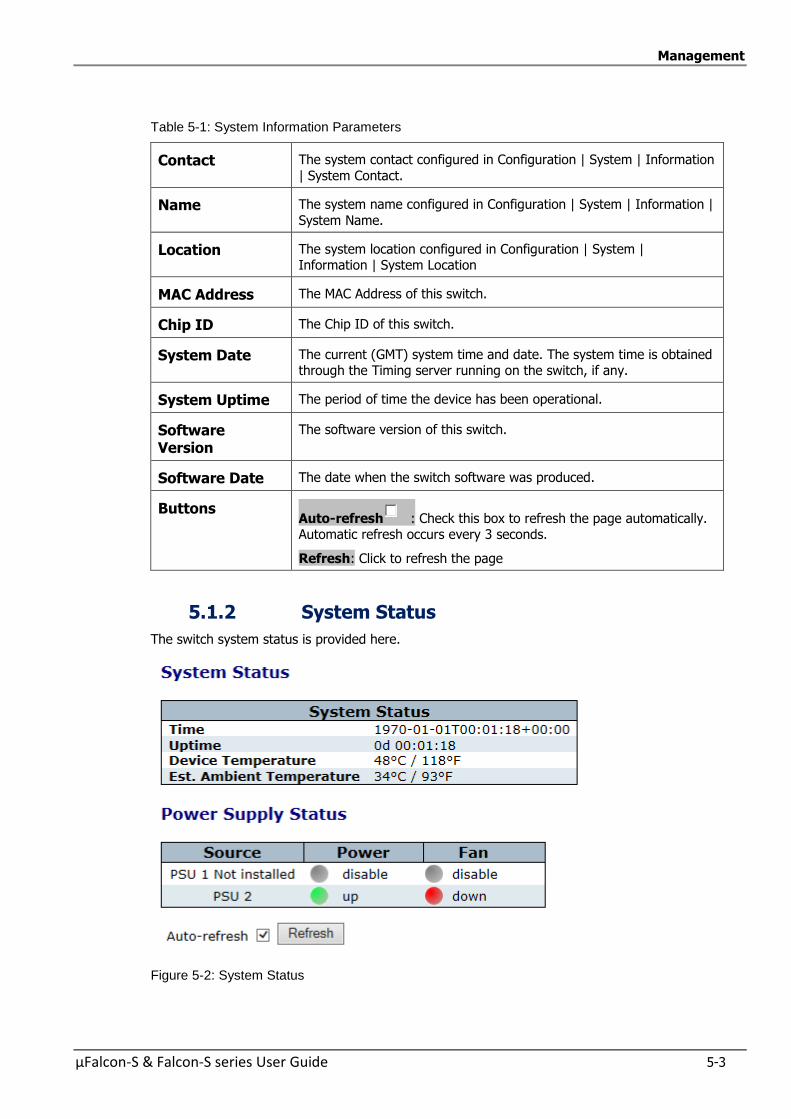
Management
µFalcon-S & Falcon-S series User Guide 5-3
Table 5-1: System Information Parameters
Contact The system contact configured in Configuration | System | Information
| System Contact.
Name The system name configured in Configuration | System | Information |
System Name.
Location The system location configured in Configuration | System | Information | System Location
MAC Address The MAC Address of this switch.
Chip ID The Chip ID of this switch.
System Date The current (GMT) system time and date. The system time is obtained through the Timing server running on the switch, if any.
System Uptime The period of time the device has been operational.
Software Version
The software version of this switch.
Software Date The date when the switch software was produced.
Buttons Auto-refresh : Check this box to refresh the page automatically. Automatic refresh occurs every 3 seconds.
Refresh: Click to refresh the page
5.1.2 System Status
The switch system status is provided here.
Figure 5-2: System Status
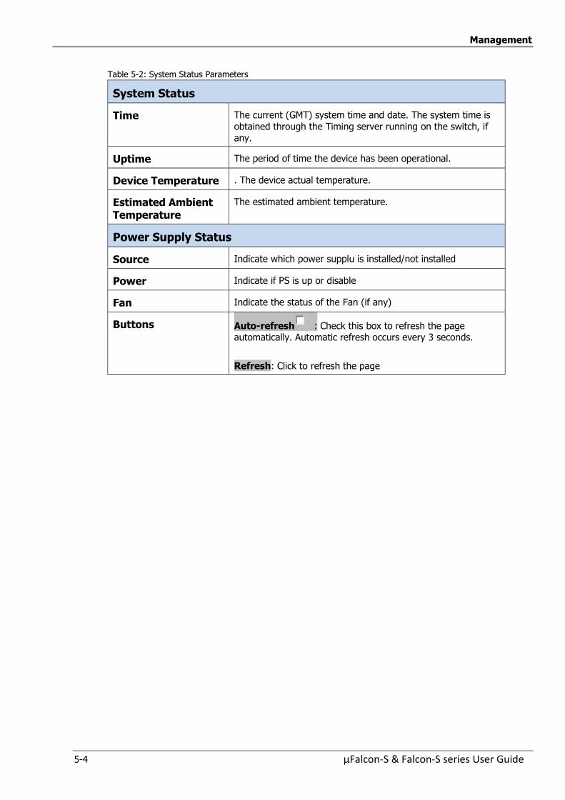
Management
5-4 µFalcon-S & Falcon-S series User Guide
Table 5-2: System Status Parameters
System Status
Time The current (GMT) system time and date. The system time is
obtained through the Timing server running on the switch, if
any.
Uptime The period of time the device has been operational.
Device Temperature . The device actual temperature.
Estimated Ambient Temperature
The estimated ambient temperature.
Power Supply Status
Source Indicate which power supplu is installed/not installed
Power Indicate if PS is up or disable
Fan Indicate the status of the Fan (if any)
Buttons Auto-refresh : Check this box to refresh the page automatically. Automatic refresh occurs every 3 seconds.
Refresh: Click to refresh the page

Management
µFalcon-S & Falcon-S series User Guide 5-5
5.1.3 CPU Load
This section displays the CPU load, using an SVG graph.
The load is measured as averaged over the last 100ms, 1sec and 10 seconds intervals. The last 120
samples are graphed, and the last numbers are displayed as text as well. In order to display the SVG graph, your browser must support the SVG format. Consult the SVG Wiki
for more information on browser support. Specifically, at the time of writing, Microsoft Internet Explorer will need to have a plug-in installed to support SVG
Figure 5-3: CPU Load
Buttons Auto-refresh : Check this box to refresh the page automatically. Automatic refresh occurs every 3 seconds.
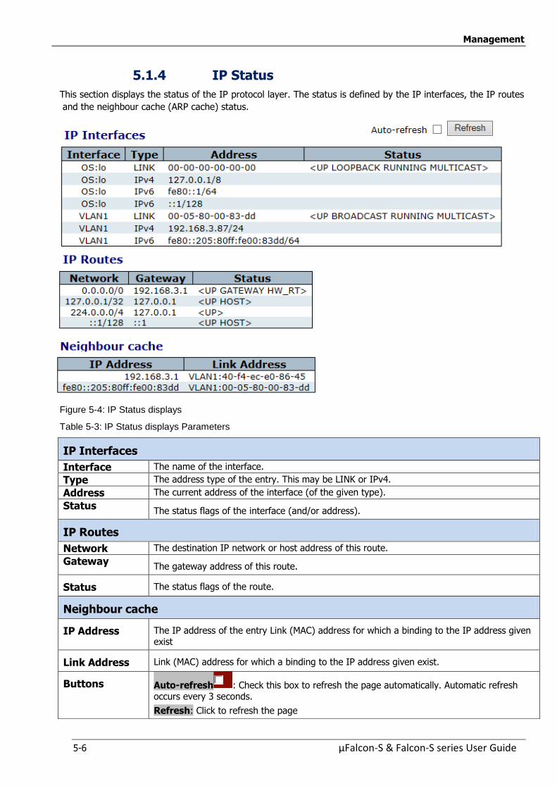
Management
5-6 µFalcon-S & Falcon-S series User Guide
5.1.4 IP Status
This section displays the status of the IP protocol layer. The status is defined by the IP interfaces, the IP routes
and the neighbour cache (ARP cache) status.
Figure 5-4: IP Status displays
Table 5-3: IP Status displays Parameters
IP Interfaces
Interface The name of the interface.
Type The address type of the entry. This may be LINK or IPv4.
Address The current address of the interface (of the given type).
Status The status flags of the interface (and/or address).
IP Routes
Network The destination IP network or host address of this route.
Gateway The gateway address of this route.
Status The status flags of the route.
Neighbour cache
IP Address The IP address of the entry Link (MAC) address for which a binding to the IP address given exist
Link Address Link (MAC) address for which a binding to the IP address given exist.
Buttons Auto-refresh : Check this box to refresh the page automatically. Automatic refresh occurs every 3 seconds.
Refresh: Click to refresh the page
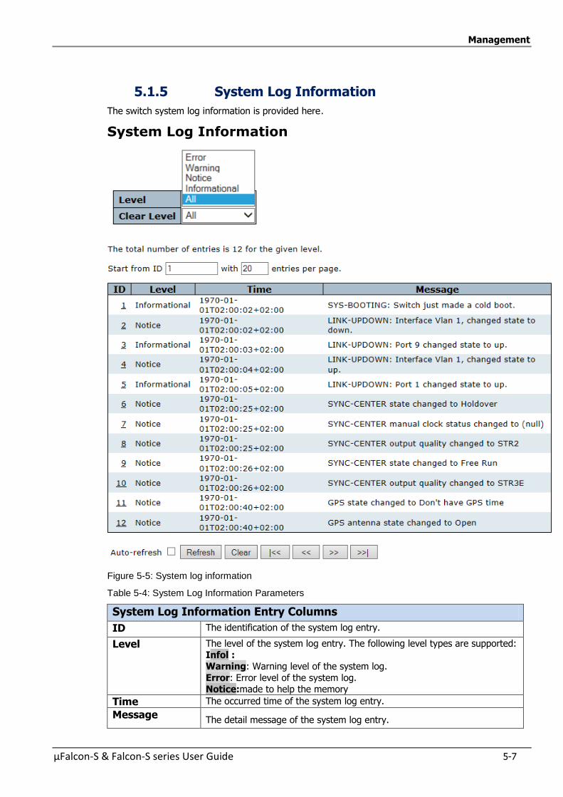
Management
µFalcon-S & Falcon-S series User Guide 5-7
5.1.5 System Log Information
The switch system log information is provided here.
System Log Information
Figure 5-5: System log information
Table 5-4: System Log Information Parameters
System Log Information Entry Columns
ID The identification of the system log entry.
Level The level of the system log entry. The following level types are supported:
Infol : Warning: Warning level of the system log.
Error: Error level of the system log. Notice:made to help the memory
Time The occurred time of the system log entry.
Message The detail message of the system log entry.
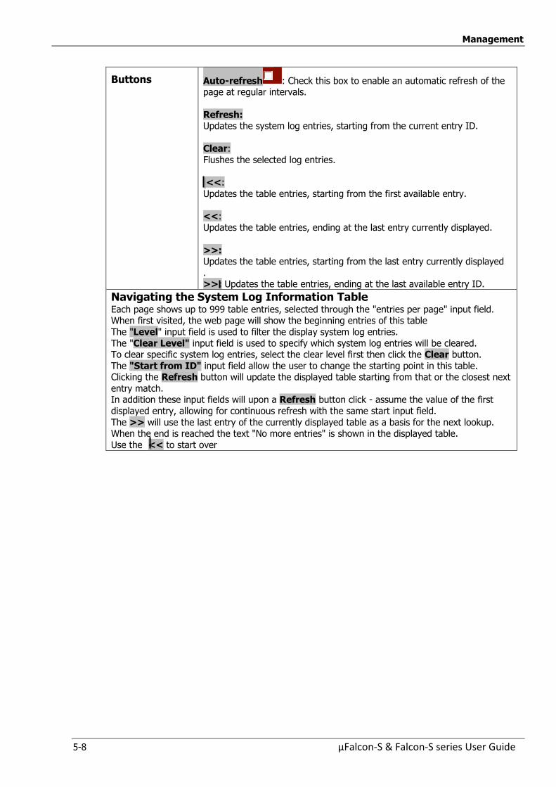
Management
5-8 µFalcon-S & Falcon-S series User Guide
Buttons Auto-refresh : Check this box to enable an automatic refresh of the page at regular intervals.
Refresh: Updates the system log entries, starting from the current entry ID.
Clear:
Flushes the selected log entries.
<<:
Updates the table entries, starting from the first available entry.
<<: Updates the table entries, ending at the last entry currently displayed.
>>: Updates the table entries, starting from the last entry currently displayed
. >>: Updates the table entries, ending at the last available entry ID.
Navigating the System Log Information Table Each page shows up to 999 table entries, selected through the "entries per page" input field. When first visited, the web page will show the beginning entries of this table
The "Level" input field is used to filter the display system log entries.
The "Clear Level" input field is used to specify which system log entries will be cleared. To clear specific system log entries, select the clear level first then click the Clear button.
The "Start from ID" input field allow the user to change the starting point in this table. Clicking the Refresh button will update the displayed table starting from that or the closest next
entry match. In addition these input fields will upon a Refresh button click - assume the value of the first
displayed entry, allowing for continuous refresh with the same start input field.
The >> will use the last entry of the currently displayed table as a basis for the next lookup. When the end is reached the text "No more entries" is shown in the displayed table.
Use the << to start over
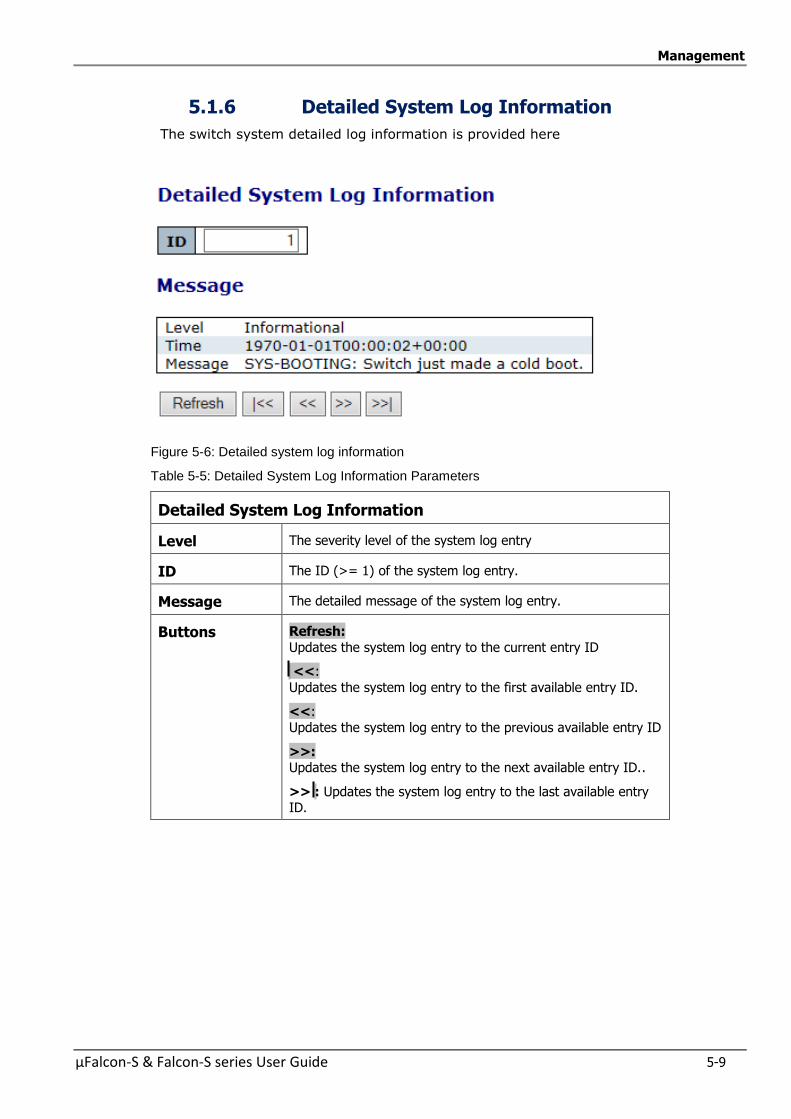
Management
µFalcon-S & Falcon-S series User Guide 5-9
5.1.6 Detailed System Log Information
The switch system detailed log information is provided here
Figure 5-6: Detailed system log information
Table 5-5: Detailed System Log Information Parameters
Detailed System Log Information
Level The severity level of the system log entry
ID The ID (>= 1) of the system log entry.
Message The detailed message of the system log entry.
Buttons Refresh:
Updates the system log entry to the current entry ID
<<:
Updates the system log entry to the first available entry ID.
<<: Updates the system log entry to the previous available entry ID
>>: Updates the system log entry to the next available entry ID..
>> : Updates the system log entry to the last available entry ID.
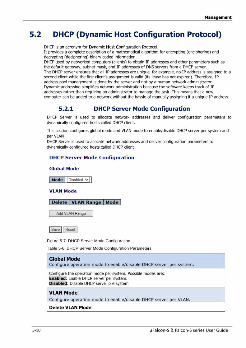
Management
5-10 µFalcon-S & Falcon-S series User Guide
5.2 DHCP (Dynamic Host Configuration Protocol)
DHCP is an acronym for Dynamic Host Configuration Protocol. It provides a complete description of a mathematical algorithm for encrypting (enciphering) and
decrypting (deciphering) binary coded information. DHCP used by networked computers (clients) to obtain IP addresses and other parameters such as
the default gateway, subnet mask, and IP addresses of DNS servers from a DHCP server.
The DHCP server ensures that all IP addresses are unique, for example, no IP address is assigned to a second client while the first client's assignment is valid (its lease has not expired). Therefore, IP
address pool management is done by the server and not by a human network administrator. Dynamic addressing simplifies network administration because the software keeps track of IP
addresses rather than requiring an administrator to manage the task. This means that a new
computer can be added to a network without the hassle of manually assigning it a unique IP address.
5.2.1 DHCP Server Mode Configuration
DHCP Server is used to allocate network addresses and deliver configuration parameters to
dynamically configured hosts called DHCP client.
This section configures global mode and VLAN mode to enable/disable DHCP server per system and
per VLAN
DHCP Server is used to allocate network addresses and deliver configuration parameters to
dynamically configured hosts called DHCP client
Figure 5-7: DHCP Server Mode Configuration
Table 5-6: DHCP Server Mode Configuration Parameters
Global Mode Configure operation mode to enable/disable DHCP server per system.
Configure the operation mode per system. Possible modes are:: Enabled: Enable DHCP server per system.
Disabled: Disable DHCP server pre system
VLAN Mode
Configure operation mode to enable/disable DHCP server per VLAN.
Delete VLAN Mode

Management
µFalcon-S & Falcon-S series User Guide 5-11
Indicate the VLAN range in which DHCP server is enabled or disabled.
The first VLAN ID must be smaller than or equal to the second VLAN ID. BUT, if the VLAN range contains only 1 VLAN ID, then you can just input it into either one of the first and
second VLAN ID or both.
On the other hand, if you want to disable existed VLAN range, then you can follow the steps.:
1. press Add VLAN Range to add a new VLAN range
2. input the VLAN range that you want to disable 3. choose Mode to be Disabled.
4. press SAVE to apply the change
Then, you will see the disabled VLAN range is removed from the DHCP Server mode
configuration page.
Indicate the operation mode per VLAN. Possible modes are: Enabled: Enable DHCP server per VLAN
Disabled: Disable DHCP server pre VLAN.
Buttons Save:Click to save changes.
Reset: Click to undo any changes made locally and revert to
previously saved values.
Add VLAN Range: Click to add a new VLAN range..
5.2.2 DHCP ServerExcluded IP Configuration
This section configures excluded IP addresses. DHCP server will not allocate these excluded IP
addresses to DHCP client.
Figure 5-8: DHCP Server Excluded IP Configuration
Table 5-7: DHCP Server Excluded IP Configuration Parameters
Excluded IP Address Configure excluded IP addresses. Delete Delete Excluded Ip Address opperation
IP Range Define the IP Range to be excluded. The first excluded IP must be
smaller than or equal to the second excluded IP. BUT, if the IP range contains only 1 excluded IP, then you can just input it to either one of
the first and second excluded IP or both
Buttons Save: Click to save changes.
Reset: Click to undo any changes made locally and revert to previously
saved values.
Add IP Range: Click to add anew exclude IP range..
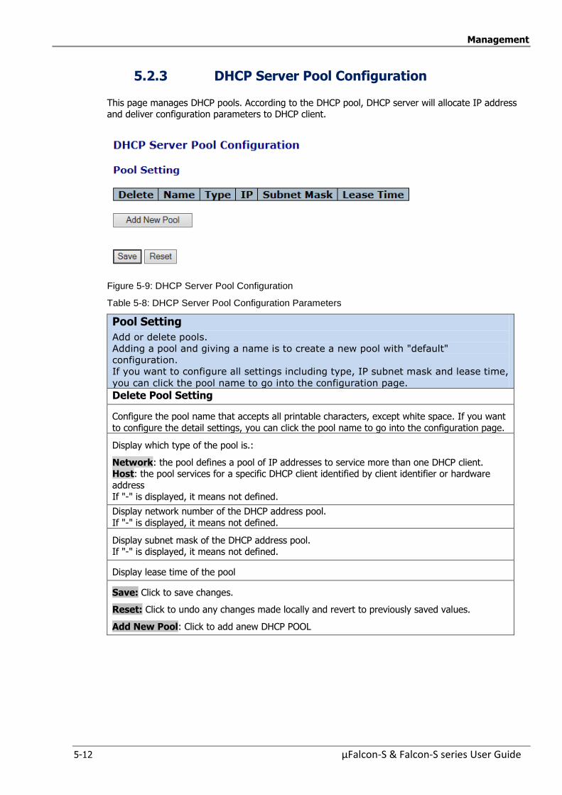
Management
5-12 µFalcon-S & Falcon-S series User Guide
5.2.3 DHCP Server Pool Configuration
This page manages DHCP pools. According to the DHCP pool, DHCP server will allocate IP address and deliver configuration parameters to DHCP client.
Figure 5-9: DHCP Server Pool Configuration
Table 5-8: DHCP Server Pool Configuration Parameters
Pool Setting
Add or delete pools.
Adding a pool and giving a name is to create a new pool with "default"
configuration.
If you want to configure all settings including type, IP subnet mask and lease time,
you can click the pool name to go into the configuration page.
Delete Pool Setting
Configure the pool name that accepts all printable characters, except white space. If you want
to configure the detail settings, you can click the pool name to go into the configuration page.
Display which type of the pool is.:
Network: the pool defines a pool of IP addresses to service more than one DHCP client. Host: the pool services for a specific DHCP client identified by client identifier or hardware
address
If "-" is displayed, it means not defined.
Display network number of the DHCP address pool.
If "-" is displayed, it means not defined.
Display subnet mask of the DHCP address pool. If "-" is displayed, it means not defined.
Display lease time of the pool
Save: Click to save changes.
Reset: Click to undo any changes made locally and revert to previously saved values.
Add New Pool: Click to add anew DHCP POOL
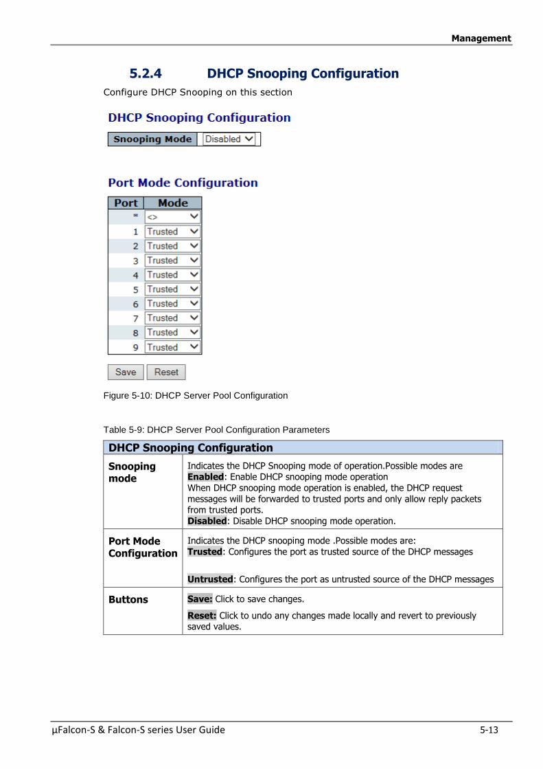
Management
µFalcon-S & Falcon-S series User Guide 5-13
5.2.4 DHCP Snooping Configuration
Configure DHCP Snooping on this section
Figure 5-10: DHCP Server Pool Configuration
Table 5-9: DHCP Server Pool Configuration Parameters
DHCP Snooping Configuration
Snooping mode
Indicates the DHCP Snooping mode of operation.Possible modes are Enabled: Enable DHCP snooping mode operation
When DHCP snooping mode operation is enabled, the DHCP request
messages will be forwarded to trusted ports and only allow reply packets from trusted ports.
Disabled: Disable DHCP snooping mode operation.
Port Mode Configuration
Indicates the DHCP snooping mode .Possible modes are:
Trusted: Configures the port as trusted source of the DHCP messages
Untrusted: Configures the port as untrusted source of the DHCP messages
Buttons Save: Click to save changes.
Reset: Click to undo any changes made locally and revert to previously saved values.

Management
5-14 µFalcon-S & Falcon-S series User Guide
5.2.5 Dynamic DHCP Snooping Table
This page display the dynamic IP assigned information after DHCP Snooping mode is disabled.
All DHCP clients obtained the dynamic IP address from the DHCP server will be listed in this table
except for local VLAN interface IP addresses.
Entries in the Dynamic DHCP snooping Table are shown on this section
Figure 5-11: Dynamic DHCP Snooping Table
Table 5-10: Dynamic DHCP Snooping Table Parameters
Dynamic DHCP snoopingTable MAC Address User MAC address of the entry
VLAN ID VLAN-ID in which the DHCP traffic is permitted
Source Port Switch Port Number for which the entries are displayed
IP Address User IP address of the entry
IP Subnet Mask User IP subnet mask of the entry
DHCP Server Address
DHCP Server address of the entry
Buttons Auto-refresh : Check this box to refresh the page automatically. Automatic refresh occurs every 3 seconds
Refresh: Refreshes the displayed table starting from the input fields.
Clear: Flushes all dynamic entries
<<: Updates the table starting from the first entry in the Dynamic DHCP snooping Table
>>: Updates the table, starting with the entry after the last entry currently displayed.
Navigating the DHCP snooping Table
Each page shows up to 99 entries from the, Dynamic DHCP snooping table, default being 20, selected through the “entries per page” input field
When first visited, the web page will show the first 20 entries from the beginning of the
Dynamic DHCP snooping Table. The “MAC address” and “VLAN” input fields allows the user to select the starting point in the
Dynamic DHCP snooping Table.
Clicking the Refresh button will update the displayed table starting from that or the closest
next MVR Channels (Groups) Information Table match In addition, the two input fields will – upon a Refresh button click – assume the value of the
first displayed entry, allowing for continuous refresh with the same start address.
The >> will use the last entry of the currently displayed table as a basis for the next lookup. When the end is reached the text “No more entries” is shown in the displayed table.
Use the <<button to start over.
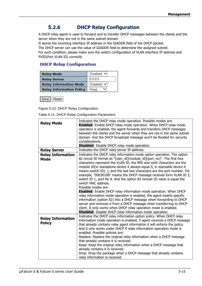
Management
µFalcon-S & Falcon-S series User Guide 5-15
5.2.6 DHCP Relay Configuration
A DHCP relay agent is used to forward and to transfer DHCP messages between the clients and the
server when they are not in the same subnet domain
It stores the incoming interface IP address in the GIADDR field of the DHCP packet.
The DHCP server can use the value of GIADDR field to determine the assigned subnet.
For such condition, please make sure the switch configuration of VLAN interface IP address and
PVID(Port VLAN ID) correctly
Figure 5-12: DHCP Relay Configuration
Table 5-11: DHCP Relay Configuration Parameters
Relay Mode Indicates the DHCP relay mode operation. Possible modes are: Enabled: Enable DHCP relay mode operation. When DHCP relay mode
operation is enabled, the agent forwards and transfers DHCP messages between the clients and the server when they are not in the same subnet
domain. And the DHCP broadcast message won't be flooded for security
considerations. Disabled: Disable DHCP relay mode operation.
Relay Server Indicates the DHCP relay server IP address.
Relay Information Mode
Indicates the DHCP relay information mode option operation. The option 82 circuit ID format as "[vlan_id][module_id][port_no]". The first four
characters represent the VLAN ID, the fifth and sixth characters are the
module ID(in standalone device it always equal 0, in stackable device it means switch ID). ), and the last two characters are the port number. For
example, "00030108" means the DHCP message receives form VLAN ID 3, switch ID 1, port No 8. And the option 82 remote ID value is equal the
switch MAC address. Possible modes are:
Enabled: Enable DHCP relay information mode operation. When DHCP
relay information mode operation is enabled, the agent inserts specific information (option 82) into a DHCP message when forwarding to DHCP
server and removes it from a DHCP message when transferring to DHCP client. It only works when DHCP relay operation mode is enabled.
Disabled: Disable DHCP relay information mode operation.
Relay Information Policy
Indicates the DHCP relay information option policy. When DHCP relay information mode operation is enabled, if agent receives a DHCP message
that already contains relay agent information it will enforce the policy.
And it only works under DHCP if relay information operation mode is enabled. Possible policies are:
Replace: Replace the original relay information when a DHCP message that already contains it is received.
Keep: Keep the original relay information when a DHCP message that already contains it is received.
Drop: Drop the package when a DHCP message that already contains
relay information is received.
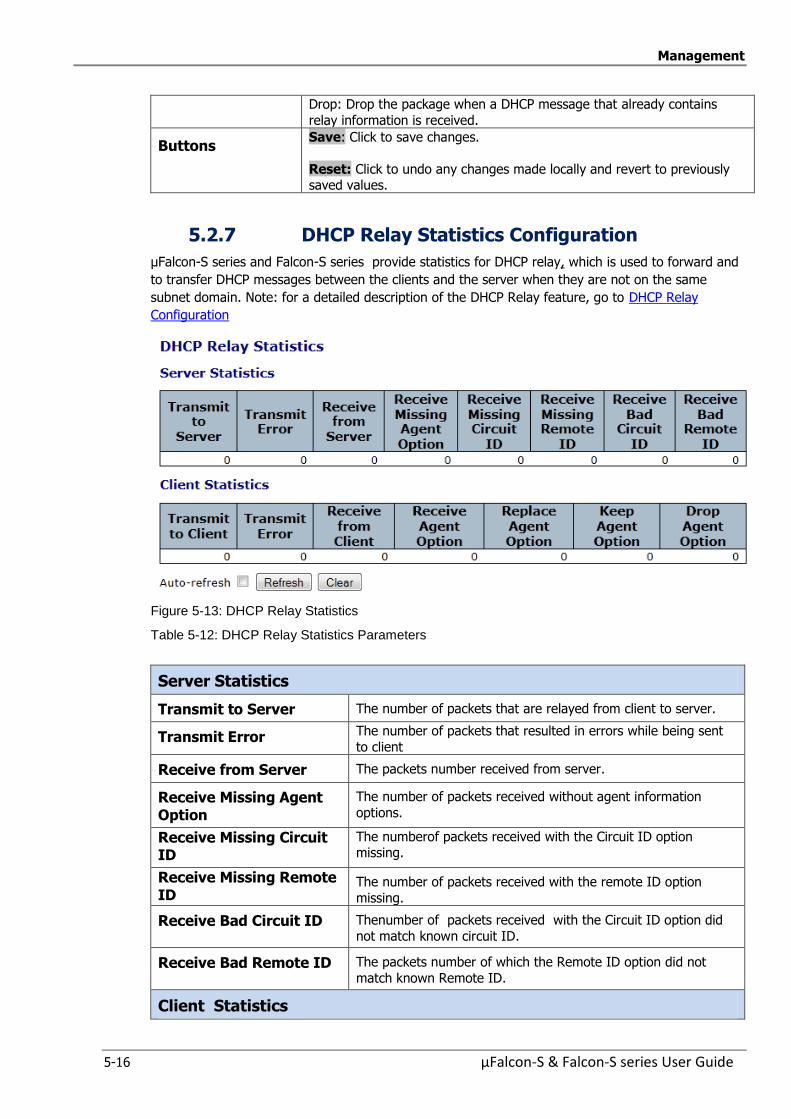
Management
5-16 µFalcon-S & Falcon-S series User Guide
Drop: Drop the package when a DHCP message that already contains
relay information is received.
Buttons Save: Click to save changes.
Reset: Click to undo any changes made locally and revert to previously saved values.
5.2.7 DHCP Relay Statistics Configuration
µFalcon-S series and Falcon-S series provide statistics for DHCP relay, which is used to forward and
to transfer DHCP messages between the clients and the server when they are not on the same
subnet domain. Note: for a detailed description of the DHCP Relay feature, go to DHCP Relay
Configuration
Figure 5-13: DHCP Relay Statistics
Table 5-12: DHCP Relay Statistics Parameters
Server Statistics
Transmit to Server The number of packets that are relayed from client to server.
Transmit Error The number of packets that resulted in errors while being sent
to client
Receive from Server The packets number received from server.
Receive Missing Agent Option
The number of packets received without agent information
options.
Receive Missing Circuit ID
The numberof packets received with the Circuit ID option missing.
Receive Missing Remote ID
The number of packets received with the remote ID option
missing.
Receive Bad Circuit ID Thenumber of packets received with the Circuit ID option did
not match known circuit ID.
Receive Bad Remote ID The packets number of which the Remote ID option did not
match known Remote ID.
Client Statistics
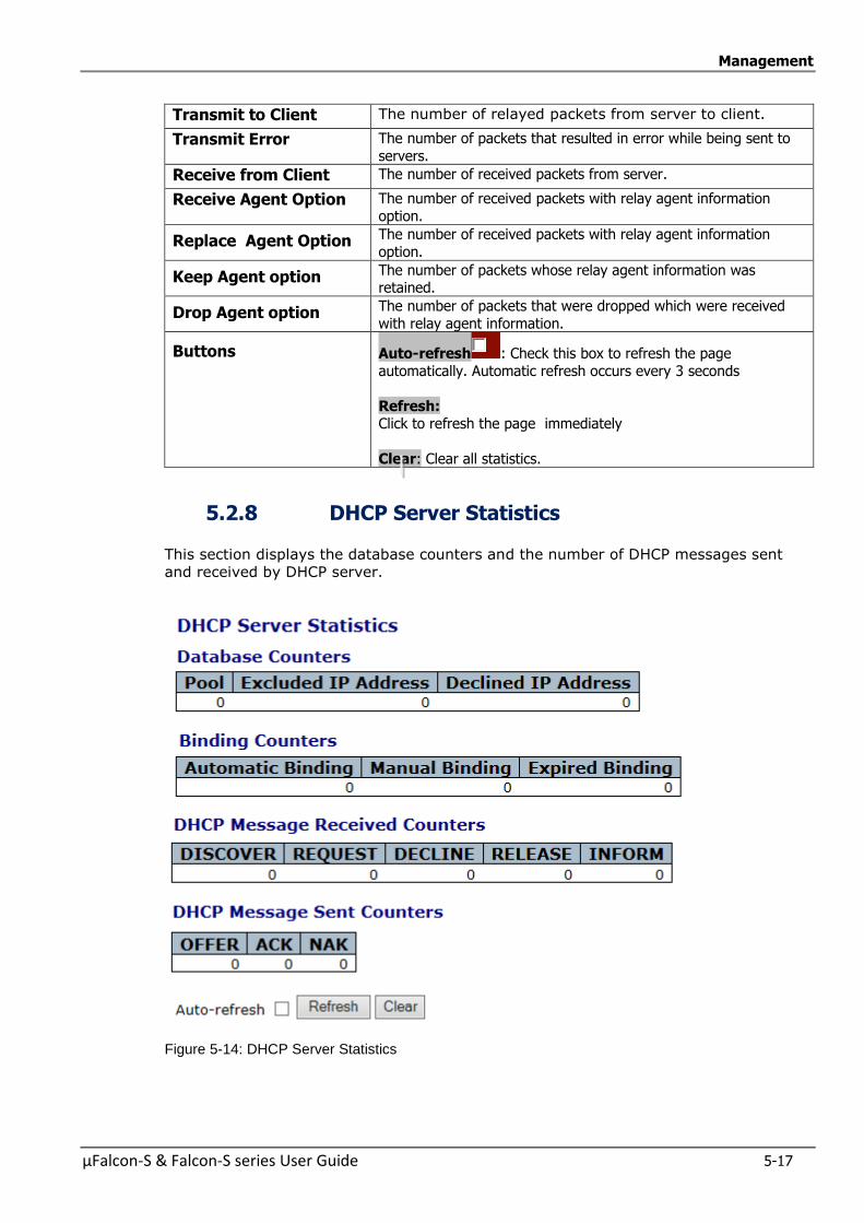
Management
µFalcon-S & Falcon-S series User Guide 5-17
Transmit to Client The number of relayed packets from server to client.
Transmit Error The number of packets that resulted in error while being sent to
servers.
Receive from Client The number of received packets from server.
Receive Agent Option The number of received packets with relay agent information
option.
Replace Agent Option The number of received packets with relay agent information
option.
Keep Agent option The number of packets whose relay agent information was retained.
Drop Agent option The number of packets that were dropped which were received
with relay agent information.
Buttons Auto-refresh : Check this box to refresh the page
automatically. Automatic refresh occurs every 3 seconds
Refresh: Click to refresh the page immediately
Clear: Clear all statistics.
5.2.8 DHCP Server Statistics
This section displays the database counters and the number of DHCP messages sent
and received by DHCP server.
Figure 5-14: DHCP Server Statistics
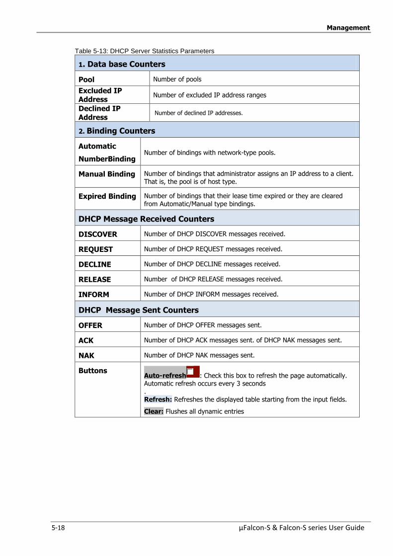
Management
5-18 µFalcon-S & Falcon-S series User Guide
Table 5-13: DHCP Server Statistics Parameters
1. Data base Counters
Pool Number of pools
Excluded IP Address
Number of excluded IP address ranges
Declined IP Address
Number of declined IP addresses.
2. Binding Counters
Automatic
NumberBinding Number of bindings with network-type pools.
Manual Binding Number of bindings that administrator assigns an IP address to a client. That is, the pool is of host type.
Expired Binding Number of bindings that their lease time expired or they are cleared
from Automatic/Manual type bindings.
DHCP Message Received Counters
DISCOVER Number of DHCP DISCOVER messages received.
REQUEST Number of DHCP REQUEST messages received.
DECLINE Number of DHCP DECLINE messages received.
RELEASE Number of DHCP RELEASE messages received.
INFORM Number of DHCP INFORM messages received.
DHCP Message Sent Counters
OFFER Number of DHCP OFFER messages sent.
ACK Number of DHCP ACK messages sent. of DHCP NAK messages sent.
NAK Number of DHCP NAK messages sent.
Buttons Auto-refresh : Check this box to refresh the page automatically. Automatic refresh occurs every 3 seconds
. Refresh: Refreshes the displayed table starting from the input fields.
Clear: Flushes all dynamic entries
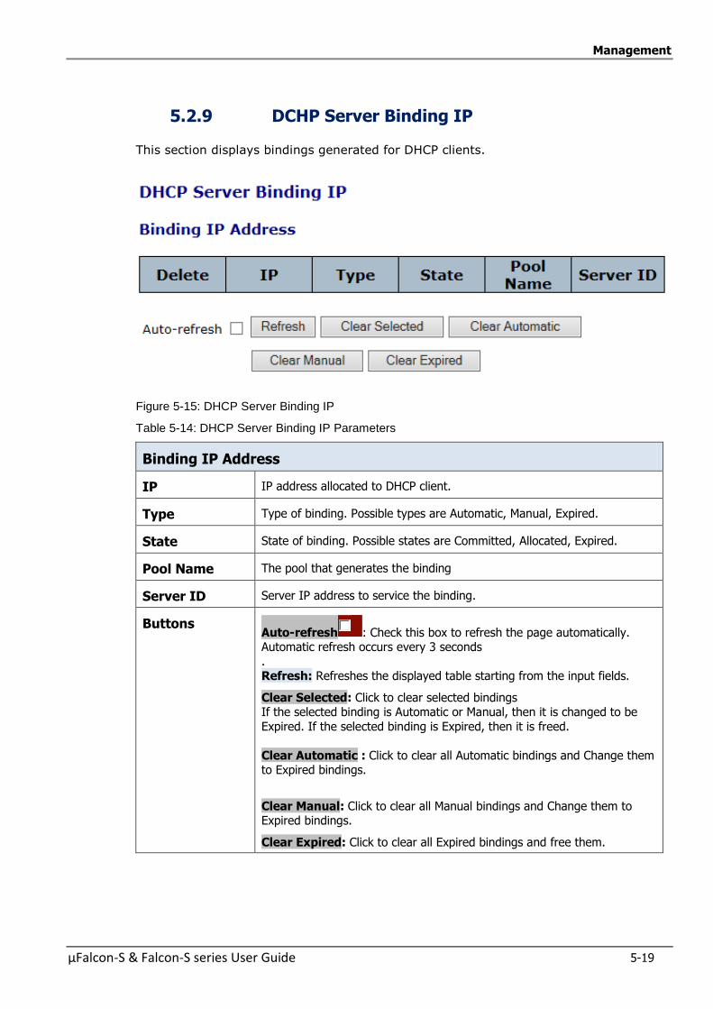
Management
µFalcon-S & Falcon-S series User Guide 5-19
5.2.9 DCHP Server Binding IP
This section displays bindings generated for DHCP clients.
Figure 5-15: DHCP Server Binding IP
Table 5-14: DHCP Server Binding IP Parameters
Binding IP Address
IP IP address allocated to DHCP client.
Type Type of binding. Possible types are Automatic, Manual, Expired.
State State of binding. Possible states are Committed, Allocated, Expired.
Pool Name The pool that generates the binding
Server ID Server IP address to service the binding.
Buttons Auto-refresh : Check this box to refresh the page automatically. Automatic refresh occurs every 3 seconds .
Refresh: Refreshes the displayed table starting from the input fields.
Clear Selected: Click to clear selected bindings If the selected binding is Automatic or Manual, then it is changed to be
Expired. If the selected binding is Expired, then it is freed.
Clear Automatic : Click to clear all Automatic bindings and Change them to Expired bindings.
Clear Manual: Click to clear all Manual bindings and Change them to Expired bindings.
Clear Expired: Click to clear all Expired bindings and free them.

Management
5-20 µFalcon-S & Falcon-S series User Guide
5.2.10 DHCP Server Declined IP
This section displays declined IP addresses.
Figure 5-16: DHCP Server Declined IP
Table 5-15: DHCP Server Declined IP Parameters
Declined IP IP Address Display IP addresses declined by DHCP clients.
Declined IP List of IP addresses declined
Buttons Auto-refresh : Check this box to refresh the page automatically. Automatic refresh occurs every ? seconds
Refresh: Click to refresh the page immediately
5.2.11 DHCP Detailed Statistics Port 1
This page provides statistics for DHCP snooping.
Notice that the normal forward per-port TX statistics isn't increased if the incoming DHCP packet is
done by L3 forwarding mechanism. And clear the statistics on specific port may not take effect on
global statistics since it gathers the different layer overview.
Figure 5-17: DHCP Detailed Statistics Port 1
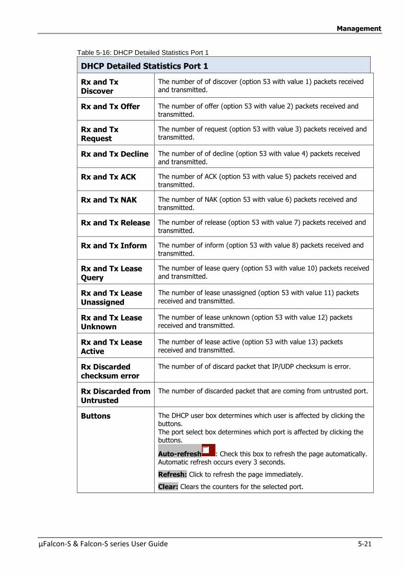
Management
µFalcon-S & Falcon-S series User Guide 5-21
Table 5-16: DHCP Detailed Statistics Port 1
DHCP Detailed Statistics Port 1
Rx and Tx Discover
The number of of discover (option 53 with value 1) packets received and transmitted.
Rx and Tx Offer The number of offer (option 53 with value 2) packets received and
transmitted.
Rx and Tx Request
The number of request (option 53 with value 3) packets received and transmitted.
Rx and Tx Decline The number of of decline (option 53 with value 4) packets received
and transmitted.
Rx and Tx ACK The number of ACK (option 53 with value 5) packets received and
transmitted.
Rx and Tx NAK The number of NAK (option 53 with value 6) packets received and transmitted.
Rx and Tx Release The number of release (option 53 with value 7) packets received and
transmitted.
Rx and Tx Inform The number of inform (option 53 with value 8) packets received and
transmitted.
Rx and Tx Lease Query
The number of lease query (option 53 with value 10) packets received and transmitted.
Rx and Tx Lease Unassigned
The number of lease unassigned (option 53 with value 11) packets
received and transmitted.
Rx and Tx Lease Unknown
The number of lease unknown (option 53 with value 12) packets received and transmitted.
Rx and Tx Lease Active
The number of lease active (option 53 with value 13) packets
received and transmitted.
Rx Discarded checksum error
The number of of discard packet that IP/UDP checksum is error.
Rx Discarded from Untrusted
The number of discarded packet that are coming from untrusted port.
Buttons The DHCP user box determines which user is affected by clicking the buttons.
The port select box determines which port is affected by clicking the buttons.
Auto-refresh : Check this box to refresh the page automatically. Automatic refresh occurs every 3 seconds.
Refresh: Click to refresh the page immediately.
Clear: Clears the counters for the selected port.
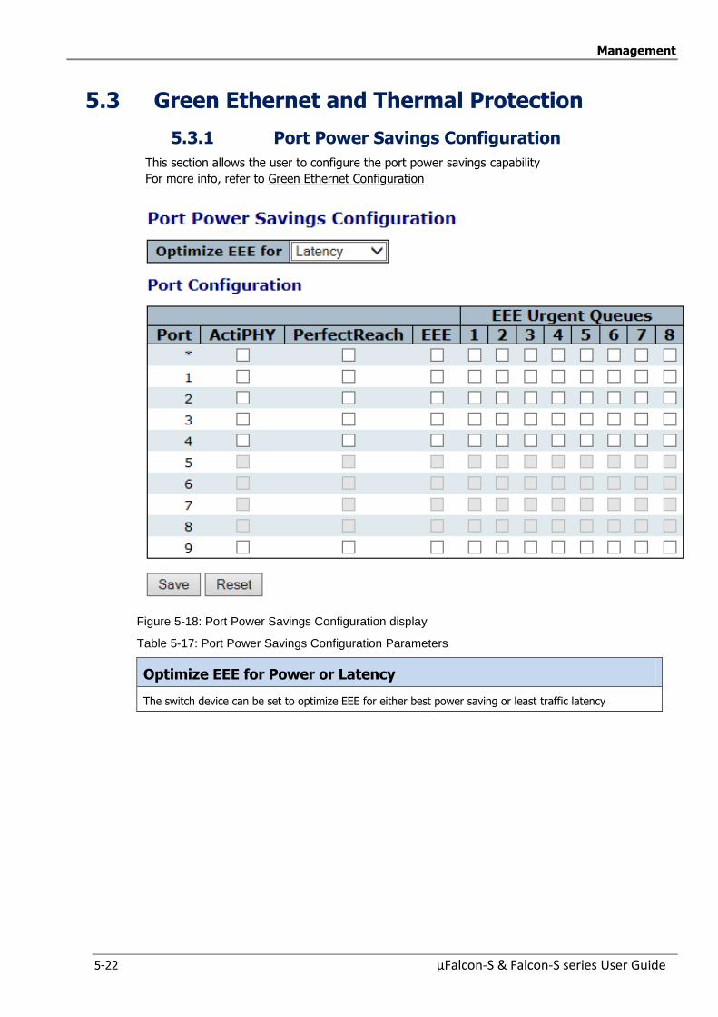
Management
5-22 µFalcon-S & Falcon-S series User Guide
5.3 Green Ethernet and Thermal Protection
5.3.1 Port Power Savings Configuration
This section allows the user to configure the port power savings capability
For more info, refer to Green Ethernet Configuration
Figure 5-18: Port Power Savings Configuration display
Table 5-17: Port Power Savings Configuration Parameters
Optimize EEE for Power or Latency
The switch device can be set to optimize EEE for either best power saving or least traffic latency
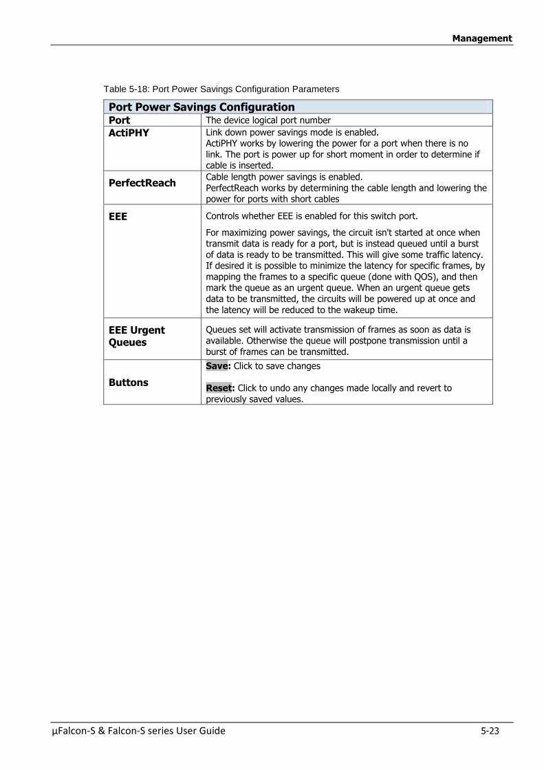
Management
µFalcon-S & Falcon-S series User Guide 5-23
Table 5-18: Port Power Savings Configuration Parameters
Port Power Savings Configuration Port The device logical port number
ActiPHY Link down power savings mode is enabled. ActiPHY works by lowering the power for a port when there is no
link. The port is power up for short moment in order to determine if cable is inserted.
PerfectReach Cable length power savings is enabled.
PerfectReach works by determining the cable length and lowering the power for ports with short cables
EEE Controls whether EEE is enabled for this switch port.
For maximizing power savings, the circuit isn't started at once when transmit data is ready for a port, but is instead queued until a burst
of data is ready to be transmitted. This will give some traffic latency. If desired it is possible to minimize the latency for specific frames, by
mapping the frames to a specific queue (done with QOS), and then mark the queue as an urgent queue. When an urgent queue gets
data to be transmitted, the circuits will be powered up at once and
the latency will be reduced to the wakeup time.
EEE Urgent Queues
Queues set will activate transmission of frames as soon as data is
available. Otherwise the queue will postpone transmission until a
burst of frames can be transmitted.
Buttons
Save: Click to save changes
Reset: Click to undo any changes made locally and revert to
previously saved values.
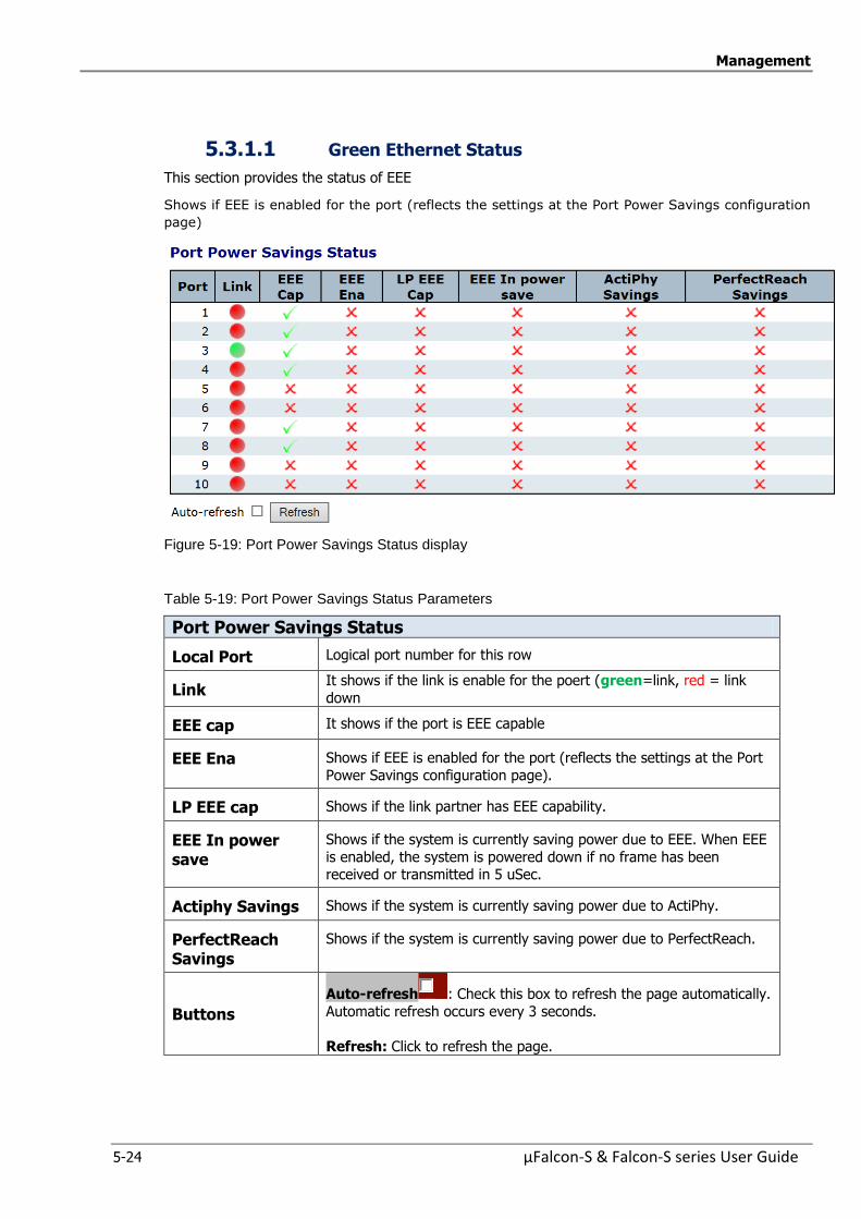
Management
5-24 µFalcon-S & Falcon-S series User Guide
5.3.1.1 Green Ethernet Status
This section provides the status of EEE
Shows if EEE is enabled for the port (reflects the settings at the Port Power Savings configuration
page)
Figure 5-19: Port Power Savings Status display
Table 5-19: Port Power Savings Status Parameters
Port Power Savings Status
Local Port Logical port number for this row
Link It shows if the link is enable for the poert (green=link, red = link
down
EEE cap It shows if the port is EEE capable
EEE Ena Shows if EEE is enabled for the port (reflects the settings at the Port
Power Savings configuration page).
LP EEE cap Shows if the link partner has EEE capability.
EEE In power save
Shows if the system is currently saving power due to EEE. When EEE
is enabled, the system is powered down if no frame has been received or transmitted in 5 uSec.
Actiphy Savings Shows if the system is currently saving power due to ActiPhy.
PerfectReach Savings
Shows if the system is currently saving power due to PerfectReach.
Buttons
Auto-refresh : Check this box to refresh the page automatically.
Automatic refresh occurs every 3 seconds.
Refresh: Click to refresh the page.

Management
µFalcon-S & Falcon-S series User Guide 5-25
5.3.2 Thermal Protection Configuration
Each group can be given a temperature at which the corresponding ports shall be turned off. This
page allows the user to inspect and configure the current setting for controlling thermal protection.
Thermal protection is used to protect the chip from getting overheated.
When the temperature exceeds the configured thermal protection temperature, ports will be turned
off in order to decrease the power consumption. It is possible to arrange the ports with different
Figure 5-20: Thermal Protection Configuration display
Table 5-20: Thermal Protection Configuration Parameters
Temperature setting for groups The temperature at which the ports with the corresponding group will be turned off. Temperatures between 0 and 255 C are supported.
Port groups The group the port belongs to. 4 groups are supported.-
Buttons Save: Click to save changes
Reset: Click to undo any changes made locally and revert to
previously saved values.
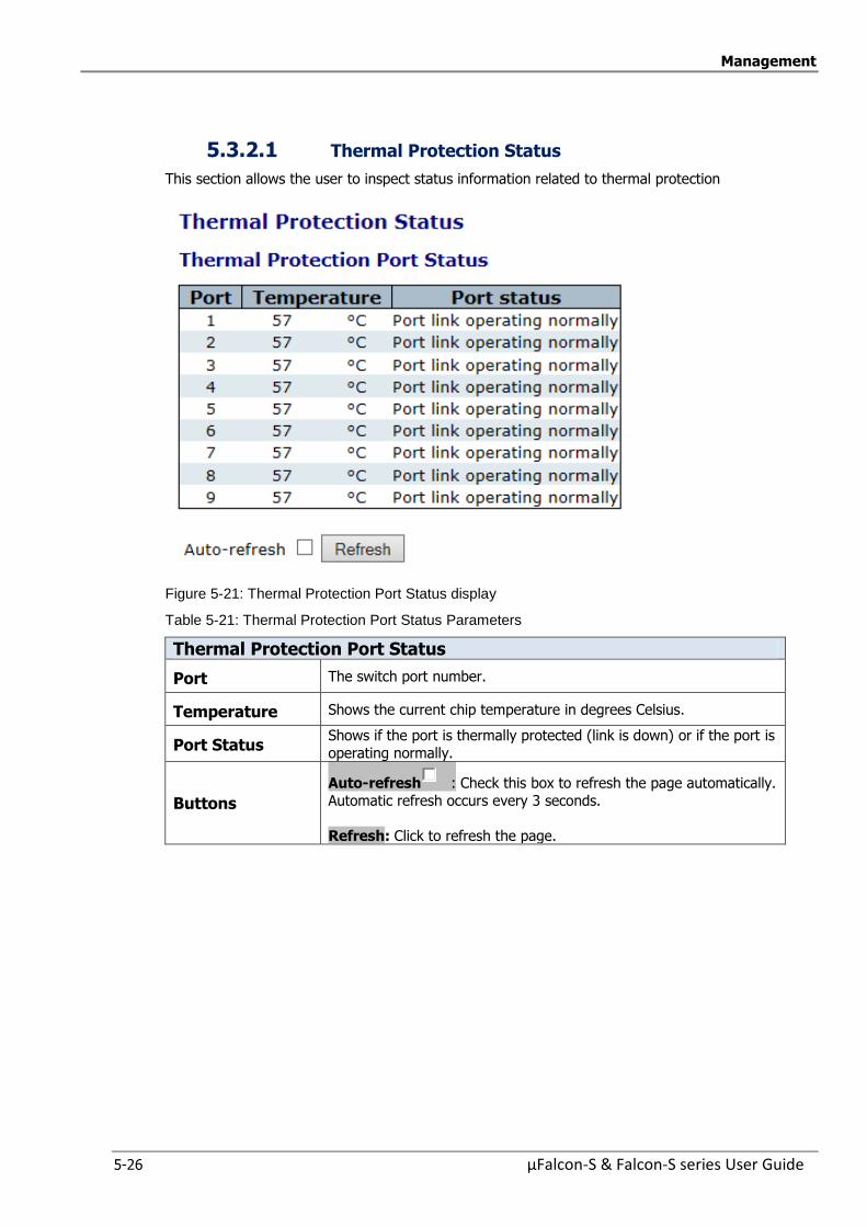
Management
5-26 µFalcon-S & Falcon-S series User Guide
5.3.2.1 Thermal Protection Status
This section allows the user to inspect status information related to thermal protection
Figure 5-21: Thermal Protection Port Status display
Table 5-21: Thermal Protection Port Status Parameters
Thermal Protection Port Status
Port The switch port number.
Temperature Shows the current chip temperature in degrees Celsius.
Port Status Shows if the port is thermally protected (link is down) or if the port is
operating normally.
Buttons
Auto-refresh : Check this box to refresh the page automatically.
Automatic refresh occurs every 3 seconds.
Refresh: Click to refresh the page.
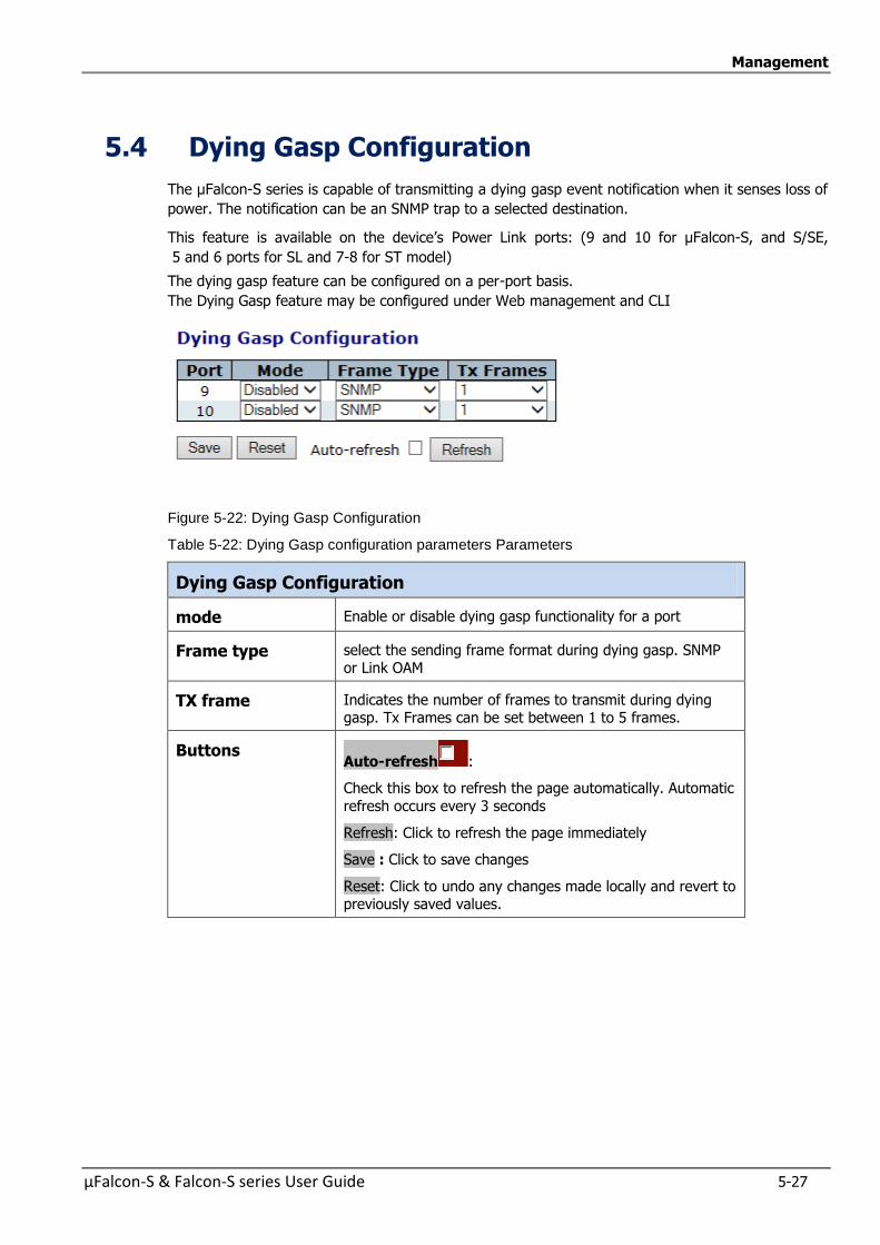
Management
µFalcon-S & Falcon-S series User Guide 5-27
5.4 Dying Gasp Configuration
The µFalcon-S series is capable of transmitting a dying gasp event notification when it senses loss of
power. The notification can be an SNMP trap to a selected destination.
This feature is available on the device’s Power Link ports: (9 and 10 for µFalcon-S, and S/SE,
5 and 6 ports for SL and 7-8 for ST model)
The dying gasp feature can be configured on a per-port basis.
The Dying Gasp feature may be configured under Web management and CLI
Figure 5-22: Dying Gasp Configuration
Table 5-22: Dying Gasp configuration parameters Parameters
Dying Gasp Configuration
mode Enable or disable dying gasp functionality for a port
Frame type select the sending frame format during dying gasp. SNMP or Link OAM
TX frame Indicates the number of frames to transmit during dying gasp. Tx Frames can be set between 1 to 5 frames.
Buttons Auto-refresh :
Check this box to refresh the page automatically. Automatic
refresh occurs every 3 seconds
Refresh: Click to refresh the page immediately
Save : Click to save changes
Reset: Click to undo any changes made locally and revert to previously saved values.

Management
5-28 µFalcon-S & Falcon-S series User Guide
5.5 Simple Network Management Protocol (SNMP)
µFalcon-S series supports SNMP management, inspection and configuration.
The following screens are used to set SNMP System Configuration and SNMP Trap settings.
SNMP System Configuration
SNMPv3 Trap Configuratio
SNMPv3 Community Configuration SNMPv3 Users Configuration
SNMPv3 Group Configuration SNMPv3 View Configuration
SNMPv3 Access Configuration
5.5.1 SNMP System Configuration
Figure 5-23: SNMP System Configuration display
Table 5-23: SNMP System Configuration Parameters
SNMP System Configuration
Mode Indicate the SNMP mode operation. Possible modes are:
“Enabled”: Enable SNMP mode operation. “Disabled”: Disable SNMP mode operation.
Version Indicate the SNMP supported version.
Possible versions are: SNMP v1: Set SNMP supported version 1.
SNMP v2c: Set SNMP supported version 2c.
SNMP v3: Set SNMP supported version 3.
Read Community
Indicates the community read access string to permit access to SNMP
agent.The allowed string length is 0 to 255, and the allowed content is the ASCII characters from 33 to 126.
The field is applicable only when SNMP version is SNMPv1 or SNMPv2c.
If If SNMP version is SNMPv3, the community string will be associated with SNMPv3 communities table.
It It provides more flexibility to configure security name than a SNMPv1 or SNMPv2c community string.
In In addition to community string, a particular range of source
addresses can be used to restrict source subne
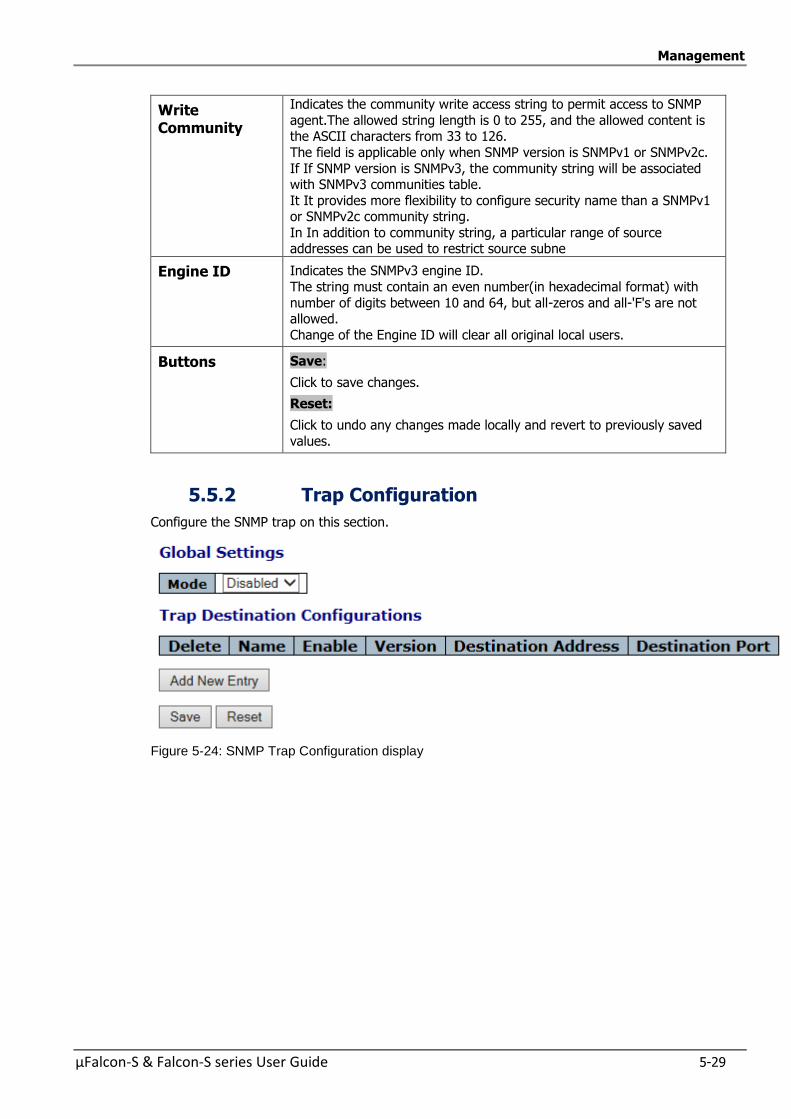
Management
µFalcon-S & Falcon-S series User Guide 5-29
Write Community
Indicates the community write access string to permit access to SNMP
agent.The allowed string length is 0 to 255, and the allowed content is the ASCII characters from 33 to 126.
The field is applicable only when SNMP version is SNMPv1 or SNMPv2c.
If If SNMP version is SNMPv3, the community string will be associated with SNMPv3 communities table.
It It provides more flexibility to configure security name than a SNMPv1 or SNMPv2c community string.
In In addition to community string, a particular range of source addresses can be used to restrict source subne
Engine ID Indicates the SNMPv3 engine ID.
The string must contain an even number(in hexadecimal format) with
number of digits between 10 and 64, but all-zeros and all-'F's are not allowed.
Change of the Engine ID will clear all original local users.
Buttons
Save:
Click to save changes.
Reset:
Click to undo any changes made locally and revert to previously saved
values.
5.5.2 Trap Configuration
Configure the SNMP trap on this section.
Figure 5-24: SNMP Trap Configuration display

Management
5-30 µFalcon-S & Falcon-S series User Guide
Table 5-24: SNMP Trap Configuration Parameters
Global Settings
Mode Indicate the SNMP trap mode operation.
Possible modes are:
“Enabled”: Enable SNMP trap mode operation. “Disabled”: Disable SNMP trap mode operation.
Trap Destination Configuration
Delete Check to delete the entry. It will be deleted during the next save.
Name Indicates the trap Configuration‘s name
Indicates the trap destination's name.
Enable Indicates the trap destination mode operation.
Possible modes are: Enabled: Enable SNMP trap mode operation.
Disabled: Disable SNMP trap mode operation.
Version Indicate the SNMP trap version. Possible versions are:
SNMP v1: Set SNMP trap supported version 1.
SNMP v2c: Set SNMP supported version 2c. SNMP v3: Set SNMP trap supported version 3.
Destination Address
Indicates the SNMP trap destination address. It allows a valid IP address in dotted decimal notation ('x.y.z.w').
And it also allows a valid hostname. A valid hostname is a string drawn from the
alphabet (A-Za-z), digits (0-9), dot (.), dash (-). Spaces are not allowed, the first character must be an alpha character, and the
first and last characters must not be a dot or a dash. Indicates the SNMP trap destination IPv6 address. IPv6 address is in 128-bit
records represented as eight fields of up to four hexadecimal digits with a colon
separating each field (:). For example, 'fe80:: 215:c5ff:fe03:4dc7’. The symbol '::' is a special syntax that can be used as a shorthand way of representing multiple
16-bit groups of contiguous zeros; but it can appear only once. It can also represent a legally valid IPv4 address. For example, ':: 192.1.2.34'.
Destination port
Indicates the SNMP trap destination port
SNMP Agent will send SNMP message via this port, the port range is 1~65535.
Buttons
Add New Entry:
Click to add a new user.
Save:
Click to save changes.
Reset:
Click to undo any changes made locally and revert to previously saved values.
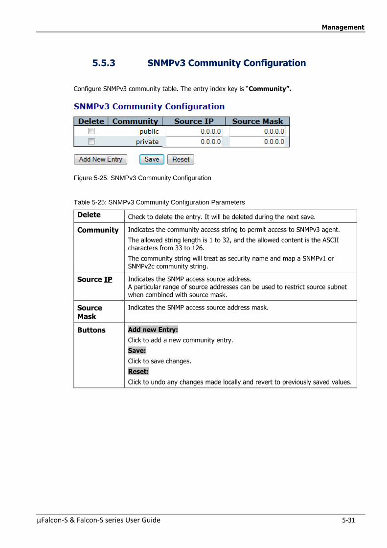
Management
µFalcon-S & Falcon-S series User Guide 5-31
5.5.3 SNMPv3 Community Configuration
Configure SNMPv3 community table. The entry index key is “Community”.
Figure 5-25: SNMPv3 Community Configuration
Table 5-25: SNMPv3 Community Configuration Parameters
Delete Check to delete the entry. It will be deleted during the next save.
Community Indicates the community access string to permit access to SNMPv3 agent.
The allowed string length is 1 to 32, and the allowed content is the ASCII
characters from 33 to 126.
The community string will treat as security name and map a SNMPv1 or SNMPv2c community string.
Source IP Indicates the SNMP access source address.
A particular range of source addresses can be used to restrict source subnet
when combined with source mask.
Source Mask
Indicates the SNMP access source address mask.
Buttons
Add new Entry:
Click to add a new community entry.
Save:
Click to save changes.
Reset:
Click to undo any changes made locally and revert to previously saved values.
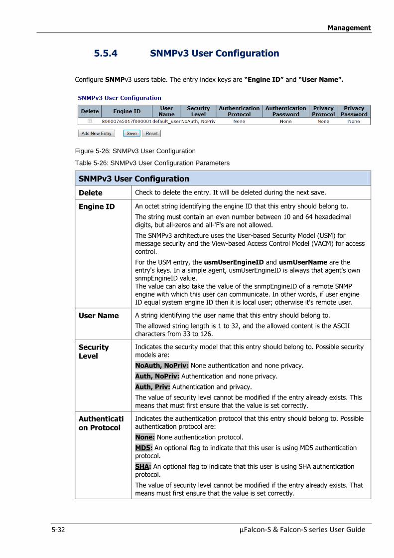
Management
5-32 µFalcon-S & Falcon-S series User Guide
5.5.4 SNMPv3 User Configuration
Configure SNMPv3 users table. The entry index keys are “Engine ID” and “User Name”.
Figure 5-26: SNMPv3 User Configuration
Table 5-26: SNMPv3 User Configuration Parameters
SNMPv3 User Configuration
Delete Check to delete the entry. It will be deleted during the next save.
Engine ID An octet string identifying the engine ID that this entry should belong to.
The string must contain an even number between 10 and 64 hexadecimal
digits, but all-zeros and all-'F's are not allowed.
The SNMPv3 architecture uses the User-based Security Model (USM) for message security and the View-based Access Control Model (VACM) for access
control.
For the USM entry, the usmUserEngineID and usmUserName are the
entry's keys. In a simple agent, usmUserEngineID is always that agent's own snmpEngineID value.
The value can also take the value of the snmpEngineID of a remote SNMP engine with which this user can communicate. In other words, if user engine
ID equal system engine ID then it is local user; otherwise it's remote user.
User Name A string identifying the user name that this entry should belong to.
The allowed string length is 1 to 32, and the allowed content is the ASCII characters from 33 to 126.
Security Level
Indicates the security model that this entry should belong to. Possible security
models are:
NoAuth, NoPriv: None authentication and none privacy.
Auth, NoPriv: Authentication and none privacy.
Auth, Priv: Authentication and privacy.
The value of security level cannot be modified if the entry already exists. This
means that must first ensure that the value is set correctly.
Authentication Protocol
Indicates the authentication protocol that this entry should belong to. Possible
authentication protocol are:
None: None authentication protocol.
MD5: An optional flag to indicate that this user is using MD5 authentication protocol.
SHA: An optional flag to indicate that this user is using SHA authentication
protocol.
The value of security level cannot be modified if the entry already exists. That
means must first ensure that the value is set correctly.

Management
µFalcon-S & Falcon-S series User Guide 5-33
Authentication Password
A string identifying the authentication password phrase. For MD5
authentication protocol, the allowed string length is 8 to 32. For SHA
authentication protocol, the allowed string length is 8 to 40. The allowed content is ASCII characters from 33 to 126.
Privacy Protocol
Indicates the privacy protocol that this entry should belong to. Possible privacy
protocol are:
None: None privacy protocol.
DES: An optional flag to indicate that this user is using DES encryption
standard
AES: An optional flag to indicate that this user uses AES authentication
protocol.
Privacy Password
A string identifying the privacy password phrase.
The allowed string length is 8 to 32, and the allowed content is the ASCII characters from 33 to 126.
Buttons
Add new Entry
Click to add a new user entry.
Save:
Click to save changes.
Reset:
Click to undo any changes made locally and revert to previously saved values.
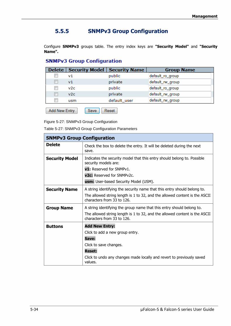
Management
5-34 µFalcon-S & Falcon-S series User Guide
5.5.5 SNMPv3 Group Configuration
Configure SNMPv3 groups table. The entry index keys are "Security Model" and "Security
Name".
Figure 5-27: SNMPv3 Group Configuration
Table 5-27: SNMPv3 Group Configuration Parameters
SNMPv3 Group Configuration
Delete Check the box to delete the entry. It will be deleted during the next
save.
Security Model Indicates the security model that this entry should belong to. Possible
security models are:
v1: Reserved for SNMPv1.
v2c: Reserved for SNMPv2c.
usm: User-based Security Model (USM).
Security Name A string identifying the security name that this entry should belong to.
The allowed string length is 1 to 32, and the allowed content is the ASCII
characters from 33 to 126.
Group Name A string identifying the group name that this entry should belong to.
The allowed string length is 1 to 32, and the allowed content is the ASCII
characters from 33 to 126.
Buttons
Add New Entry:
Click to add a new group entry.
Save:
Click to save changes.
Reset:
Click to undo any changes made locally and revert to previously saved
values.
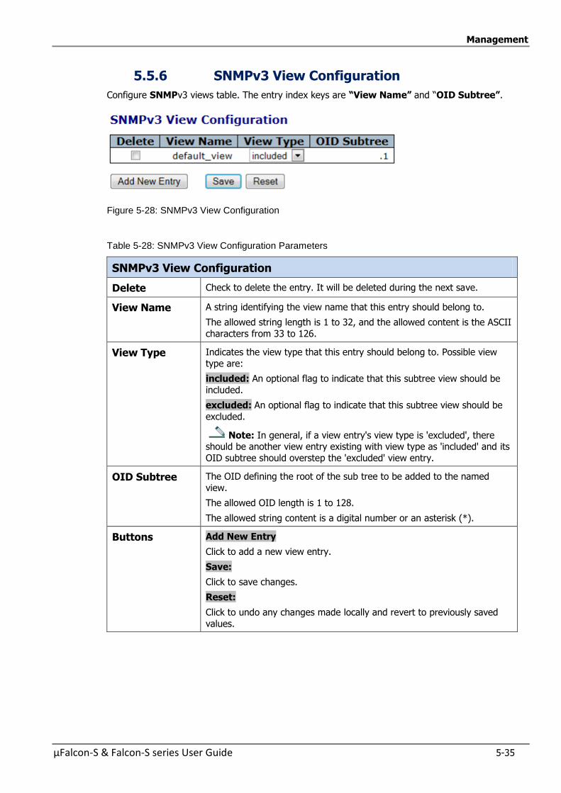
Management
µFalcon-S & Falcon-S series User Guide 5-35
5.5.6 SNMPv3 View Configuration
Configure SNMPv3 views table. The entry index keys are “View Name” and “OID Subtree”.
Figure 5-28: SNMPv3 View Configuration
Table 5-28: SNMPv3 View Configuration Parameters
SNMPv3 View Configuration
Delete Check to delete the entry. It will be deleted during the next save.
View Name A string identifying the view name that this entry should belong to.
The allowed string length is 1 to 32, and the allowed content is the ASCII
characters from 33 to 126.
View Type Indicates the view type that this entry should belong to. Possible view
type are:
included: An optional flag to indicate that this subtree view should be
included.
excluded: An optional flag to indicate that this subtree view should be
excluded.
Note: In general, if a view entry's view type is 'excluded', there should be another view entry existing with view type as 'included' and its
OID subtree should overstep the 'excluded' view entry.
OID Subtree The OID defining the root of the sub tree to be added to the named
view.
The allowed OID length is 1 to 128.
The allowed string content is a digital number or an asterisk (*).
Buttons
Add New Entry
Click to add a new view entry.
Save:
Click to save changes.
Reset:
Click to undo any changes made locally and revert to previously saved
values.
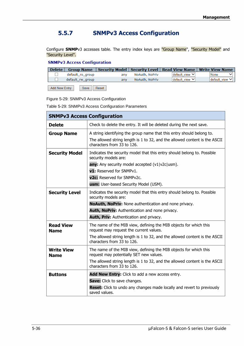
Management
5-36 µFalcon-S & Falcon-S series User Guide
5.5.7 SNMPv3 Access Configuration
Configure SNMPv3 accesses table. The entry index keys are "Group Name", "Security Model" and
"Security Level".
Figure 5-29: SNMPv3 Access Configuration
Table 5-29: SNMPv3 Access Configuration Parameters
SNMPv3 Access Configuration
Delete Check to delete the entry. It will be deleted during the next save.
Group Name A string identifying the group name that this entry should belong to.
The allowed string length is 1 to 32, and the allowed content is the ASCII characters from 33 to 126.
Security Model Indicates the security model that this entry should belong to. Possible
security models are:
any: Any security model accepted (v1|v2c|usm).
v1: Reserved for SNMPv1.
v2c: Reserved for SNMPv2c.
usm: User-based Security Model (USM).
Security Level Indicates the security model that this entry should belong to. Possible
security models are:
NoAuth, NoPriv: None authentication and none privacy.
Auth, NoPriv: Authentication and none privacy.
Auth, Priv: Authentication and privacy.
Read View Name
The name of the MIB view, defining the MIB objects for which this
request may request the current values.
The allowed string length is 1 to 32, and the allowed content is the ASCII characters from 33 to 126.
Write View Name
The name of the MIB view, defining the MIB objects for which this
request may potentially SET new values.
The allowed string length is 1 to 32, and the allowed content is the ASCII
characters from 33 to 126.
Buttons
Add New Entry: Click to add a new access entry.
Save: Click to save changes.
Reset: Click to undo any changes made locally and revert to previously
saved values.
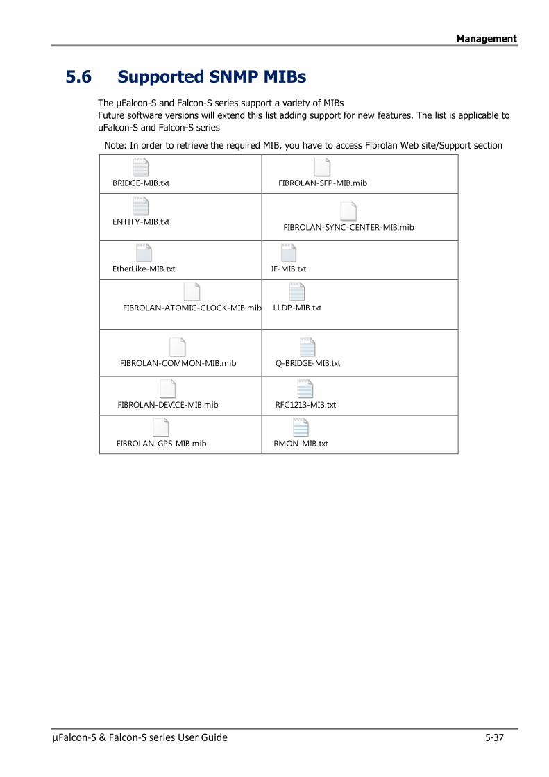
Management
µFalcon-S & Falcon-S series User Guide 5-37
5.6 Supported SNMP MIBs
The µFalcon-S and Falcon-S series support a variety of MIBs
Future software versions will extend this list adding support for new features. The list is applicable to
uFalcon-S and Falcon-S series
Note: In order to retrieve the required MIB, you have to access Fibrolan Web site/Support section
BRIDGE-MIB.txt
FIBROLAN-SFP-MIB.mib
ENTITY-MIB.txt FIBROLAN-SYNC-CENTER-MIB.mib
EtherLike-MIB.txt
IF-MIB.txt
FIBROLAN-ATOMIC-CLOCK-MIB.mib
LLDP-MIB.txt
FIBROLAN-COMMON-MIB.mib
Q-BRIDGE-MIB.txt
FIBROLAN-DEVICE-MIB.mib
RFC1213-MIB.txt
FIBROLAN-GPS-MIB.mib
RMON-MIB.txt
Management
5-38 µFalcon-S & Falcon-S series User Guide
5.7 Command Line Interface (CLI)
CLI commands are used to manage the µFalcon-S and Falcon-S series for displaying and modifying
configuration of the various elements within the system.
Use one of the following methods to open a CLI session with the µFalcon-S series:
Connect the switch console port to a management station. For information about connecting to
the console port, refer to Console Connection and Configuration.
Open a Telnet session from a remote management station. The switch must have network IP
connectivity with this remote management station.
Changes made by one Telnet user are reflected in all other Telnet sessions.
To Access µFalcon-S series via Telnet
Use any Telnet client application. The following example relates to Windows OS.
Start the “Run” option and in the command line enter:
“telnet XX.XX.XX.XX" (IP address of the µFalcon-S series)
The Telnet screen prompts for a username and password.
Username:moose
Password: 1234
5.7.1 SSH Configuration
Secure Shell or SSH is a network protocol that allows exchange of data between two networked
devices using a secure channel. SSH has been designed to replace Telnet and other insecure remote
applications. The encryption deployed by SSH provides integrity of data
Configure SSH in this section.
Link to SSH Configuration
5.7.2 HTTP Secure (HTTPS)
The µFalcon-S series supports secured web interface sessions using the HTTPS (HTTP over SSL) protocol.
HTTP is an acronym for Hypertext Transfer Protocol over Secure Socket Layer. It is used to indicate
a secure HTTP connection.
HTTPS provide authentication and encrypted communication and is widely used on the World Wide Web for security-sensitive communication such as payment transactions and corporate logons.
Link to HTTPS Configuration
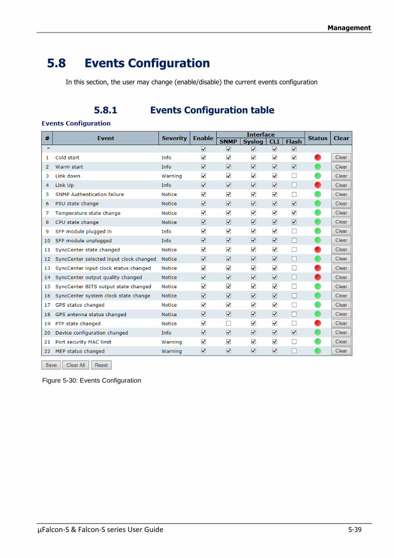
Management
µFalcon-S & Falcon-S series User Guide 5-39
5.8 Events Configuration
In this section, the user may change (enable/disable) the current events configuration
5.8.1 Events Configuration table
Figure 5-30: Events Configuration

Management
5-40 µFalcon-S & Falcon-S series User Guide
Table 5-30 Events Configuration Parameters
Events Configuration
# Event Index.
Event Unique Name of the Event.
Severity The severity level of the listed events The following lseveritytypes are supported:
Informational : Information level of the system log.
Warning: Warning level of the system log. Error: Error level of the system log.
Notice:made to help the memory
Enable Disable/Enable Event (Change will take effect on all checked interfaces: snmp,
syslog, cli).
Interface Distribute event on a give interface : snmp, syslog, cli.
Status Indication whether an event occured or not .
Clear Clear event occurred indication.
Buttons Save:
Click to save changes.
Reset:
Click to undo any changes made locally and revert to previously saved values.
Clear All : Click to clear ALL event occurred indications.
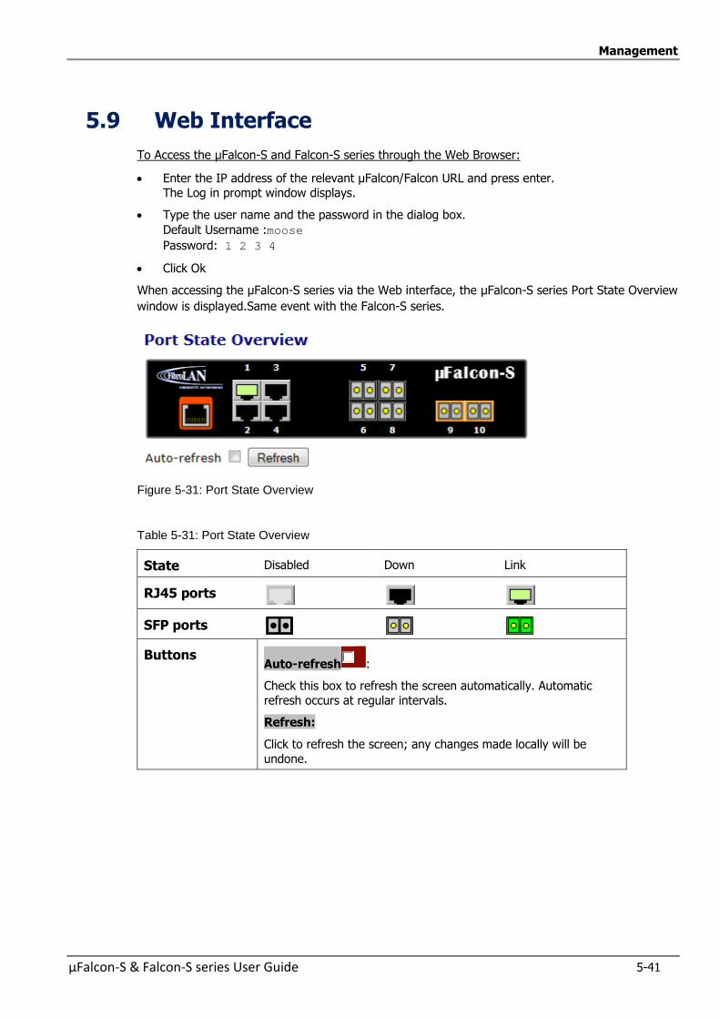
Management
µFalcon-S & Falcon-S series User Guide 5-41
5.9 Web Interface
To Access the µFalcon-S and Falcon-S series through the Web Browser:
Enter the IP address of the relevant µFalcon/Falcon URL and press enter.
The Log in prompt window displays.
Type the user name and the password in the dialog box.
Default Username :moose
Password: 1 2 3 4
Click Ok
When accessing the µFalcon-S series via the Web interface, the µFalcon-S series Port State Overview
window is displayed.Same event with the Falcon-S series.
Figure 5-31: Port State Overview
Table 5-31: Port State Overview
State Disabled Down Link
RJ45 ports
SFP ports
Buttons Auto-refresh :
Check this box to refresh the screen automatically. Automatic
refresh occurs at regular intervals.
Refresh:
Click to refresh the screen; any changes made locally will be
undone.
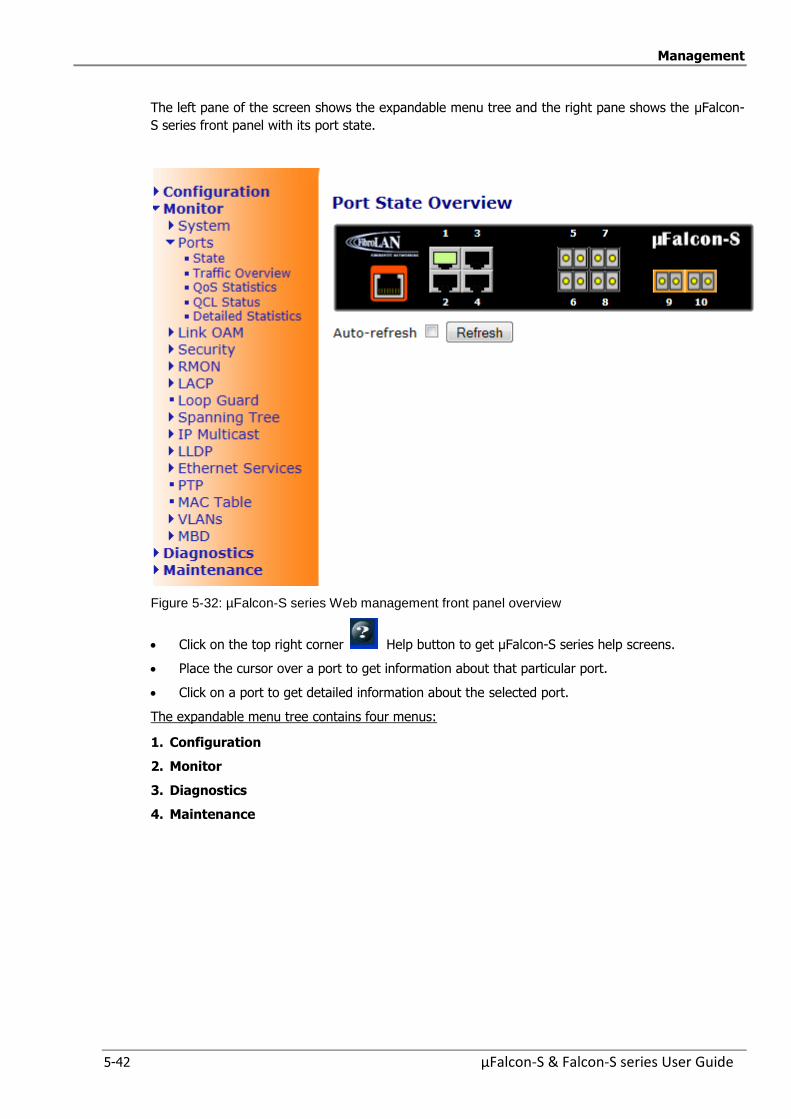
Management
5-42 µFalcon-S & Falcon-S series User Guide
The left pane of the screen shows the expandable menu tree and the right pane shows the µFalcon-
S series front panel with its port state.
Figure 5-32: µFalcon-S series Web management front panel overview
Click on the top right corner Help button to get µFalcon-S series help screens.
Place the cursor over a port to get information about that particular port.
Click on a port to get detailed information about the selected port.
The expandable menu tree contains four menus:
1. Configuration
2. Monitor
3. Diagnostics
4. Maintenance
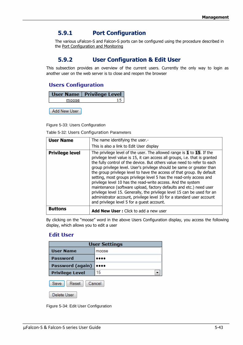
Management
µFalcon-S & Falcon-S series User Guide 5-43
5.9.1 Port Configuration
The various uFalcon-S and Falcon-S ports can be configured using the procedure described in the Port Configuration and Monitoring
5.9.2 User Configuration & Edit User
This subsection provides an overview of the current users. Currently the only way to login as
another user on the web server is to close and reopen the browser
Figure 5-33: Users Configuration
Table 5-32: Users Configuration Parameters
User Name The name identifying the user.-
This is also a link to Edit User display
Privilege level The privilege level of the user. The allowed range is 1 to 15. If the
privilege level value is 15, it can access all groups, i.e. that is granted the fully control of the device. But others value need to refer to each
group privilege level. User's privilege should be same or greater than the group privilege level to have the access of that group. By default
setting, most groups privilege level 5 has the read-only access and
privilege level 10 has the read-write access. And the system maintenance (software upload, factory defaults and etc.) need user
privilege level 15. Generally, the privilege level 15 can be used for an administrator account, privilege level 10 for a standard user account
and privilege level 5 for a guest account.
Buttons Add New User : Click to add a new user
By clicking on the “moose” word in the above Users Configuration display, you access the following
display, which allows you to edit a user
Figure 5-34: Edit User Configuration

Management
5-44 µFalcon-S & Falcon-S series User Guide
Table 5-33: Edit Users Configuration Parameters
User Name A string identifying the user name that this entry should belong to. The allowed string length is 1 to 31. The valid user name is a combination of letters, numbers and underscores.
Password The password of the user. The allowed string length is 0 to 31.
Privilege level The privilege level of the user. The allowed range is 1 to 15. If the privilege level value is 15, it can access all groups, i.e. that is granted the fully control of the device. But others value need to refer to each group privilege level. User's privilege should be same or greater than the group privilege level to have the access of that group. By default setting, most groups privilege level 5 has the read-only access and privilege level 10 has the read-write access. And the system maintenance (software upload, factory defaults and etc.) need user privilege level 15. Generally, the privilege level 15 can be used for an administrator account, privilege level 10 for a standard user account and privilege level 5 for a guest account.
Buttons Save: Click to save changes.
Reset: Click to undo any changes made locally and revert to previously saved values.
Cancel: Click to undo any changes made locally and return to the User Configuration display
Delete User: Delete the current user. This button is not available for new configurations (Add new user)
By clicking “Add New User” you get the: Add User” display to add a new user.
Figure 5-35: Add User Configuration
The Parameters are the same as reported in the above table
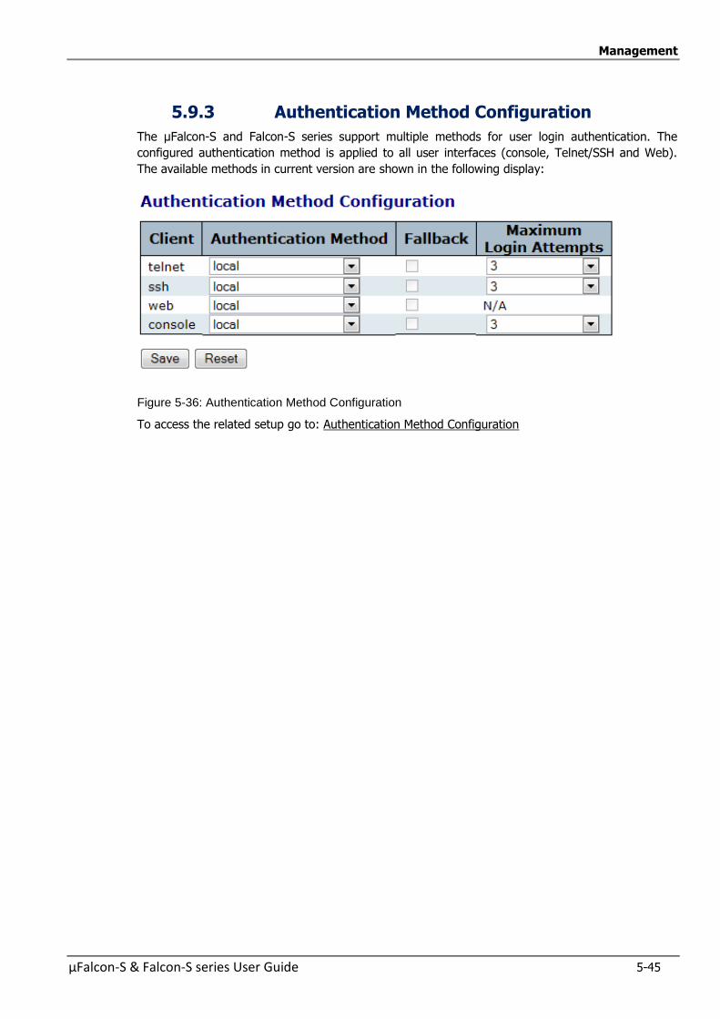
Management
µFalcon-S & Falcon-S series User Guide 5-45
5.9.3 Authentication Method Configuration
The µFalcon-S and Falcon-S series support multiple methods for user login authentication. The
configured authentication method is applied to all user interfaces (console, Telnet/SSH and Web).
The available methods in current version are shown in the following display:
Figure 5-36: Authentication Method Configuration
To access the related setup go to: Authentication Method Configuration
Management
5-46 µFalcon-S & Falcon-S series User Guide
5.9.4 Authentication Servers Configuration
This section allow the user to configure the different RADIUS Authentication Servers
To access this section, go to Authentication Server Configuration (AAA)
5.9.5 Access Management Configuration
In this section, you may configure the access management configuration
The maximum number of entries is 16. If the application's types match any one of the access
management entries, it will allow access to the switch.
To configure the Access Management Configuration go to :Access Management Configuration
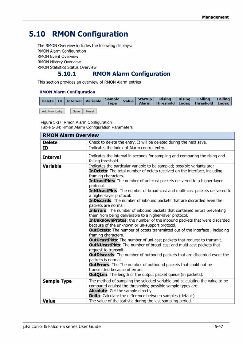
Management
µFalcon-S & Falcon-S series User Guide 5-47
5.10 RMON Configuration
The RMON Overview includes the following displays:
RMON Alarm Configuration
RMON Event Overview
RMON History Overview
RMON Statistics Status Overview
5.10.1 RMON Alarm Configuration
This section provides an overview of RMON Alarm entries
Figure 5-37: Rmon Alarm Configuration
Table 5-34: Rmon Alarm Configuration Parameters
RMON Alarm Overview
Delete Check to delete the entry. It will be deleted during the next save.
ID Indicates the index of Alarm control entry.
Interval Indicates the interval in seconds for sampling and comparing the rising and
falling threshold.
Variable Indicates the particular variable to be sampled; possible variants are: InOctets: The total number of octets received on the interface, including
framing characters. InUcastPkts: The number of uni-cast packets delivered to a higher-layer
protocol.
InNUcastPkts: The number of broad-cast and multi-cast packets delivered to a higher-layer protocol.
InDiscards: The number of inbound packets that are discarded even the packets are normal.
InErrors: The number of inbound packets that contained errors preventing them from being deliverable to a higher-layer protocol.
InUnknownProtos: the number of the inbound packets that were discarded
because of the unknown or un-support protocol. OutOctets: The number of octets transmitted out of the interface , including
framing characters. OutUcastPkts: The number of uni-cast packets that request to transmit.
OutNUcastPkts: The number of broad-cast and multi-cast packets that
request to transmit. OutDiscards: The number of outbound packets that are discarded event the
packets is normal. OutErrors: The The number of outbound packets that could not be
transmitted because of errors. OutQLen: The length of the output packet queue (in packets).
Sample Type The method of sampling the selected variable and calculating the value to be
compared against the thresholds; possible sample types are: Absolute: Get the sample directly.
Delta: Calculate the difference between samples (default).
Value The value of the statistic during the last sampling period.
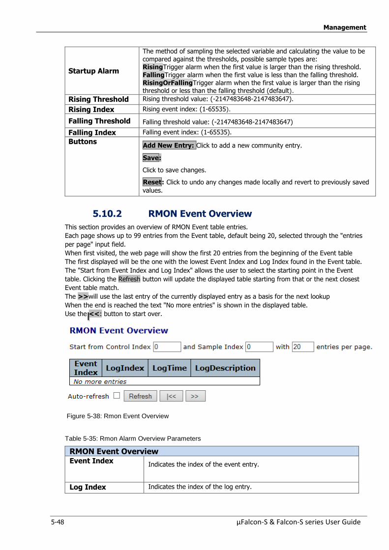
Management
5-48 µFalcon-S & Falcon-S series User Guide
Startup Alarm
The method of sampling the selected variable and calculating the value to be
compared against the thresholds, possible sample types are: RisingTrigger alarm when the first value is larger than the rising threshold.
FallingTrigger alarm when the first value is less than the falling threshold.
RisingOrFallingTrigger alarm when the first value is larger than the rising threshold or less than the falling threshold (default).
Rising Threshold Rising threshold value: (-2147483648-2147483647).
Rising Index Rising event index: (1-65535).
Falling Threshold Falling threshold value: (-2147483648-2147483647)
Falling Index Falling event index: (1-65535).
Buttons
Add New Entry: Click to add a new community entry.
Save:
Click to save changes.
Reset: Click to undo any changes made locally and revert to previously saved
values.
5.10.2 RMON Event Overview
This section provides an overview of RMON Event table entries.
Each page shows up to 99 entries from the Event table, default being 20, selected through the "entries
per page" input field.
When first visited, the web page will show the first 20 entries from the beginning of the Event table
The first displayed will be the one with the lowest Event Index and Log Index found in the Event table.
The "Start from Event Index and Log Index" allows the user to select the starting point in the Event
table. Clicking the Refresh button will update the displayed table starting from that or the next closest
Event table match.
The >>will use the last entry of the currently displayed entry as a basis for the next lookup
When the end is reached the text "No more entries" is shown in the displayed table.
Use the <<: button to start over.
Figure 5-38: Rmon Event Overview
Table 5-35: Rmon Alarm Overview Parameters
RMON Event Overview Event Index
Indicates the index of the event entry.
Log Index Indicates the index of the log entry.
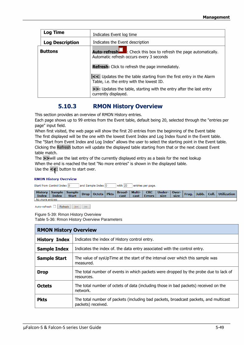
Management
µFalcon-S & Falcon-S series User Guide 5-49
Log Time Indicates Event log time
Log Description Indicates the Event description
Buttons Auto-refresh : Check this box to refresh the page automatically. Automatic refresh occurs every 3 seconds
Refresh: Click to refresh the page immediately.
<<: Updates the the table starting from the first entry in the Alarm
Table, i.e. the entry with the lowest ID.
>>: Updates the table, starting with the entry after the last entry
currently displayed.
5.10.3 RMON History Overview
This section provides an overview of RMON History entries.
Each page shows up to 99 entries from the Event table, default being 20, selected through the "entries per
page" input field.
When first visited, the web page will show the first 20 entries from the beginning of the Event table
The first displayed will be the one with the lowest Event Index and Log Index found in the Event table.
The "Start from Event Index and Log Index" allows the user to select the starting point in the Event table.
Clicking the Refresh button will update the displayed table starting from that or the next closest Event
table match.
The >>will use the last entry of the currently displayed entry as a basis for the next lookup
When the end is reached the text "No more entries" is shown in the displayed table.
Use the <<: button to start over.
Figure 5-39: Rmon History Overview
Table 5-36: Rmon History Overview Parameters
RMON History Overview
History Index Indicates the index of History control entry.
Sample Index Indicates the index of. the data entry associated with the control entry.
Sample Start The value of sysUpTime at the start of the interval over which this sample was
measured.
Drop The total number of events in which packets were dropped by the probe due to lack of
resources.
Octets The total number of octets of data (including those in bad packets) received on the network.
Pkts The total number of packets (including bad packets, broadcast packets, and multicast
packets) received.
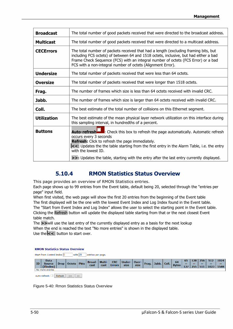
Management
5-50 µFalcon-S & Falcon-S series User Guide
Broadcast The total number of good packets received that were directed to the broadcast address.
Multicast The total number of good packets received that were directed to a multicast address.
CECErrors The total number of packets received that had a length (excluding framing bits, but including FCS octets) of between 64 and 1518 octets, inclusive, but had either a bad
Frame Check Sequence (FCS) with an integral number of octets (FCS Error) or a bad
FCS with a non-integral number of octets (Alignment Error).
Undersize The total number of packets received that were less than 64 octets.
Oversize The total number of packets received that were longer than 1518 octets.
Frag. The number of frames which size is less than 64 octets received with invalid CRC.
Jabb. The number of frames which size is larger than 64 octets received with invalid CRC.
Coll. The best estimate of the total number of collisions on this Ethernet segment.
Utilization The best estimate of the mean physical layer network utilization on this interface during
this sampling interval, in hundredths of a percent.
Buttons Auto-refresh : Check this box to refresh the page automatically. Automatic refresh occurs every 3 seconds Refresh: Click to refresh the page immediately.
<<: Updates the the table starting from the first entry in the Alarm Table, i.e. the entry
with the lowest ID.
>>: Updates the table, starting with the entry after the last entry currently displayed.
5.10.4 RMON Statistics Status Overview
This page provides an overview of RMON Statistics entries.
Each page shows up to 99 entries from the Event table, default being 20, selected through the "entries per
page" input field.
When first visited, the web page will show the first 20 entries from the beginning of the Event table
The first displayed will be the one with the lowest Event Index and Log Index found in the Event table.
The "Start from Event Index and Log Index" allows the user to select the starting point in the Event table.
Clicking the Refresh button will update the displayed table starting from that or the next closest Event
table match.
The >>will use the last entry of the currently displayed entry as a basis for the next lookup
When the end is reached the text "No more entries" is shown in the displayed table.
Use the <<: button to start over.
Figure 5-40: Rmon Statistics Status Overview
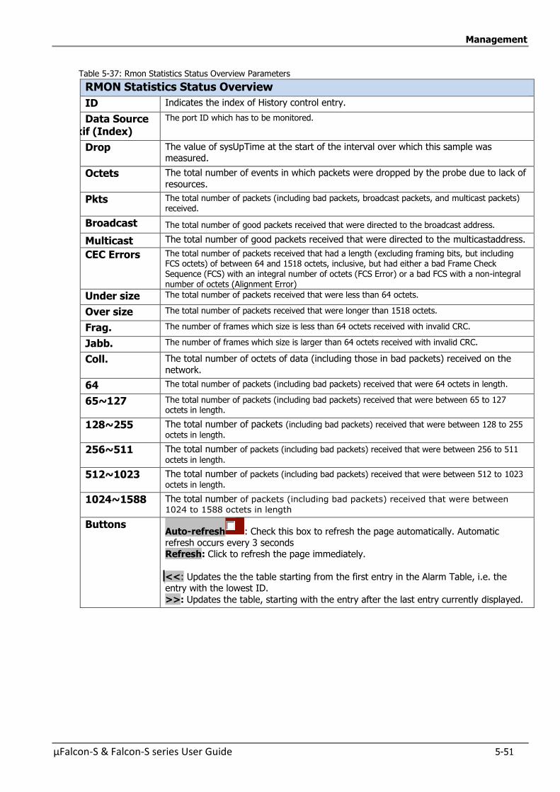
Management
µFalcon-S & Falcon-S series User Guide 5-51
Table 5-37: Rmon Statistics Status Overview Parameters
RMON Statistics Status Overview
ID Indicates the index of History control entry.
Data Source (ifIndexif (Index)
The port ID which has to be monitored.
Drop The value of sysUpTime at the start of the interval over which this sample was measured.
Octets The total number of events in which packets were dropped by the probe due to lack of
resources.
Pkts The total number of packets (including bad packets, broadcast packets, and multicast packets) received.
Broadcast The total number of good packets received that were directed to the broadcast address.
Multicast The total number of good packets received that were directed to the multicastaddress.
CEC Errors The total number of packets received that had a length (excluding framing bits, but including FCS octets) of between 64 and 1518 octets, inclusive, but had either a bad Frame Check Sequence (FCS) with an integral number of octets (FCS Error) or a bad FCS with a non-integral number of octets (Alignment Error)
Under size The total number of packets received that were less than 64 octets.
Over size The total number of packets received that were longer than 1518 octets.
Frag. The number of frames which size is less than 64 octets received with invalid CRC.
Jabb. The number of frames which size is larger than 64 octets received with invalid CRC.
Coll. The total number of octets of data (including those in bad packets) received on the
network.
64 The total number of packets (including bad packets) received that were 64 octets in length.
65~127 The total number of packets (including bad packets) received that were between 65 to 127 octets in length.
128~255 The total number of packets (including bad packets) received that were between 128 to 255
octets in length.
256~511 The total number of packets (including bad packets) received that were between 256 to 511
octets in length.
512~1023 The total number of packets (including bad packets) received that were between 512 to 1023
octets in length.
1024~1588 The total number of packets (including bad packets) received that were between
1024 to 1588 octets in length
Buttons Auto-refresh : Check this box to refresh the page automatically. Automatic refresh occurs every 3 seconds Refresh: Click to refresh the page immediately.
<<: Updates the the table starting from the first entry in the Alarm Table, i.e. the entry with the lowest ID.
>>: Updates the table, starting with the entry after the last entry currently displayed.

µFalcon-S & Falcon-S series User Guide 6-1
6 6 Maintenance
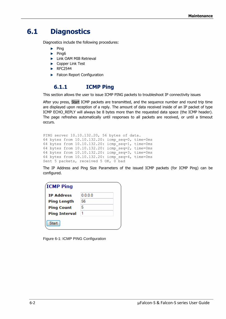
Maintenance
6-2 µFalcon-S & Falcon-S series User Guide
6.1 Diagnostics
Diagnostics include the following procedures:
Ping
Ping6
Link OAM MIB Retrieval
Copper Link Test
RFC2544
Falcon Report Configuration
6.1.1 ICMP Ping
This section allows the user to issue ICMP PING packets to troubleshoot IP connectivity issues
After you press, Start ICMP packets are transmitted, and the sequence number and round trip time
are displayed upon reception of a reply. The amount of data received inside of an IP packet of type
ICMP ECHO_REPLY will always be 8 bytes more than the requested data space (the ICMP header).
The page refreshes automatically until responses to all packets are received, or until a timeout
occurs.
PING server 10.10.132.20, 56 bytes of data.
64 bytes from 10.10.132.20: icmp_seq=0, time=0ms
64 bytes from 10.10.132.20: icmp_seq=1, time=0ms
64 bytes from 10.10.132.20: icmp_seq=2, time=0ms
64 bytes from 10.10.132.20: icmp_seq=3, time=0ms
64 bytes from 10.10.132.20: icmp_seq=4, time=0ms
Sent 5 packets, received 5 OK, 0 bad
The IP Address and Ping Size Parameters of the issued ICMP packets (for ICMP Ping) can be
configured.
Figure 6-1: ICMP PING Configuration
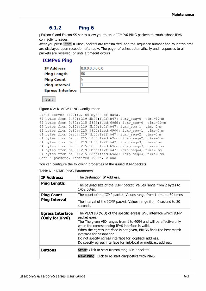
Maintenance
µFalcon-S & Falcon-S series User Guide 6-3
6.1.2 Ping 6
µFalcon-S and Falcon-SS series allow you to issue ICMPv6 PING packets to troubleshoot IPv6
connectivity issues.
After you press Start, ICMPv6 packets are transmitted, and the sequence number and roundtrip time
are displayed upon reception of a reply. The page refreshes automatically until responses to all
packets are received, or until a timeout occurs
Figure 6-2: ICMPv6 PING Configuration
PING6 server ff02::2, 56 bytes of data.
64 bytes from fe80::219:5bff:fe2f:b47: icmp_seq=0, time=10ms
64 bytes from fe80::215:58ff:feed:69dd: icmp_seq=0, time=10ms
64 bytes from fe80::219:5bff:fe2f:b47: icmp_seq=1, time=0ms
64 bytes from fe80::215:58ff:feed:69dd: icmp_seq=1, time=0ms
64 bytes from fe80::219:5bff:fe2f:b47: icmp_seq=2, time=0ms
64 bytes from fe80::215:58ff:feed:69dd: icmp_seq=2, time=0ms
64 bytes from fe80::219:5bff:fe2f:b47: icmp_seq=3, time=0ms
64 bytes from fe80::215:58ff:feed:69dd: icmp_seq=3, time=0ms
64 bytes from fe80::219:5bff:fe2f:b47: icmp_seq=4, time=0ms
64 bytes from fe80::215:58ff:feed:69dd: icmp_seq=4, time=0ms
Sent 5 packets, received 10 OK, 0 bad
You can configure the following properties of the issued ICMP packets
Table 6-1: ICMP PING Parameters
IP Address: The destination IP Address.
Ping Length: The payload size of the ICMP packet. Values range from 2 bytes to
1452 bytes.
Ping Count The count of the ICMP packet. Values range from 1 time to 60 times.
Ping Interval The interval of the ICMP packet. Values range from 0 second to 30 seconds.
Egress Interface (Only for IPv6)
The VLAN ID (VID) of the specific egress IPv6 interface which ICMP packet goes.
The The given VID ranges from 1 to 4094 and will be effective only
when the corresponding IPv6 interface is valid. When the egress interface is not given, PING6 finds the best match
interface for destination. Do not specify egress interface for loopback address.
Do specify egress interface for link-local or multicast address.
Buttons Start: Click to start transmitting ICMP packets
New Ping: Click to re-start diagnostics with PING.
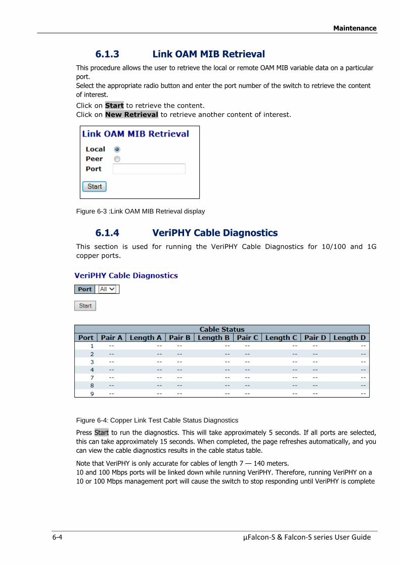
Maintenance
6-4 µFalcon-S & Falcon-S series User Guide
6.1.3 Link OAM MIB Retrieval
This procedure allows the user to retrieve the local or remote OAM MIB variable data on a particular
port.
Select the appropriate radio button and enter the port number of the switch to retrieve the content
of interest.
Click on Start to retrieve the content.
Click on New Retrieval to retrieve another content of interest.
Figure 6-3 :Link OAM MIB Retrieval display
6.1.4 VeriPHY Cable Diagnostics
This section is used for running the VeriPHY Cable Diagnostics for 10/100 and 1G
copper ports.
Figure 6-4: Copper Link Test Cable Status Diagnostics
Press Start to run the diagnostics. This will take approximately 5 seconds. If all ports are selected,
this can take approximately 15 seconds. When completed, the page refreshes automatically, and you
can view the cable diagnostics results in the cable status table.
Note that VeriPHY is only accurate for cables of length 7 — 140 meters.
10 and 100 Mbps ports will be linked down while running VeriPHY. Therefore, running VeriPHY on a
10 or 100 Mbps management port will cause the switch to stop responding until VeriPHY is complete
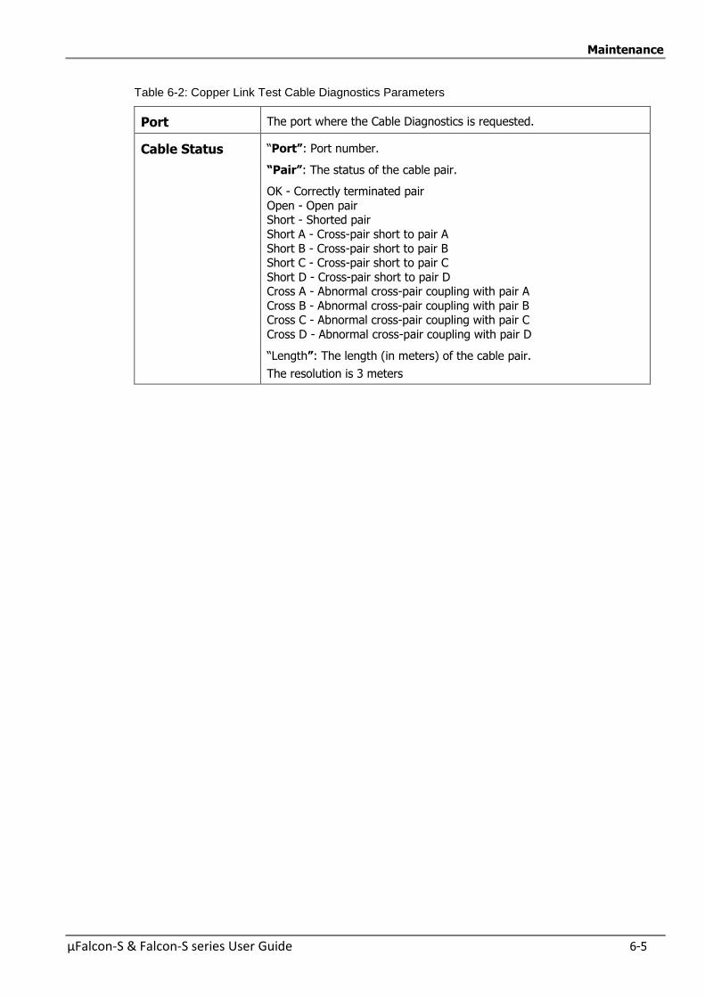
Maintenance
µFalcon-S & Falcon-S series User Guide 6-5
Table 6-2: Copper Link Test Cable Diagnostics Parameters
Port The port where the Cable Diagnostics is requested.
Cable Status “Port”: Port number.
“Pair”: The status of the cable pair.
OK - Correctly terminated pair
Open - Open pair Short - Shorted pair
Short A - Cross-pair short to pair A
Short B - Cross-pair short to pair B Short C - Cross-pair short to pair C
Short D - Cross-pair short to pair D Cross A - Abnormal cross-pair coupling with pair A
Cross B - Abnormal cross-pair coupling with pair B Cross C - Abnormal cross-pair coupling with pair C
Cross D - Abnormal cross-pair coupling with pair D
“Length”: The length (in meters) of the cable pair.
The resolution is 3 meters
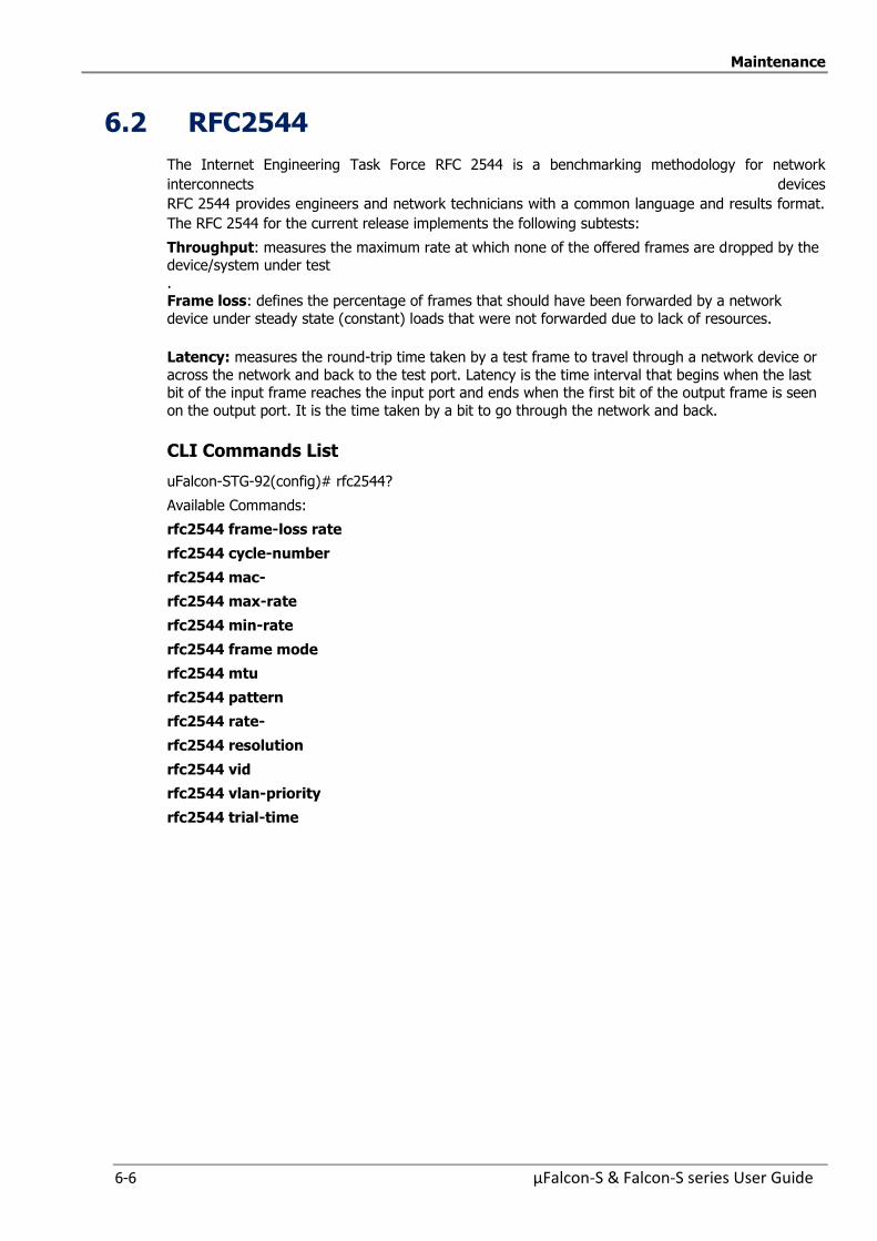
Maintenance
6-6 µFalcon-S & Falcon-S series User Guide
6.2 RFC2544
The Internet Engineering Task Force RFC 2544 is a benchmarking methodology for network
interconnects devices
RFC 2544 provides engineers and network technicians with a common language and results format.
The RFC 2544 for the current release implements the following subtests:
Throughput: measures the maximum rate at which none of the offered frames are dropped by the device/system under test
. Frame loss: defines the percentage of frames that should have been forwarded by a network
device under steady state (constant) loads that were not forwarded due to lack of resources.
Latency: measures the round-trip time taken by a test frame to travel through a network device or
across the network and back to the test port. Latency is the time interval that begins when the last bit of the input frame reaches the input port and ends when the first bit of the output frame is seen
on the output port. It is the time taken by a bit to go through the network and back.
CLI Commands List
uFalcon-STG-92(config)# rfc2544?
Available Commands:
rfc2544 frame-loss rate
rfc2544 cycle-number
rfc2544 mac-
rfc2544 max-rate
rfc2544 min-rate
rfc2544 frame mode
rfc2544 mtu
rfc2544 pattern
rfc2544 rate-
rfc2544 resolution
rfc2544 vid
rfc2544 vlan-priority
rfc2544 trial-time
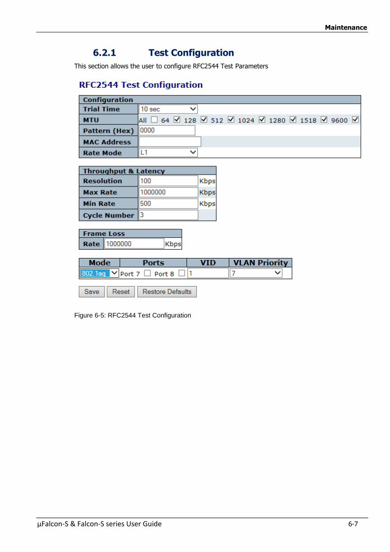
Maintenance
µFalcon-S & Falcon-S series User Guide 6-7
6.2.1 Test Configuration
This section allows the user to configure RFC2544 Test Parameters
Figure 6-5: RFC2544 Test Configuration
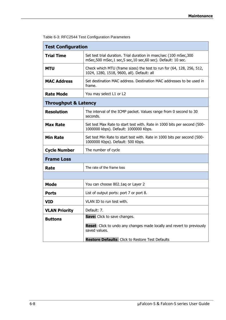
Maintenance
6-8 µFalcon-S & Falcon-S series User Guide
Table 6-3: RFC2544 Test Configuration Parameters
Test Configuration
Trial Time Set test trial duration. Trial duration in msec/sec (100 mSec,300 mSec,500 mSec,1 sec,5 sec,10 sec,60 sec). Default: 10 sec.
MTU Check which MTU (frame sizes) the test to run for (64, 128, 256, 512,
1024, 1280, 1518, 9600, all). Default: all
MAC Address Set destination MAC address. Destination MAC addresses to be used in
frame.
Rate Mode You may select L1 or L2
Throughput & Latency
Resolution The interval of the ICMP packet. Values range from 0 second to 30
seconds.
Max Rate Set test Max Rate to start test with. Rate in 1000 bits per second (500-1000000 kbps). Default: 1000000 Kbps.
Min Rate Set test Min Rate to start test with. Rate in 1000 bits per second (500-
1000000 Kbps). Default: 500 Kbps.
Cycle Number The number of cycle
Frame Loss
Rate The rate of the frame loss
Mode You can choose 802.1aq or Layer 2
Ports List of output ports: port 7 or port 8.
VID VLAN ID to run test with.
VLAN Priority Default: 7.
Buttons Save: Click to save changes.
Reset: Click to undo any changes made locally and revert to previously
saved values.
Restore Defaults: Click to Restore Test Defaults
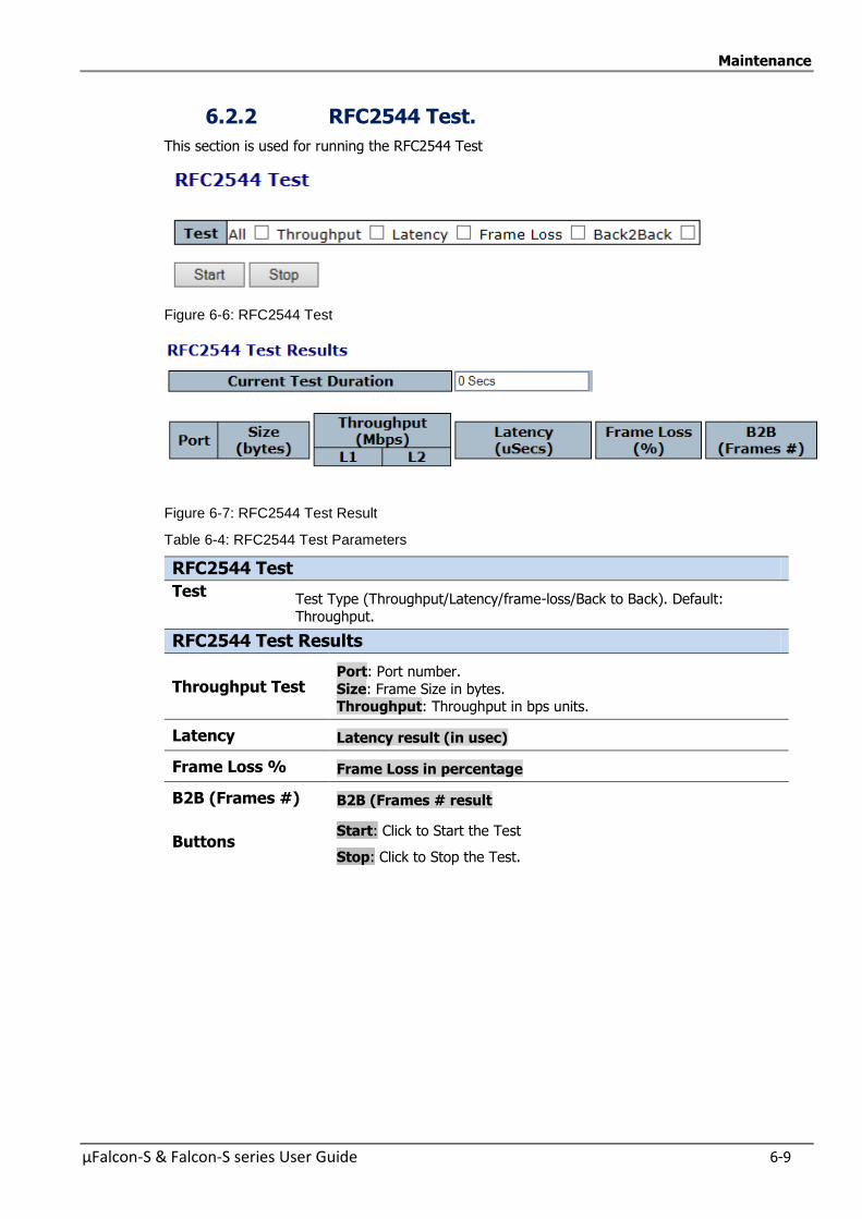
Maintenance
µFalcon-S & Falcon-S series User Guide 6-9
6.2.2 RFC2544 Test.
This section is used for running the RFC2544 Test
Figure 6-6: RFC2544 Test
Figure 6-7: RFC2544 Test Result
Table 6-4: RFC2544 Test Parameters
RFC2544 Test
Test Test Type (Throughput/Latency/frame-loss/Back to Back). Default:
Throughput.
RFC2544 Test Results
Throughput Test Port: Port number.
Size: Frame Size in bytes. Throughput: Throughput in bps units.
Latency Latency result (in usec)
Frame Loss % Frame Loss in percentage
B2B (Frames #) B2B (Frames # result
Buttons Start: Click to Start the Test
Stop: Click to Stop the Test.
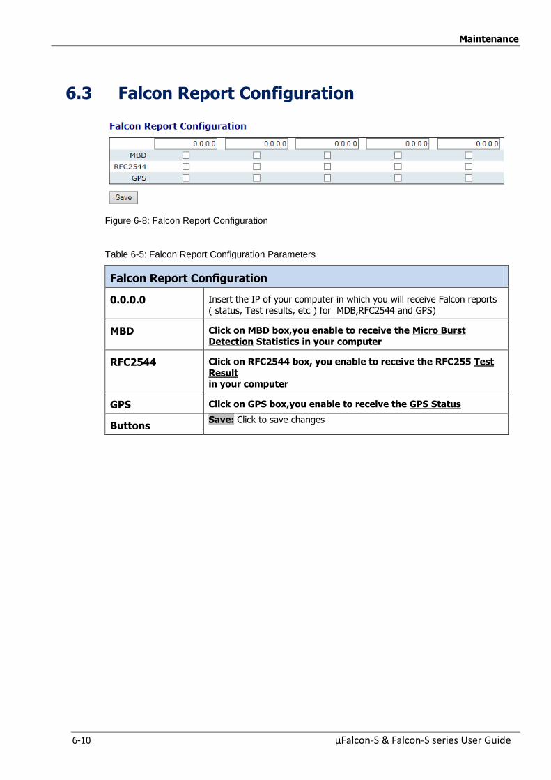
Maintenance
6-10 µFalcon-S & Falcon-S series User Guide
6.3 Falcon Report Configuration
Figure 6-8: Falcon Report Configuration
Table 6-5: Falcon Report Configuration Parameters
Falcon Report Configuration
0.0.0.0 Insert the IP of your computer in which you will receive Falcon reports
( status, Test results, etc ) for MDB,RFC2544 and GPS)
MBD Click on MBD box,you enable to receive the Micro Burst Detection Statistics in your computer
RFC2544 Click on RFC2544 box, you enable to receive the RFC255 Test
Result in your computer
GPS Click on GPS box,you enable to receive the GPS Status
Buttons Save: Click to save changes
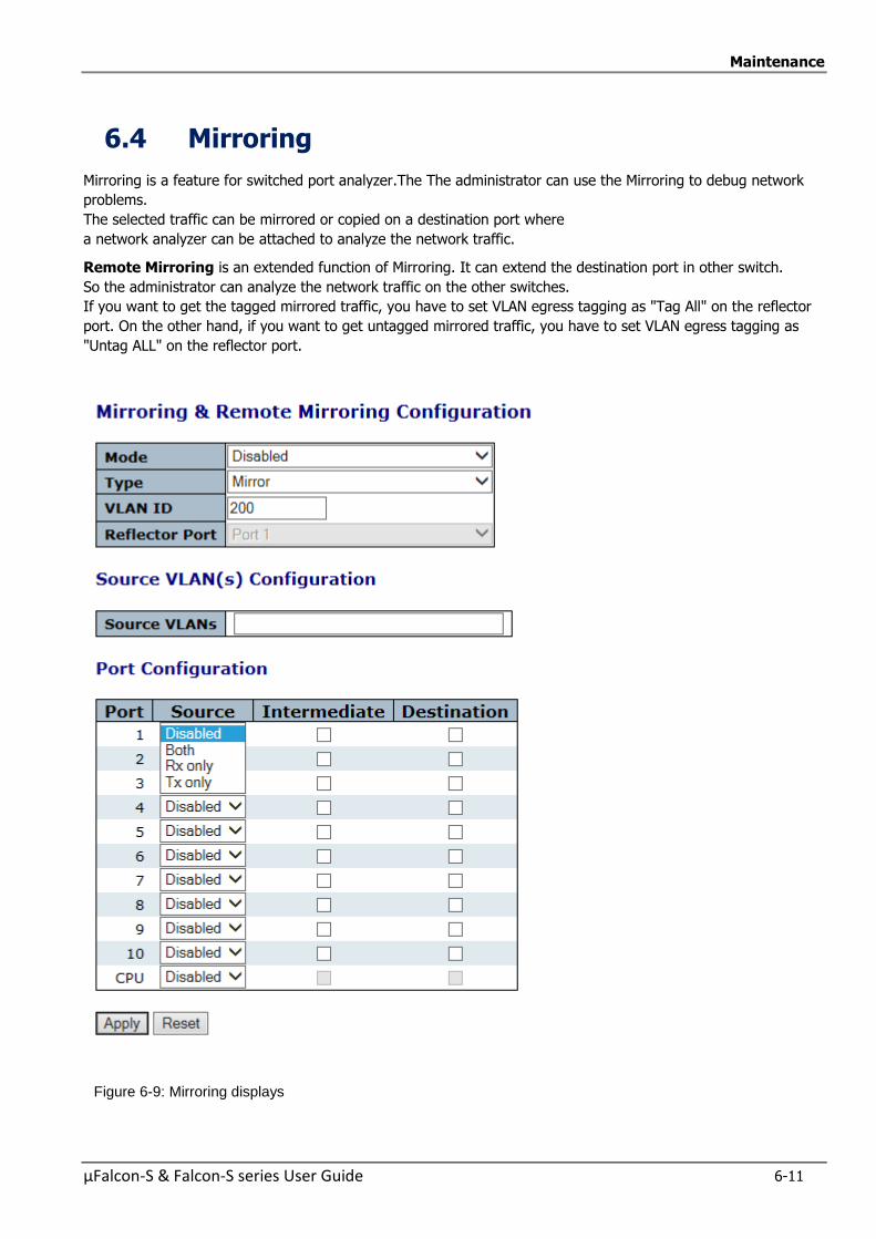
Maintenance
µFalcon-S & Falcon-S series User Guide 6-11
6.4 Mirroring
Mirroring is a feature for switched port analyzer.The The administrator can use the Mirroring to debug network
problems.
The selected traffic can be mirrored or copied on a destination port where
a network analyzer can be attached to analyze the network traffic.
Remote Mirroring is an extended function of Mirroring. It can extend the destination port in other switch.
So the administrator can analyze the network traffic on the other switches.
If you want to get the tagged mirrored traffic, you have to set VLAN egress tagging as "Tag All" on the reflector
port. On the other hand, if you want to get untagged mirrored traffic, you have to set VLAN egress tagging as
"Untag ALL" on the reflector port.
Figure 6-9: Mirroring displays
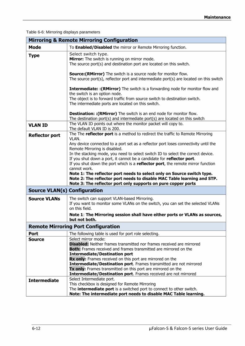
Maintenance
6-12 µFalcon-S & Falcon-S series User Guide
Table 6-6: Mirroring displays parameters
Mirroring & Remote Mirroring Configuration
Mode To Enabled/Disabled the mirror or Remote Mirroring function.
Type Select switch type. Mirror: The switch is running on mirror mode.
The source port(s) and destination port are located on this switch.
Source:(RMirror) The switch is a source node for monitor flow.
The source port(s), reflector port and intermediate port(s) are located on this switch
Intermediate: :(RMirror) The switch is a forwarding node for monitor flow and the switch is an option node.
The object is to forward traffic from source switch to destination switch. The intermediate ports are located on this switch.
Destination: :(RMirror) The switch is an end node for monitor flow. The destination port(s) and intermediate port(s) are located on this switch
VLAN ID The VLAN ID points out where the monitor packet will copy to.
The default VLAN ID is 200.
Reflector port The The reflector port is a method to redirect the traffic to Remote Mirroring
VLAN. Any device connected to a port set as a reflector port loses connectivity until the
Remote Mirroring is disabled.
In the stacking mode, you need to select switch ID to select the correct device. If you shut down a port, it cannot be a candidate for reflector port.
If you shut down the port which is a reflector port, the remote mirror function cannot work.
Note 1: The reflector port needs to select only on Source switch type.
Note 2: The reflector port needs to disable MAC Table learning and STP. Note 3: The reflector port only supports on pure copper ports
Source VLAN(s) Configuration
Source VLANs The switch can support VLAN-based Mirroring. If you want to monitor some VLANs on the switch, you can set the selected VLANs
on this field.
Note 1: The Mirroring session shall have either ports or VLANs as sources, but not both.
Remote Mirroring Port Configuration
Port The following table is used for port role selecting.
Source Select mirror mode: Disabled: Neither frames transmitted nor frames received are mirrored
Both: Frames received and frames transmitted are mirrored on the Intermediate/Destination port
Rx only: Frames received on this port are mirrored on the Intermediate/Destination port. Frames transmitted are not mirrored
Tx only: Frames transmitted on this port are mirrored on the
Intermediate/Destination port. Frames received are not mirrored
Intermediate Select Intermediate port.
This checkbox is designed for Remote Mirroring
The intermediate port is a switched port to connect to other switch. Note: The intermediate port needs to disable MAC Table learning.
Maintenance
µFalcon-S & Falcon-S series User Guide 6-13
Destination Select destination port.
This checkbox is designed for mirror or Remote Mirroring. The destination port is a switched port that you receive a copy of traffic from the
source port.
Note 1: On mirror mode, the device only supports one destination port.
Note 2: The destination port needs to disable MAC Table learning
Buttons Reset: Click to undo any changes made locally and revert to previously saved values.
Apply: Click to save changes.
Configuration Guideline for All Features
When the switch is running on Remote Mirroring mode, the administrator also needs to check whether or
not other features are enabled or disabled. For example, the administrator is not disabled the MSTP on reflector port.
All monitor traffic will be blocked on reflector port
All recommended settings are described in the Home page.

Maintenance
6-14 µFalcon-S & Falcon-S series User Guide
Select switch type. Select switch type.
6.5 Maintenance
The Maintenance includes the following procedure:
Restart Device
Factory Default
System Update
Configuration (Save/Upload)
6.5.1 Restart Device
You can restart the switch here. After restart, the switch will boot normally.
Figure 6-10: Restart Device Screen
Table 6-7: Restart Device Parameters
Yes: Click to restart device.
No: Click to return to the Port State page without restarting
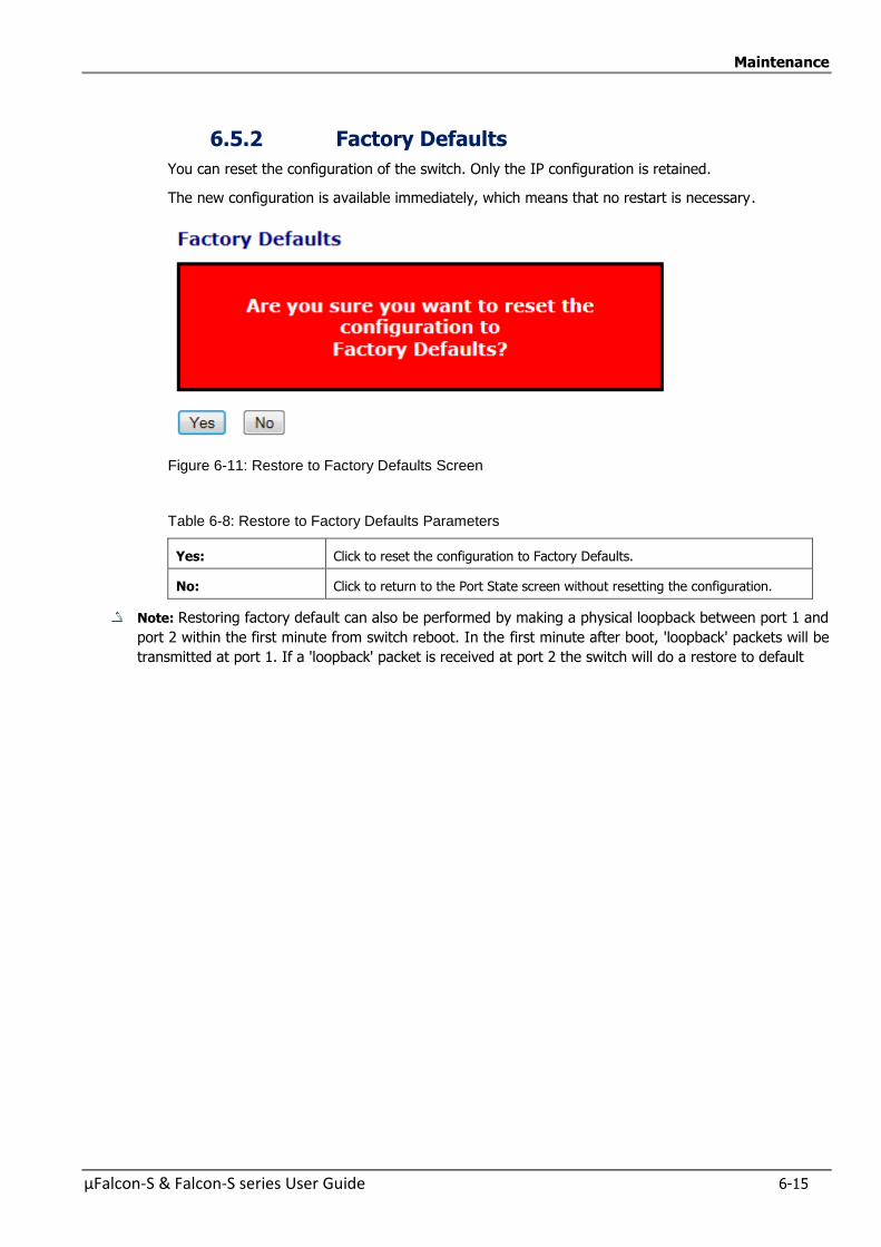
Maintenance
µFalcon-S & Falcon-S series User Guide 6-15
6.5.2 Factory Defaults
You can reset the configuration of the switch. Only the IP configuration is retained.
The new configuration is available immediately, which means that no restart is necessary.
Figure 6-11: Restore to Factory Defaults Screen
Table 6-8: Restore to Factory Defaults Parameters
Yes: Click to reset the configuration to Factory Defaults.
No: Click to return to the Port State screen without resetting the configuration.
Note: Restoring factory default can also be performed by making a physical loopback between port 1 and
port 2 within the first minute from switch reboot. In the first minute after boot, 'loopback' packets will be
transmitted at port 1. If a 'loopback' packet is received at port 2 the switch will do a restore to default
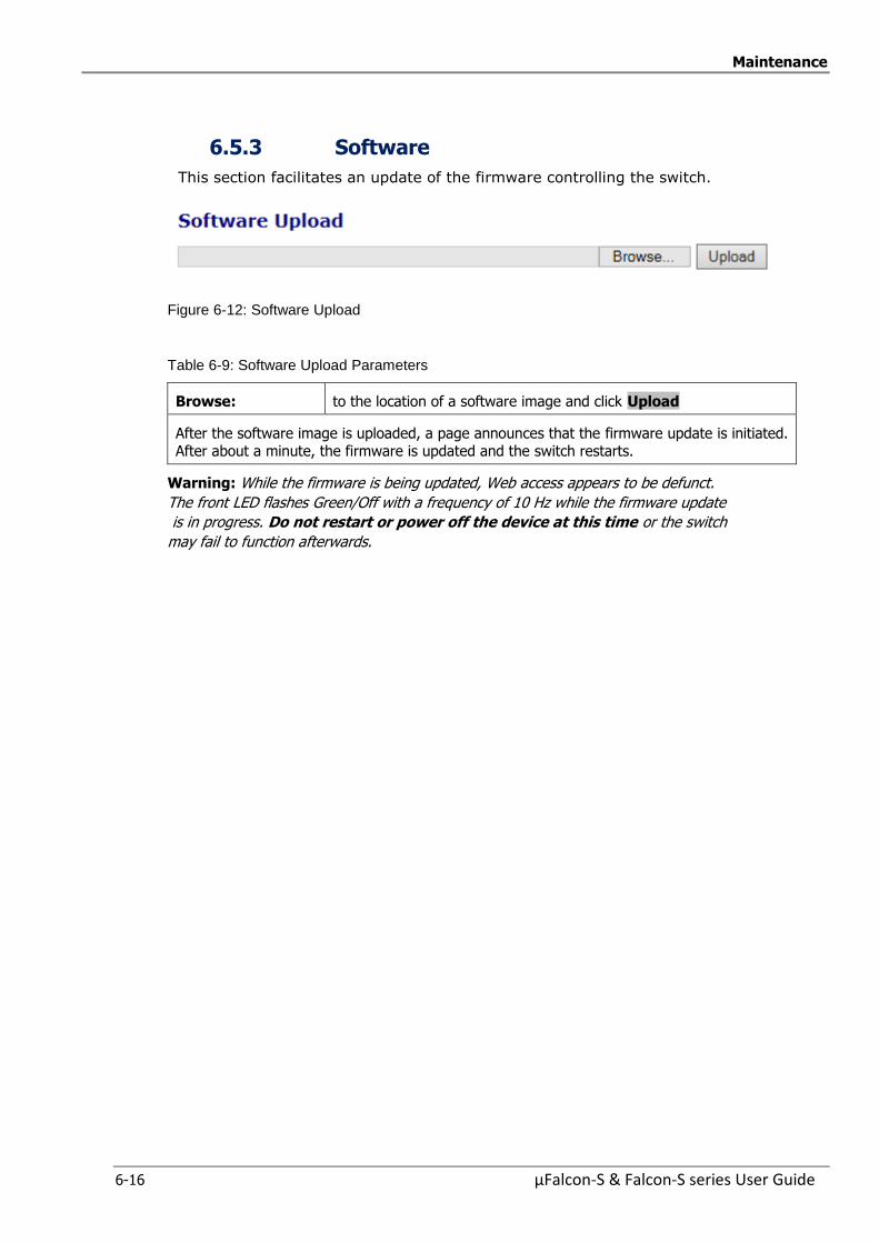
Maintenance
6-16 µFalcon-S & Falcon-S series User Guide
6.5.3 Software
This section facilitates an update of the firmware controlling the switch.
Figure 6-12: Software Upload
Table 6-9: Software Upload Parameters
Browse: to the location of a software image and click Upload
After the software image is uploaded, a page announces that the firmware update is initiated. After about a minute, the firmware is updated and the switch restarts.
Warning: While the firmware is being updated, Web access appears to be defunct.
The front LED flashes Green/Off with a frequency of 10 Hz while the firmware update
is in progress. Do not restart or power off the device at this time or the switch
may fail to function afterwards.

Maintenance
µFalcon-S & Falcon-S series User Guide 6-17
6.5.3.1 Software Image Select
This section provides information about the active and alternate (backup) firmware images in the device, and
allows you to revert to the alternate image.
The web page displays two tables with information about the active and alternate firmware images.
Figure 6-13: Software Image Selection

Maintenance
6-18 µFalcon-S & Falcon-S series User Guide
Table 6-10: Software Image Selection Parameters
Image The file name of the firmware image, from when the image was last updated.
Version The version of the firmware image.
Date The date where the firmware was produced.
Buttons Activate Alternate Image: Click to use the alternate image. This button may be disabled depending on system state.
Cancel: Cancel activating the backup image. Navigates away from this page.
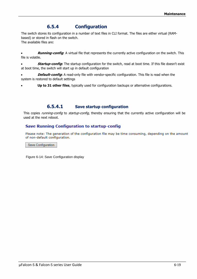
Maintenance
µFalcon-S & Falcon-S series User Guide 6-19
6.5.4 Configuration
The switch stores its configuration in a number of text files in CLI format. The files are either virtual (RAM-
based) or stored in flash on the switch.
The available files are:
Running-config: A virtual file that represents the currently active configuration on the switch. This
file is volatile.
Startup-config: The startup configuration for the switch, read at boot time. If this file doesn't exist
at boot time, the switch will start up in default configuration
Default-config: A read-only file with vendor-specific configuration. This file is read when the
system is restored to default settings
Up to 31 other files, typically used for configuration backups or alternative configurations.
6.5.4.1 Save startup configuration
This copies running-config to startup-config, thereby ensuring that the currently active configuration will be
used at the next reboot.
Figure 6-14: Save Configuration display
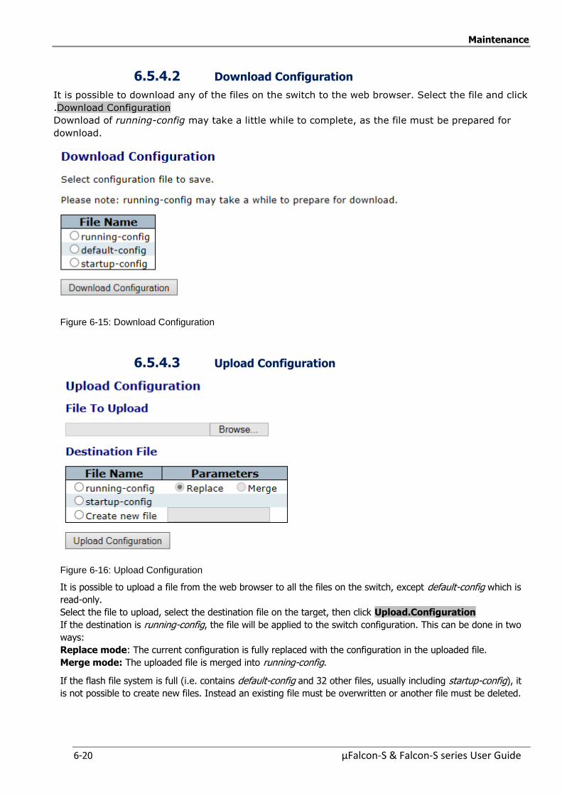
Maintenance
6-20 µFalcon-S & Falcon-S series User Guide
6.5.4.2 Download Configuration
It is possible to download any of the files on the switch to the web browser. Select the file and click
.Download Configuration
Download of running-config may take a little while to complete, as the file must be prepared for
download.
Figure 6-15: Download Configuration
6.5.4.3 Upload Configuration
Figure 6-16: Upload Configuration
It is possible to upload a file from the web browser to all the files on the switch, except default-config which is
read-only.
Select the file to upload, select the destination file on the target, then click Upload.Configuration
If the destination is running-config, the file will be applied to the switch configuration. This can be done in two
ways:
Replace mode: The current configuration is fully replaced with the configuration in the uploaded file.
Merge mode: The uploaded file is merged into running-config.
If the flash file system is full (i.e. contains default-config and 32 other files, usually including startup-config), it
is not possible to create new files. Instead an existing file must be overwritten or another file must be deleted.
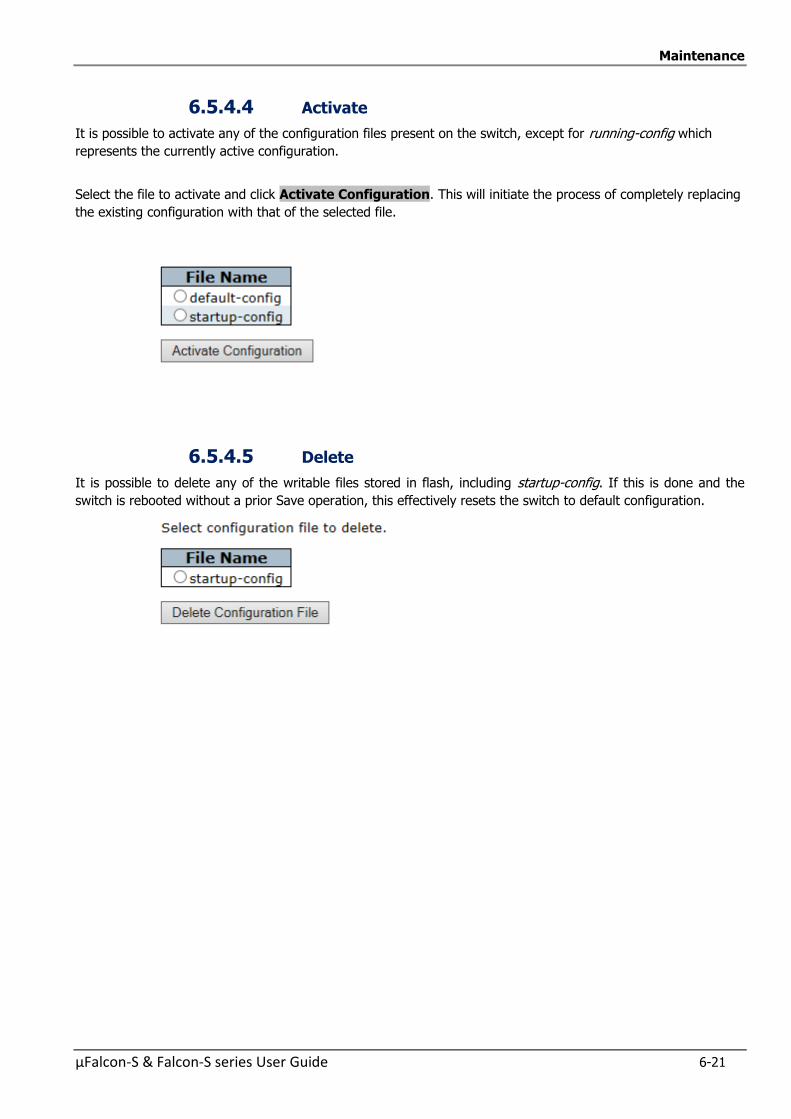
Maintenance
µFalcon-S & Falcon-S series User Guide 6-21
6.5.4.4 Activate
It is possible to activate any of the configuration files present on the switch, except for running-config which
represents the currently active configuration.
Select the file to activate and click Activate Configuration. This will initiate the process of completely replacing
the existing configuration with that of the selected file.
6.5.4.5 Delete
It is possible to delete any of the writable files stored in flash, including startup-config. If this is done and the
switch is rebooted without a prior Save operation, this effectively resets the switch to default configuration.
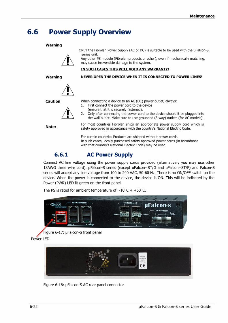
Maintenance
6-22 µFalcon-S & Falcon-S series User Guide
6.6 Power Supply Overview
Warning
ONLY the Fibrolan Power Supply (AC or DC) is suitable to be used with the µFalcon-S series unit. Any other PS module (Fibrolan products or other), even if mechanically matching, may cause irreversible damage to the system.
IN SUCH CASES THIS WILL VOID ANY WARRANTY!
Warning NEVER OPEN THE DEVICE WHEN IT IS CONNECTED TO POWER LINES!
Caution When connecting a device to an AC (DC) power outlet, always:
1. First connect the power cord to the device (ensure that it is securely fastened).
2. Only after connecting the power cord to the device should it be plugged into the wall outlet. Make sure to use grounded (3 way) outlets (for AC models).
Note: For most countries Fibrolan ships an appropriate power supply cord which is safety approved in accordance with the country’s National Electric Code. For certain countries Products are shipped without power cords. In such cases, locally purchased safety approved power cords (in accordance with that country’s National Electric Code) may be used.
6.6.1 AC Power Supply
Connect AC line voltage using the power supply cords provided (alternatively you may use other
18AWG three wire cord). µFalcon-S series (except uFalcon=ST/G and uFalcon=ST/F) and Falcon-S
series will accept any line voltage from 100 to 240 VAC, 50-60 Hz. There is no ON/OFF switch on the
device. When the power is connected to the device, the device is ON. This will be indicated by the
Power (PWR) LED lit green on the front panel.
The PS is rated for ambient temperature of: -10°C ÷ +50°C.
Figure 6-17: µFalcon-S front panel
Power LED
Figure 6-18: µFalcon-S AC rear panel connector
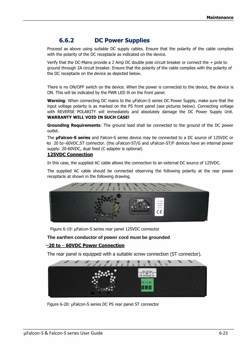
Maintenance
µFalcon-S & Falcon-S series User Guide 6-23
6.6.2 DC Power Supplies
Proceed as above using suitable DC supply cables. Ensure that the polarity of the cable complies
with the polarity of the DC receptacle as indicated on the device.
Verify that the DC-Mains provide a 2 Amp DC double pole circuit breaker or connect the + pole to
ground through 2A circuit breaker. Ensure that the polarity of the cable complies with the polarity of
the DC receptacle on the device as depicted below.
There is no ON/OFF switch on the device. When the power is connected to the device, the device is
ON. This will be indicated by the PWR LED lit on the front panel.
Warning: When connecting DC mains to the µFalcon-S series DC Power Supply, make sure that the
input voltage polarity is as marked on the PS front panel (see pictures below). Connecting voltage
with REVERSE POLARITY will immediately and absolutely damage the DC Power Supply Unit.
WARRANTY WILL VOID IN SUCH CASE!
Grounding Requirements: The ground lead shall be connected to the ground of the DC power
outlet.
The µFalcon-S series and Falcon-S series device may be connected to a DC source of 125VDC or
to 20 to 60VDC.ST connector. (the uFalcon-ST/G and uFalcon-ST/F devices have an internal power
supply: 20-60VDC, dual feed (C adapter is optional)
125VDC Connection
In this case, the supplied AC cable allows the connection to an external DC source of 125VDC.
The supplied AC cable should be connected observing the following polarity at the rear power
receptacle at shown in the following drawing.
Figure 6-19: µFalcon-S series rear panel 125VDC connector
The earthen conductor of power cord must be grounded
20 to – 60VDC Power Connection
The rear panel is equipped with a suitable screw connection (ST connector).
Figure 6-20: µFalcon-S series DC PS rear panel ST connector
Maintenance
6-24 µFalcon-S & Falcon-S series User Guide
The -20 – 60VDC internal iPS is installed in uFalcon-S, uFalcon-SE, uFalcon-SL and uFalcon-
SP devices.
—
DC powered models: Required current rating = 2A CAUTION DOUBLE POLE FUSING Verify that the DC-Mains provide a 2 Amp double pole circuit breaker.
Required power conductor size = at least 0.75mm² for flexible cable or 1mm² for non flexible
Power Consumption (AC and DC Power Supplies): µFalcon-S, µFalcon-S/SE, µFalcon-SL:
o Maximum <15W
o Typical: <12W
µFalcon-ST, µFalcon-ST/G/F o Maximum <27W o Typical: <20W
µFalcon-SP: o Maximum <20W o Typical: <15W
Falcon-MTS: o Maximum <45W o Typical: <30W
Falcon-STA: o Maximum <30W o Typical: <25W
Falcon-X: o Maximum <65W o Typical: <50W
Falcon-MX: o Maximum <60W o Typical: <50W
Note: Falcon-X and Falcon-MX devices include Dual redundant, hot swappable power supplies
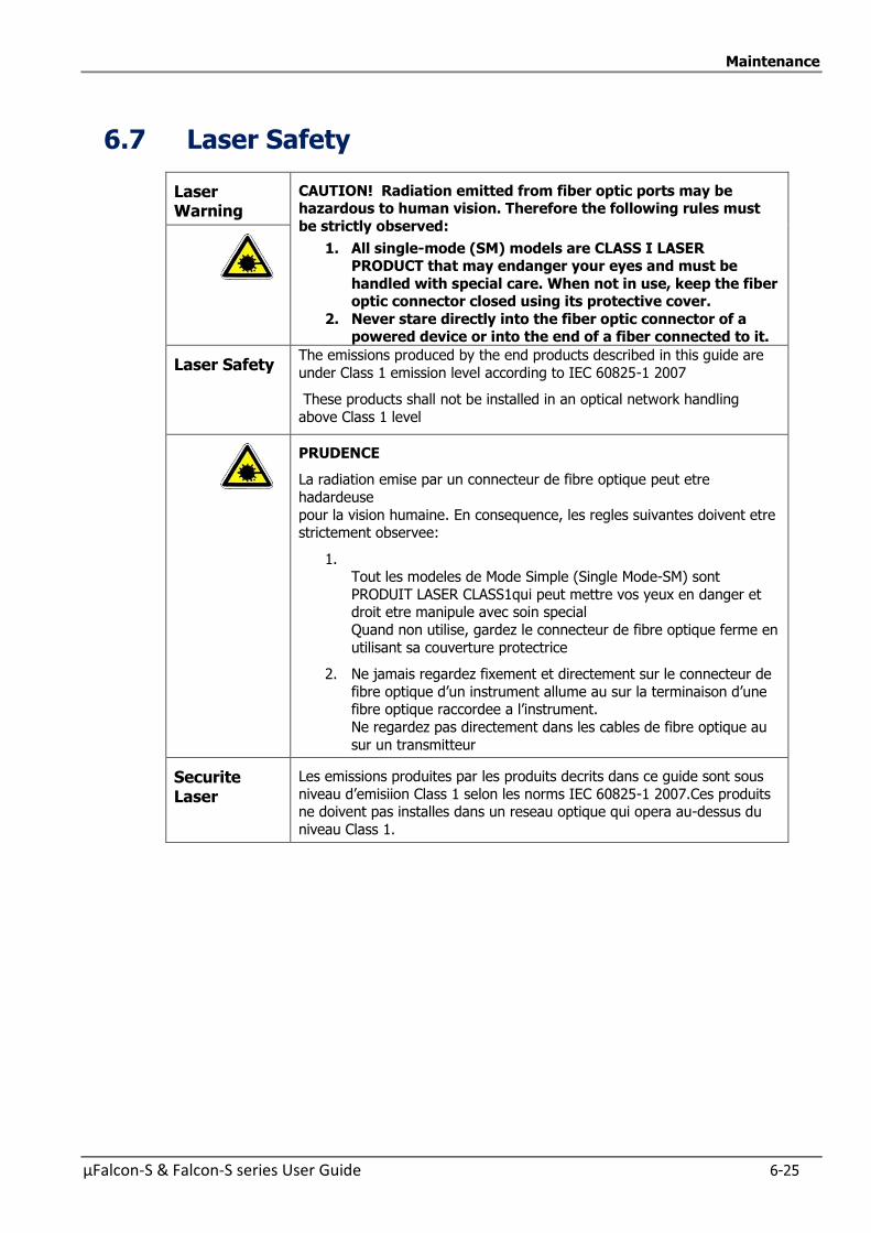
Maintenance
µFalcon-S & Falcon-S series User Guide 6-25
6.7 Laser Safety
Laser Warning
CAUTION! Radiation emitted from fiber optic ports may be hazardous to human vision. Therefore the following rules must
be strictly observed:
1. All single-mode (SM) models are CLASS I LASER PRODUCT that may endanger your eyes and must be
handled with special care. When not in use, keep the fiber optic connector closed using its protective cover.
2. Never stare directly into the fiber optic connector of a powered device or into the end of a fiber connected to it.
Laser Safety The emissions produced by the end products described in this guide are
under Class 1 emission level according to IEC 60825-1 2007
These products shall not be installed in an optical network handling
above Class 1 level
PRUDENCE
La radiation emise par un connecteur de fibre optique peut etre
hadardeuse
pour la vision humaine. En consequence, les regles suivantes doivent etre strictement observee:
1. Tout les modeles de Mode Simple (Single Mode-SM) sont
PRODUIT LASER CLASS1qui peut mettre vos yeux en danger et droit etre manipule avec soin special
Quand non utilise, gardez le connecteur de fibre optique ferme en
utilisant sa couverture protectrice
2. Ne jamais regardez fixement et directement sur le connecteur de
fibre optique d’un instrument allume au sur la terminaison d’une fibre optique raccordee a l’instrument.
Ne regardez pas directement dans les cables de fibre optique au
sur un transmitteur
Securite Laser
Les emissions produites par les produits decrits dans ce guide sont sous
niveau d’emisiion Class 1 selon les norms IEC 60825-1 2007.Ces produits ne doivent pas installes dans un reseau optique qui opera au-dessus du
niveau Class 1.


µFalcon-S & Falcon-S series User Guide 7-1
7 7 Warranty Information

Warranty Information
7-2 µFalcon-S & Falcon-S series User Guide
7.1 Warranty Limitation
Fibrolan warrants the equipment to be free from defects in material and workmanship, under
normal and proper use and in its unmodified condition for 24 month (unless otherwise
agreed upon) starting on the date of delivery from Fibrolan to its distributor.
Fibrolan’s sole obligation under this warranty shall be to furnish parts and labor for the repair or
replacement of products found by Fibrolan to be defective in material or workmanship during
the warranty period. Warranty repairs will be performed at the point of manufacture.
Following an authorized repair, the device shall be under warranty throughout its original period
but not less than 3 months.
Warranty shall be void in case where unauthorized attempts to repair or disassemble/modify
the device are evident.
You must claim repairs or replacements under this warranty only from the reseller from which
you have purchased the device, however you may refer directly to Fibrolan Ltd. To claim the
warranty you should provide a reasonable proof that the reseller ceased operation and/or
unreasonably refused to provide you with the service.
In such case report to Fibrolan the serial number of the device, date purchased, full details of
reseller from whom the device was purchase and a copy of an invoice or another proof of the
purchase.
This document and the information contained herein are proprietary of the
manufacturer and are furnished to the recipient for use in operating, maintaining and repairing manufacturer equipment. The information within may not be utilized
for any purpose except as stated herein, and may not be disclosed to third parties
without the written permission from the manufacturer. The manufacturer reserves the right to make changes to any technical specifications
in order to improve reliability, function and design.
©COPYRIGHT 2016. Fibrolan Ltd. All rights reserved- June 2017 Revision 6.4.10A. Software Version 6.4.10.
-

µFalcon-S & Falcon-S series User Guide 8-1
8 8 Glossary of
Terms
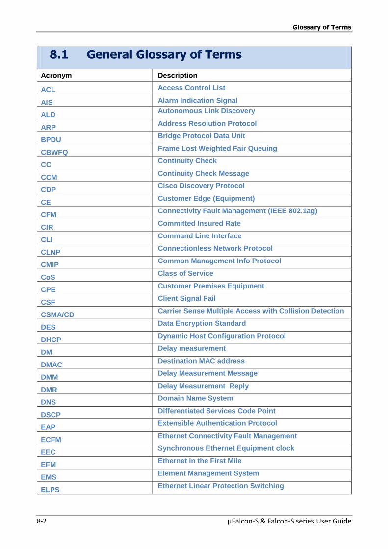
Glossary of Terms
8-2 µFalcon-S & Falcon-S series User Guide
8.1 General Glossary of Terms
Acronym Description
ACL Access Control List
AIS Alarm Indication Signal
ALD Autonomous Link Discovery
ARP Address Resolution Protocol
BPDU Bridge Protocol Data Unit
CBWFQ Frame Lost Weighted Fair Queuing
CC Continuity Check
CCM Continuity Check Message
CDP Cisco Discovery Protocol
CE Customer Edge (Equipment)
CFM Connectivity Fault Management (IEEE 802.1ag)
CIR Committed Insured Rate
CLI Command Line Interface
CLNP Connectionless Network Protocol
CMIP Common Management Info Protocol
CoS Class of Service
CPE Customer Premises Equipment
CSF Client Signal Fail
CSMA/CD Carrier Sense Multiple Access with Collision Detection
DES Data Encryption Standard
DHCP Dynamic Host Configuration Protocol
DM Delay measurement
DMAC Destination MAC address
DMM Delay Measurement Message
DMR Delay Measurement Reply
DNS Domain Name System
DSCP Differentiated Services Code Point
EAP Extensible Authentication Protocol
ECFM Ethernet Connectivity Fault Management
EEC Synchronous Ethernet Equipment clock
EFM Ethernet in the First Mile
EMS Element Management System
ELPS Ethernet Linear Protection Switching
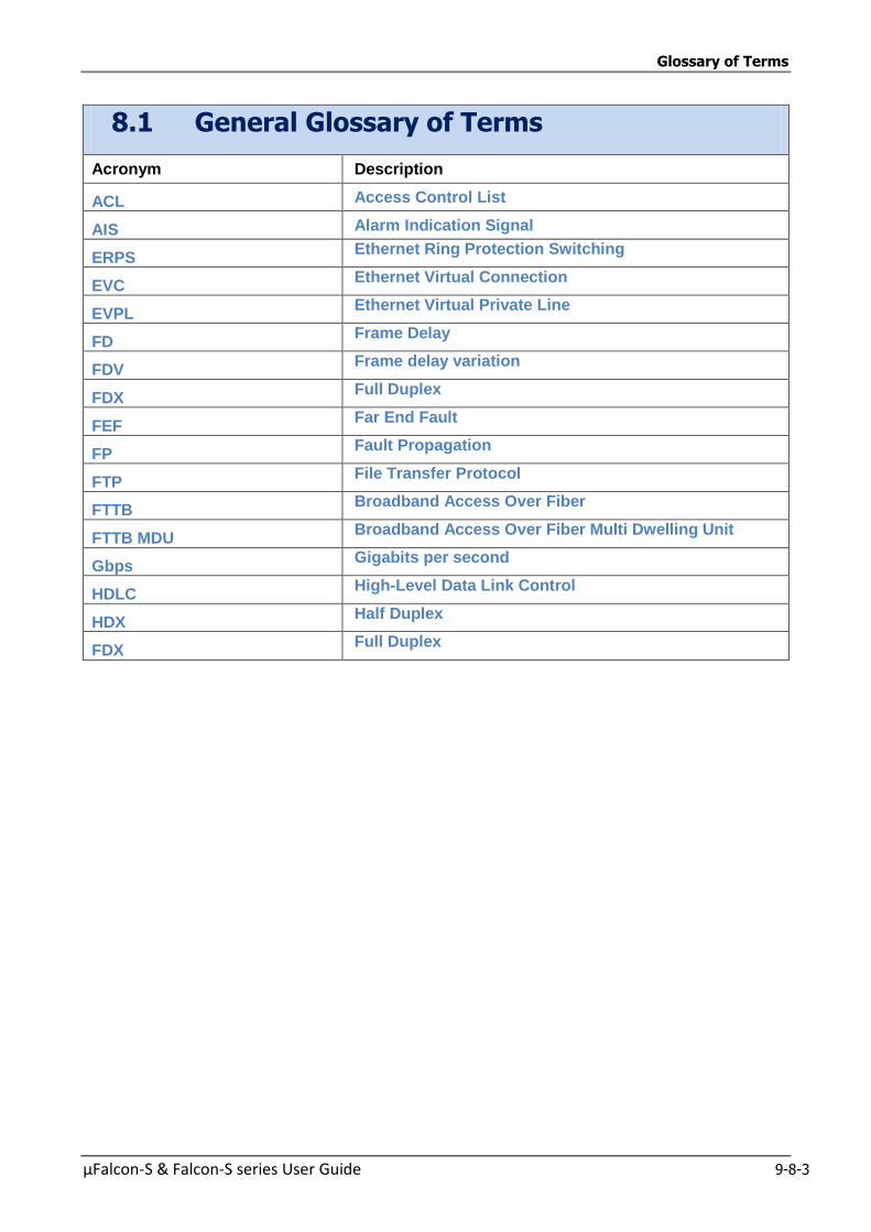
Glossary of Terms
µFalcon-S & Falcon-S series User Guide 9-8-3
8.1 General Glossary of Terms
Acronym Description
ACL Access Control List
AIS Alarm Indication Signal
ERPS Ethernet Ring Protection Switching
EVC Ethernet Virtual Connection
EVPL Ethernet Virtual Private Line
FD Frame Delay
FDV Frame delay variation
FDX Full Duplex
FEF Far End Fault
FP Fault Propagation
FTP File Transfer Protocol
FTTB Broadband Access Over Fiber
FTTB MDU Broadband Access Over Fiber Multi Dwelling Unit
Gbps Gigabits per second
HDLC High-Level Data Link Control
HDX Half Duplex
FDX Full Duplex
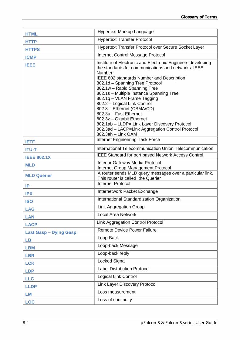
Glossary of Terms
8-4 µFalcon-S & Falcon-S series User Guide
HTML Hypertext Markup Language
HTTP Hypertext Transfer Protocol
HTTPS Hypertext Transfer Protocol over Secure Socket Layer
ICMP Internet Control Message Protocol
IEEE Institute of Electronic and Electronic Engineers developing the standards for communications and networks. IEEE Number IEEE 802 standards Number and Description 802.1d – Spanning Tree Protocol 802.1w – Rapid Spanning Tree 802.1s – Multiple Instance Spanning Tree 802.1q – VLAN Frame Tagging 802.2 – Logical Link Control 802.3 – Ethernet (CSMA/CD) 802.3u – Fast Ethernet 802.3z – Gigabit Ethernet 802.1ab – LLDP= Link Layer Discovery Protocol 802.3ad – LACP=Link Aggregation Control Protocol 802.3ah – Link OAM
IETF Internet Engineering Task Force
ITU-T International Telecommunication Union Telecommunication
IEEE 802.1X IEEE Standard for port based Network Access Control
MLD Interior Gateway Media Protocol Internet Group Management Protocol
MLD Querier A router sends MLD query messages over a particular link. This router is called the Querier
IP Internet Protocol
IPX Internetwork Packet Exchange
ISO International Standardization Organization
LAG Link Aggregation Group
LAN Local Area Network
LACP Link Aggregation Control Protocol
Last Gasp – Dying Gasp Remote Device Power Failure
LB Loop-Back
LBM Loop-back Message
LBR Loop-back reply
LCK Locked Signal
LDP Label Distribution Protocol
LLC Logical Link Control
LLDP Link Layer Discovery Protocol
LM Loss measurement
LOC Loss of continuity
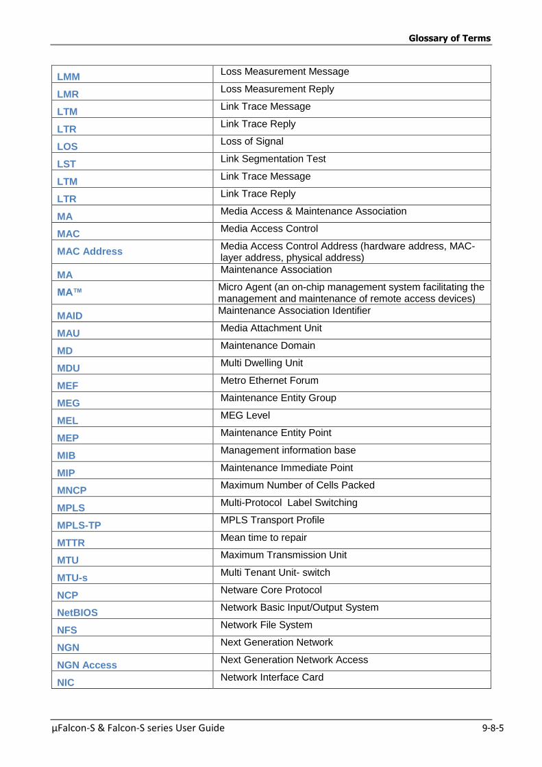
Glossary of Terms
µFalcon-S & Falcon-S series User Guide 9-8-5
LMM Loss Measurement Message
LMR Loss Measurement Reply
LTM Link Trace Message
LTR Link Trace Reply
LOS Loss of Signal
LST Link Segmentation Test
LTM Link Trace Message
LTR Link Trace Reply
MA Media Access & Maintenance Association
MAC Media Access Control
MAC Address Media Access Control Address (hardware address, MAC-layer address, physical address)
MA Maintenance Association
MA™ Micro Agent (an on-chip management system facilitating the management and maintenance of remote access devices)
MAID Maintenance Association Identifier
MAU Media Attachment Unit
MD Maintenance Domain
MDU Multi Dwelling Unit
MEF Metro Ethernet Forum
MEG Maintenance Entity Group
MEL MEG Level
MEP Maintenance Entity Point
MIB Management information base
MIP Maintenance Immediate Point
MNCP Maximum Number of Cells Packed
MPLS Multi-Protocol Label Switching
MPLS-TP MPLS Transport Profile
MTTR Mean time to repair
MTU Maximum Transmission Unit
MTU-s Multi Tenant Unit- switch
NCP Netware Core Protocol
NetBIOS Network Basic Input/Output System
NFS Network File System
NGN Next Generation Network
NGN Access Next Generation Network Access
NIC Network Interface Card
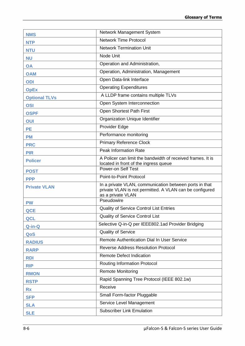
Glossary of Terms
8-6 µFalcon-S & Falcon-S series User Guide
NMS Network Management System
NTP Network Time Protocol
NTU Network Termination Unit
NU Node Unit
OA Operation and Administration,
OAM Operation, Administration, Management
ODI Open Data-link Interface
OpEx Operating Expenditures
Optional TLVs A LLDP frame contains multiple TLVs
OSI Open System Interconnection
OSPF Open Shortest Path First
OUI Organization Unique Identifier
PE Provider Edge
PM Performance monitoring
PRC Primary Reference Clock
PIR Peak Information Rate
Policer A Policer can limit the bandwidth of received frames. It is located in front of the ingress queue
POST Power-on Self Test
PPP Point-to-Point Protocol
Private VLAN In a private VLAN, communication between ports in that private VLAN is not permitted. A VLAN can be configured as a private VLAN
PW Pseudowire
QCE Quality of Service Control List Entries
QCL Quality of Service Control List
Q-in-Q Selective Q-in-Q per IEEE802.1ad Provider Bridging
QoS Quality of Service
RADIUS Remote Authentication Dial In User Service
RARP Reverse Address Resolution Protocol
RDI Remote Defect Indication
RIP Routing Information Protocol
RMON Remote Monitoring
RSTP Rapid Spanning Tree Protocol (IEEE 802.1w)
Rx Receive
SFP Small Form-factor Pluggable
SLA Service Level Management
SLE Subscriber Link Emulation
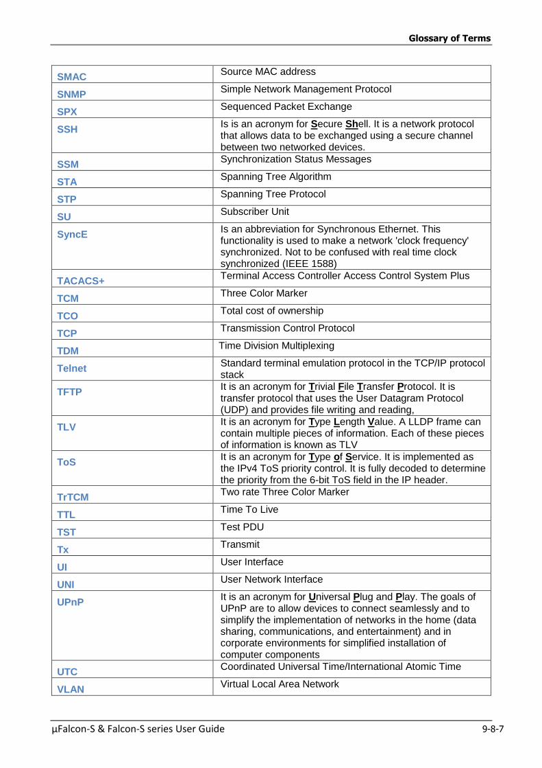
Glossary of Terms
µFalcon-S & Falcon-S series User Guide 9-8-7
SMAC Source MAC address
SNMP Simple Network Management Protocol
SPX Sequenced Packet Exchange
SSH Is is an acronym for Secure Shell. It is a network protocol that allows data to be exchanged using a secure channel between two networked devices.
SSM Synchronization Status Messages
STA Spanning Tree Algorithm
STP Spanning Tree Protocol
SU Subscriber Unit
SyncE Is an abbreviation for Synchronous Ethernet. This functionality is used to make a network 'clock frequency' synchronized. Not to be confused with real time clock synchronized (IEEE 1588)
TACACS+ Terminal Access Controller Access Control System Plus
TCM Three Color Marker
TCO Total cost of ownership
TCP Transmission Control Protocol
TDM Time Division Multiplexing
Telnet Standard terminal emulation protocol in the TCP/IP protocol stack
TFTP It is an acronym for Trivial File Transfer Protocol. It is transfer protocol that uses the User Datagram Protocol (UDP) and provides file writing and reading,
TLV It is an acronym for Type Length Value. A LLDP frame can contain multiple pieces of information. Each of these pieces of information is known as TLV
ToS It is an acronym for Type of Service. It is implemented as the IPv4 ToS priority control. It is fully decoded to determine the priority from the 6-bit ToS field in the IP header.
TrTCM Two rate Three Color Marker
TTL Time To Live
TST Test PDU
Tx Transmit
UI User Interface
UNI User Network Interface
UPnP It is an acronym for Universal Plug and Play. The goals of UPnP are to allow devices to connect seamlessly and to simplify the implementation of networks in the home (data sharing, communications, and entertainment) and in corporate environments for simplified installation of computer components
UTC Coordinated Universal Time/International Atomic Time
VLAN Virtual Local Area Network

Glossary of Terms
8-8 µFalcon-S & Falcon-S series User Guide
VLAN ID VLAN Identifier
WAN Wide Area Network
WDM Wavelength-division multiplexing

Glossary of Terms
µFalcon-S & Falcon-S series User Guide 9-8-9
8.2 Alphabetical Glossary of Terms
ACE
ACE is an acronym for Access Control Entry. It describes access permission associated with a particular ACE ID.
There are three ACE frame types (Ethernet Type, ARP, and IPv4) and two ACE actions (permit
and deny). The ACE also contains many detailed, different parameter options that are available for individual application.
ACL
ACL is an acronym for Access Control List. It is the list table of ACEs, containing access control
entries that specify individual users or groups permitted or denied to specific traffic objects, such
as a process or a program.
Each accessible traffic object contains an identifier to its ACL. The privileges determine whether there are specific traffic object access rights.
ACL implementations can be quite complex, for example, when the ACEs are prioritized for the
various situation. In networking, the ACL refers to a list of service ports or network services that are available on a host or server, each with a list of hosts or servers permitted or denied to use the service. ACL can generally be configured to control inbound traffic, and in this context, they are similar to firewalls.
There are 3 web-pages associated with the manual ACL configuration:
ACL|Access Control List: The web page shows the ACEs in a prioritized way, highest (top) to
lowest (bottom). Default the table is empty. An ingress frame will only get a hit on one ACE even though there are more matching ACEs. The first matching ACE will take action (permit/deny) on that frame and a counter associated with that ACE is incremented. An ACE can be associated with a Policy, 1 ingress port, or any ingress port (the whole switch). If an ACE Policy is created then that Policy can be associated with a group of ports under the "Ports" web-page. There are
number of Parameters that can be configured with an ACE. Read the Web page help text to get further information for each of them. The maximum number of ACEs is 64. ACL|Ports: The ACL Ports configuration is used to assign a Policy ID to an ingress port. This is
useful to group ports to obey the same traffic rules. Traffic Policy is created under the "Access Control List" - page. You can you also set up specific traffic properties (Action / Rate Limiter / Port copy, etc) for each ingress port. They will though only apply if the frame gets past the ACE matching without getting matched. In that case a counter associated with that port is incremented. See the Web page help text for each specific port property. ACL|Rate Limiters: Under this page you can configure the rate limiters. There can be 15
different rate limiters, each ranging from 1-1024K packets per seconds. Under "Ports" and
"Access Control List" web-pages you can assign a Rate Limiter ID to the ACE(s) or ingress
port(s).
AES
AES is an acronym for Advanced Encryption Standard. The encryption key protocol is applied in 802.1i standard to improve WLAN security. It is an encryption standard by the U.S. government, which will replace DES and 3DES. AES has a fixed block size of 128 bits and a key size of 128, 192, or 256 bits.
AMS
AMS is an acronym for Auto Media Select. AMS is used for dual media ports (ports supporting both copper (cu) and fiber (SFP) cables. AMS automatically determines if a SFP or a CU cable is inserted and switches to the corresponding media. If both SFP and cu cables are inserted, the port will select the prefered media.
Glossary of Terms
8-10 µFalcon-S & Falcon-S series User Guide
APS
APS is an acronym for Automatic Protection Switching. This protocol is used to secure that switching is done bidirectional in the two ends of a protection group, as defined in G.8031.
Aggregation
Using multiple ports in parallel to increase the link speed beyond the limits of a port and to increase the redundancy for higher availability.
(Also Port Aggregation, Link Aggregation).
ARP
ARP is an acronym for Address Resolution Protocol. It is a protocol that used to convert an IP address into a physical address, such as an Ethernet address. ARP allows a host to communicate with other hosts when only the Internet address of its neighbors is known. Before using IP, the
host sends a broadcast ARP request containing the Internet address of the desired destination
system.
ARP Inspection
ARP Inspection is a secure feature. Several types of attacks can be launched against a host or devices connected to Layer 2 networks by "poisoning" the ARP caches. This feature is used to block such attacks. Only valid ARP requests and responses can go through the switch device.
Auto-Negotiation
Auto-negotiation is the process where two different devices establish the mode of operation and the speed settings that can be shared by those devices for a link.
C
CC
CC is an acronym for Continuity Check. It is a MEP functionality that is able to detect loss of continuity in a network by transmitting CCM frames to a peer MEP.
CCM
CCM is an acronym for Continuity Check Message. It is a OAM frame transmitted from a MEP to it's peer MEP and used to implement CC functionality.
CDP
CDP is an acronym for Cisco Discovery Protocol.
D
DEI
DEI is an acronym for Drop Eligible Indicator. It is a 1-bit field in the VLAN tag.
DES
DES is an acronym for Data Encryption Standard. It provides a complete description of a mathematical algorithm for encrypting (enciphering) and decrypting (deciphering) binary coded information.
Encrypting data converts it to an unintelligible form called cipher. Decrypting cipher converts the data back to its original form called plaintext. The algorithm described in this standard specifies both enciphering and deciphering operations which are based on a binary number called a key.
DHCP
DHCP is an acronym for Dynamic Host Configuration Protocol. It is a protocol used for assigning
dynamic IP addresses to devices on a network.

Glossary of Terms
µFalcon-S & Falcon-S series User Guide 9-8-11
DHCP used by networked computers (clients) to obtain IP addresses and other Parameters such
as the default gateway, subnet mask, and IP addresses of DNS servers from a DHCP server.
The DHCP server ensures that all IP addresses are unique, for example, no IP address is assigned to a second client while the first client's assignment is valid (its lease has not expired). Therefore, IP address pool management is done by the server and not by a human network administrator.
Dynamic addressing simplifies network administration because the software keeps track of IP addresses rather than requiring an administrator to manage the task. This means that a new computer can be added to a network without the hassle of manually assigning it a unique IP address.
DHCP Relay
DHCP Relay is used to forward and to transfer DHCP messages between the clients and the server
when they are not on the same subnet domain.
The DHCP option 82 enables a DHCP relay agent to insert specific information into a DHCP
request packets when forwarding client DHCP packets to a DHCP server and remove the specific information from a DHCP reply packets when forwarding server DHCP packets to a DHCP client. The DHCP server can use this information to implement IP address or other assignment policies. Specifically the option works by setting two sub-options: Circuit ID (option 1) and Remote ID (option2). The Circuit ID sub-option is supposed to include information specific to which circuit the request came in on. The Remote ID sub-option was designed to carry information relating to the remote host end of the circuit.
The definition of Circuit ID in the switch is 4 bytes in length and the format is "vlan_id" "module_id" "port_no". The parameter of "vlan_id" is the first two bytes represent the VLAN ID.
The parameter of "module_id" is the third byte for the module ID (in standalone switch it always equal 0, in stackable switch it means switch ID). The parameter of "port_no" is the fourth byte and it means the port number. The Remote ID is 6 bytes in length, and the value is equal the DHCP relay agents MAC address.
DHCP Snooping
DHCP Snooping is used to block intruder on the untrusted ports of the switch device when it tries to intervene by injecting a bogus DHCP reply packet to a legitimate conversation between the DHCP client and server.
DNS
DNS is an acronym for Domain Name System. It stores and associates many types of information with domain names. Most importantly, DNS translates human-friendly domain names and computer hostnames into computer-friendly IP addresses. For example, the domain name www.example.com might translate to 192.168.0.1.
DoS
DoS is an acronym for Denial of Service. In a denial-of-service (DoS) attack, an attacker
attempts to prevent legitimate users from accessing information or services. By targeting at network sites or network connection, an attacker may be able to prevent network users from
accessing email, web sites, online accounts (banking, etc.), or other services that rely on the affected computer.
Dotted Decimal Notation
Dotted Decimal Notation refers to a method of writing IP addresses using decimal numbers and dots as separators between octets.
An IPv4 dotted decimal address has the form x.y.z.w, where x, y, z, and w are decimal numbers between 0 and 255.
Drop Precedence Level
Every incoming frame is classified to a Drop Precedence Level (DP level), which is used throughout the device for providing congestion control guarantees to the frame according to what

Glossary of Terms
8-12 µFalcon-S & Falcon-S series User Guide
was configured for that specific DP level. A DP level of 0 (zero) corresponds to 'Committed'
(Green) frames and a DP level of 1 or higher corresponds to 'Discard Eligible' (Yellow) frames.
DSCP
DSCP is an acronym for Differentiated Services Code Point. It is a field in the header of IP
packets for packet classification purposes.
E
EEE
EEE is an abbreviation for Energy Efficient Ethernet defined in IEEE 802.3az.
EPS
EPS is an abbreviation for Ethernet Protection Switching defined in ITU/T G.8031.
Ethernet Type
Ethernet Type, or EtherType, is a field in the Ethernet MAC header, defined by the Ethernet
networking standard. It is used to indicate which protocol is being transported in an Ethernet frame.
F
FTP
FTP is an acronym for File Transfer Protocol. It is a transfer protocol that uses the Transmission Control Protocol (TCP) and provides file writing and reading. It also provides directory service and security features.
Fast Leave
Multicast snooping Fast Leave processing allows the switch to remove an interface from the forwarding-table entry without first sending out group specific queries to the interface. The VLAN interface is pruned from the multicast tree for the multicast group specified in the original leave message. Fast-leave processing ensures optimal bandwidth management for all hosts on a switched network, even when multiple multicast groups are in use simultaneously. This
processing applies to MLD and MLD.
H
HTTP
HTTP is an acronym for Hypertext Transfer Protocol. It is a protocol that used to transfer or convey information on the World Wide Web (WWW).
HTTP defines how messages are formatted and transmitted, and what actions Web servers and
browsers should take in response to various commands. For example, when you enter a URL in your browser, this actually sends an HTTP command to the Web server directing it to fetch and transmit the requested Web page. The other main standard that controls how the World Wide Web works is HTML, which covers how Web pages are formatted and displayed.
Any Web server machine contains, in addition to the Web page files it can serve, an HTTP daemon, a program that is designed to wait for HTTP requests and handle them when they
arrive. The Web browser is an HTTP client, sending requests to server machines. An HTTP client initiates a request by establishing a Transmission Control Protocol (TCP) connection to a particular port on a remote host (port 80 by default). An HTTP server listening on that port waits for the client to send a request message.
HTTPS
HTTPS is an acronym for Hypertext Transfer Protocol over Secure Socket Layer. It is used to indicate a secure HTTP connection.
HTTPS provide authentication and encrypted communication and is widely used on the World
Wide Web for security-sensitive communication such as payment transactions and corporate logons.
Glossary of Terms
µFalcon-S & Falcon-S series User Guide 9-8-13
HTTPS is really just the use of Netscape's Secure Socket Layer (SSL) as a sublayer under its
regular HTTP application layering. (HTTPS uses port 443 instead of HTTP port 80 in its interactions with the lower layer, TCP/IP.) SSL uses a 40-bit key size for the RC4 stream encryption algorithm, which is considered an adequate degree of encryption for commercial exchange.
I
ICMP
ICMP is an acronym for Internet Control Message Protocol. It is a protocol that generated the error response, diagnostic or routing purposes. ICMP messages generally contain information about routing difficulties or simple exchanges such as time-stamp or echo transactions. For example, the PING command uses ICMP to test an Internet connection.
IEEE 802.1X
IEEE 802.1X is an IEEE standard for port-based Network Access Control. It provides
authentication to devices attached to a LAN port, establishing a point-to-point connection or preventing access from that port if authentication fails. With 802.1X, access to all switch ports can be centrally controlled from a server, which means that authorized users can use the same credentials for authentication from any point within the network.
MLD
MLD is an acronym for Internet Group Management Protocol. It is a communications protocol used to manage the membership of Internet Protocol multicast groups. MLD is used by IP hosts
and adjacent multicast routers to establish multicast group memberships. It is an integral part of the IP multicast specification, like ICMP for unicast connections. MLD can be used for online video and gaming, and allows more efficient use of resources when supporting these uses.
MLD Querier
A router sends MLD Query messages onto a particular link. This router is called the Querier.
IMAP
IMAP is an acronym for Internet Message Access Protocol. It is a protocol for email clients to
retrieve email messages from a mail server.
IMAP is the protocol that IMAP clients use to communicate with the servers, and SMTP is the protocol used to transport mail to an IMAP server.
The current version of the Internet Message Access Protocol is IMAP4. It is similar to Post Office
Protocol version 3 (POP3), but offers additional and more complex features. For example, the IMAP4 protocol leaves your email messages on the server rather than downloading them to your computer. If you wish to remove your messages from the server, you must use your mail client to generate local folders, copy messages to your local hard drive, and then delete and expunge the messages from the server.
IP
IP is an acronym for Internet Protocol. It is a protocol used for communicating data across an
internet network.
IP is a "best effort" system, which means that no packet of information sent over is assured to
reach its destination in the same condition it was sent. Each device connected to a Local Area Network (LAN) or Wide Area Network (WAN) is given an Internet Protocol address, and this IP
address is used to identify the device uniquely among all other devices connected to the extended network.
The current version of the Internet protocol is IPv4, which has 32-bits Internet Protocol addresses
allowing for in excess of four billion unique addresses. This number is reduced drastically by the practice of webmasters taking addresses in large blocks, the bulk of which remain unused. There is a rather substantial movement to adopt a new version of the Internet Protocol, IPv6, which would have 128-bits Internet Protocol addresses. This number can be represented roughly by a

Glossary of Terms
8-14 µFalcon-S & Falcon-S series User Guide
three with thirty-nine zeroes after it. However, IPv4 is still the protocol of choice for most of the Internet.
IPMC
IPMC is an acronym for IP MultiCast.
IPMC supports IPv4 and IPv6 multicasting. IPMCv4 denotes multicast for IPv4. IPMCv6 denotes multicast for IPv6.
IP Source Guard
IP Source Guard is a secure feature used to restrict IP traffic on DHCP snooping untrusted ports by filtering traffic based on the DHCP Snooping Table or manually configured IP Source Bindings. It helps prevent IP spoofing attacks when a host tries to spoof and use the IP address of another host.
L
LACP
LACP is an IEEE 802.3ad standard protocol. The Link Aggregation Control Protocol, allows bundling several physical ports together to form a single logical port.
LLC
The IEEE 802.2 Logical Link Control (LLC) protocol provides a link mechanism for upper layer protocols. It is the upper sub-layer of the Data Link Layer and provides multiplexing mechanisms
that make it possible for several network protocols (IP, IPX) to coexist within a multipoint network. LLC header consists of 1 byte DSAP (Destination Service Access Point), 1 byte SSAP (Source Service Access Point), 1 or 2 bytes Control field followed by LLC information.
LLDP
LLDP is an IEEE 802.1ab standard protocol.
The Link Layer Discovery Protocol(LLDP) specified in this standard allows stations attached to an IEEE 802 LAN to advertise, to other stations attached to the same IEEE 802 LAN, the major capabilities provided by the system incorporating that station, the management address or addresses of the entity or entities that provide management of those capabilities, and the identification of the stations point of attachment to the IEEE 802 LAN required by those management entity or entities. The information distributed via this protocol is stored by its
recipients in a standard Management Information Base (MIB), making it possible for the information to be accessed by a Network Management System (NMS) using a management protocol such as the Simple Network Management Protocol (SNMP).
LLDP-MED
LLDP-MED is an extension of IEEE 802.1ab and is defined by the telecommunication industry association (TIA-1057).
LOC
LOC is an acronym for Loss Of Connectivity and is detected by a MEP and is indicating lost
connectivity in the network. Can be used as a switch criteria byEPS
M
MAC Table
Switching of frames is based upon the DMAC address contained in the frame. The switch builds up a table that maps MAC addresses to switch ports for knowing which ports the frames should go to ( based upon the DMAC address in the frame ). This table contains both static and dynamic
entries. The static entries are configured by the network administrator if the administrator wants to do a fixed mapping between the DMAC address and switch ports.
The frames also contain a MAC address ( SMAC address ), which shows the MAC address of the
equipment sending the frame. The SMAC address is used by the switch to automatically update
Glossary of Terms
µFalcon-S & Falcon-S series User Guide 9-8-15
the MAC table with these dynamic MAC addresses. Dynamic entries are removed from the MAC
table if no frame with the corresponding SMAC address have been seen after a configurable age time.
MEP
MEP is an acronym for Maintenance Entity Endpoint and is an endpoint in a Maintenance Entity Group (ITU-T Y.1731).
MD5
MD5 is an acronym for Message-Digest algorithm 5. MD5 is a message digest algorithm, used cryptographic hash function with a 128-bit hash value. It was designed by Ron Rivest in 1991. MD5 is officially defined in RFC 1321 - The MD5 Message-Digest Algorithm.
Mirroring
For debugging network problems or monitoring network traffic, the switch system can be configured to mirror frames from multiple ports to a mirror port. (In this context, mirroring a
frame is the same as copying the frame.)
Both incoming (source) and outgoing (destination) frames can be mirrored to the mirror port.
MLD
MLD is an acronym for Multicast Listener Discovery for IPv6. MLD is used by IPv6 routers to
discover multicast listeners on a directly attached link, much as MLD is used in IPv4. The protocol is embedded in ICMPv6 instead of using a separate protocol.
MVR
Multicast VLAN Registration (MVR) is a protocol for Layer 2 (IP)-networks that enables multicast-traffic from a source VLAN to be shared with subscriber-VLANs.
The main reason for using MVR is to save bandwidth by preventing duplicate multicast streams
being sent in the core network, instead the stream(s) are received on the MVR-VLAN and forwarded to the VLANs where hosts have requested it/them(Wikipedia).
N
NAS
NAS is an acronym for Network Access Server. The NAS is meant to act as a gateway to guard access to a protected source. A client connects to the NAS, and the NAS connects to another
resource asking whether the client's supplied credentials are valid. Based on the answer, the NAS then allows or disallows access to the protected resource. An example of a NAS implementation is IEEE 802.1X.
NetBIOS
NetBIOS is an acronym for Network Basic Input/Output System. It is a program that allows applications on separate computers to communicate within a Local Area Network (LAN), and it is not supported on a Wide Area Network (WAN).
The NetBIOS giving each computer in the network both a NetBIOS name and an IP address corresponding to a different host name, provides the session and transport services described in the Open Systems Interconnection (OSI) model.
NFS
NFS is an acronym for Network File System. It allows hosts to mount partitions on a remote system and use them as though they are local file systems.
NFS allows the system administrator to store resources in a central location on the network,
providing authorized users continuous access to them, which means NFS supports sharing of files, printers, and other resources as persistent storage over a computer network.
Glossary of Terms
8-16 µFalcon-S & Falcon-S series User Guide
NTP
NTP is an acronym for Network TimeProtocol, a network protocol for synchronizing the clocks of computer systems. NTP uses UDP (datagrams) as transport layer.
O
OAM
OAM is an acronym for Operation Administration and Maintenance.
It is a protocol described in ITU-T Y.1731 used to implement carrier ethernet functionality. MEP functionality like CC and RDI is based on this
Optional TLVs.
A LLDP frame contains multiple TLVs
For some TLVs it is configurable if the switch shall include the TLV in the LLDP frame. These TLVs are known as optional TLVs. If an optional TLVs is disabled the corresponding information is not included in the LLDP frame.
OUI
OUI is the organizationally unique identifier. An OUI address is a globally unique identifier assigned to a vendor by IEEE. You can determine which vendor a device belongs to according to the OUI address which forms the first 24 bits of a MAC address.
P
PCP
PCP is an acronym for Priority Code Point. It is a 3-bit field storing the priority level for the 802.1Q frame. It is also known as User Priority.
PD
PD is an acronym for Powered Device. In a PoE system the power is delivered from a PSE ( power sourcing equipment ) to a remote device. The remote device is called a PD.
PHY
PHY is an abbreviation for Physical Interface Transceiver and is the device that implement the
Ethernet physical layer (IEEE-802.3).
PING
ping is a program that sends a series of packets over a network or the Internet to a specific
computer in order to generate a response from that computer. The other computer responds with
an acknowledgment that it received the packets. Ping was created to verify whether a specific computer on a network or the Internet exists and is connected.
ping uses Internet Control Message Protocol (ICMP) packets. The PING Request is the packet
from the origin computer, and the PING Reply is the packet response from the target.
PoE
PoE is an acronym for Power Over Ethernet.
Power Over Ethernet is used to transmit electrical power, to remote devices over standard
Ethernet cable. It could for example be used for powering IP telephones, wireless LAN access points and other equipment, where it would be difficult or expensive to connect the equipment to main power supply.
Policer
A policer can limit the bandwidth of received frames. It is located in front of the ingress queue.
Glossary of Terms
µFalcon-S & Falcon-S series User Guide 9-8-17
POP3
POP3 is an acronym for Post Office Protocol version 3. It is a protocol for email clients to retrieve email messages from a mail server.
POP3 is designed to delete mail on the server as soon as the user has downloaded it. However,
some implementations allow users or an administrator to specify that mail be saved for some period of time. POP can be thought of as a "store-and-forward" service.
An alternative protocol is Internet Message Access Protocol (IMAP). IMAP provides the user with more capabilities for retaining e-mail on the server and for organizing it in folders on the server. IMAP can be thought of as a remote file server.
POP and IMAP deal with the receiving of e-mail and are not to be confused with the Simple Mail Transfer Protocol (SMTP). You send e-mail with SMTP, and a mail handler receives it on your
recipient's behalf. Then the mail is read using POP or IMAP. IMAP4 and POP3 are the two most prevalent Internet standard protocols for e-mail retrieval. Virtually all modern e-mail clients and servers support both.
PPPoE
PPPoE is an acronym for Point-to-Point Protocol over Ethernet.
It is a network protocol for encapsulating Point-to-Point Protocol (PPP) frames inside Ethernet
frames. It is used mainly with ADSL services where individual users connect to the ADSL transceiver (modem) over Ethernet and in plain Metro Ethernet networks (Wikipedia).
Private VLAN
In a private VLAN, PVLANs provide layer 2 isolation between ports within the same broadcast domain. Isolated ports configured as part of PVLAN cannot communicate with each other. Member ports of a PVLAN can communicate with each other.
PTP
PTP is an acronym for Precision TimeProtocol, a network protocol for synchronizing the clocks of computer systems.
Q
QCE
QCE is an acronym for QoS Control Entry. It describes QoS class associated with a particular QCE ID.
There are six QCE frame types: Ethernet Type, VLAN, UDP/TCP Port, DSCP, TOS, and Tag
Priority. Frames can be classified by one of 4 different QoS classes: "Low", "Normal", "Medium", and "High" for individual application.
QCL
QCL is an acronym for QoS Control List. It is the list table of QCEs, containing QoS control entries
that classify to a specific QoS class on specific traffic objects.
Each accessible traffic object contains an identifier to its QCL. The privileges determine specific traffic object to specific QoS class.
QL
QL In SyncE this is the Quality Level of a given clock source. This is received on a port in a SSM
indicating the quality of the clock received in the port.
QoS
QoS is an acronym for Quality of Service. It is a method to guarantee a bandwidth relationship between individual applications or protocols.
Glossary of Terms
8-18 µFalcon-S & Falcon-S series User Guide
A communications network transports a multitude of applications and data, including high-quality
video and delay-sensitive data such as real-time voice. Networks must provide secure, predictable, measurable, and sometimes guaranteed services.
Achieving the required QoS becomes the secret to a successful end-to-end business solution. Therefore, QoS is the set of techniques to manage network resources.
QoS class
Every incoming frame is classified to a QoS class, which is used throughout the device for providing queuing, scheduling and congestion control guarantees to the frame according to what
was configured for that specific QoS class. There is a one to one mapping between QoS class, queue and priority. A QoS class of 0 (zero) has the lowest priority.
R
RARP
RARP is an acronym for Reverse Address Resolution Protocol. It is a protocol that is used to
obtain an IP address for a given hardware address, such as an Ethernet address. RARP is the complement of ARP.
RADIUS
RADIUS is an acronym for Remote Authentication DialIn User Service. It is a networking protocol that provides centralized access, authorization and accounting management for people or computers to connect and use a network service.
RDI
RDI is an acronym for Remote Defect Indication. It is a OAM functionallity that is used by a MEP to indicate defect detected to the remote peer MEP
Router Port
A router port is a port on the Ethernet switch that leads switch towards the Layer 3 multicast device.
RSTP
In 1998, the IEEE with document 802.1w introduced an evolution ofSTP: the Rapid Spanning Tree Protocol, which provides for faster spanning tree convergence after a topology change. Standard IEEE 802.1D-2004 now incorporates RSTP and obsoletes STP, while at the same time
being backwards-compatible with STP.
S
SAMBA
Samba is a program running under UNIX-like operating systems that provides seamless integration between UNIX and Microsoft Windows machines. Samba acts as file and print servers for Microsoft Windows, IBM OS/2, and other SMB client machines. Samba uses the Server Message Block (SMB) protocol and Common Internet File System (CIFS), which is the underlying
protocol used in Microsoft Windows networking.
Samba can be installed on a variety of operating system platforms, including Linux, most common Unix platforms, OpenVMS, and IBM OS/2.
Samba can also register itself with the master browser on the network so that it would appear in the listing of hosts in Microsoft Windows "Neighborhood Network".
SHA
SHA is an acronym for Secure Hash Algorithm. It designed by the National Security Agency
(NSA) and published by the NIST as a U.S. Federal Information Processing Standard. Hash algorithms compute a fixed-length digital representation (known as a message digest) of an input data sequence (the message) of any length.
Shaper
Glossary of Terms
µFalcon-S & Falcon-S series User Guide 9-8-19
A shaper can limit the bandwidth of transmitted frames. It is located after the ingress queues.
SMTP
SMTP is an acronym for Simple Mail Transfer Protocol. It is a text-based protocol that uses the Transmission Control Protocol (TCP) and provides a mail service modeled on the FTP file transfer
service. SMTP transfers mail messages between systems and notifications regarding incoming mail.
SNAP
The SubNetwork Access Protocol (SNAP) is a mechanism for multiplexing, on networks using IEEE 802.2 LLC, more protocols than can be distinguished by the 8-bit 802.2 Service Access Point (SAP) fields. SNAP supports identifying protocols by Ethernet type field values; it also supports vendor-private protocol identifier.
SNMP
SNMP is an acronym for Simple Network Management Protocol. It is part of the Transmission Control Protocol/Internet Protocol (TCP/IP) protocol for network management. SNMP allow
diverse network objects to participate in a network management architecture. It enables network management systems to learn network problems by receiving traps or change notices from network devices implementing SNMP.
SNTP
SNTP is an acronym for Simple Network TimeProtocol, a network protocol for synchronizing the clocks of computer systems. SNTP uses UDP (datagrams) as transport layer.
SPROUT
Stack Protocol using ROUting Technology. An advanced protocol for almost instantaneous discovery of topology changes within a stack as well as election of a master switch. SPROUT also calculates Parameters for setting up each switch to perform shortest path forwarding within the
stack.
SSID
Service Set Identifier is a name used to identify the particular 802.11 wireless LANs to which a
user wants to attach. A client device will receive broadcast messages from all access points within range advertising their SSIDs, and can choose one to connect to based on pre-configuration, or by displaying a list of SSIDs in range and asking the user to select one (wikipedia).
SSH
SSH is an acronym for Secure SHell. It is a network protocol that allows data to be exchanged using a secure channel between two networked devices. The encryption used by SSH provides confidentiality and integrity of data over an insecure network. The goal of SSH was to replace the earlier rlogin, TELNET and rsh protocols, which did not provide strong authentication or guarantee confidentiality (Wikipedia).
SSM
SSM In SyncE this is an abbreviation for Synchronization Status Message and is containing a QL indication.
STP
Spanning Tree Protocol is an OSI layer-2 protocol which ensures a loop free topology for any bridged LAN. The original STP protocol is now obsolete by RSTP.
Switch ID
Switch IDs (1-16) are used to uniquely identify the switches within a stack. The Switch ID of each
switch is shown on the display on the front of the switch and is used widely in the web pages as well as in the CLI commands.
SyncE
SyncE Is an abbreviation for Synchronous Ethernet. This functionality is used to make a network 'clock frequency' synchronized. Not to be confused with real time clock synchronized (IEEE 1588).
sFlow
Glossary of Terms
8-20 µFalcon-S & Falcon-S series User Guide
sFlow is an acronym for sample Flow. This protocol is used to monitor the sampled traffic on the
switch. The sFlow Agent configures the sampling rate at which the samples have to collected. The sFlow collector is configured to send the sample data to the external traffic monitoring application.
T
TACACS+
TACACS+ is an acronym for Terminal Acess Controller AccessControl System Plus. It is a networking protocol which provides access control for routers, network access servers and other networked computing devices via one or more centralized servers. TACACS+ provides separate authentication, authorization and accounting services.
Tag Priority
Tag Priority is a 3-bit field storing the priority level for the 802.1Q frame.
TCP
TCP is an acronym for Transmission Control Protocol. It is a communications protocol that uses the Internet Protocol (IP) to exchange the messages between computers.
The TCP protocol guarantees reliable and in-order delivery of data from sender to receiver and
distinguishes data for multiple connections by concurrent applications (for example, Web server and e-mail server) running on the same host.
The applications on networked hosts can use TCP to create connections to one another. It is known as a connection-oriented protocol, which means that a connection is established and maintained until such time as the message or messages to be exchanged by the application programs at each end have been exchanged. TCP is responsible for ensuring that a message is
divided into the packets that IP manages and for reassembling the packets back into the complete message at the other end.
Common network applications that use TCP include the World Wide Web (WWW), e-mail, and File Transfer Protocol (FTP).
TELNET
TELNET is an acronym for TELetype NETwork. It is a terminal emulation protocol that uses the Transmission Control Protocol (TCP) and provides a virtual connection between TELNET server and TELNET client.
TELNET enables the client to control the server and communicate with other servers on the
network. To start a Telnet session, the client user must log in to a server by entering a valid username and password. Then, the client user can enter commands through the Telnet program just as if they were entering commands directly on the server console.
TFTP
TFTP is an acronym for Trivial File Transfer Protocol. It is transfer protocol that uses the User Datagram Protocol (UDP) and provides file writing and reading, but it does not provide directory
service and security features.
ToS
ToS is an acronym for Type of Service. It is implemented as the IPv4 ToS priority control. It is fully decoded to determine the priority from the 6-bit ToS field in the IP header. The most significant 6 bits of the ToS field are fully decoded into 64 possibilities, and the singular code that results is compared against the corresponding bit in the IPv4 ToS priority control bit (0~63).
TLV
TLV is an acronym for Type Length Value. A LLDP frame can contain multiple pieces of
information. Each of these pieces of information is known as TLV.
TKIP
Glossary of Terms
µFalcon-S & Falcon-S series User Guide 9-8-21
TKIP is an acronym for Temporal Key Integrity Protocol. It used in WPA to replace WEP with a
new encryption algorithm. TKIP comprises the same encryption engine and RC4 algorithm defined for WEP. The key used for encryption in TKIP is 128 bits and changes the key used for each packet.
U
UDP
UDP is an acronym for User Datagram Protocol. It is a communications protocol that uses the Internet Protocol (IP) to exchange the messages between computers.
UDP is an alternative to the Transmission Control Protocol (TCP) that uses the Internet Protocol
(IP). Unlike TCP, UDP does not provide the service of dividing a message into packet datagrams, and UDP doesn't provide reassembling and sequencing of the packets. This means that the application program that uses UDP must be able to make sure that the entire message has arrived and is in the right order. Network applications that want to save processing time because they have very small data units to exchange may prefer UDP to TCP.
UDP provides two services not provided by the IP layer. It provides port numbers to help distinguish different user requests and, optionally, a checksum capability to verify that the data arrived intact.
Common network applications that use UDP include the Domain Name System (DNS), streaming media applications such as IPTV, Voice over IP (VoIP), and Trivial File Transfer Protocol (TFTP).
UPnP
UPnP is an acronym for Universal Plug and Play. The goals of UPnP are to allow devices to connect seamlessly and to simplify the implementation of networks in the home (data sharing, communications, and entertainment) and in corporate environments for simplified installation of computer components
User Priority
User Priority is a 3-bit field storing the priority level for the 802.1Q frame. It is also known as PCP.
V
VLAN
Virtual LAN. A method to restrict communication between switch ports. VLANs can be used for the following applications:
VLAN unaware switching: This is the default configuration. All ports are VLAN unaware with
Port VLAN ID 1 and members of VLAN 1. This means that MAC addresses are learned in VLAN 1, and the switch does not remove or insert VLAN tags.
VLAN aware switching: This is based on the IEEE 802.1Q standard. All ports are VLAN aware. Ports connected to VLAN aware switches are members of multiple VLANs and transmit tagged frames. Other ports are members of one VLAN, set up with this Port VLAN ID, and transmit untagged frames.
Provider switching: This is also known as Q-in-Q switching. Ports connected to subscribers are VLAN unaware, members of one VLAN, and set up with this unique Port VLAN ID. Ports connected to the service provider are VLAN aware, members of multiple VLANs, and set up to tag all frames.
Untagged frames received on a subscriber port are forwarded to the provider port with a single VLAN tag. Tagged frames received on a subscriber port are forwarded to the provider port with a double VLAN tag.
VLAN ID
VLAN ID is a 12-bit field specifying the VLAN to which the frame belongs.
Voice VLAN
Glossary of Terms
8-22 µFalcon-S & Falcon-S series User Guide
Voice VLAN is VLAN configured specially for voice traffic. By adding the ports with voice devices
attached to voice VLAN, we can perform QoS-related configuration for voice data, ensuring the transmission priority of voice traffic and voice quality.
W
WEP
WEP is an acronym for Wired Equivalent Privacy. WEP is a deprecated algorithm to secure IEEE 802.11 wireless networks. Wireless networks broadcast messages using radio, so are more susceptible to eavesdropping than wired networks. When introduced in 1999, WEP was intended to provide confidentiality comparable to that of a traditional wired network (Wikipedia).
WiFi
WiFi is an acronym for Wireless Fidelity. It is meant to be used generically when referring of any
type of 802.11 network, whether 802.11b, 802.11a, dual-band, etc. The term is promulgated by the Wi-Fi Alliance.
WPA
WPA is an acronym for Wi-Fi Protected Access. It was created in response to several serious weaknesses researchers had found in the previous system , Wired Equivalent Privacy (WEP). WPA implements the majority of the IEEE 802.11i standard, and was intended as an intermediate measure to take the place of WEP while 802.11i was prepared. WPA is specifically designed to
also work with pre-WPA wireless network interface cards (through firmware upgrades), but not necessarily with first generation wireless access points. WPA2 implements the full standard, but will not work with some older network cards (Wikipedia).
WPA-PSK
WPA-PSK is an acronym for Wi-Fi Protected Access - Pre Shared Key. WPA was designed to enhance the security of wireless networks. There are two flavors of WPA: enterprise and personal. Enterprise is meant for use with an IEEE 802.1X authentication server, which
distributes different keys to each user. Personal WPA utilizes less scalable 'pre-shared key' (PSK) mode, where every allowed computer is given the same passphrase. In PSK mode, security depends on the strength and secrecy of the passphrase. The design of WPA is based on a Draft 3 of the IEEE 802.11i standard (Wikipedia)
WPA-Radius
WPA-Radius is an acronym for Wi-Fi Protected Access - Radius (802.1X authentication server).
WPA was designed to enhance the security of wireless networks. There are two flavors of WPA: enterprise and personal. Enterprise is meant for use with an IEEE 802.1X authentication server, which distributes different keys to each user. Personal WPA utilizes less scalable 'pre-shared key' (PSK) mode, where every allowed computer is given the same passphrase. In PSK mode, security depends on the strength and secrecy of the passphrase. The design of WPA is based on a Draft 3 of the IEEE 802.11i standard (Wikipedia)
WPS
WPS is an acronym for Wi-Fi Protected Setup. It is a standard for easy and secure establishment of a wireless home network. The goal of the WPS protocol is to simplify the process of connecting any home device to the wireless network (Wikipedia).
WRED
WRED is an acronym for Weighted Random Early Detection. It is an active queue management mechanism that provides preferential treatment of higher priority frames when traffic builds up within a queue. A frame's DP level is used as input to WRED. A higher DP level assigned to a
frame results in a higher probability that the frame is dropped during times of congestion.
WTR
WTR is an acronym for Wait To Restore. This is the time


