1 QUINTESSENCE INTERNATIONAL doi: 10.3290/j.qi.a32634 Fracture resistance of endodontically treated teeth without ferrule using a novel H-shaped short post Patrick R. Schmidlin, Prof Dr med dent 1 /Bogna Stawarczyk, Dipl-Ing (FH), MSc 2 /Danielle DeAbreu, Med dent pract 3 / Andreas Bindl, PD Dr med dent 4 /Andreas Ender, Dr med dent 4 /Ionut P. Ichim, BDS MDS Iasi, PhD 5 Objective: To evaluate the fracture resistance and failure types of modified H-designed intradental short retention prep- aration for computer-aided design/computer-assisted manu- facture (CAD/CAM) restorations, in cases where no ferrule is possible. Method and Materials: A combined finite element analysis and in vitro testing was employed. Forty extracted single-rooted premolars were selected and prepared for the following four groups (n = 10 per group): Group A, H-post preparation restored with glass-ceramic crowns; group B, H-post preparation restored with lithium disilicate crowns; group C, endocrowns (negative control group); and group D, 2-mm ferrule preparation and restoration with fiber posts (pos- itive control). After cementation, specimens were loaded to fracture (1 mm/min) in a universal testing machine. The data were analyzed using Kolmogorov-Smirnov, Shapiro-Wilk test, one-way ANOVA, followed by post-hoc Scheffé test and chi- square test. Results: The H-post group restored with lithium disilicate crowns (group B) presented higher fracture resistance compared to the H-post group with glass-ceramic crowns (group A) and the endocrowns (group C). Among the failure analysis, only specimens of group C were all repairable after fracture load test, while the specimens of remaining groups A, B, and D accounted for 90%, 70%, and 50% repairable fracture modes, respectively. Conclusion: The modification of the short intracoronal restoration anchorage profile may be a valid concept to improve the retention and fracture resistance, given that the materials are adjusted for this purpose in terms of mechanical resistance and internal adaptation. Numerical evaluations and future in vitro studies may help to select the best designs and materials. (doi: 10.3290/j.qi.a32634) Key words: bonding, CAD/CAM, ceramic, failure types, finite element analysis, fracture resistance RESTORATIVE DENTISTRY Patrick R. Schmidlin Restoration of endodontically treated teeth represents a major clinical challenge in contemporary dentistry. Conventionally, severely compromised teeth are restored using post-retained restorations, with the post providing retention of the core and transferring the load from the crown onto the remaining root structure. Although the use of posts is a very traditional dental procedure that was recommended more than 100 years ago to retain crowns, 1 the basics have remained virtually unchanged: a cylindrical or tapered post that should extend as much as possible within the root canal but with a length no less than the height of the 1 Professor and Head of Discipline Periodontology, Clinic of Preventive Dentistry, Periodontology and Cariology, Center of Dental Medicine, University of Zurich, Zurich, Switzerland. 2 Material Scientist, Department of Prosthodontics, Ludwig-Maximilians Univer- sity Munich, Munich, Germany. 3 Research Student, Clinic of Preventive Dentistry, Periodontology and Cariology, Center of Dental Medicine, University of Zurich, Zurich, Switzerland. 4 Senior Research Associate, Clinic of Preventive Dentistry, Periodontology and Cariology, Center of Dental Medicine, University of Zurich, Zurich, Switzerland. 5 Professor and Director of the Doctor of Dental Medicine Program, School of Dentistry, University of Western Australia, Perth, Australia. Correspondence: Prof Dr Patrick Schmidlin, Clinic of Preventive Den- tistry, Periodontology and Cariology, Center of Dental Medicine, Uni- versity of Zurich, Plattenstrasse 11, CH 8032 Zurich, Switzerland. Email: [email protected]
Transcript
1
Q U I N T E S S E N C E I N T E R N AT I O N A L
doi: 10.3290/j.qi.a32634
Fracture resistance of endodontically treated teeth
without ferrule using a novel H-shaped short post
Patrick R. Schmidlin, Prof Dr med dent1/Bogna Stawarczyk, Dipl-Ing (FH), MSc2/Danielle DeAbreu, Med dent pract3/Andreas Bindl, PD Dr med dent4/Andreas Ender, Dr med dent4/Ionut P. Ichim, BDS MDS Iasi, PhD5
Objective: To evaluate the fracture resistance and failure types of modified H-designed intradental short retention prep-aration for computer-aided design/computer-assisted manu-facture (CAD/CAM) restorations, in cases where no ferrule is possible. Method and Materials: A combined finite element analysis and in vitro testing was employed. Forty extracted single-rooted premolars were selected and prepared for the following four groups (n = 10 per group): Group A, H-post preparation restored with glass-ceramic crowns; group B, H-post preparation restored with lithium disilicate crowns; group C, endocrowns (negative control group); and group D, 2-mm ferrule preparation and restoration with fiber posts (pos-itive control). After cementation, specimens were loaded to fracture (1 mm/min) in a universal testing machine. The data were analyzed using Kolmogorov-Smirnov, Shapiro-Wilk test,
one-way ANOVA, followed by post-hoc Scheffé test and chi-square test. Results: The H-post group restored with lithium disilicate crowns (group B) presented higher fracture resistance compared to the H-post group with glass-ceramic crowns (group A) and the endocrowns (group C). Among the failure analysis, only specimens of group C were all repairable after fracture load test, while the specimens of remaining groups A, B, and D accounted for 90%, 70%, and 50% repairable fracture modes, respectively. Conclusion: The modification of the short intracoronal restoration anchorage profile may be a valid concept to improve the retention and fracture resistance, given that the materials are adjusted for this purpose in terms of mechanical resistance and internal adaptation. Numerical evaluations and future in vitro studies may help to select the best designs and materials. (doi: 10.3290/j.qi.a32634)
Restoration of endodontically treated teeth represents a major clinical challenge in contemporary dentistry. Conventionally, severely compromised teeth are restored using post-retained restorations, with the post providing retention of the core and transferring the load from the crown onto the remaining root structure.
Although the use of posts is a very traditional dental procedure that was recommended more than 100 years ago to retain crowns,1 the basics have remained virtually unchanged: a cylindrical or tapered post that should extend as much as possible within the root canal but with a length no less than the height of the
1 Professor and Head of Discipline Periodontology, Clinic of Preventive Dentistry,
Periodontology and Cariology, Center of Dental Medicine, University of Zurich,
Zurich, Switzerland.
2 Material Scientist, Department of Prosthodontics, Ludwig-Maximilians Univer-
sity Munich, Munich, Germany.
3 Research Student, Clinic of Preventive Dentistry, Periodontology and Cariology,
Center of Dental Medicine, University of Zurich, Zurich, Switzerland.
4 Senior Research Associate, Clinic of Preventive Dentistry, Periodontology and
Cariology, Center of Dental Medicine, University of Zurich, Zurich, Switzerland.
5 Professor and Director of the Doctor of Dental Medicine Program, School of
Dentistry, University of Western Australia, Perth, Australia.
Correspondence: Prof Dr Patrick Schmidlin, Clinic of Preventive Den-tistry, Periodontology and Cariology, Center of Dental Medicine, Uni-versity of Zurich, Plattenstrasse 11, CH 8032 Zurich, Switzerland. Email: [email protected]
2
Q U I N T E S S E N C E I N T E R N AT I O N A L
Schmidlin et al
doi: 10.3290/j.qi.a32634
crown, so that the arms of effective lever are at least equal. Over time, the fundamental design of the posts has remained unchanged, with most of the improve-ments involving the material from which the post is made. The biomechanical behavior of the posts has been intensively investigated both in vivo and in vitro but as yet there is no consensus about the advantages of any given system.2,3 Commonly, the behavior of a certain post system is either extracted from existing clinical data or inferred from laboratory studies. The in vitro testing often tests the resistance of the restor-ation, ie the maximum load that the post-restored tooth can withstand before catastrophic failure. As such, there is a large amount of quantitative informa-tion regarding the overall fracture resistance of teeth restored with various posts systems, but there is little qualitative information regarding the events involved in the failure of the restoration, and the features of design that may prevent it. Preservation of tooth tissue, length of the post, presence of a ferrule effect, and adhesion are regarded as the most effective conditions for long-term success of post-endodontic restorations.4 Recent work indicates that a partial ferrule is superior to the absence of a ferrule for the fracture resistance of the restored tooth.5 However, in the case of severely damaged teeth there is little remaining tooth structure for the ferrule to be established, and therefore the clin-ical serviceability of such teeth may be compromised. In such cases additional clinical procedures such as crown lengthening and orthodontic extrusion have been suggested to provide additional coronal dentin.6 Such clinical difficulties leave open the need for an alternative and practical solution to increase the mechanical resistance in severely compromised end-odontically treated teeth.
This article presents a new concept of a short post design, which could increase the fracture resistance of single-rooted compromised teeth whose remaining tooth structure does not allow for a ferrule to be part of the preparation. Two experimental observations under-pin this work. First, it has been shown that anchorage of the crown only within the pulp chamber (ie, endo-crown) provides satisfactory clinical retention.6 Second,
the previous simulation showed that the interfacial displacements under loading between the crown, post, and root are important in the mechanism of failure and can be used to infer the mechanical strength of the restored tooth.7,8
To test this concept a two-part study was designed. First, finite element analysis (FEA) was used to analyze the interfacial displacements between the post and den-tin under loading. This was followed by testing the strength of the restoration in vitro, in which the fracture resistance of teeth restored with H posts was compared to that of the teeth restored with other current methods.
METHOD AND MATERIALS
H-post design
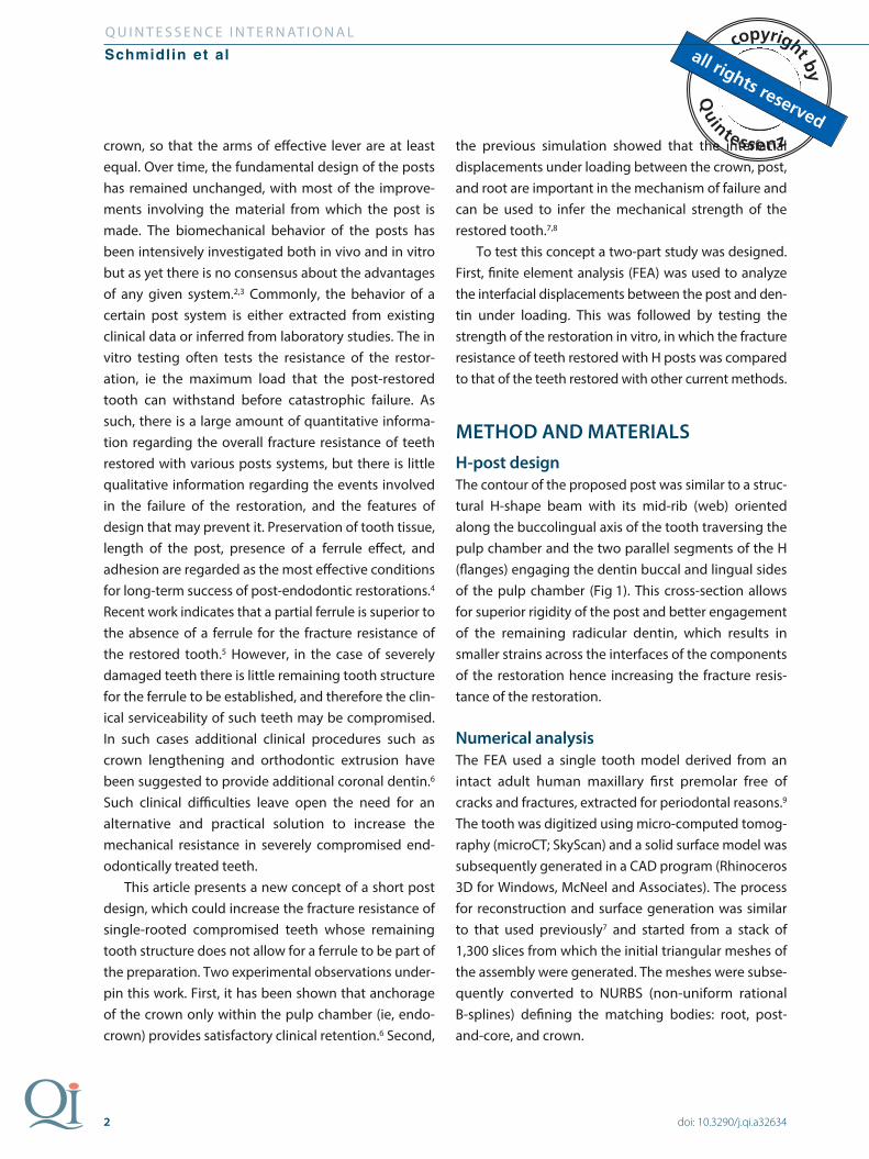
The contour of the proposed post was similar to a struc-tural H-shape beam with its mid-rib (web) oriented along the buccolingual axis of the tooth traversing the pulp chamber and the two parallel segments of the H (flanges) engaging the dentin buccal and lingual sides of the pulp chamber (Fig 1). This cross-section allows for superior rigidity of the post and better engagement of the remaining radicular dentin, which results in smaller strains across the interfaces of the components of the restoration hence increasing the fracture resis-tance of the restoration.
Numerical analysis
The FEA used a single tooth model derived from an intact adult human maxillary first premolar free of cracks and fractures, extracted for periodontal reasons.9 The tooth was digitized using micro-computed tomog-raphy (microCT; SkyScan) and a solid surface model was subsequently generated in a CAD program (Rhinoceros 3D for Windows, McNeel and Associates). The process for reconstruction and surface generation was similar to that used previously7 and started from a stack of 1,300 slices from which the initial triangular meshes of the assembly were generated. The meshes were subse-quently converted to NURBS (non-uniform rational B-splines) defining the matching bodies: root, post-and-core, and crown.
3
Q U I N T E S S E N C E I N T E R N AT I O N A L
Schmidlin et al
doi: 10.3290/j.qi.a32634
To account for the periodontal ligament, the digital model was completed by adding a material layer of 0.3-mm uniform thickness around the root, which stopped 2 mm below the cementoenamel junction (CEJ). The intra-alveolar portion was contained in a fixture to simulate the alveolar support.
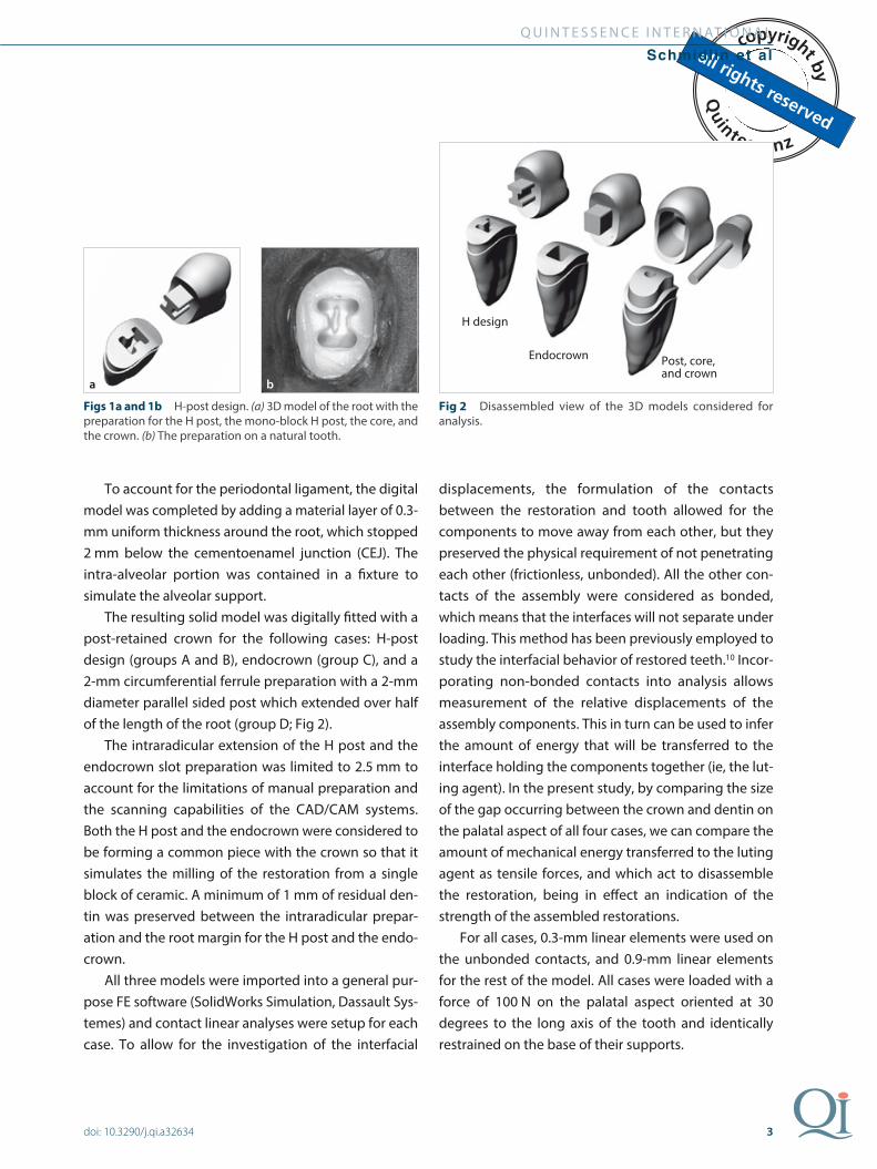
The resulting solid model was digitally fitted with a post-retained crown for the following cases: H-post design (groups A and B), endocrown (group C), and a 2-mm circumferential ferrule preparation with a 2-mm diameter parallel sided post which extended over half of the length of the root (group D; Fig 2).
The intraradicular extension of the H post and the endocrown slot preparation was limited to 2.5 mm to account for the limitations of manual preparation and the scanning capabilities of the CAD/CAM systems. Both the H post and the endocrown were considered to be forming a common piece with the crown so that it simulates the milling of the restoration from a single block of ceramic. A minimum of 1 mm of residual den-tin was preserved between the intraradicular prepar-ation and the root margin for the H post and the endo-crown.
All three models were imported into a general pur-pose FE software (SolidWorks Simulation, Dassault Sys-temes) and contact linear analyses were setup for each case. To allow for the investigation of the interfacial
displacements, the formulation of the contacts between the restoration and tooth allowed for the components to move away from each other, but they preserved the physical requirement of not penetrating each other (frictionless, unbonded). All the other con-tacts of the assembly were considered as bonded, which means that the interfaces will not separate under loading. This method has been previously employed to study the interfacial behavior of restored teeth.10 Incor-porating non-bonded contacts into analysis allows measurement of the relative displacements of the assembly components. This in turn can be used to infer the amount of energy that will be transferred to the interface holding the components together (ie, the lut-ing agent). In the present study, by comparing the size of the gap occurring between the crown and dentin on the palatal aspect of all four cases, we can compare the amount of mechanical energy transferred to the luting agent as tensile forces, and which act to disassemble the restoration, being in effect an indication of the strength of the assembled restorations.
For all cases, 0.3-mm linear elements were used on the unbonded contacts, and 0.9-mm linear elements for the rest of the model. All cases were loaded with a force of 100 N on the palatal aspect oriented at 30 degrees to the long axis of the tooth and identically restrained on the base of their supports.
Figs 1a and 1b H-post design. (a) 3D model of the root with the preparation for the H post, the mono-block H post, the core, and the crown. (b) The preparation on a natural tooth.
Fig 2 Disassembled view of the 3D models considered for analysis.
Post, core, and crown
Endocrown
H design
ba
4
Q U I N T E S S E N C E I N T E R N AT I O N A L
Schmidlin et al
doi: 10.3290/j.qi.a32634
All the materials were assumed as linear elastic. The root was considered as made out of dentin with an elastic modulus (E) of 15 GPa, and the ligament was simulated in a rubbery material with an E of 12 MPa.10 The H post and the endocrown were considered as monolithic units milled from glass-ceramic material with an E of 65 GPa.
For the ferrule case, the crown was considered as milled from the same glass-ceramic material, the posts was considered to be made of fiber-reinforced compos-ite with an E of 24 GPa,11 and the core as manufactured from hybrid composite with an E of 11 GPa. These ma-terial properties were chosen to reflect the experimen-tal setup, which will be used for the in vitro testing.
After running the analyses, the resulting displace-ments were measured as maximum displacement of the crown measured at the tip of the buccal cusp, the resulting displacement of the palatal margin of the crown, and the resulting displacement of the palatal dentin. All the displacements were collected as nodal values and represent the sum of the component dis-placements (x, y, z). The size of the palatal gap was determined by subtracting the displacement of the dentin from the displacement of the crown.
Furthermore, the principal tensile stresses produced in the restoration were also analyzed to identify the location of critical stresses in the restored tooth.
Evaluation of the fracture resistance
Forty extracted maxillary human premolars were selected, cleaned, and stored in 0.5% chloramine T (Sigma-Aldrich Laborchemikalien) at room temperature for a maximum of 7 days. Afterwards, they were stored in distilled water for a maximum of 6 months at 5°C until the experiments. All teeth had one radiograph-ically visible root canal, exhibited no visible signs of cracks, fractures, or root caries, and showed compara-ble diameters. Crowns were removed at the level of the CEJ, leaving roots of 10 ± 1 mm long. In ten teeth, crowns were removed 2 mm above the CEJ to allow additional space coronally for the circular preparation of a ferrule.
Teeth were root canal treated using Profile 0.4 (Dentsply). The working length was assessed with digi-tal X-rays (Digora). The master apical file was no. 35. No step-back procedure was performed. After each file, the canal was rinsed with sodium hypochlorite (3% w/v). After root canal preparation, the canals were dried with paper points no. 35 (Dr Wild & Co) and obturated with a single-cone technique using gutta-percha points no. 35 (Roeko). To ensure complete setting of the provi-sional material, all teeth were stored in a humidity chamber for 24 hours.
All roots were then covered with an air-thinned 0.2-mm layer of polyvinylsiloxane (President light, surface activated) to simulate a periodontal ligament. They were then centrally mounted with chemically cured resin (Paladur, Heraeus Kulzer) with a centering device (PPK). The distance between the CEJ and the resin was 2 mm.
Subsequently, all preparation steps were performed under fixation of the carriers in a parallelometer (PFG 100, Cendres & Metaux) and the roots were randomly assigned to one of the following four groups (N = 10 per group):• Groups A and B: the H-post• Group C: endocrown• Group D: control where the teeth were prepared
with a 2-mm ferrule and restored with fiber posts (Figs 3 and 4).
• Groups A and B (H-post): Teeth were prepared to receive a H-shape post with its web (3.4 mm) ori-ented along the bucco-oral axis of the tooth travers-ing the pulp chamber. The two parallel flanges of the H aimed to engage the dentin buccally and orally and were individually adapted to leave a minimal residual lateral dentin thickness of at least 1 mm. The depth of the cavity was 2.5 mm and the outline of the preparation was rounded to prevent stress concentrations on sharp corners as well as facilitating the milling (Figs 1 and 2). The only differ-ence between the groups A and B was the material out of which the restoration was milled: glass-ceramic for group A and lithium disilicate for
5
Q U I N T E S S E N C E I N T E R N AT I O N A L
Schmidlin et al
doi: 10.3290/j.qi.a32634
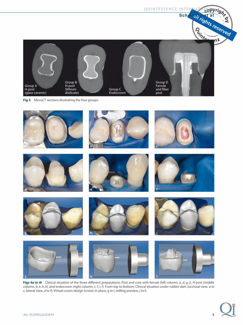
Fig 3 MicroCT sections illustrating the four groups.
Figs 4a to 4l Clinical situation of the three different preparations: Post and core with ferrule (left column, a, d, g, j), H post (middle column, b, e, h, k), and endocrown (right column, c, f, i, l). From top to bottom: Clinical situation under rubber dam (occlusal view, a to c; lateral view, d to f); Virtual crown design (crown in place, g to i; milling preview, j to l).
Group AH-post(glass-ceramic)
Group BH-post(lithium disilicate)
Group CEndocrown
Group DFerrule and fiber post
a
d
g
j
b
e
h
k
c
f
i
l
6
Q U I N T E S S E N C E I N T E R N AT I O N A L
Schmidlin et al
doi: 10.3290/j.qi.a32634
group B. Both materials were included in the study based on the FEA to avoid the premature fracture of the ceramic, and so that the geometry of the H-design could be isolated.
• Group C (endocrown, negative control group): The teeth were prepared with a round inlay cavity of 2.5-mm depth, which was limited to 1-mm resid-ual marginal dentin thickness.
• Group D (post and core, positive control group): 6-mm deep preparations for a glass fiber post (Endo Easy Efficient Yellow, VDW) were made in a slow-speed contra-angle handpiece. The canals were rinsed with tap water and an adhesive system (Adhese, Ivoclar Vivadent) was applied according to the manufacturer’s instructions. A self-curing resin luting material (Luxacore, DMG) was applied to the surface and brought into the prepared root canal with a no. 25 lentulo spiral (Maillefer). The glass fiber post was alumina powder air-abraded (50 μm; Benzer Dental) at 0.1 MPa pressure (Microetcher, Danville Engineering), silanized (Monobond-S, Ivo-clar Vivadent) for 60 seconds, covered with a thin film of bond, and inserted into the soft luting-com-posite-filled root canal. Excess material was removed with a probe before polymerization from the buccal and oral surfaces with a light gun (Blue-phase LED G2, Ivoclar Vivadent) for 60 seconds each. Filtek Supreme (3M ESPE) was then used immediately after post cementation as a composite material to build up a core, which was co-polymer-ized from the buccal and oral surfaces using the same polymerization device for 40 seconds each at 1200 mW/cm2. The core was prepared and finished in the parallelometer with tapered diamond burs under water-cooling. The ferrule height was 2 mm and the shoulder width was 0.8 mm. A minimal fer-rule thickness of at least 1 mm was maintained. The core build-up was standardized to a height of 5.5 mm in the fissure and 6.5 mm in the cusp region (distances measured from the shoulder).
The preparation surface area of the preparations of all groups was scanned (Cerec AC BlueCam, Sirona) after
application of a thin coating with scanspray (Scan’Spray, Dentaco), and measured as described ear-lier.12 The crowns’ geometry was standardized using correlation design mode (CEREC SW 3.80). Subse-quently, specimens of groups A, C, and D were restored with glass-ceramic crowns (IPS Empress CAD Multi LT A2/I12, Empress CAD HT B3/I12, Ivoclar Vivadent), whereas samples of group B were restored using a lithium disilicate ceramic (e.max CAD MO2/C14, Ivoclar Vivadent). Occlusal thickness in the main fissure was set to 1 mm and the luting space was set at 90 μm.
All root specimens were cleaned with water, tooth-paste (Signal AntiCaries, Elida Fabergé) and slowly rotating nylon brushes (Kerr). Preparations were care-fully refinished with 25-mm finishing diamond burs under water-cooling. Syntac Primer was applied for 15 seconds. After another 15 seconds, the primer was slightly dried. Syntac Adhesive was applied and slightly dried after 20 seconds’ penetration time. Heliobond was then applied and carefully thinned with air after a penetration time of at least 40 seconds. Care was taken to leave a very thin but intact film and to avoid any pooling, which would lead to an ill-fitting crown. The bonding agent was then polymerized occlusally for 60 seconds (Bluephase LED G2, Ivoclar Vivadent).
The glass-ceramic crowns of groups A, C, and D were etched with hydrofluoric acid for 60 seconds (Vita Ceramics Etch, Vita Zahnfabrik) and water-spray was applied for 40 seconds to avoid precipitation on the surface. The internal crown aspects were then silanized (Monobond-S, Ivoclar Vivadent). After 60 seconds, the solvent was air-dried and the surface was covered with a thin film of Heliobond (Ivoclar Vivadent), which was not polymerized separately. A restorative composite (Filtek Supreme, 3M ESPE) was filled into the crowns and carefully adapted to all surfaces/walls. The crowns were placed on their respective prepared teeth and brought to their end positions with ultrasound (SP Tip and Piezo-Master 400, EMS). The surplus composite was removed with a probe and after a final ultrasonic action, the composite was polymerized through the crown from all five aspects for 60 seconds each (Blue-phase LED G2, Ivoclar Vivadent). The small amount of
7
Q U I N T E S S E N C E I N T E R N AT I O N A L
Schmidlin et al
doi: 10.3290/j.qi.a32634
polymerized surplus composite was removed and the surface polished with Soflex discs of descending grain size at ×10 magnification. Specimens were stored for 24 hours in water at room temperature.
The lithium disilicate crowns were additionally crys-tallized using a Programat XP1 (Ivoclar Vivadent) oven for 5 minutes at 750°C plus 10 minutes at 850°C after the milling process. The prospective bonding surface was then air-abraded with 50 μm Al2O3 and a universal, single-component silane (Monobond Plus, Ivoclar Viva-dent) was applied for 60 seconds.
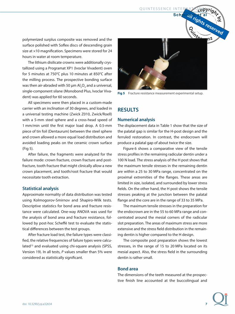
All specimens were then placed in a custom-made carrier with an inclination of 30 degrees, and loaded in a universal testing machine (Zwick Z010, Zwick/Roell) with a 5-mm steel sphere and a cross-head speed of 1 mm/min until the first major load drop. A 0.5-mm piece of tin foil (Dentaurum) between the steel sphere and crown allowed a more equal load distribution and avoided loading peaks on the ceramic crown surface (Fig 5).
After failure, the fragments were analyzed for the failure mode: crown fracture, crown fracture and post-fracture, tooth fracture that might clinically allow a new crown placement, and tooth/root fracture that would necessitate tooth extraction.
Statistical analysis
Approximate normality of data distribution was tested using Kolmogorov-Smirnov and Shapiro-Wilk tests. Descriptive statistics for bond area and fracture resis-tance were calculated. One-way ANOVA was used for the analysis of bond area and fracture resistance, fol-lowed by post-hoc Scheffé test to evaluate the statis-tical differences between the test groups.
After fracture load test, the failure types were classi-fied, the relative frequencies of failure types were calcu-lated13 and evaluated using chi-square analysis (SPSS, Version 19). In all tests, P values smaller than 5% were considered as statistically significant.
RESULTS
Numerical analysis
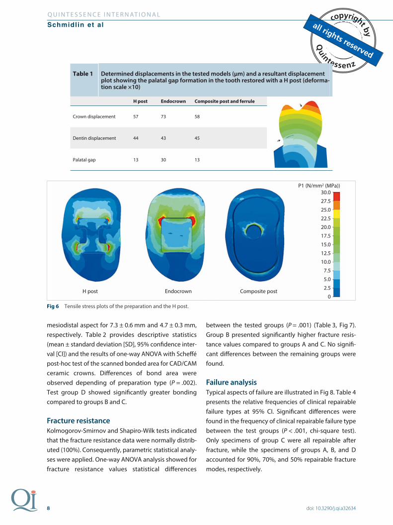
The displacement data in Table 1 show that the size of the palatal gap is similar for the H-post design and the ferruled restoration. In contrast, the endocrown will produce a palatal gap of about twice the size.
Figure 6 shows a comparative view of the tensile stress profiles in the remaining radicular dentin under a 100 N load. The stress analysis of the H post shows that the maximum tensile stresses in the remaining dentin are within a 25 to 30 MPa range, concentrated on the proximal extremities of the flanges. These areas are limited in size, isolated, and surrounded by lower stress fields. On the other hand, the H post shows the tensile stresses peaking at the junction between the palatal flange and the core are in the range of 33 to 35 MPa.
The maximum tensile stresses in the preparation for the endocrown are in the 55 to 60 MPa range and con-centrated around the mesial corners of the radicular slot preparation. The areas of maximum stress are more extensive and the stress field distribution in the remain-ing dentin is higher compared to the H design.
The composite post preparation shows the lowest stresses, in the range of 15 to 20 MPa located on its mesial aspect. Also, the stress field in the surrounding dentin is rather small.
Bond area
The dimensions of the teeth measured at the prospec-tive finish line accounted at the buccolingual and
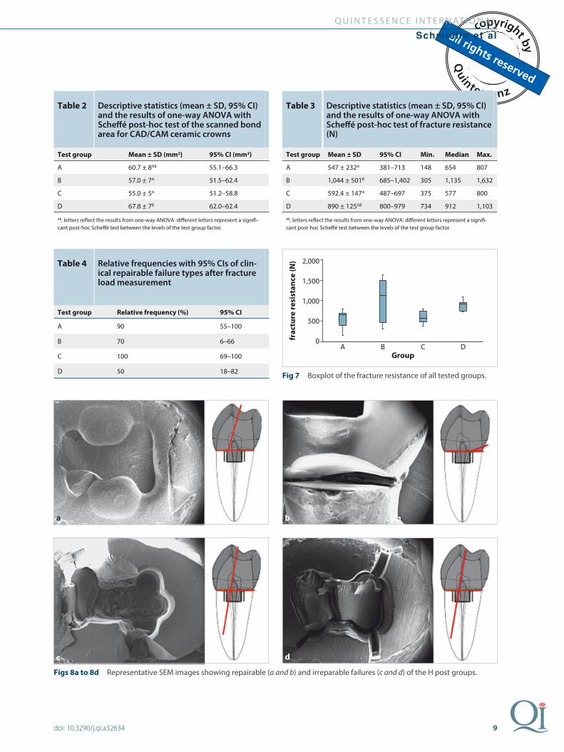
mesiodistal aspect for 7.3 ± 0.6 mm and 4.7 ± 0.3 mm, respectively. Table 2 provides descriptive statistics (mean ± standard deviation [SD], 95% confidence inter-val [CI]) and the results of one-way ANOVA with Scheffé post-hoc test of the scanned bonded area for CAD/CAM ceramic crowns. Differences of bond area were observed depending of preparation type (P = .002). Test group D showed significantly greater bonding compared to groups B and C.
Fracture resistance
Kolmogorov-Smirnov and Shapiro-Wilk tests indicated that the fracture resistance data were normally distrib-uted (100%). Consequently, parametric statistical analy-ses were applied. One-way ANOVA analysis showed for fracture resistance values statistical differences
between the tested groups (P = .001) (Table 3, Fig 7). Group B presented significantly higher fracture resis-tance values compared to groups A and C. No signifi-cant differences between the remaining groups were found.
Failure analysis
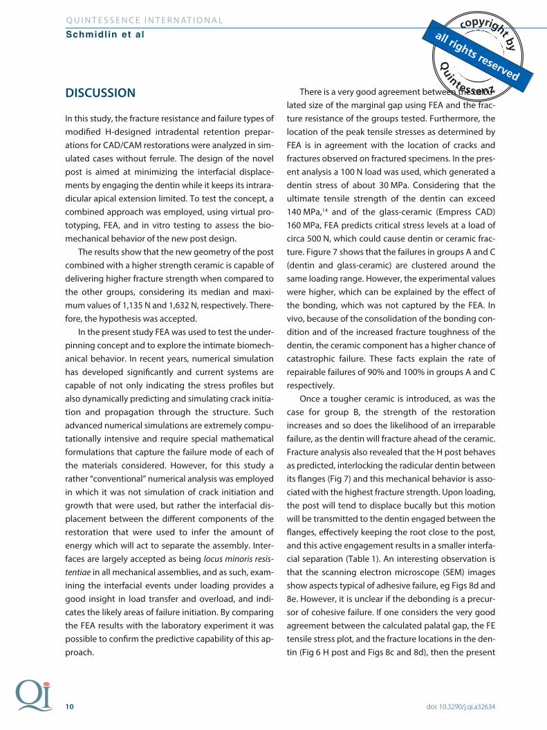
Typical aspects of failure are illustrated in Fig 8. Table 4 presents the relative frequencies of clinical repairable failure types at 95% CI. Significant differences were found in the frequency of clinical repairable failure type between the test groups (P < .001, chi-square test). Only specimens of group C were all repairable after fracture, while the specimens of groups A, B, and D accounted for 90%, 70%, and 50% repairable fracture modes, respectively.
Fig 6 Tensile stress plots of the preparation and the H post.
Table 1 Determined displacements in the tested models (μm) and a resultant displacement plot showing the palatal gap formation in the tooth restored with a H post (deforma-tion scale ×10)
H post Endocrown Composite post and ferrule
Crown displacement 57 73 58
Dentin displacement 44 43 45
Palatal gap 13 30 13
H post
30.0
27.5
25.0
22.5
20.0
17.5
15.0
12.5
10.0
7.5
5.0
2.5
0Endocrown
P1 (N/mm2 (MPa))
Composite post
9
Q U I N T E S S E N C E I N T E R N AT I O N A L
Schmidlin et al
doi: 10.3290/j.qi.a32634
Fig 7 Boxplot of the fracture resistance of all tested groups.
Table 2 Descriptive statistics (mean ± SD, 95% CI) and the results of one-way ANOVA with Scheffé post-hoc test of the scanned bond area for CAD/CAM ceramic crowns
Test group Mean ± SD (mm2) 95% CI (mm2)
A 60.7 ± 8AB 55.1–66.3
B 57.0 ± 7A 51.5–62.4
C 55.0 ± 5A 51.2–58.8
D 67.8 ± 7B 62.0–62.4
AB, letters reflect the results from one-way ANOVA: different letters represent a signifi-cant post-hoc Scheffé test between the levels of the test group factor.
Table 3 Descriptive statistics (mean ± SD, 95% CI) and the results of one-way ANOVA with Scheffé post-hoc test of fracture resistance (N)
Test group Mean ± SD 95% CI Min. Median Max.
A 547 ± 232A 381–713 148 654 807
B 1,044 ± 501B 685–1,402 305 1,135 1,632
C 592.4 ± 147A 487–697 375 577 800
D 890 ± 125AB 800–979 734 912 1,103
AB, letters reflect the results from one-way ANOVA: different letters represent a signifi-cant post-hoc Scheffé test between the levels of the test group factor.
2,000
1,500
1,000
500
0A B C D
fra
ctu
re r
esi
sta
nc
e (
N)
Group
Table 4 Relative frequencies with 95% CIs of clin-ical repairable failure types after fracture load measurement
Test group Relative frequency (%) 95% CI
A 90 55–100
B 70 6–66
C 100 69–100
D 50 18–82
Figs 8a to 8d Representative SEM images showing repairable (a and b) and irreparable failures (c and d) of the H post groups.
a
c
b
d
10
Q U I N T E S S E N C E I N T E R N AT I O N A L
Schmidlin et al
doi: 10.3290/j.qi.a32634
DISCUSSION
In this study, the fracture resistance and failure types of modified H-designed intradental retention prepar-ations for CAD/CAM restorations were analyzed in sim-ulated cases without ferrule. The design of the novel post is aimed at minimizing the interfacial displace-ments by engaging the dentin while it keeps its intrara-dicular apical extension limited. To test the concept, a combined approach was employed, using virtual pro-totyping, FEA, and in vitro testing to assess the bio-mechanical behavior of the new post design.
The results show that the new geometry of the post combined with a higher strength ceramic is capable of delivering higher fracture strength when compared to the other groups, considering its median and maxi-mum values of 1,135 N and 1,632 N, respectively. There-fore, the hypothesis was accepted.
In the present study FEA was used to test the under-pinning concept and to explore the intimate biomech-anical behavior. In recent years, numerical simulation has developed significantly and current systems are capable of not only indicating the stress profiles but also dynamically predicting and simulating crack initia-tion and propagation through the structure. Such advanced numerical simulations are extremely compu-tationally intensive and require special mathematical formulations that capture the failure mode of each of the materials considered. However, for this study a rather “conventional” numerical analysis was employed in which it was not simulation of crack initiation and growth that were used, but rather the interfacial dis-placement between the different components of the restoration that were used to infer the amount of energy which will act to separate the assembly. Inter-faces are largely accepted as being locus minoris resis-tentiae in all mechanical assemblies, and as such, exam-ining the interfacial events under loading provides a good insight in load transfer and overload, and indi-cates the likely areas of failure initiation. By comparing the FEA results with the laboratory experiment it was possible to confirm the predictive capability of this ap-proach.
There is a very good agreement between the calcu-lated size of the marginal gap using FEA and the frac-ture resistance of the groups tested. Furthermore, the location of the peak tensile stresses as determined by FEA is in agreement with the location of cracks and fractures observed on fractured specimens. In the pres-ent analysis a 100 N load was used, which generated a dentin stress of about 30 MPa. Considering that the ultimate tensile strength of the dentin can exceed 140 MPa,14 and of the glass-ceramic (Empress CAD) 160 MPa, FEA predicts critical stress levels at a load of circa 500 N, which could cause dentin or ceramic frac-ture. Figure 7 shows that the failures in groups A and C (dentin and glass-ceramic) are clustered around the same loading range. However, the experimental values were higher, which can be explained by the effect of the bonding, which was not captured by the FEA. In vivo, because of the consolidation of the bonding con-dition and of the increased fracture toughness of the dentin, the ceramic component has a higher chance of catastrophic failure. These facts explain the rate of repairable failures of 90% and 100% in groups A and C respectively.
Once a tougher ceramic is introduced, as was the case for group B, the strength of the restoration increases and so does the likelihood of an irreparable failure, as the dentin will fracture ahead of the ceramic. Fracture analysis also revealed that the H post behaves as predicted, interlocking the radicular dentin between its flanges (Fig 7) and this mechanical behavior is asso-ciated with the highest fracture strength. Upon loading, the post will tend to displace bucally but this motion will be transmitted to the dentin engaged between the flanges, effectively keeping the root close to the post, and this active engagement results in a smaller interfa-cial separation (Table 1). An interesting observation is that the scanning electron microscope (SEM) images show aspects typical of adhesive failure, eg Figs 8d and 8e. However, it is unclear if the debonding is a precur-sor of cohesive failure. If one considers the very good agreement between the calculated palatal gap, the FE tensile stress plot, and the fracture locations in the den-tin (Fig 6 H post and Figs 8c and 8d), then the present
11
Q U I N T E S S E N C E I N T E R N AT I O N A L
Schmidlin et al
doi: 10.3290/j.qi.a32634
data suggest that adhesive failure of the cement, partial or total, precedes cohesive failure of the other compo-nents, ie dentin or ceramic. This correlation further validates the predictive FEA method employed.
The scattering of the results for group B can be explained by the role played by the bonding layer, the individual variability of the fracturing properties of the human dentin, and increased incidence of small imper-fections which act as stress concentrations resulting from the manual preparation of the H slot. It is reason-able to assume that a more standardized preparation with a closer internal fit will help to reduce scattering of the data. Furthermore, in the present study single-rooted maxillary premolars were used, which seem to be more susceptible to root fractures when submitted to occlusal loading.15 Normally, loading forces at 45 degrees are applied; these are associated with more unfavorable stresses during function and are consid-ered the worst-case scenario with regard to the fracture resistance. In the present study, however, the samples carrier was studied at an inclination of 30 degrees.15 This must be taken into consideration when comparing the results of different studies. It may also explain why Zicari et al15 previously found lower fracture resistance ranging between 400 N and 550 N when using RelyX Unicem or Panavia P2.0 for the cementation of 5 mm and 7.5 mm glass-fiber posts in specimens. Their speci-mens also had no ferrule preparation. Another factor that may have led to this discrepancy is that the authors of the latter study submitted their teeth to additional chewing simulation, which was not the case in the present set-up. Differences in the adhesive ma-terials may also contribute to different results. It must be highlighted as a limitation of the present study that lithium disilicate ceramic material was not used in groups C and D as well. In using a ceramic material with a higher fracture toughness such as lithium disilicate, it was possible to isolate the structural effects of the H-design and this is shown by the increase in the num-ber of irreparable fractures in group B. Considering that the aim of the present study was to analyze primarily the effects on the H-shape of the post, the use of lith-ium disilicate for groups C and D was not warranted. It
is reasonable to consider that an increase in the frac-ture toughness of the ceramic will result in an increase in the number of irreparable fractures for group C. This inference is supported by the relative frequencies of reparable fractures, which are very close when glass-ceramic is used (90% and 100% for groups A and C re-spectively) and then drop to 70% in group B when lithium disilicate is employed (Table 4).
The present results show that the mode of failure of the restored tooth is ultimately influenced by the frac-ture strength of the ceramic. For this study, homoge-nous materials (glass-ceramics and lithium disilicate) were used, and a higher fracture strength of the H post resulted in a stronger restoration.
Novel hybrid ceramics such as resin nanoceramics (eg, LAVA Ultimate)16 or interpenetrating network ceramics (eg, VITA Enamic)17,18 show good flexural strength with elastic modulus values in the range of the natural tooth substance. Such hybrids are emerging as alternative materials for milled restorations, offering a combination of high fracture strength and low elastic modulus. Whilst their flexural strength is situated in the same range as that of the homogenous ceramics used in the present study, the failure mechanism is signifi-cantly different because of the crack-stopping features embedded within the material. As such, the results of the present study are not directly transposable to these materials; although we can safely suggest that the local environment is favorable for the crack to initiate, it can-not be assumed that this will lead to catastrophic fail-ure as is the case with homogenous ceramics. Addition-ally, the damping provided by their low elastic modulus coupled with their inherent crack resistance may pro-vide better resistance to separation. Therefore, such materials could be an interesting subject for further research.
An important point to make is the innovative profile of the present study, in which we have taken a concept, tested it numerically, used the numerical data to select the material, and tested it in vitro, showing the validity of the process and how engineering methods can be successfully applied in dentistry.
12
Q U I N T E S S E N C E I N T E R N AT I O N A L
Schmidlin et al
doi: 10.3290/j.qi.a32634
It must be mentioned, however, that no thermo-mechanical loading was applied in the present feasibil-ity study. The impact of thermocycling and mechanical stress on the retention strength and the fracture behav-ior play an important role in long-term predictability. Therefore, the results must still be considered with cau-tion, and more research is justified on this clinically rel-evant topic.
In terms of clinical application, this design can con-stitute a valid clinical solution, particularly in those cases where a ferrule cannot be placed, crown length-ening is impractical, or obstructions of the root canal prevent an adequate apical extension of a conventional post. Because of its lightweight design it is also conser-vative and allows for preservation of the tooth struc-ture, whereas to achieve a similar stiffness, a cylindrical post would require a uniform radius, which may be clinically impossible to achieve without massive dentin removal. Furthermore, the restoration can be com-pleted in one appointment providing that a CAD/CAM system is readily available.
The shape of the preparation is simple, and can be completed using a normal high-speed handpiece with an appropriate diameter cylindrical bur. The minimal dentin depth of the preparation (only about 2 mm) allows for direct vision control so that parallelism can be easily achieved.
For the preparation, the web (ie, the horizontal com-ponent of “H”) should be aligned with the buccolingual bending axis of the tooth. The flanges (ie, the vertical components of the “H”) should be positioned as far buc-cally and lingually as possible. This is based on the ana-lytical solutions of the bending of beams, in which the location of the flanges should be too far away from the neutral axis (ie, mesiodistal axis of the tooth) to increase the resistance to bending. In positioning the flanges buccally and lingually away from the neutral axis, a minimum of 0.5 mm sound dentin should be left between the flanges and the margin of the preparation. We would recommend for 1 mm or more of sound den-tin to circumscribe the preparation and for at least 1 mm of dentin to be “caught” between the flanges to allow for sufficient resistance. The thickness of the H
should be at least 0.5 mm to allow for milling and/or casting. For finishing, the outline of the preparation should be rounded to prevent stress concentrations.
CONCLUSION
The present study tested the hypothesis that a short post with a modified design can deliver improved mechanical behavior in severely compromised end-odontically treated teeth. It was shown that a short H-shape post in a non-ferruled preparation increases the fracture strength of the restoration. As mentioned, further work is needed to properly explore the bio-mechanical behavior of the modified post, but within the limitations of the study it can be concluded that an H-shape post may constitute a viable alternative to res-toring severely compromised teeth.
ACKNOWLEDGMENT
The authors thank Ms Beatrice Sener for her invaluable help in the la-
boratory.
REFERENCES 1. Morgano SM. Restoration of pulpless teeth: application of traditional princi-
ples in present and future contexts. J Prosthet Dent 1996;75:375–380.
2. Al-Ansari A. Which type of post and core system should you use? Evid Based
Dent 2007;8:42.
3. Bolla M, Muller-Bolla M, Borg C, et al. Root canal posts for the restoration of