132
WWW.RADiOSCAMATORUL.Hi2.RO WWW.GiURUMELE.Hi2.RO
| Date post: | 23-Mar-2023 |
| Category: |
Documents |
| Upload: | khangminh22 |
| View: | 0 times |
| Download: | 0 times |
WWW.RADiOSCAMATORUL.Hi2.RO
WWW.GiURUMELE.Hi2.RO
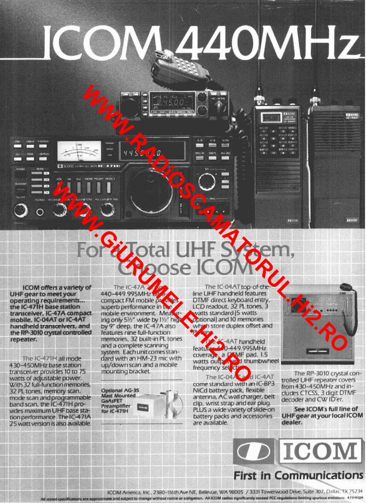
ICOM offen a varlety af UHF gearto meet your operating requiremen ts... the IC-471H base natlon transceiver, IC47A compact mobile, IC-MAT or IC-4AT handheld tramcehrerr, and the RP-3010 crystal controlled repeater.
79.- JC-P-7'LI all mode 430-450MHz base station transcerver provrdes 10 to 75 warn of aqustable power. Wrth 32 full-funaton memories, 31 PL tones, memory scan, mode scan and programmable band scan, the IC-471 H pro- wdes maxrmum UHF base st* tion performance. The IC471A
The IC-47A ZS watt 440-449.995MHz ultra- compact FM mobile provides superb performance in the mobile environment. Measur- ing only 5'12" wide by 1k5" high by 9 deep, the IC-47A also features nine full-function memories, 32 built-in PL tones and a complete scanning system. Each unit comesstan- dard with an HM-23 mic with up/down scan and a mobile mounting bracket.
Optlow1 AG-35 -v Mast Mounted - ' - F GaAsFET PrearnplMer for IC-471H
' 7 4 1;' . I ,,I
The IC-04AT top-of-the- line UHF handheld features DTMF direct keyboard entry, LCD readout. 32 PL tones, 3 watts standard (5 watts optronal) and 10 memories which store duplex offset and PL tone.
The IC-4AT handheld features 440-449.995MH.z coverage. a DTMF pad, 1.5 watts output and thumbwheel frequency selectron.
The IC-O4AT and IC-4AT come standard with an IC-EP3 NiCd battery pack, flexible antenna, AC wall charger, belt clip, wrist strap and ear plug. PLUS a wide variety of slrdeon battery packs and accessories
j I_____: The RP-3010 crystal con-
trolled UHF repeater covers from 430450MHz and In- cludes CTCSS, 3 d~grt DTMF decoder and CW ID'er.
See ICOM's full llne of UHFgearatyour local ICOM
25 k t t version isalx, available. - are available. dealer.
First in Communications ICOM America. Inc.. 2380-116thAvc NE. Bellevue. WA 98005 / 3331 Towrwood Drive, Suite 307, Dallac. TX 75234
NI SUW ~ ~ w C R l o n ~ are appmdnwnr and nmJm m dwngewimoul mtlre orobllpatbn. AJI ICOM radhn ~lpnlflonny e r e K C mqulstlon1 llmlnng Ipw(ou1 cmluDnl. 471Ul IM
WWW.RADiOSCAMATORUL.Hi2.RO
WWW.GiURUMELE.Hi2.RO
ABOVE.
Now Mobile Operators Can Enjoy An Affordable -m _I.
Personal Phone Patch. , ' /-,.. ..
I... ... .. 7 , - , .. -
\IIIII<BIII nn c'x(>snsi\,r - . . .- - r6.l)c.dtvr. . A i l \ i ~ ~ q altv l.'M tra~i(-c,ivrr , r -I : . . . . . . .
, . . .- as .I haw .ir.~linn. . . I,.. E - . I C = I n g n I-
* 'Ihv wr r r~ t is GI SIMPI.t<X . . . . ......... ..-. - arl~~,patrli. Thv SMART PAJC! I .
SMART PATCH I s Easy To Install 1 1 , i r i \ ~~ t l l SMART PATCH. ronsivc t t l i v ~ i ~ ~ l l t ~ r ~ ~ l ~ ~ r v d comptlter 5tvlv ribbon rnhlp to litic. ,111dit1. recvi~cr diw-n~,~inatt~r. I'm. and ptru,vr A ~~~udul; i r phunr cltrd i, ~)r,~vidc.cl k ~ r rcm. 11t~ctio11 v a ~ ~ r pIi1111e sv+
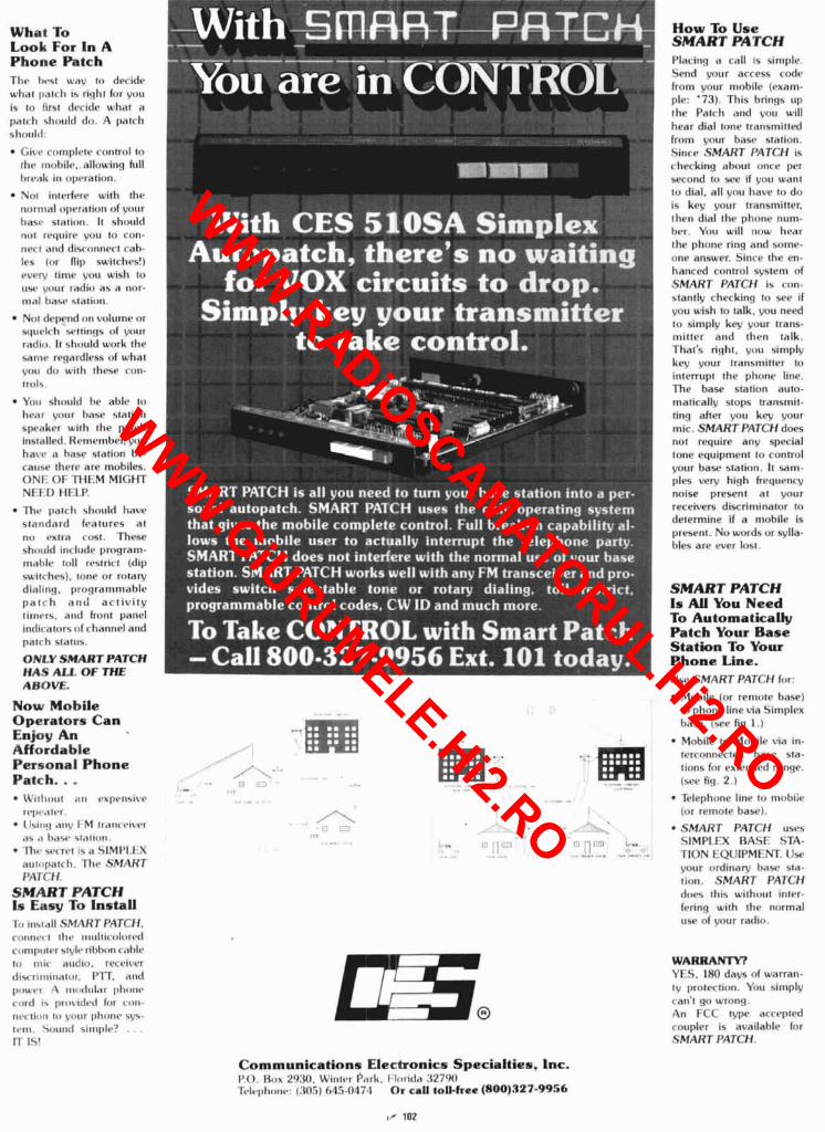
SMART PATCH I'lac.i~iq n cdll 1s simple. S~.lid y(111r access C I ~ P
from your mohilr (exam- ple: '73). This brings up the Patch and VOII will hear dial tone transmind from your basr station. Since SMART PATCH is checking ahout onre p ~ r second to see if you want to dial. all you have to dci is key your transminer, then dial the phone num- hrr. You will now l i rar the phone ring and some- one answer. Since the en- hanced control system of SMART PATCH is con. stantlv checking to see if vo11 wish to talk. vou need to simply key your trans- mitter and then talk. That's right, ynu simply key your transminer to interrupt the phone line. 7 h e base station auto- matically stops transmit- ting after you key p u r mic. SMART PATCHdoes not require any special tone equipment lo control your base station. It Sam- ples vey high hequvncy noise present at your receivers discriminator to determine if a mohile is present. Nu wnrds or sylla- hles are ever lost.
SMART PATCH I s All You Need To Automatically Patch Your Base Station To Your Phone Line. ( l w SMART PATCH for:
Mohilr (or reniote haw) 111 phone line via Simplex base. (see fig I.)
Mobile to Mnhile via in- trrrt~nnected hase sta- tions kjr extend^-d range. (we fig. 2.) Telephone line to ninhiie (or remote base).
SMART PATCH uses SIMPLFX RASE STA- TION EQUIPM1:M. Use your t~rdinarv hase sla- tion. SMART PATCH dws thi5 u,ith<~ut inter- Cring with the normal use of v o ~ ~ r radio.
WARRANTY? Y t \. IHO days of warran- l y protection. You simply can't go wrong. An FCC I~IP accepted co~~pler is available h ~ r SMART PATCH.
Communications Electronics Specialties. Inc. lp.O. l3ox 20:iO. h'intvr l'klrk. l.l,~ritl<~ : i27W Tc~lul)li,~~~c~: 1:105) 045-047.1 Or call toll-hee (800)327-9956
WWW.RADiOSCAMATORUL.Hi2.RO
WWW.GiURUMELE.Hi2.RO
---m n p n / . .Ba - .- 9 - - '* - 'd --
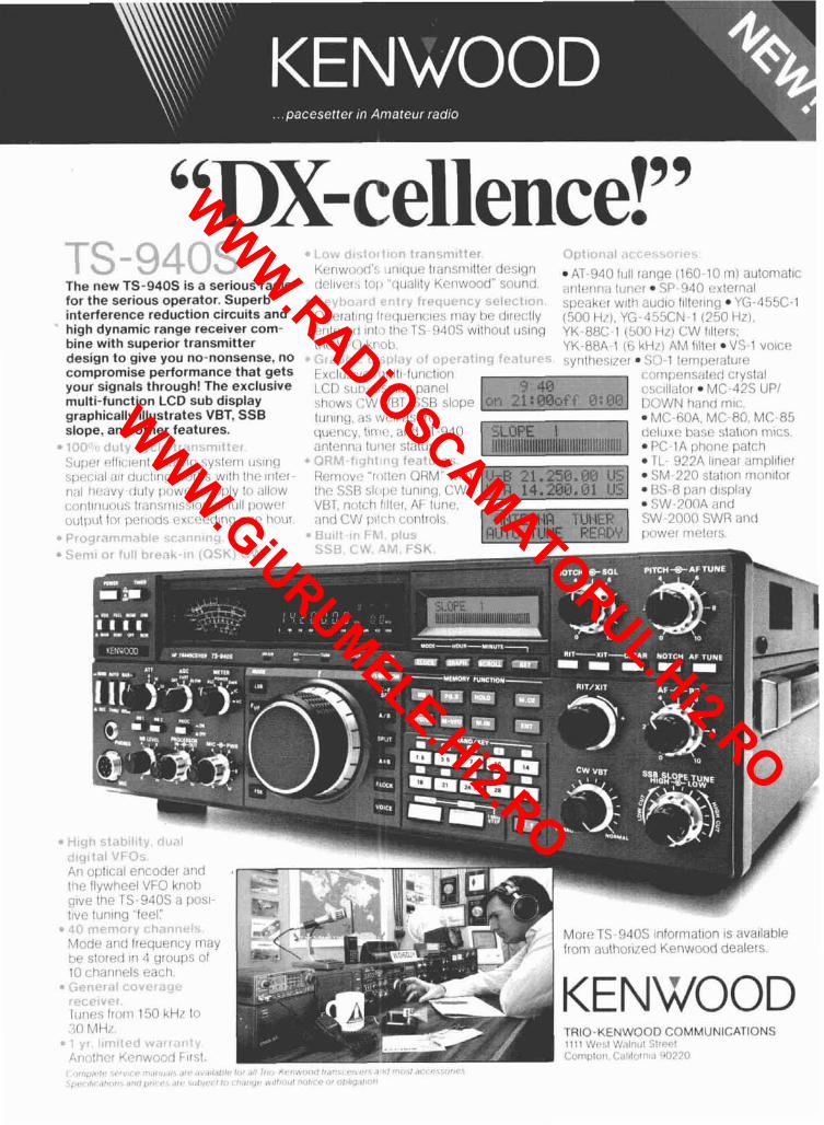
The new TS-940s is a serious radio for the serious operator. Superb interference reduction circuits and high dynamic range receiver com- bine with superior transmitter design to give you no-nonsense, no compromise performance that gets your signals through! The exclusive multi-function LCD sub display graphically illustrates VET, SSB slope, and other features.
, . > + .-.,
SLI~PI cfl~~..~ent c:r~ol~ric] system Irslncl s[~rcr:~;~l ;III dcrctin(l works w ~ l h thc 1r1lr.r - n;11 hf!;~vy-rlllty ~iowc'r ~l l [>[?ly lo ;lIlirw c:onllrruolls Irnnsnr~sslnrl at flrll ~!owcr orl l l) i~l lor l>crrotts c:xt:r?t?ding ant! hoerr.
" P!,:cl[Jf: rI>:!t!!, C ~ , . ! , r t , 1 1 : '
* 1 , , ; , ,-.I . ' I , ' r < n i!;!nc:n~~!tt.r Krnwtwd': llnlcllrr? lransni~tter des~gn drbl~vf!r, lo11 ,c l~~ ;~ l~ ty Krnwood" sorund.
* , : . . , , I , , , .:!,,,, f ~ , . [ ~ l ! ~ ~ l , ~ : " ';Pt,~~:!!<O!..
Opr?ralin(~ Ir!.!rluencres may he d~rectly entered rill'> 111~: TS- 940s wllho~rl lrslng lh(? VFO kr~~citl.
?. #G, z r . : : ! #; I .,:;I;.\, ~ ~ : - r ~ ? r n f ) ! ~ : q t u r : ,~<
Exclusrvc r~ i~~l l~- fcrnc l~on 1.CD sui7-dsl1lay panel show:; CW VliT. SSB slope lunlng, as wt?ll ;is frc- quc:ricy. l ~ n ~ t ~ , and AT-940 nnl(?nn;l IU!~PI sl;tlus
* ,-;?','! f ,-I!,+ fo,-,~l.~r~c,. Rer~iov., "rollon ORM" w~th t l i? SSE sll>ri(? lun~nrl, CW VCIT, nc.,lcti frllor, AF Iirne. ;rricl CVJ 1111r.l) controls.
" P! ; l l ' 81 F ? , ; r~l~l:,
C)l,'li,l,;'i ! - :- . .... , . . ~
AT-940 fcrll range (160-10 rn) automatlc antrr1n;i ttrncr SP-940 cxlernal speakvr w~ th nucllo f~ller~ng YG-455C-1 (500 H,,). YG -455CN-1 (250 HZ). YK-88C-1 (500 H r ) CW frllers; YK-88A-1 (6 kHr) AM (~Iter .VS-1 voice synthr:slzrr SO-1 Ic?my~eralure
conipcns;iled crystal osc~llritor MC-42s UP1 DOWN hand rn~c.
MC-GOA. MC-80. MC-85 tieluxc h;lsc> stallon niics.
P C ~ l A phone patch TL- 922A l~near anipl~t~er SM-220 slat~on rnon~tor BS-8 pan d~sp l i~y SW-20OA and
SW-2000 SWR and power mrters.
WWW.RADiOSCAMATORUL.Hi2.RO
WWW.GiURUMELE.Hi2.RO
'ow. Japi All sut
ham
magazine
contents 12 2-meter transmitter uses Weaver
modulation Norm Bernstein, Nl COX
21 VCO tunes from 1800-2600 MHz Hans Roensch, WBDTV
32 trade off power for antenna gain at VHF? Lynn A. Gerig, WASGFR
40 a 432-MHz, 1500-watt amplifier F. J. Merry, W2GN
51 micros and VHF beacons transmit messages automatically Jim Grubbs, K9EI
59 ham radio techniques Bill Orr, WGSAI
67 the weekender: a 50-500 MHz dual wattmeter Bob Lombardi, WB4EHS
75 wideband logarithmic detector Hans Evers, PABCXIDJBSA
86 VHFIUHF world Joe Reisert, WlJR
125 the Guerri report Ernie Guerri, W6MGI
126 advertisers index 111 new products and reader service 6 presstop
10 comments 5 reflections 100 DX forecaster 74 short circuits 122 flea market 8 spectrum 116 ham mart chart
July 1985 3
WWW.RADiOSCAMATORUL.Hi2.RO
WWW.GiURUMELE.Hi2.RO
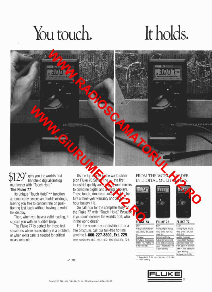
You touch. It holds.
$129* gets you the world's first handheld digital/analog
multimeter with "Touch Holdl' The Fluke 77
Its unique "Touch Holdn** function automatically senses and holds readings, leaving you free to concentrate on posi- tioning test leads without having to watch the display.
Then. when vou have a valid readina, it
It's the top model in the world cham- pion Fluke 70 Series line - the first industrial quality autoranging muitimeters to combine digital and analog displays. These tough, American-made meters fea- ture a three-year warranty and 2000+ hour battery life.
So call now for the complete story on the Fluke 77 with "Touch Holdl' Because if you don't deserve the world3 first, who
FROM TI IN DIGIT
-1E WORLD X L MULTI!
LEADER VIETERS.
".
signals you w i t i an audible beep. inathe world does? FLUKE 73 FLUKE 75 FLUKE 77 The Fluke 77 is perfect for those test For the name of your distributor or a s:+ I , l . $., ,. , 2 ; L , I, A " I ,,I 4 . h A,, .. .? ,A?, 0, - situations whereaccessibility is a ~roblem, free brochure, call our loll-free hotline ,,, ,.,,;, ,,. ',,,.,.I ,,:,' ,! ,,,,, j ,,,'Oz
or when extra care is needed for critical anytime 1-800-227-3800, Ext. 229. fl,,"l? l<S, ,!,,Mb I,"<
h l l i r a liitilihe $lrnllnillty Ai!i18blv r*lllrmlb
measurements. ~ m m outside the u s.. 1211 1-402-496-1350. EX!. 229. or;,. lXcdcmlrxy A1ll.lrilllgil (dnyhnld -rtfi1,I illlllt lundlon 7m1 . IINII MIIA~ 1111 n ,>'. L L ~ , , . ,I ,tr,t~fao, IIIIIIII <VXE. r,inpl h , ~ 3 ~:II w~rrrn? Pn.8 . I,,IL,, r u ~ ~ m i r * o <" I,!'. 6, ~ r i ~ ~ t q
Cmyrlght iZ) 1W Jnhn Fluke Mfg Co Inc All r~ghr, m v l d M th 4701 77 8
WWW.RADiOSCAMATORUL.Hi2.RO
WWW.GiURUMELE.Hi2.RO

need we be concerned? I have a nasty habit. I'm an inveterate reader. You could almost say I'm compulsive about it. I read everything that comes across my desk and have a library - both at ham radio and at home - that for volume, rivals anything else I own. To me, it's just as enjoyable to read little tidbits here and there as it is for other people to have those little in-between-meal snacks. But a strange thing happens to you in the process of reading everything you can lay your hands on. You start to see correlations between supposedly independent facts or events.
Before you read the next paragraph, please understand that I've only begun to delve into this issue, and that what I'm about to say has potential for causing alarm. At ham radio, we believe that writers and editors are ethically obliged to thoroughly research every story before a drop of ink is spread. But now - given the seriousness of the news, and the credibility of the sources - I'm going to bypass that fundamental principle of responsible journalism and call your attention to a potentially widespread and significant hazard.
A small article that originally appeared in a recent issue of Broadcasting was picked up and retrans- mitted by the W5YI Report of May 15. What caught my eye was an item about a series of complaints filed by residents living near Seattle's Cougar Mountain. Their concern was with "excessive exposure to RF non-ionizing radiation resulting from 21 towers housing FM broadcasi, microwave, and two- way communications antennas."
"So what," you say, "We've all heard, one time or another, about the danger of exposure to fields in excess of 10 milliwatts/cm2." The important point in W5Ylfs story was that "a growing number of scientific studies suggest the possibility of cell damage even without a recognizable rise in body temperature." Until now, I was under the impression that for damage to occur, a rise in temperature also had to occur.
Continuing on the same subject, W5YI noted another story that appeared in the April 27th issue of Science News, in which a Washington State epidemiologist reported "a provocative study linking death from leukemia with employment in professions that suggested possible exposures to high elec- tric and magnetic fields." According to W5YI, the study of 546 New Zealanders identified as leukemia patients found "a significant excess of leukemias among electrical workers and radioltelevision repairers."
A third story cited, among hams diagnosed as having a particular form of leukemia (myeloid), a higher incidence of mortality than found among members of the general public with the same disease.
There are those who'll say that statistics can be presented to prove any contention, and maybe that's so. But I do seem to recall that the Soviets have a much lower acceptable limit for non-ionizing radiation: approximately 100 microwattslcm2.
Perhaps this would be a good time to re-examine the amount of radiated power from that unbalanced transmission line, single-wire feed antenna, or close-by antenna. Using a backwards argument, maybe there's even some good sense in placing your antenna higher, on a taller tower. Doing this certainly won't hurt its performance.
Let me assure you that this isn't just a thinly veiled attempt on my part to influence you all to go QRP so my puny signal will be more competitive . . . it's an attempt to call your attention to a serious matter that will be discussed more fully as more information becomes available.
Rich Rosen, K2RR Editor-in-Chief
July 1985 5
WWW.RADiOSCAMATORUL.Hi2.RO
WWW.GiURUMELE.Hi2.RO

GREATLY EXPANDED NOVICE PRIVILEGES WERE PROPOSED by ARRL's Executive Committee at its May meeting in Rochester. Basically, the committee recommended giving Novices both phone and digital privileges on three bands, two of them UHF. Perhaps the most significant element of the proposal is the addition of both phone and digital communications privileges on 10 meters. There the Novice band would become 28.1-28.5 MHz, with the bottom 200 kHz for RTTY, AMOR, and packet as well as CW and the 28.3-28.5 MHz slot SSB and CW only (to pre- clude use of converted AM CB radios). Under the present rules Technicians would also gain 10 meter privileges along with Novices; power for both would remain 200 watts out but that limit wouldn't apply to others. One important problem the expansion would cause is with the 10-meter beacon band, now 28.2-28.3 MHz; some possible alternatives for beacon operators were also discussed.
On UHF The Conunittee Recommended Giving Novices Full Privileges on the entire 220 MHz band and 1246-1260 MHz. They'd be permitted to use but not put up repeaters. Power output for Novices would be limited to 25 watts on the 220-MHz band. and 5 watts on 23 cm. The new privileges would require some expansion of the Novice exam questions; already licensed Novices would, of course, be grandfathered into the new modes and bands.
At Presstime This Is Still Only An Executive Committee Proposal for the League Board of Directors to review, then aaopt or reject. However, the concept of expanding Novice privi- leges as a means of making the entry level license more attractive has seen increasing sup- port inside as well as outside the League for some time. In addition, FCC Special Services Chief Ray Kowalski indicated at Dayton that the Commission was also looking with favor toward a more attractive Novice license package.
If The Directors Do Vote In Favor Of Increasin Novice Privile es, look for the ARRL to file a Petition for Rule Making to the Comnissiongvery s o o d t h e future of the 220 MHz band is still under a cloud, the League's proposal will probably be worded in such a way that the FCC can leave that band out of any resulting NPRM if it so chooses.
ALL VECS ARE INVITED TO GETTYSBURG AUGUST 8, when the FCC will host a familiarization meeting for them. Purpose of the all-day session is to permit the VEC representatives and the FCC people they work with to meet each other face to face, so both can better appreci- ate the problems each has with the program and the Licensing system. Particular attention is planned for paperwork errors; though some VECs are very good, a survey of April applica- tions showed almost two-thirds of one VEC's submissions had significant errors! Timeliness is still another problem that's to be addressed at the meeting, with some VECs chronically late in submitting their exam session results.
THE SPACE SHUTTLE'S PRIME AMATEUR BAND DOWNLINK FRE UENCY will be 145.55 MHz, and at nresstime Launch was still schedured for Julv 15. Ama?eur o~eration could occur as early r~ - - - - - ~~- -- ~ ~. -- .- - - -
as Mission Day Two, though expectations~ are that little, if iny, of ~ ~ O R E ' S or W4NYZ1s -
time on the air will be devoted to unscheduled two-way QSOs. They will be doing a good deal of work by prearrangement with various schools and clubs, however, and hope to provide live or pre-recorded SSTV downlink signals during periods when they can't be on themselves.
RTTY, FAX, AND SSTV WERE ALL AUTHORIZED ON 160 METERS effective June 17. In its Report and Order on PR Docket 84-959. the FCC decided to ~ermit the use of all three modes across the entire band, but cautioned that introduction o> the new modes does not temper the possible reallocation of 1900-2000 kHz to radiolocation in Docket 84-874.
THE INDUSTRY GROUP THAT'S BEEN WORKING ON AMATEUR RADIO'S FUTURE had its second meeting in zyton, the Thursday night before the Hamvention. ~ b o u t m s t r y representatives attended and heard the7tasE force leaders report considerable progress on various promo- tional efforts. Travis Brann, WA5RGU, of Kantronics, succeeded Mike Lamb of AEA as de fact0 group chairman for the next quarter; Joe Schroeder, W9$UV, will continue to act as secretary/ treasurer for the time beine. A delegation from the group is scheduled to meet with Senator ., . ~arry Goldwater, K7UGA, forva briefini in early June.
The First Attempt At Implementing One Of The Group's Proposals Appears to have met with some success at the Rochester Hamfest in May. A good number of the free tickets sent to area junior hinh and hiah school teachers for distribution to interested students were used, and special booths aimea at entry level prospects were reported to be very popular.
The Average Age Of New Amateur Licensees In April was 36, the FCC determined after analyz- ing the approximately 2200 applications from never-before licensed applicants it received that month. The oldest was 82, the youngest 7, and the median age 35.
SOME FOUNDATIONS FOR A NATIONAL REPEATER COORDINATION SYSTEM were laid during the course of several well-attended meetings at Dayton. The first, organized by W8JRL (Ohio) and WBBUPM (Michigan), discussed the relative merits of 15 vs 20 kHz channel spacing, while the second was on the FCC's national repeater coordinator proposal, PR Docket 85-22. At that meeting ARRL Hudson Division Vice Director WA2DHF reported tentative League agreement to fund a computer system and incoming WATS line for coordinator use, and to publish a coordin- ator's newsletter. At the third session the consensus seemed to favor a "confederation" of area coordinators rather than a single national coordinator.
6 July 1985
WWW.RADiOSCAMATORUL.Hi2.RO
WWW.GiURUMELE.Hi2.RO
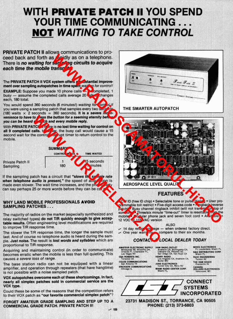
WITH PRIVATE PATCH II YOU SPEND YOUR TIME COMMUNICATING.. . NOT WAITING TO TAKE CONTROL
PRIVATE PATCH II allows communications to pro- ceed back and forth as rapidly as on a telephone. There is no waiting for sampling circuits to acquire each time the mobile transmits.
The PRIVATE PATCH II VOX system offers a substantial Improve ment over sampllng autopatches in tlme spent waiting for control! EXAMPLE: Suppose you made 10 phone calls - 9 completed, 1 busy - assume the completed calls average 20 talk exchanges each, 180 total. You would spend 360 seconds (6 minutes!) waiting for control if you were using a sampling patch that samples every two seconds (180 waits x 2 seconds = 360 seconds). It Is a severe Incon- venience to have to press the button tor a seeming eternity before you can be heard on each and every moblle reply. With PRIVATE PATCH II there is no lost tlme waltlng for control on all 9 completed calls. However, the busy call would cause a 15 second wait for the control interrupt timer to return control to the mobile.
SUMMARY CONTROL W A m TIME WAmD
Private Patch II Sampling
1 15 seconds 180 6 minutes
If the sampling patch has a circuit that "slows the sample rate when telephone audio is present," the speed of acquisition is made even slower. The wait time increases, and the phone party can say perhaps 25 or more words before they can be cut off.
THE SMARTER AUTOPATCH - -
FEATURES
WHY LAND MOBILE PROFESSIONALS AVOID CW ID (free ID chlp) Selectable tone or pulse dialing User prc- SAMPLING PATCHES.. . grammable toll restrict Five digit access code Ringback (reverse
patch) Busy channel rlngback inhibit (will not transmit on top of
The majority of radios on market (especially synthesized and someone) Threelsix minute "time-out" timer is resettable from the mobile Modular phone jack and seven foot cord Available in
relay switched types) do not TIR quickly enough to give accep 12 VDC or VAC version table results. Often engineering level modifications are required to improve TIR response time.
ALSO @ 14 day return prlvllege - when ordered factory dlrect.
The slower the TIR response time, the longer the sample must One year warranty - compare to their six months. last. And of course no telephone audio is heard durlng the sam- ~ l e . Just nolse. The result is lost words and syllables which are CONTACT A LOCAL DEALER TODAY proportional to TIR response. Acquiring and maintaining control (in order to communicate) becomes erratic when the mobile is less than full quieting. This causes a severe loss of range. The base station radio can not be equrpped with a linear amplifier, and operation through repeaters (that have hangtime) is not possible with a noise sampled patch. VOX autopatches overcome each of these shortcomings. In tact, nearly all simplex patches sold In commercial service are the VOX type. Could these be some of the reasons that the competition refers to their VOX patch as "our favorlte cammerclal simplex patch"?
AYCTNR ELECTRONIC SUPPLY N U Uffl OUM YMES ELECTllONlQ M I I W ~ U ~ W wt. wtckllne OH. ah^^^ U. B ~ ~ ~ ~ ~ . ~ . c A . FI Laudmdale. M I ~ I FL Orlando FI. Cleawaler F L Oakland CA. PMsnlx A 2 La9 V e w a N V
Sari D,eOo Van NLO MSTRlBUTlHG CORP. Miam, FL
U A ROBERTS INC. HENRY RADIO PACE ENGINEERING Torrance U LOS Anoeler C&. Anahelm CA. I , , ~ ~ ~ ~ ~7
Butler MO ---. -
COLES COMMUNlCAnONS Ssn Antonlo TX JUNS ELECTROII(QI
THE HAM SHACK Evan.1~8lle IN
ERICUSON C o M M w h x n o N S C"I"*' C1'Y CA. Reno NV Chmcepo IL Y l l Y l RAOlO CENTER COW. F$kD ELE~RONICS
Mcam, FL. Vancouver BC
/ CONNECT SYSTEMS
INCORPORATED FORGET AMATEUR GRADE SAMPLING AND STEP UP TO A 23731 MADISON ST., TORRANCE, CA 90505 COMMERCIAL GRADE PATCH. PRIVATE PATCH II! PHONE: (21 3) 373-6803
i/ 1m
WWW.RADiOSCAMATORUL.Hi2.RO
WWW.GiURUMELE.Hi2.RO

Frequency Spectrum Chart NOT TECHNICIAN LICENSEES how, pr8vnlrqo of 011
AVAILABLE Cw Iovrce frequenc,es plus Llenerol hrqvcnc#es
REPEITER PHONE """" "" ""' CW prrrnrfled on oi l frrqurncles ovo~ lob l r I0
OSCAR P,"p,": b m v tho1 Itcensr
'ehkbv8 June 17, 1985 RTIY FAX, and SSN modes also 8vaBblB
I I_ J 14 0 14 1 I4 I50 14 2 14 3 I4 35
I I I I I I L \ \ \ \ \ l \ \ \ \ \ I \ \ \ \ \ \ I \ \ \ \ \ \ ~ \ \ \ \ \ L \ \ \ \ \ Y \ \ \ \ \ ' L \ \ \ \ \ ~
4 18066 18 168
t [ NOT VET AUTHORIZED 1 210 21 I el n er 3 21 4 el 4 s
L I I 1- I \ \ \ \# \ \ \ \ l \ \ \ \ ' c \ \ \ \ ' \ \ \ \ ' g \ \ - \ \ l \\\\'\\u 24 09 24 93 PI es
I 1 I I P\\\'\\h\\\\\\'.~\\\\\'\'~\\\\\\".\\\'\\\'k'\\"\u PB o 28 3 28 s PO o 2 9 3 2 9 5 ~ es68 297
[ I 1 I \ \ \ \ ' \ \ \ \ l ' \ \ \ \ k \ \ \ \ ~ \ \ \ \ L \ \ \ \ '\\\\l\\\\'\\\\'.\\\\h)\\L\\\\\I\\\\ '\--J 5 0 0 50 I 51 0 52 0 53 0 64 0
144 0
3 3 3523 3 6 3 7 3 750 3 775 3 8 3 9 4 0
- I 1 II\\~\\\'\\\''\\\"\\\\~\\\"\\"\\\~\\\~ '\U 7 0 7025 7 I 7 I50 7 2 7 3
I I 1 I L\\\\\\h\\\\\\l\\\\> I0 I0 10 I25 10 15
I I I 1 4 0 re oea 14 I I4 I50 14 176 14 2 14 3 14 35
I I ? _ _ - - - \ - U 0
18068 18 168 Z NOT YCT AUTHORIZED I 9 21 0 21 021 21 I 21 2 21 225 21 3 21 4 21 43
---A- -.i-TX . L - ~-m\\\'\\\\"\\\\'\\\\~\\\\~\\\\'\\\\~\\\w 24 8 9 24 93 24 99
I I I I ..............................................
rsos8 18 168 u [ NOT rET AUTHOR1ZEO 1 a 210 21 oes 21 I 21 e P I 3 2 1 . ZI 43
I --L-_- -\\\"\\\\j.\\'Ts-T-
24 8 0 24 9s 9 4 9 s
I I I I P\\ \ \ \ \r \ \ \ \ \ \ \ .~ \ \ \ \ \ \ \b\ \ \ \ \ \ \ \a \ \ \ ' \ \ ' \h\ \""' l
8 July 1985 'G Copyrqht 1885. Ham Radm Maparlne
WWW.RADiOSCAMATORUL.Hi2.RO
WWW.GiURUMELE.Hi2.RO
WWW.RADiOSCAMATORUL.Hi2.RO
WWW.GiURUMELE.Hi2.RO
active antenna Dear HR:
The article in May, 1985, issue of ham radio on active antennas ("Active Antenna Covers 0.5-30 MHz," by Peter Bertini, KIZJH) was interesting but contained no evaluative data. Your readers might be interested in knowing that an evaluation of SIN performance of active antennas was published by Radjy & Hansen in the March, 1979, IEEE Transactions on Antennas and Propagation, Vol, AP-27, pages 259- 261. SIN degradation occurs over the upper part of the HF band where ex- ternal noise reduced by the impedance ratio is less than preamp noise. This degradation is aggravated by large design bandwidth since that requires a large impedance ratio.
Robert C. Hansen Tarzana, California
On-the-air support Dear HR:
I agree that we need an aggressive Junior High ham radio program - but we need actual on-the-air support just as badly, or maybe even more so.
A year and a half ago I was working with a 14-year old and a 13-year old. Those kids picked up code so fast I couldn't believe it. They were doing
great on element 2. They weren't in- terested in Novice tickets - they wanted General Class licenses, and with some on-the-air support they would have made it.
I loaned them each a transceiver (Sans finals - hi!) so they could look around the bands for something of in- terest to them. I looked for contacts I thought would be interesting to them. They worked many contacts on my rig looking for teenage support. They didn't call it that, but follow-up conversations made it obvious they couldn't find anyone on the air that shared any interests with them.
Needless to say, we - the ham world - lost two bright youngsters for what I believe was lack of interesting QSOs for two teenagers. . . . Both of them turned to computers. About 300,000 people live in our metro area, so they now find lots in common with other kids on their computer nets. They're also interested in interfacing music synthesizers with their computers.
I've tried to get them back into Amateur Radio, but I can't compete with their age group. . . .
We're friends, and the three of us play golf together. I have a feeling that when they can beat me at golf, they'll be off to greater challenges - but for now, we share that interest.
Any ideas on how to hold their inter- est? The neighborhood is full of young- sters coming into their teens, and I'm willing to try again if all of us will try to share their interests when they're on the air.
Ken Uthus, Kl7E Nine-Mile Falls, Washington
CQ DXRC? Dear HR:
I was very pleased to see your com- ments on courteous practices and the "rubber stamp" QSO ("Reflections," March and April, 1985). What made me lose interest years ago and still threatens is the fact that in any DX QSO, even from New England to Europe, which is a very solid circuit on almost any band with favorable propa-
gation, you rarely find a conversation longer than a minute. Now I don't knock awards and contests - to each his own - but to me the fact that I have the capability, with my rig, and knowledge to exchange meaningful information with individuals in foreign countries is the most exciting and in- teresting aspect of Amateur Radio.
I don't ever wish to monopolize a DX station's attention when others are calling. But there have been many, many times I have worked a DX sta- tion who cut it very short only to call "CQ DX USA" two or three times be- fore getting another QSO. This is frus- trating to me, because my own defini- tion of "rare DX" is the guy, wherever he is, who's willing to ragchew for a few minutes.
I suggest this happens because there is so much contest and certifi- cate operation that the short QSO habit develops. Is there a way we can encourage both domestic and foreign stations to chew the fat for a few minutes when there aren't any pile-ups happening? Perhaps a new general call, like "CQ DXRC," which would imply that the caller isn't looking for the rare prefix, but rather a little inter- national fellowship instead.
Anyway, I sure would like to see some movement in the direction of some of us getting to know each other, and I believe it can be done without jeopardizing the DX operators who are looking for their country totals. So often, in routine conditions, there are lots of Europeans working lots of Americans and nobody is find- ing out anything except "579 name is Bob tks 73 gb. . . . ,I
David Lewis, KAlKFC (ex WA2ZQU)
OSCAR 10 Dear HR:
Many thanks for publishing "A PSK Telemetry Demodulator for OSCAR 10" (April, 1985, page 50). Why, I wonder, has it taken so long for this to appear in an Amateur publication?
Stephen E. Bach. AA4B Scottsville, Virginia
10 July 1985
WWW.RADiOSCAMATORUL.Hi2.RO
WWW.GiURUMELE.Hi2.RO
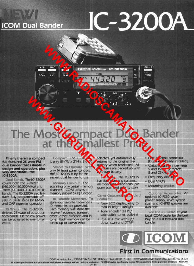
Flnally there's a compact full featured 25 watt FM dual bander that 's slmple In deslgn and operation, plus v e y affordable ... the IC- 20oA.
C:~a~i?;.v@s. The IC-3200A covers both the 2-meter (140.000-150.000MHz) and 70cm (440.000-450.000MHzJ bands. The IC-3200A also fea- tures fulfy programmable off- sets in 5KHz steps for MARS and CAP repeater operation.
25 M/,-tts. The IC-3200A delivers 25 warn of output on both bands. Or the low power can be adjusted to one to ten watts.
Compaa. The IC-3200A selected, yet automatically 6 One antenna connector is only 5K"W x 2"H x 8%"D. returns to the original fre- (Duplexer already installedl)
quency when reselected. All @ Variable tuning increments Simple to Operate. With are backed up with only 14 fmnt panel controls, a lithium battery,
5 and l5KHz (2-meters)
the IC-3200A is by far the 5 and 25KHz (70cm)
easiest dual bander to use. Sr;rnn!.r~. The IC-3200A @ Frequency dial lock
5.4emo1y Lockout. For scanning onty certain memry channels, ICOM utilizes a memory skip (M SKIP] function.
10 Tun~hle Memories. To store your favorite frequencies. 10 memories are provided. Each memory will store the receive frequency, transmit offset, offset direction and PL tone. Each memory can be tuned up or down when
has four scanning systems ... memory scan, band scan, pro- gram scan and priority scan.
Ottler Ocrstandiaq Staqc'?rci Fe;rh.tre?: e New LCD display, easy to
read in bright sunlight Tone encoder (all PL/ subaudible tones built-in) - IC-HM14 mic with up/ down scan and DTMF
B: Dual VFO's * Mounting bracket
,?nr i .3~,-~ ~;C-FCZOVI.R:. An optional IC-PS30 system power supply, mice synthe- sizer and IC-SPIO speaker are available.
SPP the r~-17?0fi at your local ICOM dealer for the best buy on a full featured dual bander.
First in Communications ICOM America, lnc, 2380-116th Ave NE. Bellevue. WA 98004 / 3331 T o w e r w m d Drive, Suite 307. Dallas. TX 75234
All Ntcd ~p+lflotlom a n appoxl- n d wbJm m rhanpc wlthoul mtlcr w obllgmlon. All ICOM rrdlol dpnlnumly crcccd FCC regulaVom lmltlng ~prrloul cmhllora. 32-5 / 111
WWW.RADiOSCAMATORUL.Hi2.RO
WWW.GiURUMELE.Hi2.RO
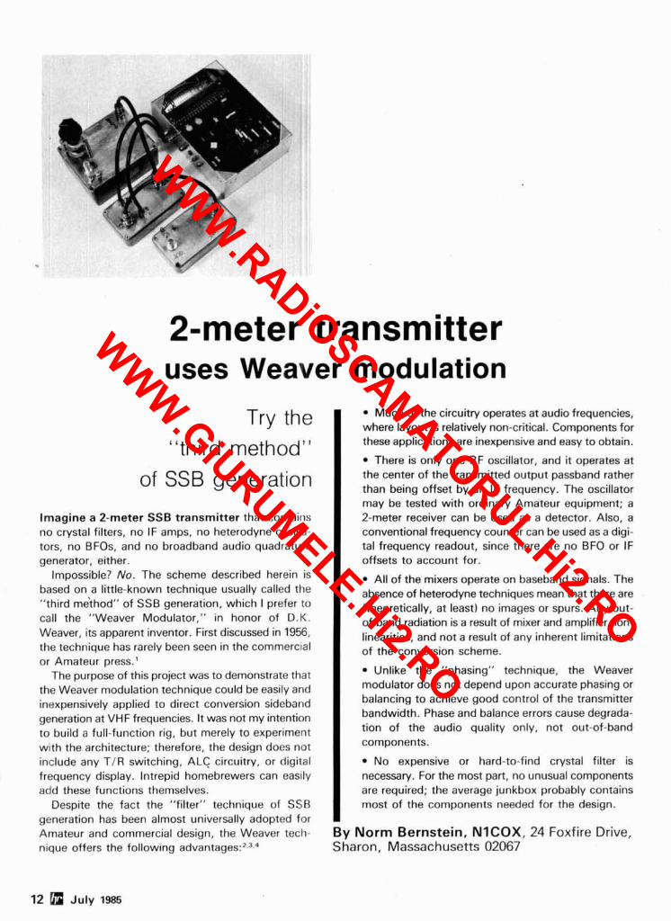
2-meter transmitter uses Weaver modulation
Try the "third method"
of SSB generation
Imagine a 2-meter SSB transmitter that contains no crystal filters, no IF amps, no heterodyne oscilla- tors, no BFOs, and no broadband audio quadrature generator, either.
Impossible? No. The scheme described herein is based on a little-known technique usually called the "third m6thod" of SSB generation, which I prefer to call the "Weaver Modulator," in honor of D.K. Weaver, its apparent inventor. First discussed in 1956, the technique has rarely been seen in the commercial or Amateur press.'
The purpose of this project was to demonstrate that the Weaver modulation technique could be easily and inexpensively applied to direct conversion sideband generation at VHF frequencies. It was not my intention to build a full-function rig, but merely to experiment with the architecture; therefore, the design does not include any TIR switching, ALC circuitry, or digital frequency display. Intrepid homebrewers can easily add these functions themselves.
Despite the fact the "filter" technique of SSB generation has been almost universally adopted for Amateur and commercial design, the Weaver tech- nique offers the following advantage^:?,^.^
Much of the circuitry operates at audio frequencies, where layout is relatively non-critical. Components for these applications are inexpensive and easy to obtain.
There is only one RF oscillator, and it operates at the center of the transmitted output passband rather than being offset by an IF frequency. The oscillator may be tested with ordinary Amateur equipment; a 2-meter receiver can be used as a detector. Also, a conventional frequency counter can be used as a digi- tal frequency readout, since there are no BFO or IF offsets to account for.
All of the mixers operate on baseband signals. The absence of heterodyne techniques mean that there are (theoretically, at least) no images or spurs. Any out- of-band radiation is a result of mixer and amplifier non- linearities, and not a result of any inherent limitations of the conversion scheme.
Unlike the "phasing" technique, the Weaver modulator does not depend upon accurate phasing or balancing to achieve good control of the transmitter bandwidth. Phase and balance errors cause degrada- tion of the audio quality only, not out-of-band components.
No expensive or hard-to-find crystal filter is necessary. For the most part, no unusual components are required; the average junkbox probably contains most of the components needed for the design.
By Norm Bernstein, NICOX, 24 Foxfire Drive, Sharon, Massachusetts 02067
12 July 1985
WWW.RADiOSCAMATORUL.Hi2.RO
WWW.GiURUMELE.Hi2.RO
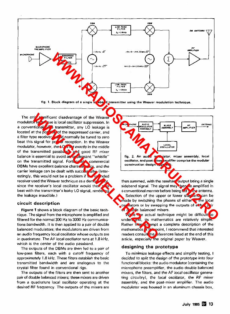
he only significant disadvantage of the Weaver modulator technique is local oscillator suppression. In a conventional SSB transmitter, any LO leakage is located at the position of the suppressed carrier, and a filter type receiver would normally be tuned to zero beat this signal for proper reception. In the Weaver modulator, however, the LO is set exactly in the middle of the transmitted passband, and good RF mixer balance is essential to avoid an unpleasant "whistle" on the transmitted signal. Fortunately, commercial DBMs have excellent balance characteristics, and the carrier leakage can be dealt with successfully. (Inter- estingly, this would not be a problem if the intended receiver used the Weaver technique as a demodulator, since the receiver's local oscillator would then zero beat with the transmitter's leaky LO signal, rendering the leakage inaudible. )
OEM 08Y
LOW PASS FILTER
circuit description
Figure 1 shows a block diagram of the basic tech- nique. The signal from the microphone is amplified and filtered for the normal 300 Hz to 3000 Hz communica- tions bandwidth. It is then applied to a pair of double balanced modulators; the modulators are driven from an audio frequency local oscillator whose outputs are in quadrature. The AF local oscillator runs at 1.8 kHz, which is the center of the audio passband.
The outputs of the DBMs are then fed to a pair of low-pass filters, each with a cutoff frequency of approximately 1.8 kHz. These filters establish the basic transmitted bandwidth and are analogous to the crystal filter found in conventional rigs.
The outputs of the filters are then sent to another pair of double balanced mixers; these mixers are driven from a quadrature local oscillator operating at the desired RF frequency. The outputs of the mixers are
PY ANTENNA
RF AMPLIFIER
tc = r.ernz
- ANTENNA *
fig. 2. An audio modulator, mixer assembly, local oscillator, and post mixer amplifier comprise the modular construction design approach.
J
MICROPHONE PREAMPLIFIER
then summed, with the resultant output being a single sideband signal. The signal may then be amplified in a conventional manner before being fed to the antenna.
Selection of the upper or lower sideband can be made by switching the phases of either of the local oscillators or by swapping the outputs of either pair of double balanced mixers.
While the actual technique might be difficult to understand, its mathematics are relatively simple. Rather than attempt a complete description of the mathematics at this point, I recommend that interested readers consult the references listed at the end of this article, especially the original paper by Weaver.
/ . e r n , LO' 144.15- r 4 4 . 3 o u n ~ L o '
designing the prototype
I , e r n t 2 0 . 1 4 4 . 1 5 - 1 4 4 . 3 0 ~ n t
MICROPHONE dANOPASS FILTER
3 0 0 - 3 k M
To minimize leakage effects and simplify testing, I decided to split the design of the prototype into four functional blocks: the audio modulator (containing the microphone preamplifier, the audio double balanced mixers, the filters, and the AF local oscillator genera- ting circuitryl, the local oscillator, the RF mixer assembly, and the post-mixer amplifier. The audio modulator was housed in an aluminum chassis box,
LOW PASS FILTER
1, = , .e rn* z DBM DEW
fig. 1. Block diagram of a single sideband transmitter using the Weaver modulation technique.
-
July 1985 13
WWW.RADiOSCAMATORUL.Hi2.RO
WWW.GiURUMELE.Hi2.RO
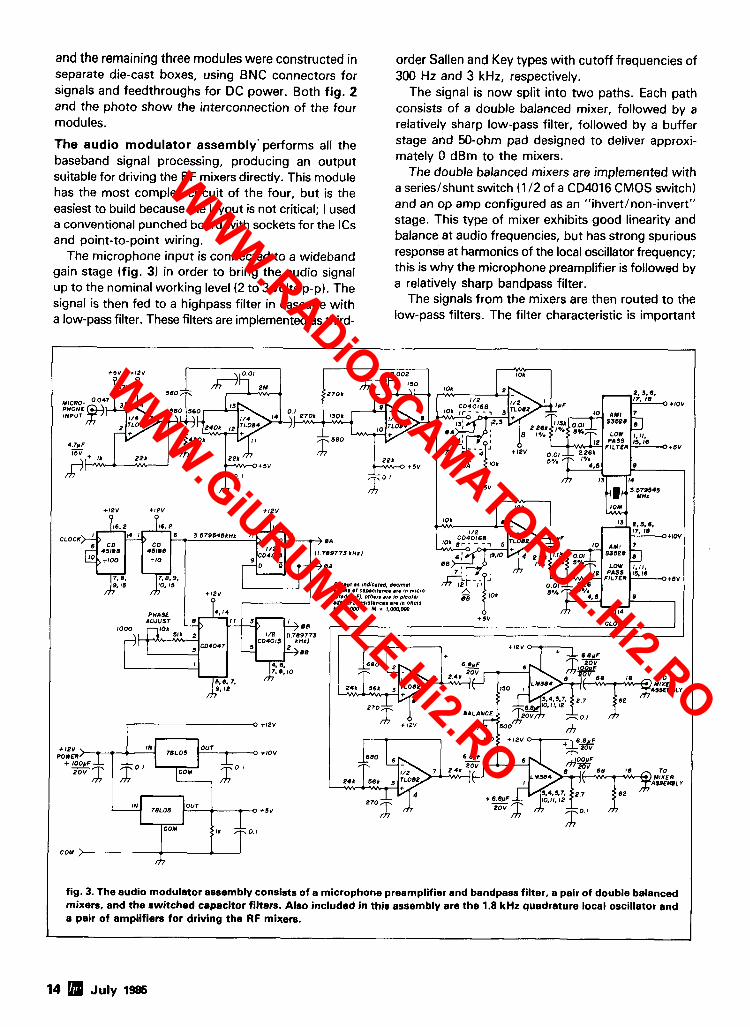
and the remaining three modules were constructed in separate die-cast boxes, using BNC connectors for signals and feedthroughs for DC power. Both fig. 2 and the photo show the interconnection of the four modules.
The audio modulator assembly'performs all the baseband signal processing, producing an output suitable for driving the RF mixers directly. This module has the most complex circuit of the four, but is the easiest to build because the layout is not critical; I used a conventional punched board with sockets for the ICs and point-to-point wiring.
The microphone input is connected to a wideband gain stage (fig. 3) in order to bring the audio signal up to the nominal working level (2 to 3 volts p-p). The signal is then fed to a highpass filter in cascade with a low-pass filter. These filters are implemented as third-
order Sallen and Key types with cutoff frequencies of 300 Hz and 3 kHz, respectively.
The signal is now split into two paths. Each path consists of a double balanced mixer, followed by a relatively sharp low-pass filter, followed by a buffer stage and 50-ohm pad designed to deliver approxi- mately 0 dBm to the mixers.
The double balanced mixers are implemented with a serieslshunt switch (1 I 2 of a CD4016 CMOS switch) and an op amp configured as an "ihvertlnon-invert" stage. This type of mixer exhibits good linearity and balance at audio frequencies, but has strong spurious response at harmonics of the local oscillator frequency; this is why the microphone preamplifier is followed by a relatively sharp bandpass filter.
The signals from the mixers are then routed to the low-pass filters. The filter characteristic is important
fig. 3. The audio modulator assembly consists of a microphone preamplifier and bandpass filter. a pair of double balanced mixers, and the switched capacitor filters. Also included in this assembly are the 1.8 kHz quadrature local oscillator and a pair of amplifiers for driving the RF mixers.
14 5 July 1986
WWW.RADiOSCAMATORUL.Hi2.RO
WWW.GiURUMELE.Hi2.RO
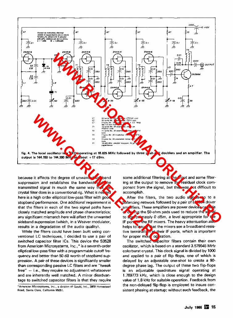
L I 33 turns No. 24 enameled. Fr5O-61 core 12 35 turns No 24 enameled. T50-6 core L3 4 turns No. I 8 Ilnned. 114" ID x 112'' long
tap I12 turn from cold and TI 12 turns No. 30 enameled. Infilar on
FT50-67 core 72 11 lurnr No. 30 enameled. tn41ar an r37.6
core T3 7 turn7 No 30 enameled, trrblar on 737-6
core 14 5 turns No 24 enameled, btlllar on FT37.61
core 71 18.025 MHz. parallel resonant. 20 pF load
capacitance
fig. 4. The local oscillator is a VXO operating at 18.025 MHz followed by three push-pull doublers and an amplifier. The output is 144.150 to 144.300 MHz at about + 17 dBm.
because it affects the degree of unwanted sideband suppression and establishes the bandwidth of the transmitted signal in much the same way that the crystal filter does in a conventional rig. What is needed here is a high order elliptical low-pass filter with good stopband performance. One additional requirement is that the filters in each of the two signal paths have closely matched amplitude and phase characteristics; any significant mismatch here will affect the unwanted sideband suppression (which, in a Weaver modulator, results in a degradation of the audio quality).
While the filters could have been built using con- ventional LC techniques, I decided to use a pair of switched capacitor filter ICs. This device the S3528 from American Microsystems, Inc.," is a seventh-order elliptical low-pass filter with a programmable cutoff fre- quency and better than 50 dB worth of stopband sup- pression. A pair of these devices is significantly smaller than corresponding passive LC filters and are "tweak free" - i.e., they require no adjustment whatsoever and are inherently well matched. A minor disadvan- tage to switched capacitor filters is that they require
*American Microsystems, Inc., a division of Gould, Inc., 3800 Homestead Road. Santa Clara, California 95051.
some additional filtering at the input and some filter- ing at the output to remove the residual clock com- ponent from the signal, but this was not difficult to accomplish.
After the filters, the two audio signals go to a balancing network followed by a pair of LM384 driver amplifiers. These amplifiers are power devices capable of driving the 50-ohm pads used to reduce the signal to approximately 0 dBm, a level appropriate for the IF ports of the RF mixers. The heavy attentuation also helps to insure that the mixers see a broadband resis- tive termination at their IF ports, which is important for proper mixer operation.
The switched capacitor filters contain their own oscillator, which is based on a standard 3.579545 MHz colorburst crystal. This clock signal is divided by 1000 and applied to a pair of flip flops, one of which is delayed by an adjustable one-shot to create a 90- degree phase lag. The output of these two flip-flops is an adjustable quadrature signal operating at 1.789773 kHz, which is close enough to the design value of 1.8 kHz for suitable operation. Feedback from the non-delayed flip-flop is employed to insure con- sistent phasing at startup; without such feedback, the
July 1985 15
WWW.RADiOSCAMATORUL.Hi2.RO
WWW.GiURUMELE.Hi2.RO
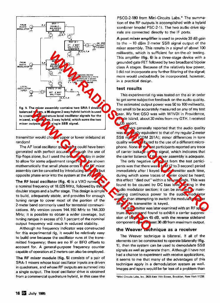
2M SSB OUTPUT (-lOd8mj
V,IY.S of ~apacltance am ,n mloo landr l,,F), others are an p1eof.r ads (pFh t.rrrtane.r .re ~n ohms k = 1.w M = 1.000.m
fig. 5. The mixer assembly contains two SRA-1 double balanced mixers, a 90-degree 2-way hybrid (which is used to create the quadrature local oscillator signals for the mixers), and 0-degree, 2-way hybrid, which sums the two mixer outputs into a single SSB signal.
transmitter would choose upper or lower sideband at random!
The AF local oscillator quadrature could have been generated with perfect accuracy through the use of flip-flops alone, but I used the one-shot delay in order to allow for some adjustment range; it can be shown mathematically that small phase errors in the RF mixer assembly can be cancelled by introducing an equal but opposite phase error into the system at the AF mixers.
The RF local oscillator (fig. 4) is a VXO running at a nominal frequency of 18.025 MHz, followed by three doubler stages and a buffer stage. This design is simple to build, adequately stable, and provides for enough tuning range to cover most of the portion of the 2-meter band commonly used for terrestrial communi- cations. My version covers 144.150 MHz to 144.300 MHz; it is possible to obtain a wider coverage, but tuning ranges in excess of 0.1 percent of the nominal output frequency will result in reduced stability.
Although no frequency indicator was constructed for this experimental rig, it would be relatively easy to build one because the oscillator runs at the trans- mitted frequency; there are no IF or BFO offsets to account for. A general-purpose frequency counter capable of operation at 2 meters can also be employed.
The RF mixer module (fig. 5) consists of a pair of SRA-1 mixers whose local oscillator inputs are driven in quadrature, and whose RF outputs are summed into a single output. The local oscillator drive is obtained from a commercial quadrature hybrid, in this case the
PSCQ-2-180 from Mini-Circuits Labs." The summa- tion of the RF outputs is accomplished with a hybrid combiner (model PSC-2-1). The two audio drive sig- nals are connected directly to the IF ports.
A post mixer amplifier is used to provide 30 dB gain to the - 10 dBm 2-meter SSB signal output of the mixer assembly. This results in a signal of about 100 milliwatts, which is sufficient for on-the-air testing. This amplifier (fig. 6 ) is a three-stage device with a grounded gate FET followed by two broadband bipolar class A stages. Because of the relatively low power, I did not incorporate any further filtering of the signal; more would undoubtedly be incorporated, however, in a practical design.
test results This experimental rig was tested on the air in order
to get some subjective feedback on the audio quality. The estimated output power was 50 to 100 milliwatts, too small to be accurately measured on any of my test gear. My first QSO was with WlVDl in Providence, Rhode Island, about 30 miles from my QTH. I received a 05 report.
Listeners generally reported that the audio quality was essentially equivalent to that of my regular 2-meter SSB rig (an ICOM 251A); minor differences in tone quality were attributed to the use of a different micro- phone. None of the test participants reported any trace of carrier leakage on the signal, which indicates that the carrier balance of the mixer assembly is adequate.
The only negative comment from the test partici- pants was that there was a brief (2 to 3-second) period immediately after I keyed the transmitter each time, during which some traces of carrier could be heard; this effect "died out" within a few seconds. This was found to be caused by DC bias level settling in the audio modulator section; it can be avoided by main- taining continuous power to the audio modulator rather than attempting to switch the modulator power when the transmitter is keyed.
The transmitter was later examined with an RF spec- trum analyzer and found to exhibit a carrier suppres- sion of better than 45 dB, with the reverse sideband component downat least 30 dB from maximum output.
the Weaver technique as a receiver The Weaver technique is bilateral. If all of the
elements can be constructed to operate bilaterally (fig. I), then the system can be used to demodulate SSB signals as well as generate them. Although I have not had a chance to experiment with receive applications, it seems to me that many of the advantages of this technique apply in a demodulation system as well. Images and spurs would be far less of a problem than
'Mini-Circuits Labs, Inc. 2625 East 14th Street, Brooklyn, New York 11235.
16 July 1985
WWW.RADiOSCAMATORUL.Hi2.RO
WWW.GiURUMELE.Hi2.RO
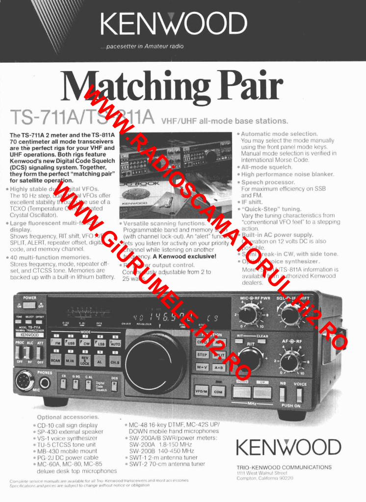
Matching Pair 1-n C I A 4 "q-7"'Ai 1. v > - f ~ ) VUFIVIIF all-mode base stations.
TheTS-711A 2 meter and theTS-811A 70 centimeter all mode transceivers are the perfect rigs for your VHF and UHF operations. Both rigs feature Kenwood's new Digital Code Squelch (DCS) signaling system. Together, they form the perfect "matching pair" for satellite operation. H~qhly ?i,7l,lc r i? ia r'iqitsl VFOs. Thr! 10 Hz step, dual d~gttal VFOs offer excellent slab~llty through the use of a TCXO (Temperature Compensated C~ystal Osc~llator).
L a r g e fluorescent multi-function d is~ lay . I ' IL~&]I ; !~~II I I ;~I I I~~ I),! 1 1 1 ,I{ICI 111~~111ory :;(.;ill
Shows frequency. RIT sh~fl. VFO AIB. (wlt l~ channel lock out). An "alerl" funct~on SPLIT. ALERT, repeater offset, cltg~tal lets you ltsten for ;~c:tlvlty on your prtority code, and memory channol. channel whlle listening on another 40 multi-function memories. frequency. A Kenwood exclusive! Stores frequency, mode, repeater off- - RF power o t~?o~! t r nntrol. set, and CTCSS tone. Memortes are Continuously adju:,table from 2 to backed up wlth a I~u~l t - tn llthluln battery. 25 watts,
Automatic rnode s~ lec t ion . You may select the mode rnanunlly uslng the front panel mode keys Manual mode selection 1s ver~f~ed In International Morse Cock All-mode sau~ l ch . I-liah performance noise blanker
* Speech processor. For maxtmum efflctency on SSB and FM. I h t i i f t . "Quick-Step" tuning. Vary the tun~ng characterlst~cs fro111 "conventtonal VFO feel" to n stepping actlon. Ruilt-in AC powct srtpplv. Operatlor1 on 12 volts UC IS also poss~hle. Semi break-iri C\N. with side tone.
0 Optional voice zvnthesizer. More TS-71lAITS-RllA ~nformatton 1s ava~lsble from author~zed Kt-'nwoo(l dealers.
( 3 ~ + 1 ! ' 7 , - : "rc i : ; . , r , . : ; - -c~
CD-10 call slgn dlsplay MC-48 16-key DTMF. MC-42s UP1 * SP-430 external sneaker DOWN mob~le hand m~crophones
VS-1 votce synthesizer SW-200AIB SWRipower meters: TU-5 CTCSS tone uri~t SW-200A 1.8-150 MHz MB-430 moblle mount SW-200B 140-.I50 MH7
* PG-2J DC power cable SWT-1 2-ni antenna tuner * MC-GOA. MC-80, MC-85 SWT-2 70-cm antenna tuner
KENWOOD deluxe desk top nilcrophones
TRIO-KENWOOD COMMUNICATIONS 1111 Vlt.~,I \,M.,l:l!,l :7l!t.+,l
( r),r :,il.lr, . l rvl i C v1:11111.11\1,(. . 4 ~ , l l l . l ! l l l ~ lill ,111 1,112 h,lli~1.,1(111 il.,li'.1 l . lv*-l~.1(11!!1I1<)' .1.1'1 6"'1?'141'',
c:,,n,,>1t,,,. c: 3l , l , l ! ,~, , , ,jti:>.'ll <,,I, , ,!a, ,,I ,,I,, ,,,I, I,,,,, #., ,,,, , . , , , ! , j < T 1 I,, , I ,,,, 10,~ W,!I,,<,,I , ,< , I , , ,% , Z ! < 3 r > l ~ ~ , ~ l ~ ~ c l r ~
WWW.RADiOSCAMATORUL.Hi2.RO
WWW.GiURUMELE.Hi2.RO
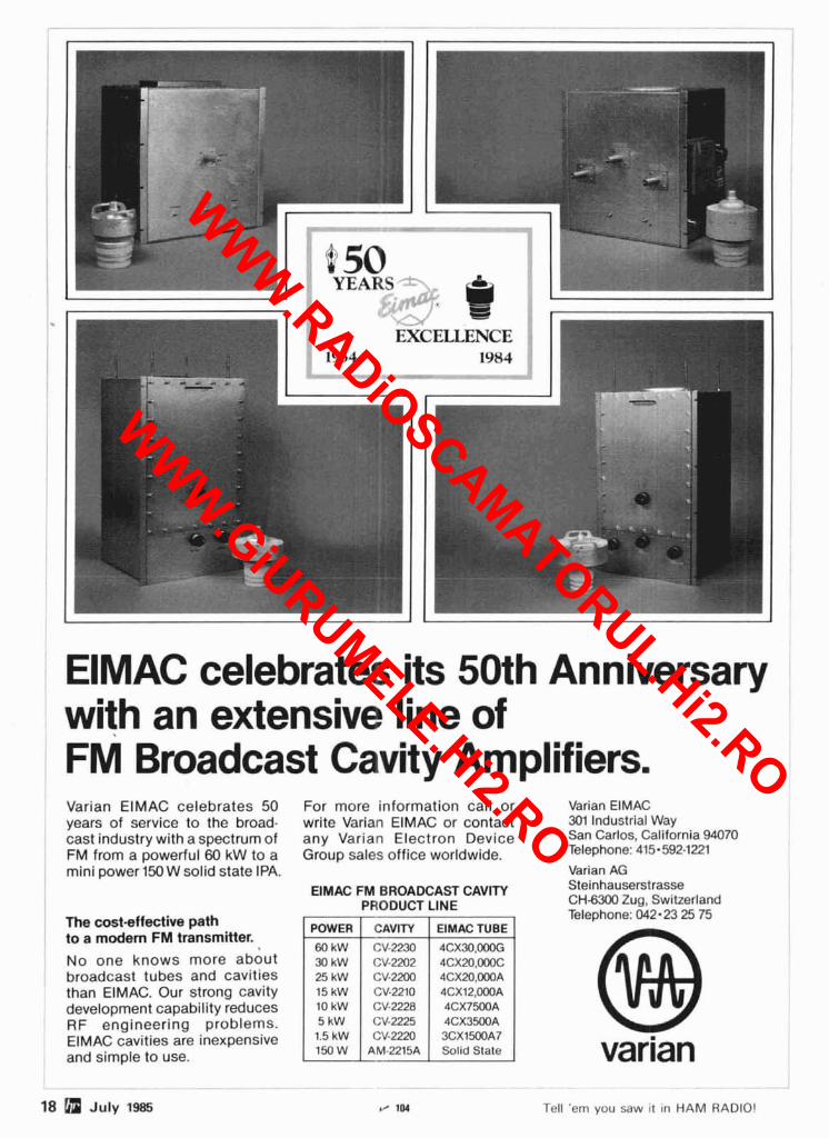
ElMAC celebrates its 50th Anniversary with an extensive line of FM Broadcast Cavity Amplifiers. Varian EIMAC celebrates 50 years of service to the broad- cast industry with a spectrum of FM from a powerful 60 kW to a mini power 150 W solid state IPA.
The cost-effective path to a modem FM transmitter.
No one knows more about broadcast tubes and cavities than EIMAC. Our strong cavity development capability reduces RF engineering problems. ElMAC cavities are inexpensive and simple to use.
For more information call or Varian ElMAC write Varian EIMAC or contact 361 Industrial Way any Varian Electron Device San Carlos, California 94070
Group sales office worldwide. Telephone: 415-592122l Varian AG
ElMAC FM BROADCAST CAVITY Steinhauserstrasse PRODUCT LINE CH-6300 Zug, Switzerland
Telephone: 042.23 25 75 POWER CAVITY ElMAC TUBE
60 kW CV-2230 4CX30,000G 30 kW CV-2202 4CX20.000C 25 kW CV-2MO 4CX20.000A 15 kW CV-2210 4CX12,000A 10 kW CV.2228 4CX7500A
1.5 kW CV-2220 3CX1500A7 150 W AM-2215A Solid State varian
18 a July 1985 Y IM Tell 'em you saw it in HAM RADIO!
WWW.RADiOSCAMATORUL.Hi2.RO
WWW.GiURUMELE.Hi2.RO
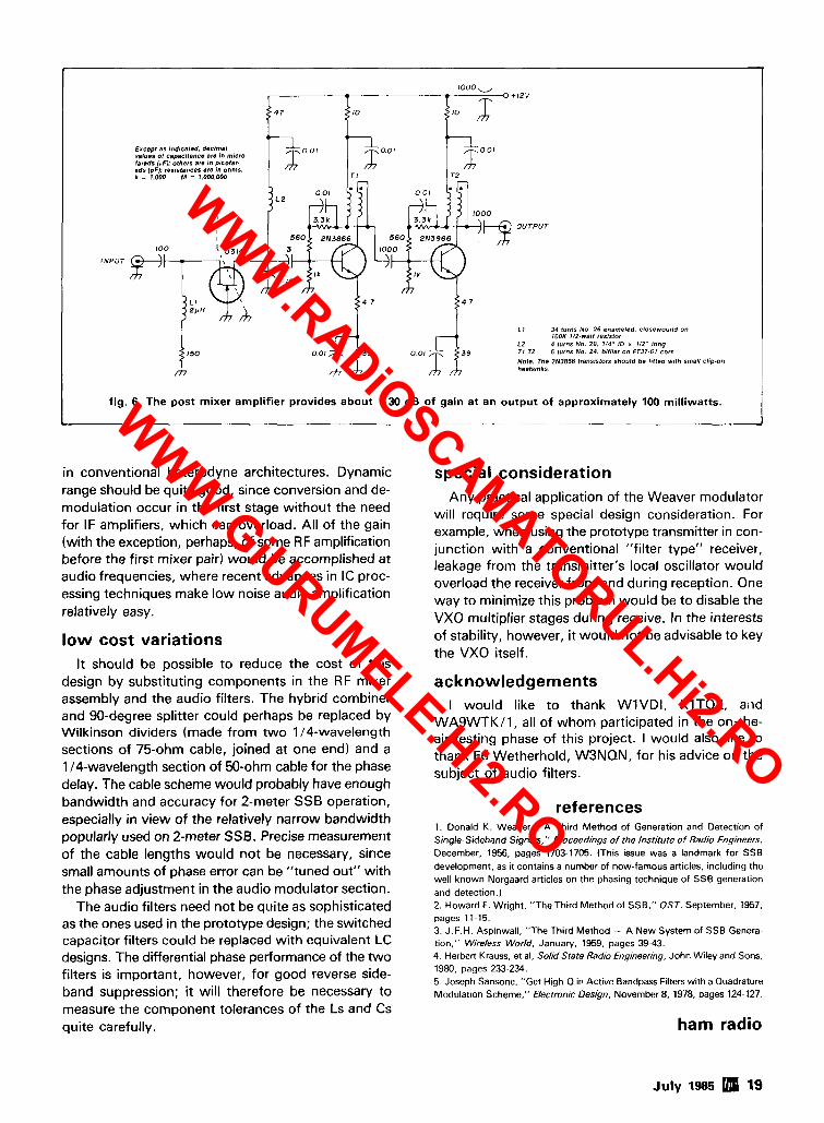
fig. 6. The post mixer amplifier provides about +30 dB of gain at an output of approximately 100 milliwatts.
- - . - - . . - - . -
in conventional heterodyne architectures. Dynamic special consideration
i
l 0 O O y 0 + 1 2 v
4 7 10 I 1 0 1
range should be quite good, since conversion and de- modulation occur in the first stage without the need for IF amplifiers, which can overload. All of the gain (with the exception, perhaps, of some RF amplification before the first mixer pair) would be accomplished at audio frequencies, where recent advances in IC proc- essing techniques make low noise audio amplification relatively easy.
low cost variations
Excspl as indicated, dscrrnal values 01 ~ a p a ~ l l a n ~ e are in micro larsdr ("FJ: olherr are in picola, ads IpFI: reststances are in ohms. k = 1,WO M = I.OOO,WO
It should be possible to reduce the cost of this design by substituting components in the RF mixer assembly and the audio filters. The hybrid combiner and 90-degree splitter could perhaps be replaced by Wilkinson dividers (made from two 114-wavelength sections of 75-ohm cable, joined at one end) and a 114-wavelength section of 50-ohm cable for the phase delay. The cable scheme would probably have enough bandwidth and accuracy for 2-meter SSB operation, especially in view of the relatively narrow bandwidth popularly used on 2-meter SSB. Precise measurement of the cable lengths would not be necessary, since small amounts of phase error can be "tuned out" with the phase adjustment in the audio modulator section.
The audio filters need not be quite as sophisticated as the ones used in the prototype design; the switched capacitor filters could be replaced with equivalent LC designs. The differential phase performance of the two filters is important, however, for good reverse side- band suppression; it will therefore be necessary to measure the component tolerances of the Ls and Cs quite carefully.
I I I
O U T P U T
I N P U T
L 1 34 turns No 26 enameled, closewound on lOOK l/Z-wall rerrrlar
LZ 4 IurnS No. 20 . 114" 10 x 112'' long 3 9 39 T1.12 5 turns No 24. bt6lar on FT37-61 core
Note: The 2N3866 transrstorr should be fllted wllh small cbp-on heatsmks
30~' T I
<
3.0'
Any practical application of the Weaver modulator will require some special design consideration. For example, when using the prototype transmitter in con- junction with a conventional "filter type" receiver, leakage from the transmitter's local oscillator would overload the receiver front end during reception. One way to minimize this problem would be to disable the VXO multiplier stages during receive. In the interests of stability, however, it would not be advisable to key the VXO itself.
-ioo1 TZ
acknowledgements I would like to thank WIVDI, KITOZ, aild
WASWTKII, all of whom participated in the on-the- air testing phase of this project. I would also like to thank Ed Wetherhold, W3NQN, for his advice on the subject of audio filters.
references 1. Donald K. Weaver, "A Third Method of Generation and Detection of Single-Sideband Signals," Proceedings of the Institute of Radio Engineers, December, 1956, pages 1703-1705. (This issue was a landmark for SSB development, as it contains a number of now-famous articles, including the well known Norgaard articles on the phasing technique of SSB generation and detection.) 2. Howard F. Wright, "TheThird Method of SSB," QST, September, 1957, pages 11-15. 3. J.F.H. Aspinwall, "The Third Method - A New System of SSB Genera- tion," Wireless World. January, 1959, pages 39-43. 4. Herbert Krauss, et al, Sokd State Radio filgineering, John Wiley and Sons. 1980. pages 233~234. 5. Joseph Sansone, "Get High-Q in Active Bandpass Filters with a Quadrature Modulation Scheme," Electronic Design, November 8, 1978, pages 124-127.
ham radio
July 1985 19
WWW.RADiOSCAMATORUL.Hi2.RO
WWW.GiURUMELE.Hi2.RO

ShackMaster"' puts your home station in the palm of your hand. Whether portable, mobile, around the yard or around town you'll be linked through your handheld to your high performance equipment at home. Even call home from any Touch-Tone phone and operate. Scan the bands, change modes, select antennas, turn gear on and off - all from your Touch-Tone keypad. Check into nets, work skeds, ragchew and DX without being tied down to the shack.
Exchange electronic mailbox messages with your family- like "I'll be late", or "All is OK". Or talkwith you1 family directly through Shackpatch", with you in remote control of your home station. Report traffic accidents 01
disabled motorists through your home phone while mobile or portable with PersonalPatch:' All the power of your home station (and more) really can follow you anywhere. . . to find out more about ShackMaster" just write, send us your QSL, or call and talk with us at 408-749-8330.
QCC advanced computer controls, inc. 10816 Northrldge Square Cupert~no. CA 95014 (408) 749-8330
20 July 1985
WWW.RADiOSCAMATORUL.Hi2.RO
WWW.GiURUMELE.Hi2.RO
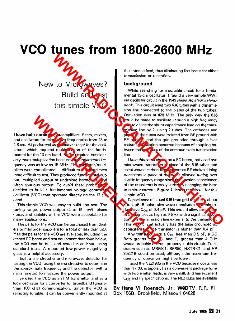
VCO tunes from 1800-2600 MHz
New to Microwaves?
Build and test this simple VCO
I have built antennas, preamplifiers, filters, mixers, and oscillators for microwave frequencies from 23 to 4.8 cm. All performed as expected except for the oscil- lators, which required multiplication of the funda- mental for the 13-cm band. Some required consider- ably more multiplication because the fundamental fre- quency was as low as 15 MHz. The oscillator/multi- pliers were complicated - difficult to build and even more difficult to test. They produced fundamental out- put, multiplied output at undesired harmonics, and often spurious output. To avoid these problems, I decided to build a fundamental voltage controlled oscillator (VCO) that operated directly on the 13-cm band.
This simple VCO was easy to build and test. The tuning range, power output (2 to 15 mW), phase noise, and stability of the VCO were acceptable for many applications.
The parts for the VCO can be purchased from deal- ers or mail order suppliers for a total of less than $20. If all the parts for the VCO are available, including the etched PC board and test equipment described below, the VCO can be built and tested in an hour, using standard tools. A mounted low-power magnifying glass is a helpful accessory.
I built a line stretcher and microwave detector for testing the VCO, using the line stretcher to determine the approximate frequency and the detector (with a milliammeter) to measure the power output.
I've used the VCO as an FM transmitter and as a local oscillator for a converter for broadband (greater than 100 kHz) communication. Since the VCO is remotely tunable, it can be conveniently mounted at
the antenna feed, thus eliminating line losses for either transmission or reception.
background While searching for a suitable circuit for a funda-
mental 13-cm oscillator, I found a very simple WWll era oscillator circuit in the 1949 Radio Amateur's Hand- book. This circuit used two 6J6 tubes with a transmis- sion line connected to the plates of the two tubes. Oscillation was at 420 MHz. The only way the 6J6 could be made to oscillate at such a high frequency was to divide the shunt capacitance load on the trans- mission line by 2, using 2 tubes. The cathodes and plates of the tubes were isolated from RF ground with RF chokes, and the grid grounded through a bias resistor. Oscillation occurred because of coupling be- tween the two sides of the common plate transmission line.
I built this same circuit on a PC board, but used two microwave transistors in place of the 6J6 tubes and spiral wound carbon film resistors as RF chokes. Using transistors in place of the tubes allowed tuning over a wide frequency range since the junction capacitance of the transistors is easily varied by changing the base to emitter current. Figure 1 shows the circuit for this simple VCO.
Capacitance of a dual 6J6 from grid to plate is about 3 to 4 pF. Bipolar microwave transistors available to- day have COB of 0.4 pF. This should allow oscillation at frequencies as high as 6 GHz with a significant por- tion of a transmission line external to the transistors. This VCO circuit actually has the base grounded so capacitance in the transistor is higher than 0.4 pF.
Any transistor with a COB less than 0.5 pF, a DC Beta greater than 25, and FT greater than 4 GHz would probably operate properly in this circuit. Tran- sistors such as MRF901, BFRSO, HXTR-61, and HP 358218 could be used, although the maximum fre- quency of operation might be lower.
I used the NE21935 in the VCO because it costs less than $7.00, is bipolar, has a convenient package form with two emitter leads, is very small, and has excellent COB and FT specifications. The NE21935s are available
By Hans M. Roensch, Jr., WBDTV, R.R. #I, Box 1566, Brookfield, Missouri 64628
July 1985 21
WWW.RADiOSCAMATORUL.Hi2.RO
WWW.GiURUMELE.Hi2.RO
- I TO -12
T U N I N G VOLTAGE
0 1 = 0 2 = N E 2 1 9 3 5 Ezcspl ss ~ndicatsd, dsctmal values of capacltencs are in mlero.
El = E 2 - 0 . 0 3 " l O B m m l E Y E L E T S rarsds fr,FJ; others are in picola,. ads 1pF): resistances are In ohms.
( G R O U N D T E R M I N A L S 1 L = 7.000 M = 7,000,M)O 4 L L RESISTORS 4RE I N W I T T , S P I R I L .
CARBON FILM TYPE
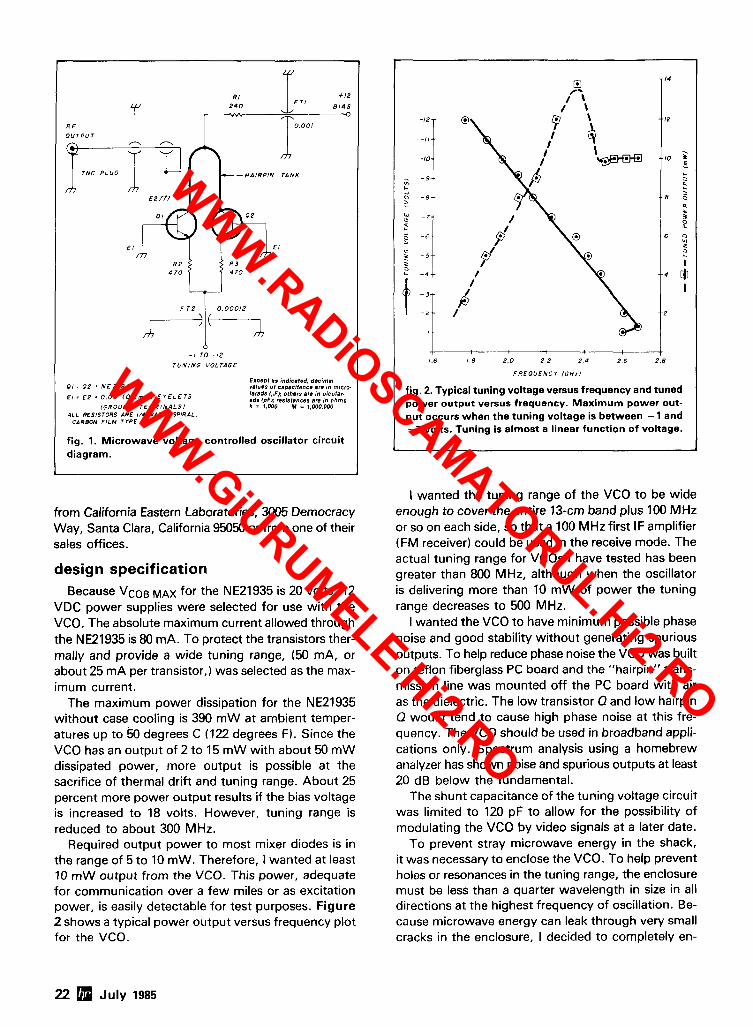
fig. 1. Microwave voltage controlled oscillator circuit diagram.
from California Eastern Laboratories, 3005 Democracy Way, Santa Clara, California 95050 or from one of their sales offices.
design specification Because VcoB MAX for the NE21935 is 20 volts, 12
VDC power supplies were selected for use with the VCO. The absolute maximum current allowed through the NE21935 is 80 mA. To protect the transistors ther- mally and provide a wide tuning range, (50 mA, or about 25 mA per transistor,) was selected as the max- imum current.
The maximum power dissipation for the NE21935 without case cooling is 390 m W at ambient temper- atures up to 50 degrees C (122 degrees F). Since the VCO has an output of 2 to 15 mW with about 50 m W dissipated power, more output is possible at the sacrifice of thermal drift and tuning range. About 25 percent more power output results if the bias voltage is increased to 18 volts. However, tuning range is reduced to about 300 MHz.
Required output power to most mixer diodes is in the range of 5 to 10 mW. Therefore, I wanted at least 10 mW output from the VCO. This power, adequate for communication over a few miles or as excitation power, is easily detectable for test purposes. Figure 2 shows a typical power output versus frequency plot for the VCO.
1
!3 -14
If-\
C
VI C
- I - -
1- 1.6 1 8 2 . 0 2 2 2 . 4 2 . 6 2 . 8
F R E O U E N C Y l C H z l
fig. 2. Typical tuning voltage versus frequency and tuned power output versus frequency. Maximum power out- put occurs when the tuning voltage is between - 1 and -7 volts. Tuning is almost a linear function of voltage.
1
I wanted the tuning range of the VCO to be wide enough to cover the entire 13-cm band plus 100 MHz or so on each side, so that a 100 MHz first IF amplifier (FM receiver) could be used in the receive mode. The actual tuning range for VCOs I have tested has been greater than 800 MHz, although when the oscillator is delivering more than 10 m W of power the tuning range decreases to 500 MHz.
I wanted the VCO to have minimum possible phase noise and good stability without generating spurious outputs. To help reduce phase noise the VCO was built on teflon fiberglass PC board and the "hairpin" trans- mission line was mounted off the PC board with air as the dielectric. The low transistor Q and low hairpin Q would tend to cause high phase noise at this fre- quency. The VCO should be used in broadband appli- cations only. Spectrum analysis using a homebrew analyzer has shown noise and spurious outputs at least 20 dB below the fundamental.
The shunt capacitance of the tuning voltage circuit was limited to 120 pF to allow for the possibility of modulating the VCO by video signals at a later date.
To prevent stray microwave energy in the shack, it was necessary to enclose the VCO. To help prevent holes or resonances in the tuning range, the enclosure must be less than a quarter wavelength in size in all directions at the highest frequency of oscillation. Be- cause microwave energy can leak through very small cracks in the enclosure, I decided to completely en-
22 July 1985
WWW.RADiOSCAMATORUL.Hi2.RO
WWW.GiURUMELE.Hi2.RO
close the VCO in a copper housing, seam soldering all gaps except where the two feedthrough capacitors and the RG-58 coax enter.
The output is closely coupled to the hairpin tank transmission line and therefore high Q and/or mis- matched loads at the output may cause tuning holes or resonances. Changes in load will also cause shifts in frequency.
acquiring the parts The 0.03 inch (0.76 mm) thick, 1 ounce (28 gram),
double-sided teflon fiberglass PC board, the eyelets, feedthrough capacitors, and copper foil were pur- chased from Gateway Electronics, 8123-25 Page Boul- evard, St. Louis, Missouri 63130; Surplus Sales, Inc., 2412 Chandler Road, East Bellevue, Nebraska 68005 also stocks needed items. Any value of feedthrough capacitor between 50 and 1000 pF can be used, depending on desired maximum modulation frequency and allowable RF leakage. Standard epoxy fiberglass PC board could probably be substituted for the teflon fiberglass PC board, but some degradation in rnaxi- mum frequency and some reduction in Q might be ex- pected. All other parts and materials can be obtained from local or mail order dealers.
construction I use a 20 to 30-watt soldering iron, a 100 to 200-watt
soldering.iron, a thin track saw (available from model railroad hobby shops), a tubing cutter, rosin core solder, long nosed and Vise-Gripm pliers, a hand drill, a small sharp knife, tin snips, a small heatsink clip, and a low-power magnifying glass for construction. All parts except the PC board, eyelets, the transistor leads, and the copper foil are tinned before soldering. Construction proceeds in this order:
Prepare the PC board with cut out and eyelets.
Solder the transistors and "hairpin" to the PC board.
Install the feedthrough capacitors, resistors, and coax.
Test the VCO for proper operation.
Solder the VCO into its enclosure and retest.
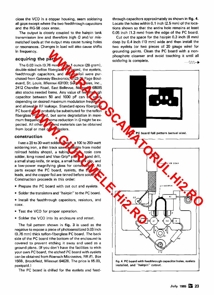
The foil pattern shown in fig. 3 is used as the negative to expose a piece of photosensitized 0.03 inch (0.76 mm) thick teflon-fiberglass PC board. The back side of the PC board (the bottom of the enclosure) is covered to prevent etching it away and used as a ground plane. (If you don't have the facilities to etch your own PC board, the etched PC board with eyelets can be obtained from Roensch Microwave, RR #I, Box 1568, Brookfield, Missouri 64628. The price is $5.00, postpaid.
The PC board is drilled for the eyelets and feed-
through capacitors approximately as shown in fig. 4. Locate the holes within 0.1 inch (2.5 mm) of the loca- tions shown so that the entire hole remains at least 0.05 inch (1.3 mm) from the edge of the PC board.
Cut out the space for the hairpin 0.3 inch (8 mm) deep by 0.4 inch (10 mm) wide and then install the two eyelets (or two pieces of 20 gauge wire) for grounding points. Clean the PC board with a non- phosphate cleanser and avoid touching it until all soldering is complete. --2RRr,
I fig. 3. PC board foil pattern (actual size). I
- R G - 5 8 C O A X
fig. 4. PC board with feedthrough capacitor holes, eyelets installed, and "hairpin" cutout.
July 1985 23
WWW.RADiOSCAMATORUL.Hi2.RO
WWW.GiURUMELE.Hi2.RO
Next, install the transistors. (The base lead of the each transistor) as short as possible so that the tran- NE21935 is identified by the 45-degree angle of its sistors can be mounted close to each other with both termination.) The lead opposite the base lead is the base leads pointing in the ground direction as shown collector and the other two leads connect to the emit- in fig. 5. With a drop of solder on the tip of a clean, ter. Cut one emitter lead (the opposite emitter lead on hot 20 to 30 watt soldering iron, place the first tran-
sistor on the PC board. While holdinq a base lead in - place with a finger, place a drop of solder on the col- lector lead and PC board solder pad tacking the lead in place. Make a good solder joint at the other two transistor leads. Then remelt the solder and add a lit- tle solder at the collector, base, and emitter to make a good, shiny buildup with adhesion of solder suffi- cient so no copper shows at all three transistor leads. Do not apply heat at transistor leads for longer than 3 seconds without a long cool-off period. Install the second transistor in the same manner with its cut-off emitter lead about 0.02 inch (0.5 mm) from the other transistor's cut-off emitter lead. The emitter leads must be close but must not touch each other.
Cut and bend the hairpin next. I used tin snips to cut a pieceof 0.016 inch (0.4 mm) thick brass0.1 inch (2.5 rnm) wide by 0.7 inch (18 mm) long. Bend this
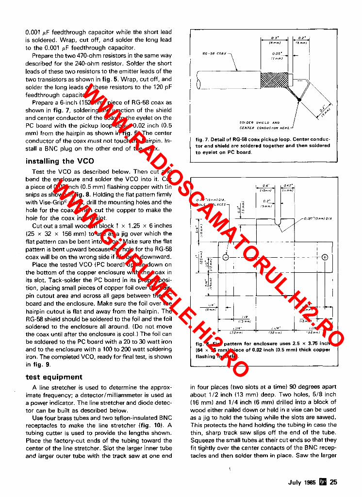
T I N N E D E N D
T l N N C D C E N T E R ' '7 0 ,5*
(4 -".I
0 2 5 ' - 0 3 ' - - ITrnrnl
, 1 T I N N E D
E N D
T t N N E D C E N T E R
O F " E d 0
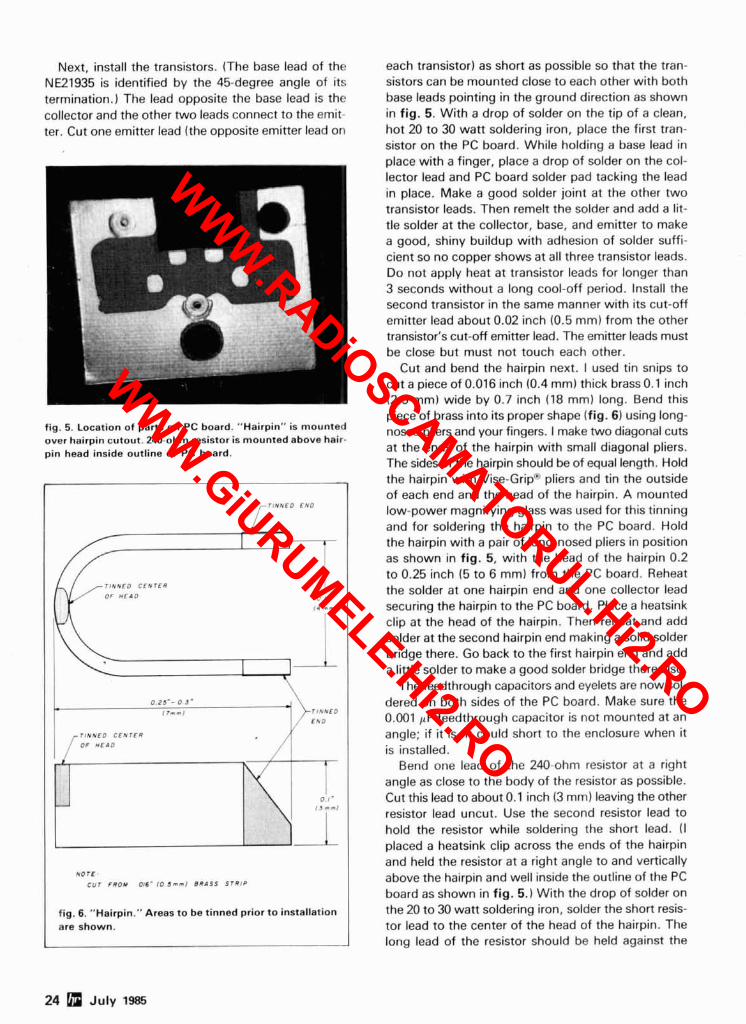
piece of brass into its proper shape (fig. 6) using long- fig. 5. Location of parts on PC board. "Hairpin" is mounted nosed pliers and your fingers. I make two diagonal cuts over hairpin cutout. 240-ohm resistor is mounted above hair- pin head inside outline of PC board. at the ends of the hairpin with small diagonal pliers.
The sides of the hairpin should be of equal length. Hold the hairpin with Vise-Grip"' pliers and tin the outside of each end and the head of the hairpin. A mounted low-power magnifying glass was used for this tinning and for soldering the hairpin to the PC board. Hold the hairpin with a pair of long-nosed pliers in position as shown in fig. 5, with the head of the hairpin 0.2 to 0.25 inch (5 to 6 mm) from the PC board. Reheat the solder at one hairpin end and one collector lead securing the hairpin to the PC board. Piace a heatsink clip at the head of the hairpin. Then reheat and add solder at the second hairpin end making a solid solder bridge there. Go back to the first hairpin end and add a little solder to make a good solder bridge there also.
The feedthrough capacitors and eyelets are now sol- dered on both sides of the PC board. Make sure the 0.001 pF feedthrough capacitor is not mounted at an angle; if it is, it could short to the enclosure when it is installed.
Bend one lead of the 240-ohm resistor at a right angle as close to the body of the resistor as possible. Cut this lead to about 0.1 inch (3 mm) leaving the other resistor lead uncut. Use the second resistor lead to hold the resistor while soldering the short lead. (I placed a heatsink clip across the ends of the hairpin and held the resistor at a right angle to and vertically above the hairpin and well inside the outline of the PC board as shown in fig. 5.) With the drop of solder on the 20 to 30 watt soldering iron, solder the short resis- tor lead to the center of the head of the hairpin. The long lead of the resistor should be held against the
-
24 July 1985
0 1 -
I J m m l
N O T E C U T F R O M 016' 10 5 m n l B R A S S S I R l P \1 fig. 6. "Hairpin." Areas to be tinned prior to installation are shown.
WWW.RADiOSCAMATORUL.Hi2.RO
WWW.GiURUMELE.Hi2.RO
0.001 pF feedthrough capacitor while the short lead is soldered. Wrap, cut off, and solder the long lead to the 0.001 pF feedthrough capacitor.
Prepare the two 470-ohm resistors in the same way described for the 240-ohm resistor. Solder the short leads of these two resistors to the emitter leads of the two transistors as shown in fig. 5. Wrap, cut off, and solder the long leads of these resistors to the 120 pF feedthrough capacitor.
Prepare a 6-inch (152 mm) piece of RG-58 coax as shown in fig. 7, soldering the junction of the shield and center conductor of the coax to the eyelet on the PC board with the pickup loop about 0.02 inch (0.5 mm) from the hairpin as shown in fig. 5. The center conductor of the coax must not touch the hairpin. In- stall a BNC plug on the other end of the coax.
installing the VCO Test the VCO as described below. Then cut and
bend the enclosure and solder the VCO into it. Cut a piece of 0.02 inch (0.5 mm) flashing copper with tin snips as shown in fig. 8. Holding the flat pattern firmly with Vise-Gripm pliers, drill the mounting holes and the hole for the coax. Then cut the copper to make the hole for the coax into a slot.
Cut out a small wooden block 1 x 1.25 x 6 inches (25 x 32 x 156 mm) to use as a jig over which the flat pattern can be bent into a box. Make sure the flat pattern is bent upward because the hole for the RG-58 coax will be on the wrong side if it's bent downward.
Place the tested VCO (PC board) upside down on the bottom of the copper enclosure with the coax in its slot. Tack-solder the PC board in its proper posi- tion, placing small pieces of copper foil over the hair- pin cutout area and across all gaps between the PC board and the enclosure. Make sure the foil over the hairpin cutout is flat and away from the hairpin. The RG-58 shield should be soldered to the foil and the foil soldered to the enclosure all around. (Do not move the coax until after the enclosure is cool.) The foil can be soldered to the PC board with a 20 to 30 watt iron and to the enclosure with a 100 to 200 watt soldering iron. The completed VCO, ready for final test, is shown in fig. 9.
test equipment A line stretcher is used to determine the approx-
imate frequency; a detectorlmilliammeter is used as a power indicator. The line stretcher and diode detec- tor can be built as described below.
Use four brass tubes and two teflon-insulated BNC receptacles to make the line stretcher (fig. 10). A tubing cutter is used to provide the lengths shown. Place the factory-cut ends of the tubing toward the center of the line stretcher. Slot the larger inner tube and larger outer tube with the track saw at one end
R G - 5 8 C O A X
S O L D E R S H I E L D A N D
C E N T E R C O N D U C T O R H E R E
fig. 7. Detail of RG-58 coax pickup loop. Center conduc- tor and shield are soldered together and then soldered to eyelet on PC board.
in four places (two slots at a time) 90 degrees apart about 112 inch (13 mm) deep. Two holes, 518 inch (16 mm) and 114 inch (6 mm) drilled into a block of wood either nailed down or held in a vise can be used as a jig to hold the tubing while the slots are sawed. This protects the hand holding the tubing in case the thin, sharp track saw slips off the end of the tube. Squeeze the small tubes at their cut ends so that they fit tightly over the center contacts of the BNC recep- tacles and then solder them in place. Saw the larger
n[ 115mmJ ( I i m m J
0 . I 8 7 " l S m m J DIA. ?
HOLE 2 P L A C E S - E L 15mmJ
o?
O.I87"15mmJ D l 4
- - - - - - - I
I I
- +- - 40 I I I I
July 1985 25
1- - -
'p - - 'E ?
1 1 / 4 " ( 3 ~ m m 1
t
1 / 4 "
(6mmJ
fig. 8. Flat pattern for enclosure uses 2.5 x 3.75 inch (64 x 95 mm) piece of 0.02 inch (0.5 rnml thick copper flashing material.
I
1 1/4" ( 3 2 m m l
- i
I I N " - ( 3 Z m m l
1 /2"
I13mmJ
1 / 4 "
f 6 m m )
- 1 / 2 " i l 3 m m J
WWW.RADiOSCAMATORUL.Hi2.RO
WWW.GiURUMELE.Hi2.RO
t TIME FOR AN BREAKTHROUGH
The high quality of AEA products is appreciated long after the price paid is forgotten.
Wllt improve the operattng sk~lls ol ANY CW operalor'
tenna lo assemble
ASCII package wrllten rspec#arrv f r l r
MARS and other traltlr oDerator% SWLTEXTTM ~ n e most soph~~tecat<.<t
'Retail Prices-Call For Your Special Discount!
MIDWEST AMATEUR RADIO SUPPLY 3456 Fremont Avenue. North
Minneapolis. MN 55412 Store Hours: Mon.-Fri. 9-6. Saturday 9-3
WWW.RADiOSCAMATORUL.Hi2.RO
WWW.GiURUMELE.Hi2.RO
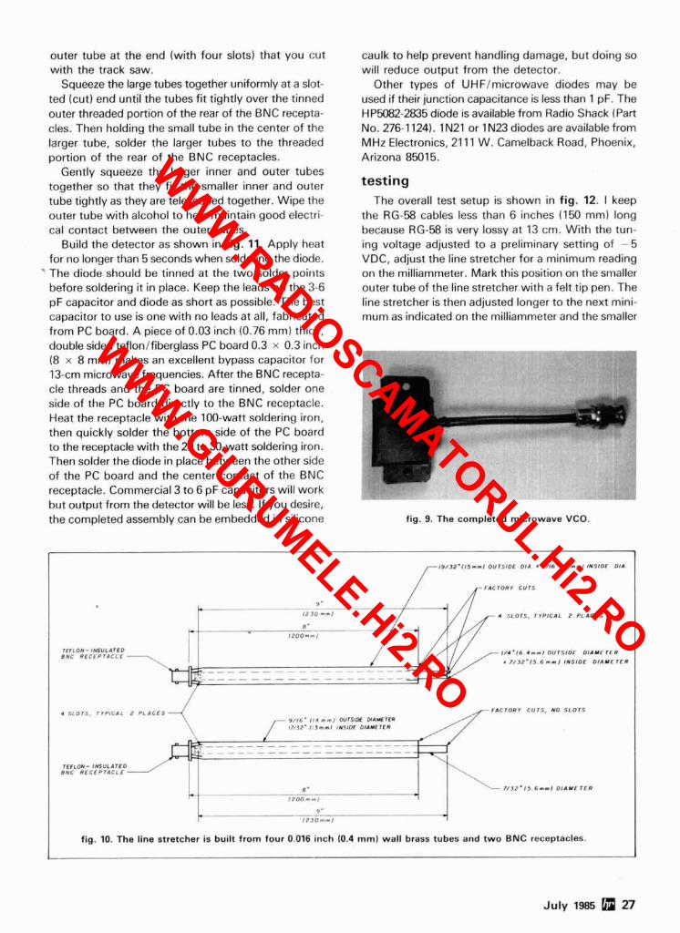
outer tube at the end (with four slots) that you cut with the track saw.
Squeeze the large tubes together uniformly at a slot- ted (cut) end until the tubes fit tightly over the tinned outer threaded portion of the rear of the BNC recepta- cles. Then holding the small tube in the center of the larger tube, solder the larger tubes to the threaded portion of the rear of the BNC receptacles.
Gently squeeze the larger inner and outer tubes together so that they fit the smaller inner and outer tube tightly as they are telescoped together. Wipe the outer tube with alcohol to help maintain good electri- cal contact between the outer tubes.
Build the detector as shown in fig. 11. Apply heat for no longer than 5 seconds when soldering the diode. ' The diode should be tinned at the two solder points
before soldering it in place. Keep the leads on the 3-6 pF capacitor and diode as short as possible. The best capacitor to use is one with no leads at all, fabricated from PC board. A piece of 0.03 inch (0.76 mm) thick, double sided teflonlfiberglass PC board 0.3 x 0.3 inch (8 x 8 mm) makes an excellent bypass capacitor for 13-cm microwave frequencies. After the BNC recepta- cle threads and the PC board are tinned, solder one side of the PC board directly to the BNC receptacle. Heat the receptacle with the 100-watt soldering iron, then quickly solder the bottom side of the PC board to the receptacle with the 20 to 30-watt soldering iron. Then solder the diode in place between the other side of the PC board and the center contact of the BNC receptacle. Commercial 3 to 6 pF capacitors will work but output from the detector will be less. If you desire, the completed assembly can be embedded in silicone
caulk to help prevent handling damage, but doing so will reduce output from the detector.
Other types of UHFImicrowave diodes may be used if their junction capacitance is less than 1 pF. The HP5082-2835 diode is available from Radio Shack (Part No. 276-1 124). 1 N21 or 1 N23 diodes are available from MHz Electronics, 21 11 W. Camelback Road, Phoenix, Arizona 85015.
testing The overall test setup is shown in fig. 12. 1 keep
the RG-58 cables less than 6 inches (150 mm) long because RG-58 is very lossy at 13 cm. With the tun- ing voltage adjusted to a preliminary setting of - 5 VDC, adjust the line stretcher for a minimum reading on the milliammeter. Mark this position on the smaller outer tube of the line stretcher with a felt tip pen. The line stretcher is then adjusted longer to the next mini- mum as indicated on the milliammeter and the smaller
fig. 9. The completed microwave VCO.
July 1985 Q n
F ~ C T O R Y curs
9.
12 JO n r l 4 S L O T S . T ~ P ~ C A ' 2 PLACES
e'
rc r 'oY - I Y S U L ~ ~ E O B N C R E C E P r A C L L
11a.16 < r - l OUTSIDE O I A Y E T E R
N J 2 . 1 5 b n r l IUS IOE O l 4 Y E r E R - - - - - - - - - . - - - - - - - - - - - - - - - - - - - - - - - - - - -
. SLOTS, r l P l C A L 2 PLACES NCTORV c u r s . NO SLOTS
rrnm- INSULI)ICO 8°C RECEPTACLE
N J Z . 1 5 6s-1 D I A Y E T E R
fig. 10. The line stretcher is built from four 0.016 inch (0.4 mm) wall brass tubes and two BNC receptacles.
*
WWW.RADiOSCAMATORUL.Hi2.RO
WWW.GiURUMELE.Hi2.RO
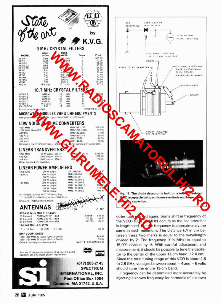
A # K.V.G. I 9 MHz CRYSTAL FILTERS 1
Appll. Band. MODEL w t l o n wldlh Poles Prlcm
SSB SSB LSB US8 SSB AM AM F M CW CW CW
IF notse
2 4 kHz 2 4 kHz 2 4 kHz 2 4 kHz 2 4 kHz 3 75 kHz 5 0 kHz
120 kHz YM HZ 500 Hz 250 Hz
15 kHz
10.7 MHz CRYSTAL FILTERS XFlO7.A NBFM I 2 kHz 8 167.M XF107.B NBFM 15 kHz 8 67 30 XFlO7-C WBFM 30 kHz 8 67.30 XFlO7.D WBFM 36 kHz 8 67.30 XF107.E PtrlDala 40 kHz 8 67 30 XM107.SO4 FM 14 kHz 4 30.15 Export lnqulrles lnvlled Shtpplng $3 75
MICROWAVE MODULES VHF & UHF EQUIPMENTS Use your exlsttng HF or 2M rlg on other VHF or UHF bands
LOW NOISE RECEIVE CONVERTERS 1691 MHz MMk1691-137 $249 95 1296 MHz GaAsFET MMk1296.144G 14945 4321435 MMc432-2WS) 74.95 439-ATV MMc43SCh x 89 95 220 MHz MMc220.28 74 95 144 MHz MMc144.28 59 95 Oploons: Low NF (2.0dB max.. 1.25dBmax.), olher bands 6 IF'savallable
LINEAR TRANSVERTERS 1296MHz 1 8 W OU~OUI. 2M 8n MM11296- 144-G 5m 95 432435 IOWouIput. 10M ~n MM1437.28fSl 269 95 144 MHz I O W ~ u t p u l . 10M #n MM1144-2R I7995 Other bands 6 IF3 ava~lable.
LINEAR POWER AMPLIFIERS 12% MHz 20 W oulpul UP129620.L 439 95 4321435 100 W oulpul MML432.100 369 95
50 W oulpul MML432.50 I9995 30 W outpul MML432.30-LS 209 95
144 MHz 200 W oulpul MML144-200-S 374 95 IOU W oulpul MML144-IOU-LS 239 95 50 W OUIPUI MMLl44.50.S 149 95 30 W OUIPUI MML144-30-LS 109 95
1\11 models include VOX T I R swllchlng. ..L" model3 1 or 3W drove. others 10W drwe.
Shlpplng: FOB Concord. Mass.
ANTENNAS 420-450 MHz MULTIBEAMS 28 Elernenl 70fMBM28 12 d8d $39 95 48 Elemenl 70lMBM48 15 7 dBd 59 95 88 Elemenl 70IMBMflfl 18 5 dBd 4Bf56- 89 95
144.148 MHz J.SLOTS 10 + 10 Twlsl lOXYl2M 11 3 dB4 69 95
UHF LOOP YAGlS 1250.1350 MH129loops 1296-LY20dBl $49 95 1650-179 MHz29loops 169l.LY 20dB1 59 95 Order LoopYa~n connector extra. Type N $14 95. SMA $5 95
I equlpmenl and KVG cwlal producl repulremenlr
(617) 263.21 45 SPECTRUM
TERNATIONAL, INC. Post Office Box 1084
8NC 1012- 2135 OR
RECEPNICLE IN?! OR IN23
\ 10 on I W OHUS O-'oY:' UTCWNIL ~FSISIAYCC IF PC OR 801RO 3 TO 69F CIPAClTOR CIPACITOR
WIRES 10 YILLIAYYE 0.3.11mn1 r 03.1#n.l PtECE 0 03'(0.7#nml THICK IEPLON- F1l)ERGLASS PC BOARD
T I *LON IUSULATlO BNC RECEPTACLE
fig. 11. The diode detector is built on a teflon insulated BNC receptacle using a microwave diode and homemade bypass capacitor.
outer tube marked again. Some shift in frequency of the VCO (10 or 20 MHz) occurs as the line stretcher is lengthened, but the frequency is approximately the same at each minimum. The distance (dl in cm be- tween these two marks is equal to the wavelength divided by 2. The frequency ( f in MHz) is equal to 15,000 divided by d. With careful adjustment and measurement, it should be possible to tune the oscilla- tor to the center of the upper 13-cm band (12.4 cm). Since the total tuning range of this VCO is about 1.8 to 2.6 GHz, voltages between about - 4 and - 6 volts should tune the entire 13-cm band.
Frequency can be determined more accurately by injecting a known frequency (or harmonic of a known
28 July 1985
WWW.RADiOSCAMATORUL.Hi2.RO
WWW.GiURUMELE.Hi2.RO
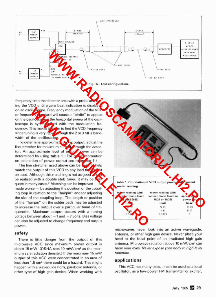
0 - l o n l
Y t T E R
or T E C T O R 10 OR 100 OWYS
I N T E R N A L
R E S I S 7 A N C E
- I ro -,* r u w r N 6
TMC PLUGS
C t - 5 8 C O l l 1NC PLUG
R G - 5 8 COAX
I I " - , " m a
Y t T E R
10 OR 100 OWYS
I N T E R N A L . . . . . . . . . . .
fig. 12. Test configuration.
frequency) into the detector area with a probe and tun- ing the VCO until a zero beat indication is displayed on an oscilloscope. Frequency modulation of the VCO or frequency standard will cause a "birdie" to appear on the oscilloscope if the horizontal sweep of the oscil- loscope is synchronized with the modulation fre- quency. This makes it easier to find the VCO frequency since tuning is very rapid through the 2 or 3 MHz band- width of the oscilloscope.
To determine approximate power output, adjust the line stretcher for maximum current through the detec- tor. An approximate level of output power can be determined by using table 1. (For more information on estimation of power output see reference 1.)
The line stretcher used above can be used to help match the output of this VCO to any load that might be used. Although this matching is not as good as can be realized with a double stub tuner, it may be ade- quate in many cases.' Matching can be improved - or made worse - by adjusting the position of the coupl- ing loop m relation to the "hairpin" and/or adjusting the size of the coupling loop. The length or position of the "hairpin" on the solder pads may be adjusted to increase the output over a particular band of fre- quencies. Maximum output occurs with a tuning voltage between about - 1 and - 7 volts. Bias voltage can also be adjusted to change frequency and output power.
safety There is little danger from the output of this
microwave VCO since maximum power output is about 15 mW. (OSHA sets 10 mW/cm2 as the max- imum safe radiation density.) If the maximum 15 mW output of this VCO were concentrated in an area of less than 1.5 cm2 there could be a hazard. This might happen with a waveguide horn, parabolic antenna, or other type of high gain device. When working with
table 1. Correlation of VCO output power with current meter reading.
meter reading with meter reading with Schottky diode isuch contact diode isuch as approximate
as 5082.28351 IN21 or IN231 power out lmAl im A) imWl 10 20 9 10 10 20 6 10 4 6 5 10
0 5 0 8 0 8 0 9 1
microwaves never look into an active waveguide, antenna, or other high gain device. Never place your head at the focal point of an irradiated high gain antenna. Microwave radiation above 10 mWlcm2 can harm your eyes. Never expose your body to high-level radiation.
applications This VCO has many uses. It can be used as a local
oscillator, as a low-power FM transmitter or exciter,
July 1985 29
WWW.RADiOSCAMATORUL.Hi2.RO
WWW.GiURUMELE.Hi2.RO
SUBSCRIP'ION
WHAT'S REALLY
SATELLITE TELEVISION
M A G A Z I N E .
install it, system performance, legal viewpoints, and in dustry insights! With your subscription to STVm you wil receive a FREE LCD CalendarlClock.
IF YOU HAVE A SATELLITE SYSTEM, THEN YOU REALLY
The best in satellite programming! Featuring: +Al Scheduled Channels +Weekly Updated Listing +Magazine Format +Complete Movie Listing +A1 Sports Specials +Prime Time Highlights +Special Listing and +Programming Updates!
STV@/OnSat@ P.O. Box 2384--Dept. HR Shelby, NC 28151-2384
30 July 1985 r / 108
as a component in a spectrum analyzer or sweep gen- erator, as a signal source to test amplifiers, attenu- ators, antennas, transistors, filters, oscillators, detec- tors, feed horns, or mixers. It can also be used at slightly lower frequencies for TVRO reception if a doubling mixer is used.3
This VCO cannot, however, be used with narrow- band systems where crystal stability and minimum phase noise are required. If accurate frequency con- trol is needed, a phase-locked loop and frequency counter may be added to the VCO.'
If you have problems with the construction, testing, or operation of this VCO I'll be glad to help you. Please send a SASE with your inquiry to me at the address shown at the beginning of this article.
references 1. Evans b Jessop. VHF-UHF Manual, IRSGBI. 1982, page 8.16. 2. George Hatherell, "Double-stub Tuner for 1296 MHz." ham radio. December. 1978. page 72. 3. Jim Dietrich. "Twin-diode Mixer - A New Microwave Mixer." hamradfo. October. 1978. page 84. 4. Norman J. Fwt, "Multipurpose Voltage-tuned UHF Oscillator." ham radio. December. 1980. page 12.
I ham radio
Uninlarrupted Frequency J.1. L, SX-400 vvt~h t o o w z ~ ~ ~ w z opllonai Converlers
-i . -
w
G - . . .. .. .
A professionally created scanner for the serious listener Wide frequency coverage 26 to 520 MHz (with optional converters 100 kHz to 1400 MHz) Continuous coverage. You'll hear everything. Birdie.Free, no internal 'signals' to interlere with scanning 20 Channel memory. AM-FM Mode memory. Priority memory Carrier Operated Relay (COR) permits automatic startlstop of a recorder Four low-noise front end converters for optimum performance 12 Volt DC operation (120 Volt AC power supply optional) Check JIL's ad in this issue for further details
Sale Price $549.95 List $739.90 ,t 1 1 // P.1A Power Supply $34.95 = HOT. SUMMER SPECIAL Other options call 21, ,\- $499.95
9 EEB 516 Mill Street 800.368-3270
Vienna, Virginia 22180 L/ 2M (703) 938.3350
WWW.RADiOSCAMATORUL.Hi2.RO
WWW.GiURUMELE.Hi2.RO
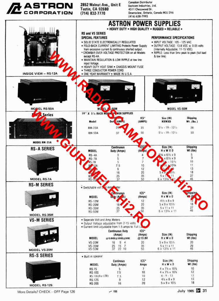
Conadion Distributor 2852 Walnut Avo., Unit E Eostcom Industries, ~ t d . kAsTRoN Tustin,CA!I2680 451 I chesswood Dr.
c 0 R PORAT ION (714) 832-7770 Downsview, Ontario, Canada M3J 2V6 (41 6) 638-7995
1 I ASTRON POWER SUPPLIES
INSIDE V I E W - RS-12A
HEAW DUTY HIGH QUALITY RUGGED RELIABLE RS ad VS SERIES SPECIAL FEATURES PERFORMANCE SPECIFICATIONS
SOLID STATE ELECTRONICALLY REGULATED INWT VOLTAGE: 105 - 125 VAC FOLDBACK CURRENT LIMITING Rot& Power Supply OUTPUT VOLTAGE: 13.8 VDC i 0.05 'mils from excessive current & wnlinuws shorted output. ( Inter~lty Adjustable: 11-15 VDC) CROWBAR OVER VOLTAGE PROTECTtON on all Mcdels RIPPLE: Less than 5mv peak to peak (full bad except AS-4A. & low line) MAINTAIN REGULATION & LOW R I m E at low llne input Vonage. HEAW DUTY HEAT SINK CHASSIS MOUNT FUSE THREE CONDUCTOR POWER CORD ONE YEAR WARRANTY MADE IN U.S.A.
I
MODEL R 5 5 0 A
RM-A Series
RS-A SERIES
MODEL RS-7A
R S - M SERIES
MODEL R S 3 5 M
V S - M SERIES
MOD EL VS-20M
RS-S SERIES
MODEL RS-SOM I MODEL VS-SOM 19" X 5 % RACK MOUNT POWER SUPPLIES
Continuous ICI' Sixe (IN) Shipping Medal Duty (AMPS) (AMPS) HXWXD Wt. (Ibs.)
ConHnuws ICS* Slzo (IN) Shlpplnp MODEL o w (Amps) (Amps) H x W X D Wt (lbs) RS-4A 3 4 3 % x 6 % x 9 5 RS- 7A 5 7 3% x 6% x 9 9 US-70 5 7 4 . 75'7 . lo3,. 10 RS-1OA 7.5 10 4 ~ 7 % x lo5/, 11 RS-t2A 9 12 4 % x 8 x 9 13 US-2OA 16 20 5 ~ 9 ~ 1 0 % 18 AS-35A 25 35 5 X l t x 1 1 . 27 RS-5OA 37 50 6 x 13% x 11 46
; Switchable volt and Amp meter
Continuous ICS' Slzs (IN) Shlpplng MODEL DuW (Amps) (Amps) H x W x D Wt (Ibs) RS-12M 9 12 4'/2 x 8 x 9 13 RS-2OM 16 20 5 x 9 x l O f i 18 US-35M 25 35 5 x 1 1 ~ 1 1 27 RS-5OM 37 50 6 x 13% x 11 46
Seperate Volt and Amp Meters Output Voltage adjustable from 2.15 volts Current limit adjustable trom 1.5 amps lo Full Load
Contlnuous Duty ICS' (Amps) (Amps) Slzs (IN) Shlpplng
MODEL @ts.matmoeapm @13.8V H x W x D WI (Ibs)
I
Built In soeaker Conllnous ICS' Slzo (IN) Shipplng
MODEL Duty (Amps) Amps HxWID WI (lbs) RS-IS 5 7 4 x 7% x 10% 10 RS-10s 7.5 10 4 x 7% x 10% 12 RS-1 OL(For LTRI 7.5 10 4 . 9 . 1 3 13
RS-12s 9 12 4 % x 8 x 9 13 RS.2OS 16 20 5 x 9 x 10% 18
MODEL RS-12s
More Deta i ls? CHECK-OFF Page 126 fl 155 July 1985 31
WWW.RADiOSCAMATORUL.Hi2.RO
WWW.GiURUMELE.Hi2.RO

trade off power for antenna gain at VHF?
These computer programs
simplify calculations and help you decide
If you operate at VHF or UHF frequencies and would like to find the most cost-effective way to in- crease your range - or if you have $100 to spend but don't know whether to invest it in higher power, more antenna gain, or a taller tower - a few minutes at your computer can give you projected communications ranges for any combination you wish to try. While pro- grams shown in fig. 1 and 2 are written for Commodore-64 and Texas Instruments-9914A com- puters, respectively, they can be easily converted, us- ing BASIC, for use on other microcomputers. Both free space range (for satellite communications) and range over real earth are given.
propagation curves Although propagation curves have been available
for about 40 years, most hams have either not been aware of them or have not known how to use them. The classical curves developed by Bell Labs cover fre- quencies from 200 kHz to 600 MHz, distances of 0.5 to 1000 miles, and are arranged in six sections cover- ing propagation over sea water, good soil, and poor soil for vertical and horizontal polarizations.' Typical inputs and outputs are expressed in terms of 1 kW transmitted from a grounded vertical antenna and units of field strength in dB above 1 microvolt per meter,
however, and one must be wise in the ways of antenna conversions to use them. Predictions are also com- plicated at HF, where antennas are usually located within a few wavelengths of ground, because actual antenna directivity and efficiency are directly affected by soil conductivity.
Propagation predictions at VHF and UHF are more straightforward because antennas at these frequen- cies are usually mounted many wavelengths above ground. At these frequencies the communications range is essentially independent of polarization used and soil type for antenna heights of 100 feet or more, and variations of not more than 3 or 4 dB are to be expected at heights of 25 feet. Based upon these facts (and other assumptions), the ESSA curves are useful for frequencies above 100 MHz.2
The computer programs described below utilize data taken from selected curves in reference 2. After you enter operating frequency, receiver sensitivity, transmitter power, and antenna heights and gains, the programs calculate your expected communications range. A typical output from the Commodore-64 pro- gram is shown in fig. 1A.
C-64 program description This section describes the program as written for
the Commodore-64 because the machine is very pop- ular among hams and because the program contains the most features. (Similar versions for other com- puters, with fewer features, will be described later.) In the Commodore-64 program shown in fig. 1, line
By Lynn A. Gerig, WASGFR, RR # I , Monroe- ville, lndiana 46773, and Joseph R. Hennel, 4316 Winston Drive, Ft. Wayne, lndiana 46806
32 July 1985
WWW.RADiOSCAMATORUL.Hi2.RO
WWW.GiURUMELE.Hi2.RO
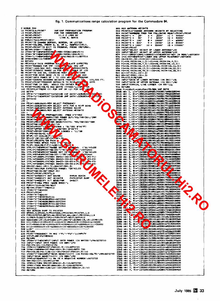
fig. 1. Communications range calculation program for the Commodore 64.
2 6 0 B U B 5 0 0 800 REM M E W HEl6HT8 10 PRINTCLIlPRINT" W/W PROPMATION PROGRW 802 P R 1 N T C L I " m lYlTEmA HEIGHTS BY BELECTIff i 12 WINTIPRINT* FOR THE WmOWRE 6 4 804 P R I N T " W R E FROM THE FOLLCUIff i WIW*IPRINTIPRINT 14 PRIN~IPRINT. V1.O C 1984 BY 606 PRINT-1 - 25' 6 - 2000' 11 - 30000' 16 PRINTIPRINT" LYNN A. GERIG BOB PRINT"2 - 30' 7 - 1 2 - 40000' 20 FORJ~ITOIOIPRINTIWEXT 8 1 0 PRINTm3 1 100' S - I=: 1 3 -0' 22 PRINT"T0 BORDER. SCREEN, OR LETTER 812 PRINTU4 - 24 PRINT"Cu0RS. PRESS 8, 8, OR L. RESPECTIVELY. 814 ~ I N T " ~ - :: : 26 PRINTnPRINTnTO EXIT TO PROGRM, PRESS <RETURN>. 820 PRINTIPRINT 3 0 GETAIIIF&I-'*THENSO 830 INPUT'SELECT HEIWT OF L D Y R I U n E W " l H 1 3 2 IFAI-"B"THEHDaKES3280, (F'€EK(53280)WDIS)+l BJ2 INPUT"%LECT H E I W T OF UPPER A N m m # H 2 3 4 I F P I I - " 8 " T ~ S 3 ~ l t (PEEK(53281)WD15)+1 834 IFHI<IORIP<IORHl>ISORH2>15THEHDRINT"~T I N rlENU"1WT0830 Sb I F A I - " L " T ~ E ~ ~ ~ , ( P E E K ( ~ ~ ~ ~ W D ~ S I + ~ I G O T D I O 836 I F H l M42THEHDRINT"LaER AND UPPER REVERED" I GOTOB30 J8 IFAS-CM.( lS>THEMO 840 HI-HI(H~,HZIIHI-H(H~)IHZ-H(HZI 4 0 GOTD30 050 Pi -VALIMIDI IHI , 1.3) ) I D I - V R L ( M I D I ~ H I . ~ . S ~ )
5 0 PRINTCLI'THIS PROGRAM WILL CRLCULATE EXPECTED 852 PZ-VIY(MID1(W.7,31) ID~-VCIL(MIDI(H., 10.3) I 5 2 P R 1 N T " R M S FOR VHF (100-175 M Z ) (WD UHF 854 P~-VALU.M~DI(HI.~~.~))ID~-VIIL~MIDI(UI.~~,~~ I 5 4 PRINT"(225-500 M Z I FREOUENCIES. WPROXIMTE 656 P ~ - V R L U . M ~ D I ( H . , ~ ~ , ~ ~ I I D ~ - V ~ ~ M I W ~ W , ~ ~ . ~ ) ) 54 PR2NT"DYNIYIIC R- I 8 FOR PATH LOBBES OF 125 858 PS-VIY(MIDI(HI.25.3) )IDS-VRL(MID*(H*,~B,SI~ 58 PRINTmTO 200 D8. COVERING rOST WPLICATIONB 860 91-INT(DI11.151+.5) 6 0 PRINT-FOR RCVR BEN8 .5 TO 10 MICRO-VOLTS AND 862 65- INT(D5I l . lSI+.SI 6 2 PR1NT"XHTR WUER OF 1 TO 1000 MTTS. PROGRM 870 PRINTCLIlRETURN 6 4 PRINT"COVER8 A N T E W HEIGHTS FROM 25 FT TO 100,000 FT. 900 1NPUT"WIN OF L D V R A N T E W ( I N DB1)"lGL 7 0 PRINT1PRINT"PROGRAM DEFlKlLTS TO RCVR SENS W D XMTR 902 INPUT"G4IN OF UPPER A N T E W ( I N DBI) " IW 7 2 PRINTU- I N DBM. Y I U D Y W RATMER UWIK WITH 904 1WUT"CDI)XIAL L I h E LOBBES ( I N DB) " lLL 7 4 PRINT"MICR0-VOLTS AND UATTS (Y-YES) "I I INPUT D I 906 RETURN 100 PRINTCLI0'PRESS <V> FOR WF OR <U> FOR UIIF8'tPRINT ZOO0 FI- lZSlFL-1001FLCl788l lP l HF WrLl 102 GETFI ZOOS MI 1, 1 ) ~ . 1 4 0 0 1 0 1 C Q 0 1 5 1 7 0 0 3 8 1 7 ~ 104 IFF*-"V" THENPRINT"ENTER1NG VHF DATA" I WBU820001 GOT0200 2010 WI( 1. 2 ) - m 1 S S O I O I L 0 0 3 0 1 7 0 W b I ~ 106 IFF*-"U"THEWRINTYENTERING UF DATA" I GOSUB~OOOI GOT0200 2015 MI 1, S ~ - ~ I S D 0 1 D 1 M O S 7 1 7 0 0 8 3 1 ~ 108 WT0102 zolo MOI 1, 4 1 - " 1 1 7 0 1 0 1 b ~ 0 ~ 0 1 7 ~ 0 ~ 1 ~ 1 0 0 ~ 199 1 2015 cnc 1. s ~ - = r l s o r o l ~ 7 o l b ~ I 1 5 1 ~ l s 200 PRINTl608UBb001REM SELECT FREWENCV 2030 W ( 1. 6 1 - ~ l ~ 1 0 l s # * o l 7 0 l 0 0 1 ~ 1 ~ ~ ~ 205 PRINTIGOSLIB~OIRE SELECT XUTR PUR I RCVR SEN8 2035 )(.I 1. 7~-~1000101~1701301~i~lUOO 210 PRINTIM)BUWO~IREM SELECT ANTENNA GaINS 2040 ml I. ~ ~ - m 1 1 ~ 1 3 2 1 0 0 1 7 0 1 U 1 7 b 1 ~ 1 S 4 Q 0 215 PRINTIGOWBWOIREM BELECT ANTENNA HEIGHTS 2045 W( 1, T ) ~ ~ ~ ~ ~ ~ ~ ~ ~ ~ c o ~ ~ I T ~ I ~ c o I I o I o o 220 1 zoso mc 1.io~-~rz~~m1rs~7o~uh~)1mz~sz~~rn 300 PR1NTCLIFI"W P R W ~ A T I O N I FRED -"F"MZ ZOsa l 1 1 1 ) ~ ~ 1 S 0 1 L O i ~ 2 1 0 1 7 7 ~ 1 ~ 1 0 4 4 0 542 PRINTIPRINT"TR/IMY(ITTER POYR WTI"PDITAB(SO))"DM Z O C ~ MI 1 r 1 2 1 ~ " l ~ l ~ 1 5 0 2 4 0 1 ~ ~ 1 ~ ~ 1 0 1 7 ~ 304 P R I N T T I U ~ ~ ~ I ~ ~ I T A . ( ~ O ~ " ~ T T B ' 2065 W.1 I. 1 3 ) - ~ 1 m Z 0 1 4 5 2 Y ) I ~ I U Q O l I ~ I O SO6 PRINTIPRINT"RECE1VER B E W l T I V I T V l *RD~TAB(30l"DB(( 2070 M f 1,14~-~133T70l50330177~l30440210330 308 PRINTTAB(22)MTAB(30) "W 2078 HI( I, 1 Z l ~ - ~ 1 S a S O O 1 ~ 1 7 0 4 1 0 1 ~ 1 0 ( * 0 310 PRINT1PRINTo'LOYR WTEW I "GL"DBI ~-HI*FT moo no( a, ~ ~ - ~ I ~ ~ ~ ~ ~ ~ ~ Q I ~ S I ~ Z I O ~ O O 312 PRINTnUPPER M E W I "W"DB1 a"H2"FT 20.5 MI 2, SI-~1100101~S2lLW#)i~i~1OSIO 314 P R I N T I P R I N T " ~ X I & L LINE LOBEE8 I "LLYDB 2OW 2. 4 ~ - ~ 1 1 0 0 l O l ~ l b 7 O W 1 U I W ~ 320 PL-PD-RD+WSL-LL lorn ml 2, ~ ~ ~ ~ i ~ 1 0 l ~ o a 7 s 1 ~ 1 0 0 1 ~ 1 ~ 0 l ~ ~ ~ ~ 322 W--37-ZOILOG I F ) /LOG (10) 2100 W ( 2. b1~~11003014SOW1701201WhW)~ 324 DF-1On(DF/2O1 IDF-INT(DF+.S) 2105 m( 2. 7 l - ~ 1 1 ~ l ~ l L z 1 2 s l ~ 1 W 1 1 0 3 7 0 326 PRINTIPR1NTPL"DB PATH 2110 MI 2. ~)~"1~14.1401651CO1701TS210400 328 PRINT-FREE SPKE PATH -"W~~MILES 211s mc 2, ~ ) - - i a 1 m r m r u 1 7 o i ~ s 1 ~ 1 0 4 2 0 350 PLIPL-ZOILOG (F/FI) /LOG (10) I PRINT 2120 m ( 2. 1 0 ~ - . 1 n i r o 1 ~ t 7 0 1 7 i z r s r ~ ~ i 0 4 4 0 352 I F P L < P I T W E N P R I N T " S NOT I N PROGRWI <"Sl"MILES 212s m( 2 . 1 1 ) - . 1 ~ 1 ~ 1 4 5 ~ 1 ~ 1 7 1 2 5 0 1 ~ 354 I F P L < P l T ~ I N T T A B ( 2 3 ) " < " D 1 ' ( ~ T M I l " I W T 0 4 0 0 2lSO -1 2 ~ 1 Z l ~ ~ I 3 0 2 l O l 3 o l s o 1 7 3 1 . s l ~ 2 1 l S O O 3% IFPL>PSTHENPRINT"RlWGE NOT I N PRUZRMI >"SS"MILES 21SS MI 2,1S~-~13anslSOSOOl74~I.I4ZMOUiD 358 IFFt>PSTWENPRINTTAB(Z31 *>"D5" ( W T MI) "1GOT0400 2140 mc 2, I4~-'lUmol50S4017SS701T047~ S60 IFPL>WIANWL<P2TW!N D(CDl+(D2-DI)I(PL-Pl)/(P2-P1) 2145 MI 2. 1 ~ l ) ~ ~ ~ ~ 4 0 1 5 0 3 7 5 1 7 4 4 1 0 1 . # . 0 ~ 562 IFPL>IPZWDPL<PSTHEN DN-D2+ (03-DZ) 1 (PC-P21 / (PJ-P21 2150 H.( 3. ~ ) r ~ 1 2 5 0 1 ~ 1 5 5 0 4 5 1 ~ ~ 0 ~ 1 7 4 1 ~ ~ 364 IFPL>-PSWDPL<P4TMN D(CDS+(D4-D3)1(PL-PS)/(P4-P31 2155 1401 3. 4~-~11502015~16SOW1771W205300 366 IFPL>IP4AWPL<PSTKN DN=D4+(D3-D4)I(PL-P41/(PS-P41 2 1 ~ IW( 3. ~~-"1100~1sz0701651~lm2c0~10~~ W D~-INT(DNII.~S~+.SII~INT(DN+.SI 2165 HOc 3. b ~ ~ ' 1 1 0 0 W l ~ l W I I O l T S 2 7 S - 370 PRINT"MX1fWl EXPECTED R-I "DSa'MILES 2170 HI( 3. 7 ~ - m 1 1 ~ 1 4 0 1 0 0 1 ~ 1 ~ 1 T b 3 0 0 Z 1 1 4 0 0 372 PRINTTAB(24)DN" ( W T MI ) 2175 Hl( 3. I)-~I2s110131~1471~1U2702045.0 400 PRINTIPRINTIPRINTLLI 2190 MI 3, ~ 1 ~ ~ 1 ~ ~ 1 ~ 1 4 0 1 ~ 0 1 6 5 l ~ 1 7 ~ ~ 1 0 402 PRINT"611Y)DIFY ANT GAINS R-RUN M A I N 2 1 m w.( ~~10)~~1251501351701~21~17~402034~ 404 PRINT~H-~YIDIFY ANT ~ I W T S P-PRINTER D W ~ a l s o mc s . t ~ ~ - = ~ n 1 . s ~ 4 s n o ~ ~ t n 2 . 0 z i o ~ o o 406 PRINT-x-~DIFV R/T BENB/PYI a-WIT alm m( ~ . ~ ~ ~ - ~ ~ ~ ~ ~ O I S ~ Z ~ ~ ~ Z Y ) I ~ ~ Z O S U O 408 PRINTUF-NEW FREO t B M E WNDra'* 2200 W ( S ~ I S ~ - ~ 1 ~ 2 7 0 1 4 U 0 0 1 L O 5 2 0 1 7 0 ~ 2 0 ~ 2 0 410 FORJ-ITOIOIGETAIINEXT 2106 W l 3,14)-.1SSS201bSS7017S4001~ 412 GETAIaIFAI-""THEN412 2'210 MI 3, I S ~ - ~ I 3 5 3 5 5 1 ~ 1 7 S 4 3 5 1 7 . 4 L o ~ 413 IFAI-"P'THEN43O 2215 Wc 4. 4 ~ - ~ 1 l 0 0 3 0 1 ~ 1 ~ ~ ~ l ~ ~ 414 PRINTlPRINT 2220 HI( 4, 5)-"11~~1510401~0110170153241~40 415 IFAI-"R"THEN100 2225 H.1 4, 6 ) - ~ 1 1 L O b O 1 ~ 1 1 0 1 6 1 1 ~ 1 7 ~ 3 5 0 416 lFAI-"O"TCENSVS6S126 2230 W( 4. 7)-~l231001~14Sl65IU1~~2lM20 4 18 IFAI-"G"THENGOBUWOOI GOT0300 223s mc 4. .)-.1151351571.01bszoo1~Io150 420 I F I I I - " H " T H E N G O ~ U ~ ~ ~ ~ I W T O ~ O O 2240 WI( 4, 1~-~1301701CO2101LI2~1W40021lSOO 422 IFAI-"X "THENC108UB700s wTOS00 2245 H.1 4.10)-w130110151LZS1c.2C01~104Ts 424 IFAS-"F"THENGOBUB~~~IWTOSOO ml 4 . 1 1 1 - ~ 1 ~ ~ ~ 1 ~ ~ o 1 7 0 2 7 5 1 ~ 3 7 5 a 0 c l ~ 426 GOT0412 2255 MI 4 ~ l 2 ~ ~ " l S S 2 b O l b O Z T 4 1 b ~ l u 4 0 0 2 0 ~ 430 REM SCREEN DUW TO PRINTER 2 2 m wc 4.t3~-min~m1m~i~ss30t72380~2340 432 OPENS. 310PEN4.41 PRINTHOIl lPRINT#41 PRINTI4, L L I 2265 WI( 4 . 1 4 ~ - ~ 1 ~ 1 . 0 1 5 0 3 4 0 1 b 2 ~ 1 7 W 2 0 ~ 434 F O R J - O T O ~ ~ ~ I G E T # ~ . ~ I I P R I N T ~ ~ . ~ I I I ~ X T I P R I N T ~ ~ , L L I 2270 1401 ~ . I s ) - " ~ ~ ~ w ~ s ~ ~ ~ L ~ s o I ~ ~ u o ~ o ~ L z o 436 CLOBE41CL-SIFORJ-IT MI PRINT IN EX TI GO TO^^^ 2275 H I ( 5. 5 ~ - ' 1 1 ~ 5 1 4 ~ 1 S J 1 1 0 1 6 5 1 ~ 500 HOI-CCR.(~~~ICLIICCR.(~~~IIDI-'N~IDI~(~S,ISIIDII+I(~S~ 2280 +I@( 5, 6 ~ - ~ l ~ l 4 S l l D l ~ 1 3 5 1 7 0 1 ~ 2 0 4 Y O 502 Hlll-25~H~2~-501H(3l-1001H~4~-5001H~5~-loOg1H~6~-2000 2295 MI S, 7)~"12512014S140131LOlLSl~ 504 H ~ ~ ~ ~ ~ I H ~ ~ ~ - ~ ~ ~ ~ ~ I ~ ~ ~ I - ~ H H K ) I H ~ I ~ I - ~ I H ~ ~ I I - ~ ~ ~ ~ ~ 2290 mc s. m ~ - - ~ n r ~ ~ ~ ~ w ~ ~ 2 2 o o ~ ~ ~ ~ ~ s ~ ~ 4 o o
~ ( 1 2 1 - 4 ~ 1 n ( 1 3 ~ . ~ 1 n ~ 1 4 ~ - 8 0 0 ~ 1 ~ ~ 1 5 1 - 1 0 0 0 ~ z m ml 5. 9 , - n 1 n 1 7 4 1 s 0 2 0 s l m ~ 1 u 2 ~ ~ 1 4 ~ L L W ~ --------------------------------------" 2300 H . 1 5.10)-"12720015022S1592401~260200435
510 RETURN 2305 HI( 5,11)=*12923515526S16027Sib5~202~ 600 PRINT"FRE0uENCY 1N m 2 ('FL"-"FU")") I 1NPUTF 2310 )(.I 5.12l-~IR1801282~1M)~1673~20f500 602 IFF<RORFFUTHENMK) 2315 H.1 5.13l-~la51801303151572101bsS742005$0 604 RETURN 2320 H I ( 5.14)-~12B2M)IS13~15038016841020~ 700 IFW-"YUTHENINPUT"INPUT XMTR WUER ( I N M T T 8 ) "1PUlWT0710 2325 H .1 5.15)-"12.260132375i6045417545519TL00 702 1NPUT"INPUT XMTR WYER ( I N DBII)"IPD 2354 H I ( 6. 61-~125l00l50l54l~150168180200S50 704 PY-(PD-30) / lOsPY- lO"PY 2 ~ 5 H.1 6. 7)-~1221301491~lM)lBO170220200375 706 ZFPW>-I TUE-INT (PW~IO*. 5) IIOIGOTO~ZO 2310 n r c a. a~--rnraars4lool60~101~~40mos 708 I F ~ < I T ~ I N T ( P Y 1 1 0 0 0 + . 5 ~ / 1 0 W l W T O 720 Z Y 5 H .1 L. 9)-'12s1901502aOlLO2SS1~265~JO 710 PD-IOILOCI(PW) /Lffi(10)+301PD-INT(PD110+.5) 110 2350 H . 1 6.10)-*1262121502401602M)167275200445 720 IFW-*V*TbENIHWT*RCW SENEITIVITY ( I N M I C R ~ - V O L T S ) " I R ? ~ I W T O ~ ~ O 2335 HI( 6.11)-'1292~153280163300170325~ 722 1HWT"RCVR SENSITIVITY ( I N DM)"IRD 2StQ H . 1 6.12)-'12s1801292~515030616633S200510 723 IFRD>OTklEHSIINT"<I IW I 8 A WEGATIVE NUnBER"~60T0722 2365 I t s ( 6.13~-"1~1801303~1SSStQl6E390aOSS90 724 RM-<RD+107) /201M-lO"R1( 2370 H.1 6,14)-"127220131370155405l694302~20 726 1FRI(>-ITHEN ~ I K T ( M 1 1 0 + . 5 ~ / 1 0 1 W T 0 7 4 0 2375 H .1 6,15)-m127220132410155440168~S~25 728 lFR(K1THEN WINT(MI100+.5)11001WTO740 2380 H . 1 7. 7~-"l2Sl65lJoI~1~2101692WZOOI00 730 RD-20IL06(R10/L06(10~-1071RD~INT(RD110+~5~/10 2- H . 1 7, 81-01252001432201572W1662L0200430 740 RETURN 2390 H .1 7. 9~~"12722515S2~1642s0170300aoO4M
July 1985 33
WWW.RADiOSCAMATORUL.Hi2.RO
WWW.GiURUMELE.Hi2.RO
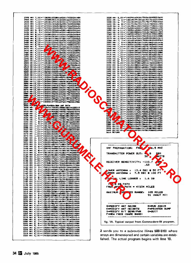
..-- 3355 nee i ~ 1 1 ~ - ~ ~ 3 e 2 u ~ a s z e o l ~ s ~ ~ 1 7 s s ~ s ~ ~ o 4 7 0 3360 me 6 12)-"13728515530017031517~34021l~ X S A S He1 &~13l-~13E530165~01743751~1395210540 ---- . -.-- - - - - - ~ - - 3370 HI1 6.14)-'140375164&17~4151~1430210~~0 3375 nee a.1s)--t4wls~a744oi7~4ssie44mz1~~0 3580 MI 7, 7)-~1321651651001752WlW240zOCn63
...................................... VHF PROPAGATION: FREQ - 146.5 HHZ
TRANSMITTER POWER OUT1 44.8 DBM 30 WATTS
RECEIVER SENSITIVITYI -110.7 DBM .65 W
LOWER ANTENNA 1 12.4 DB I SO F T UPPER ANTENNA : 7.5 D B I 100 F T
COAXIAL L I N E LOBBEB : 1.6 DB
173.8 DB PATH FREE SPACE PATH = 47224 MILES
MAXlMWl EXPECTED RANQE: 10s MILES 91 CNAUT M I )
...................................... Q-MODIFY ANT QAINS R-RUN AQAIN H-MODIFY ANT HEIQHTS P-PRINTER D W XmtKIDIFY R/T BENB/PWR 0 - W I T F-NEW FREQ (SAME BAND) ......................................
fig. 1A. Typical output from Commodore-64 program.
! sends you to a subroutine (lines 500-510) where lrrays are dimensioned and certain variables are estab- ished. The actual program begins with line 10.
34 July 1985
WWW.RADiOSCAMATORUL.Hi2.RO
WWW.GiURUMELE.Hi2.RO
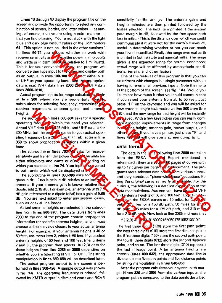
Lines 10 through 40 display the program title on the screen and provide the opportunity to select any com- bination of screen, border, and letter colors - assum- ing, of course, that you're using a color monitor - that you find pleasing. You're not stuck with the light blue and dark blue default colors of the Commodore 64. (This option is not included in the other versions. In lines 50-74 you choose whether to work with receiver sensitivity and transmitter power in microvolts and watts or in dBm (decibels relative to 1 milliwatt). This is for your convenience only; the program will convert either type input to the other and display both as an output. In lines 100-108 you select either VHF or UHF as your operating band, and the appropriate data is read (VHF data lines 2000-2610 or UHF data lines 3000-3610).
Actual program inputs for range calculations begin at line 200 where you are sequentially sent to subroutines for selecting frequency, transmitter and receiver parameters, antenna gains, and antenna heights.
The subroutine in lines 600-604 asks for a specific operating frequency within the band you selected. Actual VHF data is for 125 MHz, and UHF data is for 300 MHz, but the program scales to your actual oper- ating frequency by a 20 x Log (FIF ref) factor in line 350 to show propagation variations within a given band.
The subroutine in lines 700-740 asks for receiver sensitivity and transmitter power output. The units are either microvolts and watts or dBm, depending on which you selected in line 74. Your input is converted to both units which will be displayed later.
The subroutine in lines 900-906 asks for antenna gains in dBi. This is gain in dB relative to an isotropic antenna. If your antenna gain is known relative to a dipole, add 2.15 dB. For example, an antenna with 7.5 dB gain referenced to a dipole (dBd) has a gain of 9.65 dBi. You are next asked to enter any system losses, such as coaxial line losses.
Actual antenna heights are selected in the subrou- tine from lines 800-870. The data tables from lines 2000 to the end of the program contain propagation information for specific antenna heights, so you must choose a discrete value closest to your actual antenna height. For example, if your antenna height is 40 or 60 feet, use menu item 2, which is 50 feet. If you select antenna heights of 50 feet and 100 feet (menu items 2 and 31, the program then selects HS (2,3) data for these heights from line 2085 or 3085 depending on whether you are operating at VHF or UHF. The string manipulation in lines 850-858 will be described later.
The actual program output to the screen is per- formed in lines 300-426. A sample output was shown in fig. 1A. The operating frequency is printed, fol- lowed by XMTR output in dBm and watts and RCVR
sensitivity in dBm and pv. The antenna gains and heights selected are then printed followed by the losses selected. The next item printed is the system path margin in dB, followed by the free space path loss in miles. (This is the distance over which you could communicate if it were not for the earth's curvature, useful in determining whether or not you can reach your favorite satellite.) Finally, the range over real earth is printed in both statute and nautical miles. The range given is the expected range for normal conditions; actual range will be affected by atmospheric condi- tions, terrain, and other factors.
One of the features of this program is that you can experiment with changes in a single parameter without having to re-enter all previous inputs. Note the menu at the bottom of the screen (see fig. 1A). Would you like to see how much further you could communicate if you raised your antenna from 25 to 50 feet. Just press "H" on the keyboard and you will be asked for new antenna height (subroutine at line 800 from line 4201, and the new range for that height will be instantly displayed. With a few keystrokes you can easily com- pare expected improvements in range from changes in antenna height, antenna gain, power output, and other factors. If you have a printer, just press "P" and lines 430-436 will give you a screen dump to it.
data format The data in the lines following line 2000 are taken
from the ESSA Technical Report mentioned in reference 2; there are about 100 pages of curves with up to 17 curves per page in that document. The pro- grams store selected data points from various curves, and they construct "piece-wise linear" equations fit- ting the original curve as nearly as possible. For the curious, the following is a detailed explanation of the data manipulations. Assume you have selected VHF and antenna heights of 50 and 100 feet. Logical break- points in the ESSA curves are 10 miles for a 120 dB path, 32 miles for a 150 dB path, 50 miles for a 165 dB path, 105 miles for a 175 dB path, and 310 miles for a 210 dB path. Now look at line 2085 and note that
H$(2,3) = "120010150032165050175105210310".
The first three digits (120) store the first path point; the next three digits (010) store the first distance point; the third three digits (150) store the second path point; the fourth three digits (032) store the second distance point, and so on. The last three digits (310) represent the last mileage point. After antenna heights are chosen (lines 800-8321, the appropriate data line is divided up into five path points and five distance points by string manipulation in lines 840-858.
After the program calculates your system path mar- gin (lines 320 and 350) from the various inputs, the program path is compared to the data points described
July 1985 35
WWW.RADiOSCAMATORUL.Hi2.RO
WWW.GiURUMELE.Hi2.RO
~u SPECIAL
IC-745 , $789.00 Plus shipping
. . . Also displayinl: rhe p o p r t k ~ r occes.~.ories ncc~li,d ro c.ornplr11, o HAM STATION
ARRL PUBLICATIONS AEA PRODUCTS AMPHENOL ALPHA DELTA ASTRON AUSTIN ANTENNAS AVANT1
7 1 UELDEN BENCHER B & W DAIWA HAM-KEY HUSTLER KLM LARSEN MIRAGE ROHN
KENWOOD TELEX/HY-GAIN VIUROPLEX WELZ ETC. SPECIAL
NEW r / 113 OPEN SIX DAYS A WEEK
Tubes 3-4002 ................... .$85.00 7360 ...................... $1 0.00 3-5002. .................... 85.00 7735A ...................... 27.50 4-400A.. .................. .80.00 81 22 ..................... .1 1 0.00 4CX2508 ................. 50.00 81 56 ........................ 12.50 5728 ........................ 55.00 8643 ........................ 82.50 81 1A ........................ 12.00 8844 ........................ 26.50 813 .......................... 30.00 8873 ...................... 175.00 61468 ........................ 6.50 8874 ...................... 195.00 6360 .......................... 4.25 8877 ...................... 500.00 68838.. ...................... 6.75 8908 ........................ 12.50
MAJOR BRANDS ON RECEIVER TUBES 75% off list
Semiconductors MRF 245lSD1416 ..$30.00 SD1088 ................... 19.95 MRF 454 ................. 14.95 2N3055 ....................... 750 MRF 455 ................. 10.95 2N6084 .................... 12.50
RF Connectors PI259 ................. 101$4.95 M358 ................... 2.50 ea. PI258 ................... 10/8.95 M359 ................. ..1.75 ea. UG 1751176 .......... 1011.60 Type "N" Twist on UG2551u .............. 2.50 ea. (RGBIu) ............. .$4.75 ea. UG273/u .............. 2.25 ea. Minimum Order $25.00 - Allow $3.00 min. tor UPS charqes irr
RON-ANTENNAS -? [q 1 ' , COMMUNICATIONS A STEP NO NO RADIALS! IN TUNERS! FORWARD HF
NO COMPROMISE!
Models From
. C , 160-10 Meters
- - I
Cnmpar~nR antenna< Frank rnent~oned to me that the lrotron was 59 + 10 dB whereas the outrtde antenna was only S9+ 5 dB1 Hrre the lsotron actually put out a better s~pnal than the regular antenna' Probably s k ~ p angle. ect , but who cares? The performance of the lsotmn 40 IS lust platn phenomen- al S e e revlew In October 73. 1984
F~nally, a full sue Antenna In a 3-d~menstonal package Perfect for I ~ m ~ t e d space RV's, Marlne and mar? The lsotrons offer you excellent transm~ttlng per-
formance along w ~ t h low notse reception and a sensltlve recelvlnR aual~ty
Bl lAL COMPANY S.R. 2, Box 62. Dept. 91
Eucha. Ok. 74342 PH: 916-253-4094
WWW.RADiOSCAMATORUL.Hi2.RO
WWW.GiURUMELE.Hi2.RO
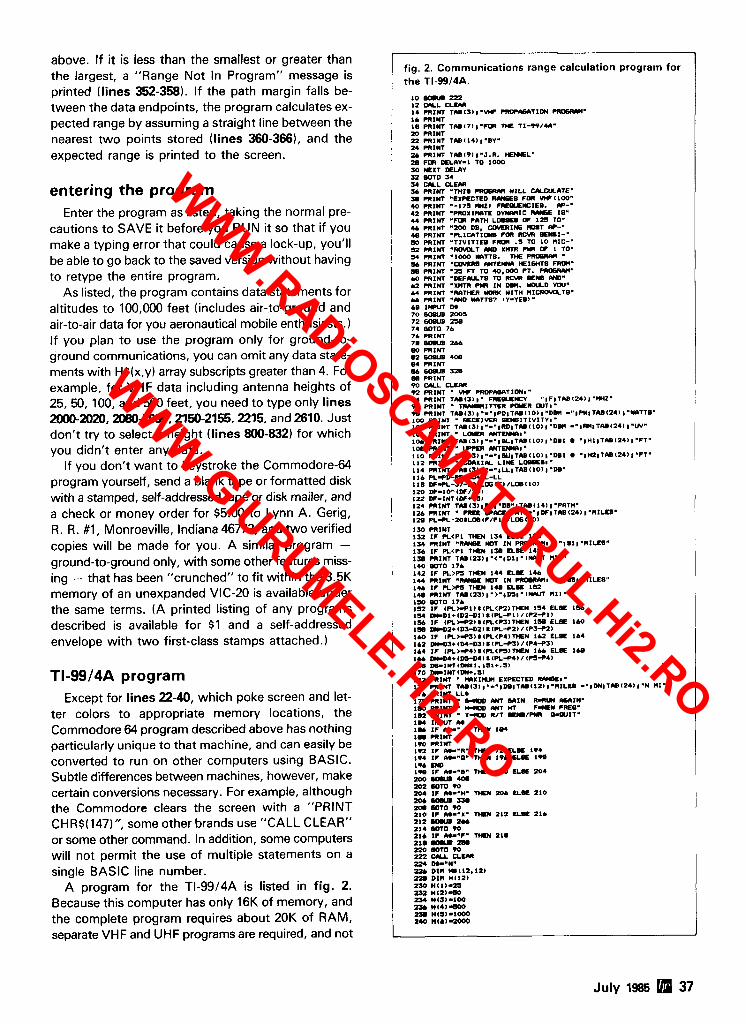
above. If it is less than the smallest or greater than the largest, a "Range Not In Program" message is printed (lines 352-358). If the path margin falls be- tween the data endpoints, the program calculates ex- pected range by assuming a straight line between the nearest two points stored (lines 360-3661, and the expected range is printed to the screen.
entering the program Enter the program as listed, taking the normal pre-
cautions to SAVE it before you RUN it so that if you make a typing error that could cause a lock-up, you'll be able to go back to the saved version without having to retype the entire program.
As listed, the program contains data statements for altitudes to 100,000 feet (includes air-to-ground and air-to-air data for you aeronautical mobile enthusiasts.) If you plan to use the program only for ground-to- ground communications, you can omit any data state- ments with H$(x,y) array subscripts greater than 4. For example, for VHF data including antenna heights of 25,50, 100, and 500 feet, you need to type only lines 2000-2020.2080-2090.2150-2156.2215. and 2610. Just don't try to select a height (lines 800-832) for which you didn't enter any data.
If you don't want to keystroke the Commodore-64 program yourself, send a blank tape or formatted disk with a stamped, self-addressed tape or disk mailer, and a check or money order for $5.00 to Lynn A. Gerig, R. R. #1, Monroeville, Indiana 46773, and two verified copies will be made for you. A similar program - ground-to-ground only, with some other features miss- ing - that has been "crunched" to fit within the 3.5K memory of an unexpanded VIC-20 is available under the same terms. (A printed listing of any programs described is available for $1 and a self-addressed envelope with two first-class stamps attached.)
TI-9914A program Except for lines 22-40, which poke screen and let-
ter colors to appropriate memory locations, the Commodore 64 program described above has nothing particularly unique to that machine, and can easily be converted to run on other computers using BASIC. Subtle differences between machines, however, make certain conversions necessary. For example, although the Commodore clears the screen with a "PRINT CHR$(147)", some other brands use "CALL CLEAR" or some other command. In addition, some computers will not permit the use of multiple statements on a single BASIC line number.
A program for the TI-9914A is listed in fig. 2. Because this computer has only 16K of memory, and the complete program requires about 20K of RAM, separate VHF and UHF programs are required, and not
I
fig. 2. Communications range calculation program for the TI-99/4A.
10 CQU m 12 CULL C L E M 1 4 PRINT TUlS11.VIF m D W T I O 1 -. 1. mlm 1 8 PRINT T U ( 7 I l . F m T I E TI-9914A. m .OINT - - . . . -. . . 22 PRlNT TAB(14)a.BV" i 4 PRINT 2 4 PRlNT TU(911.J.R. nEHEL" 2 8 FOR DELLY-1 TO 1000 SO WXT DELhY 31 WTO U S4 U Y L CLEM Y PRINT -trite ~osnm u r L L ULCULOTE" 31 PRINT "EXPECTED It-8 FOR W I 1 0 0 " 40 PRINT '-173 M 1 1 -1EI. W-. 42 PRINT .PROXI-= D Y W I C R W 18" 44 PRINT .FOR M T H LOWE8 OF 125 TO" 44 PRINT "200 Dm. COMRIffi lQDT W-• 48 PRINT .RICATILWB FOR RCVR S E M I - " 50 PRlNT "T IVIT IE8 F R m .3 TO 1 0 NIC-" 52 PRINT WOVCLT IW XMTR P*R OF 1 10" Y PRINT -1000 WTTB. TnE PR06RM 5 4 PRINT -- M E W n E I M B F R m " S PRINT -23 FT TO 40.000 FT. -M" 40 PRlNT VEFIYLTS TO RCW S E M IW. b 2 PRINT - x m n m IN DW. uu~ v w - 44 PRlNT .RATHER *ORK UITH MIC-TO* 4 4 PRINT "nND WTT87 IY-YEB). ae 1- M
72 MSUB ZSE 74 WTO 74 76 PRlNT 76 WWB 244 w PRINT 0 2 60M 408 M mlw E4 - 328 m PRlNT -- 90 CULL ? E M 92 PRINT VIF PROPn6aTIDN," 94 PRINT ~ A . ( S l l w FREOUEHEY " IF ITh8(24)1"WZ. 9 4 PRINT -1TTER PWER WTI. TB PRINT T~(S))"-.IPDIT(U(IOII.DW - "#Pw1TUl241 I'WTTS" 100 PRINT m E I V E R %WBITIVITV,. 102 PRINT T U I ~ I ~ . - " ~ R D I T U ( I O ) I " D m - " l l b l 1 T U I 2 4 l l . W " 104 PRINT . LOYR M-I' 104 PRINT TA~(~~I.-.IBCITA.(LO)I~D~I * I H I I T L ~ ( W I I " F T * 108 PRINT " M amDCrca1. 110 PRINT ~ h B ~ 3 l ~ ~ - ~ ~ W ~ T ~ I l O l ~ ~ M I l " I M & T O ( Z ~ ) I " F T * 112 mxw COLXIK LIWE LCBsEmm 114 PRINT T L I ~ ( ~ I I " - " I U I T M ( ~ O ~ I ~ D B ~
iao w - i o - t ~ ~ / m ~ 122 DF-INTlDF+.S) 124 PRINT TAI(SI(PL(.DB"ITMII~II'PITH~ 124 PRINT ' FM!E W m P L T H - * I D F I T U ( ~ ~ I I . M I L E ~ ' 128 PL-R-aOtLOO(F/Fll/L06(10)
1-30 PRINT 132 I F R < P l T t€N 134 ELSE I S 4 1- PRINT "R(VBE NDT I N PROWMI <"18ll.MlLE8" I S 4 I F PL<Pl TM)) 1 W ELSE 142 1Y) PRINT T ~ D ~ ~ ~ ) I " < " I D ~ I . I N M J T M I ) " 140 WTO 174 i r a I F R>PS ~m 144 ELSE 146 144 PRINT . R M M K I T I N -MI >"l(nl.MILEBa' 1I. I F P L M TIM 1- ELSE 152 1- PRINT T U ( 2 3 I , - > - , D S l * ( I Y M MI). . . l S 6 WTO 174 132 I F ( P L > ~ l ) t ( R < P 2 l T n E N 154 ELSE 154 154 DnDl+(D2-Dl)t(R+l)/~P24ll 154 I F l R > I C 2 l t l P L < C I l T M E N 159 ELSE 140 1% D)CD2+~D3-D2l1lW+2lIlP3+2l 140 I F (PL>lrS)LtPL<P4ITIEN 142 EL#€ 164 1.2 ~DS*lM-D3)~~CL93l/lP443) 164 I F l P L > I C I l 8 ( R < r S > l t € N 144 EL% 1CB 1- D n M * ~ D C M l t ~ P L ~ 4 1 / ( r S 9 4 1 lbe De-INT~Dy*I. l31+.S) 170 D(CINT(DIC.5l 172 PRINT W X I M EXPECTED R-1. 174 PRINT T U ( 3 1 I.-"ID.ITU(L~I ).MILE8 -"IDNITAB(~~)I.N MI" 174 PRINT LL* 178 PRINT - Ml a 1 N WRlN W I N ' 1 m PRINT " moD nNT nT F e w CREO" 102 PRINT . X- R I T llOYBICYI W I T . 1 W 1 I M M. 1- I F H-' TIM I W 1- PRINT l W PRINT 172 I F m-.R' T m 72 EL= 194 194 I F O.r-0" T m 19. UE 198 194 W it. I F M-.B" T H N 200 EL= 204 200YIW40. -.. .--- ~
nn W D w 204 I T M-94. TIM '204 ELSE 210 Z D L Y U I U . aa SOTO w 210 IF M--x- TIM 212 ua 2 1 ~
-. - - .. pL DIM m(.L12,121 22. DIM n1121
July 1985 37
WWW.RADiOSCAMATORUL.Hi2.RO
WWW.GiURUMELE.Hi2.RO
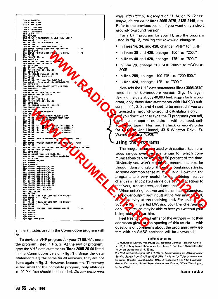
1 4 1 U ( 7 ) 3 0 0 0 264 Mi.)-10000 246 M<9)-ISQQO 248 H(10)-20000 250 M(l l l -10000 252 H(l2)-40QY) 254 LL*-.---------------------------. n+ rrrurar. 25. PRINT FIILPLIEWCV I N ) H Z (100-175). 240 I IPUT 'IF
244 mmmd 244 I F DI-'V. THEN 2bE ELOE 272 a u IW - 1 m r r xm~ pm (IN u n ~ ~ e ~ " S P Y 270 w l o a+a 272 I- -1- xmr par^ (IN o m , , -*PO 274 PRINT 274 -(PO-Y))/ IO 27. R l O " r * 10 I F PW>-1 TIEW 282 ELSE 294 2.2 RcINTICY*IO+.S)/IO 2.4 6010 29a 2U I F W l T K N ZBB
290 WTO Z U 292 PD-108LBcFW)/Lffi(10)*W 294 PD-lNT(PD8ld+.S)/IO 294 m1h-r me IF oo--v- TIM soo aes 304 100 IIPUT . BE- ( I N MICROWLTI)) so2 -0 322 so4 I lPVT .RCw BLNBITIVITY ( I N o m )
UO CIYL C L W U 2 PRINT -- LmOlH HEIWTB BY. S34 PRINT --CTIM5 HIIIU) FROM T W "
PRINT 540 PRlYT bi PRINT .I- n. r ~ o o o * 9- lsooo.- 344 PRINT "2- 50' 6- 2000 '10- 10000'' ~ 4 4 mztn -1- 100' 7- smo' 11- YYDO'. W PRINT -4- 500' 8- 10000' 12- 40000" UQ PRINT 3sa m r m 354 1- "BUECT W z I W OF LY1 WT-8 .*MI UL PRINT sm I- .=LECT ~ I W OF um m m a -1142 SM) PRINT
I L L
all the altitudes used in the Commodore program will fit.
To devise a VHF program for your TI-99/4A, enter the program listed in fig. 2. At the end of program, type the VHF data statements (lines 2005-2610) listed in the Commodore version (fig. 1). Since the data statements are the same for all versions, they are not listed again in fig. 2. However, because the TI memory is too small for the complete program, only altitudes to 40,000 feet should be included. Do not enter data
lines with HSlx, y/ subscripts of 13, 14, or 15. For ex- ample, do not enter lines 2065-2075, 2135-2145, etc. Refer to the previous section if you want only a short ground-to-ground version.
For a UHF program for your TI, use the program listed in fig. 2, making the following changes:
In lines 14.34, and 430, change "VHF" to "UHF."
In lines 38 and 426, change "100" to "200."
In lines 40 and 428, change "175" to "500."
In line 70, change "GOSUB 2005" to "GOSUB 3005."
In line 258, change "100-175" to "200-500."
In line 424, change "125" to "300."
Now add the UHF data statements (lines 3005-3610) listed in the Commodore version (fig. I), again deleting the data above 40,000 feet. Again for this pro- gram, only those data statements with H$(X,Y) sub- scripts of I , 2, 3, and 4 need to be entered if you are interested in ground-to-ground calculations only.
If you don't want to type the TI programs yourself, send a blank tape - no disks - with stamped, self- addressed tape mailer, and a check or money order for $5.00 to Joe Hennel, 4316 Winston Drive, Ft. Wayne, lndian-
\ using the programs The program must be used with caution. Each pro-
vides ranges over average terrain for which com- munications can be expected 50 percent of the time. Obviously you won't be able to communicate as far through dense jungle or through mountainous areas, so some common sense must be used. However, the programs are very useful for determining relative changes in anticipated range due to modifications to receivers, transmitters, and antennas.
When entering receiver and transmitter parameters, use power output (not input) at the transmitting end, and sensitivity at the receiving end. For example, if you are running a full kW, and your friend is running only 10 watts, he may be able to hear you without your being able to hear him.
Feel free to contact either of the authors - at their addresses given at the opening of this article - with questions or comments about the programs; only let- ters with an SASE enclosed will be answered.
references 1. Propagation Curves, Reporf966-6C, National Defense Research Commit- tee 15, Bell Telephone Laboratories, Inc.. Issue 3, October, 1944 (declassified to OPEN status March 8. 1946). 2. ESSA Technical Repori ERL 11 1-ITS 79, Transmission Loss Atlas for Select Serv~ce Bands from 0.125 to 15.5 GHz, Institute for Telecommunication Sciences, Boulder Colorado, May, 1969. (Available for $1.25 from Superinten- dent of Documents, United States Government Printing Office, Washington, D. C. 20402.)
ham radio
38 July 1985
WWW.RADiOSCAMATORUL.Hi2.RO
WWW.GiURUMELE.Hi2.RO
ANTENNA SALE HYGAIN TOWERS HG37SS . . . . . . . . . . . . . . . . . . 745.00 HG52SS . . . . . . . . . . . . . . . . . . 1095.00 HG54HD . . . . . . . . . . . . . . . . . . 1675.00 HGiOHD . . . . . . . . . . . . . . . . . . 2675.00
CUSHCRAFT A3.. . . . . . . . . . . . . . . . . . . . . . . . 205 00 A4.. . . . . . . . . . . . . . . . . . . . . . . . 275.00 40-CD2.. . . . . . . . . . . . . . . . . . . 275 00
ARX2B . :. . . . . . . . . . . . . . . . . . 35.00 A144-11. . . . . . . . . . . . . . . . . . . . 46 00 A144-20T . . . . . . . . . . . . . . . . . . 6900 4248 . . . . . . . . . . . . . . . . . . . . . . 75.00 AOP.. . . . . . . . . . . . . . . . . . . . . . 137 00
KLM KT34A . . . . . KT34XA ... 432-2OLBX. 432-3OLBX. 435-180 . . . 435-40C . . . 2 ~ - 1 3 ~ 6 ~ ................. 77.00 2M-14C . . . . . . . . . . . . . . . . . . . . 85.00 2M-16LBX . . . . . . . . . . . . . . . . . 89.00 2M-22C.. . . . . . . . . . . . . . . . . . . 115.00
HYGAIN
EN86 . . . . . . . . . . . . . . . . . . . . . . 19.95
HUSTLER 25"'o OFF ALL MOBILE 6BTV . . . . . . . . . . . . . . . . . . . . . . 12500
AEA 144% . . . . . . . . . . . . . . . . . . . . . 42.00
BUTTERNUT HF6V . . . . . . . . . . . . . . . . . . . . . . 110.00 HF2V. . . . . . . . . . . . . . . . . . . . . . 110.00
LARSEN LM 518 MAG.. . . . . . . . . . . . . . 36.95
ROTATORS CD45.. . . . . . . . . . . . . . . . . . . . . 139.00 HAM IV . . . . . . . . . . . . . . . . . . . . 228.00 T2X . . . . . . . . . . . . . . . . . . . . . . . 275.00
AVANT1 2M . . . . . . . . . . . . . . . . 29.95 HI -0 BAL . . . . . . . . . . . . . . 9.95
KENPRO KR400 . . . . . . . . . . . . . . . . . . . . . 11 9.00 KR500 . . . . . . . . . . . . . . . . . . . . . 149.00 KR600 . . . . . . . . . . . . . . . . . . . . . 199.00
NOT so tenna rod 15 a sure sgn that of n~ckcl and chrome pro-
tect the copper trom wr- rosion and provide a sleek finish, without hindering
ergy, but the dissipation is so rapid you can't tee1 the heat. That's why it's impor- 1 for fun, or calling for help, tant to know the cold facts
I you can depend on Larsen about Larsen antennas. / antennas and our no-
Our exclusive Kulrodm nonsense warranty to de- whip minimizes RF loss liver a strong, clear signal. .. regardless of the watts instead of a lot of hot air.
I
Shown in cutaway: Top touch even at high power. phting of chrome. Inner
The stainless steel rod platings of nickel, copper is first plated with nickel. and nickel aver stainless then with copper for high I steel rod. (Luyers not
I drcrun to sale.)
rsen nntenncrs The Amateur's Professional'"
See your favor~te amateur dealer or wr~te for a free amateur catalog IN USA Larsrr! t l r ~ l ~ u r ~ ~ r s Ihs IN LANADA CdndUldll L n r w n t lwlcm!cc Lld
1161 I N t 5Olh AYP PO Box 1/94 149 WFI 6th Avw ~r Vanrouver WA 98668 van<ouver 8 C V',Y 1 K? 206 573 2727 604 872 851 7
WRSEN' KUI RODX AND KULDIICKIE" ARE REGISTFRCD TRADEMARKS OF LARSFN ELECTRONICS INC
f l 118 July 1985 39
WWW.RADiOSCAMATORUL.Hi2.RO
WWW.GiURUMELE.Hi2.RO
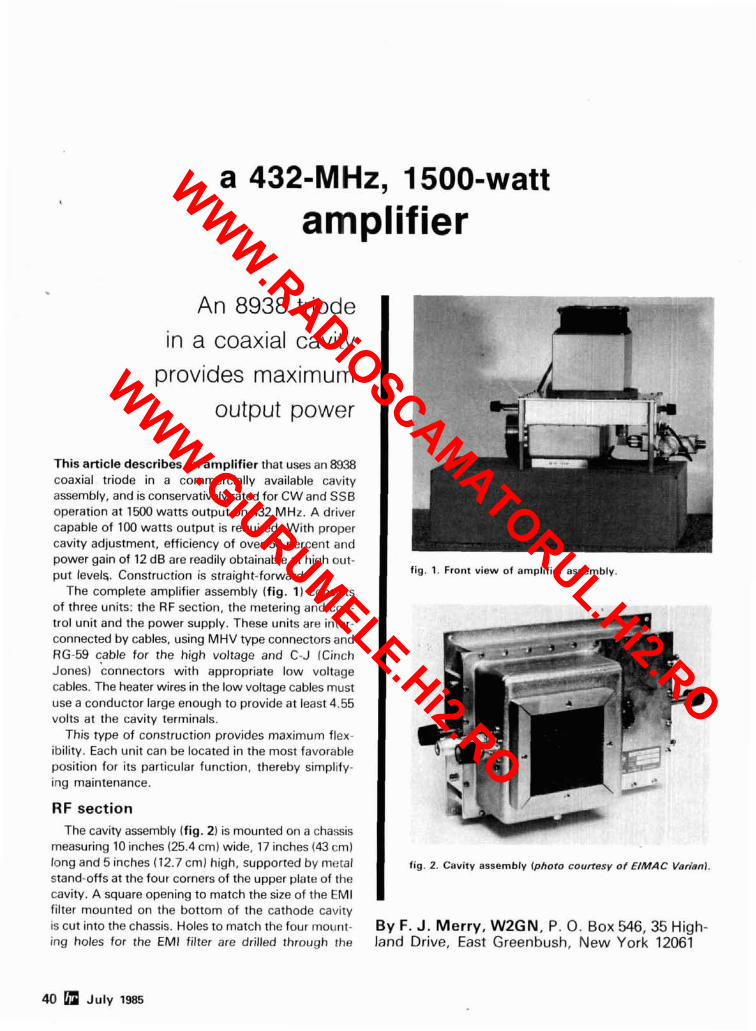
amplifier
An 8938 triode in a coaxial cavity
provides maximum output power
This article describes an amplifier that uses an 8938 coaxial triode in a commercially available cavity assembly, and is conservatively rated for CW and SSB operation at 1500 watts output on 432 MHz. A driver capable of 100 watts output is required. With proper cavity adjustment, efficiency of over 50 percent and power gain of 12 dB are readily obtainable at high out- put levels,. Construction is straight-forward.
The complete amplifier assembly (fig. 11 consists of three units: the RF section, the metering and con- trol unit and the power supply. These units are inter- connected by cables, using MHV type connectors and RG-59 cable for the high voltage and C-J (Cinch Jones) 'connectors with appropriate low voltage cables. The heater wires in the low voltage cables must use a conductor large enough to provide at least 4.55 volts at the cavity terminals.
This type of construction provides maximum flex- ibility. Each unit can be located in the most favorable position for its particular function, thereby simplify- ing maintenance.
RF section The cavity assembly (fig. 2) is mounted on a chassis
measuring 10 inches (25.4 cm) wide, 17 inches (43 cml long and 5 inches (12.7 cml high, supported by metal stand-offs at the four corners of the upper plate of the cavity. A square opening to match the size of the EM1 filter mounted on the bottom of the cathode cavity is cut into the chassis. Holes to match the four mount- ing holes for the EM1 filter are drilled through the
fig. 1. Front view of amplifier assembly.
I fig. 2. Cavity assembly (photo courtesy of €/MAC Verianl.
By F. J. Merry, W2GN, P. 0. Box 546,35 High- land Drive, East Greenbush, New York 12061
40 July 1985
WWW.RADiOSCAMATORUL.Hi2.RO
WWW.GiURUMELE.Hi2.RO
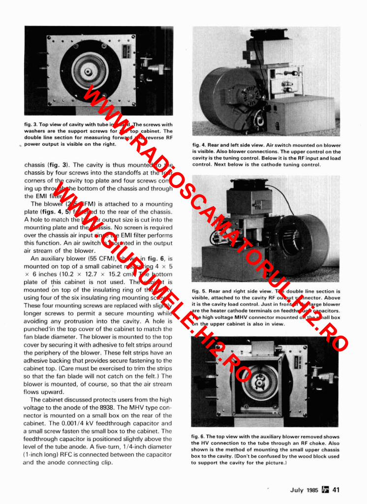
corners of the cavity top plate and four screws com- ing up through the bottom of the chassis and through the EM1 filter.
The blower (265 CFM) is attached to a mounting plate (figs. 4, 5) fastened to the rear of the chassis. A hole to match the blower output size is cut into the mounting plate and the chassis. No screen is required over the chassis air input since the EM1 filter performs this function. An air switch is mounted in the output air stream of the blower.
An auxiliary blower (55 CFM), shown in fig. 6, is mounted on top of a small cabinet measuring 4 x 5 x 6 inches (10.2 x 12.7 x 15.2 cm). The bottom plate of this cabinet is not used. The cabinet is
. .-.- . *-
fig. 3. Top view of cavity with tube installed. The screws with d n washers are the support screws for the top cabinet. The double line section for measuring forward and reverse RF . power output is visible on the right. fig. 4. Rear and left side view. Air switch mounted on blower
is visible. Also blower connections. The upper control on the cavity is the tuning control. Below it is the RF input and load
chassis (fig. 3). The cavity is thus mounted to the control. Next below is the cathode tuning control.
chassis by four screws into the standoffs at the four
mounted on top of the insulating ring of the cavity fig. 5. Rear and right side view. The double line section is using four of the six insulating ring mounting screws. visible. attached to the cavity RF output connector. Above
These four mountina screws are re~laced with sliahtlv it is the cavity load control. Just in front of the large blower - " , longer screws to permit a secure mounting while are the heater cathode terminals on feedthrough capacitors.
The high voltage MHV connector mounted on the small box avoiding any protrusion into the cavity. A hole is on the upper cabinet is also in view. punched'in the top cover of the cabinet to match the fan blade diameter. The blower is mounted to the top cover by securing it with adhesive to felt strips around the periphery of the blower. These felt strips have an adhesive backing that provides secure fastening to the cabinet top. (Care must be exercised to trim the strips so that the fan blade will not catch on the felt.) The blower is mounted, of course, so that the air stream flows upward.
The cabinet discussed protects users from the high voltage to the anode of the 8938. The MHV type con- nector is mounted on a small box on the rear of the cabinet. The 0.001 I 4 kV feedthrough capacitor and a small screw fasten the small box to the cabinet. The
fig. 6. The top view with the auxiliary blower removed shows feedthrough capacitor is positioned slightly above the the HV connection to the tube through an RF choke, Also
level of the tube anode. A five-turn, 114-inch diameter shown is the method of mounting the small upper chassis (1-inch long) RFC is connected between the capacitor box to the cavity. (Don't be confused by the wood block used and the anode connecting clip. to support the cavity for the picture.1
July 1985 obi 41
WWW.RADiOSCAMATORUL.Hi2.RO
WWW.GiURUMELE.Hi2.RO
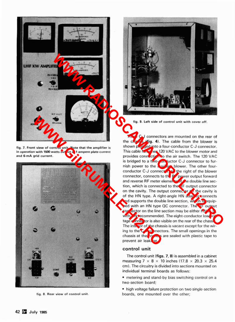
fig. 9. Left side of control unit with cover off.
Three C-J connectors are mounted on the rear of the chassis (fig. 4). The cable from the blower is
fig. 7. Front view of control unit. Note that the amplifier is shown plugged into a four-conductor C-J connector. in operation with 1500 watts output at 1-ampere plate current This cable furnishes 120 VAC to the blower motor and and 6-mA grid current. provides connection to the air switch. The 120 VAC
is bridged to a two-conductor C-J connector to fur- nish power to the auxiliary blower. The other four- conductor C-J connector, to the right of the blower
: ., connector, connects to the RF power output forward and reverse RF meter elements of the double line sec-
..O..?J .: tion, which is connected to the RF output connector on the cavity. The output connector bn the cavity is of the HN type. A right-angle HN adapter connects
. .. . , .. and supports the double line section, which is equip- ped with an HN type QC connector. The RF output connector on the line section may be either HN or N, with HN recommended. The eight-conductor low vol- tage connector is also visible on the rear of the chassis. The interior of the chassis is vacant except for the wir- ing to the C-J connectors. The small openings in the chassis at the corners are sealed with plastic tape to prevent air leakage.
control unit The control unit (figs. 7,8) is assembled in a cabinet
measuring 7 x 8 x 10 inches (17.8 x 20.3 x 25.4 cm). The circuitry is divided into sections mounted on individual terminal boards as follows:
metering and stand-by bias switching control on a two-section board;
high voltage failure protection on two single-section fig. 8. Rear view of control unit. boards, one mounted over the other;
WWW.RADiOSCAMATORUL.Hi2.RO
WWW.GiURUMELE.Hi2.RO
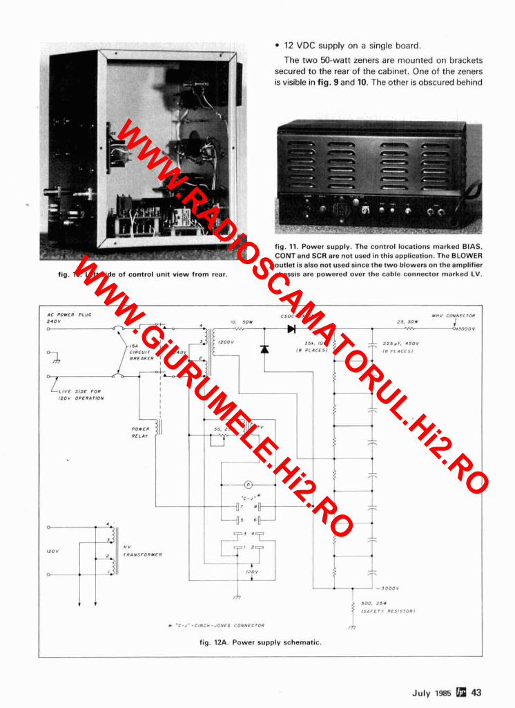
12 VDC supply on a single board.
The two 50-watt zeners are mounted on brackets secured to the rear of the cabinet. One of the zeners is visible in fig. 9 and 10. The other is obscured behind
fig. 10. Left side of control unit view from rear
fig. 11. Power supply. The control locations marked BIAS, CONTand SCR are not used in this application. The BLOWER outlet is also not used since the two blowers on the amplifier chassis are powered over the cable connector marked LV.
AC POWER PLUG C S O C I 5 X V I 5 0 Y H V CONNECTOR
Z I O V !O. 5 0 1 2 5 . 1 0 1 . U / 0 O I J O O O V
3 5 1 , /OW -- 2 2 5 r F . 4 5 O V
C r R c u l r I Z IOV 1 8 PLACES1 I 8 PLACES1
L I Y C S IDE FOR I
1 2 0 V OPERATION I I I I
-- r-.
RELAY -- -7
. C - J - *
8
5 0 0 , 2 5 w
I S l F E T r RCSISTORI
* . C - J - - C I N C * - JONES CONNECTO"
fig. 12A. Power supply schematic.
July 1985 a 43
WWW.RADiOSCAMATORUL.Hi2.RO
WWW.GiURUMELE.Hi2.RO
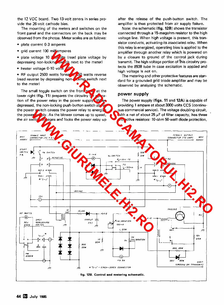
the 12 VDC board. Two 13-volt zeners in series pro- vide the 26-volt cathode bias.
The mounting of the meters and switches on the front panel and the connectors on the back may be observed from the photos. Meter scales are as follows:
plate current 0-3 amperes
grid current 100 milliamperes
plate voltage 10 kilovolts (read plate voltage by depressing non-locking switch next to the meter)
heater voltage 0-10 volts AC
RF output 2500 watts forward, 250 watts reverse (read reverse by depressing non-locking switch next to the meter)
The small toggle switch on the front panel at the lower right (fig. 11) prepares the circuitry for opera- tion of the power relay in the power supply. When depressed, the non-locking push-button switch above the power switch causes the power relay to energize the power supply. As the blower comes up to speed, the air switch engages and locks the power relay up
after the release of the push-button switch. The amplifier is thus protected from air supply failure.
Note: the schematic (fig. 12B) shows the transistor connected through a 15-megohm resistor to the high voltage line. When high voltage is present, this tran- sistor conducts, activating its associated relay. When this relay is energized, operating bias is applied to the amplifier through another relay which is powered on by a closure to ground of the control jack during transmit. The high voltage portion of ?his circuitry pro- tects the 8938 tube in case excitation is applied and high voltage is not on.
The metering and other protective features are stan- dard for a grounded grid triode amplifier and may be observed by analyzing the schematic.
power supply The power supply (figs. 11 and 12AI is capable of
providing 1 ampere at about 3000 volts CCS (continu- ous commercial service). The voltage doubling circuit, with a net of about 25 pF of filter capacity, has three protective resistors: 10-ohm 50-watt diode protection,
(GROUND ON TRANSMlTJ 0
fig. 128. Control and metering schematic.
44 July 1985
WWW.RADiOSCAMATORUL.Hi2.RO
WWW.GiURUMELE.Hi2.RO
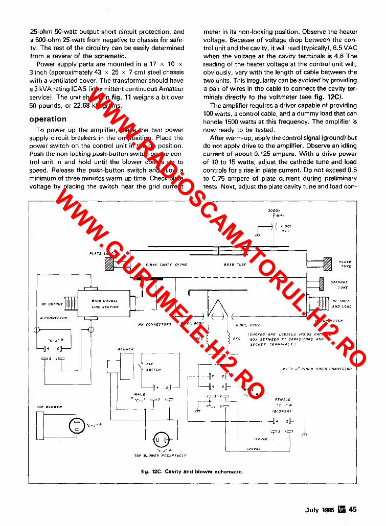
25-ohm 50-watt output short circuit protection, and a 500-ohm 25-watt from negative to chassis for safe- ty. The rest of the circuitry can be easily determined from a review of the schematic.
Power supply parts are mounted in a 17 x 10 x 3 inch (approximately 43 x 25 x 7 cm) steel chassis with a ventilated cover. The transformer should have a 3 kVA rating ICAS (intermittent continuous Amateur service). The unit shown in fig. 11 weighs a bit over 50 pounds, or 22.68 kilograms.
operation To power up the amplifier, place the two power
supply circuit breakers in the on position. Place the power switch on the control unit in the on position. Push the non-locking push-button switch on the con- trol unit in and hold until the blower comes up to speed. Release the push-button switch and allow a minimum of three minutes warm-up time. Check plate voltage by placing the switch near the grid current
meter in its non-locking position. Observe the heater voltage. Because of voltage drop between the con- trol unit and the cavity, it will read (typically), 6.5 VAC when the voltage at the cavity terminals is 4.6 The reading of the heater voltage at the control unit will, obviously, vary with the length of cable between the two units. This irregularity can be avoided by providing a pair of wires in the cable to connect the cavity ter- minals directly to the voltmeter (see fig. 12C).
The amplifier requires a driver capable of providing 100 watts, a control cable, and a dummy load that can handle 1500 watts at this frequency. The amplifier is now ready to be tested.
After warm-up, apply the control signal (ground) but do not apply drive to the amplifier. Observe an idling current of about 0.125 ampere. With a drive power of 10 to 15 watts, adjust the cathode tune and load controls for a rise in plate current. Do not exceed 0.5 to 0.75 ampere of plate current during preliminary tests. Next, adjust the plate cavity tune and load con-
3 0 0 0 V
8 9 3 8 TUBE
--- -----
B I R D O O U B L C
L I N E S E C T I O N
N C O N N E C T O R N C O N N E C T O R
H N C O N N E C T O R S
R F C BOX B E T W E E N F T C A P A C I T O R S A N 0
S O C K E T T E R M I N A L S I
*. " C - J " C I N C H J O N E S C O N N E C T O R
F E M A L E
T O P B L O W C R ' < C - J " *
l B L O W E R l
*c . J - X I Z O V A C
T O P B L O W E R R E C E P T A C L E
fig. 12C. Cavity and blower schematic.
July 1985 45
WWW.RADiOSCAMATORUL.Hi2.RO
WWW.GiURUMELE.Hi2.RO
WWW.RADiOSCAMATORUL.Hi2.RO
WWW.GiURUMELE.Hi2.RO
WWW.RADiOSCAMATORUL.Hi2.RO
WWW.GiURUMELE.Hi2.RO

BUSINESS REPLY CARD
IN THE UNITED STATES - B I B I B I B I - - -
Postage W ~ l l Be Patd By Addressee - - - B I
ham B I
radio - - I I B I
Greenv~lle NH 03048 -
WWW.RADiOSCAMATORUL.Hi2.RO
WWW.GiURUMELE.Hi2.RO
PARTS C O Y P O ~ svs-
Dalbanf Corporation offers the finest in audio, video, computer and home electronics, for the professional retailer or home specialist.
To obtain a copy of our 88 page full-line 1985 catalog please call:
WWW.RADiOSCAMATORUL.Hi2.RO
WWW.GiURUMELE.Hi2.RO
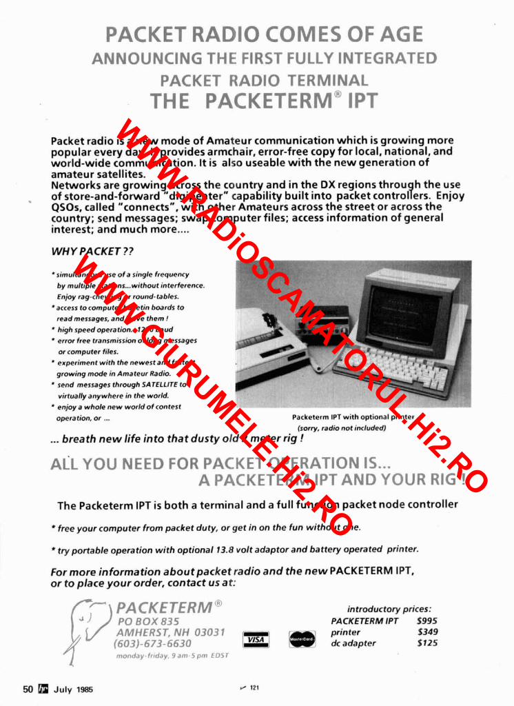
PACKET RADIO COMES OF AGE ANNOUNCING THE FIRST FULLY INTEGRATED
PACKET RADIO TERMINAL THE PACKETERM" IpT
Packet radio is a n e w mode of Amateur communication which is g rowing more popular every day. It provides armchair, error-free copy for local, national, and world-wide communication. It is also useable with the n e w generation o f amateur satellites. Networks are growing across the country and in the DX regions throu h the use 9 of store-and-forward "digipeater" capability built in to packet control ers. Enjoy QSOs, called "connects", with other Amateurs across the street.or across the country; send messages; swap computer files; access information o f general interest; and much more....
WHY PACKET??
simultaneous use of a single frequency
by multiple stations ... without interference.
Enjoy rag-chewing or round-tables.
access to computer bulletin boards to
read messages, andleave them !
high speed operation ... 1200 baud
error free transmission of long messages
or computer files.
experiment with the newest and fastest
growing mode in Amateur Radio.
send messages through SATELLITE to
virtually anywhere in the world.
enjoy a whole new worldof contest
operation, or ... Packeterm IPT with optional printer
(sorry, radio not included)
... breath n e w l i fe into tha t dusty old 2 meter rig !
ALL YOU MEED FOR PACKET OPERATION IS ... A PACKETERM IPT AND YOUR RIG !
The Packeterm IPT is bo th a terminal and a full function packet node controller
free your computer from packet duty, or get in on the fun without one.
* try portable operation with optional 13.8 volt adaptor and battery operated printer.
For more information aboutpacket radio a n d the n e w PACKETERM IPT, or to place your order, contact us at:
PACKETERM~ introductory prices: Po Box 835 PACKETERM IPT 2995 AMHERST, NH 03031 printer $349 (603)- 673- 6630 - dc adapter $125 monday-frrday. 9 a m - 5 pm E D S T
50 July 1985 fl 121
WWW.RADiOSCAMATORUL.Hi2.RO
WWW.GiURUMELE.Hi2.RO
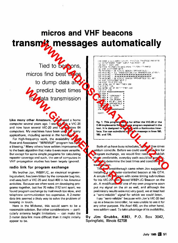
micros and VHF beacons transmit messages automatically
Tied to beacons, micros find best times
to dump data and predict best times
for data transmission
Like many other Amateurs, I purchased a home computer several years ago. I started with a VIC-20 and now have several VIC-20 and Commodore 64 computers. My machines have been used for many applications, including several in the hamshack.
For high-frequency work, the availability of Bob Rose and Associates' "MINIMUF" program has been a blessing.' Many others have written improvements to the basic algorithm that make it even more versatile. But except for some simple programs for calculating repeater coverage and such, the use of computers in VHF propagation studies has been largely ignored.
radio link for program exchange My brother Jon, WBSYJC, an electrical engineer-
ing student, has been bitten by the computer bug too, and uses both a VIC-20 and Atari 400 in his Amateur activities. Because we often work on developing pro- grams together, but live 70 miles (1 12 km) apart, we found program exchange by mail much too slow, and telephone communication too expensive. A 2-meter data link seemed a likely way to solve the problem of keeping in touch.
Here in the Midwest, this would seem to be a reasonable solution. But other considerations - parti- cularly antenna height limitations - can make the 2-meter data link more difficult than it might initially appear to be.
] rrO OF.EH 2 . 2 , I; .CHP$t j ,;E:.3';'8 T7=77131!, T?='3-1'58 P F I t I T " 3 " . , . ,i! - FF1HT"FIITEF TIME" It4FIIT T I $ PPItJT "7 t.sct fiI-."" C;DTO 2 6 6 1 ::@ PI~I} E T?,PEEt' lTl j xOP::~ T; .PFFI r T 7 *At4TI?? 1 J@ FOP :,!:I TI? 1 OUL7 ' EIFI'T i 5~1 F.FII~T#:. " TIE l : Z a Y I BERCOtI SPPIIIIGFIELD. " . 175 pF.IEIT#;. , " I L L TRRHSMITTIblrj FC:P PFOPHGRTIOt4 STl.lIl'i'' . ll;i:, F P I h T 1 2 , " I lbl I+I~$I!*l~I*l.lCU~l~+IJ'$~!$l.l~I.I$I_I~l I#IJClJC" . 1155 PFIEIT#2, " I 141.1*I.IIIJ*lJ*lJ*IJ'~U~CICIIl~U'IU~I~41J+U+lJI . 1 7 8 PF.IHTU2, " DE t'?j:'i'? REfiCOtl SPPIbIOFIELD I1 I. RR" I2Ci F ~ I F -=ITT?Li:ORB EIFXT ? 1 1 0 FnVF T 5 . f EOTnlZB ':on lLFT#?. RS I F H I = " "THEII 2BU . i l B F'FIHT 1 1 3 . :2@ GETU1, fit I F A$'? ""THE14 1 2 0 '::a 1',17TI-l 130 ,249 FFM ***5I4t**XI+I** 256 FEM Q I 268 FEM + "I.'EPCHUNI"' C 2 7 0 REM * IC; 1985 $ 2 8 6 PEP1 + TIM GPILIRRS 5 ??il PFM * FO ECI:! 3842 C 3C10 FEU * $FRIblCiFIELIl * 3 1 6 R E M 4 IL62788 + '320 FEN 4 4 338 REP1 *I*Wl*+*b****'I
F'EfiDY.
fig. 1. This program listing for either the VIC-20 or the C-64 implements the Kerchunk program explained in the text. I t is designed to be used with a Kantronics inter- face. You can substitute your own message in lines 150. 160, and 170.
Both of us have busy schedules, and our free times seldom coincide. Before we could use a radio link for program exchange, we would first need to establish that a predictable, everyday path would be possible, and then determine the best times and conditions for transmission.
The first breakthrough came when Jon suggested installing a computer-controlled beacon at his QTH. A simple CW program with some timing subroutines for his VIC-20 soon placed WBSYJCIBeacon on the ' air. A qodification of one of my own programs soon
I put my signal on the air as well, and although the
1 preliminary results were not very good, we at least had a "semi-reliable" signal for which we could listen.
I say "semi-reliable" because with Jon's VIC-20 tied up as a beacon controller, he was unable to use it for any other purpose. His Atari 400, on the other hand, was seldom used. To take advantage of its availability,
By Jim Grubbs, KgEI, P.O. Box 3042, Springfield, Illinois 62708
July 1985 51
WWW.RADiOSCAMATORUL.Hi2.RO
WWW.GiURUMELE.Hi2.RO
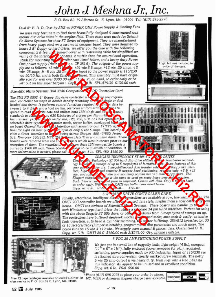
John J Meshna Jr, Inc. P. 0. BOX 6 2 19 Allerton St. E. Lynn, Ma. 01 904 Tel: (61 7 ) 595-2275
Dual 8" F. D. D. Case b y SMS w/ PO WER ONE Power Supply & Cooling Fans W e were very fortunate t o find these beautifully designed & constructed rack mount disc drive cases in the surplus field. These cases were made for Scienti- fic Micro Systems for their FT Series of equipment. They are manufactured from heavy guage steel w/ a cast metal designer bezel. They were designed t o house 2 8" floppy or hard drives. We offer you the case with the following components & features: hinged cover with restraining cable for simplified ser- vicing of the interior components, 2 muf f in fans for assured cool operation, studs for mounting the controller card listed below, and a heavy duty Power One power supply (their model no. CP 281A). The outputs of the power s u p ply are as follows: +5 vdc 11 amps, +24 vdc 3.5 amps, +12 vdc .25 amps, -1 2 vdc .25 amps, & -5 vdc .25 amps. The input t o the power supply is 11 51230 vac 50160 Hz. and is both filtered and fused. This assembly must have origin- ally sold for well over $300.00 each ! Only 25 on hand, so order early or be le f t out on this super bargain ! Shpg. wt. 38 lb. SPLA79-35 $135.00 each
Scientific Micro Systems IBM 3740 Compatible 8" FDD Controller Card
The SMS FD 0502 8" floppy disc drive controUer is a complete preprogram- med controller for single or double density recording on either single or dual headed disc drives. It performs control functions required to transfer data be-
ogy for reliable storage of up to 5 megabytes of formotled doto. Some features of this very popular drive ore: 5 megobit/second data transfer rote, simple floppy like inter- - face, high speed band actuator & stepper head positioning, requires only + 5 & + 12 vdc, and same physical size and mounting parameters as a mini floppy.drive. This Shugarl compatible drive is the same as used on many home personal computers. Eoch drive is checked out prior to shipment. Comes with data. Only a few on hand,
I' so order earlv. Will run with OMTI con troller card listed below. R- ' ~hb. wt. 8 lb. ST.506 $175.00 -
5 ?4" H A R D DRIVE CONTROLLER CARD
' Phone (61 7) 595-2275 to place your order by phone. . Free 72 page c a t a l w e available or send $1.00 for 1st M$ VISA or American Express charge cards a C c e p f e d . ~ ~ ) clars service to P. 0. Box 62 E. Lynn, Ma 01904.
52 July 1985 Ir 122
WWW.RADiOSCAMATORUL.Hi2.RO
WWW.GiURUMELE.Hi2.RO
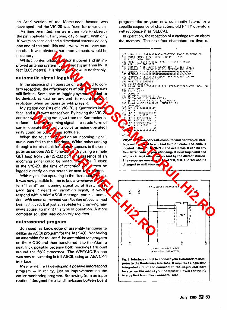
an Atari version of the Morse-code beacon was program, the program now constantly listens for a developed and the VIC-20 was freed for other uses. specific sequence of characters; old RTTY operators
As time permitted, we were then able to observe will recognize it as SELCAL. the path between us anytime, day or night. With only In operation, the reception of a carriage return clears 10 watts on each end and a directional antenna on only the memory. The next four characters are then re- one end of the path (his end), we were not very suc- cessful. It was obvious that improvements would be necessary.
While I contemplated additional power and an im- proved antenna system, Jon raised his antenna by 10 feet (3.05 meters). His signal was now up noticeably.
automatic signal logging In the absence of an operator on either end to con-
firm reception, the effectiveness of our beacons was still limited. Some sort of logging system needed to be devised, at least on one end, to record times of reception when on operator was present.
My station consists of a VIC-20, a Kantronics inter- face, and a 10-watt transceiver. By having the VIC-20 constantly searching out input from the Kantronics in- terface - i.e., an incoming signal - a crude form of carrier operated (actually a voice or noise operated) relay could be built, using software.
When the squelch opened on an incoming signal, audio was fed to the interface. White noise coming through a terminal unit fortunately appears to the com- puter as random ASCll characters. By using a simple GET loop from the RS-232 port, the presence of an incoming signal could be noted. Using the TI clock in the VIC-20, the time of reception could then be logged directly on the screen or sent to a printer.
With my station operating in the "kerchunk" mode, it was now possible for me to know whenever my sys- tem "heard" an incoming signal or, at least, noise. Each time it heard an incoming signal, it would respond with a brief ASCll message; partial automa- tion, with some unmanned vertification of results, had been achieved. But just as repeater kerchunking may invite abuse, so might this type of operation. A more complete solution was obviously required.
autorespond program Jon used his knowledge of assembly language to
design an ASCll program for the Atari 400. Not having an assembler for the Atari, he assembled the program on the VIC-20 and then transferred it to the Atari, a neat trick possible because both machines are built around the 6502 processor. The WBSYJCIBeacon was now transmitting in full ASCII, using an AEA CP-1 interface.
Meanwhile, I was developing a positive autorespond program - in reality, just an improvement on the earlier monitoring program. Borrowing from an input routine I designed for a landline-based bulletin board
1OG l]F.EtI 2 .2 ,3 .1 :HRt~128+35~~T i= ,~ I71~E. T9=?7138 PH1tIT"n" l l @ FP1EiT"EtITER T I N E " IIiPLIT T I * PRIt1T "7" 120 R f - " " C.UTCI 2 0 @ 1 33 FOYE T,?. PEEY (TS,OP3:. POYE T 7 . PEFK<T7)f lND32 14B FOP :':=lTOlB88 NEXT I 5 8 PPIEITX:. " IJE KZS::'fZ BEHCOII SPPItIGFIELD. I L L " . 155 PRIHTM2, " TPHIIE:~~TTIIIG FOP FRCIPRGATICItI 5Tl.lD8f" . 160 PP INTXZ, " ! l~ ! l~ I . I * l l~CI* t~$ l~~1J*~J$l~ lXLI~LI fL l~U~lJ$ l~ l~ " 2
167 PF IHTI12, " IJf UiCU*l.l*lJ$lJ$IIhIII$IJiCIJ$IJ$I I$I! I IJ~IJ~l! l" , 170 F'PIbJTX2. " TIE I'Z3t:'iZ E:EfiCl-IbI SPRIIIGFIELD I L L AP" J Z U FnF' 7 = l T l ' ~ l 2 6 0 O NE::T ; 1 '?El v13b:E 1'3. d GOTll120 .-- .. utj LEI::4 GCvSIJB 2 3 6 210 I F Rf="t.ItltItI" THFtIPFJtIT T I $ . Fl~lPD=1T~I?~Fir l t 1IE:;:T GOTO 1 3 8 ,;a T.I?T~ > R C ~ -.*, . .,13 H$="" ',$=""
748 OETR;',f'$ .;F,O IF ' i0-r"" THEF4 I:,I)TI:I 2 4 0 . -. Zt,M I F I'$=I'HPt:l'?'( THFItl PETIJPt1 .- , b r - TF Y* '" " R*' " - 8 , THEN hlilTO24O
H~=Hs+','I IF LEtrt A*.':'LH THE~I FETUPH .,an - . - -, - - . . r1.h 1.1 LJY 300 REM +C+C*+Ct#h#** I * : j 0 PFI'I t 4 - - - :;'PI PFM 4 HI!Tl:lFF':.F'OUD O : : T t PEP1 4 8 I-', 1 3 3 5 4 4 O PEP1 t JIP1 GEUBFE. 6 350 FE~I j pa ~ o : : ::itJr' + :GCi PEP1 4 SPF'THl~~FTEI.Tl 4 ?:'O F'FM f TI . 6:':il.' * .-- ;:ill PFFl O + :9i ! PFI.1 + + * ~ 4 ~ 4 C + + ~ + C + +
FFH~I '~ ' .
VIC-20 or Commodore-64 computer and Kantronics inter- face will respond to a preset turn-on code. The code is located in line210 (NNNN in the example). I t can be any four letter code of your choosing. It must begin and end with a carriage return when sent by the distant station. The response message in lines 150,160, and 170 can be changed to suit your needs.
July 1985 53
. 5 P IN MOLEX CONNECTOR
iEo:~i~~: 14
fl 12
.o 7
6 C M J
COMPUTER USER PORT
2 4 P I N EDGE CONNECTOR
fig. 3. Interface circuit to connect your Commodore com- puter to the Kantronics interface. It requires a single 4077 integrated circuit and connects to the 24-pin user port located on the rear of your computer. Power for the IC is supplied from this connector also.
- 'O"
WWW.RADiOSCAMATORUL.Hi2.RO
WWW.GiURUMELE.Hi2.RO
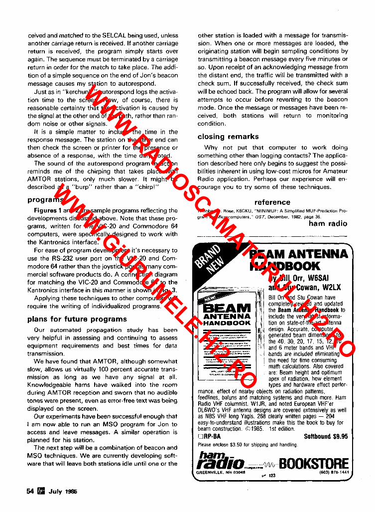
ceived and matched to the SELCAL being used, unless another carriage return is received. If another carriage return is received, the program simply starts over again. The sequence must be terminated by a carriage return in order for the match to take place. The addi- tion of a simple sequence on the end of Jon's beacon message causes my station to autorespond.
Just as in "kerchunk," autorespond logs the activa- tion time to the screen. Now, of course, there is reasonable certainty that the activation is caused by the signal at the other end of the path, rather than ran- dom noise or other signals.
It is a simple matter to include the time in the response message. The station on the other end can then check the screen or printer for the presence or absence of a response, with the time duly noted.
The sound of the autorespond program in action reminds me of the chirping that takes place with AMTOR stations, only much slower. It might be described as a "burp" rather than a "chirp!"
programs Figures 1 and 2 are sample programs reflecting the
developments discussed above. Note that these pro- grams, written for the VIC-20 and Commodore 64 computers, were specifically designed to work with the Kantronics interface.
For ease of program development it's necessary to use the RS-232 user port on the VIC-20 and Com- modore 64 rather than the joystick port as many com- mercial software products do. A connection diagram for matching the VIC-20 and Commodore 64 to the Kantronics interface in this manner is shown in fig. 3.
Applying these techniques to other computers will require the writing of individualized programs.
plans for future programs Our automated propagation study has been
very helpful in assessing and continuing to assess equipment requirements and best times for data transmission.
We have found that AMTOR, although somewhat slow, allows us virtually 100 percent accurate trans- mission as long as we have any signal at all. Knowledgeable hams have walked into the room during AMTOR reception and sworn that no audible tones were present, even as error-free text was being displayed on the screen.
Our experiments have been successful enough that I am now able to run an MSO program for Jon to access and leave messages. A similar operation is planned for his station.
The next step will be a combination of beacon and MSO techniques. We are currently developing soft- ware that will leave both stations idle until one or the
other station is loaded with a message for transmis- sion. When one or more messages are loaded, the originating station will begin sampling conditions by transmitting a beacon message every five minutes or so. Upon receipt of an acknowledging message from the distant end, the traffic will be transmitted with a check sum. If successfully received, the check sum will be echoed back. The program will allow for several attempts to occur before reverting to the beacon mode. Once the message or messages have been re- ceived, both stations will return to monitoring condition.
closing remarks Why not put that computer to work doing
something other than logging contacts? The applica- tion described here only begins to suggest the possi- bilities inherent in using low-cost micros for Amateur Radio application. Perhaps our experience will en- courage you to try some of these techniques.
reference 1. Robert B. Rose, K6GKU. "MINIMUF: A Simplified MUF-Prediction Pro- gram for Microcomputers." QST, December, 1982, page 36.
ham radio
, ".,".",". "0" ""d lo ."a* .mu,
*.," m..,mumP.,n,"m,".m"m.p.rr
rDmD"lll .m.IDI Ol,ll."llla.1I"".
mance, effect of nearby objects on radiation patterns, feedlines, baluns and matching systems and much more. Ham Radio VHF columnist, W1 JR, and noted European VHF'er DL6WO's VHF antenna designs are covered extensively as well as NBS VHF long Yagis. 268 clearly written pages - 204 easy-to-understand illustrations make this the book to buy for beam construction. 631985. 1st edition.
Please enclose $3.50 for shipping and handling.
54 July 1985
WWW.RADiOSCAMATORUL.Hi2.RO
WWW.GiURUMELE.Hi2.RO
A high performance 4 GHz, 70 MHz input ,?- receiver featuring programmable video and audio, hand held remote, four dif- ferent audio systems, switchable audio
A bandwidths, built- in RF modulator, t w o speed scanning modes and built- in stereo processor. ....
Offers Independent channel selection for multiple TV sets from a single antenna, w i t h a selection of up to 2 4 ind~vidual channels from a slngle satellite. The Mark 2 also features lndlvldually programmed audlo, automatic fine tunlng control. flne tunlng storage, speclal function switches and built- in stereo processor.
~ -
Offers versatility and quality performance includ ing fine tuning and video, automatic audio and 111 video digital memory, automatic polarization and four programmable audio modes. , , . 4 + r -
The Northeast's Leading Distributor Satellite
Sales and -,,far' etlr7c1 ... , ~ , s s ~ s ~ ~ n ~ ~ ! F ? r , ? ~ r v A~-Ph~r i ;zed Serwice Video
Services Prc?"essioni711 Tra!nioa .. Seminars (20-083 Actwerfisino Sr..rpqgrt
P\,cr+om~Pecil !JoS S h i ~ v i ~ n -
!;.!1..11,1.. '"I!!..,? :;; l l t~!l l l ' . \'I I<.O C ' . ..,,,<.II,i1. . V!,I'.,> 5 !:',I!!:', \/l(lnr?
' ;s.!~',, .... s4.,,!,< ,~., n11i I.,!: I - A I!.!, ';!.rut-..< \YNY, I t i f :
RR # l . Box 85 S RFD #2, Harr~nian Hill Rd. 317 E. Pleasant Valley Blvd. East Avenue Extens~on Catsk~ll. N Y 1 2 4 14 Raymond. NH 0 3 0 7 7 Altoona. PA 16602 Hornell NY 14843 51 8-678-9581 603-895-3 182 81 4-942-5003 607-324-3435
800-528 DISH - National 800-448-0012 - National 800-242-3860 - PA Only 800-641 -001 8 - NY Only 800-831 -DISH - NY Only
More Details? CHECK-OFF Page 126 f l 124 July 1985 55
WWW.RADiOSCAMATORUL.Hi2.RO
WWW.GiURUMELE.Hi2.RO
dual scale ~nd~cator.
One installation
The DRlO Dual Axis Antenna Rotor System ~;~i~;l~,9;;'nf0rmatlon-
A New Concept in Drive Systems 191 28 Industrial Blvd. , > T > Elk River. MN 55330 (USA)
'not t n r l u c f e d 612441 4303 Telex 7561 35 I
220 N. FULTON AVENUE P.O. BOX 4405
EVANSVILLE, INDIANA 47710
I Cali lo, Oiscocml Prlrr i IC-32W Call rot Specla1 Prrce
99 95
119995 245 00 279 95
CALL
1142500 CALL
235 00 1 75 00 779 00 249 95 299 95 279 95
Ih
1 9995 49 95
13995 229 95 269 95 15500 755 00 31500
1 25111 36111 35111 25111 35'11
1119W 125 W
s499 95
HUSTLER G6 I U B 2M 85 95 G6 440 440MHZ 10995
HF L VHF Mobcte Anlennas ,n s1wh
U R G E STOCK OF NEW EOUIPMENT AT DlSCOUNJ PRICES
Package MP 20 or MP 6 4 MAP 64 *IAMTOR MP t -M#cropal~h DR DX OR OSO PKT I Packs1 Canlroller
lrapaler Hot Rods Sollware cn
ASTRON POWER SUPPLIES
I ;:;;:;:::Amp RS12A 9 12 Amp H520A 16 20 AmD RS20M 16 20Amp wlMeler RS35A 25 35 Amp RS3SM 25 35Amp wIMaler RSWA 37 50 Am0 R550M 37 50Amp wlMelcl
BENCNER 01 1 BI~cLI IBV 2 C h r a w ZA IA Balun
B 1 W AC 3 5 30(IormetIv 370 151 AT 1 l o 5 Band leap Dlpo4e A1 55 4 Band 1-0 08polt.
OAIWA CNdlOM3 5 150MHZ CN 520 1 8 60 MHz CN 6708 1 8 150 MHz CN 610 140 4511 MH7 CS 701 2 Po, S w l c b CS 401 4 PO? 5*.,1rh
HAL Call tor Proces
HUSTLER G7 144 2M
WELZ Ali New MMPIs ~n Stwh
ENCOUY NF W H DK FM 240 75 Wall
Orders 1-800-523-7731 Indiana (81 2) 422-0231
Info & Service (81 2) 422-0252 1435 00
Erplorer -4 3EL frlhnnder 309 00 V2S Vert 138 174 MHZ 49 00
C a m n l ~ 1 ~ Line on Sloch
VAESU n 9 8 n Dr1u.e Xcvr FT-%IGX G P ~ COV Xcrr FC '5rAT Auto Tuncr FT75IHD P S wrFan n v f i n 1~8 Band Xcvr
l ICOY $TI7900
769 00 CALL CALL CALL
749 95 699 95 949 I 5 31995 3'5 00 799 95 349 95 19995
ea 219 95 (.ALL
284 95 CALL
AEA NEIL ARRL UUSTLER ALLIANCE HV-GAIN AMECO ICOY AMERIIRON KLY AVINTl KANTRONICS ASTRON KENPRO B L W LARSEN BENCHER YFJ BUTTERNUT MIRAGE CALL BOOK NVE VIKING COlLCO SHURE CONNECT SVSTEY TEN-TEC CUSUCRAFT UNAOILLA OAlWA VALOR ENCOMU WELZ HA1 VAESU
C U L Foa P M S ON EOUIP.ENT FOR OSCAR 10
Sma MSE I h nr nr L u~ . g u M 11.1 YON F I I SAYdPY . S I T SAY IPY
PRICES AND AVAILABILTIY SUBJECT TO
CHANGE FREIGHT F O B EVANSVILLE.
751 Top 01 tne Llnr 745 G?n Cav Xcvr 73s NEW H F a,g R: lAGrn Cor Rcvr 271A ZM 411 M m r 27 lH 2M AIIModr I W W 471A 410 650 MHz 25W 471H A30 450 MHz :5W 27A 2M 7SW MoOllr 27H 7M 45YI MoOmi? 31A 170 MHZ Mobile 47A 440 MHZ M<,bIt. 7 A l 7U H T
ROTORS All tanc~ HD 73 AlllanCP 11 110 lple. CD 45 11 Telv. HAM 4 1.1... 17X Kcn KR5W K m Pro KRSIM Men Pro KR56W
3 ~ 1 n ~ l 2201440 H T I NEW 3200 Dual Randel O?AT ZM H T OIAT 440 MHZ H T I - All Accerror8es ~n Sloch CABLE
S!,?nO.+td 8 Cond Rolor H r d v ~ Dufv ACnna Rolor p;AU 47"r Sh8eld <;HX 97"n Snlrld
nc, 7tl
I AOP I orcar Phg Rmqa Rangers 2M 6M 720 4 M
COmplCl~ Lone #n Slwh
BUTTERNUT HF2V HFfiV
I KANTRONICS Pnchel Commun8calar U 1 U Unlverml Termtnal Unll
NVE M R V A
56 n JUIY 1985 Tell 'em you saw 11 ~n HAM RADIO'
WWW.RADiOSCAMATORUL.Hi2.RO
WWW.GiURUMELE.Hi2.RO
Doctor QSOm Is The Code Buster
Morse Code Phobla! Doctor QSOTM is a plug-in cartridge for the Commodore 64 computer that provides a very realistic simulation of on-the-air two-way Morse Code ragchew contacts (QSOs). AEA, the undisputed leader in Morse training, has introduced Doctor QSO to amateur radio for the purpose of making Morse skill upgrading FUN and EASY. With Doctor QSO you can look forward to practicing your Morse Code skills in a non-confusing manner. Forget about all the drudgery you associated with Morse Code in the past; Doctor QSO ushers in a totally new era in Morse Code learning.
Doctor QSO is basedon thesame technology that has made the Doctor DXTMcontest trainer sofa- mous. The Doctor QSO simulator is so realistic that most skilled operators find it every bit as re- warding as the real thing. Youcan operateanytime you want; theonly extra equipment you need i sa Commodore 64 and a TV set.
Doctor QSO also removes the mysteryof theCODE BEHINDTHE CODE. Many peoplego so far as to learn the Morse Code characters, only to be frightened of getting on the air the first time because the QSO format is so confusing. With Doctor QSO, you will be a pro before you turn on your first transmitter. The Doctor QSO trainerlsimulator is ideal forthe aspiring Amateur Radiooperator with little or no contact with helpful hams.
With Doctor QSO you will become familiar wlth ail the U.S. call areas and associated call letter prefixes. The standard international QSO format is observed along wlth all thecommon amateur ra- dio abbreviations which areexplained thoroughly in theoperator's manual. All Morse skill levels are addressed by Doctor QSO, from the person who has not yet learned the Code, to the person comfort- able with sending and receiving at 40 + WPM.
Who says Morse Code can't be fun? You can even have fun wlth Doctor QSO before you have learned the Code. To begin with, the operator can view the messages being sent by the computer generated stations In real-time. Theoperator canalsosend Morse with the keyboard. In addition, the operator can select simulation of static interference (QRN) and adjacent CW interference (QRM). Normally, the beginner would operate in the novice band wherestations will be sending as slow as3 WPM. Later as the user becomes more skllled, he can move down the band to faster speeds, and he 1 has the cholce of using a key or keyer for sending. I
If you have tried every other method known to learn the MorseCode and failed, then Doctor QSO has just the prescription for you. Now you can upgrade your Amateur Radio license in record time. Doctor QSO is more than the written word can describe. To fully appreciate all the merits of this trainer, see your dealer for a demonstration or contact AEA for more information.
I
Prlces end speclflcetlons subject to change A wlthout notice or obllgetlon.
COMMUNICATIONS 915 North Main Street
Janestown, New York 147M (716)664-6345
I
Brings you the Breakthrough!
WWW.RADiOSCAMATORUL.Hi2.RO
WWW.GiURUMELE.Hi2.RO
?IE STANDARD OF EXCELLE"" The worM of R T m and nav DUAL AMTDR* is as clc your fingertz* with the new brilliantly innovative state-of-the-c mic npUk trolled EX IOE. mor r con
Wide R..tc -a I RYIUIU~ IIU --.aqi IIIVISF LWS trafifimilting technoloa~. iust a console and keyboard can accomdish com~lete saed can be set from the keyboard at any ratebetween 5-100 WPM automat~knd/rmive of ~ o n c ~ c o d e (cw), Baudot code (RTTY). (&cry word per minute). A~~TCYTRACK-O~ w i v e . For communica- ASCII Code (RTTY) and new ARQ/FEC (AMTOR). tion in Baudot and ASCII Coda, rate i s variable by a keyboard in- Code: Morre(CW includes Kana). Baudot (RTTY), ASCII ( U r n ) , struction between 12-300 Baud when using RTTY M o d m and between JIS (RTTY 1. ARQ/FEC (AMTOR). 12-600 Baud when usinnTTL level. The variable speed feature makes Cban*ar: ~lphabet. Figures. Symbols. Special Characters. Kana. the wt ideal for amateur. bwinas and commercid w. Bulllim-Modtor: 5'high resolution, delayed persistence green moni- P d o d F r d o m : The buffer memory a n store the messages written tor - provides sharpclcar image with no jiggle or jitter &n under from the keyboard instead of sending them immediately. 7% stored fluorescent lighting. Also has a provision for composite video signal messages can be sent with a keyboard command. outout. "RUBOUT' Furtlocl: You can correct mistakes wblle w ' ' ntlng
a d while
ally sent
-.....A- .,
T&u& Displays Month. Date. Hour and Minute on the scrc TLme/TnumlwJor /Rca l~ Faurr : The built-in timer enable completely automaticTX/RX without operator's attendunce. Sdcld (SdcrUvc C.llly) Sysln: With this feature. the unit only I ce im messages following a preset d e . Built-in Demodulator fa! l i igh Performance: Newly designed high oped RTTY dcmodulat~ has rmiving capability of as fast as 300 Baud. Three-step shifts w either 170Hz. 42SHz or 8SOHzshif1 with manual fine tunecontrol
en. t s 1
nassga in thc buffer memory. Misspellings u he information is still in the buffer memory.
in also be a
F automatic \utrmatk CR/LF: While transmitting. CR/L w r y 64,72 or 80characten. WORD MODE opmCk roupin&s. MX every ch~ ceyboard inUruQion. UNE MODE o ~ n H o c l
ers can be tl m the buffel
scanktrlu
ransmitted I r memory w
I: Character ...--, space channel for odd shifts. HIGH (Mark Frequency 2125Hz)/L'\'" :rigs from the buffer me...u.,.
(Mark Frequency 127SHz) lone pair selccl. Mark only or Space01 WORD-WRAP-AROUND opmtlom: In receive mode. W coov cambilitv for selective fadinn. ARO/FEC features incorwr, WRAP-AROUND re vats the Iaat word of the line from !
"" I~Y 1 ated. 1
t v
ORD- rplitting in
I A*.. -" )u
~ t d ~ b m ( r o l * d AFSK ModulI'ior: ~~ranseciver without FkK function can transmit in RTTY mode by utilizing the high stabilir crystaleontrolled modulator controlled by thecomputer. PLotomm~kr CW. FSK Kner kllt-ID: Vew high voltane. hiah n
wo and maka the &reen w i l y read. 'ECHO" Fmu(k.: With a keyboard instruction. w i v e d ,- - d ead and sat WI at thesame time. This function &able8 a age recorder to be wcd aa a back-UD munon. and a rvatsl I
went t c
CII 4 3 P
- - photocoupler keyer is provided for CW. FSK keying. Comvrdent ASCII Kw Amwemen(: The kevbosrd lavoul is A 9
:<cat& just like telex which uses pasr tape. . Eunor Control Fbwio*: Full cursor control ( u ~ / d o m , k !ft/right) is
"' and arrangement with function keys. Automatic insertion of LTR/FIl code makes owation a brme.
lvallrble fmm the keyboard. Test M m g e ~un&ion: "RY 'QBF" test messages can be repeated with this function. HARK-AND-MEAK (SPACEANDBREAK) Svecs: E
-
I ds. is < rn 1
ither mark
I of dot to
B.ttery hck$p Memory: Data in the battery back-upmmory. covering 72 characters x 7 channels and 24 chnractm x 8 cham
. - ,r space tone a n be us& to copy RTTY. Vuhbk CW wahbtr: For CW transmission. weiahts (ratic retained even when the external wwer source is removed. M m l
can be recalled from a keyboard'instruction and some particular- channels can be read out continuouslv. You can write
~nsh)can be char& within the l imiu of I:<-1:6- .
4udio Momitor Ckcclil: A built-in audio monitor circuit with an amo- any channel while receiving. LargeCaprlly MIphy Memory: Coven up to 1,280 r Sereen Format contains 40 characters x 16 lines x 2 1 Screw D lwk T y p A k . d B.fIer Memory: A 160-character buffer memory is displayed on the lower part of the screen. Thecharactm move lo the
natic trpmmit/rmive switch enables checking of the transmitting and ecciving state. In rmive mode, it is possible to chsk the output of the nark filter, the space filter and A W amplifier prior to the filters.
CW Pnc(lec F.m The unit reads --- . -- . . . . . . . . . . , . . . data from the hand key and displays the
characters on the scrcan. CW keyingout. put circuit works according to the key
pages.
lelt erasing one by one as soon as they are transmitted. Messages can k written 1 "c"w'":db. Gcsmtor: Output alCW during the rmiving state for transmis- random signal canbe uacd asCW reading sion with httery back-up memory or practice. Bsrgnpb LED Meter lor SEND function. Tnmla: Tuning of CW and RTT'Y is Qractloo Dlrplry System: Each function very easy with the bargraph LED meter. (mode, channel oumber. speed. ac.) is In addition, provision has ber displayed on the screen. attachment of an oscilloscope Prlntff Interface: Centronics Para Com- tuning. patiblc interface enables easy connection hllt-im ACIDC: Power supply 1s swtcn- o f a lowcost dot printer for ha ableas required; 100-120 VAC; 220-240
VAC/SO/M)Hz + 13:8VDC. Color: Light grey withdark g matches most c u m 1 t ranm Di-363(W) x 121@ 351(D) mm: Terminal Unll.
:n made for :to aid
rd copy.
Wammly: One Year Limited s r a c l a t b = ~ l O c b S
Everytning built 1n - nnfltlng eue to ouy!
EXCLUSIVE DISTRIBUTOR: DEALER INQUIRIES INVITED IUR NEAREST DEALER OR TO ORDER: AMATEUR-WHOLESALE ELECTRONICS 8817 S.W. 129th Terrace. Miami, Florida33176
DLL FREE. . .MO-327-3102 r-1 Telephone (305) 233-3 Telex: 80-3356 - FOR YO
TI
MANUFACTURER: OTONO CORPORATION
98 Mo(csofa Mechi. MaebashlShi. 371. Japan ' h ro l Amroc C ~ ~ m m i o l q u o l i t y , the EXLJDDOE in- rreommmdntions47&2 for commminl requirements.
~ppon the an
58 n July 1985
WWW.RADiOSCAMATORUL.Hi2.RO
WWW.GiURUMELE.Hi2.RO
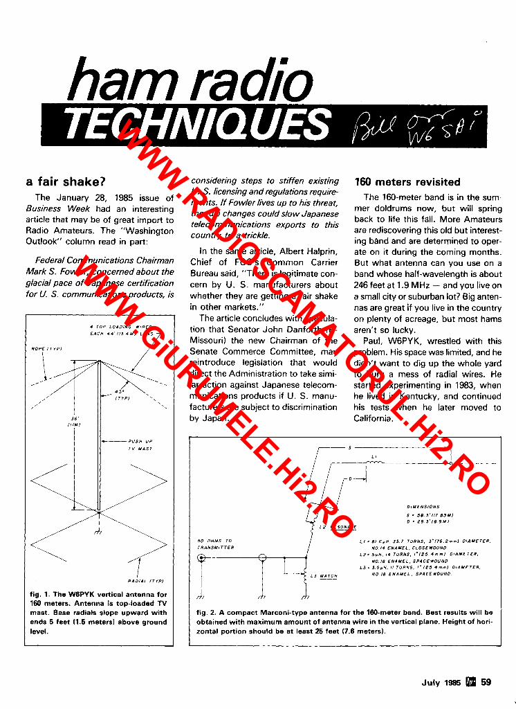
ham radio
a fair shake? The January 28, 1985 issue of
Business Week had an interesting article that may be of great import to Radio Amateurs. The "Washington Outlook" column read in part:
Federal Communications Chairman Mark S. Fowler, concerned about the glacial pace of Japanese certification for U. S. communications products, is
considering steps to stiffen existing U, S. licensing and regulations require- ments. If Fowler lives up to his threat, the rule changes could slow Japanese telecommunications exports to this country to a trickle.
4 T O P L O A D I N G W I R E S
E A C H 4 4 ' 1 1 . 3 4 M I L O N G
R O P E ( T I P 1
13 -/ )- / T I P 1 -- . ,
In the same article, Albert Halprin, Chief of FCC's Common Carrier Bureau said, "There is legitimate con- cern by U. S. manufacturers about whether they are getting a fair shake in other markets."
The article concludes with specula- tion that Senator John Danforth (R- Missouri) the new Chairman of the Senate Commerce Committee, may reintroduce legislation that would direct the Administration to take simi- lar action against Japanese telecom- munications products if U. S. manu- facturers are subject to discrimination by Japan.
/--
,
3 6 ' l l l M l
I
160 meters revisited The 160-meter band is in the sum-
mer doldrums now, but will spring back to life this fall. More Amateurs are rediscovering this old but interest- ing band and are determined to oper- ate on it during the coming months. But what antenna can you use on a band whose half-wavelength is about 246 feet at 1.9 MHz - and you live on a small city or suburban lot? Big anten- nas are great If you live in the country on plenty of acreage, but most hams aren't so lucky.
Paul, W6PY K, wrestled with this problem. His space was limited, and he didn't want to dig up the whole yard to bury a mess of radial wires. He started experimenting in 1983, when he lived in Kentucky, and continued his tests when he later moved to California.
. 4 5*
- P U S H U P
T V M A S T 1 _ _ _ _ _ _ _ _
D I M E N S I O N S
S . 58 5 ' 1 1 7 B J M l D = 2 9 3 ( 8 9 M J
5 0 O H M S TO L I - 8 1 6 r H . 3 5 7 T U R N S , 3"176 Z m m l D I I M E T E R .
T R A N S M I T T E R NO 14 E N A M E L . C L O S E W O U N D
L Z = 5 p H I 4 T U R N S . l " ( 2 5 4 m m I D I A M E T E R .
NO I S E N A M E L . S P A C E W O U N D L 3 = 3 5 p H . 11 T U R N S , I " ( 2 5 4 m m l D I A M E T E R .
N O 18 E N A M E L . S P A C E WOUND
fig. 2. A compact Marconi-type antenna for the 160-meter band. Best results will be obtained with maximum amount of antenna wire in the vertical plane. Height of hori- zontal portion should be at least 25 feet (7.6 meters).
R A D l A l ( T I P 1
fig. 1. The W6PYK vertical antenna for 160 meters. Antenna is top-loaded TV mast. Base radials slope upward with ends 5 feet 11.5 meters) above ground level.
July 1985 59
WWW.RADiOSCAMATORUL.Hi2.RO
WWW.GiURUMELE.Hi2.RO
EQUIPMENT
KENWOOD
TH21AT 2 Mtr HT sh~rt pocket size In Stock TH41AT 70 Cm HT Compan~on to TH21 AT In Stock Accessories for TH21 & TH41 In Stock TS711 A 2m All Mode 25 Watt Call SM220 Statlon Monltor Call TR7930 TR7950 Call TM211A TM411A Call R l 000 R2000 Gen Cov Receivers Call TR2600A Spare PB26 Battery Pack free wlpurchase Call HMC 1 Headset w~th TR2600A only 19 95
OTHER EQUIPMENT
ICOM R71 A 649 00 ICOM IC02AT 299 95 Tentec 2591 269 00 Mirage amps less 12% Amerltron RCS 8 remote coax switch 119 00 Dentron GLT1000C Tuner 1 KW, PEP 175 00 YAESU FT203R Call
SERVICES
Alignment, any late model rlg . . . . . . . . . . . . 50 00 Flat Fee Coll~ns rebu~ld . . . . . . . . . . . . . ..Call
ACCESSORIES
HElL HC31HC41HC5 Stock HElL SS 2 Powered Spkr 49 50 HElL BM10 Boom M~kelHeadset 53 95 HElL HCS Control Boxllnterface 89 95 CES 51 0 Smart Patch 349 00 FLUKE 77 auto ranglng dlgital multlmeter 115 00 Alpha Delta MACC 8 Surge Protector 73 00 Nye 8 wire phone patch 82 00 Shure 444D MIC 49 95 Blrd 43 Wattmeter + accessories In stock Bird 4240 300 AdaptorIConnector Klt 70 00 Da~wa CN620B 20 200 2000W 109 95 Trlppllte PR25 Regulated PS 25Al16A Continuous 99 95 Tr~ppllte PR40 25A Cont~nuous 149 95 Gordon West Code Tapes 9 95 Collins 500Hz F~lter F455J05 new 95 00 Sanyo AA Nlcads 2 00
KEYS - -
Bencher & Vibroplex Less 10%
AE A
New Products In Stock MP 1 CW RTTY AMTOR Interface 134 95 CP 100 (More features than CP I ) 319 95 ATU 1000 M~litary!Commerc~al Interface 1199 95 Dr DX 89 95 Dr QSO 79 95
Alpha Delta MACC. . . . . . . . . . . . 73 00 Master AC Control Console for Control of Entire Stat~on or Independent Circuits. Ellminates Wear of Equipment Switches Best clrcuit protection of any Industry unit SuraelTrans~ent Protection
OPTIONS
MBA-TOR (Includes Amtor & features).. .. 30.00 SWL Text (Special SWL Software) ..... . . . 30.00
TI-l Tun~ng indicator 84 00
BOOKS
Hayden Computer Programm~ng for Amateur Radlo 16 95
TUBES
GE6146B 11 95 GE572B 62 00 E~mac 3 5002 99 95 GE lndustr~al Tubes Call GE 12BY7A 6 00
ANTENNAS
AR2XB V2S 2MCV 5, ISOPOLE 44 95 A3 219 95 A4 289 95 402CD 279 95 Ornnc 2J 2M 112 Wave MoblleIPortable 39 95 Omnl 400 112 Wave Mob~lelPortable 39 95 Hustler 6BTV 129 95 G7 144 119 95 Cushcraft A1 47 1 1 49 95 215WB New 15L. 2MBeam 79 95 A1 47-4 29 95 AOP.1 Complete Oscar Antenna 149 95 Butternut HF6V 80-1 0 Vertlcal 125 00 HF2V 80 & 40 Vertical 125 00
BARKER & WILLIAMSON
All Band B & W D~poles Less 10%
HY-GAIN
HG52SS 1099 00 Ham 4 Rotator 219 95 Ham T2X 269 95 HY Galn accessorles shlpped prepald from the factory wlth tower orders
KLM KT34A 349 95 JV2X 2 Meter Vertical 32 00 2M13LBA 79 95 2M 14C 88 00 2M22C 11995 2M 16LBX 99 95 432 3OLBX 96 00 435 18C lncl CS 2 11695 435 40X 159 95 432 16LB 68 00 HF World Class Series Antennas Call Don
OTHER ANTENNAS Larsen Kulduck 17 00 Larsen Cellular Antenna Stock Valor 75-10M complete mob11 antenna 79 95 Avanti ASP151 3G thru glass 2M 33 00 Anteco 2M 518 Mag Mount Comp 25 00 Metz SW 1 SWL Ant 5Hz - 54Mhz 59 95
SURPLUS
CDE 2 Pole DT Relay 10 Amp Enclosed (New) 5 00 2 5Al1000PIV Epoxy dlode 29c Each or 19 0011 00 Grainwheat 12V Lamps $ 50 001 511 0KV $1 95 455 KHz IF Transformer 49 3N201 95
BELDEN 9528RG8X 191ft 991 3 low loss, sol~d center folllbrald shield 50cIft 821 4 RG8 Foam 43clft
8237 RG8 4Oclfl 8267 RG213 52clft 8000 14Ga stranded copper ant wlre 13clft 8448 8 conductor rotor cable 3 1 clft 9405 Heavy duty 2 16 Ga 6 18 Ga 52clft 9258 RG8x 19clft 8403 MIC Cable 3 condctr & sh~eld 80c!ft I00 Feet 821 4 wlends installed 45 00
ROHN
FK2548 48ft with guy bracket rotor shelf eave bracket and M200H mast 999 00 114" E H S Guy cable Rohn US 1000 ft 250 00 3116 ' E H S cable 210 00 114" Guy Cable 61 00# 7x7 strand 15clft 311 6 Guy Cable 3700# 7x7 strand 12clft Premax Ground Rods Heavy Copper Plat~ng 318 112 518 314 Inches dia 4-8 ft ~n Length Stock 318 x 6 E&J Turnbuckle 7 95 3116" Wre Rope Clips 40 114" wlre clips 50 Porcelain 500D Guy Insulator (3116) 1 69 Porcela~n 502 Guy Insulators (114) 2 99
USED EQUIPMENT
All equipment used clean w~th 90 day warranty and 30 day trlal SIX months full trade agalnst new equipment Sales prlce refunded 11 not satlsfled Always Excellent Used Collins
POLICIES.
Mlnlmum order $10 00 Mastercharge VISA or C 0 D All prices FOB Houston except as noted Prices sublect to change w~thout notlce Items subject to prlor sale Call anytlrne to check the status of your order Texas res~dents add sales tax D ats all folks
DONS CORNER
Thls month Madlson moves to newer and more luxurious quarters wlth our new address at 3621 Fannln St In Houston Those of you who vlslted us at our old locatlon on McK~nney will greatly appreciate the Increased park~ng etc etc We II mlss our legendary McKlnney locat~on but new tlmes demand new store space and we fully Intend to keep up wlth the tlmes
New t~mes also demand new modes of communlcatlng to you, our customers, and so we contlnue to work on our MADISONILINE Bulletln board We re runnlng a l~ttle beh~nd on gettlng phone lines ~nstalled and hardware up-and-run nlng because of the move but we should have all that Ironed out shortly
WWW.RADiOSCAMATORUL.Hi2.RO
WWW.GiURUMELE.Hi2.RO
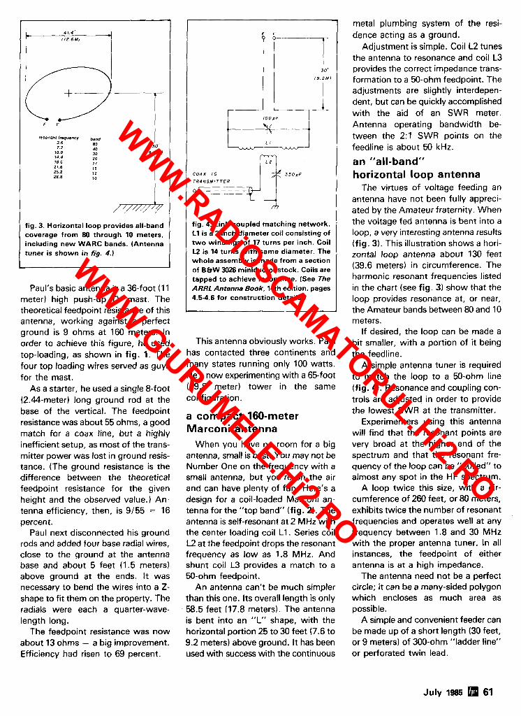
.
F F
resonant bequency ban,, 3 6 7.2
80 40
30' 10.8 30 1 9 . Z M I 14 4 18 0 21 6 25 2 28.8
fig. 3. Horizontal loop provides all-band coverage from 80 through 10 meters, including new WARC bands. (Antenna tuner is shown in fig. 4.)
Paul's basic antenna is a 36-foot (1 1 meter) high push-up TV mast. The theoretical feedpoint resistance of this antenna, working against a perfect ground is 9 ohms at 160 meters. In order to achieve this figure, he used top-loading, as shown in fig. 1. The four top loading wires served as guys for the mast.
As a starter, he used a single &foot (2.44-meter) long ground rod at the base of the vertical. The feedpoint resistance was about 55 ohms, a good match for a coax line, but a highly inefficient setup, as most of the trans- mitter power was lost in ground resis- tance. (The ground resistance is the difference between the theoretical feedpoint resistance for the given height and the observed value.) An- tenna efficiency, then, is 9/55 = 16 percent.
Paul next disconnected his ground rods and added four base radial wires, close to the ground at the antenna base and about 5 feet (1.5 meters) above ground at the ends. It was necessary to bend the wires into a Z- shape to fit them on the property. The radials were each a quarter-wave- length long.
The feedpoint resistance was now about 13 ohms - a big improvement. Efficiency had risen to 69 percent.
F F
1 9 . 2 M I
C O A X T O
fig. 4. Link-coupled matching network. L1 is a 2-inch diameter coil consisting of two windings of 17 turns per inch. Coil U is 14 turns with same diameter. The whole assembly is made from a section of BBW 3026 miniductor stock. Coils are tapped to achieve resonance. (See The ARRL Antenna Book, 14th edition. pages 4.5-4.6 for construction details.)
This antenna obviously works. Paul has contacted three continents and many states running only 100 watts. He's now experimenting with a 65-foot (19.8 meter) tower in the same configuration.
a compact 160-meter Marconi antenna
When you have no room for a big antenna, small is best. You may not be Number One on the frequency with a small antenna, but you're on the air and can have plenty of fun. Here's a design for a coil-loaded Marconi an- tenna for the "top band" (fig. 2). The antenna is self-resonant at 2 MHz with the center loading coil L1. Series coil L2 at the feedpoint drops the resonant frequency as low as 1.8 MHz. And shunt coil L3 provides a match to a 50-ohm feedpoint.
An antenna can't be much simpler than this one. Its overall length is only 58.5 feet (17.8 meters). The antenna is bent into an "L" shape, with the horizontal portion 25 to 30 feet (7.6 to 9.2 meters) above ground. It has been used with success with the continuous
metal plumbing system of the resi- dence acting as a ground.
Adjustment is simple. Coil L2 tunes the antenna to resonance and coil L3 provides the correct impedance trans- formation to a 50-ohm feedpoint. The adjustments are slightly interdepen- dent, but can be quickly accomplished with the aid of an SWR meter. Antenna operating bandwidth be- tween the 2:l SWR points on the feedline is about 50 kHz.
an "all-band" horizontal loop antenna
The virtues of voltage feeding an antenna have not been fully appreci- ated by the Amateur fraternity. When the voltage fed antenna is bent into a loop, a very interesting antenna results (fig. 3). This illustration shows a hori- zontal loop antenna about 130 feet (39.6 meters) in circumference. The harmonic resonant frequencies listed in the chart (see fig. 3) show that the loop provides resonance at, or near, the Amateur bands between 80 and 10 meters.
If desired, the loop can be made a bit smaller, with a portion of it being the feedline.
A simple antenna tuner is required to match the loop to a 50-ohm line (fig. 4). Resonance and coupling con- trols are adjusted in order to provide the lowest SWR at the transmitter.
Experimenters using this antenna will find that the resonant points are very broad at the higher end of the spectrum and that the resonant fre- quency of the loop can be "pulled" to almost any spot in the HF spectrum.
A loop twice this size, with a cir- cumference of 260 feet, or 80 meters, exhibits twice the number of resonant frequencies and operates well at any frequency between 1.8 and 30 MHz with the proper antenna tuner. In all instances, the feedpoint of either antenna is at a high impedance.
The antenna need not be a perfect circle; it can be a many-sided polygon which encloses as much area as possible.
A simple and convenient feeder can be made up of a short length (30 feet, or 9 meters) of 300-ohm "ladder line" or perforated twin lead.
July 1985 5 61
WWW.RADiOSCAMATORUL.Hi2.RO
WWW.GiURUMELE.Hi2.RO
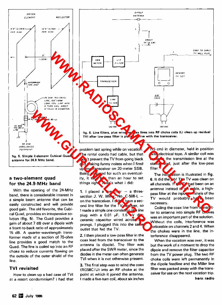
D R I V E N
E L E M E N T R E F L E C T O R
9 ' 9 " I 2 9 8 M ) 1 0 ' 4 " ( 3 . 1 5 M l
P E R S I D E
problem last spring while on vacation. The rental condo had cable, but that didn't prevent the N from going black and making funny noises when I fired up my transceiver on 20-meter SSB. Being prepared for such an eventual-
a two-element quad ity, it took less than an hour to set
for the 24.9-MHz band things right. Here's what I did:
r - D I P O L E
A N T E N N A
L I7 A B O U T
3 2 M )
L COAX TO C A B L E
With the opening of the 24-MHz band, there is colisiderable interest in a simple beam antenna that can be easily constructed and will provide good gain. The old favorite, the Cubi- cal Quad, provides an inexpensive so- lution (fig. 5 ) . The Quad provides a gain of about 7 dB over a dipole with a front-to-back ratio of approximately 15 dB. A quarter-wavelength trans- former made of a section of 75-ohm line provides a good match to the Quad. The line is coiled up into an RF choke to reduce currents flowing on the outside of the outer shield of the line.
I I -
TVI revisited
L T V WALL PLUG
K__
How to clean up a bad case of TVI at a resort condominium? I had that
I r
L - P -
7 5 O H M ( R G - 5 9 / U I
L I N E , 6 ' 6 " 1 1 9 9 M I
LONO. COIL L I N E I N T O 5 T U R N C O I L A B O U T 6 " 1 1 5 c m l I N D I A M E T E R .
1. I placed a line filter - a three- section J. W. Miller, No. C-508-L - on the transceiver. I didn't have a sec- ond line filter for the TV receiver, so I made a simple one consisting of a line plug with a 0.01 CLF, 1.6 kV disc ceramic capacitor wired across the prongs. I plugged this into the same outlet that fed the TV.
2. 1 then placed a low-pass filter in the coax lead from the transceiver to the antenna (a dipole). The filter was placed after the SWR meter, since the diodes in the meter can often generate TVI when it is not otherwise present.
3. The final step was to wind the coax (RG58CIU) into an RF choke at the point at which it joined the antenna. I made a five-turn coil, about six inches
5 '
11 5 2 M )
M E T E R
S W R
- - -
(15 cm) in diameter, held in position with electrical tape. A similar coil was made in the transmission line at the station end, just after the low-pass filter.
The installation is illustrated in fig. 6. It did the job! The TV was clean on all channels. If the TV had been on an
F I L T E R
COAX AOAPTER c P L - 2 5 8 (AMPMENOL 83- 1Jl
antenna instead of on cable, a high- pass filter at the input terminals of the TV would probably have been necessary.
Coiling the coax line from transmit- ter to antenna into simple RF chokes was an important part of the solution. Without the coils, interference was noticeable on channels 2 and 4. When the chokes were in the line, the in- terference disappeared.
When the vacation was over, it was but the work of a moment to drop the dipole and remove the filter capacitor from the TV power plug. The two RF choke coils were left permanently in the dipole feedline and the Miller line filter was packed away with the trans- ceiver for use on the next vacation trip.
5 0 OHM I R G - 5 B / U l ~~~d 5 0 O H M
U N B A L A N C E 0
F E E D P O I N T
fig. 5. Simple 2-element Cubical Quad antenna for 24.9 MHz band.
ham radio
T R A N S C E I V E R I 0 0
N E A R B Y
T V S E T
L 0 0 1
L I N E
F l L T E R
- 1 6 h V
\I
-
I 2 0 VAC 1 2 0 VAC
fig. 6. Line filters, plus winding coax lines into RF choke coils (Ll clean up residual TVI after low-pass filter is placed in line with the transceiver.
WWW.RADiOSCAMATORUL.Hi2.RO
WWW.GiURUMELE.Hi2.RO
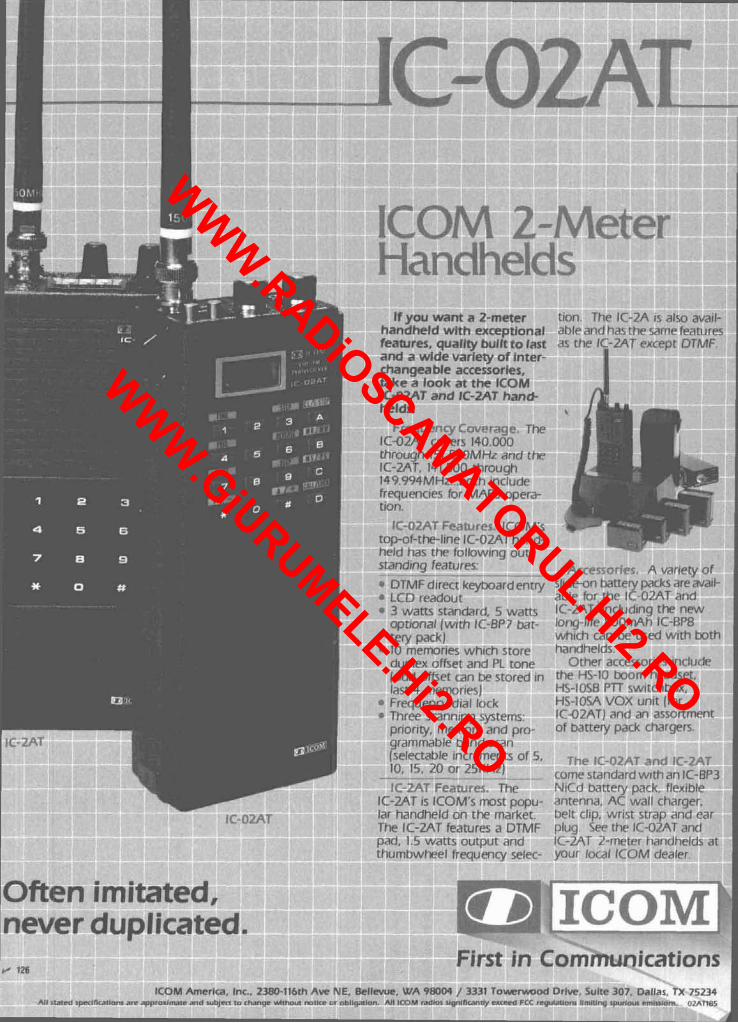
tlon 11 ahl?;
nwres, quallry oulrr ro last the IL.-LM~ ezxcriJr L
id a wide variety of i n t e ~ langeable accessories. k e a look at the ICOM -02AT and IC-2A
If YOU H rndheld -
rant a 2- with ex1 -..-.. - . *
The IC-2 tnd has tt - 8,- , A T -
I avail- vrtrres - 7 . .?
meter cept1on;l .,- ,
:T hand- !Ids. I
Frnp?:~n P
-0ZAT covers r.to.uuu roogh iS1.550MHz and the -2AT, 14 1.500 ttirough 9.994MHz ... both 1nc111de qumcles for MA1 f r ~
tic ?S opera
;. ICOM' , - * L A - -
LJ-UI-LI r-III IY IL-ULM I r~dr~c, Id has th 'Indmg fe
CY of sllar-on mtrpry pa^^^ <ire mat!- able for thr !C-OLAT and IC-?AT, ~ncludlnq t h ~ nnw lonq-11lr 8OOmAt 1 IC-RPFi
car1 bP llsed wlth both
.-
DTMF d~rect keyhoard entry .CD readout ? watts standard. 3prronal (wrth IC- :ery pack) 10 rnernorles which store 3upl?x offset and PL tone odd offset can he stored II ast 4 memories) 'requency dial lo( rhree scannlng sy ,3r1orrty, memory arlu pro- grammable band scan (selectablr increments of 5 10. 15, 20 or 25KHz)
-- - .
:C-Z 0.T Feanirr?. .2AT is ICOM's r n
""8 , 1 1 1 I
hantlt- Ott
7 thr H' . .- S O T I ~ S inc TI headsf
.. . . lude 't .
H\-llJ\H 1 ' 1 I t W l l C t l M l X .
H<-IO\A VOX unrr (for IC-QIAT] ,mtl an nc5ortrnent of battery pack charqers
7P"' com? standard w ~ t h an IC-BP3 N C f 1 bartpry pdck, flcrrble antenna. AC wall charqcr,
The OSt POplJ market. - -7. .r
handheld on t h ~ hrlt clip. wr15t str+) ,inti rar P IC-2AT features <I ur rvlr ~ l i ~ o )re thc. IC-OIAT and
,Id$ at ~t and icy selec.
ic.-%1 - your I
r ~-mc,tr ncal ICO
-- -
imitated, never duplicated.
mun ications ICOM Arnerlca. In( 5th Ave NE. Bellewe, WA 9BOW / 3331 T o w e w o d Drive. ! Dallas, TX 75234
All IL11ea ~ ~ l ~ c a l l o n s arc approxtmtc and l u b l m to I ut m r l c r or nbllqallar~ All ICOM rrdlol rtqnlnc~nrly exreed FCC rrqulm!om Iln 0 ~ n 8 5
WWW.RADiOSCAMATORUL.Hi2.RO
WWW.GiURUMELE.Hi2.RO

-0 OCITLET 6 STORE BUYING POWER!
*
TOLL-FREE PHONE: 800-854-6046 INCLUDING ALASKA AN[) HAWAII CALO ANII M I I I I N I C U ~ , ~ . Y . I < . . l l i i i . . , . . - I 57. 8 , . ml r i i 6 I VLIV
FREE SHIPMENT MOST ITEMS. U.P.S. SURFACE.
MA-550 55' tubular WIII handle 12 sq. It. antennas 2 METERS 100 WATTS 430-450MHz 75 WATTS
ALL-MODE ALL-MODE at 50 MPH wlnds.
IN STOCK FOR IMMEDIATE DELIVERY
. 1 , : , . , ) ; J
ON 4LL <.! iHEH h?C!DELS
SUPER-COMPACT 2 METER MOBILE
ALSO *IC-27H HIGH POWER VERSION TRANSCEIVER
IN STOCK. . .
TIME STANDARD
FOR ACCURACY
W-51 SALE S899 LM-354 SALE S1599
-.
THE VERY BEST DEAL ON EVERY COUNT!
WWW.RADiOSCAMATORUL.Hi2.RO
WWW.GiURUMELE.Hi2.RO
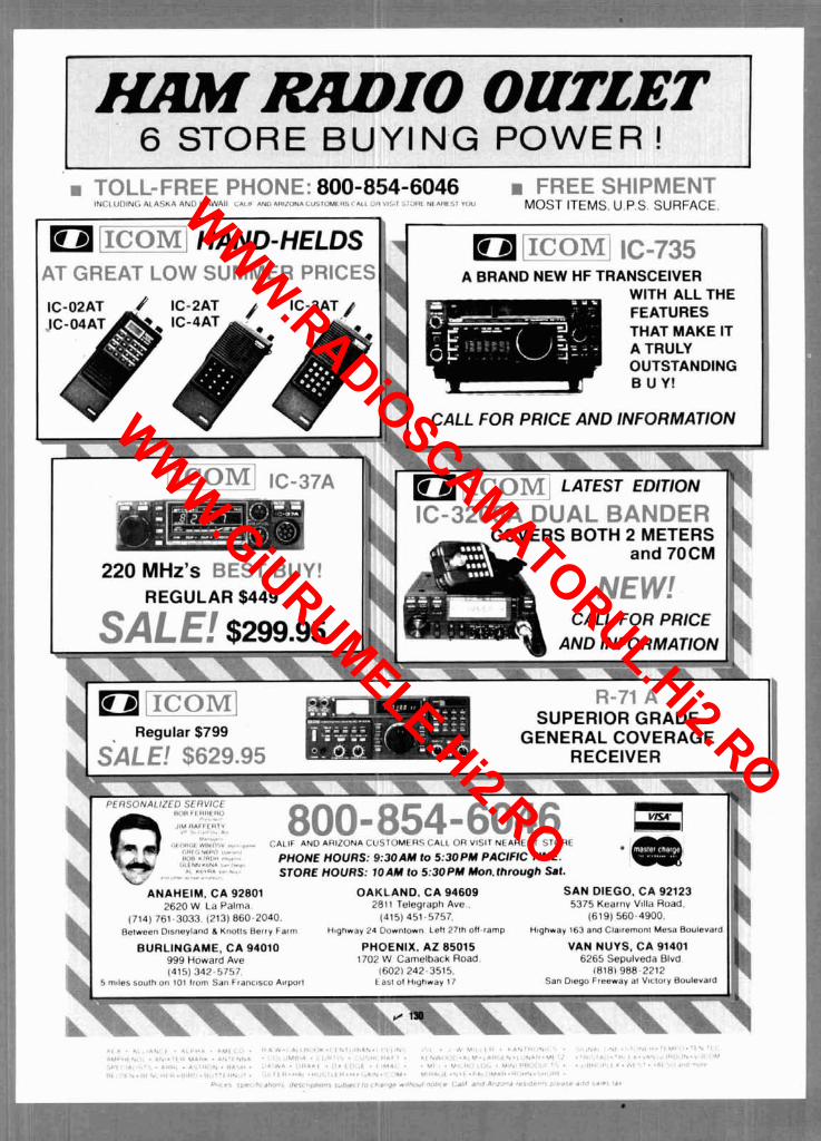
m R R D I C DMTJET 6 STORE I Y I N G POWE
TOLL-FREE PHONE: 800-854-6046 INCLUOINC. ALASKA ANll HAWAII C N I I A N I & & H I I I I N I C U ~ ~ ~ ~ ~ I ~ i , n . I .#,..; i: l u i , t i , riil . I rnu
FREE SHIPMENT MOST ITEMS. U.P.S. SURFACE.
A BRAND NEW HF TRANSCEIVER
THAT MAKE IT
220 MHz's PEST QUY! REGULAR $449
CALL FOR PRICE
GENERALCOVERAGE
,,,,,< * 111.1, ...... 1 * T . 8 , .." ,.a. '. -.. PHONE HOURS: 9:30AM lo 5:30PM PACIFIC TIME.
A > - , , - * , a ....... STORE HOURS: lOAM to 5:30PM Mon.through Sat.
ANAHEIM. CA 92801 OAKLAND. CA 94609 SAN DIEGO. CA 92123 2620 W La Palma. 2811 Telegraph Ave 5375 Kearnv Villa Road.
(415) 451-5757. (619) 560-4900.
BURLINGAME. CA 94010 PHOENIX. AZ 85015 VAN NUVS, CA 91401 999 Howard Ave
. . . . . . . . . . / a . . .... . . . . . . . . . . . . . . . . . ~ . . . . . ._,.. . . , ,.. ,,>... ..,. / ..I.. 1 . . / / . ....... . , . . . , . . . . I . . . . . / : . : :/ . . . . . . . . . . . . ..I . . . . . . . _ . . . . . . . . . . _ . . . . . . . . . :, > , , . : ,,. ../ (./ ,.:.. ,,., s., I.,.. . . / ( . ...;,. . . . . . . . . . . . . . . . . . . . . . . . . . . . . . . . . . . . . _ , ,_ , . ......... . . / ..., 1 ... / ...... & . , . ,,. ..,/.> . . . . . . . . . L I.,: . . . . . .,... .....
Y . . . . .,,. ' . . A ' . , q . . I " . ..,,,.. .........,.. , .,... * , n .,., . ̂ ,,,,." t I . r .,n.r,,., <r,..,,.. .. :.,.* i. 1 1 . I . . I .
w
WWW.RADiOSCAMATORUL.Hi2.RO
WWW.GiURUMELE.Hi2.RO
SSI-202P CMOS I WEOVERPURCHASED I
Our over supply can be your gain. We've just got to try and get even so we are going to let our ham friends
share in some of these great circuits, for a great price. FEATURES
Central office quality Output in either 4-bit hexadecimal code or binary Band-splitting filters included on chip coded 2 of 8. Use 74159 decoder for 1 of 16 output Single, low-tolerance. 5-volt supply Uses inexpensive 3.579545-MHz color-burst crystal for Detects either 12 or 16 standard DTMF digits reference (Radio Shack PIN 272-1310 $1.69) 18-pin DIP package Excellent speech immunity
All you need is a color-burst XTAL from Radio Shack & 1 meg reslstor to make a C.O. Qual~ty Touch Tone decoder. SSI-202 is a 5V part and unlike the older 201 is TTL compatible and will directly interface to personal computers.
These won't last long and are limited to available supply, so HURRY!!
INCLUDING SPECS & SCHEMATICS $1 8 n W ~ L add 7 9010 sales tax m
R.M. FULLER CO. m 902 Industry D r . Seattle, WA 98188
1-800-626-6662 I I 1
I H 131 In Wash. Call (206) 575-8640 I
11 1 1 '2
guarantee S1 'a sbppfng IFrsl Class
WWW.RADiOSCAMATORUL.Hi2.RO
WWW.GiURUMELE.Hi2.RO
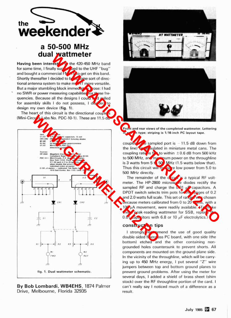
the
a 50-500 MHz dual wattmeter
Having been interested In the 420-450 MHz band for some time, I finally succumbed to the UHF "bun" and bought a commercial FM HT to get on this band. Shortly thereafter I decided to build some sort of direc- tional antenna system to make my HT more versatile. But a major stumbling block immediately arose: I had no SWR or power measuring capabilities for these fre- quencies. Because all the designs I could find called for assembly skills I do not possess, I decided to design my own device (fig. 1).
The heart of this circuit is the directional couplers (Mini-Circuits Labs No. PDC-10-1). These are 11.5 dB
I , . " , d"cr,p*n CI.CZ 0 0 , *I l"M* c-,,DI.. 1 , .d, CRI .CI I MP.2IW or .pulvhnl ScnotDv d- U I . Y ? O.tW nl m.,." RI.ll4 50 kflohm I t t m m 0 1 . n l M t . R UI.V? YmI-C l rcu( ls PDC.lbl
dmrll.3NI coup,."
wrm' MP.28W YqhnYqhn El.c,ra*.. I111 w..,
Dnn(b.cb R M . Pk.",.. l"l0N l 5 l O 5 W E . I O - I : UmI-CsCYI Is . P 0. 6.3. 166. Bmol lvn.
NO- ran I 8235 bar. .p~mn,m.,e,, S I I 50 . u h dm 5 lo 45 puanlllv ( S s p * . 4-l daub* that price 1 Club or #nd#rldu.l orders rcspted
O.iW 4 ms<er, - C.,lb,.,ad 6.. Rld,. a*.. ,086 E.1, 6ureL0. BOX llO5 L # N , Ohlo45802
* U I I U 2 I' * . -
\ f
4
m C W I C R 2 m
R ,
M I Y Z
F W D R E F
fig. 1. Dual wanmeter schematic.
Front and rear views of the completed wanmeter. Lettering is rub-on type; striping is 1116-inch PC layout tape.
couplers (the sampled pot? is - 11.5 dB down from the line) encapsulated in miniature metal cans. The coupling ratio is flat to within + 0.6 dB from 500 kHz to 500 MHz, and maximum power on the throughline is 3 watts from 5 to 500 MHz (1.5 watts below that). Thus this circuit will measure low power from 5.0 to 500 MHz directly.
The remainder of the circuit is a typical RF volt- meter. The HP-2800 microwave diodes rectify the sampled RF and charge the 0.01 LFF capacitors. A DPDT switch selects trim pots for the ranges of 0.2 and 2.0 watts full scale. This set of ranges was chosen because meters calibrated from 0 to 20 watts, with a 100 FA movement, were readily available. (To make this a peak-reading wattmeter for SSB, replace the 0.01 capacitors with 6.8 or 10 FF electrolytics.)
construction tips I strongly recommend the use of good quality
double-sided fiberglass PC board, with one side (the bottom) etched and the other containing non- grounded holes countersunk to prevent shorts. All components are mounted on the ground-plane side. In the vicinity of the throughline, which will be carry- ing up to 450 MHz energy, I put several "Z" wire jumpers between top and bottom ground planes to prevent ground problems. After using the meter for several days, I added a shield of brass sheet (shim stock) over the RF throughline portion of the card. I
By Bob Lombardi, WB4EHS, 1874 Palmer can't really say I noticed much of a difference as a Drive, Melbourne, Florida 32935 result.
July 1985 67
WWW.RADiOSCAMATORUL.Hi2.RO
WWW.GiURUMELE.Hi2.RO

ALL ARE 115 VAC
T I # 1053214-2 1,4" BUSHING COMPACT WELL REGULATED SWITCHING POWER SUPPLY DESIGNED TO POWER TEXA INSTRUMENTS COMPUTER EQUIPMENT
INPUT 14VAC-25 VAC AT l A 100 FOR 530 00
OUTPUT + 12VDCAT 350MA SPECIFY COLOR 12 VOC@ 2.6 AMP HOUR
+ SVOC AT 1 2A - 5VDC AT 200MA
SIZE 4%' x 4%" x 1%' 1S.w mCI(
13 8VDC POWER SUPPLIES ALL FEATURE 100% SOLID STATE CONSTRUCTION, FUSE PROTECTION. L E D POWER INDICATOR 2,000 mfd. 200 VDC
FLASHER LED 1 3 / 4 OIA . 5" HIGH S2.W
3,800 mfd. 40 VDC 1 310" DIA , 3 3 / 4 HIGH $1.00
WWW.RADiOSCAMATORUL.Hi2.RO
WWW.GiURUMELE.Hi2.RO
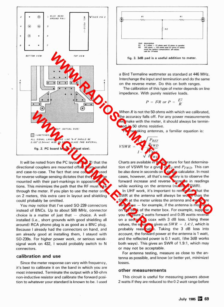
It will be noted from the PC layout (fig. 2) that the directional couplers are mounted offset from parallel and case-to-case. The fact that one coupler is used for reverse voltage sensing dictates that they must be mounted with their part-markings in opposite direc- tions. This minimizes the path that the RF must take through the meter. If you plan to use the meter only on 2 meters, this extra care in layout and shielding could ptobably be omitted.
You may notice that I've used SO-239 connectors instead of BNCs. Up to about 500 MHz, connector choice is a matter of just that - choice. A well- installed (i.e., short grounds with good shielding all around) RCA phono plug is as good as a BNC plug. Because I already had the connectors on hand, and am already good at installing them, I stayed with SO-239s. For higher power work, or serious weak- signal work on 432, 1 would probably switch to N connectors.
FI i::::Nr; y1. 1
- 6
6 .
BOTTOM VIEW TOP VIEW
POClO - I
P C L A r o U r iACTUAL S1ZC1
. UNETCHEO COPPER
I L L SlGNAL LANOS ABOVE L!NE -1-1. S l O U L O BE
O . l O O ~ i Z . S 1 m n ~ WIDE ON EPOXY-GLASS PWB MATERIAL
fig. 2. PC board layout factual sizel.
calibration and use
1
Since the meter response can vary with frequency, it's best to calibrate it on the band in which you are most interested. Terminate the output with a 50-ohm non-inductive resistor and calibrate the forward posi- tion to whatever your standard is known to be. I used
I1.m d..crtp,k., ar aI&ms - i s e m s n d ~ ~ c + m s r n p r ~ R2 142 ohms - 120 Mm *ill Zl ohm. h s w * .
nust M e n C m p O W M . dI ..h*s can k4 I14-waI8
fig. 3. 3dB pad is a useful addition to meter.
a Bird Termaline wattmeter as standard at 446 MHz. Interchange the input and termination and do the same on the reverse meter. Do this on both ranges.
The calibration of this type of meter depends on line impedance. With purely resistive loads.
When R is not the 50 ohms with which we calibrated, the accuracy falls off. For any power measurements we make with the meter, it should always be termin- ated in 50 ohms resistive.
For tweaking antennas, a familiar equation is:
Charts are available in the literature for fast determina- tion of VSWR for a given PREFand PFwn. This can be also done in seconds on a simple calculator. In most cases, however, all that's necessary is to 0 b s e ~ e the forward increase and reverse decrease in readings while working on the antenna (nulling VSWR).
In UHF work, it's important to remember that the SWR at the antenna will always be worse than the SWR at the meter unless the antenna and meter are very close - for example, if the antenna is mounted on the back of the meter box. For example, suppose you measure 2 watts forward and 0.05 watts reverse on a section of coax with 3 dB loss. Using these values, the equation gives us SWR = 1.4:1, which is probably reasonable. Taking the 3 dB loss into account, the forward power at the antenna is 1 watt, and the reflected power is 0.1 watt, (the 3dB works both ways). This gives an SWR of 1.9:1, which may or may not be acceptable.
For antenna testing, measure as close to the an- tenna as possible, and know (or better yet, minimize) losses.
other measurements This circuit is useful for measuring powers above
2 watts if they are reduced to the 0-2 watt range before
July 1985 69
WWW.RADiOSCAMATORUL.Hi2.RO
WWW.GiURUMELE.Hi2.RO
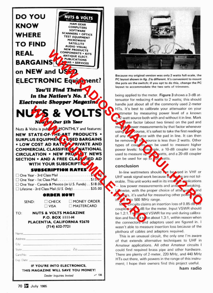
Because my original version was only 2 watts full-scale, the PC layout shown in fig. 2 is different. It's convenient to mount the pots on the switch; if you opt to do this. change the PC layout to accommodate the two sets of trimmers.
ELECTRONIC Equipment? You'll Find Them
in the Nation's No. 1 Electronic Shopper Magazine
NUTS & VOLTS Now In Our 5th Ymr
Nuts & Volts is published MONTHLY and features:
NEW STATE-OF-THE-ART PRODUCTS SURPLUS EQUIPMENT USED BARGAINS
LOW COST AD RATES PRIVATE AND COMMERCIAL CLASSIFIEDS NATIONAL CIRCULATION NEW PRODUCT NEWS SECTION AND A FREE CLASSIFIED AD
WITH YOUR SUBSCRIPTION SUBSCR1PTIOII RATES
One Year - 3rd Class Mail . . . . . . . . . . . . . . . . $10.00 One Year - l st Class Mail. . . . . . . . . . . . . . . . . S I 5.00 One Year - Canada & Mexico (in U.S. Funds) . . $18.00 Lifetime - 3rd Class Mail (U.S. Only) . . . . . . . . .$35.00
ORDER NOW?
CHECK W MONEY ORDER MASTERCARD
NUTS & VOLTS MAGAZINE P.O. BOX I I I I-H
PLACENTIA, CALIFORNIA 92670 (7 14) 632-772 1
being applied to the meter. Figure 3 shows a 3-dB at- tenuator for reducing 4 watts to 2 watts; this should
Name
Address
City
S t a t e ZIP
Card No
l i p Date
IF YOU'RE I N T O ELECTRONICS, THIS MAGAZINE WILL SAVE YOU MONEY!
Dealer Inquiries Invited r / 136
handle just about all of the commonly used 2-meter
L
HTs. It's best to calibrate your attenuator on your wattmeter by measuring power level of a known I 2 watt source both with and without it in line. Mark the power factor (about two times) on the pad and multiply power measurements by that factor whenever using it. Of course, it's safest to take the first readings of any new source with the pad in line. It can then be removed if the source is less than 2 watts. Other types of couplers can be used to measure higher power levels: for example, a 10-dB coupler can be used to measure up to 20 watts, and a 20-dB coupler can be used for up to 200 watts.
conclusion In-line wattmeters should not be used in VHF or
UHF weak signal work because the losses are not tol- erable. This unit works well in its intended applications - low power measurements and antenna tweaking. Likewise, with the proper choice of attenuators and couplers, it's useful for measuring other power levels in the 5 to 500 MHz range.
Mini-Circuits claims an insertion loss of 0.85 dB per coupler, or 1.7 dB for the meter. Input VSWR should be 1.2:1. 1 measured VSWR for my unit during calibra- tion and found it to be about 1.3:1, within reason when the connectors and adaptors used are figured in. I wasn't able to measure insertion loss because of the plethora of cables and adaptors required.
This is an unusual circuit, the only one I'm aware of that extends alternative techniques to UHF in Amateur applications. All other Amateur circuits I could find required brass pipe and other hardware. There are plenty of 2-meter, 220 MHz, and 440 MHz HTs out there, with powers in the range of this instru- ment; I hope their owners find this project useful.
ham radio
70 a July 1985
WWW.RADiOSCAMATORUL.Hi2.RO
WWW.GiURUMELE.Hi2.RO
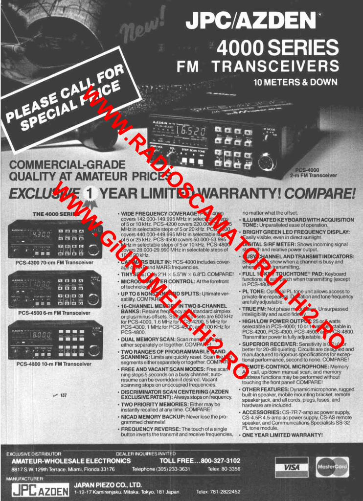
I r v n l ~ ISWE 1 "EAR LIMITED WARRANTY! Cn"VPARE! lllOllrl whal theol
covers 142 000.149 991 MHz In SeleCtaDle 01501 10 kHz PCS-4 !:lOcovers 270 000.2 MHz (n seleclablr. slelv, ol5 or 20 "Hz PC5 covers 440 000-449 ! $5 MHz In se f!ClaDlc? of 5or 25 <Hz PCS-4 v,Ocovers 50 000-53 MHz In se1ectab.c- stfy~s 015 or 10 ~ H z . PC5 covers 28 000-29 9W IdHz In selectable st6 lOor20kH7
steps , '24.995 ;-4300 , steps naz
. ILLUMINI TONE: UI - BRIGHT1 r--., . .
PTEDKEY iparallrled GREEN LE L,- - -- .
IYUAHUWI I n a L u u l a l I IUN ease ol oprratlon iD FREQUENCY DISPLAY:
C ~ ~ I I Y YIBIUII-. we11 111 dlrect sunllqhl p DIGITAL SIRF METER: Shows strenqlh and relatlve power outp
p BUSY-CHANNELANDTRANSMITINDIC ATORS: qnd CAPIMARS BUILT IN: PCS-4000 includes
ageof CAP and MAR T1NYSIZE:Only 2"H . MICROCOMPUTER of technoloqyt
cover-
. . - . - - . Brloht LEDs show when achannel is busv;
les. 6.8"D. C01 -:At the for
when you o FULL16 ' . . - -. . - - -
are transm KEY TOU( as autopalc 100).
lttlng. :HTONE' :I1 when Ira
PAD: Keyb nsmlttlng (I
Ml'AHt!
etront lUllCllUllb
In PCS-41 PLTONE: upllorial rL 1urieur111 allvwsau private-llnerepealers. Devtationandtonefrc are fully adjustable. . TRUE FM: Not phase modulation. Unsurp; intell~gth~lhtyand autl~ofidelity HIGH/LOW POWER OUTPUT: 115
selectable In PCS-4000: 10or 1 ..,,.a,8,,;able in PCS-4200. PCS-43011, PCS-4500. and PCS-4800. Transmtlter power IS fully adlustable. SUPERIOR RECEIVER: Sensttlvlty is0.21 better for 20-dB quletlnq. Clrcults are desig manufactured to rtqorous specillcatlons tor t~onal perforrnancc. second to none COMF
s REMOTE-CONTROL MICROPHONE: Mt A-1 call, updown manual scan, and memc addresslunct~onsrnay be performed wltho touchlng Ihe fronl panel' COMPARE1 OTHER FEATURES: Dynam~crn~crophone, rugged built-in speaker, mobile rnountlng bracket, remote speaker jack, and all cords, plugs. fuses, and hardware are Included.
s ACCESSORIES: C I CS-4.5R 4.5-amp ac speaker, and Cornmc PL lone module. . ONE YEAR LIMITEDWARRAI
oam except
tever- '
INEL . 1BCHANNEL MEMORY IN TWO ECHAN BANKS: Relains freouencv and standard s'mnl-v :S-4500 6-m FM Transceiver .a.'yI'"
500 kHz izlor * :Hz tor
-8.-
or plus mlnus offsets ~landard offsets are f for PCS-4000. 1 F MHz for PCS-4200.5 Mt PCS-4300, 1 MHz for PCS-4500. and 100 b PCS-4800 DUAL ME etther sep;
4N: Scan memory bar~na lrjether COMPARE!
ned and excep-
9 A D F I
- TWO RAN ROGRAMMABLE BAND SCANNINu. ~ 1 1 ~ 1 ~ 3 O I C ~ U I C ~ I ~ rPsPt Scan the two Soamt'rIC3r) IherseDat alc vor loqether COh .m FM Trar APARE!
b scan- to- t
FREE AND VACANT SCAN MODES: Free ntng stops 5 secondsorl a busy channel: au resume can be overrldd~n 11 deslred Vacan scanntng stops on unoccup~ed frequencies
DISCRIMINATOR SCAN CENTERING (AZDEN EXCLUSIVE PATENT): Alwaysstopsonlrequency. TWO PRIORITY MEMORIES: Either may be instantly recalled a1 any Ilme. COMPARE! . NlCAD MEMORY BACKUP: NE grammed channels' FREQUENCY REVERSE: The iuucn~ u~ a 3 bulton Inverts the lrar
) ac power! phi. CS-AS ;pec~alists
supply. remote SS-32
3 Pro- wer lose thl
,^..^L ̂ '^ - lsmlt and n
WWW.RADiOSCAMATORUL.Hi2.RO
WWW.GiURUMELE.Hi2.RO
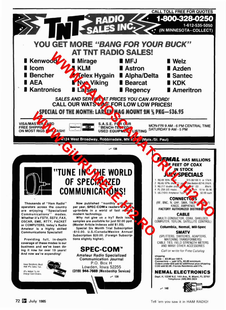
YOU GET MORE "BANG FOR YOUR BUCK" AT TNT RADIO SALES!
I Kenwood I Mirage I MFJ I Welz I lcom I KLM I Astron I Azden I Bencher I Telex Hygain I AlphaIDelta I Santec I AEA I Nye Viking I Bearcat I KDK I Kantronics I Larsen I Regency I Ameritron
SALES AND SERVICE AT PRICES YOU CAN AFFORD! CALL OUR WATS LINE FOR LOW LOW PRICES!
SPECIAL OF THE MONTH: LARSEN MAG MOUNT PM js PKG-$36.95
VISAIMASTER CARD S.A.S.E. FOR OUR FREE SHIPPING "BENCH-TESTED" MON-FRI 9 AM - 6 PM CENTRAL TIME ON MOST RIGS FOR CASH! USED EQUIPMENT LISTING SATURDAY 9 AM - 5 PM
[ B J ! OF SPECIALIZED L AI COMMUNICATIONS! Thousands of "Ham Radlo" Now publlshed "monthly" 10 tlmes
operators across the country per year. SPEC-COMTW readers are kepl are enjoying "Speclallzed up toda te In a world of fast moving Communlcat lons" modes. modern technology. Whether It's FSTV, SSTV. FAX. Why not glve us a try? Back issue OSCAR. EM€. RTTY. PACKET samples are available for just $2.00 ppd. or COMPUTERS. today's Radio (Master Artlcle Indexes add 81.00). Amateur Is a hlghly skllled Special Six Month Trial Subscrlptlon Communlcatlons Speclallst! -$10.00. U.S.ICanadalMexico Annual
Subscrlptlon 520.00. (Foreign Subscr ip Prov id ing ful l . In -depth lions slightly higher).
coverage of these modes is our business and we've been do- Ing It now for over 19 years! And now we're expanding!
SPEC-COMm Amateur Radlo Specialized
Communication Journal l m a Rcr&nls Mur l P.0. BOX H AM 1.1. saks tar Lowden, Iowa 52255 4% *ddM 10 All ChafQe Card Oldels
13191 944-7689 (Membership Services)
\ / 139
NEMAL HAS MILLIONS I OF FEET OF COAX IN STOCK
JULY SPECIALS 1 RGBX 95% shleld S ~ ~ W I I W ~ o r l h l n 2 RGBU 97% shteld 11 gauge (like Helden 8214) 31tIn 3 RG 217 double shleld M ohm 518 OD 85tIn 4 PL 259 (US nlade) 656 each 10 lor $5 90 5 UG 2101U Amphenol Type N 53 W each
CONNECTORS (RF. BNC. N. UHF SMA. TNC LC. HN. F)
KINGS. AMPHENOL FACTORY AUTHORIZED DISTRIBUTOR
CABLE (MULTI CONDUCTOR COAX. SHIELDED.
COMPUTER. TEFLON SATELLITE CONTROL)
Columbia, Nemal. MiCSpec SMATV - . - -. - . -
(SPLITTERS. SWITCHES. ADAPTERS. MATCHING TRANSFORMERS)
CABLE TIES. FIELD STRENGTH METERS AND MANY OTHER ACCESSORIES
Call or write lor Free Catalog
cable - saw p . ~ i w n. Connecton -add 10%. $3.00 mlnlmum. Orders under $20 add 12 addiflonalplus shlpplnp. COD add S2.W. Florrda Rssldsnls add 5%.
NEMAL ELECTRONlCS Dspl. H . 12240 N.E. 7 4 l h Are.. N. Miami. FL 33161
Telephone: 1305J893.3924
72 July 1985 Tell 'em you saw it in H A M RADIO!
WWW.RADiOSCAMATORUL.Hi2.RO
WWW.GiURUMELE.Hi2.RO
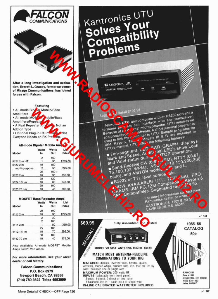
&lmm COMMUNICATIONS
$h qlp Alter a long Invwtlgatlan and evafua. tlon. Everett L.Qracey, formerco-owner of Mlrage Communlcatlons, has Joined forces wlth Falcon.
Featuring All-mode Bipolar MobilelBase
Amplifiers All-mode MOSFET MobilelBase
AmplifierslRepeaters A Real Repeater Ampllfier, Not an
Add-on Type Optional Plug-in RX Pre-amp-Not
Everyone Needs an RX Pre-amp.
All-mode Blpolar Moblla Amps w ~ n a wanr ~1st
M0d.l In Out Prlw
2 150 5121 2 m HT 1 90 $285.00 5122 2 m 10 150
multl.purpose 2 50 275.00 25 150+
3123 2 m 10 90 235.00 30 120
3124 1% m 10 89 IOa 30 100
5125 70 cm 10 40 305.00
MOSFET BsmlRapeater Amps w ~ n s wrnr List
M0d.l In Out Prlw
20 100 4111 2m 1 0 9 0 5295.00
2 30 2 100
25 100 41121% m 10 70 295.00
30 100 5142 70 cm 10 40 375.00
Also Available: All.mode MOSFET Moblle Amps and 28 Volt Amps.
For more Inlormatlon, s w your local dealer or call factory.
Falcon Communlcatlons P.O. Box 8979
Newport Beach, CA 92658 (7l4) 780-3622 Telex 4993999 -
Fully Assembled and Tested
MATCH MOST ANTENNA-FEEDLINE COMBINATIONS TO YOUR RIG
MATCHES: d1l1r11r.s. 1nverlr:d vces. I~earris, quads.
qlg verticals. rnoh~lc whtps. random wlre. elc that are led by coax, balanced l~ne or slngle wlre MAXIMUM POWER: 300 watts RF RADIOKIT INPUTS (:;eleclaDle lrorn lrorlt panel) BOX 4rrn
3-coax ld~ret l 7-direcl or lhru tuner Qmrllh. NH 03048 I-balanced Itnr' (4 1 balun Inc I or slngle wlre (603) 87E1033
IN-LINE CALIBRATED WATTMETER INCLUDED telex 887897
More Details? CHECK-OFF Page 126 r* 142
WWW.RADiOSCAMATORUL.Hi2.RO
WWW.GiURUMELE.Hi2.RO
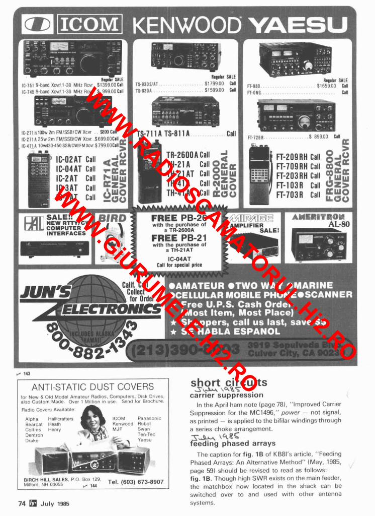
I I I I I I 1 1 I 8
Rs(ulir SALE Regular SALE I 8 lC-75, Y h r d Xrrr 1.10 MHZ l i c i r $ 1 i . 4 i~ Cal l B l l O S / A T . . . . . . . . . . . . $111100 CIII 1 n-g80 . . . . $l!si~Y 00 CIII ! , 1C-745 9-bard Xcvr l l -30 MHz Rcvr . S 9'r9OOC1ll I ! TS-9301 . . . . . . . . . . . . . . . . . . $1599 00 Clll ; FI-ON C , . . . , , , , , , , , , . , . , Clll ;
I IC-271 h 1Niw :rn i M biic/( W Xi vr S'fi Call I IC-271 A 25w 2m FMISSBICW Xcvr $649 OOCall '
a, 1 I C - ~ ~ I A ~ ~ ~ ~ ~ ~ ~ ~ ~ S S ~ ~ L W I F M X C V I $ ~ ~ ! ~ O O C ~ ~ ~ ,
46 I C - O P A T Call 44e: I I C - 0 4 A T Call
I C - 2 A T Call b8-1 r J 1 PC;:, 3 I C - 3 A T Call , g , l r p
I C - 4 A T Call g~:~_,~ A
INTERFACES
S H r I ' i i l l ~ Clll
ANTI-STATIC DUST COVERS lor New 8 Old Model Amateur Radios. Computers Dlsk Dr~ves. also Custom Made Over 1 Mill~on In use Send for Brochure
Radlo Covers Available
ICOM Panasonlc Bearcat Healh Kenwood Robol Coll~ns Henry MJF Swan Dentron Ten Tec Drake , ~ a e s u
I BIRCH HILL SALES I rJ l m r I h41lfnrd NII 0 Jot,1, . 1.4~ Tel. (603) 673-8907
74 a July 1985
short circuits S* \ S B S
carrler suppression In the April ham note (page 78). "Improved Carrier
Suppression for the MC1496," power - not signal, as printed - is applied to the bifilar windings through a series choke arrangement.
('8" eeding phased arrays The caption for fig. 1B of KB8l's article, "Feeding
Phased Arrays: An Alternative Method" (May, 1985, page 59) should be revised to read as follows: fig. 1B. Though high SWR exists on the main feeder, the matchbox now located in the shack can be switched over to and used with other antenna systems.
WWW.RADiOSCAMATORUL.Hi2.RO
WWW.GiURUMELE.Hi2.RO
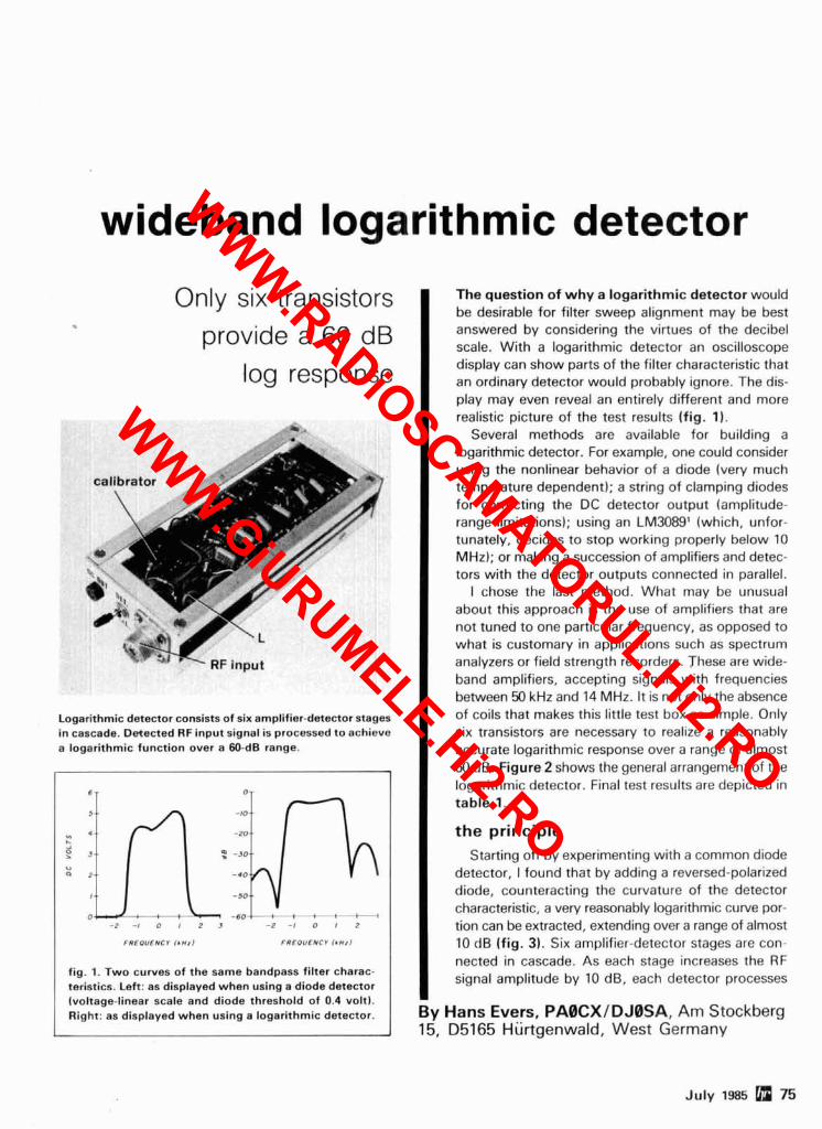
wideband logarithmic detector
Only six transistors provide a 60 dB
log response
rc.,
hl 7.. RF Input
Logarithmic detector consists of six amplifier-detector stages in cascade. Detected RF input signal is processed to achieve a logarithmic function over a 60-dB range.
3 ; 9 in, 2 , lp, 0 , - 2 0 1 2 3 -P - I 0 , 2
FREOUENCI i r H 1 1 FREOUENCI I.*,]
fig. 1. Two curves of the same bandpass filter charac- teristics. Left: as displayed when using a diode detector (voltage-linear scale and diode threshold of 0.4 volt). Right: as displayed when using a logarithmic detector.
The question of why a logarithmic detector would be desirable for filter sweep alignment may be best answered by considering the virtues of the decibel scale. With a logarithmic detector an oscilloscope display can show parts of the filter characteristic that an ordinary detector would probably ignore. The dis- play may even reveal an entirely different and more realistic picture of the test results (fig. 1).
Several methods are available for building a logarithmic detector. For example, one could consider using the nonlinear behavior of a diode (very much temperature dependent); a string of clamping diodes for correcting the DC detector output (amplitude- range limitations); using an LM3089' (which, unfor- tunately, decides to stop working properly below 10 MHz); or making a succession of amplifiers and detec- tors with the detector outputs connected in parallel.
I chose the last method. What may be unusual about this approach is the use of amplifiers that are not tuned to one particular frequency, as opposed to what is customary in applications such as spectrum analyzers or field strength recorders. These are wide- band amplifiers, accepting signals with frequencies between 50 kHz and 14 MHz. It is not only the absence of coils that makes this little test box so simple. Only six transistors are necessary to realize a reasonably accurate logarithmic response over a range of almost 60 dB. Figure 2 shows the general arrangement of the logarithmic detector. Final test results are depicted in
I table 1.
the principle Starting off by experimenting with a common diode
detector, I found that by adding a reversed-polarized diode, counteracting the curvature of the detector characteristic, a very reasonably logarithmic curve por- tion can be extracted, extending over a range of almost 10 dB (fig. 3). Six amplifier-detector stages are con- nected in cascade. As each stage increases the RF signal amplitude by 10 dB, each detector processes
By Hans Evers, PABCXIDJBSA, Am Stockberg 15, D5165 Hiirtgenwald, West Germany
WWW.RADiOSCAMATORUL.Hi2.RO
WWW.GiURUMELE.Hi2.RO
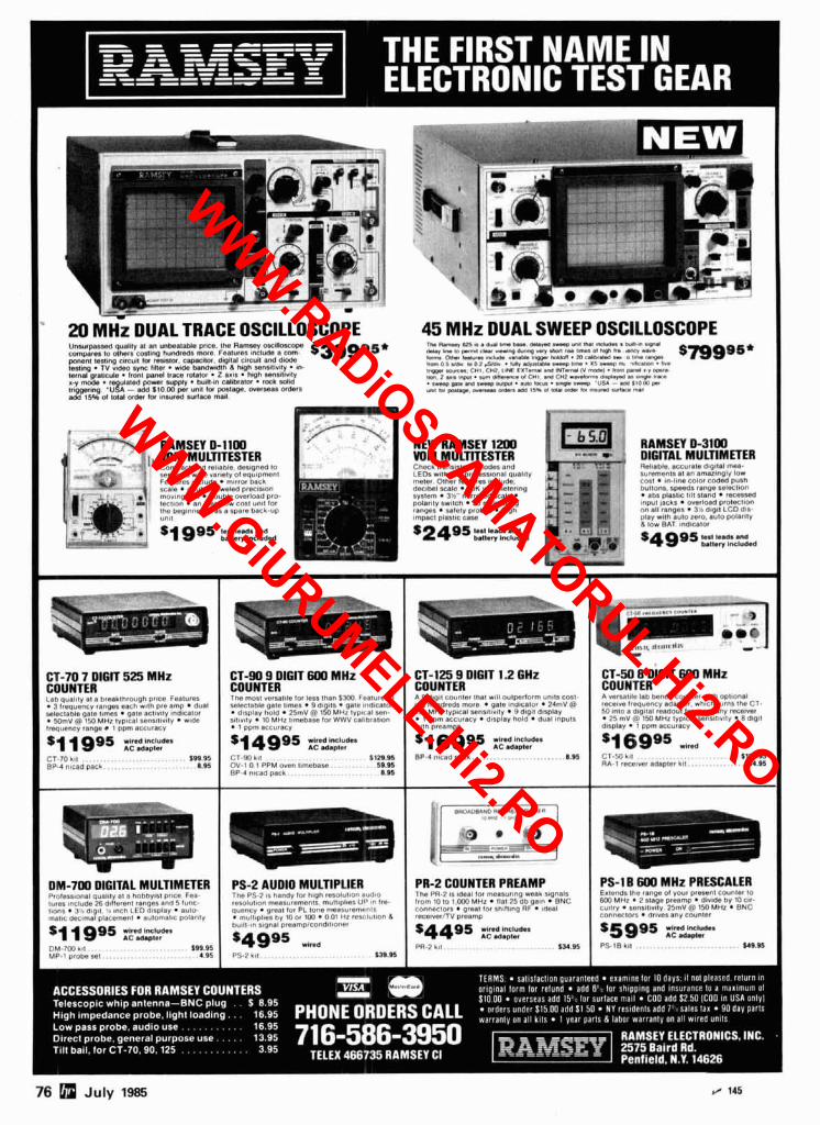
Uosurpasr~n qu&l#ly dl an unbeatable prmce. IUIII A s m r y ou8llowow
45 MHz DUAL SWEEP OSCILLOSCOPE ,m Rmq bXI r . d""i ,,n* "..I *.w r- "l l l l In* rnlWl.. . l,,l,,> m .,yl"l
compare. 10 .,,hers colflng nundrsdr m0.n F".>,ursr include a com s39995* (UI ,- 1" d., .-ny ",,.,W "*" 'nxl ,,a ,,ms, 0, n,gn 8,. Irr", .."" testlng clrcul! lo, rerlnnt, capac,~or, dlgl!at clrclli~ and asme
b",, on, ,."I"," ,mIm ".1,.* 1 1 w . IM" . a r.hDI.m .-. o n * , . o w norno, r,,* ,o0*.5ior . I.CII* (III"I("1.a l a p l l m " . .b % m a . m. ..!lC.I.31,. I*.
tes!mg . T V vfdoo sync f,ller . w~de bandwdlh h hmqh wnsclwlty 8"-
tern~, graxlcule . ocont panel trace ro$atnr . Zsxma . htgh wnstt,nl~ I,,- -.<" CHI L*., I IN* 1 "1"rn"t ..M lWl"."U I" -1 . ll"lll C 4 . l .I "Ut. .." mm. . , "lafed p w e , *UP@" . "",l,.," calibrator . roc* sdld la I ..,, ,-I. ."", ,,,". ,erro o4 <."l an, <.*I .."elem" <ayln*n .. .m* I,*+ . ,- pt. .m .- cu~mll . .ujo wvl -- 'USA m (ma, P,
trbpgercng .21\ - add srom par ""8, tor p s l n w mrrrenr aden urn,, Ir p$41 --.. mals m 111. a, a* wm X I mnsv,a .ultwe mm-,
1110 1596 01 tolal ocder lor 1n9urod surlsce mall
NEW MMSEY 1200 RAMSEY ~ 3 1 0 0 M M MULlTTESTER < <<,.<. I,,,, ,,>,,,r> <,#",,'.', ,,r,<,
DIGITAL MULTlMElER pi.. ,,ti.. . I ~ ~ U r d ~ e ,1,4110 m a -
L , [,, w,,>> ,"?,, ~ ~ , ~ , , ~ . 5 % , # l r ~ a ~ c,"~I,," r i , . l~nl l -n l l R I s n nnr.lZln"l" low m*.,s.r 0l""l ,,.n,ur<.5 ,lll.llltlP. Cr , r t . j l n s coiill r l ~ t l ~ push dr,.Drl scat,: . 7°K ""I! n,c.,cnng hlillonr speeds Ianqr r, 'UCllOm
IyllCm . 3 , m,,r",sd nca,<. . poiority svltcn . 20 rnearuung ,anqrs. 5a,a,y prole, . hlqn ,mnac, plarllc clr"
, .,,. :, .I.. 111 1/ . ' .
CT-90 9 DIGIT 600 MHz
,,e"uency rnnpe. I ppm ecrurncy
BP-4 htrad pack ... . . . . . . . . . . . . 8.#5
PR-2 COUNTER PREAMP
76 n July 1985 r, Ids
WWW.RADiOSCAMATORUL.Hi2.RO
WWW.GiURUMELE.Hi2.RO
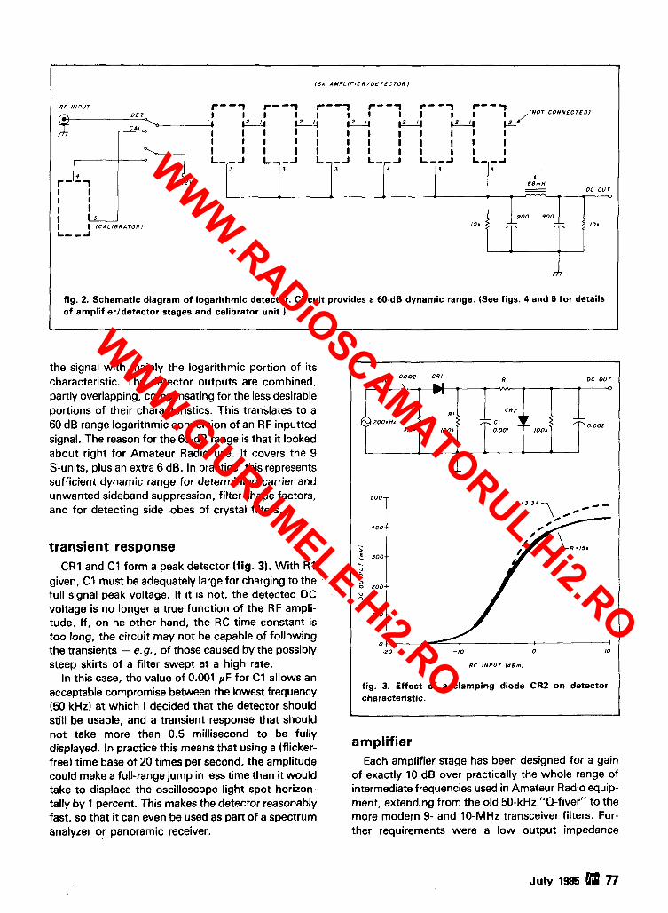
16X A M P L I F I E R / O E T E C T O R )
RF INPUT r"l - 1 r"f r--- r--7 DE T I I I I I 1 I I I I I '- - 'w,lNo7 CONNECTEOI 1 2 - w
I I I I t I I I I I I I I 1 1 I I I I I I I I I I I I I t I I I I I L--J L--J L--J L - F ~ LT-A L--a
8 8 m H
I OC o u r
I I I 9 0 0 9 0 0
I I i c A L l B R A T o R , 10. 77 -- ,.
L- -a
- -
rt7
fig. 2. Schematic diagram of logarithmic detector. Circuit provides a 60-dB dynamic range. (See figs. 4 and 6 for details of amplifierldetector stages and calibrator unit.)
the signal with mainly the logarithmic portion of its characteristic. The detector outputs are combined, partly overlapping, compensating for the less desirable portions of their characteristics. This translates to a 60 dB range logarithmic conversion of an RF inputted signal. The reason for the 60-dB range is that it looked about right for Amateur Radio use. It covers the 9 S-units, plus an extra 6 dB. In practice, this represents sufficient dynamic range for determining carrier and unwanted sideband suppression, filter shape factors, and for detecting side lobes of crystal filters.
transient response CR1 and C1 form a peak detector (fig. 3). With R1
given, C1 must be adequately large for charging to the full signal peak voltage. If it is not, the detected DC voltage is no longer a true function of the RF ampli- tude. If, on he other hand, the RC time constant is too long, the circuit may not be capable of following the transients - e.g., of those caused by the possibly steep skirts of a filter swept at a high rate.
In this case, the value of 0.001 pF for C1 allows an acceptable compromise between the lowest frequency (50 kHz) at which I decided that the detector should still be usable, and a transient response that should not take more than 0.5 millisecond to be fully displayed. In practice this means that using a (flicker- free) time base of 20 times per second, the amplitude could make a full-range jump in less time than it would take to displace the oscilloscope light spot horizon- tally by 1 percent. This makes the detector reasonably fast, so that it can even be used as part of a spectrum analyzer or panoramic receiver.
amplifier Each amplifier stage has been designed for a gain
of exactly 10 dB over practically the whole range of intermediate frequencies used in Amateur Radio equip- ment, extending from the old 50-kHz "Q-fiver" to the more modern 9- and 10-MHz transceiver filters. Fur- ther requirements were a low output impedance
50 0 . 0 0 2 CR I R OC OUT
July 1985 H n
20Ob Hz 3.31.
m
5 0 0 -
4 0 0 - -
- h
.! 300 . - L 5 e 0 2 0 0 -
U Q
l o o - -
0 t - 2 0 -10 0 10
RF INPUT ldBml
fig. 3. Effect of a clamping diode CR2 on detector characteristic.
Z M ; T -0
Rl
1004
L
, 0 0 0 2
C R 2
7; C l r 0.001 I 0 0 4
7;
WWW.RADiOSCAMATORUL.Hi2.RO
WWW.GiURUMELE.Hi2.RO
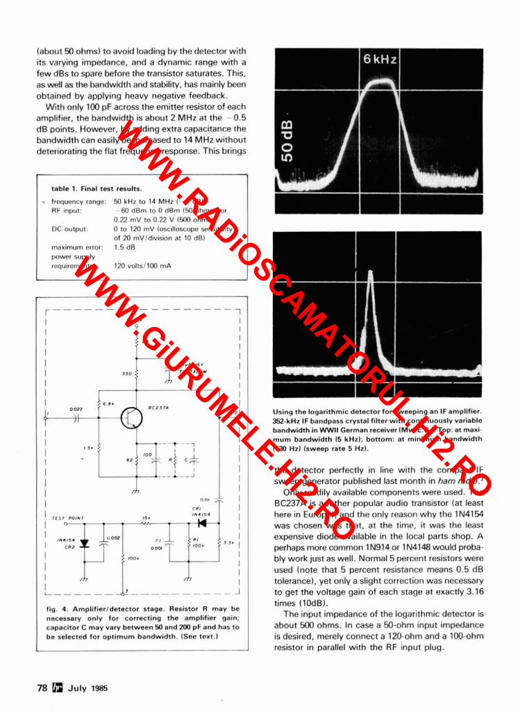
(about 50 ohms) to avoid loading by the detector with its varying impedance, and a dynamic range with a few dBs to spare before the transistor saturates. This, as well as the bandwidth and stability, has mainly been obtained by applying heavy negative feedback.
With only 100 pF across the emitter resistor of each amplifier, the bandwidth is about 2 MHz at the -0.5 dB points. However, by adding extra capacitance the bandwidth can easily be increased to 14 MHz without deteriorating the flat frequency response. This brings
- table 1. Final test results. - frequency range: 50 kHz to 14 MHz I - 1 dB) RF input: - 00 dBm to 0 dBm I50 ohms), or
0.22 mV to 0.22 V (500 ohms) DC output: 0 to 120 mV (oscilloscope sensitivity
of 20 mV1division at 10 dB) maximum error: 1.5 dB power supply requirements: 120 volts1100 mA
Using the logarithmic detector for sweeping an IF amplifier. 352-kHz IF bandpass crystal filter with continuously variable bandwidth in WWll German receiver IP4w.E.C.). Top: at maxi- mum bandwidth (5 kHz); bottom: at minimum bandwidth I730 Hz) (sweep rate 5 Hz).
- - - - - - - - - - - - - - - - - - 1
I + l S V I
1 I
I P P I
the detector perfectly in line with the compact IF sweep generator published last month in ham radio.z
Only readily available components were used. The BC237A is a rather popular audio transistor (at least here in Europe), and the only reason why the IN4154
I I
330 :: I I I I 6.81
was chosen was that, at the time, it was the least expensive diode available in the local parts shop. A perhaps more common 1 N914 or IN4148 would proba- bly work just as well. Normal 5 percent resistors were used (note that 5 percent resistance means 0.5 dB tolerance), yet only a slight correction was necessary to get the voltage gain of each stage at exactly 3.16 times (10dB).
The input impedance of the logarithmic detector is
I I
I 0 " f . 16" I
2 rANTALUY I I
about 500 ohms. In case a 50-ohm input impedance is desired, merely connect a 120-ohm and a 100-ohm resistor in parallel with the RF input plug.
R C P J I A
78 July 1985
I I
2
I I I I I I I I I I
+; 1 I I I
1 5 .
I I
I 0 -
I I rn
I oat ;; CCI I N I I 5 4 I T E S l POlNT I S *
:;
I -- PI I I IW.154
----t --1
C !
r * o ~ - I
c +
I I c R P pow?
,---&--J I '
I ,OD, o om -, loo, 3 J 1 1
I I I L ------
I I
rn I ---------- J
fig. 4. Amplifierldetector stage. Resistor R may be necessary only for correcting the amplifier gain: capacitor C may vary between 50 and 200 pF and has to be selected for optimum bandwidth. (See text.)
WWW.RADiOSCAMATORUL.Hi2.RO
WWW.GiURUMELE.Hi2.RO
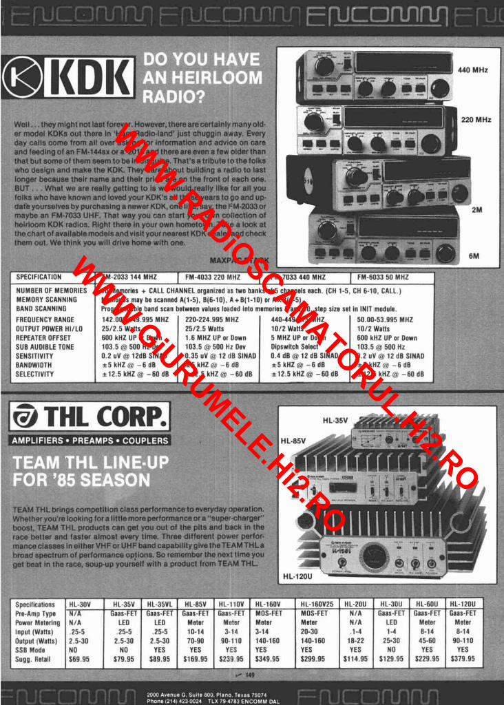
Well.. . they mlght not last forever. However,therearecertalnly many old. er model KDKs out there In 'Ham Radio-land' just chuggln away. Every day calls come from all over asking for Information and advice on care and feedlng of an FM-144sx or a'2015 and thereareeven a few older than that but some of them seem to be In dlsgulse. That's a trlbutetothe folks who design and make the KDK. They care about bulldlng a radio to last longer because their name and thelr pride are on the front of each one. BUT . . . What we are really gettlng to Is we would really llke for all you folks who have known and loved your KDK's all these years to go and u p date yourselves by purchasing a newer KDK,one llke, say, the FM-2033or maybe an FM-7033 UHF. That way you can start your own collection of heirloom KDK radios. Right there In your own hometown. Take a look at thechart of available modelsand visit your nearest KDKdealer and check them out. We thlnk you will drive home with one.
MEMORY SCANNING BAND SCANNING FREOUENCY RANGE 50.00-53.995 MHz
REPEATER OFFSET 600 kHz UP or Down 1.6 MHz UP or Down 600 kHz UP or Dowlt 103.5 rru auu nt DOV
Ia THL CORP.~
TEAM THL brlngscompetltlon class performance toeveryday operation. Whether you're looklng for a littlemore performanceor a-super-charger" boost, TEAM THL products can get you out of the pits and back in the race batter and faster almost every the . Three different power perfor- manceclasses in eitherVHFor UHF band capablllty glvetheTEAMTHLa broad spectrum of performanca op!lons. So remember the next tlme you get beat In the race, soup-up yourself with a product from TEAM THL.
Spacif~calions HL-30V 1 HL-35V I HL-35VL I HL-85V I HL-I IOV I HL-160V I H L - I O U V L J 1 HL-20U 1 HL-3011 I HL-60U I HL-12OU Pre-Amr Troe 1 l /A I Gaas-FET I Gaas-FET 1 Gaas-FET I G ~ ~ ! ~ F E T I MOS-FET I MOS-FET 1 N/A I Gaas-FET 1 Gaas-FET I Gaas-FET , . Power Metering N/A LEO LEO Meter Mnter Meter Meter N I A LEO Meter Meter Input (Watts) , 2 5 4 .25-5 , 2 5 4 10-14 3-14 3-14 20-30 . l - 4 1-4 8-14 8-14 Output (Watts) 2.5-30 2.5-30 2.5-30 70-90 90-110 140-160 140-160 18-22 25.30 45-60 90-110 SSB Mode NO NO YES YES YES YES YES YES NO YES YES Sugg. Retall $79.95 589.95 $169.95 5239.95 $349.95 f $114.95 5129.95 5229.95 $379.95
WWW.RADiOSCAMATORUL.Hi2.RO
WWW.GiURUMELE.Hi2.RO
m:. , , ./ -.. w&fbnnw,d -_ For more lhon 40 y w r x we
nove been serving the omoleur QUALITY PROOUCTS ond
DEPENDABLE "SE-R-V-IC-E" ond. we fully ontend to carry on this proud trodition with even MORE new product lines plus the same "foir" treatment you've come to rely on. Our reconditioned equipment is of the finest quolily with 30, 60 and even POdoy porn and lobor warranties on selected pieces. And, remember. . .
- WE SERVICE WHAT WE SELL - A11 DRAKE HOSELEV AMKO ENCDMM NYI
STORE HOURS: 1-5 P.M. (CST)
MONDAY *n FRIDAY OPEN SATURDAYS
from 9-1 P.M. (CST) CLOSED
UINDAVS/HOLIDAIT
"AMERICA'S MOST RELIABLE AMATEUR RADIO DEALER"
I New & Reconditioned
HAM EQUIPMENT Call o r Write Us Today For a Quote!
You'll Find Us to be Courteous, Knowledgeable and Honest
A M R ~ numn PALWU AWEK ICOM RADIO CAlllOOI ARRL JANEL ROBOT ASTRW IAWTIOWICS ROHN ANTENNA I D I T ~ L ~ X I n ~ u *
SPECIALISTS ILM TEN-nc BLW L A W N TRIO-Im00D BENCHER MFJ UNADlLlA I REYCO BUTTERNUT MINI.PRODUCIS VAESU CusncnAn MI RAG^ AEA AMT-I . REGULARLY $479.95 DIAWA
NOW ONLY $299.95 w I THE AMTOR TERMINAL UNIT! ! 1 Works w ~ t h any
P 0 Box 73 ASCII terrnlnal or personal computer wlth a terminal 208 East Kernp program Also works RTTY. CW. ASCII
Watertown. SD 57201 ORDER YOURS TODAY ! Lirntled quantities
zi=-v TOWERS 1 HIGHEST QUALITY 4D.llm
- .'\ ,. - . alnk ~p TELESCOPING ICAANK UP) rdd T mu 611YEO ISTACK UP1
STATE OF THE ART
The 1985 Edition of The Radio Amateur's Handbook carries on the tradition of the previous edi- tions by presenting 1028 pages of comprehensive information for the radio amateur, engineer, tech- nician and student. Paper edition: $15 in the U.S., $16 in Canada. and elsewhere.
. . . --. . . - - . . - . . .
I I TILT-OVER MODELS Easy to Install. Low Prices.
Crank-ups to 100 11. I I
r / 147 r / 1 4 80 July 19115
This publication is available in microform
from University
I 1 Please send tnlormntnon R ~ U I I h w Iltles:
Name
Cnmp~nyflnslilulton
Addresa
Cily
State ZP
Phone 1 2 . Call 1nU.lmnBm-521-3M4. In Michiwn.
Alnnka anrl I lnwn~, call rnllnrl :lI:l.7fil-47M. Or mall ~ n q u ~ r y to Unnvnmly Mirn>lblms Inlsmstianal. .m Norlh 7n.h Rmd. Ann Arlnr. MI 48106
WWW.RADiOSCAMATORUL.Hi2.RO
WWW.GiURUMELE.Hi2.RO
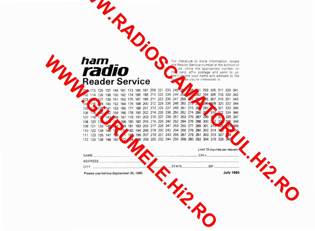
ham radio Reader Service
For literature or more information, locate the Reader Service number at the bottom of the ad, circle the appropriate number on this card, affix postage and send to us We'll hustle your name and address to the compantes you're ~nterested In
Limit ldinquiries per request.
NAME CAL-
CITY STAT;. ZIP
Please use before September 30.1985 July 1985
WWW.RADiOSCAMATORUL.Hi2.RO
WWW.GiURUMELE.Hi2.RO

AFFIX POSTAGE
OR
POST OFFICE
WILL NGT
DELIVER
ham I-
magazine
READER SERVICE CENTER P.O. BOX 2558 WOBURN. MA 01888
ATTN: Reader Service Dept.
WWW.RADiOSCAMATORUL.Hi2.RO
WWW.GiURUMELE.Hi2.RO
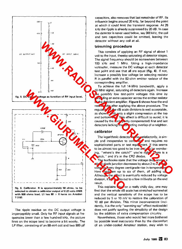
I20 - 0
capacitors, also removes that last remainder of RF. Its influence begins around 20 kHz, far beyond the point at which it could limit the transient response. At 28 kHz the ripple is already suppressed by 20 dB. In case the detector is never used below, say 300 kHz, the coil and two capacitors could be omitted, leaving the detector without any coil at all.
OC OUTPUT l m V I
50--
0 -
- - - - - - - - - - - - - 1
I I I I I I I 0.002
I \ I
I I
looh A
trimming procedure This consists of applying an RF signal of about 1
volt to the input, thereby saturating all detector stages. The signal frequency should be somewhere between 100 kHz and 1 MHz. Using a high-impedance voltmeter, measure the DC voltage at each detector test point and see that all are equal (fig. 4). If not, increase a possibly low voltage be selecting resistor R in parallel with the 82-ohm emitter resistor of the corresponding amplifier.
To achieve the full 14-MHz bandwidth, apply a 10-MHz signal, saturating all detectors again. Increase the possibly low test-point voltages this time by paralleling an extra capacitor across the emitter resistor of the deficient amplifier. Figure 5 shows how the end result looks after applying the above procedure. The regularity of the dB scale divisions is well acceptable, as shown, with only a slight compression at the top and bottom end. This effect is difficult to avoid; it is caused by the (only partly compensated) first and last detectors lacking the correcting overlap of a neighbor.
- - - - -- -20
- - - - -
- - - 3 0 RF INPUT l a 8 m l
- - - -
- - - - 4 0 - -
- - - -50 - - - - - - 60
I I
calibrator
fig. 5. DC output voltage as function of RF input level.
-
I I I
The logarithmic detector works satisfactorily, is sim- ple and inexpensive to construct, and requires no sophisticated parts or test equipment. If this seems to be almost too good to be true and you're wonder- ing, "where's the catch?" you're right. There is a "catch," and it's in the CR2 diodes.
The textbooks state that the voltage drop across a silicon diode junction decreases by about 2 to 2.5 milli- volts for every degree centigrade rise in temperature. Here there are up to six of them, all adding up. Although the effect is eventually reduced by voltage division, it still works out to a few millivolts on the end result.
This explains why, on a really chilly day, one may find that the whole dB scale has stretched somewhat and the vertical sensitivity of the scope has to be reduced by 5 or 10 mV to restore the calibration of 10 dB per division. This minor inconvenience (inci- dently, it is the only "warming-up" effect noticeable)
The ripple residue on the DC output voltage is does not justify spoiling the simplicity of the design imperceptibly small. Only for RF input signals at fre- by the addition of extra compensation circuitry. quencies lower than a few hundred kHz, the picture Nevertheless, those who would feel more bothered lines on the scope tend to become a bit woolly. The by possible level inaccuracy than by the discomfort LP filter, consisting of an 88-mH coil and two 900-pF of an under-cooled Amateur station, may wish to
July 1985 83
I m R I
I I I I
5
I I00 120 I I
I I
I
I I L ------------ "_ - - --- --A
fig. 6. Calibrator. R is approximately 50 ohms, to be selected to obtain a calibrator output of 0.22 volts RMS with 500 ohms load. L1 has 80 + 6 turns on Amidon T-3-50.
-
WWW.RADiOSCAMATORUL.Hi2.RO
WWW.GiURUMELE.Hi2.RO
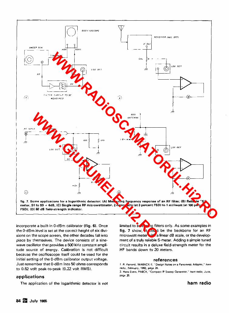
S W E E P CEN - H O R
F I L T E R C I R C U I T TO BE
M E P S U R E D
L O S C O P E
L O G O E T
R F I N P U T R G - S B / U
LOG D E T
j R E C E I V E R IAGC O F F 1
R O D
A N T E N N A 1
LOG D E T
0 - 1 m A
* 2 b i"' fig. 7. Some applications for a logarithmic detector: (A1 Measuring frequency response of an RF filter; (01 Reliable "S" meter, S1 to S9 + 6dB. (C) Single range RF microwattmeter, 2 nanowatts (at 3 percent FSDI to 1 milliwatt (at 100 percent FSDI; (Dl 60 dB field-strength indicator.
incorporate a built-in 0-dBm calibrator (fig. 61. Once the 0-dBm level is set at the correct height of six divi- sions on the scope screen, the other decades fall into place by themselves. The device consists of a sine- wave oscillator that provides a 500 kHz constant ampli- tude source of energy. Calibration is not difficult because the oscilloscope itself could be used for the initial setting of the 0-dBm calibrator output voltage. Just remember that 0-dBm into 50 ohms corresponds to 0.62 volt peak-to-peak (0.22 volt RMS).
applications The application of the logarithmic detector is not
limited to sweeping filters only. As some examples in fig. 7 show, it could be the backbone for an RF microwatt meter with a linear dB scale, or the develop- ment of a truly reliable S-meter. Adding a simple tuned circuit results in a deluxe field-strength meter for the HF bands down to 20 meters.
references 1 A . Ferranti, WAGNCXI 1. "Design Notes on a Panoramic Adapter," ham radio, February. 1983, page 26. 2 . Hans Evers. PAQCX, "Compact IF Sweep Generator," ham radio, June, page 35.
ham radio
84 July 1985
WWW.RADiOSCAMATORUL.Hi2.RO
WWW.GiURUMELE.Hi2.RO
Band Wired 1OM,6M, 21111,220 $680 $880
440 $780 $980
FEATURES:
8 SENSlTlVlPl SECONDTO NONE; 0.15 uV (VHF), 0.2 uV(UHF)TYP. ; SELECTIVITY THAT CAN'T BE BEAT! BOTH 8 POLE XTAL FILTER
&CERAMICFILTERFOR > lOOdBAT i 12KHZ.HELlCALRESON- ATOR FRONT ENDS TO FIGHT DESENSE & INTERMOD. OTHER GREAT RECEIVER FEATURES: FLUTTER-PROOF SQUELCH, AFC TO COMPENSATE FOR OFF-FREQ TRANSMIT- TERS. SEPARATE LOCALSPEAKER AMPLIFIER & CONTROL.
. . , resonator front end for exceptional selectivity, 1 >lOOdBat -t 12kHz, best availabletoday. Flut-
ter-proof squelch. AFC tracks drifting xrntrs. Xtal oven avail. Kit only $138. R451 FM RCVR Same but for uhf. Tuned linefront end,0.3uVsens. Kitonly5138. R76 FM RCVR for IOM, 6M, 2M, or 220. As above, but wlo AFCor her. res. Kits only$l78. Alsoavail w/4polefilter, only$Wkit. R110 VHF AM RECEIVER kit for VHF aircraft ,- or ham bands or Space Shuttle. Only$98.
T51 VHF FM EXCITER for 10M,6M,2M, or 220MHz.2Wattscontinuous, up to3W intermittent. $681kit. T451 UHF FM EXCITER2to3Watts.Kitonl Xtal oven avail. VHF & UHF LINEAR AMPLIFIERS. For either FM or SSB. Power levels from 10 to45 Watts to go with exciters &xmtg converters.Several models. Kitsfrom$78.
c~mkEasy ru~ETRnNsM~nER; up~020w~ns OuT(upO 1 NOCFCC TYPE-ACCEPTED TRANSMITTERS & R E C E I V E R W BLE 1 I SOW WITH OPnONAL PA). FOR HIGH-BAND& UHF. CALL FOR DETAILS.
Models tocovereverypractlcal r f (L If range to listen to SSB.
FM,AN,etc.NF=2dBorless.
VHF MODELS 144-148 50-54 220.222 28-30
Klt wlth Case 220-224 144-148
Less Case 220-224 50-54 Wlred tsS W-224 a7-30
UHF MODELS 432.434 28-30
Klt wlth Case $59 435-437 28-30
Less Case WQ 432-436 144-148
wlreti $75 432-436 439.25 50-54 61.25
- - -
SCANNER CONVERTERS Copy 808MHzband on any scan- ner. WiredltestedONLY $08.
For SSB, CW, AN, FM, etc. Why pay big bucks for a multi mode rig foreach band?Can be linked with recelveconvert- erstortranscelve.2Wattsoutput vhf, 1 Watt uhf.
Exciter Antenna For VH F, 1nputR.y OutpU'
Model XV2 28;Y) 144-146 28-P 18-148
Kit $79 28-30 50-52 n - n . 4 IU-144.4
Wired $149 28-30 220.222'
(Specify band) 220-224 50-52
50-54 144-148 144-148 28-30
For UHF, 28-30 432-434
Model XV4 28-20 425-437 50-54 432-438
Kit $99 61.25 U8.25 144-148 432-436.
Wired $169 'AddSZOfor2M ihpul
VHF & UHF LINEAR AMPLIFIERS. Use with above Power levels from 10 to 45 Watts. Several models kits from $78.
Hamtronics Breaks the Price Barrier!
Jk NO Need to Pay $60 to $125
for a GaAs FET Preamp.
FEATURES: Very Low Noise: 0.7 dB VHF, 0.8 dB UHF High Gain: 18 to 28 dB, Depending on Freq. Wide Dynamic Range for Overload Resistance Latest Dual-gate GaAs FET, Very Stable
MODEL TUNES RANGE PRlCE LNG-28 26-30 MHz $49 LNG-50 46-56 MHz $49 LNG-144 137-150 MHz $49 LNG-160 150-172 MHz $49 LNG-220 210-230 MHz $49 LNG-432 400-470 MHz $49 LNG800 800-960 M HZ $49
Low-noise preamps with helical resonators re- duce intermod and cross-band interference
12dBgain. in critical applications.
Model Tuning Range Price HRA-144 143-150 MHz $49 H RA-220 21 3-233 M Hz $49 H RA-432 420-450 M HZ $59 HRA-( ) 150-1 74 MHz $54 H R A i ) 450-470 MHz $64
MO-202 FSK DATA MODULATOR. Run up to 1200 baud digital or packet radiosig- nals through any FM transmitter. Auto- matically keys transmitter and provides handshakes. 120012200 Hz tones. Kit only $45. DE.202 FSK DATA DEMODULATOR. Use with any FM receiver todetect packet ra- dio or other digital data in "202" modem format. Provides audioconditioning and handshakes. Kit only $38. COR-2 KIT With audio mixer, local speaker amplifier, tail &time-out timers. Only $38. COR-3 KIT as above, but with "courtesy beep". Only $58. CWlD KITS 158 bits, easily field program- mable, clean audio. Kit only $68. A16 RF TIGHT BOX Deep drawn alum. case with tight cover and no seams. 7 x 8 x 2 inches. Designed especially for repeaters. $20. DTMF DECODERICONTROLLER KITS. Control 2 separateonloff functions with touchtones", e.g., repeater and auto- patch. Use with main oraux. receiver or with Autopatch. Only $90 AUTOPATCH KITS. Provide repeater auto- patch, reverse patch, phone line remote control of repeater, secondary control via repeater receiver. Many other features. Only $90. Requlres DTMF Module. SIMPLEX AUTOPATCH. Use with your FM transceiver. System includes DTMF & Au- topatch modules aboveand new Timing module to provide simplex autopatch and reverse autopatch. Complete patch sys- tem only $200lkit. Call orwrite for details.
WWW.RADiOSCAMATORUL.Hi2.RO
WWW.GiURUMELE.Hi2.RO
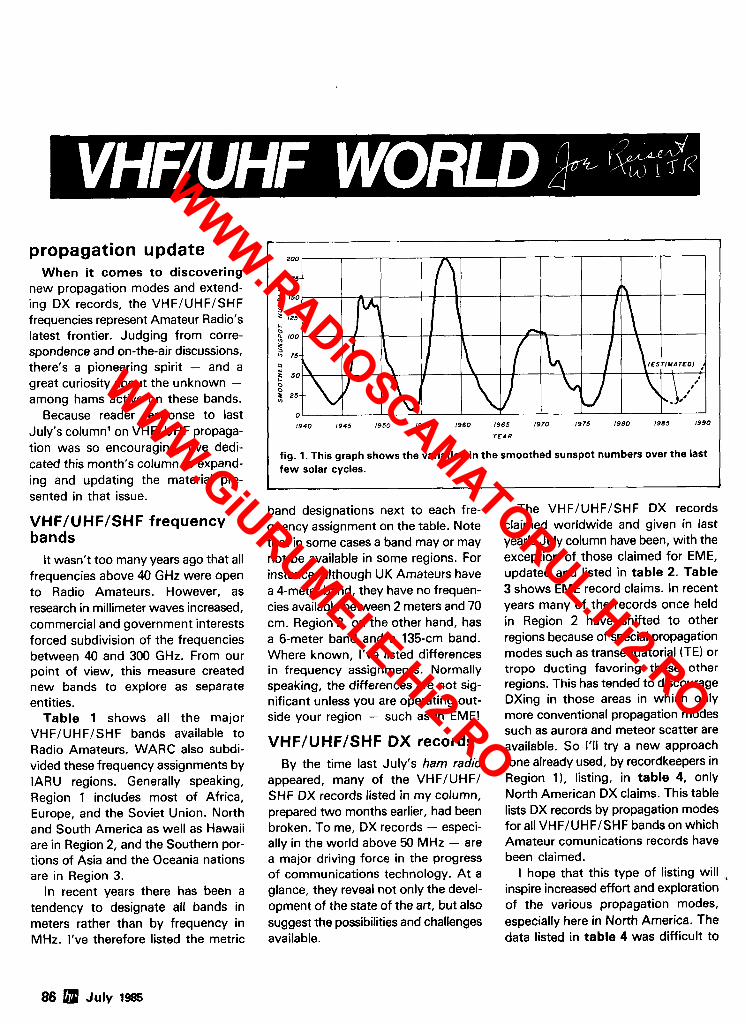
propagation update When it comes to discovering
new propagation modes and extend- ing DX records, the VHF/UHF/SHF frequencies represent Amateur Radio's latest frontier. Judging from corre- spondence and on-the-air discussions, there's a pioneering spirit - and a great curiosity about the unknown - among hams active on these bands.
Because reader response to last July's column1 on VHF/UHF propaga- tion was so encouraging, I've dedi- cated this month's column to expand- ing and updating the material pre- sented in that issue.
VHF/UHF/SHF frequency bands
It wasn't too many years ago that all frequencies above 40 GHz were open to Radio Amateurs. However, as research in millimeter waves increased, commercial and government interests forced subdivision of the frequencies between 40 and 300 GHz. From our point of view, this measure created new bands to explore as separate entities.
Table 1 shows all the major VHFIUHFISHF bands available to Radio Amateurs. WARC also subdi- vided these frequency assignments by IARU regions. Generally speaking, Region 1 includes most of Africa, Europe, and the Soviet Union. North and South America as well as Hawaii are in Region 2, and the Southern por- tions of Asia and the Oceania nations are in Region 3.
In recent years there has been a tendency to designate all bands in meters rather than by frequency in MHz. I've therefore listed the metric
t
1940 1945 1950 1955 1960 1965 1970 1975 I980 1985 1990 Y E A R
fig. 1. This graph shows the variation in the smoothed sunspot numbers over the last few solar cycles.
band designations next to each fre- quency assignment on the table. Note that in some cases a band may or may not be available in some regions. For instance, although UK Amateurs have a Cmeter band, they have no frequen- cies available between 2 meters and 70 cm. Region 2, on the other hand, has a 6-meter band and a 135-cm band. Where known, I've listed differences in frequency assignments. Normally speaking, the differences are not sig- nificant unless you are operating out- side your region - such as in EME!
VHF/UHF/SHF DX records By the time last July's ham radio
appeared, many of the VHFIUHFI SHF DX records listed in my column, prepared two months earlier, had been broken. To me, DX records - especi- ally in the world above 50 MHz - are a major driving force in the progress of communications technology. At a glance, they reveal not only the devel- opment of the state of the art, but also suggest the possibilities and challenges available.
The VHFIUHFISHF DX records claimed worldwide and given in last year's July column have been, with the exception of those claimed for EME, updated and listed in table 2. Table 3 shows EME record claims. In recent years many of the records once held in Region 2 have shifted to other regions because of special propagation modes such as transequatorial (TE) or tropo ducting favoring these other regions. This has tended to discourage DXing in those areas in which only more conventional propagation modes such as aurora and meteor scatter are available. So I'll try a new approach (one already used, by recordkeepers in Region I ) , listing, in table 4, only North American DX claims. This table lists DX records by propagation modes for all VHFIUHFISHF bands on which Amateur comunications records have been claimed.
I hope that this type of listing will inspire increased effort and exploration of the various propagation modes, especially here in North America. The data listed in table 4 was difficult to
86 July 1-
WWW.RADiOSCAMATORUL.Hi2.RO
WWW.GiURUMELE.Hi2.RO
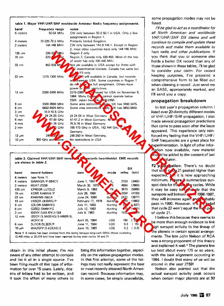
i
table 2. Claimed VHFIUHFISHF terrestrial OX records (worldwide). EME records are shown i n table 3.
DX band record holders date mode miles (km)
6 meters (see Note 1) 4 meters GW4ASRlP-584CY June 7, 1981 E, 2153 (3465) 2 meters I4EAT-ZS3B March 30, 1979 TE 4884 (7860) 135 cm KP4EOR-LU7DJZ March 9, 1983 TE 3670 (5906) 70 cm KD6R-KH6IAAIP July 28, 1980 ducting 2550 (4103) 23 crn KH6HME-N6CA ' June 24, 1984 ducting 2472 (3977) 13 cm VK5QR-VK6WGIP February 17, 1978 ducting 1170 (1883) 9 cm G3LQR-SM6HYG July 11, 1983 ducting 576 ( 927) 6 crn G3ZEZ-SM6HYG July 12, 1983 ducting 610 ( 987) 3 cm IOSNYlEA9-IOYLI/IE9 July 8, 1983 ducting 1032 (1660) 12 mm 13SOY/3,IW3EHQ/3-14BER/6,
14CHYl6 April 25, 1984 LOS 180 ( 289) 6 rnm DJlCR-DL3ER/P June 11, 1984 LOS 9.3 ( 15) 10 prn WA2GFP/2-K2KXS/2 June 10, 1983 LOS 0.2 ( 0.3)
Note 1. 6 meters has been omitted from this listing because long-path QSOs (those exceeding 12,440 miles or 20,016 km) have been reported during solar cycles 19 and 21.
-
I table 1. Major VHFIUHFISHF worldwide Amateur Radio frequency assignments.
band frequency range notes 6 meters 50-54 MHz CW only between 50.0-50.1 in USA. Only a few
assignments in Region 1. 4 meters 70.025-70.5 MHz Primarily United Kingdom. 2 meters 144-148 MHz CW only between 144.0-144.1. Except in Region
2, most other countries have only 144-146 MHz. 135 cm 220-225 MHz Region 2 only. 70 cm 420-450 MHz Region 2, Canada only 430-450. Most of the rest
of world has only 430-440 MHz. 33 cm 902-928 MHz Not yet available in USA except for those with
FCC experimental licenses. Canada has same but on A31F3 only.
23 crn 1215-1300 MHz 1215-1240 still available in Canada, but recently withdrawn in USA. Some countries in Region 1 do not have the full assignment. Others have power or ElRP restrictions.
13 cm 2300-2450 MHz 2310-2390 was removed for USA on November 6, 1984. Many Europeans cannot operate below 2320. Japan has only 2400-2450.
9 cm 3300-3500 MHz Some area restrictions apply. UK has 3400-3475. 6 crn 5650-5925 MHz Some area restrictions apply. UK has 5650-5850. 3 cm 10.0-10.5 GHz 12 mm 24-24.25 GHz 24-24.05 in West Germany 6 mm 47-50 GHz 47-47.2 in West Germany, 48-50 in USA 4 mm 71-76 GHz 75.5-76 in West Germany 2 mm 142-170 GHz 165-170 GHz in USA, 142-144 GHz in West
Germany. 12 pm 240-250 GHz 248-250 in West Germany. 10 am 300 GHz and above No restrictions in USA
-
some propagation modes may not be listed.
I'll be glad to act as a coordinator for all North American and worldwide VHFIUHFISHF DX claims and will continue to compile and update these records and make them available to ham radio and other publications. If you think that you or someone else holds a better DX record than any of those shown in these tables, I'II be glad to consider your claim. For record keeping purposes, I've prepared a comprehensive form to be filled out when claiming a record. Just send me an SASE, appropriately marked, and I'II send you a copy.
propagation breakdown In last year's propagation column I
listed over 20 distinctly different modes of VHFIUHFISHF propagation. I also made several propagation predictions that came to pass soon after the issue appeared. This experience only rein- forced my feeling that the VHFIUHFI SHF frequencies are a great place for experimentation. In light of other infor- mation now available, new material should be added to the content of last year's column.
F2 propagation. There's no doubt that solar cycle 21 peaked higher than expected, but it is now approaching minimum. Figure 1 summarizes sun- spot data for the last few cycles. While it may be easy to conclude that the sunspots will bottom out in 1986-1987, they will increase again and probably peak in 1990. However, it is my belief that cycle 22 won't equal the high peak of cycle 21.
I believe this because there seems to be more than enough evidence to link high sunspot activity to the lineup of the planets in certain special arrange- ments. The late John Nelson of RCA was a strong proponent of this theory and explained it well.* The planets line
obtain in this initial phase; I'm not bring this information together, especi- up best about every 175 or so years, aware of any other attempt to compile ally on the various propagation modes. with the best alignment occurring in and list it all in a single source. I've In this first attempt, some of the list- 1984. 1 doubt that many of us will be been filing much of this type of infor- ings may not really represent the best around in the year 2159! mation for over 15 years. Lately, doz- or most recently attained North Ameri- Nelson also pointed out that the ens of letters had to be written, and can record. Because information may, actual sunspot activity peak occurs it took the effort of many others to in some cases, be simply unavailable, when certain major planets are at 90
,
July 1985 87
WWW.RADiOSCAMATORUL.Hi2.RO
WWW.GiURUMELE.Hi2.RO
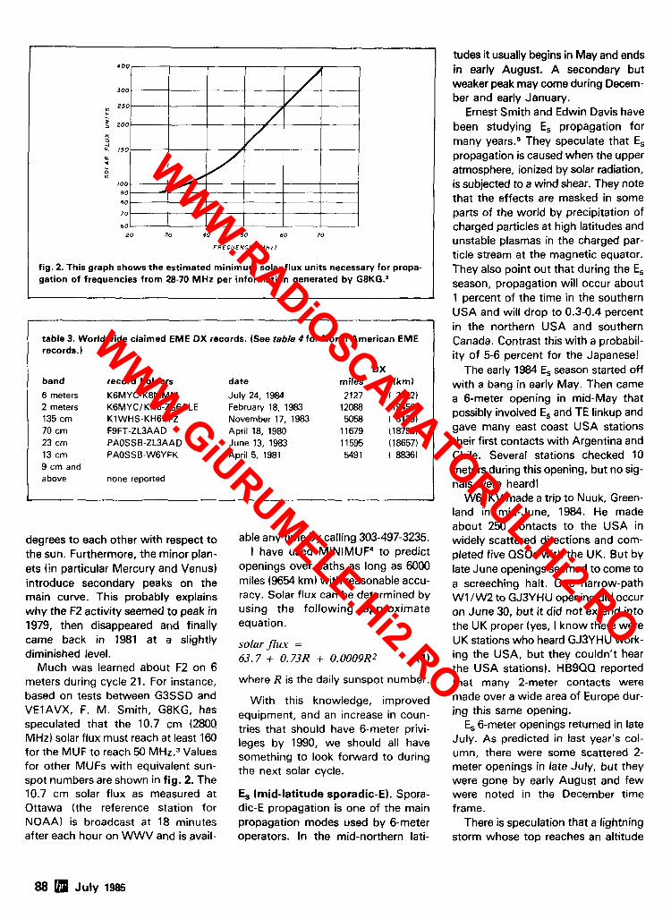
7 0 ~ 3 3 3 60
20 30 40 50 60 70
F R E Q U E N C Y ( M H z I
fig. 2. This graph shows the estimated minimum solar flux units necessary for propa- gation of frequencies from 28-70 MHz per information generated by G8KG.l
table 3. Worldwide claimed EME DX records. (See table 4 for North American EME records.)
DX band record holders date miles fkm)
6 meters K6MYC-K8MMM July 24, 1984 2127 ( 3422) 2 meters KGMYCIKH6-ZS6ALE February 18, 1983 12088 (19450) 135 cm K1 WHS-KH6BFZ November 17, 1983 5058 ( 8139) 70 crn FSFT-ZL3AAD April 18, 1980 1 1679 (1 8793) 23 cm PAOSSB-ZL3AAD June 13, 1983 1 1595 ( 18657) 13 crn PAOSSB-W6YFK April 5, 1981 5491 t 8836) 9 cm and above none reported
degrees to each other with respect to the sun. Furthermore, the minor plan- ets iin particular Mercury and Venus) introduce secondary peaks on the main curve. This probably expiains why the F2 activity seemed to peak in 1979, then disappeared and finally came back in 1981 at a slightly diminished level.
Much was learned about F2 on 6 meters during cycle 21. For instance, based on tests between G3SSD and VEIAVX, F. M. Smith, G8KG, has speculated that the 10.7 cm (2800 MHz) solar flux must reach at least 160 for the MUF to reach 50 MHz.3 Values for other MUFs with equivalent sun- spot numbers are shown in fig. 2. The 10.7 cm solar flux as measured at Ottawa (the reference station for NOAA) is broadcast at 18 minutes after each hour on WWV and is avail-
able any time by calling 303-497-3235. I have used MINIMUF4 to predict
openings over paths as long as 6000 miles (9654 km) with reasonable accu- racy. Solar flux can be determined by using the following approximate equation.
solar flux = 63.7 + 0.73R + 0.0009R2 (1)
where R is the daily sunspot number.
With this knowledge, improved equipment, and an increase in coun- tries that should have 6-meter privi- leges by 1990, we should all have something to look forward to during the next solar cycle.
Es (mid-latitude sporadic-El. Spora- dic-E propagation is one of the main propagation modes used by 6-meter operators. In the mid-northern lati-
tudes it usually begins in May and ends in early August. A secondary but weaker peak may come during Decem- ber and early January.
Ernest Smith and Edwin Davis have been studying Es propagation for many years.5 They speculate that Es propagation is caused when the upper atmosphere, ionized by solar radiation, is subjected to a wind shear. They note that the effects are masked in some parts of the world by precipitation of charged particles at high latitudes and unstable plasmas in the charged par- ticle stream at the magnetic equator. They also point out that during the Es season, propagation will occur about 1 percent of the time in the southern USA and will drop to 0.3-0.4 percent in the northern USA and southern Canada. Contrast this with a probabil- ity of 5-6 percent for the Japanese!
The early 1984 Es season started off with a bang in early May. Then came a 6-meter opening in mid-May that possibly involved Es and TE linkup and gave many east coast USA stations their first contacts with Argentina and Chile. Several stations checked 10 meters during this opening, but no sig- nals were heard!
WGJKV made a trip to Nuuk, Green- land in mid-June, 1984. He made about 250 contacts to the USA in widely scattered directions and com- pleted five QSOs with the UK. But by late June openings seemed to come to a screeching halt. One narrow-path W1 lW2 to GJ3YHU opening did occur on June 30, but it did not extend into the UK proper (yes, I know there were UK stations who heard GJ3YHU work- ing the USA, but they couldn't hear the USA stations). HB9QQ reported that many 2-meter contacts were made over a wide area of Europe dur- ing this same opening.
Es 6-meter openings returned in late July. As predicted in last year's col- umn, there were some scattered 2- meter openings in late July, but they were gone by early August and few were noted in the December time frame.
There is speculation that a lightning storm whose top reaches an altitude
88 July 1985
WWW.RADiOSCAMATORUL.Hi2.RO
WWW.GiURUMELE.Hi2.RO
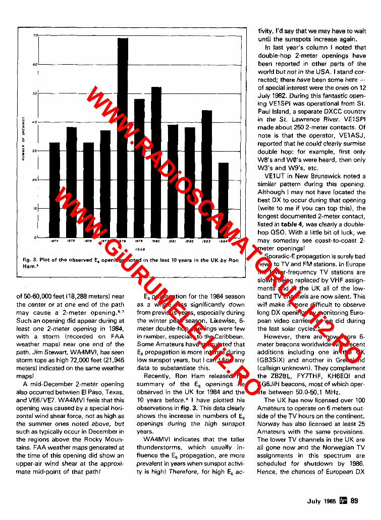
70
6 0
so
4
4 0
1 % IL 0
Q
8 3 0
5
2 0
10
0 1974 1976 1976 1977 1978 1979 1980 1981 1982 IS83 1984
I E A R
fig. 3. Plot of the observed E, openings noted in the last 10 years in the UK by Ron Harn.O
of 50-60,000 feet (18,288 meters) near the center or at one end of the path may cause a 2-meter Such an opening did appear during at least one 2-meter opening in 1984, with a storm (recorded on FAA weather maps) near one end of the path. Jim Stewart, WA4MV1, has seen storm tops as high 72,000 feet (21,946 meters) indicated on the same weather maps!
A mid-December 2-meter opening also occurred between El Paso, Texas, and VE6lVE7. WA4MVI feels that this opening was caused by a special hori- zontal wind shear force, not as high as the summer ones noted above, but such as typically occur in December in the regions above the Rocky Moun- tains. FAA weather maps generated at the time of this opening did show an upper-air wind shear at the approxi- mate mid-point of that path!
E, propagation for the 1984 season as a whole was significantly down from previous years, especially during the winter peak season. Likewise, 6- meter double-hop openings were few in number, especially to the Caribbean. Some Amateurs have speculated that Es propagation is more intense during low sunspot years, but I can't find any data to substantiate this.
Recently, Ron Ham released his summary of the E, openings he observed in the UK for 1984 and the 10 years beforens I have plotted his observations in fig. 3. This data clearly shows the increase in numbers of E, openings during the high sunspot years.
WA4MVl indicates that the taller thunderstorms, which usually in- fluence the Es propagation, are more prevalent in years when sunspot activi- ty is high! Therefore, for high E, ac-
tivity, I'd say that we may have to wait until the sunspots increase again.
In last year's column I noted that double-hop 2-meter openings have been reported in other parts of the world but not in the USA. I stand cor- rected; there have been some here - of special interest were the ones on 12 July 1982. During this fantastic open- ing VElSPl was operational from St. Paul Island, a separate DXCC country in the St. Lawrence River. VElSPl made about 250 2-meter contacts. Of note is that the operator, VEIASJ, reported that he could clearly surmise double hop: for example, first only W8's and W0's were heard, then only W3's and Wg's, etc.
VEl UT in New Brunswick noted a similar pattern during this opening. Although I may not have located the best DX to occur during that opening (write to me if you can top this), the longest documented 2-meter contact, listed in table 4, was clearly a double- hop QSO. With a little bit of luck, we may someday see coast-to-coast 2- meter openings!
Sporadic-E propagation is surely bad news to n/ and FM stations. In Europe the lower-frequency TV stations are slowly being replaced by VHF assign- ments and in the UK all of the low- band TV channels are now silent. This will make it more difficult to observe long DX openings by monitoring Euro- pean video carriers as we did during the last solar cycles.'
However, there are now more 6- meter beacons worldwide with recent additions including one in the UK (GB3SIX) and another in Greenland (callsign unknown). They complement the ZB2BL, FY7THF, KHGEQI and KGGJIH beacons, most of which oper- ate between 50.0-50.1 MHz.
The UK has now licensed over 100 Amateurs to operate on 6 meters out- side of the TV hours on the continent. Norway has also licensed at least 25 Amateurs with the same provisions. The lower TV channels in the UK are all gone now and the Norwegian TV assignments in this spectrum are scheduled for shutdown by 1986. Hence, the chances of European DX
July 1 s 5 89
WWW.RADiOSCAMATORUL.Hi2.RO
WWW.GiURUMELE.Hi2.RO
3HN brings thc you with its patented design.
,r the ultimate "on the ground arvice and antenna installatior RQHN "Fold-Over" Tower is !
L ? ~ f . b ~ y . Your safety comes firs1 w t t r i
:old-Over." For complc - - -
?te deta
G.R.A.M. BATAVIA HAMFEST SUN.. JULY 14. 1985
I
915 North Main Street s m r i . r d * . . r - d e ~ Jarnestown, New York 14701 pH. (716)664-6345
......... Conloc! " 5 lor 011 01 you, nnlntrur rodin ii-v,i. FEATURING:
ICOM, AEA, LARSEN, V A N GORDEN, VIBROPLEX. NYE VIKING, FALCON COMM. LEADING EDGE. ARRL PUULICATIONS, KAGLO. HAMTRONICS, PROWRITER, ELEPHANT DIS!~S. DEBCO, TRIONYX
.. Input uslng Eimac X651Z: s~lver-plated cavlty i n removable drawer. Requlres 1151 230 VAC 8 20 VDC. 7x t9%x18" . 75 IbS.
sh Used-nnl lesled, excellent condition. 5159.50
MOSFET m q y In m a n Md. d l l s pam arnplllle~s. Bvlll lor those who demand quallly.
r / 19
AM-61541GRT VHF POWER AMP, same as AM-6155 except coves 116 -149 9 5 MHz range; used-not tested. ........................................... ..$209.50 CU-872 HF ANTENNA COUPLER tor u p l o sigh1 2-32 MHz receivers; 70 ohm output. N connections, test meler. and 20/6922 tubes. 7 x 9 x 1 6 . 5 . 40 Ibs sh.
.............................................. Used. $49.50
FWmr F.O.B. UM. 0. VISA. MASTERCARD A m Allow fw Shlppinp Send fw Naw FREE C A T A L O P '
Addrarr nnnl WR Phona: 4141227.6573
F l l s n s l o e m o s t HF-SSB l r a n s c e l v e r s . R e q u ~ r e s h u m a n v o i c e t o activate.
* I g n o r e s s t a t i c , n o i s e a n d h e t e r o d y n e s . C o n n e c t s t o audio l e a d s a n d 9112 V D C . F u l l y a s s e m b l e d a n d t e s t e d $99 95. C o m p l e t e c o m p r e - h e n s i v e m a n u a l . U s e d w o r l d w i d e in commercial a n d rnlli t a r y t r ansce i ve rs .
, . r / 152
COMMUNICATIONS 5479 Jelporl . Tampa. FL 33814 . (813) 8853996
Complelely assembled 6 ready lo use Commerc#al guallry, bull1 10 Ian .Ltghtwe+pht sealed, mnherprwl traps .AUIornal~C band srllchlnp . low 10s end msulalors - Handles up lo XYX) wails PEP - for all Iransrnlners, r m v e r s 6 transceivers . Tuner usually never repu~red -Deluxe center In.
sulalor. wllh bull1 m lhphtnlnp arrsslor, accepts PL-259 wax connsnor -May be used as lnvened " V . Excellent lor all class amaleurs - lnnruc1,ons included . I 0 day money back guarantee' 4-Band-40,20.l5,10mN~s(55') 2 traps m42m % m 5-Band.BO.40 20.15.10 meters (105'1 2 lrapRD52159 95PW
s n l m o WSTPAI~I Rum TO USEI 90 H. RG58U. 52 ohm coax cable. wrlh PL.259 connsetor on each end - Add 112 W lo abave Prtce
I w ~ e e p l VISA~MCGNI Card r . ~ x p Date. Si~nnure
SP I -RO D ISTRIBUTORS fl l"
Electronic Repair Center Servicing
Amateur Commercial Radio
The most complete repair facility on the East Coast.
Large parts inventory and factory author~zed warranty service for
Kenwood, lcom and Yaesu.
SEND US YOUR PROBLEMS Serv~cmg "Hams" for 30 years, no ng
loo old or new for us
lGs,im 4033 Brownsville Road
Trevose, Pa. 19047
2 15-357-1 400
MICROWAVE EQUIPMENT R M S G Manual Tuned S I G N A L G E N E R A T O R 19, .2 to 2 MW + 12 V D C
1 3 7 4 2 GHz 65000 - w
3 2 I 2 2 G H z 1 6 0 0 0 ' 5 2 3 2 d S G H z 66000
R M V O V o l t a g e Tuned Osc~llator 1 to 10MW + 1 2 V D C B i a s
-1 to -12 V D C Tunlng On PC Board 1 1 8 2 6 G H z S25 00
A l s o D e t e c t o r s . L~ne S t r e t c h e r s . V a r l a b l e A l t e n u a l o r s . 2 3 GHZ T e s t A n t e n n a s M ~ x e r s . L N A ' s and C o n v e r t e r s
ROENSCH MICROWAVE R R I BOX 1568. BROOKFIELO MISSOURI 84628 r / 153
>
WWW.RADiOSCAMATORUL.Hi2.RO
WWW.GiURUMELE.Hi2.RO
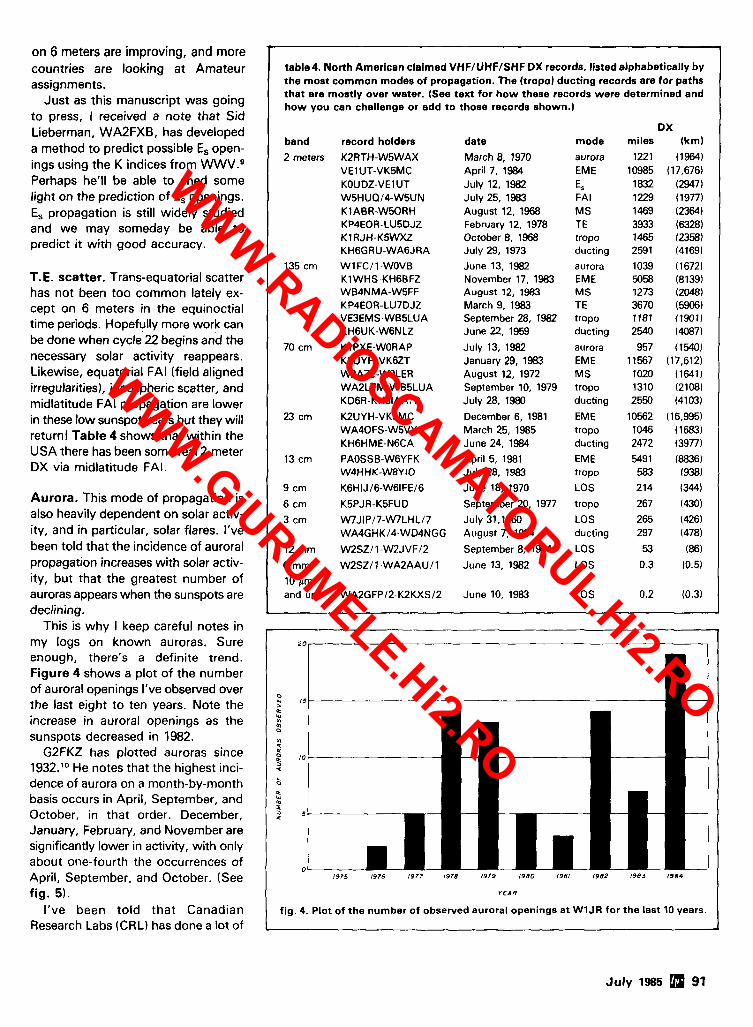
on 6 meters are improving, and more countries are looking at Amateur assignments.
Just as this manuscript was going to press, I received a note that Sid Lieberman, WA2FXB, has developed a method to predict possible Es open- ings using the K indices from WWV.g Perhaps he'll be able to shed some light on the prediction of Es openings. E, propagation is still widely studied and we may someday be able to predict it with good accuracy.
T.E. scatter. Trans-equatorial scatter has not been too common lately ex- cept on 6 meters in the equinoctial time periods. Hopefully more work can be done when cycle.22 begins and the necessary solar activity reappears. Likewise, equatorial FA1 (field aligned irregularities), ionospheric scatter, and rnidlatitude FA1 propagation are lower in these low sunspot years but they will return! Table 4 shows that within the USA there has been some real 2-meter DX via midlatitude FAI.
Aurora. This mode of propagation is also heavily dependent on solar activ- ity, and in particular, solar flares. I've been told that the incidence of auroral propagation increases with solar activ- ity, but that the greatest number of auroras appears when the sunspots are declining.
This is why I keep careful notes in my logs on known auroras. Sure enough, there's a definite trend. Figure 4 shows a plot of the number of auroral openings I've observed over the last eight to ten years. Note the increase in auroral openings as the sunspots decreased in 1982.
G2FKZ has plotted auroras since 1932.1° He notes that the highest inci- dence of aurora on a month-by-month basis occurs in April, September, and October, in that order. December, January, February, and November are significantly lower in activity, with only about one-fourth the occurrences of April, September, and October. (See fig. 5).
I've been told that Canadian Research Labs (CRL) has done a lot of
w
table4. North American claimed VHF/UHF/SHF DX records, listed alphabetically by the most common modes of propagation. The (tropo) ducting records are for paths that are mostly over water. (See text for how these records were determined and how you can challenge or add t o those records shown.)
ox band record holders date mode miles ikm)
2 meters KZRTH-W5WAX March 8, 1970 aurora 1221 (1964) VE1 UT-VK5MC April 7, 1984 EME 10985 (17,676) KOUDZ-VE1 UT July 12, 1982 ES 1832 (2947) W5HUQl4-W5UN July 25, 1983 FA1 1229 (1977) KlABR-W50RH August 12, 1968 M S 1469 (2364) KP4EOR-LU5DJZ February 12, 1978 TE 3933 (6328) K1 RJH-K5WXZ October 8, 1968 tropo 1465 (23581 KH6GRU-WA6JRA July 29, 1973 ducting 2591 (41691
135 cm WlFC11-WOVE June 13, 1982 aurora 1039 (1672) K1 WHS-KH6BFZ November 17, 1983 EME 5058 (8139) WB4NMA-WBFF August 12, 1983 M S 1273 (2048) KP4EOR-LU7DJZ March 9, 1983 TE 3670 (5906) VE3EMS-WB5LUA September 28, 1982 tropo 1181 (19011 KHGUK-W6NLZ June 22, 1959 ducting 2540 (4087)
70 cm K l PXE-WORAP July 13, 1982 aurora 957 (15401 K2UYH-VK6ZT January29.1983 EME 11567 (17,612) W2AZL-WOLER August 12, 1972 MS 1020 (1641) WA2LTM-WB5LUA September 10, 1979 tropo 1310 (2108) KD6R-KH6IAAIP July 28, 1980 ducting 2550 (4103)
23 cm KPUYH-VK5MC December 6, 1981 EME 10562 (16,995) WA40FS-W5VY March 25, 1985 tropo 1046 (1683) KHGHME-N6CA June 24, 1984 ducting 2472 (3977)
13 cm PAOSSB-W6YFK April 5, 1981 EM€ 5491 (8836) W4HHK-W8YIO July 28, 1983 tropo 583 1938)
9 cm K6HIJl6-W61FEl6 June 18, 1970 LOS 214 (344)
6 cm K5PJR-K5FUD September 20, 1977 tropo 267 (430)
3 cm WJIPl7-W7LHL/7 July 31,1960 LOS 265 (426) WA4GHKl4-WD4NGG August 7, 1984 ducting 297 (478)
12 mm W2SZl 1 -W2JVF/2 September 8, 1984 LOS 53 (86)
6 mm W2SZ11-WA2AAUIl June 13, 1982 LOS 0.3 10.5)
10 r m and up WA2GFPl2-K2KXSl2 June 10, 1983 LOS 0.2 (0.3)
Ju ly 1985 91
20
n *r IS
C
2 0
VI q
10 q
LC 0
Q *r
5 -
0
7
-
-
1975 1976 1977 1978 1979 1980 1981 1982 1983 1984
Y E A R
fig. 4. Plot of the number of observed auroral openings at WlJR for the last 10 years.
WWW.RADiOSCAMATORUL.Hi2.RO
WWW.GiURUMELE.Hi2.RO
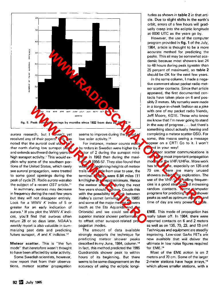
JAN F E B M A R A P R MAY JUNE JULY AUG S E P T OCT NOV D E C
I fig. 5. Peak auroral openings by mc
M O N T H
mths since 1932 from data by G2FKZ.1°
aurora research, but I haven't yet received any of their papers. CRL has noted that the auroral oval stays fur- ther north during low sunspot years and extends southward during years of high sunspot activity. This would ex- plain why some of the southern por- tions of the United States, which rarely see auroral propagation, were treated to some good openings during the peak of cycle 21. Radio aurora wasalso the subject of a recent QST article."
In summary, aurora; inay decrease in frequency during the next few years but they will not disappear entirely. Look for a WWV K index of 5 or greater for an early indication of aurora.' If you plot the WWV K indi- ces, you'll find that auroras often return 28 or so days later. NOAA's weekly report is also valuable in sum- marizing past data and predicting future sunspot, A and K indicies.12
Meteor scatter. This is "the fun mode" that heretofore wasn't thought to have been affected by solar activity.
Some Swedish scientists, however, now report that from their observa- tions, meteor scatter propagation
seems to improve during the period of low solar activity.13
For instance, meteor counts made by radars in Sweden were higher by a factor of 2 during the sunspot mini- mum in 1963 than during the maxi- mum in 1956-57. They also found that while the beginning heights of meteor trails varied little from year to year, the terminal heights were 6.84 miles (11 km) higherat sunspot minimum. Hence the meteor showers during the next few years should improve. Couple this with the possibility of a link between Halley's comet (arriving in late 1985) and some of the major meteor showers (such as the Eta Aquarids and the Orionids) and we could see some superior meteor shower performance to offset other sunspot-related pro- pagation modes.
The amount of data available strongly supports the technique for predicting meteor shower peaks described in my June, 1984, column.14 In fact, this method predicted the 1985 Quadrantids shower peak to within hours of its beginning. But there seems to be some disagreement on the accuracy of using the ecliptic longi-
tudes as shown in table 2 in that arti- cle. Due to slight shifts in the earth's orbit, errors of a few hours will grad- ually creep into the ecliptic longitude at 0000 UTC as the years go by.
However, the use of the computer program provided in fig. 1 of the July, 1984, article is thought to be a more accurate method for predicting the peaks. This all may be somewhat aca- demic because most showers last 24 to 48 hours during peak (greater than 25 percent of maximum), so table 2 should be OK for the next few years.
In the same column, I made a nega- tive comment about packet radio met- eor scatter contacts. Since that article appeared, the first documented con- tacts have taken place on 6 and pos- sibly 2 meters. My remarks were made in a tongue-in-cheek fashion as a joke with one of my packet radio friends, Jeff Moore, KQ1 E. Those who know me know that I'm never going to stand in the way of progress. . . but there's something about actually hearing and completing a meteor scatter QSO. For some, this means seeing a message appear on a CRT! Go to it. I won't stand in your way!
Meteor scatter communications is one of the most important propagation modes for the VHFIUHFer. More work has to be done, especially on 135 and 70 cm. There are many unused showers available for exploration. The use of the VHFIUHF calling frequen- cies is a good step toward increasing random contacts. Home computer programs for predicting meteor shower peaks as well as optimum direction and time of day are very powerful tools.
EME. This mode of propagation has really taken off. In 1984, there were reported contacts on 6 and 2 meters as well as on 135, 70, 23, and 13 cm! Techniques and equipment are steadily improving. Low-cost GaAs FETs a;e now available that will deliver the ultimate in low noise figures required for EME.15
Most of the EME action is on 2 meters and 70 cm. Some of the larger 2-meter stations have huge arrays,16 which allows smaller stations, with a
92 a July 1985
WWW.RADiOSCAMATORUL.Hi2.RO
WWW.GiURUMELE.Hi2.RO
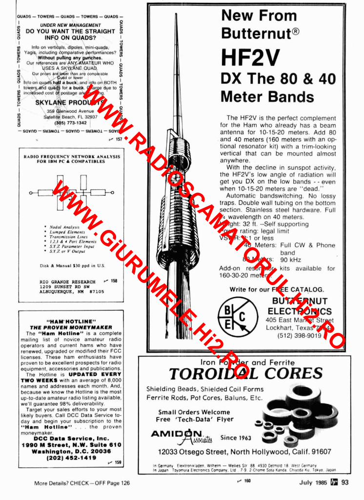
TOWERS - OUADS - TOWERS - OUADS - UNDER NEW MANAGEMENT D
YOU WANT THE STRAIGHT Z 3 o INFO ON QUADS? I I 4
0 Info on vertlbals, dlpoles, mlnl-quads. I
Yagls, lncludlng Wmparatlve performances'? 2 Without pulng any punches. ' Our references are ANY AMATEUR WHO I
I USES A SKYLANE OWAD e D 8 Our prloss rr er than any cornphrable Z
U %d or lowet
2 IWO on q u d h a f a buck and en, om BOTH !, I l o w e p quads lor a buok Charge due to 0
tncr sed cost of postage and prlnllng 3 n V)
SKYLANE PRODUCTS I I 359 Glenwood Avenue ? 9 Satell~te Beach. FL 32937 o V)
3 0
(305) 773-1342 I
- sovno - SL~~MOL - savno - WPMOL- w r n o
1/ 151
RADIO FREQUENCY NETWORK ANALYSIS FOR I B M PC & COMPATIBLES ++
Nodnl Annly5lr Lumped Elcmcnrr Tranrmtrston Ltnes I .2 .J d 4 Po11 Elcmrsn S . Y I Pnramcrrr Inpul S.Y.Z or v ourpuc
Disk d Manual $30 ppd in U.S.
R I O CRANDE RESEARCH @ 1% 1209 SUNSET RD SU ALBUQUERQUE, NM 87105
"HAWHOTLINE" THE PROVEN MONEYMAKER
The "Ham Hotllno" IS a complete mailing l~s t of novlce amateur radio operators and current hams who have renewed, upgraded or modified their FCC licenses. These ham enthusiasts have proven to be excellent prospects for radio equipment, accessories and publications.
The Hotline IS UPDATED EVERY TWO WEEKS with an average of 8.000 names and addresses each month. And. because we know the Hotline IS the most up-to-date amateur radio l~sting available, we'll guarantee 98% deliverab~lity.
Target your sales ellorts to your most likely buyers. Call DCC Data Service to- day and begin your subscription to the "Ham Hotlino" . . . the proven moneymaker.
DCC Dmtm Service, Inc. 1990 M Street, N.W. Suite 6 1 0
Washington, D.C. 20036 (202) 452-1419
r / 159 ,
More Details? CHECK-OFF Page 126 1/ 180 July 1985 93
New From Butternut@
HF2V DX The 80 & 40 Meter Bands
The HF2V is the perfect complement for the Ham who already has a beam antenna for 10-15-20 meters. Add 80 and 40 meters (160 meters with an op- tional resonator kit) with a trim-looking vertical that can be mounted almost anywhere.
With the decline in sunspot activity, the HF2V's low angle of radiation will get you DX on the low bands - - even when 10-15-20 meters are "dead."
Automatic bandswitching. No lossy traps. Double wall tubing on the bottom section. Stainless steel hardware. Full '14 wavelength on 40 meters. Height: 32 f t . --Self supporting Power rating: legal limit VSWR: 2:l or less
40 Meters: Full CW & Phone band
80 Meters: 90 kHz Add-on resonator kits available for 160-30-20 meters.
Write for our FREE CATALOG.
@ BUTTERNUT ELECTRONICS
405 East Market Street Lockhart, Texas 78644
(512) 398-9019
Iron P o w d e r and F e r r i t e
4
TOROIDAL CORES Shielding Beads, Shielded Coil Forms Ferr i te Rods, Pot Cores, Baluns, Etc.
Small Orders Welcome Free 'Tech-Data' Flyer a- * AM'DA,N& Since ,963 J
12033 Otsego Street, North Hollywood, calif. 91607
In Germany tteulron~klaaen. W!tnetm - McllleS Str 88 4930 Delmola I 8 West Germany In Jawn Tjyomura Eleclron~cs Company. Lld 7-9 2 Cnome Sola-Kanda Ch~yoda-Mu Tohyo Jaoan
WWW.RADiOSCAMATORUL.Hi2.RO
WWW.GiURUMELE.Hi2.RO
single Yagis and moderate power (500 watts output), to routinely make con- tacts with the larger stations using a rising or setting moon.
Although the 135-cm band has been very much ignored by the EMEers, it's a terrific band for EME. Antenna sys- tems are not as critical and are only 50-75 percent of the size required for 2-meter EME. Because the sky noise is lower, the signals are stronger. All the necessary 135-cm EME components can now be built or purchased." Warning: this is a band we could lose if we don't start using it properly.'*
EME on 70,23, and 13 cm is matur- ing rapidly. Over 40 DXCC countries are available on 70 cm on all contin- ents. Twenty DXCC countries from five continents are now active on 23 cm and almost ten countries are on 13 cm. On 23 and 13 cm, the parabolic dish is king. If low-noise GaAs FET preamplifiers are used, echoes can be obtained with as little as 100 watts and a 13-foot (4 meter) parabolic dish.
The stout-hearted and others in search of a real challenge should give EME a try. Still quite an adventure, it's an excellent proving ground for new equipment. I think we'd be at least five years behind in antenna technology to- day if it weren't for the need for high- gain efficient Yagi antennas required for EME. Now these same antennas are being used to improve perfor- mance on other, more conventional, propagation modes.
Weather-related propagation. Watching the weather and trying to predict it was a hobby of mine until I discovered Amateur Radio. This back- ground has served me especially well since I began working the VHFJUHF frequencies.
Over the years I've noticed a strange weather phenomenon, especially in cli- mates that experience temperature changes of greater than 75 degrees F (42 degrees C): there seems to be more than four distinct seasons.
According to my "Five-Season Weather Calendar," the weather appears to change on five key pivot calendar dates, 73 days apart. I find
that March 1 is a good reference point for determining the first pivot date. The other dates are May 13, July 25, October 6, and December 18.
What I notice is that the weather in any particular area of the country around each pivot date ( + 1 week) gives an indication of the weather to be expected during the next 73-day period. For instance, if the weather is generally cold at the end of February through the first week of March, the weather to follow will probably be cool until the next pivot day (May 13). Likewise, in the northern hemisphere, moderate temperatures near the weeks surrounding December 18 portend a milder winter season.
Furthermore, this five-season weather concept seems to be in step with radio propagation. For instance, the E, season seems to begin around May 13 and is usually almost over by July 25. Could it be that the jet stream moves in approximately 73-day incre- ments? Hurricanes in the United States seem to form in late July and are usu- ally over by early October. Is this con- cept only a figment of my imagination? Or is it really so?
Tropospheric propagation. There's no doubt that tropospheric propaga- tion, tropospheric ducting, and super- refraction are directly related to the weather patterns. As mentioned in ref- erence 1, long-haul tropo DX seems to come after a slow-moving high-pres- sure area (greater than 30.27 inches of 1025 millibars on a barometer) is fol- lowed by a moist low-pressure system. Recently, VE3CIE wrote an interesting article on tropo propagation as related to meteor~logy.'~
The past year has seen some good long tropospheric openings both in North America and Europe. First there was the ducting from California to Hawaii when KH6HME and N6CA fi- nally made the grade on 23 cm. At the time a tropical depression was noted on the southern side of the path off Baja, California. As in the past open- ings, the signals disappeared a few miles inland at the California end of the path.
Next came the openings between the Canary Islands (EA8) and the United Kingdom in July. This opening was also a function of ducting, since only stations near the coast of south- ern England and Wales were able to hear the EA8 stations. Signals were strong and relatively small stations (10 watts) were able to make contacts.
Finally came the fantastic opening that extended from New England and New York to Florida during the ARRL September VHF QSO party. This was a classic opening that was clearly a mix of normal tropo and ducting. The ba- rometer was very high - and right off the east coast was the large hurricane Diana! Who says there's no link be- tween hurricanes and good DX?
The salient feature of this opening was the evidence of an elevated duct. The stations located at least 500 feet (150 meters) above sea level were par- ticulary favored. W2SZl1 and WlXXl2 were over 3000 feet (900 meters) above sea level and they reported that mak- ing long-haul contacts was like shoot- ing fish in a barrel. W2SZI1 operators noticed a distinct haze layer above and below their mountaintop location in the early morning.
WA4MV1, a private pilot, decided to observe the opening from the air. He loaded his 70-cm gear, including a five- element Yagi, into a small plane. He then flew at various elevations over the western tip of South Carolina and into North Carolina to see if there was a duct and, if so, where it was located. At 750 miles (1200 km) from W2SZI 1, he was able to continuously monitor their 70-crn signal strength from approximately ground level to about 14,000 feet (4,267 meters). He found a duct between about 4000 feet (1200 meters) and 10,000 feet (3050 meters). Signals in the duct were typically 20 dB over S9. However, signals abruptly weakened above and below the duct, dropping to almost inaudible at ground level and at 14,000 feet. His temper- ature-versus-elevation observations showed a more or less constant value within the duct instead of the normal decrease with increasing altitude. He also noted that the wind speed in the
94 5 July 1985
WWW.RADiOSCAMATORUL.Hi2.RO
WWW.GiURUMELE.Hi2.RO
duct was very high - typically 40 knots - and that the wind came from the east. However, above and below the duct there was only a moderate 10- knot wind - coming from the west!
In mid-December, when such phe- nomena are rare, another east coast tropospheric duct period was in evi- dence. Also present, just off shore, was an unwelcome guest - hurricane Lily! (The weather reports said that this was one of the few hurricanes ever seen in that part of the Atlantic Ocean during the month of December.)
And how about the terrific openings during the ARRL VHF contest in Sep- tember, 1979, when hurricanes David and Frederic were both off the South- eastern coast of the United States? Again, the link between hurricanes and good long-haul VHFIUHF DX seems difficult to dispute!
Openings such as this prompt some hams to remark "Oh, the bands are always open. It's just that we don't have all that mountaintop activity out- side of the contests." This just isn't so. Most of the VHFIUHF contest dates are planned to coincide with periods known to have good radio propaga- tion. Mountain-toppers are always active, especially during contests, but they usually experience only the nor- mal extended range expected for an elevated QTH. To have an extended opening, you have to have the right ingredients: proper weather and location.
In my July, 1984, column I stated that ducts do not extend far inland. This statement applies mainly to the oceans, especially when the land near the coast is hilly or mountainous. The Gulf of Mexico does not fit this description but instead acts more like a large inland body of water sur- rounded by relatively flat land. As a result, ducting can move inland.
This is most noticeable on the path between Texas and Florida, especially between the months of February and May. Just as this column was being completed, I learned of a particularly long DX contact (approximately 1046 miles or 1683 km) on 23 cm, between WA40FS (St. Cloud, Florida) and
W5VY (San Antonio) - see table 4. Both stations are very far inland.
The next few years should prove very interesting as the jet stream moves slightly because of lower sun- spot counts. Will tropo propagation disappear? I doubt it very much - but it may favor different areas of the country than it does during the high sunspot years.
Lightning scatter. Over the past year I've had many reports from individuals who've used various scatter mecha- nisms. W7BYF informed me that he made what was undoubtedly a light- ning scatter contact when he was W8NAF in Dayton, Ohio. In July of 1958 he worked W8KAY in Akron, Ohio, on 2 meters, with both stations pointing their antennas at a lightning storm center in Ft. Wayne, Indiana. Several other stations also worked W8KAY by the same technique.
To work lightning scatter, set up a schedule for 15-30 minute periods with a distant station. Each station trans- mits for 1 minute - one on the odd minute and the other on the even min- utes. Listen carefully when working extended paths. More often than not, the signals will seem to appear almost out of nowhere. When signals appear, switch over to break-in procedures and enjoy a quick snappy QSO. The better the location and the shorter the dis- tance between stations, the longer the propagation will last.
Aircraft scatter. VHF/UHFers often seem surprised when you mention that they may be using aircraft scatter propagation. However, scatter is often present on 200-400 mile (325-650 km) contacts even though it may not be obvious on the lower VHF bands. On 70 cm and above, aircraft is most often responsible for extended daily con- tacts. Using aircraft scatter requires some patience, since aircraft may be in the proper location for only a few minutes.
Barium clouds. The jury is still out on whether VHF/UHFers can use these man-made ionization clouds, which apparently last for 15 to 30 minutes, for
comunications. On Christmas morn- ing, 1984, there was supposed to be a Barium cloud, dubbed the Christmas Comet, released over Peru at 70,000 miles (21,336 km) altitude. Unfortu- nately the test had to be rescheduled, so many persons missed their chance to try, and those who did were appar- ently unsuccessful. These opportuni- ties, which occur infrequently and often unexpectedly, deserve more attention.
finding direction When working DX on the UHF
bands, your antenna can have very narrow beamwidths. This requires good rotator accuracy as well as a knowledge of the correct beam head- ings. One way to calibrate your rotator in the northern hemisphere is to aim your antenna at Polaris (the North Star).
You can also use the sun. By con- sulting your local daily newspaper for times of sunrise and sunset, you can estimate the time the sun passes directly south. Simply determine the midpoint between sunrise and sunset. For instance, if the sun rises at 5:30 AM and sets at 7 PM local, the time of southerly transit or time when the sun is directly south will be 12:15 PM.
A compass can also be used. But beware - magnetic north may be dif- ferent than true north. Since many VHFers now use home computers and have direction bearing programs, it is easy to find the true bearing for mag- netic north. For USA stations, just compute the direction of the magnetic north pole using the approximate coor- dinates of 74 degrees north latitude and 101 degrees west longitude. For southern hemisphere stations, the southern magnetic pole is at approxi- mately 68 degrees south latitude and 144 degrees east longitude. This will give you the true direction indicated on a hand compass.
summary Again, I've run out of time and
space, but I hope the information pre- sented will be useful. If you've never seen my July, 1984, column, I suggest
July 1985 95
WWW.RADiOSCAMATORUL.Hi2.RO
WWW.GiURUMELE.Hi2.RO
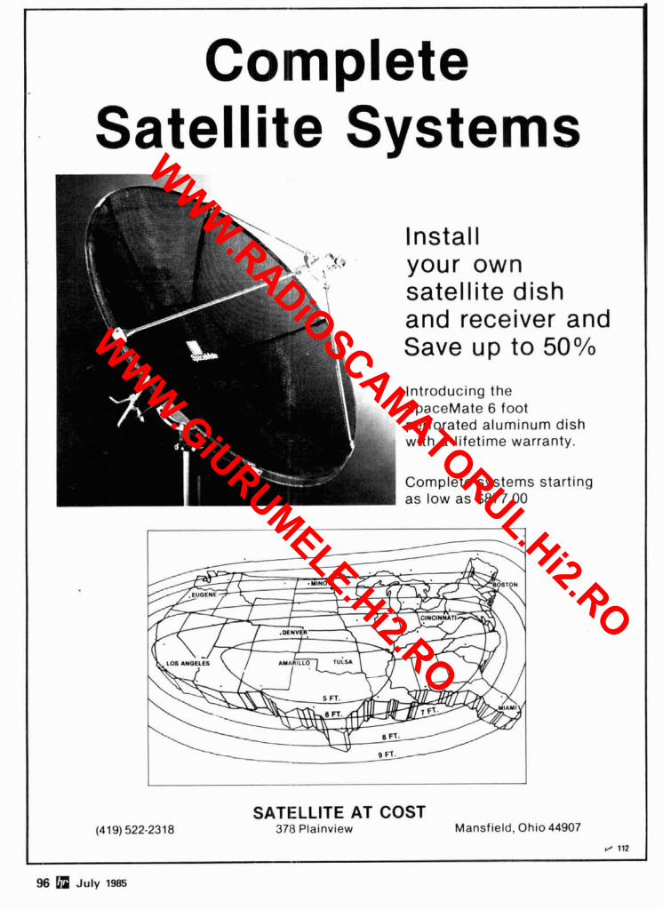
Complete Satellite Systems
satellite dish and receiver and Save up to 5O0/0
Introducing the SpaceMate 6 foot perforated aluminum dish with a lifetime warranty.
Complete systems starting as low as $877.00
SATELLITE AT COST (41 9) 522-231 8 378 Plalnv~ew Mansfield, Ohlo 44907
J 112 - 96 a July 1985
WWW.RADiOSCAMATORUL.Hi2.RO
WWW.GiURUMELE.Hi2.RO
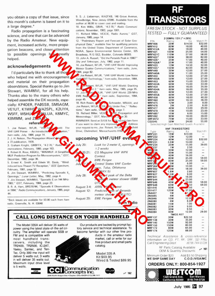
you obtain a copy of that issue, since this month's column is based on it to a large degree."
Radio propagation is a fascinating science, and one that can be advanced by the Radio Amateur. New equip- ment, increased activity, more propa- gation beacons, and closer attention to possible openings has greatly helped.
acknowledgements I'd particularly like to thank all those
who helped me with encouragement and material on their propagation obserntions. Special thanks go to Jim Stewart, WA4MV1, for all his help. Thanks also to the many others who helped assemble the DX records, espe- cially: KP4OER, PABSSB, SM5AGM. VElUT, KlWHS, WA2SPL, KZUYH, W5FF, W5HUQ, WB5LUA, KGMYC, K8MMM, and ZL3AAD.
references 1. Joe Reisert, WIJR. "VHFIUHF World. The VHFiUHF Primer - An Introduction to Propagation." ham radio. July, 1984. page 14. 2. J. H. Nelson. The Propagarion Wizard's Handbook. a 73 publication, 1978. 3. Graham Knight, GMBFFX. "4-2-70." RadIo Com~ munrcarions, February, 1980. page 163. 4. Robert 8. Rose. K6GKU. "MINIMUF: A Simplified MUF-Prediction Program for Microcomputers." OST. December. 1982. page 36. 5. Ernest K. Smith and Edwin W. Davis. "Wind- induced Ions Thwart TV Reception." IEEE Speclrum. February. 1981. page 52. 6. Jim Stewan, WA4MVI. "Predicting Sporadic E, Openings." Lunar Lerrer. May. 1982. page 4. 7. Jlm Stewart. WA4MVI. "Sporadic Eon 144 MHz- 1983." 0.71. February. 1984. page 23. 8. R. A. Ham. BRS15744. "Sporadic-E Observations in 1W." Radio Commonrcarions, January, 1985, page 44.
'Back issues are available for $3.00 each from ham radIo, Greenville. N. H. 03048
9. S. J. Lieberman. WA2FXB. 146 Grove Avenue. Woodbridge, New Jersey 07095. Available from the author at $8.00 lo cover cost and malllng. 10. Ken Willis, G8VR. "4-2-70." Radio Communt- carions. November. 1983, page 1001. 11. Richard Miller. VE3CIE. Radio Aurora." 0.71. January. 1985. page 14 12. "Preliminary Repon and Forecast of Solar Geo- physical Data." available free lor qualifying persons from the United States Department of Commerce. NOAA. Space Environmental Service Center. 325 Broadway, RIEISU. Boulder. Colorado 80303. 13. John A. Russell, "Did the Perseids Peak In 19807" Sky and Telescope. July. 1982. page 11 14. Joe Reisert. WIJR. "VHFIUHF World: Improving Meteor Scaner Communications," ham radio. June. 1984, page 82. 15. Joe Reisen, WIJR, "VHFIUHF World: Low-Noise GaAs FET Technology." ham radio. December. 1984. page 99. 16. Joe Reisert. WIJR. "VHFIUHF World: Stacking Antennas. Pan 2." hanr radto, May. 1985. page 95. 17. Joe Reisen. WIJR. "VHFIUHF World: 220-MHz EME Requirements." tram rad~o, September. 1984. page 45. 18. Rich Rosen, K2RR. Joe Schroeder. WSJUV. and Joe Reisen, WIJR. "220 MHz Under Fire," "Reflec- tions," ham radro, October 1984, page 7. 19. Richard Miller. VEOCIE. "VHF Propagation and Meteorology," OST, March. 1984. page 3. REMINDER: Send an SASE for a DX r%ord claim form if you want to clam any improved records. Address your rcqucst to me. Joc Rc~scn, WIJR, 17 Monsfsld Drive, Chelmsford. Massachusetts 01824.
upcoming VHFIUHF events July 20:
July 20-21:
July 25:
July 27-29:
July 28:
August 3-4: August 12:
August 20:
Look lo r 2-meter E, openings
+ 2 weeks CO Magazine VHF WPX
Contest
EME Perigee
Central States VHF Confer-
ence, Tulsa, Oklahoma
(W0RRYISI Predicted peak o f the Delta
Acquarids meteor shower 10303 UTCl
ARRL UHF Contest
Predicted peak o f Persetds
meteor shower 10130 UTCl EME Perigee
ham radio
* CALL LONG DISTANCE ON YOUR HANDHELD
The Model 335A will del~ver 35 watts of Our products are backed by prompt fat- power uslng the latest state-of-the-art clr- tory servlce and technical assistance TO
cultry The ampl~fler w ~ l l operate SSB or become famlllar wlth our other flne pro-
FM and IS compat~ble w11h
"It ducts In the amateur r ad~o
m o s t h a n d h e l d t r ans - market, call or wrlte for our celvers, ~ n c l u d ~ n g t he free product and small parts TR2400, TR2500. IC-2AT.
I catalog
Yaesu. Santec, and Ten- Tec Only 300 mw tnput wtll Model 335 A dellver 5 watts out, 3 watts In will dellver 35 watts out
K I ~ $69 95
Max~mum Input drlve level W~red & Tested $89.95
IS 5 watts ommunication - - m E o n c e p t s inc. , ,, 2648 Nn I t A l r q narc .Dayton Oho45420.15111?% 167%
L
FRESH STOCK - NOT SURFJLUS I TESTED - FULLY GUARANTEED 1 2.30MHz 12V ('=28V)
PIN Rnlno L d Mittctl Pr MRF4OB 20W $ 14.50 132.00 MRF412 80W 18.00 40.00 MRF412A 8OW 18.00 40.00 MRF421 100W 25.00 54.00 MRF421C l lOW 27.00 58.00 MRF422' 150W 38.00 82.00 MRF426' 25W 17.00 40.00 MRF426A' 25W 17.00 40.00 MRF433 13W 14.50 32.00 MRF435' 150W 42.00 90.00 MRF449 30W 12.00 27.00 MRF449A 30W 11.00 25.00 MRF450 50W 12.00 27.00 MRF450A 50W 12.00 27.00 MRF453 60W 15.00 33.00
VHF TRANSISTORS Ral~n? l d
15W $10.00 12W 12.00 40W 13.50 3.5W 10.00 25W 15.00 1 W 2.50
30W 12.00 30W 15.00 40W 16.00 BOW 25.00 BOW 25.00
5 W 6.00 30W 13.00 70W 18.00
1.8W 2.60 0.5W . 9.00 15W 18.00 25W 23.00 40W 24.00 SOW 29.50 80W 29.50
1 W 1.25 4 W 10.00
tow 12.00 4 W 6.00
15W 7.00 25W 9.00 30W 9.50 40W 12.00
TMOS FET 30W $22.50 30W 35.00
150W 92.00 150W 80.00 BOW 65.00
125W 88.00
I ~ c h n ~ c a l Assrsfance 8 cross rel?rence lnlorrnahon on C l l PT RF SRF SD PINS Call Engrneerrng Den1 (fi19l 744 O i 2 H
RF Parts Calalog Available , OEM 8 Ouanl~ly Dlscounl5
M ~ n ~ m u m Order $20 Add $3 50 Shlpp~nq WE SHIP SAME DAY C.O.D.IVISAIMC
ORDERS ONLY: 800-854-1 927
July 1985 n 97
WWW.RADiOSCAMATORUL.Hi2.RO
WWW.GiURUMELE.Hi2.RO
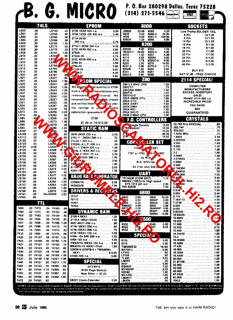
P. 0. Bow 280298 Dallas
LSlO .20
LS12 .35 LS13 .40 LS14 .40 LS15 .32 LS20 .20 LS21 .25 LS27 .28 LS30 .20 LS241 .80 LS32 .25 LS33 .40 LS37 .33 LS38 .30 LS42 .40 LS51 .24 INCREDIBLE PRICE1 LS54 .25 YOU SAVE1 LS55 .24 LS73 .35 LS74 .30 LS85 .60 LS266 .40 LS86 .25 LS273 1.00 LS90 .50 LS279 .40
. . . . . . . . . . . . . . . . . . . . . LS93 .55 LS280 1.00 262.1 44 .75 LS107 .37 LS283 .SO LS109 .25 LS112 .30
. . . . . . . . . . . . . . . . . . . LS122 .45 2.000000 2.49 . . . . . . . . . . . . . . . . . . . . . . LS123 .55 2.560 .1.49 . . . . . . . . . . . . . . . . . . . . . . LS124 2.00 3.000 1.15
. . . . . . . . . . . . . . . . . . . . . . . LS125 .40 3.120 1.20 LS126 .49 LS132 .50 LS133 .35 LS138 .45
. . . . . . . . . . . . . . . . . . . . . . LS139 .40 4.000 1.75 . . . . . . . . . . . . . . . . . . . LSl5 l .45 LS374 1.00 4.194304 1.50 . . . . . . . . . . . . . . . . . . . . LS153 .40 LS375 .50 4.43361 8 .75 . . . . . . . . . . . . . . . . . . . LS154 .99 4444.000 1.25
LS155 .50 LS156 .50 LS157 .40 LS158 .50 LS399 1.25
. . . . . . . . . . . . . . . . . . . . . . LS160 .65 LS670 1.50 5.616 1.59 LS161 .SO 25LS2569 3.00 6.000 . . . . . . . . . . . . . . . . . . . . . . .2.49
. . . . . . . . . . . . . . . . . . . . . . . LS162 .65 6.176 1.49 . . . . . . . . . . . . . . . . . . . . . . 7.164112.. . . . . . . . . . . . . . . . . . . 1.00
. . . . . . . . . . . . . . . . . . . . . . . . . . . . . . . . . . . . . . . . . . . . . 7.3728 .1.49 8.000 . . . . . . . . . . . . . . . . . . . . . . 1.49 9.000 . . . . . . . . . . . . . . . . . . . . . . . 1.49
. . . . . . . . . . . . . . . . . . . . 9.90000 1.25 10.69425 . . . . . . . . . . . . . . . . . . . 2.50
. . . . . . . . . . . . . . . . . . . . 10.8864 1.49 10.920 . . . . . . . . . . . . . . . . . . . . . 1.49 11.088 . . . . . . . . . . . . . . . . . . . . . 1.59
98 July 1985 Tell 'em you saw it in HAM RADIO!
WWW.RADiOSCAMATORUL.Hi2.RO
WWW.GiURUMELE.Hi2.RO

0. 0. B o x 2 8 0 2 9 8 Dallas, Tewas 75228 rBe Ge MICRO (214) 271 -5546 -7 -LA b-?-?
Big Computer Mfg. Makes $900,000 Goof!!
ORIGINALLY DESIGNED TO RUN A 2-80 BASED SINGLE BOARD COMPUTER
WITH TWO 5-1/4 IN. DISK DRIVES AND CRT MONITOR.
BRAND NEW: UNUSED! $249SEa hRq*ch ADD $1.50 PER UNIT FOR UPS
- ~ . ~~
SPECS: + SVDC 5 AMPS MAX #1 + 12 VDC 2.8 AMPS MAX 1
I #2 + 12 VDC 2.0 AMPS MAX / I !
- 12 VDC .5 AMPS MAX - .- - -- i
INPUT: 115 or 230 VAC 60Hz I -- -
CAN EASILY BE MODIFIED TO GIVE 24V @ 1.5 AMP
SMALL SIZE: 6-1/8 x 7-318 In. HIGH EFFlClENCY SWITCHER MFG. BY CAL. DC I N USA!
The poor Purchasing Agent bought about 10 times as many of these DC switchers as his company would ever use! We were told that even in
10,000 piece lots they paid over $72 each for these multi-output switchers. When this large computer manufacturer discontinued their Z-80 Computer, guess what the Big Boss found in the backwarehouse; several truckloads of unused $72.00 power supplies. Fortunately we heard about the deal and made the surplus buy of the decade. Even though we bought a huge quantity, please order early to avoid disappointment. Please do not confuse these high quality American made power supplies with the cheap import units sold by others.
f l 163
TERMS: (Unless spec~ f~ed elsewhere) Add $1 50 postage, we pay balance. Orders over $50.00 add856 lor insurance. No C.O.D. Texas Res. add6-118% Tax. 90 Day Money Back Guaranlee on all ilems. All items subjecl l o prior sale Pr~ces subject to change without notice. Forelgn order - US funds only. We cannot ship to Merico.Countries otherthan Canada add I3 50 shiaaina and handlina.
More Details? CHECK-OFF Page 126 July 1985 99
WWW.RADiOSCAMATORUL.Hi2.RO
WWW.GiURUMELE.Hi2.RO
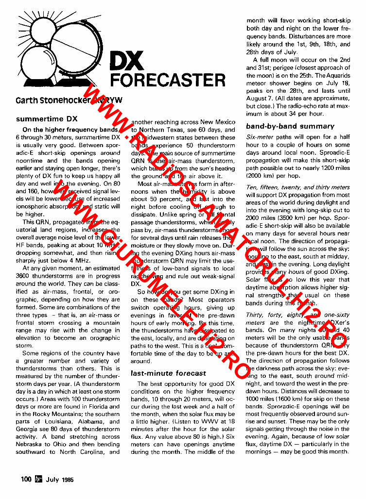
FOR ECAST Garth Stonehocker, K0RYW
summertime DX On the higher frequency bands,
6 through 30 meters, summertime DX is usually very good. Between spor- adic-€ short-skip openings around noontime and the bands opening earlier and staying open longer, there's plenty of DX fun to keep us happy all day and well into the evening. On 80 and 160, however, received signal lev- els will be lower because of increased ionospheric absorption, and static will be higher.
This QRN, propagated from the eq- uatorial land regions, increases the overall average noise level of the lower HF bands, peaking at about 10 MHz, dropping somewhat, and then rising sharply just below 4 MHz.
At any given moment, an estimated 3600 thunderstorms are in progress around the world. They can be class- ified as air-mass, frontal, or oro- graphic, depending on how they are formed. Some are combinations of the three types - that is, an air-mass or frontal storm crossing a mountain range may rise with the change in elevation to become an orographic storm.
Some regions of the country have a greater number and variety of thunderstorms than others. This is measured by the number of thunder- storm days per year. ( A thunderstorm day is a day in which at least one storm occurs.) Areas with 100 thunderstorm days or more are found in Florida and in the Rocky Mountains; the southern parts of Louisiana, Alabama, and Georgia see 80 days of thunderstorm activity. A band stretching across Nebraska to Ohio and then bending southward to North Carolina, and
another reaching across New Mexico to Northern Texas, see 60 days, and the midwestern states between these bands experience 50 thunderstorm days. The main source of summertime QRN is the air-mass thunderstorm, which builds up from the sun's heating the ground and the air above it.
Most air-mass storms form in after- noons when the humidity is above about 50 percent, and last into the night before cooling off enough to dissipate. Unlike spring or fall frontal passage thunderstorms, which simply pass by, air-mass thunderstorms linger for several days until rain releases their moisture or they slowly move on. Dur- ing the evening DXing hours air-mass thunderstorm QRN may limit the use- fulness of low-band signals to local ragchewing and rule out weak-signal DX.
So how do you get some DXing in on these bands? Most operators switch operating hours, giving up evenings in favor of the pre-dawn hours of early morning. By this time, the thunderstorms have dissipated to the east, locally, and are dissipating on paths to the west. This is a cool, com- fortable time of the day to be up and around.
last-minute forecast The best opportunity for good DX
conditions on the higher frequency bands, 10 through 20 meters, will oc- cur during the last week and a half of the month, when the solar flux may be a little higher. (Listen to WWV at 18 minutes after the hour for the solar flux. Any value above 80 is high.) Six meters can have openings anytime during the month. The middle of the
month will favor working short-skip both day and night on the lower fre- quency bands. Disturbances are more likely around the Ist, 9th, 18th, and 28th days of July.
A full moon will occur on the 2nd and 31st; perigee (closest approach of the moon) is on the 25th. The Aquarids meteor shower begins on July 18, peaks on the 28th, and lasts until August 7. (All dates are approximate, but close.) The radio-echo rate at max- imum is about 34 per hour.
band-by-band summary Six-meter paths will open for a half hour to a couple of hours on some days around local noon. Sproadic-E propagation will make this short-skip path possible out to nearly 1200 miles (2000 km) per hop.
Ten, fifteen, twenty, and thirty meters will support DX propagation from most areas of the world during daylight and into the evening with long-skip out to 2000 miles 13500 km) per hop. Spor- adic-E short-skip will also be available on many days for several hours near local noon. The direction of propaga- tion will follow the sun across the sky: morning to the east, south at midday, and west in the evening. Long daylight provides many hours of good DXing. Solar flux is so low this year that daytime absorption allows higher sig- nal strengths than usual on these bands during this month.
Thirty, forty, eighty, and one-sixty meters are the nighttime DXer's bands. On many nights 30 and 40 meters will be the only usable bands because of thunderstorm QRN. Try the pre-dawn hours for the best DX. The direction of propagation follows the darkness path across the sky: eve- ning to the east, south around mid- night, and toward the west in the pre- dawn hours. Distances will decrease to 1000 miles (1600 km) for skip on these bands. Sproradic-E openings will be most frequently observed around sun- rise and sunset. These may be the only signals getting through the noise in the evening. Again, because of low solar flux, daytime DX - particularly in the mornings - may be good this month.
100 July 1985
WWW.RADiOSCAMATORUL.Hi2.RO
WWW.GiURUMELE.Hi2.RO
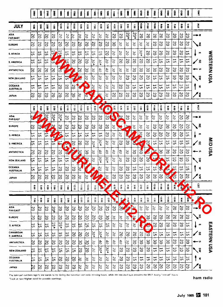
The ~talfc~zed numbers slgnofy the bands to try dur~ng the trans,uon and early mrprnmg hours, wh~le the standard type provides the MUF dur~ng "normal" hours
'I.ook at next higher band for poss~ble openings. ham radio
July 1985 101
JULY
ASIA
FAR EAST
EUROPE
- 4 -
LJ N N N N N N W S. AFRICA
W W W W W W N N N U L J b b N N N N N W P W W W W V) SAMERICA m m m m m m 0 0 0 0 0 0 O l o 0 0 0 O I C n U l m vl ul / # 4 * * rn
0 0 0 0 0 0 0 0 0 Q 0 0 0 O 0 0 0 0 0 0 0 0 0 0 z NEWZEALAND
OCEANIA AUSTRALIA
JAPAN
g g g ~ g ~ ~ $ ~ . ~ $ s $ ~ . ~ ~ g ~ ~ ~ N N N N ~ ~ ~ ~ ~ ~ ~ ~ ~ N N ~ ~ N N I U N N N N N - ~
0 0 0 0 0 0 0 0 0 0 0 0 0 0 0 0 0 0 0 0 0 0 0 0 \ g
0 0 0 0 0 0 0 0 0 0 0 0 0 0 ~ ~ 0 0 0 0 0 0 0 0
N N N N N N N N N N N N W U U U U U N N N N N N
m m
- - A - - A
ASIA N N ~ * * N N N N N N N N N N ~ ~ ~ ~ ~ ~ ~ ~ U N N + ~ FAR EAST 0 0 ~ ~ ~ 0 0 0 0 0 0 0 0 0 0 0 0 0 0 0 O O O O
a d d
m
!.?.?ig
8 8 8
C " L " C " L " O O O 0
EUROPE N N N N N N N N N N N N U U U U U U N N N N N N
- - -~ - -
O O O O O O O O O O O O O O O O O O ~ O O O O O O \ ~ -
S. AFRICA
2 P
m
SAMERICA
NEWZEALAND
OCEANIA AUSTRALIA
JAPAN
ASIA
FAR EAST
EUROPE -
m m m m o
r 2
S. AFRICA rn
--
N N N N N N N W W L , h h Q Q U W W W W W W N N N 0 0 0 0 0 0 0 0 0 0 0 0 D 0 0 0 0 0 0 0 0 0 0 0
-" z C V)
OCEANIA AUSTRALIA
JAPAN N N N N N N N E \ , l u b b b b N N N N N N N N N N N O O O O O O O O O O O 0 0 0 O O O O 0 0 O O 0 0 / f
m m
0
0
N N N
0
0
Y m V I P Y W -
m
0
0
s * s s s B s Y -
m m m m m m 0 0 0 0
W W W W W W W N b b b b b b N N N N W W P C - , W W D
r r r r N N N b b h , b b m N N r r r r r r r r r 0
N N N N N N W U L J U U U N N N N N N N N N N N N
A d -
8 8
N N N N W
0 0 0 0 0 0 0 0 0 0 0 0 0 0 0 0 0 0 0 0 O O O O
N N N N N N N N N N N W U U L J U L J W N N N N N N
0 1 0 0 0 0 0 0 0 0 0 0 0 0 0 0 0 0 0 0 0 ~ 0 0 0 0 0 0 / ~
N N N N N N N N N N N N N N N ~ ~ ~ ~ I U I U N N N - ~
0 0 0 0 0 0 0 0 0 0 0 0 0 0 0 0 0 0 0 0 0 0 0 0 \ :
m m m m o o o
2
O 1 O O m m L " ( L " L " m v l L " v l
2
~ O O O y l v l v l O O O \ z C y) B
f s
W U
2
&A
+
~ ~ W W W W N N N U ~ ~ ~ N N N N N W P P P ~ W
A 0 0 0 0 0 0 0 0 0 0 0 0 0 0 0 0 0 0 0 0 0 0 0 0
r w W C ) W + r N N b g g b b N N N N c . l c . l C - ' C - l c . l W
W W W W N N N U U ~ ~ P O L U N N W + ~ ~ ~ - ~ - + m m m m o o o o o o O o o o o m m m m m m m m m
W N N N N N N U U U U U N N N N N N N N N N N N
A
o
O O O O O O O O O D O 0 O O O O O O O O O O O O / ~
A
0
LJ W W
~ 0 0 0 O O O O l ~ ~ m ~ v l i n / 1 : I
W W W
0 0 0 0 m m m O 0 0 \ z
- A -
N l u N N + ( n
g
C
F
f s
WWW.RADiOSCAMATORUL.Hi2.RO
WWW.GiURUMELE.Hi2.RO
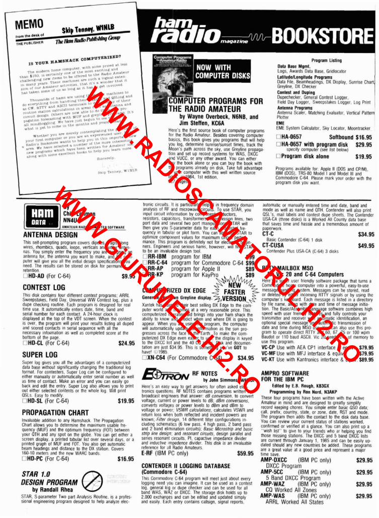
I Program Llslrng
Oala Base Mgml. Logs, Awards Dala Base. Gr~dlocator
1 I buy the book alone or vou can buv the book with tile programs already on d~sk Take full advantage Programs ava~lable for Apple I1 (00s and CP/M). 01 you1 computer wlIh thls well wrlnen source IBM (00s). TRS-80 Model I and Model ill and b ~ k 1984 1st edrhon. Commodore C M Please mark your order WIM the 327 pages program dlsk you wan1
ANTENNA DESIGN Thl\ sell-promptlnq proqranl covers dipoles. Yagis, long WIICS. rhomblcs. quads, luops. verticals and other anlen- nas You s~mply enter the frequency you are deslgnlng an antenna for. the anlenna you want to make. and the com- puler w~l l glve you all Ihe lnltral destgn speclhcatrons you need The resulls can be stored on dlsk lor pelmanent relention I IHD-A0 (For C-64) $9.95
CONTEST LOG Tht? disk contams lour dlllerent contest ragrams. ARRL Sweepylakes held Day. Un~versal WW dntes l log, plus a dupe checklng routine Each program IS desrgned lor real tlrne use It automatically enlers date. llme band and serlal number lor each contacl A 24.hour clork 1s displayed al Ihe lop of the VDT screen When the conlest IS over. Ihe program will prlnt your resulls llstlng all duped and scored conlacts In senal sequence wrlh all Ihe nece5sary ~nformatlon as well as completPd score at the bottom of the paqe I IHO-CL (For C-64)
SUPER LOG SUPPI log glves you all the advantages of a computerized data base w~lhout slgnthcanlly changlng the tradlt~onal log lorrnal for contesters Super Log can be cont~gured lo ellher manually or automat~cally enter senal number as well as llme ol contact Make an error and you can eas~ly go bark and ed~l Ihe entry Super Log also allows you lo prlnt out ellher srlected conlenrs or the whole log W~l l prtnt OSLs Easy to modlly I IHD-SL (For C-64) $19.95
PROPAGATION CHART Invaluable addlhon lo any Hamshack m e Propagation Ch t r l allows you lo determtne the maxlmum usable Ire. qllrnc (MUF) and the optlmum frequency (FOTI bekeen yollr JTH and any spot on the globe You can gel e~ther a screen d~splay a prlnted tabular llsl over Several days or a printed qraph of MUF and FOT You also get automallc beam head~ngs and drstance to the DX slallon Covers 160 10 nwters and the new WARC bands I IHD-PC (For C-64) $16.95
STAR 1.0 DESIGN PROGRAM @
by Randall Rhea STAR. S-parameler Two part Analysts Routine, is a proles- sronal englneertng program destgned lo help analyze elec-
--
trontc clrcu~ts. I1 IS panrularly helpful In frequency domaln analysls of RF and mrcrowave circu~ts. To use STAR, you lnpul clrcutt lntormat~on by companenl: Inductors, resistors. capacitors. translormers. transmlsslon Ilnes. two porl data and several two port manlpulatlons STAR will then glve you S-parameler dala lor each requested Ire- quency In labular or plol lorm You can also use STAR to optlmlze component values lor maxlmum clrcu~l pertor. mance. Thls proqram IS deflnltely not lor electron~c begin- ners Engineers and sertous hams. however, wtll llnd STAR to be an invaluable deslgn tool ILIRR-IBM program for IBM $99 ILIRR-C-64 program for Commodore C-64 $99 URR-AP program for Apple II $ 89 ORR-KP program for KayPro $89
COMPUTERIZED OX EDGE p5 Generala your own Gmyllns dlsply. VERSION, Xantek has adapted Ihelr besl selltng OX E d g ~ lo the com. puler world and tt comes al a very reasonable price Th~s computerrzed operatlnq aid brings lnlo your ham shack the ablllly to know and predict when and where DX IS golng to appear When you are ustng the program. the computer will automattcally update the Intormallon as the sun pro- gresses across the face of the tanh To make the com. putertzed DX Fdge even easler lo use. the dlsplay IS keyed lo the UXCC lrgl and !he 40 CO mnes. Disk and documen- tatlon are lust $34 95 Thls IS something you've GOT lo have! , 1985 I 1XN-C64 (For Commodore C-64) $34.95
RF NOTES - by,,-",,, Here's an easv way lo et answers lor onen asked elec. trorlrcs questtony RF N ~ T E S contains programs written by broadcast engineers Mal answer' dB conversion, to convert voltage. currerlt or power levels to dB: dBm conversrons. converts vollalles or power levels lo dBm and dBm lo vollage or power. VSWR calculanons. calculates VSWR and return loss when bolh rellecled and tncldenl powers are known: frller ~lesrgn. 14 dlllerent lllter conhgurat~ons rn- clud~ng schematics (6 low pass. 4 h~gh pass. 2 band pass and 2 band ellm~nallon c~rcu~tsl: Bas~c M~croslnp and bastc slnp lrne desqn. and resonant circu~ts. deslgn parallel and serles resonanl clrcurls, PI, capactlve Impedance dlv~der and lnducllve lmpedence dlvlder Thls disk IS an ~rlvaluable reference lor all Rad~o Amateurs. E-RF (IBM PC only) $59.95
CONTENDER II LOGGING DATABASE (Commodore C-64) Th1.i Comn~od~lre C-M program will meet just aboul every logging need vou can Imaglne. It can be used as a contest log, general log or dupe checker and can be used for all band WAS. WAZ or DXCC The storage disk holds up lo 2.WO exchanties and can be edited and updaled simply and eastly Each entry contalns callstgn, stgnal reports.
automatlc or manually entered tlme and date, band and mode as well as name and OTH Contender mll also pnnt OSL s, marl labels and conlest dupe sheets The Contender USA-CA (Ihree disks) IS a Worked All County dala base that saves llme and hassle and a lremendous amounl of Oaoerwork t i - c 536.95 --
Aaslc Contender (C-64) 1 disk CT-CUSA $49.95
Corltender Plus USA-CA (C-64) 3 dlsks
RTTY MAILBOX MSO for Vic 20 and C-64 Computen
Heres a super user lrrendly Somare package that lums a Commodore home computer lnlo a powerful easy-to-use mestaqe handllng system Messa es can be stored read or deleted by elther lncomlng RT$Y slgnals or by uslng the compllter s keyboard Each message 15 llsled In a d~rectory by llle name, along wlth date and tlme 01 message Inltla- tlon The Bas~cIAssembly language somvare comblnes htgh speed with user lr~endly lealures and lully controls your lransm~ner and recelver wtth automatlc ldentll~cat~on an optlonal speclal message and automallc Iransmlssion ol date and tlme durlng MSO use You can dlso use lhis pro- gram lo operate dlrrcl R r P l and 60 67. 75 or 100 wpm Baudot or 110 baud ASCII VIC 20 needs 24k 01 memory to use thls program VC-CP Use with AEA CP1 interface & equiv. $79.1 VC-MF Use with MFJ interlace & equiv. $79.95 VC-KT Use with Kantronics interface 8 equiv. 589.95
AMPRO SOFTWARE FOR THE IBM PC
Edltsd by E B Rough. K W X Pmprammlng by Ron Nord. NMKP
These lour programs have been wrtnen wlth the Acbve Amateur In mlnd and are deslgned to greatly slm Illy record keeplng chores You slmple enter basrc 0!0 data. call prel~x country slate, or zone. date. RST and mode The proqram then adds the contact lo Ihe d~sk dala base You can revlew your currenl stalus of stahons worked conllrmed or vertlred at a glance You can also pnnt up a
w~sh list to glve to your lr~ends who ar helping you find those mlsslng statlons The DXCC and 5 band DXCC lhsts are current through January 1 1985 and can be easlly u p dated should any new countries be added These programs are a qreal value al a good prlce and represent a malor lime save AMP-DXCC (IBM PC only) $29.95
DXCC Prooram - = - A M P ~ C C (IBM PC only) $29.95
5 Band DXCC Prooram AMP-WAZ (IBM~PC onlv) 529.95 , , CQ Worked AII Zones
AMP-WAS (IBM PC only) t29.95 ARRL Worked All States
WWW.RADiOSCAMATORUL.Hi2.RO
WWW.GiURUMELE.Hi2.RO
COMMODORE 64 USER'S GUIDE by Commodore Engineers
Thls beginner's book glves you hands-on lnstructlons on how to set up and use your brand new C 64 computer Learn how to do color anlmatlon, generate muslc or speclallzed sound effects and Interface the computer wlth perrpheral equipment Just about every questlon a beglnner could ask IS answered ~n thls useful text (~11982 166 pages 1122010 Softbound $12.95
COMMODORE 64 PROGRAMMER'S REFERENCE GUIDE This programmer's guide will give you all the handy hints and tips that will let you get full value from your C-64. For the beginner, complicated topics are taken step-by-step, with plenty of sample programs and complete detailed ex- planations. Advanced users,wlll find plenty of pretested and debugged programs. 1st edlBon. 486 pages. rn22056 Softbound $19.95
COMMODORE C-64 STARTER BOOK by Jan and Christopher Titus and David Larsen
This book is designed to get the new C-64 owner up and running with the minimum of fuss and hassle,, Each chapter is packed with experrments and exercrses designed to build competence ~n the user Full of srmple to load and use programs written with the beqlnner's need in mind. 01984; 384 pages.
22293 Softbound $17.95
REPAIR AND TROUBLESHOOTING GUIDES C-64, IBM-PC AND APPLE II
by Robert C. Brenner If you've been taklng care of your ham gear, there's cer talnly no reason why you can't do much of your own m~crocomputer sewlclng These handy gu~des glve you a real headstart ~n takrng on your mlcro" when problems arlse Troubleshoot~ng IS clearly illustrated by s~mple flow charts that are des~gned to plnpolnt fallures and correct them There IS also an Advanced Troubleshootlng chapter for more complicated systems fallures Clear easy to-read text and plenty of ~llustrat~ons I 122363 Commodore C-64 &'I985 $18.95 1 122353 Apple II Plusllle @ I 9 8 4 $19.95 1 122358 IBM-PC (GI985 $18.95
CIRCUIT DESIGN PROGRAMS FOR THE APPLE II . . . -- . .
by Howard Berlin, W3HB Use your Apple to help design electronic circuits. This book is a series of engineering programs written in Applesofl that give you various "what happens if" and "what's needed when" as they apply to a number of engineering questions. By uslng the computer you can change various circuit components and tell exactly, how the circuit will per- form w~thout going through extensive manual calculations @1982. 132 paaes. n21863 Softbound $15.95
APPLE Ile PROGRAMMER'S GUIDE by David Heigerman
This book zeros in on how to program the popular Apple Ile home computer In both BASIC and assembly language. Chock full of helpful facts, applications. ideas, suggestions and technical information in one simple easy-to-use reference manual. You also get a number of short applica- t~on and demonstration programs ~n BASIC and assembly language. (01984, 416 pages. 022299 Softbound $19.95
APPLE PROGRAMMER'S HANDBOOK by Paul Irwin
Get the most of your Apple computer by learnlng assembly langua e programming Assembly language programs run much ?aster than basic programs and can be des~gned for maxlmum effectiveness w~th mlntmum compromise Plenty of stock routlnes are Included organized by toplc and detalled memory map Thls 408-page book will answer just about all your questions on assembly language pro- grammrng 101984 480 pages 1122175 Softbound $22.95
COMPUTER DICTIONARY AND HANDBOOK by Sippl
More than 22.000 definitions, acronyms. and abbreviat~ons as well as 14 information packed appendixes make this an invaluable reference book for all levels of computer users. Operational control, storage devices, and time sharing are just a few of the subjects extensively covered in this im- portant volume. 81980, 928 pages D21632 SAVE $5 Softbound $29.95
VIC 20 PROGRAMMER'S REFERENCE GUIDE To get the VIC to perform for you, you have to know how to program. The book is divided into four sections: BASIC Programming. Machine Language Programming, InputlOut- put lnterfaclng and Programming Graphics and Sound. Each chapter is fully illustrated with sample programs and has plenty of "how to" explanations. 1st edition. 01982. 289 pages 021948 Softbound $16.95
THE 68000 PRINCIPLES AND PROGRAMMING by Leo Scanlon
Motorola's 68000 is the first 16 bit r p to have a 32 bit in- lernal architecture. This book covers CPU informabon that IS needed for all microcomputer professionals and hobby- ists alike. Also includes information on Motorola's cross- macro assembler, a 68000 instruction set, printouts and interfacing. 01981. 240 pages. 021853 Softbound $15.95
2-80 MICROPROCESSOR PROGRAMMING AND INTERFACING
by Nichols and Rony This is the easy way for novices and experts to learn how to write and design programs for the popular 2-00 micro- processor. Book 1 focuses on fundamentals and use of the 2-80 while Book 2 explores special interest topics in great deoth. 01979. ~ 2 1 6 0 9 ~ o o k 1 Softbound 512.95 021610 Book 2 Softbound $16.95 OBuy BOTH Special $24.95
SAVE $4.95
MICRO COOKBOOk Vol. 1 and 2 by Don Lancaster
Learning to use a PC can be a real challenge. However. Don Lancaster has tried to filter out all the gobbledygook and make it as easy as can be. Volume 1 features down- to-earth coverage of fundamentals, number systems, hard- ware and software logic, mainstream codes and standards, electronic memory and memory devrces and other appllca- lions. Volume 2 covers address spdce, addressing, system architecture, machine code programming. 110 and helpful suggestions to common problems. 021828 Volume 1 01982 $15.95 U21829 Volume 2 01983 $15.95
Buy BOTH Special $26.95 SAVE $4.95
ORDER FORM Name - A d d r e s s City- S t a t e Z i p I I C h e c k o r M o n e y O r d e r E n c l o s e d 1 1 V I S A I 1 M a s t e r c a r d
C a r d # ___ E x p i r e s ____-
t j ham r i i d i ~ ~ ~ ~ ~ ~ ~ ~ ~ ~
/ 123 G R E E N V I L L E , NH 03048 BOOKrnRE
(603) 878-1 441
WWW.RADiOSCAMATORUL.Hi2.RO
WWW.GiURUMELE.Hi2.RO
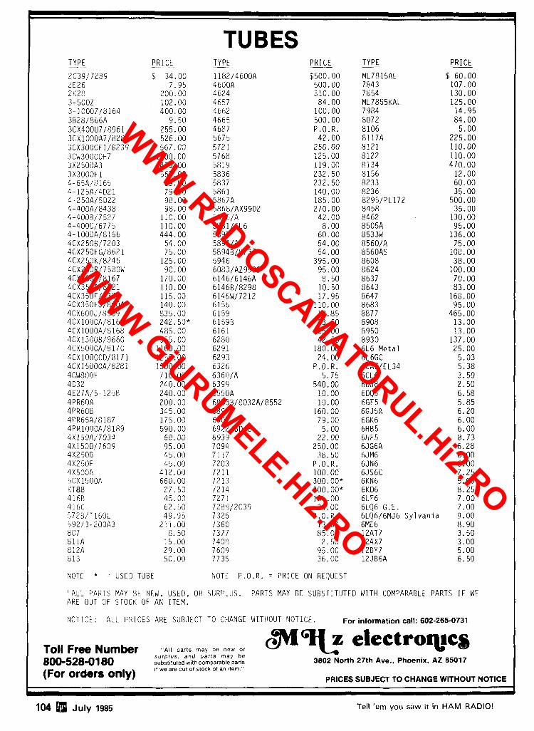
104 Q July 1985 Tell 'em you saw it in HAM RADIO!
t
TYPE PRICE
TUBES TYPE - -- PRICE - TYPE PRICE
2C39/7289 $ 34.00 l l82/4600A $500.00 ML7815AL $ 60.00 2E26 7.95 4600A 500.00 7843 107.00 2KL8 LOO.OO 4624 310.00 7854 130.00 3- 5002 102.00 4657 84.00 ML7855KAL 125.00 3-10002/8164 400.00 4662 100.00 7984 14.95 3B281866A 9.50 4665 500.00 8072 84.00 3CX4OOU7/8961 255.00 4687 P.O.R. 8106 5.00 3CX1000A7/8283 526.00 5675 42.00 8117A 225.00 3CX30OOFl/8239 567.00 572 1 250.00 8121 110.00 3CW30000H7 1700.00 5768 125.00 8122 110.00 3X2500A3 473.00 5819 119.00 8134 470.00 3X3000F1 567.00 5836 232.50 8156 12.00 4-65A/8165 69.00 5837 232.50 8233 60.00 4-125A/4021 79.00 586 1 140.00 8236 35.00 4-250A/ 5D22 98.00 5867A 185.00 8295lPL172 500.00 4-400A18438 98.00 5866/AX9902 270.00 8458 35.00 4-4008/7527 110.00 5876/A 42.00 8462 130.00 4-4OOCl6775 110.00 5881/6L6 8.00 8505A 95.00 4-1000A/8166 444.00 5893 60.00 8533W 136.00 4CX2506/7203 54.00 5894/A 54.00 8560/A 75.00 4CX250FG/8621 75.00 5894B/8737 54.00 8560AS 100.00 4CX250K/8245 125.00 5946 395.00 8608 38.00 4CX250R/7580W 90.00 6083/AZ9909 95.00 8624 100.00 4CX300A/8167 170.00 6146/6146A 8.50 8637 70.00 4CX350A/8321 110.00 6146B/8298 10.50 8643 83.00 4CX35OF/8322 115.00 6146W/7212 17.95 8647 168.00 4CX35OFJ/8904 140.00 6156 110.00 8683 95.00 4CX600J/8809 835.00 6159 13.85 8877 465.00 4CX1000A/8168 242.50* 61598 23.50 8908 13.00 4CX1000A/8168 485.00 6161 325.00 8950 13.00 4CXl5008/8660 555.00 6280 42.50 8930 137.00 4CX5000A/8170 1100.00 6291 180.00 6L6 Metal 25.00 4CX10000D/8171 1255.00 6293 24.00 6L6GC 5.03 4CX15000A/8281 1500.00 6326 P.O.R. 6CA7/EL34 5.38 4CW8OOF 710.00 6360/A 5.75 6CL6 3.50 4D32 240.00 6399 540.00 6DJ8 2.50 4E27A/5-125B 240.00 6550A 10.00 6DQ5 6.58 4PR60A 200.00 6883B/8032A/8552 10.00 6GF5 5.85 4PR60B 345.00 6897 160.00 6GJ5A 6.20 4PR65A/8187 175.00 6907 79.00 6GK6 6.00 4PR1000A/8189 590.00 6922/60J8 5.00 6HB5 6.00 4X150A/7034 60.00 6939 22.00 6HF5 8.73 4X1500/7609 95.00 7094 250.00 6JG6A 6.28 4X250B 45.00 7 11 1 38.50 6JM6 6.00 4X250F 45.00 7203 P.O.R. 6JN6 6.00 4X500A 412.00 7211 100.00 6JS6C 7.25 5CX1500A 660.00 72 13 300.00* 6KN6 5.05 KT88 27.50 7214 300.00* 6KD6 8.25 4 16B 45.00 7271 135.00 6LF6 7.00 416C 62.50 7289/2C39 34.00 6LQ6G.E. 7.00 572B/Tl60L 49.95 7325 P.O.R. 6LQ6/6MJ6 Sy lvan ia 9.00 592/3-200A3 211.00 7360 13.50 6ME6 8.90 807 8.50 737/ 85.00 12AT7 3.50 811A 15.00 7408 2.50 12AX7 3.00 812A 29.00 7609 95.00 12BY7 5.00 813 50.00 7735 36.00 12JB6A 6.50
NOTE * = USE0 TUBE NOTt P.O.R. = PRICE ON REQUEST
"ALL PARTS MAY BE NEW, USED, OR SURPLUS. PARTS MAY BE SUBSTITUTED WITH COMPARABLE PARTS I F WE ARE OUT OF STOCK OF AN ITEM.
NOTICE: ALL PRICES ARE SUBJECT TO CHANGE WITHOUT NOTICE. For information call: 602-265-0731
Toll Free Number AII parts may be new or surplus and par ts may be
m-2 e l e ~ t r o ~ c s 800-528-01 80 subst~tufed w ~ l h comparable parts 3802 North 27th Ave., Phoenix, AZ 85017
(For orders only) 11 we are out of stock of an Item
PRICES SUBJECT TO CHANGE WITHOUT NOTICE
!
WWW.RADiOSCAMATORUL.Hi2.RO
WWW.GiURUMELE.Hi2.RO
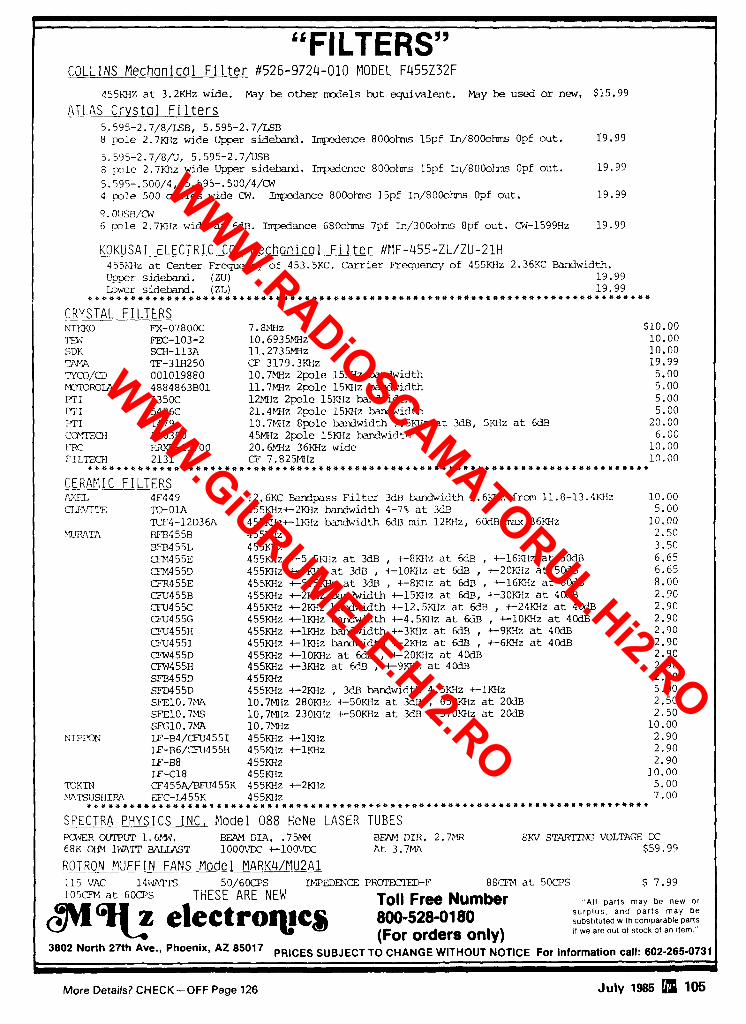
"FILTERS" COLLINS Mechan i ca 1 F i 1 ter #526-9724-010 MODEL F455Z32F
455MZ a t 3.2KHz wide. May be other mrde l s b u t e q u i v a l e n t . May be used or new, $15.99
ATLAS Crystal Filters 5.595-2.7/8/LSB, 5.595-2.7/LSB 8 ole 2.7KHz wide Upper sidebard. Impadence 8 0 0 0 h 15pf I n / 8 0 0 o M Opf out. 19.99
5.595-2.7/8/U, 5.595-2.7DSB 8 p o l e 2.7Khz wide Upper s ideband. Impdence 8000hm 15pf In/8000hms Opf out. 19.99
5.595-.500/4, 5.595-.500/4/M 4 p>le 500 c y c l e s wide Cw. Inpdance 8 0 0 o M 15pf I n / 8 0 0 0 h Opf out. 19.99
9.0USB/cw 6 ~ n l e 2.7KIIz wide a t 6dB. Impedance 6800hms 7pf In/3000hms 8pf out. M-1599Hz 19.99
KOKUSAI ELECTRIC CO, Mechanical Filter #HF-455-ZL/ZU-21H -
455KI1z a t Cen te r R - ~ q u e n c y of 453.5KC. Carrier F ' r q e n c y of 455M1z 2.36KC Bandwidth. Upper sid-. (ZU) 19.99 LDwer s i d e b r d . (ZL) 19.99
~ ~ ~ ~ u u ~ ~ u * ~ u * u + ~ u u u ~ ~ ~ ~ u u ~ ~ * ~ ~ ~ ~ ~ ~ u ~ ~ * u u * ~ ~ u * u u ~ ~ u ~ Q ~ ~ ~ Q ~ u u ~ ~ u * * ~ ~ ~ Q * U U * * Q * Q Q *
CRYSTAL F I LTERS N I I X O F'X-07800C ~ . ~ I . E I Z $lO.OC) TEW m - 1 0 3 - 2 10.6935MH~ 10.00 SDK SCH-113A 11.2735MH~ 10.00 TAMA TF-3U1250 CF 3179.3KH~ 19.99 ?rCO/CD 001019880 10.7MHz 2 p l e 15KHz bandwidth 5.00 ~ ~ R O I A 4884863B01 11.7MHz 2po le 15KHz bandwidth 5.00 PTI 5350C 12MHz 2 p l e 15KHz bandwidth 5.00 PI'I 5426C 21.4MIz 2 p 1 e 15EIz bandwidth 5.00 FTI 1479 10.7MIIz 8 p l e bandwidth 7.5KHz a t 3dB, 5KHz a t 6dB 20.00 C C r m I A10300 45MHz 2 p l e 15KHz M w i d t ! i 6.00 FRC ERXF-15700 20.6Mflz 36KHz wide 10.00 CILTECH 2131 CF 7.825MHz 10.00
~ b t U + Q ~ ~ Q Q Q ~ 4 Q ~ U ~ U U U ~ U U U U ~ ~ U ~ U ~ * C U ~ Q U U Q U U U ~ ~ U U * U U ~ ~ U ~ ~ U U ~ * Q U Q U ~ Q U Q ~ ~ U ~ ~ U Q * Q Q ~ U
ERAPlIC FILTERS AXEL 4F449 12.6KC Bardpass F i l t e r 3dB tundwidth 1.6KHz from 11.8-13.4KIlz 10.00 CLWITE TO-OlA 455KHzc2KHz hxxiwidth 4-78 a t 3dB 5.00
KF4-12D36A 455KIIztlKIlz bvldwidth 6d13 min 12KHz, 6CdB m u 36KHz 10 .05 LHLWTA DF13455B 455RIz 2.50
BFB4 55L 455KHz 3.50 WM455E 455KHz t 5 . 5 E i z a t MB , t 8 K l l z a t 6dB , t 16KHz a t 5- 6.65 CFM455D 455KFIz +-7012 a t 3dD , t lOKI lz a t 6dB , +-20KHz a t 50dB 6.65 DR455E 455KHz t5 .5KHz a t 3dE3 , t 8 K l i z a t 6dB , t-16KIIz a t 6CdB 8.00 CFU455B 455Kl1z t 2 w z bandwidth + - 1 5 ~ 1 z a t 6dB, t 3 0 E l z a t 40dB 2.90 CFU45X: 455KHz t 2 K H z bandwidth t12 .5KHz a t 6dB , +-24KHz at 4CdB 2.90 CFU4 55G 455KHz t l K H z bandwidth t4 .5KI Iz a t H E , +-1OKHz a t 40dB 2.90 CFU455H 455KHz i-1KHz bardwidth +-3KfIz a t 6dB , t 9 K H z a t 40dB 2.90 CFU4551 455KHz t N z hardwidth +-2KHz a t 6dB , t 6 K H z a t 40dB 2.90 CFW4 5 5D 455KHz t lOKHz a t 6dB , t 20KHz a t 4CdB 2.90 CEW455H 455KHz +-%Hz a t €dB , t 9 K H z at 40dn 2.90 SFD455D 455KHz 2.50 SFD455D 455KHz t 2 K H z , 3dB kindwidth 4.5KHz +-1KHz 5.00 SF'ElO. 7MA 10.7MHz 280KHz t50KHz a t 3dB , 650KHz at 20dB 2.50 SE'E10.7MS 10,7MHz 230KHz t5OKHz at 3dB , 570KHz a t 20dB 2.50 SFG10.7MA 10.7MHz 10.00
N I P P O N LF-B4/CTU4551 455KHz t 1 X H z 2.90 LF-BG/CFU455!I 455KH~ t l K H z 2.90 LF-B8 4 55KHz 2.90 LF-C18 455KH~ 10.00
TOKIN CF455q/BFU455K 455KHz t 2 m I z 5.00 IIATSUSHIRA PC-LA55K 455KHz 7.00
U C ~ ~ Q * ~ ~ ~ Q U U U ~ ~ Q U U Q U ~ ~ Q * ~ U ~ ~ U * U U ~ X ~ Q U U Q U U Q ~ Q U ~ * ~ U ~ Q Q * ~ U U U ~ * * Q U * * * * * * * U * Q * ~ * ~ * Q
SEECTRA PHYSICS INC, Clodel 088 HeNe LASER TUBES KJ.IER OUTPUT 1.6p.W. BEAM DIA. . 7 5 m DFAM DIR. 2.7PZR SKV STNlTTNG VOLTAGE IX 68K OHM 1FIATT BALZAST lOOOVDC i-100VD;: A t 3.7MA $59.99
R_OLRON MUFF I N FANS Model MARK4/Pl&AL 1 1 5 ~ 14;.mm 50 /608S IMPEDENCE PR0I'EClT.D-F 8 8 t 3 a t 5 0 a S $ 7.99 105CR.I a t 6 0 8 s THESE ARE NEW ToII Free Number , 'A l l parts may be new or
electroqacs 800-528-0180 surplus. and par ts may be subst~tuted w ~ t h comparable parts
(For orders only) ,t we are out 01 stock 01 an Itern - 3802 North 27th 85017 PRICES SUBJECT TO CHANGE WITHOUT NOTICE For information call: 602-265-0731
t 1 More Details? CHECK -OFF Page 126 July 1985 105
WWW.RADiOSCAMATORUL.Hi2.RO
WWW.GiURUMELE.Hi2.RO
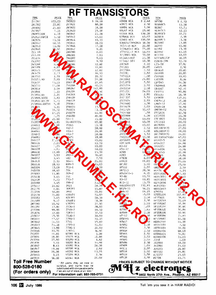
L 4
E RF TRANSISTORS
PR;Cx 'n'PL - - PRICE TYPE PRICE PRICE - 2N1561 $25.00 2N5920 $ 70.00 40608 RCA $ 2 . 4 8 8FYgO $ 1.50 2N1562 25.00 2N5921 80.00 40673 RCA 2 .50 BLW60C5 15.00 2N1692 25.00 2N5922 10 .00 40894 RCA 1 .00 BLX67 12 .25 2N2857 1 .55 2N5923 25.00 60247 RCA 25.00 BLX67C3 12.25 2N2857JAN 4 .10 2N5941 23.00 61206 RCA 100.00 BLX93C3 22.21 2N2857JANTX 4.50 2N5942 40.00 62800A RCA 60.00 BLY87A 7. 50 2N2876 13.50 2N5944 10.35 62803KCA 100.00 BLY88C3 13 .08 2N2947 18.35 2N5945 10.00 4304 1 4 / 3 9 9 0 R C ~ 50.00 BLY89C 13.00 2N29411 13.00 2N5946 12.00 3457159 RCA 20.00 BLY90 45.00 2N2949 15.50 2N5947 9 . 2 0 3729685-2 RCA 75.00 HLY92 13.30 2N3118 5 .00 2N6080 6.00 7729701-2 RCA 50.00 BLY94C 45.00 2N3119 4.00 2N6081 7.00 3753883 KCA 50.00 BLY351 10.00 2N3134 1. 15 2N6082 9.00 615467-902 25.00 B L Y S ~ ~ C I C F 30.00 2N3281 4.90 2N6083 9 .50 615467-903 40 .00 C2M70-28R 92.70 2N 3288 4.40 2N6084 12.00 2SC568 2 .50 C25-28 57.00 2N3309 4 .85 2N6094 11.00 2SC703 36.00 C4005 2.50 2N3375 17.10 2N6095 12.00 2SC756A 7.50 CD1659 20.00 2N3478 2 .13 2N6096 16.10 2SC781 2.80 C111899 20.00 2N3551 1.55 LN6097 20. 70 2SC1018 1 .00 C111920 10.00 2N3553JAN 2 .90 2N6105 21 .00 2SC1042 24.00 C02188 18.00 2N3632 15.50 2N6136 21.85 2SC1070 2.50 CD2545 24.00 2N3733 11.00 2N6166 40.24 2SC1216 2.50 CD2664A 16.00 2N3818 5 .00 2N6267 142.00 2SC1239 2.50 CD1167 92.70 2N3866 1.30 LN6304 1.50 2SC1251 24.00 CD7353 95.00 2N 3866.JAN 2.20 2N6368 30.00 2SC1306 2.90 CD3435 26.30 2N3866.JANTX 3.80 2N6439 55.31 2SC1307 5 .50 CD3900 152.95 2N386bJANTXV 4.70 2N6459 18.00 2SC1424 2.80 CM25-12 20.00 2N3866AJANTXV 5.30 ?N6567 10.06 2SC1600 5 .00 CM40-12 27.90 2N3924 3.35 2N6603 13.50 2SC1678 2.00 CM40-28 56.90 2N3926 16.10 2N6604 13.50 2SC1729 32.40 CME50-12 j n . 00 2N3927 17.25 2N6679 44.00 2SC1760 1.50 CTC2001 42.00 LN3948 1 .75 2N6680 80 .00 2SC1909 4.00 CTC2005 55.00 2N39 50 25.00 021-1 15.00 2SC1945 10.00 CTC30G5 70.00 2N3959 3 .85 01-80703T4 65.00 2SC1946 40 .00 LTC3460 20.00 2N4012 11.00 35C05 15.00 2SC1947 10.00 DV2820S 25.00 2N4027 2.00 102-1 28.00 2SC1970 2 .50 DXI,I003t'70 22.00 2N404 I 14.00 103-1 28.00 2561974 4.00 DXL2001P70 19.00 2N4072 1 .80 103-2 28.00 2SC2 166 5 .50 DXL2002P70 14.00 2N4080 4.53 104P1 18.00 2SC2237 32.00 I)XL3501APIOOF 47.00 2N4127 21.00 163P1 10.00 2SC2695 47.00 EFJLOIS IZ.OL7 2N4416 2 .25 181-3 15.00 A2X1698 POR EFJ4017 24 .00 2N4427 1 .25 210-2 10.00 1\3-12 14.45 EFJ4021 24.00 2N4428 1.85 269-1 18.00 A50-12 24.00 EFJ4026 35.00 2N4430 11.80 281-1 15.00 A209 10.00 EN15745 20.00 2N4927 3.90 282-1 30.00 A283 6.00 FJ9540 16 .00 2N4957 3.45 482 7.50 A283B 6.00 FSX52WF 58.00 2N4959 2.30 564-1 25.00 A1610 19.00 C65739 25.00 2N5016 18.40 698-3 15.00 AFIOZ 2.50 G65386 15.00 2N5026 15.00 703-1 15.00 AFY 12 2.50 GM02901\ 2.50 2N5070 18.40 704 4.00 AH7115 20.00 HEP76 4 . 9 5 2N5090 13.80 709-2 11.00 ~ ~ 4 1 4 3 5 - 5 6.35 HEPS3002 11.40 2N5108 3.45 711 4.00 82-82 10.70 tlEPS300 1 30.00 2N5109 1 .70 733-2 15 .00 83-12 10.85 HEPS3005 10.00 2N5160 3.45 798-2 25.00 812-12 15.70 HEPS3006 19 .90 2N5177 21.62 3421 28.00 BAL0204125 152.95 HEPS300I 25.00 2N5179 1.04 3683Pl 15.00 BF25-35 56.25 HEPS3010 11.34 2N5216 56.00 3992 25.00 B40-12 19.25 HF8003 10.00 2N5470 75.00 4164Pl 15.00 R70-12 55.00 HFET2204 112.00 2N5583 3 .45 4243Pl 28.00 BF272A 2.50 HP35821 3R.00 2N5589 9.77 4340P3 18.00 BFQ85 2.50 HP35826B 32.00 2N5590 10.92 4387P1 27.50 BFRZ L 2.50 HP35826E 32.00 2N5591 13.80 7104-1 28.00 BFR90 1.00 HP35831E '30. 0(; 2N5596 99.00 7249-2 10.50 HFR9 1 1.65 HP 35832E 50.00 2N5636 12.00 7283-1 J7.50 KFR99 2.50 HP35833E 5 0 . 0 0 2N5637 15.50 7536-1 30.00 HF1'12 2.50 111'35859E 75.00 2N5641 12.42 7794-1 10. 50 BFW 16A 2 .50 HP 358661.' 44.00 2N5642 14.03 7795 15.00 IIFW 17 2.50 HXTR2 10 1 4 4 . 00 2N5643 25.50 7795-1 1 5 .00 BFW92 1.50 HXTR3101 1.00 2N5645 13.80 7796-1 24 .00 BFX44 2.50 HXTRSI01 31 .00 2N5646 20.70 7797-1 J6 .00 HFX48 2.50 HXTR6104 68.00 2N5651 11.05 40081 RCA 5.00 BFX65 2.50 HXTR6105 31.00 2N5691 18.00 40279 RCA 10.00 BFX84 2.50 HXTR6106 33.00 2N5764 27 .00 40280 RCA 4.62 BFX85 2.50 5 3 1 0 1 .00 2N5836 3 .45 40281 RCA 10.00 BFX86 2.50 .102000 10 .00 2N5842 8 .45 40282 RCA 20.00 BFX89 1.00 JU2001 25.00 2N5847 19.90 40290 RCA 2.80 BFY 11 2.50 504045 24.00 2N5849 20.00 40292 RCA 13.05 BFY 18 2.50 KD5522 25.00 2N59 13 3.25 40294 RCA 2 .50 RFY19 2.50 KJ5522 25.00 IN5916 36.00 40341 RCA 21.00 BFY39 2.50 MI106 13.75
Toll Free Numkr ,,At1 parts be ,,, PRICES SUBJECT TO CHANGE WITHOUT NOTICE
800-528-01 80 surplus, and par ts may be substltuted wlth Comparable parts 11 we are out of stock of an Itern "
(For Orden only) For information call: 602-265-0731
106 July 1985 Tell 'em you saw it in HAM RADIO!
WWW.RADiOSCAMATORUL.Hi2.RO
WWW.GiURUMELE.Hi2.RO
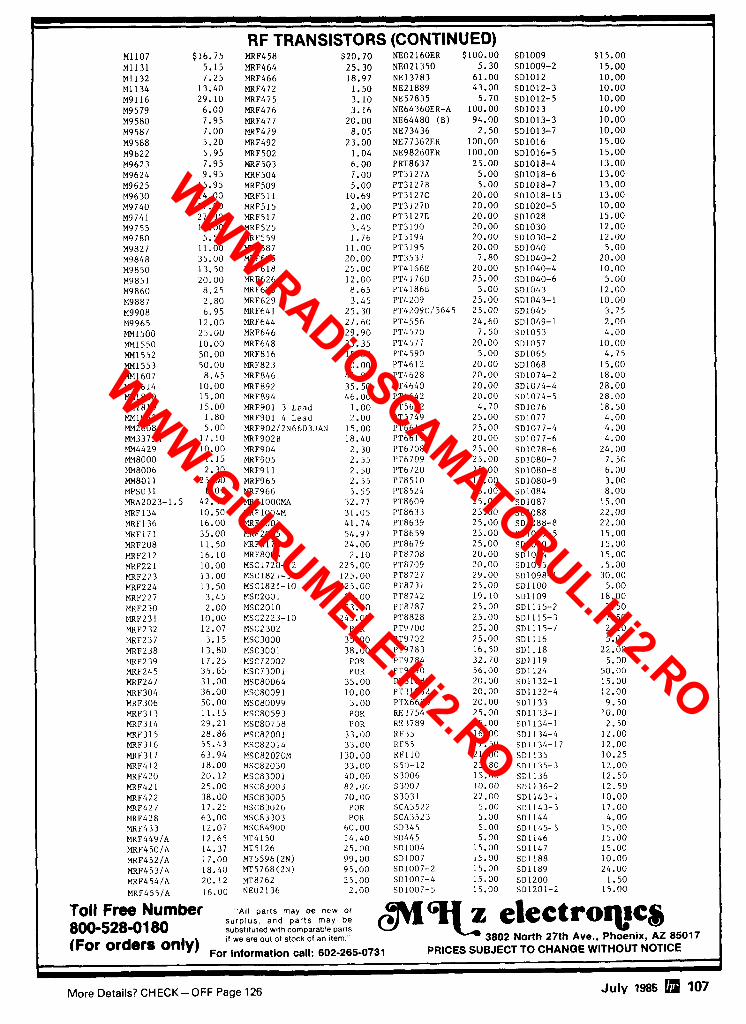
7
RF TRANSISTORS (CONTINUED) M1107 M1131 MI132 M1134 M9116 M9579 M9580 M9587 M9588 M9622 M9623 M9624 M9625 M9630 M9740 M9741 M9755 M9780 M9827 M9848 M9850 M9851 M9860 M9887 M9908 M9965 MM1500 MM1550 MM1552 MM1553 MM1607 MM1614 MM1810 mi810 MM1943 MM2608 MM3375A MM4429 MM8000 MM8006 ma01 1 MPSU31 MRA2023-1. MRF 134 MRF136 MRF17 1 MRF208 MRF212 MRF221 MRF223 MRF224 MRF227 MRF230 ~ ~ ~ 2 3 1 MRF232 MRF237 MRF238 IIRF239 MRF245 MRF247 MRF304 MRF306 MRF313 MRF314 MRF315 MRF316 MRF317 MRF412 MRF420 MRF42 1 MRF422 MRF427 MRF428 MRF433 MRF449/A MRF450fA MRF452/A MRF453/A M~F454lA M~F4551A
$16.75 5.15 7.25 13.40 29.10 6.00 7.95 7.00 5.20 5.95 7.95 9.95 15.95 14.00 27.90 27.90 16.00 5.50 11.00 35.00 13.50 20.00 8.25 2.80 6.95 12.00 25.00 10.00 50.00 50.00 8.45 10.00 15.00 15.00 1.80 5.00 17.10 10.00 1.15 2.30 25.00 1.01
5 42.50 LO. 50 16.00 35.00 11.50 16.10 10.00 13.00 13.50 3.45 2.00 10.00 12.07 3. 15 13.80 17.25 35.65 31.00 36.00 50.00 11.15 29.21 28.86 55.43 63.94 18.00 20.12 25.00 38.00 17.25 63.00 12.07 12.65 14.37 17.00 18.40 20.12 16.00
MRF458 MRF464 MRF466 MRF472 MRF475 MRF476 MRF477 MRF479 MRF492 MRF502 MRF503 MRF504 MRF509 MRF5 I I MRF515 MRF5 17 MRF525 MRF559 MRF587 MRF605 MRF6 18 MRF626 MRF628 MRF629 MRF641 MRF644 MRF646 MRF648 MRF8 16 MRF823 MRF846 MRF892 MRF894 MRF901 3 Lead MRF901 4 Lead MRF902/2N6603JAN MRF9028 MRF904 MRF905 MRF9 1 1 MRF965 MRF966 MRF lOOOMA MRFlOO4M MRF2001 MRF2005 MRF5176 MRF8004 MSC1720-12 MSC182 1-3 MSC1821-10 MSC2001 MSC2010 MSC2223-10 MSC2302 MSC3000 MSC3001
$20.70 25.30 18.97 1.50 3.10 3.16 20.00 8.05 23.00 1.04 6.00 7.00 5.00 10.69 2.00 2.00 3.45 1.76 11.00 20.00 25.00 12.00 8.65 3.45 25.30 27.60 29.90 33.35 15.00 20.00 44.85 35.50 46.00 1.00 2.00 15.00 18.40 2.30 2.55 2.50 2.55 3.55 32.77 31.05 41.74 54.97 24.00 2.10
225.00 125.00 225.00 30.00 93.00 245.00 POR 35.00 38.00 POR POR 35.00 10.00 3.00 POR P OR 33.00 33.00 130.00 33.00 40.00 82.00 70.00 POR POR 60.00 14.40 25.00 99.00 95.00 25.00 2.00
NE02160ER $100.00 NE021350 5.30 NE13783 61.00 NE21889 43.00 NE57835 5.70 NE64360ER-A 100.00 NE6448O (B) 94.00 NE73436 2.50 NE77362ER 100.00 NE9826OER 100.00 PRT8637 25.00 PT3127A 5.00 PT3127B 5.00 PT3127C 20.00 PT31270 20.00 PT3127E 20.00 PT3190 20.00 PT3194 20.00 PT3195 20.00 PT3537 7.80 PT4166E 20.00 PT4176D 25.00 PT4 1868 5.00 PT4209 25.00 PT420YC/5645 25.00 PT4556 24.60 PT4570 7.50 PT4577 20.00 PT4 590 5.00 PT4612 20.00 PT4628 20.00 PT4640 20.00 PT4642 20.00 PT5632 4.70 PT5749 25.00 PT6612 25.00 IJT6619 20.00 PT670R 25.00 IJT6709 25.00 l'T6720 25.00 PT8510 15.00 FIT8524 25.00 l'T8609 25.00 ~ ~ 8 6 3 3 25.00 PT8639 25.00 PT8659 25.00 PT8679 25.00 PT8708 20.00 ~1'8709 20.00 PT8727 29.00 P1'8 7 3 1 25.00 P7'8742 19.10 PT8787 25.00 PT8828 25.00 PT9 700 25.00 PT9702 25.00 PT9783 16.50 PTY 784 32.70 PT9790 56.00 P'r310a1 20.00 P'C 11962 20.00 PTX6680 20.00 RE 3754 25.00 RE 1789 25.00 RF35 16.00 RF85 17.50 RFI10 21.00 550-12 23.80 S 3006 15.00 5 3007 10.00 S3031 22.00 SCA3522 5.00 SCA.1523 5.00 SD345 5.00 50445 5.00 SD 1004 15.00 SD1007 15.00 SD1007-2 15.00 SD1007-4 15.00 SD1007-5 15.00
SD1009 $ SD1009-2 SD1012 SD1012-3 SD1012-5 SD1013 SD1013-3 SD1013-7 SDlOl6 SD1016-5 SD1018-4 SD1018-6 SD1018-7 SD1018-15 SD1020-5 SD1028 SD1030 SD1030-2 SD1040 SD1040-2 SD1040-4 SD1040-6 SD1043 SD1043-1 SD1045 501049-1 SD1053 SD1057 SD1065 SD1068 SD1074-2 SD1074-4 SD1074-5 SD1076 SD1077 SD1077-4 SD1077-6 SD1078-6 SD1080-7 SD 1080-8 SD1080-9 SD1084 SD1087 SO1088 SDl088-8 SD1089-5 SD1090 SD1094 SD1095 SD1098-I SDllOO SD1109 SD1115-2 SD1115-3 SD1115-7 SD1116 SD1118 SD1119 SD1124 SD1132-1 SD 11 32-4 SD1133 SD1133-1 SD1134-1 SD1134-4 SD1134-17 SD1135 SD1135-3 SD1136 SL)1136-2 SD1143-I SD1143-3 SDL144 SD1145-5 SD1146 SD1147 sD1188 SD1189 SD1200 SD1201-2
surplu;, and Darts may be f
I ( F ~ ~ orders only) I' we are out ohtock obn 1'"" ' - 3802 North 27th Ave., Phoenix, AZ 85017
For information call: 602-265-0731 PRICES SUBJECT TO CHANGE WITHOUT NOTICE I t I
More Details? CHECK-OFF Page 126 July 1985 107
WWW.RADiOSCAMATORUL.Hi2.RO
WWW.GiURUMELE.Hi2.RO
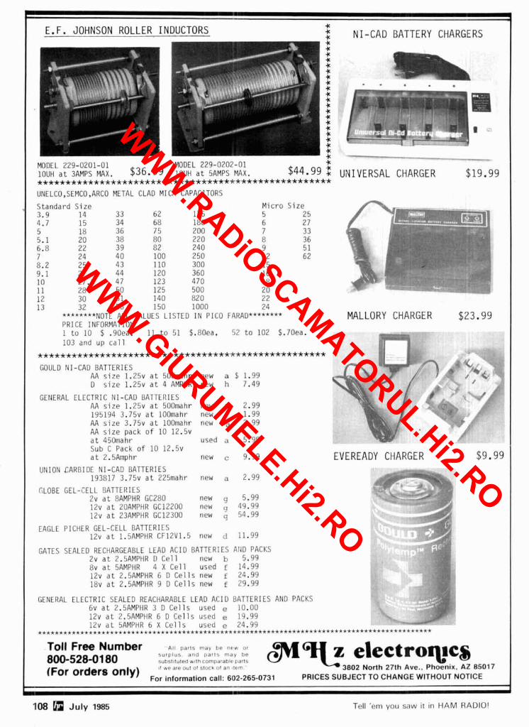
108 n July 1985 Tell 'em you saw ~t ~n HAM RADIO1
.
L 4 E.F. JOHNSON ROLLER INDUCTORS C
f NI-CAD BATTERY CHARGERS * * * * * C * C * *
- T"II" * C * * * .. B t * --. r L r . C C *
MODEL 129-U201-01 MODEL 2?9-010~ -01 * ~ O U H a t 3AMPS MAX. $36.99 18UH a t 5AMPS MAX. $44.99 f UNIVERSAL CHARGER .................................................... $19.99
UNELCO,SEMCO,ARCO METAL CLAD MICA CAPACITORS
Standard S ize M ic ro S i ze - - _ __ 3.9 14 33 62 175 5 25 4.7 15 34 68 180 6 2 7 c- -
a 5 18 36 75 200 7 33 5.1 20 38 80 220 8 36 6.8 22 39 82 240 9 51 7 24 40 100 250 12 62 8.2 25 43 110 300 15 9.1 27 44 120 360 16 \ 10 27.5 47 123 470 18 11 28 50 125 500 20
9 12 30 5 1 140 82 0 2 2 13 32 56 150 1000 24
********NOTE ALL VALUES LISTED IN PIC0 FARAD*******+ MALLORY CHARGER $23.99 PRICE INFORMATION 1 t o 10 $ .90ea. 11 t o 51 $.80ea. 52 t o 102 $.70ea. 103 and up c a l l "1---
................................................... ? GOULD NI-CAD BATTERIES
- ;P AA s i z e 1.2% a t 500mahr new a 5 1.99 4-1 - / C D s i z e 1 . 2 5 ~ a t 4 AMPHR new h 7.49
GENERAL ELECTRIC NI-CAD BATTERIES AA s i z e 1 . 2 5 ~ a t 500mahr new a 2.99 195194 3 . 7 5 ~ a t lOOmahr new 1.99
6, " l-
i AA s i z e 3 . 7 5 ~ a t lOOmahr new a 2.99 / AA s i z e pack o f 10 1 2 . 5 ~ I ,
a t 450mahr used a 5.99 Sub C Pack o f 10 1 2 . 5 ~ a t 2.5Amphr new c 9.99 EVEREADY CHARGER $9.99
UNION CARBIDE NI-CAD BATTERIES 193817 3 . 7 5 ~ a t 225mahr new a 2.99
F CLOBE GEL-CELL BATTERIES
- -
2v a t 8AMPHR GC280 new 5.99 /a
12v a t ZOAMPHR GC12200 new 49.99 12v a t 23AMPHR GC12300 new q 54.99
EAGLE PICHER GEL-CELL BATTERIES 12v a t 1.5AMPHR CF12V1.5 new d 11.99
GATES SEALED RECHARGEABLE LEAD ACID BATTERIES A140 PACKS 2v a t 2.5AMPHR 0 C e l l new b 5.99 8v a t 5AMPHR 4 X C e l l used E 14.99 12v a t 2.5AMPHR 6 D C e l l s new f 24.99 18v a t 2.5AMPHR 9 D C e l l s new f 29.99
GENERAL ELECTRIC SEALED REACHARABLE LEAD ACID BATTERIES AN0 PACKS 6v a t 2.5AMPHR 3 D C e l l s used e 10.00 12v a t 2.5AMPHR 6 D C e l l s used e 19.99 12v a t 5AMPHR 6 X C e l l s used e 24.99
.............................................................................................
Toll Free Number A I ~ "arts may tse n r w or
800-528-01 80 S U I ~ ~ U S and part ' , may be sub$tltuted w!lh comDatablc tarts 11 we are out ot slork <,I an t t rn
$l- electroqps 3802 North 27th Ave , Phoenlx. AZ 85017
Orders '"Iy) For lnformation call: 602-265-0731 PRICES SUBJECT TO CHANGE WITHOUT NOTICE .
WWW.RADiOSCAMATORUL.Hi2.RO
WWW.GiURUMELE.Hi2.RO
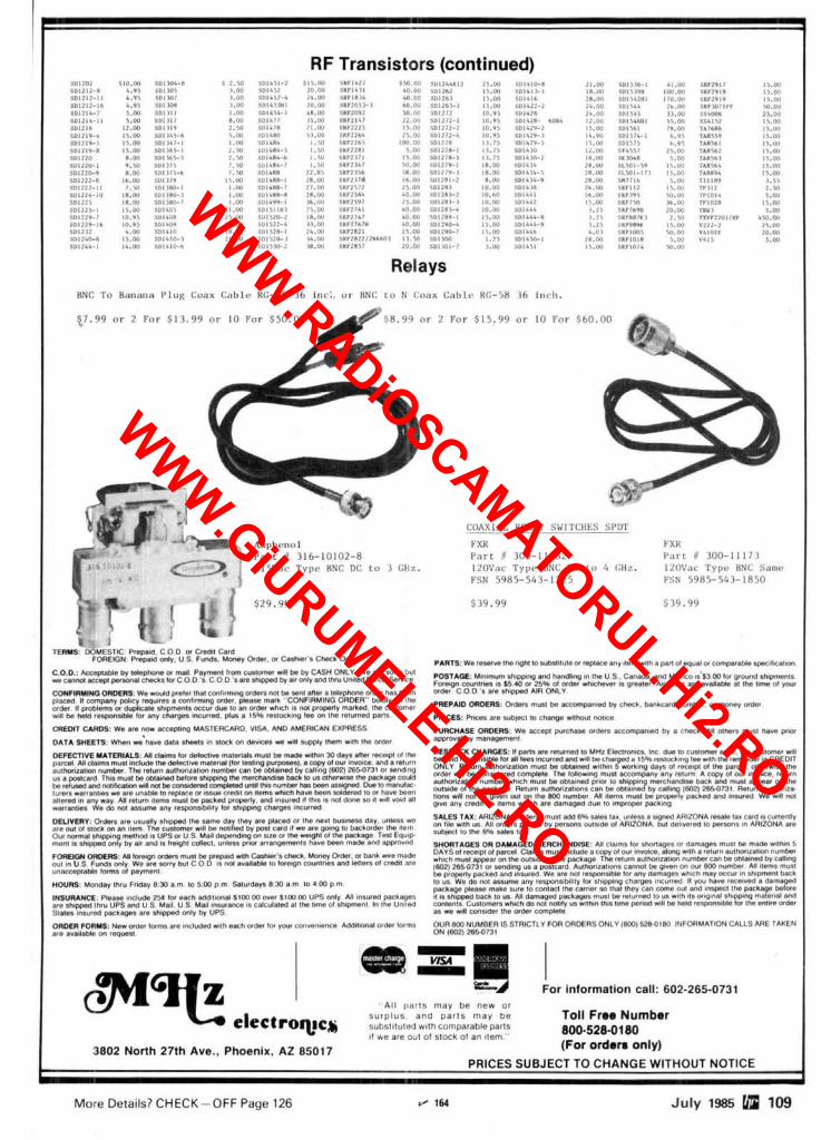
WWW.RADiOSCAMATORUL.Hi2.RO
WWW.GiURUMELE.Hi2.RO
NAMPA SATELLITE SYSTEMS, mc. r
TWO LOCATIONS
3 12 12th Ave. So. 6103 W. 34th St. Nampa, Idaho 8365 1 Houston, Texas 77092 (208) 466-6727 (71 3) 957-5 140
1 -800-654-0795 For Service ONLY (208) 467-3204
--
NEW LOW, LOW PRICES! NATIONAL FINANCING AVAILABLE THROUGH NAMPA SATELLITE
MD9 - 9 Dish FOR MORE INFORMATION CALL 208-466-6727 ALL SYSTEMS FREIGHT PRE-PAID FROM NAMPA, IDAHO OR HOUSTON, TEXAS
EACH OF THE FOLLOWING SYSTEMS CONSIST OF: Recerver. 8 S 0 LNA. LNB, or LNC. Wilson MD-9 Dish, 100 Ft. Cable Pack, LNA Cover. Polarmatrc I Feedhorn. NSS Dish Drive, A l l Connectors and instructions
Wilson YM 1 000 System $1648 loe/. Down Payment-5164.80 36 payments of S54.001mo.
Wilson YM400 System $1442 10% Down Payment-S 144.20 36 payments of S46.001mo.
Little Wil LW5 $1099 10% Down Payment-$ 109.90 36 payments of S36.001mo.
Little Wil RV5 $1399 10% Down PaymenbS139.90 36 payments of S45.001mo.
Drake 2 4 0 A + APS24 $1995 10% Down Payment-5199.50 36 payments of S65.001mo.
Luxor Mark 2 System BLOCK DC $25 12 10% Down Payment-S25 1.20 36 payments of S75.001mo.
Dexcel'l300-0 1 System $1988 10% Down Payment-S 198.80 36 payments of S63.001mo.
Dexcel 1 200-01 System $1633 10% Down Payment-S163.30 36 paymentc of S54.001mo.
I Uniden UST 3 0 0 0 System $1 772 10% Down Payment-$1 77.20 36 payments of S57.001mo.
Uniden UST 1 000 System $1 5 7 1 10% Down Payment-S157.10 36 payments of S52.001mo.
Sigma Mark 2 A $1438 10% Down Payment-S143.80 36 payments of S46.001mo.
Sigma Mark 3 sloc~ oc $1662 10% Down Payment-$166.20 36 payments of S54.001mo.
Sigma Mark 5 BLOCK DC $2049 10% Down Payment-$204.90 36 payments of S66.001mo.
1 10% Down Payment-$228.20 36 paymen& of S74.001mo.
I M I A Com TI B L ~ K oc $21 82 10% Down Payment-$21 8.20 36 payments of S71.001mo.
I STS MBS-SR-AA I l o r Down Payment-$234.90 36 paymen; of S76.00Imo.
....................................... PM 9' Dish .................................... S 60 MTI 2 1 0 0 $ 2 2 5 Starbeam 1 0 ' Mesh Dish ................ S 1 8 0 MTI 4 1 0 0 ....................................... S 345 ..................... Prodelin 1 0 ' Dish ........................... $ 4 0 0 Houston Tracker 111 + $ 2 1 5 ..................... Continental Mesh Dish 1 0 I............. $ 4 0 0 Houston Tracker IV + $375
110 July 1985
WWW.RADiOSCAMATORUL.Hi2.RO
WWW.GiURUMELE.Hi2.RO
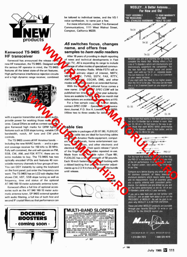
be tailored to individual tastes, and the VS-1 voice synthesizer, to name just a few.
For more information, contact Trio-Kenwood Communications, 11 11 West Walnut Street, Compton, California 90220.
products A5 switches focus, changes name, and offers free
Kenwood TS-940s samples to ham radio readers HF transceiver
Kenwood has announced the release of its new HF transceiver, the TS-940s. Designed with the serious HF operator in mind, the TS-940s features all the latest state-of-the-art features. High performance interference rejection circuits and a high dynamic range receiver, combined
with a superior transmitter and excellent audio, provide power for working those really tough ones. Casual DXers as well as contest operators give Kenwood high marks for QRM fighting features such as SSB slope tuning, variable CW bandwidth, notch. AF tune and CW pitch controls.
The TS-940s covers all HF Amateur bands - including the new WARC bands - and is a gen- eral coverage receiver for 150 kHz to 30 MHz. Fully self-contained, the unit will operate on FM, SSB, CW, AM, and FSK RTTY: there are no extra modules to buy. The TS-940s has two optically encoded VFOs and features 40 non- volatile memory channels in four groups of ten. You can QSY instantly by using the keyboard on the front panel; just enter the frequency you want. The TS-940s has an LCD sub-diplay that shows CW, VBT, SSB slope tuning as well as frequency, time and status of the optional AT-940 160-10 meter automatic antenna tuner.
Kenwood offers a full line of optional acces- sories such as the AT-940 160-10 meter auto- matic antenna tuner, SP-940s external speaker with audio filtering. a full line of both first and second IF crystal filters so that performance can
After 18 years of providing in-depth reporting of n e w and technical developments in Fast Scan N, A5 is expanding its range to include coverage of other modes of specialized commun- ications in Amateur Radio. While FSTV will re- main the primary object of interest, N B N , M S N , SAW, NRO, SSN, FAX, RTTY, AMTOR, Packet. OSCAR. EME, and other modes will be addressed in an extended format.
With the change in editorial focus comes a new name: SPEC-COM." SPEC-COM will be published ten times a year. One-year subscrip lions are available for $20: special six-month trial subscriptions are a~ilablh3 to new readers at $10.
For a free sample copy and further details, contact SPEC-COM - Specialized Communica- tions Journal. P.O. Box H, Lowden, Iowa 92%. (Allow two to three weeks for delivew.)
cable ties Availabk in packages of 20 ($7.001. FLEXLOC
reusable cable ties are ideal for bunching cables anached to Amateur Radio equipment, comput- ers and peripherals, home entertainment sys- tems, AIV devices, and other electronic and electrical hardware. Their quick-release ("pinch of the fingers") lock enables repeated re-use. Made from tough, flexible nylon (Type 66). FLEXLOC has a tensile strength of 50 pounds. Each 10-inch fastening strap is self-locking with a ribbed backing that permits diameter adjust- ments up to 2-314 inches and secures the bundle until release.
1 [ T I - coming soon -
/ 166 July 1985 Fbl 111
WWW.RADiOSCAMATORUL.Hi2.RO
WWW.GiURUMELE.Hi2.RO
112 July 1985 H 191
DRAKE R-4lT-4X OWNERS AVOID OBSOLESCENCE
PLUG-IN SOLID STATE TUBES! Get stnle-of-the-art performance.
Most types available
INSTALL KlTS TO UPGRADE PERFORMANCE!
BASIC Improvement - Audio Bandpass Filter Audio IC Amplifier
TUBES $23 PPD KlTS $25 PPD
OVERSEAS AIR 37
SARTORI ASSOCIATES, W5DA BOX 832085
RICHARDSON. TX 75083 214-494-3093 , leg
Covers 100 MHz to 199.999 MHz in 1 kHz steps with thumbwheel dial Accuracy +/- 1 part per 10 million at all frequencies Internal FM adjustable from 0 to 100 kHz at a 1 kHz rate External FM input accepts tones or voice Spurs and noise at least 60 dB below carrier Out- put adjuslable from 5-500 mV at 50 Ohms
Operates on 12 Vdc @ '12 Amp Available for immediate delivery $429.95 delivered Add-on accessories available to extend freq range, add infinite resolu- tion, AM, and a precision 120 dB attenuator
Call or write for details Phone in your order for fast COD shipment. , ,70
VANGUARDLABS 19623 Jamaica Awe.. Hollls, NV 11423 Phone: (718) 468-2720 Mon. l h ~ Thu.
7 MILLION TUBES
FREE CATALOG Includes all Current, Obsolete. An. tique, Hard.To-Find Receiving. Broadcast. Industrial, RadioITV types. LOWEST PRICES. Major Brands, In Stock.
UNITY Electronics Dept. H FO. Box 213 , ,,,
Elizabeth, NJ 07206
products
For further information, contact Visual Depar- tures. Ltd., 1641 Third Avenue, Suite202, New York. New York 10128.
Circle 13(11 on Reader Service Card.
full half-wave UHF antenna for portables
Larsen Antenna's new KD 14-450-HW an- tenna. a full half-wave UHF antenna for pona- bles, interfaces with any BNC output portable. Said to offer performance equivalent to a full quarter wave on a perfect ground plane, the KD 14-450-HW is appropriate for any UHF applica- tion requiring maximum performance. Because of its inherent resonance, it may be easily rernoted via a coaxial line from the portable. The overall whip length is 12 inches; the impedance transformer at the base of the whip is 3.25 inches long.
For more information, contact Larsen Elec- tronics, P.O. Box 1799, Vancouver, Washington 98668.
Circle IJm on Reader Service Card.
scope memory Sibex. Inc. has introduced a new device called
the Scope Memory. This instrument attaches to your oscilloscope and converts it into a high per- formance digital storage scope. The Scope Memory can be an economical answer for the service technician, hobbyist, or manufacturing firm that needs a storage scope but cannot ju!Sify its expense.
The Scope Memory stores low frequency sig- nals, transients, and one-shot pulses in a single sweep. It stores both analog and digital signals and features laselectable sampling times with a 1.4 MHz maximum rate, an Erange input salec- tor with over-range indication and a wide vari- ety of triggering modes.
The pre- and post-trigger modes allow view- ing the waveform that occurs both before and after an event. This feature makes the device a
WWW.RADiOSCAMATORUL.Hi2.RO
WWW.GiURUMELE.Hi2.RO
useful tool for trouble shooting. The price is $515.00 plus shipping.
For additional information, contact Sibex. Inc.. 2340 State Road 580. Suite 241, Ckarwater, Florida 33515.
C i r c l q w on Reader Service Card.
ATV transceivers P.C. Electronics has introduced a new com-
pact 1-wan 70-cm A N transceiver aimed at in- troducing hams to the video mode.
The T C M l A N tranxeiver accepts standard Wa Stork * E l . ARRL. Y lha . Amco. h n t m Sprl.ll~l*. AS1.llc. A r s v B I K. B I W B n h B m h n . 81.d. BullnM). CDE. CES.CU1sn..
composite video input from any source. Video and audio input RCA jacks on the rear panel are provided for connection to black and white or
- ~ ~-~
color cameras, computers. VCRs, and NROs. I I w.....,., ,:.? a .- ,." .......... T ~ . . , , ~ , - ...... pU I ;;:;:"; .:.:',,.,::;:;e C-~~. .C~. I H.~IO. vwm V ~ ~ I ~ . . CYIII,. TI, I. W . C O ~ DYPIR.~IS. ., ... . 1 Roa.af.ss Pl,mlo. 0- F a n m l n l r ? c r m r . Scmnnm C n v l a I s . R d l o I
II :.,,,,,,,., " ,"r,,,.3 ," .- ,,> ." ,.,.. ....,,. ", . .
A front panel switch selects video and audio AurHon lz ro DISTS MCKAr DYMEI FOR WE WOW S r O C I COMMERCI1LCOMMYWIC&lIONSSYSTEYS
i n ~ u t from these iacks or from the 10-pin con- SnoAT"AvE RECE'vERS I R I K E I "SmM 51 Sfatson . LIE.IERINCIUIUICSINVIIID PYONE I H ~ O U ~ U U C ) ~ I I L R ~ UEIMBUPSED
Audio input is selected from the color camera microphone or line level from the rear panel jack. In addition there is a microphone input that accepts any low impedance dynamic micro- phone. Next to the microphone input is a mini jack for PTL. A "push-to-look" feature resembles push-to-talk on audio-only transceivers, can be used for microphone or remote transmit receive switching or the front panel toggle switch may be used.
Full-color live action video and wund are transmitted with over 1 watt PEP on one or two selected crystal controlled frequencies in the range of 425 to 440 MHz in the 70-cm Amateur band. The line-of-sight snow-free radius with TC70-1s and KLM 440-27 antennas at each end is 15 miles. The unit was made small and com- pact (7 x 7 x 2.5 inches) for portable use. but either a 20-watt or 50-wan video compensated RF linear amplifier for greater distance, base or mobile, is available.
fbr direct connection ,o of the popular color cameras made for portable VCRs.
DX'ERS MAGAZINE For over 17 years. Gus's DX'ERS MAGAZINE has brought thousands of DX'ERS worldwide, timely. pertinent information on when and where lo find those elusive DX stations. Gus's personable. chatty writing style and his years of DX operating experience makes the DX'ERS MAGAZINE a unique publication. One year $14.00 USA. Canada & Mexico.
**v: BMT . P V I ~ ~ . s i s t m l i a -'=739 COI~UC~A. 1 ~ 0 1 0 a . 1 ~ 1 ~ I .. nur...n .r.na.... ' N D " """B"* s'm"m" - Amateur Radio Counsr Olven On Our Pmmlsas. Call
Bur Broadwny 16 to Sprlns St P.,l-.m I 1 l l " A" S8.llrn L 'lln I.mrl0rd.r. Shlp0.d Imm.dl.l.lv. T ILEX
~ - ~ --
July 1985 113
WWW.RADiOSCAMATORUL.Hi2.RO
WWW.GiURUMELE.Hi2.RO

JUST SLIGHTLY AHEAD! WlTH THE QUALITY YOU HAVE ALWAYS LOOKED FOR! 4 MEMORYS - 3 WAY AUTO SCAN. 40.15 AND6 METERS AREYOUR BASE A GREAT ORP RIG WITH THE BIG RIG
DUAL VFO. IF SHIFT. CW-W. 400 Hz STATION OR MOBILE WITH AClDC SIGNAL. 2 WATTS OR 10 WATTS OUT.
CW -N 200 Hz ALL 9 BANDS PLUS BUILT IN POWER SUPPLY CW-N 200 BUILT IN CW SIDE TONE, DIGITAL MARS. BUILT IN AClDC POWER SSB Hz OR USB. 2.S0239 ANTENNA CON- DISPLAY. HAND MIC. TOP MOUNTED
CW OR RTTY. I F TUNE 3-STEP NECTORS. HAND MIC. BUILT IN TVI SPEAKER. MOBILE BRACKET. RIT OR TUNING SPEED. 200 WATT PEP. FILTER LITTLE TO NO TV INTER- FINE TUNE TXBRX r4KHz. 21 TO MICROPHONE IMPEDANCE 600-50K FERENCE. 20 WATTS PEP. MARS ON 21 450 MHz SIGNAL TO NOISE MORE OHM HAND MIC INCLUDED 40 AND 6 METERS THAN lOdB DOWN
SPECIAL SPECIAL SPECIAL 90 DAY WARRANTY ON ALL TRANSCEIVERS - DIRECT FROM NCG OR YOUR DEALER
WE HAVE 1 2 GHz BASElREPEATER 8 MOBILE ANTENNAS NOTE: PRICES LND SPECIFICATIONS SUeJECl TO
1275 N. Grove Street. Anaheim. CA 92800 I7141 630-4541 J 173 CHANGE WITHOUT NOTICE OR OBLIGATION
I 114 WAVELENGTH I Modal No. Fraq. MHZ Dascrlpllon MN 196-200 144-148 5/16-32 stud wlsprlnp t5.95 196-204 . " BNC connactor w/sprinp 7.95 196214 " BNC connsclw 6.95 196-224 144-UP Bnc conn adl. lnpk 7.95 196-814 220-225 BNC connactor 6.95
518 WAVELENGTH
191-210 " 5/16-32 lor old TEMPO 22.95 191-214 " BNC connactor 19.95 191-219 " PL-259 wlM-359 8dpl. 22.95 191-810 220-225 5/16-32 lor old TEMPO 22.95 191-814 " BNC connmctor 19.95 191-940 440-450 5/16-32 lor HT-220 22.95 191-941 " 1/4-32 Stud 22.95 191-944 " BNC connaclw 19.95
Largest Selection of Telescopic Ante* nas. Write for Info. Prices are postpaid via UPS to 48 States. For air delivery via UPS Blue add $2.25. Florida add 5% sales tax. Payment by M.O. or Cashiers Check only. r / 174
114 July 1965
WWW.RADiOSCAMATORUL.Hi2.RO
WWW.GiURUMELE.Hi2.RO
With the TC70-1, the only other items necessary to get on ATV are a good 70-cm antenna, low loss coax. a TV set, and any device with a standard 1 volt P-P composite video out- put commonly found on black and white CCTV cameras, home video color cameras and VCRs, computers, and RTTYlvideo converters. A Technician class or higher Amateur radio license is required for purchase of this equipment from P.C. Electronics and subsequent operation.
Priced under $300, the TC70-1 makes getting on this exciting visual mode affordable. For fur- ther information, contact P.C. Electronics, 2522 Paxson Lane, Arcadia. California 91006.
Circle m5 on Reader Service Cerd.
antenna rotator The AR-2OLlXL antenna rotator operates from
115 VAC and provides 220 poundslinch torque to turn an antenna array or surveillance camera. Full 360-degree rotation is achieved in 60 seconds. Motor voltages are held below 18 VAC for safety and only three conductors are required between the control unit and rotator. The con- trol unit incorporates a demand heading control and a present heading indicator presented con- centrically on a compass rose. Designed for medium-duty applications, the rotator will sup- port a vertical load of up to 100 pounds with a wind loading of 5 square feet.
For further information, contact CMC Com- munications. Inc., 5479 Jetport Industrial Boul- evard. Tampa. Florida 33614.
Circle on Reader Service Card.
new receivers Yaesu Electronics has announced two addi-
tions to its line of high-performance receiver products.
, Interferen
Stuck Mil
Cable lV
Security I
ee Locatla
:rophones
Leaks
- -
r VHF and
b
DIREmON HNDING? ---
* UHF Coverage
* $I
* .II
* Monitoring C
New Technology (patent pendlng) converts any VHF or UHF FM recelver lnto an advanced Doppler sh~ft radto dlrpctlon flnder Stmply plug lnto receiver's antenna and external speaker lacks Uses four omn~direct~onal antennas Lov sensit~vlty for weak scgnal detection Call or wrlte lor full deta~ls and
Igh
@ DOPPLER SYSTEMS, INC. 5540 E. C b r t e r oak. (mz, 98-1 151 Scottsdale, AZ 85254
r Compute:
r Speech S
r 12 VDC 0
r Interface
;yntheslzel
peratlon
v noise, h~ prices.
- - . - - -
Now there's a hardware maga- zine that's all about computers for people who like to build their own. Compriter Smyth's pre- miere issue is now published. providing all the pleasure, ccon- omy and satisfaction of build-it- yourself projects that Hams know so well.
Our authors take you inside the chips, talk about what they d o ant1 Iiow they're controlled. and explain command options you m;ly never h:lve heard of before. (:om/)uter S?nyth 3 first quarter- ly issue hegins a series on n com- plete ZHO hased computer on three .I x hl/> " hoards. which lets you interface 2 % . 5 % and 8" floppy disks in all densities and track configurations. John Atlams' series nrill include a switching power supply. a PROM burner and software options for this rack-mount system. The first issue also f r~ tu res an XI)' plotter \ou can huild, an in-
----------------------------- -
expensive motorized wire-wrap tool and an R(iR color to coni- posite adapter.
Iluring its premiere year. Corn- pliterS?j~)~tb will survey the more than two dozen computer kits nonr available in the I'S. Kit builders will report on many of them. A major series on building a 32-bit OH000 micro hegins in issire two.
Coni/)rit~r Smyth is published by Autlio Amateur I'uhlic:ttions. publishers of Audio A??lfIt<'llr and S/)c~crkc~r Rr~ilrl~r mng:lzines. All three are reader-centered, hard- \\.are-intensive publications whose editors helieve that a rnag:lzine's primary job is sitisfy- ing the reader not consumer ninr- kcting. Our magazines :ire run hy tech enthusiasts not XIRAs look- ing for profits.
We gu:lr:~ntee tliat i f you :ire unhappy with Cb?n/)rtter .St?i)-th for any reason. your nioney will he refunded upon request .
,-----------------------------
a hfxkr that ruo !c.#r* .I! S 5 -
'Town Slxlr Zip
%l(:l\'lSA (:ard -
Expirr Si~naturr
Computer Smyth Magazine / 116
PO Box 176, Peterborough, NH 03458
WWW.RADiOSCAMATORUL.Hi2.RO
WWW.GiURUMELE.Hi2.RO
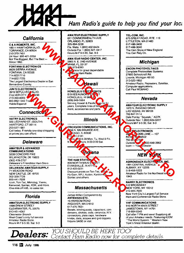
Ham Radio's guide to help you find your loci i California
C & A ROBERTS, INC. 1851 1 HAWTHORN BLVD. TORRANCE, CA 90504 21 3-370-7451 24 Hour: 800-421-2258 Not The Biggest, But The Best - Since 1962.
FONTANA ELECTRONICS 8628 SIERRA AVENUE FONTANA, CA 92335 71 4-822-771 0 71 4-822-7725 The Largest Electronics Dealer in San Bernardino County.
JUN'S ELECTRONICS 3919 SEPULVEDA BLVD. CULVER CITY, CA 90230 21 3-390-8003 800-882-1 343 Trades Habla Espanol
Connecticut HATRY ELECTRONICS 500 LEDYARD ST. (SOUTH) HARTFORD, CT 061 14 203-527-1 881 Call today. Friendly one-stop shopping at prices you can afford.
Delaware AMATEUR & ADVANCED COMMUNICATIONS 3208 CONCORD PIKE WILMINGTON, DE 19803 (302) 478-2757 Delaware's Friendliest Ham Store.
DELAWARE AMATEUR SUPPLY 71 MEADOW ROAD NEW CASTLE, DE 19720 302-328-7728 800-441 -7008 Icom, Ten-Tec, Microlog, Yaesu, Kenwood, Santec, KDK, and more One mile off 1-95. no sales tax. -- --- -
Florida AMATEUR ELECTRONIC SUPPLY 1898 DREW STREET CLEARWATER. FL 33575 81 3-461-4267 Clearwater Branch West Coast's only full servlce Amateur Rad~o Store Hours M-F 9-5'30, Sat 9-3
AMATEUR ELECTRONIC SUPPLY 621 COMMONWEALTH AVE. ORLANDO, FL 32803 305-894-3238 Fla. Wats: 1 (800) 432-9424 Outside Fla: 1 (800) 327-191 7 Hours M-F 9-5:30, Sat. 9-3
AMATEUR RADIO CENTER, INC. 2805 N. E. 2ND AVENUE MIAMI, FL 33137 305-573-8383 The place for great dependable names in Ham Radio.
Hawaii HONOLULU ELECTRONICS 819 KEEAUMOKU STREET HONOLULU, HI 96814 (808) 949-5564 Serving Hawaii & Pacific area for 51 years. Complete lines of Amateur equip- ment, accessories and parts.
Illinois ERICKSON COMMUNICATIONS, INC. 5456 N. MILWAUKEE AVE. CHICAGO, IL 60630 312-631-5181 Hours: 9:30-5:30 Mon, Tu, Wed & Fri; 9:30-890 Thurs; 9:OO-3:00 Sat.
Indiana THE HAM STATION 808 NORTH MAlN STREET EVANSVILLE, IN 47710 81 2-422-0231 Discount prices on,Ten-Tec, Cubic, Hy-Gain, MFJ, Azden. Kantronics. Santec and others.
Massachusetts James Millen Components by ANTENNAS ETC. 16 HANSOM ROAD ANDOVER, MA 01810 61 7-475-7831 Bezels, bindng posts, capacitors, con- densers, chokes, coils, ceramics, H.V. connectors, plate caps, hardware knobs, dials, scopes and grid dippers. Inquire SASE or visit.
TEL-COM, INC. 675 GREAT ROAD, RTE. 11 9 LITTLETON, MA 01460 61 7-486-3400 61 7-486-3040 The Ham Store of New England You Can Rely On.
Michigan ENCON PHOTOVOLTAICS Complete Photovoltaic Systems 27600 Schoolcraft Rd. Livonia, Michigan 48150 31 3-523-1 850 Amateur Radio, Repeaters, Satellite, Computer applications. Call Paul WDBAHO
Nevada AMATEUR ELECTRONIC SUPPLY 1072 N. RANCHO DRIVE LAS VEGAS, NV 89106 702-647-31 14 Dale Porray "Squeak," AD7K Outside Nev: 1 (800) 634-6227 Hours M-F 9-5:30, Sat. 9-3
JUN'S ELECTRONICS 460 E. PLUMB LANE - 107 RENO, NV 89502 702-827-5732 Outside Nev: 1 (800) 648-3962 lcom - Yaesu Dealer
NEW YORK ADIRONDACK ELECTRONICS, INC. 1991 CENTRAL AVENUE ALBANY, NY 12205 51 8-456-0203 Amateur Radio for the Northeast since 1943.
BARRY ELECTRONICS 512 BROADWAY NEW YORK. NY 10012 21 2-925-7000 New York City's Largest Full Service Ham and Commercial Radio Store.
VHF COMMUNICATIONS 91 5 NORTH MAlN STREET JAMESTOWN, NY 14701 71 6-664-6345 Call after 7 PM and save! Supplying all of your Amateur needs. Featuring ICOM "The World System." Western New York's finest Amateur dealer.
YOUSHOULD BE HERE TOO! Dealers: c ontact Ham Radio now for comdete details.
116 July 1985
WWW.RADiOSCAMATORUL.Hi2.RO
WWW.GiURUMELE.Hi2.RO
na teur Radio Dealer
Ohio AMATEUR ELECTRONIC SUPPLY 28940 EUCLID AVE. WICKLIFFE. OH (CLEVELAND AREA)
44092 216-585-7388 Ohio Wats: 1 (800) 362-0290 Outside Ohio: 1 (800) 321-3594 Hours M-F 9-5:30. Sat. 9-3
UNIVERSAL AMATEUR RADIO, INC. 1280 AlDA DRIVE REYNOLDSBURG (COLUMBUS). OH
43068 61 4-866-4267 Featuring Kenwood. Yaesu. Icom, and other fine gear. Factory author- ized sales and service. Shortwave specialists. Near 1-270 and airport.
Pennsylvania HAMTRONICS, DIV. OF TREVOSE ELECTRONICS 4033 BROWNSV~LLE-ROAD TREVOSE. PA 19047 21 5-357-1 400 Same Location for 30 Years.
LaRUE ELECTRONICS 11 12 GRANDVIEW STREET SCRANTON. PENNSYLVANIA 18509 71 7-343-21 24 Icom. Bird. Cushcraft. Beckman. Larsen. Hustler. Astron. Belden. Antenna Specialists. W2AUMI2VS. AEA, BBW. Amphenol. Saxton. J.W. MillerIDaiwa. Vibroplex.
THE VHF SHOP 16 S. MOUNTAIN BLVD.. RTE. 309 MOUNTAINTOP. PA 18707 717-474-9399 '
Lunar. Microwave Modules, ARCOS. Astron, KLM. Tama, Tonna-F9FT. UHF UnitslParabolic. Santec. Tokyo Hy-Power. Dentron. Mirage. Amphenol, Belden
Texas MADISON ELECTRONICS SUPPLY 1508 McKlNNEY HOUSTON. TX 77010 71 3-658-0268 Christmas?? Now??
Wisconsin AMATEUR ELECTRONIC SUPPLY 4828 W. FOND DU LAC AVE. MILWAUKEE. WI 53216
Wisc. Wats: 1 (800) 242-5195 Outside W~sc: 1 (800) 558-041 1 M-F 9-5:30 Sat 9-3
products
The FRG-8800 is a deluxe HF receiver cover- ing 150 kHz through 29.99 MHz. Direct fre- quency entry is provided via the front panel keyboard, which also controls scanning func- tions and storagelrecall of the memory channels. The innovative green LCD information display provides frequency, mode, and signal strength information. Selectable AGC, all-mode squelch, two 24-hour clocks, and recording capability (including onloff timer switching1 make for max- imum operating flexibility. The FRG-8800 is designed for easy interface to a personal com- puter for expanded operating control, and the FRV-8800 VHF Converter option expands cover- age to include 118-174 MHz, with front panel entry and display.
The FRG-9600 is a high-tech VHFIUHF muhi- mode receiver covering 60 through 905 MHz continuously, with direct keyboard frequency entry and 100 memory channels. Capable of AM, FM, and SSB reception ISSB through 460 MHzl. the FRG-9600 comes equipped with both wide and narrow bandwidlhs on AM and FM, plus a total of seven different tuning steps from 100 Hz through 100 kHz, depending on the mode and typical operating requirements for the service being received. A variety of scanning features are included, with extra performance offered via the audio scan stop function which will prevent stopping on inactive "carrier-only" channels. Computer interface capability, 24-hour clock/ timer, and multiplexed output are among the features provided that allow the sophisticated listener tremendous expansion possibilities. An optional NTSC video will also permit monitoring of N signals. The FRG-9600 is ready for opera- tion from either 12 volts OC or 117 volts AC.
For further information, contact Yaesu Electronics Corporation, P. 0. Box 49, Para- mount. California 90723.
Circle C307 on Reader Service Card.
1/ 177 July 1985 n 117
WWW.RADiOSCAMATORUL.Hi2.RO
WWW.GiURUMELE.Hi2.RO
MODEL APlO
Designedfor APARTMENTS MOTELS VAC4TK)NS
Quick Simple Installath. Operates on 2,6,10.15.20,30 and40 meters. All cdlssupplled. OnV22-112 lncheskg. Weighs ba than 2 I b . Supplied with 10 ft. RG 58 coax and counter poise. Whlp extends to 57 inches. Handles up to 300 waM. VSWR-1.1:l when tuned webrman,ds(Obamdhefk%wpodeh
P .. - .- - ALL am PROWCTS Gizi%w-rl'-'
BARKER & WILLIAM Qual~ty Communkattm Products S l m At your Distributors Wrlte or C 10 Canal Street. Bristol PA 15 (215) 780-5501
SATELLITE TELEVISION RECEIVER SEMlKlT
*
w~th dual conversion downconverter
FEATURES: Infrared remote control tuning AFC, SAW filter RF or vldeo output Stereo output Polorator controls LED channel & tuning indicators
Install six factory assembled circuit boards to complete.
SEMIKIT $300.00 Completed downconverter add 100.00 Completed receiver and downconverter add 150.00
JAMES WALTER SATELLITE RECEIVER 2697 N~ckel, San Pablo, CA 94806 # 178 Tel 415-724-0587
118 GI/I July 1985
2
Join AMSAT.. .Today Amateur Radio Satellite OSCAR 10
provides:
A New Worldwide DX Ham Band open 10 hours a day.
Rag Chew With Rare DX Stations in an uncrowded, gentlemanly fashion.
Popular Modes In Use: SSB, CW, RTTY, SSTV, Packet
Full Operating Privileges open to Technician Class
licensee or higher.
Other A M S A T Membership Benefits:
ORBlT Magazine Subscription: Dependable technical articles, satellite news, orbital elements, product reviews, DX news, and more.
Satellite Tracking Software Available for most popular PCs.
QSL Bureau, AMSAT Nets, Area Coordinator Support, Forum Talks
Construction of Future Satellites For Your Enjoyment!
AMSAT Membership is $24 a year, $26 out- side North America. VISA and MC accepted.
AMSAT P.O. Box 27
Washington, DC 20044
301 589-6062
# 179
WWW.RADiOSCAMATORUL.Hi2.RO
WWW.GiURUMELE.Hi2.RO
t o R S - 2 3 2 4 1 300 BAUD INTERFACE ( , I-? L. 107
I Sample BASIC p-oprar, d o a ~ r s r r u c c ~ o n s ~ ~ n r l ~ a e ~ I
I L E D Inomcator Model ,,AP.l "Decode-A-Padsm Wtred and Tested s89.95
NOW MXUKS ANSWERS m FWVEC EXAM W ~ ~ O N S
ARRL LICENSE MANUAL Here s the latest up-to-date llcenstng gutde lrom the ARRL. Plenty ol thwv and deta~led explanat~ons take most ol the patn out 01 studytng to upgrade your
1984 8Gth edition 216 pages Softbound 54.00
PI~ase $7 shlpptng 6 hnndllq
HAM RADIO'S BOOKSTORE Greenville. NH 03048
'REMOTE A PADo' MODEL RAP-1
2 FOUR DIGIT OTMF OFTOnFAS PI IISlfinlGlT
K l Y P 4 D CONTROL
N N E 7UL WORLD FROM
July 1985 n 119
WWW.RADiOSCAMATORUL.Hi2.RO
WWW.GiURUMELE.Hi2.RO
Great with New Solid State Transceivers
Trap-POSE IIe
Mobile Antenna
FEATURE: Trap Is completely weather
FEATURE: EXLIULIVP MOSLEY trapdesign assures Stablc operallon. Inductive and capacilive values cannot change'
FEATURE RBSC ~081-Material is char. coal acllvated polyethylene. Unaffecled by weather or road shock!
Here 1s a lhree band Mobl:s Whlp which owr. ateson 10,15and2Ometerswlth .. . NOBAND. SWITCHING.. .or olher mechanical devices. An overall lenglh ol78'h' provldes an electri- cal % wavelength on each band assuring ex- cellent performance wlth low SWR over lull bandwidth. Colls are moislure.prooled lor constant all weather operation Traps en. closed en pollsned aluminum cover with slim profile lor low wlnd resistance. Anti.sway deslgn Improves signal stability while "in mo. lion:' Stainless steel whip sections. Base
Stainless steel whip sect lons (290,000 PSI) permit antenna t o lay forward over car for "garaging."
GUARANTEED! May be used Wilh any 40-80
will NO^ ~~k~ set! meter base Ioadmg co!ll
will Not Warp! M o s l e y 10-80 M e t e r
B a s e C o i l N o w Ava i l ab le ! SWRIFREQ CURVES FOR MODEL MA4 TRAP.MOBILE ANTENNA
, , , , . , . . . .
1 3 4 4 B a u r B o u l e v a r d , St. Louis. Mo. 63132
1.314.994.7872 1-800-325.4016
120 July 1985 e 181
American Edition AS an added bonus. the 1 9 8 5 U.S. Cal lbook also lists the amateurs I n Canada and Mexico! VOU get the complete and accurate U.S. listlngs (prepared b y ou r o w n ed i tor la l staff). a l l the usual up-to-date Cal lbook charts a n d tables, PLUS Canada and Mexlco. N o w that 's
The best just got better! O f course. Canadlan and Mexican amateurs are also l isted I n the 1 9 8 5 Foreign Cal lbook. Don ' t delay! T h e great new 1 9 8 5 Cal lbooks were publ ished December 1. 1984.
Order your copies now!
Each ShipplnQ Total
0U.S. Cal lbook $21.95 $3.05 $25.00
oFore lgn Cal lbook 20.95 3.05 24.00
Order b o t h books a t the same t lme fo r $45.00 lnc lud lng shipping w l t h l n the USA.
Order f r o m y o u r dealer o r d i rec t ly f r o m the publlsher. Forelgn resldents add $4.55 f o r shlpplng. l l l lno is resldents add 6% sales tax.
Keep your 1985 Callbooks up to date. The U.S. and Forelgn Supplements conta in a l l ac t lv l ty f o r the previous three mon ths Inc lud ing new licenses. Avallable f r o m the publ lsher I n sets o f three (March 1. June 1. and September 1 ) f o r on l y $15.00 Per set Inc lud ing shlpplng. Speclfy U.S. o r Forelgn supplements when ordering. l l l lno ls res- idents add 6% sales tax. O f fe r vo ld after November 1. 1985.
~r 182 RADIO AMATEUR
Dept. F ac ;;; b;;;;;;;g Tel: (312) 2 3 4 6 6 0 0
I HAZER YOUR ROHN 25 GTower Antenna and rotator mount o n HAZER. Complele system trams lower In vertlcle
I upnghl posi't~on. Safely lock system o n HAZER operales whale ratslna-lowerlno 8 normal ~ o s l l t o n . I Never can tail. Wetght transferred direclly t o tower. Winch cable used only lor ralstng 8 lower lng Easy l o ~nsta l l and use. I
I Wtll support most antenna arrays H ~ g h qua l l t y materials 8 work - manshln
I ~ a l e t v ' - soeed - convenience - 1 *I! I smooih tra& I . Complete ktt l o r 50 or less tower 4 1 ~ncludes wlnch cable hardwareand / . . - . . -
Haz#!12 Heavy duly alunl 12sq I t load1291 mQ9d. Haw3-Standard alilnt Bsq I! load 213WQPd. Hazel 4 Hc.dvy qatv steel 16 sq I1 load 218m ppd I Ball lhr~st bear.ng 1.. l o r any OI~I~OYP 4250 ppd. k9 1 As an allernat~ve, purchase a Marttn C I
M-13 Or M-18 alurnfnum tower engl- neered spec~ l l ca l l y l o r the HAZER system 53 1
GLEN MARTIN ENGINEERING INC. P.O. Bor H 253 Bomville Mo. 65233 4
. I , w ! I " . Hrr,,,,l,,,,,,*N" con lrlxli . I,"". <,,,, ,,,,,<,< . ,,,C,li ';,lrrcr.l 1'11 llllcllae . rw- r,,,,.,, wa,nyuv , . s,i- war row cnwt .~r~u - 6 , , w M I ~'~lu- 9 IS YIY or .m ma . cw,?wr r-,, . cdjp 15" . 15. . *,,.i ,.,," l,,," ,,.. . . hll ir,,,w,m., IrwI,"**
RPT-2A Kit Only $119 plus $3 W shlwlno
PROCESSOR CONCEPTS P 0 BOX I85 FORT ATKINSON. WI U538
e (414) 563-4962 7pm-10pm ewnjngr
CALL OR WRITE FOR FREE CATALOG WD SPECIFICAIl~I',S
I -10; loss and Insulator Handles UP lo 2WO wans PEP Aulomaltc nand sml. ch~ng .Fgf all lransmttters recslvers 6 ~ranqcerwrs -Tune! usuallv never re. I I I pu~red-- Wuxe end feed connector, mfh I b;l~~-i 14ohtntnp arrestor, acceats PL-259 / I ! I coax cotkec~o; -use as slow or venbcal . Permanent or portable use . Easy lo In- stall .Can be used wrthou! radials . Al. laches to almoa any suppan -Excellent tor all class anIPICUfS Inslf~Cl~onS ln-
I ciuaea 10 day mnnevback puaranteetc' I 4-Band-40.20.15 I0 melers 127 ) I IrapYVS41 $39 95 plus 54 W shlppmg 5 Band.80.40.M 15.10 meters 152'1 2 traps NS-52 $54 95 plus yl m shlpplng 50 n RG MU. 52 ohm coax Cable unh PL-259 connmor on each end add 58 W lo alwve price
We accept VISAIMC gwe Cardn EKD dale Slonalure
SPI.RO DISTRIBUTORS. * '" Room 103 P 0 Box 1538 1-
' . -2 I Hendersonvllle NC 28793 tr-' "' - -
Tell 'em you saw it in HAM RADIO!
WWW.RADiOSCAMATORUL.Hi2.RO
WWW.GiURUMELE.Hi2.RO
Read, WC~IP 6 dckle messages . Lirl a d8r~clory ol all mcswes - Scan dlretlnry 01 messages . User relrclable baud !alp$ Automnltr dale and llmP krrplcq A~~lom~t~c ltme out lealttw . AlltOmdllC 11) 01 YOU1 Call . Aulomalbc tnd!catbon 01 mcmwy used 3 mmr? - MSO. SYSOP 6 arecl Rm WOI~S ~ r n ot Y~I~WI 6sk flwe Powrrtlll menu dr~vPn lerl edllor . Swc~l8callv lor VIC 70 (24 k mln) w CM
SolWarr encMge lncludcs - manual poolam dlskene w Cawlle and nl~rface cable
579.00 plus S1.W portage IKdnlronlCs ~nlerlaces dfl I10 (XI1
Ph. (818) 957-7550
. AZOTIC INDUSTRIES
2026 W. BELMONT CHICAGO. IL 60618
31 2-975- 1290
ELECTRONIC COMPONENTS 6 SUPPLIES RF CONNECTORS IDC CONNECTORS IIG CONNECTORS . D-SURMINIATLIRF
AUDIO CONNECTORS . TEST EOUlP . I INEAR IC S . TRANSISTORS
DIGITAL IC S DIODES TRANSFORMERS TRIM CAPS
METERS . RELAYS . COMPUTER CABLES SWITCHES
DISKETTES . TOOLS
WRITE FOR FREE CATALOG VISIT OUR RETAIL STORE
HRS. MON-FRi 10-5 SAT 10-2 PHONE ORDERS WELCOMED
312-975-1290 1/ tn
p l l r i m l l r m q
I FREECATALOG! I ) Features Hard-to-Find Tools 1
and Test Equipment w
- Jensen s new catalog features hard-to- 1 find precision tools, tool kits, tool cases I and test eauioment used bv ham radio I operators. ' hbbbylsts, sc~&t~sts, en- ' alneers. laboratones and aovemment I
oommunkation syslwn (avolco. m. vldma or dols lmnomlsokm, not to mnt lon mounlslntop DXlngl MM7141.1 (palr 0110 mW h8nsuh.n) S25195. High p o r r r unlls (up to 200 mW) srollablo. 8. Mlcm- w o n Aa.ocloIu 24 OHz Ounnploxor. Slmflor chomctorlstlco to 10 OH1 unll. MM78XI.4 (palr of 20 mW tmnaolvsn) $799.20. C. Thls support modulo Is dsslgnad lor u n W h th. MA87141 and MA87820 and pmr(dn 011 of ltn clmul lq lor l lull duplsx audlo t m n m h s syslom. Tho h r d mnlslns s low-nolu. SOMHz hn -h.r medulaten lorvako mnd mew -rollan. Qunn dlado -ulmlor and rnrnetor suenlv. . . . . . . . - . . . . . . . . --- - - . -- - - - - - - - - - - - - - - - ----, Whr outpuls a n pmvldod f w monlbrlng nnld sIanaI Iwals, dlurlmlnntu wtpu l and rsrsctor lunlng volto~o. RXMRSOVD osumblsd and tostod 1119.95. D Complsla, nady lo us. communkallon sys1.m (a v o l a or mew o p n l l o n Idoal for mpaa1.r llnklng A powr supply copsbls 01 dellrsrlng 13 volts dc at 2W mA (lor s $0 mW nnbn) , m k m p h w . and hoadphom ond/a 1oud.p.aksr am lh. only addl1lon.l Itom0 r*.d.d la opomtlon. Tho Ounnploan u n b. n m o n d lor nmoto mountlng lo s lowor w 2 w 4 loot psnbollc ontonno. TRlK)A(lOOHa 10 mW)S39#35. HlQhr powor unlts srsIIaMo. TR240Al24 OH&
20 m W M39.06. Also ovollable: horn. 2 and 4 loot p.m. bollc anlonnss. Ounn, vsrsctor and dotutor dlodar. nun91 and lock systems, olclllmtor modulos. wmguld.. fls-. otc. Coil or mtl. tor sddltlonsl Informollon. Lel
NO FRILLS-JUST LOW PRICES I CALL FOR SPECIAL PRICES ON- I
KENWOOD
ICOM
YAESU
TEN-TEC
DAlWA METERS- KEYERS - AUDIO FILTERS CUSHCRAFT LINE OF ANTENNAS
CALL TOLL FREE m!p @ 1-800-433-3203 \
v loo More .Details? CHECK - OFF Page 126 July 1985 n 121
WWW.RADiOSCAMATORUL.Hi2.RO
WWW.GiURUMELE.Hi2.RO
RATES Noncommerc ia l ads l0C per word; commercial ads 60C per word both payable in advance. No cash discounts or agency com- missions allowed.
HAMFESTS Sponsored by non-pro f i t or- ganizations receive one f ree Flea Market ad (sub jec t to our editing) on a space available bass only. Repeat inser t ions o f hamfes t ads pay the non-commercial rate.
COPY No special layout or arrangements available. Material should be typewritten or clearly printed (not all capitals) and must in- clude fu l l name and address. We reserve the right to reject unsuitable copy. Ham Radio can- not check each advertiser and t h u s cannot be held responsible for claims made. Liability for correctness of material limited to cor rec ted ad in n e x t available issue.
DEADLINE 15th of second preceding month.
SEND MATERIAL TO: Flea Market, Ham Radio, Greenville, N. H. 03048.
MILITARY COMMUNICATIONS: CPRC-26 Manpack Radio (described In March 1985 Ham Radio), transceives 46-54 MHz FM. with banery box, antenna. crystal. handset: $22.50 apiece. $42.501pair, good condition. R-390A Receiver, ,530 MHz all modes. 4 mechanical fillers, meters sealed (Government re- moved. operation unaffected): completelchecked $175. com- pletelunchecked $115, spare parts unit (80% complete. missing PTOIpower supply) $65. Info SASE. CPRC-26 add Wunit sh~pping. R-390A shipping charges cdlect. Baytronics. Dept. HR. Box 591. Sandusky. OH 44870. Phone (419) 627-0460 evenings. - CX7 REPAIRS. 415-549-9210.
LETTERING and text for QSL pastsup and label usage. Stamp brings circular. Labelcraft. PO Box 412, W. Sand Lake, NY 12196.
HOUSE READY FOR HIM. Beautiful mountain top all brick 4 bedroom. 3 full bath home and radio site on one acre land- scaped, private, with huge inground pool. Located 55 mlles from Washington, DC and 60 miles from Baltimore, easy com-
Foreign Subscription Agents for Ham Radio Magazine
Ham Radba Auslrla Karln Uebsr
Canada
POSlIBCh 2454 Send orders to
0 7850 Loerraeh Ham Radto Magazine
wea Germany Greenv~lle NH 03048 USA P n ~ e s ~n Canedran lundr
Ham Radw Bslgwm 1 yr $2995 2 yrs $5330
Slereahouse 3 yrs $75 40
Brusselresleenweg 416 8 9218 Gent Ham Radlo llaly
wum Voa Podenone I I 120132 Mtlano
Ham Radlo Holland Italy PostbU~ 413 NL 7BW Ar Emmen Ham Rads Swllzerland Holland Karln Ueber
Ham Radto Europe Parlfach 2454
8 0 x 2084 0 1850 Lwnach
S 194 02 Upplands Varby We51 Germany
Sweden Ham Radla England
Ham Radio Frame d 0 R S G B SM Electron~c Alma House 20 bjs Ave dss Clar~ons Clanborne Road F 89WO Auxelre Pollera Bar France Hens EN6 a W
England Ham Radm Germany Karin Usbe, P0Stf~cP 2454
Holland Radio
0 7850 Loerrach 143 Greenway
West Germany Greenslde Johannesburg Rnpubllc of South Afnca
mute by Amtrack or van pods. Extremely energy efficient brick home, full basement and other extra rooms, radio room. All cable, poles, antennas, fire alarm system and intercom system stay Must see to fully appreciate Call or wrlte to recelve free wrlllen deta~ls ol all features. $250.000 1301) 371-7521 John Murray. Box 290, ~efferson: ~aryland 21755. -- TENNATEST - Antenna n o w brldge - out-performs others, accurate, costs less, satisfaction guaranteed, $41.00. Send stamp for details. WBUUR. 1025 Wildwood Road, Quincy. MI 49062.
CUSTOM MADE embroidered patches. Any size, shape, colors. F~ve patch minimum. Free sample, prtces and order- mg ~nformatlon Hein Specialties. Inc.. Dept. 301. 4202 N. Drake. Chicago. IL 60618.
-- -
RECLAIM SILVER from electron~cs scrap! Write RALTEC. 25884F Highland, Cleveland, OH 44143.
HF QRP KIT. 5 walls output on 40.30.20 meters $39.95 plus $2.00 sh~pp~ng lncludes one crystal, your choice of 7.035. 7.125. 10.108. 10.125 or 14.035 MHz. Wrlte for full data and schematic. RF Kit Co., Box 27127, Seattle, WA 98126.
CUSTOM EMBROIDERED Emblems - Cloisonne' enameled pins, your design, low mlnimum. excellent quality, free booklet. A.T Patch Co . Dept. 65, Littleton. NH 03561. (603) 444-3423.
ANIPRC-25 wcth accessories; handset, 2 antennas, canvas and battery. Working. $200. PRC-74 accessories; battery boxes. CY-6121 or CY-6314, new condillon. $30ea. PRC-748 manuals: depot $18 or operators $10. Looking for a PRC-74 transceiver in any condition. Stroh. NGJSO. 21930 Valerio St.. No I I , Canoga Park, CA 91 303.
PLASTIC PACKAGE Sealing Tape: 4- standard 165' tan rolls. 1.314'' $6; I - 112" $5. One roll 3" clear for sealing or label pro- tectlon $2 50. All postpaid and satisfaction guaranteed. Lisaius. 116 Orton Rd., W Caldwell, NJ 07006. (201) 226-7943.
WANTED 512-F1 P.S. Collins; sell 50 year collection tubes; send lisl of requirements for price quotes. M. Levy, 4141 Krupp Drive. El Paso, TX 79902
FOR SALE: Heath HW-101 $175.00. Robot 400 $225.00. Heath 2K luner $85.00. TH5DX $175.00. KCOPT (913) 625-7141.
FOR SALE: Hafficrafters SX-100 communications receiver. Antique collectors item. Good condition. $139 or best offer. Gerry Nemetz, W4NEX, 6202 Beechwood Drive, Lynchburg, VA 24502 (804) 239-7789. - FOR SALE: Yaesu FV 301; FP 301 speaker: FT 301s transceiver; FL 110 linear amplifier; dynamic mike; Drake matching network MN-4C; DSI 3550 frequency counter. $750 takes the package. Send money order. Milt Kappstaner, 39 Glenview Drive. Springfield, NJ 07081
--
PRACTICAL APPLICATIONS mathematics system on disk for C-64. Will calculate geometric shapes, linear regression. linear interpolation, and base change. A must for calculating mechanical aspects of tower and antenna construction. $29.95 Microenergy Systems. PO Box 5291, High Point. NC 27262. (919) 885-0433.
RUBBER STAMPS: 3 l~nes $4.50 PPD. Send check or MO to G.L. Pierce. 5521 Birkdale Way. San Diego. CA 92117. SASE br~ngs information.
CHASSIS and cabinet kits. SASE K31WK
IMRA, lnternatnnal Mission Radm Assoc~ation, helps mission- aries. Equipment loaned. Weekday net. 14.280 MHz. 2-3 PM Eastern. Eight hundred Amateurs in 40 countries. Brother Frey. I Pryer Manor Road. Larchmont. NY 10538.
-
ELECTRON TUBES: Recetving. transmitting, microwave. . . all types available. Large stock. Next day delivery, most cases. Daily Electronics, PO Box 5029. Compton. CA 09224 (213) 7741 255. -- RTTY-EXCLUSIVELY for the Amateur Teleprinter. One year $7.00. Beginners RTPl Handbook $8.00 includes journal index. P.O. Box RY, Cardiff. CA 92007.
JENNINGS UCSL-1000 vacuum variable capacitors. 10 thru 1 W MMFD at 5 W V with gear drive lraln and mounting bracket Perfect for that linear amplifier or antenna tuner, brand new $59.50, plus $3.00 UPS. Lab calibrated HP 60% signal generators 10 MHz thru 480 MHz. Perfect for HFI VHFIUHF repair $345.00. HP614A covers 900 MHz thru 21 00 MHz, excellent microwave signal generator $345.00. order t e day, have good stock. MIC. Visa, or check. Phone Bill Slep 704-524-7519. Slep Electronics Company. Highway 441. Otto. NC 28763.
KT56 Antenna 160M-10M no traps! $59.95. Weather boo1 klt $8.95. Open-wire, roller-inductor, antenna accessories and much more KibTec. PO Box 1001, Oak View. CA 93022. Tel: 805-646-9645.
CABLE TV EQUIPMENT. Jerrold, Hamlin, Zenith - many others..Factory Unitsllowest dealer prlces. Complete illustrated catalog $2.00. Pacific Cable Co., Inc., 7325Vz Reseda Blvd.. DepL 1003. Reseda, CA 91335. (816) 716-5914.
BROWN BROTHERS PADDLE - 500 No address QSL cards. For swap or oiler. Kenneth Hand. WBZEUF, PO Box 708. East Hampton, NY 11937.
RADIO OFFICER: FCC and USCG licenses, and 6 months endorsement required for seagoing employment. Excellent money and fringes for technically qualified person. Send resume and copies of licenses to: Box HR2413,810 Seventh Avenue. New York. NY 10019.
RETAIL STORE belng liquidated by mail auction. Parts, tools. test equipment, home supplies, SASE to ESI. Box 328. Mesa. AZ 65201
Coming Events ACTIVITIES "Places to go ..."
MICHIGAN: The "85" U.P. Hamfest. July 27 and 28. St Francis de Sales School, Manistique. Friday evening Fish Fry, set and eyeball for early arrivals. Saturday 6 AM to 5 PM. Ban- quet 6:30 PM. Sunday 8 AM to 2 PM. Registration $3.50. Free baby sitting Table space $3.00 per 4' table. For more information: Debbie Barton, WD8fBT. 509 Range St., Manistque. MI 49854. (906) 341-5694 after 3 PM.
SOUTH CAROLINA: Charleston Hamfest, sponsored by the Charleston Amateur Radio Socielv. Julv 13 and 14 at the Omar Shr~ne Tem~le. East Bay Street '8 30'10 4 00 Saturday. 9 W to 4.00 sunday ~eneraiadmissin $5.00 includes ad rk ion to Hos~ital~hr Room. 7 30 PM to I I PM Saturdav. 12 and under free. F'CC hams Saturday. Buffet available both days. Flea market tables $5. Commercial booths $40. Talk in on 146,19179. For information contact: Hamfest Committee. PO Box 70341, Charleston, SC 29405 or (808) 747-2324 or 554-8058.
IOWA: The Des Moines Radii Amateur Association will hold an Electronic Fair, Airport Hilton Inn, Des Moines. July 20 and 21. The Electronic Fair combines the Iowa ARRL Convention with what was the Des Moines Hamfest. General public ad. mission fee $2.00. Flea market parking $3.00. Saturday evening banquet $15.00 per person. Featured banquet speaker Nick Johnson. There will be seminars both days for computer and satellite enthusiasts. Amateur Radio operators and spouses. For further information: Des Moines Radio Amateur Association. PO Box 88. Des Moines. IA 50301 - MINNESOTA: The St. Cloud Amateur Radio Club Hamfest, August I t . Sauk Rapids Municipal Park, off MN Hwy 15 (Benton Drive). Displays, demonstrations and trades. Ticket donation $3. Extra ticket $2. Snack counter. Talk in 34/94 primary: 6151015 secondary. Contact: SCARC, Box 141. St. Cloud, MN 56302.
KENtUCKY: The Central Kentucky ARRL Hamfest, spon- sored by the Bluegrass ARS. Sunday, August 11. 8 AM to 5 PM. Scdt County HS. Longlick Road and US 25, Georgetown. Tech forums, license exams, awards and exhibits. Alr condi- t i facilil'i. Free outdoor Rea market space. Tickets $3.50 advance and $4 00 at gate Talk in on 76/16. For lnformatlon or llckets SASE to Scott Hecknev. K14LE. 829 Cra~a Lane. Georgetown. KY 40324.
MISSOURI: The 23rd annual ZewBeaters ARC Hamfest, July 21. 9 AM to 3 PM, Washington. MO Fairgrounds. Free admis- sion. Free flea market area. Limited rental spaces under pavillin. Advance reservation advised. FCC exams, cake walk, candy scramble, traders tow, refreshments and food available. Talk in on 147.24-84.146.52. For information: Zero- Beaters ARC, Box 24. Dulzow. MO 63342.
NORTH CAROLINA: The Western Caroline Amateur Radio Society's annual Hamfest, July 27 and 28 at Buncombe County Fireman's Training Center, Asheville. Admisssion $4 at gate, $3.50 advance. Free parking, camping (no hookups). forums, and VEC exams will be available. Outside flee market sites - bring own table. Talk in on 16/76 and 31191. For ad- vance tickets contact: Mewin Soloman, K14EA, 14 Carjen Avenue. Asheville, NC 28804. All other inquiries to: Earl Ellion. K14UO. 17 Emory Road, Asheville. NC 28808.
122 5 July 1985
WWW.RADiOSCAMATORUL.Hi2.RO
WWW.GiURUMELE.Hi2.RO

PENNSYLVANIA: The Foothills ARC'S 17th annual Greensburg Hamfest. Nevin Arena. Sunday. July 28. Tickets $2.00 or 31$5.00. lhdoor tables $5.00. Tailgating $2.00. Refreshments. Mobile check in on 147.78118. For further in- formation, registration or tables: F.A.C.R.. PO Box 236, Greensburg, PA 15601 or contact WB3KJH
INDIANA: The WA9SNT Amateur Rad~o Club will hold its annual Swapfesl, August 4. ITT Technical Inst~tute. 951 1 Angola Court, Indianapolis 8 AM to 4 PM. Admission $2.00. Students $1.00. Flea market space $1 .OO addit. Talk in on 146.94 and 3910i . For information: Dave Johnston. K9HDQ. ITT Technical Institute. 951 1 Angola Court, Indianapolis, IN 46268. (317) 875-8640.
sponsored by the Cary ARC. Saturday. July 20,s AM to 3 PM. Lion's Club Shelter. Cary. Talk in on 80-30. 146.281.88, 30-2. 147.751.15. 2.0. 146.521.52. For information. Cary ARC, PO Box 53. Cary, NC 2751 1.
USA group meets one hour earlier at 3888 kHz year-round. Send business SASE to AGON, Gary McDuffle. Rt. 1. Box 464. Bayard. NE 69334 and ask for net Information.
July 7-13: The Cherryland ARC will operate speclal events station KA8QVH to commemorate the National Cherry Festi- val. Traverse City. MI. 1lOOZ July 7 thru 0200Z July 13 daily. Send large SASE with OSL to Ed Irwin, 346 Peninsula Trail, Traverse City. MI 49684 for an attractive certificate:
BRITISH COLUMBIA: Okanagan International Hamfest, July 27 and 28, Oliver Centennial Park, Oliver. Registration July 27 at 9 AM Activities Saturday. July 27 at 1 PM and Sunday July 28 at 2.30 PM. Saturday potluck supper. Talk in on 146.34194 OKN Rpt 76/76. For further Inlo Lola Harvey. VE7DKL, 584 Heather Ad.. Pentlcton, BC V2A 1W8. (604) 492-5768.
July 27: CARS Third annual SPACE DAY special event sta- toon will be on the air 0000 GMT July 27 to 1900 GMT July 28. For a certificate send QSL and $1 .OO postage to CARS. PO Box 512. Jackson, MI 49204. BRITISH COLUMBIA: Maple Ridge Hamfest, July 13 and 14.
St. Patrlcks Center. 22589 - 121 Avenue. Maple Ridge. Ad- mission: Hams $5.00; non-hams $2.00 Food. swap 8 shop. commercial displays, bunny hunt and family activities. Close to shopping and swimming. Camper space, no hookups. Talk In on 3.758 MHz 146/20/80 and 146.34194. For informatlon and a 20% pre-registration discount: Maple Ridge ARC. Box 292 Maple Ridge, BC. Canada V2X 7G2.
MARYLAND: The Baltimore Radio Amateur Television Socie- ty's famous BRATS Maryland Hamfest and Computerfesl. Sunday. July 28. Howard County Fairgrounds. Rt. 144, near 1-70, West Friendship. Over 175 tables all indoors. Tailgating $3.00 per space. RV hookups available on grounds. Nearby motels. Free walk-in VE exams. For funher informationltabte reservations: Mayer Zirnmerman. WJGXK, BRATS, PO Box 5915. Baltimore. MD 21208.
July 19, 20: The lndlan Hills Community College ARC wlll operate special events station WAOIUQ during the 1985 Ottumwa Hot-Air Balloon Races. 2200 GMT to 0400 GMT on SSB only each day. For a commemorative QSL send your OSL wlth SASE to WAOIUQ at Callbook address. - WIA 75 AWARD: March 1 to December 31, 1985: The world's first and oldest radio society, Wireless Institute of Australia is celebrating 11s 75th anniversary. To qualify for the WIA award, Australian Amateurs and SWL's musl log 75 members of WIA: Overseas Amateurs and SWL's contact station VK75A; contact Amateur already qualified for WIA 75 award; contact 75 WIA members and log membership numbers. Send Info plus $2 for certificate and sah to: WIA 75 Award Manager. Wireless Inst. of Australia, 412 Brunswlck St., Fitzroy 3065, Victorla, Australia.
FLORIDA: The 12th annual Greater Jacksonvllle Hamfest. Augusl 3 and 4. Jacksonvllle CIVIC Audltorlum. Saturday 8 to 5 PM. Sunday 9 to 3 PM Req~slrat~on $4 00 Ch~ldren under 16 admitted- free. ~esewed swap tables $9.0011 day; $15.00/bolh days. FCC exams for all grades Saturday at 1 PM on a walk-in basis. For information and registration: SASE to Jacksonville Hamtest Assn., PO Box 23134. Jackson- ville. FL 32241
MICHIGAN: The Straits Area ARC is having its 12th annual Swap 'N Shop. July 20, Emmet County Fairgrounds, Petoskey. 9 AM to 2 PM. General admission $2.50. Single table $3.00. Refreshments available. Free parking Friday night for self- contained RV's. Petoskey State Park nearby. Come and bring the family. Talk in on 07/67 and 52. For further information: Joe Werden. WDBMJB, PO Box 444, Conway. MI (616) 347-8693. Please SASE. - 1985 BLOSSOMLAND BLAST. Sunday. October 6, 1985. Write "BLAST". PO Box 175, St. Joseph. MI 49085.
NEW YORK: The Mt Beacon ARC Hamfest, Saturday, July 20, Arlington Senior Hlgh School. Poughkeeps~elLagrange. Tickets $2.00. Non-hams and children admitted free. Tailgate space $3.00. Tables $4.00. Doors open 8 AM. Talk in on 146.37197 and 146.52. For information: Julius Jones. W2IHY. RR2. Vanessa Ln. Staatsburg. NY 12580. (914) 889-4933.
July 25: The Kaual Amateur Radio Club is planning an ex- pedition to Hawaii's 5th county. Kalawao County on the island of Molokal. Calls~gn KH6F on July 25, 26. 27 and 28. 80. 40, 20,15 10 and 2 meters. SSB. FM, CW. Send OSL and SASE or IRC to KH6F. PO Box 675. Koloa, HI 96756 WISCONSIN: The Oshkosh Amateur Radio Club in conjunc-
tion with the S.O.L.A.R. Assn. will host EAA hams for the 1965 convention. July 26 - August 2. Stop and rest, charge your batteries, leave messages, etc at the E M Ham Shack located at the north and of the commercial exhibit area. Look for the red and white ARRL flag. On Saturday, July 27 at 3 PM, there will be a gathering for all E M hams hosted by the Oshkosh ARC. We'll be serving bratwurst, burgers and refreshrnents free of charge. Bring your wives and kids. You're in for atreat! For further info: Forest Schafer. WDSIWL, 417 Willow St.. Omro, WI 54963.
COLORADO: Amateur Radio Motorcycle Club Rocky Moun- tain Roundup Ill will be held somewhere west of Denver. Rldlng rad~o operators check the ARMC net Thursday nlghts, 0300 UTC. 7237 5 kHz Send bus~ness SASE to AGON. Garv McDuffie. k t . 1. Box 464, Bayard. NE 69334 and ask for net information.
MASSACHUSETTS: The first ARRL Heavy Hitters Hamfest, July 20 and 21. Topsfield Fairgrounds. US 1, Topsfield. 9 to 4 both days. Giant flea market. ARRL. PACKET. AMSAT, A N and more. License exams held at nearby school. For reserva- tions send completed 610 form and $4 00 check payable to ARRWEC, copy of current license and SASE for confirma- t i n to: Topsfield Exams, c/o PO Box 71. Hanover, MA 02339 by June 21. Sorry no Novice exams. Free camplng Saturday night for tents end sell-contained RV's. Nearby hotels. Ad- vance tickets $3.00. $4.00 a door. Non-ham spouses and kids admitted free. Talk in on 146.64 and 147.285 repeaters. For information: Russ Corkum, WAITTV. 21 Thorndike Street. Arlington. MA 02174.
GROUND MOUNT SLOPERS - No R.dl.1.
ANY angle from Stralghtup to 80 degrees lor orsollent "SLOPER" DX Antann. Gal" o* bend It anywhere ou need to1 2000 Watt PEP Input, rnax $armanent or portable Use In.t.11. In 10 mhutas SMALL - NEAT - ALMOST INVISABLE -No on. dl know you
hare . HI-Power DX Antsnn. Ideal For COND'O. APART- MENTS- RESTRICTED AREAS - PI.-tuned for 2-1 or IS.. SWR over ALL band. i.xc.pt 80-l80-300ksl No adlust- merits needad - EVER COMPLETELY ASSEMBLED, wlth 50 I t RG-58U Coax I e~d l l n~ and PL259 con cs to r - Bvllt E!UO,"~~ mrrertor - t o hoouun~ FULL INSTRUC-
WEST VIRGINIA: Wheeling Hamfest and Computer Fair, Wheeling Park. Sunday, July 21. Dealers welcome. Flea market. ARRL. AMSAT, SWOT, SMIRK booths. Fam~ly ac- tivities available at Park. Admission $3.00. To reserve space contact Jay Paulovicks, KDBGL. RD 3. Box 238. Wheeling, WV 28003. (304) 232-6796 or TSRAC. Box 240. RD I. Adena. OH 43901 (614) 5463930.
CQ CONTEST: VHF'ers please note! The first annual CQ World Wide VHF WPX Contest is July 20-22. 50 thru 1296 MHz. For details, logsheets, etc.. write to SCORE. PO Box 1161. Denville. NJ 07834 or to CQ Magazine. We need your entry to make this a success. OPERATING EVENTS
"Things to do ..." WISCONSIN: The South Milwaukee Amateur Radio Club's annual Swapfest, Saturday. July 13, American Legion Post #434.9327 South Shepard Avenue. Oak Creek. Acliities Start about 7 AM and will run through 4 PM. Parking, picnic area. focd and relreshments available. Free overnight camping. Ad- mission $3.00 and includes a free beverage. The Milwaukee Volunteer Core Gmup will conduct Amateur Radio exams dur- ing the day. For more details and a map: South Milwaukee ARC. PO Box 102. South Milwaukee. WI 53172-0102.
NEW JERSEY: (Augusta) July 20: The Sussex County ARC will sponsor SCARC '85 at the Sussex County Fairground. Plains Rd., off Rt. 208. Doors open 8 AM. Registration $2.00. Indoor tables $7.00 each. Tailgate space $5.00. Food and refreshments. Free parking. Talk in on 147.90130 and 146.52. For funher information: Donald R. Stickle, K20X, Weldoo Ad , AD #4, Lake Hopatcong. NJ 07849. (201) 663-0877.
The Eartern Michigan ARC will commemorate the annual Poll Huron to Mackinac Island Yacht Race, July 20 and 21 from 1400 Z to 0200 Z both days. Listen for KBEPV. For a cer- tificate send QSL with legal-size SASE to KBEPV (C.B.A.) or 654 Georgia. Marysville. MI 48040.
A dlrect Trans-Atlrntlc QSO on 2 meters - can it be done? The attempt is be~ng organized by the West Kent Amateur Radio Society and will take place between August 19 and 30. Arrangements for skeds (high power station$ only please) can be made by contacting Dave Green, G40TV, 13 Culverden Down, Tunbridge Wells. Kent. TN4 9SB, England Tel: 892-28275.
Vaynerboro, Vlrglnla Parks and Recreatlonr Department and the Vallev Amateur Radlo As~c ia t i on will operate CALIFORNIA: The first International Youth Telecongress will
convene in Santa Cruz, July 19 to 23. The goal is to link young people around the world via Amateur Radio and computer bulletin board networks. For information: Redwood Youth
speclal event siatlon Kl4BR In R~dgevlew Park In celebration of "Summer Extravaaanra" 1700 hours C T U on Saturdav and Sunday, July 1 3 k d 14. A "First Edition Certificate" wiil acknowledge QSO and receipt of QSL. SASE to K14BR. PO Box 565, Waynesboro, VA 22980
The Southern Michlgu, Anutwr Radlo Soclety will operate W8DFI8 during the 7th World Hot-Air Balloon Championship, July 13 to 21, Kellogg Regional Airport. Banle Creek, Michigan. Phone: center of General 8010 meters and CW in Novice bands. For a special QSL SASE to PO Box 934. Battle Creek, MI 49016.
already wound and ready for installation in your transmatch or you may enclose them in a weatherproof box and connect them directly at the antenna. They are designed for 3-30 MHzop- eration. (See ARRL Handbook pages 19-9 or 6-20 for construction details.)
lWWat114:1.(1:1.9:1.0r 1:1 Im~edancb.salactonel S 8.50
Foundation. 5300 Glen Haven Road. Soquel. CA 95073 (408) 476-2905 or (408) 662-0300 WA6KFA - WEST VIRGINIA: The 7th annual TSRAC Wheeling Hamfest and Computer Falr. Sunday. July 21. Wheellng Park. 9 AM to 4 PM. Easv access, dealers, exh~b~ts all under roof 5 acres Fba MMaet kefreshmenls, free parking, larnlly park ectnltles Admlsslon $3 00 ARRL. AMSAT. SWOT. SMIRK. etc For In- fo,mation a id map: ~ai~aulovic-ks, KDBGL, RD 3, Box 238, Wheelln~. WV 26003. (304) 2328796 or TSRAC. Box 240. RO 1, Adena, OH 43901 (614) 546-3930. - NORTH CAROLINA: The 13th annual Mid-Summer Swapfest.
Rldlng Radlo Operatom - Amateur Radio Motorcycle Club Net meets every Thursday night at 0300 UTC at 3888 kHz standard time and 7237.5 kHz daylight saving time. An eastern
Unlvarsal Transmatch 2 KW(L1.0:l or 1:l-seleclone) 18.50 Please send large SASE for info.
July 1985 5 123
WWW.RADiOSCAMATORUL.Hi2.RO
WWW.GiURUMELE.Hi2.RO
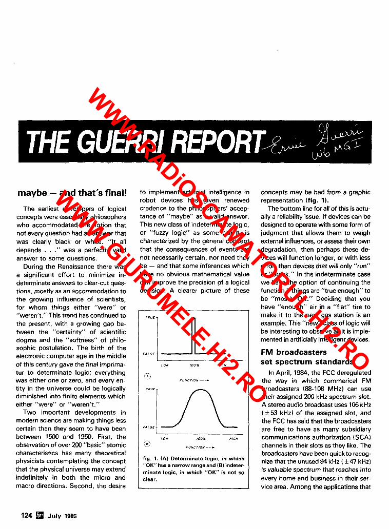
maybe - and that's final!
The earliest developers of logical concepts were essentially philosophers who accommodated the notion that not every question had an answer that was clearly black or white. "It all depends . . ." was a perfectly valid answer to some questions.
During the Renaissance there was a significant effort to minimize in- determinate answers to clear-cut ques- tions, mostly as an accommodation to the growing influence of scientists, for whom things either "were" or "weren't." This trend has continued to the present, with a growing gap be- tween the "certainty" of scientific dogma and the "softness" of philo- sophic postulation. The birth of the electronic computer age in the middle of this century gave the final imprima- tur to determinate logic; everything was either one or zero, and every en- tity in the universe could be logically diminished into finite elements which either "were" or "weren't."
Two important developments in modern science are making things less certain than they seem to have been between 1500 and 1950. First, the observation of over 200 "basic" atomic characteristics has many theoretical physicists contemplating the concept that the physical universe may extend indefinitely in both the micro and macro directions. Second, the desire
to implement artificial intelligence in robot devices has given renewed credence to the philosophers' accep- tance of "maybe" as a valid answer. This new class of indeterminate logic, or "fuzzy logic" as some call it, is characterized by the general concept that the consequences of events are not necessarily certain, nor need they be - and that some inferences which have no obvious mathematical value can improve the precision of a logical decision. A clearer picture of these
LOW 100% H I G H
fig. 1. (A) Determinate logic, in which "OK" has a narrow range and (6 ) indeter- minate logic, in which "OK" is not so clear.
concepts may be had from a graphic representation (fig. 1).
The bottom line for all of this is actu- ally a reliability issue. If devices can be designed to operate with some form of judgment that allows them to weigh external influences, or assess their own degradation, then perhaps these de- vices will function longer, or with less error, than devices that will only "run" or "break." In the indeterminate case we have the option of continuing the function if things are "true enough" to be "mostly OK." Deciding that you have "enough" air in a "flat" tire to make it to the next gas station is an example. This "new" class of logic will be interesting to observe as it is imple- mented in artificially intelligent devices.
FM broadcasters set spectrum standards
In April, 1984, the FCC deregulated the way in which commerical FM broadcasters (88-108 MHz) can use their assigned 200 kHz spectrum slot. A stereo audio broadcast uses 106 kHz (k53 kHz) of the assigned slot, and the FCC has said that the broadcasters are free to have as many subsidiary communications authorization (SCA) channels in their slots as they like. The broadcasters have been quick to recog- nize that the unused 94 kHz ( f 47 kHz) is valuable spectrum that reaches into every home and business in their ser- vice area. Among the applications that
124 July 1985
WWW.RADiOSCAMATORUL.Hi2.RO
WWW.GiURUMELE.Hi2.RO
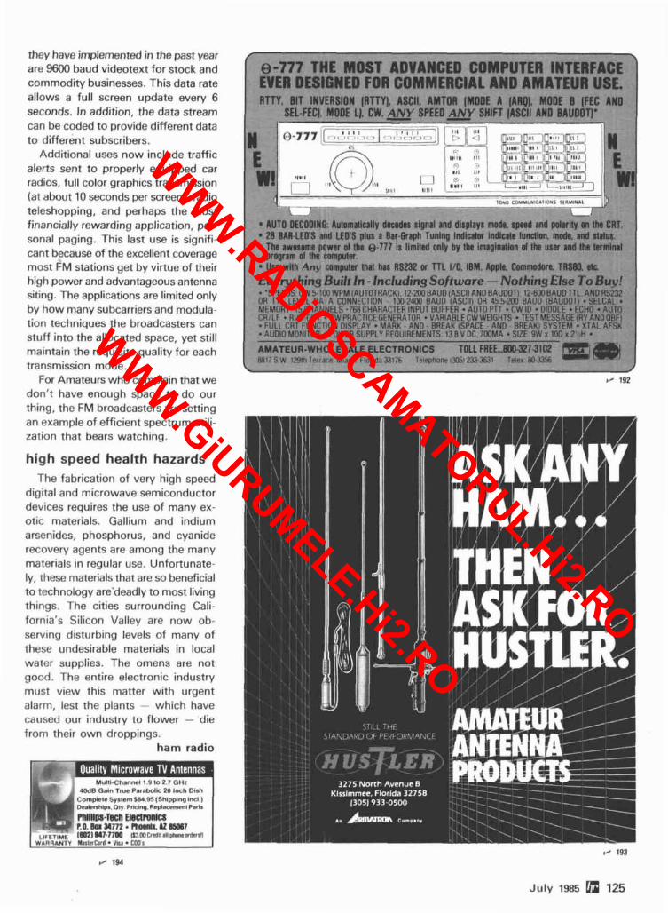
they have implemented in the past year are 9600 baud videotext for stock and commodity businesses. This data rate allows a full screen update every 6 seconds. In addition, the data stream can be coded to provide different data to different subscribers.
Additional uses now include traffic alerts sent to properly equipped car radios, full color graphics transmission (at about 10 seconds per screen), radio teleshopping, and perhaps the most financially rewarding application, per- sonal paging. This last use is signifi- cant because of the excellent coverage most FM stations get by virtue of their high power and advantageous antenna siting. The applications are limited only by how many subcarriers and modula- tion techniques the broadcasters can stuff into the allocated space, yet still maintain the requisite quality for each transmission mode.
For Amateurs who complain that we don't have enough space to do our thing, the FM broadcasters are setting an example of efficient spectrum utili- zation that bears watching.
high speed health hazards The fabrication of very high speed
digital and microwave semiconductor devices requires the use of many ex- otic materials. Gallium and indium arsenides, phosphorus, and cyanide recovery agents are among the many materials in regular use. Unfortunate- ly, these materials that are so beneficial to technology are'deadly to most living things. The cities surrounding Cali- fornia's Silicon Valley are now ob- serving disturbing levels of many of these undesirable materials in local water supplies. The omens are not good. The entire electronic industry must view this matter with urgent alarm, lest the plants - which have caused our industry to flower - die from their own droppings.
ham radio
EVER DESIGNED FOR COMMERCIAL AND AMATE~R~SE. RTTY. BIT INVERSION (RTTY). ASCII. AMTOR [MODE A IARO). MODE B [FEC AND
SEL.FECI. MODE L), CW. ANY SPEED ANY SHIFT lASCll AND BRUDOTJ' , - . . --.---.-- -
. . 28 BAR-LED'S and LEO'S plus'a 8ar.~rap<~unlng lndbior indlcrte'lundion, made. and staim. The awesome power of the 0.777 is limited only by the Imlglnatlon af Ihe usm and the termlnal program ol the computer Use with Anu compular Ihal has RS232 or TTL 110. IBM. Apple. Commodore. TflSBD. dc
I Everuthina Built In -1ncludina Software - Nothins Else To Buv! 1 - 'SPFEOS C W ~ % WPM IAUTOTRACKI. 12 $ 0 0 ~ ~ ~ 6 IASCII ANDRAUDOTI. IZ .W~AUD TTL. A N D R S ~ OR T T I LEVEL D i i i A CONNFCTION 1002400 RAUD lASCIIl OR 45>?M R A W IBAUDOTI SFLCAL.. MEMORY 15 CHAIJNFLS . iMiCHARACTER INPUl RllFFER . AUTO PTT . CW 10 . DIDOLE .ECHO AUTO CI1:LI Rl l l l .OUl . CW PRACllCFGENERATflR V4RIbBLECW WEIGHTS . TEST UESSAGEiRY ANDORF!
FULL t 9 1 FUNCf iOY DISPLAY - M A R K - A N 0 - RArAK lSPI\CI - AY I l RREAKI SYSTEM XTAL AFSK AUDIO MONITOR . POWFR SUPPLY AFOUIRFMFNTS 138 V DC iWM4 . SVF 9W x 100 r 7 H .
I AMATEUR-WHOLESALE ELECTRONICS TOLL FREE ...KO. 3273102 M I ' S W 1 . 3 - TPI ,I P Mndrnl I I o r~ Ia5?17F I r l r pha~r l Y K l ? n ?KW T4e t RO 7?% 1
1, 19:1
July 1985 125
WWW.RADiOSCAMATORUL.Hi2.RO
WWW.GiURUMELE.Hi2.RO
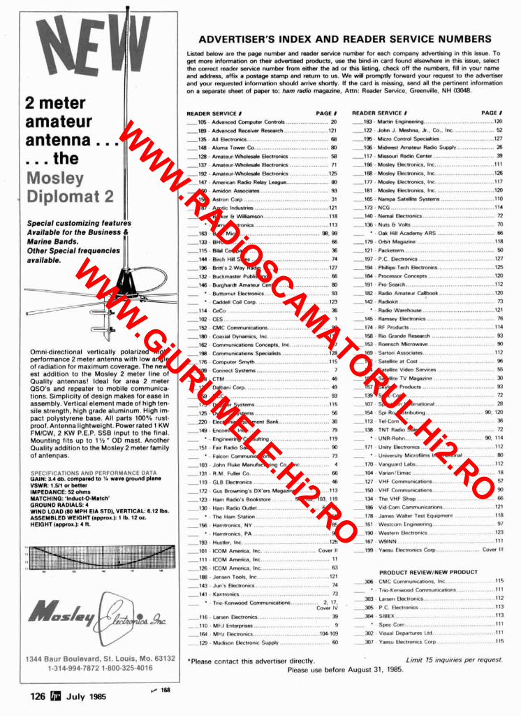
Mosley Diplomat 2
2 meter amateur antenna ...
the m . .
11 Speck1 customlzlng features Available tor the Budness 6 Marine Bands . Other Special trequencles available .
I I
I !
Omnldlrectlonal vertlcaily polarlred hlgh- Derformance 2 meter antenna wlth low angle of radiation for maximum coverage . The new- est addition to the Mosley 2 meter line of Ouality antennas! Ideal for area 2 meter OSO's and repeater to mobile communica . lions . Simollcltv 01 desian makes lor ease in assembly.'~ertiial element made of hlgh ten- sile strenath . hiah arade aluminum . Hiah im- pact polystyrene bise . All parts 100% rust- pro01 . Antenna lightweight . Power rated 1 KW FMICW . 2 KW P.E.P. SSB Input to the final . Mounting fits up to l'/rm OD mast . Another Ouality addition to the Mosley 2 meter family of antenpas .
SPECIFICATIONS AND PERFORMANCE DATA QAIN: 3.4 m . capand to 'A w a n wound p ( m n VSWR: 1.511 a bettor IMPEDANCE: 52 ohms MATCHING: '1nducI.O.Ymtch' GROUND RADIALS: 4 WIND LOAD (80 MPH EIA STD) . VERTICAL: 0.12 lbr . ASSEMBLED WEIQHT (appol.): 1 I b . 12 OZ. HEIGHT lapprol.): 4 I1 .
ADVERTISER'S INDEX AND READER SERVICE NUMBERS L i bdaw are the pa@ number and rssder sarics nu& for ssch wmpany in this issue . To get mxe information on their advertbad products . use the bind-in card found elsewhere in this issue . sdecl the cwrect reader urnrim number from aher the ad or thii listing. check off the numben . fill in your name and address. affix a p t sge aamp and return lo w . We will prompny lotward your requnn to the advertiser and your requested infomtion should arrive shortly . If the card is missing. send all the pertimml information on a separate sheat of paper to: ham radio magazine . Ann: Readsr Service . Greenville . NH 03048 .
READER SERVICE 8 PAQE 1 - 1 O c i . A d v a r s d C o m p u t a ~ ............. .. ..... 20
. ........................ -189 AdMnsd R a s i w R-ch 121
-135 - M Ekmrmk, ......................................... 68 -148 . Ahnns T- Co ........................................ 80
-128 . ~mnsur -Who lso la Ekmrmk, ..................... 58
-137 . Amaav.Who(asala Okmnirr ..................... 71
-192 . Amaaur.Wmbde RacOonio ..................... 125 1 4 7 . A m s u n Radii R d l y L- ....................... 80
-180 . Amidan CI..oc Ma .................................... 93
-156 . Aamn fhp .......................................... 31
-187 . Alollc I- ........................................ 121 .. ................................... - Barha b W l l i 118 ........................................ .. - B r r y E l s R m n i 113
-163 . B.G. M'
. .................................... -1% 127
-in . Buck- ~ublahilp ................... .. ......... 6s ........................... . -146 Bur(lhardl Amarsur h l a 80
- ' . Bunanut Aenmnict ......................... ......... 93 ....................................... - ' . c . d d a H C d f h p I23
-152 . CMC Communimiom .............................. 90
. . ................................. -180 CoerW mi Inc 119 . ..................... . -162 Canrmnicalimm Inc 97 .......................... . - 198 Cammunicniora SpacY ist. 128
....................................... . -1m cmwuts sm* 115 -109 . Comac( synaa ....................................... 7
-118 . CTM . 46 -120 . 0 ~ 8 Gorp 49
-158 . OCC ......................... .- ........................ 93 ........................................ . -175 oo@m s m 115
-125 . Dymlr Synana ........................................ 56
.................. 2- a -1e . . 79 . . ........................ 119 -
. ........................................ -151 Faw R a d i Sslsr 90
.... .. - F&on C-unicfiiore 73 ................ .. . -la John Fluke Manutrturinp CO Inc 4
-131 . R.M. . 66
-119 GLB ......................................... 46 . .................. -172 Gus Brouling's DX'a Magalins 113
. . .......... . - 1 n H~ u d i ' s adnore 54 102. lm 119
. . .............................. -la Ham R a d i i Outla ... 64 65
..................................... . . - The Ham StMan 56
-158 . H a w o n l a . NY ....................................... 85 . . Hamtronla . PA 90
READER SERVICE I PAGE 1 -163 . M a e n Enekmainp ................................... 120
...................... . . . .. .. -122 ~ o h n J Mashna Jr Co Inc 52 -1% . Micm Cmrrd S w J l i i ............................. 127 -108 - M i AMcm R s d a Supply .................... 28
-117 . M i Radii C m l a ................................. 39 . ............................... . - 166 Mos$q Oklronics Inc 111
-168 . Mosby Ebclronks . lnc ............................... I26
. . ................................ - 1 n Moaq E l s R m n i Irn 117 ..... . . ....................... -181 Mos$q Elsnronia 1% .... 120
. ............................ -166 N m w Satsllka Sy.nmr 110 -173 . NCG ....................................................... 114
. ...................................... -la N m d Elan- 72 -136 . N u s b
- -Oak Hi
-1A . O M Maganna
-121 . P r k m
-1%- PNHp.Tech Ekmrmk, ............................... 125 ................................ . -184 P- C m c q m -120
-191 . Pm-Search 12 -1Q . Radio Amalar .............................. 120
-142 . RadoLi( 73 .. ...................................... - Radio Wanhnua 121
-145 . R a s y Elenrorh ................................... X
-174 . RF P m h n a 14 .................................. . -158 R i GRnda R-ch 93
.................................. . -153 R-h Minowave 90
. ...................................... -189 Smwo Anoc i t ss 112 -112 . Salslia m C 96
-124 . Salsllna V k h 55 . ............................... -108 Satdllte N Magazine 30
....................................... . -in skvlsm Roducn 93
-139 . S p c - C 72 . . . . . . . . . . . . . . . . . . . . . . . . . . -107 S-m InlsrnniOnd 28
-113 . Td-C
- 127 VHF Conmunicallons ................................ 57 ............................... . 1 5 0 vHF Cwnmunratms 90
- 134 . The VHF 66
-188 Vd-Com ........................... 21 ..................... - 178 J- W d t a Tan Equipmmt 118
. . . . . . . . . . . . . . . . . . - 161 Wsslca E%narin(t 97 . . . . . . . . . . . . . . . . . . . . . . . -190 Western E k l r o n m 123 .
.............................................. . . . ............................................... -193 H u s k Inc 1 -167 W N N 111 ........................ . . ............................ - 101 ICOM Armrim Inc C m 11 -199 Y w w Eklronlcs Cmp C m Ill
-Ill . ICOM Armrim . Inc ................................... 11
. ........................ . -128 ICOM A r n i c a In U . . ..................................... -168 Jan=" Tm(s Inc 121
-143 . Jun's E l s c n d m .................................... 74
-141 . Kantrtnics ................................................ 73
. . .. - T r i o - K s n d C-uniutlons 2 17 COW IV
PRODUCT REVlEWlNEW PROOUCT
. ................... . a6 CMC CmaunralDns IN. 115 . ................... - ' T r i . K m w m d Communhlionr 111
................... . ............ -X3 L s ~ n E k l r o n i a .-- 112 . . . . . . . . . . . . . . . . . . . . . . . . . 305 P C Elsnronicr 113
. . . . . . . . . . . . . . . . . . . . . . . . . . . . . . . . . . . -116 . L n s n Ektronics ..................... .- .............. 39 -304 SIBEX 113
110 . MFJ E n l h ......................................... 9 - ' Spec Com ... . . . . . . . . . . . . . . . . . . . . . . . . . . . . . . . . 111 . . . . . . . . . . . . . . . ................................... -164 MHz E k w o n c s 104-109 - 3m Vsu.1 Dmnures Lld 111
. . . . . . . . . . . . . . . . . . . . . . .......................... 129 M a r l k n Elsnronr Supply 60 - 307 Y ~ U EIec~tonic~ CMP 115
1344 Baur Boulevard . St . Louis. MO . 63132 .please contact this advertiser directb. Limit 15 inquiries per request . 1.31 4-994-7872 1.800.325.401 6 Please use before August 31 . 1985 .
WWW.RADiOSCAMATORUL.Hi2.RO
WWW.GiURUMELE.Hi2.RO
The only repeaters and controllers with REAL SPEECH!
No other repeaters or controllers match Create messages just by talking. Speak any phrases or
Mark 4 in capability and features. That's words in any languages Or dialect and your own voice why Mark 4 is the performance leader at is stored instantlv in solid-state memorv. Perfect for amateur and repeater sites emergency warnings, club news bulleiins, and DX around the world. Only Mark 4 gives you Message Masterru real speech voice alerts. Create unique ID and tail messages, and the readout of received signal strength, Ultimate in a real speech user mailbox - only with a deviation, and frequency error 0 - 4- Mark 4, channel receiver voting clock time announcements and function control 7- helical filter receiver extensive phone patch functions. Unlike others. Mark 4 even includes power supply and a handsome cabinet.
Call or write for specifications on the repeater, controller, and receiver winners.
MICRO CONTROL SPECIALTIES I- Division of Kendecom Inc.
23 Elm Park. Groveland. MA 01834 (617) 372-3442
YOU WANT IT? DAN'S GOT IT! NEW 70 C M ATV TRANSCEIVER
ALL YOU NEED IN ONE BOX . -, , , 1 KENWOOD
ALL OF THESE GOODIES AND MANY MORE AT A SUPER SAVINGS!
CALL TODAY
1 (800) 241-2027 BRITT'S 2-WAY RADIO
Sales & Service 2508 Atlanta Street
SMYRNA. GA. 30080 f l 1%
(404) 432-8006
FULL COLOR. SOUND. L LIVE ACTION lusl toke broadcast TV Gel on lhls ercllong amaleur vldeo mode a1 our atlardable ready l o go prlce
WHAT IS REOUIRED FOR A COMPLETE OPERATING SYSTEM? The TC70 I s I downconvertel outpuls 10 any TV on ch 3 lor recelvlng Connect agood 70 cm
1 anlenna and low loss coax Plug In any compastte vtdeo source you want l o Iransmfl. Camera, VCR, compurer. erc Plug cn any low Z dynamlc mlc or us? color camera mlc lor Standard 4 5 mHz TV sound Connecl l o 13 8 vdc lor base, mobtle. or portable. See chap!. 20 1985 ARRL Handbook That's 11'
WHAT CAN YOU DO WITH THE TC7O.l ATV TRANCEIVER? Show the shack. prolecls. compuler program I!sllngs, home vldeo lapes, repeal Space Shultle audio and v~deo 11 you hare a TVRO, repeal SSTV or R n Y . Weather Radar a0 public sewtce evenls such as parades, maralhons, races. CAP searches and l esc~es t h e llsl goes on. DX depends on antennas and lerraln, lyp8cally 1 10 40 miles. We have vtdea compensaled RF Irnear amps for 20 lSt19I or 50 IS 1891 walls pep lor greater DX.
FEATURES: Small 7 x 7 ~ 2 5.. Push 10 Look (PTL) TIR swllchlng GaASlel downconverter tunes whole 420.4M mHz band. Two swllch selected vldeo & audm lnpuls RCA phone lacks and 10 pln color camera lack Xmml vlOeo manllot oulpul Over 1 wall pep RF oulpul on one or two ladd $15) selecled cryslal conlrolled lrequencies 439 25. 434.0, or 426 25 mHz.
CALL OR WRITE FOR OUR CATALOG lor more Info or who IS on In your area We sloch antennas. modules, and evevlhlng you need on ATV
TERMS: Vlsa. MC. or cash only UPS CODs by phone or mall Checks must clear bank before sntpmenl. Prlce ~ncludes UPS surface shlpplng I" con1 USA others add 3"b Tlansmllllng equlpmenl sold only l o licensed Tech class or h14hrl amateurs. rerlloable !n 1985 call book or copy 01 new license
(81 8) 447-4565 m-f 6am-6pm pot. s, j01 P.C. ELECTRONICS 2522 Paxson Lane Tom WBORG Maryann WB6YSS Arcadla CA 91006
WWW.RADiOSCAMATORUL.Hi2.RO
WWW.GiURUMELE.Hi2.RO

We just struck gold with a miniature, high qual- ity and very reliable DTMF decoder at a rock bottom price of $59.95. Our DTD-I will decode 5040, 4 digit codes with the security of wrong digit reset. I t contains acrystal controlled. single chip DTMF decoder that works great in had sig- nal-to noise environments and prov~des latched and momentary outputs. Why carry that heavy gear when its size is only 1.25 x 2.0 x .? inches and it comes with our etched in stone, legendary. one year warranty.
Instead of sifting through the field.. . warch- ing, use our super quick one day delivery and cash in on a rare find.
flCOMMUN~CATIOnl.9 SPEEC(llISTS
J.'~I \ \ I ,,I I :\it . ( )rxric~., (',I <12(<>5-42'h I 1 I - I ).AS 17141'~7J-?J70
ml - Entire I1.S.A. 1-800-8-54-0.547 dk
r / 198
WWW.RADiOSCAMATORUL.Hi2.RO
WWW.GiURUMELE.Hi2.RO
Yxsu has serious listeners for the serious listenev.
KI*~,~I~. star I( # ( I , . .I'IC ~ut ~IVI I I , ; vnu b~-,tli.t- ;~,Iv: LCI tun,? I r l thr worlti .uril II I I ~ yrlt~
AIIC~ wl~erher- I!'\ for- li:~c~il act~on or- wi,r-l<lw~ii*. DX, vcru'll f111d CII.I~ V t i l LlHF ,irlrl HF I-l-4crtvr.t.; ,ir-f? thi. c,~~llc,~ 1 i t 1 . tn,itrl~ 1 ; ~ ,111 yci111- l15ter7- In!? r,t-i.tls
The FRG-9600. A pmmium VHFIUHF xanning communi- ations receivw. i - I I _ 11, 1
i'$, 8 , . I I ~ , I I , I , ' , ~ ~~~ ! r i i l II'C ?, l iV In \<- . $.~,hv
'Ou wori'r i n l 5 s any Inc,il ,~ct~on w ~ t h ri~~ll~rlrli:luc riwf~r;lpi~ ft-om 6.0 t i I '105 M H z .
'l; I tl.lvi. mot-i opc31;it~nb: modes I,> l~ . , : t > r i In (TI ~ i p l i ~ ~ . C)I~ Ic?wt?t- ' ~ i i t - , i > i r - ~ i l . CLY AM WII~I: ot- n,lr-rrlw ,Ill< I I PI \Wl, i t , , 11 rl,ll-l~i~w
\; )I I I-,II~ $?vf,r> w,~lcli lc~lt?v~\~on PIC ,:,I i r y l>% IIV ~I~II~,:\~,II>>~, 111 \III.I(Y> r 1 ~ 0 ~ ~ 1 1 i ~ >I 111li> Itri. i ~ ~ ~ l l f l ~ l , l ~ V I ~ I Y ~
The FRG-8800 HF cammunica- tiw receiver A better way to listen to the world. . ,:, 1 1 ; .;,.I:I I
i i l l l l ; i l !. l l . 1 . I l : l l , t ' ! l l i ~ ~ l . [ l , l ~ I . ! i~ '~ tt11'1 I<C ,~N i (H 1 I. 1 1 1 ' II,:~III ICII VOII
YILI ij,'i < ~rrllI,llr '!I \,/I 11 I ~ l i ~ l ~ i t ~ I~ov~~I,I,?~. IITII; I it8( ' t Ibl: I( 1 <I i r.'il I: Ar~cj I in\.t.~r~!'~t I I ~ ,111 I l k . , I, > l/4 p1tj: ~ 1 1 1 1 ,111 8 ,pi <'.,.!I VI-It , ~ ~ t l \ ~ ~ ~ l - r l ~ l
1 l l . l l~ l l I11 . I l l 1. I' 1 1 1 1 ) ( I t 0; ! I ? I
,ln,I li I,V~.I , I , : , I . i I I ' LZI Al.1 ,.y~<i.- 0 1 ~ l~ l~ l l l~ I \v ,111 I I t 1
I>i, $I,, l l , ~ : , l l t ~ l , I * , , , . l l l ~ l I ! l l t l . ~
l l , ' , 1 1 , I , , I I \ . ~ , ~ I \ . < 8 l l ! t l
l l ~ . l ~ % It 11 11.8 ~i..ll :
Yaesu Electronics Corporation '! . , . , > ( . ' . / # .. , . . . , . , _ ' .'
l . ' : l . , . k v l
Yaesu Cincinnati M i c e Center , , 1 : , m ! , , .I I I -Ir, lil
: 1 ' 1 I . ,.!-,11i In :>Ic~< c11 5. 10, 12':, 25
,111,rl ? i K ) K1-l;. 4rrrr .lnv frpr~ilc-ncy arid
Prccr, and rpw~ftrartonr wbjrarr r o c h a t ~ ~ r ~ wlrhrrur nortcc
FRG-9600 558 coverage. 60 lo 460 MHz.
WWW.RADiOSCAMATORUL.Hi2.RO
WWW.GiURUMELE.Hi2.RO
Digital DX-terity-that outstanding attribute built into every Kenwood TS-430s lets you QSY from band to band, frequency to frequency and mode to mode with the speed and ease that will help you earn that dominant DX position from the shack or from the mobile!
r ~ : ! ;,,, . ' , . ~ , " :~,: , Solid ;t;~t(? design perrnlts ~r r f j~r l power IIS.I:iO i:urrlf~ac.l A(: Irtw13r :;upply of ?5[l watts PEP on SSB. 200 watts DC SP-430 external speakrr MB-430 of1 CVJ. 170 w;ilts on FM (opt~orlal). or rnoblle niountlng bracket *AT-130 60 wiilts on AM. Flnal arnol~f~er orotec- conivact arjlvnna tuner covers 80-10 I I I ~ (:II(.LII~S ant1 a cooling Itifi art? tru~lt-~n, p,fi.-.?-, ),,, ,- , i.h.?nn~l<. tight 1nic:mory channels store frrq~rency, mode ; ~ r ~ d t:aritf data Channel 8 may t)r2 prograninrcd for s l ~ l ~ t - l r f ' c l ~~e r~c :~ operation. A fror,l ~,;rric?l sw~tcli allow,; !.;irh mcrnory cliarirrr-41 to o[lerntc ;IS an ~ r~ t l f ~pc~ r~dcn t VFO or as a
eters. ~ncl . WARC bands T-250 auloniat~c enna tuner covers
0-10 meters. lncl. WARC ntls AT~230 base stallon antenna tuner
FM-430 TM un~t YK-88C (500 Hz) or
YK-88CN I270 Hz) CW .-% ' l~lters YK-RRSN (1.8 kHz)
t? n;lrrnw SSR filler YK-88A ( t i kHz) AM f~lter MC-42s
fixed frtcrluer1c:y. A Ilthlurn hat11 > I V I ~ . i ( .ks ' -- I I t ' , I ]OWN hand rnlr: MC-6OA U ( J s t l~ r t~d ~nlorrnal~crr~. dt5luxe ( l .>sk rnlc:.. wltli UPIDOWN swltct , , ,:,.., ..., , --, , I I . : , SW.2000 SWRipower meter ? : , : , ,, .. I r , . c ..c.,..c>i , , ( , ; ! , . , , , SW-100A SWRl[lowf?rlvolt rneler ; ,... 8 . , ; , , , :<, , , ,
j PC-1A [jhono Dalch HS-4. HS-5. . 160 l t i r i ~ i r $ ~ t ~ 1 0 ~I I I , I~~I~,, ; I ! , vi*~.Il < I : , t t l t ,
new 30. 17.. ;ind 1: r?ir:ter WAHC tr:~ncls, H ~ g h dynrlrnic rarioe. (]f?nernl coverage recelver tirnes from 150 kHz to 30 MH7. Easlly rriod~ficd for HF MARS orrPrntlon.
* ?>,~!,2F>?h , ~ , ~ , . . ~ : . - ' ~ ~ : , - p ,,>,' J , !,,,!, Ellmlnatr ORM with thc II- ,;h~f! and tlrn~nhle riotch flller. A noise t)lnrikr>~ suprosses ~gn~l ion nolse. Sc~u~Ic:ti. RF attm~rntor, and HIT arcJ ;ilso prov~rled Optlonnl IF lllters may Irr? ;itfdotf for optiniuni ~nterf~rrnc:e red~rr-tlc~n
TRIO-KENWOOD COMMUNICATIONS 1 1 1 1 ')It.,' \',/,,I<,,,l 51rq . , I
I ! , , , , , I , , I t. !l#l,,r ,,I, i ',xl.':'l'#
WWW.RADiOSCAMATORUL.Hi2.RO
WWW.GiURUMELE.Hi2.RO


