212
2020 National Electrical Code ® Review A Guide for the Use of Appleton™ Products in Hazardous Locations Interpreting the Requirements of Articles 500-516 of the NEC ®
| Date post: | 26-Feb-2023 |
| Category: |
Documents |
| Upload: | khangminh22 |
| View: | 0 times |
| Download: | 0 times |
2020 National Electrical Code® ReviewA Guide for the Use of Appleton™ Products in Hazardous Locations
Interpreting the Requirements of Articles 500-516 of the NEC®

i
2020 CODE REVIEW
TABLE OF CONTENTS
Introduction …………………………………………………………………………………………………………………………………………………………………… 1
General Information ………………………………………………………………………………………………………………………………………………………… 3
Types of Explosionproof Construction – Appleton™ Products ………………………………………………………………………………………………… 6
NEC® ARTICLES 100, 500 THROUGH 516 – TEXT AND COMMENTARY
Article 90: Introduction
Changes to Article 90 ……………………………………………………………………………………………………………………………………………………… 11
90.1 Purpose …………………………………………………………………………………………………………………………………………………………………… 11
90.2 Scope ……………………………………………………………………………………………………………………………………………………………………… 11
90.3 Code Arrangement …………………………………………………………………………………………………………………………………………………… 12
90.4 Enforcement …………………………………………………………………………………………………………………………………………………………… 12
90.5 Mandatory Rules, Permissive Rules, and Explanatory Material ………………………………………………………………………………………… 12
90.6 Formal Interpretations ……………………………………………………………………………………………………………………………………………… 13
90.7 Examination of Equipment for Safety …………………………………………………………………………………………………………………………… 13
90.8 Wiring Planning ……………………………………………………………………………………………………………………………………………………… 13
90.9 Units of Measure ……………………………………………………………………………………………………………………………………………………… 13
Article 100: Definitions
Changes to Article 100 …………………………………………………………………………………………………………………………………………………… 15
Part I. General ………………………………………………………………………………………………………………………………………………………………… 15
Part II. Over 1000 Volts, Nominal ………………………………………………………………………………………………………………………………………… 24
Part III. Hazardous (Classified) Locations (CMP-14) ………………………………………………………………………………………………………………… 24
Article 500: Hazardous (Classified) Locations, Class I, II, and III, Divisions 1 and 2
Changes to Article 500 ……………………………………………………………………………………………………………………………………………………… 29
500.1 Scope — Articles 500 Through 504 …………………………………………………………………………………………………………………………… 29
500.3 Other Articles ……………………………………………………………………………………………………………………………………………………… 29
500.4 Documentation …………………………………………………………………………………………………………………………………………………… 29
500.5 Classifications of Locations ……………………………………………………………………………………………………………………………………… 29
500.6 Material Groups …………………………………………………………………………………………………………………………………………………… 32
500.7 Protection Techniques …………………………………………………………………………………………………………………………………………… 34
500.8 Equipment …………………………………………………………………………………………………………………………………………………………… 36
500.9 Specific Occupancies ……………………………………………………………………………………………………………………………………………… 40
Article 501: Class I Locations
Changes to Article 501 …………………………………………………………………………………………………………………………………………………… 41
501.1 Scope …………………………………………………………………………………………………………………………………………………………………… 41
501.5 Zone Equipment …………………………………………………………………………………………………………………………………………………… 41
501.10 Wiring Methods …………………………………………………………………………………………………………………………………………………… 41
501.15 Sealing and Drainage …………………………………………………………………………………………………………………………………………… 45
501.17 Process Sealing …………………………………………………………………………………………………………………………………………………… 53
501.20 Conductor Insulation, Class I, Divisions 1 and 2 ………………………………………………………………………………………………………… 54
501.25 Uninsulated Exposed Parts, Class I, Divisions 1 and 2 ………………………………………………………………………………………………… 54
501.30 Grounding and Bonding, Class I, Divisions 1 and 2 ……………………………………………………………………………………………………… 54
ii
2020 CODE REVIEW
TABLE OF CONTENTS
501.35 Surge Protection ………………………………………………………………………………………………………………………………………………… 54
501.100 Transformers and Capacitors ……………………………………………………………………………………………………………………………… 55
501.105 Meters, Instruments, and Relays …………………………………………………………………………………………………………………………… 55
501.115 Switches, Circuit Breakers, Motor Controllers, and Fuses …………………………………………………………………………………………… 56
501.120 Control Transformers and Resistors ……………………………………………………………………………………………………………………… 57
501.125 Motors and Generators ……………………………………………………………………………………………………………………………………… 57
501.130 Luminaires ……………………………………………………………………………………………………………………………………………………… 59
501.135 Utilization Equipment ………………………………………………………………………………………………………………………………………… 62
501.140 Flexible Cords, Class I, Divisions 1 and 2 ………………………………………………………………………………………………………………… 63
501.145 Receptacles and Attachment Plugs, Class I, Divisions 1 and 2 …………………………………………………………………………………… 64
501.150 Signaling, Alarm, Remote-Control, and Communications Systems ……………………………………………………………………………… 65
Article 502: Class II Locations
Changes to Article 502 …………………………………………………………………………………………………………………………………………………… 67
502.1 Scope …………………………………………………………………………………………………………………………………………………………………… 67
502.5 Explosionproof Equipment ……………………………………………………………………………………………………………………………………… 67
502.6 Zone Equipment …………………………………………………………………………………………………………………………………………………… 67
502.10 Wiring Methods …………………………………………………………………………………………………………………………………………………… 67
502.15 Sealing, Class II, Divisions 1 and 2 …………………………………………………………………………………………………………………………… 70
502.25 Uninsulated Exposed Parts, Class II, Divisions 1 and 2 ………………………………………………………………………………………………… 71
502.30 Grounding and Bonding, Class II, Divisions 1 and 2 …………………………………………………………………………………………………… 71
502.35 Surge Protection — Class II, Divisions 1 and 2 …………………………………………………………………………………………………………… 72
502.100 Transformers and Capacitors ……………………………………………………………………………………………………………………………… 72
502.115 Switches, Circuit Breakers, Motor Controllers, and Fuses …………………………………………………………………………………………… 72
502.120 Control Transformers and Resistors ……………………………………………………………………………………………………………………… 72
502.125 Motors and Generators ……………………………………………………………………………………………………………………………………… 73
502.128 Ventilating Piping ……………………………………………………………………………………………………………………………………………… 74
502.130 Luminaires ………………………………………………………………………………………………………………………………………………………… 74
502.135 Utilization Equipment ………………………………………………………………………………………………………………………………………… 76
502.140 Flexible Cords — Class II, Divisions 1 and 2 ……………………………………………………………………………………………………………… 77
502.145 Receptacles and Attachment Plugs ……………………………………………………………………………………………………………………… 77
502.150 Signaling, Alarm, Remote-Control, and Communications Systems; and Meters, Instruments, and Relays ………………………… 78
Article 503: Class III Locations
Changes to Article 503 …………………………………………………………………………………………………………………………………………………… 81
503.1 Scope …………………………………………………………………………………………………………………………………………………………………… 81
503.5 General ………………………………………………………………………………………………………………………………………………………………… 81
503.6 Zone Equipment …………………………………………………………………………………………………………………………………………………… 81
503.10 Wiring Methods …………………………………………………………………………………………………………………………………………………… 82
503.25 Uninsulated Exposed Parts, Class III, Divisions 1 and 2 ………………………………………………………………………………………………… 83
503.30 Grounding and Bonding — Class III, Divisions 1 and 2 ………………………………………………………………………………………………… 83
503.100 Transformers and Capacitors — Class III, Divisions 1 and 2 ………………………………………………………………………………………… 83
503.115 Switches, Circuit Breakers, Motor Controllers, and Fuses — Class III, Divisions 1 and 2 …………………………………………………… 83
iii
2020 CODE REVIEW
TABLE OF CONTENTS
503.120 Control Transformers and Resistors — Class III, Divisions 1 and 2 ………………………………………………………………………………… 83
503.125 Motors and Generators — Class III, Divisions 1 and 2 ………………………………………………………………………………………………… 83
503.128 Ventilating Piping — Class III, Divisions 1 and 2 ………………………………………………………………………………………………………… 84
503.130 Luminaires — Class III, Divisions 1 and 2 ………………………………………………………………………………………………………………… 84
503.135 Utilization Equipment — Class III, Divisions 1 and 2 …………………………………………………………………………………………………… 85
503.140 Flexible Cords — Class III, Divisions 1 and 2 ……………………………………………………………………………………………………………… 85
503.145 Receptacles and Attachment Plugs — Class III, Divisions 1 and 2 ………………………………………………………………………………… 85
503.150 Signaling, Alarm, Remote-Control, and Local Loudspeaker Intercommunications Systems — Class III, Divisions 1 and 2 ……… 85
503.155 Electric Cranes, Hoists, and Similar Equipment — Class III, Divisions 1 and 2 …………………………………………………………………… 86
503.160 Storage Battery Charging Equipment — Class III, Divisions 1 and 2 ……………………………………………………………………………… 86
Article 504: Intrinsically Safe Systems
Changes to Article 504 …………………………………………………………………………………………………………………………………………………… 87
504.1 Scope …………………………………………………………………………………………………………………………………………………………………… 87
504.3 Application of Other Articles …………………………………………………………………………………………………………………………………… 87
504.4 Equipment …………………………………………………………………………………………………………………………………………………………… 87
504.10 Equipment Installation ………………………………………………………………………………………………………………………………………… 87
504.20 Wiring Methods …………………………………………………………………………………………………………………………………………………… 88
504.30 Separation of Intrinsically Safe Conductors ……………………………………………………………………………………………………………… 88
504.50 Grounding …………………………………………………………………………………………………………………………………………………………… 89
504.60 Bonding ……………………………………………………………………………………………………………………………………………………………… 89
504.70 Sealing ………………………………………………………………………………………………………………………………………………………………… 89
504.80 Identification ……………………………………………………………………………………………………………………………………………………… 89
Article 505: Zone 0, 1, and 2 Locations
Changes to Article 505 …………………………………………………………………………………………………………………………………………………… 91
505.1 Scope …………………………………………………………………………………………………………………………………………………………………… 91
505.3 Other Articles ………………………………………………………………………………………………………………………………………………………… 91
505.4 Documentation ……………………………………………………………………………………………………………………………………………………… 92
505.5 Classifications of Locations ……………………………………………………………………………………………………………………………………… 92
505.6 Material Groups …………………………………………………………………………………………………………………………………………………… 93
505.7 Special Precaution ………………………………………………………………………………………………………………………………………………… 94
505.8 Protection Techniques …………………………………………………………………………………………………………………………………………… 94
505.9 Equipment …………………………………………………………………………………………………………………………………………………………… 96
505.15 Wiring Methods …………………………………………………………………………………………………………………………………………………… 101
505.16 Sealing and Drainage …………………………………………………………………………………………………………………………………………… 103
505.17 Flexible Cords and Connections ……………………………………………………………………………………………………………………………… 106
505.18 Conductors and Conductor Insulation ……………………………………………………………………………………………………………………… 107
505.19 Uninsulated Exposed Parts …………………………………………………………………………………………………………………………………… 107
505.20 Equipment Requirements ……………………………………………………………………………………………………………………………………… 107
505.22 Increased Safety “e” Motors and Generators …………………………………………………………………………………………………………… 108
505.25 Grounding and Bonding ………………………………………………………………………………………………………………………………………… 108
505.26 Process Sealing …………………………………………………………………………………………………………………………………………………… 109
iv
2020 CODE REVIEW
TABLE OF CONTENTS
Article 506: Zone 20, 21, and 22 Locations for Combustible Dusts or Ignitable Fibers/Flyings
Changes to Article 506 …………………………………………………………………………………………………………………………………………………… 111
506.1 Scope …………………………………………………………………………………………………………………………………………………………………… 111
506.3 Other Articles ………………………………………………………………………………………………………………………………………………………… 111
506.4 Documentation …………………………………………………………………………………………………………………………………………………… 111
506.5 Classification of Locations ……………………………………………………………………………………………………………………………………… 111
506.6 Material Groups …………………………………………………………………………………………………………………………………………………… 113
506.7 Special Precaution ………………………………………………………………………………………………………………………………………………… 113
506.8 Protection Techniques …………………………………………………………………………………………………………………………………………… 113
506.9 Equipment Requirements ………………………………………………………………………………………………………………………………………… 114
506.15 Wiring Methods …………………………………………………………………………………………………………………………………………………… 117
506.16 Sealing ………………………………………………………………………………………………………………………………………………………………… 118
506.17 Flexible Cords ……………………………………………………………………………………………………………………………………………………… 118
506.20 Equipment Installation …………………………………………………………………………………………………………………………………………… 119
506.25 Grounding and Bonding ………………………………………………………………………………………………………………………………………… 119
Article 510: Hazardous (Classified) Locations – Specific
Changes to Article 510 …………………………………………………………………………………………………………………………………………………… 121
510.1 Scope …………………………………………………………………………………………………………………………………………………………………… 121
510.2 General ………………………………………………………………………………………………………………………………………………………………… 121
Article 511: Commercial Garages, Repair and Storage
Changes to Article 511 …………………………………………………………………………………………………………………………………………………… 123
511.1 Scope …………………………………………………………………………………………………………………………………………………………………… 123
511.3 Area Classification, General ……………………………………………………………………………………………………………………………………… 123
511.4 Wiring and Equipment in Class I Locations ………………………………………………………………………………………………………………… 123
511.7 Wiring and Equipment Installed Above Class I Locations ……………………………………………………………………………………………… 125
511.8 Underground Wiring Below Class I Locations ……………………………………………………………………………………………………………… 125
511.9 Sealing ………………………………………………………………………………………………………………………………………………………………… 125
511.10 Special Equipment ……………………………………………………………………………………………………………………………………………… 126
511.12 Ground-Fault Circuit-Interrupter Protection for Personnel …………………………………………………………………………………………… 126
511.16 Grounding and Bonding Requirements …………………………………………………………………………………………………………………… 126
Article 513: Aircraft Hangars
Changes to Article 513 …………………………………………………………………………………………………………………………………………………… 127
513.1 Scope …………………………………………………………………………………………………………………………………………………………………… 127
513.3 Classification of Locations ………………………………………………………………………………………………………………………………………… 127
513.4 Wiring and Equipment in Class I Locations ………………………………………………………………………………………………………………… 127
513.7 Wiring and Equipment Not Installed in Class I Locations ……………………………………………………………………………………………… 127
513.8 Underground Wiring ……………………………………………………………………………………………………………………………………………… 128
513.9 Sealing ………………………………………………………………………………………………………………………………………………………………… 128
513.10 Special Equipment ………………………………………………………………………………………………………………………………………………… 128
513.12 Ground-Fault Circuit-Interrupter Protection for Personnel …………………………………………………………………………………………… 129
513.16 Grounding and Bonding Requirements …………………………………………………………………………………………………………………… 129
v
2020 CODE REVIEW
TABLE OF CONTENTS
Article 514: Motor Fuel Dispensing Facilities
Changes to Article 514 …………………………………………………………………………………………………………………………………………………… 131
514.1 Scope …………………………………………………………………………………………………………………………………………………………………… 131
514.3 Classification of Locations ……………………………………………………………………………………………………………………………………… 131
514.4 Wiring and Equipment Installed in Class I Locations ……………………………………………………………………………………………………… 136
514.7 Wiring and Equipment Above Class I Locations …………………………………………………………………………………………………………… 136
514.8 Underground Wiring ……………………………………………………………………………………………………………………………………………… 136
514.9 Sealing ………………………………………………………………………………………………………………………………………………………………… 136
514.11 Circuit Disconnects ……………………………………………………………………………………………………………………………………………… 137
514.13 Provisions for Maintenance and Service of Dispensing Equipment ………………………………………………………………………………… 137
514.16 Grounding and Bonding ……………………………………………………………………………………………………………………………………… 137
Article 515: Bulk Storage Plants
Changes to Article 515 …………………………………………………………………………………………………………………………………………………… 139
515.1 Scope …………………………………………………………………………………………………………………………………………………………………… 139
515.3 Class I Locations ……………………………………………………………………………………………………………………………………………………… 139
515.4 Wiring and Equipment Located in Class I Locations ……………………………………………………………………………………………………… 142
515.7 Wiring and Equipment Above Class I Locations …………………………………………………………………………………………………………… 142
515.8 Underground Wiring ……………………………………………………………………………………………………………………………………………… 142
515.9 Sealing ………………………………………………………………………………………………………………………………………………………………… 142
515.10 Special Equipment — Gasoline Dispensers ………………………………………………………………………………………………………………… 142
515.16 Grounding and Bonding ………………………………………………………………………………………………………………………………………… 142
Article 516: Spray Application, Dipping, Coating, and Printing Processes Using Flammable or Combustible Materials
Changes to Article 516 …………………………………………………………………………………………………………………………………………………… 145
516.1 Scope …………………………………………………………………………………………………………………………………………………………………… 145
516.3 Class I Locations ……………………………………………………………………………………………………………………………………………………… 145
516.4 Area Classification for Open Containers ……………………………………………………………………………………………………………………… 145
516.5 Area Classification for Spray Application Processes ……………………………………………………………………………………………………… 146
516.6 Wiring and Equipment in Class I Locations ………………………………………………………………………………………………………………… 148
516.7 Wiring and Equipment Not Within Classified Locations ………………………………………………………………………………………………… 150
516.10 Special Equipment ………………………………………………………………………………………………………………………………………………… 150
516.16 Grounding …………………………………………………………………………………………………………………………………………………………… 152
516.18 Area Classification for Temporary Membrane Enclosures …………………………………………………………………………………………… 152
516.23 Electrical and Other Sources of Ignition …………………………………………………………………………………………………………………… 152
516.29 Classification of Locations for Printing, Dipping, and Coating Processes ………………………………………………………………………… 153
516.35 Areas Adjacent to Enclosed Dipping and Coating Processes ………………………………………………………………………………………… 154
516.36 Equipment and Containers in Ventilated Areas ………………………………………………………………………………………………………… 154
516.37 Luminaires …………………………………………………………………………………………………………………………………………………………… 155
516.38 Wiring and Equipment Not Within Classified Locations ……………………………………………………………………………………………… 155
516.40 Static Electric Discharges ……………………………………………………………………………………………………………………………………… 155
vi
2020 CODE REVIEW
TABLE OF CONTENTS
APPENDICES
Appendix A-1: Class I Flammable Gases And Vapors ……………………………………………………………………………………………………………… 157
Appendix A-2: Class II Combustible Dusts …………………………………………………………………………………………………………………………… 163
Appendix B-1: Referenced Product and Installation Standards ………………………………………………………………………………………………… 167
Appendix B-2: NEMA Enclosure Definitions ………………………………………………………………………………………………………………………… 169
Appendix B-3: The Relationship Between NEMA 250 – “Enclosures for Electrical Equipment (1000 Volts Maximum)” and IEC 60529 – “Degrees of Protection Provided By Enclosures (IP Code)” …………………………………………………………………………………………………… 170
Appendix C: Standards, Testing and Certification Organizations ……………………………………………………………………………………………… 173
Appendix D: Quick Selection Guide — Equipment for Hazardous Locations ……………………………………………………………………………… 175
Appendix E-1: Lighting and Power Diagrams: Class I, Divisions 1 and 2, Group B; Class I, Zones 1 and 2, Groups IIA, IIB + H2 ……………… 182
Appendix E-2: Power Diagram: Class I, Division 1, Groups C and D, Class I, Zone 1, Groups IIA, IIB ………………………………………………… 184
Appendix E-3: Lighting Diagram: Class I, Division 1, Groups C and D; Class 1, Zone 1, Groups IIA and IIB ………………………………………… 186
Appendix E-4: Lighting and Power Diagram: Class I, Division 2, Groups C and D; Class I, Zone 2, Groups IIA and IIB ………………………… 188
Appendix E-5: Power Diagram: Class II, Divisions 1 and 2, Groups E, F and G; Class II, Zones 21 and 22 ………………………………………… 190
Appendix E-6: Lighting Diagram: Class II, Divisions 1 and 2, Groups E, F and G; Class II, Zones 21 and 22 ……………………………………… 192
Appendix E-7: Lighting and Power Diagram: Class I, Zone 1; Class I, Zone 2 ……………………………………………………………………………… 194
2020 CODE REVIEW
1
INTRODUCTION
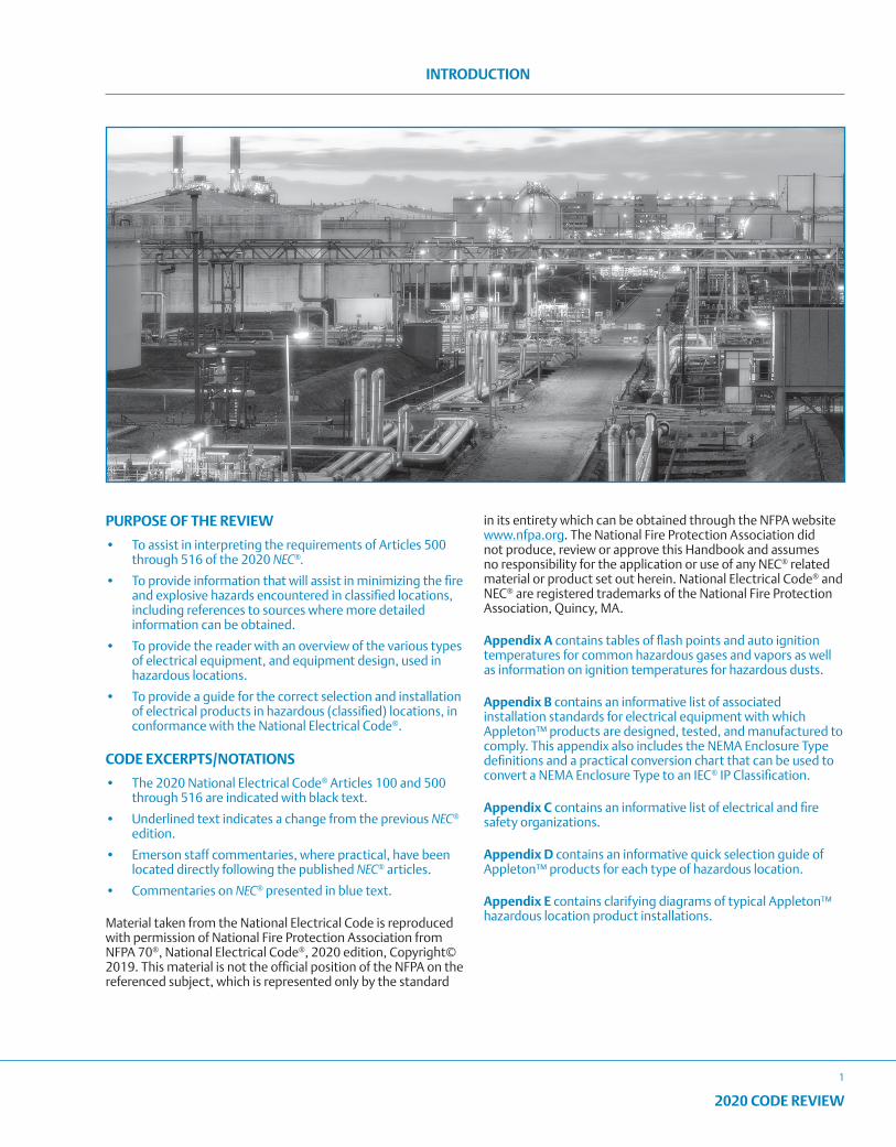
PURPOSE OF THE REVIEW
• To assist in interpreting the requirements of Articles 500 through 516 of the 2020 NEC®.
• To provide information that will assist in minimizing the fire and explosive hazards encountered in classified locations, including references to sources where more detailed information can be obtained.
• To provide the reader with an overview of the various types of electrical equipment, and equipment design, used in hazardous locations.
• To provide a guide for the correct selection and installation of electrical products in hazardous (classified) locations, in conformance with the National Electrical Code®.
CODE EXCERPTS/NOTATIONS
• The 2020 National Electrical Code® Articles 100 and 500 through 516 are indicated with black text.
• Underlined text indicates a change from the previous NEC® edition.
• Emerson staff commentaries, where practical, have been located directly following the published NEC® articles.
• Commentaries on NEC® presented in blue text.
Material taken from the National Electrical Code is reproduced with permission of National Fire Protection Association from NFPA 70®, National Electrical Code®, 2020 edition, Copyright© 2019. This material is not the official position of the NFPA on the referenced subject, which is represented only by the standard
in its entirety which can be obtained through the NFPA website www.nfpa.org. The National Fire Protection Association did not produce, review or approve this Handbook and assumes no responsibility for the application or use of any NEC® related material or product set out herein. National Electrical Code® and NEC® are registered trademarks of the National Fire Protection Association, Quincy, MA.
Appendix A contains tables of flash points and auto ignition temperatures for common hazardous gases and vapors as well as information on ignition temperatures for hazardous dusts.
Appendix B contains an informative list of associated installation standards for electrical equipment with which Appleton™ products are designed, tested, and manufactured to comply. This appendix also includes the NEMA Enclosure Type definitions and a practical conversion chart that can be used to convert a NEMA Enclosure Type to an IEC® IP Classification.
Appendix C contains an informative list of electrical and fire safety organizations.
Appendix D contains an informative quick selection guide of Appleton™ products for each type of hazardous location.
Appendix E contains clarifying diagrams of typical Appleton™ hazardous location product installations.

2
2020 CODE REVIEW
NOTES
2020 CODE REVIEW
3
GENERAL INFORMATION
TECHNICAL HELP AVAILABLE
The information presented in this booklet provides extensive help in determining NEC® requirements for the use of electrical products in hazardous locations. However, even though every attempt has been made to provide complete data, questions inevitably arise. In these circumstances, contact your local Emerson sales representative for technical assistance. In addition, our staff of technical experts is at your service and can be contacted via [email protected].
The NEC® and other NFPA® Standards are international standards. All measurements in the 2020 NEC® are shown in SI metric units, followed by the inch-pound value in parentheses. For example, 3.2 mm (1/8 in.).
A soft metric conversion is when the dimensions of a product already designed and manufactured to the English or Imperial inch or pound system have their dimensions converted to metric dimensions. The product does not change.
A hard metric measurement is where a product has been designed to SI metric dimensions. No conversion from English or Imperial inch-pound measurement units is involved.
A hard conversion is where an existing product is redesigned into a new size. For example, if a dimension is required to be 10 feet, it is shown in the NEC® as 3.0 m (10 ft.). Where rounding off would create a safety hazard, the metric conversions are mathematically identical. Note that the 10 feet remains the same, and the metric value of 3.03 m appears and has not been rounded off to 3.0 m.
DISCLAIMER
The information presented in this booklet has been assembled from various sources. Although every attempt has been made to ensure accuracy, neither Appleton Grp LLC or Emerson Electric Co. assumes responsibility for any inaccuracies or omissions in the data presented. As a safety precaution, information to be utilized from this booklet should be verified from the 2020 National Electrical Code® and other sources.
PERMISSIONS
Reprinted with permission from NFPA® 70 - 2020, National Electrical Code®, Copyright © 2019, National Fire Protection Association, Quincy, MA. This material is not the official position of the NFPA® on the referenced subject, which is represented only by the standard in its entirety. Such permission does not imply an endorsement by the NFPA® of Appleton™ equipment featured in this booklet. NFPA® 70, the title National Electrical Code® and the acronym NEC® are registered trademarks of the National Fire Protection Association.
TRADE SIZES
The electrical industry has been incorrectly referring to raceways in inches for many years. Raceway sizes have always been an approximation. For example, there has never been a ½˝ raceway. The NEC® in Section 90.9(C)(1) states that “where the actual measured size of a product is not the same as the nominal size, trade size designators shall be used rather than dimensions.” To alleviate potential confusion, this text uses only the term trade size when referring to conduit and tubing sizes.
THE MAJORITY OF APPLETON™ PRODUCTS DESIGNED FOR HAZARDOUS LOCATIONS ARE SUITABLE FOR ALL CLASSES
Many Appleton™ electrical products approved for Class I, Division 1 and 2, are also suitable for Class II, Division 1 and 2, and for Class III, Division 1 and 2. A glance through the Appleton™ product catalogs will confirm this information. All Appleton™ products intended for use in Class I, Class II, and Class III locations are designed to conform to the relevant requirements in NEC® Sections:
500.7(A) Explosionproof. Class I, Division 1
500.7(G) Nonincendive, Class I, Division 2
500.7(B) Dust Ignitionproof, Class II, Division 1
500.7(C) Dusttight, Class II, Division 2, Class II, Divisions 1 and 2
EQUIVALENCY RATINGS:
The NEC® and the listing product standards address equivalency ratings between the Class-Division classification system and the Class-Zone classification system. This is accomplished by considering the safety hazards for the corresponding classification system against what the listing product standards require for a level of evaluation. In many cases a standard that is utilized for one classification system may be deemed to adequately address the safety hazards of the other classification system. Equivalency ratings are required to be marked on the equipment to be permitted for installation into the specific classified system. These ratings are addressed in the relevant hazardous location sections.
It is critical to understand that products that have been evaluated and listed to the Zone classification system. IEC® based ANSI product standards have also been evaluated for their safety concerning electrical fire and shock hazards. These products will have an AEx marking. Products that have been evaluated to the direct IEC® standards for Explosive Atmospheres have only been evaluated to their safety in an Explosive Atmosphere. These products are marked as Ex and are not permitted in accordance with the NEC®.
4
2020 CODE REVIEW
GENERAL INFORMATION
APPLETON™ PRODUCTS MEET OR EXCEED AUTHORITATIVE STANDARDS
Appleton™ explosionproof, flameproof, dust-ignitionproof, dusttight, nonincendive, increased safety, restricted breathing, and nonsparking products meet or exceed the prescribed requirements of Underwriters Laboratories, Inc., and Chapter 5 of the 2020 National Electrical Code®. They provide an extra margin of safety and greater durability than the minimum specifications require.
Many other national, state, and local codes and regulations are invoked where custom-made equipment is manufactured. This Code Review is offered only as a guide to the correct and safe protection for classified products installed in hazardous location applications. State and local authorities and codes should always be consulted to properly meet all installation requirements.
CONDITIONS DEFINING HAZARDOUS LOCATIONS
In order to create an explosion, three things need to be present: fuel, oxygen, and an ignition source. In addition to these three factors being present, an explosion will only occur if the mixture of the fuel with oxygen is between its upper and lower flammable limits.
The lower flammable limit (LFL) is the minimum level of fuel that must be present, as a percentage of the total fuel/oxygen mixture, to start and sustain combustion. At fuel levels below the minimum flammable limit, there is not enough fuel mixed with oxygen to support combustion.
The upper flammable limit (UFL) is the maximum level of fuel that can be present, as a percentage of the total fuel/oxygen mixture, to start and sustain combustion. At fuel levels above the upper flammable limit, there is not enough oxygen mixed with fuel to support combustion.
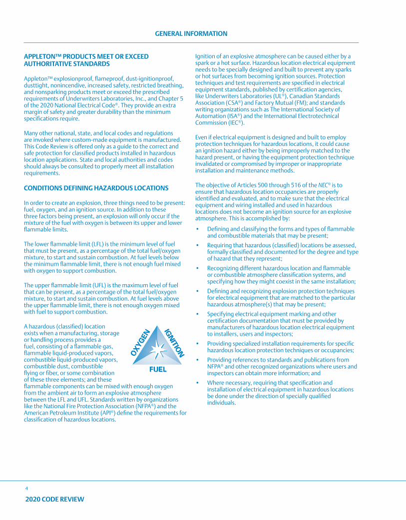
A hazardous (classified) location exists when a manufacturing, storage or handling process provides a fuel, consisting of a flammable gas, flammable liquid-produced vapors, combustible liquid-produced vapors, combustible dust, combustible flying or fiber, or some combination of these three elements; and these flammable components can be mixed with enough oxygen from the ambient air to form an explosive atmosphere between the LFL and UFL. Standards written by organizations like the National Fire Protection Association (NFPA®) and the American Petroleum Institute (API®) define the requirements for classification of hazardous locations.
Ignition of an explosive atmosphere can be caused either by a spark or a hot surface. Hazardous location electrical equipment needs to be specially designed and built to prevent any sparks or hot surfaces from becoming ignition sources. Protection techniques and test requirements are specified in electrical equipment standards, published by certification agencies, like Underwriters Laboratories (UL®), Canadian Standards Association (CSA®) and Factory Mutual (FM); and standards writing organizations such as The International Society of Automation (ISA®) and the International Electrotechnical Commission (IEC®).
Even if electrical equipment is designed and built to employ protection techniques for hazardous locations, it could cause an ignition hazard either by being improperly matched to the hazard present, or having the equipment protection technique invalidated or compromised by improper or inappropriate installation and maintenance methods.
The objective of Articles 500 through 516 of the NEC® is to ensure that hazardous location occupancies are properly identified and evaluated, and to make sure that the electrical equipment and wiring installed and used in hazardous locations does not become an ignition source for an explosive atmosphere. This is accomplished by:
• Defining and classifying the forms and types of flammable and combustible materials that may be present;
• Requiring that hazardous (classified) locations be assessed, formally classified and documented for the degree and type of hazard that they represent;
• Recognizing different hazardous location and flammable or combustible atmosphere classification systems, and specifying how they might coexist in the same installation;
• Defining and recognizing explosion protection techniques for electrical equipment that are matched to the particular hazardous atmosphere(s) that may be present;
• Specifying electrical equipment marking and other certification documentation that must be provided by manufacturers of hazardous location electrical equipment to installers, users and inspectors;
• Providing specialized installation requirements for specific hazardous location protection techniques or occupancies;
• Providing references to standards and publications from NFPA® and other recognized organizations where users and inspectors can obtain more information; and
• Where necessary, requiring that specification and installation of electrical equipment in hazardous locations be done under the direction of specially qualified individuals.
2020 CODE REVIEW
5
GENERAL INFORMATION
The following is a partial list of Registered Trademarks of Appleton Grp LLC that may be found in this 2020 Code Review Booklet.
A-51
Baymaster
Code•Master
Contender
Areamaster
FM7
FM8
Form 35
Kwiko
Mercmaster
PlexPower
Powertite
Rigmaster
Reelite
Slide-Loc
“ST”
Stylmaster
U-Line
Unicode
V-51
Viamaster
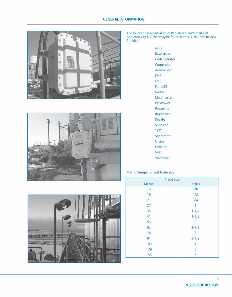
Metric Designator and Trade Size
Trade SizeMetric Inches
12 3/8
16 1/2
21 3/4
27 1
35 1-1/4
41 1-1/2
53 2
63 2-1/2
78 3
91 3-1/2
103 4
129 5
155 6
6
2020 CODE REVIEW
TYPES OF EXPLOSIONPROOF CONSTRUCTION – APPLETON™ PRODUCTS
DESIGN OF EXPLOSIONPROOF EQUIPMENT
There is a rather common misconception that explosionproof equipment is gas-tight. It would be inadvisable to make an entire wiring system gas-tight. Whenever an enclosure was opened for servicing apparatus, for example, the explosive mixture could enter and be trapped in the enclosure. The trapped atmosphere could then explode the instant the apparatus was again operated. The explosion could develop pressures sufficient to burst a gas-tight enclosure and allow flames to escape into the surrounding atmosphere.
The requirement is not that enclosures be gas-tight, but that they be designed and manufactured strong enough to contain an explosion and prevent the escape of flame or heat that could ignite surrounding atmospheres. Burned gases do escape from explosionproof equipment, but their escape path has been engineered so the temperature of the escaping gas is well below its ignition point when it escapes into the surrounding atmosphere. Appleton™ explosionproof products are designed to withstand a hydrostatic test of four times the maximum internal explosion pressure that could be developed from a gas explosion.
Appleton™ products have several different types of explosionproof construction. They are as follows:
• Ground joint construction
• Threaded joint construction
• Threaded joint construction (other than NPT threads)
• Labyrinth-path construction
• Precision acme/square thread construction
• Close tolerance shaft construction
GROUND JOINT CONSTRUCTION
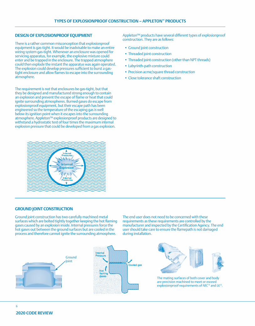
Ground joint construction has two carefully machined metal surfaces which are bolted tightly together keeping the hot flaming gases caused by an explosion inside. Internal pressures force the hot gases out between the ground surfaces but are cooled in the process and therefore cannot ignite the surrounding atmosphere.
The end user does not need to be concerned with these requirements as these requirements are controlled by the manufacturer and inspected by the Certification Agency. The end user should take care to ensure the flamepath is not damaged during installation.
The mating surfaces of both cover and body are precision machined to meet or exceed explosionproof requirements of NEC ® and UL®.
Ground Joint
2020 CODE REVIEW
7
TYPES OF EXPLOSIONPROOF CONSTRUCTION – APPLETON™ PRODUCTS
Fitting with a shoulder and no undercut
Fitting with a shoulder and no undercut
Fitting without a shoulder and no undercut
Fitting with a shoulder and undercut
InternalThreads
External Threads
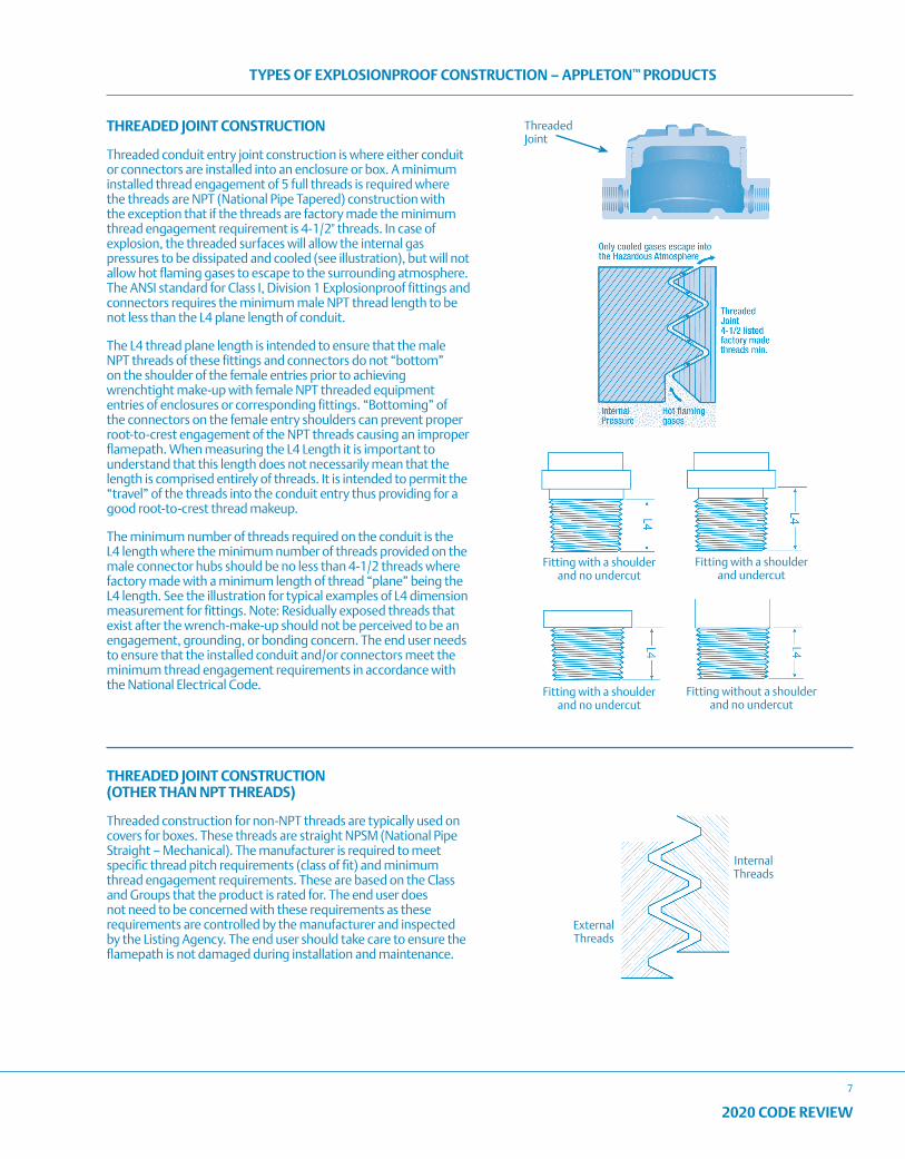
THREADED JOINT CONSTRUCTION
Threaded conduit entry joint construction is where either conduit or connectors are installed into an enclosure or box. A minimum installed thread engagement of 5 full threads is required where the threads are NPT (National Pipe Tapered) construction with the exception that if the threads are factory made the minimum thread engagement requirement is 4-1/2" threads. In case of explosion, the threaded surfaces will allow the internal gas pressures to be dissipated and cooled (see illustration), but will not allow hot flaming gases to escape to the surrounding atmosphere. The ANSI standard for Class I, Division 1 Explosionproof fittings and connectors requires the minimum male NPT thread length to be not less than the L4 plane length of conduit.
The L4 thread plane length is intended to ensure that the male NPT threads of these fittings and connectors do not “bottom” on the shoulder of the female entries prior to achieving wrenchtight make-up with female NPT threaded equipment entries of enclosures or corresponding fittings. “Bottoming” of the connectors on the female entry shoulders can prevent proper root-to-crest engagement of the NPT threads causing an improper flamepath. When measuring the L4 Length it is important to understand that this length does not necessarily mean that the length is comprised entirely of threads. It is intended to permit the “travel” of the threads into the conduit entry thus providing for a good root-to-crest thread makeup.
The minimum number of threads required on the conduit is the L4 length where the minimum number of threads provided on the male connector hubs should be no less than 4-1/2 threads where factory made with a minimum length of thread “plane” being the L4 length. See the illustration for typical examples of L4 dimension measurement for fittings. Note: Residually exposed threads that exist after the wrench-make-up should not be perceived to be an engagement, grounding, or bonding concern. The end user needs to ensure that the installed conduit and/or connectors meet the minimum thread engagement requirements in accordance with the National Electrical Code.
Threaded Joint
THREADED JOINT CONSTRUCTION (OTHER THAN NPT THREADS)
Threaded construction for non-NPT threads are typically used on covers for boxes. These threads are straight NPSM (National Pipe Straight – Mechanical). The manufacturer is required to meet specific thread pitch requirements (class of fit) and minimum thread engagement requirements. These are based on the Class and Groups that the product is rated for. The end user does not need to be concerned with these requirements as these requirements are controlled by the manufacturer and inspected by the Listing Agency. The end user should take care to ensure the flamepath is not damaged during installation and maintenance.
8
2020 CODE REVIEW
TYPES OF EXPLOSIONPROOF CONSTRUCTION – APPLETON™ PRODUCTS
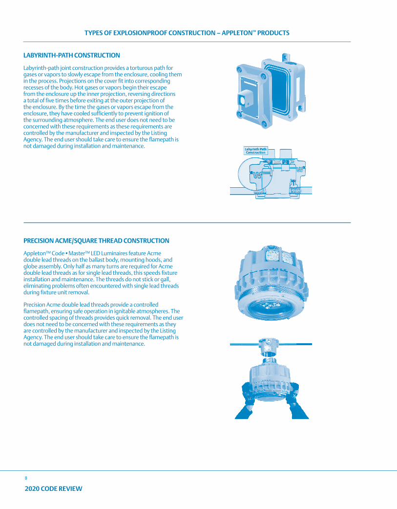
LABYRINTH-PATH CONSTRUCTION
Labyrinth-path joint construction provides a torturous path for gases or vapors to slowly escape from the enclosure, cooling them in the process. Projections on the cover fit into corresponding recesses of the body. Hot gases or vapors begin their escape from the enclosure up the inner projection, reversing directions a total of five times before exiting at the outer projection of the enclosure. By the time the gases or vapors escape from the enclosure, they have cooled sufficiently to prevent ignition of the surrounding atmosphere. The end user does not need to be concerned with these requirements as these requirements are controlled by the manufacturer and inspected by the Listing Agency. The end user should take care to ensure the flamepath is not damaged during installation and maintenance.
PRECISION ACME/SQUARE THREAD CONSTRUCTION
Appleton™ Code•Master™ LED Luminaires feature Acme double lead threads on the ballast body, mounting hoods, and globe assembly. Only half as many turns are required for Acme double lead threads as for single lead threads, this speeds fixture installation and maintenance. The threads do not stick or gall, eliminating problems often encountered with single lead threads during fixture unit removal.
Precision Acme double lead threads provide a controlled flamepath, ensuring safe operation in ignitable atmospheres. The controlled spacing of threads provides quick removal. The end user does not need to be concerned with these requirements as they are controlled by the manufacturer and inspected by the Listing Agency. The end user should take care to ensure the flamepath is not damaged during installation and maintenance.
2020 CODE REVIEW
9
TYPES OF EXPLOSIONPROOF CONSTRUCTION – APPLETON™ PRODUCTS
Combination Push Button and Pilot Light.
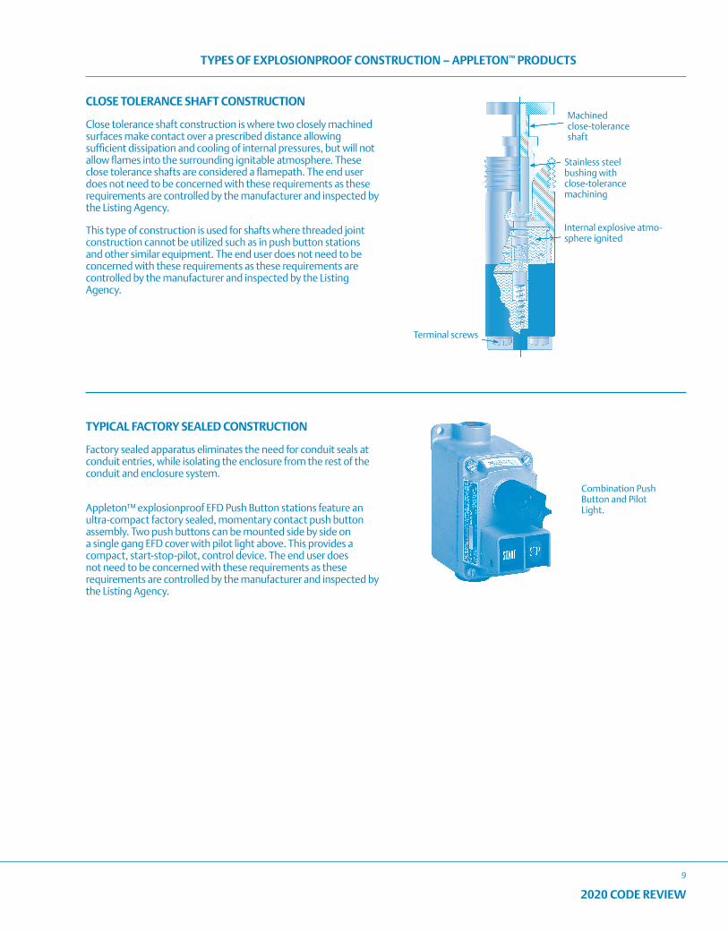
CLOSE TOLERANCE SHAFT CONSTRUCTION
Close tolerance shaft construction is where two closely machined surfaces make contact over a prescribed distance allowing sufficient dissipation and cooling of internal pressures, but will not allow flames into the surrounding ignitable atmosphere. These close tolerance shafts are considered a flamepath. The end user does not need to be concerned with these requirements as these requirements are controlled by the manufacturer and inspected by the Listing Agency.
This type of construction is used for shafts where threaded joint construction cannot be utilized such as in push button stations and other similar equipment. The end user does not need to be concerned with these requirements as these requirements are controlled by the manufacturer and inspected by the Listing Agency.
TYPICAL FACTORY SEALED CONSTRUCTION
Factory sealed apparatus eliminates the need for conduit seals at conduit entries, while isolating the enclosure from the rest of the conduit and enclosure system.
Appleton™ explosionproof EFD Push Button stations feature an ultra-compact factory sealed, momentary contact push button assembly. Two push buttons can be mounted side by side on a single gang EFD cover with pilot light above. This provides a compact, start-stop-pilot, control device. The end user does not need to be concerned with these requirements as these requirements are controlled by the manufacturer and inspected by the Listing Agency.
Machined close-tolerance shaft
Stainless steel bushing with close-tolerance machining
Internal explosive atmo-sphere ignited
Terminal screws

10
2020 CODE REVIEW
NOTES
Reproduced with permission of NFPA from NFPA 70®, National Electrical Code®, 2020 edition. Copyright © 2019, National Fire Protection Association. For a full copy of NFPA 70, please go to www.nfpa.org. 11
INTERPRETATION OF ARTICLE 90: INTRODUCTION
2020 CODE REVIEW
90.2
CHANGES TO ARTICLE 90 – Introduction
There were no significant revisions to Article 90 during the 2020 NEC® Code cycle.
Underlined text indicates a section that has been revised from the previous NEC® edition. It is not intended to indicate legislation text detailing the word-for-word revisions to the section. Where minor revisions have been made to a section, these will include underlined text for select words to indicate the minor revision.
ARTICLE 90 Introduction
90.1 Purpose
(A) Practicale Safeguarding. The purpose of this Code is the practical safeguarding of persons and property from hazards arising from the use of electricity. This Code is not intended as a design specification or an instruction manual for untrained persons.
(B) Adequacy. This Code contains provisions that are considered necessary for safety. Compliance therewith and proper maintenance result in an installation that is essentially free from hazard but not necessarily efficient, convenient, or adequate for good service or future expansion of electrical use.
Informational Note: Hazards often occur because of overloading of wiring systems by methods or usage not in conformity with this Code. This occurs because initial wiring did not provide for increases in the use of electricity. An initial adequate installation and reasonable provisions for system changes provide for future increases in the use of electricity.
(C) Relation to Other International Standards. The requirements in this Code address the fundamental principles of protection for safety contained in Section 131 of International Electrotechnical Commission Standard 60364-1, Electrical Installations of Buildings.
Informational Note: IEC 60364-1, Section 131, contains fundamental principles of protection for safety that encompass protection against electric shock, protection against thermal effects, protection against overcurrent, protection against fault currents, and protection against overvoltage. All of these potential hazards are addressed by the requirements in this Code.
90.2 Scope.
(A) Covered. This Code covers the installation and removal of electrical conductors, equipment, and raceways; signaling and communications conductors, equipment, and raceways; and optical fiber cables for the following:
(1) Public and private premises, including buildings, structures, mobile homes, recreational vehicles, and floating buildings
(2) Yards, lots, parking lots, carnivals, and industrial substations
(3) Installations of conductors and equipment that connect to the supply of electricity
(4) Installations used by the electric utility, such as office buildings, warehouses, garages, machine shops, and recreational buildings, that are not an integral part of a generating plant, substation, or control center
(5) Installations supplying shore power to ships and watercraft in marinas and boatyards, including monitoring of leakage current
(6) Installations used to export electric power from vehicles to premises wiring or for bidirectional current flow
(B) Not Covered. This Code does not cover the following:
(1) Installations in ships, watercraft other than floating buildings, railway rolling stock, aircraft, or automotive vehicles other than mobile homes and recreational vehicles
Informational Note: Although the scope of this Code indicates that the Code does not cover installations in ships, portions of this Code are incorporated by reference into Title 46, Code of Federal Regulations, Parts 110–113.
(2) Installations underground in mines and self-propelled mobile surface mining machinery and its attendant electrical trailing cable
(3) Installations of railways for generation, transformation, transmission, energy storage, or distribution of power used exclusively for operation of rolling stock or installations used exclusively for signaling and communications purposes
(4) Installations of communications equipment under the exclusive control of communications utilities located outdoors or in building spaces used exclusively for such installations
(5) Installations under the exclusive control of an electric utility where such installations
a. Consist of service drops or service laterals, and associated metering, or
b. Are on property owned or leased by the electric utility for the purpose of communications, metering, generation, control, transformation, transmission, energy storage, or distribution of electric energy, or
c. Are located in legally established easements or rights-of-way, or
d. Are located by other written agreements either designated by or recognized by public service commissions, utility commissions, or other regulatory agencies having jurisdiction for such installations. These written agreements shall be limited to installations for the purpose of communications, metering, generation, control, transformation, transmission, energy storage, or distribution of electric energy where legally established easements or rights-of-way cannot be obtained. These installations shall be limited to federal lands, Native American reservations through the U.S. Department of the Interior Bureau of Indian Affairs, military bases, lands controlled by port authorities and state agencies and departments, and lands owned by railroads.
Informational Note to (4) and (5): Examples of utilities may include those entities that are typically designated or recognized by governmental law or regulation by public service/utility commissions and that install, operate, and maintain electric supply (such as generation, transmission, or distribution systems) or communications systems (such as telephone, CATV, Internet, satellite, or data services). Utilities may be subject to compliance with codes and standards covering their regulated activities as adopted under governmental law or regulation. Additional information can be found through consultation with the appropriate governmental bodies, such as state regulatory commissions, the Federal Energy Regulatory Commission, and the Federal Communications Commission.
Reproduced with permission of NFPA from NFPA 70®, National Electrical Code®, 2020 edition. Copyright © 2019, National Fire Protection Association. For a full copy of NFPA 70, please go to www.nfpa.org.12
2020 CODE REVIEW
INTERPRETATION OF ARTICLE 90: INTRODUCTION
2020 CODE REVIEW
90.2
(C) Special Permission. The authority having jurisdiction for enforcing this Code may grant exception for the installation of conductors and equipment that are not under the exclusive control of the electric utilities and are used to connect the electric utility supply system to the service conductors of the premises served, provided such installations are outside a building or structure, or terminate inside at a readily accessible location nearest the point of entrance of the service conductors.
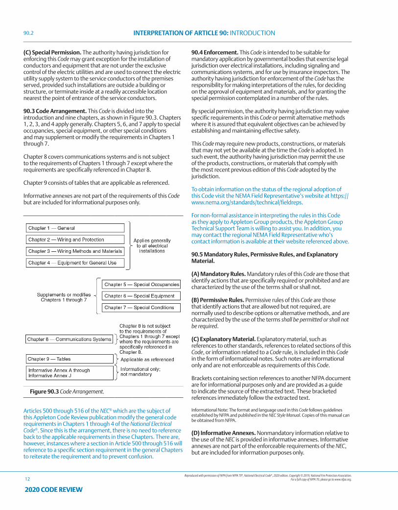
90.3 Code Arrangement. This Code is divided into the introduction and nine chapters, as shown in Figure 90.3. Chapters 1, 2, 3, and 4 apply generally. Chapters 5, 6, and 7 apply to special occupancies, special equipment, or other special conditions and may supplement or modify the requirements in Chapters 1 through 7.
Chapter 8 covers communications systems and is not subject to the requirements of Chapters 1 through 7 except where the requirements are specifically referenced in Chapter 8.
Chapter 9 consists of tables that are applicable as referenced.
Informative annexes are not part of the requirements of this Code but are included for informational purposes only.
Figure 90.3 Code Arrangement.
Articles 500 through 516 of the NEC® which are the subject of this Appleton Code Review publication modify the general code requirements in Chapters 1 through 4 of the National Electrical Code®. Since this is the arrangement, there is no need to reference back to the applicable requirements in these Chapters. There are, however, instances where a section in Article 500 through 516 will reference to a specific section requirement in the general Chapters to reiterate the requirement and to prevent confusion.
90.4 Enforcement. This Code is intended to be suitable for mandatory application by governmental bodies that exercise legal jurisdiction over electrical installations, including signaling and communications systems, and for use by insurance inspectors. The authority having jurisdiction for enforcement of the Code has the responsibility for making interpretations of the rules, for deciding on the approval of equipment and materials, and for granting the special permission contemplated in a number of the rules.
By special permission, the authority having jurisdiction may waive specific requirements in this Code or permit alternative methods where it is assured that equivalent objectives can be achieved by establishing and maintaining effective safety.
This Code may require new products, constructions, or materials that may not yet be available at the time the Code is adopted. In such event, the authority having jurisdiction may permit the use of the products, constructions, or materials that comply with the most recent previous edition of this Code adopted by the jurisdiction.
To obtain information on the status of the regional adoption of this Code visit the NEMA Field Representative’s website at https://www.nema.org/standards/technical/fieldreps.
For non-formal assistance in interpreting the rules in this Code as they apply to Appleton Group products, the Appleton Group Technical Support Team is willing to assist you. In addition, you may contact the regional NEMA Field Representative who’s contact information is available at their website referenced above.
90.5 Mandatory Rules, Permissive Rules, and Explanatory Material.
(A) Mandatory Rules. Mandatory rules of this Code are those that identify actions that are specifically required or prohibited and are characterized by the use of the terms shall or shall not.
(B) Permissive Rules. Permissive rules of this Code are those that identify actions that are allowed but not required, are normally used to describe options or alternative methods, and are characterized by the use of the terms shall be permitted or shall not be required.
(C) Explanatory Material. Explanatory material, such as references to other standards, references to related sections of this Code, or information related to a Code rule, is included in this Code in the form of informational notes. Such notes are informational only and are not enforceable as requirements of this Code.
Brackets containing section references to another NFPA document are for informational purposes only and are provided as a guide to indicate the source of the extracted text. These bracketed references immediately follow the extracted text.
Informational Note: The format and language used in this Code follows guidelines established by NFPA and published in the NEC Style Manual. Copies of this manual can be obtained from NFPA.
(D) Informative Annexes. Nonmandatory information relative to the use of the NEC is provided in informative annexes. Informative annexes are not part of the enforceable requirements of the NEC, but are included for information purposes only.
Reproduced with permission of NFPA from NFPA 70®, National Electrical Code®, 2020 edition. Copyright © 2019, National Fire Protection Association. For a full copy of NFPA 70, please go to www.nfpa.org. 13
INTERPRETATION OF ARTICLE 90: INTRODUCTION
2020 CODE REVIEW
90.9
90.6 Formal Interpretations. To promote uniformity of interpretation and application of this Code, formal interpretation procedures have been established and are found in the Regulations Governing the Development of NFPA Standards.
For general assistance in interpreting the rules in this Code as they apply to Appleton products, the Appleton Group Technical Support Team ([email protected]) is available to assist you. In addition, you may contact the regional NEMA Field Representative at https://www.nema.org/standards/technical/fieldreps.
90.7 Examination of Equipment for Safety. For specific items of equipment and materials referred to in this Code, examinations for safety made under standard conditions provide a basis for approval where the record is made generally available through promulgation by organizations properly equipped and qualified for experimental testing, inspections of the run of goods at factories, and service-value determination through field inspections. This avoids the necessity for repetition of examinations by different examiners, frequently with inadequate facilities for such work, and the confusion that would result from conflicting reports on the suitability of devices and materials examined for a given purpose.
It is the intent of this Code that factory-installed internal wiring or the construction of equipment need not be inspected at the time of installation of the equipment, except to detect alterations or damage, if the equipment has been listed by a qualified electrical testing laboratory that is recognized as having the facilities described in the preceding paragraph and that requires suitability for installation in accordance with this Code. Suitability shall be determined by application of requirements that are compatible with this Code.
Informational Note No. 1: See requirements in 110.3.
Informational Note No. 2: Listed is defined in Article 100.
Informational Note No. 3: Informative Annex A contains a list of product safety standards that are compatible with this Code.
90.8 Wiring Planning.
(A) Future Expansion and Convenience. Plans and specifications that provide ample space in raceways, spare raceways, and additional spaces allow for future increases in electric power and communications circuits. Distribution centers located in readily accessible locations provide convenience and safety of operation.
(B) Number of Circuits in Enclosures. It is elsewhere provided in this Code that the number of circuits confined in a single enclosure be varyingly restricted. Limiting the number of circuits in a single enclosure minimizes the effects from a short circuit or ground fault.
90.9 Units of Measurement.
(A) Measurement System of Preference. For the purpose of this Code, metric units of measurement are in accordance with the modernized metric system known as the International System of Units (SI).
(B) Dual System of Units. SI units shall appear first, and inch-pound units shall immediately follow in parentheses. Conversion
from inch-pound units to SI units shall be based on hard conversion except as provided in 90.9(C).
(C) Permitted Uses of Soft Conversion. The cases given in 90.9(C)(1) through (C)(4) shall not be required to use hard conversion and shall be permitted to use soft conversion.
(1) Trade Sizes. Where the actual measured size of a product is not the same as the nominal size, trade size designators shall be used rather than dimensions. Trade practices shall be followed in all cases.
(2) Extracted Material. Where material is extracted from another standard, the context of the original material shall not be compromised or violated. Any editing of the extracted text shall be confined to making the style consistent with that of the NEC.
(3) Industry Practice. Where industry practice is to express units in inch-pound units, the inclusion of SI units shall not be required.
(4) Safety. Where a negative impact on safety would result, soft conversion shall be used.
(D) Compliance. Conversion from inch-pound units to SI units shall be permitted to be an approximate conversion. Compliance with the numbers shown in either the SI system or the inch-pound system shall constitute compliance with this Code.
Informational Note No. 1: Hard conversion is considered a change in dimensions or properties of an item into new sizes that might or might not be interchangeable with the sizes used in the original measurement. Soft conversion is considered a direct mathematical conversion and involves a change in the description of an existing measurement but not in the actual dimension.
Informational Note No. 2: SI conversions are based on IEEE/ASTM SI 10-1997, Standard for the Use of the International System of Units (SI): The Modern Metric System.

14
2020 CODE REVIEW
NOTES
Reproduced with permission of NFPA from NFPA 70®, National Electrical Code®, 2020 edition. Copyright © 2019, National Fire Protection Association. For a full copy of NFPA 70, please go to www.nfpa.org.
INTERPRETATION OF ARTICLE 100: DEFINITIONS
15
2020 CODE REVIEW
CHANGES TO ARTICLE 100 - DEFINITIONSAll definitions that had been located in Articles 500 through 516 are now located in Article 100. In addition, each definition in Article 100 also contains a notation as to which Code Making Panel (CMP) is responsible for the definition.
The definitions have been separated into three Parts:
• Part I: General
• Part II: Part II. Over 1000 Volts, Nominal
• Part III: Part III. Hazardous (Classified) Locations (CMP-14).
ARTICLE 100 Definitions
Scope. This article contains only those definitions essential to the application of this Code. It is not intended to include commonly defined general terms or commonly defined technical terms from related codes and standards. In general, only those terms that are used in two or more articles are defined in Article 100. Definitions are also found in XXX.2 sections of other articles.
Part I of this article contains definitions intended to apply wherever the terms are used throughout this Code. Part II contains definitions applicable to installations and equipment operating at over 1000 volts, nominal. Part III contains definitions applicable to Hazardous (Classified) Locations.
Part I. General
Accessible (as applied to equipment). Capable of being reached for operation, renewal, and inspection. (CMP-1)
Accessible (as applied to wiring methods). Capable of being removed or exposed without damaging the building structure or finish or not permanently closed in by the structure or finish of the building. (CMP-1)
Accessible, Readily (Readily Accessible). Capable of being reached quickly for operation, renewal, or inspections without requiring those to whom ready access is requisite to take actions such as to use tools (other than keys), to climb over or under, to remove obstacles, or to resort to portable ladders, and so forth. (CMP-1)Informational Note: Use of keys is a common practice under controlled or supervised conditions and a common alternative to the ready access requirements under such supervised conditions as provided elsewhere in the NEC.
Adjustable Speed Drive. Power conversion equipment that provides a means of adjusting the speed of an electric motor. (CMP-11)Informational Note: A variable frequency drive is one type of electronic adjustable speed drive that controls the rotational speed of an ac electric motor by controlling the frequency and voltage of the electrical power supplied to the motor.
Adjustable Speed Drive System. A combination of an adjustable speed drive, its associated motor(s), and auxiliary equipment. (CMP-11)
Ampacity. The maximum current, in amperes, that a conductor can carry continuously under the conditions of use without exceeding its temperature rating. (CMP-6)
Appliance. Utilization equipment, generally other than industrial, that is normally built in standardized sizes or types and is installed or connected as a unit to perform one or more functions such as clothes washing, air-conditioning, food mixing, deep frying, and so forth. (CMP-17)
Approved. Acceptable to the authority having jurisdiction. (CMP-1)
Arc-Fault Circuit Interrupter (AFCI). A device intended to provide protection from the effects of arc faults by recognizing characteristics unique to arcing and by functioning to de-energize the circuit when an arc fault is detected. (CMP-2)
Askarel. A generic term for a group of nonflammable synthetic chlorinated hydrocarbons used as electrical insulating media. (CMP-9)Informational Note: Askarels of various compositional types are used. Under arcing conditions, the gases produced, while consisting predominantly of noncombustible hydrogen chloride, can include varying amounts of combustible gases, depending on the askarel type.
Attachment Fitting. A device that, by insertion into a locking support and mounting receptacle, establishes a connection between the conductors of the attached utilization equipment and the branch-circuit conductors connected to the locking support and mounting receptacle. (CMP-18)Informational Note: An attachment fitting is different from an attachment plug because no cord is associated with the fitting. An attachment fitting in combination with a locking support and mounting receptacle secures the associated utilization equipment in place and supports its weight.
Attachment Plug (Plug Cap) (Plug). A device that, by insertion in a receptacle, establishes a connection between the conductors of the attached flexible cord and the conductors connected permanently to the receptacle. (CMP-18)
Authority Having Jurisdiction (AHJ). An organization, office, or individual responsible for enforcing the requirements of a code or standard, or for approving equipment, materials, an installation, or a procedure. (CMP-1)Informational Note: The phrase “authority having jurisdiction,” or its acronym AHJ, is used in NFPA documents in a broad manner, since jurisdictions and approval agencies vary, as do their responsibilities. Where public safety is primary, the authority having jurisdiction may be a federal, state, local, or other regional department or individual such as a fire chief; fire marshal; chief of a fire prevention bureau, labor department, or health department; building official; electrical inspector; or others having statutory authority. For insurance purposes, an insurance inspection department, rating bureau, or other insurance company representative may be the authority having jurisdiction. In many circumstances, the property owner or his or her designated agent assumes the role of the authority having jurisdiction; at government installations, the commanding officer or departmental official may be the authority having jurisdiction.
Automatic. Performing a function without the necessity of human intervention. (CMP-1)
Bathroom. An area including a sink (basin) with one or more of the following: a toilet, a urinal, a tub, a shower, a bidet, or similar plumbing fixtures. (CMP-2)
Battery System. Interconnected battery subsystems consisting of one or more storage batteries and battery chargers, and can include inverters, converters, and associated electrical equipment. (CMP-13)
Bonded (Bonding). Connected to establish electrical continuity and conductivity. (CMP-5)
Bonding Conductor or Jumper. A reliable conductor to ensure the required electrical conductivity between metal parts required to be electrically connected. (CMP-5)
Bonding Jumper, Equipment. The connection between two or more portions of the equipment grounding conductor. (CMP-5)
Bonding Jumper, Main. The connection between the grounded circuit conductor and the equipment grounding conductor, or the supply-side bonding jumper, or both, at the service. (CMP-5)
Reproduced with permission of NFPA from NFPA 70®, National Electrical Code®, 2020 edition. Copyright © 2019, National Fire Protection Association. For a full copy of NFPA 70, please go to www.nfpa.org.
INTERPRETATION OF ARTICLE 100: DEFINITIONS
16
2020 CODE REVIEW
Bonding Jumper, Supply-Side. A conductor installed on the supply side of a service or within a service equipment enclosure(s), or for a separately derived system, that ensures the required electrical conductivity between metal parts required to be electrically connected. (CMP-5)
Bonding Jumper, System. The connection between the grounded circuit conductor and the supply-side bonding jumper, or the equipment grounding conductor, or both, at a separately derived system. (CMP-5)
Branch Circuit. The circuit conductors between the final overcurrent device protecting the circuit and the outlet(s). (CMP-2)
Branch Circuit, Appliance. A branch circuit that supplies energy to one or more outlets to which appliances are to be connected and that has no permanently connected luminaires that are not a part of an appliance. (CMP-2)
Branch Circuit, General-Purpose. A branch circuit that supplies two or more receptacles or outlets for lighting and appliances. (CMP-2)
Branch Circuit, Individual. A branch circuit that supplies only one utilization equipment. (CMP-2)
Branch Circuit, Multiwire. A branch circuit that consists of two or more ungrounded conductors that have a voltage between them, and a grounded conductor that has equal voltage between it and each ungrounded conductor of the circuit and that is connected to the neutral or grounded conductor of the system. (CMP-2)
Building. A structure that stands alone or that is separated from adjoining structures by fire walls. (CMP-1)
Cabinet. An enclosure that is designed for either surface mounting or flush mounting and is provided with a frame, mat, or trim in which a swinging door or doors are or can be hung. (CMP-9)
Cable, Coaxial. A cylindrical assembly composed of a conductor centered inside a metallic tube or shield, separated by a dielectric material, and usually covered by an insulating jacket. (CMP-16)
Cable, Optical Fiber. A factory assembly or field assembly of one or more optical fibers having an overall covering. (CMP-16)Informational Note: A field-assembled optical fiber cable is an assembly of one or more optical fibers within a jacket. The jacket, without optical fibers, is installed in a manner similar to conduit or raceway. Once the jacket is installed, the optical fibers are inserted into the jacket, completing the cable assembly.
Cable, Optical Fiber, Composite. A cable containing optical fibers and current-carrying electrical conductors. (CMP-16)
Cable, Optical Fiber, Conductive. A factory assembly of one or more optical fibers having an overall covering and containing non–current-carrying conductive member(s) such as metallic strength member(s), metallic vapor barrier(s), metallic armor, or metallic sheath. (CMP-16)
Cable, Optical Fiber, Nonconductive. A factory assembly of one or more optical fibers having an overall covering and containing no electrically conductive materials. (CMP-16)
Cable Routing Assembly. A single channel or connected multiple channels, as well as associated fittings, forming a structural system that is used to support and route communications wires and cables, optical fiber cables, data cables associated with information technology and communications equipment, Class 2, Class 3, and Type PLTC cables, and power-limited fire alarm cables in plenum, riser, and general-purpose applications. (CMP-16)
Charge Controller. Equipment that controls dc voltage or dc current, or both, and that is used to charge a battery or other energy storage device. (CMP-13)
Circuit Breaker. A device designed to open and close a circuit by nonautomatic means and to open the circuit automatically on a predetermined overcurrent without damage to itself when properly applied within its rating. (CMP-10)Informational Note: The automatic opening means can be integral, direct acting with the circuit breaker, or remote from the circuit breaker.
Adjustable (as applied to circuit breakers). A qualifying term indicating that the circuit breaker can be set to trip at various values of current, time, or both, within a predetermined range.
Instantaneous Trip (as applied to circuit breakers). A qualifying term indicating that no delay is purposely introduced in the tripping action of the circuit breaker.
Inverse Time (as applied to circuit breakers). A qualifying term indicating that there is purposely introduced a delay in the tripping action of the circuit breaker, which delay decreases as the magnitude of the current increases.
Nonadjustable (as applied to circuit breakers). A qualifying term indicating that the circuit breaker does not have any adjustment to alter the value of the current at which it will trip or the time required for its operation.
Setting (of circuit breakers). The value of current, time, or both, at which an adjustable circuit breaker is set to trip.
Circuit Integrity (CI) Cable. Cable(s) used for remote-control, signaling, or power-limited systems that supply critical circuits to ensure survivability for continued circuit operation for a specified time under fire conditions. (CMP-3)
Class 1 Circuit. The portion of the wiring system between the load side of the overcurrent device or power-limited supply and the connected equipment. (CMP-3)Informational Note: See 725.41 for voltage and power limitations of Class 1 circuits.
Class 2 Circuit. The portion of the wiring system between the load side of a Class 2 power source and the connected equipment. Due to its power limitations, a Class 2 circuit considers safety from a fire initiation standpoint and provides acceptable protection from electric shock. (CMP-3)
Class 3 Circuit. The portion of the wiring system between the load side of a Class 3 power source and the connected equipment. Due to its power limitations, a Class 3 circuit considers safety from a fire initiation standpoint. Since higher levels of voltage and current than for Class 2 are permitted, additional safeguards are specified to provide protection from an electric shock hazard that could be encountered. (CMP-3)
Clothes Closet. A nonhabitable room or space intended primarily for storage of garments and apparel. (CMP-1)
Communications Equipment. The electronic equipment that performs the telecommunications operations for the transmission of audio, video, and data, and includes power equipment (e.g., dc converters, inverters, and batteries), technical support equipment (e.g., computers), and conductors dedicated solely to the operation of the equipment. (CMP-16)Informational Note: As the telecommunications network transitions to a more data-centric network, computers, routers, servers, and their powering equipment, are becoming essential to the transmission of audio, video, and data and are finding increasing application in communications equipment installations.
Reproduced with permission of NFPA from NFPA 70®, National Electrical Code®, 2020 edition. Copyright © 2019, National Fire Protection Association. For a full copy of NFPA 70, please go to www.nfpa.org.
INTERPRETATION OF ARTICLE 100: DEFINITIONS
17
2020 CODE REVIEW
Concealed. Rendered inaccessible by the structure or finish of the building. (CMP-1)Informational Note: Wires in concealed raceways are considered concealed, even though they may become accessible by withdrawing them.
Conductor, Bare. A conductor having no covering or electrical insulation whatsoever. (CMP-6)
Conductor, Covered. A conductor encased within material of composition or thickness that is not recognized by this Code as electrical insulation. (CMP-6)
Conductor, Insulated. A conductor encased within material of composition and thickness that is recognized by this Code as electrical insulation. (CMP-6)
Conduit Body. A separate portion of a conduit or tubing system that provides access through a removable cover(s) to the interior of the system at a junction of two or more sections of the system or at a terminal point of the system.
Boxes such as FS and FD or larger cast or sheet metal boxes are not classified as conduit bodies. (CMP-9)
Connector, Pressure (Solderless). A device that establishes a connection between two or more conductors or between one or more conductors and a terminal by means of mechanical pressure and without the use of solder. (CMP-1)
Continuous Load. A load where the maximum current is expected to continue for 3 hours or more. (CMP-2)
Control Circuit. The circuit of a control apparatus or system that carries the electric signals directing the performance of the controller but does not carry the main power current. (CMP-11)
Controller. A device or group of devices that serves to govern, in some predetermined manner, the electric power delivered to the apparatus to which it is connected. (CMP-1)
Cooking Unit, Counter-Mounted. A cooking appliance designed for mounting in or on a counter and consisting of one or more heating elements, internal wiring, and built-in or mountable controls. (CMP-2)
Coordination, Selective (Selective Coordination). Localization of an overcurrent condition to restrict outages to the circuit or equipment affected, accomplished by the selection and installation of overcurrent protective devices and their ratings or settings for the full range of available overcurrents, from overload to the available fault current, and for the full range of overcurrent protective device opening times associated with those overcurrents. (CMP-10)
Copper-Clad Aluminum Conductors. Conductors drawn from a copper-clad aluminum rod, with the copper metallurgically bonded to an aluminum core, where the copper forms a minimum of 10 percent of the cross-sectional area of a solid conductor or each strand of a stranded conductor. (CMP-6)
Cutout Box. An enclosure designed for surface mounting that has swinging doors or covers secured directly to and telescoping with the walls of the enclosure. (CMP-9)
DC-to-DC Converter. A device that can provide an output dc voltage and current at a higher or lower value than the input dc voltage and current. (CMP-4)
Dead Front. Without live parts exposed to a person on the operating side of the equipment. (CMP-9)
Demand Factor. The ratio of the maximum demand of a system,
or part of a system, to the total connected load of a system or the part of the system under consideration. (CMP-2)
Device. A unit of an electrical system, other than a conductor, that carries or controls electric energy as its principal function. (CMP-1)
Disconnecting Means. A device, or group of devices, or other means by which the conductors of a circuit can be disconnected from their source of supply. (CMP-1)
Dormitory Unit. A building or a space in a building in which group sleeping accommodations are provided for more than 16 persons who are not members of the same family in one room, or a series of closely associated rooms, under joint occupancy and single management, with or without meals, but without individual cooking facilities. (CMP 2)
Duty, Continuous. Operation at a substantially constant load for an indefinitely long time. (CMP-1)
Duty, Intermittent. Operation for alternate intervals of (1) load and no load; or (2) load and rest; or (3) load, no load, and rest. (CMP-1)
Duty, Periodic. Intermittent operation in which the load conditions are regularly recurrent. (CMP-1)
Duty, Short-Time. Operation at a substantially constant load for a short and definite, specified time. (CMP-1)
Duty, Varying. Operation at loads, and for intervals of time, both of which may be subject to wide variation. (CMP-1)
Dwelling, One-Family. A building that consists solely of one dwelling unit. (CMP-1)
Dwelling, Two-Family. A building that consists solely of two dwelling units. (CMP-1)
Dwelling, Multifamily. A building that contains three or more dwelling units. (CMP-1)
Dwelling Unit. A single unit, providing complete and independent living facilities for one or more persons, including permanent provisions for living, sleeping, cooking, and sanitation. (CMP-2)
Effective Ground-Fault Current Path. An intentionally constructed, low-impedance electrically conductive path designed and intended to carry current under ground-fault conditions from the point of a ground fault on a wiring system to the electrical supply source and that facilitates the operation of the overcurrent protective device or ground-fault detectors. (CMP-5)
Electric Power Production and Distribution Network. Power production, distribution, and utilization equipment and facilities, such as electric utility systems that are connected to premises wiring and are external to and not controlled by an interactive system. (CMP-13)
Electric Sign. A fixed, stationary, or portable self-contained, electrically operated and/or electrically illuminated utilization equipment with words or symbols designed to convey information or attract attention. (CMP-18)
Electric Vehicle (EV). An automotive-type vehicle for on-road use, such as passenger automobiles, buses, trucks, vans, neighborhood electric vehicles, electric motorcycles, and the like, primarily powered by an electric motor that draws current from a rechargeable storage battery, fuel cell, photovoltaic array, or other source of electric current. Plug-in hybrid electric vehicles (PHEV) are electric vehicles having a second source of motive power. Off-road, self-propelled electric mobile equipment, such as industrial
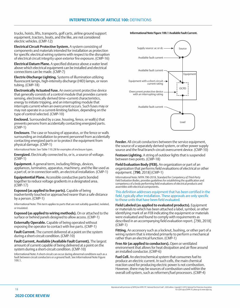
Reproduced with permission of NFPA from NFPA 70®, National Electrical Code®, 2020 edition. Copyright © 2019, National Fire Protection Association. For a full copy of NFPA 70, please go to www.nfpa.org.
INTERPRETATION OF ARTICLE 100: DEFINITIONS
18
2020 CODE REVIEW
trucks, hoists, lifts, transports, golf carts, airline ground support equipment, tractors, boats, and the like, are not considered electric vehicles. (CMP-12)
Electrical Circuit Protective System. A system consisting of components and materials intended for installation as protection for specific electrical wiring systems with respect to the disruption of electrical circuit integrity upon exterior fire exposure. (CMP-16)
Electrical Datum Plane. A specified distance above a water level above which electrical equipment can be installed and electrical connections can be made. (CMP-7)
Electric-Discharge Lighting. Systems of illumination utilizing fluorescent lamps, high-intensity discharge (HID) lamps, or neon tubing. (CMP-18)
Electronically Actuated Fuse. An overcurrent protective device that generally consists of a control module that provides current-sensing, electronically derived time–current characteristics, energy to initiate tripping, and an interrupting module that interrupts current when an overcurrent occurs. Such fuses may or may not operate in a current-limiting fashion, depending on the type of control selected. (CMP-10)
Enclosed. Surrounded by a case, housing, fence, or wall(s) that prevents persons from accidentally contacting energized parts. (CMP-1)
Enclosure. The case or housing of apparatus, or the fence or walls surrounding an installation to prevent personnel from accidentally contacting energized parts or to protect the equipment from physical damage. (CMP-1)Informational Note: See Table 110.28 for examples of enclosure types.
Energized. Electrically connected to, or is, a source of voltage. (CMP-1)
Equipment. A general term, including fittings, devices, appliances, luminaires, apparatus, machinery, and the like used as a part of, or in connection with, an electrical installation. (CMP-1)
Equipotential Plane. Accessible conductive parts bonded together to reduce voltage gradients in a designated area. (CMP-17)
Exposed (as applied to live parts). Capable of being inadvertently touched or approached nearer than a safe distance by a person. (CMP-1)
Informational Note: This term applies to parts that are not suitably guarded, isolated, or insulated.
Exposed (as applied to wiring methods). On or attached to the surface or behind panels designed to allow access. (CMP-1)
Externally Operable. Capable of being operated without exposing the operator to contact with live parts. (CMP-1)
Fault Current. The current delivered at a point on the system during a short-circuit condition. (CMP-10)
Fault Current, Available (Available Fault Current). The largest amount of current capable of being delivered at a point on the system during a short-circuit condition. (CMP-10)Informational Note: A short-circuit can occur during abnormal conditions such as a fault between circuit conductors or a ground fault. See Informational Note Figure 100.1.
Informational Note Figure 100.1 Available Fault Current.
Feeder. All circuit conductors between the service equipment, the source of a separately derived system, or other power supply source and the final branch-circuit overcurrent device. (CMP-10)
Festoon Lighting. A string of outdoor lights that is suspended between two points. (CMP-18)
Field Evaluation Body (FEB). An organization or part of an organization that performs field evaluations of electrical or other equipment. [790, 2018] (CMP-1)Informational Note: NFPA 790-2018, Standard for Competency of Third-Party Field Evaluation Bodies, provides guidelines for establishing the qualification and competency of a body performing field evaluations of electrical products and assembles with electrical components.
This definition addresses equipment that has been certified in the field, typically after installation. These approvals are only specific to those units that have been field evaluated.
Field Labeled (as applied to evaluated products). Equipment or materials to which has been attached a label, symbol, or other identifying mark of an FEB indicating the equipment or materials were evaluated and found to comply with requirements as described in an accompanying field evaluation report. [790, 2018] (CMP-1)
Fitting. An accessory such as a locknut, bushing, or other part of a wiring system that is intended primarily to perform a mechanical rather than an electrical function. (CMP-1)
Free Air (as applied to conductors). Open or ventilated environment that allows for heat dissipation and air flow around an installed conductor. (CMP-6)
Fuel Cell. An electrochemical system that consumes fuel to produce an electric current. In such cells, the main chemical reaction used for producing electric power is not combustion. However, there may be sources of combustion used within the overall cell system, such as reformers/fuel processors. (CMP-4)
Reproduced with permission of NFPA from NFPA 70®, National Electrical Code®, 2020 edition. Copyright © 2019, National Fire Protection Association. For a full copy of NFPA 70, please go to www.nfpa.org.
INTERPRETATION OF ARTICLE 100: DEFINITIONS
19
2020 CODE REVIEW
Fuel Cell System. The complete aggregate of equipment used to convert chemical fuel into usable electricity and typically consisting of a reformer, stack, power inverter, and auxiliary equipment. (CMP-4)
Garage. A building or portion of a building in which one or more self-propelled vehicles can be kept for use, sale, storage, rental, repair, exhibition, or demonstration purposes. (CMP-1)Informational Note: For commercial garages, repair and storage, see Article 511.
Generating Capacity, Inverter. The sum of parallel-connected inverter maximum continuous output power at 40°C in watts or kilowatts. (CMP-4)
Ground. The earth. (CMP-5)
Ground Fault. An unintentional, electrically conductive connection between an ungrounded conductor of an electrical circuit and the normally non–current-carrying conductors, metallic enclosures, metallic raceways, metallic equipment, or earth. (CMP-5)
Grounded (Grounding). Connected (connecting) to ground or to a conductive body that extends the ground connection. (CMP-5)
Grounded, Solidly. Connected to ground without inserting any resistor or impedance device. (CMP-5)
Grounded Conductor. A system or circuit conductor that is intentionally grounded. (CMP-5)Informational Note: Although an equipment grounding conductor is grounded, it is not considered a grounded conductor.
Ground-Fault Circuit Interrupter (GFCI). A device intended for the protection of personnel that functions to de-energize a circuit or portion thereof within an established period of time when a ground-fault current exceeds the values established for a Class A device. (CMP-2)Informational Note: Class A ground-fault circuit interrupters trip when the ground-fault current is 6 mA or higher and do not trip when the ground-fault current is less than 4 mA. For further information, see UL 943, Standard for Ground-Fault Circuit Interrupters.
Ground-Fault Current Path. An electrically conductive path from the point of a ground fault on a wiring system through normally non–current-carrying conductors, grounded conductors, equipment, or the earth to the electrical supply source. (CMP-5)Informational Note: Examples of ground-fault current paths are any combination of equipment grounding conductors, metallic raceways, metallic cable sheaths, electrical equipment, and any other electrically conductive material such as metal, water, and gas piping; steel framing members; stucco mesh; metal ducting; reinforcing steel; shields of communications cables; grounded conductors; and the earth itself.
Ground-Fault Protection of Equipment. A system intended to provide protection of equipment from damaging line-to-ground fault currents by operating to cause a disconnecting means to open all ungrounded conductors of the faulted circuit. This protection is provided at current levels less than those required to protect conductors from damage through the operation of a supply circuit overcurrent device. (CMP-5)
Grounding Conductor, Equipment (EGC). A conductive path(s) that is part of an effective ground-fault current path and connects normally non–current-carrying metal parts of equipment together and to the system grounded conductor or to the grounding electrode conductor, or both. (CMP-5)Informational Note No. 1: It is recognized that the equipment grounding conductor also performs bonding.
Informational Note No. 2: See 250.118 for a list of acceptable equipment grounding conductors.
Grounding Electrode. A conducting object through which a direct connection to earth is established. (CMP-5)
Grounding Electrode Conductor. A conductor used to connect the system grounded conductor or the equipment to a grounding electrode or to a point on the grounding electrode system. (CMP-5)
Guarded. Covered, shielded, fenced, enclosed, or otherwise protected by means of suitable covers, casings, barriers, rails, screens, mats, or platforms to remove the likelihood of approach or contact by persons or objects to a point of danger. (CMP-1)
Guest Room. An accommodation combining living, sleeping, sanitary, and storage facilities within a compartment. (CMP-2)
Guest Suite. An accommodation with two or more contiguous rooms comprising a compartment, with or without doors between such rooms, that provides living, sleeping, sanitary, and storage facilities. (CMP-2)
Habitable Room. A room in a building for living, sleeping, eating, or cooking, but excluding bathrooms, toilet rooms, closets, hallways, storage or utility spaces, and similar areas. (CMP-2)
Handhole Enclosure. An enclosure for use in underground systems, provided with an open or closed bottom, and sized to allow personnel to reach into, but not enter, for the purpose of installing, operating, or maintaining equipment or wiring or both. (CMP-9)
Hermetic Refrigerant Motor-Compressor. A combination consisting of a compressor and motor, both of which are enclosed in the same housing, with no external shaft or shaft seals, with the motor operating in the refrigerant. (CMP-11)
Hoistway. Any shaftway, hatchway, well hole, or other vertical opening or space in which an elevator or dumbwaiter is designed to operate. (CMP-12)
Hybrid System. A system comprised of multiple power sources. These power sources could include photovoltaic, wind, micro-hydro generators, engine-driven generators, and others, but do not include electric power production and distribution network systems. Energy storage systems such as batteries, flywheels, or superconducting magnetic storage equipment do not constitute a power source for the purpose of this definition. The energy regenerated by an overhauling (descending) elevator does not constitute a power source for the purpose of this definition. (CMP-4)
Identified (as applied to equipment). Recognizable as suitable for the specific purpose, function, use, environment, application, and so forth, where described in a particular Code requirement. (CMP-1)Informational Note: Some examples of ways to determine suitability of equipment for a specific purpose, environment, or application include investigations by a qualified testing laboratory (listing and labeling), an inspection agency, or other organizations concerned with product evaluation.
In Sight From (Within Sight From, Within Sight). Where this Code specifies that one equipment shall be “in sight from,” “within sight from,” or “within sight of,” and so forth, another equipment, the specified equipment is to be visible and not more than 15 m (50 ft) distant from the other. (CMP-1)
Industrial Control Panel. An assembly of two or more components consisting of one of the following: (1) power circuit components only, such as motor controllers, overload relays,
Reproduced with permission of NFPA from NFPA 70®, National Electrical Code®, 2020 edition. Copyright © 2019, National Fire Protection Association. For a full copy of NFPA 70, please go to www.nfpa.org.
INTERPRETATION OF ARTICLE 100: DEFINITIONS
20
2020 CODE REVIEW
fused disconnect switches, and circuit breakers; (2) control circuit components only, such as push buttons, pilot lights, selector switches, timers, switches, and control relays; (3) a combination of power and control circuit components. These components, with associated wiring and terminals, are mounted on, or contained within, an enclosure or mounted on a subpanel. The industrial control panel does not include the controlled equipment. (CMP-11)
Information Technology Equipment (ITE). Equipment and systems rated 1000 volts or less, normally found in offices or other business establishments and similar environments classified as ordinary locations, that are used for creation and manipulation of data, voice, video, and similar signals that are not communications equipment as defined in Part I of Article 100 and do not process communications circuits as defined in 805.2. (CMP-12)Informational Note: For information on listing requirements for both information technology equipment and communications equipment, see UL 60950-1-2014, Information Technology Equipment — Safety — Part 1: General Requirements or UL 62368-1-2014, Audio/Video Information and Communication Technology Equipment Part 1: Safety Requirements.
Information Technology Equipment Room. A room within the information technology equipment area that contains the information technology equipment. [75:3.3.14] (CMP-12)
Innerduct. A nonmetallic raceway placed within a larger raceway. (CMP-16)
Interactive Inverter. An inverter intended for use in parallel with power source(s) such as an electric utility to supply common loads and capable of delivering power to the utility. (CMP-13)
Interactive System. An electric power production system that is operating in parallel with and capable of delivering energy to an electric primary source supply system. (CMP-4)
Interrupting Rating. The highest current at rated voltage that a device is identified to interrupt under standard test conditions. (CMP-10)Informational Note: Equipment intended to interrupt current at other than fault levels may have its interrupting rating implied in other ratings, such as horsepower or locked rotor current.
Intersystem Bonding Termination. A device that provides a means for connecting intersystem bonding conductors for communications systems to the grounding electrode system. (CMP-16)
Inverter. Equipment that changes dc to ac. (CMP-4)
Inverter Input Circuit. Conductors connected to the dc input of an inverter. (CMP-13)
Inverter Output Circuit. Conductors connected to the ac output of an inverter. (CMP-13)
Inverter, Multimode. Equipment having the capabilities of both the interactive inverter and the stand-alone inverter. (CMP-4)
Island Mode. The operational mode for stand-alone power production equipment or an isolated microgrid, or for a multimode inverter or an interconnected microgrid that is disconnected from an electric power production and distribution network or other primary power source. (CMP-4)Informational Note: Isolated microgrids are distinguished from interconnected microgrids, which are addressed in Article 705.
Isolated (as applied to location). Not readily accessible to persons unless special means for access are used. (CMP-1)
Kitchen. An area with a sink and permanent provisions for food preparation and cooking. (CMP-2)
Labeled. Equipment or materials to which has been attached a label, symbol, or other identifying mark of an organization that is acceptable to the authority having jurisdiction and concerned with product evaluation, that maintains periodic inspection of production of labeled equipment or materials, and by whose labeling the manufacturer indicates compliance with appropriate standards or performance in a specified manner. (CMP-1)Informational Note: If a listed product is of such a size, shape, material, or surface texture that it is not possible to apply legibly the complete label to the product, the complete label may appear on the smallest unit container in which the product is packaged.
Laundry Area. An area containing or designed to contain a laundry tray, clothes washer, or clothes dryer. (CMP-2)
Lighting Outlet. An outlet intended for the direct connection of a lampholder or luminaire. (CMP-18)
Lighting Track (Track Lighting). A manufactured assembly designed to support and energize luminaires that are capable of being readily repositioned on the track. Its length can be altered by the addition or subtraction of sections of track. (CMP-18)
Listed. Equipment, materials, or services included in a list published by an organization that is acceptable to the authority having jurisdiction and concerned with evaluation of products or services, that maintains periodic inspection of production of listed equipment or materials or periodic evaluation of services, and whose listing states that either the equipment, material, or service meets appropriate designated standards or has been tested and found suitable for a specified purpose. (CMP-1)Informational Note: The means for identifying listed equipment may vary for each organization concerned with product evaluation, some of which do not recognize equipment as listed unless it is also labeled. Use of the system employed by the listing organization allows the authority having jurisdiction to identify a listed product.
Typically, a listed product is complete in nature in that it can be installed in an electrical system by following the installation code. A listed product typically does not require specific conditions of acceptance to be provided. See the editorial added definitions of Classified and Recognized Component.
Live Parts. Energized conductive components. (CMP-1)
Location, Damp. Locations protected from weather and not subject to saturation with water or other liquids but subject to moderate degrees of moisture. (CMP-1)Informational Note: Examples of such locations include partially protected locations under canopies, marquees, roofed open porches, and like locations, and interior locations subject to moderate degrees of moisture, such as some basements, some barns, and some cold-storage warehouses.
Location, Dry. A location not normally subject to dampness or wetness. A location classified as dry may be temporarily subject to dampness or wetness, as in the case of a building under construction. (CMP-1)
Location, Wet. Installations underground or in concrete slabs or masonry in direct contact with the earth; in locations subject to saturation with water or other liquids, such as vehicle washing areas; and in unprotected locations exposed to weather. (CMP-1)
Luminaire. A complete lighting unit consisting of a light source such as a lamp or lamps, together with the parts designed to position the light source and connect it to the power supply. It may also include parts to protect the light source or the ballast or to distribute the light. A lampholder itself is not a luminaire. (CMP-18)

Reproduced with permission of NFPA from NFPA 70®, National Electrical Code®, 2020 edition. Copyright © 2019, National Fire Protection Association. For a full copy of NFPA 70, please go to www.nfpa.org.
INTERPRETATION OF ARTICLE 100: DEFINITIONS
21
2020 CODE REVIEW
Messenger or Messenger Wire. A wire that is run along with or integral with a cable or conductor to provide mechanical support for the cable or conductor. (CMP-6)
Motor Control Center. An assembly of one or more enclosed sections having a common power bus and principally containing motor control units. (CMP-11)
Multioutlet Assembly. A type of surface, flush, or freestanding raceway designed to hold conductors and receptacles, assembled in the field or at the factory. (CMP-18)
Neutral Conductor. The conductor connected to the neutral point of a system that is intended to carry current under normal conditions. (CMP-5)
Neutral Point. The common point on a wye-connection in a polyphase system or midpoint on a single-phase, 3-wire system, or midpoint of a single-phase portion of a 3-phase delta system, or a midpoint of a 3-wire, direct-current system. (CMP-5)Informational Note: At the neutral point of the system, the vectorial sum of the nominal voltages from all other phases within the system that utilize the neutral, with respect to the neutral point, is zero potential.
Nonautomatic. Requiring human intervention to perform a function. (CMP-1)
Nonlinear Load. A load where the wave shape of the steady-state current does not follow the wave shape of the applied voltage. (CMP-1)Informational Note: Electronic equipment, electronic/electric-discharge lighting, adjustable-speed drive systems, and similar equipment may be nonlinear loads.
Outlet. A point on the wiring system at which current is taken to supply utilization equipment. (CMP-1)
Outline Lighting. An arrangement of incandescent lamps, electric-discharge lighting, or other electrically powered light sources to outline or call attention to certain features such as the shape of a building or the decoration of a window. (CMP-18)
Overcurrent. Any current in excess of the rated current of equipment or the ampacity of a conductor. It may result from overload, short circuit, or ground fault. (CMP-10)Informational Note: A current in excess of rating may be accommodated by certain equipment and conductors for a given set of conditions. Therefore, the rules for overcurrent protection are specific for particular situations.
Overcurrent Protective Device, Branch-Circuit. A device capable of providing protection for service, feeder, and branch circuits and equipment over the full range of overcurrents between its rated current and its interrupting rating. Such devices are provided with interrupting ratings appropriate for the intended use but no less than 5000 amperes. (CMP-10)
Overcurrent Protective Device, Supplementary. A device intended to provide limited overcurrent protection for specific applications and utilization equipment such as luminaires and appliances. This limited protection is in addition to the protection provided in the required branch circuit by the branch-circuit overcurrent protective device. (CMP-10)
Overload. Operation of equipment in excess of normal, full-load rating, or of a conductor in excess of its ampacity that, when it persists for a sufficient length of time, would cause damage or dangerous overheating. A fault, such as a short circuit or ground fault, is not an overload. (CMP-10)
Panelboard. A single panel or group of panel units designed for assembly in the form of a single panel, including buses and
automatic overcurrent devices, and equipped with or without switches for the control of light, heat, or power circuits; designed to be placed in a cabinet or cutout box placed in or against a wall, partition, or other support; and accessible only from the front. (CMP-9)
Photovoltaic (PV) System. The total components, circuits, and equipment up to and including the PV system disconnecting means that, in combination, convert solar energy into electric energy. (CMP-4)
Pier. A structure extending over the water and supported on a fixed foundation (fixed pier), or on flotation (floating pier), that provides access to the water. [303:3.3.17] (CMP-7)
Pier, Fixed. Pier constructed on a permanent, fixed foundation, such as on piles, that permanently establishes the elevation of the structure deck with respect to land. [303:3.3.17.2] (CMP-7)
Pier, Floating. Pier designed with inherent flotation capability that allows the structure to float on the water surface and rise and fall with water level changes. [303:3.3.17.3] (CMP-7)
Plenum. A compartment or chamber to which one or more air ducts are connected and that forms part of the air distribution system. (CMP-3)
Power Outlet. An enclosed assembly that may include receptacles, circuit breakers, fuseholders, fused switches, buses, and watt-hour meter mounting means; intended to supply and control power to mobile homes, recreational vehicles, park trailers, or boats or to serve as a means for distributing power required to operate mobile or temporarily installed equipment.(CMP-7)
Power Production Equipment. Electrical generating equipment supplied by any source other than a utility service, up to the source system disconnecting means. (CMP-4)Informational Note: Examples of power production equipment include such items as generators, solar photovoltaic systems, and fuel cell systems.
Power-Limited Tray Cable (PLTC). A factory assembly of two or more insulated conductors rated at 300 volts, with or without associated bare or insulated equipment grounding conductors, under a nonmetallic jacket. (CMP-3)
Premises Wiring (System). Interior and exterior wiring, including power, lighting, control, and signal circuit wiring together with all their associated hardware, fittings, and wiring devices, both permanently and temporarily installed. This includes (a) wiring from the service point or power source to the outlets or (b) wiring from and including the power source to the outlets where there is no service point.
Such wiring does not include wiring internal to appliances, luminaires, motors, controllers, motor control centers, and similar equipment. (CMP-1)Informational Note: Power sources include, but are not limited to, interconnected or stand-alone batteries, solar photovoltaic systems, other distributed generation systems, or generators.
Prime Mover. The machine that supplies the mechanical horsepower to a generator. (CMP-13)
Qualified Person. One who has skills and knowledge related to the construction and operation of the electrical equipment and installations and has received safety training to recognize and avoid the hazards involved. (CMP-1)Informational Note: Refer to NFPA 70E-2018, Standard for Electrical Safety in the Workplace, for electrical safety training requirements.
Reproduced with permission of NFPA from NFPA 70®, National Electrical Code®, 2020 edition. Copyright © 2019, National Fire Protection Association. For a full copy of NFPA 70, please go to www.nfpa.org.
INTERPRETATION OF ARTICLE 100: DEFINITIONS
22
2020 CODE REVIEW
Raceway. An enclosed channel designed expressly for holding wires, cables, or busbars, with additional functions as permitted in this Code. (CMP-8)Informational Note: A raceway is identified within specific article definitions.
Raceway, Communications. An enclosed channel of nonmetallic materials designed expressly for holding communications wires and cables; optical fiber cables; data cables associated with information technology and communications equipment; Class 2, Class 3, and Type PLTC cables; and power-limited fire alarm cables in plenum, riser, and general-purpose applications. (CMP-16)
Rainproof. Constructed, protected, or treated so as to prevent rain from interfering with the successful operation of the apparatus under specified test conditions. (CMP-1)
Raintight. Constructed or protected so that exposure to a beating rain will not result in the entrance of water under specified test conditions. (CMP-1)
Receptacle. A contact device installed at the outlet for the connection of an attachment plug, or for the direct connection of electrical utilization equipment designed to mate with the corresponding contact device. A single receptacle is a single contact device with no other contact device on the same yoke or strap. A multiple receptacle is two or more contact devices on the same yoke or strap. (CMP-18)Informational Note: A duplex receptacle is an example of a multiple receptacle that has two receptacles on the same yoke or strap.
Receptacle Outlet. An outlet where one or more receptacles are installed. (CMP-18)
Recognized Component. Many listing agencies provide for a Component Recognition as opposed to a listing. These component recognition evaluations cover the evaluation of components or materials intended for use in a complete product or system. They are intended for incorporation into another end-product that is eligible to be listed. A typical example of these types of components are switches employed in the design of an end product. (This is an interpretation by the technical reviewers.)
Reconditioned. Electromechanical systems, equipment, apparatus, or components that are restored to operating conditions. This process differs from normal servicing of equipment that remains within a facility, or replacement of listed equipment on a one-to-one basis. (CMP-10)Informational Note: The term reconditioned is frequently referred to as rebuilt, refurbished, or remanufactured.
Remote-Control Circuit. Any electrical circuit that controls any other circuit through a relay or an equivalent device. (CMP-3)
Retrofit Kit. A general term for a complete subassembly of parts and devices for field conversion of utilization equipment. (CMP-18)
Sealable Equipment. Equipment enclosed in a case or cabinet that is provided with a means of sealing or locking so that live parts cannot be made accessible without opening the enclosure. (CMP-1)Informational Note: The equipment may or may not be operable without opening the enclosure.
Separately Derived System. An electrical source, other than a service, having no direct connection(s) to circuit conductors of any other electrical source other than those established by grounding and bonding connections. (CMP-5)
Service. The conductors and equipment connecting the serving utility to the wiring system of the premises served. (CMP-10)
Service Cable. Service conductors made up in the form of a cable. (CMP-10)
Service Conductors. The conductors from the service point to the service disconnecting means. (CMP-10)
Service Conductors, Overhead. The overhead conductors between the service point and the first point of connection to the service-entrance conductors at the building or other structure. (CMP-10)
Service Conductors, Underground. The underground conductors between the service point and the first point of connection to the service-entrance conductors in a terminal box, meter, or other enclosure, inside or outside the building wall. (CMP-10)Informational Note: Where there is no terminal box, meter, or other enclosure, the point of connection is considered to be the point of entrance of the service conductors into the building.
Service Drop. The overhead conductors between the serving utility and the service point. (CMP-10)
Service-Entrance Conductors, Overhead System. The service conductors between the terminals of the service equipment and a point usually outside the building, clear of building walls, where joined by tap or splice to the service drop or overhead service conductors. (CMP-10)
Service-Entrance Conductors, Underground System. The service conductors between the terminals of the service equipment and the point of connection to the service lateral or underground service conductors. (CMP-10)Informational Note: Where service equipment is located outside the building walls, there may be no service-entrance conductors or they may be entirely outside the building.
Service Equipment. The necessary equipment, consisting of a circuit breaker(s) or switch(es) and fuse(s) and their accessories, connected to the serving utility and intended to constitute the main control and disconnect of the serving utility. (CMP-10)
Service Lateral. The underground conductors between the utility electric supply system and the service point. (CMP-10)
Service Point. The point of connection between the facilities of the serving utility and the premises wiring. (CMP-10)Informational Note: The service point can be described as the point of demarcation between where the serving utility ends and the premises wiring begins. The serving utility generally specifies the location of the service point based on the conditions of service.
Short-Circuit Current Rating. The prospective symmetrical fault current at a nominal voltage to which an apparatus or system is able to be connected without sustaining damage exceeding defined acceptance criteria. (CMP-10)
Show Window. Any window, including windows above doors, used or designed to be used for the display of goods or advertising material, whether it is fully or partly enclosed or entirely open at the rear and whether or not it has a platform raised higher than the street floor level. (CMP-2)
Signaling Circuit. Any electrical circuit that energizes signaling equipment. (CMP-3)
Single-Pole Separable Connector. A device that is installed at the ends of portable, flexible, single-conductor cable that is used to establish connection or disconnection between two cables or one cable and a single-pole, panel-mounted separable connector. (CMP-18)
Reproduced with permission of NFPA from NFPA 70®, National Electrical Code®, 2020 edition. Copyright © 2019, National Fire Protection Association. For a full copy of NFPA 70, please go to www.nfpa.org.
INTERPRETATION OF ARTICLE 100: DEFINITIONS
23
2020 CODE REVIEW
Special Permission. The written consent of the authority having jurisdiction. (CMP-1)
Stand-Alone System. A system that is capable of supplying power independent of an electric power production and distribution network.(CMP-4)
Structure. That which is built or constructed, other than equipment. (CMP-1)
Surge Arrester. A protective device for limiting surge voltages by discharging or bypassing surge current; it also prevents continued flow of follow current while remaining capable of repeating these functions. (CMP-10)
Surge-Protective Device (SPD). A protective device for limiting transient voltages by diverting or limiting surge current; it also prevents continued flow of follow current while remaining capable of repeating these functions and is designated as follows:
Type 1: Permanently connected SPDs intended for installation between the secondary of the service transformer and the line side of the service disconnect overcurrent device.
Type 2: Permanently connected SPDs intended for installation on the load side of the service disconnect overcurrent device, including SPDs located at the branch panel.
Type 3: Point of utilization SPDs.
Type 4: Component SPDs, including discrete components, as well as assemblies. (CMP-10)Informational Note: For further information on Type 1, Type 2, Type 3, and Type 4 SPDs, see UL 1449, Standard for Surge Protective Devices.
Switch, Bypass Isolation. A manual, nonautomatic, or automatic operated device used in conjunction with a transfer switch to provide a means of directly connecting load conductors to a power source and of disconnecting the transfer switch. (CMP-13)
Switch, General-Use. A switch intended for use in general distribution and branch circuits. It is rated in amperes, and it is capable of interrupting its rated current at its rated voltage. (CMP-9)
Switch, General-Use Snap. A form of general-use switch constructed so that it can be installed in device boxes or on box covers, or otherwise used in conjunction with wiring systems recognized by this Code. (CMP-9)
Switch, Isolating. A switch intended for isolating an electrical circuit from the source of power. It has no interrupting rating, and it is intended to be operated only after the circuit has been opened by some other means. (CMP-9)
Switch, Motor-Circuit. A switch rated in horsepower that is capable of interrupting the maximum operating overload current of a motor of the same horsepower rating as the switch at the rated voltage. (CMP-11)
Switch, Transfer. An automatic or nonautomatic device for transferring one or more load conductor connections from one power source to another. (CMP-13)
Switchboard. A large single panel, frame, or assembly of panels on which are mounted on the face, back, or both, switches, overcurrent and other protective devices, buses, and usually instruments. These assemblies are generally accessible from the rear as well as from the front and are not intended to be installed in cabinets. (CMP-9)
Switchgear. An assembly completely enclosed on all sides and top with sheet metal (except for ventilating openings and inspection
windows) and containing primary power circuit switching, interrupting devices, or both, with buses and connections. The assembly may include control and auxiliary devices. Access to the interior of the enclosure is provided by doors, removable covers, or both. (CMP-9)Informational Note: All switchgear subject to NEC requirements is metal enclosed. Switchgear rated below 1000 V or less may be identified as “low-voltage power circuit breaker switchgear.” Switchgear rated over 1000 V may be identified as “metal-enclosed switchgear” or “metal-clad switchgear.” Switchgear is available in non–arc-resistant or arc-resistant constructions.
Thermal Protector (as applied to motors). A protective device for assembly as an integral part of a motor or motor-compressor that, when properly applied, protects the motor against dangerous overheating due to overload and failure to start. (CMP-11)Informational Note: The thermal protector may consist of one or more sensing elements integral with the motor or motor-compressor and an external control device.
Thermally Protected (as applied to motors). A motor or motor-compressor that is provided with a thermal protector. (CMP-11)
Ungrounded. Not connected to ground or to a conductive body that extends the ground connection. (CMP-5)
Uninterruptible Power Supply. A power supply used to provide alternating current power to a load for some period of time in the event of a power failure. (CMP-13)Informational Note: In addition, it may provide a more constant voltage and frequency supply to the load, reducing the effects of voltage and frequency variations.
Utilization Equipment. Equipment that utilizes electric energy for electronic, electromechanical, chemical, heating, lighting, or similar purposes. (CMP-1)
Voltage (of a circuit). The greatest root-mean-square (rms) (effective) difference of potential between any two conductors of the circuit concerned. (CMP-1)Informational Note: Some systems, such as 3-phase 4-wire, single-phase 3-wire, and 3-wire direct current, may have various circuits of various voltages.
Voltage, Nominal. A nominal value assigned to a circuit or system for the purpose of conveniently designating its voltage class (e.g., 120/240 volts, 480Y/277 volts, 600 volts). (CMP-1)Informational Note No. 1: The actual voltage at which a circuit operates can vary from the nominal within a range that permits satisfactory operation of equipment.
Informational Note No. 2: See ANSI C84.1-2011, Voltage Ratings for Electric Power Systems and Equipment (60 Hz).
Informational Note No. 3: Certain battery units may be considered to be rated at nominal 48 volts dc, but may have a charging float voltage up to 58 volts. In dc applications, 60 volts is used to cover the entire range of float voltages.
Voltage to Ground. For grounded circuits, the voltage between the given conductor and that point or conductor of the circuit that is grounded; for ungrounded circuits, the greatest voltage between the given conductor and any other conductor of the circuit. (CMP-1)
Watertight. Constructed so that moisture will not enter the enclosure under specified test conditions. (CMP-1)
Weatherproof. Constructed or protected so that exposure to the weather will not interfere with successful operation. (CMP-1)Informational Note: Rainproof, raintight, or watertight equipment can fulfill the requirements for weatherproof where varying weather conditions other than wetness, such as snow, ice, dust, or temperature extremes, are not a factor.
Reproduced with permission of NFPA from NFPA 70®, National Electrical Code®, 2020 edition. Copyright © 2019, National Fire Protection Association. For a full copy of NFPA 70, please go to www.nfpa.org.
INTERPRETATION OF ARTICLE 100: DEFINITIONS
24
2020 CODE REVIEW
Part II. Over 1000 Volts, Nominal
Electronically Actuated Fuse. An overcurrent protective device that generally consists of a control module that provides current sensing, electronically derived time–current characteristics, energy to initiate tripping, and an interrupting module that interrupts current when an overcurrent occurs. Electronically actuated fuses may or may not operate in a current-limiting fashion, depending on the type of control selected. (CMP-10)
Fuse. An overcurrent protective device with a circuit-opening fusible part that is heated and severed by the passage of overcurrent through it. (CMP-10)Informational Note: A fuse comprises all the parts that form a unit capable of performing the prescribed functions. It may or may not be the complete device necessary to connect it into an electrical circuit.
Controlled Vented Power Fuse. A fuse with provision for controlling discharge circuit interruption such that no solid material may be exhausted into the surrounding atmosphere.Informational Note: The fuse is designed so that discharged gases will not ignite or damage insulation in the path of the discharge or propagate a flashover to or between grounded members or conduction members in the path of the discharge where the distance between the vent and such insulation or conduction members conforms to manufacturer’s recommendations.
Expulsion Fuse Unit (Expulsion Fuse). A vented fuse unit in which the expulsion effect of gases produced by the arc and lining of the fuseholder, either alone or aided by a spring, extinguishes the arc.
Nonvented Power Fuse. A fuse without intentional provision for the escape of arc gases, liquids, or solid particles to the atmosphere during circuit interruption.
Power Fuse Unit. A vented, nonvented, or controlled vented fuse unit in which the arc is extinguished by being drawn through solid material, granular material, or liquid, either alone or aided by a spring.
Vented Power Fuse. A fuse with provision for the escape of arc gases, liquids, or solid particles to the surrounding atmosphere during circuit interruption.
Multiple Fuse. An assembly of two or more single-pole fuses. (CMP-10)
Substation. An assemblage of equipment (e.g., switches, interrupting devices, circuit breakers, buses, and transformers) through which electric energy is passed for the purpose of distribution, switching, or modifying its characteristics. (CMP-9)
Switching Device. A device designed to close, open, or both, one or more electrical circuits. (CMP-1)
Circuit Breaker. A switching device capable of making, carrying, and interrupting currents under normal circuit conditions, and also of making, carrying for a specified time, and interrupting currents under specified abnormal circuit conditions, such as those of short circuit.
Cutout. An assembly of a fuse support with either a fuseholder, fuse carrier, or disconnecting blade. The fuseholder or fuse carrier may include a conducting element (fuse link) or may act as the disconnecting blade by the inclusion of a nonfusible member.
Disconnecting Means. A device, group of devices, or other means whereby the conductors of a circuit can be disconnected from their source of supply.
Disconnecting (or Isolating) Switch (Disconnector, Isolator). A mechanical switching device used for isolating a circuit or equipment from a source of power.
Interrupter Switch. A switch capable of making, carrying, and interrupting specified currents.
Oil Cutout (Oil-Filled Cutout). A cutout in which all or part of the fuse support and its fuse link or disconnecting blade is mounted in oil with complete immersion of the contacts and the fusible portion of the conducting element (fuse link) so that arc interruption by severing of the fuse link or by opening of the contacts will occur under oil.
Oil Switch. A switch having contacts that operate under oil (or askarel or other suitable liquid).
Regulator Bypass Switch. A specific device or combination of devices designed to bypass a regulator.
Part III. Hazardous (Classified) Locations (CMP-14).
Aircraft Painting Hangar. An aircraft hangar constructed for the express purpose of spray/coating/dipping applications and provided with dedicated ventilation supply and exhaust.
Associated Apparatus. Apparatus in which the circuits are not necessarily intrinsically safe themselves but that affects the energy in the intrinsically safe circuits and is relied on to maintain intrinsic safety. Such apparatus is one of the following:
(1) Electrical apparatus that has an alternative type of protection for use in the appropriate hazardous (classified) location
(2) Electrical apparatus not so protected that shall not be used within a hazardous (classified) locationInformational Note No. 1: Associated apparatus has identified intrinsically safe connections for intrinsically safe apparatus and also may have connections for nonintrinsically safe apparatus.
Informational Note No. 2: An example of associated apparatus is an intrinsic safety barrier, which is a network designed to limit the energy (voltage and current) available to the protected circuit in the hazardous (classified) location, under specified fault conditions.
The function of associated apparatus in an intrinsically safe system is to limit the power supplied to the intrinsically safe apparatus to a voltage and current level that will not ignite the flammable atmosphere. Associated apparatus is also used to separate signal lines connected to intrinsically safe apparatus from possible unprotected sources of power in the unclassified location. Associated apparatus devices are often called “barriers.” An associated apparatus is usually installed in the unclassified location. If associated apparatus is installed in a hazardous location, it must be protected using another protection technique suitable for that hazardous location, for instance inside an explosionproof enclosure if installed in Division 1.
Associated Nonincendive Field Wiring Apparatus. Apparatus in which the circuits are not necessarily nonincendive themselves but that affect the energy in nonincendive field wiring circuits and are relied upon to maintain nonincendive energy levels. Such apparatus are one of the following:
(1) Electrical apparatus that has an alternative type of protection for use in the appropriate hazardous (classified) location
(2) Electrical apparatus not so protected that shall not be used in a hazardous (classified) locationInformational Note: Associated nonincendive field wiring apparatus has designated associated nonincendive field wiring apparatus connections for nonincendive field wiring apparatus and may also have connections for other electrical apparatus.
Classified. Many listing agencies provide for a “Classification” as opposed to a listing. A Classification is similar to a listing except it limits the evaluation in scope. An example of this would be
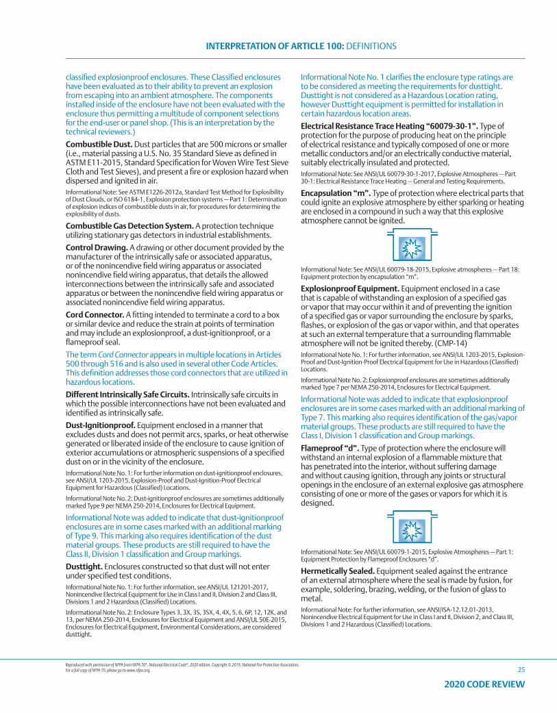
Reproduced with permission of NFPA from NFPA 70®, National Electrical Code®, 2020 edition. Copyright © 2019, National Fire Protection Association. For a full copy of NFPA 70, please go to www.nfpa.org.
INTERPRETATION OF ARTICLE 100: DEFINITIONS
25
2020 CODE REVIEW
classified explosionproof enclosures. These Classified enclosures have been evaluated as to their ability to prevent an explosion from escaping into an ambient atmosphere. The components installed inside of the enclosure have not been evaluated with the enclosure thus permitting a multitude of component selections for the end-user or panel shop. (This is an interpretation by the technical reviewers.)
Combustible Dust. Dust particles that are 500 microns or smaller (i.e., material passing a U.S. No. 35 Standard Sieve as defined in ASTM E11-2015, Standard Specification for Woven Wire Test Sieve Cloth and Test Sieves), and present a fire or explosion hazard when dispersed and ignited in air.Informational Note: See ASTM E1226-2012a, Standard Test Method for Explosibility of Dust Clouds, or ISO 6184-1, Explosion protection systems — Part 1: Determination of explosion indices of combustible dusts in air, for procedures for determining the explosibility of dusts.
Combustible Gas Detection System. A protection technique utilizing stationary gas detectors in industrial establishments.
Control Drawing. A drawing or other document provided by the manufacturer of the intrinsically safe or associated apparatus, or of the nonincendive field wiring apparatus or associated nonincendive field wiring apparatus, that details the allowed interconnections between the intrinsically safe and associated apparatus or between the nonincendive field wiring apparatus or associated nonincendive field wiring apparatus.
Cord Connector. A fitting intended to terminate a cord to a box or similar device and reduce the strain at points of termination and may include an explosionproof, a dust-ignitionproof, or a flameproof seal.
The term Cord Connector appears in multiple locations in Articles 500 through 516 and is also used in several other Code Articles. This definition addresses those cord connectors that are utilized in hazardous locations.
Different Intrinsically Safe Circuits. Intrinsically safe circuits in which the possible interconnections have not been evaluated and identified as intrinsically safe.
Dust-Ignitionproof. Equipment enclosed in a manner that excludes dusts and does not permit arcs, sparks, or heat otherwise generated or liberated inside of the enclosure to cause ignition of exterior accumulations or atmospheric suspensions of a specified dust on or in the vicinity of the enclosure.Informational Note No. 1: For further information on dust-ignitionproof enclosures, see ANSI/UL 1203-2015, Explosion-Proof and Dust-Ignition-Proof Electrical Equipment for Hazardous (Classified) Locations.
Informational Note No. 2: Dust-ignitionproof enclosures are sometimes additionally marked Type 9 per NEMA 250-2014, Enclosures for Electrical Equipment.
Informational Note was added to indicate that dust-ignitionproof enclosures are in some cases marked with an additional marking of Type 9. This marking also requires identification of the dust material groups. These products are still required to have the Class II, Division 1 classification and Group markings.
Dusttight. Enclosures constructed so that dust will not enter under specified test conditions.Informational Note No. 1: For further information, see ANSI/UL 121201-2017, Nonincendive Electrical Equipment for Use in Class I and II, Division 2 and Class III, Divisions 1 and 2 Hazardous (Classified) Locations.
Informational Note No. 2: Enclosure Types 3, 3X, 3S, 3SX, 4, 4X, 5, 6, 6P, 12, 12K, and 13, per NEMA 250-2014, Enclosures for Electrical Equipment and ANSI/UL 50E-2015, Enclosures for Electrical Equipment, Environmental Considerations, are considered dusttight.
Informational Note No. 1 clarifies the enclosure type ratings are to be considered as meeting the requirements for dusttight. Dusttight is not considered as a Hazardous Location rating, however Dusttight equipment is permitted for installation in certain hazardous location areas.
Electrical Resistance Trace Heating “60079-30-1”. Type of protection for the purpose of producing heat on the principle of electrical resistance and typically composed of one or more metallic conductors and/or an electrically conductive material, suitably electrically insulated and protected.Informational Note: See ANSI/UL 60079-30-1-2017, Explosive Atmospheres — Part 30-1: Electrical Resistance Trace Heating — General and Testing Requirements.
Encapsulation “m”. Type of protection where electrical parts that could ignite an explosive atmosphere by either sparking or heating are enclosed in a compound in such a way that this explosive atmosphere cannot be ignited.
Informational Note: See ANSI/UL 60079-18-2015, Explosive atmospheres — Part 18: Equipment protection by encapsulation “m”.
Explosionproof Equipment. Equipment enclosed in a case that is capable of withstanding an explosion of a specified gas or vapor that may occur within it and of preventing the ignition of a specified gas or vapor surrounding the enclosure by sparks, flashes, or explosion of the gas or vapor within, and that operates at such an external temperature that a surrounding flammable atmosphere will not be ignited thereby. (CMP-14)Informational Note No. 1: For further information, see ANSI/UL 1203-2015, Explosion-Proof and Dust-Ignition-Proof Electrical Equipment for Use in Hazardous (Classified) Locations.
Informational Note No. 2: Explosionproof enclosures are sometimes additionally marked Type 7 per NEMA 250-2014, Enclosures for Electrical Equipment.
Informational Note was added to indicate that explosionproof enclosures are in some cases marked with an additional marking of Type 7. This marking also requires identification of the gas/vapor material groups. These products are still required to have the Class I, Division 1 classification and Group markings.
Flameproof “d”. Type of protection where the enclosure will withstand an internal explosion of a flammable mixture that has penetrated into the interior, without suffering damage and without causing ignition, through any joints or structural openings in the enclosure of an external explosive gas atmosphere consisting of one or more of the gases or vapors for which it is designed.
Informational Note: See ANSI/UL 60079-1-2015, Explosive Atmospheres — Part 1: Equipment Protection by Flameproof Enclosures “d”.
Hermetically Sealed. Equipment sealed against the entrance of an external atmosphere where the seal is made by fusion, for example, soldering, brazing, welding, or the fusion of glass to metal.Informational Note: For further information, see ANSI/ISA-12.12.01-2013, Nonincendive Electrical Equipment for Use in Class I and II, Division 2, and Class III, Divisions 1 and 2 Hazardous (Classified) Locations.
Reproduced with permission of NFPA from NFPA 70®, National Electrical Code®, 2020 edition. Copyright © 2019, National Fire Protection Association. For a full copy of NFPA 70, please go to www.nfpa.org.
INTERPRETATION OF ARTICLE 100: DEFINITIONS
26
2020 CODE REVIEW
Increased Safety “e”. Type of protection applied to electrical equipment that does not produce arcs or sparks in normal service and under specified abnormal conditions, in which additional measures are applied so as to give increased security against the possibility of excessive temperatures and of the occurrence of arcs and sparks.
Informational Note: See ANSI/UL 60079-7–2017, Explosive Atmospheres — Part 7: Equipment Protection by Increased Safety “e”.
Inherently Safe Optical Radiation “op is”. Type of protection to minimize the risk of ignition in explosive atmospheres from optical radiation where visible or infrared radiation is incapable of producing sufficient energy under normal or specified fault conditions to ignite a specific explosive atmosphere.Informational Note: See ANSI/UL 60079-28-2017, Explosive Atmospheres — Part 28: Protection of Equipment and Transmission Systems Using Optical Radiation.
Intrinsic Safety “i”. Type of protection where any spark or thermal effect is incapable of causing ignition of a mixture of flammable or combustible material in air under prescribed test conditions.
Informational Note: See UL 913-2015, Intrinsically Safe Apparatus and Associated Apparatus for Use in Class I, II, and III, Division 1 Hazardous (Classified) Locations; and ANSI/UL 60079-11-2013, Explosive Atmospheres — Part 11: Equipment protection by intrinsic safety “i”.
Intrinsically Safe Apparatus. Apparatus in which all the circuits are intrinsically safe.
Intrinsically Safe Circuit. A circuit in which any spark or thermal effect is incapable of causing ignition of a mixture of flammable or combustible material in air under prescribed test conditions.Informational Note: Test conditions are described in ANSI/UL 913-2013, Standard for Safety, Intrinsically Safe Apparatus and Associated Apparatus for Use in Class I, II, and III, Division 1, Hazardous (Classified) Locations.
Intrinsically Safe System. An assembly of interconnected intrinsically safe apparatus, associated apparatus, and interconnecting cables, in that those parts of the system that may be used in hazardous (classified) locations are intrinsically safe circuits.Informational Note: An intrinsically safe system may include more than one intrinsically safe circuit.
Limited Finishing Workstation. An apparatus that is capable of confining the vapors, mists, residues, dusts, or deposits that are generated by a spray application process but does not meet the requirements of a spray booth or spray room, as herein defined. [33:3.3.18.1]Informational Note: See Section 14.3 of NFPA 33, Standard for Spray Application Using Flammable or Combustible Materials, for limited finishing workstations.
Liquid Immersion “o”. Type of protection where electrical equipment is immersed in a protective liquid in such a way that an explosive atmosphere that may be above the liquid or outside the enclosure cannot be ignited.
Informational Note: See ANSI/UL 60079-6-2016, Explosive Atmospheres — Part 6: Equipment protection by liquid immersion “o”.
Major Repair Garage. A building or portions of a building where major repairs, such as engine overhauls, painting, body and fender work, and repairs that require draining of the motor vehicle fuel tank are performed on motor vehicles, including associated floor space used for offices, parking, or showrooms. [30A:3.3.12.1]
Membrane Enclosure. A temporary enclosure used for the spraying of workpieces that cannot be moved into a spray booth where open spraying is not practical due to the proximity to other operations, finish quality, or concerns such as the collection of overspray.Informational Note: See Chapter 18 of NFPA 33-2016, Standard for Spray Application Using Flammable or Combustible Materials, for information on the construction and use of membrane enclosures.
Minor Repair Garage. A building or portions of a building used for lubrication, inspection, and minor automotive maintenance work, such as engine tune-ups, replacement of parts, fluid changes (e.g., oil, antifreeze, transmission fluid, brake fluid, air-conditioning refrigerants), brake system repairs, tire rotation, and similar routine maintenance work, including associated floor space used for offices, parking, or showrooms. [30A:3.3.12.2]
Mobile Equipment. Equipment with electrical components suitable to be moved only with mechanical aids or is provided with wheels for movement by person(s) or powered devices.
Motor Fuel Dispensing Facility. That portion of a property where motor fuels are stored and dispensed from fixed equipment into the fuel tanks of motor vehicles or marine craft or into approved containers, including all equipment used in connection therewith. [30A:3.3.11]Informational Note: Refer to Articles 510 and 511 with respect to electrical wiring and equipment for other areas used as lubritoriums, service rooms, repair rooms, offices, salesrooms, compressor rooms, and similar locations.
Nonincendive Circuit. A circuit, other than field wiring, in which any arc or thermal effect produced under intended operating conditions of the equipment, is not capable, under specified test conditions, of igniting the flammable gas–air, vapor–air, or dust–air mixture. Informational Note: Conditions are described in ANSI/ISA-12.12.01-2013, Nonincendive Electrical Equipment for Use in Class I and II, Division 2, and Class III, Divisions 1 and 2 Hazardous (Classified) Locations.
Nonincendive Component. A component having contacts for making or breaking an incendive circuit and the contacting mechanism is constructed so that the component is incapable of igniting the specified flammable gas–air or vapor–air mixture. The housing of a nonincendive component is not intended to exclude the flammable atmosphere or contain an explosion. Informational Note: For further information, see ANSI/ISA-12.12.01-2013, Nonincendive Electrical Equipment for Use in Class I and II, Division 2, and Class III, Divisions 1 and 2 Hazardous (Classified) Locations.
Nonincendive Equipment. Equipment having electrical/electronic circuitry that is incapable, under normal operating conditions, of causing ignition of a specified flammable gas–air, vapor–air, or dust–air mixture due to arcing or thermal means.Informational Note: For further information, see ANSI/ISA-12.12.01-2013, Nonincendive Electrical Equipment for Use in Class I and II, Division 2, and Class III, Divisions 1 and 2 Hazardous (Classified) Locations.
Nonincendive Field Wiring. Wiring that enters or leaves an equipment enclosure and, under normal operating conditions of the equipment, is not capable, due to arcing or thermal effects,
Reproduced with permission of NFPA from NFPA 70®, National Electrical Code®, 2020 edition. Copyright © 2019, National Fire Protection Association. For a full copy of NFPA 70, please go to www.nfpa.org.
INTERPRETATION OF ARTICLE 100: DEFINITIONS
27
2020 CODE REVIEW
of igniting the flammable gas–air, vapor–air, or dust–air mixture. Normal operation includes opening, shorting, or grounding the field wiring.
Nonincendive Field Wiring Apparatus. Apparatus intended to be connected to nonincendive field wiring.Informational Note: For further information, see ANSI/ISA-12.12.01-2013, Nonincendive Electrical Equipment for Use in Class I and II, Division 2, and Class III, Divisions 1 and 2 Hazardous (Classified) Locations.
Oil Immersion. Electrical equipment immersed in a protective liquid in such a way that an explosive atmosphere that may be above the liquid or outside the enclosure cannot be ignited.
Optical Radiation. Electromagnetic radiation at wavelengths in vacuum between the region of transition to X-rays and the region of transition to radio waves, that is approximately between 1 nm and 1000 μm.Informational Note: For additional information on types of protection that can be applied to minimize the risk of ignition in explosive atmospheres from optical radiation in the wavelength range from 380 nm to 10 μm, see ANSI/UL 60079-28-2017, Explosive Atmospheres — Part 28: Protection of Equipment and Transmission Systems Using Optical Radiation.
Optical System With Interlock “op sh”. Type of protection to minimize the risk of ignition in explosive atmospheres from optical radiation where visible or infrared radiation is confined inside optical fiber or other transmission medium with interlock cut-off provided to reliably reduce the unconfined beam strength to safe levels within a specified time in case the confinement fails and the radiation becomes unconfined.Informational Note: See ANSI/UL 60079-28-2017, Explosive Atmospheres — Part 28: Protection of Equipment and Transmission Systems Using Optical Radiation.
Outdoor Spray Area. A spray area that is outside the confines of a building or that has a canopy or roof that does not limit the dissipation of the heat of a fire or dispersion of flammable vapors and does not restrict fire-fighting access and control. For the purpose of this standard, an outdoor spray area can be treated as an unenclosed spray area. [33:3.3.2.3.1]
Portable Equipment. Equipment with electrical components suitable to be moved by a single person without mechanical aids.
Powder Filling “q”. Type of protection where electrical parts capable of igniting an explosive atmosphere are fixed in position and completely surrounded by filling material (glass or quartz powder) to prevent the ignition of an external explosive atmosphere.
Informational Note: See ANSI/UL 60079-5-2016, Explosive Atmospheres — Part 5: Equipment protection by powder filling “q”.
Pressurized. The process of supplying an enclosure with a protective gas with or without continuous flow, at sufficient pressure to prevent the entrance of combustible dust or ignitible fibers/flyings.
Pressurized Enclosure “p”. Type of protection for electrical equipment that uses the technique of guarding against the ingress of the external atmosphere, which may be explosive, into an enclosure by maintaining a protective gas therein at a pressure above that of the external atmosphere.
Informational Note: See ANSI/UL-60079-2-2017, Explosive Atmospheres — Part 2: Equipment protection by pressurized enclosures “p”.
Process Seal. A seal between electrical systems and flammable or combustible process fluids where a failure could allow the migration of process fluids into the premises’ wiring system.
This definition is the same definition for Process Seal that is contained in the product listing standard, ANSI/UL 122701.
Protected Optical Fiber Cable. Optical fiber cable protected from releasing optical radiation into the atmosphere during normal operating conditions and foreseeable malfunctions by additional armoring, conduit, cable tray, or raceway.Informational Note: See ANSI/UL 60079-28-2017, Explosive Atmospheres — Part 28: Protection of Equipment and Transmission Systems Using Optical Radiation.
Protected Optical Radiation “op pr”. Type of protection to minimize the risk of ignition in explosive atmospheres from optical radiation where visible or infrared radiation is confined inside optical fiber or other transmission medium under normal constructions or constructions with additional mechanical protection based on the assumption that there is no escape of radiation from the confinement.Informational Note: See ANSI/UL 60079-28-2017, Explosive Atmospheres — Part 28: Protection of Equipment and Transmission Systems Using Optical Radiation.
Protection by Enclosure “t”. Type of protection for explosive dust atmospheres where electrical equipment is provided with an enclosure providing dust ingress protection and a means to limit surface temperatures.Informational Note: For additional information, see ANSI/UL 60079-31-2015, Explosive Atmospheres — Part 31: Equipment Dust Ignition Protection by Enclosure “t”.
The previous ANSI /ISA 61241-1 standard for this protection method was withdrawn and therefore the informational note referencing that standard has been removed from the 2020 NEC®.
Purged and Pressurized. The process of (1) purging, supplying an enclosure with a protective gas at a sufficient flow and positive pressure to reduce the concentration of any flammable gas or vapor initially present to an acceptable level; and (2) pressurization, supplying an enclosure with a protective gas with or without continuous flow at sufficient pressure to prevent the entrance of a flammable gas or vapor, a combustible dust, or an ignitible fiber.Informational Note: For further information, see ANSI/NFPA 496-2013, Purged and Pressurized Enclosures for Electrical Equipment.
Simple Apparatus. An electrical component or combination of components of simple construction with well-defined electrical parameters that does not generate more than 1.5 volts, 100 mA, and 25 mW, or a passive component that does not dissipate more than 1.3 watts and is compatible with the intrinsic safety of the circuit in which it is used.Informational Note No. 1: The following apparatus are examples of simple apparatus:
(1) Passive components; for example, switches, instrument connectors, plugs and sockets, junction boxes, resistance temperature devices, and simple semiconductor devices such as LEDs
(2) Sources of stored energy consisting of single components in simple circuits with well-defined parameters; for example, capacitors or inductors, whose values are considered when determining the overall safety of the system
(3) Sources of generated energy; for example, thermocouples and photocells, that do not generate more than 1.5 volts, 100 mA, and 25 mW
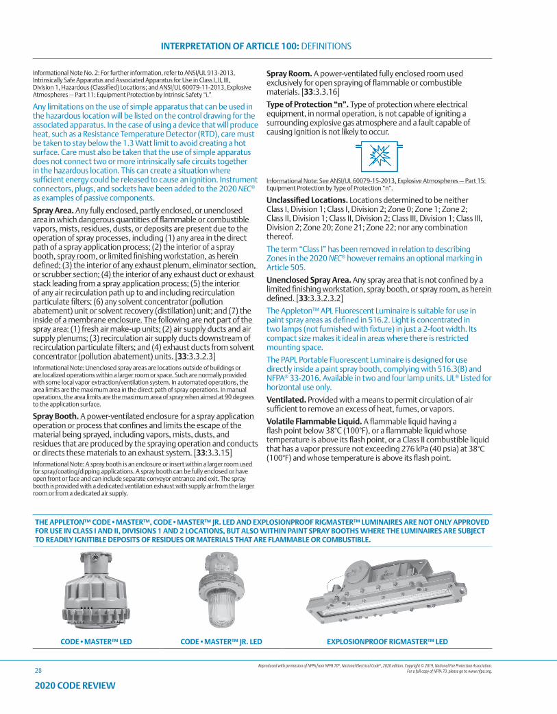
Reproduced with permission of NFPA from NFPA 70®, National Electrical Code®, 2020 edition. Copyright © 2019, National Fire Protection Association. For a full copy of NFPA 70, please go to www.nfpa.org.
INTERPRETATION OF ARTICLE 100: DEFINITIONS
28
2020 CODE REVIEW
Informational Note No. 2: For further information, refer to ANSI/UL 913-2013, Intrinsically Safe Apparatus and Associated Apparatus for Use in Class I, II, III, Division 1, Hazardous (Classified) Locations; and ANSI/UL 60079-11-2013, Explosive Atmospheres — Part 11: Equipment Protection by Intrinsic Safety “i.”
Any limitations on the use of simple apparatus that can be used in the hazardous location will be listed on the control drawing for the associated apparatus. In the case of using a device that will produce heat, such as a Resistance Temperature Detector (RTD), care must be taken to stay below the 1.3 Watt limit to avoid creating a hot surface. Care must also be taken that the use of simple apparatus does not connect two or more intrinsically safe circuits together in the hazardous location. This can create a situation where sufficient energy could be released to cause an ignition. Instrument connectors, plugs, and sockets have been added to the 2020 NEC® as examples of passive components.
Spray Area. Any fully enclosed, partly enclosed, or unenclosed area in which dangerous quantities of flammable or combustible vapors, mists, residues, dusts, or deposits are present due to the operation of spray processes, including (1) any area in the direct path of a spray application process; (2) the interior of a spray booth, spray room, or limited finishing workstation, as herein defined; (3) the interior of any exhaust plenum, eliminator section, or scrubber section; (4) the interior of any exhaust duct or exhaust stack leading from a spray application process; (5) the interior of any air recirculation path up to and including recirculation particulate filters; (6) any solvent concentrator (pollution abatement) unit or solvent recovery (distillation) unit; and (7) the inside of a membrane enclosure. The following are not part of the spray area: (1) fresh air make-up units; (2) air supply ducts and air supply plenums; (3) recirculation air supply ducts downstream of recirculation particulate filters; and (4) exhaust ducts from solvent concentrator (pollution abatement) units. [33:3.3.2.3]Informational Note: Unenclosed spray areas are locations outside of buildings or are localized operations within a larger room or space. Such are normally provided with some local vapor extraction/ventilation system. In automated operations, the area limits are the maximum area in the direct path of spray operations. In manual operations, the area limits are the maximum area of spray when aimed at 90 degrees to the application surface.
Spray Booth. A power-ventilated enclosure for a spray application operation or process that confines and limits the escape of the material being sprayed, including vapors, mists, dusts, and residues that are produced by the spraying operation and conducts or directs these materials to an exhaust system. [33:3.3.15]Informational Note: A spray booth is an enclosure or insert within a larger room used for spray/coating/dipping applications. A spray booth can be fully enclosed or have open front or face and can include separate conveyor entrance and exit. The spray booth is provided with a dedicated ventilation exhaust with supply air from the larger room or from a dedicated air supply.
Spray Room. A power-ventilated fully enclosed room used exclusively for open spraying of flammable or combustible materials. [33:3.3.16]
Type of Protection “n”. Type of protection where electrical equipment, in normal operation, is not capable of igniting a surrounding explosive gas atmosphere and a fault capable of causing ignition is not likely to occur.
Informational Note: See ANSI/UL 60079-15-2013, Explosive Atmospheres — Part 15: Equipment Protection by Type of Protection “n”.
Unclassified Locations. Locations determined to be neither Class I, Division 1; Class I, Division 2; Zone 0; Zone 1; Zone 2; Class II, Division 1; Class II, Division 2; Class III, Division 1; Class III, Division 2; Zone 20; Zone 21; Zone 22; nor any combination thereof.
The term “Class I” has been removed in relation to describing Zones in the 2020 NEC® however remains an optional marking in Article 505.
Unenclosed Spray Area. Any spray area that is not confined by a limited finishing workstation, spray booth, or spray room, as herein defined. [33:3.3.2.3.2]
The Appleton™ APL Fluorescent Luminaire is suitable for use in paint spray areas as defined in 516.2. Light is concentrated in two lamps (not furnished with fixture) in just a 2-foot width. Its compact size makes it ideal in areas where there is restricted mounting space.
The PAPL Portable Fluorescent Luminaire is designed for use directly inside a paint spray booth, complying with 516.3(B) and NFPA® 33-2016. Available in two and four lamp units. UL® Listed for horizontal use only.
Ventilated. Provided with a means to permit circulation of air sufficient to remove an excess of heat, fumes, or vapors.
Volatile Flammable Liquid. A flammable liquid having a flash point below 38°C (100°F), or a flammable liquid whose temperature is above its flash point, or a Class II combustible liquid that has a vapor pressure not exceeding 276 kPa (40 psia) at 38°C (100°F) and whose temperature is above its flash point.
THE APPLETON™ CODE•MASTER™, CODE•MASTER™ JR. LED AND EXPLOSIONPROOF RIGMASTER™ LUMINAIRES ARE NOT ONLY APPROVED FOR USE IN CLASS I AND II, DIVISIONS 1 AND 2 LOCATIONS, BUT ALSO WITHIN PAINT SPRAY BOOTHS WHERE THE LUMINAIRES ARE SUBJECT TO READILY IGNITIBLE DEPOSITS OF RESIDUES OR MATERIALS THAT ARE FLAMMABLE OR COMBUSTIBLE.
CODE•MASTER™ LED CODE•MASTER™ JR. LED EXPLOSIONPROOF RIGMASTER™ LED
Reproduced with permission of NFPA from NFPA 70®, National Electrical Code®, 2020 edition. Copyright © 2019, National Fire Protection Association. For a full copy of NFPA 70, please go to www.nfpa.org.
INTERPRETATION OF ARTICLE 500: HAZARDOUS (CLASSIFIED) LOCATIONS, CLASSES I, II, AND III, DIVISIONS 1 AND 2
29
2020 CODE REVIEW
CHANGES TO ARTICLE 500 – HAZARDOUS (CLASSIFIED) LOCATIONS, CLASSES I, II, AND III, DIVISIONS 1 and 2
The following Article 500 sections have been revised during the 2020 NEC® Code cycle. These changes are those that are substantive and should be noted. This list does not include those changes that are editorial in nature.
Underlined text indicates a section that has been revised from the previous NEC® edition. It is not intended to indicate legislation text detailing the word-for-word revisions to the section. Where minor revisions have been made to a section, these will include underlined text for select words to indicate the minor revision.
• 500.5(C)(1): Classification of Locations. Class II, Division 1.
• 500.7(K)(2): Protection Techniques. Inadequate Ventilation.
• 500.7(L) New: Protection Techniques. Inherently Safe Optical Radiation “op is”.
• 500.7(M) New: Protection Techniques. Protected Optical Radiation “op pr”.
• 500.7(N) New: Protection Techniques. Optical System with Interlock “op sh”.
• 500.7(O) New: Protection Techniques. Protection by Skin Effect Trace Heating
“IEEE 844.1”.
• 500.8(G): Equipment. Equipment Involving Optical Radiation.
ARTICLE 500 Hazardous (Classified) Locations, Classes I, II, and III, Divisions 1 and 2
500.1 Scope — Articles 500 Through 504. Articles 500 through 504 cover the requirements for electrical and electronic equipment and wiring for all voltages in Class I, Divisions 1 and 2; Class II, Divisions 1 and 2; and Class III, Divisions 1 and 2 locations where fire or explosion hazards may exist due to flammable gases, flammable liquid–produced vapors, combustible liquid–produced vapors, combustible dusts, or ignitible fibers/flyings.
Informational Note No. 1: The unique hazards associated with explosives, pyrotechnics, and blasting agents are not addressed in this article.
Informational Note No. 2: For the requirements for electrical and electronic equipment and wiring for all voltages in Zone 0, Zone 1, and Zone 2 hazardous (classified) locations where fire or explosion hazards may exist due to flammable gases or vapors or flammable liquids, refer to Article 505.
Informational Note No. 3: For the requirements for electrical and electronic equipment and wiring for all voltages in Zone 20, Zone 21, and Zone 22 hazardous (classified) locations where fire or explosion hazards may exist due to combustible dusts or ignitible fibers/flyings, refer to Article 506.
Informational Note No. 4: Text that is followed by a reference in brackets has been extracted from NFPA 497-2017, Recommended Practice for the Classification of Flammable Liquids, Gases, or Vapors and of Hazardous (Classified) Locations for Electrical Installations in Chemical Process Areas, and NFPA 499-2017, Recommended Practice for the Classification of Combustible Dusts and of Hazardous (Classified) Locations for Electrical Installation in Chemical Process Areas. Only editorial changes were made to the extracted text to make it consistent with this Code.
500.3 Other Articles. Except as modified in Articles 500 through 504, all other applicable rules contained in this Code shall apply to
electrical equipment and wiring installed in hazardous (classified) locations.
500.4 Documentation. All areas designated as hazardous (classified) locations shall be properly documented. This documentation shall be available to those authorized to design, install, inspect, maintain, or operate electrical equipment at the location.
Informational Note No. 1: For further information on the classification of locations, see NFPA 30-2018, Flammable and Combustible Liquids Code; NFPA 32-2016, Standard for Drycleaning Facilities; NFPA 33-2018, Standard for Spray Application Using Flammable or Combustible Materials; NFPA 34-2018, Standard for Dipping, Coating and Printing Processes Using Flammable or Combustible Liquids; NFPA 35-2016, Standard for the Manufacture of Organic Coatings; NFPA 36-2017, Standard for Solvent Extraction Plants; NFPA 45-2019, Standard on Fire Protection for Laboratories Using Chemicals; NFPA 55-2016, Compressed Gases and Cryogenic Fluids Code; NFPA 58-2017, Liquefied Petroleum Gas Code; NFPA 59-2018, Utility LP-Gas Plant Code; NFPA 497-2017, Recommended Practice for the Classification of Flammable Liquids, Gases, or Vapors and of Hazardous (Classified) Locations for Electrical Installations in Chemical Process Areas; NFPA 499-2017, Recommended Practice for the Classification of Combustible Dusts and of Hazardous (Classified) Locations for Electrical Installations in Chemical Process Areas; NFPA 820-2016, Standard for Fire Protection in Wastewater Treatment and Collection Facilities; ANSI/API RP 500-2012, Recommended Practice for Classification of Locations of Electrical Installations at Petroleum Facilities Classified as Class I, Division 1 and Division 2; and ISA-12.10-1988, Area Classification in Hazardous (Classified) Dust Locations.
Informational Note No. 2: For further information on protection against static electricity and lightning hazards in hazardous (classified) locations, see NFPA 77-2019, Recommended Practice on Static Electricity; NFPA 780-2017, Standard for the Installation of Lightning Protection Systems; and API RP 2003-2015, Protection Against Ignitions Arising Out of Static Lightning and Stray Currents.
Informational Note No. 3: For further information on ventilation, see NFPA 30-2018, Flammable and Combustible Liquids Code; and ANSI/API RP 500-2012, Recommended Practice for Classification of Locations for Electrical Installations at Petroleum Facilities Classified as Class I, Division 1 and Division 2.
Informational Note No. 4: For further information on electrical systems for hazardous (classified) locations on offshore oil- and gas-producing platforms, drilling rigs, and workover rigs, see ANSI/API RP 14F-2018, Recommended Practice for Design and Installation of Electrical Systems for Fixed and Floating Offshore Petroleum Facilities for Unclassified and Class I, Division 1 and Division 2 Locations.
Informational Note No. 5: Portable or transportable equipment having self-contained power supplies, such as battery-operated equipment, could potentially become an ignition source in hazardous (classified) locations. See ANSI/UL 121203-2011, Standard for Portable Electronic Products Suitable for Use in Class I and II, Division 2, Class I Zone 2 and Class III, Division 1 and 2 Hazardous (Classified) Locations.
Informational Note No. 6: For information on electrical resistance trace heating for hazardous (classified) locations, see ANSI/UL 60079-30-1-2017, Explosive Atmospheres — Electrical Resistance Trace Heating — General and Testing Requirements, and ANSI/IEEE 60079-30-2-2015, IEEE/IEC International Standard for Explosive atmospheres — Part 30-2: Electrical resistance trace heating — Application guide for design, installation, and maintenance.
Informational Note No. 7: For information on electric skin effect trace heating for hazardous (classified) locations, see IEEE 844.1-2017/CSA C22.2 No. 293.1-17, IEEE/CSA Standard for Skin Effect Trace Heating of Pipelines, Vessels, Equipment, and Structures — General, Testing, Marking, and Documentation Requirements, and IEEE 844.2-2017/CSA C293.2-17, IEEE/CSA Standard for Skin Effect Trace Heating of Pipelines, Vessels, Equipment, and Structures — Application Guide for Design, Installation, Testing, Commissioning, and Maintenance.
500.5 Classifications of Locations.
(A) General. Locations shall be classified depending on the properties of the flammable gas, flammable liquid–produced vapor, combustible liquid–produced vapors, combustible dusts, or fibers/flyings that could be present, and the likelihood that a flammable or combustible concentration or quantity is present. Each room, section, or area shall be considered individually in
500.5
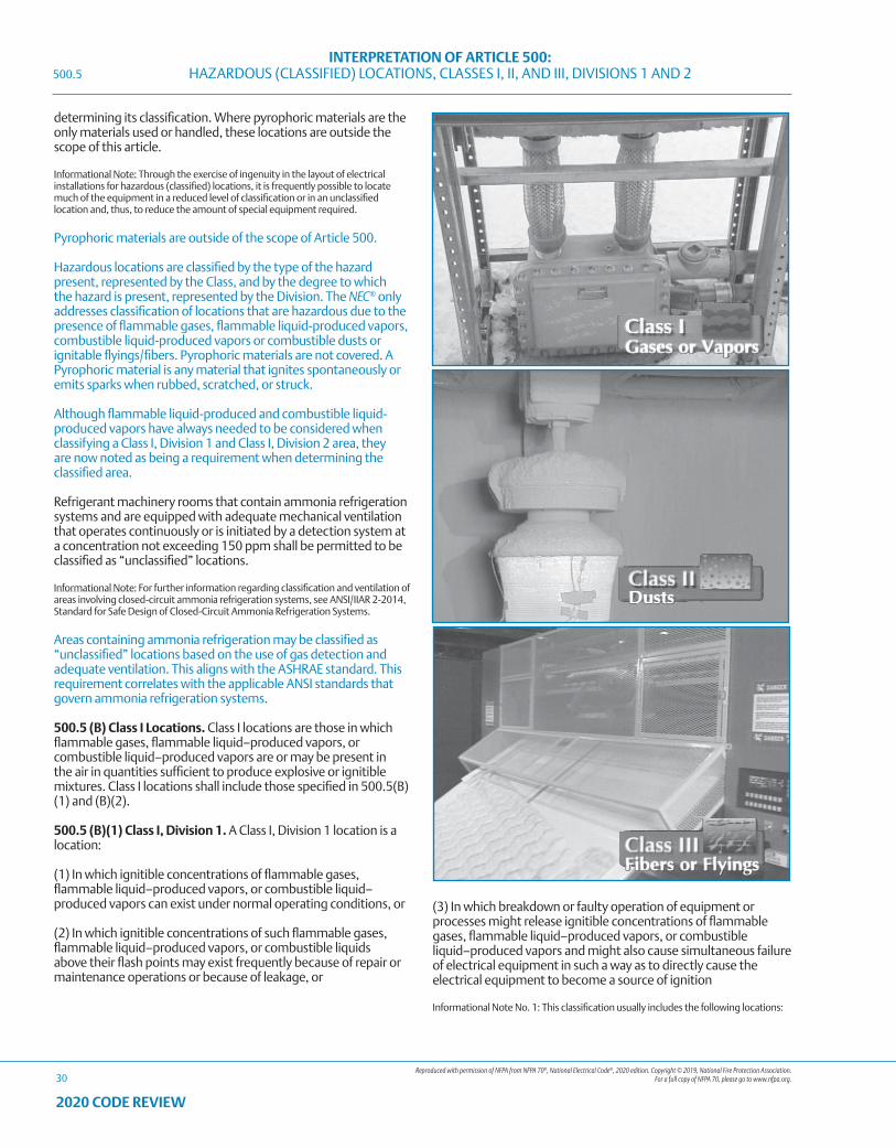
Reproduced with permission of NFPA from NFPA 70®, National Electrical Code®, 2020 edition. Copyright © 2019, National Fire Protection Association. For a full copy of NFPA 70, please go to www.nfpa.org.
INTERPRETATION OF ARTICLE 500: HAZARDOUS (CLASSIFIED) LOCATIONS, CLASSES I, II, AND III, DIVISIONS 1 AND 2
30
2020 CODE REVIEW
determining its classification. Where pyrophoric materials are the only materials used or handled, these locations are outside the scope of this article.
Informational Note: Through the exercise of ingenuity in the layout of electrical installations for hazardous (classified) locations, it is frequently possible to locate much of the equipment in a reduced level of classification or in an unclassified location and, thus, to reduce the amount of special equipment required.
Pyrophoric materials are outside of the scope of Article 500.
Hazardous locations are classified by the type of the hazard present, represented by the Class, and by the degree to which the hazard is present, represented by the Division. The NEC® only addresses classification of locations that are hazardous due to the presence of flammable gases, flammable liquid-produced vapors, combustible liquid-produced vapors or combustible dusts or ignitable flyings/fibers. Pyrophoric materials are not covered. A Pyrophoric material is any material that ignites spontaneously or emits sparks when rubbed, scratched, or struck.
Although flammable liquid-produced and combustible liquid-produced vapors have always needed to be considered when classifying a Class I, Division 1 and Class I, Division 2 area, they are now noted as being a requirement when determining the classified area.
Refrigerant machinery rooms that contain ammonia refrigeration systems and are equipped with adequate mechanical ventilation that operates continuously or is initiated by a detection system at a concentration not exceeding 150 ppm shall be permitted to be classified as “unclassified” locations.
Informational Note: For further information regarding classification and ventilation of areas involving closed-circuit ammonia refrigeration systems, see ANSI/IIAR 2-2014, Standard for Safe Design of Closed-Circuit Ammonia Refrigeration Systems.
Areas containing ammonia refrigeration may be classified as “unclassified” locations based on the use of gas detection and adequate ventilation. This aligns with the ASHRAE standard. This requirement correlates with the applicable ANSI standards that govern ammonia refrigeration systems.
500.5 (B) Class I Locations. Class I locations are those in which flammable gases, flammable liquid–produced vapors, or combustible liquid–produced vapors are or may be present in the air in quantities sufficient to produce explosive or ignitible mixtures. Class I locations shall include those specified in 500.5(B)(1) and (B)(2).
500.5 (B)(1) Class I, Division 1. A Class I, Division 1 location is a location:
(1) In which ignitible concentrations of flammable gases, flammable liquid–produced vapors, or combustible liquid–produced vapors can exist under normal operating conditions, or
(2) In which ignitible concentrations of such flammable gases, flammable liquid–produced vapors, or combustible liquids above their flash points may exist frequently because of repair or maintenance operations or because of leakage, or
(3) In which breakdown or faulty operation of equipment or processes might release ignitible concentrations of flammable gases, flammable liquid–produced vapors, or combustible liquid–produced vapors and might also cause simultaneous failure of electrical equipment in such a way as to directly cause the electrical equipment to become a source of ignition
Informational Note No. 1: This classification usually includes the following locations:
500.5
Reproduced with permission of NFPA from NFPA 70®, National Electrical Code®, 2020 edition. Copyright © 2019, National Fire Protection Association. For a full copy of NFPA 70, please go to www.nfpa.org.
INTERPRETATION OF ARTICLE 500: HAZARDOUS (CLASSIFIED) LOCATIONS, CLASSES I, II, AND III, DIVISIONS 1 AND 2
31
2020 CODE REVIEW
(1) Where volatile flammable liquids or liquefied flammable gases are transferred from one container to another
(2) Interiors of spray booths and areas in the vicinity of spraying and painting operations where volatile flammable solvents are used
(3) Locations containing open tanks or vats of volatile flammable liquids
(4) Drying rooms or compartments for the evaporation of flammable solvents
(5) Locations containing fat- and oil-extraction equipment using volatile flammable solvents
(6) Portions of cleaning and dyeing plants where flammable liquids are used
(7) Gas generator rooms and other portions of gas manufacturing plants where flammable gas may escape
(8) Inadequately ventilated pump rooms for flammable gas or for volatile flammable liquids
(9) The interiors of refrigerators and freezers in which volatile flammable materials are stored in open, lightly stoppered, or easily ruptured containers
(10) All other locations where ignitible concentrations of flammable vapors or gases are likely to occur in the course of normal operations
Informational Note No. 2: In some Division 1 locations, ignitible concentrations of flammable gases or vapors may be present continuously or for long periods of time. Examples include the following:
A Class I, Division 1 location is one where there is or may be an explosive atmosphere of gases or vapors mixed with air present during normal operation, for any reason.
(1) The inside of inadequately vented enclosures containing instruments normally venting flammable gases or vapors to the interior of the enclosure
(2) The inside of vented tanks containing volatile flammable liquids
(3) The area between the inner and outer roof sections of a floating roof tank containing volatile flammable fluids
(4) Inadequately ventilated areas within spraying or coating operations using volatile flammable fluids
(5) The interior of an exhaust duct that is used to vent ignitible concentrations of gases or vapors
Experience has demonstrated the prudence of avoiding the installation of instrumentation or other electrical equipment in these particular areas altogether or where it cannot be avoided because it is essential to the process and other locations are not feasible [see 500.5(A), Informational Note] using electrical equipment or instrumentation approved for the specific application or consisting of intrinsically safe systems as described in Article 504.
500.5 (B)(2) Class I, Division 2. A Class I, Division 2 location is a location:
(1) In which volatile flammable gases, flammable liquid–produced vapors, or combustible liquid–produced vapors are handled, processed, or used, but in which the liquids, vapors, or gases will normally be confined within closed containers or closed systems from which they can escape only in case of accidental rupture or breakdown of such containers or systems or in case of abnormal operation of equipment, or
(2) In which ignitible concentrations of flammable gases, flammable liquid–produced vapors, or combustible liquid–produced vapors are normally prevented by positive mechanical ventilation and which might become hazardous through failure or abnormal operation of the ventilating equipment, or
(3) That is adjacent to a Class I, Division 1 location, and to which ignitible concentrations of flammable gases, flammable liquid–produced vapors, or combustible liquid–produced vapors above their flash points might occasionally be communicated unless such communication is prevented by adequate positive-pressure ventilation from a source of clean air and effective safeguards against ventilation failure are provided.
Informational Note No. 1: This classification usually includes locations where volatile flammable liquids or flammable gases or vapors are used but that, in the judgment of the authority having jurisdiction, would become hazardous only in case of an accident or of some unusual operating condition. The quantity of flammable material that might escape in case of accident, the adequacy of ventilating equipment, the total area involved, and the record of the industry or business with respect to explosions or fires are all factors that merit consideration in determining the classification and extent of each location.
Informational Note No. 2: Piping without valves, checks, meters, and similar devices would not ordinarily introduce a hazardous condition even though used for flammable liquids or gases. Depending on factors such as the quantity and size of the containers and ventilation, locations used for the storage of flammable liquids or liquefied or compressed gases in sealed containers may be considered either hazardous (classified) or unclassified locations. See NFPA 30-2018, Flammable and Combustible Liquids Code, and NFPA 58-2017, Liquefied Petroleum Gas Code.
A Class I, Division 2 location is one where there is an explosive atmosphere of gases or vapors mixed with air when an abnormal condition exists, such as failure of a containment wall or ventilation system.
500.5 (C) Class II Locations. Class II locations are those that are hazardous because of the presence of combustible dust. Class II locations shall include those specified in 500.5(C)(1) and (C)(2).
500.5 (C)(1) Class II, Division 1. A Class II, Division 1 location is a location:
(1) In which combustible dust is in the air under normal operating conditions in quantities sufficient to produce explosive or ignitible mixtures, or
(2) Where mechanical failure or abnormal operation of machinery or equipment might cause such explosive or ignitible mixtures to be produced, and might also provide a source of ignition through simultaneous failure of electrical equipment, through operation of protection devices, or from other causes, or
(3) In which Group E combustible dusts may be present in quantities sufficient to be hazardous in normal or abnormal operating conditions.
Informational Note: Dusts containing magnesium or aluminum are particularly hazardous, and the use of extreme precaution is necessary to avoid ignition and explosion.
This section specifically references Group E metal dust. This is a more appropriate reference than “dusts of an electrically conductive nature,” which is vague, since just about any dust can become electrically conductive when it has a high enough moisture content. Group E dusts are not permitted in a Class II,
500.5
Reproduced with permission of NFPA from NFPA 70®, National Electrical Code®, 2020 edition. Copyright © 2019, National Fire Protection Association. For a full copy of NFPA 70, please go to www.nfpa.org.
INTERPRETATION OF ARTICLE 500: HAZARDOUS (CLASSIFIED) LOCATIONS, CLASSES I, II, AND III, DIVISIONS 1 AND 2
32
2020 CODE REVIEW
Division 2 location therefore the code acknowledges that even under abnormal operating conditions, the location containing Group E dusts is to be classified as a Class II, Division 1 location.
500.5 (C)(2) Class II, Division 2. A Class II, Division 2 location is a location:
(1) In which combustible dust due to abnormal operations may be present in the air in quantities sufficient to produce explosive or ignitible mixtures; or
(2) Where combustible dust accumulations are present but are normally insufficient to interfere with the normal operation of electrical equipment or other apparatus, but could as a result of infrequent malfunctioning of handling or processing equipment become suspended in the air; or
(3) In which combustible dust accumulations on, in, or in the vicinity of the electrical equipment could be sufficient to interfere with the safe dissipation of heat from electrical equipment, or could be ignitible by abnormal operation or failure of electrical equipment.
Informational Note No. 1: The quantity of combustible dust that may be present and the adequacy of dust removal systems are factors that merit consideration in determining the classification and may result in an unclassified area.
Informational Note No. 2: Where products such as seed are handled in a manner that produces low quantities of dust, the amount of dust deposited may not warrant classification.
This section separates the dust accumulation issue from the dust suspension probability issue.
500.5 (D) Class III Locations. Class III locations are those that are hazardous because of the presence of easily ignitible fibers or where materials producing combustible flyings are handled, manufactured, or used, but in which such fibers/flyings are not likely to be in suspension in the air in quantities sufficient to produce ignitible mixtures. Class III locations shall include those specified in 500.5(D)(1) and (D)(2).
500.5 (D)(1) Class III, Division 1. A Class III, Division 1 location is a location in which easily ignitible fibers/flyings are handled, manufactured, or used.
Informational Note No. 1: Such locations usually include some parts of rayon, cotton, and other textile mills; combustible fibers/flyings manufacturing and processing plants; cotton gins and cotton-seed mills; flax-processing plants; clothing manufacturing plants; woodworking plants; and establishments and industries involving similar hazardous processes or conditions.
Informational Note No. 2: Easily ignitible fibers/flyings include rayon, cotton (including cotton linters and cotton waste), sisal or henequen, istle, jute, hemp, tow, cocoa fiber, oakum, baled waste kapok, Spanish moss, excelsior, and other materials of similar nature.
500.5 (D)(2) Class III, Division 2. A Class III, Division 2 location is a location in which easily ignitible fibers/flyings are stored or handled other than in the process of manufacture.
500.6 Material Groups. For purposes of testing, approval, and area classification, various air mixtures (not oxygen-enriched) shall be grouped in accordance with 500.6(A) and (B).
Exception: Equipment identified for a specific gas, vapor, dust, or fiber/flying.
Informational Note: This grouping is based on the characteristics of the materials. Facilities are available for testing and identifying equipment for use in the various atmospheric groups.
500.6 (A) Class I Group Classifications. Class I groups shall be according to 500.6(A)(1) through (A)(4).
Informational Note No. 1: Informational Note Nos. 2 and 3 apply to 500.6(A).
Informational Note No. 2: The explosion characteristics of air mixtures of gases or vapors vary with the specific material involved. For Class I locations, Groups A, B, C, and D, the classification involves determinations of maximum explosion pressure and maximum safe clearance between parts of a clamped joint in an enclosure. It is necessary, therefore, that equipment be identified not only for class but also for the specific group of the gas or vapor that will be present.
Informational Note No. 3: Certain chemical atmospheres may have characteristics that require safeguards beyond those required for any of the Class I groups. Carbon disulfide is one of these chemicals because of its low autoignition temperature (90°C) and the small joint clearance permitted to arrest its flame.
GROUPS A, B, C AND D (Class I)
Potentially explosive gases and vapors are divided into four groups, A, B, C, and D. NFPA® 497, “Classification of Flammable Liquids, Gases, or Vapors and of Hazardous (Classified) Locations for Electrical Installations in Chemical Process Areas”, contains information on which gases and vapors go into each of these groups, and also provides information on how to classify hazardous areas due to the presence of flammable gases and vapors.
The four gas groups were created so that electrical equipment intended to be used in hazardous (classified) locations could be rated for families of gases and vapors, and tested with a designated worst-case gas/air mixture to cover the entire group. If electrical equipment will be used only in the presence of one flammable gas, the testing can be done with that gas instead of the designated test gas.
There are four characteristics of flammable gases that are critical to the design of electrical equipment to be used in hazardous (classified) locations. These characteristics are: maximum experimental safe gap (MESG), minimum igniting current ratio (MIC ratio), maximum explosion pressure, and autoignition temperature.
The gases fall into Gas Groups A, B, C or D based on two of these characteristics: MESG and MIC ratio.
The MESG is determined by using a device called the Westerberg apparatus. This device has two chambers that are separated by two parallel metal plates. The plates can be adjusted to different gaps between them. A flammable gas/air mixture is introduced into both sides of the apparatus, and is then ignited on one side. The MESG is the maximum gap between the two plates that will not cause ignition of the gas in the volume without the ignition source.
MESG is important in the design of explosionproof enclosures, which rely on the enclosure to keep an ignition inside the enclosure from propagating to the outside atmosphere. Enclosures for gases with a small MESG number will require smaller gaps in their joints and tighter tolerances than those designed for gases with higher MESG numbers.
500.5
Reproduced with permission of NFPA from NFPA 70®, National Electrical Code®, 2020 edition. Copyright © 2019, National Fire Protection Association. For a full copy of NFPA 70, please go to www.nfpa.org.
INTERPRETATION OF ARTICLE 500: HAZARDOUS (CLASSIFIED) LOCATIONS, CLASSES I, II, AND III, DIVISIONS 1 AND 2
33
2020 CODE REVIEW
The MIC ratio is the minimum current required in a specified inductive ignition device that will ignite a gas/air mixture; divided by the minimum current required to ignite a methane/air mixture, using the same inductive ignition device. The resulting MIC ratio compares the minimum ignition energy of the gas/air mixture being tested, to the minimum ignition energy of methane. The most likely reason that methane is used as the reference is because the early work in hazardous location safety was done in coal mines where methane is the gas most often encountered.
The minimum ignition energy is important in the design of an intrinsically safe apparatus, which limits the energy that can be stored and released by any part of a circuit to less than the minimum ignition energy of the gas or vapor that will be present in use.
The maximum explosion pressure is the peak pressure produced inside an enclosure when the designated test gas/air mixture is ignited inside of it. This parameter is important in the design of explosionproof enclosures, since the housing has to survive a hydrostatic pressure test, without permanent deformation, to a pressure based on a multiple of the maximum explosion pressure.
The substance’s autoignition temperature is the lowest temperature at which it will burst into flame in air, even without an external spark or other source. This parameter is important for all methods of protection. The autoignition temperature, however, has no correlation to MESG or the MIC ratio. For example, hydrogen has both a very low MESG and MIC ratio, but has a very high autoignition temperature over +500 °C (+932 °F).
The gas groups, from A to D, contain gases with MESG values and MIC ratios that go from smallest to largest.
More information on the properties of flammable gases and vapors can be found in Appendix A.
500.6 (A)(1) Group A. Acetylene. [497:3.3.5.1.1]
Gas Group A contains only acetylene. Acetylene has similar MESG and MIC ratio numbers to hydrogen, but is separated into its own Group because of two other reasons. Acetylene will form hot particles when combusted in concentrations with air over about 30%, and design considerations for Group A enclosures need to consider the ejection of these hot particles. Acetylene can also react with some metals and form unstable compounds. Acetylene is the designated test gas for Group A.
500.6 (A)(2) Group B. Flammable gas, flammable liquid–produced vapor, or combustible liquid–produced vapor mixed with air that may burn or explode, having either a maximum experimental safe gap (MESG) value less than or equal to 0.45 mm or a minimum igniting current ratio (MIC ratio) less than or equal to 0.40. [497:3.3.5.1.2]
Informational Note: A typical Class I, Group B material is hydrogen.
Exception No. 1: Group D equipment shall be permitted to be used for atmospheres containing butadiene, provided all conduit runs into explosionproof equipment are provided with explosionproof seals installed within 450 mm (18 in.) of the enclosure.
Exception No. 2: Group C equipment shall be permitted to be used for atmospheres containing allyl glycidyl ether, n-butyl glycidyl ether,
ethylene oxide, propylene oxide, and acrolein, provided all conduit runs into explosionproof equipment are provided with explosionproof seals installed within 450 mm (18 in.) of the enclosure.
There are two exceptions allowed by this section. These exceptions are allowed for explosionproof equipment, because the gases specified in both exceptions have minimum ignition energies that put them into the Group B range, but have MESG values that are in the range of Group D for butadiene, and in Group C for the gases in Exception No. 2. Minimum ignition energy is not a critical factor in the performance of explosionproof enclosures, but it is for other methods of protection, such as intrinsic safety. Therefore, these exceptions are only valid for explosionproof applications. The explosionproof conduit seals are required to minimize the passage of gases and vapors and prevent the passage of flames.
500.6 (A)(3) Group C. Flammable gas, flammable liquid–produced vapor, or combustible liquid–produced vapor mixed with air that may burn or explode, having either a maximum experimental safe gap (MESG) value greater than 0.45 mm and less than or equal to 0.75 mm, or a minimum igniting current (MIC) ratio greater than 0.40 and less than or equal to 0.80. [497:3.3.5.1.3]
Informational Note: A typical Class I, Group C material is ethylene.
Gas Group C contains flammable gas having either an MESG value greater than 0.45 mm and less than or equal to 0.75 mm, or an MIC ratio greater than 0.40 and less than or equal to 0.80. Ethylene is the designated test gas for Group C.
500.6 (A)(4) Group D. Flammable gas, flammable liquid–produced vapor, or combustible liquid–produced vapor mixed with air that may burn or explode, having either a maximum experimental safe gap (MESG) value greater than 0.75 mm or a minimum igniting current (MIC) ratio greater than 0.80. [497:3.3.5.1.4]
Informational Note No. 1: A typical Class I, Group D material is propane. [497:3.3.5.1.4]
Informational Note No. 2: For classification of areas involving ammonia atmospheres, see ANSI/ASHRAE 15-2016, Safety Standard for Refrigeration Systems.
Ammonia is a Group D gas that is often encountered and widely used as a component in refrigerants and fertilizers. For classification of areas involving ammonia, see ANSI/ASHRAE 15-1994, “Safety Code for Mechanical Refrigeration”, and ANSI/CGA G2.1 1989, “Safety Requirements for the Storage and Handling of Anhydrous Ammonia”.
500.6 (B) Class II Group Classifications. Class II groups shall be in accordance with 500.6(B)(1) through (B)(3).
Groups E, F and G (Class II)
Combustible dusts are defined as any finely divided solid material 420 microns or less in diameter (U.S. No. 40 Standard Sieve or smaller), and are divided into three Groups, E, F, and G. NFPA® 499, “Classification of Combustible Dusts and of Hazardous (Classified) Locations for Electrical Installations in Chemical Process Areas”, contains information on which dusts go into each of these groups, and also provides information on how to classify hazardous areas due to the presence of combustible dusts.
500.6
Reproduced with permission of NFPA from NFPA 70®, National Electrical Code®, 2020 edition. Copyright © 2019, National Fire Protection Association. For a full copy of NFPA 70, please go to www.nfpa.org.
INTERPRETATION OF ARTICLE 500: HAZARDOUS (CLASSIFIED) LOCATIONS, CLASSES I, II, AND III, DIVISIONS 1 AND 2
34
2020 CODE REVIEW
More information on the properties of combustible dusts can be found in Appendix A-2.
500.6 (B)(1) Group E. Atmospheres containing combustible metal dusts, including aluminum, magnesium, and their commercial alloys, or other combustible dusts whose particle size, abrasiveness, and conductivity present similar hazards in the use of electrical equipment. [499:3.3.4.1]
Informational Note: Certain metal dusts may have characteristics that require safeguards beyond those required for atmospheres containing the dusts of aluminum, magnesium, and their commercial alloys. For example, zirconium, thorium, and uranium dusts have extremely low ignition temperatures [as low as 20°C (68°F)] and minimum ignition energies lower than any material classified in any of the Class I or Class II groups.
Section 500.6(B)(1) states that “Group E dusts are considered to be electrically conductive.” These dusts are metal dusts, such as aluminum, magnesium, and their commercial alloys or other dusts of small particle size, abrasiveness and/or electrical conductivity as to present a similar hazard. Although electrical conductivity is not a major criteria for classifying dusts into Groups, it is a characteristic nature of Group E dusts. If the dust is electrically conductive, caution is advised, as these dusts may ignite from bridging the gap between energized terminals, from arcs or from failure of equipment. Where Group E dusts are present in hazardous quantities, only Class II, Division 1 electrical equipment can be used. There is no such classification as Class II, Division 2, Group E. There is no middle ground. Either the location contains enough electrically conductive dusts to make it a Division 1 location, or there is not enough dust present to make it a hazardous location. However, great care must be taken, as only a small amount of electrically conductive combustible dust can make a location Class II, Division 1, Group E. Unless thorough tests are made, it is safer to use Division 1 equipment.
Group E contains combustible metal dusts. Any area that has a sufficient quantity of Group E dusts present to cause a hazard must be classified as Class II, Division 1. Classification as a Division 2 area is not allowed. Metal dusts can be extremely hazardous. Some metals, like magnesium, can burn even when under water.
500.6 (B)(2) Group F. Atmospheres containing combustible carbonaceous dusts that have more than 8 percent total entrapped volatiles (see ASTM D3175-2017, Standard Test Method for Volatile Matter in the Analysis Sample of Coal and Coke, for coal and coke dusts) or that have been sensitized by other materials so that they present an explosion hazard. [499:3.3.4.2] Coal, carbon black, charcoal, and coke dusts are examples of carbonaceous dusts. [499:A.3.3.4.2]
Informational Note: Testing of specific dust samples, following established ASTM testing procedures, is a method used to identify the combustibility of a specific dust and the need to classify those locations containing that material as Group F.
500.6 (B)(3) Group G. Atmospheres containing combustible dusts not included in Group E or Group F, including flour, grain, wood, plastic, and chemicals. [499:3.3.4.3]
Informational Note No. 1: For additional information on group classification of Class II materials, see NFPA 499-2017, Recommended Practice for the Classification of Combustible Dusts and of Hazardous (Classified) Locations for Electrical Installations in Chemical Process Areas.
Informational Note No. 2: The explosion characteristics of air mixtures of dust vary with the materials involved. For Class II locations, Groups E, F, and G, the classification involves the tightness of the joints of assembly and shaft openings to prevent the
entrance of dust in the dust-ignitionproof enclosure, the blanketing effect of layers of dust on the equipment that may cause overheating, and the ignition temperature of the dust. It is necessary, therefore, that equipment be identified not only for the class but also for the specific group of dust that will be present.
Informational Note No. 3: Certain dusts may require additional precautions due to chemical phenomena that can result in the generation of ignitible gases. See ANSI/IEEE C2-2017, National Electrical Safety Code, Section 127A, Coal Handling Areas.
500.7 Protection Techniques. Electrical and electronic equipment in hazardous (classified) locations shall be protected by one or more of the techniques in 500.7(A) through (P).
500.7 (A) Explosionproof Equipment. This protection technique shall be permitted for equipment in Class I, Division 1 or 2 locations.
Explosionproof enclosures are very widely used to protect electrical equipment in hazardous (classified) locations. The protection concept works by enclosing the electrical apparatus inside a robust housing, where every path from the inside of the enclosure to the outside, called a flamepath, is controlled. If a flammable atmosphere gets inside the enclosure and is ignited by the electrical apparatus, the flamepaths will prevent that ignition from being transmitted to the flammable atmosphere outside the enclosure. The outside surface temperature of the explosionproof enclosure also must be controlled so it does not become an ignition source for the outside atmosphere. More information on explosionproof enclosures and flamepath construction can be found in the beginning of this Code Review under Types of Explosionproof Construction – Appleton™ Products.
500.7 (B) Dust Ignitionproof. This protection technique shall be permitted for equipment in Class II, Division 1 or 2 locations.
500.7 (C) Dusttight. This protection technique shall be permitted for equipment in Class II, Division 2 or Class III, Division 1 or 2 locations.
Dust protection concepts work by ensuring enclosures that are used in Class II environments keep dust from entering enclosures in quantities large enough to cause a problem with the electrical equipment inside. For dust-ignitionproof enclosures the outside surface temperature of the enclosure also must be controlled to avoid thermal ignition of a dust cloud, or burning of a dust layer on the enclosure.
500.7 (D) Purged and Pressurized. This protection technique shall be permitted for equipment in any hazardous (classified) location for which it is identified.
Purging can be used to keep a hazardous atmosphere from reaching its lower flammable limit (LFL). Pressurizing with clean air or inert gas can be used to keep flammable gas or dust out of an enclosure, or even entire rooms or buildings. If inert gas is used in areas where personnel will be present, care must be taken to avoid any asphyxiation hazards.
500.7 (E) Intrinsic Safety. This protection technique shall be permitted for equipment in Class I, Division 1 or 2; or Class II, Division 1 or 2; or Class III, Division 1 or 2 locations. The provisions of Articles 501 through 503 and Articles 510 through 516 shall not be considered applicable to such installations, except as required by Article 504, and installation of intrinsically safe apparatus and wiring shall be in accordance with the requirements of Article 504.
500.6
Reproduced with permission of NFPA from NFPA 70®, National Electrical Code®, 2020 edition. Copyright © 2019, National Fire Protection Association. For a full copy of NFPA 70, please go to www.nfpa.org.
INTERPRETATION OF ARTICLE 500: HAZARDOUS (CLASSIFIED) LOCATIONS, CLASSES I, II, AND III, DIVISIONS 1 AND 2
35
2020 CODE REVIEW
Intrinsic safety does not depend on an enclosure to protect electrical apparatus. Intrinsic safety is a system consisting of a special power limiter (associated apparatus) located in the unclassified area, the wiring to the unit in the hazardous area, and the hazardous area apparatus. This system is designed so that it is not capable of storing and releasing enough energy in the hazardous location to ignite a flammable atmosphere. The system must be safe even with up to two faults applied to the circuit. Intrinsic safety, because of the limited amount of power that can be transmitted to the hazardous location, is limited to instrumentation and other applications that do not use much power. This is especially true for Gas Groups A and B, where the gases have very low ignition energies. In addition to Division 1 wiring methods, any ordinary location wiring method can be used for the wiring between the associated apparatus in the safe area and the hazardous location apparatus, provided the wiring is separated adequately from other circuits. This is possible because there is not enough energy in each intrinsically safe circuit to cause an ignition capable spark, even if the wires are shorted to each other or to ground.
500.7 (F) Nonincendive Circuit. This protection technique shall be permitted for equipment in Class I, Division 2; Class II, Division 2; or Class III, Division 1 or 2 locations.
Unlike intrinsically safe circuits, nonincendive circuits are evaluated with no faults applied, since the risk in Division 2 of having a flammable atmosphere present is lower. These circuits can also be installed using ordinary location wiring methods, provided adequate separation from other circuits is maintained.
500.7 (G) Nonincendive Equipment. This protection technique shall be permitted for equipment in Class I, Division 2; Class II, Division 2; or Class III, Division 1 or 2 locations.
Nonincendive equipment does not depend on an enclosure as protection against causing ignition of a flammable atmosphere. It has no normally arcing or sparking components that are not protected by other methods, and has no hot surface capable of causing thermal ignition of a flammable atmosphere. Nonincendive equipment may have both incendive and nonincendive circuit connections, for instance, a 120 V connection for power, which is incendive; and a signal or sensor circuit that is nonincendive. Appropriate Division 2 wiring methods must always be used to wire incendive circuits.
500.7 (H) Nonincendive Component. This protection technique shall be permitted for equipment in Class I, Division 2; Class II, Division 2; or Class III, Division 1 or 2 locations.
A nonincendive component is treated the same as nonincendive equipment. The wiring connections to a nonincendive component may be either incendive or nonincendive, and must be installed appropriately.
500.7 (I) Oil Immersion. This protection technique shall be permitted for current-interrupting contacts in Class I, Division 2 locations as described in 501.115(B)(1)(2).
Oil immersion works by submerging arcing or sparking contacts in a noncombustible mineral oil, isolating the flammable atmosphere from the ignition source. This method of protection is not very widely used anymore, since it requires frequent maintenance.
500.7 (J) Hermetically Sealed. This protection technique shall be permitted for equipment in Class I, Division 2; Class II, Division 2; or Class III, Division 1 or 2 locations.
Hermetic sealing isolates ignition capable arcing or sparking contacts from flammable atmospheres by placing them in an enclosure that is sealed gastight, by using fusion joints of metal, glass, or ceramic materials.
500.7 (K) Combustible Gas Detection System. A combustible gas detection system shall be permitted as a means of protection in industrial establishments with restricted public access and where the conditions of maintenance and supervision ensure that only qualified persons service the installation.
500.7 (K)(1) General. Any gas detection system utilized as a protection technique shall meet all of the requirements in 500.7(K)(1)(a) through (K)(1)(e).
(a) The gas detection equipment used shall be listed for Class I, Division 1 and listed for the detection of the specific gas or vapor to be encountered.
(b) The gas detection system shall not utilize portable or transportable equipment or temporary wiring methods.
(c) The gas detection system shall only use point-type sensors. The system shall be permitted to be augmented with open-path (line-of-sight)–type sensors, but open-path–type sensors shall not be the basis for this protection technique.
(d) The type of detection equipment, its listing, installation location(s), alarm and shutdown criteria, and calibration frequency shall be documented where combustible gas detectors are used as a protection technique.
(e) The applications for the use of combustible gas detection systems as a protection technique shall be limited to 500.7(K)(2), (K)(3), or (K)(4).
Informational Note No. 1: For further information, see ISA-TR12.13.03-2009, Guide for Combustible Gas Detection as a Method of Protection.
Informational Note No. 2: For further information, see ANSI/ISA-60079-29-1 (12.13.01)-2013, Explosive Atmospheres — Part 29-1: Gas detectors — Performance requirements of detectors for flammable gases.
Informational Note No. 3: For further information, see ANSI/API RP 500-2012, Recommended Practice for Classification of Locations for Electrical Installations at Petroleum Facilities Classified as Class I, Division 1 and Division 2.
Informational Note No. 4: For further information, see ANSI/ISA-60079-29-2 (12.13.02)-2012, Explosive Atmospheres — Part 29-2: Gas detectors — Selection, installation, use and maintenance of detectors for flammable gases and oxygen.
The section was written to provide clarity.
500.7 (K)(2) Inadequate Ventilation. A location, enclosed space, or building that is classified as a Class I, Division 1 location due to inadequate ventilation, that is provided with a combustible gas detection system shall be permitted to utilize electrical equipment, installation methods, and wiring practices suitable for Class I, Division 2 installations. Sensing a gas concentration of not more than 40 percent of the lower flammable limit or a gas detector system malfunction shall activate an alarm (audible or visual, or both, as most appropriate for the area).
500.7
Reproduced with permission of NFPA from NFPA 70®, National Electrical Code®, 2020 edition. Copyright © 2019, National Fire Protection Association. For a full copy of NFPA 70, please go to www.nfpa.org.
INTERPRETATION OF ARTICLE 500: HAZARDOUS (CLASSIFIED) LOCATIONS, CLASSES I, II, AND III, DIVISIONS 1 AND 2
36
2020 CODE REVIEW
500.7 (K)(3) Interior of a Building or Enclosed Space. Any building or enclosed space that does not contain a source of flammable gas or vapors that is located in, or with an opening into, a Class I, Division 2 hazardous (classified) location that is provided with a combustible gas detection system shall be permitted to utilize electrical equipment, installation methods, and wiring practices suitable for unclassified installations under all of the following conditions:
(1) An alarm (audible or visual, or both) shall be sounded at not more than 20 percent of the lower flammable limit.
(2) Sensing a gas concentration of not more than 40 percent of the lower flammable limit or a gas detector system malfunction shall both activate an alarm (audible or visual, or both, as most appropriate for the area) and initiate automatic disconnection of power from all electrical devices in the area that are not suitable for Class I, Division 2.
(3) The power disconnecting device(s) shall be suitable for Class I, Division 1 if located inside the building or enclosed space. If the disconnecting device(s) is located outside the building or enclosed space, it shall be suitable for the location in which it is installed.
Redundant or duplicate equipment (such as sensors) shall be permitted to be installed to avoid disconnecting electrical power when equipment malfunctions are indicated.
When automatic shutdown could introduce additional or increased hazard, this technique shall not be permitted.
500.7 (K)(4) Interior of a Control Panel. Inside the interior of a control panel containing instrumentation or other equipment utilizing or measuring flammable liquids, gases, or vapors, which is provided with combustible gas detection equipment shall be permitted to utilize electrical equipment, installation methods, and wiring practices suitable for Class I, Division 2 installations.
An alarm (audible or visual, or both) shall be sounded at not more than 40 percent of the lower flammable limit.
Protection of electrical apparatus using combustible gas detection works by using these detectors, rated for use in the hazardous area, to shut down equipment when the flammable gas level gets to a predetermined point, usually 25% of the LFL. This protection method was introduced to allow the use of Division 2 rated equipment in Division 1 under certain conditions, or to allow the use of ordinary location equipment in Division 2. There are some circumstances where specialized equipment that is not hazardous area rated has to be used in a hazardous area to maintain the overall safety of the process. Use of this protection scheme should be very rare. There is a great deal of engineering and technical expertise necessary to successfully implement protection of this type, and that is why it is limited to industrial establishments with limited public access.
Documentation for the application of the combustible gas detection protection method is required.
500.7 (L) Inherently Safe Optical Radiation “op is.” This protection technique shall be permitted for equipment in Class I or II, Division 1 or 2 locations for which the equipment is identified.
Informational Note: The identified class and division depends on the intended explosive atmosphere and the number of faults applied as part of the protection technique evaluation.
500.7 (M) Protected Optical Radiation “op pr.” This protection technique shall be permitted for equipment in Class I or II, Division 2 locations for which the equipment is identified.
Informational Note: The identified class and division depends on the intended explosive atmosphere as part of the protection technique evaluation.
500.7 (N) Optical System With Interlock “op sh.” This protection technique shall be permitted for equipment in Class I or II, Division 1 or 2 locations for which the equipment is identified.
Informational Note: The identified class and division depends on the intended explosive atmosphere and the number of faults applied as part of the protection technique evaluation.
Non-convergent LED light sources such as luminaires are not considered to be a source of optical radiation that would create dangerous isolated temperature rises on surfaces in a hazardous (classified) location. For other light sources that do not apply to the hazardous condition refer to ANSI/UL 60079-28 “Explosive Atmospheres – Part 28: Protection of Equipment and Transmission Systems Using Optical Radiation”.
500.7 (O) Protection by Skin Effect Trace Heating “IEEE 844.1”. This protection technique shall be permitted for skin effect trace heating equipment in Class I, Division 2; Class II, Division 2; or Class III, Division 2 for which it is listed.
Since Section 500.4 pertaining to Documentation requirements contains this protection technique in an Informational Note No. 7 of 500.4, it has also been added to this section for correlation.
500.7 (P) Other Protection Techniques. Other protection techniques used in equipment identified for use in hazardous (classified) locations.
500.8 Equipment. Articles 500 through 504 require equipment construction and installation that ensure safe performance under conditions of proper use and maintenance.
Informational Note No. 1: It is important that inspection authorities and users exercise more than ordinary care with regard to installation and maintenance.
Informational Note No. 2: Since there is no consistent relationship between explosion properties and ignition temperature, the two are independent requirements.
Informational Note No. 2 reinforces the point that ignition temperature is unrelated to the other properties of gases that cause them to be classified into either Groups A, B, C, or D.
Informational Note No. 3: Low ambient conditions require special consideration. Explosionproof or dust-ignitionproof equipment may not be suitable for use at temperatures lower than -25ºC (-13ºF) unless they are identified for low-temperature service. However, at low ambient temperatures, flammable concentrations of vapors may not exist in a location classified as Class I, Division 1 at normal ambient temperature.
500.8 (A) Suitability. Suitability of identified equipment shall be determined by one of the following:
(1) Equipment listing or labeling
500.7
Reproduced with permission of NFPA from NFPA 70®, National Electrical Code®, 2020 edition. Copyright © 2019, National Fire Protection Association. For a full copy of NFPA 70, please go to www.nfpa.org.
INTERPRETATION OF ARTICLE 500: HAZARDOUS (CLASSIFIED) LOCATIONS, CLASSES I, II, AND III, DIVISIONS 1 AND 2
37
2020 CODE REVIEW
(2) Evidence of equipment evaluation from a qualified testing laboratory or inspection agency concerned with product evaluation
(3) Evidence acceptable to the authority having jurisdiction such as a manufacturer’s self-evaluation or an owner’s engineering judgment
Informational Note: Additional documentation for equipment may include certificates demonstrating compliance with applicable equipment standards, indicating special conditions of use, and other pertinent information. Guidelines for certificates may be found in ANSI/UL 120002-2014, Certificate Standard for AEx Equipment for Hazardous (Classified) Locations.
Section 500.8 requires that electrical equipment installed in a hazardous location meet the requirements to be used in that location, and gives three different ways that the information about the suitability of the equipment can be obtained. Equipment listing and labeling is the most common method of determining suitability however Appleton Grp LLC has the ability in most cases, to provide evidence of suitability by the other permitted methods upon request.
500.8 (B) Approval for Class and Properties.
500.8 (B)(1) Equipment shall be identified not only for the class of location but also for the explosive, combustible, or ignitible properties of the specific gas, vapor, dust, or fibers/flyings that will be present. In addition, Class I equipment shall not have any exposed surface that operates at a temperature in excess of the autoignition temperature of the specific gas or vapor. Class II equipment shall not have an external temperature higher than that specified in 500.8(D)(2). Class III equipment shall not exceed the maximum surface temperatures specified in 503.5.
Informational Note: Luminaires and other heat-producing apparatus, switches, circuit breakers, and plugs and receptacles are potential sources of ignition and are investigated for suitability in classified locations. Such types of equipment, as well as cable terminations for entry into explosionproof enclosures, are available as listed for Class I, Division 2 locations. Fixed wiring, however, may utilize wiring methods that are not evaluated with respect to classified locations. Wiring products such as cable, raceways, boxes, and fittings, therefore, are not marked as being suitable for Class I, Division 2 locations. Also see 500.8(C)(6)(a).
Some mechanical and electrical wiring products are necessary and acceptable to use in Class I, Division 2 hazardous locations in accordance with Chapter 5 of the NEC®; however they generally will not be marked as suitable for Class I, Division 2.
500.8 (B)(2) Equipment that has been identified for a Division 1 location shall be permitted in a Division 2 location of the same class, group, and temperature class and shall comply with 500.8(B)(2)(a) or (B)(2)(b) as applicable.
(a) Intrinsically safe apparatus having a control drawing requiring the installation of associated apparatus for a Division 1 installation shall be permitted to be installed in a Division 2 location if the same associated apparatus is used for the Division 2 installation.
(b) Equipment that is required to be explosionproof shall incorporate seals in accordance with 501.15(A) or (D) when the wiring methods of 501.10(B) are employed.
Autoignition temperature is not related to other gas properties and has to be considered independently. Intrinsically safe installations are a system, and must be installed as a system in order to meet their design requirements, even when installed in Division 2. Explosionproof enclosures usually contain arcing and sparking devices, and the seals are necessary to maintain the integrity of the installation of the explosionproof enclosure in Division 2 as well as in Division 1.
500.8 (B)(3) Where specifically permitted in Articles 501 through 503, general-purpose equipment or equipment in general-purpose enclosures shall be permitted to be installed in Division 2 locations if the equipment does not constitute a source of ignition under normal operating conditions.
Determining whether or not a particular piece of general-purpose equipment is suitable to use in a Division 2 location requires evidence of suitability from a qualified source.
500.8 (B)(4) Equipment that depends on a single compression seal, diaphragm, or tube to prevent flammable or combustible fluids from entering the equipment shall be identified for a Class I, Division 2 location even if installed in an unclassified location. Equipment installed in a Class I, Division 1 location shall be identified for the Class I, Division 1 location.
Informational Note: Equipment used for flow measurement is an example of equipment having a single compression seal, diaphragm, or tube.
This section recognizes that the inside of an electrical equipment enclosure that is connected to a flammable process through a single seal, is in fact a Division 2 area. Leakage or failure of the seal could produce a flammable atmosphere inside the equipment enclosure. Since the inside of the enclosure meets the definition of a Division 2 location, the electrical equipment must be identified as suitable for use in a Division 2 location, even if the location outside the enclosure is not classified. Measures that must be taken to ensure process gas or fluid does not enter the wiring raceway are addressed in 501.17.
500.8 (B)(5) Unless otherwise specified, normal operating conditions for motors shall be assumed to be rated full-load steady conditions.
500.8 (B)(6) Where flammable gases, flammable liquid–produced vapors, combustible liquid–produced vapors, or combustible dusts are or may be present at the same time, the simultaneous presence of both shall be considered when determining the safe operating temperature of the electrical equipment.
Informational Note: The characteristics of various atmospheric mixtures of gases, vapors, and dusts depend on the specific material involved.
Dust layers can cause an insulating effect that can raise the operating temperature of heat producing electrical equipment in normal operation. This might create a situation where an equipment surface temperature exposed to the flammable atmosphere would be cool enough for a particular flammable gas when dust is not present, but would be over the temperature rating of the same flammable gas when dust is present.
500.8 (C) Marking. Equipment shall be marked to show the environment for which it has been evaluated. Unless otherwise specified or allowed in 500.8(C)(6), the marking shall include the information specified in 500.8(C)(1) through (C)(5).
500.8
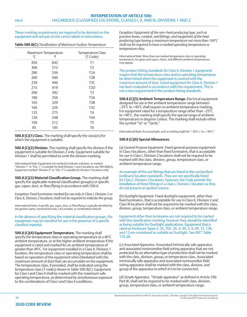
Reproduced with permission of NFPA from NFPA 70®, National Electrical Code®, 2020 edition. Copyright © 2019, National Fire Protection Association. For a full copy of NFPA 70, please go to www.nfpa.org.
INTERPRETATION OF ARTICLE 500: HAZARDOUS (CLASSIFIED) LOCATIONS, CLASSES I, II, AND III, DIVISIONS 1 AND 2
38
2020 CODE REVIEW
These marking requirements are required to be denoted on the equipment and not just on the carton labels or instructions.
Table 500.8(C) Classification of Maximum Surface Temperature
Maximum Temperature Temperature Class °C °F (T Code)
450 842 T1 300 572 T2 280 536 T2A 260 500 T2B 230 446 T2C 215 419 T2D 200 392 T3 180 356 T3A 165 329 T3B 160 320 T3C 135 275 T4 120 248 T4A 100 212 T5 85 185 T6
500.8 (C)(1) Class. The marking shall specify the class(es) for which the equipment is suitable.
500.8 (C)(2) Division. The marking shall specify the division if the equipment is suitable for Division 2 only. Equipment suitable for Division 1 shall be permitted to omit the division marking.
Informational Note: Equipment not marked to indicate a division, or marked “Division 1” or “Div. 1,” is suitable for both Division 1 and 2 locations; see 500.8(B)(2). Equipment marked “Division 2” or “Div. 2” is suitable for Division 2 locations only.
500.8 (C)(3) Material Classification Group. The marking shall specify the applicable material classification group(s) or specific gas, vapor, dust, or fiber/flying in accordance with 500.6.
Exception: Fixed luminaires marked for use only in Class I, Division 2 or Class II, Division 2 locations shall not be required to indicate the group.
Informational Note: A specific gas, vapor, dust, or fiber/flying is typically identified by the generic name, chemical formula, CAS number, or combination thereof.
In the absence of specifying the material classification groups, the equipment may be classified for use in the presence of a specific classified material.
500.8 (C)(4) Equipment Temperature. The marking shall specify the temperature class or operating temperature at a 40°C ambient temperature, or at the higher ambient temperature if the equipment is rated and marked for an ambient temperature of greater than 40°C. For equipment installed in a Class II, Division 1 location, the temperature class or operating temperature shall be based on operation of the equipment when blanketed with the maximum amount of dust that can accumulate on the equipment. The temperature class, if provided, shall be indicated using the temperature class (T codes) shown in Table 500.8(C). Equipment for Class I and Class II shall be marked with the maximum safe operating temperature, as determined by simultaneous exposure to the combinations of Class I and Class II conditions.
Exception: Equipment of the non–heat-producing type, such as junction boxes, conduit, and fittings, and equipment of the heat-producing type having a maximum temperature not more than 100°C shall not be required to have a marked operating temperature or temperature class.
Informational Note: More than one marked temperature class or operating temperature, for gases and vapors, dusts, and different ambient temperatures, may appear.
The product listing standards for Class II, Division 1 equipment require that the temperature class and/or operating temperature be determined when the equipment is covered with the maximum amount of dust. Listed equipment for Class II, Division 1 has been evaluated in accordance with this requirement. This is not a new requirement in the product listing standards.
500.8 (C)(5) Ambient Temperature Range. Electrical equipment designed for use in the ambient temperature range between –25°C to +40°C shall require no ambient temperature marking. For equipment rated for a temperature range other than –25°C to +40°C, the marking shall specify the special range of ambient temperatures in degrees Celsius. The marking shall include either the symbol “Ta” or “Tamb.”
Informational Note: As an example, such a marking might be “–30°C ≤ Ta ≤ +40°C.”
500.8 (C)(6) Special Allowances.
(a) General-Purpose Equipment. Fixed general-purpose equipment in Class I locations, other than fixed luminaires, that is acceptable for use in Class I, Division 2 locations shall not be required to be marked with the class, division, group, temperature class, or ambient temperature range.
An example of this are fittings that are listed to the unclassified (ordinary) location standards. They are not specifically listed for Class I, Division 2 locations, however, the Code permits the installation of these fittings in a Class I, Division 2 location as they do not present an ignition source.
(b) Dusttight Equipment. Fixed dusttight equipment, other than fixed luminaires, that is acceptable for use in Class II, Division 2 and Class III locations shall not be required to be marked with the class, division, group, temperature class, or ambient temperature range.
Equipment other than luminaires are not required to be marked with the classification marking, however they should be identified as being suitable for Dusttight applications. Equipment that is rated as Enclosure Types 3, 3S, 3SX, 3X, 4, 4X, 5, 6, 6P, 12, 12K, and 13 are considered as suitable as Dusttight. See NEC® Table 110.28.
(c) Associated Apparatus. Associated intrinsically safe apparatus and associated nonincendive field wiring apparatus that are not protected by an alternative type of protection shall not be marked with the class, division, group, or temperature class. Associated intrinsically safe apparatus and associated nonincendive field wiring apparatus shall be marked with the class, division, and group of the apparatus to which it is to be connected.
(d) Simple Apparatus. “Simple apparatus” as defined in Article 100 Part III, shall not be required to be marked with class, division, group, temperature class, or ambient temperature range.
500.8
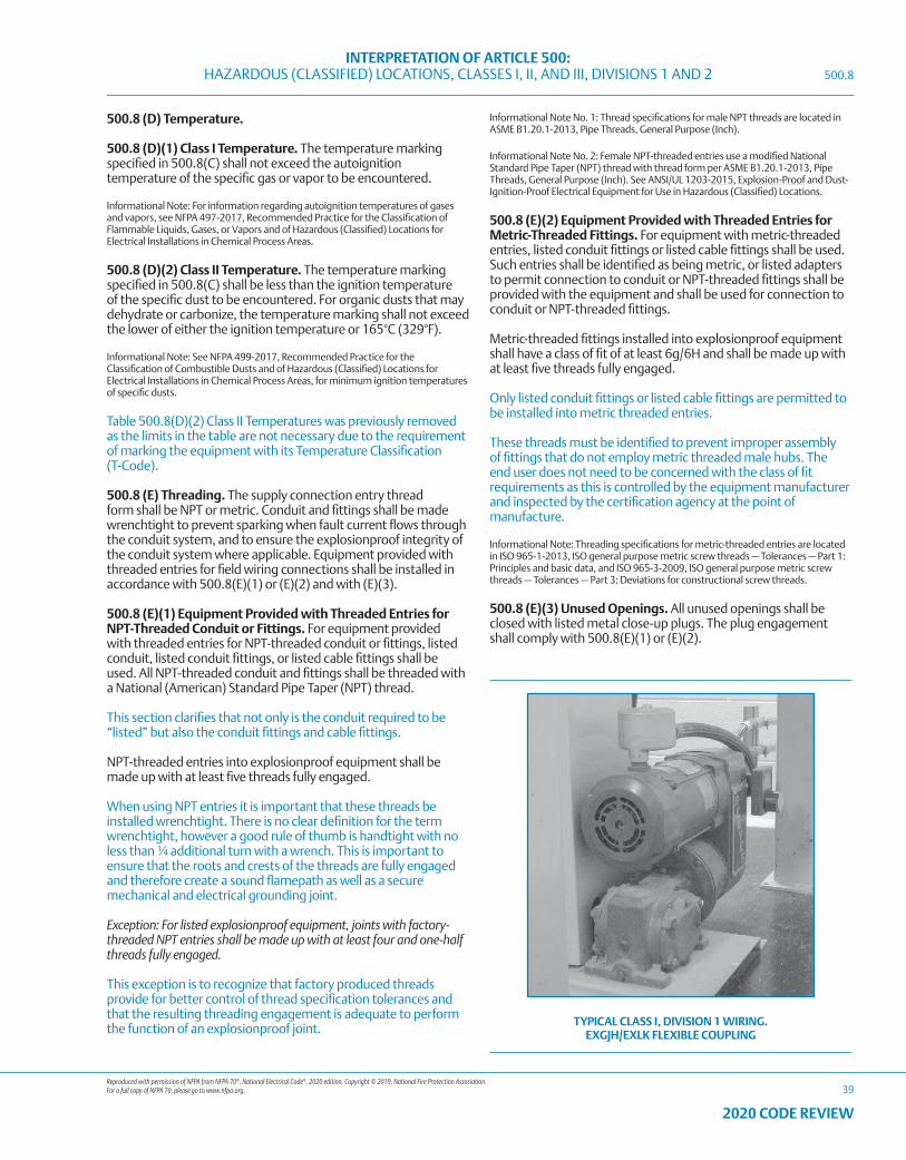
Reproduced with permission of NFPA from NFPA 70®, National Electrical Code®, 2020 edition. Copyright © 2019, National Fire Protection Association. For a full copy of NFPA 70, please go to www.nfpa.org.
INTERPRETATION OF ARTICLE 500: HAZARDOUS (CLASSIFIED) LOCATIONS, CLASSES I, II, AND III, DIVISIONS 1 AND 2
39
2020 CODE REVIEW
500.8 (D) Temperature.
500.8 (D)(1) Class I Temperature. The temperature marking specified in 500.8(C) shall not exceed the autoignition temperature of the specific gas or vapor to be encountered.
Informational Note: For information regarding autoignition temperatures of gases and vapors, see NFPA 497-2017, Recommended Practice for the Classification of Flammable Liquids, Gases, or Vapors and of Hazardous (Classified) Locations for Electrical Installations in Chemical Process Areas.
500.8 (D)(2) Class II Temperature. The temperature marking specified in 500.8(C) shall be less than the ignition temperature of the specific dust to be encountered. For organic dusts that may dehydrate or carbonize, the temperature marking shall not exceed the lower of either the ignition temperature or 165°C (329°F).
Informational Note: See NFPA 499-2017, Recommended Practice for the Classification of Combustible Dusts and of Hazardous (Classified) Locations for Electrical Installations in Chemical Process Areas, for minimum ignition temperatures of specific dusts.
Table 500.8(D)(2) Class II Temperatures was previously removed as the limits in the table are not necessary due to the requirement of marking the equipment with its Temperature Classification (T-Code).
500.8 (E) Threading. The supply connection entry thread form shall be NPT or metric. Conduit and fittings shall be made wrenchtight to prevent sparking when fault current flows through the conduit system, and to ensure the explosionproof integrity of the conduit system where applicable. Equipment provided with threaded entries for field wiring connections shall be installed in accordance with 500.8(E)(1) or (E)(2) and with (E)(3).
500.8 (E)(1) Equipment Provided with Threaded Entries for NPT-Threaded Conduit or Fittings. For equipment provided with threaded entries for NPT-threaded conduit or fittings, listed conduit, listed conduit fittings, or listed cable fittings shall be used. All NPT-threaded conduit and fittings shall be threaded with a National (American) Standard Pipe Taper (NPT) thread.
This section clarifies that not only is the conduit required to be “listed” but also the conduit fittings and cable fittings.
NPT-threaded entries into explosionproof equipment shall be made up with at least five threads fully engaged.
When using NPT entries it is important that these threads be installed wrenchtight. There is no clear definition for the term wrenchtight, however a good rule of thumb is handtight with no less than ¼ additional turn with a wrench. This is important to ensure that the roots and crests of the threads are fully engaged and therefore create a sound flamepath as well as a secure mechanical and electrical grounding joint.
Exception: For listed explosionproof equipment, joints with factory-threaded NPT entries shall be made up with at least four and one-half threads fully engaged.
This exception is to recognize that factory produced threads provide for better control of thread specification tolerances and that the resulting threading engagement is adequate to perform the function of an explosionproof joint.
Informational Note No. 1: Thread specifications for male NPT threads are located in ASME B1.20.1-2013, Pipe Threads, General Purpose (Inch).
Informational Note No. 2: Female NPT-threaded entries use a modified National Standard Pipe Taper (NPT) thread with thread form per ASME B1.20.1-2013, Pipe Threads, General Purpose (Inch). See ANSI/UL 1203-2015, Explosion-Proof and Dust-Ignition-Proof Electrical Equipment for Use in Hazardous (Classified) Locations.
500.8 (E)(2) Equipment Provided with Threaded Entries for Metric-Threaded Fittings. For equipment with metric-threaded entries, listed conduit fittings or listed cable fittings shall be used. Such entries shall be identified as being metric, or listed adapters to permit connection to conduit or NPT-threaded fittings shall be provided with the equipment and shall be used for connection to conduit or NPT-threaded fittings.
Metric-threaded fittings installed into explosionproof equipment shall have a class of fit of at least 6g/6H and shall be made up with at least five threads fully engaged.
Only listed conduit fittings or listed cable fittings are permitted to be installed into metric threaded entries.
These threads must be identified to prevent improper assembly of fittings that do not employ metric threaded male hubs. The end user does not need to be concerned with the class of fit requirements as this is controlled by the equipment manufacturer and inspected by the certification agency at the point of manufacture.
Informational Note: Threading specifications for metric-threaded entries are located in ISO 965-1-2013, ISO general purpose metric screw threads — Tolerances — Part 1: Principles and basic data, and ISO 965-3-2009, ISO general purpose metric screw threads — Tolerances — Part 3: Deviations for constructional screw threads.
500.8 (E)(3) Unused Openings. All unused openings shall be closed with listed metal close-up plugs. The plug engagement shall comply with 500.8(E)(1) or (E)(2).
TYPICAL CLASS I, DIVISION 1 WIRING. EXGJH/EXLK FLEXIBLE COUPLING
500.8

Reproduced with permission of NFPA from NFPA 70®, National Electrical Code®, 2020 edition. Copyright © 2019, National Fire Protection Association. For a full copy of NFPA 70, please go to www.nfpa.org.
INTERPRETATION OF ARTICLE 500: HAZARDOUS (CLASSIFIED) LOCATIONS, CLASSES I, II, AND III, DIVISIONS 1 AND 2
40
2020 CODE REVIEW
The listing standard, UL/ANSI 1203 requires an explosionproof box or enclosure to be factory-provided with close-up plugs for all entries except for one entry. These plugs may not independently be marked with the listing and classification information, however they have been evaluated as part of the full box and enclosure listing.
500.8 (F) Optical Fiber Cables. An optical fiber cable, with or without current-carrying conductors (composite optical fiber cable), shall be installed to address the associated fire hazard and sealed to address the associated explosion hazard in accordance with the requirements of Article 500, 501, 502, or 503, as applicable.
500.8 (G) Equipment Involving Optical Radiation. For equipment involving sources of optical radiation (such as laser or LED sources) in the wavelength range from 380 nm to 10 μm, the risk of ignition from optical radiation shall be considered for all electrical parts and circuits that may be exposed to the radiation, both inside and outside the optical equipment. This includes optical equipment, which itself is located outside the explosive atmosphere, but its emitted optical radiation enters such atmospheres.
Informational Note: For additional information on types of protection that can be applied to minimize the risk of ignition in explosive atmospheres from optical radiation, see ANSI/UL 60079-28-2017, Explosive Atmospheres — Part 28: Protection of Equipment and Transmission Systems Using Optical Radiation.
Exception: All luminaires (fixed, portable, or transportable) and hand lights intended to be supplied by mains (with or without galvanic isolation) or powered by batteries, with any continuous divergent light source, including LEDs, shall be excluded from this requirement.
Non-convergent continuous LED light sources such as luminaires are not considered to be a source of optical radiation that would create dangerous isolated temperature rises on surfaces in a hazardous (classified) location. For other light sources that do not apply to the hazardous condition refer to ANSI/UL 60079-28 “Explosive Atmospheres – Part 28: Protection of Equipment and Transmission Systems Using Optical Radiation”.
500.9 Specific Occupancies. Articles 510 through 517 cover garages, aircraft hangars, motor fuel dispensing facilities, bulk storage plants, spray application, dipping and coating processes, and health care facilities.
500.8
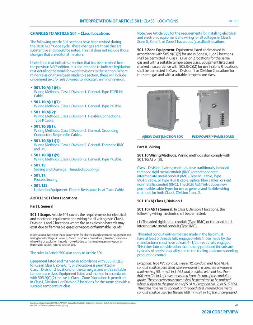
Reproduced with permission of NFPA from NFPA 70®, National Electrical Code®, 2020 edition. Copyright © 2019, National Fire Protection Association. For a full copy of NFPA 70, please go to www.nfpa.org.
INTERPRETATION OF ARTICLE 501: CLASS I LOCATIONS
41
2020 CODE REVIEW
CHANGES TO ARTICLE 501 – Class I Locations
The following Article 501 sections have been revised during the 2020 NEC® Code cycle. These changes are those that are substantive and should be noted. This list does not include those changes that are editorial in nature.
Underlined text indicates a section that has been revised from the previous NEC® edition. It is not intended to indicate legislation text detailing the word-for-word revisions to the section. Where minor revisions have been made to a section, these will include underlined text for select words to indicate the minor revision.
• 501.10(A)(1)(6): Wiring Methods. Class I, Division 1, General. Type TC-ER-HL
Cable.
• 501.10(A)(1)(7): Wiring Methods. Class I, Division 1. General. Type P Cable.
• 501.10(A)(2): Wiring Methods. Class I, Division 1. Flexible Connections.
Type P Cable.
• 501.10(B)(1): Wiring Methods. Class I, Division 2. General. Grounding
Conductors Required in Cables.
• 501.10(B)(1)(1): Wiring Methods. Class I, Division 2. General. Threaded RMC
and IMC.
• 501.10(B)(1)(9): Wiring Methods. Class I, Division 2. General. Type P Cable.
• 501.15: Sealing and Drainage. Threaded Couplings
• 501.17: Process Sealing.
• 501.135: Utilization Equipment. Electric Resistance Heat Trace Cable.
ARTICLE 501 Class I Locations
Part I. General
501.1 Scope. Article 501 covers the requirements for electrical and electronic equipment and wiring for all voltages in Class I, Division 1 and 2 locations where fire or explosion hazards may exist due to flammable gases or vapors or flammable liquids.
Informational Note: For the requirements for electrical and electronic equipment and wiring for all voltages in Zone 0, Zone 1, or Zone 2 hazardous (classified) locations where fire or explosion hazards may exist due to flammable gases or vapors or flammable liquids, refer to Article 505.
The rules in Article 500 also apply to Article 501.
Equipment listed and marked in accordance with 505.9(C)(2) for use in Class I, Zone 0, 1, or 2 locations is permitted in Class I, Division 2 locations for the same gas and with a suitable temperature class. Equipment listed and marked in accordance with 505.9(C)(2) for use in Class I, Zone 0 locations is permitted in Class I, Division 1 or Division 2 locations for the same gas with a suitable temperature class.
Note: See Article 505 for the requirements for installing electrical and electronic equipment and wiring for all voltages in Class I, Zone 0, Zone 1, or Zone 2 hazardous (classified) locations.
501.5 Zone Equipment. Equipment listed and marked in accordance with 505.9(C)(2) for use in Zone 0, 1, or 2 locations shall be permitted in Class I, Division 2 locations for the same gas and with a suitable temperature class. Equipment listed and marked in accordance with 505.9(C)(2) for use in Zone 0 locations shall be permitted in Class I, Division 1 or Division 2 locations for the same gas and with a suitable temperature class.
AJBEW CAST JUNCTION BOX PLEXPOWER™ PANELBOARD
Part II. Wiring
501.10 Wiring Methods. Wiring methods shall comply with 501.10(A) or (B).
Class I, Division 1 wiring methods have traditionally included threaded rigid metal conduit (RMC) or threaded steel intermediate metal conduit (IMC), Type MI. cable, Type MC-HL cable, or Type ITC-HL cable, optical fiber cables, or rigid nonmetallic conduit (RNC). The 2020 NEC® introduces new permissible cable Types for use as general and flexible wiring methods for both Class I, Division 1 and 2.
501.10 (A) Class I, Division 1.
501.10 (A)(1) General. In Class I, Division 1 locations, the following wiring methods shall be permitted:
(1) Threaded rigid metal conduit (Type RMC) or threaded steel intermediate metal conduit (Type IMC).
Threaded conduit entries that are made in the field must have at least 5 threads fully engaged while those made by the manufacturer must have at least 4–1/2 threads fully engaged. This takes into consideration that factory produced threads are typically of precision quality due to the tooling and corresponding production control.
Exception: Type PVC conduit, Type RTRC conduit, and Type HDPE conduit shall be permitted where encased in a concrete envelope a minimum of 50 mm (2 in.) thick and provided with not less than 600 mm (24 in.) of cover measured from the top of the conduit to grade. The concrete encasement shall be permitted to be omitted where subject to the provisions of 514.8, Exception No. 2, or 515.8(A). Threaded rigid metal conduit or threaded steel intermediate metal conduit shall be used for the last 600 mm (24 in.) of the underground
501.10
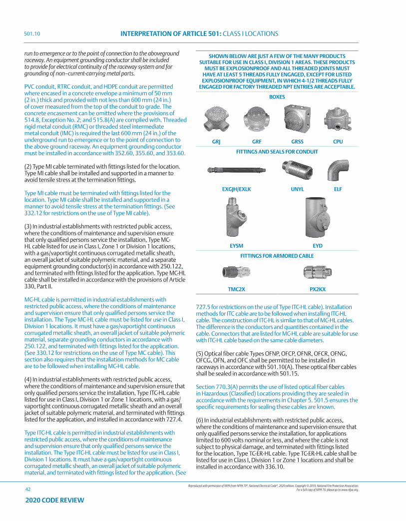
Reproduced with permission of NFPA from NFPA 70®, National Electrical Code®, 2020 edition. Copyright © 2019, National Fire Protection Association. For a full copy of NFPA 70, please go to www.nfpa.org.
INTERPRETATION OF ARTICLE 501: CLASS I LOCATIONS
42
2020 CODE REVIEW
run to emergence or to the point of connection to the aboveground raceway. An equipment grounding conductor shall be included to provide for electrical continuity of the raceway system and for grounding of non–current-carrying metal parts.
PVC conduit, RTRC conduit, and HDPE conduit are permitted where encased in a concrete envelope a minimum of 50 mm (2 in.) thick and provided with not less than 600 mm (24 in.) of cover measured from the top of the conduit to grade. The concrete encasement can be omitted where the provisions of 514.8, Exception No. 2; and 515.8(A) are complied with. Threaded rigid metal conduit (RMC) or threaded steel intermediate metal conduit (IMC) is required the last 600 mm (24 in.) of the underground run to emergence or to the point of connection to the above ground raceway. An equipment grounding conductor must be installed in accordance with 352.60, 355.60, and 353.60.
(2) Type MI cable terminated with fittings listed for the location. Type MI cable shall be installed and supported in a manner to avoid tensile stress at the termination fittings.
Type MI cable must be terminated with fittings listed for the location. Type MI cable shall be installed and supported in a manner to avoid tensile stress at the termination fittings. (See 332.12 for restrictions on the use of Type MI cable).
(3) In industrial establishments with restricted public access, where the conditions of maintenance and supervision ensure that only qualified persons service the installation, Type MC-HL cable listed for use in Class I, Zone 1 or Division 1 locations, with a gas/vaportight continuous corrugated metallic sheath, an overall jacket of suitable polymeric material, and a separate equipment grounding conductor(s) in accordance with 250.122, and terminated with fittings listed for the application. Type MC-HL cable shall be installed in accordance with the provisions of Article 330, Part II.
MC-HL cable is permitted in industrial establishments with restricted public access, where the conditions of maintenance and supervision ensure that only qualified persons service the installation. The Type MC-HL cable must be listed for use in Class I, Division 1 locations. It must have a gas/vaportight continuous corrugated metallic sheath, an overall jacket of suitable polymeric material, separate grounding conductors in accordance with 250.122, and terminated with fittings listed for the application. (See 330.12 for restrictions on the use of Type MC cable). This section also requires that the installation methods for MC cable are to be followed when installing MC-HL cable.
(4) In industrial establishments with restricted public access, where the conditions of maintenance and supervision ensure that only qualified persons service the installation, Type ITC-HL cable listed for use in Class I, Division 1 or Zone 1 locations, with a gas/vaportight continuous corrugated metallic sheath and an overall jacket of suitable polymeric material, and terminated with fittings listed for the application, and installed in accordance with 727.4.
Type ITC-HL cable is permitted in industrial establishments with restricted public access, where the conditions of maintenance and supervision ensure that only qualified persons service the installation. The Type ITC-HL cable must be listed for use in Class I, Division 1 locations. It must have a gas/vaportight continuous corrugated metallic sheath, an overall jacket of suitable polymeric material, and terminated with fittings listed for the application. (See
727.5 for restrictions on the use of Type ITC-HL cable). Installation methods for ITC cable are to be followed when installing ITC-HL cable. The construction of ITC-HL is similar to that of MC-HL cables. The difference is the conductors and quantities contained in the cable. Connectors that are listed for MC-HL cable are suitable for use with ITC-HL cable based on the same cable diameters.
(5) Optical fiber cable Types OFNP, OFCP, OFNR, OFCR, OFNG, OFCG, OFN, and OFC shall be permitted to be installed in raceways in accordance with 501.10(A). These optical fiber cables shall be sealed in accordance with 501.15.
Section 770.3(A) permits the use of listed optical fiber cables in Hazardous (Classified) Locations providing they are sealed in accordance with the requirements in Chapter 5. 501.5 ensures the specific requirements for sealing these cables are known.
(6) In industrial establishments with restricted public access, where the conditions of maintenance and supervision ensure that only qualified persons service the installation, for applications limited to 600 volts nominal or less, and where the cable is not subject to physical damage, and terminated with fittings listed for the location, Type TC-ER-HL cable. Type TC-ER-HL cable shall be listed for use in Class I, Division 1 or Zone 1 locations and shall be installed in accordance with 336.10.
SHOWN BELOW ARE JUST A FEW OF THE MANY PRODUCTS SUITABLE FOR USE IN CLASS I, DIVISION 1 AREAS. THESE PRODUCTS
MUST BE EXPLOSIONPROOF AND ALL THREADED JOINTS MUST HAVE AT LEAST 5 THREADS FULLY ENGAGED, EXCEPT FOR LISTED EXPLOSIONPROOF EQUIPMENT, IN WHICH 4-1/2 THREADS FULLY
ENGAGED FOR FACTORY THREADED NPT ENTRIES ARE ACCEPTABLE.
BOXES
GRJ GRF GRSS CPU
FITTINGS AND SEALS FOR CONDUIT
EXGJH/EXLK UNYL ELF
EYSM EYD
FITTINGS FOR ARMORED CABLE
TMC2X PX2KX
501.10
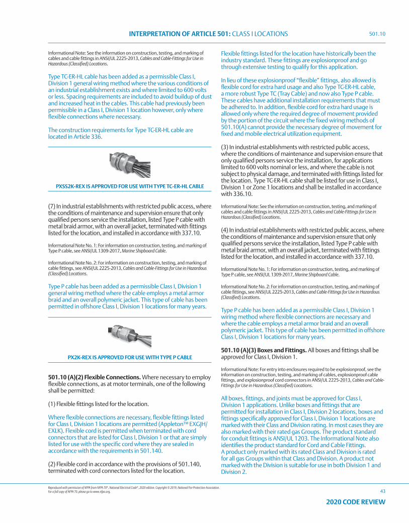
Reproduced with permission of NFPA from NFPA 70®, National Electrical Code®, 2020 edition. Copyright © 2019, National Fire Protection Association. For a full copy of NFPA 70, please go to www.nfpa.org.
INTERPRETATION OF ARTICLE 501: CLASS I LOCATIONS
43
2020 CODE REVIEW
Informational Note: See the information on construction, testing, and marking of cables and cable fittings in ANSI/UL 2225-2013, Cables and Cable-Fittings for Use in Hazardous (Classified) Locations.
Type TC-ER-HL cable has been added as a permissible Class I, Division 1 general wiring method where the various conditions of an industrial establishment exists and where limited to 600 volts or less. Spacing requirements are included to avoid buildup of dust and increased heat in the cables. This cable had previously been permissible in a Class I, Division 1 location however, only where flexible connections where necessary.
The construction requirements for Type TC-ER-HL cable are located in Article 336.
PXSS2K-REX IS APPROVED FOR USE WITH TYPE TC-ER-HL CABLE
(7) In industrial establishments with restricted public access, where the conditions of maintenance and supervision ensure that only qualified persons service the installation, listed Type P cable with metal braid armor, with an overall jacket, terminated with fittings listed for the location, and installed in accordance with 337.10.
Informational Note No. 1: For information on construction, testing, and marking of Type P cable, see ANSI/UL 1309-2017, Marine Shipboard Cable.
Informational Note No. 2: For information on construction, testing, and marking of cable fittings, see ANSI/UL 2225-2013, Cables and Cable-Fittings for Use in Hazardous (Classified) Locations.
Type P cable has been added as a permissible Class I, Division 1 general wiring method where the cable employs a metal armor braid and an overall polymeric jacket. This type of cable has been permitted in offshore Class I, Division 1 locations for many years.
PX2K-REX IS APPROVED FOR USE WITH TYPE P CABLE
501.10 (A)(2) Flexible Connections. Where necessary to employ flexible connections, as at motor terminals, one of the following shall be permitted:
(1) Flexible fittings listed for the location.
Where flexible connections are necessary, flexible fittings listed for Class I, Division 1 locations are permitted (Appleton™ EXGJH/EXLK). Flexible cord is permitted when terminated with cord connectors that are listed for Class I, Division 1 or that are simply listed for use with the specific cord where they are sealed in accordance with the requirements in 501.140.
(2) Flexible cord in accordance with the provisions of 501.140, terminated with cord connectors listed for the location.
Flexible fittings listed for the location have historically been the industry standard. These fittings are explosionproof and go through extensive testing to qualify for this application.
In lieu of these explosionproof “flexible” fittings, also allowed is flexible cord for extra hard usage and also Type TC-ER-HL cable, a more robust Type TC (Tray Cable) and now also Type P cable. These cables have additional installation requirements that must be adhered to. In addition, flexible cord for extra hard usage is allowed only where the required degree of movement provided by the portion of the circuit where the fixed wiring methods of 501.10(A) cannot provide the necessary degree of movement for fixed and mobile electrical utilization equipment.
(3) In industrial establishments with restricted public access, where the conditions of maintenance and supervision ensure that only qualified persons service the installation, for applications limited to 600 volts nominal or less, and where the cable is not subject to physical damage, and terminated with fittings listed for the location. Type TC-ER-HL cable shall be listed for use in Class I, Division 1 or Zone 1 locations and shall be installed in accordance with 336.10.
Informational Note: See the information on construction, testing, and marking of cables and cable fittings in ANSI/UL 2225-2013, Cables and Cable-Fittings for Use in Hazardous (Classified) Locations.
(4) In industrial establishments with restricted public access, where the conditions of maintenance and supervision ensure that only qualified persons service the installation, listed Type P cable with metal braid armor, with an overall jacket, terminated with fittings listed for the location, and installed in accordance with 337.10.
Informational Note No. 1: For information on construction, testing, and marking of Type P cable, see ANSI/UL 1309-2017, Marine Shipboard Cable.
Informational Note No. 2: For information on construction, testing, and marking of cable fittings, see ANSI/UL 2225-2013, Cables and Cable-Fittings for Use in Hazardous (Classified) Locations.
Type P cable has been added as a permissible Class I, Division 1 wiring method where flexible connections are necessary and where the cable employs a metal armor braid and an overall polymeric jacket. This type of cable has been permitted in offshore Class I, Division 1 locations for many years.
501.10 (A)(3) Boxes and Fittings. All boxes and fittings shall be approved for Class I, Division 1.
Informational Note: For entry into enclosures required to be explosionproof, see the information on construction, testing, and marking of cables, explosionproof cable fittings, and explosionproof cord connectors in ANSI/UL 2225-2013, Cables and Cable-Fittings for Use in Hazardous (Classified) Locations.
All boxes, fittings, and joints must be approved for Class I, Division 1 applications. Unlike boxes and fittings that are permitted for installation in Class I, Division 2 locations, boxes and fittings specifically approved for Class I, Division 1 locations are marked with their Class and Division rating. In most cases they are also marked with their rated gas Groups. The product standard for conduit fittings is ANSI/UL 1203. The Informational Note also identifies the product standard for Cord and Cable Fittings. A product only marked with its rated Class and Division is rated for all gas Groups within that Class and Division. A product not marked with the Division is suitable for use in both Division 1 and Division 2.
501.10
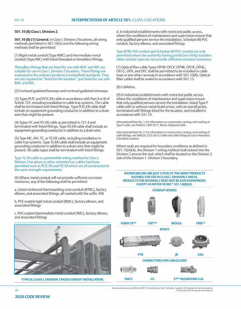
Reproduced with permission of NFPA from NFPA 70®, National Electrical Code®, 2020 edition. Copyright © 2019, National Fire Protection Association. For a full copy of NFPA 70, please go to www.nfpa.org.
INTERPRETATION OF ARTICLE 501: CLASS I LOCATIONS
44
2020 CODE REVIEW
501.10 (B) Class I, Division 2.
501.10 (B) (1) General. In Class I, Division 2 locations, all wiring methods permitted in 501.10(A) and the following wiring methods shall be permitted:
(1) Rigid metal conduit (Type RMC) and intermediate metal conduit (Type IMC) with listed threaded or threadless fittings.
Threadless fittings that are listed for use with RMC and IMC are suitable for use in Class I, Division 2 locations. These fittings are evaluated to the ordinary locations (unclassified) standards. They are not required be “listed for the location”, just listed for use with RMC and IMC.
(2) Enclosed gasketed busways and enclosed gasketed wireways.
(3) Types PLTC and PLTC-ER cable in accordance with Part II or III of Article 725, including installation in cable tray systems. The cable shall be terminated with listed fittings. Type PLTC-ER cable shall include an equipment grounding conductor in addition to a drain wire that might be present.
(4) Types ITC and ITC-ER cable as permitted in 727.4 and terminated with listed fittings. Type ITC-ER cable shall include an equipment grounding conductor in addition to a drain wire.
(5) Type MC, MV, TC, or TC-ER cable, including installation in cable tray systems. Type TC-ER cable shall include an equipment grounding conductor in addition to a drain wire that might be present. All cable types shall be terminated with listed fittings.
Type TC-ER cable is a permissible wiring method for Class I, Division 2 locations as other extended run cables had been permitted such as PLTC-ER and ITC-ER which are all constructed to the same strength requirements.
(6) Where metal conduit will not provide sufficient corrosion resistance, any of the following shall be permitted:
a. Listed reinforced thermosetting resin conduit (RTRC), factory elbows, and associated fittings, all marked with the suffix -XW
b. PVC-coated rigid metal conduit (RMC), factory elbows, and associated fittings
c. PVC-coated intermediate metal conduit (IMC), factory elbows, and associated fittings
d. In industrial establishments with restricted public access, where the conditions of maintenance and supervision ensure that only qualified persons service the installation, Schedule 80 PVC conduit, factory elbows, and associated fittings
Type RTRC-XW conduit and Schedule 80 PVC conduit are only permitted where the authority having jurisdiction (AHJ) considers other conduit types do not provide sufficient corrosion resistance.
(7) Optical fiber cable Types OFNP, OFCP, OFNR, OFCR, OFNG, OFCG, OFN, and OFC shall be permitted to be installed in cable trays or any other raceway in accordance with 501.10(B). Optical fiber cables shall be sealed in accordance with 501.15.
(8) Cablebus.
(9) In industrial establishments with restricted public access, where the conditions of maintenance and supervision ensure that only qualified persons service the installation, listed Type P cable with or without metal braid armor, with an overall jacket, terminated with fittings listed for the location, and installed in accordance with 337.10.
Informational Note No. 1: For information on construction, testing, and marking of Type P cable, see ANSI/UL 1309-2017, Marine Shipboard Cable.
Informational Note No. 2: For information on construction, testing, and marking of cable fittings, see ANSI/UL 2225-2013, Cables and Cable-Fittings for Use in Hazardous (Classified) Locations.
Where seals are required for boundary conditions as defined in 501.15(A)(4), the Division 1 wiring method shall extend into the Division 2 area to the seal, which shall be located on the Division 2 side of the Division 1–Division 2 boundary.
SHOWN BELOW ARE JUST A FEW OF THE MANY PRODUCTS SUITABLE FOR USE IN CLASS I, DIVISION 2 AREAS.
PRODUCTS FOR DIVISION 2 NEED NOT BE EXPLOSIONPROOF, EXCEPT AS NOTED IN NEC® 501.10(B)(4).
CONDUIT BODIES
FORM 35™ FM7™ MOGUL FM8™
BOXES
PTB JB GSU
CONNECTORS FOR CABLE/CORD
TMC2 CG ST™ W/GROUND LUGTYPICAL CLASS I, DIVISION 2 RIGID CONDUIT INSTALLATION.
501.10
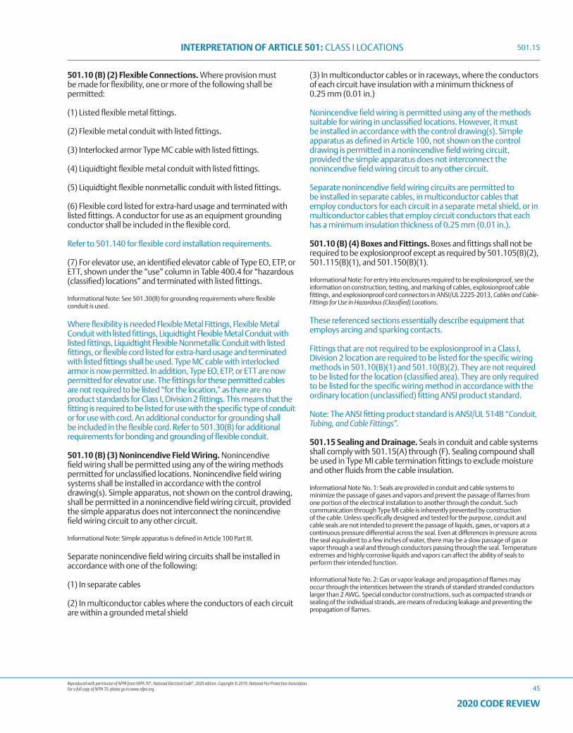
Reproduced with permission of NFPA from NFPA 70®, National Electrical Code®, 2020 edition. Copyright © 2019, National Fire Protection Association. For a full copy of NFPA 70, please go to www.nfpa.org.
INTERPRETATION OF ARTICLE 501: CLASS I LOCATIONS
45
2020 CODE REVIEW
501.10 (B) (2) Flexible Connections. Where provision must be made for flexibility, one or more of the following shall be permitted:
(1) Listed flexible metal fittings.
(2) Flexible metal conduit with listed fittings.
(3) Interlocked armor Type MC cable with listed fittings.
(4) Liquidtight flexible metal conduit with listed fittings.
(5) Liquidtight flexible nonmetallic conduit with listed fittings.
(6) Flexible cord listed for extra-hard usage and terminated with listed fittings. A conductor for use as an equipment grounding conductor shall be included in the flexible cord.
Refer to 501.140 for flexible cord installation requirements.
(7) For elevator use, an identified elevator cable of Type EO, ETP, or ETT, shown under the “use” column in Table 400.4 for “hazardous (classified) locations” and terminated with listed fittings.
Informational Note: See 501.30(B) for grounding requirements where flexible conduit is used.
Where flexibility is needed Flexible Metal Fittings, Flexible Metal Conduit with listed fittings, Liquidtight Flexible Metal Conduit with listed fittings, Liquidtight Flexible Nonmetallic Conduit with listed fittings, or flexible cord listed for extra-hard usage and terminated with listed fittings shall be used. Type MC cable with interlocked armor is now permitted. In addition, Type EO, ETP, or ETT are now permitted for elevator use. The fittings for these permitted cables are not required to be listed “for the location,” as there are no product standards for Class I, Division 2 fittings. This means that the fitting is required to be listed for use with the specific type of conduit or for use with cord. An additional conductor for grounding shall be included in the flexible cord. Refer to 501.30(B) for additional requirements for bonding and grounding of flexible conduit.
501.10 (B) (3) Nonincendive Field Wiring. Nonincendive field wiring shall be permitted using any of the wiring methods permitted for unclassified locations. Nonincendive field wiring systems shall be installed in accordance with the control drawing(s). Simple apparatus, not shown on the control drawing, shall be permitted in a nonincendive field wiring circuit, provided the simple apparatus does not interconnect the nonincendive field wiring circuit to any other circuit.
Informational Note: Simple apparatus is defined in Article 100 Part III.
Separate nonincendive field wiring circuits shall be installed in accordance with one of the following:
(1) In separate cables
(2) In multiconductor cables where the conductors of each circuit are within a grounded metal shield
(3) In multiconductor cables or in raceways, where the conductors of each circuit have insulation with a minimum thickness of 0.25 mm (0.01 in.)
Nonincendive field wiring is permitted using any of the methods suitable for wiring in unclassified locations. However, it must be installed in accordance with the control drawing(s). Simple apparatus as defined in Article 100, not shown on the control drawing is permitted in a nonincendive field wiring circuit, provided the simple apparatus does not interconnect the nonincendive field wiring circuit to any other circuit.
Separate nonincendive field wiring circuits are permitted to be installed in separate cables, in multiconductor cables that employ conductors for each circuit in a separate metal shield, or in multiconductor cables that employ circuit conductors that each has a minimum insulation thickness of 0.25 mm (0.01 in.).
501.10 (B) (4) Boxes and Fittings. Boxes and fittings shall not be required to be explosionproof except as required by 501.105(B)(2), 501.115(B)(1), and 501.150(B)(1).
Informational Note: For entry into enclosures required to be explosionproof, see the information on construction, testing, and marking of cables, explosionproof cable fittings, and explosionproof cord connectors in ANSI/UL 2225-2013, Cables and Cable-Fittings for Use in Hazardous (Classified) Locations.
These referenced sections essentially describe equipment that employs arcing and sparking contacts.
Fittings that are not required to be explosionproof in a Class I, Division 2 location are required to be listed for the specific wiring methods in 501.10(B)(1) and 501.10(B)(2). They are not required to be listed for the location (classified area). They are only required to be listed for the specific wiring method in accordance with the ordinary location (unclassified) fitting ANSI product standard.
Note: The ANSI fitting product standard is ANSI/UL 514B “Conduit, Tubing, and Cable Fittings”.
501.15 Sealing and Drainage. Seals in conduit and cable systems shall comply with 501.15(A) through (F). Sealing compound shall be used in Type MI cable termination fittings to exclude moisture and other fluids from the cable insulation.
Informational Note No. 1: Seals are provided in conduit and cable systems to minimize the passage of gases and vapors and prevent the passage of flames from one portion of the electrical installation to another through the conduit. Such communication through Type MI cable is inherently prevented by construction of the cable. Unless specifically designed and tested for the purpose, conduit and cable seals are not intended to prevent the passage of liquids, gases, or vapors at a continuous pressure differential across the seal. Even at differences in pressure across the seal equivalent to a few inches of water, there may be a slow passage of gas or vapor through a seal and through conductors passing through the seal. Temperature extremes and highly corrosive liquids and vapors can affect the ability of seals to perform their intended function.
Informational Note No. 2: Gas or vapor leakage and propagation of flames may occur through the interstices between the strands of standard stranded conductors larger than 2 AWG. Special conductor constructions, such as compacted strands or sealing of the individual strands, are means of reducing leakage and preventing the propagation of flames.
501.15
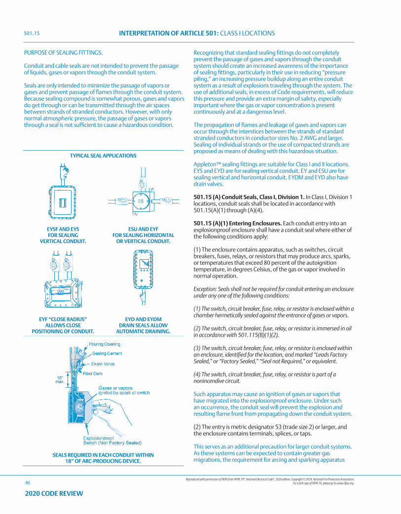
Reproduced with permission of NFPA from NFPA 70®, National Electrical Code®, 2020 edition. Copyright © 2019, National Fire Protection Association. For a full copy of NFPA 70, please go to www.nfpa.org.
INTERPRETATION OF ARTICLE 501: CLASS I LOCATIONS
46
2020 CODE REVIEW
PURPOSE OF SEALING FITTINGS.
Conduit and cable seals are not intended to prevent the passage of liquids, gases or vapors through the conduit system.
Seals are only intended to minimize the passage of vapors or gases and prevent passage of flames through the conduit system. Because sealing compound is somewhat porous, gases and vapors do get through or can be transmitted through the air spaces between strands of stranded conductors. However, with only normal atmospheric pressure, the passage of gases or vapors through a seal is not sufficient to cause a hazardous condition.
Recognizing that standard sealing fittings do not completely prevent the passage of gases and vapors through the conduit system should create an increased awareness of the importance of sealing fittings, particularly in their use in reducing “pressure piling,” an increasing pressure buildup along an entire conduit system as a result of explosions traveling through the system. The use of additional seals, in excess of Code requirements, will reduce this pressure and provide an extra margin of safety, especially important where the gas or vapor concentration is present continuously and at a dangerous level.
The propagation of flames and leakage of gases and vapors can occur through the interstices between the strands of standard stranded conductors in conductor sizes No. 2 AWG and larger. Sealing of individual strands or the use of compacted strands are proposed as means of dealing with this hazardous situation.
Appleton™ sealing fittings are suitable for Class I and II locations.EYS and EYD are for sealing vertical conduit. EY and ESU are for sealing vertical and horizontal conduit. EYDM and EYD also have drain valves.
501.15 (A) Conduit Seals, Class I, Division 1. In Class I, Division 1 locations, conduit seals shall be located in accordance with 501.15(A)(1) through (A)(4).
501.15 (A)(1) Entering Enclosures. Each conduit entry into an explosionproof enclosure shall have a conduit seal where either of the following conditions apply:
(1) The enclosure contains apparatus, such as switches, circuit breakers, fuses, relays, or resistors that may produce arcs, sparks, or temperatures that exceed 80 percent of the autoignition temperature, in degrees Celsius, of the gas or vapor involved in normal operation.
Exception: Seals shall not be required for conduit entering an enclosure under any one of the following conditions:
(1) The switch, circuit breaker, fuse, relay, or resistor is enclosed within a chamber hermetically sealed against the entrance of gases or vapors.
(2) The switch, circuit breaker, fuse, relay, or resistor is immersed in oil in accordance with 501.115(B)(1)(2).
(3) The switch, circuit breaker, fuse, relay, or resistor is enclosed within an enclosure, identified for the location, and marked “Leads Factory Sealed,” or “Factory Sealed,” “Seal not Required,” or equivalent.
(4) The switch, circuit breaker, fuse, relay, or resistor is part of a nonincendive circuit.
Such apparatus may cause an ignition of gases or vapors that have migrated into the explosionproof enclosure. Under such an occurrence, the conduit seal will prevent the explosion and resulting flame front from propagating down the conduit system.
(2) The entry is metric designator 53 (trade size 2) or larger, and the enclosure contains terminals, splices, or taps.
This serves as an additional precaution for larger conduit systems. As these systems can be expected to contain greater gas migrations, the requirement for arcing and sparking apparatus
TYPICAL SEAL APPLICATIONS
EYSF AND EYS FOR SEALING
VERTICAL CONDUIT.
ESU AND EYF FOR SEALING HORIZONTAL
OR VERTICAL CONDUIT.
EYF “CLOSE RADIUS” ALLOWS CLOSE
POSITIONING OF CONDUIT.
EYD AND EYDM DRAIN SEALS ALLOW
AUTOMATIC DRAINING.
SEALS REQUIRED IN EACH CONDUIT WITHIN 18” OF ARC-PRODUCING DEVICE.
501.15
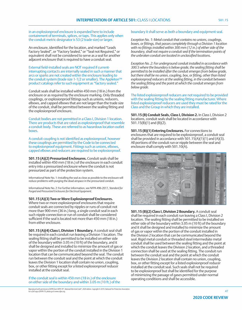
Reproduced with permission of NFPA from NFPA 70®, National Electrical Code®, 2020 edition. Copyright © 2019, National Fire Protection Association. For a full copy of NFPA 70, please go to www.nfpa.org.
INTERPRETATION OF ARTICLE 501: CLASS I LOCATIONS
47
2020 CODE REVIEW
in an explosionproof enclosure is expanded here to include containment of terminals, splices, or taps. This applies only when the conduit metric designator is 53 (2 trade size) or larger.
An enclosure, identified for the location, and marked “Leads Factory Sealed”, or “Factory Sealed,” or “Seal not Required,” or equivalent shall not be considered to serve as a seal for another adjacent enclosure that is required to have a conduit seal.
External field-installed seals are NOT required if current-interrupting contacts are internally sealed in such a manner that arcs or sparks are not created within the enclosure leading to the conduit system (trade size 1-1/2 or smaller). The Appleton™ product catalogs refer to such equipment as “factory sealed.”
Conduit seals shall be installed within 450 mm (18 in.) from the enclosure or as required by the enclosure marking. Only threaded couplings, or explosionproof fittings such as unions, reducers, elbows, and capped elbows that are not larger than the trade size of the conduit, shall be permitted between the sealing fitting and the explosionproof enclosure.
Conduit bodies are not permitted in a Class I, Division 1 location. There are products that are rated as explosionproof that resemble a conduit body. These are referred to as hazardous location outlet boxes.
A conduit coupling is not identified as explosionproof, however these couplings are permitted by the Code to be connected to explosionproof equipment. Fittings such as unions, elbows, capped elbows and reducers are required to be explosionproof.
501.15 (A)(2) Pressurized Enclosures. Conduit seals shall be installed within 450 mm (18 in.) of the enclosure in each conduit entry into a pressurized enclosure where the conduit is not pressurized as part of the protection system.
Informational Note No. 1: Installing the seal as close as possible to the enclosure will reduce problems with purging the dead airspace in the pressurized conduit.
Informational Note No. 2: For further information, see NFPA 496-2017, Standard for Purged and Pressurized Enclosures for Electrical Equipment.
501.15 (A)(3) Two or More Explosionproof Enclosures. Where two or more explosionproof enclosures that require conduit seals are connected by nipples or runs of conduit not more than 900 mm (36 in.) long, a single conduit seal in each such nipple connection or run of conduit shall be considered sufficient if the seal is located not more than 450 mm (18 in.) from either enclosure.
501.15 (A)(4) Class I, Division 1 Boundary. A conduit seal shall be required in each conduit run leaving a Division 1 location. The sealing fitting shall be permitted to be installed on either side of the boundary within 3.05 m (10 ft) of the boundary, and it shall be designed and installed to minimize the amount of gas or vapor within the portion of the conduit installed in the Division 1 location that can be communicated beyond the seal. The conduit run between the conduit seal and the point at which the conduit leaves the Division 1 location shall contain no union, coupling, box, or other fitting except for a listed explosionproof reducer installed at the conduit seal.
If the conduit seal is within 450 mm (18 in.) of the enclosure on either side of the boundary and within 3.05 m (10 ft.) of the
boundary it shall serve as both a boundary and equipment seal.
Exception No. 1: Metal conduit that contains no unions, couplings, boxes, or fittings, that passes completely through a Division 1 location with no fittings installed within 300 mm (12 in.) of either side of the boundary, shall not require a conduit seal if the termination points of the unbroken conduit are located in unclassified locations.
Exception No. 2: For underground conduit installed in accordance with 300.5 where the boundary is below grade, the sealing fitting shall be permitted to be installed after the conduit emerges from below grade, but there shall be no union, coupling, box, or fitting, other than listed explosionproof reducers at the sealing fitting, in the conduit between the sealing fitting and the point at which the conduit emerges from below grade.
The listed explosionproof reducers are not required to be provided with the sealing fitting by the sealing fitting manufacturer. Where listed explosionproof reducers are used they must be rated for the Class and the Group in which they are installed.
501.15 (B) Conduit Seals, Class I, Division 2. In Class I, Division 2 locations, conduit seals shall be located in accordance with 501.15(B)(1) and (B)(2).
501.15 (B)(1) Entering Enclosures. For connections to enclosures that are required to be explosionproof, a conduit seal shall be provided in accordance with 501.15(A)(1)(1) and (A)(3). All portions of the conduit run or nipple between the seal and enclosure shall comply with 501.10(A).
501.15 (B)(2) Class I, Division 2 Boundary. A conduit seal shall be required in each conduit run leaving a Class I, Division 2 location. The sealing fitting shall be permitted to be installed on either side of the boundary within 3.05 m (10 ft) of the boundary and it shall be designed and installed to minimize the amount of gas or vapor within the portion of the conduit installed in the Division 2 location that can be communicated beyond the seal. Rigid metal conduit or threaded steel intermediate metal conduit shall be used between the sealing fitting and the point at which the conduit leaves the Division 2 location, and a threaded connection shall be used at the sealing fitting. The conduit run between the conduit seal and the point at which the conduit leaves the Division 2 location shall contain no union, coupling, box, or other fitting except for a listed explosionproof reducer installed at the conduit seal. Such seals shall not be required to be explosionproof but shall be identified for the purpose of minimizing the passage of gases permitted under normal operating conditions and shall be accessible.
501.15
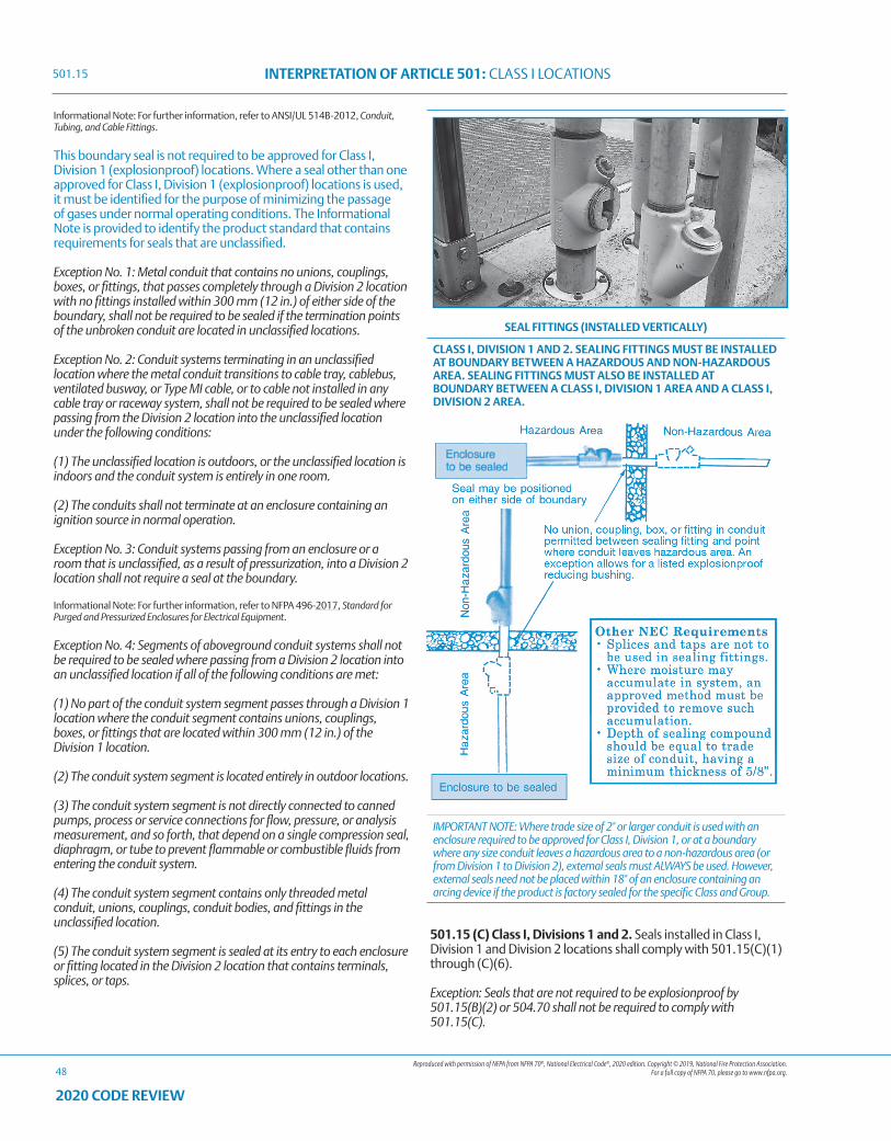
Reproduced with permission of NFPA from NFPA 70®, National Electrical Code®, 2020 edition. Copyright © 2019, National Fire Protection Association. For a full copy of NFPA 70, please go to www.nfpa.org.
INTERPRETATION OF ARTICLE 501: CLASS I LOCATIONS
48
2020 CODE REVIEW
Informational Note: For further information, refer to ANSI/UL 514B-2012, Conduit, Tubing, and Cable Fittings.
This boundary seal is not required to be approved for Class I, Division 1 (explosionproof) locations. Where a seal other than one approved for Class I, Division 1 (explosionproof) locations is used, it must be identified for the purpose of minimizing the passage of gases under normal operating conditions. The Informational Note is provided to identify the product standard that contains requirements for seals that are unclassified.
Exception No. 1: Metal conduit that contains no unions, couplings, boxes, or fittings, that passes completely through a Division 2 location with no fittings installed within 300 mm (12 in.) of either side of the boundary, shall not be required to be sealed if the termination points of the unbroken conduit are located in unclassified locations.
Exception No. 2: Conduit systems terminating in an unclassified location where the metal conduit transitions to cable tray, cablebus, ventilated busway, or Type MI cable, or to cable not installed in any cable tray or raceway system, shall not be required to be sealed where passing from the Division 2 location into the unclassified location under the following conditions:
(1) The unclassified location is outdoors, or the unclassified location is indoors and the conduit system is entirely in one room.
(2) The conduits shall not terminate at an enclosure containing an ignition source in normal operation.
Exception No. 3: Conduit systems passing from an enclosure or a room that is unclassified, as a result of pressurization, into a Division 2 location shall not require a seal at the boundary.
Informational Note: For further information, refer to NFPA 496-2017, Standard for Purged and Pressurized Enclosures for Electrical Equipment.
Exception No. 4: Segments of aboveground conduit systems shall not be required to be sealed where passing from a Division 2 location into an unclassified location if all of the following conditions are met:
(1) No part of the conduit system segment passes through a Division 1 location where the conduit segment contains unions, couplings, boxes, or fittings that are located within 300 mm (12 in.) of the Division 1 location.
(2) The conduit system segment is located entirely in outdoor locations.
(3) The conduit system segment is not directly connected to canned pumps, process or service connections for flow, pressure, or analysis measurement, and so forth, that depend on a single compression seal, diaphragm, or tube to prevent flammable or combustible fluids from entering the conduit system.
(4) The conduit system segment contains only threaded metal conduit, unions, couplings, conduit bodies, and fittings in the unclassified location.
(5) The conduit system segment is sealed at its entry to each enclosure or fitting located in the Division 2 location that contains terminals, splices, or taps.
501.15 (C) Class I, Divisions 1 and 2. Seals installed in Class I, Division 1 and Division 2 locations shall comply with 501.15(C)(1) through (C)(6).
Exception: Seals that are not required to be explosionproof by 501.15(B)(2) or 504.70 shall not be required to comply with 501.15(C).
SEAL FITTINGS (INSTALLED VERTICALLY)
CLASS I, DIVISION 1 AND 2. SEALING FITTINGS MUST BE INSTALLED AT BOUNDARY BETWEEN A HAZARDOUS AND NON-HAZARDOUS AREA. SEALING FITTINGS MUST ALSO BE INSTALLED AT BOUNDARY BETWEEN A CLASS I, DIVISION 1 AREA AND A CLASS I, DIVISION 2 AREA.
IMPORTANT NOTE: Where trade size of 2" or larger conduit is used with an enclosure required to be approved for Class I, Division 1, or at a boundary where any size conduit leaves a hazardous area to a non-hazardous area (or from Division 1 to Division 2), external seals must ALWAYS be used. However, external seals need not be placed within 18" of an enclosure containing an arcing device if the product is factory sealed for the specific Class and Group.
501.15
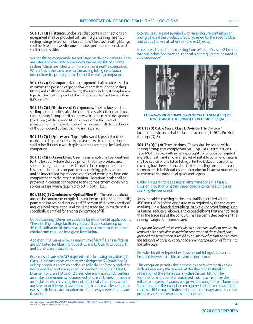
Reproduced with permission of NFPA from NFPA 70®, National Electrical Code®, 2020 edition. Copyright © 2019, National Fire Protection Association. For a full copy of NFPA 70, please go to www.nfpa.org.
INTERPRETATION OF ARTICLE 501: CLASS I LOCATIONS
49
2020 CODE REVIEW
501.15 (C)(1) Fittings. Enclosures that contain connections or equipment shall be provided with an integral sealing means, or sealing fittings listed for the location shall be used. Sealing fittings shall be listed for use with one or more specific compounds and shall be accessible.
Sealing fitting compounds are not listed on their own merits. They are listed and evaluated for use with the sealing fittings. Some sealing fittings are listed with more than one sealing compound. Where this is the case, refer to the sealing fitting installation instructions for proper preparation of the sealing compound.
501.15 (C)(2) Compound. The compound shall provide a seal to minimize the passage of gas and/or vapors through the sealing fitting and shall not be affected by the surrounding atmosphere or liquids. The melting point of the compound shall not be less than 93°C (200°F).
501.15 (C)(3) Thickness of Compounds. The thickness of the sealing compound installed in completed seals, other than listed cable sealing fittings, shall not be less than the metric designator (trade size) of the sealing fitting expressed in the units of measurement employed; however, in no case shall the thickness of the compound be less than 16 mm (5/8 in.).
501.15 (C)(4) Splices and Taps. Splices and taps shall not be made in fittings intended only for sealing with compound; nor shall other fittings in which splices or taps are made be filled with compound.
501.15 (C)(5) Assemblies. An entire assembly shall be identified for the location where the equipment that may produce arcs, sparks, or high temperatures is located in a compartment that is separate from the compartment containing splices or taps, and an integral seal is provided where conductors pass from one compartment to the other. In Division 1 locations, seals shall be provided in conduit connecting to the compartment containing splices or taps where required by 501.15(A)(1)(2).
501.15 (C)(6) Conductor or Optical Fiber Fill. The cross-sectional area of the conductors or optical fiber tubes (metallic or nonmetallic) permitted in a seal shall not exceed 25 percent of the cross-sectional area of a rigid metal conduit of the same trade size unless the seal is specifically identified for a higher percentage of fill.
Conduit sealing fittings are available for expanded fill applications. These sealing fittings facilitate conduit fill applications up to 40% fill. Utilization of these seals can reduce the total number of conduit runs required by a given installation.
Appleton™ EF Series allows a maximum of 40% fill. These fittings are UL® Listed for Class I, Groups B, C, and D, Class II, Groups E, F, and G and Class III locations.
External seals are ALWAYS required in the following situations: (1) Class I, Division 1 areas where metric designator 53 (trade size 2) or larger conduit enters an enclosure (whether or factory sealed or not or whether containing an arcing device or not); (2) in Class I, Division 1 or Class I, Division 2 areas where any size conduit enters an enclosure required to be approved for Class I, Division 1 (such as an enclosure with an arcing device); and (3) at a boundary where any size conduit leaves a hazardous area to an area of lesser hazard (see specific boundary situations in " Cut-a-Way View Comparison" illustration).
External seals are not required with an enclosure containing an arcing device if the product is factory sealed for the specific Class and Group [unless situations (1) and or (2) exist].
Note: In each conduit run passing from a Class I, Division 2 location into an unclassified location, the seal is not required to be rated as explosionproof.
501.15 (D) Cable Seals, Class I, Division 1. In Division 1 locations, cable seals shall be located according to 501.15(D)(1) through (D)(3).
501.15 (D)(1) At Terminations. Cables shall be sealed with sealing fittings that comply with 501.15(C) at all terminations. Type MC-HL cables with a gas/vaportight continuous corrugated metallic sheath and an overall jacket of suitable polymeric material shall be sealed with a listed fitting after the jacket and any other covering have been removed so that the sealing compound can surround each individual insulated conductor in such a manner as to minimize the passage of gases and vapors.
Cable is required to be sealed at all terminations in a Class I, Division 1 location whether the enclosure contains arcing and sparking devices or not.
Seals for cables entering enclosures shall be installed within 450 mm (18 in.) of the enclosure or as required by the enclosure marking. Only threaded couplings, or explosionproof fittings such as unions, reducers, elbows, and capped elbows that are not larger than the trade size of the conduit, shall be permitted between the sealing fitting and the enclosure.
Exception: Shielded cables and twisted pair cables shall not require the removal of the shielding material or separation of the twisted pairs, provided the termination is sealed by an approved means to minimize the entrance of gases or vapors and prevent propagation of flame into the cable core.
Provides for other types of explosionproof fittings that can be installed between a cable seal and an enclosure.
This exception permits shielded cables and twisted pair cables without requiring the removal of the shielding material or separation of the twisted pairs within the seal fitting. The termination must be by an approved means to minimize the entrance of gases or vapors and prevent propagation of flame into the cable core. This exception recognizes that the removal of the cable shield for sealing individual conductors may cause electronic problems in some instrumentation circuits.
CUT-A-WAY VIEW COMPARISON OF 25% FILL SEAL (LEFT) VS 40% EXPANDED FILL (RIGHT) TO MEET 501.15(C)(6).
501.15
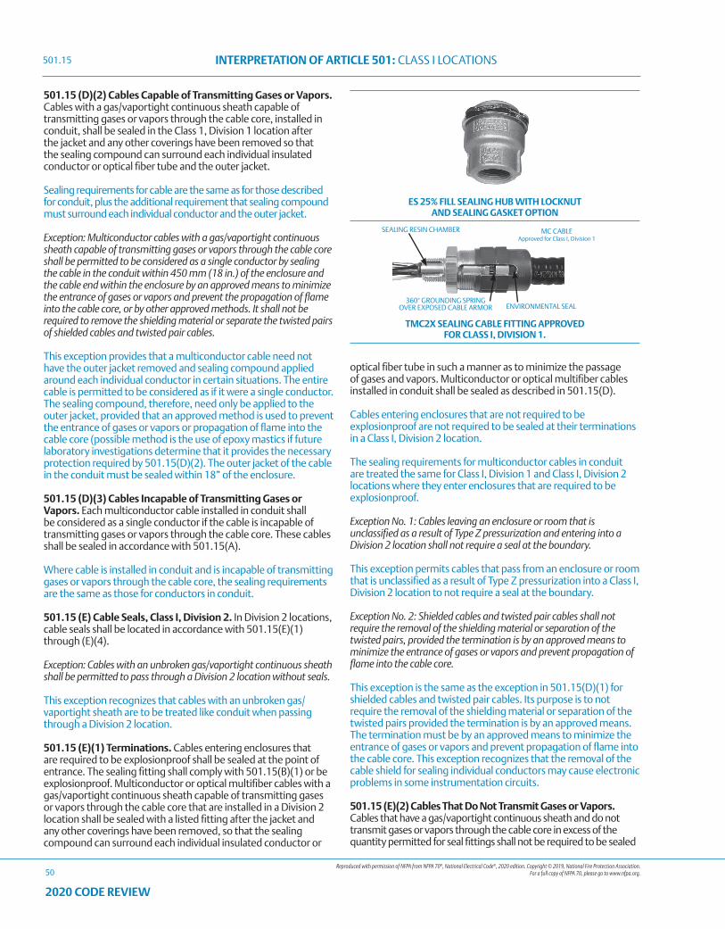
Reproduced with permission of NFPA from NFPA 70®, National Electrical Code®, 2020 edition. Copyright © 2019, National Fire Protection Association. For a full copy of NFPA 70, please go to www.nfpa.org.
INTERPRETATION OF ARTICLE 501: CLASS I LOCATIONS
50
2020 CODE REVIEW
501.15 (D)(2) Cables Capable of Transmitting Gases or Vapors. Cables with a gas/vaportight continuous sheath capable of transmitting gases or vapors through the cable core, installed in conduit, shall be sealed in the Class 1, Division 1 location after the jacket and any other coverings have been removed so that the sealing compound can surround each individual insulated conductor or optical fiber tube and the outer jacket.
Sealing requirements for cable are the same as for those described for conduit, plus the additional requirement that sealing compound must surround each individual conductor and the outer jacket.
Exception: Multiconductor cables with a gas/vaportight continuous sheath capable of transmitting gases or vapors through the cable core shall be permitted to be considered as a single conductor by sealing the cable in the conduit within 450 mm (18 in.) of the enclosure and the cable end within the enclosure by an approved means to minimize the entrance of gases or vapors and prevent the propagation of flame into the cable core, or by other approved methods. It shall not be required to remove the shielding material or separate the twisted pairs of shielded cables and twisted pair cables.
This exception provides that a multiconductor cable need not have the outer jacket removed and sealing compound applied around each individual conductor in certain situations. The entire cable is permitted to be considered as if it were a single conductor. The sealing compound, therefore, need only be applied to the outer jacket, provided that an approved method is used to prevent the entrance of gases or vapors or propagation of flame into the cable core (possible method is the use of epoxy mastics if future laboratory investigations determine that it provides the necessary protection required by 501.15(D)(2). The outer jacket of the cable in the conduit must be sealed within 18” of the enclosure.
501.15 (D)(3) Cables Incapable of Transmitting Gases or Vapors. Each multiconductor cable installed in conduit shall be considered as a single conductor if the cable is incapable of transmitting gases or vapors through the cable core. These cables shall be sealed in accordance with 501.15(A).
Where cable is installed in conduit and is incapable of transmitting gases or vapors through the cable core, the sealing requirements are the same as those for conductors in conduit.
501.15 (E) Cable Seals, Class I, Division 2. In Division 2 locations, cable seals shall be located in accordance with 501.15(E)(1) through (E)(4).
Exception: Cables with an unbroken gas/vaportight continuous sheath shall be permitted to pass through a Division 2 location without seals.
This exception recognizes that cables with an unbroken gas/vaportight sheath are to be treated like conduit when passing through a Division 2 location.
501.15 (E)(1) Terminations. Cables entering enclosures that are required to be explosionproof shall be sealed at the point of entrance. The sealing fitting shall comply with 501.15(B)(1) or be explosionproof. Multiconductor or optical multifiber cables with a gas/vaportight continuous sheath capable of transmitting gases or vapors through the cable core that are installed in a Division 2 location shall be sealed with a listed fitting after the jacket and any other coverings have been removed, so that the sealing compound can surround each individual insulated conductor or
optical fiber tube in such a manner as to minimize the passage of gases and vapors. Multiconductor or optical multifiber cables installed in conduit shall be sealed as described in 501.15(D).
Cables entering enclosures that are not required to be explosionproof are not required to be sealed at their terminations in a Class I, Division 2 location.
The sealing requirements for multiconductor cables in conduit are treated the same for Class I, Division 1 and Class I, Division 2 locations where they enter enclosures that are required to be explosionproof.
Exception No. 1: Cables leaving an enclosure or room that is unclassified as a result of Type Z pressurization and entering into a Division 2 location shall not require a seal at the boundary.
This exception permits cables that pass from an enclosure or room that is unclassified as a result of Type Z pressurization into a Class I, Division 2 location to not require a seal at the boundary.
Exception No. 2: Shielded cables and twisted pair cables shall not require the removal of the shielding material or separation of the twisted pairs, provided the termination is by an approved means to minimize the entrance of gases or vapors and prevent propagation of flame into the cable core.
This exception is the same as the exception in 501.15(D)(1) for shielded cables and twisted pair cables. Its purpose is to not require the removal of the shielding material or separation of the twisted pairs provided the termination is by an approved means. The termination must be by an approved means to minimize the entrance of gases or vapors and prevent propagation of flame into the cable core. This exception recognizes that the removal of the cable shield for sealing individual conductors may cause electronic problems in some instrumentation circuits.
501.15 (E)(2) Cables That Do Not Transmit Gases or Vapors. Cables that have a gas/vaportight continuous sheath and do not transmit gases or vapors through the cable core in excess of the quantity permitted for seal fittings shall not be required to be sealed
ES 25% FILL SEALING HUB WITH LOCKNUT AND SEALING GASKET OPTION
ENVIRONMENTAL SEAL360° GROUNDING SPRING
OVER EXPOSED CABLE ARMOR
SEALING RESIN CHAMBER MC CABLE Approved for Class I, Division 1
TMC2X SEALING CABLE FITTING APPROVED FOR CLASS I, DIVISION 1.
501.15
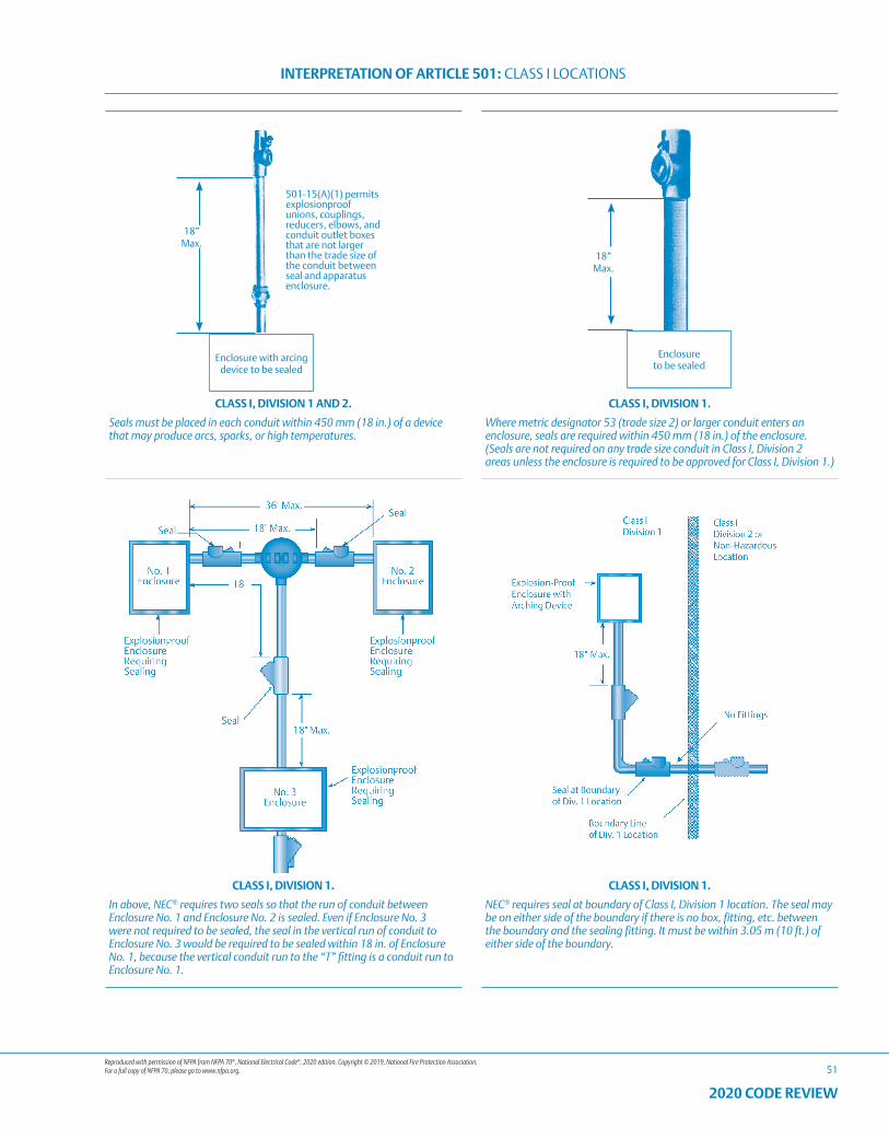
Reproduced with permission of NFPA from NFPA 70®, National Electrical Code®, 2020 edition. Copyright © 2019, National Fire Protection Association. For a full copy of NFPA 70, please go to www.nfpa.org.
INTERPRETATION OF ARTICLE 501: CLASS I LOCATIONS
51
2020 CODE REVIEW
18” Max.
501-15(A)(1) permits explosionproof unions, couplings, reducers, elbows, and conduit outlet boxes that are not larger than the trade size of the conduit between seal and apparatus enclosure.
Enclosure with arcingdevice to be sealed
18” Max.
Enclosure to be sealed
CLASS I, DIVISION 1 AND 2. CLASS I, DIVISION 1.
Seals must be placed in each conduit within 450 mm (18 in.) of a device that may produce arcs, sparks, or high temperatures.
Where metric designator 53 (trade size 2) or larger conduit enters an enclosure, seals are required within 450 mm (18 in.) of the enclosure. (Seals are not required on any trade size conduit in Class I, Division 2 areas unless the enclosure is required to be approved for Class I, Division 1.)
CLASS I, DIVISION 1. CLASS I, DIVISION 1.
In above, NEC® requires two seals so that the run of conduit between Enclosure No. 1 and Enclosure No. 2 is sealed. Even if Enclosure No. 3 were not required to be sealed, the seal in the vertical run of conduit to Enclosure No. 3 would be required to be sealed within 18 in. of Enclosure No. 1, because the vertical conduit run to the “T” fitting is a conduit run to Enclosure No. 1.
NEC® requires seal at boundary of Class I, Division 1 location. The seal may be on either side of the boundary if there is no box, fitting, etc. between the boundary and the sealing fitting. It must be within 3.05 m (10 ft.) of either side of the boundary.
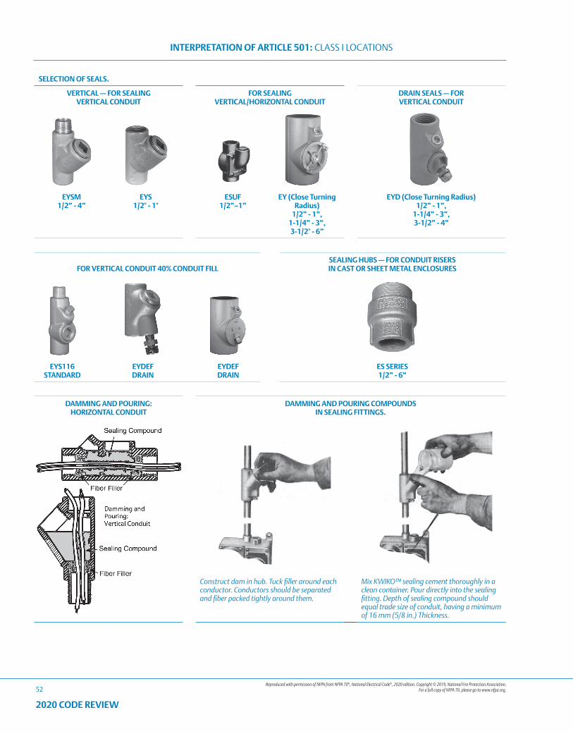
Reproduced with permission of NFPA from NFPA 70®, National Electrical Code®, 2020 edition. Copyright © 2019, National Fire Protection Association. For a full copy of NFPA 70, please go to www.nfpa.org.
INTERPRETATION OF ARTICLE 501: CLASS I LOCATIONS
52
2020 CODE REVIEW
SELECTION OF SEALS.
VERTICAL — FOR SEALING VERTICAL CONDUIT
FOR SEALING VERTICAL/HORIZONTAL CONDUIT
DRAIN SEALS — FOR VERTICAL CONDUIT
EYSM 1/2” - 4”
EYS 1/2" - 1"
ESUF 1/2”–1”
EY (Close Turning Radius)
1/2” - 1”, 1-1/4” - 3”, 3-1/2" - 6”
EYD (Close Turning Radius) 1/2” - 1”,
1-1/4” - 3”, 3-1/2” - 4”
FOR VERTICAL CONDUIT 40% CONDUIT FILLSEALING HUBS — FOR CONDUIT RISERS IN CAST OR SHEET METAL ENCLOSURES
EYS116 STANDARD
EYDEF DRAIN
EYDEF DRAIN
ES SERIES 1/2” - 6”
DAMMING AND POURING: HORIZONTAL CONDUIT
DAMMING AND POURING COMPOUNDS IN SEALING FITTINGS.
Construct dam in hub. Tuck filler around each conductor. Conductors should be separated and fiber packed tightly around them.
Mix KWIKO™ sealing cement thoroughly in a clean container. Pour directly into the sealing fitting. Depth of sealing compound should equal trade size of conduit, having a minimum of 16 mm (5/8 in.) Thickness.
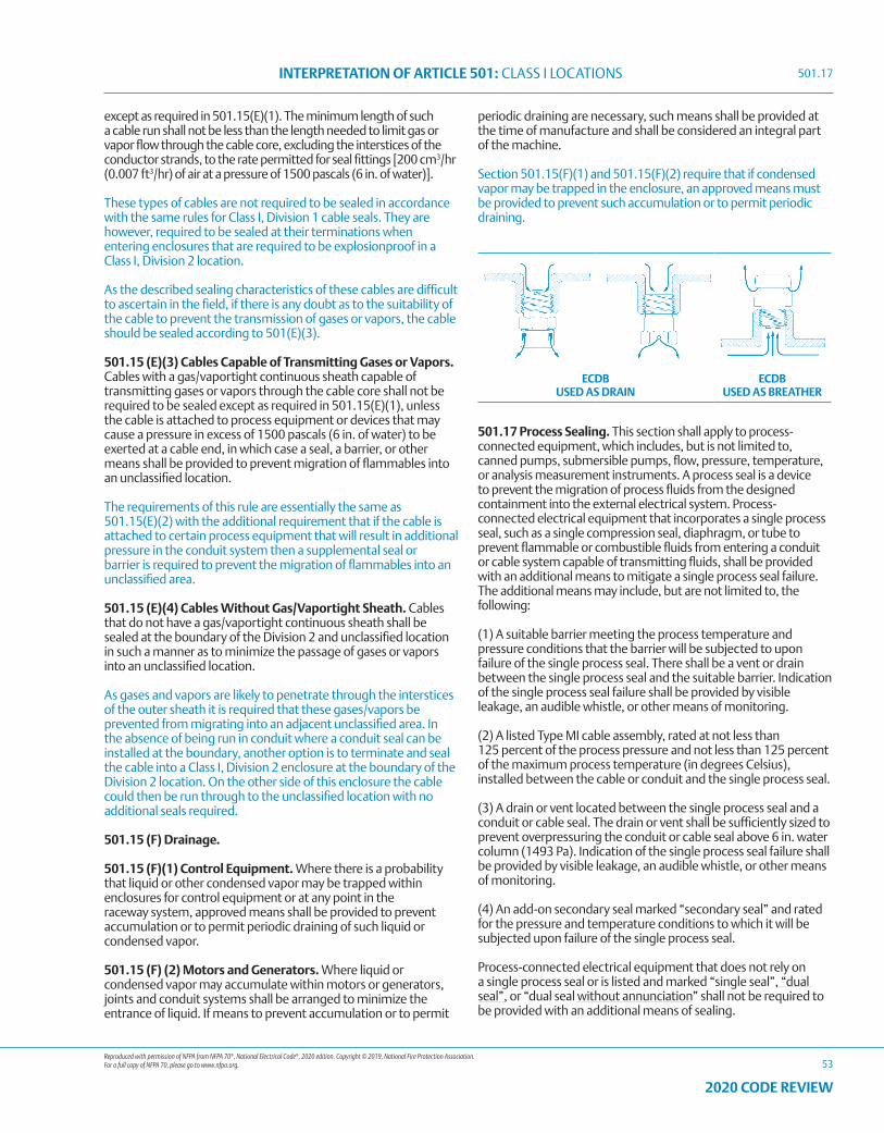
Reproduced with permission of NFPA from NFPA 70®, National Electrical Code®, 2020 edition. Copyright © 2019, National Fire Protection Association. For a full copy of NFPA 70, please go to www.nfpa.org.
INTERPRETATION OF ARTICLE 501: CLASS I LOCATIONS
53
2020 CODE REVIEW
except as required in 501.15(E)(1). The minimum length of such a cable run shall not be less than the length needed to limit gas or vapor flow through the cable core, excluding the interstices of the conductor strands, to the rate permitted for seal fittings [200 cm3/hr (0.007 ft3/hr) of air at a pressure of 1500 pascals (6 in. of water)].
These types of cables are not required to be sealed in accordance with the same rules for Class I, Division 1 cable seals. They are however, required to be sealed at their terminations when entering enclosures that are required to be explosionproof in a Class I, Division 2 location.
As the described sealing characteristics of these cables are difficult to ascertain in the field, if there is any doubt as to the suitability of the cable to prevent the transmission of gases or vapors, the cable should be sealed according to 501(E)(3).
501.15 (E)(3) Cables Capable of Transmitting Gases or Vapors. Cables with a gas/vaportight continuous sheath capable of transmitting gases or vapors through the cable core shall not be required to be sealed except as required in 501.15(E)(1), unless the cable is attached to process equipment or devices that may cause a pressure in excess of 1500 pascals (6 in. of water) to be exerted at a cable end, in which case a seal, a barrier, or other means shall be provided to prevent migration of flammables into an unclassified location.
The requirements of this rule are essentially the same as 501.15(E)(2) with the additional requirement that if the cable is attached to certain process equipment that will result in additional pressure in the conduit system then a supplemental seal or barrier is required to prevent the migration of flammables into an unclassified area.
501.15 (E)(4) Cables Without Gas/Vaportight Sheath. Cables that do not have a gas/vaportight continuous sheath shall be sealed at the boundary of the Division 2 and unclassified location in such a manner as to minimize the passage of gases or vapors into an unclassified location.
As gases and vapors are likely to penetrate through the interstices of the outer sheath it is required that these gases/vapors be prevented from migrating into an adjacent unclassified area. In the absence of being run in conduit where a conduit seal can be installed at the boundary, another option is to terminate and seal the cable into a Class I, Division 2 enclosure at the boundary of the Division 2 location. On the other side of this enclosure the cable could then be run through to the unclassified location with no additional seals required.
501.15 (F) Drainage.
501.15 (F)(1) Control Equipment. Where there is a probability that liquid or other condensed vapor may be trapped within enclosures for control equipment or at any point in the raceway system, approved means shall be provided to prevent accumulation or to permit periodic draining of such liquid or condensed vapor.
501.15 (F) (2) Motors and Generators. Where liquid or condensed vapor may accumulate within motors or generators, joints and conduit systems shall be arranged to minimize the entrance of liquid. If means to prevent accumulation or to permit
periodic draining are necessary, such means shall be provided at the time of manufacture and shall be considered an integral part of the machine.
Section 501.15(F)(1) and 501.15(F)(2) require that if condensed vapor may be trapped in the enclosure, an approved means must be provided to prevent such accumulation or to permit periodic draining.
ECDB USED AS DRAIN
ECDB USED AS BREATHER
501.17 Process Sealing. This section shall apply to process-connected equipment, which includes, but is not limited to, canned pumps, submersible pumps, flow, pressure, temperature, or analysis measurement instruments. A process seal is a device to prevent the migration of process fluids from the designed containment into the external electrical system. Process-connected electrical equipment that incorporates a single process seal, such as a single compression seal, diaphragm, or tube to prevent flammable or combustible fluids from entering a conduit or cable system capable of transmitting fluids, shall be provided with an additional means to mitigate a single process seal failure. The additional means may include, but are not limited to, the following:
(1) A suitable barrier meeting the process temperature and pressure conditions that the barrier will be subjected to upon failure of the single process seal. There shall be a vent or drain between the single process seal and the suitable barrier. Indication of the single process seal failure shall be provided by visible leakage, an audible whistle, or other means of monitoring.
(2) A listed Type MI cable assembly, rated at not less than 125 percent of the process pressure and not less than 125 percent of the maximum process temperature (in degrees Celsius), installed between the cable or conduit and the single process seal.
(3) A drain or vent located between the single process seal and a conduit or cable seal. The drain or vent shall be sufficiently sized to prevent overpressuring the conduit or cable seal above 6 in. water column (1493 Pa). Indication of the single process seal failure shall be provided by visible leakage, an audible whistle, or other means of monitoring.
(4) An add-on secondary seal marked “secondary seal” and rated for the pressure and temperature conditions to which it will be subjected upon failure of the single process seal.
Process-connected electrical equipment that does not rely on a single process seal or is listed and marked “single seal”, “dual seal”, or “dual seal without annunciation” shall not be required to be provided with an additional means of sealing.
501.17
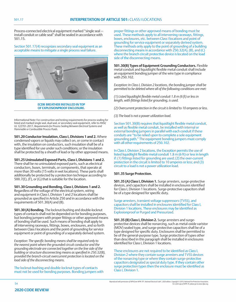
Reproduced with permission of NFPA from NFPA 70®, National Electrical Code®, 2020 edition. Copyright © 2019, National Fire Protection Association. For a full copy of NFPA 70, please go to www.nfpa.org.
INTERPRETATION OF ARTICLE 501: CLASS I LOCATIONS
54
2020 CODE REVIEW
Process-connected electrical equipment marked “single seal — install conduit or cable seal” shall be sealed in accordance with 501.15.
Section 501.17(4) recognizes secondary seal equipment as an acceptable means to mitigate a single process seal failure.
ECDB BREATHER INSTALLED IN TOP OF EXPLOSIONPROOF ENCLOSURE.
Informational Note: For construction and testing requirements for process sealing for listed and marked single seal, dual seal, or secondary seal equipment, refer to ANSI/UL 122701-2017, Requirements for Process Sealing Between Electrical Systems and Flammable or Combustible Process Fluids.
501.20 Conductor Insulation, Class I, Divisions 1 and 2. Where condensed vapors or liquids may collect on, or come in contact with, the insulation on conductors, such insulation shall be of a type identified for use under such conditions; or the insulation shall be protected by a sheath of lead or by other approved means.
501.25 Uninsulated Exposed Parts, Class I, Divisions 1 and 2. There shall be no uninsulated exposed parts, such as electrical conductors, buses, terminals, or components, that operate at more than 30 volts (15 volts in wet locations). These parts shall additionally be protected by a protection technique according to 500.7(E), (F), or (G) that is suitable for the location.
501.30 Grounding and Bonding, Class I, Divisions 1 and 2. Regardless of the voltage of the electrical system, wiring and equipment in Class I, Division 1 and 2 locations shall be grounded as specified in Article 250 and in accordance with the requirements of 501.30(A) and (B).
501.30 (A) Bonding. The locknut-bushing and double-locknut types of contacts shall not be depended on for bonding purposes, but bonding jumpers with proper fittings or other approved means of bonding shall be used. Such means of bonding shall apply to all intervening raceways, fittings, boxes, enclosures, and so forth between Class I locations and the point of grounding for service equipment or point of grounding of a separately derived system.
Exception: The specific bonding means shall be required only to the nearest point where the grounded circuit conductor and the grounding electrode are connected together on the line side of the building or structure disconnecting means as specified in 250.32(B), provided the branch-circuit overcurrent protection is located on the load side of the disconnecting means.
The locknut-bushing and double-locknut types of contacts must not be used for bonding purposes. Bonding jumpers with
proper fittings or other approved means of bonding must be used. These methods apply to all intervening raceways, fittings, boxes, enclosures, etc. between Class I locations and point of grounding for service equipment or separately derived system. These methods only apply to the point of grounding of a building disconnecting means in accordance with 250.32(A), (B), and (C) where the branch circuit protective device is located on the load side of the disconnecting means.
501.30(B) Types of Equipment Grounding Conductors. Flexible metal conduit and liquidtight flexible metal conduit shall include an equipment bonding jumper of the wire type in compliance with 250.102.
Exception: In Class I, Division 2 locations, the bonding jumper shall be permitted to be deleted where all of the following conditions are met:
(1) Listed liquidtight flexible metal conduit 1.8 m (6 ft) or less in length, with fittings listed for grounding, is used.
(2) Overcurrent protection in the circuit is limited to 10 amperes or less.
(3) The load is not a power utilization load.
Section 501.30(B) requires that liquidtight flexible metal conduit, as well as flexible metal conduit, be installed with internal or external bonding jumpers in parallel with each conduit if these conduits are “to be relied upon to complete a sole equipment grounding path.” The equipment bonding jumpers must comply with all other requirements of 250.102.
In Class I, Division 2 locations, the Exception permits the use of listed liquidtight flexible metal conduit 1.8 m (6 ft) or less in length if: (1) fittings listed for grounding are used; (2) the over-current protection in the circuit is limited to 10 amperes or less; and (3) circuit to a load is not a power utilization load.
501.35 Surge Protection.
501.35 (A) Class I, Division 1. Surge arresters, surge-protective devices, and capacitors shall be installed in enclosures identified for Class I, Division 1 locations. Surge-protective capacitors shall be of a type designed for specific duty.
Surge arresters, transient voltage suppressors (TVSS), and capacitors shall be installed in enclosures identified for Class I, Division 1 locations. These enclosures may be identified as Explosionproof or Purged and Pressurized.
501.35 (B) Class I, Division 2. Surge arresters and surge-protective devices shall be nonarcing, such as metal-oxide varistor (MOV) sealed type, and surge-protective capacitors shall be of a type designed for specific duty. Enclosures shall be permitted to be of the general-purpose type. Surge protection of types other than described in this paragraph shall be installed in enclosures identified for Class I, Division 1 locations.
These enclosures are not required to be identified as Class I, Division 2 where they contain surge arresters and TVSS devices of the nonarcing type or where they contain surge-protective capacitors designated as special duty type. If they contain other surge protection types then the enclosure must be identified as Class I, Division 1.
501.17
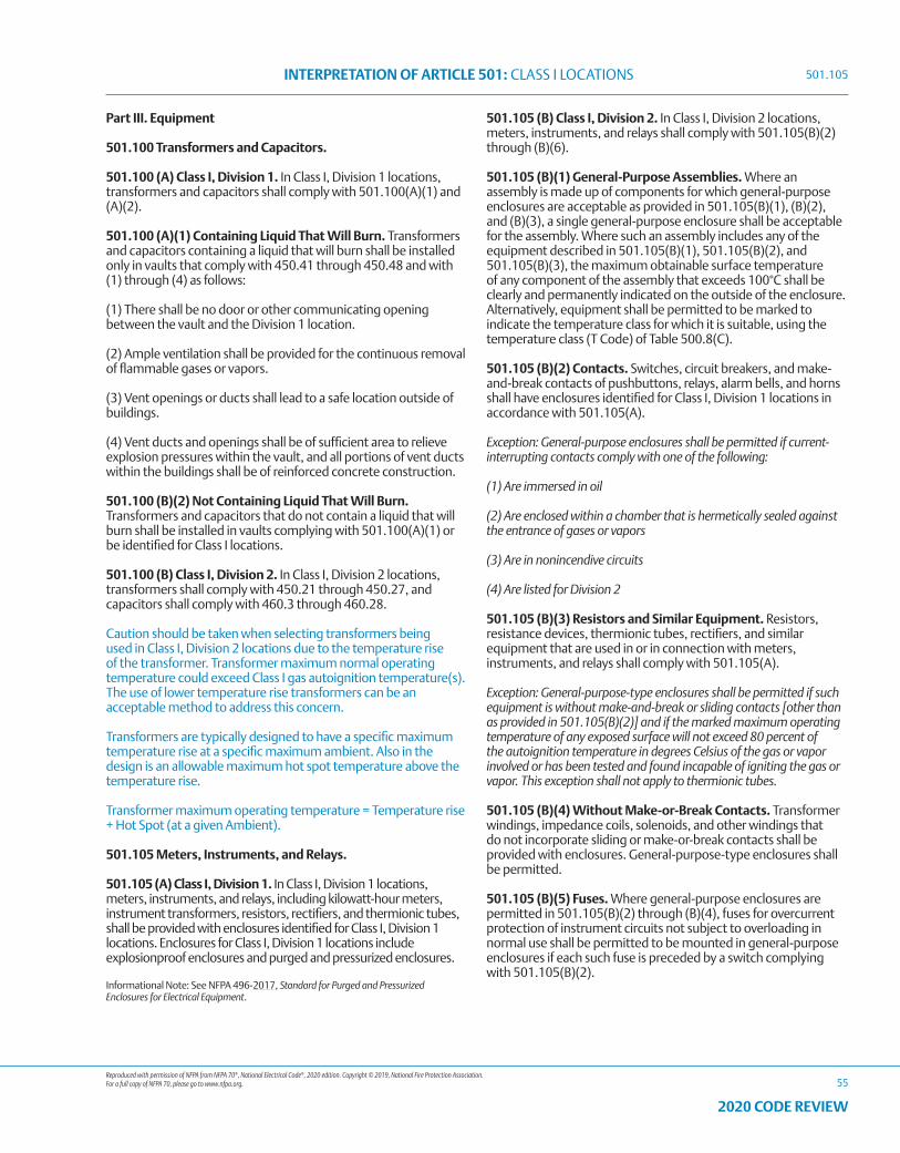
Reproduced with permission of NFPA from NFPA 70®, National Electrical Code®, 2020 edition. Copyright © 2019, National Fire Protection Association. For a full copy of NFPA 70, please go to www.nfpa.org.
INTERPRETATION OF ARTICLE 501: CLASS I LOCATIONS
55
2020 CODE REVIEW
Part III. Equipment
501.100 Transformers and Capacitors.
501.100 (A) Class I, Division 1. In Class I, Division 1 locations, transformers and capacitors shall comply with 501.100(A)(1) and (A)(2).
501.100 (A)(1) Containing Liquid That Will Burn. Transformers and capacitors containing a liquid that will burn shall be installed only in vaults that comply with 450.41 through 450.48 and with (1) through (4) as follows:
(1) There shall be no door or other communicating opening between the vault and the Division 1 location.
(2) Ample ventilation shall be provided for the continuous removal of flammable gases or vapors.
(3) Vent openings or ducts shall lead to a safe location outside of buildings.
(4) Vent ducts and openings shall be of sufficient area to relieve explosion pressures within the vault, and all portions of vent ducts within the buildings shall be of reinforced concrete construction.
501.100 (B)(2) Not Containing Liquid That Will Burn. Transformers and capacitors that do not contain a liquid that will burn shall be installed in vaults complying with 501.100(A)(1) or be identified for Class I locations.
501.100 (B) Class I, Division 2. In Class I, Division 2 locations, transformers shall comply with 450.21 through 450.27, and capacitors shall comply with 460.3 through 460.28.
Caution should be taken when selecting transformers being used in Class I, Division 2 locations due to the temperature rise of the transformer. Transformer maximum normal operating temperature could exceed Class I gas autoignition temperature(s). The use of lower temperature rise transformers can be an acceptable method to address this concern.
Transformers are typically designed to have a specific maximum temperature rise at a specific maximum ambient. Also in the design is an allowable maximum hot spot temperature above the temperature rise.
Transformer maximum operating temperature = Temperature rise + Hot Spot (at a given Ambient).
501.105 Meters, Instruments, and Relays.
501.105 (A) Class I, Division 1. In Class I, Division 1 locations, meters, instruments, and relays, including kilowatt-hour meters, instrument transformers, resistors, rectifiers, and thermionic tubes, shall be provided with enclosures identified for Class I, Division 1 locations. Enclosures for Class I, Division 1 locations include explosionproof enclosures and purged and pressurized enclosures.
Informational Note: See NFPA 496-2017, Standard for Purged and Pressurized Enclosures for Electrical Equipment.
501.105 (B) Class I, Division 2. In Class I, Division 2 locations, meters, instruments, and relays shall comply with 501.105(B)(2) through (B)(6).
501.105 (B)(1) General-Purpose Assemblies. Where an assembly is made up of components for which general-purpose enclosures are acceptable as provided in 501.105(B)(1), (B)(2), and (B)(3), a single general-purpose enclosure shall be acceptable for the assembly. Where such an assembly includes any of the equipment described in 501.105(B)(1), 501.105(B)(2), and 501.105(B)(3), the maximum obtainable surface temperature of any component of the assembly that exceeds 100°C shall be clearly and permanently indicated on the outside of the enclosure. Alternatively, equipment shall be permitted to be marked to indicate the temperature class for which it is suitable, using the temperature class (T Code) of Table 500.8(C).
501.105 (B)(2) Contacts. Switches, circuit breakers, and make-and-break contacts of pushbuttons, relays, alarm bells, and horns shall have enclosures identified for Class I, Division 1 locations in accordance with 501.105(A).
Exception: General-purpose enclosures shall be permitted if current-interrupting contacts comply with one of the following:
(1) Are immersed in oil
(2) Are enclosed within a chamber that is hermetically sealed against the entrance of gases or vapors
(3) Are in nonincendive circuits
(4) Are listed for Division 2
501.105 (B)(3) Resistors and Similar Equipment. Resistors, resistance devices, thermionic tubes, rectifiers, and similar equipment that are used in or in connection with meters, instruments, and relays shall comply with 501.105(A).
Exception: General-purpose-type enclosures shall be permitted if such equipment is without make-and-break or sliding contacts [other than as provided in 501.105(B)(2)] and if the marked maximum operating temperature of any exposed surface will not exceed 80 percent of the autoignition temperature in degrees Celsius of the gas or vapor involved or has been tested and found incapable of igniting the gas or vapor. This exception shall not apply to thermionic tubes.
501.105 (B)(4) Without Make-or-Break Contacts. Transformer windings, impedance coils, solenoids, and other windings that do not incorporate sliding or make-or-break contacts shall be provided with enclosures. General-purpose-type enclosures shall be permitted.
501.105 (B)(5) Fuses. Where general-purpose enclosures are permitted in 501.105(B)(2) through (B)(4), fuses for overcurrent protection of instrument circuits not subject to overloading in normal use shall be permitted to be mounted in general-purpose enclosures if each such fuse is preceded by a switch complying with 501.105(B)(2).
501.105
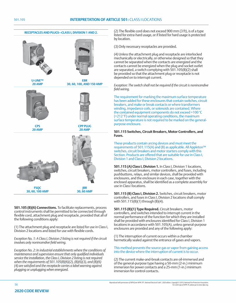
Reproduced with permission of NFPA from NFPA 70®, National Electrical Code®, 2020 edition. Copyright © 2019, National Fire Protection Association. For a full copy of NFPA 70, please go to www.nfpa.org.
INTERPRETATION OF ARTICLE 501: CLASS I LOCATIONS
56
2020 CODE REVIEW
501.105 (B)(6) Connections. To facilitate replacements, process control instruments shall be permitted to be connected through flexible cord, attachment plug and receptacle, provided that all of the following conditions apply:
(1) The attachment plug and receptacle are listed for use in Class I, Division 2 locations and listed for use with flexible cords.
Exception No. 1: A Class I, Division 2 listing is not required if the circuit involves only nonincendive field wiring.
Exception No. 2: In industrial establishments where the conditions of maintenance and supervision ensure that only qualified individuals service the installation, the Class I, Division 2 listing is not required when the requirements of 501.105(B)(6)(2), (B)(6)(3), and (B)(6)(4) are satisfied and the receptacle carries a label warning against plugging or unplugging when energized.
(2) The flexible cord does not exceed 900 mm (3 ft), is of a type listed for extra-hard usage, or if listed for hard usage is protected by location.
(3) Only necessary receptacles are provided.
(4) Unless the attachment plug and receptacle are interlocked mechanically or electrically, or otherwise designed so that they cannot be separated when the contacts are energized and the contacts cannot be energized when the plug and socket outlet are separated, a switch complying with 501.105(B)(2) shall be provided so that the attachment plug or receptacle is not depended on to interrupt current.
Exception: The switch shall not be required if the circuit is nonincendive field wiring.
The requirement for marking the maximum surface temperature has been added for these enclosures that contain switches, circuit breakers, and make or break contacts or where transformers winding, impedance coils, or solenoids are contained. Where the contained equipment components do not exceed +100 °C (+212 °F) under normal operating conditions, the maximum surface temperature is not required to be marked on the general-purpose enclosure.
501.115 Switches, Circuit Breakers, Motor Controllers, and Fuses.
These products contain arcing devices and must meet the requirements of 501.115(A) and (B) as applicable. All Appleton™ switches, circuit breakers and motor starters comply with this Section. Products are offered that are suitable for use in Class I, Division 1 and Class I, Division 2 locations.
501.115 (A) Class I, Division 1. In Class I, Division 1 locations, switches, circuit breakers, motor controllers, and fuses, including pushbuttons, relays, and similar devices, shall be provided with enclosures, and the enclosure in each case, together with the enclosed apparatus, shall be identified as a complete assembly for use in Class I locations.
501.115 (B) Class I, Division 2. Switches, circuit breakers, motor controllers, and fuses in Class I, Division 2 locations shall comply with 501.115(B)(1) through (B)(4).
501.115 (B)(1) Type Required. Circuit breakers, motor controllers, and switches intended to interrupt current in the normal performance of the function for which they are installed shall be provided with enclosures identified for Class I, Division 1 locations in accordance with 501.105(A), unless general-purpose enclosures are provided and any of the following apply:
(1) The interruption of current occurs within a chamber hermetically sealed against the entrance of gases and vapors.
This method prevents the source gas or vapor from gaining access into the device where the interruption of current is to occur.
(2) The current make-and-break contacts are oil-immersed and of the general-purpose type having a 50-mm (2-in.) minimum immersion for power contacts and a 25-mm (1-in.) minimum immersion for control contacts.
RECEPTACLES AND PLUGS—CLASS I, DIVISION 1 AND 2.
U-LINE™ 20 AMP
EBR 30, 60, 100, AND 150 AMP
CPS 20 AMP
CPP PLUG 20 AMP
FSQC 30, 60, 100 AMP
JBR 30, 60 AMP
501.105
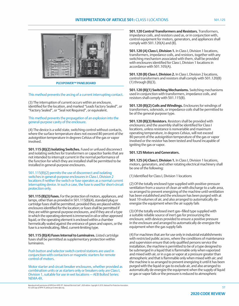
Reproduced with permission of NFPA from NFPA 70®, National Electrical Code®, 2020 edition. Copyright © 2019, National Fire Protection Association. For a full copy of NFPA 70, please go to www.nfpa.org.
INTERPRETATION OF ARTICLE 501: CLASS I LOCATIONS
57
2020 CODE REVIEW
This method prevents the arcing of a current interrupting contact.
(3) The interruption of current occurs within an enclosure, identified for the location, and marked “Leads Factory Sealed”, or “Factory Sealed”, or “Seal not Required”, or equivalent.
This method prevents the propagation of an explosion into the general-purpose cavity of the enclosure.
(4) The device is a solid state, switching control without contacts, where the surface temperature does not exceed 80 percent of the autoignition temperature in degrees Celsius of the gas or vapor involved.
501.115 (B)(2) Isolating Switches. Fused or unfused disconnect and isolating switches for transformers or capacitor banks that are not intended to interrupt current in the normal performance of the function for which they are installed shall be permitted to be installed in general-purpose enclosures.
501.115(B)(2) permits the use of disconnect and isolating switches in general-purpose enclosures in Class I, Division 2 locations if neither the switch or fuse operates as a normal current interrupting device. In such a case, the fuse is used for short-circuit protection only.
501.115 (B)(3) Fuses. For the protection of motors, appliances, and lamps, other than as provided in 501.115(B)(4), standard plug or cartridge fuses shall be permitted, provided they are placed within enclosures identified for the location; or fuses shall be permitted if they are within general-purpose enclosures, and if they are of a type in which the operating element is immersed in oil or other approved liquid, or the operating element is enclosed within a chamber hermetically sealed against the entrance of gases and vapors, or the fuse is a nonindicating, filled, current-limiting type.
501.115 (B)(4) Fuses Internal to Luminaires. Listed cartridge fuses shall be permitted as supplementary protection within luminaires.
Push button and selector switch control stations are used in conjunction with contactors or magnetic starters for remote control of motors.
Motor starter and circuit breaker enclosures, whether provided as combination units or as starters only or breakers only are Class I, Division 1, suitable for use in wet locations — AEB Bolted Series: NEMA 4X.
501.120 Control Transformers and Resistors. Transformers, impedance coils, and resistors used as, or in conjunction with, control equipment for motors, generators, and appliances shall comply with 501.120(A) and (B).
501.120 (A) Class I, Division 1. In Class I, Division 1 locations, transformers, impedance coils, and resistors, together with any switching mechanism associated with them, shall be provided with enclosures identified for Class I, Division 1 locations in accordance with 501.105(A).
501.120 (B) Class I, Division 2. In Class I, Division 2 locations, control transformers and resistors shall comply with 501.120(B)(1) through (B)(3).
501.120 (B)(1) Switching Mechanisms. Switching mechanisms used in conjunction with transformers, impedance coils, and resistors shall comply with 501.115(B).
501.120 (B)(2) Coils and Windings. Enclosures for windings of transformers, solenoids, or impedance coils shall be permitted to be of the general-purpose type.
501.120 (B)(3) Resistors. Resistors shall be provided with enclosures; and the assembly shall be identified for Class I locations, unless resistance is nonvariable and maximum operating temperature, in degrees Celsius, will not exceed 80 percent of the autoignition temperature of the gas or vapor involved or the resistor has been tested and found incapable of igniting the gas or vapor.
501.125 Motors and Generators.
501.125 (A) Class I, Division 1. In Class I, Division 1 locations, motors, generators, and other rotating electrical machinery shall be one of the following:
(1) Identified for Class I, Division 1 locations
(2) Of the totally enclosed type supplied with positive-pressure ventilation from a source of clean air with discharge to a safe area, so arranged to prevent energizing of the machine until ventilation has been established and the enclosure has been purged with at least 10 volumes of air, and also arranged to automatically de-energize the equipment when the air supply fails
(3) Of the totally enclosed inert gas–filled type supplied with a suitable reliable source of inert gas for pressurizing the enclosure, with devices provided to ensure a positive pressure in the enclosure and arranged to automatically de-energize the equipment when the gas supply fails
(4) For machines that are for use only in industrial establishments with restricted public access, where the conditions of maintenance and supervision ensure that only qualified persons service the installation, the machine is permitted to be of a type designed to be submerged in a liquid that is flammable only when vaporized and mixed with air, or in a gas or vapor at a pressure greater than atmospheric and that is flammable only when mixed with air; and the machine is so arranged to prevent energizing it until it has been purged with the liquid or gas to exclude air, and also arranged to automatically de-energize the equipment when the supply of liquid or gas or vapor fails or the pressure is reduced to atmospheric
PLEXPOWER™ PANELBOARD
501.125
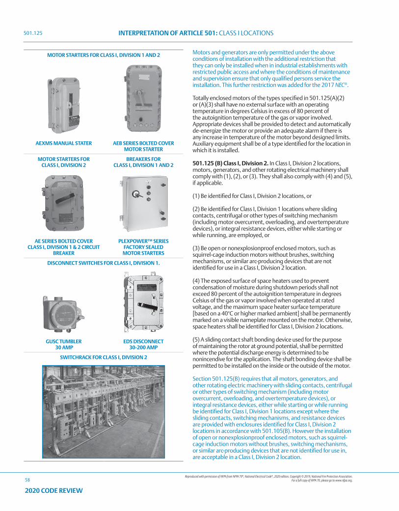
Reproduced with permission of NFPA from NFPA 70®, National Electrical Code®, 2020 edition. Copyright © 2019, National Fire Protection Association. For a full copy of NFPA 70, please go to www.nfpa.org.
INTERPRETATION OF ARTICLE 501: CLASS I LOCATIONS
58
2020 CODE REVIEW
Motors and generators are only permitted under the above conditions of installation with the additional restriction that they can only be installed when in industrial establishments with restricted public access and where the conditions of maintenance and supervision ensure that only qualified persons service the installation. This further restriction was added for the 2017 NEC®.
Totally enclosed motors of the types specified in 501.125(A)(2) or (A)(3) shall have no external surface with an operating temperature in degrees Celsius in excess of 80 percent of the autoignition temperature of the gas or vapor involved. Appropriate devices shall be provided to detect and automatically de-energize the motor or provide an adequate alarm if there is any increase in temperature of the motor beyond designed limits. Auxiliary equipment shall be of a type identified for the location in which it is installed.
501.125 (B) Class I, Division 2. In Class I, Division 2 locations, motors, generators, and other rotating electrical machinery shall comply with (1), (2), or (3). They shall also comply with (4) and (5), if applicable.
(1) Be identified for Class I, Division 2 locations, or
(2) Be identified for Class I, Division 1 locations where sliding contacts, centrifugal or other types of switching mechanism (including motor overcurrent, overloading, and overtemperature devices), or integral resistance devices, either while starting or while running, are employed, or
(3) Be open or nonexplosionproof enclosed motors, such as squirrel-cage induction motors without brushes, switching mechanisms, or similar arc-producing devices that are not identified for use in a Class I, Division 2 location.
(4) The exposed surface of space heaters used to prevent condensation of moisture during shutdown periods shall not exceed 80 percent of the autoignition temperature in degrees Celsius of the gas or vapor involved when operated at rated voltage, and the maximum space heater surface temperature [based on a 40°C or higher marked ambient] shall be permanently marked on a visible nameplate mounted on the motor. Otherwise, space heaters shall be identified for Class I, Division 2 locations.
(5) A sliding contact shaft bonding device used for the purpose of maintaining the rotor at ground potential, shall be permitted where the potential discharge energy is determined to be nonincendive for the application. The shaft bonding device shall be permitted to be installed on the inside or the outside of the motor.
Section 501.125(B) requires that all motors, generators, and other rotating electric machinery with sliding contacts, centrifugal or other types of switching mechanism (including motor overcurrent, overloading, and overtemperature devices), or integral resistance devices, either while starting or while running be identified for Class I, Division 1 locations except where the sliding contacts, switching mechanisms, and resistance devices are provided with enclosures identified for Class I, Division 2 locations in accordance with 501.105(B). However the installation of open or nonexplosionproof enclosed motors, such as squirrel-cage induction motors without brushes, switching mechanisms, or similar arc-producing devices that are not identified for use in, are acceptable in a Class I, Division 2 location.
MOTOR STARTERS FOR CLASS I, DIVISION 1 AND 2
AEXMS MANUAL STATER AEB SERIES BOLTED COVER MOTOR STARTER
MOTOR STARTERS FOR CLASS I, DIVISION 2
BREAKERS FOR CLASS I, DIVISION 1 AND 2
AE SERIES BOLTED COVER CLASS I, DIVISION 1 & 2 CIRCUIT
BREAKER
PLEXPOWER™ SERIES FACTORY SEALED MOTOR STARTERS
DISCONNECT SWITCHES FOR CLASS I, DIVISION 1.
GUSC TUMBLER 30 AMP
EDS DISCONNECT 30-200 AMP
SWITCHRACK FOR CLASS I, DIVISION 2
501.125
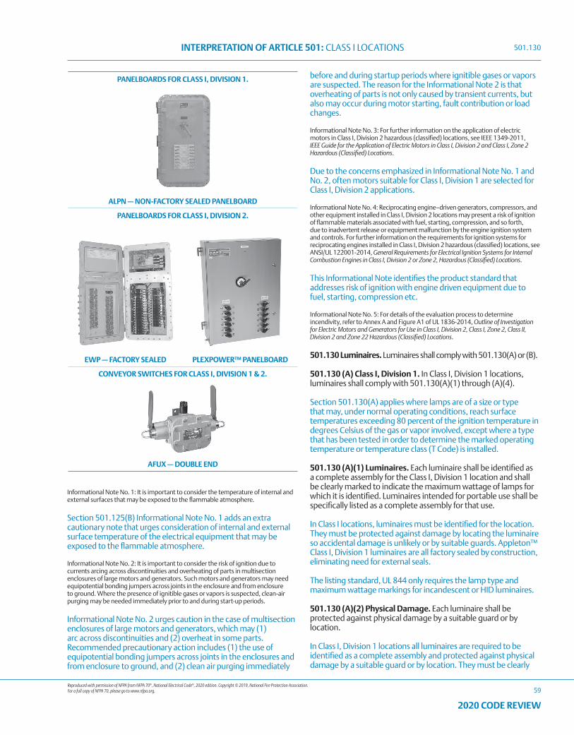
Reproduced with permission of NFPA from NFPA 70®, National Electrical Code®, 2020 edition. Copyright © 2019, National Fire Protection Association. For a full copy of NFPA 70, please go to www.nfpa.org.
INTERPRETATION OF ARTICLE 501: CLASS I LOCATIONS
59
2020 CODE REVIEW
PANELBOARDS FOR CLASS I, DIVISION 1.
ALPN — NON-FACTORY SEALED PANELBOARD
PANELBOARDS FOR CLASS I, DIVISION 2.
EWP — FACTORY SEALED PLEXPOWER™ PANELBOARD
CONVEYOR SWITCHES FOR CLASS I, DIVISION 1 & 2.
AFUX — DOUBLE END
Informational Note No. 1: It is important to consider the temperature of internal and external surfaces that may be exposed to the flammable atmosphere.
Section 501.125(B) Informational Note No. 1 adds an extra cautionary note that urges consideration of internal and external surface temperature of the electrical equipment that may be exposed to the flammable atmosphere.
Informational Note No. 2: It is important to consider the risk of ignition due to currents arcing across discontinuities and overheating of parts in multisection enclosures of large motors and generators. Such motors and generators may need equipotential bonding jumpers across joints in the enclosure and from enclosure to ground. Where the presence of ignitible gases or vapors is suspected, clean-air purging may be needed immediately prior to and during start-up periods.
Informational Note No. 2 urges caution in the case of multisection enclosures of large motors and generators, which may (1) arc across discontinuities and (2) overheat in some parts. Recommended precautionary action includes (1) the use of equipotential bonding jumpers across joints in the enclosures and from enclosure to ground, and (2) clean air purging immediately
before and during startup periods where ignitible gases or vapors are suspected. The reason for the Informational Note 2 is that overheating of parts is not only caused by transient currents, but also may occur during motor starting, fault contribution or load changes.
Informational Note No. 3: For further information on the application of electric motors in Class I, Division 2 hazardous (classified) locations, see IEEE 1349-2011, IEEE Guide for the Application of Electric Motors in Class I, Division 2 and Class I, Zone 2 Hazardous (Classified) Locations.
Due to the concerns emphasized in Informational Note No. 1 and No. 2, often motors suitable for Class I, Division 1 are selected for Class I, Division 2 applications.
Informational Note No. 4: Reciprocating engine–driven generators, compressors, and other equipment installed in Class I, Division 2 locations may present a risk of ignition of flammable materials associated with fuel, starting, compression, and so forth, due to inadvertent release or equipment malfunction by the engine ignition system and controls. For further information on the requirements for ignition systems for reciprocating engines installed in Class I, Division 2 hazardous (classified) locations, see ANSI/UL 122001-2014, General Requirements for Electrical Ignition Systems for Internal Combustion Engines in Class I, Division 2 or Zone 2, Hazardous (Classified) Locations.
This Informational Note identifies the product standard that addresses risk of ignition with engine driven equipment due to fuel, starting, compression etc.
Informational Note No. 5: For details of the evaluation process to determine incendivity, refer to Annex A and Figure A1 of UL 1836-2014, Outline of Investigation for Electric Motors and Generators for Use in Class I, Division 2, Class I, Zone 2, Class II, Division 2 and Zone 22 Hazardous (Classified) Locations.
501.130 Luminaires. Luminaires shall comply with 501.130(A) or (B).
501.130 (A) Class I, Division 1. In Class I, Division 1 locations, luminaires shall comply with 501.130(A)(1) through (A)(4).
Section 501.130(A) applies where lamps are of a size or type that may, under normal operating conditions, reach surface temperatures exceeding 80 percent of the ignition temperature in degrees Celsius of the gas or vapor involved, except where a type that has been tested in order to determine the marked operating temperature or temperature class (T Code) is installed.
501.130 (A)(1) Luminaires. Each luminaire shall be identified as a complete assembly for the Class I, Division 1 location and shall be clearly marked to indicate the maximum wattage of lamps for which it is identified. Luminaires intended for portable use shall be specifically listed as a complete assembly for that use.
In Class I locations, luminaires must be identified for the location. They must be protected against damage by locating the luminaire so accidental damage is unlikely or by suitable guards. Appleton™ Class I, Division 1 luminaires are all factory sealed by construction, eliminating need for external seals.
The listing standard, UL 844 only requires the lamp type and maximum wattage markings for incandescent or HID luminaires.
501.130 (A)(2) Physical Damage. Each luminaire shall be protected against physical damage by a suitable guard or by location.
In Class I, Division 1 locations all luminaires are required to be identified as a complete assembly and protected against physical damage by a suitable guard or by location. They must be clearly
501.130
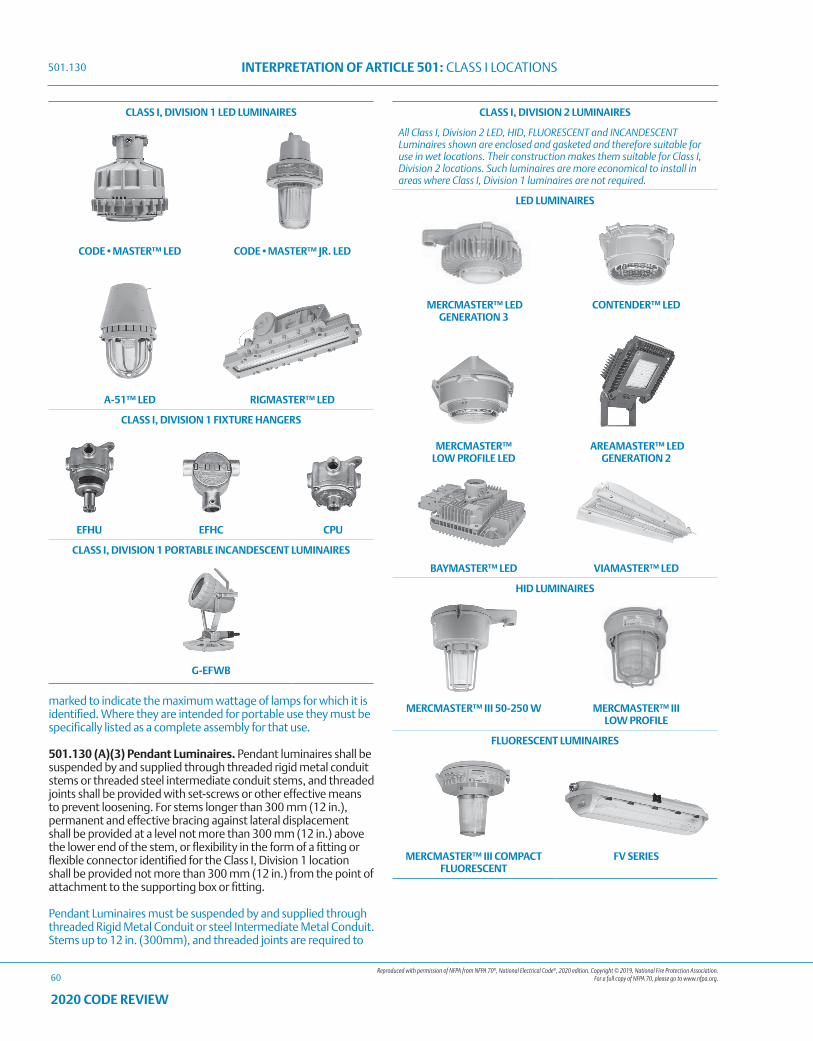
Reproduced with permission of NFPA from NFPA 70®, National Electrical Code®, 2020 edition. Copyright © 2019, National Fire Protection Association. For a full copy of NFPA 70, please go to www.nfpa.org.
INTERPRETATION OF ARTICLE 501: CLASS I LOCATIONS
60
2020 CODE REVIEW
marked to indicate the maximum wattage of lamps for which it is identified. Where they are intended for portable use they must be specifically listed as a complete assembly for that use.
501.130 (A)(3) Pendant Luminaires. Pendant luminaires shall be suspended by and supplied through threaded rigid metal conduit stems or threaded steel intermediate conduit stems, and threaded joints shall be provided with set-screws or other effective means to prevent loosening. For stems longer than 300 mm (12 in.), permanent and effective bracing against lateral displacement shall be provided at a level not more than 300 mm (12 in.) above the lower end of the stem, or flexibility in the form of a fitting or flexible connector identified for the Class I, Division 1 location shall be provided not more than 300 mm (12 in.) from the point of attachment to the supporting box or fitting.
Pendant Luminaires must be suspended by and supplied through threaded Rigid Metal Conduit or steel Intermediate Metal Conduit. Stems up to 12 in. (300mm), and threaded joints are required to
CLASS I, DIVISION 2 LUMINAIRES
All Class I, Division 2 LED, HID, FLUORESCENT and INCANDESCENT Luminaires shown are enclosed and gasketed and therefore suitable for use in wet locations. Their construction makes them suitable for Class I, Division 2 locations. Such luminaires are more economical to install in areas where Class I, Division 1 luminaires are not required.
LED LUMINAIRES
MERCMASTER™ LED GENERATION 3
CONTENDER™ LED
MERCMASTER™ LOW PROFILE LED
AREAMASTER™ LED GENERATION 2
BAYMASTER™ LED VIAMASTER™ LED
HID LUMINAIRES
MERCMASTER™ III 50-250 W MERCMASTER™ III LOW PROFILE
FLUORESCENT LUMINAIRES
MERCMASTER™ III COMPACT FLUORESCENT
FV SERIES
CLASS I, DIVISION 1 LED LUMINAIRES
CODE•MASTER™ LED CODE•MASTER™ JR. LED
A-51™ LED RIGMASTER™ LED
CLASS I, DIVISION 1 FIXTURE HANGERS
EFHU EFHC CPU
CLASS I, DIVISION 1 PORTABLE INCANDESCENT LUMINAIRES
G-EFWB
501.130
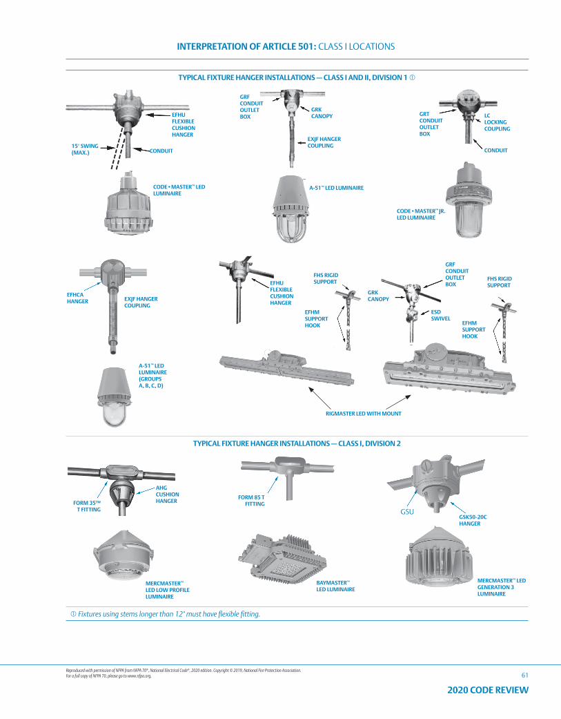
Reproduced with permission of NFPA from NFPA 70®, National Electrical Code®, 2020 edition. Copyright © 2019, National Fire Protection Association. For a full copy of NFPA 70, please go to www.nfpa.org.
INTERPRETATION OF ARTICLE 501: CLASS I LOCATIONS
61
2020 CODE REVIEW
TYPICAL FIXTURE HANGER INSTALLATIONS — CLASS I AND II, DIVISION 1
GRT CONDUIT OUTLET BOX
LC LOCKING COUPLING
CONDUIT
EFHU FLEXIBLE CUSHION HANGER
GRF CONDUIT OUTLET BOX
GRK CANOPY
EXJF HANGER COUPLING
A-51™ LED LUMINAIRECODE•MASTER™ LED
LUMINAIRE
15° SWING (MAX.) CONDUIT
EXJF HANGER COUPLING
RIGMASTER LED WITH MOUNT
GRK CANOPY
GRF CONDUIT OUTLET BOX
ESD SWIVEL
EFHM SUPPORT HOOK
A-51™ LED LUMINAIRE (GROUPS A, B, C, D)
EFHCA HANGER
FHS RIGID SUPPORT
FHS RIGID SUPPORT
EFHM SUPPORT HOOK
EFHU FLEXIBLE CUSHION HANGER
CODE•MASTER™ JR. LED LUMINAIRE
TYPICAL FIXTURE HANGER INSTALLATIONS — CLASS I, DIVISION 2
AHG CUSHION HANGER
FORM 85 T FITTING
GSK50-20C HANGER
MERCMASTER™ LED GENERATION 3 LUMINAIRE
FORM 35™ T FITTING
BAYMASTER™ LED LUMINAIRE
MERCMASTER™ LED LOW PROFILE LUMINAIRE
GSU
Fixtures using stems longer than 12" must have flexible fitting.
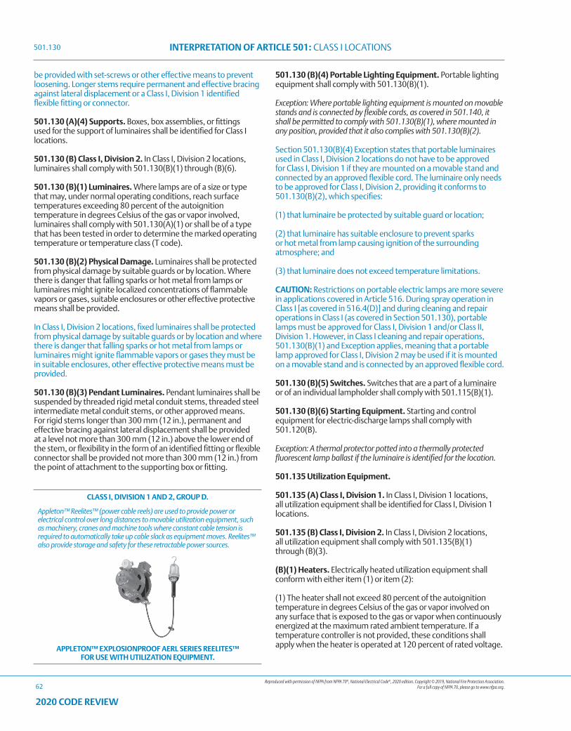
Reproduced with permission of NFPA from NFPA 70®, National Electrical Code®, 2020 edition. Copyright © 2019, National Fire Protection Association. For a full copy of NFPA 70, please go to www.nfpa.org.
INTERPRETATION OF ARTICLE 501: CLASS I LOCATIONS
62
2020 CODE REVIEW
be provided with set-screws or other effective means to prevent loosening. Longer stems require permanent and effective bracing against lateral displacement or a Class I, Division 1 identified flexible fitting or connector.
501.130 (A)(4) Supports. Boxes, box assemblies, or fittings used for the support of luminaires shall be identified for Class I locations.
501.130 (B) Class I, Division 2. In Class I, Division 2 locations, luminaires shall comply with 501.130(B)(1) through (B)(6).
501.130 (B)(1) Luminaires. Where lamps are of a size or type that may, under normal operating conditions, reach surface temperatures exceeding 80 percent of the autoignition temperature in degrees Celsius of the gas or vapor involved, luminaires shall comply with 501.130(A)(1) or shall be of a type that has been tested in order to determine the marked operating temperature or temperature class (T code).
501.130 (B)(2) Physical Damage. Luminaires shall be protected from physical damage by suitable guards or by location. Where there is danger that falling sparks or hot metal from lamps or luminaires might ignite localized concentrations of flammable vapors or gases, suitable enclosures or other effective protective means shall be provided.
In Class I, Division 2 locations, fixed luminaires shall be protected from physical damage by suitable guards or by location and where there is danger that falling sparks or hot metal from lamps or luminaires might ignite flammable vapors or gases they must be in suitable enclosures, other effective protective means must be provided.
501.130 (B)(3) Pendant Luminaires. Pendant luminaires shall be suspended by threaded rigid metal conduit stems, threaded steel intermediate metal conduit stems, or other approved means. For rigid stems longer than 300 mm (12 in.), permanent and effective bracing against lateral displacement shall be provided at a level not more than 300 mm (12 in.) above the lower end of the stem, or flexibility in the form of an identified fitting or flexible connector shall be provided not more than 300 mm (12 in.) from the point of attachment to the supporting box or fitting.
501.130 (B)(4) Portable Lighting Equipment. Portable lighting equipment shall comply with 501.130(B)(1).
Exception: Where portable lighting equipment is mounted on movable stands and is connected by flexible cords, as covered in 501.140, it shall be permitted to comply with 501.130(B)(1), where mounted in any position, provided that it also complies with 501.130(B)(2).
Section 501.130(B)(4) Exception states that portable luminaires used in Class I, Division 2 locations do not have to be approved for Class I, Division 1 if they are mounted on a movable stand and connected by an approved flexible cord. The luminaire only needs to be approved for Class I, Division 2, providing it conforms to 501.130(B)(2), which specifies:
(1) that luminaire be protected by suitable guard or location;
(2) that luminaire has suitable enclosure to prevent sparks or hot metal from lamp causing ignition of the surrounding atmosphere; and
(3) that luminaire does not exceed temperature limitations.
CAUTION: Restrictions on portable electric lamps are more severe in applications covered in Article 516. During spray operation in Class I [as covered in 516.4(D)] and during cleaning and repair operations in Class I (as covered in Section 501.130), portable lamps must be approved for Class I, Division 1 and/or Class II, Division 1. However, in Class I cleaning and repair operations, 501.130(B)(1) and Exception applies, meaning that a portable lamp approved for Class I, Division 2 may be used if it is mounted on a movable stand and is connected by an approved flexible cord.
501.130 (B)(5) Switches. Switches that are a part of a luminaire or of an individual lampholder shall comply with 501.115(B)(1).
501.130 (B)(6) Starting Equipment. Starting and control equipment for electric-discharge lamps shall comply with 501.120(B).
Exception: A thermal protector potted into a thermally protected fluorescent lamp ballast if the luminaire is identified for the location.
501.135 Utilization Equipment.
501.135 (A) Class I, Division 1. In Class I, Division 1 locations, all utilization equipment shall be identified for Class I, Division 1 locations.
501.135 (B) Class I, Division 2. In Class I, Division 2 locations, all utilization equipment shall comply with 501.135(B)(1) through (B)(3).
(B)(1) Heaters. Electrically heated utilization equipment shall conform with either item (1) or item (2):
(1) The heater shall not exceed 80 percent of the autoignition temperature in degrees Celsius of the gas or vapor involved on any surface that is exposed to the gas or vapor when continuously energized at the maximum rated ambient temperature. If a temperature controller is not provided, these conditions shall apply when the heater is operated at 120 percent of rated voltage.
CLASS I, DIVISION 1 AND 2, GROUP D.
Appleton™ Reelites™ (power cable reels) are used to provide power or electrical control over long distances to movable utilization equipment, such as machinery, cranes and machine tools where constant cable tension is required to automatically take up cable slack as equipment moves. Reelites™ also provide storage and safety for these retractable power sources.
APPLETON™ EXPLOSIONPROOF AERL SERIES REELITES™ FOR USE WITH UTILIZATION EQUIPMENT.
501.130
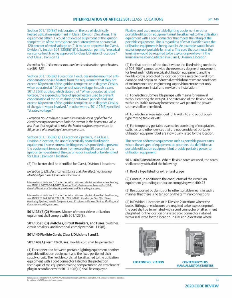
Reproduced with permission of NFPA from NFPA 70®, National Electrical Code®, 2020 edition. Copyright © 2019, National Fire Protection Association. For a full copy of NFPA 70, please go to www.nfpa.org.
INTERPRETATION OF ARTICLE 501: CLASS I LOCATIONS
63
2020 CODE REVIEW
Section 501.135(B)(1) elaborates on the use of electrically heated utilization equipment in Class I, Division 2 locations. This equipment either (1) could not exceed 80 percent of the ignition temperature of the atmosphere encountered when operated at 120 percent of rated voltage or (2) it must be approved for Class I, Division 1. Section 501.135(B)(1)(1), Exception permits “electrical resistance heat tracing approved for Class I, Division 2 locations” (not Class I, Division 1).
Exception No. 1: For motor-mounted anticondensation space heaters, see 501.125.
Section 501.135(B)(1) Exception 1 excludes motor-mounted anti-condensation space heaters from the requirement that they not exceed 80 percent of the ignition temperature in degrees Celsius when operated at 120 percent of rated voltage. In such a case, 501.125(B) applies, which states that “When operated at rated voltage, the exposed surface of space heaters used to prevent condensation of moisture during shut-down periods shall not exceed 80 percent of the ignition temperature in degrees Celsius of the gas or vapor involved.” In other words, 501.125(B) specified “at rated voltage.”
Exception No. 2: Where a current-limiting device is applied to the circuit serving the heater to limit the current in the heater to a value less than that required to raise the heater surface temperature to 80 percent of the autoignition temperature.
Section 501.135(B)(1)(1), Exception 2 permits, in a Class I, Division 2 location, the use of electrically heated utilization equipment if some current-limiting means is provided to prevent the equipment temperature from exceeding 80 percent of the ignition temperature of the gas or vapor involved or be identified for Class I, Division 1 location.
(2) The heater shall be identified for Class I, Division 1 locations.
Exception to (2): Electrical resistance and skin effect heat tracing identified for Class I, Division 2 locations.
Informational Note No. 1: For further information on electric resistance heat tracing, see ANSI/UL 60079-30-1-2017, Standard for Explosive Atmospheres — Part 30-1: Electrical Resistance Trace Heating — General and Testing Requirements.
Informational Note No. 2: For further information on electric skin effect heat tracing, see ANSI/IEEE 844.1/CSA C22.2 No. 293.1-2017, Standard for Skin Effect Trace Heating of Pipelines, Vessels, Equipment, and Structures — General, Testing, Marking, and Documentation Requirements.
501.135 (B)(2) Motors. Motors of motor-driven utilization equipment shall comply with 501.125(B).
501.135 (B)(3) Switches, Circuit Breakers, and Fuses. Switches, circuit breakers, and fuses shall comply with 501.115(B).
501.140 Flexible Cords, Class I, Divisions 1 and 2.
501.140 (A) Permitted Uses. Flexible cord shall be permitted:
(1) For connection between portable lighting equipment or other portable utilization equipment and the fixed portion of their supply circuit. The flexible cord shall be attached to the utilization equipment with a cord connector listed for the protection technique of the equipment wiring compartment. An attachment plug in accordance with 501.140(B)(4) shall be employed.
Flexible cord used on portable lighting equipment or other portable utilization equipment must be attached to the utilization equipment with a cord connector that meets the rating of the portable equipment. This is regardless of what classified area the utilization equipment is being used in. An example would be an explosionproof portable luminaire. The cord that connects the luminaire would be required to be explosionproof even if the luminaire was being utilized in a Class I, Division 2 location.
(2) For that portion of the circuit where the fixed wiring methods of 501.10(A) cannot provide the necessary degree of movement for fixed and mobile electrical utilization equipment, and the flexible cord is protected by location or by a suitable guard from damage and only in an industrial establishment where conditions of maintenance and engineering supervision ensure that only qualified persons install and service the installation.
(3) For electric submersible pumps with means for removal without entering the wet-pit. The extension of the flexible cord within a suitable raceway between the wet-pit and the power source shall be permitted.
(4) For electric mixers intended for travel into and out of open-type mixing tanks or vats.
(5) For temporary portable assemblies consisting of receptacles, switches, and other devices that are not considered portable utilization equipment but are individually listed for the location.
This section addresses equipment such as portable power carts where these types of equipment do not meet the definition as portable utilization equipment but provide portable power to utilization equipment.
501.140 (B) Installation. Where flexible cords are used, the cords shall comply with all of the following:
(1) Be of a type listed for extra-hard usage
(2) Contain, in addition to the conductors of the circuit, an equipment grounding conductor complying with 400.23
(3) Be supported by clamps or by other suitable means in such a manner that there is no tension on the terminal connections
(4) In Division 1 locations or in Division 2 locations where the boxes, fittings, or enclosures are required to be explosionproof, the cord shall be terminated with a cord connector or attachment plug listed for the location or a listed cord connector installed with a seal listed for the location. In Division 2 locations where
EDS CONTROL STATION CONTENDER™ EDS MANUAL MOTOR STARTERS
501.140
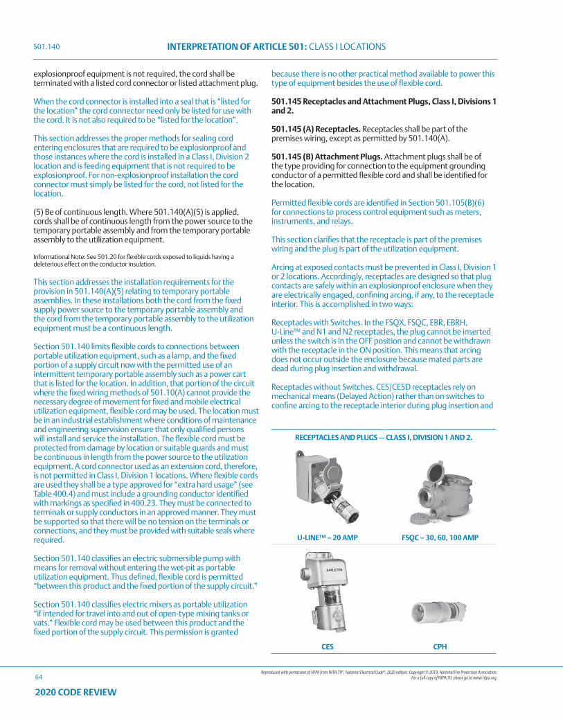
Reproduced with permission of NFPA from NFPA 70®, National Electrical Code®, 2020 edition. Copyright © 2019, National Fire Protection Association. For a full copy of NFPA 70, please go to www.nfpa.org.
INTERPRETATION OF ARTICLE 501: CLASS I LOCATIONS
64
2020 CODE REVIEW
explosionproof equipment is not required, the cord shall be terminated with a listed cord connector or listed attachment plug.
When the cord connector is installed into a seal that is “listed for the location” the cord connector need only be listed for use with the cord. It is not also required to be “listed for the location”.
This section addresses the proper methods for sealing cord entering enclosures that are required to be explosionproof and those instances where the cord is installed in a Class I, Division 2 location and is feeding equipment that is not required to be explosionproof. For non-explosionproof installation the cord connector must simply be listed for the cord, not listed for the location.
(5) Be of continuous length. Where 501.140(A)(5) is applied, cords shall be of continuous length from the power source to the temporary portable assembly and from the temporary portable assembly to the utilization equipment.
Informational Note: See 501.20 for flexible cords exposed to liquids having a deleterious effect on the conductor insulation.
This section addresses the installation requirements for the provision in 501.140(A)(5) relating to temporary portable assemblies. In these installations both the cord from the fixed supply power source to the temporary portable assembly and the cord from the temporary portable assembly to the utilization equipment must be a continuous length.
Section 501.140 limits flexible cords to connections between portable utilization equipment, such as a lamp, and the fixed portion of a supply circuit now with the permitted use of an intermittent temporary portable assembly such as a power cart that is listed for the location. In addition, that portion of the circuit where the fixed wiring methods of 501.10(A) cannot provide the necessary degree of movement for fixed and mobile electrical utilization equipment, flexible cord may be used. The location must be in an industrial establishment where conditions of maintenance and engineering supervision ensure that only qualified persons will install and service the installation. The flexible cord must be protected from damage by location or suitable guards and must be continuous in length from the power source to the utilization equipment. A cord connector used as an extension cord, therefore, is not permitted in Class I, Division 1 locations. Where flexible cords are used they shall be a type approved for “extra hard usage” (see Table 400.4) and must include a grounding conductor identified with markings as specified in 400.23. They must be connected to terminals or supply conductors in an approved manner. They must be supported so that there will be no tension on the terminals or connections, and they must be provided with suitable seals where required.
Section 501.140 classifies an electric submersible pump with means for removal without entering the wet-pit as portable utilization equipment. Thus defined, flexible cord is permitted “between this product and the fixed portion of the supply circuit.”
Section 501.140 classifies electric mixers as portable utilization “if intended for travel into and out of open-type mixing tanks or vats.” Flexible cord may be used between this product and the fixed portion of the supply circuit. This permission is granted
because there is no other practical method available to power this type of equipment besides the use of flexible cord.
501.145 Receptacles and Attachment Plugs, Class I, Divisions 1 and 2.
501.145 (A) Receptacles. Receptacles shall be part of the premises wiring, except as permitted by 501.140(A).
501.145 (B) Attachment Plugs. Attachment plugs shall be of the type providing for connection to the equipment grounding conductor of a permitted flexible cord and shall be identified for the location.
Permitted flexible cords are identified in Section 501.105(B)(6) for connections to process control equipment such as meters, instruments, and relays.
This section clarifies that the receptacle is part of the premises wiring and the plug is part of the utilization equipment.
Arcing at exposed contacts must be prevented in Class I, Division 1 or 2 locations. Accordingly, receptacles are designed so that plug contacts are safely within an explosionproof enclosure when they are electrically engaged, confining arcing, if any, to the receptacle interior. This is accomplished in two ways:
Receptacles with Switches. In the FSQX, FSQC, EBR, EBRH, U-Line™ and N1 and N2 receptacles, the plug cannot be inserted unless the switch is in the OFF position and cannot be withdrawn with the receptacle in the ON position. This means that arcing does not occur outside the enclosure because mated parts are dead during plug insertion and withdrawal.
Receptacles without Switches. CES/CESD receptacles rely on mechanical means (Delayed Action) rather than on switches to confine arcing to the receptacle interior during plug insertion and
RECEPTACLES AND PLUGS — CLASS I, DIVISION 1 AND 2.
U-LINE™ – 20 AMP FSQC – 30, 60, 100 AMP
CES CPH
501.140
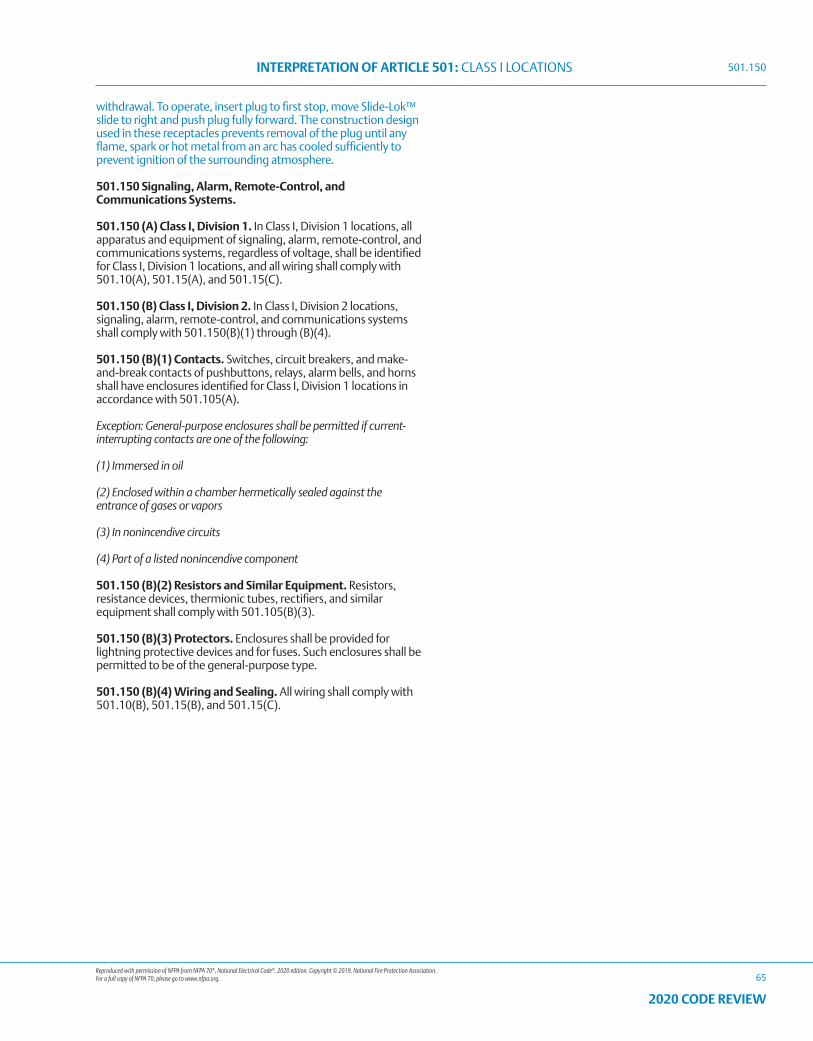
Reproduced with permission of NFPA from NFPA 70®, National Electrical Code®, 2020 edition. Copyright © 2019, National Fire Protection Association. For a full copy of NFPA 70, please go to www.nfpa.org.
INTERPRETATION OF ARTICLE 501: CLASS I LOCATIONS
65
2020 CODE REVIEW
withdrawal. To operate, insert plug to first stop, move Slide-Lok™ slide to right and push plug fully forward. The construction design used in these receptacles prevents removal of the plug until any flame, spark or hot metal from an arc has cooled sufficiently to prevent ignition of the surrounding atmosphere.
501.150 Signaling, Alarm, Remote-Control, and Communications Systems.
501.150 (A) Class I, Division 1. In Class I, Division 1 locations, all apparatus and equipment of signaling, alarm, remote-control, and communications systems, regardless of voltage, shall be identified for Class I, Division 1 locations, and all wiring shall comply with 501.10(A), 501.15(A), and 501.15(C).
501.150 (B) Class I, Division 2. In Class I, Division 2 locations, signaling, alarm, remote-control, and communications systems shall comply with 501.150(B)(1) through (B)(4).
501.150 (B)(1) Contacts. Switches, circuit breakers, and make-and-break contacts of pushbuttons, relays, alarm bells, and horns shall have enclosures identified for Class I, Division 1 locations in accordance with 501.105(A).
Exception: General-purpose enclosures shall be permitted if current-interrupting contacts are one of the following:
(1) Immersed in oil
(2) Enclosed within a chamber hermetically sealed against the entrance of gases or vapors
(3) In nonincendive circuits
(4) Part of a listed nonincendive component
501.150 (B)(2) Resistors and Similar Equipment. Resistors, resistance devices, thermionic tubes, rectifiers, and similar equipment shall comply with 501.105(B)(3).
501.150 (B)(3) Protectors. Enclosures shall be provided for lightning protective devices and for fuses. Such enclosures shall be permitted to be of the general-purpose type.
501.150 (B)(4) Wiring and Sealing. All wiring shall comply with 501.10(B), 501.15(B), and 501.15(C).
501.150

66
2020 CODE REVIEW
NOTES
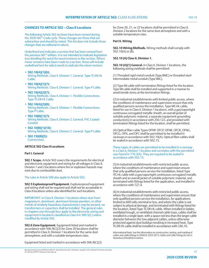
Reproduced with permission of NFPA from NFPA 70®, National Electrical Code®, 2020 edition. Copyright © 2019, National Fire Protection Association. For a full copy of NFPA 70, please go to www.nfpa.org.
INTERPRETATION OF ARTICLE 502: CLASS II LOCATIONS
67
2020 CODE REVIEW
CHANGES TO ARTICLE 502 – Class II Locations
The following Article 502 sections have been revised during the 2020 NEC® Code cycle. These changes are those that are substantive and should be noted. This list does not include those changes that are editorial in nature.
Underlined text indicates a section that has been revised from the previous NEC® edition. It is not intended to indicate legislation text detailing the word-for-word revisions to the section. Where minor revisions have been made to a section, these will include underlined text for select words to indicate the minor revision.
• 502.10(A)(1)(6): Wiring Methods. Class II, Division 1. General. Type TC-ER-HL
Cable.
• 502.10(A)(1)(7): Wiring Methods. Class II, Division 1. General. Type P Cable.
• 502.10(A)(2)(7): Wiring Methods. Class II, Division 1. Flexible Connections.
Type TC-ER-HL Cable.
• 502.10(A)(2)(8): Wiring Methods. Class II, Division 1. Flexible Connections.
Type P Cable.
• 502.10(B)(1)(7): Wiring Methods. Class II, Division 2. General. PVC Coated
Conduit
• 502.10(B)(1)(10): Wiring Methods. Class II, Division 2. General. Type P Cable.
• 502.150(B)(5): Connections.
ARTICLE 502 Class II Locations
Part I. General
502.1 Scope. Article 502 covers the requirements for electrical and electronic equipment and wiring for all voltages in Class II, Division 1 and 2 locations where fire or explosion hazards may exist due to combustible dust.
The rules in Article 500 also apply to Article 502.
502.5 Explosionproof Equipment. Explosionproof equipment and wiring shall not be required and shall not be acceptable in Class II locations unless also identified for such locations.
IMPORTANT: In Class II, Division 1 locations where dust from magnesium, aluminum, aluminum bronze powders, or other metals of similarly hazardous characteristics may be present, no transformers or capacitors shall be installed. The general rules in chapters one through four apply to the electronic wiring and equipment in locations classified as Class II in 500.5(C) unless modified by Article 502.
502.6 Zone Equipment. Equipment listed and marked in accordance with 506.9(C)(2) for Zone 20 locations shall be permitted in Class II, Division 1 locations for the same dust atmosphere; and with a suitable temperature class.
Equipment listed and marked in accordance with 506.9(C)(2)
for Zone 20, 21, or 22 locations shall be permitted in Class II, Division 2 locations for the same dust atmosphere and with a suitable temperature class.
Part II. Wiring
502.10 Wiring Methods. Wiring methods shall comply with 502.10(A) or (B).
502.10 (A) Class II, Division 1.
502.10 (A)(1) General. In Class II, Division 1 locations, the following wiring methods shall be permitted:
(1) Threaded rigid metal conduit (Type RMC) or threaded steel intermediate metal conduit (Type IMC).
(2) Type MI cable with termination fittings listed for the location. Type MI cable shall be installed and supported in a manner to avoid tensile stress at the termination fittings.
(3) In industrial establishments with limited public access, where the conditions of maintenance and supervision ensure that only qualified persons service the installation, Type MC-HL cable, listed for use in Class II, Division 1 locations, with a gas/vaportight continuous corrugated metallic sheath, an overall jacket of suitable polymeric material, a separate equipment grounding conductor(s) in accordance with 250.122, and provided with termination fittings listed for the location, shall be permitted.
(4) Optical fiber cable Types OFNP, OFCP, OFNR, OFCR, OFNG, OFCG, OFN, and OFC shall be permitted to be installed in raceways in accordance with 502.10(A). Optical fiber cables shall be sealed in accordance with 502.15.
These types of cables are permitted to be installed in a raceway in a Class II, Division 1 location and correlates with the permitted uses found in 770.3(A). They are required to be sealed in accordance with 502.15.
(5) In industrial establishments with restricted public access, where the conditions of maintenance and supervision ensure that only qualified persons service the installation, listed Type ITC-HL cable with a gas/vaportight continuous corrugated metallic sheath and an overall jacket of suitable polymeric material, and terminated with fittings listed for the application, and installed in accordance with 727.4.
(6) In industrial establishments with restricted public access, where the conditions of maintenance and supervision ensure that only qualified persons service the installation, for applications limited to 600 volts nominal or less, and where the cable is not subject to physical damage, and terminated with fittings listed for the location, listed Type TC-ER-HL cable. When installed in ladder, ventilated trough, or ventilated channel cable trays, cables shall be installed in a single layer, with a space not less than the larger cable diameter between the two adjacent cables, unless otherwise protected against dust buildup resulting in increased heat, Type TC-ER-HL cable shall be installed in accordance with 336.10.
Informational Note: See the information on construction, testing, and marking of cables and cable fittings in ANSI/UL 2225-2013, Cables and Cable-Fittings for Use in Hazardous (Classified) Locations.
502.10
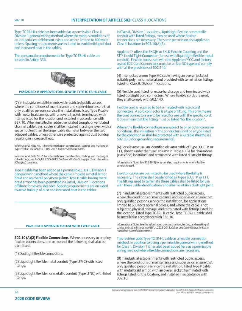
Reproduced with permission of NFPA from NFPA 70®, National Electrical Code®, 2020 edition. Copyright © 2019, National Fire Protection Association. For a full copy of NFPA 70, please go to www.nfpa.org.
INTERPRETATION OF ARTICLE 502: CLASS II LOCATIONS
68
2020 CODE REVIEW
Type TC-ER-HL cable has been added as a permissible Class II, Division 1 general wiring method where the various conditions of an industrial establishment exists and where limited to 600 volts or less. Spacing requirements are included to avoid buildup of dust and increased heat in the cables.
The construction requirements for Type TC-ER-HL cable are located in Article 336.
PXSS2K-REX IS APPROVED FOR USE WITH TYPE TC-ER-HL CABLE
(7) In industrial establishments with restricted public access, where the conditions of maintenance and supervision ensure that only qualified persons service the installation, listed Type P cable with metal braid armor, with an overall jacket, terminated with fittings listed for the location and installed in accordance with 337.10. When installed in ladder, ventilated trough, or ventilated channel cable trays, cables shall be installed in a single layer, with a space not less than the larger cable diameter between the two adjacent cables, unless otherwise protected against dust buildup resulting in increased heat.
Informational Note No. 1: For information on construction, testing, and marking of Type P cable, see ANSI/UL 1309-2017, Marine Shipboard Cable.
Informational Note No. 2: For information on construction, testing, and marking of cable fittings, see ANSI/UL 2225-2013, Cables and Cable-Fittings for Use in Hazardous (Classified) Locations.
Type P cable has been added as a permissible Class II, Division 1 general wiring method where the cable employs a metal armor braid and an overall polymeric jacket. Type P cable having metal braid armor has been permitted in Class II, Division 1 locations offshore for several decades. Spacing requirements are included to avoid buildup of dust and increased heat in the cables.
PX2K-REX IS APPROVED FOR USE WITH TYPE P CABLE
502.10 (A)(2) Flexible Connections. Where necessary to employ flexible connections, one or more of the following shall also be permitted:
(1) Dusttight flexible connectors.
(2) Liquidtight flexible metal conduit (Type LFMC) with listed fittings.
(3) Liquidtight flexible nonmetallic conduit (Type LFNC) with listed fittings.
In Class II, Division 1 locations, liquidtight flexible nonmetallic conduit with listed fittings, may be used where flexible connections are necessary. The same permission also applies to Class III locations in 503.10(A)(3).
Appleton™ offers the EXGJH or EXLK Flexible Coupling and the ST™ Liquid Tight Connector (for use with liquidtight flexible metal conduit). Flexible cords used with the Appleton™ CG and factory sealed ECC Cord Connectors must be an S or SO type and comply with all the provisions of 502.140.
(4) Interlocked armor Type MC cable having an overall jacket of suitable polymeric material and provided with termination fittings listed for Class II, Division 1 locations.
(5) Flexible cord listed for extra-hard usage and terminated with listed dusttight cord connectors. Where flexible cords are used, they shall comply with 502.140.
Flexible cord is required to be terminated with listed cord connectors. A cord connector is a type of fitting. This only means the cord connectors are to be listed for use with the specific cord. It does mean that the fitting must be listed “for the location”.
Where the flexible connections are subject to oil or other corrosive conditions, the insulation of the conductors shall be a type listed for the condition or shall be protected with a suitable sheath [see 502.30(B) for grounding requirements].
(6) For elevator use, an identified elevator cable of Type EO, ETP, or ETT, shown under the “use” column in Table 400.4 for “hazardous (classified) locations” and terminated with listed dusttight fittings.
Informational Note: See 502.30(B) for grounding requirements where flexible conduit is used.
Elevator cables are permitted to be used where flexibility is necessary. The cable shall be identified as Types EO, ETP, or ETT. The fittings used to terminate these cables shall be listed for use with these cable identifications and also maintain a dusttight joint.
(7) In industrial establishments with restricted public access, where the conditions of maintenance and supervision ensure that only qualified persons service the installation, for applications limited to 600 volts nominal or less, and where the cable is not subject to physical damage, and terminated with fittings listed for the location, listed Type TC-ER-HL cable. Type TC-ER-HL cable shall be installed in accordance with 336.10.
Informational Note: See the information on construction, testing, and marking of cables and cable fittings in ANSI/UL 2225-2013, Cables and Cable-Fittings for Use in Hazardous (Classified) Locations.
This revision adds Type TC-ER-HL cable as a flexible connection method. In addition to being a permissible general wiring method for Class II, Division 1 it has also been added here as a permissible wiring method where flexible connections are necessary.
(8) In industrial establishments with restricted public access, where the conditions of maintenance and supervision ensure that only qualified persons service the installation, listed Type P cable with metal braid armor, with an overall jacket, terminated with fittings listed for the location, and installed in accordance with 337.10.
502.10
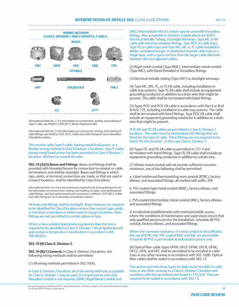
Reproduced with permission of NFPA from NFPA 70®, National Electrical Code®, 2020 edition. Copyright © 2019, National Fire Protection Association. For a full copy of NFPA 70, please go to www.nfpa.org.
INTERPRETATION OF ARTICLE 502: CLASS II LOCATIONS
69
2020 CODE REVIEW
Informational Note No. 1: For information on construction, testing, and marking of Type P cable, see ANSI/UL 1309-2017, Marine Shipboard Cable.
Informational Note No. 2: For information on construction, testing, and marking of cable fittings, see ANSI/UL 2225-2013, Cables and Cable-Fittings for Use in Hazardous (Classified) Locations.
This revision adds Type P cable, having metal braid armor, as a flexible wiring method in Class II Division 1 locations. Type P cables having metal braid armor has been permitted in Class II Division 1 locations offshore for several decades.
502.10 (A)(3) Boxes and Fittings. Boxes and fittings shall be provided with threaded bosses for connection to conduit or cable terminations and shall be dusttight. Boxes and fittings in which taps, joints, or terminal connections are made, or that are used in Group E locations, shall be identified for Class II locations.
Informational Note: For entry into enclosures required to be dust-ignitionproof, see the information on construction, testing, and marking of cables, dust-ignitionproof cable fittings, and dust-ignitionproof cord connectors in ANSI/UL 2225-2013, Cables and Cable-Fittings for Use in Hazardous (Classified) Locations.
All boxes and fittings shall be dusttight. Boxes however are required to be identified for Class II locations where they contain taps, joints, or terminal connections or where used in Group E locations. Note: Fittings are not permitted to contain splices or taps.
Where a box contains heat-producing devices then the box is required to be identified as Class II, Division 1 (Dust-Ignitionproof) and contain a temperature classification in accordance with 500.8(D)(2).
502.10 (B) Class II, Division 2.
502.10 (B)(1) General. In Class II, Division 2 locations, the following wiring methods shall be permitted:
(1) All wiring methods permitted in 502.10(A).
In Class II, Division 2 locations all of the wiring methods acceptable for Class II, Division 1 may be used. It is important to note that threaded conduit is not required. (RMC) Rigid Metal Conduit and
(IMC) Intermediate Metal Conduit may be used with threadless fittings. Also acceptable in Division 2 applications are (EMT) Electrical Metallic Tubing, Dusttight Wireways, Type MC or MI cable with listed termination fittings, Type PLTC in cable trays, Type ITC in cable trays and Type MC, MI, or TC cable installed in ladder, ventilated trough, or ventilated channel cable trays in a single layer, with a space not less than the larger cable diameter between the two adjacent cables.
(2) Rigid metal conduit (Type RMC), intermediate metal conduit (Type IMC), with listed threaded or threadless fittings.
(3) Electrical metallic tubing (Type EMT) or dusttight wireways.
(4) Type MC, MV, TC, or TC-ER cable, including installation in cable tray systems. Type TC-ER cable shall include an equipment grounding conductor in addition to a drain wire that might be present. The cable shall be terminated with listed fittings.
(5) Types PLTC and PLTC-ER cable in accordance with Part II or III of Article 725, including installation in cable tray systems. The cable shall be terminated with listed fittings. Type PLTC-ER cable shall include an equipment grounding conductor in addition to a drain wire that might be present.
PLTC-ER and ITC-ER cables are permitted in Class II, Division 2 locations. The cable must be terminated with fittings that are listed for the type of cable. These fittings are not required to be listed “for the location”, in this case Class II, Division 2.
(6) Types ITC and ITC-ER cable as permitted in 727.4 and terminated with listed fittings. Type ITC-ER cable shall include an equipment grounding conductor in addition to a drain wire.
(7) Where metal conduit will not provide sufficient corrosion resistance, any of the following shall be permitted:
a. Listed reinforced thermosetting resin conduit (RTRC), factory elbows, and associated fittings, all marked with suffix -XW
b. PVC-coated rigid metal conduit (RMC), factory elbows, and associated fittings
c. PVC-coated intermediate metal conduit (IMC), factory elbows, and associated fittings
d. In industrial establishments with restricted public access, where the conditions of maintenance and supervision ensure that only qualified persons service the installation, Schedule 80 PVC conduit, factory elbows, and associated fittings
Where the corrosion resistance of metal conduit is not sufficient, the use of RTRC-XW, PVC coated RMC and IMC are permissible. Schedule 80 PVC is permissible in industrial locations only.
(8) Optical fiber cable Types OFNP, OFCP, OFNR, OFCR, OFNG, OFCG, OFN, and OFC shall be permitted to be installed in cable trays or any other raceway in accordance with 502.10(B). Optical fiber cables shall be sealed in accordance with 502.15.
This section permits these types of cables to be installed in cable trays or any other raceway in a Class II, Division 2 location and correlates with the permitted uses found in 770.3(A). They are required to be sealed in accordance with 502.15.
WIRING METHODS CLASS II, DIVISION 1 AND 2 GROUPS E, F AND G.
BOXES
GRU GRSS GRX GRJS CPU
FITTINGS
UNY EXGJH/EXLK TMC2
CG ST™
502.10
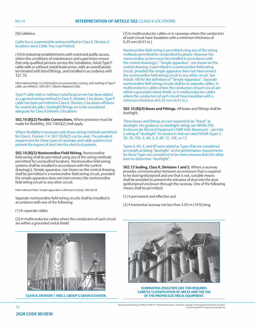
Reproduced with permission of NFPA from NFPA 70®, National Electrical Code®, 2020 edition. Copyright © 2019, National Fire Protection Association. For a full copy of NFPA 70, please go to www.nfpa.org.
INTERPRETATION OF ARTICLE 502: CLASS II LOCATIONS
70
2020 CODE REVIEW
(9) Cablebus.
Cable bus is a permissible wiring method in Class II, Division 2 locations since Cable Tray is permitted.
(10) In industrial establishments with restricted public access, where the conditions of maintenance and supervision ensure that only qualified persons service the installation, listed Type P cable with or without metal braid armor, with an overall jacket, terminated with listed fittings, and installed in accordance with 337.10.
Informational Note: For information on construction, testing, and marking of Type P cable, see ANSI/UL 1309-2017, Marine Shipboard Cable.
Type P cable with or without metal braid armor has been added as a general wiring method in Class II, Division 2 locations. Type P cable has been permitted in Class II, Division 2 locations offshore for several decades. Dusttight fittings are to be considered adequate for Class II Division 2 locations.
502.10 (B)(2) Flexible Connections. Where provision must be made for flexibility, 502.10(A)(2) shall apply.
Where flexibility is necessary only those wiring methods permitted for Class II, Division 1 in 502.10(A)(2) can be used. The prevalent requirement for these types of raceways and cable systems is to prevent the ingress of dust into the electrical systems.
502.10 (B)(3) Nonincendive Field Wiring. Nonincendive field wiring shall be permitted using any of the wiring methods permitted for unclassified locations. Nonincendive field wiring systems shall be installed in accordance with the control drawing(s). Simple apparatus, not shown on the control drawing, shall be permitted in a nonincendive field wiring circuit, provided the simple apparatus does not interconnect the nonincendive field wiring circuit to any other circuit.
Informational Note: Simple apparatus is defined in Article 100 Part III.
Separate nonincendive field wiring circuits shall be installed in accordance with one of the following:
(1) In separate cables
(2) In multiconductor cables where the conductors of each circuit are within a grounded metal shield
(3) In multiconductor cables or in raceways where the conductors of each circuit have insulation with a minimum thickness of 0.25 mm (0.01 in.)
Nonincendive field wiring is permitted using any of the wiring methods permitted for unclassified locations. However the nonincendive system must be installed in accordance with the control drawing(s). “Simple apparatus”, not shown on the control drawing, is permitted in a nonincendive field wiring circuit, provided the simple apparatus does not interconnect the nonincendive field wiring circuit to any other circuit. See Article 100 for the definition of “Simple Apparatus”. Separate nonincendive field wiring circuits shall be in separate cables, in multiconductor cables where the conductors of each circuit are within a grounded metal shield, or in multiconductor cables where the conductors of each circuit have insulation with a minimum thickness of 0.25 mm (0.01 in.).
502.10 (B)(4) Boxes and Fittings. All boxes and fittings shall be dusttight.
These boxes and fittings are not required to be “listed” as dusttight. For guidance on dusttight ratings see NEMA 250, Enclosures for Electrical Equipment (1000 Volts Maximum) – permits a rating of “dusttight” for products that are rated NEMA Types 3, 3X, 3S, 3SX, 4, 4X, 5, 6, 6P, 12, 12K, or 13.
Types 4, 4X, 6, and 6P were added as Types that are considered to comply as being “dusttight” as the performance requirements for these Types are considered to be more onerous than the other tests to determine “dusttight”.
502.15 Sealing, Class II, Divisions 1 and 2. Where a raceway provides communication between an enclosure that is required to be dust-ignitionproof and one that is not, suitable means shall be provided to prevent the entrance of dust into the dust-ignitionproof enclosure through the raceway. One of the following means shall be permitted:
(1) A permanent and effective seal
(2) A horizontal raceway not less than 3.05 m (10 ft) long
CLASS II, DIVISION 1 AND 2, GROUP G GRAIN ELEVATOR.
ELIMINATING DISASTERS LIKE THIS REQUIRES CAREFUL CLASSIFICATION OF AREAS AND THE USE
OF THE PROPER ELECTRICAL EQUIPMENT.
502.10
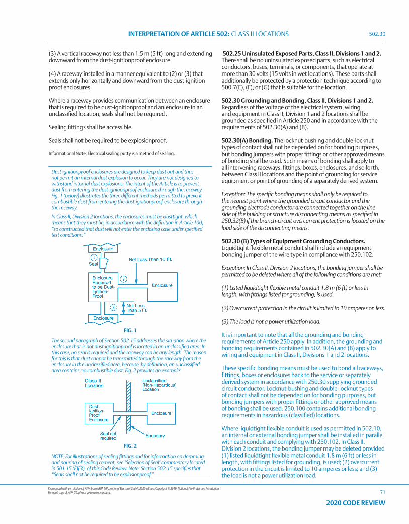
Reproduced with permission of NFPA from NFPA 70®, National Electrical Code®, 2020 edition. Copyright © 2019, National Fire Protection Association. For a full copy of NFPA 70, please go to www.nfpa.org.
INTERPRETATION OF ARTICLE 502: CLASS II LOCATIONS
71
2020 CODE REVIEW
(3) A vertical raceway not less than 1.5 m (5 ft) long and extending downward from the dust-ignitionproof enclosure
(4) A raceway installed in a manner equivalent to (2) or (3) that extends only horizontally and downward from the dust-ignition proof enclosures
Where a raceway provides communication between an enclosure that is required to be dust-ignitionproof and an enclosure in an unclassified location, seals shall not be required.
Sealing fittings shall be accessible.
Seals shall not be required to be explosionproof.
Informational Note: Electrical sealing putty is a method of sealing.
502.25 Uninsulated Exposed Parts, Class II, Divisions 1 and 2. There shall be no uninsulated exposed parts, such as electrical conductors, buses, terminals, or components, that operate at more than 30 volts (15 volts in wet locations). These parts shall additionally be protected by a protection technique according to 500.7(E), (F), or (G) that is suitable for the location.
502.30 Grounding and Bonding, Class II, Divisions 1 and 2. Regardless of the voltage of the electrical system, wiring and equipment in Class II, Division 1 and 2 locations shall be grounded as specified in Article 250 and in accordance with the requirements of 502.30(A) and (B).
502.30(A) Bonding. The locknut-bushing and double-locknut types of contact shall not be depended on for bonding purposes, but bonding jumpers with proper fittings or other approved means of bonding shall be used. Such means of bonding shall apply to all intervening raceways, fittings, boxes, enclosures, and so forth, between Class II locations and the point of grounding for service equipment or point of grounding of a separately derived system.
Exception: The specific bonding means shall only be required to the nearest point where the grounded circuit conductor and the grounding electrode conductor are connected together on the line side of the building or structure disconnecting means as specified in 250.32(B) if the branch-circuit overcurrent protection is located on the load side of the disconnecting means.
502.30 (B) Types of Equipment Grounding Conductors. Liquidtight flexible metal conduit shall include an equipment bonding jumper of the wire type in compliance with 250.102.
Exception: In Class II, Division 2 locations, the bonding jumper shall be permitted to be deleted where all of the following conditions are met:
(1) Listed liquidtight flexible metal conduit 1.8 m (6 ft) or less in length, with fittings listed for grounding, is used.
(2) Overcurrent protection in the circuit is limited to 10 amperes or less.
(3) The load is not a power utilization load.
It is important to note that all the grounding and bonding requirements of Article 250 apply. In addition, the grounding and bonding requirements contained in 502.30(A) and (B) apply to wiring and equipment in Class II, Divisions 1 and 2 locations.
These specific bonding means must be used to bond all raceways, fittings, boxes or enclosures back to the service or separately derived system in accordance with 250.30 supplying grounded circuit conductor. Locknut-bushing and double-locknut types of contact shall not be depended on for bonding purposes, but bonding jumpers with proper fittings or other approved means of bonding shall be used. 250.100 contains additional bonding requirements in hazardous (classified) locations.
Where liquidtight flexible conduit is used as permitted in 502.10, an internal or external bonding jumper shall be installed in parallel with each conduit and complying with 250.102. In Class II, Division 2 locations, the bonding jumper may be deleted provided (1) listed liquidtight flexible metal conduit 1.8 m (6 ft) or less in length, with fittings listed for grounding, is used; (2) overcurrent protection in the circuit is limited to 10 amperes or less; and (3) the load is not a power utilization load.
Dust-ignitionproof enclosures are designed to keep dust out and thus not permit an internal dust explosion to occur. They are not designed to withstand internal dust explosions. The intent of the Article is to prevent dust from entering the dust-ignitionproof enclosure through the raceway. Fig. 1 (below) illustrates the three different methods permitted to prevent combustible dust from entering the dust-ignitionproof enclosure through the raceway.
In Class II, Division 2 locations, the enclosures must be dusttight, which means that they must be, in accordance with the definition in Article 100, “so constructed that dust will not enter the enclosing case under specified test conditions.”
FIG. 1
The second paragraph of Section 502.15 addresses the situation where the enclosure that is not dust-ignitionproof is located in an unclassified area. In this case, no seal is required and the raceway can be any length. The reason for this is that dust cannot be transmitted through the raceway from the enclosure in the unclassified area, because, by definition, an unclassified area contains no combustible dust. Fig. 2 provides an example:
FIG. 2
NOTE: For illustrations of sealing fittings and for information on damming and pouring of sealing cement, see "Selection of Seal" commentary located in 501.15 (E)(3). of this Code Review. Note: Section 502.15 specifies that “Seals shall not be required to be explosionproof.”
502.30
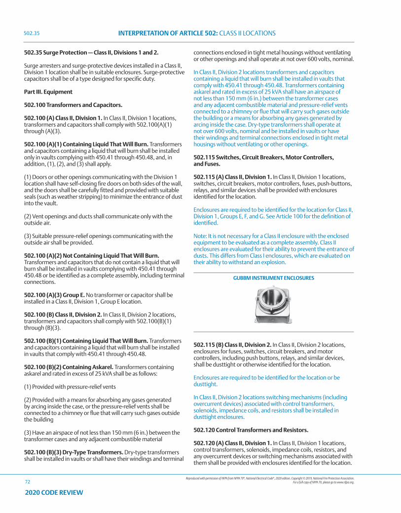
Reproduced with permission of NFPA from NFPA 70®, National Electrical Code®, 2020 edition. Copyright © 2019, National Fire Protection Association. For a full copy of NFPA 70, please go to www.nfpa.org.
INTERPRETATION OF ARTICLE 502: CLASS II LOCATIONS
72
2020 CODE REVIEW
502.35 Surge Protection — Class II, Divisions 1 and 2.
Surge arresters and surge-protective devices installed in a Class II, Division 1 location shall be in suitable enclosures. Surge-protective capacitors shall be of a type designed for specific duty.
Part III. Equipment
502.100 Transformers and Capacitors.
502.100 (A) Class II, Division 1. In Class II, Division 1 locations, transformers and capacitors shall comply with 502.100(A)(1) through (A)(3).
502.100 (A)(1) Containing Liquid That Will Burn. Transformers and capacitors containing a liquid that will burn shall be installed only in vaults complying with 450.41 through 450.48, and, in addition, (1), (2), and (3) shall apply.
(1) Doors or other openings communicating with the Division 1 location shall have self-closing fire doors on both sides of the wall, and the doors shall be carefully fitted and provided with suitable seals (such as weather stripping) to minimize the entrance of dust into the vault.
(2) Vent openings and ducts shall communicate only with the outside air.
(3) Suitable pressure-relief openings communicating with the outside air shall be provided.
502.100 (A)(2) Not Containing Liquid That Will Burn. Transformers and capacitors that do not contain a liquid that will burn shall be installed in vaults complying with 450.41 through 450.48 or be identified as a complete assembly, including terminal connections.
502.100 (A)(3) Group E. No transformer or capacitor shall be installed in a Class II, Division 1, Group E location.
502.100 (B) Class II, Division 2. In Class II, Division 2 locations, transformers and capacitors shall comply with 502.100(B)(1) through (B)(3).
502.100 (B)(1) Containing Liquid That Will Burn. Transformers and capacitors containing a liquid that will burn shall be installed in vaults that comply with 450.41 through 450.48.
502.100 (B)(2) Containing Askarel. Transformers containing askarel and rated in excess of 25 kVA shall be as follows:
(1) Provided with pressure-relief vents
(2) Provided with a means for absorbing any gases generated by arcing inside the case, or the pressure-relief vents shall be connected to a chimney or flue that will carry such gases outside the building
(3) Have an airspace of not less than 150 mm (6 in.) between the transformer cases and any adjacent combustible material
502.100 (B)(3) Dry-Type Transformers. Dry-type transformers shall be installed in vaults or shall have their windings and terminal
connections enclosed in tight metal housings without ventilating or other openings and shall operate at not over 600 volts, nominal.
In Class II, Division 2 locations transformers and capacitors containing a liquid that will burn shall be installed in vaults that comply with 450.41 through 450.48. Transformers containing askarel and rated in excess of 25 kVA shall have an airspace of not less than 150 mm (6 in.) between the transformer cases and any adjacent combustible material and pressure-relief vents connected to a chimney or flue that will carry such gases outside the building or a means for absorbing any gases generated by arcing inside the case. Dry-type transformers shall operate at not over 600 volts, nominal and be installed in vaults or have their windings and terminal connections enclosed in tight metal housings without ventilating or other openings.
502.115 Switches, Circuit Breakers, Motor Controllers, and Fuses.
502.115 (A) Class II, Division 1. In Class II, Division 1 locations, switches, circuit breakers, motor controllers, fuses, push-buttons, relays, and similar devices shall be provided with enclosures identified for the location.
Enclosures are required to be identified for the location for Class II, Division 1, Groups E, F, and G. See Article 100 for the definition of identified.
Note: It is not necessary for a Class II enclosure with the enclosed equipment to be evaluated as a complete assembly. Class II enclosures are evaluated for their ability to prevent the entrance of dusts. This differs from Class I enclosures, which are evaluated on their ability to withstand an explosion.
GUBBM INSTRUMENT ENCLOSURES
502.115 (B) Class II, Division 2. In Class II, Division 2 locations, enclosures for fuses, switches, circuit breakers, and motor controllers, including push buttons, relays, and similar devices, shall be dusttight or otherwise identified for the location.
Enclosures are required to be identified for the location or be dusttight.
In Class II, Division 2 locations switching mechanisms (including overcurrent devices) associated with control transformers, solenoids, impedance coils, and resistors shall be installed in dusttight enclosures.
502.120 Control Transformers and Resistors.
502.120 (A) Class II, Division 1. In Class II, Division 1 locations, control transformers, solenoids, impedance coils, resistors, and any overcurrent devices or switching mechanisms associated with them shall be provided with enclosures identified for the location.
502.35
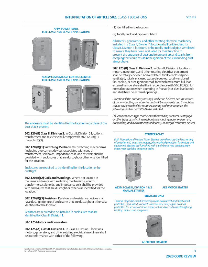
Reproduced with permission of NFPA from NFPA 70®, National Electrical Code®, 2020 edition. Copyright © 2019, National Fire Protection Association. For a full copy of NFPA 70, please go to www.nfpa.org.
INTERPRETATION OF ARTICLE 502: CLASS II LOCATIONS
73
2020 CODE REVIEW
STARTERS ONLY
Both Magnetic and Manual Motor Starters provide across-the-line starting of polyphase AC induction motors, plus overload protection for motors and equipment. Starters are furnished with 3-pole block type overload relay; other types available on special order.
AEXMS CLASS I, DIVISION 1 & 2 MANUAL STARTER
AEB MOTOR STARTER
BREAKERS ONLY
Thermal magnetic circuit breakers provide overcurrent and short circuit protection, plus safe disconnect. Thermal time delay offers overload protection for service entrance, feeder, or branch circuits used for lighting, heating, motors and equipment.
AE CIRCUIT BREAKER
The enclosure must be identified for the location regardless of the dust that is present.
502.120 (B) Class II, Division 2. In Class II, Division 2 locations, transformers and resistors shall comply with 502.120(B)(1) through (B)(3).
502.120 (B)(1) Switching Mechanisms. Switching mechanisms (including overcurrent devices) associated with control transformers, solenoids, impedance coils, and resistors shall be provided with enclosures that are dusttight or otherwise identified for the location.
Enclosures are required to be identified for the location or be dusttight.
502.120 (B)(2) Coils and Windings. Where not located in the same enclosure with switching mechanisms, control transformers, solenoids, and impedance coils shall be provided with enclosures that are dusttight or otherwise identified for the location.
502.120 (B)(3) Resistors. Resistors and resistance devices shall have dust-ignitionproof enclosures that are dusttight or otherwise identified for the location.
Resistors are required to be installed in enclosures that are identified for Class II, Division 1.
502.125 Motors and Generators.
502.125 (A) Class II, Division 1. In Class II, Division 1 locations, motors, generators, and other rotating electrical machinery shall be in conformance with either of the following:
(1) Identified for the location
(2) Totally enclosed pipe-ventilated
All motors, generators, and other rotating electrical machinery installed in a Class II, Division 1 location shall be identified for Class II, Division 1 locations, or be totally enclosed pipe-ventilated to ensure they have been evaluated for their function to prevent the entrance of dust and to prevent arc and sparks from escaping that could result in the ignition of the surrounding dust atmosphere.
502.125 (B) Class II, Division 2. In Class II, Division 2 locations, motors, generators, and other rotating electrical equipment shall be totally enclosed nonventilated, totally enclosed pipe-ventilated, totally enclosed water-air-cooled, totally enclosed fan-cooled, or dust-ignitionproof, for which maximum full-load external temperature shall be in accordance with 500.8(D)(2) for normal operation when operating in free air (not dust blanketed) and shall have no external openings.
Exception: If the authority having jurisdiction believes accumulations of nonconductive, nonabrasive dust will be moderate and if machines can be easily reached for routine cleaning and maintenance, the following shall be permitted to be installed:
(1) Standard open-type machines without sliding contacts, centrifugal or other types of switching mechanism (including motor overcurrent, overloading, and overtemperature devices), or integral resistance devices
APPN POWER PANEL FOR CLASS I AND CLASS II APPLICATIONS
ACSEW CUSTOM CAST CONTROL CENTER FOR CLASS I AND CLASS II APPLICATIONS
502.125
Reproduced with permission of NFPA from NFPA 70®, National Electrical Code®, 2020 edition. Copyright © 2019, National Fire Protection Association. For a full copy of NFPA 70, please go to www.nfpa.org.
INTERPRETATION OF ARTICLE 502: CLASS II LOCATIONS
74
2020 CODE REVIEW
(2) Standard open-type machines with such contacts, switching mechanisms, or resistance devices enclosed within dusttight housings without ventilating or other openings
(3) Self-cleaning textile motors of the squirrel-cage type
(4) Machines with sealed bearings, bearing isolators, and seals
All motors, generators, and other rotating electrical machinery installed in a Class II, Division 2 location must be totally enclosed nonventilated, totally enclosed, pipe-ventilated, totally enclosed water-air-cooled, totally enclosed fan-cooled or dust-ignitionproof with no external openings. If the authority having jurisdiction (AHJ) believes accumulations of nonconductive, nonabrasive dust will be moderate and if machines can be easily reached for routine cleaning and maintenance the AHJ may permit standard open-type machines without sliding contacts, centrifugal or other types of switching mechanism (including motor overcurrent, overloading, and overtemperature devices), or integral resistance devices or standard open type machines with such contacts, switching mechanisms, or resistance devices enclosed within dusttight housing ventilation or other openings or self-cleaning textile motors of the squirrel-cage type.
Motors that employ sealed bearings, bearing isolators, and seals in a Class II, Division 2 should not be considered as having unused external openings.
502.128 Ventilating Piping. Ventilating pipes for motors, generators, or other rotating electrical machinery, or for enclosures for electrical equipment, shall be of metal not less than 0.53 mm (0.021 in.) in thickness or of equally substantial noncombustible material and shall comply with all of the following:
(1) Lead directly to a source of clean air outside of buildings
(2) Be screened at the outer ends to prevent the entrance of small animals or birds
(3) Be protected against physical damage and against rusting or other corrosive influences
Ventilating pipes shall also comply with 502.128(A) and (B).
502.128 (A) Class II, Division 1. In Class II, Division 1 locations, ventilating pipes, including their connections to motors or to the dust-ignitionproof enclosures for other equipment, shall be dusttight throughout their length. For metal pipes, seams and joints shall comply with one of the following:
(1) Be riveted and soldered
(2) Be bolted and soldered
(3) Be welded
(4) Be rendered dusttight by some other equally effective means
502.128 (B) Class II, Division 2. In Class II, Division 2 locations, ventilating pipes and their connections shall be sufficiently tight to prevent the entrance of appreciable quantities of dust into the ventilated equipment or enclosure and to prevent the escape of sparks, flame, or burning material that might ignite dust
accumulations or combustible material in the vicinity. For metal pipes, lock seams and riveted or welded joints shall be permitted; and tight-fitting slip joints shall be permitted where some flexibility is necessary, as at connections to motors.
All ventilating piping from electrical equipment such as enclosures, motors and generators are required to be manufactured from 0.021 metal (0.53 mm) or equal. The piping must comply with 502.128(A) for Class II, Division 1 and 501.128(B) for Class II, Division 2.
502.130 Luminaires.
502.130 (A) Class II, Division 1. In Class II, Division 1 locations, luminaires for fixed and portable lighting shall comply with 502.130(A)(1) through (A)(4).
502.130 (A)(1) Marking. Each luminaire shall be identified for the location and shall be clearly marked to indicate the type and maximum wattage of the lamp for which it is designed.
For HID luminaires the Code requires that the maximum wattage of the lamp required to be marked on the luminaire. There are several other marking requirements for listed luminaires. See the ANSI listing standard ANSI/UL 844, Standard for Luminaires for Use in Hazardous (Classified) Locations for the additional marking requirements.
The listing standard, UL 844 only requires the lamp type and maximum wattage markings for incandescent or HID luminaires.
502.130 (A)(2) Physical Damage. Each luminaire shall be protected against physical damage by a suitable guard or by location.
502.130 (A)(3) Pendant Luminaires. Pendant luminaires shall be suspended by threaded rigid metal conduit stems, by threaded steel intermediate metal conduit stems, by chains with approved fittings, or by other approved means. For rigid stems longer than 300 mm (12 in.), permanent and effective bracing against lateral displacement shall be provided at a level not more than 300 mm (12 in.) above the lower end of the stem, or flexibility in the form of a fitting or a flexible connector listed for the location shall be provided not more than 300 mm (12 in.) from the point of attachment to the supporting box or fitting. Threaded joints shall be provided with set screws or other effective means to prevent loosening. Where wiring between an outlet box or fitting and a pendant luminaire is not enclosed in conduit, flexible cord listed for hard usage shall be permitted to be used in accordance with 502.10(A)(2)(5). Flexible cord shall not serve as the supporting means for a luminaire.
502.130 (A)(4) Supports. Boxes, box assemblies, or fittings used for the support of luminaires shall be identified for Class II locations.
502.130 (B) Class II, Division 2. In Class II, Division 2 locations, luminaires shall comply with 502.130(B)(1) through (B)(5).
502.130 (B)(1) Portable Lighting Equipment. Portable lighting equipment shall be identified for the location. They shall be clearly marked to indicate the maximum wattage of lamps for which they are designed.
502.125
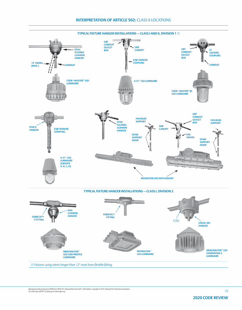
Reproduced with permission of NFPA from NFPA 70®, National Electrical Code®, 2020 edition. Copyright © 2019, National Fire Protection Association. For a full copy of NFPA 70, please go to www.nfpa.org.
INTERPRETATION OF ARTICLE 502: CLASS II LOCATIONS
75
2020 CODE REVIEW
TYPICAL FIXTURE HANGER INSTALLATIONS — CLASS I AND II, DIVISION 1
GRT CONDUIT OUTLET BOX
LC LOCKING COUPLING
CONDUIT
EFHU FLEXIBLE CUSHION HANGER
GRF CONDUIT OUTLET BOX
GRK CANOPY
EXJF HANGER COUPLING
A-51™ LED LUMINAIRECODE•MASTER™ LED
LUMINAIRE
15° SWING (MAX.) CONDUIT
EXJF HANGER COUPLING
RIGMASTER LED WITH MOUNT
GRK CANOPY
GRF CONDUIT OUTLET BOX
ESD SWIVEL
EFHM SUPPORT HOOK
A-51™ LED LUMINAIRE (GROUPS A, B, C, D)
EFHCA HANGER
FHS RIGID SUPPORT
FHS RIGID SUPPORT
EFHM SUPPORT HOOK
EFHU FLEXIBLE CUSHION HANGER
CODE•MASTER™ JR. LED LUMINAIRE
TYPICAL FIXTURE HANGER INSTALLATIONS — CLASS I, DIVISION 2
AHG CUSHION HANGER
FORM 85 T FITTING
GSK50-20C HANGER
MERCMASTER™ LED GENERATION 3 LUMINAIRE
FORM 35™ T FITTING
BAYMASTER™ LED LUMINAIRE
MERCMASTER™ LED LOW PROFILE LUMINAIRE
GSU
Fixtures using stems longer than 12" must have flexible fitting.
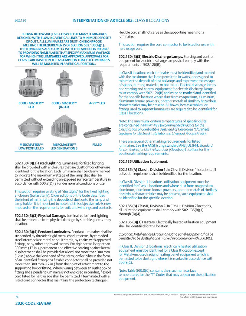
Reproduced with permission of NFPA from NFPA 70®, National Electrical Code®, 2020 edition. Copyright © 2019, National Fire Protection Association. For a full copy of NFPA 70, please go to www.nfpa.org.
INTERPRETATION OF ARTICLE 502: CLASS II LOCATIONS
76
2020 CODE REVIEW
SHOWN BELOW ARE JUST A FEW OF THE MANY LUMINAIRES DESIGNED WITH FLOWING VERTICAL LINES TO MINIMIZE DEPOSITS
OF DUST. ALL LUMINAIRES ARE DUST-IGNITIONPROOF, MEETING THE REQUIREMENTS OF SECTION 502.130(A)(1).
THE LUMINAIRES ALSO COMPLY WITH THIS ARTICLE IN REGARD TO PROVIDING NAMEPLATES THAT SPECIFY MAXIMUM WATTAGE
FOR WHICH THE LUMINAIRES ARE APPROVED. APPROVALS FOR CLASS II ARE BASED ON THE ASSUMPTION THAT THE LUMINAIRES
WILL BE MOUNTED IN A VERTICAL POSITION..
CODE•MASTER™ LED
CODE•MASTER™ JR. LED
A-51™ LED
MERCMASTER™ LOW PROFILE LED
MERCMASTER™ LED GENERATION 3
FNLED
502.130 (B)(2) Fixed Lighting. Luminaires for fixed lighting shall be provided with enclosures that are dusttight or otherwise identified for the location. Each luminaire shall be clearly marked to indicate the maximum wattage of the lamp that shall be permitted without exceeding an exposed surface temperature in accordance with 500.8(D)(2) under normal conditions of use.
This section requires a rating of “dusttight” for the fixed lighting enclosure (ballast tank). Older editions of the Code described the intent of minimizing the deposits of dust onto the lamp and lamp holder. It is important to note that this objective rule is now imposed on the requirements for coils and windings and contacts.
502.130 (B)(3) Physical Damage. Luminaires for fixed lighting shall be protected from physical damage by suitable guards or by location.
502.130 (B)(4) Pendant Luminaires. Pendant luminaires shall be suspended by threaded rigid metal conduit stems, by threaded steel intermediate metal conduit stems, by chains with approved fittings, or by other approved means. For rigid stems longer than 300 mm (12 in.), permanent and effective bracing against lateral displacement shall be provided at a level not more than 300 mm (12 in.) above the lower end of the stem, or flexibility in the form of an identified fitting or a flexible connector shall be provided not more than 300 mm (12 in.) from the point of attachment to the supporting box or fitting. Where wiring between an outlet box or fitting and a pendant luminaire is not enclosed in conduit, flexible cord listed for hard usage shall be permitted if terminated with a listed cord connector that maintains the protection technique.
Flexible cord shall not serve as the supporting means for a luminaire.
This section requires the cord connector to be listed for use with hard usage cord.
502.130 (B)(5) Electric-Discharge Lamps. Starting and control equipment for electric-discharge lamps shall comply with the requirements of 502.120(B).
In Class II locations each luminaire must be identified and marked with the maximum size lamp permitted in watts, or designed to minimize the deposit of dust on lamps and to prevent the escape of sparks, burning material, or hot metal. Electric-discharge lamps and starting and control equipment for electric-discharge lamps must comply with 502.120(B) and must be marked and identified for the specific location where dust from magnesium, aluminum, aluminum bronze powders, or other metals of similarly hazardous characteristics may be present. All boxes, box assemblies, or fittings used to support luminaires are required to be identified for Class II locations.
Note: The minimum ignition temperatures of specific dusts are contained in NFPA® 499 (Recommended Practice for the Classification of Combustible Dusts and of Hazardous (Classified) Locations for Electrical Installations in Chemical Process Areas).
There are several other marking requirements for listed luminaires. See the ANSI listing standard ANSI/UL 844, Standard for Luminaires for Use in Hazardous (Classified) Locations for the additional marking requirements.
502.135 Utilization Equipment.
502.135 (A) Class II, Division 1. In Class II, Division 1 locations, all utilization equipment shall be identified for the location.
In Class II, Division 1 locations, utilization equipment must be identified for Class II locations and where dust from magnesium, aluminum, aluminum bronze powders, or other metals of similarly hazardous characteristics may be present, such equipment shall be identified for the specific location.
502.135 (B) Class II, Division 2. In Class II, Division 2 locations, all utilization equipment shall comply with 502.135(B)(1) through (B)(4).
502.135 (B)(1) Heaters. Electrically heated utilization equipment shall be identified for the location.
Exception: Metal-enclosed radiant heating panel equipment shall be permitted to be dusttight and marked in accordance with 500.8(C).
In Class II, Division 2 locations, electrically heated utilization equipment must be identified for a Class II location except for Metal-enclosed radiant heating panel equipment which is permitted to be dusttight where it is marked in accordance with 500.8(C).
Note: Table 500.8(C) contains the maximum surface temperatures for the “T” Codes that may appear on the utilization equipment.
502.130
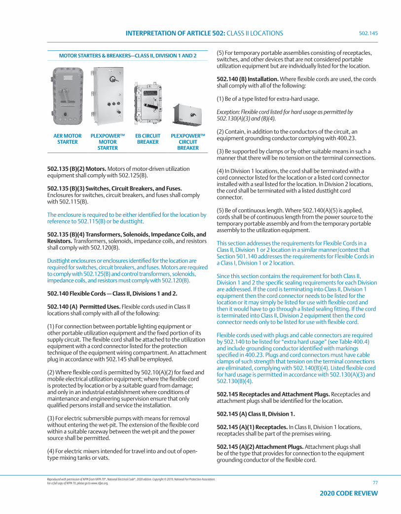
Reproduced with permission of NFPA from NFPA 70®, National Electrical Code®, 2020 edition. Copyright © 2019, National Fire Protection Association. For a full copy of NFPA 70, please go to www.nfpa.org.
INTERPRETATION OF ARTICLE 502: CLASS II LOCATIONS
77
2020 CODE REVIEW
MOTOR STARTERS & BREAKERS—CLASS II, DIVISION 1 AND 2
AER MOTOR STARTER
PLEXPOWER™ MOTOR
STARTER
EB CIRCUIT BREAKER
PLEXPOWER™ CIRCUIT
BREAKER
502.135 (B)(2) Motors. Motors of motor-driven utilization equipment shall comply with 502.125(B).
502.135 (B)(3) Switches, Circuit Breakers, and Fuses. Enclosures for switches, circuit breakers, and fuses shall comply with 502.115(B).
The enclosure is required to be either identified for the location by reference to 502.115(B) or be dusttight.
502.135 (B)(4) Transformers, Solenoids, Impedance Coils, and Resistors. Transformers, solenoids, impedance coils, and resistors shall comply with 502.120(B).
Dusttight enclosures or enclosures identified for the location are required for switches, circuit breakers, and fuses. Motors are required to comply with 502.125(B) and control transformers, solenoids, impedance coils, and resistors must comply with 502.120(B).
502.140 Flexible Cords — Class II, Divisions 1 and 2.
502.140 (A) Permitted Uses. Flexible cords used in Class II locations shall comply with all of the following:
(1) For connection between portable lighting equipment or other portable utilization equipment and the fixed portion of its supply circuit. The flexible cord shall be attached to the utilization equipment with a cord connector listed for the protection technique of the equipment wiring compartment. An attachment plug in accordance with 502.145 shall be employed.
(2) Where flexible cord is permitted by 502.10(A)(2) for fixed and mobile electrical utilization equipment; where the flexible cord is protected by location or by a suitable guard from damage; and only in an industrial establishment where conditions of maintenance and engineering supervision ensure that only qualified persons install and service the installation.
(3) For electric submersible pumps with means for removal without entering the wet-pit. The extension of the flexible cord within a suitable raceway between the wet-pit and the power source shall be permitted.
(4) For electric mixers intended for travel into and out of open-type mixing tanks or vats.
(5) For temporary portable assemblies consisting of receptacles, switches, and other devices that are not considered portable utilization equipment but are individually listed for the location.
502.140 (B) Installation. Where flexible cords are used, the cords shall comply with all of the following:
(1) Be of a type listed for extra-hard usage.
Exception: Flexible cord listed for hard usage as permitted by 502.130(A)(3) and (B)(4).
(2) Contain, in addition to the conductors of the circuit, an equipment grounding conductor complying with 400.23.
(3) Be supported by clamps or by other suitable means in such a manner that there will be no tension on the terminal connections.
(4) In Division 1 locations, the cord shall be terminated with a cord connector listed for the location or a listed cord connector installed with a seal listed for the location. In Division 2 locations, the cord shall be terminated with a listed dusttight cord connector.
(5) Be of continuous length. Where 502.140(A)(5) is applied, cords shall be of continuous length from the power source to the temporary portable assembly and from the temporary portable assembly to the utilization equipment.
This section addresses the requirements for Flexible Cords in a Class II, Division 1 or 2 location in a similar manner/context that Section 501.140 addresses the requirements for Flexible Cords in a Class I, Division 1 or 2 location.
Since this section contains the requirement for both Class II, Division 1 and 2 the specific sealing requirements for each Division are addressed. If the cord is terminating into Class II, Division 1 equipment then the cord connector needs to be listed for the location or it may simply be listed for use with flexible cord and then it would have to go through a listed sealing fitting. If the cord is terminated into Class II, Division 2 equipment then the cord connector needs only to be listed for use with flexible cord.
Flexible cords used with plugs and cable connectors are required by 502.140 to be listed for “extra hard usage” (see Table 400.4) and include grounding conductor identified with markings specified in 400.23. Plugs and cord connectors must have cable clamps of such strength that tension on the terminal connections are eliminated, complying with 502.140(B)(4). Listed flexible cord for hard usage is permitted in accordance with 502.130(A)(3) and 502.130(B)(4).
502.145 Receptacles and Attachment Plugs. Receptacles and attachment plugs shall be identified for the location.
502.145 (A) Class II, Division 1.
502.145 (A)(1) Receptacles. In Class II, Division 1 locations, receptacles shall be part of the premises wiring.
502.145 (A)(2) Attachment Plugs. Attachment plugs shall be of the type that provides for connection to the equipment grounding conductor of the flexible cord.
502.145
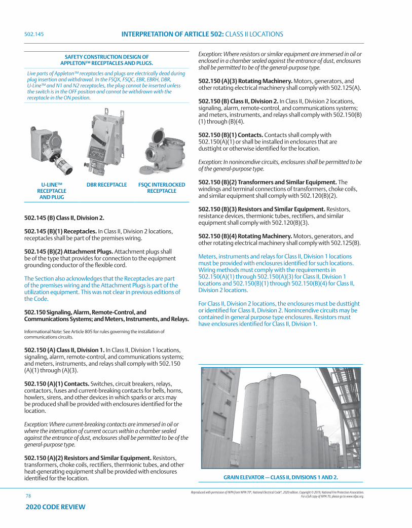
Reproduced with permission of NFPA from NFPA 70®, National Electrical Code®, 2020 edition. Copyright © 2019, National Fire Protection Association. For a full copy of NFPA 70, please go to www.nfpa.org.
INTERPRETATION OF ARTICLE 502: CLASS II LOCATIONS
78
2020 CODE REVIEW
SAFETY CONSTRUCTION DESIGN OF APPLETON™ RECEPTACLES AND PLUGS.
Live parts of Appleton™ receptacles and plugs are electrically dead during plug insertion and withdrawal. In the FSQX, FSQC, EBR, EBRH, DBR, U-Line™ and N1 and N2 receptacles, the plug cannot be inserted unless the switch is in the OFF position and cannot be withdrawn with the receptacle in the ON position.
U-LINE™ RECEPTACLE
AND PLUG
DBR RECEPTACLE FSQC INTERLOCKED RECEPTACLE
GRAIN ELEVATOR — CLASS II, DIVISIONS 1 AND 2.
502.145 (B) Class II, Division 2.
502.145 (B)(1) Receptacles. In Class II, Division 2 locations, receptacles shall be part of the premises wiring.
502.145 (B)(2) Attachment Plugs. Attachment plugs shall be of the type that provides for connection to the equipment grounding conductor of the flexible cord.
The Section also acknowledges that the Receptacles are part of the premises wiring and the Attachment Plugs is part of the utilization equipment. This was not clear in previous editions of the Code.
502.150 Signaling, Alarm, Remote-Control, and Communications Systems; and Meters, Instruments, and Relays.
Informational Note: See Article 805 for rules governing the installation of communications circuits.
502.150 (A) Class II, Division 1. In Class II, Division 1 locations, signaling, alarm, remote-control, and communications systems; and meters, instruments, and relays shall comply with 502.150 (A)(1) through (A)(3).
502.150 (A)(1) Contacts. Switches, circuit breakers, relays, contactors, fuses and current-breaking contacts for bells, horns, howlers, sirens, and other devices in which sparks or arcs may be produced shall be provided with enclosures identified for the location.
Exception: Where current-breaking contacts are immersed in oil or where the interruption of current occurs within a chamber sealed against the entrance of dust, enclosures shall be permitted to be of the general-purpose type.
502.150 (A)(2) Resistors and Similar Equipment. Resistors, transformers, choke coils, rectifiers, thermionic tubes, and other heat-generating equipment shall be provided with enclosures identified for the location.
Exception: Where resistors or similar equipment are immersed in oil or enclosed in a chamber sealed against the entrance of dust, enclosures shall be permitted to be of the general-purpose type.
502.150 (A)(3) Rotating Machinery. Motors, generators, and other rotating electrical machinery shall comply with 502.125(A).
502.150 (B) Class II, Division 2. In Class II, Division 2 locations, signaling, alarm, remote-control, and communications systems; and meters, instruments, and relays shall comply with 502.150(B)(1) through (B)(4).
502.150 (B)(1) Contacts. Contacts shall comply with 502.150(A)(1) or shall be installed in enclosures that are dusttight or otherwise identified for the location.
Exception: In nonincendive circuits, enclosures shall be permitted to be of the general-purpose type.
502.150 (B)(2) Transformers and Similar Equipment. The windings and terminal connections of transformers, choke coils, and similar equipment shall comply with 502.120(B)(2).
502.150 (B)(3) Resistors and Similar Equipment. Resistors, resistance devices, thermionic tubes, rectifiers, and similar equipment shall comply with 502.120(B)(3).
502.150 (B)(4) Rotating Machinery. Motors, generators, and other rotating electrical machinery shall comply with 502.125(B).
Meters, instruments and relays for Class II, Division 1 locations must be provided with enclosures identified for such locations. Wiring methods must comply with the requirements in 502.150(A)(1) through 502.150(A)(3) for Class II, Division 1 locations and 502.150(B)(1) through 502.150(B)(4) for Class II, Division 2 locations.
For Class II, Division 2 locations, the enclosures must be dusttight or identified for Class II, Division 2. Nonincendive circuits may be contained in general purpose type enclosures. Resistors must have enclosures identified for Class II, Division 1.
502.145
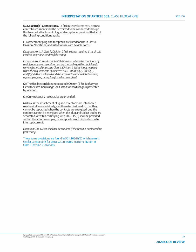
Reproduced with permission of NFPA from NFPA 70®, National Electrical Code®, 2020 edition. Copyright © 2019, National Fire Protection Association. For a full copy of NFPA 70, please go to www.nfpa.org.
INTERPRETATION OF ARTICLE 502: CLASS II LOCATIONS
79
2020 CODE REVIEW
502.150 (B)(5) Connections. To facilitate replacements, process control instruments shall be permitted to be connected through flexible cord, attachment plug, and receptacle, provided that all of the following conditions apply:
(1) Attachment plug and receptacle are listed for use in Class II, Division 2 locations, and listed for use with flexible cords.
Exception No. 1: A Class II, Division 2 listing is not required if the circuit involves only nonincendive field wiring.
Exception No. 2: In industrial establishments where the conditions of maintenance and supervision ensure that only qualified individuals service the installation, the Class II, Division 2 listing is not required when the requirements of list items 502.150(B)(5)(2), (B)(5)(3), and (B)(5)(4) are satisfied and the receptacle carries a label warning against plugging or unplugging when energized.
(2) The flexible cord does not exceed 900 mm (3 ft), is of a type listed for extra-hard usage, or if listed for hard usage is protected by location.
(3) Only necessary receptacles are provided.
(4) Unless the attachment plug and receptacle are interlocked mechanically or electrically, or otherwise designed so that they cannot be separated when the contacts are energized, and the contacts cannot be energized when the plug and socket outlet are separated, a switch complying with 502.115(B) shall be provided so that the attachment plug or receptacle is not depended on to interrupt current.
Exception: The switch shall not be required if the circuit is nonincendive field wiring.
These same provisions are found in 501.105(B)(6) which permits similar connections for process connected instrumentation in Class I, Division 2 locations.
502.150

80
2020 CODE REVIEW
NOTES
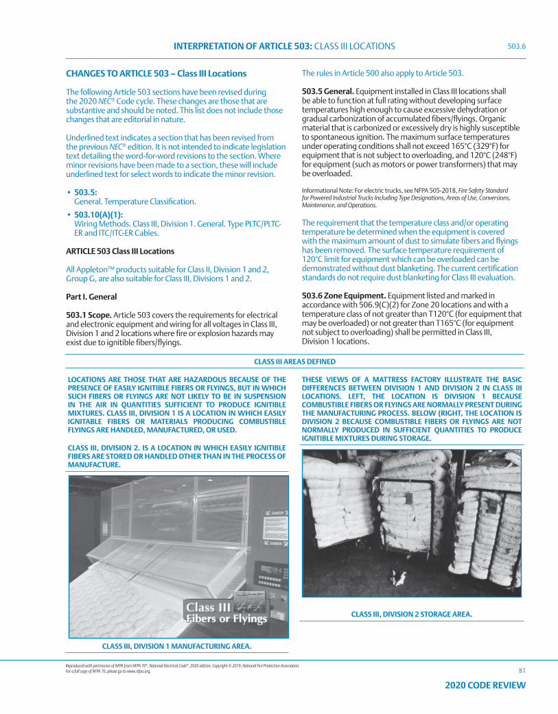
Reproduced with permission of NFPA from NFPA 70®, National Electrical Code®, 2020 edition. Copyright © 2019, National Fire Protection Association. For a full copy of NFPA 70, please go to www.nfpa.org.
INTERPRETATION OF ARTICLE 503: CLASS III LOCATIONS
81
2020 CODE REVIEW
CHANGES TO ARTICLE 503 – Class III Locations
The following Article 503 sections have been revised during the 2020 NEC® Code cycle. These changes are those that are substantive and should be noted. This list does not include those changes that are editorial in nature.
Underlined text indicates a section that has been revised from the previous NEC® edition. It is not intended to indicate legislation text detailing the word-for-word revisions to the section. Where minor revisions have been made to a section, these will include underlined text for select words to indicate the minor revision.
• 503.5: General. Temperature Classification.
• 503.10(A)(1): Wiring Methods. Class III, Division 1. General. Type PLTC/PLTC-
ER and ITC/ITC-ER Cables.
ARTICLE 503 Class III Locations
All Appleton™ products suitable for Class II, Division 1 and 2, Group G, are also suitable for Class III, Divisions 1 and 2.
Part I. General
503.1 Scope. Article 503 covers the requirements for electrical and electronic equipment and wiring for all voltages in Class III, Division 1 and 2 locations where fire or explosion hazards may exist due to ignitible fibers/flyings.
The rules in Article 500 also apply to Article 503.
503.5 General. Equipment installed in Class III locations shall be able to function at full rating without developing surface temperatures high enough to cause excessive dehydration or gradual carbonization of accumulated fibers/flyings. Organic material that is carbonized or excessively dry is highly susceptible to spontaneous ignition. The maximum surface temperatures under operating conditions shall not exceed 165°C (329°F) for equipment that is not subject to overloading, and 120°C (248°F) for equipment (such as motors or power transformers) that may be overloaded.
Informational Note: For electric trucks, see NFPA 505-2018, Fire Safety Standard for Powered Industrial Trucks Including Type Designations, Areas of Use, Conversions, Maintenance, and Operations.
The requirement that the temperature class and/or operating temperature be determined when the equipment is covered with the maximum amount of dust to simulate fibers and flyings has been removed. The surface temperature requirement of 120°C limit for equipment which can be overloaded can be demonstrated without dust blanketing. The current certification standards do not require dust blanketing for Class III evaluation.
503.6 Zone Equipment. Equipment listed and marked in accordance with 506.9(C)(2) for Zone 20 locations and with a temperature class of not greater than T120°C (for equipment that may be overloaded) or not greater than T165°C (for equipment not subject to overloading) shall be permitted in Class III, Division 1 locations.
CLASS III AREAS DEFINED
LOCATIONS ARE THOSE THAT ARE HAZARDOUS BECAUSE OF THE PRESENCE OF EASILY IGNITIBLE FIBERS OR FLYINGS, BUT IN WHICH SUCH FIBERS OR FLYINGS ARE NOT LIKELY TO BE IN SUSPENSION IN THE AIR IN QUANTITIES SUFFICIENT TO PRODUCE IGNITIBLE MIXTURES. CLASS III, DIVISION 1 IS A LOCATION IN WHICH EASILY IGNITABLE FIBERS OR MATERIALS PRODUCING COMBUSTIBLE FLYINGS ARE HANDLED, MANUFACTURED, OR USED.
CLASS III, DIVISION 2. IS A LOCATION IN WHICH EASILY IGNITIBLE FIBERS ARE STORED OR HANDLED OTHER THAN IN THE PROCESS OF MANUFACTURE.
THESE VIEWS OF A MATTRESS FACTORY ILLUSTRATE THE BASIC DIFFERENCES BETWEEN DIVISION 1 AND DIVISION 2 IN CLASS III LOCATIONS. LEFT, THE LOCATION IS DIVISION 1 BECAUSE COMBUSTIBLE FIBERS OR FLYINGS ARE NORMALLY PRESENT DURING THE MANUFACTURING PROCESS. BELOW (RIGHT, THE LOCATION IS DIVISION 2 BECAUSE COMBUSTIBLE FIBERS OR FLYINGS ARE NOT NORMALLY PRODUCED IN SUFFICIENT QUANTITIES TO PRODUCE IGNITIBLE MIXTURES DURING STORAGE.
CLASS III, DIVISION 2 STORAGE AREA.
CLASS III, DIVISION 1 MANUFACTURING AREA.
503.6
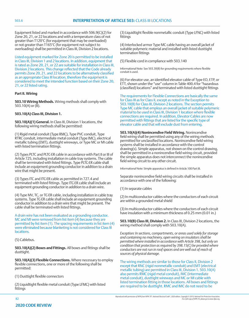
Reproduced with permission of NFPA from NFPA 70®, National Electrical Code®, 2020 edition. Copyright © 2019, National Fire Protection Association. For a full copy of NFPA 70, please go to www.nfpa.org.
INTERPRETATION OF ARTICLE 503: CLASS III LOCATIONS
82
2020 CODE REVIEW
Equipment listed and marked in accordance with 506.9(C)(2) for Zone 20, 21, or 22 locations and with a temperature class of not greater than T120°C (for equipment that may be overloaded) or not greater than T165°C (for equipment not subject to overloading) shall be permitted in Class III, Division 2 locations.
Listed equipment marked for Zone 20 is permitted to be installed in Class III, Division 1 and 2 locations. In addition, equipment that is rated as Zone 20, 21, or 22 are suitable for installation in Class III, Division 2 locations. This change reflected that the Code already permits Zone 20, 21, and 22 locations to be alternatively classified as an appropriate Class III location, therefore the equipment is considered to meet the intended function based on their Zone 20, 21, or 22 listed rating.
Part II. Wiring
503.10 Wiring Methods. Wiring methods shall comply with 503.10(A) or (B).
503.10(A) Class III, Division 1.
503.10(A)(1) General. In Class III, Division 1 locations, the following wiring methods shall be permitted:
(1) Rigid metal conduit (Type RMC), Type PVC conduit, Type RTRC conduit, intermediate metal conduit (Type IMC), electrical metallic tubing (EMT), dusttight wireways, or Type MC or MI cable with listed termination fittings.
(2) Types PLTC and PLTC-ER cable in accordance with Part II or III of Article 725, including installation in cable tray systems. The cable shall be terminated with listed fittings. Type PLTC-ER cable shall include an equipment grounding conductor in addition to a drain wire that might be present.
(3) Types ITC and ITC-ER cable as permitted in 727.4 and terminated with listed fittings. Type ITC-ER cable shall include an equipment grounding conductor in addition to a drain wire.
(4) Type MV, TC, or TC-ER cable, including installation in cable tray systems. Type TC-ER cable shall include an equipment grounding conductor in addition to a drain wire that might be present. The cable shall be terminated with listed fittings.
A drain wire has not been evaluated as a grounding conductor. MC and MI were removed from list item (4) because they are permitted by list item (1). The spacing requirements in list item (4) were eliminated because blanketing is not considered for Class III locations.
(5) Cablebus.
503.10(A)(2) Boxes and Fittings. All boxes and fittings shall be dusttight.
503.10(A)(3) Flexible Connections. Where necessary to employ flexible connections, one or more of the following shall be permitted:
(1) Dusttight flexible connectors
(2) Liquidtight flexible metal conduit (Type LFMC) with listed fittings
(3) Liquidtight flexible nonmetallic conduit (Type LFNC) with listed fittings
(4) Interlocked armor Type MC cable having an overall jacket of suitable polymeric material and installed with listed dusttight termination fittings
(5) Flexible cord in compliance with 503.140
Informational Note: See 503.30(B) for grounding requirements where flexible conduit is used.
(6) For elevator use, an identified elevator cable of Type EO, ETP, or ETT, shown under the “use” column in Table 400.4 for “hazardous (classified) locations” and terminated with listed dusttight fittings
The requirements for Flexible Connections are basically the same for Class III as for Class II, except as noted in the Exception to 503.10(B) for Class III, Division 2 locations. The section permits Type MC cable that employs an overall jacket of suitable polymeric material to be used in Class III, Division 1 location where flexible connections are required. In addition, Elevator Cables are now permitted with fittings that are listed for the specific type of elevator cable and that will exclude dust from entering.
503.10(A)(4) Nonincendive Field Wiring. Nonincendive field wiring shall be permitted using any of the wiring methods permitted for unclassified locations. Nonincendive field wiring systems shall be installed in accordance with the control drawing(s). Simple apparatus, not shown on the control drawing, shall be permitted in a nonincendive field wiring circuit, provided the simple apparatus does not interconnect the nonincendive field wiring circuit to any other circuit.
Informational Note: Simple apparatus is defined in Article 100 Part III.
Separate nonincendive field wiring circuits shall be installed in accordance with one of the following:
(1) In separate cables
(2) In multiconductor cables where the conductors of each circuit are within a grounded metal shield
(3) In multiconductor cables where the conductors of each circuit have insulation with a minimum thickness of 0.25 mm (0.01 in.)
503.10(B) Class III, Division 2. In Class III, Division 2 locations, the wiring method shall comply with 503.10(A).
Exception: In sections, compartments, or areas used solely for storage and containing no machinery, open wiring on insulators shall be permitted where installed in accordance with Article 398, but only on condition that protection as required by 398.15(C) be provided where conductors are not run in roof spaces and are well out of reach of sources of physical damage.
The wiring methods are similar to those for Class II, Division 2 except that RNC (rigid nonmetallic conduit) and EMT (electrical metallic tubing) are permitted in Class III, Division 1. 503.10(A) also permits RMC (rigid metal conduit), IMC (intermediate metal conduit), dusttight wireways and MC or MI cable with listed termination fitting in those locations. All boxes and fittings are required to be dusttight. RMC and IMC do not need to be
503.6
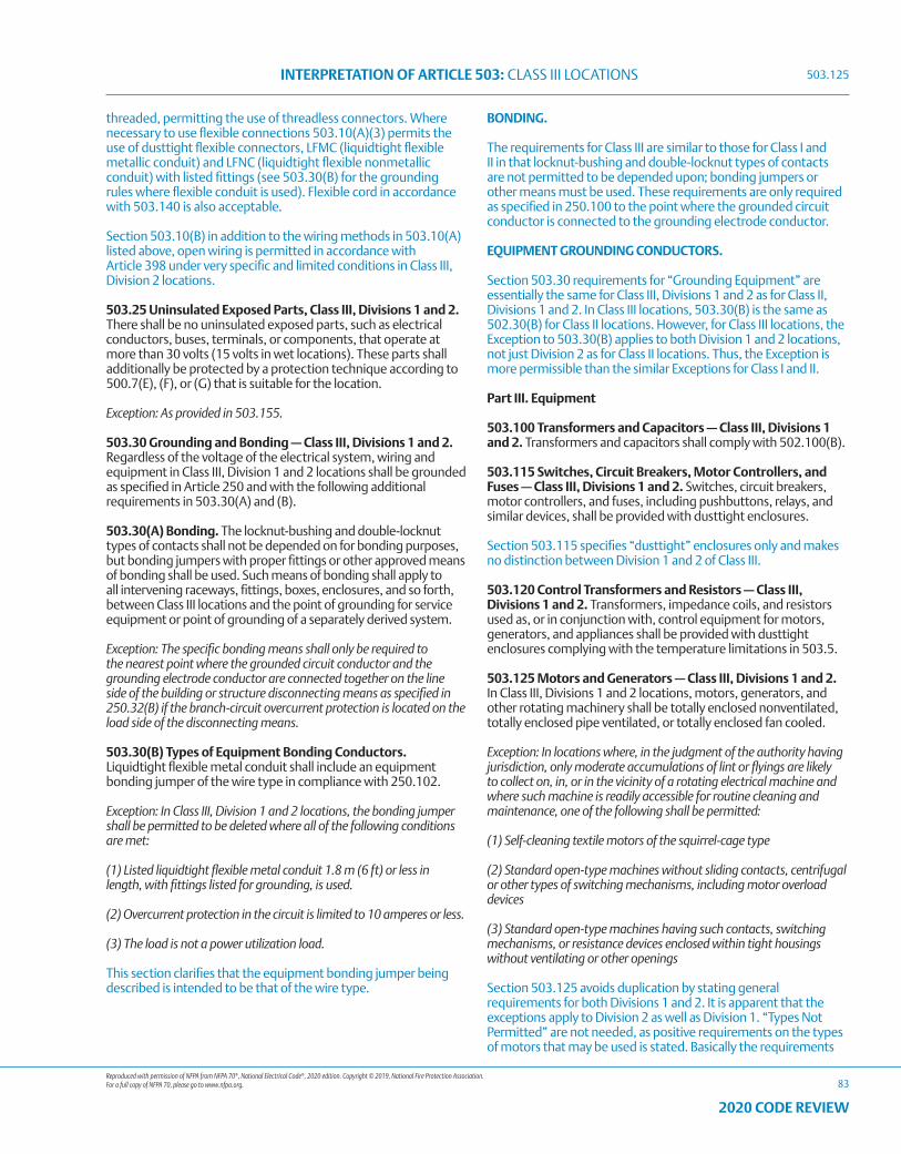
Reproduced with permission of NFPA from NFPA 70®, National Electrical Code®, 2020 edition. Copyright © 2019, National Fire Protection Association. For a full copy of NFPA 70, please go to www.nfpa.org.
INTERPRETATION OF ARTICLE 503: CLASS III LOCATIONS
83
2020 CODE REVIEW
threaded, permitting the use of threadless connectors. Where necessary to use flexible connections 503.10(A)(3) permits the use of dusttight flexible connectors, LFMC (liquidtight flexible metallic conduit) and LFNC (liquidtight flexible nonmetallic conduit) with listed fittings (see 503.30(B) for the grounding rules where flexible conduit is used). Flexible cord in accordance with 503.140 is also acceptable.
Section 503.10(B) in addition to the wiring methods in 503.10(A) listed above, open wiring is permitted in accordance with Article 398 under very specific and limited conditions in Class III, Division 2 locations.
503.25 Uninsulated Exposed Parts, Class III, Divisions 1 and 2. There shall be no uninsulated exposed parts, such as electrical conductors, buses, terminals, or components, that operate at more than 30 volts (15 volts in wet locations). These parts shall additionally be protected by a protection technique according to 500.7(E), (F), or (G) that is suitable for the location.
Exception: As provided in 503.155.
503.30 Grounding and Bonding — Class III, Divisions 1 and 2. Regardless of the voltage of the electrical system, wiring and equipment in Class III, Division 1 and 2 locations shall be grounded as specified in Article 250 and with the following additional requirements in 503.30(A) and (B).
503.30(A) Bonding. The locknut-bushing and double-locknut types of contacts shall not be depended on for bonding purposes, but bonding jumpers with proper fittings or other approved means of bonding shall be used. Such means of bonding shall apply to all intervening raceways, fittings, boxes, enclosures, and so forth, between Class III locations and the point of grounding for service equipment or point of grounding of a separately derived system.
Exception: The specific bonding means shall only be required to the nearest point where the grounded circuit conductor and the grounding electrode conductor are connected together on the line side of the building or structure disconnecting means as specified in 250.32(B) if the branch-circuit overcurrent protection is located on the load side of the disconnecting means.
503.30(B) Types of Equipment Bonding Conductors. Liquidtight flexible metal conduit shall include an equipment bonding jumper of the wire type in compliance with 250.102.
Exception: In Class III, Division 1 and 2 locations, the bonding jumper shall be permitted to be deleted where all of the following conditions are met:
(1) Listed liquidtight flexible metal conduit 1.8 m (6 ft) or less in length, with fittings listed for grounding, is used.
(2) Overcurrent protection in the circuit is limited to 10 amperes or less.
(3) The load is not a power utilization load.
This section clarifies that the equipment bonding jumper being described is intended to be that of the wire type.
BONDING.
The requirements for Class III are similar to those for Class I and II in that locknut-bushing and double-locknut types of contacts are not permitted to be depended upon; bonding jumpers or other means must be used. These requirements are only required as specified in 250.100 to the point where the grounded circuit conductor is connected to the grounding electrode conductor.
EQUIPMENT GROUNDING CONDUCTORS.
Section 503.30 requirements for “Grounding Equipment” are essentially the same for Class III, Divisions 1 and 2 as for Class II, Divisions 1 and 2. In Class III locations, 503.30(B) is the same as 502.30(B) for Class II locations. However, for Class III locations, the Exception to 503.30(B) applies to both Division 1 and 2 locations, not just Division 2 as for Class II locations. Thus, the Exception is more permissible than the similar Exceptions for Class I and II.
Part III. Equipment
503.100 Transformers and Capacitors — Class III, Divisions 1 and 2. Transformers and capacitors shall comply with 502.100(B).
503.115 Switches, Circuit Breakers, Motor Controllers, and Fuses — Class III, Divisions 1 and 2. Switches, circuit breakers, motor controllers, and fuses, including pushbuttons, relays, and similar devices, shall be provided with dusttight enclosures.
Section 503.115 specifies “dusttight” enclosures only and makes no distinction between Division 1 and 2 of Class III.
503.120 Control Transformers and Resistors — Class III, Divisions 1 and 2. Transformers, impedance coils, and resistors used as, or in conjunction with, control equipment for motors, generators, and appliances shall be provided with dusttight enclosures complying with the temperature limitations in 503.5.
503.125 Motors and Generators — Class III, Divisions 1 and 2. In Class III, Divisions 1 and 2 locations, motors, generators, and other rotating machinery shall be totally enclosed nonventilated, totally enclosed pipe ventilated, or totally enclosed fan cooled.
Exception: In locations where, in the judgment of the authority having jurisdiction, only moderate accumulations of lint or flyings are likely to collect on, in, or in the vicinity of a rotating electrical machine and where such machine is readily accessible for routine cleaning and maintenance, one of the following shall be permitted:
(1) Self-cleaning textile motors of the squirrel-cage type
(2) Standard open-type machines without sliding contacts, centrifugal or other types of switching mechanisms, including motor overload devices
(3) Standard open-type machines having such contacts, switching mechanisms, or resistance devices enclosed within tight housings without ventilating or other openings
Section 503.125 avoids duplication by stating general requirements for both Divisions 1 and 2. It is apparent that the exceptions apply to Division 2 as well as Division 1. “Types Not Permitted” are not needed, as positive requirements on the types of motors that may be used is stated. Basically the requirements
503.125
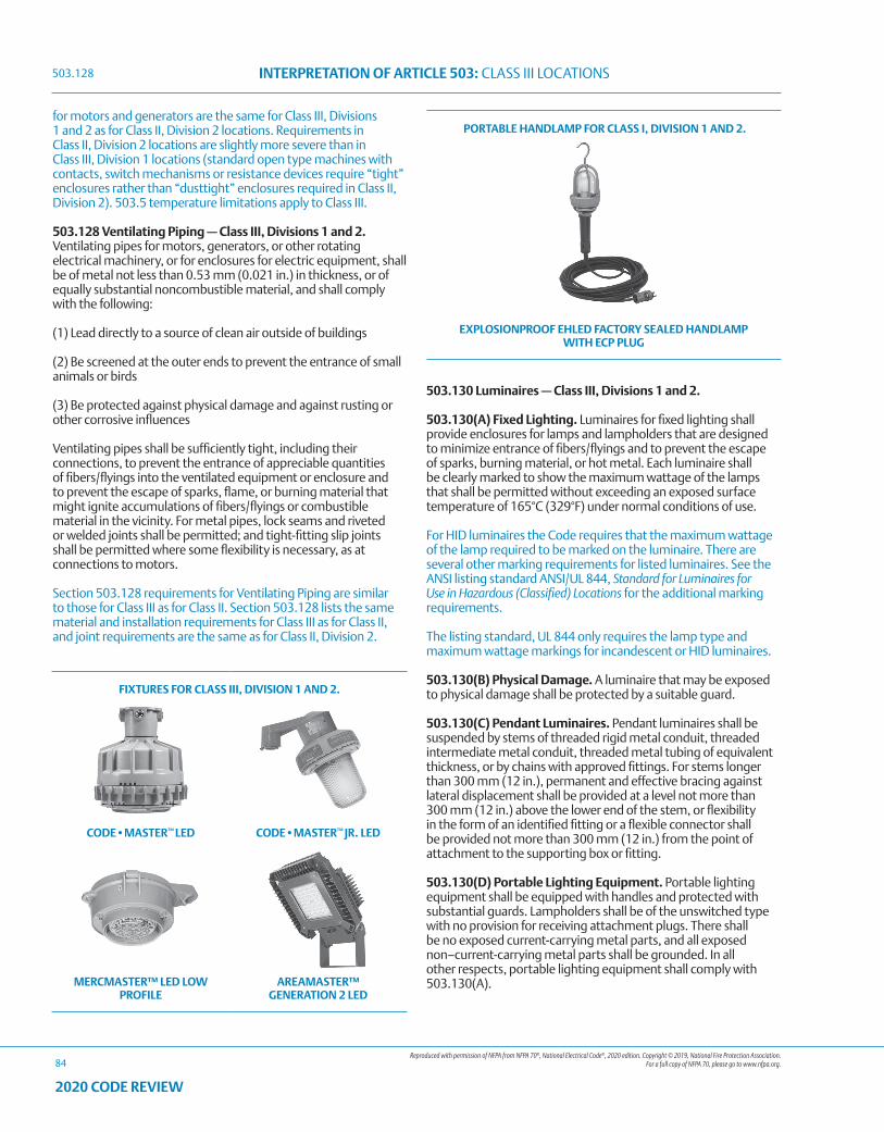
Reproduced with permission of NFPA from NFPA 70®, National Electrical Code®, 2020 edition. Copyright © 2019, National Fire Protection Association. For a full copy of NFPA 70, please go to www.nfpa.org.
INTERPRETATION OF ARTICLE 503: CLASS III LOCATIONS
84
2020 CODE REVIEW
for motors and generators are the same for Class III, Divisions 1 and 2 as for Class II, Division 2 locations. Requirements in Class II, Division 2 locations are slightly more severe than in Class III, Division 1 locations (standard open type machines with contacts, switch mechanisms or resistance devices require “tight” enclosures rather than “dusttight” enclosures required in Class II, Division 2). 503.5 temperature limitations apply to Class III.
503.128 Ventilating Piping — Class III, Divisions 1 and 2. Ventilating pipes for motors, generators, or other rotating electrical machinery, or for enclosures for electric equipment, shall be of metal not less than 0.53 mm (0.021 in.) in thickness, or of equally substantial noncombustible material, and shall comply with the following:
(1) Lead directly to a source of clean air outside of buildings
(2) Be screened at the outer ends to prevent the entrance of small animals or birds
(3) Be protected against physical damage and against rusting or other corrosive influences
Ventilating pipes shall be sufficiently tight, including their connections, to prevent the entrance of appreciable quantities of fibers/flyings into the ventilated equipment or enclosure and to prevent the escape of sparks, flame, or burning material that might ignite accumulations of fibers/flyings or combustible material in the vicinity. For metal pipes, lock seams and riveted or welded joints shall be permitted; and tight-fitting slip joints shall be permitted where some flexibility is necessary, as at connections to motors.
Section 503.128 requirements for Ventilating Piping are similar to those for Class III as for Class II. Section 503.128 lists the same material and installation requirements for Class III as for Class II, and joint requirements are the same as for Class II, Division 2.
503.130 Luminaires — Class III, Divisions 1 and 2.
503.130(A) Fixed Lighting. Luminaires for fixed lighting shall provide enclosures for lamps and lampholders that are designed to minimize entrance of fibers/flyings and to prevent the escape of sparks, burning material, or hot metal. Each luminaire shall be clearly marked to show the maximum wattage of the lamps that shall be permitted without exceeding an exposed surface temperature of 165°C (329°F) under normal conditions of use.
For HID luminaires the Code requires that the maximum wattage of the lamp required to be marked on the luminaire. There are several other marking requirements for listed luminaires. See the ANSI listing standard ANSI/UL 844, Standard for Luminaires for Use in Hazardous (Classified) Locations for the additional marking requirements.
The listing standard, UL 844 only requires the lamp type and maximum wattage markings for incandescent or HID luminaires.
503.130(B) Physical Damage. A luminaire that may be exposed to physical damage shall be protected by a suitable guard.
503.130(C) Pendant Luminaires. Pendant luminaires shall be suspended by stems of threaded rigid metal conduit, threaded intermediate metal conduit, threaded metal tubing of equivalent thickness, or by chains with approved fittings. For stems longer than 300 mm (12 in.), permanent and effective bracing against lateral displacement shall be provided at a level not more than 300 mm (12 in.) above the lower end of the stem, or flexibility in the form of an identified fitting or a flexible connector shall be provided not more than 300 mm (12 in.) from the point of attachment to the supporting box or fitting.
503.130(D) Portable Lighting Equipment. Portable lighting equipment shall be equipped with handles and protected with substantial guards. Lampholders shall be of the unswitched type with no provision for receiving attachment plugs. There shall be no exposed current-carrying metal parts, and all exposed non–current-carrying metal parts shall be grounded. In all other respects, portable lighting equipment shall comply with 503.130(A).
FIXTURES FOR CLASS III, DIVISION 1 AND 2.
CODE•MASTER™ LED CODE•MASTER™ JR. LED
MERCMASTER™ LED LOW PROFILE
AREAMASTER™ GENERATION 2 LED
PORTABLE HANDLAMP FOR CLASS I, DIVISION 1 AND 2.
EXPLOSIONPROOF EHLED FACTORY SEALED HANDLAMP WITH ECP PLUG
503.128
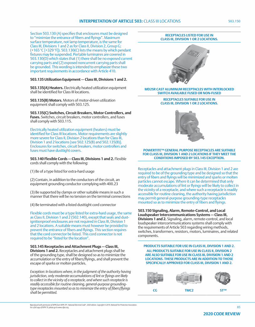
Reproduced with permission of NFPA from NFPA 70®, National Electrical Code®, 2020 edition. Copyright © 2019, National Fire Protection Association. For a full copy of NFPA 70, please go to www.nfpa.org.
INTERPRETATION OF ARTICLE 503: CLASS III LOCATIONS
85
2020 CODE REVIEW
Section 503.130 (A) specifies that enclosures must be designed to “minimize the entrance of fibers and flyings”. Maximum surface temperature, not lamp temperature, is the same for Class III, Divisions 1 and 2 as for Class II, Division 2, Group G; (+165 °C [+329 °F]). 503.130(C) lists the means by which pendant fixtures may be suspended. Portable luminaires are covered in 503.130(D) which states that (1) there shall be no exposed current carrying parts and (2) exposed noncurrent carrying parts shall be grounded. This wording is intended to emphasize these two important requirements in accordance with Article 410.
503.135 Utilization Equipment — Class III, Divisions 1 and 2.
503.135(A) Heaters. Electrically heated utilization equipment shall be identified for Class III locations.
503.135(B) Motors. Motors of motor-driven utilization equipment shall comply with 503.125.
503.135(C) Switches, Circuit Breakers, Motor Controllers, and Fuses. Switches, circuit breakers, motor controllers, and fuses shall comply with 503.115.
Electrically heated utilization equipment (heaters) must be identified for Class III locations. Motor requirements are slightly more severe for Class II, Division 2 locations than for Class III, Division 1 and 2 locations [see 502.125(B) and 502.135(B)]. Enclosures for switches, circuit breakers, motor controllers and fuses must have dusttight covers.
503.140 Flexible Cords — Class III, Divisions 1 and 2. Flexible cords shall comply with the following:
(1) Be of a type listed for extra-hard usage
(2) Contain, in addition to the conductors of the circuit, an equipment grounding conductor complying with 400.23
(3) Be supported by clamps or other suitable means in such a manner that there will be no tension on the terminal connections
(4) Be terminated with a listed dusttight cord connector
Flexible cords must be a type listed for extra-hard usage, the same as Class II, Division 1 and 2 (502.140), except that seals and dust-ignitionproof enclosures are not required in Class III, Division 1 and 2 locations. A suitable means must however be provided to prevent the entrance of fibers and flyings. This section requires that the cord connector be listed. This cord connector is not required to be “listed for the location”.
503.145 Receptacles and Attachment Plugs — Class III, Divisions 1 and 2. Receptacles and attachment plugs shall be of the grounding type, shall be designed so as to minimize the accumulation or the entry of fibers/flyings, and shall prevent the escape of sparks or molten particles.
Exception: In locations where, in the judgment of the authority having jurisdiction, only moderate accumulations of lint or flyings are likely to collect in the vicinity of a receptacle, and where such receptacle is readily accessible for routine cleaning, general-purpose grounding-type receptacles mounted so as to minimize the entry of fibers/flyings shall be permitted.
Receptacles and attachment plugs in Class III, Division 1 and 2 are required to be of the grounding type and be designed so that the entry of fibers and flyings will be minimized and sparks or molten particles cannot escape. Where it can be determined that only moderate accumulations of lint or flyings will be likely to collect in the vicinity of a receptacle, and where such a receptacle is readily accessible for routine cleaning, the authority having jurisdiction may permit general-purpose grounding-type receptacles mounted so as to minimize the entry of fibers and flyings.
503.150 Signaling, Alarm, Remote-Control, and Local Loudspeaker Intercommunications Systems — Class III, Divisions 1 and 2. Signaling, alarm, remote-control, and local loudspeaker intercommunications systems shall comply with the requirements of Article 503 regarding wiring methods, switches, transformers, resistors, motors, luminaires, and related components.
RECEPTACLES LISTED FOR USE IN CLASS III, DIVISION 1 OR 2 LOCATIONS.
MD2SR CAST ALUMINUM RECEPTACLES WITH INTERLOCKED SWITCH AVAILABLE FUSED OR NON-FUSED
RECEPTACLES SUITABLE FOR USE IN CLASS III, DIVISION 1 OR 2 LOCATIONS.
POWERTITE™ GENERAL PURPOSE RECEPTACLES ARE SUITABLE FOR CLASS III, DIVISION 1 AND 2 LOCATIONS IF THEY MEET THE
CONDITIONS IMPOSED BY 503.145 EXCEPTION.
PRODUCTS SUITABLE FOR USE IN CLASS III, DIVISION 1 AND 2.ALL PRODUCTS SUITABLE FOR USE IN CLASS II, DIVISION 2
ARE ALSO SUITABLE FOR USE IN CLASS III, DIVISION 1 AND 2 LOCATIONS. THESE PRODUCTS ARE IN ADDITION TO THOSE SPECIFICALLY APPROVED FOR CLASS III, DIVISION 1 AND 2.
CG TMC2 ST™
503.150
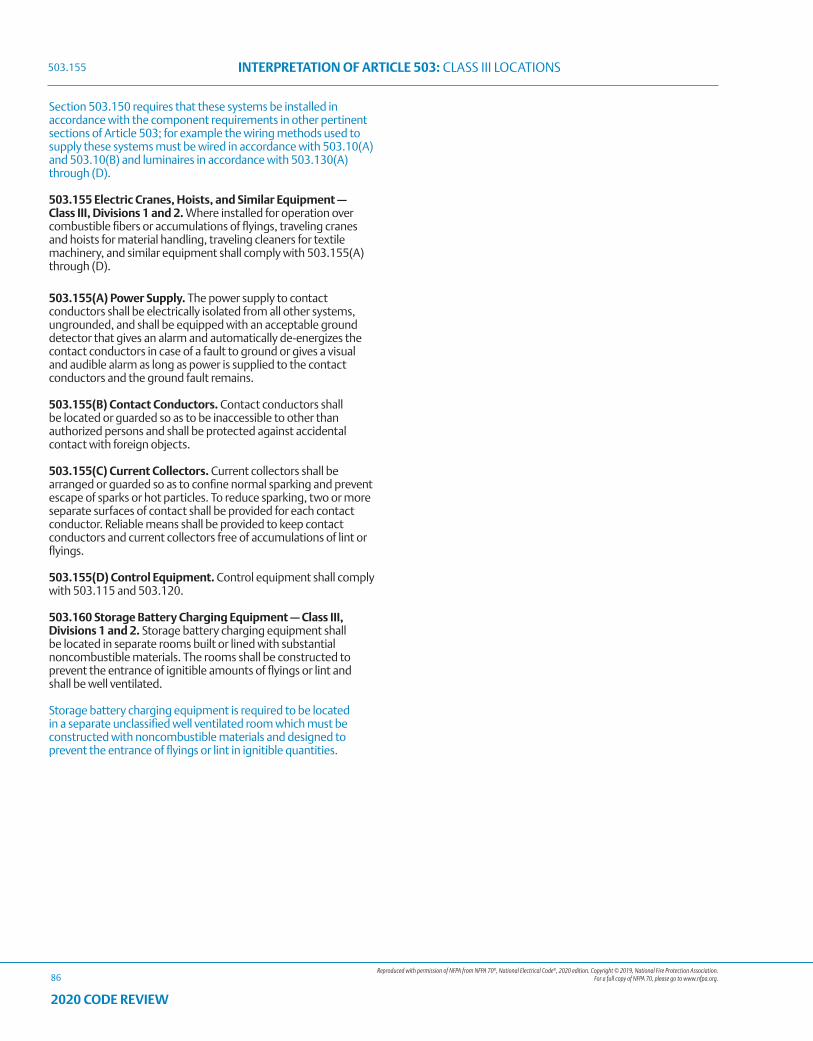
Reproduced with permission of NFPA from NFPA 70®, National Electrical Code®, 2020 edition. Copyright © 2019, National Fire Protection Association. For a full copy of NFPA 70, please go to www.nfpa.org.
INTERPRETATION OF ARTICLE 503: CLASS III LOCATIONS
86
2020 CODE REVIEW
Section 503.150 requires that these systems be installed in accordance with the component requirements in other pertinent sections of Article 503; for example the wiring methods used to supply these systems must be wired in accordance with 503.10(A) and 503.10(B) and luminaires in accordance with 503.130(A) through (D).
503.155 Electric Cranes, Hoists, and Similar Equipment — Class III, Divisions 1 and 2. Where installed for operation over combustible fibers or accumulations of flyings, traveling cranes and hoists for material handling, traveling cleaners for textile machinery, and similar equipment shall comply with 503.155(A) through (D).
503.155(A) Power Supply. The power supply to contact conductors shall be electrically isolated from all other systems, ungrounded, and shall be equipped with an acceptable ground detector that gives an alarm and automatically de-energizes the contact conductors in case of a fault to ground or gives a visual and audible alarm as long as power is supplied to the contact conductors and the ground fault remains.
503.155(B) Contact Conductors. Contact conductors shall be located or guarded so as to be inaccessible to other than authorized persons and shall be protected against accidental contact with foreign objects.
503.155(C) Current Collectors. Current collectors shall be arranged or guarded so as to confine normal sparking and prevent escape of sparks or hot particles. To reduce sparking, two or more separate surfaces of contact shall be provided for each contact conductor. Reliable means shall be provided to keep contact conductors and current collectors free of accumulations of lint or flyings.
503.155(D) Control Equipment. Control equipment shall comply with 503.115 and 503.120.
503.160 Storage Battery Charging Equipment — Class III, Divisions 1 and 2. Storage battery charging equipment shall be located in separate rooms built or lined with substantial noncombustible materials. The rooms shall be constructed to prevent the entrance of ignitible amounts of flyings or lint and shall be well ventilated.
Storage battery charging equipment is required to be located in a separate unclassified well ventilated room which must be constructed with noncombustible materials and designed to prevent the entrance of flyings or lint in ignitible quantities.
503.155
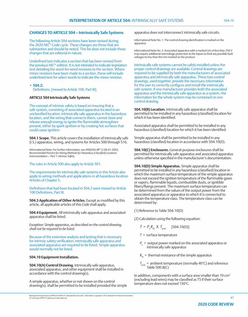
Reproduced with permission of NFPA from NFPA 70®, National Electrical Code®, 2020 edition. Copyright © 2019, National Fire Protection Association. For a full copy of NFPA 70, please go to www.nfpa.org.
INTERPRETATION OF ARTICLE 504: INTRINSICALLY SAFE SYSTEMS
87
2020 CODE REVIEW
CHANGES TO ARTICLE 504 – Intrinsically Safe Systems
The following Article 504 sections have been revised during the 2020 NEC® Code cycle. These changes are those that are substantive and should be noted. This list does not include those changes that are editorial in nature.
Underlined text indicates a section that has been revised from the previous NEC® edition. It is not intended to indicate legislation text detailing the word-for-word revisions to the section. Where minor revisions have been made to a section, these will include underlined text for select words to indicate the minor revision.
• 504.2: Definitions. [moved to Article 100, Part III].
ARTICLE 504 Intrinsically Safe Systems
The concept of intrinsic safety is based on insuring that a safe system, consisting of associated apparatus located in an unclassified location, intrinsically safe apparatus in the hazardous location, and the wiring that connects them, cannot store and release enough energy to ignite the flammable atmosphere present, either by spark ignition or by creating hot surfaces that could cause ignition.
504.1 Scope. This article covers the installation of intrinsically safe (I.S.) apparatus, wiring, and systems for Articles 500 through 516.
Informational Note: For further information, see ANSI/ISA-RP 12.06.01-2003, Recommended Practice for Wiring Methods for Hazardous (Classified) Locations Instrumentation — Part 1: Intrinsic Safety.
The rules in Article 500 also apply to Article 501.
The requirements for intrinsically safe systems in this Article also apply to wiring methods and applications in all hazardous location Articles of Chapter 5.
Definitions that had been located in 504.2 were moved to Article 100 Definitions, Part III.
504.3 Application of Other Articles. Except as modified by this article, all applicable articles of this Code shall apply.
504.4 Equipment. All intrinsically safe apparatus and associated apparatus shall be listed.
Exception: Simple apparatus, as described on the control drawing, shall not be required to be listed.
Because of the extensive analysis and testing that is necessary for intrinsic safety verification, intrinsically safe apparatus and associated apparatus are required to be listed. Simple apparatus would normally not be listed.
504.10 Equipment Installation.
504.10(A) Control Drawing. Intrinsically safe apparatus, associated apparatus, and other equipment shall be installed in accordance with the control drawing(s).
A simple apparatus, whether or not shown on the control drawing(s), shall be permitted to be installed provided the simple
apparatus does not interconnect intrinsically safe circuits.
Informational Note No. 1: The control drawing identification is marked on the apparatus.
Informational Note No. 2: Associated apparatus with a marked Um of less than 250 V may require additional overvoltage protection at the inputs to limit any possible fault voltages to less than the Um marked on the product.
Intrinsically safe systems cannot be safely installed unless the proper control drawings are available. Control drawings are required to be supplied by both the manufacturers of associated apparatus and intrinsically safe apparatus. These two control drawings, used together, provide the necessary information for the user to correctly configure and install the intrinsically safe system. If one manufacturer provides both the associated apparatus and the intrinsically safe apparatus as a system, the information for the whole system may be contained on one control drawing.
504.10(B) Location. Intrinsically safe apparatus shall be permitted to be installed in any hazardous (classified) location for which it has been identified.
Associated apparatus shall be permitted to be installed in any hazardous (classified) location for which it has been identified.
Simple apparatus shall be permitted to be installed in any hazardous (classified) location in accordance with 504.10(D).
504.10(C) Enclosures. General-purpose enclosures shall be permitted for intrinsically safe apparatus and associated apparatus unless otherwise specified in the manufacturer’s documentation.
504.10(D) Simple Apparatus. Simple apparatus shall be permitted to be installed in any hazardous (classified) location in which the maximum surface temperature of the simple apparatus does not exceed the ignition temperature of the flammable gases or vapors, flammable liquids, combustible dusts, or ignitible fibers/flyings present. The maximum surface temperature can be determined from the values of the output power from the associated apparatus or apparatus to which it is connected to obtain the temperature class. The temperature class can be determined by:
(1) Reference to Table 504.10(D)
(2) Calculation using the following equation:
T = Po Rth X Tamb [504.10(D)]
T = surface temperature
Po = output power marked on the associated apparatus or intrinsically safe apparatus
Rth = thermal resistance of the simple apparatus
Tamb = ambient temperature (normally 40°C) and reference Table 500.8(C)
In addition, components with a surface area smaller than 10 cm2 (excluding lead wires) may be classified as T5 if their surface temperature does not exceed 150°C.
504.10
Reproduced with permission of NFPA from NFPA 70®, National Electrical Code®, 2020 edition. Copyright © 2019, National Fire Protection Association. For a full copy of NFPA 70, please go to www.nfpa.org.
INTERPRETATION OF ARTICLE 504: INTRINSICALLY SAFE SYSTEMS
88
2020 CODE REVIEW
To avoid causing a thermal ignition hazard using simple apparatus, this clause gives a method to calculate the temperature likely to be generated, using information available on the control drawing provided for the associated apparatus. Higher temperatures are allowed for very small surfaces, since testing has proven that it takes higher temperatures from devices with very small surface areas to thermally ignite flammable atmospheres.
The thermal resistance of a device is a parameter that tells you how much something will heat up as a function of how much power is applied to it, and the units need to be in °C/ (°F) Watt to work with Table 504.10(D).
The requirements to consider the temperature of simple apparatus, as well as the calculations for simple apparatus temperature determination, is included in 504.10(D). Table 504.10(D) was also added to permit temperature allowances for small components. Allowing any component to heat up to a level over the autoignition temperature of the flammable gas present may not seem the right thing to do, but testing has determined that a higher temperature is necessary to ignite a flammable atmosphere when a hot surface also has a very small surface area.
Table 504.10(D) Assessment for T4 Classification According to Component Size and TemperatureTotal Surface Area Excluding Lead Wires
Requirement for T4 Classification
<20 mm2 Surface temperature ≤275°C≥20 mm2 ≤10 cm2 Surface temperature ≤200°C≥20 mm2 Power not exceeding 1.3 W*
*Based on 40°C ambient temperature. Reduce to 1.2 W with an ambient of 60°C or 1.0 W with 80°C ambient temperature.
504.20 Wiring Methods. Any of the wiring methods suitable for unclassified locations, including those covered by Chapter 7 and Chapter 8, shall be permitted for installing intrinsically safe apparatus. Sealing shall be as provided in 504.70, and separation shall be as provided in 504.30.
Since intrinsically safe wiring does not carry enough energy to ignite the flammable atmospheres that it is listed for, any wiring method allowed by the NEC® can be used in Division 1 and Division 2 to connect associated apparatus and intrinsically safe apparatus. To avoid accidental connection to other nonintrinsically safe circuits or picking up induced currents from other higher power wiring, there are wiring separation requirements imposed by 504.30.
504.30 Separation of Intrinsically Safe Conductors.
504.30(A) From Nonintrinsically Safe Circuit Conductors.
504.30(A)(1) In Raceways, Cable Trays, and Cables. Conductors of intrinsically safe circuits shall not be placed in any raceway, cable tray, or cable with conductors of any nonintrinsically safe circuit.
Exception No. 1: Where conductors of intrinsically safe circuits are separated from conductors of nonintrinsically safe circuits by a distance of at least 50 mm (2 in.) and secured, or by a grounded metal partition or an approved insulating partition.
Informational Note: No. 20 gauge sheet metal partitions 0.91 mm (0.0359 in.) or thicker are generally considered acceptable.
Exception No. 2: Where either (1) all of the intrinsically safe circuit conductors or (2) all of the nonintrinsically safe circuit conductors are in grounded metal-sheathed or metal-clad cables where the sheathing or cladding is capable of carrying fault current to ground.
Informational Note: Cables meeting the requirements of Articles 330 and 332 are typical of those considered acceptable.
Exception No. 3: Intrinsically safe circuits in a Division 2 or Zone 2 location shall be permitted to be installed in a raceway, cable tray, or cable along with nonincendive field wiring circuits when installed in accordance with 504.30(B).
Exception No. 4: Intrinsically safe circuits passing through a Division 2 or Zone 2 location to supply apparatus that is located in a Division 1, Zone 0 or Zone 1 location shall be permitted to be installed in a raceway, cable tray, or cable along with nonincendive field wiring circuits when installed in accordance with 504.30(B).
Informational Note: Nonincendive field wiring circuits are described in 501.10(B)(3), 502.10(B)(3), and 503.10(A)(4).
504.30(A)(2) Within Enclosures. Conductors of intrinsically safe circuits shall be secured so that any conductor that might come loose from a terminal is unlikely to come into contact with another terminal. The conductors shall be separated from conductors of nonintrinsically safe circuits by one of the methods in (1) through (4).
(1) Separation by at least 50 mm (2 in.) from conductors of any nonintrinsically safe circuits
(2) Separation from conductors of nonintrinsically safe circuits by use of a grounded metal partition 0.91 mm (0.0359 in.) or thicker
(3) Separation from conductors of nonintrinsically safe circuits by use of an approved insulating partition that extends to within 1.5 mm (0.0625 in.) of the enclosure walls
(4) Where either (1) all of the intrinsically safe circuit conductors or (2) all of the nonintrinsically safe circuit conductors are in grounded metal-sheathed or metal-clad cables where the sheathing or cladding is capable of carrying fault current to ground
Informational Note No. 1: Cables meeting the requirements of Articles 330 and 332 are typical of those considered acceptable.
Informational Note No. 2: The use of separate wiring compartments for the intrinsically safe and nonintrinsically safe terminals is a typical method of complying with this requirement.
Informational Note No. 3: Physical barriers such as grounded metal partitions or approved insulating partitions or approved restricted access wiring ducts separated from other such ducts by at least 19 mm (3/4 in.) can be used to help ensure the required separation of the wiring.
504.30(A)(3) Other (Not in Raceway or Cable Tray Systems). Conductors and cables of intrinsically safe circuits run in other than raceway or cable tray systems shall be separated by at least 50 mm (2 in.) and secured from conductors and cables of any nonintrinsically safe circuits.
Exception: Where either (1) all of the intrinsically safe circuit conductors are in Type MI or MC cables or (2) all of the nonintrinsically safe
504.10
Reproduced with permission of NFPA from NFPA 70®, National Electrical Code®, 2020 edition. Copyright © 2019, National Fire Protection Association. For a full copy of NFPA 70, please go to www.nfpa.org.
INTERPRETATION OF ARTICLE 504: INTRINSICALLY SAFE SYSTEMS
89
2020 CODE REVIEW
circuit conductors are in raceways or Type MI or MC cables where the sheathing or cladding is capable of carrying fault current to ground.
504.30(B) From Different Intrinsically Safe Circuit Conductors. The clearance between two terminals for connection of field wiring of different intrinsically safe circuits shall be at least 6 mm (0.25 in.), unless this clearance is permitted to be reduced by the control drawing. Different intrinsically safe circuits shall be separated from each other by one of the following means:
(1) The conductors of each circuit are within a grounded metal shield.
(2) The conductors of each circuit have insulation with a minimum thickness of 0.25 mm (0.01 in.).
Exception: Unless otherwise identified.
504.30(C) From Grounded Metal. The clearance between the uninsulated parts of field wiring conductors connected to terminals and grounded metal or other conducting parts shall be at least 3 mm (0.125 in.).
Separation of intrinsically safe circuits, both terminations and conductors, from all other circuits, including other intrinsically safe circuits, must be maintained in order to ensure the safety of the system. Separation is accomplished by using separate raceways for intrinsically safe wiring, keeping a certain distance between intrinsically safe circuits and other circuits, or in some cases, by making sure the conductors are separated by a minimum thickness of solid insulation.
Section 504.30(B) provides a default field wiring terminal clearance requirement of 6 mm for intrinsically safe circuits, unless the control drawing permits a smaller clearance.
504.50 Grounding.
504.50(A) Intrinsically Safe Apparatus, Enclosures, and Raceways. Intrinsically safe apparatus, enclosures, and raceways, if of metal, shall be connected to the equipment grounding conductor.
Informational Note: In addition to an equipment grounding conductor connection, a connection to a grounding electrode may be needed for some associated apparatus; for example, zener diode barriers, if specified in the control drawing. See ANSI/ISA-RP 12.06.01-2003, Recommended Practice for Wiring Methods for Hazardous (Classified) Locations Instrumentation — Part 1: Intrinsic Safety.
504.50(B) Associated Apparatus and Cable Shields. Associated apparatus and cable shields shall be grounded in accordance with the required control drawing. See 504.10(A).
Informational Note: Supplementary connection(s) to the grounding electrode may be needed for some associated apparatus; for example, zener diode barriers, if specified in the control drawing. See ANSI/ISA RP 12.06.01-2003, Recommended Practice for Wiring Methods for Hazardous (Classified) Locations Instrumentation — Part 1: Intrinsic Safety.
504.50(C) Connection to Grounding Electrodes. Where connection to a grounding electrode is required, the grounding electrode shall be as specified in 250.52(A)(1), (A)(2), (A)(3), and (A)(4) and shall comply with 250.30(A)(4). Sections 250.52(A)(5), (A)(7), and (A)(8) shall not be used if any of the electrodes specified in 250.52(A)(1), (A)(2), (A)(3), or (A)(4) are present.
504.60 Bonding.
504.60(A) Intrinsically Safe Apparatus. Intrinsically safe apparatus, if of metal, shall be bonded in the hazardous (classified) location in accordance with 501.30(A), 502.30(A), 503.30(A), 505.25, or 506.25, as applicable.
504.60(B) Metal Raceways. Where metal raceways are used for intrinsically safe system wiring, bonding at all ends of the raceway, regardless of the location, shall be in accordance with 501.30(A), 502.30(A), 503.30(A), 505.25, or 506.25, as applicable.
Section 504.60(A) and (B) provides better clarity that metal raceways shall be bonded in accordance with the hazardous location rules.
504.70 Sealing. Conduits and cables that are required to be sealed by 501.15, 502.15, 505.16, and 506.16 shall be sealed to minimize the passage of gases, vapors, or dusts. Such seals shall not be required to be explosionproof or flameproof but shall be identified for the purpose of minimizing passage of gases, vapors, or dusts under normal operating conditions and shall be accessible.
Exception: Seals shall not be required for enclosures that contain only intrinsically safe apparatus, except as required by 501.17.
Unlike explosionproof enclosures, where listed explosionproof seals are necessary to keep an explosion generated inside the enclosure from traveling through the raceway, seals on intrinsically safe enclosures do not need to be explosionproof, since intrinsically safe equipment cannot cause an ignition. The seals used do not need to be listed, and only need to provide environmental protection. These seals are required to be identified for the purpose of minimizing the passage of gases, vapors or dusts under normal operating conditions. This rule requires that these seals be accessible. (See Article 100 for the definition of Identified.)
504.80 Identification. Labels required by this section shall be suitable for the environment where they are installed, with consideration given to exposure to chemicals and sunlight.
504.80(A) Terminals. Intrinsically safe circuits shall be identified at terminal and junction locations in a manner that is intended to prevent unintentional interference with the circuits during testing and servicing.
504.80(B) Wiring. Raceways, cable trays, and other wiring methods for intrinsically safe system wiring shall be identified with permanently affixed labels with the wording “Intrinsic Safety Wiring” or equivalent. The labels shall be located so as to be visible after installation and placed so that they may be readily traced through the entire length of the installation. Intrinsic safety circuit labels shall appear in every section of the wiring system that is separated by enclosures, walls, partitions, or floors. Spacing between labels shall not be more than 7.5 m (25 ft).
Exception: Circuits run underground shall be permitted to be identified where they become accessible after emergence from the ground.
Informational Note No. 1: Wiring methods permitted in unclassified locations may be used for intrinsically safe systems in hazardous (classified) locations. Without labels to identify the application of the wiring, enforcement authorities cannot determine that an installation is in compliance with this Code.
504.80

Reproduced with permission of NFPA from NFPA 70®, National Electrical Code®, 2020 edition. Copyright © 2019, National Fire Protection Association. For a full copy of NFPA 70, please go to www.nfpa.org.
INTERPRETATION OF ARTICLE 504: INTRINSICALLY SAFE SYSTEMS
90
2020 CODE REVIEW
Informational Note No. 2: In unclassified locations, identification is necessary to ensure that nonintrinsically safe wire will not be inadvertently added to existing raceways at a later date.
504.80(C) Color Coding. Color coding shall be permitted to identify intrinsically safe conductors where they are colored light blue and where no other conductors colored light blue are used. Likewise, color coding shall be permitted to identify raceways, cable trays, and junction boxes where they are colored light blue and contain only intrinsically safe wiring.
Terminals and wiring for intrinsically safe circuits need to be identified to keep them adequately separated from all other wiring. Light blue is designated as a color code for intrinsically safe wiring if color-coding is desired and light blue has not been used as a color code for any other wiring.
504.80
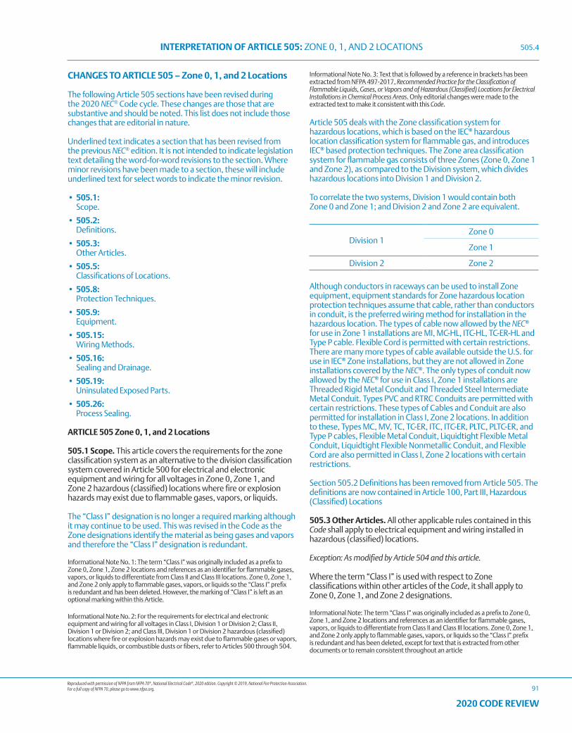
Reproduced with permission of NFPA from NFPA 70®, National Electrical Code®, 2020 edition. Copyright © 2019, National Fire Protection Association. For a full copy of NFPA 70, please go to www.nfpa.org.
INTERPRETATION OF ARTICLE 505: ZONE 0, 1, AND 2 LOCATIONS
91
2020 CODE REVIEW
CHANGES TO ARTICLE 505 – Zone 0, 1, and 2 Locations
The following Article 505 sections have been revised during the 2020 NEC® Code cycle. These changes are those that are substantive and should be noted. This list does not include those changes that are editorial in nature.
Underlined text indicates a section that has been revised from the previous NEC® edition. It is not intended to indicate legislation text detailing the word-for-word revisions to the section. Where minor revisions have been made to a section, these will include underlined text for select words to indicate the minor revision.
• 505.1: Scope.
• 505.2: Definitions.
• 505.3: Other Articles.
• 505.5: Classifications of Locations.
• 505.8: Protection Techniques.
• 505.9: Equipment.
• 505.15: Wiring Methods.
• 505.16: Sealing and Drainage.
• 505.19: Uninsulated Exposed Parts.
• 505.26: Process Sealing.
ARTICLE 505 Zone 0, 1, and 2 Locations
505.1 Scope. This article covers the requirements for the zone classification system as an alternative to the division classification system covered in Article 500 for electrical and electronic equipment and wiring for all voltages in Zone 0, Zone 1, and Zone 2 hazardous (classified) locations where fire or explosion hazards may exist due to flammable gases, vapors, or liquids.
The “Class I” designation is no longer a required marking although it may continue to be used. This was revised in the Code as the Zone designations identify the material as being gases and vapors and therefore the “Class I” designation is redundant.
Informational Note No. 1: The term “Class I” was originally included as a prefix to Zone 0, Zone 1, Zone 2 locations and references as an identifier for flammable gases, vapors, or liquids to differentiate from Class II and Class III locations. Zone 0, Zone 1, and Zone 2 only apply to flammable gases, vapors, or liquids so the “Class I” prefix is redundant and has been deleted. However, the marking of “Class I” is left as an optional marking within this Article.
Informational Note No. 2: For the requirements for electrical and electronic equipment and wiring for all voltages in Class I, Division 1 or Division 2; Class II, Division 1 or Division 2; and Class III, Division 1 or Division 2 hazardous (classified) locations where fire or explosion hazards may exist due to flammable gases or vapors, flammable liquids, or combustible dusts or fibers, refer to Articles 500 through 504.
Informational Note No. 3: Text that is followed by a reference in brackets has been extracted from NFPA 497-2017, Recommended Practice for the Classification of Flammable Liquids, Gases, or Vapors and of Hazardous (Classified) Locations for Electrical Installations in Chemical Process Areas. Only editorial changes were made to the extracted text to make it consistent with this Code.
Article 505 deals with the Zone classification system for hazardous locations, which is based on the IEC® hazardous location classification system for flammable gas, and introduces IEC® based protection techniques. The Zone area classification system for flammable gas consists of three Zones (Zone 0, Zone 1 and Zone 2), as compared to the Division system, which divides hazardous locations into Division 1 and Division 2.
To correlate the two systems, Division 1 would contain both Zone 0 and Zone 1; and Division 2 and Zone 2 are equivalent.
Division 1Zone 0
Zone 1
Division 2 Zone 2
Although conductors in raceways can be used to install Zone equipment, equipment standards for Zone hazardous location protection techniques assume that cable, rather than conductors in conduit, is the preferred wiring method for installation in the hazardous location. The types of cable now allowed by the NEC® for use in Zone 1 installations are MI, MC-HL, ITC-HL, TC-ER-HL and Type P cable. Flexible Cord is permitted with certain restrictions. There are many more types of cable available outside the U.S. for use in IEC® Zone installations, but they are not allowed in Zone installations covered by the NEC®. The only types of conduit now allowed by the NEC® for use in Class I, Zone 1 installations are Threaded Rigid Metal Conduit and Threaded Steel Intermediate Metal Conduit. Types PVC and RTRC Conduits are permitted with certain restrictions. These types of Cables and Conduit are also permitted for installation in Class I, Zone 2 locations. In addition to these, Types MC, MV, TC, TC-ER, ITC, ITC-ER, PLTC, PLTC-ER, and Type P cables, Flexible Metal Conduit, Liquidtight Flexible Metal Conduit, Liquidtight Flexible Nonmetallic Conduit, and Flexible Cord are also permitted in Class I, Zone 2 locations with certain restrictions.
Section 505.2 Definitions has been removed from Article 505. The definitions are now contained in Article 100, Part III, Hazardous (Classified) Locations
505.3 Other Articles. All other applicable rules contained in this Code shall apply to electrical equipment and wiring installed in hazardous (classified) locations.
Exception: As modified by Article 504 and this article.
Where the term “Class I” is used with respect to Zone classifications within other articles of the Code, it shall apply to Zone 0, Zone 1, and Zone 2 designations.
Informational Note: The term “Class I” was originally included as a prefix to Zone 0, Zone 1, and Zone 2 locations and references as an identifier for flammable gases, vapors, or liquids to differentiate from Class II and Class III locations. Zone 0, Zone 1, and Zone 2 only apply to flammable gases, vapors, or liquids so the “Class I” prefix is redundant and has been deleted, except for text that is extracted from other documents or to remain consistent throughout an article
505.4
Reproduced with permission of NFPA from NFPA 70®, National Electrical Code®, 2020 edition. Copyright © 2019, National Fire Protection Association. For a full copy of NFPA 70, please go to www.nfpa.org.
INTERPRETATION OF ARTICLE 505: ZONE 0, 1, AND 2 LOCATIONS
92
2020 CODE REVIEW
505.4 Documentation. All areas in industrial occupancies designated as hazardous (classified) locations shall be properly documented. This documentation shall be available to those authorized to design, install, inspect, maintain, or operate electrical equipment at the location.
Informational Note No. 1: For examples of area classification drawings, see ANSI/API RP 505-2018, Recommended Practice for Classification of Locations for Electrical Installations at Petroleum Facilities Classified as Class I, Zone 0, Zone 1, and Zone 2; ANSI/ISA-60079-10-1 (12.24.01)-2014 Explosive Atmospheres — Part 10-1: Classification of Areas — Explosive gas atmospheres; and Model Code of Safe Practice, Part 15: Area Classification Code for Installations Handling Flammable Fluids, EI 15:2015, Energy Institute, London.
Informational Note No. 2: Where gas detection equipment is used as a means of protection in accordance with 505.8(I)(2), (I)(3), or (I)(4), the documentation typically includes the type of detection equipment, its listing, installation location(s), alarm and shutdown criteria, and calibration frequency.
Informational Note No. 3: For further information on the classification of locations, see NFPA 497-2017, Recommended Practice for the Classification of Flammable Liquids, Gases, or Vapors and of Hazardous (Classified) Locations for Electrical Installations in Chemical Process Areas; ANSI/API RP 505-2018, Recommended Practice for Classification of Locations for Electrical Installations at Petroleum Facilities Classified as Class I, Zone 0, Zone 1, and Zone 2; ANSI/ISA-60079-10-1 (12.24.01)-2014, Explosive Atmospheres — Part 10-1: Classification of Areas — Explosive gas atmospheres; and Model Code of Safe Practice, Part 15: Area Classification Code for Installations Handling Flammable Fluids, EI 15:2015, Energy Institute, London.
Informational Note No. 4: For further information on protection against static electricity and lightning hazards in hazardous (classified) locations, see NFPA 77-2019, Recommended Practice on Static Electricity; NFPA 780-2017, Standard for the Installation of Lightning Protection Systems; and API RP 2003-2015, Protection Against Ignitions Arising Out of Static Lightning and Stray Currents.
Informational Note No. 5: For further information on ventilation, see NFPA 30-2018, Flammable and Combustible Liquids Code, and ANSI/API RP 505-2018, Recommended Practice for Classification of Locations for Electrical Installations at Petroleum Facilities Classified as Class I, Zone 0, Zone 1, and Zone 2.
Informational Note No. 6: For further information on electrical systems for hazardous (classified) locations on offshore oil and gas producing platforms, drilling rigs, and workover rigs, see ANSI/API RP 14FZ-2013, Recommended Practice for Design and Installation of Electrical Systems for Fixed and Floating Offshore Petroleum Facilities for Unclassified and Class I, Zone 0, Zone 1, and Zone 2 Locations.
Informational Note No. 7: For further information on application of electrical equipment in hazardous (classified) locations in general, see ANSI/ISA-60079-0 (12.00.01)-2013, Explosive Atmospheres — Part 0: Equipment — General Requirements; ANSI/ISA-12.01.01-2013, Definitions and Information Pertaining to Electrical Apparatus in Hazardous (Classified) Locations; and ANSI/UL 60079-0:2013, Electrical Apparatus for Explosive Gas Atmospheres — Part 0: General Requirements.
Informational Note No. 8: Portable or transportable equipment having self-contained power supplies, such as battery-operated equipment, could potentially become an ignition source in hazardous (classified) locations. See ANSI/UL 121203-2011, Standard for Portable Electronic Products Suitable for Use in Class I and II, Division 2, Class I Zone 2 and Class III, Division 1 and 2 Hazardous (Classified) Locations.
Informational Note No. 9: For additional information concerning the installation of equipment utilizing optical emissions technology (such as laser equipment) that could potentially become an ignition source in hazardous (classified) locations, see ANSI/UL-60079-28-2017, Explosive Atmospheres — Part 28: Protection of equipment and transmission systems using optical radiation.
Informational Note No. 10: For information on electrical resistance trace heating for hazardous (classified) locations, see ANSI/IEEE 60079-30-2:2015, IEEE/IEC International Standard for Explosive Atmospheres — Part 30-2: Electrical resistance trace heating — Application guide for design, installation and maintenance.
Informational Note No. 11: For information on electric skin effect trace heating for hazardous (classified) locations, IEEE 844.1-2017/CSA C22.2 No. 293.1-17, IEEE/CSA Standard for Skin Effect Trace Heating of Pipelines, Vessels, Equipment, and Structures — General, Testing, Marking, and Documentation Requirements, and IEEE
844.2-2017/CSA C293.2:17, IEEE/CSA Standard for Skin Effect Trace Heating of Pipelines, Vessels, Equipment, and Structures — Application Guide for Design, Installation, Testing, Commissioning, and Maintenance.
505.5 Classifications of Locations.
505.5(A) General. Locations shall be classified depending on the properties of the flammable gases, flammable liquid–produced vapors, combustible liquid–produced vapors, combustible dusts, or fibers/flyings that could be present and the likelihood that a flammable or combustible concentration or quantity is present. Each room, section, or area shall be considered individually in determining its classification. Where pyrophoric materials are the only materials used or handled, these locations are outside the scope of this article.
NFPA® 497 and NFPA® 499 do not address the requirements for the use of pyrophoric materials.
Informational Note No. 1: See 505.7 for restrictions on area classification.
Informational Note No. 2: Through the exercise of ingenuity in the layout of electrical installations for hazardous (classified) locations, it is frequently possible to locate much of the equipment in reduced level of classification or in an unclassified location and, thus, to reduce the amount of special equipment required.
Refrigerant machinery rooms that contain ammonia refrigeration systems and are equipped with adequate mechanical ventilation that operates continuously or is initiated by a detection system at a concentration not exceeding 150 ppm shall be permitted to be classified as “unclassified” locations.
Informational Note: For further information regarding classification and ventilation of areas involving closed-circuit ammonia refrigeration systems, see ANSI/IIAR 2-2014, Standard for Safe Design of Closed-Circuit Ammonia Refrigeration Systems.
505.5(B) Zone 0, 1, and 2 Locations. Zone 0, 1, and 2 locations are those in which flammable gases or vapors are or may be present in the air in quantities sufficient to produce explosive or ignitible mixtures. Zone 0, 1, and 2 locations shall include those specified in 505.5(B)(1), (B)(2), and (B)(3).
505.5(B)(1) Zone 0. A Zone 0 location is a location in which one of the following conditions exists:
(1) Ignitible concentrations of flammable gases or vapors are present continuously
(2) Ignitible concentrations of flammable gases or vapors are present for long periods of time
Informational Note No. 1: As a guide in determining when flammable gases or vapors are present continuously or for long periods of time, refer to ANSI/API RP 505-2018, Recommended Practice for Classification of Locations for Electrical Installations of Petroleum Facilities Classified as Class I, Zone 0, Zone 1, and Zone 2, and ANSI/ISA 60079-10-1-2014, Explosive Atmospheres — Part 10-1: Classification of Areas — explosive gas atmospheres.
Informational Note No. 2: This classification includes locations inside vented tanks or vessels that contain volatile flammable liquids; inside inadequately vented spraying or coating enclosures where volatile flammable solvents are used; between the inner and outer roof sections of a floating roof tank containing volatile flammable liquids; inside open vessels, tanks, and pits containing volatile flammable liquids; the interior of an exhaust duct that is used to vent ignitible concentrations of gases or vapors; and inside inadequately ventilated enclosures that contain normally venting instruments utilizing or analyzing flammable fluids and venting to the inside of the enclosures.
505.3
Reproduced with permission of NFPA from NFPA 70®, National Electrical Code®, 2020 edition. Copyright © 2019, National Fire Protection Association. For a full copy of NFPA 70, please go to www.nfpa.org.
INTERPRETATION OF ARTICLE 505: ZONE 0, 1, AND 2 LOCATIONS
93
2020 CODE REVIEW
505.5(B)(2) Zone 1. A Zone 1 location is a location
(1) In which ignitible concentrations of flammable gases or vapors are likely to exist under normal operating conditions; or
(2) In which ignitible concentrations of flammable gases or vapors may exist frequently because of repair or maintenance operations or because of leakage; or
(3) In which equipment is operated or processes are carried on, of such a nature that equipment breakdown or faulty operations could result in the release of ignitible concentrations of flammable gases or vapors and also cause simultaneous failure of electrical equipment in a mode to cause the electrical equipment to become a source of ignition; or
(4) That is adjacent to a Zone 0 location from which ignitible concentrations of vapors could be communicated, unless communication is prevented by adequate positive pressure ventilation from a source of clean air and effective safeguards against ventilation failure are provided.
Informational Note No. 1: Normal operation is considered the situation when plant equipment is operating within its design parameters. Minor releases of flammable material may be part of normal operations. Minor releases include the releases from mechanical packings on pumps. Failures that involve repair or shutdown (such as the breakdown of pump seals and flange gaskets, and spillage caused by accidents) are not considered normal operation.
Informational Note No. 2: This classification usually includes locations where volatile flammable liquids or liquefied flammable gases are transferred from one container to another. In areas in the vicinity of spraying and painting operations where flammable solvents are used; adequately ventilated drying rooms or compartments for evaporation of flammable solvents; adequately ventilated locations containing fat and oil extraction equipment using volatile flammable solvents; portions of cleaning and dyeing plants where volatile flammable liquids are used; adequately ventilated gas generator rooms and other portions of gas manufacturing plants where flammable gas may escape; inadequately ventilated pump rooms for flammable gas or for volatile flammable liquids; the interiors of refrigerators and freezers in which volatile flammable materials are stored in the open, lightly stoppered, or in easily ruptured containers; and other locations where ignitible concentrations of flammable vapors or gases are likely to occur in the course of normal operation but not classified Zone 0.
505.5(B)(3) Zone 2. A Zone 2 location is a location
(1) In which ignitible concentrations of flammable gases or vapors are not likely to occur in normal operation and, if they do occur, will exist only for a short period; or
(2) In which volatile flammable liquids, flammable gases, or flammable vapors are handled, processed, or used but in which the liquids, gases, or vapors normally are confined within closed containers of closed systems from which they can escape, only as a result of accidental rupture or breakdown of the containers or system, or as a result of the abnormal operation of the equipment with which the liquids or gases are handled, processed, or used; or
(3) In which ignitible concentrations of flammable gases or vapors normally are prevented by positive mechanical ventilation but which may become hazardous as a result of failure or abnormal operation of the ventilation equipment; or
(4) That is adjacent to a Zone 1 location, from which ignitible concentrations of flammable gases or vapors could be communicated, unless such communication is prevented by adequate positive-pressure ventilation from a source of clean air and effective safeguards against ventilation failure are provided.
Informational Note: The Zone 2 classification usually includes locations where volatile flammable liquids or flammable gases or vapors are used but which would become hazardous only in case of an accident or of some unusual operating condition.
505.6 Material Groups. For purposes of testing, approval, and area classification, various air mixtures (not oxygen enriched) shall be grouped as required in 505.6(A), (B), and (C).
Informational Note No. 1: Group I is intended for use in describing atmospheres that contain firedamp (a mixture of gases, composed mostly of methane, found underground, usually in mines). This Code does not apply to installations underground in mines. See 90.2(B).
Informational Note No. 2: The gas and vapor subdivision as described above is based on the maximum experimental safe gap (MESG), minimum igniting current (MIC), or both. The test equipment for determining MIC is described in ANSI/UL 60079-11-2014, Explosive Atmospheres — Part 11: Equipment Protection by Intrinsic Safety “i”. The classification of gases or vapors according to their maximum experimental safe gaps and minimum igniting currents is described in ISO/IEC 80079-20-1-2018, Explosive atmospheres — Part 20-1: Material characteristics for gas and vapour classification — Test methods and data.
Informational Note No. 3: Group II is currently subdivided into Group IIA, Group IIB, and Group IIC. Prior marking requirements permitted some types of protection to be marked without a subdivision, showing only Group II.
Informational Note No. 4: It is necessary that the meanings of the different equipment markings and Group II classifications be carefully observed to avoid confusion with Class I, Divisions 1 and 2, Groups A, B, C, and D.
Zone 0, 1, and 2, groups shall be as follows:
505.6(A) Group IIC. Atmospheres containing acetylene, hydrogen, or flammable gas, flammable liquid–produced vapor, or combustible liquid–produced vapor mixed with air that may burn or explode, having either a maximum experimental safe gap (MESG) value less than or equal to 0.50 mm or minimum igniting current (MIC) ratio less than or equal to 0.45. [497:3.3.5.2.3]
Informational Note: Group IIC is equivalent to a combination of Class I, Group A, and Class I, Group B, as described in 500.6(A)(1) and (A)(2).
505.6(B) Group IIB. Atmospheres containing acetaldehyde, ethylene, or flammable gas, flammable liquid–produced vapor, or combustible liquid–produced vapor mixed with air that may burn or explode, having either maximum experimental safe gap (MESG) values greater than 0.50 mm and less than or equal to 0.90 mm or minimum igniting current ratio (MIC ratio) greater than 0.45 and less than or equal to 0.80. [497:3.3.5.2.2]
Informational Note: Group IIB is equivalent to Class I, Group C, as described in 500.6(A)(3).
505.6(C) Group IIA. Atmospheres containing acetone, ammonia, ethyl alcohol, gasoline, methane, propane, or flammable gas, flammable liquid–produced vapor, or combustible liquid–produced vapor mixed with air that may burn or explode, having either a maximum experimental safe gap (MESG) value greater than 0.90 mm or minimum igniting current (MIC) ratio greater than 0.80. [497:3.3.5.2.1]
Informational Note: Group IIA is equivalent to Class I, Group D as described in 500.6(A)(4).
As in the Class/Division system the grouping of flammable gases in the Zone system is also done by ranking them by ignition energy and MESG. Group I gases are those found in underground mines, and are not covered by the scope of the NEC®. Group II gases are those not in mining situations, and are divided into three groups:
505.6
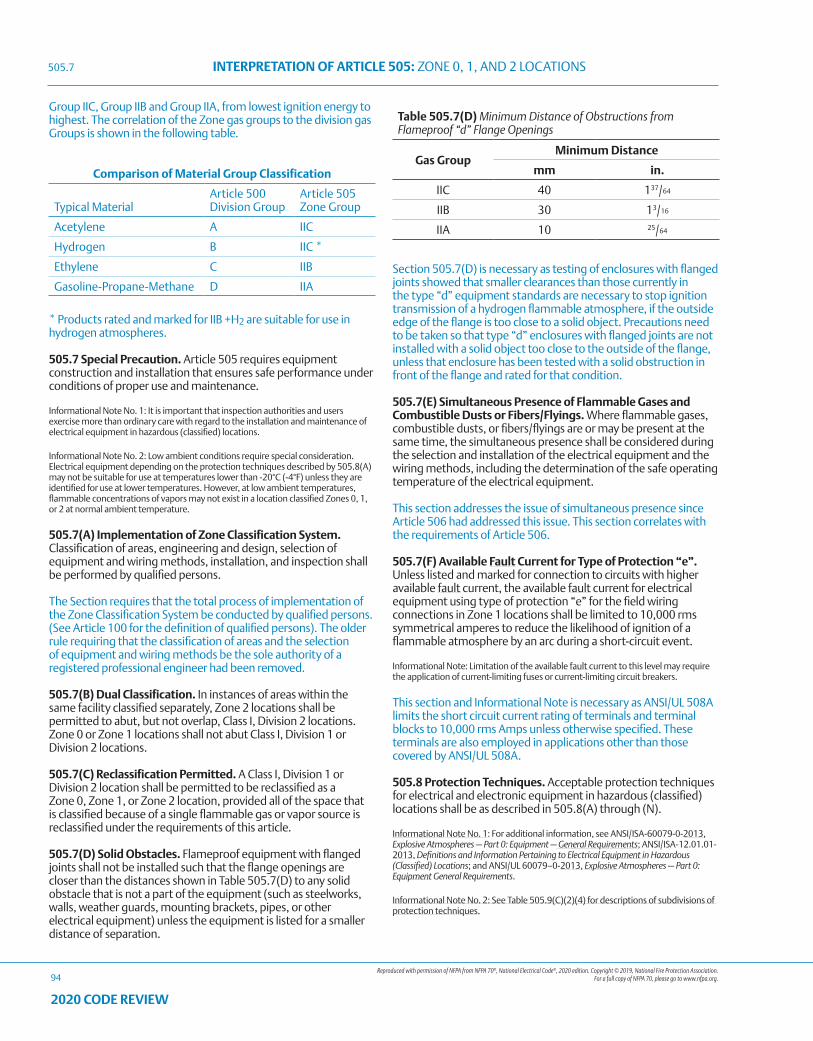
Reproduced with permission of NFPA from NFPA 70®, National Electrical Code®, 2020 edition. Copyright © 2019, National Fire Protection Association. For a full copy of NFPA 70, please go to www.nfpa.org.
INTERPRETATION OF ARTICLE 505: ZONE 0, 1, AND 2 LOCATIONS
94
2020 CODE REVIEW
Group IIC, Group IIB and Group IIA, from lowest ignition energy to highest. The correlation of the Zone gas groups to the division gas Groups is shown in the following table.
Comparison of Material Group Classification
Typical MaterialArticle 500Division Group
Article 505Zone Group
Acetylene A IIC
Hydrogen B IIC *
Ethylene C IIB
Gasoline-Propane-Methane D IIA
* Products rated and marked for IIB +H2 are suitable for use in hydrogen atmospheres.
505.7 Special Precaution. Article 505 requires equipment construction and installation that ensures safe performance under conditions of proper use and maintenance.
Informational Note No. 1: It is important that inspection authorities and users exercise more than ordinary care with regard to the installation and maintenance of electrical equipment in hazardous (classified) locations.
Informational Note No. 2: Low ambient conditions require special consideration. Electrical equipment depending on the protection techniques described by 505.8(A) may not be suitable for use at temperatures lower than -20°C (-4°F) unless they are identified for use at lower temperatures. However, at low ambient temperatures, flammable concentrations of vapors may not exist in a location classified Zones 0, 1, or 2 at normal ambient temperature.
505.7(A) Implementation of Zone Classification System. Classification of areas, engineering and design, selection of equipment and wiring methods, installation, and inspection shall be performed by qualified persons.
The Section requires that the total process of implementation of the Zone Classification System be conducted by qualified persons. (See Article 100 for the definition of qualified persons). The older rule requiring that the classification of areas and the selection of equipment and wiring methods be the sole authority of a registered professional engineer had been removed.
505.7(B) Dual Classification. In instances of areas within the same facility classified separately, Zone 2 locations shall be permitted to abut, but not overlap, Class I, Division 2 locations. Zone 0 or Zone 1 locations shall not abut Class I, Division 1 or Division 2 locations.
505.7(C) Reclassification Permitted. A Class I, Division 1 or Division 2 location shall be permitted to be reclassified as a Zone 0, Zone 1, or Zone 2 location, provided all of the space that is classified because of a single flammable gas or vapor source is reclassified under the requirements of this article.
505.7(D) Solid Obstacles. Flameproof equipment with flanged joints shall not be installed such that the flange openings are closer than the distances shown in Table 505.7(D) to any solid obstacle that is not a part of the equipment (such as steelworks, walls, weather guards, mounting brackets, pipes, or other electrical equipment) unless the equipment is listed for a smaller distance of separation.
Table 505.7(D) Minimum Distance of Obstructions from Flameproof “d” Flange Openings
Gas GroupMinimum Distance
mm in.
IIC 40 137/64
IIB 30 13/16
IIA 10 25/64
Section 505.7(D) is necessary as testing of enclosures with flanged joints showed that smaller clearances than those currently in the type “d” equipment standards are necessary to stop ignition transmission of a hydrogen flammable atmosphere, if the outside edge of the flange is too close to a solid object. Precautions need to be taken so that type “d” enclosures with flanged joints are not installed with a solid object too close to the outside of the flange, unless that enclosure has been tested with a solid obstruction in front of the flange and rated for that condition.
505.7(E) Simultaneous Presence of Flammable Gases and Combustible Dusts or Fibers/Flyings. Where flammable gases, combustible dusts, or fibers/flyings are or may be present at the same time, the simultaneous presence shall be considered during the selection and installation of the electrical equipment and the wiring methods, including the determination of the safe operating temperature of the electrical equipment.
This section addresses the issue of simultaneous presence since Article 506 had addressed this issue. This section correlates with the requirements of Article 506.
505.7(F) Available Fault Current for Type of Protection “e”. Unless listed and marked for connection to circuits with higher available fault current, the available fault current for electrical equipment using type of protection “e” for the field wiring connections in Zone 1 locations shall be limited to 10,000 rms symmetrical amperes to reduce the likelihood of ignition of a flammable atmosphere by an arc during a short-circuit event.
Informational Note: Limitation of the available fault current to this level may require the application of current-limiting fuses or current-limiting circuit breakers.
This section and Informational Note is necessary as ANSI/UL 508A limits the short circuit current rating of terminals and terminal blocks to 10,000 rms Amps unless otherwise specified. These terminals are also employed in applications other than those covered by ANSI/UL 508A.
505.8 Protection Techniques. Acceptable protection techniques for electrical and electronic equipment in hazardous (classified) locations shall be as described in 505.8(A) through (N).
Informational Note No. 1: For additional information, see ANSI/ISA-60079-0-2013, Explosive Atmospheres — Part 0: Equipment — General Requirements; ANSI/ISA-12.01.01-2013, Definitions and Information Pertaining to Electrical Equipment in Hazardous (Classified) Locations; and ANSI/UL 60079–0-2013, Explosive Atmospheres — Part 0: Equipment General Requirements.
Informational Note No. 2: See Table 505.9(C)(2)(4) for descriptions of subdivisions of protection techniques.
505.7
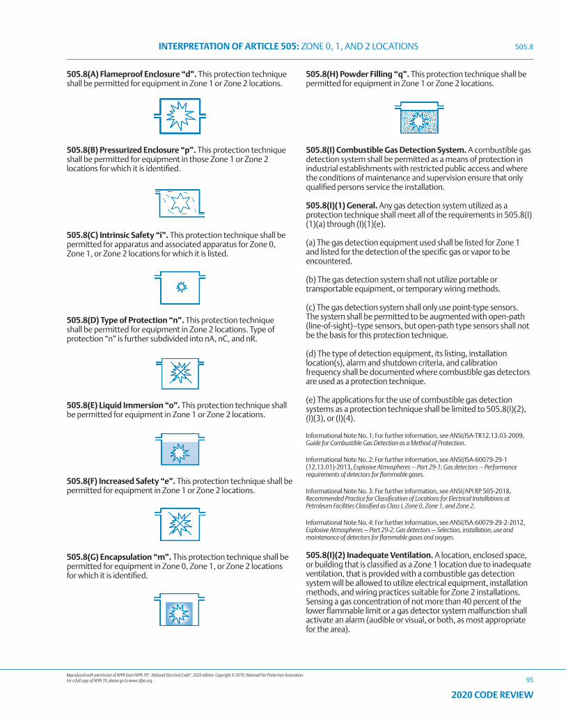
Reproduced with permission of NFPA from NFPA 70®, National Electrical Code®, 2020 edition. Copyright © 2019, National Fire Protection Association. For a full copy of NFPA 70, please go to www.nfpa.org.
INTERPRETATION OF ARTICLE 505: ZONE 0, 1, AND 2 LOCATIONS
95
2020 CODE REVIEW
505.8(A) Flameproof Enclosure “d”. This protection technique shall be permitted for equipment in Zone 1 or Zone 2 locations.
505.8(B) Pressurized Enclosure “p”. This protection technique shall be permitted for equipment in those Zone 1 or Zone 2 locations for which it is identified.
505.8(C) Intrinsic Safety “i”. This protection technique shall be permitted for apparatus and associated apparatus for Zone 0, Zone 1, or Zone 2 locations for which it is listed.
505.8(D) Type of Protection “n”. This protection technique shall be permitted for equipment in Zone 2 locations. Type of protection “n” is further subdivided into nA, nC, and nR.
505.8(E) Liquid Immersion “o”. This protection technique shall be permitted for equipment in Zone 1 or Zone 2 locations.
505.8(F) Increased Safety “e”. This protection technique shall be permitted for equipment in Zone 1 or Zone 2 locations.
505.8(G) Encapsulation “m”. This protection technique shall be permitted for equipment in Zone 0, Zone 1, or Zone 2 locations for which it is identified.
505.8(H) Powder Filling “q”. This protection technique shall be permitted for equipment in Zone 1 or Zone 2 locations.
505.8(I) Combustible Gas Detection System. A combustible gas detection system shall be permitted as a means of protection in industrial establishments with restricted public access and where the conditions of maintenance and supervision ensure that only qualified persons service the installation.
505.8(I)(1) General. Any gas detection system utilized as a protection technique shall meet all of the requirements in 505.8(I)(1)(a) through (I)(1)(e).
(a) The gas detection equipment used shall be listed for Zone 1 and listed for the detection of the specific gas or vapor to be encountered.
(b) The gas detection system shall not utilize portable or transportable equipment, or temporary wiring methods.
(c) The gas detection system shall only use point-type sensors. The system shall be permitted to be augmented with open-path (line-of-sight)–type sensors, but open-path type sensors shall not be the basis for this protection technique.
(d) The type of detection equipment, its listing, installation location(s), alarm and shutdown criteria, and calibration frequency shall be documented where combustible gas detectors are used as a protection technique.
(e) The applications for the use of combustible gas detection systems as a protection technique shall be limited to 505.8(I)(2), (I)(3), or (I)(4).
Informational Note No. 1: For further information, see ANSI/ISA-TR12.13.03-2009, Guide for Combustible Gas Detection as a Method of Protection.
Informational Note No. 2: For further information, see ANSI/ISA-60079-29-1 (12.13.01)-2013, Explosive Atmospheres — Part 29-1: Gas detectors — Performance requirements of detectors for flammable gases.
Informational Note No. 3: For further information, see ANSI/API RP 505-2018, Recommended Practice for Classification of Locations for Electrical Installations at Petroleum Facilities Classified as Class I, Zone 0, Zone 1, and Zone 2.
Informational Note No. 4: For further information, see ANSI/ISA-60079-29-2-2012, Explosive Atmospheres — Part 29-2: Gas detectors — Selection, installation, use and maintenance of detectors for flammable gases and oxygen.
505.8(I)(2) Inadequate Ventilation. A location, enclosed space, or building that is classified as a Zone 1 location due to inadequate ventilation, that is provided with a combustible gas detection system will be allowed to utilize electrical equipment, installation methods, and wiring practices suitable for Zone 2 installations. Sensing a gas concentration of not more than 40 percent of the lower flammable limit or a gas detector system malfunction shall activate an alarm (audible or visual, or both, as most appropriate for the area).
505.8
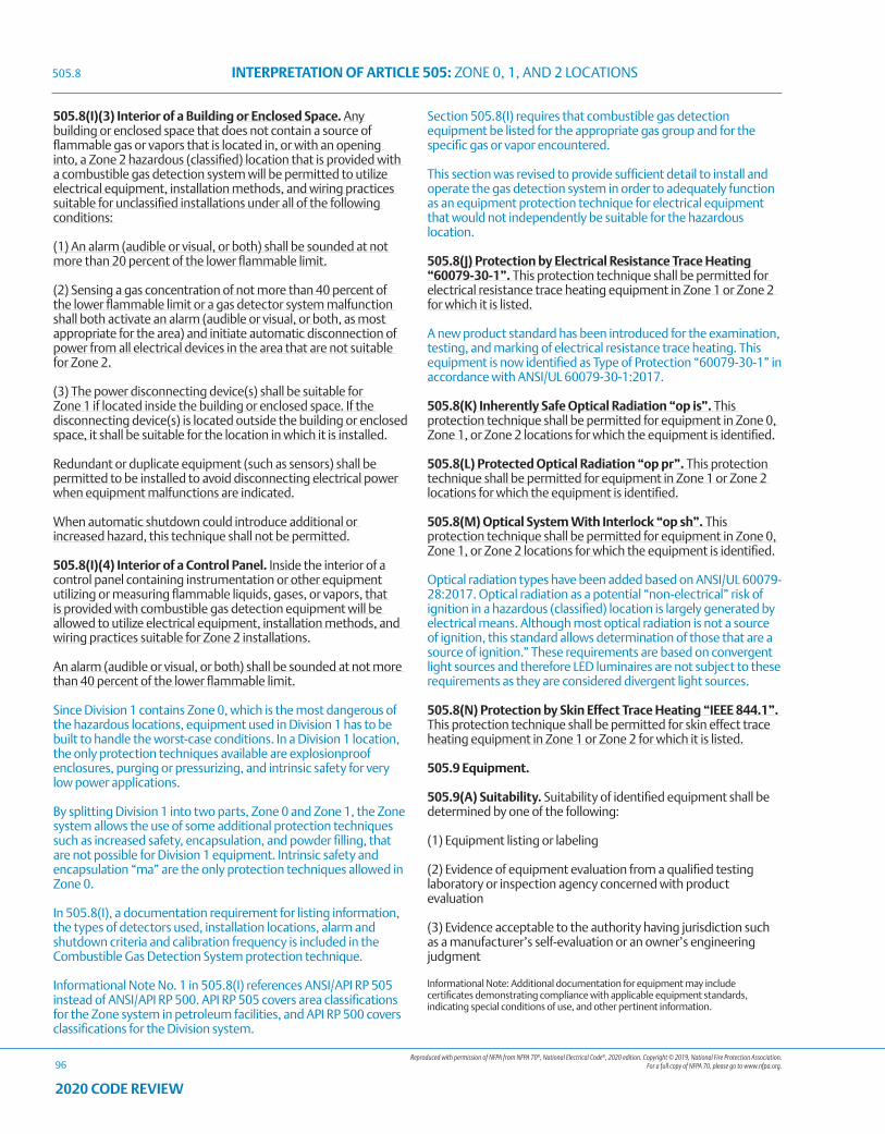
Reproduced with permission of NFPA from NFPA 70®, National Electrical Code®, 2020 edition. Copyright © 2019, National Fire Protection Association. For a full copy of NFPA 70, please go to www.nfpa.org.
INTERPRETATION OF ARTICLE 505: ZONE 0, 1, AND 2 LOCATIONS
96
2020 CODE REVIEW
505.8(I)(3) Interior of a Building or Enclosed Space. Any building or enclosed space that does not contain a source of flammable gas or vapors that is located in, or with an opening into, a Zone 2 hazardous (classified) location that is provided with a combustible gas detection system will be permitted to utilize electrical equipment, installation methods, and wiring practices suitable for unclassified installations under all of the following conditions:
(1) An alarm (audible or visual, or both) shall be sounded at not more than 20 percent of the lower flammable limit.
(2) Sensing a gas concentration of not more than 40 percent of the lower flammable limit or a gas detector system malfunction shall both activate an alarm (audible or visual, or both, as most appropriate for the area) and initiate automatic disconnection of power from all electrical devices in the area that are not suitable for Zone 2.
(3) The power disconnecting device(s) shall be suitable for Zone 1 if located inside the building or enclosed space. If the disconnecting device(s) is located outside the building or enclosed space, it shall be suitable for the location in which it is installed.
Redundant or duplicate equipment (such as sensors) shall be permitted to be installed to avoid disconnecting electrical power when equipment malfunctions are indicated.
When automatic shutdown could introduce additional or increased hazard, this technique shall not be permitted.
505.8(I)(4) Interior of a Control Panel. Inside the interior of a control panel containing instrumentation or other equipment utilizing or measuring flammable liquids, gases, or vapors, that is provided with combustible gas detection equipment will be allowed to utilize electrical equipment, installation methods, and wiring practices suitable for Zone 2 installations.
An alarm (audible or visual, or both) shall be sounded at not more than 40 percent of the lower flammable limit.
Since Division 1 contains Zone 0, which is the most dangerous of the hazardous locations, equipment used in Division 1 has to be built to handle the worst-case conditions. In a Division 1 location, the only protection techniques available are explosionproof enclosures, purging or pressurizing, and intrinsic safety for very low power applications.
By splitting Division 1 into two parts, Zone 0 and Zone 1, the Zone system allows the use of some additional protection techniques such as increased safety, encapsulation, and powder filling, that are not possible for Division 1 equipment. Intrinsic safety and encapsulation “ma” are the only protection techniques allowed in Zone 0.
In 505.8(I), a documentation requirement for listing information, the types of detectors used, installation locations, alarm and shutdown criteria and calibration frequency is included in the Combustible Gas Detection System protection technique.
Informational Note No. 1 in 505.8(I) references ANSI/API RP 505 instead of ANSI/API RP 500. API RP 505 covers area classifications for the Zone system in petroleum facilities, and API RP 500 covers classifications for the Division system.
Section 505.8(I) requires that combustible gas detection equipment be listed for the appropriate gas group and for the specific gas or vapor encountered.
This section was revised to provide sufficient detail to install and operate the gas detection system in order to adequately function as an equipment protection technique for electrical equipment that would not independently be suitable for the hazardous location.
505.8(J) Protection by Electrical Resistance Trace Heating “60079-30-1”. This protection technique shall be permitted for electrical resistance trace heating equipment in Zone 1 or Zone 2 for which it is listed.
A new product standard has been introduced for the examination, testing, and marking of electrical resistance trace heating. This equipment is now identified as Type of Protection “60079-30-1” in accordance with ANSI/UL 60079-30-1:2017.
505.8(K) Inherently Safe Optical Radiation “op is”. This protection technique shall be permitted for equipment in Zone 0, Zone 1, or Zone 2 locations for which the equipment is identified.
505.8(L) Protected Optical Radiation “op pr”. This protection technique shall be permitted for equipment in Zone 1 or Zone 2 locations for which the equipment is identified.
505.8(M) Optical System With Interlock “op sh”. This protection technique shall be permitted for equipment in Zone 0, Zone 1, or Zone 2 locations for which the equipment is identified.
Optical radiation types have been added based on ANSI/UL 60079-28:2017. Optical radiation as a potential “non-electrical” risk of ignition in a hazardous (classified) location is largely generated by electrical means. Although most optical radiation is not a source of ignition, this standard allows determination of those that are a source of ignition.” These requirements are based on convergent light sources and therefore LED luminaires are not subject to these requirements as they are considered divergent light sources.
505.8(N) Protection by Skin Effect Trace Heating “IEEE 844.1”. This protection technique shall be permitted for skin effect trace heating equipment in Zone 1 or Zone 2 for which it is listed.
505.9 Equipment.
505.9(A) Suitability. Suitability of identified equipment shall be determined by one of the following:
(1) Equipment listing or labeling
(2) Evidence of equipment evaluation from a qualified testing laboratory or inspection agency concerned with product evaluation
(3) Evidence acceptable to the authority having jurisdiction such as a manufacturer’s self-evaluation or an owner’s engineering judgment
Informational Note: Additional documentation for equipment may include certificates demonstrating compliance with applicable equipment standards, indicating special conditions of use, and other pertinent information.
505.8
Reproduced with permission of NFPA from NFPA 70®, National Electrical Code®, 2020 edition. Copyright © 2019, National Fire Protection Association. For a full copy of NFPA 70, please go to www.nfpa.org.
INTERPRETATION OF ARTICLE 505: ZONE 0, 1, AND 2 LOCATIONS
97
2020 CODE REVIEW
505.9(B) Listing.
(1) Equipment that is listed for a Zone 0 location shall be permitted in a Zone 1 or Zone 2 location of the same gas or vapor, provided that it is installed in accordance with the requirements for the marked type of protection. Equipment that is listed for a Zone 1 location shall be permitted in a Zone 2 location of the same gas or vapor, provided that it is installed in accordance with the requirements for the marked type of protection.
(2) Equipment shall be permitted to be listed for a specific gas or vapor, specific mixtures of gases or vapors, or any specific combination of gases or vapors.
Informational Note: One common example is equipment marked for “IIB. + H2.”
IMPORTANT: Equipment intended to be installed in NEC® Zone hazardous locations needs to be evaluated to determine its suitability. Equipment that is certified to standards other than those adapted to meet U.S. requirements, may not be suitable for use when installed using NEC® installation techniques, and the electrical portions of the equipment may not even meet the minimum U.S. requirements for use in unclassified locations.
For example, type “db” enclosures evaluated to the IEC® standards assume that cables will be used to connect them to the wiring system, and will be sealed by a cable gland within 50 mm (2 in.) of the enclosure. If the enclosure is connected using conduit, with a seal within 18 inches to NEC® rules, the internal explosion pressure could be higher. The IEC® test gas mixtures used for the explosion transmission testing are also different from those specified in the standards for Division explosionproof equipment. These factors taken together could cause a type “db” enclosure to fail when installed with conduit according to the NEC® rules.
The Informational Note for this section notes the gas group rating IIB +H2 is often used. This is because IIB +H2 in the Zone system corresponds to the Division system Gas Group B.
Intrinsically safe apparatus listed and marked only for Zone 0 needs to be used with the associated apparatus for Zone 0 specified on its control drawing, even if the intrinsically safe apparatus is installed in Zone 1 or Zone 2. If the installation for Zone 1 and/or Zone 2 uses different associated apparatus, it needs to be separately listed and marked for Zone 1 and/or Zone 2, and the specifications for the Zone 1 and/or Zone 2 associated apparatus need to be listed on the control drawing as well.
505.9(C) Marking. Equipment shall be marked in accordance with 505.9(C)(1) or (C)(2).
505.9(C)(1) Division Equipment. Equipment identified for Class I, Division 1 or Class I, Division 2 shall, in addition to being marked in accordance with 500.8(C), be permitted to be marked with all of the following:
(1) Class I, Zone 1 or Zone 1; Class I, Zone 2 or Zone 2 (as applicable)
(2) Applicable gas classification group(s) in accordance with Table 505.9(C)(1)(2)
(3) Temperature classification in accordance with 505.9(D)(1)
Table 505.9(C)(1)(2) Material Groups
Material Group Comment
IIC See 505.6(A)
IIB See 505.6(B)
IIA See 505.6(C)
505.9(C)(2) Zone Equipment. Equipment meeting one or more of the protection techniques described in 505.8 shall be marked with all of the following in the order shown:
This section includes all of the current Zone 0, 1, and 2 protection techniques based on the revised product standards.
(1) Class I (equipment shall be permitted to omit the Class I marking)
“Class I” term is no longer a mandatory marking requirement since the Zone marking identifies the type of material.
(2) Zone [in accordance with Table 505.9(C)(2)(4)]
Item (2) is revised to make it clear that the Zone number must be identified on the equipment.
(3) Symbol “AEx”
(4) Protection technique(s) in accordance with Table 505.9(C)(2)(4)
(5) Applicable material group in accordance with Table 505.9(C)(1)(2) or a specific gas or vapor
(6) Temperature classification in accordance with 505.9(D)(1)
(7) Equipment protection level (EPL)
Item (7) now requires the EPL marking. Equipment Protection Levels (EPL) were added to align with the introduction of the concept in the product standards. The EPL is aligned with the Zone.
EPL’s were introduced as a result of extensive revisions to the 60079 series of Ex standards. These standards were revised to identify the different performance, construction, and marking requirements for each Zone. A suffix “a” to the Protection Method indicates evaluation to Zone 0 with an EPL of Ga. A suffix “b” to the Protection Method indicates evaluation to Zone 1 with an EPL of Gb. A suffix “c” to the Protection Method indicates evaluation to Zone 2 with an EPL of Gc.
Exception No. 1: Associated apparatus NOT suitable for installation in a hazardous (classified) location shall be required to be marked only with (3), (4), and (5), but BOTH the symbol AEx (3) and the symbol for the type of protection (4) shall be enclosed within the same square brackets, for example, [AEx ia Ga] IIC.
Exception No. 1 to 505.9(C)(2)(6) clarifies the use of the square brackets in the marking requirements for intrinsically safe associated apparatus. If the associated apparatus is designed to be installed in the hazardous location, it has to use another method of protection to protect the associated apparatus, and only the output of the hazardous area terminals is intrinsically safe and
505.9
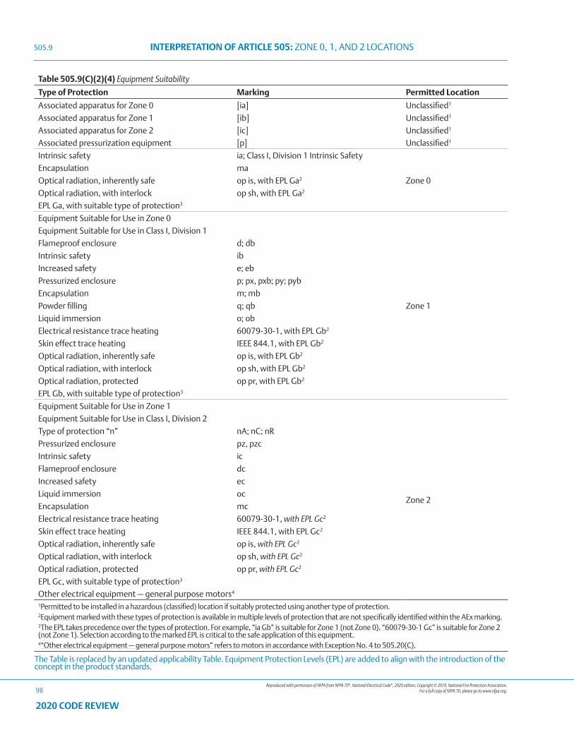
Reproduced with permission of NFPA from NFPA 70®, National Electrical Code®, 2020 edition. Copyright © 2019, National Fire Protection Association. For a full copy of NFPA 70, please go to www.nfpa.org.
INTERPRETATION OF ARTICLE 505: ZONE 0, 1, AND 2 LOCATIONS
98
2020 CODE REVIEW
Table 505.9(C)(2)(4) Equipment Suitability
Type of Protection Marking Permitted Location
Associated apparatus for Zone 0 [ia] Unclassified1
Associated apparatus for Zone 1 [ib] Unclassified1
Associated apparatus for Zone 2 [ic] Unclassified1
Associated pressurization equipment [p] Unclassified1
Intrinsic safety ia; Class I, Division 1 Intrinsic Safety
Zone 0
Encapsulation ma
Optical radiation, inherently safe op is, with EPL Ga2
Optical radiation, with interlock op sh, with EPL Ga2
EPL Ga, with suitable type of protection3
Equipment Suitable for Use in Zone 0
Zone 1
Equipment Suitable for Use in Class I, Division 1
Flameproof enclosure d; db
Intrinsic safety ib
Increased safety e; eb
Pressurized enclosure p; px, pxb; py; pyb
Encapsulation m; mb
Powder filling q; qb
Liquid immersion o; ob
Electrical resistance trace heating 60079-30-1, with EPL Gb2
Skin effect trace heating IEEE 844.1, with EPL Gb2
Optical radiation, inherently safe op is, with EPL Gb2
Optical radiation, with interlock op sh, with EPL Gb2
Optical radiation, protected op pr, with EPL Gb2
EPL Gb, with suitable type of protection3
Equipment Suitable for Use in Zone 1
Zone 2
Equipment Suitable for Use in Class I, Division 2
Type of protection “n” nA; nC; nR
Pressurized enclosure pz, pzc
Intrinsic safety ic
Flameproof enclosure dc
Increased safety ec
Liquid immersion oc
Encapsulation mc
Electrical resistance trace heating 60079-30-1, with EPL Gc2
Skin effect trace heating IEEE 844.1, with EPL Gc2
Optical radiation, inherently safe op is, with EPL Gc2
Optical radiation, with interlock op sh, with EPL Gc2
Optical radiation, protected op pr, with EPL Gc2
EPL Gc, with suitable type of protection3
Other electrical equipment — general purpose motors4
1Permitted to be installed in a hazardous (classified) location if suitably protected using another type of protection.2Equipment marked with these types of protection is available in multiple levels of protection that are not specifically identified within the AEx marking.3The EPL takes precedence over the types of protection. For example, “ia Gb” is suitable for Zone 1 (not Zone 0). “60079-30-1 Gc” is suitable for Zone 2 (not Zone 1). Selection according to the marked EPL is critical to the safe application of this equipment. 4“Other electrical equipment — general purpose motors” refers to motors in accordance with Exception No. 4 to 505.20(C).
The Table is replaced by an updated applicability Table. Equipment Protection Levels (EPL) are added to align with the introduction of the concept in the product standards.
505.9
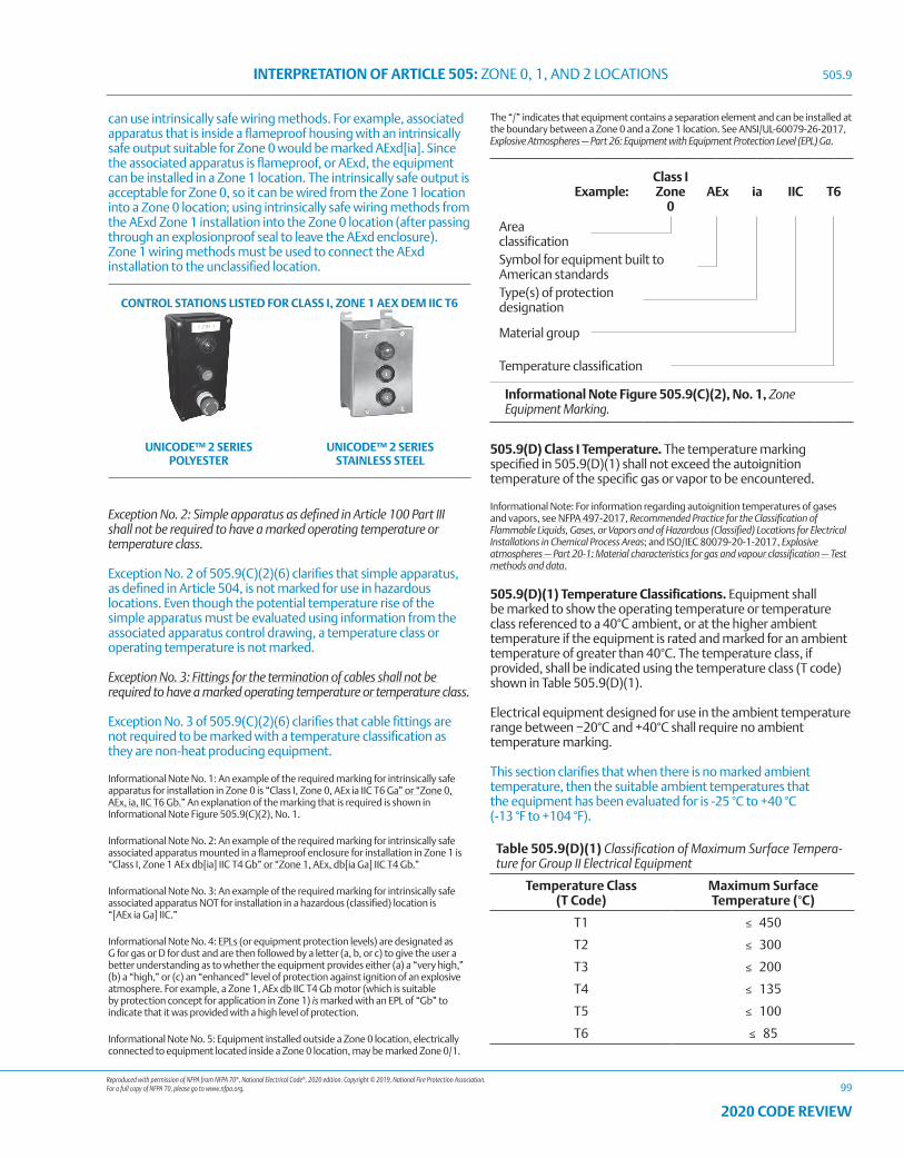
Reproduced with permission of NFPA from NFPA 70®, National Electrical Code®, 2020 edition. Copyright © 2019, National Fire Protection Association. For a full copy of NFPA 70, please go to www.nfpa.org.
INTERPRETATION OF ARTICLE 505: ZONE 0, 1, AND 2 LOCATIONS
99
2020 CODE REVIEW
can use intrinsically safe wiring methods. For example, associated apparatus that is inside a flameproof housing with an intrinsically safe output suitable for Zone 0 would be marked AExd[ia]. Since the associated apparatus is flameproof, or AExd, the equipment can be installed in a Zone 1 location. The intrinsically safe output is acceptable for Zone 0, so it can be wired from the Zone 1 location into a Zone 0 location; using intrinsically safe wiring methods from the AExd Zone 1 installation into the Zone 0 location (after passing through an explosionproof seal to leave the AExd enclosure). Zone 1 wiring methods must be used to connect the AExd installation to the unclassified location.
CONTROL STATIONS LISTED FOR CLASS I, ZONE 1 AEX DEM IIC T6
UNICODE™ 2 SERIES POLYESTER
UNICODE™ 2 SERIES STAINLESS STEEL
Exception No. 2: Simple apparatus as defined in Article 100 Part III shall not be required to have a marked operating temperature or temperature class.
Exception No. 2 of 505.9(C)(2)(6) clarifies that simple apparatus, as defined in Article 504, is not marked for use in hazardous locations. Even though the potential temperature rise of the simple apparatus must be evaluated using information from the associated apparatus control drawing, a temperature class or operating temperature is not marked.
Exception No. 3: Fittings for the termination of cables shall not be required to have a marked operating temperature or temperature class.
Exception No. 3 of 505.9(C)(2)(6) clarifies that cable fittings are not required to be marked with a temperature classification as they are non-heat producing equipment.
Informational Note No. 1: An example of the required marking for intrinsically safe apparatus for installation in Zone 0 is “Class I, Zone 0, AEx ia IIC T6 Ga” or “Zone 0, AEx, ia, IIC T6 Gb.” An explanation of the marking that is required is shown in Informational Note Figure 505.9(C)(2), No. 1.
Informational Note No. 2: An example of the required marking for intrinsically safe associated apparatus mounted in a flameproof enclosure for installation in Zone 1 is “Class I, Zone 1 AEx db[ia] IIC T4 Gb” or “Zone 1, AEx, db[ia Ga] IIC T4 Gb.”
Informational Note No. 3: An example of the required marking for intrinsically safe associated apparatus NOT for installation in a hazardous (classified) location is “[AEx ia Ga] IIC.”
Informational Note No. 4: EPLs (or equipment protection levels) are designated as G for gas or D for dust and are then followed by a letter (a, b, or c) to give the user a better understanding as to whether the equipment provides either (a) a “very high,” (b) a “high,” or (c) an “enhanced” level of protection against ignition of an explosive atmosphere. For example, a Zone 1, AEx db IIC T4 Gb motor (which is suitable by protection concept for application in Zone 1) is marked with an EPL of “Gb” to indicate that it was provided with a high level of protection.
Informational Note No. 5: Equipment installed outside a Zone 0 location, electrically connected to equipment located inside a Zone 0 location, may be marked Zone 0/1.
The “/” indicates that equipment contains a separation element and can be installed at the boundary between a Zone 0 and a Zone 1 location. See ANSI/UL-60079-26-2017, Explosive Atmospheres — Part 26: Equipment with Equipment Protection Level (EPL) Ga.
Example:Class I Zone
0AEx ia IIC T6
Area classificationSymbol for equipment built to American standardsType(s) of protection designation
Material group
Temperature classification
Informational Note Figure 505.9(C)(2), No. 1, Zone Equipment Marking.
505.9(D) Class I Temperature. The temperature marking specified in 505.9(D)(1) shall not exceed the autoignition temperature of the specific gas or vapor to be encountered.
Informational Note: For information regarding autoignition temperatures of gases and vapors, see NFPA 497-2017, Recommended Practice for the Classification of Flammable Liquids, Gases, or Vapors and of Hazardous (Classified) Locations for Electrical Installations in Chemical Process Areas; and ISO/IEC 80079-20-1-2017, Explosive atmospheres — Part 20-1: Material characteristics for gas and vapour classification — Test methods and data.
505.9(D)(1) Temperature Classifications. Equipment shall be marked to show the operating temperature or temperature class referenced to a 40°C ambient, or at the higher ambient temperature if the equipment is rated and marked for an ambient temperature of greater than 40°C. The temperature class, if provided, shall be indicated using the temperature class (T code) shown in Table 505.9(D)(1).
Electrical equipment designed for use in the ambient temperature range between −20°C and +40°C shall require no ambient temperature marking.
This section clarifies that when there is no marked ambient temperature, then the suitable ambient temperatures that the equipment has been evaluated for is -25 °C to +40 °C (-13 °F to +104 °F).
Table 505.9(D)(1) Classification of Maximum Surface Tempera-ture for Group II Electrical Equipment
Temperature Class (T Code)
Maximum Surface Temperature (°C)
T1 ≤ 450
T2 ≤ 300
T3 ≤ 200
T4 ≤ 135
T5 ≤ 100
T6 ≤ 85
505.9
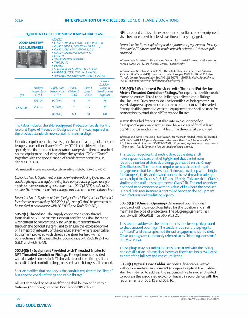
Reproduced with permission of NFPA from NFPA 70®, National Electrical Code®, 2020 edition. Copyright © 2019, National Fire Protection Association. For a full copy of NFPA 70, please go to www.nfpa.org.
INTERPRETATION OF ARTICLE 505: ZONE 0, 1, AND 2 LOCATIONS
100
2020 CODE REVIEW
The table includes the EPL (Equipment Protection Levels) for the relevant Types of Protection Designations. This was required as the product standards now contain these markings.
Electrical equipment that is designed for use in a range of ambient temperatures other than −20°C to +40°C is considered to be special; and the ambient temperature range shall then be marked on the equipment, including either the symbol “Ta” or “Tamb” together with the special range of ambient temperatures, in degrees Celsius.
Informational Note: As an example, such a marking might be “−30°C to +40°C.”
Exception No. 1: Equipment of the non–heat-producing type, such as conduit fittings, and equipment of the heat-producing type having a maximum temperature of not more than 100°C (212°F) shall not be required to have a marked operating temperature or temperature class.
Exception No. 2: Equipment identified for Class I, Division 1 or Division 2 locations as permitted by 505.20(A), (B), and (C) shall be permitted to be marked in accordance with 505.8(C) and Table 500.8(C).
505.9(E) Threading. The supply connection entry thread form shall be NPT or metric. Conduit and fittings shall be made wrenchtight to prevent sparking when fault current flows through the conduit system, and to ensure the explosionproof or flameproof integrity of the conduit system where applicable. Equipment provided with threaded entries for field wiring connections shall be installed in accordance with 505.9(E)(1) or (E)(2) and with (E)(3).
505.9(E)(1) Equipment Provided with Threaded Entries for NPT Threaded Conduit or Fittings. For equipment provided with threaded entries for NPT threaded conduit or fittings, listed conduit, listed conduit fittings, or listed cable fittings shall be used.
Section clarifies that not only is the conduit required to be “listed” but also the conduit fittings and cable fittings.
All NPT threaded conduit and fittings shall be threaded with a National (American) Standard Pipe Taper (NPT) thread.
NPT threaded entries into explosionproof or flameproof equipment shall be made up with at least five threads fully engaged.
Exception: For listed explosionproof or flameproof equipment, factory-threaded NPT entries shall be made up with at least 41∕2 threads fully engaged.
Informational Note No. 1: Thread specifications for male NPT threads are located in ASME B1.20.1-2013, Pipe Threads, General Purpose (Inch).
Informational Note No. 2: Female NPT threaded entries use a modified National Standard Pipe Taper (NPT) thread with thread form per ASME B1.20.1-2013, Pipe Threads, General Purpose (Inch). See ANSI/UL 60079-1:2015, Explosive Atmospheres — Part 1: Equipment Protection by Flameproof Enclosures “d.”
505.9(E)(2) Equipment Provided with Threaded Entries for Metric Threaded Conduit or Fittings. For equipment with metric threaded entries, listed conduit fittings or listed cable fittings shall be used. Such entries shall be identified as being metric, or listed adapters to permit connection to conduit or NPT threaded fittings shall be provided with the equipment and shall be used for connection to conduit or NPT threaded fittings.
Metric threaded fittings installed into explosionproof or flameproof equipment entries shall have a class of fit of at least 6g/6H and be made up with at least five threads fully engaged.
Informational Note: Threading specifications for metric threaded entries are located in ISO 965-1-2013, ISO general purpose metric screw threads — Tolerances — Part 1: Principles and basic data, and ISO 965-3-2009, ISO general purpose metric screw threads — Tolerances — Part 3: Deviations for constructional screw threads.
This section requires that metric threaded entries shall have a specified class of fit of 6g/gH and that a minimum required number of threads are engaged based on the Group Classifications. The intended requirement is that the thread engagement shall be no less than 5 threads made up wrenchtight for Groups C, D, IIB, and IIA and no less than 8 threads made up wrenchtight for Groups A, B, IIC, and IIB +H2. This metric fit Class is similar to the unified straight thread Class 2 fit. The end-user does not need to be concerned with this class of fit where the product is listed. This requirement is controlled between the equipment manufacturer and the listing agency.
505.9(E)(3) Unused Openings. All unused openings shall be closed with close-up plugs listed for the location and shall maintain the type of protection. The plug engagement shall comply with 505.9(E)(1) or 505.9(E)(2).
This section addresses the requirements for close-up plugs used to close unused openings. The section requires these plugs to be “listed” and that a specified thread engagement is provided. Close-up plugs are commonly referred to as “blanking elements” and visa-versa.
These plugs may not independently be marked with the listing and classification information, however they have been evaluated as part of the full box and enclosure listing.
505.9(F) Optical Fiber Cables. An optical fiber cable, with or without current-carrying current (composite optical fiber cable), shall be installed to address the associated fire hazard and sealed to address the associated explosion hazard in accordance with the requirements of 505.15 and 505.16.
505.9
EQUIPMENT LABELED TO SHOW TEMPERATURE CLASS
CODE•MASTER™
LED LUMINAIRES
NEC/CEC:• CLASS I, DIVISION 1 AND 2, GROUPS B, C, D • CLASS I, ZONE 1, GROUPS IIA, IIB, IIB + H2• CLASS II, DIVISION 1, GROUP E, F, G• CLASS II, DIVISION 2, GROUP F, G• CLASS III• SIMULTANEOUS EXPOSURE• TYPE 3R, 4X• IP66/67• SUITABLE FOR USE IN WET LOCATIONS• MARINE OUTSIDE TYPE (SALT WATER) • APPROVED FOR USE IN PAINT SPRAY BOOTHS
Type
Ambient Temperature
C° (F°)
Supply WireTemperature
C° (F°)
Class I, Division 1
(Gas)
Class I, Zone 1 (Gas)
Class II Division 1 (Dust) &
Simultaneous Exposure
CMLED40
40 (104) 90 (104) T6 T6 T6
55 (131) 90 (104) T5 T5 T5
90 (104) T4A T4 T4A
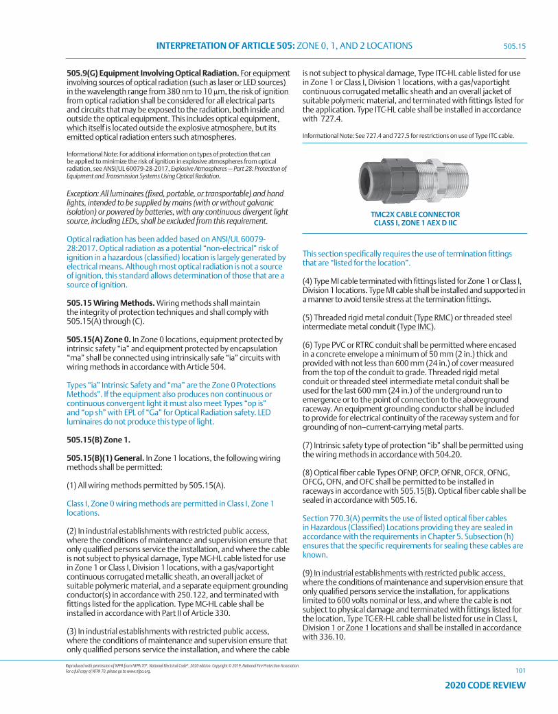
Reproduced with permission of NFPA from NFPA 70®, National Electrical Code®, 2020 edition. Copyright © 2019, National Fire Protection Association. For a full copy of NFPA 70, please go to www.nfpa.org.
INTERPRETATION OF ARTICLE 505: ZONE 0, 1, AND 2 LOCATIONS
101
2020 CODE REVIEW
505.9(G) Equipment Involving Optical Radiation. For equipment involving sources of optical radiation (such as laser or LED sources) in the wavelength range from 380 nm to 10 μm, the risk of ignition from optical radiation shall be considered for all electrical parts and circuits that may be exposed to the radiation, both inside and outside the optical equipment. This includes optical equipment, which itself is located outside the explosive atmosphere, but its emitted optical radiation enters such atmospheres.
Informational Note: For additional information on types of protection that can be applied to minimize the risk of ignition in explosive atmospheres from optical radiation, see ANSI/UL 60079-28-2017, Explosive Atmospheres — Part 28: Protection of Equipment and Transmission Systems Using Optical Radiation.
Exception: All luminaires (fixed, portable, or transportable) and hand lights, intended to be supplied by mains (with or without galvanic isolation) or powered by batteries, with any continuous divergent light source, including LEDs, shall be excluded from this requirement.
Optical radiation has been added based on ANSI/UL 60079-28:2017. Optical radiation as a potential “non-electrical” risk of ignition in a hazardous (classified) location is largely generated by electrical means. Although most optical radiation is not a source of ignition, this standard allows determination of those that are a source of ignition.
505.15 Wiring Methods. Wiring methods shall maintain the integrity of protection techniques and shall comply with 505.15(A) through (C).
505.15(A) Zone 0. In Zone 0 locations, equipment protected by intrinsic safety “ia” and equipment protected by encapsulation “ma” shall be connected using intrinsically safe “ia” circuits with wiring methods in accordance with Article 504.
Types “ia” Intrinsic Safety and “ma” are the Zone 0 Protections Methods”. If the equipment also produces non continuous or continuous convergent light it must also meet Types “op is” and “op sh” with EPL of “Ga” for Optical Radiation safety. LED luminaires do not produce this type of light.
505.15(B) Zone 1.
505.15(B)(1) General. In Zone 1 locations, the following wiring methods shall be permitted:
(1) All wiring methods permitted by 505.15(A).
Class I, Zone 0 wiring methods are permitted in Class I, Zone 1 locations.
(2) In industrial establishments with restricted public access, where the conditions of maintenance and supervision ensure that only qualified persons service the installation, and where the cable is not subject to physical damage, Type MC-HL cable listed for use in Zone 1 or Class I, Division 1 locations, with a gas/vaportight continuous corrugated metallic sheath, an overall jacket of suitable polymeric material, and a separate equipment grounding conductor(s) in accordance with 250.122, and terminated with fittings listed for the application. Type MC-HL cable shall be installed in accordance with Part II of Article 330.
(3) In industrial establishments with restricted public access, where the conditions of maintenance and supervision ensure that only qualified persons service the installation, and where the cable
is not subject to physical damage, Type ITC-HL cable listed for use in Zone 1 or Class I, Division 1 locations, with a gas/vaportight continuous corrugated metallic sheath and an overall jacket of suitable polymeric material, and terminated with fittings listed for the application. Type ITC-HL cable shall be installed in accordance with 727.4.
Informational Note: See 727.4 and 727.5 for restrictions on use of Type ITC cable.
TMC2X CABLE CONNECTOR CLASS I, ZONE 1 AEX D IIC
This section specifically requires the use of termination fittings that are “listed for the location”.
(4) Type MI cable terminated with fittings listed for Zone 1 or Class I, Division 1 locations. Type MI cable shall be installed and supported in a manner to avoid tensile stress at the termination fittings.
(5) Threaded rigid metal conduit (Type RMC) or threaded steel intermediate metal conduit (Type IMC).
(6) Type PVC or RTRC conduit shall be permitted where encased in a concrete envelope a minimum of 50 mm (2 in.) thick and provided with not less than 600 mm (24 in.) of cover measured from the top of the conduit to grade. Threaded rigid metal conduit or threaded steel intermediate metal conduit shall be used for the last 600 mm (24 in.) of the underground run to emergence or to the point of connection to the aboveground raceway. An equipment grounding conductor shall be included to provide for electrical continuity of the raceway system and for grounding of non–current-carrying metal parts.
(7) Intrinsic safety type of protection “ib” shall be permitted using the wiring methods in accordance with 504.20.
(8) Optical fiber cable Types OFNP, OFCP, OFNR, OFCR, OFNG, OFCG, OFN, and OFC shall be permitted to be installed in raceways in accordance with 505.15(B). Optical fiber cable shall be sealed in accordance with 505.16.
Section 770.3(A) permits the use of listed optical fiber cables in Hazardous (Classified) Locations providing they are sealed in accordance with the requirements in Chapter 5. Subsection (h) ensures that the specific requirements for sealing these cables are known.
(9) In industrial establishments with restricted public access, where the conditions of maintenance and supervision ensure that only qualified persons service the installation, for applications limited to 600 volts nominal or less, and where the cable is not subject to physical damage and terminated with fittings listed for the location, Type TC-ER-HL cable shall be listed for use in Class I, Division 1 or Zone 1 locations and shall be installed in accordance with 336.10.
505.15
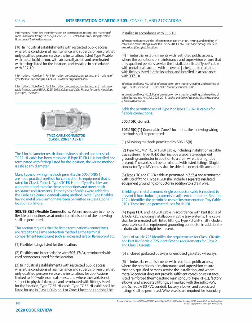
Reproduced with permission of NFPA from NFPA 70®, National Electrical Code®, 2020 edition. Copyright © 2019, National Fire Protection Association. For a full copy of NFPA 70, please go to www.nfpa.org.
INTERPRETATION OF ARTICLE 505: ZONE 0, 1, AND 2 LOCATIONS
102
2020 CODE REVIEW
Informational Note: See the information on construction, testing, and marking of cables and cable fittings in ANSI/UL 2225-2013, Cables and Cable-Fittings for Use in Hazardous (Classified) Locations.
(10) In industrial establishments with restricted public access, where the conditions of maintenance and supervision ensure that only qualified persons service the installation, listed Type P cable with metal braid armor, with an overall jacket, and terminated with fittings listed for the location, and installed in accordance with 337.10.
Informational Note No. 1: For information on construction, testing, and marking of Type P cable, see ANSI/UL 1309-2017, Marine Shipboard Cable.
Informational Note No. 2: For information on construction, testing, and marking of cable fittings, see ANSI/UL 2225-2013, Cables and Cable-Fittings for Use in Hazardous (Classified) Locations.
TMC2 CABLE CONNECTOR CLASS I, ZONE 1 AEX E II
The 1 inch diameter restriction previously placed on the use of TC-ER-HL cable has been removed. If Type TC-ER-HL is installed and terminated with fittings listed for the location, the wiring method is safe at any diameter.
Many types of wiring methods permitted in 505.15(B)(1) are not a practical method for connection to equipment that is rated for Class I, Zone 1. Types TC-ER-HL and Type P cables are a good method to make these connections and meet crush resistance requirements. These types of cables were added to the Code as a Zone 1 general wiring method. Note: Type P cables having metal braid armor have been permitted in Class I, Zone 1 locations offshore.
505.15(B)(2) Flexible Connections. Where necessary to employ flexible connections, as at motor terminals, one of the following shall be permitted:
This section requires that the listed terminations (connectors) are rated to the same protection method as the terminal compartment (enclosure) such as increased safety, flameproof etc.
(1) Flexible fittings listed for the location.
(2) Flexible cord in accordance with 505.17(A), terminated with cord connectors listed for the location.
(3) In industrial establishments with restricted public access, where the conditions of maintenance and supervision ensure that only qualified persons service the installation, for applications limited to 600 volts nominal or less, and where the cable is not subject to physical damage, and terminated with fittings listed for the location, Type TC-ER-HL cable. Type TC-ER-HL cable shall be listed for use in Class I, Division 1 or Zone 1 locations and shall be
installed in accordance with 336.10.
Informational Note: See the information on construction, testing, and marking of cables and cable fittings in ANSI/UL 2225-2013, Cables and Cable-Fittings for Use in Hazardous (Classified) Locations.
(4) In industrial establishments with restricted public access, where the conditions of maintenance and supervision ensure that only qualified persons service the installation, listed Type P cable with metal braid armor, with an overall jacket, and terminated with fittings listed for the location, and installed in accordance with 337.10.
Informational Note No. 1: For information on construction, testing, and marking of Type P cable, see ANSI/UL 1309-2017, Marine Shipboard Cable.
Informational Note No. 2: For information on construction, testing, and marking of cable fittings, see ANSI/UL 2225-2013, Cables and Cable-Fittings for Use in Hazardous (Classified) Locations.
Adds the permitted use of Type P or Types TC-ER-HL cables for flexible connections.
505.15(C) Zone 2.
505.15(C)(1) General. In Zone 2 locations, the following wiring methods shall be permitted:
(1) All wiring methods permitted by 505.15(B).
(2) Type MC, MV, TC, or TC-ER cable, including installation in cable tray systems. Type TC-ER shall include a separate equipment grounding conductor in addition to a drain wire that might be present. The cable shall be terminated with listed fittings. Single conductor Type MV cables shall be shielded or metallic-armored.
(3) Types ITC and ITC-ER cable as permitted in 727.4 and terminated with listed fittings. Type ITC-ER shall include a separate insulated equipment grounding conductor in addition to a drain wire.
Shielding of metal armored single conductor cable is required to prevent it from inducing currents in adjacent conductors. Section 727.4 identifies the permitted uses of Instrumentation Tray Cable (ITC). These include permitted uses for ITC-ER.
(4) Types PLTC and PLTC-ER cable in accordance with Part II or III of Article 725, including installation in cable tray systems. The cable shall be terminated with listed fittings. Type PLTC-ER shall include a separate insulated equipment grounding conductor in addition to a drain wire that might be present.
Part II of Article 725 identifies the requirements for Class I Circuits and Part III of Article 725 identifies the requirements for Class 2 and Class 3 Circuits.
(5) Enclosed gasketed busways or enclosed gasketed wireways.
(6) In industrial establishments with restricted public access, where the conditions of maintenance and supervision ensure that only qualified persons service the installation, and where metallic conduit does not provide sufficient corrosion resistance, listed reinforced thermosetting resin conduit (Type RTRC), factory elbows, and associated fittings, all marked with the suffix -XW, and Schedule 80 PVC conduit, factory elbows, and associated fittings shall be permitted. Where seals are required for boundary
505.15
Reproduced with permission of NFPA from NFPA 70®, National Electrical Code®, 2020 edition. Copyright © 2019, National Fire Protection Association. For a full copy of NFPA 70, please go to www.nfpa.org.
INTERPRETATION OF ARTICLE 505: ZONE 0, 1, AND 2 LOCATIONS
103
2020 CODE REVIEW
conditions as defined in 505.16(C)(1)(b), the Zone 1 wiring method shall extend into the Zone 2 area to the seal, which shall be located on the Zone 2 side of the Zone 1/Zone 2 boundary.
This section permits RTRC conduit and Schedule 80 PVC conduit in Class I, Zone 2 areas of industrial establishments and where additional corrosion resistance is required. RTRC conduit is required to be “listed”.
(7) Intrinsic safety type of protection “ic” shall be permitted using any of the wiring methods permitted for unclassified locations. Intrinsic safety type of protection “ic” systems shall be installed in accordance with the control drawing(s). Simple apparatus, not shown on the control drawing, shall be permitted in an intrinsic safety type of protection “ic” circuit, provided that the simple apparatus does not interconnect the intrinsic safety type of protection “ic” systems to any other circuit.
Separate intrinsic safety type of protection “ic” systems shall be installed in accordance with one of the following:
a. In separate cables
b. In multiconductor cables where the conductors of each circuit are within a grounded metal shield
c. In multiconductor cables where the conductors of each circuit have insulation with a minimum thickness of 0.25 mm (0.01 in.)
Informational Note: Simple apparatus is defined in Article 100 Part III.
(8) Optical fiber cable of Types OFNP, OFCP, OFNR, OFCR, OFNG, OFCG, OFN, and OFC shall be permitted to be installed in cable trays or any other raceway in accordance with 505.15(C). Optical fiber cable shall be sealed in accordance with 505.16.
(9) Cablebus.
(10) In industrial establishments with restricted public access, where the conditions of maintenance and supervision ensure that only qualified persons service the installation, listed Type P cable with or without metal braid armor, with an overall jacket, and terminated with fittings listed for the location, and installed in accordance with 337.10.
Informational Note No. 1: For information on construction, testing, and marking of Type P cable, see ANSI/UL 1309-2017, Marine Shipboard Cable.
Informational Note No. 2: For information on construction, testing, and marking of cable fittings, see ANSI/UL 2225-2013, Cables and Cable-Fittings for Use in Hazardous (Classified) Locations.
This section permits a relatively new protection technique for Zone 2 locations. The “ic” and “[ic]” methods are contained in the ANSI standard for Intrinsic Safety.
Type “-ER” cable constructions used in a hazardous (classified) locations must include an equipment grounding conductor and the drain or shield conductor may not be used for that purpose.
505.15(C)(2) Flexible Connections. Where provision must be made for flexibility, one or more of the following shall be permitted:
(1) Listed flexible metal fittings.
(2) Flexible metal conduit with listed fittings.
(3) Interlocked armor Type MC cable with listed fittings.
(4) Type P cable.
(5) Type TC-ER or Type TC-ER-HL cable.
(6) Type ITC-ER or Type ITC-HL cable.
(7) Type PLTC-ER cable.
(8) Liquidtight flexible metal conduit with listed fittings.
(9) Liquidtight flexible nonmetallic conduit with listed fittings.
(10) Flexible cord in accordance with the provisions of 505.17 terminated with a listed cord connector that maintains the type of protection of the terminal compartment shall be permitted.
(11) For elevator use, an identified elevator cable of Type EO, ETP, or ETT, shown under the “use” column in Table 400.4 for “hazardous (classified) locations” and terminated with listed fittings.
Informational Note: See 505.25(B) for grounding requirements where flexible conduit is used.
Type EO, ETP, or ETT are now specifically permitted in the section for elevator use as these are recognized in Table 400.4 for hazardous (classified) locations.
505.16 Sealing and Drainage. Seals in conduit and cable systems shall comply with 505.16(A) through (E). Sealing compound shall be used in Type MI cable termination fittings to exclude moisture and other fluids from the cable insulation.
Informational Note No. 1: Seals are provided in conduit and cable systems to minimize the passage of gases and vapors and prevent the passage of flames from one portion of the electrical installation to another through the conduit. Such communication through Type MI cable is inherently prevented by construction of the cable. Unless specifically designed and tested for the purpose, conduit and cable seals are not intended to prevent the passage of liquids, gases, or vapors at a continuous pressure differential across the seal. Even at differences in pressure across the seal equivalent to a few inches of water, there may be a slow passage of gas or vapor through a seal and through conductors passing through the seal. See 505.16(C)(2)(b). Temperature extremes and highly corrosive liquids and vapors can affect the ability of seals to perform their intended function. See 505.16(D)(2).
Informational Note No. 2: Gas or vapor leakage and propagation of flames may occur through the interstices between the strands of standard stranded conductors larger than 2 AWG. Special conductor constructions, for example, compacted strands or sealing of the individual strands, are means of reducing leakage and preventing the propagation of flames.
505.16(A) Zone 0. In Zone 0 locations, seals shall be located according to 505.16(A)(1), (A)(2), and (A)(3).
505.16(A)(1) Conduit Seals. Seals shall be provided within 3.05 m (10 ft) of where a conduit leaves a Zone 0 location. There shall be no unions, couplings, boxes, or fittings, except listed reducers at the seal, in the conduit run between the seal and the point at which the conduit leaves the location.
Exception: A rigid unbroken conduit that passes completely through the Zone 0 location with no fittings less than 300 mm (12 in.) beyond each boundary shall not be required to be sealed if the termination points of the unbroken conduit are in unclassified locations.
505.16
Reproduced with permission of NFPA from NFPA 70®, National Electrical Code®, 2020 edition. Copyright © 2019, National Fire Protection Association. For a full copy of NFPA 70, please go to www.nfpa.org.
INTERPRETATION OF ARTICLE 505: ZONE 0, 1, AND 2 LOCATIONS
104
2020 CODE REVIEW
505.16(A)(2) Cable Seals. Seals shall be provided on cables at the first point of termination after entry into the Zone 0 location.
505.16(A)(3) Not Required to Be Explosionproof or Flameproof. Seals shall not be required to be explosionproof or flameproof.
505.16(B) Zone 1. In Zone 1 locations, seals shall be located in accordance with 505.16(B)(1) through (B)(8).
505.16(B)(1) Type of Protection “d”, “db”, “e”, or “eb” Enclosures. Conduit seals shall be provided within 50 mm (2 in.) for each conduit entering enclosures having type of protection “d”, “db”, “e”, or “eb”.
Exception No. 1: Where the enclosure having type of protection “d” or “db” is marked to indicate that a seal is not required.
Exception No. 2: For type of protection “e” or “eb”, conduit and fittings employing only NPT to NPT raceway joints or fittings listed for type of protection “e” or “eb” shall be permitted between the enclosure and the seal, and the seal shall not be required to be within 50 mm (2 in.) of the entry.
Informational Note: Examples of fittings employing other than NPT threads include conduit couplings, capped elbows, unions, and breather drains.
Exception No. 3: For conduit installed between type of protection “e” or “eb” enclosures employing only NPT to NPT raceway joints or conduit fittings listed for type of protection “e” or “eb”, a seal shall not be required.
ANSI/UL 60079-1 now recognizes and marks equipment as “db” for Zone 1, replacing the former marking of “d”. ANSI/UL 60079-7 now recognizes and marks equipment as “eb” for Zone 1, replacing the former marking of “e”.
505.16(B)(1) requires a conduit seal within 50 mm (2 in.) of a type “d” or “e” enclosure, instead of just stating that seals are required.
Exceptions 2 and 3 are to make type “e” equipment easier to install in Zone 1 locations.
Exception 2 to 505.16(B)(1) allows a close nipple, elbow, or other NPT threaded fitting to be used between a type “e” enclosure and the conduit seal, thus allowing the seal to be more than 50 mm (2 in.) from the enclosure. This is allowable because type “e” equipment is designed to prevent ignitions from occurring by using widely spaced terminals that are mechanically protected from loosening in service. The enclosures of type “e” equipment are not designed to contain an explosion like type “d” enclosures are. The distance that a conduit seal is located from the enclosure can affect the explosion pressure inside a type “d” enclosure, but is not a factor in a type “e” enclosure. There are often many connections made to type “e” junction boxes, and allowing the conduit seal to be further away from the type “e” enclosure makes installation much easier.
Because of the fact that explosions do not occur in type “e” enclosures and explosion pressure is not an issue, Exception 3 to Section 505.16(B)(1) allows the conduit seal to be eliminated when type “e” enclosures are connected only to each other, using conduit and fittings with NPT joints only. Seals are still required if one end of the conduit is connected to a type “d” enclosure or crosses an area classification boundary.
505.16(B)(2) Explosionproof Equipment. Conduit seals shall be provided for each conduit entering explosionproof equipment according to 505.16(B)(2)(a), (B)(2)(b), and (B)(2)(c).
In each conduit entry into an explosionproof enclosure where either of the following conditions apply:
(1) The enclosure contains apparatus, such as switches, circuit breakers, fuses, relays, or resistors that may produce arcs, sparks, or high temperatures that are considered to be an ignition source in normal operation. For the purposes of this section, high temperatures shall be considered to be any temperatures exceeding 80 percent of the autoignition temperature in degrees Celsius of the gas or vapor involved.
Exception: Seals shall not be required for conduit entering an enclosure where such switches, circuit breakers, fuses, relays, or resistors comply with one of the following:
(a) Are enclosed within a chamber hermetically sealed against the entrance of gases or vapors.
(b) Are immersed in oil.
(c) Are enclosed within an enclosure, identified for the location, and marked “Leads Factory Sealed,” “Factory Sealed,” “Seal not Required,” or equivalent.
(2) The entry is metric designator 53 (trade size 2) or larger and the enclosure contains terminals, splices, or taps.
An enclosure, identified for the location, and marked “Leads Factory Sealed,” or “Factory Sealed,” Seal not Required,” or equivalent shall not be considered to serve as a seal for another adjacent explosionproof enclosure that is required to have a conduit seal.
(b) Conduit seals shall be installed within 450 mm (18 in.) from the enclosure. Only threaded couplings, or explosionproof fittings such as unions, reducers, elbows, and capped elbows that are not larger than the trade size of the conduit, shall be permitted between the sealing fitting and the explosionproof enclosure.
Revised to add clarification as to what types of fittings are permitted to be installed between the sealing fittings and the explosionproof enclosure.
(c) Where two or more explosionproof enclosures for which conduit seals are required under 505.16(B)(2) are connected by nipples or by runs of conduit not more than 900 mm (36 in.) long, a single conduit seal in each such nipple connection or run of conduit shall be considered sufficient if located not more than 450 mm (18 in.) from either enclosure.
505.16(B)(3) Pressurized Enclosures. Conduit seals shall be provided in each conduit entry into a pressurized enclosure where the conduit is not pressurized as part of the protection system. Conduit seals shall be installed within 450 mm (18 in.) from the pressurized enclosure.
Informational Note No. 1: Installing the seal as close as possible to the enclosure reduces problems with purging the dead airspace in the pressurized conduit.
Informational Note No. 2: For further information, see NFPA 496-2017, Standard for Purged and Pressurized Enclosures for Electrical Equipment.
505.16
Reproduced with permission of NFPA from NFPA 70®, National Electrical Code®, 2020 edition. Copyright © 2019, National Fire Protection Association. For a full copy of NFPA 70, please go to www.nfpa.org.
INTERPRETATION OF ARTICLE 505: ZONE 0, 1, AND 2 LOCATIONS
105
2020 CODE REVIEW
505.16(B)(4) Zone 1 Boundary. Conduit seals shall be provided in each conduit run leaving a Zone 1 location. The sealing fitting shall be permitted on either side of the boundary of such location within 3.05 m (10 ft) of the boundary and shall be designed and installed so as to minimize the amount of gas or vapor within the Zone 1 portion of the conduit from being communicated to the conduit beyond the seal. Except for listed explosionproof reducers at the conduit seal, there shall be no union, coupling, box, or fitting between the conduit seal and the point at which the conduit leaves the Zone 1 location.
Exception: Metal conduit containing no unions, couplings, boxes, or fittings and passing completely through a Zone 1 location with no fittings less than 300 mm (12 in.) beyond each boundary shall not require a conduit seal if the termination points of the unbroken conduit are in unclassified locations.
505.16(B)(5) Cables Capable of Transmitting Gases or Vapors. Conduits containing cables with a gas/vaportight continuous sheath capable of transmitting gases or vapors through the cable core shall be sealed in the Zone 1 location after removing the jacket and any other coverings so that the sealing compound surrounds each individual insulated conductor or optical fiber tube and the outer jacket.
Exception: Multiconductor cables with a gas/vaportight continuous sheath capable of transmitting gases or vapors through the cable core shall be permitted to be considered as a single conductor by sealing the cable in the conduit within 450 mm (18 in.) of the enclosure and the cable end within the enclosure by an approved means to minimize the entrance of gases or vapors and prevent the propagation of flame into the cable core, or by other approved methods. For shielded cables and twisted pair cables, it shall not be required to remove the shielding material or separate the twisted pair.
505.16(B)(6) Cables Incapable of Transmitting Gases or Vapors. Each multiconductor or optical multifiber cable in conduit shall be considered as a single conductor or single optical fiber tube if the cable is incapable of transmitting gases or vapors through the cable core. These cables shall be sealed in accordance with 505.16(D).
505.16(B)(7) Cables Entering Enclosures. Cable seals shall be provided for each cable entering flameproof or explosionproof enclosures. The seal shall comply with 505.16(D).
505.16(B)(8) Zone 1 Boundary. Cables shall be sealed at the point at which they leave the Zone 1 location.
Exception: Where cable is sealed at the termination point.
505.16(C) Zone 2. In Zone 2 locations, seals shall be located in accordance with 505.16(C)(1) and (C)(2).
505.16(C)(1) Conduit Seals. Conduit seals shall be located in accordance with 505.16(C)(1)(a) and (C)(1)(b).
(a) For connections to enclosures that are required to be flameproof or explosionproof, a conduit seal shall be provided in accordance with 505.16(B)(1) and (B)(2). All portions of the conduit run or nipple between the seal and enclosure shall comply with 505.16(B).
(b) In each conduit run passing from a Zone 2 location into an
unclassified location. The sealing fitting shall be permitted on either side of the boundary of such location within 3.05 m (10 ft) of the boundary and shall be designed and installed so as to minimize the amount of gas or vapor within the Zone 2 portion of the conduit from being communicated to the conduit beyond the seal. Rigid metal conduit or threaded steel intermediate metal conduit shall be used between the sealing fitting and the point at which the conduit leaves the Zone 2 location, and a threaded connection shall be used at the sealing fitting. Except for listed explosionproof reducers at the conduit seal, there shall be no union, coupling, box, or fitting between the conduit seal and the point at which the conduit leaves the Zone 2 location. Conduits shall be sealed to minimize the amount of gas or vapor within the Zone 2 portion of the conduit from being communicated to the conduit beyond the seal. Such seals shall not be required to be flameproof or explosionproof but shall be identified for the purpose of minimizing passage of gases under normal operating conditions and shall be accessible.
This section correlates with the purpose and explanation of seals that is also found in Article 501.
Exception No. 1: Metal conduit containing no unions, couplings, boxes, or fittings and passing completely through a Zone 2 location with no fittings less than 300 mm (12 in.) beyond each boundary shall not be required to be sealed if the termination points of the unbroken conduit are in unclassified locations.
Exception No. 2: Conduit systems terminating at an unclassified location where a wiring method transition is made to cable tray, cablebus, ventilated busway, Type MI cable, or cable that is not installed in a raceway or cable tray system shall not be required to be sealed where passing from the Zone 2 location into the unclassified location. The unclassified location shall be outdoors or, if the conduit system is all in one room, it shall be permitted to be indoors. The conduits shall not terminate at an enclosure containing an ignition source in normal operation.
Exception No. 3: Conduit systems passing from an enclosure or room that is unclassified as a result of pressurization into a Zone 2 location shall not require a seal at the boundary.
Informational Note: For further information, refer to NFPA 496-2013, Standard for Purged and Pressurized Enclosures for Electrical Equipment.
Exception No. 4: Segments of aboveground conduit systems shall not be required to be sealed where passing from a Zone 2 location into an unclassified location if all the following conditions are met:
(1) No part of the conduit system segment passes through a Zone 0 or Zone 1 location where the conduit contains unions, couplings, boxes, or fittings within 300 mm (12 in.) of the Zone 0 or Zone 1 location.
(2) The conduit system segment is located entirely in outdoor locations.
(3) The conduit system segment is not directly connected to canned pumps, process or service connections for flow, pressure, or analysis measurement, and so forth, that depend on a single compression seal, diaphragm, or tube to prevent flammable or combustible fluids from entering the conduit system.
(4) The conduit system segment contains only threaded metal conduit, unions, couplings, conduit bodies, and fittings in the unclassified location.
505.16
Reproduced with permission of NFPA from NFPA 70®, National Electrical Code®, 2020 edition. Copyright © 2019, National Fire Protection Association. For a full copy of NFPA 70, please go to www.nfpa.org.
INTERPRETATION OF ARTICLE 505: ZONE 0, 1, AND 2 LOCATIONS
106
2020 CODE REVIEW
(5) The conduit system segment is sealed at its entry to each enclosure or fitting housing terminals, splices, or taps in Zone 2 locations.
505.16(C)(2) Cable Seals. Cable seals shall be located in accordance with 505.16(C)(2)(a), (C)(2)(b), and (C)(2)(c).
(a) Explosionproof and Flameproof Enclosures. Cables entering enclosures required to be flameproof or explosionproof shall be sealed at the point of entrance. The seal shall comply with 505.16(D). Multiconductor or optical multifiber cables with a gas/vaportight continuous sheath capable of transmitting gases or vapors through the cable core shall be sealed in the Zone 2 location after removing the jacket and any other coverings so that the sealing compound surrounds each individual insulated conductor or optical fiber tube in such a manner as to minimize the passage of gases and vapors. Multiconductor or optical multifiber cables in conduit shall be sealed as described in 505.16(B)(4).
Exception No. 1: Cables passing from an enclosure or room that is unclassified as a result of Type Z pressurization into a Zone 2 location shall not require a seal at the boundary.
Exception No. 2: Shielded cables and twisted pair cables shall not require the removal of the shielding material or separation of the twisted pairs, provided the termination is by an approved means to minimize the entrance of gases or vapors and prevent propagation of flame into the cable core.
(b) Cables That Will Not Transmit Gases or Vapors. Cables with a gas/vaportight continuous sheath and that will not transmit gases or vapors through the cable core in excess of the quantity permitted for seal fittings shall not be required to be sealed except as required in 505.16(C)(2)(b). The minimum length of such cable run shall not be less than the length that limits gas or vapor flow through the cable core to the rate permitted for seal fittings [200 cm3/hr (0.007 ft3/hr) of air at a pressure of 1500 pascals (6 in. of water)].
Informational Note No. 1: For further information on construction, testing, and marking of cables, cable fittings, and cord connectors, see ANSI/UL 2225-2013, Cables and Cable-Fittings for Use in Hazardous (Classified) Locations.
Informational Note No. 2: The cable core does not include the interstices of the conductor strands.
(c) Cables Capable of Transmitting Gases or Vapors. Cables with a gas/vaportight continuous sheath capable of transmitting gases or vapors through the cable core shall not be required to be sealed except as required in 505.16(C)(2)(b), unless the cable is attached to process equipment or devices that may cause a pressure in excess of 1500 pascals (6 in. of water) to be exerted at a cable end, in which case a seal, barrier, or other means shall be provided to prevent migration of flammables into an unclassified area.
Exception: Cables with an unbroken gas/vaportight continuous sheath shall be permitted to pass through a Zone 2 location without seals.
(d) Cables Without Gas/Vaportight Continuous Sheath. Cables that do not have gas/vaportight continuous sheath shall be sealed at the boundary of the Zone 2 and unclassified location in such a manner as to minimize the passage of gases or vapors into an unclassified location.
Informational Note: The cable sheath may be either metal or a nonmetallic material.
505.16(D) Zones 0, 1, and 2. Where required, seals in Zones 0, 1, and 2 locations shall comply with 505.16(D)(1) through (D)(5).
505.16(D)(1) Fittings. Enclosures for connections or equipment shall be provided with an integral means for sealing, or sealing fittings listed for the location shall be used. Sealing fittings shall be listed for use with one or more specific compounds and shall be accessible.
505.16(D)(2) Compound. The compound shall provide a seal against passage of gas or vapors through the seal fitting, shall not be affected by the surrounding atmosphere or liquids, and shall not have a melting point less than 93°C (200°F).
505.16(D)(3) Thickness of Compounds. In a completed seal, the minimum thickness of the sealing compound shall not be less than the trade size of the sealing fitting and, in no case, less than 16 mm (5∕8 in.).
Exception: Listed cable sealing fittings shall not be required to have a minimum thickness equal to the trade size of the fitting.
505.16(D)(4) Splices and Taps. Splices and taps shall not be made in fittings intended only for sealing with compound, nor shall other fittings in which splices or taps are made be filled with compound.
505.16(D)(5) Conductor or Optical Fiber Fill. The cross-sectional area of the conductors or optical fiber tubes (metallic or nonmetallic) permitted in a seal shall not exceed 25 percent of the cross-sectional area of a rigid metal conduit of the same trade size unless it is specifically listed for a higher percentage of fill.
505.16(E) Drainage.
505.16(E)(1) Control Equipment. Where there is a probability that liquid or other condensed vapor may be trapped within enclosures for control equipment or at any point in the raceway system, approved means shall be provided to prevent accumulation or to permit periodic draining of such liquid or condensed vapor.
505.16(E)(2) Motors and Generators. Where liquid or condensed vapor may accumulate within motors or generators, joints and conduit systems shall be arranged to minimize entrance of liquid. If means to prevent accumulation or to permit periodic draining are necessary, such means shall be provided at the time of manufacture and shall be considered an integral part of the machine.
505.17 Flexible Cables, Cords and Connections.
505.17(A) Flexible Cords, Zones 1 and 2. A flexible cord shall be permitted for connection between portable lighting equipment or other portable utilization equipment and the fixed portion of their supply circuit. Flexible cord shall also be permitted for that portion of the circuit where the fixed wiring methods of 505.15(B) and (C) cannot provide the necessary degree of movement for fixed and mobile electrical utilization equipment in an industrial establishment where conditions of maintenance and engineering supervision ensure that only qualified persons install and service the installation, and where the flexible cord is protected by location or by a suitable guard from damage. The length of the flexible cord shall be continuous. Where flexible cords are used, the cords shall comply with the following:
505.16
Reproduced with permission of NFPA from NFPA 70®, National Electrical Code®, 2020 edition. Copyright © 2019, National Fire Protection Association. For a full copy of NFPA 70, please go to www.nfpa.org.
INTERPRETATION OF ARTICLE 505: ZONE 0, 1, AND 2 LOCATIONS
107
2020 CODE REVIEW
(1) Be of a type listed for extra-hard usage.
(2) Contain, in addition to the conductors of the circuit, an equipment grounding conductor complying with 400.23.
(3) Be connected to terminals or to supply conductors in an approved manner.
(4) Be supported by clamps or by other suitable means in such a manner that there will be no tension on the terminal connections.
(5) Be terminated with a listed cord connector that maintains the type of protection where the flexible cord enters boxes, fittings, or enclosures that are required to be explosionproof or flameproof.
(6) Cord entering an increased safety “e” enclosure shall be terminated with a listed increased safety “e” cord connector.
Informational Note: See 400.10 for permitted uses of flexible cords.
This section requires the cord connectors to be not only be listed, but to be listed for the purpose of maintaining the type of protection where the cord connector enters equipment that is required to be explosionproof or flameproof.
Electric submersible pumps with means for removal without entering the wet-pit shall be considered portable utilization equipment. The extension of the flexible cord within a suitable raceway between the wet-pit and the power source shall be permitted.
Electric mixers intended for travel into and out of open-type mixing tanks or vats shall be considered portable utilization equipment.
Informational Note: See 505.18 for flexible cords exposed to liquids having a deleterious effect on the conductor insulation.
505.17(B) Instrumentation Connections for Zone 2.
To facilitate replacements, process control instruments shall be permitted to be connected through flexible cords, attachment plugs, and receptacles, provided that all of the following conditions apply:
(1) A switch listed for Zone 2 is provided so that the attachment plug is not depended on to interrupt current, unless the circuit is type “ia,” “ib,” or “ic” protection, in which case the switch is not required.
(2) The current does not exceed 3 amperes at 120 volts, nominal.
(3) The power-supply cord does not exceed 900 mm (3 ft), is of a type listed for extra-hard usage or for hard usage if protected by location, and is supplied through an attachment plug and receptacle of the locking and grounding type.
(4) Only necessary receptacles are provided.
(5) The receptacle carries a label warning against unplugging under load.
505.18 Conductors and Conductor Insulation.
505.18(A) Conductors. For type of protection “e,” field wiring conductors shall be copper. Every conductor (including spares) that enters Type “e” equipment shall be terminated at a Type “e” terminal.
Type “e” terminals rely on spacing and protection from loosening, so that sparks or high terminal temperatures are not generated that could cause an explosion; spare unterminated conductors could decrease terminal spacings and possibly cause sparks or increased terminal temperatures to occur. This would not be a problem in a type “d” enclosure, since the enclosure would contain an explosion, but causing sparking or increased terminal temperatures would completely negate the type “e” protection method.
505.18(B) Conductor Insulation. Where condensed vapors or liquids may collect on, or come in contact with, the insulation on conductors, such insulation shall be of a type identified for use under such conditions, or the insulation shall be protected by a sheath of lead or by other approved means.
505.19 Uninsulated Exposed Parts. There shall be no uninsulated exposed parts, such as electrical conductors, buses, terminals, or components, that operate at more than 30 volts (15 volts in wet locations). These parts shall additionally be protected by type of protection “ia”, “ib”, or “ic” that is suitable for the location.
Revised to include type of protection “ic”. The reference to the old type of protection “nA” was removed because it is not a type of protection suitable for exposed live parts.
Intrinsically safe “ia” or “ib” apparatus and nonincendive “nA” equipment, operating at no more than 30 volts, are permissible. Some types of instrumentation that employ this method of protection, such as pH sensors, have bare live parts that must be in direct contact with the process in order to operate.
505.20 Equipment Requirements.
505.20(A) Zone 0. In Zone 0 locations, only equipment specifically listed and marked as suitable for the location shall be permitted.
Exception: Intrinsically safe apparatus listed for use in Class I, Division 1 locations for the same gas, or as permitted by 505.9(B)(2), and with a suitable temperature class shall be permitted.
505.20(B) Zone 1. In Zone 1 locations, only equipment specifically listed and marked as suitable for the location shall be permitted.
Exception No. 1: Equipment identified for use in Class I, Division 1 or listed for use in Zone 0 locations for the same gas, or as permitted by 505.9(B)(2), and with a suitable temperature class shall be permitted.
Exception No. 2: Equipment identified for Zone 1 or Zone 2 type of protection “p” shall be permitted.
505.20(C) Zone 2. In Zone 2 locations, only equipment specifically listed and marked as suitable for the location shall be permitted.
505.20

Reproduced with permission of NFPA from NFPA 70®, National Electrical Code®, 2020 edition. Copyright © 2019, National Fire Protection Association. For a full copy of NFPA 70, please go to www.nfpa.org.
INTERPRETATION OF ARTICLE 505: ZONE 0, 1, AND 2 LOCATIONS
108
2020 CODE REVIEW
Exception No. 1: Equipment listed for use in Zone 0 or Zone 1 locations for the same gas, or as permitted by 505.9(B)(2), and with a suitable temperature class, shall be permitted.
Exception No. 2: Equipment identified for Zone 1 or Zone 2 type of protection “p” shall be permitted.
Exception No. 3: Equipment identified for use in Class I, Division 1 or Division 2 locations for the same gas, or as permitted by 505.9(B)(2), and with a suitable temperature class shall be permitted.
Exception No. 4: In Zone 2 locations, the installation of open or nonexplosionproof or nonflameproof enclosed motors, such as squirrel-cage induction motors without brushes, switching mechanisms, or similar arc-producing devices that are not identified for use in a Zone 2 location shall be permitted.
Informational Note No. 1: It is important to consider the temperature of internal and external surfaces that may be exposed to the flammable atmosphere.
Informational Note No. 2: It is important to consider the risk of ignition due to currents arcing across discontinuities and overheating of parts in multisection enclosures of large motors and generators. Such motors and generators may need equipotential bonding jumpers across joints in the enclosure and from enclosure to ground. Where the presence of ignitible gases or vapors is suspected, clean air purging may be needed immediately prior to and during start-up periods.
Informational Note No. 3: For further information on the application of electric motors in Zone 2 hazardous (classified) locations, see IEEE 1349-2011, IEEE Guide for the Application of Electric Motors in Class I, Division 2 and Class I, Zone 2 Hazardous (Classified) Locations.
505.20(D) Materials. Equipment marked Group IIC shall be permitted for applications requiring Group IIA or Group IIB equipment. Similarly, equipment marked Group IIB shall be permitted for applications requiring Group IIA equipment.
Equipment marked for a specific gas or vapor shall be permitted for applications where the specific gas or vapor may be encountered.
Informational Note: One common example combines these markings with equipment marked IIB +H2. This equipment is suitable for applications requiring Group IIA equipment, Group IIB equipment, or equipment for hydrogen atmospheres.
Section 505.20(D) clarifies that IIC equipment is suitable for applications requiring IIA or IIB equipment. Similarly, it clarifies that IIB equipment is suitable for applications requiring IIA equipment. This correlates with the marking requirements in the product standards.
505.20(E) Manufacturer’s Instructions. Electrical equipment installed in hazardous (classified) locations shall be installed in accordance with the instructions (if any) provided by the manufacturer.
505.22 Increased Safety “e” Motors and Generators. In Zone 1 locations, increased safety “e” motors and generators of all voltage ratings shall be listed for Zone 1 locations, and shall comply with all of the following:
(1) Motors shall be marked with the current ratio, IA/IN, and time, tE.
(2) Motors shall have controllers marked with the model or identification number, output rating (horsepower or kilowatt), full-load amperes, starting current ratio (IA/IN), and time (tE) of the
motors that they are intended to protect; the controller marking shall also include the specific overload protection type (and setting, if applicable) that is listed with the motor or generator.
(3) Connections shall be made with the specific terminals listed with the motor or generator.
(4) Terminal housings shall be permitted to be of substantial, nonmetallic, nonburning material, provided an internal grounding means between the motor frame and the equipment grounding connection is incorporated within the housing.
(5) The provisions of Part III of Article 430 shall apply regardless of the voltage rating of the motor.
(6) The motors shall be protected against overload by a separate overload device that is responsive to motor current. This device shall be selected to trip or shall be rated in accordance with the listing of the motor and its overload protection.
(7) Sections 430.32(C) and 430.44 shall not apply to such motors.
(8) The motor overload protection shall not be shunted or cut out during the starting period.
Since type “e” motors and generators are designed to not cause an explosion, and do not rely on their enclosures to contain explosions like type “d” equipment, the hottest temperature that occurs anywhere in the motor or generator needs to be measured and marked, not just the outside surface temperature. Overload protection devices are required to keep these internal temperatures from exceeding those determined during the testing process.
Informational Note: Reciprocating engine-driven generators, compressors, and other equipment installed in Zone 2 locations may present a risk of ignition of flammable materials associated with fuel, starting, compression, and so forth, due to inadvertent release or equipment malfunction by the engine ignition system and controls. For further information on the requirements for ignition systems for reciprocating engines installed in Zone 2 hazardous (classified) locations, see ANSI/UL 122001-2014, General Requirements for Electrical Ignition Systems for Internal Combustion Engines in Class I, Division 2 or Zone 2, Hazardous (Classified) Locations.
The Informational Note references the product standard for electrical ignition systems for engines that may become a source of ignition in a classified location. The standard employs Class I, Zone 2 protection techniques utilizing non-shielded technology for ignition systems in these applications.
505.25 Grounding and Bonding. Regardless of the voltage of the electrical system, grounding and bonding shall comply with Article 250 and the requirements in 505.25(A) and (B).
505.25(A) Bonding. The locknut-bushing and double-locknut types of contacts shall not be depended on for bonding purposes, but bonding jumpers with proper fittings or other approved means of bonding shall be used. Such means of bonding shall apply to all intervening raceways, fittings, boxes, enclosures, and so forth, between Class I locations and the point of grounding for service equipment or point of grounding of a separately derived system.
Exception: The specific bonding means shall be required only to the nearest point where the grounded circuit conductor and the grounding electrode are connected together on the line side of the
505.20
Reproduced with permission of NFPA from NFPA 70®, National Electrical Code®, 2020 edition. Copyright © 2019, National Fire Protection Association. For a full copy of NFPA 70, please go to www.nfpa.org.
INTERPRETATION OF ARTICLE 505: ZONE 0, 1, AND 2 LOCATIONS
109
2020 CODE REVIEW
building or structure disconnecting means as specified in 250.32(B), provided the branch-circuit overcurrent protection is located on the load side of the disconnecting means.
505.25(B) Types of Equipment Grounding Conductors. Flexible metal conduit and liquidtight flexible metal conduit shall include an equipment bonding jumper of the wire type in compliance with 250.102.
Exception: In Zone 2 locations, the bonding jumper shall be permitted to be deleted where all of the following conditions are met:
(1) Listed liquidtight flexible metal conduit 1.8 m (6 ft) or less in length, with fittings listed for grounding, is used.
(2) Overcurrent protection in the circuit is limited to 10 amperes or less.
(3) The load is not a power utilization load.
505.26 Process Sealing. This section shall apply to process-connected equipment, which includes, but is not limited to, canned pumps, submersible pumps, flow, pressure, temperature, or analysis measurement instruments. A process seal is a device to prevent the migration of process fluids from the designed containment into the external electrical system. Process-connected electrical equipment that incorporates a single process seal, such as a single compression seal, diaphragm, or tube to prevent flammable or combustible fluids from entering a conduit or cable system capable of transmitting fluids, shall be provided with an additional means to mitigate a single process seal failure. The additional means may include, but is not limited to, the following:
(1) A suitable barrier meeting the process temperature and pressure conditions that the barrier is subjected to upon failure of the single process seal. There shall be a vent or drain between the single process seal and the suitable barrier. Indication of the single process seal failure shall be provided by visible leakage, an audible whistle, or other means of monitoring.
(2) A listed Type MI cable assembly, rated at not less than 125 percent of the process pressure and not less than 125 percent of the maximum process temperature (in degrees Celsius), installed between the cable or conduit and the single process seal.
(3) A drain or vent located between the single process seal and a conduit or cable seal. The drain or vent shall be sufficiently sized to prevent overpressuring the conduit or cable seal above 6 in. water column (1493 Pa). Indication of the single process seal failure shall be provided by visible leakage, an audible whistle, or other means of monitoring.
(4) An add-on secondary seal marked “secondary seal” and rated for the pressure and temperature conditions to which it will be subjected upon failure of the single process seal.
Process-connected electrical equipment that does not rely on a single process seal or is listed and marked “single seal”, “dual seal”, or “dual seal without annunciation” shall not be required to be provided with an additional means of sealing.
Process-connected electrical equipment marked “single seal — install conduit or cable seal” shall be sealed in accordance with 505.16.
This subsection was included to address the secondary seal method that is now covered in the product standard ANSI/UL 122701.
Revisions are made to reflect recent revisions to ANSI/UL 122701 standard which now includes the markings “dual seal without annunciation” and “single seal – install conduit or cable seal”.
Informational Note: For construction and testing requirements for process sealing for listed and marked single seal, dual seal, or secondary seal equipment, refer to ANSI/UL 122701-2017, Requirements for Process Sealing Between Electrical Systems and Flammable or Combustible Process Fluids.
505.26

110
2020 CODE REVIEW
NOTES
Reproduced with permission of NFPA from NFPA 70®, National Electrical Code®, 2020 edition. Copyright © 2019, National Fire Protection Association. For a full copy of NFPA 70, please go to www.nfpa.org.
INTERPRETATION OF ARTICLE 506: ZONE 20, 21, AND 22 LOCATIONS FOR COMBUSTIBLE DUSTS OR IGNITABLE FIBERS/FLYINGS
111
2020 CODE REVIEW
CHANGES TO ARTICLE 506 – Zone 20, 21, and 22 Locations for Combustible Dusts or Ignitible Fibers/Flyings
The following Article 506 sections have been revised during the 2020 NEC® Code cycle. These changes are those that are substantive and should be noted. This list does not include those changes that are editorial in nature.
Underlined text indicates a section that has been revised from the previous NEC® edition. It is not intended to indicate legislation text detailing the word-for-word revisions to the section. Where minor revisions have been made to a section, these will include underlined text for select words to indicate the minor revision.
• 506.2 Definitions
• 506.5(B)(1), (B)(2), and (B)(3) Classification of Locations. Zone 20, 21, and 22
• 506.8 Protection Techniques
• 506.9 Equipment Requirements
• 506.15 Wiring Methods
ARTICLE 506 - Zone 20, 21, and 22 Locations for Combustible Dusts or Ignitible Fibers/Flyings
506.1 Scope. This article covers the requirements for the zone classification system as an alternative to the division classification system covered in Article 500, Article 502, and Article 503 for electrical and electronic equipment and wiring for all voltages in Zone 20, Zone 21, and Zone 22 hazardous (classified) locations where fire and explosion hazards may exist due to combustible dusts or ignitible fibers/flyings.
Informational Note No. 1: For the requirements for electrical and electronic equipment and wiring for all voltages in Class I, Division 1 or Division 2; Class II, Division 1 or Division 2; Class III, Division 1 or Division 2; Zone 0; Zone 1; or Zone 2 hazardous (classified) locations where fire or explosion hazards may exist due to flammable gases or vapors, flammable liquids, or combustible dusts or ignitible fibers/flyings, refer to Articles 500 through 505.
Informational Note No. 2: Zone 20, Zone 21, and Zone 22 area classifications are based on the modified IEC area classification system as defined in ANSI/ISA 60079-10-2 (12.10.05)-2013, Explosive Atmospheres — Part 10-2: Classification of Areas — Combustible Dust Atmospheres.
Informational Note No. 3: The unique hazards associated with explosives, pyrotechnics, and blasting agents are not addressed in this article.
Informational Note No. 4: NFPA 499-2017, Recommended Practice for the Classification of Combustible Dusts and of Hazardous (Classified) Locations for Electrical Installations in Chemical Process Areas, provides additional information for classification of hazardous (classified) locations using Zone methodology
Article 506 addresses the Zone system for combustible dust, fibers and flyings. Like the Zone system for flammable gas, the Zone dust classification has three Zones (Zone 20, Zone 21, and Zone 22), and is the primary system used for combustible dust hazardous locations outside North America. More information on how the dust Zones are classified can be found in ANSI/ISA 60079-10-2 (12.10.05)-2013, Explosive Atmospheres – Part 10-2: Classification of Areas – Combustible Dust Atmospheres. Combustible metallic dusts are now incorporated
into the scope of Article 506. The primary purpose of Article 506 is to allow installations using Zone based area classifications for combustible dust. Article 506 also provides a cross reference to the Class II and Class III protection techniques allowed in Articles 502 and 503, and how equipment using those Class II and III, Division 1 and Division 2 based techniques can be safely installed and used in Zone 20, 21, and 22 hazardous locations.
506.2 This section was withdrawn, and the definitions were moved to Article 100, Part III.
506.3 Other Articles. All other applicable rules contained in this Code shall apply to electrical equipment and wiring installed in hazardous (classified) locations.
Exception: As modified by Article 504 and this article.
This section ties in the requirements that are contained in the General Sections of the Code. It had been missing from previous editions of the NEC®. This is important for proper use of the Code.
506.4 Documentation. Areas designated as hazardous (classified) locations shall be properly documented. This documentation shall be available to those authorized to design, install, inspect, maintain, or operate electrical equipment.
Informational Note No. 1: For additional information concerning the installation of equipment utilizing optical emissions technology (such as laser equipment) that could potentially become an ignition source in hazardous (classified) locations, see ANSI/UL 60079-28-2017, Explosive Atmospheres — Part 28: Protection of equipment and transmission systems using optical radiation.
Informational Note No. 2: For information on electrical resistance trace heating for hazardous (classified) locations, see ANSI/UL 60079-30-1-2017, Standard for Explosive Atmospheres — Part 30-1: Electrical Resistance Trace Heating — General and Testing Requirements, and ANSI/IEEE 60079-30-2-2015, Explosive Atmospheres — Part 30-2: Electrical resistance trace heating — Application guide for design, installation and maintenance.
Informational Note No. 2 references the standard where clarification can be found for the potential risk of ignition from electrical equipment utilizing optical emissions technology.
Informational Note No. 3: For information on electric skin effect trace heating for hazardous (classified) locations, see IEEE 844.1-2017/CSA C22.2 No. 293.1-17, IEEE/CSA Standard for Skin Effect Trace Heating of Pipelines, Vessels, Equipment, and Structures — General, Testing, Marking, and Documentation Requirements, and IEEE 844.2-2017/CSA C293.2-17, IEEE/CSA Standard for Skin Effect Trace Heating of Pipelines, Vessels, Equipment, and Structures — Application Guide for Design, Installation, Testing, Commissioning, and Maintenance.
506.5 Classification of Locations.
The dust zones are classified using the same philosophy as for the gas zones. The dust Zone 20 is where a hazard is present much of the time in normal operation, Zone 21 is where the hazard is present at least part of the time, and Zone 22 is where the dust hazard exists only during abnormal operation or leaks.
506.5(A) Classifications of Locations. Locations shall be classified on the basis of the properties of the combustible dust or ignitible fibers/flyings that may be present, and the likelihood that a combustible or combustible concentration or quantity is present. Each room, section, or area shall be considered individually in determining its classification. Where pyrophoric materials are the only materials used or handled, these locations are outside of the scope of this article.
506.5
Reproduced with permission of NFPA from NFPA 70®, National Electrical Code®, 2020 edition. Copyright © 2019, National Fire Protection Association. For a full copy of NFPA 70, please go to www.nfpa.org.
INTERPRETATION OF ARTICLE 506: ZONE 20, 21, AND 22 LOCATIONS FOR COMBUSTIBLE DUSTS OR IGNITABLE FIBERS/FLYINGS
112
2020 CODE REVIEW
506.5(B) Zone 20, Zone 21, and Zone 22 Locations. Zone 20, Zone 21, and Zone 22 locations are those in which combustible dust or ignitible fibers/flyings are or may be present in the air or in layers, in quantities sufficient to produce explosive or ignitible mixtures. Zone 20, Zone 21, and Zone 22 locations shall include those specified in 506.5(B)(1), (B)(2), and (B)(3).
Informational Note: Through the exercise of ingenuity in the layout of electrical installations for hazardous (classified) locations, it is frequently possible to locate much of the equipment in a reduced level of classification and, thus, to reduce the amount of special equipment required.
506.5(B)(1) Zone 20. A Zone 20 location is a location in which any of the following occur:
(1) Ignitible concentrations of combustible dust or ignitible fibers/flyings are present continuously.
(2) Ignitible concentrations of combustible dust or ignitible fibers/flyings are present for long periods of time.
Informational Note No. 1: As a guide to classification of Zone 20 locations, refer to ANSI/ISA 60079-10-2 (12.10.05)-2013, Explosive Atmospheres — Part 10-2: Classification of areas — Combustible dust atmospheres.
Informational Note No. 2: Zone 20 classification includes locations inside dust containment systems; hoppers, silos, etc., cyclones and filters, dust transport systems, except some parts of belt and chain conveyors, etc.; blenders, mills, dryers, bagging equipment, etc.
(3) Group IIIC combustible dusts are present in quantities sufficient to be hazardous continuously or for long periods of time.
Group IIIC combustible dusts were added as a Zone 20 location due to the high risk of explosion of Group IIIC materials.
506.5(B)(2) Zone 21. A Zone 21 location is a location where one of the following apply:
(1) Ignitible concentrations of combustible dust or ignitible fibers/flyings are likely to exist occasionally under normal op erating conditions; or
(2) Ignitible concentrations of combustible dust or ignitible fibers/flyings may exist frequently because of repair or maintenance operations or because of leakage; or
(3) Equipment is operated or processes are carried on, of such a nature that equipment breakdown or faulty operations could result in the release of ignitible concentrations of combustible dust or ignitible fibers/flyings and also cause simultaneous failure of electrical equipment in a mode to cause the electrical equipment to become a source of ignition; or
(4) The location is adjacent to a Zone 20 location from which ignitible concentrations of dust or ignitible fibers/flyings could be communicated.
Exception: When communication from an adjacent Zone 20 location is minimized by adequate positive pressure ventilation from a source of clean air, and effective safeguards against ventilation failure are provided.
(5) Group IIIC combustible dusts are present in quantities sufficient to be hazardous occasionally; under normal or
abnormal operating conditions; or frequently because of repair or maintenance operations or because of leakage.
Group IIIC combustible dusts were added as a Zone 21 location due to the high risk of explosion of Group IIIC materials.
Informational Note No. 1: As a guide to classification of Zone 21 locations, refer to ANSI/ISA 60079-10-2 (12.10.05)-2013, Explosive Atmospheres — Part 10-2: Classification of areas — Combustible dust atmospheres.
Informational Note No. 2: This classification usually includes locations outside dust containment and in the immediate vicinity of access doors subject to frequent removal or opening for operation purposes when internal combustible mixtures are present; locations outside dust containment in the proximity of filling and emptying points, feed belts, sampling points, truck dump stations, belt dump over points, etc., where no measures are employed to prevent the formation of combustible mixtures; locations outside dust containment where dust accumulates and where due to process operations the dust layer is likely to be disturbed and form combustible mixtures; locations inside dust containment where explosive dust clouds are likely to occur (but neither continuously, nor for long periods, nor frequently) as, for example, silos (if filled and/or emptied only occasionally) and the dirty side of filters if large self-cleaning intervals are occurring.
Class II, Division 1 equipment is permitted for Zone 20 and 21 installations.
506.5(B)(3) Zone 22. A Zone 22 location is a location where one of the following apply:
(1) Ignitible concentrations of combustible dust or ignitible fibers/flyings are not likely to occur in normal operation and, if they do occur, will only persist for a short period; or
(2) Combustible dust or fibers/flyings are handled, processed, or used but in which the dust or fibers/flyings are normally confined within closed containers of closed systems from which they can escape only as a result of the abnormal operation of the equipment with which the dust or fibers/flyings are handled, processed, or used; or
(3) The location is adjacent to a Zone 21 location, from which ignitible concentrations of dust or fibers/flyings could be communicated.
Exception No. 1: When communication from an adjacent Zone 21 location is minimized by adequate positive pressure ventilation from a source of clean air, and effective safeguards against ventilation failure are provided.
Exception No. 2: For Group IIIC combustible dusts, there are only Zone 20 or 21 locations.
Informational Note No. 1: As a guide to classification of Zone 22 locations, refer to ANSI/ISA 60079-10-2 (12.10.05)-2013, Explosive Atmospheres — Part 10-2: Classification of areas — Combustible dust atmospheres.
Informational Note No. 2: Zone 22 locations usually include outlets from bag filter vents, because in the event of a malfunction there can be emission of combustible mixtures; locations near equipment that has to be opened at infrequent intervals or equipment that from experience can easily form leaks where, due to pressure above atmospheric, dust will blow out; pneumatic equipment, flexible connections that can become damaged, etc.; storage locations for bags containing dusty product, since failure of bags can occur during handling, causing dust leakage; and locations where controllable dust layers are formed that are likely to be raised into explosive dust–air mixtures. Only if the layer is removed by cleaning before hazardous dust–air mixtures can be formed is the area designated unclassified.
Informational Note No. 3: Locations that normally are classified as Zone 21 can fall into Zone 22 when measures are employed to prevent the formation of explosive
506.5
Reproduced with permission of NFPA from NFPA 70®, National Electrical Code®, 2020 edition. Copyright © 2019, National Fire Protection Association. For a full copy of NFPA 70, please go to www.nfpa.org.
INTERPRETATION OF ARTICLE 506: ZONE 20, 21, AND 22 LOCATIONS FOR COMBUSTIBLE DUSTS OR IGNITABLE FIBERS/FLYINGS
113
2020 CODE REVIEW
dust–air mixtures. Such measures include exhaust ventilation. The measures should be used in the vicinity of (bag) filling and emptying points, feed belts, sampling points, truck dump stations, belt dump over points, etc.
Class II, Division 1 and 2 equipment is permitted for Zone 22 installations.
506.6 Material Groups. For the purposes of testing, approval, and area classification, various air mixtures (not oxygen enriched) shall be grouped as required in 506.6(A), (B), and (C).
506.6(A) Group IIIC. Combustible metal dust. Group IIIC shall be considered to be equivalent to Class II, Group E.
506.6(B) Group IIIB. Combustible dust other than combustible metal dust. Group IIIB shall be considered to be equivalent to Class II, Groups F and G.
506.6(C) Group IIIA. Solid particles, including fibers, greater than 500 μm in nominal size, which could be suspended in air and could settle out of the atmosphere under their own weight. Group IIIA shall be considered to be equivalent to Class III.
Informational Note: Examples of flyings include rayon, cotton (including cotton linters and cotton waste), sisal, jute, hemp, cocoa fiber, oakum, and baled waste kapok.
Product standards include marking requirements for the dust group. Article 506 now defines the dust groups to better ensure proper selection of the equipment.
506.7 Special Precaution. Article 506 requires equipment construction and installation that ensures safe performance under conditions of proper use and maintenance.
Informational Note: It is important that inspection authorities and users exercise more than ordinary care with regard to the installation and maintenance of electrical equipment in hazardous (classified) locations.
506.7(A) Implementation of Zone Classification System. Classification of areas, engineering and design, selection of equipment and wiring methods, installation, and inspection shall be performed by qualified persons.
Zone dust installations require the use of qualified personnel. Those individuals who are qualified to perform Class II installations should not have any trouble with the Zone system, since the general requirements of Chapters 1 through 4 apply for both the Class and Zone classification systems.
506.7(B) Dual Classification. In instances of areas within the same facility classified separately, Zone 22 locations shall be permitted to abut, but not overlap, Class II or Class III, Division 2 locations. Zone 20 or Zone 21 locations shall not abut Class II or Class III, Division 1 or Division 2 locations.
506.7(C) Reclassification Permitted. A Class II or Class III, Division 1 or Division 2 location shall be permitted to be reclassified as a Zone 20, Zone 21, or Zone 22 location, provided that all of the space that is classified because of a single combustible dust or ignitible fiber/flying source is reclassified under the requirements of this article.
The reclassification and dual classification rules parallel those applied to Zone flammable gas locations.
506.7(D) Simultaneous Presence of Flammable Gases and Combustible Dusts or Fibers/Flyings. Where flammable gases, combustible dusts, or fibers/flyings are or may be present at the same time, the simultaneous presence shall be considered during the selection and installation of the electrical equipment and the wiring methods, including the determination of the safe operating temperature of the electrical equipment.
As with Class II installations, care must be taken when flammable gas and combustible dust are present at the same time. The temperature rating is usually more critical for dust than gas, and the equipment temperature can go higher, since dust can have an insulating effect on heat dissipation. This is especially true with high heat producing equipment like luminaires, where dust can both insulate radiated heat and absorb radiated light energy so as to produce heat.
506.8 Protection Techniques. Acceptable protection techniques for electrical and electronic equipment in hazardous (classified) locations shall be as described in 506.8(A) through (N).
Informational Note: See Table 506.9(C)(2)(3) for descriptions of subdivisions of protection techniques.
506.8(A) Dust Ignitionproof. This protection technique shall be permitted for equipment in Zone 20, Zone 21, and Zone 22 locations for which it is identified.
Dust-ignitionproof protection is acceptable for Class II, Division 1, and therefore is acceptable for any dust Zone location based on the equivalent material groups. The construction and testing requirements for Class II, Division 1 dust-ignitionproof enclosures are considered technically equivalent to those required in the parallel Zone system standards.
506.8(B) Pressurized. This protection technique shall be permitted for equipment in Zone 21 and Zone 22 locations for which it is identified.
Pressurization to Class I, Division 1 or Zone 1 standards are acceptable for Zone 21, and pressurization to Class I, Division 2 and Zone 2 standards are acceptable for Zone 22, since the process of pressurizing an enclosure keeps flammable gas and dust out of the enclosure.
506.8(C) Intrinsic Safety. This protection technique shall be permitted for equipment in Zone 20, Zone 21, and Zone 22 locations for which it is identified.
Intrinsic safety for Divisions or Zones will almost always be acceptable for combustible dust, since the ignition energy of dusts is usually above the ignition energies of all the gases. Very fine dust and some of the new “nanodusts” may be an exception to this, but very little data is available at this time on these substances. Dust ingress can cause operational problems with intrinsically safe equipment that is not designed to exclude dust from entering the enclosure, and in particular, metallic dust can cause severe problems with intrinsically safe equipment, Intrinsic safety works in part by maintaining certain spacing between different parts of the circuit, and conductive metal dust can violate these spacings.
506.8(D) Dusttight. This protection technique shall be permitted for equipment in Zone 22 locations for which it is identified.
506.8
Reproduced with permission of NFPA from NFPA 70®, National Electrical Code®, 2020 edition. Copyright © 2019, National Fire Protection Association. For a full copy of NFPA 70, please go to www.nfpa.org.
INTERPRETATION OF ARTICLE 506: ZONE 20, 21, AND 22 LOCATIONS FOR COMBUSTIBLE DUSTS OR IGNITABLE FIBERS/FLYINGS
114
2020 CODE REVIEW
Dusttight protection is suitable for Class II, Division 2, and therefore is also suitable for Zone 22.
506.8(E) Protection by Encapsulation “m”. This protection technique shall be permitted for equipment in Zone 20, Zone 21, and Zone 22 locations for which it is identified.
506.8(F) Nonincendive Equipment. This protection technique shall be permitted for equipment in Zone 22 locations for which it is identified.
Nonincendive circuits also work in dust environments for the same reason that intrinsically safe circuits do. The ignition energy available from equipment certified for gas atmospheres is not sufficient to ignite combustible dust atmospheres. As with intrinsically safe equipment, care should be taken with equipment that will not exclude dust from the equipment enclosure, making sure the ingress of dust will not adversely affect equipment operation.
506.8(G) Protection by Enclosure “t”. This protection technique shall be permitted for equipment in Zone 20, Zone 21, and Zone 22 locations for which it is identified.
506.8(H) Protection by Pressurized Enclosure “p”. This protection technique shall be permitted for equipment in Zone 21 and Zone 22 locations for which it is identified.
506.8(I) Protection by Intrinsic Safety “i”. This protection technique shall be permitted for equipment in Zone 20, Zone 21, and Zone 22 locations for which it is listed.
506.8(J) Protection by Electrical Resistance Trace Heating “60079-30-1”. This protection technique shall be permitted for electrical resistance trace heating equipment in Zone 21 or Zone 22 for which it is listed.
Electrical Resistance Trace Heaters are now marked as “60079-30-1” and is available in EPL Db for Zone 21 and EPL Dc for Zone 22.
506.8(K) Inherently Safe Optical Radiation “op is”. This protection technique shall be permitted for equipment in Zone 20, 21, or 22 locations for which the equipment is identified.
506.8(L) Protected Optical Radiation “op pr”. This protection technique shall be permitted for equipment in Zone 21 or 22 locations for which the equipment is identified.
506.8(M) Optical System with Interlock “op sh”. This protection technique shall be permitted for equipment in Zone 20, 21, or 22 locations for which the equipment is identified.
Types of protection revisions for optical radiation have been added based on ANSI/UL 60079-28:2017. Optical radiation as a potential “non-electrical” risk of ignition in a hazardous (classified) location is largely generated by electrical means. Although most optical radiation is not a source of ignition, this standard allows determination of those that are a source of ignition. Note: LED luminaire light sources are not considered as a means of ignition as they are divergent light sources.
506.8(N) Protection by Skin Effect Trace Heating “IEEE 844.1”. This protection technique shall be permitted for skin effect trace heating equipment in Zone 21 or Zone 22 for which it is listed.
506.9 Equipment Requirements.
506.9(A) Suitability. Suitability of identified equipment shall be determined by one of the following:
(1) Equipment listing or labeling
(2) Evidence of equipment evaluation from a qualified testing laboratory or inspection agency concerned with product evaluation
(3) Evidence acceptable to the authority having jurisdiction such as a manufacturer’s self-evaluation or an owner’s engineering judgment
Informational Note: Additional documentation for equipment may include certificates demonstrating compliance with applicable equipment standards, indicating special conditions of use, and other pertinent information.
506.9(B) Listing. Equipment that is listed for Zone 20 shall be permitted in a Zone 21 or Zone 22 location of the same dust or ignitible fiber/flying. Equipment that is listed for Zone 21 may be used in a Zone 22 location of the same dust or ignitible fiber/flying.
506.9(C) Marking.
506.9(C)(1) Division Equipment. Equipment identified for Class II, Division 1 or Class II, Division 2 shall, in addition to being marked in accordance with 500.8(C), be permitted to be marked with all of the following:
(1) Zone 20, 21, or 22 (as applicable)
(2) Material group in accordance with 506.6
(3) Maximum surface temperature in accordance with 506.9(D), marked as a temperature value in degrees C, preceded by “T” and followed by the symbol “°C”
506.9(C)(2) Zone Equipment.
Equipment meeting one or more of the protection techniques described in 506.8 shall be marked with the following in the order shown:
(1) Zone in accordance with Table 506.9(C)(2)(3)
(2) Symbol “AEx”
(3) Protection technique(s) in accordance with Table 506.9(C)(2)(3)
(4) Material group in accordance with 506.6
(5) Maximum surface temperature in accordance with 506.9(D), marked as a temperature value in degrees Celsius, preceded by “T” and followed by the symbol “°C”
(6) Ambient temperature marking in accordance with 506.9(D)
(7) Equipment protection level (EPL)
Informational Note: EPLs (or equipment protection levels) are designated as G for gas, or D for dust, and are then followed by a letter (a, b, or c) to give the user a better understanding as to whether the equipment provides (a) a “very high,” (b) a “high,”
506.8
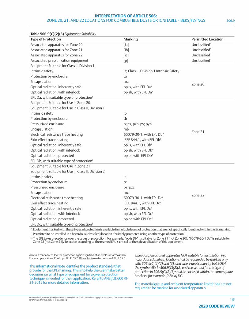
Reproduced with permission of NFPA from NFPA 70®, National Electrical Code®, 2020 edition. Copyright © 2019, National Fire Protection Association. For a full copy of NFPA 70, please go to www.nfpa.org.
INTERPRETATION OF ARTICLE 506: ZONE 20, 21, AND 22 LOCATIONS FOR COMBUSTIBLE DUSTS OR IGNITABLE FIBERS/FLYINGS
115
2020 CODE REVIEW
Table 506.9(C)(2)(3) Equipment Suitability Type of Protection Marking Permitted Location
Associated apparatus for Zone 20 [ia] Unclassified*
Associated apparatus for Zone 21 [ib] Unclassified*
Associated apparatus for Zone 22 [ic] Unclassified*
Associated pressurization equipment [p] Unclassified*
Equipment Suitable for Class II, Division 1 Intrinsic safety ia; Class II, Division 1 Intrinsic Safety
Zone 20
Protection by enclosure taEncapsulation maOptical radiation, inherently safe op is, with EPL Da#
Optical radiation, with interlock op sh, with EPL Da#
EPL Da, with suitable type of protection†
Equipment Suitable for Use in Zone 20
Zone 21
Equipment Suitable for Use in Class II, Division 1 Intrinsic safety ibProtection by enclosure tbPressurized enclosure p; px, pxb; py; pybEncapsulation mbElectrical resistance trace heating 60079-30-1, with EPL Db#
Skin effect trace heating IEEE 844.1, with EPL Db#
Optical radiation, inherently safe op is, with EPL Db#
Optical radiation, with interlock op sh, with EPL Db#
Optical radiation, protected op pr, with EPL Db#
EPL Db, with suitable type of protection†
Equipment Suitable for Use in Zone 21
Zone 22
Equipment Suitable for Use in Class II, Division 2 Intrinsic safety icProtection by enclosure tcPressurized enclosure pz; pzcEncapsulation mcElectrical resistance trace heating 60079-30-1, with EPL Dc#
Skin effect trace heating IEEE 844.1, with EPL Dc#
Optical radiation, inherently safe op is, with EPL Dc#
Optical radiation, with interlock op sh, with EPL Dc#
Optical radiation, protected op pr, with EPL Dc#
EPL Dc, with suitable type of protection†
#: Equipment marked with these types of protection is available in multiple levels of protection that are not specifically identified within the Ex marking.* Permitted to be installed in a hazardous (classified) location if suitably protected using another type of protection.† The EPL takes precedence over the types of protection. For example, “op is Db” is suitable for Zone 21 (not Zone 20). “60079-30-1 Dc” is suitable for
Zone 22 (not Zone 21). Selection according to the marked EPL is critical to the safe application of this equipment.
506.9
or (c) an “enhanced” level of protection against ignition of an explosive atmosphere. For example, a Zone 21 AEx pb IIIB T165°C Db motor is marked with an EPL of “Db”.
This informational Note identifies the product standards that provide for the EPL marking. This is to help the user make better decisions on what type of equipment for a given protection technique is needed for their application. Refer to ANSI/UL 60079-31-2015 for more detailed information.
Exception: Associated apparatus NOT suitable for installation in a hazardous (classified) location shall be required to be marked only with 506.9(C)(2)(2) and (3), and where applicable (4), but BOTH the symbol AEx in 506.9(C)(2)(2) and the symbol for the type of protection in 506.9(C)(2)(3) shall be enclosed within the same square brackets; for example, [AEx ia] IIIC.
The material group and ambient temperature limitations are not required to be marked for associated apparatus.
Reproduced with permission of NFPA from NFPA 70®, National Electrical Code®, 2020 edition. Copyright © 2019, National Fire Protection Association. For a full copy of NFPA 70, please go to www.nfpa.org.
INTERPRETATION OF ARTICLE 506: ZONE 20, 21, AND 22 LOCATIONS FOR COMBUSTIBLE DUSTS OR IGNITABLE FIBERS/FLYINGS
116
2020 CODE REVIEW
Informational Note: The “D” suffix on the type of protection designation was employed prior to the introduction of Group IIIA, IIIB, and IIIC, which is now used to distinguish between the type of protection employed for Group II (Gases) or Group III (Dusts).
The prefix of the “III” in the Group marking makes it clear that these ratings are for Dusts.
Equipment Protection Levels (EPL) were added to align with the introduction of the concept in the product standards. It should be noted that the EPL is aligned with the Zone.
The term for Type of Protection “p” has been changed to “pressurized enclosure” in ANSI/UL 60079-2:2017. The designations for optical radiation have been added based on ANSI/UL 60079-28:2017. Optical radiation as a potential “non-electrical” risk of ignition in a hazardous (classified) location is largely generated by electrical means. Although most optical radiation is not a source of ignition, this standard allows determination of those that are a source of ignition.
Note: LED luminaire light sources are considered as diverted light and therefore are not required to have a protection method for optical radiation.
506.9(D) Temperature Classifications. Equipment shall be marked to show the maximum surface temperature referenced to a 40°C ambient, or at the higher marked ambient temperature if the equipment is rated and marked for an ambient temperature of greater than 40°C. For equipment installed in a Zone 20 or Zone 21 location, the operating temperature shall be based on operation of the equipment when blanketed with the maximum amount of dust (or with dust-simulating fibers/flyings) that can accumulate on the equipment. Electrical equipment designed for use in the ambient temperature range between -20°C and +40°C shall require no additional ambient temperature marking. Electrical equipment that is designed for use in a range of ambient temperatures other than -20°C and +40°C is considered to be special; and the ambient temperature range shall then be marked on the equipment, including either the symbol “Ta” or “Tamb” together with the special range of ambient temperatures.
Informational Note: As an example, such a marking might be “–30°C ≤ Ta ≤ +40°C.”
The Section clarifies the required elements for the Temperature Classification marking and correlates with the requirements that are contained in the product standards.
Exception No. 1: Equipment of the non–heat-producing type, such as conduit fittings, shall not be required to have a marked operating temperature.
Exception No. 2: Equipment identified for Class II, Division 1 or Class II, Division 2 locations as permitted by 506.20(B) and (C) shall be permitted to be marked in accordance with 500.8(C) and Table 500.8(C).
506.9(E) Threading. The supply connection entry thread form shall be NPT or metric. Conduit and fittings shall be made wrenchtight to prevent sparking when the fault current flows through the conduit system and to ensure the integrity of the conduit system. Equipment provided with threaded entries for field wiring connections shall be installed in accordance with 506.9(E)(1) or (E)(2) and with (E)(3).
506.9(E)(1) Equipment Provided with Threaded Entries for NPT-Threaded Conduit or Fittings. For equipment provided with threaded entries for NPT-threaded conduit or fittings, listed conduit fittings or listed cable fittings shall be used. All NPT-threaded conduit and fittings shall be threaded with a National (American) Standard Pipe Taper (NPT) thread.
Informational Note: Thread specifications for NPT threads are located in ASME B1.20.1-2013, Pipe Threads, General Purpose (Inch).
506.9(E)(2) Equipment Provided with Threaded Entries for Metric-Threaded Fittings. For equipment with metric-threaded entries, listed conduit fittings or listed cable fittings shall be used. Such entries shall be identified as being metric, or listed adapters to permit connection to conduit or NPT-threaded fittings shall be provided with the equipment and shall be used for connection to conduit or NPT-threaded fittings. Metric-threaded fittings installed into equipment entries shall be made up with at least five threads fully engaged.
Fittings are required to be listed when used in metric threaded entries and that there be a minimum of 5 threads engaged. If it is a conduit fitting, it must be listed for use with that conduit type. If it is a cable fitting, it must be listed for use with that cable type.
506.9(E)(3) Unused Openings. All unused openings shall be closed with listed metal close-up plugs. The plug engagement shall comply with 506.9(E)(1) or (E)(2).
All unused openings are required to be closed in a manner that maintains the level of protection. Although this appears to be self-evident it was not previously addressed in Article 506.
These plugs may not independently be marked with the listing and classification information, however they have been evaluated as part of the full box and enclosure listing.
506.9(F) Optical Fiber Cables. An optical fiber cable, with or without current-carrying conductors (composite optical fiber cable), shall be installed to address the associated fire hazard and sealed to address the associated explosion hazard in accordance with the requirements of 506.15 and 506.16.
This section clarifies that the cable needs to be sealed to address the fire and explosion hazards regardless if the cable contains current carrying conductors or not.
506.9(G) Equipment Involving Optical Radiation. For equipment involving sources of optical radiation (such as laser or LED sources) in the wavelength range from 380 nm to 10 μm, the risk of ignition from optical radiation shall be considered for all electrical parts and circuits that may be exposed to the radiation, both inside and outside the optical equipment. This includes optical equipment, which itself is located outside the explosive atmosphere, but its emitted optical radiation enters such atmospheres.
Informational Note: For additional information on types of protection that can be applied to minimize the risk of ignition in explosive atmospheres from optical radiation, see ANSI/UL 60079-28-2017, Explosive Atmospheres — Part 28: Protection of Equipment and Transmission Systems Using Optical Radiation.
Exception: All luminaires (fixed, portable, or transportable) and hand lights intended to be supplied by mains (with or without galvanic isolation) or powered by batteries, with any continuous divergent light source, including LEDs, shall be excluded from this requirement.
506.9
Reproduced with permission of NFPA from NFPA 70®, National Electrical Code®, 2020 edition. Copyright © 2019, National Fire Protection Association. For a full copy of NFPA 70, please go to www.nfpa.org.
INTERPRETATION OF ARTICLE 506: ZONE 20, 21, AND 22 LOCATIONS FOR COMBUSTIBLE DUSTS OR IGNITABLE FIBERS/FLYINGS
117
2020 CODE REVIEW
506.15
All Appleton™ LED Luminaires comply with this exception
506.15 Wiring Methods. Wiring methods shall maintain the integrity of the protection techniques and shall comply with 506.15(A), (B), or (C).
506.15(A) Zone 20. In Zone 20 locations, the following wiring methods shall be permitted:
“iaD” is no longer recognized as a protection concept
(1) Threaded rigid metal conduit (Type RMC) or threaded steel intermediate metal conduit (Type IMC).
(2) Type MI cable terminated with fittings listed for the location. Type MI cable shall be installed and supported in a manner to avoid tensile stress at the termination fittings.
Exception No. 1: Type MI cable and fittings listed for Class II, Division 1 locations shall be permitted to be used.
Exception No. 2: Equipment identified as intrinsically safe “ia” shall be permitted to be connected using the wiring methods identified in 504.20.
The wiring methods permitted for intrinsically safe apparatus in explosive dust atmospheres classified under the Zone system are different from those permitted under the Division scheme. The wiring methods for intrinsically safe apparatus were previously addressed in 506.8 – Protection techniques.
(3) In industrial establishments with limited public access, where the conditions of maintenance and supervision ensure that only qualified persons service the installation, Type MC-HL cable listed for use in Zone 20 locations, with a continuous corrugated metallic sheath, an overall jacket of suitable polymeric material, and a separate equipment grounding conductor(s) in accordance with 250.122, and terminated with fittings listed for the application, shall be permitted. Type MC-HL cable shall be installed in accordance with Part II of Article 330.
Exception: Type MC-HL cable and fittings listed for Class II, Division 1 locations shall be permitted to be used.
(4) In industrial establishments with restricted public access, where the conditions of maintenance and supervision ensure that only qualified persons service the installation, and where the cable is not subject to physical damage, Type ITC-HL cable listed for use in Zone 1 or Class I, Division 1 locations, with a gas/vaportight continuous corrugated metallic sheath and an overall jacket of suitable polymeric material, and terminated with fittings listed for the application. Type ITC-HL cable shall be installed in accordance with 727.4.
The use of ITC-HL cable is permitted in a Zone 20 location. The cable must be terminated with fittings that are listed for the application. In other words the fitting must provide the required level of protection to maintain the protection technique.
(5) Fittings and boxes shall be identified for use in Zone 20 locations.
Exception: Boxes and fittings listed for Class II, Division 1 locations shall be permitted to be used.
(6) Where necessary to employ flexible connections, liquidtight flexible metal conduit (Type LFMC) with listed fittings, liquidtight flexible nonmetallic conduit (Type LFNC) with listed fittings, or flexible cord listed for extra-hard usage and provided with listed fittings shall be used. Where flexible cords are used, they shall also comply with 506.17 and shall be terminated with a listed cord connector that maintains the type of protection of the terminal compartment. Where flexible connections are subject to oil or other corrosive conditions, the insulation of the conductors shall be of a type listed for the condition or shall be protected by means of a suitable sheath.
Cord connectors are required to be listed for the location to maintain the protection level of the terminal compartment.
Exception No. 1: Liquidtight flexible conduit (Type LFMC or LFNC), flexible conduit fittings, and cord fittings listed for Class II, Division 1 locations shall be permitted.
Exception No. 2: For elevator use, an identified elevator cable of Type EO, ETP, or ETT, shown under the “use” column in Table 400.4 for “hazardous (classified) locations,” and terminated with listed connectors that maintain the type of protection of the terminal compartment shall be permitted.
Informational Note No. 1: See 506.25 for grounding requirements where flexible conduit is used.
Informational Note No. 2: For further information on construction, testing, and marking of cables, cable fittings, and cord connectors, see ANSI/UL 2225-2013, Cables and Cable-Fittings for Use in Hazardous (Classified) Locations.
Type EO, ETP, or ETT are now specifically permitted in the Section for elevator use as these are recognized in Table 400.4 for hazardous (classified) locations.
The wiring methods suitable for Class II, Division 1 are suitable for Zone 20.
(7) Optical fiber cable Types OFNP, OFCP, OFNR, OFCR, OFNG, OFCG, OFN, and OFC shall be permitted to be installed in raceways in accordance with 506.15(A). Optical fiber cables shall be sealed in accordance with 506.16.
This section correlates with the permitted uses for these types of cables in 770.3(A).
506.15(B) Zone 21. In Zone 21 locations, the following wiring methods shall be permitted:
“iaD” is no longer recognized as a protection concept
(1) All wiring methods permitted in 506.15(A).
(2) Fittings and boxes that are dusttight, provided with threaded bosses for connection to conduit, in which taps, joints, or terminal connections are not made, and are not used in locations where metal dust is present, may be used.
In Zone 21, all the methods for Zone 20 are permitted as well as dusttight fittings and boxes, since the area is not as hazardous as Zone 20.
Reproduced with permission of NFPA from NFPA 70®, National Electrical Code®, 2020 edition. Copyright © 2019, National Fire Protection Association. For a full copy of NFPA 70, please go to www.nfpa.org.
INTERPRETATION OF ARTICLE 506: ZONE 20, 21, AND 22 LOCATIONS FOR COMBUSTIBLE DUSTS OR IGNITABLE FIBERS/FLYINGS
118
2020 CODE REVIEW
These boxes and fittings are not required to be “listed” as dusttight. For guidance on dusttight ratings see NEMA 250, Enclosures for Electrical Equipment (1000 Volts Maximum) – permits a rating of “dusttight” for products that are rated NEMA Types 3, 3X, 3S, 3SX, 4, 4X, 5, 6, 6P, 12, 12K, or 13.
Informational Note: For further information on construction, testing, and marking of cables, cable fittings, and cord connectors, see ANSI/UL 2225-2013, Cables and Cable-Fittings for Use in Hazardous (Classified) Locations.
Exception: Equipment identified as intrinsically safe “ib” shall be permitted to be connected using the wiring methods identified in 504.20.
506.15(C) Zone 22. In Zone 22 locations, the following wiring methods shall be permitted:
The permitted wiring methods have been reorganized to clarify the requirements. Requirements for grounding conductors were added for an equipment grounding conductor in hazardous locations. A drain wire cannot act as a equipment grounding conductor.
(1) All wiring methods permitted in 506.15(B).
(2) Rigid metal conduit (Type RMC) or intermediate metal conduit (Type IMC) with listed threaded or threadless fittings.
(3) Electrical metallic tubing (Type EMT) or dusttight wireways.
(4) Type MC or MI cable with listed termination fittings.
(5) Type PLTC or PLTC-ER cable in accordance with Part II or III of Article 725, including installation in cable tray systems. The cable shall be terminated with listed fittings. Type PLTC-ER cable shall include an equipment grounding conductor in addition to a drain wire that might be present.
Type PLTC-ER cable is permitted to be used in a Zone 22 location and where terminated with listed fittings. This simply means the fittings must be listed for the cable type. The fittings are not required to be listed for the location.
(6) Type ITC or ITC-ER cable as permitted in 727.4 and terminated with listed fittings. Type ITC-ER cable shall include an equipment grounding conductor in addition to a drain wire.
Type TC-ER cable terminated with listed fittings is permitted as other Extended Run cable constructions are currently permitted. Type PLTC-ER, Type ITC-ER and Type TC-ER are all built to the same strength requirements.
(7) Type MV, TC, or TC-ER cable, including installation in cable tray systems. Type TC-ER cable shall include an equipment grounding conductor in addition to a drain wire that might be present. The cable shall be terminated with listed fittings.
(8) Intrinsic safety type of protection “ic” shall be permitted using any of the wiring methods permitted for unclassified locations. Intrinsic safety type of protection “ic” systems shall be installed in accordance with the control drawing(s). Simple apparatus, not shown on the control drawing, shall be permitted in a circuit of intrinsic safety type of protection “ic”, provided that the simple apparatus does not interconnect the intrinsic safety type of protection “ic” circuit to any other circuit. Separation of circuits of
intrinsic safety type of protection “ic” shall be in accordance with one of the following:
a. Be in separate cables
b. Be in multiconductor cables where the conductors of each circuit are within a grounded metal shield
c. Be in multiconductor cables where the conductors have insulation with a minimum thickness of 0.25 mm (0.01 in.)
Informational Note: The term simple apparatus is defined in Part III of Article 100.
(9) Boxes and fittings shall be dusttight.
In Zone 22, any Class II, Division 1 or Division 2 wiring method is acceptable.
These boxes and fittings are not required to be “listed” as dusttight. For guidance on dusttight ratings see NEMA 250, Enclosures for Electrical Equipment (1000 Volts Maximum) – permits a rating of “dusttight” for products that are rated NEMA Types 3, 3X, 3S, 3SX, 5, 12, 12K, or 13.
(10) Optical fiber cable Types OFNP, OFCP, OFNR, OFCR, OFNG, OFCG, OFN, and OFC shall be permitted to be installed in cable trays or any raceway in accordance with 506.15(C). Optical fiber cables shall be sealed in accordance with 506.16.
(11) Cablebus.
Cablebus is permitted when installed in accordance with Article 370. Cablebus provides a safety level equivalent to the other wiring methods permitted.
This section correlates with the permitted uses for these types of cables in Section 770.3(A).
506.16 Sealing. Where necessary to protect the ingress of combustible dust or ignitible fibers/flyings, or to maintain the type of protection, seals shall be provided. The seal shall be identified as capable of preventing the ingress of combustible dust or ignitible fibers/flyings and maintaining the type of protection but need not be explosionproof or flameproof.
As with seals on intrinsically safe equipment, the seals on Zone dust equipment do not have to be explosionproof to prevent the ingress of dust. The only time explosionproof seals would be required is when the location is also classified as Zone 0, 1, or 2 as well as for Zone 20, 21, or 22, and the enclosure is rated as explosionproof for flammable gas as well as suitable for use with combustible dust.
506.17 Flexible Cords. Flexible cords used in Zone 20, Zone 21, and Zone 22 locations shall comply with all of the following:
(1) Be of a type listed for extra-hard usage
(2) Contain, in addition to the conductors of the circuit, an equipment grounding conductor complying with 400.23
(3) Be connected to terminals or to supply conductors in an approved manner
506.15
Reproduced with permission of NFPA from NFPA 70®, National Electrical Code®, 2020 edition. Copyright © 2019, National Fire Protection Association. For a full copy of NFPA 70, please go to www.nfpa.org.
INTERPRETATION OF ARTICLE 506: ZONE 20, 21, AND 22 LOCATIONS FOR COMBUSTIBLE DUSTS OR IGNITABLE FIBERS/FLYINGS
119
2020 CODE REVIEW
(4) Be supported by clamps or by other suitable means in such a manner to minimize tension on the terminal connections
(5) Be terminated with a listed cord connector that maintains the protection technique of the terminal compartment
The use of flexible cords is the same as that allowed for Class II locations.
Informational Note: For further information on construction, testing, and marking of cables, cable fittings, and cord connectors, see ANSI/UL 2225-2013, Cables and Cable-Fittings for Use in Hazardous (Classified) Locations.
506.20 Equipment Installation.
506.20(A) Zone 20. In Zone 20 locations, only equipment listed and marked as suitable for the location shall be permitted.
Exception: Equipment listed for use in Class II, Division 1 locations with a suitable temperature class shall be permitted.
506.20(B) Zone 21. In Zone 21 locations, only equipment listed and marked as suitable for the location shall be permitted.
Exception No. 1: Apparatus listed for use in Class II, Division 1 locations with a suitable temperature class shall be permitted.
Exception No. 2: Pressurized equipment identified for Class II, Division 1 shall be permitted.
506.20(C) Zone 22. In Zone 22 locations, only equipment listed and marked as suitable for the location shall be permitted.
Exception No. 1: Apparatus listed for use in Class II, Division 1 or Class II, Division 2 locations with a suitable temperature class shall be permitted.
Exception No. 2: Pressurized equipment identified for Class II, Division 1 or Division 2 shall be permitted.
506.20(D) Material Group. Equipment marked Group IIIC shall be permitted for applications requiring IIIA or IIIB equipment. Similarly, equipment marked Group IIIB shall be permitted for applications requiring IIIA equipment.
This section clarifies the elements of the material group markings that are also contained in the product standards.
506.20(E) Manufacturer’s Instructions. Electrical equipment installed in hazardous (classified) locations shall be installed in accordance with the instructions (if any) provided by the manufacturer.
506.20(F) Temperature. The temperature marking specified in 506.9(C)(2)(5) shall comply with (F)(1) or (F)(2):
(1) For combustible dusts, less than the lower of either the layer or cloud ignition temperature of the specific combustible dust. For organic dusts that may dehydrate or carbonize, the temperature marking shall not exceed the lower of either the ignition temperature or 165°C (329°F).
(2) For ignitible fibers/flyings, less than 165°C (329°F) for equipment that is not subject to overloading, or 120°C (248°F) for
equipment (such as motors or power transformers) that may be overloaded.
Informational Note: See NFPA 499-2017, Recommended Practice for the Classification of Combustible Dusts and of Hazardous (Classified) Locations for Electrical Installations in Chemical Process Areas, for minimum ignition temperatures of specific dusts.
506.25 Grounding and Bonding. Regardless of the voltage of the electrical system, grounding and bonding shall comply with Article 250 and the requirements in 506.25(A) and (B).
506.25(A) Bonding. The locknut-bushing and double-locknut types of contacts shall not be depended on for bonding purposes, but bonding jumpers with proper fittings or other approved means of bonding shall be used. Such means of bonding shall apply to all intervening raceways, fittings, boxes, enclosures, and so forth, between Zone 20, Zone 21, and Zone 22 locations and the point of grounding for service equipment or point of grounding of a separately derived system.
Exception: The specific bonding means shall be required only to the nearest point where the grounded circuit conductor and the grounding electrode conductor are connected together on the line side of the building or structure disconnecting means as specified in 250.32(B) if the branch side overcurrent protection is located on the load side of the disconnecting means.
506.25(B) Types of Equipment Grounding Conductors. Liquidtight flexible metal conduit shall include an equipment bonding jumper of the wire type in compliance with 250.102.
Exception: In Zone 22 locations, the bonding jumper shall be permitted to be deleted where all of the following conditions are met:
(1) Listed liquidtight flexible metal conduit 1.8 m (6 ft) or less in length, with fittings listed for grounding, is used.
(2) Overcurrent protection in the circuit is limited to 10 amperes or less.
(3) The load is not a power utilization load.
506.25

120
2020 CODE REVIEW
NOTES
Reproduced with permission of NFPA from NFPA 70®, National Electrical Code®, 2020 edition. Copyright © 2019, National Fire Protection Association. For a full copy of NFPA 70, please go to www.nfpa.org.
INTERPRETATION OF ARTICLE 510: HAZARDOUS (CLASSIFIED) LOCATIONS – SPECIFIC
121
2020 CODE REVIEW
CHANGES TO ARTICLE 510 – Hazardous (Classified) Locations — Specific
There were no revisions to Article 510 during the 2020 NEC® Code cycle.
ARTICLE 510 Hazardous (Classified) Locations — Specific
510.1 Scope. Articles 511 through 517 cover occupancies or parts of occupancies that are or may be hazardous because of atmospheric concentrations of flammable liquids, gases, or vapors, or because of deposits or accumulations of materials that may be readily ignitible.
510.2 General. The general rules of this Code and the provisions of Articles 500 through 504 shall apply to electrical wiring and equipment in occupancies within the scope of Articles 511 through 517, except as such rules are modified in Articles 511 through 517. Where unusual conditions exist in a specific occupancy, the authority having jurisdiction shall judge with respect to the application of specific rules.
These articles deal with specific hazardous locations and parts of those locations where highly volatile flammable gases and vapors are present. The flammable liquids covered by these articles include gasoline, jet fuels, paints and lacquers, all highly volatile flammable liquids that release large volumes of vapors and gases. Such vapors are not only dangerous near their point of release, but often at considerable distances from the liquid itself. Warning: Some locations may need to be classified as both Class l and Class II hazardous locations, such as paints.
In addition to addressing those locations where highly volatile flammable gases and vapors are present, Article 516 also addresses those locations where deposits or accumulations of materials that may be readily ignitible.
Articles 511 through 517 also contain the Zone equivalency requirements in accordance with Article 505 as provided in the tables and figures based on other NFPA installation standards.
DIVISION 1/ZONE 1 AND DIVISION 2/ZONE 2 DIFFERENCES.
Articles 511-517 hazardous locations are typically either outdoor applications or large indoor areas with few partitions or walls. Class I, Division 1/Class I, Zone 1 and Class I, Division 2/Class I, Zone 2 areas characteristically exist adjacent to each other — the Division 1/Zone 1 location being near the point of vapor release and the Division 2/Zone 2 location being at a given distance from the point of release from the flammable liquid. In such locations, Division 1/Zone 1 means that the vapor concentration is sufficient to produce an ignitable mixture under normal conditions. A Division 2/Zone 2 location indicates that the vapor concentration necessary to produce a flammable mixture exists only under unusual conditions, such as an accidental rupture of a flammable liquid container or the simultaneous failure of process equipment and electrical equipment (a remote possibility).
In areas where the spread of flammable vapors and gases is not contained by adequate partitions, Class I, Division 2/Class I, Zone 2 can be thought of as “transition zone” between the Class I, Division 1/Class I, Zone 1 location and the non-hazardous area. Class I, Division 1/Class I, Zone 1 is a hazardous area where flammable gases or vapors are released from the liquid. Further away from the point of release, the gases or vapors are not normally of sufficient concentration to produce an ignitable mixture — and so such an area is designated as a Class I, Division 2/Class I, Zone 2 location. This Class I, Division 2/Class I, Zone 2 location is sometimes referred to as the “transition zone.” Outside this Division 2/Zone 2 “transition zone” is the non-hazardous area.
510.2

122
2020 CODE REVIEW
NOTES
Reproduced with permission of NFPA from NFPA 70®, National Electrical Code®, 2020 edition. Copyright © 2019, National Fire Protection Association. For a full copy of NFPA 70, please go to www.nfpa.org.
INTERPRETATION OF ARTICLE 511: COMMERCIAL GARAGES, REPAIR AND STORAGE
123
2020 CODE REVIEW
CHANGES TO ARTICLE 511 – Commercial Garages, Repair and Storage
The following Article 511 sections have been revised during the 2020 NEC® Code cycle. These changes are those that are substantive and should be noted. This list does not include those changes that are editorial in nature.
Underlined text indicates a section that has been revised from the previous NEC® edition. It is not intended to indicate legislation text detailing the word-for-word revisions to the section. Where minor revisions have been made to a section, these will include underlined text for select words to indicate the minor revision.
• 511.2 Definitions
• 511.3 Area Classification. General
• 511.12 Ground-Fault Circuit-Interrupter Protection for Personnel.
ARTICLE 511 Commercial Garages, Repair and Storage
511.1 Scope. These occupancies shall include locations used for service and repair operations in connection with self-propelled vehicles (including, but not limited to, passenger automobiles, buses, trucks, and tractors) in which volatile flammable liquids or flammable gases are used for fuel or power.
Informational Note: Text that is followed by a reference in brackets has been extracted from NFPA 30A-2018, Code for Motor Fuel Dispensing Facilities and Repair Garages. Only editorial changes were made to the extracted text to make it consistent with this Code.
The scope of Article 511 includes occupancies used for the service and repair operations in connection with self-propelled vehicles (such as, passenger automobiles, buses, trucks, and tractors.) But it is not limited to these examples. It covers occupancies in which volatile flammable liquids or flammable gases are used for fuel or power. These include gasoline, propane, compressed natural gas and liquefied natural gas.
511.2, Definitions have been removed and now appear in Article 100, Part III.
511.3 Area Classification, General. Where Class I liquids or gaseous fuels are stored, handled, or transferred, electrical wiring and electrical utilization equipment shall be designed in accordance with the requirements for Class I, Division 1 or 2 hazardous (classified) locations as classified in accordance with 500.5 and 500.6, and this article. A Class I location shall not extend beyond an unpierced wall, roof, or other solid partition that has no openings. [30A:8.3.1, 8.3.3]
Where the term “Class I” is used with respect to Zone classifications within this article of the Code, it shall apply to Zone 0, Zone 1, and Zone 2 designations.
Informational Note: The term “Class I” was originally included as a prefix to Zone 0, Zone 1, and Zone 2 locations and references as an identifier for flammable gases, vapors, or liquids to differentiate from Class II and Class III locations. Zone 0, Zone 1, and Zone 2 only apply to flammable gases, vapors, or liquids so the “Class I” prefix is redundant and has been deleted, except for text that is extracted from other documents or to remain consistent throughout this article.
The added text clarifies the application of what was the “Class I” prefix to Zones 0, 1, and 2. The new text provides clarification that those designations with the prefix “Class I” are applied as Zones 0, 1, and 2 per Article 505.
The term “Class I” is now an optional equipment marking, as the Zone designations are specific to Class I areas.
511.3(A) Parking Garages. Parking garages used for parking or storage shall be permitted to be unclassified.
Informational Note: For further information, see NFPA 88A-2019, Standard for Parking Structures, and NFPA 30A-2018, Code for Motor Fuel Dispensing Facilities and Repair Garages.
511.3(B) Repair Garages, with Dispensing. Major and minor repair garages that dispense motor fuels into the fuel tanks of vehicles, including flammable liquids having a flash point below 38°C (100°F) such as gasoline, or gaseous fuels such as natural gas, hydrogen, or LPG, shall have the dispensing functions and components classified in accordance with Table 514.3(B)(1) in addition to any classification required by this section. Where Class I liquids, other than fuels, are dispensed, the area within 900 mm (3 ft) of any fill or dispensing point, extending in all directions, shall be a Class I, Division 2 location.
511.3(C) Repair Garages, Major and Minor. Where vehicles using Class I liquids or heavier-than-air gaseous fuels (such as LPG) are repaired, hazardous area classification guidance is found in Table 511.3(C).
Informational Note: For additional information, see NFPA 30A-2018, Code for Motor Fuel Dispensing Facilities and Repair Garages, Table 8.3.2.
511.3(D) Repair Garages, Major. Where vehicles using lighter-than-air gaseous fuels (such as hydrogen and natural gas) are repaired or stored, hazardous area classification guidance is found in Table 511.3(D).
Informational Note: For additional information see NFPA 30A-2018, Code for Motor Fuel Dispensing Facilities and Repair Garages, Table 8.3.2.
511.3(E) Modifications to Classification.
511.3(E)(1) Specific Areas Adjacent to Classified Locations. Areas adjacent to classified locations in which flammable vapors are not likely to be released, such as stock rooms, switchboard rooms, and other similar locations, shall be unclassified where mechanically ventilated at a rate of four or more air changes per hour, or designed with positive air pressure, or where effectively cut off by walls or partitions.
511.3(E)(2) Alcohol-Based Windshield Washer Fluid. The area used for storage, handling, or dispensing into motor vehicles of alcohol-based windshield washer fluid in repair garages shall be unclassified unless otherwise classified by a provision of 511.3. [30A:8.3.1, Exception]
The classification of locations includes the requirements based on the garage categories.
511.4 Wiring and Equipment in Class I Locations.
511.4(A) Wiring Located in Class I Locations. Within Class I locations as classified in 511.3, wiring shall conform to applicable provisions of Article 501.
511.4
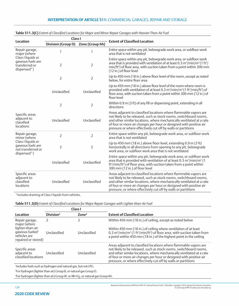
Reproduced with permission of NFPA from NFPA 70®, National Electrical Code®, 2020 edition. Copyright © 2019, National Fire Protection Association. For a full copy of NFPA 70, please go to www.nfpa.org.
INTERPRETATION OF ARTICLE 511: COMMERCIAL GARAGES, REPAIR AND STORAGE
124
2020 CODE REVIEW
Table 511.3(C) Extent of Classified Locations for Major and Minor Repair Garages with Heavier-Than-Air Fuel
LocationClass I
Extent of Classified LocationDivision (Group D) Zone (Group IIA)
Repair garage, major (where Class I liquids or gaseous fuels are transferred or dispensed*)
1 1 Entire space within any pit, belowgrade work area, or subfloor work area that is not ventilated
2 2
Entire space within any pit, belowgrade work area, or subfloor work area that is provided with ventilation of at least 0.3 m3/min/m2 (1 ft3/min/ft2) of floor area, with suction taken from a point within 300 mm (12 in.) of floor level
2 2 Up to 450 mm (18 in.) above floor level of the room, except as noted below, for entire floor area
Unclassified Unclassified
Up to 450 mm (18 in.) above floor level of the room where room is provided with ventilation of at least 0.3 m3/min/m2 (1 ft3/min/ft2) of floor area, with suction taken from a point within 300 mm (12 in.) of floor level
2 2 Within 0.9 m (3 ft) of any fill or dispensing point, extending in all directions
Specific areas adjacent to classified locations
Unclassified Unclassified
Areas adjacent to classified locations where flammable vapors are not likely to be released, such as stock rooms, switchboard rooms, and other similar locations, where mechanically ventilated at a rate of four or more air changes per hour or designed with positive air pressure or where effectively cut off by walls or partitions
Repair garage, minor (where Class I liquids or gaseous fuels are not transferred or dispensed*)
2 2 Entire space within any pit, belowgrade work area, or subfloor work area that is not ventilated
2 2Up to 450 mm (18 in.) above floor level, extending 0.9 m (3 ft) horizontally in all directions from opening to any pit, belowgrade work area, or subfloor work area that is not ventilated
Unclassified Unclassified
Entire space within any pit, belowgrade work area, or subfloor work area that is provided with ventilation of at least 0.3 m3/min/m2 (1 ft3/min/ft2) of floor area, with suction taken from a point within 300 mm (12 in.) of floor level
Specific areas adjacent to classified locations
Unclassified Unclassified
Areas adjacent to classified locations where flammable vapors are not likely to be released, such as stock rooms, switchboard rooms, and other similar locations, where mechanically ventilated at a rate of four or more air changes per hour or designed with positive air pressure, or where effectively cut off by walls or partitions
*Includes draining of Class I liquids from vehicles.
Table 511.3(D) Extent of Classified Locations for Major Repair Garages with Lighter-than-Air Fuel
Location
Class I
Extent of Classified LocationDivision2 Zone3
Repair garage, major (where lighter-than-air gaseous fueled1 vehicles are repaired or stored)
2 2 Within 450 mm (18 in.) of ceiling, except as noted below
Unclassified UnclassifiedWithin 450 mm (18 in.) of ceiling where ventilation of at least 0.3 m3/min/m2 (1 ft3/min/ft2) of floor area, with suction taken from a point within 450 mm (18 in.) of the highest point in the ceiling
Specific areas adjacent to classified locations
Unclassified Unclassified
Areas adjacent to classified locations where flammable vapors are not likely to be released, such as stock rooms, switchboard rooms, and other similar locations, where mechanically ventilated at a rate of four or more air changes per hour or designed with positive air pressure, or where effectively cut off by walls or partitions
1Includes fuels such as hydrogen and natural gas, but not LPG.2For hydrogen (lighter than air) Group B, or natural gas Group D.3For hydrogen (lighter than air) Group IIC or IIB+H2, or natural gas Group IIA.

Reproduced with permission of NFPA from NFPA 70®, National Electrical Code®, 2020 edition. Copyright © 2019, National Fire Protection Association. For a full copy of NFPA 70, please go to www.nfpa.org.
INTERPRETATION OF ARTICLE 511: COMMERCIAL GARAGES, REPAIR AND STORAGE
125
2020 CODE REVIEW
511.4(B) Equipment Located in Class I Locations. Within Class I locations as defined in 511.3, equipment shall conform to applicable provisions of Article 501.
511.4(B)(1) Fuel-Dispensing Units. Where fuel-dispensing units (other than liquid petroleum gas, which is prohibited) are located within buildings, the requirements of Article 514 shall govern.
Where mechanical ventilation is provided in the dispensing area, the control shall be interlocked so that the dispenser cannot operate without ventilation, as prescribed in 500.5(B)(2).
511.4(B)(2) Portable Lighting Equipment. Portable lighting equipment shall be equipped with handle, lampholder, hook, and substantial guard attached to the lampholder or handle. All exterior surfaces that might come in contact with battery terminals, wiring terminals, or other objects shall be of nonconducting material or shall be effectively protected with insulation. Lampholders shall be of an unswitched type and shall not provide means for plug-in of attachment plugs. The outer shell shall be of molded composition or other suitable material. Unless the lamp and its cord are supported or arranged in such a manner that they cannot be used in the locations classified in 511.3, they shall be of a type identified for Class I, Division 1 locations.
511.7 Wiring and Equipment Installed Above Class I Locations.
511.7(A) Wiring in Spaces Above Class I Locations.
511.7(A)(1) Fixed Wiring Above Class I Locations. All fixed wiring above Class I locations shall be in metal raceways, rigid nonmetallic conduit, electrical nonmetallic tubing, flexible metal conduit, liquidtight flexible metal conduit, or liquidtight flexible nonmetallic conduit, or shall be Type MC, AC, MI, manufactured wiring systems, or PLTC cable in accordance with Article 725, or Type TC cable or Type ITC cable in accordance with Article 727. Cellular metal floor raceways or cellular concrete floor raceways shall be permitted to be used only for supplying ceiling outlets or extensions to the area below the floor, but such raceways shall have no connections leading into or through any Class I location above the floor.
511.7(A)(2) Pendant. For pendants, flexible cord suitable for the type of service and listed for hard usage shall be used.
511.7(B) Electrical Equipment Installed Above Class I Locations.
511.7(B)(1) Fixed Electrical Equipment. Electrical equipment in a fixed position shall be located above the level of any defined Class I location or shall be identified for the location.
(a) Arcing Equipment. Equipment that is less than 3.7 m (12 ft) above the floor level and that may produce arcs, sparks, or particles of hot metal, such as cutouts, switches, charging panels, generators, motors, or other equipment (excluding receptacles, lamps, and lampholders) having make-and-break or sliding contacts, shall be of the totally enclosed type or constructed so as to prevent the escape of sparks or hot metal particles.
(b) Fixed Lighting. Lamps and lampholders for fixed lighting that is located over lanes through which vehicles are commonly driven or that may otherwise be exposed to physical damage shall be located not less than 3.7 m (12 ft) above floor level, unless of the
totally enclosed type or constructed so as to prevent escape of sparks or hot metal particles.
511.8 Underground Wiring Below Class I Locations. Underground wiring shall be installed in threaded rigid metal conduit or intermediate metal conduit.
Exception: Type PVC conduit, Type RTRC conduit, and Type HDPE conduit shall be permitted where buried under not less than 600 mm (2 ft) of cover. Where Type PVC conduit, Type RTRC conduit, or Type HDPE conduit is used, threaded rigid metal conduit or threaded steel intermediate metal conduit shall be used for the last 600 mm (2 ft) of the underground run to emergence or to the point of connection to the aboveground raceway, and an equipment grounding conductor shall be included to provide electrical continuity of the raceway system and for grounding of non–current-carrying metal parts.
Section 511.8 permits Type PVC, Type RTRC, and Type HDPE Conduits to be installed where buried at least with 2 feet of cover under a commercial garage. Where under less than 2 feet of cover, for instance, where the run terminates, then the other wiring methods of Article 511 apply.
511.9 Sealing. Seals complying with the requirements of 501.15 and 501.15(B)(2) shall be provided and shall apply to horizontal as well as vertical boundaries of the defined Class I locations.
LUMINAIRES (A) AND FS OR FD BOXES (D) ILLUSTRATED HERE MAY BE INSTALLED LESS THAN 12 FEET FROM THE FLOOR LEVEL BECAUSE THEY MEET SECTION 511.7(B)(1) REQUIREMENT OF BEING “TOTALLY ENCLOSED.” THE LUMINAIRES (A) ARE ENCLOSED AND GASKETED AND THE FS/FD (D) UNITS ARE ENCLOSED WITH GASKETED COVERS. SPARKS OR HOT METAL PARTICLES ARE CONTAINED BY THE COVERS OR ENCLOSURES (B) AND CANNOT BE TRANSMITTED THROUGH THE CONDUIT TO THE HAZARDOUS AREA NEAR THE FLOOR BECAUSE OF THE SEAL (F).
A—CLASS I, DIVISION 2 LUMINAIRESB—ENCLOSED AND GASKETED FIXTURE HANGERSC—CONDUIT BODYD—FS OR FD WEATHERPROOF COVERE—MALLEABLE IRON CLAMPS AND CLAMP BACKSF—EXPLOSIONPROOF SEALS
511.10
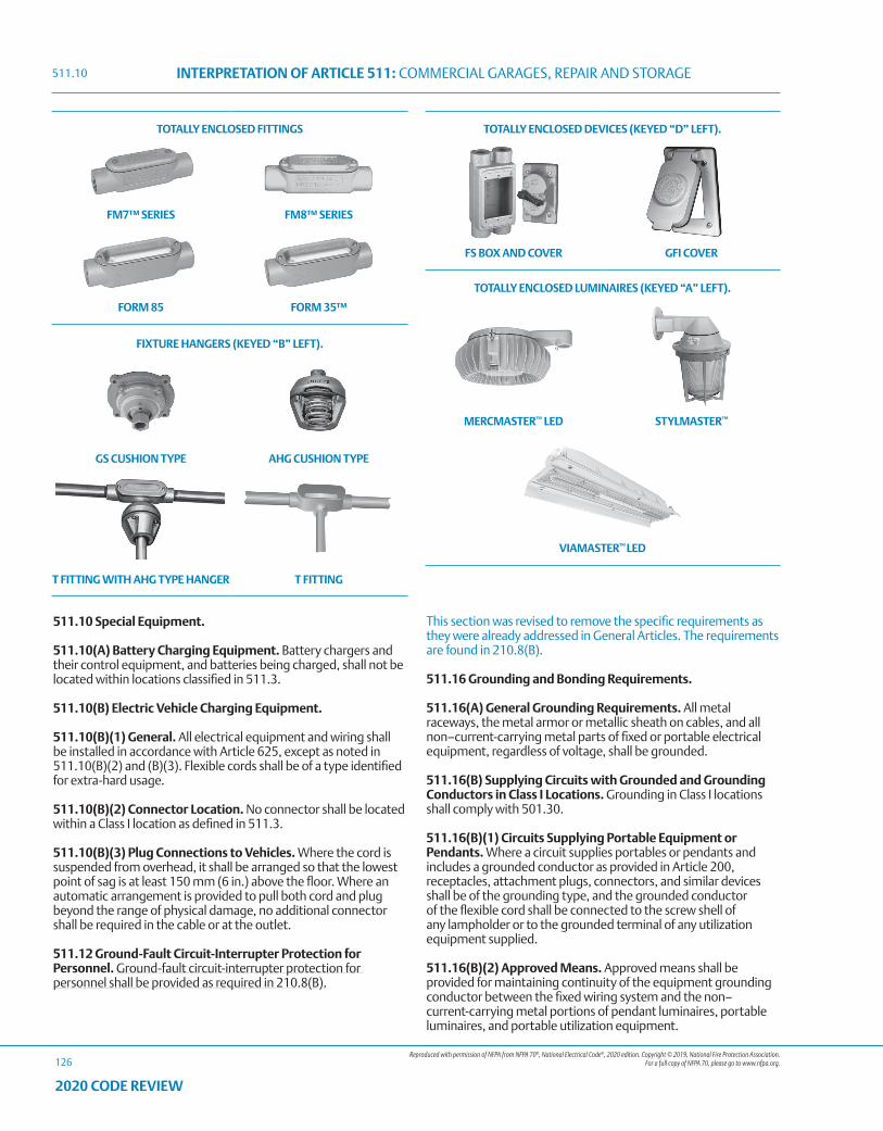
Reproduced with permission of NFPA from NFPA 70®, National Electrical Code®, 2020 edition. Copyright © 2019, National Fire Protection Association. For a full copy of NFPA 70, please go to www.nfpa.org.
INTERPRETATION OF ARTICLE 511: COMMERCIAL GARAGES, REPAIR AND STORAGE
126
2020 CODE REVIEW
TOTALLY ENCLOSED FITTINGS
FM7™ SERIES FM8™ SERIES
FORM 85 FORM 35™
FIXTURE HANGERS (KEYED “B” LEFT).
GS CUSHION TYPE AHG CUSHION TYPE
T FITTING WITH AHG TYPE HANGER T FITTING
TOTALLY ENCLOSED DEVICES (KEYED “D” LEFT).
FS BOX AND COVER GFI COVER
TOTALLY ENCLOSED LUMINAIRES (KEYED “A” LEFT).
MERCMASTER™ LED STYLMASTER™
VIAMASTER™ LED
511.10 Special Equipment.
511.10(A) Battery Charging Equipment. Battery chargers and their control equipment, and batteries being charged, shall not be located within locations classified in 511.3.
511.10(B) Electric Vehicle Charging Equipment.
511.10(B)(1) General. All electrical equipment and wiring shall be installed in accordance with Article 625, except as noted in 511.10(B)(2) and (B)(3). Flexible cords shall be of a type identified for extra-hard usage.
511.10(B)(2) Connector Location. No connector shall be located within a Class I location as defined in 511.3.
511.10(B)(3) Plug Connections to Vehicles. Where the cord is suspended from overhead, it shall be arranged so that the lowest point of sag is at least 150 mm (6 in.) above the floor. Where an automatic arrangement is provided to pull both cord and plug beyond the range of physical damage, no additional connector shall be required in the cable or at the outlet.
511.12 Ground-Fault Circuit-Interrupter Protection for Personnel. Ground-fault circuit-interrupter protection for personnel shall be provided as required in 210.8(B).
This section was revised to remove the specific requirements as they were already addressed in General Articles. The requirements are found in 210.8(B).
511.16 Grounding and Bonding Requirements.
511.16(A) General Grounding Requirements. All metal raceways, the metal armor or metallic sheath on cables, and all non–current-carrying metal parts of fixed or portable electrical equipment, regardless of voltage, shall be grounded.
511.16(B) Supplying Circuits with Grounded and Grounding Conductors in Class I Locations. Grounding in Class I locations shall comply with 501.30.
511.16(B)(1) Circuits Supplying Portable Equipment or Pendants. Where a circuit supplies portables or pendants and includes a grounded conductor as provided in Article 200, receptacles, attachment plugs, connectors, and similar devices shall be of the grounding type, and the grounded conductor of the flexible cord shall be connected to the screw shell of any lampholder or to the grounded terminal of any utilization equipment supplied.
511.16(B)(2) Approved Means. Approved means shall be provided for maintaining continuity of the equipment grounding conductor between the fixed wiring system and the non–current-carrying metal portions of pendant luminaires, portable luminaires, and portable utilization equipment.
511.10
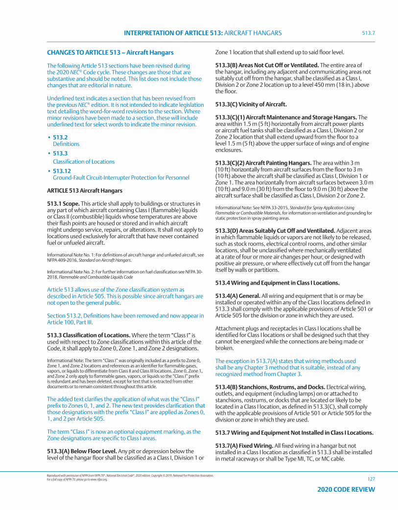
Reproduced with permission of NFPA from NFPA 70®, National Electrical Code®, 2020 edition. Copyright © 2019, National Fire Protection Association. For a full copy of NFPA 70, please go to www.nfpa.org.
INTERPRETATION OF ARTICLE 513: AIRCRAFT HANGARS
127
2020 CODE REVIEW
CHANGES TO ARTICLE 513 – Aircraft Hangars
The following Article 513 sections have been revised during the 2020 NEC® Code cycle. These changes are those that are substantive and should be noted. This list does not include those changes that are editorial in nature.
Underlined text indicates a section that has been revised from the previous NEC® edition. It is not intended to indicate legislation text detailing the word-for-word revisions to the section. Where minor revisions have been made to a section, these will include underlined text for select words to indicate the minor revision.
• 513.2 Definitions
• 513.3 Classification of Locations
• 513.12 Ground-Fault Circuit-Interrupter Protection for Personnel
ARTICLE 513 Aircraft Hangars
513.1 Scope. This article shall apply to buildings or structures in any part of which aircraft containing Class I (flammable) liquids or Class II (combustible) liquids whose temperatures are above their flash points are housed or stored and in which aircraft might undergo service, repairs, or alterations. It shall not apply to locations used exclusively for aircraft that have never contained fuel or unfueled aircraft.
Informational Note No. 1: For definitions of aircraft hangar and unfueled aircraft, see NFPA 409-2016, Standard on Aircraft Hangars.
Informational Note No. 2: For further information on fuel classification see NFPA 30-2018, Flammable and Combustible Liquids Code
Article 513 allows use of the Zone classification system as described in Article 505. This is possible since aircraft hangars are not open to the general public.
Section 513.2, Definitions have been removed and now appear in Article 100, Part III.
513.3 Classification of Locations. Where the term “Class I” is used with respect to Zone classifications within this article of the Code, it shall apply to Zone 0, Zone 1, and Zone 2 designations.
Informational Note: The term “Class I” was originally included as a prefix to Zone 0, Zone 1, and Zone 2 locations and references as an identifier for flammable gases, vapors, or liquids to differentiate from Class II and Class III locations. Zone 0, Zone 1, and Zone 2 only apply to flammable gases, vapors, or liquids so the “Class I” prefix is redundant and has been deleted, except for text that is extracted from other documents or to remain consistent throughout this article.
The added text clarifies the application of what was the “Class I” prefix to Zones 0, 1, and 2. The new text provides clarification that those designations with the prefix “Class I” are applied as Zones 0, 1, and 2 per Article 505.
The term “Class I” is now an optional equipment marking, as the Zone designations are specific to Class I areas.
513.3(A) Below Floor Level. Any pit or depression below the level of the hangar floor shall be classified as a Class I, Division 1 or
Zone 1 location that shall extend up to said floor level.
513.3(B) Areas Not Cut Off or Ventilated. The entire area of the hangar, including any adjacent and communicating areas not suitably cut off from the hangar, shall be classified as a Class I, Division 2 or Zone 2 location up to a level 450 mm (18 in.) above the floor.
513.3(C) Vicinity of Aircraft.
513.3(C)(1) Aircraft Maintenance and Storage Hangars. The area within 1.5 m (5 ft) horizontally from aircraft power plants or aircraft fuel tanks shall be classified as a Class I, Division 2 or Zone 2 location that shall extend upward from the floor to a level 1.5 m (5 ft) above the upper surface of wings and of engine enclosures.
513.3(C)(2) Aircraft Painting Hangars. The area within 3 m (10 ft) horizontally from aircraft surfaces from the floor to 3 m (10 ft) above the aircraft shall be classified as Class I, Division 1 or Zone 1. The area horizontally from aircraft surfaces between 3.0 m (10 ft) and 9.0 m (30 ft) from the floor to 9.0 m (30 ft) above the aircraft surface shall be classified as Class I, Division 2 or Zone 2.
Informational Note: See NFPA 33-2015, Standard for Spray Application Using Flammable or Combustible Materials, for information on ventilation and grounding for static protection in spray painting areas.
513.3(D) Areas Suitably Cut Off and Ventilated. Adjacent areas in which flammable liquids or vapors are not likely to be released, such as stock rooms, electrical control rooms, and other similar locations, shall be unclassified where mechanically ventilated at a rate of four or more air changes per hour, or designed with positive air pressure, or where effectively cut off from the hangar itself by walls or partitions.
513.4 Wiring and Equipment in Class I Locations.
513.4(A) General. All wiring and equipment that is or may be installed or operated within any of the Class I locations defined in 513.3 shall comply with the applicable provisions of Article 501 or Article 505 for the division or zone in which they are used.
Attachment plugs and receptacles in Class I locations shall be identified for Class I locations or shall be designed such that they cannot be energized while the connections are being made or broken.
The exception in 513.7(A) states that wiring methods used shall be any Chapter 3 method that is suitable, instead of any recognized method from Chapter 3.
513.4(B) Stanchions, Rostrums, and Docks. Electrical wiring, outlets, and equipment (including lamps) on or attached to stanchions, rostrums, or docks that are located or likely to be located in a Class I location, as defined in 513.3(C), shall comply with the applicable provisions of Article 501 or Article 505 for the division or zone in which they are used.
513.7 Wiring and Equipment Not Installed in Class I Locations.
513.7(A) Fixed Wiring. All fixed wiring in a hangar but not installed in a Class I location as classified in 513.3 shall be installed in metal raceways or shall be Type MI, TC, or MC cable.
513.7
Reproduced with permission of NFPA from NFPA 70®, National Electrical Code®, 2020 edition. Copyright © 2019, National Fire Protection Association. For a full copy of NFPA 70, please go to www.nfpa.org.
INTERPRETATION OF ARTICLE 513: AIRCRAFT HANGARS
128
2020 CODE REVIEW
Exception: Wiring in unclassified locations, as described in 513.3(D), shall be permitted to be any suitable type wiring method recognized in Chapter 3.
513.7(B) Pendants. For pendants, flexible cord suitable for the type of service and identified for hard usage or extra-hard usage shall be used. Each such cord shall include a separate equipment grounding conductor.
513.7(C) Arcing Equipment. In locations above those described in 513.3, equipment that is less than 3.0 m (10 ft) above wings and engine enclosures of aircraft and that may produce arcs, sparks, or particles of hot metal, such as lamps and lampholders for fixed lighting, cutouts, switches, receptacles, charging panels, generators, motors, or other equipment having make-and-break or sliding contacts, shall be of the totally enclosed type or constructed so as to prevent the escape of sparks or hot metal particles.
Exception: Equipment in areas described in 513.3(D) shall be permitted to be of the general-purpose type.
513.7(D) Lampholders. Lampholders of metal-shell, fiber-lined types shall not be used for fixed incandescent lighting.
513.7(E) Stanchions, Rostrums, or Docks. Where stanchions, rostrums, or docks are not located or likely to be located in a Class I location, as defined in 513.3(C), wiring and equipment shall comply with 513.7, except that such wiring and equipment not more than 457 mm (18 in.) above the floor in any position shall comply with 513.4(B). Receptacles and attachment plugs shall be of a locking type that will not readily disconnect.
513.7(F) Mobile Stanchions. Mobile stanchions with electrical equipment complying with 513.7(E) shall carry at least one permanently affixed warning sign with the following words or equivalent:
WARNING KEEP 5 FT CLEAR OF AIRCRAFT
ENGINES AND FUEL TANK AREASor
WARNING KEEP 1.5 METERS CLEAR OF AIRCRAFT
ENGINES AND FUEL TANK AREAS
513.8 Underground Wiring.
513.8(A) Wiring and Equipment Embedded, Under Slab, or Underground. All wiring installed in or under the hangar floor shall comply with the requirements for Class I, Division 1 locations. Where such wiring is located in vaults, pits, or ducts, adequate drainage shall be provided.
513.8(B) Uninterrupted Raceways, Embedded, Under Slab, or Underground. Uninterrupted raceways that are embedded in a hangar floor or buried beneath the hangar floor shall be considered to be within the Class I location above the floor, regardless of the point at which the raceway descends below or rises above the floor.
513.9 Sealing. Seals shall be provided in accordance with 501.15 or 505.16, as applicable. Sealing requirements specified shall apply to horizontal as well as to vertical boundaries of the defined Class I locations.
The sealing section reflects the harmonized sealing language used in the other Articles.
513.10 Special Equipment.
513.10(A) Aircraft Electrical Systems.
513.10(A)(1) De-energizing Aircraft Electrical Systems. Aircraft electrical systems shall be de-energized when the aircraft is stored in a hangar and, whenever possible, while the aircraft is undergoing maintenance.
513.10(A)(2) Aircraft Batteries. Aircraft batteries shall not be charged where installed in an aircraft located inside or partially inside a hangar.
513.10(B) Aircraft Battery Charging and Equipment. Battery chargers and their control equipment shall not be located or operated within any of the Class I locations defined in 513.3 and shall preferably be located in a separate building or in an area such as defined in 513.3(D). Mobile chargers shall carry at least one permanently affixed warning sign with the following words or equivalent:
WARNING KEEP 5 FT CLEAR OF AIRCRAFT ENGINES
AND FUEL TANK AREASor
WARNING KEEP 1.5 METERS CLEAR OF AIRCRAFT
ENGINES AND FUEL TANK AREAS
STATIC ELECTRICITY.
THE FLOW OF FLAMMABLE LIQUIDS THROUGH NON-CONDUCTING MATERIALS CAN GENERATE STATIC ELECTRICITY. THEREFORE THE AIRCRAFT AND TRUCK DISPENSING THE FUEL NEED TO BE GROUNDED TO SAFELY DISSIPATE THE STATIC CHARGE. AN EFFECTIVE METHOD OF PROVIDING SUCH SAFETY IS THROUGH THE USE OF AN APPLETON™ STATIC GROUNDING REEL.
SD SERIES STATIC DISCHARGE GROUNDING REEL
SDG GROUNDING STUD AND SDP GROUNDING PLUG
GROUNDING REEL INSTALLED ON A TRUCK.
513.7
Reproduced with permission of NFPA from NFPA 70®, National Electrical Code®, 2020 edition. Copyright © 2019, National Fire Protection Association. For a full copy of NFPA 70, please go to www.nfpa.org.
INTERPRETATION OF ARTICLE 513: AIRCRAFT HANGARS
129
2020 CODE REVIEW
Tables, racks, trays, and wiring shall not be located within a Class I location and, in addition, shall comply with Article 480.
513.10(C) External Power Sources for Energizing Aircraft.
513.10(C)(1) Not Less Than 450 mm (18 in.) Above Floor. Aircraft energizers shall be designed and mounted such that all electrical equipment and fixed wiring will be at least 450 mm (18 in.) above floor level and shall not be operated in a Class I location as defined in 513.3(C).
513.10(C)(2) Marking for Mobile Units. Mobile energizers shall carry at least one permanently affixed warning sign with the following words or equivalent:
WARNING KEEP 5 FT CLEAR OF AIRCRAFT
ENGINES AND FUEL TANK AREASor
WARNING KEEP 1.5 METERS CLEAR OF AIRCRAFT
ENGINES AND FUEL TANK AREAS
513.10(C)(3) Cords. Flexible cords for aircraft energizers and ground support equipment shall be identified for the type of service and extra-hard usage and shall include an equipment grounding conductor.
513.10(D) Mobile Servicing Equipment with Electrical Components.
513.10(D)(1) General. Mobile servicing equipment (such as vacuum cleaners, air compressors, air movers) having electrical wiring and equipment not suitable for Class I, Division 2 or Zone 2 locations shall be so designed and mounted that all such fixed wiring and equipment will be at least 450 mm (18 in.) above the floor. Such mobile equipment shall not be operated within the Class I location defined in 513.3(C) and shall carry at least one permanently affixed warning sign with the following words or equivalent:
WARNING KEEP 5 FT CLEAR OF AIRCRAFT ENGINES
AND FUEL TANK AREASor
WARNING KEEP 1.5 METERS CLEAR OF AIRCRAFT ENGINES
AND FUEL TANK AREAS
513.10(D)(2) Cords and Connectors. Flexible cords for mobile equipment shall be suitable for the type of service and identified for extra-hard usage and shall include an equipment grounding conductor. Attachment plugs and receptacles shall be identified for the location in which they are installed and shall provide for connection of the equipment grounding conductor.
513.10(D)(3) Restricted Use. Equipment that is not identified as suitable for Class I, Division 2 locations shall not be operated in locations where maintenance operations likely to release flammable liquids or vapors are in progress.
513.10(E) Portable Equipment.
513.10(E)(1) Portable Lighting Equipment. Portable lighting equipment that is used within a hangar shall be identified for the location in which they are used. For portable luminaires, flexible cord suitable for the type of service and identified for extra-hard usage shall be used. Each such cord shall include a separate equipment grounding conductor.
513.10(E)(2) Portable Utilization Equipment. Portable utilization equipment that is or may be used within a hangar shall be of a type suitable for use in Class I, Division 2 or Zone 2 locations. For portable utilization equipment, flexible cord suitable for the type of service and approved for extra-hard usage shall be used. Each such cord shall include a separate equipment grounding conductor.
513.12 Ground-Fault Circuit-Interrupter Protection for Personnel. Ground-fault circuit-interrupter protection for personnel shall be provided as required in 210.8(B).
Section 513.12 brings aircraft hangars in line with commercial garages in requiring ground-fault circuit interrupter protection for personnel. Receptacles that provide 400 Hz power for aircraft equipment are not covered by this requirement.
This section was revised to remove the specific requirements as they were already addressed in General Articles. The requirements are found in 210.8(B).
513.16 Grounding and Bonding Requirements.
513.16(A) General Grounding Requirements. All metal raceways, the metal armor or metallic sheath on cables, and all non–current-carrying metal parts of fixed or portable electrical equipment, regardless of voltage, shall be grounded. Grounding in Class I locations shall comply with 501.30 for Class I, Division 1 and 2 locations and 505.25 for Zone 0, 1, and 2 locations.
513.16(B) Supplying Circuits with Grounded and Equipment Grounding Conductors in Class I Locations.
513.16(B)(1) Circuits Supplying Portable Equipment or Pendants. Where a circuit supplies portables or pendants and includes a grounded conductor, receptacles, attachment plugs, connectors, and similar devices shall be of the grounding type, and the grounded conductor of the flexible cord shall be connected to the screw shell of any lampholder or to the grounded terminal of any utilization equipment supplied.
513.16(B)(2) Approved Means. Approved means shall be provided for maintaining continuity of the equipment grounding conductor between the fixed wiring system and the non–current-carrying metal portions of pendant luminaires, portable luminaires, and portable utilization equipment.
513.16

130
2020 CODE REVIEW
NOTES
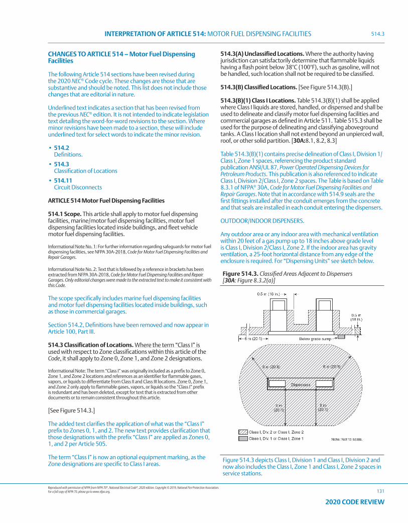
Reproduced with permission of NFPA from NFPA 70®, National Electrical Code®, 2020 edition. Copyright © 2019, National Fire Protection Association. For a full copy of NFPA 70, please go to www.nfpa.org.
INTERPRETATION OF ARTICLE 514: MOTOR FUEL DISPENSING FACILITIES
131
2020 CODE REVIEW
CHANGES TO ARTICLE 514 – Motor Fuel Dispensing Facilities
The following Article 514 sections have been revised during the 2020 NEC® Code cycle. These changes are those that are substantive and should be noted. This list does not include those changes that are editorial in nature.
Underlined text indicates a section that has been revised from the previous NEC® edition. It is not intended to indicate legislation text detailing the word-for-word revisions to the section. Where minor revisions have been made to a section, these will include underlined text for select words to indicate the minor revision.
• 514.2 Definitions.
• 514.3 Classification of Locations
• 514.11 Circuit Disconnects
ARTICLE 514 Motor Fuel Dispensing Facilities
514.1 Scope. This article shall apply to motor fuel dispensing facilities, marine/motor fuel dispensing facilities, motor fuel dispensing facilities located inside buildings, and fleet vehicle motor fuel dispensing facilities.
Informational Note No. 1: For further information regarding safeguards for motor fuel dispensing facilities, see NFPA 30A-2018, Code for Motor Fuel Dispensing Facilities and Repair Garages.
Informational Note No. 2: Text that is followed by a reference in brackets has been extracted from NFPA 30A-2018, Code for Motor Fuel Dispensing Facilities and Repair Garages. Only editorial changes were made to the extracted text to make it consistent with this Code.
The scope specifically includes marine fuel dispensing facilities and motor fuel dispensing facilities located inside buildings, such as those in commercial garages.
Section 514.2, Definitions have been removed and now appear in Article 100, Part III.
514.3 Classification of Locations. Where the term “Class I” is used with respect to Zone classifications within this article of the Code, it shall apply to Zone 0, Zone 1, and Zone 2 designations.
Informational Note: The term “Class I” was originally included as a prefix to Zone 0, Zone 1, and Zone 2 locations and references as an identifier for flammable gases, vapors, or liquids to differentiate from Class II and Class III locations. Zone 0, Zone 1, and Zone 2 only apply to flammable gases, vapors, or liquids so the “Class I” prefix is redundant and has been deleted, except for text that is extracted from other documents or to remain consistent throughout this article.
[See Figure 514.3.]
The added text clarifies the application of what was the “Class I” prefix to Zones 0, 1, and 2. The new text provides clarification that those designations with the prefix “Class I” are applied as Zones 0, 1, and 2 per Article 505.
The term “Class I” is now an optional equipment marking, as the Zone designations are specific to Class I areas.
514.3(A) Unclassified Locations. Where the authority having jurisdiction can satisfactorily determine that flammable liquids having a flash point below 38°C (100°F), such as gasoline, will not be handled, such location shall not be required to be classified.
514.3(B) Classified Locations. [See Figure 514.3(B).]
514.3(B)(1) Class I Locations. Table 514.3(B)(1) shall be applied where Class I liquids are stored, handled, or dispensed and shall be used to delineate and classify motor fuel dispensing facilities and commercial garages as defined in Article 511. Table 515.3 shall be used for the purpose of delineating and classifying aboveground tanks. A Class I location shall not extend beyond an unpierced wall, roof, or other solid partition. [30A:8.1, 8.2, 8.3]
Table 514.3(B)(1) contains precise delineation of Class I, Division 1/Class I, Zone 1 spaces, referencing the product standard publication ANSI/UL 87, Power Operated Dispensing Devices for Petroleum Products. This publication is also referenced to indicate Class I, Division 2/Class I, Zone 2 spaces. The Table is based on Table 8.3.1 of NFPA® 30A, Code for Motor Fuel Dispensing Facilities and Repair Garages. Note that in accordance with 514.9 seals are the first fittings installed after the conduit emerges from the concrete and that seals are installed in each conduit entering the dispensers.
OUTDOOR/INDOOR DISPENSERS.
Any outdoor area or any indoor area with mechanical ventilation within 20 feet of a gas pump up to 18 inches above grade level is Class I, Division 2/Class I, Zone 2. If the indoor area has gravity ventilation, a 25-foot horizontal distance from any edge of the enclosure is required. For “Dispensing Units” see sketch below.
Figure 514.3. Classified Areas Adjacent to Dispensers [30A: Figure 8.3.2(a)]
Figure 514.3 depicts Class I, Division 1 and Class I, Division 2 and now also includes the Class I, Zone 1 and Class I, Zone 2 spaces in service stations.
514.3
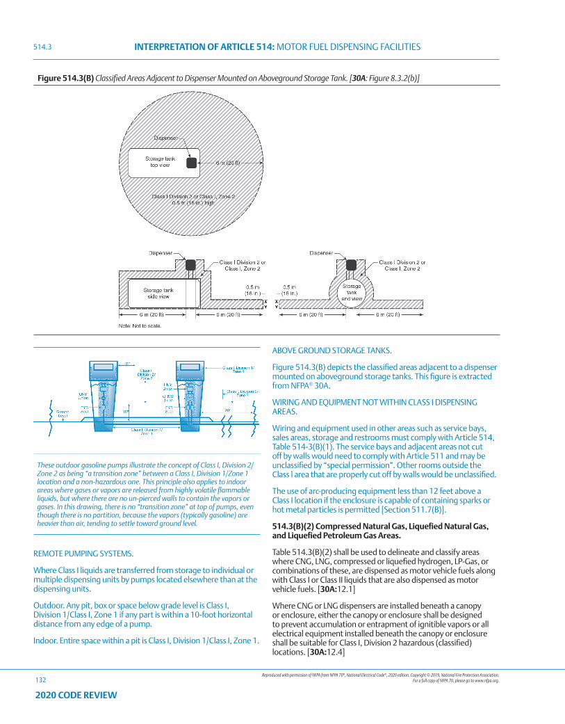
Reproduced with permission of NFPA from NFPA 70®, National Electrical Code®, 2020 edition. Copyright © 2019, National Fire Protection Association. For a full copy of NFPA 70, please go to www.nfpa.org.
INTERPRETATION OF ARTICLE 514: MOTOR FUEL DISPENSING FACILITIES
132
2020 CODE REVIEW
Figure 514.3(B) Classified Areas Adjacent to Dispenser Mounted on Aboveground Storage Tank. [30A: Figure 8.3.2(b)]
REMOTE PUMPING SYSTEMS.
Where Class I liquids are transferred from storage to individual or multiple dispensing units by pumps located elsewhere than at the dispensing units.
Outdoor. Any pit, box or space below grade level is Class I, Division 1/Class I, Zone 1 if any part is within a 10-foot horizontal distance from any edge of a pump.
Indoor. Entire space within a pit is Class I, Division 1/Class I, Zone 1.
ABOVE GROUND STORAGE TANKS.
Figure 514.3(B) depicts the classified areas adjacent to a dispenser mounted on aboveground storage tanks. This figure is extracted from NFPA® 30A.
WIRING AND EQUIPMENT NOT WITHIN CLASS I DISPENSING AREAS.
Wiring and equipment used in other areas such as service bays, sales areas, storage and restrooms must comply with Article 514, Table 514-3(B)(1). The service bays and adjacent areas not cut off by walls would need to comply with Article 511 and may be unclassified by “special permission”. Other rooms outside the Class l area that are properly cut off by walls would be unclassified.
The use of arc-producing equipment less than 12 feet above a Class I location if the enclosure is capable of containing sparks or hot metal particles is permitted [Section 511.7(B)].
514.3(B)(2) Compressed Natural Gas, Liquefied Natural Gas, and Liquefied Petroleum Gas Areas.
Table 514.3(B)(2) shall be used to delineate and classify areas where CNG, LNG, compressed or liquefied hydrogen, LP-Gas, or combinations of these, are dispensed as motor vehicle fuels along with Class I or Class II liquids that are also dispensed as motor vehicle fuels. [30A:12.1]
Where CNG or LNG dispensers are installed beneath a canopy or enclosure, either the canopy or enclosure shall be designed to prevent accumulation or entrapment of ignitible vapors or all electrical equipment installed beneath the canopy or enclosure shall be suitable for Class I, Division 2 hazardous (classified) locations. [30A:12.4]
514.3
These outdoor gasoline pumps illustrate the concept of Class I, Division 2/Zone 2 as being “a transition zone” between a Class I, Division 1/Zone 1 location and a non-hazardous one. This principle also applies to indoor areas where gases or vapors are released from highly volatile flammable liquids, but where there are no un-pierced walls to contain the vapors or gases. In this drawing, there is no “transition zone” at top of pumps, even though there is no partition, because the vapors (typically gasoline) are heavier than air, tending to settle toward ground level.
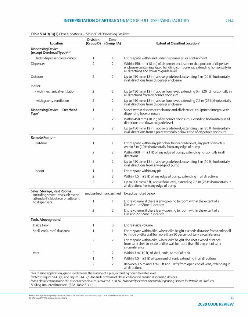
Reproduced with permission of NFPA from NFPA 70®, National Electrical Code®, 2020 edition. Copyright © 2019, National Fire Protection Association. For a full copy of NFPA 70, please go to www.nfpa.org.
INTERPRETATION OF ARTICLE 514: MOTOR FUEL DISPENSING FACILITIES
133
2020 CODE REVIEW
Table 514.3(B)(1) Class I Locations — Motor Fuel Dispensing Facilities
Location Division
(Group D)Zone
(Group IIA) Extent of Classified Location1
Dispensing Device (except Overhead Type) 2, 3
Under dispenser containment 1 1 Entire space within and under dispenser pit or containment
Dispenser 2 2 Within 450 mm (18 in.) of dispenser enclosure or that portion of dispenser enclosure containing liquid handling components, extending horizontally in all directions and down to grade level
Outdoor 2 2 Up to 450 mm (18 in.) above grade level, extending 6 m (20 ft) horizontally in all directions from dispenser enclosure
Indoor
- with mechanical ventilation 2 2 Up to 450 mm (18 in.) above floor level, extending 6 m (20 ft) horizontally in all directions from dispenser enclosure
- with gravity ventilation 2 2 Up to 450 mm (18 in.) above floor level, extending 7.5 m (25 ft) horizontally in all directions from dispenser enclosure
Dispensing Device — OverheadType4
1 1 Space within dispenser enclosure and all electrical equipment integral with dispensing hose or nozzle
2 2 Within 450 mm (18 in.) of dispenser enclosure, extending horizontally in all directions and down to grade level
2 2 Up to 450 mm (18 in.) above grade level, extending 6 m (20 ft) horizontally in all directions from a point vertically below edge of dispenser enclosure
Remote Pump —
Outdoor 1 1 Entire space within any pit or box below grade level, any part of which is within 3 m (10 ft) horizontally from any edge of pump
2 2 Within 900 mm (3 ft) of any edge of pump, extending horizontally in all directions
2 2 Up to 450 mm (18 in.) above grade level, extending 3 m (10 ft) horizontally in all directions from any edge of pump
Indoor 1 1 Entire space within any pit
2 2 Within 1.5 m (5 ft) of any edge of pump, extending in all directions
2 2 Up to 900 mm (3 ft) above floor level, extending 7.5 m (25 ft) horizontally in all directions from any edge of pump
Sales, Storage, Rest Rooms including structures (such as the attendant’s kiosk) on or adjacent to dispensers
unclassified unclassified Except as noted below
1 1 Entire volume, if there is any opening to room within the extent of a Division 1 or Zone 1 location
2 2 Entire volume, if there is any opening to room within the extent of a Division 2 or Zone 2 location
Tank, Aboveground
Inside tank 1 0 Entire inside volume
Shell, ends, roof, dike area 1 1 Entire space within dike, where dike height exceeds distance from tank shell to inside of dike wall for more than 50 percent of tank circumference
2 2 Entire space within dike, where dike height does not exceed distance from tank shell to inside of dike wall for more than 50 percent of tank circumference
Vent 2 2 Within 3 m (10 ft) of shell, ends, or roof of tank
1 1 Within 1.5 m (5 ft) of open end of vent, extending in all directions
2 2 Between 1.5 m and 3 m (5 ft and 10 ft) from open end of vent, extending in all directions
1For marine application, grade level means the surface of a pier, extending down to water level.2Refer to Figure 514.3(a) and Figure 514.3(b) for an illustration of classified location around dispensing devices.3Area classification inside the dispenser enclosure is covered in UL 87, Standard for Power-Operated Dispensing Devices for Petroleum Products.4Ceiling-mounted hose reel. [30A: Table 8.3.1]
514.3
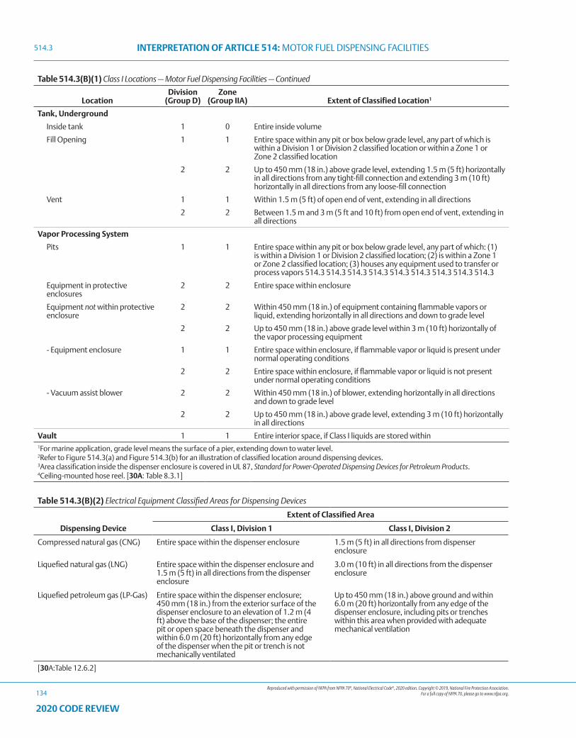
Reproduced with permission of NFPA from NFPA 70®, National Electrical Code®, 2020 edition. Copyright © 2019, National Fire Protection Association. For a full copy of NFPA 70, please go to www.nfpa.org.
INTERPRETATION OF ARTICLE 514: MOTOR FUEL DISPENSING FACILITIES
134
2020 CODE REVIEW
Table 514.3(B)(1) Class I Locations — Motor Fuel Dispensing Facilities — Continued
Location Division
(Group D)Zone
(Group IIA) Extent of Classified Location1
Tank, Underground
Inside tank 1 0 Entire inside volume
Fill Opening 1 1 Entire space within any pit or box below grade level, any part of which is within a Division 1 or Division 2 classified location or within a Zone 1 or Zone 2 classified location
2 2 Up to 450 mm (18 in.) above grade level, extending 1.5 m (5 ft) horizontally in all directions from any tight-fill connection and extending 3 m (10 ft) horizontally in all directions from any loose-fill connection
Vent 1 1 Within 1.5 m (5 ft) of open end of vent, extending in all directions
2 2 Between 1.5 m and 3 m (5 ft and 10 ft) from open end of vent, extending in all directions
Vapor Processing System
Pits 1 1 Entire space within any pit or box below grade level, any part of which: (1) is within a Division 1 or Division 2 classified location; (2) is within a Zone 1 or Zone 2 classified location; (3) houses any equipment used to transfer or process vapors 514.3 514.3 514.3 514.3 514.3 514.3 514.3 514.3 514.3
Equipment in protective enclosures
2 2 Entire space within enclosure
Equipment not within protective enclosure
2 2 Within 450 mm (18 in.) of equipment containing flammable vapors or liquid, extending horizontally in all directions and down to grade level
2 2 Up to 450 mm (18 in.) above grade level within 3 m (10 ft) horizontally of the vapor processing equipment
- Equipment enclosure 1 1 Entire space within enclosure, if flammable vapor or liquid is present under normal operating conditions
2 2 Entire space within enclosure, if flammable vapor or liquid is not present under normal operating conditions
- Vacuum assist blower 2 2 Within 450 mm (18 in.) of blower, extending horizontally in all directions and down to grade level
2 2 Up to 450 mm (18 in.) above grade level, extending 3 m (10 ft) horizontally in all directions
Vault 1 1 Entire interior space, if Class I liquids are stored within1For marine application, grade level means the surface of a pier, extending down to water level.2Refer to Figure 514.3(a) and Figure 514.3(b) for an illustration of classified location around dispensing devices.3Area classification inside the dispenser enclosure is covered in UL 87, Standard for Power-Operated Dispensing Devices for Petroleum Products.4Ceiling-mounted hose reel. [30A: Table 8.3.1]
Table 514.3(B)(2) Electrical Equipment Classified Areas for Dispensing Devices
Dispensing Device
Extent of Classified Area
Class I, Division 1 Class I, Division 2
Compressed natural gas (CNG) Entire space within the dispenser enclosure 1.5 m (5 ft) in all directions from dispenser enclosure
Liquefied natural gas (LNG) Entire space within the dispenser enclosure and 1.5 m (5 ft) in all directions from the dispenser enclosure
3.0 m (10 ft) in all directions from the dispenser enclosure
Liquefied petroleum gas (LP-Gas) Entire space within the dispenser enclosure; 450 mm (18 in.) from the exterior surface of the dispenser enclosure to an elevation of 1.2 m (4 ft) above the base of the dispenser; the entire pit or open space beneath the dispenser and within 6.0 m (20 ft) horizontally from any edge of the dispenser when the pit or trench is not mechanically ventilated
Up to 450 mm (18 in.) above ground and within 6.0 m (20 ft) horizontally from any edge of the dispenser enclosure, including pits or trenches within this area when provided with adequate mechanical ventilation
[30A:Table 12.6.2]
514.3
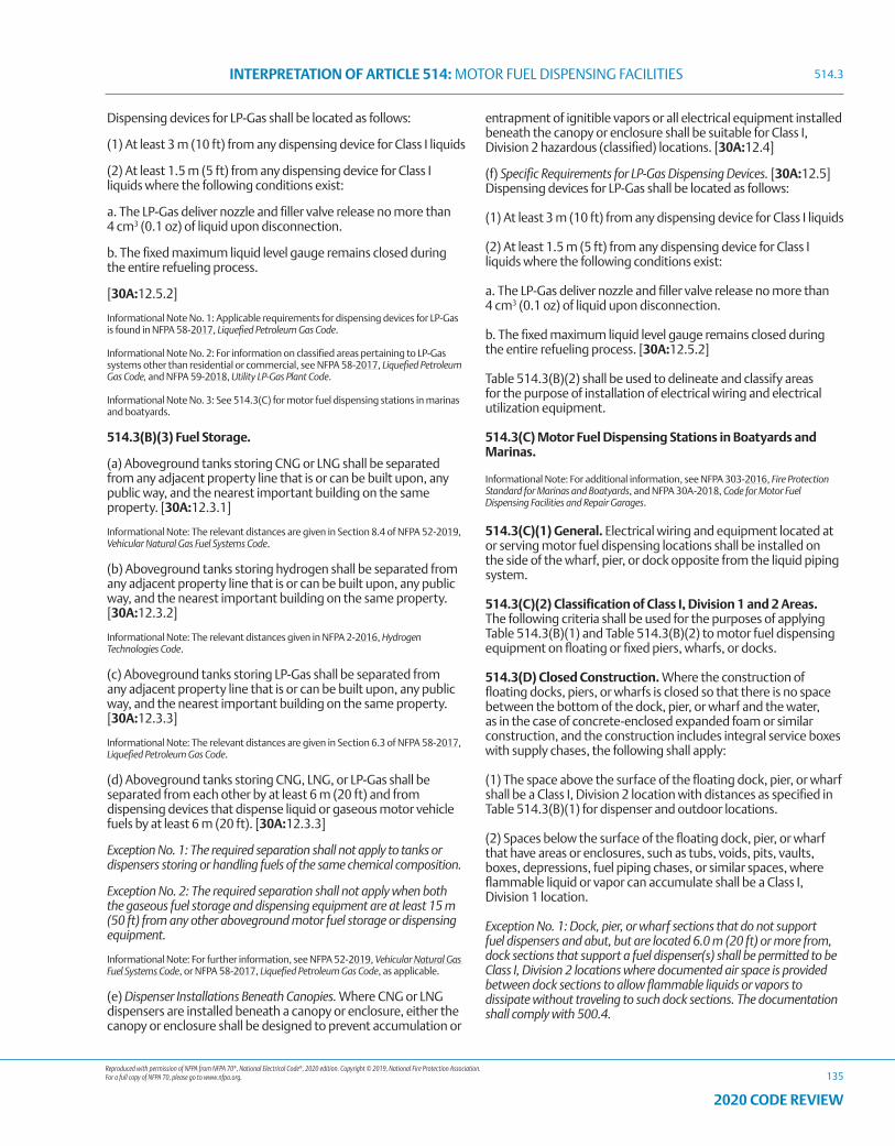
Reproduced with permission of NFPA from NFPA 70®, National Electrical Code®, 2020 edition. Copyright © 2019, National Fire Protection Association. For a full copy of NFPA 70, please go to www.nfpa.org.
INTERPRETATION OF ARTICLE 514: MOTOR FUEL DISPENSING FACILITIES
135
2020 CODE REVIEW
Dispensing devices for LP-Gas shall be located as follows:
(1) At least 3 m (10 ft) from any dispensing device for Class I liquids
(2) At least 1.5 m (5 ft) from any dispensing device for Class I liquids where the following conditions exist:
a. The LP-Gas deliver nozzle and filler valve release no more than 4 cm3 (0.1 oz) of liquid upon disconnection.
b. The fixed maximum liquid level gauge remains closed during the entire refueling process.
[30A:12.5.2]
Informational Note No. 1: Applicable requirements for dispensing devices for LP-Gas is found in NFPA 58-2017, Liquefied Petroleum Gas Code.
Informational Note No. 2: For information on classified areas pertaining to LP-Gas systems other than residential or commercial, see NFPA 58-2017, Liquefied Petroleum Gas Code, and NFPA 59-2018, Utility LP-Gas Plant Code.
Informational Note No. 3: See 514.3(C) for motor fuel dispensing stations in marinas and boatyards.
514.3(B)(3) Fuel Storage.
(a) Aboveground tanks storing CNG or LNG shall be separated from any adjacent property line that is or can be built upon, any public way, and the nearest important building on the same property. [30A:12.3.1]
Informational Note: The relevant distances are given in Section 8.4 of NFPA 52-2019, Vehicular Natural Gas Fuel Systems Code.
(b) Aboveground tanks storing hydrogen shall be separated from any adjacent property line that is or can be built upon, any public way, and the nearest important building on the same property. [30A:12.3.2]
Informational Note: The relevant distances given in NFPA 2-2016, Hydrogen Technologies Code.
(c) Aboveground tanks storing LP-Gas shall be separated from any adjacent property line that is or can be built upon, any public way, and the nearest important building on the same property. [30A:12.3.3]
Informational Note: The relevant distances are given in Section 6.3 of NFPA 58-2017, Liquefied Petroleum Gas Code.
(d) Aboveground tanks storing CNG, LNG, or LP-Gas shall be separated from each other by at least 6 m (20 ft) and from dispensing devices that dispense liquid or gaseous motor vehicle fuels by at least 6 m (20 ft). [30A:12.3.3]
Exception No. 1: The required separation shall not apply to tanks or dispensers storing or handling fuels of the same chemical composition.
Exception No. 2: The required separation shall not apply when both the gaseous fuel storage and dispensing equipment are at least 15 m (50 ft) from any other aboveground motor fuel storage or dispensing equipment.
Informational Note: For further information, see NFPA 52-2019, Vehicular Natural Gas Fuel Systems Code, or NFPA 58-2017, Liquefied Petroleum Gas Code, as applicable.
(e) Dispenser Installations Beneath Canopies. Where CNG or LNG dispensers are installed beneath a canopy or enclosure, either the canopy or enclosure shall be designed to prevent accumulation or
entrapment of ignitible vapors or all electrical equipment installed beneath the canopy or enclosure shall be suitable for Class I, Division 2 hazardous (classified) locations. [30A:12.4]
(f) Specific Requirements for LP-Gas Dispensing Devices. [30A:12.5] Dispensing devices for LP-Gas shall be located as follows:
(1) At least 3 m (10 ft) from any dispensing device for Class I liquids
(2) At least 1.5 m (5 ft) from any dispensing device for Class I liquids where the following conditions exist:
a. The LP-Gas deliver nozzle and filler valve release no more than 4 cm3 (0.1 oz) of liquid upon disconnection.
b. The fixed maximum liquid level gauge remains closed during the entire refueling process. [30A:12.5.2]
Table 514.3(B)(2) shall be used to delineate and classify areas for the purpose of installation of electrical wiring and electrical utilization equipment.
514.3(C) Motor Fuel Dispensing Stations in Boatyards and Marinas.
Informational Note: For additional information, see NFPA 303-2016, Fire Protection Standard for Marinas and Boatyards, and NFPA 30A-2018, Code for Motor Fuel Dispensing Facilities and Repair Garages.
514.3(C)(1) General. Electrical wiring and equipment located at or serving motor fuel dispensing locations shall be installed on the side of the wharf, pier, or dock opposite from the liquid piping system.
514.3(C)(2) Classification of Class I, Division 1 and 2 Areas. The following criteria shall be used for the purposes of applying Table 514.3(B)(1) and Table 514.3(B)(2) to motor fuel dispensing equipment on floating or fixed piers, wharfs, or docks.
514.3(D) Closed Construction. Where the construction of floating docks, piers, or wharfs is closed so that there is no space between the bottom of the dock, pier, or wharf and the water, as in the case of concrete-enclosed expanded foam or similar construction, and the construction includes integral service boxes with supply chases, the following shall apply:
(1) The space above the surface of the floating dock, pier, or wharf shall be a Class I, Division 2 location with distances as specified in Table 514.3(B)(1) for dispenser and outdoor locations.
(2) Spaces below the surface of the floating dock, pier, or wharf that have areas or enclosures, such as tubs, voids, pits, vaults, boxes, depressions, fuel piping chases, or similar spaces, where flammable liquid or vapor can accumulate shall be a Class I, Division 1 location.
Exception No. 1: Dock, pier, or wharf sections that do not support fuel dispensers and abut, but are located 6.0 m (20 ft) or more from, dock sections that support a fuel dispenser(s) shall be permitted to be Class I, Division 2 locations where documented air space is provided between dock sections to allow flammable liquids or vapors to dissipate without traveling to such dock sections. The documentation shall comply with 500.4.
514.3
Reproduced with permission of NFPA from NFPA 70®, National Electrical Code®, 2020 edition. Copyright © 2019, National Fire Protection Association. For a full copy of NFPA 70, please go to www.nfpa.org.
INTERPRETATION OF ARTICLE 514: MOTOR FUEL DISPENSING FACILITIES
136
2020 CODE REVIEW
Exception No. 2: Dock, pier, or wharf sections that do not support fuel dispensers and do not directly abut sections that support fuel dispensers shall be permitted to be unclassified where documented air space is provided and where flammable liquids or vapors cannot travel to such dock sections. The documentation shall comply with 500.4.
514.3(E) Open Construction. Where the construction of piers, wharfs, or docks is open, as in the case of decks built on stringers supported by pilings, floats, pontoons, or similar construction, the following shall apply:
(1) The area 450 mm (18 in.) above the surface of the dock, pier, or wharf and extending 6.0 m (20 ft) horizontally in all directions from the outside edge of the dispenser and down to the water level shall be a Class 1, Division 2 location.
(2) Enclosures such as tubs, voids, pits, vaults, boxes, depressions, piping chases, or similar spaces where flammable liquids or vapors can accumulate within 6.0 m (20 ft) of the dispenser shall be a Class I, Division 1 location.
514.4 Wiring and Equipment Installed in Class I Locations. All electrical equipment and wiring installed in Class I locations as classified in 514.3 shall comply with the applicable provisions of Article 501.
Exception: As permitted in 514.8.
Informational Note: For special requirements for conductor insulation, see 501.20.
Requirements are somewhat different than for indoor pumps, as liquids dispensed are not typically gasoline.
Table 514.3(B)(1) gives requirements for a lubrication or service room where no dispensing takes place. An unventilated pit in such an area has been determined to be Class I, Division 2/Class I, Zone 2. The area is unclassified when ventilated in accordance with NFPA® 30A, 5-3.1.
Flammable liquids shall be known as Class I liquids. Class I liquids are divided into three Classes as follows:
Class IA shall include liquids having flash points below +22.8 °C (+73 °F) and having a boiling point below +37.8 °C (+100 °F).
Class IB shall include liquids having flash points below +22.8 °C (+73 °F) and having a boiling point at or above +37.8 °C (+100 °F).
Class IC shall include liquids having flash points at or above +22.8 °C (+73 °F) and having a boiling point below +37.8 °C (+100 °F).
The flash point was selected as the basis for classification of flammable and combustible liquids because it is directly related to a liquid’s ability to generate vapor, i.e., its volatility. Since it is the vapor of the liquid, not the liquid itself that burns, vapor generation becomes the primary factor in determining the fire hazard. The expression “low flash - high hazard” applies. Liquids having flash points below ambient storage temperatures generally display a rapid rate of flame spread over the surface of the liquid, since it is not necessary for the heat of the fire to expend its energy in heating the liquid to generate more vapor.
VAPOR PROCESSING EQUIPMENT NOT WITHIN PROTECTIVE ENCLOSURES AND VACUUM ASSIST BLOWERS.
For “Vapor Processing Equipment Located Within Protective Enclosures,” see NFPA® 30A, Code for Motor Fuel Dispensing Facilities and Repair Garages, Section 10.1. Any of the equipment within the protective enclosure is Class I, Division 2, Group D/Class I, Zone 2 IIA.
514.7 Wiring and Equipment Above Class I Locations. Wiring and equipment above the Class I locations as classified in 514.3 shall comply with 511.7.
514.8 Underground Wiring. Underground wiring shall be installed in threaded rigid metal conduit or threaded steel intermediate metal conduit. Any portion of electrical wiring that is below the surface of a Class I, Division 1 or a Class I, Division 2 location [as classified in Table 514.3(B)(1) and Table 514.3(B)(2)] shall be sealed within 3.05 m (10 ft) of the point of emergence above grade. Except for listed explosionproof reducers at the conduit seal, there shall be no union, coupling, box, or fitting between the conduit seal and the point of emergence above grade. Refer to Table 300.5.
Exception No. 1: Type MI cable shall be permitted where it is installed in accordance with Article 332.
Exception No. 2: Type PVC conduit, Type RTRC conduit, and Type HDPE conduit shall be permitted where buried under not less than 600 mm (2 ft) of cover. Where Type PVC conduit, Type RTRC conduit, or Type HDPE conduit is used, threaded rigid metal conduit or threaded steel intermediate metal conduit shall be used for the last 600 mm (2 ft) of the underground run to emergence or to the point of connection to the aboveground raceway, and an equipment grounding conductor shall be included to provide electrical continuity of the raceway system and for grounding of non–current-carrying metal parts.
Section 514.8 prohibits joints between where a conduit emerges from the grade and the conduit seal, except for listed reducers. In addition, the seal must be within 10 ft of the point of emergence from grade. The section now specifies what specific types of rigid nonmetallic conduit are permissible.
Type HDPE conduit is considered as providing the same level of protection as Type PVC or Type RTRC when buried 24 inches in the earth. It is important to understand that when transitioning to threaded rigid conduit or threaded steel intermediate metal conduit that the transition fitting be identified as being suitable for wet locations as this transition is required underground before emergence from the earth.
514.9 Sealing.
514.9(A) At Dispenser. A listed seal shall be provided in each conduit run entering or leaving a dispenser or any cavities or enclosures in direct communication therewith. The sealing fitting or listed explosionproof reducer at the seal shall be the first fitting after the conduit emerges from the earth or concrete.
514.9(B) At Boundary. Additional seals shall be provided in accordance with 501.15. Sections 501.15(A)(4) and (B)(2) shall apply to horizontal as well as to vertical boundaries of the defined Class I locations.
514.3
Reproduced with permission of NFPA from NFPA 70®, National Electrical Code®, 2020 edition. Copyright © 2019, National Fire Protection Association. For a full copy of NFPA 70, please go to www.nfpa.org.
INTERPRETATION OF ARTICLE 514: MOTOR FUEL DISPENSING FACILITIES
137
2020 CODE REVIEW
514.11 Circuit Disconnects.
514.11(A) Emergency Electrical Disconnects. Fuel dispensing systems shall be provided with one or more clearly identified emergency shutoff devices or electrical disconnects. Such devices or disconnects shall be installed in approved locations but not less than 6 m (20 ft) or more than 30 m (100 ft) from the fuel dispensing devices that they serve. Emergency shutoff devices or electrical disconnects shall disconnect power to all dispensing devices; to all remote pumps serving the dispensing devices; to all associated power, control, and signal circuits; and to all other electrical equipment in the hazardous (classified) locations surrounding the fuel dispensing devices. When more than one emergency shutoff device or electrical disconnect is provided, all devices shall be interconnected. Resetting from an emergency shutoff condition shall require manual intervention and the manner of resetting shall be approved by the authority having jurisdiction. [30A:6.7]
The emergency shutoff device shall disconnect simultaneously from the source of supply, all conductors of the circuits, including the grounded conductor, if any. Equipment grounding conductors shall remain connected.
Exception: Intrinsically safe electrical equipment need not meet this requirement. [30A:6.7]
Section 514.11 was revised to clarify that the grounded conductor should be disconnected simultaneously with all of the other conductors when the emergency disconnect is activated. The revision also clarifies that the equipment grounding conductors should not be disconnected.
514.11(B) Attended Self-Service Motor Fuel Dispensing Facilities. At attended motor fuel dispensing facilities, the devices or disconnects shall be readily accessible to the attendant. [30A:6.7.1]
514.11(C) Unattended Self-Service Motor Fuel Dispensing Facilities. At unattended motor fuel dispensing facilities, the devices or disconnects shall be readily accessible to patrons and at least one additional device or disconnect shall be readily accessible to each group of dispensing devices on an individual island. [30A:6.7.2]
514.13 Provisions for Maintenance and Service of Dispensing Equipment. Each dispensing device shall be provided with a means to remove all external voltage sources, including power, communications, data, and video circuits and including feedback, during periods of maintenance and service of the dispensing equipment. The location of this means shall be permitted to be other than inside or adjacent to the dispensing device. The means shall be capable of being locked in the open position in accordance with 110.25.
Section 514.13 requires a lock out means to remove all voltages from dispensing equipment during service and maintenance. The section specifies all of the types of circuits that are required to have provisions that remove all voltage sources to the dispensing device during maintenance and service operations. Section 110.25 consolidates requirements for disconnecting means that are capable of being locked in the open position. This is intended to also address any circuits that are not power circuits.
514.16 Grounding and Bonding. All metal raceways, the metal armor or metallic sheath on cables, and all non–current-carrying metal parts of fixed and portable electrical equipment, regardless of voltage, shall be grounded and bonded. Grounding and bonding in Class I locations shall comply with 501.30.
514.16

138
2020 CODE REVIEW
NOTES
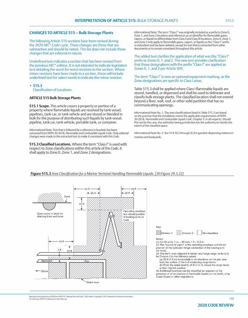
Reproduced with permission of NFPA from NFPA 70®, National Electrical Code®, 2020 edition. Copyright © 2019, National Fire Protection Association. For a full copy of NFPA 70, please go to www.nfpa.org.
INTERPRETATION OF ARTICLE 515: BULK STORAGE PLANTS
139
2020 CODE REVIEW
CHANGES TO ARTICLE 515 – Bulk Storage Plants
The following Article 515 sections have been revised during the 2020 NEC® Code cycle. These changes are those that are substantive and should be noted. This list does not include those changes that are editorial in nature.
Underlined text indicates a section that has been revised from the previous NEC® edition. It is not intended to indicate legislation text detailing the word-for-word revisions to the section. Where minor revisions have been made to a section, these will include underlined text for select words to indicate the minor revision.
• 515.3 Classification of Locations.
ARTICLE 515 Bulk Storage Plants
515.1 Scope. This article covers a property or portion of a property where flammable liquids are received by tank vessel, pipelines, tank car, or tank vehicle and are stored or blended in bulk for the purpose of distributing such liquids by tank vessel, pipeline, tank car, tank vehicle, portable tank, or container.
Informational Note: Text that is followed by a reference in brackets has been extracted from NFPA 30-2018, Flammable and Combustible Liquids Code. Only editorial changes were made to the extracted text to make it consistent with this Code.
515.3 Classified Locations. Where the term “Class I” is used with respect to Zone classifications within this article of the Code, it shall apply to Zone 0, Zone 1, and Zone 2 designations.
Informational Note: The term “Class I” was originally included as a prefix to Zone 0, Zone 1, and Zone 2 locations and references as an identifier for flammable gases, vapors, or liquids to differentiate from Class II and Class III locations. Zone 0, Zone 1, and Zone 2 only apply to flammable gases, vapors, or liquids so the “Class I” prefix is redundant and has been deleted, except for text that is extracted from other documents or to remain consistent throughout this article.
The added text clarifies the application of what was the “Class I” prefix to Zones 0, 1, and 2. The new text provides clarification that those designations with the prefix “Class I” are applied as Zones 0, 1, and 2 per Article 505.
The term “Class I” is now an optional equipment marking, as the Zone designations are specific to Class I areas.
Table 515.3 shall be applied where Class I flammable liquids are stored, handled, or dispensed and shall be used to delineate and classify bulk storage plants. The classified location shall not extend beyond a floor, wall, roof, or other solid partition that has no communicating openings.
Informational Note No. 1: The area classifications listed in Table 515.3 are based on the premise that the installation meets the applicable requirements of NFPA 30-2018, Flammable and Combustible Liquids Code, Chapter 5, in all respects. Should this not be the case, the authority having jurisdiction has the authority to classify the extent of the classified space.
Informational Note No. 2: See 514.3(C) through (E) for gasoline dispensing stations in marinas and boatyards.
Figure 515.3 Area Classification for a Marine Terminal Handling Flammable Liquids. [30:Figure 29.3.22]
515.3
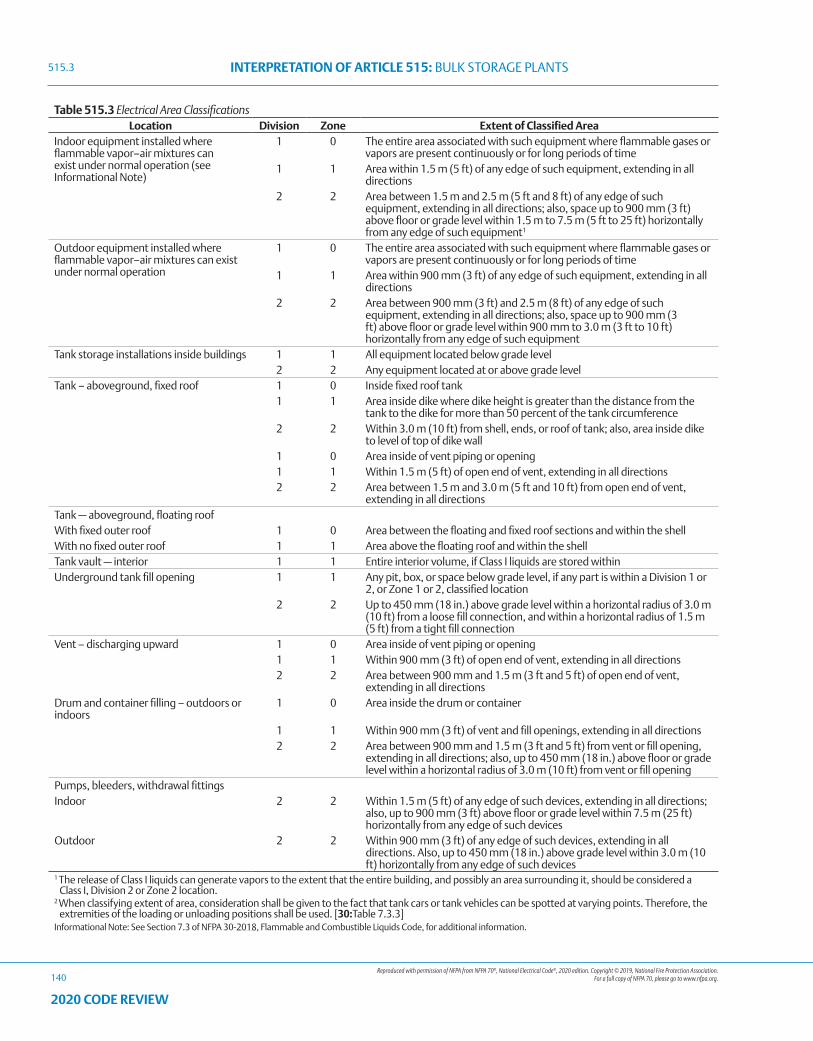
Reproduced with permission of NFPA from NFPA 70®, National Electrical Code®, 2020 edition. Copyright © 2019, National Fire Protection Association. For a full copy of NFPA 70, please go to www.nfpa.org.
INTERPRETATION OF ARTICLE 515: BULK STORAGE PLANTS
140
2020 CODE REVIEW
Table 515.3 Electrical Area ClassificationsLocation Division Zone Extent of Classified Area
Indoor equipment installed where flammable vapor–air mixtures can exist under normal operation (see Informational Note)
1 0 The entire area associated with such equipment where flammable gases or vapors are present continuously or for long periods of time
1 1 Area within 1.5 m (5 ft) of any edge of such equipment, extending in all directions
2 2 Area between 1.5 m and 2.5 m (5 ft and 8 ft) of any edge of such equipment, extending in all directions; also, space up to 900 mm (3 ft) above floor or grade level within 1.5 m to 7.5 m (5 ft to 25 ft) horizontally from any edge of such equipment1
Outdoor equipment installed where flammable vapor–air mixtures can exist under normal operation
1 0 The entire area associated with such equipment where flammable gases or vapors are present continuously or for long periods of time
1 1 Area within 900 mm (3 ft) of any edge of such equipment, extending in all directions
2 2 Area between 900 mm (3 ft) and 2.5 m (8 ft) of any edge of such equipment, extending in all directions; also, space up to 900 mm (3 ft) above floor or grade level within 900 mm to 3.0 m (3 ft to 10 ft) horizontally from any edge of such equipment
Tank storage installations inside buildings 1 1 All equipment located below grade level2 2 Any equipment located at or above grade level
Tank – aboveground, fixed roof 1 0 Inside fixed roof tank1 1 Area inside dike where dike height is greater than the distance from the
tank to the dike for more than 50 percent of the tank circumference2 2 Within 3.0 m (10 ft) from shell, ends, or roof of tank; also, area inside dike
to level of top of dike wall1 0 Area inside of vent piping or opening1 1 Within 1.5 m (5 ft) of open end of vent, extending in all directions2 2 Area between 1.5 m and 3.0 m (5 ft and 10 ft) from open end of vent,
extending in all directionsTank — aboveground, floating roofWith fixed outer roof 1 0 Area between the floating and fixed roof sections and within the shellWith no fixed outer roof 1 1 Area above the floating roof and within the shellTank vault — interior 1 1 Entire interior volume, if Class I liquids are stored withinUnderground tank fill opening 1 1 Any pit, box, or space below grade level, if any part is within a Division 1 or
2, or Zone 1 or 2, classified location2 2 Up to 450 mm (18 in.) above grade level within a horizontal radius of 3.0 m
(10 ft) from a loose fill connection, and within a horizontal radius of 1.5 m (5 ft) from a tight fill connection
Vent – discharging upward 1 0 Area inside of vent piping or opening1 1 Within 900 mm (3 ft) of open end of vent, extending in all directions2 2 Area between 900 mm and 1.5 m (3 ft and 5 ft) of open end of vent,
extending in all directionsDrum and container filling – outdoors or indoors
1 0 Area inside the drum or container
1 1 Within 900 mm (3 ft) of vent and fill openings, extending in all directions2 2 Area between 900 mm and 1.5 m (3 ft and 5 ft) from vent or fill opening,
extending in all directions; also, up to 450 mm (18 in.) above floor or grade level within a horizontal radius of 3.0 m (10 ft) from vent or fill opening
Pumps, bleeders, withdrawal fittingsIndoor 2 2 Within 1.5 m (5 ft) of any edge of such devices, extending in all directions;
also, up to 900 mm (3 ft) above floor or grade level within 7.5 m (25 ft) horizontally from any edge of such devices
Outdoor 2 2 Within 900 mm (3 ft) of any edge of such devices, extending in all directions. Also, up to 450 mm (18 in.) above grade level within 3.0 m (10 ft) horizontally from any edge of such devices
1 The release of Class I liquids can generate vapors to the extent that the entire building, and possibly an area surrounding it, should be considered a Class I, Division 2 or Zone 2 location.
2 When classifying extent of area, consideration shall be given to the fact that tank cars or tank vehicles can be spotted at varying points. Therefore, the extremities of the loading or unloading positions shall be used. [30:Table 7.3.3]
Informational Note: See Section 7.3 of NFPA 30-2018, Flammable and Combustible Liquids Code, for additional information.
515.3
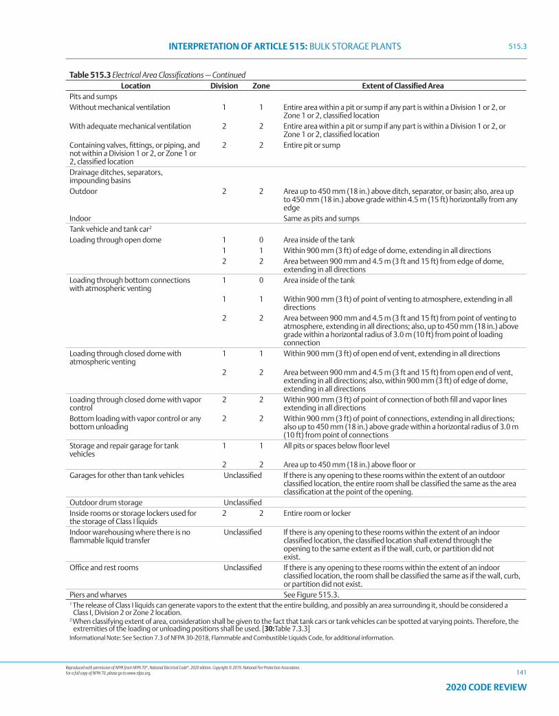
Reproduced with permission of NFPA from NFPA 70®, National Electrical Code®, 2020 edition. Copyright © 2019, National Fire Protection Association. For a full copy of NFPA 70, please go to www.nfpa.org.
INTERPRETATION OF ARTICLE 515: BULK STORAGE PLANTS
141
2020 CODE REVIEW
Table 515.3 Electrical Area Classifications — ContinuedLocation Division Zone Extent of Classified Area
Pits and sumpsWithout mechanical ventilation 1 1 Entire area within a pit or sump if any part is within a Division 1 or 2, or
Zone 1 or 2, classified locationWith adequate mechanical ventilation 2 2 Entire area within a pit or sump if any part is within a Division 1 or 2, or
Zone 1 or 2, classified locationContaining valves, fittings, or piping, and not within a Division 1 or 2, or Zone 1 or 2, classified location
2 2 Entire pit or sump
Drainage ditches, separators, impounding basinsOutdoor 2 2 Area up to 450 mm (18 in.) above ditch, separator, or basin; also, area up
to 450 mm (18 in.) above grade within 4.5 m (15 ft) horizontally from any edge
Indoor Same as pits and sumpsTank vehicle and tank car2 Loading through open dome 1 0 Area inside of the tank
1 1 Within 900 mm (3 ft) of edge of dome, extending in all directions2 2 Area between 900 mm and 4.5 m (3 ft and 15 ft) from edge of dome,
extending in all directionsLoading through bottom connections with atmospheric venting
1 0 Area inside of the tank
1 1 Within 900 mm (3 ft) of point of venting to atmosphere, extending in all directions
2 2 Area between 900 mm and 4.5 m (3 ft and 15 ft) from point of venting to atmosphere, extending in all directions; also, up to 450 mm (18 in.) above grade within a horizontal radius of 3.0 m (10 ft) from point of loading connection
Loading through closed dome with atmospheric venting
1 1 Within 900 mm (3 ft) of open end of vent, extending in all directions
2 2 Area between 900 mm and 4.5 m (3 ft and 15 ft) from open end of vent, extending in all directions; also, within 900 mm (3 ft) of edge of dome, extending in all directions
Loading through closed dome with vapor control
2 2 Within 900 mm (3 ft) of point of connection of both fill and vapor lines extending in all directions
Bottom loading with vapor control or any bottom unloading
2 2 Within 900 mm (3 ft) of point of connections, extending in all directions; also up to 450 mm (18 in.) above grade within a horizontal radius of 3.0 m (10 ft) from point of connections
Storage and repair garage for tank vehicles
1 1 All pits or spaces below floor level
2 2 Area up to 450 mm (18 in.) above floor orGarages for other than tank vehicles Unclassified If there is any opening to these rooms within the extent of an outdoor
classified location, the entire room shall be classified the same as the area classification at the point of the opening.
Outdoor drum storage UnclassifiedInside rooms or storage lockers used for the storage of Class I liquids
2 2 Entire room or locker
Indoor warehousing where there is no flammable liquid transfer
Unclassified If there is any opening to these rooms within the extent of an indoorclassified location, the classified location shall extend through theopening to the same extent as if the wall, curb, or partition did notexist.
Office and rest rooms Unclassified If there is any opening to these rooms within the extent of an indoor classified location, the room shall be classified the same as if the wall, curb, or partition did not exist.
Piers and wharves See Figure 515.3.1 The release of Class I liquids can generate vapors to the extent that the entire building, and possibly an area surrounding it, should be considered a
Class I, Division 2 or Zone 2 location.2 When classifying extent of area, consideration shall be given to the fact that tank cars or tank vehicles can be spotted at varying points. Therefore, the
extremities of the loading or unloading positions shall be used. [30:Table 7.3.3]Informational Note: See Section 7.3 of NFPA 30-2018, Flammable and Combustible Liquids Code, for additional information.
515.3
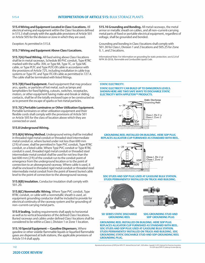
Reproduced with permission of NFPA from NFPA 70®, National Electrical Code®, 2020 edition. Copyright © 2019, National Fire Protection Association. For a full copy of NFPA 70, please go to www.nfpa.org.
INTERPRETATION OF ARTICLE 515: BULK STORAGE PLANTS
142
2020 CODE REVIEW
515.4 Wiring and Equipment Located in Class I Locations. All electrical wiring and equipment within the Class I locations defined in 515.3 shall comply with the applicable provisions of Article 501 or Article 505 for the division or zone in which they are used.
Exception: As permitted in 515.8.
515.7 Wiring and Equipment Above Class I Locations.
515.7(A) Fixed Wiring. All fixed wiring above Class I locations shall be in metal raceways, Schedule 80 PVC conduit, Type RTRC marked with the suffix -XW, or Type MI, Type TC, or Type MC cable, or Type PLTC and Type PLTC-ER cable in accordance with the provisions of Article 725, including installation in cable tray systems or Type ITC and Type ITC-ER cable as permitted in 727.4. The cable shall be terminated with listed fittings.
515.7(B) Fixed Equipment. Fixed equipment that may produce arcs, sparks, or particles of hot metal, such as lamps and lampholders for fixed lighting, cutouts, switches, receptacles, motors, or other equipment having make-and-break or sliding contacts, shall be of the totally enclosed type or be constructed so as to prevent the escape of sparks or hot metal particles.
515.7(C) Portable Luminaires or Other Utilization Equipment. Portable luminaires or other utilization equipment and their flexible cords shall comply with the provisions of Article 501 or Article 505 for the class of location above which they are connected or used.
515.8 Underground Wiring.
515.8(A) Wiring Method. Underground wiring shall be installed in threaded rigid metal conduit or threaded steel intermediate metal conduit or, where buried under not less than 600 mm (2 ft) of cover, shall be permitted in Type PVC conduit, Type RTRC conduit, or a listed cable. Where Type PVC conduit or Type RTRC conduit is used, threaded rigid metal conduit or threaded steel intermediate metal conduit shall be used for not less than the last 600 mm (2 ft) of the conduit run to the conduit point of emergence from the underground location or to the point of connection to an aboveground raceway. Where cable is used, it shall be enclosed in threaded rigid metal conduit or threaded steel intermediate metal conduit from the point of lowest buried cable level to the point of connection to the aboveground raceway.
515.8(B) Insulation. Conductor insulation shall comply with 501.20.
515.8(C) Nonmetallic Wiring. Where Type PVC conduit, Type RTRC conduit, or cable with a nonmetallic sheath is used, an equipment grounding conductor shall be included to provide for electrical continuity of the raceway system and for grounding of non–current-carrying metal parts.
515.9 Sealing. Sealing requirements shall apply to horizontal as well as to vertical boundaries of the defined Class I locations. Buried raceways and cables under defined Class I locations shall be considered to be within a Class I, Division 1 or Zone 1 location.
515.10 Special Equipment — Gasoline Dispensers. Where gasoline or other volatile flammable liquids or liquefied flammable gases are dispensed at bulk stations, the applicable provisions of Article 514 shall apply.
515.16 Grounding and Bonding. All metal raceways, the metal armor or metallic sheath on cables, and all non–current-carrying metal parts of fixed or portable electrical equipment, regardless of voltage, shall be grounded and bonded.
Grounding and bonding in Class I locations shall comply with 501.30 for Class I, Division 1 and 2 locations and 505.25 for Zone 0, 1, and 2 locations.
Informational Note: For information on grounding for static protection, see 6.5.4 of NFPA 30-2018, Flammable and Combustible Liquids Code.
STATIC ELECTRICITY.
STATIC ELECTRICITY CAN BUILD UP TO DANGEROUS LEVELS. SHOWN HERE ARE TWO SAFE WAYS TO DISCHARGE STATIC ELECTRICITY WITH APPLETON™ PRODUCTS.
GROUNDING REEL INSTALLED ON BUILDING. HERE SDP PLUG REPLACES ALLIGATOR CLIP FURNISHED AS STANDARD WITH REEL.
SDG STUDS AND SDP PLUG USED AT GASOLINE BULK STATION. STUDS PERMANENTLY INSTALLED ON TRUCK AND BUILDING.
SD SERIES STATIC DISCHARGE GROUNDING REEL
SDG GROUNDING STUD AND SDP GROUNDING PLUG
GROUNDING REEL INSTALLED ON BUILDING. HERE SDP PLUG REPLACES ALLIGATOR CLIP FURNISHED AS STANDARD WITH REEL. SDG STUDS AND SDP PLUG USED AT GASOLINE BULK STATION. STUDS PERMANENTLY INSTALLED ON TRUCK AND BUILDING. SDG GROUNDING STATIC DISCHARGE STUD AND SDP GROUNDING REEL GROUNDING PLUG.
515.4
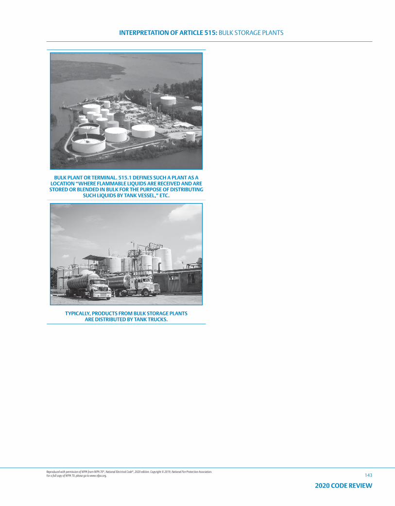
Reproduced with permission of NFPA from NFPA 70®, National Electrical Code®, 2020 edition. Copyright © 2019, National Fire Protection Association. For a full copy of NFPA 70, please go to www.nfpa.org.
INTERPRETATION OF ARTICLE 515: BULK STORAGE PLANTS
143
2020 CODE REVIEW
BULK PLANT OR TERMINAL. 515.1 DEFINES SUCH A PLANT AS A LOCATION “WHERE FLAMMABLE LIQUIDS ARE RECEIVED AND ARE
STORED OR BLENDED IN BULK FOR THE PURPOSE OF DISTRIBUTING SUCH LIQUIDS BY TANK VESSEL,” ETC.
TYPICALLY, PRODUCTS FROM BULK STORAGE PLANTS ARE DISTRIBUTED BY TANK TRUCKS.

144
2020 CODE REVIEW
NOTES
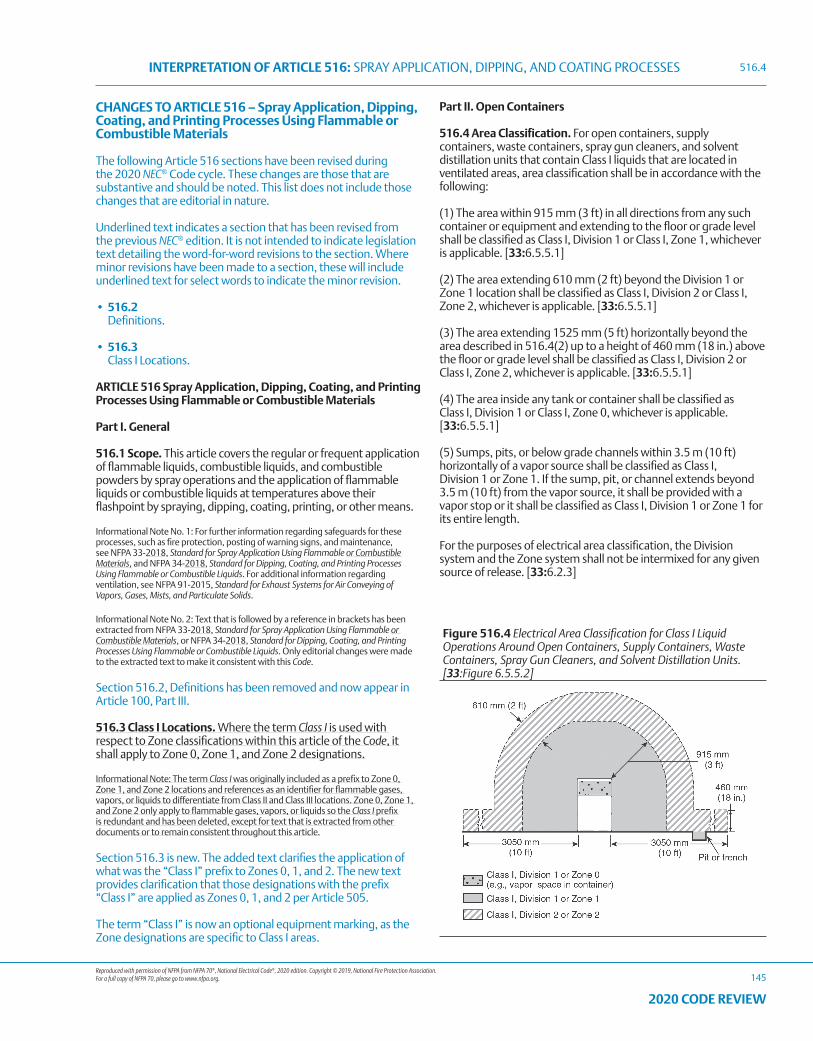
Reproduced with permission of NFPA from NFPA 70®, National Electrical Code®, 2020 edition. Copyright © 2019, National Fire Protection Association. For a full copy of NFPA 70, please go to www.nfpa.org.
INTERPRETATION OF ARTICLE 516: SPRAY APPLICATION, DIPPING, AND COATING PROCESSES
145
2020 CODE REVIEW
CHANGES TO ARTICLE 516 – Spray Application, Dipping, Coating, and Printing Processes Using Flammable or Combustible Materials
The following Article 516 sections have been revised during the 2020 NEC® Code cycle. These changes are those that are substantive and should be noted. This list does not include those changes that are editorial in nature.
Underlined text indicates a section that has been revised from the previous NEC® edition. It is not intended to indicate legislation text detailing the word-for-word revisions to the section. Where minor revisions have been made to a section, these will include underlined text for select words to indicate the minor revision.
• 516.2 Definitions.
• 516.3 Class I Locations.
ARTICLE 516 Spray Application, Dipping, Coating, and Printing Processes Using Flammable or Combustible Materials
Part I. General
516.1 Scope. This article covers the regular or frequent application of flammable liquids, combustible liquids, and combustible powders by spray operations and the application of flammable liquids or combustible liquids at temperatures above their flashpoint by spraying, dipping, coating, printing, or other means.
Informational Note No. 1: For further information regarding safeguards for these processes, such as fire protection, posting of warning signs, and maintenance, see NFPA 33-2018, Standard for Spray Application Using Flammable or Combustible Materials, and NFPA 34-2018, Standard for Dipping, Coating, and Printing Processes Using Flammable or Combustible Liquids. For additional information regarding ventilation, see NFPA 91-2015, Standard for Exhaust Systems for Air Conveying of Vapors, Gases, Mists, and Particulate Solids.
Informational Note No. 2: Text that is followed by a reference in brackets has been extracted from NFPA 33-2018, Standard for Spray Application Using Flammable or Combustible Materials, or NFPA 34-2018, Standard for Dipping, Coating, and Printing Processes Using Flammable or Combustible Liquids. Only editorial changes were made to the extracted text to make it consistent with this Code.
Section 516.2, Definitions has been removed and now appear in Article 100, Part III.
516.3 Class I Locations. Where the term Class I is used with respect to Zone classifications within this article of the Code, it shall apply to Zone 0, Zone 1, and Zone 2 designations.
Informational Note: The term Class I was originally included as a prefix to Zone 0, Zone 1, and Zone 2 locations and references as an identifier for flammable gases, vapors, or liquids to differentiate from Class II and Class III locations. Zone 0, Zone 1, and Zone 2 only apply to flammable gases, vapors, or liquids so the Class I prefix is redundant and has been deleted, except for text that is extracted from other documents or to remain consistent throughout this article.
Section 516.3 is new. The added text clarifies the application of what was the “Class I” prefix to Zones 0, 1, and 2. The new text provides clarification that those designations with the prefix “Class I” are applied as Zones 0, 1, and 2 per Article 505.
The term “Class I” is now an optional equipment marking, as the Zone designations are specific to Class I areas.
Part II. Open Containers
516.4 Area Classification. For open containers, supply containers, waste containers, spray gun cleaners, and solvent distillation units that contain Class I liquids that are located in ventilated areas, area classification shall be in accordance with the following:
(1) The area within 915 mm (3 ft) in all directions from any such container or equipment and extending to the floor or grade level shall be classified as Class I, Division 1 or Class I, Zone 1, whichever is applicable. [33:6.5.5.1]
(2) The area extending 610 mm (2 ft) beyond the Division 1 or Zone 1 location shall be classified as Class I, Division 2 or Class I, Zone 2, whichever is applicable. [33:6.5.5.1]
(3) The area extending 1525 mm (5 ft) horizontally beyond the area described in 516.4(2) up to a height of 460 mm (18 in.) above the floor or grade level shall be classified as Class I, Division 2 or Class I, Zone 2, whichever is applicable. [33:6.5.5.1]
(4) The area inside any tank or container shall be classified as Class I, Division 1 or Class I, Zone 0, whichever is applicable. [33:6.5.5.1]
(5) Sumps, pits, or below grade channels within 3.5 m (10 ft) horizontally of a vapor source shall be classified as Class I, Division 1 or Zone 1. If the sump, pit, or channel extends beyond 3.5 m (10 ft) from the vapor source, it shall be provided with a vapor stop or it shall be classified as Class I, Division 1 or Zone 1 for its entire length.
For the purposes of electrical area classification, the Division system and the Zone system shall not be intermixed for any given source of release. [33:6.2.3]
Figure 516.4 Electrical Area Classification for Class I Liquid Operations Around Open Containers, Supply Containers, Waste Containers, Spray Gun Cleaners, and Solvent Distillation Units. [33:Figure 6.5.5.2]
516.4
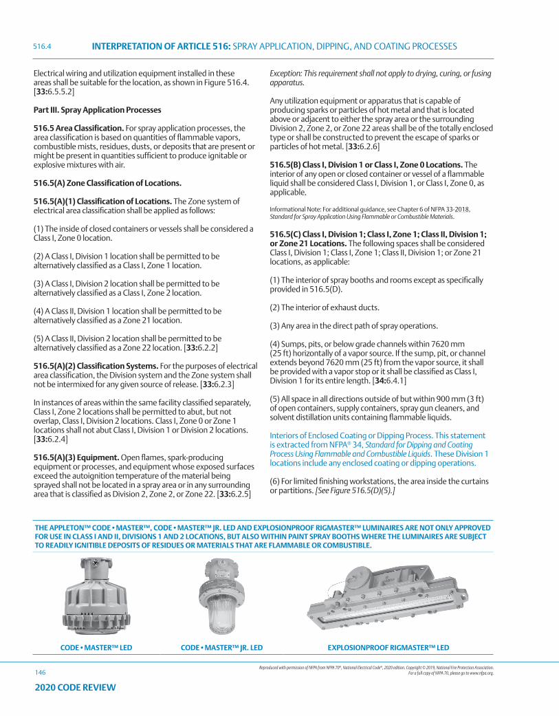
Reproduced with permission of NFPA from NFPA 70®, National Electrical Code®, 2020 edition. Copyright © 2019, National Fire Protection Association. For a full copy of NFPA 70, please go to www.nfpa.org.
INTERPRETATION OF ARTICLE 516: SPRAY APPLICATION, DIPPING, AND COATING PROCESSES
146
2020 CODE REVIEW
Electrical wiring and utilization equipment installed in these areas shall be suitable for the location, as shown in Figure 516.4. [33:6.5.5.2]
Part III. Spray Application Processes
516.5 Area Classification. For spray application processes, the area classification is based on quantities of flammable vapors, combustible mists, residues, dusts, or deposits that are present or might be present in quantities sufficient to produce ignitable or explosive mixtures with air.
516.5(A) Zone Classification of Locations.
516.5(A)(1) Classification of Locations. The Zone system of electrical area classification shall be applied as follows:
(1) The inside of closed containers or vessels shall be considered a Class I, Zone 0 location.
(2) A Class I, Division 1 location shall be permitted to be alternatively classified as a Class I, Zone 1 location.
(3) A Class I, Division 2 location shall be permitted to be alternatively classified as a Class I, Zone 2 location.
(4) A Class II, Division 1 location shall be permitted to be alternatively classified as a Zone 21 location.
(5) A Class II, Division 2 location shall be permitted to be alternatively classified as a Zone 22 location. [33:6.2.2]
516.5(A)(2) Classification Systems. For the purposes of electrical area classification, the Division system and the Zone system shall not be intermixed for any given source of release. [33:6.2.3]
In instances of areas within the same facility classified separately, Class I, Zone 2 locations shall be permitted to abut, but not overlap, Class I, Division 2 locations. Class I, Zone 0 or Zone 1 locations shall not abut Class I, Division 1 or Division 2 locations. [33:6.2.4]
516.5(A)(3) Equipment. Open flames, spark-producing equipment or processes, and equipment whose exposed surfaces exceed the autoignition temperature of the material being sprayed shall not be located in a spray area or in any surrounding area that is classified as Division 2, Zone 2, or Zone 22. [33:6.2.5]
Exception: This requirement shall not apply to drying, curing, or fusing apparatus.
Any utilization equipment or apparatus that is capable of producing sparks or particles of hot metal and that is located above or adjacent to either the spray area or the surrounding Division 2, Zone 2, or Zone 22 areas shall be of the totally enclosed type or shall be constructed to prevent the escape of sparks or particles of hot metal. [33:6.2.6]
516.5(B) Class I, Division 1 or Class I, Zone 0 Locations. The interior of any open or closed container or vessel of a flammable liquid shall be considered Class I, Division 1, or Class I, Zone 0, as applicable.
Informational Note: For additional guidance, see Chapter 6 of NFPA 33-2018, Standard for Spray Application Using Flammable or Combustible Materials.
516.5(C) Class I, Division 1; Class I, Zone 1; Class II, Division 1; or Zone 21 Locations. The following spaces shall be considered Class I, Division 1; Class I, Zone 1; Class II, Division 1; or Zone 21 locations, as applicable:
(1) The interior of spray booths and rooms except as specifically provided in 516.5(D).
(2) The interior of exhaust ducts.
(3) Any area in the direct path of spray operations.
(4) Sumps, pits, or below grade channels within 7620 mm (25 ft) horizontally of a vapor source. If the sump, pit, or channel extends beyond 7620 mm (25 ft) from the vapor source, it shall be provided with a vapor stop or it shall be classified as Class I, Division 1 for its entire length. [34:6.4.1]
(5) All space in all directions outside of but within 900 mm (3 ft) of open containers, supply containers, spray gun cleaners, and solvent distillation units containing flammable liquids.
Interiors of Enclosed Coating or Dipping Process. This statement is extracted from NFPA® 34, Standard for Dipping and Coating Process Using Flammable and Combustible Liquids. These Division 1 locations include any enclosed coating or dipping operations.
(6) For limited finishing workstations, the area inside the curtains or partitions. [See Figure 516.5(D)(5).]
THE APPLETON™ CODE•MASTER™, CODE•MASTER™ JR. LED AND EXPLOSIONPROOF RIGMASTER™ LUMINAIRES ARE NOT ONLY APPROVED FOR USE IN CLASS I AND II, DIVISIONS 1 AND 2 LOCATIONS, BUT ALSO WITHIN PAINT SPRAY BOOTHS WHERE THE LUMINAIRES ARE SUBJECT TO READILY IGNITIBLE DEPOSITS OF RESIDUES OR MATERIALS THAT ARE FLAMMABLE OR COMBUSTIBLE.
CODE•MASTER™ LED CODE•MASTER™ JR. LED EXPLOSIONPROOF RIGMASTER™ LED
516.4
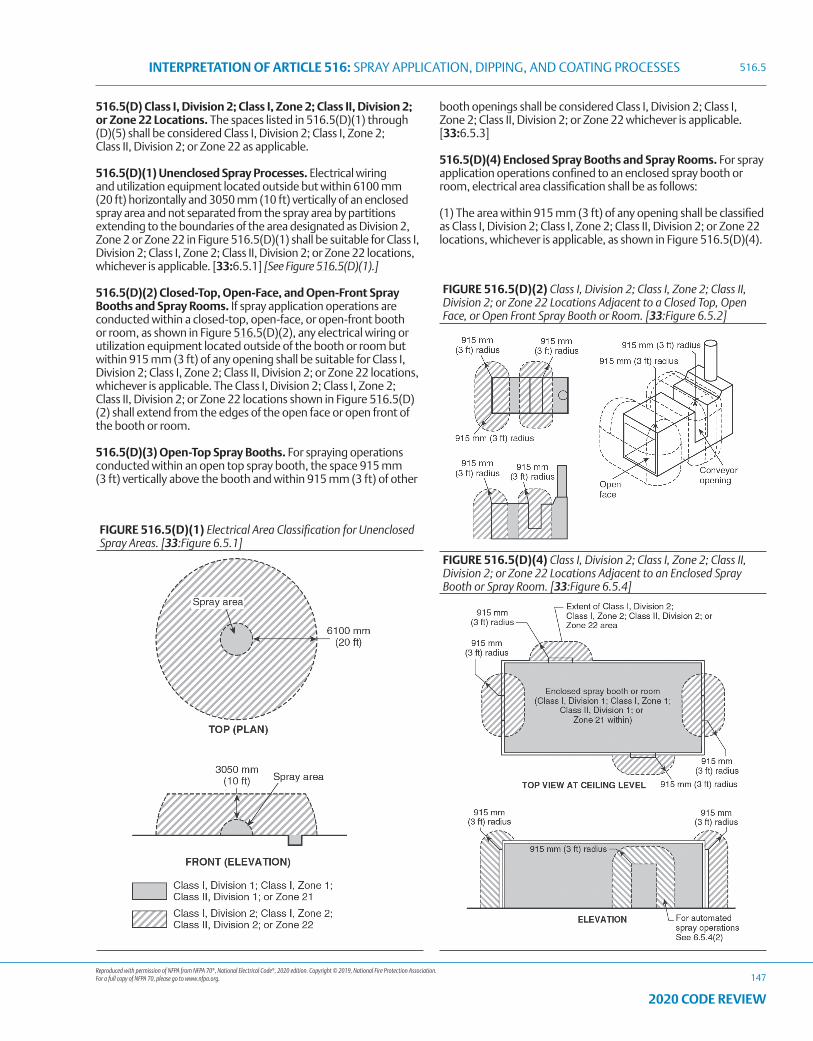
Reproduced with permission of NFPA from NFPA 70®, National Electrical Code®, 2020 edition. Copyright © 2019, National Fire Protection Association. For a full copy of NFPA 70, please go to www.nfpa.org.
INTERPRETATION OF ARTICLE 516: SPRAY APPLICATION, DIPPING, AND COATING PROCESSES
147
2020 CODE REVIEW
516.5(D) Class I, Division 2; Class I, Zone 2; Class II, Division 2; or Zone 22 Locations. The spaces listed in 516.5(D)(1) through (D)(5) shall be considered Class I, Division 2; Class I, Zone 2; Class II, Division 2; or Zone 22 as applicable.
516.5(D)(1) Unenclosed Spray Processes. Electrical wiring and utilization equipment located outside but within 6100 mm (20 ft) horizontally and 3050 mm (10 ft) vertically of an enclosed spray area and not separated from the spray area by partitions extending to the boundaries of the area designated as Division 2, Zone 2 or Zone 22 in Figure 516.5(D)(1) shall be suitable for Class I, Division 2; Class I, Zone 2; Class II, Division 2; or Zone 22 locations, whichever is applicable. [33:6.5.1] [See Figure 516.5(D)(1).]
516.5(D)(2) Closed-Top, Open-Face, and Open-Front Spray Booths and Spray Rooms. If spray application operations are conducted within a closed-top, open-face, or open-front booth or room, as shown in Figure 516.5(D)(2), any electrical wiring or utilization equipment located outside of the booth or room but within 915 mm (3 ft) of any opening shall be suitable for Class I, Division 2; Class I, Zone 2; Class II, Division 2; or Zone 22 locations, whichever is applicable. The Class I, Division 2; Class I, Zone 2; Class II, Division 2; or Zone 22 locations shown in Figure 516.5(D)(2) shall extend from the edges of the open face or open front of the booth or room.
516.5(D)(3) Open-Top Spray Booths. For spraying operations conducted within an open top spray booth, the space 915 mm (3 ft) vertically above the booth and within 915 mm (3 ft) of other
booth openings shall be considered Class I, Division 2; Class I, Zone 2; Class II, Division 2; or Zone 22 whichever is applicable. [33:6.5.3]
516.5(D)(4) Enclosed Spray Booths and Spray Rooms. For spray application operations confined to an enclosed spray booth or room, electrical area classification shall be as follows:
(1) The area within 915 mm (3 ft) of any opening shall be classified as Class I, Division 2; Class I, Zone 2; Class II, Division 2; or Zone 22 locations, whichever is applicable, as shown in Figure 516.5(D)(4).
FIGURE 516.5(D)(1) Electrical Area Classification for Unenclosed Spray Areas. [33:Figure 6.5.1]
FIGURE 516.5(D)(2) Class I, Division 2; Class I, Zone 2; Class II, Division 2; or Zone 22 Locations Adjacent to a Closed Top, Open Face, or Open Front Spray Booth or Room. [33:Figure 6.5.2]
FIGURE 516.5(D)(4) Class I, Division 2; Class I, Zone 2; Class II, Division 2; or Zone 22 Locations Adjacent to an Enclosed Spray Booth or Spray Room. [33:Figure 6.5.4]
516.5
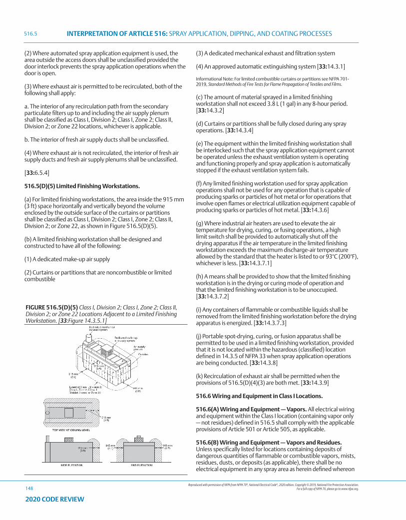
Reproduced with permission of NFPA from NFPA 70®, National Electrical Code®, 2020 edition. Copyright © 2019, National Fire Protection Association. For a full copy of NFPA 70, please go to www.nfpa.org.
INTERPRETATION OF ARTICLE 516: SPRAY APPLICATION, DIPPING, AND COATING PROCESSES
148
2020 CODE REVIEW
(2) Where automated spray application equipment is used, the area outside the access doors shall be unclassified provided the door interlock prevents the spray application operations when the door is open.
(3) Where exhaust air is permitted to be recirculated, both of the following shall apply:
a. The interior of any recirculation path from the secondary particulate filters up to and including the air supply plenum shall be classified as Class I, Division 2; Class I, Zone 2; Class II, Division 2; or Zone 22 locations, whichever is applicable.
b. The interior of fresh air supply ducts shall be unclassified.
(4) Where exhaust air is not recirculated, the interior of fresh air supply ducts and fresh air supply plenums shall be unclassified.
[33:6.5.4]
516.5(D)(5) Limited Finishing Workstations.
(a) For limited finishing workstations, the area inside the 915 mm (3 ft) space horizontally and vertically beyond the volume enclosed by the outside surface of the curtains or partitions shall be classified as Class I, Division 2; Class I, Zone 2; Class II, Division 2; or Zone 22, as shown in Figure 516.5(D)(5).
(b) A limited finishing workstation shall be designed and constructed to have all of the following:
(1) A dedicated make-up air supply
(2) Curtains or partitions that are noncombustible or limited combustible
(3) A dedicated mechanical exhaust and filtration system
(4) An approved automatic extinguishing system [33:14.3.1]
Informational Note: For limited combustible curtains or partitions see NFPA 701-2019, Standard Methods of Fire Tests for Flame Propagation of Textiles and Films.
(c) The amount of material sprayed in a limited finishing workstation shall not exceed 3.8 L (1 gal) in any 8-hour period. [33:14.3.2]
(d) Curtains or partitions shall be fully closed during any spray operations. [33:14.3.4]
(e) The equipment within the limited finishing workstation shall be interlocked such that the spray application equipment cannot be operated unless the exhaust ventilation system is operating and functioning properly and spray application is automatically stopped if the exhaust ventilation system fails.
(f) Any limited finishing workstation used for spray application operations shall not be used for any operation that is capable of producing sparks or particles of hot metal or for operations that involve open flames or electrical utilization equipment capable of producing sparks or particles of hot metal. [33:14.3.6]
(g) Where industrial air heaters are used to elevate the air temperature for drying, curing, or fusing operations, a high limit switch shall be provided to automatically shut off the drying apparatus if the air temperature in the limited finishing workstation exceeds the maximum discharge-air temperature allowed by the standard that the heater is listed to or 93°C (200°F), whichever is less. [33:14.3.7.1]
(h) A means shall be provided to show that the limited finishing workstation is in the drying or curing mode of operation and that the limited finishing workstation is to be unoccupied. [33:14.3.7.2]
(i) Any containers of flammable or combustible liquids shall be removed from the limited finishing workstation before the drying apparatus is energized. [33:14.3.7.3]
(j) Portable spot-drying, curing, or fusion apparatus shall be permitted to be used in a limited finishing workstation, provided that it is not located within the hazardous (classified) location defined in 14.3.5 of NFPA 33 when spray application operations are being conducted. [33:14.3.8]
(k) Recirculation of exhaust air shall be permitted when the provisions of 516.5(D)(4)(3) are both met. [33:14.3.9]
516.6 Wiring and Equipment in Class I Locations.
516.6(A) Wiring and Equipment — Vapors. All electrical wiring and equipment within the Class I location (containing vapor only — not residues) defined in 516.5 shall comply with the applicable provisions of Article 501 or Article 505, as applicable.
516.6(B) Wiring and Equipment — Vapors and Residues. Unless specifically listed for locations containing deposits of dangerous quantities of flammable or combustible vapors, mists, residues, dusts, or deposits (as applicable), there shall be no electrical equipment in any spray area as herein defined whereon
FIGURE 516.5(D)(5) Class I, Division 2; Class I, Zone 2; Class II, Division 2; or Zone 22 Locations Adjacent to a Limited Finishing Workstation. [33:Figure 14.3.5.1]
516.5
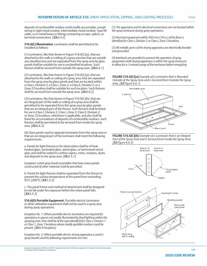
Reproduced with permission of NFPA from NFPA 70®, National Electrical Code®, 2020 edition. Copyright © 2019, National Fire Protection Association. For a full copy of NFPA 70, please go to www.nfpa.org.
INTERPRETATION OF ARTICLE 516: SPRAY APPLICATION, DIPPING, AND COATING PROCESSES
149
2020 CODE REVIEW
deposits of combustible residue could readily accumulate, except wiring in rigid metal conduit, intermediate metal conduit, Type MI cable, or in metal boxes or fittings containing no taps, splices, or terminal connections. [33:6.4.2]
516.6(C) Illumination. Luminaires shall be permitted to be installed as follows:
(1) Luminaires, like that shown in Figure 516.6(C)(a), that are attached to the walls or ceiling of a spray area but that are outside any classified area and are separated from the spray area by glass panels shall be suitable for use in unclassified locations. Such fixtures shall be serviced from outside the spray area. [33:6.6.1]
(2) Luminaires, like that shown in Figure 516.6(C)(a), that are attached to the walls or ceiling of a spray area; that are separated from the spray area by glass panels and that are located within a Class I, Division 2; a Class I, Zone 2; a Class II, Division 2; or a Zone 22 location shall be suitable for such location. Such fixtures shall be serviced from outside the spray area. [33:6.6.2]
(3) Luminaires, like that shown in Figure 516.6(C)(b), that are an integral part of the walls or ceiling of a spray area shall be permitted to be separated from the spray area by glass panels that are an integral part of the fixture. Such fixtures shall be listed for use in Class I, Division 2; Class I, Zone 2; Class II, Division 2; or Zone 22 locations, whichever is applicable, and also shall be listed for accumulations of deposits of combustible residues. Such fixtures shall be permitted to be serviced from inside the spray area. [33:6.6.3]
(4) Glass panels used to separate luminaires from the spray area or that are an integral part of the luminaire shall meet the following requirements:
a. Panels for light fixtures or for observation shall be of heat-treated glass, laminated glass, wired glass, or hammered-wired glass and shall be sealed to confine vapors, mists, residues, dusts, and deposits to the spray area. [33:5.5.1]
Exception: Listed spray booth assemblies that have vision panels constructed of other materials shall be permitted.
b. Panels for light fixtures shall be separated from the fixture to prevent the surface temperature of the panel from exceeding 93°C (200°F). [33:5.5.2]
c. The panel frame and method of attachment shall be designed to not fail under fire exposure before the vision panel fails. [33:5.5.3]
516.6(D) Portable Equipment. Portable electric luminaires or other utilization equipment shall not be used in a spray area during spray operations.
Exception No. 1: Where portable electric luminaires are required for operations in spaces not readily illuminated by fixed lighting within the spraying area, they shall be of the type identified for Class I, Division 1 or Class 1, Zone 1 locations where readily ignitible residues could be present. [33:6.9 Exception]
Exception No. 2: Where portable electric drying apparatus is used in spray booths and the following requirements are met:
(1) The apparatus and its electrical connections are not located within the spray enclosure during spray operations.
(2) Electrical equipment within 450 mm (18 in.) of the floor is identified for Class I, Division 2 or Class I, Zone 2 locations.
(3) All metallic parts of the drying apparatus are electrically bonded and grounded.
(4) Interlocks are provided to prevent the operation of spray equipment while drying apparatus is within the spray enclosure, to allow for a 3-minute purge of the enclosure before energizing
FIGURE 516.6(C)(a) Example of a Luminaire that is Mounted Outside of the Spray Area and is Serviced from Outside the Spray Area. [33:Figure 6.6.1]
FIGURE 516.6(C)(b) Example of a Luminaire that is an Integral Part of the Spray Area and is Serviced from Inside the Spray Area. [33:Figure 6.6.3]
516.6
Reproduced with permission of NFPA from NFPA 70®, National Electrical Code®, 2020 edition. Copyright © 2019, National Fire Protection Association. For a full copy of NFPA 70, please go to www.nfpa.org.
INTERPRETATION OF ARTICLE 516: SPRAY APPLICATION, DIPPING, AND COATING PROCESSES
150
2020 CODE REVIEW
the drying apparatus and to shut off drying apparatus on failure of ventilation system.
516.6(E) Electrostatic Equipment. Electrostatic spraying or detearing equipment shall be installed and used only as provided in 516.10.
Informational Note: For further information, see NFPA 33-2018, Standard for Spray Application Using Flammable or Combustible Materials.
516.6(F) Static Electric Discharges. All persons and all electrically conductive objects, including any metal parts of the process equipment or apparatus, containers of material, exhaust ducts, and piping systems that convey flammable or combustible liquids, shall be electrically grounded. [34:6.8.1]
516.7 Wiring and Equipment Not Within Classified Locations.
516.7(A) Wiring. All fixed wiring above the Class I and II locations shall be in metal raceways, Type PVC conduit, Type RTRC conduit, or electrical nonmetallic tubing; where cables are used, they shall be Type MI, Type TC, or Type MC cable. Cellular metal floor raceways shall only be permitted to supply ceiling outlets or as extensions to the area below the floor of a Class I or II location. Where cellular metal raceways are used, they shall not have connections leading into or passing through the Class I or II location unless suitable seals are provided.
516.7(B) Equipment. Equipment that could produce arcs, sparks, or particles of hot metal, such as lamps and lampholders for fixed lighting, cutouts, switches, receptacles, motors, or other equipment having make-and-break or sliding contacts, where installed above a classified location or above a location where freshly finished goods are handled, shall be of the totally enclosed type or be constructed so as to prevent the escape of sparks or hot metal particles.
516.10 Special Equipment.
516.10(A) Fixed Electrostatic Equipment. This section shall apply to any equipment using electrostatically charged elements for the atomization, charging, and/or precipitation of hazardous materials for coatings on articles or for other similar purposes in which the charging or atomizing device is attached to a mechanical support or manipulator. This shall include robotic devices. This section shall not apply to devices that are held or manipulated by hand. Where robot or programming procedures involve manual manipulation of the robot arm while spraying with the high voltage on, the provisions of 516.10(B) shall apply. The installation of electrostatic spraying equipment shall comply with 516.10(A)(1) through (A)(10). Spray equipment shall be listed. All automatic electrostatic equipment systems shall comply with 516.6(A) through (F).
516.10(A)(1) Power and Control Equipment. Transformers, high-voltage supplies, control apparatus, and all other electrical portions of the equipment shall be installed outside of the Class I location or be of a type identified for the location.
Exception: High-voltage grids, electrodes, electrostatic atomizing heads, and their connections shall be permitted within the Class I location.
516.10(A)(2) Electrostatic Equipment. Electrodes and
electrostatic atomizing heads shall be adequately supported in permanent locations and shall be effectively insulated from ground. Electrodes and electrostatic atomizing heads that are permanently attached to their bases, supports, reciprocators, or robots shall be deemed to comply with this section.
516.10(A)(3) High-Voltage Leads. High-voltage leads shall be properly insulated and protected from mechanical damage or exposure to destructive chemicals. Any exposed element at high voltage shall be effectively and permanently supported on suitable insulators and shall be effectively guarded against accidental contact or grounding.
516.10(A)(4) Support of Goods. Goods being coated using this process shall be supported on conveyors or hangers. The conveyors or hangers shall be arranged (1) to ensure that the parts being coated are electrically connected to ground with a resistance of 1 megohm or less and (2) to prevent parts from swinging.
516.10(A)(5) Automatic Controls. Electrostatic apparatus shall be equipped with automatic means that will rapidly de-energize the high-voltage elements under any of the following conditions:
(1) Stoppage of ventilating fans or failure of ventilating equipment from any cause
(2) Stoppage of the conveyor carrying goods through the high-voltage field unless stoppage is required by the spray process
(3) Occurrence of excessive current leakage at any point in the high-voltage system
(4) De-energizing the primary voltage input to the power supply
516.10(A)(6) Grounding. All electrically conductive objects in the spray area, except those objects required by the process to be at high voltage, shall be adequately grounded. This requirement shall apply to paint containers, wash cans, guards, hose connectors, brackets, and any other electrically conductive objects or devices in the area.
Informational Note: For more information on grounding and bonding for static electricity purposes, see NFPA 33-2018, Standard for Spray Application Using Flammable or Combustible Materials; NFPA 34-2018, Standard for Dipping, Coating, and Printing Processes Using Flammable or Combustible Liquids; and NFPA 77-2019, Recommended Practice on Static Electricity.
516.10(A)(7) Isolation. Safeguards such as adequate booths, fencing, railings, interlocks, or other means shall be placed about the equipment or incorporated therein so that they, either by their location, character, or both, ensure that a safe separation of the process is maintained.
516.10(A)(8) Signs. Signs shall be conspicuously posted to convey the following:
(1) Designate the process zone as dangerous with regard to fire and accident
(2) Identify the grounding requirements for all electrically conductive objects in the spray area
(3) Restrict access to qualified personnel only
516.6
Reproduced with permission of NFPA from NFPA 70®, National Electrical Code®, 2020 edition. Copyright © 2019, National Fire Protection Association. For a full copy of NFPA 70, please go to www.nfpa.org.
INTERPRETATION OF ARTICLE 516: SPRAY APPLICATION, DIPPING, AND COATING PROCESSES
151
2020 CODE REVIEW
516.10(A)(9) Insulators. All insulators shall be kept clean and dry.
516.10(A)(10) Other Than Nonincendive Equipment. Spray equipment that cannot be classified as nonincendive shall comply with 516.10(A)(10)(a) and (A)(10)(b).
(a) Conveyors, hangers, and application equipment shall be arranged so that a minimum separation of at least twice the sparking distance is maintained between the workpiece or material being sprayed and electrodes, electrostatic atomizing heads, or charged conductors. Warnings defining this safe distance shall be posted. [33:11.4.1]
(b) The equipment shall provide an automatic means of rapidly de-energizing the high-voltage elements in the event the distance between the goods being painted and the electrodes or electrostatic atomizing heads falls below that specified in 516.10(A)(10)(a). [33:11.3.8]
516.10(B) Hand-Spraying Electrostatic Equipment. This section shall apply to any equipment using electrostatically charged elements for the atomization, charging, or precipitation of flammable and combustible materials for coatings on articles, or for other similar purposes in which the charging or atomizing device is hand-held and manipulated during the spraying operation. Electrostatic hand-spraying equipment and devices used in connection with paint-spraying operations shall be of listed types and shall comply with 516.10(B)(1) through (B)(5).
516.10(B)(1) General. The high-voltage circuits shall be designed so as not to produce a spark of sufficient intensity to ignite the most readily ignitible of those vapor–air mixtures likely to be encountered or result in appreciable shock hazard upon coming in contact with a grounded object under all normal operating conditions. The electrostatically charged exposed elements of the handgun shall be capable of being energized only by an actuator that also controls the coating material supply.
516.10(B)(2) Power Equipment. Transformers, power packs, control apparatus, and all other electrical portions of the equipment shall be located outside of the Class I location or be identified for the location.
Exception: The handgun itself and its connections to the power supply shall be permitted within the Class I location.
516.10(B)(3) Handle. The handle of the spraying gun shall be electrically connected to ground by a conductive material and be constructed so that the operator in normal operating position is in electrical contact with the grounded handle with a resistance of not more than 1 megohm to prevent buildup of a static charge on the operator’s body. Signs indicating the necessity for grounding other persons entering the spray area shall be conspicuously posted.
516.10(B)(4) Electrostatic Equipment. All electrically conductive objects in the spraying area, except those objects required by the process to be at high voltage shall be electrically connected to ground with a resistance of not more than 1 megohm. This requirement shall apply to paint containers, wash cans, and any other electrical conductive objects or devices in the area. The equipment shall carry a prominent, permanently installed warning regarding the necessity for this grounding feature.
Informational Note: For more information on grounding and bonding for static electricity purposes, see NFPA 33-2018, Standard for Spray Application Using Flammable or Combustible Materials; NFPA 34-2018, Standard for Dipping, Coating, and Printing Processes Using Flammable or Combustible Liquids; and NFPA 77-2019, Recommended Practice on Static Electricity.
516.10(B)(5) Support of Objects. Objects being painted shall be maintained in electrical contact with the conveyor or other grounded support. Hooks shall be regularly cleaned to ensure adequate grounding of 1 megohm or less. Areas of contact shall be sharp points or knife edges where possible. Points of support of the object shall be concealed from random spray where feasible, and, where the objects being sprayed are supported from a conveyor, the point of attachment to the conveyor shall be located so as to not collect spray material during normal operation.
516.10(C) Powder Coating. This section shall apply to processes in which combustible dry powders are applied. The hazards associated with combustible dusts are present in such a process to a degree, depending on the chemical composition of the material, particle size, shape, and distribution.
516.10(C)(1) Electrical Equipment and Sources of Ignition. Electrical equipment and other sources of ignition shall comply with the requirements of Article 502. Portable electric luminaires and other utilization equipment shall not be used within a Class II location during operation of the finishing processes. Where such luminaires or utilization equipment are used during cleaning or repairing operations, they shall be of a type identified for Class II, Division 1 locations, and all exposed metal parts shall be connected to an equipment grounding conductor.
Exception: Where portable electric luminaires are required for operations in spaces not readily illuminated by fixed lighting within the spraying area, they shall be of the type listed for Class II, Division 1 locations where readily ignitible residues may be present.
516.10(C)(2) Fixed Electrostatic Spraying Equipment. The provisions of 516.10(A) and 516.10(C)(1) shall apply to fixed electrostatic spraying equipment.
516.10(C)(3) Electrostatic Hand-Spraying Equipment. The provisions of 516.10(B) and 516.10(C)(1) shall apply to electrostatic hand-spraying equipment.
516.10(C)(4) Electrostatic Fluidized Beds. Electrostatic fluidized beds and associated equipment shall be of identified types. The high-voltage circuits shall be designed such that any discharge produced when the charging electrodes of the bed are approached or contacted by a grounded object shall not be of sufficient intensity to ignite any powder–air mixture likely to be encountered or to result in an appreciable shock hazard.
(a) Transformers, power packs, control apparatus, and all other electrical portions of the equipment shall be located outside the powder-coating area or shall otherwise comply with the requirements of 516.10(C)(1).
Exception: The charging electrodes and their connections to the power supply shall be permitted within the powder-coating area.
(b) All electrically conductive objects within the powder-coating area shall be adequately grounded. The powder-coating equipment shall carry a prominent, permanently installed warning regarding the necessity for grounding these objects.
516.10
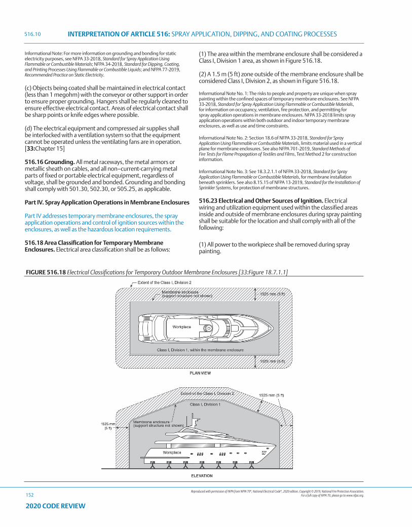
Reproduced with permission of NFPA from NFPA 70®, National Electrical Code®, 2020 edition. Copyright © 2019, National Fire Protection Association. For a full copy of NFPA 70, please go to www.nfpa.org.
INTERPRETATION OF ARTICLE 516: SPRAY APPLICATION, DIPPING, AND COATING PROCESSES
152
2020 CODE REVIEW
Informational Note: For more information on grounding and bonding for static electricity purposes, see NFPA 33-2018, Standard for Spray Application Using Flammable or Combustible Materials; NFPA 34-2018, Standard for Dipping, Coating, and Printing Processes Using Flammable or Combustible Liquids; and NFPA 77-2019, Recommended Practice on Static Electricity.
(c) Objects being coated shall be maintained in electrical contact (less than 1 megohm) with the conveyor or other support in order to ensure proper grounding. Hangers shall be regularly cleaned to ensure effective electrical contact. Areas of electrical contact shall be sharp points or knife edges where possible.
(d) The electrical equipment and compressed air supplies shall be interlocked with a ventilation system so that the equipment cannot be operated unless the ventilating fans are in operation. [33:Chapter 15]
516.16 Grounding. All metal raceways, the metal armors or metallic sheath on cables, and all non–current-carrying metal parts of fixed or portable electrical equipment, regardless of voltage, shall be grounded and bonded. Grounding and bonding shall comply with 501.30, 502.30, or 505.25, as applicable.
Part IV. Spray Application Operations in Membrane Enclosures
Part IV addresses temporary membrane enclosures, the spray application operations and control of ignition sources within the enclosures, as well as the hazardous location requirements.
516.18 Area Classification for Temporary Membrane Enclosures. Electrical area classification shall be as follows:
(1) The area within the membrane enclosure shall be considered a Class I, Division 1 area, as shown in Figure 516.18.
(2) A 1.5 m (5 ft) zone outside of the membrane enclosure shall be considered Class I, Division 2, as shown in Figure 516.18.
Informational Note No. 1: The risks to people and property are unique when spray painting within the confined spaces of temporary membrane enclosures. See NFPA 33-2018, Standard for Spray Application Using Flammable or Combustible Materials, for information on occupancy, ventilation, fire protection, and permitting for spray application operations in membrane enclosures. NFPA 33-2018 limits spray application operations within both outdoor and indoor temporary membrane enclosures, as well as use and time constraints.
Informational Note No. 2: Section 18.6 of NFPA 33-2018, Standard for Spray Application Using Flammable or Combustible Materials, limits material used in a vertical plane for membrane enclosures. See also NFPA 701-2019, Standard Methods of Fire Tests for Flame Propagation of Textiles and Films, Test Method 2 for construction information.
Informational Note No. 3: See 18.3.2.1.1 of NFPA 33-2018, Standard for Spray Application Using Flammable or Combustible Materials, for membrane installation beneath sprinklers. See also 8.15.15 of NFPA 13-2019, Standard for the Installation of Sprinkler Systems, for protection of membrane structures.
516.23 Electrical and Other Sources of Ignition. Electrical wiring and utilization equipment used within the classified areas inside and outside of membrane enclosures during spray painting shall be suitable for the location and shall comply with all of the following:
(1) All power to the workpiece shall be removed during spray painting.
FIGURE 516.18 Electrical Classifications for Temporary Outdoor Membrane Enclosures [33:Figure 18.7.1.1]
516.10
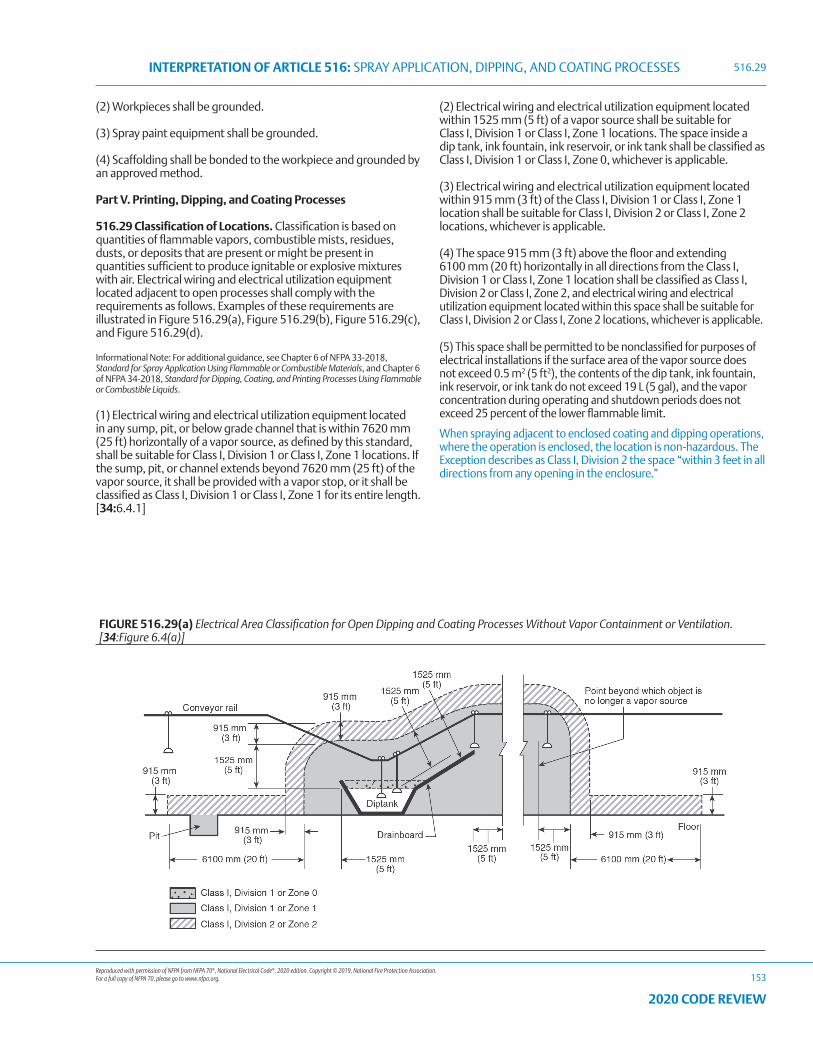
Reproduced with permission of NFPA from NFPA 70®, National Electrical Code®, 2020 edition. Copyright © 2019, National Fire Protection Association. For a full copy of NFPA 70, please go to www.nfpa.org.
INTERPRETATION OF ARTICLE 516: SPRAY APPLICATION, DIPPING, AND COATING PROCESSES
153
2020 CODE REVIEW
(2) Workpieces shall be grounded.
(3) Spray paint equipment shall be grounded.
(4) Scaffolding shall be bonded to the workpiece and grounded by an approved method.
Part V. Printing, Dipping, and Coating Processes
516.29 Classification of Locations. Classification is based on quantities of flammable vapors, combustible mists, residues, dusts, or deposits that are present or might be present in quantities sufficient to produce ignitable or explosive mixtures with air. Electrical wiring and electrical utilization equipment located adjacent to open processes shall comply with the requirements as follows. Examples of these requirements are illustrated in Figure 516.29(a), Figure 516.29(b), Figure 516.29(c), and Figure 516.29(d).
Informational Note: For additional guidance, see Chapter 6 of NFPA 33-2018, Standard for Spray Application Using Flammable or Combustible Materials, and Chapter 6 of NFPA 34-2018, Standard for Dipping, Coating, and Printing Processes Using Flammable or Combustible Liquids.
(1) Electrical wiring and electrical utilization equipment located in any sump, pit, or below grade channel that is within 7620 mm (25 ft) horizontally of a vapor source, as defined by this standard, shall be suitable for Class I, Division 1 or Class I, Zone 1 locations. If the sump, pit, or channel extends beyond 7620 mm (25 ft) of the vapor source, it shall be provided with a vapor stop, or it shall be classified as Class I, Division 1 or Class I, Zone 1 for its entire length. [34:6.4.1]
(2) Electrical wiring and electrical utilization equipment located within 1525 mm (5 ft) of a vapor source shall be suitable for Class I, Division 1 or Class I, Zone 1 locations. The space inside a dip tank, ink fountain, ink reservoir, or ink tank shall be classified as Class I, Division 1 or Class I, Zone 0, whichever is applicable.
(3) Electrical wiring and electrical utilization equipment located within 915 mm (3 ft) of the Class I, Division 1 or Class I, Zone 1 location shall be suitable for Class I, Division 2 or Class I, Zone 2 locations, whichever is applicable.
(4) The space 915 mm (3 ft) above the floor and extending 6100 mm (20 ft) horizontally in all directions from the Class I, Division 1 or Class I, Zone 1 location shall be classified as Class I, Division 2 or Class I, Zone 2, and electrical wiring and electrical utilization equipment located within this space shall be suitable for Class I, Division 2 or Class I, Zone 2 locations, whichever is applicable.
(5) This space shall be permitted to be nonclassified for purposes of electrical installations if the surface area of the vapor source does not exceed 0.5 m2 (5 ft2), the contents of the dip tank, ink fountain, ink reservoir, or ink tank do not exceed 19 L (5 gal), and the vapor concentration during operating and shutdown periods does not exceed 25 percent of the lower flammable limit.
When spraying adjacent to enclosed coating and dipping operations, where the operation is enclosed, the location is non-hazardous. The Exception describes as Class I, Division 2 the space “within 3 feet in all directions from any opening in the enclosure.”
516.29
FIGURE 516.29(a) Electrical Area Classification for Open Dipping and Coating Processes Without Vapor Containment or Ventilation. [34:Figure 6.4(a)]
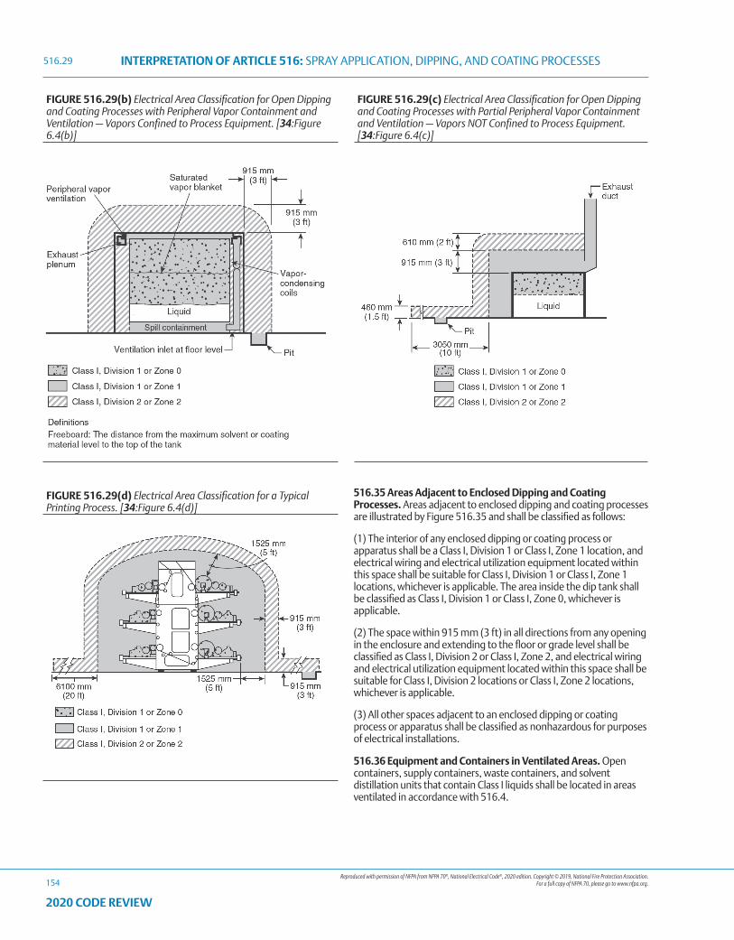
Reproduced with permission of NFPA from NFPA 70®, National Electrical Code®, 2020 edition. Copyright © 2019, National Fire Protection Association. For a full copy of NFPA 70, please go to www.nfpa.org.
INTERPRETATION OF ARTICLE 516: SPRAY APPLICATION, DIPPING, AND COATING PROCESSES
154
2020 CODE REVIEW
FIGURE 516.29(b) Electrical Area Classification for Open Dipping and Coating Processes with Peripheral Vapor Containment and Ventilation — Vapors Confined to Process Equipment. [34:Figure 6.4(b)]
FIGURE 516.29(c) Electrical Area Classification for Open Dipping and Coating Processes with Partial Peripheral Vapor Containment and Ventilation — Vapors NOT Confined to Process Equipment. [34:Figure 6.4(c)]
FIGURE 516.29(d) Electrical Area Classification for a Typical Printing Process. [34:Figure 6.4(d)]
516.29
516.35 Areas Adjacent to Enclosed Dipping and Coating Processes. Areas adjacent to enclosed dipping and coating processes are illustrated by Figure 516.35 and shall be classified as follows:
(1) The interior of any enclosed dipping or coating process or apparatus shall be a Class I, Division 1 or Class I, Zone 1 location, and electrical wiring and electrical utilization equipment located within this space shall be suitable for Class I, Division 1 or Class I, Zone 1 locations, whichever is applicable. The area inside the dip tank shall be classified as Class I, Division 1 or Class I, Zone 0, whichever is applicable.
(2) The space within 915 mm (3 ft) in all directions from any opening in the enclosure and extending to the floor or grade level shall be classified as Class I, Division 2 or Class I, Zone 2, and electrical wiring and electrical utilization equipment located within this space shall be suitable for Class I, Division 2 locations or Class I, Zone 2 locations, whichever is applicable.
(3) All other spaces adjacent to an enclosed dipping or coating process or apparatus shall be classified as nonhazardous for purposes of electrical installations.
516.36 Equipment and Containers in Ventilated Areas. Open containers, supply containers, waste containers, and solvent distillation units that contain Class I liquids shall be located in areas ventilated in accordance with 516.4.
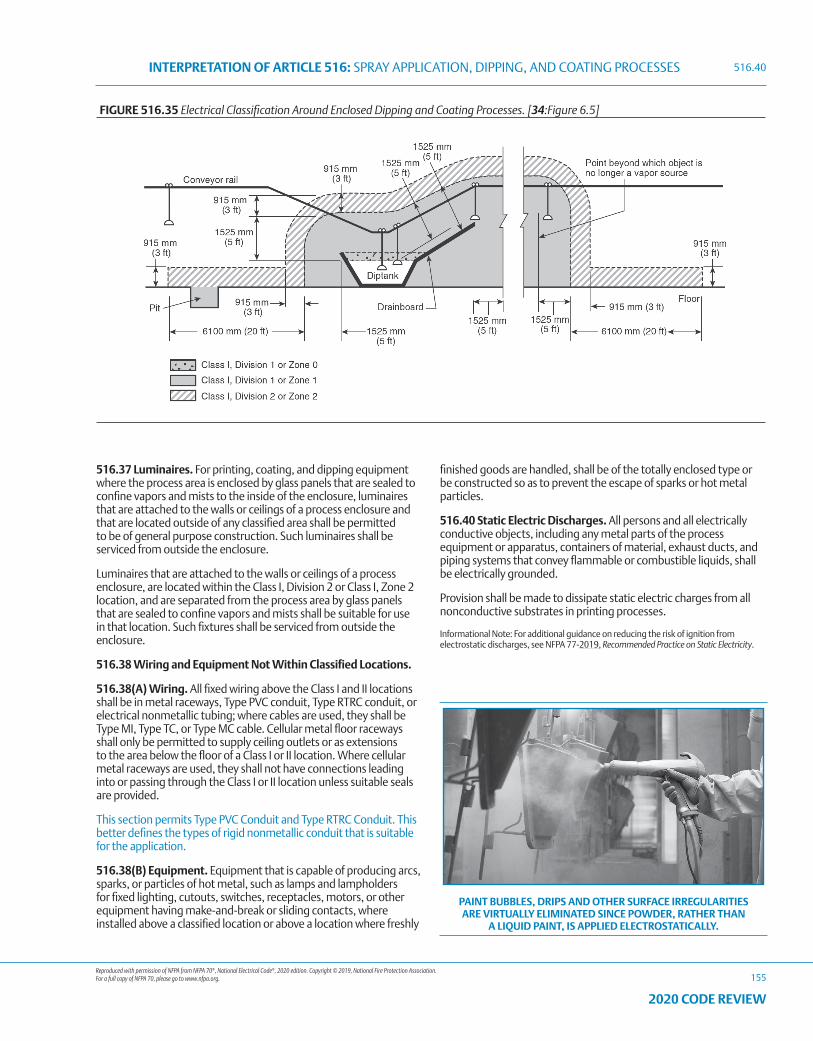
Reproduced with permission of NFPA from NFPA 70®, National Electrical Code®, 2020 edition. Copyright © 2019, National Fire Protection Association. For a full copy of NFPA 70, please go to www.nfpa.org.
INTERPRETATION OF ARTICLE 516: SPRAY APPLICATION, DIPPING, AND COATING PROCESSES
155
2020 CODE REVIEW
516.37 Luminaires. For printing, coating, and dipping equipment where the process area is enclosed by glass panels that are sealed to confine vapors and mists to the inside of the enclosure, luminaires that are attached to the walls or ceilings of a process enclosure and that are located outside of any classified area shall be permitted to be of general purpose construction. Such luminaires shall be serviced from outside the enclosure.
Luminaires that are attached to the walls or ceilings of a process enclosure, are located within the Class I, Division 2 or Class I, Zone 2 location, and are separated from the process area by glass panels that are sealed to confine vapors and mists shall be suitable for use in that location. Such fixtures shall be serviced from outside the enclosure.
516.38 Wiring and Equipment Not Within Classified Locations.
516.38(A) Wiring. All fixed wiring above the Class I and II locations shall be in metal raceways, Type PVC conduit, Type RTRC conduit, or electrical nonmetallic tubing; where cables are used, they shall be Type MI, Type TC, or Type MC cable. Cellular metal floor raceways shall only be permitted to supply ceiling outlets or as extensions to the area below the floor of a Class I or II location. Where cellular metal raceways are used, they shall not have connections leading into or passing through the Class I or II location unless suitable seals are provided.
This section permits Type PVC Conduit and Type RTRC Conduit. This better defines the types of rigid nonmetallic conduit that is suitable for the application.
516.38(B) Equipment. Equipment that is capable of producing arcs, sparks, or particles of hot metal, such as lamps and lampholders for fixed lighting, cutouts, switches, receptacles, motors, or other equipment having make-and-break or sliding contacts, where installed above a classified location or above a location where freshly
finished goods are handled, shall be of the totally enclosed type or be constructed so as to prevent the escape of sparks or hot metal particles.
516.40 Static Electric Discharges. All persons and all electrically conductive objects, including any metal parts of the process equipment or apparatus, containers of material, exhaust ducts, and piping systems that convey flammable or combustible liquids, shall be electrically grounded.
Provision shall be made to dissipate static electric charges from all nonconductive substrates in printing processes.
Informational Note: For additional guidance on reducing the risk of ignition from electrostatic discharges, see NFPA 77-2019, Recommended Practice on Static Electricity.
FIGURE 516.35 Electrical Classification Around Enclosed Dipping and Coating Processes. [34:Figure 6.5]
PAINT BUBBLES, DRIPS AND OTHER SURFACE IRREGULARITIES ARE VIRTUALLY ELIMINATED SINCE POWDER, RATHER THAN
A LIQUID PAINT, IS APPLIED ELECTROSTATICALLY.
516.40

156
2020 CODE REVIEW
NOTES
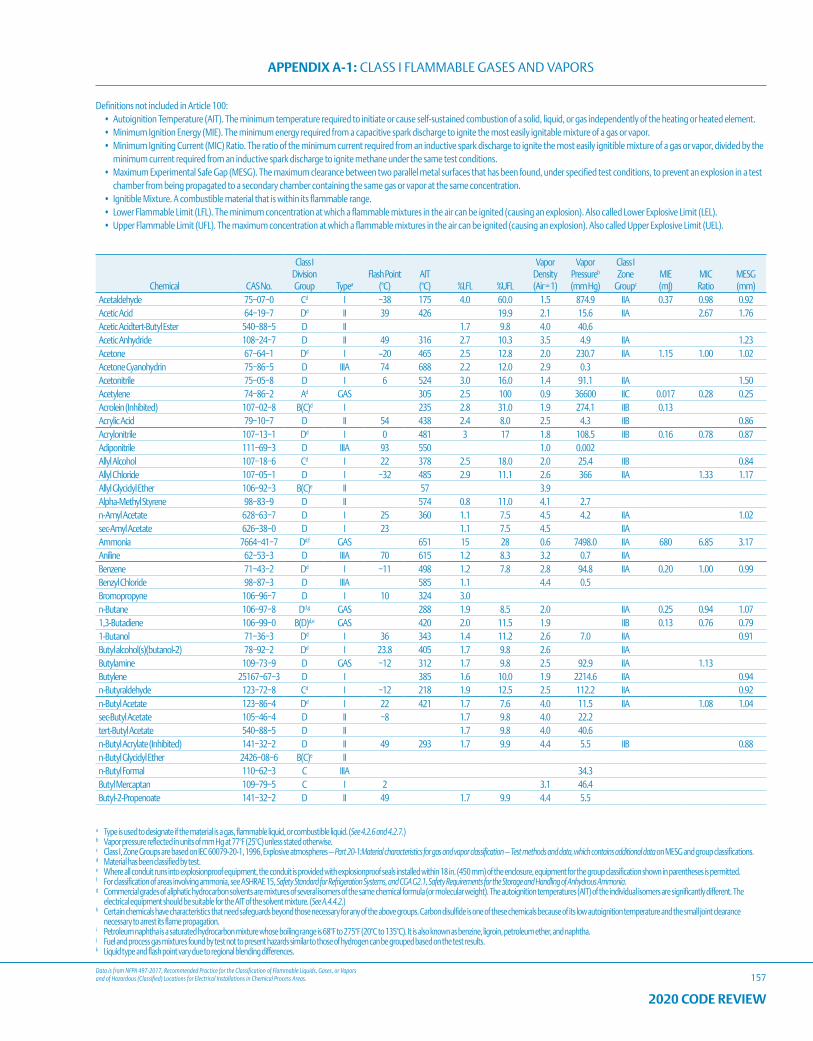
Data is from NFPA 497-2017, Recommended Practice for the Classification of Flammable Liquids, Gases, or Vapors and of Hazardous (Classified) Locations for Electrical Installations in Chemical Process Areas.
APPENDIX A-1: CLASS I FLAMMABLE GASES AND VAPORS
157
a Type is used to designate if the material is a gas, flammable liquid, or combustible liquid. (See 4.2.6 and 4.2.7.)b Vapor pressure reflected in units of mm Hg at 77°F (25°C) unless stated otherwise.c Class I, Zone Groups are based on IEC 60079-20-1, 1996, Explosive atmospheres — Part 20-1:Material characteristics for gas and vapor classification — Test methods and data, which contains additional data on MESG and group classifications.d Material has been classified by test.e Where all conduit runs into explosionproof equipment, the conduit is provided with explosionproof seals installed within 18 in. (450 mm) of the enclosure, equipment for the group classification shown in parentheses is permitted.f For classification of areas involving ammonia, see ASHRAE 15, Safety Standard for Refrigeration Systems, and CGA G2.1, Safety Requirements for the Storage and Handling of Anhydrous Ammonia.g Commercial grades of aliphatic hydrocarbon solvents are mixtures of several isomers of the same chemical formula (or molecular weight). The autoignition temperatures (AIT) of the individual isomers are significantly different. The
electrical equipment should be suitable for the AIT of the solvent mixture. (See A.4.4.2.)h Certain chemicals have characteristics that need safeguards beyond those necessary for any of the above groups. Carbon disulfide is one of these chemicals because of its low autoignition temperature and the small joint clearance
necessary to arrest its flame propagation.i Petroleum naphtha is a saturated hydrocarbon mixture whose boiling range is 68°F to 275°F (20°C to 135°C). It is also known as benzine, ligroin, petroleum ether, and naphtha.j Fuel and process gas mixtures found by test not to present hazards similar to those of hydrogen can be grouped based on the test results.k Liquid type and flash point vary due to regional blending differences.
2020 CODE REVIEW
Chemical CAS No.
Class I Division Group Typea
Flash Point (°C)
AIT (°C) %LFL %UFL
Vapor Density (Air = 1)
Vapor Pressureb
(mm Hg)
Class I Zone
Groupc
MIE (mJ)
MIC Ratio
MESG (mm)
Acetaldehyde 75−07−0 Cd I −38 175 4.0 60.0 1.5 874.9 IIA 0.37 0.98 0.92Acetic Acid 64−19−7 Dd II 39 426 19.9 2.1 15.6 IIA 2.67 1.76Acetic Acidtert-Butyl Ester 540−88−5 D II 1.7 9.8 4.0 40.6Acetic Anhydride 108−24−7 D II 49 316 2.7 10.3 3.5 4.9 IIA 1.23Acetone 67−64−1 Dd I –20 465 2.5 12.8 2.0 230.7 IIA 1.15 1.00 1.02Acetone Cyanohydrin 75−86−5 D IIIA 74 688 2.2 12.0 2.9 0.3Acetonitrile 75−05−8 D I 6 524 3.0 16.0 1.4 91.1 IIA 1.50Acetylene 74−86−2 Ad GAS 305 2.5 100 0.9 36600 IIC 0.017 0.28 0.25Acrolein (Inhibited) 107−02−8 B(C)d I 235 2.8 31.0 1.9 274.1 IIB 0.13Acrylic Acid 79−10−7 D II 54 438 2.4 8.0 2.5 4.3 IIB 0.86Acrylonitrile 107−13−1 Dd I 0 481 3 17 1.8 108.5 IIB 0.16 0.78 0.87Adiponitrile 111−69−3 D IIIA 93 550 1.0 0.002Allyl Alcohol 107−18−6 Cd I 22 378 2.5 18.0 2.0 25.4 IIB 0.84Allyl Chloride 107−05−1 D I −32 485 2.9 11.1 2.6 366 IIA 1.33 1.17Allyl Glycidyl Ether 106−92−3 B(C)e II 57 3.9Alpha-Methyl Styrene 98−83−9 D II 574 0.8 11.0 4.1 2.7n-Amyl Acetate 628−63−7 D I 25 360 1.1 7.5 4.5 4.2 IIA 1.02sec-Amyl Acetate 626−38−0 D I 23 1.1 7.5 4.5 IIAAmmonia 7664−41−7 Dd,f GAS 651 15 28 0.6 7498.0 IIA 680 6.85 3.17Aniline 62−53−3 D IIIA 70 615 1.2 8.3 3.2 0.7 IIABenzene 71−43−2 Dd I −11 498 1.2 7.8 2.8 94.8 IIA 0.20 1.00 0.99Benzyl Chloride 98−87−3 D IIIA 585 1.1 4.4 0.5Bromopropyne 106−96−7 D I 10 324 3.0n-Butane 106−97−8 Dd,g GAS 288 1.9 8.5 2.0 IIA 0.25 0.94 1.071,3-Butadiene 106−99−0 B(D)d,e GAS 420 2.0 11.5 1.9 IIB 0.13 0.76 0.791-Butanol 71−36−3 Dd I 36 343 1.4 11.2 2.6 7.0 IIA 0.91Butyl alcohol(s)(butanol-2) 78−92−2 Dd I 23.8 405 1.7 9.8 2.6 IIAButylamine 109−73−9 D GAS −12 312 1.7 9.8 2.5 92.9 IIA 1.13Butylene 25167−67−3 D I 385 1.6 10.0 1.9 2214.6 IIA 0.94n-Butyraldehyde 123−72−8 Cd I −12 218 1.9 12.5 2.5 112.2 IIA 0.92n-Butyl Acetate 123−86−4 Dd I 22 421 1.7 7.6 4.0 11.5 IIA 1.08 1.04sec-Butyl Acetate 105−46−4 D II −8 1.7 9.8 4.0 22.2tert-Butyl Acetate 540−88−5 D II 1.7 9.8 4.0 40.6n-Butyl Acrylate (Inhibited) 141−32−2 D II 49 293 1.7 9.9 4.4 5.5 IIB 0.88n-Butyl Glycidyl Ether 2426−08−6 B(C)e IIn-Butyl Formal 110−62−3 C IIIA 34.3Butyl Mercaptan 109−79−5 C I 2 3.1 46.4Butyl-2-Propenoate 141−32−2 D II 49 1.7 9.9 4.4 5.5
Definitions not included in Article 100: • Autoignition Temperature (AIT). The minimum temperature required to initiate or cause self-sustained combustion of a solid, liquid, or gas independently of the heating or heated element.• Minimum Ignition Energy (MIE). The minimum energy required from a capacitive spark discharge to ignite the most easily ignitable mixture of a gas or vapor.• Minimum Igniting Current (MIC) Ratio. The ratio of the minimum current required from an inductive spark discharge to ignite the most easily ignitible mixture of a gas or vapor, divided by the
minimum current required from an inductive spark discharge to ignite methane under the same test conditions.• Maximum Experimental Safe Gap (MESG). The maximum clearance between two parallel metal surfaces that has been found, under specified test conditions, to prevent an explosion in a test
chamber from being propagated to a secondary chamber containing the same gas or vapor at the same concentration.• Ignitible Mixture. A combustible material that is within its flammable range.• Lower Flammable Limit (LFL). The minimum concentration at which a flammable mixtures in the air can be ignited (causing an explosion). Also called Lower Explosive Limit (LEL).• Upper Flammable Limit (UFL). The maximum concentration at which a flammable mixtures in the air can be ignited (causing an explosion). Also called Upper Explosive Limit (UEL).
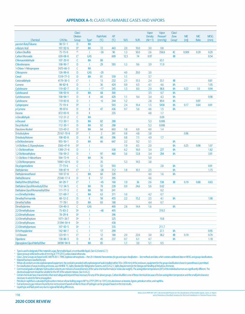
Data is from NFPA 497-2017, Recommended Practice for the Classification of Flammable Liquids, Gases, or Vapors and of Hazardous (Classified) Locations for Electrical Installations in Chemical Process Areas.
APPENDIX A-1: CLASS I FLAMMABLE GASES AND VAPORS
158
a Type is used to designate if the material is a gas, flammable liquid, or combustible liquid. (See 4.2.6 and 4.2.7.)b Vapor pressure reflected in units of mm Hg at 77°F (25°C) unless stated otherwise.c Class I, Zone Groups are based on IEC 60079-20-1, 1996, Explosive atmospheres — Part 20-1:Material characteristics for gas and vapor classification — Test methods and data, which contains additional data on MESG and group classifications.d Material has been classified by test.e Where all conduit runs into explosionproof equipment, the conduit is provided with explosionproof seals installed within 18 in. (450 mm) of the enclosure, equipment for the group classification shown in parentheses is permitted.f For classification of areas involving ammonia, see ASHRAE 15, Safety Standard for Refrigeration Systems, and CGA G2.1, Safety Requirements for the Storage and Handling of Anhydrous Ammonia.g Commercial grades of aliphatic hydrocarbon solvents are mixtures of several isomers of the same chemical formula (or molecular weight). The autoignition temperatures (AIT) of the individual isomers are significantly different. The
electrical equipment should be suitable for the AIT of the solvent mixture. (See A.4.4.2.)h Certain chemicals have characteristics that need safeguards beyond those necessary for any of the above groups. Carbon disulfide is one of these chemicals because of its low autoignition temperature and the small joint clearance
necessary to arrest its flame propagation.i Petroleum naphtha is a saturated hydrocarbon mixture whose boiling range is 68°F to 275°F (20°C to 135°C). It is also known as benzine, ligroin, petroleum ether, and naphtha.j Fuel and process gas mixtures found by test not to present hazards similar to those of hydrogen can be grouped based on the test results.k Liquid type and flash point vary due to regional blending differences.
2020 CODE REVIEW
Chemical CAS No.
Class I Division Group Typea
Flash Point (°C)
AIT (°C) %LFL %UFL
Vapor Density (Air = 1)
Vapor Pressureb
(mm Hg)
Class I Zone
Groupc
MIE (mJ)
MIC Ratio
MESG (mm)
para tert-Butyl Toluene 98−51−1 D IIIAn-Butyric Acid 107−92−6 Dd IIIA 72 443 2.0 10.0 3.0 0.8Carbon Disulfide 75−15−0 d,h I −30 90 1.3 50.0 2.6 358.8 IIC 0.009 0.39 0.20Carbon Monoxide 630−08−0 Cd GAS 609 12.5 74 0.97 IIB 0.54Chloroacetaldehyde 107−20−0 C IIIA 88 63.1Chlorobenzene 108−90−7 D I 29 593 1.3 9.6 3.9 11.91-Chloro-1-Nitropropane 2425−66−3 C IIIAChloroprene 126−99−8 D GAS −20 4.0 20.0 3.0Cresol 1319−77−3 D IIIA 81 559 1.1 3.7Crotonaldehyde 4170−30−3 Cd I 13 232 2.1 15.5 2.4 33.1 IIB 0.81Cumene 98−82−8 D I 36 424 0.9 6.5 4.1 4.6 IIA 1.05Cyclohexane 110−82−7 D I −17 245 1.3 8.0 2.9 98.8 IIA 0.22 1.0 0.94Cyclohexanol 108−93−0 D IIIA 68 300 3.5 0.7 IIACyclohexanone 108−94−1 D II 44 420 1.1 9.4 3.4 4.3 IIA 0.98Cyclohexene 110−83−8 D I −6 244 1.2 2.8 89.4 IIA 0.97Cyclopropane 75−19−4 Dd I 503 2.4 10.4 1.5 5430 IIA 0.17 0.84 0.91p-Cymene 99−87-6 D II 47 436 0.7 5.6 4.6 1.5 IIADecene 872−05−9 D II 235 4.8 1.7n-Decaldehyde 112−31−2 C IIIA 0.09n-Decanol 112−30−1 D IIIA 82 288 5.3 0.008Decyl Alcohol 112−30−1 D IIIA 82 288 5.3 0.008Diacetone Alcohol 123−42−2 D IIIA 64 603 1.8 6.9 4.0 1.4Di-Isobutylene 25167−70−8 Dd I 2 391 0.8 4.8 3.8 0.96Di-Isobutyl Ketone 108−83−8 D II 60 396 0.8 7.1 4.9 1.7o-Dichlorobenzene 955−50−1 D IIIA 66 647 2.2 9.2 5.1 IIA1,4-Dichloro-2,3 Epoxybutane 3583−47−9 Dd I 1.9 8.5 2.0 IIA 0.25 0.98 1.071,1-Dichloroethane 1300−21−6 D I 438 6.2 16.0 3.4 227 IIA 1.821,2-Dichloroethylene 156−59−2 D I 97 460 5.6 12.8 3.4 204 IIA 3.911,1-Dichloro-1-Nitroethane 594−72−9 C IIIA 76 5.01,3-Dichloropropene 10061−02−6 D I 35 5.3 14.5 3.8Dicyclopentadiene 77−73−6 C I 32 503 2.8 IIA 0.91Diethylamine 109−87−9 Cd I −28 312 1.8 10.1 2.5 IIA 1.15Diethylaminoethanol 100−37−8 C IIIA 60 320 4.0 1.6 IIADiethyl Benzene 25340−17−4 D II 57 395 4.6Diethyl Ether (Ethyl Ether) 60−29−7 Cd I −45 160 1.9 36 2.6 538 IIB 0.19 0.88 0.83Diethylene Glycol Monobutyl Ether 112−34−5 C IIIA 78 228 0.9 24.6 5.6 0.02Diethylene Glycol Monomethyl Ether 111−77−3 C IIIA 93 241 0.2n-n-Dimethyl Aniline 121−69−7 C IIIA 63 371 1.0 4.2 0.7Dimethyl Formamide 68−12−2 D II 58 455 2.2 15.2 2.5 4.1 IIA 1.08Dimethyl Sulfate 77−78-1 D IIIA 83 188 4.4 0.7Dimethylamine 124−40−3 C GAS 400 2.8 14.4 1.6 IIA2,2-Dimethylbutane 75−83−2 Dg I −48 405 319.32,3-Dimethylbutane 78−29−8 Dg I 3963,3-Dimethylheptane 1071−26-7 Dg I 325 10.82,3-Dimethylhexane 31394−54−4 Dg I 4382,3-Dimethylpentane 107−83−5 Dg I 335 211.7Di-N-Propylamine 142−84−7 C I 17 299 27.1 IIA 0.951,4-Dioxane 123−91−1 Cd I 12 180 2.0 22.0 3.0 38.2 IIB 0.19 0.70Dipentene 138−86−3 D II 45 237 0.7 6.1 4.7 IIA 1.18Dipropylene Glycol Methyl Ether 34590−94−8 C IIIA 85 1.1 3.0 5.1 0.5
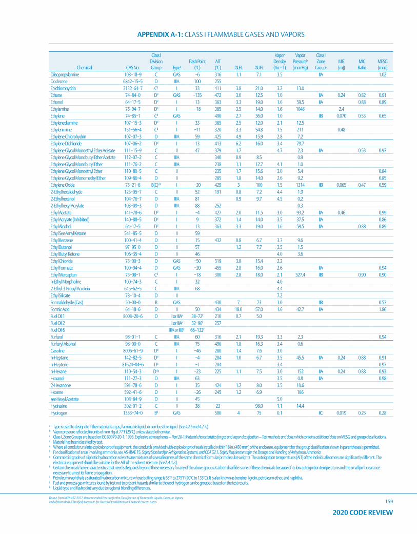
Data is from NFPA 497-2017, Recommended Practice for the Classification of Flammable Liquids, Gases, or Vapors and of Hazardous (Classified) Locations for Electrical Installations in Chemical Process Areas.
APPENDIX A-1: CLASS I FLAMMABLE GASES AND VAPORS
159
a Type is used to designate if the material is a gas, flammable liquid, or combustible liquid. (See 4.2.6 and 4.2.7.)b Vapor pressure reflected in units of mm Hg at 77°F (25°C) unless stated otherwise.c Class I, Zone Groups are based on IEC 60079-20-1, 1996, Explosive atmospheres — Part 20-1:Material characteristics for gas and vapor classification — Test methods and data, which contains additional data on MESG and group classifications.d Material has been classified by test.e Where all conduit runs into explosionproof equipment, the conduit is provided with explosionproof seals installed within 18 in. (450 mm) of the enclosure, equipment for the group classification shown in parentheses is permitted.f For classification of areas involving ammonia, see ASHRAE 15, Safety Standard for Refrigeration Systems, and CGA G2.1, Safety Requirements for the Storage and Handling of Anhydrous Ammonia.g Commercial grades of aliphatic hydrocarbon solvents are mixtures of several isomers of the same chemical formula (or molecular weight). The autoignition temperatures (AIT) of the individual isomers are significantly different. The
electrical equipment should be suitable for the AIT of the solvent mixture. (See A.4.4.2.)h Certain chemicals have characteristics that need safeguards beyond those necessary for any of the above groups. Carbon disulfide is one of these chemicals because of its low autoignition temperature and the small joint clearance
necessary to arrest its flame propagation.i Petroleum naphtha is a saturated hydrocarbon mixture whose boiling range is 68°F to 275°F (20°C to 135°C). It is also known as benzine, ligroin, petroleum ether, and naphtha.j Fuel and process gas mixtures found by test not to present hazards similar to those of hydrogen can be grouped based on the test results.k Liquid type and flash point vary due to regional blending differences.
2020 CODE REVIEW
Chemical CAS No.
Class I Division Group Typea
Flash Point (°C)
AIT (°C) %LFL %UFL
Vapor Density (Air = 1)
Vapor Pressureb
(mm Hg)
Class I Zone
Groupc
MIE (mJ)
MIC Ratio
MESG (mm)
Diisopropylamine 108−18−9 C GAS −6 316 1.1 7.1 3.5 IIA 1.02Dodecene 6842−15−5 D IIIA 100 255Epichlorohydrin 3132−64−7 Cd I 33 411 3.8 21.0 3.2 13.0Ethane 74−84−0 Dd GAS −135 472 3.0 12.5 1.0 IIA 0.24 0.82 0.91Ethanol 64−17−5 Dd I 13 363 3.3 19.0 1.6 59.5 IIA 0.88 0.89Ethylamine 75−04−7 Dd I −18 385 3.5 14.0 1.6 1048 2.4Ethylene 74−85−1 Cd GAS 490 2.7 36.0 1.0 IIB 0.070 0.53 0.65Ethylenediamine 107−15−3 Dd I 33 385 2.5 12.0 2.1 12.5Ethylenimine 151−56−4 Cd I −11 320 3.3 54.8 1.5 211 0.48Ethylene Chlorohydrin 107−07−3 D IIIA 59 425 4.9 15.9 2.8 7.2Ethylene Dichloride 107−06−2 Dd I 13 413 6.2 16.0 3.4 79.7Ethylene Glycol Monoethyl Ether Acetate 111−15−9 C II 47 379 1.7 4.7 2.3 IIA 0.53 0.97Ethylene Glycol Monobutyl Ether Acetate 112−07−2 C IIIA 340 0.9 8.5 0.9Ethylene Glycol Monobutyl Ether 111−76−2 C IIIA 238 1.1 12.7 4.1 1.0Ethylene Glycol Monoethyl Ether 110−80−5 C II 235 1.7 15.6 3.0 5.4 0.84Ethylene Glycol Monomethyl Ether 109−86−4 D II 285 1.8 14.0 2.6 9.2 0.85Ethylene Oxide 75−21−8 B(C)d,e I −20 429 3 100 1.5 1314 IIB 0.065 0.47 0.592-Ethylhexaldehyde 123−05−7 C II 52 191 0.8 7.2 4.4 1.92-Ethylhexanol 104−76−7 D IIIA 81 0.9 9.7 4.5 0.22-Ethylhexyl Acrylate 103−09−3 D IIIA 88 252 0.3Ethyl Acetate 141−78−6 Dd I −4 427 2.0 11.5 3.0 93.2 IIA 0.46 0.99Ethyl Acrylate (Inhibited) 140−88−5 Dd I 9 372 1.4 14.0 3.5 37.5 IIA 0.86Ethyl Alcohol 64−17−5 Dd I 13 363 3.3 19.0 1.6 59.5 IIA 0.88 0.89Ethyl Sec-Amyl Ketone 541−85−5 D II 59Ethyl Benzene 100−41−4 D I 15 432 0.8 6.7 3.7 9.6Ethyl Butanol 97−95−0 D II 57 1.2 7.7 3.5 1.5Ethyl Butyl Ketone 106−35−4 D II 46 4.0 3.6Ethyl Chloride 75−00−3 D GAS −50 519 3.8 15.4 2.2Ethyl Formate 109−94−4 D GAS −20 455 2.8 16.0 2.6 IIA 0.94Ethyl Mercaptan 75−08−1 Cd I −18 300 2.8 18.0 2.1 527.4 IIB 0.90 0.90n-Ethyl Morpholine 100−74−3 C I 32 4.02-Ethyl-3-Propyl Acrolein 645−62−5 C IIIA 68 4.4Ethyl Silicate 78−10−4 D II 7.2Formaldehyde (Gas) 50−00−0 B GAS 430 7 73 1.0 IIB 0.57Formic Acid 64−18−6 D II 50 434 18.0 57.0 1.6 42.7 IIA 1.86Fuel Oil 1 8008−20−6 D II or IIIAk 38−72k 210 0.7 5.0Fuel Oil 2 II or IIIAk 52−96k 257Fuel Oil 6 IIIA or IIIBk 66–132k
Furfural 98−01−1 C IIIA 60 316 2.1 19.3 3.3 2.3 0.94Furfuryl Alcohol 98−00−0 C IIIA 75 490 1.8 16.3 3.4 0.6Gasoline 8006−61−9 Dd I −46 280 1.4 7.6 3.0n-Heptane 142−82−5 Dd I −4 204 1.0 6.7 3.5 45.5 IIA 0.24 0.88 0.91n-Heptene 81624−04−6 Dg I −1 204 3.4 0.97n-Hexane 110−54−3 Dd,g I −23 225 1.1 7.5 3.0 152 IIA 0.24 0.88 0.93Hexanol 111−27−3 D IIIA 63 3.5 0.8 IIA 0.982-Hexanone 591−78−6 D I 35 424 1.2 8.0 3.5 10.6Hexene 592−41−6 D I −26 245 1.2 6.9 186sec-Hexyl Acetate 108−84−9 D II 45 5.0Hydrazine 302−01−2 C II 38 23 98.0 1.1 14.4Hydrogen 1333−74−0 Bd GAS 500 4 75 0.1 IIC 0.019 0.25 0.28
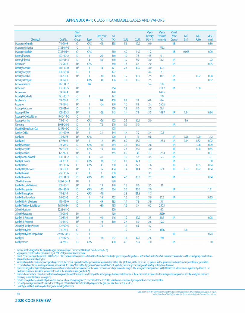
Data is from NFPA 497-2017, Recommended Practice for the Classification of Flammable Liquids, Gases, or Vapors and of Hazardous (Classified) Locations for Electrical Installations in Chemical Process Areas.
APPENDIX A-1: CLASS I FLAMMABLE GASES AND VAPORS
160
a Type is used to designate if the material is a gas, flammable liquid, or combustible liquid. (See 4.2.6 and 4.2.7.)b Vapor pressure reflected in units of mm Hg at 77°F (25°C) unless stated otherwise.c Class I, Zone Groups are based on IEC 60079-20-1, 1996, Explosive atmospheres — Part 20-1:Material characteristics for gas and vapor classification — Test methods and data, which contains additional data on MESG and group classifications.d Material has been classified by test.e Where all conduit runs into explosionproof equipment, the conduit is provided with explosionproof seals installed within 18 in. (450 mm) of the enclosure, equipment for the group classification shown in parentheses is permitted.f For classification of areas involving ammonia, see ASHRAE 15, Safety Standard for Refrigeration Systems, and CGA G2.1, Safety Requirements for the Storage and Handling of Anhydrous Ammonia.g Commercial grades of aliphatic hydrocarbon solvents are mixtures of several isomers of the same chemical formula (or molecular weight). The autoignition temperatures (AIT) of the individual isomers are significantly different. The
electrical equipment should be suitable for the AIT of the solvent mixture. (See A.4.4.2.)h Certain chemicals have characteristics that need safeguards beyond those necessary for any of the above groups. Carbon disulfide is one of these chemicals because of its low autoignition temperature and the small joint clearance
necessary to arrest its flame propagation.i Petroleum naphtha is a saturated hydrocarbon mixture whose boiling range is 68°F to 275°F (20°C to 135°C). It is also known as benzine, ligroin, petroleum ether, and naphtha.j Fuel and process gas mixtures found by test not to present hazards similar to those of hydrogen can be grouped based on the test results.k Liquid type and flash point vary due to regional blending differences.
2020 CODE REVIEW
Chemical CAS No.
Class I Division Group Typea
Flash Point (°C)
AIT (°C) %LFL %UFL
Vapor Density (Air = 1)
Vapor Pressureb
(mm Hg)
Class I Zone
Groupc
MIE (mJ)
MIC Ratio
MESG (mm)
Hydrogen Cyanide 74−90−8 Cd GAS −18 538 5.6 40.0 0.9 IIB 0.80Hydrogen Selenide 7783−07−5 C I 7793Hydrogen Sulfide 7783−06−4 Cd GAS 260 4.0 44.0 1.2 IIB 0.068 0.90Isoamyl Acetate 123−92−2 D I 25 360 1.0 7.5 4.5 6.1Isoamyl Alcohol 123−51−3 D II 43 350 1.2 9.0 3.0 3.2 IIA 1.02Isobutane 75−28−5 Dg GAS 460 1.8 8.4 2.0 IIA 0.95Isobutyl Acetate 110−19−0 Dd I 18 421 2.4 10.5 4.0 17.8Isobutyl Acrylate 106−63−8 D I 427 4.4 7.1Isobutyl Alcohol 78−83−1 Dd I −40 416 1.2 10.9 2.5 10.5 IIA 0.92 0.98Isobutyraldehyde 78−84−2 C GAS −40 196 1.6 10.6 2.5 IIA 0.92Isodecaldehyde 112−31−2 C IIIA 5.4 0.09Isohexane 107−83−5 Dg 264 211.7 IIA 1.00Isopentane 78−78−4 Dg 420 688.6Isooctyl Aldehyde 123−05−7 C II 197 1.9Isophorone 78−59−1 D 84 460 0.8 3.8 4.8 0.4Isoprene 78−79−5 Dd I −54 220 1.5 8.9 2.4 550.6Isopropyl Acetate 108−21−4 D I 460 1.8 8.0 3.5 60.4Isopropyl Ether 108−20−3 Dd I −28 443 1.4 7.9 3.5 148.7 IIA 1.14 0.94Isopropyl Glycidyl Ether 4016−14−2 C IIsopropylamine 75−31−0 D GAS −26 402 2.3 10.4 2.0 2.0Kerosene 8008−20−6 D II 72 210 0.7 5.0 IIALiquefied Petroleum Gas 68476−8−7 D I 405Mesityl Oxide 141−97−9 Dd I 31 344 1.4 7.2 3.4 47.6Methane 74−82−8 Dd GAS 600 5 15 0.6 IIA 0.28 1.00 1.12Methanol 67−56−1 Dd I 12 385 6.0 36.0 1.1 126.3 IIA 0.14 0.82 0.92Methyl Acetate 79−20−9 D GAS −10 454 3.1 16.0 2.6 IIA 1.08 0.99Methyl Acrylate 96−33−3 D GAS −3 468 2.8 25.0 3.0 IIB 0.98 0.85Methyl Alcohol 67−56−1 Dd I 385 6.0 36 1.1 126.3 IIA 0.91Methyl Amyl Alcohol 108−11−2 D II 41 1.0 5.5 3.5 5.3 IIA 1.01Methyl Chloride 74−87−3 D GAS −46 632 8.1 17.4 1.7 IIA 1.00Methyl Ether 115−10−6 Cd GAS −41 350 3.4 27.0 1.6 IIB 0.85 0.84Methyl Ethyl Ketone 78−93−3 Dd I −6 404 1.4 11.4 2.5 92.4 IIB 0.53 0.92 0.84Methyl Formal 534−15−6 Cd I 1 238 3.1Methyl Formate 107−31−3 D GAS −19 449 4.5 23.0 2.1 IIA 0.942-Methylhexane 31394−54−4 Dg I 280Methyl Isobutyl Ketone 108−10−1 Dd I 13 440 1.2 8.0 3.5 11Methyl Isocyanate 624−83−9 D GAS −15 534 5.3 26.0 2.0 IIA 1.21Methyl Mercaptan 74−93−1 C GAS −18 3.9 21.8 1.7Methyl Methacrylate 80−62−6 D I 10 422 1.7 8.2 3.6 37.2 IIA 0.95Methyl N-Amyl Ketone 110−43−0 D II 49 393 1.1 7.9 3.9 3.8Methyl Tertiary Butyl Ether 1634−04−4 D I −80 435 1.6 8.4 0.2 250.12-Methyloctane 3221−61−2 220 6.32-Methylpropane 75−28−5 Dg I 460 2639Methyl-1-Propanol 78−83−1 Dd I −40 416 1.2 10.9 2.5 10.1 IIA 0.98Methyl-2-Propanol 75−65−0 Dd I 10 360 2.4 8.0 2.6 42.22-Methyl-5-Ethyl Pyridine 104−90−5 D 74 1.1 6.6 4.2Methylacetylene 74−99−7 Cd I 1.7 1.4 4306 0.11Methylacetylene- Propadiene 27846−30−6 C I IIB 0.74Methylal 109−87−5 C I −18 237 1.6 17.6 2.6 398Methylamine 74−89−5 D GAS 430 4.9 20.7 1.0 IIA 1.10
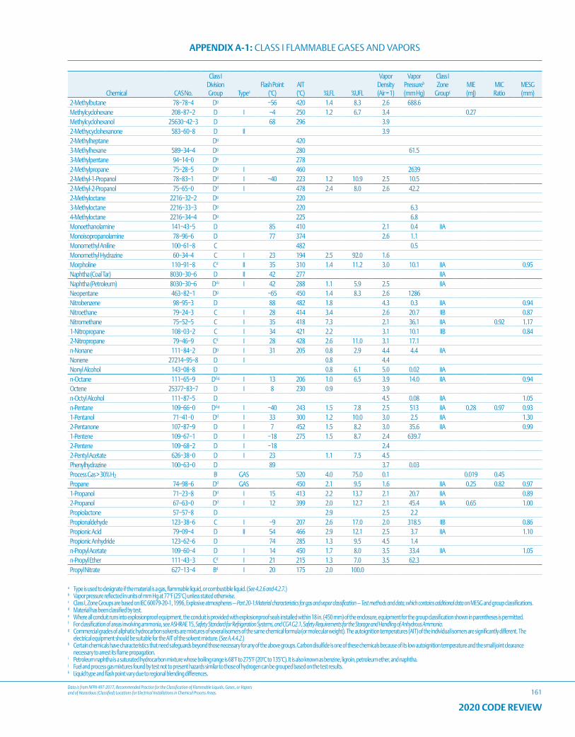
Data is from NFPA 497-2017, Recommended Practice for the Classification of Flammable Liquids, Gases, or Vapors and of Hazardous (Classified) Locations for Electrical Installations in Chemical Process Areas.
APPENDIX A-1: CLASS I FLAMMABLE GASES AND VAPORS
161
a Type is used to designate if the material is a gas, flammable liquid, or combustible liquid. (See 4.2.6 and 4.2.7.)b Vapor pressure reflected in units of mm Hg at 77°F (25°C) unless stated otherwise.c Class I, Zone Groups are based on IEC 60079-20-1, 1996, Explosive atmospheres — Part 20-1:Material characteristics for gas and vapor classification — Test methods and data, which contains additional data on MESG and group classifications.d Material has been classified by test.e Where all conduit runs into explosionproof equipment, the conduit is provided with explosionproof seals installed within 18 in. (450 mm) of the enclosure, equipment for the group classification shown in parentheses is permitted.f For classification of areas involving ammonia, see ASHRAE 15, Safety Standard for Refrigeration Systems, and CGA G2.1, Safety Requirements for the Storage and Handling of Anhydrous Ammonia.g Commercial grades of aliphatic hydrocarbon solvents are mixtures of several isomers of the same chemical formula (or molecular weight). The autoignition temperatures (AIT) of the individual isomers are significantly different. The
electrical equipment should be suitable for the AIT of the solvent mixture. (See A.4.4.2.)h Certain chemicals have characteristics that need safeguards beyond those necessary for any of the above groups. Carbon disulfide is one of these chemicals because of its low autoignition temperature and the small joint clearance
necessary to arrest its flame propagation.i Petroleum naphtha is a saturated hydrocarbon mixture whose boiling range is 68°F to 275°F (20°C to 135°C). It is also known as benzine, ligroin, petroleum ether, and naphtha.j Fuel and process gas mixtures found by test not to present hazards similar to those of hydrogen can be grouped based on the test results.k Liquid type and flash point vary due to regional blending differences.
2020 CODE REVIEW
Chemical CAS No.
Class I Division Group Typea
Flash Point (°C)
AIT (°C) %LFL %UFL
Vapor Density (Air = 1)
Vapor Pressureb
(mm Hg)
Class I Zone
Groupc
MIE (mJ)
MIC Ratio
MESG (mm)
2-Methylbutane 78−78−4 Dg −56 420 1.4 8.3 2.6 688.6Methylcyclohexane 208−87−2 D I −4 250 1.2 6.7 3.4 0.27Methylcyclohexanol 25630−42−3 D 68 296 3.92-Methycyclohexanone 583−60−8 D II 3.92-Methylheptane Dg 4203-Methylhexane 589−34−4 Dg 280 61.53-Methylpentane 94−14−0 Dg 2782-Methylpropane 75−28−5 Dg I 460 26392-Methyl-1-Propanol 78−83−1 Dd I −40 223 1.2 10.9 2.5 10.52-Methyl-2-Propanol 75−65−0 Dd I 478 2.4 8.0 2.6 42.22-Methyloctane 2216−32−2 Dg 2203-Methyloctane 2216−33−3 Dg 220 6.34-Methyloctane 2216−34−4 Dg 225 6.8Monoethanolamine 141−43−5 D 85 410 2.1 0.4 IIAMonoisopropanolamine 78−96−6 D 77 374 2.6 1.1Monomethyl Aniline 100−61−8 C 482 0.5Monomethyl Hydrazine 60−34−4 C I 23 194 2.5 92.0 1.6Morpholine 110−91−8 Cd II 35 310 1.4 11.2 3.0 10.1 IIA 0.95Naphtha (Coal Tar) 8030−30−6 D II 42 277 IIANaphtha (Petroleum) 8030−30−6 Dd,i I 42 288 1.1 5.9 2.5 IIANeopentane 463−82−1 Dg −65 450 1.4 8.3 2.6 1286Nitrobenzene 98−95−3 D 88 482 1.8 4.3 0.3 IIA 0.94Nitroethane 79−24−3 C I 28 414 3.4 2.6 20.7 IIB 0.87Nitromethane 75−52−5 C I 35 418 7.3 2.1 36.1 IIA 0.92 1.171-Nitropropane 108−03−2 C I 34 421 2.2 3.1 10.1 IIB 0.842-Nitropropane 79−46−9 Cd I 28 428 2.6 11.0 3.1 17.1n-Nonane 111−84−2 Dg I 31 205 0.8 2.9 4.4 4.4 IIANonene 27214−95−8 D I 0.8 4.4Nonyl Alcohol 143−08−8 D 0.8 6.1 5.0 0.02 IIAn-Octane 111−65−9 Dd,g I 13 206 1.0 6.5 3.9 14.0 IIA 0.94Octene 25377−83−7 D I 8 230 0.9 3.9n-Octyl Alcohol 111−87−5 D 4.5 0.08 IIA 1.05n-Pentane 109−66−0 Dd,g I −40 243 1.5 7.8 2.5 513 IIA 0.28 0.97 0.931-Pentanol 71−41−0 Dd I 33 300 1.2 10.0 3.0 2.5 IIA 1.302-Pentanone 107−87−9 D I 7 452 1.5 8.2 3.0 35.6 IIA 0.991-Pentene 109−67−1 D I −18 275 1.5 8.7 2.4 639.72-Pentene 109−68−2 D I −18 2.42-Pentyl Acetate 626−38−0 D I 23 1.1 7.5 4.5Phenylhydrazine 100−63−0 D 89 3.7 0.03Process Gas > 30% H2 Bj GAS 520 4.0 75.0 0.1 0.019 0.45Propane 74−98−6 Dd GAS 450 2.1 9.5 1.6 IIA 0.25 0.82 0.971-Propanol 71−23−8 Dd I 15 413 2.2 13.7 2.1 20.7 IIA 0.892-Propanol 67−63−0 Dd I 12 399 2.0 12.7 2.1 45.4 IIA 0.65 1.00Propiolactone 57−57−8 D 2.9 2.5 2.2Propionaldehyde 123−38−6 C I −9 207 2.6 17.0 2.0 318.5 IIB 0.86Propionic Acid 79−09−4 D II 54 466 2.9 12.1 2.5 3.7 IIA 1.10Propionic Anhydride 123−62−6 D 74 285 1.3 9.5 4.5 1.4n-Propyl Acetate 109−60−4 D I 14 450 1.7 8.0 3.5 33.4 IIA 1.05n-Propyl Ether 111−43−3 Cd I 21 215 1.3 7.0 3.5 62.3Propyl Nitrate 627−13−4 Bd I 20 175 2.0 100.0
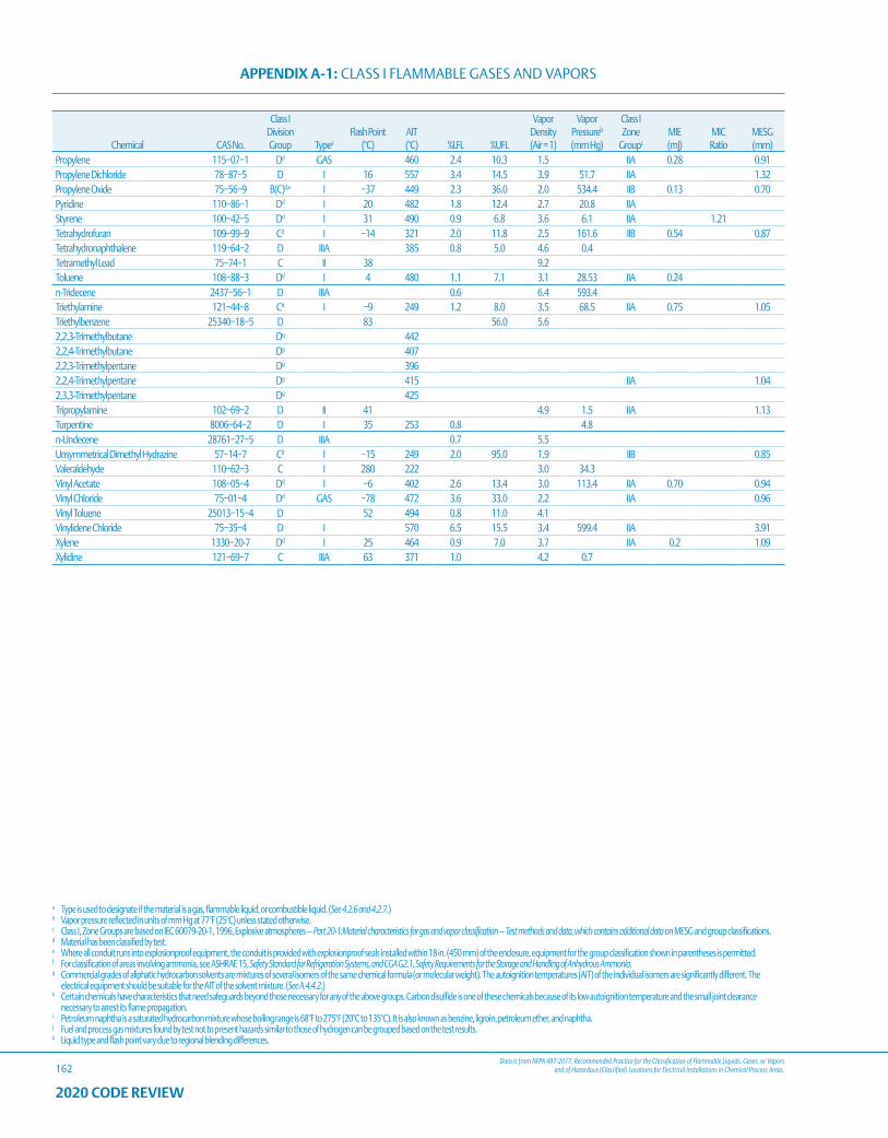
Data is from NFPA 497-2017, Recommended Practice for the Classification of Flammable Liquids, Gases, or Vapors and of Hazardous (Classified) Locations for Electrical Installations in Chemical Process Areas.
APPENDIX A-1: CLASS I FLAMMABLE GASES AND VAPORS
162
a Type is used to designate if the material is a gas, flammable liquid, or combustible liquid. (See 4.2.6 and 4.2.7.)b Vapor pressure reflected in units of mm Hg at 77°F (25°C) unless stated otherwise.c Class I, Zone Groups are based on IEC 60079-20-1, 1996, Explosive atmospheres — Part 20-1:Material characteristics for gas and vapor classification — Test methods and data, which contains additional data on MESG and group classifications.d Material has been classified by test.e Where all conduit runs into explosionproof equipment, the conduit is provided with explosionproof seals installed within 18 in. (450 mm) of the enclosure, equipment for the group classification shown in parentheses is permitted.f For classification of areas involving ammonia, see ASHRAE 15, Safety Standard for Refrigeration Systems, and CGA G2.1, Safety Requirements for the Storage and Handling of Anhydrous Ammonia.g Commercial grades of aliphatic hydrocarbon solvents are mixtures of several isomers of the same chemical formula (or molecular weight). The autoignition temperatures (AIT) of the individual isomers are significantly different. The
electrical equipment should be suitable for the AIT of the solvent mixture. (See A.4.4.2.)h Certain chemicals have characteristics that need safeguards beyond those necessary for any of the above groups. Carbon disulfide is one of these chemicals because of its low autoignition temperature and the small joint clearance
necessary to arrest its flame propagation.i Petroleum naphtha is a saturated hydrocarbon mixture whose boiling range is 68°F to 275°F (20°C to 135°C). It is also known as benzine, ligroin, petroleum ether, and naphtha.j Fuel and process gas mixtures found by test not to present hazards similar to those of hydrogen can be grouped based on the test results.k Liquid type and flash point vary due to regional blending differences.
2020 CODE REVIEW
Chemical CAS No.
Class I Division Group Typea
Flash Point (°C)
AIT (°C) %LFL %UFL
Vapor Density (Air = 1)
Vapor Pressureb
(mm Hg)
Class I Zone
Groupc
MIE (mJ)
MIC Ratio
MESG (mm)
Propylene 115−07−1 Dd GAS 460 2.4 10.3 1.5 IIA 0.28 0.91Propylene Dichloride 78−87−5 D I 16 557 3.4 14.5 3.9 51.7 IIA 1.32Propylene Oxide 75−56−9 B(C)d,e I −37 449 2.3 36.0 2.0 534.4 IIB 0.13 0.70Pyridine 110−86−1 Dd I 20 482 1.8 12.4 2.7 20.8 IIAStyrene 100−42−5 Dd I 31 490 0.9 6.8 3.6 6.1 IIA 1.21Tetrahydrofuran 109−99−9 Cd I −14 321 2.0 11.8 2.5 161.6 IIB 0.54 0.87Tetrahydronaphthalene 119−64−2 D IIIA 385 0.8 5.0 4.6 0.4Tetramethyl Lead 75−74−1 C II 38 9.2Toluene 108−88−3 Dd I 4 480 1.1 7.1 3.1 28.53 IIA 0.24n-Tridecene 2437−56−1 D IIIA 0.6 6.4 593.4Triethylamine 121−44−8 Cd I −9 249 1.2 8.0 3.5 68.5 IIA 0.75 1.05Triethylbenzene 25340−18−5 D 83 56.0 5.62,2,3-Trimethylbutane Dg 4422,2,4-Trimethylbutane Dg 4072,2,3-Trimethylpentane Dg 3962,2,4-Trimethylpentane Dg 415 IIA 1.042,3,3-Trimethylpentane Dg 425Tripropylamine 102−69−2 D II 41 4.9 1.5 IIA 1.13Turpentine 8006−64−2 D I 35 253 0.8 4.8n-Undecene 28761−27−5 D IIIA 0.7 5.5Unsymmetrical Dimethyl Hydrazine 57−14−7 Cd I −15 249 2.0 95.0 1.9 IIB 0.85Valeraldehyde 110−62−3 C I 280 222 3.0 34.3Vinyl Acetate 108−05−4 Dd I −6 402 2.6 13.4 3.0 113.4 IIA 0.70 0.94Vinyl Chloride 75−01−4 Dd GAS −78 472 3.6 33.0 2.2 IIA 0.96Vinyl Toluene 25013−15−4 D 52 494 0.8 11.0 4.1Vinylidene Chloride 75−35−4 D I 570 6.5 15.5 3.4 599.4 IIA 3.91Xylene 1330−20-7 Dd I 25 464 0.9 7.0 3.7 IIA 0.2 1.09Xylidine 121−69−7 C IIIA 63 371 1.0 4.2 0.7
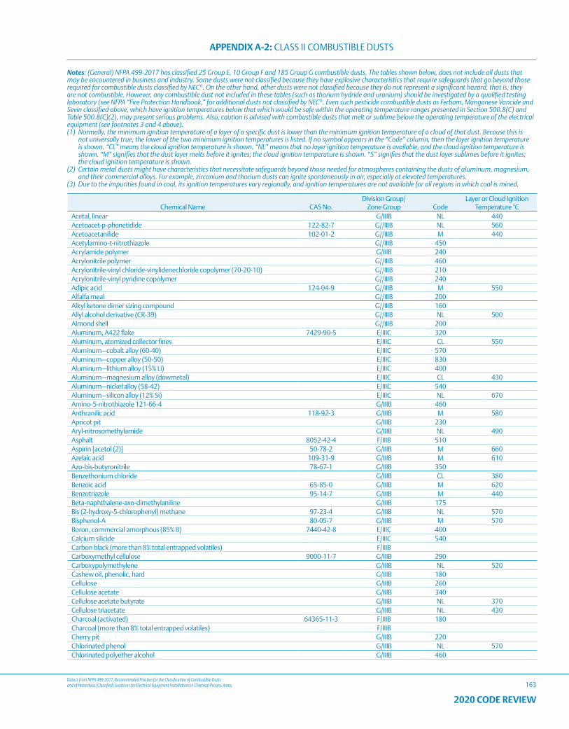
Data is from NFPA 499-2017, Recommended Practice for the Classification of Combustible Dusts and of Hazardous (Classified) Locations for Electrical Equipment Installations in Chemical Process Areas.
APPENDIX A-2: CLASS II COMBUSTIBLE DUSTS
163
2020 CODE REVIEW
Chemical Name CAS No.Division Group/
Zone Group CodeLayer or Cloud Ignition
Temperature °CAcetal, linear G/IIIB NL 440Acetoacet-p-phenetidide 122-82-7 G//IIIB NL 560Acetoacetanilide 102-01-2 G//IIIB M 440Acetylamino-t-nitrothiazole G//IIIB 450Acrylamide polymer G/IIIB 240Acrylonitrile polymer G//IIIB 460Acrylonitrile-vinyl chloride-vinylidenechloride copolymer (70-20-10) G//IIIB 210Acrylonitrile-vinyl pyridine copolymer G//IIIB 240Adipic acid 124-04-9 G//IIIB M 550Alfalfa meal G//IIIB 200Alkyl ketone dimer sizing compound G//IIIB 160Allyl alcohol derivative (CR-39) G//IIIB NL 500Almond shell G//IIIB 200Aluminum, A422 flake 7429-90-5 E/IIIC 320Aluminum, atomized collector fines E/IIIC CL 550Aluminum—cobalt alloy (60-40) E/IIIC 570Aluminum—copper alloy (50-50) E/IIIC 830Aluminum—lithium alloy (15% Li) E/IIIC 400Aluminum—magnesium alloy (dowmetal) E/IIIC CL 430Aluminum—nickel alloy (58-42) E/IIIC 540Aluminum—silicon alloy (12% Si) E/IIIC NL 670Amino-5-nitrothiazole 121-66-4 G/IIIB 460Anthranilic acid 118-92-3 G/IIIB M 580Apricot pit G/IIIB 230Aryl-nitrosomethylamide G/IIIB NL 490Asphalt 8052-42-4 F/IIIB 510Aspirin [acetol (2)] 50-78-2 G/IIIB M 660Azelaic acid 109-31-9 G/IIIB M 610Azo-bis-butyronitrile 78-67-1 G/IIIB 350Benzethonium chloride G/IIIB CL 380Benzoic acid 65-85-0 G/IIIB M 620Benzotriazole 95-14-7 G/IIIB M 440Beta-naphthalene-axo-dimethylaniline G/IIIB 175Bis (2-hydroxy-5-chlorophenyl) methane 97-23-4 G/IIIB NL 570Bisphenol-A 80-05-7 G/IIIB M 570Boron, commercial amorphous (85% B) 7440-42-8 E/IIIC 400Calcium silicide E/IIIC 540Carbon black (more than 8% total entrapped volatiles) F/IIIBCarboxymethyl cellulose 9000-11-7 G/IIIB 290Carboxypolymethylene G/IIIB NL 520Cashew oil, phenolic, hard G/IIIB 180Cellulose G/IIIB 260Cellulose acetate G/IIIB 340Cellulose acetate butyrate G/IIIB NL 370Cellulose triacetate G/IIIB NL 430Charcoal (activated) 64365-11-3 F/IIIB 180Charcoal (more than 8% total entrapped volatiles) F/IIIBCherry pit G/IIIB 220Chlorinated phenol G/IIIB NL 570Chlorinated polyether alcohol G/IIIB 460
Notes: (General) NFPA 499-2017 has classified 25 Group E, 10 Group F and 185 Group G combustible dusts. The tables shown below, does not include all dusts that may be encountered in business and industry. Some dusts were not classified because they have explosive characteristics that require safeguards that go beyond those required for combustible dusts classified by NEC®. On the other hand, other dusts were not classified because they do not represent a significant hazard, that is, they are not combustible. However, any combustible dust not included in these tables (such as thorium hydride and uranium) should be investigated by a qualified testing laboratory (see NFPA “Fire Protection Handbook,” for additional dusts not classified by NEC®. Even such pesticide combustible dusts as Ferbam, Manganese Vancide and Sevin classified above, which have ignition temperatures below that which would be safe within the operating temperature ranges presented in Section 500.8(C) and Table 500.8(C)(2), may present serious problems. Also, caution is advised with combustible dusts that melt or sublime below the operating temperature of the electrical equipment (see footnotes 3 and 4 above).(1) Normally, the minimum ignition temperature of a layer of a specific dust is lower than the minimum ignition temperature of a cloud of that dust. Because this is
not universally true, the lower of the two minimum ignition temperatures is listed. If no symbol appears in the “Code” column, then the layer ignition temperature is shown. “CL” means the cloud ignition temperature is shown. “NL” means that no layer ignition temperature is available, and the cloud ignition temperature is shown. “M” signifies that the dust layer melts before it ignites; the cloud ignition temperature is shown. “S” signifies that the dust layer sublimes before it ignites; the cloud ignition temperature is shown.
(2) Certain metal dusts might have characteristics that necessitate safeguards beyond those needed for atmospheres containing the dusts of aluminum, magnesium, and their commercial alloys. For example, zirconium and thorium dusts can ignite spontaneously in air, especially at elevated temperatures.
(3) Due to the impurities found in coal, its ignition temperatures vary regionally, and ignition temperatures are not available for all regions in which coal is mined.
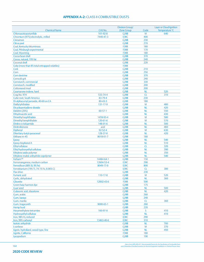
Data is from NFPA 499-2017, Recommended Practice for the Classification of Combustible Dusts and of Hazardous (Classified) Locations for Electrical Equipment Installations in Chemical Process Areas.
APPENDIX A-2: CLASS II COMBUSTIBLE DUSTS
164
2020 CODE REVIEW
Chemical Name CAS No.Division Group/
Zone Group CodeLayer or Cloud Ignition
Temperature °CChloroacetoacetanilide 101-92-8 G/IIIB M 640Chromium (97%) electrolytic, milled 7440-47-3 E/IIIC 400Cinnamon G/IIIB 230Citrus peel G/IIIB 270Coal, Kentucky bituminous F/IIIB 180Coal, Pittsburgh experimental F/IIIB 170Coal, Wyoming F/IIIB 180Cocoa bean shell G/IIIB 370Cocoa, natural, 19% fat G/IIIB 240Coconut shell G/IIIB 220Coke (more than 8% total entrapped volatiles) F/IIIBCork G/IIIB 210Corn G/IIIB 250Corn dextrine G/IIIB 370Corncob grit G/IIIB 240Cornstarch, commercial G/IIIB 330Cornstarch, modified G/IIIB 200Cottonseed meal G/IIIB 200Coumarone-indene, hard G/IIIB NL 520Crag No. 974 533-74-4 G/IIIB CL 310Cube root, South America 83-79-4 G/IIIB 230Di-alphacumyl peroxide, 40-60 on CA 80-43-3 G/IIIB 180Diallyl phthalate 131-17-9 G/IIIB M 480Dicyclopentadiene dioxide G/IIIB NL 420Dieldrin (20%) 60-57-1 G/IIIB NL 550Dihydroacetic acid G/IIIB NL 430Dimethyl isophthalate 1459-93-4 G/IIIB M 580Dimethyl terephthalate 120-61-6 G/IIIB M 570Dinitro-o-toluamide 148-01-6 G/IIIB NL 500Dinitrobenzoic acid G/IIIB NL 460Diphenyl 92-52-4 G/IIIB M 630Ditertiary-butyl-paracresol 128-37-0 G/IIIB NL 420Dithane m-45 8018-01-7 G/IIIB 180Epoxy G/IIIB NL 540Epoxy-bisphenol A G/IIIB NL 510Ethyl cellulose G/IIIB CL 320Ethyl hydroxyethyl cellulose G/IIIB NL 390Ethylene oxide polymer G/IIIB NL 350Ethylene-maleic anhydride copolymer G/IIIB NL 540Ferbam™ 14484-64-1 G/IIIB 150Ferromanganese, medium carbon 12604-53-4 E/IIIC 290Ferrosilicon (88% Si, 9% Fe) 8049-17-0 E/IIIC 800Ferrotitanium (19% Ti, 74.1% Fe, 0.06% C) E/IIIC CL 380Flax shive G/IIIB 230Fumaric acid 110-17-8 G/IIIB M 520Garlic, dehydrated G/IIIB NL 360Gilsonite 12002-43-6 F/IIIB 500Green base harmon dye G/IIIB 175Guar seed G/IIIB NL 500Gulasonic acid, diacetone G/IIIB NL 420Gum, arabic G/IIIB 260Gum, karaya G/IIIB 240Gum, manila G/IIIB CL 360Gum, tragacanth 9000-65-1 G/IIIB 260Hemp hurd G/IIIB 220Hexamethylene tetramine 100-97-0 G/IIIB S 410Hydroxyethyl cellulose G/IIIB NL 410Iron, 98% H2 reduced E/IIIC 290Iron, 99% carbonyl 13463-40-6 E/IIIC 310Isotoic anhydride G/IIIB NL 700L-sorbose G/IIIB M 370Lignin, hydrolized, wood-type, fine G/IIIB NL 450Lignite, California F/IIIB 180Lycopodium G/IIIB 190
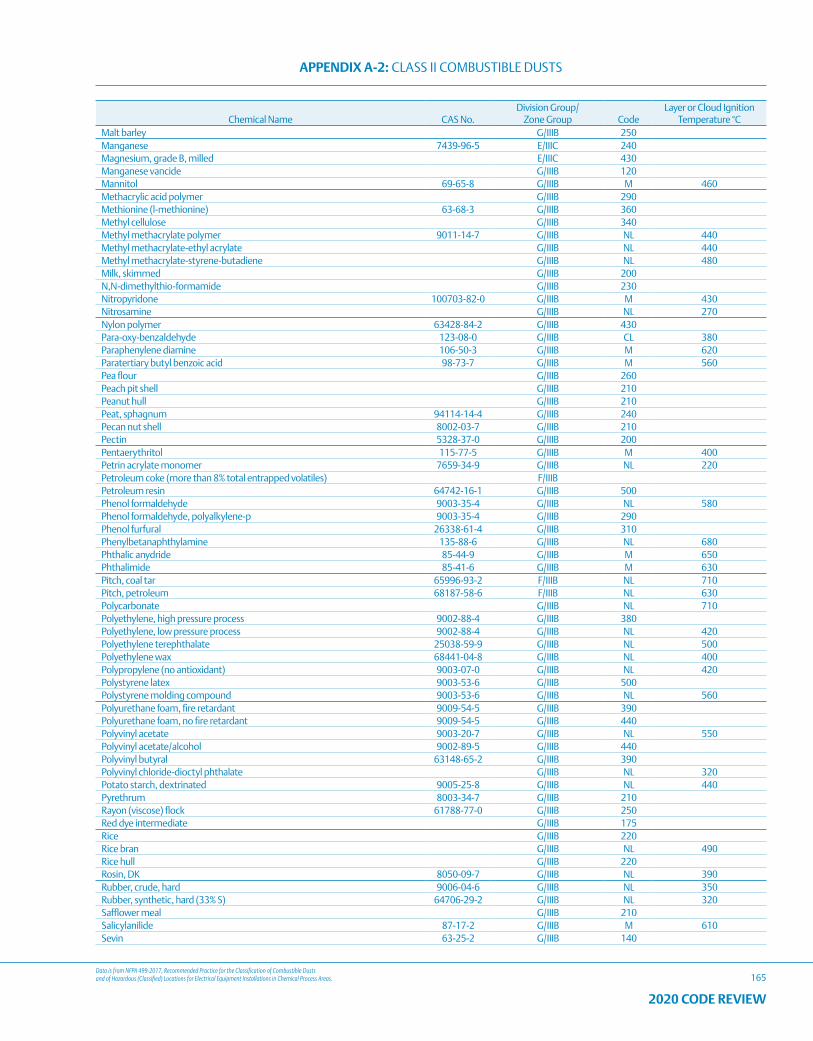
Data is from NFPA 499-2017, Recommended Practice for the Classification of Combustible Dusts and of Hazardous (Classified) Locations for Electrical Equipment Installations in Chemical Process Areas.
APPENDIX A-2: CLASS II COMBUSTIBLE DUSTS
165
2020 CODE REVIEW
Chemical Name CAS No.Division Group/
Zone Group CodeLayer or Cloud Ignition
Temperature °CMalt barley G/IIIB 250Manganese 7439-96-5 E/IIIC 240Magnesium, grade B, milled E/IIIC 430Manganese vancide G/IIIB 120Mannitol 69-65-8 G/IIIB M 460Methacrylic acid polymer G/IIIB 290Methionine (l-methionine) 63-68-3 G/IIIB 360Methyl cellulose G/IIIB 340Methyl methacrylate polymer 9011-14-7 G/IIIB NL 440Methyl methacrylate-ethyl acrylate G/IIIB NL 440Methyl methacrylate-styrene-butadiene G/IIIB NL 480Milk, skimmed G/IIIB 200N,N-dimethylthio-formamide G/IIIB 230Nitropyridone 100703-82-0 G/IIIB M 430Nitrosamine G/IIIB NL 270Nylon polymer 63428-84-2 G/IIIB 430Para-oxy-benzaldehyde 123-08-0 G/IIIB CL 380Paraphenylene diamine 106-50-3 G/IIIB M 620Paratertiary butyl benzoic acid 98-73-7 G/IIIB M 560Pea flour G/IIIB 260Peach pit shell G/IIIB 210Peanut hull G/IIIB 210Peat, sphagnum 94114-14-4 G/IIIB 240Pecan nut shell 8002-03-7 G/IIIB 210Pectin 5328-37-0 G/IIIB 200Pentaerythritol 115-77-5 G/IIIB M 400Petrin acrylate monomer 7659-34-9 G/IIIB NL 220Petroleum coke (more than 8% total entrapped volatiles) F/IIIBPetroleum resin 64742-16-1 G/IIIB 500Phenol formaldehyde 9003-35-4 G/IIIB NL 580Phenol formaldehyde, polyalkylene-p 9003-35-4 G/IIIB 290Phenol furfural 26338-61-4 G/IIIB 310Phenylbetanaphthylamine 135-88-6 G/IIIB NL 680Phthalic anydride 85-44-9 G/IIIB M 650Phthalimide 85-41-6 G/IIIB M 630Pitch, coal tar 65996-93-2 F/IIIB NL 710Pitch, petroleum 68187-58-6 F/IIIB NL 630Polycarbonate G/IIIB NL 710Polyethylene, high pressure process 9002-88-4 G/IIIB 380Polyethylene, low pressure process 9002-88-4 G/IIIB NL 420Polyethylene terephthalate 25038-59-9 G/IIIB NL 500Polyethylene wax 68441-04-8 G/IIIB NL 400Polypropylene (no antioxidant) 9003-07-0 G/IIIB NL 420Polystyrene latex 9003-53-6 G/IIIB 500Polystyrene molding compound 9003-53-6 G/IIIB NL 560Polyurethane foam, fire retardant 9009-54-5 G/IIIB 390Polyurethane foam, no fire retardant 9009-54-5 G/IIIB 440Polyvinyl acetate 9003-20-7 G/IIIB NL 550Polyvinyl acetate/alcohol 9002-89-5 G/IIIB 440Polyvinyl butyral 63148-65-2 G/IIIB 390Polyvinyl chloride-dioctyl phthalate G/IIIB NL 320Potato starch, dextrinated 9005-25-8 G/IIIB NL 440Pyrethrum 8003-34-7 G/IIIB 210Rayon (viscose) flock 61788-77-0 G/IIIB 250Red dye intermediate G/IIIB 175Rice G/IIIB 220Rice bran G/IIIB NL 490Rice hull G/IIIB 220Rosin, DK 8050-09-7 G/IIIB NL 390Rubber, crude, hard 9006-04-6 G/IIIB NL 350Rubber, synthetic, hard (33% S) 64706-29-2 G/IIIB NL 320Safflower meal G/IIIB 210Salicylanilide 87-17-2 G/IIIB M 610Sevin 63-25-2 G/IIIB 140
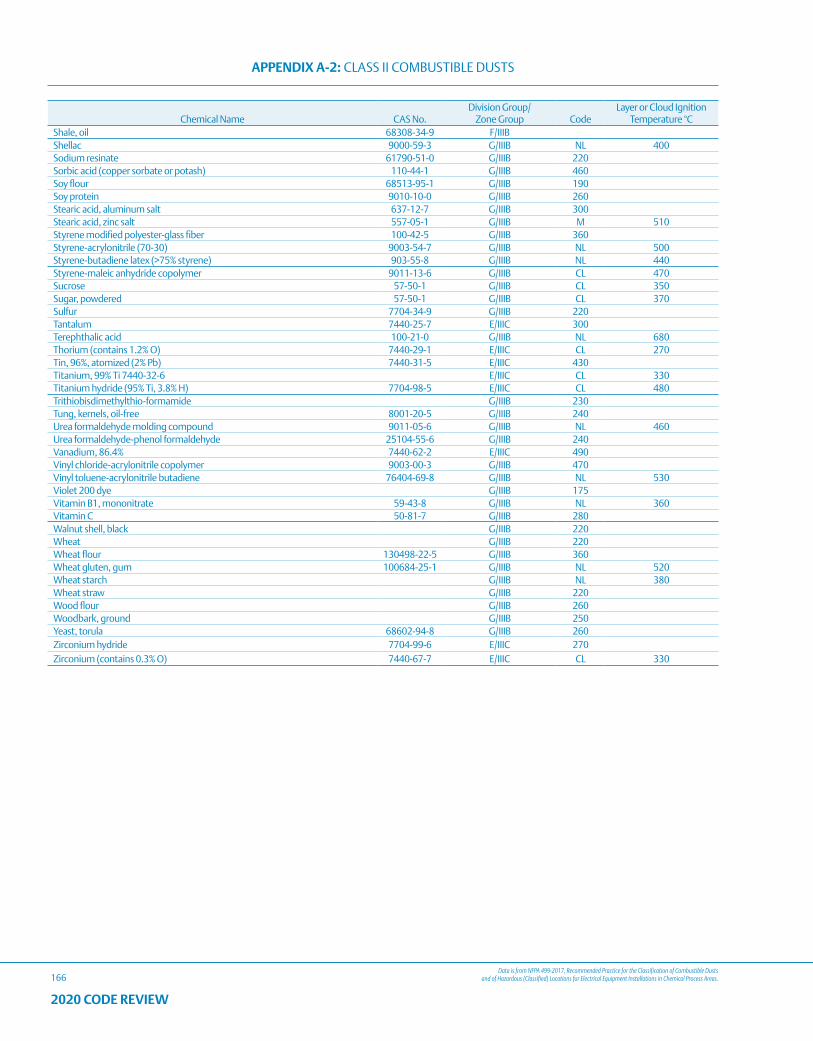
Data is from NFPA 499-2017, Recommended Practice for the Classification of Combustible Dusts and of Hazardous (Classified) Locations for Electrical Equipment Installations in Chemical Process Areas.
APPENDIX A-2: CLASS II COMBUSTIBLE DUSTS
166
2020 CODE REVIEW
Chemical Name CAS No.Division Group/
Zone Group CodeLayer or Cloud Ignition
Temperature °CShale, oil 68308-34-9 F/IIIBShellac 9000-59-3 G/IIIB NL 400Sodium resinate 61790-51-0 G/IIIB 220Sorbic acid (copper sorbate or potash) 110-44-1 G/IIIB 460Soy flour 68513-95-1 G/IIIB 190Soy protein 9010-10-0 G/IIIB 260Stearic acid, aluminum salt 637-12-7 G/IIIB 300Stearic acid, zinc salt 557-05-1 G/IIIB M 510Styrene modified polyester-glass fiber 100-42-5 G/IIIB 360Styrene-acrylonitrile (70-30) 9003-54-7 G/IIIB NL 500Styrene-butadiene latex (>75% styrene) 903-55-8 G/IIIB NL 440Styrene-maleic anhydride copolymer 9011-13-6 G/IIIB CL 470Sucrose 57-50-1 G/IIIB CL 350Sugar, powdered 57-50-1 G/IIIB CL 370Sulfur 7704-34-9 G/IIIB 220Tantalum 7440-25-7 E/IIIC 300Terephthalic acid 100-21-0 G/IIIB NL 680Thorium (contains 1.2% O) 7440-29-1 E/IIIC CL 270Tin, 96%, atomized (2% Pb) 7440-31-5 E/IIIC 430Titanium, 99% Ti 7440-32-6 E/IIIC CL 330Titanium hydride (95% Ti, 3.8% H) 7704-98-5 E/IIIC CL 480Trithiobisdimethylthio-formamide G/IIIB 230Tung, kernels, oil-free 8001-20-5 G/IIIB 240Urea formaldehyde molding compound 9011-05-6 G/IIIB NL 460Urea formaldehyde-phenol formaldehyde 25104-55-6 G/IIIB 240Vanadium, 86.4% 7440-62-2 E/IIIC 490Vinyl chloride-acrylonitrile copolymer 9003-00-3 G/IIIB 470Vinyl toluene-acrylonitrile butadiene 76404-69-8 G/IIIB NL 530Violet 200 dye G/IIIB 175Vitamin B1, mononitrate 59-43-8 G/IIIB NL 360Vitamin C 50-81-7 G/IIIB 280Walnut shell, black G/IIIB 220Wheat G/IIIB 220Wheat flour 130498-22-5 G/IIIB 360Wheat gluten, gum 100684-25-1 G/IIIB NL 520Wheat starch G/IIIB NL 380Wheat straw G/IIIB 220Wood flour G/IIIB 260Woodbark, ground G/IIIB 250Yeast, torula 68602-94-8 G/IIIB 260Zirconium hydride 7704-99-6 E/IIIC 270Zirconium (contains 0.3% O) 7440-67-7 E/IIIC CL 330
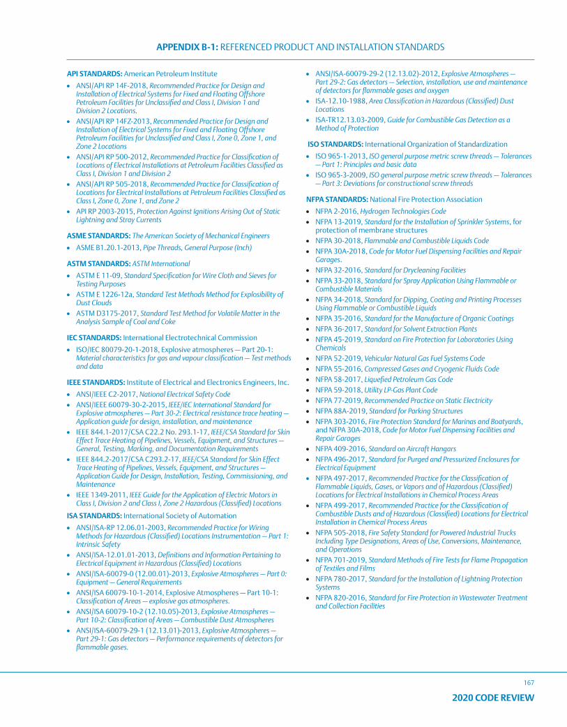
APPENDIX B-1: REFERENCED PRODUCT AND INSTALLATION STANDARDS
167
2020 CODE REVIEW
API STANDARDS: American Petroleum Institute
• ANSI/API RP 14F-2018, Recommended Practice for Design and Installation of Electrical Systems for Fixed and Floating Offshore Petroleum Facilities for Unclassified and Class I, Division 1 and Division 2 Locations.
• ANSI/API RP 14FZ-2013, Recommended Practice for Design and Installation of Electrical Systems for Fixed and Floating Offshore Petroleum Facilities for Unclassified and Class I, Zone 0, Zone 1, and Zone 2 Locations
• ANSI/API RP 500-2012, Recommended Practice for Classification of Locations of Electrical Installations at Petroleum Facilities Classified as Class I, Division 1 and Division 2
• ANSI/API RP 505-2018, Recommended Practice for Classification of Locations for Electrical Installations at Petroleum Facilities Classified as Class I, Zone 0, Zone 1, and Zone 2
• API RP 2003-2015, Protection Against Ignitions Arising Out of Static Lightning and Stray Currents
ASME STANDARDS: The American Society of Mechanical Engineers
• ASME B1.20.1-2013, Pipe Threads, General Purpose (Inch)
ASTM STANDARDS: ASTM International
• ASTM E 11-09, Standard Specification for Wire Cloth and Sieves for Testing Purposes
• ASTM E 1226-12a, Standard Test Methods Method for Explosibility of Dust Clouds
• ASTM D3175-2017, Standard Test Method for Volatile Matter in the Analysis Sample of Coal and Coke
IEC STANDARDS: International Electrotechnical Commission
• ISO/IEC 80079-20-1-2018, Explosive atmospheres — Part 20-1: Material characteristics for gas and vapour classification — Test methods and data
IEEE STANDARDS: Institute of Electrical and Electronics Engineers, Inc.
• ANSI/IEEE C2-2017, National Electrical Safety Code• ANSI/IEEE 60079-30-2-2015, IEEE/IEC International Standard for
Explosive atmospheres — Part 30-2: Electrical resistance trace heating — Application guide for design, installation, and maintenance
• IEEE 844.1-2017/CSA C22.2 No. 293.1-17, IEEE/CSA Standard for Skin Effect Trace Heating of Pipelines, Vessels, Equipment, and Structures — General, Testing, Marking, and Documentation Requirements
• IEEE 844.2-2017/CSA C293.2-17, IEEE/CSA Standard for Skin Effect Trace Heating of Pipelines, Vessels, Equipment, and Structures — Application Guide for Design, Installation, Testing, Commissioning, and Maintenance
• IEEE 1349-2011, IEEE Guide for the Application of Electric Motors in Class I, Division 2 and Class I, Zone 2 Hazardous (Classified) Locations
ISA STANDARDS: International Society of Automation
• ANSI/ISA-RP 12.06.01-2003, Recommended Practice for Wiring Methods for Hazardous (Classified) Locations Instrumentation — Part 1: Intrinsic Safety
• ANSI/ISA-12.01.01-2013, Definitions and Information Pertaining to Electrical Equipment in Hazardous (Classified) Locations
• ANSI/ISA-60079-0 (12.00.01)-2013, Explosive Atmospheres — Part 0: Equipment — General Requirements
• ANSI/ISA 60079-10-1-2014, Explosive Atmospheres — Part 10-1: Classification of Areas — explosive gas atmospheres.
• ANSI/ISA 60079-10-2 (12.10.05)-2013, Explosive Atmospheres — Part 10-2: Classification of Areas — Combustible Dust Atmospheres
• ANSI/ISA-60079-29-1 (12.13.01)-2013, Explosive Atmospheres — Part 29-1: Gas detectors — Performance requirements of detectors for flammable gases.
• ANSI/ISA-60079-29-2 (12.13.02)-2012, Explosive Atmospheres — Part 29-2: Gas detectors — Selection, installation, use and maintenance of detectors for flammable gases and oxygen
• ISA-12.10-1988, Area Classification in Hazardous (Classified) Dust Locations
• ISA-TR12.13.03-2009, Guide for Combustible Gas Detection as a Method of Protection
ISO STANDARDS: International Organization of Standardization
• ISO 965-1-2013, ISO general purpose metric screw threads — Tolerances — Part 1: Principles and basic data
• ISO 965-3-2009, ISO general purpose metric screw threads — Tolerances — Part 3: Deviations for constructional screw threads
NFPA STANDARDS: National Fire Protection Association
• NFPA 2-2016, Hydrogen Technologies Code• NFPA 13-2019, Standard for the Installation of Sprinkler Systems, for
protection of membrane structures• NFPA 30-2018, Flammable and Combustible Liquids Code• NFPA 30A-2018, Code for Motor Fuel Dispensing Facilities and Repair
Garages.• NFPA 32-2016, Standard for Drycleaning Facilities• NFPA 33-2018, Standard for Spray Application Using Flammable or
Combustible Materials• NFPA 34-2018, Standard for Dipping, Coating and Printing Processes
Using Flammable or Combustible Liquids• NFPA 35-2016, Standard for the Manufacture of Organic Coatings• NFPA 36-2017, Standard for Solvent Extraction Plants• NFPA 45-2019, Standard on Fire Protection for Laboratories Using
Chemicals• NFPA 52-2019, Vehicular Natural Gas Fuel Systems Code• NFPA 55-2016, Compressed Gases and Cryogenic Fluids Code• NFPA 58-2017, Liquefied Petroleum Gas Code• NFPA 59-2018, Utility LP-Gas Plant Code• NFPA 77-2019, Recommended Practice on Static Electricity• NFPA 88A-2019, Standard for Parking Structures• NFPA 303-2016, Fire Protection Standard for Marinas and Boatyards,
and NFPA 30A-2018, Code for Motor Fuel Dispensing Facilities and Repair Garages
• NFPA 409-2016, Standard on Aircraft Hangars• NFPA 496-2017, Standard for Purged and Pressurized Enclosures for
Electrical Equipment• NFPA 497-2017, Recommended Practice for the Classification of
Flammable Liquids, Gases, or Vapors and of Hazardous (Classified) Locations for Electrical Installations in Chemical Process Areas
• NFPA 499-2017, Recommended Practice for the Classification of Combustible Dusts and of Hazardous (Classified) Locations for Electrical Installation in Chemical Process Areas
• NFPA 505-2018, Fire Safety Standard for Powered Industrial Trucks Including Type Designations, Areas of Use, Conversions, Maintenance, and Operations
• NFPA 701-2019, Standard Methods of Fire Tests for Flame Propagation of Textiles and Films
• NFPA 780-2017, Standard for the Installation of Lightning Protection Systems
• NFPA 820-2016, Standard for Fire Protection in Wastewater Treatment and Collection Facilities
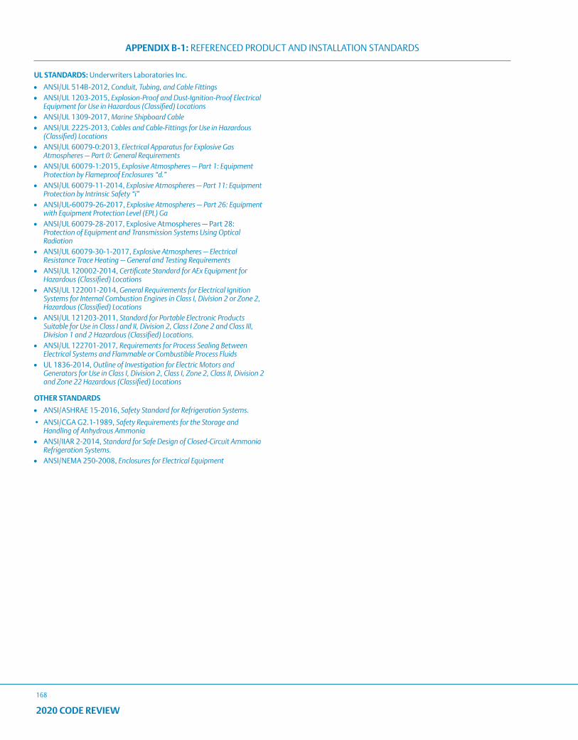
APPENDIX B-1: REFERENCED PRODUCT AND INSTALLATION STANDARDS
168
2020 CODE REVIEW
UL STANDARDS: Underwriters Laboratories Inc.
• ANSI/UL 514B-2012, Conduit, Tubing, and Cable Fittings• ANSI/UL 1203-2015, Explosion-Proof and Dust-Ignition-Proof Electrical
Equipment for Use in Hazardous (Classified) Locations• ANSI/UL 1309-2017, Marine Shipboard Cable• ANSI/UL 2225-2013, Cables and Cable-Fittings for Use in Hazardous
(Classified) Locations• ANSI/UL 60079-0:2013, Electrical Apparatus for Explosive Gas
Atmospheres — Part 0: General Requirements• ANSI/UL 60079-1:2015, Explosive Atmospheres — Part 1: Equipment
Protection by Flameproof Enclosures “d.”• ANSI/UL 60079-11-2014, Explosive Atmospheres — Part 11: Equipment
Protection by Intrinsic Safety “i”• ANSI/UL-60079-26-2017, Explosive Atmospheres — Part 26: Equipment
with Equipment Protection Level (EPL) Ga• ANSI/UL 60079-28-2017, Explosive Atmospheres — Part 28:
Protection of Equipment and Transmission Systems Using Optical Radiation
• ANSI/UL 60079-30-1-2017, Explosive Atmospheres — Electrical Resistance Trace Heating — General and Testing Requirements
• ANSI/UL 120002-2014, Certificate Standard for AEx Equipment for Hazardous (Classified) Locations
• ANSI/UL 122001-2014, General Requirements for Electrical Ignition Systems for Internal Combustion Engines in Class I, Division 2 or Zone 2, Hazardous (Classified) Locations
• ANSI/UL 121203-2011, Standard for Portable Electronic Products Suitable for Use in Class I and II, Division 2, Class I Zone 2 and Class III, Division 1 and 2 Hazardous (Classified) Locations.
• ANSI/UL 122701-2017, Requirements for Process Sealing Between Electrical Systems and Flammable or Combustible Process Fluids
• UL 1836-2014, Outline of Investigation for Electric Motors and Generators for Use in Class I, Division 2, Class I, Zone 2, Class II, Division 2 and Zone 22 Hazardous (Classified) Locations
OTHER STANDARDS
• ANSI/ASHRAE 15-2016, Safety Standard for Refrigeration Systems.
• ANSI/CGA G2.1-1989, Safety Requirements for the Storage and Handling of Anhydrous Ammonia
• ANSI/IIAR 2-2014, Standard for Safe Design of Closed-Circuit Ammonia Refrigeration Systems.
• ANSI/NEMA 250-2008, Enclosures for Electrical Equipment
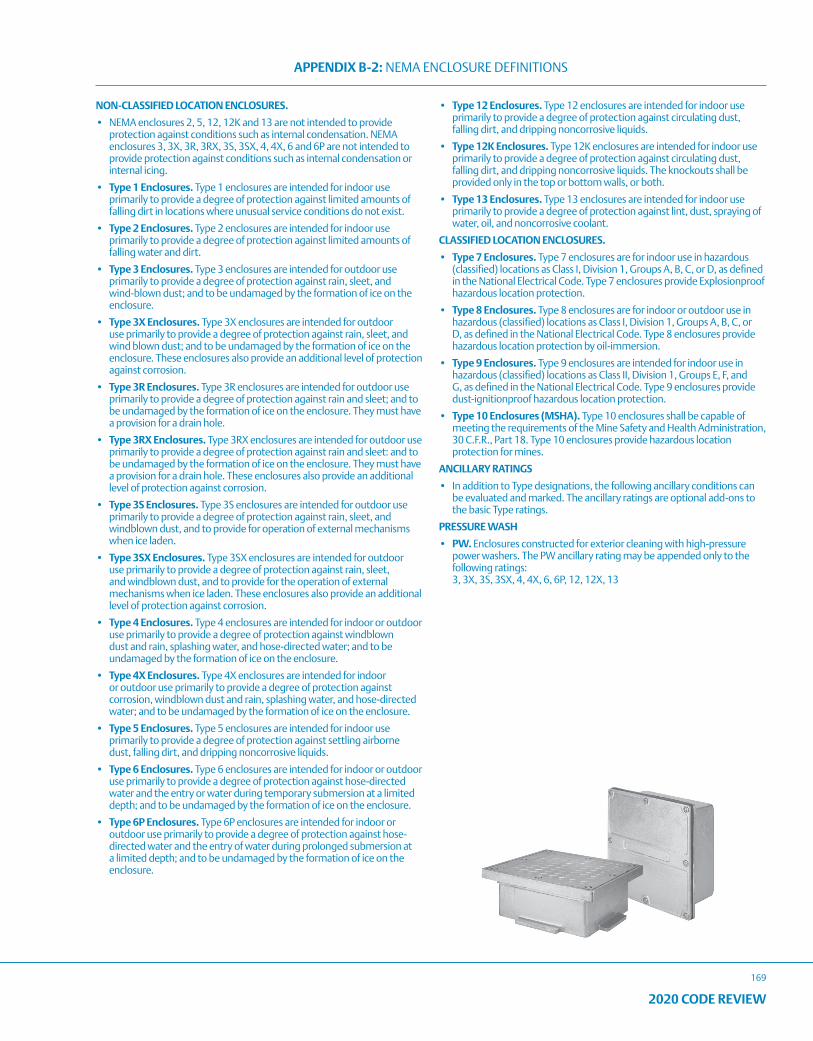
APPENDIX B-2: NEMA ENCLOSURE DEFINITIONS
169
2020 CODE REVIEW
NON-CLASSIFIED LOCATION ENCLOSURES.
• NEMA enclosures 2, 5, 12, 12K and 13 are not intended to provide protection against conditions such as internal condensation. NEMA enclosures 3, 3X, 3R, 3RX, 3S, 3SX, 4, 4X, 6 and 6P are not intended to provide protection against conditions such as internal condensation or internal icing.
• Type 1 Enclosures. Type 1 enclosures are intended for indoor use primarily to provide a degree of protection against limited amounts of falling dirt in locations where unusual service conditions do not exist.
• Type 2 Enclosures. Type 2 enclosures are intended for indoor use primarily to provide a degree of protection against limited amounts of falling water and dirt.
• Type 3 Enclosures. Type 3 enclosures are intended for outdoor use primarily to provide a degree of protection against rain, sleet, and wind-blown dust; and to be undamaged by the formation of ice on the enclosure.
• Type 3X Enclosures. Type 3X enclosures are intended for outdoor use primarily to provide a degree of protection against rain, sleet, and wind blown dust; and to be undamaged by the formation of ice on the enclosure. These enclosures also provide an additional level of protection against corrosion.
• Type 3R Enclosures. Type 3R enclosures are intended for outdoor use primarily to provide a degree of protection against rain and sleet; and to be undamaged by the formation of ice on the enclosure. They must have a provision for a drain hole.
• Type 3RX Enclosures. Type 3RX enclosures are intended for outdoor use primarily to provide a degree of protection against rain and sleet: and to be undamaged by the formation of ice on the enclosure. They must have a provision for a drain hole. These enclosures also provide an additional level of protection against corrosion.
• Type 3S Enclosures. Type 3S enclosures are intended for outdoor use primarily to provide a degree of protection against rain, sleet, and windblown dust, and to provide for operation of external mechanisms when ice laden.
• Type 3SX Enclosures. Type 3SX enclosures are intended for outdoor use primarily to provide a degree of protection against rain, sleet, and windblown dust, and to provide for the operation of external mechanisms when ice laden. These enclosures also provide an additional level of protection against corrosion.
• Type 4 Enclosures. Type 4 enclosures are intended for indoor or outdoor use primarily to provide a degree of protection against windblown dust and rain, splashing water, and hose-directed water; and to be undamaged by the formation of ice on the enclosure.
• Type 4X Enclosures. Type 4X enclosures are intended for indoor or outdoor use primarily to provide a degree of protection against corrosion, windblown dust and rain, splashing water, and hose-directed water; and to be undamaged by the formation of ice on the enclosure.
• Type 5 Enclosures. Type 5 enclosures are intended for indoor use primarily to provide a degree of protection against settling airborne dust, falling dirt, and dripping noncorrosive liquids.
• Type 6 Enclosures. Type 6 enclosures are intended for indoor or outdoor use primarily to provide a degree of protection against hose-directed water and the entry or water during temporary submersion at a limited depth; and to be undamaged by the formation of ice on the enclosure.
• Type 6P Enclosures. Type 6P enclosures are intended for indoor or outdoor use primarily to provide a degree of protection against hose-directed water and the entry of water during prolonged submersion at a limited depth; and to be undamaged by the formation of ice on the enclosure.
• Type 12 Enclosures. Type 12 enclosures are intended for indoor use primarily to provide a degree of protection against circulating dust, falling dirt, and dripping noncorrosive liquids.
• Type 12K Enclosures. Type 12K enclosures are intended for indoor use primarily to provide a degree of protection against circulating dust, falling dirt, and dripping noncorrosive liquids. The knockouts shall be provided only in the top or bottom walls, or both.
• Type 13 Enclosures. Type 13 enclosures are intended for indoor use primarily to provide a degree of protection against lint, dust, spraying of water, oil, and noncorrosive coolant.
CLASSIFIED LOCATION ENCLOSURES.
• Type 7 Enclosures. Type 7 enclosures are for indoor use in hazardous (classified) locations as Class I, Division 1, Groups A, B, C, or D, as defined in the National Electrical Code. Type 7 enclosures provide Explosionproof hazardous location protection.
• Type 8 Enclosures. Type 8 enclosures are for indoor or outdoor use in hazardous (classified) locations as Class I, Division 1, Groups A, B, C, or D, as defined in the National Electrical Code. Type 8 enclosures provide hazardous location protection by oil-immersion.
• Type 9 Enclosures. Type 9 enclosures are intended for indoor use in hazardous (classified) locations as Class II, Division 1, Groups E, F, and G, as defined in the National Electrical Code. Type 9 enclosures provide dust-ignitionproof hazardous location protection.
• Type 10 Enclosures (MSHA). Type 10 enclosures shall be capable of meeting the requirements of the Mine Safety and Health Administration, 30 C.F.R., Part 18. Type 10 enclosures provide hazardous location protection for mines.
ANCILLARY RATINGS
• In addition to Type designations, the following ancillary conditions can be evaluated and marked. The ancillary ratings are optional add-ons to the basic Type ratings.
PRESSURE WASH
• PW. Enclosures constructed for exterior cleaning with high-pressure power washers. The PW ancillary rating may be appended only to the following ratings: 3, 3X, 3S, 3SX, 4, 4X, 6, 6P, 12, 12X, 13
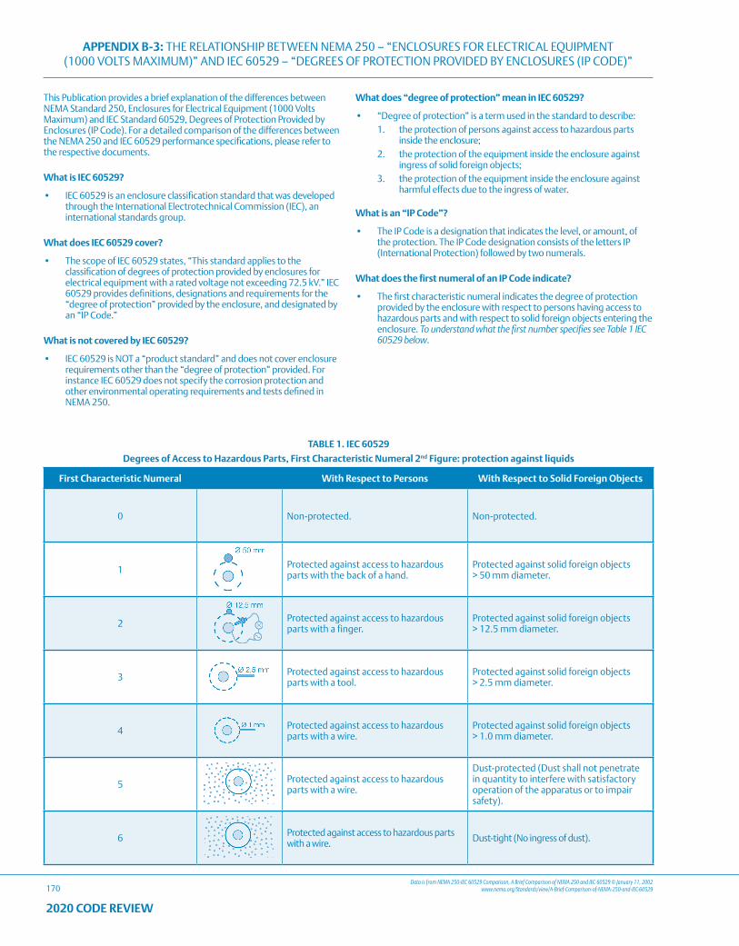
APPENDIX B-3: THE RELATIONSHIP BETWEEN NEMA 250 – “ENCLOSURES FOR ELECTRICAL EQUIPMENT (1000 VOLTS MAXIMUM)” AND IEC 60529 – “DEGREES OF PROTECTION PROVIDED BY ENCLOSURES (IP CODE)”
170Data is from NEMA 250-IEC 60529 Comparison, A Brief Comparison of NEMA 250 and IEC 60529 © January 11, 2002
www.nema.org/Standards/view/A-Brief-Comparison-of-NEMA-250-and-IEC-60529
2020 CODE REVIEW
This Publication provides a brief explanation of the differences between NEMA Standard 250, Enclosures for Electrical Equipment (1000 Volts Maximum) and IEC Standard 60529, Degrees of Protection Provided by Enclosures (IP Code). For a detailed comparison of the differences between the NEMA 250 and IEC 60529 performance specifications, please refer to the respective documents.
What is IEC 60529?
• IEC 60529 is an enclosure classification standard that was developed through the International Electrotechnical Commission (IEC), an international standards group.
What does IEC 60529 cover?
• The scope of IEC 60529 states, “This standard applies to the classification of degrees of protection provided by enclosures for electrical equipment with a rated voltage not exceeding 72.5 kV.” IEC 60529 provides definitions, designations and requirements for the “degree of protection” provided by the enclosure, and designated by an “IP Code.”
What is not covered by IEC 60529?
• IEC 60529 is NOT a “product standard” and does not cover enclosure requirements other than the “degree of protection” provided. For instance IEC 60529 does not specify the corrosion protection and other environmental operating requirements and tests defined in NEMA 250.
What does “degree of protection” mean in IEC 60529?
• “Degree of protection” is a term used in the standard to describe:1. the protection of persons against access to hazardous parts
inside the enclosure;2. the protection of the equipment inside the enclosure against
ingress of solid foreign objects;3. the protection of the equipment inside the enclosure against
harmful effects due to the ingress of water.
What is an “IP Code”?
• The IP Code is a designation that indicates the level, or amount, of the protection. The IP Code designation consists of the letters IP (International Protection) followed by two numerals.
What does the first numeral of an IP Code indicate?
• The first characteristic numeral indicates the degree of protection provided by the enclosure with respect to persons having access to hazardous parts and with respect to solid foreign objects entering the enclosure. To understand what the first number specifies see Table 1 IEC 60529 below.
TABLE 1. IEC 60529
Degrees of Access to Hazardous Parts, First Characteristic Numeral 2nd Figure: protection against liquids
First Characteristic Numeral With Respect to Persons With Respect to Solid Foreign Objects
0 Non-protected. Non-protected.
1 Protected against access to hazardous parts with the back of a hand.
Protected against solid foreign objects > 50 mm diameter.
2 Protected against access to hazardous parts with a finger.
Protected against solid foreign objects > 12.5 mm diameter.
3 Protected against access to hazardous parts with a tool.
Protected against solid foreign objects > 2.5 mm diameter.
4 Protected against access to hazardous parts with a wire.
Protected against solid foreign objects > 1.0 mm diameter.
5 Protected against access to hazardous parts with a wire.
Dust-protected (Dust shall not penetrate in quantity to interfere with satisfactory operation of the apparatus or to impair safety).
6 Protected against access to hazardous parts with a wire. Dust-tight (No ingress of dust).
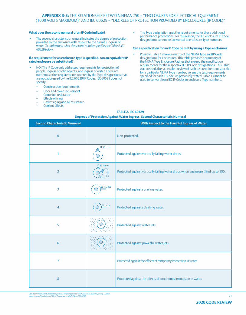
APPENDIX B-3: THE RELATIONSHIP BETWEEN NEMA 250 – “ENCLOSURES FOR ELECTRICAL EQUIPMENT (1000 VOLTS MAXIMUM)” AND IEC 60529 – “DEGREES OF PROTECTION PROVIDED BY ENCLOSURES (IP CODE)”
171Data is from NEMA 250-IEC 60529 Comparison, A Brief Comparison of NEMA 250 and IEC 60529 © January 11, 2002www.nema.org/Standards/view/A-Brief-Comparison-of-NEMA-250-and-IEC-60529
2020 CODE REVIEW
What does the second numeral of an IP Code indicate?
• The second characteristic numeral indicates the degree of protection provided by the enclosure with respect to the harmful ingress of water. To understand what the second number specifies see Table 2 IEC 60529 below.
If a requirement for an enclosure Type is specified, can an equivalent IP rated enclosure be substituted?
• NO! The IP Code only addresses requirements for protection of people, ingress of solid objects, and ingress of water. There are numerous other requirements covered by the Type designations that are not addressed by the IEC 60529/IP Codes. IEC 60529 does not specify:
– Construction requirements – Door and cover securement – Corrosion resistance – Effects of icing – Gasket aging and oil resistance – Coolant effects
• The Type designation specifies requirements for these additional performance protections. For this reason, the IEC enclosure IP Code designations cannot be converted to enclosure Type numbers.
Can a specification for an IP Code be met by using a Type enclosure?
• Possibly! Table 1 shows a matrix of the NEMA Type and IP Code designations for enclosures. This table provides a summary of the NEMA Type Enclosure Ratings that exceed the specification requirements for the respective IEC IP Code designations. This Table was created after a detailed review of each test requirement specified for a particular NEMA Type number, versus the test requirements specified for each IP Code. As previously stated, Table 1 cannot be used to convert from IEC IP Codes to enclosure Type numbers.
TABLE 2. IEC 60529
Degrees of Protection Against Water Ingress, Second Characteristic Numeral
Second Characteristic Numeral With Respect to the Harmful Ingress of Water
0 Non-protected.
1 Protected against vertically falling water drops.
2 Protected against vertically falling water drops when enclosure tilted up to 150.
3 Protected against spraying water.
4 Protected against splashing water.
5 Protected against water jets.
6 Protected against powerful water jets.
7 Protected against the effects of temporary immersion in water.
8 Protected against the effects of continuous immersion in water.
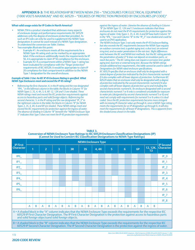
APPENDIX B-3: THE RELATIONSHIP BETWEEN NEMA 250 – “ENCLOSURES FOR ELECTRICAL EQUIPMENT (1000 VOLTS MAXIMUM)” AND IEC 60529 – “DEGREES OF PROTECTION PROVIDED BY ENCLOSURES (IP CODE)”
172Data is from NEMA 250-IEC 60529 Comparison, A Brief Comparison of NEMA 250 and IEC 60529 © January 11, 2002
www.nema.org/Standards/view/A-Brief-Comparison-of-NEMA-250-and-IEC-60529
2020 CODE REVIEW
What valid usage exists for IP Codes in North America?
• NEMA 250 is a product standard that addresses many aspects of enclosure design and performance requirements; IEC 60529 addresses only the degree of enclosure protection provided. As such an IP Code can only be used to supplement the NEMA Type designation; it cannot be used instead of a NEMA Type designation. To understand the conversion see Table 3 below.
• Two examples illustrate this point: – Example #1: An enclosure meets all the requirements for a
NEMA Type 4X rating and can be marked by an appropriate label. If the enclosure additionally meets the requirements for IP 56, it is appropriate to claim IP 56 compliance for the enclosure.
– Example #2: If a compartment within a NEMA Type 1 rating has been evaluated for compliance with the “finger protection” requirements of IEC 60529, it would be appropriate to claim IP 20 compliance for that compartment in addition to the NEMA Type 1 designation for the overall enclosure.
Example of Table 3 Use: An IEC IP 45 Enclosure Rating is specified. What NEMA Type Enclosures meet and exceed the IP 45 rating?
• Referencing the first character, 4, in the IP rating and the row designated “IP4_” in the leftmost column in the table; the blocks in Column “A” for NEMA Types 3, 3S, 4, 4X, 5, 6, 6P, 12, 12K and 13 are shaded. These NEMA ratings meet and exceed the IEC protection requirements against access to hazardous parts and solid foreign objects. Referencing the second character, 5, in the IP rating and the row designated “IP_5” in the rightmost column in the table; the blocks in Column “B” for NEMA Types 3, 3S, 4, 4X, 6 and 6P are shaded. These NEMA ratings meet and exceed the IEC requirements for protection against the ingress of water. The absence of shading in Column “B” beneath the “NEMA Enclosure Type 5” indicates that Type 5 does not meet the IP 45 protection requirements
against the ingress of water. Likewise the absence of shading in Column “B” for NEMA Type 12, 12K and 13 enclosures indicates that these enclosures do not meet the IP 45 requirements for protection against the ingress of water. Only Types 3, 3S, 4, 4X, 6 and 6P have both Column “A” in the “IP4_” row and Column “B” in the “IP_5” row shaded and could be used in an IP45 application.
• The NEMA Enclosure Type 3 not only meets the IP 45 Enclosure Rating, but also exceeds the IEC requirements because the NEMA Type requires an outdoor corrosion test; a gasket aging test; a dust test; an external icing test; and no water penetration in the rain test. Slight differences exist between the IEC and NEMA test methods, but the IEC rating permits the penetration of water if “it does not deposit on insulation parts, or reach live parts.” The IEC rating does not require a corrosion test; gasket aging test; dust test or external icing test. Because the NEMA ratings include additional test requirements, this table cannot be used to select IP Designations for NEMA rated enclosure specifications.
• IEC 60529 specifies that an enclosure shall only be designated with a stated degree of protection indicated by the first characteristic numeral if it also complies with all lower degrees of protection. Furthermore IEC 60529 states that an enclosure shall only be designated with a degree of protection indicated by the second characteristic numeral if it also complies with all lower degrees of protection up to and including the second characteristic numeral 6. An enclosure designated with a second characteristic numeral 7 or 8 only is considered unsuitable for exposure to water jets (designated by second characteristic numeral 5 or 6) and need not comply with requirements for numeral 5 or 6 unless it is dual coded. Since the IEC protection requirements become more stringent with increasing IP character value up through 6, once a NEMA Type rating meets the requirements for an IP designation up through 6, it will also meet the requirements for all lower IP designations. This is apparent from the shaded areas shown in the table.
TABLE 3.Conversion of NEMA Enclosure Type Ratings to IEC 60529 Enclosure Classification Designations (IP)
(Cannot be Used to Convert IEC Classification Designations to NEMA Type Ratings)
IP First Character
NEMA Enclosure TypeIP Second Character1 2 3 3R 3S 4, 4X 5 6 6P 12, 12K,
13
IP0_ IP_0
IP1_ IP_1
IP2_ IP_2
IP3_ IP_3
IP4_ IP_4
IP5_ IP_5
IP6_ IP_6
IP_7
IP_8
A B A B A B A B A B A B A B A B A B A B
A = A shaded block in the “A” column indicates that the NEMA Enclosure Type exceeds the requirements for the respective IEC 60529 IP First Character Designation. The IP First Character Designation is the protection against access to hazardous parts and solid foreign objectsand solid foreign objects.
B = A shaded block in the “B” column indicates that the NEMA Enclosure Type exceeds the requirements for the respective IEC 60529 IP Second Character Designation. The IP Second Character Designation is the protection against the ingress of water.
APPENDIX C: STANDARDS, TESTING AND CERTIFICATION ORGANIZATIONS
173
2020 CODE REVIEW
AMERICAN NATIONAL STANDARDS INSTITUTE (ANSI).
• The Institute oversees the creation, promulgation and use of thousands of norms and guidelines that directly impact businesses in nearly every sector: from acoustical devices to construction equipment, from dairy and livestock production to energy distribution, and many more. ANSI is also actively engaged in accrediting programs that assess conformance to standards – including globally-recognized cross-sector programs such as the ISO 9000 (quality) and ISO 14000 (environmental) management systems.
INSTITUTE OF ELECTRICAL AND ELECTRONICS ENGINEERS (IEEE).
• IEEE’s core purpose is to foster technological innovation and excellence for the benefit of humanity.
INTERNATIONAL SOCIETY OF AUTOMATION. (ISA®)
• ISA® develops standards; certifies industry professionals; provides education and training; publishes books and technical articles; and hosts conferences and exhibitions for automation professionals. ISA® is the founding sponsor of the Automation Federation.
INTERTEK TESTING SERVICES (ITS).
• ITS is an OSHA Certified Nationally Recognized Testing Laboratory (NRTL). The ITS mark for electrical safety is the ETL mark.
AMERICAN PETROLEUM INSTITUTE (API®).
• This organization publishes Recommended Practice for Classification of Locations for Electrical Installations in Petroleum Facilities (API RP 500).
NATIONAL ELECTRICAL MANUFACTURERS ASSOCIATION (NEMA).
• NEMA issues standards on electrical equipment on all major categories of electrical equipment. Generally, where construction and performance relate to safety, reference is made to standards of others, such as Underwriters Laboratories Incorporated. The widely recognized NEMA enclosure types are described in NEMA’s Standard Publication/No. 250.
INTERNATIONAL ELECTROTECHNICAL COMMISSION (IEC®).
• This organization is comprised of approximately forty member countries, including the United States. The purpose of the IEC® is to establish standards for a wide variety of electrical products to encourage international trade. IEC® publication series 79, entitled Electrical Apparatus for Explosive Gas Atmospheres, consists of several parts covering area classification, test apparatus and several techniques used for protection of apparatus, intended for use in hazardous locations.
OCCUPATIONAL SAFETY AND HEALTH ADMINISTRATION (OSHA).
• OSHA mandates the use of electrical equipment that has been verified by Nationally Recognized Test Labs (NRTLs) as being suitable for the application. Some units of a system installation are not necessarily NRTL certified if such certification is judged not applicable. All products involved must meet NEC® requirements, as interpreted by OSHA.
OTHER ASSOCIATIONS.
• Professional and technical organizations develop and/or sponsor standards as product guidelines, application recommendations, safety rules or test methods. Typical associations include the American Iron and Steel Institute (AISI), the Aluminum Association (AA), the Illuminating Engineering Society (IES) and the Edison Electric Institute (EEI).
UNDERWRITERS LABORATORIES, INC. (UL®).
• UL® is an OSHA Certified Nationally Recognized Testing Laboratory (NRTL). In addition to specific UL Standards, UL publishes a “Green” book, an “Orange” book and a “Red” book. These three books contain the names of companies who have qualified to use the Listing or Classification Marking of Underwriters Laboratories on products which have been found to be in compliance with applicable UL requirements. The “Green” book, entitled Electrical Construction Materials Directory, contains detailed information on listed electrical devices generally considered as construction materials, and for use by electricians or others in the electrical industry. The “Orange” book, entitled Electrical Appliance and Utilization Equipment Directory, contains detailed information on listed appliances or other similar equipment generally considered for use by the general public. The “Red” book, entitled Hazardous Location Equipment Directory, contains detailed information on listed equipment intended for use in hazardous locations as defined by Article 500 of the National Electrical Code. These three publications can be used to obtain the names of companies who have a Listing in a specific product category, and to obtain information regarding the scope, limitations, or special conditions of a particular product category.
LOCAL BUILDING CODES.
• These codes influence and determine ultimate decisions on product suitability. NEC® Article 100 provides this definition: “APPROVED: Acceptable to authority having jurisdiction.”
MANUFACTURERS DATA.
• Manufacturers such as Emerson, working with recognized organizations, develop and improve products for third party certification and thus set additional product suitability standards.
• Standards set by such organizations as Underwriters Laboratories (UL) and Canadian Standards Association (CSA) identify the criteria used by Appleton in the design and company testing of its products. These Third Party standards evolved over the years as manufacturing and processing became more complex and more hazardous.
NATIONAL FIRE PROTECTION ASSOCIATION (NFPA®).
• One of the pioneering organizations to set standards for the wiring and control of electricity was the National Fire Protection Association. Formed in 1896, the NFPA is composed of national and regional groups, plus individuals, firms and institutions interested in protecting life and property. This organization sets minimum standards to form a National Electrical Code (NEC®), which is used as a criteria for insurance, state and civic inspectors when making inspections or recommendations for electrical installations. Typical member organizations of the NFPA are the National Electrical Manufacturers Association, American Petroleum Institute, Institute of Electrical and Electronic Engineers, American Institute of Architects, Underwriters Laboratories, Inc., Factory Mutual, American Insurance Association, and many fire underwriting groups.
• Emerson designs and tests its Appleton brand products to meet or exceed the standards established by Third Party Certifiers.
CANADIAN STANDARDS ASSOCIATION (CSA®).
• CSA® is an OSHA Certified Nationally Recognized Testing Laboratory (NRTL). CSA® has established standards similar to UL for the testing of electrical products. Thousands of Appleton products marketed in the USA are both UL Listed and CSA® Certified. All products manufactured by Emerson at their Appleton Group Canada, Ltd facility meets or exceeds CSA® standards and most are CSA certified.
APPENDIX C: STANDARDS, TESTING AND CERTIFICATION ORGANIZATIONS
174
2020 CODE REVIEW
FACTORY MUTUAL (FM).
• FM is an OSHA Certified Nationally Recognized Testing Laboratory (NRTL). FM is a non-profit third party testing and certification organization, providing many of the same services as UL®. FM uses three broad standards: 3611, 3615 and 3616. In addition, FM tests and approves products not covered by these standards.
OUR CERTIFICATION POLICY.
• In each section of the Appleton™ Catalog under “Compliances,” the appropriate published UL Standard is shown. This number signifies that the products in that section meet or exceed the requirements of that UL Standard. The term “Compliances” does not necessarily mean that the products are UL® Listed. UL® approval is a matter of independent record, signified by product nameplate or carton marking and can be ascertained by referring to approved sources. Although the majority of Appleton products are UL® Listed, there are instances where this is impractical. For example, a product may not be UL Listed because it is a subassembly, such as a mounting box. Often a product is not UL® Listed because it is in the process of being approved by UL. Due to technical problems in presentation, most of the Appleton UL Listed products are not so indicated in the Appleton Catalog, but information regarding UL® approvals on any specific product is obtainable upon request. Emerson has thousands of UL Listed Appleton™ products. In addition, all other NRTL and/or IEC® standards and compliances are also listed.
NORTH AMERICAN CERTIFICATION.
• The United States and Canada are both members of the IECEx Conformity Assessment System. As a result, for Hazardous Location Certification UL and CSA accepts each other’s data for purpose of providing their National Certification Marks. This applies when the Essential Requirements of both countries are the same.
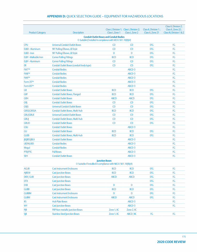
APPENDIX D: QUICK SELECTION GUIDE – EQUIPMENT FOR HAZARDOUS LOCATIONS
175
2020 CODE REVIEW
Product Category DescriptionClass I, Division 1;
Class I, Zone 1Class I, Division 2;
Class I, Zone 2Class II, Division 1 ;
Class II, Zone 21
Class II, Division 2; Class II, Zone 22 ;
Class III, Division 1 & 2
Conduit Outlet Boxes and Conduit Bodies Suitable if installed in compliance with NEC© 501.10(B)(4)
CPU Universal Conduit Outlet Boxes CD CD EFG FG
ELBD - Aluminum 90° Pulling Elbows, LB Style CD CD EFG FG
ELBD - Iron 90° Pulling Elbows, LB Style D D EFG FG
ELBY - Malleable Iron Corner Pulling Fittings BCD BCD EFG FG
ELBY - Aluminum Corner Pulling Fittings CD CD EFG FG
ER Conduit Outlet Boxes (conduit body type) CD CD EFG FG
FM7™ Conduit Bodies ABCD FG
FM8™ Conduit Bodies ABCD FG
FM9™ Conduit Bodies ABCD FG
Form 35™ Conduit Bodies ABCD FG
Form 85™ Conduit Bodies ABCD FG
GR Conduit Outlet Boxes BCD BCD EFG FG
GRF Conduit Outlet Boxes, Flanged BCD BCD EFG FG
GRH Conduit Outlet Boxes ABCD ABCD EFG FG
GRJ Conduit Outlet Boxes CD CD EFG FG
GRJS Universal Conduit Outlet Boxes CD CD EFG FG
GRSS/GRSSA Conduit Outlet Boxes, Multi-hub BCD BCD EFG FG
GRU/GRUE Universal Conduit Outlet Boxes CD CD EFG FG
GRUJ Conduit Outlet Boxes, Multi-hub CD CD EFG FG
GRUO Conduit Outlet Boxes CD CD EFG FG
GSU Conduit Outlet Boxes ABCD FG
GU Conduit Outlet Boxes BCD BCD EFG FG
GUEB Conduit Outlet Boxes, Multi-hub BCD BCD EFG FG
JB/JBD/JBLX Conduit Outlet Boxes ABCD FG
LBDN/LBD Conduit Bodies ABCD FG
Mogul Conduit Bodies ABCD FG
PTB/PTC Pull Boxes ABCD FG
SEH Conduit Outlet Boxes ABCD FG
Junction Boxes Suitable if installed in compliance with NEC© 501.10(B)(4)
AGUB Cast Instrument Enclosures BCD BCD EFG FG
AJBEW Cast Junction Boxes BCD BCD EFG FG
DER / GUB Cast Junction Boxes ABCD ABCD EFG FG
DTX Cast Junction Boxes EFG FG
EXB Cast Junction Boxes D D EFG FG
GUBB Cast Junction Boxes BCD BCD EFG FG
GUBBM Cast Instrument Enclosures D D EFG FG
GUBM Cast Instrument Enclosures ABCD ABCD EFG FG
RS Hub Plate Boxes ABCD FG
WY Cast Junction Boxes ABCD FG
PJB FRP Non-metallic Junction Boxes Zone 1, IIC Zone 2, IIC
SJB Stainless Steel Junction Boxes Zone 1, IIC ABCD / IIC FG FG
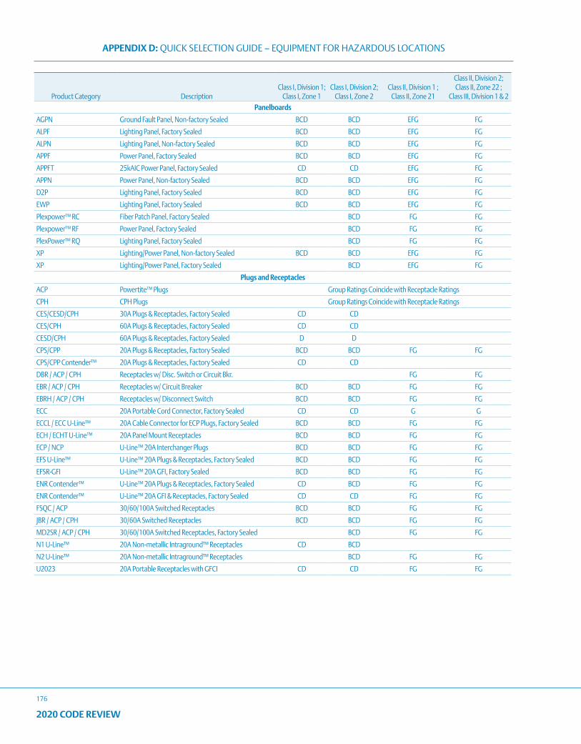
APPENDIX D: QUICK SELECTION GUIDE – EQUIPMENT FOR HAZARDOUS LOCATIONS
176
2020 CODE REVIEW
Product Category DescriptionClass I, Division 1;
Class I, Zone 1Class I, Division 2;
Class I, Zone 2Class II, Division 1 ;
Class II, Zone 21
Class II, Division 2; Class II, Zone 22 ;
Class III, Division 1 & 2Panelboards
AGPN Ground Fault Panel, Non-factory Sealed BCD BCD EFG FG
ALPF Lighting Panel, Factory Sealed BCD BCD EFG FG
ALPN Lighting Panel, Non-factory Sealed BCD BCD EFG FG
APPF Power Panel, Factory Sealed BCD BCD EFG FG
APPFT 25kAIC Power Panel, Factory Sealed CD CD EFG FG
APPN Power Panel, Non-factory Sealed BCD BCD EFG FG
D2P Lighting Panel, Factory Sealed BCD BCD EFG FG
EWP Lighting Panel, Factory Sealed BCD BCD EFG FG
Plexpower™ RC Fiber Patch Panel, Factory Sealed BCD FG FG
Plexpower™ RF Power Panel, Factory Sealed BCD FG FG
PlexPower™ RQ Lighting Panel, Factory Sealed BCD FG FG
XP Lighting/Power Panel, Non-factory Sealed BCD BCD EFG FG
XP Lighting/Power Panel, Factory Sealed BCD EFG FG
Plugs and Receptacles
ACP Powertite™ Plugs Group Ratings Coincide with Receptacle Ratings
CPH CPH Plugs Group Ratings Coincide with Receptacle Ratings
CES/CESD/CPH 30A Plugs & Receptacles, Factory Sealed CD CD
CES/CPH 60A Plugs & Receptacles, Factory Sealed CD CD
CESD/CPH 60A Plugs & Receptacles, Factory Sealed D D
CPS/CPP 20A Plugs & Receptacles, Factory Sealed BCD BCD FG FG
CPS/CPP Contender™ 20A Plugs & Receptacles, Factory Sealed CD CD
DBR / ACP / CPH Receptacles w/ Disc. Switch or Circuit Bkr. FG FG
EBR / ACP / CPH Receptacles w/ Circuit Breaker BCD BCD FG FG
EBRH / ACP / CPH Receptacles w/ Disconnect Switch BCD BCD FG FG
ECC 20A Portable Cord Connector, Factory Sealed CD CD G G
ECCL / ECC U-Line™ 20A Cable Connector for ECP Plugs, Factory Sealed BCD BCD FG FG
ECH / ECHT U-Line™ 20A Panel Mount Receptacles BCD BCD FG FG
ECP / NCP U-Line™ 20A Interchanger Plugs BCD BCD FG FG
EFS U-Line™ U-Line™ 20A Plugs & Receptacles, Factory Sealed BCD BCD FG FG
EFSR-GFI U-Line™ 20A GFI, Factory Sealed BCD BCD FG FG
ENR Contender™ U-Line™ 20A Plugs & Receptacles, Factory Sealed CD BCD FG FG
ENR Contender™ U-Line™ 20A GFI & Receptacles, Factory Sealed CD CD FG FG
FSQC / ACP 30/60/100A Switched Receptacles BCD BCD FG FG
JBR / ACP / CPH 30/60A Switched Receptacles BCD BCD FG FG
MD2SR / ACP / CPH 30/60/100A Switched Receptacles, Factory Sealed BCD FG FG
N1 U-Line™ 20A Non-metallic Intraground™ Receptacles CD BCD
N2 U-Line™ 20A Non-metallic Intraground™ Receptacles BCD FG FG
U2023 20A Portable Receptacles with GFCI CD CD FG FG
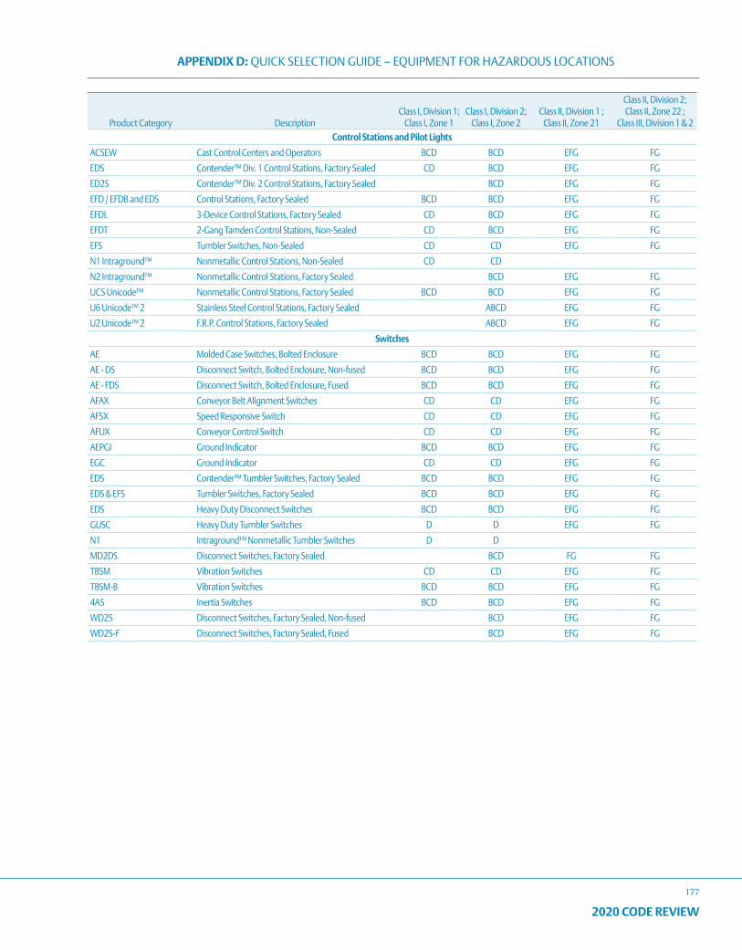
APPENDIX D: QUICK SELECTION GUIDE – EQUIPMENT FOR HAZARDOUS LOCATIONS
177
2020 CODE REVIEW
Product Category DescriptionClass I, Division 1;
Class I, Zone 1Class I, Division 2;
Class I, Zone 2Class II, Division 1 ;
Class II, Zone 21
Class II, Division 2; Class II, Zone 22 ;
Class III, Division 1 & 2Control Stations and Pilot Lights
ACSEW Cast Control Centers and Operators BCD BCD EFG FG
EDS Contender™ Div. 1 Control Stations, Factory Sealed CD BCD EFG FG
ED2S Contender™ Div. 2 Control Stations, Factory Sealed BCD EFG FG
EFD / EFDB and EDS Control Stations, Factory Sealed BCD BCD EFG FG
EFDL 3-Device Control Stations, Factory Sealed CD BCD EFG FG
EFDT 2-Gang Tamden Control Stations, Non-Sealed CD BCD EFG FG
EFS Tumbler Switches, Non-Sealed CD CD EFG FG
N1 Intraground™ Nonmetallic Control Stations, Non-Sealed CD CD
N2 Intraground™ Nonmetallic Control Stations, Factory Sealed BCD EFG FG
UCS Unicode™ Nonmetallic Control Stations, Factory Sealed BCD BCD EFG FG
U6 Unicode™ 2 Stainless Steel Control Stations, Factory Sealed ABCD EFG FG
U2 Unicode™ 2 F.R.P. Control Stations, Factory Sealed ABCD EFG FG
Switches
AE Molded Case Switches, Bolted Enclosure BCD BCD EFG FG
AE - DS Disconnect Switch, Bolted Enclosure, Non-fused BCD BCD EFG FG
AE - FDS Disconnect Switch, Bolted Enclosure, Fused BCD BCD EFG FG
AFAX Conveyor Belt Alignment Switches CD CD EFG FG
AFSX Speed Responsive Switch CD CD EFG FG
AFUX Conveyor Control Switch CD CD EFG FG
AEPGI Ground Indicator BCD BCD EFG FG
EGC Ground Indicator CD CD EFG FG
EDS Contender™ Tumbler Switches, Factory Sealed BCD BCD EFG FG
EDS & EFS Tumbler Switches, Factory Sealed BCD BCD EFG FG
EDS Heavy Duty Disconnect Switches BCD BCD EFG FG
GUSC Heavy Duty Tumbler Switches D D EFG FG
N1 Intraground™ Nonmetallic Tumbler Switches D D
MD2DS Disconnect Switches, Factory Sealed BCD FG FG
TBSM Vibration Switches CD CD EFG FG
TBSM-B Vibration Switches BCD BCD EFG FG
4AS Inertia Switches BCD BCD EFG FG
WD2S Disconnect Switches, Factory Sealed, Non-fused BCD EFG FG
WD2S-F Disconnect Switches, Factory Sealed, Fused BCD EFG FG
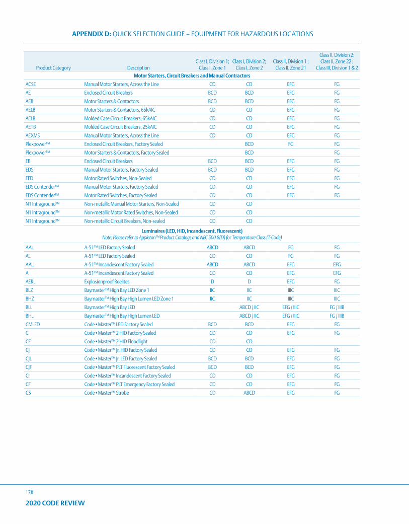
APPENDIX D: QUICK SELECTION GUIDE – EQUIPMENT FOR HAZARDOUS LOCATIONS
178
2020 CODE REVIEW
Product Category DescriptionClass I, Division 1;
Class I, Zone 1Class I, Division 2;
Class I, Zone 2Class II, Division 1 ;
Class II, Zone 21
Class II, Division 2; Class II, Zone 22 ;
Class III, Division 1 & 2Motor Starters, Circuit Breakers and Manual Contractors
ACSE Manual Motor Starters, Across the Line CD CD EFG FG
AE Enclosed Circuit Breakers BCD BCD EFG FG
AEB Motor Starters & Contactors BCD BCD EFG FG
AELB Motor Starters & Contactors, 65kAIC CD CD EFG FG
AELB Molded Case Circuit Breakers, 65kAIC CD CD EFG FG
AETB Molded Case Circuit Breakers, 25kAIC CD CD EFG FG
AEXMS Manual Motor Starters, Across the Line CD CD EFG FG
Plexpower™ Enclosed Circuit Breakers, Factory Sealed BCD FG FG
Plexpower™ Motor Starters & Contactors, Factory Sealed BCD FG
EB Enclosed Circuit Breakers BCD BCD EFG FG
EDS Manual Motor Starters, Factory Sealed BCD BCD EFG FG
EFD Motor Rated Switches, Non-Sealed CD CD EFG FG
EDS Contender™ Manual Motor Starters, Factory Sealed CD CD EFG FG
EDS Contender™ Motor Rated Switches, Factory Sealed CD CD EFG FG
N1 Intraground™ Non-metallic Manual Motor Starters, Non-Sealed CD CD
N1 Intraground™ Non-metallic Motor Rated Switches, Non-Sealed CD CD
N1 Intraground™ Non-metallic Circuit Breakers, Non-sealed CD CD
Luminaires (LED, HID, Incandescent, Fluorescent)Note: Please refer to Appleton™ Product Catalogs and NEC 500.8(D) for Temperature Class (T-Code)
AAL A-51™ LED Factory Sealed ABCD ABCD FG FG
AL A-51™ LED Factory Sealed CD CD FG FG
AAU A-51™ Incandescent Factory Sealed ABCD ABCD EFG EFG
A A-51™ Incandescent Factory Sealed CD CD EFG EFG
AERL Explosionproof Reelites D D EFG FG
BLZ Baymaster™ High Bay LED Zone 1 IIC IIC IIIC IIIC
BHZ Baymaster™ High Bay High Lumen LED Zone 1 IIC IIC IIIC IIIC
BLL Baymaster™ High Bay LED ABCD / IIC EFG / IIIC FG / IIIB
BHL Baymaster™ High Bay High Lumen LED ABCD / IIC EFG / IIIC FG / IIIB
CMLED Code•Master™ LED Factory Sealed BCD BCD EFG FG
C Code•Master™ 2 HID Factory Sealed CD CD EFG FG
CF Code•Master™ 2 HID Floodlight CD CD
CJ Code•Master™ Jr. HID Factory Sealed CD CD EFG FG
CJL Code•Master™ Jr. LED Factory Sealed BCD BCD EFG FG
CJF Code•Master™ PLT Fluorescent Factory Sealed BCD BCD EFG FG
CI Code•Master™ Incandescent Factory Sealed CD CD EFG FG
CF Code•Master™ PLT Emergency Factory Sealed CD CD EFG FG
CS Code•Master™ Strobe CD ABCD EFG FG
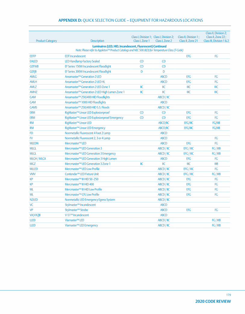
APPENDIX D: QUICK SELECTION GUIDE – EQUIPMENT FOR HAZARDOUS LOCATIONS
179
2020 CODE REVIEW
Product Category DescriptionClass I, Division 1;
Class I, Zone 1Class I, Division 2;
Class I, Zone 2Class II, Division 1 ;
Class II, Zone 21
Class II, Division 2; Class II, Zone 22 ;
Class III, Division 1 & 2
Luminaires (LED, HID, Incandescent, Fluorescent) ContinuedNote: Please refer to Appleton™ Product Catalogs and NEC 500.8(D) for Temperature Class (T-Code)
EDTP EDT Incandescent EFG FG
EHLED LED Handlamp Factory Sealed CD CD
GEFWB EF Series 150W Incandescent Floodlight CD CD
GEFJB EF Series 300W Incandescent Floodlight D D
AMLG Areamaster™ Generation 2 LED ABCD EFG FG
AMLH Areamaster™ Generation 2 LED HL ABCD EFG FG
AMLZ Areamaster™ Generation 2 LED Zone 1 IIC IIC IIIC IIIC
AMHZ Areamaster™ Generation 2 LED High Lumen Zone 1 IIC IIC IIIC IIIC
GAM Areamaster™ 250/400 HID Floodlights ABCD / IIC
GAM Areamaster™ 1000 HID Floodlights ABCD
GAMS Areamaster™ 250/400 HID S.S. Floods ABCD / IIC
ERM RigMaster™ Linear LED Explosionproof CD CD EFG FG
ERM RigMaster™ Linear LED Explosionproof Emergency CD CD EFG FG
RM RigMaster™ Linear LED ABCD/IIC EFG/IIIC FG/IIIB
RM RigMaster™ Linear LED Emergency ABCD/IIC EFG/IIIC FG/IIIB
FD Nonmetallic Fluorescent 4 Foot 2 Lamp ABCD
FV Nonmetallic Fluorescent 2, 3 or 4 Lamp ABCD FG
MLEDN Mercmaster™ LED ABCD EFG FG
MLGL Mercmaster™ LED Generation 3 ABCD / IIC EFG / IIIC FG / IIIB
MLGL Mercmaster™ LED Generation 3 Emergency ABCD / IIC EFG / IIIC FG / IIIB
MLGH / MLGX Mercmaster™ LED Generation 3 High Lumen ABCD EFG FG
MGZ Mercmaster™ LED Generation 3 Zone 1 IIC IIC IIIC IIIB
MLLED Mercmaster™ LED Low Profile ABCD / IIC EFG / IIIC FG
VMV Contender™ LED Fixture Unit ABCD / IIC EFG / IIIC FG / IIIB
KP Mercmaster™ III HID 50 -250 ABCD / IIC EFG FG
KP Mercmaster™ III HID 400 ABCD / IIC EFG FG
ML Mercmaster™ III HID Low Profile ABCD / IIC EFG FG
ML Mercmaster™ CFL Low Profile ABCD / IIC EFG FG
N2LED Nonmetallic LED Emergency Egress System ABCD / IIC
VC Stylmaster™ Incandescent ABCD
VP Stylmaster™ Strobe ABCD EFG FG
VA/VX/JB V-51™ Incandescent ABCD
LLED Viamaster™ LED ABCD / IIC FG / IIIB
LLED Viamaster™ LED Emergency ABCD / IIC FG / IIIB
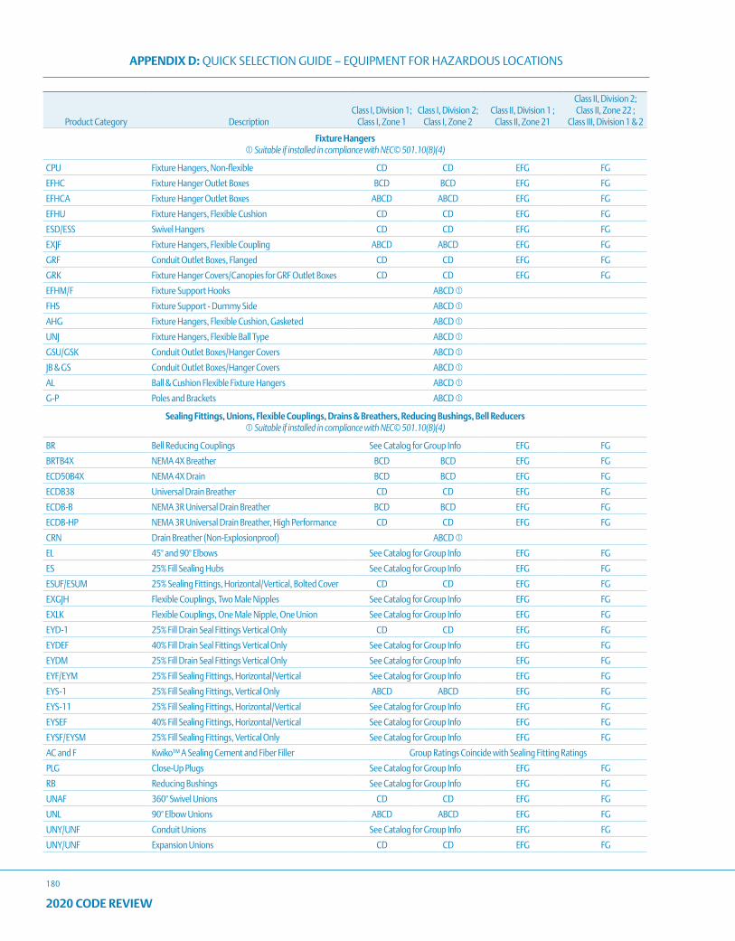
APPENDIX D: QUICK SELECTION GUIDE – EQUIPMENT FOR HAZARDOUS LOCATIONS
180
2020 CODE REVIEW
Product Category DescriptionClass I, Division 1;
Class I, Zone 1Class I, Division 2;
Class I, Zone 2Class II, Division 1 ;
Class II, Zone 21
Class II, Division 2; Class II, Zone 22 ;
Class III, Division 1 & 2
Fixture Hangers Suitable if installed in compliance with NEC© 501.10(B)(4)
CPU Fixture Hangers, Non-flexible CD CD EFG FG
EFHC Fixture Hanger Outlet Boxes BCD BCD EFG FG
EFHCA Fixture Hanger Outlet Boxes ABCD ABCD EFG FG
EFHU Fixture Hangers, Flexible Cushion CD CD EFG FG
ESD/ESS Swivel Hangers CD CD EFG FG
EXJF Fixture Hangers, Flexible Coupling ABCD ABCD EFG FG
GRF Conduit Outlet Boxes, Flanged CD CD EFG FG
GRK Fixture Hanger Covers/Canopies for GRF Outlet Boxes CD CD EFG FG
EFHM/F Fixture Support Hooks ABCD
FHS Fixture Support - Dummy Side ABCD
AHG Fixture Hangers, Flexible Cushion, Gasketed ABCD
UNJ Fixture Hangers, Flexible Ball Type ABCD
GSU/GSK Conduit Outlet Boxes/Hanger Covers ABCD
JB & GS Conduit Outlet Boxes/Hanger Covers ABCD
AL Ball & Cushion Flexible Fixture Hangers ABCD
G-P Poles and Brackets ABCD
Sealing Fittings, Unions, Flexible Couplings, Drains & Breathers, Reducing Bushings, Bell Reducers Suitable if installed in compliance with NEC© 501.10(B)(4)
BR Bell Reducing Couplings See Catalog for Group Info EFG FG
BRTB4X NEMA 4X Breather BCD BCD EFG FG
ECD50B4X NEMA 4X Drain BCD BCD EFG FG
ECDB38 Universal Drain Breather CD CD EFG FG
ECDB-B NEMA 3R Universal Drain Breather BCD BCD EFG FG
ECDB-HP NEMA 3R Universal Drain Breather, High Performance CD CD EFG FG
CRN Drain Breather (Non-Explosionproof) ABCD
EL 45° and 90° Elbows See Catalog for Group Info EFG FG
ES 25% Fill Sealing Hubs See Catalog for Group Info EFG FG
ESUF/ESUM 25% Sealing Fittings, Horizontal/Vertical, Bolted Cover CD CD EFG FG
EXGJH Flexible Couplings, Two Male Nipples See Catalog for Group Info EFG FG
EXLK Flexible Couplings, One Male Nipple, One Union See Catalog for Group Info EFG FG
EYD-1 25% Fill Drain Seal Fittings Vertical Only CD CD EFG FG
EYDEF 40% Fill Drain Seal Fittings Vertical Only See Catalog for Group Info EFG FG
EYDM 25% Fill Drain Seal Fittings Vertical Only See Catalog for Group Info EFG FG
EYF/EYM 25% Fill Sealing Fittings, Horizontal/Vertical See Catalog for Group Info EFG FG
EYS-1 25% Fill Sealing Fittings, Vertical Only ABCD ABCD EFG FG
EYS-11 25% Fill Sealing Fittings, Horizontal/Vertical See Catalog for Group Info EFG FG
EYSEF 40% Fill Sealing Fittings, Horizontal/Vertical See Catalog for Group Info EFG FG
EYSF/EYSM 25% Fill Sealing Fittings, Vertical Only See Catalog for Group Info EFG FG
AC and F Kwiko™ A Sealing Cement and Fiber Filler Group Ratings Coincide with Sealing Fitting Ratings
PLG Close-Up Plugs See Catalog for Group Info EFG FG
RB Reducing Bushings See Catalog for Group Info EFG FG
UNAF 360° Swivel Unions CD CD EFG FG
UNL 90° Elbow Unions ABCD ABCD EFG FG
UNY/UNF Conduit Unions See Catalog for Group Info EFG FG
UNY/UNF Expansion Unions CD CD EFG FG
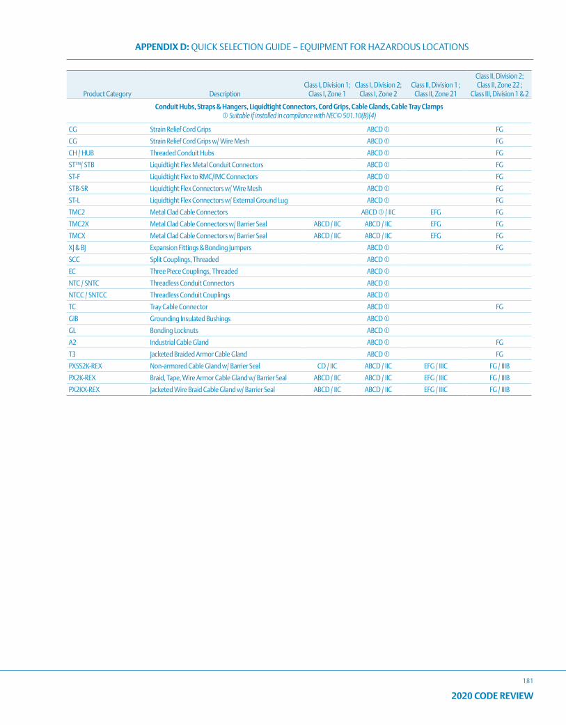
APPENDIX D: QUICK SELECTION GUIDE – EQUIPMENT FOR HAZARDOUS LOCATIONS
181
2020 CODE REVIEW
Product Category DescriptionClass I, Division 1;
Class I, Zone 1Class I, Division 2;
Class I, Zone 2Class II, Division 1 ;
Class II, Zone 21
Class II, Division 2; Class II, Zone 22 ;
Class III, Division 1 & 2
Conduit Hubs, Straps & Hangers, Liquidtight Connectors, Cord Grips, Cable Glands, Cable Tray Clamps Suitable if installed in compliance with NEC© 501.10(B)(4)
CG Strain Relief Cord Grips ABCD FG
CG Strain Relief Cord Grips w/ Wire Mesh ABCD FG
CH / HUB Threaded Conduit Hubs ABCD FG
ST™/ STB Liquidtight Flex Metal Conduit Connectors ABCD FG
ST-F Liquidtight Flex to RMC/IMC Connectors ABCD FG
STB-SR Liquidtight Flex Connectors w/ Wire Mesh ABCD FG
ST-L Liquidtight Flex Connectors w/ External Ground Lug ABCD FG
TMC2 Metal Clad Cable Connectors ABCD / IIC EFG FG
TMC2X Metal Clad Cable Connectors w/ Barrier Seal ABCD / IIC ABCD / IIC EFG FG
TMCX Metal Clad Cable Connectors w/ Barrier Seal ABCD / IIC ABCD / IIC EFG FG
XJ & BJ Expansion Fittings & Bonding Jumpers ABCD FG
SCC Split Couplings, Threaded ABCD
EC Three Piece Couplings, Threaded ABCD
NTC / SNTC Threadless Conduit Connectors ABCD
NTCC / SNTCC Threadless Conduit Couplings ABCD
TC Tray Cable Connector ABCD FG
GIB Grounding Insulated Bushings ABCD
GL Bonding Locknuts ABCD
A2 Industrial Cable Gland ABCD FG
T3 Jacketed Braided Armor Cable Gland ABCD FG
PXSS2K-REX Non-armored Cable Gland w/ Barrier Seal CD / IIC ABCD / IIC EFG / IIIC FG / IIIB
PX2K-REX Braid, Tape, Wire Armor Cable Gland w/ Barrier Seal ABCD / IIC ABCD / IIC EFG / IIIC FG / IIIB
PX2KX-REX Jacketed Wire Braid Cable Gland w/ Barrier Seal ABCD / IIC ABCD / IIC EFG / IIIC FG / IIIB
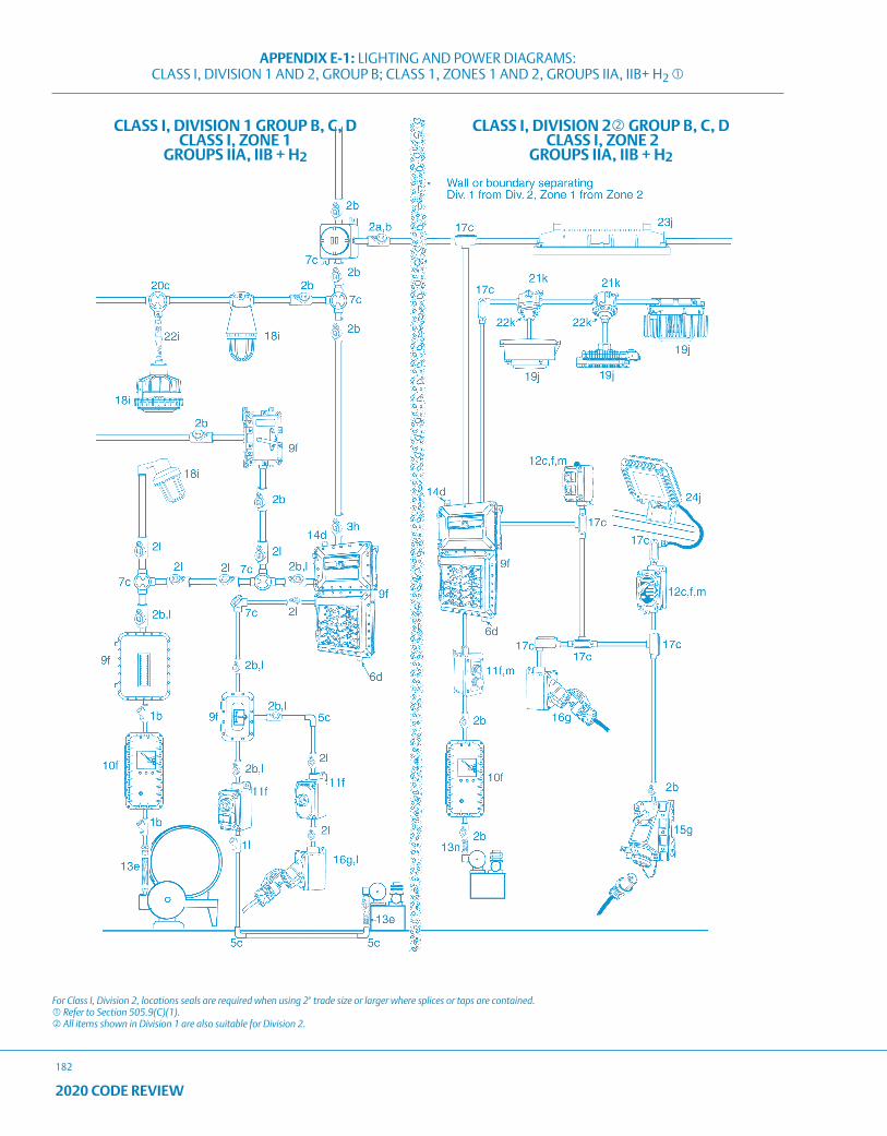
APPENDIX E-1: LIGHTING AND POWER DIAGRAMS: CLASS I, DIVISION 1 AND 2, GROUP B; CLASS 1, ZONES 1 AND 2, GROUPS IIA, IIB+ H2
182
2020 CODE REVIEW
CLASS I, DIVISION 1 GROUP B, C, D CLASS I, ZONE 1
GROUPS IIA, IIB + H2
CLASS I, DIVISION 2 GROUP B, C, D CLASS I, ZONE 2
GROUPS IIA, IIB + H2
For Class I, Division 2, locations seals are required when using 2" trade size or larger where splices or taps are contained. Refer to Section 505.9(C)(1). All items shown in Division 1 are also suitable for Division 2.
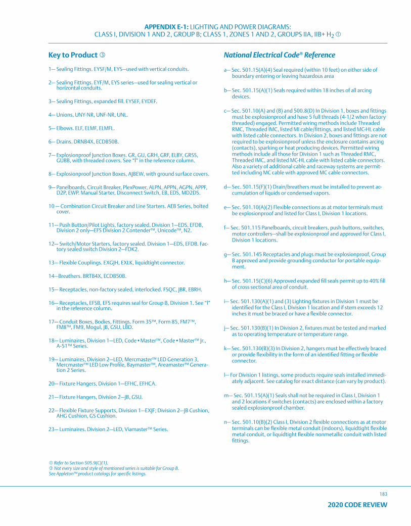
APPENDIX E-1: LIGHTING AND POWER DIAGRAMS: CLASS I, DIVISION 1 AND 2, GROUP B; CLASS 1, ZONES 1 AND 2, GROUPS IIA, IIB+ H2
183
2020 CODE REVIEW
Key to Product
1— Sealing Fittings. EYSF/M, EYS—used with vertical conduits.
2— Sealing Fittings. EYF/M, EYS series—used for sealing vertical or horizontal conduits.
3— Sealing Fittings, expanded fill. EYSEF, EYDEF.
4— Unions, UNY-NR, UNF-NR, UNL.
5— Elbows. ELF, ELMF, ELMFL.
6— Drains. DRNB4X, ECDB50B.
7— Explosionproof Junction Boxes. GR, GU, GRH, GRF, ELBY, GRSS, GUBB, with threaded covers. See “l” in the reference column.
8— Explosionproof Junction Boxes, AJBEW, with ground surface covers.
9— Panelboards, Circuit Breaker, PlexPower, ALPN, APPN, AGPN, APPF, D2P, EWP. Manual Starter, Disconnect Switch, EB, EDS, MD2DS.
10 — Combination Circuit Breaker and Line Starters. AEB Series, bolted cover.
11— Push Button/Pilot Lights, factory sealed. Division 1—EDS, EFDB, Division 2 only—EFS Division 2 Contender™, Unicode™, N2.
12— Switch/Motor Starters, factory sealed. Division 1—EDS, EFDB. Fac-tory sealed switch Division 2—FDK2.
13— Flexible Couplings. EXGJH, EXLK, liquidtight connector.
14—Breathers. BRTB4X, ECDB50B.
15— Receptacles, non-factory sealed, interlocked. FSQC, JBR, EBRH.
16— Receptacles, EFSB, EFS requires seal for Group B, Division 1. See “l” in the reference column.
17— Conduit Boxes, Bodies, Fittings. Form 35™, Form 85, FM7™, FM8™, FM9, Mogul, JB, GSU, LBD.
18— Luminaires, Division 1—LED, Code•Master™, Code•Master™ Jr., A-51™ Series.
19— Luminaires, Division 2—LED, Mercmaster™ LED Generation 3, Mercmaster™ LED Low Profile, Baymaster™, Areamaster™ Genera-tion 2 Series.
20— Fixture Hangers, Division 1—EFHC, EFHCA.
21— Fixture Hangers, Division 2—JB, GSU.
22— Flexible Fixture Supports, Division 1—EXJF; Division 2—JB Cushion, AHG Cushion, GS Cushion.
23— Luminaires. Division 2—LED, Viamaster™ Series.
National Electrical Code® Reference
a— Sec. 501.15(A)(4) Seal required (within 10 feet) on either side of boundary entering or leaving hazardous area
b— Sec. 501.15(A)(1) Seals required within 18 inches of all arcing devices.
c— Sec. 501.10(A) and (B) and 500.8(D) In Division 1, boxes and fittings must be explosionproof and have 5 full threads (4-1/2 when factory threaded) engaged. Permitted wiring methods include Threaded RMC, Threaded IMC, listed MI cable/fittings, and listed MC-HL cable with listed cable connectors. In Division 2, boxes and fittings are not required to be explosionproof unless the enclosure contains arcing (contacts), sparking or heat producing devices. Permitted wiring methods include all those for Division 1 such as Threaded RMC, Threaded IMC, and listed MC-HL cable with listed cable connectors. Also a variety of additional cable and raceway systems are permit-ted including MC cable with approved MC cable connectors.
d— Sec. 501.15(F)(1) Drain/breathers must be installed to prevent ac-cumulation of liquids or condensed vapors.
e— Sec. 501.10(A)(2) Flexible connections as at motor terminals must be explosionproof and listed for Class I, Division 1 locations.
f— Sec. 501.115 Panelboards, circuit breakers, push buttons, switches, motor controllers—shall be explosionproof and approved for Class I, Division 1 locations.
g— Sec. 501.145 Receptacles and plugs must be explosionproof, Group B approved and provide grounding conductor for portable equip-ment.
h— Sec. 501.15(C)(6) Approved expanded fill seals permit up to 40% fill of cross sectional area of conduit.
i— Sec. 501.130(A)(1) and (3) Lighting fixtures in Division 1 must be identified for the Class I, Division 1 location and if stem exceeds 12 inches it must be braced or have a flexible connector.
j— Sec. 501.130(B)(1) In Division 2, fixtures must be tested and marked as to operating temperature or temperature range.
k— Sec. 501.130(B)(3) In Division 2, hangers must be effectively braced or provide flexibility in the form of an identified fitting or flexible connector.
l— For Division 1 listings, some products require seals installed immedi-ately adjacent. See catalog for exact distance (can vary by product).
m— Sec. 501.15(A)(1) Seals shall not be required in Class I, Division 1 and 2 locations if switches (contacts) are enclosed within a factory sealed explosionproof chamber.
n— Sec. 501.10(B)(2) Class I, Division 2 flexible connections as at motor terminals can be flexible metal conduit (indoors), liquidtight flexible metal conduit, or liquidtight flexible nonmetallic conduit with listed fittings.
Refer to Section 505.9(C)(1). Not every size and style of mentioned series is suitable for Group B. See Appleton™ product catalogs for specific listings.
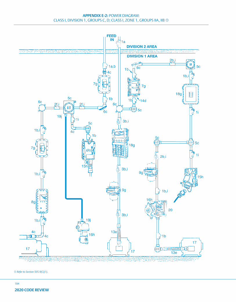
APPENDIX E-2: POWER DIAGRAM: CLASS I, DIVISION 1, GROUPS C, D; CLASS I, ZONE 1, GROUPS IIA, IIB
184
2020 CODE REVIEW
Refer to Section 505.9(C)(1).
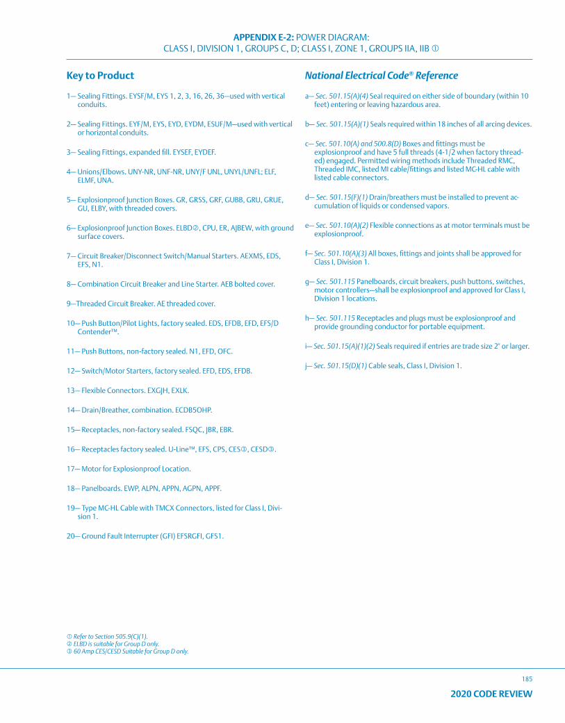
APPENDIX E-2: POWER DIAGRAM: CLASS I, DIVISION 1, GROUPS C, D; CLASS I, ZONE 1, GROUPS IIA, IIB
185
2020 CODE REVIEW
Key to Product
1— Sealing Fittings. EYSF/M, EYS 1, 2, 3, 16, 26, 36—used with vertical conduits.
2— Sealing Fittings. EYF/M, EYS, EYD, EYDM, ESUF/M—used with vertical or horizontal conduits.
3— Sealing Fittings, expanded fill. EYSEF, EYDEF.
4— Unions/Elbows. UNY-NR, UNF-NR, UNY/F UNL, UNYL/UNFL; ELF, ELMF, UNA.
5— Explosionproof Junction Boxes. GR, GRSS, GRF, GUBB, GRU, GRUE, GU, ELBY, with threaded covers.
6— Explosionproof Junction Boxes. ELBD, CPU, ER, AJBEW, with ground surface covers.
7— Circuit Breaker/Disconnect Switch/Manual Starters. AEXMS, EDS, EFS, N1.
8— Combination Circuit Breaker and Line Starter. AEB bolted cover.
9—Threaded Circuit Breaker. AE threaded cover.
10— Push Button/Pilot Lights, factory sealed. EDS, EFDB, EFD, EFS/D Contender™.
11— Push Buttons, non-factory sealed. N1, EFD, OFC.
12— Switch/Motor Starters, factory sealed. EFD, EDS, EFDB.
13— Flexible Connectors. EXGJH, EXLK.
14— Drain/Breather, combination. ECDB5OHP.
15— Receptacles, non-factory sealed. FSQC, JBR, EBR.
16— Receptacles factory sealed. U-Line™, EFS, CPS, CES, CESD.
17— Motor for Explosionproof Location.
18— Panelboards. EWP, ALPN, APPN, AGPN, APPF.
19— Type MC-HL Cable with TMCX Connectors, listed for Class I, Divi-sion 1.
20— Ground Fault Interrupter (GFI) EFSRGFI, GFS1.
National Electrical Code® Reference
a— Sec. 501.15(A)(4) Seal required on either side of boundary (within 10 feet) entering or leaving hazardous area.
b— Sec. 501.15(A)(1) Seals required within 18 inches of all arcing devices.
c— Sec. 501.10(A) and 500.8(D) Boxes and fittings must be explosionproof and have 5 full threads (4-1/2 when factory thread-ed) engaged. Permitted wiring methods include Threaded RMC, Threaded IMC, listed MI cable/fittings and listed MC-HL cable with listed cable connectors.
d— Sec. 501.15(F)(1) Drain/breathers must be installed to prevent ac-cumulation of liquids or condensed vapors.
e— Sec. 501.10(A)(2) Flexible connections as at motor terminals must be explosionproof.
f— Sec. 501.10(A)(3) All boxes, fittings and joints shall be approved for Class I, Division 1.
g— Sec. 501.115 Panelboards, circuit breakers, push buttons, switches, motor controllers—shall be explosionproof and approved for Class I, Division 1 locations.
h— Sec. 501.115 Receptacles and plugs must be explosionproof and provide grounding conductor for portable equipment.
i— Sec. 501.15(A)(1)(2) Seals required if entries are trade size 2" or larger.
j— Sec. 501.15(D)(1) Cable seals, Class I, Division 1.
Refer to Section 505.9(C)(1). ELBD is suitable for Group D only. 60 Amp CES/CESD Suitable for Group D only.
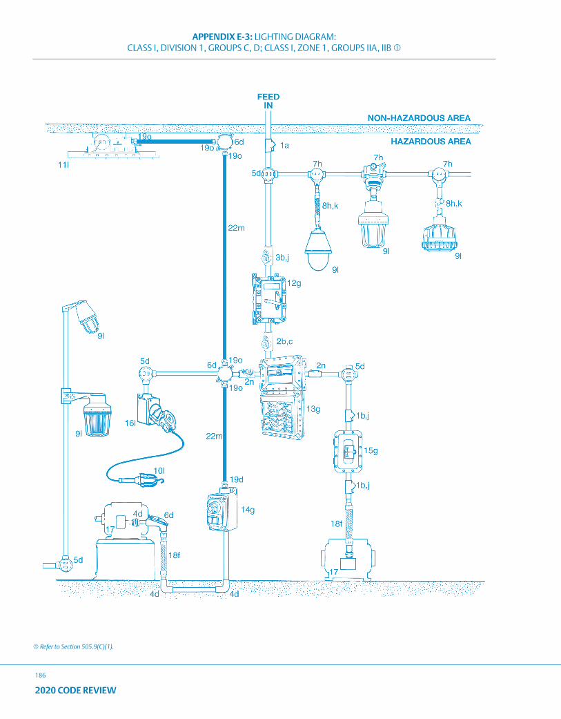
APPENDIX E-3: LIGHTING DIAGRAM: CLASS I, DIVISION 1, GROUPS C, D; CLASS I, ZONE 1, GROUPS IIA, IIB
186
2020 CODE REVIEW
Refer to Section 505.9(C)(1).
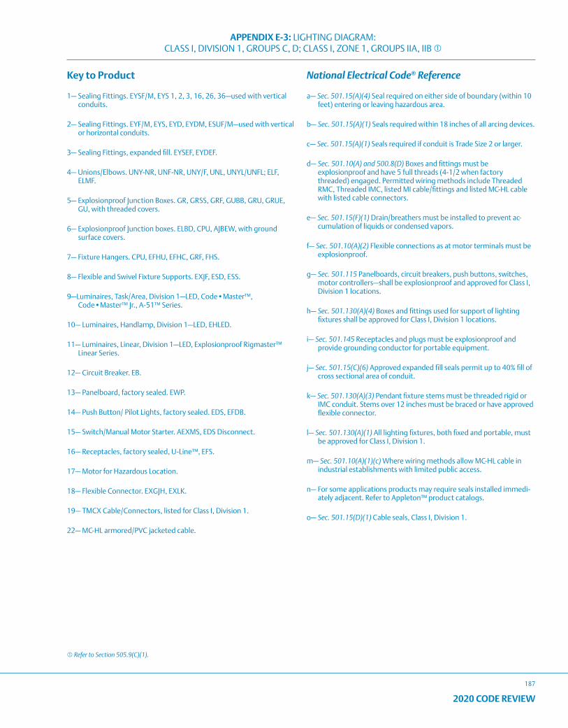
APPENDIX E-3: LIGHTING DIAGRAM: CLASS I, DIVISION 1, GROUPS C, D; CLASS I, ZONE 1, GROUPS IIA, IIB
187
2020 CODE REVIEW
Key to Product
1— Sealing Fittings. EYSF/M, EYS 1, 2, 3, 16, 26, 36—used with vertical conduits.
2— Sealing Fittings. EYF/M, EYS, EYD, EYDM, ESUF/M—used with vertical or horizontal conduits.
3— Sealing Fittings, expanded fill. EYSEF, EYDEF.
4— Unions/Elbows. UNY-NR, UNF-NR, UNY/F, UNL, UNYL/UNFL; ELF, ELMF.
5— Explosionproof Junction Boxes. GR, GRSS, GRF, GUBB, GRU, GRUE, GU, with threaded covers.
6— Explosionproof Junction boxes. ELBD, CPU, AJBEW, with ground surface covers.
7— Fixture Hangers. CPU, EFHU, EFHC, GRF, FHS.
8— Flexible and Swivel Fixture Supports. EXJF, ESD, ESS.
9—Luminaires, Task/Area, Division 1—LED, Code•Master™, Code•Master™ Jr., A-51™ Series.
10— Luminaires, Handlamp, Division 1—LED, EHLED.
11— Luminaires, Linear, Division 1—LED, Explosionproof Rigmaster™ Linear Series.
12— Circuit Breaker. EB.
13— Panelboard, factory sealed. EWP.
14— Push Button/ Pilot Lights, factory sealed. EDS, EFDB.
15— Switch/Manual Motor Starter. AEXMS, EDS Disconnect.
16— Receptacles, factory sealed, U-Line™, EFS.
17— Motor for Hazardous Location.
18— Flexible Connector. EXGJH, EXLK.
19— TMCX Cable/Connectors, listed for Class I, Division 1.
22— MC-HL armored/PVC jacketed cable.
National Electrical Code® Reference
a— Sec. 501.15(A)(4) Seal required on either side of boundary (within 10 feet) entering or leaving hazardous area.
b— Sec. 501.15(A)(1) Seals required within 18 inches of all arcing devices.
c— Sec. 501.15(A)(1) Seals required if conduit is Trade Size 2 or larger.
d— Sec. 501.10(A) and 500.8(D) Boxes and fittings must be explosionproof and have 5 full threads (4-1/2 when factory threaded) engaged. Permitted wiring methods include Threaded RMC, Threaded IMC, listed MI cable/fittings and listed MC-HL cable with listed cable connectors.
e— Sec. 501.15(F)(1) Drain/breathers must be installed to prevent ac-cumulation of liquids or condensed vapors.
f— Sec. 501.10(A)(2) Flexible connections as at motor terminals must be explosionproof.
g— Sec. 501.115 Panelboards, circuit breakers, push buttons, switches, motor controllers—shall be explosionproof and approved for Class I, Division 1 locations.
h— Sec. 501.130(A)(4) Boxes and fittings used for support of lighting fixtures shall be approved for Class I, Division 1 locations.
i— Sec. 501.145 Receptacles and plugs must be explosionproof and provide grounding conductor for portable equipment.
j— Sec. 501.15(C)(6) Approved expanded fill seals permit up to 40% fill of cross sectional area of conduit.
k— Sec. 501.130(A)(3) Pendant fixture stems must be threaded rigid or IMC conduit. Stems over 12 inches must be braced or have approved flexible connector.
l— Sec. 501.130(A)(1) All lighting fixtures, both fixed and portable, must be approved for Class I, Division 1.
m— Sec. 501.10(A)(1)(c) Where wiring methods allow MC-HL cable in industrial establishments with limited public access.
n— For some applications products may require seals installed immedi-ately adjacent. Refer to Appleton™ product catalogs.
o— Sec. 501.15(D)(1) Cable seals, Class I, Division 1.
Refer to Section 505.9(C)(1).
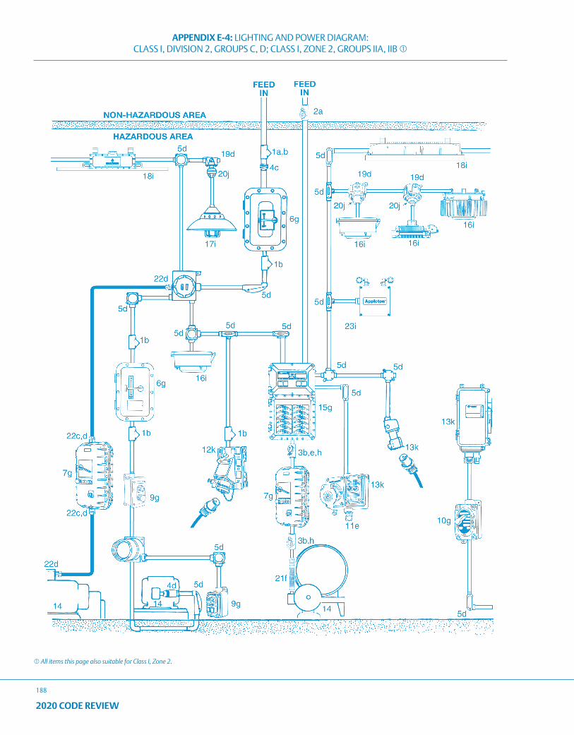
APPENDIX E-4: LIGHTING AND POWER DIAGRAM: CLASS I, DIVISION 2, GROUPS C, D; CLASS I, ZONE 2, GROUPS IIA, IIB
188
2020 CODE REVIEW
All items this page also suitable for Class I, Zone 2.
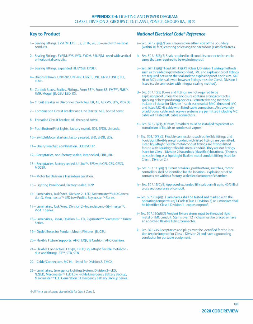
APPENDIX E-4: LIGHTING AND POWER DIAGRAM: CLASS I, DIVISION 2, GROUPS C, D; CLASS I, ZONE 2, GROUPS IIA, IIB
189
2020 CODE REVIEW
Key to Product
1— Sealing Fittings. EYSF/M, EYS 1, 2, 3, 16, 26, 36—used with vertical conduits.
2— Sealing Fittings. EYF/M, EYS, EYD, EYDM, ESUF/M—used with vertical or horizontal conduits.
3— Sealing Fittings, expanded fill. EYSEF, EYDEF.
4— Unions/Elbows. UNY-NR, UNF-NR, UNY/F, UNL, UNYL/ UNFL; ELF, ELMF.
5— Conduit Boxes, Bodies, Fittings. Form 35™, Form 85, FM7™, FM8™, FM9, Mogul, JB, GSU, LBD, RS.
6— Circuit Breaker or Disconnect Switches. EB, AE, AEXMS, EDS, MD2DS.
7— Combination Circuit Breaker and Line Starter. AEB, bolted cover.
8— Threaded Circuit Breaker, AE, threaded cover.
9— Push Button/Pilot Lights, factory sealed. EDS, EFDB, Unicode.
10— Switch/Motor Starters, factory sealed. EFD, EFDB, EDS.
11— Drain/Breather, combination. ECDB5OHP.
12— Receptacles, non-factory sealed, interlocked, EBR, JBR.
13— Receptacles, factory sealed, U-Line™. EFS with GFI, CES, CESD, MD2SR.
14— Motor for Division 2 Hazardous Location.
15— Lighting Panelboard, factory sealed. D2P.
16— Luminaires, Task/Area, Division 2—LED, Mercmaster™ LED Genera-tion 3, Mercmaster™ LED Low Profile, Baymaster™ Series.
17— Luminaires, Task/Area, Division 2—Incandescent—Stylmaster™, V-51™ Series.
18— Luminaires, Linear, Division 2—LED, Rigmaster™, Viamaster™ Linear Series.
19— Outlet Boxes for Pendant Mount Fixtures. JB, GSU.
20— Flexible Fixture Supports. AHG, EXJF, JB Cushion, AHG Cushion.
21— Flexible Connectors. EXGJH, EXLK; Liquidtight flexible metal con-duit and fittings. ST™, STB, STN.
22— Cable/Connectors. MC-HL—listed for Division 2. TMCX.
23— Luminaires, Emergency Lighting System, Division 2—LED, N2LED, Mercmaster™ LED Low Profile Emergency Battery Backup, Mercmaster™ LED Generation 3 Emergency Battery Backup Series.
National Electrical Code® Reference
a— Sec. 501.15(B)(2) Seals required on either side of the boundary (within 10 feet) entering or leaving the hazardous (classified) areas.
b— Sec. 501.15(B)(1) Seals required in all conduits connected to enclo-sures that are required to be explosionproof.
c— Sec. 501.15(B)(1) and 501.15(E)(1) Class I, Division 1 wiring methods such as threaded rigid metal conduit, IMC and explosionproof fittings are required between the seal and the explosionproof enclosure. MC-HL or MC cable is allowed however fittings must be Class I, Division 1 listed (cable connector with integral sealing method).
d— Sec. 501.10(B) Boxes and fittings are not required to be explosionproof unless the enclosure contains arcing (contacts), sparking or heat producing devices. Permitted wiring methods include all those for Division 1 such as threaded RMC, threaded IMC and listed MC-HL cable with listed cable connectors. Also a variety of additional cable and raceway systems are permitted including MC cable with listed MC cable connectors.
e— Sec. 501.15(F)(1) Drains/Breathers must be installed to prevent ac-cumulation of liquids or condensed vapors.
f— Sec. 501.10(B)(2) Flexible connections such as flexible fittings and liquidtight flexible metal conduit with listed fittings are permitted. listed liquidtight flexible metal conduit fittings are fittings listed for use with liquidtight flexible metal conduit. They are not fittings listed for Class I, Division 2 hazardous (classified) locations. (There is no such thing as a liquidtight flexible metal conduit fitting listed for Class I, Division 2.)
g— Sec. 501.115(B)(1) Circuit breakers, pushbuttons, switches, motor controllers shall be identified for the location - explosionproof or contacts are within a factory sealed explosionproof chamber.
h— Sec. 501.15(C)(6) Approved expanded fill seals permit up to 40% fill of cross sectional area of conduit.
i— Sec. 501.130(B)(1) Luminaires shall be tested and marked with the operating temperature/T-Code (Class I, Division 2) or luminaires shall be identified Class I, Division 1 - explosionproof.
j— Sec. 501.130(B)(3) Pendant fixture stems must be threaded rigid metal or IMC conduit. Stems over 12 inches must be braced or have an approved flexible fitting/connector.
k— Sec. 501.145 Receptacles and plugs must be identified for the loca-tion (explosionproof or Class I, Division 2) and have a grounding conductor for portable equipment.
All items on this page also suitable for Class I, Zone 2.
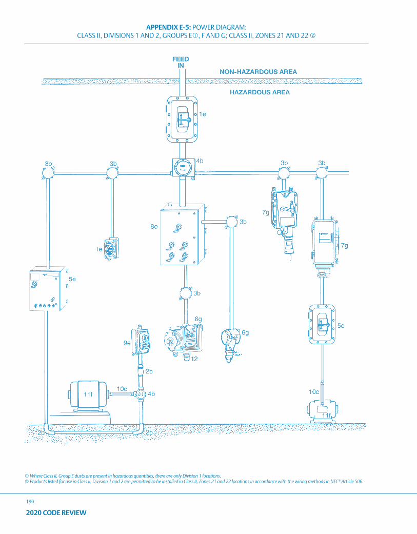
APPENDIX E-5: POWER DIAGRAM: CLASS II, DIVISIONS 1 AND 2, GROUPS E, F AND G; CLASS II, ZONES 21 AND 22
190
2020 CODE REVIEW
Where Class II, Group E dusts are present in hazardous quantities, there are only Division 1 locations. Products listed for use in Class II, Division 1 and 2 are permitted to be installed in Class II, Zones 21 and 22 locations in accordance with the wiring methods in NEC® Article 506.
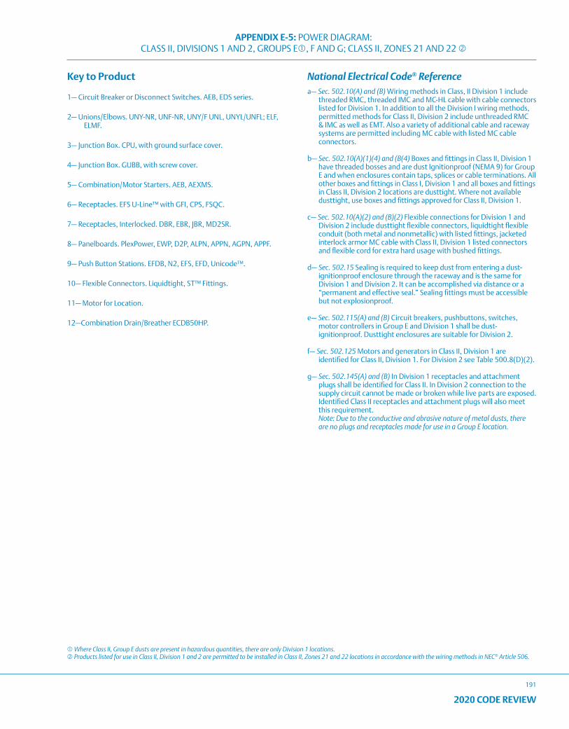
APPENDIX E-5: POWER DIAGRAM: CLASS II, DIVISIONS 1 AND 2, GROUPS E, F AND G; CLASS II, ZONES 21 AND 22
191
2020 CODE REVIEW
Key to Product
1— Circuit Breaker or Disconnect Switches. AEB, EDS series.
2— Unions/Elbows. UNY-NR, UNF-NR, UNY/F UNL, UNYL/UNFL; ELF, ELMF.
3— Junction Box. CPU, with ground surface cover.
4— Junction Box. GUBB, with screw cover.
5— Combination/Motor Starters. AEB, AEXMS.
6— Receptacles. EFS U-Line™ with GFI, CPS, FSQC.
7— Receptacles, Interlocked. DBR, EBR, JBR, MD2SR.
8— Panelboards. PlexPower, EWP, D2P, ALPN, APPN, AGPN, APPF.
9— Push Button Stations. EFDB, N2, EFS, EFD, Unicode™.
10— Flexible Connectors. Liquidtight, ST™ Fittings.
11— Motor for Location.
12—Combination Drain/Breather ECDB50HP.
National Electrical Code® Referencea— Sec. 502.10(A) and (B) Wiring methods in Class, II Division 1 include
threaded RMC, threaded IMC and MC-HL cable with cable connectors listed for Division 1. In addition to all the Division I wiring methods, permitted methods for Class II, Division 2 include unthreaded RMC & IMC as well as EMT. Also a variety of additional cable and raceway systems are permitted including MC cable with listed MC cable connectors.
b— Sec. 502.10(A)(1)(4) and (B(4) Boxes and fittings in Class II, Division 1 have threaded bosses and are dust Ignitionproof (NEMA 9) for Group E and when enclosures contain taps, splices or cable terminations. All other boxes and fittings in Class I, Division 1 and all boxes and fittings in Class II, Division 2 locations are dusttight. Where not available dusttight, use boxes and fittings approved for Class II, Division 1.
c— Sec. 502.10(A)(2) and (B)(2) Flexible connections for Division 1 and Division 2 include dusttight flexible connectors, liquidtight flexible conduit (both metal and nonmetallic) with listed fittings, jacketed interlock armor MC cable with Class II, Division 1 listed connectors and flexible cord for extra hard usage with bushed fittings.
d— Sec. 502.15 Sealing is required to keep dust from entering a dust-ignitionproof enclosure through the raceway and is the same for Division 1 and Division 2. It can be accomplished via distance or a “permanent and effective seal.” Sealing fittings must be accessible but not explosionproof.
e— Sec. 502.115(A) and (B) Circuit breakers, pushbuttons, switches, motor controllers in Group E and Division 1 shall be dust-ignitionproof. Dusttight enclosures are suitable for Division 2.
f— Sec. 502.125 Motors and generators in Class II, Division 1 are identified for Class II, Division 1. For Division 2 see Table 500.8(D)(2).
g— Sec. 502.145(A) and (B) In Division 1 receptacles and attachment plugs shall be identified for Class II. In Division 2 connection to the supply circuit cannot be made or broken while live parts are exposed. Identified Class II receptacles and attachment plugs will also meet this requirement. Note: Due to the conductive and abrasive nature of metal dusts, there are no plugs and receptacles made for use in a Group E location.
Where Class II, Group E dusts are present in hazardous quantities, there are only Division 1 locations. Products listed for use in Class II, Division 1 and 2 are permitted to be installed in Class II, Zones 21 and 22 locations in accordance with the wiring methods in NEC® Article 506.
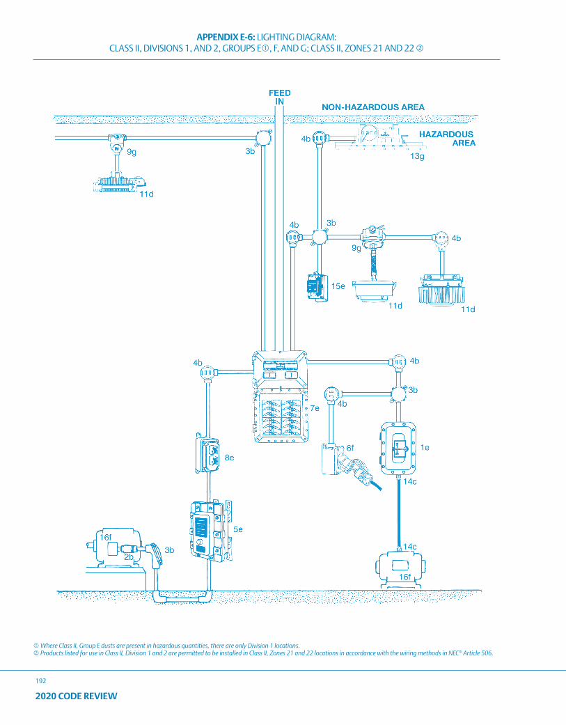
APPENDIX E-6: LIGHTING DIAGRAM: CLASS II, DIVISIONS 1, AND 2, GROUPS E, F, AND G; CLASS II, ZONES 21 AND 22
192
2020 CODE REVIEW
Where Class II, Group E dusts are present in hazardous quantities, there are only Division 1 locations. Products listed for use in Class II, Division 1 and 2 are permitted to be installed in Class II, Zones 21 and 22 locations in accordance with the wiring methods in NEC® Article 506.
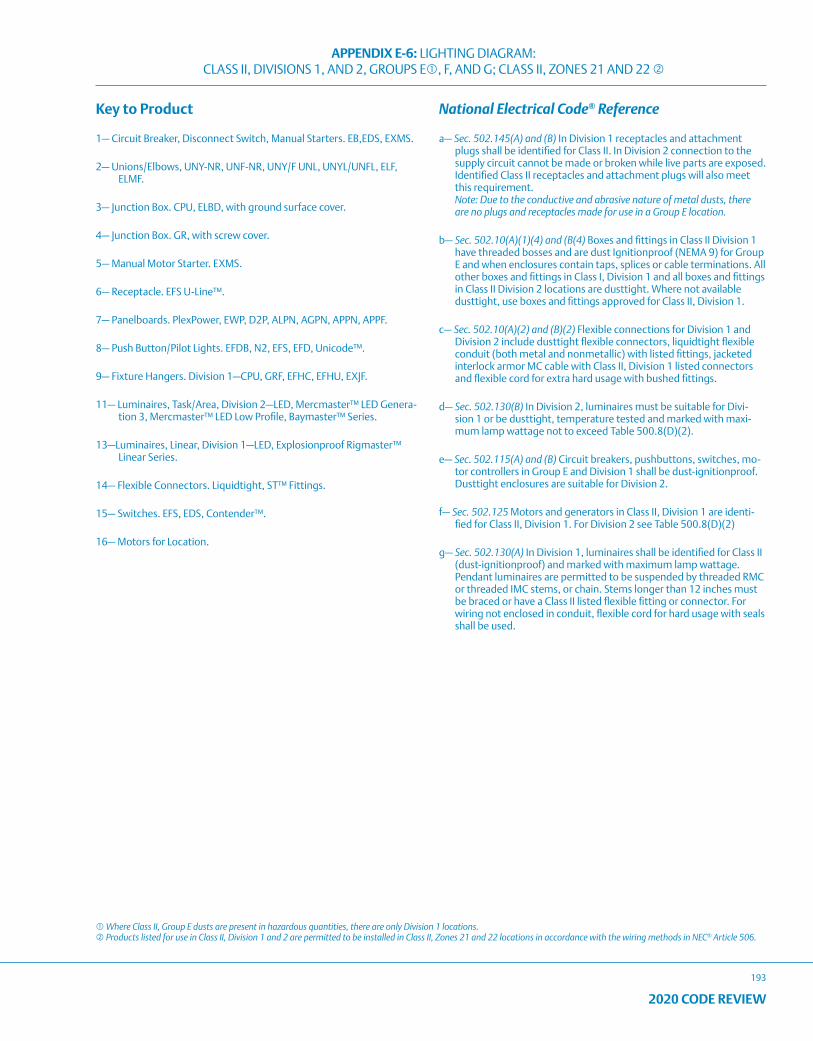
APPENDIX E-6: LIGHTING DIAGRAM: CLASS II, DIVISIONS 1, AND 2, GROUPS E, F, AND G; CLASS II, ZONES 21 AND 22
193
2020 CODE REVIEW
Key to Product
1— Circuit Breaker, Disconnect Switch, Manual Starters. EB,EDS, EXMS.
2— Unions/Elbows, UNY-NR, UNF-NR, UNY/F UNL, UNYL/UNFL, ELF, ELMF.
3— Junction Box. CPU, ELBD, with ground surface cover.
4— Junction Box. GR, with screw cover.
5— Manual Motor Starter. EXMS.
6— Receptacle. EFS U-Line™.
7— Panelboards. PlexPower, EWP, D2P, ALPN, AGPN, APPN, APPF.
8— Push Button/Pilot Lights. EFDB, N2, EFS, EFD, Unicode™.
9— Fixture Hangers. Division 1—CPU, GRF, EFHC, EFHU, EXJF.
11— Luminaires, Task/Area, Division 2—LED, Mercmaster™ LED Genera-tion 3, Mercmaster™ LED Low Profile, Baymaster™ Series.
13—Luminaires, Linear, Division 1—LED, Explosionproof Rigmaster™ Linear Series.
14— Flexible Connectors. Liquidtight, ST™ Fittings.
15— Switches. EFS, EDS, Contender™.
16— Motors for Location.
National Electrical Code® Reference
a— Sec. 502.145(A) and (B) In Division 1 receptacles and attachment plugs shall be identified for Class II. In Division 2 connection to the supply circuit cannot be made or broken while live parts are exposed. Identified Class II receptacles and attachment plugs will also meet this requirement. Note: Due to the conductive and abrasive nature of metal dusts, there are no plugs and receptacles made for use in a Group E location.
b— Sec. 502.10(A)(1)(4) and (B(4) Boxes and fittings in Class II Division 1 have threaded bosses and are dust Ignitionproof (NEMA 9) for Group E and when enclosures contain taps, splices or cable terminations. All other boxes and fittings in Class I, Division 1 and all boxes and fittings in Class II Division 2 locations are dusttight. Where not available dusttight, use boxes and fittings approved for Class II, Division 1.
c— Sec. 502.10(A)(2) and (B)(2) Flexible connections for Division 1 and Division 2 include dusttight flexible connectors, liquidtight flexible conduit (both metal and nonmetallic) with listed fittings, jacketed interlock armor MC cable with Class II, Division 1 listed connectors and flexible cord for extra hard usage with bushed fittings.
d— Sec. 502.130(B) In Division 2, luminaires must be suitable for Divi-sion 1 or be dusttight, temperature tested and marked with maxi-mum lamp wattage not to exceed Table 500.8(D)(2).
e— Sec. 502.115(A) and (B) Circuit breakers, pushbuttons, switches, mo-tor controllers in Group E and Division 1 shall be dust-ignitionproof. Dusttight enclosures are suitable for Division 2.
f— Sec. 502.125 Motors and generators in Class II, Division 1 are identi-fied for Class II, Division 1. For Division 2 see Table 500.8(D)(2)
g— Sec. 502.130(A) In Division 1, luminaires shall be identified for Class II (dust-ignitionproof) and marked with maximum lamp wattage. Pendant luminaires are permitted to be suspended by threaded RMC or threaded IMC stems, or chain. Stems longer than 12 inches must be braced or have a Class II listed flexible fitting or connector. For wiring not enclosed in conduit, flexible cord for hard usage with seals shall be used.
Where Class II, Group E dusts are present in hazardous quantities, there are only Division 1 locations. Products listed for use in Class II, Division 1 and 2 are permitted to be installed in Class II, Zones 21 and 22 locations in accordance with the wiring methods in NEC® Article 506.
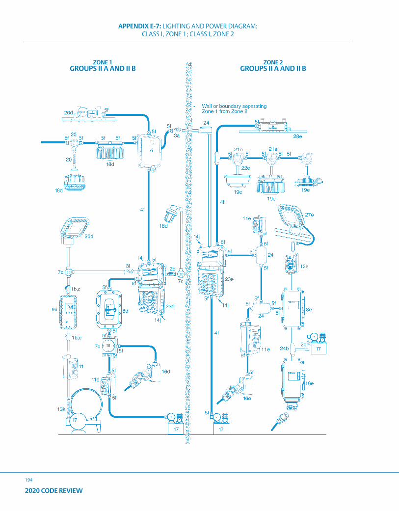
APPENDIX E-7: LIGHTING AND POWER DIAGRAM: CLASS I, ZONE 1; CLASS I, ZONE 2
194
2020 CODE REVIEW
ZONE 1GROUPS II A AND II B
ZONE 2GROUPS II A AND II B
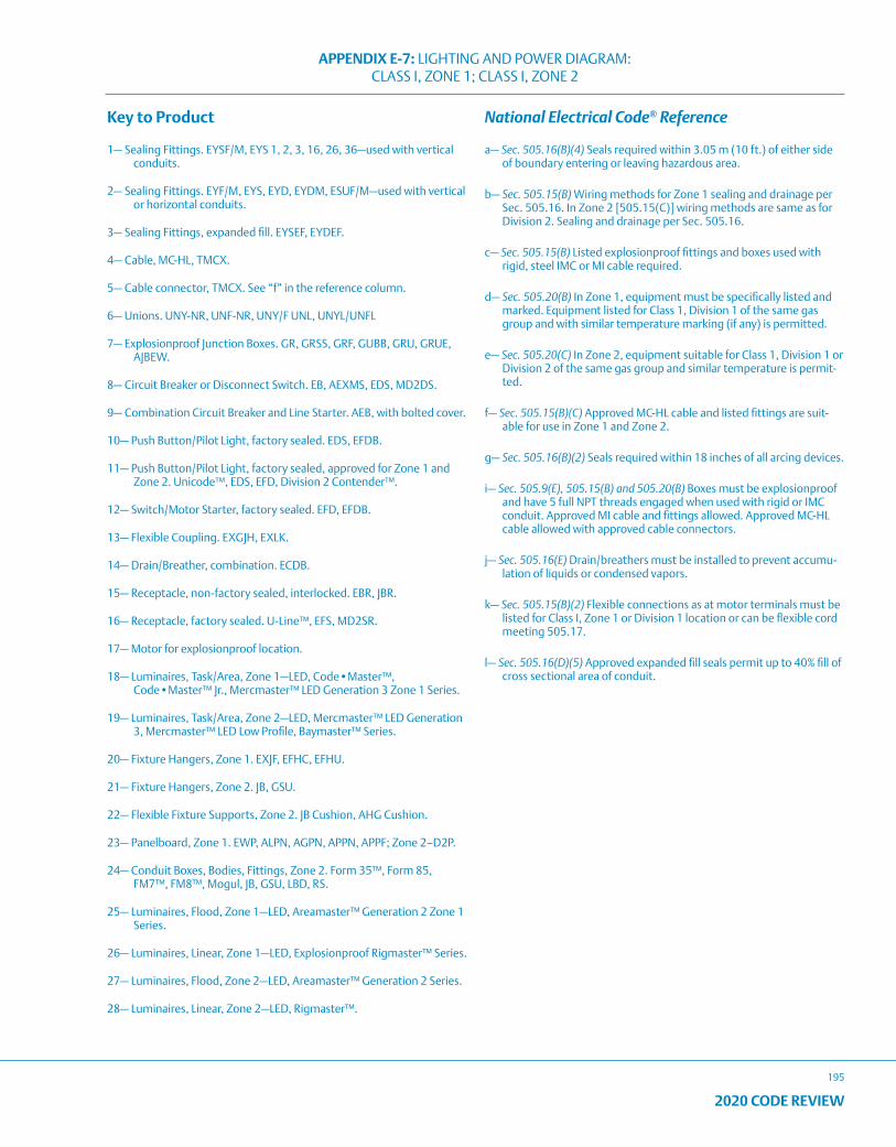
APPENDIX E-7: LIGHTING AND POWER DIAGRAM: CLASS I, ZONE 1; CLASS I, ZONE 2
195
2020 CODE REVIEW
Key to Product
1— Sealing Fittings. EYSF/M, EYS 1, 2, 3, 16, 26, 36—used with vertical conduits.
2— Sealing Fittings. EYF/M, EYS, EYD, EYDM, ESUF/M—used with vertical or horizontal conduits.
3— Sealing Fittings, expanded fill. EYSEF, EYDEF.
4— Cable, MC-HL, TMCX.
5— Cable connector, TMCX. See “f” in the reference column.
6— Unions. UNY-NR, UNF-NR, UNY/F UNL, UNYL/UNFL
7— Explosionproof Junction Boxes. GR, GRSS, GRF, GUBB, GRU, GRUE, AJBEW.
8— Circuit Breaker or Disconnect Switch. EB, AEXMS, EDS, MD2DS.
9— Combination Circuit Breaker and Line Starter. AEB, with bolted cover.
10— Push Button/Pilot Light, factory sealed. EDS, EFDB.
11— Push Button/Pilot Light, factory sealed, approved for Zone 1 and Zone 2. Unicode™, EDS, EFD, Division 2 Contender™.
12— Switch/Motor Starter, factory sealed. EFD, EFDB.
13— Flexible Coupling. EXGJH, EXLK.
14— Drain/Breather, combination. ECDB.
15— Receptacle, non-factory sealed, interlocked. EBR, JBR.
16— Receptacle, factory sealed. U-Line™, EFS, MD2SR.
17— Motor for explosionproof location.
18— Luminaires, Task/Area, Zone 1—LED, Code•Master™, Code•Master™ Jr., Mercmaster™ LED Generation 3 Zone 1 Series.
19— Luminaires, Task/Area, Zone 2—LED, Mercmaster™ LED Generation 3, Mercmaster™ LED Low Profile, Baymaster™ Series.
20— Fixture Hangers, Zone 1. EXJF, EFHC, EFHU.
21— Fixture Hangers, Zone 2. JB, GSU.
22— Flexible Fixture Supports, Zone 2. JB Cushion, AHG Cushion.
23— Panelboard, Zone 1. EWP, ALPN, AGPN, APPN, APPF; Zone 2–D2P.
24— Conduit Boxes, Bodies, Fittings, Zone 2. Form 35™, Form 85, FM7™, FM8™, Mogul, JB, GSU, LBD, RS.
25— Luminaires, Flood, Zone 1—LED, Areamaster™ Generation 2 Zone 1 Series.
26— Luminaires, Linear, Zone 1—LED, Explosionproof Rigmaster™ Series.
27— Luminaires, Flood, Zone 2—LED, Areamaster™ Generation 2 Series.
28— Luminaires, Linear, Zone 2—LED, Rigmaster™.
National Electrical Code® Reference
a— Sec. 505.16(B)(4) Seals required within 3.05 m (10 ft.) of either side of boundary entering or leaving hazardous area.
b— Sec. 505.15(B) Wiring methods for Zone 1 sealing and drainage per Sec. 505.16. In Zone 2 [505.15(C)] wiring methods are same as for Division 2. Sealing and drainage per Sec. 505.16.
c— Sec. 505.15(B) Listed explosionproof fittings and boxes used with rigid, steel IMC or MI cable required.
d— Sec. 505.20(B) In Zone 1, equipment must be specifically listed and marked. Equipment listed for Class 1, Division 1 of the same gas group and with similar temperature marking (if any) is permitted.
e— Sec. 505.20(C) In Zone 2, equipment suitable for Class 1, Division 1 or Division 2 of the same gas group and similar temperature is permit-ted.
f— Sec. 505.15(B)(C) Approved MC-HL cable and listed fittings are suit-able for use in Zone 1 and Zone 2.
g— Sec. 505.16(B)(2) Seals required within 18 inches of all arcing devices.
i— Sec. 505.9(E), 505.15(B) and 505.20(B) Boxes must be explosionproof and have 5 full NPT threads engaged when used with rigid or IMC conduit. Approved MI cable and fittings allowed. Approved MC-HL cable allowed with approved cable connectors.
j— Sec. 505.16(E) Drain/breathers must be installed to prevent accumu-lation of liquids or condensed vapors.
k— Sec. 505.15(B)(2) Flexible connections as at motor terminals must be listed for Class I, Zone 1 or Division 1 location or can be flexible cord meeting 505.17.
l— Sec. 505.16(D)(5) Approved expanded fill seals permit up to 40% fill of cross sectional area of conduit.

196
2020 CODE REVIEW
NOTES

2020 CODE REVIEW
197
NOTES

198
2020 CODE REVIEW
NOTES

2020 CODE REVIEW
199
NOTES

200
2020 CODE REVIEW
NOTES

2020 CODE REVIEW
201
NOTES

202
2020 CODE REVIEW
NOTES

Ensure Safety and Reliabilityin Corrosive Environments and Hazardous Atmospheres.
Appleton™ is the cornerstone brand of Emerson's Electrical and Lighting business; trusted worldwide to make electrical installations safer, more productive and more reliable.
The Emerson logo is a trademark and service mark of Emerson Electric Co. © 2021 Emerson Electric Co. All other marks are the property of their respective owners. © 2021 Emerson Automation Solutions. All rights reserved.
United States (Headquarters) Appleton Grp LLC9377 W. Higgins RoadRosemont, IL 60018United StatesT +1 800 621 1506
Australia Sales OfficeBayswater, Victoria T +61 3 9721 0387
Europe ATX SASEspace Industriel Nord35, rue André Durouchez, CS 9801780084 Amiens Cedex 2, FranceT +33 3 2254 1390
China Sales OfficeShanghai T +86 21 3338 7000
CanadaEGS Electrical Group Canada Ltd.99 Union StreetElmira ON, N3B 3L7CanadaT +1 888 765 2226
Middle East Sales OfficeDammam, Saudi ArabiaT +966 13 510 3702
Chile Sales OfficeLas CondesT +56 2928 4819
India Sales OfficeChennaiT +91 44 3919 7300
Korea Sales OfficeSeoulT +82 2 3483 1555
Asia Pacific EGS Private Ltd.Block 4008, Ang Mo Kio Ave 10, #04-16 TechPlace 1, Singapore 569625 T +65 6556 1100
Latin America EGS Comercializadora Mexico S de RL de CVCalle 10 N°145 Piso 3Col. San Pedro de los PinosDel. Álvaro ObregonCiudad de México. 01180T +52 55 5809 5049


