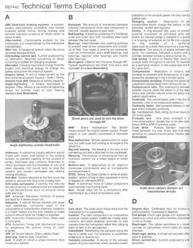
Kawasaki ZX600 (ZZ-R600 & Ninja ZX-6)Service and Repair Manualby Mike Stubblefieldand John H Haynes Member of the Guild of Motoring Writers
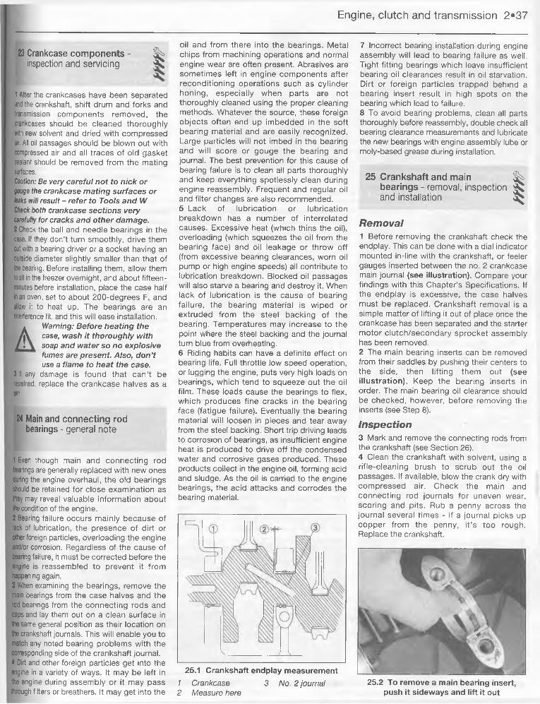
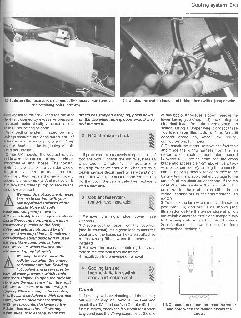
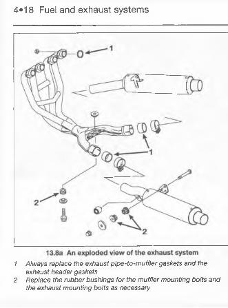
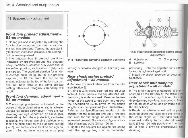
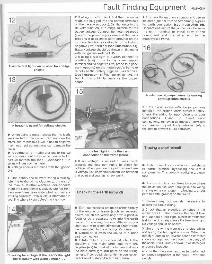
Models covered (2U6-248-nz3)ZX600D (ZZ-R600). 599cc. UK 1990 to 1993 ZX600D (Ninja ZX-6). 599cc. US 1990 to 1993 ZX600E (ZZ-R600). 599cc. UK 1993 to 2000 ZX600E (Ninja ZX-6). 599cc. US 1993 to 2000
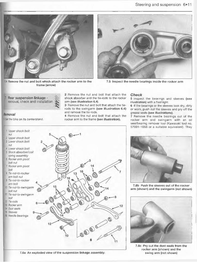
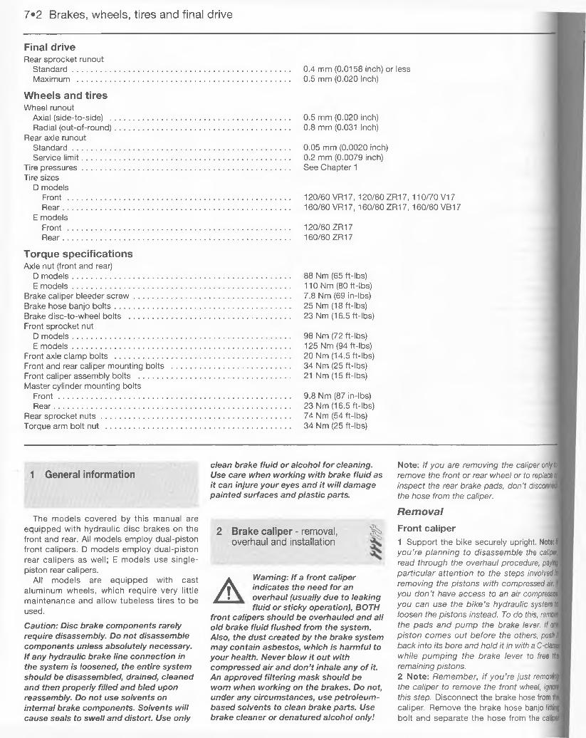
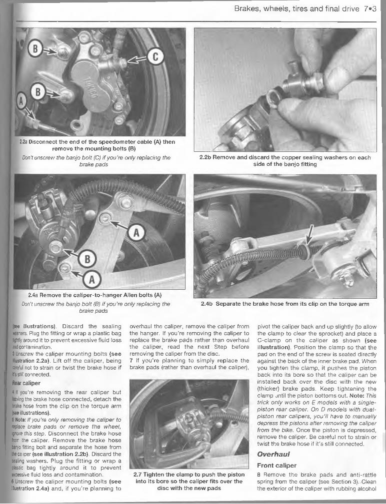
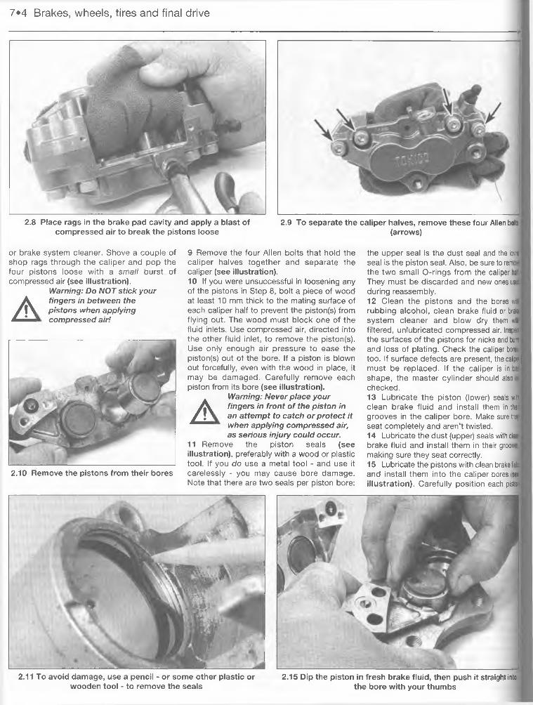
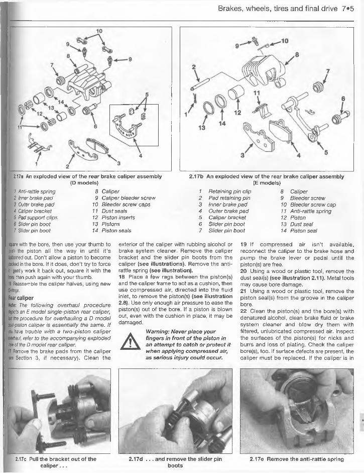
A book in the Haynes Service and Repair Manual Series
All rights reserved. No part of this book may be reproduced or transmitted in any form or by any means, electronic or mechanical, including photocopying, recording or by any information storage or retrieval system, without permission in writing from the copyright holder.
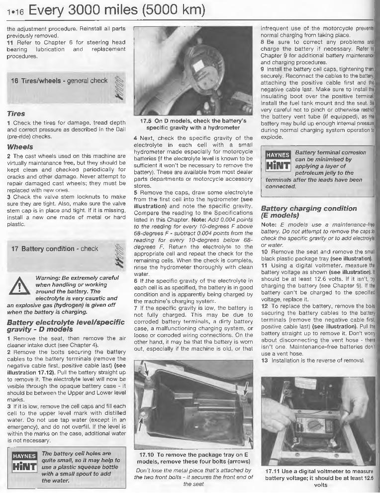
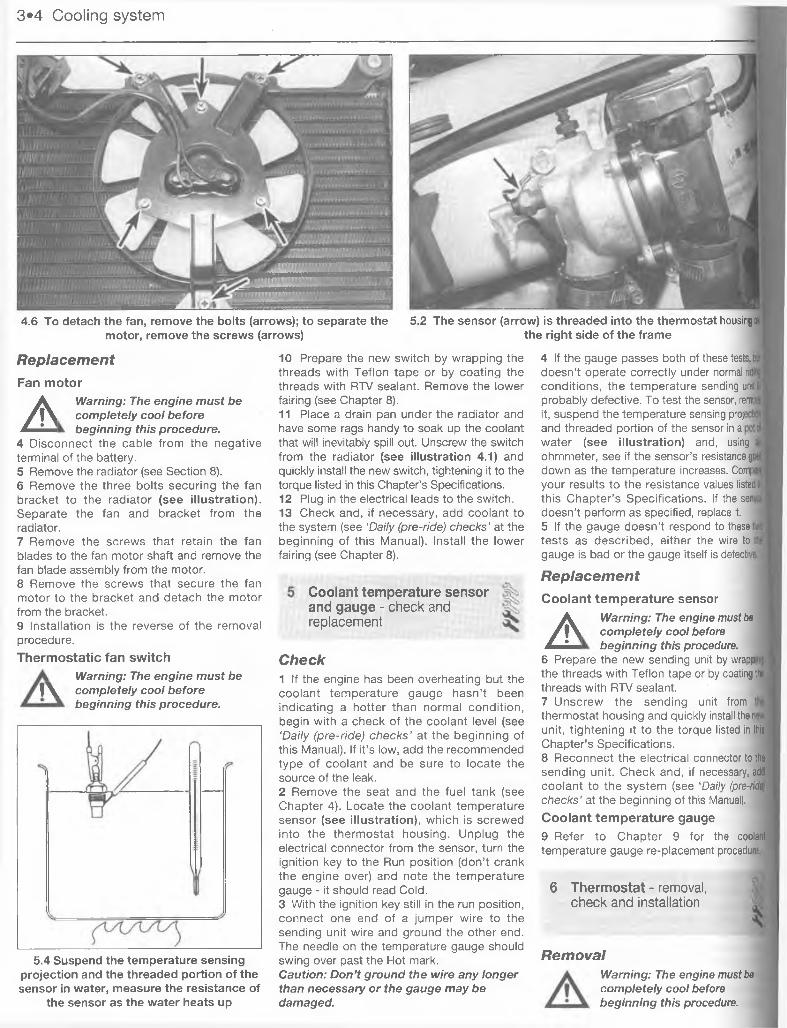
ISBN 1 85960 795 0
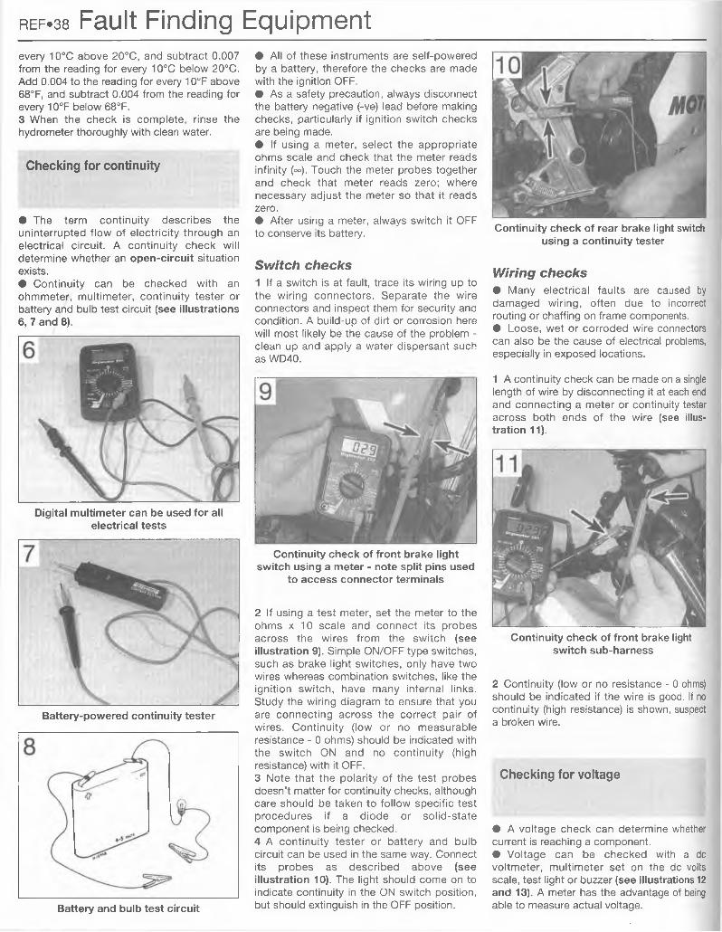
Library of Congress Control Number 01-131055
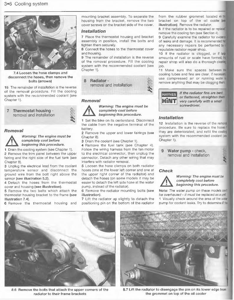
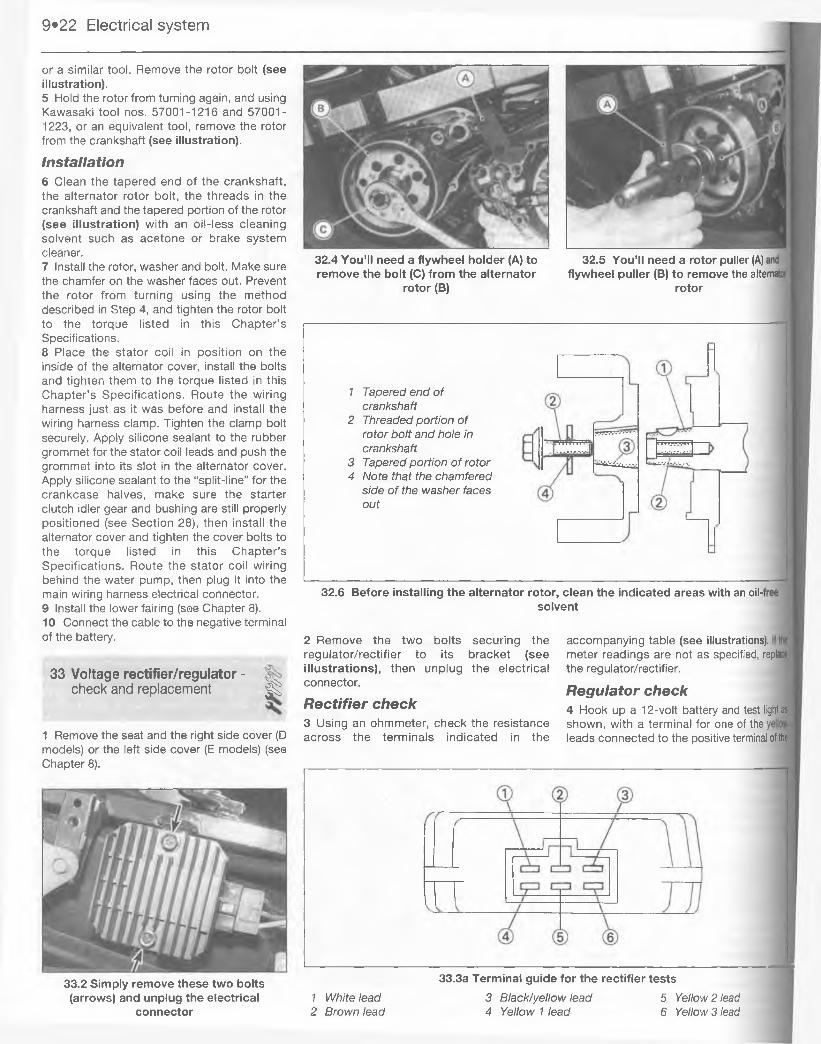
Printed in the USA
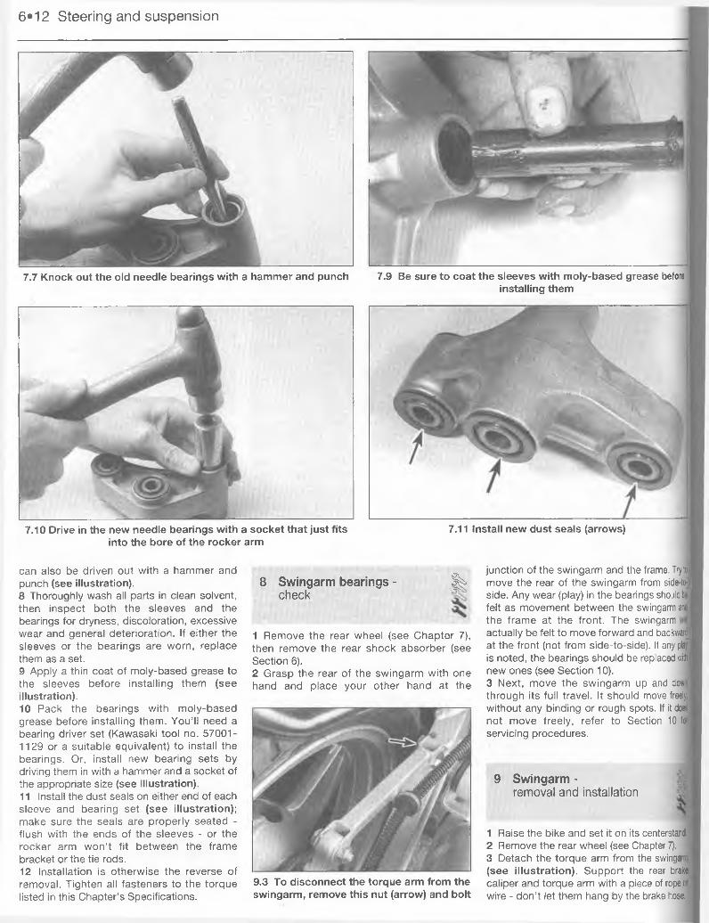
Haynes PublishingSparkford, Yeovil, Somerset BA22 7JJ, England
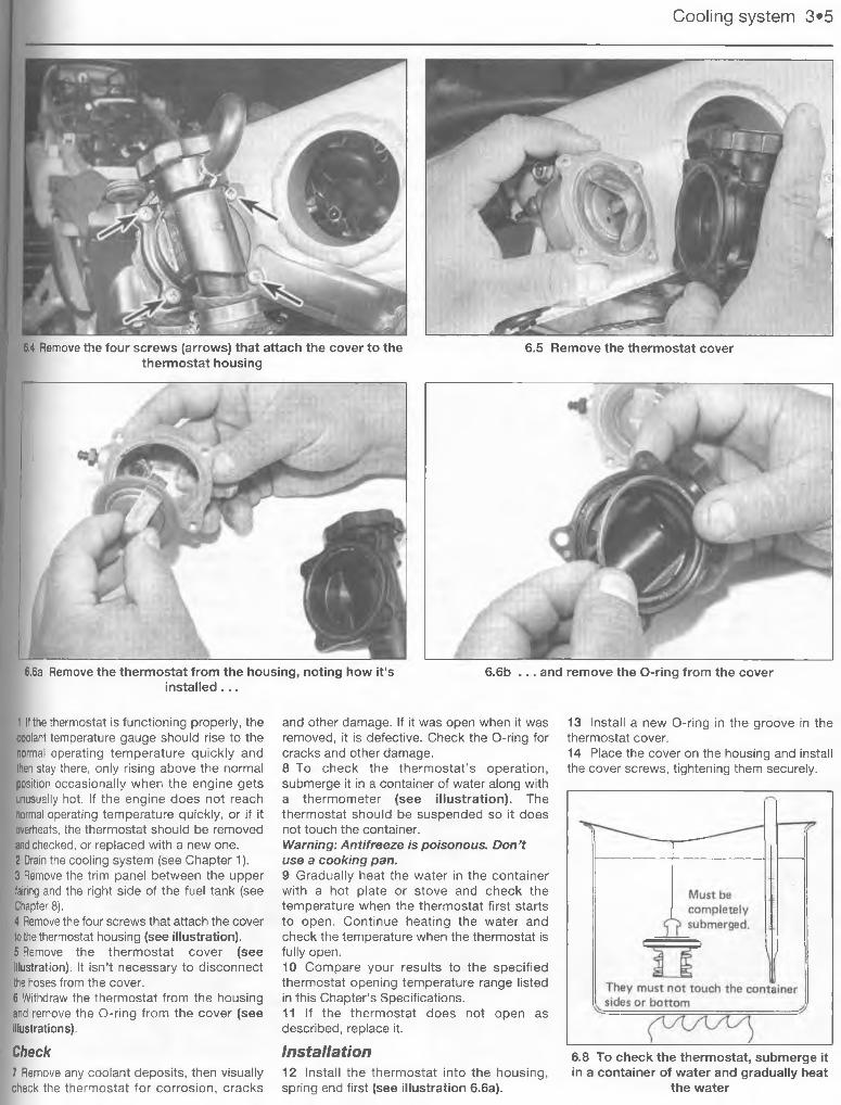
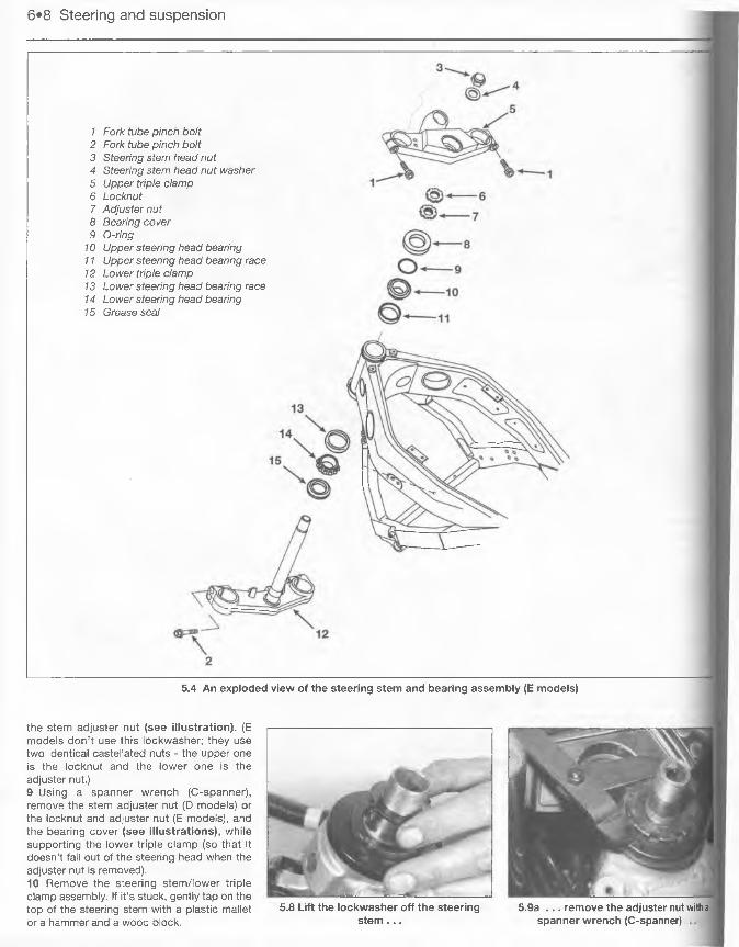
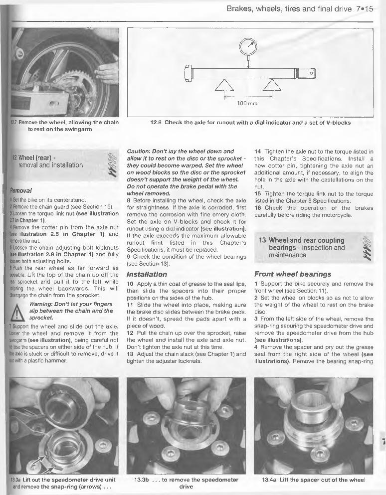
Haynes North America, Inc861 Lawrence Drive, Newbury Park, California 91320, USA
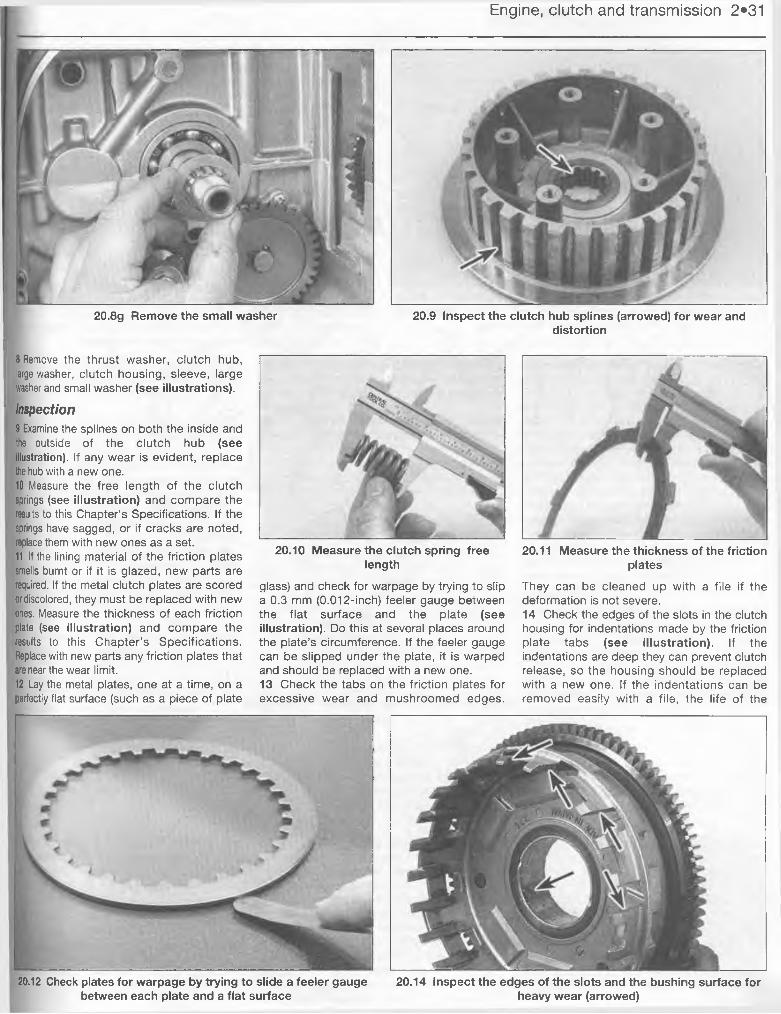
Editions Haynes4, Rue de I'Abreuvoir92415 COURBEVOIE CEDEX, France
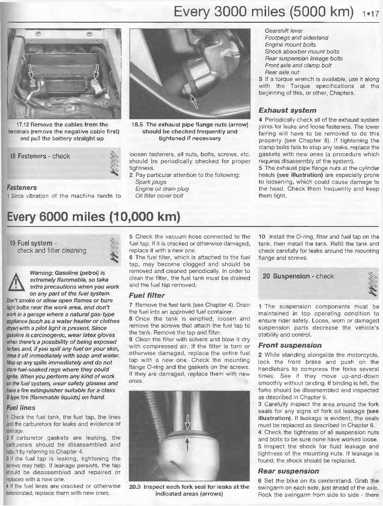
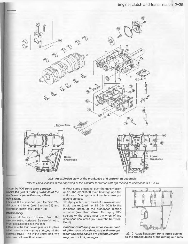
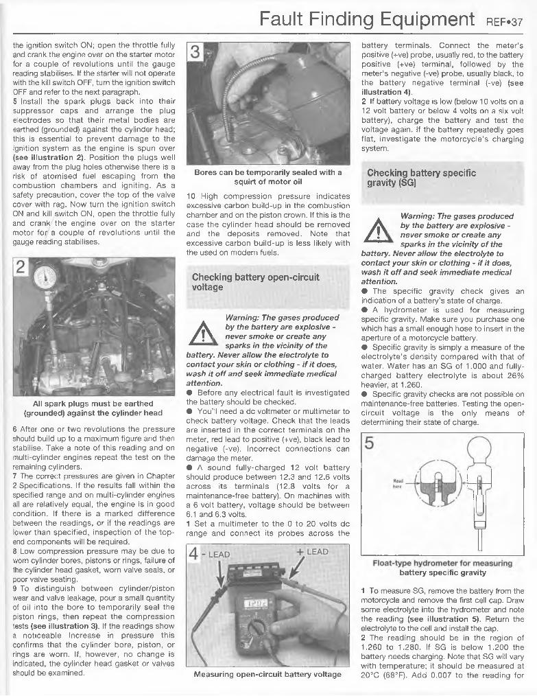
British Library Cataloguing in Publication DataA catalogue record for this book is available from the British Library.
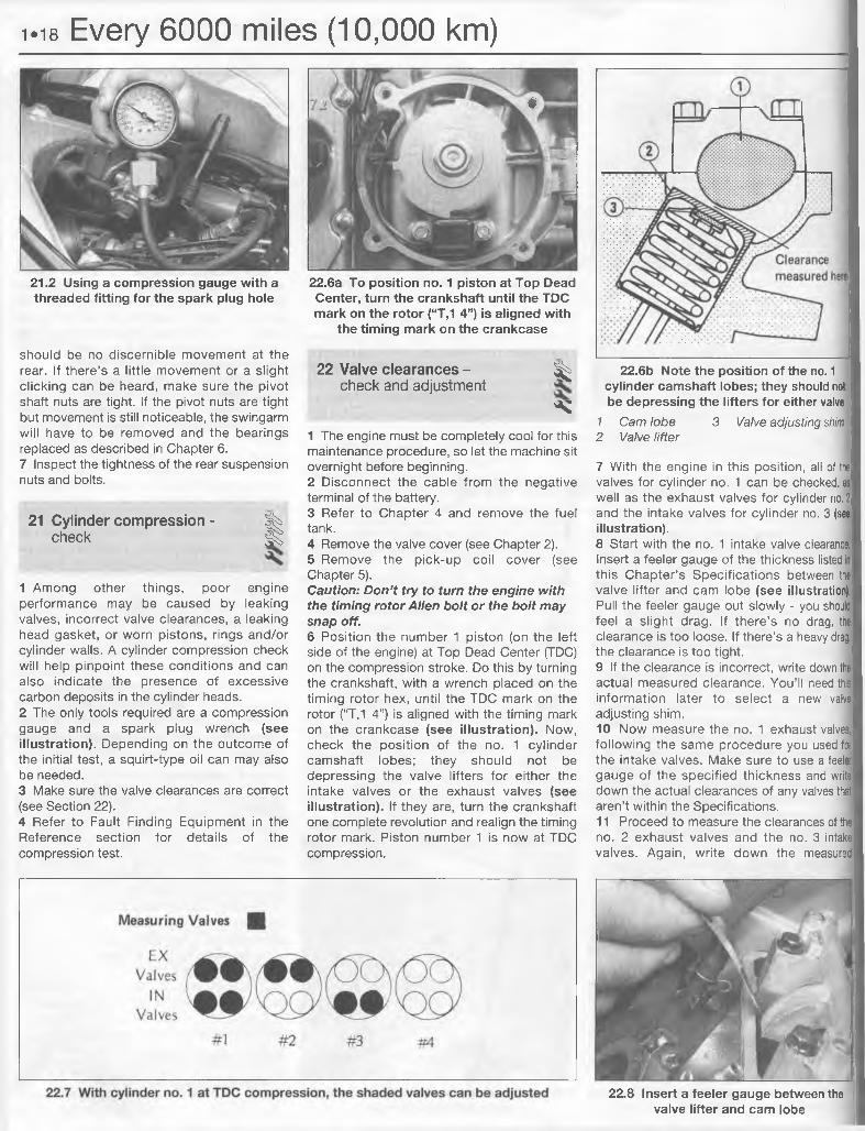
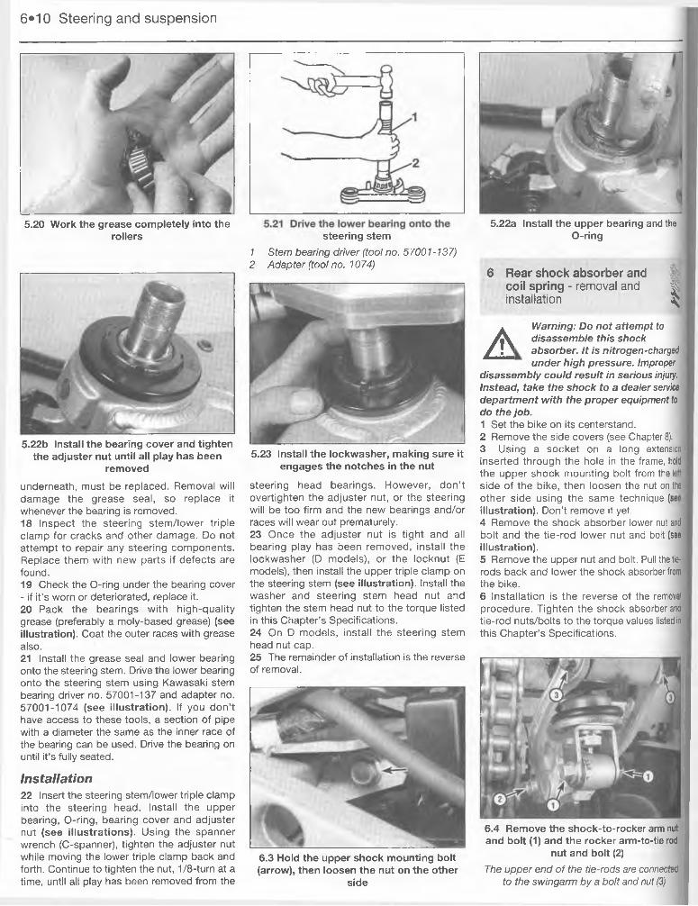
Haynes Publishing Nordiska ABBox 1504, 751 45 UPPSALA, Sweden
LIVING WITH YOUR KAWASAKI ZX600
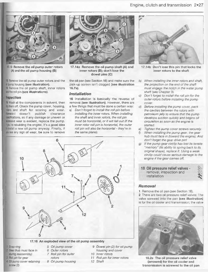
IntroductionKawasaki - The Green Meanies Page 0*4Acknowledgements Page 0*7About this manual Page 0*7Safety first! Page 0*8Identification numbers Page 0*9Buying spare parts Page 0*9
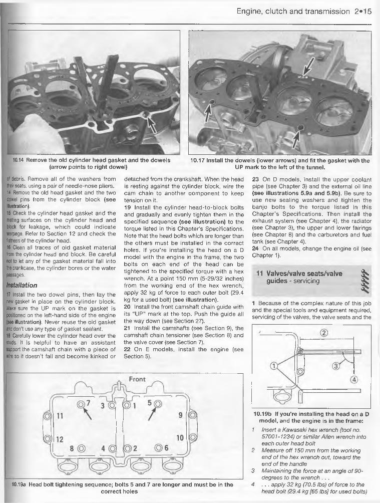
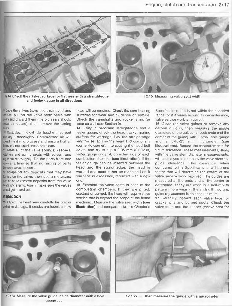
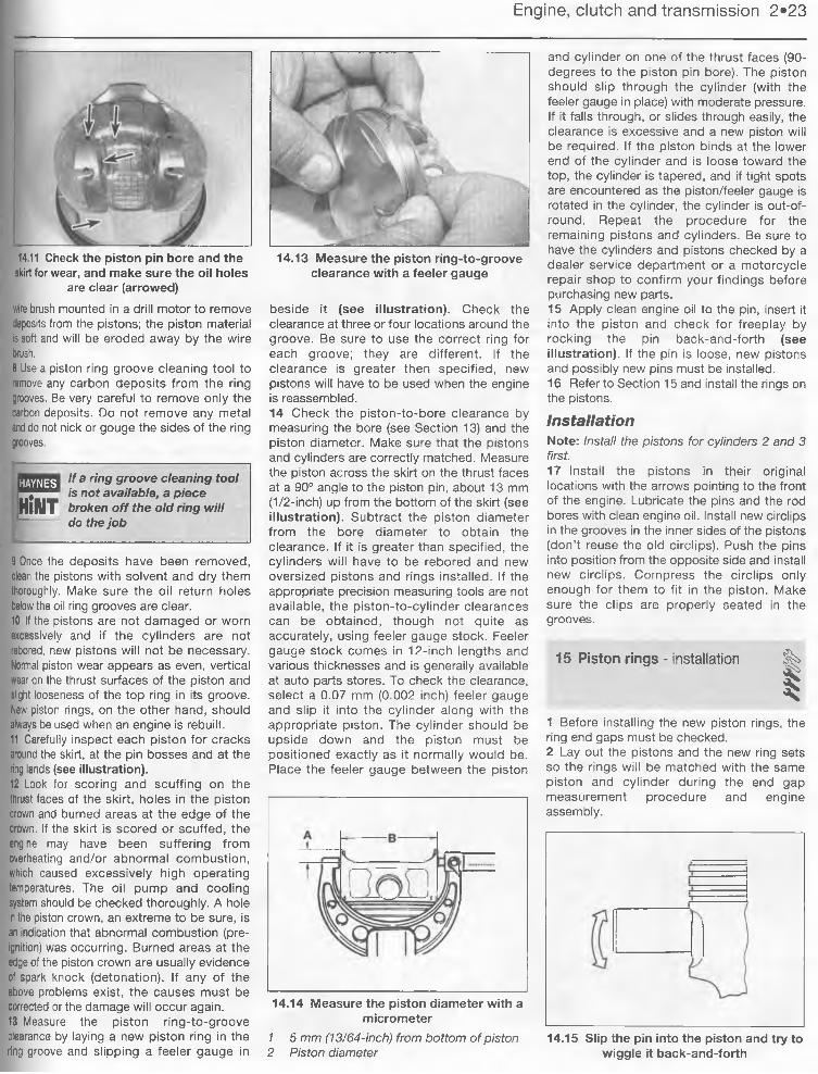
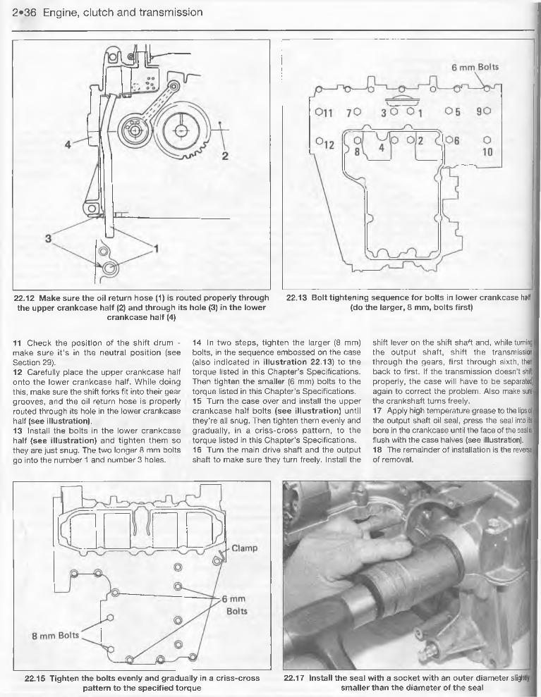
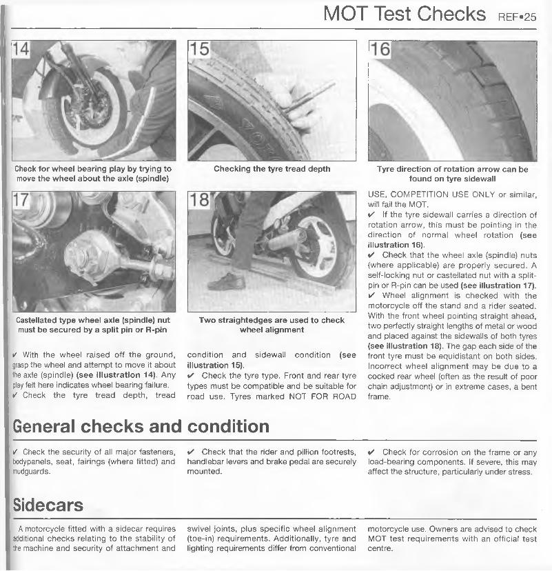
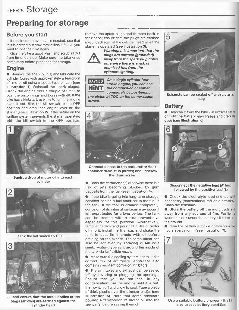
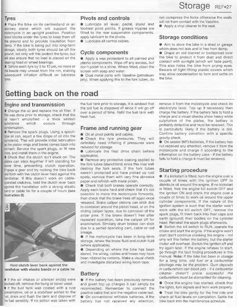
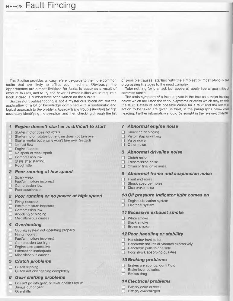
REPAIRS AND OVERHAULEngine, transmission and associated systemsEngine, clutch and transmission Page 2»1Cooling system Page 3«1Fuel and exhaust systems Page 4»1Ignition system Page 5«1
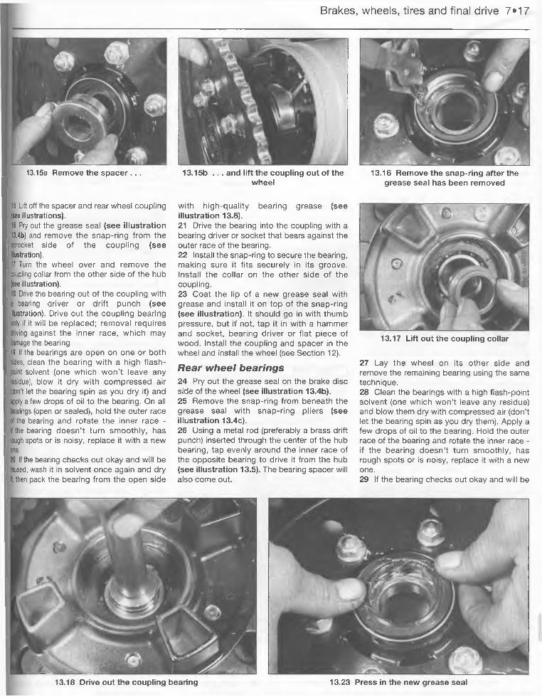
Chassis componentsSuspension and steering Page 6*1Brakes Page 7»1Wheels Page 7*13Tires Page 7»18Final drive Page 7*18Fairing, bodywork and frame Page 8*1
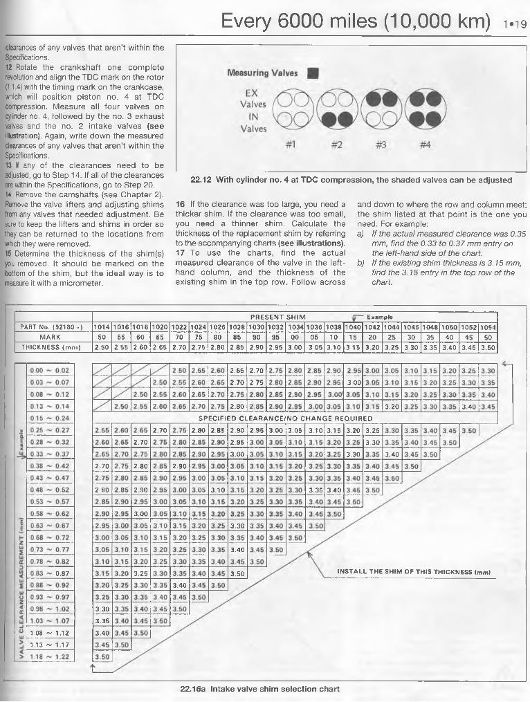
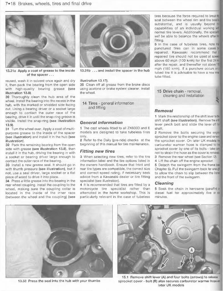
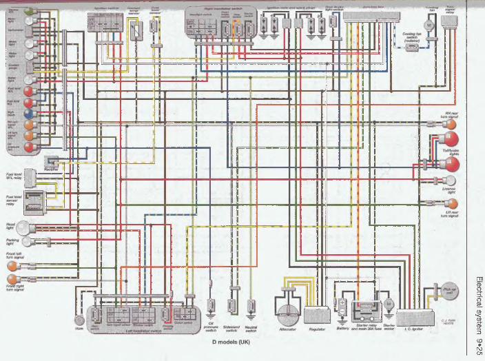
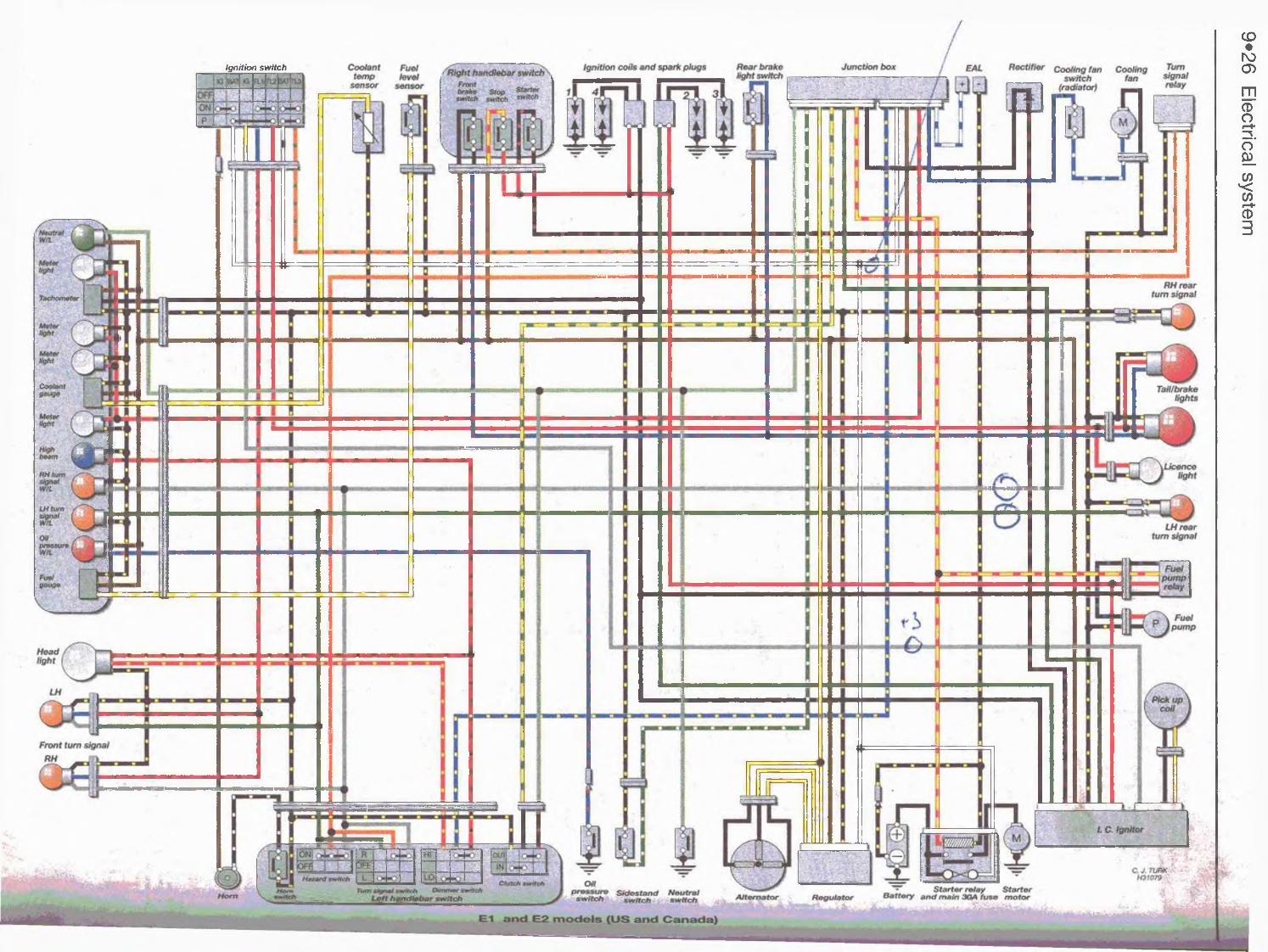
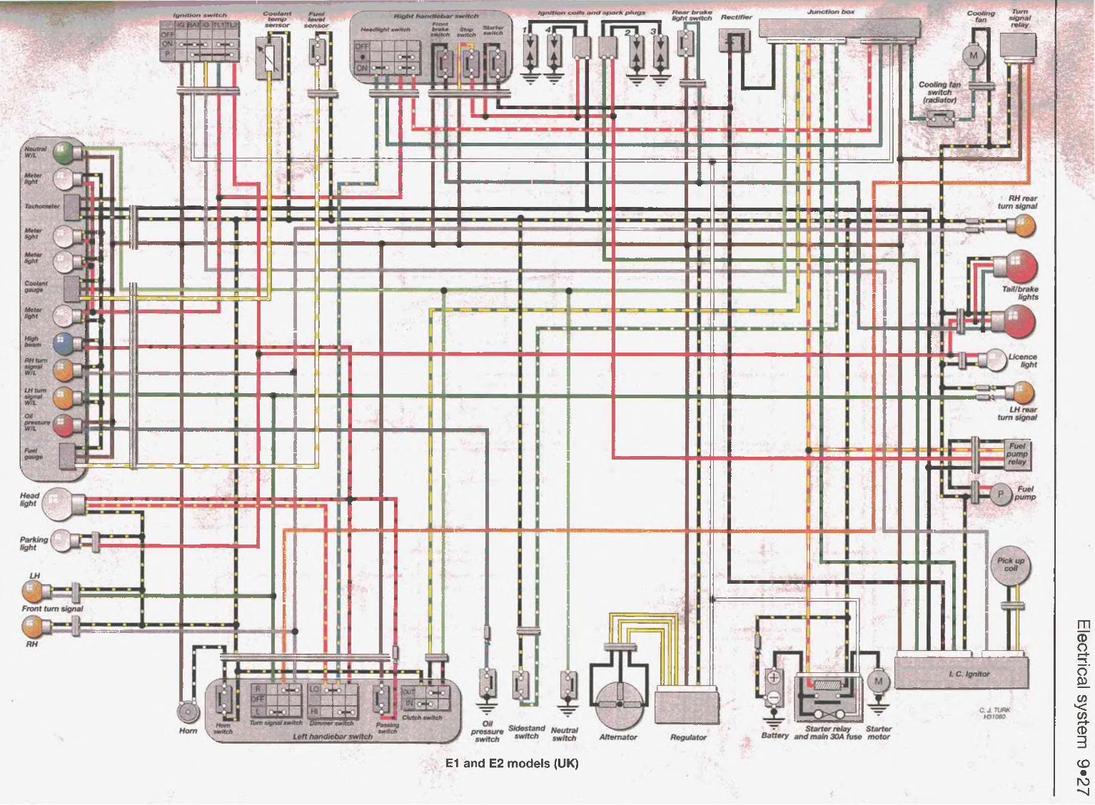
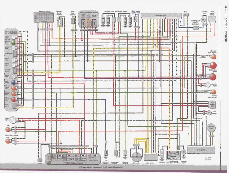
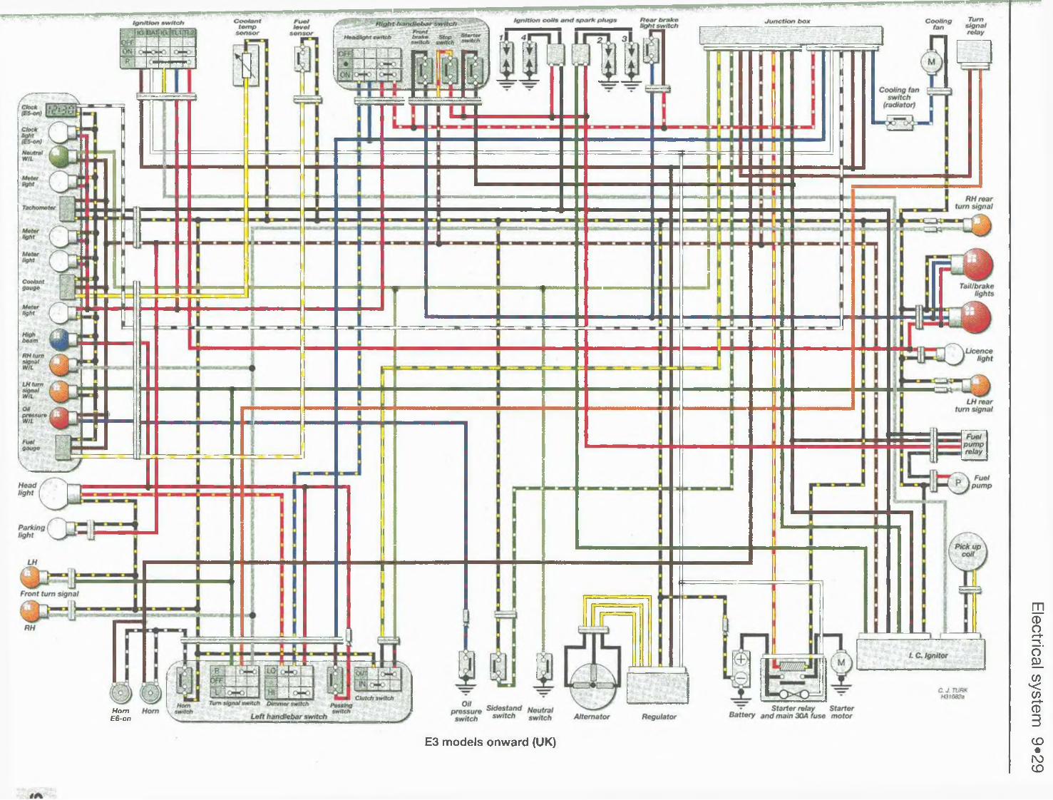
Electrical system Page 9»1
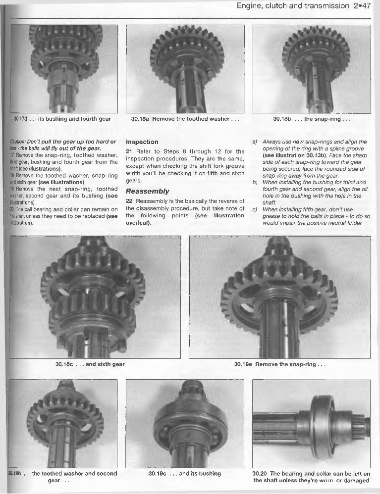
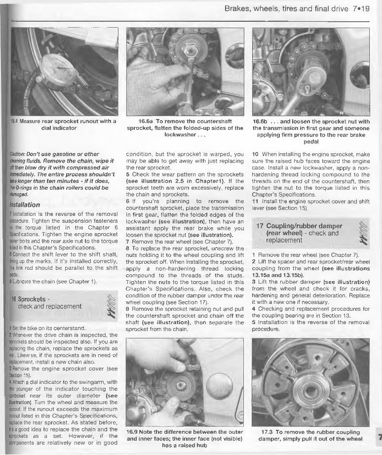
Wiring diagrams Page 9*25
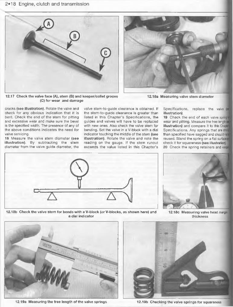
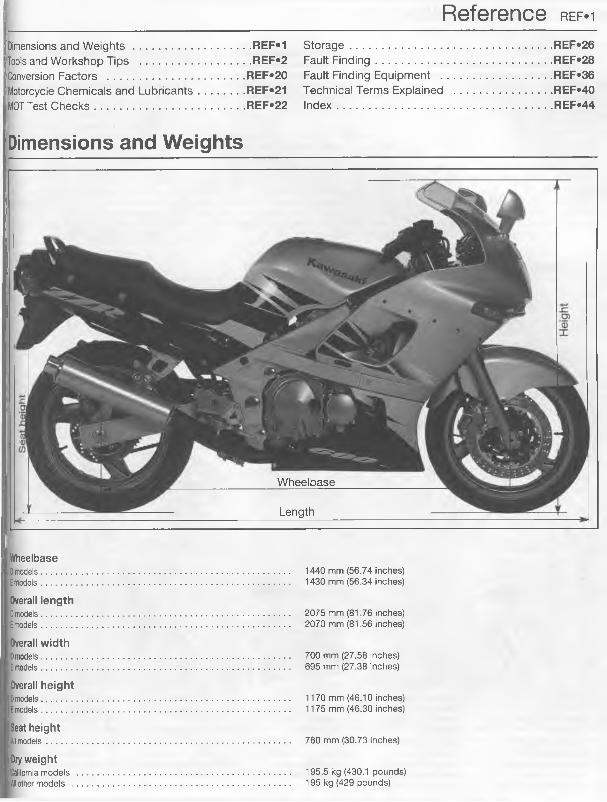
REFERENCEDimensions and Weights Page REF*!Tools and Workshop Tips Page REF*2Conversion Factors . Page REF«20Motorcycle Chemicals and Lubricants Page REF«21MOT Test Checks Page REF*22Storage Page REF*26Fault Finding t V , 1 Page REF*28Fault Finding Equipment Page REF*36Technical Terms Explained Page REF»40
Index Page REF*44
o.4 Introduction
KawasakiThe Green Meanies
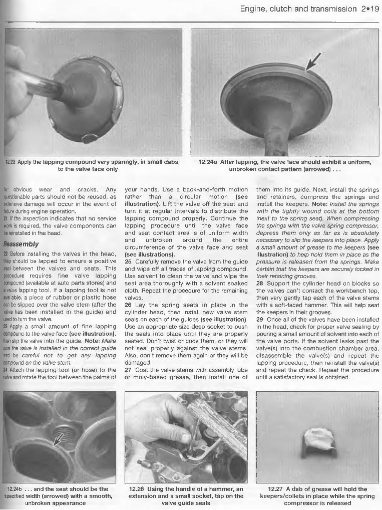
by Julian Ryder
Kawasaki Heavy Industries
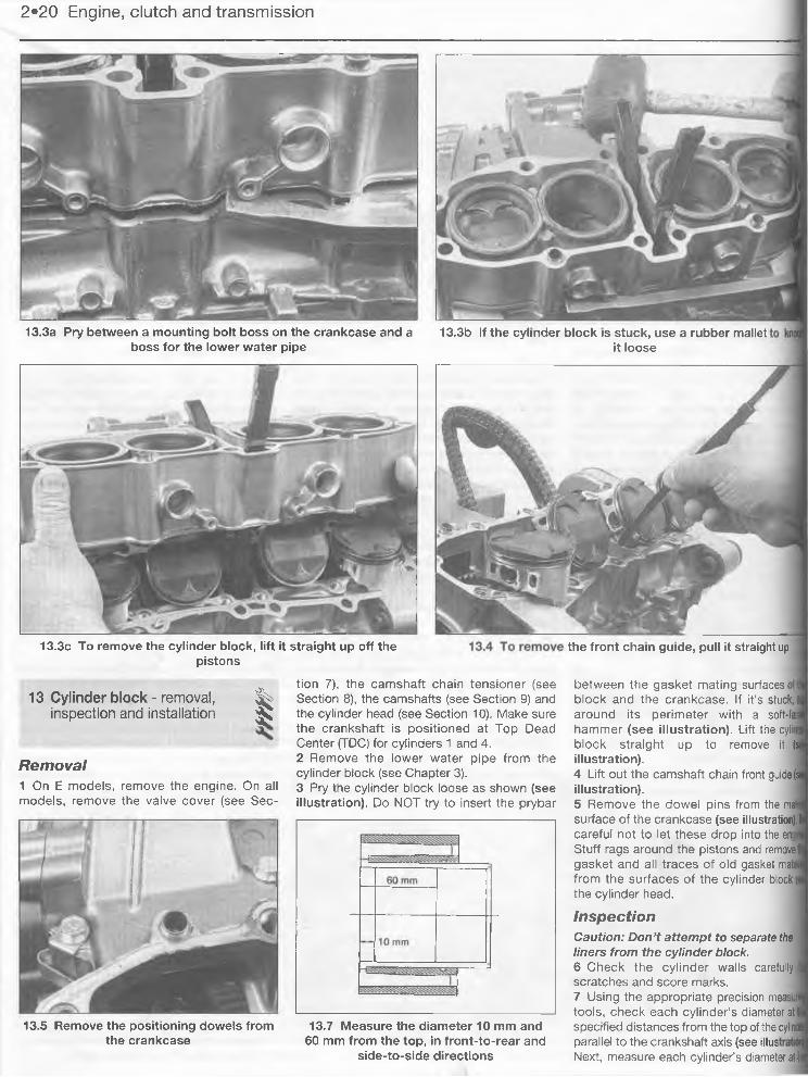
Kawasaki is a company of contradictions. It is the smallest of the big four Japanese manufacturers but the
biggest company, it was the last of the four to make and market motorcycles yet it owns the oldest name in the Japanese industry, and it was the first to set up a factory in the USA. Kawasaki Heavy Industries, of which the motorcycle operation is but a small component, is a massive company with its heritage firmly in the old heavy industries like shipbuilding and railways; nowadays it is as much involved in aerospace as in motorcycles.
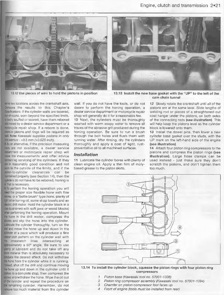
In fact it may be because of this that Kawasaki’s motorcycles have always been quirky, you get the impression that they are designed by a small group of enthusiasts who are given an admirably free hand. More realistically, it may be that Kawasaki’s designers have experience with techniques and materials from other engineering disciplines. Either way, Kawasaki have managed to be the factory who surprise us more than the rest. Quite often, they do this by totally ignoring a market segment the others are scrabbling over, but more often they hit us with pure, undiluted performance.
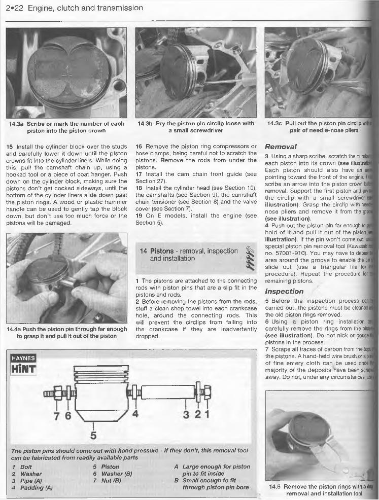
The origins of the company, and its name, go back to 1878 when Shozo Kawasaki set up a dockyard in Tokyo. By the late 1930s, the company was making its own steel in massive steelworks and manufacturing railway locos and rolling stock. In the run up to war, the Kawasaki Aircraft Company was set up in 1937 and it was this arm of the now giant operation that would look to motorcycle engine manufacture in post-war Japan.
They bought their high-technology experience to bear first on engines which were sold on to a number of manufacturers as
original equipment. Both two- and four-stroke units were made, a 58 cc and 148 cc OHC unit. One of the customer companies was Meihatsu Heavy Industries, another company within the Kawasaki group, which in 1961 was shaken up and renamed Kawasaki Auto Sales. At the same time, the Akashi factory which was to be Kawasaki’s main production facility until the Kobe earthquake of 1995, was opened. Shortly afterwards, Kawasaki took over the ailing Meguro company, Japan’s oldest motorcycle maker, thus instantly obtaining a range of bigger bikes which were marketed as Kawasaki-Meguros. The following year, the first bike to be made and sold as a Kawasaki was produced, a 125 cc single called the B8 and in 1963 a motocross version, the B8M appeared.
The three cylinder two-stroke 750
Introduction 0*5
Model development
Kawasaki’s first appearance on a road- race circuit came in 1965 with a batch of disc-valve 125 twins. They were no
match for the opposition from Japan in the shape of Suzuki and Yamaha or for the fading force of the factory MZs from East Germany.Only after the other Japanese factories had pulled out of the class did Kawasaki win, with British rider Dave Simmonds becoming World 125 GP Champion in 1969 on a bike that looked astonishingly similar to the original racer. That same year Kawasaki reorganised once again, this time merging three companies to form Kawasaki Heavy Industries. One of the new organisation’s objectives was to take motorcycie production forward and exploit markets outside Japan.
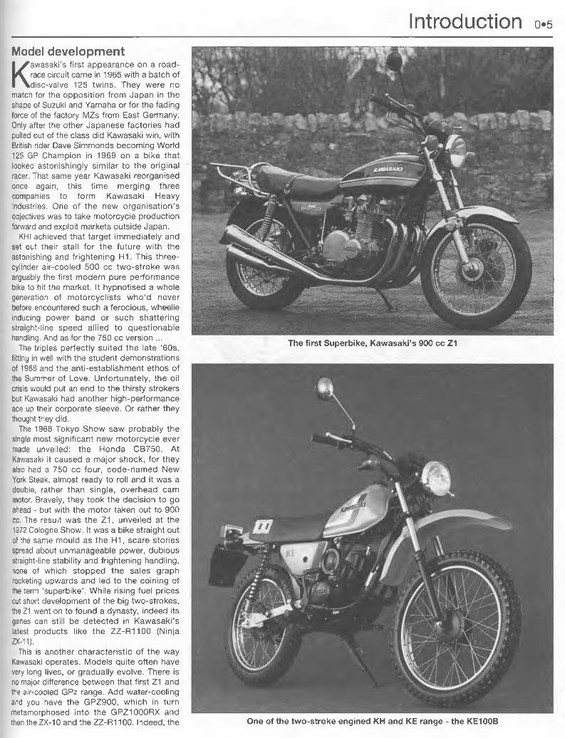
KHI achieved that target immediately and set out their stall for the future with the astonishing and frightening H1. This three- cylinder air-cooled 500 cc two-stroke was arguably the first modern pure performance bike to hit the market. It hypnotised a whole generation of motorcyclists who'd never before encountered such a ferocious, wheelie inducing power band or such shattering straight-line speed allied to questionable handling. And as for the 750 cc version ...
The triples perfectly suited the late ‘60s, fitting in well with the student demonstrations of 1968 and the anti-establishment ethos of the Summer of Love. Unfortunately, the oil crisis would put an end to the thirsty strokers but Kawasaki had another high-performance ace up their corporate sleeve. Or rather they thought they did.
The 1968 Tokyo Show saw probably the single most significant new motorcycle ever made unveiled: the Honda CB750. At Kawasaki it caused a major shock, for they also had a 750 cc four, code-named New York Steak, almost ready to roll and it was a double, rather than single, overhead cam motor. Bravely, they took the decision to go ahead - but with the motor taken out to 900 cc. The result was the Z1, unveiled at the 1972 Cologne Show. It was a bike straight out of the same mould as the H1, scare stories spread about unmanageable power, dubious straight-line stability and frightening handling, none of which stopped the sales graph rocketing upwards and led to the coining of the term ‘superbike’. While rising fuel prices cut short development of the big two-strokes, the Z1 went on to found a dynasty, indeed its genes can still be detected in Kawasaki’s latest products like the ZZ-R1100 (Ninja ZX-11).
This is another characteristic of the way Kawasaki operates. Models quite often have very long lives, or gradually evolve. There is no major difference between that first Z1 and the air-cooled GPz range. Add water-cooling and you have the GPZ900, which in turn metamorphosed into the GPZ1000RX and then the ZX-10 and the ZZ-R1100. Indeed, the One of the two-stroke engined KH and KE range - the KE100B
The first Superbike, Kawasaki’s 900 cc Z1
o*6 Introduction
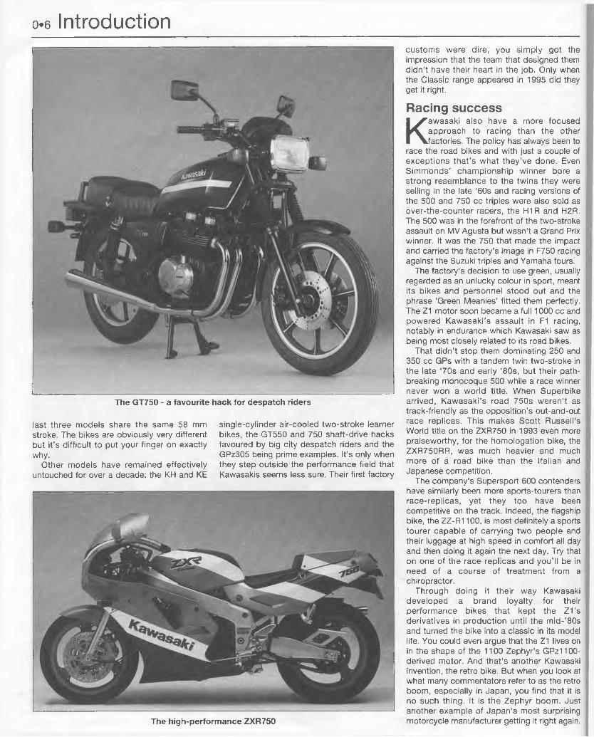
The GT750 - a favourite hack for despatch riders
last three models share the same 58 mm stroke. The bikes are obviously very different but it’s difficult to put your finger on exactly why.
Other models have remained effectively untouched for over a decade: the KH and KE
single-cylinder air-cooled two-stroke learner bikes, the GT550 and 750 shaft-drive hacks favoured by big city despatch riders and the GPz305 being prime examples. It’s only when they step outside the performance field that Kawasakis seems less sure. Their first factory
customs were dire, you simply got the Iimpression that the team that designed them Ididn’t have their heart in the job. Only when Lthe Classic range appeared in 1995 did they I get it right.
Racing success
Kawasaki also have a more focused 1 approach to racing than the other factories. The policy has always been to I
race the road bikes and with just a couple of I exceptions that’s what they’ve done. Even I Simmonds’ championship winner bore a I strong resemblance to the twins they were selling in the late ‘60s and racing versions of I the 500 and 750 cc triples were also sold as « over-the-counter racers, the H1R and H2R. ' The 500 was in the forefront of the two-stroke ' assault on MV Agusta but wasn’t a Grand Prix | winner. It was the 750 that made the impact I and carried the factory’s image in F750 racing |l against the Suzuki triples and Yamaha fours.
The factory’s decision to use green, usually | regarded as an unlucky colour in sport, meant its bikes and personnel stood out and the I phrase ‘Green Meanies’ fitted them perfectly. | The Z1 motor soon became a full 1000 cc and I' powered Kawasaki’s assault in F1 racing, I' notably in endurance which Kawasaki saw as being most closely related to its road bikes.
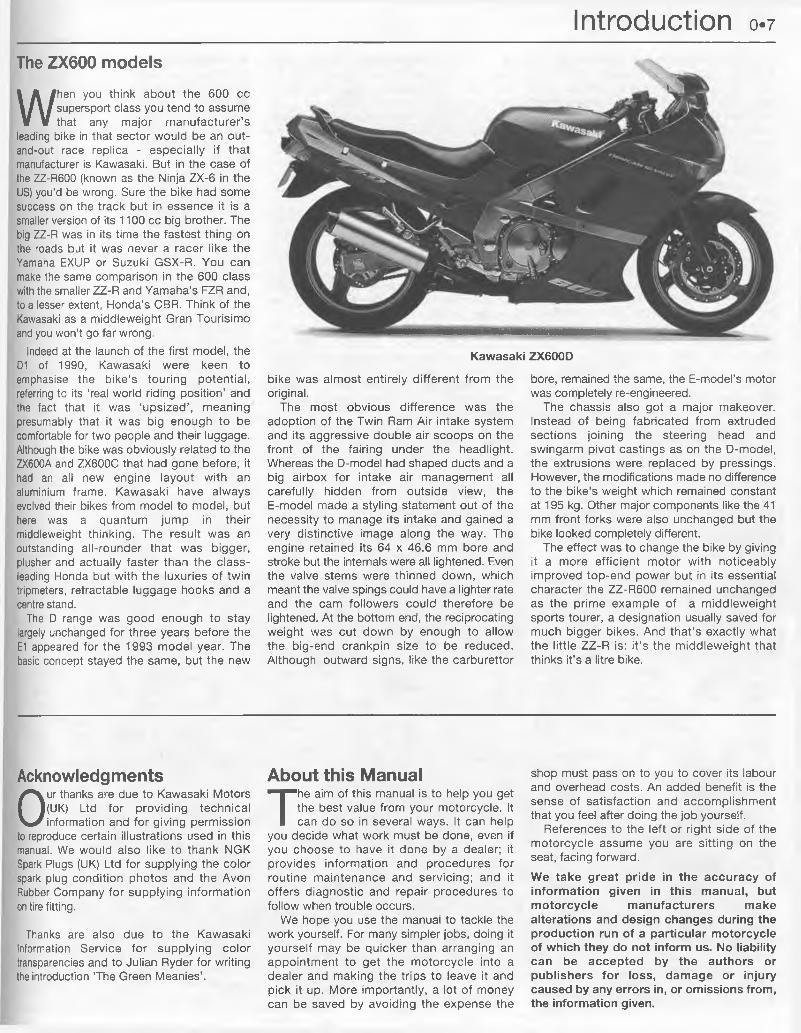
That didn’t stop them dominating 250 and 350 cc GPs with a tandem twin two-stroke in I the late ‘70s and early ‘80s, but their path- breaking monocoque 500 while a race winner never won a world title. When Superbike arrived, Kawasaki’s road 750s weren’t as I track-friendly as the opposition’s out-and-out f race replicas. This makes Scott Russell’s a World title on the ZXR750 in 1993 even more | praiseworthy, for the homologation bike, the I ZXR750RR, was much heavier and much 1 more of a road bike than the Italian and 1 Japanese competition.
The company’s Supersport 600 contenders , have similarly been more sports-tourers than race-replicas, yet they too have been competitive on the track. Indeed, the flagship I bike, the ZZ-R1100, is most definitely a sports tourer capable of carrying two people and their luggage at high speed in comfort all day I and then doing it again the next day. Try that on one of the race replicas and you’ll be in I need of a course of treatment from a chiropractor.
Through doing it their way Kawasaki |j developed a brand loyalty for their performance bikes that kept the Z1’s derivatives in production until the m id-’80s and turned the bike into a classic in its model life. You could even argue that the Z1 lives on in the shape of the 1100 Zephyr’s GPz1100- I derived motor. And that’s another Kawasaki invention, the retro bike. But when you look at what many commentators refer to as the retro boom, especially in Japan, you find that it is no such thing. It is the Zephyr boom. Just another example of Japan’s most surprising motorcycle manufacturer getting it right again.The high-performance ZXR750
Introduction 0.7
Kawasaki ZX600D
The ZX600 models
W hen you think about the 600 cc supersport class you tend to assume that any major manufacturer’s
leading bike in that sector would be an out- and-out race replica - especially if that manufacturer is Kawasaki. But in the case of the ZZ-R600 (known as the Ninja ZX-6 in the US) you’d be wrong. Sure the bike had some success on the track but in essence it is a smaller version of its 1100 cc big brother. The big ZZ-R was in its time the fastest thing on the roads but it was never a racer like the Yamaha EXUP or Suzuki GSX-R. You can make the same comparison in the 600 class with the smaller ZZ-R and Yamaha’s FZR and, to a lesser extent, Honda’s CBR. Think of the Kawasaki as a middleweight Gran Tourisimo and you won’t go far wrong.
Indeed at the launch of the first model, the D1 of 1990, Kawasaki were keen to emphasise the bike’s touring potential, referring to its ‘real world riding position’ and the fact that it was ‘upsized’ , meaning presumably that it was big enough to be comfortable for two people and their luggage. Although the bike was obviously related to the ZX600A and ZX600C that had gone before, it had an all new engine layout with an aluminium frame. Kawasaki have always evolved their bikes from model to model, but here was a quantum jump in their middleweight thinking. The result was an outstanding all-rounder that was bigger, plusher and actually faster than the class- leading Honda but with the luxuries of twin tripmeters, retractable luggage hooks and a centre stand.
The D range was good enough to stay largely unchanged for three years before the E1 appeared for the 1993 model year. The basic concept stayed the same, but the new
bike was almost entirely different from the original.
The most obvious difference was the adoption of the Twin Ram Air intake system and its aggressive double air scoops on the front of the fairing under the headlight. Whereas the D-model had shaped ducts and a big airbox for intake air management all carefully hidden from outside view, the E-model made a styling statement out of the necessity to manage its intake and gained a very distinctive image along the way. The engine retained its 64 x 46.6 mm bore and stroke but the internals were all lightened. Even the valve stems were thinned down, which meant the valve spings could have a lighter rate and the cam followers could therefore be lightened. At the bottom end, the reciprocating weight was cut down by enough to allow the big-end crankpin size to be reduced. Although outward signs, like the carburettor
bore, remained the same, the E-model’s motor was completely re-engineered.
The chassis also got a major makeover. Instead of being fabricated from extruded sections joining the steering head and swingarm pivot castings as on the D-model, the extrusions were replaced by pressings. However, the modifications made no difference to the bike’s weight which remained constant at 195 kg. Other major components like the 41 mm front forks were also unchanged but the bike looked completely different.
The effect was to change the bike by giving it a more efficient motor with noticeably improved top-end power but in its essential character the ZZ-R600 remained unchanged as the prime example of a middleweight sports tourer, a designation usually saved for much bigger bikes. And that’s exactly what the little ZZ-R is: it ’s the middleweight that thinks it’s a litre bike.
Acknowledgments
Our thanks are due to Kawasaki Motors (UK) Ltd for providing technical information and for giving permission
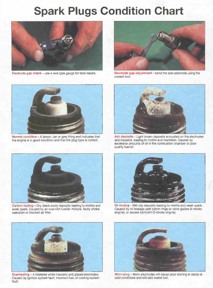
to reproduce certain illustrations used in this manual. We would also like to thank NGK Spark Plugs (UK) Ltd for supplying the color spark plug condition photos and the Avon Rubber Company for supplying information on tire fitting.
Thanks are also due to the Kawasaki Information Service for supplying color transparencies and to Julian Ryder for writing the introduction ’The Green Meanies’.
About this Manual
The aim of this manual is to help you get the best value from your motorcycle. It can do so in several ways. It can help
you decide what work must be done, even if you choose to have it done by a dealer; it provides information and procedures for routine maintenance and servicing; and it offers diagnostic and repair procedures to follow when trouble occurs.
We hope you use the manual to tackle the work yourself. For many simpler jobs, doing it yourself may be quicker than arranging an appointment to get the motorcycle into a dealer and making the trips to leave it and pick it up. More importantly, a lot of money can be saved by avoiding the expense the
shop must pass on to you to cover its labour and overhead costs. An added benefit is the sense of satisfaction and accomplishment that you feel after doing the job yourself.
References to the left or right side of the motorcycle assume you are sitting on the seat, facing forward.
We take great pride in the accuracy of information given in this manual, but motorcycle manufacturers make alterations and design changes during the production run of a particular motorcycle of which they do not inform us. No liability can be accepted by the authors or publishers for loss, damage or injury caused by any errors in, or omissions from, the information given.
o»8 Safety first!Professional mechanics are trained in safe
working procedures. However enthusiastic you may be about getting on with the job at hand, take the time to ensure that your safety is not put at risk. A moment’s lack of attention can result in an accident, as can failure to observe simple precautions.
There will always be new ways of having accidents, and the following is not a comprehensive list of all dangers; it is intended rather to make you aware of the risks and to encourage a safe approach to all work you carry out on your bike.
Asbestos• Certain friction, insulating, sealing and other products - such as brake pads, clutch linings, gaskets, etc. - contain asbestos. Extreme care must be taken to avoid inhalation of dust from such products since it is hazardous to health. If in doubt, assume that they do contain asbestos.
Fire• Remember at all times that petrol is highly flammable. Never smoke or have any kind of naked flame around, when working on the vehicle. But the risk does not end there - a spark caused by an electrical short-circuit, by two metal surfaces contacting each other, by careless use of tools, or even by static electricity built up in your body under certain conditions, can ignite petrol vapour, which in a confined space is highly explosive. Never use petrol as a cleaning solvent. Use an approved safety solvent.
• Always disconnect the battery earth terminal before working on any part of the fuel or electrical system, and never risk spilling fuel on to a hot engine or exhaust.• It is recommended that a fire extinguisher of a type suitable for fuel and electrical fires is kept handy in the garage or workplace at all times. Never try to extinguish a fuel or electrical fire with water.
Fumes• Certain fumes are highly toxic and can quickly cause unconsciousness and even death if inhaled to any extent. Petrol vapour comes into this category, as do the vapours from certain solvents such as trichloro- ethylene. Any draining or pouring of such volatile fluids should be done in a well ventilated area.• When using cleaning fluids and solvents, read the instructions carefully. Never use materials from unmarked containers - they may give off poisonous vapours.• Never run the engine of a motor vehicle in an enclosed space such as a garage. Exhaust fumes contain carbon monoxide which is extremely poisonous; if you need to run the engine, always do so in the open air or at least have the rear of the vehicle outside the workplace.
The battery• Never cause a spark, or allow a naked light near the vehicle’s battery. It will normally be giving off a certain amount of hydrogen gas, which is highly explosive.
• Always disconnect the battery ground (earth) terminal before working on the fuel or electrical systems (except where noted).• If possible, loosen the filler plugs or cover when charging the battery from an external source. Do not charge at an excessive rate or the battery may burst.• Take care when topping up, cleaning or carrying the battery. The acid electrolyte, evenwhen diluted, is very corrosive and should not be allowed to contact the eyes or skin. Always wear rubber gloves and goggles or a face shield. If you ever need to prepare electrolyte yourself, always add the acid slowly to the water; never add the water to the acid.
Electricity• When using an electric power tool, inspection light etc., always ensure that the appliance is correctly connected to its plug and that, where necessary, it is properly grounded (earthed). Do not use such appliances in damp conditions and, again, beware of creating a spark or applying excessive heat in the vicinity of fuel or fuel vapour. Also ensure that the appliances meet national safety standards.• A severe electric shock can result from touching certain parts of the electrical system, such as the spark plug wires (HT leads), when the engine is running or being cranked, particularly if components are damp or the insulation is defective. Where an electronic ignition system is used, the secondary (HT) voltage is much higher and could prove fatal.
Remember...X Don’t start the engine without first ascertaining that the transmission is in neutral. X Don’t suddenly remove the pressure cap from a hot cooling system - cover it with a cloth and release the pressure gradually first, or you may get scalded by escaping coolant. X Don’t attempt to drain oil until you are sure it has cooled sufficiently to avoid scalding you.X Don’t grasp any part of the engine or exhaust system without first ascertaining that it is cool enough not to burn you.X Don’t allow brake fluid or antifreeze to contact the machine’s paintwork or plastic components.X Don’t siphon toxic liquids such as fuel, hydraulic fluid or antifreeze by mouth, or allow them to remain on your skin.X Don’t inhale dust - it may be injurious to health (see Asbestos heading).X Don’t allow any spilled oil or grease to remain on the floor - wipe it up right away, before someone slips on it.X Don’t use ill-fitting spanners or other tools which may slip and cause injury.X Don’t lift a heavy component which may be beyond your capability - get assistance.
X Don’t rush to finish a job or take unverified short cuts.X Don’t allow children or animals in or around an unattended vehicle.X Don’t inflate a tyre above the recommended pressure. Apart from overstressing the carcass, in extreme cases the tyre may blow off forcibly.✓ Do ensure that the machine is supported securely at all times. This is especially important when the machine is blocked up to aid wheel or fork removal.✓ Do take care when attempting to loosen a stubborn nut or bolt. It is generally better to pull on a spanner, rather than push, so that if you slip, you fall away from the machine rather than onto it.✓ Do wear eye protection when using power tools such as drill, sander, bench grinder etc.✓ Do use a barrier cream on your hands prior to undertaking dirty jobs - It will protect your skin from infection as well as making the dirt easier to remove afterwards; but make sure your hands aren’t left slippery. Note that long-term contact with used engine oil can be a health hazard.✓ Do keep loose clothing (cuffs, ties etc. and long hair) well out of the way of moving mechanical parts.
✓ Do remove rings, wristwatch etc., before working on the vehicle - especially the electrical system.✓ Do keep your work area tidy - it is only too easy to fall over articles left lying around.✓ Do exercise caution when compressing springs for removal or installation. Ensure that the tension is applied and released in a controlled manner, using suitable tools which preclude the possibility of the spring escaping violently.✓ Do ensure that any lifting tackle used has a safe working load rating adequate for the job.✓ Do get someone to check periodically that all is well, when working alone on the vehicle.✓ Do carry out work in a logical sequence and check that everything is correctly assembled and tightened afterwards.✓ Do remember that your vehicle’s safety affects that of yourself and others. If in doubt on any point, get professional advice.• If in spite of following these precautions, you are unfortunate enough to injure yourself, seek medical attention as soon as possible.
Identification numbers 0.9
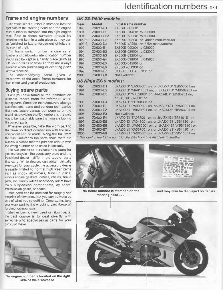
Frame and engine numbersThe frame serial number is stamped into the
right side of the steering head and the engine serial number is stamped into the right engine case. Both of these numbers should be recorded and kept in a safe place so they can be furnished to law enforcement officials in the event of theft.
The frame serial number, engine serial number and carburetor identification number should also be kept in a handy place (such as with your driver’s license) so they are always available when purchasing or ordering parts for your machine.
The accompanying table gives a breakdown of the initial frame numbers for each model and year of production.
Buying spare partsOnce you have found all the identification
numbers, record them for reference when buying parts. Since the manufacturers change specifications, parts and vendors (companies that manufacture various components on the machine), providing the ID numbers is the only way to be reasonably sure that you are buying the correct parts.
Whenever possible, take the worn part to the dealer so direct comparison with the new component can be made. Along the trail from the manufacturer to the parts shelf, there are numerous places that the part can end up with the wrong number or be listed incorrectly.
The two places to purchase new parts for your motorcycle - the accessory store and the franchised dealer - differ in the type of parts they carry. While dealers can obtain virtually every part for your cycle, the accessory dealer is usually limited to normal high wear items such as shock absorbers, tune-up parts, various engine gaskets, cables, chains, brake parts, etc. Rarely will an accessory outlet have major suspension components, cylinders, transmission gears, or cases.
Used parts can be obtained for roughly half the price of new ones, but you can’t always be sure of what you’re getting. Once again, take your worn part to the wrecking yard (breaker) for direct comparison.
Whether buying new, used or rebuilt parts, the best course is to deal directly with someone who specializes in parts for your particular make.
UK ZZ-R600 models:Year Model Initial frame number1990 ZX600-D1 ZX600D-0000011991 ZX600-D2 ZX600D-014001 to 0280001991 ZX600-D2A ZX600D-600001 to 6025001992/3 ZX600-D3 ZX600D-028001 on (Japan manufacture)1992/3 ZX600-D3 ZX600D-602501 on (USA manufacture)1993 ZX600-E1 ZX600E-000001 to 0200001994 ZX600-E2 ZX600E-020001 to 0320001995 ZX600-E3 ZX600E-032001 on1996 ZX600-E4 ZX600E-038001 to 0450001997 ZX600-E5 ZX600E-045001 on1998 ZX600-E6 ZX600E-050001 on1999 ZX600-E7 JKAZX600EEA057001 on2000 ZX600-E8 Not available
US Ninja ZX-6 models:1990 ZX600-D1 JKAZX4D1 *I_A000001 on, or JKAZX4D1*LB500001 on1991 ZX600-D2 JKAZX4D1 *MA014001 on, or JKAZX4D1*MB502201 on1992 ZX600-D3 JKAZX4D1 "NA028001 on, JKAZX4D1*NB505201 on,
or ZX600D-028001 on1993 ZX600-D4 JKAZX4D1 *PB508301 on1993 ZX600-E1 JKAZX4E1 *PA000001 on, or JKAZX4E1*PB500001 on1994 ZX600-E2 JKAZX4E1 *RA020001 on, or JKAZX4E1*RB503201 on1995 ZX600-E3 Not available1996 ZX600-E4 JKAZX4E1 *TA038001 on, or JKAZX4E1*TB510151 on1997 ZX600-E5 JKAZX4E1 *VA045001 on, or JKAZX4E1 *VB511801 on1998 ZX600-E6 JKAZX4E1 'WA050001 on, or JKAZX4E1‘WB513101 on1999 ZX600-E7 JKAZX4E1 ‘XA057001 on, or JKAZX4E1*XB514301 on2000 ZX600-E8 JKAZX4E1 *YA065001 on, or JKAZX4E1*YB515601 on* This digit in the frame number changes from one machine to another.
The engine number is located on the right side of the crankcase
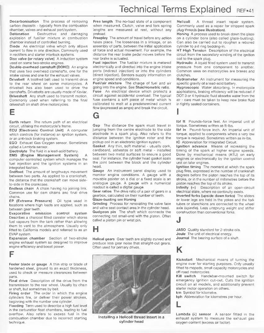
i w a inn im *”• ■'f t * m tii tu iT iiiW m in I'M c ihxta tiHmtu ««1 m us mi tit aai; m
5 OMITS SS M II II m CM J.KAZXDLXXXXXXXXX
HftMCTOf
and may also be displayed on decalsThe frame number is stamped on the steering head . . .
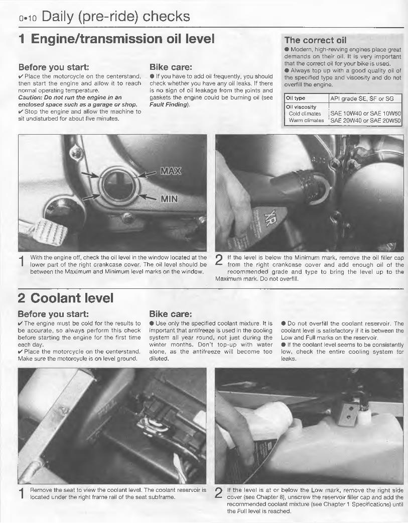
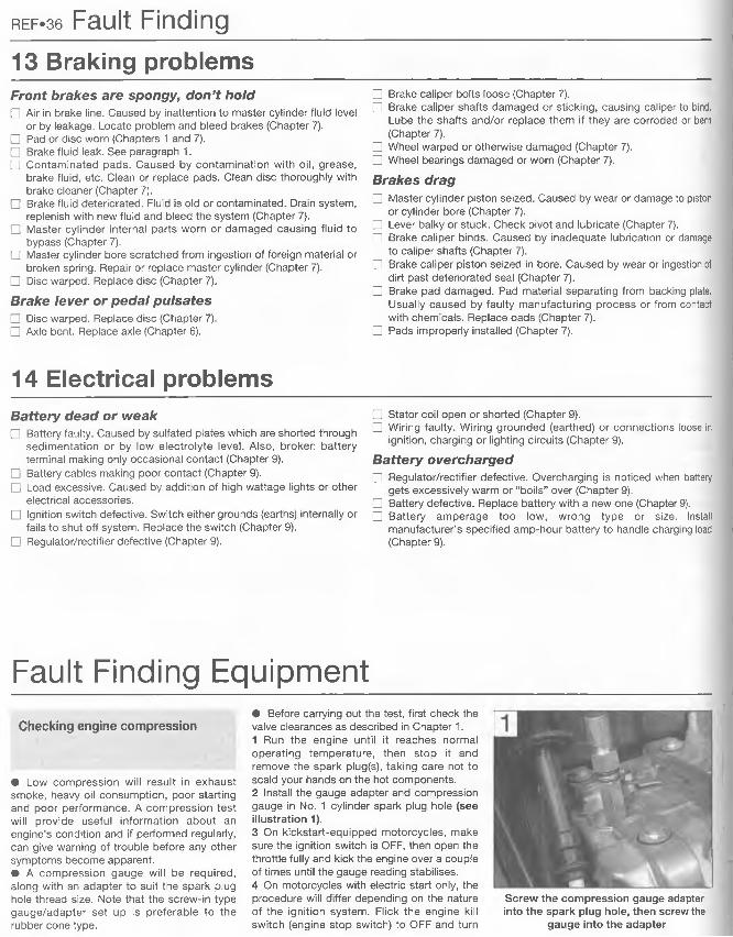
Before you start:✓ Place the motorcycle on the centerstand, then start the engine and allow it to reach normal operating temperature.Caution: Do not run the engine in an enclosed space such as a garage or shop.✓ Stop the engine and allow the machine to sit undisturbed for about five minutes.
Bike care:• If you have to add oil frequently, you should check whether you have any oil leaks. If there is no sign of oil leakage from the joints and gaskets the engine could be burning oil (see Fault Finding).
The correct oil• Modern, high-rewing engines place great demands on their oil. It is very important that the correct oil for your bike is used.• Always top up with a good quality oil of the specified type and viscosity and do not overfill the engine.
Oil type API grade SE, SF or SGOil viscosityCold climates Warm climates
SAE 10W40 or SAE 10W50 SAE 20W40 or SAE 20W50
I With the engine off, check the oil level in the window located at the lower part of the right crankcase cover. The oil level should be between the Maximum and Minimum level marks on the window.
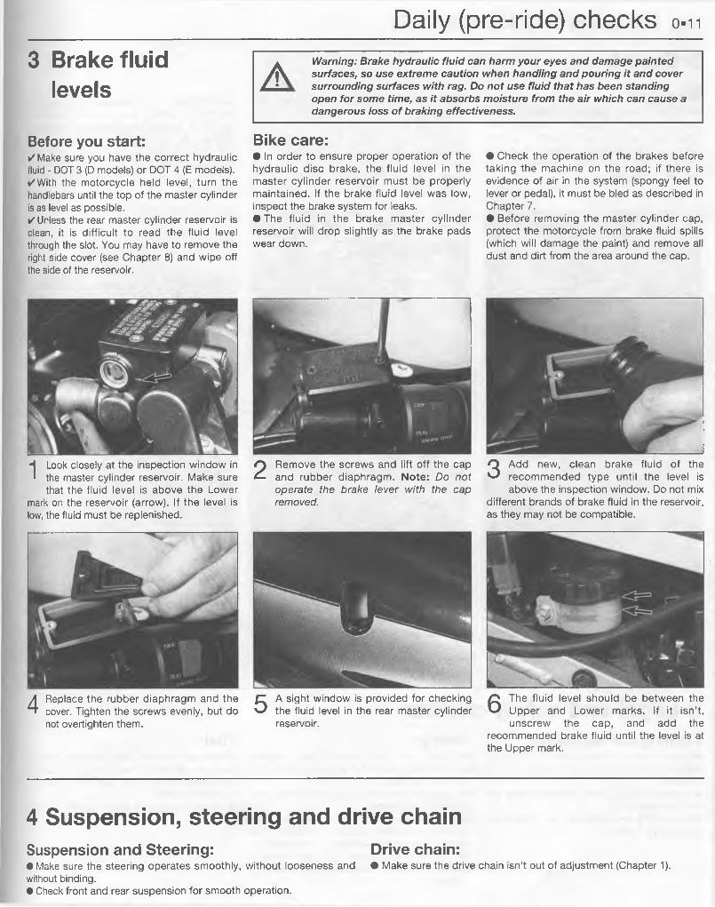
2 If the level is below the Minimum mark, remove the oil filler cap from the right crankcase cover and add enough oil of the recommended grade and type to bring the level up to the
Maximum mark. Do not overfill.
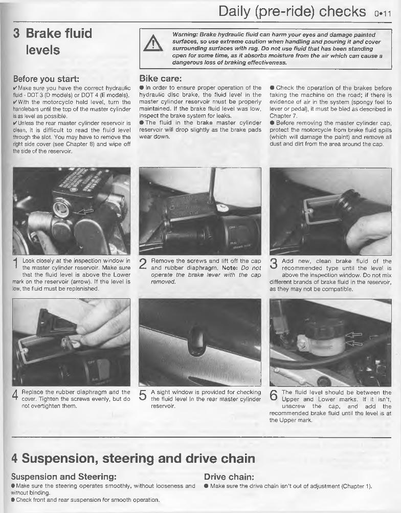
2 Coolant levelBefore you start:✓ The engine must be cold for the results to be accurate, so always perform this check before starting the engine for the first time each day.✓ Place the motorcycle on the centerstand. Make sure the motorcycle is on level ground.
Bike care:• Use only the specified coolant mixture. It is important that antifreeze is used in the cooling system all year round, not just during the winter months. Don’t top-up with water alone, as the antifreeze will become too diluted.
• Do not overfill the coolant reservoir. The coolant level is satisfactory if it is between the Low and Full marks on the reservoir.• If the coolant level seems to be consistently low, check the entire cooling system for leaks.
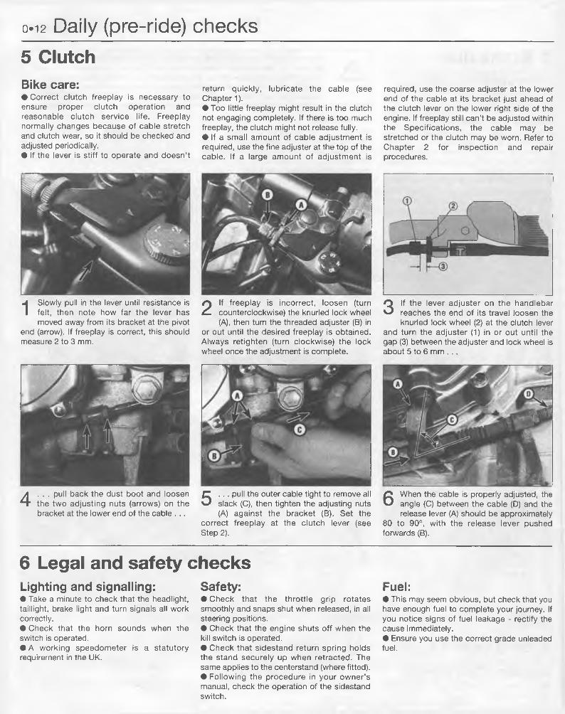
1 Remove the seat to view the coolant level. The coolant reservoir is located under the right frame rail of the seat subframe. 2 If the level is at or below the Low mark, remove the right side
cover (see Chapter 8), unscrew the reservoir filler cap and add the recommended coolant mixture (see Chapter 1 Specifications) until the Full level is reached.
Daily (pre-ride) checks 0.11
3 Brake fluid levels A Warning: Brake hydraulic fluid can harm your eyes and damage painted
surfaces, so use extreme caution when handling and pouring it and cover surrounding surfaces with rag. Do not use fluid that has been standing open for some time, as it absorbs moisture from the air which can cause a dangerous loss of braking effectiveness.
Before you start:✓ Make sure you have the correct hydraulic fluid - DOT 3 (D models) or DOT 4 (E models).✓ With the motorcycle held level, turn the handlebars until the top of the master cylinder is as level as possible.✓ Unless the rear master cylinder reservoir is clean, it is difficult to read the fluid level through the slot. You may have to remove the right side cover (see Chapter 8) and wipe off the side of the reservoir.
Bike care:• In order to ensure proper operation of the hydraulic disc brake, the fluid level in the master cylinder reservoir must be properly maintained. If the brake fluid level was low, inspect the brake system for leaks.• The fluid in the brake master cylinder reservoir will drop slightly as the brake pads wear down.
• Check the operation of the brakes before taking the machine on the road; if there is evidence of air in the system (spongy feel to lever or pedal), it must be bled as described in Chapter 7.• Before removing the master cylinder cap, protect the motorcycle from brake fluid spills (which will damage the paint) and remove all dust and dirt from the area around the cap.
ILook closely at the inspection window in the master cylinder reservoir. Make sure that the fluid level is above the Lower
mark on the reservoir (arrow). If the level is low, the fluid must be replenished.
2 Remove the screws and lift off the cap and rubber diaphragm. Note: Do not operate the brake lever with the cap removed.
3 Add new, clean brake fluid of the recommended type until the level is above the inspection window. Do not mix
different brands of brake fluid in the reservoir, as they may not be compatible.
5 A sight window is provided for checking the fluid level in the rear master cylinder reservoir.
6 The fluid level should be between the Upper and Lower marks. If it isn’t, unscrew the cap, and add the
recommended brake fluid until the level is at the Upper mark.
4 Replace the rubber diaphragm and the cover. Tighten the screws evenly, but do not overtighten them.
4 Suspension, steering and drive chainSuspension and Steering: Drive chain:• Make sure the steering operates smoothly, without looseness and • Make sure the drive chain isn’t out of adjustment (Chapter 1). without binding.• Check front and rear suspension for smooth operation.
Daily (pre-ride) checks on3 Brake fluid
levels A Warning: Brake hydraulic fluid can harm your eyes and damage painted surfaces, so use extreme caution when handling and pouring it and cover surrounding surfaces with rag. Do not use fluid that has been standing open for some time, as it absorbs moisture from the air which can cause a dangerous loss of braking effectiveness.
Before you start:✓ Make sure you have the correct hydraulic fluid - DOT 3 (D models) or DOT 4 (E models).✓ With the motorcycle held level, turn the handlebars until the top of the master cylinder is as level as possible.✓ Unless the rear master cylinder reservoir is clean, it is difficult to read the fluid level through the slot. You may have to remove the right side cover (see Chapter 8) and wipe off the side of the reservoir.
Bike care:• In order to ensure proper operation of the hydraulic disc brake, the fluid level in the master cylinder reservoir must be properly maintained. If the brake fluid level was low, inspect the brake system for leaks.• The fluid in the brake master cylinder reservoir will drop slightly as the brake pads wear down.
• Check the operation of the brakes before taking the machine on the road; if there is evidence of air in the system (spongy feel to lever or pedal), it must be bled as described in Chapter 7.• Before removing the master cylinder cap, protect the motorcycle from brake fluid spills (which will damage the paint) and remove all dust and dirt from the area around the cap.
ILook closely at the inspection window in the master cylinder reservoir. Make sure that the fluid level is above the Lower
mark on the reservoir (arrow). If the level is low, the fluid must be replenished.
2 Remove the screws and lift off the cap and rubber diaphragm. Note: Do not operate the brake lever with the cap removed.
5 A sight window is provided for checking the fluid level in the rear master cylinder reservoir.
3 Add new, clean brake fluid of the recommended type until the level is above the inspection window. Do not mix
different brands of brake fluid in the reservoir, as they may not be compatible.
6 The fluid level should be between the Upper and Lower marks. If it isn’t, unscrew the cap, and add the
recommended brake fluid until the level is at the Upper mark.
4 Replace the rubber diaphragm and the cover. Tighten the screws evenly, but do not overtighten them.
4 Suspension, steering and drive chainSuspension and Steering: Drive chain:• Make sure the steering operates smoothly, without looseness and • Make sure the drive chain isn’t out of adjustment (Chapter 1). without binding.• Check front and rear suspension for smooth operation.
o.i2 Daily (pre-ride) checks5 ClutchBike care:• Correct clutch freeplay is necessary to ensure proper clutch operation and reasonable clutch service life. Freeplay normally changes because of cable stretch and clutch wear, so it should be checked and adjusted periodically.• If the lever is stiff to operate and doesn’t
return quickly, lubricate the cable (see Chapter 1).• Too little freeplay might result in the clutch not engaging completely. If there is too much freeplay, the clutch might not release fully.• If a small amount of cable adjustment is required, use the fine adjuster at the top of the cable. If a large amount of adjustment is
required, use the coarse adjuster at the lower end of the cable at its bracket just ahead of the clutch lever on the lower right side of the engine. If freeplay still can’t be adjusted within the Specifications, the cable may be stretched or the clutch may be worn. Refer to Chapter 2 for inspection and repair procedures.
2 If freeplay is incorrect, loosen (turn counterclockwise) the knurled lock wheel (A), then turn the threaded adjuster (B) in
or out until the desired freeplay is obtained. Always retighten (turn clockwise) the lock wheel once the adjustment is complete.
4 . . . pull back the dust boot and loosen the two adjusting nuts (arrows) on the bracket at the lower end of the cable . . .
5 . . . pull the outer cable tight to remove all slack (C), then tighten the adjusting nuts (A) against the bracket (B). Set the
correct freeplay at the clutch lever (see Step 2).
6 Legal and safety checksLighting and signalling:• Take a minute to check that the headlight, taillight, brake light and turn signals all work correctly.• Check that the horn sounds when the switch is operated.• A working speedometer is a statutory requirement in the UK.
Safety:• Check that the throttle grip rotates smoothly and snaps shut when released, in all steering positions.• Check that the engine shuts off when the kill switch is operated.• Check that sidestand return spring holds the stand securely up when retracted. The same applies to the centerstand (where fitted).• Following the procedure in your owner’s manual, check the operation of the sidestand switch.
Fuel:• This may seem obvious, but check that you have enough fuel to complete your journey. If you notice signs of fuel leakage - rectify the cause immediately.• Ensure you use the correct grade unleaded fuel.
1 Slowly pull in the lever until resistance is felt, then note how far the lever has moved away from its bracket at the pivot
end (arrow). If freeplay is correct, this should measure 2 to 3 mm.
3 If the lever adjuster on the handlebar reaches the end of its travel loosen the knurled lock wheel (2) at the clutch lever
and turn the adjuster (1) in or out until the gap (3) between the adjuster and lock wheel is about 5 to 6 mm . . .
6 When the cable is properly adjusted, the angle (C) between the cable (D) and the release lever (A) should be approximately
80 to 90°, with the release lever pushed forwards (B).
Daily (pre-ride) checks 0.13
7 Tires
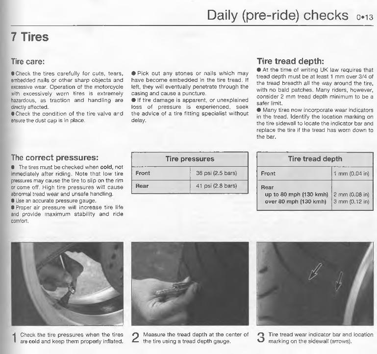
Tire care:• Check the tires carefully for cuts, tears, embedded nails or other sharp objects and excessive wear. Operation of the motorcycle with excessively worn tires is extremely hazardous, as traction and handling are directly affected.• Check the condition of the tire valve and ensure the dust cap is in place.
• Pick out any stones or nails which may have become embedded in the tire tread. If left, they will eventually penetrate through the casing and cause a puncture.• If tire damage is apparent, or unexplained loss of pressure is experienced, seek the advice of a tire fitting specialist without delay.
Tire tread depth:• At the time of writing UK law requires that tread depth must be at least 1 mm over 3/4 of the tread breadth all the way around the tire, with no bald patches. Many riders, however, consider 2 mm tread depth minimum to be a safer limit.• Many tires now incorporate wear indicators in the tread. Identify the location marking on the tire sidewall to locate the indicator bar and replace the tire if the tread has worn down to the bar.
The correct pressures:• The tires must be checked when cold, not immediately after riding. Note that low tire pressures may cause the tire to slip on the rim or come off. High tire pressures will cause abnormal tread wear and unsafe handling.• Use an accurate pressure gauge.• Proper air pressure will increase tire life and provide maximum stability and ride comfort.
Tire pressures
Front 36 psi (2.5 bars)
Rear 41 psi (2.8 bars)
Tire tread depth
Front 1 mm (0.04 in)
Rearup to 80 mph (130 kmh) over 80 mph (130 kmh)
2 mm (0.08 in)3 mm (0.12 in)
1 Check the tire pressures when the tires Q Measure the tread depth at the center of O Tire tread wear indicator bar and location are cold and keep them properly inflated. ^ the tire using a tread depth gauge. O marking on the sidewall (arrows).
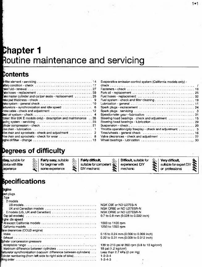
hapter 1Routine maintenance and servicingContentsfilter element - servic ing.....................................................................14
Doling system - servicing ............................... ..................................... 23flinder compression - check ............................... ...............................21Ive chain - lubrication ......................................................................... 1ive chain and sprockets - check and adjustment ........................... 2Ive chain and sprockets - check for w e a r ........................................ 8tgine oil/filter - ch a n ge ............................... ..................................... . . 1 3
)egrees of difficulty
Evaporative emission control system (California models only) -c h e c k .......................................................................................................... 7Fasteners - c h e c k .................................................................. .................18Fork oil - rep lacem ent...................... ; .....................................................25Fuel hoses - replacement ....................................................................... 32Fuel system - check and filter cleaning.................................................19Lubrication - general ................................................................................ 11Spark plugs - replacement ............. .............................................. 24Spark plugs - se rv ic in g ........................................................................... 3Speedometer gear - lubrication ............................................ ...............31Steering head bearings - check anc* adjustment ...............................15Steering head bearings - lub rication ..................................................... 29Suspension - check .................................................................................. 20Throttle operation/grip freeplay - check and ad jus tm en t.................. 5Tires/wheels - general check ................................................................ 16Valve clearances - check and adjustment ..........................................22Wheel bearings - lub rica tion .............................................................. , 30
y, suitable for novice with little experience
Fairly easy, suitable for beginner with ^ some experience
Fairly difficultsuitable for competent DIY mechanic ^
Difficult, suitable for experienced DIY mechanic ^
Very difficult, ^suitable for expert DIY ^ or professional
pecificationsngineDark plugs Type
D modelsUS m odels........................................................................................... NGK C9E or ND U27ES-NUK and Canadian m o d e ls ................................................................ NGK CR9E or ND U27ESR-N
E models (US, UK and Canadian)....................................................... .....NGK CR9E or ND U27ESR-NGap (all models) .............................................................................................. 0.7 to 0.8 mm (0.028 to 0.032 inch)igine idle speedAll except California m od e ls .......................................................................... 1000 to 1100 rpmCalifornia models ............................................................................................ 1250 to 1350 rpmlive clearances (COLD engine)Intake ......................................................................................................... ..... 0.15 to 0.24 mm (0.006 to 0.009 inch)Exhaust........................................................................................ '.............. ..... 0.22 to 0.31 mm (0.009 to 0.012 inch)
Jylinder compression pressureAcceptable range ..,.........v............................ ........................ ' . . . . . . . 139 to 213 psi @ 350 rpm (9.8 to 15 kg/cm2)Maximum difference between cy linders................................................ ..... 18 psi (1.2 kg/cm2)
"arburetor synchronization (vacuum difference between cylinders) . . . Less than 2.7 kPa (2 cm Hg)Under numbering (from left side to right side of b ike )................................ 1 -2-3-4
firing o rd e r................. ................................................................................... ..... 1-2-4-3
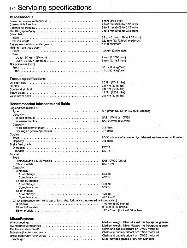
1.2 Servicing specificationsMiscellaneousBrake pad minimum thickness...........................................................Choke cable freeplay ........................................................................Clutch lever freeplay..........................................................................Throttle grip freeplay ........................................................................Drive chain
Up to 130 km/h (80 mph) ...........................................................Over 130 km/h (80 m ph).............................................................
Torque specificationsOil drain plug .............................................................................. .. . •Oil filte r .............................................................................................Coolant drain b o lt..............................................................................Spark plugs........................................................................................Valve cover bolts ..............................................................................
Recommended lubricants and fluidsEngine/transmission oil
Type .............................................................................................Viscosity
In cold climates..........................................................................In warm climates........................................................................
CapacityAt oil and filter change ...............................................................Dry engine (following rebuild) .....................................................
D models and E1, E2 models.....................................................E3-on models ............................................................................
Capacity D models
At oil change..........................................................................Completely dry ......................................................................
E1 and E2 modelsAt oil change.........................................................................Completely dry ......................................................................
Oil level (distance from oil to top of fork tube, fork fully compressed,D models................................................... ..............................E1 and E2 models......................................................................E3-on models ............................................................................
MiscellaneousWheel bearings................................................................................Swingarm pivot bearings .................................... ..............Cables and lever pivots .......................................................Sidestand/centerstand pivots.............................................................Brake pedal/shift lever pivots...........................................................Throttle grip ....................................................................................
1 mm (3/64-inch)2 to 3 mm (0.08 to 0.12 inch)2 to 3 mm (0.08 to 0.12 inch)2 to 3 mm (0.08 to 0.12 inch)
35 to 40 mm (1.38 to 1.57 inch) 323 mm (12.73 inch) maximum1.260 minimum
50/50 mixture of ethylene glycol-based antifreeze and soft water2.5 liters
DOT 3 DOT 4
SAE 10W20 fork oil SAE 10W
384 cc 452 cc
429 cc 505 cc
405 cc 477 ± 4 cc
without spring)140 mm (5.52 inches)98 mm (3.86 inches)112 ± 2 mm (4.41 ± 0.08 inches)
Medium weight, lithium-based multi-purpose grease Medium weight, lithium-based multi-purpose grease Chain and cable lubricant or 10W30 motor oil Chain and cable lubricant or 10W30 motor oil Chain and cable lubricant or 10W30 motor oil Multi-purpose grease or dry film lubricant
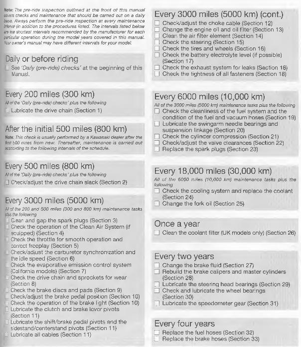
Note: The pre-ride inspection outlined at the front of this manual covers checks and maintenance that should be carried out on a daily basis. Always perform the pre-ride inspection at every maintenance Interval fin addition to the procedures listed. The intervals listed below are the shortest intervals recommended by the manufacturer for each •particular operation during the model years covered in this manual. Your owner's manual may have different intervals for your model.
Daily or before ridingC See ‘Daily (pre-ride) checks’ at the beginning of this
Manual.
Every 200 miles (300 km)All of the 'Daily (pre-ride) checks ’ plus the following
0 Lubricate the drive chain (Section 1)
After the initial 500 miles (800 km)Note: This check is usually performed by a Kawasaki dealer after the first 500 miles from new. Thereafter, maintenance is carried out lacccording to the following intervals of the schedule.
Every 500 miles (800 km)All of the ‘Daily (pre-ride) checks ' plus the following
|0 Check/adjust the drive chain slack (Section 2)
Every 3000 miles (5000 km)All of the 200 and 500 miles (300 and 800 km) maintenance tasks plus the followingL Clean and gap the spark plugs (Section 3)□ Check the operation of the Clean Air System (if __ equipped) (Section 4)f Check the throttle for smooth operation and
correct freeplay (Section 5)H Check/adjust the carburetor synchronization and
the idle speed (Section 6)G Check the evaporative emission control system
(California models) (Section 7)[I Check the drive chain and sprockets for wear
(Section 8)□ Check the brake discs and pads (Section 9)□ Check/adjust the brake pedal position (Section 10)□ Check the operation of the brake light (Section 10) D Lubricate the clutch and brake lever pivots
(Section 11)D Lubricate the shift/brake pedal pivots and the
sidestand/centerstand pivots (Section 11)C Lubricate all cables (Section 11)
Every 3000 miles (5000 km) (cont.)□ Check/adjust the choke cable (Section 12)3 Change the engine oil and oil filter (Section 13)□ Clean the air filter element (Section 14)O Check the steering (Section 15)□ Check the tires and wheels (Section 16)□ Check the battery electrolyte level (if possible)
(Section 17)□ Check the exhaust system for leaks (Section 18)□ Check the tightness of all fasteners (Section 18)
Every 6000 miles (10,000 km)All of the 3000 miles (5000 km) maintenance tasks plus the following□ Check the cleanliness of the fuel system and the
condition of the fuel and vacuum hoses (Section 19)□ Lubricate the swingarm needle bearings and
suspension linkage (Section 20)□ Check the cylinder compression (Section 21)□ Check/adjust the valve clearances (Section 22)□ Replace the spark plugs (Section 23)
Every 18,000 miles (30,000 km)All o f the 6000 miles (10,000 km) maintenance tasks plus the following□ Check the cooling system and replace the coolant
(Section 24)□ Change the fork oil (Section 25)
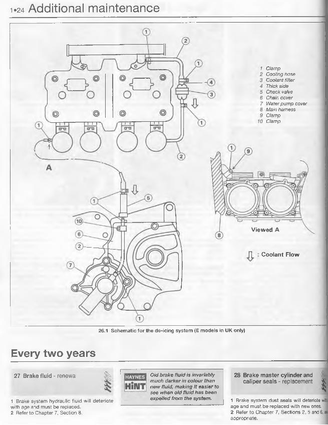
Once a year□ Clean the coolant filter (UK models only) (Section 26)
Every two years□ Change the brake fluid (Section 27)□ Rebuild the brake calipers and master cylinders
(Section 28)□ Lubricate the steering head bearings (Section 29)□ Check and lubricate the wheel bearings _ (Section 30)□ Lubricate the speedometer gear (Section 31)
Every four years□ Replace the fuel hoses (Section 32) Q Replace the brake hoses (Section 33)
V .
I__ ___________
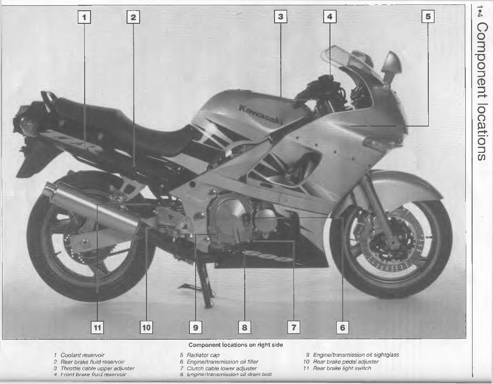
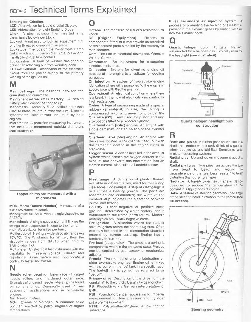
1 Coolant reservoir2 Rear brake fluid reservoir3 Throttle cable upper adjuster4 F ro n t b rake flu id re se rvo ir
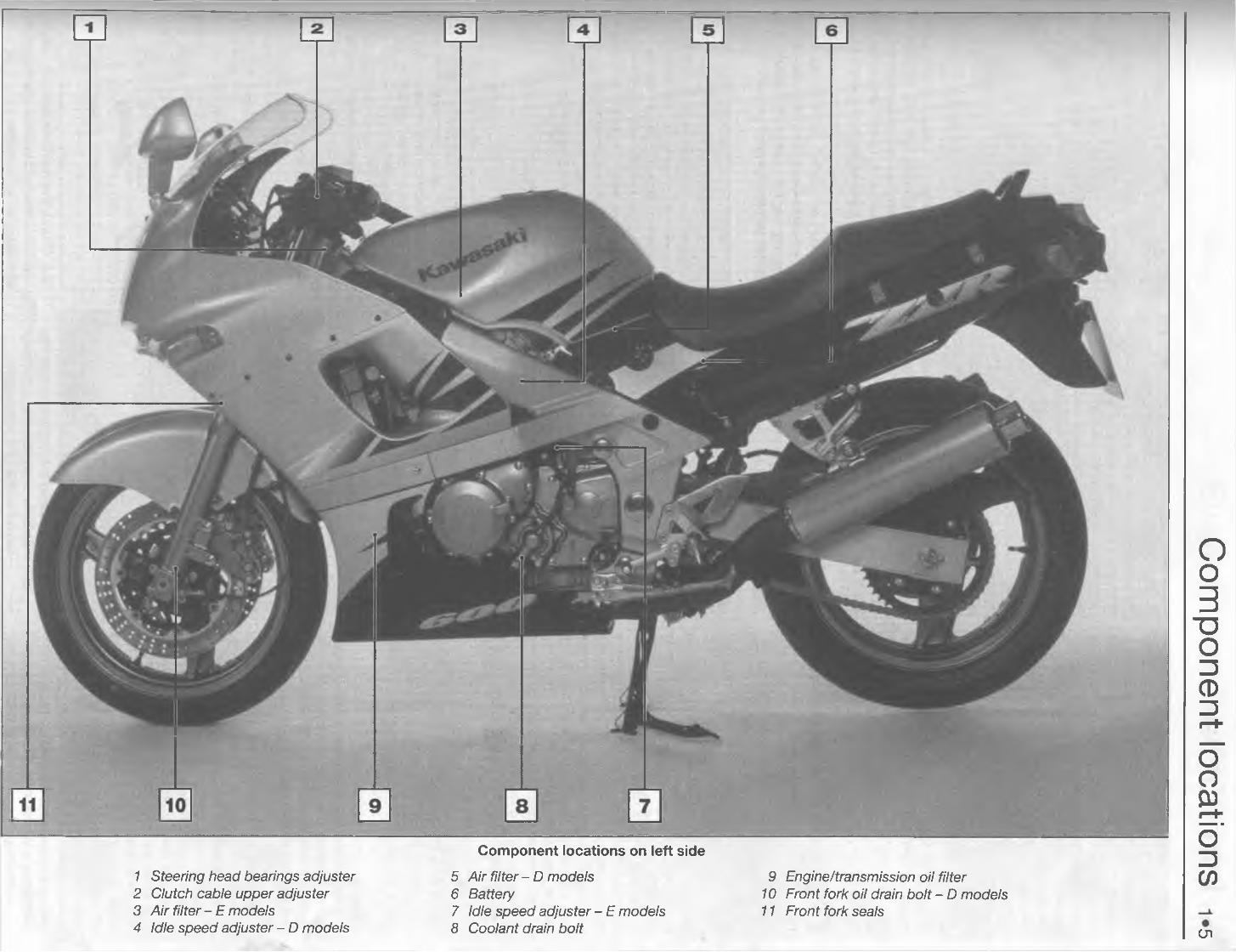
Component locations on right side
5 Radiator cap6 Engine/transmission oil filler7 Clutch cable lower adjuster8 E n g in e /tra n sm iss io n o il d ra in b o lt
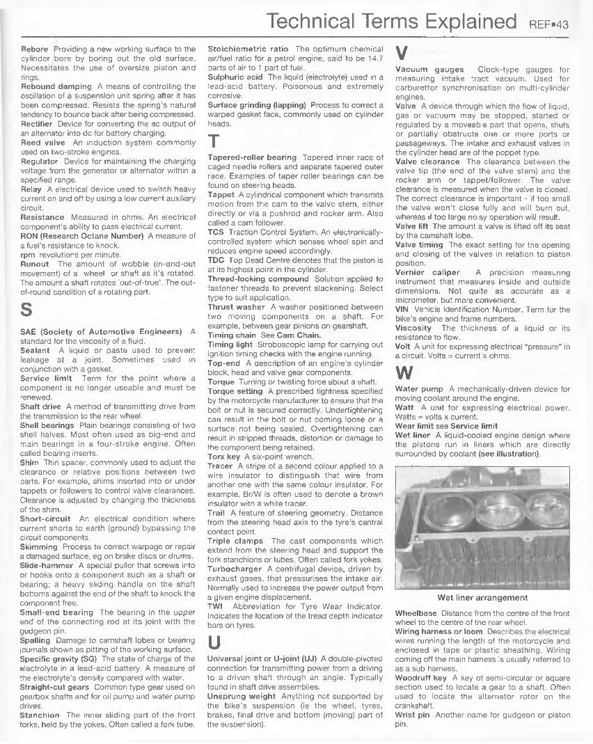
1 Steering head bearings adjuster2 Clutch cable upper adjuster3 Air filter - E models4 Idle speed adjuster - D models
5 Air filter - D models6 Battery7 Idle speed adjuster - E models8 Coolant drain bolt
9 Engine/transmission oil filter10 Front fork oil drain bolt - O models11 Front fork seals
c n
Com
ponent locations
1.6 IntroductionThis Chapter covers in detail the checks
and procedures necessary for the tune-up and routine maintenance of your motorcycle, and includes the routine maintenance schedule, which is designed to keep the machine in proper running condition and prevent possible problems. The remaining Sections contain detailed procedures for carrying out the items listed on the maintenance schedule, as well as additional maintenance information designed to increase reliability.
Since routine maintenance plays such an important role in the safe and efficient operation of your motorcycle, it is presented here as a comprehensive check list. For the rider who does all his own maintenance, these lists outline the procedures and checks that should be done on a routine basis.
Deciding where to start or plug into the routine maintenance schedule depends on several factors. If you have a motorcycle whose warranty has recently expired, and if it has been maintained according to the warranty standards, you may want to pick-up routine maintenance as it coincides with the next mileage or calendar interval. If you have owned the machine for some time but have never performed any maintenance on it, then you may want to start at the nearest interval and include some additional procedures to ensure that nothing important is overlooked. If you have just had a major engine overhaul, then you may want to start the maintenance routine from the beginning. If you have a used machine and have no knowledge of its history or maintenance record, you may desire to combine all the checks into one large service
initially and then settle into the maintenance schedule prescribed.
The Sections which actually outline the inspection and maintenance procedures are written as step-by-step comprehensive guides to the actual performance of the work. They explain in detail each of the routine inspections and maintenance procedures on the check list. References to additional information in applicable Chapters is also included and should not be overlooked.
Before beginning any actual maintenance or repair, the machine should be cleaned thoroughly, especially around the oil filter housing, spark plugs, cylinder head covers, side covers, carburetors, etc. Cleaning will help ensure that dirt does not contaminate the engine and will allow you to detect wear and damage that could otherwise easily go unnoticed.
Every 200 miles (300 km)1 Drive chain - lubrication %
apply it to the area where the side plates overlap - not the middle of the rollers. After
applying the lubricant, let it soak in a few | minutes before wiping off any excess.
Note: If the chain is extremely dirty, it should be removed and cleaned before it is lubricated (see Chapter 6).1 The best time to lubricate the chain is after the motorcycle has been ridden. When the chain is warm, the lubricant will penetrate the joints between the side plates, pins, bushings and rollers to provide lubrication of the internal load bearing areas.2 Use a good quality chain lubricant and
Apply chain lubricant to the joints between the side plates, pins, bushings and rollers to provide lubrication of the internal load bearing areas - not the middle of the rollers. With the bike on its centerstand, hold the plastic nozzle near the edge of the chain and turn the wheel by hand as the lubricant sprays out; repeat this procedure on the inside edge of the chain
Every 500 miles (800 km)Drive chain and sprocketscheck and adjustment %
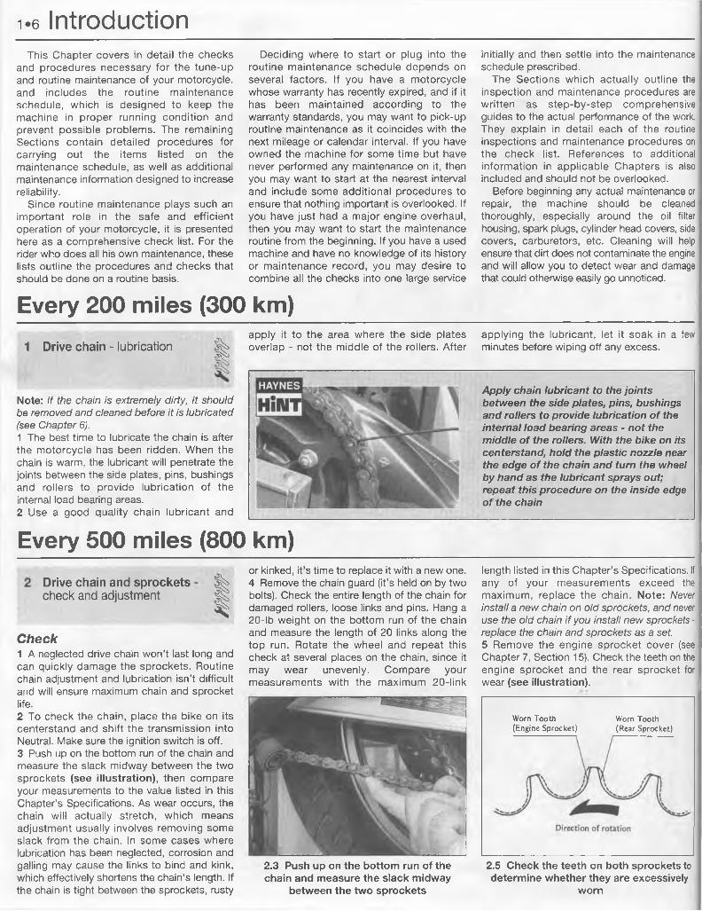
ICheck1 A neglected drive chain won’t last long and can quickly damage the sprockets. Routine chain adjustment and lubrication isn’t difficult and will ensure maximum chain and sprocket life.2 To check the chain, place the bike on its centerstand and shift the transmission into Neutral. Make sure the ignition switch is off.3 Push up on the bottom run of the chain and measure the slack midway between the two sprockets (see illustration), then compare your measurements to the value listed in this Chapter’s Specifications. As wear occurs, the chain will actually stretch, which means adjustment usually involves removing some slack from the chain. In some cases where lubrication has been neglected, corrosion and galling may cause the links to bind and kink, which effectively shortens the chain’s length. If the chain is tight between the sprockets, rusty
or kinked, it’s time to replace it with a new one.4 Remove the chain guard (it’s held on by two bolts). Check the entire length of the chain for damaged rollers, loose links and pins. Hang a 20-lb weight on the bottom run of the chain and measure the length of 20 links along the top run. Rotate the wheel and repeat this check at several places on the chain, since it may wear unevenly. Compare your measurements with the maximum 20-link
length listed in this Chapter’s Specifications. If any of your measurements exceed the maximum, replace the chain. Note: Never install a new chain on old sprockets, and never use the old chain if you install new sprockets - replace the chain and sprockets as a set.5 Remove the engine sprocket cover (see Chapter 7, Section 15). Check the teeth on the engine sprocket and the rear sprocket for wear (see illustration).
Worn Tooth (Engine Sprocket)
Worn Tooth (Rear Sprocket)
2.3 Push up on the bottom run of the chain and measure the slack midway
between the two sprockets
2.5 Check the teeth on both sprockets to determine whether they are excessively
worn
Every 500 miles (800 km) w
2.8 Remove the cotter pin and loosen the axle nut
2.9 Loosen and back-off the locknuts on the chain adjuster bolts
2,7 Before adjusting the chain, loosen both torque link nuts (arrows)
Adjustment6 Place the bike on its centerstand and shift the transmission into Neutral. Make sure the ignition switch is off. Rotate the rear wheel until the chain is positioned with the least amount of slack present.7 Loosen both torque link nuts (see illustration).8 Remove the cotter pin and loosen the axle nut (see illustration).9 Loosen and back-off the locknuts on the chain adjuster bolts (see illustration).10 Turn the axle adjusting bolts on both sides of the swingarm until the proper chain tension is obtained. Be sure to turn the adjusting bolts
evenly to keep the rear wheel in alignment. If the adjusting bolts reach the end of their travel, the chain is excessively worn and should be replaced with a new one (see Chapter 6).11 When the chain has the correct amount of slack, make sure the marks on the adjusters correspond to the same relative marks on each side of the swingarm (see illustration). Tighten the axle nut to the torque listed in the Chapter 7 Specifications, then install a new cotter pin. If necessary, turn the nut an additional amount to line up the cotter pin hole with the castellations in the nut - don’t loosen the nut to do this.12 Tighten the locknuts and the torque link nut securely.
2.11 When the chain is adjusted, make sure the marks on the swingarm
correspond on each side
Every 3000 miles (5000 km)3 Spark plugs - servicing %
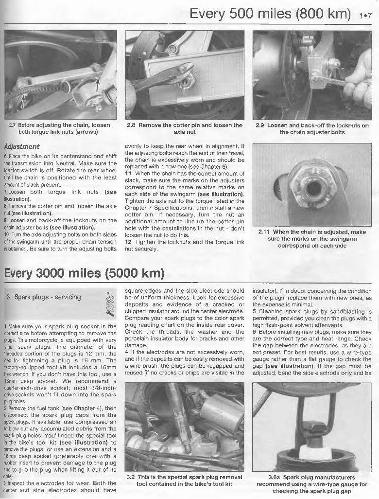
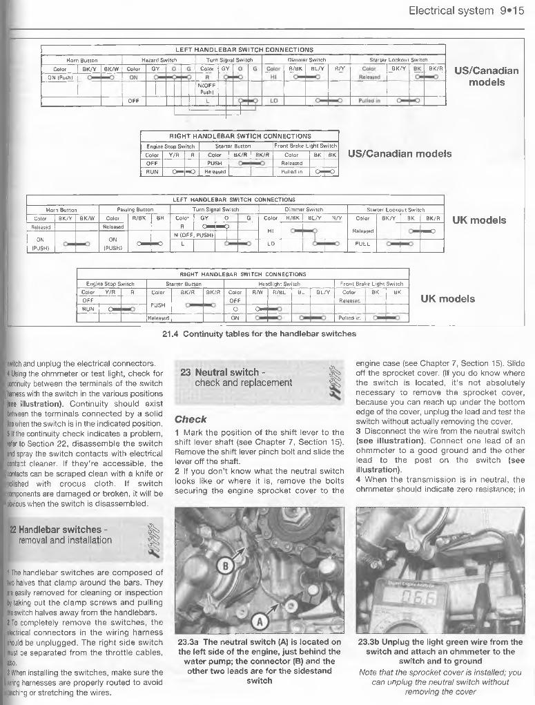
1 Make sure your spark plug socket is the correct size before attempting to remove the plugs. This motorcycle is equipped with very small spark plugs. The diameter of the threaded portion of the plugs is 12 mm; the hex for tightening a plug is 16 mm. The factory-equipped tool kit includes a 16mm hex wrench. If you don’t have this tool, use a 16mm deep socket. We recommend a quarter-inch-drive socket; most 3/8-inch- drive sockets won’t fit down into the spark plug holes.2 Remove the fuel tank (see Chapter 4), then disconnect the spark plug caps from the spark plugs. If available, use compressed air to blow out any accumulated debris from the spark plug holes. You’ll need the special tool in the bike’s tool kit (see illustration) to remove the plugs, or use an extension and a 16mm deep socket (preferably one with a rubber insert to prevent damage to the plug and to grip the plug when lifting it out of its hole).3 Inspect the electrodes for wear. Both the center and side electrodes should have
square edges and the side electrode should be of uniform thickness. Look for excessive deposits and evidence of a cracked or chipped insulator around the center electrode. Compare your spark plugs to the color spark plug reading chart on the inside rear cover. Check the threads, the washer and the porcelain insulator body for cracks and other damage.4 If the electrodes are not excessively worn, and if the deposits can be easily removed with a wire brush, the plugs can be regapped and reused (if no cracks or chips are visible in the
insulator). If in doubt concerning the condition of the plugs, replace them with new ones, as the expense is minimal.5 Cleaning spark plugs by sandblasting is permitted, provided you clean the plugs with a high flash-point solvent afterwards.6 Before installing new plugs, make sure they are the correct type and heat range. Check the gap between the electrodes, as they are not preset. For best results, use a wire-type gauge rather than a flat gauge to check the gap (see illustration). If the gap must be adjusted, bend the side electrode only and be
3.2 This is the special spark plug removal tool contained in the bike’s tool kit
3.6a Spark plug manufacturers recommend using a wire-type gauge for
checking the spark plug gap
1.8 Every 3000 miles (5000 km)
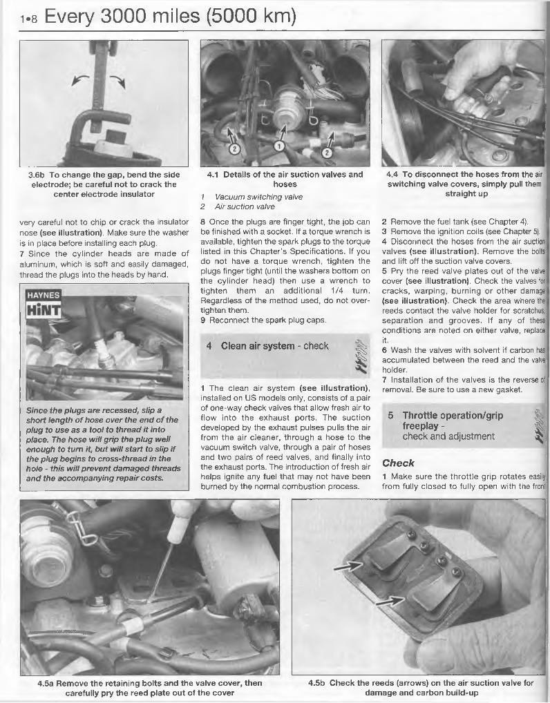
3.6b To change the gap, bend the side electrode; be careful not to crack the
center electrode insulator
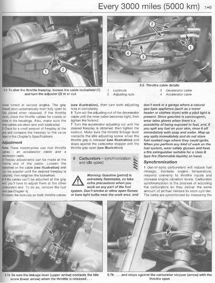
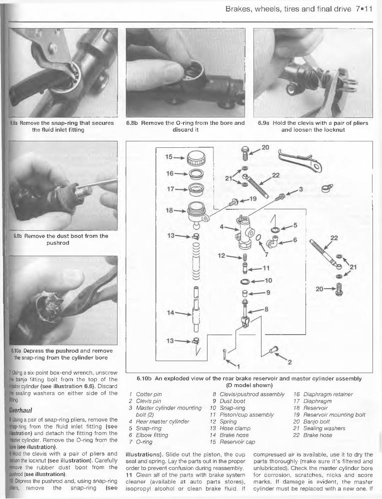
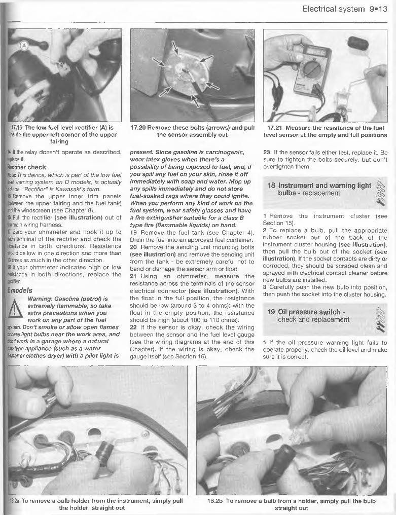
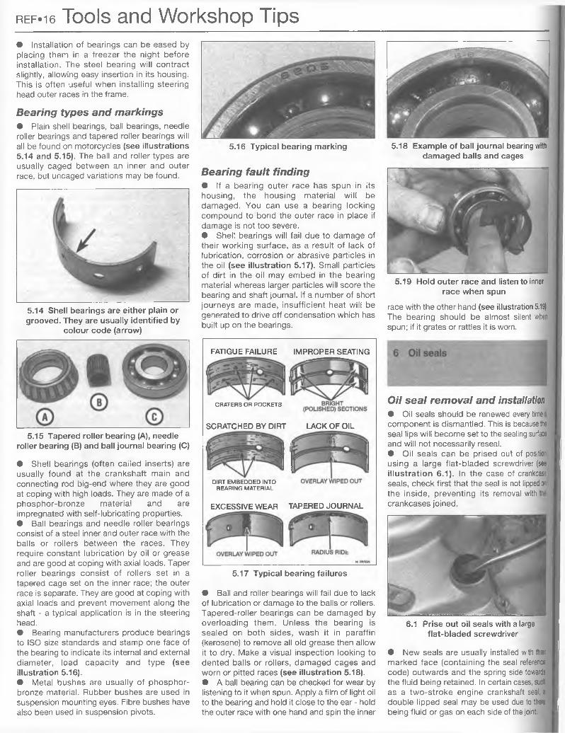
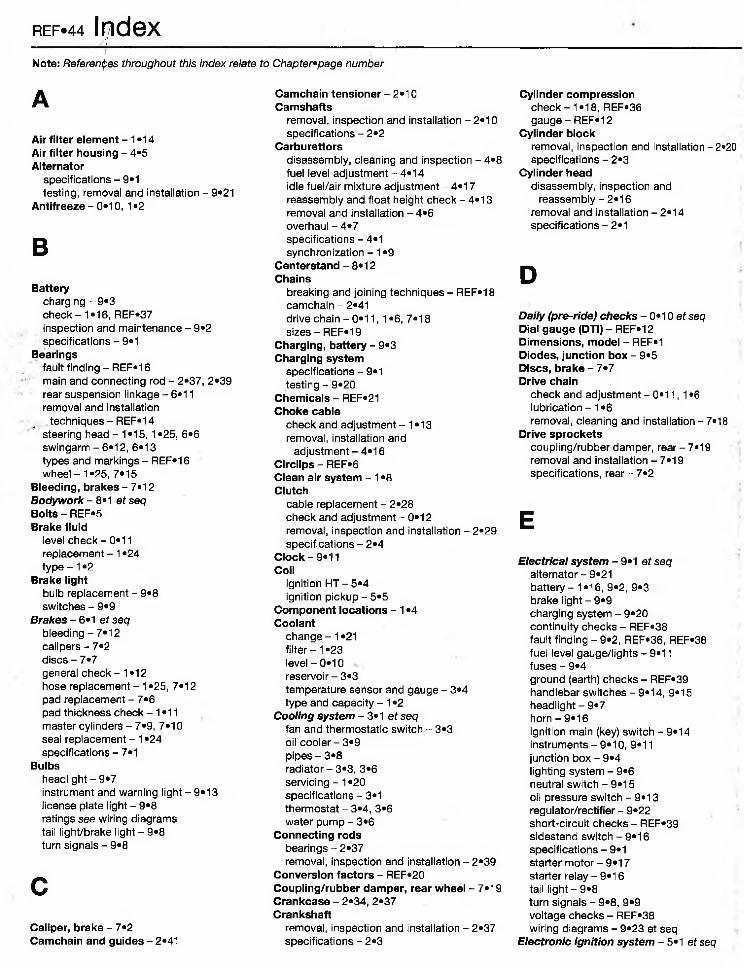
4.1 Details of the air suction valves and hoses
1 Vacuum switching valve2 Air suction valve
8 Once the plugs are finger tight, the job can be finished with a socket. If a torque wrench is available, tighten the spark plugs to the torque listed in this Chapter’s Specifications. If you do not have a torque wrench, tighten the plugs finger tight (until the washers bottom on the cylinder head) then use a wrench to tighten them an additional 1/4 turn. Regardless of the method used, do not overtighten them.9 Reconnect the spark plug caps.
4 Clean air system - check n1 The clean air system (see illustration),installed on US models only, consists of a pair of one-way check valves that allow fresh air to flow into the exhaust ports. The suction developed by the exhaust pulses pulls the air from the air cleaner, through a hose to the vacuum switch valve, through a pair of hoses and two pairs of reed valves, and finally into the exhaust ports. The introduction of fresh air helps ignite any fuel that may not have been burned by the normal combustion process.
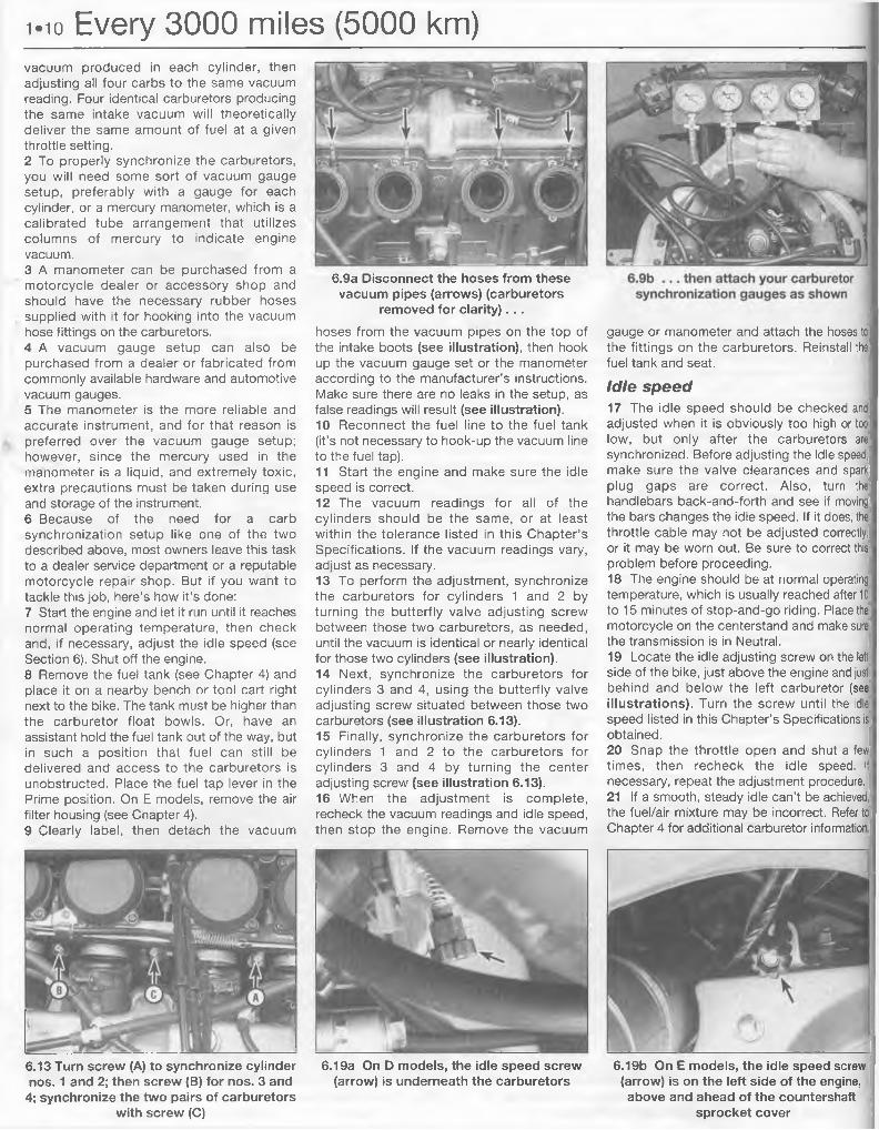
4.4 To disconnect the hoses from the air switching valve covers, simply pull them
straight up
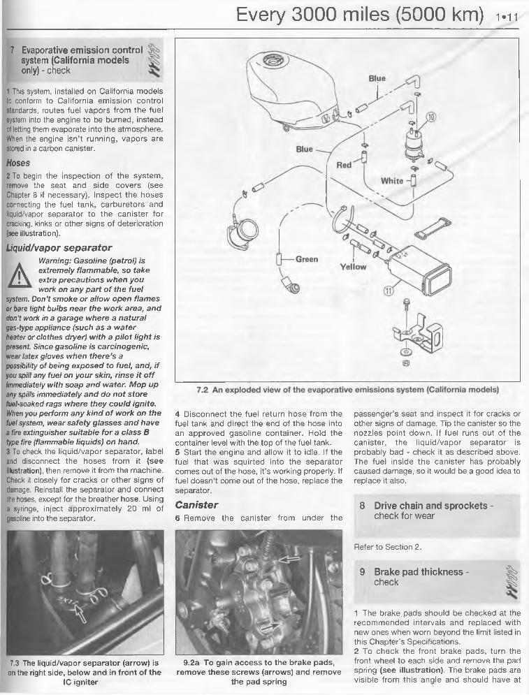
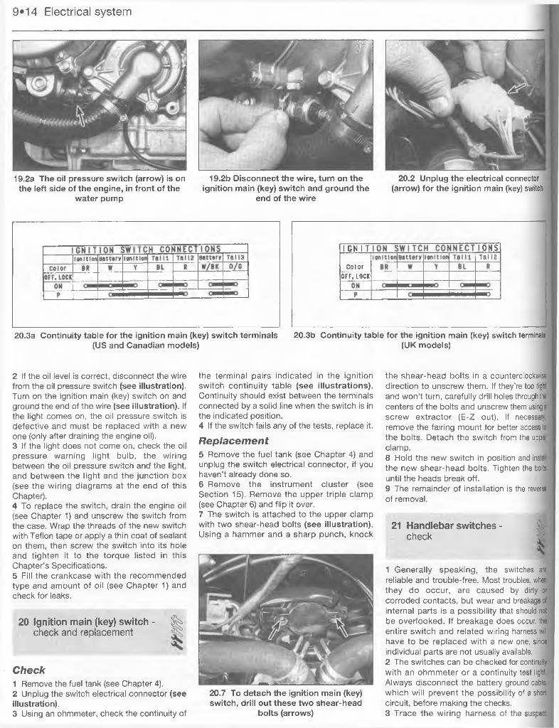
2 Remove the fuel tank (see Chapter 4).3 Remove the ignition coils (see Chapter 5). i4 Disconnect the hoses from the air suction valves (see illustration). Remove the bolts and lift off the suction valve covers.5 Pry the reed valve plates out of the valve cover (see illustration). Check the valves for cracks, warping, burning or other damage (see illustration). Check the area where the reeds contact the valve holder for scratches, separation and grooves. If any of these conditions are noted on either valve, replace it.6 Wash the valves with solvent if carbon has accumulated between the reed and the valve holder.7 Installation of the valves is the reverse of removal. Be sure to use a new gasket.
5 Throttle operation/grip freeplay - | |check and adjustment ^
Check1 Make sure the throttle grip rotates easily from fully closed to fully open with the front
very careful not to chip or crack the insulator nose (see illustration). Make sure the washer is in place before installing each plug.7 Since the cylinder heads are made of aluminum, which is soft and easily damaged, thread the plugs into the heads by hand.
Since the plugs are recessed, slip a short length of hose over the end of the plug to use as a tool to thread it into place. The hose will grip the plug well enough to turn it, but will start to slip if the plug begins to cross-thread in the hole - this will prevent damaged threads and the accompanying repair costs.
4.5a Remove the retaining bolts and the valve cover, then 4.5b Check the reeds (arrows) on the air suction valve forcarefully pry the reed plate out of the cover damage and carbon build-up
Every 3000 miles (5000 km) 1.9
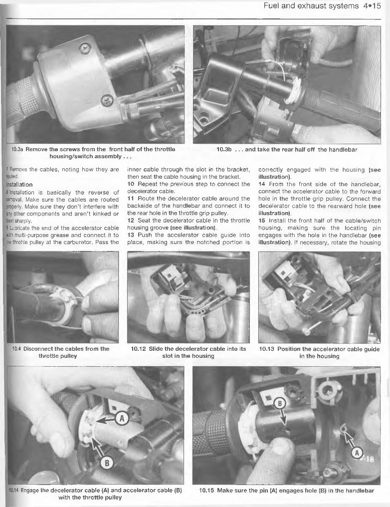
5.5 Throttle cable details5.3 To alter the throttle freeplay, loosen the cable lockwheel (1) 7 Locknuts 3 Decelerator cable
and turn the adjuster (2) in or out 2 Adjusting nuts 4 Accelerator cable
wheel turned at various angles. The grip should return automatically from fully open to fully closed when released. If the throttle sticks, check the throttle cables for cracks or kinks in the housings. Also, make sure the inner cables are clean and well-lubricated.2 Check for a small amount of freeplay at the grip and compare the freeplay to the value listed in this Chapter’s Specifications.
AdjustmentNote: These motorcycles use two throttle cables - an accelerator cable and a decelerater cable.3 Freeplay adjustments can be made at the throttle end of the cable. Loosen the lockwheel on the cable (see illustration) and turn the adjuster until the desired freeplay is obtained, then retighten the lockwheel.4 If the cables can’t be adjusted at the grip end, you’ll have to adjust them at the other (carburetor) end. To do so, remove the fuel tank (see Chapter 4).5 Loosen the locknuts on both throttle cables
(see illustration), then turn both adjusting nuts in completely.6 Turn out the adjusting nut of the decelerator cable until the inner cable becomes tight, then tighten the locknut.7 Turn the accelerator adjusting nut until the desired freeplay is obtained, then tighten the locknut. Make sure the throttle linkage lever contacts the idle adjusting screw when the throttle grip is released (see illustration) and stops against the carburetor stopper with the throttle grip open (see illustration).
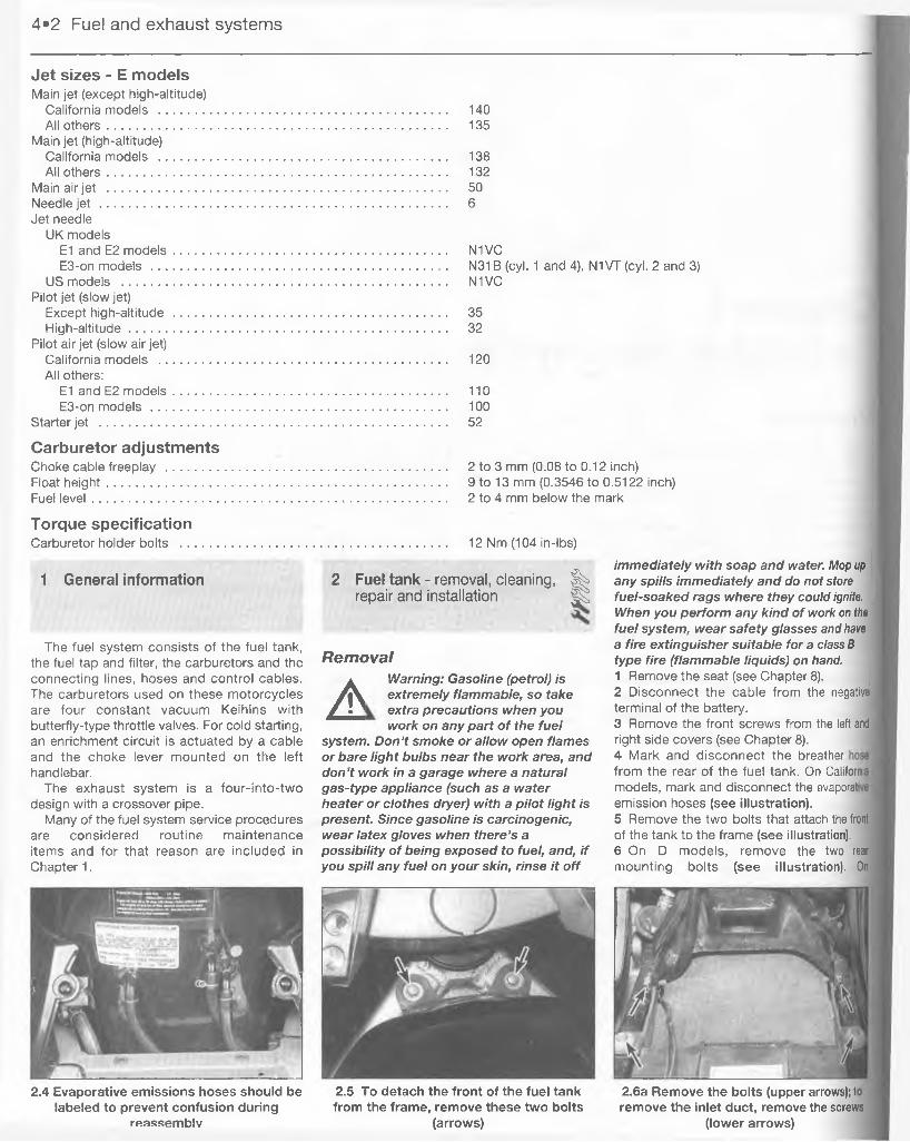
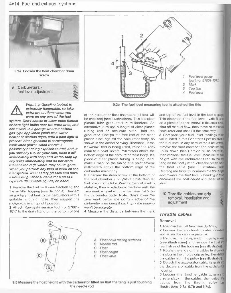
A Warning: Gasoline (petrol) is extremely flammable, so take extra precautions when you work on any part of the fuel
system. Don’t smoke or allow open flames or bare light bulbs near the work area, and
don’t work in a garage where a natural gas-type appliance (such as a water heater or clothes dryer) with a pilot light is present. Since gasoline is carcinogenic, wear latex gloves when there’s a possibility of being exposed to fuel, and, if you spill any fuel on your skin, rinse it off immediately with soap and water. Mop up any spills immediately and do not store fuel-soaked rags where they could ignite. When you perform any kind of work on the fuel system, wear safety glasses and have a fire extinguisher suitable for a class B type fire (flammable liquids) on hand.
Synchronization1 Out-of-sync carburetors will reduce fuel mileage, increase engine temperature, respond unevenly to throttle inputs and increase engine vibration levels. Carburetor synchronization is the process of adjusting the carburetors so they deliver the same amount of air/fuel mixture to each cylinder. The carbs are synchronized by measuring the
Carburetors - synchronization ^ and idle speed
5.7a Be sure the linkage lever (upper arrow) contacts the idle 5.7b . . . and stops against the carburetor stopper (arrow) with the screw (lower arrow) when the throttle is released . . . throttle open
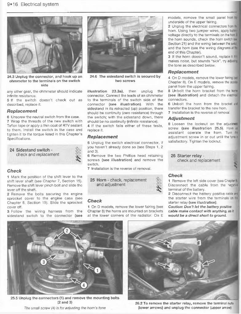
i.io Every 3000 miles (5000 km)vacuum produced in each cylinder, then adjusting all four carbs to the same vacuum reading. Four identical carburetors producing the same intake vacuum will theoretically deliver the same amount of fuel at a given throttle setting.2 To properly synchronize the carburetors, you will need some sort of vacuum gauge setup, preferably with a gauge for each cylinder, or a mercury manometer, which is a calibrated tube arrangement that utilizes columns of mercury to indicate engine vacuum.3 A manometer can be purchased from a motorcycle dealer or accessory shop and should have the necessary rubber hoses supplied with it for hooking into the vacuum hose fittings on the carburetors.4 A vacuum gauge setup can also be purchased from a dealer or fabricated from commonly available hardware and automotive vacuum gauges.5 The manometer is the more reliable and accurate instrument, and for that reason is preferred over the vacuum gauge setup; however, since the mercury used in the manometer is a liquid, and extremely toxic, extra precautions must be taken during use and storage of the instrument.6 Because of the need for a carb synchronization setup like one of the two described above, most owners leave this task to a dealer service department or a reputable motorcycle repair shop. But if you want to tackle this job, here's how it’s done:7 Start the engine and let it run until it reaches normal operating temperature, then check and, if necessary, adjust the idle speed (see Section 6). Shut off the engine.8 Remove the fuel tank (see Chapter 4) and place it on a nearby bench or tool cart right next to the bike. The tank must be higher than the carburetor float bowls. Or, have an assistant hold the fuel tank out of the way, but in such a position that fuel can still be delivered and access to the carburetors is unobstructed. Place the fuel tap lever in the Prime position. On E models, remove the air filter housing (see Chapter 4).9 Clearly label, then detach the vacuum
hoses from the vacuum pipes on the top of the intake boots (see illustration), then hook up the vacuum gauge set or the manometer according to the manufacturer’s instructions. Make sure there are no leaks in the setup, as false readings will result (see illustration).10 Reconnect the fuel line to the fuel tank (it’s not necessary to hook-up the vacuum line to the fuel tap).11 Start the engine and make sure the idle speed is correct.12 The vacuum readings for all of the cylinders should be the same, or at least within the tolerance listed in this Chapter’s Specifications. If the vacuum readings vary, adjust as necessary.13 To perform the adjustment, synchronize the carburetors for cylinders 1 and 2 by turning the butterfly valve adjusting screw between those two carburetors, as needed, until the vacuum is identical or nearly identical for those two cylinders (see illustration).14 Next, synchronize the carburetors for cylinders 3 and 4, using the butterfly valve adjusting screw situated between those two carburetors (see illustration 6.13).15 Finally, synchronize the carburetors for cylinders 1 and 2 to the carburetors for cylinders 3 and 4 by turning the center adjusting screw (see illustration 6.13).16 When the adjustment is complete, recheck the vacuum readings and idle speed, then stop the engine. Remove the vacuum
6.9a Disconnect the hoses from these vacuum pipes (arrows) (carburetors
removed for clarity). . .
6.13 Turn screw (A) to synchronize cylinder nos. 1 and 2; then screw (B) for nos. 3 and
4; synchronize the two pairs of carburetors with screw (C)
6.19a On D models, the idle speed screw (arrow) is underneath the carburetors
gauge or manometer and attach the hoses to the fittings on the carburetors. Reinstall the fuel tank and seat.
Idle speed17 The idle speed should be checked and adjusted when it is obviously too high or too low, but only after the carburetors are synchronized. Before adjusting the idle speed, make sure the valve clearances and spark plug gaps are correct. Also, turn the handlebars back-and-forth and see if moving the bars changes the idle speed. If it does, the throttle cable may not be adjusted correctly, or it may be worn out. Be sure to correct this problem before proceeding.18 The engine should be at normal operating temperature, which is usually reached after 10 to 15 minutes of stop-and-go riding. Place the motorcycle on the centerstand and make sure the transmission is in Neutral.19 Locate the idle adjusting screw on the left side of the bike, just above the engine and just behind and below the left carburetor (see illustrations). Turn the screw until the idle speed listed in this Chapter’s Specifications is obtained.20 Snap the throttle open and shut a few times, then recheck the idle speed. If necessary, repeat the adjustment procedure.21 If a smooth, steady idle can’t be achieved, the fuel/air mixture may be incorrect. Refer to Chapter 4 for additional carburetor information
6.19b On E models, the idle speed screw (arrow) is on the left side of the engine, above and ahead of the countershaft
sprocket cover
Every 3000 miles (5000 km) 1.11
7 Evaporative emission control ^ system (California models ^ only) - check
1 This system, installed on California models to conform to California emission control standards, routes fuel vapors from the fuel system into the engine to be burned, instead of letting them evaporate into the atmosphere. When the engine isn’t running, vapors are stored in a carbon canister.
Hoses2 To begin the inspection of the system, remove the seat and side covers (see Chapter 8 if necessary). Inspect the hoses connecting the fuel tank, carburetors and liquid/vapor separator to the canister for cracking, kinks or other signs of deterioration (see illustration).
Liquid/vapor separator
A Warning: Gasoline (petrol) is extremely flammable, so take extra precautions when you work on any part of the fuel
system. Don’t smoke or allow open flames or bare light bulbs near the work area, and don’t work in a garage where a natural gas-type appliance (such as a water heater or clothes dryer) with a pilot light is present. Since gasoline is carcinogenic, wear latex gloves when there’s a possibility of being exposed to fuel, and, if you spill any fuel on your skin, rinse it off immediately with soap and water. Mop up any spills immediately and do not store fuel-soaked rags where they could ignite. When you perform any kind of work on the fuel system, wear safety glasses and have a fire extinguisher suitable for a class B type fire (flammable liquids) on hand.3 To check the liquid/vapor separator, label and disconnect the hoses from it (see illustration), then remove it from the machine. Check it closely for cracks or other signs of damage. Reinstall the separator and connect the hoses, except for the breather hose. Using a syringe, inject approximately 20 ml of gasoline into the separator.
4 Disconnect the fuel return hose from the fuel tank and direct the end of the hose into an approved gasoline container. Hold the container level with the top of the fuel tank.5 Start the engine and allow it to idle. If the fuel that was squirted into the separator comes out of the hose, it’s working properly. If fuel doesn’t come out of the hose, replace the separator.
Canister6 Remove the canister from under the
passenger’s seat and inspect it for cracks or other signs of damage. Tip the canister so the nozzles point down. If fuel runs out of the canister, the liquid/vapor separator is probably bad - check it as described above. The fuel inside the canister has probably caused damage, so it would be a good idea to replace it also.
8 Drive chain and sprockets -check for wear
7.3 The liquid/vapor separator (arrow) is on the right side, below and in front of the
IC igniter
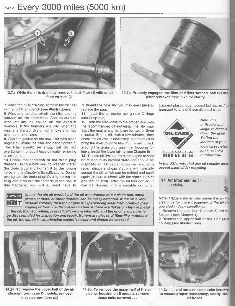
9.2a To gain access to the brake pads, remove these screws (arrows) and remove
the pad spring
Refer to Section 2.
9 Brake pad thickness - %check ^
1 The brake pads should be checked at the recommended intervals and replaced with new ones when worn beyond the limit listed in this Chapter’s Specifications.2 To check the front brake pads, turn the front wheel to each side and remove the pad spring (see illustration). The brake pads are visible from this angle and should have at
1.12 Every 3000 miles (5000 km)
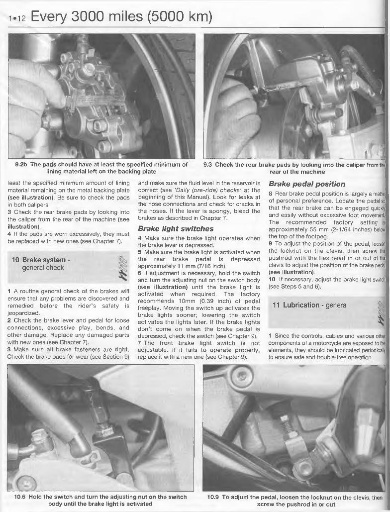
9.2b The pads should have at least the specified minimum of lining material left on the backing plate
least the specified minimum amount of lining material remaining on the metal backing plate (see illustration). Be sure to check the pads in both calipers.3 Check the rear brake pads by looking into the caliper from the rear of the machine (see illustration).4 If the pads are worn excessively, they must be replaced with new ones (see Chapter 7).
10 Brake system -general check
1 A routine general check of the brakes will ensure that any problems are discovered and remedied before the rider’s safety is jeopardized.2 Check the brake lever and pedal for loose connections, excessive play, bends, and other damage. Replace any damaged parts with new ones (see Chapter 7).3 Make sure all brake fasteners are tight. Check the brake pads for wear (see Section 9)
and make sure the fluid level in the reservoir is correct (see ‘Daily (pre-ride) checks’ at the beginning of this Manual). Look for leaks at the hose connections and check for cracks in the hoses. If the lever is spongy, bleed the brakes as described in Chapter 7.
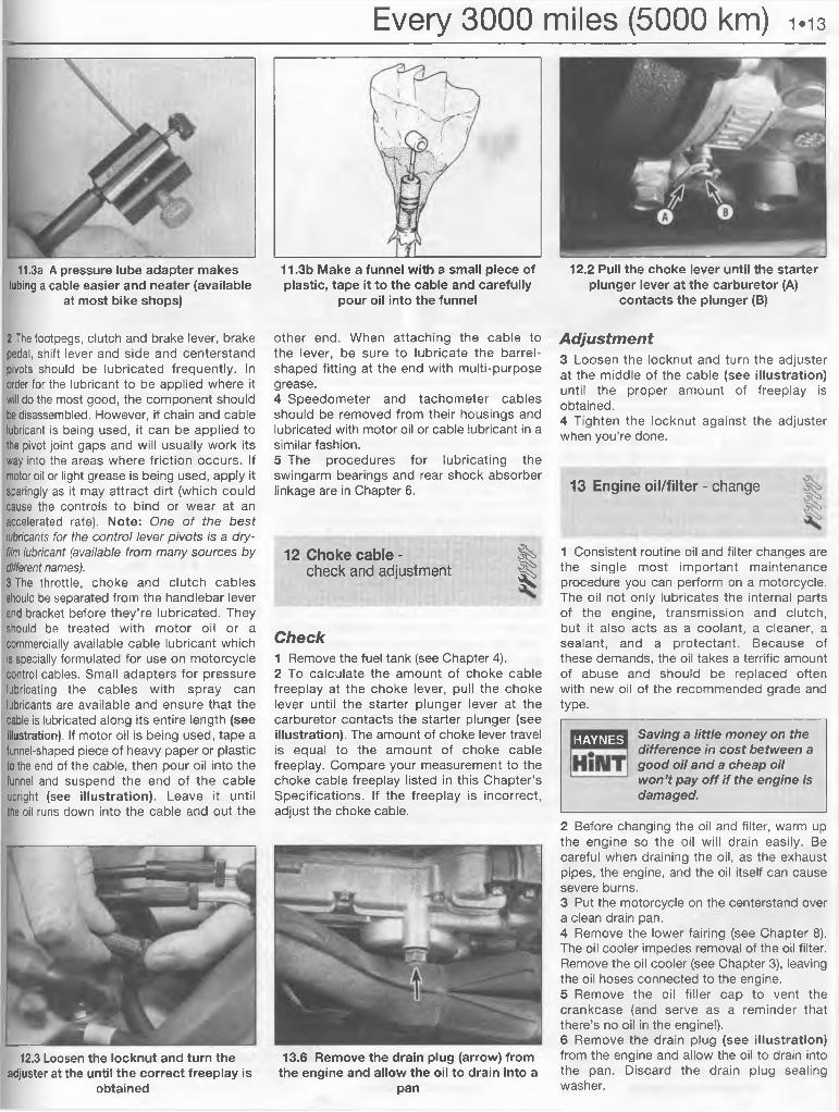
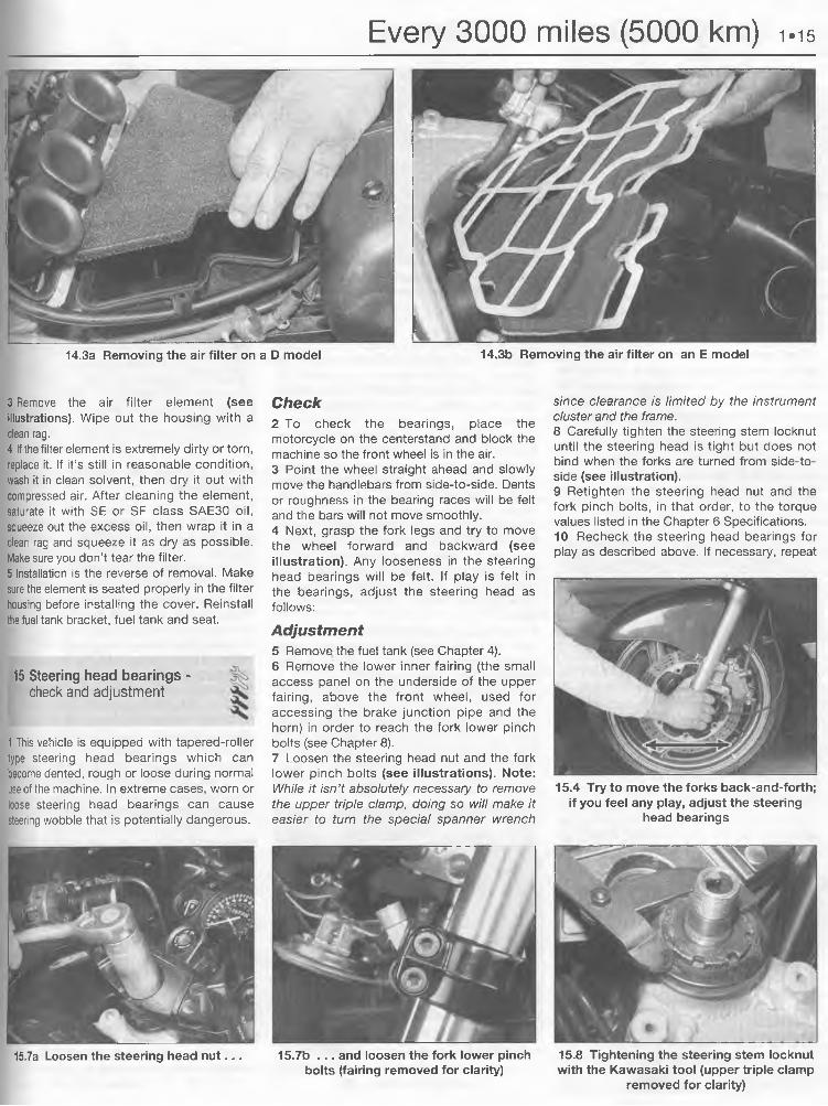
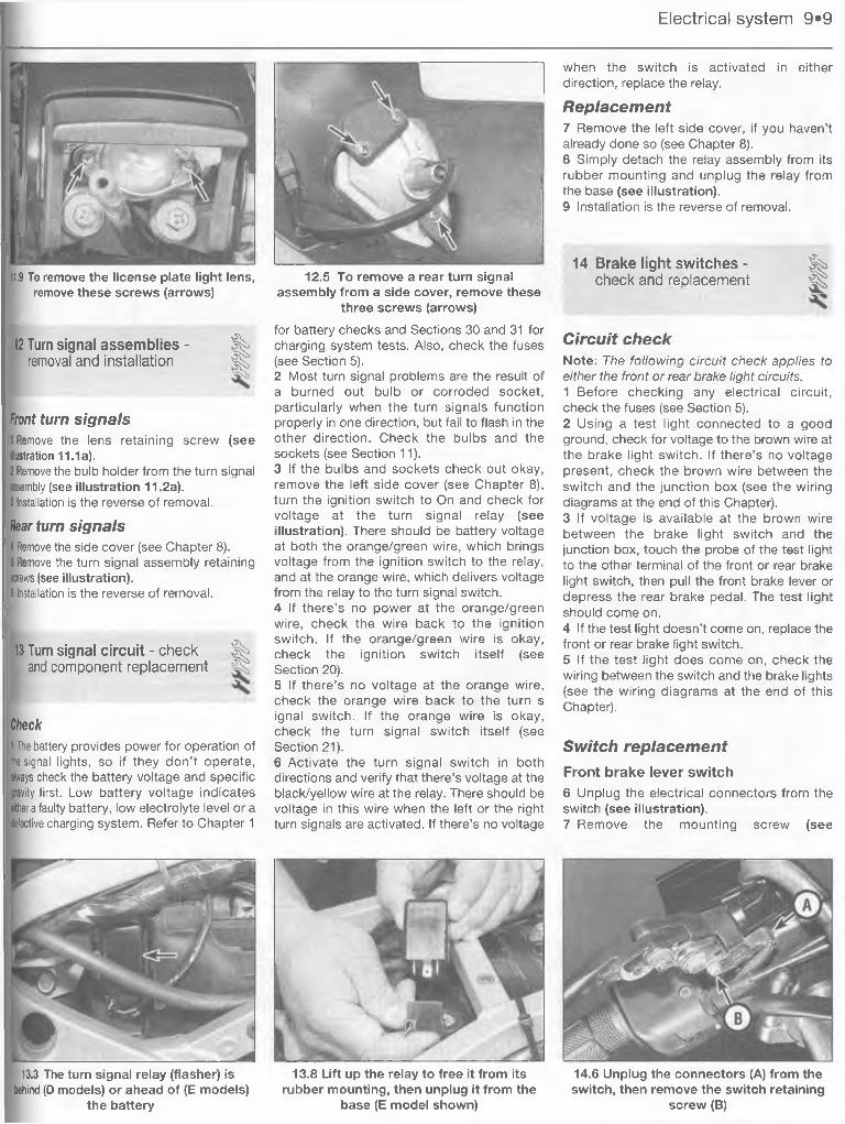
Brake light switches4 Make sure the brake light operates when the brake lever is depressed.5 Make sure the brake light is activated when the rear brake pedal is depressed approximately 11 mm (7/16 inch).6 If adjustment is necessary, hold the switch and turn the adjusting nut on the switch body (see illustration) until the brake light is activated when required. The factory recommends 10mm (0.39 inch) of pedal freeplay. Moving the switch up activates the brake lights sooner; lowering the switch activates the lights later. If the brake lights don’t come on when the brake pedal is depressed, check the switch (see Chapter 9).7 The front brake light switch is not adjustable. If it fails to operate properly, replace it with a new one (see Chapter 9).
Brake pedal position8 Rear brake pedal position is largely a matteTi of personal preference. Locate the pedal so that the rear brake can be engaged quickly and easily without excessive foot movement The recommended factory setting approximately 55 mm (2-1/64 inches) below the top of the footpeg.9 To adjust the position of the pedal, loosen the locknut on the clevis, then screw the pushrod with the hex head in or out of the clevis to adjust the position of the brake pedal (see illustration).10 If necessary, adjust the brake light switch (see Steps 5 and 6).
11 Lubrication - general
1 Since the controls, cables and various other components of a motorcycle are exposed to the elements, they should be lubricated periodically to ensure safe and trouble-free operation.
9.3 Check the rear brake pads by looking into the caliper from the rear of the machine
10.6 Hold the switch and turn the adjusting nut on the switch 10.9 To adjust the pedal, loosen the locknut on the clevis, thenbody until the brake light is activated screw the pushrod in or out
Every 3000 miles (5000 km) 1-13
11.3a A pressure lube adapter makes tubing a cable easier and neater (available
at most bike shops)
11.3b Make a funnel with a small piece of plastic, tape it to the cable and carefully
pour oil into the funnel
12.2 Pull the choke lever until the starter plunger lever at the carburetor (A)
contacts the plunger (B)
2 The footpegs, clutch and brake lever, brake pedal, shift lever and side and centerstand pivots should be lubricated frequently. In order for the lubricant to be applied where it will do the most good, the component should be disassembled. However, if chain and cable lubricant is being used, it can be applied to the pivot joint gaps and will usually work its way into the areas where friction occurs. If motor oil or light grease is being used, apply it sparingly as it may attract dirt (which could cause the controls to bind or wear at an accelerated rate). Note: One o f the best lubricants for the control lever pivots is a dry- film lubricant (available from many sources by different names).3 The throttle, choke and clutch cables should be separated from the handlebar lever and bracket before they’re lubricated. They should be treated with motor oil or a commercially available cable lubricant which is specially formulated for use on motorcycle control cables. Small adapters for pressure lubricating the cables with spray can lubricants are available and ensure that the cable is lubricated along its entire length (see illustration). If motor oil is being used, tape a funnel-shaped piece of heavy paper or plastic to the end of the cable, then pour oil into the funnel and suspend the end of the cable upright (see illustration). Leave it until the oil runs down into the cable and out the
12.3 Loosen the locknut and turn the adjuster at the until the correct freeplay is
obtained
other end. When attaching the cable to the lever, be sure to lubricate the barrelshaped fitting at the end with multi-purpose grease.4 Speedometer and tachometer cables should be removed from their housings and lubricated with motor oil or cable lubricant in a similar fashion.5 The procedures for lubricating the swingarm bearings and rear shock absorber linkage are in Chapter 6.
12 Choke cable -check and adjustment %I
Check1 Remove the fuel tank (see Chapter 4).2 To calculate the amount of choke cable freeplay at the choke lever, pull the choke lever until the starter plunger lever at the carburetor contacts the starter plunger (see illustration). The amount of choke lever travel is equal to the amount of choke cable freeplay. Compare your measurement to the choke cable freeplay listed in this Chapter’s Specifications. If the freeplay is incorrect, adjust the choke cable.
13.6 Remove the drain plug (arrow) from the engine and allow the oil to drain into a
pan
Adjustment3 Loosen the locknut and turn the adjuster at the middle of the cable (see illustration) until the proper amount of freeplay is obtained.4 Tighten the locknut against the adjuster when you’re done.
13 Engine oil/filter - change
1 Consistent routine oil and filter changes are the single most important maintenance procedure you can perform on a motorcycle. The oil not only lubricates the internal parts of the engine, transmission and clutch, but it also acts as a coolant, a cleaner, a sealant, and a protectant. Because of these demands, the oil takes a terrific amount of abuse and should be replaced often with new oil of the recommended grade and type.
HAYNES Saving a little money on the difference in cost between a good oil and a cheap oil won’t pay off if the engine is damaged.
2 Before changing the oil and filter, warm up the engine so the oil will drain easily. Be careful when draining the oil, as the exhaust pipes, the engine, and the oil itself can cause severe burns.3 Put the motorcycle on the centerstand over a clean drain pan.4 Remove the lower fairing (see Chapter 8). The oil cooler impedes removal of the oil filter. Remove the oil cooler (see Chapter 3), leaving the oil hoses connected to the engine.5 Remove the oil filler cap to vent the crankcase (and serve as a reminder that there’s no oil in the engine!).6 Remove the drain plug (see illustration) from the engine and allow the oil to drain into the pan. Discard the drain plug sealing washer.
1*14 Every 3000 miles (5000 km)
13.7a While the oil is draining, remove the oil filter (1) with an oil filter wrench (2)
13.7b Properly engaged, the filter and filter wrench look like this (filter removed from bike for clarity)
7 While the oil is draining, remove the oil filter with an oil filter wrench (see illustrations).8 Wipe any residual oil off the filter sealing surface on the crankcase. And be sure to wipe off any oil spilled on the exhaust headers. If the headers are oily when the engine is started, this oil will smoke and may even burst into flame.9 Coat the gasket on the new filter with clean engine oil. Install the filter and hand tighten it. The filter should be snug, but do not overtighten it or you’ll have difficulty removing it next time.10 Check the condition of the drain plug threads. Using a new sealing washer, install the drain plug and tighten it to the torque listed in this Chapter’s Specifications. Do not overtighten the drain plug! Overtightening the plug can strip out the threads in the pan. If this happens, you will at least have to
re-thread the hole and you may even have to replace the pan.11 Install the oil cooler using new O-rings (see Chapter 3)12 Refill the crankcase to the proper level with the recommended oil and install the filler cap. Start the engine and let it run for two or three minutes. Shut it off, wait a few minutes, then check the oil level. If necessary, add more oil to bring the level up to the Maximum mark. Check around the drain plug and filter housing for leaks. Install the lower fairing (see Chapter 8)13 The old oil drained from the engine cannot be reused in its present state and should be disposed of. Oil reclamation centers, auto repair shops and gas stations will normally accept the oil, which can be refined and used again (be sure to check with the repair shop or gas station first). After the oil has cooled, it can be drained into a suitable container
(capped plastic jugs, topped bottles, etc.) for transport to one of these disposal sites.
Note: It is antisocial and illegal to dump oil down the drain. To find the location of your local oil recycling
o i l i * ii k i i n i bank, call this 0800 66 33 66 number free.
In the USA, note that any oil supplier must accept used oil for recycling
14 Air filter element -servicina ^
Note: Replace the air filter element every five cleanings (or more frequently, i f the bike is operated in dusty conditions).1 Remove the seat (see Chapter 8) and the fuel tank (see Chapter 4).2 Remove the upper half of the air cleaner housing (see illustrations).
Check the old oil carefully. If the oil was drained into a clean pan, small pieces of metal or other material can be easily detected. If the oil is very metallic colored, then the engine is experiencing wear from break-in (new engine) or from insufficient lubrication. If there are flakes or chips of metal
in the oil, then something is drastically wrong internally and the engine will have to be disassembled for inspection and repair. If there are pieces of fiber-like material in the oil, the clutch is experiencing excessive wear and should be checked.
HAYNES
HilUT
14.2a To remove the upper half of the air 14.2b To remove the upper half of the air cleaner housing on D models, remove cleaner housing on E models, remove
these screws (arrows) these bolts (arrows). . .
14.2c . . . and remove these bolts (arrows); to ensure proper reassembly, clearly label
all hoses
Every 3000 miles (5000 km) 1.15
14.3b Removing the air filter on an E model14.3a Removing the air filter on a 0 model
3 Remove the air filter element (see illustrations). Wipe out the housing with a clean rag.4 If the filter element is extremely dirty or torn, replace it. If it’s still in reasonable condition, wash it in clean solvent, then dry it out with compressed air. After cleaning the element, saturate it with SE or SF class SAE30 oil, squeeze out the excess oil, then wrap it in a clean rag and squeeze it as dry as possible. Make sure you don’t tear the filter.5 Installation is the reverse of removal. Make sure the element is seated properly in the filter housing before installing the cover. Reinstall the fuel tank bracket, fuel tank and seat.
15 Steering head bearings -check and adjustment
1 This vehicle is equipped with tapered-roller type steering head bearings which can become dented, rough or loose during normal use of the machine. In extreme cases, worn or loose steering head bearings can cause steering wobble that is potentially dangerous.
Check2 To check the bearings, place the motorcycle on the centerstand and block the machine so the front wheel is in the air.3 Point the wheel straight ahead and slowly move the handlebars from side-to-side. Dents or roughness in the bearing races will be felt and the bars will not move smoothly.4 Next, grasp the fork legs and try to move the wheel forward and backward (see illustration). Any looseness in the steering head bearings will be felt. If play is felt in the bearings, adjust the steering head as follows:
Adjustment5 Remove the fuel tank (see Chapter 4).6 Remove the lower inner fairing (the small access panel on the underside of the upper fairing, above the front wheel, used for accessing the brake junction pipe and the horn) in order to reach the fork lower pinch bolts (see Chapter 8).7 Loosen the steering head nut and the fork lower pinch bolts (see illustrations). Note:While it isn't absolutely necessary to remove the upper triple clamp, doing so will make it easier to turn the special spanner wrench
since clearance is limited by the instrument cluster and the frame.8 Carefully tighten the steering stem locknut until the steering head is tight but does not bind when the forks are turned from side-to- side (see illustration).9 Retighten the steering head nut and the fork pinch bolts, in that order, to the torque values listed in the Chapter 6 Specifications.10 Recheck the steering head bearings for play as described above. If necessary, repeat
15.4 Try to move the forks back-and-forth; if you feel any play, adjust the steering
head bearings
15.7a Loosen the steering head nut . . . 15.7b . . . and loosen the fork lower pinchbolts (fairing removed for clarity)
15.8 Tightening the steering stem locknut with the Kawasaki tool (upper triple clamp
removed for clarity)
1.16 Every 3000 miles (5000 km)the adjustment procedure. Reinstall all parts previously removed.11 Refer to Chapter 6 for steering head bearing lubrication and replacement procedures.
16 Tires/wheels - general check
Tires1 Check the tires for damage, tread depth and correct pressure as described in the Dail (pre-ride) checks.
Wheels2 The cast wheels used on this machine are virtually maintenance free, but they should be kept clean and checked periodically for cracks and other damage. Never attempt to repair damaged cast wheels; they must be replaced with new ones.3 Check the valve stem locknuts to make sure they are tight. Also, make sure the valve stem cap is in place and tight. If it is missing, install a new one made of metal or hard plastic.
17 Battery condition - check
A Warning: Be extremely careful when handling or working around the battery. The electrolyte is very caustic and
an explosive gas (hydrogen) is given off when the battery is charging.
Battery electrolyte level/specific gravity - D models1 Remove the seat, then remove the air cleaner intake duct (see Chapter 4).2 Remove the bolts securing the battery cables to the battery terminals (remove the negative cable first, positive cable last) (see illustration 17.12). Pull the battery straight up to remove it. The electrolyte level will now be visible through the opaque battery case - it should be between the Upper and Lower level marks.3 If it is low, remove the cell caps and fill each cell to the upper level mark with distilled water. Do not use tap water (except in an emergency), and do not overfill. If the level is within the marks on the case, additional water is not necessary.
The battery cell holes are quite small, so it may help to use a plastic squeeze bottle with a small spout to add the water.
HAYNES
HilUT
4 Next, check the specific gravity of the electrolyte in each cell with a small hydrometer made especially for motorcycle batteries (if the electrolyte level is known to be sufficient it won’t be necessary to remove the battery). These are available from most dealer parts departments or motorcycle accessory stores.5 Remove the caps, draw some electrolyte from the first cell into the hydrometer (see illustration) and note the specific gravity. Compare the reading to the Specifications listed in this Chapter. Note: Add 0.004 points to the reading for every 10-degrees F above 68-degrees F - subtract 0.004 points from the reading for every 10-degrees below 68- degrees F. Return the electrolyte to the appropriate cell and repeat the check for the remaining cells. When the check is complete, rinse the hydrometer thoroughly with clean water.6 I f ,the specific gravity of the electrolyte in each cell is as specified, the battery is in good condition and is apparently being charged by the machine’s charging system.7 If the specific gravity is low, the battery is not fully charged. This may be due to corroded battery terminals, a dirty battery case, a malfunctioning charging system, or loose or corroded wiring connections. On the other hand, it may be that the battery is worn out, especially if the machine is old, or that
infrequent use of the motorcycle prevents! normal charging from taking place.8 Be sure to correct any problems and, charge the battery if necessary. Refer to Chapter 9 for additional battery maintenance and charging procedures.9 Install the battery cell caps, tightening them securely. Reconnect the cables to the battery, attaching the positive cable first and the negative cable last. Make sure to install the insulating boot over the positive terminal. Install the fuel tank mount and the seat. Be very careful not to pinch or otherwise restrict the battery vent tube (if equipped), as the battery may build up enough internal pressure during normal charging system operation to explode.
Battery terminal corrosion can be minimised by applying a layer of petroleum jelly to the
terminals after the leads have been connected.
Battery charging condition (E models)Note: E models use a maintenance-free battery. Do not attempt to remove the caps to check the specific gravity or to add electrolyte or water.10 Remove the seat and remove the small black plastic package tray (see illustration).11 Using a digital voltmeter, measure the battery voltage as shown (see illustration). It should be at least 12.6 volts. If it isn’t, try charging the battery (see Chapter 9). If the battery can’t be charged to the specified voltage, replace it.12 To replace the battery, remove the bolts securing the battery cables to the battery terminals (remove the negative cable first, positive cable last) (see illustration). Pull the battery straight up to remove it. Don’t worry about disconnecting the vent hose - there isn’t one. Maintenance-free batteries don't use a vent hose.13 Installation is the reverse of removal.
HAYNES
HilUT
17.5 On D models, check the battery’s specific gravity with a hydrometer
17.10 To remove the package tray on E models, remove these four bolts (arrows)Don’t lose the metal piece that’s attached by
the two front bolts - it secures the front end of the seat
17.11 Use a digital voltmeter to measure battery voltage; it should be at least 12.6
volts
Every 3000 miles (5000 km) 1-17
Gearshift lever Footpegs and sidestand Engine mount bolts Shock absorber mount bolts Rear suspension linkage bolts Front axle and clamp bolt Rear axle nut
3 If a torque wrench is available, use it along with the Torque specifications at the beginning of this, or other, Chapters.
17.12 Remove the cables from the terminals (remove the negative cable first)
and pull the battery straight up
18 Fasteners - check %| |Fasteners1 Since vibration of the machine tends to
18.5 The exhaust pipe flange nuts (arrow) should be checked frequently and
tightened if necessary
loosen fasteners, all nuts, bolts, screws, etc. should be periodically checked for proper tightness.2 Pay particular attention to the following:
Exhaust system4 Periodically check all of the exhaust system joints for leaks and loose fasteners. The lower fairing will have to be removed to do this properly (see Chapter 8). If tightening the clamp bolts fails to stop any leaks, replace the gaskets with new ones (a procedure which requires disassembly of the system).5 The exhaust pipe flange nuts at the cylinder heads (see illustration) are especially prone to loosening, which could cause damage to the head. Check them frequently and keep them tight.
Every 6000 miles (10,000 km)
19 Fuel system -check and filter cleaning %
Warning: Gasoline (petrol) is f | \ extremely flammable, so take
extra precautions when you work on any part of the fuel system.
Don’t smoke or allow open flames or bare light bulbs near the work area, and don’t work in a garage where a natural gas-type appliance (such as a water heater or clothes dryer) with a pilot light is present. Since gasoline is carcinogenic, wear latex gloves when there’s a possibility of being exposed to fuel, and, if you spill any fuel on your skin, rinse it off immediately with soap and water. Mop up any spills immediately and do not store fuel-soaked rags where they could ignite. When you perform any kind of work on the fuel system, wear safety glasses and have a fire extinguisher suitable for a class B type fire (flammable liquids) on hand.
Fuel lines1 Check the fuel tank, the fuel tap, the lines and the carburetors for leaks and evidence of damage.2 If carburetor gaskets are leaking, the carburetors should be disassembled and rebuilt by referring to Chapter 4.3 If the fuel tap is leaking, tightening the screws may help. If leakage persists, the tap should be disassembled and repaired or replaced with a new one.4 If the fuel lines are cracked or otherwise deteriorated, replace them with new ones.
5 Check the vacuum hose connected to the fuel tap. If it is cracked or otherwise damaged, replace it with a new one.6 The fuel filter, which is attached to the fuel tap, may become clogged and should be removed and cleaned periodically. In order to clean the filter, the fuel tank must be drained and the fuel tap removed.
Fuel filter7 Remove the fuel tank (see Chapter 4). Drain the fuel into an approved fuel container.8 Once the tank is emptied, loosen and remove the screws that attach the fuel tap to the tank. Remove the tap and filter.9 Clean the filter with solvent and blow it dry with compressed air. If the filter is torn or otherwise damaged, replace the entire fuel tap with a new one. Check the mounting flange O-ring and the gaskets on the screws. If they are damaged, replace them with new ones.
10 Install the O-ring, filter and fuel tap on the tank, then install the tank. Refill the tank and check carefully for leaks around the mounting flange and screws.
20 Suspension - check %I
20.3 Inspect each fork seal for leaks at the indicated areas (arrows)
1 The suspension components must be maintained in top operating condition to ensure rider safety. Loose, worn or damaged suspension parts decrease the vehicle’s stability and control.
Front suspension2 While standing alongside the motorcycle, lock the front brake and push on the handlebars to compress the forks several times. See if they move up-and-down smoothly without binding. If binding is felt, the forks should be disassembled and inspected as described in Chapter 6.3 Carefully inspect the area around the fork seals for any signs of fork oil leakage (see illustration). If leakage is evident, the seals must be replaced as described in Chapter 6.4 Check the tightness of all suspension nuts and bolts to be sure none have worked loose.5 Inspect the shock for fluid leakage and tightness of the mounting nuts. If leakage is found, the shock should be replaced.
Rear suspension6 Set the bike on its centerstand. Grab the swingarm on each side, just ahead of the axle. Rock the swingarm from side to side - there
1.18 Every 6000 miles (10,000 km)
21.2 Using a compression gauge with a threaded fitting for the spark plug hole
should be no discernible movement at the rear. If there’s a little movement or a slight clicking can be heard, make sure the pivot shaft nuts are tight. If the pivot nuts are tight but movement is still noticeable, the swingarm will have to be removed and the bearings replaced as described in Chapter 6.7 Inspect the tightness of the rear suspension nuts and bolts.
21 Cylinder compression - %check ^
1 Among other things, poor engine performance may be caused by leaking valves, incorrect valve clearances, a leaking head gasket, or worn pistons, rings and/or cylinder walls. A cylinder compression check will help pinpoint these conditions and can also indicate the presence of excessive carbon deposits in the cylinder heads.2 The only tools required are a compression gauge and a spark plug wrench (see illustration). Depending on the outcome of the initial test, a squirt-type oil can may also be needed.3 Make sure the valve clearances are correct (see Section 22).4 Refer to Fault Finding Equipment in the Reference section for details of the compression test.
#
ft
22.6a To position no. 1 piston at Top Dead Center, turn the crankshaft until the TDC mark on the rotor (“T,1 4”) is aligned with
the timing mark on the crankcase
22 Valve clearances - ^check and adjustment
S
1 The engine must be completely cool for this maintenance procedure, so let the machine sit overnight before beginning.2 Disconnect the cable from the negative terminal of the battery.3 Refer to Chapter 4 and remove the fuel tank.4 Remove the valve cover (see Chapter 2).5 Remove the pick-up coil cover (see Chapter 5).Caution: Don’t try to turn the engine with the timing rotor Allen bolt or the bolt may snap off.6 Position the number 1 piston (on the left side of the engine) at Top Dead Center (TDC) on the compression stroke. Do this by turning the crankshaft, with a wrench placed on the timing rotor hex, until the TDC mark on the rotor (“T,1 4”) is aligned with the timing mark on the crankcase (see illustration). Now, check the position of the no. 1 cylinder camshaft lobes; they should not be depressing the valve lifters for either the intake valves or the exhaust valves (see illustration). If they are, turn the crankshaft one complete revolution and realign the timing rotor mark. Piston number 1 is now at TDC compression.
22.6b Note the position of the no. 1 cylinder camshaft lobes; they should not be depressing the lifters for either valve
1 Cam lobe 3 Valve adjusting shim2 Valve lifter
7 With the engine in this position, all of the valves for cylinder no. 1 can be checked, as well as the exhaust valves for cylinder no. 2 and the intake valves for cylinder no. 3 (sea illustration).8 Start with the no. 1 intake valve clearance. Insert a feeler gauge of the thickness listed in this Chapter’s Specifications between tha valve lifter and cam lobe (see illustration). Pull the feeler gauge out slowly - you should feel a slight drag. If there’s no drag, tha clearance is too loose. If there’s a heavy drag, the clearance is too tight.9 If the clearance is incorrect, write down the actual measured clearance. You’ll need this information later to select a new valve adjusting shim.10 Now measure the no. 1 exhaust valves, following the same procedure you used for the intake valves. Make sure to use a feeler gauge of the specified thickness and write down the actual clearances of any valves that aren’t within the Specifications. 111 Proceed to measure the clearances of the no. 2 exhaust valves and the no. 3 intake valves. Again, write down the measured
22.8 Insert a feeler gauge between the valve lifter and cam lobe
Every 6000 miles (1 0 ,0 0 0 km) 1.19
22.12 With cylinder no. 4 at TDC compression, the shaded valves can be adjusted
clearances of any valves that aren’t within the Specifications.12 Rotate the crankshaft one complete revolution and align the TDC mark on the rotor (T 1,4) with the timing mark on the crankcase, which will position piston no. 4 at TDC compression. Measure all four valves on cylinder no. 4, followed by the no. 3 exhaust valves and the no. 2 intake valves (see illustration). Again, write down the measured clearances of any valves that aren’t within the Specifications.13 If any of the clearances need to be adjusted, go to Step 14. If all of the clearances are within the Specifications, go to Step 20.14 Remove the camshafts (see Chapter 2). Remove the valve lifters and adjusting shims from any valves that needed adjustment. Be sure to keep the lifters and shims in order so they can be returned to the locations from which they were removed.15 Determine the thickness of the shim(s) you removed. It should be marked on the bottom of the shim, but the ideal way is to measure it with a micrometer.
16 If the clearance was too large, you need a thicker shim. If the clearance was too small, you need a thinner shim. Calculate the thickness of the replacement shim by referring to the accompanying charts (see illustrations).17 To use the charts, find the actual measured clearance of the valve in the left- hand column, and the thickness of the existing shim in the top row. Follow across
and down to where the row and column meet; the shim listed at that point is the one you need. For example:a) If the actual measured clearance was 0.35
mm, find the 0.33 to 0.37 mm entry on the left-hand side of the chart.
b) If the existing shim thickness is 3.15 mm, find the 3.15 entry in the top row of the chart.
c) Follow the lines across and down from these two entries until they meet. The number listed in that space (3.30 mm) is the needed shim thickness.
18 Perform Steps 15 through 17 to select a new shim for each of the valves that needed adjustment.19 Install the shims, lifters and camshafts
HAYNES It is worthwhile noting down all the valve shim thicknesses to save time and expense when the valve
clearances are next adjusted; provided they are not worn or damaged, the shims can be moved to other locations.
and recheck the clearances (see Chapter and Steps 6 through 12 above).20 With all of the clearances within th Specifications, install the valve cover and of the components that had to be removed to get it off.21 Install the fuel tank and reconnect thi cable to the negative terminal of the battery,
Every 18,000 miles (30,000 km)
23 Cooling system - servicing$
CheckWarning: The engine must be
| \ cool before beginning this procedure.A
Note: Refer to ‘Daily (pre-ride) checks’ at the
beginning o f this Manual and check the coolant level before performing this check.1 The entire cooling system should be checked carefully at the recommended intervals. Look for evidence of leaks, check the condition of the coolant, check the radiator for clogged fins and damage and make sure the fan operates when required.2 Examine each of the rubber coolant hoses along its entire length. Look for cracks, abrasions and other damage. Squeeze each hose at various points. They should feel firm,
yet pliable, and return to their original shape when released. If they are dried out or hard replace them with new ones.3 Check for evidence of leaks at each cooling system joint. Tighten the hose clamp carefully to prevent future leaks.4 Check the radiator for evidence of leaks and other damage. Remove the fairings if necessary (see Chapter 8). Leaks in the radiator leave tell-tale scale deposits coolant stains on the outside of the core below the leak. If leaks are noted, remove the
SPECIFIED CLEARANCE/NO CHANGE REQUIRED
INSTALL THE SHIM OF THIS THICKNESS (mm)
22.16b Exhaust valve shim selection chart
Every 18,000 miles (30,000 km) 1.21
23.6 Turn the cap slowly to the first stop and allow all pressure to 23.7 An antifreeze hydrometer is helpful for determining the escape before removing it condition of the coolant
The arrow points to the thermostat housing bleeder bolt
radiator (refer to Chapter 3) and have it repaired at a radiator shop or replace it with a new one.Caution: Do not use a liquid leak stopping compound to try to repair leaks.5 Check the radiator fins for mud, dirt and insects, which may impede the flow of air through the radiator. If the fins are dirty, force water or low pressure compressed air through the fins from the backside. If the fins are bent or distorted, straighten them carefully with a screwdriver.6 Remove the trim panel between the tank and the right fairing (see Chapter 8), then remove the radiator cap by turning it counterclockwise until it reaches a stop. If you hear a hissing sound (indicating there is still pressure in the system), wait until it stops. Now, press down on the cap and continue turning the cap counterclockwise until it can be removed (see illustration). Check the condition of the coolant in the radiator. If it is rust colored or if accumulations of scale are visible in the radiator, drain, flush and refill the system with new coolant. Check the cap gaskets for cracks and other damage. Have the cap tested by a dealer service department or replace it with a new one. Install the cap by turning it clockwise until it reaches the first stop, then push down on the cap and continue turning until it can turn no further.7 Check the antifreeze content of the coolant with an antifreeze hydrometer (see illustration). Sometimes coolant may look like it's in good condition, but might be too weak to offer adequate protection. If the hydrometer indicates a weak mixture, drain, flush and refill the cooling system.8 Start the engine and let it reach normal operating temperature, then check for leaks again. As the coolant temperature increases, the fan should come on automatically and the temperature should begin to drop. If it does not, refer to Chapter 3 and check the fan and fan circuit carefully.
9 If the coolant level is consistently low, and no evidence of leaks can be found, have the entire system pressure checked by a Kawasaki dealer service department, motorcycle repair shop or service station.
Draining
A Warning: Allow the engine to cool completely before performing this maintenance operation. Also, don’t allow
antifreeze to come into contact with your skin or painted surfaces of the vehicle. Rinse off spills immediately with plenty of water. Antifreeze is highly toxic if ingested. Never leave antifreeze lying around in an open container or in puddles on the floor; children and pets are attracted by its sweet smell and may drink it. Check with local authorities about disposing of used antifreeze. Many communities have collection centers which will see that antifreeze is disposed of safely. Antifreeze is also combustible, so don’t store or use it near open flames.10 Remove the plastic trim panel between the right side of the fairing and the fuel tank (see Chapter 8). Loosen the radiator cap (see
illustration 24.6). Place a large, clean drain pan under the left side of the engine.11 Remove the lower fairing (see Chapter 8).12 Remove the drain bolt from the water pump outlet pipe (the one closer to the engine) and allow the coolant to drain into the pan (see illustration). Note: The coolant will rush out with considerable force, so position the drain pan accordingly. Remove the radiator cap completely to ensure that all of the coolant can drain.13 Remove the reservoir (see Chapter 3) and drain it. Wash out the reservoir with water.
Flushing14 Flush the system with clean tap water by inserting a garden hose in the radiator filler neck. Allow the water to run through the system until it is clear when it exits the drain bolt hole. If the radiator is extremely corroded, remove it by referring to Chapter 3 and have it cleaned at a radiator shop.15 Check the drain bolt gasket. Replace it with a new one if necessary.16 Clean the hole, then install the drain bolt and tighten it to the torque listed in this Chapter’s Specifications.17 Fill the cooling system with clean water mixed with a flushing compound. Make sure the flushing 1 compound is compatible with aluminum components, and follow the manufacturer’s instructions carefully.18 Start the engine and allow it to reach normal operating temperature. Let it run for about ten minutes.19 Stop the engine. Let the machine cool for awhile, then cover the radiator cap with a heavy rag and turn it counterclockwise to the first stop, releasing any pressure that may be present in the system. Once the hissing stops, push down on the cap and remove it completely.20 Drain the system once again.21 Fill the system with clean water, then repeat Steps 9,10 and 11.
23.12 Remove the bolt from the water pump outlet pipe (hose disconnected from
inlet pipe for clarity)
1.22 Every 18,000 miles (30,000 km)
25.2 Remove this drain screw (arrow) to drain each fork leg (D models)
25.16a Push the top plug into the fork tube and remove the wire retaining ring, then
remove the plug
Refilling22 Fill the system with the proper coolant mixture (see this Chapter’s Specifications). When the system is full (all the way up to the top of the radiator cap filler neck), loosen the bleeder bolts on the water pump (see illustration 9.5 in Chapter 3) and the thermostat housing (see illustration 24.6). When coolant free of air bubbles flows from the bleeders, tighten them securely. Start the engine (radiator cap removed) and allow it to run until no air bubbles remain in the coolant.23 Add coolant until it reaches the top of the filler neck. Reinstall the cap.24 Check the coolant level in the reservoir (see ‘Daily (pre-ride) checks’ at the beginning of this Manual). If the coolant level is low, add the specified mixture until it reaches the FULL mark in the reservoir.25 Check the system for leaks.26 Do not dispose of the old coolant by pouring it down a drain. Instead, pour it into a heavy plastic container, cap it tightly and take it to an authorized disposal site or a service station.
24 Spark plugs - replacement
25 Fork oil - replacement II
Refer to Section 3.
Draining and adding oil D models1 Place the motorcycle on the centerstand.2 Place a drain pan under one fork leg and remove the drain screw (see illustration).
A Warning: Do not allow the forkoil to contact the brake discs or pads. If it does, clean the discs with brake system cleaner and
replace the pads with new ones before riding the motorcycle.3 After most of the oil has drained, slowly compress and release the forks to pump out the remaining oil. An assistant will most likely be required to do this procedure.4 Check the drain screw gasket for damage. Replace it if necessary. Apply sealant to the threads of the drain screw, install the screw and gasket and tighten it securely.5 Repeat Steps 2, 3 and 4 for the other fork leg.6 Remove the lower fairing (see Chapter 8) and place a floor jack underneath the engine. Put a block of wood between the jack head and the engine to protect the engine cases. (The purpose of this step is to take the weight of the bike off the front wheel so that the forks are fully extended when adding new oil.)7 Remove the handlebar from one side (see Chapter 6).
25.16b Inspect the top plug O-ring - if it's damaged, discard it and get a new one
8 Depress the top plug with a large punch o Phillips screwdriver and remove the wire retaining ring (see illustration 25.24a Inspect the top plug O-ring - if it’s damaged, replace it. Pull out the spacer, spring seat (large washer) and fork spring (see illustrations 25.24b through 25.24e).9 Pour the type and amount of fork oil listed in this Chapter’s Specifications into the fork tube through the opening at the top.10 Install the fork spring with the smaller (tapered) end facing down into the fork tube. Install the spring seat and spacer.11 Install the top plug (don’t forget the O' ring!), depress it with a large punch or Phillips screwdriver, and install the wire retaining ring, Make sure the ring is properly seated in its groove in the tube before releasing the plug.12 Install the handlebar (see Chapter 6).13 Repeat this procedure for the other fork leg.E models14 Remove the fork legs (see Chapter 6).15 Place one fork leg in a bench vise.16 On E1 and E2 models, depress the top plug with a large punch or Phillips screwdriver and remove the wire retaining ring (see illustration). On E3-on models, unscrew the fork top bolt and carefully withdraw the long damping adjustment rod from the fork. On all models, remove the top plug and inspect thi plug O-ring - if it’s damaged, replace it (see illustration). Pull out the spacer, spring seat’ (large washer) and fork spring (see illustrations).
25.16c Pull out the spacer . . . 25.16d . . . and remove the spring seat (amagnet may be required to do this)
25.16e Pull out the spring; the slight taper at the lower end of the spring must face
down when installed
Every 18,000 miles (30,000 km) 1.23
25.24a Depress the plug with a large punch or Phillips screwdriver, remove the wire
retaining ring . . .
. .. and remove the spring seat (the large washer) with a magnet
25.24b . . . and remove the plug
25.24e Remove the fork spring and remember which end faces down
(the slightly tapered end)
25.24c Pull out the spacer . . .
25.26 Raise the wheel to compress the forks and measure the distance from the
tube top to the oil
17 Pour out the old fork oil into a suitable container, then firmly grasp the fork tube and pump the fork slider up and down several limes to make sure all the old oil is expelled.18 Pour the type and amount of fork oil listed in this Chapter’s Specifications into the fork tube through the opening at the top.19 Install the fork spring with the smaller (tapered) end facing down into the fork tube. Install the spring seat and spacer.20 Install the top plug (don’t forget the
ifMing!). On E1 and E2 models, depress thetop plug with a large punch or Phillips screwdriver, and install the wire retaining ring,
■ike sure the ring is properly seated in its groove in the tube before releasing the plug. On E3-on models, carefully install the
damping adjustment rod into the fork and screw the top bolt securely into the fork tube.21 Repeat this procedure for the other fork leg.22 Install the fork legs (see Chapter 6).
Calculating the amount of fork oil without draining the forksNote: If one fork seal has been leaking, or if the oil in one fork leg is simply lower or higher than the other leg for some reason, you can use the following method to calculate the correct amount o f oil in each leg without draining the old oil.23 Remove the handlebar from one side (see Chapter 6).24 On E1 and E2 models, depress the top plug with a large punch or Phillips screwdriver and
remove the wire retaining ring (see illustration). On E3-on models, unscrew the fork top bolt and carefully withdraw the long damping adjustment rod from the fork. Pull out the spacer, spring seat (large washer) and fork spring (see illustrations).25 Place a small jack under the front wheel, then slowly pump it up until the front fork sliders (the lower part of the forks) are fully compressed.26 Insert a tape measure into the fork tube and measure the distance from the top of the tube to the oil (see illustration). Compare your measurement to the distance listed in this Chapter’s Specifications, then add or subtract oil as necessary. If you’re removing oil, use a small syringe.
Once a year
26 Coolant filter (UK E models o'1 only) - description and ^I maintenance ^
DescriptionME models sold in the UK are equipped with
a carburetor de-icing system (see illustration overleaf) that uses engine coolant to prevent icing around the mouths of the carburetors.
Maintenance2 Every year, prior to the winter riding season, clean the coolant filter.
3 Drain the coolant (see Section 24).4 Remove the fuel tank (see Chapter 4).5 Remove the filter (see illustration 26.1).6 Blow off any dirt and sediment on the filter with compressed air.7 Installation is the reverse of removal.
1.24 Additional maintenance
ClampCooling hose Coolant filter Thick side Check valve Chain cover Water pump cover Main harness Clamp Clamp
Viewed A
Coolant Flow
26.1 Schematic for the de-icing system (E models in UK only)
Every two years
27 Brake fluid - renewal ^
1 Brake system hydraulic fluid will deteriote with age and must be replaced.2 Refer to Chapter 7, Section 8.
Oid brake flu id is invariably much darker in co lour than new fluid, making it easier to see when o ld flu id has been expelled from the system.
28 Brake master cylinder and caliper seals - replacement ^
‘ !ri\kS'\ W w fc *1 Brake system dust seals will deteriote witft age and must be replaced with new ones. I2 Refer to Chapter 7, Sections 2, 5 and 6, ad appropriate.
Additional maintenance 1«25
29 Steering head bearings - ||>lubrication
1 Periodic cleaning and repacking of the steering head bearings is recommended by the manufacturer. Refer to Chapter 6 for steering head bearing lubrication and replacement procedures.
30 Wheel bearings -lubrication
1
1 Periodic cleaning and repacking of the wheel bearings is recommended by the manufacturer. Refer to Chapter 7 for wheel bearing lubrication and replacement procedures.
31 Speedometer gear -lubrication ^
1 Refer to Chapter 7 and remove the front wheel. Disengage the speedometer drive unit from the wheel and grease its drive gear.
Every four years
32 Fuel hoses - replacement
1 Fuel system hoses will deteriote with age 1 Brake system hoses will deteriote with age and must be replaced with new ones. and must be replaced with new ones.2 Refer to Chapter 4. 2 Refer to Chapter 7, Section 7.
Chapter 2Engine, clutch and transmissionContentsCamshaft chain and guides - removal, inspection
and installation ...............................................................................27Camshaft chain tensioner - removal and installation ....................... 8Camshafts and lifters - removal, inspection and installation .......... 9Clutch cable - replacement................................................................ 19
[Clutch - removal, inspection and installation ................................... 20Connecting rods and bearings - removal, inspection
and installation ...............................................................................26Crankcase components - inspection and servicing .........................23Crankcase - disassembly and reassembly....................................... 22Crankshaft and main bearings - removal, inspection
and installation ...............................................................................25Cylinder block - removal, inspection and installation.......................13Cylinder compression check ......................................... See Chapter 1Cylinder head and valves - disassembly, inspection
and reassembly...............................................................................12Cylinder head - removal and installation........................................... 10Engine disassembly and reassembly - general inform ation............ 6Engine oil/filter change....................................................See Chapter 1Engine - removal and installation ...................................................... 5Fluid levels - check..................................... See Daily (pre-ride) checksGeneral information............................................................................ 1
Initial start-up after overhaul..............................................................31Main and connecting rod bearings - general note ...........................24Major engine repair - general note .................................................... 4Oil cooler - removal and installation............................... See Chapter 3Oil pan - removal and installation......................................................16Oil pressure relief valves - removal, inspection and installation . . . . 18Oil pump - pressure check, removal,
inspection and installation..............................................................17Operations possible with the engine in the fram e............................. 2Operations requiring engine removal ................................................ 3Piston rings - installation.................................................................... 15Pistons - removal, inspection and installation .................................14Recommended break-in procedure ..................................................32Shift drum and forks - removal, inspection and installation............ 29Shift shaft/external shift mechanism - removal,
inspection and installation..............................................................21Spark plug replacement..................................................See Chapter 1Transmission shafts - disassembly, inspection and reassembly . . . 30Transmission shafts - removal and installation.................................28Valve cover - removal and installation ............................................. 7Valves/valve seats/valve guides - servicing ..................................... 11Water pump - check, removal and installation.............. See Chapter 3
Degrees of difficultyEasy, suitable for novice with little experience ^
Fairly easy, suitable Jk for beginner with ^ some experience ^
Fairly difficult, Jksuitable for competent ^ DIY mechanic ^
Difficult, suitable for ^ experienced DIY ^ mechanic ^
Very difficult, SS,suitable for expert DIY or professional
SpecificationsGeneralBore....................................................................................................... 64.0 mm (2.522 inches)Stroke...................................................................................................... 46.6 mm (1.836 inches)Displacement........................................................................................... 599 ccCompression ratio
D models.............................................................................................. .... 11.5 : 1E models.............................................................................................. 12.0:1
Cylinder numbering ..................................................................................... 1-2-3-4 (from left end of engine)Firing order.............................................................................................. .... 1-2-4-3
Torque specifications Engine top endValve cover bolts .............................................Camshaft bearing cap b o lts ..............................Camshaft sprocket bolts .................................Cam chain tensioner mounting b o lts ................Cylinder head bolts
New bolts, washers, cylinder head................Used bolts, washers, cylinder head ..............
0.05 to 0.21 mm (0.0020 to 0.0083 inch)0.40 mm (0.0158 inch)
0.13 mm to 0.33 mm (0.0051 to 0.0130 inch) 0.50 mm (0.0217 inch)
0.035 to 0.059 mm (0.0014 to 0.002 inch) 0.10 mm (0.0043 inch)
0.036 to 0.066 mm (0.0014 to 0.0026 inch) 0.10 mm (0.0043 inch)
36.000 to 36.008 mm (1.4184 to 1.4187 inch)36.009 to 36.016 mm (1.4188 to 1.4190 inch)
33.000 to 33.008 mm (1.3002 to 1.3005 inch)33.009 to 33.016 mm (1.3006 to 1.3008 inch)
32.984 to 32.992 mm (1.2996 to 1.2999 inch)32.993 to 33.000 mm (1.2999 to 1.3002 inch)
29.984 to 29.994 mm (1.1814 to 1.1818 inch) 29.995 to 30.000 mm (1.1818 to 1.182 inch)
60 to 68 psi (4.2 to 4.8 bars) 54 to 77 psi (3.8 to 5.4 bars)
33.6 mm (1.3238 inches)32.6 mm (1.2844 inches)
0.2 mm (0.0079 inch) or less0.3 mm (0.0118 inch)
2.9 to 3.1 mm (0.1143 to 0.1221 inch)2.8 mm (0.1103 inch)
4.9 to 5.0 mm (0.1929 to 0.1969 inch)4.8 mm (0.189 inch)
5.05 to 5.15 mm (0.1988 to 0.2028 inch)5.2 mm (0.2049 inch)
7.9 to 8.0 mm (0.3110 to 0.315 inch)7.8 mm (0.3071 inch)
8.05 to 8.20 mm (0.3169 to 0.3228 inch)8.3 mm (0.3268 inch)
Torque specifications (continued)ClutchClutch cover bolts.........................................Clutch cover noise damper b o lts .................Clutch spring b o lts .......................................Clutch hub nut .............................................Engine lubrication systemExternal oil line banjo b o lts ...........................Oil pan bolts.................................................Oil pressure relief vaive.................................Oil pressure sw itch.......................................Oil separator cover bolts (upper crankcase). Engine bottom endCrankcase bolts (see illustration 22.8)
Connecting rod cap nuts:D models...................................................E models (with new bolts/nuts).................E models (with used bolts/nuts)..............
Alternator stator b o lts ...................................Engine mounting bolts/nuts
D models...................................................E models...................................................
Engine mounting bracket Allen boltsD models...................................................E models...................................................
The engine/transmission unit is of the water-cooled, in-line, four-cylinder design, installed transversely across the frame. The sixteen valves are operated by double overhead camshafts which are chain driven off the crankshaft, the engine/transmission assembly is constructed from aluminum alloy. The crankcase is divided horizontally.
The crankcase incorporates a wet sump, pressure-fed lubrication system which uses a gear-driven, dual-rotor oil pump, an oil filter and by-pass valve assembly, a relief valve and an oil pressure switch. Also contained in the crankcase is the secondary shaft and the starter motor clutch.
Power from the crankshaft is routed to the transmission via the clutch, which is of the wet, multi-plate type and is chain-driven off the crankshaft. The transmission is a six- speed, constant-mesh unit.
2 Operations possible with the engine in the frame
The components and assemblies listed below can be removed without having to
remove the engine from the frame. If, however, a number of areas require attention at the same time, removal of the engine is recommended.
Gear selector mechanism external components
Water pump Starter motor Alternator Clutch assemblyOil pan, oil pump and relief valve Valve cover, camshafts, shims and buckets Cam chain tensioner Cylinder head (D models only)Cylinder block and pistons (D models only)
3 Operations requiring engine removal
It is necessary to remove the engine/transmission assembly from the frame and separate the crankcase halves to gain access to the following components:
Cylinder head (E models only)Cylinder block and pistons (E models only) Crankshaft, connecting rods and bearings Transmission shafts Shift drum and forks Camshaft chain
4 Major engine repair -general note
1 It is not always easy to determine when or if an engine should be completely overhauled, as a number of factors must be considered.2 High mileage is not necessarily an indication that an overhaul is needed, while low mileage, on the other hand, does not preclude the need for an overhaul. Frequency of servicing is probably the single most important consideration. An engine that has regular and frequent oil and filter changes, as well as other required maintenance, will most likely give many miles of reliable service. Conversely, a neglected engine, or one which has not been broken in properly, may require an overhaul very early in its life.3 Exhaust smoke and excessive oil consumption are both indications that piston rings and/or valve guides are in need of attention. Make sure oil leaks are not responsible before deciding that the rings and guides are bad. Refer to Chapter 1 and perform a cylinder compression check to determine for certain the nature and extent of the work required.4 Low oil pressure is usually an indicator of excessive crankshaft bearing wear or a worn out oil pump. To check the oil pressure, refer to Section 17. If the oil pressure is lower than
2*6 Engine, clutch and transmission
5.9a To remove the external oil line, remove these two banjo bolts (arrowed)
from the cylinder head . . .
5.9b . . . and this banjo bolt (arrowed) from the crankcase
specified, inspect the oil passages for clogging, and inspect the oil pump, oil pressure relief valves and the crankshaft bearing inserts for excessive wear.5 If the engine is making obvious knocking or rumbling noises, the connecting rod and/or main bearings are probably at fault.6 Loss of power, rough running, excessive valve train noise and high fuel consumption rates may also point to the need for an overhaul, especially if they are all present at the same time. If a complete tune-up does not remedy the situation, major mechanical work is the only solution.7 An engine overhaul generally involves restoring the internal parts to the specifications of a new engine. During an overhaul the piston rings are replaced and the cylinder walls are bored and/or honed. If a rebore is done, then new pistons are also required. The main and connecting rod bearings are generally replaced with new ones and, if necessary, the crankshaft is also replaced. Generally the valves are serviced as well, since they are usually in less than perfect condition at this point. While the engine is being overhauled, other components such as the carburetors and the starter motor can be rebuilt also. The end result should be a like- new engine that will give as many trouble free miles as the original.8 Before beginning the engine overhaul, read through all of the related procedures to familiarize yourself with the scope and requirements of the job. Overhauling an engine is not all that difficult, but it is time consuming. Plan on the motorcycle being tied up for a minimum of two (2) weeks. Check on the availability of parts and make sure that any necessary special tools, equipment and supplies are obtained in advance.9 Most work can be done with typical shop hand tools, although a number of precision measuring tools are required for inspecting parts to determine if they must be replaced. Often a dealer service department or motorcycle repair shop will handle the inspection of parts and offer advice concerning reconditioning and replacement.
HAYNES As a general rule, time is the primary cost of an overhaul so it doesn’t pay to install worn or substandard parts.
10 As a final note, to ensure maximum life and minimum trouble from a rebuilt engine, everything must be assembled with care in a spotlessly clean environment.
5 Engine -removal and installation %I
A Warning: Engine removal and installation should be done with the aid of at least one assistant - and preferably two - to avoid
back injuries, or injuries that could occur if the engine is dropped. A hydraulic floor jack should be used to support and lower the engine if possible (available at any equipment rental yard).
Removal1 Set the bike on its centerstand.2 Remove the seat, the side covers and the upper and lower fairings (see Chapter 8).
5.15a To detach the center heat guard, remove these two bolts (arrowed)
5.15b To detach the side heat guards fronl the frame, remove these two bolts
(arrowed)
5.14 Remove this bolt (arrowed) from the top of the case and detach the ground stra
3 Remove the fuel tank (see Chapter 4).4 Drain the coolant and the engine oil Chapter 1).5 Remove the ignition coils (see Chapter6 Remove the air suction valve and vacuum switching valve (see Chapter 1).7 Remove the carburetors (see Chapter and plug the intake openings with rags.8 Remove the radiator, radiator hoses and cooler (see Chapter 3).9 Remove the external oil line from the fi of the engine (see illustrations).10 Remove the exhaust system Chapter 4).11 Disconnect the lower end of the clul cable from the lever and bracket (see 'Da (pre-ride) checks’ at the beginning of Manual).12 Remove the engine sprocket covi unbolt the engine sprocket and detach t sprocket and chain from the engine (: Chapter 7).13 Mark and disconnect the wires fromoil pressure switch, the neutral switch and starter motor. Unplug the alternat sidestand and pickup coil electric connectors (see Chapters 5 and 9).14 Remove the bolt securing the ground 4 to the engine case (see illustration).15 Remove the heat guards illustrations).16 Support the engine with a floor jack a
Engine, clutch and transmission 2*7
5.18a Hold the bolt on the left side of the frame and unscrew the lower rear engine
mounting nut
wood block (see illustration). Put the block of wood between the two projections on the pan -allowing the weight of the engine to rest on these projections could damage them.17 Remove the front engine mounting nuts and bolts (see illustrations).18 Pry the plugs from the holes in the frame and remove the rear engine mounting nuts and bolts (see illustrations).19 Slowly and carefully lower the engine assembly until the jack is fully collapsed (see illustration).20 Have a couple of assistants lift the engine by hand just high enough so you can slip the jack and wood block out from under the engine assembly.21 Place a block of wood under the front wheel and have one assistant tilt the bike to one side while you and the other helper drag the engine assembly out from under the right side of the bike.
Installation22 Be sure to inspect all engine mounting bushings (see illustration) for cracks and tears. Replace any damaged or worn bushings.23 Once the engine is in position, install the front and rear mounting bolts, but don’t tighten them until the engine has been correctly aligned with the frame. This may ssem like an unnecessary step, but it’s not. On these models, the engine is a
5.16 Support the engine with a floor jack 5.17b Remove the right front engine bolt, the Allen bolts above it and the right
engine mounting bracket
5.18b Use the same technique to remove 5.19 Lower the engine from the frame until the upper rear engine mounting bolt the floor jack is fully collapsed
5.22 Engine mounting bolts, nuts and bushings (D model shown, E model similar)
5.25 Engine adjustment details (E models)A Lower rear engine mounting bolt B Engine mounting bolt adjuster C 10 mm (0.394 inch)
“ stressed-member,” i.e. part of the frame. Because of manufacturing tolerances, the engine must be correctly aligned, or it could affect handling and/or wear on the drive chain and the countershaft and rear sprockets. A pair of “adjusters" (actually bushings with internal hexes) take up the clearance between the engine and the frame in both rear mounting bolt holes on D models; a single adjuster - in the lower rear hole only - does the same thing on E models. You'll find the adjuster(s) inside the rear engine mounting bolt hole(s) on the right side of the frame.24 To align the engine on D models, insert the collars and the rear upper and lower engine mounting bolts from the left side of the engine, but don’t shove the bolts all the way through yet; leave about 25 mm (.985 inch) protruding as shown (see illustration). Screw the lower engine mounting adjuster in a clockwise direction until it contacts the engine, then tighten it to the torque listed in this Chapter’s Specifications. Now do the same thing with the upper adjuster: Turn it in
6.2a A selection of brushes is required for cleaning holes and passages in the engine
components
until it contacts the engine, then tighten to the torque listed in this Chapter’s Specifications. Push both mounting bolts the rest of the way through the holes in the adjusters, install the nuts and tighten them to the torque listed in this Chapter’s Specifications.25 The alignment procedure for E models (see illustration) is exactly the same except that there’s only one adjuster - for the lower rear engine mounting bolt.26 The remainder of installation is essentially the reverse of removal, with the following additions:a) Use new gaskets at all exhaust pipe
connections.b) Make sure all wires and hoses are routed
properly (refer to the cable, wire and hose routing diagrams at the end this book).
c) Adjust the drive chain, throttle cables, choke cable and clutch cable following the procedures in ‘Daily (pre-ride) checks' and Chapter 1.
d) Fill the engine with the specified oil (see Chapter 1).
crankshaft, connecting rod and camshaft oil clearance
e) Add the specified 50/50 mixture of antifreeze and water (see Chapter 1) and bleed the air from the cooling system.
f) Synchronize the carburetors and adjust, the idle (see Chapter 1).
6 Engine disassembly and reassembly -general information
1 Before disassembling the engine, clean exterior with a degreaser and rinse it v water.
A clean engine will make th job easier and prevent the possibility of getting dirt int the internal areas of the engine.
2 In addition to the precision measuring to< mentioned earlier, you will need a torqj wrench, a valve spring compressor, oil galk brushes, a piston ring removal and installatlj tool, a piston ring compressor, a pin-tyj spanner wrench and a clutch holder to (which is described in Section 20). Some nay clean engine oil of the correct grade and typ some engine assembly lube (or moly-bas< grease), a tube of Kawasaki Bond liqu gasket (part no. 92104-1003) or equivalati and a tube of Kawasaki Bond silicone sealal (part no. 56019-120) or equivalent, will also! required. Although it may not be consider tool, some Plastigauge should also I obtained to use for checking bearing ( clearances (see illustrations).
HAYNES
HilUT
Engine, clutch and transmission 2*9
6.3 Construct an engine stand with short lengths of 2x4s and lag bolts or nails
3 An engine support stand made from short ! lengths of 2x4s bolted together will facilitate
the disassembly and reassembly procedures (see illustration). The perimeter of the mount should be just big enough to accommodate the engine oil pan.4 When disassembling the engine, keep "mated” parts together (including gears, cylinders, pistons, etc. that have been in contact with each other during engine operation). These “mated” parts must be reused or replaced as an assembly.5 Engine/transmission disassembly should be done in the following general order with reference to the appropriate Sections.
Remove the cylinder head Remove the cylinder block Remove the pistons Remove the clutch Remove the oil panRemove the external shift mechanism Remove the alternator rotor/starter clutch
from the left end o f the crank (see B Chapter 9)
Remove the starter gear from the left end of the crankshaft
Remove the timing rotor from the right end of the crankshaft (see Chapter 5)
Separate the crankcase halves Remove the crankshaft and connecting
[ | i rodsRemove the transmission shafts/gears Remove the shift drum/forks
6 Reassembly is accomplished by reversing the general disassembly sequence.
7 Valve cover -removal and installation
Note: The valve cover can be removed with the engine in the frame. If the engine has been removed, ignore the steps which don’tapply.
Removal1 Set the bike on its centerstand.2 Remove the seat and the front screws from both side covers (see Chapter 8).3 Remove the fuel tank (see Chapter 4).
7.8 To remove the valve cover, remove these eight bolts (arrowed)
4 Remove the upper and lower fairings (see Chapter 8).5 On US models, remove the Air Suction Valve and the Vacuum Switching Valve (see Chapter 1).6 Remove the ignition coils and their brackets, along with the spark plug wires (see Chapter 5).7 Remove the heat guards (see illustration 5.15a and 5.15b).8 Remove the valve cover bolts (see illustration).9 Lift the cover off the cylinder head. If it’s stuck, don’t attempt to pry it off - tap around the sides of it with a plastic hammer to dislodge it.10 Check the rubbing block in the center of the cover - if it’s excessively worn, pry it out and install a new one (see illustration).
7.10 Flip the valve cover upside-down and inspect the chain rubbing block - if it’s
worn, replace it
Installation11 Peel the rubber gasket from the cover. If it is cracked, hardened, has soft spots or shows signs of general deterioration, replace it.12 Clean the mating surfaces of the cylinder head and the valve cover with lacquer thinner, acetone or brake system cleaner. Apply a thin film of RTV sealant to the half-circle cutouts on each side of the head (see illustration).13 Install the gasket to the cover. Position the cover on the cylinder head, making sure the gasket doesn’t slip out of place.14 Check the rubber seals on the valve cover bolts; if they’re cracked, dried out or worn, replace them. Install the bolts, tightening them evenly to the torque listed in this Chapter’s Specifications.15 The remainder of installation is the reverse of removal.
7.12 The valve cover assembly; apply sealant to the head, or to the areas (arrowed) ofthe gasket
2*10 Engine, clutch and transmission
i p i
8.3 Remove the cap bolt (center arrow), washer and spring, then the mounting bolts (outer arrows)
8.5 Depress the stopper (arrowed) and push in the plunger. Turr the tensioner upside down and tap it in your hand - the guide pin |
will fall out
Camshaft chain tensioner -removal and installation %I
RemovalNote: The camshaft chain tensioner can be removed with the engine in the frame. If the engine has been removed, ignore the steps which don't apply.1 Set the bike on its centerstand.2 Remove the fuel tank and carburetors (see Chapter 4).3 Remove the tensioner cap bolt, sealing washer and spring (see illustration).4 Remove the tensioner mounting bolts and detach the tensioner from the cylinder block. Caution: This is a “non-return” type cam chain tensioner; the tensioner plunger doesn’t return to its original position once it has moved out to take up slack in the cam chain. When removing the tensioner, NEVER take out the bolts only halfway; if
you retighten them from this position, you could damage the tensioner and the cam chain. Once the bolts are removed, the tensioner must be removed and reset as described below. And once the tensioner is removed, NEVER turn over the crankshaft. Doing so could upset cam chain timing and damage the valves.5 Push the stopper to release the ratchet mechanism (see illustration), depress the tensioner plunger and fish out the guide pin from the spring side of the tensioner. Wash the tensioner components with solvent.
Installation6 Lubricate the friction surfaces of the components with moly-based grease.7 Inspect the tensioner gasket for cracks or hardening. If it’s damaged, replace it.8 Depress the stopper to release the ratchet mechanism (see illustration 8.5) and push in the tensioner plunger.9 Position the tensioner body on the cylinder block with the arrow on the tensioner at the
top (see illustration), install the tension mounting bolts and tighten them to the torqi listed in this Chapter’s Specifications.10 Insert the guide pin into the spring am install the spring and guide pin into ttjj tensioner, then push them in with the capt (see illustration). Don’t forget to put copper sealing washer on the cap bolt11 Using a wrench on the crankshaft bolt a the right end of the engine (see Timing rota removal and installation in Chapter 5), slow turn the crankshaft over a couple of turns ii the normal direction of rotation.
9 Camshafts and lifters -removal, inspection and installation
Camshafts RemovalNote: This procedure can be performed Ithe engine in the frame.
8.9 Install the cam chain tensioner with the arrow on top 8.10 Install the spring and guide pin into the tensioner, then collapse the spring with the cap bolt
Engine, clutch and transmission 2*11
9.3 Turn the crankshaft until the T (TDC) mark (2) for 1,4 9.5 Remove these bolts (arrowed) in the reverse order in which(cylinders 1 and 4) is aligned with the case pointer (1) they’re numbered
1 Remove the front retaining screws from both side covers (see Chapter 8), and remove the fuel tank and the carburetors (see Chapter 4).2 Remove the valve cover (see Section 7).3 Remove the pickup coil cover from the right side of the engine (see Chapter 5). Using a wrench on the large engine turning hex on the end of the crankshaft, rotate the engine clockwise until the T 1,4 mark on the timing rotor aligns with the static index mark on the casing (see illustration).
4 Remove the cam chain tensioner (see Section 8).5 Note the small numbers embossed on the bearing caps next to each pair of cap bolts; these numbers indicate the order in which the bearing cap bolts are to be tightened (see illustration 9.21). When loosening the cap bolts, reverse this order. Unscrew the bearing cap bolts (see illustration) evenly, a little at a time, until they are all loose, then lift off the bearing caps. Also note the “L” (bearing cap for the left side of the head) and “R” (bearing
cap for right side) embossed on each bearing cap; when you reinstall the caps, be sure to install them in the same positions.Caution: If the bearing cap bolts aren’t loosened evenly, the camshaft may bind.6 Look for marks on the camshafts. The intake camshaft should have an IN mark and the exhaust camshaft should have an EX mark. If you can’t find these marks, label the camshafts to ensure they are installed in their original locations (see illustration). Now loosen both intake camshaft sprocket bolts and the bolt
9.6b Slide the intake cam through the intake sprocket and remove i t . . .
9.6c . . . then remove the intake cam sprocket
9.6e Remove the exhaust cam and sprocket
9.6f Remove all four spark plug hole O-rings and discard them; don’t lose the
four dowels
9.6a Label the camshaft sprockets and remove the three bolts (arrowed) you can
see
9.6d Lift the chain off the cam sprocket and rotate the cam slightly to get at the
other bolt
2*12 Engine, clutch and transmission
9.7 A broom handle makes a good hanger for the cam chain so the chain won’t fall
down into the tunnel
that’s visible on the exhaust cam sprocket. Pull up on the camshaft chain and carefully guide the intake camshaft out of the intake sprocket and remove the sprocket (see illustrations). Now that you have some chain slack, pull up on the chain so it isn’t engaged with the exhaust sprocket teeth, rotate the exhaust cam just enough to reach that fourth sprocket bolt and remove the bolt (see illustration). Now remove the exhaust cam and sprocket (see illustration). Finally, remove all four spark plug hole O-rings and all four dowels (see illustration). You can use these dowels again (it’s a good idea to pull them out and put them in a small plastic bag), but discard the O-rings and install new ones when you reassemble the camshaft assembly. Caution: DON’T rotate the crankshaft or the cam chain!7 While the camshafts are out, don’t allow the chain to go slack - if you do, it will become detached from the gear on the crankshaft and may bind between the crankshaft and case, which could cause damage to these components. Wire the chain to another component, or hang it from a wooden dowel (see illustration), to prevent it from dropping down into the cam chain tunnel.
Cover the top of the cylinder head with a rag to prevent foreign objects from falling into the engine.
HAYNES
HilUT
9.9a Check the lobes for wear - here’s a good example of damage which requires
replacement or repair
InspectionNote: Before replacing camshafts or the cylinder head and bearing caps because of damage, check with local machine shops specializing in motorcycle engine work. In the case of the camshafts, it may be possible for cam lobes to be welded, reground and hardened, at a cost far lower than that o f a new camshaft. If the bearing surfaces in the cylinder head are damaged, it may be possible for them to be bored out to accept bearing inserts. Because of the high cost o f a new cylinder head, we recommend that all options be explored before condemning it as trash!8 inspect the cam bearing surfaces of the head and the bearing caps. Look for score marks, deep scratches and evidence of spading (a pitted appearance).9 Check the camshaft lobes for heat discoloration (blue appearance), score marks, chipped areas, flat spots and spalling (see illustration). Measure the height of each lobe with a micrometer (see illustration) and compare the results to the minimum lobe height listed in this Chapter’s Specifications. If damage is noted or wear is excessive, the camshaft must be replaced. Also, be sure to check the condition of the followers as described later in this Section.10 Next, check the camshaft bearing oil clearances. Clean the camshafts, the bearing surfaces in the cylinder head and bearing
9.11 Lay a strip of Plastigauge across each bearing journal, parallel with the camshaft
centerline
9.13a Compare the width of the crushed Plastigauge to the scale printed on the
Plastigauge container
9.13b Measure the cam bearing with a micrometer
jouma
9.9b Measure the height of the cams lobes with a micrometer
caps with a clean lint-free cloth, then lay II cams in place in the cylinder head. Eng the cam chain with the sprockets, camshafts don’t turn as the bearing c; tightened.11 Cut eight strips of Plastigauge and lay c piece on each bearing journal, parallel! the camshaft centerline (see illustration! Install the bearing caps in their positions (see illustration 9.21) and in: bolts. Tighten the bolts evenly in a criss-c pattern until the specified torque is i While doing this, don’t let the camsh rotate.12 Now unscrew the bolts a little at a tin and carefully lift off the bearing caps.13 To determine the oil clearance, comp the crushed Plastigauge (at its widest po on each journal to the scale printed on I Plastigauge container (see illustratio Compare the results to this Chapie Specifications, noting that the figures diff depending on the cylinder number. If the £ clearance is greater than specified, meas< the diameter of the cam bearing journal \ micrometer (see illustration). If the joura diameter is less than the specified replace the camshaft with a new one i recheck the clearance. If the clearance is s too great, replace the cylinder head bearing caps with new parts.14 Except in cases of oil starvation, the (
Engine, clutch and transmission 2*13
sprockets! Sprocket 3 Marked face2 Bolt
chain wears very little. If the chain has stretched excessively, which makes it difficult to maintain proper tension, replace it with a new one (see Section 27 for chain stretch measurement and replacement).15 Check the sprockets for wear, cracks and other damage, replacing them if necessary. If the sprockets are worn, the cam chain is also worn, and so is the sprocket on the crankshaft. If severe wear is apparent, the entire engine should be disassembled for inspection.16 Replace the camshaft sprockets if necessary. Install the new sprocket so that its marked side faces away from the flange to which it's attached, toward the right of the engine (see illustration). Apply thread locking
9.19a The exhaust cam has the letters EX embossed on it (1); the intake camhas IN on it (2)
compound to the sprocket bolts and tighten them to the specified torque when installing the camshafts.17 Inspect the front (exhaust side) and rear (intake side) cam chain guides (the long black rubbing blocks that protect the cam chain tunnel from the chain) (see Section 27). If the front cam chain guide must be replaced, you’ll have to remove the cylinder head (see Section 10). If the rear guide must be replaced, the cylinder block must be removed (see Section 13). If the cam chain itself must be replaced, you’ll have to split the cases (see Section 22).Installation18 Make sure the bearing surfaces in the cylinder head and the bearing caps are clean, then apply engine oil to each of them. Install four new spark plug hole O-rings.
19 Apply engine oil (or a coat of engine assembly lube if new camshafts are being fitted) to the lobes. Make sure the camshaft bearing journals are clean, then lay the exhaust camshaft, followed by the intake camshaft, in the cylinder head - do not mix them up (see illustration). Verify that the T1.4 mark on the timing rotor is still aligned (see Step 3) and align the marks on the cam sprockets exactly with the cylinder head surface (see illustration).20 Make sure that the timing marks are aligned as described in Step 19, then mesh the chain with the camshaft sprockets. Count the number of chain link pins between the EX mark and the IN mark (see illustration 9.19b). There should be no slack in the chain between the two sprockets.21 Install the dowels in their locations.
9.19b Make sure the camshaft sprockets are properly aligned before installing and tighten the bolts
2*14 Engine, clutch and transmission
9.21 The camshaft bearing caps are marked L and R to indicate which side of the head they’re attached. The tightening sequence for the bearing caps is indicated by the
number embossed into the cap next to each bolt1 Camshaft caps 2 “L” mark 3 Longer bolts 4 “R” mark
Carefully set the bearing caps in place in their proper positions (see illustration) and install the bolts. Snug all of the bolts evenly, in the order of the number next to each bolt, then tighten them in this same order to the torque listed in this Chapter’s Specifications.22 Insert your finger or a wood dowel into the cam chain tensioner hole and apply pressure to the cam chain. Check the timing marks to make sure they are aligned (see Step 19) and there are still the correct number of link pins between the EX and IN marks on the cam sprockets. If necessary, change the position of the sprocket(s) on the chain to bring all of the marks into alignment.Caution: If the marks are not aligned exactly as described, the valve timing will be incorrect and the valves may contact the pistons, causing extensive damage to the engine.23 Install the cam chain tensioner (see Section 8).24 Check the valve clearances (see Chapter 1) and install the pickup coil cover (see Chapter 5).25 Install the valve cover (see Section 7).26 Install the carburetors and the fuel tank (see Chapter 4). Install and tighten the front retaining screws for the side covers (see Chapter 8). Install the seat.
LiftersRemoval27 Remove the camshafts.28 Obtain a container with at least 16 compartments and label each compartment with the number of its corresponding valve in the cylinder head. Or write the cylinder number and position of the lifter on top with a laundry marking pen (for example: cylinder no.1, intake, left; cyl no. 2, intake, right; etc.) and stick the lifter and shim into a plastic bag. Whatever method you use, DON’T MIX UP THE LIFTERS! Not only will you have to measure the valve clearances all over again -
and probably have to remove the camshafts again as well, but you may also damage valve train parts.29 Using a magnet if necessary, lift each follower out of the cylinder head and store it in its corresponding compartment in the container. The shim is likely to stick to the inside of the follower so take great care not to lose it when removing the follower. Remove the shims and store each one with its respective follower.Inspection30 No figures are available to determine wear of the lifters or bore. Inspect the lifters for signs of excessive wear or scoring, and if necessary replace them. Wear of their bores will necessitate cylinder head replacement.Installation31 Fit each shim to the top of its correct valve making sure it is correctly seated in the valve spring retainer. Note: It is essential that the shims are returned to their original valves, otherwise the valve clearances will be inaccurate.32 Lubricate the surface of the followers with engine oil, then install them in their respective positions in the cylinder head, making sure each one squarely enters its bore.33 Install the camshafts and check the valve clearances.
10 Cylinder head -removal and installation
RemovalCaution: The engine must be completely cool before beginning this procedure, or the cylinder head may become warped. Note: On D models, the cylinder head can be removed with the engine in the frame (although it ’s difficult); so, if you have already
removed the engine on a D model, ignore the steps which don't apply. It should be noteO, however, that removing and installing the four outer cylinder head bolts on D models is trick, with the engine still attached to the frame. So we recommend removing the engine befon removing the head even on D modeli Although removing and installing the engine certainly adds more time to head removal ant installation, it makes the job itself easier. h\ any rate, if you’re removing the head on a I) model, read through the following procedure before you decide which way to go. Finally, on E models, you MUST remove the engine from the bike before the cylinder head can be removed.D models1 Remove the fuel tank and the carburetors (see Chapter 4).2 Remove the upper and lower fairings (see Chapter 8).3 Remove the radiator (see Chapter 3).4 Remove the exhaust system (see Chapter 4).5 Remove the upper coolant pipe from the cylinder head (see Chapter 3).6 Remove the external oil line banjo bolts and washers from the cylinder head and the crankcase (see illustrations 5.9a and 5.9b and remove the external oil line.E models7 Remove the engine (see Section 5).All models8 Remove the valve cover (see Section 7),9 Remove the camshaft chain tensioner (see Section 8).10 Remove the camshafts (see Section 9). i11 Remove the cylinder block-to-cylinder head bolts in the reverse order of the tightening sequence (see illustration 10.19a), Besides the eight bolts within the perimeterol the head, don’t forget the two bolts on each end of the head. To remove these outer bolts on D models with the engine still installed lit the frame, you’ll need Kawasaki’s hex wrendl (tool no. 57001-1234) or a suitable equivalent.12 On D models with the engine in the framei raise the head slightly and remove the two left and two right bolts. On D models with the engine removed, and on all E models, simpl pull the cylinder head off the cylinder block, the head is stuck, tap around the side of the head with a rubber mallet to jar it loose, or use two wooden dowels inserted into the intakes exhaust ports to lever the head off. Don't attempt to pry the head off by inserting 8 screwdriver between the head and the cylinder block - you’ll damage the sealing surfaces.13 Pull out the front cam chain guide and inspect it (see Section 27). You can't remove the rear cam chain guide without pulling off the cylinder block, but now is the time to inspect it anyway, just in case it needs to be replaced (see Section 27). Stuff a clean ra§ into the cam chain tunnel to prevent the entry
Engine, clutch and transmission 2*15
10.14 Remove the old cylinder head gasket and the dowels (arrow points to right dowel)
10.17 Install the dowels (lower arrows) and fit the gasket with the UP mark to the left of the tunnel.
of debris. Remove all of the washers from their seats, using a pair of needle-nose pliers.14 Remove the old head gasket and the two dowel pins from the cylinder block (see illustration).15 Check the cylinder head gasket and the mating surfaces on the cylinder head and block for leakage, which could indicate warpage. Refer to Section 12 and check the flatness of the cylinder head.16 Clean all traces of old gasket material from the cylinder head and block. Be careful not to let any of the gasket material fall into the crankcase, the cylinder bores or the water passages.
Installation17 Install the two dowel pins, then lay the new gasket in place on the cylinder block. Make sure the UP mark on the gasket is positioned on the left-hand side of the engine (see illustration). Never reuse the old gasket and don’t use any type of gasket sealant.18 Carefully lower the cylinder head over the studs. It is helpful to have an assistant support the camshaft chain with a piece of wire so it doesn’t fall and become kinked or
detached from the crankshaft. When the head is resting against the cylinder block, wire the cam chain to another component to keep tension on it.19 Install the cylinder head-to-block bolts and gradually and evenly tighten them in the specified sequence (see illustration) to the torque listed in this Chapter’s Specifications. Note that the head bolts which are longer than the others must be installed in the correct holes. If you’ re installing the head on a D model with the engine in the frame, the two bolts on each end of the head can be tightened to the specified torque with a hex wrench. At a point 150 mm (5-29/32 inches) from the working end of the hex wrench, apply 32 kg of force to each outer bolt (29.4 kg for a used bolt) (see illustration).20 Install the front camshaft chain guide with its “UP” mark at the top. Push the guide all the way down (see Section 27).21 Install the camshafts (see Section 9), the camshaft chain tensioner (see Section 8) and the valve cover (see Section 7).22 On E models, install the engine (see Section 5).
23 On D models, install the upper coolant pipe (see Chapter 3) and the external oil line (see illustrations 5.9a and 5.9b). Be sure to use new sealing washers and tighten the banjo bolts to the torque listed in this Chapter’s Specifications. Then install the exhaust system (see Chapter 4), the radiator (see Chapter 3), the upper and lower fairings (see Chapter 8) and the carburetors and fuel tank (see Chapter 4).24 On all models, change the engine oil (see Chapter 1).
1 Because of the complex nature of this job and the special tools and equipment required, servicing of the valves, the valve seats and the
10.19b If you’re installing the head on a D model, and the engine is in the frame:
1 Insert a Kawasaki hex wrench (tool no. 57001-1234) or similar Allen wrench into each outer head bolt
2 Measure off 150 mm from the working end of the hex wrench out, toward the end of the handle
3 Maintaining the force at an angle of 90- degrees to the wrench . . .
4 . . . apply 32 kg (70.5 lbs) of force to the head bolt (29.4 kg [65 lbs] for used bolts)
10.19a Head bolt tightening sequence; bolts 5 and 7 are longer and must be in thecorrect holes
2*16 Engine, clutch and transmission
valve guides (commonly known as a valve job) is best left to a professional.2 The home mechanic can, however, remove and disassemble the head, do the initial cleaning and inspection, then reassemble and deliver the head to a dealer service department or properly equipped motorcycle repair shop for the actual valve servicing. Refer to Section 12 for those procedures.3 The dealer service department will remove the valves and springs, recondition or replace the valves and valve seats, replace the valve guides, check and replace the valve springs, spring retainers and keepers (as necessary), replace the valve seals with new ones and reassemble the valve components.4 After the valve job has been performed, the head will be in like-new condition.
12 Cylinder head and valves - ^disassembly, inspection and ^ reassembly ^
1 As mentioned in the previous Section, valve servicing and valve guide replacement should be left to a dealer service department or motorcycle repair shop. However, disassembly, cleaning and inspection of the valves and related components can be done
(if the necessary special tools are available) by the home mechanic. This way no expense is incurred if the inspection reveals that service work is not required at this time.2 To properly disassemble the valve components without the risk of damaging them, a valve spring compressor is absolutely necessary. If the special tool is not available, have a dealer service department or motorcycle repair shop handle the entire process of disassembly, inspection, service or repair (if required) and reassembly of the valves.
Disassembly3 Remove the lifters and their shims if you haven’t already done so (see Section 9). Store the components in such a way that they can be returned to their original locations without getting mixed up (labeled plastic bags work well).4 Before the valves are removed, scrape away any traces of gasket material from the head gasket sealing surface. Work slowly and do not nick or gouge the soft aluminum of the
When the head is returned, be sure to clean it again very thoroughly before installation on the engine to
remove any metal particles or abrasive grit that may still be present from the valve service operations. Use compressed air, if available, to blow out all the holes and passages.
HAYNES
HilUT
Lifter (bucket) ShimCollets (keepers) Valve spring retainerInner valve spring Outer valve springValve spring seat Valve guide seal Valve
12.7c An exploded view of the exhaust (left) and intake (right) valve assemblies
12.7d If the valve binds in the guide, deburr the area above the collet (keeper)
groove
12.7a Compress the valve spring with a valve spring compressor . . .
12.7b . . . and remove the collets (kee
head. Gasket removing solvents, which very well, are available at most motorq shops and auto parts stores.5 Carefully scrape all carbon deposits the combustion chamber area. A hand-l wire brush or a piece of fine emery cloth be used once the majority of deposits hi been scraped away. Do not use a wire b| mounted in a drill motor, or one extremely stiff bristles, as the head mati soft and may be eroded away or scratchi the wire brush.6 Before proceeding, arrange to label store the valves along with their relat! components so they can be kept sepi and reinstalled in the same valve guides are removed from (again, plastic bags well for this).7 Compress the valve spring on the first vi with a spring compressor, then remove keepers (see illustrations) and the from the valve assembly. Do not comi the springs any more than is absol necessary. Carefully release the valve spi compressor and remove the springs and valve from the head (see illustration). If valve binds in the guide (won’t pull throi push it back into the head and deburr the around the keeper groove with a very fine or whetstone (see illustration).8 Repeat the procedure for the remainl valves. Remember to keep the parts fore; valve together so they can be reinstalled in same location.
DEBURR
Engine, clutch and transmission 2*17
12.14 Check the gasket surface for flatness with a straightedge and feeler gauge in all directions
12.15 Measuring valve seat width
9 Once the valves have been removed and labeled, pull off the valve stem seals with pliers and discard them (the old seals should never be reused), then remove the spring seats.10 Next, clean the cylinder head with solvent and dry it thoroughly. Compressed air will speed the drying process and ensure that all holes and recessed areas are clean.11 Clean all of the valve springs, keepers, retainers and spring seats with solvent and dry them thoroughly. Do the parts from one valve at a time so that no mixing of parts between valves occurs.12 Scrape off any deposits that may have formed on the valve, then use a motorized wire brush to remove deposits from the valve heads and stems. Again, make sure the valves do not get mixed up.
Inspection13 Inspect the head very carefully for cracks and other damage. If cracks are found, a new
head will be required. Check the cam bearing surfaces for wear and evidence of seizure. Check the camshafts and rocker arms for wear as well (see Section 9).14 Using a precision straightedge and a feeler gauge, check the head gasket mating surface for warpage. Lay the straightedge lengthwise, across the head and diagonally (corner-to-corner), intersecting the head bolt holes, and try to slip a 0.05 mm (0.002 in) feeler gauge under it, on either side of each combustion chamber (see illustration). If the feeler gauge can be inserted between the head and the straightedge, the head is warped and must either be machined or, if warpage is excessive, replaced with a new one.15 Examine the valve seats in each of the combustion chambers. If they are pitted, cracked or burned, the head will require valve service that is beyond the scope of the home mechanic. Measure the valve seat width (see illustration) and compare it to this Chapter’s
Specifications. If it is not within the specified range, or if it varies around its circumference, valve service work is required.16 Clean the valve guides to remove any carbon buildup, then measure the inside diameters of the guides (at both ends and the center of the guide) with a small hole gauge and a 0-to-25 mm micrometer (see illustrations). Record the measurements for future reference. These measurements, along with the valve stem diameter measurements, will enable you to compute the valve stem-to- guide clearance. This clearance, when compared to the Specifications, will be one factor that will determine the extent of the valve service work required. The guides are measured at the ends and at the center to determine if they are worn in a bell-mouth pattern (more wear at the ends). If they are, guide replacement is an absolute must.17 Carefully inspect each valve face for cracks, pits and burned spots. Check the valve stem and the keeper groove area for
12.16a Measure the valve guide inside diameter with a hole gauge. . .
12.16b . then measure the gauge with a micrometer
2*18 Engine, clutch and transmission
12.17 Check the valve face (A), stem (B) and keeper/collet groove (C) for wear and damage
12.18a Measuring valve stem diameter
cracks (see illustration). Rotate the valve and check for any obvious indication that it is bent. Check the end of the stem for pitting and excessive wear and make sure the bevel is the specified width. The presence of any of the above conditions indicates the need for valve servicing.18 Measure the valve stem diameter (see illustration). By subtracting the stem diameter from the valve guide diameter, the
valve stem-to-guide clearance is obtained. If the stem-to-guide clearance is greater than listed in this Chapter’s Specifications, the guides and valves will have to be replaced with new ones. Also check the valve stem for bending. Set the valve in a V-block with a dial indicator touching the middle of the stem (see illustration). Rotate the valve and note the reading on the gauge. If the stem runout exceeds the value listed in this Chapter’s
Specifications, replace the valve (; illustration).19 Check the end of each valve spring wear and pitting. Measure the free length(i illustration) and compare it to this Chapti Specifications. Any springs that are shoi than specified have sagged and should nol reused. Stand the spring on a flat surface I check it for squareness (see illustration).20 Check the spring retainers and keep
12.18b Check the valve stem for bends with a V-block (or V-blocks, as shown here) anda dial indicator
12.19a Measuring the free length of the valve springs
12.18c Measuring valve head margin thickness
12.19b Checking the valve springs for squareness
Engine, clutch and transmission 2*19
12.24a After lapping, the valve face should exhibit a uniform, unbroken contact pattern (arrowed). . .
12.23 Apply the lapping compound very sparingly, in small dabs, to the valve face only
lor obvious wear and cracks. Any questionable parts should not be reused, as extensive damage will occur in the event of failure during engine operation.21 If the inspection indicates that no service work is required, the valve components can be reinstalled in the head.
Reassembly22 Before installing the valves in the head, they should be lapped to ensure a positive seal between the valves and seats. This procedure requires fine valve lapping compound (available at auto parts stores) and avalve lapping tool. If a lapping tool is not available, a piece of rubber or plastic hose can be slipped over the valve stem (after the wive has been installed in the guide) and used to turn the valve.23 Apply a small amount of fine lapping compound to the valve face (see illustration), then slip the valve into the guide. Note: Make sure the valve is installed in the correct guide and be careful not to get any lapping compound on the valve stem.24 Attach the lapping tool (or hose) to the valve and rotate the tool between the palms of
your hands. Use a back-and-forth motion rather than a circular motion (see illustration). Lift the valve off the seat and turn it at regular intervals to distribute the lapping compound properly. Continue the lapping procedure until the valve face and seat contact area is of uniform width and unbroken around the entire circumference of the valve face and seat (see illustrations).25 Carefully remove the valve from the guide and wipe off all traces of lapping compound. Use solvent to clean the valve and wipe the seat area thoroughly with a solvent soaked cloth. Repeat the procedure for the remaining valves.26 Lay the spring seats in place in the cylinder head, then install new valve stem seals on each of the guides (see illustration). Use an appropriate size deep socket to push the seals into place until they are properly seated. Don’t twist or cock them, or they will not seal properly against the valve stems. Also, don't remove them again or they will be damaged.27 Coat the valve stems with assembly lube or moly-based grease, then install one of
them into its guide. Next, install the springs and retainers, compress the springs and install the keepers. Note: Install the springs with the tightly wound coils at the bottom (next to the spring seat). When compressing the springs with the valve spring compressor, depress them only as far as is absolutely necessary to slip the keepers into place. Apply a small amount o f grease to the keepers (see illustration) to help hold them in place as the pressure is released from the springs. Make certain that the keepers are securely locked in their retaining grooves.28 Support the cylinder head on blocks so the valves can’t contact the workbench top, then very gently tap each of the valve stems with a soft-faced hammer. This will help seat the keepers in their grooves.29 Once all of the valves have been installed in the head, check for proper valve sealing by pouring a small amount of solvent into each of the valve ports. If the solvent leaks past the valve(s) into the combustion chamber area, disassemble the valve(s) and repeat the lapping procedure, then reinstall the valve(s) and repeat the check. Repeat the procedure until a satisfactory seal is obtained.
12.27 A dab of grease will hold the keepers/collets in place while the spring
compressor is released
12.26 Using the handle of a hammer, an extension and a small socket, tap on the
valve guide seals
12.24b . . . and the seat should be the specified width (arrowed) with a smooth,
unbroken appearance
2*20 Engine, clutch and transmission
13.3a Pry between a mounting bolt boss on the crankcase and a boss for the lower water pipe
13.3b If the cylinder block is stuck, use a rubber malletit loose
13.3c To remove the cylinder block, lift it straight up off thepistons
13 Cylinder block - removal, ^ inspection and installation ^
Removal1 On E models, remove the engine. On all models, remove the valve cover (see Sec
13.5 Remove the positioning dowels from the crankcase
the front chain guide, pull it straight up
between the gasket mating surfaces! block and the crankcase. If it's stuck, I around its perimeter with a soft-fa hammer (see illustration). Lift the cylin block straight up to remove it (a illustration).4 Lift out the camshaft chain front guide(sj illustration).5 Remove the dowel pins from the ma surface of the crankcase (see illustration].£ careful not to let these drop into the en Stuff rags around the pistons and removefi gasket and all traces of old gasket mat( from the surfaces of the cylinder block) the cylinder head.
InspectionCaution: Don’t attempt to separate the liners from the cylinder block.6 Check the cylinder walls carefully scratches and score marks.7 Using the appropriate precision mea tools, check each cylinder’s diameter at t specified distances from the top of the cylin parallel to the crankshaft axis (see illus Next, measure each cylinder’s diameter atl
tion 7), the camshaft chain tensioner (see Section 8), the camshafts (see Section 9) and the cylinder head (see Section 10). Make sure the crankshaft is positioned at Top Dead Center (TDC) for cylinders 1 and 4.2 Remove the lower water pipe from the cylinder block (see Chapter 3).3 Pry the cylinder block loose as shown (see illustration). Do NOT try to insert the prybar
13.7 Measure the diameter 10 mm and 60 mm from the top, in front-to-rear and
side-to-side directions
Engine, clutch and transmission 2*21
13.12 Use pieces of wire to hold the pistons in position 13.13 Install the new base gasket with the “UP” to the left of thecam chain tunnel
same two locations across the crankshaft axis. Compare the results to this Chapter's Specifications. If the cylinder walls are tapered, out-of-round, worn beyond the specified limits, or badly scuffed or scored, have them rebored and honed by a dealer service department or a motorcycle repair shop. If a rebore is done, oversize pistons and rings will be required as well. Note: Kawasaki supplies pistons in only one oversize - +0.5 mm (+0.020 inch).8 As an alternative, if the precision measuring tools are not available, a dealer service department or motorcycle repair shop will make the measurements and offer advice concerning servicing of the cylinders. If they are in reasonably good condition and not worn to the outside of the limits, and if the piston-to-cylinder clearances can be maintained properly (see Section 14), then the cylinders do not have to be rebored; honing is all that is necessary.9 To perform the honing operation you will need the proper size flexible hone with fine stones, or a “bottle brush” type hone, plenty of light oil or honing oil, some shop towels and an electric drill motor. Hold the cylinder block in a visa (cushioned with soft jaws or wood blocks) when performing the honing operation. Mount the hone in the drill motor, compress the stones and slip the hone into the cylinder. Lubricate the cylinder thoroughly, turn on the drill and move the hone up and down in the cylinder at a pace which will produce a fine crosshatch pattern on the cylinder wall with the crosshatch lines intersecting at approximately a 60° angle. Be sure to use plenty of lubricant and do not take off any more material than is absolutely necessary to produce the desired effect. Do not withdraw
I the hone from the cylinder while it is running. Instead, shut off the drill and continue moving the hone up and down in the cylinder until it comes to a complete stop, then compress the stones and withdraw the hone. Wipe the oil out of the cylinder and repeat the procedure on
I the remaining cylinder. Remember, do not remove too much material from the cylinder
wall. If you do not have the tools, or do not desire to perform the honing operation, a dealer service department or motorcycle repair shop will generally do it for a reasonable fee.10 Next, the cylinders must be thoroughly washed with warm soapy water to remove all traces of the abrasive grit produced during the honing operation. Be sure to run a brush through the bolt holes and flush them with running water. After rinsing, dry the cylinders thoroughly and apply a coat of light, rust- preventative oil to all machined surfaces.
Installation11 Lubricate the cylinder bores with plenty of clean engine oil. Apply a thin film of moly- based grease to the piston skirts.
12 Slowly rotate the crankshaft until all of the pistons are at the same level. Slide lengths of welding rod or pieces of a straightened-out coat hanger under the pistons, on both sides of the connecting rods (see illustration). This will help keep the pistons level as the cylinder block is lowered onto them.13 Install the dowel pins, then lower a new cylinder base gasket over the studs, with the UP mark on the left-hand side of the engine (see illustration).14 Attach four piston ring compressors to the pistons and compress the piston rings (see illustration). Large hose clamps can be used instead - just make sure they don’t scratch the pistons, and don’t tighten them too much.
13.14 To install the cylinder block, squeeze the piston rings with four piston ringcompressors
1 Piston base (Kawasaki tool no. 57001-1336)2 Piston ring compressor assembly (Kawasaki tool no. 5 7001-1094)3 Chamfer on piston compressor tool faces up4 Front of engine (tools must be installed from rear)
2*22 Engine, clutch and transmission
14.3a Scribe or mark the number of each piston into the piston crown
15 Install the cylinder block over the studs and carefully lower it down until the piston crowns fit into the cylinder liners. While doing this, pull the camshaft chain up, using a hooked tool or a piece of coat hanger. Push down on the cylinder block, making sure the pistons don’t get cocked sideways, until the bottom of the cylinder liners slide down past the piston rings. A wood or plastic hammer handle can be used to gently tap the block down, but don’t use too much force or the pistons will be damaged.
16 Remove the piston ring compressors or hose clamps, being careful not to scratch the pistons. Remove the rods from under the pistons.17 Install the cam chain front guide (see Section 27).18 Install the cylinder head (see Section 10), the camshafts (see Section 9), the camshaft chain tensioner (see Section 8) and the valve cover (see Section 7).19 On E models, install the engine (see Section 5).
14 Pistons - removal, inspection ^ and installation Sjk
1 The pistons are attached to the connecting rods with piston pins that are a slip fit in the pistons and rods.2 Before removing the pistons from the rods, stuff a clean shop towel into each crankcase hole, around the connecting rods. This will prevent the circlips from falling into the crankcase if they are inadvertently dropped.
14.3b Pry the piston pin circlip loose with a small screwdriver
14.4a Push the piston pin through far enough to grasp it and pull it out of the piston
HAYNES
m s
The piston pins should come out with hand pressure - if they don’t, this removal tool can be fabricated from readily available parts1 Bolt 5 Piston A Large enough for piston2 Washer 6 Washer (B) pin to fit inside3 Pipe (A) 7 Nut (B) B Small enough to fit4 Padding (A) through piston pin bore 14.6 Remove the piston rings with a rin
removal and installation tool
14.3c Pull out the piston pin circlip wit pair of needle-nose pliers
Removal3 Using a sharp scribe, scratch the numb each piston into its crown (see illustratiijj Each piston should also have an an pointing toward the front of the engine. Iff scribe an arrow into the piston crown I removal. Support the first piston and pryc the circlip with a small screwdriver illustration). Grasp the circlip with ne nose pliers and remove it from the gro (see illustration).4 Push out the piston pin far enough tot hold of it and pull it out of the piston I illustration). If the pin won’t come out, i special piston pin removal tool (Kawasaki no. 57001-910). You may have to deburrt! area around the groove to enable the pin slide out (use a triangular file for procedure). Repeat the procedure for I remaining pistons.
Inspection5 Before the inspection process can] carried out, the pistons must be cleane the old piston rings removed.6 Using a piston ring installation to carefully remove the rings from the pisti (see illustration). Do not nick or gouget pistons in the process.7 Scrape all traces of carbon from the top the pistons. A hand-held wire brush or a pie of fine emery cloth can be used once! majority of the depositsTiave been sera away. Do not, under any circumstances, us
Engine, clutch and transmission 2*23
14.11 Check the piston pin bore and the skirt for wear, and make sure the oil holes
are clear (arrowed)wire brush mounted in a drill motor to remove deposits from the pistons; the piston material is soft and will be eroded away by the wire brush.8 Use a piston ring groove cleaning tool to remove any carbon deposits from the ring grooves. Be very careful to remove only the carbon deposits. Do not remove any metal and do not nick or gouge the sides of the ring grooves.
If a ring groove cleaning tool is not available, a piece broken off the old ring will do the job
9 Once the deposits have been removed, clean the pistons with solvent and dry them thoroughly. Make sure the oil return holes below the oil ring grooves are clear.10 If the pistons are not damaged or worn excessively and if the cylinders are not rebored, new pistons will not be necessary. Normal piston wear appears as even, vertical wear on the thrust surfaces of the piston and slight looseness of the top ring in its groove. New piston rings, on the other hand, should always be used when an engine is rebuilt.11 Carefully inspect each piston for cracks around the skirt, at the pin bosses and at the ring lands (see illustration).12 Look for scoring and scuffing on the thrust faces of the skirt, holes in the piston crown and burned areas at the edge of the crown. If the skirt is scored or scuffed, the engine may have been suffering from overheating and/or abnormal combustion, which caused excessively high operating temperatures. The oil pump and cooling system should be checked thoroughly. A hole in the piston crown, an extreme to be sure, is an indication that abnormal combustion (preignition) was occurring. Burned areas at the edge of the piston crown are usually evidence of spark knock (detonation). If any of the above problems exist, the causes must be corrected or the damage will occur again.13 Measure the piston ring-to-groove clearance by laying a new piston ring in the ring groove and slipping a feeler gauge in
HAYNES
m
beside it (see illustration). Check the clearance at three or four locations around the groove. Be sure to use the correct ring for each groove; they are different. If the clearance is greater then specified, new pistons will have to be used when the engine is reassembled.14 Check the piston-to-bore clearance by measuring the bore (see Section 13) and the piston diameter. Make sure that the pistons and cylinders are correctly matched. Measure the piston across the skirt on the thrust faces at a 90° angle to the piston pin, about 13 mm (1/2-inch) up from the bottom of the skirt (see illustration). Subtract the piston diameter from the bore diameter to obtain the clearance. If it is greater than specified, the cylinders will have to be rebored and new oversized pistons and rings installed. If the appropriate precision measuring tools are not available, the piston-to-cylinder clearances can be obtained, though not quite as accurately, using feeler gauge stock. Feeler gauge stock comes in 12-inch lengths and various thicknesses and is generally available at auto parts stores. To check the clearance, select a 0.07 mm (0.002 inch) feeler gauge and slip it into the cylinder along with the appropriate piston. The cylinder should be upside down and the piston must be positioned exactly as it normally would be. Place the feeler gauge between the piston
and cylinder on one of the thrust faces (90- degrees to the piston pin bore). The piston should slip through the cylinder (with the feeler gauge in place) with moderate pressure. If it falls through, or slides through easily, the clearance is excessive and a new piston will be required. If the piston binds at the lower end of the cylinder and is loose toward the top, the cylinder is tapered, and if tight spots are encountered as the piston/feeler gauge is rotated in the cylinder, the cylinder is out-ofround. Repeat the procedure for the remaining pistons and cylinders. Be sure to have the cylinders and pistons checked by a dealer service department or a motorcycle repair shop to confirm your findings before purchasing new parts.15 Apply clean engine oil to the pin, insert it into the piston and check for freeplay by rocking the pin back-and-forth (see illustration). If the pin is loose, new pistons and possibly new pins must be installed.16 Refer to Section 15 and install the rings on the pistons.
InstallationNote: Install the pistons for cylinders 2 and 3 first.17 Install the pistons in their original locations with the arrows pointing to the front of the engine. Lubricate the pins and the rod bores with clean engine oil. Install new circlips in the grooves in the inner sides of the pistons (don’t reuse the old circlips). Push the pins into position from the opposite side and install new circlips. Compress the circlips only enough for them to fit in the piston. Make sure the clips are properly seated in the grooves.
15 Piston rings - installation |I
1 Before installing the new piston rings, the ring end gaps must be checked.2 Lay out the pistons and the new ring sets so the rings will be matched with the same piston and cylinder during the end gap measurement procedure and engine assembly.
1 5 mm (13/64-inch) from bottom of piston 14.15 Slip the pin into the piston and try to2 Piston diameter wiggle it back-and-forth
14.14 Measure the piston diameter with a micrometer
14.13 Measure the piston ring-to-groove clearance with a feeler gauge
2*24 Engine, clutch and transmission
15.11a Install the second (middle) ring into the middle groove in the piston
15.11b Don’t confuse the top ring with the second (middle) ring1 Top ring 2 Middle (second) ring 3 “R” identification mark
15.3 Measure the piston ring end gap with a feeler gauge
15.9a When installing the oil ring expander, make sure the ends don’t
overlap
3 Insert the top (No. 1) ring into the bottom of the first cylinder and square it up with the cylinder walls by pushing it in with the top of the piston. The ring should be about one inch above the bottom edge of the cylinder. To measure the end gap, slip a feeler gauge between the ends of the ring (see illustration) and compare the measurement to the Specifications.4 If the gap is larger or smaller than specified, double check to make sure that you have the correct rings before proceeding.
15.9b Do NOT use a ring installation tool to install the oil ring side rails
5 If the gap is too small, it must be enlarged or the ring ends may come in contact with each other during engine operation, which can cause serious damage. The end gap can be increased by filing the ring ends very carefully with a fine file (see illustration). When performing this operation, file only from the outside in.6 Excess end gap is not critical unless it is greater than 0.040 in (1 mm). Again, double check to make sure you have the correct rings for your engine.
________________________15.5 Clamp a file in a vise and file the ring ends (from the ou
in only) to enlarge the gap slightly
7 Repeat the procedure for each ring that be installed in the first cylinder and for ring in the remaining cylinder. Rememl keep the rings, pistons and cylinders mate up.8 Once the ring end gaps have checked/corrected, the rings can be ins! on the pistons.9 The oil control ring (lowest on the pisti installed first. It is composed of three sepi components. Slip the expander into groove, then install the upper side rail illustrations). Do not use a piston installation tool on the oil ring side railsi they may be damaged. Instead, place one of the side rail into the groove between spacer expander and the ring land. Ho! firmly in place and slide a finger around piston while pushing the rail into the gri Next, install the lower side rail in themanner.10 After the three oil ring components I been installed, check to make sure that I the upper and lower side rails can be tun smoothly in the ring groove.11 Install the no. 2 (middle) ring in the i groove on the piston (see illustration), sure that the “R” identification mark is fad up (see illustration). And don’t mix up the I
Engine, clutch and transmission 2*25
and middle rings. They can be readily distinguished by their different cross- section shapes. Finally, don’t expand the ring any more than is necessary to slide it into place.12 Install the no. 1 (top) ring in the same manner. Again, make sure the identifying mark is facing up.13 Repeat the procedure for the remaining piston and rings. Be very careful not to confuse the no. 1 and no. 2 rings.14 Once the rings have been properly installed, stagger the end gaps, including those of the oil ring side rails (see illustration).
16 Oil pan - %removal and installation
S
RemovalNote: The oil pan can be removed with the engine in the frame.1 Set the bike on its centerstand.2 Drain the engine oil (see Chapter 1).3 Remove the exhaust system (see Chapter 4).4 Remove the banjo bolts that attach the oil cooler lines to the oil pan (see Chapter 3).5 Remove the oil pan bolts (see il lu s tra tio n ) and detach the pan from the crankcase.6 Remove all traces of old gasket material from the mating surfaces of the oil pan and crankcase.
Installation7 Inspect the screen on the oil pick-up tube (see illustration). The presence of chunks of metal could indicate serious wear or damage In the bottom end or gearbox (pieces of “casting flash” and gasket look worse than they are; they’re typical on a new engine). Inspect the O-rings on the pick-up tube and the oil pipe (see i l lu s t r a t io n s ) . If they’re cracked, torn or deteriorated, replace them.
15.14 Ring gap positioning details1 Top ring 3 Oil ring side rails 52 Second (middle ring) 4 Oil ring expander
Be sure to wash the screen before installing the pick-up.8 Position a new gasket on the oil pan. A thin film of RTV sealant can be used to hold the gasket in place. Install the oil pan and bolts, tightening the bolts to the torque listed in this
Arrowhead mark (must point toward front of engine)
Chapter’s Specifications, using a criss-cross pattern.9 The remainder of installation is the reverse of removal. Install a new filter and fill the crankcase with oil (see Chapter 1), then run the engine and check for leaks.
16.7a Inspect the screen on the oil pick-up tube for signs of engine damage
16.5 To remove the oil pan, remove these bolts (arrowed)
16.7b To remove the oil pick-up tube, simply pull it straight off. Inspect the O-ring (arrowed)
16.7c To remove the oil pipe, simply pull it straight off. Inspect the O-rings (arrowed)
17.9 Remove the oil pump gear snap-ring 17.10 Remove the oil pump gear
17.12 To remove the oil pump cover, remove these three!(arrowed)
Check
A Warning: If the oil passage plug is removed when the engine is hot, hot oil will drain out - wait until the engine is cold before
beginning this check (it must be cold to perform the relief valve opening pressure check, anyway).Note: The oil pump can be removed with the engine in the frame.1 Remove the lower fairing (see Chapter 8).2 Remove the plug at the bottom of the crankcase on the right-hand side and hook up Kawasaki's oil pressure gauge and adapter (tool nos. 57001-164 and 57001-1278, respectively) or a suitable equivalent gauge and adapter (see illustration).3 Start the engine and watch the gauge while varying the engine rpm. The pressure should
stay within the relief valve opening pressure listed in this Chapter’s Specifications. If the pressure is too high, a relief valve is stuck closed. To check it, see Section 18.4 If the pressure is lower than the standard, either a relief valve is stuck open, the oil pump is faulty, or there is other engine damage. Begin diagnosis by checking the relief valves (see Section 18), then the oil pump (see below). If those items check out okay, chances are the bearing oil clearances are excessive and the engine needs to be overhauled.5 If the pressure reading is in the desired range, allow the engine to warm up to normal operating temperature and check the pressure again, at the specified engine rpm. Compare your findings with this Chapter’s Specifications.6 If the pressure is significantly lower than specified, check the relief valve and the oil pump.
Removal7 Place the bike on its centerstand.8 Remove the clutch cover and clutch assembly (see Section 20).
17.2 Remove the bolt from the end oi main oil passage, attach an oil gauge
start the engine
9 Remove the oil pump gear snap-ring illustration).10 Remove the oil pump gear illustration).11 Remove the oil pump gear roll pin illustration).12 Remove the oil pump cover illustration).
Engine, clutch and transmission 2*27
17.13 Remove the oil pump outer rotors (A) and the oil pump housing (B)
13 Remove the oil pump outer rotors and the oil pump housing (see illustration).14 Remove the oil pump shaft, inner rotors and the roll pin (see illustrations).
Inspection15 Wash all the components in solvent, then dry them off. Check the pump cover, housing, rotors and shaft for scoring and wear. Kawasaki doesn’t publish clearance Specifications, so if any damage or uneven or excessive wear is evident, replace the pump. If you're rebuilding the engine, it’s a good idea to install a new oil pump anyway. Finally, if you see any sign of wear, be sure to remove
17.14a Remove the oil pump shaft (A) and inner rotors (B); don’t lose the
dowel pins (C)
the oil pan (see Section 16) and make sure the pick-up screen isn’t clogged (see illustration 16.7a).
Installation16 Installation is basically the reverse of removal (see illustration). However, there are a few things that must be done a certain way:a) Don't forget to install the roll pin before
installing the inner rotors. When installing the shaft and inner rotors, the roll pin must be horizontal, or it will fall out (if the inner rotor roll pin is horizontal, the outer roll pin will also be horizontal - they're in the same plane).
1 Snap-ring 5 Oil pump cover 9 Dowel pin (2) for oil pump2 Gear (hub must face in 6 Outer rotors housing and cover
during reassembly) 7 Roll pin for outer 10 Inner rotors3 Roll pin for gear rotors 11 Roll pin for inner rotors4 Oil pump cover retaining 8 Oil pump housing 12 Shaft
screw (2)
b) When installing the inner rotors and shaft, the projection on the end of the shaft must engage the notch in the water pump shaft (see Chapter 3).
c) Don't forget to install the roll pin for the outer rotors before installing the pump cover.
d) Before installing the pump cover, pack the cavities between the rotors with petroleum jelly to ensure that the pump develops suction quickly and begins oil circulation as soon as the engine is started.
e) Tighten the pump cover screws securely.f) When installing the pump gear, the gear
hub must face in (toward the engine). And don’t forget the gear drive pin!
g) If the pump gear circlip has lost its tensile “memory" (its ability to spring back to its original shape), replace i t Using a weak circlip could cause serious damage to the engine if the gear comes off.
Removal1 Remove the oil pan (see Section 16).2 There are two oil pressure relief valves: Thevalve screwed into the pan (see illustration)is for the oil cooler and transmission; the valve
18.2a The oil pressure relief valve (arrowed) for the oil cooler and
transmission is screwed to the oil pan
17.14b Don’t lose this pin that locks the inner rotors to the shaft
2*28 Engine, clutch and transmission
18.2b The oil pressure relief valve (arrowed) fo r the main oil passage is screwed into the crank web
19.5 Align the slots in the lock wheel and adjuster and pull <cable
screwed into the crank web (see illustration) is for the main oil passage. Both of these valves are normally trouble-free; their only function is to prevent excessive oil pressure (which can cause seals to leak) in the event an oil passage becomes clogged. However, if you’re installing a new oil pan, or planning to soak the engine bottom end or pan in some sort of cleaning solution, the relief valve(s) must be removed. When installing either relief valve, be sure to coat the threads with a nonlocking thread agent and tighten it to the torque listed in this Chapter’s Specifications.
Inspection3 Clean the valve with solvent and dry it, using compressed air if available.4 Using a wood or plastic tool, depress the steel ball inside the valve and see if it moves smoothly. Make sure it returns to its seat completely. If it doesn't, replace it with a new one (don’t attempt to disassemble and repair it).
Installation5 Apply a non-hardening thread locking
compound to the threads of the valve, install it into the crank web or oil pan, and tighten it to the torque listed in this Chapter’s Specifications.6 The remainder of installation is the reverse of removal.
19 Clutch cable - replacement
1 Place the bike on its centerstand.2 Remove the lower fairing (see Chapter 8).3 To put some slack in the cable, pull back the dust boot and fully loosen the adjuster nuts at the bracket just in front of the clutch lever on the right side of the engine (see illustration in ‘Daily (pre-ride) checks’ at the beginning of this Manual).4 To put some more slack in the cable, loosen the knurled lock wheel at the clutch lever on the handlebar (see illu s tra tion in
‘Daily (pre-ride) checks' at the beginnin this Manual) and turn the threaded adjusts the way in until it stops.5 Align the slots in both the lock wheel i the adjuster so that they’re both fa forward and pull out the cable illustration).6 To disconnect the clutch cable fromj clutch lever, align the cable with the slot In bottom of the lever and disengage the < end from the lever (see illustration).7 Release the other end of the cable from I release lever (see illustration).8 Before removing the cable from the I tape the lower end of the new cable I upper end of the old cable. Slowly pu lower end of the old cable out, guidin new cable down into position. Using method will ensure the cable is rou correctly.9 Lubricate the cable (see Chapter 1).10 Installation is the reverse of removal.11 Adjust the cable (see ‘Daily (pre-i checks’ at the beginning of this Manual).
19.6 To disconnect the cable from the lever, pull it out of the slot, then slide the end out of the lever
19.7 To disconnect the cable from the lever, push the lever forward and disengage the cable
Engine, clutch and transmission 2*29
20.5 Remove the bolts and springs (arrowed), then remove the spring plate
and pushrod {center arrow)
20.6 Remove the clutch friction and steel plates
20.4 To remove the clutch cover, remove these bolts (arrowed)
20.7a Hold th e c lu tc h h u b w ith a c lu tc h holder too l and b re a k th e c lu tc h h u b n u t
lo o s e
20 Clutch - removal, inspection and installation ^
I *Note: The clutch can be removed with the engine in the frame.
Removal1 Set the bike on its centerstand. Remove the lower fairing (see Chapter 8).2 Drain the engine oil (see Chapter 1).3 Completely loosen the rear adjustment nuts on the clutch cable at its bracket on the clutch cover. Pull the cable out of the bracket, then detach the cable end from the lever (see Section 19).4 Remove the clutch cover bolts (s e e illustration) and take off the cover. If the cover is stuck, tap around its perimeter with a soft-face hammer.5 Remove the clutch springs and bolts (see illustration). To prevent the assembly from turning, thread one of the cover mounting bolts into the case and wedge a screwdriver between the bolt and the clutch housing. Remove the clutch spring plate, bearing and pushrod.6 Remove the friction and steel plates from the clutch housing (see illu s tra tio n ) .7 Remove the clutch hub nut, using a special holding tool (Kawasaki tool no. 57001-
H16190
20.7b Homemade version of the Kawasaki clutch holding tool
1243, or a suitable equivalent) to prevent the from some steel strap, bent at the ends and clutch housing from turning (see illustration), bolted together in the middle (see An alternative to this tool can be fabricated illustration).
TOOL
Another way to hold the clutch is to drill holes in a friction plate and a steel plate and bolt them together as they would be installed. Slip the bolted plates into their installed positions; the clutch hub will be locked to the clutch housing. Shift the transmission into a low gear and have an assistant apply and hold the rear brake. Unscrew the nut and remove it
2*30 Engine, clutch and transmission
20.8b Remove the clutch hub20.8a Remove the thrust washer
20.8d To separate the sleeve from the housing, install a couplei bolts as shown, screw them in and pull it out
20.8c Remove the large washer
20.8e Remove the clutch housing 20.8f Remove the large washer
Engine, clutch and transmission 2*31
20.8g Remove the small washer 20.9 Inspect the clutch hub splines (arrowed) for wear and distortion
8 Remove the thrust washer, clutch hub, large washer, clutch housing, sleeve, large washer and small washer (see illustrations).
Inspection9 Examine the splines on both the inside and the outside of the clutch hub (see illustration). If any wear is evident, replace the hub with a new one.10 Measure the free length of the clutch springs (see illustration) and compare the results to this Chapter’s Specifications. If the springs have sagged, or if cracks are noted, replace them with new ones as a set.11 If the lining material of the friction plates smells burnt or if it is glazed, new parts are required. If the metal clutch plates are scored or discolored, they must be replaced with new ones. Measure the thickness of each friction plate (see illustration) and compare the results to this Chapter’s Specifications. Replace with new parts any friction plates that are near the wear limit.12 Lay the metal plates, one at a time, on a perfectly flat surface (such as a piece of plate
20.10 Measure the clutch spring free length
glass) and check for warpage by trying to slip a 0.3 mm (0.012-inch) feeler gauge between the flat surface and the plate (see illustration). Do this at several places around the plate’s circumference. If the feeler gauge can be slipped under the plate, it is warped and should be replaced with a new one.13 Check the tabs on the friction plates for excessive wear and mushroomed edges.
20.11 Measure the thickness of the friction plates
They can be cleaned up with a file if the deformation is not severe.14 Check the edges of the slots in the clutch housing for indentations made by the friction plate tabs (see illustration). If the indentations are deep they can prevent clutch release, so the housing should be replaced with a new one. If the indentations can be removed easily with a file, the life of the
20.12 Check plates for warpage by trying to slide a feeler gauge between each plate and a flat surface
20.14 Inspect the edges of the slots and the bushing surface for heavy wear (arrowed)
2*32 Engine, clutch and transmission
housing can be prolonged to an extent. Also, check the primary gear teeth for cracks, chips and excessive wear. If the gear is worn or damaged, the clutch housing must be replaced with a new one. Check the bearing for score marks, scratches and excessive wear.15 Check the bearing journal on the transmission mainshaft for score marks, heat discoloration and evidence of excessive wear. Check the clutch spring plate for wear and damage.
16 Clean all traces of old gasket material from the clutch cover. If the seal for the oil level window (see illustration) has been leaking, pry out the old seal and install a new one. If the release shaft seal has been leaking, pull out the release shaft, pry out the seal and drive in a new seal with a hammer and a small socket with an outside diameter slightly smaller than that of the seal. While the release shaft is removed, inspect the two small needle bearings that support the shaft at each end. It’s unlikely that either of these bearings will
ever need replacement; if either one is wo damaged, take the cover to an automoti motorcycle machine shop and have th pressed out and new ones installed. FinallyJ you’re planning to install a new cover, re the noise damper from the old covers install it on the new cover.
Installation17 Installation is basically the reven removal (see illustration 20.16), with I following points:
10 Clutch release shaft 14 Spring bolt (5) 21 Clutch hub nut15 Spring (5) 22 Hub nut washer
232425262728
Clutch hub Large washer Clutch housing Sleeve Large washer Small washer
Engine, clutch and transmission 2*33
21.4b . . . and pull out the shift shaft and external shift mechanism
21.6 Check the condition of:1 Return spring for the shift mechanism arm2 Return spring for the shift shaft3 Return spring for gear positioning lever
20.20 Make sure the tangs on the last friction plate fit into these special grooves in the clutch housing
21.4a Grasp the shaft, push the spring-loaded mechanism arm toward the shaft (in the direction of the arrow) to disengage the
mechanism from the shift drum...Arrow on the right points to the gear positioning lever
18 Be sure to lubricate all bearing and friction surfaces with engine oil to protect them when the engine is started for the first time after
1 reassembly.19 Use one of the holding techniques described in Step 7 to prevent the hub from turning while tightening the hub nut to the torque listed in this Chapter’s Specifications.20 Coat the clutch friction plates with engine
I oil and install the plates, starting with a frictionplate and alternating them with steel plates. There are seven friction plates and six steel plates (Therefore, the last plate installed should also be a friction plate - if it isn’t, you've got them out of sequence - check your work). Make sure the last friction plate Is installed as shown (see illustration), with its tangs in the groove on the clutch housing.21 Lubricate the pushrod with moly grease and install it through the spring plate. Mount the spring plate to the clutch assembly and Install the springs and bolts, tightening them to the torque listed in this Chapter’s Specifications in a criss-cross pattern.
r
22 Install the clutch cover and bolts, using a new gasket. Tighten the bolts, in a criss-cross pattern, to the torque listed in this Chapter’s Specifications.23 Connect the clutch cable to the release lever and adjust the freeplay (see ‘Daily (preride) checks’ at the beginning of this Manual).24 Fill the crankcase with the recommended type and amount of engine oil (see Chapter 1).25 Install the lower fairing (see Chapter 8).
Removal1 Set the bike on its centerstand. Drain the engine oil (see Chapter 1).2 Turn the shift lever to the first-gear position and leave it there. Note: Don’t rotate the shift shaft during this procedure or you’ll have to find first gear again before you can remove the shift shaft and external shift mechanism.
Remove the shift lever, engine sprocket cover and the engine sprocket (see Chapter 7).3 Remove the clutch (see Section 20).4 With the shift shaft (and therefore the shift drum) in the first gear position, grasp the end of the shift shaft, push the spring-loaded shift mechanism arm toward the shift shaft, then pull the external shift mechanism and shift shaft out (see illustrations). Remove the retaining bolt for the gear positioning lever and remove the lever and spring.Caution: Don’t pull either shift rod out of the crankcase - the shift forks will fall into the oil pan, and the upper and lower halves of the crankcase will have to be separated to reinstall them.Inspection5 Check the shift shaft for bends and damage to the splines. If the shaft is bent or the shift lever splines are damaged, replace the shift shaft/external shift mechanism.6 Check the condition of the return spring for the shift mechanism arm and check the pawl spring (see illustration). If either spring is cracked or distorted, replace it.
2*34 Engine, clutch and transmission
7 Check the shift mechanism arm for cracks, distortion and wear. If any of these conditions are found, replace the shift shaft and external shift mechanism.8 Check the collar and spring for the gear positioning lever. If either part is cracked or distorted, replace it.9 Check the condition of the shift shaft seals and the oil level window seal in the clutch cover (see Section 20). If they have been leaking, drive them out with a hammer and punch. New seals can be installed by driving them in with a socket.
Installation10 Slide the external shift mechanism into place, push in the shift mechanism arm to clear the shift drum and push the shift shaft all the way through the case until the splined end comes out the other side. Make sure the shift mechanism arm and pawl springs are positioned correctly.11 Install the gear positioning lever return spring, collar, lever and bolt (see illustration). Make sure the spring is positioned correctly.12 Install the clutch and clutch cover (see Section 20).13 Install the engine sprocket and chain, engine sprocket cover and the shift lever (see Chapter 7).14 Add engine oil (see Chapter 1).
22 Crankcase - ^disassembly and reassembly
1 To examine and repair or replace the crankshaft, connecting rods, bearings, and/or transmission components, the engine must be removed (see Section 5) and the crankcase must be split into two parts.2 If the crankcase is being separated to remove the crankshaft, remove the cylinder head, cylinder block and pistons (see Sections 10, 13 and 14).3 Before splitting the cases, remove the following components:a) Coolant hoses, pipes and water pump
(see Chapter 3).b) Alternator cover and alternator rotor (see
22.4c Upper crankcase bolts (arrowed)
21.11 Installation details of the gear positioning lever assembly
Flanged collar (installed flat against raised boss on case, with hub side projecting through lever)Gear positioning lever Return spring (installed over boss, between case and collar; both ends of spring face to the rear, inner end flat against case projection, outer end hooked around outer face of lever) Retaining bolt
the transmission input shaft if you're only servicing the crankshaft.
f) Shift shaft/external shift mechanism (see Section 21).
g) Oil filter (see Chapter 1), oil pan and oil pump (see Sections 16 and 17).
h) Cam chain guides (see Section 27).
Disassembly4 Remove the lower crankcase bolts (6 bolts first), then remove the upper crankca: bolts (see illustrations).5 Separate the crankcase halves (see | illustration). If they’re stuck, carefully pry tl case halves apart by inserting a pryb: between suitable bosses or projections illustration).
22.4b Don’t forget these three bolts (arrowed) inside the engine
d)
Chapter 9). Note: The cover has to come off for everything, but the alternator rotor can remain installed on the crankshaft if you’re only servicing the transmission. Starter motor, starter idler gear and starter clutch (see Chapter 9). Note: The starter clutch must come off if you’re servicing the crankshaft, but can remain on the crank if you're only servicing the transmission. Timing rotor and pick-up coil (see Chapter 5). Note: The timing rotor must come off if you’re servicing the crank, but can remain on the crank if you’re only servicing the transmission.Clutch cover and clutch (see Section 20). Note: The cover has to come off for everything, but the clutch can remain on
22.4a Lower crankcase bolts (arrowed); remove the 6 mm bolts (the ones along the
front) first
22.5a Separate the crankcase halves 22.5b If the crankcase halves are! together, lever them apart with a prybarc
large screwdriver
Engine, clutch and transmission 2*35
22.8 An exploded view of the crankcase and crankshaft assemblyRefer to Specifications at the beginning of this Chapter for torque settings relating to components T1 to T8
Caution: Do NOT try to stick a prybar between the gasket mating surfaces of the case halves or you will damage their sealing ability.8 Remove the crankshaft (see Section 25), shift drum and forks (see Section 29) and transmission shafts (see Section 28).
Reassembly7 Remove all traces of sealant from the crankcase mating surfaces. Be careful not to letany old sealant fall into the case.8 Make sure the four dowel pins are in place In their holes in the mating surfaces of the crankcase halves - two in the upper half, two in the lower half (see illustration).
9 Pour some engine oil over the transmission gears, the crankshaft main bearings and the shift drum. Don’t get any oil on the crankcase mating surface.10 Apply a thin, even bead of Kawasaki Bond liquid gasket (part no. 92104-1003) to the indicated areas of the crankcase mating surfaces (see illustration). Also apply RTV sealant to the areas near the ends of the crankshaft seal areas (lay it over the Kawasaki Bond).
Caution: Don’t apply an excessive amount of either type of sealant, as it will ooze out when the case halves are assembled and may obstruct oil passages.
22.10 Apply Kawasaki Bond liquid gasket to the shaded areas of the mating surfaces
2*36 Engine, clutch and transmission
22.12 Make sure the oil return hose (1) is routed properly through the upper crankcase half (2) and through its hole (3) in the lower
crankcase half (4)
22.13 Bolt tightening sequence for bolts in lower crankcase half (do the larger, 8 mm, bolts first)
11 Check the position of the shift drum - make sure it’s in the neutral position (see Section 29).12 Carefully place the upper crankcase half onto the lower crankcase half. While doing this, make sure the shift forks fit into their gear grooves, and the oil return hose is properly routed through its hole in the lower crankcase half (see illustration).13 Install the bolts in the lower crankcase half (see illustration) and tighten them so they are just snug. The two longer 8 mm bolts go into the number 1 and number 3 holes.
14 In two steps, tighten the larger (8 mm) bolts, in the sequence embossed on the case (also indicated in illustration 22.13) to the torque listed in this Chapter’s Specifications. Then tighten the smaller (6 mm) bolts to the torque listed in this Chapter’s Specifications.15 Turn the case over and install the upper crankcase half bolts (see illustration) until they’re all snug. Then tighten them evenly and gradually, in a criss-cross pattern, to the torque listed in this Chapter’s Specifications.16 Turn the main drive shaft and the output shaft to make sure they turn freely. Install the
shift lever on the shift shaft and, while turning the output shaft, shift the transmission through the gears, first through sixth, then back to first. If the transmission doesn't shift properly, the case will have to be separated again to correct the problem. Also make surfc the crankshaft turns freely.17 Apply high temperature grease to the lips of the output shaft oil seal, press the seal into its bore in the crankcase until the face of the seal is flush with the case halves (see illustration).18 The remainder of installation is the reverse of removal.
22.15 Tighten the bolts evenly and gradually in a criss-cross 22.17 Install the seal with a socket with an outer diameter sligl pattern to the specified torque smaller than the diameter of the seal
Engine, clutch and transmission 2*37
23 Crankcase components - ^inspection and servicing S
1 After the crankcases have been separated and the crankshaft, shift drum and forks and transmission components removed, the crankcases should be cleaned thoroughly with new solvent and dried with compressed air. All oil passages should be blown out with compressed air and all traces of old gasket sealant should be removed from the mating surfaces.Caution: Be very careful not to nick or gouge the crankcase mating surfaces or leaks will result - refer to Tools and W Check both crankcase sections very carefully for cracks and other damage.2 Check the ball and needle bearings in the case. If they don’t turn smoothly, drive them out with a bearing driver or a socket having an outside diameter slightly smaller than that of the bearing. Before installing them, allow them 10sit in the freezer overnight, and about fifteen- minutes before installation, place the case half in an oven, set to about 200-degrees F, and allow it to heat up. The bearings are an interference fit, and this will ease installation.
A Warning: Before heating the case, wash it thoroughly with soap and water so no explosive fumes are present. Also, don’t use a flame to heat the case.
3 If any damage is found that can’t be repaired, replace the crankcase halves as a set.
24 Main and connecting rod bearings - general note
1 Even though main and connecting rod bearings are generally replaced with new ones during the engine overhaul, the old bearings Should be retained for close examination as they may reveal valuable information about the condition of the engine.2 Bearing failure occurs mainly because of lack of lubrication, the presence of dirt or other foreign particles, overloading the engine and/or corrosion. Regardless of the cause of bearing failure, it must be corrected before the engine is reassembled to prevent it from happening again.3 When examining the bearings, remove the main bearings from the case halves and the rod bearings from the connecting rods and caps and lay them out on a clean surface in the same general position as their location on the crankshaft journals. This will enable you to match any noted bearing problems with the corresponding side of the crankshaft journal.4 Dirt and other foreign particles get into the engine in a variety of ways. It may be left in the engine during assembly or it may pass through filters or breathers. It may get into the
oil and from there into the bearings. Metal chips from machining operations and normal engine wear are often present. Abrasives are sometimes left in engine components after reconditioning operations such as cylinder honing, especially when parts are not thoroughly cleaned using the proper cleaning methods. Whatever the source, these foreign objects often end up imbedded in the soft bearing material and are easily recognized. Large particles will not imbed in the bearing and will score or gouge the bearing and journal. The best prevention for this cause of bearing failure is to clean all parts thoroughly and keep everything spotlessly clean during engine reassembly. Frequent and regular oil and filter changes are also recommended.5 Lack of lubrication or lubrication breakdown has a number of interrelated causes. Excessive heat (which thins the oil), overloading (which squeezes the oil from the bearing face) and oil leakage or throw off (from excessive bearing clearances, worn oil pump or high engine speeds) all contribute to lubrication breakdown. Blocked oil passages will also starve a bearing and destroy it. When lack of lubrication is the cause of bearing failure, the bearing material is wiped or extruded from the steel backing of the bearing. Temperatures may increase to the point where the steel backing and the journal turn blue from overheating.6 Riding habits can have a definite effect on bearing life. Full throttle low speed operation, or lugging the engine, puts very high loads on bearings, which tend to squeeze out the oil film. These loads cause the bearings to flex, which produces fine cracks in the bearing face (fatigue failure). Eventually the bearing material will loosen in pieces and tear away from the steel backing. Short trip driving leads to corrosion of bearings, as insufficient engine heat is produced to drive off the condensed water and corrosive gases produced. These products collect in the engine oil, forming acid and sludge. As the oil is carried to the engine bearings, the acid attacks and corrodes the bearing material.
7 Incorrect bearing installation during engine assembly will lead to bearing failure as well. Tight fitting bearings which leave insufficient bearing oil clearances result in oil starvation. Dirt or foreign particles trapped behind a bearing insert result in high spots on the bearing which lead to failure.8 To avoid bearing problems, clean all parts thoroughly before reassembly, double check all bearing clearance measurements and lubricate the new bearings with engine assembly lube or moly-based grease during installation.
25 Crankshaft and main ^bearings - removal, inspection 5 and installation ^
Removal1 Before removing the crankshaft check the endplay. This can be done with a dial indicator mounted in-line with the crankshaft, or feeler gauges inserted between the no. 2 crankcase main journal (see illustration). Compare your findings with this Chapter’s Specifications. If the endplay is excessive, the case halves must be replaced. Crankshaft removal is a simple matter of lifting it out of place once the crankcase has been separated and the starter motor clutch/secondary sprocket assembly has been removed.2 The main bearing inserts can be removed from their saddles by pushing their centers to the side, then lifting them out (see illustration). Keep the bearing inserts in order. The main bearing oil clearance should be checked, however, before removing the inserts (see Step 8).
Inspection3 Mark and remove the connecting rods from the crankshaft (see Section 26).4 Clean the crankshaft with solvent, using a rifle-cleaning brush to scrub out the oil passages. If available, blow the crank dry with compressed air. Check the main and connecting rod journals for uneven wear, scoring and pits. Rub a penny across the journal several times - if a journal picks up copper from the penny, it’s too rough. Replace the crankshaft.
25.2 To remove a main bearing insert, push it sideways and lift it out
2*38 Engine, clutch and transmission
25.15 Crankshaft main journal size marking locations (#1 mark or no mark); use in conjunction with . . .
25.16 . . . crankcase markings to determine insert size
25.10 Measure the width of the crushed Plastigauge
and lower the crankshaft into the upper half of the case. Cut five pieces of Plastigauge and lay them on the crankshaft main journals, parallel with journal axis (see illustration).9 Very carefully, guide the lower case half down onto the upper case half. Install the large (8 mm) bolts and tighten them, using the recommended sequence, to the torque listed in this Chapter’s Specifications (see Section 22). Don’t rotate the crankshaft!10 Now, remove the bolts and carefully lift the lower case half off. Compare the width of the crushed Plastigauge on each journal to the scale printed on the Plastigauge envelope to obtain the main bearing oil clearance (see illustration). Write down your findings, then remove all traces of Plastigauge from the journals, using your fingernail or the edge of a credit card.11 If the oil clearance falls into the specified range, no bearing replacement is required (provided they are in good shape). If the clearance is between 0.038 mm (0.0015 inch) and the 0.070 mm (0.0028 inch) service limit, and the bearings are excessively worn, replace the old bearing inserts with new inserts that have blue paint marks (see illustration), then check the oil clearance once again. Always replace all of the inserts at the same time.12 If the bearings are not excessively worn, the clearance can slightly exceed the standard clearance, as long as it isn’t greater than the maximum clearance or less than the minimum clearance.13 If the clearance is greater than the service limit listed in this Chapter’s Specifications,
25.8 Lay the Plastigauge strips (arrowed) on the journals, parallel to the crankshaft
centerline
25.13 Measure the diameter of each crankshaft journal
5 Check the camshaft chain gear and the primary chain gear on the crankshaft for chipped teeth and other wear. If any undesirable conditions are found, replace the crankshaft. Check the chains as described in Section 27.6 Check the rest of the crankshaft for cracks and other damage. It should be magnafluxed to reveal hidden cracks - a dealer service department or motorcycle machine shop will handle the procedure.7 Set the crankshaft on V-blocks and check the runout with a dial indicator touching the center main journal, comparing your findings with this Chapter’s Specifications. If the runout exceeds the limit, replace the crank.
Main bearing selection8 To check the main bearing oil clearance, clean off the bearing inserts (and reinstall them, if they’ve been removed from the case)
25.11 Location of the bearing insert col code
measure the diameter of the cranK journals with a micrometer (see illustra and compare your findings with this Chapte Specifications. Also, by measuring diameter at a number of points around ( journal’s circumference, you’ll be able I determine whether or not the journal is ou round. Take the measurement at each em the journal, near the crank throu determine if the journal is tapered.14 If any crank journal has worn downp the service limit, replace the crankshaft.15 If the diameters of the journals aren't! than the service limit but differ from original markings on the crankshaft illustration), apply new marks with a ha and punch.a) If the journal measures between 31.98
31.992 mm (1.2602 to 1.2605 inches) don’t make any marks on the crank(thesi shouldn’t be any marks there, anywa;
b) If the journal measures between 31.932.000 mm (1.2605 to 1.2608 inchesj, make a “ 1" mark on the crank in the e indicated (if it's not already there).
16 Remove the main bearing inserts i assemble the case halves (see Section! Using a telescoping gauge and a micron measure the diameters of the main be bores, then compare the measurements« the marks on the upper case half illustration).a) If the bores measure between 36.000 to
36.008 mm (1.4184 to 1.4187-inches), there should be a “0" mark in the indicated areas.
Engine, clutch and transmission 2»39
Main Bearing Insert Selection
Crankcase Main Bearing Bore
Diameter Mark
Crankshaft Main Journal Diameter
Mark
Crankshaft Bearing Insert*
Size Color Part Number Journal Nos.
O 1 Brown 13034-1016 1, 2,5
13034-1066 3, 4,6
None 1 Black 13034-1017 1,2,5
O None 13034-1065 3, 4 ,6
None None Blue 13034-1018 1,2,5
13034-1064 3, 4 ,6
‘The bearing inserts for Nos. 1, 2, and 5 journals have an oil groove, respectively.
25.17 Main bearing insert size selection table
!)J If the bores measure between 36.009 to 36.016 mm (1.4187 to 1.4190-inches), there shouldn't be any marks in the Indicated areas.
17 Using the marks on the crank and the marks on the case, determine the bearing sizes required by referring to the accompanying
I selection chart (see illustration).
Installation18 Separate the case halves once again. Clean the bearing saddles in the case halves,
25.18 Make sure the tabs on the bearing Inserts fit into the notches in the crank
web
then install the bearing inserts in their webs in the case (see illustration). The bearing inserts for all except the two middle journals have oil grooves. When installing the bearings, use your hands only - don’t tap them into place with a hammer.19 Lubricate the bearing inserts with engine assembly lube or moly-based grease.20 Install the connecting rods, if they were removed (see Section 26).21 Loop the camshaft chain over the crankshaft sprocket.22 Carefully lower the crankshaft into place.23 Assemble the case halves (see Section 22) and make sure the crankshaft and the transmission shafts turn freely.
26 Connecting rods and ^bearings - removal, inspection ^ and installation ^
Removal1 Before removing the connecting rods from the crankshaft, measure the side clearance of each rod with a feeler gauge (see illustration). If the clearance on any rod is greater than that listed in this Chapter’s
Specifications, that rod will have to be replaced with a new one.2 Using a center punch, mark the position of each rod and cap, relative to its position on the crankshaft (see illustration).3 Unscrew the bearing cap nuts, separate the cap from the rod, then detach the rod from the crankshaft. If the cap is stuck, tap on the ends of the rod bolts with a soft face hammer to free them.4 Separate the bearing inserts from the rods and caps, keeping them in order so they can be reinstalled in their original locations. Wash the parts in solvent and dry them with compressed air, if available.
Inspection5 Check the connecting rods for cracks and other obvious damage. Lubricate the piston pin for each rod, install it in the proper rod and check for play (see illustration). If it is loose, replace the connecting rod and/or the pin.6 Refer to Section 24 and examine the connecting rod bearing inserts. If they are scored, badly scuffed or appear to have been seized, new bearings must be installed. Always replace the bearings in the connecting rods as a set. If they are badly damaged, check the corresponding crankshaft journal.
26.1 Check the connecting rod side clearance with a feeler gauge
26.2 Using a hammer and punch, make matching marks in the connecting rod and
its cap
26.5 Check the piston pin and connecting rod bore for excessive wear by rocking the
pin back-and-forth
2*40 Engine, clutch and transmission
26.18 The marking locations for the connecting rod journal sizes; used in conjunctionw ith . . .
Evidence of extreme heat, such as discoloration of the bearing inserts, indicates that lubrication failure has
occurred. Be sure to thoroughly check the oil pump and pressure relief valve as well as all oil holes and passages before reassembling the engine.
HAYNES
7 Have the rods checked for twist and bending at a dealer service department or other motorcycle repair shop.
Bearing selection8 If the bearings and journals appear to be in good condition, check the oil clearances as follows:9 Start with the rod for the number one cylinder. Wipe the bearing inserts and the connecting rod and cap clean, using a lint- free cloth.10 Install the bearing inserts in the connecting rod and cap. Make sure the tab on the bearing engages with the notch in the rod or cap.11 Wipe off the connecting rod journal with a lint-free cloth. Lay a strip of Plastigauge across the top of the journal, parallel with the journal axis (see illustration 25.8).12 Position the connecting rod on the bottom
of the journal, then install the rod cap and nuts. Tighten the nuts to the torque listed in this Chapter's Specifications, but don’t allow the connecting rod to rotate at all. On E models, tighten the nuts to the torque value listed for ‘used’ nuts.13 Unscrew the nuts and remove the connecting rod and cap from the journal, being very careful not to disturb the Plastigauge. Compare the width of the crushed Plastigauge to the scale printed in the Plastigauge envelope (see illustration 25.10) to determine the bearing oil clearance.14 If the clearance is within the range listed in this Chapter’s Specifications and the bearings are in perfect condition, they can be reused. If the clearance is between 0.059 mm (0.0023- inch) and the service limit 0.10 mm (0.0039- inch), replace the bearing inserts with inserts that have blue paint marks, then check the oil clearance once again. Always replace all of the inserts at the same time.15 The clearance might be slightly greater than the standard clearance, but that doesn’t matter, as long as it isn’t greater than the maximum clearance or less than the minimum clearance.16 If the clearance is greater than the service limit listed in this Chapter’s Specifications, measure the diameter of the connecting rod
'O" mark or no mark
journal with a micrometer and compare y findings with this Chapter’s Specification Also, by measuring the diameter at a number of points around the journal’s circumferen: you’ll be able to determine whether or not t' journal is out-of-round. Take th measurement at each end of the journal to determine if the journal is tapered.17 If any journal has worn down past the service limit, replace the crankshaft.18 If the diameter of the journal isn’t less th' the service limit but differs from the origin markings on the crankshaft (see illustration), apply new marks with a hammer and punch,a) If the journal measures between 32.984
33.992 mm (1.2996 to 1.2999-inches), don’t make any marks on the crank (there shouldn’t be one there anyway).
b) If the journal measures between 32.993 to,33.000 mm (1.2999 to 1.3002-inches), make a "0” mark on the crank in the ares indicated (if not already there).
19 Remove the bearing inserts from connecting rod and cap, then assemble the cap to the rod. Tighten the nuts to the tor listed in this Chapter’s Specifications.20 Using a telescoping gauge and micrometer, measure the inside diameter the connecting rod (see illustration). 7 mark on the connecting rod (if any) shou coincide with the measurement, but if doesn’t, make a new mark (see illustration).a) If the inside diameter measures between
36.000 to 36.008 mm (1.4184 to 1.4187 inches), don't make any mark on the rod (there shouldn’t be any there anyway).
b) If the inside diameter measures between 36.009 to 36.016 mm (1.4187 to 1.4190- inches), make a 0 mark on the rod (it should already be there).
21 By referring to the accompanying ch' (see illustration), select the corr connecting rod bearing inserts.22 Repeat the bearing selection procedure for the remaining connecting rods.
/ \ : Crankpin Diameter Marks,
26.20a . . . the mark (or no mark) on the connecting rod (arrowed) to determine insert size
26.20b Measure the diameter of the connecting rod with i telescoping gauge, then measure the gauge
The letter is a weight grade mark
Engine, clutch and transmission 2*41
Big End Bearing Insert Selection
Con-Rod Big End Bore Diameter Marking
CrankpinDiameterMarking
Bearing Insert
Size Color Part Number
None O Brown 13034-1069
None None Black 13034-1068
0 O
0 None Blue 13034-1067
20-link Length
26.21 Connecting rod bearing insert selection table 27.6 To remove the rear cam chain guide, remove these two Allenbolts from the crank web
27.11 Cam chain guide installation details1 “UP” mark on front chain guide at the top
and facing forward2 Front of the bike3 Front cam chain guide
Installation23 Wipe off the bearing inserts and
Ronnecting rods and caps. Install the inserts itfnto the rods and caps, using your hands only, ■taking sure the tabs on the inserts engage with the notches in the rods and caps. When fill the inserts are installed, lubricate them with engine assembly lube or moly-based grease. Don't get any lubricant on the mating surfaces of the rod or cap.
m Assemble each connecting rod to its proper journal, making sure the previously
applied matchmarks correspond to each other. Note: The letter present at the rod/cap
Beam on one side of the connecting rod is a five/gM mark. If new rods are being installed
indthey don’t all have the same letter on Hfem, two rods with the same letter should f ile installed on one side of the crank, and the letters on the other two rods
\ should match each other. This will minimize vibration.25 When you’re sure the rods are positioned
■jwrectly, apply a small amount of engine oil Nothe threads of the bolts and the seating BUrface of the nuts. On D models, tighten the Kits to the torque listed in this Chapter’s Specifications. On E models, the bolts are of Hie stretch type and must be renewed whgnever they are disturbed; measure the length of the new bolts and record the figure, Men install the bolts and tighten their nuts to Wie torque listed followed by tightening jjhrough the specified angle. Now measure the lolt length and compare it to the original [length; the difference should not exceed 0.25- 0.35 mm.
26 Turn the rods on the crankshaft. If any of them feel tight, tap on the bottom of the connecting rod caps with a hammer - this should relieve stress and free them up. If it doesn’t, recheck the bearing clearance.27 As a final step, recheck the connecting rod side clearances (see Step 1). If the clearances aren’t correct, find out why before proceeding with engine assembly.
27 Camshaft chain and guides - ^removal, inspection and ^ installation ^
RemovalCamshaft chain1 Remove the engine (see Section 5).2 Separate the crankcase halves (see Section 22).3 Remove the crankshaft (see Section 25).4 Remove the chains from the crankshaft.Chain guides5 The cam chain front guide can be lifted from the cylinder block after the head has been removed, or from the crankcase after the head and block have been removed (see illustration 13.4).6 The cam chain rear guide is fastened to the crankcase with a bracket and two bolts (see illustration). Remove the bolts and detach the guide and bracket from the case.
InspectionCamshaft chain7 Pull the chain tight to eliminate all slack and
measure the length of twenty links, pin-to-pin (see illustration). Compare your findings to the length listed in this Chapter’s Specifications.8 Also check the chain for binding and obvious damage.9 If the twenty-link length is not as specified, or there is visible damage, replace the chain. Chain guides10 Check the guides for deep grooves, cracking and other obvious damage, replacing them if necessary.
Installation11 Installation of the chain and guides is the reverse of removal. Make sure the “UP” mark on the front camshaft chain guide is at the top and facing forward (see illustration). When installing the bracket for the cam chain rear guide, apply a non-hardening thread locking compound to the threads of the bolts. Tighten the bolts to the torque listed in this Chapter’s Specifications. Apply engine oil to the faces of the guides and to the chains.
27.7 Cam chain stretch measurement
2*42 Engine, clutch and transmission
28 Transmission shafts -removal and installation ^
28.2 Once the crankcase has been separated, the transmission shafts can be lifted out
28.4 Make sure the shaft bearings are properly engaged set pins (A) and set rings (B)
with
29.2 To remove the shift drum assembly, remove the:1 Shift drum retainer plate 3 Shift rod for output shaft
screws 4 Shift rod for input shaft2 Shift drum retainer plate 5 Shift drum assembly
Removal1 Remove the engine and clutch, then separate the case halves (see Sections 5, 20 and 22).2 The shafts can simply be lifted out of the upper half of the case (see illustration). If they are stuck, use a soft-face hammer and gently tap on the bearings on the ends of the shafts to free them. The shaft nearest the rear of the case is the output shaft - the other shaft is the main drive shaft.3 Refer to Section 29 for information pertaining to the shift drum and forks and to Section 30 for information pertaining to transmission shaft service.
Installation4 Check to make sure the set pins and rings
and29.3a Remove the shift rod for the output shaft (shown) i input shaft (not shown). . .
are present in the upper case half, where the shaft bearings seat (see illustration).5 Carefully lower each shaft into place. The holes in the needle bearing outer races must engage with the set pins, and the grooves in the ball bearing outer races must engage with the set rings. If you have trouble fitting the cases together, this is the most likely cause of the problem6 The remainder of installation is the reverse of removal.
29 Shift drum and forks -removal, inspection and 5installation ^
Removal1 Remove the engine, separate the crankcase halves and remove the external shift mechanism (see Sections 5, 21 and 22).2 Remove the retaining plate for the shift drum and shift rods (see illustration).
3 Support the shift forks and pull the rods out (see illustration). The driveshaft forks and the shift rods are but it’s a good idea to soon as they’re removed from the they can be returned to their origina (see illustration).
29.3b . . . and reassemble them so can be returned to their original
positions
Engine, clutch and transmission 2*43
♦ Slide the shift drum out of the crankcase (see illustration).
Inspectionfi Check the edges of the grooves in the drum for signs of excessive wear (see illustration). Measure the widths of the grooves and compare your findings to this Chapter’s Specifications.8 Put the shift drum in a bench vise and remove the drum cam bolt and disassemble (he drum (see illustration). Check the pin plate and pins for wear or damage and replace them as necessary. Spin the bearing and check for roughness, noise or looseness. Replace the bearing if defects are
29.4 Remove the shift drum assembly 29.5 Inspect the edges of the fork groovesfor wear, especially at their points (arrowed)
11 Input shaft shift rod and fork2 Output shaft shift rod and
I forks3 Shift drum cam bolt
I 4 Washer J5 Shift drum cam
I 6 Spacer !7 Bearing Q8 Woodruff key \9 Shift drum JV10 Neutral switch f ,II Washer12 Snap-ring ‘<CS:13 Needle bearing c?14 Needle bearing outer race -------J5 Thrust washer16 Second gear17 Bushing18 Sixth gear19 Toothed washer20 Snap-ring 1321 Third/fourth gear \22 Snap-ring \23 Toothed washer24 Bushing25 Fifth gear26 Input shaft (also referred to as
the "drive shaft” orI "mainshaft") 4 9
27 Bearing \28 Snap-ring 50 ^29 Needle bearing 51 \30 Bearing outer race \31 Thrust washer ’■32 First gear I P33 Fifth gear 47 Bearing34 Snap-ring 48 Collar35 Toothed washer 49 Countershaft sprocket36 Third gear (also referred to as the37 Fourth gear ‘‘drive sprocket”)38 Bushing 50 Locking washer39 Toothed washer 51 Countershaft sprocket40 Snap-ring nut41 Sixth gear 52 Shift linkage pinch42 Snap-ring bolt43 Toothed washer 53 Shift linkage44 Second gear 54 Snap-ring45 Bushing 55 Collar46 Output shaft 56 Return spring
Shift shaft/external shift mechanism assembly Return spring StudGear positioning lever retaining bolt Gear positioning lever CollarReturn spring Shift linkage adjustment rod and nuts Shift lever rubber Shift lever
29.6 An exploded view of the shift drum and transmission shaft assemblies
2*44 Engine, clutch and transmission
29.7 Measure the thickness of the shift fork ears and replace the shift forks if
they’re wornfound. To reassemble the shift drum, fit the spacer and the drum cam onto the shift drum so that the Woodruff key fits into the groove in the spacer and the cam.7 Check the shift forks for distortion and wear, especially at the fork ears. Measure the thickness of the fork ears and compare your findings with this Chapter’s Specifications (see illustration). If they are discolored or severely worn they are probably bent. If damage or wear is evident, check the shift fork groove in the corresponding gear as well. Inspect the guide pins and the shaft bore for excessive wear and distortion and replace any defective parts with new ones.8 Check the shift fork shafts for evidence of
wear, galling and other damage. Make sure the shift forks move smoothly on the shafts. If the shafts are worn or bent, replace them with new ones.
Installation9 Installation is the reverse of removal; note the following points:a) Lubricate all parts with engine oil before
installing them.b) Use non-permanent thread locking agent
on the threads of the shift drum and shift rod retaining plate bolts. Tighten the bolts securely.
30 Transmission shafts - ^disassembly, inspection and reassembly ^
1 Remove the shafts from the case (see Section 28).
Input shaftDisassembly2 Remove the needle bearing outer race, then remove the snap-ring from the end of the shaft and slide the needle bearing off (see illustrations).3 Remove the thrust washer and slide second gear off the shaft (see illustration).
30.2b . . . then remove the snap-ring and bearing
30.4a Slide off sixth gear . . . 30.4b . . . and its bushing
30.2a Slide off the needle bearing outer race . . .
30.5a Remove the toothed washer an snap-ring . . .
When disassembling the transmis shafts, place the parts on a long rod o thread a wire through them to keep them in order and facing the proper direction. A large rubber band will kei them from being disturbed
4 Remove sixth gear and bushing illustrations).5 Slide the toothed washer off and re the snap-ring (see illustration). To kee snap-ring from bending as it’s expande the back of it with pliers (see illustration),6 Remove the third/fourth gear cluster! the shaft (see illustration).7 Remove the next snap-ring, then slid washer, fifth gear and its bushing off the s (see illustrations).
30.3 Remove the thrust washer and second gear
Engine, clutch and transmission 2»45
InspectionI Wash all of the components in clean solvent and dry them off. Rotate the ball bearing on the shaft, feeling for tightness, ugh spots, excessive looseness and ning for noises. If any of these conditions found, replace the bearing. This will
quire the use of a hydraulic press or a iring puller setup. If you don’t have access
) these tools, take the shaft and bearing to a vasaki dealer or other motorcycle repair
hop and have them press the old bearing off lie shaft and install the new one.9 Measure the shift fork groove between third and fourth gears (see illustration). If the
ove width exceeds the figure listed in this Chapter’s Specifications, replace the
30.11 Replace the gear if the bushing (left arrow) is worn; also if the slot edges (right
arrow) are rounded
30.6 Slide the third/fourth gear off the shaft
30.7c . . . and its bushing
third/fourth gear assembly, and also check the third/fourth gear shift fork (see Section 29).10 Check the gear teeth for cracking and other obvious damage. Check the bushing and surface in the inner diameter of the fifth and sixth gears for scoring or heat discoloration. If either one is damaged, replace it.11 Inspect the dogs and the dog holes in the gears for excessive wear (see illustration
30.9 and the accompanying illustration).Replace the paired gears as a set if necessary.12 Check the needle bearing and race for wear or heat discoloration and replace them if necessary.
R eassem bly
13 Reassembly is the basically the reverse of the disassembly procedure, but take note of the following points (see illustration):
30.9 If the grooves are too wide, replace the gear - also replace the gear if the dogs
(arrowed) are worn
2*46 Engine, clutch and transmission
30.13b When installing snap-rings (1), align the opening (3) with a spline
groove (2)
30.14b , . . and the bearing 30.15 Remove the thrust washer (arrowed) and first gear
30.16b These balls ride in slots in the shaft; they must be flung outward by centrifugal force to remove fifth gear
30.17a Remove the snap-ring . . . 30.17b . . . the toothed washer . . .
30.16a Hold third gear (A) with one hand and spin the transmission shaft while
lifting up on fifth gear (B)
30.13c Be sure to align the bushing oil hole with the shaft oil hole (arrowed)
30.14a Slide off the bearing outer race.,
a) Always use new snap-rings and align t opening of the ring with a spline groove j (see illustration). Face the sharp side c snap-ring toward the gear being secuit the rounded side faces away from thee,
b) When installing the gear bushings on t shaft, align the oil hole in the shaft witfi the oil hole in the bushing (see illustration).
c) Lubricate the components with engin before assembling them.
Output shaftDisassembly14 Remove the needle bearing outer and slide the needle bearing off illustrations).15 Remove the thrust washer and first from the shaft (see illustration).16 Remove fifth gear from the shaft, gear has three steel balls in it for the po: neutral finder mechanism. These lock gear to the shaft unless it is spun ra| enough to fling the balls outward. To rei fifth gear, grasp third gear and hold the in a vertical position with one hand, and the other hand, spin the shaft back and foi holding onto fifth gear and pulling up illustration); it may take several tri disengage fifth gear from the shaft, but slide off easily once it is disengaged .Afti gear is removed, collect the three steel (see illustration).
30.17c . . . third gear.
Engine, clutch and transmission 2*47
30.17d . . . its bushing and fourth gear 30.18b . . . the snap-ring
Caution: Don’t pull the gear up too hard or fast ■ the balls will fly out of the gear.17 Remove the snap-ring, toothed washer, third gear, bushing and fourth gear from the shaft (see illustrations).18 Remove the toothed washer, snap-ring and sixth gear (see illustrations).19 Remove the next snap-ring, toothed washer, second gear and its bushing (see Illustrations).20 The ball bearing and collar can remain on the shaft unless they need to be replaced (see illustration).
Inspection21 Refer to Steps 8 through 12 for the inspection procedures. They are the same, except when checking the shift fork groove width you’ll be checking it on fifth and sixth gears.
Reassembly22 Reassembly is the basically the reverse of the disassembly procedure, but take note of the following points (see illustration overleaf):
a) Always use new snap-rings and align the opening of the ring with a spline groove (see illustration 30.13b). Face the sharp side of each snap-ring toward the gear being secured; face the rounded side of snap-ring away from the gear.
b) When installing the bushing for third and fourth gear and second gear, align the oil hole in the bushing with the hole in the shaft.
c) When installing fifth gear, don't use grease to hold the balls in place - to do so would impair the positive neutral finder
30.18a Remove the toothed washer . . .
30.18c . . . and sixth gear 30.19a Remove the snap-ring . . .
30.19b . . . the toothed washer and second gear. . .
30.19c . . . and its bushing 30.20 The bearing and collar can be left on the shaft unless they’re worn or damaged
2*48 Engine, clutch and transmission
mechanism. Just set the balls in their holes (the holes that they can't pass through), keep the gear in a vertical position and carefully set it on the shaft (engine oil will help keep them in place). The spline grooves that contain the holes with the balls must be aligned with the slots in the shaft spline grooves. Lubricate the components with engine oil before assembling them.
31 Initial start-up after overhaul %
Note: Make sure the cooling system is checked carefully (especially the coolant level) before starting and running the engine.1 Make sure the engine oil level is correct, then remove the spark plugs from the engine. Place the engine STOP switch in the Off position and unplug the primary (low tension) wires from the coil.2 Turn on the key switch and crank the engine over with the starter until the oil pressure indicator light goes off (which indicates that oil pressure exists). Reinstall the spark plugs, connect the wires and turn the switch to On.3 Make sure there is fuel in the tank, then turn the fuel tap to the Prime position and operate the choke.4 Start the engine and allow it to run at a moderately fast idle until it reaches operating temperature.
A Warning: If the oil pressure indicator light doesn’t go off, or it comes on while the engine is running, stop the engine immediately.
5 Check carefully for oil leaks and make sure the transmission and controls, especially the brakes, function properly before road testing the machine. Refer to Section 32 for the recommended break-in procedure.6 Upon completion of the road test, and after the engine has cooled down completely, recheck the valve clearances (see Chapter 1).
1 Any rebuilt engine needs time to break-in, even if parts have been installed in their original locations. For this reason, treat the machine gently for the first few miles to make sure oil has circulated throughout the engine and any new parts installed have started to seat.2 Even greater care is necessary if the engine has been rebored or a new crankshaft has been installed. In the case of a rebore, the engine will have to be broken in as if the
machine were new. This means greater the transmission and a restraining hand throttle until at least 500 miles (800 km) been covered. There’s no point in kee any set speed limit - the main idea is to from lugging the engine and to grad increase performance until the 500 mile km) mark is reached. These recommei can be lessened to an extent when only crankshaft is installed. Experience is the guide, since it’s easy to tell when an eng running freely.3 If a lubrication failure is suspected, stop engine immediately and try to find the If an engine is run without oil, even fora period of time, irreparable damage will
Chapter 3Cooling systemContentsCoolant level check ................................See Daily (pre-ride) checksCoolant pipe(s) - removal and installation..................................... 10Coolant reservoir - removal and installation.................................. 3Coolant temperature sensor and gauge - check
and replacement..................................................................................... 5Cooling fan and thermostatic fan switch - check
afid replacement..................................................................................... 4Cooling system check ...............................................See Chapter 1Cooling system draining, flushing and refilling.............See Chapter 1
Fluid levels - check..................................See Daily (pre-ride) checksGeneral information..................................................................... 1Oil cooler - removal and installation .............................................11Radiator cap - check................................................................... 2Radiator - removal and installation............................................... 8Thermostat housing - removal and installation.............................. 7Thermostat - removal, check and installation................................ 6Water pump - check, removal and installation.............................. 9
Degrees of difficultyEasy, suitable for novice with little
Fairly easy, suitable | k for beginner with
Fairly difficult, | ksuitable for competent ^
Difficult, suitable for experienced DIY 5^
Very difficult,suitable for expert DIY or professional|-experience % some experience ^ DIY mechanic mechanic ^
SpecificationsGeneralCoolant type....................................Mixture ratio....................................Radiator cap pressure rating .............litemiostatic fan switch rating
I Rising temperature........................Falling temperature........................
Off..........................................Coolant temperature sensor resistance
At 80-degrees C (176-degrees F) . . . At 100-degrees C (212-degrees F) . .
Thermostat ra tingValve opening temperature.................Valve fully open a t.............................Valve travel (when fully open).............
Torque specificationsIpeiTnostatic fan switch....................Coolant temperature sensor...............Oil cooler
See Chapter 1 See Chapter 114 to 18 psi (0.95 to 1.25 bars)
From Off to On at 96 to 100° C (205 to 212° F) From On to Off at 91 to 95° C (196 to 203° F)
Less than 0.5 ohms More than 1 M-ohm
47 to 57 ohms26 to 30 ohms
80 to 84° C (176 to 183° F)95° C (203° F)Not less then 8 mm (5/16-inch)
18 Nm (156 in-lbs)7.8 Nm (69 in-lbs)
25 Nm (216 in-lbs)12 Nm (104 in-lbs)
3»2 Cooling system
1 General information
The models covered by this manual are equipped with a liquid cooling system (see illustration) which utilizes a water/antifreeze mixture to carry away excess heat produced during the combustion process. The cylinders are surrounded by water jackets, through which the coolant is circulated by the water pump. The pump is mounted to the left side of the crankcase and is driven by a gear mounted on the secondary shaft. The coolant
passes up through a flexible hose and a coolant pipe, which distributes the water around the four cylinders. It flows through the water passages in the cylinder head, through another pipe (or hoses) and into the thermostat housing. The hot coolant then flows down into the radiator (which is mounted on the frame downtubes to take advantage of maximum air flow), where it is cooled by the passing air, through another hose and back to the water pump, where the cycle is repeated.
An electric fan, mounted behind the radiator and automatically controlled by a thermostatic switch, provides a flow of cooling air through the radiator when the
motorcycle is not moving. Under certain conditions, the fan may come on even after the engine is stopped, and the ignition switch is off, and may run for several minutes.
The coolant temperature sending unit, threaded into the thermostat housing, senses the temperature of the coolant and controls the coolant temperature gauge on the instrument cluster.
The entire system is sealed and pressurized. The pressure is controlled by a valve which is part of the radiator cap. By pressurizing the coolant, the boiling point is raised, which prevents premature boiling of the coolant. An overflow hose, connected between the radiator and reservoir tank.
1.1 The cooling systemRefer to illustration 26.1 in Chapter 1 for carburetor warmer system hose routing on later UK models
1 Water pump2 Cylinder cooling jacket3 Cylinder head cooling
passage
4 Thermostat5 Coolant temperature sensor6 Air bleeder hole7 Air bleeder bolt
8 Radiator cap9 Reservoir-to-radiator cap
hose10 Reservoir tank
11 Radiator12 Radiator fan13 Thermostatic fan switch14 Drain bolt
Cooling system 3*3
3.2 To detach the reservoir, disconnect the hoses, then remove the retaining bolts (arrows)
4.1 Unplug the switch leads and bridge them with a jumper wire
coolant to the tank when the radiator cap valve is opened by excessive pressure. The coolant is automatically siphoned back to the radiator as the engine cools.
Many cooling system inspection and service procedures are considered part of routine maintenance and are included in ‘Daily (pre-ride) checks’ at the beginning of this Manual and Chapter 1.
On later UK models, the coolant is also used to warm the carburetor bodies via an arrangement of small hoses. The coolant travels from the rear of the cylinder block, through a filter, through the carburetor castings and then rejoins the main cooling system at the water pump. A check valve is fitted above the water pump to ensure the correct flow of coolant.
A Warning: Do not allow antifreeze to come in contact with your skin or painted surfaces of the vehicle. Rinse off spills
immediately with plenty of water.Antifreeze is highly toxic if ingested. Never leave antifreeze lying around in an open container or in puddles on the floor; children and pets are attracted by it’s sweet smell and may drink it. Check with local authorities about disposing of used antifreeze. Many communities have collection centers which will see that antifreeze is disposed of safely.
A Warning: Do not remove the radiator cap when the engine and radiator are hot. Scalding hot coolant and steam may be
blown out under pressure, which could cause serious injury. To open the radiator cap, remove the rear screw from the right side panel on the inside of the fairing (if equipped). When the engine has cooled, lift up the panel and place a thick rag, like a towel, over the radiator cap; slowly rotate the cap counterclockwise to the first stop. This procedure allows any residual pressure to escape. When the
steam has stopped escaping, press down on the cap while turning counterclockwise and remove it.
2 Radiator cap - check
IIf problems such as overheating and loss of
coolant occur, check the entire system as described in Chapter 1. The radiator cap opening pressure should be checked by a dealer service department or service station equipped with the special tester required to do the job. If the cap is defective, replace it with a new one.
Coolant reservoir -removal and installation
1 Remove the right side cover (see Chapter 8).2 Disconnect the hoses from the reservoir (see illustration). It’s a good idea to mark the positions of the hoses so they aren’t attached to the wrong fitting when the reservoir is installed.3 Remove the reservoir retaining bolts and detach the reservoir from the frame.4 Installation is the reverse of removal.
Cooling fan and thermostatic fan switch -check and replacement I
Check1 If the engine is overheating and the cooling fan isn’t coming on, remove the seat and check the (10A) fan fuse (see Chapter 9). If the fuse is blown, check the fan circuit for a short to ground (see the Wiring diagrams at the end
of this book). If the fuse is good, remove the lower fairing (see Chapter 8) and unplug the electrical leads from the thermostatic fan switch. Using a jumper wire, connect these two leads (see illustration). If the fan still doesn’t come on, check the wiring, connectors and fan motor.2 To check the motor, remove the fuel tank and trace the wiring harness from the fan motor to its electrical connector, located between the steering head and the cross brace and accessible from above (it’s a two- wire black connector). Unplug the connector and, using two jumper wires connected to the battery terminals, apply battery voltage to the fan-side of the electrical connector. If the fan doesn’t rotate, replace the fan motor. If it does rotate, the problem is either in the wiring, connectors or the thermostatic fan switch3 To check the fan switch, remove the switch (see Step 10) and test it as shown (see illustration). Note the temperature at which the switch closes the circuit and compare this to the temperature listed in this Chapter’s Specifications. If the switch doesn’t perform as described, replace it.
4.3 Connect an ohmmeter, heat the water and note when the switch closes the
circuit
3*4 Cooling system
4.6 To detach the fan, remove the bolts (arrows); to separate the motor, remove the screws (arrows)
5.2 The sensor (arrow) is threaded into the thermostat housing o the right side of the frame
ReplacementFan motor
A Warning: The engine must be completely cool before beginning this procedure.
4 Disconnect the cable from the negative terminal of the battery.5 Remove the radiator (see Section 8).6 Remove the three bolts securing the fan bracket to the radiator (see illustration). Separate the fan and bracket from the radiator.7 Remove the screws that retain the fan blades to the fan motor shaft and remove the fan blade assembly from the motor.8 Remove the screws that secure the fan motor to the bracket and detach the motor from the bracket.9 Installation is the reverse of the removal procedure.Thermostatic fan switch
Warning: The engine must be | \ completely cool before
beginning this procedure.
5.4 Suspend the temperature sensing projection and the threaded portion of the sensor in water, measure the resistance of
the sensor as the water heats up
10 Prepare the new switch by wrapping the threads with Teflon tape or by coating the threads with RTV sealant. Remove the lower fairing (see Chapter 8).11 Place a drain pan under the radiator and have some rags handy to soak up the coolant that will inevitably spill out. Unscrew the switch from the radiator (see illustration 4.1) and quickly install the new switch, tightening it to the torque listed in this Chapter’s Specifications.12 Plug in the electrical leads to the switch.13 Check and, if necessary, add coolant to the system (see ‘Daily (pre-ride) checks’ at the beginning of this Manual). Install the lower fairing (see Chapter 8).
Coolant temperature sensorand gauge - check and replacement
Check1 If the engine has been overheating but the coolant temperature gauge hasn’t been indicating a hotter than normal condition, begin with a check of the coolant level (see ‘Daily (pre-ride) checks’ at the beginning of this Manual). If it’s low, add the recommended type of coolant and be sure to locate the source of the leak.2 Remove the seat and the fuel tank (see Chapter 4). Locate the coolant temperature sensor (see illustration), which is screwed into the thermostat housing. Unplug the electrical connector from the sensor, turn the ignition key to the Run position (don't crank the engine over) and note the temperature gauge - it should read Cold.3 With the ignition key still in the run position, connect one end of a jumper wire to the sending unit wire and ground the other end. The needle on the temperature gauge should swing over past the Hot mark.Caution: Don’t ground the wire any longer than necessary or the gauge may be damaged.
4 If the gauge passes both of these tests, doesn’t operate correctly under normal rii conditions, the temperature sending uniti probably defective. To test the sensor, remi it, suspend the temperature sensing proji and threaded portion of the sensor in a water (see illustration) and, using ohmmeter, see if the sensor’s resistance gi down as the temperature increases. Com| your results to the resistance values listed ii this Chapter’s Specifications. If the sens doesn’t perform as specified, replace it.5 If the gauge doesn’t respond to these tests as described, either the wire to gauge is bad or the gauge itself is defect!’
ReplacementCoolant temperature sensor
A Warning: The engine must be completely cool before beginning this procedure.
6 Prepare the new sending unit by wrapp the threads with Teflon tape or by coating B* threads with RTV sealant.7 Unscrew the sending unit from thermostat housing and quickly install ther unit, tightening it to the torque listed in this Chapter’s Specifications.8 Reconnect the electrical connector to the sending unit. Check and, if necessary, add coolant to the system (see ‘Daily (pre-ride, checks’ at the beginning of this Manual).Coolant temperature gauge9 Refer to Chapter 9 for the coolant temperature gauge re-placement procedun
6 Thermostat - removal, check and installation
RemovalWarning: The engine must be completely cool before beginning this procedure.
Cooling system 3*5
6.4 Remove the four screws (arrows) that attach the cover to the thermostat housing
6.5 Remove the thermostat cover
6,6a Remove the thermostat from the housing, noting how it’s 6.6b . . . and remove the O-ring from the coverinstalled . . .
1 If the thermostat is functioning properly, the coolant temperature gauge should rise to the normal operating temperature quickly and (hen stay there, only rising above the normal position occasionally when the engine gets unusually hot. If the engine does not reach normal operating temperature quickly, or if it overheats, the thermostat should be removed and checked, or replaced with a new one.2 Drain the cooling system (see Chapter 1).3 Remove the trim panel between the upper fairing and the right side of the fuel tank (see Chapter 8).4 Remove the four screws that attach the cover to the thermostat housing (see illustration).5 Remove the thermostat cover (see illustration). It isn’t necessary to disconnect the hoses from the cover.6 Withdraw the thermostat from the housing and remove the O-ring from the cover (see illustrations).
Check7 Remove any coolant deposits, then visually check the thermostat for corrosion, cracks
and other damage. If it was open when it was removed, it is defective. Check the O-ring for cracks and other damage.8 To check the thermostat’s operation, submerge it in a container of water along with a thermometer (see illustration). The thermostat should be suspended so it does not touch the container.Warning: Antifreeze is poisonous. Don’t use a cooking pan.9 Gradually heat the water in the container with a hot plate or stove and check the temperature when the thermostat first starts to open. Continue heating the water and check the temperature when the thermostat is fully open.10 Compare your results to the specified thermostat opening temperature range listed in this Chapter’s Specifications.11 If the thermostat does not open as described, replace it.
Installation12 Install the thermostat into the housing, spring end first (see illustration 6.6a).
13 Install a new O-ring in the groove in the thermostat cover.14 Place the cover on the housing and install the cover screws, tightening them securely.
6.8 To check the thermostat, submerge it in a container of water and gradually heat
the water
3*6 Cooling system
from the rubber grommet located in bracket on top of the oil cooler (see illustration). Remove the radiator.8 If the radiator is to be repaired or replaced! remove the cooling fan (see Section 4).9 Carefully examine the radiator for evide of leaks and damage. It is recommended M l any necessary repairs be performed by 8 J reputable radiator repair shop.10 If the radiator is clogged, or if larg amounts of rust or scale have formed, repair shop will also do a thorough cieanin job.11 Make sure the spaces between the? cooling tubes and fins are clear. If necessa use compressed air or running water to remove anything that may be clogging them.
HAYNES If the radiator fins are bent or flattened, straighten them very carefully with a small screwdriver.
Installation12 Installation is the reverse of the removal procedure. Be sure to replace the hoses il they are deteriorated, and refill the cooling system with the recommended coolant (see1 Chapter 1).
Water pump - check, removal and installation
Check
A Warning: The engine must be completely cool before beginning this procedure.
Note: The water pump on these models can't be overhauled - it must be replaced as a unit.1 Visually check around the area of the water pump for coolant leaks. Try to determine if the
8.6 Remove the bolts that attach the upper corners of the radiator to their frame brackets
8.7 Lift the radiator to disengage the pin on its lower edge from the grommet on top of the oil cooler
7.4 Loosen the hose clamps and disconnect the hoses, then remove the
bolts (arrows)
15 The remainder of installation is the reverse of the removal procedure. Fill the cooling system with the recommended coolant (see Chapter 1).
7 Thermostat housing - %removal and installation ^
Removal
A Warning: The engine must be completely cool before beginning this procedure.
1 Drain the cooling system (see Chapter 1).2 Remove the trim panel between the upper fairing and the right side of the fuel tank (see Chapter 8).3 Unplug the electrical lead from the coolant temperature sensor and disconnect the ground wire from the bolt right above the sensor (see illustration 5.2).4 Detach the hoses from the thermostat cover and housing (see illustration).5 Remove the two bolts which attach the thermostat housing bracket to the frame (see illustration 7.4).6 Remove the thermostat housing and
mounting bracket assembly. To separate the housing from the bracket, remove the two cover screws on the bracket side of the cover.
Installation7 Place the thermostat housing and bracket assembly in position, install the bolts and tighten them securely.8 Connect the hoses to the thermostat cover and housing.9 The remainder of installation is the reverse of the removal procedure. Fill the cooling system with the recommended coolant (see Chapter 1).
Radiator - %removal and installation
RemovalWarning: The engine must be completely cool before beginning this procedure.
1 Set the bike on its centerstand. Disconnect the cable from the negative terminal of the battery.2 Remove the upper and lower fairings (see Chapter 8).3 Drain the coolant (see Chapter 1).4 Remove the fuel tank (see Chapter 4). Follow the wiring harness from the fan motor to the electrical connector, then unplug the connector. Detach any other wiring that may interfere with radiator removal.5 Loosen the hose clamps on both radiator hoses (one at the lower left corner and one at the upper right corner of the radiator) and detach the hoses (on some models it may be easier to detach the left side hose at the water pump, instead of the radiator).6 Remove the radiator mounting bolts (see illustration).7 Lift the radiator up slightly to detach the positioning pin on the bottom of the radiator
Cooling system 3*7
9.5 Loosen the clamp (arrow) and detach the hose, then remove 9.7 Try to wiggle the the cover bolts (arrows)
The upper and lower bolts are also the water pump-to-engine retaining bolts
leak is simply the result of a loose hose clamp or deteriorated hose.2 Set the bike on its centerstand.3 Remove the lower fairing (see Chapter 8).4 Drain the engine coolant (see Chapter 1).5 Loosen the hose clamp and detach the inlet hose from the water pump cover (see illustration).6 Remove the cover bolts (see illustration 9.5) and separate the cover from the water pump body.7 Try to wiggle the water pump impeller back-and-forth and in-and-out (see illustration). If you can feel movement, the water pump must be replaced.8 Check the impeller blades for corrosion. If they are heavily corroded, replace the water pump and flush the system thoroughly (it would also be a good idea to check the internal condition of the radiator).9 If the cause of the leak was just a defective
cover O-ring, remove the old O-ring (see illustration) and install a new one.
Removal10 Drain the coolant (see Chapter 1).11 Disconnect the inlet hose from the pump cover (see illustration 9.5).12 Disconnect the outlet hose and drain bolt housing from the water pump (see illustration).13 Pull the pump straight out to remove it (see illustration).14 Check the “weep hole” (coolant drainage passage) in the underside of the pump body (see illustration overleaf). If there is coolant residue around it, the water pump is defective (when coolant gets past the mechanical seal inside the pump, it leaks out the weep hole). Replace the pump.15 If the original water pump is to be installed, check the O-ring on the pump
water pump impeller back-and-forth and in- and-out
9.9 Inspect the water pump cover O-ring for cracks; if it’s damaged or deteriorated,
replace it
sleeve (see illustration 9.14 overleaf). If it’s cracked or otherwise deteriorated, replace it with a new one.
9.13 To remove the water pump assembly, pull it straight out ofthe engine
9.12 Remove the drain plug housing retaining bolt and detach the housing and outlet hose
3*8 Cooling system
9.14 Inspect the “weep hole” carefully 9.16 Make sure the water pump is engaged with the D-shaped nose (arrow) on the oil pump shaft
Installation16 Installation is basically the reverse of removal. Before installing the pump, smear a little engine oil on the sleeve O-ring. The water pump is driven off the left end of the oil pump shaft. Make sure the pump is engaged properly with the D-shaped end of this shaft (see illustration). Be sure to tighten the pump cover bolts securely. Fill the cooling system with the recommended coolant (see Chapter 1).
10 Coolant pipe(s) - %removal and installation ^
A Warning: The engine must be completely cool before beginning this procedure.
1 Place the bike on its centerstand.2 Remove the lower fairing (see Chapter 8).3 Drain the engine coolant (see Chapter 1).
Upper coolant pipe4 Loosen the hose clamp and detach the coolant hose from the right end of the upper coolant pipe.5 Remove the coolant pipe-to-cylinder head bolts (see illustration) and separate the pipe from the cylinder head.6 Remove the O-rings from the ends of the pipe and install new ones. If one of the ends doesn’t have an O-ring, be sure to retrieve it from one of the holes in the cylinder head.7 Check the holes in the head for corrosion, and remove all traces of corrosion if any exists.8 Lubricate the new O-rings with clean engine oil, then install them on the pipe ends.9 Install the ends of the coolant pipe into the holes in the cylinder head. Make sure the O-rings don’t bunch up or tear. Install the mounting bolts and tighten them securely.10 Inspect the upper coolant hose. If it ’s cracked, torn or otherwise deteriorated, this is a good time to replace it. Reattach the coolant hose and tighten the hose clamp securely.
Lower coolant pipe11 Loosen the hose clamp and detach the coolant hose from the left end of the lower coolant pipe.12 Remove the two coolant pipe-to-engine block bolts (see illustration).13 Separate the pipe from the cylinder block, Make sure all the O-rings come out with the pipe - if not, be sure to retrieve them.14 Check the pipe ends and the holes in the cylinder block for corrosion, and remove all traces of corrosion if any exists.15 Lubricate the new O-rings with clean engine oil and install them on the pipe ends.16 Install the ends of the coolant pipe into the holes in the cylinder block. Install the mounting bolts and tighten them securely.
Upper and lower coolant pipes17 Fill the cooling system with the recommended coolant (see Chapter 1) and check for leaks.18 The remainder of installation is the reverse of the removal procedure.
10.5 Loosen the clamp and detach the hose from the right end of the pipe, then remove the bolts (arrows) and pull the pipe ends
out of the cylinder head
10.12 Loosen the clamp and detach the hose from the lower left end of the pipe, then remove the bolts (arrows) and pull the pipe
ends out of the cylinder block; discard the old O-rings
Cooling system 3*9
11.3 Remove the banjo bolts (arrow); discard the old sealing washers
11.4 To detach the oil cooler from the frame, remove these two bolts (arrows)
11 Oil cooler - ^; removal and installation H?
Note: Wait until the engine is cool before | beginning this procedure. If the oil cooler isI being removed to access the oil filter, take
care to avoid burning your hands on the hot exhausts or scalding them with hot oil.
T1 Set the bike on its centerstand and drain the engine oil (see Chapter 1).
2 Remove the lower fairing (see Chapter 8).3 Place a drain pan under the oil cooler and remove the hose-to-oil cooler banjo bolts (see illustration). Discard the sealing washers.4 Remove the oil cooler retaining bolts (see illustration).5 Inspect both oil cooler hoses for cracks and tears. If either hose is damaged or otherwise deteriorated, replace it. To detach the hoses from the engine, remove the bolts (see illustration) that attach the hose
11.5 To detach the oil cooler hoses from the engine, remove these flange bolts
(arrows)
flanges to the pan. Discard the old O-rings. Lubricate the new O-rings with clean engine oil and tighten the flange bolts to the torque listed in this Chapter’s Specifications.6 Installation of the oil cooler is the reverse of removal. Be sure to use new sealing washers when installing the hose-to-cooler banjo bolts. Tighten the banjo bolts to the torque listed in this Chapter’s Specifications. Fill the crankcase with the recommended type and amount of oil (see Chapter 1).
Chapter 4Fuel and exhaust systems
ContentsAir filter housing - removal and insta lla tion.......................................... 4Air filter element - servicing .............................................. See Chapter 1
buretor overhaul - general information .......................................... 6uretors - disassembly, cleaning and inspection ........................ 7uretors - fuel level ad justm ent....................................................... 9uretors - reassembly and float height adjustment...................... 8uretors - removal and installation ................................................ 5
Choke cable - removal, installation and adjustm ent.......................... 11Exhaust system - removal and insta lla tion ..........................................13Fuel system - check and filter cleaning .......................... See Chapter 1
Fuel tank - removal, cleaning, repair and installation ........................ 2Fuel tap - removal and insta lla tion................................... See Chapter 1General inform ation................................................................................. 1Idle fuel/air mixture adjustment - general information ......................12Idle speed - check and adjustment ................................. See Chapter 1Throttle cables and grip - removal, installation
and ad jus tm en t....................................................................................10Throttle and choke operation/grip freeplay - check
and adjustm ent................................................................See Chapter 1
Easy, suitable for novice with little experience ^
Fairly easy, suitable | k for beginner with some experience ^
Fairly difficult, ^suitable for competent ^ DIY mechanic ^
Difficult, suitable for ^ experienced DIY ^ mechanic ^
Very difficult, \suitable for expert DIY or professional ^
SpecificationsGeneral
buretor type ............................................................................................ .....Keihin Seiki CVK-D36 (four)Fuel pressure (E models) ............................................................................. .....1.6 to 2.3 psi (0.11 to 0.16 bars)
Jet sizes - D models Main jet (except high-altitude)
| California models ...........................................................................................145All others.................................................................................................... .....142
Main jet (high-altitude)■ California models ...........................................................................................142
All others.................................................................................................... .....140Main air jet .................................................................................................... .....70Needle je t ...................................................................................................... .....6Needle jet mark.............................................................................................. .....N14GPilot jet (slow jet)
■ Except high-altitude................................................................................. .....35I High-altitude.............................................................................................. .....32Pilot air jet (slow air je t ) ................................................................................. .....110
k California models ...................................................................................... 48All o thers................................................................................................................... 52
4*2 Fuel and exhaust systems
Jet sizes - E modelsMain jet (except high-altitude)
California models .................All o the rs ................................
Main jet (high-altitude)California models .................All o the rs ................................
Main air jet ................................Needle j e t ..................................Jet needle
UK modelsE1 and E2 m odels.............E3-on m o d e ls ...................
US models ............................Pilot jet (slow jet)
Except h igh-a ltitude.............H igh-altitude.........................
Pilot air jet (slow air jet)California models .................All others:
E1 and E2 m odels.............E3-on models ...................
Starter jet ..................................
Carburetor adjustmentsChoke cable freeplay ...............Float he igh t................................Fuel leve l....................................
The fuel system consists of the fuel tank, the fuel tap and filter, the carburetors and the connecting lines, hoses and control cables. The carburetors used on these motorcycles are four constant vacuum Keihins with butterfly-type throttle valves. For cold starting, an enrichment circuit is actuated by a cable and the choke lever mounted on the left handlebar.
The exhaust system is a four-into-two design with a crossover pipe.
Many of the fuel system service procedures are considered routine maintenance items and for that reason are included in Chapter 1.
2.4 Evaporative emissions hoses should be labeled to prevent confusion during
reassembly
140135
138132506
N1VCN31B (cyl. 1 and 4), N1VT (cyl. 2 and 3) N1VC
3532
120
11010052
2 to 3 mm (0.08 to 0.12 inch)9 to 13 mm (0.3546 to 0.5122 inch)2 to 4 mm below the mark
12 Nm (104 in-lbs)
2 Fuel tank - removal, cleaning, ^ repair and installation ^
Removal
A Warning: Gasoline (petrol) is extremely flammable, so take extra precautions when you work on any part of the fuel
system. Don’t smoke or allow open flames or bare light bulbs near the work area, and don’t work in a garage where a natural gas-type appliance (such as a water heater or clothes dryer) with a pilot light is present. Since gasoline is carcinogenic, wear latex gloves when there’s a possibility of being exposed to fuel, and, if you spill any fuel on your skin, rinse it off
immediately with soap and water. Mop up any spills immediately and do not store fuel-soaked rags where they could ignite, When you perform any kind of work on the fuel system, wear safety glasses and have a fire extinguisher suitable for a class B type fire (flammable liquids) on hand.1 Remove the seat (see Chapter 8).2 Disconnect the cable from the negative terminal of the battery.3 Remove the front screws from the left and right side covers (see Chapter 8).4 Mark and disconnect the breather from the rear of the fuel tank. On Californi models, mark and disconnect the evaporati emission hoses (see illustration).5 Remove the two bolts that attach the front of the tank to the frame (see illustration).6 On D models, remove the two rear mounting bolts (see illustration). On
2.5 To detach the front of the fuel tank from the frame, remove these two bolts
(arrows)
2.6a Remove the bolts (upper arrows); 1 remove the inlet duct, remove the screws
(lower arrows)
Fuel and exhaust systems 4*3
2.6b Remove the bolt that’s located just underneath and ahead of this frame
crossmember
2.7 On E models, lift up the tank and unplug the electrical connector for the fuel
level sensor
E models, there’s only one rear mounting bolt (see illustration).7 On E models, lift up the rear of the tank and unplug the electrical connector for the fuel
sensor (see illustration).8 Disconnect the fuel line from the fuel tap.
Carefully lift the tank away from themachine.
Cleaning and re p a ir10 All repairs to the fuel tank should be carried out by a professional who has experience in this critical and potentially
gerous work. Even after cleaning and ishing of the fuel system, explosive fumes
can remain and ignite during repair of the tank.11 If the fuel tank is removed from the vehicle, it should not be placed in an area where sparks or open flames could ignite the fumes coming out of the tank. Be especially careful inside garages where a natural gas- type appliance is located, because the pilot light could cause an explosion.
Installation12 Before installing the tank, check the condition of the rubber bushings in the front and rear mounting brackets (see illustrations). If they're hardened, cracked, or show any other signs of deterioration, replace them.
2.12a An exploded view of the fuel tank assembly (D models)
2.12b An exploded view of the fuel tank assembly (E models)
4*4 Fuel and exhaust systems
3.5 Unplug connector (A), remove bolts (B), loosen clamps (C), and label and detach the hoses
3.7 The fuel pump relay (arrow) is on the right side of the bike in front of the coolant reservoir
13 Installation is the reverse of removal. Make sure the tank seats properly and does not pinch any control cables or wires. If it ’s difficult to align the holes in the tank brackets with the holes in the frame, stop and check to see if a hose or cable is in the way.
Fuel pump (E models) -description, check and component replacement
|I
Description1 The fuel pump operates when the starter button is depressed and, under certain conditions, when the engine is running. When the fuel level in the float chambers is low, the fuel pump supplies fuel to the carburetors; when the fuel reaches the predetermined level, the fuel pressure rises and the fuel pump goes off. The fuel pressure sensor is integral with the pump.Removal
Warning: Gasoline (petrol) is extremely flammable, so take extra precautions when you
work on any part of the fuel system. Don’t smoke or allow open flames or bare light bulbs near the work area, and don't work in a garage where a natural gas-type appliance (such as a water heater or clothes dryer) with a pilot light is present. Since gasoline is carcinogenic, wear latex gloves when there’s a possibility of being exposed to fuel, and, if you spill any fuel on your skin, rinse it off immediately with soap and water. Mop up any spills immediately and do not store fuel-soaked rags where they could ignite. When you perform any kind of work on the fuel system, wear safety glasses and have a fire extinguisher suitable for a class B type fire (flammable liquids) on hand.
2 Remove the seat (see Chapter 8).3 Disconnect the cable from the negative terminal of the battery.4 Remove the fuel tank (see Section 2).5 Unplug the electrical connector for the pump (see illustration).6 Remove the pump mounting bolts (see illustration 3.5), detach the fuel hoses and remove the pump.
CheckFuel pump relay7 The fuel pump relay is located on the right side of the bike (see illustration). To get at it, remove the right side cover (see Chapter 8).8 Pull the relay out of its rubber holder and unplug the electrical connector.9 Using a digital high-impedance (10 megohm) multimeter, set the ohmmeter scale to the 1 x K-ohms range and measure the resistance at the indicated terminals (see illustrations). If your readings are not as specified, replace the fuel pump relay, your readings are okay, check the fuel pump itself.Caution: Using an analog meter without 10 meg-ohm internal circuitry will produce inaccurate results and damage the fuel pump relay.
Fuel pump
A Warning: To protect your eyes from spilled or splashed kerosene, wear safety goggles during the following test procedure.
Fuel Pump Relay Internal Resistance
Range
x 1 kQ
Tester (+) Lead Connection
1 2 3 4* 1 - 00 00 oo
2 00 - 00 00
3 00 10-100 - 00
4 00 20-200 1 - 5 -
*: Tester ( - ) Lead Connection
3.9a Resistance table for testing the electric fuel pump on E models
3.9b Terminal guide for testing the electric fuel pump on E models
3.11 This is the setup for testing the electric fuel pump on E models
Note: If you don’t have a suitable automotive- type fuel pressure gauge for this procedure, lake the pump to a Kawasaki dealer and it tested there.10 Remove the fuel pump (see Steps 2 through 6 above) and the fuel filter.11 Fill a container with kerosene (paraffin) and hook up the fuel pump, hoses and filter as shown (see illustration). Connect a fuel pressure gauge to the high pressure side with aT-fitting as shown.
A Warning: Do NOT use gasoline for this test! It’s unnecessary and dangerous.
12 Hook up the pump leads to a 12-volt battery as shown (see illustration 3,11) and note whether the pump is energized:8) If the pump operates, check the pump . relay.b) If the pump does not operate, it's
defective - replace it.Cj If the pump operates AND the fuel pump
relay is also okay, close the outletI hose momentarily while the pump is | running - when the pump stops, note the
indicated pressure on the fuel pressure
gauge and compare this reading to the fuel pressure listed in this Chapter's Specifications. If the gauge reading is outside that spec, the pump is defective - replace it.
Installation13 Installation is the reverse of removal (see illustration). Make sure the hose clamps are all snug; if they’re not, replace them.
4 Air filter housing - f | *removal and installation
1 Remove the seat and loosen the front screws on the side covers (see Chapter 8).2 Remove the fuel tank (see Section 2).3 On D models, remove the inlet duct (see illustration 2.6a).4 On D models, remove the front screws (see illustration 12.2a in Chapter 1) and the rear bolt from the air filter housing (see illustration), label and detach the drain hose and crankcase breather hose, move the lower
4.5a Remove the screen . . . 4.5b . . . remove the rear mounting bolts (arrows). . .
3.13 An exploded view of the electric fuel pump assembly used on E models
half of the housing forward to clear the hook and remove the housing.5 On E models, detach the crankcase breather hose, remove the upper half of the housing (see Chapter 1), remove the screen, remove the rear mounting bolts and remove the lower half of the housing assembly (see illustrations). (Kawasaki also provides a pair of removable plugs on the rear of the housing
4.4 Remove the front screws and rear bolt (arrow) from the air filter housing
(D models)
4.5c . . . and remove the air filter housing. Note the access plugs (arrows) on the
back of the housing
4*6 Fuel and exhaust systems
4.6a Air filter housing details (D models)
(Californiamodels)
to allow you to get at the rear mounting bolts without having to remove the upper half of the housing; this is the faster removal method, but you’ll still have to remove the upper half of the housing when installing the bolts.)6 Installation is the reverse of removal (see illustrations). If you chose the fast method to remove the air filter housing on an E model, remove the upper half of the housing (see Chapter 1); it’s very difficult to install the rear bolts through the access holes in the housing. Make sure all hoses are reattached correctly.
5 Carburetors -removal and installation %I
4.6b Air filter housing details (E models)
RemovalWarning: Gasoline (petrol) is extremely flammable, so take
/ J \ extra precautions when you work on any part of the fuel
system. Don’t smoke or allow open flames or bare light bulbs near the work area, and don’t work in a garage where a natural gas-type appliance (such as a water heater or clothes dryer) with a pilot light is present Since gasoline is carcinogenic, wear latex gloves when there’s a possibility of being exposed to fuel, and, if you spill any fuel on your skin, rinse it off immediately with soap and water.Mop up any spills immediately and do not store fuel-soaked rags where they could ignite. When you perform any kind of work on the fuel system, wear safety glasses and have a fire extinguisher suitable fora class B type fire (flammable liquids) on hand.1 Remove the seat (see Chapter 8). Remove the fuel tank (see Section 2).2 Remove the air filter housing (see Section 4).3 Disconnect the choke cable from the carburetor assembly (see Section 11).4 Loosen the lockwheel on the throttle cable adjuster at the handlebar and turn the adjuster in all the way (see illustration 4.3 in Chapter 1). If this doesn’t give you sufficie slack in the cable to disconnect it from the carburetors, disassemble the switch housin and disconnect the cable from the twist grip (see Section 10).5 Mark and disconnect all vacuum hose- from the carburetors. On UK E model disconnect and plug the coolant hoses (see Chapter 1).6 Loosen the clamp screws on the intake manifolds (the rubber tubes that connect the carburetors to the engine) and pull the carburetor assembly to the rear, clear of the intake manifold tubes (see illustration).7 Raise the carburetor assembly up far enough to disconnect the throttle cables from
Fuel and exhaust systems 4*7
5.6 Pull the carburetors out of the rubber intake boots (arrows point to two middle intake boots)
5.7a Lift the carburetor assembly, flip it over, pull the cable toward the pulley to create some slack . . .
the throttle pulley (see illustrations), then remove the carburetors.8 After the carburetors have been removed, stuff clean rags into the intake manifold tubes to prevent the entry of dirt or other objects.
Installation9 Position the assembly over the intake manifold tubes. Lightly lubricate the ends of the throttle cables with multi-purpose grease and attach them to the throttle pulley. Make sure the accelerator and decelerator cables are in their proper positions.10 Tilt the front of the assembly down and Insert the fronts of the carburetors into the intake manifold tubes. Push the assembly forward and tighten the clamps.11 Adjust the throttle grip freeplay at the handlebar (see Chapter 1).12 Connect and adjust the choke cable (see Section 11).13 Install the air filter housing (see Section 4).14 On UK E models, connect the coolant lines to the carburetors (see Chapter 1).
Connect all vacuum hoses that were disconnected.15 Install the air filter housing (see Section 4).16 Install the fuel tank, turn the fuel tap to PRI and check for leaks.17 Check and, if necessary, adjust the idle speed and carburetor synchronization (see Chapter 1).18 Install the seat (see Chapter 8).
6 Carburetor overhaul -general information
1 Poor engine performance, hesitation, hard starting, stalling, flooding and backfiring are all signs that major carburetor maintenance may be required.2 Keep in mind that many so-called carburetor problems are really not carburetor problems at all, but mechanical problems within the engine or ignition system malfunctions. Try to establish for certain that
the carburetors are in need of maintenance before beginning a major overhaul.3 Check the fuel tap filter, the fuel lines, the gas tank cap vent, the intake manifold hose clamps, the vacuum hoses, the air filter element, the cylinder compression, the spark plugs, and the carburetor synchronization before assuming that a carburetor overhaul is required.4 Most carburetor problems are caused by dirt particles, varnish and other deposits which build up in and block the fuel and air passages. Also, in time, gaskets and O-rings shrink or deteriorate and cause fuel and air leaks which lead to poor performance.5 When the carburetor is overhauled, it is generally disassembled completely and the parts are cleaned thoroughly with a carburetor cleaning solvent and dried with filtered, unlubricated compressed air. The fuel and air passages are also blown through with compressed air to force out any dirt that may have been loosened but not removed by the solvent. Once the cleaning process is
5.7b ... disengage the throttle cables from the throttle pulley 5.7c . . . then remove the elbow-shaped cable housings from their brackets on the carburetor
HAYNES It is recommended that only one carburetor be overhauled at a time to avoid mixing up parts.
7.2f Intake boot mounting screws (arrows) (E models)
7.2g The synchronizing screws and springs (arrows) should look like this
7.2a Remove the choke shaft spring (arrow). . . 7.2b . . . and the three choke shaft screws .
complete, the carburetor is reassembled using new gaskets, O-rings and, generally, a new inlet needle valve and seat.6 Before disassembling the carburetors, make sure you have a carburetor rebuild kit (which will include all necessary O-rings and other parts), some carburetor cleaner, a supply or rags, some means of blowing out the carburetor passages and a clean place to work.
7.2c . . . there are two plastic washers for each screw, one on each side of the choke
shaft. . .
wear latex gloves when there’s a possibility of being exposed to fuel, and, if you spill any fuel on your skin, rinse it off immediately with soap and water. Mop up any spills immediately and do not store fuel-soaked rags where they could ignite. When you perform any kind of work on the fuel system, wear safety glasses and have a fire extinguisher suitable for a class B type fire (flammable liquids) on hand.
Disassembly1 Remove the carburetors from the machine as described in Section 5. Set the assemb on a clean working surface. Note: Unless I O-rings on the fuel and vent fittings betwe the carburetors are leaking, don’t detach I carburetors from their mounting brackets. Also, work on one carburetor at a time to avoid getting parts mixed up.2 If the carburetors must be separated from each other, remove the choke lever spring an choke lever by removing the three screws ( six plastic washers (two washers per screw, one on each side of the lever) illustrations), then remove the screvi securing the mounting plate to the carbure (see illustrations). Mark the position of ead carburetor and gently separate them, noting how the throttle linkage is connected (se illustration) and being careful not to lose i springs or fuel and vent fittings that are pre between the carburetors (see illustration).
7 Carburetors - disassembly, cleaning and inspection
A Warning: Gasoline (petrol) is extremely flammable, so take extra precautions when you work on any part of the fuel
system. Don’t smoke or allow open flames or bare light bulbs near the work area, and don’t work in a garage where a natural gas-type appliance (such as a water heater or clothes dryer) with a pilot light is present Since gasoline is carcinogenic,
7.2d . . . separate the choke shaft from the carburetors
seat19 Main je t20 Needle je t holder21 Pilot je t22 Pilot screw
17---Q
7.4b Carburetor - exploded view
7.5b . . . and lift off the cover 7.6a Loosen the screw shown . . .
7.4a Separate the jet needle from the throttle piston
3 Remove the four screws securing vacuum chamber cover to the carburetor body. Lift the cover off and remove the pistol spring (see illustrations). Peel the diaphn away from its groove in the carburetor body, being careful not to tear it (see illustratio Lift out the diaphragm/piston assembly (see illustration).4 Remove the piston spring seat and separate the needle from the piston (se illustrations).5 Remove the four screws retaining the I chamber to the carburetor body, then deti the chamber (see illustrations).6 Push the float pivot pin out and detach t float (and fuel inlet valve needle) from carburetor body (see illustrations). Detacl
7.6b . . . then push out the float pivot pin . . .
7.5a Remove the float chamber cover screws. . .
Fuel and exhaust systems 4»11
7.6c ... and lift out the float, together with the needle valve
Ihe valve needle from the float. Remove the retaining screw and remove the needle valve seat (see illustration).7 Unscrew the main jet from the needle jet holder (see illustration).8 Unscrew the needle jet holder/air bleed pipe (see illustration).
7.6d Remove the retaining screw and lift out the needle valve seat
9 Using a small, flat-bladed screwdriver, remove the pilot jet (see illustrations).10 The pilot (idle mixture) screw is located in the bottom of the carburetor body (see illustrations). On US models, this screw is hidden behind a plug which will have to be removed if the screw is to be taken out. To do
7.7 Prevent the needle jet holder from turning and unscrew the main jet with a
screwdriver
this, punch a hole in the plug with an awl or a scribe, then pry it out. On all models, turn the pilot screw in, counting the number of turns until it bottoms lightly. Record that number for use when installing the screw. Now remove the pilot screw along with its spring, washer and O-ring.
7.9b . . . and lift it out
7.9a Unscrew the pilot jet
7.10a The pilot screw on US models is beneath a plug (arrow)
4*12 Fuel and exhaust systems
7.10b On installation, apply bonding agent around the plug
1 Bonding agent 3 Pilot screw2 Plug 4 Carburetor body
7.15 Check the tapered portion (A) of the pilot screw for wear or damage
11 The choke plunger can be removed by unscrewing the nut that retains it to the carburetor body (see illustrations) if the choke shaft has been removed (see Step 2).
CleaningCaution: Use only a carburetor cleaning solution that is safe for use with plastic parts (be sure to read the label on the container).12 Submerge the metal components in the carburetor cleaner for approximately thirty
7.11a Unscrew the choke plunger cap with a socket. . .
minutes (or longer, if the directions recommend it).13 After the carburetor has soaked long enough for the cleaner to loosen and dissolve most of the varnish and other deposits, use a brush to remove the stubborn deposits. Rinse it again, then dry it with compressed air. Blow out all of the fuel and air passages in the main and upper body.Caution: Never clean the jets or passages with a piece of wire or a drill bit, as they will be enlarged, causing the fuel and air metering rates to be upset.
Inspection14 Check the operation of the choke plunger. If it doesn’t move smoothly, replace it, along with the return spring.15 Check the tapered portion of the pilot screw for wear or damage (see illustration). Replace the pilot screw if necessary.16 Check the carburetor body, float chamber and vacuum chamber cover for cracks, distorted sealing surfaces and other damage. If any defects are found, replace the faulty component, although replacement of the entire carburetor will probably be necessary (check with your parts supplier for the availability of separate components).17 Check the jet needle for straightness by
7.11 b . . . and take out the spring and plunger
rolling it on a flat surface (such as a piece of glass). Replace it if it’s bent or if the tip is w<18 Check the needle jet and replace carburetor if it’s worn or damaged (i illustration).19 Check the tip of the fuel inlet valve needle. If it has grooves or scratches in it, it must t replaced. Push in on the rod in the other end of the needle, then release it - if it doesn’t spring back, replace the valve needle (see illustration).20 Check the O-rings on the float chamb and the drain plug (in the float chamber), Replace them if they’re damaged.21 Operate the throttle shaft to make i the throttle butterfly valve opens and ck smoothly. If it doesn’t, replace the carbureto22 Check the floats for damage. This usually be apparent by the presence of fuel inside one of the floats. If the floats damaged, they must be replaced.23 Check the diaphragm for splits, holes i general deterioration. Holding it up to a ligh will help to reveal problems of this nature.24 Insert the vacuum piston in the carburet! body and see that it moves up-and-down smoothly. Check the surface of the piston for wear. If it’s worn excessively or doesn’t i smoothly in the bore, replace the carburetor.
Push and release
7.18 Check the piston insert and the needle jet for wear or damage
7.19 Check the tip of the fuel inlet valve needle for grooves <scratches
7 Rod 2 Valve needle 3 Groove in tip
Fuel and exhaust systems 4*13
8 Carburetors - reassembly and float height adjustment ^
1 *Caution: When installing the jets, be careful not to over-tighten them - they’re made of soft material and can strip or shear easily.Note: When reassembling the carburetors, be sure to use the new O-rings, gaskets and other parts supplied in the rebuild kit.11f the choke plunger was removed, install it in Its bore, followed by its spring and nut. Tighten the nut securely and install the cap.2 Install the pilot screw (if removed) along
| -with its spring, washer and O-ring, turning it in until it seats lightly. Now, turn the screw out the number of turns that was previously recorded. If you're working on a US model, Install a new metal plug in the hole over the screw. Apply a little bonding agent around the circumference of the plug after it has been seated.3 Install the pilot jet, tightening it securely.♦ Install the needle jet holder/air bleed pipe, tightening it securely.J Install the main jet into the needle jet holder/air bleed pipe, tightening it securely.6 Oropthe jet needle down into its hole in the vacuum piston and install the spring seat over
i the needle. Make sure the spring seat doesn’t cover the hole at the bottom of the vacuum piston - reposition it if necessary.1 Install the diaphragm/vacuum piston assembly into the carburetor body. Lower the spring into the piston. Seat the bead of the diaphragm into the groove in the top of the carburetor body, making sure the diaphragm Isn't distorted or kinked. This is not always an easy task. If the diaphragm seems too large in diameter and doesn’t want to seat in the groove, place the vacuum chamber cover over the carburetor diaphragm, insert your finger into the throat of the carburetor and
push up on the vacuum piston. Push down gently on the vacuum chamber cover - it should drop into place, indicating the diaphragm has seated in its groove.8 Install the vacuum chamber cover, tightening the screws securely. If you’re working on the no. 3 carburetor, don’t forget to install the dowel and choke cable bracket (see illustration 7.3b).9 Invert the carburetor. Attach the fuel inlet valve needle to the float. Set the float into position in the carburetor, making sure the valve needle seats correctly. Install the float pivot pin. To check the float height, hold the carburetor so the float hangs down, then tilt it back until the valve needle is just seated (the rod in the end of the valve shouldn’t be compressed). Measure the distance from the float chamber gasket surface to the top of the float (see illustration) and compare your measurement to the float height listed in this Chapter’s Specifications. If it isn’t as specified, carefully bend the tang that contacts the valve needle up or down until the float height is correct.10 Install the O-ring into the groove in the float chamber. Place the float chamber on the carburetor and install the screws, tightening them securely.11 If the carburetors were separated, install new O-rings on the fuel and vent fittings. Lubricate the O-rings on the fittings with a light film of oil and install them into their respective holes, making sure they seat completely (see illustration 7.2h).12 Position the coil springs between the carburetors, gently push the carburetors together, then make sure the throttle linkages are correctly engaged. Check the fuel and vent fittings to make sure they engage properly also.13 Install the lower mounting plate and install the screws, but don’t tighten them completely yet. Set the carburetors on a sheet of glass, then align them with a straightedge placed
8.9 Measure float height with a vernier caliper or similar tool
along the edges of the bores. When the centerlines of the carburetors are all in horizontal and vertical alignment, tighten the mounting plate screws securely.14 Install the choke lever, making sure it engages correctly with all the choke plungers (see illustration). Position a plastic washer on each side of the choke lever, except on the no. 2 carburetor (see illustration) and install the screws, tightening them securely. Install the lever return spring (see illustration 7.2a), then make sure the choke mechanism operates smoothly.15 Install the throttle linkage springs (see illustration 7.2g). Visually synchronize the throttle butterfly valves, turning the adjusting screws on the throttle linkage, if necessary, to equalize the clearance between the butterfly valve and throttle bore of each carburetor. Check to ensure the throttle operates smoothly.16 If they were removed, install the throttle stop screw, throttle cable bracket and the air cleaner housing intake fittings.
I 8.14a Make sure the choke shaft engages all four plungers (arrows)
8.14b Be sure to reinstall the plastic washers on both sides of theshaft
4*14 Fuel and exhaust systems
9.2a Loosen the float chamber drain screw
9 Carburetors - f|>fuel level adjustment \
A Warning: Gasoline (petrol) is extremely flammable, so take extra precautions when you work on any part of the fuel
system. Don’t smoke or allow open flames or bare light bulbs near the work area, and don’t work in a garage where a natural gas-type appliance (such as a water heater or clothes dryer) with a pilot light is present. Since gasoline is carcinogenic, wear latex gloves when there’s a possibility of being exposed to fuel, and, if you spill any fuel on your skin, rinse it off immediately with soap and water. Mop up any spills immediately and do not store fuel-soaked rags where they could ignite. When you perform any kind of work on the fuel system, wear safety glasses and have a fire extinguisher suitable for a class B type fire (flammable liquids) on hand.
1 Remove the fuel tank (see Section 2) and the air filter housing (see Section 4). Connect an auxiliary fuel tank to the carburetors with a suitable length of hose, then support the motorcycle in an upright position.2 Attach Kawasaki service tool no. 57001- 1017 to the drain fitting on the bottom of one
of the carburetor float chambers (all four will be checked) (see illustrations). This is a clear plastic tube graduated in millimeters. An alternative is to use a length of clear plastic tubing and an accurate ruler. Hold the graduated tube (or the free end of the clear plastic tube) against the carburetor body, as shown in the accompanying illustration. If the Kawasaki tool is being used, raise the zero mark to a point several millimeters above the bottom edge of the carburetor main body. If a piece of clear plastic tubing is being used, make a mark on the tubing at a point several millimeters above the bottom edge of the carburetor main body.3 Unscrew the drain screw at the bottom of the float chamber a couple of turns, then let fuel flow into the tube. Wait for the fuel level to stabilize, then slowly lower the tube until the zero mark is level with the fuel level mark on the carburetor body. Note: Don’t lower the zero mark below the bottom edge o f the carburetor then bring it back up - the reading won’t be accurate.4 Measure the distance between the mark
and top of the fuel level in the tube or gau This distance is the fuel level - write it down on a piece of paper, screw in the drain scref' shut off the fuel flow, then move on to the next carburetor and check it the same way.5 Compare your fuel level readings to the value listed in this Chapter’s Specifications. If the fuel level in any carburetor is not cont: remove the float chamber and bend the tang up or down (see Section 8), as necessa. then recheck the fuel level. Measure the float height with the carburetor tilted so that tho, tang on the float just touches the needle rod in the float valve (see illustration). Not Bending the tang up increases the float height and lowers the fuel level - bending it down decreases the float height and raises the fu level.
10 Throttle cables and grip - *removal, installation and adjustment
Throttle cablesRemoval1 Remove the fuel tank (see Section 2).2 Loosen the accelerator cable lockwh and screw the cable adjuster in.3 Remove the cable/switch housing sere (see illustra tion) and remove the front and rear halves of the housing (see illustration'4 Rotate the ends of the cables to align with the slots in the throttle grip pulley, then detach the cables from the pulley (see illustration).5 Detach the accelerator cable, its guide and the decelerator cable from the cable/switch housing.6 Loosen the throttle cable adjusters to create slack in the cables, then detach the cables from the throttle pulley (see illustrations 5.7a, 5.7b and 5.7c).the needle rod
Fuel and exhaust systems 4*15
10.3a Remove the screws from the front half of the throttle 10.3b . . . and take the rear half off the handlebarhousing/switch assembly.
1 Remove the cables, noting how they are routed.Installation8 Installation is basically the reverse of removal. Make sure the cables are routed properly. Make sure they don’t interfere with any other components and aren’t kinked or bent sharply.9 Lubricate the end of the accelerator cable with multi-purpose grease and connect it to the throttle pulley at the carburetor. Pass the
inner cable through the slot in the bracket, then seat the cable housing in the bracket.10 Repeat the previous step to connect the decelerator cable.11 Route the decelerator cable around the backside of the handlebar and connect it to the rear hole in the throttle grip pulley.12 Seat the decelerator cable in the throttle housing groove (see illustration).13 Push the accelerator cable guide into place, making sure the notched portion is
correctly engaged with the housing (see illustration).14 From the front side of the handlebar, connect the accelerator cable to the forward hole in the throttle grip pulley. Connect the decelerator cable to the rearward hole (see illustration).15 Install the front half of the cable/switch housing, making sure the locating pin engages with the hole in the handlebar (see illustration). If necessary, rotate the housing
10.12 Slide the decelerator cable into its 10.13 Position the accelerator cable guide slot in the housing in the housing
10.4 Disconnect the cables from the throttle pulley
10.14 Engage the decelerator cable (A) and accelerator cable (B) with the throttle pulley
10.15 Make sure the pin (A) engages hole (B) in the handlebar
4*16 Fuel and exhaust systems
11.2a Loosen the locknut (A), and back off the adjuster nut (B) to put some slack in
the choke cable
back and forth, until the locating pin drops into the hole and the housing halves mate together. Install the screws and tighten them securely.Adjustment16 Follow the procedure outlined in Chapter 1, Throttle operation/grip freeplay - check and adjustment, to adjust the cables.17 Turn the handlebars back and forth to make sure the cables don’t cause the steering to bind.18 Install the fuel tank.19 With the engine idling, turn the handlebars through their full travel (full left lock to full right lock) and note whether idle speed increases. If it does, the cables are routed incorrectly. Correct this dangerous condition before riding the bike.
Throttle grip Removal20 Follow Steps 2 through 4 to detach the upper ends of the throttle cables from the throttle grip pulley.21 Remove the grip end weight and slide the throttle grip off the handlebar.Installation22 Clean the handlebar and apply a light coat of multi-purpose grease.
11.2b Pull the cable free of the bracket and slide the cable through the slot in the
bracket
23 Push the throttle grip on. Install the grip end weight and tighten the screw securely.24 Attach the cables following Steps 11 through 15, then adjust the cables following the procedure outlined in Chapter 1, Throttle operation/grip freeplay - check and adjustment.
11 Choke cable - removal,installation and adjustment ^
Removal1 Remove the seat and fuel tank (see Section 2).2 Loosen the choke cable adjuster (see illustration). Pull the choke cable housing out of its mounting bracket at the carburetor assembly, then pass the cable through the opening in the bracket (see illustration). Detach the cable end from the choke lever.3 Remove the two screws securing the choke cable/switch housing halves to the left handlebar (see illustration). Pull the front half of the housing off and separate the choke cable from the lever (see illustration).4 Remove the cable, noting how it’s routed.
11,3a Remove the choke cable/switch housing screws . . .
Installation5 Route the cable into position. Connect the upper end of the cable to the choke lever. Make sure the cable guide seats properly in the housing (see illustration). Place the housing up against the handlebar, making sure the pin in the housing fits into the hole in the handlebar. Install the screws, tightening them securely.6 Connect the lower end of the cable to the choke lever. Pull back on the cable casing and connect it to the bracket on the no. carburetor.
Adjustment7 Check the freeplay at the choke plungi lever on the carburetor assembly. It shoul' move about two to three millimeters (1/8' inch).8 If the freeplay isn’t as specified, follow cable to its mid-line adjuster above the engine valve cover (it resembles the throttle cable adjusters). Loosen the cable adjusting lockm and turn the adjusting nut in or out, i necessary, until the freeplay at the lever correct. Tighten the locknut.9 Install the fuel tank and all of the other components that were previously removed.
11.3b . . . separate the housing halves and disengage the cable from the lever
11.5 Make sure everything is installed in the switch housing before installing the housing halves
Fuel and exhaust systems 4*17
13.4 To detach a muffler, remove this bolt, washer and nut 13.5 Loosen the muffler-to-exhaust pipe clamp bolt
12 Idle fuel/air mixture adjustment -general information
1 Due to the increased emphasis on controlling motorcycle exhaust emissions, certain governmental regulations have been formulated which directly affect the Carburetion of th is machine. In order to comply with the regulations, the carburetors on some models have a metal sealing plug pressed into the hole over the pilot screw (Which c o n tro ls the idle fuel/air mixture) on each ca rb u re to r, so they can’t be tampered with. These should only be removed in the event of a complete carburetor overhaul, and even then the screws should be returned to their original settings. The pilot screws on other models are accessible, but the use of an exhaust gas analyzer is the only accurate way to adjust the idle fuel/air mixture and be sure
the machine doesn’t exceed the emissions regulations.2 If the engine runs extremely rough at idle or continually stalls, and if a carburetor overhaul does not cure the problem, take the motorcycle to a Kawasaki dealer service department or other repair shop equipped with an exhaust gas analyzer. They will be able to properly adjust the idle fuel/air mixture to achieve a smooth idle and restore low speed performance.
13 Exhaust system -removal and installation ^
1 Remove the lower fairing (see Chapter 8).2 Drain the coolant (see Chapter 1).3 Remove the radiator and oil cooler (see Chapter 3).
4 Remove the muffler mounting bolts and nuts (see illustration).5 Loosen the clamps which attach the mufflers to the exhaust pipe (see illustration), slide the clamps back, and pull the mufflers to the rear to disengage them from the exhaust pipe.6 Remove the two bolts which attach the exhaust pipe to the underside of the bike (see illustration).7 Remove the exhaust pipe nuts and slide the holders off the mounting studs (see illustration). If the split keepers didn’t come off with the holders, remove them from the pipes.8 Installation is the reverse of removal (see illustration overleaf), but be sure to install a new gasket at the connection point between the mufflers and the exhaust pipe, and make sure the clamps are properly positioned (see illustrations overleaf).
13.6 To detach the exhaust pipe, remove the two bolts (arrow only one bolt visible in this photo)
13.7 To detach the exhaust from the cylinder head, remove the eight nuts (arrows - not all are visible)
4*18 Fuel and exhaust systems
1 Always replace the exhaust pipe-to-muffler gaskets and the exhaust header gaskets
2 Replace the rubber bushings for the muffler mounting bolts and the exhaust mounting bolts as necessary
13.8b On early models with slits in the exhaust pipes, install the clamps in relation to the slits
1 Clamps 2 Slits
13.8c On late models with projections on the pipes, install the clamps so the groove fits the projection
1 Projection 2 Clamps 3 Groove
Chapter 5Ignition systemContents■General information............................................................................. 1ICigniter - removal, check and installation....................................... 6Ignition coils - check, removal and installation................................. 3Ignition (main) switch and key lock cylinder - check, removal
and installation............................................................See Chapter 9
Degrees of difficulty
Ignition stop switch - check, removal and installation .. See Chapter 9Ignition system - ch eck ...................................................................... 2Pickup coils - check, removal and installation ................................. 4Spark plug replacement..................................................See Chapter 1Timing rotor - removal and installation.............................................. 5
Easy, suitable for | k novice with little
I experience
Fairly easy, suitable Jk for beginner with some experience ^
Fairly difficult, Jksuitable for competent ^ DIY mechanic ^
Difficult, suitable for ^k experienced DIY ^ mechanic ^
Very difficult, ^suitable for expert DIY ^ or professional ^
SpecificationsIgnition coilrlmary resistance ....................................................................................... 2.3 to 3.5 ohms
ondary resistance................................................................................... 12.0 to 18.0 K-ohmsArcing distance............................................................................................. 6 mm (1/64-inch) or more
Pickup coilAir gap .................................................................................................... ....0.4 to 0.6 mm (0.016 to 0.024 inch)
| Resistance ...................................................................................................380 to 570 ohms
Ignition timingD models
California models .....................................................................................From 7.5° BTDC <§All other models .......................................................................................From 12.5° BTDC
E models
California models .....................................................................................From 5° BTDC @ 1300 rpm to 35° BTDC @ 5000 rpmAll other models .......................................................................................From 12.5° BTDC @ 1050 rpm to 35° BTDC @ 5000 rpm
Torque specificationsAlternator cover b o lts ...................................................................................8.8 Nm (78 in-lbs)
L Pickup coil cover b o lts .................................................................................8.8 Nm (78 in-lbs)I|Timing rotor Allen bolt ............................................................................ ....25 Nm (18 ft-lbs)
1300 rpm to 40° BTDC @ 3000 rpm §> 1050 rpm to 40° BTDC @ 3000 rpm
I This motorcycle is equipped with a battery- operated, fully-transistorized, breakerless ignition system (see illustrations). The system consists of the following components:
Pickup coils IC igniter unit
ttery and fuse Inition coils
Spark plugsStop and main (key) switches
imary and secondary circuit wiring• The transistorized ignition system functionsOil the same principle as a conventional DC Ignition system with the pickup unit and
iter performing the tasks normally ociated with the breaker points and ihanical advance system. As a result, ustment and maintenance of ignition ponents is eliminated (with the exception
olspark plug replacement).Because of their nature, the individual
ignition system components can be checked but not repaired. If ignition system troubles occur, and the faulty component can be
isolated, the only cure for the problem is to replace the part with a new one. Keep in mind that most electrical parts, once purchased, can’t be returned. To avoid unnecessary expense, make very sure the faulty component has been positively identified before buying a replacement part.
2 Ignition system - check %I
the plug on the engine with the threads contacting the engine. If necessary, hold the spark plug with an insulated tool (see illustration). Crank the engine over and make sure a well-defined, blue spark occurs between the spark plug electrodes.
A Warning: Don’t remove one of the spark plugs from the engine to perform this check - atomized fuel being pumped out of the
open spark plug hole could ignite, causing severe injury!
A Warning: Because of the very high voltage generated by the ignition system, extreme care should be taken when these checks are performed.
1 If the ignition system is the suspected cause of poor engine performance or failure to start, a number of checks can be made to isolate the problem.2 Make sure the ignition stop switch is in the Run or On position.
Engine will not start3 Remove the fuel tank (see Chapter 4). Disconnect one of the spark plug wires, connect the wire to a spare spark plug and lay
2.3 Ground (earth) a spark plug and operate the starter - bright blue sparks
should be visible
5*4 Ignition system
TOOL
A simple spark gap testing fixture can be constructed from a block of wood, two nails, a large alligator clip, a screw and a piece of wire
3.4 To check the resistance of the primary windings, connect the ohmmeter to the primary terminals (1); to check the resistance of the secondary (high tension) windings,
attach the the ohmmeter to the spark plug wires (2)
2.5 Unscrew the spark plug caps from the plug wires and measure their resistance with an ohmmeter
2.14 Connect the tester - when the engine is cranked, sparks should jump the gap between the nails
4 If no spark occurs, the following checks should be made:5 Unscrew a spark plug cap from a plug wire and check the cap resistance with an ohmmeter (see illustration). If the resistance is infinite, replace it with a new one. Repeat this check on the remaining plug caps.6 Make sure all electrical connectors are clean and tight. Check all wires for shorts, opens and correct installation.7 Check the battery voltage with a voltmeter and the specific gravity with a hydrometer (see Chapter 1). If the voltage is less than 12- volts or if the specific gravity is low, recharge the battery.8 Check the ignition fuse and the fuse connections. If the fuse is blown, replace it with a new one; if the connections are loose or corroded, clean or repair them.9 Refer to Section 3 and check the ignition coil primary and secondary resistance.10 Refer to Section 4 and check the pickup coil resistance.11 If the preceding checks produce positive results but there is still no spark at the plug, remove the IC igniter and have it checked by a Kawasaki dealer service department or other
repair shop equipped with the special tester required.
Engine starts but misfires12 If the engine starts but misfires, make the following checks before deciding that the ignition system is at fault.13 The ignition system must be able to produce a spark across a seven millimeter (1/4-inch) gap (minimum). A simple test fixture (see Tool Tip) can be constructed to make sure the minimum spark gap can be jumped. Make sure the fixture electrodes are positioned seven millimeters apart.14 Connect one of the spark plug wires to the protruding test fixture electrode, then attach the fixture’s alligator clip to a good engine ground (see illustration).15 Crank the engine over (it will probably start and run on the remaining cylinders) and see if well-defined, blue sparks occur between the test fixture electrodes. If the minimum spark gap test is positive, the ignition coil for that cylinder (and its companion cylinder) is functioning properly. Repeat the check on one of the spark plug wires that is connected to the other coil. If the spark will not jump the gap during either test, or if it is weak (orange colored), refer to Paragraphs 5 through 11 of this Section and perform the component checks described.
Ignition coils - check, removal and installation
Check1 In order to determine conclusively that ignition coils are defective, they should tested by an authorized Kawasaki dei service department which is equipped with the special electrical tester required for this chi2 However, the coils can be checked visui (for cracks and other damage) and the prii and secondary coil resistances can measured with an ohmmeter. If the coils undamaged, and if the resistances are specified, they are probably capable of pn operation.3 To check the coils for physical damage, must be removed (see Step 9). To check resistances, simply remove the fuel tank (i Chapter 4), unplug the primary circuit el< connectors from the coil(s) and remove spark plug wires from the plugs that connected to the coil being checked. Mark locations of all wires before disconnecting thi4 To check the coil primary resistance, atti one ohmmeter lead to one of the priman terminals and the other ohmmeter lead to other primary terminal (see illustration).
Ignition system 5*5
3,10a Remove the mounting bolts (arrows), and label and unplug the leads (arrows) - D models
3.10b Remove the mounting bolts (arrows), and label and unplug the leads (arrows) - Emodels
Place the ohmmeter selector switch in the x 1 position and compare the measured listance to the value listed in this Chapter’s
Iflcations.If the coil primary resistance is as specified, eck the coil secondary resistance by
rinecting the meter leads from the primary linals and attaching them to the spark plug
!Bterminals (see illustration 3.4).Place the ohmmeter selector switch in the x 100 position and compare the measured
resistance to the values listed in this Chapter’s Specifications.8 If the resistances are not as specified, unscrew the spark plug wire retainers from the coil, detach the wires and check the resistance again. If it is now within specifications, one or both of the wires are bad. If it’s still not as specified, the coil is probably defective and should be replaced with a new one.
Removal and installation9 Remove the fuel tank (see Chapter 4), then disconnect the spark plug wires from the plugs. Label them with tape to aid in reinstallation.
10 Support the coil with one hand, remove the coil mounting bolts (see illustrations), and remove the coil from its bracket. Label the positive primary terminal on the coil (see illustration) to ensure that the primary leads aren’t accidentally switched during reassembly.
4 Pickup coils - check, removal and installation
HAYNES If you’re removing both coils, it’s a good idea to label the coils with the cylinder numbers to which they’re connected.
11 Installation is the reverse of removal. If a new coil is being installed, unscrew the spark plug wire terminals from the coil, pull the wires out and transfer them to the new coil. Make sure the primary circuit electrical connectors are attached to the proper terminals. Just in case you forgot to mark the wires, the black and red wires connect to the no. 1 and 4 ignition coil (red to positive, black to negative) and the red and green wires attach to the no. 2 and 3 coil (red to positive, green to negative).
Check1 On D models, remove the seat (see Chapter 8). On E models, remove the right side cover (see Chapter 8).2 On D models, remove the IC igniter (see illustration) from its “holster." On E models, unbolt the IC igniter (see Section 6). The pickup coil electrical lead consists of two wires (black wire and yellow wire) that exit the pickup coil cover on the right end of the crankshaft and are routed along the right side of the bike back to the igniter. Unplug the connector from the bottom of the igniter (see illustration). The pickup coil connector is the smaller of the two multi-pin connectors on the bottom of the igniter (if it doesn’t have a black wire and a yellow wire, you’ve got the wrong connector!).3 Probe the terminals in the pickup coil
4.2a Unplug the pickup coil connector from the IC igniter (D models)
4.2b Unplug the pickup coil connector from the 2-pin connector located underneath the IC igniter (E models)
5*6 Ignition system
4.7 Remove the screws (arrows), pull the grommet (arrow) for the leads out of its notch in the case
5.2 Hold the timing rotor with a wrench and remove the Allen bolt
4.3 Measure the resistance across the two pickup coil terminals 4.4 Measure the resistance between each pickup coil terminaland ground
4.6 To remove the pickup coil cover, remove these four bolts (arrows)
connector with an ohmmeter (see illustration) and compare the resistance reading with the range of resistance listed in this Chapter’s Specifications.4 Set the ohmmeter on the highest resistance range. Measure the resistance between a good ground and each terminal in the pickup coil connector (see illustration). The meter should indicate infiniteresistance.
5 If the pickup coil fails either of the above tests, it must be replaced.
Removal6 Remove the screws that secure the pickup coil cover to the engine case (see illustration) and detach the cover from the engine.7 Unscrew the pickup coil mounting screws (see illustration) and remove the pickup coil. Note how the pickup coil wires are routed to insure proper rerouting of the new wires. Follow the wires back to the IC igniter and unplug the connector.
Installation8 Install the new pickup coil unit and tighten the screws securely. Apply silicone sealant to the grommet for the electrical leads and push the grommet into its notch in the case.9 Apply silicone sealant to the “split-line” of the crankcase halves, then install the pickup coil cover. Make sure the cover is installed with the “ UP” mark facing upward. Tighten the cover bolts to the torque listed in this Chapter’s Specifications.
10 Route the electrical lead exactly the sad way it was routed before.11 Plug in the electrical connector, install the?] IC igniter and install the seat (D models) i side cover (E models) and seat.
5 Timing rotor -removal and installation
1 Refer to Section 4 and remove the pick-up coil cover.2 Hold the timing rotor with a wrench on its hex and remove the Allen bolt (see illustration).3 Take the timing rotor off the crankshaft.4 Installation is the reverse of the removal | steps, with the following additions:a) Align the timing rotor notch with the pin on
the end of the crankshaft (see illustration).b) Hold the timing rotor hex with the same
wrench used during removal and tighten the Allen bolt to the torque listed in this Chapter's Specifications.
Ignition system 5*7
IC igniter - removal, check and installation %I
Removal1 Remove the right side cover (see Chapters).2 Unbolt the igniter (see illustration) and unplug the electrical connectors.
Check3 According to Kawasaki, a special tester is required to accurately measure the resistance values across the various terminals of the IC
I Igniter. However, if you have a high- impedance (10 meg-ohm) digital multimeter, you can test the igniter yourself.
Caution: Using an analog meter without 10 meg-ohm internal circuitry will produce mcurate results and damage the IC Igniter.Referring to the accompanying resistance tables and terminal guides (see illustrations),
5.4 Align the notch in the timing rotor with the pin on the crankshaft (arrows)
measure the resistance at the specified terminals and compare your measurements to the values listed in the resistance table for your model. If the igniter fails any test, replace it. If you’re in any doubt about the accuracy of your readings, or if you don’t have a high- impedance digital multimeter, take the unit to a Kawasaki dealer service department or
other repair shop equipped with the special tester.
Installation4 Plug in the electrical connectors, place the igniter in position, install the mounting bolts and tighten them securely.6 Install the side cover (see Chapter 8).
Degrees of difficultyEasy, suitable for novice with little experience ^
Fairly easy, suitable for beginner with ^ some experience gS
Fairly difficult, |ksuitable for competent ^ DIY mechanic ^
Difficult, suitable for ^ experienced DIY* ^ mechanic v
Very difficult, ^suitable for expert DIY ^ or professional >jS
SpecificationsFront forkSpring free length
D models■ Standard................................................................................................... .....415 mm (16.34 inches)
Minimum................................................................................................... .....407 mm (16.02 inches)E1 and E2 models
I Standard................................................................................................... .....283.6 mm (11.17 inches)I Minimum................................................................................................... .....278 mm (10.94 inches)
H E3-on modelsStandard................................................................................................... .....412.3 mm (16.23 inches)
I Minimum................................................................................................... .....404 mm (15.91 inches)Fork tube protrusion above upper triple clamp ..............................................15.0 to 16.5 mm (0.59 to 0.66 inches)
Rear shock absorberGas pressure (D models) ............................................................................... .....142 to 185 psi (10 to 13 bars)Spring preload setting
D modelsI Standard................................................................................................... .....Spring free length minus 8 mm (0.31 inch)
Usable range............................................................................................ .....Spring free length minus 8 to 17 mm (0.31 to 0.67 inch)E1 and E2 models
Standard................................................................................................... .... Spring free length minus 15 mm (0.59 inch)Usable range ............................................................................................ .....Spring free length minus 15 to 24 mm (0.59 to 0.94 inch)
I E3-on modelsr Standard................................................................................................... .... Spring free length minus 10 mm (0.39 inch)f Useable range .......................................................................................... .... Spring free length minus 10 to 19 mm (0.39 to 0.75 inch)
6*2 Steering and suspension
1 General information
2.1a To get to the handlebar bolts, pry out these two caps with a 2.1b You’ll need an Allen bit to remove the handlebar boltssmall screwdriver
Torque specificationsFront forks
Oil drain bolt (D models o n ly ) ....................................................................88 Nm (65 ft-lbs)Front axle pinch b o lt .............................................................................. ....20 Nm (14.5 ft-lbs)
Rear shock absorberUpper and lower bolts/nuts .................................................................. ....59 Nm (43 ft-lbs)Coil spring preload adjuster lock r in g ................................................... ....88 Nm (65 ft-lbs)Tie-rod bo lts /nu ts .......................................................................................59 Nm (43 ft-lbs)
Steering head Steering stem head nut
D m odels............................................................................................. ....39 Nm (29 ft-lbs)E m ode ls ............................................................................................. ....49 Nm (36 ft-lbs)
Steering stem adjuster n u t .................................................................... ....4.9 Nm (43 in-lbs) or hand tightenTriple clamp/fork tube pinch bolts (a ll) ................................................. ....20 Nm (14.5 ft-lbs)Handlebar-to-upper triple clamp bolts
D m odels............................................................................................. ....20 Nm (14.5 ft-lbs)E m ode ls ............................................................................................. .... 23 Nm (16.5 ft-lbs)
Swingarm pivot b o lt/n u t................................................................................. 88 Nm (65 ft-lbs)
The front forks are a conventional coil- spring, hydraulically-damped telescopic type, designed to run at atmospheric pressure (i.e. they’re not pressurized).
The rear suspension consists of a single nitrogen-charged shock absorber/coil spring assembly, a rocker arm, two tie-rods and a square-section aluminum swingarm. The shock absorber has an adjuster knob at the bottom which allows three rebound damping settings. Setting 1, which provides weak damping force, is for light loads, good roads and/or low speeds; setting 3, which produces the strongest damping force, is for heavy loads, bad roads and/or high speed. The coil spring preload can be adjusted by loosening a locknut and turning an adjusting nut at the upper end of the shock/coil assembly; the range of adjustment - from soft to hard - compresses the spring from 8 mm (no preload) to 17 mm (maximum preload).
conditions are found. When installing handlebars, tighten the bolts to the torque listed in this Chapter's Specifications.
Forks -removal and installation
2 Handlebars - %removal and installation
Removal
1 The handlebars are individual assemblies that slip over the tops of the fork tubes, each being retained to the steering head by two Allen-head bolts. If the handlebars must be removed for access to other components, such as the forks or the steering head, simply pry out the caps, remove the bolts and slip the handlebar(s) off the fork tubes (see illustrations). It isn’t necessary to disconnect the cables, wires or hoses, but it is a good idea to support the assembly with a piece of wire or rope, to avoid unnecessary strain on the cables, wires and (on the right side) the brake hose.2 If the handlebars are to be removed completely, refer to Chapter 9 for the master cylinder removal procedure, Chapter 4 for the throttle grip removal procedure and Chapter 9 for the switch removal procedure.3 Check the handlebars for cracks and distortion and replace them if any undesirable
1 Set the bike on its centerstand.2 Remove the handlebars (see Section 2), Support them so the cables, wires and brake hose aren’t strained or kinked.3 On E models remove the small horn access panel from the upper fairing. (Removing this panel provides access to the lower triple clamp bolts.)4 Unbolt the brake calipers (see Chapter 7) and hang them with pieces of wire or rope.5 Disconnect the speedometer cable and remove the front wheel (see Chapter 7).6 Remove the front fender/mudguard (see Chapter 8).7 Loosen the fork upper and lower triple
Steering and suspension 6*3
3.7a To detach the fork tube from the bike, remove the upper triple clamp bolt (arrow). . .
3.7b . . . and the lower triple clamps bolts (arrows) (the bodywork has been removed for clarity)
clamp bolts (see illustrations), then slide the lork tubes down, using a twisting motion. It isn’t necessary to remove the fairing to get to the lower clamp bolts; simply remove the small horn access panel on the underside of the upper fairing.
If the fork legs are seized,
S t spray the area withpenetrating oil and allowtime for it to soak in beforetrying again.
Installation8 Slide each fork leg into the lower and upper triple clamps and snug the triple clamp bolts, but don't torque them yet. Pull each tube up until it's protruding the specified amount about the upper triple clamp, then tighten the triple clamp bolts tightly enough to hold the tubes in place. Do NOT torque any of the triple clamp bolts until the front wheel is installed.9 Install the front fender/mudguard (see Chapter 8).10 Install the front wheel (see Chapter 7).11 Tighten the clamp bolts to the torque listed in this Chapter’s Specifications.12 The remainder of installation is the reverse of removal. Be sure to tighten all fasteners to the specification listed in the Chapter in which that particular component is covered.13 Pump the front brake lever several times to bring the pads into contact with the discs.
4 Forks - disassembly, ^inspection and reassembly ^
DisassemblyNote: Work on one fork leg at a time to avoid mixing up the parts.1 On D models, you can drain the fork oil (see Chapter 1) before removing the forks. On E models, there are no drain screws in the fork legs, so you can’t drain the fork oil until the fork is removed from the bike.2 Remove the forks (see Section 3).3 Place the fork leg in a bench vise (clamp the vise jaws onto the brake caliper bosses on the slider; do not clamp onto the friction surface of the fork tube itself). Remove the top plug, spacer, washer and spring (see Section 25 in Chapter 1).4 Pour out the fork oil, if you haven’t already drained it.5 Place the fork leg back in the bench vise again. To finish disassembling the fork, you must remove the large Allen bolt in the bottom of the slider. This bolt attaches the piston cylinder unit to the slider (the outer fork tube). Sometimes (if you’re lucky), this step can be as easy as inserting an Allen key into the bolt and unscrewing it (see illustration). More often (if you’re not), the bolt is too tight and the piston cylinder unit turns when you try to loosen the
bolt. If this happens, the usual next step is to use an air tool, if you have it. If not, have an assistant push the inner fork tube firmly into the slider; compressing the fork spring is often sufficient to lock the piston cylinder into place while the bolt is loosened. If that doesn't work, try compressing the fork spring and loosening the bolt with your air tool. And if that doesn’t work? Borrow or buy the special Kawasaki holder and adapter (tool no. 57001-183 and no. 57001-1057) or a suitable equivalent (see illustration), or have a dealer service department loosen the bolt. When removing the Allen bolt, retrieve the old copper sealing washer (see illustration) and discard it; sometimes, this washer sticks to the lower end of the outer fork tube, then you forget about it
4.5a If the bolt isn’t too tight, you’ll be able to remove it with an Allen wrench
4.5b This is the setup you’ll need if the slider-to-piston cylinder bolt is really tight:1 Cylinder holder handle (Kawasaki tool no. 57001-183) 4 Allen wrench2 Cylinder holder adapter (Kawasaki tool no. 57001-1057) 5 Fork leg clamped 4.5c Remove and discard the old sealing I Piston cylinder unit in vise washer
6*4 Steering and suspension
4.6 Pry the dust seal from the outer fork tube with a small screwdriver and slide it up the tube
4.7 Pry the retainer ring out of the outer fork tube with a smallscrewdriver
4.8 Grasp the inner and outer fork tubes, and pull them in opposite directions with a few sharp jerks
A Washer B Oil seal C Retaining ring D Dust seal
during reassembly. This washer must be replaced when the fork is reassembled.6 Pry the dust seal from the outer tube (see illustration). If you plan to reuse the dust seal, make sure you don’t slide it over rust spots or scratches on the fork tube, or you will ruin it. Note that the fork protector fitted to E7-on models should not be removed from the top of the outer tube unless it requires renewal, in which case ensure that its protective shield faces the front of the motorcycle when the forks are installed.7 Pry the retaining ring from its groove in the outer tube (see illustration). Remove the ring; do not distort this ring any more than necessary or you will have to use a new ring during reassembly.8 To separate the inner and outer fork tubes, hold the outer tube and yank the inner tube upward repeatedly (like a slide hammer); the outer tube bushing on the inner fork tube will pop loose the washer and seal from the outer tube (see illustration).9 Slide the seal and washer off the inner tube. Invert the tube and remove the piston cylinder unit (see illustration).10 Invert the outer tube and retrieve the
damper rod base - the small conical-shaped aluminum piece that’s in the bottom of the outer fork tube below the piston cylinder unit (see illustration 4.5b).11 There are two guide bushings at the lower end of the inner fork tube. A (smaller) inner tube guide bushing and a (larger) outer tube guide bushing; the outer bushing slides freely up and down the fork tube but the inner bushing fits tightly to a slightly smaller
4.11a The bushings on the lower end of the inner fork tube:
4.9 Invert the inner fork tube and remove the piston cylinder unitand spring
diameter end of the tube, and is seated against a shoulder (see illustration). You need not remove either bushing unless it appears worn or scratched. If it's necessary to replace the inner tube guide bushing (the one that doesn’t slide up and down, on the bottom of the inner tube), pry it apart a; the slit and slide it off; the outer tube guide bushing can then be removed (see illustrations).
4.11b To remove the inner tube guide bushing, pry it apart at the slit and slide it
off
Steering and suspension 6*5
4.11c The outer tube guide bushing can now be removed by simply sliding it off
Inspection12 Clean all parts in solvent and blow them dry with compressed air, if available. Check
the inner and outer fork tubes, the guide bushings and the damper rod for score marks, scratches, flaking of the chrome and excessive or abnormal wear. Look for dents in the tubes and replace them if any are found. Check the fork seal seat for nicks, gouges and scratches. If damage is evident, leaks will occur around the seal-to-outer tube junction. Replace worn or defective parts with new ones.13 Have the fork inner tube checked for runout at a dealer service department or other repair shop.
Warning: If the fork inner tube is bent, it should not be straightened; replace it with a new one.
14 Measure the overall length of the long spring and check it for cracks and other damage. Compare the length to the minimum
A
length listed in this Chapter’s Specifications. If it ’s defective or sagged, replace both fork springs with new ones. Never replace only one spring.
Reassembly15 Reassembly is basically the reverse of disassembly (see illustration), with the following special instructions:a) To seat the large bushing in the outer fork
tube, place the old bushing against the new bushing after the tubes are assembled. Make sure that, when installed, the split in the new bushing faces to one side - not to the front or rear- of the fork tube, then tap against the washer with a fork seal driver (Kawasaki tool no. 57001-1340 ora suitable
1 Triple clamp pinch bolts2 Upper triple clamp3 Lower triple clamp4 Top bolt and damping
4.15a An exploded view of the front suspension assembly
6*6 Steering and suspension
HAYNES
If you don’t have a bushing/seal driver tool, PVC plumbing fittings of the appropriate inside diameter work just fine as drivers
4.15b Using a split-type seal driver (this is a Kent-Moore, but any suitable equivalent will work). . .
4.15c . . . tap down gently and repeatedly to seat the bushings
4.15e Wrap the top of the fork tube with tape to prevent the lip on the new seal
from damage
the lower end o f the unit (the damper rod) into the cylinder base (see illustration). You can't install the cylinder base through the fork tube! Then invert the outer fork tube (axle end up), insert the reassembled fork tube, piston cylinder unit and cylinder base into the outer fork tube and install the damper rod bolt. Use a new sealing
4.15d Piston cylinder assemblyInstall the piston cylinder unit (1) into the inner
fork tube (2). Install the cylinder base (3) on the extended end o f the piston cylinder. Slip
the outer fork tube (4) over the piston cylinder/inner fork tube and secure with the
bolt and sealing washer
equivalent) (see illustrations); make sure the inner tube guide bushing is seated firmly against the shoulder,
b) When reassembling and installing the piston cylinder unit, install the piston cylinder unit into the fork tube, then insert
4.15g Compress the retaining ring and fit it securely into its groove
4.15f Tap the seal into place until it seats in the outer fork tube (half of the driver
removed for clarity)
washer on the damper rod bolt. Apply non-permanent thread locking agent to the threads and tighten the bolt to the torque listed in this Chapter’s Specifications.Wrap the end o f the inner fork tube with tape to protect the oil seal while it’s installed (see illustration). Drive in the seal with the same tool used to install the bushing, then install the retaining ring and | make sure it's securely seated in its groove (see illustrations).Install the dust seal and make sure it's securely seated in the outer fork tube. Install the forks (see Section 3) and on E3, j E4 and E5 models, check the adjustment settings (see Section 11).
Steering stem and bearings -removal, inspection and installation
Removal1 If the steering head bearim check/adjustment (see Chapter 1) doesr remedy excessive play or roughness in the I
10 O-ring11 Upper steering head bearing12 Upper steering head bearing race13 Lower triple clamp14 Lower steering head bearing race15 Lower steering head bearing16 Grease seal
5.3 An exploded view of the steering stem and bearing assembly (D models)
sieering head bearings, the entire front end must be disassembled and the bearings and taces replaced with new ones.2 Remove the fuel tank (see Chapter 4).3 On D models, remove the steering stem nut cover (see illustration).4 Remove the steering stem head nut (see illustration overleaf) and washer, loosen the upper triple clamp-to-fork tube pinch bolts, then lift off the upper triple clamp (sometimes
called the fork bridge or crown). Unless you plan to replace the upper triple clamp, it isn’t necessary to remove the handlebars - just set the upper triple clamp aside with everything attached.5 If there’s any strain on the electrical leads between the ignition main (key) switch and the main harness, unplug the electrical connectors for the main switch (see Chapter 9).
6 Unbolt the brake hose union (the metal pipe that serves as the junction between the hose from the master cylinder and the two hoses to the front brake calipers) from the lower triple clamp (see Chapter 7). It isn’t necessary to disconnect the hydraulic hoses, but make sure no strain is placed on them.7 Remove the front forks (see Section 3).8 On D models, remove the lockwasher from
10 Upper steering head bearing11 Upper steering head bearing race12 Lower triple clamp13 Lower steering head bearing race14 Lower steering head bearing15 Grease seal
5.4 An exploded view of the steering stem and bearing assembly (E models)
the stem adjuster nut (see illustration). (E models don’t use this lockwasher; they use two identical castellated nuts - the upper one is the locknut and the lower one is the adjuster nut.)9 Using a spanner wrench (C-spanner), remove the stem adjuster nut (D models) or the locknut and adjuster nut (E models), and the bearing cover (see illustrations), while supporting the lower triple clamp (so that it doesn’t fall out of the steering head when the adjuster nut is removed).10 Remove the steering stem/lower triple clamp assembly. If it’s stuck, gently tap on the top of the steering stem with a plastic mallet or a hammer and a wood block.
5.8 Lift the lockwasher off the steering stem . . .
5.11 Lift the upper steering head bearing out of the steering head5.9b . . . and lift off the nut and bearing cover
5.14a Drive out the bearing races with the special Kawasaki tool (no. 57001-1107) or
a similar too l. . .
5.16 Remove the lower bearing and grease seal from the steering stem only if
they’re to be replaced
5.14b . . . or insert a drift from above to drive out the race
amount of wear or damage is evident, the races should be replaced with new ones.14 To remove the races, drive them out of the steering head with Kawasaki tool no. 57001 - 1107 or a hammer and drift punch (see illustrations). A slide hammer with the proper internal-jaw puller will also work. Since the races are an interference fit in the frame,
installation will be easier if the new races are left overnight in a refrigerator. This will cause them to contract and slip into place in the frame with very little effort. When installing the races, use Kawasaki press shaft no. 57001-1075 and drivers no. 57001-1106 and 57001-1076 (see illustration), or tap them gently into place with a hammer and punch or a large socket. Do not strike the bearing surface or the race will be damaged.15 Check the bearings for wear. Look for cracks, dents, and pits in the races and flat spots on the bearings. Replace any defective parts with new ones. If a new bearing is required, replace both of them as a set.16 Check the grease seal under the lower bearing and replace it with a new one if necessary (see illustration); the wider side of the grease seal goes down.17 To remove the lower bearing and grease seal from the steering stem, use a bearing puller (Kawasaki tool no. 57001-158), combined with adapter no. 57001-317 (see illustration). A bearing puller, which can be rented, will also work. Don’t remove this bearing unless it, or the grease seal
the upper bearing (see11 Remove Illustration).
Inspection12 Clean all the parts with solvent and dry them thoroughly, using compressed air, if available. If you do use compressed air, don’t let the bearings spin as they’re dried - it could ruin them. Wipe the old grease out of the frame steering head and bearing races.13 Examine the races in the steering head for
ks, dents, and pits. If even the slightest
6*10 Steering and suspension
5.20 Work the grease completely into the rollers steering stem
5.22b Install the bearing cover and tighten the adjuster nut until all play has been
removedunderneath, must be replaced. Removal will damage the grease seal, so replace it whenever the bearing is removed.18 Inspect the steering stem/lower triple clamp for cracks and other damage. Do not attempt to repair any steering components. Replace them with new parts if defects are found.19 Check the O-ring under the bearing cover- if it’s worn or deteriorated, replace it.20 Pack the bearings with high-quality grease (preferably a moly-based grease) (see illustration). Coat the outer races with grease also.21 Install the grease seal and lower bearing onto the steering stem. Drive the lower bearing onto the steering stem using Kawasaki stem bearing driver no. 57001-137 and adapter no. 57001-1074 (see illustration). If you don’t have access to these tools, a section of pipe with a diameter the same as the inner race of the bearing can be used. Drive the bearing on until it’s fully seated.
Installation22 Insert the steering stem/lower triple clamp into the steering head. Install the upper bearing, O-ring, bearing cover and adjuster nut (see illustrations). Using the spanner wrench (C-spanner), tighten the adjuster nut while moving the lower triple clamp back and forth. Continue to tighten the nut, 1/8-turn at a time, until all play has been removed from the
5.23 Install the lockwasher, making sure it engages the notches in the nut
steering head bearings. However, don’t overtighten the adjuster nut, or the steering will be too firm and the new bearings and/or races will wear out prematurely.23 Once the adjuster nut is tight and all bearing play has been removed, install the lockwasher (D models), or the locknut (E models), then install the upper triple clamp on the steering stem (see illustration). Install the washer and steering stem head nut and tighten the stem head nut to the torque listed in this Chapter’s Specifications.24 On D models, install the steering stem head nut cap.25 The remainder of installation is the reverse of removal.
5.22a Install the upper bearing and the O-ring
6 Rear shock absorber and coil spring - removal and 4 installation ^
A Warning: Do not attempt to disassemble this shock absorber. It is nitrogen-charged under high pressure. Improper
disassembly could result in serious injury. Instead, take the shock to a dealer service department with the proper equipment to do the job.1 Set the bike on its centerstand.2 Remove the side covers (see Chapter 8).3 Using a socket on a long extension;i inserted through the hole in the frame, hold the upper shock mounting bolt from the I side of the bike, then loosen the nut on the other side using the same technique (: illustration). Don’t remove it yet.4 Remove the shock absorber lower nut and bolt and the tie-rod lower nut and bolt (see illustration).5 Remove the upper nut and bolt. Pull the tie- rods back and lower the shock absorber from the bike.6 Installation is the reverse of the removal procedure. Tighten the shock absorber ano tie-rod nuts/bolts to the torque values listed in this Chapter’s Specifications.
6.3 Hold the upper shock mounting bolt (arrow), then loosen the nut on the other
side
6.4 Remove the shock-to-rocker arm nut and bolt (1) and the rocker arm-to-tie rod
nut and bolt (2)The upper end of the tie-rods are connected
to the swingarm by a bolt and nut (3)
Steering and suspension 6*11
7,4 Remove the nut and bolt which attach the rocker arm to the frame (arrow)
7.5 Inspect the needle bearings inside the rocker arm
7 Rear suspension linkage -removal, check and installation ^
Removal1 Set the bike on its centerstand.
r
2 Remove the nut and bolt that attach the shock absorber and the tie-rods to the rocker arm (see illustration 6.4).3 Remove the nut and bolt that attach the tie- rods to the swingarm (see illustration 6.4) and remove the tie-rods.4 Remove the nut and bolt that attach the rocker arm to the frame (see illustration).
C h e c k5 Inspect the bearings and sleeves (see illustration) with a flashlight.6 If the bearings or the sleeves look dry, dirty or worn, push out the sleeves and pry off the grease seals (see illustrations).7 Remove the needle bearings out of the rocker arm and swingarm with an oil seal/bearing remover tool (Kawasaki tool no. 57001-1058 or a suitable equivalent). They
1
2
3
4
I 5 67
89
10
II
12
13
14
15
16
Upper shock bolt nutUpper shock bolt Lower shock bolt nutLower shock bolt Shock absorber/coil spring assembly Rocker arm pivot bolt nutRocker arm pivot boltTie rod-to-rocker arm bolt nut Tie rod-to-rocker arm boltTie rod-to-swingarm bolt nutTie rod-to-swingarm boltTie rods Rocker arm Dust seals SleevesNeedle bearings
7.6b Push the sleeves out of the rocker arm (shown) and the swingarm (not shown)
7.6a An exploded view of the suspension linkage assembly:
7.6c Pry out the dust seals from the rocker arm (shown) and the
swing arm (not shown)
6*12 Steering and suspension
7.7 Knock out the old needle bearings with a hammer and punch 7.9 Be sure to coat the sleeves with moly-based grease before installing them
7.10 Drive in the new needle bearings with a socket that just fits into the bore of the rocker arm
can also be driven out with a hammer and punch (see illustration).8 Thoroughly wash all parts in clean solvent, then inspect both the sleeves and the bearings for dryness, discoloration, excessive wear and general deterioration. If either the sleeves or the bearings are worn, replace them as a set.9 Apply a thin coat of moly-based grease to the sleeves before installing them (see illustration).10 Pack the bearings with moly-based grease before installing them. You’ll need a bearing driver set (Kawasaki tool no. 57001- 1129 or a suitable equivalent) to install the bearings. Or, install new bearing sets by driving them in with a hammer and a socket of the appropriate size (see illustration).11 Install the dust seals on either end of each sleeve and bearing set (see illustration); make sure the seals are properly seated - flush with the ends of the sleeves - or the rocker arm won't fit between the frame bracket or the tie rods.12 Installation is otherwise the reverse of removal. Tighten all fasteners to the torque listed in this Chapter’s Specifications.
7.11 Install new dust seals (arrows)
junction of the swingarm and the frame. TrytoJ move the rear of the swingarm from side-tofl side. Any wear (play) in the bearings should t felt as movement between the swingarm am the frame at the front. The swingarm actually be felt to move forward and backwan| at the front (not from side-to-side). If any pte is noted, the bearings should be replaced witlf| new ones (see Section 10).3 Next, move the swingarm up and dow through its full travel. It should move freely;| without any binding or rough spots. If it doei not move freely, refer to Section 10 to servicing procedures.
9 Swingarm -removal and installation ,
1 Raise the bike and set it on its centerstand.2 Remove the rear wheel (see Chapter 7).3 Detach the torque arm from the swinga (see illustration). Support the rear brake caliper and torque arm with a piece of rope c wire - don’t let them hang by the brake hose,
8 Swingarm bearings - %>check
1 Remove the rear wheel (see Chapter 7), then remove the rear shock absorber (see Section 6).2 Grasp the rear of the swingarm with one hand and place your other hand at the
9.3 To disconnect the torque arm from the swingarm, remove this nut (arrow) and bolt
Steering and suspension 6*13
10.2b An exploded view of the swingarm assembly:1 Swingarm pivot bolt nut2 Swingarm pivot bolt3 Collar4 Seal5 Snap-ring6 Ball bearing
9.4 Pry off this protective cap on the left side of the bike and loosen the nut
underneath
10.2a Slide the sleeve out of the front of the swingarm
4 Remove the swingarm pivot nut (see illustration). Don’t remove the pivot bolt yet.5 Detach the tie-rods and the shock absorber from the rocker arm (see Section 7). Support Ihe swingarm while doing this.6 Pry off the cap on the other side of the fame, support the swingarm and pull out the pivot bolt. Remove the swingarm. If necessary, remove the bolts and detach the tie-rods from the swingarm.7 Check the pivot bearings in the swingarm for dryness or deterioration. If they’re in need Of lubrication or replacement, refer to Section 10.8 Installation is the reverse of removal. Be
sure the bearing seals are in position before installing the pivot shaft. Tighten the pivot shaft nut and the shock absorber and tie-rod lower mounting bolts/nuts to the torque values listed in this Chapter’s Specifications. Adjust the chain as described in Chapter 1.
2 Slide out the sleeve (see illustrations).3 Remove the collars and pry out the seals (see illustrations).4 To remove the ball bearing from the right end of the swingarm, remove the snap-ring (see illustration 10.2a).5 Refer to Section 7, Steps 7 through 10 for the bearing service procedures.6 Make sure the new seal faces are flush with the side of the swingarm as shown (see illustration) before installing the collars.7 Install the swingarm (see Section 9).
10.3a Remove the collar(s) from the grease seal(s)
10.3b Pry out the seals with a screwdriver 10.6 Make sure the seal faces are flushwith the pivot boss of the swingarm
6*14 Steering and suspension
11 Suspension - adjustment
Front fork preload adjustment - E3-on models1 Spring preload is adjusted by rotating the fork top bolt using an open-end wrench on the two flats provided. Turning the adjuster in (clockwise) increases preload, and turning it out decreases preload.2 The adjuster has 8 preload positions, indicated by grooves around the adjuster body. Position 8 (adjuster fully extended) is the softest position, and position 1 (fully in) is the hardest. The standard position for a rider of average build (68 kg, 150 lb) is 5 grooves exposed, ie 16 mm from the top of the preload adjuster to the top of the fork top bolt hex. Set both forks to the same preload setting otherwise dangerous handling will result.
Front fork damping adjustment - E3-on models3 The damping adjuster is located in the centre of the preload adjuster and is adjuster using a flat-bladed screwdriver. There are four damping settings, identified by clicks (see illustration). Turn the adjuster fully clockwise to identify the hardest damping position no. 4, then one click back to the standard setting (no. 3), and further clicks back to settings no.2 and 1. Set both forks to the same damping
11.3 Front fork damping adjuster positions
setting otherwise dangerous handling will result
Rear shock spring preload adjustment - a ll models4 Remove the shock absorber from the bike (see Section 6).5 Using a C-wrench, back off the adjuster locknut, then unscrew the adjuster nut until the spring is under no load. Measure the free length of the spring at this point and deduct the specified figure to arrive at the spring length when compressed (see illustration). Refer to the Specifications section of this chapter for the standard amount of preload and also for the range of adjustment for increased preload. The standard figure is for a rider of average build (68 kg, 150 lb).6 Tighten the adjuster nut against the spring until the spring length is as calculated
adjustmentA Adjuster nut C Spring length B Locknut
previously. Hold the adjuster nut whilst the] locknut is tightened against it.7 Install the shock absorber as described lifl Section 6.
Rear shock unit damping adjustment - all models8 The shock absorber damping adjuster |3 situated at the bottom of the shock in the; I center of the mounting bracket. There arel three damping positions, numbered 1,2 and3 on the adjuster wheel and an index mark oij the shock body.9 Rotate the adjuster wheel until the positiof required clicks into place and the number oii the wheel aligns with the index mark. The | standard setting for a rider of averagj build (68 kg, 150 lb) is position no. 1. Positior no. 2 and 3 provide progressively more| damping.
Chapter 7Brakes, wheels, tires and final driveContentsBrake caliper - removal, overhaul and installation ........................ 2Brake disc(s) - inspection, removal and installation ...................... 4Brake hoses and lines - inspection and replacement.................... 7Brake light switches - check and adjustment .............See Chapter 9Brake pads - replacement............................................................ 3Brake pad thickness - check ..................................... See Chapter 1Brake pedal position check and adjustment.................See Chapter 1Srake system bleeding ............................................................... 8
:e system - general check ................................... See Chapter 1ling/rubber damper (rear wheel) - check and replacement . . . 17
Drive chain and sprockets - check, adjustment and1 lubrication............................................................. See Chapter 1Drive chain - removal, cleaning and installation............................15
Degrees of difficulty
Fluid levels - check................................. See Daily (pre-ride) checksGeneral information..................................................................... 1Master cylinder (front) - removal, overhaul and installation ........... 5Master cylinder (rear) - removal, overhaul and installation............. 6Sprockets - check and replacement.............................................16Tires - general information and fitting...........................................14Wheel and rear coupling bearings - inspection and
maintenance .......................................................................... 13Wheel (front) - removal and installation.........................................11Wheel (rear) - removal and installation .........................................12Wheels and tires - general check................................See Chapter 1Wheels - alignment check............................................................10Wheels - inspection and repair.................................................... 9
Easy, suitable for novice with littleexperience
Fairly easy, suitable | k for beginner with ^ some experience cS
Fairly difficult,suitable for competent ^ DIY mechanic
Difficult, suitable for ^ experienced DIY ^ mechanic ^
Very difficult, ^suitable for expert DIY ^ or professional ^
SpecificationsBrakesBrake fluid type
D models......................................................................................................... DOT 3I E models......................................................................................................... DOT 4Brake pad minimum th ickn e ss ........................................................................ 1 mm (3/64-inch)Disc thickness
D models■ Front
f Standard................................................................................................. 4.3 to 4.6 mm (0.1694 to 0.1812 inch)Minimum* ............................................................................................... 4.0 mm (0.1576 inch)
I RearStandard................................................................................................. 5.8 to 6.1 mm (0.2285 to 0.2403 inch)Minimum* ............................................................................................... 5.5 mm (0.2167 inch)
I E models■ Front
\ Standard................................................................................................. 3.8 to 4.2 mm (0.1497 to 0.1655 inch)Minimum* .............................................................................................. 3.5 mm (0.1379 inch)
I Reari Standard................................................................................................. 5.8 to 6.1 mm (0.2285 to 0.2403 inch)I Minimum* .............................................................................................. 5.0 mm (0.197 inch)
Disc runout (front and rear, all models)■^Standard......................................................................................................... 0.2 mm (0.0079 inch) or less■Minimum......................................................................................................... 0.3 mm (0.0118 inch)'Refer to marks stamped into the disc (they supersede information printed here)
7*2 Brakes, wheels, tires and final drive
Final driveRear sprocket runout
S tandard......................................................................................................0.4 mm (0.0158 inch) or lessMaximum ....................................................................................................0.5 mm (0.020 inch)
Wheels and tiresWheel runout
Axial (side-to-side) .....................................................................................0.5 mm (0.020 inch)Radial (out-of-round).............................................................................. ....0.8 mm (0.031 inch)
Rear axle runoutS tandard......................................................................................................0.05 mm (0.0020 inch)Service lim it............................................................................................. ....0.2 mm (0.0079 inch)
D modelsF ro n t.................................................................................................... ....120/60 VR17, 120/60 ZR17, 110/70 V17Rear...................................................................................................... ....160/60 VR17, 160/60 ZR17, 160/60 VB17
E modelsFront ........................................................................................................120/60 ZR17Rear...................................................................................................... ....160/60 ZR 17
Torque specificationsAxle nut (front and rear)
D m odels......................................................................................................88 Nm (65 ft-lbs)E m odels.................................................................................................. 110 Nm (80 ft-lbs)
Brake caliper bleeder s c re w ...................................................................... 7.8 Nm (69 in-lbs)Brake hose banjo b o lts ............................................................................... 25 Nm (18 ft-lbs)Brake disc-to-wheel bolts ........................................................................ ....23 Nm (16.5 ft-lbs)Front sprocket nut
D m odels......................................................................................................98 Nm (72 ft-lbs)E m odels......................................................................................................125 Nm (94 ft-lbs)
F ro n t........................................................................................................ 9.8 Nm (87 in-lbs)Rear.......................................................................................................... 23 Nm (16.5 ft-lbs)
Rear sprocket n u ts ..................................................................................... 74 Nm (54 ft-lbs)Torque arm bolt nut ................................................................................... 34 Nm (25 ft-lbs)
1 General information
The models covered by this manual are equipped with hydraulic disc brakes on the front and rear. All models employ dual-piston front calipers. D models employ dual-piston rear calipers as well; E models use singlepiston rear calipers.
All models are equipped with cast aluminum wheels, which require very little maintenance and allow tubeless tires to be used.
Caution: Disc brake components rarely require disassembly. Do not disassemble components unless absolutely necessary.If any hydraulic brake line connection in the system is loosened, the entire system should be disassembled, drained, cleaned and then properly filled and bled upon reassembly. Do not use solvents on internal brake components. Solvents will cause seals to swell and distort. Use only
clean brake fluid or alcohol for cleaning. Use care when working with brake fluid as it can injure your eyes and it will damage painted surfaces and plastic parts.
2 Brake caliper - removal, % overhaul and installation
A Warning: If a front caliper indicates the need for an overhaul (usually due to leaking fluid or sticky operation), BOTH
front calipers should be overhauled and all old brake fluid flushed from the system. Also, the dust created by the brake system may contain asbestos, which is harmful to your health. Never blow it out with compressed air and don’t inhale any of it. An approved filtering mask should be worn when working on the brakes. Do not, under any circumstances, use petroleum- based solvents to clean brake parts. Use brake cleaner or denatured alcohol only!
Note: If you are removing the caliper only to remove the front or rear wheel or to replace o| inspect the rear brake pads, don’t discon the hose from the caliper.
R e m o v a l
Front caliper1 Support the bike securely upright. Note:# you’re planning to disassemble the caliper, read through the overhaul procedure, payt particular attention to the steps involved lt\\ removing the pistons with compressed air. you don’t have access to an air compressor, you can use the b ike’s hydraulic system!oj loosen the pistons instead. To do this, rem the pads and pump the brake lever. Ifo piston comes out before the others, push it; back into its bore and hold it in with a C-clarm while pumping the brake lever to free the' remaining pistons.2 Note: Remember, if you’re just removi the caliper to remove the front wheel, ign this step. Disconnect the brake hose from t caliper. Remove the brake hose banjo fitti bolt and separate the hose from the cali
Brakes, wheels, tires and final drive 7*3
2.2b Remove and discard the copper sealing washers on each side of the banjo fitting
2.4a Remove the caliper-to-hanger Allen bolts (A)Don’t unscrew the banjo bolt (B) if you’re only replacing the
brake pads2.4b Separate the brake hose from its clip on the torque arm
pivot the caliper back and up slightly (to allow the clamp to clear the sprocket) and place a C-clamp on the caliper as shown (see illustration). Position the clamp so that the pad on the end of the screw is seated directly against the back of the inner brake pad. When you tighten the clamp, it pushes the piston back into its bore so that the caliper can be installed back over the disc with the new (thicker) brake pads. Keep tightening the clamp until the piston bottoms out. Note: This trick only works on E models with a singlepiston rear caliper. On D models with dualpiston rear calipers, you’ll have to manually depress the pistons after removing the caliper from the bike. Once the piston is depressed, remove the caliper. Be careful not to strain or twist the brake hose if it’s still connected.
OverhaulFront caliper8 Remove the brake pads and anti-rattle spring from the caliper (see Section 3). Clean the exterior of the caliper with rubbing alcohol
(see illustrations). Discard the sealing washers. Plug the fitting or wrap a plastic bag tightly around it to prevent excessive fluid loss and contamination.3 Unscrew the caliper mounting bolts (see Illustration 2.2a). Lift off the caliper, being careful not to strain or twist the brake hose if iPs still connected.Rear caliper4 If you’re removing the rear caliper but leaving the brake hose connected, detach the brake hose from the clip on the torque arm (see Illustrations).5 Note: If you’re only removing the caliper to replace brake pads or remove the wheel, ignore this step. Disconnect the brake hose from the caliper. Remove the brake hose banjo fitting bolt and separate the hose from the caliper (see illustration 2.2b). Discard the sealing washers. Plug the fitting or wrap a plastic bag tightly around it to prevent excessive fluid loss and contamination.6 Unscrew the caliper mounting bolts (see illustration 2.4a) and, if you’re planning to
2.2a Disconnect the end of the speedometer cable (A) then remove the mounting bolts (B)
Don't unscrew the banjo bolt (C) if you’re only replacing the brake pads
overhaul the caliper, remove the caliper from the hanger. If you’re removing the caliper to replace the brake pads rather than overhaul the caliper, read the next Step before removing the caliper from the disc.7 If you’re planning to simply replace the brake pads (rather than overhaul the caliper),
2.7 Tighten the clamp to push the piston into its bore so the caliper fits over the
disc with the new pads
7*4 Brakes, wheels, tires and final drive
2.11 To avoid damage, use a pencil - or some other plastic or wooden tool - to remove the seals
2.8 Place rags in the brake pad cavity and apply a blast of compressed air to break the pistons loose
2.9 To separate the caliper halves, remove these four Allen bo(arrows)
9 Remove the four Allen bolts that hold the caliper halves together and separate the caliper (see illustration).10 If you were unsuccessful in loosening any of the pistons in Step 8, bolt a piece of wood at least 10 mm thick to the mating surface of each caliper half to prevent the piston(s) from flying out. The wood must block one of the fluid inlets. Use compressed air, directed into the other fluid inlet, to remove the piston(s). Use only enough air pressure to ease the piston(s) out of the bore. If a piston is blown out forcefully, even with the wood in place, it may be damaged. Carefully remove each piston from its bore (see illustration).
A Warning: Never place your fingers in front of the piston in an attempt to catch or protect it when applying compressed air, as serious injury could occur.
11 Remove the piston seals (see illustration), preferably with a wood or plastic tool. If you do use a metal tool - and use it carelessly - you may cause bore damage. Note that there are two seals per piston bore:
the upper seal is the dust seal and the Iowa seal is the piston seal. Also, be sure to ren the two small O-rings from the caliper ha They must be discarded and new ones us during reassembly.12 Clean the pistons and the bores wit! rubbing alcohol, clean brake fluid or braki system cleaner and blow dry them will filtered, unlubricated compressed air. Ins the surfaces of the pistons for nicks and bui and loss of plating. Check the caliper bore too. If surface defects are present, the calipei | must be replaced. If the caliper is in shape, the master cylinder should also I checked.13 Lubricate the piston (lower) seals with clean brake fluid and install them in thei grooves in the caliper bore. Make sure the] seat completely and aren't twisted.14 Lubricate the dust (upper) seals with del brake fluid and install them in their groove making sure they seat correctly.15 Lubricate the pistons with clean brake flu! and install them into the caliper bores | illustration). Carefully position each pistol
2.15 Dip the piston in fresh brake fluid, then push it straight into the bore with your thumbs
or brake system cleaner. Shove a couple of shop rags through the caliper and pop the four pistons loose with a small burst of compressed air (see illustration).
Warning: Do NOT stick your
A fingers in between the pistons when applying compressed air!
2.10 Remove the pistons from their bores
Brakes, wheels, tires and final drive 7*5
2.17a An exploded view of the rear brake caliper assembly 2.17b An exploded view of the rear brake caliper assembly(D models) (E models)
1 Anti-rattle spring 8 Caliper 1 Retaining pin clip 8 Caliper2 Inner brake pad 9 Caliper bleeder screw 2 Pad retaining pin 9 Bleeder screw3 Outer brake pad 10 Bleeder screw caps 3 Inner brake pad 10 Bleeder screw cap4 Caliper bracket 11 Dust seals 4 Outer brake pad 11 Anti-rattle spring5 Pad support clips 12 Piston inserts 5 Caliper bracket 12 Piston6 Slider pin boot 13 Pistons 6 Slider pin boot 13 Dust seal7 Slider pin boot 14 Piston seals 7 Slider pin boot 14 Piston seal
square with the bore, then use your thumb to push the piston all the way in until it’s bottomed out. Don’t allow a piston to become cocked in the bore. If it does, don’t try to force H - gently work it back out, square it with the tore, then push again with your thumb.U Reassemble the caliper halves, using new O-rings.Rear caliperNote: The following overhaul procedure depicts an E model single-piston rear caliper, tut the procedure for overhauling a D model ml-piston caliper is essentially the same. If m have trouble with a two-piston caliper mhaul, refer to the accompanying exploded m of the D model rear caliper.17 Remove the brake pads from the caliper |see Section 3, if necessary). Clean the
exterior of the caliper with rubbing alcohol or brake system cleaner. Remove the caliper bracket and the slider pin boots from the caliper (see illustrations). Remove the antirattle spring (see illustration).18 Place a few rags between the piston(s) and the caliper frame to act as a cushion, then use compressed air, directed into the fluid inlet, to remove the piston(s) (see illustration 2.8). Use only enough air pressure to ease the piston(s) out of the bore. If a piston is blown out, even with the cushion in place, it may be damaged.
A Warning: Never place your fingers in front of the piston in an attempt to catch or protect it when applying compressed air, as serious injury could occur.
19 If compressed air isn’t available, reconnect the caliper to the brake hose and pump the brake lever or pedal until the piston(s) are free.20 Using a wood or plastic tool, remove the dust seal(s) (see illustration 2.11). Metal tools may cause bore damage.21 Using a wood or plastic tool, remove the piston seal(s) from the groove in the caliper bore.22 Clean the piston(s) and the bore(s) with denatured alcohol, clean brake fluid or brake system cleaner and blow dry them with filtered, unlubricated compressed air. Inspect the surfaces of the piston(s) for nicks and burrs and loss of plating. Check the caliper bore(s), too. If surface defects are present, the caliper must be replaced. If the caliper is in
2.17d . . . and remove the slider pin boots
2.17e Remove the anti-rattle spring2.17c Pull the bracket out of the caliper. . .
7*6 Brakes, wheels, tires and final drive
2.26 Bottom the piston in the caliper bore - make sure it goes in straight
bad shape, the master cylinder should also be checked.23 Temporarily reinstall the caliper bracket. Make sure it slides smoothly in-and-out of the caliper. If it doesn’t, check the slider pins for burrs or excessive wear, also check the slider pin bores in the caliper for wear and scoring. Replace the caliper bracket, the caliper, or both if necessary.24 Lubricate the piston seal(s) with clean brake fluid and install it in its groove in the caliper bore. Make sure it isn’t twisted and seats completely.25 Lubricate the dust seal(s) with clean brake fluid and install it in its groove, making sure it seats correctly.
3.2 To get at the pads on either front caliper, remove the pad cover screws
(arrows) and the cover
3.3a To remove the brake pads, pull out the retaining pin clip . . .
2.27 Install the slider pin boots
26 Lubricate the piston(s) with clean brake fluid and install it into the caliper bore. Using your thumbs, push the piston all the way in (see illustration), making sure it doesn’t get cocked in the bore.27 Install the slider pin boots (see illustration).28 Apply a thin coat of silicone grease designed for high-temperature brake applications to the slider pins on the caliper bracket (see illustration). Install the caliper bracket to the caliper and seat the boots over the lips on the bracket.
Installation29 Installation is the reverse of the removal steps, with the following additions:a) If you're installing a rear caliper, space the
pads apart so the disc will fit between them.
b) Use new sealing washers on the brake hose fitting and position the protrusion on the fitting against the locating tab on the caliper (see illustration 2.2b).
c) Tighten the caliper mounting bolts and banjo fitting bolt to the torque listed in this Chapter’s Specifications.
d) On rear calipers, tighten the torque arm bolt and nut to the torque listed in this Chapter’s Specifications and install a new cotter pin.
30 Fill the master cylinder with the recommended brake fluid (see Chapter 1) and
3.3b . . . insert pliers between the pads and twist the pliers to depress the pistons
into their bores . . .
2.28 Apply a thin coat of the specifie grease to the slider pins on the calip
bracket
bleed the system (see Section 8). Gheck leaks.31 Check the operation of the carefully before riding the motorcycle.
3 Brake pads - replacement
A Warning: When replacing the front brake pads always rep/a the pads in BOTH calipers ■ never just on one side. Also, I
dust created by the brake system may contain asbestos, which is harmful toyow health. Never blow it out with compr air and don’t inhale any of it. An appm filtering mask should be worn when working on the brakes.1 Unbolt the caliper (see Section 2) support it so that it’s not hanging by the bre hose.
Front caliper2 Remove the pad cover (see illustration).3 Remove the clip from the pad pin, dep the pistons by wedging a pair of needle-i pliers or some other suitable small hand I between the old pads, and withdraw the pit (see illustrations). Pull the pads out of tl caliper opening (see illustrations).4 Refer to Chapter 1 and inspect the pads.
3.3c . . . remove the retaining pin..
Brakes, wheels, tires and final drive 7*7
1.11a To remove the inner pad from the rear caliper, pivot the free end up, then slide the pad off the pin
3.11b To remove the outer pad, push down (arrow) and pull the pad edge out from under the bracket
.. and remove the brake pads 3.10a Before removing the pads from the rear caliper, remove this retaining
pin clip . . .
3.10b . . . then pull out this pin
5 Check the condition of the brake discs (see Section 4). If they’re in need of machining or replacement, follow the procedure in that Section to remove them. If they are okay, deglaze them with sandpaper or emery cloth, using a swirling motion.6 Remove the cap from the master cylinder reservoir and siphon out some fluid. Push the pistons into the caliper again, this time as far as possible, while keeping an eye on the master cylinder reservoir fluid level to make sure it doesn’t overflow. If you can’t depress the pistons with thumb pressure, try pushing them down with a pair of pliers or some other small .tool. If the pistons stick, remove the caliper and overhaul it as described in Section 2.7 Install the new pads, the retaining pin and the clip. Install the pad cover.8 Operate the brake lever or pedal several limes to bring the pads into contact with the disc. Check the operation of the brakes carefully before riding the motorcycle.
Rear caliperNote: The following pad replacement procedure depicts an E model single-piston rear caliper, but the procedure for changing pads on a D model dual-piston caliper is
essentially the same. If you have trouble with pad replacement on a two-piston caliper, refer to the exploded view of the D model rear caliper in Section 2.9 Remove the caliper (see Section 2).10 Remove the clip from the pad retaining pin and pull out the pin (see illustrations).11 Pull the pads out of the caliper (see illustrations).12 Refer to Chapter 1 and inspect the pads.13 Check the condition of the brake discs (see Section 4). If they’re in need of machining or replacement, follow the procedure in that Section to remove them. If they are okay, deglaze them with sandpaper or emery cloth, using a swirling motion.14 Remove the cap from the master cylinder reservoir and siphon out some fluid. Push the pistons into the caliper as far as possible, while checking the master cylinder reservoir to make sure it doesn’t overflow. If you can’t depress the pistons with thumb pressure, try using a C-clamp. If the pistons stick, remove the caliper and overhaul it as described in Section 2.15 Install the new pads (see illustration),retaining pin and clip.16 Install the caliper (see Section 2).
4 Brake disc(s) - inspection,removal and installation ^
Inspection1 Set the bike on its centerstand.2 Visually inspect the surface of the disc(s) for score marks and other damage. Light scratches are normal after use and won’t
3.15 When installing the pad that fits against the piston, be sure it’s properly
engaged with the bracket
Brakes, wheels, tires and final drive 7*9
5,4 Loosen the banjo bolt at the master cylinder and disconnect the brake hose
11f the master cylinder is leaking fluid, or if Ihe lever does not produce a firm feel when the brake is applied, and bleeding the brakes does not help, master cylinder overhaul is recommended.2 Before disassembling the master cylinder, read through the entire procedure and make sure that you have the correct rebuild kit. Also, you will need some new, clean brake
5.5 Remove the pivot nut (1) and pull out the bolt
To remove the lever and adjuster as an assembly, remove nut (2), pull out the adjuster bolt and unplug the electrical connectors (3)
fluid of the recommended type, some clean rags and internal snap-ring pliers. Note: To prevent damage to the paint from spilled brake fluid, always cover the fuel tank when working on the master cylinder.Caution: Disassembly, overhaul and reassembly of the brake master cylinder must be done in a spotlessly clean work area to avoid contamination and possible failure of the brake hydraulic system components.
5.6 To detach the master cylinder from the handlebar, remove these two Allen bolts
(arrows)
Removal3 Loosen, but do not remove, the screws holding the reservoir cover in place.4 Pull back the rubber boot, loosen the banjo fitting bolt (see illustration) and separate the brake hose from the master cylinder; discard both sealing washers - always use new washers when reattaching the banjo fitting. Wrap the end of the hose in a clean rag and suspend the hose in an upright position or bend it down carefully and place the open end in a clean container. The objective is to prevent excess loss of brake fluid, fluid spills and system contamination.5 Remove the locknut from the underside of the lever pivot bolt, then unscrew the bolt (see illustration).6 Remove the master cylinder mounting bolts (see illustration) and separate the master cylinder from the handlebar.Caution: Do not tip the master cylinder upside down or brake fluid will run out.7 Disconnect the electrical connectors from the brake light switch (see illustration 5.5).
Overhaul8 Detach the top cover and the rubber diaphragm, then drain the brake fluid into a suitable container. Wipe any remaining fluid out of the reservoir with a clean rag.9 Carefully remove the rubber dust boot from the end of the piston (see illustrations).
5.9b Remove the rubber boot from the end of the master cylinder piston . . .
r
Rubber bootBanjo bolt _ nSealing washers Brake hose NutBrake lever pivot bolt Brake lever Clamp bolt Clamp shell Brake light switch Reservoir cap DiaphragmMaster cylinder body Dust boot Snap-ring Piston assembly Junction bolt JunctionBrake hose retainer
5.9a An exploded view of the front master cylinder and brake hose assembly
7*10 Brakes, wheels, tires and final drive
5.10a . . . then depress the piston and remove the snap-ring with a pair of
snap-ring pliers
10 Using snap-ring pliers, remove the snap- ring (see illustrations) and slide out the piston, the cup seals and the spring. Lay the parts out in the proper order to prevent confusion during reassembly.11 Clean all of the parts with brake system cleaner (available at auto parts stores), rubbing alcohol or clean brake fluid. If compressed air is available, use it to dry the parts thoroughly (make sure it’s filtered and unlubricated). Check the master cylinder bore for corrosion, scratches, nicks and score marks. If damage is evident, the master cylinder must be replaced with a new one. If the master cylinder is in poor condition, then the calipers should be checked as well. Caution: Do not, under any circumstances, use a petroleum-based solvent to clean brake parts.12 Remove the old cup seals from the piston and spring and install the new ones. Make sure the lips face away from the lever end of the piston (see illustration). If a new piston is included in the rebuild kit, use it regardless of the condition of the old one.13 Before reassembling the master cylinder, soak the piston and the rubber cup seals in clean brake fluid for ten or fifteen minutes. Lubricate the master cylinder bore with clean brake fluid, then carefully insert the piston and related parts in the reverse order of disassembly. Make sure the lips on the cup
5.10b Lay out the old parts from the master cylinder to help install the new
parts correctly
seals do not turn inside out when they are slipped into the bore.14 Depress the piston, then install the snap- ring (make sure the snap-ring is properly seated in the groove with the sharp edge facing out). Install the rubber dust boot (make sure the lip is seated properly in the piston groove).
Installation15 Attach the master cylinder to the handlebar and tighten the bolts to the torque listed in this Chapter’s Specifications. The arrow and the word “UP” on the master cylinder clamp should be pointing up and readable. Install the brake lever and tighten the pivot bolt locknut.16 Connect the brake hose to the master cylinder, using new sealing washers. Tighten the banjo fitting bolt to the torque listed in this Chapter’s Specifications.17 Reattach the brake light switch leads.18 Bleed the air from the system (see Section 8).
1 If the master cylinder is leaking fluid, or if the pedal does not produce a firm feel when
6.4 Remove the cotter pin (arrow) and remove the clevis pin that attaches the
pushrod
6.5 To detach the rear master cylinder from its mounting bracket, remove these
two Allen bolts (arrows)
5.12 Make sure the lips of the cupsfaceii the proper direction
the brake is applied, and bleeding the bral does not help, master cylinder overhauls recommended.2 Before disassembling the master cylind read through the entire procedure and mi sure that you have the correct rebuild I Also, you will need some new, clean brate fluid of the recommended type, someclei rags and internal snap-ring pliers. Caution: Disassembly, overhaul and reassembly of the brake master cylinder must be done in a spotlessly clean worit area to avoid contamination and possible | failure of the brake hydraulic system components.Removal3 Set the bike on its centerstand. RemovetiK right side cover (see Chapter 8).4 Remove the cotter pin from the clevis f on the master cylinder pushrod (s« illustration). Remove the clevis pin.5 Remove the two master cylinder moun bolts (see illustration) and detach cylinder from the bracket.6 Have a container and some rags ready6 catch spilling brake fluid. Using a pair ( pliers, slide the clamp up the fluid feed hoi and detach the hose from the master cylii* (see illustration). Direct the end of the ho: into the container, unscrew the cap on I master cylinder reservoir and allow the fluidtc drain.
6.6 Loosen the hose clamp (A) and deta the hose, then unscrew the banjo bolt)
Brakes, wheels, tires and final drive 7*11
6.8a Remove the snap-ring that secures the fluid inlet fitting
6.9b Remove the dust boot from the pushrod
6.10a Depress the pushrod and remove the snap-ring from the cylinder bore
7 Using a six-point box-end wrench, unscrew the banjo fitting bolt from the top of the
ister cylinder (see illustration 6.6). Discard the sealing washers on either side of the [fitting.
Overhaul8 Using a pair of snap-ring pliers, remove the
ip-ring from the fluid inlet fitting (seeillustration) and detach the fitting from the master cylinder. Remove the O-ring from the bore (see illustration).9 Hold the clevis with a pair of pliers and loosen the locknut (see illustration). Carefully move the rubber dust boot from the pushrod (see illustration).10 Depress the pushrod and, using snap-ring oliers, remove the snap-ring (see
6.8b Remove the O-ring from the bore and discard it
6.10b An exploded view of the rear brake reservoir and master cylinder assembly
illustrations). Slide out the piston, the cup seal and spring. Lay the parts out in the proper order to prevent confusion during reassembly. 11 Clean all of the parts with brake system cleaner (available at auto parts stores), isopropyl alcohol or clean brake fluid. If
compressed air is available, use it to dry the parts thoroughly (make sure it’s filtered and unlubricated). Check the master cylinder bore for corrosion, scratches, nicks and score marks. If damage is evident, the master cylinder must be replaced with a new one. If
6.9a Hold the clevis with a pair of pliers and loosen the locknut
7*12 Brakes, wheels, tires and final drive
6.12 Make sure the lips of the cups (arrow) face away from the pushrod end of the piston
7.2 Flex the brake hoses and check for cracks, bulges and leaking fluid
the master cylinder is in poor condition, then the caliper should be checked as well. Caution: Do not, under any circumstances, use a petroleum-based solvent to clean brake parts.12 Remove the old cup seals from the piston and spring and install the new ones. Make sure the lips face away from the pushrod end of the piston (see illustration). If a new piston is included in the rebuild kit, use it regardless of the condition of the old one.13 Before reassembling the master cylinder, soak the piston and the rubber cup seals in clean brake fluid for ten or fifteen minutes. Lubricate the master cylinder bore with clean brake fluid, then carefully insert the parts in the reverse order of disassembly. Make sure the lips on the cup seals do not turn inside out when they are slipped into the bore.14 Lubricate the end of the pushrod with silicone grease designed for brake applications, and install the pushrod and stop washer into the cylinder bore. Depress the pushrod, then install the snap-ring (make sure the snap-ring is properly seated in the groove with the sharp edge facing out). Install the rubber dust boot (make sure the lip is seated properly in the groove in the piston stop nut).15 Install the clevis on the end of the pushrod, adjust the brake pedal height (see Chapter 1), then tighten the locknut.16 Install the feed hose fitting, using a newO-ring. Install the snap-ring, making sure it seats properly in its groove.
Installation17 Position the master cylinder on the frame bracket, install the bolts and tighten them to the torque listed in this Chapter’s Specifications.18 Connect the banjo fitting to the top of the master cylinder, using new sealing washers on each side of the fitting. Tighten the banjo fitting bolt to the torque listed in this Chapter’s Specifications.19 Connect the fluid feed hose to the inlet fitting and install the hose clamp.
20 Connect the clevis to the brake pedal and secure the clevis pin with a new cotter pin.21 Fill the fluid reservoir with the specified fluid (see Chapter 1) and bleed the system following the procedure in Section 8. Install the side cover.22 Check the position of the brake pedal (see Chapter 1) and adjust it if necessary. Check the operation of the brakes carefully before riding the motorcycle.
7 Brake hoses and lines -inspection and replacement i
IInspection1 Periodically check the condition of the brake hoses and fittings.2 Twist and flex the rubber hoses (see illustration) while looking for cracks, bulges and seeping fluid. Check extra carefully around the areas where the hoses connect with the banjo fittings, as these are common areas for hose failure.3 Inspect the metal lines connected to the banjo fittings. If the plating on the lines is chipped or scratched, the lines may rust. If the lines are rusted, scratched or cracked, replace them.
Replacement4 Most brake hoses have banjo fittings on each end of the hose (front brakes, see illustration 5.9a; rear brake hoses, see illustration 6.10b). Cover the surrounding area with plenty of rags and unscrew the banjo bolts on either end of the hose. If a threaded fitting is used instead of a banjo bolt, use a flare nut wrench to loosen it. Detach the hose from any clips that may be present and remove the hose.5 Position the new hose, making sure it isn’t twisted or otherwise strained, between the two components. Make sure the metal tube portion of the banjo fitting is located between
the casting protrusions on the component it connected to, if equipped. Install the ban| bolts, using new sealing washers on sides of the fittings, and tighten them tot torque listed in this Chapter’s Specific If a threaded fitting is used instead of a bai bolt, tighten it securely, again using a flare n wrench.6 Flush the old brake fluid from the systei refill the system with the recommended flui (see Chapter 1) and bleed the air from I system (see Section 8). Check the operate of the brakes carefully before riding motorcycle.
8 Brake system bleeding
1 Bleeding the brake is simply the proce removing all the air bubbles from the braKt fluid reservoir, the lines and the brake calip Bleeding is necessary whenever a braia system hydraulic connection is loosen when a component or hose is replaced,« when the master cylinder or caliper overhauled. Leaks in the system may; allow air to enter, but leaking brake fluid \ reveal their presence and warn you of I need for repair.2 To bleed the brake, you will need som new, clean brake fluid of the recommend type (see Specifications), a length of cl« vinyl or plastic tubing, a small contaim partially filled with clean brake fluid, sorr rags and a wrench to fit the brake calip bleeder valve.
Warning: If you use a beverage
A container, throw it away immediately after the bleeding procedure so nobody accidentally drinks from it.
3 Cover the fuel tank and other paint® components to prevent damage in the eve that brake fluid is spilled.4 Remove the reservoir cap or cover am
Brakes, wheels, tires and final drive 7*13
slowly pump the brake lever or pedal a few times, until no air bubbles can be seen floating up from the holes at the bottom of the reservoir. Doing this bleeds the air from the “aster cylinder end of the line. Reinstall the
ervoir cap or cover.5 Attach one end of the clear vinyl or plastic lubing to the brake caliper bleeder valve and submerge the other end in the brake fluid in the container.6 Remove the reservoir cap or cover and check the fluid level. Do not allow the fluid
I to drop below the lower mark during the eeding process.
? Slowly pump the brake lever or pedal three or four times and hold it while opening the caliper bleeder valve (see illustration). When the valve is opened, brake fluid will flow out of the caliper into the clear tubing and the lever will move toward the handlebar or the pedal will move down.8 Retighten the bleeder valve, then release the brake lever or pedal gradually. Repeat the process until no air bubbles are visible in the brake fluid leaving the caliper and the lever or pedal is firm when applied. Note: The rear 5lipers on D models have two bleeder valves air must be bled from both, one after the
other. Remember to add fluid to the reservoir as the level drops. Use only new, clean brake fluid of the recommended type. Never reuse the fluid lost during bleeding.9 If you’re bleeding the front brakes, repeat this procedure to the other caliper. Be sure to check the fluid level in the master cylinder reservoir frequently.10 Replace the reservoir cover, wipe up any spilled brake fluid and check the entire system for leaks.
If bleeding is difficult, it may be necessary to let the brake fluid in the system stabilize for a few hours (it
may be aerated). Repeat the bleeding procedure when the tiny bubbles in the system have settled out
9 W heels-inspection and repair
I1 Place the motorcycle on the centerstand, then clean the wheels thoroughly to remove mud and dirt that may interfere with the inspection procedure or mask defects. Make a general check of the wheels and tires as described in ‘Daily (pre-ride) checks’ at the beginning of this Manual and Chapter 1.2 With the motorcycle on the centerstand and .the wheel in the air, attach a dial indicator to Ihefork slider or the swingarm and position the stem against the side of the rim (see illustration). Spin the wheel slowly and check the side-to-side (axial) runout of the rim, then
8.7 To bleed the brakes you need a box wrench, clear tubing and a container
half-filled with brake fluid.
compare your readings with the value listed in this Chapter’s Specifications. In order to accurately check radial runout with the dial indicator, the wheel would have to be removed from the machine and the tire removed from the wheel. With the axle clamped in a vise, the wheel can be rotated to check the runout.3 An easier, though slightly less accurate, method is to attach a stiff wire pointer to the fork slider or the swingarm and position the end a fraction of an inch from the wheel (where the wheel and tire join). If the wheel is true, the distance from the pointer to the rim will be constant as the wheel is rotated. Repeat the procedure to check the runout of the rear wheel. Note: If wheel runout is excessive, refer to the appropriate Section in this Chapter and check the wheel bearings very carefully before replacing the wheel.4 The wheels should also be visually inspected for cracks, flat spots on the rim and other damage. Since tubeless tires are involved, look very closely for dents in the area where the tire bead contacts the rim. Dents in this area may prevent complete sealing of the tire against the rim, which leads to deflation of the tire over a period of time.5 If damage is evident, or if runout in either direction is excessive, the wheel will have to be replaced with a new one. Never attempt to repair a damaged cast aluminum wheel.
10 Wheels - alignment check %
1 Misalignment of the wheels, which may be due to a cocked rear wheel or a bent frame or triple clamps, can cause strange and possibly serious handling problems. If the frame or triple clamps are at fault, repair by a frame specialist or replacement with new parts are the only alternatives.2 To check the alignment you will need an assistant, a length of string or a perfectly straight piece of wood and a ruler graduated in 1/64 inch increments. A plumb bob or other suitable weight will also be required.3 Place the motorcycle on the centerstand,
9.2 Measure wheel runout with a dial indicator
7 Radial runout 2 Axial runout
then measure the width of both tires at their widest points. Subtract the smaller measurement from the larger measurement, then divide the difference by two. The result is the amount of offset that should exist between the front and rear tires on both sides.4 If a string is used, have your assistant hold one end of it about half way between the floor and the rear axle, touching the rear sidewall of the tire.5 Run the other end of the string forward and pull it tight so that it is roughly parallel to the floor. Slowly bring the string into contact with the front sidewall of the rear tire, then turn the front wheel until it is parallel with the string. Measure the distance from the front tire sidewall to the string.6 Repeat the procedure on the other side of the motorcycle. The distance from the front tire sidewall to the string should be equal on both sides.7 As was previously pointed out, a perfectly straight length of wood may be substituted for the string. The procedure is the same.8 If the distance between the string and tire is greater on one side, or if the rear wheel appears to be cocked, refer to Chapter 6, Swingarm bearings - check, and make sure the swingarm is tight.9 If the front-to-back alignment is correct, the wheels still may be out of alignment vertically.10 Using the plumb bob, or other suitable weight, and a length of string, check the rear wheel to make sure it is vertical. To do this, hold the string against the tire upper sidewall and allow the weight to settle just off the floor. When the string touches both the upper and lower tire sidewalls and is perfectly straight, the wheel is vertical. If it is not, place thin spacers under one leg of the centerstand.11 Once the rear wheel is vertical, check the front wheel in the same manner. If both wheels are not perfectly vertical, the frame and/or major suspension components are bent.
7*14 Brakes, wheels, tires and final drive
11.5a Pull out the axle from the right side 11.5b If the axle is difficult to remove, drive it out from the left side with a hammer and punch
11.1 If the exhaust system has been removed, prop up the front of the bike with a jack; use a block of wood to protect the oil pan
11 Wheel (front) -removal and installation
Removal1 Remove the lower portion of the fairing (see Chapter 8). Place the motorcycle on the centerstand, then tip it rearwards so that its weight is resting on the rear wheel. Prop the motorcycle up under the crankcase (see illustration), or tie it down at the rear (see Tools and Workshop Tips in the Reference section).2 Disconnect the speedometer cable (see illustration 2.2a) from the drive unit.3 Remove the brake calipers (see Section 2) and support them with a piece of wire. Don’t disconnect the brake hoses from the calipers.4 Loosen the axle clamp bolts on both sliders (see illustration), then unscrew the axle nut (see illustration).5 Support the wheel, pull out the axle from the right side (see illustration) and carefully
11.4a Loosen the axle clamp bolts (arrows) on both sliders (o fork tubes)
lower the wheel. If the axle is stuck, drive it out from the left side with a hammer and punch (see illustration). Don’t lose the spacer that fits into the right side of the hub. Note: Do not operate the front brake lever with the wheel removed.Caution: Don’t lay the wheel down and allow it to rest on one of the discs - the disc could become warped. Set the wheel on wood blocks so the disc doesn’t support the weight of the wheel. If the axle is corroded, remove the corrosion with fine emery cloth.6 Check the condition of the wheel bearings (see Section 13).
Installation7 Installation is the reverse of removal. Apply a thin coat of grease to the seal lip, then slide the collar into the right side of the hub. Position the speedometer drive unit in place in the left side of the hub, then slide the wheel into place. Make sure the notches in the speedometer drive housing line up with the lugs in the wheel.
11.4b Remove the axle nut from the left slider
8 Slip the axle into place, then tighten axle nut to the torque listed in this Chapti Specifications. Tighten the axle clamp bolt! the torque listed in this Chaptf Specifications.9 Install the brake calipers (see Section 2).10 Apply the front brake, pump the forks and down several times and check for bine and proper brake operation.
Brakes, wheels, tires and final drive 7*15
P I
9c r .»■Vu /\ Z \ "
100 mm
12.7 Remove the wheel, allowing the chain to rest on the swingarm
12.8 Check the axle for runout with a dial indicator and a set of V-blocks
12 Wheel (rear) -\ removal and installation Jk
Removal1 Set the bike on its cen te rs tand .2 Remove the chain guard (see Section 15).3 Loosen the torque link nut (see illustration2.7 in Chapter 1).4 Remove the cotter pin from the axle nut (see illustration 2.8 in Chapter 1) and remove the nut.5 Loosen the chain adjusting bolt locknuts (see illustration 2.9 in Chapter 1) and fully loosen both adjusting bolts.8 Push the rear wheel as far forward as possible. Lift the top of the chain up off the rear sprocket and pull it to the left while rotating the wheel backwards. This will disengage the chain from the sprocket.
Warning: Don’t let your fingers slip between the chain and the sprocket
7 Support the wheel and slide out the axle. Lower the wheel and remove it from the swingarm (see illustration), being careful not ■to lose the spacers on either side of the hub. If the axle is stuck or difficult to remove, drive it out with a plastic hammer.
Caution: Don’t lay the wheel down and allow it to rest on the disc or the sprocket - they could become warped. Set the wheel on wood blocks so the disc or the sprocket doesn’t support the weight of the wheel.Do not operate the brake pedal with the wheel removed.8 Before installing the wheel, check the axle for straightness. If the axle is corroded, first remove the corrosion with fine emery cloth. Set the axle on V-blocks and check it for runout using a dial indicator (see illustration). If the axle exceeds the maximum allowable runout limit listed in this Chapter’s Specifications, it must be replaced.9 Check the condition of the wheel bearings (see Section 13).
Installation10 Apply a thin coat of grease to the seal lips, then slide the spacers into their proper positions on the sides of the hub.11 Slide the wheel into place, making sure the brake disc slides between the brake pads. If it doesn’t, spread the pads apart with a piece of wood.12 Pull the chain up over the sprocket, raise the wheel and install the axle and axle nut. Don’t tighten the axle nut at this time.13 Adjust the chain slack (see Chapter 1) and tighten the adjuster locknuts.
14 Tighten the axle nut to the torque listed in this Chapter’s Specifications. Install a new cotter pin, tightening the axle nut an additional amount, if necessary, to align the hole in the axle with the castellations on the nut.15 Tighten the torque link nut to the torque listed in the Chapter 6 Specifications.16 Check the operation of the brakes carefully before riding the motorcycle.
13 Wheel and rear couplingbearings - inspection and ^ maintenance ^
Front wheel bearings1 Support the bike securely and remove the front wheel (see Section 11).2 Set the wheel on blocks so as not to allow the weight of the wheel to rest on the brake disc.3 From the left side of the wheel, remove the snap-ring securing the speedometer drive and remove the speedometer drive from the hub (see illustrations).4 Remove the spacer and pry out the grease seal from the right side of the wheel (see illustrations). Remove the bearing snap-ring
13.3b . . . to remove the speedometer 13.4a Lift the spacer out of the wheeldrive
13.3a Lift out the speedometer drive unit and remove the snap-ring (arrows). . .
7*16 Brakes, wheels, tires and final drive
13.11 Apply a coat of grease to the lip of the seal13.10 Install the speedometer drive and secure it with the snap-ring
13.8 Press grease into the open side of the bearing (A) until it’s full
from beneath the grease seal (see illustration).5 Using a metal rod (preferably a brass drift punch) inserted through the center of the hub bearing, tap evenly around the inner race of the opposite bearing to drive it from the hub (see illustration). The bearing spacer will also come out.6 Lay the wheel on its other side and remove the remaining bearing using the same technique.7 If the bearings are open on one or both
13.4c Remove the snap-ring from the right side of the wheel
13.9 With the bearing in position, install the snap-ring and make sure it’s securely
seated in its groove
sides, clean them with a high flash-point solvent (one which won’t leave any residue), blow them dry with compressed air (don’t let the bearings spin as you dry them) and apply a few drops of oil to the bearing. On all bearings (open or sealed), hold the outer race of the bearing and rotate the inner race - if the bearing doesn’t turn smoothly, has rough spots or is noisy, replace it with a new one.8 If an open bearing checks out okay and will be reused, wash it in solvent once again and dry it, then pack the bearing from the open
13.5 Once the snap-rings have been removed, drive the bearings from the hub
with a brass drift
side with high-quality bearing grease illustration).9 Thoroughly clean the hub area of the wheel. Install the right side bearing into its recess in the hub, with the marked or shielded side facing out. Using a bearing driver or a socket large enough to contact the outer race of the bearing, drive it in until the snap-ring groove is visible and install the snap-ring (see illustration).10 Turn the wheel over and install the bearing spacer and left side bearing, driving the bearing into place as described in Step 10, then install the speedometer drive and the snap-ring (see illustration).11 Coat the lip of a new grease seal grease (see illustration).12 Install the grease seal on the right side ci the wheel; it should go in with thumb pressure but if not, use a seal driver, large socket or 3 flat piece of wood to drive it into place.13 Clean off all grease from the brake discs J using acetone or brake system cleaner. Install the wheel (see Section 11).
Rear coupling bearing14 Refer to Section 12 and remove the rear wheel. Lay the wheel on its brake disc side, supported on blocks so its weight doesn't rest on the brake disc.
13.4b A screwdriver can be used to pry out the seal if you don’t have a removal
tool like this one
Brakes, wheels, tires and final drive 7*17
13.15a Remove the spacer. . . 13.15b . . . and lift the coupling out of the wheel
13.16 Remove the snap-ring after the grease seal has been removed
15 Lift off the spacer and rear wheel coupling (see illustrations).16 Pry out the grease seal (see i l lu s t r a t io n 13.4b) and remove the snap-ring from the sprocket side of the coupling (see illustration).17 Turn the wheel over and remove the coupling collar from the other side of the hub (see illustration).18 Drive the bearing out of the coupling with a bearing driver or drift punch (see illustration). Drive out the coupling bearing only if it will be replaced; removal requires driving against the inner race, which may damage the bearing19 If the bearings are open on one or both sides, clean the bearing with a high flashpoint solvent (one which won’t leave any rasidue), blow it dry with compressed air (don't let the bearing spin as you dry it) and apply a few drops of oil to the bearing. On all bearings (open or sealed), hold the outer race of the bearing and rotate the inner race - if the bearing doesn’t turn smoothly, has rough spots or is noisy, replace it with a new one.20 If the bearing checks out okay and will be reused, wash it in solvent once again and dry It, then pack the bearing from the open side
with high-quality bearing grease (see illustration 13.8).21 Drive the bearing into the coupling with a bearing driver or socket that bears against the outer race of the bearing.22 Install the snap-ring to secure the bearing, making sure it fits securely in its groove. Install the collar on the other side of the coupling.23 Coat the lip of a new grease seal with grease and install it on top of the snap-ring (see illustration). It should go in with thumb pressure, but if not, tap it in with a hammer and socket, bearing driver or flat piece of wood. Install the coupling and spacer in the wheel and install the wheel (see Section 12).
Rear wheel bearings24 Pry out the grease seal on the brake disc side of the wheel (see illustration 13.4b).25 Remove the snap-ring from beneath the grease seal with snap-ring pliers (see illustration 13.4c).26 Using a metal rod (preferably a brass drift punch) inserted through the center of the hub bearing, tap evenly around the inner race of the opposite bearing to drive it from the hub (see illustration 13.5). The bearing spacer will also come out.
13.17 Lift out the coupling collar
27 Lay the wheel on its other side and remove the remaining bearing using the same technique.28 Clean the bearings with a high flash-point solvent (one which won’t leave any residue) and blow them dry with compressed air (don’t let the bearing spin as you dry them). Apply a few drops of oil to the bearing. Hold the outer race of the bearing and rotate the inner race - if the bearing doesn’t turn smoothly, has rough spots or is noisy, replace it with a new one.29 If the bearing checks out okay and will be
13.18 Drive out the coupling bearing 13.23 Press in the new grease seal
7*18 Brakes, wheels, tires and final drive
13.31a Apply a coat of grease to the inside of the spacer . . .
reused, wash it in solvent once again and dry it, then pack the bearing from the open side with high-quality bearing grease (see illustration 13.8).30 Thoroughly clean the hub area of the wheel. Install the bearing into the recess in the hub, with the marked or shielded side facing out. Using a bearing driver or a socket large enough to contact the outer race of the bearing, drive it in until the snap-ring groove is visible. Install the snap-ring (see illustration 13.9).31 Turn the wheel over. Apply a coat of multipurpose grease to the inside of the spacer (see illustration) and install it in the hub (see illustration).32 Pack the remaining bearing from the open side with grease (see illustration 13.8), then install it in the hub, driving the bearing in with a socket or bearing driver large enough to contact the outer race of the bearing.33 Install a new grease seal. It should go in with thumb pressure (see illustration), but if not, use a seal driver, large socket or a flat piece of wood to drive it into place.34 Press a little grease into the bearing in the rear wheel coupling. Install the coupling to the wheel, making sure the coupling collar is located in the inside of the inner race (between the wheel and the coupling) (see
13.31b . . . and install the spacer in the hub
illustration 13.17).35 Clean off all grease from the brake discs using acetone or brake system cleaner. Install the wheel.
14 Tires - general information and fitting
General information1 The cast wheels fitted to all ZX600D and E models are designed to take tubeless tires only.2 Refer to the Daily (pre-ride) checks at the beginning of this manual for tire maintenance.
Fitting new tires3 When selecting new tires, refer to the tire information label and the tire options listed in the owners handbook. Ensure that front and rear tire types are compatible, the correct size and correct speed rating; if necessary seek advice from a Kawasaki dealer or tire fitting specialist (see illustration).4 It is recommended that tires are fitted by a motorcycle tire specialist rather than attempted in the home workshop. This is particularly relevant in the case of tubeless
tires because the force required to break t seal between the wheel rim and tire bead is substantial, and is usually beyond the | capabilities of an individual working normal tire levers. Additionally, the specialii will be able to balance the wheels after) fitting.5 In the case of tubeless tires, note thal punctured tires can in some cases be | repaired. Kawasaki recommend that repaired tire should not be used at speet above 60 mph (100 kmh) for the first 24 his | after the repair, and thereafter not above 110 mph (180 kmh). If a puncture occurs on a | tubed tire it is advisable to have a new inna tube fitted.
15 Drive chain - removal, cleaning and installation
Removal1 Mark the relationship of the shift lever to the shift shaft (see illustration). Remove the shill lever pinch bolt and slide the lever off I shaft.2 Remove the bolts securing the engine il sprocket cover to the engine case and removi the sprocket cover. On later UK models the carburetor warmer hose is clamped to the sprocket cover by one of its bolts - take i not to strain the hose as the cover is remove3 Remove the rear wheel (see Section 12).4 Lift the chain off the engine sprocket.5 Detach the swingarm from the frame (see Chapter 6). Pull the swingarm back far enough to allow the chain to slip between the frau and the front of the swingarm.
Cleaning6 Soak the chain in kerosene (paraffin) or diesel fuel for approximately five or six minutes.
13.33 Press the seal into the hub with your thumbs15.1 Remove shift lever (A) and four bolts (arrows) to release
sprocket cover - bolt (B) also secures carburetor warmer hose on later UK models
Brakes, wheels, tires and final drive 7*19
16.4 Measure rear sprocket runout with a dial indicator
Caution: Don’t use gasoline or other Cleaning fluids. Remove the chain, wipe it off then blow dry it with compressed air immediately. The entire process shouldn’t take longer than ten minutes - if it does, the O-rings in the chain rollers could be damaged.
InstallationJ Installation is the reverse of the removal procedure. Tighten the suspension fastenerslo the torque listed in the Chapter 6 Specifications. Tighten the engine sprocket cover bolts and the rear axle nut to the torque listed in this Chapter’s Specifications.8 Connect the shift lever to the shift shaft, lining up the marks. If it’s installed correctly, the link rod should be parallel to the shift pedal.9 Lubricate the chain (see Chapter 1).
16 Sprockets - ncheck and replacement
1 Set the bike on its centerstand.2 Whenever the drive chain is inspected, the sprockets should be inspected also. If you are replacing the chain, replace the sprockets as well. Likewise, if the sprockets are in need of replacement, install a new chain also.3 Remove the engine sprocket cover (see Section 15).4 Attach a dial indicator to the swingarm, with the plunger of the indicator touching the sprocket near its outer diameter (see Illustration). Turn the wheel and measure the runout. If the runout exceeds the maximum runout listed in this Chapter’s Specifications, replace the rear sprocket. As stated before, it's a good idea to replace the chain and the sprockets as a set. However, if the components are relatively new or in good
16.6a To remove the countershaft sprocket, flatten the folded-up sides of the
lockwasher. . .
condition, but the sprocket is warped, you may be able to get away with just replacing the rear sprocket.5 Check the wear pattern on the sprockets (see illustration 2.5 in Chapterl). If thesprocket teeth are worn excessively, replace the chain and sprockets.6 If you’re planning to remove the countershaft sprocket, place the transmission in first gear, flatten the folded edges of the lockwasher (see illustration), then have an assistant apply the rear brake while you loosen the sprocket nut (see illustration).7 Remove the rear wheel (see Chapter 7).8 To replace the rear sprocket, unscrew the nuts holding it to the wheel coupling and lift the sprocket off. When installing the sprocket, apply a non-hardening thread locking compound to the threads of the studs. Tighten the nuts to the torque listed in this Chapter’s Specifications. Also, check the condition of the rubber damper under the rear wheel coupling (see Section 17).9 Remove the sprocket retaining nut and pull the countershaft sprocket and chain off the shaft (see illustration), then separate the sprocket from the chain.
16.9 Note the difference between the outer and inner faces; the inner face (not visible)
has a raised hub
16.6b . . . and loosen the sprocket nut with the transmission in first gear and someone
applying firm pressure to the rear brake pedal
10 When installing the engine sprocket, make sure the raised hub faces toward the engine case. Install a new lockwasher, apply a nonhardening thread locking compound to the threads on the end of the countershaft, then tighten the nut to the torque listed in this Chapter’s Specifications.11 Install the engine sprocket cover and shift lever (see Section 15).
1 Remove the rear wheel (see Chapter 7).2 Lift the spacer and rear sprocket/rear wheel coupling from the wheel (see illustrations 13.15a and 13.15b).3 Lift the rubber damper (see illustration) from the wheel and check it for cracks, hardening and general deterioration. Replace it with a new one if necessary.4 Checking and replacement procedures for the coupling bearing are in Section 13.5 Installation is the reverse of the removal procedure.
17.3 To remove the rubber coupling damper, simply pull it out of the wheel
Chapter 8Fairing, bodywork and frameContentsFairing (lower) - removal and installation........................................... 2Fairing (middle) panels (E models only) - removal and
■Installation...................................................................................... 3Fairing (upper) - removal and installation ......................................... 6Fender/mudguard (front) - removal and installation ......................... 9fender/mudguard (rear) - removal and installation...........................10
lllbotpegs and brackets - removal and installation ........................... 11frame - inspection and repair............................................................ 13
Frame rear section (D models) - removal and installation.................14Fuel tank - removal and installation............................... See Chapter 4General information............................................................................. 1Mirrors - removal and installation...................................................... 5Seat - removal and installation ..................................... ................... 7Sidestand and centerstand - maintenance.................i T77.X..........12Side covers - removal and installation ............................. .. s .. 8Windscreen - removal and installation ..................................... .. r r . 4
Degrees of difficultyEasy, suitable for C .. novice with little (.experience ^
Fairly easy, suitable for beginner with some experience ^
Fairly difficult, | xsuitable for competent ^ DIY mechanic ^
Difficult, suitable for experienced DIY ^ mechanic ^
Very difficult, \suitable for expert DIY or professional ^
1 General information
Body partsMany service and repair operations on
tee motorcycles require removal of the fairing and/or other body parts. This Chapter covers the removal and installation of these parts (see illustrations on pages 8»2-8»6).If the fairing or any other body part is damaged, it must be repaired or replaced. But tie plastic used to construct the fairing and
parts cannot be repaired using intional repair techniques. Some shops ilize in “plastic welding” , so it’s a good
idea to check with local shops before discarding the damaged part.
If you decide to replace the damaged body part, first try to find a used part at a motorcycle salvage yard. If you’re successful, the part should be half as much as a new part. If the used part needs to be repainted to match your bike's colors, get an estimate on what it will cost to have it repainted, then compare the price for the used part plus the cost of painting it with the retail price for the same new (already painted) part. And don’t try to swap D model body parts with E model body parts. They’re NOT interchangeable!
FramesThe two models covered by this manual
use similar, but slightly different, frame
designs. Both are square-section aluminum tubing, but D models have a detachable subframe, while E models use a one-piece design. Like the bodywork, the two frames are NOT inter-changeable.
In the event that the bike is involved in a major accident, the frame may be damaged. If so, check with your local dealer and find out whether someone in your area specializes in frame straightening. This is a highly specialized craft and there aren’t many shops which can perform this job, but it’s often considerably less expensive to have the old frame straightened than it is to buy a new frame. And if the work is done by a reputable shop, the straightened frame will be as good as new.
8*2 Fairing, bodywork and frame
1.1a An exploded view of the frame and fairing assemblies and related components (D models)
Fairing, bodywork and frame 8*3
1.1b An exploded view of the subframe, side covers, rear fender and related components (D models)
8*4 Fairing, bodywork and frame
1.1c An exploded view of the frame assembly and related components (E models)
Fairing, bodywork and frame 8*5
1.1d An exploded view of the fairing assembly and related hardware (E models)
8*6 Fairing, bodywork and frame
1.1e An exploded view of the front and rear fenders, side covers and related components (E models)
Fairing, bodywork and frame 8*7
2.11 To detach the forward ends of the lower fairing halves, remove these two
bolts (arrows)
Remove the cover screws from each side of the bike (E model shown)
1.8 Pull the cover forward to clear the tabs and remove the cover (E model shown)
Remove the screws (arrow) that attach the lower fairing to the frame (E model shown)
2.10 To detach the rear ends of the two lower fairing halves from the bike, remove these bolts (arrows)
4 Remove the lower fairing screws and bolts (see illustration 2.9).5 Carefully maneuver the fairing out from under the bike.6 Installation is the reverse of removal.
E models7 Remove the cover screws (see illustration).8 Pull the cover forward to clear the tabs (see illustration) and remove the cover.9 Remove the screws that attach the lower fairing to the frame (see illustration).10 Remove the bolts that attach the lower
fairing to the bracket under the exhaust pipe (see illustration).11 Remove the bolts that attach the lower fairing to the bracket behind the front wheel (see illustration).12 Remove the three screws from the front piece of the lower fairing (see illustration).13 Carefully maneuver the lower fairing out from under the bike (see illustration); don’t forget that the tabs for the lower fairing halves are installed on top of the tabs for the fairing middle panels.14 Installation is the reverse of removal.
Fairing (lower) -removal and installation
D modelsSet the bike on its centerstand.
the reflector and the cover screws jsee illustration 2.7).3 Pull the cover forward to clear the taos and remove the cover (see illus
ion 2.8).
2.12 To detach the lower fairing halves from the front piece, remove these three
screws (arrows)2.13 Carefully maneuver the lower fairing
assembly off the bike
8*8 Fairing, bodywork and frame
3.2 To detach the trailing edge of the middle fairing panel, 3.3 To detach the upper edge of the middle panel, removeremove this screw five screws (arrows) and the reflector
4.1 To detach the windscreen from the upper fairing, remove these screws
(arrows) (E model shown)
4.2a To detach the instrument cluster trim panel from the fairing on a D model,
remove this screw . . .
4.2b . . . and this screw, both on the left side. . .
4.2c . . . remove this screw below the instrument cluster . . .
4.2d . . . and remove these screws (arrows) from the right side
4.2e To detach the instrument cluster trim panel from the fairing on an E model,
remove the screws (arrow, and below the right end of the panel)
3 Fairing (middle) panels (E models only) - removal and installation ^
1 Remove the lower fairing (see Section 2).2 Remove the retaining screw from the back of the panel (see illustration).3 Remove the screws (five on each side) that attach the middle fairing panels to the upper fairing (see illustration).
4 Remove the middle fairing panels.5 Installation is the reverse of removal.
4 Windscreen -removal and installation ^
1 Remove the screws securing the windscreen to the fairing (see illustration).2 Remove the screws that attach the trim
panel surrounding the instrument cluster (see illustrations). Remove the panel and the windscreen together (see illustration). (WhileI it’s not impossible to remove the windscr by itself - without removing the trim the upper fairing and the trim panel grip windscreen so tightly that it’s very remove the old windscreen, or install an one, without damaging it.)3 Installation is the reverse of the remo procedure. Be sure each screw has a
Fairing, bodywork and frame 8*9
4.2f Remove the windscreen and the instrument cluster trim panel, then separate them (E model shown)
5.1 To detach either mirror from the upper fairing, remove these two nuts (arrows) (E model shown)
sher under its head. Tighten the screws eurely, but be careful not to overtighten n, as the windshield might crack.
Mirrors -removal and installation IS
1 Remove the nuts from the two mirror mounting studs (see illustration).2 Remove the mirror3 Installation is the reverse of removal.
Fairing (upper) -removal and installation
D models1 Set the bike on its centerstand.2 Remove the lower fairing (see Section 2).4 Remove the left and right trim panels (see lustrations 4.2a, 4.2b, 4.2c and 4.2d).Remove the windscreen (see Section 4). Remove the rear view mirrors (see !tlon 5)
6 Unplug the electrical connectors for the headlight and turn signals.7 Remove the cooling duct screws (located up inside the cooling ducts on either side of the upper fairing).8 Carefully pull the fairing forward and off the bike (see illustration 1.1a). It may be necessary to spread the lower sides of the fairing to clear the frame as you do this.9 Installation is the reverse of removal.
E models10 Set the bike on its centerstand.11 Remove the lower fairing (see Section 2).12 Remove the left and right trim panels between the fairing and the tank (see illustrations).13 Remove the windscreen and the instrument cluster trim panel (see illustrations 4.2e and 4.2f).14 Remove the rear view mirrors (see Section 5).15 Remove the rear fairing mounting screws (see illustration 3.2).16 Loosen the hose clamps for the ram air ducts, slide them back and detach the ducts from the rubber hose (see illustration).17 Unplug the electrical connectors for the
headlight and the turn signals (see illustration).18 Remove the upper fairing assembly.19 Installation is the reverse of removal.Brake junction pipe/horn access panel20 The small access panel underneath the upper fairing allows access to the brake crossover pipe (see Chapter 7) and the horn (see Chapter 9). To remove this panel, simply remove the four retaining screws. Installation is the reverse of removal.
6.12a To remove the left trim panel on E models, remove these screws (arrows)
6,12b To remove the right trim panel on E models, remove these screws (arrows)
6.16 Loosen this hose clamp, slide it back and detach the hose from the ram air duct
6.17 Unplug the electrical connectors for the headlight and turn signals (arrows)
(E models)
8*10 Fairing, bodywork and frame
8.3f Before removing the side cover on E models, unplug the connector for the
turn signal light
8.3e8.3d . . . this screw (arrow), which is located underneath the tail light. . .
and this screw at the inner end of the panel (arrow)
8.2 To remove the grab rail, remove these two bolts (arrows) (E model shown,
D models similar)
to the left to release the seat latch located underneath the rear edge of the seat.5 To remove the seat, lift up the rear edge and pull the seat to the rear.6 Installation is the reverse of removal. Place the seat in position, push it forward until the tang under the forward part of the seat and the two side tangs are properly engaged with their respective brackets on the frame, then push down firmly on the seat until you hear a clicking sound, which indicates the rear latch is locked into place.
8.3b . . . this screw on the side of the cover . . . 8.3c . . . these two screws (don’t lose the cargo hooks!)...
7.1 To remove the seat from a D model, remove the bolt from each side of the seat
7 Seat - ^removal and installation %
D models1 Remove the seat bolts (see illustration).2 Pull the seat up and to the rear.3 Installation is the reverse of removal.
E models4 Insert the key into the seat lock and turn it
8.3a To detach the side cover, remove screw at the front of the cover...
•m8 Side covers -
removal and installation
1 Remove the seat (see Section 7).2 Remove the grab rail (see illustration). \3 Remove the side cover retaining screws and unplug the electrical connector for the turn signal (see illustrations).4 Remove the side cover from the bike care. The forward end of the side cover hasa plastic “stopper” that engages a rub
Fairing, bodywork and frame 8»11
grommet on the fuel tank. You’ll have to apply a little extra force to pull the stopper out of the grommet, but be careful! This stopper will easily break off if the side cover is bent at too sharp an angle during removal.5 Installation is the reverse of the removal procedure.
9 Fender/m udguard (front) -removal and installation
1 Set the bike on its centerstand.2 Disconnect the speedometer from the speedometer drive and pull the cable though Hie retainer.3 Detach the retainers that secure the brake hoses to the fender.4 Remove the four inner fender retaining bolts (two on each side) from inside the fender (see Illustration).5 Remove the two outer fender retaining screws from the fender (see illustration).6 Remove the fender by pulling it forward, between the fork legs.7 Installation is the reverse of removal.
10 Fender/m udguard (rear) -removal and installation £
Note: All models use a two-piece rear fender. The rear section can be removed separately; movalofthe front section, however, requires that the rear section be removed first.
D models
Rear section1 1 Set the bike on its centerstand.
2 Remove the seat (see Section 7).3 Remove the side covers (see Section 8)
I (Remove the coolant reservoir (see I Chapter 3).1 5 Remove the rear section retaining bolts and I nuts (see illustration 1.1b).
6 Remove the rear section of the rear fender (see illustra tion 1.1b).
m Installation is the reverse of removal.Front section8 Remove the rear section of the rear fender (see Steps 1 through 5).9 Unplug the electrical connectors for the
I brake light, tail light and turn signal lights (see \\Ghapter 9).
10 Detach the starter relay and the turnI signal relay and lay them aside, or unplug and
remove them (see Chapter 9).11 Remove the junction box (see Chapter 9).12 Remove the igniter (see Chapter 5).13 Remove the battery breather.14 Detach the reservoir for the rear brake master cylinder (see Chapter 7).15 Remove the battery (see Chapter 1).16 Remove the front section retaining bolts (see illus tra tion 1.1b).
17 Remove the lower tie-rod bolt from the rear shock absorber (see Chapter 6). (This allows you to lower the rear wheel.)18 Remove the front section of the rear fender by pulling it to the rear, over the top of the lowered rear wheel.19 Installation is the reverse of removal. If you can’t remember the routing for a hose, refer to the cable, wire and hose routing schematics which accompany Chapter 2.
E modelsRear section20 Set the bike on its centerstand.21 Remove the seat (see Section 7).22 Remove the side covers (see Section 8).23 On California models, remove the evaporative canister (see Chapter 1).24 Remove the tool pouch.25 Remove the coolant reservoir (see Chapter 3).26 Remove the tail light bracket (see Chapter 9).27 Remove the rear and side reflectors from the rear fender.28 Remove the rear section retaining bolts (see illustration 1.1e).29 Remove the rear section.30 Installation is the reverse of removal.
Front section31 Remove the rear section (see Steps 20 through 29).32 Remove the battery (see Chapter 1).
9.4 To remove the front fender, remove the two inner bolts on each side (arrows)
9.5 Remove the fender retaining screws from each side
33 Remove the fuel pump, starter and turn signal relays (see Chapter 9).34 Detach the reservoir for the rear brake master cylinder (see Chapter 7).35 Remove the IC igniter (see Chapter 5).36 Remove the front section retaining bolts (see illustration 1.1e).37 Remove the front section.38 Installation is the reverse of removal.
11 Footpegs and brackets - %removal and installation
Rider’s left side1 If it’s only necessary to detach the footpeg from the bracket, pry the C-clip off the pivot pin (see illustration), slide out the pin and detach the footpeg from the bracket. Be careful not to lose the spring. Installation is the reverse of removal, but be sure to install the spring correctly.2 If it ’s necessary to remove the entire bracket from the frame, mark the relationship of the shift lever to the shift shaft (see illustration 15.1 in Chapter 7), then remove the clamp bolt. Slide the lever off the shaft.3 Unscrew the shift lever pivot bolt (see illustration) and the bracket-to-frame bolt and separate the footpeg and bracket from the frame.4 Installation is the basically the reverse of removal. Apply a thin coat of grease to the
11.1 Pry off the C-clip and push out the pivot pin to detach the footpeg from the
bracket
11.3 Unscrew the shift lever pivot bolt from the left footpeg bracket
8*12 Fairing, bodywork and frame
11.9 To remove the right footpeg and bracket from the frame, remove these two
Allen head bolts
shift pedal pivot bolt, and be sure to line up the matchmarks on the shift lever and shift shaft. The link rod should be parallel to the shift pedal.
Rider’s right side5 If it’s only necessary to detach the footpeg from the bracket, pry the C-clip off the pivot pin (see illustration 11.1), slide out the pin and detach the footpeg from the bracket. Be careful not to lose the spring. Installation is the reverse of removal, but be sure to install the spring correctly.6 If it ’s necessary to remove the entire bracket from the frame, unplug the electrical connector for the rear brake light switch (see Chapter 9).7 Remove the cotter pin from the clevis pin that attaches the brake pedal to the master cylinder, then remove the clevis pin (see Chapter 9).8 Unbolt the master cylinder from the bracket (see Chapter 9).9 Remove the Allen-head bolts that secure the bracket to the frame (see illustration), then detach the footpeg and bracket.10 Installation is the reverse of removal.
Passenger footpegs and brackets (either side)11 If it’s only necessary to detach the footpeg from the bracket, pry the C-clip off the pivot pin (see illustration 4.1), slide out the pin and detach the footpeg from the bracket. Be careful not to lose the spring. Installation is the reverse of removal, but be sure to install the spring correctly.12 If it ’s necessary to remove the entire bracket, unscrew the two Allen head bolts (see illustration) and detach the bracket from the frame.13 Installation is the reverse of removal.
11.12 To remove either passenger footpeg bracket, remove the two Allen head bolts
12 Sidestand and centerstand - %maintenance
1 The centerstand (see illustration) pivots on two bolts attached to the frame. Periodically, remove the pivot bolts and grease them thoroughly to avoid excessive wear.2 Make sure the return spring is in good condition. A broken or weak spring is an obvious safety hazard.3 The sidestand (see illustration 12.1) isattached to a bracket bolted to the frame. An extension spring anchored to the bracket ensures that the stand is held in the retracted position.4 Make sure the pivot bolt is tight and the extension spring is in good condition and not overstretched. An accident is almost certain to occur if the stand extends while the machine is in motion.
13 Frame - 3Sinspection and repair ^
1 The frame should not require attention unless accident damage has occurred. In most cases, frame replacement is the only satisfactory remedy for such damage. A few frame specialists have the jigs and other equipment necessary for straightening the frame to the required standard of accuracy, but even then there is no simple way of assessing to what extent the frame may have been overstressed.2 After the machine has accumulated a lot of miles, the frame should be examined closely for signs of cracking or splitting at the welded joints. Rust corrosion can also cause
12.1 An exploded view of the sidestand and centerstand (D model shown, I
E model similar)
weakness at these joints. Loose engine mould bolts can cause ovaling or fracturing of ti# mounting tabs. Minor damage can often be repaired by welding, depending on the extol and nature of the damage.3 Remember that a frame which is out o' alignment will cause handling problems. If] misalignment is suspected as the result of arffl accident, it will be necessary to strip 111 machine completely so the frame can be! thoroughly checked.
14 Frame rear section (D models only) -removal and installation
1 Remove the seat.2 Remove the side covers (see Chapter 8).3 Remove the rear fender/mudguard (set Section 10).4 Detach any wiring harness clamps or othef components which may interfere with removal of the frame rear section.5 Unscrew the bolts and detach the frame rear section (see illustration 1.1b).6 If you’re replacing the frame rear section, unbolt the passenger footpeg brackets, the; seat lock and the helmet lock and install the# on the new rear section.7 Installation is the reverse of removal procedure. Be sure to tighten the bolls securely.
Chapter 9Electrical systemContentsBmator- removal and insta lla tion .....................................................32Wtemator stator coil - continuity test ...................................................31Battery - charging.................................................................................... 4Battery - inspection and maintenance ................................................ 3Brake light switches - check and replacem ent................................... 14Barging system - output test ..............................................................30larging system testing - general information and precautions . . . 29 plant temperature sensor and gauge - check
and replacement............................................................. See Chapter 3Cooling fan and thermostatic fan switch - check
I and replacement..............................................................See Chapter 3iKtrical fault finding ............................................................................. 2Hlevel system - check and component replacement ..................17Ipl pump (E m ode ls)......................................................... See Chapter 4fuses-check and replacem ent........................................................... 5
Jwieral information................................................................................. 1Handlebar switches - c h e c k .................................................................. 21landlebar switches - removal and insta lla tion................................... 22padlight aim - check and ad justm ent................................................ 10
flight assembly - removal and insta lla tion................................... 9
Headlight bulb - rep lacem ent................................................................ 8Horn - check, replacement and ad jus tm en t....................................... 25Ignition main (key) switch - check and replacement.......................... 20Instrument cluster - removal and installation ..................................... 15Instrument and warning light bulbs - replacem ent.............................18Junction box - check ............................................................................... 6Lighting system - check ........................................................................ 7Meters and gauges - check and replacement ................................... 16Neutral switch - check and replacement ............................................23Oil pressure switch - check and replacement..................................... 19Sidestand switch - check and rep lacem ent........................................24Starter motor - disassembly, inspection and reassembly................. 28Starter motor - removal and insta lla tion .............................................. 27Starter relay - check and replacement ................................................ 26Turn signal and tail light bulbs - replacem ent..................................... 11Turn signal assemblies - removal and installation ............................ 12Turn signal circuit - check and component rep lacem ent..................13Voltage rectifier/regulator - check and replacement.......................... 33Wiring diagrams ......................................................................................34
Degrees of difficultyEasy, suitable for ^
Inovice with littleFairly easy, suitable | k for beginner with
Fairly difficult,suitable for competent
Difficult, suitable for ^ experienced DIY 3^
Very difficult,suitable for expert DIY ^ or professional ^|<Kperience % some experience DIY mechanic ^ mecnanic ^
Specifications..............................................................................................................12 volt, 12Ah (amp hours)
cific gravityI Fully charged ............................................................................................ ..... 1 -280 at 68° FPnimum..........................................................................................................1.260 at 68° F
ging rate (E models)I Standard charge ........................................................................................ .....1.2 amps for 5 to 10 hoursj Quick charge.............................................................................................. .....5.0 amps for 1 hour
Charging systemlarging voltageI Regulator/rectifier output vo ltage .................................................................14 to 15 volts[Alternator output voltage ..............................................................................45 voltsitor coil resistance .........................................................................................0.2 to 0.6 ohms
9*2 Electrical system
Starter motorBrush length
S tandard.......................................................................................................11.6 to 12.4 mm (0.4570 to 0.4886 inch)M inim um .......................................................................................................8.5 mm (0.3349 inch)
Commutator diameterStandard.......................................................................................................27.8 to 28.1 mm (1.0953 inches)M in im um .......................................................................................................27 mm (1.0638 inches)
Fuse ratingsMain fuse .................................................................................................... .....30ACircuit fuses - D models and E1, E2 models
Accessory fu s e ....................................................................................... .....10AFan fuse .......................................................................................................10AHeadlight fu s e ......................................................................................... .....10AT a illig h t.........................................................................................................10A
Circuit fuses - E3-on modelsAccessory fu s e ....................................................................................... .....10AFan fuse .......................................................................................................10ATurn signal fuse ....................................................................................... .....10AHorn fuse .....................................................................................................10AIgnition fuse ........................................................................................... .....10AHeadlight fu s e ......................................................................................... .....10AT a illigh t.................................................................................................... .....10A
Torque specificationsAlternator rotor bolt ................................................................................... .... 78 Nm (58 ft-lbs)Alternator stator b o lts ..................................................................................... 12 Nm (104 in-lbs)Alternator cover b o lts ................................................................................. .... 8.8 Nm (78 in-lbs)Oil pressure sw itc h ..................................................................................... .... 15 Nm (132 in-lbs)Neutral sw itch ............................................................................................. .... 15 Nm (132 in-lbs)
1 General information
The machines covered by this manual are equipped with a 12-volt electrical system. The components include a crankshaft-mounted permanent magnet alternator and a solid state voltage regulator/rectifier unit.
The regulator maintains the charging system output within the specified range to prevent overcharging. The rectifier converts the AC output of the alternator to DC current to power the lights and other components and to charge the battery.
« The alternator consists of a multi-coil stator (bolted to the left-hand engine case) and a permanent magnet rotor.
An electric starter is mounted to the engine case behind the cylinder block. The starting system includes the motor, the battery, the solenoid, the starter circuit relay (part of the junction box) and the various wires and switches. If the engine STOP switch and the main key switch are both in the On position, the circuit relay allows the starter motor to operate only if the transmission is in Neutral (Neutral switch on) or the clutch lever is pulled to the handlebar (clutch switch on) and the sidestand is up (sidestand switch on).Note: Keep in mind that electrical parts, once purchased, can't be returned. To avoid unnecessary expense, make very sure the faulty component has been positively identified before buying a replacement part.
2 Electrical fault finding
1 A typical electrical circuit consists of an electrical component, the switches, relays, etc. related to that component and the wiring and connectors that hook the component to both the battery and the frame. To aid in locating a problem in any electrical circuit, complete wiring diagrams of each model are included at the end of this Chapter.2 Before tackling any troublesome electrical circuit, first study the appropriate diagrams thoroughly to get a complete picture of what makes up that individual circuit. Trouble spots, for instance, can often be narrowed down by noting if other components related to that circuit are operating properly or not. If several components or circuits fail at one time, chances are the fault lies in the fuse or ground connection, as several circuits often are routed through the same fuse and ground connections.3 Electrical problems often stem from simple causes, such as loose or corroded connections or a blown fuse. Prior to any electrical troubleshooting, always visually check the condition of the fuse, wires and connections in the problem circuit.4 If testing instruments are going to be utilized, use the diagrams to plan where you will make the necessary connections in order to accurately pinpoint the trouble spot.5 The basic tools needed for electrical fault
finding include a test light or voltmeter,a continuity tester (which includes a bulb, battery and set of test leads) and a jumper wire. For more extensive checks, a multimeter capable of measuring ohms, volts and anw will be required. Full details on the use of this equipment are given in Fault Finding Equipment in the Reference section at the etui | of this manual.
Battery - inspection and maintenance
*1 Most battery damage is caused by heat vibration, and/or low electrolyte levels, so keep the battery securely mounted, checkM electrolyte level frequently (D models only) and make sure the charging system Is functioning properly.2 Refer to Chapter 1 for electrolyte level anil- specific gravity checking procedures (D modi only).3 Check around the base inside of the battery for sediment, which is the result of sulfation caused by low electrolyte levels. These deposits will cause internal short circuits, which can quickly discharge the battery. Look for cracks in the case and replace the battetjf if either of these conditions is found.4 Check the battery terminals and cable ends for tightness and corrosion. If corrosion Is evident, remove the cables from the battery and clean the terminals and cable ends with a wire brush or knife and emery paper Reconnect the cables.
Electrical system 9*3
Apply a thin coat of petroleum jelly to the battery connections to slow corrosion.
4 Battery - charging
f the battery case should be kept clean to prevent current leakage, which can discharge JH battery over a period of time (especially when it sits unused). Wash the outside of the case with a solution of baking soda and water. Do not get any baking soda solution in the battery cells. Rinse the battery thoroughly, to dry it.6 If acid has been spilled on the frame or battery box, neutralize it with the baking soda and water solution, dry it thoroughly, then touch up any damaged paint. Make sure the battery vent tube is directed away from the frame and is not kinked or pinched.? If the motorcycle sits unused for long periods of time, disconnect the cables from '.he battery terminals and charge the battery once a month (see Section 4).
4.13 Battery charge time table (maintenance-free batteries)
Conventional batte ries (D models)Caution: The following procedure applies to the conventional motorcycle battery used in D models. It does NOT apply to the \mintenance-free battery used in E models. If, after checking a m aintenance- tree battery’s state o f charge, you decide to charge it, follow the m anufacturer’s instructions shown on the battery’s label.If there are no instructions on the battery itself, follow the procedure below loginning with Step 10.
m if the machine sits idle for extended periods f t If the charging system malfunctions, the lottery can be charged from an external prce.
K T o properly charge the battery, you will deed a charger of the correct rating, a
pdrometer, a clean rag and a syringe for adding distilled water to the battery cells.4 The maximum charging rate for any battery nl/10 of the rated amp/hour capacity. As an ■ample, the maximum charging rate for the Pamp/hour battery would be 1.4 amps. If the battery is charged at a higher rate, it could be
i Do not allow the battery to be subjected to pso-called quick charge (high rate of charge over a short period of time) unless you are prepared to buy a new battery.$ When charging the battery, always remove ifrom the machine and be sure to check the Hfectrolyte level before hooking up the Charger. Add distilled water to any cells that
rare low.8 Loosen the cell caps, hook up the battery
charger leads (red to positive, black to negative), cover the top of the battery with a clean rag, then, and only then, plug in the battery charger.
A Warning: Remember, the gas escaping from a charging battery is explosive, so keep open flames and sparks well
away from the area. Also, the electrolyte is extremely corrosive and will damage anything it comes in contact with.7 Allow the battery to charge until the specific gravity is as specified (refer to Chapter 1 for specific gravity checking procedures). The charger must be unplugged and disconnected from the battery when making specific gravity checks. If the battery overheats or gases excessively, the charging rate is too high. Either disconnect the charger or lower the charging rate to prevent damage to the battery.8 If one or more of the cells do not show an increase in specific gravity after a long slow charge, or if the battery as a whole does not seem to want to take a charge, it is time for a new battery.9 When the battery is fully charged, unplug the charger first, then disconnect the leads from the battery. Install the cell caps and wipe any electrolyte off the outside of the battery case.
Maintenance-free batteries (E models)10 Charging the maintenance-free battery used on these models requires a digital voltmeter and a variable-voltage charger with a built-in ammeter.
11 When charging the battery, always remove it from the machine and be sure to check the electrolyte level by looking through the translucent battery case before hooking up the charger. If the electrolyte level is low, the battery must be discarded; never remove the sealing plug to add water.12 Disconnect the battery cables (negative cable first), then connect a digital voltmeter between the battery terminals and measure the voltage.13 If terminal voltage is 12.6 volts or higher, the battery is fully charged. If it ’s lower, recharge the battery. Refer to the accompanying illustration and this Chapter’s Specifications for charging rate and time (see illustration).14 A quick charge can be used in an emergency, provided the maximum charge rates and times are not exceeded (exceeding the maximum rate or time may ruin the battery). A quick charge should always be followed as soon as possible by a charge at the standard rate and time.15 Hook up the battery charger leads (positive lead to battery positive terminal, negative lead to battery negative terminal), then, and only then, plug in the battery charger.
A Warning: The hydrogen gas escaping from a charging battery is explosive, so keep open flames and sparks well
away from the area. Also, the electrolyte is extremely corrosive and will damage anything it comes in contact with.
5.1a To get at the fuses inside the junction box, remove the plastic cover by pulling up on either end
5.1b This junction box is on an E model, under the seat, on 1 the rear fender/mudguard
16 Start charging at a high voltage setting (no more than 25 volts) and watch the ammeter for about 5 minutes. If the charging current doesn’t increase, replace the battery with a new one.17 When the charging current increases beyond the specified maximum, reduce the charging voltage to reduce the charging current to the rate listed in this Chapter’s Specifications. Do this periodically as the battery charges.18 Allow the battery to charge for the specified time listed in this Chapter’s Specifications. If the battery overheats or gases excessively, the charging rate is too high. Either disconnect the charger or lower the charging rate to prevent damage to the battery.19 After the specified time, unplug the charger first, then disconnect the leads from the battery.20 Wait 30 minutes, then measure voltage between the battery terminals. If it’s 12.6 volts or higher, the battery is fully charged. If it’s between 12.0 and 12.6 volts, charge the battery again (refer to this Chapter’s Specifications and illustration 4.13 for charge rate and time). If it’s less than 12.0 volts, it's time for a new battery.
21 When the battery is fully charged, unplug the charger first, then disconnect the leads from the battery. Wipe off the outside of the battery case and install the battery in the bike.
5 Fuses -check and replacement
1 The fuses are located under the seat, in the junction box. The fuses are protected by a plastic cover (see illustration) which snaps on and off. The junction box (see illustration) fuses (see Specifications for details) protect individual circuits from damage caused by short circuits. A couple of spare 10A fuses are included for roadside repairs.2 If you have a test light, the fuses can be checked without removing them. Turn the ignition to the On position, connect one end of the test light to a good ground, then probe each terminal on top of the fuse. If the fuse is good, there will be voltage available at both terminals. If the fuse is blown, there will only be voltage present at one of the terminals.3 The fuses can be removed and checked visually. If you can’t pull the fuse out with your
fingertips, use a pair of needle-nose pliers. A blown fuse is easily identified by a break in the element (see illustration).4 If a fuse blows, be sure to check the wirlng| harnesses very carefully for evidence of! short circuit. Look for bare wires and chafe melted or burned insulation. If a fuse i
replaced before the cause is located, ther fuse will blow immediately.5 Never, under any circumstances, use I higher rated fuse or bridge the fuse bio terminals, as damage to the electrical could result.6 Occasionally a fuse will blow or causean open circuit for no obvious reason.
HAYNES Corrosion of the fuse ends and fuse block terminals may occur and cause poor fuse contact. If this
happens, remove the corrosion with a wire brush or emery paper, then spray the fuse end and terminals with electrical contact cleaner.
6 Junction box - check
Norm al Failed
5.3 A blown fuse is identified by a broken element - replace a blown fuse with one of thesame rating
1 Aside from serving as the fuse block, I junction box also houses two relays - tN starter circuit relay (not the starter solenoic and the headlight relay. Neither of these relay; is replaceable individually. If either relay fa the junction box must be replaced.2 In addition to the relay checks, the fu& circuits and diode circuits should be check® also, to rule out the possibility of an op circuit condition or blown diode within I junction block as the cause of an electric problem. Schematics of the junction box i be found in the wiring diagrams at the ( this Chapter.
9*4 Electrical system
Electrical system 9*5
Meter Connection Meter Reading ( f l )
1 - 2 0
■1 - 3B 0
6 - 7 0
6 - 1 7 0
1 700
• 8 - 1 7 oo
('): US, Canada Models only
6.4a Fuse test connections - D model and E1, E2 models
Tester Connection
1 - 1A
1 -23A - 4
6 - 5
6 - 1 0
6 - 7
6 - 1 7
Tester Reading (Q )
Tester Connection
1 A - 8
2 - 8
3A - 8
6 - 26 - 3A
1 7 - 3 A
Tester Reading ( f l )
6.4c Fuse test connections - E3-on models
Fuse circuit check3 Remove the junction box by sliding it out of ilts holder. Unplug the electrical connectors from the box.■4 If the terminals are dirty or bent, clean and
ighten them. Using the accompanying table as a guide, check the continuity across the indicated terminals with an ohmmeter -
me should have no resistance and others ould have infinite resistance (see stations).
5 If the resistance values are not as specified, place the junction box.
Diode circuit check6 Remove the junction box by sliding it out of Its holder. Unplug the electrical connectors from the box.7 Using an ohmmeter, check the resistance toss the following pairs of terminals, then
Wrile down the readings.'re are the terminal pairs to be checked:13 and 8 (US and Canadian models only)13 and 9 (US and Canadian models only)12 and 1415 and 1416 and 14
6.4b Junction box circuit - D model and E1, E2 models
A 10 amp accessory fuse D Headlight relay* G Diodes for interlock circuitB 10 amp fan fuse EC 10 amp headlight fuse F
Diodes*Starter circuit relay
H 10 amp tail light fuse *US and Canada only
8 Now, reverse the ohmmeter leads and check the resistances again, writing down the readings. The resistances should be low in one direction and more than ten times as
much in the other direction. If the readings for any pair of terminals are low or high in both directions, a diode is defective and the junction box must be replaced.
( ') : US, Canada, and Australia Models only( “ ): The actual reading varies with the hand tester used.(+ ): Apply tester positive lead.( - ) : Apply tester negative lead.
6.10a Junction box relay check - D models and E1, E2 models 6.10b Junction box relay check - E3-on modelsWith the junction box unplugged, there should be infinite resistance With the junction box unplugged, there should be infinite resistancebetween the indicated terminals and no resistance (continuity) when between the indicated terminals and no resistance (continuity) when
battery voltage is applied battery voltage is applied
Relay checks9 Remove the junction box by sliding it out of its holder. Unplug the electrical connectors from the box.10 Using an ohmmeter, check the conductivity across the terminals indicated in the accompanying table (see illustrations). Then, energize each relay by applying battery voltage across the indicated terminals and check the conductivity across the corresponding terminals shown on the table.11 If the junction box fails any of these tests, it must be replaced.
7 Lighting system - check %
1 The battery provides power for operation of the headlight, tail light, brake light, license plate light and instrument cluster lights. If none of the lights operate, always check battery voltage before proceeding. Low battery voltage indicates either a faulty battery, low battery electrolyte level or a defective charging system. Refer to Chapter 1 for battery checks and Section 30 and 31 for charging system tests. Also, check the condition of the fuses and replace any blown fuses with new ones.
Headlight2 If the headlight is out with the engine running (US and Canadian models) or with the lighting switch in the On position (UK models), check the fuse first with the key On (see Section 5), then unplug the electrical connector for the headlight (see illustration) and use jumper wires to connect the bulb directly to the battery terminals. If the light comes on, the problem lies in the wiring or one of the switches in the circuit. Refer to Sections 20 and 21 for the switch testing procedures, and also the wiring diagrams at the end of this Chapter.3 US and Canadian models have a headlight relay in the junction box (see Section 6). On these models, the headlight doesn’t come on when the ignition switch is first turned on, but comes on when the starter button is pressed and stays on until the ignition is turned off. If the engine stalls, the light goes out, and stays off while the starter is operated, to prevent excessive strain on the battery).
Tail light/license plate lights4 If the tail light fails to work, or isn’t as bright as it should be, check the bulbs (there are two) and the bulb terminals first, then check for battery voltage at the red wire in the tail light. If voltage is present, check the ground circuit for an open or a poor connection. Check the license plate light the same way.
5 If no voltage is indicated, check the wiring between the tail light or license plate light andij the main (key) switch, then check the switch itself.
Brake lights6 See Section 14 for the brake light circuit checking procedure.
Neutral indicator light7 If the neutral light fails to operate when the transmission is in Neutral, check the fuses and the bulb (see Section 18 for bulb removal procedures). If the bulb and fuses are in good condition, check for battery voltage at the light green wire attached to the neutral switch
7.2 Unplug the electrical connector for the headlight
Electrical system 9»7
8.2 Grasping the tab at the bottom of the dust cover, carefully 8.3a To unlock the bulb holder, release the wire retainer . . .peel the cover off
onthe left side of the engine. If battery voltage I present, refer to Section 23 for the neutral switch check and replacement procedures.
I no voltage is indicated, check the brown wire between the junction box and the bulb,
pd the light green wire between the junction box and the switch and between the switch and the bulb for open circuits and poor connections.
Oil pressure w a rn ing lig h t9 See Section 19 for the oil pressure warning Sght circuit check.
Headlight bulb -replacement I
I
HAYNES
h in t
Be sure not to touch the headlight bulb with yourfingers - oil from your skin will cause the bulb to
overheat and fail prematurely. If you do touch the bulb, wipe it off with a clean rag dampened with rubbing alcohol.
5 The parking (or city) light on UK models is positioned in the base of the headlight unit. Peel back the rubber dust cover and pull the bulb holder out of the grommet in the headlight. Twist the bulb counterclockwise to release it.
Headlight assembly -removal and installation
1 Remove the upper fairing (see Chapter 8).2 Remove the screws holding the headlight assembly to the fairing (see illustration). Separate the headlight assembly from the fairing.3 Installation is the reverse of removal. Be sure to adjust the headlight aim (see Section 10).
10 Headlight aim -check and adjustment %&
1 An improperly adjusted headlight may cause problems for oncoming traffic or provide poor, unsafe illumination of the road ahead. Before adjusting the headlight, be sure to consult with local traffic laws and regulations.2 The headlight beam can be adjusted both vertically and horizontally. Before performing the adjustment, make sure the fuel tank has at least a half tank of gas, and have an assistant sit on the seat.3 Remove the trim panel around the instrument cluster and unbolt the cluster (see Section 15). It isn’t necessary to unplug anything; but pulling the cluster back slightly will give you enough room to reach the horizontal and vertical headlight adjusters.4 Insert a Phillips screwdriver into the horizontal adjuster guide (see illustration), then turn the adjuster as necessary to center the beam.5 To adjust the vertical position of the beam, turn the adjuster knob (see illustration 10.4),
1 Remove the upper fairing (see Chapter 8).2 Remove the dust cover from the headlight (see illustration).3 Lift up the retaining clip and swing it out of llie way (see illustration). Remove the bulb holder (see illustration).4 When installing the new bulb, reverse the
oval procedure.
8.3b ... then remove the bulb holder from its socket
9.2 To remove the headlight assembly from the fairing, remove these four bolts
(arrows)
10.4 To adjust horizontally, turn the screw (left arrow); to adjust vertically, turn the
knob (right arrow)
11.1b To detach a rear turn signal lens, remove this screw (E model shown)
in and turn the bulb clockwise until it locks in place. Note: The pins on the bulb are offset so it can only be installed one way.
It is a good idea to use a paper towel or dry cloth when handling a new bulb to prevent injury if the bulb should break, and to increase bulb life.
3 Position the lens on the turn signal housing and install the screw. Be careful not to overtighten it.
Tail light/brake light bulbsNote: There are actually two tail light/brake light bulbs. They're both replaced the same way.4 Remove the seat (see Chapter 8).5 Turn the bulb holder counterclockwise (see illustration) until it stops, then pull straight out to remove it from the tail light housing. The bulb can be removed from its holder by turning it counterclockwise and pulling straight out.6 Check the socket terminal for corrosion and
HAYNES
9*8 Electrical system
11.2b To remove a rear turn signal bulb from a holder, push it in, turn it counterclockwise and pull it out
11.5 To replace a tail light/brake light bulb, push in and I counterclockwise, then pull out
11.1a To detach a front turn signal assembly, remove this screw (arrow)
(E model shown)
located at the lower right corner of the headlight assembly, to raise or lower the beam.6 Install the instrument cluster and trim panel.
11 Turn signal and tail light § bulbs - replacement *§§
Turn signal bulbs1 If you’re replacing a front turn signal bulb, remove the retaining screw from the lens (see illustration) and pull out the turn signal assembly. If you're replacing a rear turn signal bulb, remove the lens retaining screw (see illustration) and remove the lens.2 To remove a front turn signal bulb, remove the bulb holder (see illustration), then remove the bulb from the holder by pushing the bulb in and turning it counterclockwise. Rear turn signal bulbs can be removed from the holder without removing the holder from the turn signal assembly (see illustration). Check the socket terminal for corrosion and clean them if necessary. Line up the pins on the new bulb with the slots in the socket, push
11.2a To remove a bulb holder from I front turn signal assembly, turn it
counterclockwise and pull out
clean it if necessary. Line up the pins on t new bulb with the slots in the socket, | and turn the bulb clockwise until it locksii place. It is a good idea to use a paper towel c dry cloth when handling the new bulb1 increase bulb life and to prevent injury li t bulb breaks. Note: The pins on the bulb < offset so it can only be installed one way.7 Make sure the rubber gaskets are in pla and in good condition, then line uptheta on the holder with the slots in the housing 2 push the holder into the mounting hole.' clockwise until it stops to lock it in placi Note: The tabs and slots are two differ sizes so the holders can only be installed c way.8 Install the seat.
License plate light bulb9 Remove the license plate lens retainir screws (see illustration).10 Turn the bulb counterclockwise unti stops, then pull straight out to remove it fro the housing.11 Installation is the reverse of removal. 8 sure to install the lens so that the "TOP" ma on the lens faces up. And don’t overtightei the lens retaining screws.
Electrical system 9*9
11,9 To remove the license plate light lens, remove these screws (arrows)
12 Turn signal assemblies - J|>, removal and installation ^
Front turn s ig n a ls1 Remove the lens retaining screw (see lustration 11.1a).[2 Remove the bulb holder from the turn signal assembly (see illustration 11.2a).3 Installation is the reverse of removal.
Hear turn s igna lsU Remove the side cover (see Chapter 8). iiJSRemove the turn signal assembly retaining Screws (see illustration).■6 Installation is the reverse of removal.
13 Turn signal circuit - check and component replacement
Check1 The battery provides power for operation of She signal lights, so if they don’t operate, iways check the battery voltage and specific gravity first. Low battery voltage indicates either a faulty battery, low electrolyte level or a elective charging system. Refer to Chapter 1
%
12.5 To remove a rear turn signal assembly from a side cover, remove these
three screws (arrows)
for battery checks and Sections 30 and 31 for charging system tests. Also, check the fuses (see Section 5).2 Most turn signal problems are the result of a burned out bulb or corroded socket, particularly when the turn signals function properly in one direction, but fail to flash in the other direction. Check the bulbs and the sockets (see Section 11).3 If the bulbs and sockets check out okay, remove the left side cover (see Chapter 8), turn the ignition switch to On and check for voltage at the turn signal relay (see illustration). There should be battery voltage at both the orange/green wire, which brings voltage from the ignition switch to the relay, and at the orange wire, which delivers voltage from the relay to the turn signal switch.4 If there’s no power at the orange/green wire, check the wire back to the ignition switch. If the orange/green wire is okay, check the ignition switch itself (see Section 20).5 If there’s no voltage at the orange wire, check the orange wire back to the turn s ignal switch. If the orange wire is okay, check the turn signal switch itself (see Section 21).6 Activate the turn signal switch in both directions and verify that there’s voltage at the black/yellow wire at the relay. There should be voltage in this wire when the left or the right turn signals are activated. If there’s no voltage
when the switch is activated in either direction, replace the relay.
Replacement7 Remove the left side cover, if you haven’t already done so (see Chapter 8).8 Simply detach the relay assembly from its rubber mounting and unplug the relay from the base (see illustration).9 Installation is the reverse of removal.
14 Brake light switches - f^,check and replacement ^
Circuit checkNote: The following circuit check applies to either the front or rear brake light circuits.1 Before checking any electrical circuit, check the fuses (see Section 5).2 Using a test light connected to a good ground, check for voltage to the brown wire at the brake light switch. If there’s no voltage present, check the brown wire between the switch and the junction box (see the wiring diagrams at the end of this Chapter).3 If voltage is available at the brown wire between the brake light switch and the junction box, touch the probe of the test light to the other terminal of the front or rear brake light switch, then pull the front brake lever or depress the rear brake pedal. The test light should come on.4 If the test light doesn’t come on, replace the front or rear brake light switch.5 If the test light does come on, check the wiring between the switch and the brake lights (see the wiring diagrams at the end of this Chapter).
Switch replacementFront brake lever switch6 Unplug the electrical connectors from the switch (see illustration).7 Remove the mounting screw (see
13.3 The turn signal relay (flasher) is 13.8 Lift up the relay to free it from its 14.6 Unplug the connectors (A) from thebehind (D models) or ahead of (E models) rubber mounting, then unplug it from the switch, then remove the switch retaining
the battery base (E model shown) screw (B)
9*10 Electrical system
15.2b Unscrew the threaded ferrule and disconnect the speedometer cable from
the speedometer
14.10 Disengage the lower end of the rear brake light switch spring from the brake pedal spring
14.11 Back off the adjuster nut (arrow) and unscrew the from its bracket
switch
illustration 14.6) and detach the switch from the master cylinder.8 Installation is the reverse of removal procedure.
Rear brake pedal switch9 Trace the electrical leads (brown and blue/red on D models; brown and blue on E models) from the top of the switch to the electrical connector (below the fuel sensor
relay and fuel level warning light relay on D models; below the IC igniter on E models) and unplug the connector. (On E models, you’ll have to unbolt the IC igniter to reach the connector.)10 Disengage the switch return spring from the brake pedal return spring (see illustration). (The switch return spring is the little spring; the brake pedal return spring is the bigger spring.)
14.12 Make sure the upper end of the switch spring (arrow) is properly engaged
with the switch plunger
15.2a Unplug the electrical connector for the instrument cluster
11 Loosen the adjuster nut (see illustratio and unscrew the switch.12 Installation is the reverse of removal. Ma sure the switch spring is properly engag with the switch plunger (see illustration).13 Adjust the switch (see Chapter Section 10).
15 Instrument cluster -removal and installation
1 Remove the windscreen and the instrui cluster trim panel (see Chapter 8).2 Unplug the electrical connectors from cluster harness and detach the speedoi cable from the speedometer illustrations).3 Remove the instrument cluster mouni bolts (see illustration) and detach the cli from the upper fairing mount.4 If you’re replacing the old instrumi cluster, remove the cluster mounting brackfil (see illustration) and transfer it to the cluster. Be sure to replace the three clusl to-bracket bushings if they’re cracked orti5 Installation is the reverse of removal,
15.3 Remove the instrument cluster mounting bolts (arrow)
15.4 To remove the mounting bracket from the old cluster, remove these bolt
(arrows) and washers
Electrical system 9*11
16.2 Bridge the two terminals of the female side of the connector for the fuel level
sensor
16 Meters and gauges - ^| check and replacement ^
Fuel gauge (E m odels)1 To check the operation of the fuel gauge, remove the fuel tank (see Chapter 4).2 Turn the ignition switch to the On position. Using a jumper wire, bridge the terminals of
m female side of the fuel level sensor connector (the wiring harness side - not the wires that lead back to the fuel tank) (see Illustration). If the fuel level gauge is working properly, the needle will swing past the full (nark on the gauge.Caution: Don’t leave the wire grounded longer than necessary to perform this check. If you do, the gauge could be damaged With the wire disconnected, the needle should fall to the empty mark.3 If the gauge doesn’t respond as described, either the wiring is defective or the gauge itself Is malfunctioning. If the gauge does pass the above test, the fuel level sensor is defective (see Section 17).
4 If it ’s necessary to replace the gauge, remove the instrument cluster (see Section 15). Remove the fasteners that secure the cluster mounting bracket to the cluster (see illustration 15.4) and detach the bracket.5 Unscrew the trip reset knob (see illustration). Remove the three screws that secure the instrument cluster cover (see illustration). Detach the cover.Caution: When the cluster cover is removed, always store the cluster with the gauges facing up or in a horizontal position - never in a face-down position, which could damage the unit.6 Mark the positions of the wires and remove the three small screws that secure the gauge to the cluster housing (see illustration 16.5b).7 Detach the gauge from the housing, being careful not to disturb the other components.8 Installation is the reverse of the removal procedure.
Temperature gauge9 Refer to Chapter 3 for the temperature gauge checking procedure. It’s part of the Coolant temperature sensor and gauge - check and replacement procedure.10 The procedure for replacing the coolant temperature gauge is exactly the same as for the fuel level gauge, except that the gauge is on the other end of the instrument cluster. See Steps 4 through 8.
Tachometer and speedometer11 Special instruments are required to properly check the operation of these meters. Take the instrument cluster to a Kawasaki dealer service department or other qualified repair shop for diagnosis.12 The replacement procedure for either of these meters is also essentially the same as the fuel level gauge replacement procedure. Follow Steps 4 through 8.
Clock (E5-on models)13 No test details are available with which to check the digital clock. If it is not working, check the wiring connections and wires for continuity before fitting a new clock.14 Access the clock by following Steps 4 and5 above. The clock is secured by two screws.
17 Fuel level system -check and component ^replacement 3 *
D models1 D models have a low fuel warning system (see illustration overleaf). When the ignition switch is turned on, the low fuel level warning lights should flash (indicating that the bulbs are okay), then go out. If the fuel level is low, the lights should continue to flash until fuel is added. If the system doesn’t function properly, inspect it as follows.Warning system inspection2 If the warning lights don’t flash when the ignition switch is turned on, check the warning light bulbs, the oil pressure switch, the rectifier and the wiring.3 If the warning lights don’t flash when the engine runs and the fuel level is low, check the fuel level warning light.a) If the warning light is operating okay,
replace the fuel level sensor.b) If the warning light is not operating
properly, check the warning system wiring.
c) If the wiring is okay, check the fuel level sensor relay.
d) If the fuel level sensor is okay, check the fuel level warning light relay.
4 If the fuel level isn’t low, but the warning lights remain on, check the warning system wiring. If the wiring is okay, check the fuel
16.5a Before removing the cover from the instrument cluster, unscrew the trip reset knob
16.5b To remove the cover from the instrument cluster, remove these four screws (large arrows)
To remove the fuel level gauge, the coolant temperature gauge, the speedometer or the tachometer, label the leads and remove the
retaining screws (small arrows)
9*12 Electrical system
+
12 V Battery
17.9 Connect a 12-volt battery and two bulbs, and count how many times the lights flash in one minute
17.13 Hook up an ohmmeter (1) and 12-volt battery (2) and seled the 1-ohm scale on your ohmmeter
level warning light relay or replace the fuel level sensor.5 If the warning lights go on and off intermittently, check the following:a) Verify that the fuel level is not low.b) Verify that the wiring is not shorting out
against other parts.c) Verify that battery charging voltage is
adequate.If the fuel level is not, the battery isn’t shorting out and battery charging voltage is okay, replace the fuel level sensor.Fuel level warning light operation6 Remove the fuel tank (see Chapter 4) and locate the fuel level sensor connector (see illustration). Turn the ignition switch on, then unplug the fuel level sensor connector. The
17.6 Unplug the two-pin electrical connector (A) for the low fuel level sensof
(D models)
fuel level warning lights should go off when the connector is unplugged. Now short the connector wires - the warning lights should flash. If the lights operate as described, replace the fuel level sensor.Fuel level warning light relay check7 Remove the right side cover (see Chapter 8).8 Remove the fuel level warning light relay (see illustration).9 Connect a 12-volt battery and two 3-watt bulbs as indicated (see illustration), and count how many times the lights flash for one minute. If the relay is operating properly, they should flash between 140 and 200 times a minute.10 If the warning lights don’t operate as described, replace the relay.
Fuel level sensor relay check11 Remove the right side cover (see Chapter 8).12 Remove the fuel level sensor relay (see illustration 17.8).13 Hook up an ohmmeter and 12-volt batti as shown (see illustration). Flip the resistance range knob on the ohmmeter to the1-ohm scale. When the battery is connect) there should be zero resistance; when the battery is disconnected, there should be infinite resistance.
Electrical system 9*13
17.20 Remove these bolts (arrows) and pull the sensor assembly out
present. Since gasoline is carcinogenic, wear latex gloves when there’s a possibility of being exposed to fuel, and, if you spill any fuel on your skin, rinse it off immediately with soap and water. Mop up any spills immediately and do not store fuel-soaked rags where they could ignite. When you perform any kind of work on the fuel system, wear safety glasses and have a fire extinguisher suitable for a class B type fire (flammable liquids) on hand.19 Remove the fuel tank (see Chapter 4). Drain the fuel into an approved fuel container.20 Remove the sending unit mounting bolts (see illustration) and remove the sending unit from the tank - be extremely careful not to bend or damage the sensor arm or float.21 Using an ohmmeter, measure the resistance across the terminals of the sensor electrical connector (see illustration). With the float in the full position, the resistance should be low (around 3 to 4 ohms); with the float in the empty position, the resistance should be high (about 100 to 110 ohms).22 If the sensor is okay, check the wiring between the sensor and the fuel level gauge (see the wiring diagrams at the end of this Chapter). If the wiring is okay, check the gauge itself (see Section 16).
17.21 Measure the resistance of the fuel level sensor at the empty and full positions
23 If the sensor fails either test, replace it. Be sure to tighten the bolts securely, but don't overtighten them.
18 Instrument and warning light ^ bulbs - replacement j p
1 Remove the instrument cluster (see Section 15).2 To replace a bulb, pull the appropriate rubber socket out of the back of the instrument cluster housing (see illustration), then pull the bulb out of the socket (see illustration). If the socket contacts are dirty or corroded, they should be scraped clean and sprayed with electrical contact cleaner before new bulbs are installed.3 Carefully push the new bulb into position, then push the socket into the cluster housing.
19 Oil pressure switch -check and replacement
1 If the oil pressure warning light fails to operate properly, check the oil level and make sure it is correct.
18.2a To remove a bulb holder from the instrument, simply pull the holder straight out
18.2b To remove a bulb from a holder, simply pull the bulb straight out
17.16 The low fuel level rectifier (A) is inside the upper left corner of the upper
fairing
14 If the relay doesn’t operate as described, place it.
Rectifier checkNote: This device, which is part o f the low fuel level warning system on D models, is actually
tidiode. “Rectifier" is Kawasaki's term.Remove the upper inner trim panels
etween the upper fairing and the fuel tank) [ and the windscreen (see Chapter 8).16 Pull the rectifier (see illustration) out ofi main wiring harness.
17 Zero your ohmmeter and hook it up to |;each terminal of the rectifier and check theresistance in both directions. Resistance
fshould be low in one direction and more than [10times as much in the other direction.18 If your ohmmeter indicates high or low resistance in both directions, replace the
[ rectifier.E models
A Warning: Gasoline (petrol) is extremely flammable, so take extra precautions when you work on any part of the fuel
system. Don’t smoke or allow open flames or bare light bulbs near the work area, and don’t work in a garage where a natural gas-fype appliance (such as a water heater or clothes dryer) with a pilot light is
9»14 Electrical system
19.2a The oil pressure switch (arrow) is on the left side of the engine, in front of the
water pump
19.2b Disconnect the wire, turn on the ignition main (key) switch and ground the
end of the wire
20.2 Unplug the electrical connector (arrow) for the ignition main (key) switch
20.3a Continuity table for the ignition main (key) switch terminals (US and Canadian models)
20.3b Continuity table for the ignition main (key) switch terminals(UK models)
2 If the oil level is correct, disconnect the wire from the oil pressure switch (see illustration). Turn on the ignition main (key) switch on and ground the end of the wire (see illustration). If the light comes on, the oil pressure switch is defective and must be replaced with a new one (only after draining the engine oil).3 If the light does not come on, check the oil pressure warning light bulb, the wiring between the oil pressure switch and the light, and between the light and the junction box (see the wiring diagrams at the end of this Chapter).4 To replace the switch, drain the engine oil (see Chapter 1) and unscrew the switch from the case. Wrap the threads of the new switch with Teflon tape or apply a thin coat of sealant on them, then screw the switch into its hole and tighten it to the torque listed in this Chapter’s Specifications.5 Fill the crankcase with the recommended type and amount of oil (see Chapter 1) and check for leaks.
20 Ignition main (key) switch -check and replacement %
Check1 Remove the fuel tank (see Chapter 4).2 Unplug the switch electrical connector (see illustration).3 Using an ohmmeter, check the continuity of
the terminal pairs indicated in the ignition switch continuity table (see illustrations). Continuity should exist between the terminals connected by a solid line when the switch is in the indicated position.4 If the switch fails any of the tests, replace it.
Replacement5 Remove the fuel tank (see Chapter 4) and unplug the switch electrical connector, if you haven’t already done so.6 Remove the instrument cluster (see Section 15). Remove the upper triple clamp (see Chapter 6) and flip it over.7 The switch is attached to the upper clamp with two shear-head bolts (see illustration). Using a hammer and a sharp punch, knock
20.7 To detach the ignition main (key) switch, drill out these two shear-head
bolts (arrows)
the shear-head bolts in a counterclockwise direction to unscrew them. If they’re too tight and won’t turn, carefully drill holes through the centers of the bolts and unscrew them using a screw extractor (E-Z out). If necessaq remove the fairing mount for better access to the bolts. Detach the switch from the uppe clamp.8 Hold the new switch in position and insta the new shear-head bolts. Tighten the bolts until the heads break off.9 The remainder of installation is the reverse of removal.
21 Handlebar switches -check
1 Generally speaking, the switches are reliable and trouble-free. Most troubles, when they do occur, are caused by dirty or corroded contacts, but wear and breakage of internal parts is a possibility that should not be overlooked. If breakage does occur, tha entire switch and related wiring harness will have to be replaced with a new one, since individual parts are not usually available.2 The switches can be checked for continuity with an ohmmeter or a continuity test lig Always disconnect the battery ground cable, which will prevent the possibility of a short circuit, before making the checks.3 Trace the wiring harness of the susped
I GN I T IONSTBI I 2
c o lo rOFF, LOCK
Electrical system 9*15
LEFT HANDLEBAR SWITCH CONNECTIONSHorn Button Hazard Switch Turn Signal Switch
ColorON (Push)
BK/Y BK/W Color
OFF
GY Color
NIOFF Push |
GY
Dimmer Switch Starter Lockout Switch
R/BK BL/Y R/Y BK/Y BK/R US/Canadianmodels
RIGHT HANDLEBAR SWTICH CONNECTIONSEngine Stop Switch Starter Burton Front Brake Light Switch
Color Y/R R Color BK/R BK/R Color BK BKOFF PUSH Released
Color Y/R R Color BK/R BK/R Color R/W R/BL BL BL/Y Color BK BK
OFFPUSH
OFF
O
Released
RUN O— o » 1 ■Released ON Pulled in
UK models
21.4 Continuity tables for the handlebar switches
switch and unplug the electrical connectors.4 Using the ohmmeter or test light, check for continuity between the terminals of the switch harness with the switch in the various positions (see illustration). Continuity should exist between the terminals connected by a solid line when the switch is in the indicated position.5 If the continuity check indicates a problem, refer to Section 22, disassemble the switch and spray the switch contacts with electrical contact cleaner. If they’re accessible, the .contacts can be scraped clean with a knife or polished with crocus cloth. If switch components are damaged or broken, it will be obvious when the switch is disassembled.
22 Handlebar s w itch es - §j^removal and installation gs
il The handlebar switches are composed of two halves that clamp around the bars. They are easily removed for cleaning or inspection by taking out the clamp screws and pulling the switch halves away from the handlebars.2 To completely remove the switches, the electrical connectors in the wiring harness should be unplugged. The right side switch must be separated from the throttle cables, also.
13 When installing the switches, make sure theI wiring harnesses are properly routed to avoid ■pinching or stretching the wires.
23 Neutral switch - | | |check and replacement §§
Check1 Mark the position of the shift lever to the shift lever shaft (see Chapter 7, Section 15). Remove the shift lever pinch bolt and slide the lever off the shaft.2 If you don’t know what the neutral switch looks like or where it is, remove the bolts securing the engine sprocket cover to the
engine case (see Chapter 7, Section 15). Slide off the sprocket cover. (If you do know where the switch is located, it’s not absolutely necessary to remove the sprocket cover, because you can reach up under the bottom edge of the cover, unplug the lead and test the switch without actually removing the cover.3 Disconnect the wire from the neutral switch (see illustration). Connect one lead of an ohmmeter to a good ground and the other lead to the post on the switch (see illustration).4 When the transmission is in neutral, the ohmmeter should indicate zero resistance; in
23.3a The neutral switch (A) is located on the left side of the engine, just behind the
water pump; the connector (B) and the other two leads are for the sidestand
switch
23.3b Unplug the light green wire from the switch and attach an ohmmeter to the
switch and to groundNote that the sprocket cover is installed; you
can unplug the neutral switch without removing the cover
9*16 Electrical system
24.3 Unplug the connector, and hook up an ohmmeter to the terminals on the switch
side
any other gear, the ohmmeter should indicate infinite resistance.5 If the switch doesn’t check out as described, replace it.
Replacement6 Unscrew the neutral switch from the case.7 Wrap the threads of the new switch with Teflon tape or apply a thin coat of RTV sealant to them. Install the switch in the case and tighten it to the torque listed in this Chapter’s Specifications.
24 Sidestand switch -check and replacement %
Check1 Mark the position of the shift lever to the shift lever shaft (see Chapter 7, Section 15). Remove the shift lever pinch bolt and slide the lever off the shaft.2 Remove the bolts securing the engine sprocket cover to the engine case (see Chapter 8, Section 15). Slide the sprocket cover off.3 Follow the wiring harness from the sidestand switch to the connector (see
24.6 The sidestand switch is secured by two screws
illustration 23.3a), then unplug the connector. Connect the leads of an ohmmeter to the terminals of the switch side of the connector (see illustration). With the sidestand in its retracted (up) position, there should be continuity (zero resistance) through the switch; with the sidestand down, there should be no continuity (infinite resistance).4 If the switch fails either of these tests, replace it.
Replacement5 Unplug the switch electrical connector, if you haven't already done so (see Steps 1, 2 and 3).6 Remove the two Phillips head retaining screws (see illustration) and remove the switch.7 Installation is the reverse of removal.
25 Horn - check, replacement and adjustment %
Check1 On D models, remove the lower fairing (see Chapter 8) the horns are mounted on brackets at the lower corners of the radiator. On E
models, remove the small panel from underside of the upper fairing.2 Unplug the electrical connectors from the| horn. Using two jumper wires, apply battei voltage directly to the terminals on the hom.K the horn sounds, check the horn switch (see Section 21) and the wiring between the switch'] and the horn (see the wiring diagrams at 1 end of this Chapter).3 If the horn doesn’t sound, replace it. I makes noise, but sounds "sick” , try adjusting the tone as described below.
Replacement4 On D models, remove the lower fairing (a Chapter 8). On E models, remove the acce panel from the upper fairing.5 Unbolt the horn bracket from the frame (see illustration) and detach the electric connectors.6 Unbolt the horn from the bracket and transfer the bracket to the new horn.7 Installation is the reverse of removal.
Adjustment8 Loosen the locknut on the adjustmen screw (see illustration 25.5). Have an assistant operate the horn. Turn the adjustment screw in or out until the tone Is satisfactory. Tighten the locknut.
26 Starter relay -check and replacement
*Check1 Remove the left side cover (see Chapter 81 Disconnect the cable from the negative terminal of the battery.2 Disconnect the battery positive cable and the starter wire from the terminals on the starter relay (see illustration).Caution: Don’t let the battery positive cable make contact with anything, as it would be a direct short to ground.
25.5 Unplug the connectors (1) and remove the mounting bolts(2 and 3)
The small screw (4) is for adjusting the horn’s tone26.2 To remove the starter relay, remove the terminal nuts
(lower arrows) and unplug the connector (upper arrow)
Electrical system 9*17
BK/Y
Y/R26.3 Attach an ohmmeter to the battery and starter terminals, then hook up a battery to
the control terminals
IConnect the leads of an ohmmeter to the terminals of the starter relay (see illustration). Hook up a jumper cable between the negative terminal of a 12-volt battery and the Back/yellow wire terminal on the starter relay as shown. Hook up another jumper cable to the positive terminal of the 12-volt battery.
ihen you touch this cable to the yellow/red re terminal as shown, the relay should click id the ohmmeter should indicate zero sistance (0 ohms). When the cable is sconnected from the yellow/red wire rminal, the ohmmeter should indicate infinite sistance.
4 If the relay clicks but the ohmmeter doesn’t Indicate zero ohms, replace the relay.5 If the relay doesn’t click, it may be defective or there may be a problem in the starter circuit. To determine which, disconnect the 'electrical connector from the relay and
loonnect a voltmeter or 12-volt test lamp between the terminals of the black/yellow andyellow/red wires in the wiring harness. Press
■lie starter button again - the voltmeter should Indicate approximately 12 volts or the test
amp should light.() If the voltmeter indicates 12 volts or the
test lamp lights, the circuit is good.Replace the relay.
[ij If the voltmeter indicates no voltage or the test lamp stays out, check all wiring connections in the starter circuit (refer to the Wiring diagrams at the end of this book). Also test the starter circuit relay in
27.6 Inspect this O-ring on the starter; if it’s cracked or torn, replace it
the junction box, the starter lockout switch, starter switch (button), engine stop switch and ignition switch.
Replacement6 Disconnect the cable from the negative terminal of the battery.7 Detach the battery positive cable, the starter cable and two-wire electrical connector from the relay (see illustration 26.2).8 To disengage the relay from its two plastic mounting tabs on the front section of the rear fender, simply lift it straight up.9 Installation is the reverse of removal. Reconnect the negative battery cable after all the other electrical connections are made.
27 Starter motor -removal and installation
Removal1 Disconnect the cable from the negative terminal of the battery.2 Remove the fuel tank and the carburetors (see Chapter 4).3 Remove the nut retaining the starter wire to the starter (see illustration).4 Remove the starter mounting bolts (see illustration 27.3).5 Lift the inner end of the starter up a little bit,
28.2a Mark the relationship of the end covers to the armature housing
27.3 Slide back the boot and disconnect the cable (left arrow), then remove the
mounting bolts (arrows)
slide the starter toward the right side of the engine case, then lift it out once it’s disengaged from the starter ring gear.6 Check the condition of the O-ring on the end of the starter (see illustration) and replace it if necessary.
Installation7 Remove any corrosion or dirt from the mounting lugs on the starter and the mounting points on the crankcase.8 Apply a little engine oil to the O-ring. Installation is otherwise the reverse of removal.
28 Starter motor - disassembly, ^ inspection and reassembly
1 Remove the starter motor (see Section 27).
Disassembly2 Mark the relationship of both end covers to the armature housing. Remove the two long screws and detach both end covers (see illustration). Make sure you don’t damage the brushes when disengaging the armature from the rear end cover. The brush plate must remain with the rear end cover when the cover is being separated from the armature (the electrical lead for one of the brushes is attached to the terminal bolt in the end cover) (see illustration). However, the brushes are
28.2b Carefully separate the rear end cover and the armature housing
9*18 Electrical system
28.7 Check the commutator for cracks and discoloring, then measure its diameter
28.8a There should be continuity between the commutator bars
28.8b There should be no continuity between the commutator bars and the
armature shaft
28.4 Remove the brush plate from the end cover 28.5 Remove the nut from the terminal bolt and push the bolt through the end cover
spring-loaded, and push against the commutator, so one of the brushes might become “ cocked” in its holder as you’re separating the armature from the end cover. If this happens, using force to pull out the armature can damage a brush or its wire. So if you feel any resistance, stop and look at what’s catching; don’t just try to pull the armature, rear end cover and brush plate apart by force!
28.6 Measure the length of the brushes
3 Pull the armature out of the housing, toward the pinion gear side.4 Lift the brush plate off the rear end cover (see illustration).5 Remove the nut from the terminal bolt, push the terminal bolt through the end cover and remove the bolt and positive brush assembly (see illustration).
Inspection6 The parts of the starter motor that will most likely require attention are the brushes. Measure the length of the brushes and compare the results to the brush length listed in this Chapter’s Specifications (see illustration). If either of the brushes is worn beyond the specified limits, replace the brush plate and terminal bolt (remember: one brush is attached to the brush plate and the other brush is attached to the terminal bolt; however, both brushes must be replaced even if only one brush is excessively worn). If the brushes are not worn excessively, cracked, chipped, or otherwise damaged, they may be re-used.7 Inspect the commutator for scoring, scratches and discoloration. The commutator
can be cleaned and polished with croci cloth, but do not use sandpaper or emei paper. After cleaning, wipe away any residi with a cloth soaked in an electrical systei cleaner or denatured alcohol. Measure ti commutator diameter (see illustration) ai compare it to the diameter listed in Chapter’s Specifications. If it is less than tl service limit, the motor must be replaced wil a new one.8 Using an ohmmeter or a continuity ti light, check for continuity between tl commutator bars (see illustration). Continuil should exist between each bar and all of the others. Also, check for continuity between tl commutator bars and the armature shaft illustration). There should be no continuity between the commutator and the shaft checks indicate otherwise, the armature defective.9 Using the 1-ohm scale of your ohmrrn check for continuity between the brush pli and the negative brush (see illustration), negative brush is the one attached to brush plate.) The meter should indicate ciose to zero resistance (0 ohms). If it doesn’t,
Electrical system 9*19
28,9 There should be virtually no resistance between the negative brush and the brush plate
positive brush plate has an open and must be replaced. Now check for continuity between the positive brush and the terminal bolt. Again, the meter should indicate near zero resistance. If either reading indicates higher resistance, the brush lead has an open. Replace the brush plate and terminal bolt assemblies.10 Using the highest range on the ohmmeter, measure the resistance between the brush holders and the brush plate (see illustration), hen measure the resistance between the terminal boit and the negative brush holder, between the terminal bolt and the end cover, and between the terminal bolt and the brush plate. All four readings should indicate infinite (resistance. If any of these readings indicates less than infinite resistance, replace the brush plate and/or the terminal bolt.11 Check the starter pinion gear for worn, cracked, chipped and broken teeth. If the gear s damaged or worn, replace the starter motor.
Reassembly12 Install the positive brush/terminal bolt assembly (see illustration); make sure the O-ring, insulator and washer are installed on
28.10 There should be no continuity between the brush plate holders and the brush plate
the terminal bolt in the correct sequence (see illustration). Tighten the terminal nut securely.13 Position the brush plate next to the rear end cover and insert the positive brush into its holder, then carefully (very carefully!) push the brushes into their holders with the side of the commutator and work the commutator through the brush plate as shown (see illustration). Make sure you don’t
force anything or you could easily damage one or both of the brushes. Slip the washer over the end of the commutator shaft (see illustration) and insert the shaft into its bushing in the rear end cover (see illustration).14 Slide the housing over the armature.15 Install the pinion end cover, align the previously applied matchmarks, install the two long screws and tighten them securely.
28.12a Install the terminal bolt in the rear 28.12b Install the O-ring first, then the end cover insulator, then the nut
28.13b Don’t forget to install this washer 28.13c Make sure the notch in the brush on the commutator shaft before inserting plate is aligned with the notch in the
the shaft armature housing
28.13a Push the brushes into their holders with the commutator while sliding it
through the plate
9*20 Electrical system
28.16 Remove these bolts (arrows) and remove this cover from the left side of the engine
28.17 Remove the starter motor idler gear and bushing and inspect both for excessive wear
Starter clutch check and replacement16 Remove the alternator cover (see illustration). It’s not necessary to unplug the electrical connector for the alternator stator coil, but don’t hang the alternator cover by these three wires or you will damage the charging system.17 Remove the starter idler gear and bushing (see illustration). Inspect the bushing and the gear teeth on the idler gear. If either part is excessively worn, replace it.18 Turn the starter clutch gear by hand (see illustration). The starter clutch gear should turn clockwise freely, but should not turn counterclockwise.19 If the starter clutch doesn’t operate as described, or if it’s noisy, replace the one-way clutch assembly. Remove the alternator rotor (see Section 32) and unbolt the one-way clutch from the backside of the rotor (see illustration). Inspect the teeth on the starter ring gear; if they’re excessively worn, replace the starter ring gear.20 Installation is the reverse of removal.
29 Charging system testing -general information and precautions
1 If the performance of the charging system (see illustration) is suspect, the system as a whole should be checked first, followed by testing of the individual components (the alternator and the voltage regulator/rectifier). Note: Before beginning the checks, make sure the battery is fully charged and that all system connections are clean and tight.2 Checking the output of the charging system and the performance of the various components within the charging system requires the use of special electrical test equipment. A voltmeter and ammeter or a multimeter are the absolute minimum tools required. In addition, an ohmmeter is generally required for checking the remainder of the system.3 When making the checks, follow the procedures carefully to prevent incorrect connections or short circuits, as irreparable
damage to electrical system components r result if short circuits occur. Because of t(* special tools and expertise required, iti recommended that the job of checking I charging system be left to a dealer service department or a reputable motorcycle rep shop.
30 Charging system -output test
Caution: Never disconnect the battery cables from the battery while the engine Is running. If the battery is disconnected, the alternator and regulator/rectifier will be damaged.1 To check the charging system output, will need a voltmeter or a multimeter with! voltmeter function.2 The battery must be fully charged (charge from an external source if necessary) and the engine must be at normal operatin temperature to obtain an accurate reading
28.18 Check the starter clutch won’t turn in a counterclockwise direction, but freewheels clockwise
28.19 An exploded view of the starter clutch assembly1 Starter motor idler gear 5 One-way clutch bolt (3)2 Idler gear bushing 6 One-way clutch3 Starter clutch ring gear 7 Spring assembly (3)4 Thrust washer 8 Roller (3)
29.1 The charging system circuit4 Rectifier/regulator connector 7 Starter relay5 Rectifier6 Regulator
8 Main (30A) fuse9 Battery
3 Attach the positive (red) voltmeter lead to the positive (+) battery terminal and the negative (black) lead to the battery negative (-) terminal, the voltmeter selector switch (if so equipped) must be in a DC volt range greater than 15 volts.4 Start the engine.5 The charging system output should be 14.5 +0.5 volts at 4000 or more rpm.6 If the output is as specified, the alternator is functioning properly. If the charging system as a whole is not performing as it should, refer to Section 33 and check the voltage
I regulator/rectifier.7 Low voltage output may be the result of
imaged windings in the alternator statorcoils, loss of magnetism in the alternator rotor, defective regulator/rectifier or wiring oblems. Make sure all electrical nections are clean and tight, then refer to ;tion 31 and check the alternator stator coil
windings and leads for continuity.
31 Alternator stator coilcontinuity test %
water pump and up to the three-terminal connector above the transmission area, near the left side of the frame. This is the electrical connector for the stator coil (the three wires on the main wiring harness side of this connector should all be yellow - if they’re not, you've got the wrong connector!).3 Unplug the stator coil electrical connector.4 Using an ohmmeter, check for continuity between each of the wires coming from the stator coil. Continuity should exist between any one wire and each of the others (Kawasaki actually specifies a resistance of 0.2 to 0.6 ohms, but the stator coil resistance of our project bike was 0.7 ohms, and it was working fine, so take this specification with a grain of salt!).5 Check for continuity between each of the wires and the engine. No continuity should exist between any of the wires and the case.6 If there is no continuity between any two of the wires, or if there is continuity between the wires and an engine ground, an open circuit or a short exists within the stator coils. Replace the stator coil (see Section 32).
10 Ignition switch11 Load
2 Remove the lower fairing.3 Remove the alternator cover (see illustration 28.16). Trace the three black wires from the alternator/starter clutch cover, behind the water pump and up to the three- terminal connector above the transmission area, near the left side of the frame. This is the electrical connector for the stator coil (the three wires on the main wiring harness side of this connector should all be yellow - if they’re not, you’ve got the wrong connector!). Unplug this connector. Remove the Allen bolt and wiring harness clamp from inside the alternator cover (see illustration). Remove the three Allen bolts which attach the stator to the alternator cover and remove the stator.4 Prevent the alternator rotor from turning by holding it with Kawasaki tool no. 57001-1313
11f charging system output is low or nonexistent, the alternator stator coil windings
leads should be checked for proper continuity. The test can be made with the stator in place on the machine.2 Trace the three black wires from the alternator/starter clutch cover, behind the
32 Alternator -removal and installation %
Removal1 Disconnect the cable from the negative terminal of the battery.
32.3 Remove the Allen bolts (arrows), the clamp retaining bolt (arrow) and the
harness clamp
9*22 Electrical system
or a similar tool. Remove the rotor bolt (see illustration).5 Hold the rotor from turning again, and using Kawasaki tool nos. 57001-1216 and 57001- 1223, or an equivalent tool, remove the rotor from the crankshaft (see illustration).
Installation6 Clean the tapered end of the crankshaft, the alternator rotor bolt, the threads in the crankshaft and the tapered portion of the rotor (see illustration) with an oil-less cleaning solvent such as acetone or brake system cleaner.7 Install the rotor, washer and bolt. Make sure the chamfer on the washer faces out. Prevent the rotor from turning using the method described in Step 4, and tighten the rotor bolt to the torque listed in this Chapter’s Specifications.8 Place the stator coil in position on the inside of the alternator cover, install the bolts and tighten them to the torque listed in this Chapter’s Specifications. Route the wiring harness just as it was before and install the wiring harness clamp. Tighten the clamp bolt securely. Apply silicone sealant to the rubber grommet for the stator coil leads and push the grommet into its slot in the alternator cover. Apply silicone sealant to the “split-line” for the crankcase halves, make sure the starter clutch idler gear and bushing are still properly positioned (see Section 28), then install the alternator cover and tighten the cover bolts to the torque listed in this Chapter’s Specifications. Route the stator coil wiring behind the water pump, then plug it into the main wiring harness electrical connector.9 Install the lower fairing (see Chapter 8).10 Connect the cable to the negative terminal of the battery.
33 Voltage rectifier/regulator -check and replacement ^
1 Remove the seat and the right side cover (D models) or the left side cover (E models) (see Chapter 8).
33.2 Simply remove these two bolts (arrows) and unplug the electrical
connector
32.6 Before installing the alternator rotor, clean the indicated areas with an oil-solvent
2 Remove the two bolts securing the regulator/rectifier to its bracket (see illustrations), then unplug the electrical connector.
Rectifier check3 Using an ohmmeter, check the resistance across the terminals indicated in the
accompanying table (see illustrations).meter readings are not as specified, repla the regulator/rectifier.
Regulator check4 Hook up a 12-volt battery and test light as shown, with a terminal for one of the; leads connected to the positive terminal pf the
7 White lead 2 Brown lead
33.3a Terminal guide for the rectifier tests3 Black/yellow lead 5 Yellow 2 lead4 Yellow 1 lead 6 Yellow 3 lead
32.4 You’ll need a flywheel holder (A) to remove the bolt (C) from the alternator
rotor (B)
7 Tapered end of crankshaft
2 Threaded portion of rotor bolt and hole in crankshaft
3 Tapered portion o f rotor4 Note that the chamfered
side of the washer faces out
32.5 You’ll need a rotor puller (A) ; flywheel puller (B) to remove the altema
rotor
Electrical system 9*23
Connections Meter
No Meter (+) to Meter ( - ) to Reading Range
1 Yi
2 Y2 w 00
3 Y3
4 Yi
5 Y2 BK/Y x 10Q
6 Y3 1 /2 scale or
7 Yi x 100 Q
8 w Y2
9 Y3
10 Yi
11 BK/Y Y2 00
12 Y3
33.3b Continuity table for testing the 33.4 Connect one of the yellow lead terminals to the positive terminal of a 12-volt battery rectifier and a test light in series between the terminal for the black/yellow wire and the negative
battery terminal.
battery, and a test light in series between the terminal for the black/yellow wire and the negative battery terminal (see illustration). The bulb should NOT come on yet.Caution: Do NOT use an ammeter instead of a test light! The test light in this testing circuit functions as an indicator and as a current limiter to protect the regulator/rectifier from excessive current.5 Now hook up a second 12-volt battery by connecting the terminal for the brown lead to the positive battery terminal and the terminal lor the black/yellow lead to the negative battery terminal (see illustration). The bulb should still not come on.6 Connect a third 12-volt battery in series to the second battery (see illustration) and BRIEFLY connect the terminal for the brown lead to the battery positive terminal and the
terminal for the black/yellow lead to the battery negative terminal. This applies 24 volts to the regulator and the bulb should now come on and stay on, briefly, until the bulb circuit is opened.7 Repeat this entire test (Steps 4, 5 and 6) at the terminals for the other two yellow leads.8 If the bulb doesn’t light as described during the third step for all three yellow leads, the regulator is defective. Replace the rectifier/regulator unit.9 These checks, combined with the charging system output test described in Section 30 and the alternator stator coil test outlined in Section 31, should diagnose most charging system problems. If the voltage regulator/rectifier passes the tests described above, and the stator coil passes the test in Section 31, have the charging system
checked by a dealer service department or other repair shop (or substitute a known good rectifier/regulator unit and recheck the charging system).
34 Wiring diagrams
Prior to troubleshooting a circuit, check the fuses to make sure they’re in good condition. Make sure the battery is fully charged and check the cable connections.
When checking a circuit, make sure all connectors are clean, with no broken or loose terminals or wires. When unplugging a connector, don’t pull on the wires - pull only on the connector housings themselves.
33.5 Hook up a second 12-volt battery by connecting the terminal 33.6 Connect a third 12-volt battery in series to the second for the brown lead to the positive battery terminal and the battery and briefly connect the brown lead terminal to the battery
terminal for the black/yellow lead to the negative battery terminal positive and the black/yellow lead terminal to thebattery negative
9*24 Electrical system
Electrical system 9*25
Ignition switch
9*26 Electrical system
E1 and E2 models (UK)
Electrical system 9*27
9*28 E
lectrical system
HornE6-on
E3 models onward (UK)
Electrical system 9*29
Reference ref.iDimensions and W e igh ts ..................................... REF*1Tools and Workshop Tips ................................... REF»2[Conversion Factors ............................................REF*20’Motorcycle Chemicals and Lubricants.............. REF*21MOT Test Checks................................................REF«22
Overall le n g thi models...............IE models...............
Overall w id thD models...............E models...............
Overall h e ig h tto models...............fe models...............
Seat he igh tfei m odels.............
Dry we igh tCalifornia models Pother models .
1440 mm (56.74 inches) 1430 mm (56.34 inches)
2075 mm (81.76 inches) 2070 mm (81.56 inches)
700 mm (27.58 inches) 695 mm (27.38 inches)
1170 mm (46.10 inches) 1175 mm (46.30 inches)
780 mm (30.73 inches)
195.5 kg (430.1 pounds) 195 kg (429 pounds)
ref.2 Tools and Workshop TipsBuying tools
A toolkit is a fundamental requirement for servicing and repairing a motorcycle. Although there will be an initial expense in building up enough tools for servicing, this will soon be offset by the savings made by doing the job yourself. As experience and confidence grow, additional tools can be added to enable the repair and overhaul of the motorcycle. Many of the specialist tools are expensive and not often used so it may be preferable to hire them, or for a group of friends or motorcycle club to join in the purchase.
As a rule, it is better to buy more expensive, good quality tools. Cheaper tools are likely to wear out faster and need to be renewed more often, nullifying the original saving.
A Warning: To avoid the risk of a poor quality tool breaking in use, causing injury or damage to the component being worked on,
always aim to purchase tools which meet the relevant national safety standards.
The following lists of tools do not represent the manufacturer’s service tools, but serve as a guide to help the owner decide which tools are needed for this level of work. In addition, items such as an electric drill, hacksaw, files, soldering iron and a workbench equipped with a vice, may be needed. Although not classed as tools, a selection of bolts, screws, nuts, washers and pieces of tubing always come in useful.
For more information about tools, refer to the Haynes Motorcycle Workshop Practice TechBook (Bk. No. 3470).
Manufacturer’s service toolsInevitably certain tasks require the use of a
service tool. Where possible an alternative tool or method of approach is recommended, but sometimes there is no option if personal injury or damage to the component is to be avoided. Where required, service tools are referred to in the relevant procedure.
Service tools can usually only be purchased from a motorcycle dealer and are identified by a part number. Some of the commonly-used tools, such as rotor pullers, are available in aftermarket form from mail-order motorcycle tool and accessory suppliers.
Maintenance and minor repair tools
1 Set of flat-bladed screwdrivers
2 Set of Phillips head screwdrivers
3 Combination open-end and ring spanners
4 Socket set (3/8 inch or 1/2 inch drive)
5 Sef of Allen keys or bits
6 Set of Torx keys or bits7 Pliers, cutters and
self-locking grips (Mole grips)
8 Adjustable spanners9 C-spanners
10 Tread depth gauge and tyre pressure gauge
11 Cable oiler clamp12 Feeler gauges13 Spark plug gap
measuring tool14 Spark plug spanner or
deep plug sockets15 Wire brush and
emery paper
16 Calibrated syringe, measuring vessel and funnel
13 Stud extractor14 Screw extractor set15 Bearing driver set
ref.4 Tools and Workshop Tips
1 Workshop equipment and facilities
The workbench• Work is made much easier by raising the bike up on a ramp - components are much more accessible if raised to waist level. The hydraulic or pneumatic types seen in the dealer’s workshop are a sound investment if you undertake a lot of repairs or overhauls (see illustration 1.1).
1.3 This auxiliary stand attaches to the swingarm pivot
r:;,:
1.1 Hydraulic motorcycle ramp
• If raised off ground level, the bike must be supported on the ramp to avoid it falling. Most ramps incorporate a front wheel locating clamp which can be adjusted to suit different diameter wheels. When tightening the clamp, take care not to mark the wheel rim or damage the tyre - use wood blocks on each side to prevent this.• Secure the bike to the ramp using tiedowns (see illustration 1.2). If the bike has only a sidestand, and hence leans at a dangerous angle when raised, support the bike on an auxiliary stand.
1.4 Always use a block of wood between the engine and jack head when supporting
the engine in this way
Fumes and fire• Refer to the Safety first! page at the beginning of the manual for full details. Make sure your workshop is equipped with a fire extinguisher suitable for fuel-related fires (Class B fire - flammable liquids) - it is not sufficient to have a water-filled extinguisher.• Always ensure adequate ventilation is available. Unless an exhaust gas extraction system is available for use, ensure that the engine is run outside of the workshop.• If working on the fuel system, make sure the workshop is ventilated to avoid a build-up of fumes. This applies equally to fume buildup when charging a battery. Do not smoke or allow anyone else to smoke in the workshop.
Fluids• If you need to drain fuel from the tank, store it in an approved container marked as suitable for the storage of petrol (gasoline) (see illustration 1.5). Do not store fuel in glass jars or bottles.
1.2 Tie-downs are used around the passenger footrests to secure the bike
• Auxiliary (paddock) stands are widely available from mail order companies or motorcycle dealers and attach either to the wheel axle or swingarm pivot (see illustration 1.3). If the motorcycle has a centrestand, you can support it under the crankcase to prevent it toppling whilst either wheel is removed (see illustration 1.4). 1.5 Use an approved can only for storing
petrol (gasoline)
• Use proprietary engine degreasers or solvents which have a high flash-point, such as paraffin (kerosene), for cleaning off oil, grease and dirt - never use petrol (gasoline) for cleaning. Wear rubber gloves when handling solvent and engine degreaser. The fumes from certain solvents can be dangerous - always work in a well-ventilated area.
Dust, eye and hand protection• Protect your lungs from inhalation ol dust particles by wearing a filtering mask over the nose and mouth. Many frictional materials still contain asbestos which is dangerous to your health. Protect your eyes from spouts of liquid and sprung components by wearing a pair of protective goggles (see illustration 1.6).
1.6 A fire extinguisher, goggles, mask and protective gloves should be at hand
in the workshop
• Protect your hands from contact with solvents, fuel and oils by wearing rubber gloves. Alternatively apply a barrier cream to your hands before starting work. If handling hot components or fluids, wear suitable gloves to protect your hands from scalding and burns. 1
What to do with old fluids• Old cleaning solvent, fuel, coolant and oils should not be poured down domestic drains or onto the ground. Package the fluid up in oldoil containers, label it accordingly, and take it to a garage or disposal facility. Contact your local authority for location of such sites or ring the oil care hotline.
Note: It is antisocial and illegal to dump oil down the drain. To find the location of your local oil recycling bank, call this
0800 66 33 66 number free.
In the USA, note that any oil supplier must accept used oil for recycling.
Tools and Workshop Tips ref-s
Caution: If the castellated nut slots do not align with the shaft hole after tightening to the torque setting, tighten the nut until the next slot aligns with the hole - never slacken the nut to align its
• Self-locking nuts either have a nylon insert, or two spring metal tabs, or a shoulder which is staked into a groove in the shaft - their advantage over conventional plain nuts is a resistance to loosening due to vibration. The nylon insert type can be used a number of times, but must be renewed when the friction of the nylon insert is reduced, ie when the nut spins freely on the shaft. The spring tab type can be reused unless the tabs are damaged. The shouldered type must be renewed every time it is disturbed.• Split pins (cotter pins) are used to lock a castellated nut to a shaft or to prevent slackening of a plain nut. Common applications are wheel axles and brake torque arms. Because the split pin arms are deformed to lock around the nut a new split pin must always be used on installation- always fit the correct size split pin which will fit snugly in the shaft hole. Make sure the split pin arms are correctly located around the nut (see illustrations 2.5 and 2.6).
2.5 Bend split pin (cotter pin) arms as shown (arrows) to secure
a castellated nut
2.6 Bend split pin (cotter pin) arms as shown to secure a plain nut
• R-pins (shaped like the letter R), or slip pins as they are sometimes called, are sprung and can be reused if they are otherwise in good condition. Always install R-pins with their closed end facing forwards (see illustration 2.7).
I Certain fasteners on the motorcycle have a tensile marking on their heads, the higher the marking the stronger the fastener. High tensile fasteners generally carry a 10 or higher marking. Never replace a high tensile fastener with one of a lower tensile strength.Washers (see illustration 2.3)I Plain washers are used between a fastener head and a component to prevent damage to the component or to spread the load when torque is applied. Plain washers can also be used as spacers or shims in certain assemblies. Copper or aluminium plain washers are often used as sealing washers on drain plugs.
2 Fasteners -screws, bolts and nuts
i! , ' \ • - ; - v # . ' /
B R 1fim
I w
Fastener types and applicationsBolts and screws# Fastener head types are either of hexagonal, Torx or splined design, with internal and external versions of each type (see illustrations 2.1 and 2.2); splined head fasteners are not in common use on motorcycles. The conventional slotted or Phillips head design is used for certain screws. Bolt or screw length is always measured from the underside of the head to the end of the item (see illustration 2.11).
2.1 Internal hexagon/Allen (A), Torx (B) and splined (C) fasteners, with
corresponding bits
2.2 External Torx (A), splined (B) and hexagon (C) fasteners, with
corresponding sockets
• The split-ring spring washer works by applying axial tension between the fastener head and component. If flattened, it is fatigued and must be renewed. If a plain (flat) washer is used on the fastener, position the spring washer between the fastener and the plain washer.• Serrated star type washers dig into the fastener and component faces, preventing loosening. They are often used on electrical earth (ground) connections to the frame.• Cone type washers (sometimes called Belleville) are conical and when tightened apply axial tension between the fastener head and component. They must be installed with the dished side against the component and often carry an OUTSIDE marking on their outer face. If flattened, they are fatigued and must be renewed.• Tab washers are used to lock plain nuts or bolts on a shaft. A portion of the tab washer is bent up hard against one flat of the nut or bolt to prevent it loosening. Due to the tab washer being deformed in use, a new tab washer should be used every time it is disturbed.• Wave washers are used to take up endfloat on a shaft. They provide light springing and prevent excessive side-to-side play of a component. Can be found on rocker arm shafts.Nuts and split pins• Conventional plain nuts are usually six- sided (see illustration 2.4). They are sized by thread diameter and pitch. High tensile nuts carry a number on one end to denote their tensile strength.
2.3 Plain washer (A), penny washer (B), spring washer (C) and serrated washer (D)
ref.6 Tools and Workshop Tips
THRUST LOAD ------------ ►
THRUST WASHER
SHARP EDGE
2.7 Correct fitting of R-pin.Arrow indicates forward direction
Circlips (see illustration 2.8)• Circlips (sometimes called snap-rings) are used to retain components on a shaft or in a housing and have corresponding external or internal ears to permit removal. Parallel-sided (machined) circlips can be installed either way round in their groove, whereas stamped circlips (which have a chamfered edge on one face) must be installed with the chamfer facing away from the direction of thrust load (see illustration 2.9).
2.10 Align circlip opening with shaft channel
• Circlips can wear due to the thrust of components and become loose in their grooves, with the subsequent danger of becoming dislodged in operation. For this reason, renewal is advised every time a circlip is disturbed.• Wire circlips are commonly used as piston pin retaining clips. If a removal tang is provided, long-nosed pliers can be used to dislodge them, otherwise careful use of a small flat-bladed screwdriver is necessary. Wire circlips should be renewed every time they are disturbed.
Thread diameter and pitch• Diameter of a male thread (screw, bolt or stud) is the outside diameter of the threaded portion (see illustration 2.11). Most motorcycle manufacturers use the ISO (International Standards Organisation) metric system expressed in millimetres, eg M6 refers to a 6 mm diameter thread. Sizing is the same for nuts, except that the thread diameter is measured across the valleys of the nut.• Pitch is the distance between the peaks of the thread (see illustration 2.11). It is expressed in millimetres, thus a common bolt size may be expressed as 6.0 x 1.0 mm (6 mm thread diameter and 1 mm pitch). Generally pitch increases in proportion to thread diameter, although there are always exceptions.• Thread diameter and pitch are related for conventional fastener applications and the accompanying table can be used as a guide. Additionally, the AF (Across Flats), spanner or socket size dimension of the bolt or nut (see illustration 2.11) is linked to thread and pitch specification. Thread pitch can be measured with a thread gauge (see illustration 2.12).
2.11 Fastener length (L), thread diameter (D), thread pitch (P) and head size (AF)
• Always use circlip pliers to remove and install circlips; expand or compress them just enough to remove them. After installation, rotate the circlip in its groove to ensure it is securely seated. If installing a circlip on a splined shaft, always align its opening with a shaft channel to ensure the circlip ends are well supported and unlikely to catch (see illustration 2.10).
2.9 Correct fitting of a stamped circlip
2.12 Using a thread gauge to measure pitch
AF size Thread diameter x pitch (mm)8 mm M5 x 0.88 mm M 6x1 .010 mm M 6x1 .012 mm M 8x1.2514 mm M 10x1.2517 mm M12 x 1.25
• The threads of most fasteners are of the right-hand type, ie they are turned clockwise to tighten and anti-clockwise to loosen. The reverse situation applies to left-hand thread fasteners, which are turned anti-clockwise to tighten and clockwise to loosen. Left-hand threads are used where rotation of a component might loosen a conventional right- hand thread fastener.
Seized fasteners• Corrosion of external fasteners due water or reaction between two dissimilar metals can occur over a period of time. It vi build up sooner in wet conditions or countries where salt is used on the roads during the winter. If a fastener is severe corroded it is likely that normal methods i removal will fail and result in its head being ruined. When you attempt removal, fastener thread should be heard to crack free and unscrew easily - if it doesn’t, stop! before damaging something.• A smart tap on the head of the fastener will often succeed in breaking free corrosio which has occurred in the threads (s illustration 2.13).• An aerosol penetrating fluid (such WD-40) applied the night beforehand may wort its way down into the thread and ease removal Depending on the location, you may be a make up a Plasticine well around the fastener head and fill it with penetrating fluid.
2.13 A sharp tap on the head of a fastener will often break free a corroded thread
Tools and Workshop Tips REF«7
• If you are working on an engine internal component, corrosion will most likely not be a problem due to the well lubricated environment. However, components can be very tight and an impact driver is a useful tool In freeing them (see illustration 2.14).
2.14 Using an impact driver to free a fastener
• Where corrosion has occurred between dissimilar metals (eg steel and aluminium alloy), the application of heat to the fastener head will create a disproportionate expansion rate between the two metals and break the seizure caused by the corrosion. Whether heat can be applied depends on the location of the fastener - any surrounding components likely to be damaged must first be removed |see illustration 2.15). Heat can be applied using a paint stripper heat gun or clothes iron, or by immersing the component in boiling water - wear protective gloves to prevent scalding or burns to the hands.
2.16 Using a hammer and chisel to free a seized fastener
Broken fasteners and damaged heads• If the shank of a broken bolt or screw is accessible you can grip it with self-locking grips. The knurled wheel type stud extractor tool or self-gripping stud puller tool is particularly useful for removing the long studs which screw into the cylinder mouth surface of the crankcase or bolts and screws from which the head has broken off (see illustration 2.17). Studs can also be removed by locking two nuts together on the threaded end of the stud and using a spanner on the lower nut (see illustration 2.18).
2.17 Using a stud extractor tool to remove a broken crankcase stud
2.15 Using heat to free a seized fastener
I As a last resort, it is possible to use a liammer and cold chisel to work the fastener head unscrewed (see illustration 2.16). This will damage the fastener, but more
portantly extreme care must be taken not to mage the surrounding component.
Caution: Remember that the component being secured is generally of more value than the bolt, nut or screw - when the lastener is freed, do not unscrew it with force, instead work the fastener back and forth when resistance is felt to
I prevent thread damage.
2.18 Two nuts can be locked together to unscrew a stud from a component
• A bolt or screw which has broken off below or level with the casing must be extracted using a screw extractor set. Centre punch the fastener to centralise the drill bit, then drill a hole in the fastener (see illustration 2.19). Select a drill bit which is approximately half to three-quarters the
2.19 When using a screw extractor, first drill a hole in the fastener . . .
diameter of the fastener and drill to a depth which will accommodate the extractor. Use the largest size extractor possible, but avoid leaving too small a wall thickness otherwise the extractor will merely force the fastener walls outwards wedging it in the casing thread.• If a spiral type extractor is used, thread it anti-clockwise into the fastener. As it is screwed in, it will grip the fastener and unscrew it from the casing (see illustration 2.20).
• If a taper type extractor is used, tap it into the fastener so that it is firmly wedged inplace. Unscrew the extractor (anti-clockwise) to draw the fastener out.
A Warning: Stud extractors are very hard and may break off in the fastener if care is not taken- ask an engineer about spark erosion if this happens.
• Alternatively, the broken bolt/screw can be drilled out and the hole retapped for an oversize bolt/screw or a diamond-section thread insert. It is essential that the drilling is carried out squarely and to the correct depth, otherwise the casing may be ruined - if in doubt, entrust the work to an engineer.• Bolts and nuts with rounded corners cause the correct size spanner or socket to slip when force is applied. Of the types of spanner/socket available always use a six-point type rather than an eight or twelve-point type - better grip
2.20 . . . then thread the extractor anti-clockwise into the fastener
ref.8 Tools and Workshop Tips
2.21 Comparison of surface drive ring spanner (left) with 12-point type (right)
is obtained. Surface drive spanners grip the middle of the hex flats, rather than the corners, and are thus good in cases of damaged heads (see illustration 2.21).• Slotted-head or Phillips-head screws are often damaged by the use of the wrong size screwdriver. Allen-head and Torx-head screws are much less likely to sustain damage. If enough of the screw head is exposed you can use a hacksaw to cut a slot in its head and then use a conventional flat- bladed screwdriver to remove it. Alternatively use a hammer and cold chisel to tap the head of the fastener around to slacken it. Always replace damaged fasteners with new ones, preferably Torx or Allen-head type.
2.23 A thread repair tool being used to correct an external thread
chasers are available for spark plug hole threads. The tool will not cut a new thread, but clean and true the original thread. Make sure that you use the correct diameter and pitch tool. Similarly, external threads can be cleaned up with a die or a thread restorer file (see illustration 2.24).
Thread repair• Threads (particularly those in aluminium alloy components) can be damaged by overtightening, being assembled with dirt in the threads, or from a component working loose and vibrating. Eventually the thread will fail completely, and it will be impossible to tighten the fastener.• If a thread is damaged or clogged with old locking compound it can be renovated with a thread repair tool (thread chaser) (see illustrations 2.22 and 2.23); special thread
2.24 Using a thread restorer file
• It is possible to drill out the old thread and retap the component to the next thread size. This will work where there is enough surrounding material and a new bolt or screw can be obtained. Sometimes, however, this is not possible - such as where the bolt/screw passes through another component which must also be suitably modified, also in cases where a spark plug or oil drain plug cannot be obtained in a larger diameter thread size.• The diamond-section thread insert (often known by its popular trade name of Heli-Coil) is a simple and effective method of renewing the thread and retaining the original size. A kit can be purchased which contains the tap, insert and installing tool (see illustration 2.25). Drill out the damaged thread with the size drill specified (see illustration 2.26). Carefully retap the thread (see illustration 2.27). Install the
2.22 A thread repair tool being used to correct an internal thread
2.25 Obtain a thread insert kit to suit the thread diameter and pitch required
A dab of valve grinding compound between the screw head and screwdriver tip will often give a good grip.
2.26 To install a thread insert, first drill out the original thread . . .
2.27 . . . tap a new thread ,
2.28 . . . fit insert on the installing 1
2.29 . . . and thread into the component
2.30 . . . break off the tang when
insert on the installing tool and thread it slo into place using a light downward (see illustrations 2.28 and 2.29). positioned between a 1/4 and 1/2 turn be the surface withdraw the installing tool and the break-off tool to press down on the breaking it off (see illustration 2.30).• There are epoxy thread repair kits on market which can rebuild stripped Intern threads, although this repair should not be used on high load-bearing components.
Tools and Workshop Tips REF*9
Ihread locking and sealing compounds
11 Locking compounds are used in locations here the fastener is prone to loosening due 'vibration or on important safety-related ns which might cause loss of control of the
motorcycle if they fail. It is also used where rportant fasteners cannot be secured by ether means such as lockwashers or split ns.
Before applying locking compound, make iure that the threads (internal and external) are iean and dry with all old compound removed, sleet a compound to suit the component
secured - a non-permanent general Cking and sealing type is suitable for most
Implications, but a high strength type is needed rpermanent fixing of studs in castings. Apply
i or two of the compound to the first few eads of the fastener, then thread it into place
nd tighten to the specified torque. Do not ply excessive thread locking compound
[Otherwise the thread may be damaged on sequent removal.Certain fasteners are impregnated with a
| dry film type coating of locking compound on Iheir threads. Always renew this type of
I fastener if disturbed.Anti-seize compounds, such as copper-
iased greases, can be applied to protect I tads from seizure due to extreme heat and [corrosion. A common instance is spark plug I inreads and exhaust system fasteners.
Measuring toots and gauges.
3.1 Feeler gauges are used for measuring small gaps and clearances - thickness is
marked on one face of gauge
Feeler gaugesI Feeler gauges (or blades) are used for measuring small gaps and clearances (see Illustration 3.1). They can also be used to measure endfloat (sideplay) of a component on a shaft where access is not possible with a dial gauge.I Feeler gauge sets should be treated with care and not bent or damaged. They are 'itched with their size on one face. Keep them
and very lightly oiled to prevent build-up.
• When measuring a clearance, select a gauge which is a light sliding fit between the two components. You may need to use two gauges together to measure the clearance accurately.
Micrometers• A micrometer is a precision tool capable of measuring to 0.01 or 0.001 of a millimetre. It should always be stored in its case and not in the general toolbox. It must be kept clean and never dropped, otherwise its frame or measuring anvils could be distorted resulting in inaccurate readings.• External micrometers are used for measuring outside diameters of components and have many more applications than internal micrometers. Micrometers are available in different size ranges, eg 0 to 25 mm, 25 to 50 mm, and upwards in 25 mm steps; some large micrometers have interchangeable anvils to allow a range of measurements to be taken. Generally the largest precision measurement you are likely to take on a motorcycle is the piston diameter.• Internal micrometers (or bore micrometers) are used for measuring inside diameters, such as valve guides and cylinder bores. Telescoping gauges and small hole gauges are used in conjunction with an external micrometer, whereas the more expensive internal micrometers have their own measuring device.External micrometerNote: The conventional analogue type instrument is described. Although much easier to read, digital micrometers are considerably more expensive.• Always check the calibration of the micrometer before use. With the anvils closed (0 to 25 mm type) or set over a test gauge (for
3.2 Check micrometer calibration before use
the larger types) the scale should read zero (see illustration 3.2); make sure that the anvils (and test piece) are clean first. Any discrepancy can be adjusted by referring to the instructions supplied with the tool. Remember that the micrometer is a precision measuring tool - don’t force the anvils closed, use the ratchet (4) on the end of the micrometer to close it. In this way, a measured force is always applied.• To use, first make sure that the item being measured is clean. Place the anvil of the micrometer (1) against the item and use the thimble (2) to bring the spindle (3) lightly into contact with the other side of the item (see illustration 3.3). Don’t tighten the thimble down because this will damage the micrometer - instead use the ratchet (4) on the end of the micrometer. The ratchet mechanism applies a measured force preventing damage to the instrument.• The micrometer is read by referring to the linear scale on the sleeve and the annular scale on the thimble. Read off the sleeve first to obtain the base measurement, then add the fine measurement from the thimble to obtain the overall reading. The linear scale on the sleeve represents the measuring range of the micrometer (eg 0 to 25 mm). The annular scale
ref.10 Tools and Workshop Tipson the thimble will be in graduations of 0.01 mm (or as marked on the frame) - one full revolution of the thimble will move 0.5 mm on the linear scale. Take the reading where the datum line on the sleeve intersects the thimble’s scale. Always position the eye directly above the scale otherwise an inaccurate reading will result.
In the example shown the item measures 2.95 mm (see illustration 3.4):
Linear scale 2.00 mmLinear scale 0.50 mmAnnular scale 0.45 mmTotal figure 2.95 mm
3.5 Micrometer reading of 46.99 mm on linear and annular scales . . .
46.000
3.4 Micrometer reading of 2.95 mm
Most micrometers have a locking lever (6) on the frame to hold the setting in place, allowing the item to be removed from the micrometer.• Some micrometers have a vernier scale on their sleeve, providing an even finer measurement to be taken, in 0.001 increments of a millimetre. Take the sleeve and thimble measurement as described above, then check which graduation on the vernier scale aligns with that of the annular scale on the thimble Note: The eye must be perpendicular to the scale when taking the vernier reading - if necessary rotate the body of the micrometer to ensure this. Multiply the vernier scale figure by 0.001 and add it to the base and fine measurement figures.
In the example shown the item measures 46.994 mm (see illustrations 3.5 and 3.6):
Linear scale (base) 46.000 mmLinear scale (base) 00.500 mmAnnular scale (fine) 00.490 mmVernier scale 00.004 mmTotal figure 46.994 mm
Internal micrometer• Internal micrometers are available for measuring bore diameters, but are expensive and unlikely to be available for home use. It is suggested that a set of telescoping gauges and small hole gauges, both of which must be used with an external micrometer, will suffice for taking internal measurements on a motorcycle.• Telescoping gauges can be used to
3.6 . . . and 0.004 mm on vernier scale
measure internal diameters of components. Select a gauge with the correct size range, make sure its ends are clean and insert it into the bore. Expand the gauge, then lock its position and withdraw it from the bore (see illustration 3.7). Measure across the gauge ends with a micrometer (see illustration 3.8).• Very small diameter bores (such as valve guides) are measured with a small hole gauge. Once adjusted to a slip-fit inside the component, its position is locked and the gauge withdrawn for measurement with a micrometer (see illustrations 3.9 and 3.10).
Vernier caliperNote: The conventional linear and dial gauge type instruments are described. Digital types are easier to read, but are far more expensive.• The vernier caliper does not provide the precision of a micrometer, but is versatile in being able to measure internal and external diameters. Some types also incorporate a depth gauge. It is ideal for measuring clutch plate friction material and spring free lengths.• To use the conventional linear scale vernier, slacken off the vernier clamp screws (1) and set its jaws over (2), or inside (3), the item to be measured (see illustration 3.11). Slide the jaw into contact, using the thumbwheel (4) for fine movement of the sliding scale (5) then tighten the clamp screws (1). Read off the main scale (6) where the zero on the sliding scale (5) intersects it, taking the whole number to the left of the zero; this provides the base measurement. View along the sliding scale and select the division which
3.7 Expand the telescoping gauge in the bore, lock its position..,
3.8 . . . then measure the gauge with a micrometer
3.10 . . . then measure the gauge with a micrometer
lines up exactly with any of the divisions < the main scale, noting that the divislo usually represents 0.02 of a millimetre. Ad this fine measurement to the ba measurement to obtain the total reading.
3.9 Expand the small hole gauge in the bore, lock its position...
In the example shown the item measures 55.92 mm (see illustration 3.12):
3.12 Vernier gauge reading of 55.92 mm
3.13 Vernier component parts (dial gauge)
t Clamp screw 5 Main scale2 External jaws 6 Sliding scale3 Internal jaws 7 Dial gauge0 Thumbwheel
5 Sliding scale 7 Depth gauge6 Main scale
Base measurement 55.00 mmFine measurement 00.92 mmTotal figure 55.92 mm
• Some vernier calipers are equipped with a dial gauge for fine measurement. Before use, check that the jaws are clean, then close them fully and check that the dial gauge reads zero. If necessary adjust the gauge ring accordingly. Slacken the vernier clamp screw (1) and set its jaws over (2), or inside (3), the item to be measured (see illustration 3.13). Slide the jaws into contact, using the thumbwheel (4) for fine movement. Read off the main scale (5) where the edge of the sliding scale (6) intersects it, taking the whole number to the left of the zero; this provides the base measurement. Read off the needle position on the dial gauge (7) scale to provide the fine measurement; each division represents 0.05 of a millimetre. Add this fine measurement to the base measurement to obtain the total reading.
In the example shown the item measures 55.95 mm (see illustration 3.14):
Plastigauge• Plastigauge is a plastic material which can be compressed between two surfaces to measure the oil clearance between them. The width of the compressed Plastigauge is measured against a calibrated scale to determine the clearance.• Common uses of Plastigauge are for measuring the clearance between crankshaft journal and main bearing inserts, between crankshaft journal and big-end bearing inserts, and between camshaft and bearing surfaces. The following example describes big-end oil clearance measurement.• Handle the Plastigauge material carefully to prevent distortion. Using a sharp knife, cut a length which corresponds with the width of the bearing being measured and place it carefully across the journal so that it is parallel with the shaft (see illustration 3.15). Carefully install both bearing shells and the connecting rod. Without rotating the rod on the journal tighten its bolts or nuts (as applicable) to the specified torque. The connecting rod and bearings are then disassembled and the crushed Plastigauge examined.
• Using the scale provided in the Plastigauge kit, measure the width of the material to determine the oil clearance (see illustration 3.16). Always remove all traces of Plastigauge after use using your fingernails.
3.16 Measuring the width3.14 Vernier gauge reading of 55.95 mm of the crushed Plastigauge
Base measurement 55.00 mmFine measurement 00.95 mmTotal figure 55.95 mm
3.15 Plastigauge placed across shaft journal
Caution: Arriving at the correct clearance demands that the assembly is torqued correctly, according to the settings and sequence (where applicable) provided by the motorcycle manufacturer.
ref.12 Tools and Workshop TipsDial gauge or DTI (Dial Test Indicator)• A dial gauge can be used to accurately measure small amounts of movement. Typical uses are measuring shaft runout or shaft endfloat (sideplay) and setting piston position for ignition timing on two-strokes. A dial gauge set usually comes with a range of different probes and adapters and mounting equipment.• The gauge needle must point to zero when at rest. Rotate the ring around its periphery to zero the gauge.• Check that the gauge is capable of reading the extent of movement in the work. Most gauges have a small dial set in the face which records whole millimetres of movement as well as the fine scale around the face periphery which is calibrated in 0.01 mm divisions. Read off the small dial first to obtain the base measurement, then add the measurement from the fine scale to obtain the total reading.
In the example shown the gauge reads 1.48 mm (see illustration 3.17):
maximum gauge reading as the amount of runout in the shaft. Note: The reading obtained will be total runout at that point - some manufacturers specify that the runout figure is halved to compare with their specified runout limit.• Endfloat (sideplay) measurement requires that the gauge is mounted securely to the surrounding component with its probe touching the end of the shaft. Using hand pressure, push and pull on the shaft noting the maximum endfloat recorded on the gauge (see illustration 3.19).
Base measurement 1.00 mmFine measurement 0.48 mmTotal figure 1.48 mm
3.17 Dial gauge reading of 1.48 mm
• If measuring shaft runout, the shaft must be supported in vee-blocks and the gauge mounted on a stand perpendicular to the shaft. Rest the tip of the gauge against the centre of the shaft and rotate the shaft slowly whilst watching the gauge reading (see illustration 3.18). Take several measurements along the length of the shaft and record the
3.19 Using a dial gauge to measure shaft endfloat
• A dial gauge with suitable adapters can be used to determine piston position BTDC on two-stroke engines for the purposes of ignition timing. The gauge, adapter and suitable length probe are installed in the place of the spark plug and the gauge zeroed at TDC. If the piston position is specified as 1.14 mm BTDC, rotate the engine back to 2.00 mm BTDC, then slowly forwards to 1.14 mm BTDC.
Cylinder compression gauges• A compression gauge is used for measuring cylinder compression. Either the rubber-cone type or the threaded adapter type can be used. The latter is preferred to ensure a perfect seal against the cylinder head. A 0 to 300 psi (0 to 20 Bar) type gauge (for petrol/gasoline engines) will be suitable for motorcycles.• The spark plug is removed and the gauge either held hard against the cylinder head (cone type) or the gauge adapter screwed into the cylinder head (threaded type) (see illustration 3.20). Cylinder compression is measured with the engine turning over, but not running - carry out the compression test as described in
3.20 Using a rubber-cone type cylinder compression gauge
3.18 Using a dial gauge to measure shaft runout
Fault Finding Equipment. The gauge will hold the reading until manually released.
Oil pressure gauge• An oil pressure gauge is used for measuring engine oil pressure. Most gauges1 come with a set of adapters to fit the thread of the take-off point (see illustration 3.21). If the take-off point specified by the motorcycle manufacturer is an external oil pipe union, make sure that the specified replacement union is used to prevent oil starvation.
3.21 Oil pressure gauge and take-off pointadapter (arrow)
• Oil pressure is measured with the engine running (at a specific rpm) and often the manufacturer will specify pressure limits fora cold and hot engine.
Straight-edge and surface plate• If checking the gasket face of a component for warpage, place a steel rule 0 ' precision straight-edge across the gasket face and measure any gap between the straightedge and component with feeler gauges (see illustration 3.22). Check diagonally across the component and between mounting holes (see illustration 3.23).
3.22 Use a straight-edge and feeler gauges to check for warpage
3.23 Check for warpage in these directions
Tools and Workshop Tips ref.13• Checking individual components for warpage, such as clutch plain (metal) plates, requires a perfectly flat plate or piece or plate glass and feeler gauges.
What is torque?• Torque describes the twisting force about a shaft. The amount of torque applied is determined by the distance from the centre of Die shaft to the end of the lever and the amount of force being applied to the end of the lever;
[distance multiplied by force equals torque.• The manufacturer applies a measured torque to a bolt or nut to ensure that it will not slacken in use and to hold two components securely together without movement in the joint. The actual torque setting depends on the thread size, bolt or nut material and the composition of the components being held.• Too little torque may cause the fastener to loosen due to vibration, whereas too much torque will distort the joint faces of the component or cause the fastener to shear off. Always stick to the specified torque setting.
Using a torque wrench
• Install the bolts/nuts in their correct location and secure them lightly. Their threads must be clean and free of any old locking compound. Unless specified the threads and flange should be dry - oiled threads are necessary in certain circumstances and the manufacturer will take this into account in the specified torque figure. Similarly, the manufacturer may also specify the application of thread-locking compound.• Tighten the fasteners in the specified sequence until the torque wrench clicks, indicating that the torque setting has been reached. Apply the torque again to doublecheck the setting. Where different thread diameter fasteners secure the component, as a rule tighten the larger diameter ones first.• When the torque wrench has been finished with, release the lock (where applicable) and fully back off its setting to zero - do not leave the torque wrench tensioned. Also, do not use a torque wrench for slackening a fastener.
Angle-tightening• Manufacturers often specify a figure in degrees for final tightening of a fastener. This usually follows tightening to a specific torque setting.• A degree disc can be set and attached to the socket (see illustration 4.2) or a protractor can be used to mark the angle of movement on the bolt/nut head and the surrounding casting (see illustration 4.3).
4.3 . . . or by marking the angle on the surrounding component
Check the calibration of the torque wench'and make sure it has a suitable range for the job. Torque wrenches are available in
(Newton-metres), kgf m (kilograms-force metre), Ibf ft (pounds-feet), Ibf in (inch- pounds). Do not confuse Ibf ft with Ibf in.• Adjust the tool to the desired torque on the scale (see illustration 4.1). If your torque wrench is not calibrated in the units specified, carefully convert the figure (see Conversion Factors). A manufacturer sometimes gives a
je setting as a range (8 to 10 Nm) rather than a single figure - in this case set the tool midway between the two settings. The same orque may be expressed as 9 Nm ± 1 Nm. Some torque wrenches have a method of Dcking the setting so that it isn’t inadvertently altered during use.
L4.1 Set the torque wrench index mark to the setting required, in this case 12 Nm
4.2 Angle tightening can be accomplished with a torque-angle gauge . . .
Loosening sequences• Where more than one bolt/nut secures a component, loosen each fastener evenly a little at a time. In this way, not all the stress of the joint is held by one fastener and the components are not likely to distort.• If a tightening sequence is provided, work in the REVERSE of this, but if not, work from the outside in, in a criss-cross sequence (see illustration 4.4).
4.4 When slackening, work from the outside inwards
Tightening sequences• If a component is held by more than one fastener it is important that the retaining bolts/nuts are tightened evenly to prevent uneven stress build-up and distortion of sealing faces. This is especially important on high-compression joints such as the cylinder head.• A sequence is usually provided by the manufacturer, either in a diagram or actually marked in the casting. If not, always start in the centre and work outwards in a criss-cross pattern (see illustration 4.5). Start off by securing all bolts/nuts finger-tight, then set the torque wrench and tighten each fastener by a small amount in sequence until the final torque is reached. By following this practice,
4.5 When tightening, work from the inside outwards
ref.14 Tools and Workshop Tipsthe joint will be held evenly and will not be distorted. Important joints, such as the cylinder head and big-end fasteners often have two- or three-stage torque settings.
Applying leverage• Use tools at the correct angle. Position a socket wrench or spanner on the bolt/nut so that you pull it towards you when loosening. If this can't be done, push the spanner without curling your fingers around it (see illustration 4.6) - the spanner may slip or the fastener loosen suddenly, resulting in your fingers being crushed against a component.
4.6 If you can’t pull on the spanner to loosen a fastener, push with your hand open
• Additional leverage is gained by extending the length of the lever. The best way to do this is to use a breaker bar instead of the regular length tool, or to slip a length of tubing over the end of the spanner or socket wrench.• If additional leverage will not work, the fastener head is either damaged or firmly corroded in place (see Fasteners).
Bearing removal and installationDrivers and sockets• Before removing a bearing, always inspect the casing to see which way it must be driven out - some casings will have retaining plates or a cast step. Also check for any identifying markings on the bearing and if installed to a certain depth, measure this at this stage. Some roller bearings are sealed on one side - take note of the original fitted position.• Bearings can be driven out of a casing using a bearing driver tool (with the correct size head) or a socket of the correct diameter. Select the driver head or socket so that it contacts the outer race of the bearing, not the balls/rollers or inner race. Always support the casing around the bearing housing with wood blocks, otherwise there is a risk of fracture. The bearing is driven out with a few blows on the driver or socket from a heavy mallet. Unless access is severely restricted (as with wheel bearings), a pin-punch is not recommended unless it is moved around the bearing to keep it square in its housing.
• The same equipment can be used to install bearings. Make sure the bearing housing is supported on wood blocks and line up the bearing in its housing. Fit the bearing as noted on removal - generally they are installed with their marked side facing outwards. Tap the bearing squarely into its housing using a driver or socket which bears only on the bearing’s outer race - contact with the bearing balls/rollers or inner race will destroy it (see illustrations 5.1 and 5.2).• Check that the bearing inner race and balls/rollers rotate freely.
off a gear shaft for example, you may have to locate the puller behind a gear pinion if there is no access to the race and draw the gear pinion off the shaft as well (see illustration 5.4).--------------------------------------------Caution: Ensure that the puller’s centre bolt locates securely against the end oI the shaft and will not slip when pressure is applied. Also ensure that puller doesnot damage the shaft end.
.1 1 1 . . —
5.1 Using a bearing driver against the bearing’s outer race
5.2 Using a large socket against the bearing’s outer race
Pullers and slide-hammers• Where a bearing is pressed on a shaft a puller will be required to extract it (see illustration 5.3). Make sure that the puller clamp or legs fit securely behind the bearing and are unlikely to slip out. If pulling a bearing
5.3 This bearing puller clamps behind the bearing and pressure is applied to the
shaft end to draw the bearing off
5.4 Where no access is available to the rear of the bearing, it is sometimes possible to
draw off the adjacent component
• Operate the puller so that its centre bol exerts pressure on the shaft end and draw the bearing off the shaft.• When installing the bearing on the shaft tap only on the bearing’s inner race - conti with the balls/rollers or outer race with des the bearing. Use a socket or length of tubing as a drift which fits over the shaft end I illustration 5.5).
5.5 When installing a bearing on a shaft use a piece of tubing which bears only on
the bearing’s inner race
• Where a bearing locates in a blind hole in a casing, it cannot be driven or pulled out c described above. A slide-hammer with knlf edged bearing puller attachment required. The puller attachment pass through the bearing and when tightened expands to fit firmly behind the bearing (se illustration 5.6). By operating the slide hammer part of the tool the bearing is ja out of its housing (see illustration 5.7).• It is possible, if the bearing is of reasonable weight, for it to drop out of its housing if the casing is heated as described opposite. If til
Tools and Workshop Tips ref.-is
5.8 Tapping a casing face down on wood blocks can often dislodge a bearing
Bearings can be installed in blind holes sing the driver or socket method describedove.
fiDrawboltsf Where a bearing or bush is set in the eye of icomponent, such as a suspension linkage
i or connecting rod small-end, removal by Inft may damage the component. Furthermore,i rubber bushing in a shock absorber eye nnot successfully be driven out of position. If
iccess is available to a engineering press, the tsk is straightforward. If not, a drawbolt can be
Ifebricated to extract the bearing or bush.
5.6 Expand the bearing puller so that it locks behind the bearing . . .
5.7 . . . attach the slide hammer to the bearing puller
method is attempted, first prepare a work surface which will enable the casing to be
| tapped face down to help dislodge the bearing a wood surface is ideal since it will not
j damage the casing’s gasket surface. Wearing protective gloves, tap the heated casing
I several times against the work surface to dislodge the bearing under its own weight (see
I lustration 5.8).
5.9 Drawbolt component parts assembled on a suspension arm
1 Bolt or length of threaded bar2 Nuts3 Washer (external diameter greater than
tubing internal diameter)4 Tubing (internal diameter sufficient to
accommodate bearing)5 Suspension arm with bearing6 Tubing (external diameter slightly smaller
than bearing)7 Washer (external diameter slightly smaller
than bearing)
Temperature change• If the bearing’s outer race is a tight fit in the casing, the aluminium casing can be heated to release its grip on the bearing. Aluminium will expand at a greater rate than the steel bearing outer race. There are several ways to do this, but avoid any localised extreme heat (such as a blow torch) - aluminium alloy has a low melting point.• Approved methods of heating a casing are using a domestic oven (heated to 100°C) or immersing the casing in boiling water (see illustration 5.12). Low temperature range localised heat sources such as a paint stripper heat gun or clothes iron can also be used (see illustration 5.13). Alternatively, soak a rag in boiling water, wring it out and wrap it around the bearing housing.
5.10 Drawing the bearing out of the suspension arm
• To extract the bearing/bush you will need a long bolt with nut (or piece of threaded bar with two nuts), a piece of tubing which has an internal diameter larger than the bearing/bush, another piece of tubing which has an external diameter slightly smaller than the bearing/ bush, and a selection of washers (see illustrations 5.9 and 5.10). Note that the pieces of tubing must be of the same length, or longer, than the bearing/bush.• The same kit (without the pieces of tubing) can be used to draw the new bearing/bush back into place (see illustration 5.11).
5.11 Installing a new bearing (1) in the suspension arm
5.13 Using a localised heat source to aid bearing removal
• If heating the whole casing note that plastic components, such as the neutral switch, may suffer - remove them beforehand.• After heating, remove the bearing as described above. You may find that the expansion is sufficient for the bearing to fall out of the casing under its own weight or with a light tap on the driver or socket.• If necessary, the casing can be heated to aid bearing installation, and this is sometimes the recommended procedure if the motorcycle manufacturer has designed the housing and bearing fit with this intention.
A Warning: All of these methods require care in use to prevent scalding and burns to the hands. Wear protective gloves when handling hot components.
5.12 A casing can be immersed in a sink of boiling water to aid bearing removal
ref.16 Tools and Workshop Tips• Installation of bearings can be eased by placing them in a freezer the night before installation. The steel bearing will contract slightly, allowing easy insertion in its housing. This is often useful when installing steering head outer races in the frame.
Bearing types and markings• Plain shell bearings, ball bearings, needle roller bearings and tapered roller bearings will all be found on motorcycles (see illustrations5.14 and 5.15). The ball and roller types are usually caged between an inner and outer race, but uncaged variations may be found.
5.14 Shell bearings are either plain or grooved. They are usually identified by
colour code (arrow)
Bearing fault finding• If a bearing outer race has spun in its housing, the housing material will be damaged. You can use a bearing locking compound to bond the outer race in place if damage is not too severe.• Shell bearings will fail due to damage of their working surface, as a result of lack of lubrication, corrosion or abrasive particles in the oil (see illustration 5.17). Small particles of dirt in the oil may embed in the bearing material whereas larger particles will score the bearing and shaft journal. If a number of short journeys are made, insufficient heat will be generated to drive off condensation which has built up on the bearings.
• Shell bearings (often cailed inserts) are usually found at the crankshaft main and connecting rod big-end where they are good at coping with high loads. They are made of a phosphor-bronze material and are impregnated with self-lubricating properties.• Ball bearings and needle roller bearings consist of a steel inner and outer race with the balls or rollers between the races. They require constant lubrication by oil or grease and are good at coping with axial loads. Taper roller bearings consist of rollers set in a tapered cage set on the inner race; the outer race is separate. They are good at coping with axial loads and prevent movement along the shaft - a typical application is in the steering head.• Bearing manufacturers produce bearings to ISO size standards and stamp one face of the bearing to indicate its internal and external diameter, load capacity and type (see illustration 5.16).• Metal bushes are usually of phosphor- bronze material. Rubber bushes are used in suspension mounting eyes. Fibre bushes have also been used in suspension pivots.
5.17 Typical bearing failures
• Ball and roller bearings will fail due to lack of lubrication or damage to the balls or rollers. Tapered-roller bearings can be damaged by overloading them. Unless the bearing is sealed on both sides, wash it in paraffin (kerosene) to remove all old grease then allow it to dry. Make a visual inspection looking to dented balls or rollers, damaged cages and worn or pitted races (see illustration 5.18).• A ball bearing can be checked for wear by listening to it when spun. Apply a film of light oil to the bearing and hold it close to the ear - hold the outer race with one hand and spin the inner
FATIGUE FAILURE IMPROPER SEATING
CRATERS OR POCKETS
SCRATCHED BY DIRT LACK OF OIL
DIRT EMBEDDED INTO REARINfi MATERIAL
EXCESSIVE WEAR TAPERED JOURNAL
5.16 Typical bearing marking
6.1 Prise out oil seals with a large flat-bladed screwdriver
• New seals are usually installed with theif marked face (containing the seal reference code) outwards and the spring side towards the fluid being retained. In certain cases, such as a two-stroke engine crankshaft seal, a double lipped seal may be used due to there being fluid or gas on each side of the joint.
5.19 Hold outer race and listen to inner race when spun
race with the other hand (see illustration 5.19) The bearing should be almost silent when spun; if it grates or rattles it is worn.
surface
Oil seal removal and installation• Oil seals should be renewed every time i component is dismantled. This is because the seal lips will become set to the sealing i and will not necessarily reseal.• Oil seals can be prised out of position using a large flat-bladed screwdriver (see illustration 6.1). In the case of crankcase seals, check first that the seal is not lipped on | the inside, preventing its removal with t' crankcases joined.
5.18 Example of ball journal bearing with damaged bails and cages
Tools and Workshop Tips ref.17• Use a bearing driver or socket which bears only on the outer hard edge of the seal to install it in the casing - tapping on the inner edge will damage the sealing lip.
Oil seal types and markings• Oil seals are usually of the single-lipped type. Double-lipped seals are found where a liquid or gas is on both sides of the joint.• Oil seals can harden and lose their sealing ability if the motorcycle has been in storage fora long period - renewal is the only solution, t Oil seal manufacturers also conform to the ISO markings for seal size - these are moulded into the outer face of the seal (see illustration 6.2).
6.2 These oil seal markings indicate inside diameter, outside diameter
and seal thickness
7 Gaskets and sealants
Types of gasket and sealantI • Gaskets are used to seal the mating I surfaces between components and keep I lubricants, fluids, vacuum or pressure contained I within the assembly. Aluminium gaskets are I sometimes found at the cylinder joints, but I most gaskets are paper-based. If the mating I surfaces of the components being joined are I undamaged the gasket can be installed dry, I although a dab of sealant or grease will be I useful to hold it in place during assembly.I • RTV (Room Temperature Vulcanising) I silicone rubber sealants cure when exposed to
moisture in the atmosphere. These sealants are good at filling pits or irregular gasket faces, but will tend to be forced out of the joint under very high torque. They can be used to replace a paper gasket, but first make sure that the width of the paper gasket is not essential to
I the shimming of internal components. RTV sealants should not be used on components containing petrol (gasoline).
I • Non-hardening, semi-hardening and hard I setting liquid gasket compounds can be used I with a gasket or between a metal-to-metal I joint. Select the sealant to suit the application: I universal non-hardening sealant can be used I on virtually all joints; semi-hardening on joint I faces which are rough or damaged; hard I setting sealant on joints which require a I permanent bond and are subjected to high I temperature and pressure. Note: Check first if I the paper gasket has a bead of sealant
impregnated in its surface before applying additional sealant.• When choosing a sealant, make sure it is suitable for the application, particularly if being applied in a high-temperature area or in the vicinity of fuel. Certain manufacturers produce sealants in either clear, silver or black colours to match the finish of the engine. This has a particular application on motorcycles where much of the engine is exposed.• Do not over-apply sealant. That which is squeezed out on the outside of the joint can be wiped off, whereas an excess of sealant on the inside can break off and clog oilways.
Breaking a sealed joint
the sealing faces of the components. It is imperative that all traces are removed to ensure correct sealing of the new gasket.• Very carefully scrape all traces of gasket away making sure that the sealing surfaces are not gouged or scored by the scraper (see illustrations 7.3, 7.4 and 7.5). Stubborn deposits can be removed by spraying with an aerosol gasket remover. Final preparation of
7.3 Paper gaskets can be scraped off with a gasket scraper too l. . .
7.1 If a pry point is provided, apply gently pressure with a flat-bladed screwdriver
7.4 . . . a knife blade
7.2 Tap around the joint with a soft-faced mallet if necessary - don’t strike cooling fins
Removal of old gasket and sealant• Paper gaskets will most likely come awaycomplete, leaving only a few traces stuck on 7 5 . . . or a household scraper
Caution: If the joint will not separate,double-check that you have removed all
■Ml ___the fasteners.
• Age, heat, pressure and the use of hard setting sealant can cause two components to stick together so tightly that they are difficult to separate using finger pressure alone. Do not resort to using levers unless there is a pry point provided for this purpose (see illustration 7.1) or else the gasket surfaces will be damaged.• Use a soft-faced hammer (see illustration 7.2) or a wood block and conventional hammer to strike the component near the mating surface. Avoid hammering against cast extremities since they may break off. If this method fails, try using a wood wedge between the two components.
Most components have one or two hollow locating dowels between the two gasket faces. If a dowel cannot be removed, do not resort to gripping it with pliers - it will almost certainly be distorted. Install a close-fitting socket or Phillips screwdriver into the dowel and then grip the outer edge of the dowel to free it.
ref.18 Tools and Workshop Tips
7.6 Fine abrasive paper is wrapped around a flat file to clean up the gasket face
8.1 Tighten the chain breaker to push the pin out of the link . . .
7.7 A kitchen scourer can be used on stubborn deposits
the gasket surface can be made with very fine abrasive paper or a plastic kitchen scourer (see illustrations 7.6 and 7.7).• Old sealant can be scraped or peeled off components, depending on the type originally used. Note that gasket removal compounds are available to avoid scraping the components clean; make sure the gasket remover suits the type of sealant used.
• Drive chains for all but small bikes are continuous and do not have a clip-type connecting link. The chain must be broken using a chain breaker tool and the new chain securely riveted together using a new soft rivet-type link. Never use a clip-type connecting link instead of a rivet-type link, except in an emergency. Various chain breaking and riveting tools are available, either as separate tools or combined as illustrated in the accompanying photographs - read the instructions supplied with the tool carefully.
• Rotate the chain and look for the soft link. The soft link pins look like they have been
8.2 . . . withdraw the pin, remove the too l. . .
8.3 . . . and separate the chain link
deeply centre-punched instead of peened over like all the other pins (see illustration 8.9) and its sideplate may be a different colour. Position the soft link midway between the sprockets and assemble the chain breaker tool over one of the soft link pins (see illustration 8.1). Operate the tool to push the pin out through the chain (see illustration 8.2). On an O-ring chain, remove the O-rings (see illustration 8.3). Carry out the same procedure on the other soft link pin.
Caution: Certain soft link pins (particularly oh the larger chains) may require their ends to be filed or ground off before they can be pressed out using the tool.
• Check that you have the correct size and strength (standard or heavy duty) new soft link - do not reuse the old link. Look for the size marking on the chain sideplates (see illustration 8.10).• Position the chain ends so that they are engaged over the rear sprocket. On an O-ring
8 Chains
Breaking and joining final drive chains
A Warning: The need to rivet the new link pins correctly cannot be overstressed - loss of control of the motorcycle is very likely
to result if the chain breaks in use.
8.5 . . . install the O-rings over the pin ends . . .
8.6 . . . followed by the sideplate
chain, install a new O-ring over each pin of the link and insert the link through the two chain ends (see illustration 8.4). Install a new O-ring over the end of each pin, followed by the sideplate (with the chain manufacturer’s marking facing outwards) (see illustrations 8.5 and 8.6). On an unsealed chain, insert the link through the two chain ends, then install the sideplate with the chain manufacturer’s marking facing outwards.• Note that it may not be possible to install the sideplate using finger pressure alone. If using a joining tool, assemble it so that the plates of the tool clamp the link and press the sideplate over the pins (see illustration 8.7). Otherwise, use two small sockets placed over
8.7 Push the sideplate into position using a clamp
Tools and Workshop Tips ref.19
the rivet ends and two pieces of the wood between a G-clamp. Operate the clamp to press the sideplate over the pins.• Assemble the joining tool over one pin (following the maker’s instructions) and tighten the tool down to spread the pin end securely (see illustrations 8.8 and 8.9). Do the same on the other pin.
A Warning: Check that the pin ends are secure and that there is no danger of the sideplate coming loose. If the pin ends
are cracked the soft link must be renewed.
Sizes commencing with a 4 (eg 428) have a pitch of 1/2 inch (12.7 mm)
Sizes commencing with a 5 (eg 520) have a pitch of 5/8 inch (15.9 mm)
Sizes commencing with a 6 (eg 630) have a pitch of 3/4 inch (19.1 mm)
• The second and third digits of the chain size relate to the width of the rollers, again in imperial units, eg the 525 shown has 5/16 inch (7.94 mm) rollers (see illustration 8.11).
9 Hoses
Clamping to prevent flow• Small-bore flexible hoses can be clamped to prevent fluid flow whilst a component is worked on. Whichever method is used, ensure that the hose material is not permanently distorted or damaged by the clamp.a) A brake hose clamp available from auto
accessory shops (see illustration 9.1).b) A wingnut type hose clamp (see
illustration 9.2).
c) Two sockets placed each side of the hose and held with straight-jawed self-locking grips (see illustration 9.3).
d) Thick card each side of the hose held between straight-jawed self-locking grips (see illustration 9.4).
9.3 . . . two sockets and a pair of self-locking grips . . .
9.4 . . . or thick card and self-locking grips
Freeing and fitting hoses• Always make sure the hose clamp is moved well clear of the hose end. Grip the hose with your hand and rotate it whilst pulling it off the union. If the hose has hardened due to age and will not move, slit it with a sharp knife and peel its ends off the union (see illustration 9.5).• Resist the temptation to use grease or soap on the unions to aid installation; although it helps the hose slip over the union it will equally aid the escape of fluid from the joint. It is preferable to soften the hose ends in hot water and wet the inside surface of the hose with water or a fluid which will evaporate.
9.5 Cutting a coolant hose free with a sharp knife
8.11 Chain dimensions
Final drive chain sizing• Chains are sized using a three digit number, followed by a suffix to denote the chain type (see illustration 8.10). Chain type is either standard or heavy duty (thicker sideplates), and also unsealed or O-ring/X-ring type.# The first digit of the number relates to the pitch of the chain, ie the distance from the centre of one pin to the centre of the next pin (see illustration 8.11). Pitch is expressed in eighths of an inch, as follows:
8.10 Typical chain size and type marking
9.1 Hoses can be clamped with an automotive brake hose clamp . . .
9.2 . . . a wingnut type hose clamp . . .
8.8 Assemble the chain riveting tool over one pin at a time and tighten it fully
8.9 Pin end correctly riveted (A), pin end unriveted (B)
ref.2o Conversion FactorsLength (distance)Inches (in) x 25.4 = Millimetres (mm) X 0.0394 = Inches (in)Feet (ft) x 0.305 = Metres (nr*) X 3.281 =■ Feet (ft)Miles x 1.609 = Kilometres (km) X 0.621 = Miles \
Volume (capacity)Cubic inches (cu in; in3) X 16.387 = Cubic centimetres (cc; cm3) X 0.061 = Cubic inches (cu in; in3)Imperial pints (Imp pt) X 0.568 = Litres (I) X 1.76 SS. Imperial pints (Imp pt)Imperial quarts (Imp qt) X 1.137 = Litres (I) X 0.88 = Imperial quarts (Imp qt)Imperial quarts (Imp qt) X 1.201 = US quarts (US qt) X 0.833 SS Imperial quarts (Imp qt)US quarts (US qt) X 0.946 = Litres (I) X 1.057 = US quarts (US qt)Imperial gallons (Imp gal) X 4.546 = Litres (I) X 0.22 = Imperial gallons (Imp gal)Imperial gallons (Imp gal) X 1.201 = US gallons (US gal) X 0.833 = Imperial gallons (Imp gal)US gallons (US gal) X 3.785 = Litres (I) X 0.264 = US gallons (US gal)
Mass (weight)Ounces (oz) X 28.35 = Grams (g) X 0.035 = Ounces (oz)Pounds (lb) X 0.454 = Kilograms (kg) X 2.205 = Pounds (lb)
ForceOunces-force (ozf; oz) X 0.278 = Newtons (N) X 3.6 = Ounces-force (ozf; oz)Pounds-force (Ibf; lb) X 4.448 = Newtons (N) X 0.225 SS Pounds-force (Ibf; lb)Newtons (N) X 0.1 = Kilograms-force (kgf; kg) X 9.81 SS Newtons (N)
PressurePounds-force per square inch X 0.070 = Kilogram s-force per square X 14.223 = Pounds-force per square inch(psi; lbf/in2; lb/in2) centimetre (kgf/cm2; kg/cm2) (psi; lbf/in2; lb/in2)Pounds-force per square inch X 0.068 = Atmospheres (atm) X 14.696 = Pounds-force per square inch(psi; lbf/in2; lb/in2) (psi; lbf/in2; lb/in2)Pounds-force per square inch X 0.069 = Bars X 14.5 = Pounds-force per square inch(psi; lbf/in2; lb/in2) (psi; lbf/in2; lb/in2)Pounds-force per square inch X 6.895 = Kilopascals (kPa) X 0.145 = Pounds-force per square inch(ps^tef/in2; lb/in2) (psi; lbf/in2; lb/in2)Kilopf|cals (kPa) X 0.01 = Kilograms-force per square
Millibar (mbar) X 100 = Pascals (Pa) X 0.01 = Millibar (mbar)Millibar (mbar) X 0.0145 = Pounds-force per square inch
(psi; lbf/in2; lb/in2)X 68.947 - Millibar (mbar)
Millibar (mbar) X 0.75 = Millimetres of mercury (mmHg) X 1.333 = Millibar (mbar)Millibar (mbar) X 0.401 = Inches of water (inH20) X 2.491 = Millibar (mbar)Millimetres of mercury (mmHg) X 0.535 = Inches of water (inH20) X 1.868 = Millimetres of mercury (mmHg)Inches of water (inH20) X 0.036 = Pounds-force per square inch
(psi; lbf/in2; lb/in2)X 27.68
=Inches of water (inH20)
Torque (moment of force)Pounds-force inches X 1.152 = Kilograms-force centimetre X 0.868 = Pounds-force inches(Ibf in; lb in) (kgf cm; kg cm) (Ibf in; lb in)Pounds-force inches X 0.113 = Newton metres (Nm) X 8.85 = Pounds-force inches(Ibf in; lb in) (Ibf in; lb in)Pounds-force inches X 0.083 = Pounds-force feet (Ibf ft; lb ft) X 12 s Pounds-force inches(Ibf in; lb in) (Ibf in; lb in)Pounds-force feet (Ibf ft; lb ft) X 0.138 = Kilograms-force metres
(kgf m; kg m)X 7.233 3= Pounds-force feet (Ibf ft; lb ft)
Pounds-force feet (Ibf ft; lb ft) X 1.356 = Newton metres (Nm) X 0.738 = Pounds-force feet (Ibf ft; lb ft)Newton metres (Nm) X 0.102 = Kilograms-force metres
(kgf m; kg rri) •X 9.804
=Newton metres (Nm)
Power •5;- , ■' ( . .
Horsepower (hp) X 745.7 = Watts (W) X 0.0013 = Horsepower (hp)
Velocity (speed)Miles per hour (miles/hr; mph) X 1.609 = Kilometres per hour (km/hr; kph) x 0.621 = Miles per hour (miles/hr; mph)
Fuel consumption*Miles per gallon (mpg) X 0.354 = Kilometres per litre (km/l) X 2.825 _ Miles per gallon (mpg)
TemperatureDegrees Fahrenheit = (°C x 1.8) + 32 Degrees Celsius (Degrees Centigrade; °C) = (°F - 32) x 0.56* It is common practice to convert from miles per gallon (mpg) to litres/100 kilometres (1/100km), where mpg x 1/100 km = 282
Motorcycle chemicals and lubricants ref.21
A number of chemicals and lubricants are available for use in motorcycle maintenance and repair. They include a wide variety of products ranging from cleaning solvents and degreasers to lubricants and protective sprays for rubber, plastic and vinyl.
• Contact point/spark plug cleaner isa solvent used to clean oily film and dirt from points, grime from electrical connectors and oil deposits from spark plugs. It is oil free and leaves no residue. It can also be used to remove gum and varnish from carburettor jets and other .orifices.
• Carburettor cleaner is similar to Contact point/spark plug cleaner but it usually has a stronger solvent and may leave a slight oily reside. It is not recommended for cleaning electrical components or connections.
• Brake system cleaner is used to ' remove grease or brake fluid from brake system components (where clean surfaces are absolutely necessary and petroleum-based solvents cannot be used); it also leaves no residue.
• Silicone-based lubricants are used to protect rubber parts such as hoses and grommets, and are used as
' lubricants for hinges and locks.
• Multi-purpose grease is an all[purpose lubricant used wherever grease is more practical than a liquid lubricant such as oil. Some multi-purpose grease is coloured white and specially
[formulated to be more resistant to water than ordinary grease.
• Gear oil (sometimes called gear lube) Is a specially designed oil used in transmissions and final drive units, as well as other areas where high friction, high temperature lubrication is required. It is available in a number of viscosities (weights) for various applications.
• Motor oil, of course, is the lubricant specially formulated for use in the engine. It normally contains a wide
variety of additives to prevent corrosion and reduce foaming and wear. Motor oil comes in various weights (viscosity ratings) of from 5 to 80. The recommended weight of the oil depends on the seasonal temperature and the demands on the engine. Light oil is used in cold climates and under light load conditions; heavy oil is used in hot climates and where high loads are encountered. Multi-viscosity oils are designed to have characteristics of both light and heavy oils and are available in a number of weights from 5W-20 to 20W- 50.
• Petrol additives perform several functions, depending on their chemical makeup. They usually contain solvents that help dissolve gum and varnish that build up on carburettor and inlet parts. They also serve to break down carbon deposits that form on the inside surfaces of the combustion chambers. Some additives contain upper cylinder lubricants for valves and piston rings.
• Brake and clutch fluid is a specially formulated hydraulic fluid that can withstand the heat and pressure encountered in brake/clutch systems. Care must be taken that this fluid does not come in contact with painted surfaces or plastics. An opened container should always be resealed to prevent contamination by water or dirt.
• Chain lubricants are formulated especially for use on motorcycle final drive chains. A good chain lube should adhere well and have good penetrating qualities to be effective as a lubricant inside the chain and on the side plates, pins and rollers. Most chain lubes are either the foaming type or quick drying type and are usually marketed as sprays. Take care to use a lubricant marked as being suitable for O-ring chains.
• Degreasers are heavy duty solvents used to remove grease and grime that may accumulate on engine and frame components. They can be sprayed or
brushed on and, depending on the type, are rinsed with either water or solvent.
• Solvents are used alone or in combination with degreasers to clean parts and assemblies during repair and overhaul. The home mechanic should use only solvents that are non-flammable and that do not produce irritating fumes.
• Gasket sealing compounds may beused in conjunction with gaskets, to improve their sealing capabilities, or alone, to seal metal-to-metal joints. Many gasket sealers can withstand extreme heat, some are impervious to petrol and lubricants, while others are capable of filling and sealing large cavities. Depending on the intended use, gasket sealers either dry hard or stay relatively soft and pliable. They are usually applied by hand, with a brush, or are sprayed on the gasket sealing surfaces.
• Thread locking compound is anadhesive locking compound that prevents threaded fasteners from loosening because of vibration. It is available in a variety of types for different applications.
• Moisture dispersants are usually sprays that can be used to dry out electrical components such as the fuse block and wiring connectors. Some types can also be used as treatment for rubber and as a lubricant for hinges, cables and locks.
• Waxes and polishes are used to help protect painted and plated surfaces from the weather. Different types of paint may require the use of different types of wax polish. Some polishes utilise a chemical or abrasive cleaner to help remove the top layer of oxidised (dull) paint on older vehicles. In recent years, many non-wax polishes (that contain a wide variety of chemicals such as polymers and silicones) have been introduced. These non-wax polishes are usually easier to apply and last longer than conventional waxes and polishes.
ref.22 MOT Test Checks
About the MOT TestIn the UK, all vehicles more than three years
old are subject to an annual test to ensure that they meet minimum safety requirements. A current test certificate must be issued before a machine can be used on public roads, and is required before a road fund licence can be issued. Riding without a current test certificate will also invalidate your insurance.
For most owners, the MOT test is an annual cause for anxiety, and this is largely due to owners not being sure what needs to be checked prior to submitting the motorcycle for testing. The simple answer is that a fully roadworthy motorcycle will have no difficulty in passing the test.
This is a guide to getting your motorcycle through the MOT test. Obviously it will not be possible to examine the motorcycle to the same standard as the professional MOT
Electrical SystemLights, turn signals, horn and reflector
✓ With the ignition on, check the operation of the following electrical components. Note: The electrical components on certain small- capacity machines are powered by the generator, requiring that the engine is run for this check.a) Headlight and tail light. Check that both
illuminate in the low and high beam switch positions.
b) Position lights. Check that the front position (or sidelight) and tail light illuminate in this switch position.
c) Turn signals. Check that all flash at the correct rate, and that the warning light(s) function correctly. Check that the turn signal switch works correctly.
c) Hazard warning system (where fitted). Check that all four turn signals flash in this switch position.
d) Brake stop light. Check that the light comes on when the front and rear brakes are independently applied. Models first used on or after 1st April 1986 must have a brake light switch on each brake.
e) Horn. Check that the sound is continuous and of reasonable volume.
✓ Check that there is a red reflector on the rear of the machine, either mounted separately or as part of the tail light lens.
✓ Check the condition of the headlight, tail light and turn signal lenses.
tester, particularly in view of the equipment required for some of the checks. However, working through the following procedures will enable you to identify any problem areas before submitting the motorcycle for the test.
It has only been possible to summarise the test requirements here, based on the regulations in force at the time of printing. Test standards are becoming increasingly stringent, although there are some exemptions for older vehicles. More information about the MOT test can be obtained from the HMSO publications, How Safe is your Motorcycle and The MOT Inspection Manual for Motorcycle Testing.
Many of the checks require that one of the wheels is raised off the ground. If the motorcycle doesn’t have a centre stand, note that an auxiliary stand will be required. Additionally, the help of an assistant may prove useful.
Headlight beam height
✓ The MOT tester will perform a headlight beam height check using specialised beam setting equipment (see illustration 1). This equipment will not be available to the home mechanic, but if you suspect that the headlight is incorrectly set or may have been maladjusted in the past, you can perform a rough test as follows.✓ Position the bike in a straight line facing a brick wall. The bike must be off its stand, upright and with a rider seated. Measure the height from the ground to the centre of the headlight and mark a horizontal line on the wall at this height. Position the motorcycle3.8 metres from the wall and draw a vertical
Certain exceptions apply to machines under 50 cc, machines without a lighting system, and Classic bikes - if in doubt about any of the requirements listed below seek confirmation from an MOT tester prior to submitting the motorcycle for the test.
Check that the frame number is clearly visible.
If a component is in borderline condition, the tester has discretion in deciding whether to pass or
fail it. If the motorcycle presented is clean and evidently well cared for, the tester may be more inclined to pass a borderline component than if the motorcycle is scruffy and apparently neglected.
Headlight beam height checking equipment
line up the wall central to the centreline of the motorcycle. Switch to dipped beam and check that the beam pattern falls slightly lower than the horizontal line and to the left of the vertical line (see illustration 2).
HAYNES
HiNT
MOT Test Checks ref.23Exhaust System and Final Drive
Exhaust
✓ Check that the exhaust mountings are secure and that the system does not foul any of the rear suspension components.✓ Start the motorcycle. When the revs are increased, check that the exhaust is neither holed nor leaking from any of its joints. On a linked system, check that the collector box is not leaking due to corrosion.
✓ Note that the exhaust decibel level (“ loudness” of the exhaust) is assessed at the discretion of the tester. If the motorcycle was first used on or after 1st January 1985 the silencer must carry the BSAU 193 stamp, or a marking relating to its make and model, or be of OE (original equipment) manufacture. If the silencer is marked NOT FOR ROAD USE, RACING USE ONLY or similar, it will fail the MOT.
Final drive
✓ On chain or belt drive machines, check that the chain/belt is in good condition and does not have excessive slack. Also check that the sprocket is securely mounted on the rear wheel hub. Check that the chain/belt guard is in place.✓ On shaft drive bikes, check for oil leaking from the drive unit and fouling the rear tyre.
Steering and SuspensionSteering
✓ With the front wheel raised off the ground, rotate the steering from lock to lock. The handlebar or switches must not contact the fuel tank or be close enough to trap the rider’s hand. Problems can be caused by damaged lock stops on the lower yoke and frame, or by the fitting of non-standard handlebars.✓ When performing the lock to lock check, also ensure that the steering moves freely without drag or notchiness. Steering movement can be impaired by poorly routed cables, or by overtight head bearings or worn bearings. The
Front wheel mounted on a surface plate for steering head bearing lower race check
tester will perform a check of the steering head bearing lower race by mounting the front wheel on a surface plate, then performing a lock to lock check with the weight of the machine on the lower bearing (see illustration 3).✓ Grasp the fork sliders (lower legs) and attempt to push and pull on the forks (see illustration 4). Any play in the steering head bearings will be felt. Note that in extreme cases, wear of the front fork bushes can be misinterpreted for head bearing play.✓ Check that the handlebars are securely mounted.✓ Check that the handlebar grip rubbers are secure. They should by bonded to the bar left end and to the throttle cable pulley on the right end.
Front suspension
✓ With the motorcycle off the stand, hold the front brake on and pump the front forks up and down (see illustration 5). Check that they are adequately damped.✓ Inspect the area above and around the front fork oil seals (see illustration 6). There should be no sign of oil on the fork tube (stanchion) nor leaking down the slider (lower leg). On models so equipped, check that there is no oil leaking from the anti-dive units.✓ On models with swingarm front suspension, check that there is no freeplay in the linkage when moved from side to side.
Rear suspension
✓ With the motorcycle off the stand and an assistant supporting the motorcycle by its handlebars, bounce the rear suspension (see illustration 7). Check that the suspension components do not foul on any of the cycle parts and check that the shock absorber(s) provide adequate damping.
Checking the steering head bearings for freeplay
Hold the front brake on and pump the front Inspect the area around the fork dust seal forks up and down to check operation for oil leakage (arrow)
Bounce the rear of the motorcycle to check rear suspension operation
ref.24 MOT Test Checks
Checking for rear suspension linkage play
✓ Visually inspect the shock absorber(s) and check that there is no sign of oil leakage from its damper. This is somewhat restricted on certain single shock models due to the location of the shock absorber.✓ With the rear wheel raised off the ground, grasp the wheel at the highest point
Brakes, Wheels andBrakes
✓ With the wheel raised off the ground, apply the brake then free it off, and check that the wheel is about to revolve freely without brake drag.✓ On disc brakes, examine the disc itself. Check that it is securely mounted and not cracked.✓ On disc brakes, view the pad material through the caliper mouth and check that the pads are not worn down beyond the limit (see illustration 11).✓ On drum brakes, check that when the brake is applied the angle between the operating lever and cable or rod is not too great (see illustration 12). Check also that the operating lever doesn’t foul any other components.
Worn suspension linkage pivots (arrows) are usually the cause of play in the rear
suspension
and attempt to pull it up (see illustration 8). Any play in the swingarm pivot or suspension linkage bearings will be felt as movement. Note: Do not confuse play with actual suspension movement. Failure to lubricate suspension linkage bearings can lead to bearing failure (see illustration 9).
Tyres✓ On disc brakes, examine the flexible hoses from top to bottom. Have an assistant hold the brake on so that the fluid in the hose is under pressure, and check that there is no sign of fluid leakage, bulges or cracking. If there are any metal brake pipes or unions, check that these are free from corrosion and damage. Where a brake-linked anti-dive system is fitted, check the hoses to the antidive in a similar manner.✓ Check that the rear brake torque arm is secure and that its fasteners are secured by self-locking nuts or castellated nuts with split- pins or R-pins (see illustration 13).✓ On models with ABS, check that the selfcheck warning light in the instrument panel works.✓ The MOT tester will perform a test of the motorcycle’s braking efficiency based on a calculation of rider and motorcycle weight. Although this cannot be carried out at home, you can at least ensure that the braking
Brake pad wear can usually be viewed without removing the caliper. Most pads
have wear indicator grooves (1) and some also have indicator tangs (2)
On drum brakes, check the angle of the operating lever with the brake fully applied.
Most drum brakes have a wear indicator pointer and scale.
Grasp the swingarm at the ends to check for play in its pivot bearings
✓ With the rear wheel raised off the ground, grasp the swingarm ends and attempt to move the swingarm from side to side and forwards and backwards - any play indicates wear of the swingarm pivot bearings (see illustration 10).
systems are properly maintained. For hydraulic disc brakes, check the fluid level, lever/pedal feel (bleed of air if its spongy) and pad material. For drum brakes, check adjustment, cable or rod operation and shoe lining thickness.
Wheels and tyres
✓ Check the wheel condition. Cast wheels should be free from cracks and if of the built- up design, all fasteners should be secure. Spoked wheels should be checked for broken, corroded, loose or bent spokes.✓ With the wheel raised off the ground, spin the wheel and visually check that the tyre and wheel run true. Check that the tyre does not foul the suspension or mudguards.
M O T Test Checks ref.25
Tyre direction of rotation arrow can be found on tyre sidewall
USE, COMPETITION USE ONLY or similar, will fail the MOT.✓ If the tyre sidewall carries a direction of rotation arrow, this must be pointing in the direction of normal wheel rotation (see illustration 16).✓ Check that the wheel axle (spindle) nuts (where applicable) are properly secured. A self-locking nut or castellated nut with a split- pin or R-pin can be used (see illustration 17).✓ Wheel alignment is checked with the motorcycle off the stand and a rider seated. With the front wheel pointing straight ahead, two perfectly straight lengths of metal or wood and placed against the sidewalls of both tyres (see illustration 18). The gap each side of the front tyre must be equidistant on both sides. Incorrect wheel alignment may be due to a cocked rear wheel (often as the result of poor chain adjustment) or in extreme cases, a bent frame.
Check for wheel bearing play by trying to move the wheel about the axle (spindle)
Two straightedges are used to check wheel alignment
condition and sidewall condition (see illustration 15).✓ Check the tyre type. Front and rear tyre types must be compatible and be suitable for road use. Tyres marked NOT FOR ROAD
Castellated type wheel axle (spindle) nut must be secured by a split pin or R-pin
✓ With the wheel raised off the ground, grasp the wheel and attempt to move it about the axle (spindle) (see illustration 14). Any play felt here indicates wheel bearing failure.✓ Check the tyre tread depth, tread
General checks and condition✓ Check the security of all major fasteners, bodypanels, seat, fairings (where fitted) and mudguards.
✓ Check that the rider and pillion footrests, handlebar levers and brake pedal are securely mounted.
✓ Check for corrosion on the frame or any load-bearing components. If severe, this may affect the structure, particularly under stress.
Sidecars
Checking the tyre tread depth
A motorcycle fitted with a sidecar requires swivel joints, plus specific wheel alignment motorcycle use. Owners are advised to check additional checks relating to the stability of (toe-in) requirements. Additionally, tyre and MOT test requirements with an official test the machine and security of attachment and lighting requirements differ from conventional centre.
REF*26 StoragePreparing for storageBefore you start
If repairs or an overhaul is needed, see that this is carried out now rather than left until you want to ride the bike again.
Give the bike a good wash and scrub all dirt from its underside. Make sure the bike dries completely before preparing for storage.
Engine• Remove the spark plug(s) and lubricate the cylinder bores with approximately a teaspoon of motor oil using a spout-type oil can (see illustration 1). Reinstall the spark plug(s). Crank the engine over a couple of times to coat the piston rings and bores with oil. If the bike has a kickstart, use this to turn the engine over. If not, flick the kill switch to the OFF position and crank the engine over on the starter (see illustration 2). If the nature on the ignition system prevents the starter operating with the kill switch in the OFF position,
Squirt a drop of motor oil into each cylinder
Flick the kill switch to OFF . . .
. and ensure that the metal bodies of the plugs (arrows) are earthed against the
cylinder head
remove the spark plugs and fit them back in their caps; ensure that the plugs are earthed (grounded) against the cylinder head when the starter is operated (see illustration 3).
Warning: It is important that the
A plugs are earthed (grounded) away from the spark plug holes otherwise there is a risk of atomised fuel from the cylinders igniting.
On a single cylinder four- stroke engine, you can seal the combustion chamber completely by positioning
the piston at TDC on the compression stroke.
HAYNES
Connect a hose to the carburettor float chamber drain stub (arrow) and unscrew
the drain screw
• Drain the carburettor(s) otherwise there is a risk of jets becoming blocked by gum deposits from the fuel (see illustration 4).• If the bike is going into long-term storage, consider adding a fuel stabiliser to the fuel in the tank. If the tank is drained completely, corrosion of its internal surfaces may occur if left unprotected for a long period. The tank can be treated with a rust preventative especially for this purpose. Alternatively, remove the tank and pour half a litre of motor oil into it, install the filler cap and shake the tank to coat its internals with oil before draining off the excess. The same effect can also be achieved by spraying WD40 or a similar water-dispersant around the inside of the tank via its flexible nozzle.• Make sure the cooling system contains the correct mix of antifreeze. Antifreeze also contains important corrosion inhibitors.• The air intakes and exhaust can be sealed off by covering or plugging the openings. Ensure that you do not seal in any condensation; run the engine until it is hot, then switch off and allow to cool. Tape a piece of thick plastic over the silencer end(s) (see illustration 5). Note that some advocate pouring a tablespoon of motor oil into the silencer(s) before sealing them off.
Exhausts can be sealed off with a plastic bag
Battery• Remove it from the bike - in extreme cases of cold the battery may freeze and crack its case (see illustration 6).
Disconnect the negative lead (A) first, followed by the positive lead (B)
• Check the electrolyte level and top up if necessary (conventional refillable batteries). Clean the terminals.• Store the battery off the motorcycle and away from any sources of fire. Position a wooden block under the battery if it is to sit on the ground.• Give the battery a trickle charge for a few hours every month (see illustration 7).
Use a suitable battery charger - this kit also assess battery condition
Storage ref.2?Tyrest Place the bike on its centrestand or an auxiliary stand which will support the motorcycle in an upright position. Position wood blocks under the tyres to keep them off the ground and to provide insulation from damp. If the bike is being put into long-term storage, ideally both tyres should be off the ground; not only will this protect the tyres, but will also ensure that no load is placed on the steering head or wheel bearings.• Deflate each tyre by 5 to 10 psi, no more or the beads may unseat from the rim, making subsequent inflation difficult on tubeless tyres.
Getting back on theEngine and transmission• Change the oil and replace the oil filter. If this was done prior to storage, check that the oil hasn’t emulsified - a thick whitish substance which occurs through condensation.• Remove the spark plugs. Using a spout- type oil can, squirt a few drops of oil into the cyllnder(s). This will provide initial lubrication as the piston rings and bores comes back into contact. Service the spark plugs, or fit new ones, and install them in the engine.• Check that the clutch isn’t stuck on. The plates can stick together if left standing for some time, preventing clutch operation. Engage a gear and try rocking the bike back and forth with the clutch lever held against the handlebar. If this doesn’t work on cable- operated clutches, hold the clutch lever back against the handlebar with a strong elastic band or cable tie for a couple of hours (see illustration 8).
Hold clutch lever back against the handlebar with elastic bands or a cable tie
• If the air intakes or silencer end(s) were blocked off, remove the bung or cover used.I If the fuel tank was coated with a rust preventative, oil or a stabiliser added to the fuel, drain and flush the tank and dispose of the fuel sensibly. If no action was taken with
Pivots and controls• Lubricate all lever, pedal, stand and footrest pivot points. If grease nipples are fitted to the rear suspension components, apply lubricant to the pivots.• Lubricate all control cables.
Cycle components• Apply a wax protectant to all painted and plastic components. Wipe off any excess, but don't polish to a shine. Where fitted, clean the screen with soap and water.• Coat metal parts with Vaseline (petroleum jelly). When applying this to the fork tubes, do
roadthe fuel tank prior to storage, it is advised that the old fuel is disposed of since it will go off over a period of time. Refill the fuel tank with fresh fuel.
Frame and running gear• Oil all pivot points and cables.• Check the tyre pressures. They will definitely need inflating if pressures were reduced for storage.• Lubricate the final drive chain (where applicable).• Remove any protective coating applied to the fork tubes (stanchions) since this may well destroy the fork seals. If the fork tubes weren’t protected and have picked up rust spots, remove them with very fine abrasive paper and refinish with metal polish.• Check that both brakes operate correctly. Apply each brake hard and check that it’s not possible to move the motorcycle forwards, then check that the brake frees off again once released. Brake caliper pistons can stick due to corrosion around the piston head, or on the sliding caliper types, due to corrosion of the slider pins. If the brake doesn’t free after repeated operation, take the caliper off for examination. Similarly drum brakes can stick due to a seized operating cam, cable or rod linkage.• If the motorcycle has been in long-term storage, renew the brake fluid and clutch fluid (where applicable).• Depending on where the bike has been stored, the wiring, cables and hoses may have been nibbled by rodents. Make a visual check and investigate disturbed wiring loom tape.
Battery• If the battery has been previously removal and given top up charges it can simply be reconnected. Remember to connect the positive cable first and the negative cable last.• On conventional refillable batteries, if the battery has not received any attention,
not compress the forks otherwise the seals will rot from contact with the Vaseline.• Apply a vinyl cleaner to the seat.
Storage conditions• Aim to store the bike in a shed or garage which does not leak and is free from damp.• Drape an old blanket or bedspread over the bike to protect it from dust and direct contact with sunlight (which will fade paint). This also hides the bike from prying eyes. Beware of tight-fitting plastic covers which may allow condensation to form and settle on the bike.
remove it from the motorcycle and check its electrolyte level. Top up if necessary then charge the battery. If the battery fails to hold a charge and a visual checks show heavy white sulphation of the plates, the battery is probably defective and must be renewed. This is particularly likely if the battery is old. Confirm battery condition with a specific gravity check.• On sealed (MF) batteries, if the battery has not received any attention, remove it from the motorcycle and charge it according to the information on the battery case - if the battery fails to hold a charge it must be renewed.
Starting procedure• If a kickstart is fitted, turn the engine over a couple of times with the ignition OFF to distribute oil around the engine. If no kickstart is fitted, flick the engine kill switch OFF and the ignition ON and crank the engine over a couple of times to work oil around the upper cylinder components. If the nature of the ignition system is such that the starter won't work with the kill switch OFF, remove the spark plugs, fit them back into their caps and earth (ground) their bodies on the cylinder head. Reinstall the spark plugs afterwards.• Switch the kill switch to RUN, operate the choke and start the engine. If the engine won’t start don’t continue cranking the engine - not only will this flatten the battery, but the starter motor will overheat. Switch the ignition off and try again later. If the engine refuses to start, go through the fault finding procedures in this manual. Note: If the bike has been in storage for a long time, old fuel or a carburettor blockage may be the problem. Gum deposits in carburettors can block jets - if a carburettor cleaner doesn’t prove successful the carburettors must be dismantled for cleaning.• Once the engine has started, check that the lights, turn signals and horn work properly.• Treat the bike gently for the first ride and check all fluid levels on completion. Settle the bike back into the maintenance schedule.
ref.28 Fault Finding
This Section provides an easy reference-guide to the more common faults that are likely to afflict your machine. Obviously, the opportunities are almost limitless for faults to occur as a result of obscure failures, and to try and cover all eventualities would require a book. Indeed, a number have been written on the subject.
Successful troubleshooting is not a mysterious ‘black art’ but the application of a bit of knowledge combined with a systematic and logical approach to the problem. Approach any troubleshooting by first accurately identifying the symptom and then checking through the list
of possible causes, starting with the simplest or most obvious and progressing in stages to the most complex.
Take nothing for granted, but above all apply liberal quantities of common sense.
The main symptom of a fault is given in the text as a major heading below which are listed the various systems or areas which may contain the fault. Details of each possible cause for a fault and the remedial action to be taken are given, in brief, in the paragraphs below each heading. Further information should be sought in the relevant Chapter.
1 Engine doesn’t start or is difficult to start□ Starter motor does not rotate□ Starter motor rotates but engine does not turn over□ Starter works but engine won’t turn over (seized)□ No fuel flow□ Engine flooded□ No spark or weak spark□ Compression low□ Stalls after starting□ Rough idle
3 Poor running or no power at high speed□ Firing incorrect□ Fuel/air mixture incorrect□ Compression low□ Knocking or pinging□ Miscellaneous causes
4 Overheating□ Cooling system not operating properly□ Firing incorrect□ Fuel/air mixture incorrect□ Compression too high□ Engine load excessive□ Lubrication inadequate□ Miscellaneous causes
5 Clutch problems□ Clutch slipping□ Clutch not disengaging completely
6 Gear shifting problems□ Doesn’t go into gear, or lever doesn’t return□ Jumps out of gear□ Overshifts
7 Abnormal engine noise□ Knocking or pinging□ Piston slap or rattling□ Valve noise□ Other noise
8 Abnormal driveline noise□ Clutch noise□ Transmission noise□ Chain or final drive noise
9 Abnormal frame and suspension noise□ Front end noise□ Shock absorber noise□ Disc brake noise
10 Oil pressure indicator light comes on□ Engine lubrication system□ Electrical system
11 Excessive exhaust smoke□ White smoke□ Black smoke□ Brown smoke
12 Poor handling or stability□ Handlebar hard to turn□ Handlebar shakes or vibrates excessively□ Handlebar pulls to one side□ Poor shock absorbing qualities
13 Braking problems□ Brakes are spongy, don’t hold□ Brake lever pulsates□ Brakes drag
14 Electrical problems□ Battery dead or weak□ Battery overcharged
Fault Finding ref.291 Engine doesn’t start or is difficult to startStarter motor does not rotate□ Engine kill switch Off.□ Fuse blown. Check fuse block (Chapter 9).□ Battery voltage low. Check and recharge battery (Chapter 9).□ Starter motor defective. Make sure the wiring to the starter is
secure. Make sure the starter solenoid (relay) clicks when the start button is pushed. If the solenoid clicks, then the fault is in the wiring or motor.
□ Starter solenoid (relay) faulty. Check it according to the procedure in Chapter 9.
□ Starter button not contacting. The contacts could be wet, corroded or dirty. Disassemble and clean the switch (Chapter 9).
□ Wiring open or shorted. Check all wiring connections and harnesses to make sure that they are dry, tight and not corroded. Also check for broken or frayed wires that can cause a short to ground/earth (see wiring diagram, Chapter 9).
□ Ignition switch defective. Check the switch according to the procedure in Chapter 9. Replace the switch with a new one if it is defective.
□ Engine kill switch defective. Check for wet, dirty or corroded contacts. Clean or replace the switch as necessary (Chapter 9).
□ Faulty starter lockout switch. Check the wiring to the switch and the switch itself according to the procedures in Chapter 9.
Starter motor rotates but engine does not turn overC Starter motor clutch defective. Inspect and repair or replace
(Chapter 2).□ Damaged idler or starter gears. Inspect and replace the damaged
parts (Chapter 2).
Starter works but engine won’t turn over (seized)□ Seized engine caused by one or more internally damaged
components. Failure due to wear, abuse or lack of lubrication. Damage can include seized valves, camshafts, pistons, crankshaft, connecting rod bearings, or transmission gears or bearings. Refer to Chapter 2 for engine disassembly.
No fuel flow□ No fuel in tank.□ Fuel tap vacuum hose broken or disconnected.□ Tank cap air vent obstructed. Usually caused by dirt or water.
Remove it and clean the cap vent hole.□ Fuel filter clogged. Inspect, and if necessary replace the filter
(Chapter 4).□ Fuel line clogged. Pull the fuel line loose and carefully blow through it.□ Inlet needle valves clogged. For both the valves to be clogged, either
a very bad batch of fuel with an unusual additive has been used, or some other foreign object has entered the tank. Many times after a machine has been stored for many months without running, the fuel turns to a varnish-like liquid and forms deposits on the inlet needle valves and jets. The carburetors should be removed and overhauled if draining the float bowls does not alleviate the problem.
Engine floodedE Float level too high. Check and adjust as described in Chapter 4.□ Inlet needle valve worn or stuck open. A piece of dirt, rust or other
debris can cause the inlet needle to seat improperly, causing excess fuel to be admitted to the float bowl. In this case, the float chamber should be cleaned and the needle and seat inspected. If the needle and seat are worn, then the leaking will persist and the parts should be replaced with new ones (Chapter 4).
0 Starting technique incorrect. Under normal circumstances (i.e., if all the carburetor functions are sound) the machine should start with little or no throttle. When the engine is cold, the choke should be
operated and the engine started without opening the throttle. When the engine is at operating temperature, only a very slight amount of throttle should be necessary. If the engine is flooded, turn the fuel tap off and hold the throttle open while cranking the engine. This will allow additional air to reach the cylinders. Remember to turn the fuel back on after the engine starts.
No spark or weak spark□ Ignition switch Off.□ Engine kill switch turned to the Off position.□ Battery voltage low. Check and recharge battery as necessary
(Chapter 9).□ Spark plug dirty, defective or worn out. Locate reason for fouled
plug(s) using spark plug condition chart and follow the plug maintenance procedures in Chapter 1.
□ Spark plug cap or secondary (HT) wiring faulty. Check condition. Replace either or both components if cracks or deterioration are evident (Chapter 5).
□ Spark plug cap not making good contact. Make sure that the plug cap fits snugly over the plug end.
□ IC igniter defective. Check the unit, referring to Chapter 5 for details.
□ Pickup coil defective. Check the unit, referring to Chapter 5 for details.
□ Ignition coil(s) defective. Check the coils, referring to Chapter 5.□ Ignition or kill switch shorted. This is usually caused by water,
corrosion, damage or excessive wear. The switches can be disassembled and cleaned with electrical contact cleaner. If cleaning does not help, replace the switches (Chapter 9).
□ Wiring shorted or broken between:Ignition switch and engine kill switch IC igniter and engine kill switchIC igniter and ignition coil Ignition coil and plug IC igniter and pickup coil
□ Make sure that all wiring connections are clean, dry and tight. Look for chafed and broken wires (Chapters 5 and 9).
Compression low□ Spark plug loose. Remove the plug and inspect the threads.
Reinstall and tighten to the specified torque (Chapter 1).□ Cylinder head not sufficiently tightened down. If the cylinder head is
suspected of being loose,; then there's a chance that the gasket or head is damaged if the problem has persisted for any length of time. The head bolts should be tightened to the proper torque in the correct sequence (Chapter 2).
□ Improper valve clearance. This means that the valve is not closing completely and compression pressure is leaking past the valve. Check and adjust the valve clearances (Chapter 1).
□ Cylinder and/or piston worn. Excessive wear will cause compression pressure to leak past the rings. This is usually accompanied by worn rings as well. A top end overhaul is necessary (Chapter 2).
□ Piston rings worn, weak, broken, or sticking. Broken or sticking piston rings usually indicate a lubrication or Carburetion problem that causes excess carbon deposits to form on the pistons and rings. Top end overhaul is necessary (Chapter 2).
□ Piston ring-to-groove clearance excessive. This is caused by excessive wear of the piston ring lands. Piston replacement is necessary (Chapter 2).
□ Cylinder head gasket damaged. If the head is allowed to become loose, or if excessive carbon build-up on the piston crown and combustion chamber causes extremely high compression, the head gasket may leak. Retorquing the head is not always sufficient to restore the seal, so gasket replacement is necessary (Chapter 2).
ref.30 Fault Finding1 Engine doesn’t start or is difficult to start (continued)□ Cylinder head warped. This is caused by overheating or improperly
tightened head bolts. Machine shop resurfacing or head replacement is necessary (Chapter 2).
□ Valve spring broken or weak. Caused by component failure or wear; the spring(s) must be replaced (Chapter 2).
□ Valve not seating properly. This is caused by a bent valve (from over-revving or improper valve adjustment), burned valve or seat (improper Carburetion) or an accumulation of carbon deposits on the seat (from Carburetion, lubrication problems). The valves must be cleaned and/or replaced and the seats serviced if possible (Chapter 2).
Stalls after starting□ Improper choke action. Make sure the choke rod is getting a full
stroke and staying in the “out” position. Adjustment of the cable slack is covered in Chapter 1.
□ Ignition malfunction. See Chapter 5.□ Carburetor malfunction. See Chapter 4.□ Fuel contaminated. The fuel can be contaminated with either dirt or
water, or can change chemically if the machine is allowed to sit for several months or more. Drain the tank and float bowls (Chapter 4).
2 Poor running at low speedSpark weak□ Battery voltage low. Check and recharge battery (Chapter 9).□ Spark plug fouled, defective or worn out. Refer to Chapter 1 for
spark plug maintenance.□ Spark plug cap or high tension wiring defective. Refer to Chap
ters 1 and 5 for details of the ignition system.□ Spark plug cap not making contact.□ Incorrect spark plug. Wrong type, heat range or cap configuration.
Check and install correct plugs listed in Chapter 1. A cold plug or one with a recessed firing electrode will not operate at low speeds without fouling.
□ IC igniter defective. See Chapter 5.□ Pickup coil defective. See Chapter 5.□ Ignition coil(s) defective. See Chapter 5.Fuel/air mixture incorrect□ Pilot screw(s) out of adjustment (Chapters 1 and 4).□ Pilot jet or air passage clogged. Remove and overhaul the
carburetors (Chapter 4).□ Air bleed holes clogged. Remove carburetor and blow out all
passages (Chapter 4).□ Air cleaner clogged, poorly sealed or missing.□ Air cleaner-to-carburetor boot poorly sealed. Look for cracks, holes
or loose clamps and replace or repair defective parts.□ Fuel level too high or too low. Adjust the floats (Chapter 4).□ Fuel tank air vent obstructed. Make sure that the air vent passage in
the filler cap is open (except California models).□ Carburetor intake manifolds loose. Check for cracks, breaks, tears
or loose clamps or bolts. Repair or replace the rubber boots.Compression low□ Spark plug loose. Remove the plug and inspect the threads.
Reinstall and tighten to the specified torque (Chapter 1).□ Cylinder head not sufficiently tightened down. If the cylinder head is
suspected of being loose, then there’s a chance that the gasket and head are damaged if the problem has persisted for any length of time. The head bolts should be tightened to the proper torque in the correct sequence (Chapter 2).
□ Improper valve clearance. This means that the valve is not closing completely and compression pressure is leaking past the valve. Check and adjust the valve clearances (Chapter 1).
□ Intake air leak. Check for loose carburetor-to-intake manifold connections, loose or missing vacuum gauge access port cap or hose, or loose carburetor top (Chapter 4).Idle speed incorrect. Turn idle speed adjuster screw until the engine idles at the specified rpm (Chapters 1 and 4).
Rough idle□ Ignition malfunction. See Chapter 5.□ Idle speed incorrect. See Chapter 1.□ Carburetors not synchronized. Adjust carburetors with vacuum
gauge set or manometer as outlined in Chapter 1.□ Carburetor malfunction. See Chapter 4.□ Fuel contaminated. The fuel can be contaminated with either dirt or
water, or can change chemically if the machine is allowed to sit for several months or more. Drain the tank and float bowls. If the problem is severe, a carburetor overhaul may be necessary (Chapters 1 and 4).
□ Intake air leak.□ Air cleaner clogged. Service or replace air filter element (Chap
ter 1).
□ Cylinder and/or piston worn. Excessive wear will cause compression pressure to leak past the rings. This is usually accompanied by worn rings as well. A top end overhaul is necessary (Chapter 2).
□ Piston rings worn, weak, broken, or sticking. Broken or sticking piston rings usually indicate a lubrication or Carburetion problem that causes excess carbon deposits to form on the pistons and rings. Top end overhaul is necessary (Chapter 2).
□ Piston ring-to-groove clearance excessive. This is caused by excessive wear of the piston ring lands. Piston replacement is necessary (Chapter 2).
□ Cylinder head gasket damaged. If the head is allowed to become loose, or if excessive carbon build-up on the piston crown and combustion chamber causes extremely high compression, the head gasket may leak. Retorquing the head is not always sufficient to restore the seal, so gasket replacement is necessary (Chapter 2).
□ Cylinder head warped. This is caused by overheating or improperly tightened head bolts. Machine shop resurfacing or head replacement is necessary (Chapter 2).
□ Valve spring broken or weak. Caused by component failure or wear; the spring(s) must be replaced (Chapter 2).
□ Valve not seating properly. This is caused by a bent valve (from overrevving or improper valve adjustment), burned valve or seat (improper Carburetion) or an accumulation of carbon deposits on the seat (from Carburetion, lubrication problems). The valves must be cleaned and/or replaced and the seats serviced if possible (Chapter 2).
Poor acceleration□ Carburetors leaking or dirty. Overhaul the carburetors (Chapter 4).□ Timing not advancing. The pickup coil unit or the IC igniter may be
defective. If so, they must be replaced with new ones, as they cannot be repaired.
□ Carburetors not synchronized. Adjust them with a vacuum gauge set or manometer (Chapter 1).
□ Engine oil viscosity too high. Using a heavier oil than that recommended in Chapter 1 can damage the oil pump or lubrication system and cause drag on the engine.
□ Brakes dragging. Usually caused by debris which has entered the brake piston sealing boot, or from a warped disc or bent axle. Repair as necessary (Chapter 7).
3 Poor running or no power atFiring incorrect□ Air filter restricted. Clean or replace filter (Chapter 1).□ Spark plug fouled, defective or worn out. See Chapter 1 for spark
plug maintenance.□ Spark plug cap or secondary (HT) wiring defective. See Chap
ters 1 and 5 for details of the ignition system.□ Spark plug cap not in good contact. See Chapter 5.□ Incorrect spark plug. Wrong type, heat range or cap configuration.
Check and install correct plugs listed in Chapter 1. A cold plug or one with a recessed firing electrode will not operate at low speeds without fouling.
□ IC igniter defective. See Chapter 5.□ Ignition coil(s) defective. See Chapter 5.
Fuel/air mixture incorrect□ Main jet clogged. Dirt, water and other contaminants can clog the
main jets. Clean the fuel tap filter, the float bowl area, and the jets and carburetor orifices (Chapter 4).
D Main jet wrong size. The standard jetting is for sea level atmospheric pressure and oxygen content.
C Throttle shaft-to-carburetor body clearance excessive. Refer to Chapter 4 for inspection and part replacement procedures.
D Air bleed holes clogged. Remove and overhaul carburetors (Chapter 4).
□ Air cleaner clogged, poorly sealed or missing.□ Air cleaner-to-carburetor boot poorly sealed. Look for cracks, holes
or loose clamps, and replace or repair defective parts.□ Fuel level too high or too low. Adjust the float(s) (Chapter 4).□ Fuel tank air vent obstructed. Make sure the air vent passage in the
filler cap is open.□ Carburetor intake manifolds loose. Check for cracks, breaks, tears
or loose clamps or bolts. Repair or replace the rubber boots (Chapter 2).
□ Fuel filter clogged. Clean, and if necessary, replace the filter (Chapter 1).
□ Fuel line clogged. Pull the fuel line loose and carefully blow through it.
Compression low□ Spark plug loose. Remove the plug and inspect the threads.
Reinstall and tighten to the specified torque (Chapter 1).□ Cylinder head not sufficiently tightened down. If the cylinder head is
suspected of being loose, then there’s a chance that the gasket and head are damaged if the problem has persisted for any length of time. The head bolts should be tightened to the proper torque in the correct sequence (Chapter 2).
□ Improper valve clearance. This means that the valve is not closing completely and compression pressure is leaking past the valve. Check and adjust the valve clearances (Chapter 1).
□ Cylinder and/or piston worn. Excessive wear will cause compression pressure to leak past the rings. This is usually accompanied by worn rings as well. A top end overhaul is necessary (Chapter 2).
Fault Finding ref.31high speed~ Piston rings worn, weak, broken, or sticking. Broken or sticking
piston rings usually indicate a lubrication or Carburetion problem that causes excess carbon deposits or seizures to form on the pistons and rings. Top end overhaul is necessary (Chapter 2).
□ Piston ring-to-groove clearance excessive. This is caused by excessive wear of the piston ring lands. Piston replacement is necessary (Chapter 2).
□ Cylinder head gasket damaged. If the head is allowed to become loose, or if excessive carbon build-up on the piston crown and combustion chamber causes extremely high compression, the head gasket may leak. Retorquing the head is not always sufficient to restore the seal, so gasket replacement is necessary (Chapter 2).
□ Cylinder head warped. This is caused by overheating or improperly tightened head bolts. Machine shop resurfacing or head replacement is necessary (Chapter 2).
□ Valve spring broken or weak. Caused by component failure or wear; the spring(s) must be replaced (Chapter 2).
□ Valve not seating properly. This is caused by a bent valve (from over-revving or improper valve adjustment), burned valve or seat (improper Carburetion) or an accumulation of carbon deposits on the seat (from Carburetion, lubrication problems). The valves must be cleaned and/or replaced and the seats serviced if possible (Chapter 2).
Knocking or pinging□ Carbon build-up in combustion chamber. Use of a fuel additive that
will dissolve the adhesive bonding the carbon particles to the crown and chamber is the easiest way to remove the build-up. Otherwise, the cylinder head will have to be removed and decarbonized (Chapter 2).
□ Incorrect or poor quality fuel. Old or improper grades of gasoline (petrol) can cause detonation. This causes the piston to rattle, thus the knocking or pinging sound. Drain old fuel and always use the recommended fuel grade.
□ Spark plug heat range incorrect. Uncontrolled detonation indicates the plug heat range is too hot. The plug in effect becomes a glow plug, raising cylinder temperatures. Install the proper heat range plug (Chapter 1).
□ Improper air/fuel mixture. This will cause the cylinder to run hot, which leads to detonation. Clogged jets or an air leak can cause this imbalance. See Chapter 4.
Miscellaneous causes□ Throttle valve doesn’t open fully. Adjust the cable slack (Chapter 1).
□ Clutch slipping. Caused by damaged, loose or worn clutch components. Refer to Chapter 2 for adjustment and overhaul procedures.
□ Timing not advancing.□ Engine oil viscosity too high. Using a heavier oil than the one
recommended in Chapter 1 can damage the oil pump or lubrication system and cause drag on the engine.
□ Brakes dragging. Usually caused by debris which has entered the brake piston sealing boot, or from a warped disc or bent axle. Repair as necessary.
ref-32 Fault Finding4 OverheatingCooling system not operating properly□ Coolant level low. Check coolant level as described in Chapter 1. If
coolant level is low, the engine will overheat.□ Leak in cooling system. Check cooling system hoses and radiator
for leaks and other damage. Repair or replace parts as necessary (Chapter 3).
□ Thermostat sticking open or closed. Check and replace as described in Chapter 3.
□ Faulty radiator cap. Remove the cap and have it pressure checked at a service station.
□ Coolant passages clogged. Have the entire system drained and flushed, then refill with new coolant.
□ Water pump defective. Remove the pump and check the components.
□ Clogged radiator fins. Clean them by blowing compressed air through the fins from the back side.
Firing incorrect□ Spark plug fouled, defective or worn out. See Chapter 1 for spark
Fuel/air mixture incorrect□ Main jet clogged. Dirt, water and other contaminants can clog the
main jets. Clean the fuel tap filter, the float bowl area and the jets and carburetor orifices (Chapter 4).
□ Main jet wrong size. The standard jetting is for sea level atmospheric pressure and oxygen content.
□ Air cleaner poorly sealed or missing.□ Air cleaner-to-carburetor boot poorly sealed. Look for cracks, holes
or loose clamps and replace or repair.□ Fuel level too low. Adjust the float(s) (Chapter 4).□ Fuel tank air vent obstructed. Make sure that the air vent passage in
the filler cap is open (except California models).□ Carburetor intake manifolds loose. Check for cracks, breaks, tears
or loose clamps or bolts. Repair or replace the rubber boots (Chapter 4).
Compression too high□ Carbon build-up in combustion chamber. Use of a fuel additive that
will dissolve the adhesive bonding the carbon particles to the piston crown and chamber is the easiest way to remove the build-up. Otherwise, the cylinder head will have to be removed and decarbonized (Chapter 2).
□ Improperly machined head surface or installation of incorrect gasket during engine assembly. Check Specifications (Chapter 2).
Engine load excessive□ Clutch slipping. Caused by damaged, loose or worn clutch
components. Refer to Chapter 2 for overhaul procedures.□ Engine oil level too high. The addition of too much oil will cause
pressurization of the crankcase and inefficient engine operation. Check Specifications and drain to proper level (Chapter 1).
□ Engine oil viscosity too high. Using a heavier oil than the one recommended in Chapter 1 can damage the oil pump or lubrication system as well as cause drag on the engine.
□ Brakes dragging. Usually caused by debris which has entered the brake piston sealing boot, or from a warped disc or bent axle. Repair as necessary.
Lubrication inadequate□ Engine oil level too low. Friction caused by intermittent lack of
lubrication or from oil that is “overworked” can cause overheating. The oil provides a definite cooling function in the engine. Check the oil level (Chapter 1).
□ Poor quality engine oil or incorrect viscosity or type. Oil is rated not only according to viscosity but also according to type. Some oils are not rated high enough for use in this engine. Check the Specifications section and change to the correct oil (Chapter 1).
Miscellaneous causes□ Modification to exhaust system. Most aftermarket exhaust systems
cause the engine to run leaner, which makes it run hotter. When installing an accessory exhaust system, always rejet the carburetors.
5 Clutch problemsClutch slipping□ Friction plates worn or warped. Overhaul the clutch assembly
(Chapter 2).□ Metal plates worn or warped (Chapter 2).□ Clutch springs broken or weak. Old or heat-damaged (from slipping
clutch) springs should be replaced with new ones (Chapter 2).□ Clutch release mechanism defective. Check the mechanism and
replace any defective parts (Chapter 2).□ Clutch hub or housing unevenly worn. This causes improper
engagement of the discs. Replace the damaged or worn parts (Chapter 2).
Clutch not disengaging completely□ Air in clutch hydraulic system. Bleed the system (Chapter 2).□ Clutch master or release cylinder worn. Inspect and, if necessary,
overhaul the cylinders (Chapter 2).□ Clutch plates warped or damaged. This will cause clutch drag,
which in turn causes the machine to creep. Overhaul the clutch assembly (Chapter 2).
□ Clutch spring tension uneven. Usually caused by a sagged or broken spring. Check and replace the springs (Chapter 2).
□ Engine oil deteriorated. Old, thin, worn out oil will not provide proper lubrication for the discs, causing the clutch to drag. Replace the oil and filter (Chapter 1).
□ Engine oil viscosity too high. Using a heavier oil than recommended in Chapter 1 can cause the plates to stick together, putting a drag on the engine. Change to the correct weight oil (Chapter 1).
□ Clutch housing seized on shaft. Lack of lubrication, severe wear or damage can cause the housing to seize on the shaft. Overhaul of the clutch, and perhaps transmission, may be necessary to repair damage (Chapter 2).
□ Clutch release mechanism defective. Worn or damaged release mechanism parts can stick and fail to apply force to the pressure plate. Overhaul the release mechanism (Chapter 2).
□ Loose clutch hub nut. Causes housing and hub misalignment putting a drag on the engine. Engagement adjustment continually varies. Overhaul the clutch assembly (Chapter 2).
Fault Finding ref*336 Gear shifting problemsDoesn’t go into gear or lever doesn’t return□ Clutch not disengaging. See Section 5.□ Shift fork(s) bent or seized. Often caused by dropping the machine
or from lack of lubrication. Overhaul the transmission (Chapter 2).□ Gear(s) stuck on shaft. Most often caused by a lack of lubrication or
excessive wear in transmission bearings and bushings. Overhaul the transmission (Chapter 2).
□ Shift drum binding. Caused by lubrication failure or excessive wear. Replace the drum and bearings (Chapter 2).
□ Shift lever return spring weak or broken (Chapter 2).□ Shift lever broken. Splines stripped out of lever or shaft, caused by
allowing the lever to get loose or from dropping the machine. Replace necessary parts (Chapter 2).
□ Shift mechanism pawl broken or worn. Full engagement and rotary movement of shift drum results. Replace shaft assembly (Chapter 2).
□ Pawl spring broken. Allows pawl to “float” , causing sporadic shift operation. Replace spring (Chapter 2).
Jumps out of gear□ Shift fork(s) worn. Overhaul the transmission (Chapter 2).□ Gear groove(s) worn. Overhaul the transmission (Chapter 2).□ Gear dogs or dog slots worn or damaged. The gears should be
inspected and replaced. No attempt should be made to service the worn parts.
Overshifts□ Pawl spring weak or broken (Chapter 2).□ Shift drum stopper lever not functioning (Chapter 2).□ Overshift limiter broken or distorted (Chapter 2).
7 Abnormal engine noiseKnocking or pinging□ Carbon build-up in combustion chamber. Use of a fuel additive that
will dissolve the adhesive bonding the carbon particles to the piston crown and chamber is the easiest way to remove the build-up. Otherwise, the cylinder head will have to be removed and decarbonized (Chapter 2).
□ Incorrect or poor quality fuel. Old or improper fuel can cause detonation. This causes the piston to rattle, thus the knocking or pinging sound. Drain the old fuel and always use the recommended grade (Chapter 4).
□ Spark plug heat range incorrect. Uncontrolled detonation indicates that the plug heat range is too hot. The plug in effect becomes a glow plug, raising cylinder temperatures. Install the proper heat range plug (Chapter 1).
□ Improper air/fuel mixture. This will cause the cylinder to run hot and lead to detonation. Clogged jets or an air leak can cause this imbalance. See Chapter 4.
Piston slap or rattling□ Cylinder-to-piston clearance excessive. Caused by improper
assembly. Inspect and overhaul top end parts (Chapter 2).□ Connecting rod bent. Caused by over-revving, trying to start a
badly flooded engine or from ingesting a foreign object into the combustion chamber. Replace the damaged parts (Chapter 2).
□ Piston pin or piston pin bore worn or seized from wear or lack of lubrication. Replace damaged parts (Chapter 2).
□ Piston ring(s) worn, broken or sticking. Overhaul the top end (Chapter 2).
□ Piston seizure damage. Usually from lack of lubrication or overheating. Replace the pistons and bore the cylinders, as necessary (Chapter 2).
□ Connecting rod bearing and/or piston pin-end clearance excessive. Caused by excessive wear or lack of lubrication. Replace worn parts.
Valve noise□ Incorrect valve clearances. Adjust the clearances by referring to
Chapter 1.□ Valve spring broken or weak. Check and replace weak valve springs
(Chapter 2).□ Camshaft or cylinder head worn or damaged. Lack of lubrication at
high rpm is usually the cause of damage. Insufficient oil or failure to change the oil at the recommended intervals are the chief causes. Since there are no replaceable bearings in the head, the head itself will have to be replaced if there is excessive wear or damage (Chapter 2).
Other noise□ Cylinder head gasket leaking. This will cause compression leakage
into the cooling system (which may show up as air bubbles in the coolant in the radiator). Also, coolant may get into the oil (which will turn the oil gray and foamy). In either case, have the cooling system checked by a dealer service department.
□ Exhaust pipe leaking at cylinder head connection. Caused by improper fit of pipe(s) or loose exhaust flange. All exhaust fasteners should be tightened evenly and carefully. Failure to do this will lead to a leak.
□ Crankshaft runout excessive. Caused by a bent crankshaft (from over-revving) or damage from an upper cylinder component failure. Can also be attributed to dropping the machine on either of the crankshaft ends.
□ Engine mounting fasteners loose. Tighten all engine mounting fasteners to the specified torque (Chapter 2).
□ Crankshaft bearings worn (Chapter 2).□ Camshaft chain tensioner defective. Replace according to the
procedure in Chapter 2.□ Camshaft chain, sprockets or guides worn (Chapter 2).
9 Abnormal frame and suspension noiseFront end noise□ Low fluid level or improper viscosity oil in forks. This can sound like
“spurting” and is usually accompanied by irregular fork action (Chapter 6).
□ Spring weak or broken. Makes a clicking or scraping sound. Fork oil, when drained, will have a lot of metal particles in it (Chapter 6).
□ Steering head bearings loose or damaged. Clicks when braking. Check and adjust or replace as necessary (Chapters 1 and 6).
□ Fork clamps loose. Make sure all fork clamp pinch bolts are tight (Chapter 6).
□ Fork tube bent. Good possibility if machine has been dropped. Replace tube with a new one (Chapter 6).
□ Front axle or axle clamp bolt loose. Tighten them to the specified torque (Chapter 7).
Shock absorber noise□ Fluid level incorrect. Indicates a leak caused by defective seal.
Shock will be covered with oil. Replace shock (Chapter 6).□ Defective shock absorber with internal damage. This is in the body
of the shock and cannot be remedied. The shock must be replaced with a new one (Chapter 6).
□ Bent or damaged shock body. Replace the shock with a new one (Chapter 6).
□ Brake noise□ Squeal caused by pad shim not installed or positioned correctly
(Chapter 7).□ Squeal caused by dust on brake pads. Usually found in
combination with glazed pads. Clean using brake cleaning solvent (Chapter 7).
□ Contamination of brake pads. Oil, brake fluid or dirt causing brake to chatter or squeal. Clean or replace pads (Chapter 7).
□ Pads glazed. Caused by excessive heat from prolonged use or from contamination. Do not use sandpaper, emery cloth, carborundum cloth or any other abrasive to roughen the pad surfaces as abrasives will stay in the pad material and damage the disc. A very fine flat file can be used, but pad replacement is suggested as a cure (Chapter 7).
H Disc warped. Can cause a chattering, clicking or intermittent squeal. Usually accompanied by a pulsating lever and uneven braking. Replace the disc (Chapter 7).
□ Loose or worn wheel bearings. Check and replace as needed (Chapter 7).
10 Oil pressure indicator light comes onEngine lubrication system□ Engine oil pump defective (Chapter 2).□ Engine oil level low. Inspect for leak or other problem causing low
oil level and add recommended lubricant (Chapters 1 and 2).□ Engine oil viscosity too low. Very old, thin oil or an improper weight
of oil used in engine. Change to correct lubricant (Chapter 1).□ Camshaft or journals worn. Excessive wear causing drop in oil
pressure. Replace cam and/or head. Abnormal wear could be caused by oil starvation at high rpm from low oil level or improperoil weight or type (Chapter 1).
□ Crankshaft and/or bearings worn. Same problems as paragraph 4. Check and replace crankshaft and/or bearings (Chapter 2).
Electrical system□ Oil pressure switch defective. Check the switch according to the
procedure in Chapter 9. Replace it if it is defective.□ Oil pressure indicator light circuit defective. Check for pinched,
shorted, disconnected or damaged wiring (Chapter 9).
Fault Finding ref.35
11 Excessive exhaust smokeWhite smoke□ Piston oil ring worn. The ring may be broken or damaged, causing
oil from the crankcase to be pulled past the piston into the combustion chamber. Replace the rings with new ones (Chapter 2).
□ Cylinders worn, cracked, or scored. Caused by overheating or oil starvation. The cylinders will have to be rebored and new pistons installed.
□ Valve oil seal damaged or worn. Replace oil seals with new ones (Chapter 2).
□ Valve guide worn. Perform a complete valve job (Chapter 2).□ Engine oil level too high, which causes oil to be forced past the
rings. Drain oil to the proper level (Chapter 1).□ Head gasket broken between oil return and cylinder. Causes oil to
be pulled into combustion chamber. Replace the head gasket and check the head for warpage (Chapter 2).
□ Abnormal crankcase pressurization, which forces oil past the rings. Clogged breather or hoses usually the cause (Chapter 4).
Black smoke□ Air cleaner clogged. Clean or replace the element (Chapter 1).□ Main jet too large or loose. Compare the jet size to the
Specifications (Chapter 4).□ Choke stuck, causing fuel to be pulled through choke circuit
(Chapter 4).□ Fuel level too high. Check and adjust the float height as necessary
(Chapter 4).□ Inlet needle held off needle seat. Clean float bowl and fuel line and
replace needle and seat if necessary (Chapter 4).
Brown smoke□ Main jet too small or clogged. Lean condition caused by wrong size
main jet or by a restricted orifice. Clean float bowl and jets and compare jet size to Specifications (Chapter 4).
□ Fuel flow insufficient. Fuel inlet needle valve stuck closed due to chemical reaction with old fuel. Float height incorrect. Restricted fuel line. Clean line and float bowl and adjust floats if necessary (Chapter 4).
□ Carburetor intake manifolds loose (Chapter 4).□ Air cleaner poorly sealed or not installed (Chapter 1).
12 Poor handling or stabilityHandlebar hard to turn□ Steering stem locknut too tight (Chapter 6).□ Bearings damaged. Roughness can be felt as the bars are turned
from side-tp-side. Replace bearings and races (Chapter 6).□ Races d^rtted or worn. Denting results from wear in only one
position (e. g., straight ahead), from striking an immovable object or hole or from dropping the machine.Replace races and bearings (Chapter 6).
□ Steering stem lubrication inadequate. Causes are grease getting hard from age or being washed out by high pressure car washes. Disassemble steering head and repack bearings (Chapter 6).
□ Steering stem bent. Caused by hitting a curb or hole or from dropping the machine. Replace damaged part. Do not try to straighten stem (Chapter 6).
□ Front tire air pressure too low (Chapter 1).
Handlebar shakes or vibrates excessively□ Tires worn or out of balance (Chapter 7).□ Swingarm bearings worn. Replace worn bearings by referring to
Chapter 6.□ Rim(s) warped or damaged. Inspect wheels for runout (Chapter 7).□ Wheel bearings worn. Worn front or rear wheel bearings can cause
poor tracking. Worn front bearings will cause wobble (Chapter 7).□ Handlebar clamp bolts loose (Chapter 6).□ Steering stem or fork clamps loose. Tighten them to the specified
torque (Chapter 6).□ Engine mount bolts loose. Will cause excessive vibration with
increased engine rpm (Chapter 2).
Handlebar pulls to one side□ Frame bent. Definitely suspect this if the machine has been
dropped. May or may not be accompanied by cracking near the bend. Replace the frame (Chapter 6).
□ Wheel out of alignment. Caused by improper location of axle spacers or from bent steering stem or frame (Chapter 6).
□ Swingarm bent or twisted. Caused by age (metal fatigue) or impact damage. Replace the arm (Chapter 6),
□ Steering stem bent. Caused by impact damage or from dropping the motorcycle. Replace the steering stem (Chapter 6).
□ Fork leg bent. Disassemble the forks and replace the damaged parts (Chapter 6).
□ Fork oil level uneven.
Poor shock absorbing qualitiesToo hard:
Fork oil level excessive (Chapter 6).Fork oil viscosity too high. Use a lighter oil (see the Specifications in Chapter 6).Fork tube bent. Causes a harsh, sticking feeling (Chapter 6).Shock shaft or body bent or damaged (Chapter 6).Fork internal damage (Chapter 6).Shock internal damage.Tire pressure too high (Chapters 1 and 7).
Too soft:Fork or shock oil insufficient and/or leaking (Chapter 6).Fork oil viscosity too light (Chapter 6).Fork springs weak or broken (Chapter 6).
ref.36 Fault Finding13 Braking problemsFront brakes are spongy, don’t hold□ Air in brake line. Caused by inattention to master cylinder fluid level
or by leakage. Locate problem and bleed brakes (Chapter 7).□ Pad or disc worn (Chapters 1 and 7).□ Brake fluid leak. See paragraph 1.□ Contaminated pads. Caused by contamination with oil, grease,
brake fluid, etc. Clean or replace pads. Clean disc thoroughly with brake cleaner (Chapter 7).
□ Brake fluid deteriorated. Fluid is old or contaminated. Drain system, replenish with new fluid and bleed the system (Chapter 7).
□ Master cylinder internal parts worn or damaged causing fluid to bypass (Chapter 7).
□ Master cylinder bore scratched from ingestion of foreign material or broken spring. Repair or replace master cylinder (Chapter 7).
□ Disc warped. Replace disc (Chapter 7).
Brake lever or pedal pulsates□ Disc warped. Replace disc (Chapter 7).□ Axle bent. Replace axle (Chapter 6).
□ Brake caliper bolts loose (Chapter 7).□ Brake caliper shafts damaged or sticking, causing caliper to bind.
Lube the shafts and/or replace them if they are corroded or bent (Chapter 7).
□ Wheel warped or otherwise damaged (Chapter 7).□ Wheel bearings damaged or worn (Chapter 7).
Brakes drag□ Master cylinder piston seized. Caused by wear or damage to piston
or cylinder bore (Chapter 7).□ Lever balky or stuck. Check pivot and lubricate (Chapter 7).□ Brake caliper binds. Caused by inadequate lubrication or damage
to caliper shafts (Chapter 7).□ Brake caliper piston seized in bore. Caused by wear or ingestion of
dirt past deteriorated seal (Chapter 7).□ Brake pad damaged. Pad material separating from backing plate.
Usually caused by faulty manufacturing process or from contact with chemicals. Replace pads (Chapter 7).
□ Pads improperly installed (Chapter 7).
14 Electrical problemsBattery dead or weak□ Battery faulty. Caused by sulfated plates which are shorted through
sedimentation or by low electrolyte level. Also, broken battery terminal making only occasional contact (Chapter 9).
□ Battery cables making poor contact (Chapter 9).□ Load excessive. Caused by addition of high wattage lights or other
electrical accessories.□ Ignition switch defective. Switch either grounds (earths) internally or
fails to shut off system. Replace the switch (Chapter 9).□ Regulator/rectifier defective (Chapter 9).
□ Stator coil open or shorted (Chapter 9).□ Wiring faulty. Wiring grounded (earthed) or connections loose in
ignition, charging or lighting circuits (Chapter 9).
Battery overcharged□ Regulator/rectifier defective. Overcharging is noticed when battery
gets excessively warm or “ boils” over (Chapter 9).□ Battery defective. Replace battery with a new one (Chapter 9).□ Battery amperage too low, wrong type or size. Install
manufacturer’s specified amp-hour battery to handle charging load (Chapter 9).
• Low compression will result in exhaust smoke, heavy oil consumption, poor starting and poor performance. A compression test will provide useful information about an engine’s condition and if performed regularly, can give warning of trouble before any other symptoms become apparent.• A compression gauge will be required, along with an adapter to suit the spark plug hole thread size. Note that the screw-in type gauge/adapter set up is preferable to the rubber cone type.
• Before carrying out the test, first check the valve clearances as described in Chapter 1.1 Run the engine until it reaches normal operating temperature, then stop it and remove the spark plug(s), taking care not to scald your hands on the hot components.2 Install the gauge adapter and compression gauge in No. 1 cylinder spark plug hole (see illustration 1).3 On kickstart-equipped motorcycles, make sure the ignition switch is OFF, then open the throttle fully and kick the engine over a couple of times until the gauge reading stabilises.4 On motorcycles with electric start only, the procedure will differ depending on the nature of the ignition system. Flick the engine kill switch (engine stop switch) to OFF and turn
Screw the compression gauge adapter into the spark plug hole, then screw the
gauge into the adapter
Fault Finding Equipment ref.s/the ignition switch ON; open the throttle fully and crank the engine over on the starter motor for a couple of revolutions until the gauge reading stabilises. If the starter will not operate with the kill switch OFF, turn the ignition switch OFF and refer to the next paragraph.5 Install the spark plugs back into their suppressor caps and arrange the plug electrodes so that their metal bodies are earthed (grounded) against the cylinder head; this is essential to prevent damage to the ignition system as the engine is spun over (see illustration 2). Position the plugs well away from the plug holes otherwise there is a risk of atomised fuel escaping from the combustion chambers and igniting. As a safety precaution, cover the top of the valve cover with rag. Now turn the ignition switch ON and kill switch ON, open the throttle fully and crank the engine over on the starter motor for a couple of revolutions until the gauge reading stabilises.
6 After one or two revolutions the pressure should build up to a maximum figure and then stabilise. Take a note of this reading and on multi-cylinder engines repeat the test on the remaining cylinders.7 The correct pressures are given in Chapter2 Specifications. If the results fall within the specified range and on multi-cylinder engines all are relatively equal, the engine is in good condition. If there is a marked difference between the readings, or if the readings are lower than specified, inspection of the top- end components will be required.8 Low compression pressure may be due to worn cylinder bores, pistons or rings, failure of the cylinder head gasket, worn valve seals, or poor valve seating.9 To distinguish between cylinder/piston wear and valve leakage, pour a small quantity of oil into the bore to temporarily seal the piston rings, then repeat the compression tests (see illustration 3). If the readings show a noticeable increase in pressure this confirms that the cylinder bore, piston, or rings are worn. If, however, no change is indicated, the cylinder head gasket or valves should be examined.
Bores can be temporarily sealed with a squirt of motor oil
10 High compression pressure indicates excessive carbon build-up in the combustion chamber and on the piston crown. If this is the case the cylinder head should be removed and the deposits removed. Note that excessive carbon build-up is less likely with the used on modern fuels.
Checking battery open-circuit voltage
Warning: The gases produced
A by the battery are explosive - never smoke or create any sparks in the vicinity of the
battery. Never allow the electrolyte to contact your skin or clothing - if it does, wash it off and seek immediate medical attention.• Before any electrical fault is investigated the battery should be checked.• You’ll need a dc voltmeter or multimeter to check battery voltage. Check that the leads are inserted in the correct terminals on the meter, red lead to positive (+ve), black lead to negative (-ve). Incorrect connections can damage the meter.• A sound fully-charged 12 volt battery should produce between 12.3 and 12.6 volts across its terminals (12.8 volts for a maintenance-free battery). On machines with a 6 volt battery, voltage should be between 6.1 and 6.3 volts.1 Set a multimeter to the 0 to 20 volts dc range and connect its probes across the
Measuring open-circuit battery voltage
battery terminals. Connect the meter’s positive (+ve) probe, usually red, to the battery positive (+ve) terminal, followed by the meter’s negative (-ve) probe, usually black, to the battery negative terminal (-ve) (see illustration 4).2 If battery voltage is low (below 10 volts on a12 volt battery or below 4 volts on a six volt battery), charge the battery and test the voltage again. If the battery repeatedly goes flat, investigate the motorcycle’s charging system.
Checking battery specific gravity (SG)
A Warning: The gases produced by the battery are explosive - never smoke or create any sparks in the vicinity of the
battery. Never allow the electrolyte to contact your skin or clothing - if it does, wash it off and seek immediate medical attention.• The specific gravity check gives an indication of a battery’s state of charge.• A hydrometer is used for measuring specific gravity. Make sure you purchase one which has a small enough hose to insert in the aperture of a motorcycle battery.• Specific gravity is simply a measure of the electrolyte’s density compared with that of water. Water has an SG of 1.000 and fully- charged battery electrolyte is about 26% heavier, at 1.260.• Specific gravity checks are not possible on maintenance-free batteries. Testing the open- circuit voltage is the only means of determining their state of charge.
battery specific gravity
1 To measure SG, remove the battery from the motorcycle and remove the first cell cap. Draw some electrolyte into the hydrometer and note the reading (see illustration 5). Return the electrolyte to the cell and install the cap.2 The reading should be in the region of 1.260 to 1.280. If SG is below 1.200 the battery needs charging. Note that SG will vary with temperature; it should be measured at 20°C (68°F). Add 0.007 to the reading for
All spark plugs must be earthed (grounded) against the cylinder head
ref.38 Fault Finding Equipmentevery 10°C above 20°C, and subtract 0.007 from the reading for every 10°C below 20°C. Add 0.004 to the reading for every 10°F above 68°F, and subtract 0.004 from the reading for every 10°F below 68°F.3 When the check is complete, rinse the hydrometer thoroughly with clean water.
Checking for continuity
• The term continuity describes the uninterrupted flow of electricity through an electrical circuit. A continuity check will determine whether an open-circuit situation exists.• Continuity can be checked with an ohmmeter, multimeter, continuity tester or battery and bulb test circuit (see illustrations 6, 7 and 8).
Digital multimeter can be used for all electrical tests
Battery-powered continuity tester
Battery and bulb test circuit
• All of these instruments are self-powered by a battery, therefore the checks are made with the ignition OFF.• As a safety precaution, always disconnect the battery negative (-ve) lead before making checks, particularly if ignition switch checks are being made.• If using a meter, select the appropriate ohms scale and check that the meter reads infinity (<*>). Touch the meter probes together and check that meter reads zero; where necessary adjust the meter so that it reads zero. ,• After using a meter, always switch it OFF to conserve its battery.
Switch checks1 If a switch is at fault, trace its wiring up to the wiring connectors. Separate the wire connectors and inspect them for security and condition. A build-up of dirt or corrosion here will most likely be the cause of the problem - clean up and apply a water dispersant such as WD40.
Continuity check of front brake light switch using a meter - note split pins used
to access connector terminals
2 If using a test meter, set the meter to the ohms x 10 scale and connect its probes across the wires from the switch (see illustration 9). Simple ON/OFF type switches, such as brake light switches, only have two wires whereas combination switches, like the ignition switch, have many internal links. Study the wiring diagram to ensure that you are connecting across the correct pair of wires. Continuity (low or no measurable resistance - 0 ohms) should be indicated with the switch ON and no continuity (high resistance) with it OFF.3 Note that the polarity of the test probes doesn’t matter for continuity checks, although care should be taken to follow specific test procedures if a diode or solid-state component is being checked.4 A continuity tester or battery and bulb circuit can be used in the same way. Connect its probes as described above (see illustration 10). The light should come on to indicate continuity in the ON switch position, but should extinguish in the OFF position.
Continuity check of rear brake light switch using a continuity tester
Wiring checks• Many electrical faults are caused by damaged wiring, often due to incorrect routing or chaffing on frame components.• Loose, wet or corroded wire connectors can also be the cause of electrical problems, especially in exposed locations.
1 A continuity check can be made on a single length of wire by disconnecting it at each end and connecting a meter or continuity tester across both ends of the wire (see illustration 11).
Continuity check of front brake light switch sub-harness
2 Continuity (low or no resistance - 0 ohms) should be indicated if the wire is good. If no continuity (high resistance) is shown, suspect a broken wire.
Checking for voltage
• A voltage check can determine whether current is reaching a component.• Voltage can be checked with a dc voltmeter, multimeter set on the dc volts scale, test light or buzzer (see illustrations 12 and 13). A meter has the advantage of being able to measure actual voltage.
Fault Finding Equipment ref.39
A simple test light can be used for voltage checks
A buzzer is useful for voltage checks
• When using a meter, check that its leads are inserted in the correct terminals on the meter, red to positive (+ve), black to negative (-ve). Incorrect connections can damage the meter.• A voltmeter (or multimeter set to the dc volts scale) should always be connected in parallel (across the load). Connecting it in series will destroy the meter.• Voltage checks are made with the ignition ON.
1 First identify the relevant wiring circuit by referring to the wiring diagram at the end of this manual. If other electrical components share the same power supply (ie are fed from the same fuse), take note whether they are working correctly - this is useful information in deciding where to start checking the circuit.
Checking for voltage at the rear brake light power supply wire using a meter . . .
2 If using a meter, check first that the meter leads are plugged into the correct terminals on the meter (see above). Set the meter to the dc volts function, at a range suitable for the battery voltage. Connect the meter red probe (+ve) to the power supply wire and the black probe to a good metal earth (ground) on the motorcycle’s frame or directly to the battery negative (-ve) terminal (see illustration 14). Battery voltage should be shown on the meter with the ignition switched ON.3 If using a test light or buzzer, connect its positive (+ve) probe to the power supply terminal and its negative (-ve) probe to a good earth (ground) on the motorcycle’s frame or directly to the battery negative (-ve) terminal (see illustration 15). With the ignition ON, the test light should illuminate or the buzzer sound.
. . . or a test light - note the earth connection to the frame (arrow)
4 If no voltage is indicated, work back towards the fuse continuing to check for voltage. When you reach a point where there is voltage, you know the problem lies between that point and your last check point.
Checking the earth (ground)
• Earth connections are made either directly to the engine or frame (such as sensors, neutral switch etc. which only have a positive feed) or by a separate wire into the earth circuit of the wiring harness. Alternatively a short earth wire is sometimes run directly from the component to the motorcycle’s frame.• Corrosion is often the cause of a poor earth connection.• If total failure is experienced, check the security of the main earth lead from the negative (-ve) terminal of the battery and also the main earth (ground) point on the wiring harness. If corroded, dismantle the connection and clean all surfaces back to bare metal.
1 To check the earth on a component, use an insulated jumper wire to temporarily bypass its earth connection (see illustration 16). Connect one end of the jumper wire between the earth terminal or metal body of the component and the other end to the motorcycle’s frame.
A selection of jumper wires for making earth (ground) checks
2 If the circuit works with the jumper wire installed, the original earth circuit is faulty. Check the wiring for open-circuits or poor connections. Clean up direct earth connections, removing all traces of corrosion and remake the joint. Apply petroleum jelly to the joint to prevent future corrosion.
Tracing a short-circuit
• A short-circuit occurs where current shorts to earth (ground) bypassing the circuit components. This usually results in a blown fuse.
• A short-circuit is most likely to occur where the insulation has worn through due to wiring chafing on a component, allowing a direct path to earth (ground) on the frame.
1 Remove any bodypanels necessary to access the circuit wiring.2 Check that all electrical switches in the circuit are OFF, then remove the circuit fuse and connect a test light, buzzer or voltmeter (set to the dc scale) across the fuse terminals. No voltage should be shown.3 Move the wiring from side to side whilst observing the test light or meter. When the test light comes on, buzzer sounds or meter shows voltage, you have found the cause of the short. It will usually shown up as damaged or burned insulation.4 Note that the same test can be performed on each component in the circuit, even the switch.
ref.40 Technical Terms ExplainedAABS (Anti-lock braking system) A system, usually electronically controlled, that senses incipient wheel lockup during braking and relieves hydraulic pressure at wheel which is about to skid.Aftermarket Components suitable for the motorcycle, but not produced by the motorcycle manufacturer.Allen key A hexagonal wrench which fits into a recessed hexagonal hole.Alternating current (ac) Current produced by an alternator. Requires converting to direct current by a rectifier for charging purposes. Alternator Converts mechanical energy from the engine into electrical energy to charge the battery and power the electrical system.Ampere (amp) A unit of measurement for the flow of electrical current. Current = Volts Ohms. Ampere-hour (Ah) Measure of battery capacity. Angle-tightening A torque expressed in degrees. Often follows a conventional tightening torque for cylinder head or main bearing fasteners (see illustration).
Angle-tightening cylinder head bolts
Antifreeze A substance (usually ethylene glycol) mixed with water, and added to the cooling system, to prevent freezing of the coolant in winter. Antifreeze also contains chemicals to inhibit corrosion and the formation of rust and other deposits that would tend to clog the radiator and coolant passages and reduce cooling efficiency.Anti-dive System attached to the fork lower leg (slider) to prevent fork dive when braking hard. Anti-seize compound A coating that reduces the risk of seizing on fasteners that are subjected to high temperatures, such as exhaust clamp bolts and nuts.API American Petroleum Institute. A quality standard for 4-stroke motor oils.Asbestos A natural fibrous mineral with great heat resistance, commonly used in the composition of brake friction materials. Asbestos is a health hazard and the dust created by brake systems should never be inhaled or ingested. ATF Automatic Transmission Fluid. Often used in front forks.ATU Automatic Timing Unit. Mechanical device for advancing the ignition timing on early engines.ATV All Terrain Vehicle. Often called a Quad. Axial play Side-to-side movement.Axle A shaft on which a wheel revolves. Also known as a spindle.
BBacklash The amount of movement between meshed components when one component is held still. Usually applies to gear teeth.Ball bearing A bearing consisting of a hardened inner and outer race with hardened steel balls between the two races.Bearings Used between two working surfaces to prevent wear of the components and a buildup of heat. Four types of bearing are commonly used on motorcycles: plain shell bearings, ball bearings, tapered roller bearings and needle roller bearings.Bevel gears Used to turn the drive through 90°. Typical applications are shaft final drive and camshaft drive (see illustration).
Bevel gears are used to turn the drive through 90°
BHP Brake Horsepower. The British measurement for engine power output. Power output is now usually expressed in kilowatts (kW).Bias-belted tyre Similar construction to radial tyre, but with outer belt running at an angle to the wheel rim.Big-end bearing The bearing in the end of the connecting rod that’s attached to the crankshaft. Bleeding The process of removing air from an hydraulic system via a bleed nipple or bleed screw.Bottom-end A description of an engine’s crankcase components and all components contained there-in.BTDC Before Top Dead Centre in terms of piston position. Ignition timing is often expressed in terms of degrees or millimetres BTDC.Bush A cylindrical metal or rubber component used between two moving parts.Burr Rough edge left on a component after machining or as a result of excessive wear.
pollutants in the exhaust gases into less harmful substances.Charging system Description of the components which charge the battery, ie the alternator, rectifer and regulator.Circlip A ring-shaped clip used to prevent endwise movement of cylindrical parts and shafts. An internal circlip is installed in a groove in a housing; an external circlip fits into a groove on the outside of a cylindrical piece such as a shaft. Also known as a snap-ring. Clearance The amount of space between two parts. For example, between a piston and a cylinder, between a bearing and a journal, etc. Coil spring A spiral of elastic steel found in various sizes throughout a vehicle, for example as a springing medium in the suspension and in the valve train.Compression Reduction in volume, and increase in pressure and temperature, of a gas, caused by squeezing it into a smaller space. Compression damping Controls the speed the suspension compresses when hitting a bump. Compression ratio The relationship between cylinder volume when the piston is at top dead centre and cylinder volume when the piston is at bottom dead centre.Continuity The uninterrupted path in the flow of electricity. Little or no measurable resistance. Continuity tester Self-powered bleeper or test light which indicates continuity.Cp Candlepower. Bulb rating common found on US motorcycles.Crossply tyre Tyre plies arranged in a criss-cross pattern. Usually four or six plies used, hence 4PR or 6PR in tyre size codes.Cush drive Rubber damper segments fitted between the rear wheel and final drive sprocket to absorb transmission shocks (see illustration).
Cush drive rubbers dampen out transmission shocks
CCam chain The chain which takes drive from the crankshaft to the camshaft(s).Canister The main component in an evaporative emission control system (California market only): contains activated charcoal granules to trap vapours from the fuel system rather than allowing them to vent to the atmosphere.Castellated Resembling the parapets along the top of a castle wall. For example, a castellated wheel axle or spindle nut.Catalytic converter A device in the exhaust system of some machines which converts certain
DDegree disc Calibrated disc for measuring piston position. Expressed in degrees.Dial gauge Clock-type gauge with adapters for measuring runout and piston position. Expressed in mm or inches.Diaphragm The rubber membrane in a master cylinder or carburettor which seals the upper chamber.Diaphragm spring A single sprung plate often used in clutches.Direct current (dc) Current produced by a dc generator.
Technical Terms Explained ref.41Decarbonisation The process of removing carbon deposits - typically from the combustion chamber, valves and exhaust port/system. Detonation Destructive and damaging explosion of fuel/air mixture in combustion chamber instead of controlled burning.Diode An electrical valve which only allows current to flow in one direction. Commonly used in rectifiers and starter interlock systems.Disc valve (or rotary valve) A induction system used on some two-stroke engines. Double-overhead camshaft (DOHC) An engine that uses two overhead camshafts, one for the intake valves and one for the exhaust valves. Drivebeit A toothed belt used to transmit drive to the rear wheel on some motorcycles. A drivebeit has also been used to drive the camshafts. Drivebelts are usually made of Kevlar. Driveshaft Any shaft used to transmit motion. Commonly used when referring to the final driveshaft on shaft drive motorcycles.
EEarth return The return path of an electrical circuit, utilising the motorcycle’s frame.ECU (Electronic Control Unit) A computer which controls (for instance) an ignition system, or an anti-lock braking system.EGO Exhaust Gas Oxygen sensor. Sometimes called a Lambda sensor.Electrolyte The fluid in a lead-acid battery.EMS (Engine Management System) A computer controlled system which manages the fuel injection and the ignition systems in an integrated fashion.Endfloat The amount of lengthways movement between two parts. As applied to a crankshaft, the distance that the crankshaft can move side- to-side in the crankcase.Endless chain A chain having no joining link. Common use for cam chains and final drive chains.EP (Extreme Pressure) Oil type used in locations where high loads are applied, such as between gear teeth.Evaporative emission control systemDescribes a charcoal filled canister which stores fuel vapours from the tank rather than allowing them to vent to the atmosphere. Usually only fitted to California models and referred to as an EVAP system.Expansion chamber Section of two-stroke engine exhaust system so designed to improve engine efficiency and boost power.
FFeeler blade or gauge A thin strip or blade of hardened steel, ground to an exact thickness, used to check or measure clearances between parts.Final drive Description of the drive from the transmission to the rear wheel. Usually by chain or shaft, but sometimes by belt.Firing order The order in which the engine cylinders fire, or deliver their power strokes, beginning with the number one cylinder.Flooding Term used to describe a high fuel level in the carburettor float chambers, leading to fuel overflow. Also refers to excess fuel in the combustion chamber due to incorrect starting technique.
Free length The no-load state of a component when measured. Clutch, valve and fork spring lengths are measured at rest, without any preload.Freeplay The amount of travel before any action takes place. The looseness in a linkage, or an assembly of parts, between the initial application of force and actual movement. For example, the distance the rear brake pedal moves before the rear brake is actuated.Fuel injection The fuel/air mixture is metered electronically and directed into the engine intake ports (indirect injection) or into the cylinders (direct injection). Sensors supply information on engine speed and conditions.Fuel/air mixture The charge of fuel and air going into the engine. See Stoichiometric ratio. Fuse An electrical device which protects a circuit against accidental overload. The typical fuse contains a soft piece of metal which is calibrated to melt at a predetermined current flow (expressed as amps) and break the circuit.
GGap The distance the spark must travel in jumping from the centre electrode to the side electrode in a spark plug. Also refers to the distance between the ignition rotor and the pickup coil in an electronic ignition system. Gasket Any thin, soft material - usually cork, cardboard, asbestos or soft metal - installed between two metal surfaces to ensure a good seal. For instance, the cylinder head gasket seals the joint between the block and the cylinder head.Gauge An instrument panel display used to monitor engine conditions. A gauge with a movable pointer on a dial or a fixed scale is an analogue gauge. A gauge with a numerical readout is called a digital gauge.Gear ratios The drive ratio of a pair of gears in a gearbox, calculated on their number of teeth. Glaze-busting see Honing Grinding Process for renovating the valve face and valve seat contact area in the cylinder head. Gudgeon pin The shaft which connects the connecting rod small-end with the piston. Often called a piston pin or wrist pin.
HHelical gears Gear teeth are slightly curved and produce less gear noise that straight-cut gears. Often used for primary drives.
Installing a Helicoil thread insert in a cylinder head
Helicoil A thread insert repair system. Commonly used as a repair for stripped spark plug threads (see illustration).Honing A process used to break down the glaze on a cylinder bore (also called glaze-busting). Can also be carried out to roughen a rebored cylinder to aid ring bedding-in.HT High Tension Description of the electrical circuit from the secondary winding of the ignition coil to the spark plug.Hydraulic A liquid filled system used to transmit pressure from one component to another. Common uses on motorcycles are brakes and clutches.Hydrometer An instrument for measuring the specific gravity of a lead-acid battery. Hygroscopic Water absorbing. In motorcycle applications, braking efficiency will be reduced if DOT 3 or 4 hydraulic fluid absorbs water from the air - care must be taken to keep new brake fluid in tightly sealed containers.
IIbf ft Pounds-force feet. An imperial unit of torque. Sometimes written as ft-lbs.Ibf in Pound-force inch. An imperial unit of torque, applied to components where a very low torque is required. Sometimes written as in-lbs. IC Abbreviation for Integrated Circuit.Ignition advance Means of increasing the timing of the spark at higher engine speeds. Done by mechanical means (ATU) on early engines or electronically by the ignition control unit on later engines.Ignition timing The moment at which the spark plug fires, expressed in the number of crankshaft degrees before the piston reaches the top of its stroke, or in the number of millimetres before the piston reaches the top of its stroke.Infinity (<*>) Description of an open-circuit electrical state, where no continuity exists. Inverted forks (upside down forks) The sliders or lower legs are held in the yokes and the fork tubes or stanchions are connected to the wheel axle (spindle). Less unsprung weight and stiffer construction than conventional forks.
JJASO Quality standard for 2-stroke oils.Joule The unit of electrical energy.Journal The bearing surface of a shaft.
KKickstart Mechanical means of turning the engine over for starting purposes. Only usually fitted to mopeds, small capacity motorcycles and off-road motorcycles.Kill switch Handebar-mounted switch for emergency ignition cut-out. Cuts the ignition circuit on all models, and additionally prevent starter motor operation on others, km Symbol for kilometre, kph Abbreviation for kilometres per hour.
LLambda (X) sensor A sensor fitted in the exhaust system to measure the exhaust gas oxygen content (excess air factor).
ref.42 Technical Terms ExplainedLapping see Grinding.LCD Abbreviation for Liquid Crystal Display.LED Abbreviation for Light Emitting Diode.Liner A steel cylinder liner inserted in a aluminium alloy cylinder block.Locknut A nut used to lock an adjustment nut, or other threaded component, in place. Lockstops The lugs on the lower triple clamp (yoke) which abut those on the frame, preventing handlebar-to-fuel tank contact.Lockwasher A form of washer designed to prevent an attaching nut from working loose.LT Low Tension Description of the electrical circuit from the power supply to the primary winding of the ignition coil.
MMain bearings The bearings between the crankshaft and crankcase.Maintenance-free (MF) battery A sealed battery which cannot be topped up.Manometer Mercury-filled calibrated tubes used to measure intake tract vacuum. Used to synchronise carburettors on multi-cylinder engines.Micrometer A precision measuring instrument that measures component outside diameters (see illustration).
Tappet shims are measured with a micrometer
MON (Motor Octane Number) A measure of a fuel’s resistance to knock.Monograde oil An oil with a single viscosity, eg SAE80W.Monoshock A single suspension unit linking the swingarm or suspension linkage to the frame, mph Abbreviation for miles per hour.Multigrade oil Having a wide viscosity range (eg 10W40). The W stands for Winter, thus the viscosity ranges from SAE10 when cold to SAE40 when hot.Multimeter An electrical test instrument with the capability to measure voltage, current and resistance. Some meters also incorporate a continuity tester and buzzer.
NNeedle roller bearing Inner race of caged needle rollers and hardened outer race. Examples of uncaged needle rollers can be found on some engines. Commonly used in rear suspension applications and in two-stroke engines.Nm Newton metres.NOx Oxides of Nitrogen. A common toxic pollutant emitted by petrol engines at higher temperatures.
OOctane The measure of a fuel’s resistance to knock.OE (Original Equipment) Relates to components fitted to a motorcycle as standard or replacement parts supplied by the motorcycle manufacturer.Ohm The unit of electrical resistance. Ohms = Volts 4- Current.Ohmmeter An instrument for measuring electrical resistance.Oil cooler System for diverting engine oil outside of the engine to a radiator for cooling purposes.Oil injection A system of two-stroke engine lubrication where oil is pump-fed to the engine in accordance with throttle position.Open-circuit An electrical condition where there is a break in the flow of electricity - no continuity (high resistance).O-ring A type of sealing ring made of a special rubber-like material; in use, the O-ring is compressed into a groove to provide the Oversize (OS) Term used for piston and ring size options fitted to a rebored cylinder. Overhead cam (sohc) engine An engine with single camshaft located on top of the cylinder head.Overhead valve (ohv) engine An engine with the valves located in the cylinder head, but with the camshaft located in the engine block or crankcase.Oxygen sensor A device installed in the exhaust system which senses the oxygen content in the exhaust and converts this information into an electric current. Also called a Lambda sensor.
PPlastigauge A thin strip of plastic thread, available in different sizes, used for measuring clearances. For example, a strip of Plastigauge is laid across a bearing journal. The parts are assembled and dismantled; the width of the crushed strip indicates the clearance between journal and bearing.Polarity Either negative or positive earth (ground), determined by which battery lead is connected to the frame (earth return). Modern motorcycles are usually negative earth. Pre-ignition A situation where the fuel/air mixture ignites before the spark plug fires. Often due to a hot spot in the combustion chamber caused by carbon build-up. Engine has a tendency to ‘run-on’.Pre-load (suspension) The amount a spring is compressed when in the unloaded state. Preload can be applied by gas, spacer or mechanical adjuster.Premix The method of engine lubrication on older two-stroke engines. Engine oil is mixed with the petrol in the fuel tank in a specific ratio. The fuel/oil mix is sometimes referred to as “petroil” .Primary drive Description of the drive from the crankshaft to the clutch. Usually by gear or chain. PS Pfedestarke - a German interpretation of BHP.PSI Pounds-force per square inch. Imperial measurement of tyre pressure and cylinder pressure measurement.PTFE Polytetrafluroethylene. A low friction substance.
Pulse secondary air injection system Aprocess of promoting the burning of excess fuel present in the exhaust gases by routing fresh air into the exhaust ports.
QQuartz halogen bulb Tungsten filament surrounded by a halogen gas. Typically used for the headlight (see illustration).
construction
RRack-and-pinion A pinion gear on the end of a shaft that mates with a rack (think of a geared wheel opened up and laid flat). Sometimes used in clutch operating systems.Radial play Up and down movement about a shaft.Radial ply tyres Tyre plies run across the tyre (from bead to bead) and around the circumference of the tyre. Less resistant to tread distortion than other tyre types.Radiator A liquid-to-air heat transfer device designed to reduce the temperature of the coolant in a liquid cooled engine.Rake A feature of steering geometry - the angle of the steering head in relation to the vertical (see illustration).
Technical Terms Explained ref*43Rebore Providing a new working surface to the cylinder bore by boring out the old surface. Necessitates the use of oversize piston and rings.Rebound damping A means of controlling the oscillation of a suspension unit spring after it has been compressed. Resists the spring’s natural tendency to bounce back after being compressed. Rectifier Device for converting the ac output of an alternator into dc for battery charging.Reed valve An induction system commonly used on two-stroke engines.Regulator Device for maintaining the charging voltage from the generator or alternator within a specified range.Relay A electrical device used to switch heavy current on and off by using a low current auxiliary circuit.Resistance Measured in ohms. An electrical component’s ability to pass electrical current. RON (Research Octane Number) A measure of a fuel’s resistance to knock, rpm revolutions per minute.Runout The amount of wobble (in-and-out movement) of a wheel or shaft as it’s rotated. The amount a shaft rotates 'out-of-true'. The out- of-round condition of a rotating part.
SSAE (Society of Automotive Engineers) Astandard for the viscosity of a fluid.Sealant A liquid or paste used to prevent leakage at a joint. Sometimes used in conjunction with a gasket.Service limit Term for the point where a component is no longer useable and must be renewed.Shaft drive A method of transmitting drive from the transmission to the rear wheel.Shell bearings Plain bearings consisting of two shell halves. Most often used as big-end and main bearings in a four-stroke engine. Often called bearing inserts.Shim Thin spacer, commonly used to adjust the clearance or relative positions between two parts. For example, shims inserted into or under tappets or followers to control valve clearances. Clearance is adjusted by changing the thickness of the shim.Short-circuit An electrical condition where current shorts to earth (ground) bypassing the circuit components.Skimming Process to correct warpage or repair a damaged surface, eg on brake discs or drums. Slide-hammer A special puller that screws into or hooks onto a component such as a shaft or bearing; a heavy sliding handle on the shaft bottoms against the end of the shaft to knock the component free.Small-end bearing The bearing in the upper end of the connecting rod at its joint with the gudgeon pin.Spading Damage to camshaft lobes or bearing journals shown as pitting of the working surface. Specific gravity (SG) The state of charge of the electrolyte in a lead-acid battery. A measure of the electrolyte’s density compared with water. Straight-cut gears Common type gear used on gearbox shafts and for oil pump and water pump drives.Stanchion The inner sliding part of the front forks, held by the yokes. Often called a fork tube.
Stoichiometric ratio The optimum chemical air/fuel ratio for a petrol engine, said to be 14.7 parts of air to 1 part of fuel.Sulphuric acid The liquid (electrolyte) used in a lead-acid battery. Poisonous and extremely corrosive.Surface grinding (lapping) Process to correct a warped gasket face, commonly used on cylinder heads.
TTapered-roller bearing Tapered inner race of caged needle rollers and separate tapered outer race. Examples of taper roller bearings can be found on steering heads.Tappet A cylindrical component which transmits motion from the cam to the valve stem, either directly or via a pushrod and rocker arm. Also called a cam follower.TCS Traction Control System. An electronically- controlled system which senses wheel spin and reduces engine speed accordingly.TDC Top Dead Centre denotes that the piston is at its highest point in the cylinder. Thread-locking compound Solution applied to fastener threads to prevent slackening. Select type to suit application.Thrust washer A washer positioned between two moving components on a shaft. For example, between gear pinions on gearshaft. Timing chain See Cam Chain.Timing light Stroboscopic lamp for carrying out ignition timing checks with the engine running. Top-end A description of an engine’s cylinder block, head and valve gear components.Torque Turning or twisting force about a shaft. Torque setting A prescribed tightness specified by the motorcycle manufacturer to ensure that the bolt or nut is secured correctly. Undertightening can result in the bolt or nut coming loose or a surface not being sealed. Overtightening can result in stripped threads, distortion or damage to the component being retained.Torx key A six-point wrench.Tracer A stripe of a second colour applied to a wire insulator to distinguish that wire from another one with the same colour insulator. For example, Br/W is often used to denote a brown insulator with a white tracer.Trail A feature of steering geometry. Distance from the steering head axis to the tyre’s central contact point.Triple clamps The cast components which extend from the steering head and support the fork stanchions or tubes. Often called fork yokes. Turbocharger A centrifugal device, driven by exhaust gases, that pressurises the intake air. Normally used to increase the power output from a given engine displacement.TWI Abbreviation for Tyre Wear Indicator. Indicates the location of the tread depth indicator bars on tyres.
UUniversal joint or U-joint (UJ) A double-pivoted connection for transmitting power from a driving to a driven shaft through an angle. Typically found in shaft drive assemblies.Unsprung weight Anything not supported by the bike’s suspension (ie the wheel, tyres, brakes, final drive and bottom (moving) part of the suspension).
VVacuum gauges Clock-type gauges for measuring intake tract vacuum. Used for carburettor synchronisation on multi-cylinder engines.Valve A device through which the flow of liquid, gas or vacuum may be stopped, started or regulated by a moveable part that opens, shuts or partially obstructs one or more ports or passageways. The intake and exhaust valves in the cylinder head are of the poppet type.Valve clearance The clearance between the valve tip (the end of the valve stem) and the rocker arm or tappet/follower. The valve clearance is measured when the valve is closed. The correct clearance is important - if too small the valve won’t close fully and will burn out, whereas if too large noisy operation will result. Valve lift The amount a valve is lifted off its seat by the camshaft lobe.Valve timing The exact setting for the opening and closing of the valves in relation to piston position.Vernier caliper A precision measuring instrument that measures inside and outside dimensions. Not quite as accurate as a micrometer, but more convenient.VIN Vehicle Identification Number. Term for the bike’s engine and frame numbers.Viscosity The thickness of a liquid or its resistance to flow.Volt A unit for expressing electrical “pressure” in a circuit. Volts = current x ohms.
WWater pump A mechanically-driven device for moving coolant around the engine.Watt A unit for expressing electrical power. Watts = volts x current.Wear limit see Service limit Wet liner A liquid-cooled engine design where the pistons run in liners which are directly surrounded by coolant (see illustration).
Wet liner arrangement
Wheelbase Distance from the centre of the front wheel to the centre of the rear wheel.Wiring harness or loom Describes the electrical wires running the length of the motorcycle and enclosed in tape or plastic sheathing. Wiring coming off the main harness is usually referred to as a sub harness.Woodruff key A key of semi-circular or square section used to locate a gear to a shaft. Often used to locate the alternator rotor on the crankshaft.Wrist pin Another name for gudgeon or piston pin.
REF«44 \ t j \ 6 e X ________________________
Note: References throughout this index relate to Chapter*page number
AAir filter element - 1 »14 Air filter housing - 4«5 Alternator
specifications - 9»1 testing, removal and installation - 9»21
Electrode gap adjustment - bend the side electrode using the correct tool.
Electrode gap check - use a wire type gauge for best results.
Ash deposits - Light brown deposits encrusted on the electrodes and insulator, leading to misfire and hesitation. Caused by excessive amounts of oil in the combustion chamber or poor quality fuel/oil.
Normal condition - A brown, tan or grey firing end indicates that the engine is in good condition and that the plug type is correct.
Oil fouling - Wet oily deposits leading to misfire and weak spark. Caused by oil leakage past piston rings or valve guides (4-stroke engine), or excess lubricant (2-stroke engine).
Carbon fouling - Dry, black sooty deposits leading to misfire and weak spark. Caused by an over-rich fuel/air mixture, faulty choke operation or blocked air filter.
Worn plug - Worn electrodes will cause poor starting in damp or cold conditions and will also waste fuel.
Overheating - A blistered white insulator and glazed electrodes. Caused by ignition system fault, incorrect fuel, or cooling system fault.