Kyowa Measuring InstrumentsDigest Edition 2018 to 2019
01
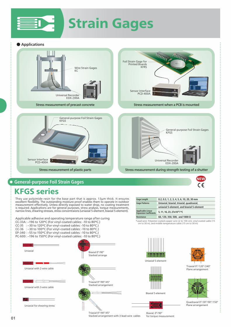
General-purpose Foil Strain Gages
KFGS seriesThey use polyimide resin for the base part that is approx. 13µm thick. It ensures excellent flexibility. The outstanding moisture proof enables them to operate in outdoor measurement effectively. Unless directly exposed to water drop, no coating treatment is required. Applications are for general purposes, stress analysis, torque measurements, narrow lines, shearing stresses, stress concentraions (uniaxial 5-element, biaxial 5-element).
Applicable adhesive and operating temperature range after curingCC-33A : −196 to 120ºC (For vinyl-coated cables: -10 to 80ºC.) CC-35 : −30 to 120ºC (For vinyl-coated cables: -10 to 80ºC.)CC-36 : −30 to 100ºC (For vinyl-coated cables: -10 to 80ºC.)EP-340 : −55 to 150ºC (For vinyl-coated cables: -10 to 80ºC.)PC-600 : −196 to 150ºC (For vinyl-coated cables: -10 to 80ºC.)
and triaxial 0°/90°/45° stacked rosette (Biaxial and triaxial are available only for a gage length of 10 mm.)
11 × 10-6/°C
Resistance 120 Ω
Applicable Linear Expansion Coefficients
Gage Length 60, 70, 80, 120 mm Gage Patterns Uniaxial
11 × 10-6/°C
Resistance 120 Ω
Applicable Linear Expansion Coefficients
Gage Length 30, 120 mm Gage Patterns Uniaxial
11 × 10-6/°C
Resistance 120 Ω
Gage Length 70 mm Gage Patterns Uniaxial
─
Resistance 120 Ω
Applicable Linear Expansion Coefficients
Applicable Linear Expansion Coefficients
Applicable Linear Expansion Coefficients
*With polyester-coated copper wire 1 m
Gage Length 2, 5 mmGage Patterns Uniaxial
11, 16, 23, 27 × 10-6/°C
Resistance 120 Ω
Applicable Linear Expansion Coefficients
Gage Length 0.15, 0.2, 0.5, 1, 2, and 5 mmGage Patterns Uniaxial, triaxial 0°/90°/45° , and uniaxial 5-element
11, 16, 23 × 10-6/°C
Resistance 120, 350 Ω
Applicable Linear Expansion Coefficients
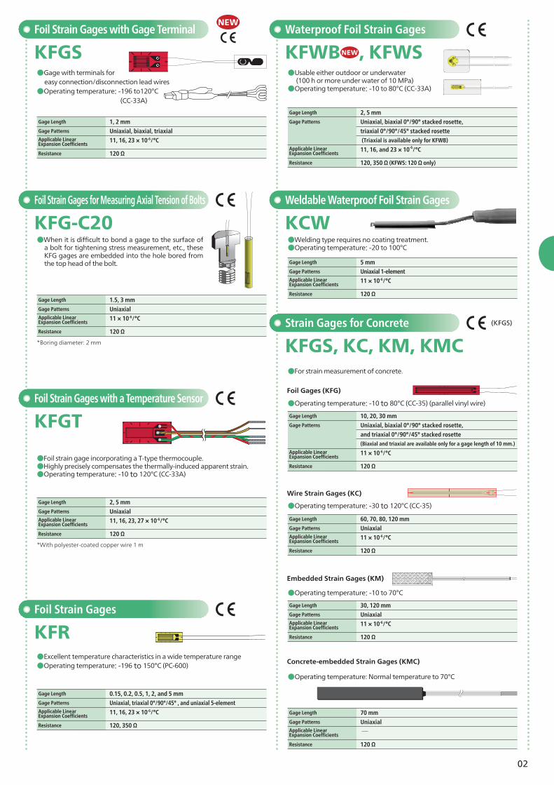
KFWBNEW, KFWS
NEW
*Boring diameter: 2 mm
Foil Strain Gages for Measuring Axial Tension of Bolts
KFG-C20●When it is difficult to bond a gage to the surface of
a bolt for tightening stress measurement, etc., these KFG gages are embedded into the hole bored from the top head of the bolt.
Gage Length 1.5, 3 mmGage Patterns Uniaxial
11 × 10-6/°C
Resistance 120 Ω
Applicable Linear Expansion Coefficients (KFGS)
03
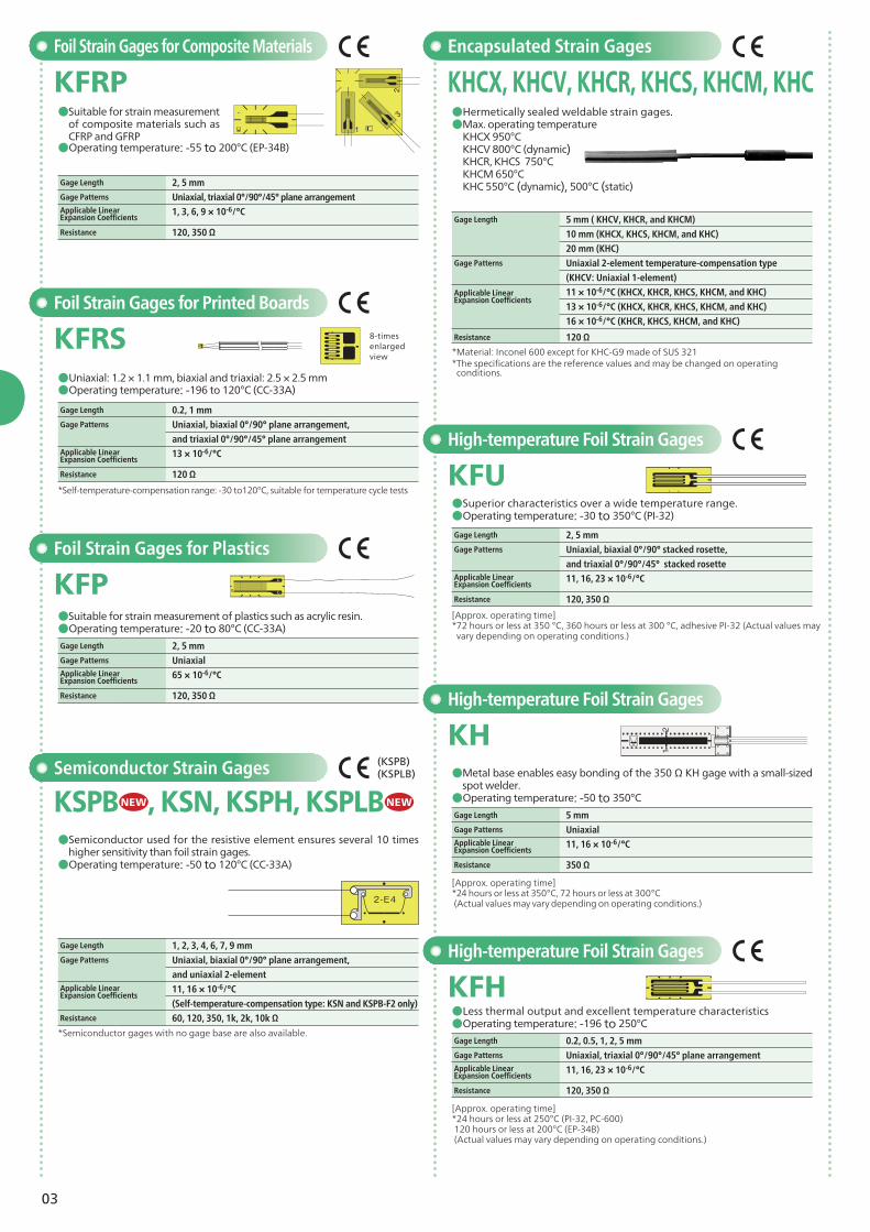
●Less thermal output and excellent temperature characteristics●Operating temperature: -196 to 250°C
High-temperature Foil Strain Gages
KFH
[Approx. operating time]*24 hours or less at 350°C, 72 hours or less at 300°C (Actual values may vary depending on operating conditions.)
[Approx. operating time]*24 hours or less at 250°C (PI-32, PC-600) 120 hours or less at 200°C (EP-34B) (Actual values may vary depending on operating conditions.)
High-temperature Foil Strain Gages
KH●Metal base enables easy bonding of the 350 Ω KH gage with a small-sized
spot welder. ●Operating temperature: -50 to 350°C
●Superior characteristics over a wide temperature range.●Operating temperature: -30 to 350°C (PI-32)
High-temperature Foil Strain Gages
KFU
*Semiconductor gages with no gage base are also available.
Semiconductor Strain Gages
●Semiconductor used for the resistive element ensures several 10 times higher sensitivity than foil strain gages.●Operating temperature: -50 to 120°C (CC-33A)
*Material: Inconel 600 except for KHC-G9 made of SUS 321* The specifications are the reference values and may be changed on operating
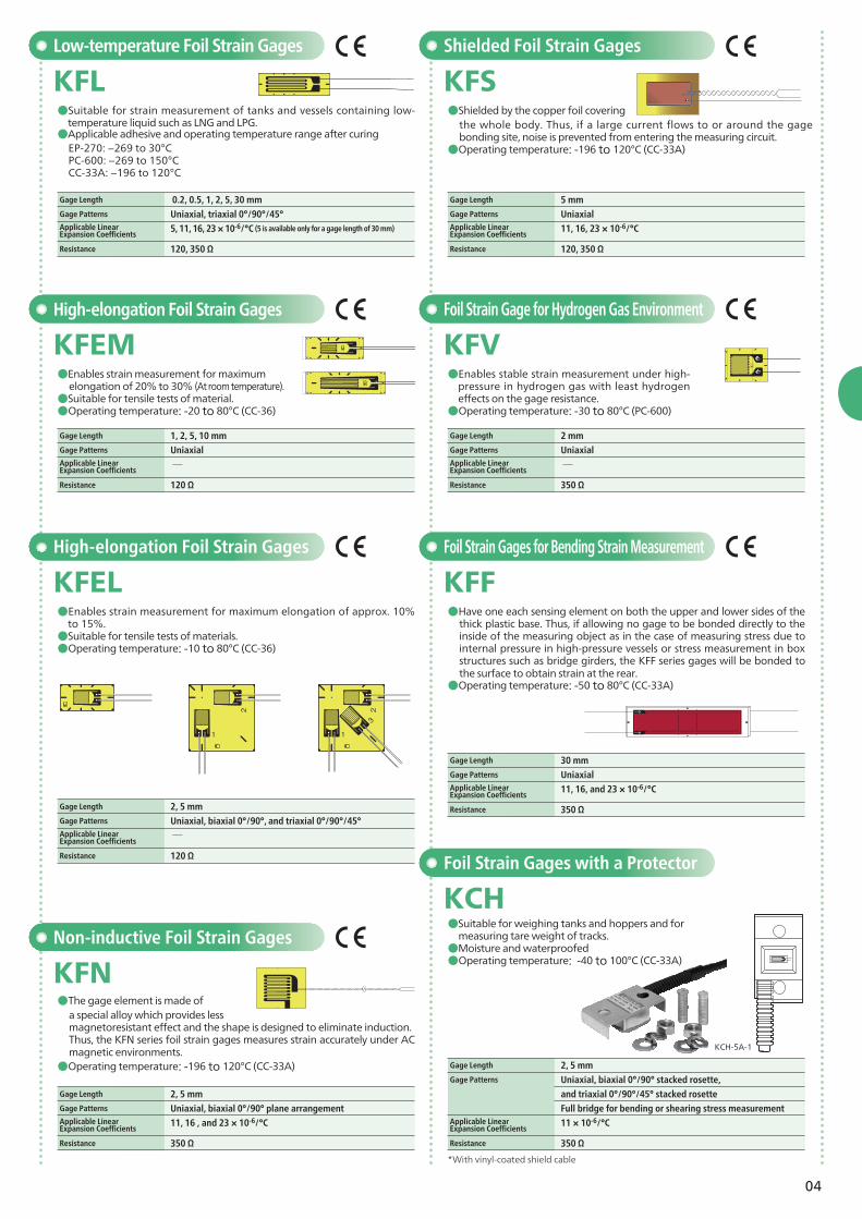
KFEL●Enables strain measurement for maximum elongation of approx. 10%
to 15%.●Suitable for tensile tests of materials.●Operating temperature: -10 to 80°C (CC-36)
High-elongation Foil Strain Gages
KFEM●Enables strain measurement for maximum elongation of 20% to 30% (At room temperature). ●Suitable for tensile tests of material.●Operating temperature: -20 to 80°C (CC-36)
Low-temperature Foil Strain Gages
KFL●Suitable for strain measurement of tanks and vessels containing low-
temperature liquid such as LNG and LPG. ●Applicable adhesive and operating temperature range after curing EP-270: −269 to 30°C PC-600: −269 to 150°C CC-33A: −196 to 120°C
●The gage element is made of a special alloy which provides less magnetoresistant effect and the shape is designed to eliminate induction.Thus, the KFN series foil strain gages measures strain accurately under AC magnetic environments.
●Operating temperature: -196 to 120°C (CC-33A)
Non-inductive Foil Strain Gages
KFN
Foil Strain Gage for Hydrogen Gas Environment
KFV●Enables stable strain measurement under high-
pressure in hydrogen gas with least hydrogen effects on the gage resistance.●Operating temperature: -30 to 80°C (PC-600)
●Shielded by the copper foil covering the whole body. Thus, if a large current flows to or around the gage bonding site, noise is prevented from entering the measuring circuit.
●Operating temperature: -196 to 120°C (CC-33A)
Shielded Foil Strain Gages
KFS
Foil Strain Gages for Bending Strain Measurement
KFF●Have one each sensing element on both the upper and lower sides of the
thick plastic base. Thus, if allowing no gage to be bonded directly to the inside of the measuring object as in the case of measuring stress due to internal pressure in high-pressure vessels or stress measurement in box structures such as bridge girders, the KFF series gages will be bonded to the surface to obtain strain at the rear.
●Operating temperature: -50 to 80°C (CC-33A)
Foil Strain Gages with a Protector
KCH●Suitable for weighing tanks and hoppers and for measuring tare weight of tracks.●Moisture and waterproofed●Operating temperature: -40 to 100°C (CC-33A)
Full bridge for bending or shearing stress measurement
11 × 10-6/°C
Resistance 350 Ω
Applicable Linear Expansion Coefficients
Gage Length 1, 2, 5, 10 mmGage Patterns Uniaxial
─
Resistance 120 Ω
Gage Length 2 mmGage Patterns Uniaxial
─
Resistance 350 Ω
Applicable Linear Expansion Coefficients
Applicable Linear Expansion Coefficients
*With vinyl-coated shield cable
KCH-5A-1
05
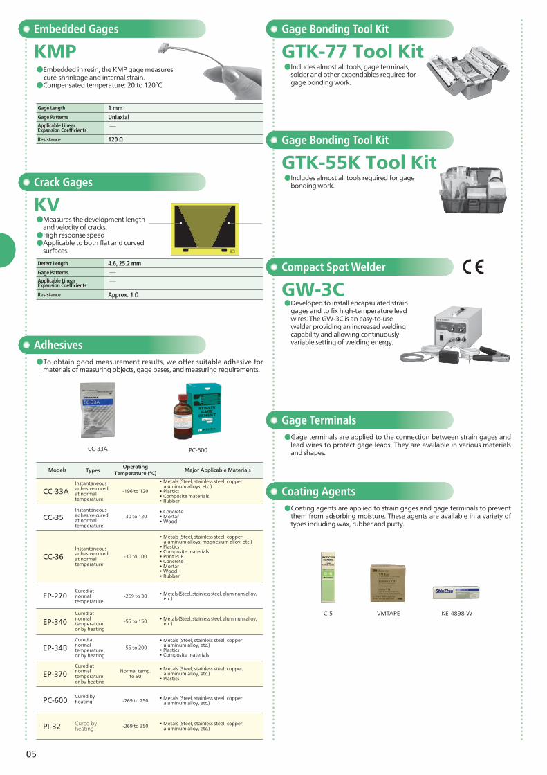
Compact Spot Welder
GW-3C●Developed to install encapsulated strain
gages and to fix high-temperature lead wires. The GW-3C is an easy-to-use welder providing an increased welding capability and allowing continuously variable setting of welding energy.Adhesives
●To obtain good measurement results, we offer suitable adhesive for materials of measuring objects, gage bases, and measuring requirements.
Coating Agents●Coating agents are applied to strain gages and gage terminals to prevent
them from adsorbing moisture. These agents are available in a variety of types including wax, rubber and putty.
Gage Terminals●Gage terminals are applied to the connection between strain gages and
lead wires to protect gage leads. They are available in various materials and shapes.
Crack Gages
KV●Measures the development length
and velocity of cracks.●High response speed●Applicable to both flat and curved
surfaces.
Gage Bonding Tool Kit
Gage Bonding Tool Kit
GTK-77 Tool Kit
GTK-55K Tool Kit
●Includes almost all tools, gage terminals, solder and other expendables required for gage bonding work.
●Includes almost all tools required for gage bonding work.
Embedded Gages
KMP●Embedded in resin, the KMP gage measures
cure-shrinkage and internal strain.●Compensated temperature: 20 to 120°C
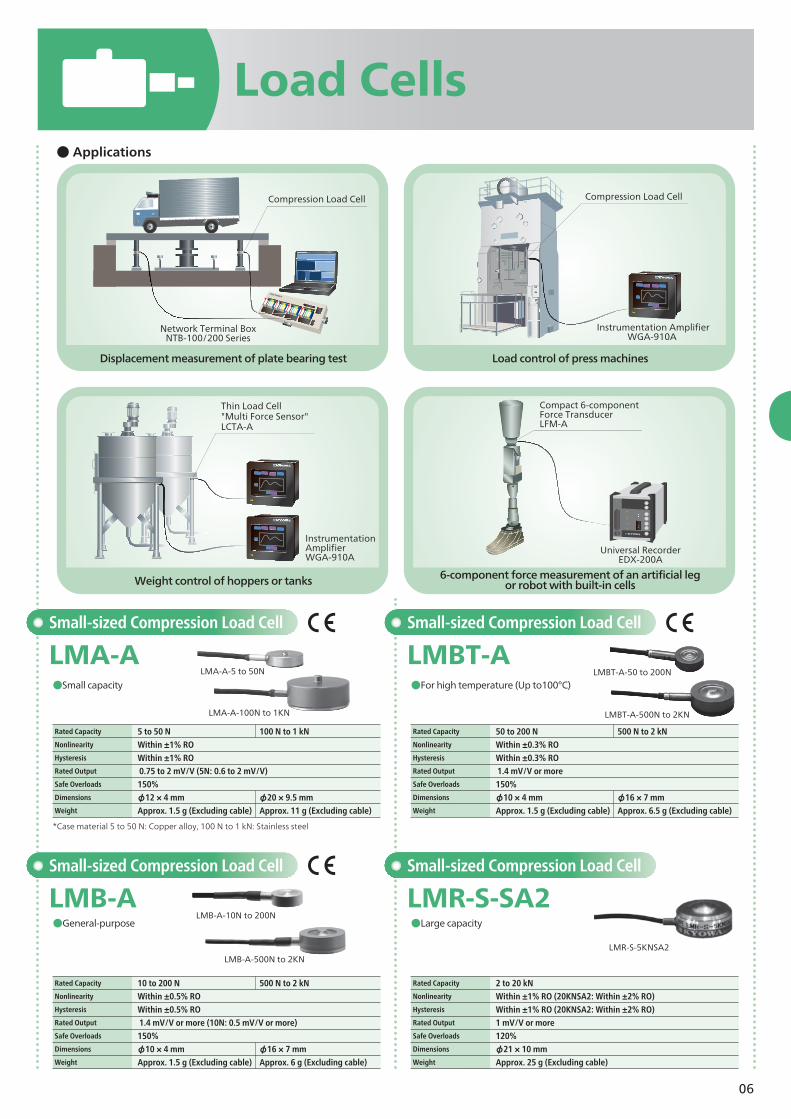
6-component force measurement of an artificial leg or robot with built-in cells
*Case material 5 to 50 N: Copper alloy, 100 N to 1 kN: Stainless steel
Rated Capacity 5 to 50 N 100 N to 1 kNNonlinearity Within ±1% ROHysteresis Within ±1% RORated Output 0.75 to 2 mV/V (5N: 0.6 to 2 mV/V)Safe Overloads 150%Dimensions φ12 × 4 mm φ20 × 9.5 mm Weight Approx. 1.5 g (Excluding cable) Approx. 11 g (Excluding cable)
Rated Capacity 50 to 200 N 500 N to 2 kNNonlinearity Within ±0.3% ROHysteresis Within ±0.3% RORated Output 1.4 mV/V or moreSafe Overloads 150% Dimensions φ10 × 4 mm φ16 × 7 mmWeight Approx. 1.5 g (Excluding cable) Approx. 6.5 g (Excluding cable)
Rated Capacity 10 to 200 N 500 N to 2 kNNonlinearity Within ±0.5% ROHysteresis Within ±0.5% RORated Output 1.4 mV/V or more (10N: 0.5 mV/V or more)Safe Overloads 150%Dimensions φ10 × 4 mm φ16 × 7 mmWeight Approx. 1.5 g (Excluding cable) Approx. 6 g (Excluding cable)
Rated Capacity 2 to 20 kNNonlinearity Within ±1% RO (20KNSA2: Within ±2% RO) Hysteresis Within ±1% RO (20KNSA2: Within ±2% RO) Rated Output 1 mV/V or moreSafe Overloads 120%Dimensions φ21 × 10 mmWeight Approx. 25 g (Excluding cable)
Network Terminal BoxNTB-100/200 Series
Universal Recorder EDX-200A
Instrumentation Amplifier WGA-910A
InstrumentationAmplifier WGA-910A
Compression Load Cell
Thin Load Cell "Multi Force Sensor"LCTA-A
Compact 6-component Force TransducerLFM-A
Compression Load Cell
07
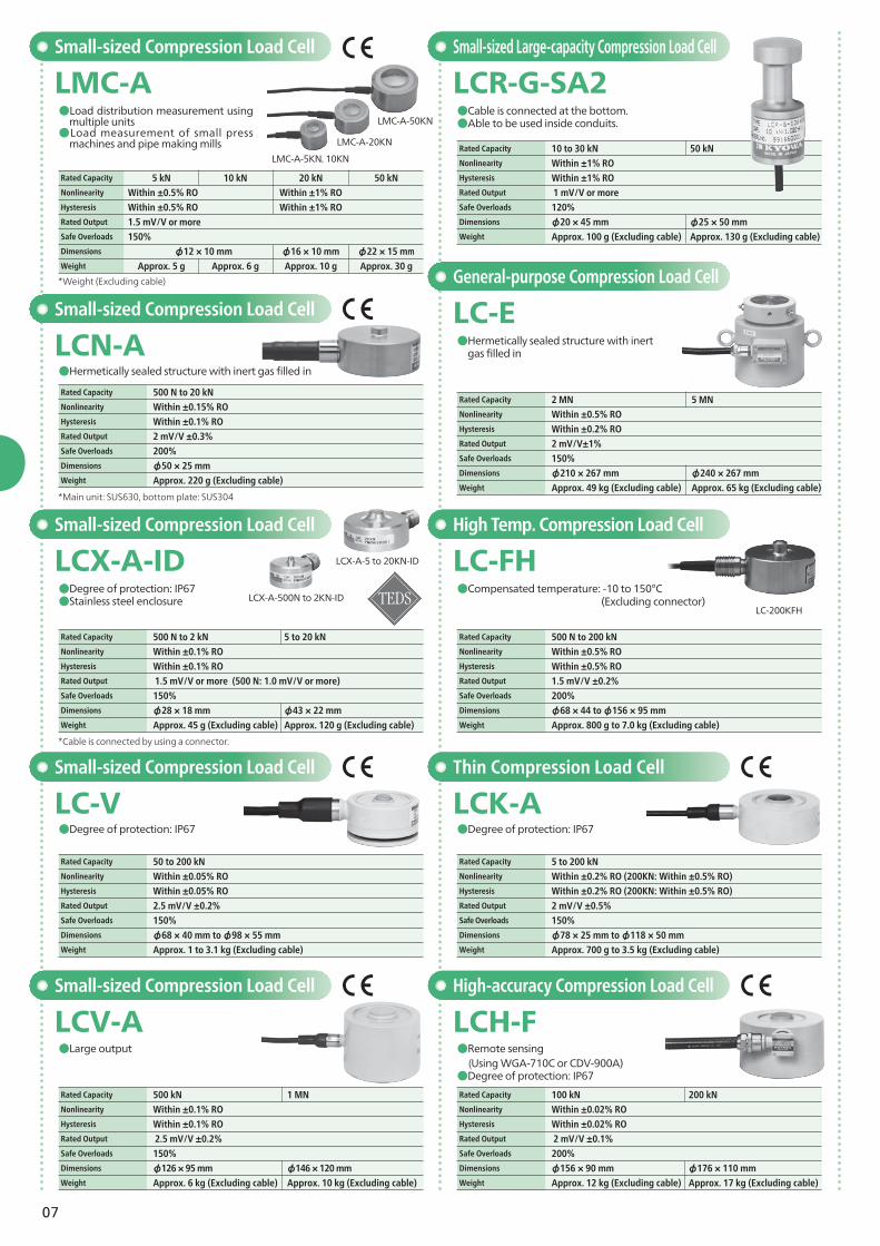
●Cable is connected at the bottom.●Able to be used inside conduits.
Small-sized Large-capacity Compression Load Cell
LCR-G-SA2
●Hermetically sealed structure with inert gas filled in
General-purpose Compression Load Cell
LC-E
●Compensated temperature: -10 to 150°C (Excluding connector)
High Temp. Compression Load Cell
LC-FH
Rated Capacity 500 N to 200 kNNonlinearity Within ±0.5% RO
Hysteresis Within ±0.5% RO Rated Output 1.5 mV/V ±0.2%Safe Overloads 200%Dimensions φ68 × 44 to φ156 × 95 mmWeight Approx. 800 g to 7.0 kg (Excluding cable)
Small-sized Compression Load Cell
LMC-A●Load distribution measurement using
multiple units●Load measurement of small press
machines and pipe making mills
*Weight (Excluding cable)
*Main unit: SUS630, bottom plate: SUS304
*Cable is connected by using a connector.
●Hermetically sealed structure with inert gas filled in
Small-sized Compression Load Cell
LCN-ARated Capacity 500 N to 20 kNNonlinearity Within ±0.15% ROHysteresis Within ±0.1% RORated Output 2 mV/V ±0.3%Safe Overloads 200%Dimensions φ50 × 25 mmWeight Approx. 220 g (Excluding cable)
●Degree of protection: IP67●Stainless steel enclosure
Small-sized Compression Load Cell
LCX-A-IDLCX-A-500N to 2KN-ID
LCX-A-5 to 20KN-ID
●Degree of protection: IP67
Small-sized Compression Load Cell
LC-V
Rated Capacity 50 to 200 kNNonlinearity Within ±0.05% ROHysteresis Within ±0.05% RORated Output 2.5 mV/V ±0.2%Safe Overloads 150%Dimensions φ68 × 40 mm to φ98 × 55 mmWeight Approx. 1 to 3.1 kg (Excluding cable)
●Large output
Small-sized Compression Load Cell
LCV-AHigh-accuracy Compression Load Cell
LCH-F●Remote sensing (Using WGA-710C or CDV-900A)●Degree of protection: IP67
●Degree of protection: IP67
Thin Compression Load Cell
LCK-A
Rated Capacity 5 to 200 kNNonlinearity Within ±0.2% RO (200KN: Within ±0.5% RO)Hysteresis Within ±0.2% RO (200KN: Within ±0.5% RO)Rated Output 2 mV/V ±0.5%Safe Overloads 150%Dimensions φ78 × 25 mm to φ118 × 50 mmWeight Approx. 700 g to 3.5 kg (Excluding cable)
Rated Capacity 5 kN 10 kN 20 kN 50 kNNonlinearity Within ±0.5% RO Within ±1% ROHysteresis Within ±0.5% RO Within ±1% RORated Output 1.5 mV/V or moreSafe Overloads 150%Dimensions φ12 × 10 mm φ16 × 10 mm φ22 × 15 mmWeight Approx. 5 g Approx. 6 g Approx. 10 g Approx. 30 g
Rated Capacity 500 N to 2 kN 5 to 20 kNNonlinearity Within ±0.1% ROHysteresis Within ±0.1% RORated Output 1.5 mV/V or more (500 N: 1.0 mV/V or more)Safe Overloads 150%Dimensions φ28 × 18 mm φ43 × 22 mmWeight Approx. 45 g (Excluding cable) Approx. 120 g (Excluding cable)
Rated Capacity 500 kN 1 MNNonlinearity Within ±0.1% ROHysteresis Within ±0.1% RORated Output 2.5 mV/V ±0.2%Safe Overloads 150%Dimensions φ126 × 95 mm φ146 × 120 mmWeight Approx. 6 kg (Excluding cable) Approx. 10 kg (Excluding cable)
Rated Capacity 10 to 30 kN 50 kNNonlinearity Within ±1% ROHysteresis Within ±1% RORated Output 1 mV/V or more Safe Overloads 120%Dimensions φ20 × 45 mm φ25 × 50 mmWeight Approx. 100 g (Excluding cable) Approx. 130 g (Excluding cable)
Rated Capacity 2 MN 5 MNNonlinearity Within ±0.5% ROHysteresis Within ±0.2% RORated Output 2 mV/V±1% Safe Overloads 150%Dimensions φ210 × 267 mm φ240 × 267 mmWeight Approx. 49 kg (Excluding cable) Approx. 65 kg (Excluding cable)
Rated Capacity 100 kN 200 kNNonlinearity Within ±0.02% ROHysteresis Within ±0.02% RORated Output 2 mV/V ±0.1% Safe Overloads 200%Dimensions φ156 × 90 mm φ176 × 110 mmWeight Approx. 12 kg (Excluding cable) Approx. 17 kg (Excluding cable)
LC-200KFH
LMC-A-50KN
LMC-A-20KN
LMC-A-5KN,10KN
08
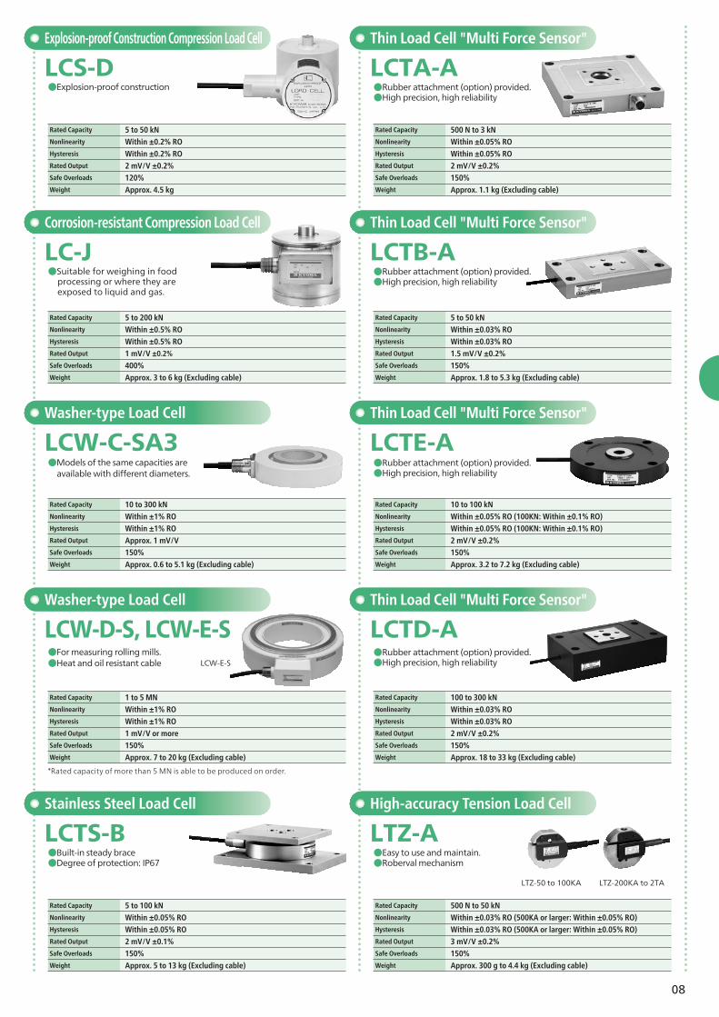
Washer-type Load Cell
LCW-C-SA3●Models of the same capacities are available with different diameters.
Rated Capacity 10 to 300 kNNonlinearity Within ±1% ROHysteresis Within ±1% RORated Output Approx. 1 mV/VSafe Overloads 150%Weight Approx. 0.6 to 5.1 kg (Excluding cable)
LCW-E-S
*Rated capacity of more than 5 MN is able to be produced on order.
Washer-type Load Cell
LCW-D-S, LCW-E-S●For measuring rolling mills.●Heat and oil resistant cable
Rated Capacity 1 to 5 MNNonlinearity Within ±1% ROHysteresis Within ±1% RORated Output 1 mV/V or moreSafe Overloads 150%Weight Approx. 7 to 20 kg (Excluding cable)
Explosion-proof Construction Compression Load Cell
Rated Capacity 5 to 50 kNNonlinearity Within ±0.2% ROHysteresis Within ±0.2% RORated Output 2 mV/V ±0.2%Safe Overloads 120%Weight Approx. 4.5 kg
●Explosion-proof construction
LCS-D
Corrosion-resistant Compression Load Cell
LC-J
Rated Capacity 5 to 200 kNNonlinearity Within ±0.5% ROHysteresis Within ±0.5% RORated Output 1 mV/V ±0.2%
Safe Overloads 400%Weight Approx. 3 to 6 kg (Excluding cable)
●Suitable for weighing in food processing or where they are exposed to liquid and gas.
Stainless Steel Load Cell
LCTS-B
Rated Capacity 5 to 100 kN
Nonlinearity Within ±0.05% RO
Hysteresis Within ±0.05% RO Rated Output 2 mV/V ±0.1% Safe Overloads 150%Weight Approx. 5 to 13 kg (Excluding cable)
●Built-in steady brace●Degree of protection: IP67
Rated Capacity 500 N to 3 kN
Nonlinearity Within ±0.05% RO
Hysteresis Within ±0.05% RO Rated Output 2 mV/V ±0.2% Safe Overloads 150%Weight Approx. 1.1 kg (Excluding cable)
●Rubber attachment (option) provided.●High precision, high reliability
LCTA-AThin Load Cell "Multi Force Sensor"
●Easy to use and maintain.●Roberval mechanism
LTZ-50 to 100KA LTZ-200KA to 2TA
High-accuracy Tension Load Cell
LTZ-A
Rated Capacity 500 N to 50 kNNonlinearity Within ±0.03% RO (500KA or larger: Within ±0.05% RO) Hysteresis Within ±0.03% RO (500KA or larger: Within ±0.05% RO) Rated Output 3 mV/V ±0.2%Safe Overloads 150%Weight Approx. 300 g to 4.4 kg (Excluding cable)
Thin Load Cell "Multi Force Sensor"
LCTB-A
Rated Capacity 5 to 50 kN Nonlinearity Within ±0.03% RO
Hysteresis Within ±0.03% RO
Rated Output 1.5 mV/V ±0.2% Safe Overloads 150%Weight Approx. 1.8 to 5.3 kg (Excluding cable)
Thin Load Cell "Multi Force Sensor"
LCTE-A
Rated Capacity 10 to 100 kN
Nonlinearity Within ±0.05% RO (100KN: Within ±0.1% RO) Hysteresis Within ±0.05% RO (100KN: Within ±0.1% RO) Rated Output 2 mV/V ±0.2%
Safe Overloads 150%Weight Approx. 3.2 to 7.2 kg (Excluding cable)
Thin Load Cell "Multi Force Sensor"
LCTD-A
Rated Capacity 100 to 300 kN
Nonlinearity Within ±0.03% RO
Hysteresis Within ±0.03% RO
Rated Output 2 mV/V ±0.2%
Safe Overloads 150%Weight Approx. 18 to 33 kg (Excluding cable)
●Rubber attachment (option) provided.●High precision, high reliability
●Rubber attachment (option) provided.●High precision, high reliability
●Rubber attachment (option) provided.●High precision, high reliability
09
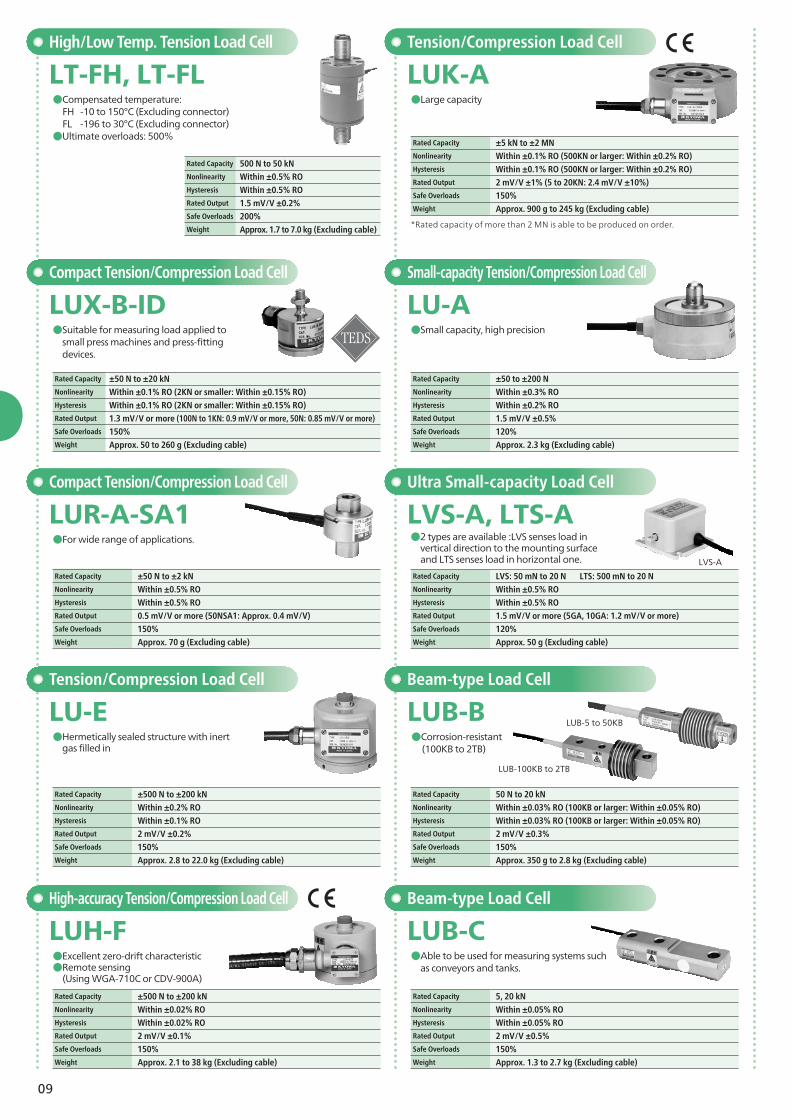
●Small capacity, high precision
Small-capacity Tension/Compression Load Cell
LU-A
Rated Capacity ±50 to ±200 N
Nonlinearity Within ±0.3% RO Hysteresis Within ±0.2% RO Rated Output 1.5 mV/V ±0.5%Safe Overloads 120%Weight Approx. 2.3 kg (Excluding cable)
●Large capacity
●2 types are available :LVS senses load in vertical direction to the mounting surface and LTS senses load in horizontal one.
Tension/Compression Load Cell
Ultra Small-capacity Load Cell
LUK-A
LVS-A, LTS-A
Rated Capacity ±5 kN to ±2 MN Nonlinearity Within ±0.1% RO (500KN or larger: Within ±0.2% RO)Hysteresis Within ±0.1% RO (500KN or larger: Within ±0.2% RO)Rated Output 2 mV/V ±1% (5 to 20KN: 2.4 mV/V ±10%)Safe Overloads 150%Weight Approx. 900 g to 245 kg (Excluding cable)
Rated Capacity LVS: 50 mN to 20 N LTS: 500 mN to 20 NNonlinearity Within ±0.5% RO
Hysteresis Within ±0.5% RO
Rated Output 1.5 mV/V or more (5GA, 10GA: 1.2 mV/V or more)Safe Overloads 120%Weight Approx. 50 g (Excluding cable)
●Able to be used for measuring systems such as conveyors and tanks.
●Corrosion-resistant (100KB to 2TB)
Beam-type Load Cell
Beam-type Load Cell
LUB-C
LUB-B
Rated Capacity 5, 20 kN
Nonlinearity Within ±0.05% RO
Hysteresis Within ±0.05% RO
Rated Output 2 mV/V ±0.5%Safe Overloads 150%Weight Approx. 1.3 to 2.7 kg (Excluding cable)
Rated Capacity 50 N to 20 kNNonlinearity Within ±0.03% RO (100KB or larger: Within ±0.05% RO)Hysteresis Within ±0.03% RO (100KB or larger: Within ±0.05% RO)
Rated Output 2 mV/V ±0.3%Safe Overloads 150%Weight Approx. 350 g to 2.8 kg (Excluding cable)
*Rated capacity of more than 2 MN is able to be produced on order.
Rated Capacity 500 N to 50 kNNonlinearity Within ±0.5% ROHysteresis Within ±0.5% RORated Output 1.5 mV/V ±0.2%Safe Overloads 200%Weight Approx. 1.7 to 7.0 kg (Excluding cable)
High/Low Temp. Tension Load Cell
LT-FH, LT-FL●Compensated temperature: FH -10 to 150°C (Excluding connector) FL -196 to 30°C (Excluding connector)●Ultimate overloads: 500%
●Hermetically sealed structure with inert gas filled in
Tension/Compression Load Cell
LU-E
Rated Capacity ±500 N to ±200 kN Nonlinearity Within ±0.2% RO
Hysteresis Within ±0.1% RO
Rated Output 2 mV/V ±0.2%Safe Overloads 150%Weight Approx. 2.8 to 22.0 kg (Excluding cable)
●For wide range of applications.
Compact Tension/Compression Load Cell
LUR-A-SA1
Rated Capacity ±50 N to ±2 kN
Nonlinearity Within ±0.5% RO
Hysteresis Within ±0.5% RO
Rated Output 0.5 mV/V or more (50NSA1: Approx. 0.4 mV/V)Safe Overloads 150%Weight Approx. 70 g (Excluding cable)
●Excellent zero-drift characteristic●Remote sensing (Using WGA-710C or CDV-900A)
High-accuracy Tension/Compression Load Cell
LUH-F
Rated Capacity ±500 N to ±200 kN Nonlinearity Within ±0.02% ROHysteresis Within ±0.02% RORated Output 2 mV/V ±0.1%Safe Overloads 150%Weight Approx. 2.1 to 38 kg (Excluding cable)
Compact Tension/Compression Load Cell
LUX-B-ID●Suitable for measuring load applied to
small press machines and press-fitting devices.
Rated Capacity ±50 N to ±20 kN Nonlinearity Within ±0.1% RO (2KN or smaller: Within ±0.15% RO)Hysteresis Within ±0.1% RO (2KN or smaller: Within ±0.15% RO)Rated Output 1.3 mV/V or more (100N to 1KN: 0.9 mV/V or more, 50N: 0.85 mV/V or more)Safe Overloads 150%Weight Approx. 50 to 260 g (Excluding cable)
LVS-A
LUB-5 to 50KB
LUB-100KB to 2TB
10
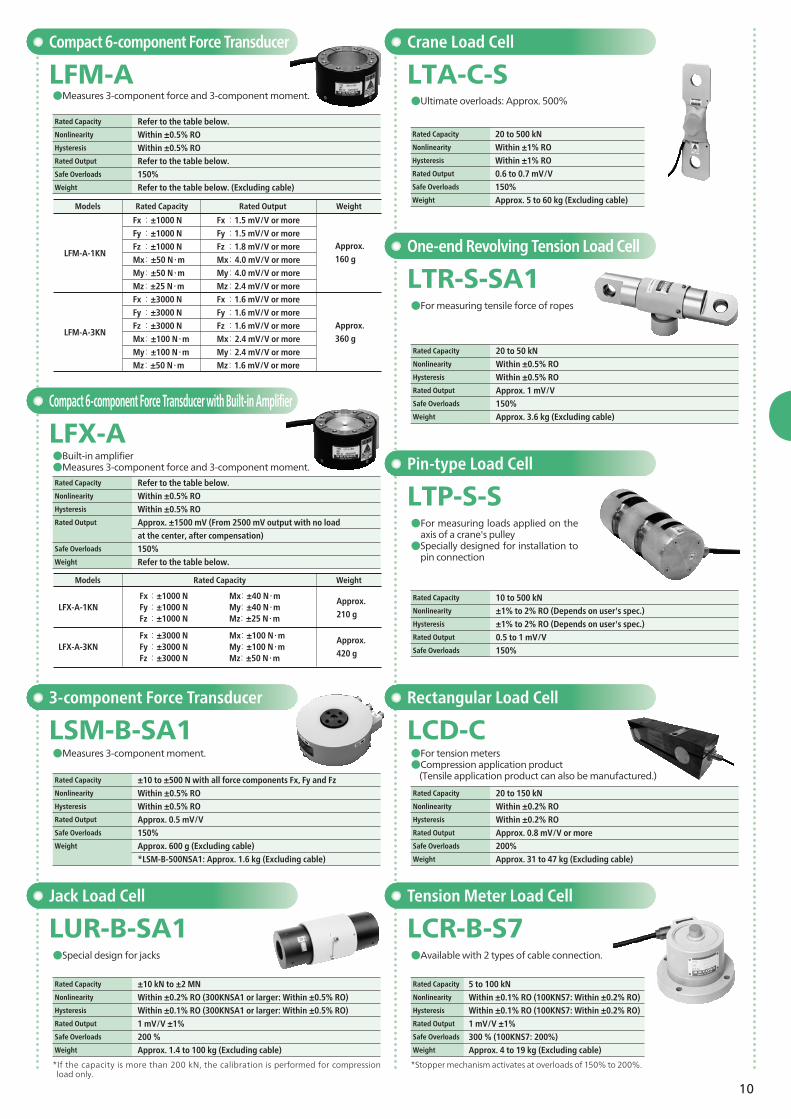
Compact 6-component Force Transducer
LFM-A●Measures 3-component force and 3-component moment.
Rated Capacity Refer to the table below.Nonlinearity Within ±0.5% ROHysteresis Within ±0.5% RORated Output Refer to the table below.Safe Overloads 150%Weight Refer to the table below. (Excluding cable)
Compact 6-component Force Transducer with Built-in Amplifier
LFX-A●Built-in amplifier●Measures 3-component force and 3-component moment.
Rated Capacity Refer to the table below.Nonlinearity Within ±0.5% ROHysteresis Within ±0.5% RORated Output Approx. ±1500 mV (From 2500 mV output with no load
at the center, after compensation) Safe Overloads 150%Weight Refer to the table below.
Crane Load Cell
LTA-C-S
Rated Capacity 20 to 500 kNNonlinearity Within ±1% ROHysteresis Within ±1% RORated Output 0.6 to 0.7 mV/VSafe Overloads 150%Weight Approx. 5 to 60 kg (Excluding cable)
●Ultimate overloads: Approx. 500%
One-end Revolving Tension Load Cell
LTR-S-SA1
Rated Capacity 20 to 50 kNNonlinearity Within ±0.5% ROHysteresis Within ±0.5% RORated Output Approx. 1 mV/VSafe Overloads 150%Weight Approx. 3.6 kg (Excluding cable)
●For measuring tensile force of ropes
Pin-type Load Cell
LTP-S-S
Rated Capacity 10 to 500 kN
Nonlinearity ±1% to 2% RO (Depends on user's spec.) Hysteresis ±1% to 2% RO (Depends on user's spec.) Rated Output 0.5 to 1 mV/VSafe Overloads 150%
●For measuring loads applied on the axis of a crane's pulley●Specially designed for installation to
pin connection
*Stopper mechanism activates at overloads of 150% to 200%.
●Available with 2 types of cable connection.
Tension Meter Load Cell
LCR-B-S7
Rated Capacity 5 to 100 kN
Nonlinearity Within ±0.1% RO (100KNS7: Within ±0.2% RO) Hysteresis Within ±0.1% RO (100KNS7: Within ±0.2% RO) Rated Output 1 mV/V ±1%Safe Overloads 300 % (100KNS7: 200%)Weight Approx. 4 to 19 kg (Excluding cable)
Rectangular Load Cell
LCD-C●For tension meters●Compression application product (Tensile application product can also be manufactured.)
Rated Capacity 20 to 150 kNNonlinearity Within ±0.2% ROHysteresis Within ±0.2% RORated Output Approx. 0.8 mV/V or moreSafe Overloads 200%Weight Approx. 31 to 47 kg (Excluding cable)
Models
LFX-A-1KN
LFX-A-3KN
Fx : ±1000 NFy : ±1000 NFz : ±1000 N
Mx: ±40 N・mMy: ±40 N・mMz: ±25 N・m
Fx : ±3000 NFy : ±3000 NFz : ±3000 N
Mx: ±100 N・mMy: ±100 N・mMz: ±50 N・m
Approx.
210 g
Approx.
420 g
Rated Capacity Weight
*If the capacity is more than 200 kN, the calibration is performed for compression load only.
Jack Load Cell
LUR-B-SA1
Rated Capacity ±10 kN to ±2 MN
Nonlinearity Within ±0.2% RO (300KNSA1 or larger: Within ±0.5% RO) Hysteresis Within ±0.1% RO (300KNSA1 or larger: Within ±0.5% RO) Rated Output 1 mV/V ±1%Safe Overloads 200 %Weight Approx. 1.4 to 100 kg (Excluding cable)
●Special design for jacks
3-component Force Transducer
LSM-B-SA1●Measures 3-component moment.
Rated Capacity ±10 to ±500 N with all force components Fx, Fy and FzNonlinearity Within ±0.5% RO
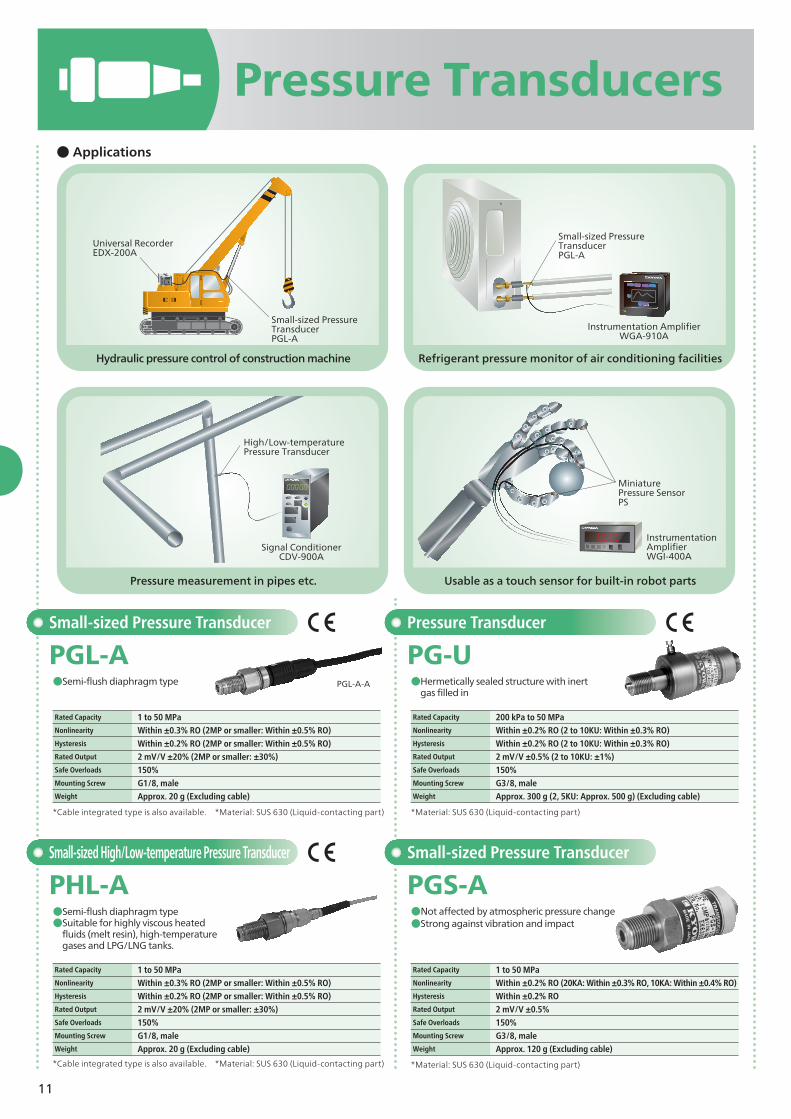
Hydraulic pressure control of construction machine
Pressure measurement in pipes etc.
Refrigerant pressure monitor of air conditioning facilities
Usable as a touch sensor for built-in robot parts
Small-sized Pressure Transducer
Small-sized Pressure Transducer
PGL-A
PGS-A
●Semi-flush diaphragm type
●Not affected by atmospheric pressure change ●Strong against vibration and impact
●Hermetically sealed structure with inert gas filled in
Rated Capacity 1 to 50 MPaNonlinearity Within ±0.3% RO (2MP or smaller: Within ±0.5% RO)Hysteresis Within ±0.2% RO (2MP or smaller: Within ±0.5% RO)Rated Output 2 mV/V ±20% (2MP or smaller: ±30%) Safe Overloads 150%Mounting Screw G1/8, maleWeight Approx. 20 g (Excluding cable)
Rated Capacity 1 to 50 MPaNonlinearity Within ±0.2% RO (20KA: Within ±0.3% RO, 10KA: Within ±0.4% RO) Hysteresis Within ±0.2% RO Rated Output 2 mV/V ±0.5%
PHL-A●Semi-flush diaphragm type●Suitable for highly viscous heated
fluids (melt resin), high-temperature gases and LPG/LNG tanks.
*Cable integrated type is also available. *Material: SUS 630 (Liquid-contacting part)
Rated Capacity 1 to 50 MPaNonlinearity Within ±0.3% RO (2MP or smaller: Within ±0.5% RO) Hysteresis Within ±0.2% RO (2MP or smaller: Within ±0.5% RO)Rated Output 2 mV/V ±20% (2MP or smaller: ±30%)Safe Overloads 150%Mounting Screw G1/8, maleWeight Approx. 20 g (Excluding cable)
Pressure Transducer
PG-U
*Material: SUS 630 (Liquid-contacting part)
Rated Capacity 200 kPa to 50 MPaNonlinearity Within ±0.2% RO (2 to 10KU: Within ±0.3% RO)Hysteresis Within ±0.2% RO (2 to 10KU: Within ±0.3% RO)Rated Output 2 mV/V ±0.5% (2 to 10KU: ±1%) Safe Overloads 150%Mounting Screw G3/8, maleWeight Approx. 300 g (2, 5KU: Approx. 500 g) (Excluding cable)
PGL-A-A
Instrumentation Amplifier WGA-910A
Signal ConditionerCDV-900A
InstrumentationAmplifier WGI-400A
Miniature Pressure Sensor PS
Small-sized Pressure Transducer PGL-A
Small-sized Pressure TransducerPGL-A
High/Low-temperature Pressure Transducer
Universal RecorderEDX-200A
12
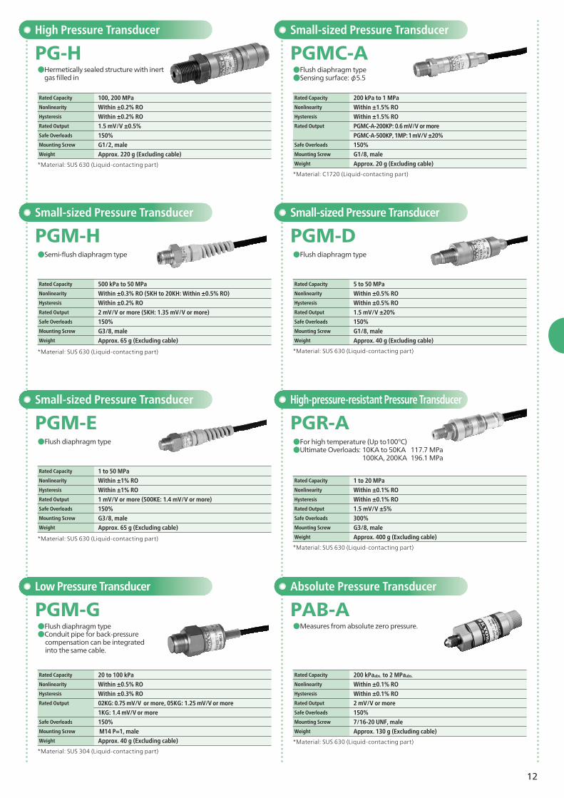
Small-sized Pressure Transducer
PGMC-A●Flush diaphragm type●Sensing surface: φ5.5
*Material: C1720 (Liquid-contacting part)
Rated Capacity 200 kPa to 1 MPaNonlinearity Within ±1.5% ROHysteresis Within ±1.5% RORated Output PGMC-A-200KP: 0.6 mV/V or more
Rated Capacity 500 kPa to 50 MPaNonlinearity Within ±0.3% RO (5KH to 20KH: Within ±0.5% RO)Hysteresis Within ±0.2% RO Rated Output 2 mV/V or more (5KH: 1.35 mV/V or more) Safe Overloads 150%Mounting Screw G3/8, maleWeight Approx. 65 g (Excluding cable)
*Material: SUS 630 (Liquid-contacting part)
PGM-ESmall-sized Pressure Transducer
●Flush diaphragm type
Rated Capacity 1 to 50 MPa
Nonlinearity Within ±1% RO Hysteresis Within ±1% RO Rated Output 1 mV/V or more (500KE: 1.4 mV/V or more) Safe Overloads 150%Mounting Screw G3/8, maleWeight Approx. 65 g (Excluding cable)
*Material: SUS 630 (Liquid-contacting part)
High Pressure Transducer
PG-H
*Material: SUS 630 (Liquid-contacting part)
Rated Capacity 100, 200 MPaNonlinearity Within ±0.2% RO Hysteresis Within ±0.2% RO Rated Output 1.5 mV/V ±0.5% Safe Overloads 150%Mounting Screw G1/2, maleWeight Approx. 220 g (Excluding cable)
*Material: SUS 304 (Liquid-contacting part)
Low Pressure Transducer
PGM-G●Flush diaphragm type●Conduit pipe for back-pressure
compensation can be integrated into the same cable.
Rated Capacity 20 to 100 kPaNonlinearity Within ±0.5% ROHysteresis Within ±0.3% RORated Output 02KG: 0.75 mV/V or more, 05KG: 1.25 mV/V or more
1KG: 1.4 mV/V or moreSafe Overloads 150%Mounting Screw M14 P=1, maleWeight Approx. 40 g (Excluding cable)
Small-sized Pressure Transducer
PGM-D●Flush diaphragm type
*Material: SUS 630 (Liquid-contacting part)
Rated Capacity 5 to 50 MPaNonlinearity Within ±0.5% ROHysteresis Within ±0.5% RORated Output 1.5 mV/V ±20%Safe Overloads 150%Mounting Screw G1/8, maleWeight Approx. 40 g (Excluding cable)
High-pressure-resistant Pressure Transducer
PGR-A●For high temperature (Up to100°C)●Ultimate Overloads: 10KA to 50KA 117.7 MPa 100KA, 200KA 196.1 MPa
*Material: SUS 630 (Liquid-contacting part)
Rated Capacity 1 to 20 MPaNonlinearity Within ±0.1% ROHysteresis Within ±0.1% RORated Output 1.5 mV/V ±5%Safe Overloads 300%Mounting Screw G3/8, maleWeight Approx. 400 g (Excluding cable)
Absolute Pressure Transducer
PAB-A●Measures from absolute zero pressure.
*Material: SUS 630 (Liquid-contacting part)
Rated Capacity 200 kPaabs. to 2 MPaabs.
Nonlinearity Within ±0.1% RO Hysteresis Within ±0.1% RO Rated Output 2 mV/V or moreSafe Overloads 150%Mounting Screw 7/16-20 UNF, maleWeight Approx. 130 g (Excluding cable)
●Hermetically sealed structure with inert gas filled in
13
High/Low-temperature Pressure Transducer
PHB-A●Compensated temperature: -196 to 200°C (Excluding connector)
*Material: SUS 630 (Liquid-contacting part)
Rated Capacity 1 to 50 MPaNonlinearity Within ±0.4% ROHysteresis Within ±0.4% RORated Output 2.2 mV/V ±15%Safe Overloads 120%Mounting Screw G3/8, maleWeight Approx. 230 to 360 g (Excluding cable)
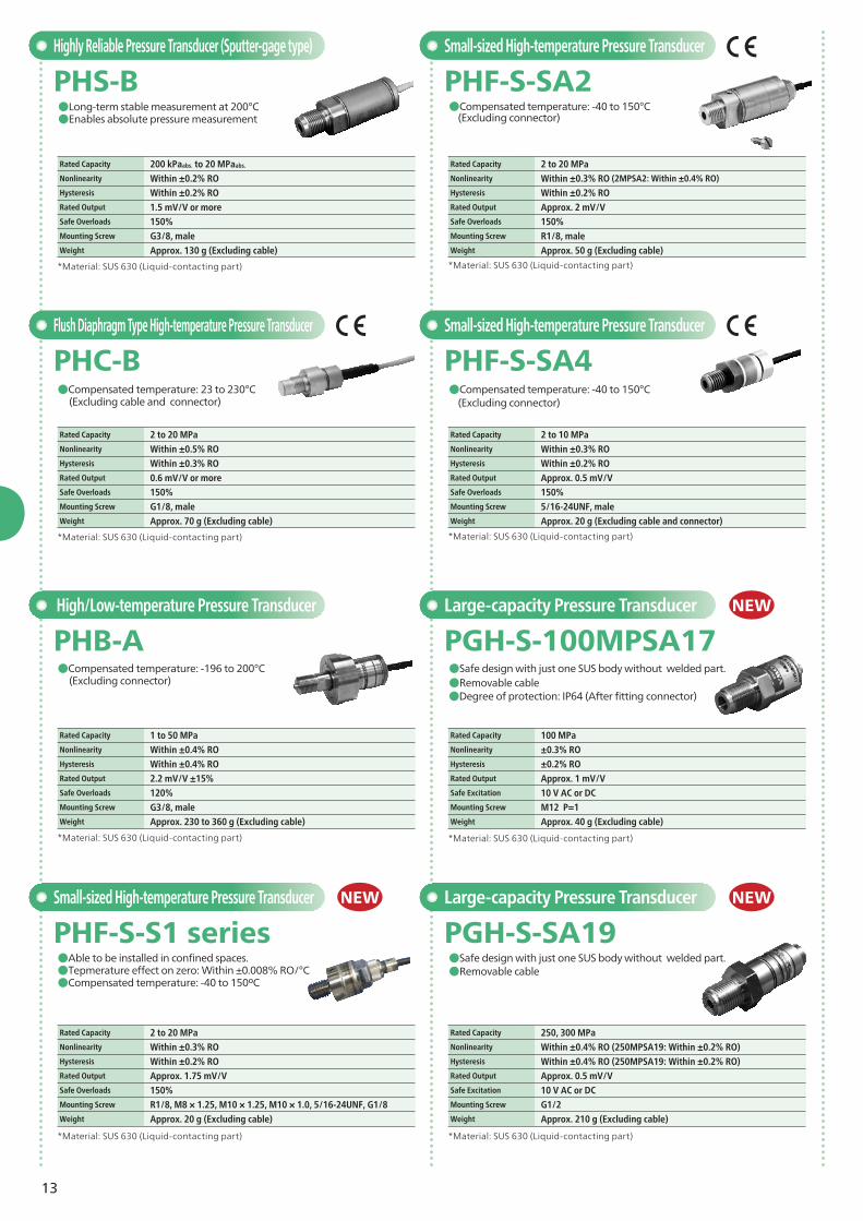
PHS-B●Long-term stable measurement at 200°C●Enables absolute pressure measurement
*Material: SUS 630 (Liquid-contacting part)
Rated Capacity 200 kPaabs. to 20 MPaabs.
Nonlinearity Within ±0.2% ROHysteresis Within ±0.2% RORated Output 1.5 mV/V or moreSafe Overloads 150%Mounting Screw G3/8, maleWeight Approx. 130 g (Excluding cable)
※材質は、本体SUS金属、接液部SUS630
Flush Diaphragm Type High-temperature Pressure Transducer
PHC-B●Compensated temperature: 23 to 230°C (Excluding cable and connector)
*Material: SUS 630 (Liquid-contacting part)
Rated Capacity 2 to 20 MPaNonlinearity Within ±0.5% ROHysteresis Within ±0.3% RORated Output 0.6 mV/V or moreSafe Overloads 150%Mounting Screw G1/8, maleWeight Approx. 70 g (Excluding cable)
Small-sized High-temperature Pressure Transducer
PHF-S-SA2●Compensated temperature: -40 to 150°C (Excluding connector)
*Material: SUS 630 (Liquid-contacting part)
Rated Capacity 2 to 20 MPaNonlinearity Within ±0.3% RO (2MPSA2: Within ±0.4% RO)
Hysteresis Within ±0.2% RORated Output Approx. 2 mV/VSafe Overloads 150%Mounting Screw R1/8, maleWeight Approx. 50 g (Excluding cable)
Small-sized High-temperature Pressure Transducer
PHF-S-SA4●Compensated temperature: -40 to 150°C (Excluding connector)
*Material: SUS 630 (Liquid-contacting part)
Rated Capacity 2 to 10 MPaNonlinearity Within ±0.3% ROHysteresis Within ±0.2% RORated Output Approx. 0.5 mV/VSafe Overloads 150%Mounting Screw 5/16-24UNF, maleWeight Approx. 20 g (Excluding cable and connector)
PGH-S-100MPSA17●Safe design with just one SUS body without welded part.●Removable cable●Degree of protection: IP64 (After fitting connector)
PGH-S-SA19●Safe design with just one SUS body without welded part.●Removable cable
*Material: SUS 630 (Liquid-contacting part)
*Material: SUS 630 (Liquid-contacting part)*Material: SUS 630 (Liquid-contacting part)
Rated Capacity 100 MPaNonlinearity ±0.3% ROHysteresis ±0.2% RORated Output Approx. 1 mV/VSafe Excitation 10 V AC or DCMounting Screw M12 P=1Weight Approx. 40 g (Excluding cable)
Rated Capacity 250, 300 MPaNonlinearity Within ±0.4% RO (250MPSA19: Within ±0.2% RO)Hysteresis Within ±0.4% RO (250MPSA19: Within ±0.2% RO)Rated Output Approx. 0.5 mV/VSafe Excitation 10 V AC or DCMounting Screw G1/2Weight Approx. 210 g (Excluding cable)
Large-capacity Pressure Transducer NEW
Large-capacity Pressure Transducer NEW
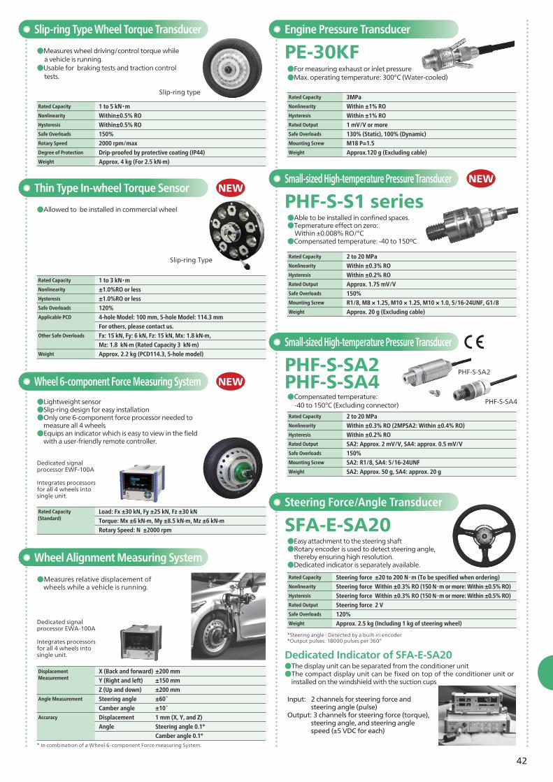
PHF-S-S1 series●Able to be installed in confined spaces.●Tepmerature effect on zero: Within ±0.008% RO/°C●Compensated temperature: -40 to 150ºC
Rated Capacity 2 to 20 MPaNonlinearity Within ±0.3% ROHysteresis Within ±0.2% RORated Output Approx. 1.75 mV/VSafe Overloads 150%Mounting Screw R1/8, M8 × 1.25, M10 × 1.25, M10 × 1.0, 5/16-24UNF, G1/8Weight Approx. 20 g (Excluding cable)
Small-sized High-temperature Pressure Transducer NEW
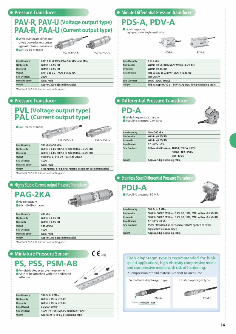
offers powerful resistance against transmission noise.●S/N: 50 dB or more
Rated Capacity PAV: 1 to 50 MPa, PAA: 500 kPa to 50 MPaNonlinearity Within ±0.2% ROHysteresis Within ±0.2% ROOutput PAV: 0 to 5 V PAA: 4 to 20 mASafe Overloads 200%Mounting Screw G3/8, maleWeight Approx. 200 g (Excluding cable)
*Material: SUS 630 (Liquid-contacting part)
Highly Stable Current-output Pressure Transducer
PAG-2KA●Noise resistant●S/N: 60 dB or more
Rated Capacity 200 kPaNonlinearity Within ±0.1% ROHysteresis Within ±0.2% ROOutput 4 to 20 mASafe Overloads 150%Mounting Screw G3/8, maleWeight Approx. 270 g (Excluding cable)
Pressure Transducer
PVL (Voltage output type) PAL (Current output type)
●S/N: 50 dB or more
*Material: SUS 630 (Liquid-contacting part)
Rated Capacity 500 kPa to 50 MPaNonlinearity Within ±0.3% RO (5K to 20K: Within ±0.5% RO) Hysteresis Within ±0.3% RO (5K to 20K: Within ±0.5% RO)Output PVL: 0 to V, 1 to 5 V PAL: 4 to 20 mA Safe Overloads 150%Mounting Screw G3/8, maleWeight PVL: Approx. 110 g, PAL: Approx. 85 g (Both excluding cables)
PVL-A, PVL-B PVL-C, PVL-D
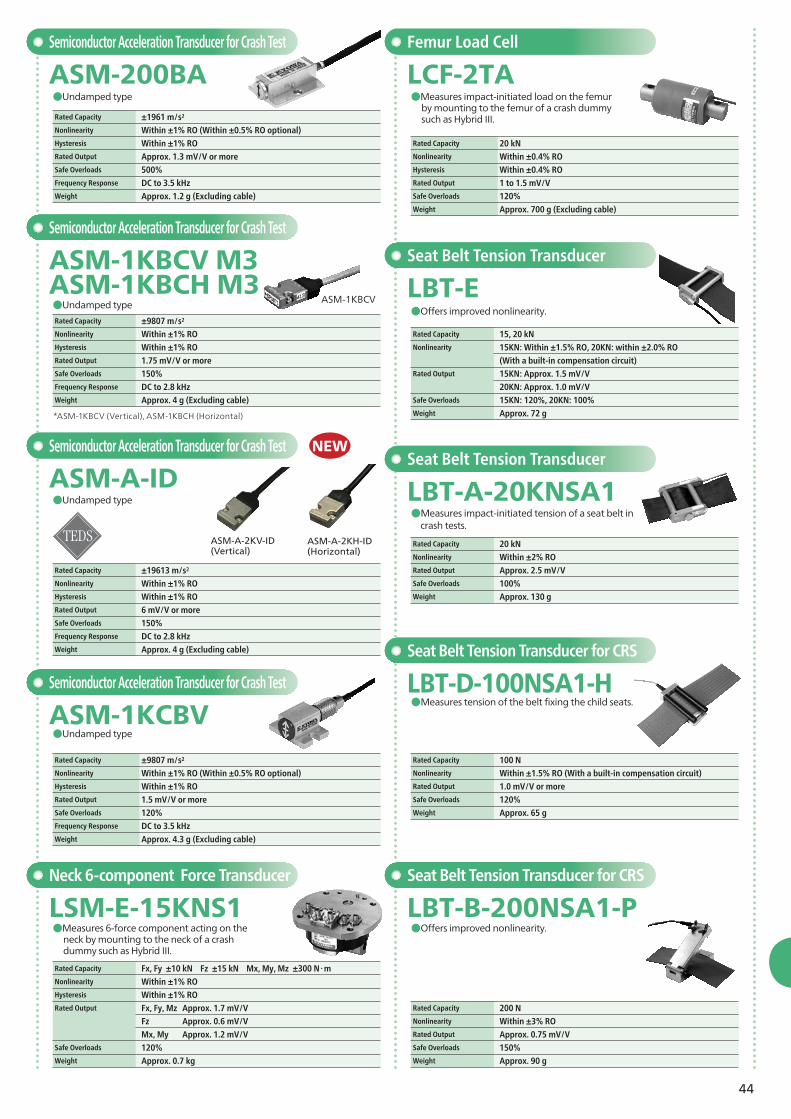
Miniature Pressure Sensor
PS, PSS, PSM-AB●For distributed pressure measurement●Able to be attached with the dedicated
adhesive.
Rated Capacity 50 kPa to 7 MPaNonlinearity Within ±1% to ±3% RO Hysteresis Within ±1% to ±3% RORated Output 0.25 to 1 mV/VSafe Overloads 150% (PS-70KC M2, PS-70KD M2: 100%) Weight Approx. 0.15 to 0.5 g (Excluding cable)
PDS-A PDV-A
Stainless Steel Differential Pressure Transducer
PDU-A●Max. line pressure: 30 MPa
Rated Capacity 50 kPa to 2 MPa Nonlinearity 50KP to 500KP: Within ±0.2% RO, 1MP, 2MP: within ±0.25% ROHysteresis 50KP to 500KP: Within ±0.2% RO, 1MP, 2MP: within ±0.25% RORated Output 1.5 mV/V ±0.5%Safe Overloads 150% (Withstand an overload of 30 MPa applied to either
high or low pressure side.)Weight Approx. 6 kg (Excluding cable)
Minute Differential Pressure Transducer
PDS-A, PDV-A●Quick response high precision, high sensitivity
Rated Capacity 1 to 7 kPaNonlinearity Within ±0.5% RO (25GA: Within ±0.7% RO) Hysteresis Within ±0.3% RORated Output PDS-A: ±13 to 23 mV (10GA: 7 to 23 mV) PDV-A: 5 VSafe Overloads 300% (10GA: 600%) Weight PDS-A: Approx. 40 g PDV-A: Approx. 100 g (Excluding cable)
Differential Pressure Transducer
PD-A●Wide line pressure margin ●Max. line pressure: 2.94 MPa
Rated Capacity 10 to 200 kPaNonlinearity Within ±0.3% ROHysteresis Within ±0.2% RORated Output 1.5 mV/V ±1%Safe Overloads Differential Pressure 100GA, 200GA: 200%
500GA, 1KA: 150%
2KA: 125%Weight Approx. 5 kg (Excluding cable)
Flash diaphragm type is recommended for high-speed applications, high-viscosity compressive media and compressive media with risk of hardening.
Semi-flush diaphragm type
*Compression of solid materials cannot be measured.
Flush diaphragm type
PGL-A PGM-E
(PS)
Pressure inlet
15
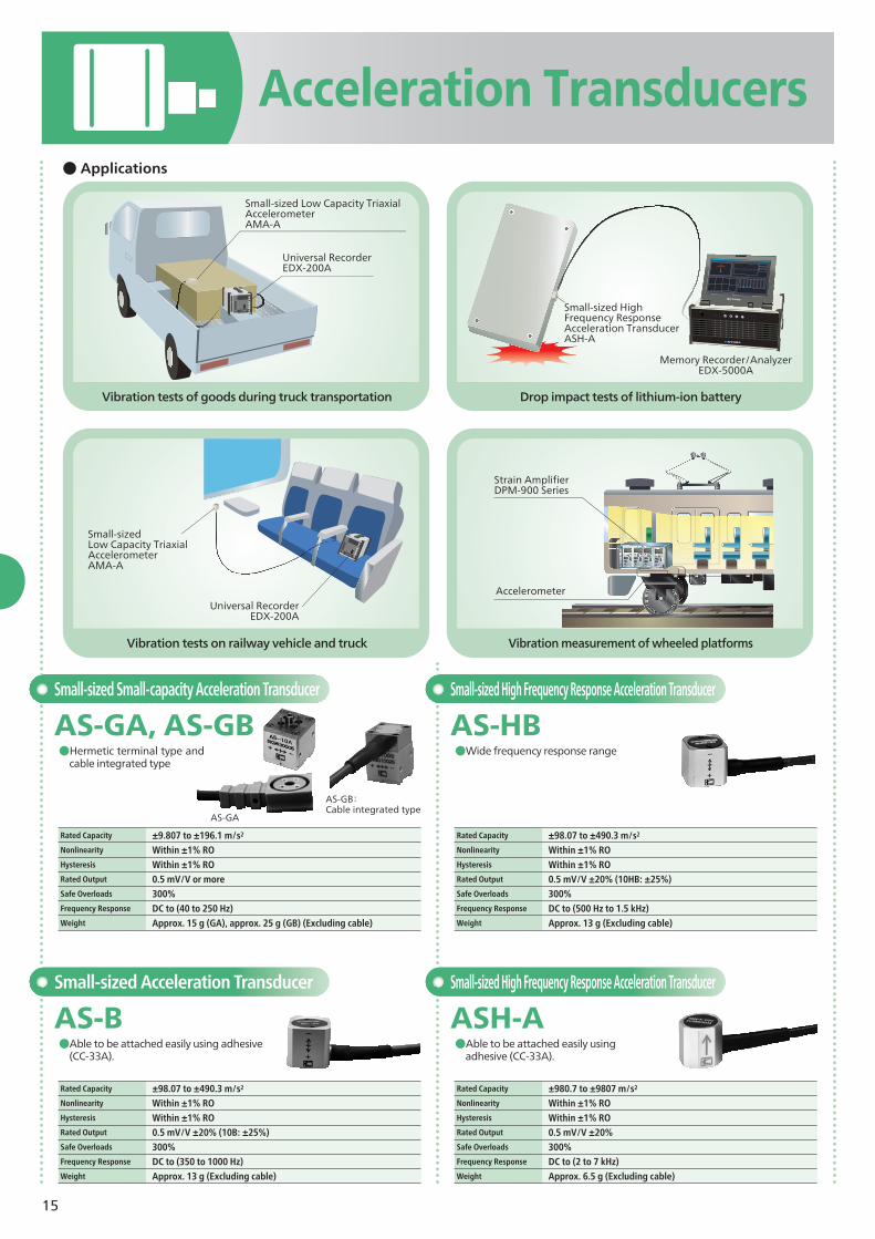
Acceleration Transducers
Vibration tests of goods during truck transportation
Vibration tests on railway vehicle and truck
Drop impact tests of lithium-ion battery
Vibration measurement of wheeled platforms
● Applications
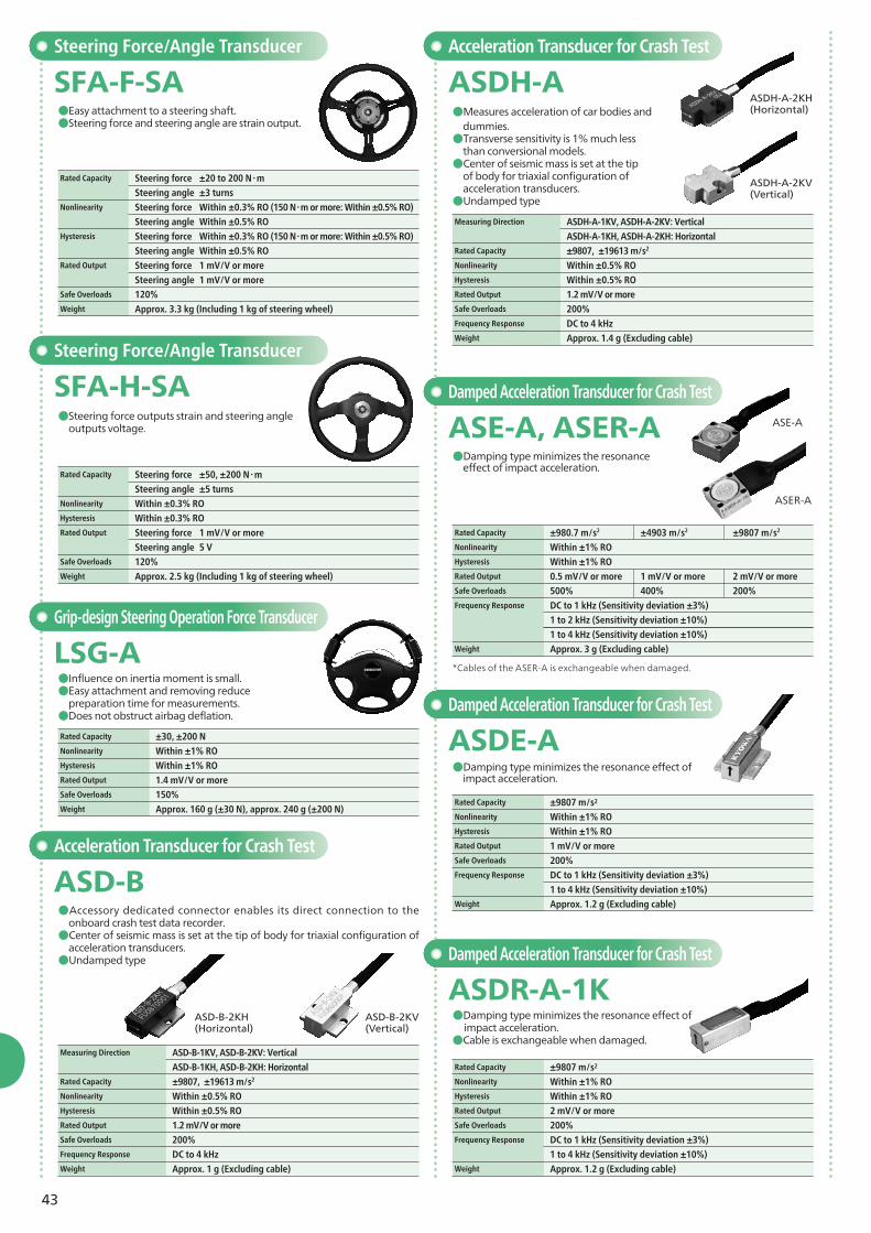
AS-HB●Wide frequency response range
Small-sized Small-capacity Acceleration Transducer Small-sized High Frequency Response Acceleration Transducer
AS-GA, AS-GB●Hermetic terminal type and
cable integrated type
Small-sized Acceleration Transducer
AS-B●Able to be attached easily using adhesive
(CC-33A).●Able to be attached easily using
adhesive (CC-33A).
Rated Capacity ±9.807 to ±196.1 m/s2
Nonlinearity Within ±1% RO
Hysteresis Within ±1% RO
Rated Output 0.5 mV/V or moreSafe Overloads 300%Frequency Response DC to (40 to 250 Hz)Weight Approx. 15 g (GA), approx. 25 g (GB) (Excluding cable)
Rated Capacity ±98.07 to ±490.3 m/s2
Nonlinearity Within ±1% RO
Hysteresis Within ±1% RO Rated Output 0.5 mV/V ±20% (10HB: ±25%) Safe Overloads 300%Frequency Response DC to (500 Hz to 1.5 kHz)Weight Approx. 13 g (Excluding cable)
ASH-ASmall-sized High Frequency Response Acceleration Transducer
Rated Capacity ±98.07 to ±490.3 m/s2
Nonlinearity Within ±1% RO
Hysteresis Within ±1% RO Rated Output 0.5 mV/V ±20% (10B: ±25%) Safe Overloads 300%Frequency Response DC to (350 to 1000 Hz)Weight Approx. 13 g (Excluding cable)
Rated Capacity ±980.7 to ±9807 m/s2
Nonlinearity Within ±1% ROHysteresis Within ±1% RORated Output 0.5 mV/V ±20% Safe Overloads 300% Frequency Response DC to (2 to 7 kHz) Weight Approx. 6.5 g (Excluding cable)
Nonlinearity Within ±1% ROHysteresis Within ±1% RORated Output 0.5 mV/V or moreSafe Overloads 1000% (With stoppers)Frequency Response DC to (40 to 250 Hz)Weight Approx. 110 g (Excluding cable)
Rated Capacity ±98.07 to ±490.3 m/s2
Nonlinearity Within ±1% ROHysteresis Within ±1% RORated Output 0.5 mV/V ±20% (10TB: ±25%)Safe Overloads 300% (Each axis) Frequency Response DC to (350 Hz to 1 kHz) Weight Approx. 95 g (Excluding cable)
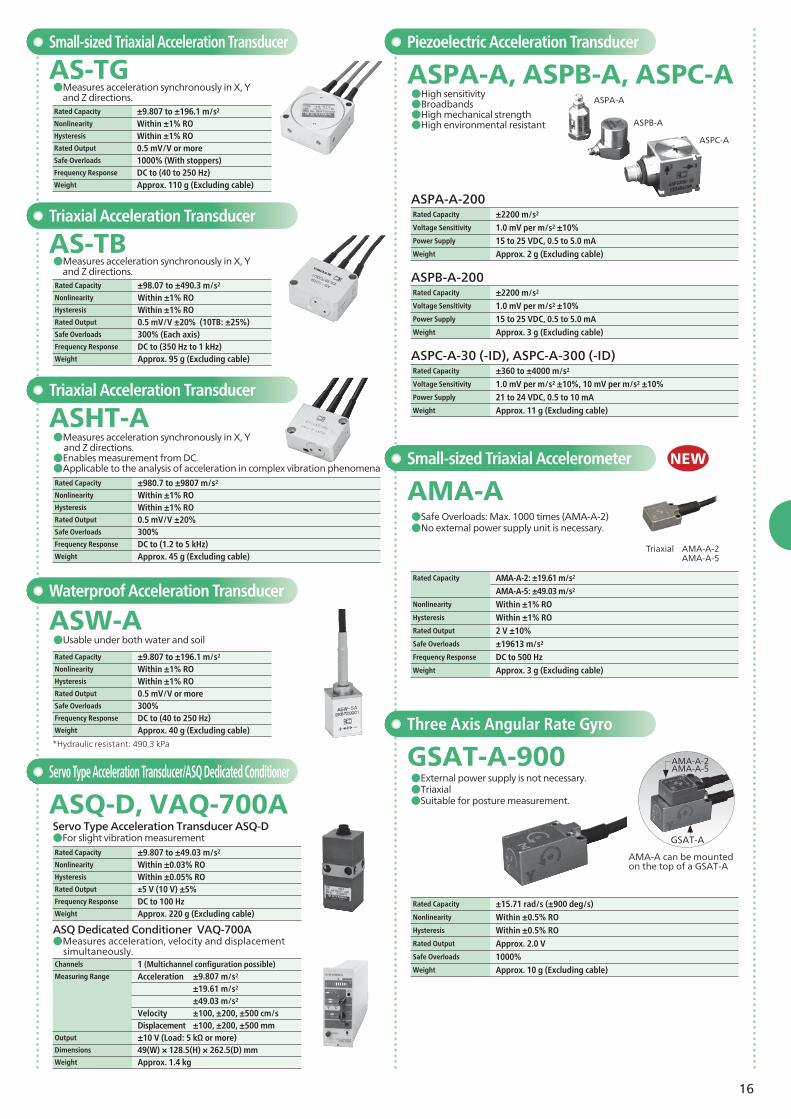
Rated Capacity ±2200 m/s2
Voltage Sensitivity 1.0 mV per m/s2 ±10%Power Supply 15 to 25 VDC, 0.5 to 5.0 mAWeight Approx. 2 g (Excluding cable)
Rated Capacity ±2200 m/s2
Voltage Sensitivity 1.0 mV per m/s2 ±10%Power Supply 15 to 25 VDC, 0.5 to 5.0 mAWeight Approx. 3 g (Excluding cable)
Rated Capacity ±360 to ±4000 m/s2
Voltage Sensitivity 1.0 mV per m/s2 ±10%, 10 mV per m/s2 ±10%Power Supply 21 to 24 VDC, 0.5 to 10 mAWeight Approx. 11 g (Excluding cable)
Triaxial Acceleration Transducer
ASHT-A
Rated Capacity ±980.7 to ±9807 m/s2
Nonlinearity Within ±1% ROHysteresis Within ±1% RORated Output 0.5 mV/V ±20% Safe Overloads 300% Frequency Response DC to (1.2 to 5 kHz) Weight Approx. 45 g (Excluding cable)
*Hydraulic resistant: 490.3 kPa
Waterproof Acceleration Transducer
ASW-A●Usable under both water and soil
Rated Capacity ±9.807 to ±196.1 m/s2
Nonlinearity Within ±1% ROHysteresis Within ±1% RORated Output 0.5 mV/V or moreSafe Overloads 300%Frequency Response DC to (40 to 250 Hz)Weight Approx. 40 g (Excluding cable)
Servo Type Acceleration Transducer ASQ-D●For slight vibration measurement
Servo Type Acceleration Transducer/ASQ Dedicated Conditioner
ASQ-D, VAQ-700A
Rated Capacity ±9.807 to ±49.03 m/s2
Nonlinearity Within ±0.03% ROHysteresis Within ±0.05% RORated Output ±5 V (10 V) ±5%Frequency Response DC to 100 HzWeight Approx. 220 g (Excluding cable)
ASQ Dedicated Conditioner VAQ-700A●Measures acceleration, velocity and displacement
simultaneously.Channels 1 (Multichannel configuration possible) Measuring Range Acceleration ±9.807 m/s2
±19.61 m/s2
±49.03 m/s2
Velocity ±100, ±200, ±500 cm/s Displacement ±100, ±200, ±500 mmOutput ±10 V (Load: 5 kΩ or more)Dimensions 49(W) × 128.5(H) × 262.5(D) mmWeight Approx. 1.4 kg
Rated Capacity AMA-A-2: ±19.61 m/s2
AMA-A-5: ±49.03 m/s2
Nonlinearity Within ±1% ROHysteresis Within ±1% RORated Output 2 V ±10% Safe Overloads ±19613 m/s2
Frequency Response DC to 500 HzWeight Approx. 3 g (Excluding cable)
Rated Capacity ±15.71 rad/s (±900 deg/s) Nonlinearity Within ±0.5% ROHysteresis Within ±0.5% RORated Output Approx. 2.0 VSafe Overloads 1000% Weight Approx. 10 g (Excluding cable)
Small-sized Triaxial Accelerometer
AMA-A ●Safe Overloads: Max. 1000 times (AMA-A-2)●No external power supply unit is necessary.
NEW
GSAT-A
AMA-A can be mounted on the top of a GSAT-A
ASPA-A
ASPB-A
ASPC-A
●Measures acceleration synchronously in X, Y and Z directions.●Enables measurement from DC.●Applicable to the analysis of acceleration in complex vibration phenomena
AMA-A-2AMA-A-5
Triaxial AMA-A-2 AMA-A-5
17
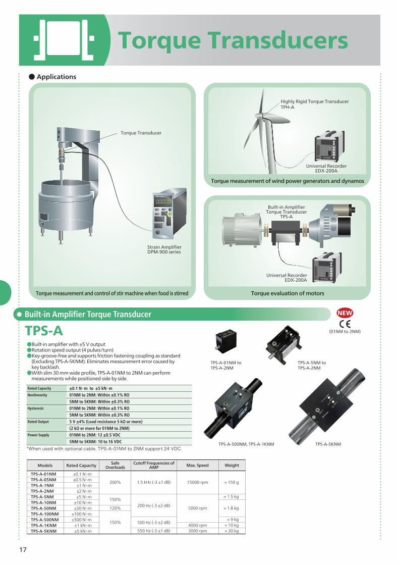
Torque Transducers
Torque measurement and control of stir machine when food is stirred
Torque measurement of wind power generators and dynamos
Torque evaluation of motors
● Applications
Built-in Amplifier Torque Transducer
TPS-A●Built-in amplifier with ±5 V output●Rotation speed output (4 pulses/turn)●Key-groove-free and supports friction fastening coupling as standard
(Excluding TPS-A-5KNM). Eliminates measurement error caused by key backlash.●With slim 30 mm wide profile, TPS-A-01NM to 2NM can perform
measurements while positioned side by side.
TPS-A-5NM toTPS-A-2NM
TPS-A-01NM to TPS-A-2NM
TPS-A-500NM, TPS-A-1KNM
Rated Capacity ±0.1 N・m to ±5 kN・mNonlinearity 01NM to 2NM: Within ±0.1% RO
5NM to 5KNM: Within ±0.3% RO Hysteresis 01NM to 2NM: Within ±0.1% RO
5NM to 5KNM: Within ±0.3% RORated Output 5 V ±4% (Load resistance 5 kΩ or more)
(2 kΩ or more for 01NM to 2NM)Power Supply 01NM to 2NM: 12 ±0.5 VDC
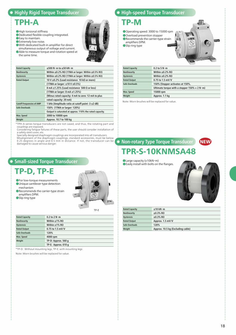
TPH-A TP-M●High torsional stiffness●Dedicated flexible coupling integrated.●Easy to maintain.●Extremely low noise.●With dedicated built-in amplifier for direct
simultaneous output of voltage and current.●Able to measure torque and rotation speed at
the same time.
●Operating speed: 3000 to 15000 rpm●Overload prevention stopper●Recommends the carrier-type strain
amplifiers DPM.●Slip ring type
Non-rotary Type Torque Transducer
TPR-S-10KNMSA48●Large capacity (±10kN・m)●Easily install with bolts on the flanges.
Rated Capacity ±500 N・m to ±50 kN・mNonlinearity Within ±0.2% RO (1TMA or larger: Within ±0.5% RO)
Hysteresis Within ±0.2% RO (1TMA or larger: Within ±0.5% RO)
Rated Output 10 V ±0.2% (Load resistance 10 kΩ or more)
(1TMA or larger: ±10 V ±0.5%)
8 mA ±1.25% (Load resistance 500 Ω or less)
(1TMA or larger: 8 mA ±1.25%)
(Minus rated capacity: 4 mA to zero: 12 mA to plus
rated capacity: 20 mA)Cutoff Frequencies of AMP 1 kHz (Amplitude ratio at cutoff point -3 ±2 dB)Safe Overloads 150% (1TMA or larger: 120%)
Output is saturated at approx. 110% the rated capacity.
Max. Speed 3000 to 10000 rpmWeight Approx. 10.7 to 100 kg
Rated Capacity 0.2 to 5 N・mNonlinearity Within ±0.2% ROHysteresis Within ±0.2% RORated Output 0.75 to 1.5 mV/VSafe Overloads 150% (Stopper activates at 150%,
Ultimate torque with a stopper 150% + 2 N・m)Max. Speed 15000 rpmWeight Approx. 1.1 kg
*TP-D: Without mounting legs, TP-E: with mounting legs
Small-sized Torque Transducer
TP-D, TP-E●For low-torque measurements●Unique cantilever type detection
mechanism●Recommends the carrier-type strain
amplifiers DPM.●Slip ring type
Rated Capacity 0.2 to 2 N・mNonlinearity Within ±1% ROHysteresis Within ±1% RORated Output 0.75 to 1.5 mV/VSafe Overloads 120%Max. Speed 4000 rpmWeight TP-D: Approx. 560 g
TP-E: Approx. 610 g
*TPH-A series torque transducers are not cased, and thus, the rotating part and couplings are exposed.Considering fatigue failures of these parts, the user should consider installation of a safety steel cover, etc.Specially designed diaphragm couplings are incorporated into all transducers. Misalignment of the diaphragm couplings, standard accessories, must be below 0.25 degrees in angle and 0.5 mm in distance. If not, the transducer can be damaged to cause serious danger.
Note: Worn brushes will be replaced for value.
Note: Worn brushes will be replaced for value.
NEW
19
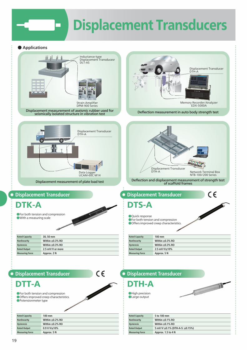
Displacement Transducers● Applications
Displacement Transducer
DTH-A●High precision●Large output
Rated Capacity 5 to 100 mmNonlinearity Within ±0.1% ROHysteresis Within ±0.1% RORated Output 5 mV/V ±0.1% (DTH-A-5: ±0.15%)Measuring Force Approx. 1.5 to 4 N
Displacement Transducer
DTK-A●For both tension and compression●With a measuring scale
Rated Capacity 30, 50 mm Nonlinearity Within ±0.3% ROHysteresis Within ±0.3% RORated Output 2.5 mV/V or moreMeasuring Force Approx. 2 N
Displacement Transducer
DTT-A●For both tension and compression●Offers improved creep characteristics.●Potensionmeter type
Rated Capacity 100 mm Nonlinearity Within ±0.2% ROHysteresis Within ±0.2% RORated Output 0.9 V/V±10% Measuring Force Approx. 5 N
●Quick response●For both tension and compression●Offers improved creep characteristics.
Displacement Transducer
DTS-A
Rated Capacity 100 mm Nonlinearity Within ±0.3% ROHysteresis Within ±0.3% RORated Output 2.5 mV/V±10%Measuring Force Approx. 5 N
Displacement measurement of aseismic rubber used for seismically isolated structure in vibration test
Displacement measurement of plate load test
Deflection measurement in auto body strength test
Deflection and displacement measurement of strength test of scaffold frames
Inductance-type Displacement TransducesrDLT-AS
Strain AmplifierDPM-900 Series
Data LoggerUCAM-60C M14
Displacement TransducerDTH-A Network Terminal Box
NTB-100/200 Series
Displacement TransducerDTH-A
Displacement TransducerDTH-A
Memory Recorder/AnalyzerEDX-5000A
20
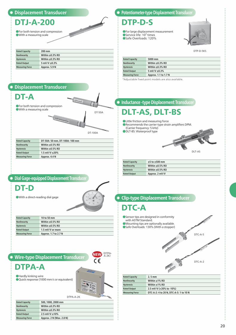
Displacement Transducer
Displacement Transducer
Potentiometer-type Displacement Transducer
Inductance -type Displacement Transducer
Clip-type Displacement Transducer
DTJ-A-200
DT-A
DTP-D-S
DLT-AS, DLT-BS
DTC-A
●For both tension and compression●With a measuring scale
●For both tension and compression●With a measuring scale
●For large displacement measurement●Service life: 104 times ●Safe Overloads: 120%
●Little friction and measuring force●Recommends the carrier-type strain amplifiers DPM. (Carrier frequency: 5 kHz)●DLT-BS: Waterproof type
●Sensor tips are designed in conformity with ASTM Standard. ●Mounting tips are optionally available.●Safe Overloads: 130% (With a stopper)
Rated Capacity 200 mmNonlinearity Within ±0.3% ROHysteresis Within ±0.3% RORated Output 5 mV/V ±0.3%Measuring Force Approx. 5.9 N
Rated Capacity DT-50A: 50 mm, DT-100A: 100 mmNonlinearity Within ±0.5% ROHysteresis Within ±0.5% RORated Output 1.5 mV/V ±20%Measuring Force Approx. 4.4 N
*Adjustable fixed point models are also available.
Rated Capacity 5000 mmNonlinearity Within ±0.3% ROHysteresis Within ±0.3% RORated Output 5 mV/V ±0.3%Measuring Force Approx. 1.1 to 1.7 N
Rated Capacity ±5 to ±500 mmNonlinearity Within ±0.5% ROHysteresis Within ±0.5% RORated Output Approx. 2 mV/V
Rated Capacity 2, 5 mmNonlinearity Within ±1% ROHysteresis Within ±1% RORated Output 2.5 mV/V (+20% to -10%)Measuring Force DTC-A-2: 4 to 20 N, DTC-A-5: 1 to 10 N
DTC-A-5
DTC-A-2
DLT-AS
Dial Gage-equipped Displacement Transducer
DT-D●With a direct-reading dial gage
Wire-type Displacement Transducer
DTPA-A●Hardly kinking wire●Quick response (1000 mm/s or equivalent)
Rated Capacity 10 to 50 mmNonlinearity Within ±0.5% ROHysteresis Within ±0.5% RORated Output 1.5 mV/V or moreMeasuring Force Approx. 1.7 to 2.7 N
Rated Capacity 500, 1000, 2000 mm Nonlinearity Within ±0.3% ROHysteresis Within ±0.3% RORated Output 2.5 mV/V ±10%Measuring Force Approx. 2 N (Max. 2.8 N)
DPM-951A, DPM-952A●Decrease the effects of inverter noises. ●Carrier-wave amplifier with powerful noise-resistance.
DPM-951A DPM-952A
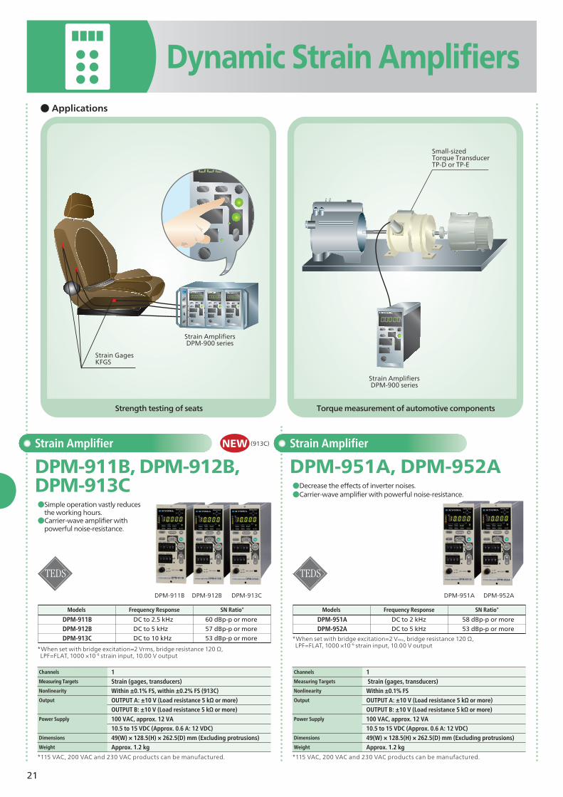
Strength testing of seats Torque measurement of automotive components
*When set with bridge excitation=2 Vrms, bridge resistance 120 Ω, LPF=FLAT, 1000 ×10-6 strain input, 10.00 V output
DPM-911BDPM-912BDPM-913C
Models Frequency Response SN Ratio*DC to 2.5 kHzDC to 5 kHzDC to 10 kHz
60 dBp-p or more57 dBp-p or more53 dBp-p or more
Channels 1 Measuring Targets Strain (gages, transducers) Nonlinearity Within ±0.1% FS, within ±0.2% FS (913C)Output OUTPUT A: ±10 V (Load resistance 5 kΩ or more)
OUTPUT B: ±10 V (Load resistance 5 kΩ or more)Power Supply 100 VAC, approx. 12 VA
10.5 to 15 VDC (Approx. 0.6 A: 12 VDC)Dimensions 49(W) × 128.5(H) × 262.5(D) mm (Excluding protrusions) Weight Approx. 1.2 kg
Channels 1Measuring Targets Strain (gages, transducers)Nonlinearity Within ±0.1% FSOutput OUTPUT A: ±10 V (Load resistance 5 kΩ or more)
OUTPUT B: ±10 V (Load resistance 5 kΩ or more) Power Supply 100 VAC, approx. 12 VA
10.5 to 15 VDC (Approx. 0.6 A: 12 VDC)Dimensions 49(W) × 128.5(H) × 262.5(D) mm (Excluding protrusions) Weight Approx. 1.2 kg
*When set with bridge excitation=2 Vrms, bridge resistance 120 Ω, LPF=FLAT, 1000 ×10-6 strain input, 10.00 V output
DPM-951ADPM-952A
Models Frequency Response SN Ratio*DC to 2 kHzDC to 5 kHz
58 dBp-p or more53 dBp-p or more
*115 VAC, 200 VAC and 230 VAC products can be manufactured. *115 VAC, 200 VAC and 230 VAC products can be manufactured.
NEW(913C)
Small-sizedTorque TransducerTP-D or TP-E
Strain AmplifiersDPM-900 series
Strain GagesKFGS
Strain AmplifiersDPM-900 series
22
Dynamic Strain Amplifiers
CDV-900A CDA-900A
Signal Conditioner
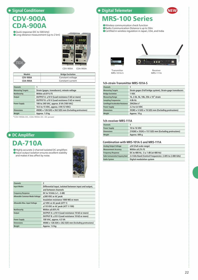
CDV-900A CDA-900A●Quick response (DC to 500 kHz)●Long-distance measurement (up to 2 km)
Channels 1 Measuring Targets Strain (gages, transducers), minute voltage Nonlinearity Within ±0.01% FSOutput OUTPUT A: ±10 V (Load resistance 5 kΩ or more)
OUTPUT B: ±10 V (Load resistance 5 kΩ or more)Power Supply 100 to 240 VAC, approx. 8 VA (100 VAC)
10.5 to 15 VDC, approx. 4 W (12 VDC)Dimensions 49(W) × 128.5(H) × 262.5(D) mm (Excluding protrusions)
Weight Approx. 1.0 kg
DC Amplifier
DA-710A●Highly accurate 2-channel isolated DC amplifiers ●Input-output isolation ensures excellent stability
and makes it less affect by noise.
CDV-900ACDA-900A
Constant voltageConstant current
Models Bridge Excitation
Channels 2Input Modes Differential input, isolated between input and output,
and between channels Frequency Response DC to 10 kHz (+1, -3 dB)Allowable Common Mode Voltage ±300 VDC or AC peak
Insulation resistance 1000 MΩ or more Allowable Max. Input Voltage ±2 VDC or AC peak (ATT 1)
±110 VDC or AC peak (ATT 1/100)Nonlinearity Within ±0.05% FSOutput OUTPUT A: ±10 V (Load resistance 10 kΩ or more)
OUTPUT B: ±10 V (Load resistance 10 kΩ or more)Power Supply 100 VAC, approx. 4.5 VADimensions 49(W) × 128.5(H) × 262.5(D) mm (Excluding protrusions)
Weight Approx. 1.0 kg
*CDV-900A-DC, CDA-900A-DC: DC power
Digital Telemeter
MRS-100 Series●Wireless communication check function●Radio Communication Distance is up to 50m●Certified in wireless regulation in Japan, USA, and India
Channels 1 Power Supply 10 to 16 VDC Dimensions 210(W) × 35(H) × 157.5(D) mm (Excluding protrusions) Weight Approx. 600 g
Analog Output Voltage ±5V (Full scale range) Measurement Accuracy Within ±0.2% FS Frequency Response DC to 480 Hz, -3 ± 1 dB (at 480 Hz) Radio Communication Frequency Band 2.4 GHz Band (Central Frequencies: 2.405 to 2.480 GHz) Radio System Digital modulation system
NEW
23
Compact Signal Conditioner
Housing Case
CDV-400B series
YC-A(For DPM-900 series , CDV-900A, CDA-900A, VAQ-700A, DA-710A)
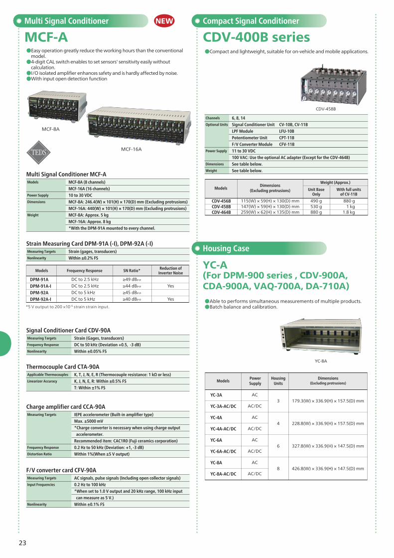
●Compact and lightweight, suitable for on-vehicle and mobile applications.
●Able to performs simultaneous measurements of multiple products.●Batch balance and calibration.
Channels 6, 8, 14Optional Units Signal Conditioner Unit CV-10B, CV-11B
LPF Module LFU-10B
Potentiometer Unit CPT-11B
F/V Converter Module CFV-11BPower Supply 11 to 30 VDC
100 VAC: Use the optional AC adapter (Except for the CDV-464B)Dimensions See table below.Weight See table below.
CDV-458B
YC-8A
YC-3A
YC-3A-AC/DC
YC-4A
YC-4A-AC/DC
YC-6A
YC-6A-AC/DC
YC-8A
YC-8A-AC/DC
3
4
6
8
179.3(W) × 336.9(H) × 157.5(D) mm
228.8(W) × 336.9(H) × 157.5(D) mm
327.8(W) × 336.9(H) × 147.5(D) mm
426.8(W) × 336.9(H) × 147.5(D) mm
AC
AC/DC
AC
AC/DC
AC
AC/DC
AC
AC/DC
HousingUnits
PowerSupply
Dimensions(Excluding protrusions)Models
Multi Signal Conditioner
MCF-A●Easy operation greatly reduce the working hours than the conventional
model. ●4-digit CAL switch enables to set sensors' sensitivity easily without
calculation. ●I/O isolated amplifier enhances safety and is hardly affected by noise. ●With input open detection function
Multi Signal Conditioner MCF-AModels MCF-8A (8 channels)
MCF-16A (16 channels)Power Supply 10 to 30 VDCDimensions MCF-8A: 246.4(W) × 101(H) × 170(D) mm (Excluding protrusions)
MCF-16A: 440(W) × 101(H) × 170(D) mm (Excluding protrusions) Weight MCF-8A: Approx. 5 kg
Thermocouple Card CTA-90AApplicable Thermocouples K, T, J, N, E, R (Thermocouple resistance: 1 kΩ or less)Linearizer Accuracy K, J, N, E, R: Within ±0.5% FS
T: Within ±1% FS
Signal Conditioner Card CDV-90AMeasuring Targets Strain (Gages, transducers)Frequency Response DC to 50 kHz (Deviation +0.5, -3 dB)Nonlinearity Within ±0.05% FS
NEW
MCF-16A
MCF-8A
DPM-91ADPM-91A-IDPM-92ADPM-92A-I
DC to 2.5 kHzDC to 2.5 kHzDC to 5 kHzDC to 5 kHz
≥49 dBp-p
≥44 dBp-p
≥45 dBp-p
≥40 dBp-p
Yes
Yes
SN Ratio* Reduction of Inverter NoiseFrequency ResponseModels
Stress evaluation of auto componentsand the strength testing of automotive bodies
Data Logger
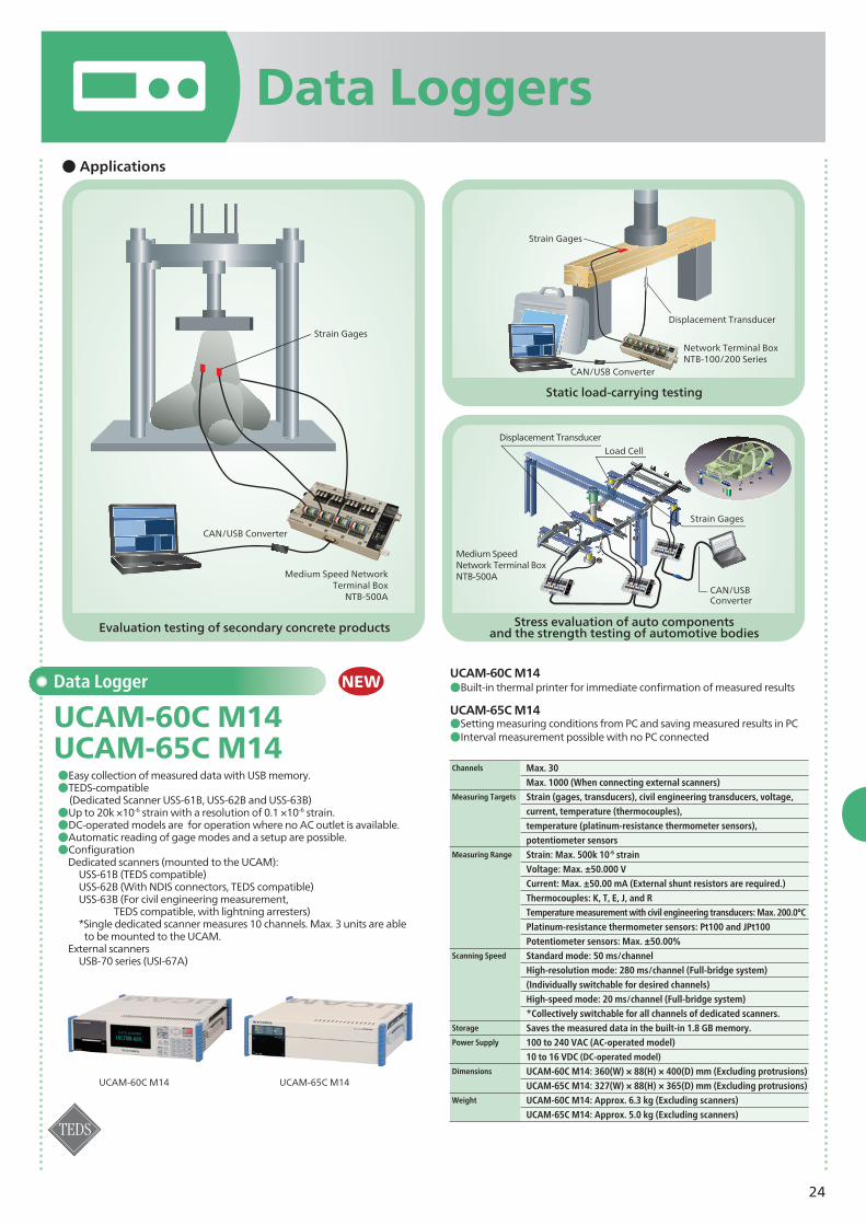
●Easy collection of measured data with USB memory. ●TEDS-compatible (Dedicated Scanner USS-61B, USS-62B and USS-63B)●Up to 20k ×10-6 strain with a resolution of 0.1 ×10⁻⁶ strain.●DC-operated models are for operation where no AC outlet is available.●Automatic reading of gage modes and a setup are possible. ●Configuration
Dedicated scanners (mounted to the UCAM): USS-61B (TEDS compatible) USS-62B (With NDIS connectors, TEDS compatible) USS-63B (For civil engineering measurement, TEDS compatible, with lightning arresters) *Single dedicated scanner measures 10 channels. Max. 3 units are able to be mounted to the UCAM.External scanners USB-70 series (USI-67A)
UCAM-60C M14●Built-in thermal printer for immediate confirmation of measured results
UCAM-65C M14●Setting measuring conditions from PC and saving measured results in PC●Interval measurement possible with no PC connected
*Collectively switchable for all channels of dedicated scanners.Storage Saves the measured data in the built-in 1.8 GB memory. Power Supply 100 to 240 VAC (AC-operated model)
UCAM-65C M14: 327(W) × 88(H) × 365(D) mm (Excluding protrusions)Weight UCAM-60C M14: Approx. 6.3 kg (Excluding scanners)
UCAM-65C M14: Approx. 5.0 kg (Excluding scanners)
NEW
UCAM-60C M14 UCAM-65C M14
UCAM-60C M14 UCAM-65C M14
Displacement TransducerLoad Cell
Strain Gages
CAN/USBConverter
Medium Speed NetworkTerminal Box
NTB-500A
Strain Gages
CAN/USB Converter
Strain Gages
Displacement Transducer
CAN/USB Converter
Network Terminal BoxNTB-100/200 Series
Medium Speed Network Terminal BoxNTB-500A
25
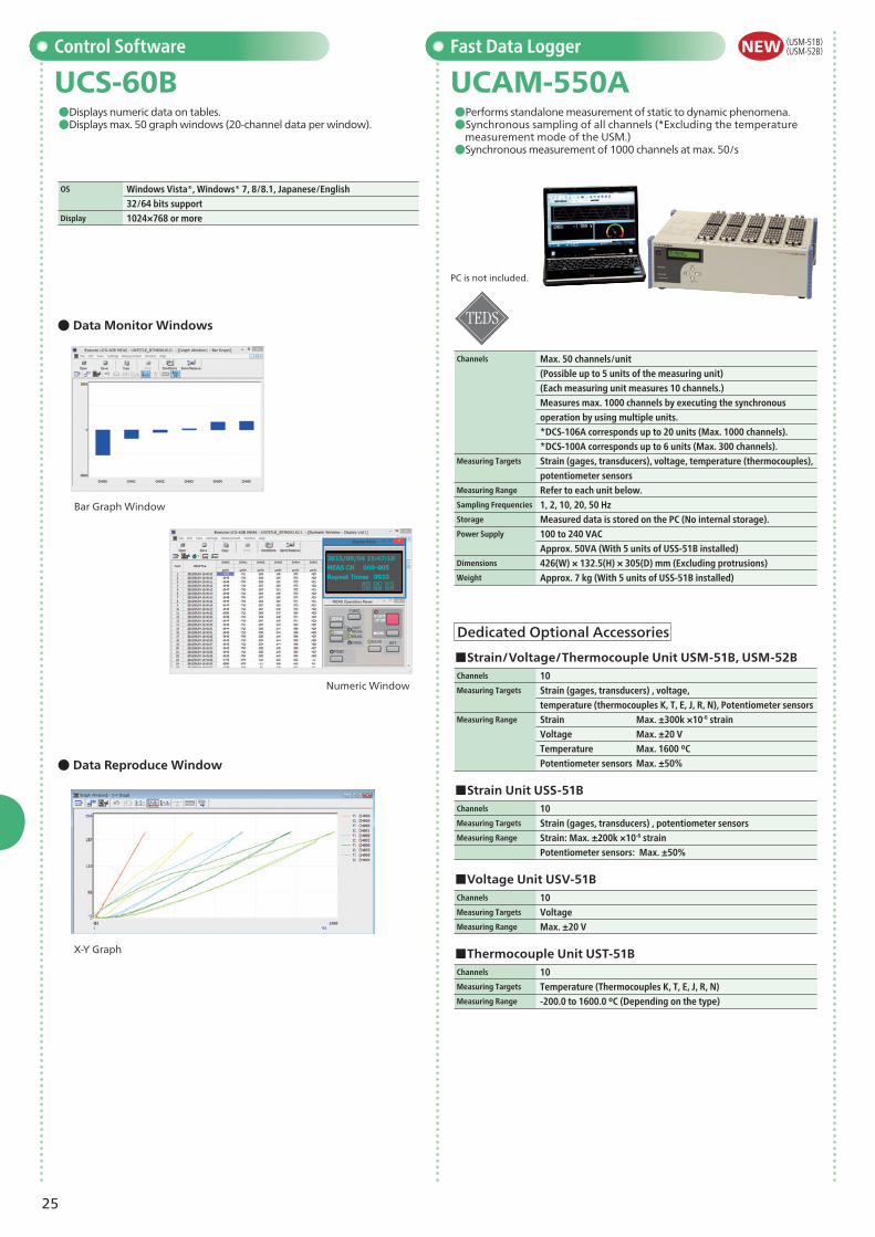
Fast Data Logger
UCAM-550A●Performs standalone measurement of static to dynamic phenomena.●Synchronous sampling of all channels (*Excluding the temperature
measurement mode of the USM.)●Synchronous measurement of 1000 channels at max. 50/s
Channels Max. 50 channels/unit
(Possible up to 5 units of the measuring unit)
(Each measuring unit measures 10 channels.)
Measures max. 1000 channels by executing the synchronous
operation by using multiple units.
*DCS-106A corresponds up to 20 units (Max. 1000 channels).
*DCS-100A corresponds up to 6 units (Max. 300 channels).Measuring Targets Strain (gages, transducers), voltage, temperature (thermocouples),
potentiometer sensorsMeasuring Range Refer to each unit below.Sampling Frequencies 1, 2, 10, 20, 50 HzStorage Measured data is stored on the PC (No internal storage).Power Supply 100 to 240 VAC
Approx. 50VA (With 5 units of USS-51B installed)Dimensions 426(W) × 132.5(H) × 305(D) mm (Excluding protrusions) Weight Approx. 7 kg (With 5 units of USS-51B installed)
PC is not included.
NEWControl Software
UCS-60B●Displays numeric data on tables.●Displays max. 50 graph windows (20-channel data per window).
OS Windows Vista®, Windows® 7, 8/8.1, Japanese/English
32/64 bits supportDisplay 1024×768 or more
● Data Reproduce Window
● Data Monitor Windows
Bar Graph Window
Numeric Window
X-Y Graph
Dedicated Optional Accessories
■Strain Unit USS-51BChannels 10Measuring Targets Strain (gages, transducers) , potentiometer sensors Measuring Range Strain: Max. ±200k ×10-6 strain
temperature (thermocouples K, T, E, J, R, N), Potentiometer sensorsMeasuring Range Strain Max. ±300k ×10-6 strain
Voltage Max. ±20 V
Temperature Max. 1600 ºC
Potentiometer sensors Max. ±50%
■Voltage Unit USV-51BChannels 10Measuring Targets VoltageMeasuring Range Max. ±20 V
■Thermocouple Unit UST-51BChannels 10Measuring Targets Temperature (Thermocouples K, T, E, J, R, N)Measuring Range -200.0 to 1600.0 ºC (Depending on the type)
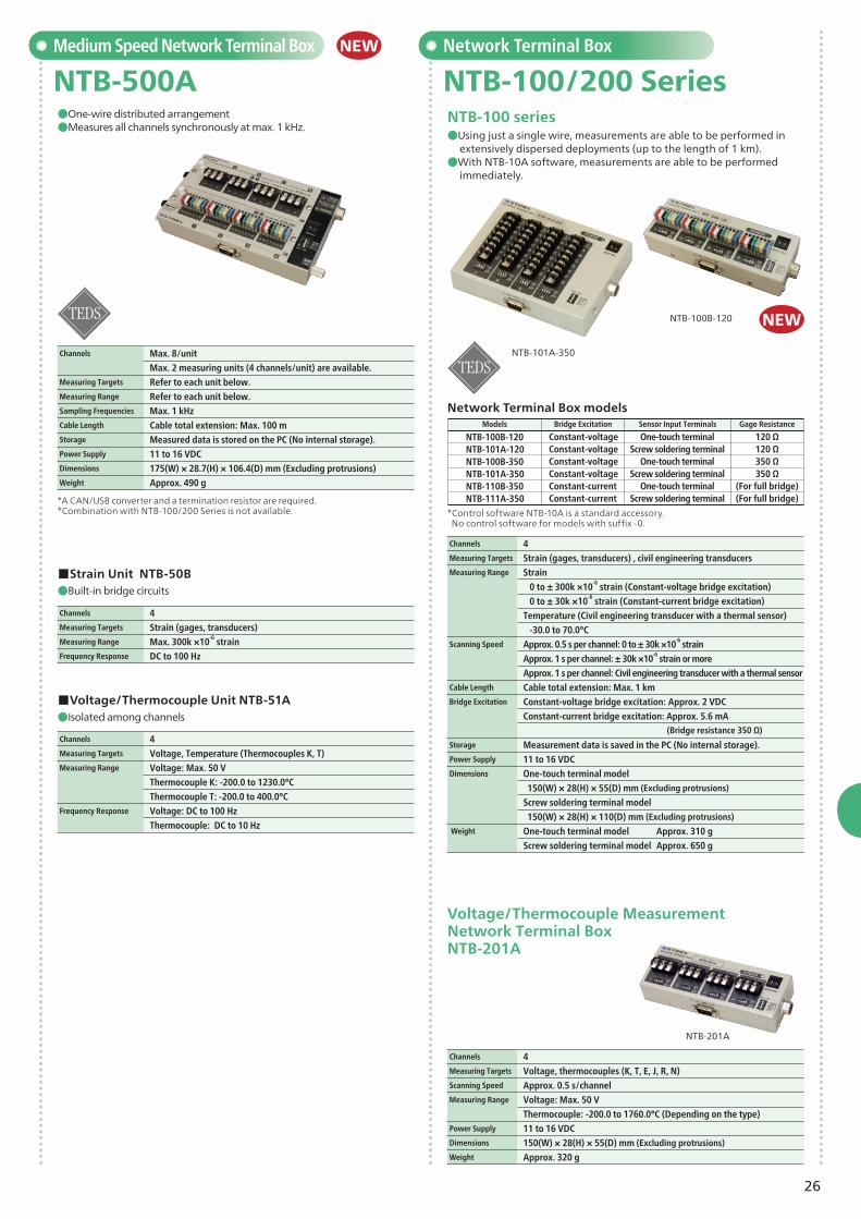
●Using just a single wire, measurements are able to be performed in extensively dispersed deployments (up to the length of 1 km).
●With NTB-10A software, measurements are able to be performed immediately.
NTB-100 series
Network Terminal Box
NTB-100/200 Series
Channels 4Measuring Targets Voltage, thermocouples (K, T, E, J, R, N) Scanning Speed Approx. 0.5 s/channel Measuring Range Voltage: Max. 50 V
Thermocouple: -200.0 to 1760.0°C (Depending on the type)Power Supply 11 to 16 VDCDimensions 150(W) × 28(H) × 55(D) mm (Excluding protrusions)
Weight Approx. 320 g
Medium Speed Network Terminal Box
NTB-500A●One-wire distributed arrangement●Measures all channels synchronously at max. 1 kHz.
Channels Max. 8/unit
Max. 2 measuring units (4 channels/unit) are available.Measuring Targets Refer to each unit below. Measuring Range Refer to each unit below. Sampling Frequencies Max. 1 kHz Cable Length Cable total extension: Max. 100 m Storage Measured data is stored on the PC (No internal storage).Power Supply 11 to 16 VDCDimensions 175(W) × 28.7(H) × 106.4(D) mm (Excluding protrusions) Weight Approx. 490 g
*A CAN/USB converter and a termination resistor are required. *Combination with NTB-100/200 Series is not available. *Control software NTB-10A is a standard accessory.
No control software for models with suffix -0.
●Built-in bridge circuits
●Isolated among channels
■Strain Unit NTB-50B
■Voltage/Thermocouple Unit NTB-51A
Channels 4 Measuring Targets Strain (gages, transducers) Measuring Range Max. 300k ×10-6 strainFrequency Response DC to 100 Hz
Channels 4 Measuring Targets Voltage, Temperature (Thermocouples K, T)Measuring Range Voltage: Max. 50 V
Thermocouple K: -200.0 to 1230.0°C
Thermocouple T: -200.0 to 400.0°C Frequency Response Voltage: DC to 100 Hz
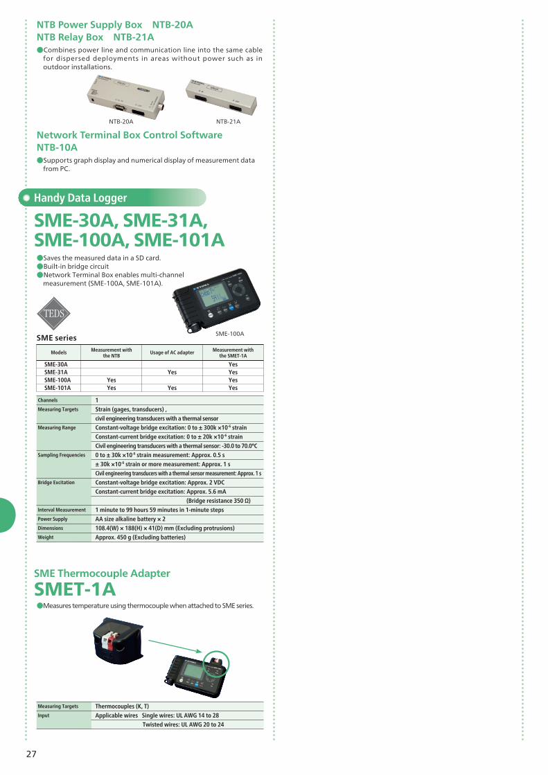
civil engineering transducers with a thermal sensorMeasuring Range Constant-voltage bridge excitation: 0 to ± 300k ×10-6 strain
Constant-current bridge excitation: 0 to ± 20k ×10-6 strain
Civil engineering transducers with a thermal sensor: -30.0 to 70.0°CSampling Frequencies 0 to ± 30k ×10-6 strain measurement: Approx. 0.5 s
± 30k ×10-6 strain or more measurement: Approx. 1 s
Civil engineering transducers with a thermal sensor measurement: Approx. 1 s Bridge Excitation Constant-voltage bridge excitation: Approx. 2 VDC
Constant-current bridge excitation: Approx. 5.6 mA
(Bridge resistance 350 Ω)Interval Measurement 1 minute to 99 hours 59 minutes in 1-minute stepsPower Supply AA size alkaline battery × 2Dimensions 108.4(W) × 188(H) × 41(D) mm (Excluding protrusions)Weight Approx. 450 g (Excluding batteries)
Handy Data Logger
SME-30A, SME-31A, SME-100A, SME-101A●Saves the measured data in a SD card.●Built-in bridge circuit●Network Terminal Box enables multi-channel
measurement (SME-100A, SME-101A).
Measuring Targets Thermocouples (K, T) Input Applicable wires Single wires: UL AWG 14 to 28
Twisted wires: UL AWG 20 to 24
SMET-1A●Measures temperature using thermocouple when attached to SME series.
SME Thermocouple Adapter
NTB-20A NTB-21A
NTB Power Supply Box NTB-20ANTB Relay Box NTB-21A
Network Terminal Box Control SoftwareNTB-10A
●Combines power line and communication line into the same cable for dispersed deployments in areas without power such as in outdoor installations.
●Supports graph display and numerical display of measurement data from PC.
SME series
SME-30ASME-31ASME-100ASME-101A
Models Measurement with the NTB
Usage of AC adapter Measurement with the SMET-1A
YesYes
Yes
Yes
YesYesYesYes
28
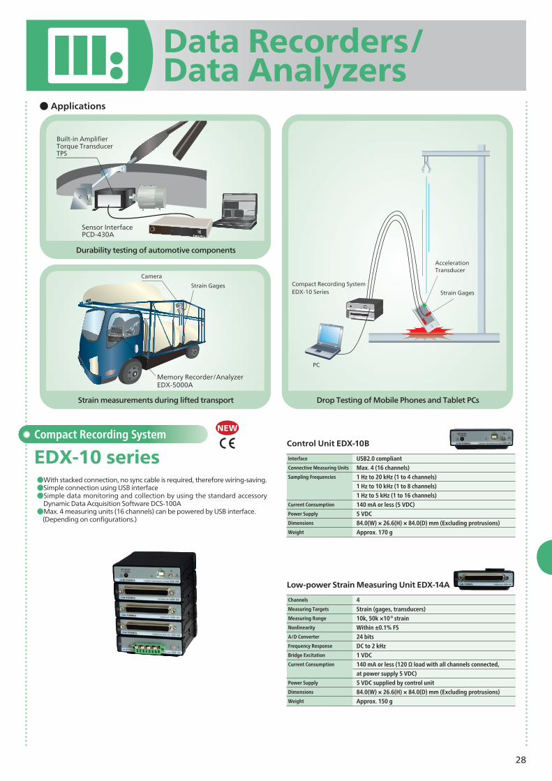
Drop Testing of Mobile Phones and Tablet PCs
Durability testing of automotive components
● Applications
Compact Recording System
EDX-10 series●With stacked connection, no sync cable is required, therefore wiring-saving.●Simple connection using USB interface●Simple data monitoring and collection by using the standard accessory
Dynamic Data Acquisition Software DCS-100A●Max. 4 measuring units (16 channels) can be powered by USB interface. (Depending on configurations.)
Interface USB2.0 compliantConnective Measuring Units Max. 4 (16 channels)Sampling Frequencies 1 Hz to 20 kHz (1 to 4 channels)
1 Hz to 10 kHz (1 to 8 channels)
1 Hz to 5 kHz (1 to 16 channels)Current Consumption 140 mA or less (5 VDC)Power Supply 5 VDCDimensions 84.0(W) × 26.6(H) × 84.0(D) mm (Excluding protrusions)Weight Approx. 170 g
Control Unit EDX-10B
NEW
Data Recorders/Data Analyzers
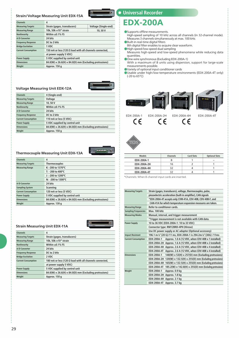
Channels 4Measuring Targets Strain (gages, transducers) Measuring Range 10k, 50k ×10-6 strainNonlinearity Within ±0.1% FSA/D Converter 24 bitsFrequency Response DC to 2 kHzBridge Excitation 1 VDC Current Consumption 140 mA or less (120 Ω load with all channels connected,
at power supply 5 VDC)Power Supply 5 VDC supplied by control unitDimensions 84.0(W) × 26.6(H) × 84.0(D) mm (Excluding protrusions)Weight Approx. 150 g
Low-power Strain Measuring Unit EDX-14A
AccelerationTransducer
Compact Recording SystemEDX-10 Series
PC
Strain Gages
Built-in AmplifierTorque TransducerTPS
Sensor InterfacePCD-430A
Strain measurements during lifted transport
Memory Recorder/AnalyzerEDX-5000A
Strain Gages
Camera
29
Channels 4Measuring Targets Strain (gages, transducers) Measuring Range 10k, 50k ×10-6 strainNonlinearity Within ±0.1% FSA/D Converter 24 bitsFrequency Response DC to 2 kHzBridge Excitation 1 VDC Current Consumption 150 mA or less (120 Ω load with all channels connected,
at power supply 5 VDC)Power Supply 5 VDC supplied by control unitDimensions 84.0(W) × 26.6(H) × 84.0(D) mm (Excluding protrusions)Weight Approx. 150 g
Strain/Voltage Measuring Unit EDX-15A
Channels 4Measuring Targets Thermocouples Measuring Range K: -200 to 1370°C
T: -200 to 400°C
J : -200 to 1200°C
N: -200 to 1300°CA/D Converter 24 bitsSampling System Scanning Current Consumption 120 mA or less (5 VDC)Power Supply 5 VDC supplied by control unitDimensions 84.0(W) × 26.6(H) × 84.0(D) mm (Excluding protrusions)Weight Approx. 130 g
Thermocouple Measuring Unit EDX-13A
Voltage (Single-end)
10, 50 V
Channels 4 (Single-end)Measuring Targets VoltageMeasuring Range 10, 50 VNonlinearity Within ±0.1% FSA/D Converter 24 bitsFrequency Response DC to 2 kHz Current Consumption 110 mA or less (5 VDC)Power Supply 5 VDC supplied by control unitDimensions 84.0(W) × 26.6(H) × 84.0(D) mm (Excluding protrusions) Weight Approx. 150 g
Voltage Measuring Unit EDX-12A
Universal Recorder
EDX-200A●Supports offline measurements.
High-speed sampling of 10 kHz across all channels (in 32-channel mode). Measures 3 channels simultaneously at max. 100 kHz.●Built-in real-time digital filters 8th digital filter enables to acquire clear waveform.●High-speed/low-speed dual sampling Measures high-speed and low-speed phenomena while reducing data
quantities.●One-wire synchronous (Excluding EDX-200A-1) With a maximum of 8 units using dispersion, support for large-scale
measurements possible.●Variety of optional input conditioner cards ●Usable under high/low-temperature environments (EDX-200A-4T only)
(-20 to 65°C)
EDX-200A-4H EDX-200A-4TEDX-200A-2HEDX-200A-1
Models Channels Card Slots Optional Slots
*Channels: When 8-channel input cards are inserted.
piezoelectric acceleration (built-in amplifier), CAN signals
*EDX-200A-4T accepts only CVM-41A, CDV-40B, CDV-40B-F, and
CAN-41A for which temperature expansion measures are taken.Measuring Range Refer to conditioner cards.Sampling Frequencies Max. 100 kHz Measuring Modes Manual, interval, and trigger measurement
*Trigger measurement is not available with CAN data. Power Supply 10 to 36 VDC (EDX-200A-1: 10 to 33 VDC)
Connector type: RM12BRD-4PH (Hirose)
Use DC power supply or AC adapter (Optional accessory)Impact Resistant 196.1 m/s2 (20 G)/11 ms, EDX-200A-1 is 294.2m/s2 (30G) /11ms Current Consumption EDX-200A-1 Approx. 1.0 A (12 VDC, when CDV-40B × 1 installed)
EDX-200A-2H Approx. 1.6 A (12 VDC, when CDV-40B × 2 installed)
EDX-200A-4H Approx. 2.6 A (12 VDC, when CDV-40B × 4 installed)
EDX-200A-4T Approx. 2.6 A (12 VDC, when CDV-40B × 4 installed)Dimensions EDX-200A-1 148(W) × 53(H) × 257(D) mm (Excluding protrusions)
EDX-200A-2H 120(W) × 132.5(H) × 255(D) mm (Excluding protrusions)
EDX-200A-4H 165(W) × 132.5(H) × 255(D) mm (Excluding protrusions)
EDX-200A-4T 185.2(W) × 142.8(H) × 255(D) mm (Excluding protrusions)Weight EDX-200A-1 Approx. 0.9 kg
EDX-200A-2H Approx. 1.8 kg
EDX-200A-4H Approx. 2.1 kg
EDX-200A-4T Approx. 3.7 kg
EDX-200A-1EDX-200A-2HEDX-200A-4HEDX-200A-4T
8163232
1244
−111
Channels 4Measuring Targets Strain (gages, transducers)Measuring Range 10k, 50k ×10-6 strainNonlinearity Within ±0.1% FSA/D Converter 24 bitsFrequency Response DC to 2 kHz Bridge Excitation 2 VDCCurrent Consumption 180 mA or less (120 Ω load with all channels connected,
at power supply 5 VDC) Power Supply 5 VDC supplied by control unitDimensions 84.0(W) × 26.6(H) × 84.0(D) mm (Excluding protrusions)Weight Approx. 150 g
Strain Measuring Unit EDX-11A
30
●Digital I/O
●Digital I/O
●Digital I/O
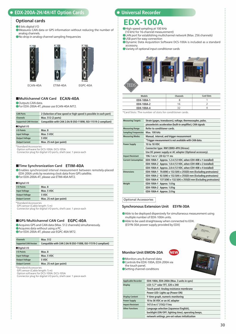
●8 bits digital I/O●Measures CAN data or GPS information without reducing the number of
analog channels.●No drop in analog-channel sampling frequencies
●Able to be deployed dispersively for simultaneous measurement using multiple number of EDX-100A units.
●Able to be used straightaway when connected to EDX. (ESYN-30A power supply provided by EDX)
●Monitors any 8-channel data●Controls the EDX-100A, EDX-200A via the touch panel.●Setting channel conditions
*Standard Accessories Option software for DCS-100A: DCS-105A Connector plug for digital I/O ports, shell case: 1 piece each
*Standard Accessories GPS sensor (Cable length: 5 m) Connector plug for digital I/O ports, shell case: 1 piece each
*Standard Accessories GPS sensor (Cable length: 5 m) Option software for DCS-100A: DCS-105A Connector plug for digital I/O ports, shell case: 1 piece each
EDX-200A-2H/4H/4T Option Cards
ECAN-40A ETIM-40A EGPC-40A
●Outputs CAN data.●For EDX-200A-4T, please use ECAN-40A M72.
●Enables synchronized interval measurement between remotely-placed EDX-200A units by receiving clock data from GPS satellite.●For EDX-200A-4T, please use ETIM-40A M72.
●Acquires GPS and CAN data (Max. 512 channels) simultaneously.●Acquires data without using a PC.●For EDX-200A-4T, please use EGPC-40A M72.
■Multichannel CAN Card ECAN-40A
Optional cards
■Time Synchronization Card ETIM-40A
■GPS/Multichannel CAN Card EGPC-40A
CAN Ports 2 (Selection of low speed or high speed is possible in each port)Channels Max. 512 (2 ports)Supported CAN Version Compatible with CAN 2.0A/B (ISO-11898, ISO-11519-2 compliant)
I/O Points Max. 8Input Voltage Max. 5 VDCOutput Voltage 5 VDCOutput Current Max. 25 mA (per point)
I/O Points Max. 8Input Voltage Max. 5 VDC Output Voltage 5 VDC Output Current Max. 25 mA (per point)
I/O Points Max. 8Input Voltage Max. 5 VDC Output Voltage 5 VDC Output Current Max. 25 mA (per point)
Channels Max. 512Supported CAN Version Compatible with CAN 2.0A/B (ISO-11898, ISO-11519-2 compliant)
Applicable Recorder EDX-100A, EDX-200A (Max. 3 units in sync)Display LCD: 5.7" color TFT, 320 × 240
Touch panel: Analog resistance membrane
Power LED: Lights up (Power ON)Display Content Y-time graph, numeric monitoringPower Supply 10 to 36 VDC or an AC adapterImpact Resistant 147.0 m/s2 (15G)/11msOther Functions Language selection (Japanese/English),
EDX-100A●High-speed sampling at 100 kHz (10 kHz for 16-channel measurement)●LAN port for establishing multichannel network (Max. 256 channels)●USB port for easy connection●Dynamic Data Acquisition Software DCS-100A is included as a standard
accessory.●Variety of optional input conditioner cards
*Card Slots: The number of slots for conditioner cards.
piezoelectric acceleration (built-in amplifier), CAN signalsMeasuring Range Refer to conditioner cards.Sampling Frequencies Max. 100 kHz Measuring Modes Manual, interval, and trigger measurement *Trigger measurement is not available with CAN data.Power Supply 10 to 18 VDC
Connector type: RM12BRD-4PH (Hirose)
Use DC power supply or AC adapter (Optional accessory).Impact Resistant 196.1 m/s2 (20 G)/11 msCurrent Consumption EDX-100A-1 Approx. 1.2 A (12 VDC, when CDV-40B × 1 installed)
EDX-100A-2 Approx. 1.8 A (12 VDC, when CDV-40B × 2 installed)
EDX-100A-4 Approx. 2.8 A (12 VDC, when CDV-40B × 4 installed)Dimensions EDX-100A-1 70.0(W) × 132.5(H) × 255(D) mm (Excluding protrusions)
EDX-100A-2 92.5(W) × 132.5(H) × 255(D) mm (Excluding protrusions)
EDX-100A-4 137.5(W) × 132.5(H) × 255(D) mm (Excluding protrusions)Weight EDX-100A-1 Approx. 1.6 kg
EDX-100A-2 Approx. 1.8 kg
EDX-100A-4 Approx. 2.0 kg
NEW
Models
EDX-100A-1EDX-100A-2EDX-100A-4
124
81632
Card SlotsChannels
Synchronous Extension Unit ESYN-30A
Optional Accessories
31
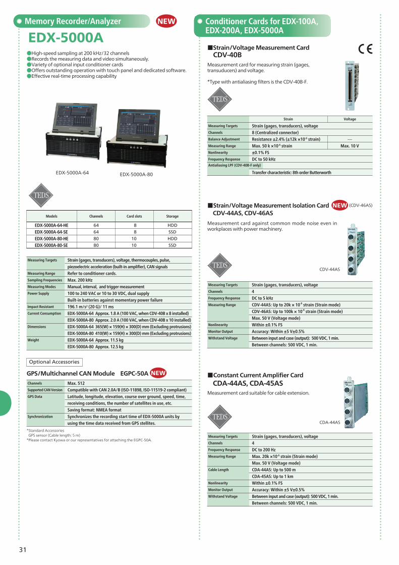
Memory Recorder/Analyzer Conditioner Cards for EDX-100A, EDX-200A, EDX-5000A
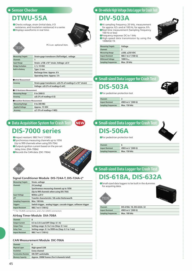
EDX-5000A●High-speed sampling at 200 kHz/32 channels●Records the measuring data and video simultaneously.●Variety of optional input conditioner cards ●Offers outstanding operation with touch panel and dedicated software.●Effective real-time processing capability
piezoelectric acceleration (built-in amplifier), CAN signalsMeasuring Range Refer to conditioner cards.Sampling Frequencies Max. 200 kHz Measuring Modes Manual, interval, and trigger measurement Power Supply 100 to 240 VAC or 10 to 30 VDC, dual supply
Built-in batteries against momentary power failureImpact Resistant 196.1 m/s2 (20 G)/ 11 msCurrent Consumption EDX-5000A-64 Approx. 1.8 A (100 VAC, when CDV-40B x 8 installed)
EDX-5000A-80 Approx. 2.0 A (100 VAC, when CDV-40B x 10 installed) Dimensions EDX-5000A-64 365(W) × 159(H) × 300(D) mm (Excluding protrusions)
EDX-5000A-80 410(W) × 159(H) × 300(D) mm (Excluding protrusions)Weight EDX-5000A-64 Approx. 11.5 kg
EDX-5000A-80 Approx. 12.5 kg
Channels Max. 512Supported CAN Version Compatible with CAN 2.0A/B (ISO-11898, ISO-11519-2 compliant)GPS Data Latitude, longitude, elevation, course over ground, speed, time,
receiving conditions, the number of satellites in use, etc.
Saving format: NMEA formatSynchronization Synchronizes the recording start time of EDX-5000A units by
Measuring Targets Strain (gages, transducers), voltageChannels 4Frequency Response DC to 5 kHz Measuring Range CDV-44AS: Up to 20k × 10-6 strain (Strain mode)
CDV-46AS: Up to 100k × 10-6 strain (Strain mode)
Max. 50 V (Voltage mode) Nonlinearity Within ±0.1% FSMonitor Output Accuracy: Within ±5 V±0.5%Withstand Voltage Between input and case (output): 500 VDC, 1 min.
Between channels: 500 VDC, 1 min.
Measurement card suitable for cable extension.
■Constant Current Amplifier Card CDA-44AS, CDA-45AS
Measuring Targets Strain (gages, transducers), voltageChannels 4Frequency Response DC to 200 Hz Measuring Range Max. 20k ×10-6 strain (Strain mode)
Max. 50 V (Voltage mode) Cable Length CDA-44AS: Up to 500 m
CDA-45AS: Up to 1 km Nonlinearity Within ±0.1% FSMonitor Output Accuracy: Within ±5 V±0.5%Withstand Voltage Between input and case (output): 500 VDC, 1 min.
Between channels: 500 VDC, 1 min.
GPS/Multichannel CAN Module EGPC-50A
Optional Accessories
*Standard Accessories GPS sensor (Cable length: 5 m)*Please contact Kyowa or our representatives for attaching the EGPC-50A.
NEW
NEW
CDV-44AS
NEW
(CDV-46AS)
EDX-5000A-64 EDX-5000A-80
32
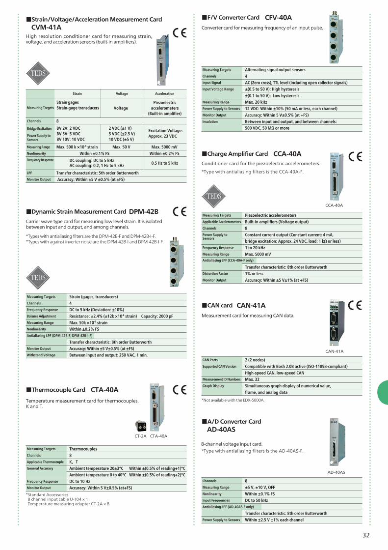
*Not available with the EDX-5000A.
High resolution conditioner card for measuring strain, voltage, and acceleration sensors (built-in amplifiers).
Converter card for measuring frequency of an input pulse.
■F/V Converter Card CFV-40A
Measuring Targets Alternating signal output sensorsChannels 4Input Signal AC (Zero cross), TTL level (Including open collector signals) Input Voltage Range ±(0.5 to 50 V): High hysteresis
±(0.1 to 50 V): Low hysteresisMeasuring Range Max. 20 kHzPower Supply to Sensors 12 VDC: Within ±10% (50 mA or less, each channel) Monitor Output Accuracy: Within 5 V±0.5% (at +FS)Insulation Between input and output, and between channels:
500 VDC, 50 MΩ or more
Conditioner card for the piezoelectric accelerometers.
bridge excitation: Approx. 24 VDC, load: 1 kΩ or less)Frequency Response 1 to 20 kHz Measuring Range Max. 5000 mV
Transfer characteristic: 8th order Butterworth Distortion Factor 1% or lessMonitor Output Accuracy: Within ±5 V±1% (at +FS)
Antialiasing LPF (CCA-40A-F only)
Measurement card for measuring CAN data.
■CAN card CAN-41A
CAN Ports 2 (2 nodes)Supported CAN Version Compatible with Bosh 2.0B active (ISO-11898-compliant)
High-speed CAN, low-speed CANMeasurement ID Numbers Max. 32Graph Display Simultaneous graph display of numerical value,
frame, and analog data
8-channel voltage input card.
■A/D Converter Card AD-40AS
*Type with antialiasing filters is the AD-40AS-F.
Channels 8Measuring Range ±5 V, ±10 V, OFFNonlinearity Within ±0.1% FSInput Frequencies DC to 50 kHzAntialiasing LPF (AD-40AS-F only) Transfer characteristic: 8th order ButterworthPower Supply to Sensors Within ±2.5 V ±1% each channel
DC coupling: DC to 5 kHzAC coupling: 0.2, 1 Hz to 5 kHz 0.5 Hz to 5 kHz
Power Supply to Sensors
AD-40AS
CTA-40ACT-2A
CCA-40A
CAN-41A
Carrier wave type card for measuring low level strain. It is isolatedbetween input and output, and among channels.
■Dynamic Strain Measurement Card DPM-42B
*Types with antialiasing filters are the DPM-42B-F and DPM-42B-I-F.*Types with against inverter noise are the DPM-42B-I and DPM-42B-I-F.
Measuring Targets Strain (gages, transducers) Channels 4Frequency Response DC to 5 kHz (Deviation: ±10%)Balance Adjustment Resistance: ±2.4% (±12k ×10-6 strain) Capacity: 2000 pFMeasuring Range Max. 50k ×10-6 strainNonlinearity Within ±0.2% FSAntialiasing LPF (DPM-42B-F, DPM-42B-I-F)
Transfer characteristic: 8th order ButterworthMonitor Output Accuracy: Within ±5 V±0.5% (at ±FS)Withstand Voltage Between input and output: 250 VAC, 1 min.
Temperature measurement card for thermocouples, K and T.
■Thermocouple Card CTA-40A
33
Combined G-resistant Data Logger Sensor Interface
Printed Circuit Assembly Stress Measurement Set
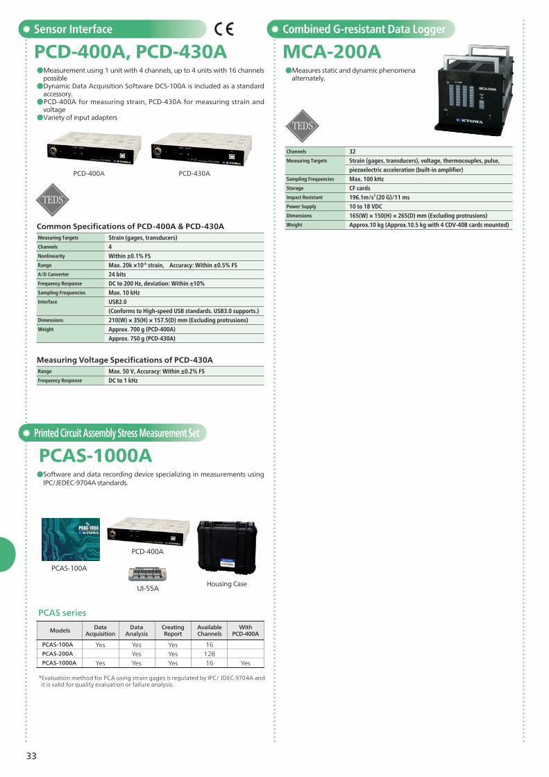
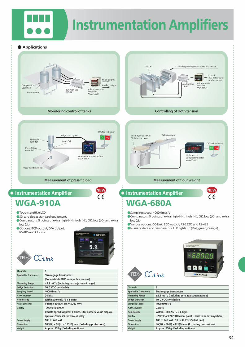
MCA-200APCD-400A, PCD-430A●Measures static and dynamic phenomena
alternately.●Measurement using 1 unit with 4 channels, up to 4 units with 16 channels
possible●Dynamic Data Acquisition Software DCS-100A is included as a standard
accessory.●PCD-400A for measuring strain, PCD-430A for measuring strain and
voltage●Variety of input adapters
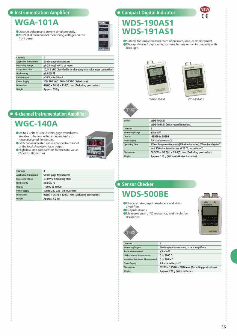
PCAS-1000A●Software and data recording device specializing in measurements using
IPC/JEDEC-9704A standards.
PCD-400A PCD-430A
PCAS-100A
PCD-400A
UI-55AHousing Case
PCAS series
*Evaluation method for PCA using strain gages is regulated by IPC/ JDEC-9704A and it is valid for quality evaluation or failure analysis.
Measuring Targets Strain (gages, transducers) Channels 4Nonlinearity Within ±0.1% FSRange Max. 20k ×10-6 strain, Accuracy: Within ±0.5% FSA/D Converter 24 bitsFrequency Response DC to 200 Hz, deviation: Within ±10%Sampling Frequencies Max. 10 kHzInterface USB2.0
(Conforms to High-speed USB standards. USB3.0 supports.)Dimensions 210(W) × 35(H) × 157.5(D) mm (Excluding protrusions)Weight Approx. 700 g (PCD-400A)
Approx. 750 g (PCD-430A)
Range Max. 50 V, Accuracy: Within ±0.2% FS Frequency Response DC to 1 kHz
Display -99999 to 99999 (Decimal point is able to be set anywhere)Power Supply 100 to 240 VAC 10 to 30 VDC (Select one)Dimensions 96(W) × 96(H) × 126(D) mm (Excluding protrusions)Weight Approx. 750 g (Excluding options)
Mount BaseJunction BoxSJB-4C
Relay output
Analog output
Instrumentation Amplifier WGA-650B
CompressionLoad Cell
Judge start signal
Press-fittingmaterial
Press-fitted material
OK/NG Indicator
Hydraulic cylinder Load Cell
Instrumentation AmplifierWGA-910A
Load Cell
Junction BoxSJB-4C
Controlling winding motor speed and tension
Instrumentation AmplifierWGA-680A
CC-LinkBCD data outputAnalog output
OK/NG Indicator
Beam-type Load Cell(Built in the case)
Belt conveyor
High-speed, Compact Indicator WGI-470AS1
35
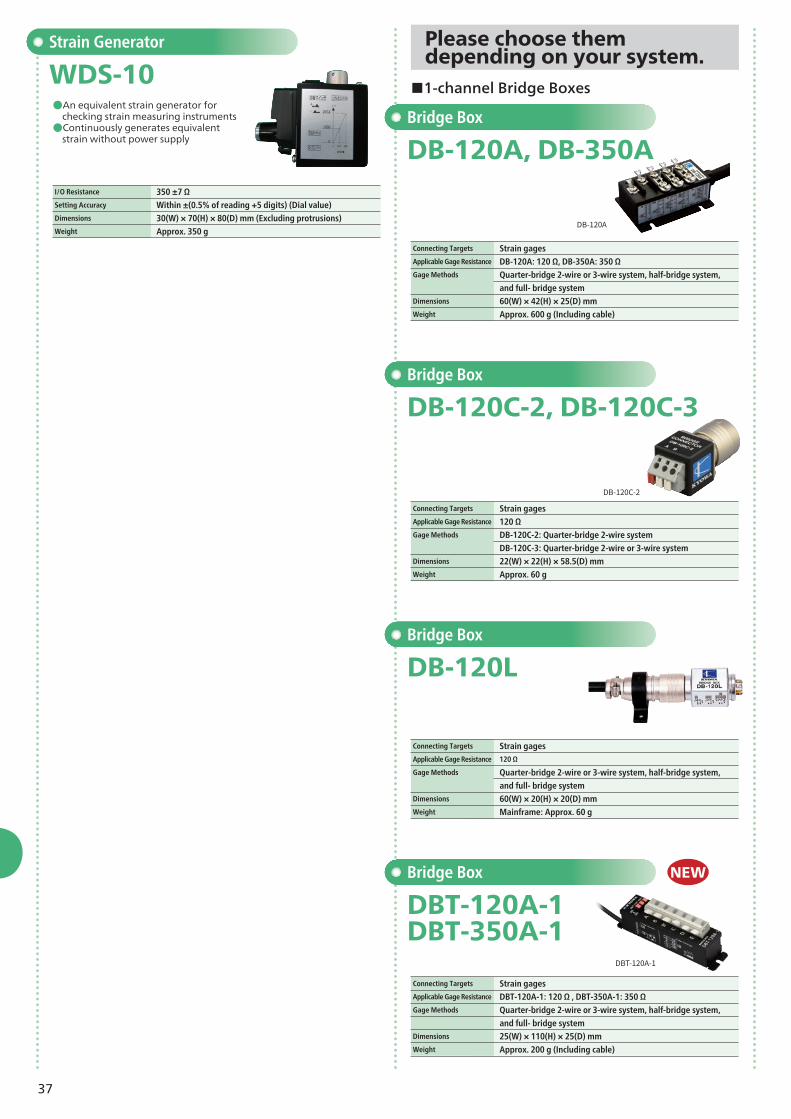
Instrumentation Amplifier
WGI-400A●High/low limit patterns: 4 switchable
Instrumentation Amplifier
WGI-470AS1●2-analog output: Simultaneous output of
voltage and current, separate scaling.
Instrumentation Amplifier
WGA-650B●Wide no-load zero adjustment range (±2 mV/V)●High/low limit comparators (2 points: High/Low)●D/A output built-in as standard (BCD data output
model currently in preparation.)●Outputs the indicated value in a voltage range of 0 to 10 V or in a current range of 4 to 20 mA.
Instrumentation Amplifier
WGA-710C●Comparator function based on pre-set high/low limits and peak hold functions
Channels 1Applicable Transducers Strain-gage transducersMeasuring Range 0 to 2.5 mV/VBridge Excitation 10, 2 VDC switchable Sampling Speed 4 times/sNonlinearity Within ±(0.03% FS + 1 digit)Display -1999 to 19999Power Supply 100 to 127 VAC or 220 to 240 VAC
20 VA or lessDimensions 96(W) × 96(H) × 139(D) mm (Excluding protrusions)Weight Approx. 1.3 kg
Channels 1Applicable Transducers Strain-gage transducersMeasuring Range ±3.2 mV/VBridge Excitation 10, 5, 2.5 VDC switchableSampling Speed 15 times/sNonlinearity Within ±(0.03% FS + 1digit)Display -9999 to 9999Power Supply 100, 115, 200, 220 VAC (Select one) Dimensions 72(W) × 144(H) × 188(D) mm (Excluding protrusions)Weight Approx. 1.7 kg
Channels 1Applicable Transducers Strain-gage transducersMeasuring Range ±3.2 mV/V (Including zero adjustment range)Bridge Excitation 2, 4 VDC switchableSampling Speed 50 times/sNonlinearity Within ±(0.1% FS ±1 digit)Display -9999 to 9999Power Supply 100 to 240 VAC, 10 to 30 VDC (Select one)Dimensions 96(W) × 48(H) × 144(D) mm (Excluding protrusions)Weight Approx. 300 g
Channels 1Applicable Transducers Strain-gage transducers Measuring Range ±3.2 mV/V (Including zero adjustment range)Bridge Excitation 10, 2 VDC switchableSampling Speed 2000 times/sNonlinearity ±(0.02% FS ± 1 digit)Display -99999 to 99999Power Supply 100 to 240 VACDimensions 96(W) × 48(H) × 144(D) mmWeight Approx. 400 g
Carrier Type Instrumentation Amplifier
WGA-120A●Strong against inverter noise●Voltage/current output switchable
Instrumentation Amplifier
WGA-100B●Outputs voltage and current simultaneously.
Channels 1Applicable Transducers Strain-gage transducersMeasuring Range ±0.2 to ±5 mV/VBridge Excitation 5, 2, 1 Vrms square wave
(Switchable by changing internal jumper connection)Nonlinearity Within ±0.1% FSRated Output Voltage ±10 V (Load resistance: 2 kΩ or more)
Current 4 to 20 mA
(Load resistance: 500 Ω or less, voltage output: 0 to 10 V)Power Supply 10.5 to 15VDC, 100, 200, 240 VAC (Select one) Dimensions 44(W) × 90(H) × 80(D) mm (Excluding protrusions)Weight DC power supply model: Approx. 350 g
AC power supply model: Approx. 450 g
Channels 1Applicable Transducers Strain-gage transducersMeasuring Range ±0.25 to ±2 mV/V or moreBridge Excitation 10, 5 VDC (Switchable by changing internal jumper connection)Nonlinearity ±0.02% FSRated Output ±10 V, 4 to 20 mAPower Supply 100, 200 VAC, 10 to 30 VDC (Select one)Dimensions 44(W) × 90(H) × 80(D) mm (Excluding protrusions)Weight Approx. 400 g
36
4-channel Instrumentation Amplifier
WGC-140A●Up to 4 units of 350 Ω strain-gage transducers
are able to be connected independently to respective amplifier circuits.●Switchable indicated value, channel to channel
or the total. Analog voltage output.●High/low limit comparators for the total value (2 points: High/Low)
Instrumentation Amplifier
WGA-101A●Outputs voltage and current simultaneously. ●MONITOR terminals for monitoring voltages on the
front panel
Compact Digital Indicator
WDS-190AS1WDS-191AS1●Suitable for simple measurement of pressure, load, or displacement.●Displays data in 5 digits, units, statuses, battery remaining capacity with
back light.
NEW
Channels 1Applicable Transducers Strain-gage transducersMeasuring Range ±0.25 to ±5 mV/V or moreBridge Excitation 10, 5, 2 VDC (Switchable by changing internal jumper connection)Nonlinearity ±0.02% FSRated Output ±10 V, 4 to 20 mAPower Supply 100, 200 VAC 10 to 30 VDC (Select one)Dimensions 44(W) × 90(H) × 110(D) mm (Excluding protrusions)Weight Approx. 650 g
Channels 4Applicable Transducers Strain-gage transducersMeasuring Range ±3 mV/V (Including tare)Nonlinearity ±0.05% FSDisplay -19999 to 19999Power Supply 100 to 240 VAC 30 VA or less Dimensions 96(W) × 96(H) × 139(D) mm (Excluding protrusions)Weight Approx. 1.2 kg
Models WDS-190AS1
WDS-191AS1 (With record functions) Channels 1Measuring Range ±5 mV/V Display -99999 to 99999Power Supply AA size battery × 2Operating Time 72h or longer continuously (Alkaline batteries) (When backlight off
and 350-ohm transducers at 25 °C, recorder off)Dimensions 66.5(W) × 92.0(H) × 28.0(D) mm (Excluding protrusions)Weight Approx. 110 g (Without AA size batteries)
Sensor Checker
WDS-500BE●Checks strain-gage transducers and strain
amplifiers●Outputs strains.●Measures strain, I/O resistance, and insulation
resistance.
Channels 1Measuring Targets Strain-gage transducers, strain amplifiersStrain Measurement ±5 mV/VI/O Resistance Measurement 0 to 2000 ΩInsulation Resistance Measurement 0 to 300 MΩPower Supply AA size battery × 2Dimensions 69(W) × 115(H) × 28(D) mm (Excluding protrusions)Weight Approx. 220 g (With batteries)
SwitchableDimensions 115(W) × 22(H) × 61.4(D) mm (Excluding protrusions)Weight Mainframe: Approx. 250 gApplicable Wire Single wire: φ0.4 to φ1.2 mm (UL AWG 16 to 26)
and full- bridge systemDimensions 154(W) × 22(H) × 61.4(D) mm (Excluding protrusions)Weight Mainframe: Approx. 280 g, With DBV4-MOUNT: Approx. 350 gApplicable Wire Single wire: φ0.4 to φ1.2 mm (UL AWG 16 to 26)
and full- bridge systemDimensions 286(W) × 22(H) × 61.4(D) mm (Excluding protrusions)Weight Mainframe: Approx. 480 g Applicable Wire Single wire: φ0.4 to φ1.2 mm (UL AWG 16 to 26)
Twisted wire: 0.2 to 0.75 mm2 (UL AWG 20 to 24)
■4-channel Bridge Box ■8-channel Bridge Boxes
■8-channel Bridge Boxes ■8-channel Voltage Input Box
39
Software
Dynamic Data Acquisition Software Data Analysis Software
DCS-100A DAS-200A●Setting of measurement conditions, data acquisition, data collection, data
reproduction and file conversion are able to be completed just by using this software.●Various graphs/numerical values (Y-time graphs, bar graphs, X-Y graphs,
digital graphs, circular meters, and bar meters)●Saves the measured data on PC's hard disk directly (With some restrictions on the sampling frequencies and the number of
channels). ●Displays various graphs and numerical values on monitor windows.●OS: Windows Vista®, Windows® 7, 8/8.1, 10
min. ●Extracts the acquired files and converts them into the CSV files.●Data analysis Statistical operation, arithmetic operation, FFT analysis, histogram analysis, filter processing, differentiation/integration, and lifetime prediction●OS: Windows Vista®, Windows® 7, 8/8.1, 10
Playing back video & reproducing data
FFT analysis
X-Y graphs
DCS-100A Optional Software
DCS-101A, DCS-104A, DCS-105A, DCS-106A
GPS Data Acquisition Optional Software DCS-104A●Monitors and acquires the positioning data, received from the GPS
receiver, simultaneously with the measuring data.
Simultaneous Acquisition of Video and Numeric Data/Arithmetic Operations/FFT Analysis Optional Software DCS-101A●Records video simultaneously. ●Real-time arithmetic operations●Monitors FFT analysis in real-time.
●Loads the CANdb files and sets them in the CAN conditions for DCS-100A●Applicable conditioner cards: CAN-41A●Applicable cards for optional slot: ECAN-40A, EGPC-40A
PCAS-100A●Guidance function allows for beginners to set and perform strain
measurements.●Analyzes the stress measurement results of PCBs and creates reports.●OS: Windows Vista®, Windows® 7, 8/8.1, 10●Creats reports according to the IPC/JEDEC-9704A.
Locating gages
Creating reports
Locating gages
Creating reports
41
*Interference: ±5% RO (Between Fx and Fy )
Automotive Test Equipment● Applications
Thin Pedal Force Transducer
Gear-change Lever Operating Force Transducer
LPR-C
LSA-A-S1
●Minimal error caused by off-set loads●Easy attachment to a brake pedal
●Measures the 2-component force initiated by operating the gear-change lever.●Accurate measurement with minimal mutual interference.
Hand Brake Operating Force Transducer
LB-B●For measuring tension of hand brakes.●Easy attachment and operation.
Hand Brake Operating Force Transducer
LBR-S-1KNSA2●Easy attachment and operation.●Accurate measurement with minimal mutual
interference.
Rated Capacity 200 N to 2 kNNonlinearity Within ±0.3% ROHysteresis Within ±0.3% RORated Output Approx. 0.9, 1.8 mV/V
Safe Overloads 150%Weight Approx. 110 g
(Excluding cable and accessories)
Rated Capacity 200, 300 NNonlinearity Within ±0.5% ROHysteresis Within ±0.5% RORated Output Approx. 0.5 mV/V (For both Fx and Fy)
Safe Overloads 120% (For both Fx and Fy)
Weight Approx. 100 g
Rated Capacity 500 N, 1 kN Nonlinearity Within ±1% ROHysteresis Within ±1% RORated Output 1 to 2 mV/V Safe Overloads 120%Weight Approx. 800 g
Rated Capacity 1 kN Nonlinearity Within ±1.0% ROHysteresis Within ±1.0% RORated Output Approx. 1.5 mV/V Safe Overloads 120%Weight Approx. 650 g
Universal RecorderEDX-200A
Barrier load cell
On-vehicle Data Logger for Crash TestDIS-7000 series
●Measures wheel driving/control torque while a vehicle is running.
●Usable for braking tests and traction control tests.
●Allowed to be installed in commercial wheel
Wheel 6-component Force Measuring System
●Lightweight sensor●Slip-ring design for easy installation●Only one 6-component force processor needed to
measure all 4 wheels●Equips an indicator which is easy to view in the field
with a user-friendly remote controller.
Wheel Alignment Measuring System
●Measures relative displacement of wheels while a vehicle is running.
PHF-S-SA4
Slip-ring type
Slip-ring Type
PHF-S-SA2
Small-sized High-temperature Pressure Transducer
PHF-S-SA2PHF-S-SA4●Compensated temperature: -40 to 150°C (Excluding connector)
Steering Force/Angle Transducer
SFA-E-SA20●Easy attachment to the steering shaft ●Rotary encoder is used to detect steering angle,
thereby ensuring high resolution.●Dedicated indicator is separately available.
Input: 2 channels for steering force and steering angle (pulse)
Output: 3 channels for steering force (torque), steering angle, and steering angle speed (±5 VDC for each)
●The display unit can be separated from the conditioner unit ●The compact display unit can be fixed on top of the conditioner unit or
installed on the windshield with the suction cups
Dedicated Indicator of SFA-E-SA20
Engine Pressure Transducer
PE-30KF●For measuring exhaust or inlet pressure●Max. operating temperature: 300°C (Water-cooled)
PHF-S-S1 series●Able to be installed in confined spaces.●Tepmerature effect on zero: Within ±0.008% RO/°C●Compensated temperature: -40 to 150ºC
Rated Capacity 2 to 20 MPaNonlinearity Within ±0.3% ROHysteresis Within ±0.2% RORated Output Approx. 1.75 mV/VSafe Overloads 150%Mounting Screw R1/8, M8 × 1.25, M10 × 1.25, M10 × 1.0, 5/16-24UNF, G1/8Weight Approx. 20 g (Excluding cable)
Rated Capacity 2 to 20 MPaNonlinearity Within ±0.3% RO (2MPSA2: Within ±0.4% RO)Hysteresis Within ±0.2% RORated Output SA2: Approx. 2 mV/V, SA4: approx. 0.5 mV/VSafe Overloads 150%Mounting Screw SA2: R1/8, SA4: 5/16-24UNFWeight SA2: Approx. 50 g, SA4: approx. 20 g
Rated Capacity 3MPaNonlinearity Within ±1% ROHysteresis Within ±1% RORated Output 1 mV/V or moreSafe Overloads 130% (Static), 100% (Dynamic)Mounting Screw M18 P=1.5Weight Approx.120 g (Excluding cable)
Small-sized High-temperature Pressure Transducer NEW
Rated Capacity 1 to 5 kN・mNonlinearity Within±0.5% ROHysteresis Within±0.5% ROSafe Overloads 150%Rotary Speed 2000 rpm/maxDegree of Protection Drip-proofed by protective coating (IP44)Weight Approx. 4 kg (For 2.5 kN∙m)
Rated Capacity 1 to 3 kN・mNonlinearity ±1.0%RO or lessHysteresis ±1.0%RO or lessSafe Overloads 120%Applicable PCD 4-hole Model: 100 mm, 5-hole Model: 114.3 mm
Torque: Mx ±6 kN·m, My ±8.5 kN·m, Mz ±6 kN·m Rotary Speed: N ±2000 rpm
X (Back and forward) ±200 mm
Y (Right and left) ±150 mm
Z (Up and down) ±200 mmAngle Measurement Steering angle ±60˚
Camber angle ±10˚Accuracy Displacement 1 mm (X, Y, and Z)
Angle Steering angle 0.1°
Camber angle 0.1°
Displacement Measurement
*Steering angle : Detected by a built-in encoder*Output pulses: 18000 pulses per 360°
* In combination of a Wheel 6-component Force measuring System.
Rated Capacity Steering force ±20 to 200 N・m (To be specified when ordering) Nonlinearity Steering force Within ±0.3% RO (150 N・m or more: Within ±0.5% RO) Hysteresis Steering force Within ±0.3% RO (150 N・m or more: Within ±0.5% RO) Rated Output Steering force 2 VSafe Overloads 120%Weight Approx. 2.5 kg (Including 1 kg of steering wheel)
(Standard)
Dedicated signal processor EWA-100A
Integrates processors for all 4 wheels into single unit.
Dedicated signal processor EWF-100A
Integrates processors for all 4 wheels into single unit.
NEW
NEW
43
Acceleration Transducer for Crash Test
ASD-B●Accessory dedicated connector enables its direct connection to the
onboard crash test data recorder.●Center of seismic mass is set at the tip of body for triaxial configuration of
acceleration transducers.●Undamped type
ASD-B-2KH(Horizontal)
ASD-B-2KV(Vertical)
Steering Force/Angle Transducer
SFA-F-SA●Easy attachment to a steering shaft.●Steering force and steering angle are strain output.
Steering Force/Angle Transducer
SFA-H-SA●Steering force outputs strain and steering angle
outputs voltage.
Grip-design Steering Operation Force Transducer
LSG-A●Influence on inertia moment is small. ●Easy attachment and removing reduce
preparation time for measurements.●Does not obstruct airbag deflation.
Acceleration Transducer for Crash Test
ASDH-A●Measures acceleration of car bodies and
dummies.●Transverse sensitivity is 1% much less
than conversional models.●Center of seismic mass is set at the tip
of body for triaxial configuration of acceleration transducers.●Undamped type
ASDH-A-2KH(Horizontal)
ASDH-A-2KV(Vertical)
Damped Acceleration Transducer for Crash Test
ASDR-A-1K●Damping type minimizes the resonance effect of
impact acceleration.●Cable is exchangeable when damaged.
Damped Acceleration Transducer for Crash Test
ASDE-A●Damping type minimizes the resonance effect of
impact acceleration.
ASE-A
ASER-A
Damped Acceleration Transducer for Crash Test
ASE-A, ASER-A●Damping type minimizes the resonance
effect of impact acceleration.
Rated Capacity Steering force ±20 to 200 N・m
Steering angle ±3 turnsNonlinearity Steering force Within ±0.3% RO (150 N・m or more: Within ±0.5% RO)
Steering angle Within ±0.5% ROHysteresis Steering force Within ±0.3% RO (150 N・m or more: Within ±0.5% RO)
Steering angle Within ±0.5% RO Rated Output Steering force 1 mV/V or more
Steering angle 1 mV/V or moreSafe Overloads 120%Weight Approx. 3.3 kg (Including 1 kg of steering wheel)
Rated Capacity Steering force ±50, ±200 N・m
Steering angle ±5 turnsNonlinearity Within ±0.3% ROHysteresis Within ±0.3% RO Rated Output Steering force 1 mV/V or more
Steering angle 5 VSafe Overloads 120%Weight Approx. 2.5 kg (Including 1 kg of steering wheel)
Rated Capacity ±30, ±200 N Nonlinearity Within ±1% ROHysteresis Within ±1% RORated Output 1.4 mV/V or more Safe Overloads 150%Weight Approx. 160 g (±30 N), approx. 240 g (±200 N)
Measuring Direction ASD-B-1KV, ASD-B-2KV: Vertical
Nonlinearity Within ±0.5% ROHysteresis Within ±0.5% RORated Output 1.2 mV/V or more Safe Overloads 200%Frequency Response DC to 4 kHzWeight Approx. 1 g (Excluding cable)
Measuring Direction ASDH-A-1KV, ASDH-A-2KV: Vertical
Nonlinearity Within ±0.5% ROHysteresis Within ±0.5% RORated Output 1.2 mV/V or more Safe Overloads 200%Frequency Response DC to 4 kHzWeight Approx. 1.4 g (Excluding cable)
*Cables of the ASER-A is exchangeable when damaged.
Rated Capacity ±980.7 m/s2 ±4903 m/s2 ±9807 m/s2
Nonlinearity Within ±1% ROHysteresis Within ±1% RORated Output 0.5 mV/V or more 1 mV/V or more 2 mV/V or moreSafe Overloads 500% 400% 200%Frequency Response DC to 1 kHz (Sensitivity deviation ±3%)
1 to 2 kHz (Sensitivity deviation ±10%)
1 to 4 kHz (Sensitivity deviation ±10%)Weight Approx. 3 g (Excluding cable)
Rated Capacity ±9807 m/s2
Nonlinearity Within ±1% ROHysteresis Within ±1% RORated Output 1 mV/V or moreSafe Overloads 200%Frequency Response DC to 1 kHz (Sensitivity deviation ±3%)
1 to 4 kHz (Sensitivity deviation ±10%) Weight Approx. 1.2 g (Excluding cable)
Rated Capacity ±9807 m/s2
Nonlinearity Within ±1% ROHysteresis Within ±1% RORated Output 2 mV/V or moreSafe Overloads 200%Frequency Response DC to 1 kHz (Sensitivity deviation ±3%)
1 to 4 kHz (Sensitivity deviation ±10%) Weight Approx. 1.2 g (Excluding cable)
44
ASM-A-2KH-ID(Horizontal)
ASM-A-2KV-ID(Vertical)
*ASM-1KBCV (Vertical), ASM-1KBCH (Horizontal)
Semiconductor Acceleration Transducer for Crash Test
ASM-1KBCV M3 ASM-1KBCH M3●Undamped type
Rated Capacity ±9807 m/s2
Nonlinearity Within ±1% ROHysteresis Within ±1% RORated Output 1.75 mV/V or moreSafe Overloads 150%Frequency Response DC to 2.8 kHz Weight Approx. 4 g (Excluding cable)
ASM-1KBCV
Neck 6-component Force Transducer
LSM-E-15KNS1●Measures 6-force component acting on the
neck by mounting to the neck of a crash dummy such as Hybrid III.
Semiconductor Acceleration Transducer for Crash Test
ASM-200BA●Undamped type
Rated Capacity ±9807 m/s2
Nonlinearity Within ±1% RO (Within ±0.5% RO optional)Hysteresis Within ±1% RORated Output 1.5 mV/V or moreSafe Overloads 120%Frequency Response DC to 3.5 kHz Weight Approx. 4.3 g (Excluding cable)
NEWSemiconductor Acceleration Transducer for Crash Test
ASM-A-ID●Undamped type
Rated Capacity ±19613 m/s2
Nonlinearity Within ±1% ROHysteresis Within ±1% RORated Output 6 mV/V or moreSafe Overloads 150%Frequency Response DC to 2.8 kHz Weight Approx. 4 g (Excluding cable)
Femur Load Cell
LCF-2TA●Measures impact-initiated load on the femur
by mounting to the femur of a crash dummy such as Hybrid III.
Rated Capacity 20 kNNonlinearity Within ±0.4% ROHysteresis Within ±0.4% RORated Output 1 to 1.5 mV/VSafe Overloads 120%Weight Approx. 700 g (Excluding cable)
Rated Capacity ±1961 m/s2
Nonlinearity Within ±1% RO (Within ±0.5% RO optional)Hysteresis Within ±1% RORated Output Approx. 1.3 mV/V or more Safe Overloads 500%Frequency Response DC to 3.5 kHz Weight Approx. 1.2 g (Excluding cable)
resistance, and insulation resistance) in a series●Displays waveforms in real time.
Data Acquisition System for Crash Test
DIS-7000 series●Impact resistant: 980.7m/s2 (100G)●Synchronous measuring channels up to 1056 (Up to 999 channels when using DIS-70A)●Outputs ignition current based on the pre-set delay time. (DIA-708A)●Records the CAN data. (DIC-706A)
(Up to 999 channels when using DIS-70A)Input Voltage Within ±20 VLPF Transfer characteristic: 5th order ButterworthSampling Frequencies Max. 100 kHzTriggers Switch trigger, analog trigger, cascade trigger, software triggerImpact Resistant 980.7 m/s2 (100 G)
Signal Conditioner Module DIS-724A-T, DIS-724A-L*
Channels 8Output Current 0.5 to 3.0 A and OFF (Step: 0.1 A)Output Time Setting range: 0.2 to 5 ms (Step: 0.1 ms)Delay Time Setting range: 0.1 to 9999 ms (Step: 0.1 to 1 ms)Impact Resistant 980.7 m/s2 (100 G)
Airbag Timer Module DIA-708A
Channels 6Physical Layer High speed CANInsulation Every channelTermination Resistor ON/OFF switchableMemory Capacity Approx. 200M frames (For 6 channels total)
and digital signalsChannels 8 (analog)Input Voltage ±20 VLPF Fixed filters, variable filtersSampling Frequencies Max. 100 kHzTriggers External triggers, level triggers, cascade triggers, and software triggers
Rated Capacity 500 kN × 48 cells, 300 kN × 80 cellsNonlinearity Within ±1% RO (In static calibration)Hysteresis Within ±1% RO (In static calibration)Rated Output Approx. 0.75 mV/V (Each cell)Recommended Excitation 1 to 5 V AC or DCSafe Overloads 120%
Analysis System for Vehicle Safety Tests
X-CrashEvaluates crash tests, sled tests, and component tests. Creates reports, compliant with international regulations (FMVSS, xMVSS, ADR, TRIAS, ECE, EU), laws and rating programs (IIHS, JNCAP, EuroCAP, etc.).
*Requires NI DIAdem Basic, Advanced, or Professional package.
47
Test Systems
●Gait analysis system●Wind pressure measuring system●Shaking table measuring software●Pipe stress measuring system●Handy type load control unit
Traffic System
"Handy Scale" Portable Weighing Systems Portable Vehicle Weighing System
HS series RWP-700A●Unique aluminum integrated structure for minimal eccentric error●Car No. can be input and printed with the built-in printer.
●Improved operability ensures easier truck weighing in the field.●USB memory for transferring data to PC●Cable disconnection check function●Built-in printer (Able to print the measured results in the filed.)
Basic System Composition Indicator: 1 unit
Detector: 2 units Detector’s Weighing 500 to 7500 kg per unit (Axle loads: 1000 to 15000 kg) Number of applicable axle Up to 7
Rated Load (per unit) 7500 kgSafe Load (per unit) 10000 kgOperating Temperature -10 to 60°CDimensions Detector: 835(W) × 35(H) × 480(D) mm
Printout Contents Measuring year, month, date, total truck load,
each axle load, truck identification numberIndication Unit 10 kgMeasurement Modes Stop mode (Recommended), running mode (5 km/h max.)Operating Temperature -10 to 40°COperating Humidity 20% to 80% (Non-condensing)Power Supply Buillt-in battery (For 8 h operation)
10 to 30 VDC, 100 to 240 VAC if AC adapter is usedStorage Internal memory stores up to 1000 trucks' data.
(Data is transferred to PC via USB memory.)Dimensions 348(W) × 149(H) × 295(D) mm (Excluding protrusions)Weight Approx. 3.7 kg
Specifications of detectors
Specifications of indicator
NEW
Rated Capacity 1000 to 5000 kg (Per detector)Nonlinearity Within ±0.1% RO Hysteresis Within ±0.1% RO Rated Output Approx. 0.7 to 1.0 mV/VSafe Overloads 120%
Channels 4 to 8Display Contents Axle, axle load, left, right, total weight, ratio%, and cross%Accuracy Within ±0.03% FSPrinter 5 × 7, dot impact printerPower Supply 100 to 240 VAC or 10 to 18 VDCWeight Approx. 7 kg
Specifications of detectors
Specifications of indicator
Indicator
Detector
Detector
Indicator
48
Civil Engineering/Construction Instruments
● Applications
Embedment Type Inclination Transducer
Guide Roller-equipped Inclination Transducer
BKJ-A
BKL-A
●Able to be installed up to 20 stages in one guide pipe.
●Able to be installed up to 15 stages in one guide pipe.●No grouting work required in the guide pipe
Rated Capacity ±5°, ±10°Nonlinearity Within ±0.5% ROHysteresis Within ±0.5% RO Rated Output 1.4 mV/V or more
(Minus rated capacity to plus rated capacity)Measuring Directions 1, 2 directions
Rated Capacity ±5°, ±10°Nonlinearity Within ±0.5% ROHysteresis Within ±0.5% RORated Output 1.4 mV/V or more
(Minus rated capacity to plus rated capacity)
Rated Capacity ±1°, ±2°Nonlinearity Within ±0.5% ROHysteresis Within ±0.5% RORated Output 2 mV/V or more (±1°)
3 mV/V or more (±2°)Measuring Directions 1, 2 directions
Monitoring system
Observation of earth filling
Insertion Type Inclination Transducer
BK-G●Highly reliable performance ensures safe use in fields.●Cable and reel are standard accessories: The cable
enables measurement up to 50 m deep.
Rated Capacity ±5°, ±10°Nonlinearity Within ±0.5% ROHysteresis Within ±0.5% RORated Output 2.182 mV/V ±0.5%
(Minus rated capacity to plus rated capacity)
Measure both strain inside lining concrete and timbering strain.
Surface-mounting Type Inclination Transducer
BKK-A●Able to be wall-mounted for measuring minor
inclination of structure. ●High resolution
NTB-100/200 SeriesNTB-100A
NETIS: No. KT-120103-A (Japan)Aki-Mos (Japan) tension monitoring system
for existing anchors
(Kyowa products used in the Aki-Mos.)
BLWL-B
●Load cell (1MN)
Hollowed load cells
Digital Strain Recorder RMH-310A
Strain Transducer
Data LoggerUCAM-60C M14
Water-level Meter
Inclination Transducer
49
Hollowed Load Cell
BLD-A-S●Measures the load applied to the PC anchors
and lock bolts
Rated Capacity 50 to 500 kNNonlinearity Within ±1% RO Hysteresis Within ±1% RORated Output 1 mV/V or more
BS-BT: ±1000 ×10-6 strainNonlinearity BS-AT: Within ±1.5% RO
BS-BT: Within ±2% RO Hysteresis Within ±2% RORated Output 2.5 mV/V or more (Minus rated capacity to plus rated capacity)
Small-sized Strain Transducer
BS-8FT●Suitable for strain measurement on earth
retaining strut, steel sheet pile and tunnel support.
*Temperature measuring range: -30 to 70°C
Rated Capacity ±1k ×10-6 strainNonlinearity Within ±2% ROHysteresis Within ±3% RORated Output 2.6 mV/V or more (Minus rated capacity to plus rated capacity)
Surface-mounting Type Strain Transducer
BS-15CT●Measures strain on steel and
concrete surfaces.
*Temperature measuring range: -30 to 70°C
Rated Capacity ±2k ×10-6 strainNonlinearity Within ±2% ROHysteresis Within ±2% RORated Output 1.25 to 2.5 mV/V (Minus rated capacity to plus rated capacity)
BS-25AT
*Temperature measuring range: -30 to 70°C
Rated Capacity ±6k ×10-6 strainNonlinearity Within ±1% ROHysteresis Within ±1% RORated Output 4 mV/V or more (Minus rated capacity to plus rated capacity)
Low-elasticity Strain Transducer
BSL-A-90TSA2●Measures strain from young material age
since the thermally-induced apparent strain is small (approx. 20 MPa).●With temperature measurement function,
removable flange
NEW
Hollowed Load Cell
BLWL-B●Aki-Mos (Japan) compatible center hole
diameter and outside diameter.
Rated Capacity 500 kN, 1 MN Nonlinearity Within ±1% ROHysteresis Within ±0.5% RORated Output Approx. 1 mV/V
BL-20TB
Hollowed Load Cell
BL-B, BL-E●Measures loads applied to earth anchors
or the support of tunnel arches.
Rated Capacity BL-B: 5 to 500 kN BL-E: 1 to 2 MNNonlinearity Within ±0.5% to 2% RO Hysteresis Within ±1% RORated Output 1 mV/V or more
Hollowed Load Cell
BLW-A●Eccentric load or inner/outer load causes
less sensitive deviation.●Degree of protection: IP68
Rated Capacity 500 kN to 2 MN Nonlinearity Within ±0.8% ROHysteresis Within ±0.5% RORated Output 1.25 mV/V or more
NEW
50
*Mounting screw: M30, P=2
Rated Capacity 200, 500 kPaNonlinearity Within ±0.5% ROHysteresis Within ±0.5% RORated Output 2 mV/V ±2%
Rated Capacity -80 kPa (200 kPa for positive pressure)Nonlinearity Within ±0.5% ROHysteresis Within ±0.5% RORated Output Approx. -0.8 mV/V
*Temperature measuring range: -30 to 70°C (BPB-A-T)*Mounting screw: R3/4
Rated Capacity 200 kPa to 2 MPaNonlinearity Within ±1% RO (200KP: Within ± 2% RO)Hysteresis Within ±1% RORated Output 1 mV/V or more (200KP: 0.75 mV/V or more)
Pore Pressure Transducer
BPC-A●Double-cased structure ensures measurement
without receiving any effect of lateral pressure.●A flat filter attached ●Stainless steel case
*Mounting screw: R3/4
Rated Capacity 200 kPa to 2 MPaNonlinearity Within ±1% RO (200KP: Within ± 2% RO)Hysteresis Within ±1% RORated Output 1 mV/V or more (200KP: 0.75 mV/V or more)
Soil Moisture Transducer
BPT-A-80KPS●Grasps the safety of the water in
landslide blocks and embankments.
Small-sized Pore Pressure Transducer
BPR-A-S●Outer diameter: φ20 mm
*Mounting screw: M10, P=1
Rated Capacity 50 to 200 kPaNonlinearity Within ±1% RO (50KPS: Within±2% RO)Hysteresis Within ±1% RORated Output 0.4 to 1.0 mV/V or more
Small-sized Pore Pressure Transducer
BPA-F-S●Outer diameter: φ10 mm●Able to be embedded for use in short-term testing operations.
Rated Capacity -30 to 70 °CMeasurement Error ±0.3˚CWeight Approx. 120 g
Small-sized Temperature Transducer
BTS-100AT●Embedded application possible for model experiments and short-term measurement●Usable only in combination with a measuring instrument
compatible with resistance thermometers.
Rated Capacity -30 to 70 °CMeasurement Error ±0.5˚CWeight Approx.10 g
High-sensitivity Pore Pressure Transducer
BPG-A-S●High sensitivity (4k ×10-6 strain)●Excellent temperature characteristics (±0.02% RO per °C)●A cone filter attached
51
Drip Proof Large-capacity Displacement Transducer
DTP-E-S●Potentiometer-type displacement transducer●Large-output, small measuring force
Rated Capacity 500 to 2000 mmNonlinearity Within ±1% ROHysteresis Within ±1% RORated Output Approx. 5 mV/V
Rock-bed Compression Displacement Transducer
BRD-AT●Detects relative displacement between
the anchor and ground surface.
*Temperature measuring range: -30 to 70°C
Rated Capacity 5 to 50 mmNonlinearity Within ±1.5% ROHysteresis Within ±1.5% RORated Output 1 mV/V or more
Rated Capacity 200 kPa to 2 MPa Nonlinearity Within ±1% RO (200KP: Within±3% RO)Hysteresis Within ±1% RORated Output 1 mV/V or more
200KP: 0.9 mV/V or moreRecommended Excitation 2 to 10 V AC or DC Safe Overloads 120%Pressure-sensing Surface Approx. φ160Weight Approx. 6 kg (BEE), approx. 5.7 kg (BEF)
Joint Transducer
BJ-AT●Measures an opening degree of joint,
such as between concrete blocks●Measures crack of rock-bed.
*Temperature measuring range: -30 to 70°C
Rated Capacity 5 to 50 mmNonlinearity Within ±1.5% ROHysteresis Within ±1.5% RORated Output 1 mV/V or more, tension: + output
Displacement Transducer
BJB-C-S, BJB-D-S, BJB-E-S ●C-S series is suitable for measuring rock-bed displacement, D-S series is
suitable for measuring soft ground settlement, and E-S series is suitable for measuring rock-bed displacement in NATM.
Crack Displacement Transducer
BCD-5B●Measures cracks occuring on rock-bed and concrete.●Small measuring force enables installation to weak rock-bed.
*Measuring force: Approx. 9.8 N (5 mm)
Rated Capacity ±5 mmNonlinearity Within ±2% ROHysteresis Within ±2% RORated Output 1 mV/V ±5%
Soil Pressure Transducer
BEE-A, BEF-A●Highly accurate. Displacement ratio
of the pressure-sensing surface to its diameter is less than 1/100000.
Concrete Surface Displacement Transducer
BCD-E-70S●Easy attachment by the dedicated
fixture and adhesive.●Screw fixing makes it reusable.
Rated Capacity* Tension: 2.0% strain or less (0 to 1.40 mm)
Compression: 0.5% strain or less (0 to 0.35 mm)
Nonlinearity Within ±3% ROHysteresis Within ±3% RORated Output Approx. 2.5 mV/V
*With a gage mark distance of 70 mm
Stress Transducer
BR-BT●Measures concrete stresses.
*Temperature measuring range: -30 to 70°C
Rated Capacity 2 to 10 MPaNonlinearity Within ±1% ROHysteresis Within ±0.5% RORated Output 1 mV/V or more
Rated Capacity 50 kPa to 1 MPa Nonlinearity Within ±2% RO (500KP and 1MP: Within±1% RO)Hysteresis Within ±1% RO Rated Output 50KP: 0.25 mV/V or more
100KP: 0.5 mV/V or more
200KP or more: 1 mV/V or moreRecommended Excitation 2 to 8 V AC or DC Safe Overloads 120%Pressure-sensing Surface Approx. φ80Weight Approx. 1 kg
Soil Pressure Transducer
BEM-A●Stainless steel case
Rated Capacity 50 to 2000 mmNonlinearity Within ±2% ROHysteresis Within ±1% RORated Output Approx. 1 mV/V
BJB-C-S
BEF-A(For wall-surface soil pressure)
BEE-A(For underground soil pressure)
52
Wall-surface Soil Pressure Transducer
BER-A-110S●Stainless steel case●Able to use as wave pressure gages by marine
growth preventing coating (custom-made).
Rated Capacity 100 kPa to 2 MPaNonlinearity Within±1% RO Hysteresis Within±1% RO Rated Output 1 mV/V or more Recommended Excitation 1 to 5V AC or DC Safe Overloads 120%Pressure-sensing Surface Approx. φ95 Weight Approx. 2.2 kg
Rated Capacity 500 kPa, 1 MPa Nonlinearity Within ±1% ROHysteresis Within ±1% RO Rated Output 1 mV/V or more Recommended Excitation 2 to 8 V AC or DC Safe Overloads 150%Pressure-sensing Surface Approx. φ70Weight Approx. 1 kg
Soil Pressure Transducer
BEN-A●Vibration-resistant design for installation on
Rated Capacity 200 kPa to 1 MPa Nonlinearity Within ±2% ROHysteresis Within ±1% RO Rated Output 0.25 mV/V or more Recommended Excitation 2 to 4 V AC or DC Safe Overloads 120%Pressure-sensing Surface Approx. φ23Weight Approx. 120 g
BEC-A
BED-A
Wall-surface Soil Pressure Transducer
BER-A-15S, BER-A-17S ●Suitable for wall-surface soil pressure measurement of a small shield
machine.
Rated Capacity 500 kPa to 5 MPaNonlinearity Within±2% RO Hysteresis Within±2% RO Rated Output 1 mV/V or more Recommended Excitation 2 to 5 V AC or DC Safe Overloads 120%Pressure-sensing Surface Approx. φ24.5 Weight Approx. 400 g (15S), approx. 500 g (17S)
BER-A-15S BER-A-17S
Wall-surface Soil Pressure Transducer
BER-S-12SA2●High overloads protection (Safe overloads up
to 1000%)●1000% overloads against the decenter load
(With a stopper)
Rated Capacity 100 kPa to 3 MPaNonlinearity ±1% RO Hysteresis ±1% RO Rated Output Approx. 1.0 mV/V Recommended Excitation 1 to 10 V AC or DC Safe Overloads 1000% full pressure (Full pressure = Variable pressure + pore pressure)Pressure-sensing Surface Approx. φ73 Weight 3.1 to 4.4 kg (Excluding cable)
NEW
Wall-surface Soil Pressure Transducer
BER-A-12S, BER-A-58S●Suitable for the chamber soil pressure of shield machine.
Rated Capacity 100 kPa to 5 MPaNonlinearity Within±1% RO Hysteresis Within±1% RO Rated Output 1 mV/V or more Recommended Excitation 2 to 5 V AC or DC Safe Overloads 120%Pressure-sensing Surface Approx. φ73 Weight Approx. 3.2 kg (12S), approx. 3.1 kg (58S)
BER-A-12S BER-A-58S
Wall-surface Soil Pressure Transducer
BER-S-15SA1, BER-S-17SA1 ●High overloads protection (Safe overloads up to 1000%)●1000% overloads against the decenter load (With a stopper)
Rated Capacity 500 kPa to 3 MPaNonlinearity Within±2% RO Hysteresis Within±2% RO Rated Output Approx. 1.5 mV/V Recommended Excitation 1 to 10V AC or DC Safe Overloads 1000% full pressure (Full pressure = Variable pressure + pore pressure)Pressure-sensing Surface Approx. φ24Weight BER-S-15SA1: 150 g (Excluding cable)
BER-S-17SA1: 800 g (Excluding cable)
NEW
BER-S-15SA1 BER-S-17SA1
Wall-surface Soil Pressure Transducer
BER-S-35SA1●High overloads protection (Safe overloads up
to 1000%)●1000% overloads against the decenter load
(With a stopper)
Rated Capacity 500 kPa to 3 MPaNonlinearity ±2% RO Hysteresis ±2% RO Rated Output Approx. 1.5 mV/V Recommended Excitation 1 to 10V AC or DC Safe Overloads 1000% full pressure (Full pressure = Variable pressure + pore pressure)Pressure-sensing Surface Approx. φ24Weight Approx. 400 g (Excluding cable)
NEW
53
Rated Capacity 500 kPa to 3 MPaNonlinearity ±2% RO Hysteresis ±2% RO Rated Output Approx. 1.5 mV/V Recommended Excitation 1 to 10V AC or DC Safe Overloads 1000% full pressure (Full pressure = Variable pressure + pore pressure)Pressure-sensing Surface Approx. φ24Weight Approx. 230 g (Excluding cable)
Wall-surface Soil Pressure Transducer
BER-S-79SA1●High overloads protection (Safe overloads up
to 1000%)●1000% overloads against the decenter load
(With a stopper)
NEW Digital Strain Recorder
RMH-310A●Suitable for long-term measurement in the
absence of personnel under the environment without external power supply●Equipped with a display used to confirm setting
conditions and measured values.●Easy to collect data by USB memory.●No control software required. Keys are provided
for operation as an independent unit.●Measurement with thermocouples possible (K, T)●Measures 10 channels.
JB-100C
Cable Connection Materials
●Kyowa Cable Connection Kits JB-200A, JB-210A Applicable outer diameter of cable sheath: φ6 to φ16 mm●Kyowa Lightning Arrester Kit JB-100C Applicable outer diameter of cable sheath: φ6 to φ16 mm●Compact Lightning Protection Connection Kit JB-300A Applicable outer diameter of cable sheath: φ6 to φ16 mm●Cable Connectors with Waterproof Cap B-10B, B-15B Protects the extension cable tip of the civil engineering transducer.
Digital Strain Recorder
RMH-301B●Suitable for long-term measurement
in the absence of personnel under the environment without external power supply●Equipped with a display used to
confirm setting conditions and measured values.●Easy to collect data by USB memory
Civil engineering transducer with a thermal sensorApplicable Bridge Resistance 350 Ω (Full-bridge system)Measuring Range Strain ±20k ×10-6 strain
Temperature (Civil engineering transducer) -30.0 to 70.0 °CResolution Strain 1 ×10⁻⁶ strain
Temperature (Civil engineering transducer) 0.1 °CStorage Strain 30720 times
Temperature (Civil engineering transducer) 30720 times
Strain + temperature 20475 timesInterval Measurement 1 to 59 minutes (1 minute step) or 1 to 99 hours (1 hour step) Power Supply 6 to 15 VDC (An optional battery pack is available.)Dimensions 112(W) × 28(H) × 66.5(D) mm (Excluding protrusions) Weight Approx. 180 g
Temperature (Civil engineering transducer) -30.0 to 70.0 °C
Temperature (Thermocouple) K: -200 to 1200 °C
T: -200 to 350°CResolution Strain 1 ×10⁻⁶ strain
Temperature (Civil engineering transducer) 0.1 °C
Temperature (Thermocouple) 0.1°CStorage 32000 data/channelInterval Measurement 1 to 59 minutes (1 minute step) or 1 to 99 hours (1 hour step) Power Supply 6 to 15 VDC (An optional battery pack is available.)Number of Measurement Times 7000 times or more
(When measuring at interval of 10 minutes at 23 °C using
the optional RB-10A battery pack [10Ah].)Dimensions 170(W) × 230(H) × 60(D) mm (Excluding protrusions) Weight 2 kg or less (Excluding the battery)
OS Windows Vista®
●Control software RMH-390A (Optional accessory)
You can count on Kyowa.Feel free to contact us, if there is something you would like to know or do not understand about Kyowa products.