80
MODULAR QUICK REFERENCE Ref.1601 · Original instructions ·
| Date post: | 26-Mar-2023 |
| Category: |
Documents |
| Upload: | khangminh22 |
| View: | 0 times |
| Download: | 0 times |
MODULAR QUICK REFERENCE
Ref.1601
· Original instructions ·
MQR-2/80 Fagor Modular Drives and Motors Quick Reference. Ref.1601
WARRANTY TERMS
INITIAL WARRANTY
All products manufactured or marketed by FAGOR carry a 12-month warranty for the end user.
In order to prevent the possibility of having the time period from the time aproduct leaves our warehouse until the end user actually receives it runagainst this 12-month warranty, the OEM or distributor must communicateto FAGOR the destination, identification and installation date of the ma-chine by filling out the Warranty Form that comes with each product.
The starting date of the warranty for the user will be the one ap-pearing as the installation date of the machine on the WarrantyForm.
This system ensures the 12-month warranty period to the user.
FAGOR offers a 12-month period for the OEM or distributor for selling andinstalling the product. This means that the warranty starting date may beup to one year after the product has left our warehouse so long as the war-ranty control sheet has been sent back to us. This translates into the ex-tension of warranty period to two years since the product left ourwarehouse.
If this sheet has not been sent to us, the warranty period ends 15 monthsfrom when the product left our warehouse.
FAGOR is committed to repairing or replacing its products from the timewhen the first such product was launched up to 8 years after such producthas disappeared from the product catalog.
It is entirely up to FAGOR to determine whether a repair is to be consid-ered under warranty.
EXCLUDING CLAUSES
The repair will take place at our facilities. Therefore, all shipping expensesas well as travelling expenses incurred by technical personnel are NOTunder warranty even when the unit is under warranty.
This warranty will be applied so long as the equipment has been installedaccording to the instructions, it has not been mistreated or damaged byaccident or negligence and has been handled by personnel authorized byFAGOR.
If once the service call or repair has been completed, the cause of the fail-ure is not to be blamed the FAGOR product, the customer must cover allgenerated expenses according to current fees.
No other implicit or explicit warranty is covered and FAGOR AUTOMA-TION shall not be held responsible, under any circumstances, of the dam-age which could be originated.
SERVICE CONTRACTS
Service and Maintenance Contracts are available for the customer withinthe warranty period as well as outside of it.
SAFETY CONDITIONS
Read the following safety instructions in order to prevent harming peopleand damage to this product or to the products connected to it. FAGOR AU-TOMATION shall not be held responsible of any physical or material dam-age originated from not complying with these basic safety rules.
Do not handle the connectors while the unit is connected tomains
Before handling the connectors (mains, moving power, feedback, etc.)make sure that the unit is not connected to mains.
Use the right mains cables
In order to avoid risks, use only the mains cables recommended for thisunit.
Avoid electrical shocks
To avoid electric shocks and the risk of fire, do not apply electrical voltagebeyond the range indicated in this manual.
Ground connection
In order to avoid electrical shocks, connect the ground terminal of this unitto the main ground point. Also, before connecting the inputs and outputs,make sure that the ground connection has been done.
Before turning the unit on, make sure that it is connected toground
In order to avoid electrical shocks, make sure that it has been connectedto ground.
Ambient conditions
Respect the limits of temperature and relative humidity indicated in thetechnical characteristics of this manual.
Do not operate this unit in explosive environments
In order to avoid risks, harm or damages, do not work in explosive envi-ronments.
Working environment
These electrical units are ready to be used in industrial environments andcomply with the current Directives and regulations of the European Com-munity.
Electrical cabinet. Diagrams
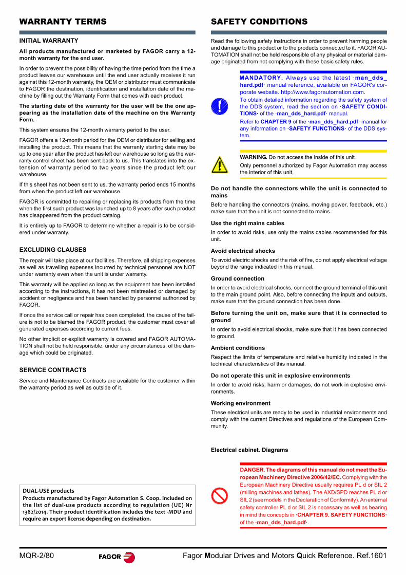
DUAL‐USE productsProducts manufactured by Fagor Automation S. Coop. included onthe list of dual‐use products according to regulation (UE) Nr1382/2014. Their product identification includes the text ‐MDU andrequire an export license depending on destination.
MANDATORY. Always use the latest ·man_dds_hard.pdf· manual reference, available on FAGOR's cor-porate website. http://www.fagorautomation.com.To obtain detailed information regarding the safety system ofthe DDS system, read the section on ·SAFETY CONDI-TIONS· of the ·man_dds_hard.pdf· manual.
Refer to CHAPTER 9 of the ·man_dds_hard.pdf· manual forany information on ·SAFETY FUNCTIONS· of the DDS sys-tem.
WARNING. Do not access the inside of this unit.
Only personnel authorized by Fagor Automation may accessthe interior of this unit.
DANGER. The diagrams of this manual do not meet the Eu-ropean Machinery Directive 2006/42/EC. Complying with theEuropean Machinery Directive usually requires PL d or SIL 2(milling machines and lathes). The AXD/SPD reaches PL d orSIL 2 (see models in the Declaration of Conformity). An externalsafety controller PL d or SIL 2 is necessary as well as bearingin mind the concepts in ·CHAPTER 9. SAFETY FUNCTIONS·of the ·man_dds_hard.pdf·.

Fagor Modular Drives and Motors Quick Reference. Ref.1601 MQR-3/80
SYNCHRONOUS MOTORS
ELECTRICAL CHARACTERISTICS
Electrical limitations for a synchronous motor
1. Curves for torque limitation by voltage depending on type of statorwinding.
2. Curve for thermal torque limitation in continuous duty S1 (100 K) withfan where T=100 K at the winding.
3. Curve for thermal torque limitation in continuous duty S1 (100 K) with-out fan where T=100 K at the winding.
4. Maximum turning speed limitation (in voltage) Nmax.
5. Voltage saturation curves.
Electrical limitations for a motor-drive combination
ZONE 1. Is the permanent duty area (S1 duty) and it is delimited by thestall motor torque and the torque at rated speed.
ZONE 2. Is the intermittent duty zone.
DEFINITIONS
Mo. Stall torque. Maximum torque that the motor can supply when the ro-tor is locked and is thermally limited by the temperature increase at thestator winding (T=100 K). This torque is available for a zero rotor turningspeed for an unlimited time period. The stall torque Mo is always greaterthan the rated torque Mnom.
Io. Stall current. Current circulating through each phase of the stator wind-ing required to generated the stall torque Mo. This current can circulate foran unlimited time.
Mn. Rated torque.Torque that the motor can supply continuously at its rat-ed speed and is thermally limited by the temperature increase at the statorwinding (T=100 K).
In. Rated current. Current circulating through each phase of the statorwinding required to generated the rated torque Mrated.
Pn. Rated power. Power available at rated speed and rated torque. Its val-ue is given in watts by expression: Mn·nN/9550 where Pn (in kW), Mn (inNm) and nN (in rev/min).
Nmax. Maximum speed. Rotor turning speed limitation due to electrical re-strictions (voltage limits). Note that the maximum value for this speed isshown in the torque-speed curves given in this manual.
Mp. Peak torque. Maximum torque (limited by current) generated by themaximum Ip current allowed at zero speed. It is available for dynamic op-erations such as accelerations, ... The value of this current is always lim-ited by the control parameter (CP20) in face of the risk of exceeding thedestruction temperature of the insulation of the stator winding.
tac. Acceleration time. Time it takes the motor to accelerate from zerospeed to its rated speed with maximum torque.
kt. Torque constant. Torque generated according to the current supplied.Its value may be calculated with the division of the stall torque by the stallcurrent (Mo/Io).
nN. Rated turning speed.
Pcal. Power value given by the expression: Mo·nN/9550 where Pcal (inkW), Mo (in Nm) and nN (in rev/min).
R. Value of the resistance of a phase at an ambient temperature of 20°C(68°F). The stator winding has a star configuration.
L. Value of the inductance corresponding to a phase when using three-phase power supply. The stator winding has a star configuration.
J. Rotor moment of inertia.
P. Mass.
WARNING. Note that this data is valid for ambient tempera-ture or an average cooling temperature of 40°C (104°F).
0 12000
SpeedN (rev/min)
Torque
1
2
3
4
2000 3000 4000
5
6A B C D
M (Nm)
5
4
1
2
3
MAINS VOLTAGE: 400 VRMS
MOTOR VOLTAGE: 400-4.5% = 382 VRMS
MAINS VOLTAGE: 220 VRMS
MOTOR VOLTAGE: 220-4.5% = 210 VRMS
MAINS VOLTAGE: 400-15% = 340 VRMS
MOTOR VOLTAGE: 400-15% -4.5% = 325 VRMS
MAINS VOLTAGE: 220-15% = 187 VRMS
MOTOR VOLTAGE: 220-15% -4,5% = 179 VRMS
MAINS VOLTAGE: 400-10% = 360 VRMS
MOTOR VOLTAGE: 400-10%-4.5% = 344 VRMS
VOLTAGE LIMITS CHARACTERISTICS
Voltage limit
1
2
Limit Torque
Limitation due to maximum
through the drive
Mlim
RatedTorqueMn
(100 K)
Rated SpeednN
Motor Peak Torque
Mp
StallTorqueMo
(100 K)
Peak Torque
limited by the drive
TORQUE (Nm)
SPEED (1/min)
MQR-4/80 Fagor Modular Drives and Motors Quick Reference. Ref.1601
FXM 1/3/5/7 MOTORS
GENERAL CHARACTERISTICSThese motors have been manufactured in accordance with the Europeanregulations EN 60204-1 and EN 60034 as instructed by the European Di-rective 2006/95/EC on Low Voltage (LVD).
TEMPERATURE SENSOR
FXM motors have a thermistor PTC (positive temperature coefficient) sen-sitive in a temperature range between 130°C (266°F) and 160°C (320°F).
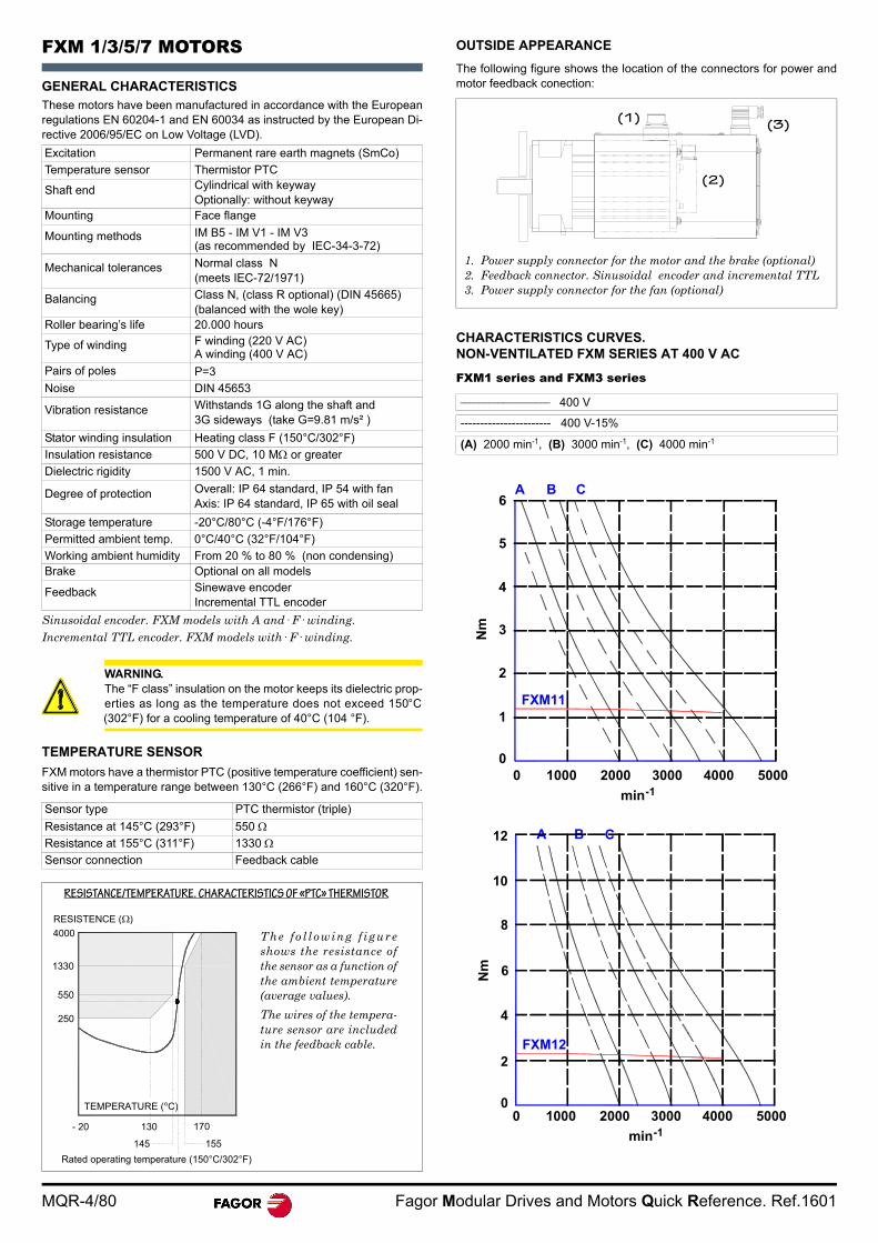
OUTSIDE APPEARANCE
The following figure shows the location of the connectors for power andmotor feedback conection:
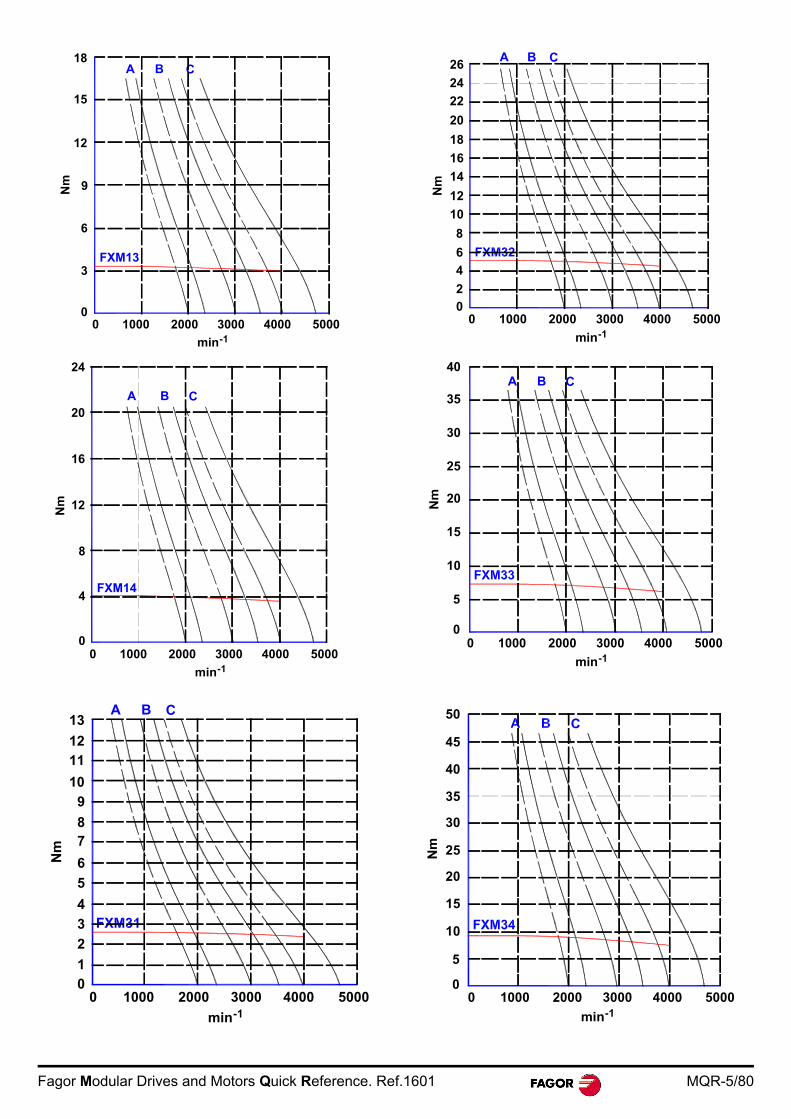
CHARACTERISTICS CURVES. NON-VENTILATED FXM SERIES AT 400 V AC
FXM1 series and FXM3 series
Excitation Permanent rare earth magnets (SmCo)
Temperature sensor Thermistor PTC
Shaft end Cylindrical with keywayOptionally: without keyway
Mounting Face flange
Mounting methods IM B5 - IM V1 - IM V3 (as recommended by IEC-34-3-72)
Mechanical tolerances Normal class N(meets IEC-72/1971)
Balancing Class N, (class R optional) (DIN 45665)(balanced with the wole key)
Roller bearing’s life 20.000 hours
Type of winding F winding (220 V AC)A winding (400 V AC)
Pairs of poles P=3
Noise DIN 45653
Vibration resistance Withstands 1G along the shaft and 3G sideways (take G=9.81 m/s² )
Stator winding insulation Heating class F (150°C/302°F)
Insulation resistance 500 V DC, 10 M or greater
Dielectric rigidity 1500 V AC, 1 min.
Degree of protection Overall: IP 64 standard, IP 54 with fanAxis: IP 64 standard, IP 65 with oil seal
Storage temperature -20°C/80°C (-4°F/176°F)
Permitted ambient temp. 0°C/40°C (32°F/104°F)
Working ambient humidity From 20 % to 80 % (non condensing)Brake Optional on all models
Feedback Sinewave encoderIncremental TTL encoder
Sinusoidal encoder. FXM models with A and· F· winding.Incremental TTL encoder. FXM models with· F· winding.
WARNING. The “F class” insulation on the motor keeps its dielectric prop-erties as long as the temperature does not exceed 150°C(302°F) for a cooling temperature of 40°C (104 °F).
Sensor type PTC thermistor (triple)
Resistance at 145°C (293°F) 550 Resistance at 155°C (311°F) 1330 Sensor connection Feedback cable
TEMPERATURE (°C)
- 20 130
145 155
170
250
1330
RESISTENCE ( )
550
4000
Rated operating temperature (150°C/302°F)
The fo l lowing f igureshows the resistance ofthe sensor as a function ofthe ambient temperature(average values).
The wires of the tempera-ture sensor are includedin the feedback cable.
RESISTANCE/TEMPERATURE. CHARACTERISTICS OF «PTC» THERMISTOR
___________________ 400 V
----------------------- 400 V-15%
(A) 2000 min-1, (B) 3000 min-1, (C) 4000 min-1
(1)
(2)
(3)
1. Power supply connector for the motor and the brake (optional)2. Feedback connector. Sinusoidal encoder and incremental TTL3. Power supply connector for the fan (optional)
A B C
0 1000 2000 3000 4000 5000
min-1
0
1
2
3
4
5
6
Nm
FXM11
0 1000 2000 3000 4000 5000
min-1
0
2
4
6
8
10
Nm
A B C12
FXM12
Fagor Modular Drives and Motors Quick Reference. Ref.1601 MQR-5/80
A B C
0 1000 2000 3000 4000 5000
min-1
0
3
6
9
12
Nm
15
FXM13
18
FXM14
0 1000 2000 3000 4000 5000
min-1
A B C
0
4
8
16
Nm
20
24
12
A B C
0 1000 2000 3000 4000 5000
min-1
0
4
5
10
Nm
1
2
3
6
78
9
1112
13
A B C
0 1000 2000 3000 4000 5000
min-1
0
8
10
Nm
2
4
6
12
14
16
18
20
22
24
26
0 1000 2000 3000 4000 5000
min-1
0
Nm
5
15
20
25
40A B C
10
30
35
0 1000 2000 3000 4000 5000
min-1
0
Nm
5
15
20
25
50
10
30
35
40
45
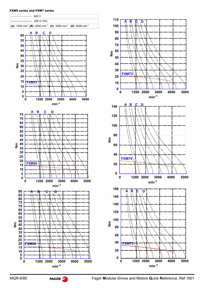
MQR-6/80 Fagor Modular Drives and Motors Quick Reference. Ref.1601
FXM5 series and FXM7 series___________________ 400 V
----------------------- 400 V-15%
(A) 1200 min-1,(B) 2000 min-1, (C) 3000 min-1, (D) 4000 min-1
0 1200 2000 3000 4000 5000
min-1
0
Nm
5
20
25
30
60
10
35
40
45
55
15
50
0 1200 2000 3000 4000-1
0
Nm
5
202530
60
10
354045
55
15
50
657075
0 1200 2000 3000 4000 5000
min-1
05
202530
60
10
354045
55
15
50
657075808590
0 1200 2000 3000 4000 5000
min-1
0
Nm
20
30
60
10
40
50
70
80
90
100
110
0 1200 2000 3000 4000 5000
min-1
0
20
60
40
80
100
120
140
0 1200 2000 3000 4000 5000
min-1
0
Nm
20
60
40
80
100
120
140
160
180
Fagor Modular Drives and Motors Quick Reference. Ref.1601 MQR-7/80
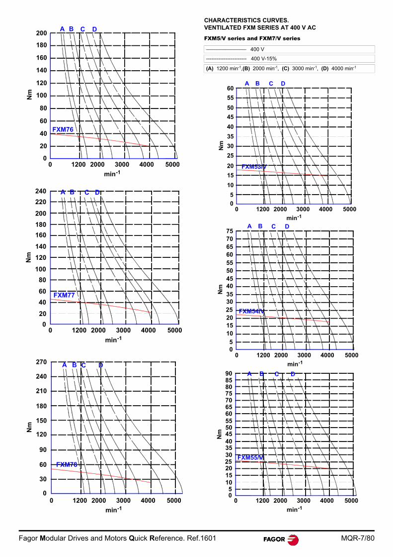
CHARACTERISTICS CURVES. VENTILATED FXM SERIES AT 400 V AC
FXM5/V series and FXM7/V series
0 1200 2000 3000 4000 5000
min-1
0
Nm
20
60
40
80
100
120
140
160
180
200
0 1200 2000 3000 4000 5000
min-1
0
Nm
20
60
40
80
100
120
140
160
180
200
220
240
0 1200 2000 3000 4000 5000
min-1
0
Nm
60
30
90
120
150
180
210
240
270
___________________ 400 V
----------------------- 400 V-15%
(A) 1200 min-1,(B) 2000 min-1, (C) 3000 min-1, (D) 4000 min-1
0 1200 2000 3000 4000 5000
min-1
0
Nm
5
20
25
30
60
10
35
40
45
55
15
50
0 1200 2000 3000 4000 5000
min-1
0
Nm
5
202530
60
10
354045
55
15
50
657075
0 1200 2000 3000 4000 5000
min-1
0
Nm
5
202530
60
10
354045
55
15
50
657075808590

MQR-8/80 Fagor Modular Drives and Motors Quick Reference. Ref.1601
0 1200 2000 3000 4000 5000
min-1
0
Nm
20
30
60
10
40
50
70
80
90
100
110
0 1200 2000 3000 4000 5000
min-1
0
Nm
20
60
40
80
100
120
140
0 1200 2000 3000 4000 5000
min-1
0
Nm
20
60
40
80
100
120
140
160
180
0 1200 2000 3000 4000 5000
min-1
0
Nm
20
60
40
80
100
120
140
160
180
200
0 1200 2000 3000 4000 5000
min-1
0
20
60
40
80
100
120
140
160
180
200
220
240
0 1200 2000 3000 4000 5000
min-1
0
Nm
60
30
90
120
150
180
210
240
270
Fagor Modular Drives and Motors Quick Reference. Ref.1601 MQR-9/80
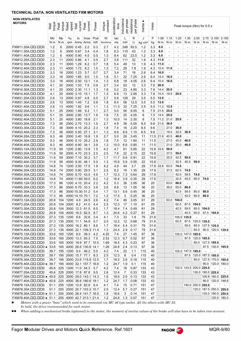
TECHNICAL DATA. NON VENTILATED FXM MOTORS
NON-VENTILATED MOTORS
Sta
ll to
rque
Pea
k to
rque
Rat
ed
spee
d
Sta
ll cu
rren
t
Pea
k cu
rren
t
Pow
er
torq
ue
cons
tant
acce
lera
tion
time
indu
ctan
ce
per
pha
se
resi
stan
ce
per
pha
se
Iner
tia
mas
s
Peak torque (Nm) for 0.5 s
Mo Mp nN Io Imax Pcal Kt tac L R J P 1.08 1.15 1.25 1.35 2.50 2.75 3.100 3.150N·m N·m rpm Arms Arms kW Nm/Arms ms mH kg·cm² kg N·m N·m N·m N·m N·m N·m N·m N·m
FXM11.20A..0 1.2 6 2000 0.45 2.2 0.3 2.7 4.2 248 93.5 1.2 3.3 6.0 - - - - - - -
FXM11.30A..0 1.2 6 3000 0.67 3.4 0.4 1.8 6.3 110 43 1.2 3.3 6.0 - - - - - - -
FXM11.40A..0 1.2 6 4000 0.90 4.5 0.5 1.3 8.4 62 23.5 1.2 3.3 6.0 - - - - - - -
FXM12.20A..0 2.3 11 2000 0.86 4.1 0.5 2.7 3.6 111 32 1.9 4.3 11.0 - - - - - - -
FXM12.30A..0 2.3 11 3000 1.29 6.2 0.7 1.8 5.4 49 13 1.9 4.3 11.0 - - - - - - -
FXM12.40A..0 2.3 11 4000 1.72 8.2 1.0 1.3 7.2 28 7.8 1.9 4.3 10.4 11.0 - - - - - -
FXM13.20A..0 3.3 16 2000 1.23 5.7 0.7 2.7 3.4 71 16 2.6 6.4 16.0 - - - - - - -
FXM13.30A..0 3.3 16 3000 1.85 9.0 1.0 1.8 5.1 32 7.25 2.6 6.4 14.4 16.0 - - - - - -
FXM13.40A..0 3.3 16 4000 2.50 12.1 1.4 1.3 6.8 18 4.05 2.6 6.4 10.4 16.0 - - - - - -
FXM14.20A..0 4.1 20 2000 1.53 7.5 0.9 2.7 3.4 52 12 3.3 7.6 20.0 - - - - - - -
FXM14.30A..0 4.1 20 3000 2.30 11.1 1.3 1.8 5.2 23 4.85 3.3 7.6 14.4 20.0 - - - - - -
FXM14.40A..0 4.1 20 4000 3.10 15.1 1.7 1.3 6.9 13 2.95 3.3 7.6 10.4 19.5 20.0 - - - - -
FXM31.20A..0 2.6 13 2000 0.97 4.8 0.5 2.7 5.6 126 29 3.5 5.5 13.0 - - - - - - -
FXM31.30A..0 2.6 13 3000 1.45 7.2 0.8 1.8 8.4 56 12.5 3.5 5.5 13.0 - - - - - - -
FXM31.40A..0 2.6 13 4000 1.92 9.6 1.1 1.3 11.3 32 7.25 3.5 5.5 11.2 13.0 - - - - - -
FXM32.20A..0 5.1 25 2000 1.89 9.3 1.1 2.7 5.0 56 9.55 6 7.5 21.6 25.0 - - - - - -
FXM32.30A..0 5.1 25 3000 2.80 13.7 1.6 1.8 7.5 25 4.05 6 7.5 14.4 25.0 - - - - - -
FXM32.40A..0 5.1 25 4000 3.80 18.6 2.1 1.3 10.0 14 2.30 6 7.5 11.2 21.0 25.0 - - - - -
FXM33.20A..0 7.3 36 2000 2.70 13.3 1.5 2.7 4.9 36 5.05 8.5 9.6 21.6 36.0 - - - - - -
FXM33.30A..0 7.3 36 3000 4.10 20.2 2.3 1.8 7.4 16 2.20 8.5 9.6 27.0 36.0 - - - - -
FXM33.40A..0 7.3 36 4000 5.50 27.1 3.1 1.3 9.9 8.6 1.15 8.5 9.6 19.5 32.5 36.0 - - - -
FXM34.20A..0 9.3 46 2000 3.40 16.8 1.9 2.7 5.0 26 3.45 11 11.5 21.6 40.5 46.0 - - - - -
FXM34.30A..0 9.3 46 3000 5.10 25.2 2.9 1.8 7.5 12 1.60 11 11.5 27.0 45.0 46.0 - - - -
FXM34.40A..0 9.3 46 4000 6.90 34.1 3.9 1.3 10.0 6.6 0.85 11 11.5 21.0 35.0 46.0 - - - -
FXM53.12A..0 11.9 59 1200 2.80 13.9 1.5 4.2 4.7 61 5.85 22 15.8 33.6 59.0 - - - - - -
FXM53.20A..0 11.9 59 2000 4.70 23.3 2.5 2.5 7.8 22 2.15 22 15.8 37.5 59.0 - - - - -
FXM53.30A..0 11.9 59 3000 7.10 35.2 3.7 1.7 11.7 9.6 0.91 22 15.8 25.5 42.5 59.0 - - - -
FXM53.40A..0 11.9 59 4000 9.30 46.1 5.0 1.3 15.6 5.6 0.55 22 15.8 32.5 45.5 59.0 - - -
FXM54.12A..0 14.8 74 1200 3.50 17.5 1.9 4.2 4.9 44 3.7 29 17.8 33.6 63.0 74.0 - - - - -
FXM54.20A..0 14.8 74 2000 5.90 29.5 3.1 2.5 8.2 16 1.35 29 17.8 37.5 62.5 74.0 - - - -
FXM54.30A..0 14.8 74 3000 8.70 43.5 4.6 1.7 12.3 7.3 0.64 29 17.8 42.5 59.5 74.0 - - -
FXM54.40A..0 14.8 74 4000 11.80 59.0 6.2 1.2 16.4 3.9 0.35 29 17.8 32.5 45.5 65.0 74.0 - -
FXM55.12A..0 17.3 86 1200 4.10 20.4 2.2 4.2 5.3 36 2.95 36 20 63.0 86.0 - - - - -
FXM55.20A..0 17.3 86 2000 6.70 33.3 3.6 2.6 8.8 13 1.05 36 20 39.0 65.0 86.0 - - - -
FXM55.30A..0 17.3 86 3000 10.30 51.2 5.4 1.7 13.1 5.6 0.45 36 20 42.5 59.5 85.0 86.0 - -
FXM55.40A..0 17.3 86 4000 14.10 70.1 7.2 1.2 17.5 3 0.25 36 20 42.0 60.0 86.0 - -
FXM73.12A..0 20.8 104 1200 4.9 24.5 2.6 4.2 7.4 46 3.05 61 29 63.0 104.0 - - - - -
FXM73.20A..0 20.8 104 2000 8.2 41.0 4.4 2.5 12.3 17 1.10 61 29 62.5 87.5 104.0 - - -
FXM73.30A..0 20.8 104 3000 12.3 61.5 6.5 1.7 18.4 7.4 0.49 61 29 42.5 59.5 85.0 104.0 - -
FXM73.40A..0 20.8 104 4000 16.5 82.5 8.7 1.3 24.6 4.2 0.27 61 29 45.5 65.0 97.5 104.0 -
FXM74.12A..0 27.3 135 1200 6.6 32.6 3.4 4.1 7.3 33 1.9 79 31.6 105.0 135.0 - - - -
FXM74.20A..0 27.3 135 2000 11.1 54.9 5.7 2.5 12.2 12 0.68 79 31.6 62.5 87.5 125.0 135.0 - -
FXM74.30A..0 27.3 135 3000 16.2 80.1 8.6 1.7 18.4 5.4 0.31 79 31.6 59.5 85.0 127.5 135.0 -
FXM74.40A..0 27.3 135 4000 22.1 109.3 11.4 1.3 24.5 2.9 0.17 79 31.6 60.0 90.0 120.0 135.0FXM75.12A..0 33.6 165 1200 8.0 39.3 4.2 4.20 7.4 27 1.45 97 36 105.0 147.0 165.0 - - -
FXM75.20A..0 33.6 165 2000 13.3 65.3 7.0 2.53 12.3 9.7 0.52 97 36 87.5 125.0 165.0 - -
FXM75.30A..0 33.6 165 3000 19.9 97.7 10.5 1.69 18.5 4.3 0.23 97 36 85.0 127.5 165.0 -
FXM75.40A..0 33.6 165 4000 26.6 130.6 14.1 1.26 24.6 2.4 0.13 97 36 97.5 130.0 165.0
FXM76.12A..0 39.7 195 1200 9.4 46.2 5.0 4.2 7.4 22 1.1 115 40 105.0 147.0 195.0 - - -
FXM76.20A..0 39.7 195 2000 15.7 77.1 8.3 2.5 12.3 8 0.4 115 40 87.5 125.0 187.5 195.0 -
FXM76.30A..0 39.7 195 3000 23.6 115.9 12.5 1.7 18.5 3.6 0.18 115 40 85.0 127.5 170.0 195.0FXM76.40A..0 39.7 195 4000 32.1 157.7 16.6 1.2 24.7 1.9 0.1 115 40 90.0 120.0 180.0
FXM77.12A..0 45.6 225 1200 11.0 54.3 5.7 4.2 7.4 18 0.87 133 43 102.5 143.5 205.0 225.0 - -
FXM77.20A..0 45.6 225 2000 17.8 87.8 9.5 2.6 12.4 7 0.33 133 43 130.0 195.0 225.0 -
FXM77.30A..0 45.6 225 3000 29.0 143.1 14.3 1.6 18.6 2.6 0.13 133 43 100.8 160.0 225.0
FXM77.40A..0 45.6 225 4000 36.6 180.6 19.1 1.2 24.7 1.7 0.08 133 43 90.0 120.0 148.8
FXM78.12A..0 51.1 255 1200 12.6 62.9 6.4 4.1 7.4 15 0.71 151 47 140.0 200.0 255.0 - -
FXM78.20A..0 51.1 255 2000 20.7 103.3 10.7 2.5 12.4 5.7 0.27 151 47 125.0 187.5 250.0 255.0FXM78.30A..0 51.1 255 3000 28.4 141.7 16.0 1.8 18.6 3 0.14 151 47 135.0 180.0 255.0FXM78.40A..0 51.1 255 4000 42.7 213.1 21.4 1.2 24.8 1.3 0.07 151 47 120.0 180.0
Motors with a power “base” which need to be connected via MC 46 type socket. All the others with MC 23. In bold, the drive recommended for each motor.
When adding a mechanical brake (optional) to the motor, the moment of inertia values of the brake will also have to be taken into account.
MQR-10/80 Fagor Modular Drives and Motors Quick Reference. Ref.1601
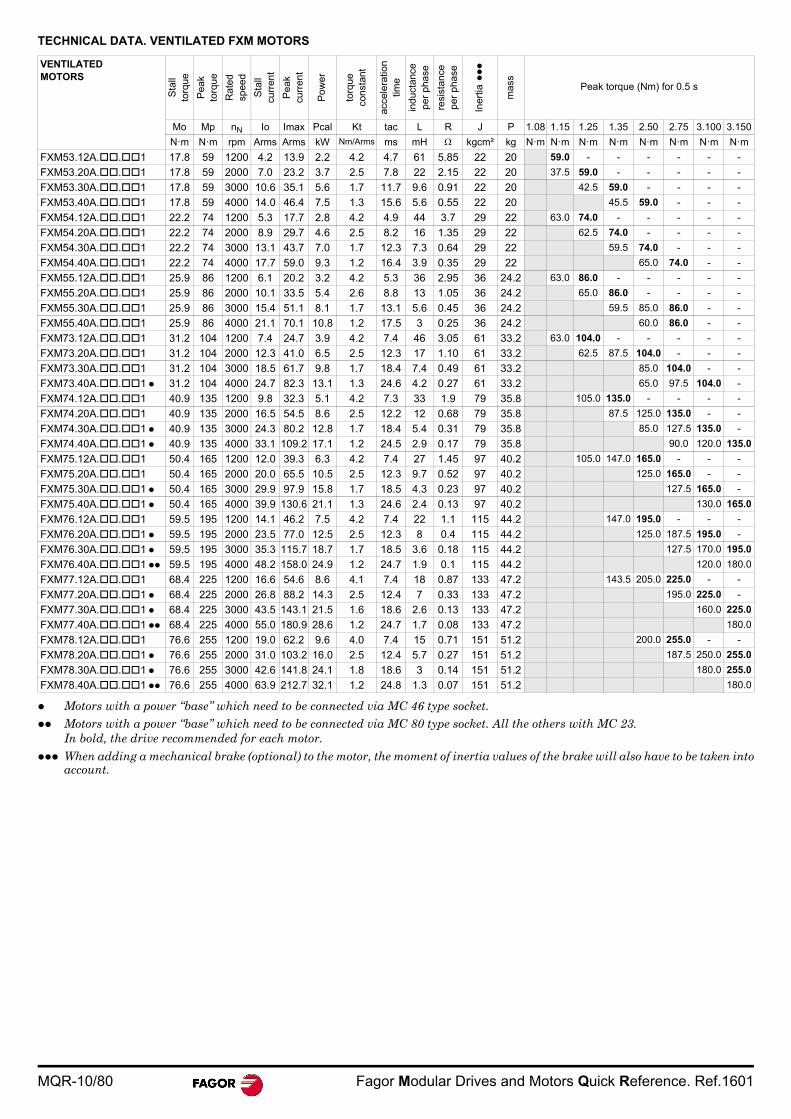
TECHNICAL DATA. VENTILATED FXM MOTORS
VENTILATED MOTORS
Sta
ll to
rqu
e
Pe
ak
torq
ue
Rat
ed
spee
d
Sta
ll cu
rren
t
Pe
ak
curr
ent
Po
we
r
torq
ue
cons
tant
acce
lera
tion
tim
e
ind
ucta
nce
per
pha
se
resi
stan
ce
per
pha
se
Iner
tia
mas
s
Peak torque (Nm) for 0.5 s
Mo Mp nN Io Imax Pcal Kt tac L R J P 1.08 1.15 1.25 1.35 2.50 2.75 3.100 3.150
N·m N·m rpm Arms Arms kW Nm/Arms ms mH kgcm² kg N·m N·m N·m N·m N·m N·m N·m N·m
FXM53.12A..1 17.8 59 1200 4.2 13.9 2.2 4.2 4.7 61 5.85 22 20 59.0 - - - - - -
FXM53.20A..1 17.8 59 2000 7.0 23.2 3.7 2.5 7.8 22 2.15 22 20 37.5 59.0 - - - - -
FXM53.30A..1 17.8 59 3000 10.6 35.1 5.6 1.7 11.7 9.6 0.91 22 20 42.5 59.0 - - - -
FXM53.40A..1 17.8 59 4000 14.0 46.4 7.5 1.3 15.6 5.6 0.55 22 20 45.5 59.0 - - -
FXM54.12A..1 22.2 74 1200 5.3 17.7 2.8 4.2 4.9 44 3.7 29 22 63.0 74.0 - - - - -
FXM54.20A..1 22.2 74 2000 8.9 29.7 4.6 2.5 8.2 16 1.35 29 22 62.5 74.0 - - - -
FXM54.30A..1 22.2 74 3000 13.1 43.7 7.0 1.7 12.3 7.3 0.64 29 22 59.5 74.0 - - -
FXM54.40A..1 22.2 74 4000 17.7 59.0 9.3 1.2 16.4 3.9 0.35 29 22 65.0 74.0 - -
FXM55.12A..1 25.9 86 1200 6.1 20.2 3.2 4.2 5.3 36 2.95 36 24.2 63.0 86.0 - - - - -
FXM55.20A..1 25.9 86 2000 10.1 33.5 5.4 2.6 8.8 13 1.05 36 24.2 65.0 86.0 - - - -
FXM55.30A..1 25.9 86 3000 15.4 51.1 8.1 1.7 13.1 5.6 0.45 36 24.2 59.5 85.0 86.0 - -
FXM55.40A..1 25.9 86 4000 21.1 70.1 10.8 1.2 17.5 3 0.25 36 24.2 60.0 86.0 - -
FXM73.12A..1 31.2 104 1200 7.4 24.7 3.9 4.2 7.4 46 3.05 61 33.2 63.0 104.0 - - - - -
FXM73.20A..1 31.2 104 2000 12.3 41.0 6.5 2.5 12.3 17 1.10 61 33.2 62.5 87.5 104.0 - - -
FXM73.30A..1 31.2 104 3000 18.5 61.7 9.8 1.7 18.4 7.4 0.49 61 33.2 85.0 104.0 - -
FXM73.40A..1 31.2 104 4000 24.7 82.3 13.1 1.3 24.6 4.2 0.27 61 33.2 65.0 97.5 104.0 -
FXM74.12A..1 40.9 135 1200 9.8 32.3 5.1 4.2 7.3 33 1.9 79 35.8 105.0 135.0 - - - -
FXM74.20A..1 40.9 135 2000 16.5 54.5 8.6 2.5 12.2 12 0.68 79 35.8 87.5 125.0 135.0 - -
FXM74.30A..1 40.9 135 3000 24.3 80.2 12.8 1.7 18.4 5.4 0.31 79 35.8 85.0 127.5 135.0 -
FXM74.40A..1 40.9 135 4000 33.1 109.2 17.1 1.2 24.5 2.9 0.17 79 35.8 90.0 120.0 135.0
FXM75.12A..1 50.4 165 1200 12.0 39.3 6.3 4.2 7.4 27 1.45 97 40.2 105.0 147.0 165.0 - - -
FXM75.20A..1 50.4 165 2000 20.0 65.5 10.5 2.5 12.3 9.7 0.52 97 40.2 125.0 165.0 - -
FXM75.30A..1 50.4 165 3000 29.9 97.9 15.8 1.7 18.5 4.3 0.23 97 40.2 127.5 165.0 -
FXM75.40A..1 50.4 165 4000 39.9 130.6 21.1 1.3 24.6 2.4 0.13 97 40.2 130.0 165.0
FXM76.12A..1 59.5 195 1200 14.1 46.2 7.5 4.2 7.4 22 1.1 115 44.2 147.0 195.0 - - -
FXM76.20A..1 59.5 195 2000 23.5 77.0 12.5 2.5 12.3 8 0.4 115 44.2 125.0 187.5 195.0 -
FXM76.30A..1 59.5 195 3000 35.3 115.7 18.7 1.7 18.5 3.6 0.18 115 44.2 127.5 170.0 195.0
FXM76.40A..1 59.5 195 4000 48.2 158.0 24.9 1.2 24.7 1.9 0.1 115 44.2 120.0 180.0
FXM77.12A..1 68.4 225 1200 16.6 54.6 8.6 4.1 7.4 18 0.87 133 47.2 143.5 205.0 225.0 - -
FXM77.20A..1 68.4 225 2000 26.8 88.2 14.3 2.5 12.4 7 0.33 133 47.2 195.0 225.0 -
FXM77.30A..1 68.4 225 3000 43.5 143.1 21.5 1.6 18.6 2.6 0.13 133 47.2 160.0 225.0
FXM77.40A..1 68.4 225 4000 55.0 180.9 28.6 1.2 24.7 1.7 0.08 133 47.2 180.0
FXM78.12A..1 76.6 255 1200 19.0 62.2 9.6 4.0 7.4 15 0.71 151 51.2 200.0 255.0 - -
FXM78.20A..1 76.6 255 2000 31.0 103.2 16.0 2.5 12.4 5.7 0.27 151 51.2 187.5 250.0 255.0
FXM78.30A..1 76.6 255 3000 42.6 141.8 24.1 1.8 18.6 3 0.14 151 51.2 180.0 255.0
FXM78.40A..1 76.6 255 4000 63.9 212.7 32.1 1.2 24.8 1.3 0.07 151 51.2 180.0
Motors with a power “base” which need to be connected via MC 46 type socket. Motors with a power “base” which need to be connected via MC 80 type socket. All the others with MC 23.
In bold, the drive recommended for each motor. When adding a mechanical brake (optional) to the motor, the moment of inertia values of the brake will also have to be taken into
account.
Fagor Modular Drives and Motors Quick Reference. Ref.1601 MQR-11/80
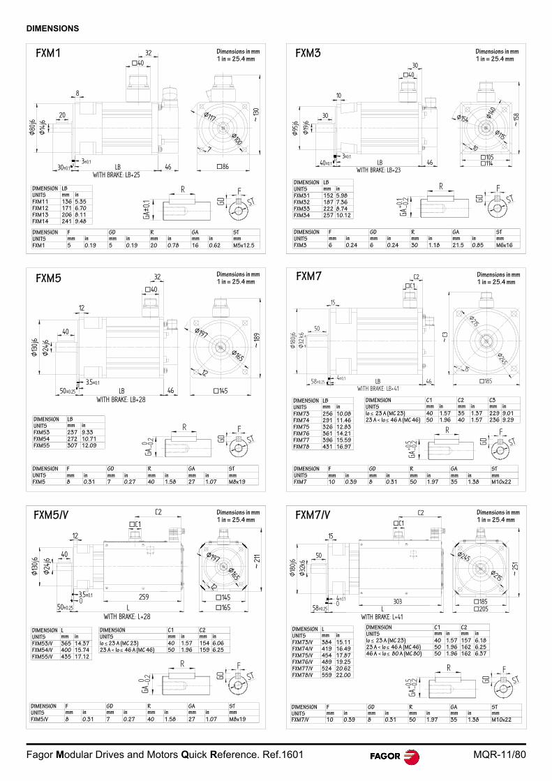
DIMENSIONS
GD
FST
40
8
LB 4630±0.1
Ø80
j6Ø
14j6
03±0.1
20
86
7
Ø100
Ø117 ~13
0
DIMENSION LBUNITS mm in
FXM11 136 5.35FXM12 171 6.70FXM13 206 8.11FXM14 241 9.48
DIMENSION F GD R GA STUNITS mm in mm in mm in mm in mm
FXM1 5 0.19 5 0.19 20 0.78 16 0.62 M5x12.5
Dimensions in mm1 in = 25.4 mm
FXM1
GA
GD
FST
-0.2
+0.1
30
10
~15
8
10
114
Ø115
Ø154 Ø140
Ø95
j6
Ø19
j6
30
40±0.10
3±0.1LB
WITH BRAKE: LB+2346
40
105
DIMENSION LBUNITS mm in
FXM31 152 5.98FXM32 187 7.36FXM33 222 8.74FXM34 257 10.12
DIMENSION F GD R GA STUNITS mm in mm in mm in mm in mmFXM3 6 0.24 6 0.24 30 1.18 21.5 0.85 M6x16
FXM3 Dimensions in mm1 in = 25.4 mm
Ø165
12
40
Ø13
0j6
Ø24
j6
50±0.250 3.5±0.1
LBWITH BRAKE: LB+28
46
40
12
145
Ø197
~18
9
DIMENSION LBUNITS mm in
FXM53 237 9.33FXM54 272 10.71FXM55 307 12.09
DIMENSION F GD R GA STUNITS mm in mm in mm in mm in mmFXM5 8 0.31 7 0.27 40 1.58 27 1.07 M8x19
GA
GD
FST
-0.2
Dimensions in mm1 in = 25.4 mmFXM5
C1C2
~C3
Ø215
Ø245
15
Ø18
0j6
Ø32
k6
15
LBWITH BRAKE: LB+41
46
50
58±0.25 04±0.1
185
GA
GD
FST
-0.2
+0.5
DIMENSION LBUNITS mm in
FXM73 256 10.08FXM74 291 11.46FXM75 326 12.83FXM76 361 14.21FXM77 396 15.59FXM78 431 16.97
DIMENSION F GD R GA STUNITS mm in mm in mm in mm in mmFXM7 10 0.39 8 0.31 50 1.97 35 1.38 M10x22
DIMENSION C1 C2 C3UNITS mm in mm in mm in
Io 23 A (MC 23) 40 1.57 35 1.37 229 9.0123 A < Io 46 A (MC 46) 50 1.96 40 1.57 236 9.29
FXM7 Dimensions in mm1 in = 25.4 mm
40
Ø24
j6
Ø13
0j6
50±0.25
3.5±0.10 259
L 165145
C2
C1
12
12
~21
1Ø197
Ø165
WITH BRAKE: L+28
DIMENSION LUNITS mm in
FXM53/V 365 14.37FXM54/V 400 15.74FXM55/V 435 17.12
DIMENSION F GD R GA STUNITS mm in mm in mm in mm in mm
FXM5/V 8 0.31 7 0.27 40 1.58 27 1.07 M8x19
DIMENSION C1 C2UNITS mm in mm inIo 23 A (MC 23) 40 1.57 154 6.0623 A < Io 46 A (MC 46) 50 1.96 159 6.25
GA
GD
FST
-0.2
FXM5/V Dimensions in mm1 in = 25.4 mm
~25
1
185205
Ø245
Ø215
C1
15
Ø32
k6
50
58±0.25 L3034±0.1
0
WITH BRAKE: L+41
GA
GD
FST
-0.2
+0.5
DIMENSION LUNITS mm in
FXM73/V 384 15.11FXM74/V 419 16.49FXM75/V 454 17.87FXM76/V 489 19.25FXM77/V 524 20.62FXM78/V 559 22.00
DIMENSION F GD R GA STUNITS mm in mm in mm in mm in mmFXM7/V 10 0.39 8 0.31 50 1.97 35 1.38 M10x22
DIMENSION C1 C2UNITS mm in mm in
Io 23 A (MC 23) 40 1.57 157 6.1823 A < Io 46 A (MC 46) 50 1.96 162 6.2546 A < Io 80 A (MC 80) 50 1.96 162 6.37
FXM7/V Dimensions in mm1 in = 25.4 mm
MQR-12/80 Fagor Modular Drives and Motors Quick Reference. Ref.1601
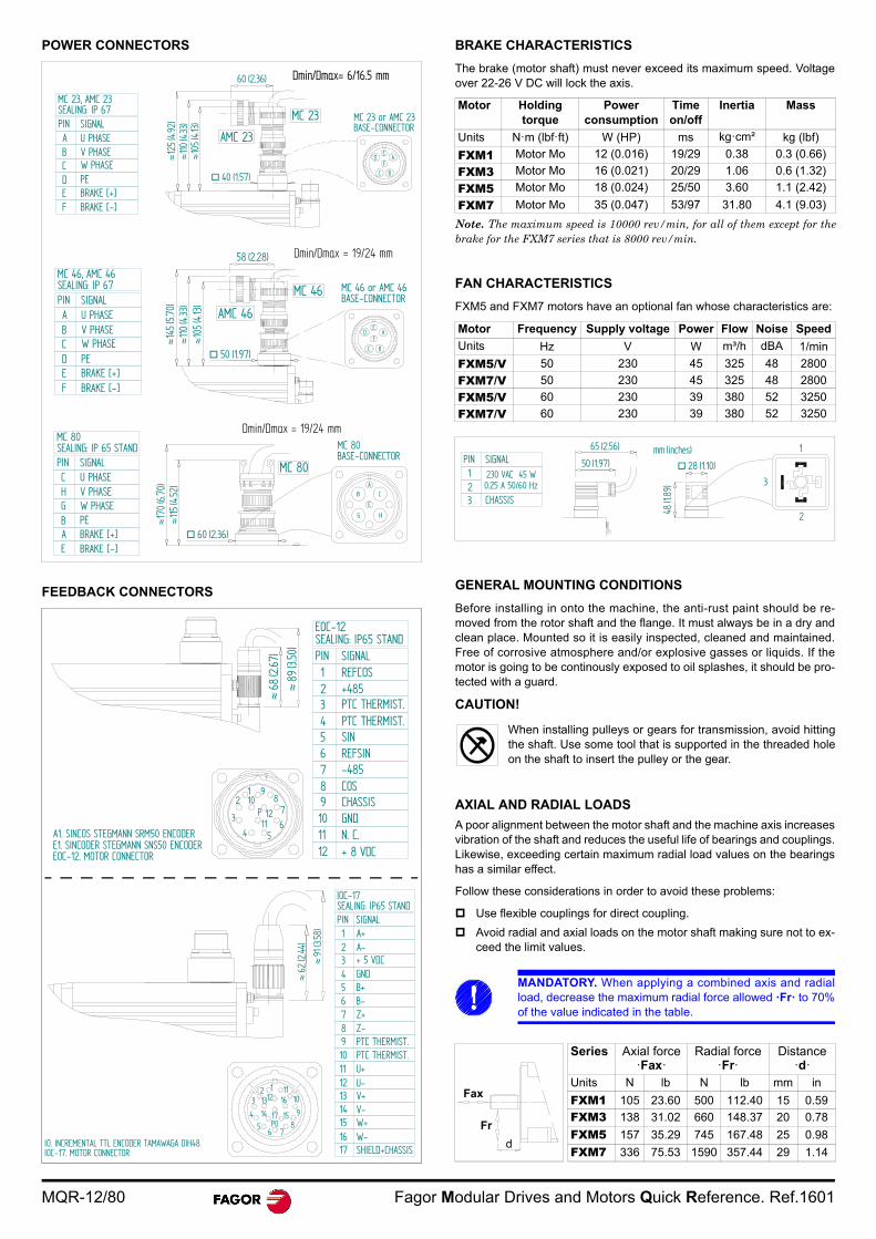
POWER CONNECTORS
FEEDBACK CONNECTORS
BRAKE CHARACTERISTICS
The brake (motor shaft) must never exceed its maximum speed. Voltageover 22-26 V DC will lock the axis.
FAN CHARACTERISTICS
FXM5 and FXM7 motors have an optional fan whose characteristics are:
GENERAL MOUNTING CONDITIONS
Before installing in onto the machine, the anti-rust paint should be re-moved from the rotor shaft and the flange. It must always be in a dry andclean place. Mounted so it is easily inspected, cleaned and maintained.Free of corrosive atmosphere and/or explosive gasses or liquids. If themotor is going to be continously exposed to oil splashes, it should be pro-tected with a guard.
CAUTION!
AXIAL AND RADIAL LOADS
A poor alignment between the motor shaft and the machine axis increasesvibration of the shaft and reduces the useful life of bearings and couplings.Likewise, exceeding certain maximum radial load values on the bearingshas a similar effect.
Follow these considerations in order to avoid these problems:
Use flexible couplings for direct coupling.
Avoid radial and axial loads on the motor shaft making sure not to ex-ceed the limit values.
MC 80BASE-CONNECTOR
E
ACB
G H
MC 80SEALING: IP 65 STANDPIN SIGNALCHGBAE
U PHASEV PHASEW PHASEPEBRAKE [+]BRAKE [-]
60 (2.36)
170
(6.70
)1
15(4
.52)
MC 80
MC 46, AMC 46SEALING: IP 67PIN SIGNALABCDEF
U PHASEV PHASEW PHASEPEBRAKE [+]BRAKE [-]
145
(5.70
)1
10(4
.33)
105
(4.13
)
50 (1.97)
58 (2.28)
EA
FD
C B
AMC 46
MC 46 MC 46 or AMC 46BASE-CONNECTOR
MC 23, AMC 23SEALING: IP 67PIN SIGNALABCDEF
U PHASEV PHASEW PHASEPEBRAKE [+]BRAKE [-]
AMC 23
MC 23
60 (2.36)
40 (1.57)
MC 23 or AMC 23BASE-CONNECTOR
EA
FD
C B1
25(4
.92)
110
(4.33
)1
05(4
.13)
Dmin/Dmax= 6/16.5 mm
Dmin/Dmax = 19/24 mm
Dmin/Dmax = 19/24 mm
EOC-12SEALING: IP65 STANDPIN SIGNAL123456
REFCOS+485PTC THERMIST.PTC THERMIST.SINREFSIN
1 98
76
54
3
2
1112
10P
789101112
-485COSCHASSISGNDN. C.+ 8 VDC
A1. SINCOS STEGMANN SRM50 ENCODERE1. SINCODER STEGMANN SNS50 ENCODEREOC-12. MOTOR CONNECTOR
68
(2.67
)
89(3.
50)
1
SEALING: IP65 STANDPIN SIGNAL123456
A+A-+ 5 VDCGNDB+B-
789101112
Z+Z-PTC THERMIST.PTC THERMIST.U+U-
13 V+14 V-15 W+16 W-17 SHIELD+CHASSIS
23
45
6 78
9
IO. INCREMENTAL TTL ENCODER TAMAWAGA OIH48IOC-17. MOTOR CONNECTOR
62
(2.44
)
91
(3.58
)
1110161213
14 1517P0
Motor Holding torque
Power consumption
Time on/off
Inertia Mass
Units N·m (lbf·ft) W (HP) ms kg·cm² kg (lbf)
FXM1 Motor Mo 12 (0.016) 19/29 0.38 0.3 (0.66)
FXM3 Motor Mo 16 (0.021) 20/29 1.06 0.6 (1.32)
FXM5 Motor Mo 18 (0.024) 25/50 3.60 1.1 (2.42)
FXM7 Motor Mo 35 (0.047) 53/97 31.80 4.1 (9.03)
Note. The maximum speed is 10000 rev/min, for all of them except for thebrake for the FXM7 series that is 8000 rev/min.
Motor Frequency Supply voltage Power Flow Noise Speed
Units Hz V W m³/h dBA 1/min
FXM5/V 50 230 45 325 48 2800
FXM7/V 50 230 45 325 48 2800
FXM5/V 60 230 39 380 52 3250
FXM7/V 60 230 39 380 52 3250
When installing pulleys or gears for transmission, avoid hittingthe shaft. Use some tool that is supported in the threaded holeon the shaft to insert the pulley or the gear.
MANDATORY. When applying a combined axis and radialload, decrease the maximum radial force allowed ·Fr· to 70%of the value indicated in the table.
Series Axial force ·Fax·
Radial force ·Fr·
Distance·d·
Units N lb N lb mm in
FXM1 105 23.60 500 112.40 15 0.59
FXM3 138 31.02 660 148.37 20 0.78
FXM5 157 35.29 745 167.48 25 0.98
FXM7 336 75.53 1590 357.44 29 1.14
PIN SIGNAL123
230 VAC 45 W0.25 A 50/60 Hz
CHASSIS
65 (2.56)
50 (1.97)mm (inches)
28 (1.10)
1
2
3
48 (1
.89)
Fax
Fr
d
Fagor Modular Drives and Motors Quick Reference. Ref.1601 MQR-13/80
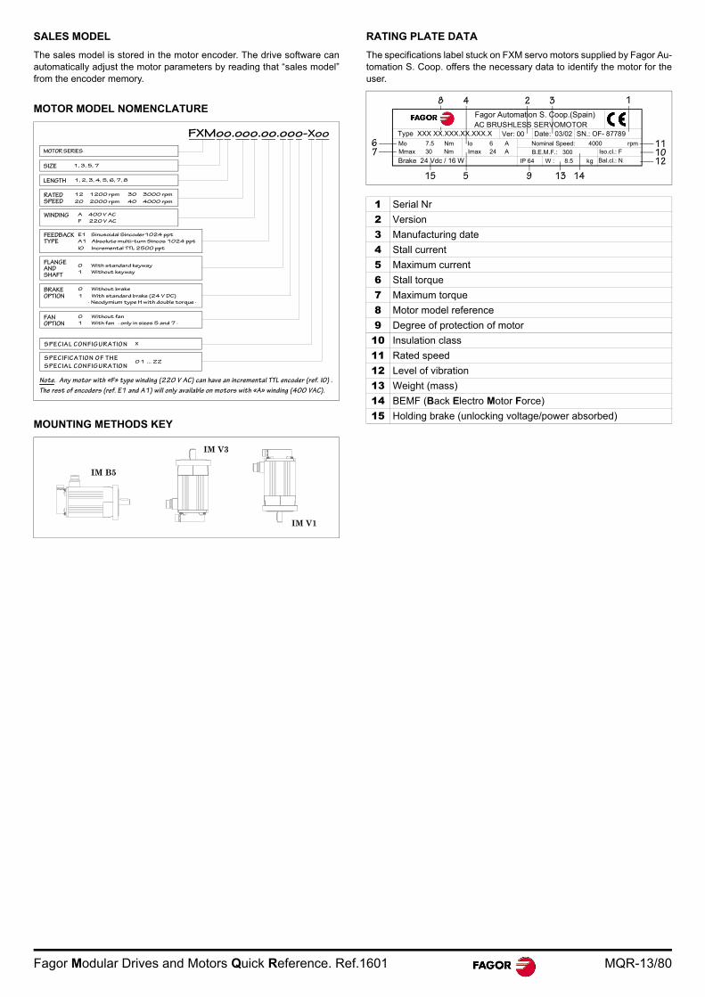
SALES MODEL
The sales model is stored in the motor encoder. The drive software canautomatically adjust the motor parameters by reading that “sales model”from the encoder memory.
MOTOR MODEL NOMENCLATURE
MOUNTING METHODS KEY
RATING PLATE DATA
The specifications label stuck on FXM servo motors supplied by Fagor Au-tomation S. Coop. offers the necessary data to identify the motor for theuser.
MOTOR SERIES
FXMoo.ooo.oo.ooo-Xoo
SIZE 1, 3, 5, 7
RATEDSPEED
LENGTH 1, 2, 3, 4, 5, 6, 7, 8
12 1200 rpm
20 2000 rpm
30 3000 rpm
40 4000 rpm
WINDING A 400 V AC
F 220 V AC
E1 Sinusoidal Sincoder1024 ppt
A1 Absolute multi-turn Sincos 1024 ppt
FEEDBACKTYPE
I0 Incremental TTL 2500 ppt
0 With standard keyway
1 Without keyway
FLANGEANDSHAFT
BRAKEOPTION
0 Without brake
1 With standard brake (24 V DC)
· Neodymium type H with double torque ·
FANOPTION
0 Without fan
1 With fan · only in sizes 5 and 7 ·
S P EC IA L C O N FIG UR A TIO N X
S P EC IFIC A TIO N O F TH E
S P EC IA L C O N FIG UR A TIO N 0 1 ... Z Z
Note. Any motor with «F» type winding (220 V AC) can have an incremental TTL encoder (ref. I0) .
The rest of encoders (ref. E1 and A1) will only available on motors with «A» winding (400 VAC).
IM B5 IM V3 IM V1
IM B5
IM V3
IM V1
1 Serial Nr
2 Version
3 Manufacturing date
4 Stall current
5 Maximum current
6 Stall torque
7 Maximum torque
8 Motor model reference
9 Degree of protection of motor
10 Insulation class
11 Rated speed
12 Level of vibration
13 Weight (mass)
14 BEMF (Back Electro Motor Force)
15 Holding brake (unlocking voltage/power absorbed)
Fagor Automation S. Coop.(Spain)AC BRUSHLESS SERVOMOTOR
Type XXX XX.XXX.XX.XXX.XMo 7.5 Nm
Mmax 30 Nm
Ver: 00 Date: 03/02 SN.: OF- 87789Io 6 A
Imax 24 A
Nominal Speed: 4000 rpm
B.E.M.F.: 300 Iso.cl.: F
Bal.cl.: N W : 8.5 kg IP 64
8
Brake 24 Vdc / 16 W
4 2 3 1
111012
14139515
76
MQR-14/80 Fagor Modular Drives and Motors Quick Reference. Ref.1601
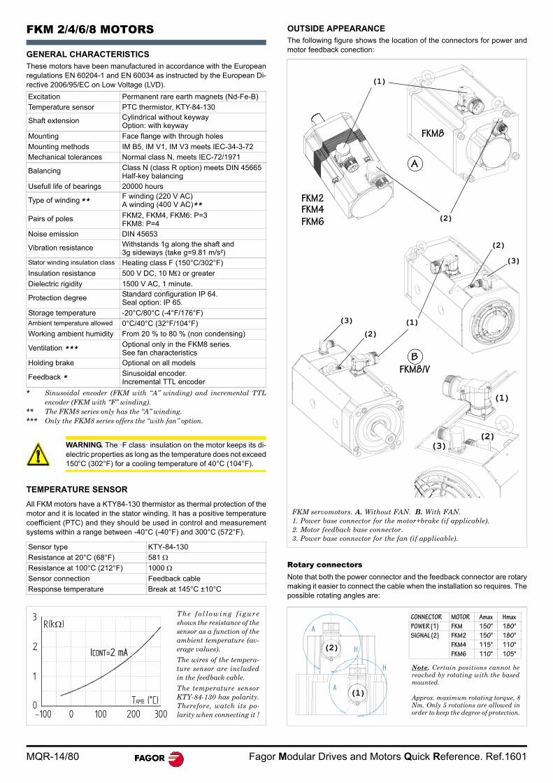
FKM 2/4/6/8 MOTORS
GENERAL CHARACTERISTICSThese motors have been manufactured in accordance with the Europeanregulations EN 60204-1 and EN 60034 as instructed by the European Di-rective 2006/95/EC on Low Voltage (LVD).
TEMPERATURE SENSOR
All FKM motors have a KTY84-130 thermistor as thermal protection of themotor and it is located in the stator winding. It has a positive temperaturecoefficient (PTC) and they should be used in control and measurementsystems within a range between -40°C (-40°F) and 300°C (572°F).
OUTSIDE APPEARANCEThe following figure shows the location of the connectors for power andmotor feedback conection:
Rotary connectorsNote that both the power connector and the feedback connector are rotarymaking it easier to connect the cable when the installation so requires. Thepossible rotating angles are:
Excitation Permanent rare earth magnets (Nd-Fe-B)
Temperature sensor PTC thermistor, KTY-84-130
Shaft extension Cylindrical without keywayOption: with keyway
Mounting Face flange with through holes
Mounting methods IM B5, IM V1, IM V3 meets IEC-34-3-72
Mechanical tolerances Normal class N, meets IEC-72/1971
Balancing Class N (class R option) meets DIN 45665Half-key balancing
Usefull life of bearings 20000 hours
Type of winding ** F winding (220 V AC)A winding (400 V AC)**
Pairs of poles FKM2, FKM4, FKM6: P=3FKM8: P=4
Noise emission DIN 45653
Vibration resistance Withstands 1g along the shaft and 3g sideways (take g=9.81 m/s²)
Stator winding insulation class Heating class F (150°C/302°F)
Insulation resistance 500 V DC, 10 M or greater
Dielectric rigidity 1500 V AC, 1 minute.
Protection degree Standard configuration IP 64.Seal option: IP 65.
Storage temperature -20°C/80°C (-4°F/176°F)Ambient temperature allowed 0°C/40°C (32°F/104°F)Working ambient humidity From 20 % to 80 % (non condensing)
Ventilation *** Optional only in the FKM8 series.See fan characteristics
Holding brake Optional on all models
Feedback * Sinusoidal encoder.Incremental TTL encoder
* Sinusoidal encoder (FKM with “A” winding) and incremental TTLencoder (FKM with “F” winding).
** The FKM8 series only has the “A” winding.*** Only the FKM8 series offers the “with fan” option.
WARNING. The ·F class· insulation on the motor keeps its di-electric properties as long as the temperature does not exceed150°C (302°F) for a cooling temperature of 40°C (104°F).
Sensor type KTY-84-130
Resistance at 20°C (68°F) 581 Resistance at 100°C (212°F) 1000 Sensor connection Feedback cable
Response temperature Break at 145°C ±10°C
TAMB (°C)
R(k
ICONT=2 mA
)
0
1
2
The fo l lowing f igureshows the resistance of thesensor as a function of theambient temperature (av-erage values).
The wires of the tempera-ture sensor are includedin the feedback cable.
The temperature sensorKTY-84-130 has polarity.Therefore, watch its po-larity when connecting it !
FKM8
FKM2
(2)
(1)
FKM servomotors. A. Without FAN. B. With FAN.1. Power base connector for the motor+brake (if applicable).2. Motor feedback base connector. 3. Power base connector for the fan (if applicable).
FKM4
FKM6
(1)(2)
(3)
(3)(2)
FKM8/V
(1)
(2)(3)
B
A
CONNECTOR MOTOR Amax Hmax
POWER (1) FKM 150° 180°
SIGNAL (2) FKM2 150° 180°
FKM4 115° 110°
FKM6 110° 105°
Note. Certain positions cannot bereached by rotating with the basedmounted.
Approx. maximum rotating torque, 8Nm. Only 5 rotations are allowed inorder to keep the degree of protection.
A
A
H
H
(1)
(2)
Fagor Modular Drives and Motors Quick Reference. Ref.1601 MQR-15/80
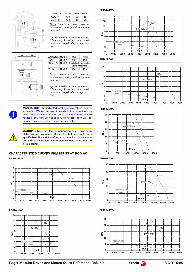
CHARACTERISTICS CURVES. FKM SERIES AT 400 V AC
FKM21.60A
FKM22.30A
FKM22.50A
FKM22.60A
FKM42.30A
FKM42.45A
FKM42.60A
MANDATORY. The indicated rotating angle values must beexceeded. We recommend to rotate both connectors onlywhen necessary and not too often. The more times they arerotated, the torque necessary to rotate them will de-crease.They must not be forced permanently.
WARNING. Note that the corresponding cable must be in-stalled on each connector. Remember that each cable has aspecific flexibility and, therefore, when handling the connectorwith the cable installed, its maximum bending radius must notbe exceeded.
CONNECTOR MOTOR Amax. Hmax.
POWER (1) FKM8 200° 110°
SIGNAL (2) FKM8 110° 105°
Note. Certain positions cannot bereached by rotating with the basedmounted.
Approx. maximum rotating torque,8 Nm. Only 5 rotations are allowedin order to keep the degree of protec-tion.
A
A
H
H
(1)
(2)
A
H
FIJO
A
H
(1)
(2)
(3)
FIXED
CONNECTOR MOTOR Amax Hmax
POWER (1) FKM8/V 200° 110°
SIGNAL (2) FKM8/V Keep it fixed in the position shown in the image
FAN (3) FKM8/V 110° 105°
Note. Certain positions cannot bereached by rotating with the basedmounted.
Approx. maximum rotating torque,8 Nm. Only 5 rotations are allowedin order to keep the degree of protec-tion.
0
1
2
3
4
5
6
Nm
1/min
FKM21.60A
400V-15%
400V
0 1000 2000 3000 4000 50000
2
4
6
8
10
Nm
12
14
FKM22.30A
1/min
400V-15%
400V
400V-15%
400V
0
2
4
6
8
10
12
14
0 1000 2000 3000 4000 5000 6000 7000 8000
FKM22.50A
1/min
400V-15%
400V
0
2
4
6
8
10
12
14
0 1000 2000 3000 4000 5000 6000 7000 8000 9000
FKM22.60A
1/min
10000
2000 3000 4000 5000
1/min
5
0
10
15
20
25
FKM42.30A
400V-15%
400V
Nm
0 1000 2000 3000 4000 5000 6000 70000
5
10
Nm
15
20
25
1/min
FKM42.45A
400V-15%
400V
0 1000 2000 3000 4000 5000 6000 70000
5
10
15
20
25
8000 9000
FKM42.60A
1/min
400V-15%
400V
MQR-16/80 Fagor Modular Drives and Motors Quick Reference. Ref.1601
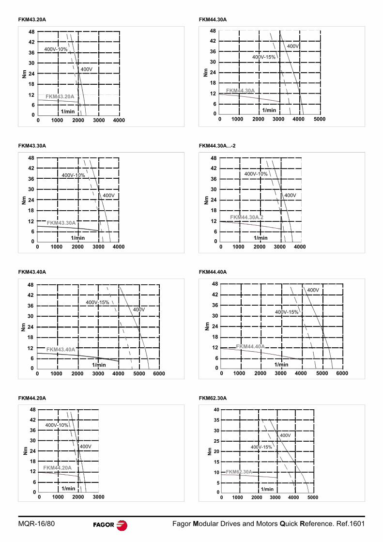
FKM43.20A
FKM43.30A
FKM43.40A
FKM44.20A
FKM44.30A
FKM44.30A...-2
FKM44.40A
FKM62.30A
FKM43.20A
48
1/min
42
36
30
24
18
12
6
010000 2000 3000 4000
400V-10%
400V
42
36
30
24
18
12
6
0
Nm
10000 2000 3000 4000
400V
400V-10%
FKM43.30A
1/min
48
42
36
30
24
18
12
6
010000 2000 3000 4000 5000 6000
400V-15%
400V
1/min
FKM43.40A
0 1000 2000 3000
12
6
0
18
24
30
36
42
48
FKM44.20A
1/min
400V-10%
400V
FKM44.30A
1/min
400V-15%
400V
0 1000 2000 3000 4000 50000
6
12
18
24
30
36
42
48
0
6
12
Nm
18
24
30
36
42
48
0 1000 2000 3000 4000
FKM44.30A.2
1/min
400V-10%
400V
0 1000 2000 3000 4000 5000 60000
6
12
Nm
18
24
30
36
42
1/min
FKM44.40A
400V-15%
400V
0 1000 2000 3000 4000 50000
5
10
Nm
15
20
25
30
35
40
1/min
FKM62.30A
400V-15%
400V
Fagor Modular Drives and Motors Quick Reference. Ref.1601 MQR-17/80
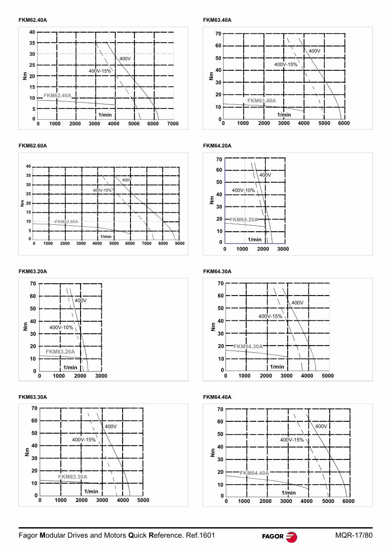
FKM62.40A
FKM62.60A
FKM63.20A
FKM63.30A
FKM63.40A
FKM64.20A
FKM64.30A
FKM64.40A
0 1000 2000 3000 4000 5000 6000 70000
5
10
Nm
15
20
25
30
35
40
1/min
FKM62.40A
400V-15%
400V
400V-15%
400V
0
5
10
Nm
15
20
25
30
35
40
0 1000 2000 3000 4000 5000 6000 7000 8000 9000
FKM62.60A
1/min
FKM63.20A
10000 2000 3000
1/min 0
Nm
10
20
30
40
50
60
70
400V-10%
400V
1/min
FKM63.30A
400V-15%
400V
40
0
Nm
10
20
30
50
60
10000 2000 3000 4000 5000
40
0
Nm
10
20
30
50
60
10000 2000 3000 4000 5000 6000
1/min
FKM63.40A
400V-15%
400V
0 1000 2000 30000
10
20N
m30
40
50
60
70
1/min
FKM64.20A
400V-10%
400V
0 1000 2000 3000 4000 50000
10
20
Nm
30
40
50
60
FKM64.30A
1/min
400V-15%
400V
0 1000 2000 3000 4000 5000 60000
20
Nm
30
40
50
60
70
10
FKM64.40A
1/min
400V-15%
400V
MQR-18/80 Fagor Modular Drives and Motors Quick Reference. Ref.1601
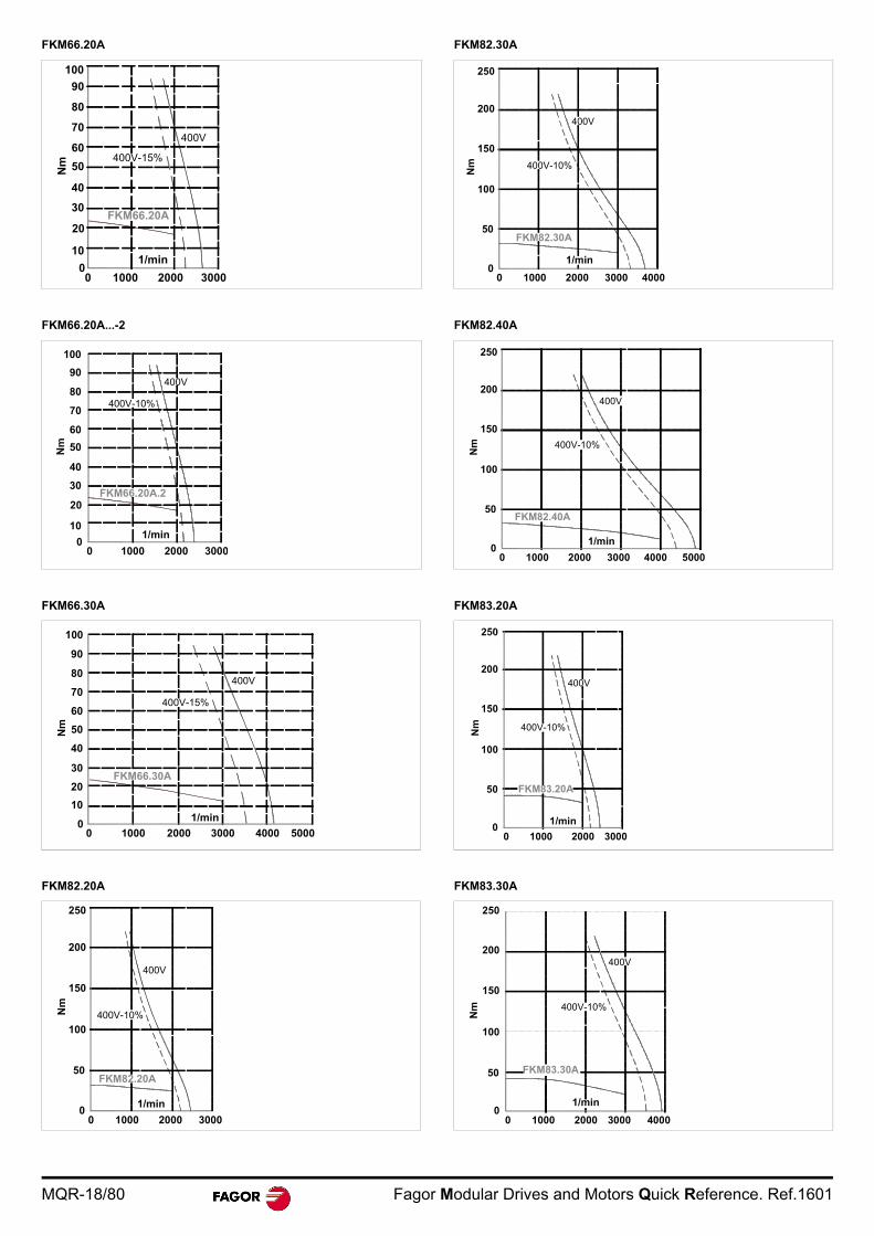
FKM66.20A
FKM66.20A...-2
FKM66.30A
FKM82.20A
FKM82.30A
FKM82.40A
FKM83.20A
FKM83.30A
0 1000 2000 30000
20
Nm
30
40
50
60
70
10
80
90
100
FKM66.20A
1/min
400V-15%
400V
400V-10%
400V
FKM66.20A.2
0 1000 2000
1/min0
20
30
40
50
60
70
10
80
90
100
0
10
20
30
40
50
60
70
80
90
100
1/min
FKM66.30A
Nm
0 1000 2000 3000 4000 5000
400V-15%
400V
400V-10%
400V
1/min
50
0
100
150
200
Nm
0 1000 2000 3000
FKM82.20A
250
FKM82.30A
0 1000 2000 3000 4000
50
0
100
150
200
250
Nm
1/min
400V-10%
400V
FKM82.40A
0 1000 2000 3000 4000 5000
1/min
50
0
100
150
200
250
Nm 400V-10%
400V
FKM83.20A
1/min
0 1000 2000 30000
50
100
150
200
Nm 400V-10%
400V
400V-10%
400V
0 1000 2000 3000 4000
FKM83.30A
250
200
150
100
50
0
Nm
1/min
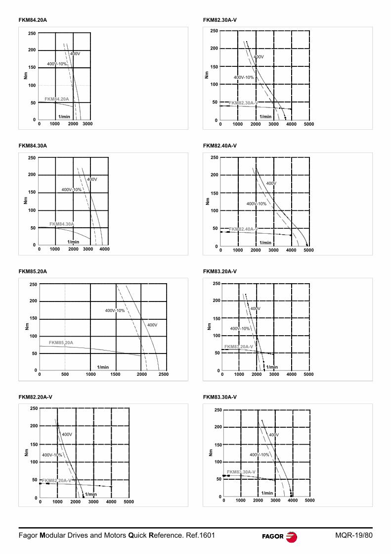
Fagor Modular Drives and Motors Quick Reference. Ref.1601 MQR-19/80
FKM84.20A
FKM84.30A
FKM85.20A
FKM82.20A-V
FKM82.30A-V
FKM82.40A-V
FKM83.20A-V
FKM83.30A-V
FKM84.20A
0 1000 2000 30000
50
100
150
200
250
Nm
1/min
400V-10%
400V
FKM84.30A
0
50
100
150
200
250
0 1000 2000 3000 4000
1/min
400V-10%
400V
2500
FKM85.20A
0
50
100
150
200
250
Nm
2000150010005000
1/min
400V-10%
400V
0 1000 2000 3000 4000 5000
50
0
100
150
200
Nm
FKM82.20A-V
250
1/min
400V-10%
400V
400V-10%
400V
0 1000 2000 3000 4000 5000
50
0
100
150
200
250
Nm
FKM82.30A-V
1/min
400V-10%
400V
0 1000 2000 3000 4000 5000
50
0
100
150
200
250
Nm
FKM82.40A-V
1/min
50
0
100
150
200
250
0 1000 2000 3000 4000 5000
FKM83.20A-V
400V-10%
400V
Nm
1/min
50
0
100
150
200
250
0 1000 2000 3000 4000 5000
FKM83.30A-V
400V-10%
400V
Nm
1/min
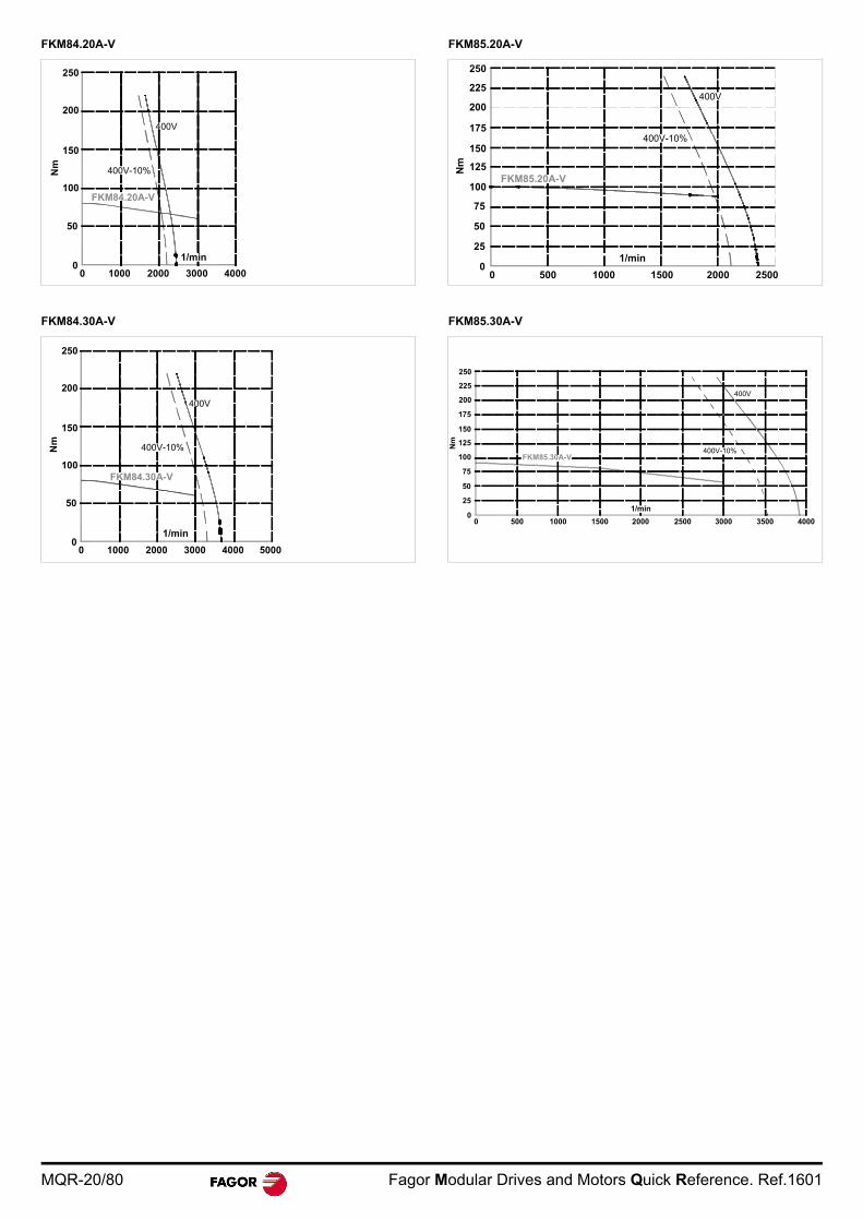
MQR-20/80 Fagor Modular Drives and Motors Quick Reference. Ref.1601
FKM84.20A-V
FKM84.30A-V
FKM85.20A-V
FKM85.30A-V
50
0
100
150
200
250
0 1000 2000 3000 4000
FKM84.20A-V
400V-10%
400V
Nm
1/min
50
0
100
150
200
250
0 1000 2000 3000 4000 5000
FKM84.30A-V
400V-10%
400V
Nm
1/min
50
0
100
150
200
25
75
125
175
225
0 500 1000 1500 2000 2500
FKM85.20A-V
400V-10%
400V
Nm
1/min
400V-10%
400V
100
0
Nm
25
50
75
125
150
175
200
225
250
5000
1/min
1000 1500 2000 2500 3000 3500 4000
FKM85.30A-V
Fagor Modular Drives and Motors Quick Reference. Ref.1601 MQR-21/80
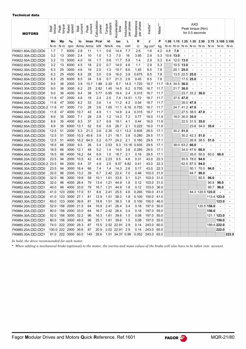
Technical data
MOTORS
Sta
ll
torq
ue
Pe
ak
torq
ue
Rat
ed
spee
d
Sta
ll
curr
ent
Pe
ak
curr
ent
Cal
cula
tion
pow
er
Tor
que
co
nsta
nt
Acc
eler
atio
n tim
e
Indu
cta
nce
per
phas
e
Res
ista
nce
per
phas
e
Ine
rtia
*
Ma
ss** AXD
Peak torque (Nm) for 0.5 seconds
Mo Mp nN Io Imax Pcal kt tac L R J P 1.08 1.15 1.25 1.35 2.50 2.75 3.100 3.150
N·m N·m rpm Arms Arms kW Nm/A ms mH kg·cm² kg N·m N·m N·m N·m N·m N·m N·m N·m
FKM21.60A..0 1.7 7 6000 2.8 11 1.1 0.6 14.4 7.7 2.6 1.6 4.2 4.8 7.0 - - - - - -
FKM22.30A..0 3.2 13 3000 2.4 10 1.0 1.3 7.0 16 3.95 2.9 5.3 10.6 13.0 - - - - - -
FKM22.50A..0 3.2 13 5000 4.0 16 1.7 0.8 11.7 5.8 1.4 2.9 5.3 6.4 12.0 13.0 - - - - -
FKM22.60A..0 3.2 13 6000 4.5 18 2.0 0.7 14.0 4.6 1.1 2.9 5.3 10.5 13.0 - - - - -
FKM42.30A..0 6.3 25 3000 4.6 19 2.0 1.3 10.7 8.6 1.45 8.5 7.8 20.1 25.0 - - - - -
FKM42.45A..0 6.3 25 4500 6.9 28 3.0 0.9 16.0 3.9 0.675 8.5 7.8 13.5 22.5 25.0 - - - -
FKM42.60A..0 6.3 25 6000 8.5 34 3.9 0.7 21.3 2.6 0.45 8.5 7.8 17.5 25.0 - - - -
FKM43.20A..0 9.0 36 2000 3.9 15.7 1.88 2.30 9.7 14.5 1.720 16.7 11.7 18.4 34.5 36.0 - - - - -
FKM43.30A..0 9.0 36 3000 6.2 25 2.82 1.45 14.5 6.2 0.755 16.7 11.7 21.7 36.0 - - - - -
FKM43.40A..0 9.0 36 4000 9.4 38 3.77 0.95 19.4 2.4 0.315 16.7 11.7 23.7 33.2 36.0 - - -
FKM44.20A..0 11.6 47 2000 4.6 19 2.4 2.5 7.4 14.51 1.72 16.7 11.7 37.5 47.0 - - - - -
FKM44.30A..0 11.6 47 3000 8.2 33 3.6 1.4 11.2 4.2 0.54 16.7 11.7 35.0 47.0 - - - -
FKM44.30A..0.2 11.6 47 3000 7.0 28 3.6 1.65 11.1 6.16 0.755 16.7 11.7 24.7 41.2 47.0 - - - -
FKM44.40A..0 11.6 47 4000 10.7 43 4.9 1.1 14.9 2.4 0.315 16.7 11.7 27.5 38.5 47.0 - - -
FKM62.30A..0 8.9 35 3000 7.1 28 2.8 1.2 14.3 7.2 0.77 16.0 11.9 18.0 30.0 35.0 - - - -
FKM62.40A..0 8.9 35 4000 9.3 37 3.7 0.9 19.1 4.1 0.44 16.0 11.9 22.5 31.5 35.0 - - -
FKM62.60A..0 8.9 35 6000 13.1 52 5.6 0.6 28.7 2.1 0.225 16.0 11.9 23.8 34.0 35.0 - -
FKM63.20A..0 12.5 51 2000 5.3 21.3 2.6 2.35 12.1 13.2 0.935 29.5 17.1 35.2 51.0 - - - - -
FKM63.30A..0 12.5 51 3000 10.3 40.6 3.9 1.21 18.1 3.8 0.280 29.5 17.1 30.2 42.3 51.0 - - -
FKM63.40A..0 12.5 51 4000 16.2 64.0 5.2 0.77 24.2 2.1 0.160 29.5 17.1 26.9 38.5 51.0 - -
FKM64.20A..0 16.5 66 2000 6.5 26 3.4 2.53 9.3 13.16 0.935 29.5 17.1 38.0 63.2 66.0 - - - -
FKM64.30A..0 16.5 66 3000 12.1 48 5.2 1.4 14.0 3.8 0.285 29.5 17.1 34.0 47.6 66.0 - - -
FKM64.40A..0 16.5 66 4000 16,2 64 6.9 1.0 18.7 2.1 0.16 29.5 17.1 35.0 50.0 63.0 66.0 -
FKM66.20A..0 23.5 94 2000 10,5 42 4.9 2.23 9.5 4.6 0.31 43.0 22.3 55.9 78.0 94.0 - - -
FKM66.20A..0.2 23.5 94 2000 9.4 37 4.9 2.5 9.57 8.82 0.41 43.0 22.3 62.5 87.5 94.0 - - -
FKM66.30A..0 23.5 94 3000 16.4 66 7.4 1.4 14.3 2.6 0.17 43.0 22.3 50.1 70.0 94.0 - -
FKM82.20A..0 32.0 96 2000 13.2 39 6.7 2.42 22.4 7.0 0.48 103.0 31.0 84.7 96.0 - - -
FKM82.30A..0 32.0 96 3000 19.8 59 10.1 1.61 33.6 3.1 0.21 103.0 31.0 80.5 96.0 - -
FKM82.40A..0 32.0 96 4000 26.4 79 13.4 1.21 44.9 1.8 0.12 103.0 31.0 90.9 96.0 -
FKM82.40A..1 40.0 96 4000 33.0 79 16.7 1.21 44.9 1.8 0.12 103.0 36.0 90.7 96.0 -
FKM83.20A..0 41.0 123 2000 17.0 51 8.6 2.41 25.5 4.6 0.265 150.0 41.0 84.3 120.5 123.0 - -
FKM83.30A..0 41.0 123 3000 27.1 81 12.9 1.51 38.3 1.8 0.100 150.0 41.0 113.4 123.0 -
FKM83.30A..1 60.0 123 3000 39.6 81 18.8 1.51 38.3 1.8 0.100 150.0 46.0 123.0 -
FKM84.20A..0 52.0 156 2000 21.5 64 10.9 2.41 26.4 3.4 0.18 197.0 50.0 120.5 156.0 - -
FKM84.20A..1 80.0 156 2000 33.0 64 16.7 2.42 26.4 3.4 0.18 197.0 55.0 156.0 - -
FKM84.30A..0 52.0 156 3000 32.2 96 16.3 1.61 39.6 1.5 0.08 197.0 50.0 121.1 123.0 -
FKM84.30A..1 80.0 156 3000 49.5 96 25.1 1.61 39.6 1.5 0.08 197.0 55.0 156.0 -
FKM85.20A..0 74.0 222 2000 29.3 87 15.5 2.52 22.91 2.9 0.14 243.0 60.0 189.4 222.0 -
FKM85.20A..1 100.0 222 2000 39.6 87 20.9 2.52 22.91 2.9 0.14 243.0 65.0 222.0 -
FKM85.30A..1 91.0 222 3000 60.0 145 28.6 1.51 34.37 0.99 0.052 243.0 65.0 222.0
In bold, the drive recommended for each motor.
* When adding a mechanical brake (optional) to the motor, the inertia and mass values of the brake will also have to be taken into account.
MQR-22/80 Fagor Modular Drives and Motors Quick Reference. Ref.1601
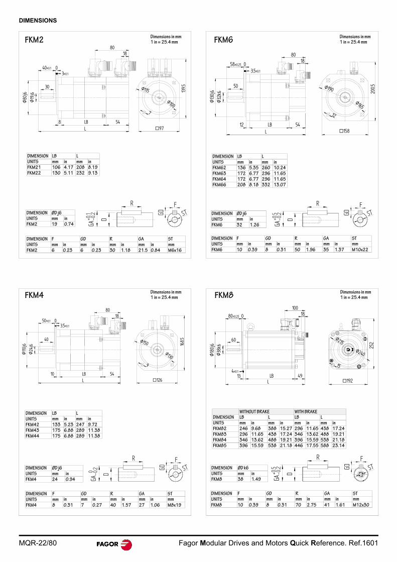
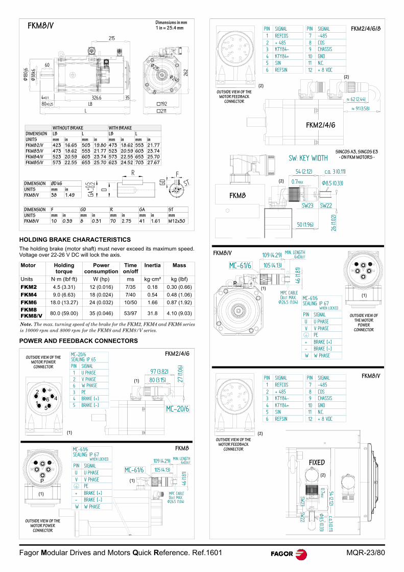
DIMENSIONS
8018
40±0.1 03±0.1
Ø80
j6Ø
19j6
30
8 54LBL 97
139.5
7
Ø100
Ø115
DIMENSION LB LUNITS mm in mm inFKM21 106 4.17 208 8.19FKM22 130 5.11 232 9.13
DIMENSION ØD j6UNITS mm inFKM2 19 0.74
DIMENSION F GD R GA STUNITS mm in mm in mm in mm in mmFKM2 6 0.23 6 0.23 30 1.18 21.5 0.84 M6x16
D
GA
GD
FST
-0.2
FKM2Dimensions in mm1 in = 25.4 mm
8018
50±0.1 03.5±0.1
Ø24
j6Ø
110j
6
40
10 54LBL 126
168.5
9
Ø130
Ø150
D
GA
GD
FST
-0.20
DIMENSION LB LUNITS mm in mm in
FKM42 133 5.23 247 9.72FKM43 175 6.88 289 11.38FKM44 175 6.88 289 11.38
DIMENSION ØD j6UNITS mm inFKM4 24 0.94
DIMENSION F GD R GA STUNITS mm in mm in mm in mm in mm
FKM4 8 0.31 7 0.27 40 1.57 27 1.06 M8x19
FKM4Dimensions in mm1 in = 25.4 mm
200.5
12
03.5±0.1
50
Ø32
k6
Ø165
Ø190
12 54LBL 158
1858±0.25
DIMENSION LB LUNITS mm in mm inFKM62 136 5.35 260 10.24FKM63 172 6.77 296 11.65FKM64 172 6.77 296 11.65FKM66 208 8.18 332 13.07
DIMENSION ØD j6UNITS mm in
FKM6 32 1.26
DIMENSION F GD R GA STUNITS mm in mm in mm in mm in mm
FKM6 10 0.39 8 0.31 50 1.96 35 1.37 M10x22
D
GA
GD
FST
-0.2
FKM6Dimensions in mm1 in = 25.4 mm
252
15
Ø215
192
Ø240
60
80±0.25 0
10018
4±0.113 49LB
L
Ø38
k6Ø
180j
6
D
GA-0
.2+0
.5 GD
FST
WITHOUT BRAKE WITH BRAKEDIMENSION LB L LB LUNITS mm in mm in mm in mm inFKM82 246 9.68 388 15.27 296 11.65 438 17.24FKM83 296 11.65 438 17.24 346 13.62 488 19.21FKM84 346 13.62 488 19.21 396 15.59 538 21.18FKM85 396 15.59 538 21.18 446 17.55 588 23.14
DIMENSION ØD k6UNITS mm inFKM8 38 1.49
DIMENSION F GD R GA STUNITS mm in mm in mm in mm in mm
FKM8 10 0.39 8 0.31 70 2.75 41 1.61 M12x30
FKM8Dimensions in mm1 in = 25.4 mm
Fagor Modular Drives and Motors Quick Reference. Ref.1601 MQR-23/80
HOLDING BRAKE CHARACTERISTICS
The holding brake (motor shaft) must never exceed its maximum speed.Voltage over 22-26 V DC will lock the axis.
POWER AND FEEDBACK CONNECTORS
Motor Holding torque
Power consumption
Time on/off
Inertia Mass
Units N·m (lbf·ft) W (hp) ms kg·cm² kg (lbf)
FKM2 4.5 (3.31) 12 (0.016) 7/35 0.18 0.30 (0.66)
FKM4 9.0 (6.63) 18 (0.024) 7/40 0.54 0.48 (1.06)
FKM6 18.0 (13.27) 24 (0.032) 10/50 1.66 0.87 (1.92)
FKM8FKM8/V 80.0 (59.00) 35 (0.046) 53/97 31.8 4.10 (9.03)
Note. The max. turning speed of the brake for the FKM2, FKM4 and FKM6 seriesis 10000 rpm and 8000 rpm for the FKM8 and FKM8/V series.
262
192211
15
Ø215
Ø240
215
Ø18
0j6
Ø38
k6
60
LLB
326.6 354±0.1
80±0.25D
GA-0
.2+0
.5 GD
FST
WITHOUT BRAKE WITH BRAKEDIMENSION LB L LB LUNITS mm in mm in mm in mm inFKM82/V 423 16.65 503 19.80 473 18.62 553 21.77FKM83/V 473 18.62 553 21.77 523 20.59 603 23.74FKM84/V 523 20.59 603 23.74 573 22.55 653 25.70FKM85/V 573 22.55 653 25.70 623 24.52 703 27.67
DIMENSION ØD k6UNITS mm inFKM8/V 38 1.49
DIMENSION F GD R GA STUNITS mm in mm in mm in mm in mmFKM8/V 10 0.39 8 0.31 70 2.75 41 1.61 M12x30
FKM8/VDimensions in mm1 in = 25.4 mm
97 (3.82)80 (3.15) 27
(1.06
)
MC-20/6
OUTSIDE VIEW OF THE MOTOR POWER
CONNECTOR
1
24
5
6
(1)
FKM2/4/6MC-20/6SEALING: IP 65PIN SIGNAL126345
U PHASEV PHASEW PHASEPEBRAKE [+]BRAKE [-]
(1)
MC-61/6
MPC CABLEDOUT MAX.
Ø26.5 (1.04)
109 (4.29)
105 (4.13)
MIN. LENGTH6xDOUT
46(1.
81)
(1)
(1)
P
WHEN LOCKED
MC-61/6SEALING: IP 67
PIN SIGNALUV
+-W
U PHASEV PHASEPEBRAKE [+]BRAKE [-]W PHASE
OUTSIDE VIEW OF THE MOTOR POWER
CONNECTOR
FKM8
FKM8/V
54(2.12)
0.7MAX
Ø8.5
(0.33)
c.a.3(0.11)
SW23
SW22
OUTSIDE VIEW OF THE MOTOR FEEDBACK
CONNECTOR
(2)
(2)
PIN SIGNAL123456
REFCOS+ 485KTY84-KTY84+SINREFSIN
PIN SIGNAL78910
-485COSCHASSISGNDN.C.+ 8 VDC
1112
MC-61/6
MPC CABLEDOUT MAX.
Ø26.5 (1.04)
109 (4.29)
105 (4.13)
MIN. LENGTH6xDOUT
46(1.
81)
(1)
54 (2.12)
0.7MAX Ø8.5 (0.33)
50 (1.96)
26(1.
02)
c.a. 3 (0.11)
SW23 SW22
SW: KEY WIDTH
PIN SIGNAL123456
REFCOS+ 485KTY84-KTY84+SINREFSIN
PIN SIGNAL78910
-485COSCHASSISGNDN.C.+ 8 VDC
1112
62 (2.44)
91 (3.58)
SINCOS A3, SINCOS E3- ON FKM MOTORS -
OUTSIDE VIEW OF THE MOTOR FEEDBACK
CONNECTOR
(2)
FKM2/4/6/8
(2)
FKM2/4/6
(2)
FKM8
FKM8/V
(1)
P
OUTSIDE VIEW OF THE MOTOR
POWERCONNECTOR
WHEN LOCKED
MC-61/6SEALING: IP 67
PIN SIGNALUV
+-W
U PHASEV PHASEPEBRAKE [+]BRAKE [-]W PHASE
FIXED
MQR-24/80 Fagor Modular Drives and Motors Quick Reference. Ref.1601
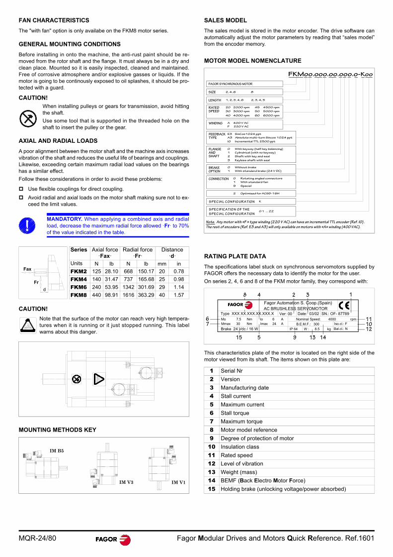
FAN CHARACTERISTICS
The "with fan" option is only availabe on the FKM8 motor series.
GENERAL MOUNTING CONDITIONS
Before installing in onto the machine, the anti-rust paint should be re-moved from the rotor shaft and the flange. It must always be in a dry andclean place. Mounted so it is easily inspected, cleaned and maintained.Free of corrosive atmosphere and/or explosive gasses or liquids. If themotor is going to be continously exposed to oil splashes, it should be pro-tected with a guard.
CAUTION!When installing pulleys or gears for transmission, avoid hittingthe shaft.
Use some tool that is supported in the threaded hole on theshaft to insert the pulley or the gear.
AXIAL AND RADIAL LOADS
A poor alignment between the motor shaft and the machine axis increasesvibration of the shaft and reduces the useful life of bearings and couplings.Likewise, exceeding certain maximum radial load values on the bearingshas a similar effect.
Follow these considerations in order to avoid these problems:
Use flexible couplings for direct coupling.
Avoid radial and axial loads on the motor shaft making sure not to ex-ceed the limit values.
CAUTION!
MOUNTING METHODS KEY
SALES MODEL
The sales model is stored in the motor encoder. The drive software canautomatically adjust the motor parameters by reading that “sales model”from the encoder memory.
MOTOR MODEL NOMENCLATURE
RATING PLATE DATA
The specifications label stuck on synchronous servomotors supplied byFAGOR offers the necessary data to identify the motor for the user.
On series 2, 4, 6 and 8 of the FKM motor family, they correspond with:
This characteristics plate of the motor is located on the right side of themotor viewed from its shaft. The items shown on this plate are:
MANDATORY. When applying a combined axis and radialload, decrease the maximum radial force allowed ·Fr· to 70%of the value indicated in the table.
Series Axial force ·Fax·
Radial force·Fr·
Distance·d·
Units N lb N lb mm in
FKM2 125 28.10 668 150.17 20 0.78
FKM4 140 31.47 737 165.68 25 0.98
FKM6 240 53.95 1342 301.69 29 1.14
FKM8 440 98.91 1616 363.29 40 1.57
Note that the surface of the motor can reach very high tempera-tures when it is running or it just stopped running. This labelwarns about this danger.
Fax
Fr
d
IM B5
IM V3 IM V1
1 Serial Nr
2 Version
3 Manufacturing date
4 Stall current
5 Maximum current
6 Stall torque
7 Maximum torque
8 Motor model reference
9 Degree of protection of motor
10 Insulation class
11 Rated speed
12 Level of vibration
13 Weight (mass)
14 BEMF (Back Electro Motor Force)
15 Holding brake (unlocking voltage/power absorbed)
FAGOR SYNCHRONOUS MOTOR
FKMoo.ooo.oo.ooo.o-Koo
SIZE 2, 4, 6 8
RATEDSPEED
LENGTH 1, 2, 3, 4, 6 2, 3, 4, 5
20 2000 rpm
30 3000 rpm
45 4500 rpm
50 5000 rpm
WINDING A 400 V AC
F 220 V AC
E3 SinCos1024 ppt
A3 Absolute multi-turn Sincos 1024 ppt
FEEDBACKTYPE
I0 Incremental TTL 2500 ppt
0 With keyway (half-key balancing)
1 Cylindrical (with no keyway)
FLANGEANDSHAFT
BRAKEOPTION
0 Without brake
1 With standard brake (24 V DC)
CONNECTION 0 Rotating angled connectors
1 With standard fan
S PEC IA L C O N FIG UR A TIO N K
S PEC IFICA TIO N O F TH E
S PEC IA L C O N FIG UR A TIO N 0 1 ... ZZ
Note. Any motor with «F » type winding (220 V AC) can have an incremental TTL encoder (Ref. I0) .
The rest of encoders (Ref. E3 and A3) will only available on motors with «A» winding (400 VAC).
40 4000 rpm 60 6000 rpm
2 Shaft with key and seal
3 Keyless shaft with seal
9 Special
2 Optimized for ACSD-16H
Fagor Automation S. Coop.(Spain)AC BRUSHLESS SERVOMOTOR
Type XXX XX.XXX.XX.XXX.XMo 7.5 Nm
Mmax 30 Nm
Ver: 00 Date: 03/02 SN.: OF- 87789Io 6 A
Imax 24 A
Nominal Speed: 4000 rpm
B.E.M.F.: 300 Iso.cl.: F
Bal.cl.: N W : 8.5 kg IP 64
8
Brake 24 Vdc / 16 W
4 2 3 1
111012
14139515
76

Fagor Modular Drives and Motors Quick Reference. Ref.1601 MQR-25/80
FKM9 MOTORS
GENERAL CHARACTERISTICSThese motors have been manufactured in accordance with the Europeanregulations EN 60204-1 and EN 60034 as instructed by the European Di-rective 2006/95/EC on Low Voltage (LVD).
TEMPERATURE SENSORKTY-84-130 series sensors have a positive temperature coefficient (PTC)and they should be used in control and measurement systems within arange between -40°C (-40°F) and 300°C (572°F).
OUTSIDE APPEARANCEThe following figure shows the location of the connectors for power andmotor feedback conection:
Note that both the power connector and the feedback connector are rotarymaking it easier to connect the cable when the installation so requires.
Rotary connectors
CHARACTERISTICS CURVES. FKM9 SERIES AT 400 V AC
FKM94.20A
FKM95.20A
FKM96.20A
Excitation Permanent Neodymium magnets
Temperature sensor PTC thermistor KTY84-130
Shaft end Cylindrical without keywayOptionally: with keyway
Mounting Face flange
Mounting methods IM B5 - IM V1 - IM V3 (as recommended by IEC-34-3-72)
Mechanical tolerances Normal class N(meets IEC-72/1971)
Balancing Class N, (class R optional) (DIN 45665)
Type of winding A winding (400 V AC)
Pairs of poles P=3Noise DIN 45653Stator winding insulation Heating class F (150°C/302°F)
Storage temperature -20°C/80°C (-4°F/176°F)Ambient temperature -20°C/40°C (-4°F/104°F)
Working ambient humidity From 15 % to 85 % (non condensing)Fan Not available
Holding brake Optional only on FKM94 & FKM95 models
Feedback Sinusoidal encoder
WARNING. The · F class · insulation of the windings keeps itsdielectric properties as long as the temperature stays under150°C (302°F).
Sensor type KTY-84-130
Resistance at 20 °C (68 °F) 581 Resistance at 100 °C (212 °F) 1000 Sensor connection Feedback cable
Motor series FKM9
The following figure shows theresistance of the sensor as afunction of the ambient tem-perature (average values).
The wires of the temperaturesensor are included in the feed-back cable.
TAMB (°C)
R(k
ICONT=2 mA
)
0
1
2
The temperature sensor KTY-84-130 has polarity. Therefore,watch its polarity when con-necting it !
(1)
(2)
1. Motor power base connector+brake(if applicable).
2. Motor feedback base connector.
MANDATORY. Do not try to exceed the indicated rotating an-gle values. We recommend to rotate both connectors onlywhen necessary and very seldom. Remember that the moreoften it is rotated the less torque will be needed to rotate it.
WARNING. Note that the corresponding cable must be installedon each connector. Remember that each cable has a specificflexibility and, therefore, when handling the connector with thecable installed, its maximum bending radius must not be ex-ceeded.
CONNECTOR MOTOR Amax Hmax
POWER (1) FKM9 200° 110°
SIGNAL (2) FKM9 110° 105°
Note. Certain positions cannot bereached by rotating with the basedmounted.
Approx. maximum rotating torque,8 Nm. Only 5 rotations are allowedin order to keep the degree of pro-tection.
A
A
H
H
(1)
(2)
FKM94.20A
0
50
100
Nm
150
200
250
1/min 1320
5680.8
2190
68
204
0 500 1000 1500 2000 2500
FKM95.20A
0
50
100
Nm
150
200
250
300
350
0 500 1000 1500 2000 2500
93
279
13101/min70
76.5
2090
0
50
100
Nm
150
200
250
300
350
400
0 500 1000 1500 2000 2500
115FKM96.20A
345
1410
85
139
21501/min

MQR-26/80 Fagor Modular Drives and Motors Quick Reference. Ref.1601
Technical data
DIMENSIONS
POWER CONNECTOR
FEEDBACK CONNECTOR
BRAKE CHARACTERISTICS
The brake (motor shaft) must never exceed its maximum speed. Voltageover 26 V will lock the axis.
The FKM96 model does not offer the brake option.
FAN CHARACTERISTICS
FKM9 motors do not offer the fan in any of their models.
GENERAL MOUNTING CONDITIONS
Before installing in onto the machine, the anti-rust paint should be re-moved from the rotor shaft and the flange. It must always be in a dry andclean place. Mounted so it is easily inspected, cleaned and maintained.Free of corrosive atmosphere and/or explosive gasses or liquids. If themotor is going to be continously exposed to oil splashes, it should be pro-tected with a guard.
CAUTION!
When installing pulleys or gears for transmission, avoid hittingthe shaft. Use some tool that is supported in the threaded holeon the shaft to insert the pulley or the gear.
MOTORS
Sta
ll
torq
ue
Pe
ak
torq
ue
Rat
ed
spee
d
Sta
ll
curr
ent
Pe
ak
curr
ent
Ca
lcu
latio
n p
owe
r
torq
ue
cons
tant
acce
lera
tion
tim
e
ind
ucta
nce
per
pha
se
resi
stan
ce
per
pha
se
Ine
rtia
*
mas
s Peak torque (Nm) for 0.5 seconds
Mo Mp nN Io Imax Pow kt tac L R J P 2.75 3.100 3.150
N·m N·m rpm Arms Arms kW Nm/Arms ms mH kg·cm² kg N·m N·m N·m
FKM94.20A..0 68 204 2000 25.4 99 14.2 2.7 11.69 3.15 0.120 430 56 170.1 204 -
FKM95.20A..0 93 279 2000 33.1 129 19.5 2.8 11.48 2.40 0.075 550 73 176.4 279 -
FKM96.20A..0 115 345 2000 42.1 164 24.0 2.7 11.52 1.70 0.055 660 89 270 334.8
In bold, the drive recommended for each motor.* When adding a mechanical brake (optional) to the motor, the inertia values of the brake will also have to be taken into account.
E
240
18
4 55
25
293
45
12
8 89.5 15
1
Ø23
0j6
ØDk
6
L
29
Ø265Ø300
14.5
K
FKM9 Dimensions in mm1 in = 25.4 mm
D
GD
FST
DIMENSION ØD k6
UNITS mm in
FKM94 38 1.49FKM95 42 1.65FKM96 42 1.65
The FKM96 model does not offer the brake option.
DIMENSION E L (without brake) L (with brake) K (without brake) K (with brake)
UNITS mm in mm in mm in mm in mm in
FKM94 80 3.14 527 20.7 621 24.4 392 15.4 486 19.1FKM95 110 4.33 625 24.6 720 28.3 460 18.1 555 21.8
FKM96 110 4.33 693 27.3 - - 528 20.8 - -
DIMENSION F GD R GA STUNITS mm in mm in mm in mm in mm
FKM94 10 0.39 8 0.31 63 2.48 41.4 1.62 M12x30FKM95 12 0.47 8 0.31 63 2.48 45.2 1.77 M12x30FKM96 12 0.47 8 0.31 63 2.48 45.2 1.77 M12x30
MC-61/6
MPC CABLEDOUT MAX.
Ø26.5 (1.04)
109 (4.29)
105 (4.13)
MIN. LENGTH6xDOUT
46(1.
81)
2+3+PE
PE
(1)
OUTSIDE VIEW OF THE MOTOR
POWER CONNECTOR
WHEN LOCKED
MC-61/6SEALING: IP 67
PIN SIGNALUV
+-W
U PHASEV PHASEPEBRAKE [+]BRAKE [-]W PHASE
(1)
Motor Holding torque
Power consumption
Time on/off
Releasing voltage
Inertia Mass
Units N·m (lbf·ft) W (hp) ms V DC kg·cm² kg (lbf)
FKM9 145.0 (106.9)
50 (0.067)
65/190 22-26 0.535.35
(11.79)
PIN SIGNAL123456
REFCOS+ 485KTY84-KTY84+SINREFSIN
PIN SIGNAL78910
-485COSCHASSISGNDN.C.+ 8 VDC
1112
(2)
54 (2.12)
0.7MAX Ø8.5 (0.33)
50 (1.96)
26(1.
02)
c.a. 3 (0.11)
SW23 SW22
SW: KEY WIDTH
SINCOS A3, SINCOS E3- ON FKM9 MOTORS -
OUTSIDE VIEW OF THE
MOTOR FEEDBACK
CONNECTOR
(2)
Fagor Modular Drives and Motors Quick Reference. Ref.1601 MQR-27/80
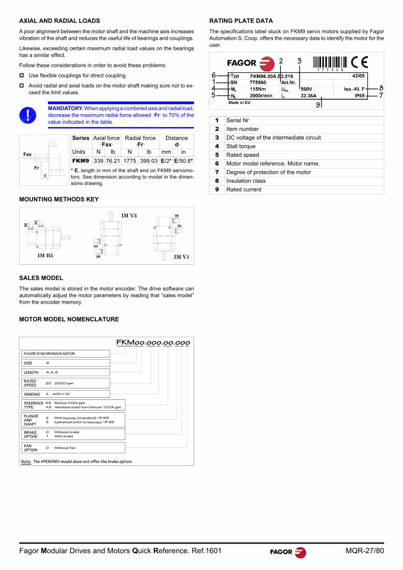
AXIAL AND RADIAL LOADS
A poor alignment between the motor shaft and the machine axis increasesvibration of the shaft and reduces the useful life of bearings and couplings.
Likewise, exceeding certain maximum radial load values on the bearingshas a similar effect.
Follow these considerations in order to avoid these problems:
Use flexible couplings for direct coupling.
Avoid radial and axial loads on the motor shaft making sure not to ex-ceed the limit values.
MOUNTING METHODS KEY
SALES MODEL
The sales model is stored in the motor encoder. The drive software canautomatically adjust the motor parameters by reading that “sales model”from the encoder memory.
MOTOR MODEL NOMENCLATURE
RATING PLATE DATA
The specifications label stuck on FKM9 servo motors supplied by FagorAutomation S. Coop. offers the necessary data to identify the motor for theuser.
MANDATORY. When applying a combined axis and radial load,decrease the maximum radial force allowed ·Fr· to 70% of thevalue indicated in the table.
Series Axial force ·Fax·
Radial force·Fr·
Distance·d·
Units N lb N lb mm in
FKM9 339 76.21 1775 399.03 E/2* E/50.8*
* E, length in mm of the shaft end on FKM9 servomo-tors. See dimension according to model in the dimen-sions drawing.
Fax
Fr
d
IM B5
IM V3
IM V1
FAGOR SYNCHRONOUS MOTOR
FKMoo.ooo.oo.ooo
SIZE 9
RATEDSPEED
LENGTH 4, 5, 6
20 2000 rpm
WINDING A 400 V AC
E3 SinCos1024 ppt
A3 Absolute multi-turn Sincos 1024 ppt
FEEDBACKTYPE
2 With keyway (standard) / IP 65
3 Cylindrical (with no keyway) / IP 65
FLANGEANDSHAFT
FANOPTION
0 Without fan
Note. The «FKM96» model does not offer the brake option.
BRAKEOPTION
0 Without brake
1 With brake
1 Serial Nr
2 Item number
3 DC voltage of the intermediate circuit
4 Stall torque
5 Rated speed
6 Motor model reference. Motor name.
7 Degree of protection of the motor
8 Insulation class
9 Rated current
16
45
87
9
2 3
MQR-28/80 Fagor Modular Drives and Motors Quick Reference. Ref.1601
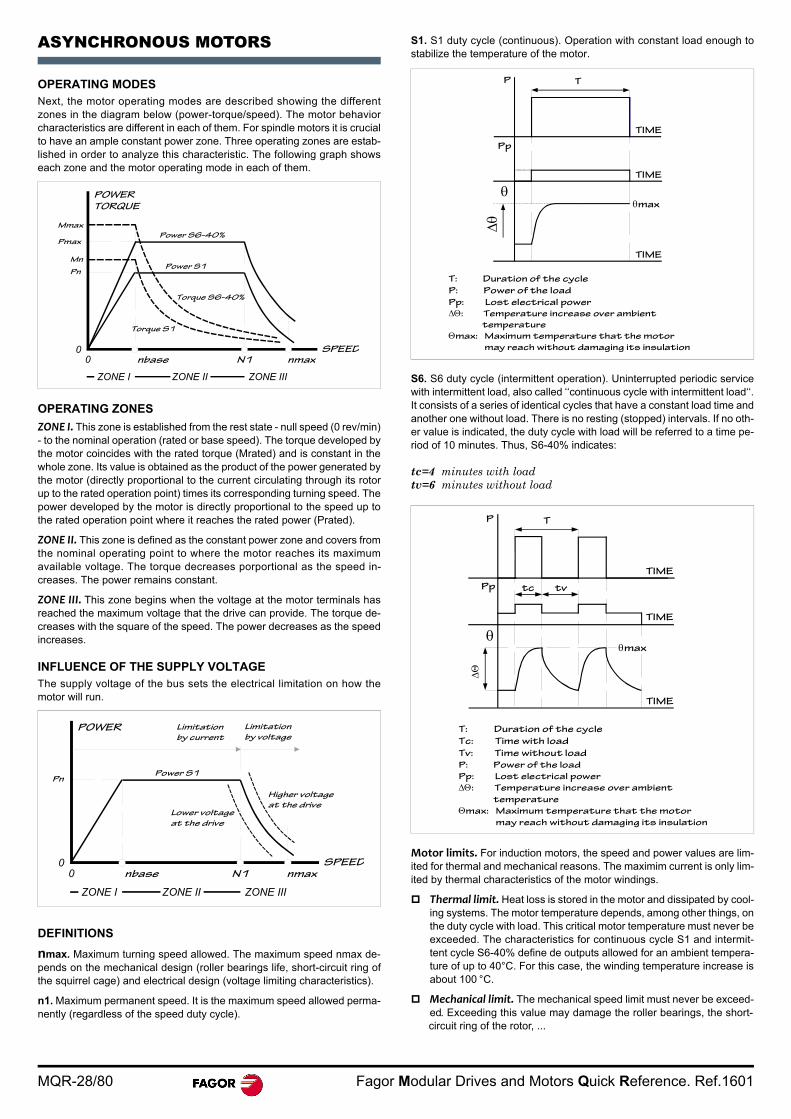
ASYNCHRONOUS MOTORS
OPERATING MODESNext, the motor operating modes are described showing the differentzones in the diagram below (power-torque/speed). The motor behaviorcharacteristics are different in each of them. For spindle motors it is crucialto have an ample constant power zone. Three operating zones are estab-lished in order to analyze this characteristic. The following graph showseach zone and the motor operating mode in each of them.
OPERATING ZONES
ZONE I. This zone is established from the rest state - null speed (0 rev/min)- to the nominal operation (rated or base speed). The torque developed bythe motor coincides with the rated torque (Mrated) and is constant in thewhole zone. Its value is obtained as the product of the power generated bythe motor (directly proportional to the current circulating through its rotorup to the rated operation point) times its corresponding turning speed. Thepower developed by the motor is directly proportional to the speed up tothe rated operation point where it reaches the rated power (Prated).
ZONE II. This zone is defined as the constant power zone and covers fromthe nominal operating point to where the motor reaches its maximumavailable voltage. The torque decreases porportional as the speed in-creases. The power remains constant.
ZONE III. This zone begins when the voltage at the motor terminals hasreached the maximum voltage that the drive can provide. The torque de-creases with the square of the speed. The power decreases as the speedincreases.
INFLUENCE OF THE SUPPLY VOLTAGEThe supply voltage of the bus sets the electrical limitation on how themotor will run.
DEFINITIONS
nmax. Maximum turning speed allowed. The maximum speed nmax de-pends on the mechanical design (roller bearings life, short-circuit ring ofthe squirrel cage) and electrical design (voltage limiting characteristics).
n1. Maximum permanent speed. It is the maximum speed allowed perma-nently (regardless of the speed duty cycle).
S1. S1 duty cycle (continuous). Operation with constant load enough tostabilize the temperature of the motor.
S6. S6 duty cycle (intermittent operation). Uninterrupted periodic servicewith intermittent load, also called ‘‘continuous cycle with intermittent load‘‘.It consists of a series of identical cycles that have a constant load time andanother one without load. There is no resting (stopped) intervals. If no oth-er value is indicated, the duty cycle with load will be referred to a time pe-riod of 10 minutes. Thus, S6-40% indicates:
tc=4 minutes with load tv=6 minutes without load
Motor limits. For induction motors, the speed and power values are lim-ited for thermal and mechanical reasons. The maximim current is only lim-ited by thermal characteristics of the motor windings.
Thermal limit. Heat loss is stored in the motor and dissipated by cool-ing systems. The motor temperature depends, among other things, onthe duty cycle with load. This critical motor temperature must never beexceeded. The characteristics for continuous cycle S1 and intermit-tent cycle S6-40% define de outputs allowed for an ambient tempera-ture of up to 40°C. For this case, the winding temperature increase isabout 100 °C.
Mechanical limit. The mechanical speed limit must never be exceed-ed. Exceeding this value may damage the roller bearings, the short-circuit ring of the rotor, ...
0
POWER
N10
ZONE I
TORQUE
Mmax
Pmax
Pn
Mn
ZONE II ZONE III
nbase
Power S6-40%
Power S1
Torque S6-40%
Torque S1
SPEEDnmax
0
POWER
N10
ZONE I
Pn
ZONE II ZONE III
nbase
Power S1
SPEEDnmax
Limitation
by current
Limitation
by voltage
Lower voltage
at the drive
Higher voltage
at the drive
T
TIME
P
max
Pp
TIME
TIME
T: Duration of the cycle
P: Power of the load
Pp: Lost electrical power
: Temperature increase over ambient
temperature
max: Maximum temperature that the motor
may reach without damaging its insulation
TIME
TIME
TIME
TP
Pp
max
tc tv
T: Duration of the cycle
Tc: Time with load
Tv: Time without load
P: Power of the load
Pp: Lost electrical power
: Temperature increase over ambient
temperature
max: Maximum temperature that the motor
may reach without damaging its insulation
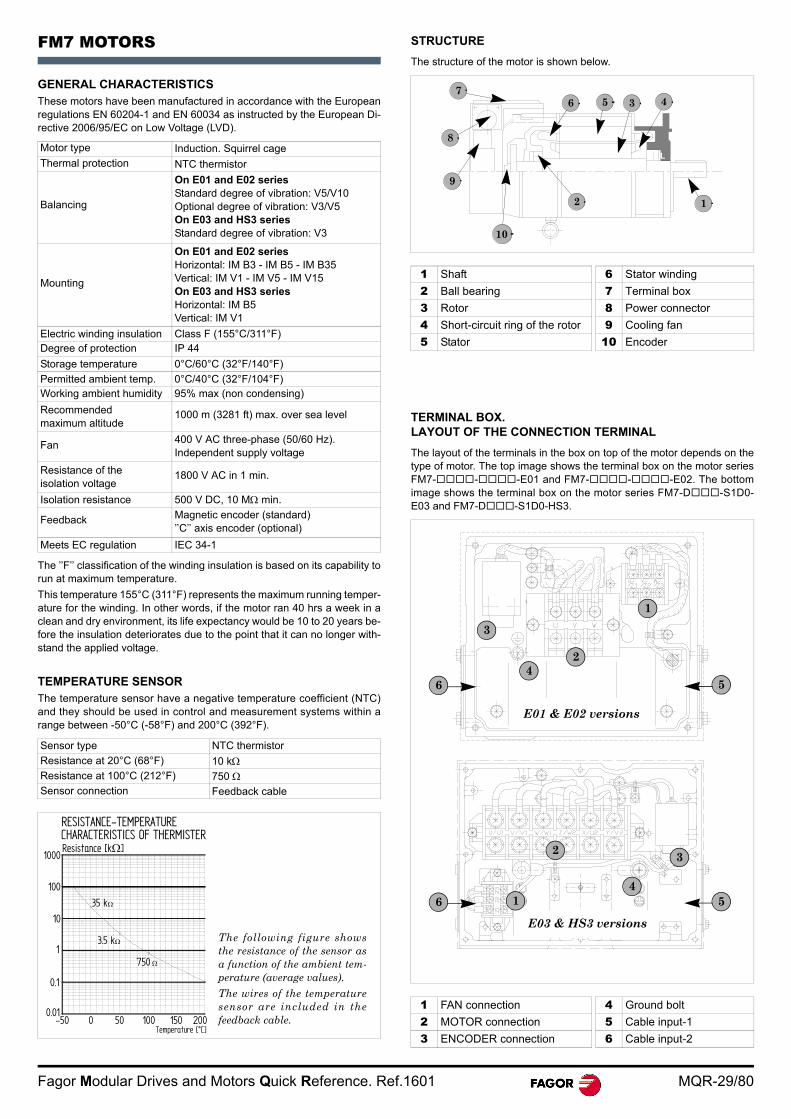
Fagor Modular Drives and Motors Quick Reference. Ref.1601 MQR-29/80
FM7 MOTORS
GENERAL CHARACTERISTICSThese motors have been manufactured in accordance with the Europeanregulations EN 60204-1 and EN 60034 as instructed by the European Di-rective 2006/95/EC on Low Voltage (LVD).
The ’’F’’ classification of the winding insulation is based on its capability torun at maximum temperature.
This temperature 155°C (311°F) represents the maximum running temper-ature for the winding. In other words, if the motor ran 40 hrs a week in aclean and dry environment, its life expectancy would be 10 to 20 years be-fore the insulation deteriorates due to the point that it can no longer with-stand the applied voltage.
TEMPERATURE SENSORThe temperature sensor have a negative temperature coefficient (NTC)and they should be used in control and measurement systems within arange between -50°C (-58°F) and 200°C (392°F).
STRUCTURE
The structure of the motor is shown below.
TERMINAL BOX. LAYOUT OF THE CONNECTION TERMINAL
The layout of the terminals in the box on top of the motor depends on thetype of motor. The top image shows the terminal box on the motor seriesFM7---E01 and FM7---E02. The bottomimage shows the terminal box on the motor series FM7-D-S1D0-E03 and FM7-D-S1D0-HS3.
Motor type Induction. Squirrel cageThermal protection NTC thermistor
Balancing
On E01 and E02 seriesStandard degree of vibration: V5/V10 Optional degree of vibration: V3/V5On E03 and HS3 seriesStandard degree of vibration: V3
Mounting
On E01 and E02 seriesHorizontal: IM B3 - IM B5 - IM B35Vertical: IM V1 - IM V5 - IM V15On E03 and HS3 seriesHorizontal: IM B5Vertical: IM V1
Electric winding insulation Class F (155°C/311°F)Degree of protection IP 44
Storage temperature 0°C/60°C (32°F/140°F)
Permitted ambient temp. 0°C/40°C (32°F/104°F)Working ambient humidity 95% max (non condensing)
Recommended maximum altitude
1000 m (3281 ft) max. over sea level
Fan 400 V AC three-phase (50/60 Hz).Independent supply voltage
Resistance of the isolation voltage
1800 V AC in 1 min.
Isolation resistance 500 V DC, 10 M min.
Feedback Magnetic encoder (standard)’’C’’ axis encoder (optional)
Meets EC regulation IEC 34-1
Sensor type NTC thermistor
Resistance at 20°C (68°F) 10 kResistance at 100°C (212°F) 750 Sensor connection Feedback cable
Temperature [°C]
3.5 k
750
Resistance [k]
35 k
CHARACTERISTICS OF THERMISTERRESISTANCE-TEMPERATURE
200-50 0 50 100 1500.01
0.1
1
10
100
1000
The following figure showsthe resistance of the sensor asa function of the ambient tem-perature (average values).
The wires of the temperaturesensor are included in thefeedback cable.
1 Shaft 6 Stator winding
2 Ball bearing 7 Terminal box
3 Rotor 8 Power connector
4 Short-circuit ring of the rotor 9 Cooling fan
5 Stator 10 Encoder
1 FAN connection 4 Ground bolt
2 MOTOR connection 5 Cable input-1
3 ENCODER connection 6 Cable input-2
356
2
10
9
8
47
1
1
2
3
4
56 1
2 3
4
56
E01 & E02 versions
E03 & HS3 versions
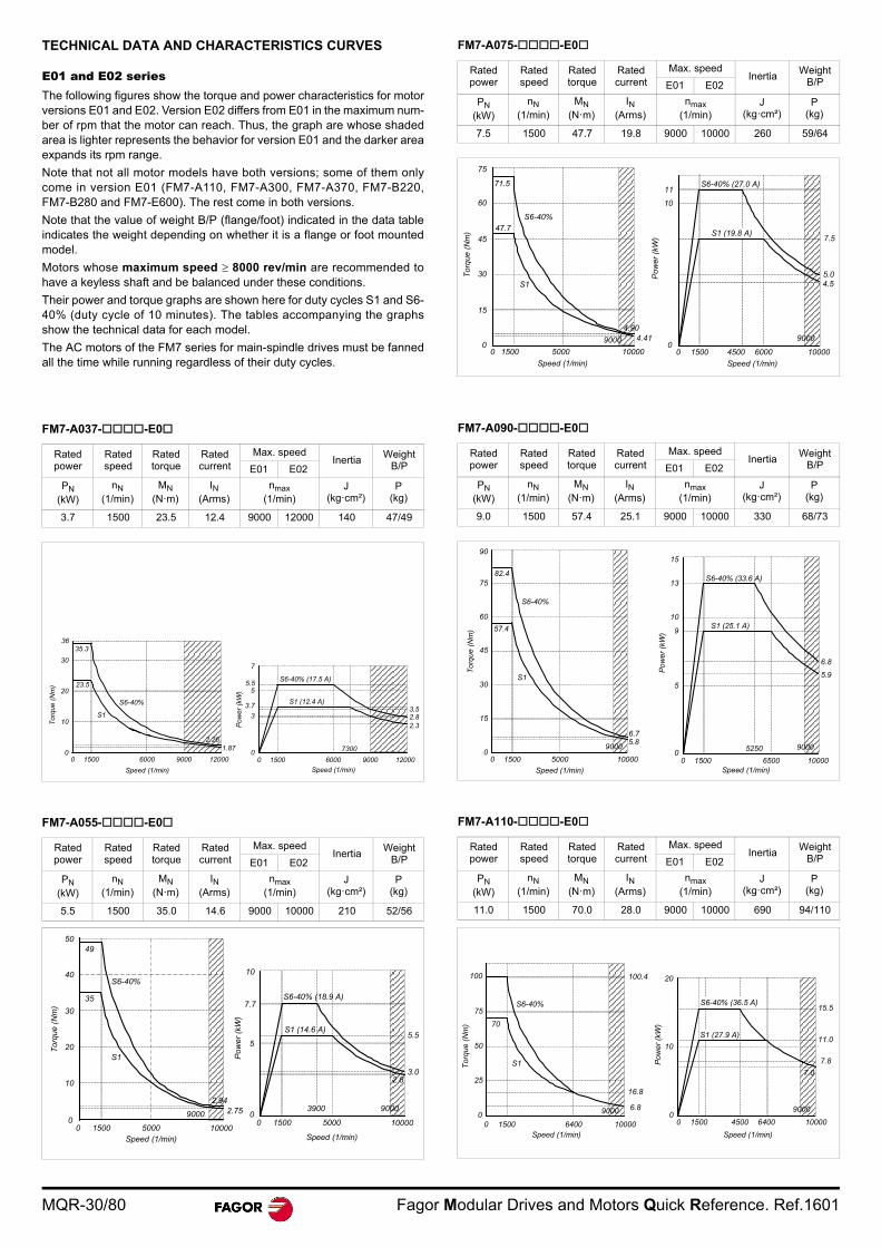
MQR-30/80 Fagor Modular Drives and Motors Quick Reference. Ref.1601
TECHNICAL DATA AND CHARACTERISTICS CURVES
E01 and E02 seriesThe following figures show the torque and power characteristics for motorversions E01 and E02. Version E02 differs from E01 in the maximum num-ber of rpm that the motor can reach. Thus, the graph are whose shadedarea is lighter represents the behavior for version E01 and the darker areaexpands its rpm range.
Note that not all motor models have both versions; some of them onlycome in version E01 (FM7-A110, FM7-A300, FM7-A370, FM7-B220,FM7-B280 and FM7-E600). The rest come in both versions.
Note that the value of weight B/P (flange/foot) indicated in the data tableindicates the weight depending on whether it is a flange or foot mountedmodel.
Motors whose maximum speed 8000 rev/min are recommended tohave a keyless shaft and be balanced under these conditions.
Their power and torque graphs are shown here for duty cycles S1 and S6-40% (duty cycle of 10 minutes). The tables accompanying the graphsshow the technical data for each model.
The AC motors of the FM7 series for main-spindle drives must be fannedall the time while running regardless of their duty cycles.
FM7-A037--E0
FM7-A055--E0
FM7-A075--E0
FM7-A090--E0
FM7-A110--E0
Rated power
Rated speed
Rated torque
Rated current
Max. speedInertia
WeightB/PE01 E02
PN (kW)
nN (1/min)
MN (N·m)
IN (Arms)
nmax (1/min)
J (kg·cm²)
P(kg)
3.7 1500 23.5 12.4 9000 12000 140 47/49
Rated power
Rated speed
Rated torque
Rated current
Max. speedInertia
WeightB/PE01 E02
PN (kW)
nN (1/min)
MN (N·m)
IN (Arms)
nmax (1/min)
J (kg·cm²)
P(kg)
5.5 1500 35.0 14.6 9000 10000 210 52/56
To
rque
(N
m)
35.336
0
23.5
S1
S6-40%
10
20
30
0 1500 6000 9000 12000
Speed (1/min)
Po
we
r (k
W)
Speed (1/min)
0 1500 6000 9000 12000
2.32.83.5
7300
S6-40% (17.5 A)
S1 (12.4 A)
0
3
3.7
55.5
7
1.872.26
Speed (1/min)
Tor
que
(Nm
)
Pow
er (
kW)
Speed (1/min)
S6-40% (18.9 A)
S1 (14.6 A)5.5
3.02.8
5000 10000150000
5
7.7
10
3900 9000
5000 1000015000
49
0
10
20
30
40
50
S6-40%
S1
9000
35
2.752.94
Rated power
Rated speed
Rated torque
Rated current
Max. speedInertia
WeightB/PE01 E02
PN (kW)
nN (1/min)
MN (N·m)
IN (Arms)
nmax (1/min)
J (kg·cm²)
P(kg)
7.5 1500 47.7 19.8 9000 10000 260 59/64
Rated power
Rated speed
Rated torque
Rated current
Max. speedInertia
WeightB/PE01 E02
PN (kW)
nN (1/min)
MN (N·m)
IN (Arms)
nmax (1/min)
J (kg·cm²)
P(kg)
9.0 1500 57.4 25.1 9000 10000 330 68/73
Rated power
Rated speed
Rated torque
Rated current
Max. speedInertia
WeightB/PE01 E02
PN (kW)
nN (1/min)
MN (N·m)
IN (Arms)
nmax (1/min)
J (kg·cm²)
P(kg)
11.0 1500 70.0 28.0 9000 10000 690 94/110
Tor
que
(Nm
)
Pow
er (
kW)
Speed (1/min)
0 1500 6000
9000
1000045000
4.55.0
S6-40% (27.0 A)
S1 (19.8 A)7.5
10
11
Speed (1/min)
0 1500 100005000
90000
15
30
45
60
75
71.5
47.7
S6-40%
S1
4.414.90
Speed (1/min)
0 1500 5000
9000
10000
S6-40% (33.6 A)
S1 (25.1 A)
Po
wer
(kW
)
15
13
10
9
6.8
5.9
5
Speed (1/min)0 1500 6500 10000
900052500
Tor
que
(Nm
)
0
15
30
45
60
57.4
7582.4
90
S6-40%
S1
5.86.7
0 1500 6400
9000
10000Speed (1/min)
Tor
que
(N
m)
S6-40%
S1
70
100.4
0
25
50
75
100
Po
wer
(kW
)
S6-40% (36.5 A)
S1 (27.9 A)
15.5
7.8
0
10
20
11.0
7.0
6.8
16.8
Speed (1/min)
0 1500 6400 10000
9000
4500
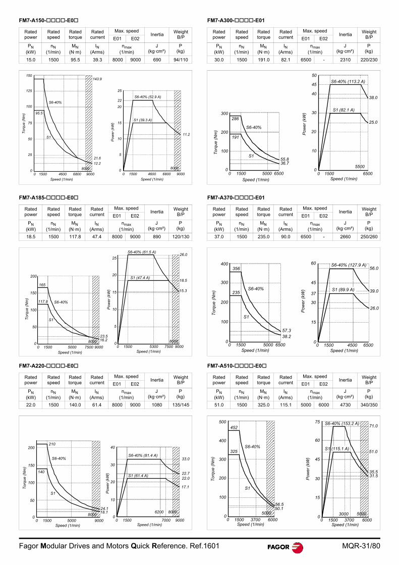
Fagor Modular Drives and Motors Quick Reference. Ref.1601 MQR-31/80
FM7-A150--E0
FM7-A185--E0
FM7-A220--E0
FM7-A300--E01
FM7-A370--E01
FM7-A510--E0
Rated power
Rated speed
Rated torque
Rated current
Max. speedInertia
WeightB/PE01 E02
PN (kW)
nN (1/min)
MN (N·m)
IN (Arms)
nmax (1/min)
J (kg·cm²)
P(kg)
15.0 1500 95.5 39.3 8000 9000 690 94/110
Rated power
Rated speed
Rated torque
Rated current
Max. speedInertia
WeightB/PE01 E02
PN (kW)
nN (1/min)
MN (N·m)
IN (Arms)
nmax (1/min)
J (kg·cm²)
P(kg)
18.5 1500 117.8 47.4 8000 9000 890 120/130
Rated power
Rated speed
Rated torque
Rated current
Max. speedInertia
WeightB/PE01 E02
PN (kW)
nN (1/min)
MN (N·m)
IN (Arms)
nmax (1/min)
J (kg·cm²)
P(kg)
22.0 1500 140.0 61.4 8000 9000 1080 135/145
S6-40%
S1
143.9150
125
100
Tor
que
(N
m)
75
50
25
Speed (1/min)
0 1500 6800 90004600
80000
95.5
21.6
12.2
S6-40% (52.9 A)
S1 (39.3 A)
Pow
er (
kW)
Speed (1/min)
0 1500 6800 90004600
8000
11.2
0
5
10
15
20
22
25
Speed (1/min)0 1500 7500 90005000
8000
Tor
que
(N
m)
165
117.8 S6-40%
S1
200
0
50
100
150
16.223.5
Speed (1/min)0 1500 7500 90005300
8000
15.3
18.5
26.0S6-40% (61.5 A)
S1 (47.4 A)
0
5
10
15
20
25
Pow
er (
kW)
Speed (1/min)0 1500
8000
90005000
210200
140
S6-40%
S1
150
100
50
0
Tor
que
(Nm
)
Speed (1/min)0 1500 90007000
80006200
S6-40% (81.4 A)
S1 (61.4 A)
33.0
22.722.0
17.1
0
10
20
30
40
Po
we
r (k
W)
18.124.1
Rated power
Rated speed
Rated torque
Rated current
Max. speedInertia
WeightB/PE01 E02
PN (kW)
nN (1/min)
MN (N·m)
IN (Arms)
nmax (1/min)
J (kg·cm²)
P(kg)
30.0 1500 191.0 82.1 6500 - 2310 220/230
Rated power
Rated speed
Rated torque
Rated current
Max. speedInertia
WeightB/PE01 E02
PN (kW)
nN (1/min)
MN (N·m)
IN (Arms)
nmax (1/min)
J (kg·cm²)
P(kg)
37.0 1500 235.0 90.0 6500 - 2660 250/260
Rated power
Rated speed
Rated torque
Rated current
Max. speedInertia
WeightB/PE01 E02
PN (kW)
nN (1/min)
MN (N·m)
IN (Arms)
nmax (1/min)
J (kg·cm²)
P(kg)
51.0 1500 325.0 115.1 5000 6000 4730 340/350
286
191
S6-40%
S1
Speed (1/min)
0 1500 65005000
To
rque
(N
m)
300
200
100
0
Speed (1/min)0 1500 6500
5500
S6-40% (113.2 A)
S1 (82.1 A)
Po
wer
(kW
)
50
45
40
30
20
10
0
38.0
25.0
55.836.7
Tor
que
(N
m)
400
Speed (1/min)0 1500 65005000
356
S6-40%
S1
235
300
200
100
038.257.3
S6-40% (127.9 A)
Pow
er
(kW
)
60
45
3739.0
3026.0
56.0
15
0
Speed (1/min)0 1500 65004500
S1 (89.9 A)
500
400
300
200
100
0
Tor
que
(Nm
)
Speed (1/min)0 1500
5000
60003700
S6-40%
S1
452
325
50.156.5
S6-40% (153.2 A) 71.0
51.0
35.531.5
Pow
er (
kW)
S1 (115.1 A)
75
Speed (1/min)0 1500 60003700
5000
60
45
30
15
03000
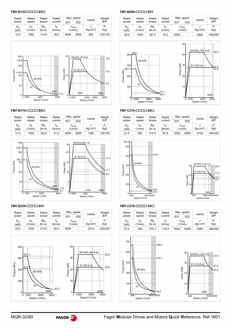
MQR-32/80 Fagor Modular Drives and Motors Quick Reference. Ref.1601
FM7-B120--E0
FM7-B170--E0
FM7-B220--E01
FM7-B280--E01
FM7-C215--E0
FM7-C270--E0
Rated power
Rated speed
Rated torque
Rated current
Max. speedInertia
WeightB/PE01 E02
PN (kW)
nN (1/min)
MN (N·m)
IN (Arms)
nmax (1/min)
J (kg·cm²)
P(kg)
12.0 1000 114.6 35.0 8000 9000 890 120/130
Rated power
Rated speed
Rated torque
Rated current
Max. speedInertia
WeightB/PE01 E02
PN (kW)
nN (1/min)
MN (N·m)
IN (Arms)
nmax (1/min)
J (kg·cm²)
P(kg)
17.0 1000 162.0 47.2 8000 9000 1080 135/145
Rated power
Rated speed
Rated torque
Rated current
Max. speedInertia
WeightB/PE01 E02
PN (kW)
nN (1/min)
MN (N·m)
IN (Arms)
nmax (1/min)
J (kg·cm²)
P(kg)
22.0 1000 210.0 64.9 6500 - 2310 220/230
Speed (1/min)0 1000 90004500
Tor
qu
e (
Nm
)
200
150
100
50
0
176.6
114.6
S6-40%
S1
8000
S6-40% (47.5 A)
S1 (35.0 A)
0 1000 90004500 6000
2800 8000
Speed (1/min)
6.0
18.520
12.0
10
0
Po
wer
(kW
)
6.0
Tor
que
(Nm
)
250
238.7
200
162.3150
100
50
0
S6-40%
S1
Speed (1/min)0 1000 90004700
8000
0 1000 90004000
4700
Speed (1/min)
8000
S6-40% (64.1 A)
S1 (47.2 A)
11.1
8.9
9.411.8
25
20
17.0
15
Po
wer
(kW
)
10
5
0
Tor
que
(N
m)
400
315.1
Speed (1/min)0 1000 65004000
5800
S6-40%
S1
210.0
300
200
100
0
S6-40% (89.5 A)
S1 (64.9 A)
40
30
20
10
0
33.0
22.0
Speed (1/min)0 1000 65004000
5800
Pow
er (
kW)
32.3
Rated power
Rated speed
Rated torque
Rated current
Max. speedInertia
WeightB/PE01 E02
PN (kW)
nN (1/min)
MN (N·m)
IN (Arms)
nmax (1/min)
J (kg·cm²)
P(kg)
28.0 1000 267.4 78.2 6500 - 2660 250/260
Rated power
Rated speed
Rated torque
Rated current
Max. speedInertia
WeightB/PE01 E02
PN (kW)
nN (1/min)
MN (N·m)
IN (Arms)
nmax (1/min)
J (kg·cm²)
P(kg)
21.5 500 410.6 87.8 5000 6000 4730 340/350
Rated power
Rated speed
Rated torque
Rated current
Max. speedInertia
WeightB/PE01 E02
PN (kW)
nN (1/min)
MN (N·m)
IN (Arms)
nmax (1/min)
J (kg·cm²)
P(kg)
27.0 500 515.7 116.9 5000 6000 5480 380/390
401.1
267.4
300
400
S6-40%
S1
0
100
200
To
rque
(N
m)
Speed (1/min)0 1000 65004000
Speed (1/min)0 1000 65004000
Pow
er (
kW)
S6-40% (109.0 A)
S1 (78.2 A)
50
4042.0
28.027.0
30
20
10
06250
41.139.7
553.9
500
410.6400
300
200
100
0500 60005000
S6-40%
S1
Speed (1/min)
Tor
que
(N
m)
25.626.9
S6-40% (114.7 A)
S1 (87.8 A)
29.0
21.5
16.916.1
30
20
10
0
Pow
er
(kW
)
Speed (1/min)500 60003500 5000
4500
706.6
515.7
Tor
que
(Nm
)
750
600
450
300
5000
S6-40%
S1
60005000Speed (1/min)
S6-40% (153.2 A)
S1 (116.9 A)
Po
wer
(kW
)
36.6
150
37.0
27.0
23.0
40
30
20
10
0500 60005000
Speed (1/min)
3900
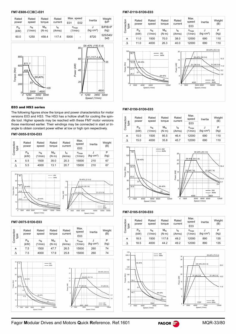
Fagor Modular Drives and Motors Quick Reference. Ref.1601 MQR-33/80
FM7-E600-CB-E01
E03 and HS3 seriesThe following figures show the torque and power characteristics for motorversions E03 and HS3. The HS3 has a hollow shaft for cooling the spin-dle tool. Higher speeds may be reached with these FM7 motor versionsthose mentioned earlier. Their windings may be connected in start or tri-angle to obtain constant power either at low or high rpm respectively.
FM7-D055-S1D0-E03
FM7-D075-S1D0-E03
FM7-D110-S1D0-E03
FM7-D150-S1D0-E03
FM7-D185-S1D0-E03
Rated power
Rated speed
Rated torque
Rated current
Max. speedInertia
WeightB/PE01 E02
PN (kW)
nN (1/min)
MN (N·m)
IN (Arms)
nmax (1/min)
J (kg·cm²)
B/P/B+P(kg)
60.0 1250 458.4 117.4 5000 - 8720525/540/
545
Co
nn
ectio
n
typ
e
Rated power
Rated speed
Rated torque
Rated current
Max.speed Inertia
Weight(B)
E03
PN (kW)
nN (1/min)
MN (N·m)
IN (Arms)
nmax (1/min)
J (kg·cm²)
P(kg)
5.5 1500 35.0 20.3 15000 210 67
5.5 4000 13.1 20.7 15000 210 67
Con
ne
ctio
n
type
Rated power
Rated speed
Rated torque
Rated current
Max.speed Inertia
Weight(B)
E03
PN (kW)
nN (1/min)
MN (N·m)
IN (Arms)
nmax (1/min)
J (kg·cm²)
P(kg)
7.5 1500 47.7 26.5 15000 260 74
7.5 4000 17.9 25.8 15000 260 74
458.4
Tor
que
(Nm
)
800
600
400
12500
S6-40%
S1
5000Speed (1/min)
105
200
S6-40% (150.5 A)
S1 (117.4 A)
Pow
er
(kW
)
55
80
60
40
20
01250 5000Speed (1/min)
3450
460020003450
4600
611.1
00
Tor
que
(Nm
)
5049
40
30
35
23.8
13.1
20
10
S6-40%
S6-40%
S1
00 1500 4000 5000 10000 13000 15000
Speed (1/min)
S1
S6-40% (21.9 A)
S6-40% (26.2 A)
S1 (21.0 A)S1 (20.3 A)
8.6
5.5
2.6
1.8
0 1500 4000 5000 10000 13000 15000
Speed (1/min)
Po
wer
(kW
)
10
7.7
stardelta
5.0
0
star
delta
7070
60
50
47.7S6-40%
Tor
que
(Nm
) 40
30
20
10
00 1500 4000 6000 10000 15000
Speed (1/min)
S1
17.9
31.0
S6-40%
S1
4.4
3.0
S1 (26.5 A) S1 (25.8 A)
S6-40% (35.7 A)
S6-40% (34.5 A)
Pow
er (
kW)
15
13
11
0 1500
6000
10000 15000
Speed (1/min)
5000
4000
stardelta
10
7.5
5
0
stardelta
Co
nne
ctio
n
typ
e
Rated power
Rated speed
Rated torque
Rated current
Max.speed Inertia
Weight(B)
E03
PN (kW)
nN (1/min)
MN (N·m)
IN (Arms)
nmax (1/min)
J (kg·cm²)
P(kg)
11.0 1500 70.0 38.0 12000 690 110
11.0 4000 26.3 40.0 12000 690 110
Co
nn
ect
ion
ty
pe
Rated power
Rated speed
Rated torque
Rated current
Max.speed Inertia
Weight(B)
E03
PN (kW)
nN (1/min)
MN (N·m)
IN (Arms)
nmax (1/min)
J (kg·cm²)
P(kg)
15.0 1500 95.5 46.4 12000 690 110
15.0 4000 35.8 45.7 12000 690 110
Con
ne
ctio
n
type
Rated power
Rated speed
Rated torque
Rated current
Max.speed Inertia
Weight(B)
E03
PN (kW)
nN (1/min)
MN (N·m)
IN (Arms)
nmax (1/min)
J (kg·cm²)
P(kg)
18.5 1500 117.8 49.2 12000 890 135
18.5 4000 44.2 49.2 12000 890 135
100
75
98.7
S6-40%70.0
47.7
26.3
Tor
que
(Nm
)
50
25
00 1500 4000 6400 12000
Speed (1/min)
S6-40%
S1
S1
stardelta
Pow
er (
kW)
20
stardelta
Speed (1/min)
15
S6-40% (52.0 A)
S6-40% (50.0 A)15.5
11.0
8.2
5.8
S1 (40.0 A)S1 (38.0 A)
0 1500 5000 6400 12000
4000
10000
10
5
0
150
140
95.5
125
100
75
62.0
35.8
50
25
0
Tor
que
(Nm
)
S6-40%
S6-40%
S1
S1
0 1500 4000 6800 12000Speed (1/min)
stardelta
8500
S6-40% (62.3 A)
S6-40% (63.3 A)
S1 (45.7 A)S1 (46.7 A)
18.4
11.0
9.18.4
Pow
er
(kW
)
26
22
20
15
10
5
00 1500 5000 6800 12000
Speed (1/min)
stardelta
8500
4000 8800
175
165.5
150
125117.8
100
S6-40%
76.475
50
25
Tor
que
(Nm
)
44.2
S1
00 1500 4000
7500
12000Speed (1/min)
stardelta
8000
S1
S6-40%
S6-40% (70.5 A)
26.0
32
30
S6-40% (63.0 A)
25
2018.5
15
11.6
10
5
0
S1 (49.2 A) S1 (49.2 A)
0 1500 4000 12000Speed (1/min)
stardelta
7500
5300
Pow
er (
kW)
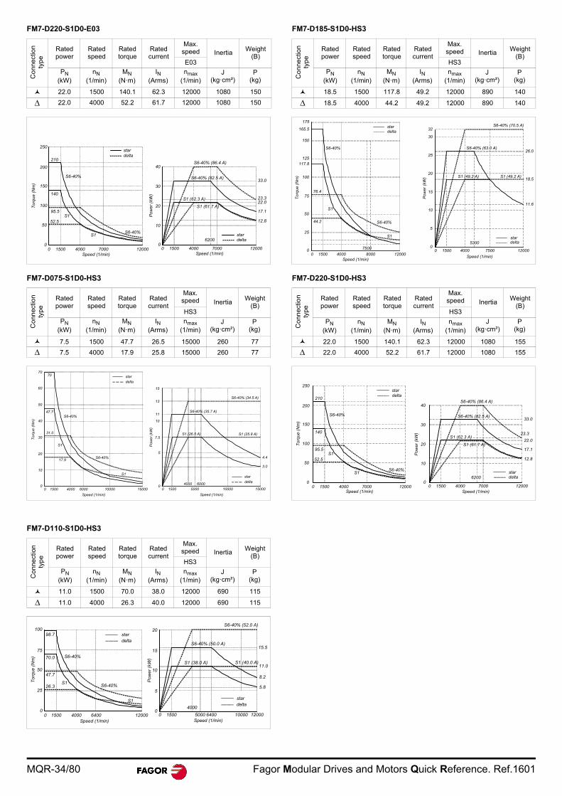
MQR-34/80 Fagor Modular Drives and Motors Quick Reference. Ref.1601
FM7-D220-S1D0-E03
FM7-D075-S1D0-HS3
FM7-D110-S1D0-HS3
FM7-D185-S1D0-HS3
FM7-D220-S1D0-HS3
Co
nne
ctio
n
typ
eRated power
Rated speed
Rated torque
Rated current
Max.speed Inertia
Weight(B)
E03
PN (kW)
nN (1/min)
MN (N·m)
IN (Arms)
nmax (1/min)
J (kg·cm²)
P(kg)
22.0 1500 140.1 62.3 12000 1080 150
22.0 4000 52.2 61.7 12000 1080 150
Co
nn
ectio
n ty
pe
Rated power
Rated speed
Rated torque
Rated current
Max.speed Inertia
Weight(B)
HS3
PN (kW)
nN (1/min)
MN (N·m)
IN (Arms)
nmax (1/min)
J (kg·cm²)
P(kg)
7.5 1500 47.7 26.5 15000 260 77
7.5 4000 17.9 25.8 15000 260 77
Co
nne
ctio
n
typ
e
Rated power
Rated speed
Rated torque
Rated current
Max.speed Inertia
Weight(B)
HS3
PN (kW)
nN (1/min)
MN (N·m)
IN (Arms)
nmax (1/min)
J (kg·cm²)
P(kg)
11.0 1500 70.0 38.0 12000 690 115
11.0 4000 26.3 40.0 12000 690 115
250
210
200
S6-40%
S6-40%
0 1500 4000 12000Speed (1/min)
stardelta
7000
150
140
10095.5
50
0
52.5
S1
To
rqu
e (N
m)
S1
40
33.0
23.322.0
17.1
12.8
S6-40% (86.4 A)
S6-40% (82.5 A)
S1 (62.3 A)
S1 (61.7 A)
Pow
er (
kW)
30
20
0 1500 4000 12000Speed (1/min)
stardelta
7000
6200
10
0
7070
60
50
47.7S6-40%
Tor
que
(Nm
) 40
30
20
10
00 1500 4000 6000 10000 15000
Speed (1/min)
S1
17.9
31.0
S6-40%
S1
4.4
3.0
S1 (26.5 A) S1 (25.8 A)
S6-40% (35.7 A)
S6-40% (34.5 A)
Pow
er
(kW
)
15
13
11
0 1500
6000
10000 15000
Speed (1/min)
5000
4000
star
delta
10
7.5
5
0
star
delta
100
75
98.7
S6-40%70.0
47.7
26.3
Tor
que
(Nm
)
50
25
00 1500 4000 6400 12000
Speed (1/min)
S6-40%
S1
S1
stardelta
Pow
er (
kW)
20
Speed (1/min)
15
S6-40% (52.0 A)
S6-40% (50.0 A)15.5
11.0
8.2
5.8
S1 (40.0 A)S1 (38.0 A)
0 1500 5000 6400 12000
4000
10000
10
5
0
stardelta
Co
nne
ctio
n
typ
e
Rated power
Rated speed
Rated torque
Rated current
Max.speed Inertia
Weight(B)
HS3
PN (kW)
nN (1/min)
MN (N·m)
IN (Arms)
nmax (1/min)
J (kg·cm²)
P(kg)
18.5 1500 117.8 49.2 12000 890 140
18.5 4000 44.2 49.2 12000 890 140
Co
nn
ectio
n ty
pe
Rated power
Rated speed
Rated torque
Rated current
Max.speed Inertia
Weight(B)
HS3
PN (kW)
nN (1/min)
MN (N·m)
IN (Arms)
nmax (1/min)
J (kg·cm²)
P(kg)
22.0 1500 140.1 62.3 12000 1080 155
22.0 4000 52.2 61.7 12000 1080 155
175
165.5
150
125117.8
100
S6-40%
76.475
50
25
Tor
que
(Nm
)
44.2
S1
00 1500 4000
7500
12000Speed (1/min)
stardelta
8000
S1
S6-40%
S6-40% (70.5 A)
26.0
32
30
S6-40% (63.0 A)
25
2018.5
15
11.6
10
5
0
S1 (49.2 A) S1 (49.2 A)
0 1500 4000 12000
Speed (1/min)
stardelta
7500
5300
Po
wer
(kW
)
250
210
200
S6-40%
S6-40%
0 1500 4000 12000Speed (1/min)
stardelta
7000
150
140
10095.5
50
0
52.5
S1
Tor
que
(N
m)
S1
40
33.0
23.3
22.0
17.1
12.8
S6-40% (86.4 A)
S6-40% (82.5 A)
S1 (62.3 A)
S1 (61.7 A)
Po
wer
(kW
)
30
20
0 1500 4000 12000Speed (1/min)
stardelta
7000
6200
10
0

Fagor Modular Drives and Motors Quick Reference. Ref.1601 MQR-35/80
DIMENSIONS FM7. E01/E02 series. Foot mounting
Units in mm A B C D E F G H h J KD L M N P R XB Y Z SQ
FM7-A037-3-E0 324.0 113.0 100 174 80.0 70.0 9 250 - 34 34.0 499.0 188 168 110.5 175.0 45 31 12 174FM7-A055-3-E0 286.0 117.0 112 204 95.0 50.0 10 269 247.0 75 42.5 486.0 220 129 114.0 200.0 70 55 12 204FM7-A075-3-E0 296.0 137.0 112 204 95.0 70.0 10 269 247.0 75 42.5 546.0 220 177 114.0 250.0 70 55 12 204FM7-A090-3-E0 317.0 156.0 112 204 95.0 89.0 10 269 247.0 75 42.5 586.0 220 215 114.0 269.0 70 55 12 204FM7-A110-3-E0 264.0 196.0 160 279 127.0 89.0 16 343 331.5 55 42.5 571.0 290 223 131.0 307.0 108 84 15 260FM7-A150-3-E0 264.0 196.0 160 279 127.0 89.0 16 343 331.5 55 42.5 571.0 290 223 131.0 307.0 108 84 15 260FM7-A185-3-E0 310.0 212.0 160 279 127.0 105.0 16 343 331.5 55 42.5 633.0 290 255 131.0 323.0 108 84 15 260FM7-A220-3-E0 313.5 246.5 160 279 127.0 139.5 16 343 331.5 55 42.5 671.0 290 324 131.0 357.5 108 84 15 260FM7-A300-3-E0 381.0 246.0 180 320 139.5 127.0 16 407 401.0 55 61.0 769.0 320 298 163.5 388.0 121 99 19 320FM7-A370-3-E0 421.0 246.0 180 320 139.5 127.0 16 407 401.0 55 61.0 809.0 320 298 163.5 388.0 121 99 19 320FM7-A510-3-E0 398.0 302.0 225 388 178.0 155.5 21 540 480.0 75 61.0 842.5 420 425 235.5 444.5 149 73 24 380FM7-B120-3-E0 310.0 212.0 160 279 127.0 105.0 16 343 331.5 55 42.5 633.0 290 255 131.0 323.0 108 84 15 260FM7-B170-3-E0 313.5 246.5 160 279 127.0 139.5 16 343 331.5 55 42.5 671.0 290 324 131.0 357.5 108 84 15 260FM7-B220-3-E0 381.0 246.0 180 320 139.5 127.0 16 407 401.0 55 61.0 769.0 320 298 163.5 388.0 121 99 19 320FM7-B280-3-E0 421.0 246.0 180 320 139.5 127.0 16 407 401.0 55 61.0 809.0 320 298 163.5 388.0 121 99 19 320FM7-C215-3-E0 398.0 302.0 225 388 178.0 155.5 21 540 480.0 75 61.0 842.5 420 425 235.5 444.5 149 73 24 380FM7-C270-3-E0 429.0 321.0 225 388 178.0 174.5 21 540 480.0 75 61.0 892.5 420 465 235.5 463.5 149 73 24 380
FM7-E600-C3B-E01 589.0 331.5 225 388 178.0 228.5 21 540 480.0 90 61.0 1065.5 420 590 235.5 476.5 108 65 24 380
Units in inches A B C D E F G H h J KD L M N P R XB Y Z SQFM7-A037-3-E0 12.76 4.45 3.94 6.85 3.15 2.76 0.35 9.84 - 1.34 1.34 19.65 7.40 6.61 4.35 6.89 1.77 1.22 0.47 6.85FM7-A055-3-E0 11.26 4.61 4.41 8.03 3.74 1.97 0.39 10.59 9.72 2.95 1.67 19.13 8.66 5.08 4.49 7.87 2.76 2.16 0.47 8.03FM7-A075-3-E0 11.65 5.39 4.41 8.03 3.74 2.76 0.39 10.59 9.72 2.95 1.67 21.50 8.66 6.97 4.49 9.84 2.76 2.16 0.47 8.03FM7-A090-3-E0 12.48 6.14 4.41 8.03 3.74 3.50 0.39 10.59 9.72 2.95 1.67 21.50 8.66 8.46 4.49 10.59 2.76 2.16 0.47 8.03FM7-A110-3-E0 10.39 7.72 6.30 11.00 5.00 3.50 0.63 13.50 13.05 2.16 1.67 22.48 11.42 8.78 5.16 12.09 4.25 3.31 0.59 10.24FM7-A150-3-E0 10.39 7.72 6.30 11.00 5.00 3.50 0.63 13.50 13.05 2.16 1.67 22.48 11.42 8.78 5.16 12.09 4.25 3.31 0.59 10.24FM7-A185-3-E0 12.20 8.35 6.30 11.00 5.00 4.13 0.63 13.50 13.05 2.16 1.67 24.92 11.42 10.04 5.16 12.72 4.25 3.31 0.59 10.24FM7-A220-3-E0 12.34 9.70 6.30 11.00 5.00 5.49 0.63 13.50 13.05 2.16 1.67 26.42 11.42 12.76 5.16 14.07 4.25 3.31 0.59 10.24FM7-A300-3-E0 15.00 9.69 7.09 12.60 5.49 5.00 0.63 16.02 15.79 2.16 2.40 30.28 12.60 11.73 6.44 15.28 4.76 3.90 0.75 12.60FM7-A370-3-E0 16.57 9.69 7.09 12.60 5.49 5.00 0.63 16.02 15.79 2.16 2.40 31.85 12.60 11.73 6.44 15.28 4.76 3.90 0.75 12.60FM7-A510-3-E0 15.67 11.90 8.86 15.30 7.01 6.12 0.83 21.26 18.90 2.95 2.40 33.17 16.54 16.73 9.27 17.50 5.87 2.87 0.94 14.96FM7-B120-3-E0 12.20 8.35 6.30 11.00 5.00 4.13 0.63 13.50 13.05 2.16 42.5 24.92 11.42 10.04 5.16 12.72 4.25 3.31 0.59 10.24FM7-B170-3-E0 12.34 9.70 6.30 11.00 5.00 5.49 0.63 13.50 13.05 2.16 42.5 26.42 11.42 12.76 5.16 14.07 4.25 3.31 0.59 10.24FM7-B220-3-E0 15.00 9.69 7.09 12.60 5.49 5.00 0.63 16.02 15.79 2.16 2.40 30.28 12.60 11.73 6.44 15.28 4.76 3.90 0.75 12.60FM7-B280-3-E0 16.57 9.69 7.09 12.60 5.49 5.00 0.63 16.02 15.79 2.16 2.40 31.85 12.60 11.73 6.44 15.28 4.76 3.90 0.75 12.60FM7-C215-3-E0 15.67 11.90 8.86 15.30 7.01 6.12 0.83 21.26 18.90 2.95 2.40 33.17 16.54 16.73 9.27 17.50 5.87 2.87 0.94 14.96FM7-C270-3-E0 16.89 12.60 8.86 15.30 7.01 6.87 0.83 21.26 18.90 2.95 2.40 35.14 16.54 18.31 9.27 18.25 5.87 2.87 0.94 14.96FM7-E600-C3B-E01 23.18 13.05 8.86 15.30 7.01 8.99 0.83 21.26 18.90 3.54 2.40 41.94 16.54 23.22 9.27 18.75 4.25 2.55 0.94 14.96
L
A R
LF B
Q
F F XB
N Y
SQ
KD
h
4 - Ø ZDiameter ofmounting holeM
E E
J
D
H
PC
G
Symbol indicating the direction of the cooling air
Note. Only shafts having a key have tappedholes (M3, 10 mm deep) for mounting the cou-pling. See figure.
d
QQR
R
QK
3 - mDepth 10 S
T
W
U
Detail of the shaft extension
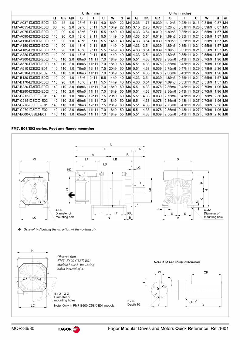
MQR-36/80 Fagor Modular Drives and Motors Quick Reference. Ref.1601
FM7. E01/E02 series. Foot and flange mounting
Units in mm Units in inches
Q QK QR S T U W d m Q QK QR S T U W d mFM7-A037-3-E0 60 45 1.0 28h6 7h11 4.0 8h9 22 M4 2.36 1.77 0.039 1.10h6 0.28h11 0.16 0.31h9 0.87 M4FM7-A055-3-E0 80 70 2.0 32h6 8h11 5.0 10h9 22 M5 3.15 2.76 0.078 1.26h6 0.31h11 0.20 0.39h9 0.87 M5FM7-A075-3-E0 110 90 0.5 48h6 9h11 5.5 14h9 40 M5 4.33 3.54 0.019 1.89h6 0.35h11 0.21 0.55h9 1.57 M5FM7-A090-3-E0 110 90 0.5 48h6 9h11 5.5 14h9 40 M5 4.33 3.54 0.019 1.89h6 0.35h11 0.21 0.55h9 1.57 M5FM7-A110-3-E0 110 90 1.0 48h6 9h11 5.5 14h9 40 M5 4.33 3.54 0.039 1.89h6 0.35h11 0.21 0.55h9 1.57 M5FM7-A150-3-E0 110 90 1.0 48h6 9h11 5.5 14h9 40 M5 4.33 3.54 0.039 1.89h6 0.35h11 0.21 0.55h9 1.57 M5FM7-A185-3-E0 110 90 1.0 48h6 9h11 5.5 14h9 40 M5 4.33 3.54 0.039 1.89h6 0.35h11 0.21 0.55h9 1.57 M5FM7-A220-3-E0 110 90 1.0 48h6 9h11 5.5 14h9 40 M5 4.33 3.54 0.039 1.89h6 0.35h11 0.21 0.55h9 1.57 M5FM7-A300-3-E0 140 110 2.0 60m6 11h11 7.0 18h9 50 M6 5.51 4.33 0.078 2.36m6 0.43h11 0.27 0.70h9 1.96 M6FM7-A370-3-E0 140 110 2.0 60m6 11h11 7.0 18h9 50 M6 5.51 4.33 0.078 2.36m6 0.43h11 0.27 0.70h9 1.96 M6FM7-A510-3-E01 140 110 1.0 70m6 12h11 7.5 20h9 60 M6 5.51 4.33 0.039 2.75m6 0.47h11 0.29 0.78h9 2.36 M6FM7-A510-3-E02 140 110 2.0 60m6 11h11 7.0 18h9 50 M6 5.51 4.33 0.078 2.36m6 0.43h11 0.27 0.70h9 1.96 M6FM7-B120-3-E0 110 90 1.0 48h6 9h11 5.5 14h9 40 M5 4.33 3.54 0.039 1.89h6 0.35h11 0.21 0.55h9 1.57 M5FM7-B170-3-E0 110 90 1.0 48h6 9h11 5.5 14h9 40 M5 4.33 3.54 0.039 1.89h6 0.35h11 0.21 0.55h9 1.57 M5FM7-B220-3-E0 140 110 2.0 60m6 11h11 7.0 18h9 50 M6 5.51 4.33 0.078 2.36m6 0.43h11 0.27 0.70h9 1.96 M6FM7-B280-3-E0 140 110 2.0 60m6 11h11 7.0 18h9 50 M6 5.51 4.33 0.078 2.36m6 0.43h11 0.27 0.70h9 1.96 M6FM7-C215-3-E01 140 110 1.0 70m6 12h11 7.5 20h9 60 M6 5.51 4.33 0.039 2.75m6 0.47h11 0.29 0.78h9 2.36 M6FM7-C215-3-E02 140 110 2.0 60m6 11h11 7.0 18h9 50 M6 5.51 4.33 0.078 2.36m6 0.43h11 0.27 0.70h9 1.96 M6FM7-C270-3-E01 140 110 1.0 70m6 12h11 7.5 20h9 60 M6 5.51 4.33 0.039 2.75m6 0.47h11 0.29 0.78h9 2.36 M6FM7-C270-3-E02 140 110 2.0 60m6 11h11 7.0 18h9 50 M6 5.51 4.33 0.078 2.36m6 0.43h11 0.27 0.70h9 1.96 M6FM7-E600-C3B-E01 140 110 1.0 65m6 11h11 7.0 18h9 55 M6 5.51 4.33 0.039 2.56m6 0.43h11 0.27 0.70h9 2.16 M6
KI
LC
4-ØZ
LHLA
N
F F
KD
SQ h
LB
Q
5
LG
LELF
LD
A R
LL LR
L
D
M
E E
J
PC
H
G
B
BBDiameter ofmounting hole
4-ØZDiameter ofmounting hole
KI
LC
LH LA
4 x 2 - Ø ZDiameter ofmounting holes
Note. Only in FM7-E600-C5BX-E01 models
Observe thatFM7- E600-C5BX-E01 models have 8 mounting holes instead of 4.
d
QQR
R
QK
3 - mDepth 10 S
T
W
U
Symbol indicating the direction of the cooling air
Detail of the shaft extension
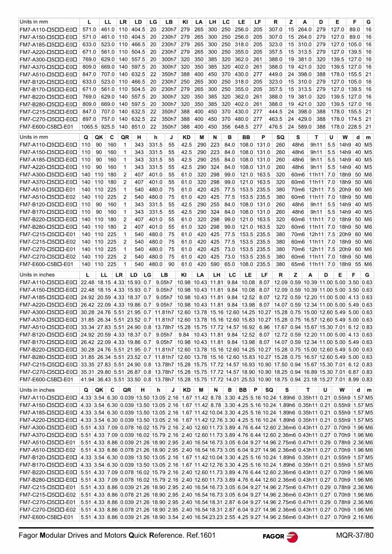
Fagor Modular Drives and Motors Quick Reference. Ref.1601 MQR-37/80
Units in mm L LL LR LD LG LB KI LA LH LC LE LF R Z A D E F G
FM7-A110-5-E0 571.0 461.0 110 404.5 20 230h7 279 265 300 250 256.0 205 307.0 15 264.0 279 127.0 89.0 16
FM7-A150-5-E0 571.0 461.0 110 404.5 20 230h7 279 265 300 250 256.0 205 307.0 15 264.0 279 127.0 89.0 16
FM7-A185-5-E0 633.0 523.0 110 466.5 20 230h7 279 265 300 250 318.0 205 323.0 15 310.0 279 127.0 105.0 16
FM7-A220-5-E0 671.0 561.0 110 504.5 20 230h7 279 265 300 250 355.0 205 357.5 15 313.5 279 127.0 139.5 16
FM7-A300-5-E0 769.0 629.0 140 557.5 20 300h7 320 350 385 320 362.0 261 388.0 19 381.0 320 139.5 127.0 16
FM7-A370-5-E0 809.0 669.0 140 597.5 20 300h7 320 350 385 320 402.0 261 388.0 19 421.0 320 139.5 127.0 16
FM7-A510-5-E0 847.0 707.0 140 632.5 22 350h7 388 400 450 370 430.0 277 449.0 24 398.0 388 178.0 155.5 21
FM7-B120-5-E0 633.0 523.0 110 466.5 20 230h7 250 265 300 250 318.0 205 323.0 15 310.0 279 127.0 105.0 16
FM7-B170-5-E0 671.0 561.0 110 504.5 20 230h7 279 265 300 250 355.0 205 357.5 15 313.5 279 127.0 139.5 16
FM7-B220-5-E0 769.0 629.0 140 557.5 20 300h7 320 350 385 320 362.0 261 388.0 19 381.0 320 139.5 127.0 16
FM7-B280-5-E0 809.0 669.0 140 597.5 20 300h7 320 350 385 320 402.0 261 388.0 19 421.0 320 139.5 127.0 16
FM7-C215-5-E0 847.0 707.0 140 632.5 22 350h7 388 400 450 370 430.0 277 444.5 24 398.0 388 178.0 155.5 21
FM7-C270-5-E0 897.0 757.0 140 632.5 22 350h7 388 400 450 370 480.0 277 463.5 24 429.0 388 178.0 174.5 21
FM7-E600-C5B-E01 1065.5 925.5 140 851.0 22 350h7 388 400 450 356 648.5 277 476.5 24 589.0 388 178.0 228.5 21
Units in mm Q QK C QR H h J KD M N B BB P SQ S T U W d mFM7-A110-5-E0 110 90 160 1 343 331.5 55 42.5 290 223 84.0 108.0 131.0 260 48h6 9h11 5.5 14h9 40 M5FM7-A150-5-E0 110 90 160 1 343 331.5 55 42.5 290 223 84.0 108.0 131.0 260 48h6 9h11 5.5 14h9 40 M5FM7-A185-5-E0 110 90 160 1 343 331.5 55 42.5 290 255 84.0 108.0 131.0 260 48h6 9h11 5.5 14h9 40 M5FM7-A220-5-E0 110 90 160 1 343 331.5 55 42.5 290 324 84.0 108.0 131.0 260 48h6 9h11 5.5 14h9 40 M5FM7-A300-5-E0 140 110 180 2 407 401.0 55 61.0 320 298 99.0 121.0 163.5 320 60m6 11h11 7.0 18h9 50 M6FM7-A370-5-E0 140 110 180 2 407 401.0 55 61.0 320 298 99.0 121.0 163.5 320 60m6 11h11 7.0 18h9 50 M6FM7-A510-5-E01 140 110 225 1 540 480.0 75 61.0 420 425 77.5 153.5 235.5 380 70m6 12h11 7.5 20h9 60 M6FM7-A510-5-E02 140 110 225 2 540 480.0 75 61.0 420 425 77.5 153.5 235.5 380 60m6 11h11 7.0 18h9 50 M6FM7-B120-5-E0 110 90 160 1 343 331.5 55 42.5 290 255 84.0 108.0 131.0 260 48h6 9h11 5.5 14h9 40 M5FM7-B170-5-E0 110 90 160 1 343 331.5 55 42.5 290 324 84.0 108.0 131.0 260 48h6 9h11 5.5 14h9 40 M5FM7-B220-5-E0 140 110 180 2 407 401.0 55 61.0 320 298 99.0 121.0 163.5 320 60m6 11h11 7.0 18h9 50 M6FM7-B280-5-E0 140 110 180 2 407 401.0 55 61.0 320 298 99.0 121.0 163.5 320 60m6 11h11 7.0 18h9 50 M6FM7-C215-5-E01 140 110 225 1 540 480.0 75 61.0 420 425 77.5 153.5 235.5 380 70m6 12h11 7.5 20h9 60 M6FM7-C215-5-E02 140 110 225 2 540 480.0 75 61.0 420 425 77.5 153.5 235.5 380 60m6 11h11 7.0 18h9 50 M6FM7-C270-5-E01 140 110 225 1 540 480.0 75 61.0 420 425 73.0 153.5 235.5 380 70m6 12h11 7.5 20h9 60 M6FM7-C270-5-E02 140 110 225 2 540 480.0 75 61.0 420 425 73.0 153.5 235.5 380 60m6 11h11 7.0 18h9 50 M6FM7-E600-C5B-E01 140 110 225 1 540 480.0 90 61.0 420 590 65.0 108.0 235.5 380 65m6 11h11 7.0 18h9 55 M6
Units in inches L LL LR LD LG LB KI LA LH LC LE LF R Z A D E F GFM7-A110-5-E0 22.48 18.15 4.33 15.93 0.7 9.05h7 10.98 10.43 11.81 9.84 10.08 8.07 12.09 0.59 10.39 11.00 5.00 3.50 0.63FM7-A150-5-E0 22.48 18.15 4.33 15.93 0.7 9.05h7 10.98 10.43 11.81 9.84 10.08 8.07 12.09 0.59 10.39 11.00 5.00 3.50 0.63FM7-A185-5-E0 24.92 20.59 4.33 18.37 0.7 9.05h7 10.98 10.43 11.81 9.84 12.52 8.07 12.72 0.59 12.20 11.00 5.00 4.13 0.63FM7-A220-5-E0 26.42 22.09 4.33 19.86 0.7 9.05h7 10.98 10.43 11.81 9.84 13.98 8.07 14.07 0.59 12.34 11.00 5.00 5.49 0.63FM7-A300-5-E0 30.28 24.76 5.51 21.95 0.7 11.81h7 12.60 13.78 15.16 12.60 14.25 10.27 15.28 0.75 15.00 12.60 5.49 5.00 0.63FM7-A370-5-E0 31.85 26.34 5.51 23.52 0.7 11.81h7 12.60 13.78 15.16 12.60 15.83 10.27 15.28 0.75 16.57 12.60 5.49 5.00 0.63FM7-A510-5-E0 33.34 27.83 5.51 24.90 0.8 13.78h7 15.28 15.75 17.72 14.57 16.92 6.96 17.67 0.94 15.67 15.30 7.01 6.12 0.83FM7-B120-5-E0 24.92 20.59 4.33 18.37 0.7 9.05h7 9.84 10.43 11.81 9.84 12.52 8.07 12.72 0.59 12.20 11.00 5.00 4.13 0.63FM7-B170-5-E0 26.42 22.09 4.33 19.86 0.7 9.05h7 10.98 10.43 11.81 9.84 13.98 8.07 14.07 0.59 12.34 11.00 5.00 5.49 0.63FM7-B220-5-E0 30.28 24.76 5.51 21.95 0.7 11.81h7 12.60 13.78 15.16 12.60 14.25 10.27 15.28 0.75 15.00 12.60 5.49 5.00 0.63FM7-B280-5-E0 31.85 26.34 5.51 23.52 0.7 11.81h7 12.60 13.78 15.16 12.60 15.83 10.27 15.28 0.75 16.57 12.60 5.49 5.00 0.63FM7-C215-5-E0 33.35 27.83 5.51 24.90 0.8 13.78h7 15.28 15.75 17.72 14.57 16.93 10.90 17.50 0.94 15.67 15.30 7.01 6.12 0.83FM7-C270-5-E0 35.31 29.80 5.51 26.87 0.8 13.78h7 15.28 15.75 17.72 14.57 18.90 10.90 18.25 0.94 16.89 15.30 7.01 6.87 0.83FM7-E600-C5B-E01 41.94 36.43 5.51 33.50 0.8 13.78h7 15.28 15.75 17.72 14.01 25.53 10.90 18.75 0.94 23.18 15.27 7.01 8.99 0.83
Units in inches Q QK C QR H h J KD M N B BB P SQ S T U W d m
FM7-A110-5-E0 4.33 3.54 6.30 0.039 13.50 13.05 2.16 1.67 11.42 8.78 3.30 4.25 5.16 10.24 1.89h6 0.35h11 0.21 0.55h9 1.57 M5FM7-A150-5-E0 4.33 3.54 6.30 0.039 13.50 13.05 2.16 1.67 11.42 8.78 3.30 4.25 5.16 10.24 1.89h6 0.35h11 0.21 0.55h9 1.57 M5FM7-A185-5-E0 4.33 3.54 6.30 0.039 13.50 13.05 2.16 1.67 11.42 10.04 3.30 4.25 5.16 10.24 1.89h6 0.35h11 0.21 0.55h9 1.57 M5FM7-A220-5-E0 4.33 3.54 6.30 0.039 13.50 13.05 2.16 1.67 11.42 12.76 3.30 4.25 5.16 10.24 1.89h6 0.35h11 0.21 0.55h9 1.57 M5FM7-A300-5-E0 5.51 4.33 7.09 0.078 16.02 15.79 2.16 2.40 12.60 11.73 3.89 4.76 6.44 12.60 2.36m6 0.43h11 0.27 0.70h9 1.96 M6FM7-A370-5-E0 5.51 4.33 7.09 0.039 16.02 15.79 2.16 2.40 12.60 11.73 3.89 4.76 6.44 12.60 2.36m6 0.43h11 0.27 0.70h9 1.96 M6FM7-A510-5-E01 5.51 4.33 8.86 0.039 21.26 18.90 2.95 2.40 16.54 16.73 3.05 6.04 9.27 14.96 2.75m6 0.47h11 0.29 0.78h9 2.36 M6FM7-A510-5-E02 5.51 4.33 8.86 0.078 21.26 18.90 2.95 2.40 16.54 16.73 3.05 6.04 9.27 14.96 2.36m6 0.43h11 0.27 0.70h9 1.96 M6FM7-B120-5-E0 4.33 3.54 6.30 0.039 13.50 13.05 2.16 1.67 11.42 10.04 3.30 4.25 5.16 10.24 1.89h6 0.35h11 0.21 0.55h9 1.57 M5FM7-B170-5-E0 4.33 3.54 6.30 0.039 13.50 13.05 2.16 1.67 11.42 12.76 3.30 4.25 5.16 10.24 1.89h6 0.35h11 0.21 0.55h9 1.57 M5FM7-B220-5-E0 5.51 4.33 7.09 0.078 16.02 15.79 2.16 2.40 12.60 11.73 3.89 4.76 6.44 12.60 2.36m6 0.43h11 0.27 0.70h9 1.96 M6FM7-B280-5-E0 5.51 4.33 7.09 0.078 16.02 15.79 2.16 2.40 12.60 11.73 3.89 4.76 6.44 12.60 2.36m6 0.43h11 0.27 0.70h9 1.96 M6FM7-C215-5-E01 5.51 4.33 8.86 0.039 21.26 18.90 2.95 2.40 16.54 16.73 3.05 6.04 9.27 14.96 2.75m6 0.47h11 0.29 0.78h9 2.36 M6FM7-C215-5-E02 5.51 4.33 8.86 0.078 21.26 18.90 2.95 2.40 16.54 16.73 3.05 6.04 9.27 14.96 2.36m6 0.43h11 0.27 0.70h9 1.96 M6FM7-C270-5-E01 5.51 4.33 8.86 0.039 21.26 18.90 2.95 2.40 16.54 18.31 2.87 6.04 9.27 14.96 2.75m6 0.47h11 0.29 0.78h9 2.36 M6FM7-C270-5-E02 5.51 4.33 8.86 0.078 21.26 18.90 2.95 2.40 16.54 18.31 2.87 6.04 9.27 14.96 2.36m6 0.43h11 0.27 0.70h9 1.96 M6FM7-E600-C5B-E01 5.51 4.33 8.86 0.039 21.26 18.90 3.54 2.40 16.54 23.23 2.55 4.25 9.27 14.96 2.56m6 0.43h11 0.27 0.70h9 2.16 M6
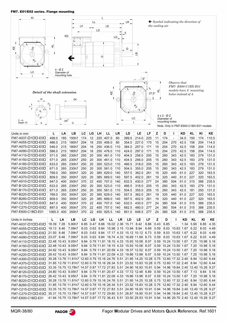
MQR-38/80 Fagor Modular Drives and Motors Quick Reference. Ref.1601
FM7. E01/E02 series. Flange mounting
Units in mm L LA LB LC LG LH LL LR LD LE LF Z D I KD KL KI KE
FM7-A037-1-E0 499.0 185 150h7 174 12 220 407.0 60 399.0 214.0 225 11 174 - 34.0 150 174 110.5FM7-A055-1-E0 486.0 215 180h7 204 16 250 406.0 80 354.0 227.0 170 15 204 270 42.5 158 204 114.0FM7-A075-1-E0 546.0 215 180h7 204 16 250 436.0 110 384.0 257.0 171 15 204 270 42.5 158 204 114.0FM7-A090-1-E0 586.0 215 180h7 204 16 250 476.0 110 424.0 297.0 171 15 204 270 42.5 158 204 114.0FM7-A110-1-E0 571.0 265 230h7 250 20 300 461.0 110 404.5 256.0 205 15 260 343 42.5 183 279 131.0FM7-A150-1-E0 571.0 265 230h7 250 20 300 461.0 110 404.5 256.0 205 15 260 343 42.5 183 279 131.0FM7-A185-1-E0 633.0 265 230h7 250 20 300 523.0 110 466.5 318.0 205 15 260 343 42.5 183 279 131.0FM7-A220-1-E0 671.0 265 230h7 250 20 300 561.0 110 504.5 355.0 205 15 260 343 42.5 183 279 131.0FM7-A300-1-E0 769.0 350 300h7 320 20 385 629.0 140 557.5 362.0 261 19 320 440 61.0 227 320 163.5FM7-A370-1-E0 809.0 350 300h7 320 20 385 669.0 140 597.5 402.0 261 19 320 440 61.0 227 320 163.5FM7-A510-1-E0 847.0 400 350h7 370 22 450 707.0 140 632.5 430.0 277 24 380 504 61.0 315 388 235.5FM7-B120-1-E0 633.0 265 230h7 250 20 300 523.0 110 466.5 318.0 205 15 260 343 42.5 183 279 131.0FM7-B170-1-E0 671.0 265 230h7 250 20 300 561.0 110 504.5 355.0 205 15 260 343 42.5 181 250 131.0FM7-B220-1-E0 769.0 350 300h7 320 20 385 629.0 140 557.5 362.0 261 19 320 440 61.0 227 320 163.5FM7-B280-1-E0 809.0 350 300h7 320 20 385 669.0 140 597.5 402.0 261 19 320 440 61.0 227 320 163.5FM7-C215-1-E0 847.0 400 350h7 370 22 450 707.0 140 632.5 430.0 277 24 380 504 61.0 315 388 235.5FM7-C270-1-E0 897.0 400 350h7 370 22 450 757.0 140 682.5 480.0 277 24 380 504 61.0 315 388 235.5FM7-E600-C1B-E01 1065.5 400 350h7 370 22 450 925.5 140 851.0 648.5 277 24 380 526 61.0 315 388 235.5
Units in inches L LA LB LC LG LH LL LR LD LE LF Z D I KD KL KI KE
FM7-A037-1-E0 18.39 7.28 5.90h7 6.85 0.47 8.66 16.02 2.36 15.71 8.42 8.86 0.43 6.85 - 1.34 5.90 6.85 4.35
FM7-A055-1-E0 19.13 8.46 7.09h7 8.03 0.63 9.84 15.98 3.15 13.94 8.94 6.69 0.59 8.03 10.63 1.67 6.22 8.03 4.49
FM7-A075-1-E0 21.50 8.46 7.09h7 8.03 0.63 9.84 17.17 4.33 15.12 10.12 6.73 0.59 8.03 10.63 1.67 6.22 8.03 4.49
FM7-A090-1-E0 23.07 8.46 7.09h7 8.03 0.63 9.84 18.74 4.33 16.69 11.69 6.73 0.59 8.03 10.63 1.67 6.22 8.03 4.49
FM7-A110-1-E0 22.48 10.43 9.05h7 9.84 0.79 11.81 18.15 4.33 15.93 10.08 8.07 0.59 10.24 13.50 1.67 7.20 10.98 5.16
FM7-A150-1-E0 22.48 10.43 9.05h7 9.84 0.79 11.81 18.15 4.33 15.93 10.08 8.07 0.59 10.24 13.50 1.67 7.20 10.98 5.16
FM7-A185-1-E0 24.92 10.43 9.05h7 9.84 0.79 11.81 20.59 4.33 18.37 12.52 8.07 0.59 10.24 13.50 1.67 7.20 10.98 5.16
FM7-A220-1-E0 26.42 10.43 9.05h7 9.84 0.79 11.81 22.09 4.33 19.86 13.98 8.07 0.59 10.24 13.50 1.67 7.20 10.98 5.16
FM7-A300-1-E0 30.28 13.78 11.81h7 12.60 0.79 15.16 24.76 5.51 21.95 14.25 10.28 0.75 12.60 17.32 2.40 8.94 12.60 6.44
FM7-A370-1-E0 31.85 13.78 11.81h7 12.60 0.79 15.16 26.34 5.51 23.52 15.83 10.28 0.75 12.60 17.32 2.40 8.94 12.60 6.44
FM7-A510-1-E0 33.35 15.75 13.78h7 14.57 0.87 17.72 27.83 5.51 24.90 16.93 10.91 0.94 14.96 19.84 2.40 12.40 15.28 9.27
FM7-B120-1-E0 24.80 10.43 9.05h7 9.84 0.79 11.81 20.47 4.33 17.72 12.48 6.89 0.59 10.24 13.50 1.67 7.13 9.84 5.16
FM7-B170-1-E0 26.42 10.43 9.05h7 9.84 0.79 11.81 22.09 4.33 19.86 13.98 8.07 0.59 10.24 13.50 1.67 7.20 10.98 5.16
FM7-B220-1-E0 30.28 13.78 11.81h7 12.60 0.79 15.16 24.76 5.51 21.95 14.25 10.28 0.75 12.60 17.32 2.40 8.94 12.60 6.44
FM7-B280-1-E0 31.85 13.78 11.81h7 12.60 0.79 15.16 26.34 5.51 23.52 15.83 10.28 0.75 12.60 17.32 2.40 8.94 12.60 6.44
FM7-C215-1-E0 33.35 15.75 13.78h7 14.57 0.87 17.72 27.83 5.51 24.90 16.93 10.91 0.94 14.96 19.84 2.40 12.40 15.28 9.27
FM7-C270-1-E0 35.31 15.75 13.78h7 14.57 0.87 17.72 29.80 5.51 26.87 18.90 10.91 0.94 14.96 19.84 2.40 12.40 15.28 9.27
FM7-E600-C1B-E01 41.94 15.75 13.78h7 14.57 0.87 17.72 36.43 5.51 33.50 25.53 10.91 0.94 14.96 20.70 2.40 12.40 15.28 9.27
4 x 2 - Ø ZDiameter ofmounting holesI
LC
KE K
L
LHLA
Note. Only in FM7-E600-C1BX-E01 models
37,5°
37,5°
4 - Ø ZDiameter ofmounting holeI
LC
KE
KI
KL
LHLA
L
LL LR
LELF
LD
KD
D
Q
5
LG
LB
d
QQR
R
QK
3 - mDepth 10 S
T
W
U
Detail of the shaft extension
Observe thatFM7- E600-C1BX-E01 models have 8 mounting holes instead of 4.
Symbol indicating the direction of the cooling air
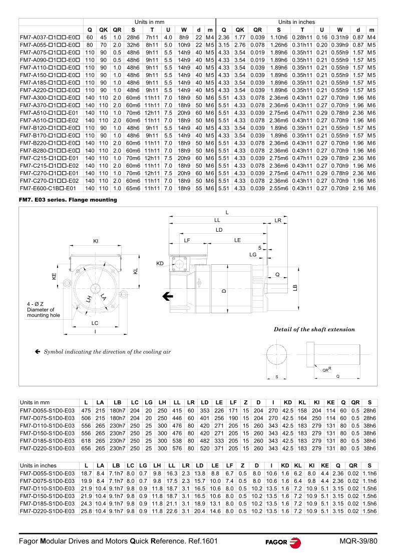
Fagor Modular Drives and Motors Quick Reference. Ref.1601 MQR-39/80
FM7. E03 series. Flange mounting
Units in mm Units in inches
Q QK QR S T U W d m Q QK QR S T U W d mFM7-A037-1-E0 60 45 1.0 28h6 7h11 4.0 8h9 22 M4 2.36 1.77 0.039 1.10h6 0.28h11 0.16 0.31h9 0.87 M4FM7-A055-1-E0 80 70 2.0 32h6 8h11 5.0 10h9 22 M5 3.15 2.76 0.078 1.26h6 0.31h11 0.20 0.39h9 0.87 M5FM7-A075-1-E0 110 90 0.5 48h6 9h11 5.5 14h9 40 M5 4.33 3.54 0.019 1.89h6 0.35h11 0.21 0.55h9 1.57 M5FM7-A090-1-E0 110 90 0.5 48h6 9h11 5.5 14h9 40 M5 4.33 3.54 0.019 1.89h6 0.35h11 0.21 0.55h9 1.57 M5FM7-A110-1-E0 110 90 1.0 48h6 9h11 5.5 14h9 40 M5 4.33 3.54 0.039 1.89h6 0.35h11 0.21 0.55h9 1.57 M5FM7-A150-1-E0 110 90 1.0 48h6 9h11 5.5 14h9 40 M5 4.33 3.54 0.039 1.89h6 0.35h11 0.21 0.55h9 1.57 M5FM7-A185-1-E0 110 90 1.0 48h6 9h11 5.5 14h9 40 M5 4.33 3.54 0.039 1.89h6 0.35h11 0.21 0.55h9 1.57 M5FM7-A220-1-E0 110 90 1.0 48h6 9h11 5.5 14h9 40 M5 4.33 3.54 0.039 1.89h6 0.35h11 0.21 0.55h9 1.57 M5FM7-A300-1-E0 140 110 2.0 60m6 11h11 7.0 18h9 50 M6 5.51 4.33 0.078 2.36m6 0.43h11 0.27 0.70h9 1.96 M6FM7-A370-1-E0 140 110 2.0 60m6 11h11 7.0 18h9 50 M6 5.51 4.33 0.078 2.36m6 0.43h11 0.27 0.70h9 1.96 M6FM7-A510-1-E01 140 110 1.0 70m6 12h11 7.5 20h9 60 M6 5.51 4.33 0.039 2.75m6 0.47h11 0.29 0.78h9 2.36 M6FM7-A510-1-E02 140 110 2.0 60m6 11h11 7.0 18h9 50 M6 5.51 4.33 0.078 2.36m6 0.43h11 0.27 0.70h9 1.96 M6FM7-B120-1-E0 110 90 1.0 48h6 9h11 5.5 14h9 40 M5 4.33 3.54 0.039 1.89h6 0.35h11 0.21 0.55h9 1.57 M5FM7-B170-1-E0 110 90 1.0 48h6 9h11 5.5 14h9 40 M5 4.33 3.54 0.039 1.89h6 0.35h11 0.21 0.55h9 1.57 M5FM7-B220-1-E0 140 110 2.0 60m6 11h11 7.0 18h9 50 M6 5.51 4.33 0.078 2.36m6 0.43h11 0.27 0.70h9 1.96 M6FM7-B280-1-E0 140 110 2.0 60m6 11h11 7.0 18h9 50 M6 5.51 4.33 0.078 2.36m6 0.43h11 0.27 0.70h9 1.96 M6FM7-C215-1-E01 140 110 1.0 70m6 12h11 7.5 20h9 60 M6 5.51 4.33 0.039 2.75m6 0.47h11 0.29 0.78h9 2.36 M6FM7-C215-1-E02 140 110 2.0 60m6 11h11 7.0 18h9 50 M6 5.51 4.33 0.078 2.36m6 0.43h11 0.27 0.70h9 1.96 M6FM7-C270-1-E01 140 110 1.0 70m6 12h11 7.5 20h9 60 M6 5.51 4.33 0.039 2.75m6 0.47h11 0.29 0.78h9 2.36 M6FM7-C270-1-E02 140 110 2.0 60m6 11h11 7.0 18h9 50 M6 5.51 4.33 0.078 2.36m6 0.43h11 0.27 0.70h9 1.96 M6FM7-E600-C1B-E01 140 110 1.0 65m6 11h11 7.0 18h9 55 M6 5.51 4.33 0.039 2.55m6 0.43h11 0.27 0.70h9 2.16 M6
Units in mm L LA LB LC LG LH LL LR LD LE LF Z D I KD KL KI KE Q QR S
FM7-D055-S1D0-E03 475 215 180h7 204 20 250 415 60 353 226 171 15 204 270 42.5 158 204 114 60 0.5 28h6FM7-D075-S1D0-E03 506 215 180h7 204 20 250 446 60 401 256 190 15 204 270 42.5 164 250 114 60 0.5 28h6FM7-D110-S1D0-E03 556 265 230h7 250 25 300 476 80 420 271 205 15 260 343 42.5 183 279 131 80 0.5 38h6FM7-D150-S1D0-E03 556 265 230h7 250 25 300 476 80 420 271 205 15 260 343 42.5 183 279 131 80 0.5 38h6FM7-D185-S1D0-E03 618 265 230h7 250 25 300 538 80 482 333 205 15 260 343 42.5 183 279 131 80 0.5 38h6FM7-D220-S1D0-E03 656 265 230h7 250 25 300 576 80 520 371 205 15 260 343 42.5 183 279 131 80 0.5 38h6
Units in inches L LA LB LC LG LH LL LR LD LE LF Z D I KD KL KI KE Q QR S
FM7-D055-S1D0-E03 18.7 8.4 7.1h7 8.0 0.7 9.8 16.3 2.3 13.8 8.8 6.7 0.5 8.0 10.6 1.6 6.2 8.0 4.4 2.36 0.02 1.1h6FM7-D075-S1D0-E03 19.9 8.4 7.1h7 8.0 0.7 9.8 17.5 2.3 15.7 10.0 7.4 0.5 8.0 10.6 1.6 6.4 9.8 4.4 2.36 0.02 1.1h6FM7-D110-S1D0-E03 21.9 10.4 9.1h7 9.8 0.9 11.8 18.7 3.1 16.5 10.6 8.0 0.5 10.2 13.5 1.6 7.2 10.9 5.1 3.15 0.02 1.5h6FM7-D150-S1D0-E03 21.9 10.4 9.1h7 9.8 0.9 11.8 18.7 3.1 16.5 10.6 8.0 0.5 10.2 13.5 1.6 7.2 10.9 5.1 3.15 0.02 1.5h6FM7-D185-S1D0-E03 24.3 10.4 9.1h7 9.8 0.9 11.8 21.1 3.1 18.9 13.1 8.0 0.5 10.2 13.5 1.6 7.2 10.9 5.1 3.15 0.02 1.5h6FM7-D220-S1D0-E03 25.8 10.4 9.1h7 9.8 0.9 11.8 22.6 3.1 20.4 14.6 8.0 0.5 10.2 13.5 1.6 7.2 10.9 5.1 3.15 0.02 1.5h6
LB
LG5
KD
D
KL
KE
4 - Ø Z
LH
LA
Diameter ofmounting hole
KI
LC
I
L
LL
LD
LF LE
Q
LR
S Q
QRR
Detail of the shaft extension
Symbol indicating the direction of the cooling air
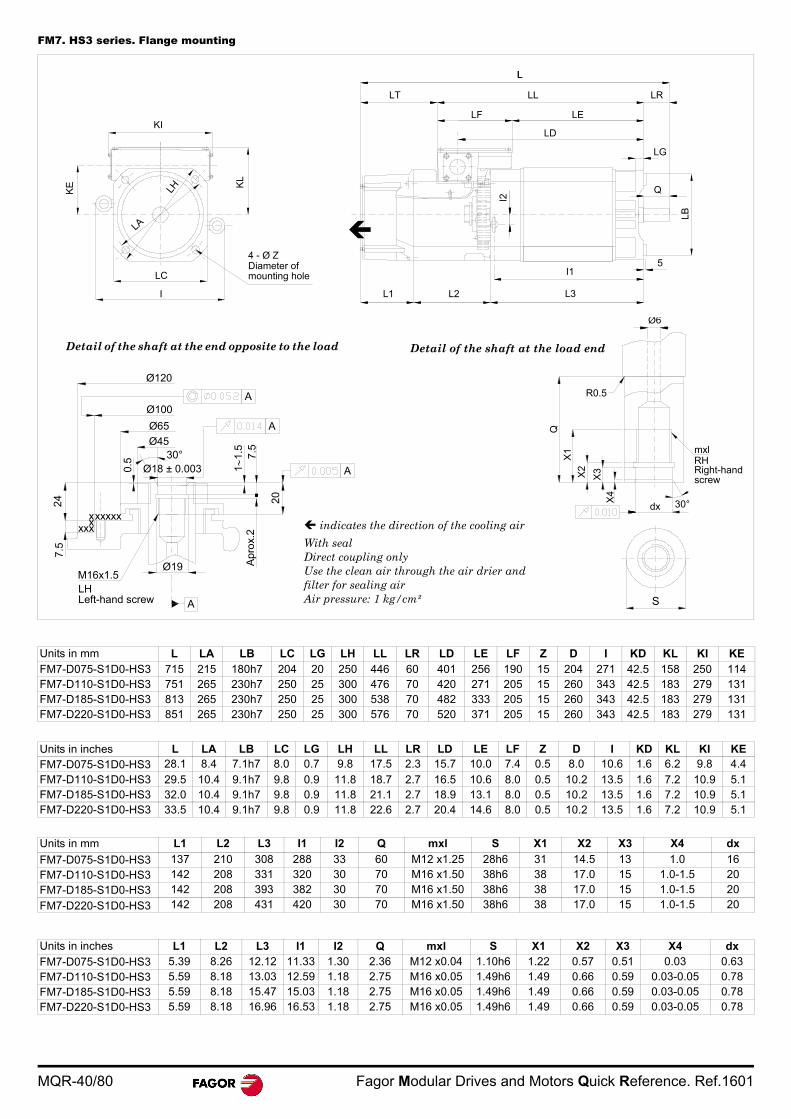
MQR-40/80 Fagor Modular Drives and Motors Quick Reference. Ref.1601
FM7. HS3 series. Flange mounting
Units in mm L LA LB LC LG LH LL LR LD LE LF Z D I KD KL KI KEFM7-D075-S1D0-HS3 715 215 180h7 204 20 250 446 60 401 256 190 15 204 271 42.5 158 250 114FM7-D110-S1D0-HS3 751 265 230h7 250 25 300 476 70 420 271 205 15 260 343 42.5 183 279 131FM7-D185-S1D0-HS3 813 265 230h7 250 25 300 538 70 482 333 205 15 260 343 42.5 183 279 131FM7-D220-S1D0-HS3 851 265 230h7 250 25 300 576 70 520 371 205 15 260 343 42.5 183 279 131
Units in inches L LA LB LC LG LH LL LR LD LE LF Z D I KD KL KI KEFM7-D075-S1D0-HS3 28.1 8.4 7.1h7 8.0 0.7 9.8 17.5 2.3 15.7 10.0 7.4 0.5 8.0 10.6 1.6 6.2 9.8 4.4
FM7-D110-S1D0-HS3 29.5 10.4 9.1h7 9.8 0.9 11.8 18.7 2.7 16.5 10.6 8.0 0.5 10.2 13.5 1.6 7.2 10.9 5.1FM7-D185-S1D0-HS3 32.0 10.4 9.1h7 9.8 0.9 11.8 21.1 2.7 18.9 13.1 8.0 0.5 10.2 13.5 1.6 7.2 10.9 5.1FM7-D220-S1D0-HS3 33.5 10.4 9.1h7 9.8 0.9 11.8 22.6 2.7 20.4 14.6 8.0 0.5 10.2 13.5 1.6 7.2 10.9 5.1
Units in mm L1 L2 L3 I1 I2 Q mxl S X1 X2 X3 X4 dx
FM7-D075-S1D0-HS3 137 210 308 288 33 60 M12 x1.25 28h6 31 14.5 13 1.0 16
FM7-D110-S1D0-HS3 142 208 331 320 30 70 M16 x1.50 38h6 38 17.0 15 1.0-1.5 20
FM7-D185-S1D0-HS3 142 208 393 382 30 70 M16 x1.50 38h6 38 17.0 15 1.0-1.5 20
FM7-D220-S1D0-HS3 142 208 431 420 30 70 M16 x1.50 38h6 38 17.0 15 1.0-1.5 20
Units in inches L1 L2 L3 I1 I2 Q mxl S X1 X2 X3 X4 dx
FM7-D075-S1D0-HS3 5.39 8.26 12.12 11.33 1.30 2.36 M12 x0.04 1.10h6 1.22 0.57 0.51 0.03 0.63FM7-D110-S1D0-HS3 5.59 8.18 13.03 12.59 1.18 2.75 M16 x0.05 1.49h6 1.49 0.66 0.59 0.03-0.05 0.78FM7-D185-S1D0-HS3 5.59 8.18 15.47 15.03 1.18 2.75 M16 x0.05 1.49h6 1.49 0.66 0.59 0.03-0.05 0.78FM7-D220-S1D0-HS3 5.59 8.18 16.96 16.53 1.18 2.75 M16 x0.05 1.49h6 1.49 0.66 0.59 0.03-0.05 0.78
S
Ø6
Q
R0.5
dx 30°
mxl
X1
X2
X3
X4
RHRight-handscrew
Ø18 ± 0.003
Ø45
Ø65
Ø100
Ø120
20
Ø19
xxxxxxxx
xx
M16x1.5LH
A
A
Apr
ox.
2
A
A
7.5
11.
5
0.5
247
.5
30°
Left-hand screw
KI
KL
KE
LA
LH
I
LC
4 - Ø ZDiameter ofmounting hole
LL
LT LL LR
LF LE
LD
LG
5
Q
LB
I1
L1 L2 L3
I2
Detail of the shaft at the end opposite to the load Detail of the shaft at the load end
indicates the direction of the cooling air
With sealDirect coupling onlyUse the clean air through the air drier andfilter for sealing airAir pressure: 1 kg/cm²
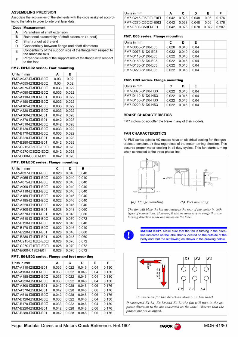
Fagor Modular Drives and Motors Quick Reference. Ref.1601 MQR-41/80
ASSEMBLING PRECISIONAssociate the accuracies of the elements with the code assigned accord-ing to the table in order to interpret later data.
FM7. E01/E02 series. Foot mounting
FM7. E01/E02 series. Flange mounting
FM7. E01/E02 series. Flange and foot mounting
FM7. E03 series. Flange mounting
FM7. HS3 series. Flange mounting
BRAKE CHARACTERISTICS
FM7 motors do not offer the brake in any of their models.
FAN CHARACTERISTICS
All FM7 series spindle AC motors have an electrical cooling fan that gen-erates a constant air flow regardless of the motor turning direction. Thisassures proper motor cooling in all duty cycles. This fan starts turningwhen connected to the three-phase line.
Code MeasurementA Parallelism of shaft extensiónB Rotational excentricity of shaft extension (runout)C Shaft runout at the endD Concentricity between flange and shaft diameters
E Concentricity of the support side of the flange with respect to the machine axis
F Perpendicularity of the support side of the flange with respect to the foot
Units in mm A BFM7-A037-3-E0 0.03 0.02FM7-A055-3-E0 0.03 0.02FM7-A075-3-E0 0.033 0.022FM7-A090-3-E0 0.033 0.022FM7-A110-3-E01 0.033 0.022FM7-A150-3-E0 0.033 0.022FM7-A185-3-E0 0.033 0.022FM7-A220-3-E0 0.033 0.022FM7-A300-3-E01 0.042 0.028FM7-A370-3-E01 0.042 0.028FM7-A510-3-E0 0.042 0.028FM7-B120-3-E0 0.033 0.022FM7-B170-3-E0 0.033 0.022FM7-B220-3-E01 0.042 0.028FM7-B280-3-E01 0.042 0.028FM7-C215-3-E0 0.042 0.028FM7-C270-3-E0 0.042 0.028FM7-E600-C3B-E01 0.042 0.028
Units in mm C D EFM7-A037-1-E0 0.020 0.040 0.040FM7-A055-1-E0 0.020 0.040 0.040FM7-A075-1-E0 0.022 0.040 0.040FM7-A090-1-E0 0.022 0.040 0.040FM7-A110-1-E0 0.022 0.046 0.040FM7-A150-1-E0 0.022 0.046 0.040FM7-A185-1-E0 0.022 0.046 0.040FM7-A220-1-E0 0.022 0.046 0.040FM7-A300-1-E01 0.028 0.048 0.060FM7-A370-1-E01 0.028 0.048 0.060FM7-A510-1-E0 0.028 0.070 0.072FM7-B120-1-E0 0.022 0.046 0.040FM7-B170-1-E0 0.022 0.046 0.040FM7-B220-1-E01 0.028 0.048 0.060FM7-B280-1-E01 0.028 0.048 0.060FM7-C215-1-E0 0.028 0.070 0.072FM7-C270-1-E0 0.028 0.070 0.072FM7-E600-C1B-E01 0.028 0.070 0.072
Units in mm A C D E FFM7-A110-5-E01 0.033 0.022 0.046 0.04 0.130FM7-A150-5-E0 0.033 0.022 0.046 0.04 0.130FM7-A185-5-E0 0.033 0.022 0.046 0.04 0.130FM7-A220-5-E0 0.033 0.022 0.046 0.04 0.130FM7-A300-5-E01 0.042 0.028 0.048 0.06 0.176FM7-A370-5-E01 0.042 0.028 0.048 0.06 0.176FM7-A510-5-E0 0.042 0.028 0.048 0.06 0.176FM7-B120-5-E0 0.033 0.022 0.046 0.04 0.130FM7-B170-5-E0 0.033 0.022 0.046 0.04 0.130FM7-B220-5-E01 0.042 0.028 0.048 0.06 0.176FM7-B280-5-E01 0.042 0.028 0.048 0.06 0.176
Units in mm A C D E FFM7-C215-5-E0 0.042 0.028 0.048 0.06 0.176FM7-C270-5-E0 0.042 0.028 0.048 0.06 0.176FM7-E600-C5B-E01 0.042 0.028 0.070 0.072 0.207
Units in mm C D EFM7-D055-S1D0-E03 0.020 0.040 0.04FM7-D075-S1D0-E03 0.022 0.040 0.04FM7-D110-S1D0-E03 0.022 0.046 0.04FM7-D150-S1D0-E03 0.022 0.046 0.04FM7-D185-S1D0-E03 0.022 0.046 0.04
FM7-D220-S1D0-E03 0.022 0.046 0.04
Units in mm C D E
FM7-D075-S1D0-HS3 0.022 0.040 0.04FM7-D110-S1D0-HS3 0.022 0.046 0.04FM7-D150-S1D0-HS3 0.022 0.046 0.04FM7-D220-S1D0-HS3 0.022 0.046 0.04
MANDATORY. Make sure that the fan is turning in the direc-tion indicated on the label that is located on the outside of thebody and that the air flowing as shown in the drawing below.
(a) Flange mounting (b) Foot mounting
The fan will blow the hot air towards the rear of the motor in bothtypes of connections. However, it will be necessary to verify that theturning direction is the one shown on the label.
(a) Flange mounting (b) Foot mounting
If connected Z1-L1, Z2-L2 and Z3-L3 the fan will turn in the op-posite direction to the one indicated on the label. Observe that thephases are not swapped.
AIR
FL
OW F
AN
MO
TO
RR
OT
AT
ION
Connection for the direction show n on fan label
Z1 Z2 Z3
L2 L1 L3
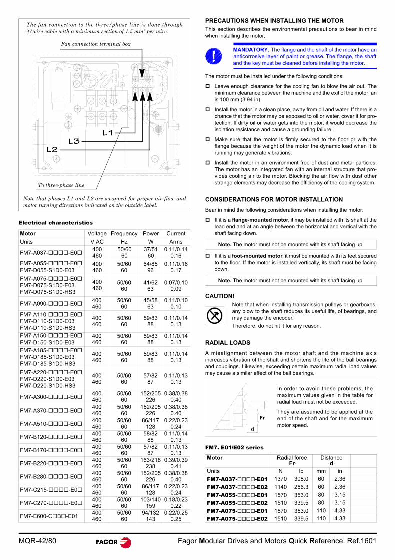
MQR-42/80 Fagor Modular Drives and Motors Quick Reference. Ref.1601
Electrical characteristics
PRECAUTIONS WHEN INSTALLING THE MOTORThis section describes the environmental precautions to bear in mindwhen installing the motor.
The motor must be installed under the following conditions:
Leave enough clearance for the cooling fan to blow the air out. Theminimum clearance between the machine and the exit of the motor fanis 100 mm (3.94 in).
Install the motor in a clean place, away from oil and water. If there is achance that the motor may be exposed to oil or water, cover it for pro-tection. If dirty oil or water gets into the motor, it would decrease theisolation resistance and cause a grounding failure.
Make sure that the motor is firmly secured to the floor or with theflange because the weight of the motor the dynamic load when it isrunning may generate vibrations.
Install the motor in an environment free of dust and metal particles.The motor has an integrated fan with an internal structure that pro-vides cooling air to the motor. Blocking the air flow with dust otherstrange elements may decrease the efficiency of the cooling system.
CONSIDERATIONS FOR MOTOR INSTALLATION
Bear in mind the following considerations when installing the motor:
If it is a flange-mounted motor, it may be installed with its shaft at theload end and at an angle between the horizontal and vertical with theshaft facing down.
If it is a foot-mounted motor, it must be mounted with its feet securedto the floor. If the motor is installed vertically, its shaft must be facingdown.
CAUTION!Note that when installing transmission pulleys or gearboxes,any blow to the shaft reduces its useful life, of bearings, andmay damage the encoder.
Therefore, do not hit it for any reason.
RADIAL LOADS
A misalignment between the motor shaft and the machine axisincreases vibration of the shaft and shortens the life of the ball bearingsand couplings. Likewise, exceeding certain maximum radial load valuesmay cause a similar effect of the ball bearings.
FM7. E01/E02 series
Motor Voltage Frequency Power Current
Units V AC Hz W Arms
FM7-A037--E0400460
50/6060
37/5160
0.11/0.140.16
FM7-A055--E0FM7-D055-S1D0-E03
400460
50/6060
64/8596
0.11/0.160.17
FM7-A075--E0FM7-D075-S1D0-E03FM7-D075-S1D0-HS3
400460
50/6060
41/6263
0.07/0.100.09
FM7-A090--E0400460
50/6060
45/5863
0.11/0.100.10
FM7-A110--E0FM7-D110-S1D0-E03FM7-D110-S1D0-HS3
400460
50/6060
59/8388
0.11/0.140.13
FM7-A150--E0FM7-D150-S1D0-E03
400460
50/6060
59/8388
0.11/0.140.13
FM7-A185--E0FM7-D185-S1D0-E03FM7-D185-S1D0-HS3
400460
50/6060
59/8388
0.11/0.140.13
FM7-A220--E0FM7-D220-S1D0-E03FM7-D220-S1D0-HS3
400460
50/6060
57/8287
0.11/0.130.13
FM7-A300--E0400460
50/6060
152/205226
0.38/0.380.40
FM7-A370--E0400460
50/6060
152/205226
0.38/0.380.40
FM7-A510--E0400460
50/6060
86/117128
0.22/0.230.24
FM7-B120--E0400460
50/6060
58/8288
0.11/0.140.13
FM7-B170--E0400460
50/6060
57/8287
0.11/0.130.13
FM7-B220--E0400460
50/6060
163/218238
0.39/0.390.41
FM7-B280--E0400460
50/6060
152/205226
0.38/0.380.40
FM7-C215--E0400460
50/6060
86/117128
0.22/0.230.24
FM7-C270--E0400460
50/6060
103/140159
0.18/0.230.22
FM7-E600-CB-E01400460
50/6060
94/132143
0.22/0.250.25
Note that phases L1 and L2 are swapped for proper air flow andmotor turning directions indicated on the outside label.
The fan connection to the three/phase line is done through4/wire cable with a minimum section of 1.5 mm² per wire.
L1
Fan connection terminal box
To three-phase line
L3L2
MANDATORY. The flange and the shaft of the motor have ananticorrosive layer of paint or grease. The flange, the shaftand the key must be cleaned before installing the motor.
Note. The motor must not be mounted with its shaft facing up.
Note. The motor must not be mounted with its shaft facing up.
Motor Radial force·Fr·
Distance·d·
Units N lb mm in
FM7-A037--E01 1370 308.0 60 2.36
FM7-A037--E02 1140 256.3 60 2.36
FM7-A055--E01 1570 353.0 80 3.15
FM7-A055--E02 1510 339.5 80 3.15
FM7-A075--E01 1570 353.0 110 4.33
FM7-A075--E02 1510 339.5 110 4.33
Fr
d
In order to avoid these problems, themaximum values given in the table forradial load must not be exceeded.
They are assumed to be applied at theend of the shaft and for the maximummotor speed.
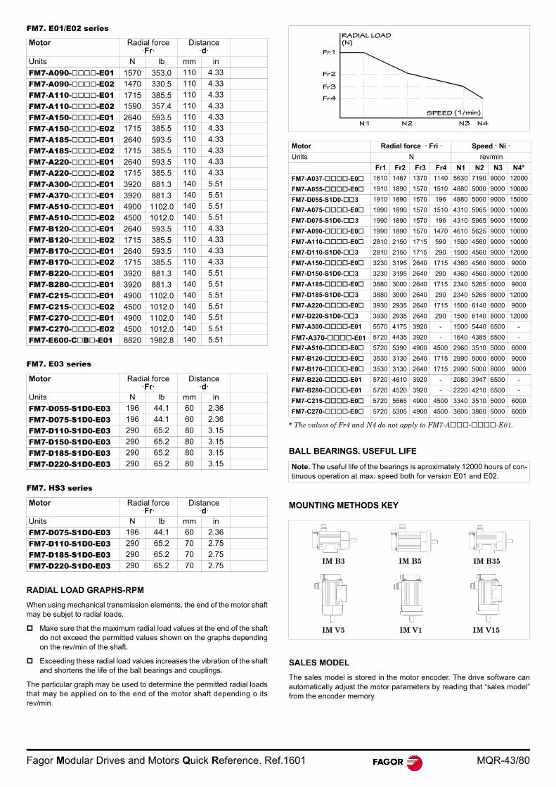
Fagor Modular Drives and Motors Quick Reference. Ref.1601 MQR-43/80
FM7. E01/E02 series
FM7. E03 series
FM7. HS3 series
RADIAL LOAD GRAPHS-RPM
When using mechanical transmission elements, the end of the motor shaftmay be subjet to radial loads.
Make sure that the maximum radial load values at the end of the shaftdo not exceed the permitted values shown on the graphs dependingon the rev/min of the shaft.
Exceeding these radial load values increases the vibration of the shaftand shortens the life of the ball bearings and couplings.
The particular graph may be used to determine the permitted radial loadsthat may be applied on to the end of the motor shaft depending o itsrev/min.
BALL BEARINGS. USEFUL LIFE
MOUNTING METHODS KEY
SALES MODEL
The sales model is stored in the motor encoder. The drive software canautomatically adjust the motor parameters by reading that “sales model”from the encoder memory.
Motor Radial force·Fr·
Distance·d·
Units N lb mm in
FM7-A090--E01 1570 353.0 110 4.33
FM7-A090--E02 1470 330.5 110 4.33
FM7-A110--E01 1715 385.5 110 4.33
FM7-A110--E02 1590 357.4 110 4.33
FM7-A150--E01 2640 593.5 110 4.33
FM7-A150--E02 1715 385.5 110 4.33
FM7-A185--E01 2640 593.5 110 4.33
FM7-A185--E02 1715 385.5 110 4.33
FM7-A220--E01 2640 593.5 110 4.33
FM7-A220--E02 1715 385.5 110 4.33
FM7-A300--E01 3920 881.3 140 5.51
FM7-A370--E01 3920 881.3 140 5.51
FM7-A510--E01 4900 1102.0 140 5.51
FM7-A510--E02 4500 1012.0 140 5.51
FM7-B120--E01 2640 593.5 110 4.33
FM7-B120--E02 1715 385.5 110 4.33
FM7-B170--E01 2640 593.5 110 4.33
FM7-B170--E02 1715 385.5 110 4.33
FM7-B220--E01 3920 881.3 140 5.51
FM7-B280--E01 3920 881.3 140 5.51
FM7-C215--E01 4900 1102.0 140 5.51
FM7-C215--E02 4500 1012.0 140 5.51
FM7-C270--E01 4900 1102.0 140 5.51
FM7-C270--E02 4500 1012.0 140 5.51
FM7-E600-CB-E01 8820 1982.8 140 5.51
Motor Radial force·Fr·
Distance·d·
Units N lb mm in
FM7-D055-S1D0-E03 196 44.1 60 2.36
FM7-D075-S1D0-E03 196 44.1 60 2.36
FM7-D110-S1D0-E03 290 65.2 80 3.15
FM7-D150-S1D0-E03 290 65.2 80 3.15
FM7-D185-S1D0-E03 290 65.2 80 3.15
FM7-D220-S1D0-E03 290 65.2 80 3.15
Motor Radial force·Fr·
Distance·d·
Units N lb mm in
FM7-D075-S1D0-E03 196 44.1 60 2.36
FM7-D110-S1D0-E03 290 65.2 70 2.75
FM7-D185-S1D0-E03 290 65.2 70 2.75
FM7-D220-S1D0-E03 290 65.2 70 2.75
Motor Radial force · Fri · Speed · Ni ·
Units N rev/min
Fr1 Fr2 Fr3 Fr4 N1 N2 N3 N4*
FM7-A037--E0 1610 1467 1370 1140 5630 7190 9000 12000
FM7-A055--E0 1910 1890 1570 1510 4880 5000 9000 10000
FM7-D055-S1D0-3 1910 1890 1570 196 4880 5000 9000 15000
FM7-A075--E0 1990 1890 1570 1510 4310 5965 9000 10000
FM7-D075-S1D0-3 1990 1890 1570 196 4310 5965 9000 15000
FM7-A090--E0 1990 1890 1570 1470 4610 5625 9000 10000
FM7-A110--E0 2810 2150 1715 590 1500 4560 9000 10000
FM7-D110-S1D0-3 2810 2150 1715 290 1500 4560 9000 12000
FM7-A150--E0 3230 3195 2640 1715 4360 4560 8000 9000
FM7-D150-S1D0-3 3230 3195 2640 290 4360 4560 8000 12000
FM7-A185--E0 3880 3000 2640 1715 2340 5265 8000 9000
FM7-D185-S1D0-3 3880 3000 2640 290 2340 5265 8000 12000
FM7-A220--E0 3930 2935 2640 1715 1500 6140 8000 9000
FM7-D220-S1D0-3 3930 2935 2640 290 1500 6140 8000 12000
FM7-A300--E01 5570 4175 3920 - 1500 5440 6500 -
FM7-A370--E01 5720 4435 3920 - 1640 4385 6500 -
FM7-A510--E0 5720 5390 4900 4500 2960 3510 5000 6000
FM7-B120--E0 3530 3130 2640 1715 2990 5000 8000 9000
FM7-B170--E0 3530 3130 2640 1715 2990 5000 8000 9000
FM7-B220--E01 5720 4610 3920 - 2080 3947 6500 -
FM7-B280--E01 5720 4520 3920 - 2220 4210 6500 -
FM7-C215--E0 5720 5565 4900 4500 3340 3510 5000 6000
FM7-C270--E0 5720 5305 4900 4500 3600 3860 5000 6000
* The values of Fr4 and N4 do not apply to FM7-A--E01.
Note. The useful life of the bearings is aproximately 12000 hours of con-tinuous operation at max. speed both for version E01 and E02.
RADIAL LOAD(N)
Fr1
Fr2
Fr3
Fr4
N1 N2 N3 N4
SPEED (1/min)
IM B3 IM B5 IM B35
IM V5 IM V1 IM V15
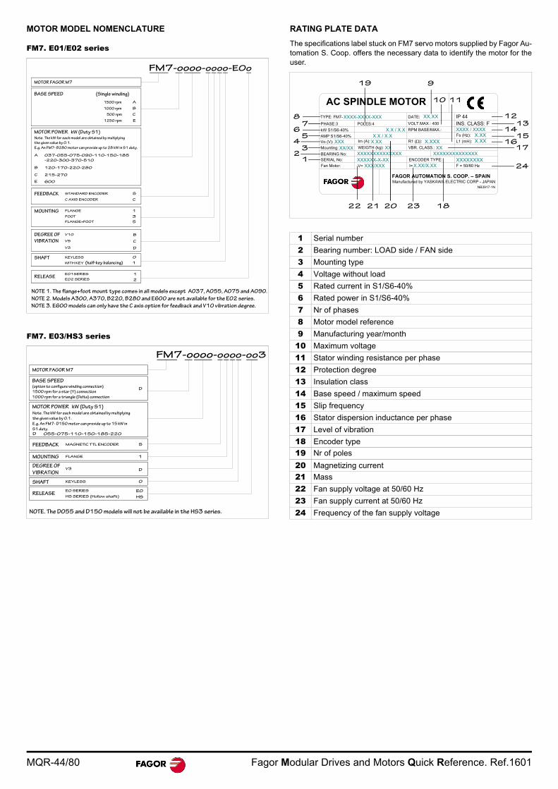
MQR-44/80 Fagor Modular Drives and Motors Quick Reference. Ref.1601
MOTOR MODEL NOMENCLATURE
FM7. E01/E02 series
FM7. E03/HS3 series
RATING PLATE DATA
The specifications label stuck on FM7 servo motors supplied by Fagor Au-tomation S. Coop. offers the necessary data to identify the motor for theuser.
MOTOR FAGOR M7
FM7-oooo-oooo-E0o
MOTOR POWER kW (Duty S1)
A 037-055-075-090-110-150-185
-220-300-370-510
STANDARD ENCODER
1E01SERIES
1500 rpm
SHAFT
FLANGE
V10
KEYLESS
RELEASEE02 SERIES
DEGREE OF
VIBRATION
MOUNTING
FEEDBACK
2
0
B
1
S
Note. The kW for each model are obtained by multplying
the given value by 0.1.
E.g. An FM7- B280 motor can provide up to 28 kW in S1 duty.
A
BASE SPEED (Single winding)
1000 rpm B
500 rpm C
1250 rpm E
B 120-170-220-280
C 215-270
E 600
C AXIS ENCODER C
FOOT 3
FLANGE+FOOT 5
V5 C
V3 D
WITH KEY (half-key balancing) 1
.
NOTE 1. The flange+foot mount type comes in all models except A037, A055, A075 and A090.
NOTE 2. Models A300, A370, B220, B280 and E600 are not available for the E02 series.
NOTE 3. E600 models can only have the C axis option for feedback and V10 vibration degree.
BASE SPEED (option to configure winding connection)
MOTOR FAGOR M7
FM7-oooo-oooo-oo3
MOTOR POWER kW (Duty S1)
D 055-075-110-150-185-220
MAGNETIC TTL ENCODER
E0E0 SERIES
1500 rpm for a star (Y) connection
1000 rpm for a triangle (Delta) connection
SHAFT
FLANGE
V3
KEYLESS
RELEASEHS SERIES (Hollow shaft)
DEGREE OF
VIBRATION
MOUNTING
FEEDBACK
HS
0
D
1
S
Note. The kW for each model are obtained by multplying
the given value by 0.1.
E.g. An FM7- D150 motor can provide up to 15 kW in
S1 duty.
D
NOTE. The D055 and D150 models will not be available in the HS3 series.
1 Serial number
2 Bearing number: LOAD side / FAN side
3 Mounting type
4 Voltage without load
5 Rated current in S1/S6-40%
6 Rated power in S1/S6-40%
7 Nr of phases
8 Motor model reference
9 Manufacturing year/month
10 Maximum voltage
11 Stator winding resistance per phase
12 Protection degree
13 Insulation class
14 Base speed / maximum speed
15 Slip frequency
16 Stator dispersion inductance per phase
17 Level of vibration
18 Encoder type
19 Nr of poles
20 Magnetizing current
21 Mass
22 Fan supply voltage at 50/60 Hz
23 Fan supply current at 50/60 Hz
24 Frequency of the fan supply voltage
AC SPINDLE MOTOR
Fs (Hz):
FAGOR AUTOMATION S. COOP. – SPAIN
XX.XX
X.XXXXXXX
X.XX X.XXX.XX
X.X / X.X
IP 44 XXXX-XXXX-XXX
XXXXX/XX
INS. CLASS: F VOLT.MAX.: 400
DATE:TYPE: FM7-
PHASE:3
kW S1/S6-40%
POLES:4
Manufactured by YASKAWA ELECTRIC CORP - JAPANNB3917-1N
AMP S1/S6-40% X.X / X.XVo (V):
Mounting:
BEARING No:
SERIAL No:
XXXXXXXXXXXXXX XXXXXXXXXXXXXX
Im (A):
WEIGTH (kg):
R1 ( ): L1 (mH):
VBR. CLASS.:
Fan Motor: V= XXX/XXXENCODER TYPE: XXXXXXXXXXXXXX-X-XXI= X.XX/X.XX F = 50/60 Hz
RPM BASE/MAX.: XXXX / XXXX
22 21 20 23 18
24
1716
1514
1312
1110
919
12
34
56
78
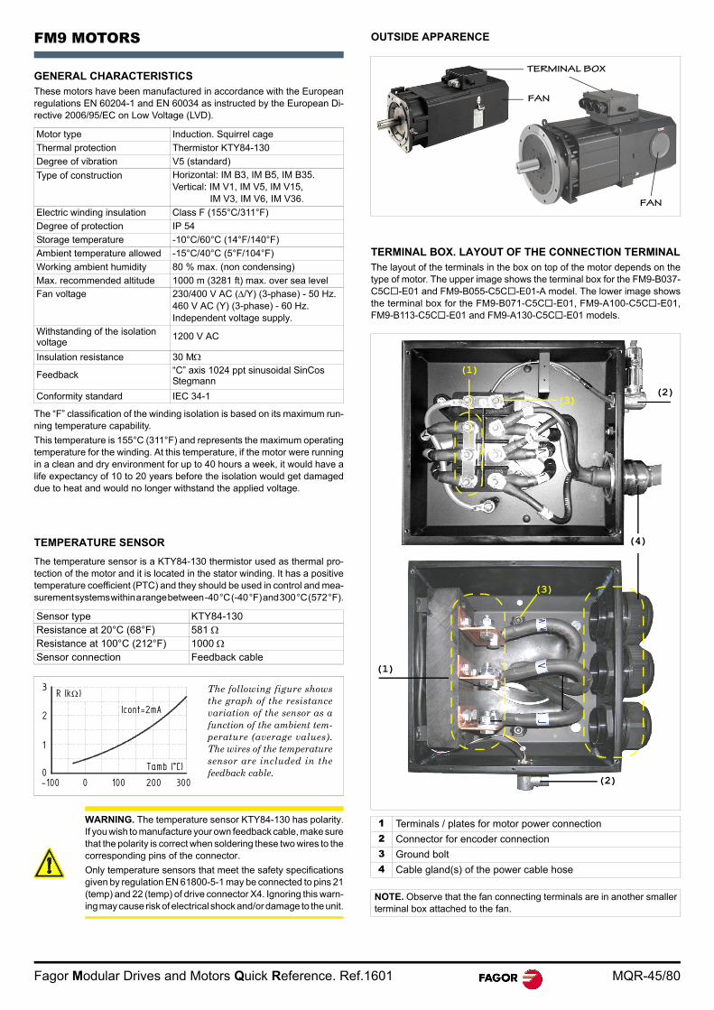
Fagor Modular Drives and Motors Quick Reference. Ref.1601 MQR-45/80
FM9 MOTORS
GENERAL CHARACTERISTICSThese motors have been manufactured in accordance with the Europeanregulations EN 60204-1 and EN 60034 as instructed by the European Di-rective 2006/95/EC on Low Voltage (LVD).
The “F” classification of the winding isolation is based on its maximum run-ning temperature capability.
This temperature is 155°C (311°F) and represents the maximum operatingtemperature for the winding. At this temperature, if the motor were runningin a clean and dry environment for up to 40 hours a week, it would have alife expectancy of 10 to 20 years before the isolation would get damageddue to heat and would no longer withstand the applied voltage.
TEMPERATURE SENSOR
The temperature sensor is a KTY84-130 thermistor used as thermal pro-tection of the motor and it is located in the stator winding. It has a positivetemperature coefficient (PTC) and they should be used in control and mea-surement systems within a range between -40 °C (-40 °F) and 300 °C (572 °F).
OUTSIDE APPARENCE
TERMINAL BOX. LAYOUT OF THE CONNECTION TERMINALThe layout of the terminals in the box on top of the motor depends on thetype of motor. The upper image shows the terminal box for the FM9-B037-C5C-E01 and FM9-B055-C5C-E01-A model. The lower image showsthe terminal box for the FM9-B071-C5C-E01, FM9-A100-C5C-E01,FM9-B113-C5C-E01 and FM9-A130-C5C-E01 models.
Motor type Induction. Squirrel cage
Thermal protection Thermistor KTY84-130
Degree of vibration V5 (standard)
Type of construction Horizontal: IM B3, IM B5, IM B35.Vertical: IM V1, IM V5, IM V15,
IM V3, IM V6, IM V36.
Electric winding insulation Class F (155°C/311°F)
Degree of protection IP 54
Storage temperature -10°C/60°C (14°F/140°F)
Ambient temperature allowed -15°C/40°C (5°F/104°F)
Working ambient humidity 80 % max. (non condensing)
Max. recommended altitude 1000 m (3281 ft) max. over sea levelFan voltage 230/400 V AC (/Y) (3-phase) - 50 Hz.
460 V AC (Y) (3-phase) - 60 Hz.Independent voltage supply.
Withstanding of the isolation voltage
1200 V AC
Insulation resistance 30 M
Feedback “C” axis 1024 ppt sinusoidal SinCos Stegmann
Conformity standard IEC 34-1
Sensor type KTY84-130Resistance at 20°C (68°F) 581 Resistance at 100°C (212°F) 1000 Sensor connection Feedback cable
WARNING. The temperature sensor KTY84-130 has polarity.If you wish to manufacture your own feedback cable, make surethat the polarity is correct when soldering these two wires to thecorresponding pins of the connector.
Only temperature sensors that meet the safety specificationsgiven by regulation EN 61800-5-1 may be connected to pins 21(temp) and 22 (temp) of drive connector X4. Ignoring this warn-ing may cause risk of electrical shock and/or damage to the unit.
The following figure showsthe graph of the resistancevariation of the sensor as afunction of the ambient tem-perature (average values).The wires of the temperaturesensor are included in thefeedback cable.
3002001000-1000
1
2
R (k )
Tamb (°C)
Icont=2mA
1 Terminals / plates for motor power connection
2 Connector for encoder connection
3 Ground bolt
4 Cable gland(s) of the power cable hose
NOTE. Observe that the fan connecting terminals are in another smallerterminal box attached to the fan.
TERMINAL BOX
FAN
FAN
(2)(3)
(1)
(4)
(1)
(2)
(3)
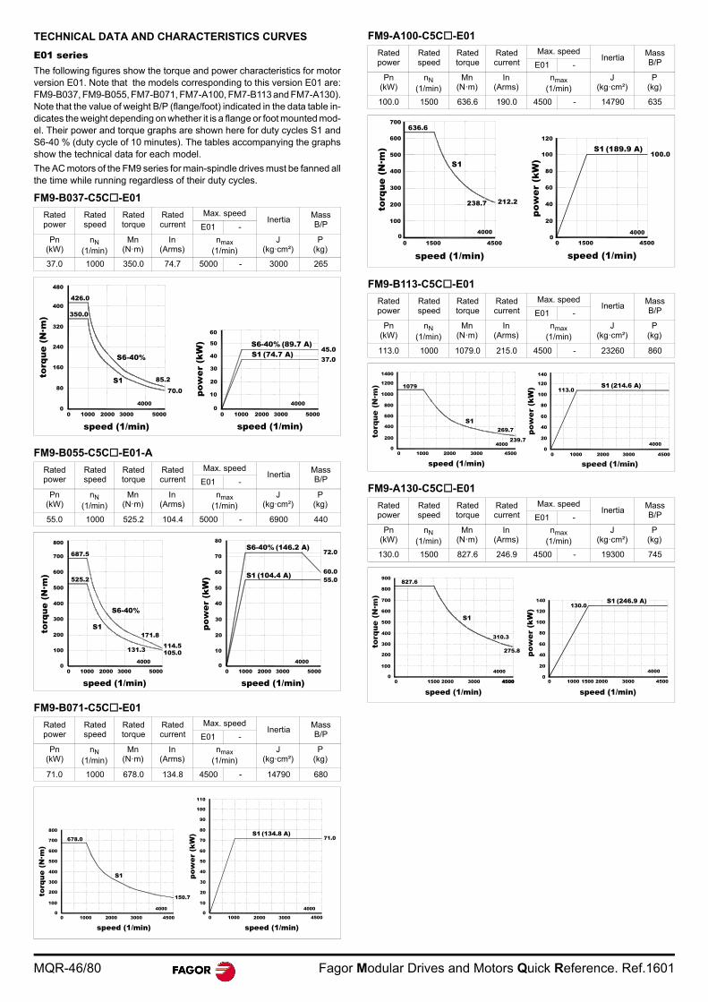
MQR-46/80 Fagor Modular Drives and Motors Quick Reference. Ref.1601
TECHNICAL DATA AND CHARACTERISTICS CURVES
E01 seriesThe following figures show the torque and power characteristics for motorversion E01. Note that the models corresponding to this version E01 are:FM9-B037, FM9-B055, FM7-B071, FM7-A100, FM7-B113 and FM7-A130).Note that the value of weight B/P (flange/foot) indicated in the data table in-dicates the weight depending on whether it is a flange or foot mounted mod-el. Their power and torque graphs are shown here for duty cycles S1 andS6-40 % (duty cycle of 10 minutes). The tables accompanying the graphsshow the technical data for each model.
The AC motors of the FM9 series for main-spindle drives must be fanned allthe time while running regardless of their duty cycles.
FM9-B037-C5C-E01
FM9-B055-C5C-E01-A
FM9-B071-C5C-E01
FM9-A100-C5C-E01
FM9-B113-C5C-E01
FM9-A130-C5C-E01
Rated power
Rated speed
Rated torque
Rated current
Max. speedInertia
MassB/PE01 -
Pn (kW)
nN (1/min)
Mn (N·m)
In (Arms)
nmax (1/min)
J (kg·cm²)
P(kg)
37.0 1000 350.0 74.7 5000 - 3000 265
Rated power
Rated speed
Rated torque
Rated current
Max. speedInertia
MassB/PE01 -
Pn (kW)
nN (1/min)
Mn (N·m)
In (Arms)
nmax (1/min)
J (kg·cm²)
P(kg)
55.0 1000 525.2 104.4 5000 - 6900 440
Rated power
Rated speed
Rated torque
Rated current
Max. speedInertia
MassB/PE01 -
Pn (kW)
nN (1/min)
Mn (N·m)
In (Arms)
nmax (1/min)
J (kg·cm²)
P(kg)
71.0 1000 678.0 134.8 4500 - 14790 680
speed (1/min)
torq
ue (
N·m
)
426.0
S170.0
0 500010000
4000
85.2
S6-40%
80
160
240
320
400
480
350.0
pow
er (
kW)
10
0
50
60
20
30
40
0 50001000
4000
S1 (74.7 A)S6-40% (89.7 A)
37.045.0
2000 3000 2000 3000
speed (1/min)
0 50001000
100
400
500
600
2000 30000
200
300
700
800
4000
0 50001000 2000 3000
10
0
40
50
20
30
60
70
4000
S1 (104.4 A)
S6-40% (146.2 A)72.0
60.055.0
S1
S6-40%
687.5
525.2
171.8
114.5105.0131.3
torq
ue (
N·m
)
speed (1/min) speed (1/min)
pow
er (
kW)
torq
ue (
N·m
)
pow
er (
kW)
678.0
S1
150.7
S1 (134.8 A)71.0
0 45001000
100
0
200
300
400
500
600
700
800
10
0
50
60
70
20
30
40
80
90
100
110
0 450010002000 3000
4000 4000
2000 3000
speed (1/min) speed (1/min)
Rated power
Rated speed
Rated torque
Rated current
Max. speedInertia
MassB/PE01 -
Pn (kW)
nN (1/min)
Mn (N·m)
In (Arms)
nmax (1/min)
J (kg·cm²)
P(kg)
100.0 1500 636.6 190.0 4500 - 14790 635
Rated power
Rated speed
Rated torque
Rated current
Max. speedInertia
MassB/PE01 -
Pn (kW)
nN (1/min)
Mn (N·m)
In (Arms)
nmax (1/min)
J (kg·cm²)
P(kg)
113.0 1000 1079.0 215.0 4500 - 23260 860
Rated power
Rated speed
Rated torque
Rated current
Max. speedInertia
MassB/PE01 -
Pn (kW)
nN (1/min)
Mn (N·m)
In (Arms)
nmax (1/min)
J (kg·cm²)
P(kg)
130.0 1500 827.6 246.9 4500 - 19300 745
S1 (189.9 A)
212.2238.7
S1
636.6
100.0
pow
er (
kW)
torq
ue (
N·m
)
200
300
400
500
600
20
0
40
60
80
100
120
0 45001500
4000
speed (1/min) speed (1/min)0 45001500
100
04000
pow
er (
kW)
0 45001000
200
0
400
600
800
1000
1200
1400
20
0
40
60
80
100
120
140
0 45001000
239.74000
269.7
1079
S1
4000
S1 (214.6 A)113.0
2000 30002000 3000
speed (1/min)
S1
S1 (246.9 A)130.0
4000
0 45001000 30001500 2000
20
0
40
60
80
100
120
140
pow
er (
kW)
100
0
200
300
400
500
600
700
800
275.8
310.3
0 45001500 2000 3000 4500
4000
827.6
speed (1/min)speed (1/min)
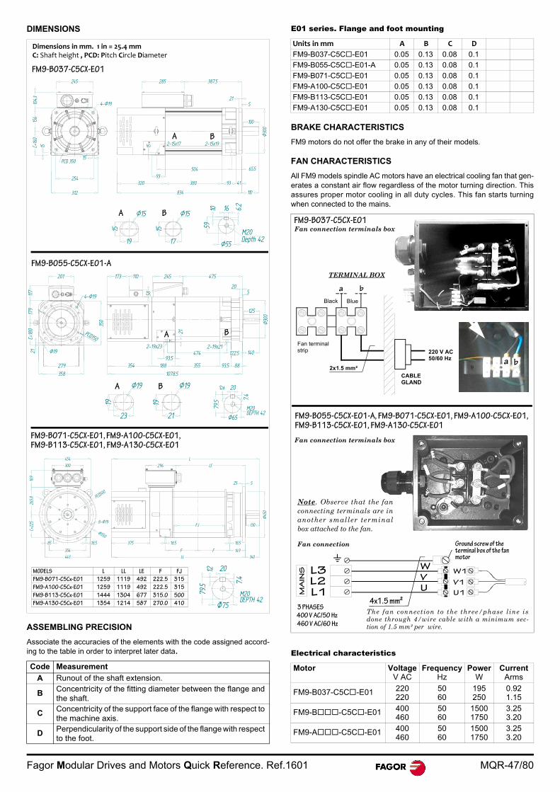
Fagor Modular Drives and Motors Quick Reference. Ref.1601 MQR-47/80
DIMENSIONS
ASSEMBLING PRECISION
Associate the accuracies of the elements with the code assigned accord-ing to the table in order to interpret later data.
E01 series. Flange and foot mounting
BRAKE CHARACTERISTICS
FM9 motors do not offer the brake in any of their models.
FAN CHARACTERISTICS
All FM9 models spindle AC motors have an electrical cooling fan that gen-erates a constant air flow regardless of the motor turning direction. Thisassures proper motor cooling in all duty cycles. This fan starts turningwhen connected to the mains.
Electrical characteristics
Code Measurement
A Runout of the shaft extension.
B Concentricity of the fitting diameter between the flange andthe shaft.
C Concentricity of the support face of the flange with respect tothe machine axis.
D Perpendicularity of the support side of the flange with respectto the foot.
4-Ø19
834 110
380320
100
245 285 387.5
521
Ø30
0
93 41
312
254
15
65.593
504
C=16
015
610
4.315 15 2-15x17 2-15x19
PCD 350
A B
Ø15
19
16
M20Depth 42
Ø55
1059
6.2
Ø15
17
15
A B
454300
525
L
LL 140443
C=22
5 8-Ø19
PCD500
296 LE
F F 149356
85 18.5 18.518.5
FJ 130
375
Ø45
0
Ø550
169
265.8
FM9-B037-C5CX-E01
FM9-B071-C5CX-E01, FM9-A100-C5CX-E01, FM9-B113-C5CX-E01, FM9-A130-C5CX-E01
FM9-B055-C5CX-E01-A
MODELS L LL LE F FJ
FM9-B071-C5Cx-E01 1259 1119 492 222.5 315
FM9-A100-C5Cx-E01 1259 1119 492 222.5 315
FM9-B113-C5Cx-E01 1444 1304 677 315.0 500
FM9-A130-C5Cx-E01 1354 1214 587 270.0 410
173 110
58
475245
205
350
201
117
21
125
1078.5354 188 355
4-Ø19
140
93.5 8893.5
21
474 122.52-19x212-19x23
358279
Ø19
PCD350
23
19
Ø19
21
19
Ø65
79.5
M20DEPTH 42
7.4
2012Ø19
A B
A B
M20DEPTH 42
7.4
12
Dimensions in mm. 1 in = 25.4 mmC: Shaft height , PCD: Pitch Circle Diameter
Units in mm A B C D
FM9-B037-C5C-E01 0.05 0.13 0.08 0.1
FM9-B055-C5C-E01-A 0.05 0.13 0.08 0.1
FM9-B071-C5C-E01 0.05 0.13 0.08 0.1
FM9-A100-C5C-E01 0.05 0.13 0.08 0.1
FM9-B113-C5C-E01 0.05 0.13 0.08 0.1
FM9-A130-C5C-E01 0.05 0.13 0.08 0.1
Motor Voltage V AC
Frequency Hz
Power W
Current Arms
FM9-B037-C5C-E01 220220
5060
195250
0.921.15
FM9-B-C5C-E01 400460
5060
15001750
3.253.20
FM9-A-C5C-E01 400460
5060
15001750
3.253.20
MA
INS
3 PHASES
400 V AC/50 Hz
460 V AC/60 Hz
4x1.5 mm²
L3L2L1
Ground screw of the terminal box of the fan motor
U
V
W
U1
V1
W1
220 V AC50/60 Hz
2x1.5 mm²
BlueBlack
Fan terminal strip
CABLEGLAND
Fan connection terminals box
Fan connection
The fan connection to the three/phase line isdone through 4/wire cable with a minimum sec-tion of 1.5 mm² per wire.
FM9-B055-C5CX-E01-A, FM9-B071-C5CX-E01, FM9-A100-C5CX-E01, FM9-B113-C5CX-E01, FM9-A130-C5CX-E01
FM9-B037-C5CX-E01Fan connection terminals box
TERMINAL BOX
a b
a b
Note. Observe that the fanconnecting terminals are inanother smaller terminalbox attached to the fan.
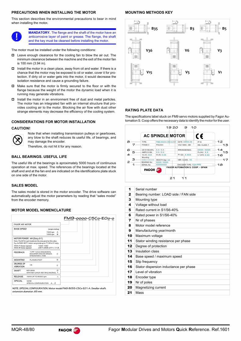
MQR-48/80 Fagor Modular Drives and Motors Quick Reference. Ref.1601
PRECAUTIONS WHEN INSTALLING THE MOTOR
This section describes the environmental precautions to bear in mindwhen installing the motor.
The motor must be installed under the following conditions:
Leave enough clearance for the cooling fan to blow the air out. Theminimum clearance between the machine and the exit of the motor fanis 100 mm (3.94 in).
Install the motor in a clean place, away from oil and water. If there is achance that the motor may be exposed to oil or water, cover it for pro-tection. If dirty oil or water gets into the motor, it would decrease theisolation resistance and cause a grounding failure.
Make sure that the motor is firmly secured to the floor or with theflange because the weight of the motor the dynamic load when it isrunning may generate vibrations.
Install the motor in an environment free of dust and metal particles.The motor has an integrated fan with an internal structure that pro-vides cooling air to the motor. Blocking the air flow with dust otherstrange elements may decrease the efficiency of the cooling system.
CONSIDERATIONS FOR MOTOR INSTALLATION
CAUTION!Note that when installing transmission pulleys or gearboxes,any blow to the shaft reduces its useful life, of bearings, andmay damage the encoder.
Therefore, do not hit it for any reason.
BALL BEARINGS. USEFUL LIFE
The useful life of the bearings is aproximately 5000 hours of continuousoperation at max. speed. The references of the bearings located at theshaft end and at the fan end are indicated on the identifications plate stuckon one side of the motor.
SALES MODEL
The sales model is stored in the motor encoder. The drive software canautomatically adjust the motor parameters by reading that “sales model”from the encoder memory.
MOTOR MODEL NOMENCLATURE
MOUNTING METHODS KEY
RATING PLATE DATA
The specifications label stuck on FM9 servo motors supplied by Fagor Au-tomation S. Coop offers the necessary data to identify the motor for the user.
MANDATORY. The flange and the shaft of the motor have ananticorrosive layer of paint or grease. The flange, the shaftand the key must be cleaned before installing the motor.
BASE SPEED (single winding)
FAGOR M9 MOTOR
FM9-oooo-C5Co-E0o-o
MOTOR POWER kW (Duty S1)
1VPP 1024 SINUSOIDAL
ENCODER SINCOS SRS64
STEGMANN C AXIS
1500 rpm
SHAFT
FLANGE+FOOT
V5
KEYLESS
RELEASE VMAX UP TO 9000 rpm
DEGREE OF
VIBRATION
MOUNTING
FEEDBACK
1
0
C
5
C
Note. The kW for each model are the ones given by this value.
E.g. An FM9- B071 motor can provide up to 71 kW in S1 duty.
A
1000 rpm B
WITH KEY (HALF-KEY BALANCING) 1
With A base speed 100-130With B base speed O37-055-071-113
NOTE. SPECIAL CONFIGURATION. Motor model FM9-B055-C5Cx-E01-A. Smaller shaft
extension diameter, 65 mm.
SPECIAL NONE
A ... ZSPECIAL CONFIGURATION
1 Serial number
2 Bearing number: LOAD side / FAN side
3 Mounting type
4 Voltage without load
5 Rated current in S1/S6-40%
6 Rated power in S1/S6-40%
7 Nr of phases
8 Motor model reference
9 Manufacturing year/month
10 Maximum voltage
11 Stator winding resistance per phase
12 Degree of protection
13 Insulation class
14 Base speed / maximum speed
15 Slip frequency
16 Stator dispersion inductance per phase
17 Level of vibration
18 Encoder type
19 Nr of poles
20 Magnetizing current
21 Mass
B35
V36
V15
B3
V6
V5
B5
V3
V1
AC SPINDLE MOTOR
FAGOR AUTOMATION S. COOP. – SPAIN
XXXX.XX
V5XX
X.XX
XXXX / XXXX1024 PPRXXXXXXXX
X.XXX.X
XXXX / XXXXX.X / X.XX.X / X.X
FM9-XXXX-C5CX-E01
XXX
B3/B5/V1/V5/V3/V6
TYPE:
PHASE:3
kW S1/S6-40%:
AMPS S1/S6:
Mounting:
BEARING No:
SERIAL No:
Vo (V):
POLES:4
Im (A):
WEIGTH (kg):
ENCODER TYPE:
VBR. CLASS.:
X.XXXR1 ( ): L1 (mH):
Fs (Hz): RPM BASE/MAX.:
INS. CLASS: F
IP 54 DATE:
VOLT.MAX.: 380
18
17
1615
14
1312
1121
1092019
1
3
5
7
2
4
6
8
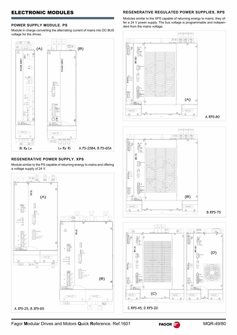
Fagor Modular Drives and Motors Quick Reference. Ref.1601 MQR-49/80
ELECTRONIC MODULES
POWER SUPPLY MODULE. PSModule in charge converting the alternating current of mains into DC BUSvoltage for the drives.
REGENERATIVE POWER SUPPLY. XPS
Module similar to the PS capable of returning energy to mains and offeringa voltage supply of 24 V.
REGENERATIVE REGULATED POWER SUPPLIES. RPS
Modules similar to the XPS capable of returning energy to mains; they of-fer a 24 V power supply. The bus voltage is programmable and indepen-dent from the mains voltage.
POW
ER S
UPP
LY
Ri Re L+
POW
ER S
UPP
LY
A. PS-25B4, B. PS-65A
(A) (B)
L+ Re Ri
POW
ER S
UPP
LY
XPS 6
5
XPS 2
5
A. XPS-25, B. XPS-65
(A)
(B)
RPS
80
A. RPS-80
(A)
RPS
75
B. RPS-75
(B)RP
S 20
RPS
45
C. RPS-45, D. RPS-20
(C)
(D)
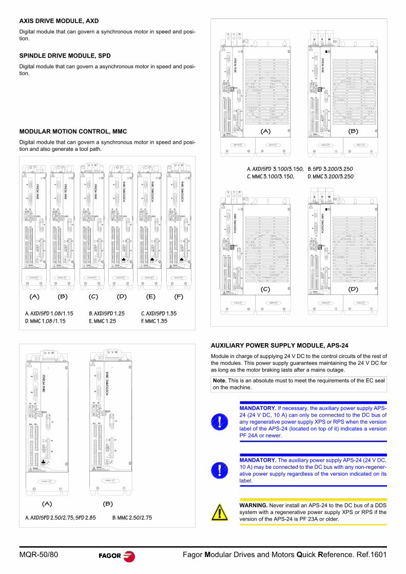
MQR-50/80 Fagor Modular Drives and Motors Quick Reference. Ref.1601
AXIS DRIVE MODULE, AXD
Digital module that can govern a synchronous motor in speed and posi-tion.
SPINDLE DRIVE MODULE, SPD
Digital module that can govern a asynchronous motor in speed and posi-tion.
MODULAR MOTION CONTROL, MMC
Digital module that can govern a synchronous motor in speed and posi-tion and also generate a tool path.
AUXILIARY POWER SUPPLY MODULE, APS-24
Module in charge of supplying 24 V DC to the control circuits of the rest ofthe modules. This power supply guarantees maintaining the 24 V DC foras long as the motor braking lasts after a mains outage.
X4
X3
X1
NODE
OUT
IN
STATUSDISPLAY
X5 X6
SL2 SL1
+24 Vdc
0 V
DR.O.K.
SPEEDENABLE
DRIVEENABLE
GND
AS1
AS2X7
X2
POSITIO
NING D
RIVE
POSITIO
NING D
RIVE
POSITIO
NING D
RIVE
DANGERHIGH VOLTAGEDISCHARGE TIME>4Min
DANGERHIGH VOLTAGEDISCHARGE TIME>4Min
DANGERHIGH VOLTAGEDISCHARGE TIME>4Min
DANGERHIGH VOLTAGEDISCHARGE TIME>4Min
DANGERHIGH VOLTAGEDISCHARGE TIME>4Min
+24 Vdc
0 V
DR.O.K.
SPEEDENABLE
DRIVEENABLE
GND
AS1
AS2X7
X2
X4
X3
X1
NODE
OUT
IN
STATUSDISPLAY
X5 X6
SL2 SL1
X4
X3
X1
NODE
OUT
IN
STATUSDISPLAY
X5 X6
SL2 SL1
+24 Vdc
0 V
DR.O.K.
SPEEDENABLE
DRIVEENABLE
GND
AS1
AS2X7
X2
X4
X3
X1
X5
SL2 SL1
+24 Vdc
0 V
DR.O.K.
SPEEDENABLE
DRIVEENABLE
GND
AS1
AS2X7
X2
U V W
X4
X3
X1
X5
SL2 SL1
+24 Vdc
0 V
DR.O.K.
SPEEDENABLE
DRIVEENABLE
GND
AS1
AS2X7
X2
U V W
NODE
OUT
IN
STATUSDISPLAY
X6
NODE
OUT
IN
STATUSDISPLAY
X6
DRIVE
MO
DULE
DRIVE
MO
DULE
+24 Vdc
0 V
DR.O.K.
SPEEDENABLE
DRIVEENABLE
GND
AS1
AS2X7
X2
DANGERHIGH VOLTAGEDISCHARGE TIME>4Min
DRIVE
MO
DULE
X4
X3
X1
NODE
OUT
IN
STATUSDISPLAY
X5 X6
SL2 SL1
A. AXD/SPD 1.08/1.15 B. AXD/SPD 1.25 C. AXD/SPD 1.35
D. MMC 1.08 /1.15 E. MMC 1.25 F. MMC 1.35
(A) (B) (C) (D) (E) (F)
DRIVE
MO
DULE
POSITIO
NING D
RIVE
DANGERHIGH VOLTAGEDISCHARGE TIME>4Min
DANGERHIGH VOLTAGEDISCHARGE TIME>4Min
X4
X3
X5 X6
SL2 SL1
X1
U V W
+24 Vdc
0 V
DR.O.K.
SPEEDENABLE
DRIVEENABLE
GND
AS1
AS2X7
X2
NODE
OUT
IN
STATUSDISPLAY
X4
X3
X5 X6
SL2 SL1
X1
U V W
+24 Vdc
0 V
DR.O.K.
SPEEDENABLE
DRIVEENABLE
GND
AS1
AS2X7
X2
NODE
OUT
IN
STATUSDISPLAY
A. AXD/SPD 2.50/2.75, SPD 2.85 B. MMC 2.50/2.75
(A) (B)
Note. This is an absolute must to meet the requirements of the EC sealon the machine.
MANDATORY. If necessary, the auxiliary power supply APS-24 (24 V DC, 10 A) can only be connected to the DC bus ofany regenerative power supply XPS or RPS when the versionlabel of the APS-24 (located on top of it) indicates a versionPF 24A or newer.
MANDATORY. The auxiliary power supply APS-24 (24 V DC,10 A) may be connected to the DC bus with any non-regener-ative power supply regardless of the version indicated on itslabel.
WARNING. Never install an APS-24 to the DC bus of a DDSsystem with a regenerative power supply XPS or RPS if theversion of the APS-24 is PF 23A or older.
X4
X3
X5 X6
U V W
SL2 SL1
X1
+24 Vdc
0 V
DR.O.K.
SPEEDENABLE
DRIVEENABLE
GND
AS1
AS2 X7
X2
STATUSDISPLAY
X4
X3
X5 X6
U V W
SL2 SL1
X1
+24 Vdc
0 V
DR.O.K.
SPEEDENABLE
DRIVEENABLE
GND
AS1
AS2 X7
X2
STATUSDISPLAY
X4
X3
X1
+24 Vdc
0 V
DR.O.K.
SPEEDENABLE
DRIVEENABLE
GND
AS1
AS2X7
X2
U V W
X5
SL2 SL1
X6
STATUSDISPLAY
X4
X3
X1
+24 Vdc
0 V
DR.O.K.
SPEEDENABLE
DRIVEENABLE
GND
AS1
AS2X7
X2
U V W
X5
SL2 SL1
STATUSDISPLAY
NODE
OUT
IN
NODE
OUT
IN
NODE
OUT
IN
NODE
OUT
IN
DRIVE
MO
DULE
DRIVE
MO
DULE
POSITIO
NING D
RIVE
POSITIO
NING D
RIVE
DANGERHIGH VOLTAGEDISCHARGE TIME>4Min
DANGERHIGH VOLTAGEDISCHARGE TIME>4Min
DANGERHIGH VOLTAGEDISCHARGE TIME>4Min
DANGERHIGH VOLTAGEDISCHARGE TIME>4Min
A. AXD/SPD 3.100/3.150, B. SPD 3.200/3.250
C. MMC 3.100/3.150, D. MMC 3.200/3.250
(A) (B)
(C) (D)
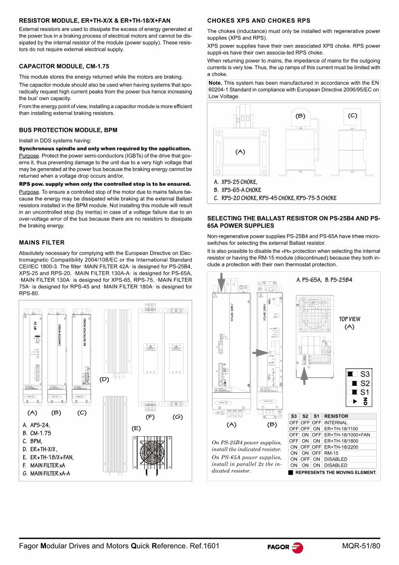
Fagor Modular Drives and Motors Quick Reference. Ref.1601 MQR-51/80
RESISTOR MODULE, ER+TH-X/X & ER+TH-18/X+FANExternal resistors are used to dissipate the excess of energy generated atthe power bus in a braking process of electrical motors and cannot be dis-sipated by the internal resistor of the module (power supply). These resis-tors do not require external electrical supply.
CAPACITOR MODULE, CM-1.75
This module stores the energy returned while the motors are braking.
The capacitor module should also be used when having systems that spo-radically request high current peaks from the power bus hence increasingthe bus' own capacity.
From the energy point of view, installing a capacitor module is more efficientthan installing external braking resistors.
BUS PROTECTION MODULE, BPM
Install in DDS systems having:
Synchronous spindle and only when required by the application. Purpose. Protect the power semi-conductors (IGBTs) of the drive that gov-erns it, thus preventing damage to the unit due to a very high voltage thatmay be generated at the power bus because the braking energy cannot bereturned when a voltage drop occurs and/or,
RPS pow. supply when only the controlled stop is to be ensured. Purpose. To ensure a controlled stop of the motor due to mains failure be-cause the energy may be dissipated while braking at the external Ballastresistors installed in the BPM module. Not installing this module will resultin an uncontrolled stop (by inertia) in case of a voltage failure due to anover-voltage error of the bus because there are no resistors to dissipatethe braking energy.
MAINS FILTER
Absolutely necessary for complying with the European Directive on Elec-tromagnetic Compatibility 2004/108/EC or the International StandardCEI/IEC 1800-3. The filter ·MAIN FILTER 42A· is designed for PS-25B4,XPS-25 and RPS-20, ·MAIN FILTER 130A-A· is designed for PS-65A,·MAIN FILTER 130A· is designed for XPS-65, RPS-75, ·MAIN FILTER75A· is designed for RPS-45 and ·MAIN FILTER 180A· is designed forRPS-80.
CHOKES XPS AND CHOKES RPS
The chokes (inductance) must only be installed with regenerative powersupplies (XPS and RPS).
XPS power supplies have their own associated XPS choke. RPS powersuppli-es have their own associa-ted RPS choke.
When returning power to mains, the impedance of mains for the outgoingcurrents is very low. Thus, the up ramps of this current must be limited witha choke.
SELECTING THE BALLAST RESISTOR ON PS-25B4 AND PS-65A POWER SUPPLIES
Non-regenerative power supplies PS-25B4 and PS-65A have trhee micro-switches for selecting the external Ballast resistor.
It is also possible to disable the «I²t» protection when selecting the internalresistor or having the RM-15 module (discontinued) because they both in-clude a protection with their own thermostat protection.
APS
24
RESET
OVER VOLTAGE
OVER CURRENT
ON
L1
L2
X1
L1
INPUT400-460 Vac.
OUTPUT24Vdc.
+24Vdc.
0 V.
+24Vdc.
0 V.
+24Vdc.
0 V.
X2
X3
X4
BUS
PRO
TEC
TIO
N M
ODULE
CAPA
CITO
R MO
DULE
A. APS-24,
B. CM-1.75
C. BPM,
D. ER+TH-X/X ,
E. ER+TH-18/X+FAN,
F. MAIN FILTER xA
G. MAIN FILTER xA-A
(A) (B) (C)
(D)
(G)
(E)
(F)
Note. This system has been manufactured in accordance with the EN60204-1 Standard in compliance with European Directive 2006/95/EC onLow Voltage.
(A)
A. XPS-25 CHOKE,
B. XPS-65-A CHOKE
C. RPS-20 CHOKE, RPS-45 CHOKE, RPS-75-3 CHOKE
(B) (C)
POW
ER S
UPP
LY
POW
ER S
UPP
LY
S3 S2 S1 RESISTOROFF OFF OFF INTERNALOFF OFF ON ER+TH-18/1100OFF ON OFF ER+TH-18/1000+FANOFF ON ON ER+TH-18/1800ON OFF OFF ER+TH-18/2200ON ON OFF RM-15 ON OFF ON DISABLEDON ON ON DISABLED
REPRESENTS THE MOVING ELEMENT.
A. PS-65A, B. PS-25B4
ON
S1S2S3
TOP VIEW
On PS-25B4 power supplies,install the indicated resistor.
On PS-65A power supplies,install in parallel 2x the in-dicated resistor.
(A)
(A) (B)

MQR-52/80 Fagor Modular Drives and Motors Quick Reference. Ref.1601
POWER SUPPLY MODULES. PS-65A
Technical data POWER SUPPLY MODULES, PS-25B4
Technical data
PS-65A
Power supply (Vmains)2Three phase 50/60 Hz
with a voltage range between 400 V AC-10 % & 460 V AC+10 %
Mains power consumption 100 ArmsMax. connection cable section 50 mm²
Power bus voltage VBUSnom 565 V DC - 650 V DCRated (peak) output current 120 A (360 A, 1 s)
Rated (peak) output power1 65 kW (195 kW, 1 s)Power for the module control circuit 24 V DC (between 21-28 V DC)Consumption of the module control circuit itself
1 A at 24 V (24 W)
Internal Ballast resistance (power)1 9 (600 W)Energy pulse to be dissipated 36 kWs (0.6 s)
Ballast circuit ON/OFF 3 768 V DC / 760 V DC (712 V DC / 704 V DC)
Min. external Ballast resistance 9 Filter capacity 940 µF, 900 V DCEnergy stored in the capacitors 0.5 C·V²Max. SYSTEM OK contact voltage 125 V AC, 150 V ACMax. SYSTEM OK contact current 2 AModule width 117 mm / 4.61 inModule weight 9.9 kg / 22 lbPower dissipated at max. load 275 W
Ambient temperature1 0°C/45°C (32°F/113°F)Storage temperature -25°C/60°C (-13°F/140°F)Maximum humidity < 90% non condens. at 45°C/113°FMax. installation altitude 2000 m (6561 ft) above sea levelOperating/shipping vibration 1 g / 1.5 g
Sealing IP 2x
ProtectionsOvervoltage, heat-sink temperature,
hardware error, Ballast overload.
1 See derating curves in case of high temperatures.
2 Previous power supplies PS-XX only admitted Vmains of 400 V AC.
3 When the module is set for Vmains = 400 V AC, as same PS-XX.
PS-25B4
Power supply (Vmains)1 Three-phase 50/60 Hz with a voltage range 400-10% and 460+10% V AC
Mains power consumption 38 Arms
Max. connection cable section 10 mm²Power bus voltage VBUSnom3 565 V DC / 650 V DCRated (peak) output current 45 A (135 A, 1 s)Rated (peak) output power 25 kW (75 kW, 1 s)
Internal Ballast resistance 16.5 (500 W)
Energy pulse to be dissipated 6 kWs (0.2 s)
Ballast circuit ON/OFF2 768 V DC / 760 V DC(712 V DC / 704 V DC)
Min. external Ballast resistance 16.5 Filter capacity 820 µF, 900 V DCEnergy stored in the capacitors 0.5 C·V²Max. SYSTEM OK contact voltage 125 V AC, 150 V DCMax. SYSTEM OK contact current 2 AModule width 77 mm/3.03 inModule weight 6.0 kg/13.2 lb
Power dissipated at max. load 180 WOutput voltage, max. current 24 V DC (5 %), 10 A
Input voltage 400 V AC -10% and 450 V AC +10% 50/60 Hz
Mains consumption 0.72 A (400 V AC); 0.63 A (460 V AC)
Max. Inrush current 23.9 A (460 V AC)
Bus consumption 0.485 A (565 V DC); 0.44 A (650 V DC)
Bus max. voltage 790 V DC
Ambient temperature3 0°C/45°C (32°F/113°F)Storage temperature -25°C/+60°C (-13°F/+140°F)Maximum humidity < 90% non condens. at 45°C/113°FMax. installation altitude 2000 m (6561 ft) above sea levelOperating/shipping vibration 1 g / 1.5 g
Sealing IP 2x
ProtectionsOvervoltage, heat-sink temperature,
hardware error, Ballast overload
1 Previous power supplies PS-XX only admitted Vmains of 400 V AC.
2 When the module is set for 400 V AC, like the PS-25B3, or like the pre-vious PS-XX.
3 See derating curves in case of high temperatures.
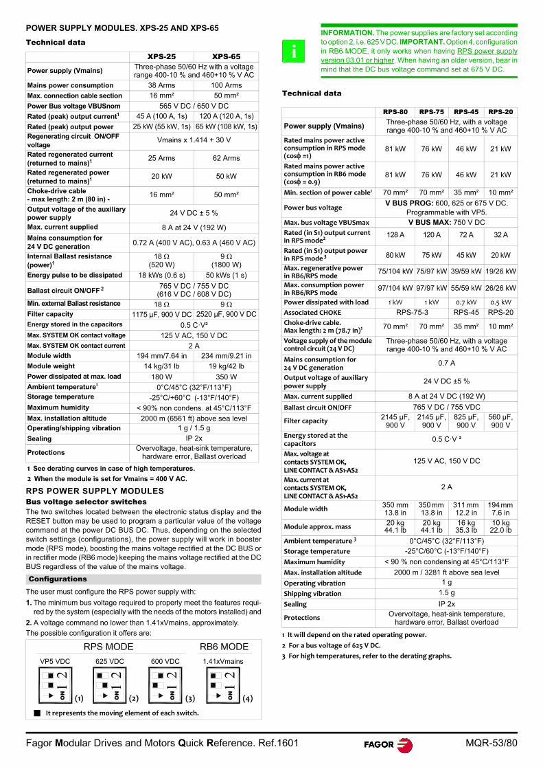
Fagor Modular Drives and Motors Quick Reference. Ref.1601 MQR-53/80
POWER SUPPLY MODULES. XPS-25 AND XPS-65
Technical data
RPS POWER SUPPLY MODULES Bus voltage selector switchesThe two switches located between the electronic status display and theRESET button may be used to program a particular value of the voltagecommand at the power DC BUS DC. Thus, depending on the selectedswitch settings (configurations), the power supply will work in boostermode (RPS mode), boosting the mains voltage rectified at the DC BUS orin rectifier mode (RB6 mode) keeping the mains voltage rectified at the DCBUS regardless of the value of the mains voltage.
The user must configure the RPS power supply with:
1. The minimum bus voltage required to properly meet the features requi-red by the system (especially with the needs of the motors installed) and
2. A voltage command no lower than 1.41xVmains, approximately.
The possible configuration it offers are:
Technical data
XPS-25 XPS-65
Power supply (Vmains) Three-phase 50/60 Hz with a voltage range 400-10 % and 460+10 % V AC
Mains power consumption 38 Arms 100 Arms
Max. connection cable section 16 mm² 50 mm²
Power Bus voltage VBUSnom 565 V DC / 650 V DC
Rated (peak) output current1 45 A (100 A, 1s) 120 A (120 A, 1s)
Rated (peak) output power 25 kW (55 kW, 1s) 65 kW (108 kW, 1s)Regenerating circuit ON/OFF voltage
Vmains x 1.414 + 30 V
Rated regenerated current (returned to mains)1 25 Arms 62 Arms
Rated regenerated power (returned to mains)1 20 kW 50 kW
Choke-drive cable- max length: 2 m (80 in) -
16 mm² 50 mm²
Output voltage of the auxiliary power supply
24 V DC ± 5 %
Max. current supplied 8 A at 24 V (192 W)
Mains consumption for 24 V DC generation 0.72 A (400 V AC), 0.63 A (460 V AC)
Internal Ballast resistance (power)1
18 (520 W)
9 (1800 W)
Energy pulse to be dissipated 18 kWs (0.6 s) 50 kWs (1 s)
Ballast circuit ON/OFF 2 765 V DC / 755 V DC (616 V DC / 608 V DC)
Min. external Ballast resistance 18 9 Filter capacity 1175 µF, 900 V DC 2520 µF, 900 V DCEnergy stored in the capacitors 0.5 C·V²Max. SYSTEM OK contact voltage 125 V AC, 150 V DCMax. SYSTEM OK contact current 2 AModule width 194 mm/7.64 in 234 mm/9.21 inModule weight 14 kg/31 lb 19 kg/42 lbPower dissipated at max. load 180 W 350 WAmbient temperature1 0°C/45°C (32°F/113°F)Storage temperature -25°C/+60°C (-13°F/140°F)Maximum humidity < 90% non condens. at 45°C/113°FMax. installation altitude 2000 m (6561 ft) above sea levelOperating/shipping vibration 1 g / 1.5 g
Sealing IP 2x
ProtectionsOvervoltage, heat-sink temperature,
hardware error, Ballast overload
1 See derating curves in case of high temperatures.
2 When the module is set for Vmains = 400 V AC.
Configurations
ON
ON
ON
ON
VP5 VDC 625 VDC 600 VDC 1.41xVmains
(1)
It represents the moving element of each switch.
(2) (3) (4)
INFORMATION. The power supplies are factory set accordingto option 2, i.e. 625 V DC. IMPORTANT. Option 4, configurationin RB6 MODE, it only works when having RPS power supplyversion 03.01 or higher. When having an older version, bear inmind that the DC bus voltage command set at 675 V DC.
RPS-80 RPS-75 RPS-45 RPS-20
Power supply (Vmains) Three-phase 50/60 Hz, with a voltage range 400-10 % and 460+10 % V AC
Rated mains power active consumption in RPS mode (cos ≈1)
81 kW 76 kW 46 kW 21 kW
Rated mains power active consumption in RB6 mode (cos ≈ 0.9)
81 kW 76 kW 46 kW 21 kW
Min. section of power cable1 70 mm² 70 mm² 35 mm² 10 mm²
Power bus voltageV BUS PROG: 600, 625 or 675 V DC.
Programmable with VP5.Max. bus voltage VBUSmax V BUS MAX: 750 V DCRated (in S1) output current in RPS mode2
128 A 120 A 72 A 32 A
Rated (in S1) output power in RPS mode 3 80 kW 75 kW 45 kW 20 kW
Max. regenerative power in RB6/RPS mode
75/104 kW 75/97 kW 39/59 kW 19/26 kW
Max. consumption power in RB6/RPS mode
97/104 kW 97/97 kW 55/59 kW 26/26 kW
Power dissipated with load 1 kW 1 kW 0.7 kW 0.5 kW
Associated CHOKE RPS-75-3 RPS-45 RPS-20Choke‐drive cable.Max length: 2 m (78.7 in)1
70 mm² 70 mm² 35 mm² 10 mm²
Voltage supply of the module control circuit (24 V DC)
Three-phase 50/60 Hz, with a voltage range 400-10 % and 460+10 % V AC
Mains consumption for 24 V DC generation
0.7 A
Output voltage of auxiliary power supply
24 V DC ±5 %
Max. current supplied 8 A at 24 V DC (192 W)
Ballast circuit ON/OFF 765 V DC / 755 VDC
Filter capacity 2145 µF, 900 V
2145 µF, 900 V
825 µF, 900 V
560 µF, 900 V
Energy stored at the capacitors
0.5 C·V ²
Max. voltage at contacts SYSTEM OK, LINE CONTACT & AS1‐AS2
125 V AC, 150 V DC
Max. current at contacts SYSTEM OK, LINE CONTACT & AS1‐AS2
2 A
Module width 350 mm 13.8 in
350 mm 13.8 in
311 mm 12.2 in
194 mm 7.6 in
Module approx. mass 20 kg44.1 lb
20 kg44.1 lb
16 kg35.3 lb
10 kg22.0 lb
Ambient temperature 3 0°C/45°C (32°F/113°F)Storage temperature -25°C/60°C (-13°F/140°F)
Maximum humidity < 90 % non condensing at 45°C/113°F
Max. installation altitude 2000 m / 3281 ft above sea level
Operating vibration 1 g
Shipping vibration 1.5 g
Sealing IP 2x
Protections Overvoltage, heat-sink temperature, hardware error, Ballast overload
1 It will depend on the rated operating power.
2 For a bus voltage of 625 V DC.
3 For high temperatures, refer to the derating graphs.
i

MQR-54/80 Fagor Modular Drives and Motors Quick Reference. Ref.1601
AXIS DRIVE MODULES. AXD/MMC
SPINDLE DRIVE MODULES. SPD
Technical data
CHOKES
CHOKE for XPS power supply. Technical data
CHOKE for RPS power supply. Technical data
EXTERNAL BALLAST RESISTOR
With external thermostat. Technical data
With internal thermostat. Technical data
With internal FAN AXIS DRIVE AXDCurrents (Arms) at fc=4 kHz
1.08 1.15 1.25 1.35 2.50 2.75 2.85 3.100 3.150 3.200
I S1=In (Arms) 4.0 7.5 12.5 17.5 25.0 37.5 - 50.0 75.0 90.0
Imax S1 (Arms) 8.0 15.0 25.0 35.0 50.0 75.0 - 100.0 150.0 180.0
Dissipat. power 33 69 88 156 225 270 - 351 536 834
With internal FAN AXIS DRIVE AXD
Currents (Arms) at fc=8 kHz
1.08 1.15 1.25 1.35 2.50 2.75 2.85 3.100 3.150 3.200
I S1=In (Arms) 4.0 7.5 12.5 17.5 25.0 37.5 - 50.0 75.0 90.0
Imax S1 (Arms) 8.0 15.0 25.0 35.0 50.0 75.0 - 100.0 150.0 180.0
Dissipat. power 44 89 132 195 305 389 - 510 605 840
With internal FAN SPINDLE DRIVE SPD
Currents (Arms) at fc=4 kHz
1.25 1.35 2.50 2.75 2.85 3.100 3.150 3.200 3.250
I S1=In (Arms) 16.0 23.1 31.0 42.0 50.0 70.0 90.0 121.0 135.0
0.7xIn (Arms) 11.2 16.1 21.7 29.0 35.0 49.0 63.0 84.7 94.5
I S6-40% (Arms) 20.8 30.0 40.3 54.6 65.0 91.0 117.0 157.3 175.5
Dissipat. power (W) 110 195 349 389 432 496 626 1163 1333
With internal FAN SPINDLE DRIVE SPD
Currents (Arms) at fc=8 kHz
1.25 1.35 2.50 2.75 2.85 3.100 3.150 3.200 3.250
I S1=In (Arms) 13.0 18.0 27.0 32.0 37.0 56.0 70.0 97.0 108.0
0.7xIn (Arms) 9.1 12.6 18.9 22.4 25.9 39.2 49.7 67.9 75.6
I S6-40% (Arms) 16.9 23.4 35.1 41.6 48.1 72.8 91.0 126.1 140.4
Dissipat. power (W) 130 201 350 333 438 546 668 1187 1344
AXD/SPD/MMC1.08, 1.15 1.25, 1.35
2.502.75, 2.85
3.100, 3.1503.200, 3.250
Power voltage input 542-800 V DC
Power to control circuits 24 V DC (between 21-28 V DC)
Consumption on these circuits (24 V DC)
0.9 A 1.25 A 2 A
Speed feedback Encoder
Controling method PWM, AC sinewave, vector control
Communications Serial line to connect to a PC
InterfaceStandard analog or digital
via SERCOS ring or CAN bus (in all models)Serial line RS-232/RS-422 (only in MMC drives)
Status display 7 - segment display
ProtectionsOvervoltage, overcurrent, overspeed, heat-sink,
temperature, CPU temperature, motor temperature, hardware error, overload.
Frequency 1 Lower than 600 Hz
Speed range with analog input 1:8192
Current bandwidth 800 Hz
Speed bandwidth 100 Hz (depends of the motor/drive set)
Ambient temperature 2 0°C/45°C (32°F/113°F)
Storage temperature -25°C/60°C (-13°F/140°F)
Sealing IP 2x
Maximum humidity < 90 % (non condensing at 45°C/113°F)
Max. installation altitude 2000 m / 3281 ft above sea level
Operating vibration 1 g
Shipping vibration 1.5 g
Approx. mass, kg/lb 6.0/33.2 10.0/22.0 13.6/29.9
1 Equal to or higher than 600 Hz only for commercial models SPD ... - MDU (dual-use). 2 For high temperatures, refer to derating graphs (power reduction graph).
CHOKE XPS-25 XPS-65-AInductance (10 kHz) 0.350 mH 0.250 mH
Rated current 50 A 120 A
Peak current 100 A 185 A
Max. terminal section 10 mm² 70 mm²
Operating ambient temperature 5°C/45°C (41°F/113°F)
Storage temperature -20°C/60°C (-4°F/140°F)
Relative humidity 80 % max.
Operating vibration 0.5 g
Shipping vibration 2 g
Sealing IP 20
Approx. mass, kg (lb) 8.0 (17.6) 12.0 (26.4)
CHOKE RPS-20 RPS-45 RPS-75-3Inductance (8 kHz) 0.90 mH 0.40 mH 0.175 mH
Rated current 32 A 72 A 180 A
Min. section cable 10 mm² 35 mm² 70 mm²Operating ambient temperature 0°C/60°C (32°F/140°F)
Storage temperature - 20°C/60°C (- 4°F/140°F)
Relative humidity < 90 % (non condensing at 45°C/113°F)
Operating/shipping vibration 0.5 g / 2 g
Sealing IP 20
Approx. mass, kg (lb) 12.7 (28.0) 20.4 (44.9) 36.0 (79.3)
ER+TH-OO/OOOO 24/750 24/1100 18/1100Resistance 24 24 18 RMS power 650 W 950 950 W
Energy absorbed in 5" overloaded 37 kJ 55 kJ 55 kJ
Operating ambient temperature 5°C/45°C (41°F/113°F)
Storage temperature -20°C/60°C (-4°F/140°F)
Relative humidity < 90 % (non condensing at 45°C/113°F)
Operation/shipping vibration 0.5 g / 2 g
Sealing IP 55
Approx. mass, gr (lb) 920 (2.02) 1250 (2.75)
WARNING. Be careful with the surface of the resistors. Re-member that its temperature may reach 400°C (752°F).
ER+TH-OO/OOOO 18/1800 18/2200Resistance 18 18 RMS power 1300 W 2000 W
Energy absorbed in 5’’ overloaded 55 kJ 83 kJ
Operating ambient temperature 5°C/45°C (41°F/113°F)
Storage temperature -20°C/60°C (-4°F/140°F)
Relative humidity < 90 % (non condensing at 45°C/113°F)
Operation/shipping vibration 0.5 g / 2 g
Sealing IP 54
Approx. mass, kg (lb) 3.0 (6.60) 6.2 (13.66)
WARNING. Be careful with the surface of the resistors. Re-member that its temperature may reach 410°C (770°F).
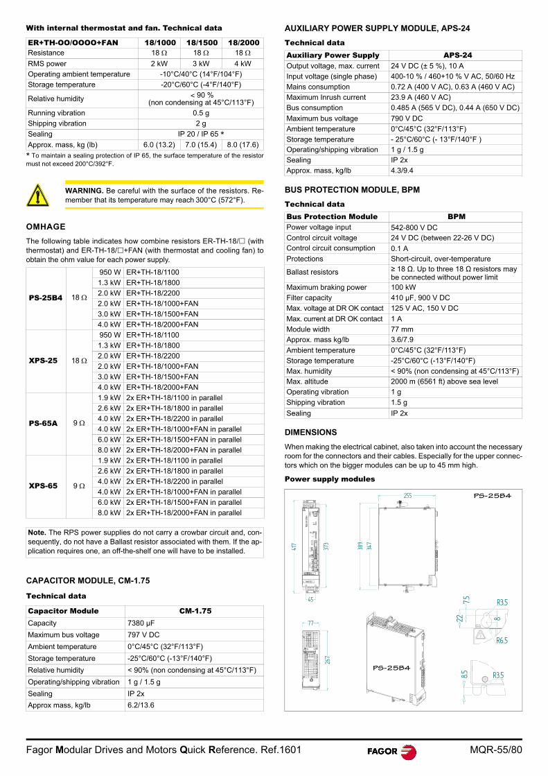
Fagor Modular Drives and Motors Quick Reference. Ref.1601 MQR-55/80
With internal thermostat and fan. Technical data
OMHAGE
The following table indicates how combine resistors ER-TH-18/ (withthermostat) and ER-TH-18/+FAN (with thermostat and cooling fan) toobtain the ohm value for each power supply.
CAPACITOR MODULE, CM-1.75
Technical data
AUXILIARY POWER SUPPLY MODULE, APS-24
Technical data
BUS PROTECTION MODULE, BPM
Technical data
DIMENSIONS
When making the electrical cabinet, also taken into account the necessaryroom for the connectors and their cables. Especially for the upper connec-tors which on the bigger modules can be up to 45 mm high.
Power supply modules
ER+TH-OO/OOOO+FAN 18/1000 18/1500 18/2000Resistance 18 18 18 RMS power 2 kW 3 kW 4 kW
Operating ambient temperature -10°C/40°C (14°F/104°F)
Storage temperature -20°C/60°C (-4°F/140°F)
Relative humidity < 90 % (non condensing at 45°C/113°F)
Running vibration 0.5 g
Shipping vibration 2 g
Sealing IP 20 / IP 65 *
Approx. mass, kg (lb) 6.0 (13.2) 7.0 (15.4) 8.0 (17.6)
* To maintain a sealing protection of IP 65, the surface temperature of the resistormust not exceed 200°C/392°F.
WARNING. Be careful with the surface of the resistors. Re-member that its temperature may reach 300°C (572°F).
PS-25B4 18
950 W ER+TH-18/1100
1.3 kW ER+TH-18/1800
2.0 kW ER+TH-18/2200
2.0 kW ER+TH-18/1000+FAN
3.0 kW ER+TH-18/1500+FAN
4.0 kW ER+TH-18/2000+FAN
XPS-25 18
950 W ER+TH-18/1100
1.3 kW ER+TH-18/1800
2.0 kW ER+TH-18/2200
2.0 kW ER+TH-18/1000+FAN
3.0 kW ER+TH-18/1500+FAN
4.0 kW ER+TH-18/2000+FAN
PS-65A 9
1.9 kW 2x ER+TH-18/1100 in parallel
2.6 kW 2x ER+TH-18/1800 in parallel
4.0 kW 2x ER+TH-18/2200 in parallel
4.0 kW 2x ER+TH-18/1000+FAN in parallel
6.0 kW 2x ER+TH-18/1500+FAN in parallel
8.0 kW 2x ER+TH-18/2000+FAN in parallel
XPS-65 9
1.9 kW 2x ER+TH-18/1100 in parallel
2.6 kW 2x ER+TH-18/1800 in parallel
4.0 kW 2x ER+TH-18/2200 in parallel
4.0 kW 2x ER+TH-18/1000+FAN in parallel
6.0 kW 2x ER+TH-18/1500+FAN in parallel
8.0 kW 2x ER+TH-18/2000+FAN in parallel
Note. The RPS power supplies do not carry a crowbar circuit and, con-sequently, do not have a Ballast resistor associated with them. If the ap-plication requires one, an off-the-shelf one will have to be installed.
Capacitor Module CM-1.75Capacity 7380 µF
Maximum bus voltage 797 V DC
Ambient temperature 0°C/45°C (32°F/113°F)
Storage temperature -25°C/60°C (-13°F/140°F)
Relative humidity < 90% (non condensing at 45°C/113°F)
Operating/shipping vibration 1 g / 1.5 g
Sealing IP 2x
Approx mass, kg/lb 6.2/13.6
Auxiliary Power Supply APS-24 Output voltage, max. current 24 V DC (± 5 %), 10 A
Input voltage (single phase) 400-10 % / 460+10 % V AC, 50/60 Hz
Mains consumption 0.72 A (400 V AC), 0.63 A (460 V AC)
Maximum Inrush current 23.9 A (460 V AC)
Bus consumption 0.485 A (565 V DC), 0.44 A (650 V DC)
Maximum bus voltage 790 V DC
Ambient temperature 0°C/45°C (32°F/113°F)
Storage temperature - 25°C/60°C (- 13°F/140°F )Operating/shipping vibration 1 g / 1.5 g
Sealing IP 2x
Approx. mass, kg/lb 4.3/9.4
Bus Protection Module BPMPower voltage input 542-800 V DCControl circuit voltage 24 V DC (between 22-26 V DC)Control circuit consumption 0.1 AProtections Short-circuit, over-temperature
Ballast resistors ≥ 18 Ω. Up to three 18 Ω resistors may be connected without power limit
Maximum braking power 100 kW
Filter capacity 410 µF, 900 V DC
Max. voltage at DR OK contact 125 V AC, 150 V DC
Max. current at DR OK contact 1 A
Module width 77 mmApprox. mass kg/lb 3.6/7.9
Ambient temperature 0°C/45°C (32°F/113°F)
Storage temperature -25°C/60°C (-13°F/140°F)
Max. humidity < 90% (non condensing at 45°C/113°F)Max. altitude 2000 m (6561 ft) above sea level
Operating vibration 1 g
Shipping vibration 1.5 g
Sealing IP 2x
77
255
267
389
373
347
45
417
PS-25B4
R3.58.5
R3.5
R6.5
8
7.5
PS-25B4
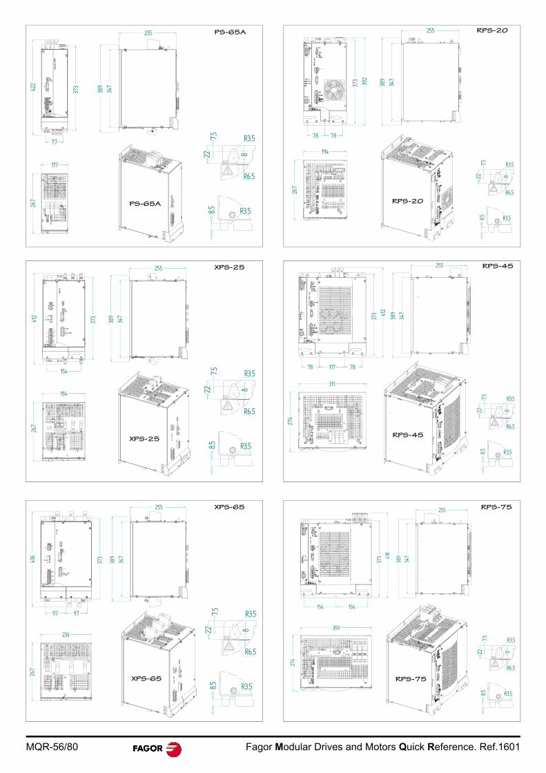
MQR-56/80 Fagor Modular Drives and Motors Quick Reference. Ref.1601
117
25526
7
389
347
77
422
373
PS-65A
R3.58.5
R3.5
R6.5
8
7.5
PS-65A
255
389
347
194
267
373
154
412
XPS-25
R3.58.5
R3.5
R6.5
8
7.5
XPS-25
97
255
389
347
234
373
97
XPS-65
R3.58.5
R3.5
R6.5
8
7.5
XPS-65
194
267
389
347
255
78 78
373 392
RPS-20
RPS-20
R3.58.5
R3.5
R6.5
8
7.5
389
347
78 117 7837
3 412
274
311
RPS-45
R3.58.5
R3.5
R6.5
8
7.5
RPS-45
389
347
156156
373 41
8
350
274
RPS-75
RPS-75
R3.58.5
R3.5
R6.5
8
7.5
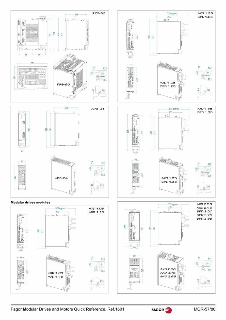
Fagor Modular Drives and Motors Quick Reference. Ref.1601 MQR-57/80
Modular drives modules
389
347
156156
373 41
8
350
274
RPS-80
RPS-80
R3.58.5
R3.5
R6.5
8
7.5
373
77
267
389
347
255
45
APS-24
APS-24
R3.58.5
R3.5
R6.5
8
7.5
77
267
325 approx.255
389
347
45
373
AXD 1.08
AXD 1.15
AXD 1.08
AXD 1.15
R3.58.5
R3.5
R6.5
8
7.5
77
267
45
255
389
347
325 approx.
373
AXD 1.25
SPD 1.25
AXD 1.25
SPD 1.25
R3.58.5
R3.5
R6.5
8
7.5
389
347
325 approx.255
45
373
77
267
398
AXD 1.35
SPD 1.35
AXD 1.35
SPD 1.35
R3.58.5
R3.5
R6.5
8
7.5
389
347
325 approx.255
77
37339
9
267
117
AXD 2.50
AXD 2.75
SPD 2.50
SPD 2.75
SPD 2.85
R3.58.5
R3.5
R6.5
8
7.5
AXD 2.50
AXD 2.75
SPD 2.85

MQR-58/80 Fagor Modular Drives and Motors Quick Reference. Ref.1601
Capacitor module
Bus Protection Module
Mains filter
412
389
347
325 approx.255
234
272
97 97
373
AXD 3.100
AXD 3.150
SPD 3.100
SPD 3.150
R3.58.5
R3.5
R6.5
8
7.5
AXD 3.100
AXD 3.150
SPD 3.100
SPD 3.150
97 97
373
423
389
347
325 approx.255
234
272
R3.58.5
R3.5
R6.5
8
7.5
AXD 3.200
SPD 3.200
SPD 3.250
AXD 3.200
SPD 3.200
SPD 3.250
373
347
255
CAPA
CITO
R MO
DULE
389
7745
CM-1.75
CM-1.75
R3.58.5
R3.5
R6.5
8
7.5
MAIN FILTER 42A 75A 130A 180AUnits mm in mm in mm in mm in
L 330 12.99 330 12.99 440 17.32 440 17.32
L-1 300 11.81 300 11.81 400 15.74 400 15.74
C 15 0.59 40 1.57 45 1.77 45 1.77
W 70 2.75 80 3.15 110 4.33 110 4.33
H 185 7.28 220 8.66 240 9.44 240 9.44
X 314 12.36 314 12.36 414 16.29 414 16.29
Y 45 1.77 55 2.16 80 3.14 80 3.14
M M6 M6 M10 M10
D M5 M6 M6 M6
389
45
373
347
266
255BPM
22
R3.5
R6.5
8
7.5
R3.58.5H
LL-1
M
W
YX
CC
D
MAIN FILTER xA
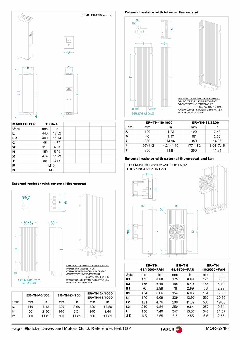
Fagor Modular Drives and Motors Quick Reference. Ref.1601 MQR-59/80
External resistor with external thermostat
External resistor with internal thermostat
External resistor with external thermostat and fan
MAIN FILTER 130A-AUnits mm in
L 440 17.32
L-1 400 15.74
C 45 1.77
W 110 4.33
H 150 5.90
X 414 16.29
Y 80 3.15
M M10
D M6
ER+TH-43/350 ER+TH-24/750 ER+TH-24/1000ER+TH-18/1000
Units mm in mm in mm inL 110 4.33 220 8.66 320 12.59ln 60 2.36 140 5.51 240 9.44lf 300 11.81 300 11.81 300 11.81
W
L-1
C
X
Y
D
H
M
L
CMAIN FILTER xA-A
30
9571L
8084
THERMO-SWITCH 160 °CFAST ON 6.3 mm
Inlf
EXTERNAL THERMOSTAT SPECIFICATIONS
PROTECTION DEGREE: IP 20
CONTACT PERSON: NORMALLY CLOSED
CONTACT OPENING TEMPERATURE:
200 °C / 392 °F ±10 %
RATED VOLTAGE - CURRENT: 250 V AC - 2 A
WIRE SECTION: 0.25 mm²
ER+TH-18/1800 ER+TH-18/2200Units mm in mm inA 120 4.72 190 7.48B 40 1.57 67 2.63L 380 14.96 380 14.96I 107112 4.214.40 177182 6.967.16P 300 11.81 300 11.81
ER+TH-18/1000+FAN
ER+TH-18/1500+FAN
ER+TH-18/2000+FAN
Units mm in mm in mm inB1 175 6.88 175 6.88 175 6.88B2 165 6.49 165 6.49 165 6.49H1 76 2.99 76 2.99 76 2.99H2 154 6.06 154 6.06 154 6.06L1 170 6.69 329 12.95 530 20.86L2 121 4.76 280 11.02 500 19.68L3 250 9.84 250 9.84 250 9.84L 188 7.40 347 13.66 548 21.57Ø D 6.5 2.55 6.5 2.55 6.5 2.55
INTERNAL THERMOSTAT SPECIFICATIONS
CONTACT PERSON: NORMALLY CLOSED
CONTACT OPENING TEMPERATURE:
160 °C / 320 °F ±10 %
RATED VOLTAGE - CURRENT: 250 V AC - 2 A
WIRE SECTION: 0.25 mm²
I
A
B
P L
2.5 mm²2.5 mm²
Ø6,5Ø12
1
B1
B2
L3
L2 L1L
H2
H1
119
ØD
EXTERNAL RESISTOR WITH EXTERNAL
THERMOSTAT AND FAN
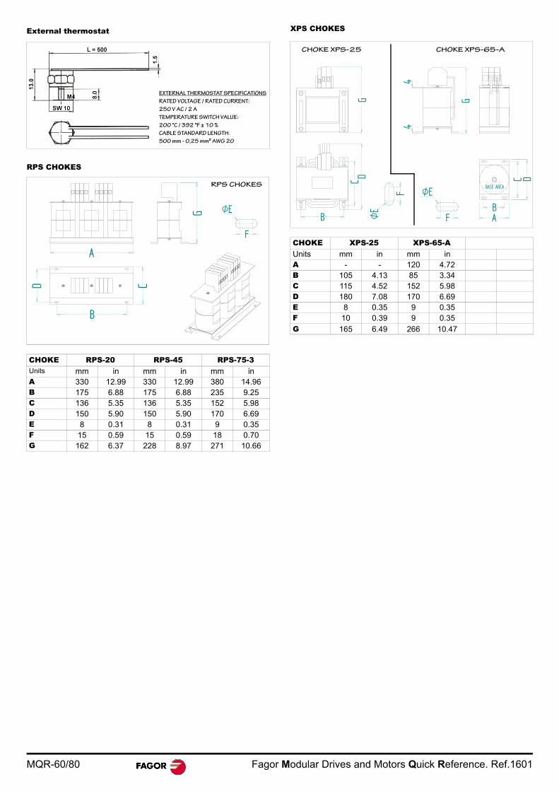
MQR-60/80 Fagor Modular Drives and Motors Quick Reference. Ref.1601
External thermostat
RPS CHOKES
XPS CHOKES
CHOKE RPS-20 RPS-45 RPS-75-3Units mm in mm in mm inA 330 12.99 330 12.99 380 14.96B 175 6.88 175 6.88 235 9.25C 136 5.35 136 5.35 152 5.98D 150 5.90 150 5.90 170 6.69E 8 0.31 8 0.31 9 0.35F 15 0.59 15 0.59 18 0.70G 162 6.37 228 8.97 271 10.66
EXTERNAL THERMOSTAT SPECIFICATIONS
RATED VOLTAGE / RATED CURRENT:
250 V AC / 2 A
TEMPERATURE SWITCH VALUE:
200 °C / 392 °F ± 10 %
CABLE STANDARD LENGTH:
500 mm - 0,25 mm² AWG 20
A
C
RPS CHOKES
CHOKE XPS-25 XPS-65-AUnits mm in mm inA - - 120 4.72B 105 4.13 85 3.34C 115 4.52 152 5.98D 180 7.08 170 6.69E 8 0.35 9 0.35F 10 0.39 9 0.35G 165 6.49 266 10.47
BASE AREAØE
4
G
B
C D
G
4
A
DC
BFØ
E
F
CHOKE XPS-25 CHOKE XPS-65-A
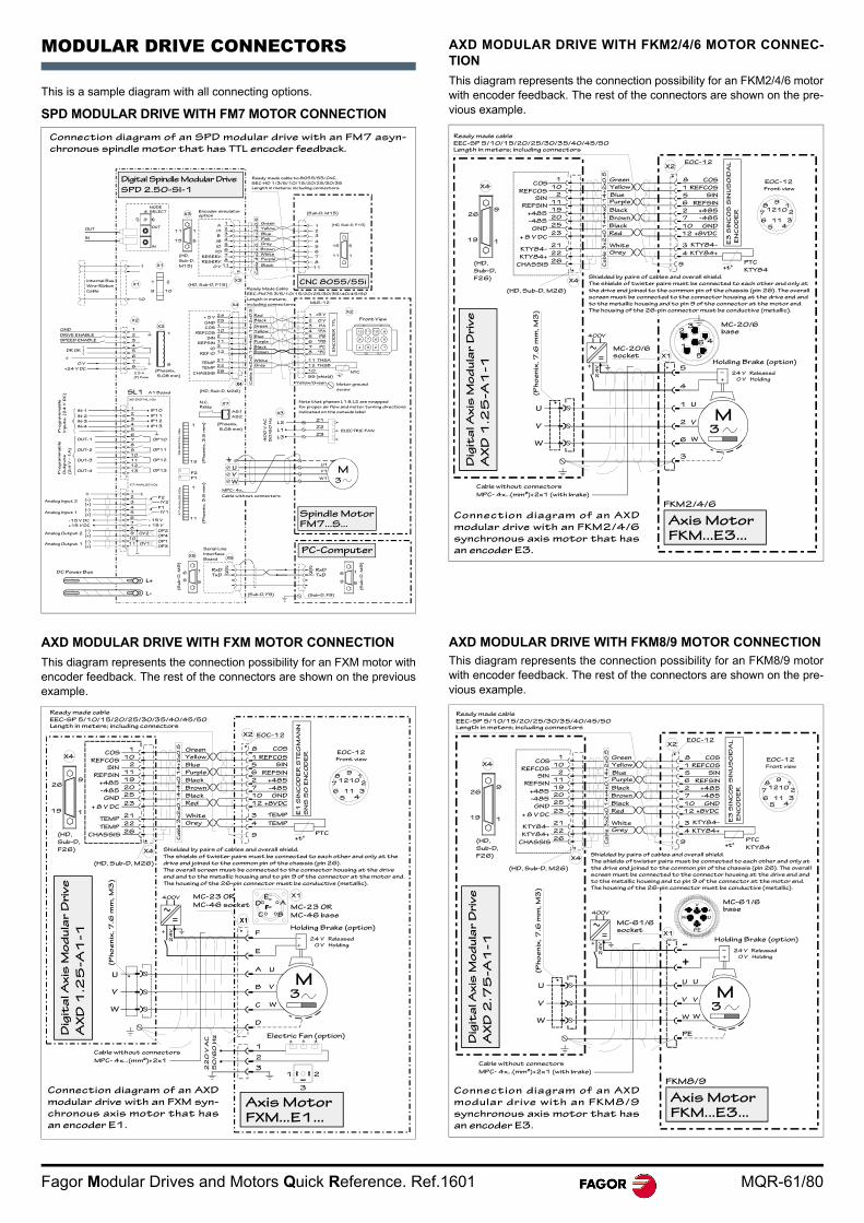
Fagor Modular Drives and Motors Quick Reference. Ref.1601 MQR-61/80
MODULAR DRIVE CONNECTORS
This is a sample diagram with all connecting options.
SPD MODULAR DRIVE WITH FM7 MOTOR CONNECTION
AXD MODULAR DRIVE WITH FXM MOTOR CONNECTION
This diagram represents the connection possibility for an FXM motor withencoder feedback. The rest of the connectors are shown on the previousexample.
AXD MODULAR DRIVE WITH FKM2/4/6 MOTOR CONNEC-TION
This diagram represents the connection possibility for an FKM2/4/6 motorwith encoder feedback. The rest of the connectors are shown on the pre-vious example.
AXD MODULAR DRIVE WITH FKM8/9 MOTOR CONNECTIONThis diagram represents the connection possibility for an FKM8/9 motorwith encoder feedback. The rest of the connectors are shown on the pre-vious example.
Connection diagram of an SPD modular drive with an FM7 asyn-
chronous spindle motor that has TTL encoder feedback.
1
(HD, Sub-D, F15)Internal Bus
Wire-Ribbon
Cable
DC Power Bus
L+
IN
OUT
(HD,
Sub-D,
M15)X1
X1
P2
P1
Serial Line
Interface
Board
(Sub-D, F9)
X5
(Su
b-D
, M
9)
1
(Sub-D, M15)
A1 Board
(Phoenix,
5.08 mm)
(Ph
oe
nix
, 3
.5 m
m)
IN
OUT
4
2.5 A
(F) Fuse
Pr
og
ra
mm
ab
le
Inp
ut
s (2
4 V
DC
)
Pr
og
ra
mm
ab
le
Ou
tp
ut
s
(24
V -
1A
)
IN-1
(Su
b-D
, M
9)
Analog Output 1
Analog Input 1
Analog Output 2
(-)
(+)
IP10
OV2
Green
Yellow
Blue
Purple
Grey
Pink
Brown
White
Black
MPC- 4x...
M3
U1
Cable without connectors
U
X3
ELECTRIC FAN
40
0 V
AC
50
/6
0 H
z Z1
Note that phases L1 & L2 are swapped
for proper air flow and motor turning directions
indicated on the outside label
Front View
9
Ready Made Cable
EEC-FM7S 3/5/10/15/20/25/30/35/40/45/50
Length in meters; including connectors
NTC
MLR-12
(HD, Sub-D, M26)
X4
Green
Blue
Red
Purple
Grey
Yellow
Brown
GND
COS
+ 5 V
X2
Black
Black
10
EN
CO
DE
R T
TL
SS (shield)
Motor ground
screw
Yellow/Green
*PC
THSB
-t°
+15 V DC
Ca
ble
4x
2x
0.1
4+
2x
0.5
Ca
ble
3x
2x
0.1
4+
4x
0.1
4+
2x
0.5
AS1
X7
(Phoenix,
5.08 mm)
AS2
RelayN.C.
X6-DIGITAL I/Os
SL1
X7-ANALOG I/Os
X6
-DIG
ITA
L I
/Os
X7
-A
NA
LO
G I/O
s
15
(HD, Sub-D, F15)
Digital Spindle Modular Drive
SPD 2.50-SI-1SEC-HD 1/3/5/10/15/20/25/30/35
Ready made cable to 8055/55i CNC,
Length in meters; including connectors
CNC 8055/55i
Encoder simulator optionX3
X3
NODE SELECT
PC-Computer
Spindle MotorFM7...S...
23
RxDTxD
1
5
6
9
(Sub-D, F9)
6
9
1
5
X5
23
RxDTxD
V
W
V1
W1
Z2
Z3
L2
L1
L3
12
11 THSA
8
7 PC
6 *PB
5 PB
4 *PA
PA3
2
1
0 V
+5 V
101112
5678
1234
11 1
5
2
3
4
5
6
7
8
11
80
11
15
1
5
A
/A
B
/B
I0
/I0
RESERV.
RESERV.
0 V
2
3
4
5
6
7
8
11
10
21
9
1
10
1
8
GND
DRIVE ENABLE
SPEED ENABLE
DR OK
0 V
+24 V DC
X2
X21
2
3
4
5
6
7
8
X4
24
25
1
10
2
11
3
12
REFCOS
SIN
REFSIN
I0
REF I0
21
22
26CHASSIS
TEMP
TEMP
IN-2
IN-3
IN-4
OUT-1
OUT-2
OUT-3
OUT-4
1
2
3
4
5
6
7
8
9
10
11
12
13
IP11
IP12
IP13
OP10
OP11
OP12
OP13
L-
(-)
(+)
-15 V DC
Analog Input 2
(-)
(+)
(-)
(+)
1
2
3
4
5
6
7
8
9
10
11
- 15 V
+ 15 V
OV1
OP2
OP4
OP1
OP3
P2
P1
IV2
IV1
11
1
1
(Ph
oe
nix
, 3
.5 m
m)
13
White
M3
MPC- 4x...(mm²)+2x1
(HD,
Sub-D,
F26)
X4
X1
(Ph
oe
nix
, 7
.6 m
m,
M3
)
24 V Released
F
X1
Cable without connectors
22
0 V
AC
50
/6
0 H
z
1
Dig
ita
l A
xis
Mo
du
lar D
riv
e
AX
D 1
.25
-A
1-1
Axis MotorFXM...E1...
MC-23 OR
MC-46 base
MC-23 OR
MC-46 socket
Electric Fan (option)
Shielded by pairs of cables and overall shield.
The shields of twister pairs must be connected to each other and only at the
drive end joined to the common pin of the chassis (pin 26).
The overall screen must be connected to the connector housing at the drive
end and to the metallic housing and to pin 9 of the connector at the motor end.
The housing of the 26-pin connector must be conductive (metallic).
PTC
EOC-12
(HD, Sub-D, M26)
X4
Blue
Black
Green
Brown
Grey
Purple
White
Red
1
8
REFCOS
REFSIN
X2
Yellow
Black
E1
SIN
CO
DE
R S
TE
GM
AN
N
SN
S 5
0 E
NC
OD
ER
+485
+t°
E0C-12Front view
Ca
ble
3x
2x
0.1
4+
4x
0.1
4+
2x
0.5 COS
REFCOS
EEC-SP 5/10/15/20/25/30/35/40/45/50Length in meters; including connectors
Ready made cable
2
31 2
3
D
C
B
A
E
F
U
V
W
U
V
W
Holding Brake (option)
0 V Holding
A
BC
DE
SIN5
REFSIN6
2
-4857
10 GND
12 +8VDC
TEMP
TEMP
3
4
91
2
345
6
7
8
11
1012
9
COS1
SIN
10
2
11
19+485
-48520
GND25
23+ 8 V DC
21TEMP
22TEMP
26CHASSIS
1
926
19
+
=
400V
24
V
Connection diagram of an AXD
modular drive with an FXM syn-
chronous axis motor that has
an encoder E1.
X1
Shielded by pairs of cables and overall shield.
The shields of twister pairs must be connected to each other and only at
the drive end joined to the common pin of the chassis (pin 26). The overall
screen must be connected to the connector housing at the drive end and
to the metallic housing and to pin 9 of the connector at the motor end.
The housing of the 26-pin connector must be conductive (metallic).
Blue
Black
Green
Brown
Grey
Purple
White
Red
Yellow
Black
+t°
Axis MotorFKM...E3...
Dig
ita
l A
xis
Mo
du
lar D
riv
e
AX
D 1
.25
-A
1-1
MPC- 4x...(mm²)+2x1 (with brake)
Cable without connectors
M3
24 V Released
Holding Brake (option)
0 V Holding
MC-20/6 base
MC-20/6 socket
3
6
2
1
4
5
5
461
23
EEC-SP 5/10/15/20/25/30/35/40/45/50Length in meters; including connectors
Ready made cable
(HD,
Sub-D,
F26)
X4
1
926
19
(HD, Sub-D, M26)
X4
REFCOS
REFSIN
COS
SIN
+485
-485
GND
+ 8 V DC
KTY84-
KTY84+
CHASSIS Ca
ble
3x
2x
0.1
4+
4x
0.1
4+
2x
0.5
1
10
2
11
19
20
25
23
21
22
26
EOC-12X2
E3
SIN
CO
S S
INU
SO
IDA
L
EN
CO
DE
R
8 COS
1 REFCOS
SIN5
REFSIN6
+4852
-4857
10 GND
12 +8VDC
3 KTY84-
KTY84+4
9
E0C-12Front view
91
2
345
6
7
8
11
1012
PTC
KTY84
(Ph
oe
nix
, 7
.6 m
m,
M3
)
U
V
W
U
V
W
FKM2/4/6
+
=
400V
24
V
Connection diagram of an AXD
modular drive with an FKM2/4/6
synchronous axis motor that has
an encoder E3.
X1
Shielded by pairs of cables and overall shield.
The shields of twister pairs must be connected to each other and only at
the drive end joined to the common pin of the chassis (pin 26). The overall
screen must be connected to the connector housing at the drive end and
to the metallic housing and to pin 9 of the connector at the motor end.
The housing of the 26-pin connector must be conductive (metallic).
Blue
Black
Green
Brown
Grey
Purple
White
Red
Yellow
Black
+t°
Axis MotorFKM...E3...
Dig
ita
l A
xis
Mo
du
lar D
riv
e
AX
D 2
.75
-A
1-1
MPC- 4x...(mm²)+2x1 (with brake)
Cable without connectors
M3
24 V Released
Holding Brake (option)
0 V Holding
MC-61/6 base
MC-61/6 socket
PE
W
V
U
+
EEC-SP 5/10/15/20/25/30/35/40/45/50Length in meters; including connectors
Ready made cable
(HD,
Sub-D,
F26)
X4
1
926
19
(HD, Sub-D, M26)
X4
REFCOS
REFSIN
COS
SIN
+485
-485
GND
+ 8 V DC
KTY84-
KTY84+
CHASSIS Ca
ble
3x
2x
0.1
4+
4x
0.1
4+
2x
0.5
1
10
2
11
19
20
25
23
21
22
26
EOC-12X2
E3
SIN
CO
S S
INU
SO
IDA
L
EN
CO
DE
R
8 COS
1 REFCOS
SIN5
REFSIN6
+4852
-4857
10 GND
12 +8VDC
3 KTY84-
KTY84+4
9
E0C-12Front view
91
2
345
6
7
8
11
1012
PTC
KTY84
(Ph
oe
nix
, 7
.6 m
m,
M3
)
U
V
W
U
V
W
FKM8/9
UW
V
PE
+-
-+
=
400V
24
V
Connection diagram of an AXD
modular drive with an FKM8/9
synchronous axis motor that has
an encoder E3.
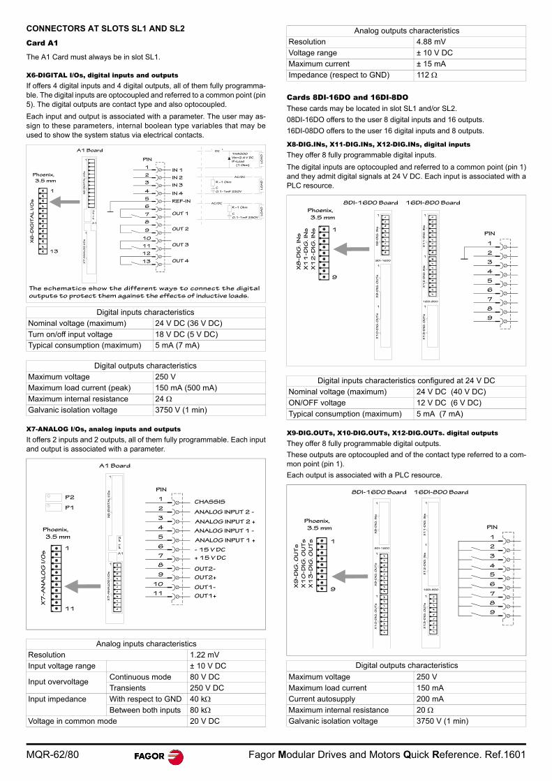
MQR-62/80 Fagor Modular Drives and Motors Quick Reference. Ref.1601
CONNECTORS AT SLOTS SL1 AND SL2
Card A1
The A1 Card must always be in slot SL1.
X6-DIGITAL I/Os, digital inputs and outputsIf offers 4 digital inputs and 4 digital outputs, all of them fully programma-ble. The digital inputs are optocoupled and referred to a common point (pin5). The digital outputs are contact type and also optocoupled.
Each input and output is associated with a parameter. The user may as-sign to these parameters, internal boolean type variables that may beused to show the system status via electrical contacts.
X7-ANALOG I/Os, analog inputs and outputsIt offers 2 inputs and 2 outputs, all of them fully programmable. Each inputand output is associated with a parameter.
Cards 8DI-16DO and 16DI-8DOThese cards may be located in slot SL1 and/or SL2.
08DI-16DO offers to the user 8 digital inputs and 16 outputs.
16DI-08DO offers to the user 16 digital inputs and 8 outputs.
X8-DIG.INs, X11-DIG.INs, X12-DIG.INs, digital inputsThey offer 8 fully programmable digital inputs.
The digital inputs are optocoupled and referred to a common point (pin 1)and they admit digital signals at 24 V DC. Each input is associated with aPLC resource.
X9-DIG.OUTs, X10-DIG.OUTs, X12-DIG.OUTs. digital outputsThey offer 8 fully programmable digital outputs.
These outputs are optocoupled and of the contact type referred to a com-mon point (pin 1).
Each output is associated with a PLC resource.
Digital inputs characteristics
Nominal voltage (maximum) 24 V DC (36 V DC)
Turn on/off input voltage 18 V DC (5 V DC)Typical consumption (maximum) 5 mA (7 mA)
Digital outputs characteristics
Maximum voltage 250 V
Maximum load current (peak) 150 mA (500 mA)
Maximum internal resistance 24 Galvanic isolation voltage 3750 V (1 min)
Analog inputs characteristics
Resolution 1.22 mV
Input voltage range ± 10 V DC
Input overvoltageContinuous mode 80 V DC
Transients 250 V DC
Input impedance With respect to GND 40 kBetween both inputs 80 k
Voltage in common mode 20 V DC
IN 1
PIN
Phoenix,
3.5 mm
X6
-D
IGIT
AL
I/O
s
A1
1
1
X7
-A
NA
LO
G I
/Os
X6
-D
IGIT
AL
I/O
s
P2
P1
A1 Board
1
13
IN 2
IN 3
IN 4
REF-IN
OUT 1
OUT 2
OUT 3
OUT 413
12
11
10
9
8
7
6
5
4
3
2
1
The schematics show the different ways to connect the digital
outputs to protect them against the effects of inductive loads.
DC
AC/DC
R ~1 Ohm
1N4000
Vbr=2.4 V DC
IF=Load
(1 Ohm)
C
0.1-1mF 250V
LO
AD
LO
AD
AC/DC
R ~1 Ohm
C
0.1-1mF 250V
LO
AD
X7
-A
NA
LO
G I
/O
s A1
1
1
X7
-A
NA
LO
G I
/Os
X6
-D
IGIT
AL
I/O
s
P2
P1
P2
P1
OUT2-
OUT2+
OUT1-
OUT1+
A1 Board
Phoenix,
3.5 mm
1
11
- 15 V DC
+ 15 V DC
CHASSIS
ANALOG INPUT 2 -
ANALOG INPUT 2 +
ANALOG INPUT 1 -
ANALOG INPUT 1 +
PIN
1
2
3
4
5
6
7
8
9
10
11
Analog outputs characteristics
Resolution 4.88 mV
Voltage range ± 10 V DC
Maximum current ± 15 mA
Impedance (respect to GND) 112
Digital inputs characteristics configured at 24 V DC
Nominal voltage (maximum) 24 V DC (40 V DC)
ON/OFF voltage 12 V DC (6 V DC)
Typical consumption (maximum) 5 mA (7 mA)
Digital outputs characteristics
Maximum voltage 250 V
Maximum load current 150 mA
Current autosupply 200 mA
Maximum internal resistance 20 Galvanic isolation voltage 3750 V (1 min)
X8
-D
IG.
INs
X1
1-D
IG.
INs
X1
2-D
IG.
INs
X8
-D
IG.
INs
X9
-D
IG.
OU
Ts
X1
0-D
IG.
OU
Ts
8DI-16D0
X1
1-D
IG.
INs
X1
2-D
IG.
INs
X1
3-D
IG.
OU
Ts
8DI-16DO Board 16DI-8DO Board
Phoenix,
3.5 mm
1
9
1
1
1
16DI-8D0
1
1
1
1
PIN
2
3
4
5
6
7
8
9
X9
-D
IG.
OU
Ts
X1
0-D
IG.
OU
Ts
X1
3-D
IG.
OU
Ts
X8
-D
IG.
INs
X9
-D
IG.
OU
Ts
X1
0-D
IG.
OU
Ts
X1
1-D
IG.
INs
X1
2-D
IG.
INs
X1
3-D
IG.
OU
Ts
8DI-16DO Board 16DI-8DO Board
Phoenix,
3.5 mm
1
9
1
8DI-16D0
1
1 1
16DI-8D0
1
1
1
PIN
2
3
4
5
6
7
8
9
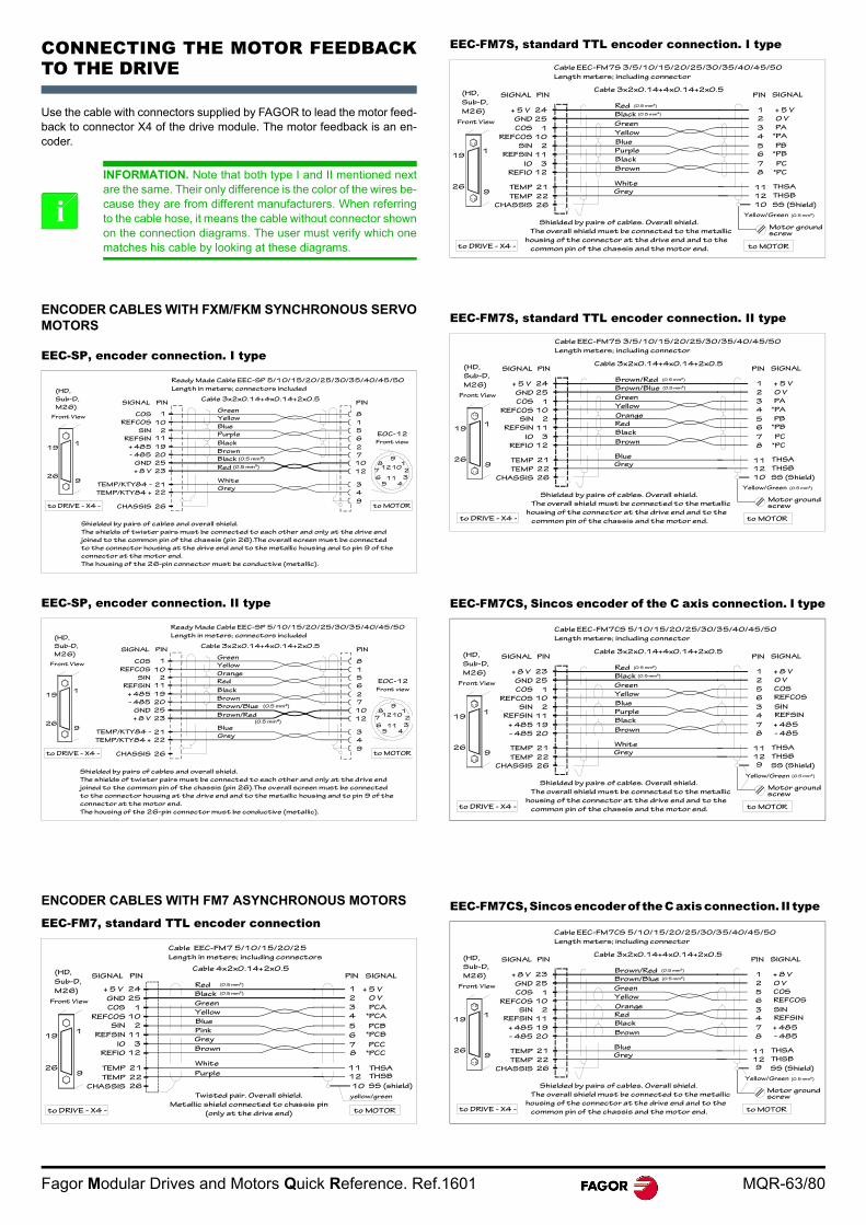
Fagor Modular Drives and Motors Quick Reference. Ref.1601 MQR-63/80
CONNECTING THE MOTOR FEEDBACKTO THE DRIVE
Use the cable with connectors supplied by FAGOR to lead the motor feed-back to connector X4 of the drive module. The motor feedback is an en-coder.
ENCODER CABLES WITH FXM/FKM SYNCHRONOUS SERVOMOTORS
EEC-SP, encoder connection. I type
EEC-SP, encoder connection. II type
ENCODER CABLES WITH FM7 ASYNCHRONOUS MOTORS
EEC-FM7, standard TTL encoder connection
EEC-FM7S, standard TTL encoder connection. I type
EEC-FM7S, standard TTL encoder connection. II type
EEC-FM7CS, Sincos encoder of the C axis connection. I type
EEC-FM7CS, Sincos encoder of the C axis connection. II type
INFORMATION. Note that both type I and II mentioned nextare the same. Their only difference is the color of the wires be-cause they are from different manufacturers. When referringto the cable hose, it means the cable without connector shownon the connection diagrams. The user must verify which onematches his cable by looking at these diagrams.
i
Black
Green
Brown
Grey
White
Red
Ready Made Cable EEC-SP 5/10/15/20/25/30/35/40/45/50
Length in meters; connectors included
REFCOS
SIN
REFSIN
+ 485
- 485
GND
+ 8 V
COS
26
Cable 3x2x0.14+4x0.14+2x0.5
CHASSIS
E0C-12
9
Front view
to DRIVE - X4 - to MOTOR
(0.5 mm²)
(0.5 mm²)
Shielded by pairs of cables and overall shield.
The shields of twister pairs must be connected to each other and only at the drive end
joined to the common pin of the chassis (pin 26).The overall screen must be connected
to the connector housing at the drive end and to the metallic housing and to pin 9 of the
connector at the motor end.
The housing of the 26-pin connector must be conductive (metallic).
Black
22
21
TEMP/KTY84 +
TEMP/KTY84 -
9
4
3
12
10
7
2
6
5
1
8
23
25
20
19
11
2
10
1
PINSIGNAL PIN
1
2
345
6
7
8
11
1012
Yellow
Blue
Purple
9
1
(HD,
Sub-D,
M26)
Front View
19
26
Black
Green
Brown
Grey
Blue
Brown/Red
Ready Made Cable EEC-SP 5/10/15/20/25/30/35/40/45/50
Length in meters; connectors included
REFCOS
SIN
REFSIN
+ 485
- 485
GND
+ 8 V
COS
26
Cable 3x2x0.14+4x0.14+2x0.5
CHASSIS
E0C-12
9
Front view
to DRIVE - X4 - to MOTOR
(0.5 mm²)
(0.5 mm²)
Shielded by pairs of cables and overall shield.
The shields of twister pairs must be connected to each other and only at the drive end
joined to the common pin of the chassis (pin 26).The overall screen must be connected
to the connector housing at the drive end and to the metallic housing and to pin 9 of the
connector at the motor end.
The housing of the 26-pin connector must be conductive (metallic).
Brown/Blue
22
21
TEMP/KTY84 +
TEMP/KTY84 -
9
4
3
12
10
7
2
6
5
1
8
23
25
20
19
11
2
10
1
PINSIGNAL PIN
1
2
345
6
7
8
11
1012
Yellow
Orange
Red
9
1
(HD,
Sub-D,
M26)
Front View
19
26
Blue
Yellow
Purple
White
Brown
Cable EEC-FM7 5/10/15/20/25
Length in meters; including connectors
GND
COS
REFCOS
SIN
REFSIN
I0
CHASSIS
TEMP
REFI0
+ 5 V 24
3
Green
Grey
Cable 4x2x0.14+2x0.5
Twisted pair. Overall shield.
Metallic shield connected to chassis pin
(only at the drive end)to DRIVE - X4 - to MOTOR
Pink
0 V
PCC
THSB
+ 5 V
SS (shield)
Red
Black (0.5 mm²)
yellow/green
*PCC
PINSIGNAL
25
1
10
2
11
12
21
22TEMP
26 10
12
11 THSA
(0.5 mm²)
PIN SIGNAL
1
2
8
*PCB
PCB
*PCA
PCA3
4
5
6
7
9
1
(HD,
Sub-D,
M26)
Front View
19
26
9
1
(HD,
Sub-D,
M26)
Blue
Green
Grey
White
Brown
Cable EEC-FM7S 3/5/10/15/20/25/30/35/40/45/50
Length meters; including connector
Yellow
Black
Cable 3x2x0.14+4x0.14+2x0.5
Shielded by pairs of cables. Overall shield.
The overall shield must be connected to the metallic
housing of the connector at the drive end and to the
common pin of the chassis and the motor end.
Front View
Purple
10
THSB
SS (Shield)
Motor groundscrew
Yellow/Green
to DRIVE - X4 - to MOTOR
PINSIGNAL
GND
COS
REFCOS
SIN
REFSIN
I0
CHASSIS
TEMP
REFI0
+ 5 V 24
3
25
1
10
2
11
12
21
22TEMP
26
19
26
Red (0.5 mm²)
Black (0.5 mm²)
PIN SIGNAL
(0.5 mm²)
THSA
12
11
*PC8
PC7
*PB6
PB5
*PA4
PA3
0 V2
+ 5 V1
9
1
(HD,
Sub-D,
M26)
Orange
Green
Grey
Blue
Brown
Cable EEC-FM7S 3/5/10/15/20/25/30/35/40/45/50
Length meters; including connector
Yellow
Black
Cable 3x2x0.14+4x0.14+2x0.5
Shielded by pairs of cables. Overall shield.
The overall shield must be connected to the metallic
housing of the connector at the drive end and to the
common pin of the chassis and the motor end.
Front View
Red
10
THSB
SS (Shield)
Motor groundscrew
Yellow/Green
to DRIVE - X4 - to MOTOR
PINSIGNAL
GND
COS
REFCOS
SIN
REFSIN
I0
CHASSIS
TEMP
REFI0
+ 5 V 24
3
25
1
10
2
11
12
21
22TEMP
26
19
26
Brown/Red (0.5 mm²)
Brown/Blue (0.5 mm²)
PIN SIGNAL
(0.5 mm²)
THSA
12
11
*PC8
PC7
*PB6
PB5
*PA4
PA3
0 V2
+ 5 V1
9
1
(HD,
Sub-D,
M26)
Blue
Green
Grey
White
Brown
Cable EEC-FM7CS 5/10/15/20/25/30/35/40/45/50
Length meters; including connector
Yellow
Black
Cable 3x2x0.14+4x0.14+2x0.5
Shielded by pairs of cables. Overall shield.
The overall shield must be connected to the metallic
housing of the connector at the drive end and to the
common pin of the chassis and the motor end.
Front View
Purple
THSB
SS (Shield)
Motor groundscrew
Yellow/Green
to DRIVE - X4 - to MOTOR
PINSIGNAL
GND
COS
REFCOS
SIN
REFSIN
+ 485
CHASSIS
TEMP
- 485
+ 8 V 23
25
1
10
2
11
20
21
22TEMP
26
19
26
Red (0.5 mm²)
Black (0.5 mm²)
PIN SIGNAL
(0.5 mm²)
THSA
12
11
8
+ 4857
REFSIN4
SIN3
6
COS5
0 V2
+ 8 V1
19
9
REFCOS
- 485
9
1
(HD,
Sub-D,
M26)
Orange
Green
Grey
Blue
Brown
Cable EEC-FM7CS 5/10/15/20/25/30/35/40/45/50
Length meters; including connector
Yellow
Black
Cable 3x2x0.14+4x0.14+2x0.5
Shielded by pairs of cables. Overall shield.
The overall shield must be connected to the metallic
housing of the connector at the drive end and to the
common pin of the chassis and the motor end.
Front View
Red
THSB
SS (Shield)
Motor groundscrew
Yellow/Green
to DRIVE - X4 - to MOTOR
PINSIGNAL
GND
COS
REFCOS
SIN
REFSIN
+ 485
CHASSIS
TEMP
- 485
+ 8 V 23
25
1
10
2
11
20
21
22TEMP
26
19
26
Brown/Red (0.5 mm²)
Brown/Blue (0.5 mm²)
PIN SIGNAL
(0.5 mm²)
THSA
12
11
8
+ 4857
REFSIN4
SIN3
6
COS5
0 V2
+ 8 V1
19
9
REFCOS
- 485

MQR-64/80 Fagor Modular Drives and Motors Quick Reference. Ref.1601
CONTROL AND COMMUNICATION SIGNALSConnect the encoder simulator signal to the CNC.
SEC-HD, encoder simulator connection
EC- PD, direct feedback with external incremental linearor rotary encoder (1 Vpp or diferential TTL)
EC-B-D, direct feedback with external absolute linearencoder (1 Vpp or diferential TTL)
Direct feedback Stegmann sinusoidal encoder
RS-232 SERIAL LINE. X5 CONNECTOR
RS-232 serial line cable to a PC
To transfer the parameter table and setup the system, the drive must beconnected to a PC-Compatible computer through a serial line RS-232.
RS232/RS422 BE adapter
Some connections will mention the “RS232/RS422 BE” adapter , thus be-ing necessary to describe it and its pinout at both ends.
RS-232 serial line between PC and VT (without adapter)
The VT-PC connection is essential for transferring the communicationdriver and the proyect.
Yellow
Green
Ready Made Cable SEC-HD 1/3/5/10/15/20/25/30/35
Length in meters; including connectors
Cable 4x2x0.14+2x0.5
Twisted pair. Overall shield.
Metallic shield connected to CHASSIS pin
(at the CNC end and at the DRIVE end)
(HD,
Sub-D,
M15)
Front View
to 8055 CNC - X1, X2, X3 OR X4 -
1
5
11
15
to 8055i CNC - X10, X11, X12 OR X13 -
(HD,
Sub-D,
M15)
Front View
to DRIVE - X3 -
PINSIGNAL
A 1
/A 2
B 3
/B 4
I0 5
/I0 6
7
8
11
CHASSIS
11
PIN
1
2
3
4
5
6
7
8
Blue
Pink
Grey
Brown
White
Purple
Black
1
515
11
Cable 4x2x0.14
Twisted pairs. Overall shield.
Overall shield connected to chassis pin
(on the sensor side and drive side)
A
+5 V DC
GND
FAGOR EC-X PD sensor cable
Length in meters; including connectors
CHASSIS
/A
1/2/3/4/6/8/9/10/12
Brown
White
Green
Yellow
Blue
Red
Grey
Pink
to DRIVE - X3 -
(HD,
Sub-D,
M15)
Front View
1
515
11
to EXTERNAL
INCREMENTAL
FEEDBACK DEVICE
15
6
5
PINSIGNAL
B
/B
I0
/IO
4
3
2
1
11
9
Cable 4x0.09+4x0.14+(4x0.09)
A
+ 5 V DC
GND
1/3/6/9
GND SENSE
+ 5 SENSE
Brown
White
Green
Yellow
Blue
Red
Grey
Pink
Black
Purple
Red/Blue
Grey/Pink
FAGOR EC-XB-D sensor cable
Length in meters; including connectors
Twisted pairs. Overall shield.
Overall shield connected to chassis
(on the sensor side and drive side)
SIGNAL
to DRIVE - X3 -
(HD,
Sub-D,
M15)
Front View
1
515
11
PIN
to EXTERNAL
ABSOLUTE
FEEDBACK DEVICE
/A
B
/B
DATA
/DATA
CLK
/CLK
9
11
1
2
3
4
5
6
7
8
10
12
15
Pin-Out of
connector X3
when using Stegmann
external sinusoidal
encoder as direct
feedback + 485
+8 V DC
GND
A
SIGNAL
(HD, Sub-D, M15)
Front View
1
515
11
to DRIVE - X3 -
PIN
8
7
4
3
2
1
11
14
/A
B
/B
- 485
Note. Remember that the user is free to use it or not. However, using itwould make the connection a lot easier.
RS-232 CABLE
864
2
5
PIN
Overall shield. Metallic shield connected to CHASSIS pin.
Only at the drive end.
RxD
SIGNAL
5
(Sub-D, F9)
Front view
13
16
9
TxD 3
DTR
DSR
CTS
GND
CHASSIS
PIN SIGNAL
2
3
RxD
TxD
DTR
DSR
CTS
GND
5
16
9
to DRIVE - X5 - to PC
(Sub-D, F9)
Front view
5
(Sub-D, F9)
Front view
16
9864
2
5
PIN
RxD
SIGNAL
TxD 3
DTR
DSR
CTS
GND
CHASSIS
PIN SIGNAL
RxD
TxD
DTR
DSR
CTS
GND
4
6
8
5
2
3
20
6
8
5
(Sub-D, F25)
Front view
1
25
14
1Connect this end of theadapter directly to theMSP connector of the VT.
B port of the adapter (Sub-D, M9)
Connect the end of the RS-232or RS-422 cable to this end ofthe adapter.
RS232/RS422 BE adapter
A port of the adapter (Sub-D, M25)
13 25
14
1
5
6
9
9-pin Sub-D, F9type female connector
9-pin Sub-D, M25 type female connector
RS-232 CABLE
5
TxD
CHASSIS
Maximum length: 15 meters
Sub-D, F9
to PC to VT panel (ESA)
PINSIGNAL
Sub-D, M25
PIN SIGNAL
CTS 8
7RTS
DSR
DTR
6
4
3
2RxD 2
3
15
18
4
5
7
25
GND
CTS
TRS
RxD
TxD
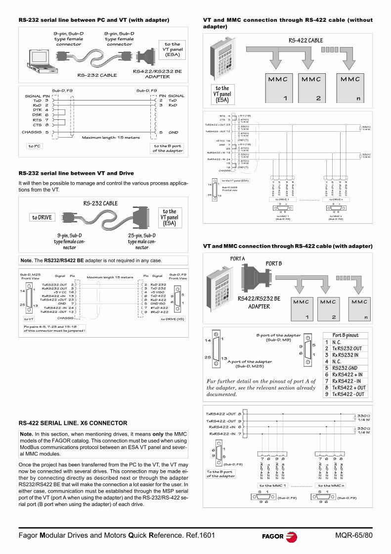
Fagor Modular Drives and Motors Quick Reference. Ref.1601 MQR-65/80
RS-232 serial line between PC and VT (with adapter)
RS-232 serial line between VT and Drive
It will then be possible to manage and control the various process applica-tions from the VT.
RS-422 SERIAL LINE. X6 CONNECTOR
Once the project has been transferred from the PC to the VT, the VT maynow be connected with several drives. This connection may be made ei-ther by connecting directly as described next or through the adapterRS232/RS422 BE that will make the connection a lot easier for the user. Ineither case, communication must be established through the MSP serialport of the VT (port A when using the adapter) and the RS-232/RS-422 se-rial port (B port when using the adapter) of each drive.
VT and MMC connection through RS-422 cable (withoutadapter)
VT and MMC connection through RS-422 cable (with adapter)
Note. The RS232/RS422 BE adapter is not required in any case.
Note. In this section, when mentioning drives, it means only the MMCmodels of the FAGOR catalog. This connection must be used when usingModBus communications protocol between an ESA VT panel and sever-al MMC modules.
to the
VT panel
(ESA)
RS-232 CABLE
9-pin, Sub-D
type female
connector
9-pin, Sub-D
type female
connector
RS422/RS232 BE
ADAPTER
5
RxD
CHASSIS
Maximum length: 15 meters
Sub-D, F9
to PC to the B port
of the adapter
PINSIGNAL
Sub-D, F9
PIN SIGNAL
CTS 8
7RTS
DSR
DTR
6
4
2
3TxD 2
3
5 GND
RxD
TxD
to DRIVE
RS-232 CABLE
9-pin, Sub-D type female con-
nector
25-pin, Sub-D type male con-
nector
to the VT panel
(ESA)
2
Pin pairs 4-5, 7-25 and 15-18
of this connector must be jumpered !
Sub-D, M25
Front ViewSignal Pin
3
16
13
23
7
24
12
CHASSISto VT
1
1325
14
Maximum length 15 meters
to DRIVE (X5)
Pin Signal Sub-D, F9
Front View
2
3
4
6
8
5
7
9
9
6
5
1
TxRS232 OUT
RxRS232 OUT
+5 V CC
RxRS422 +IN
TxRS422 +OUT
GND
TxRS422 -IN
TxRS422 -OUT
RxD 232
TxD 232
+5 VISO
TxD 422
RxD 422
GND ISO
#TxD 422
#RxD 422
to the VT panel
(ESA)
M M C M M C M M C
n 2 1
RS-422 CABLE
to DRIVE 1 .....................
TxRS422 + OUT
CHASSIS
+5 VCC
GND
470 1/4 W
+ 5 V (16)RTS
Sub-D, M25
Frontal view
to MMC 1
(Sub-D, F9)
1
8 R
xD
42
2
6 T
xD
42
2
7 /
Tx
D 4
22
to DRIVE n
4
CTS 5
23
TxRS422 - OUT 12
330 1/4 W
470 1/4 W
GND (7)16
7
25
13RxRS422 + IN
24RxRS422 - IN
15
18
+ 5 V (16)
470 1/4 W
330 1/4 W
470 1/4 W
330 1/4 W
to the VT panel (ESA)
GND (7)
13
114
25
330 1/4 W
9 / R
xD
42
2
to MMC n
(Sub-D, F9)
5
69
15
69
8 R
xD
42
2
6 T
xD
42
2
7 /
Tx
D 4
22
9 / R
xD
42
2
M M C M M C M M C
n 2 1
RS422/RS232 BE
ADAPTER
PORT BPORT A
Port B pinout
1 N. C.2 Tx RS232 0UT
3 Rx RS232 IN
4 N. C.
5 RS232 GND
6 Rx RS422 + IN
7 Rx RS422 - IN
8 Tx RS422 + OUT
9 Tx RS422 - OUT
Fur further detail on the pinout of port A ofthe adapter, see the relevant section alreadydocumented.
13A port of the adapter
(Sub-D, M25)
B port of the adapter
(Sub-D, M9)114
25
9
6 1
5
to the MMC 1
8
(Sub-D, F9)
Rx
D 4
22
RxRS422 +IN
To the B port
of the adapter
..
..
..
..TxRS422 +OUT
TxRS422 -OUT 9
6
RxRS422 -IN 7
330 1/4 W
330 1/4 W
1
5
6
9
15
69
(Sub-D, F9)
15
69
(Sub-D, F9)
to the MMC n...........................
8967 /R
xD
42
2
Tx
D 4
22
/R
xD
42
2
Rx
D 4
22
/R
xD
42
2
Tx
D 4
22
/R
xD
42
2
8967
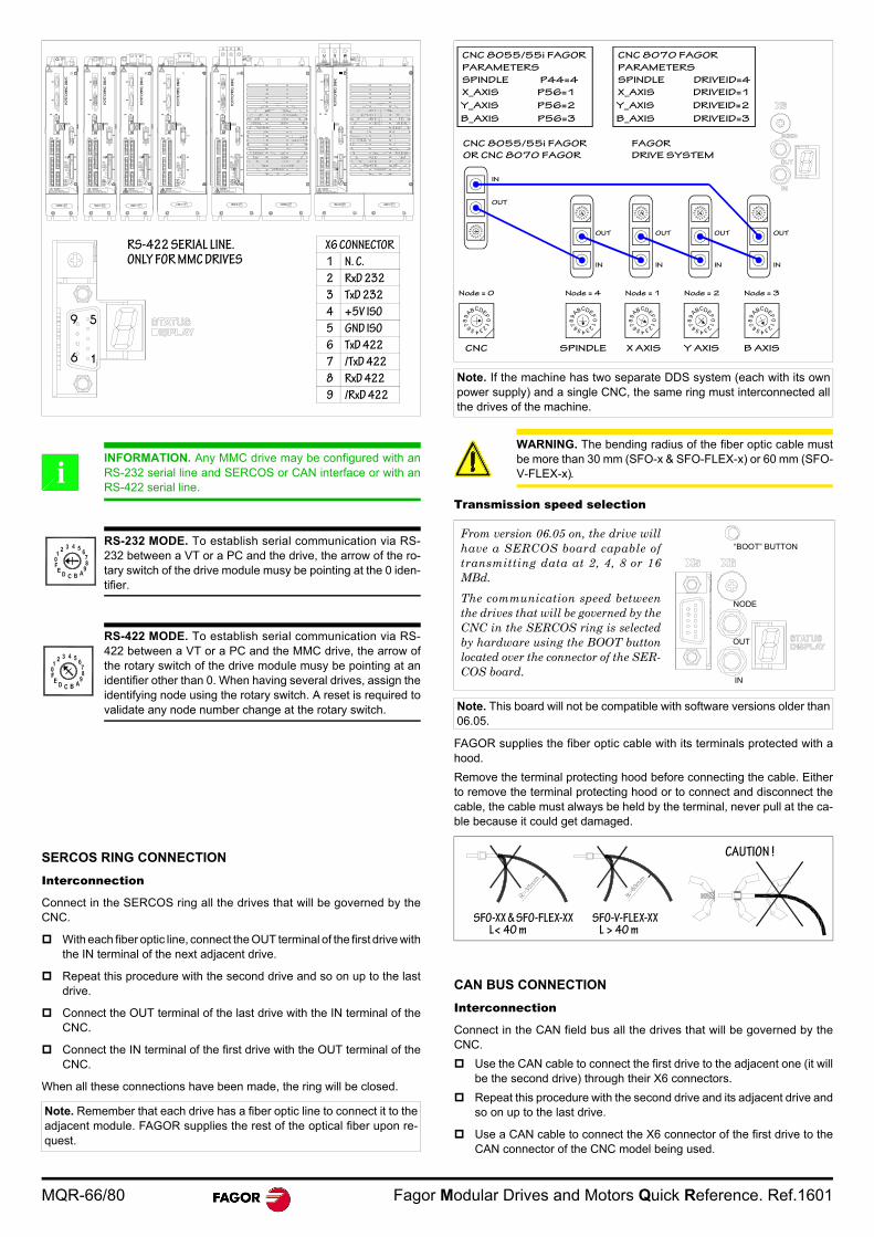
MQR-66/80 Fagor Modular Drives and Motors Quick Reference. Ref.1601
SERCOS RING CONNECTION
Interconnection
Connect in the SERCOS ring all the drives that will be governed by theCNC.
With each fiber optic line, connect the OUT terminal of the first drive withthe IN terminal of the next adjacent drive.
Repeat this procedure with the second drive and so on up to the lastdrive.
Connect the OUT terminal of the last drive with the IN terminal of theCNC.
Connect the IN terminal of the first drive with the OUT terminal of theCNC.
When all these connections have been made, the ring will be closed.
Transmission speed selection
FAGOR supplies the fiber optic cable with its terminals protected with ahood.
Remove the terminal protecting hood before connecting the cable. Eitherto remove the terminal protecting hood or to connect and disconnect thecable, the cable must always be held by the terminal, never pull at the ca-ble because it could get damaged.
CAN BUS CONNECTION
Interconnection
Connect in the CAN field bus all the drives that will be governed by theCNC.
Use the CAN cable to connect the first drive to the adjacent one (it willbe the second drive) through their X6 connectors.
Repeat this procedure with the second drive and its adjacent drive andso on up to the last drive.
Use a CAN cable to connect the X6 connector of the first drive to theCAN connector of the CNC model being used.
INFORMATION. Any MMC drive may be configured with anRS-232 serial line and SERCOS or CAN interface or with anRS-422 serial line.
RS-232 MODE. To establish serial communication via RS-232 between a VT or a PC and the drive, the arrow of the ro-tary switch of the drive module musy be pointing at the 0 iden-tifier.
RS-422 MODE. To establish serial communication via RS-422 between a VT or a PC and the MMC drive, the arrow ofthe rotary switch of the drive module musy be pointing at anidentifier other than 0. When having several drives, assign theidentifying node using the rotary switch. A reset is required tovalidate any node number change at the rotary switch.
Note. Remember that each drive has a fiber optic line to connect it to theadjacent module. FAGOR supplies the rest of the optical fiber upon re-quest.
1
5
6
9
RS-422 SERIAL LINE. ONLY FOR MMC DRIVES
X6 CONNECTOR
1 N. C.
2 RxD 232
3 TxD 232
4 +5V ISO
5 GND ISO
6 TxD 422
7 /TxD 422
8 RxD 422
9 /RxD 422
positio
ning d
rive
positio
ning d
rive
positio
ning d
rive
positio
ning d
rive
X3
positio
ning d
rive
positio
ning d
rive
DANGERHIGH VOLTAGEDISCHARGE TIME>4Min
DANGERHIGH VOLTAGEDISCHARGE TIME>4Min
DANGERHIGH VOLTAGEDISCHARGE TIME>4Min
DANGERHIGH VOLTAGEDISCHARGE TIME>4Min
DANGERHIGH VOLTAGEDISCHARGE TIME>4Min
DANGERHIGH VOLTAGEDISCHARGE TIME>4Min
2.5A(F)
FUSE(250V)
2.5A(F)
FUSE(250V)
2.5A(F)
FUSE(250V)
2.5A(F)
FUSE(250V)
2.5A(F)
FUSE(250V)
2.5A(F)
FUSE(250V)
DR.O.K.
AS1AS2
DR.O.K.
AS1AS2
DR.O.K.
AS1AS2
DR.O.K.
AS1AS2
DR.O.K.
AS1AS2
X4
X3
X5 X6
SL2 SL1
X1
U V W
+24Vdc
0V
SPEEDENABLE
DRIVEENABLE
GND
X7
X2
STATUSDISPLAY
X4
X3
X5 X6
U V W
SL2 SL1
X1
+24Vdc
0V
SPEEDENABLE
DRIVEENABLE
GND
X7
X2
STATUSDISPLAY
X4
X1
+24Vdc
0 V
DR.O.K.
SPEEDENABLE
DRIVEENABLE
GND
AS1AS2 X7
X2
U V W
X5
SL2 SL1
X6
STATUSDISPLAY
X4
X3
X1
STATUSDISPLAY
X5 X6
SL2 SL1
+24Vdc
0V
SPEEDENABLE
DRIVEENABLE
GND
X7
X2
X4
X3
X1
STATUSDISPLAY
X5 X6
SL2 SL1
+24Vdc
0V
SPEEDENABLE
DRIVEENABLE
GND
X7
X2
X4
X3
X1
X5
SL2 SL1
+24Vdc
0V
SPEEDENABLE
DRIVEENABLE
GND
X7
X2
U V W
STATUSDISPLAY
X6
i
Note. If the machine has two separate DDS system (each with its ownpower supply) and a single CNC, the same ring must interconnected allthe drives of the machine.
WARNING. The bending radius of the fiber optic cable mustbe more than 30 mm (SFO-x & SFO-FLEX-x) or 60 mm (SFO-V-FLEX-x).
Note. This board will not be compatible with software versions older than06.05.
4
0FEDCBA
98
7 6 5 32
1
IN
4
01
FEDCBA
98
7 6 5 32
C
4
0FEDBA
98
7 6 5 32
1
Node = 4
SPINDLE
4
0FEDCBA
98
7 6 5 321
4
0FEDCBA
98
7 6 5 321
4
8
5
0FEDCBA
97 6 32
1
45
C
3
0FEDBA
98
7 6 2
1
4
0F
C
5 3
1
EDBA
98
7 6 2
4
0F
C
5 3
1
EDBA
98
7 6 2
4
0FEDCBA
98
7 6 5 321
X AXIS
Node = 1
Y AXIS
Node = 2
B AXIS
Node = 3
CNC
Node = 0
OUT
OUT
IN
OUT
IN
OUT
IN
OUT
IN
CNC 8055/55i FAGOR
PARAMETERS
SPINDLE P44=4
X_AXIS P56=1
Y_AXIS P56=2
B_AXIS P56=3
CNC 8070 FAGOR
PARAMETERS
SPINDLE DRIVEID=4
X_AXIS DRIVEID=1
Y_AXIS DRIVEID=2
B_AXIS DRIVEID=3
CNC 8055/55i FAGOR
OR CNC 8070 FAGOR
FAGOR
DRIVE SYSTEM
From version 06.05 on, the drive willhave a SERCOS board capable oftransmitting data at 2, 4, 8 or 16MBd.
The communication speed betweenthe drives that will be governed by theCNC in the SERCOS ring is selectedby hardware using the BOOT buttonlocated over the connector of the SER-COS board.
NODE
OUT
IN
“BOOT” BUTTON
SFO-XX & SFO-FLEX-XX SFO-V-FLEX-XXL< 40 m L > 40 m
CAUTION !
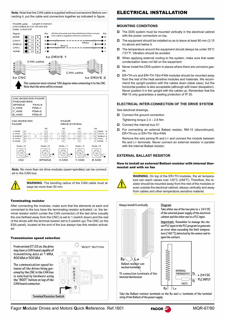
Fagor Modular Drives and Motors Quick Reference. Ref.1601 MQR-67/80
Terminating resistorAfter connecting the modules, make sure that the elements at each endconnected to the bus have the terminating resistor activated; i.e. the ter-minal resistor switch (under the CAN connector) of the last drive (usuallythe one farthest away from the CNC) is set to 1 (switch down) and the restof the drives with the terminal resistor set to 0 (switch up).The CNC (or theESA panel), located at the end of the bus always has this resistor activat-ed.
Transmission speed selection
ELECTRICAL INSTALLATION
MOUNTING CONDITIONS
The DDS system must be mounted vertically in the electrical cabinetwith the power connectors on top.
The equipment should be installed so as to leave at least 80 mm (3.15in) above and below it.
The temperature around the equipment should always be under 55°C/131°F. Vibration should be avoided.
When applying external cooling to the system, make sure that watercondensation does not fall on the equipment.
Never install the DDS system in places where there are corrosive gas-es.
ER+TH-x/x and ER+TH-18/x+FAN modules should be mounted awayfrom the rest of the heat sensitive modules and materials. We recom-mend the upright position with the cables down (ideal case), but thehorizontal position is also acceptable (although with lower dissipation).Never position it in the upright with the cables up. Remember that theRM-15 only guarantees a sealing protection of IP 20.
ELECTRICAL INTER-CONNECTION OF THE DRIVE SYSTEM
See electrical drawings.
Connect the ground connection
Tightening torque 2.3 2.8 Nm
Connect the internal bus X1
For connecting an external Ballast resistor, RM-15 (discontinued),ER+TH-x/x or ER+TH-18/x+FAN
Remove the wire joining Ri and L+ and connect the module betweenRe and L+ terminals. Never connect an external resistor in parallelwith the internal Ballast resistor.
EXTERNAL BALLAST RESISTOR
How to install an external Ballast resistor with internal ther-mostat and with no fan
Note. Note that the CAN cable is supplied without connectors! Before con-necting it, put the cable and connectors together as indicated in figure.
Note. No more than six drive modules (axes+spindles) can be connect-ed in the CAN bus.
WARNING. The bending radius of the CAN cable must al-ways be more than 50 mm.
1
Brown
Signal All the wire ends and the shield have their own pin.
This cable is supplied without connectors
FAGOR cable
CAN CABLE 5/10/15/20/25
Cable 1x2x0.25
Length in meters
NONE
CAN H
SHIELD
CAN L
N0NE
2
3
4
5
Pin
White
1
2
3
4
5
Pin
This connector must rotated 180 degrees when connecting it to the CNC.Note that the wires will be crossed.
to CNC
CAN cable
CAN cable
to DRIVE 1
to DRIVE 2
12345
4
01
FEDCBA
98
7 6 5 32
C
4
0FEDBA
98
7 6 5 32
1
Node = 4
SPINDLE4
0FEDCBA
98
7 6 5 321
4
0FEDCBA
98
7 6 5 321
4
0FEDCBA
98
7 6 5 321
X AXIS
Node = 1
Y AXIS
Node = 2
B AXIS
Node = 3
CNC
Node = 0
CNC 8055/55i FAGOR
PARAMETERS
SPINDLE P44=4
X_AXIS P56=1
Y_AXIS P56=2
B_AXIS P56=3
CNC 8055/55i
FAGOR
FAGOR
DRIVE SYSTEM
NONE 5
4
3
2
1
1
2
3
4
5
CAN L
SHIELD
CAN H
NONE
NONE
CAN H
SHIELD
CAN L
NONE
X6 X6 X6 X6
0
1
0
1
0
10
1
1
0
2345
1
From version 07.02 on, the drivemay have a CAN board capable oftransmitting data at 1 MBd,800 kBd or 500 kBd.
The communication speed be-tween all the drives being gov-erned by the CNC in the CAN busis selected by hardware usingthe “BOOT” button on top of theCAN board connector.
10
“BOOT” BUTTON
Terminal Resistor Switch
WARNING. On top of the ER+TH modules, the air tempera-ture can reach values over 120°C (248°F). Therefore, the re-sistor should be mounted away from the rest of the modules oreven outside the electrical cabinet, always vertically and awayfrom cables and other temperature sensitive material.
Always install it vertically
Ballast resistor con-nection terminals
Tk connection terminals of theinternal thermostat
DiagramTake either one of the two pins to + 24 V DC
of the external power supply of the electrical
cabinet and the other one to a PLC input.
Important. Remember to manage the cho-
sen PLC input in the PLC program to generate
an error when exceeding the limit tempera-
ture (160 °C) detected by the sensor and to
open the contact.
Take the Ballast resistor terminals to the Re and L+ terminals of the terminalstrip of the Ballast of the power supply.
L+Re
INTERNALTHERMOSTAT Tk
Tk PLC INPUT
+ 24 V DC
160°C
L+Re
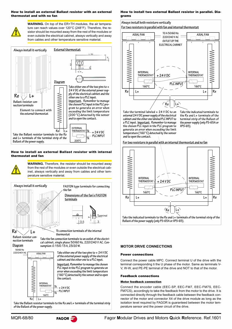
MQR-68/80 Fagor Modular Drives and Motors Quick Reference. Ref.1601
How to install an external Ballast resistor with an externalthermostat and with no fan
How to install an external Ballast resistor with internalthermostat and fan
How to install two external Ballast resistor in parallel. Dia-grams
MOTOR DRIVE CONNECTIONS
Power connections
Connect the power cable MPC. Connect terminal U of the drive with theterminal corresponding ti the U phase of the motor. Same as terminals V-V, W-W, and PE-PE terminal of the drive and NOT to that of the motor.
Feedback connections
Motor feedback connection
Connect the encoder cable (EEC-SP, EEC-FM7, EEC-FM7S, EEC-FM7CS), accordingly to take the feedback from the motor to the drive. It isconnected directly through the feedback cable between the feedback con-nector of the motor and connector X4 of the drive module as long as theisolation level required by FAGOR is guaranteed between the motor tem-perature sensor and the power circuit of the drive.
WARNING. On top of the ER+TH modules, the air tempera-ture can reach values over 120°C (248°F). Therefore, the re-sistor should be mounted away from the rest of the modules oreven outside the electrical cabinet, always vertically and awayfrom cables and other temperature sensitive material.
WARNING. Therefore, the resistor should be mounted awayfrom the rest of the modules or even outside the electrical cab-inet, always vertically and away from cables and other tem-perature sensitive material.
EXTERNALTHERMOSTAT Tk
Tk PLC INPUT+ 24 V DC
200°C
L+Re
Always install it vertically
Ballast resistor con-nection terminals
Element to connect withthe external thermostat
Re
Diagram
Take either one of the two pins to +24 V DC of the external power sup-ply of the electrical cabinet and theother one to a PLC input. Important. Remember to managethe chosen PLC input in the PLC pro-gram to generate an error whenexceeding the limit temperature(200 °C) detected by the sensorand to open the contact.
Take the Ballast resistor terminals to the Reand L+ terminals of the terminal strip of theBallast of the power supply.
External thermostat
L+
INTERNALTHERMOSTAT Tk
Tk
+ 24 V DCPLC INPUT
160°C
L+Re
AXIAL FAN
50/60 Hz
220/240 V AC
Always install it vertically
Ballast resistor con-nection terminals
Tk connection terminals of the internalthermostat
Diagram
Take either one of the two pins to + 24 V DCof the external power supply of the electricalcabinet and the other one to a PLC input.
Important. Remember to manage the chosenPLC input in the PLC program to generate anerror when exceeding the limit temperature(160 °C) detected by the sensor and to openthe contact.
Take the Ballast resistor terminals to the Re and L+ terminals of the terminal stripof the Ballast of the power supply.
FASTON type terminals for connectingthe fan
Dimensions of the fan’s FASTONterminals
Take the fan connection terminals to an outlet of the electri-cal cabinet, single phase 50/60 Hz, 220/240 V AC. Con-sumption: 0.15/0.13 A, 23/20 W.
Re L+
INTERNALTHERMOSTAT
INTERNALTHERMOSTAT
160°C
+ 24 V DC
PLC INPUT160°C
L+Re L+ Re
Re L+
AXIAL FANTO A 50/60 Hz
220/240 V AC
OUTLET OF THE
ELECTRICAL CABINET
AXIAL FAN
INTERNALTHERMOSTAT
INTERNALTHERMOSTAT
160°C
+ 24 V DC
PLC INPUT160°C
L+Re L+ Re
Re L+
Take the indicated terminals to the Re and L+ terminals of the terminal strip of theBallast of the power supply (only PS-65A or XPS-65).
Always install both resistors vertically
For two resistors in parallel with fan and internal thermostat
Take the terminal labeled + 24 V DC to anexternal 24 V DC power supply of the electricalcabinet and the other one labeled PLC INPUT toa PLC input. Important. Remember to managethe chosen PLC input in the PLC program togenerate an error when exceeding the limittemperature (160 °C) detected by the sensorand to open the contact.
Take the indicated terminals tothe Re and L+ terminals of theterminal strip of the Ballast ofthe power supply (only PS-65A orXPS-65).
For two resistors in parallel with an internal thermostat and no fan
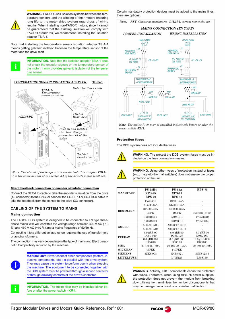
Fagor Modular Drives and Motors Quick Reference. Ref.1601 MQR-69/80
Note that installing the temperature sensor isolation adapter TSIA-1means getting galvanic isolation between the temperature sensor of themotor and the drive itself.
Direct feedback connection or encoder simulator connection
Connect the SEC-HD cable to take the encoder simulation from the drive(X3 connector) to the CNC, or connect the EC- PD or EC-B-D cable totake the feedback from the sensor to the drive (X3 connector).
CABLING OF THE SYSTEM TO MAINS
Mains connection
The FAGOR DDS system is designed to be connected to TN type three-phase mains with values within the voltage range between 400 V AC (-10%) and 460 V AC (+10 %) and a mains frequency of 50/60 Hz.
Connecting it to a different voltage range requires the use of transformersor autotransformers.
The connection may vary depending on the type of mains and Electromag-netic Compatibility required by the machine.
Certain mandatory protection devices must be added to the mains lines.thers are optional.
Protection fuses
The DDS system does not include the fuses.
WARNING. FAGOR uses isolation systems between the tem-perature sensors and the winding of their motors ensuringlong life to the motor-drive system regardless of wiringlengths. When installing non-FAGOR motors, since it cannotbe guaranteed that the existing isolation will comply withFAGOR standards, we recommend installing the isolationadapter TSIA-1.
INFORMATION. Note that the isolation adapter TSIA-1 doesnot check the encoder signals or the temperature sensor ofthe motor. It only provides galvanic isolation of the tempera-ture sensor.
MANDATORY. Never connect other components (motors, in-ductive components, etc.) in parallel with the drive system.They may cause the system to perform poorly when stoppingthe machine. The equipment to be connected together withthe DDS system must be powered through a second contactoror through auxiliary contacts of the drive's contactor.
INFORMATION. The mains filter may be installed either be-fore or after the power switch - KM1.
i
TEMPERATURE SENSOR ISOLATION ADAPTER: TSIA-1
TSIA-1Front view
X4
AXD/SPD
TSIA-1. Temperature sensor isolation
Motor feedback cable
Plug in and tightenthe two screws toconnector X4 of thedrive
Note. The pinout of the temperature sensor isolation adapter TSIA-1 is the same as that of connector X4 of the drive's motor feedback.
TSIA-1Rear view
i
WARNING. The protect the DDS system fuses must be in-cludes on the lines coming from mains.
WARNING. Using other types of protection instead of fuses(e.g.: magneto-thermal switches) does not ensure the properprotection of the unit.
MANUFACT.PS-25B4XPS-25RPS-20
PS-65AXPS-65RPS-45
RPS-75
BUSSMANN
FWH45B RF00-125A -
XL50F-45A XL50F-125A -
RF-000-40A RF-000-125A -40FE 100FE 160FEE (5700)
170M2611 170M1318 170M1319
170M3009 170M3013 170M3014
GOULDA00-66C5D8 A00-66C125D8 -
A00-66C5D1 A00-66C125D1 -
FERRAZ
6.9 gRB 00D08L 040
6.9 gRB 00D08L 125
6.9 gRB 00D08L 160
6.6 gRB 000D08/040
6.6 gRB 000D08/100
6.6 gRB 000D08/160
SIBA 20 189 20- 50A 20 189 20- 125A 20 189 20-160AWICKMAN 45FEE 140FEE -SIEMENS 3NE8 003 3NE8 021 3NC8423-3
LITTELFUSE - L70S125 L70S150
WARNING. Actually, IGBT components cannot be protectedwith fuses. Therefore, when using RPS-75 power supplies,the protection does not prevent the module from breakingdown. Using them minimizes the number of components thatmay be damaged as a result of a possible malfunction.
Note. The mains filter may be installed indistinctly before or after thepower switch -KM1.
MAINS CONNECTION (TN TYPE)
PROPER INSTALLATION WRONG INSTALLATION
Note. RST, Classic nomenclature; L1L2L3, current nomenclature
- S1MECHANICALMAIN SWITCH
MAINS FILTER
L3L2L1
(R)
CONTACTOR
- KM1
DIFFERENTIALBREAKER
POWER MAINS
IT A MUST TOUSE FUSES
TRANSFORMER oRAUTOTRANSFORMER
3x400-460 V ACDDS CONNECTION
OTHER UNITS
- KM2
- Q1
CONTACTOR
OTHER UNITS
CONTACTOR
- KM1
TRANSFORMER oRAUTOTRANSFORMER
DIFFERENTIALBREAKER
- Q1
IT A MUST TOUSE FUSES
- S1MECHANICALMAIN SWITCH
-F3
OTHER UNITSL3L2L13x400-460 V ACDDS CONNECTION
L1 L2 L3(S) (T)
MAINS FILTER
(R)
POWER MAINSL1 L2 L3
(S) (T)
-F4 -F5-F3 -F4 -F5
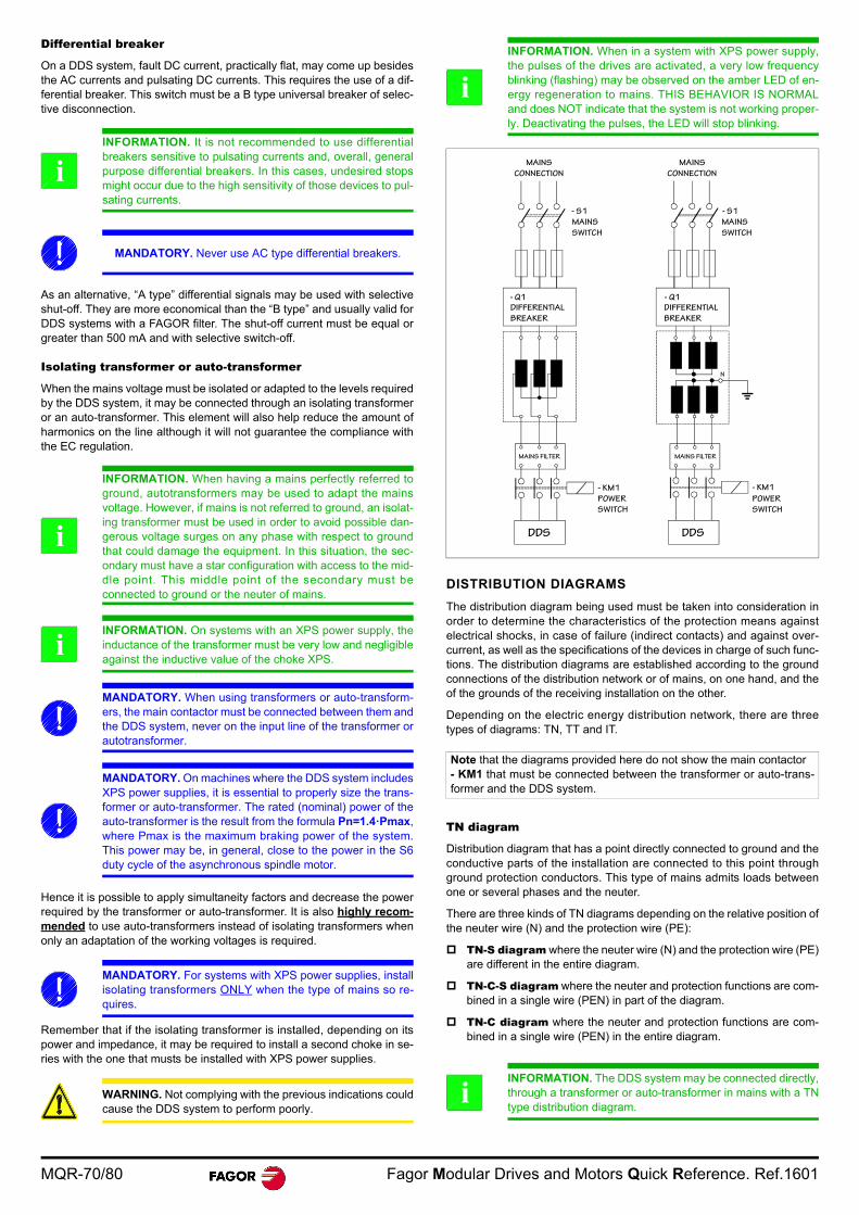
MQR-70/80 Fagor Modular Drives and Motors Quick Reference. Ref.1601
Differential breaker
On a DDS system, fault DC current, practically flat, may come up besidesthe AC currents and pulsating DC currents. This requires the use of a dif-ferential breaker. This switch must be a B type universal breaker of selec-tive disconnection.
As an alternative, “A type” differential signals may be used with selectiveshut-off. They are more economical than the “B type” and usually valid forDDS systems with a FAGOR filter. The shut-off current must be equal orgreater than 500 mA and with selective switch-off.
Isolating transformer or auto-transformer
When the mains voltage must be isolated or adapted to the levels requiredby the DDS system, it may be connected through an isolating transformeror an auto-transformer. This element will also help reduce the amount ofharmonics on the line although it will not guarantee the compliance withthe EC regulation.
Hence it is possible to apply simultaneity factors and decrease the powerrequired by the transformer or auto-transformer. It is also highly recom-mended to use auto-transformers instead of isolating transformers whenonly an adaptation of the working voltages is required.
Remember that if the isolating transformer is installed, depending on itspower and impedance, it may be required to install a second choke in se-ries with the one that musts be installed with XPS power supplies.
DISTRIBUTION DIAGRAMS
The distribution diagram being used must be taken into consideration inorder to determine the characteristics of the protection means againstelectrical shocks, in case of failure (indirect contacts) and against over-current, as well as the specifications of the devices in charge of such func-tions. The distribution diagrams are established according to the groundconnections of the distribution network or of mains, on one hand, and theof the grounds of the receiving installation on the other.
Depending on the electric energy distribution network, there are threetypes of diagrams: TN, TT and IT.
TN diagram
Distribution diagram that has a point directly connected to ground and theconductive parts of the installation are connected to this point throughground protection conductors. This type of mains admits loads betweenone or several phases and the neuter.
There are three kinds of TN diagrams depending on the relative position ofthe neuter wire (N) and the protection wire (PE):
TN-S diagram where the neuter wire (N) and the protection wire (PE)are different in the entire diagram.
TN-C-S diagram where the neuter and protection functions are com-bined in a single wire (PEN) in part of the diagram.
TN-C diagram where the neuter and protection functions are com-bined in a single wire (PEN) in the entire diagram.
INFORMATION. It is not recommended to use differentialbreakers sensitive to pulsating currents and, overall, generalpurpose differential breakers. In this cases, undesired stopsmight occur due to the high sensitivity of those devices to pul-sating currents.
MANDATORY. Never use AC type differential breakers.
INFORMATION. When having a mains perfectly referred toground, autotransformers may be used to adapt the mainsvoltage. However, if mains is not referred to ground, an isolat-ing transformer must be used in order to avoid possible dan-gerous voltage surges on any phase with respect to groundthat could damage the equipment. In this situation, the sec-ondary must have a star configuration with access to the mid-dle point. This middle point of the secondary must beconnected to ground or the neuter of mains.
INFORMATION. On systems with an XPS power supply, theinductance of the transformer must be very low and negligibleagainst the inductive value of the choke XPS.
MANDATORY. When using transformers or auto-transform-ers, the main contactor must be connected between them andthe DDS system, never on the input line of the transformer orautotransformer.
MANDATORY. On machines where the DDS system includesXPS power supplies, it is essential to properly size the trans-former or auto-transformer. The rated (nominal) power of theauto-transformer is the result from the formula Pn=1.4·Pmax,where Pmax is the maximum braking power of the system.This power may be, in general, close to the power in the S6duty cycle of the asynchronous spindle motor.
MANDATORY. For systems with XPS power supplies, installisolating transformers ONLY when the type of mains so re-quires.
WARNING. Not complying with the previous indications couldcause the DDS system to perform poorly.
i
i
i
INFORMATION. When in a system with XPS power supply,the pulses of the drives are activated, a very low frequencyblinking (flashing) may be observed on the amber LED of en-ergy regeneration to mains. THIS BEHAVIOR IS NORMALand does NOT indicate that the system is not working proper-ly. Deactivating the pulses, the LED will stop blinking.
Note that the diagrams provided here do not show the main contactor- KM1 that must be connected between the transformer or auto-trans-former and the DDS system.
INFORMATION. The DDS system may be connected directly,through a transformer or auto-transformer in mains with a TNtype distribution diagram.
i
MAINS
CONNECTION
- S1
MAINS
SWITCH
- Q1
DIFFERENTIAL
BREAKER
MAINS FILTER
- KM1
POWER
SWITCH
DDS DDS
- KM1
- Q1
- S1
MAINS FILTER
POWER
SWITCH
DIFFERENTIAL
BREAKER
MAINS
SWITCH
MAINS
CONNECTION
N
i
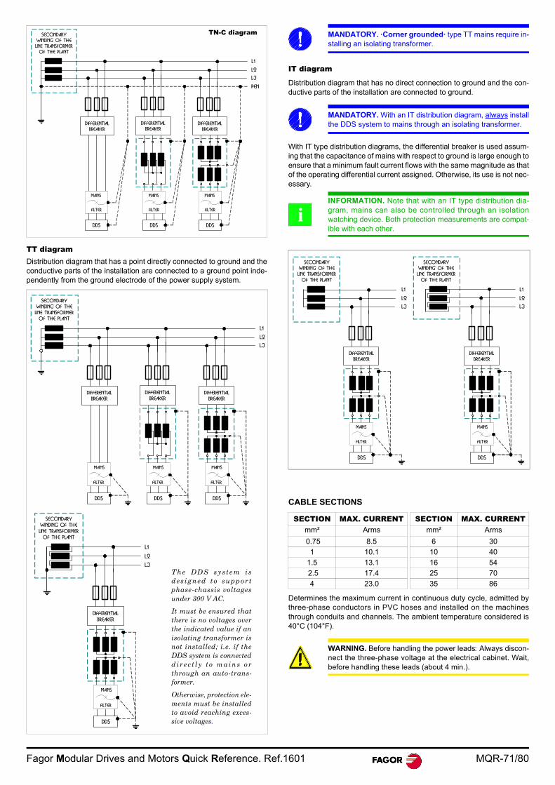
Fagor Modular Drives and Motors Quick Reference. Ref.1601 MQR-71/80
TT diagramDistribution diagram that has a point directly connected to ground and theconductive parts of the installation are connected to a ground point inde-pendently from the ground electrode of the power supply system.
IT diagram
Distribution diagram that has no direct connection to ground and the con-ductive parts of the installation are connected to ground.
With IT type distribution diagrams, the differential breaker is used assum-ing that the capacitance of mains with respect to ground is large enough toensure that a minimum fault current flows with the same magnitude as thatof the operating differential current assigned. Otherwise, its use is not nec-essary.
CABLE SECTIONS
Determines the maximum current in continuous duty cycle, admitted bythree-phase conductors in PVC hoses and installed on the machinesthrough conduits and channels. The ambient temperature considered is40°C (104°F).
DDSDDS
L1
L2
L3
DIFFERENTIAL
BREAKER
DDS
SECONDARY
WINDING OF THE
LINE TRANSFORMER
OF THE PLANT
DIFFERENTIAL
BREAKERDIFFERENTIAL
BREAKER
MAINS
FILTER
PEN
MAINS
FILTER
MAINS
FILTER
TN-C diagram
L1
L2
L3
DDS
DIFFERENTIAL
BREAKER
SECONDARY
WINDING OF THE
LINE TRANSFORMER
OF THE PLANT
MAINS
FILTER
The DDS system isdes igned to suppor tphase-chassis voltagesunder 300 V AC.
It must be ensured thatthere is no voltages overthe indicated value if anisolating transformer isnot installed; i.e. if theDDS system is connecteddirec t ly to mains orthrough an auto-trans-former.
Otherwise, protection ele-ments must be installedto avoid reaching exces-sive voltages.
DDSDDS
L1
L2
L3
DIFFERENTIAL
BREAKER
DDS
SECONDARY
WINDING OF THE
LINE TRANSFORMER
OF THE PLANT
DIFFERENTIAL
BREAKERDIFFERENTIAL
BREAKER
MAINS
FILTER
MAINS
FILTER
MAINS
FILTER
MANDATORY. ·Corner grounded· type TT mains require in-stalling an isolating transformer.
MANDATORY. With an IT distribution diagram, always installthe DDS system to mains through an isolating transformer.
INFORMATION. Note that with an IT type distribution dia-gram, mains can also be controlled through an isolationwatching device. Both protection measurements are compat-ible with each other.
SECTION MAX. CURRENT SECTION MAX. CURRENTmm² Arms mm² Arms
0.75 8.5 6 30
1 10.1 10 40
1.5 13.1 16 54
2.5 17.4 25 70
4 23.0 35 86
WARNING. Before handling the power leads: Always discon-nect the three-phase voltage at the electrical cabinet. Wait,before handling these leads (about 4 min.).
i
DDS
L1
L2
L3
SECONDARY
WINDING OF THE
LINE TRANSFORMER
OF THE PLANT
DIFFERENTIAL
BREAKER
MAINS
FILTER
L1
L2
L3
DDS
DIFFERENTIAL
BREAKER
SECONDARY
WINDING OF THE
LINE TRANSFORMER
OF THE PLANT
MAINS
FILTER
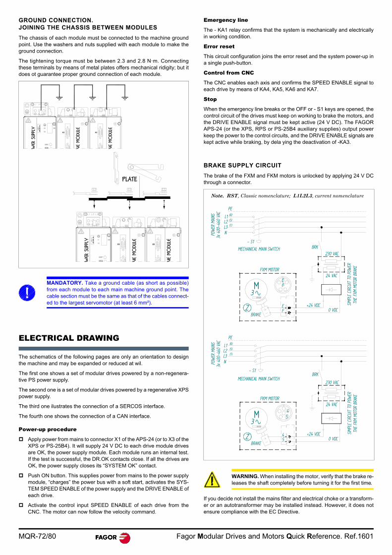
MQR-72/80 Fagor Modular Drives and Motors Quick Reference. Ref.1601
GROUND CONNECTION. JOINING THE CHASSIS BETWEEN MODULES
The chassis of each module must be connected to the machine groundpoint. Use the washers and nuts supplied with each module to make theground connection.
The tightening torque must be between 2.3 and 2.8 N·m. Connectingthese terminals by means of metal plates offers mechanical ridigity; but itdoes ot guarantee proper ground connection of each module.
ELECTRICAL DRAWING
The schematics of the following pages are only an orientation to designthe machine and may be expanded or reduced at wil.
The first one shows a set of modular drives powered by a non-regenera-tive PS power supply.
The second one is a set of modular drives powered by a regenerative XPSpower supply.
The third one ilustrates the connection of a SERCOS interface.
The fourth one shows the connection of a CAN interface.
Power-up procedure
Apply power from mains to connector X1 of the APS-24 (or to X3 of theXPS or PS-25B4). It will supply 24 V DC to each drive module drivesare OK, the power supply module. Each module runs an internal test.If the test is successful, the DR.OK contacts close. If all the drives areOK, the power supply closes its “SYSTEM OK” contact.
Push ON button. This supplies power from mains to the power supplymodule, “charges” the power bus with a soft start, activates the SYS-TEM SPEED ENABLE of the power supply and the DRIVE ENABLE ofeach drive.
Activate the control input SPEED ENABLE of each drive from theCNC. The motor can now follow the velocity command.
Emergency line
The - KA1 relay confirms that the system is mechanically and electricallyin working condition.
Error reset
This circuit configuration joins the error reset and the system power-up ina single push-button.
Control from CNC
The CNC enables each axis and confirms the SPEED ENABLE signal toeach drive by means of KA4, KA5, KA6 and KA7.
Stop
When the emergency line breaks or the OFF or - S1 keys are opened, thecontrol circuit of the drives must keep on working to brake the motors, andthe DRIVE ENABLE signal must be kept active (24 V DC). The FAGORAPS-24 (or the XPS, RPS or PS-25B4 auxiliary supplies) output powerkeep the power to the control circuits, and the DRIVE ENABLE signals arekept active while braking, by dela ying the deactivation of -KA3.
BRAKE SUPPLY CIRCUIT
The brake of the FXM and FKM motors is unlocked by applying 24 V DCthrough a connector.
If you decide not install the mains filter and electrical choke or a transform-er or an autotransformer may be installed instead. However, it does notensure compliance with the EC Directive.
MANDATORY. Take a ground cable (as short as possible)from each module to each main machine ground point. Thecable section must be the same as that of the cables connect-ed to the largest servomotor (at least 6 mm²).
X3 X3
X3 X3
PLATE
WARNING. When installing the motor, verify that the brake re-leases the shaft completely before turning it for the first time.
3x 4
00-4
60 V
AC L1L2L3N
FXM MOTOR
BRAKE
EF
+24 VDC0 VDC
BRK
24 VAC
230 VAC
EF
3M
Z
- S1
MECHANICAL MAIN SWITCH
SIMP
LE C
IRCU
IT T
O PO
WER
THE
FXM
MOTO
R BR
AKE
POW
ER M
AINS
PE(R)(S)(T)
PE
3x 4
00-4
60 V
AC
FKM MOTOR
BRAKE
45
+24 VDC0 VDC
BRK
24 VAC
230 VAC
3M
Z
45
- S1
MECHANICAL MAIN SWITCH
SIMP
LE C
IRCU
IT T
O PO
WER
THE
FKM
MOTO
R BR
AKE
POW
ER M
AINS L1
L2L3N
(R)(S)(T)
Note. RST, Classic nomenclature; L1L2L3, current nomenclature
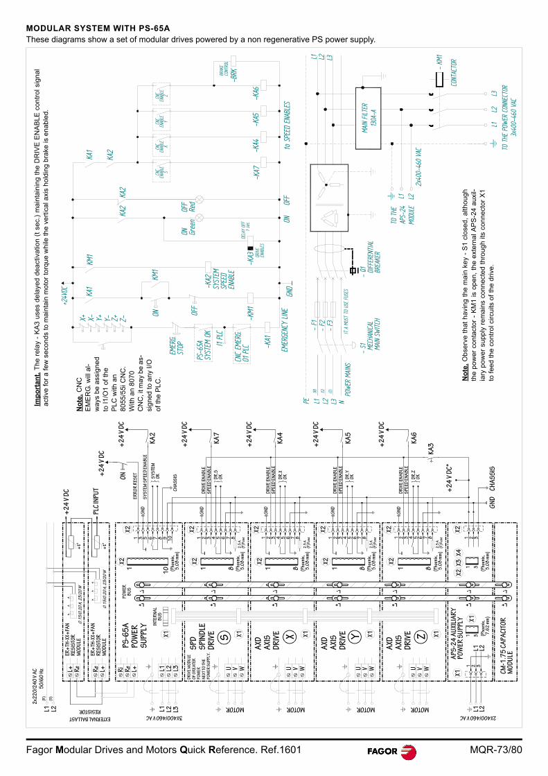
Fagor Modular Drives and Motors Quick Reference. Ref.1601 MQR-73/80
MODULAR SYSTEM WITH PS-65AThese diagrams show a set of modular drives powered by a non regenerative PS power supply.
+24V
DC
X+ X- Y+ Y- Z+ Z-
KA1
KM1
KA2
KA2
KA2
KA1
CNC
ENAB
LES
-KA7
-KA4
-KA5
-KA6
BRAK
ECO
NTRO
L
-BRK
EMER
G.ST
OP
PS-6
5ASY
STEM
OK
I1 PL
C
CNC
EMER
G.O1
PLC
OFF
-KM1ON
KM1
-KA2
SYST
EMSP
EED
ENAB
LE
-KA1
EMER
GENC
Y LIN
EGN
DON
OFF
to S
PEED
ENA
BLES
ON Gree
nOF
FRe
d
DELA
Y OF
F
-KA3 DR
IVE
ENAB
LES
t se
c.
CNC
ENAB
LEX
CNC
ENAB
LEY
CNC
ENAB
LEZ
(R)
(S) (T)
PE
- S1 ME
CHAN
ICAL
MAIN
SW
ITCH
- F1
- F2
- F3
MAIN
FILT
ER13
0A-A
L1
L3L2
L1
3x40
0-46
0 VA
C
2x40
0-46
0 VA
C
L1 L2 L3
L1 L2 L3
CONT
ACTO
R
- KM
1
L2
N
- Q1 DIFF
EREN
TIAL
BREA
KER
POW
ER M
AINS
IT A
MUS
T TO
USE
FUS
ES
TO T
HE P
OWER
CON
NECT
OR
TO T
HEAP
S-24
MODU
LE
(Pho
enix
, 5
.08
mm
)
8
2.5
A(F
) Fus
e
DR
IVE
MO
DU
LEO
F G
RE
ATE
R
PO
WE
RN
EXT
TO
TH
EP
OW
ER
SU
PPLY
.
L+L+ L+L+ L+ L+L+
L- L-L- L-L- L-L-
S
+t°
L2
2x2
20
/24
0 V
AC
50
/60
Hz
0.1
5/0
.20
A, 2
3/2
0 W
L1
EXTERNAL BALLAST
RESISTOR3X400/460 V AC
L+ Re
Re
L+ Ri
Re
L+P
S-6
5A
PO
WE
R
SU
PPL
Y
ER+
TH-X
X+FA
NR
ESIS
TOR
MO
DU
LE
ER+
TH-X
X+FA
NR
ESIS
TOR
MO
DU
LE0
.15
/0.2
0 A
, 23
/20
W+
t°
L1 L2 L3
X1
INTE
RN
AL
BU
S
PO
WER
BU
S
X21
10
L1 L2 L3
SP
DS
PIN
DLE
DR
IVE X1
AXD
AXI
SD
RIV
E X X1
AXD
AXI
SD
RIV
E Y X1
AXD
AXI
SD
RIV
E Z X1
U V W
MOTOR MOTOR MOTOR MOTOR
2X400/460 V AC
L1 L2L1 L2
21 3
CM
-1.7
5 C
AP
AC
ITO
RM
OD
ULEAP
S-2
4 A
UXI
LIA
RY
PO
WE
R S
UP
PLY
(Pho
enix
, 5
.08
mm
)
(Pho
enix
, 5
.08
mm
)
(Pho
enix
, 5
.08
mm
)
(Pho
enix
, 5
.08
mm
)
(Pho
enix
, 5
.08
mm
)G
ND
CH
AS
SIS
KA
3KA
6
+2
4 V
DC
KA
5
+2
4 V
DC
KA
4
+2
4 V
DC
KA
7
+2
4 V
DC
KA
2
+2
4 V
DC
+2
4 V
DC
ON
ER
RO
R R
ESET
SY
STE
M S
PEE
D E
NA
BLE
SY
STE
MO
K
CH
AS
SIS
DR
IVE
EN
AB
LES
PEED
EN
AB
LE
DR
.SO
K
DR
IVE
EN
AB
LES
PEED
EN
AB
LE
DR
.XO
K
DR
IVE
EN
AB
LES
PEED
EN
AB
LE
DR
.YO
K
DR
IVE
EN
AB
LES
PEED
EN
AB
LE
DR
.ZO
K
+2
4 V
DC
*
U V W U V W U V W
X1
(Pho
enix
, 7
.62
mm
)
1 3
1 321 3
X2X3
X4X2
X1
2.5
A(F
) Fus
e
2.5
A(F
) Fus
e
2.5
A(F
) Fus
e
+2
4 V
DC
PLC
INP
UT
1 8 1 8 1 8 1 87654321
X2
GN
D
GN
D
GN
D
GN
D
GN
D
X2X2X2
X2X2
X2X2
8765432187654321876543211 3 5 6 7 8 9 10
X2
(R)
(S)
No
te.
Ob
serv
e th
at h
avin
g t
he
ma
in k
ey
- S
1 c
lose
d,
alth
oug
hth
e p
ower
co
ntac
tor
- K
M1
is o
pen
, th
e e
xte
rna
l AP
S-2
4 a
uxi
l-ia
ry p
ower
su
pply
re
mai
ns c
onn
ecte
d th
roug
h it
s co
nne
ctor
X1
to f
eed
the
cont
rol c
ircui
ts o
f th
e d
rive
.
Imp
ort
an
t. T
he
re
lay
- K
A3
use
s d
ela
yed
de
act
iva
tion
(t
sec.
) m
ain
tain
ing
the
DR
IVE
EN
AB
LE
co
ntr
ol s
ign
alac
tive
for
a fe
w s
econ
ds t
o m
ain
tain
mot
or t
orq
ue w
hile
th
e ve
rtic
al a
xis
hold
ing
bra
ke is
en
able
d.
No
te.
CN
C
EM
ER
G. w
ill a
l-w
ays
be a
ssig
ned
to I1
/O1
of th
e P
LC
with
an
80
55/5
5i C
NC
. W
ith a
n 80
70
CN
C, i
t ma
y b
e as
-si
gn
ed
to a
ny
I/O
of
th
e P
LC
.
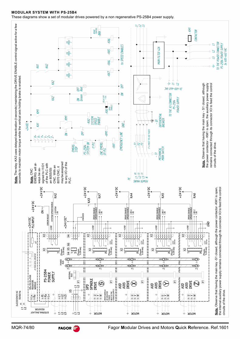
MQR-74/80 Fagor Modular Drives and Motors Quick Reference. Ref.1601
MODULAR SYSTEM WITH PS-25B4These diagrams show a set of modular drives powered by a non regenerative PS-25B4 power supply.
S
2x2
20
/24
0 V
AC
50
/60
Hz
ER+
TH-X
X+FA
NR
ESIS
TOR
MO
DU
LE
PS
-25
B4
PO
WE
R
SU
PPL
Y
EXTERNAL BALLAST
RESISTORL+ R
e Ri
Re
L+
0.1
5/0
.20
A, 2
3/2
0 W
+t°
+2
4 V
DC
PLC
INP
UT
L1 L2 L3 L1 L2
DR
IVE
MO
DU
LEO
F G
RE
ATE
R
PO
WE
RN
EXT
TO
TH
EP
OW
ER
SU
PPLY
.
L1 L2 L3
INTE
RN
AL
BU
S
PO
WE
RB
US
SP
DS
PIN
DLE
DR
IVE
AXD
AXI
SD
RIV
E X
AXD
AXI
SD
RIV
E Y
AXD
AXI
SD
RIV
E Z
MOTOR
U V W
MOTOR
U V W
MOTOR
U
MOTOR
UV VW W
X1X1
(Pho
enix
, 5
.08
mm
)2
.5 A
(F) F
use
2.5
A(F
) Fus
e
(Pho
enix
, 5
.08
mm
)
1 8
X2
87654321
GN
D
KA
6D
R.Z
OK
DR
IVE
EN
AB
LES
PE
ED E
NA
BLE
DR
.YO
K
DR
IVE
EN
AB
LES
PE
ED E
NA
BLE
DR
.XO
K
DR
IVE
EN
AB
LES
PE
ED E
NA
BLE
KA
5
KA
4
X2
GN
D
GN
D
GN
D
GN
D
DR
.SO
K
DR
IVE
EN
AB
LES
PE
ED E
NA
BLE
KA
7
KA
3
+2
4 V
DC
+2
4 V
DC
+2
4 V
DC
+2
4 V
DC
8765432187654321
2.5
A(F
) Fus
e
(Pho
enix
, 5
.08
mm
)
2.5
A(F
) Fus
e
(Pho
enix
, 5
.08
mm
)
1 81 81 81 3(P
hoen
ix,
5.0
8 m
m)
876543213211 3 5 6 7
GN
D
ER
RO
R R
ESE
T
SY
STE
M S
PEE
D E
NA
BLE
SY
STE
MO
K
+2
4 V
DC
KA
2
+2
4 V
DC
ON
1 7(P
hoen
ix,
5.0
8 m
m)
X2X2
X2X2
X2X2
X4X5
X6X4
+2
4 V
DC
*
X2X2
CH
AS
SIS
L+
L-
L+
L-
L+
L-
L+
L-
L+
L-
X1X1X1L1 L2
21 3
X3
L2L1(R
)
(S)
PS-2
5B4
SYST
EM O
K
+24V
DC
X+ X- Y+ Y- Z+ Z-
KA1
KM1
ONKM
1
EMER
G.ST
OP
-KA2
OFF
SYST
EMSP
EED
ENAB
LE
-KM1
-KA1
EMER
GENC
Y LIN
E
I1 PL
C
CNC
EMER
G.O1
PLC
GND
ONOF
Fto
SPE
ED E
NABL
ES
-KA7
ON Gree
nOF
FRe
d
KA2
KA2
KA2
KA1
-KA3
-KA4
-KA5
-KA6
BRAK
ECO
NTRO
L
-BRK
CNC
ENAB
LES
CNC
ENAB
LEX
CNC
ENAB
LEY
CNC
ENAB
LEZ
DELA
Y OF
F
DRIV
EEN
ABLE
S
t se
c.
PE
- S1
MECH
ANIC
ALMA
IN S
WIT
CHMA
IN F
ILTER
42A
L1
L1L2
L3
3x 4
00-4
60 V
AC
2x 400-460 VAC
L1 L2 L3
L2
N
- Q1
DIFF
EREN
TIAL
BREA
KER
IT A
MUS
T TO
USE
FUS
ES
TO T
HE P
OWER
CON
NECT
ORPS
-25B
4 PO
WER
SUP
PLY
TO T
HE X
3 CO
NNEC
TOR
PS-2
5B4
POW
ER S
UPPL
Y
L1 L2 L3
POWER MAINS
(R)
(S) (T)
- F1
- F2
- F3
CONT
ACTO
R
- KM
1
No
te. T
he
rela
y -K
A3
use
s d
elay
ed d
eac
tiva
tion
(t s
eco
nds
) mai
nta
inin
g th
e D
RIV
E E
NA
BL
E c
ontr
ol s
igna
l act
ive
for a
few
seco
nds
to m
ain
tain
mo
tor
torq
ue
whi
le t
he v
ertic
al a
xis
hol
ding
bra
ke is
ena
bled
.
No
te.
Obs
erve
tha
t ha
ving
the
mai
n k
ey
-S1
clos
ed,
alth
ough
the
po
wer
con
tact
or
-KM
1 is
ope
n,
the
inte
rnal
au
xilia
ry p
ow
er s
upp
ly r
em
ains
con
nect
ed th
roug
h its
con
nect
or X
3 to
fee
d th
e c
ont
rol
circ
uits
of t
he d
rive.
No
te. C
NC
E
ME
RG
. will
al-
way
s be
as-
sign
ed t
o I1
/O1
of th
e P
LC w
ith
an 8
055
/55i
C
NC
. With
an
80
70
CN
C,
it m
ay b
e as
sign
ed
to a
ny
I/O
of t
he
P
LC.
No
te.
Ob
serv
e t
ha
t h
avi
ng
th
e m
ain
ke
y -
S1
clo
sed
, a
ltho
ug
hth
e p
ow
er
con
tact
or
- K
M1
is o
pe
n,
the
au
xilia
ry p
ow
er
sup
ply
rem
ains
co
nnec
ted
thro
ugh
its
con
nect
or X
3 t
o f
eed
th
e co
ntro
lci
rcui
ts o
f the
driv
e.

Fagor Modular Drives and Motors Quick Reference. Ref.1601 MQR-75/80
MODULAR SYSTEM WITH XPSThese diagrams show a set of modular drives powered by a regenerative XPS power supply.
GND
- Q1
DIFF
EREN
TIAL
BREA
KER
EARL
Y OP
ENCO
NTAC
T
EARL
YOP
ENCO
NTAC
T
L1 L2 L3 N
(R)
(S) (T)
L1 L2 L3
PE
- S1 ME
CHAN
ICAL
MAIN
SW
ITCH
- F1
- F2
- F3
MAIN
FILT
ER x
A
L1
L3L2
L1
3x40
0-46
0 VA
C
2x40
0-46
0 VA
C
CONT
ACTO
R
- KM
1
L2
- Q1 DIFF
EREN
TIAL
BREA
KER
POW
ER M
AINS
IT A
MUS
T TO
USE
FUS
ES
TO T
HE P
OWER
CON
NECT
OR
TO T
HE X
3CO
NNEC
TOR
K1EARL
Y OP
ENCO
NTAC
TK2
+24V
DC
-KA3
KA3
K1 EARL
YOP
ENCO
NTAC
T
K2
OFF
DELA
YCO
NTAC
T
GND
- S1
MECH
ANIC
ALMA
IN S
WIT
CH
CONT
ACTO
R-
KM1
BRAK
ECO
NTRO
L
-BRK
DELA
Y OF
F
DRIV
EEN
ABLE
S
t se
c.
+24V
DC
X+ X- Y+ Y- Z+ Z-
EMER
G.ST
OP
XPS
SYST
EM O
K
I1 PL
C
CNC
EMER
G.O1
PLC EM
ERGE
NCY
LINE
GND
-KA3
SYST
EMSP
EED
ENAB
LE
-KA2
-KM1
ON OFF
KA2
KA3
KA2
KA2
ON Gree
nOF
FRe
d
ONOF
Fto
SPE
ED E
NABL
ES
-KA7
-KA4
-KA5
-KA6
CNC
ENAB
LEX
CNC
ENAB
LES
KA1
-KA1
K1 EARL
YOP
ENCO
NTAC
T
K2
KA2
CNC
ENAB
LEY
CNC
ENAB
LEZ
KA1
OFF
DELA
YCO
NTAC
T
EARL
YOP
ENCO
NTAC
T
+2
4 V
DC
10
mm
² (X
PS-2
5)
50
mm
² (X
PS-6
5)
(ON
LY IN
XPS
)
Ri
Re
L+ L1
ER
+TH
-18
/x o
r ER
+TH
-18
/x+
FAN
RES
ISTO
R M
OD
ULE
(XP
S-2
5)
EXT
ERN
AL
BA
LLA
ST
RE
SIS
TOR
OR
INTE
RN
AL
BA
LLA
ST
RE
SIS
TOR
CH
OO
SE
EIT
HE
R C
ON
FIG
UR
ATI
ON
,N
OT
BO
TH
2x
ER+
TH-1
8/x
or
2x
ER+
TH-1
8/x
+FA
N R
ESIS
TOR
MO
DU
LES
in p
aral
lel (
XPS
-65
)**S
EE S
ECT
ION
“EX
TER
NA
L B
ALL
AS
T R
ES
ISTO
R C
ON
NEC
TIO
N”
+2
4 V
DC
N.C
. TH
ER
MO
STA
T
16
0°C
PLC
INP
UT
1
CH1
CH
OK
E X
PS
-XX
L2 L3
L1 L2 L3
XPS
-XX
PO
WE
R
SU
PPL
Y
+2
4 V
DC
ON
ER
RO
R R
ESE
T
SY
STE
M S
PEE
D E
NA
BLE
GN
D
KA
2S
YS
TEM
OK
+2
4 V
DC
+2
4 V
DC
KA
3 KA
7
CH
AS
SIS
DR
IVE
EN
AB
LES
PEED
EN
AB
LE
DR
.SO
K
DR
IVE
EN
AB
LES
PEE
D E
NA
BLE
DR
.XO
K
(Pho
enix
, 5
.08
mm
)
1 32 3
X4X4
X5X6
INTE
RN
AL
BU
S
PO
WER
BU
S
L+
L-
X1L1 L2
L1 L2
1 2 3
X3
+2
4 V
DC
KA
4
KA
5
KA
6
+2
4 V
DC
+2
4 V
DC
DR
IVE
EN
AB
LES
PEE
D E
NA
BLE
DR
.YO
K
DR
IVE
EN
AB
LES
PEE
D E
NA
BLE
DR
.ZO
K
GN
D
GN
D
GN
D
GN
D GN
D
(Pho
enix
, 5
.08
mm
)2
.5 A
(F) F
use
87654321X2
X2
1 8
(Pho
enix
, 5
.08
mm
)2
.5 A
(F) F
use
1 8
X2X2
(Pho
enix
, 5
.08
mm
)2
.5 A
(F) F
use
1 8
8765432187654321X2
X2
(Pho
enix
, 5
.08
mm
)2
.5 A
(F) F
use
1 887654321
X2X2
1 3 5 6 7
(Pho
enix
, 5
.08
mm
)
1 7
X2X2
CH2
L+
L-
L+
L-
L+
L-
L+
L-
X1 X1 X1 X1
MOTOR
U V W
AXD
AXI
SD
RIV
E
Z
AXD
AXI
SD
RIV
E
Y
AXD
AXI
SD
RIV
E
XS
SP
DS
PIN
DLE
DR
IVE
DR
IVE
MO
DU
LEO
F G
RE
ATE
R
PO
WE
RN
EXT
TO
TH
EP
OW
ER
SU
PPLY
.
MOTOR
U V W
MOTOR
U V W
MOTOR
U V W
2X400/460 V AC3X400/460 V AC
(R)
(S)
(T)
No
te.
Th
e r
ela
y -
KA
3 u
ses
de
laye
d d
ea
ctiv
atio
n f
or
con
tact
or
- K
M1
(t
sec)
in o
rde
r to
be
ab
le t
o k
ee
p it
clo
sed
lon
ge
noug
h to
ret
urn
to m
ain
s th
e e
xces
s en
ergy
gen
erat
ed w
hile
bra
kin
g th
e m
otor
. Ma
ke s
ure
that
the
dela
y t p
rog
ram
med
at r
ela
y -
KA
3 is
slig
htly
long
er t
han
the
bra
kin
g t
ime
un
til t
he
mo
tor
com
es
to fu
ll st
op.
No
te.
Obs
erve
th
at h
avin
g th
e m
ain
ke
y -
S1
clos
ed,
alth
oug
h th
e p
ow
er
con
tact
or -
KM
1 is
open
, the
inte
rnal
au
xilia
ry p
ow
er s
upp
ly o
f th
e X
PS
re
mai
ns c
onn
ect
ed th
roug
h its
con
nec
tor
X3
to f
eed
the
cont
rol c
ircui
ts o
f the
driv
e.
K1.
Aux
iliar
y ea
rly
open
con
tact
Ex
amp
les
:
- A
uxili
ary
cont
act
GA
X11
10
EA
of
the
GA
se
ries
ofsw
itche
s an
d br
eake
rs,
Lova
to E
lect
ric.
- A
uxili
ary
con
tact
HI1
1-P
1/P
3E
061
813
app
licab
le t
osw
itch
es
an
d b
rea
kers
P1
-...
/E,
.../
EA
...,
...
/EZ
y P
3-
.../E
, .../
EA
, fr
om
Mo
elle
r.
K2.
Aux
iliar
y ea
rly
open
con
tact
Ex
amp
les
:
- A
uxili
ary
cont
act
HIV
in a
utom
atic
sw
itche
s N
ZM
1,
2o
r 3
from
Moe
ller.
see
fig.
a
fig.a
No
te. C
NC
EM
ER
G.
will
alw
ays
be a
s-si
gne
d to
I1/O
1 of
the
P
LC w
ith a
n 8
055/
55i
CN
C. W
ith a
n 8
070
CN
C, i
t may
be
as-
sign
ed
to a
ny
I/O o
f th
e P
LC.
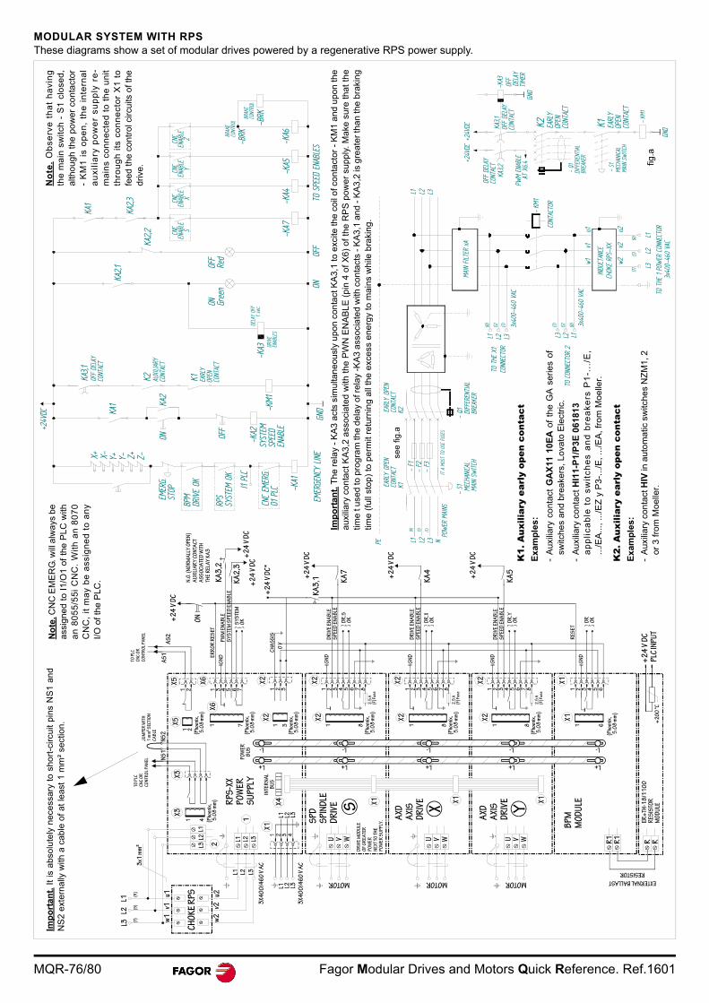
MQR-76/80 Fagor Modular Drives and Motors Quick Reference. Ref.1601
MODULAR SYSTEM WITH RPSThese diagrams show a set of modular drives powered by a regenerative RPS power supply.
+24V
DC
X+ X- Y+ Y- Z+ Z-
-KA2
SYST
EMSP
EED
ENAB
LE
RPS
SYST
EM O
K
I1 PL
C
CNC
EMER
G.O1
PLC -K
A1
EMER
GENC
Y LIN
EGN
DON
OFF
TO S
PEED
ENA
BLES
KA2,1
ON Gree
nOF
FRe
d
-KA3
-KA7
-KA4
-KA5
-KA6
CNC
ENAB
LES
CNC
ENAB
LEX
CNC
ENAB
LEY
CNC
ENAB
LEZ
BPM
DRIV
E OK
ONKA
2
-KM1
KA3,1
K1 EARL
YOP
ENCO
NTAC
T
K2 AUXI
LIARY
CONT
ACT
OFF
DELA
YCO
NTAC
T
KA1
KA1
KA2,3
KA2,2
OFF
EMER
G.ST
OP
BRAK
ECO
NTRO
L
-BRK
BRAK
ECO
NTRO
L
-BRK
DELA
Y OF
F
DRIV
EEN
ABLE
S
t se
c.
N.O
. (N
OR
MA
LLY
OP
EN
) A
UXI
LIA
RY
CO
NTA
CT
AS
SO
CIA
TED
WIT
HTH
E R
ELA
Y K
A3
RPS
-XX
PO
WE
R
SU
PPL
Y
CH
OK
E R
PS
3x1
mm
²
L3L2
L1
TO P
LCC
NC
OR
C
ON
TRO
L P
AN
ELJU
MPE
R W
ITH
1 m
m²
SEC
TIO
NC
AB
LE
NS
2N
S1
TO P
LCC
NC
OR
C
ON
TRO
L P
AN
EL
AS
1A
S2
(Pho
enix
, 5
.08
mm
)
1 2
X51 2
X5
PO
WE
RB
US
INTE
RN
AL
BU
S
w1
v1u1
w2
v2u2
L1 L2 L3
L1 L2 L3
3X4
00
/46
0 V
AC
3X4
00
/46
0 V
AC
L1 L2 L3
MOTOR
U V WS
SP
DS
PIN
DLE
DR
IVE
DR
IVE
MO
DU
LEO
F G
RE
ATE
R
PO
WE
RN
EXT
TO
TH
EP
OW
ER
SU
PPLY
.X1X4
L1 L2 L3
X1
1(Pho
enix
, 5
.08
mm
)
41
X3X3
1 7(P
hoen
ix,
5.0
8 m
m)
X6
X6
+2
4 V
DC
ON
KA
3,2
KA
2,3
+2
4 V
DC
+2
4 V
DC
+2
4 V
DC
*
+2
4 V
DC
KA
3,1 K
A7
+2
4 V
DC
KA
4
KA
5
+2
4 V
DC
DR
IVE
EN
AB
LES
PEE
D E
NA
BLE
DR
.SO
K
DR
IVE
EN
AB
LES
PEE
D E
NA
BLE
DR
.XO
K
DR
IVE
EN
AB
LES
PEE
D E
NA
BLE
DR
.YO
K
DR
OK
GN
D
(Pho
enix
, 5
.08
mm
)
654321
GN
D
GN
D
GN
D
0 V
CH
AS
SIS
(Pho
enix
, 5
.08
mm
)
1 3 1 8(P
hoen
ix,
5.0
8 m
m)
(Pho
enix
, 5
.08
mm
)
1 8
(Pho
enix
, 5
.08
mm
)
1 8 1 6
2.5
A(F
) Fus
e
87654321
2.5
A(F
) Fus
e
87654321
2.5
A(F
) Fus
e
87654321321X2
X2
ER
RO
R R
ES
ET
GN
DP
WM
EN
AB
LES
YS
TEM
SP
EED
EN
AB
LE
SY
STE
MO
K
X2X2
X2X2
X2X2
X1X1
L+
L-
L+
L-
L+
L-
L+
L-
L+
L-
X1X1
AXD
AXI
SD
RIV
E
X
AXD
AXI
SD
RIV
E
Y
BP
MM
OD
ULE
MOTOR
U V W
MOTOR
U V W
1 3 4 5 6 7
1 2 3 4
L1L2
L3 2
RE
SE
T
ER+
TH-1
8/1
10
0R
ESIS
TOR
MO
DU
LE
EXTERNAL BALLAST
RESISTOR
R RR1
R1
+2
00
°C
+2
4 V
DC
PLC
INP
UT
(R)
(S)
(T)
L1 L2 L3
(T)(S)
(R)
MAIN
FILT
ER x
A
CHOK
E RP
S-XX
w1v1
u1
w2v2
u2
L2
L1L2
L3
TO T
HE X
1CO
NNEC
TOR
TO T
HE 1
POW
ER C
ONNE
CTOR
3x40
0-46
0 VA
C
3x40
0-46
0 VA
C
TO C
ONNE
CTOR
2
3x40
0-46
0 VA
C
L1 L3
(R)
INDU
CTAN
CE
PE
- S1 ME
CHAN
ICAL
MAIN
SW
ITCH
- F1
- F2
- F3
- Q1 DIFF
EREN
TIAL
BREA
KER
POW
ER M
AINS
IT A
MUS
T TO
USE
FUS
ES
K1EARL
Y OP
ENCO
NTAC
TK2
CONT
ACTO
R
- KM
1
EARL
Y OP
ENCO
NTAC
T
K1 EARL
YOP
ENCO
NTAC
T
K2GN
D
- S1
MECH
ANIC
ALMA
IN S
WIT
CH
- KM
1
GND
- Q1
DIFF
EREN
TIAL
BREA
KER
EARL
YOP
ENCO
NTAC
T
KA3,2
KA3,1
+24V
DC
AT X
6.4PW
M EN
ABLE
+24V
DC
OFF
DELA
YTI
MER
-KA3
OFF
DELA
YCO
NTAC
T
OFF
DELA
YCO
NTAC
T
L1 L2 L3 N
(R)
(S) (T)
L2L3 L1
(S)(T)(T)(S)(R)
Imp
ort
ant.
It
is a
bsol
ute
ly n
ece
ssar
y to
sho
rt-c
ircu
it pi
ns
NS
1 an
dN
S2
ext
ern
ally
with
a c
able
of
at le
ast
1 m
m²
sect
ion
.N
ote
. CN
C E
ME
RG
. will
alw
ays
bea
ssig
ne
d t
o I
1/O
1 o
f th
e P
LC
with
an
80
55
/55
i C
NC
. W
ith
an
80
70
CN
C,
it m
ay
be
ass
ign
ed
to
an
yI/
O o
f the
PLC
.
see
fig.
a
fig.a
K1.
Aux
iliar
y ea
rly
open
con
tact
Ex
amp
les
:
- A
uxili
ary
cont
act
GA
X11
10
EA
of
the
GA
se
ries
ofsw
itche
s an
d br
eake
rs,
Lova
to E
lect
ric.
- A
uxili
ary
cont
act
HI1
1-P
1/P
3E
061
813
ap
pli
ca
ble
to
sw
itc
he
s a
nd
bre
ak
ers
P1
-...
/E,
.../E
A...
, ...
/EZ
y P
3-.
../E
, ...
/EA
, fro
m M
oe
ller.
K2.
Aux
iliar
y ea
rly
open
con
tact
Ex
amp
les
:
- A
uxili
ary
co
nta
ct H
IV in
aut
om
atic
sw
itche
s N
ZM
1, 2
or
3 fr
om M
oelle
r.
Imp
ort
ant.
The
rel
ay
- K
A3
act
s si
mul
tan
eou
sly
upo
n c
onta
ct K
A3,
1 to
exc
ite th
e c
oil o
f con
tact
or -
KM
1 a
nd u
pon
the
au
xilia
ry c
on
tact
KA
3,2
ass
oci
ate
d w
ith th
e P
WN
EN
AB
LE
(p
in 4
of
X6
) o
f th
e R
PS
po
we
r su
pp
ly.
Ma
ke s
ure
tha
t th
etim
e t
used
to p
rog
ram
the
del
ay o
f rel
ay -
KA
3 a
ssoc
iate
d w
ith c
onta
cts
- K
A3
,1 a
nd
- K
A3
,2 is
gre
ater
tha
n th
e b
raki
ng
time
(fu
ll st
op)
to p
erm
it re
turn
ing
all t
he e
xces
s en
ergy
to m
ain
s w
hile
bra
king
.
No
te.
Ob
serv
e t
ha
t h
avi
ng
the
ma
in s
witc
h -
S1
clo
sed
,al
tho
ugh
the
po
wer
co
nta
ctor
- K
M1
is
op
en
, th
e i
nte
rna
la
ux
ilia
ry p
ow
er
su
pp
ly r
e-
ma
ins
con
ne
cte
d t
o t
he
un
itth
rou
gh
its
co
nn
ect
or
X1
to
feed
the
cont
rol c
ircu
its o
f the
driv
e.
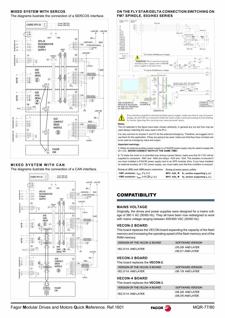
Fagor Modular Drives and Motors Quick Reference. Ref.1601 MQR-77/80
MIXED SYSTEM WITH SERCOSThe diagrams ilustrate the connection of a SERCOS interface.
M I X E D S Y S T E M W I T H C A NThe diagrams ilustrate the connection of a CAN interface.
ON THE FLY STAR/DELTA CONNECTION SWITCHING ONFM7 SPINDLE, E03/HS3 SERIES
COMPATIBILITY
MAINS VOLTAGEOriginally, the drives and power supplies were designed for a mains volt-age of 380 V AC (50/60 Hz). They all have been now redesigned to workwith mains voltage ranging between 400/460 VAC (50/60 Hz).
VECON-2 BOARDThis board replaces the VECON board expanding the capacity of the flashmemory and increasing the operating speed of the flash memory and of theRAM memory.
VECON-3 BOARDThis board replaces the VECON-2.
VECON-4 BOARDThis board replaces the VECON-3.
X3
X2
CHOKE XPS-XX10 mm² (XPS-25)50 mm² (XPS-65)
CH1 CH2
XPS-XXREGENERATIVEPOWER SUPPLY
RiRe
L+
L1
L2
L33x4
00
/46
0 V
AC
L1
L2
L3 POWERBUS
INTERNALBUS
+24 V DC +24 V DC
FAGOR CNC
IN
OUT
CHASSIS
DR.SOK
SPEED ENABLE
ERROR RESETDRIVE ENABLE
GND
KA3
GND
SPEED ENABLEDRIVE ENABLE
DR.ZOK
GND
GND
KA3
+24 V DC
ON
2.5 A(F) Fuse
89
10
7654321
IN
OUT
1 S
SCDCOMPACTDRIVEMODULE
L1L2
L1L2
123
2x4
00
/46
0 V
AC
L1
L2
L3
3x4
00
/46
0 V
AC
X1
L1
L2
L3
8
9
OUT2
OUT2
X6
MO
TOR U
VW
Z
2
OUT
IN
X1
AXDAXISDRIVE
AXDAXISDRIVE
X X1
3
OUT IN
MO
TOR U
VW
2x4
00
/46
0 V
AC
L1L2
123
L1L2
X1
531
67
ON
ERROR RESET KA2SYSTEM SPEED ENABLE
SYSTEMOK
GND
+24 V DC*
X2
X4
123
X2
CHASSIS
DRIVE ENABLESPEED ENABLE
DR.XOK
12345678
2.5 A(F) Fuse
X212345678
L+ L-
L+ L-
L+ L-
1C
AN
L(2
)S
HIE
LD(3
)C
AN
H(4
)
CHOKE XPS-XX10 mm² (XPS-25)50 mm² (XPS-65)
RiRe
L+
L1
L2
L33x4
00
/46
0 V
AC
L1
L2
L3
XPS-XXREGENERATIVEPOWER SUPPLY
CH1 CH2
+24 V DC +24 V DC
ON
KA2ERROR RESET
SYSTEM SPEED ENABLEGND
SYSTEMOK
+24 V DC*
CHASSIS
KA3GND
GND
DRIVE ENABLESPEED ENABLE
DR.XOK
DRIVE ENABLESPEED ENABLE
DR.ZOK
GND +24 V DC
ON
KA3
SPEED ENABLE
ERROR RESETDRIVE ENABLE
GND
DR.SOK
CHASSIS
FAGOR CNC
2x4
00
/46
0 V
AC
3x4
00
/46
0 V
AC
L1
L2L3
L1L2
123
L1L2
S
SCDCOMPACTDRIVEMODULE10
10
4
8NODE
SELE
CT
OUT289
OUT2
X6
MO
TOR U
VW
MO
TOR U
VW
0
4
8NODE
SELE
CT
0
4
8NODE
SELE
CT
AXDAXISDRIVE
X X1
101
101
AXDAXISDRIVE Z
X1
531
67
321
X1
POWERBUS
INTERNALBUS
2.5 A(F) Fuse
12345678
12345678
2.5 A(F) Fuse
123456789
10
X2
X2
X2
X4
X2
2x4
00
/46
0 V
AC
L1L2
L1L2
123
X3 L+ L-
L+ L-
L+ L-
L1
L2L3
X1
VERSION OF THE VECON-2 BOARD SOFTWARE VERSION
VEC 01A AND LATER05.08 AND LATER
06.01 AND LATER
VERSION OF THE VECON-3 BOARD SOFTWARE VERSION
VEC 01A AND LATER 06.18 AND LATER
VERSION OF THE VECON-4 BOARD SOFTWARE VERSION
VEC 01A AND LATER06.26 AND LATER
08.05 AND LATER
DIGITAL INPUT
X1
X2
GND
I8
I1
N.C.
I2
I3
I4
I5
I6
I7
GND
I16
I9
N.C.
I10
I11
I12
I13
I14
I15
DIGITAL OUTPUT
X1
X2
GND
O8
O1
+24V
O2
O3
O4
O5
O6
O7
GND
O16
O9
+24V.
O10
O11
O12
O13
O14
O15
POWER SUPPLYFAGOR
PS
-65
A +
AP
S24
(X
2, X
3 &
X4)
24
V D
C, 1
0 A
PS
-25
B4
(X4
, X5
& X
6) 2
4 V
DC
, 1
0 A
XP
S-X
X (
X4,
X5
& X
6)
24
V D
C, 8
AR
PS
-XX
(X
2)
24 V
DC
, 8 A
24 V (of the FAGOR power voltage)
0 V (of the FAGOR power voltage)
K3K2
K1K4
*
GND
CAN L
SHIELD
SHIELD
CAN H
X3
GND
CAN L
SHIELD
SHIELD
CAN H
X2
POWER SUPPLY
4
01
F
DCB
98
7
5 3
ADD MSB
LINE TERM
10
12
ADDRESS
RESET
POWER
SYSTEM READY
+5 ERROR
+5 OVER CURRENT
OVER VOLTAGE+5V
X1
GND IN
CHASIS
GND IN
+24V IN
SYSTEM
READY
K1
K2
A1
A2
Auxiliary relays - KA3, - KA4. e.g. RP821024Flywheel diodes D3, D4. e.g. 1N4934
24 V
24 V
OUTPUT 24 V DC
THE STAR/DELTA SWITCH IS MANAGED BY THE PLC PROGRAM AT THE 8070 CNC
*
24 V
0 V
0 V
24 V
A1
A2
0 VI10
I11
REMOTE I/O
A1
Flywheel diode1N4934
CANFagorINTERFACE
0 V
24 V
O11
O10
A2
A1
A2
- KM2Star
- KM1Delta
MPC-4xN2
U/U1V/V1 W/W1
U
V
W
MPC-4xN1
MPC-4xN1
MPC-4xN1 MPC-4xN1
M3
MPC-4xN1
X/U2 Y/V2 Z/W2
- KA1 D3 - KA2 D4
- KA4D3- KA3
D4
EXTERNAL AUXILIARY POWER SUPPLY
Flywheel diode1N4934
DRIVE SPDFAGOR
0 VCHASSIS
MPC- 4xN1 N1: section supporting IN ( )MPC- 4xN2 N2: section supporting IN ( )
Notes.The I/O selected in the figure have been chosen arbitrarily. In general any Ixx and Oxx may beused always matching the ones used in the PLC.
It is very common to choose I1 and O1 for the external emergency. Therefore, we suggest not touse them for this application. If they are going to be used, make sure that they have not been setto be used as emergency input and output.
Sizing of -KM1 and -KM2 power contactors Sizing of motor power cables
Important warnings.
1. Either an external auxiliary power supply or a FAGOR power supply may be used to supply the24 V DC. NEVER CONNECT BOTH AT THE SAME TIME!
2. To brake the motor in a controlled way during a power failure, make sure that 24 V DC will besupplied to contactors - KM1 and - KM2 and relays - KA3 and - KA4. This situation is ensured ifyou have installed a FAGOR power supply next to an SPD modular drive. If you have installedan external auxiliary 24 V DC power supply, you must make sure that this condition is ensured.
If you decide to install an external auxiliary power supply, make sure that in case of a poweroutage, the 24 V DC are ensured to brake the motor under control preventing it from brakingby inertia. Ignoring this warning may cause personal injury.
* WARNING. Never connect an externalauxiliary power supply and a FAGORpower supply at the same time.
- KM1 contactor: I(KM1) > IN ( )
I(KM2) > (1/ ) IN ( ) 3
- KM2 contactor:
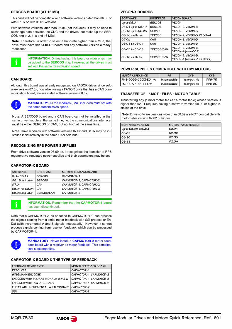
MQR-78/80 Fagor Modular Drives and Motors Quick Reference. Ref.1601
SERCOS BOARD (AT 16 MB)
This card will not be compatible with software versions older than 06.05 orwith 07.0x or with 08.01 versions.
With software versions later than 06.04 (not included), it may be used toexchange data between the CNC and the drives that make up the SER-COS ring at 2, 4, 8 and 16 MBd.
CAN BOARD
Although this board was already recognized on FAGOR drives since soft-ware version 07.0x, now when using a FAGOR drive that has a CAN com-munication board, always install software version 08.0x.
RECOGNIZING RPS POWER SUPPLIES
From drive software version 06.09 on, it recognizes the identifier of RPSregenerative regulated power supplies and their parameters may be set.
CAPMOTOR-X BOARD
Note that a CAPMOTOR-2, as opposed to CAPMOTOR-1, can processthe signals coming from a serial motor feedback with SSI protocol or En-Dat (with incremental A and B signals, necessarily). However, it cannotprocess signals coming from resolver feedback, which can be processedby CAPMOTOR-1.
CAPMOTOR-X BOARD & THE TYPE OF FEEDBACK
VECON-X BOARDS
POWER SUPPLIES COMPATIBLE WITH FM9 MOTORS
TRANSFER OF · *.MOT · FILES · MOTOR TABLE
Transferring any (*.mot) motor file (AKA motor table) whose version ishigher than 02.01 requires having a software version 08.09 or higher in-stalled at the drive.
Note. Therefore, in order to select a baudrate higher than 4 MBd, thedrive must have this SERCOS board and any software version alreadymentioned.
INFORMATION. Drives having this board or older ones maybe added to the SERCOS ring. However, all the drives mustset with the same transmission speed.
MANDATORY. All the modules (CNC included) must set withthe same transmission speed.
Note. A SERCOS board and a CAN board cannot be installed in thesame drive module at the same time; i.e. the communications interfacemust be either SERCOS or CAN, but not both at the same time.
Note. Drive modules with software versions 07.0x and 08.0x may be in-stalled indistinctively in the same CAN field bus.
SOFTWARE INTERFACE MOTOR FEEDBACK BOARD
Up to 06.17 SERCOS CAPMOTOR-1
06.18 and later SERCOS CAPMOTOR-1, CAPMOTOR-2
07.0x CAN CAPMOTOR-1, CAPMOTOR-2
08.01 to 08.04 CAN CAPMOTOR-1, CAPMOTOR-2
08.05 and later SERCOS/CAN CAPMOTOR-2
INFORMATION. Remember that the CAPMOTOR-1 boardhas been discontinued.
MANDATORY. Never install a CAPMOTOR-2 motor feed-back board with a resolver as motor feedback. This combina-tion is incompatible.
FEEDBACK DEVICE TYPE MOTOR FEEDBACK BOARD
RESOLVER CAPMOTOR-1
STEGMANN ENCODER CAPMOTOR-1, CAPMOTOR-2
ENCODER WITH SQUARE SIGNALS U, V & W CAPMOTOR-1, CAPMOTOR-2
ENCODER WITH C & D SIGNALS CAPMOTOR-1, CAPMOTOR-2
ENDAT WITH INCREMENTAL A & B SIGNALS CAPMOTOR-2
SSI CAPMOTOR-2
i
i
SOFTWARE INTERFACE VECON BOARD
Up to 06.01 SERCOS VECON
06.01 up to 06.17 SERCOS VECON-2, VECON-3
06.18 up to 06.25 SERCOS VECON-2, VECON-3
06.26 and later SERCOS VECON-2, VECON-3, VECON-4
07.0x CAN VECON-2, VECON-3
08.01 to 08.04 CAN VECON-2, VECON-3
08.05 to 08.09 SERCOS/CANVECON-2, VECON-3,
VECON-4 (vers.00A)
08.10 and later SERCOS/CANVECON-2, VECON-3,
VECON-4 (vers.00A and later)
MOTOR REFERENCE PS XPS RPS
FM9-B055-C5C-E01-A incompatible incompatible RPS-75
FM9-B071-C5C-E01 incompatible incompatible RPS-80
Note. Drive software versions older than 08.09 are NOT compatible withmotor table version 02.02 or higher.
SOFTWARE VERSION MOTOR TABLE VERSION
Up to 08.08 included 02.01
08.09 02.02
08.10 02.03
08.11 02.04

Fagor Modular Drives and Motors Quick Reference. Ref.1601 MQR-79/80
User notes

MQR-80/80 Fagor Modular Drives and Motors Quick Reference. Ref.1601
Í.NÂ*MÎ
Cod.14460010
Fagor Automation S. Coop.Bº San Andrés, 19 - Apdo. 144E-20500 Arrasate-Mondragón, SpainTel: +34 943 719 200
+34 943 039 800Fax: +34 943 791 712E-mail: [email protected]
FAGOR AUTOMATION


