1 2 3 4 5 6-7 8-9 8-9 10 11-13 14-15 16-17 18-19 20-21 22 22 23-25 26-30 31 32 www.keylineacademy.com Where Customers Become Experts NINJA TOTAL QUICK-START GUIDE CONTENTS Machine Registration Installing Safety Shield Powering Machine ON/OFF Login/Password Entry Important Machine Notices Cut Cut by Decode High Security Cut by Code High Security Using Ford AV12 Adaptor Cut by Decode Dimple Cut by Code Dimple Cut by Decode Edge Cut Cut by Code Edge Cut Cut Cutter Replacement Tracer Replacement Software Update Via Ethernet Software Update Via USB Favorites Spare Parts List I PAGE # Watch the Ninja Total Training Course for Free!
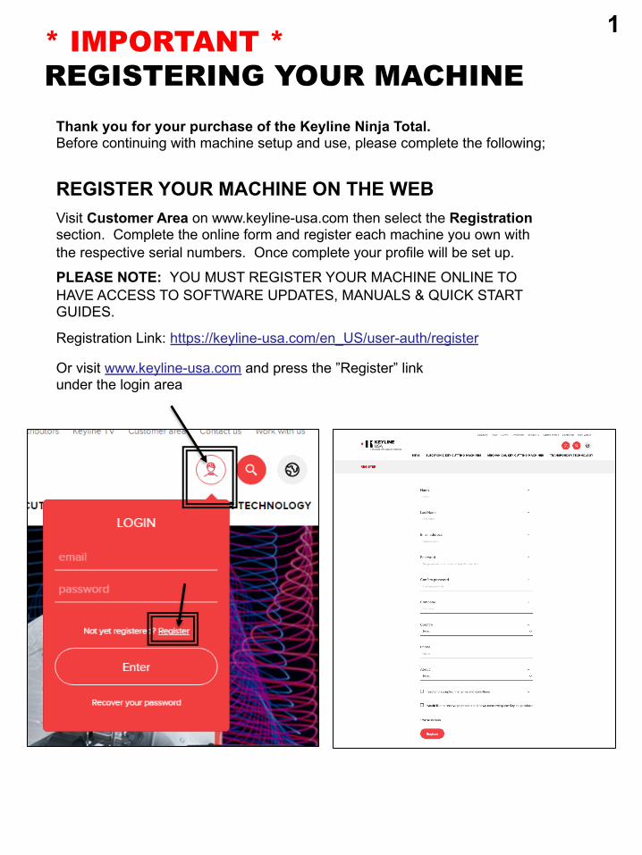
REGISTER YOUR MACHINE ON THE WEBVisit Customer Area on www.keyline-usa.com then select the Registration section. Complete the online form and register each machine you own with the respective serial numbers. Once complete your profile will be set up.
PLEASE NOTE: YOU MUST REGISTER YOUR MACHINE ONLINE TO HAVE ACCESS TO SOFTWARE UPDATES, MANUALS & QUICK START GUIDES.
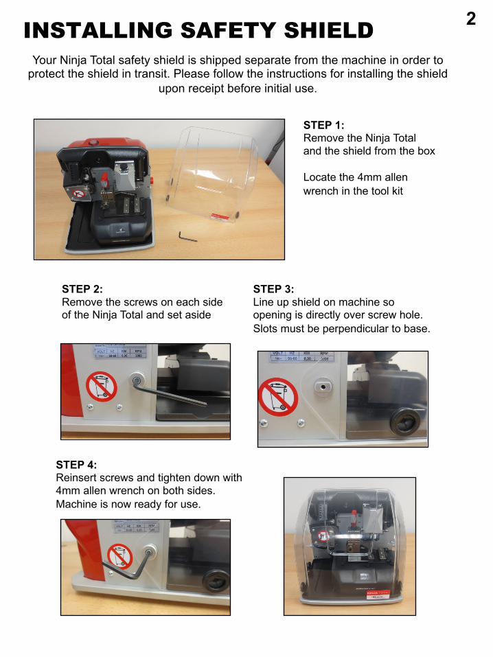
STEP 1:Remove the Ninja Total and the shield from the box
Locate the 4mm allen wrench in the tool kit
Your Ninja Total safety shield is shipped separate from the machine in order to protect the shield in transit. Please follow the instructions for installing the shield
upon receipt before initial use.
STEP 2:Remove the screws on each side of the Ninja Total and set aside
STEP 3:Line up shield on machine so opening is directly over screw hole. Slots must be perpendicular to base.
STEP 4:Reinsert screws and tighten down with 4mm allen wrench on both sides. Machine is now ready for use.
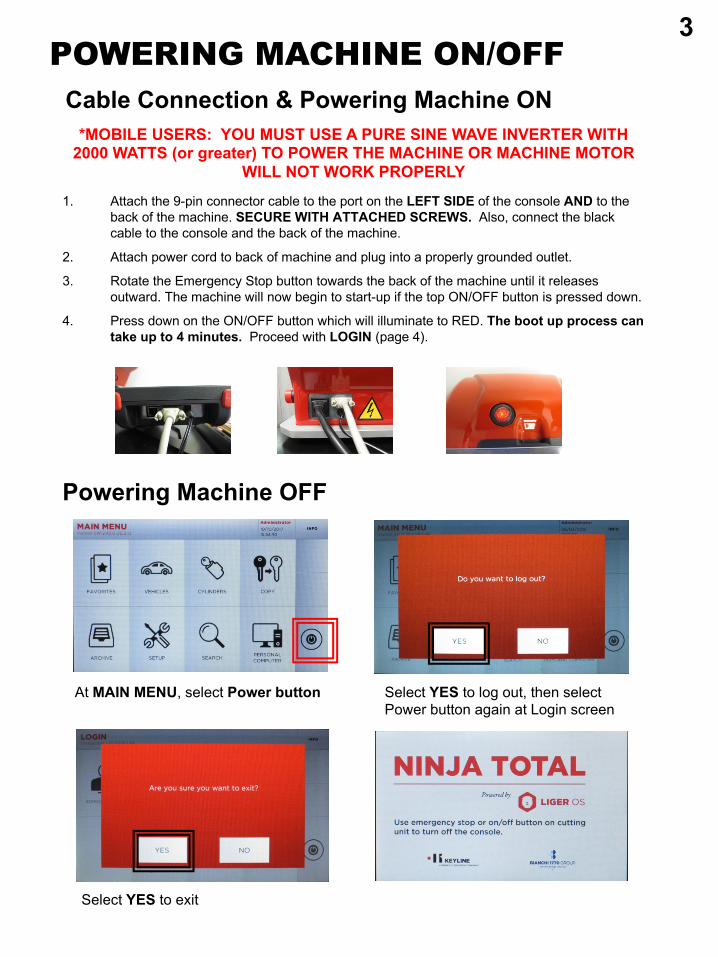
Powering Machine OFF
Cable Connection & Powering Machine ON
1. Attach the 9-pin connector cable to the port on the LEFT SIDE of the console AND to the back of the machine. SECURE WITH ATTACHED SCREWS. Also, connect the black cable to the console and the back of the machine.
2. Attach power cord to back of machine and plug into a properly grounded outlet.
3. Rotate the Emergency Stop button towards the back of the machine until it releases outward. The machine will now begin to start-up if the top ON/OFF button is pressed down.
4. Press down on the ON/OFF button which will illuminate to RED. The boot up process can take up to 4 minutes. Proceed with LOGIN (page 4).
POWERING MACHINE ON/OFF
*MOBILE USERS: YOU MUST USE A PURE SINE WAVE INVERTER WITH 2000 WATTS (or greater) TO POWER THE MACHINE OR MACHINE MOTOR
WILL NOT WORK PROPERLY
At MAIN MENU, select Power button Select YES to log out, then select Power button again at Login screen
Select YES to exit
3
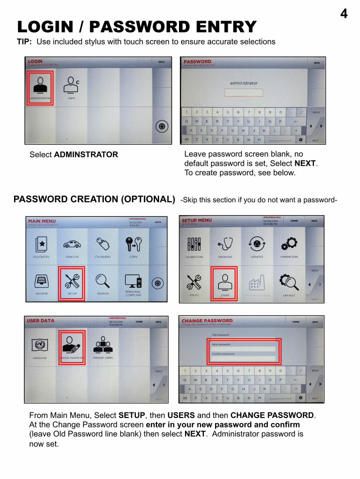
Select ADMINSTRATOR
LOGIN / PASSWORD ENTRYTIP: Use included stylus with touch screen to ensure accurate selections
From Main Menu, Select SETUP, then USERS and then CHANGE PASSWORD. At the Change Password screen enter in your new password and confirm (leave Old Password line blank) then select NEXT. Administrator password is now set.
PASSWORD CREATION (OPTIONAL) -Skip this section if you do not want a password-
Leave password screen blank, no default password is set, Select NEXT. To create password, see below.
4
IMPORTANTSAFETY SHIELD
The safety shield works in conjunction with the software prompts. The software, before starting some cut and decode procedures, requires the closing of the safety shield. If it is not closed when requested, it will continue to ask its closing. If the user opens the safety shield during an operating phase (for example, when the machine is cutting or decoding a key) it will stop immediately and, at the closing of the shield, the machine will reset the operation and go back to the beginning of the procedure. Make sure to complete all parts of the process at one time, then close the shield before proceeding to the next step. This will avoid having to replicate steps.
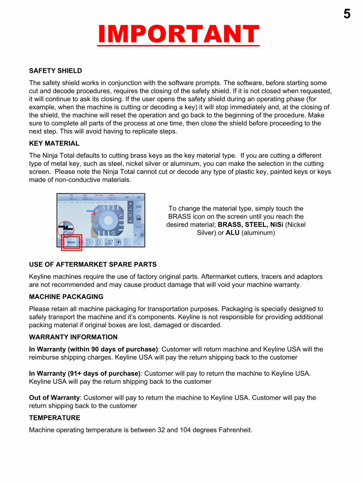
KEY MATERIAL
The Ninja Total defaults to cutting brass keys as the key material type. If you are cutting a different type of metal key, such as steel, nickel silver or aluminum, you can make the selection in the cutting screen. Please note the Ninja Total cannot cut or decode any type of plastic key, painted keys or keys made of non-conductive materials.
USE OF AFTERMARKET SPARE PARTS
Keyline machines require the use of factory original parts. Aftermarket cutters, tracers and adaptors are not recommended and may cause product damage that will void your machine warranty.
MACHINE PACKAGING
Please retain all machine packaging for transportation purposes. Packaging is specially designed to safely transport the machine and it’s components. Keyline is not responsible for providing additional packing material if original boxes are lost, damaged or discarded.
WARRANTY INFORMATION
In Warranty (within 90 days of purchase): Customer will return machine and Keyline USA will the reimburse shipping charges. Keyline USA will pay the return shipping back to the customer
In Warranty (91+ days of purchase): Customer will pay to return the machine to Keyline USA. Keyline USA will pay the return shipping back to the customer
Out of Warranty: Customer will pay to return the machine to Keyline USA. Customer will pay the return shipping back to the customer
TEMPERATURE
Machine operating temperature is between 32 and 104 degrees Fahrenheit.
To change the material type, simply touch the BRASS icon on the screen until you reach the
desired material; BRASS, STEEL, NiSi (Nickel Silver) or ALU (aluminum)
5
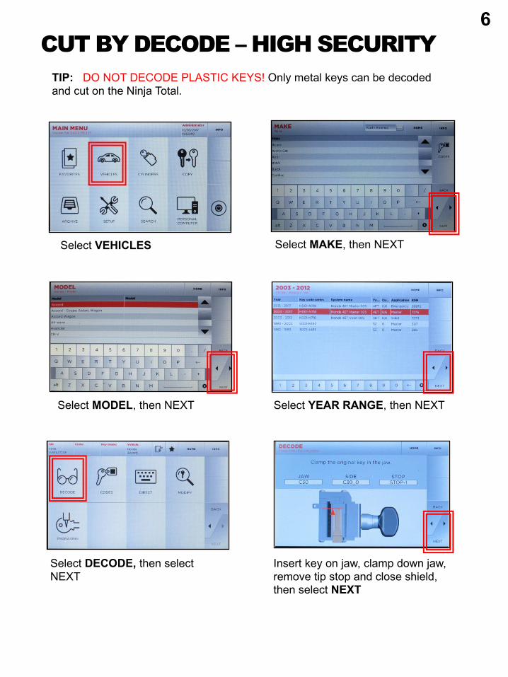
CUT BY DECODE – HIGH SECURITY
Select MODEL, then NEXT
Select MAKE, then NEXTSelect VEHICLES
Select DECODE, then select NEXT
Insert key on jaw, clamp down jaw, remove tip stop and close shield, then select NEXT
Select YEAR RANGE, then NEXT
TIP: DO NOT DECODE PLASTIC KEYS! Only metal keys can be decoded and cut on the Ninja Total.
6
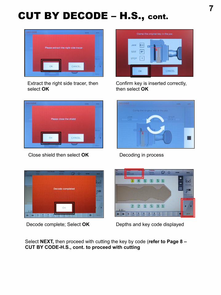
CUT BY DECODE – H.S., cont.
Close shield then select OK Decoding in process
Extract the right side tracer, then select OK
Decode complete; Select OK Depths and key code displayed
Select NEXT, then proceed with cutting the key by code (refer to Page 8 –CUT BY CODE-H.S., cont. to proceed with cutting
Confirm key is inserted correctly, then select OK
7
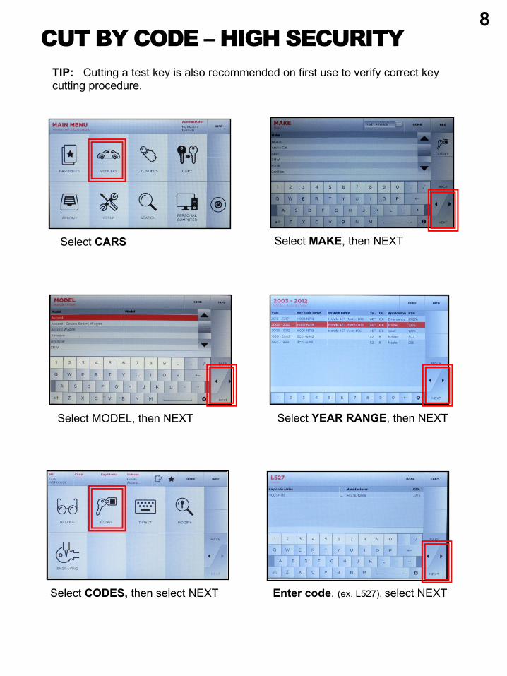
CUT BY CODE – HIGH SECURITY
Select : Cut by Code when prompted
1. Select: SETUP
Select MODEL, then NEXT
Select MAKE, then NEXTSelect CARS
Select CODES, then select NEXT Enter code, (ex. L527), select NEXT
TIP: Cutting a test key is also recommended on first use to verify correct key cutting procedure.
Select YEAR RANGE, then NEXT
8
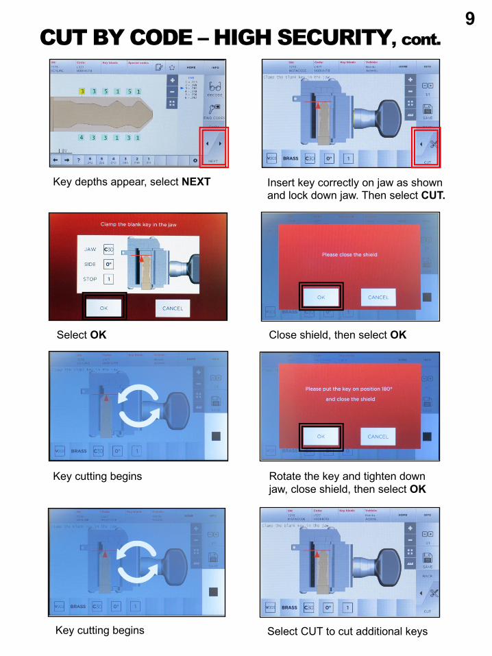
CUT BY CODE – HIGH SECURITY, cont.
Insert key correctly on jaw as shown and lock down jaw. Then select CUT.
Key depths appear, select NEXT
Rotate the key and tighten down jaw, close shield, then select OK
Select OK Close shield, then select OK
Key cutting begins
Key cutting begins
Select CUT to cut additional keys
9
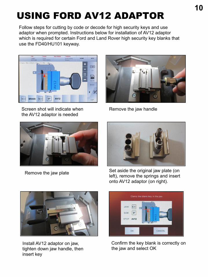
USING FORD AV12 ADAPTOR
1. Select: SETUP
Screen shot will indicate when the AV12 adaptor is needed
Remove the jaw handle
Remove the jaw plate
Follow steps for cutting by code or decode for high security keys and use adaptor when prompted. Instructions below for installation of AV12 adaptor which is required for certain Ford and Land Rover high security key blanks that use the FD40/HU101 keyway.
Confirm the key blank is correctly on the jaw and select OK
10
Set aside the original jaw plate (on left), remove the springs and insert onto AV12 adaptor (on right).
Install AV12 adaptor on jaw, tighten down jaw handle, then insert key
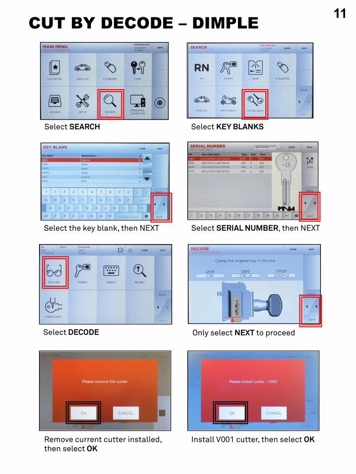
CUT BY DECODE – DIMPLE
Select SERIAL NUMBER, then NEXTSelect the key blank, then NEXT
Select SEARCH
Select DECODE Only select NEXT to proceed
Remove current cutter installed, then select OK
Install V001 cutter, then select OK
Select KEY BLANKS
11
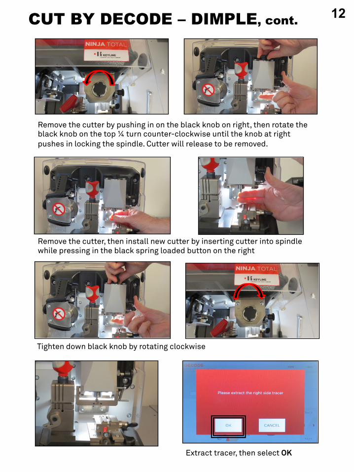
CUT BY DECODE – DIMPLE, cont.
Remove the cutter by pushing in on the black knob on right, then rotate the black knob on the top ¼ turn counter-clockwise until the knob at right pushes in locking the spindle. Cutter will release to be removed.
Extract tracer, then select OK
Tighten down black knob by rotating clockwise
Remove the cutter, then install new cutter by inserting cutter into spindle while pressing in the black spring loaded button on the right
12
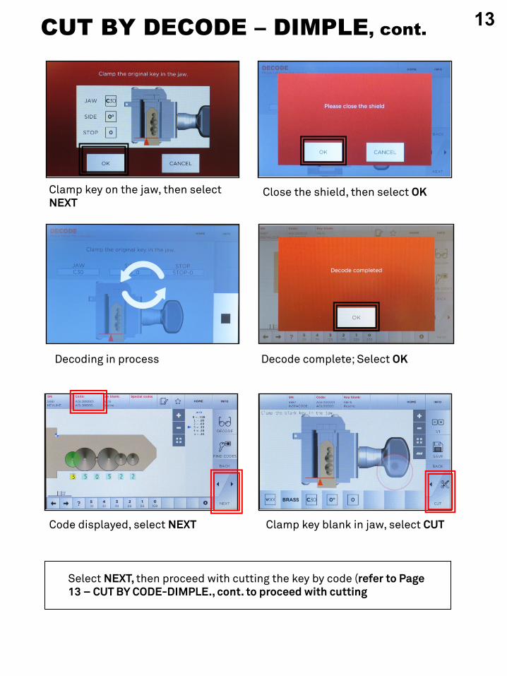
CUT BY DECODE – DIMPLE, cont.
Decoding in process Decode complete; Select OK
Code displayed, select NEXT Clamp key blank in jaw, select CUT
Select NEXT, then proceed with cutting the key by code (refer to Page 13 – CUT BY CODE-DIMPLE., cont. to proceed with cutting
Close the shield, then select OKClamp key on the jaw, then select NEXT
13
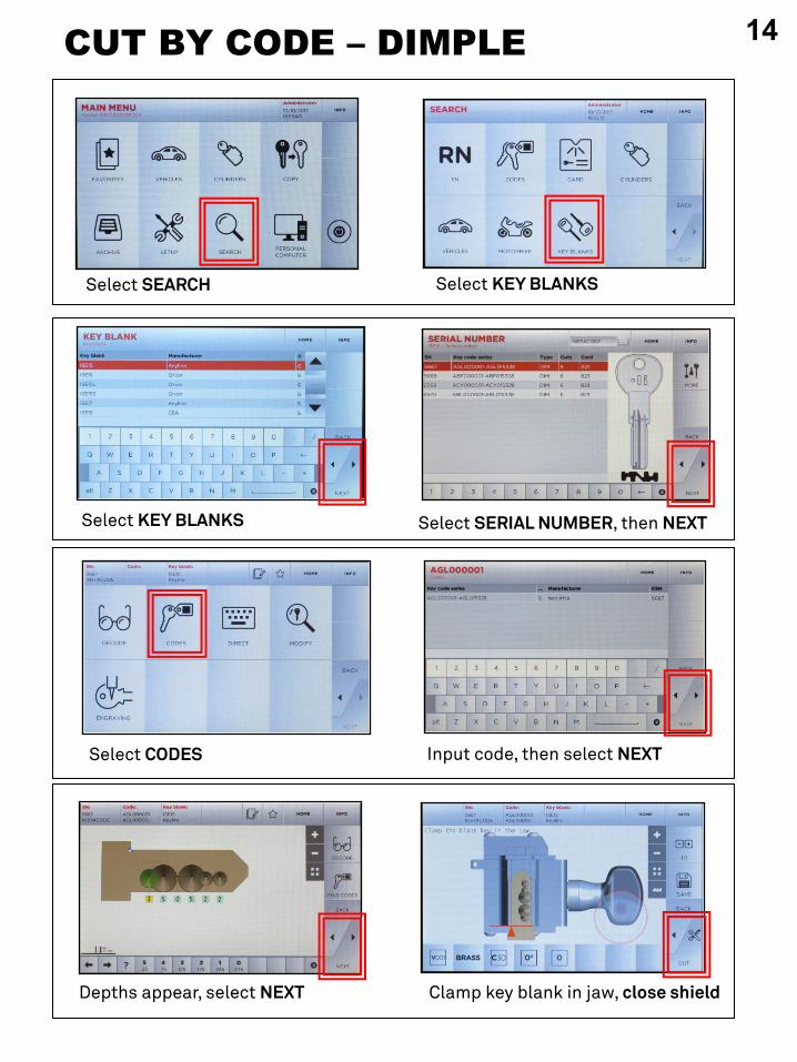
CUT BY CODE – DIMPLE
Select : Cut by Code when prompted
Select CODES
Select SERIAL NUMBER, then NEXTSelect KEY BLANKS
Depths appear, select NEXT Clamp key blank in jaw, close shield
Input code, then select NEXT
Select SEARCH Select KEY BLANKS
14
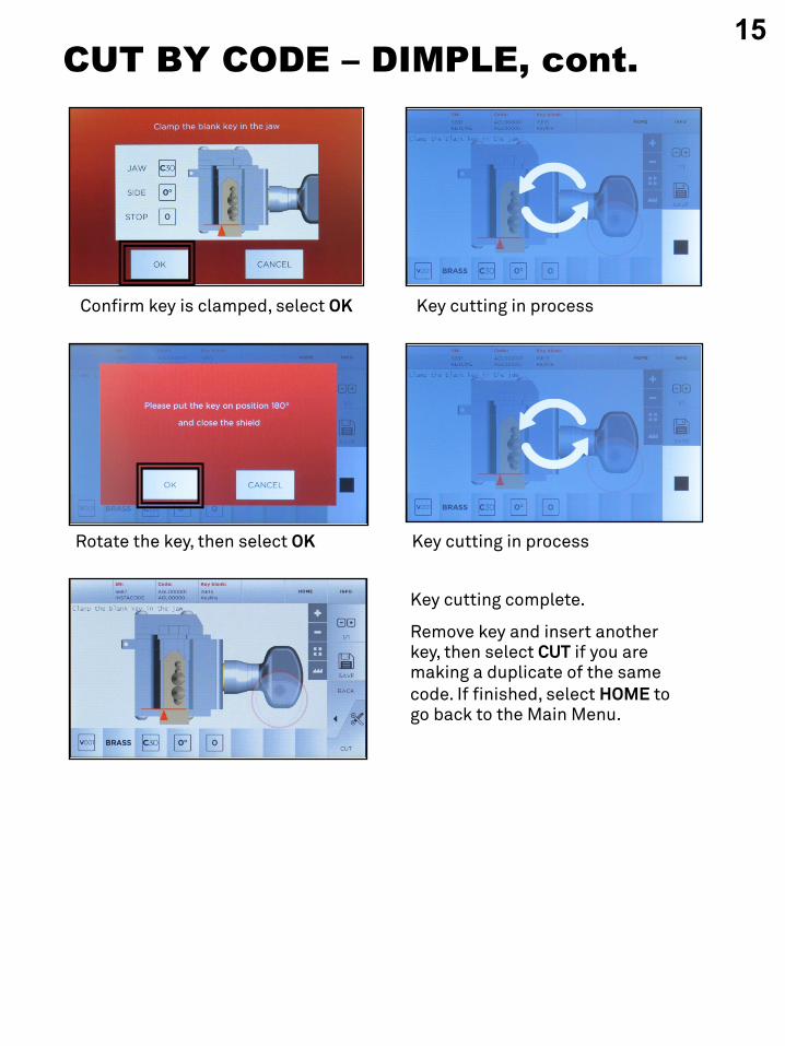
CUT BY CODE – DIMPLE, cont.
Key cutting in processConfirm key is clamped, select OK
Key cutting in processRotate the key, then select OK
Key cutting complete.
Remove key and insert another key, then select CUT if you are making a duplicate of the same code. If finished, select HOME to go back to the Main Menu.
15
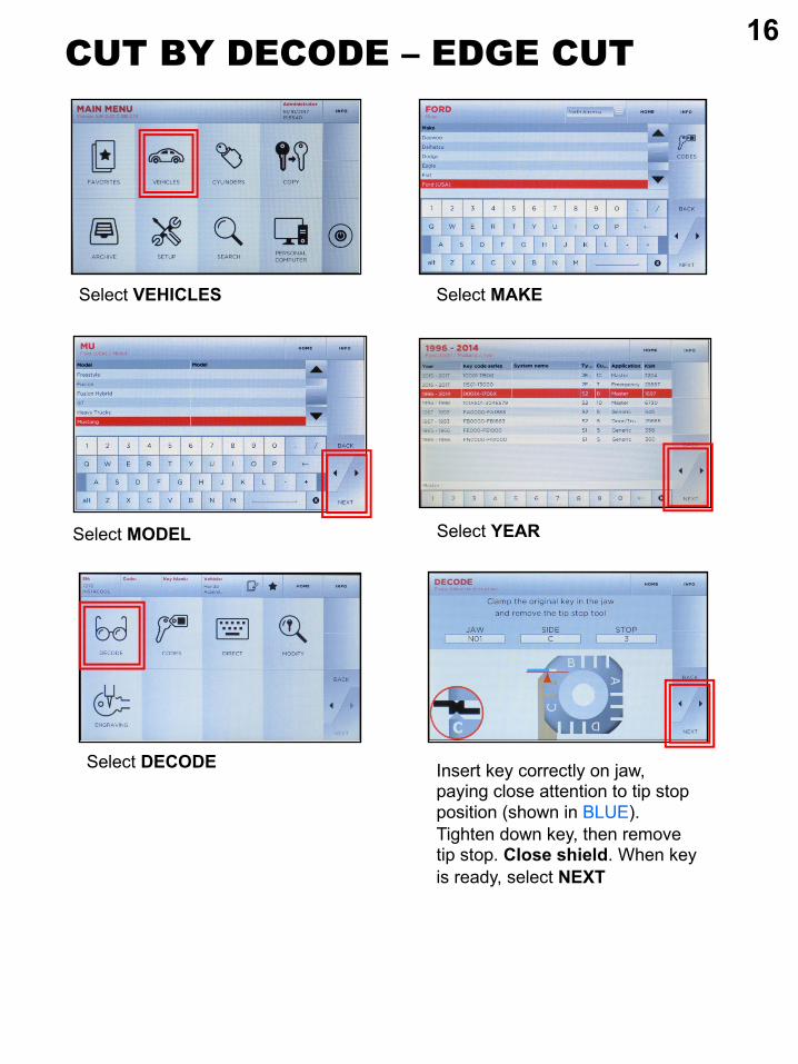
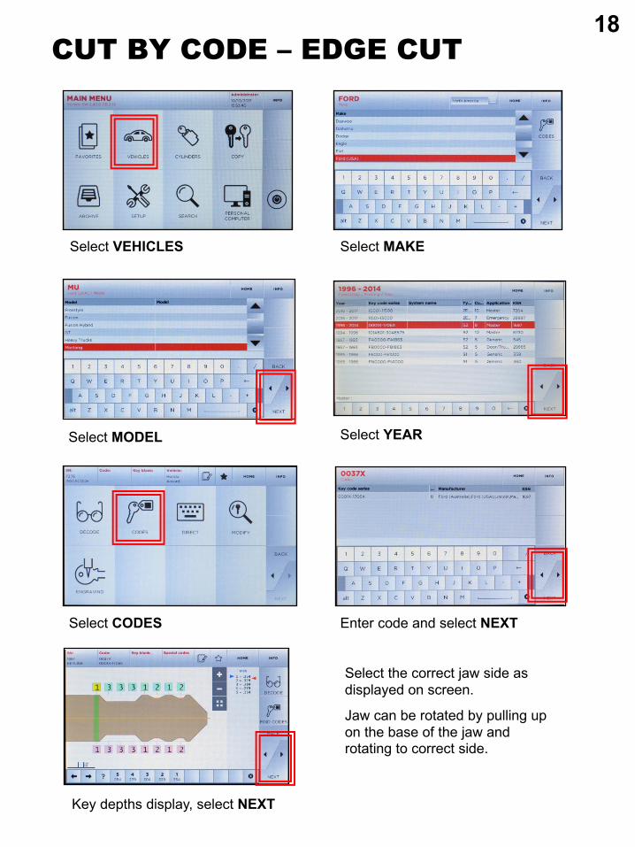
Select YEAR
Select DECODE
CUT BY DECODE – EDGE CUT
Select MODEL
Select MAKE
Insert key correctly on jaw, paying close attention to tip stop position (shown in BLUE). Tighten down key, then remove tip stop. Close shield. When key is ready, select NEXT
Select VEHICLES
16
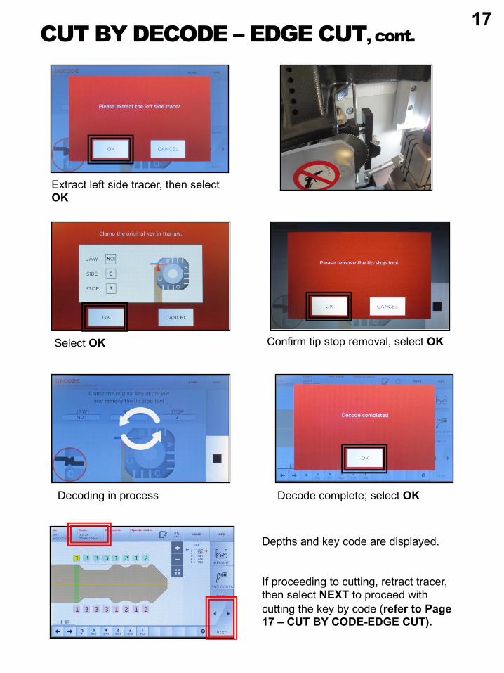
CUT BY DECODE – EDGE CUT, cont.
Decoding in process
Extract left side tracer, then select OK
Confirm tip stop removal, select OK
Decode complete; select OK
Depths and key code are displayed.
If proceeding to cutting, retract tracer, then select NEXT to proceed with cutting the key by code (refer to Page 17 – CUT BY CODE-EDGE CUT).
Select OK
17
CUT BY CODE – EDGE CUT
Key depths display, select NEXT
Select YEAR
Select CODES
Select MODEL
Select MAKESelect VEHICLES
Enter code and select NEXT
Select the correct jaw side as displayed on screen.
Jaw can be rotated by pulling up on the base of the jaw and rotating to correct side.
18
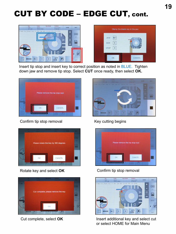
CUT BY CODE – EDGE CUT, cont.
Key cutting begins
Insert tip stop and insert key to correct position as noted in BLUE. Tighten down jaw and remove tip stop. Select CUT once ready, then select OK.
Confirm tip stop removal
Rotate key and select OK
Cut complete, select OK
Confirm tip stop removal
Insert additional key and select cut or select HOME for Main Menu
19
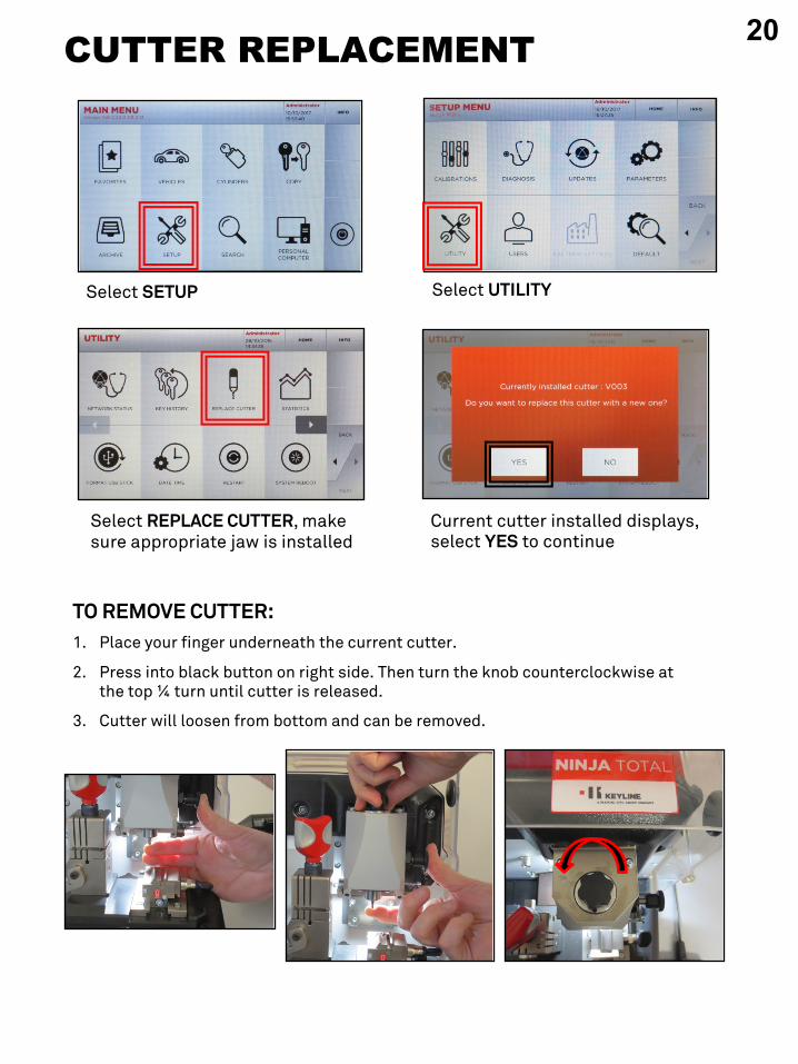
1. Select: SETUP
Select SETUP
Select REPLACE CUTTER, make sure appropriate jaw is installed
Current cutter installed displays, select YES to continue
CUTTER REPLACEMENT
Select UTILITY
TO REMOVE CUTTER:1. Place your finger underneath the current cutter.
2. Press into black button on right side. Then turn the knob counterclockwise at the top ¼ turn until cutter is released.
3. Cutter will loosen from bottom and can be removed.
20
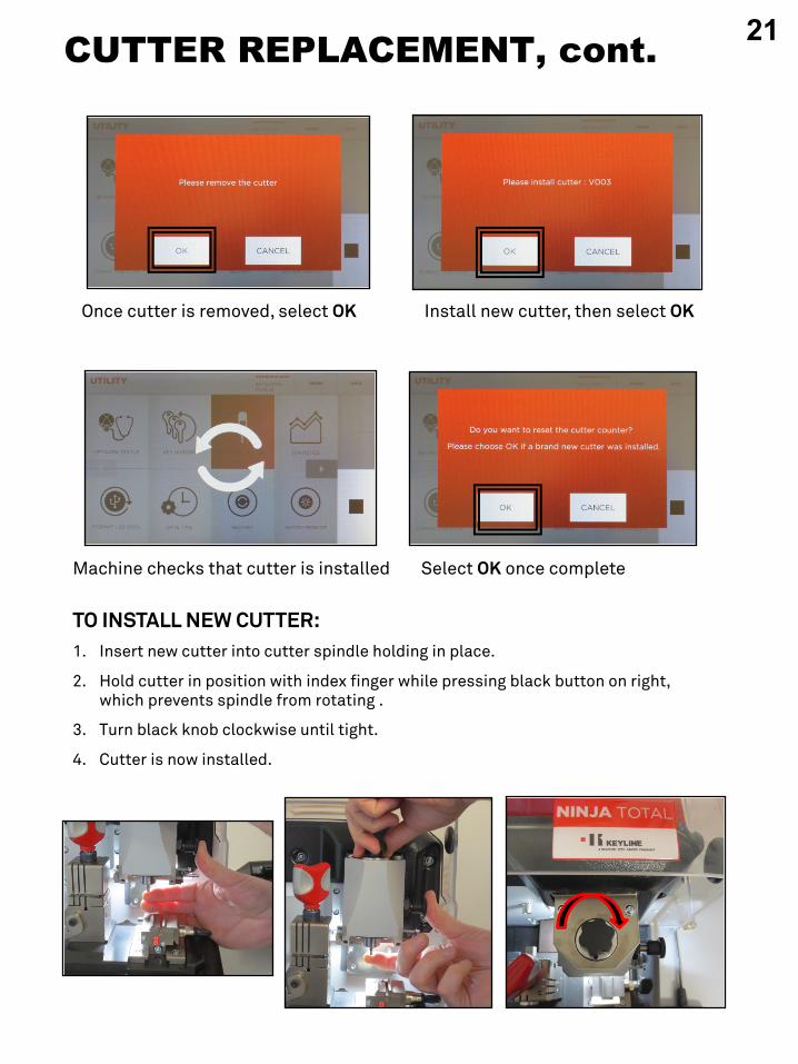
CUTTER REPLACEMENT, cont.
Install new cutter, then select OK
TO INSTALL NEW CUTTER:1. Insert new cutter into cutter spindle holding in place.
2. Hold cutter in position with index finger while pressing black button on right, which prevents spindle from rotating .
3. Turn black knob clockwise until tight.
4. Cutter is now installed.
Once cutter is removed, select OK
Select OK once completeMachine checks that cutter is installed
21
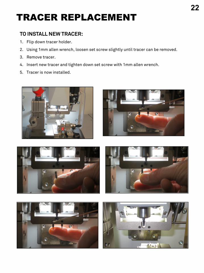
TRACER REPLACEMENTTO INSTALL NEW TRACER:1. Flip down tracer holder.
2. Using 1mm allen wrench, loosen set screw slightly until tracer can be removed.
3. Remove tracer.
4. Insert new tracer and tighten down set screw with 1mm allen wrench.
5. Tracer is now installed.
22
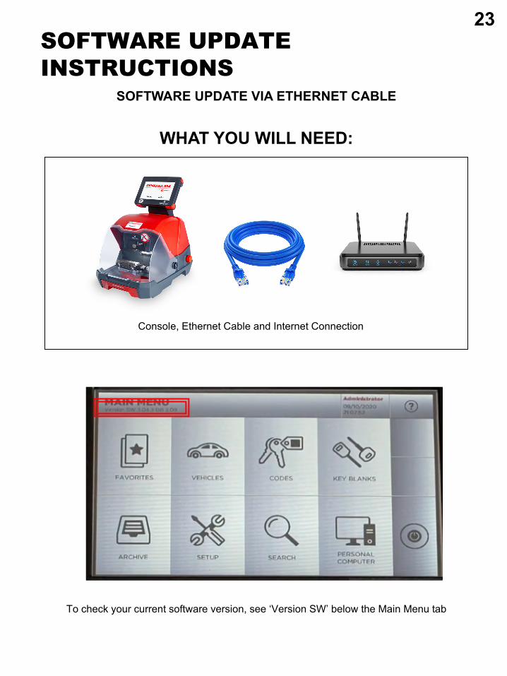
WHAT YOU WILL NEED:
Console, Ethernet Cable and Internet Connection
SOFTWARE UPDATE INSTRUCTIONS
SOFTWARE UPDATE VIA ETHERNET CABLE
To check your current software version, see ‘Version SW’ below the Main Menu tab
23
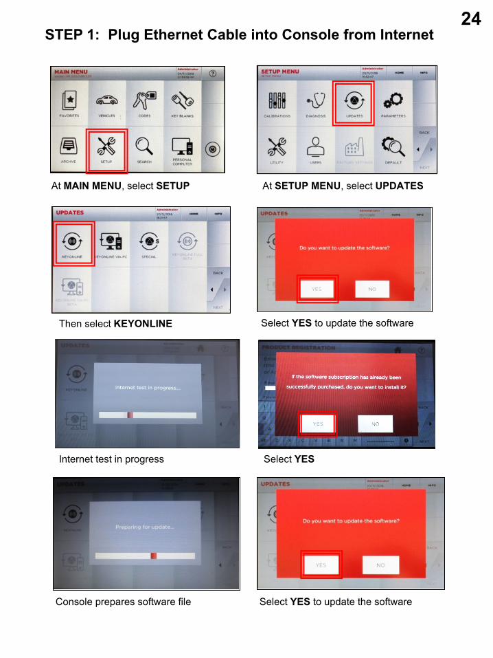
STEP 1: Plug Ethernet Cable into Console from Internet
At MAIN MENU, select SETUP At SETUP MENU, select UPDATES
Then select KEYONLINE Select YES to update the software
Internet test in progress Select YES
Console prepares software file Select YES to update the software
24
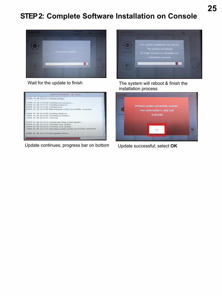
STEP 2: Complete Software Installation on Console
Wait for the update to finish The system will reboot & finish the installation process
Update continues; progress bar on bottom Update successful; select OK
25
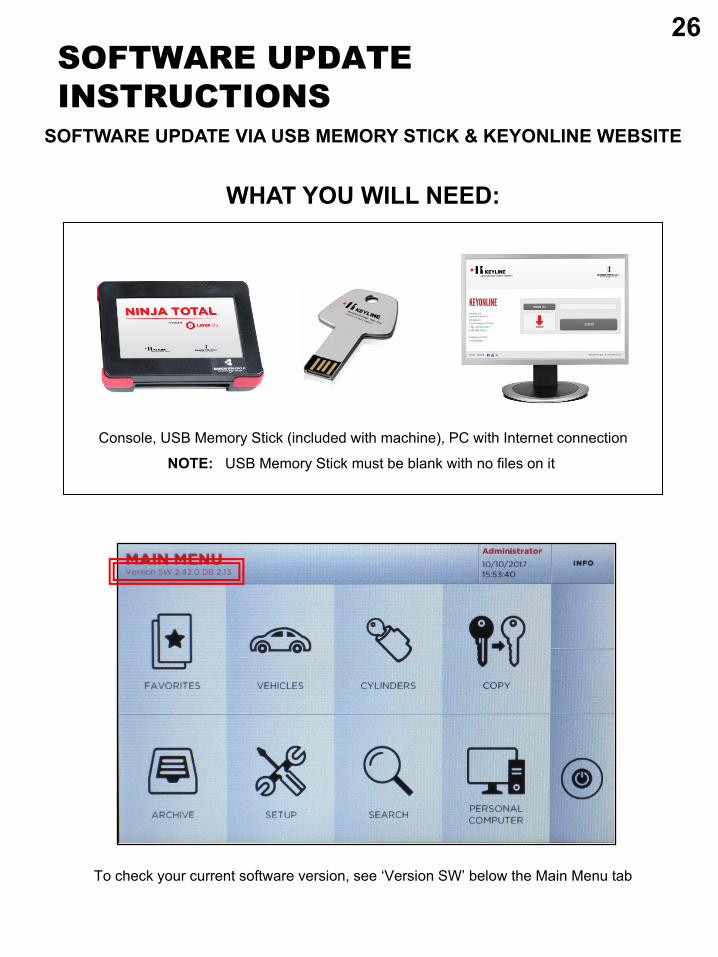
WHAT YOU WILL NEED:
Console, USB Memory Stick (included with machine), PC with Internet connection
NOTE: USB Memory Stick must be blank with no files on it
SOFTWARE UPDATE INSTRUCTIONS
SOFTWARE UPDATE VIA USB MEMORY STICK & KEYONLINE WEBSITE
To check your current software version, see ‘Version SW’ below the Main Menu tab
26
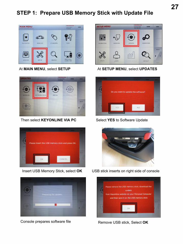
STEP 1: Prepare USB Memory Stick with Update File
At MAIN MENU, select SETUP At SETUP MENU, select UPDATES
Then select KEYONLINE VIA PC Select YES to Software Update
Insert USB Memory Stick, select OK USB stick inserts on right side of console
Console prepares software file Remove USB stick, Select OK
27
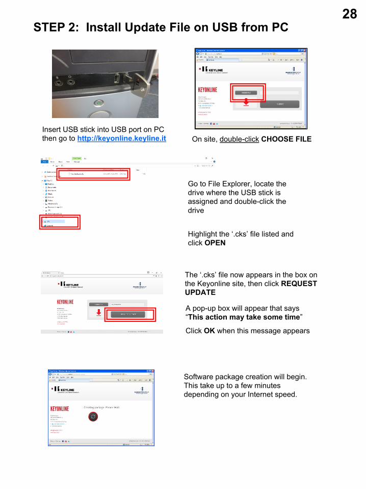
STEP 2: Install Update File on USB from PC
Insert USB stick into USB port on PC then go to http://keyonline.keyline.it On site, double-click CHOOSE FILE
Software package creation will begin. This take up to a few minutes depending on your Internet speed.
Highlight the ‘.cks’ file listed and click OPEN
Go to File Explorer, locate the drive where the USB stick is assigned and double-click the drive
The ‘.cks’ file now appears in the box on the Keyonline site, then click REQUEST UPDATE
A pop-up box will appear that says “This action may take some time”
Click OK when this message appears
28
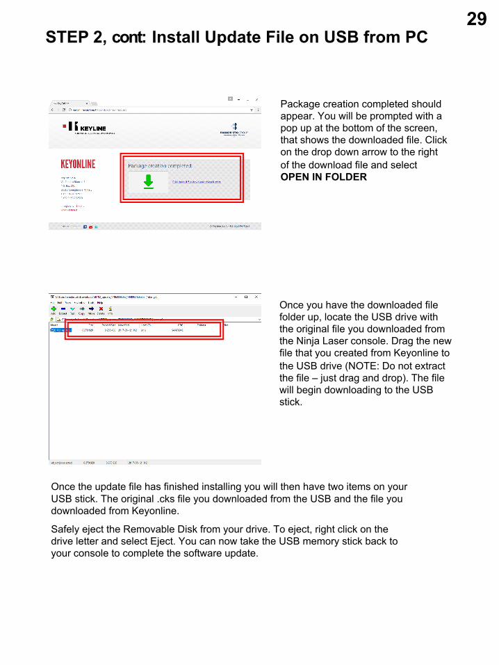
STEP 2, cont: Install Update File on USB from PC
Package creation completed should appear. You will be prompted with a pop up at the bottom of the screen, that shows the downloaded file. Click on the drop down arrow to the right of the download file and select OPEN IN FOLDER
Once you have the downloaded file folder up, locate the USB drive with the original file you downloaded from the Ninja Laser console. Drag the new file that you created from Keyonline to the USB drive (NOTE: Do not extract the file – just drag and drop). The file will begin downloading to the USB stick.
Once the update file has finished installing you will then have two items on your USB stick. The original .cks file you downloaded from the USB and the file you downloaded from Keyonline.
Safely eject the Removable Disk from your drive. To eject, right click on the drive letter and select Eject. You can now take the USB memory stick back to your console to complete the software update.
29
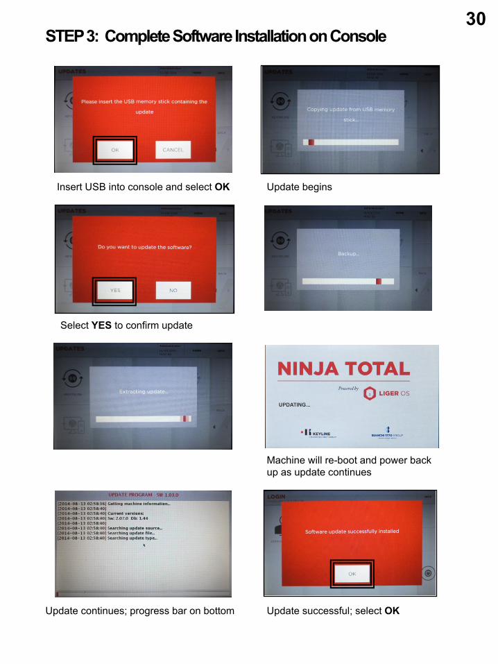
STEP 3: Complete Software Installation on Console
Insert USB into console and select OK Update begins
Select YES to confirm update
Update continues; progress bar on bottom Update successful; select OK
Machine will re-boot and power back up as update continues
30
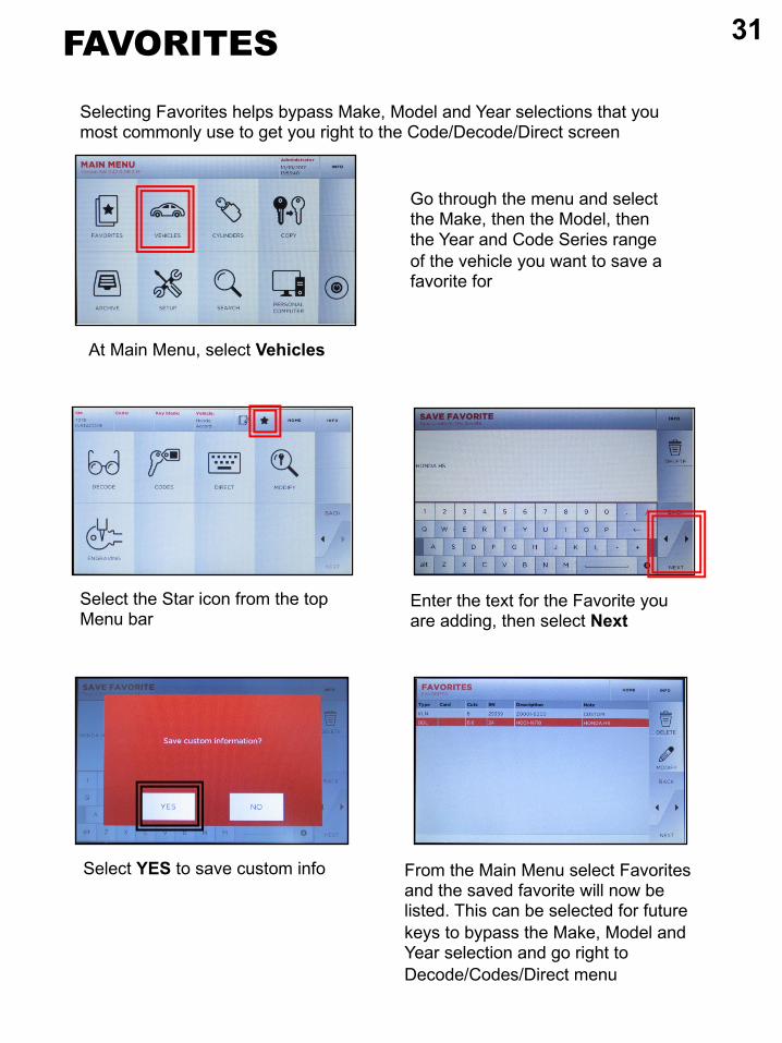
FAVORITES
Selecting Favorites helps bypass Make, Model and Year selections that you most commonly use to get you right to the Code/Decode/Direct screen
At Main Menu, select Vehicles
Go through the menu and select the Make, then the Model, then the Year and Code Series range of the vehicle you want to save a favorite for
Select the Star icon from the top Menu bar
Enter the text for the Favorite you are adding, then select Next
Select YES to save custom info From the Main Menu select Favorites and the saved favorite will now be listed. This can be selected for future keys to bypass the Make, Model and Year selection and go right to Decode/Codes/Direct menu