Piezoelectric Voltage Coupled Reentrant Cavity Resonator N. C. Carvalho, 1,2a) Y. Fan, 1,2 J-M. Le Floch, 1,2 and M. E. Tobar 1,2 1 School of Physics, The University of Western Australia, 35 Stirling Hwy, 6009 Crawley, Western Australia, Australia 2 ARC Centre of Excellence, Engineered Quantum Systems (EQuS), The University of Western Australia, 35 Stirling Hwy, 6009 Crawley, Western Australia, Australia A piezoelectric voltage coupled microwave reentrant cavity has been developed. The central cavity post is bonded to a piezoelectric actuator allowing the voltage control of small post displacements over a high dynamic range. We show that such a cavity can be implemented as a voltage tunable resonator, a transducer for exciting and measuring mechanical modes of the structure and a transducer for measuring comparative sensitivity of the piezoelectric material. Experiments were conducted at room and cryogenic temperatures with results verified using Finite Element software. I. INTRODUCTION Microwave reentrant cavities are typically made up of a right cylinder with a central post and have been widely investigated 1-13 . The post acts as a capacitor, creating a very intense electric field at the central region of the cavity, in the gap between the post and the adjacent wall. The magnetic field, on the other hand, circulates the post, composing the inductive region of the cavity 14 . Adjusting the gap spacing between the post and the cavity's wall allows this cavity to be employed as a highly tunable or displacement sensitive microwave resonator, making such a device very useful for a wide range of applications, such as solid state microwave oscillators 15 , particle accelerators 16 , dielectric characterization 17 , electron spin resonance spectroscopy 18 , electromechanical transducers for gravitational wave detectors 12,19 and test of fundamental physics experiments 20,21 , and more. Microwave cavities coupled to piezoelectric (PZT) crystals have also been developed for several purposes in the last decades, patents 22,23 from 1969 and 1978 reveal that methods to tune cavity resonant frequencies through PZT devices have long been explored. Since then, more elaborated structures than the former cavities with tunable walls are being created. Examples of how PZT devices still attract great scientific interest for resonators design can be found on recent works, as the micro-strip resonator at reference 24 or the Whispering Gallery resonator described
Transcript
Piezoelectric Voltage Coupled Reentrant Cavity Resonator
N. C. Carvalho,1,2a) Y. Fan,1,2 J-M. Le Floch,1,2 and M. E. Tobar1,2
1School of Physics, The University of Western Australia, 35 Stirling Hwy, 6009 Crawley, Western Australia, Australia 2ARC Centre of Excellence, Engineered Quantum Systems (EQuS), The University of Western Australia, 35 Stirling Hwy, 6009 Crawley, Western Australia, Australia
A piezoelectric voltage coupled microwave reentrant cavity has been developed. The central cavity post is bonded to a piezoelectric actuator allowing the voltage control of small post displacements over a high dynamic range. We show that such a cavity can be implemented as a voltage tunable resonator, a transducer for exciting and measuring mechanical modes of the structure and a transducer for measuring comparative sensitivity of the piezoelectric material. Experiments were conducted at room and cryogenic temperatures with results verified using Finite Element software.
I. INTRODUCTION
Microwave reentrant cavities are typically made up of a right cylinder with a central post
and have been widely investigated1-13. The post acts as a capacitor, creating a very intense
electric field at the central region of the cavity, in the gap between the post and the adjacent wall.
The magnetic field, on the other hand, circulates the post, composing the inductive region of the
cavity14. Adjusting the gap spacing between the post and the cavity's wall allows this cavity to be
employed as a highly tunable or displacement sensitive microwave resonator, making such a
device very useful for a wide range of applications, such as solid state microwave oscillators15,
particle accelerators16, dielectric characterization17, electron spin resonance spectroscopy18,
electromechanical transducers for gravitational wave detectors12,19 and test of fundamental
physics experiments20,21, and more.
Microwave cavities coupled to piezoelectric (PZT) crystals have also been developed for
several purposes in the last decades, patents22,23 from 1969 and 1978 reveal that methods to tune
cavity resonant frequencies through PZT devices have long been explored. Since then, more
elaborated structures than the former cavities with tunable walls are being created. Examples of
how PZT devices still attract great scientific interest for resonators design can be found on recent
works, as the micro-strip resonator at reference24 or the Whispering Gallery resonator described
by reference25. This work, despite these, presents a completely novel highly tunable voltage
coupled piezoelectric reentrant cavity, where the PZT actuator is used to tune the resonance
frequency through the cavity post not the cavity wall and it takes benefit of the unique features of
reentrant cavities.
We have already developed a highly tunable cavity with a screw mechanism to
mechanically tune the gap26. However, the drawback of such a device is the way to control the
tuning mechanism, which has to be adjusted by hand and could not be easily controlled
electronically without the development of a more complex structure; such has been implemented
previously to tune sapphire Whispering Gallery mode resonators using stepper motors at
cryogenic temperatures27. Now, differently, we couple a PZT ceramic actuator to the cavity post,
which allows finer control using a DC voltage source. Such a device is more versatile as it can be
more easily adapted to work at cryogenic temperatures. In our case, we have implemented the
device in a 4 K cryogen-free pulse-tube cryocooler, which will be useful for a range of low
temperature physics experiments.
This device demonstrated notable performance as a very sensitive tunable resonator,
allowing us to idealize and test innovative applications for such a mechanism. As an
electromechanical sensor, it can be used as tool for investigating electromechanical systems,
exciting and measuring mechanical modes, and for PZT characterization at room and cryogenic
temperatures.
II. VOLTAGE TUNABLE RESONANT CAVITY EXPERIMENT
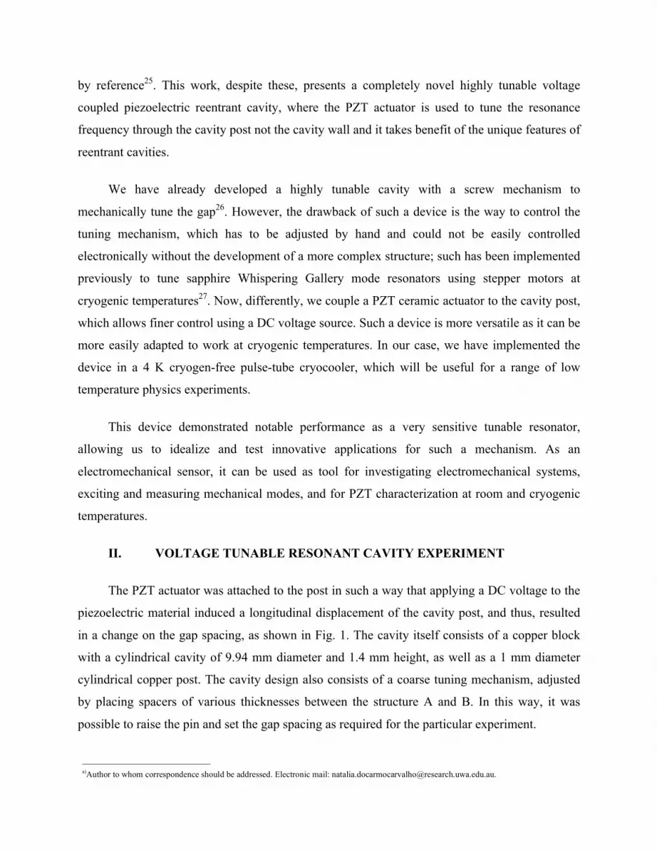
The PZT actuator was attached to the post in such a way that applying a DC voltage to the
piezoelectric material induced a longitudinal displacement of the cavity post, and thus, resulted
in a change on the gap spacing, as shown in Fig. 1. The cavity itself consists of a copper block
with a cylindrical cavity of 9.94 mm diameter and 1.4 mm height, as well as a 1 mm diameter
cylindrical copper post. The cavity design also consists of a coarse tuning mechanism, adjusted
by placing spacers of various thicknesses between the structure A and B. In this way, it was
possible to raise the pin and set the gap spacing as required for the particular experiment.
a)Author to whom correspondence should be addressed. Electronic mail: [email protected].
FIG. 1. (Color online). Illustration of the cross-section of the tunable cavity resonator. The cavity is
placed into an enclosure consisting of two parallel plates; the distance between them is fixed. The cavity
is screwed to the lower plate and the post is bonded to the PZT block, which is attached to the structure A.
Structure A passes through the upper plate (structure B), which is lifted by spacers of different
thicknesses to alter and set the initial gap spacing.
A number of experimental runs were undertaken at room temperature by adjusting
different resonant frequencies using a variety of spacers. Then, for each configuration, fine-
tuning was achieved by implementing the PZT actuator. A DC voltage was applied to the PZT
block; consequently its excitation provided an additional decrease of the reentrant cavity gap
proportionally to the applied voltage. Fig. 2 shows a diagram of the measurement set up. The
reentrant cavity resonant modes were measured in transmission, S21, with a vector network
analyzer (VNA), where the loop probes were adjusted to be in the under coupled regime and
excited the transverse azimuthal magnetic field component oscillating around the post.
FIG. 2. (Color online). Schematic diagram of the measurement system for the tunable resonant cavity
experiment. For cryogenic experimental runs, the tunable system was placed into a cryogen free
cryocooler.
A tuning range from 2.8 GHz to 12.5 GHz was achieved with the mechanical tuning spacer
mechanism. Fig. 3 shows a variety of experimental runs, where f represents the resonant mode
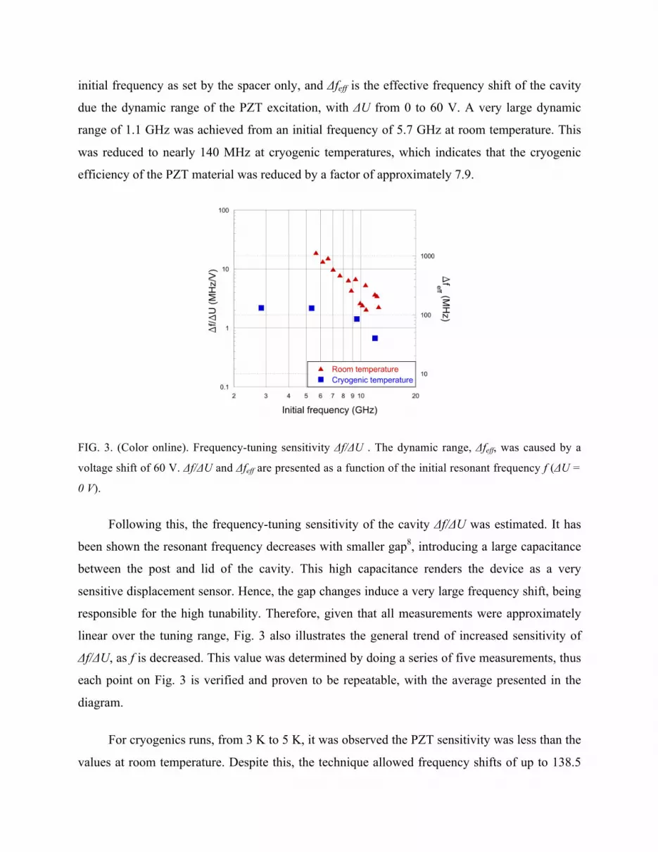
initial frequency as set by the spacer only, and Δfeff is the effective frequency shift of the cavity
due the dynamic range of the PZT excitation, with ΔU from 0 to 60 V. A very large dynamic
range of 1.1 GHz was achieved from an initial frequency of 5.7 GHz at room temperature. This
was reduced to nearly 140 MHz at cryogenic temperatures, which indicates that the cryogenic
efficiency of the PZT material was reduced by a factor of approximately 7.9.
FIG. 3. (Color online). Frequency-tuning sensitivity Δf/ΔU . The dynamic range, Δfeff, was caused by a
voltage shift of 60 V. Δf/ΔU and Δfeff are presented as a function of the initial resonant frequency f (ΔU =
0 V).
Following this, the frequency-tuning sensitivity of the cavity Δf/ΔU was estimated. It has
been shown the resonant frequency decreases with smaller gap8, introducing a large capacitance
between the post and lid of the cavity. This high capacitance renders the device as a very
sensitive displacement sensor. Hence, the gap changes induce a very large frequency shift, being
responsible for the high tunability. Therefore, given that all measurements were approximately
linear over the tuning range, Fig. 3 also illustrates the general trend of increased sensitivity of
Δf/ΔU, as f is decreased. This value was determined by doing a series of five measurements, thus
each point on Fig. 3 is verified and proven to be repeatable, with the average presented in the
diagram.
For cryogenics runs, from 3 K to 5 K, it was observed the PZT sensitivity was less than the
values at room temperature. Despite this, the technique allowed frequency shifts of up to 138.5
MHz. This was obtained at f = 2.8 GHz, corresponding to a sensitivity of 2.2 MHz/V. At room
temperature, the highest tuning sensitivity measured was 19 MHz/V at 5.7 GHz.
III. PIEZOELECTRIC PROPERTIES
The high tunability and sensitivity of the reentrant cavity resonator make the device
suitable for characterizing the sensing properties of the PZT actuator from room to cryogenic
temperatures. Taking x as the gap size, the Δx/ΔU parameter represents a figure of merit of the
piezoelectric actuator, i.e., the displacement achieved per unit input voltage. At a set
temperature, the Δx/ΔU is intrinsically related to the PZT properties and should be independent
of the reentrant mode frequencies and initial gap setting. This parameter may be calculated by:
∆x∆U
= ∆f∆U
× ∆x∆f
(1)
In the range we are calculating the gap spacing, the reentrant cavity lumped equivalent
model11 presents a very good agreement with measurements26, then we calculated Δf/Δx from the
following equation:
f x = 2 π h µμ! ln!!"#!!"#$
! !!"#$! !!!
+ 4 r!"#$ ϵ! 1+ ln!!! !!"#!!!"#$
!
!" (2)
Where, h and rcav are the cavity height and radius, rpost is the post radius and µ0, ε0 are the
permeability and the permittivity of free space, respectively.
Thus, by dividing the Δf/ΔU obtained experimentally and Δf/Δx calculated from Equation
2, the value of Δx/ΔU may be determined. Fig. 4 shows Δx/ΔU for the different initial frequencies
that was set for each run; these are negatives values, because a positive voltage causes the gap
spacing to decrease as the voltage increases.
FIG. 4. (Color online). Modulus of the gap spacing displacement per unit volt, |Δx/ΔU|, versus the initial
reentrant resonant frequency. The solid lines are the average values of |Δx/ΔU|, while the detached areas
correspond to the standard error. The solid triangles and squares represent the determination by
measurements, based on the data in Fig. 3.
It is expected that Δx/ΔU is constant at a specific temperature and in no way should depend
on the gap size or the resonance frequency of the cavity. Thus, the precision of the Δx/ΔU
determination at a constant temperature can be improved by calculating its average along with its
standard error across all measurements. At room temperature, the average value is calculated to
be -28.8 ± 3 nm/V and at 4K, -5.1 ± 1 nm/V. These results mean that the PZT actuator at
cryogenic temperatures works at approximately 18% of its performance at room temperature, or
is reduced in sensitivity by a factor of 5.7.
IV. CAVITY ELECTROMECHANICAL PROPERTIES
The cavity resonant mode was also dynamically tuned by the PZT actuator, which was
driven by an AC voltage by using a Direct Digital Synthesizer (DDS). This induced a time
varying gap displacement, and consequently produced a frequency modulation at the PZT
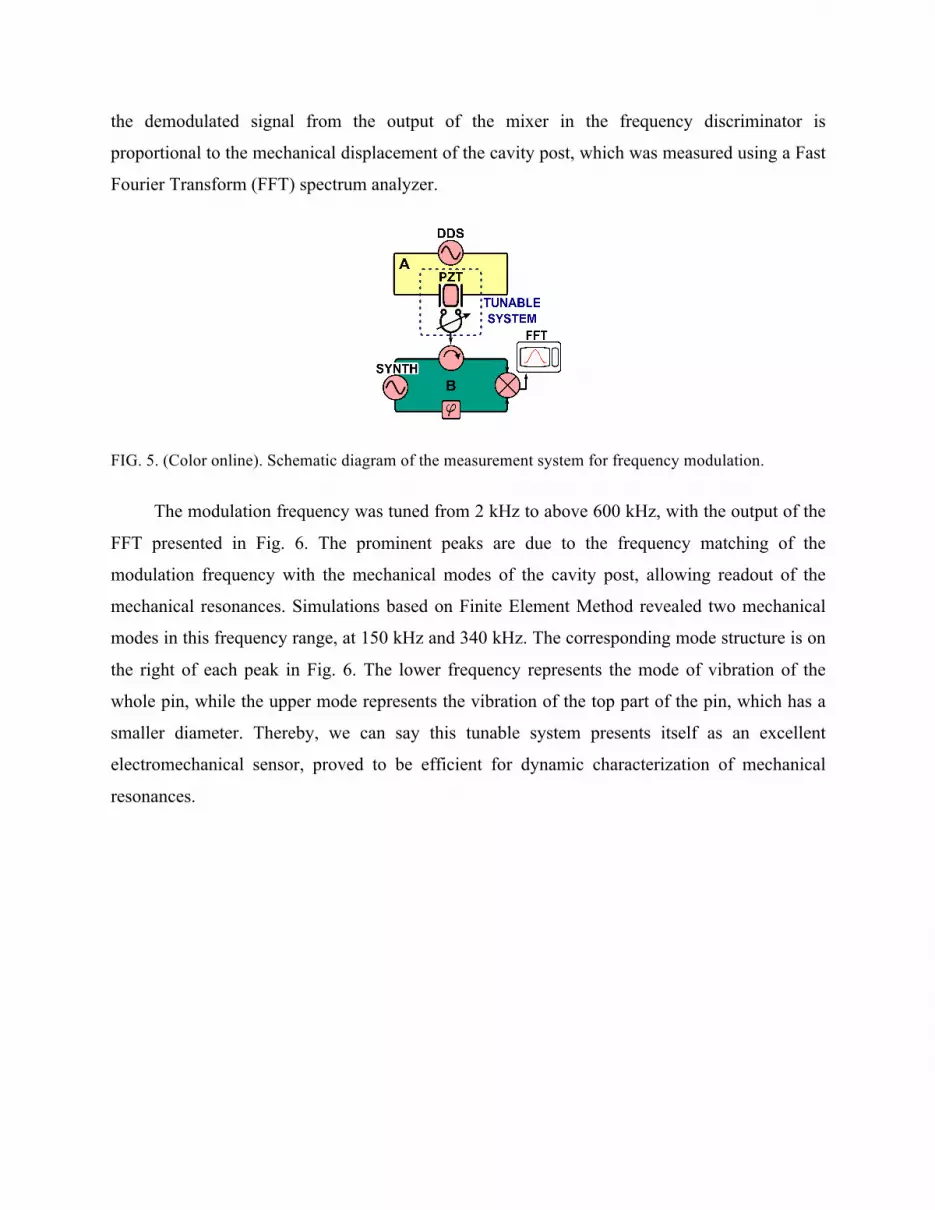
excitation rate. The measurement setup used is shown in Fig. 5. The top part (A) describes the
PZT excitation, and the bottom part (B) illustrates the readout system. The frequency synthesizer
(SYNTH) excited the cavity resonant frequency and the signal was transmitted through the
resonator. The reflected signal was mixed with the synthesizer frequency. In this configuration,
the demodulated signal from the output of the mixer in the frequency discriminator is
proportional to the mechanical displacement of the cavity post, which was measured using a Fast
Fourier Transform (FFT) spectrum analyzer.
FIG. 5. (Color online). Schematic diagram of the measurement system for frequency modulation.
The modulation frequency was tuned from 2 kHz to above 600 kHz, with the output of the
FFT presented in Fig. 6. The prominent peaks are due to the frequency matching of the
modulation frequency with the mechanical modes of the cavity post, allowing readout of the
mechanical resonances. Simulations based on Finite Element Method revealed two mechanical
modes in this frequency range, at 150 kHz and 340 kHz. The corresponding mode structure is on
the right of each peak in Fig. 6. The lower frequency represents the mode of vibration of the
whole pin, while the upper mode represents the vibration of the top part of the pin, which has a
smaller diameter. Thereby, we can say this tunable system presents itself as an excellent
electromechanical sensor, proved to be efficient for dynamic characterization of mechanical
resonances.
FIG. 6. (Color online). Mechanical modes of cavity pin obtained due the PZT dynamic excitation. Dark
colors indicate maximum and light colors minimum displacement.
V. CONCLUSION
A highly tunable voltage coupled piezoelectric reentrant cavity was constructed and tested,
which showed a great performance as a tunable cavity and an electromechanical sensor. It has
been demonstrated the system was able to be fine-tuned electronically over a large frequency
range: 1.1 GHz at room temperature (19%) and 138.5 MHz (5%) at cryogenic temperatures, at
resonant frequencies of 5.7 GHz and 2.8 GHz, respectively. In addition, the cavity exhibited a
high tuning sensitivity. At room temperature, a sensitivity of 2.3 MHz/V to 19 MHz/V was
achieved, while at cryogenic temperatures the range was from 0.7 MHz/V to 2.2 MH/V.
Moreover, we have shown that the voltage tunable reentrant cavity can be used for determining
piezoelectric sensitivity at different temperatures, allowing a novel and highly precise technique
for in situ characterization of piezoelectric materials. Also, we have illustrated it was possible to
excite and detect the mechanical modes of the cavity through the piezoelectric excitation.
Consequently, the piezoelectric coupled reentrant cavity can be used as a tool for investigating
electromechanical systems. Therefore, we can conclude that interesting applications can be
drawn with such a device; in summary, with a single cavity it is possible to tune frequency
resonances, characterize PZT actuators and have an electromechanical sensor.
ACKNOWLEDGMENTS
This research is supported by the Australian Research Council FL0992016, CE110001013 and
by the Conselho Nacional de Desenvolvimento Científico e Tecnológico (CNPq – Brazil).
REFERENCES
1W. W. Hansen, J. Appl. Phys. 10(1), 38 (1939).
2M. Jaworski, IEEE Trans. On Microw.. Theory Techn. 26(4), 256 (1978).
3D. P. Howson, IEE Proc. Microwaves, Opt. and Anten. 131(6) (1984).
4J. J. Barroso, P. J. Castro, O. D. Aguiar, L. A. Carneiro Rev. Sci. Instrum. 75(4) (2004).
5A. Francik, Intl. Conference on Microwaves, Radar and Wireless Communications Proceedings
103 (2002).
6C. Simon, M. Luong, S. Chel, O. Napoly, J. Novo, D. Roudier, N. Rouviere, N. Baboi, N.
Mildner, D. Nolle, Phys. Rev. ST Accel. Beams 11(8), 082802 (2008).
7A. J. C. Vieira, P. R. Herczfeld, A. Rosen, M. Ermold, E. E. Funk, W. D. Jemison, K. J.
Williams, IEEE Trans. Microw. Theory Techn. 49(10), 1882 (2001).
8X. Liu, L. P. B. Katehi, W. J. Chappell, D. Peroulis, Journal of Microelectromechanical Systems
19(4), 5512545, 774 (2010).
9F. Bordoni, L. Yinghua, B. Spataro, F. Feliciangeli, F. Vasarelli, G. Cardarilli, B. Antonini, R.
Scrimaglio, Meas. Sci. Tec. 6, 1208 (1995).
10A. Kaczkowski, A. Milewski IEEE Trans. Microw. Theory Techn. 28(3), 225 (1980).
11K. Fujisawa, IRE Trans. Microw. Theory Techn. 6(4), 344 (1958).
12N. P. Linthorne, D. G. Blair, Rev. Sci. Instrum 63, 4154 (1992).
13Y. Fan, Z. Zang, N. C. Carvalho, J-M. Le Floch, Q. Shan, M. E. Tobar, IEEE Trans. On
Microw.. Theory Techn., accepted for publication.
14G. L. Pimentel, O. D. Aguiar, J. J. Barroso, M. E. Tobar, Journal of Physics: Conference Series
122, 012028 (2008).
15A. G. Williamson, IEEE Trans. Microw. Theory Techn. MTT-24, 182 (1976).
16T. L. Grimm, A. Aizaz, M. Johnson, W. Hartung, F. Marti, D. Meidlinger, M. Meidlinger, J.
Popielarski, R. C. York, IEEE Trans. On Applied Superconductivity 15, 2393 (2005).
17J. Baker-Jarvis, R. G. Geyer, J. H. Grosvenor Jr, M. D. Janezic, C. A. Jones, B. Riddle, C. M.
Weil, J. Krupka, IEEE Transaction on Dielectrics and Electrical Insulation 5(4), 571 (1998).
18M. Giordano, F. Momo, A. Sotgiu, J. Phys. E: Sci. Inst. 16, 774 (1983).
19O. D. Aguiar, J. J. Barroso, N. C. Carvalho et al, J. Phys.: Conference Series 363, 012003
(2012).
20G. Giunchi, A. Figini Albisetti, C. Braggio, G. Carugno, G. Messineo, G. Ruoso, G. Galeazzi,
F. Della Valle, IEEE Transaction on Applied Superconductivity 21 (3), 745 (2011).
21S. K. Remillard, A. Hardaway, B. Mork, J. Gilliland, J. Gibbs, Prog. Electromagn. Res. B 15,
175 (2009).
22R. E. Klotz, U.S. Patent No. 3,471,811 (1969).
23H. T. Buscher, W. F. Kolbe, B. Leskovar, U.S. Patent No. 4,110,686. (1978).
24T. Faust, P. Krenn, S. Manus, J. P. Kotthaus, E. M. Weig, Nature communications, 3, 728
(2012).
25X. Han, C. Xiong, K. Y. Fong, X. Zhang, H. X. New Journal of Physics, 16(6), 063060 (2014).
26J.-M. Le Floch, Y. Fan, M. Aubourg, D. Cros, N. C. Carvalho, Q. Shan, J. Bourhill, E. N.
Ivanov, G. Humbert, V. Madrangeas, M. E. Tobar, Rev. Sci. Instrum 84, 125114 (2013).
27M. E. Tobar and D. G. Blair, IEEE Trans. On Microw. Theory Techn. 39(9), 1582 (1991).