The UK’s premier electronics and computing maker magazine Practical Electronics www.epemag.com @practicalelec practicalelectronics Audio Out Cable and connectors Micromite Serial data communication Electronic Building Blocks Budget data logger Circuit Surgery Understanding Active loads Electronics PLUS! Net Work – Freeview frustration Techno Talk – The great landline switchover – EPE – NEW NAME NEW DESIGN! WIN! Microchip 1 Msps SAR ADC Evaluation Kit WIN! Automotive Fan/ Pump Controller Useless Box! Clever and fun! Building the Colour Maximite Computer Extremely Sensitive Magnetometer Stepper motor basic drivers 12 9 772632 573016 Dec 2019 £4.99 Building the Colour Extremely Sensitive Magnetometer PLUS! Automotive Fan/ Pump Controller
Transcript
The UK’s premier electronics and computing maker magazine
Delivering You the World’s LargestInventory of Microchip Products
Practical Electronics | December | 2019 1
Contents
PracticalElectronics
Extremely Sensitive Magnetometer by Rev. Thomas Scarborough 14It might not look much like your traditional metal detector. It’s not! But, its sensitivity ison a par with – or better than – some of the best commercial designs.Useless Box! Design by Les Kerr, article by Les Kerr & Ross Tester 26A super Christmas project that will keep the kids entertained well into the New Year!Four-channel High-current DC Fan and Pump Controller by Nicholas Vinen 32A highly versatile controller that can be used anywhere you need to adjust thespeed of low-voltage DC fans or other PWM-controlled devices.Colour Maximite Computer – Part 2 by Phil Boyce 38Construction details for building your own standalone computer based on apowerful PIC32 microcontroller running the easy-to-use MMBASIC language.
The Fox Report by Barry Fox 8Chinese smartphone update Techno Talk by Mark Nelson 10There may be trouble ahead
Net Work by Alan Winstanley 12The fun and games involved with retuning Freeview TVs, the changing profi le ofUK energy consumption and the evolving complexity of electricity metering.Using Stepper Motors by Paul Cooper 46Basic drivers for stepper motorsCircuit Surgery by Ian Bell 52Active loadsAudio Out by Jake Rothman 56Speaker nuts and bolts – Part 2Max’s Cool Beans by Max The Magnifi cent 62Programmers assemble!Make it with Micromite by Phil Boyce 66Part 11: Serial data communicationElectronic Building Blocks by Julian Edgar 76Compact temperature data logger
Subscribe to Practical Electronics and save money 4
Wireless for the Warrior 6
Reader services – Editorial and Advertising Departments 7
Editorial 7Important news about subscriptions and our websitePE Teach-In 9 9
Practical Electronics back issues CD-ROM – great 15-year deal! 24
Exclusive Microchip reader offer 25 Win a Microchip 1 Msps SAR ADC Evaluation KitPE Teach-In 8 45
Practical Electronics – get your back issues here! 51
Practical Electronics CD-ROMS for electronics 70A superb range of CD-ROMs for hobbyists, students and engineersDirect Book Service 73Build your library of carefully chosen technical booksPractical Electronics PCB Service 78PCBs for Practical Electronics projectsClassifi ed ads and Advertiser index 79Next month! – highlights of our next issue of Practical Electronics 80
Copyright in all drawings, photographs, articles, technical designs, software and intellectual property published in Practical Electronics is fully protected, and reproduction or imitation in whole or in part are expressly forbidden.
The January 2020 issue of Practical Electronics will be published on Thursday, 5 December 2019 – see page 80.
Regulars and Services
Projects and Circuits
Series, Features and Columns
Stepper motor image on cover and contents page courtesy of Pololu Robotics & Electronics, pololu.com
Quasar Electronics Limited PO Box 6935, Bishops Stortford CM23 4WP, United Kingdom Tel: 01279 467799 E-mail: [email protected] Web: quasarelectronics.co.uk
All prices INCLUDE 20.0% VAT. Free UK delivery on orders over £48 Postage & Packing Options (Up to 0.5Kg gross weight): UK Standard 3-7 Day Delivery - £4.95; UK Mainland Next Day Delivery - £9.95; Europe (EU) - £12.95; Rest of World - £14.95 (up to 0.5Kg). !! Order online for reduced price postage and fast despatch !! Payment: We accept all major credit/debit cards. Make cheques/PO’s payable to Quasar Electronics Limited. Please visit our online shop now for full details of over 1000 electronic kits, projects, modules and publications. Discounts for bulk quantities.
PIC Programmer & Experimenter Board Great learning tool. Includes programming examples and a repro-grammable 16F627 Flash Microcontroller. Test buttons & LED indicators. Software to compile & program your source code is included. Supply: 12-15Vdc. Pre-assembled and ready to use. Order Code: VM111 - £38.88 £35.94 USB PIC Programmer and Tutor Board The only tutorial project board you need to take your first steps into Microchip PIC programming us-ing a PIC16F882 (included). Later you can use it for more advanced programming. Programs all the devices a Microchip PICKIT2® can! Use the free Microchip tools for PICKit2™ & MPLAB® IDE environment. Order Code: EDU10 - £46.74 USB /Serial Port PIC Programmer Fast programming. Wide range of PICs supported (see website for details). Free Win-dows software & ICSP header cable. USB or Serial connection. ZIF Socket, leads, PSU not included. Kit Order Code: 3149EKT - £49.96 £29.95 Assembled Order Code: AS3149E - £44.95 Assembled with ZIF socket Order Code: AS3149EZIF - £74.96 £49.95 PICKit™2 USB PIC Programmer Module Versatile, low cost, PICKit™2 Development Programmer. Programs all the devices a Micro-chip PICKIT2 program-mer can. Onboard sockets & ICSP header. USB powered. Assembled Order Code: VM203 - £35.94
PIC & ATMEL Programmers
We have a wide range of PIC, ATMEL Ar-duino and Raspberry Pi projects.
Bidirectional DC Motor Speed Controller Control the speed of most common DC motors (rated up to 32Vdc/5A) in both the forward and reverse directions. The range of control is from fully OFF to fully ON in both directions. The direc-tion and speed are controlled using a single potentiometer. Screw terminal block for con-nections. PCB: 90x42mm. Kit Order Code: 3166KT - £19.99 Assembled Order Code: AS3166 - £29.99 8-Ch Serial Port Isolated I/O Relay Module Computer controlled 8 channel relay board. 5A mains rated relay outputs and 4 opto-isolated digital inputs (for monitoring switch states, etc). Useful in a variety of control and sensing applications. Programmed via serial port (use our free Windows interface, termi-nal emulator or batch files). Serial cable can be up to 35m long. Includes plastic case 130x100x30mm. Power: 12Vdc, 500mA. Kit Order Code: 3108KT - £74.95 Assembled Order Code: AS3108 - £89.95 8-Channel RF Remote Control Set Control 8 onboard relays with included RF remote control unit. Toggle or momentary mode for each output. Up to 50m range. Board Supply: 12Vac, 500mA Assembled Order Code: VM118 - £71.94 Temperature Monitor & Relay Controller Computer serial port temperature monitor & relay controller. Ac-cepts up to four Dallas DS18S20 / DS18B20 digital thermometer sensors (1 included). Four relay outputs are independent of the sensors giving flexibility to setup the linkage any way you choose. Commands for reading temperature / controlling relays are simple text strings sent using a simple terminal or coms program (e.g. HyperTerminal) or our free Windows application. Supply: 12Vdc. Kit Order Code: 3190KT - £79.96 £47.95 Assembled Order Code: AS3190 - £59.95 3x5Amp RGB LED Controller with RS232 3 independent high power channels. Preprogrammed or user-editable light sequences. Standalone or 2-wire serial interface for microcontroller or PC communication with simple command set. Suits common anode RGB LED strips, LEDs, incandescent bulbs. 12A total max. Supply: 12Vdc. 69x56x18mm Kit Order Code: 8191KT - £24.95 Assembled Order Code: AS8191 - £27.95
Controllers & Loggers
Here are just a few of the controller and data acquisition and control units we have. See website for full details. 12Vdc PSU for all units: Order Code 660.446UK £10.68
Solutions for Home, Education & Industry Since 1993
USB Experiment Interface Board Updated Version! 5 digital inputs, 8 digital outputs plus two ana-logue inputs and two analogue outputs. 8 bit resolution. DLL. Kit Order Code: K8055N - £39.95 £22.20 Assembled Order Code: VM110N - £35.94 2-Channel High Current UHF RC Set State-of-the-art high security. Momentary or latching relay outputs rated to switch up to 240Vac @ 12 Amps. Range up to 40m. 15 Tx’s can be learnt by one Rx. Kit includes one Tx (more available separately). 9-15Vdc. Kit Order Code: 8157KT - £44.95 Assembled Order Code: AS8157 - £49.96 Computer Temperature Data Logger Serial port 4-ch temperature logger. °C/°F. Continuously log up to 4 sensors located 200m+ from board. Choice of free software applications downloads for storing/using data. PCB just 45x45mm. Powered by PC. Includes one DS18S20 sensor. Kit Order Code: 3145KT - £19.95 £16.97 Assembled Order Code: AS3145 - £19.96 Additional DS18S20 Sensors - £4.96 each 8-Channel Ethernet Relay Card Module Connect to your router with standard network cable. Operate the 8 relays or check the status of input from anywhere in world. Use almost any internet browser, even mo-bile devices. Email status reports, program-mable timers... Test software & DLL online. Assembled Order Code: VM201 - £130.80 Computer Controlled / Standalone Unipolar Stepper Motor Driver Drives any 5-35Vdc 5, 6 or 8-lead unipolar step-per motor rated up to 6 Amps. Provides speed and direction control. Operates in stand-alone or PC-controlled mode for CNC use. Con-nect up to six boards to a single parallel port. Board supply: 9Vdc. PCB: 80x50mm. Kit Order Code: 3179KT - £15.26 Assembled Order Code: AS3179 - £22.26
Official Main Dealer stocking the full range of Kits, Modules, Ro-bots, Instruments, tools and much, much more...
My card number is: .......................................................................Please print clearly, and check that you have the number correct
Card Security Code .................. Valid From Date........................
(The last 3 digits on or just under the signature strip)
Card Ex. Date ......................................
Name ............................................................................................
Digital Sound Digital Sound Digital Sound E ects ModuleE ects Module
ArduinoArduinoArduinoNFCShieldShield
White Noise SourceWhite Noise SourceWhite Noise SourceWhite Noise Source
dsPIC33CHCuriosity
Development Board
NEW SERIESNEW SERIESNEW SERIESNEW SERIESNEW SERIESNEW SERIESNEW SERIESBuild your ownBuild your ownBuild your ownBuild your ownBuild your ownBuild your ownBuild your ownLS3/5A speakers!LS3/5A speakers!LS3/5A speakers!
The UK’s premier electronics and computing maker magazine
The UK’s premier electronics and computing maker magazine
ElectronicsElectronics
July 2019 £4.65
MicromiteBuilding smartElectronic dice
Circuit SurgeryUnderstanding bipolar transistors
PIC n’ MixSmall, cheap and powerful PICs
Cool BeansFixing a dynamic range problem
PLUS!
500MHz frequency counter
MIDI Ultimate Synthesiser
Build the superbBuild the superbBuild the superbBuild the superbBuild the superbBuild the superbBuild the superbBuild the superbPE Theremin!PE Theremin!
Evaluation Kit
10A Universal Motor 10A Universal Motor 10A Universal Motor 10A Universal Motor 10A Universal Motor 10A Universal Motor 10A Universal Motor 10A Universal Motor 10A Universal Motor 10A Universal Motor 10A Universal Motor 10A Universal Motor 10A Universal Motor 10A Universal Motor 10A Universal Motor 10A Universal Motor Speed ControllerSpeed Controller
Start your own success story at www.microchip.com/Real-Analog
The Microchip name and logo and the Microchip logo are registered trademarks of Microchip Technology Incorporated in the U.S.A. and other countries. All
other trademarks are the property of their registered owners.
World-Class Analog from a Microcontroller Leader?If You Only Know Microchip as an MCU Supplier, We’re About to Blow Your Mind
Microchip’s success story wouldn’t be complete without including our analog
solutions. Our history as a leading solution supplier providing comprehensive
design support and a broad product portfolio doesn’t only include our
microcontroller products.
We also ofer high-performance, easy-to-implement linear, mixed-signal, power management, thermal and interface products. When combined, Microchip’s extensive portfolio can be used in numerous applications with various performance requirements.
You will have the power, lexibility and conidence to choose the right solution for your design, regardless of design constraints. Take advantage of our experience and complete system solutions to save time and simplify your design efort.
ORDER YOURS TODAY!
JUST CALL 01202 880299 OR VISIT www.epemag.com
WIRELESS FOR
THE WARRIOR
THE DEFINITIVE TECHNICAL HISTORY OF RADIO
COMMUNICATION EQUIPMENT IN THE BRITISH ARMY
The Wireless for the Warrior books are a
source of reference for the history and
development of radio communication
equipment used by the British Army from the
very early days of wireless up to the 1960s.
The books are very detailed and include
circuit diagrams, technical specifi cations
and alignment data, technical development
history, complete station lists and vehicle
fi tting instructions.
Volume 1 and Volume 2 cover transmitters
and transceivers used between 1932-1948.
An era that starts with positive steps
taken to formulate and develop a new
series of wireless sets that offered great
improvements over obsolete World War I
pattern equipment. The other end of this
timeframe saw the introduction of VHF FM
and hermetically sealed equipment.
Volume 3 covers army receivers from 1932 to
the late 1960s. The book not only describes
receivers specifi cally designed for the British
Army, but also the Royal Navy and RAF. Also
covered: special receivers, direction fi nding
receivers, Canadian and Australian Army
receivers, commercial receivers adopted by the
Army, and Army Welfare broadcast receivers.
Volume 4 covers clandestine, agent or ‘spy’
radio equipment, sets which were used by
special forces, partisans, resistance, ‘stay
behind’ organisations, Australian Coast
Watchers and the diplomatic service. Plus,
selected associated power sources, RDF and
intercept receivers, bugs and radar beacons.
by LOUIS MEULSTEE
Practical Electronics | December | 2019 7
Editorial
PracticalElectronicsEditorial offi cesPractical Electronics Tel 01273 777619
Technical enquiriesWe regret technical enquiries cannot be answered over the
telephone. We are unable to offer any advice on the use, purchase,
repair or modifi cation of commercial equipment or the incorporation or modifi cation of designs published in the magazine. We cannot provide data or answer queries on articles or projects that are
more than fi ve years old.
Questions about articles or projects should be sent to the editor
Projects and circuitsAll reasonable precautions are taken to ensure that the advice and
data given to readers is reliable. We cannot, however, guarantee
it and we cannot accept legal responsibility for it.
A number of projects and circuits published in Practical Electronics
employ voltages that can be lethal. You should not build, test,
modify or renovate any item of mains-powered equipment unless
you fully understand the safety aspects involved and you use an
RCD (GFCI) adaptor.
Component suppliesWe do not supply electronic components or kits for building the
projects featured, these can be supplied by advertisers. We
advise readers to check that all parts are still available before
commencing any project in a back-dated issue.
AdvertisementsAlthough the proprietors and staff of Practical Electronics take
reasonable precautions to protect the interests of readers by
ensuring as far as practicable that advertisements are bona fi de, the magazine and its publishers cannot give any undertakings
in respect of statements or claims made by advertisers, whether
these advertisements are printed as part of the magazine, or in
inserts. The Publishers regret that under no circumstances will
the magazine accept liability for non-receipt of goods ordered, or
for late delivery, or for faults in manufacture.
Transmitters/bugs/telephone equipmentWe advise readers that certain items of radio transmitting and
telephone equipment which may be advertised in our pages
cannot be legally used in the UK. Readers should check the law
before buying any transmitting or telephone equipment, as a fi ne, confi scation of equipment and/or imprisonment can result from illegal use or ownership. The laws vary from country to country;
readers should check local laws.
Important news about subscriptionsWe are changing the way we handle print magazine subscriptions. We’ve run subscriptions in-house for years (actually, decades), and although that service has worked well, with just one magazine there is a limit to how much money and effort we can invest in systems to look after our valued subscribers. For companies that are focused on handling this vital aspect of customer service it is worth their while to use up-to-date bespoke databases that can keep track of subscriptions and respond quickly and accurately to customer enquiries.
With that in mind, we have decided to hand print subscriptions over to Select Publisher Services. Most of you have probably never heard of Select, but they have worked with PE/EPE for a long time as our UK and international distributor. If you’ve bought a magazine in WHSmith, New York or Sydney then you have Select’s behind-the-scenes effi ciency to thank. We are in reliable and experienced hands.
Full details are on page 4, which shows in a none-too-subtle way that we have set up a dedicated phone line for subscribers: 01202 087631 – or for those of you who prefer email: [email protected]
If you make purchases online then simply go to our web shop; a click on print subscriptions will take you through to Select’s website.
Change of address? Missing issue? Renewal date? New subscription? All or any print magazine subscription questions now go to Select’s professional team.
One other useful option that Select offers is direct debit payment. If you are happy for your subscription to continue indefi nitely then you can sign up for direct debit payment and relax, safe in the knowledge that you do not need to remember to renew your subscription. You can of course cancel it at any time, and remember, it is only an option– if you want to buy your subscription by the year then you can.
Please note that for now, digital subscriptions are unchanged.
Last, I want to thank Stewart Kearn for handling in-house subscriptions for the last ten years. He has done a magnifi cent job and will continue to run the rest of our shop: books, CD-ROMs, back issues and more. Thank you, Stewart.
Website updateAt last, we are getting close to launching our new website! We are doing this in stages, and for technical reasons we need to start with much the most complicated part – our shop. I ‘hope’ that by the time you read the next Editorial it will be up and running and you should fi nd that your account (if you have one) has moved seamlessly over to the new website. Once it goes live we will be able to add a much larger range of stock, so please do watch this space.
Cheque paymentsIt is no secret that banks want to get rid of cheques and they are defi nitely making life more diffi cult for anyone accepting them. Long gone are the days when we could accept cheques payable to any number of variations on the magazine or publisher’s name. We can now – strictly – only accept cheques (in sterling) payable to ‘Practical Electronics’ – unfortunately, anything else will have to be returned.
In fact, our flagship smartphones, including the P30 Series, will soon be upgraded to Android Q, which we showcased at the recent Huawei Developer Conference in China.’
Huawei Honor 20Quite how Huawei can be so certain about the future when even the US government is unsure what President Trump will say and/or do next, is an open question. But I can add one personal experience note. Before the grand launch in London in May of Huawei/Honor’s latest upmarket smartphone, the Honor 20, press were given bar-coded chits enabling them to take away review samples of the phone after the speeches. But at the end of the event there were no phones and no one to explain why there were no phones. I fi nally got my hands on one, after much nagging, in October; and only on short loan. A cynic might wonder if Huawei has been worried about the press having ready access to phones which are powered by an OS which suddenly stops updating – or worse still, stops working.
On hurried first tests, the 20 is full of clever new features, mostly relating to its multi-sensor, multi-lens camera. After hurried fi rst tests, I can
Smartphone maker Huawei (roughly pronounced ‘who are we’) has done so well in
recent years that it is now challeng-ing Samsung’s role as the generally acknowledged leader in top-end An-droid smartphones. But there’s more from China – a new kid on the block, Oppo (which is pronounced ‘oh po’).
Android – situation normal?First though, Huawei – the company’s inexorable rise in the smartphone market has recently been stymied by concern over Huawei’s close ties with the Chinese government and its growing dominance in the supply of 5G infrastructure used by the West, with spin-off threats to block Huawei’s use of all-American Google’s Android operating system. In the long term the question mark over Huawei’s use of Android is likely to backfi re badly because China will simply develop its own competitive OS. In the short term, Huawei is mounting a PR offensive, recently issuing ‘a friendly reminder of the reality of the current situation.’
‘As we have been saying for some time now, nothing’s changed’ says Huawei. ‘And the good thing for our consumers is that nothing will change… All Huawei smartphones, tablets and
PCs which are sold and are selling in the market will continue to receive security patches, Android updates and Microsoft support. Anyone who has already bought, or is about to buy a Huawei smartphone, can continue to access the world of apps as they have always done. All devices continue to be covered by our manufacturer’s warranty and will receive full service support accordingly.
‘Our most popular current devices will be able to access Android Q.
Chinese smartphone updateThe Chinese are coming. In fact, they have arrived. Chinese company FoxConn make Apple’s iPhones,
China’s Huawei is a major player in the Android market and now there is a new Chinese producer, Oppo.
The Honor 20 smartphone
Practical Electronics | December | 2019 9
report that its Android 9 Pie OS is working normally and – in line with the current trend to turn smartphones into viable pocket alternatives to bulky digital cameras – the zoom is a very impressive 30×, thanks to a seamless combination of optical and digital technology, with electronic stabilisation. I shall be digging deeper if loan time limits permit.
Oppo Reno2Meanwhile Oppo is challenging Huawei/Honor with its own fl agship smartphone, the Reno2. Probably because Oppo’s profi le is lower, and the company is not involved in 5G infrastructure, the company has so far remained under the White House Trump radar.
The Reno2 has a 20× zoom lens, again thanks to seamless optoelectronic integration. My fi rst fi eld tests confi rm that the zoom lens will be a boon for sports and wildlife photographers. Zoom clarity, thanks to electronic image stabilisation, is remarkable.
Time for a real phone cameraPerversely, though, the bulk of a digital SLR camera remains its strength.
Oppo’s Reno2 smartphone has a 20× zoom lens and perhaps the opportunity for a direct-view viewfi nder.
ELECTRONICS TEACH-IN 9
FREE CD-ROMTWO TEACH-INsFOR THE PRICE
OF ONE
Teach-In 9
Files for:PIC n’ Mix
PLUSTeach-In 2 -Using
PIC Microcontrollers.In PDF format
Inc l udi ng Prac t i cal Di gi tal Si gnal Processi ng
GET THE LATEST COPY OF OUR TEACH-IN SERIESAVAILABLE NOW!
FREE COVER-MOUNTED CD-ROM On the free cover-mounted CD-ROM you will fi nd the software for the PIC n’ Mix series of articles. Plus the full Teach-In 2 book – Using PIC Microcontrollers – A practical introduction – in PDF format. Also included are Microchip’s MPLAB ICD 4 In-Circuit Debugger User’s Guide; MPLAB PICkit 4 In-Circuit Debugger Quick Start Guide; and MPLAB PICkit4 Debugger User’s Guide.
PRICE £8.99(includes P&P to UK if ordered direct from us)
Teach-In 9 – Get Testing!This series of articles provides a broad-based introduction to choosing and using a wide range of test gear, how to get the best out of each item and the pitfalls to avoid. It provides hints and tips on using, and – just as importantly – interpreting the results that you get. The series deals with familiar test gear as well as equipment designed for more specialised applications.
The articles have been designed to have the broadest possible appeal and are applicable to all branches of electronics. The series crosses the boundaries of analogue and digital electronics with applications that span the full range of electronics – from a single-stage transistor amplifi er to the most sophisticated microcontroller system. There really is something for everyone!
Each part includes a simple but useful practical test gear project that will build into a handy gadget that will either extend the features, ranges and usability of an existing item of test equipment or that will serve as a stand-alone instrument. We’ve kept the cost of these projects as low as possible, and most of them can be built for less than £10 (including components, enclosure and circuit board).
ON SALE in WHSmith and other
independent newsagents
ORDER YOUR COPY TODAY JUST CALL
01202 880299 OR VISIT www.epemag.com
It is easy to grasp and press a big camera body into your face, while peering through a direct-view gun-sight viewfi nder, and pressing chunky buttons. However, holding a small, light phone with one hand while having to use the TV-like screen as a viewfi nder and repeatedly prodding to find the correct touch-sensitive area to focus, snap a shot, or start and stop movie fi lming is far from ideal. Moreover, the phone screen soaks up battery power and on sunny days the view-fi nding picture is washed out. Surely the obvious answer is to build a direct-view gun-sight viewfi nder into a phone, with snapping and shooting under the control of tactile buttons. Who will be fi rst to do this?
A clue perhaps? The Oppo Reno 2 has a somewhat gimmicky ‘shark’s fi n’ extension which pivots itself out of the case to expose an additional lens to take selfi es. This could provide the ideal mount for a direct view viewfi nder. Then, at last, serious photographers may be tempted to leave their digital cameras at home.
Barry Fox, FBKS (Fellow, International Moving Image Society)
10 Practical Electronics | December | 2019
Techno TalkMark Nelson
There may betrouble ahead
In some cases, particularly in rural areas, broadband may not be delivered by fi bre but by wireless instead. A BT insider tells me that existing ‘hybrid’ cabling of fi bre to the street cabinet and copper into the premises may remain in use longer than might be assumed. Not everyone desires a fi xed broadband con-nection of course, and many users are satisfi ed with wirefree broadband from their mobile phone service provider. They say it’s cheaper, more portable and more reliable, wherever they roam. Rates are highly competitive now, with unlimit-ed data for £18.75 / month in one case.
A change is gonna comeRegardless of when the changeover finally takes place, the conversion programme requires that you and I can continue to use our existing tele-phones, answering machines and phone line-based security systems without al-teration, meaning that service providers will have to provide adapter boxes that interface analogue subscribers’ appara-tus to the new digital broadband service. The assumption is that these ‘terminal adapters’ will be mains powered, but what will happen if the power fails for any reason and you then need to dial 999? OFCOM says it ‘requires commu-nications providers to take all necessary measures to ensure uninterrupted ac-cess to emergency organisations for their customers. Providers should have at least one solution available that en-ables access to emergency services for a minimum of one hour in the event of a power outage in the premises.’
Somehow, I don’t fi nd this very reas-suring. An hour is not very long and I see myself buying an SLA (sealed lead-acid) battery to maintain power during longer mains interruptions. Yes, you could try using your mobile, but of course not ev-eryone has a mobile. In any case, your nearest base station may well have been knocked out by the same power outage and probably has no backup whatsoever.
North Sea gas again?Chances are that the conversion from analogue telephony to digital (also
known as Voice over Internet Protocol or VoIP) will be as involved as when we changed from town gas to natural gas over the period 1967 to 1977. One of the problems is that BT has no record or knowledge of the subscriber appa-ratus installed in customers’ premises, which may not work with the terminal adapters being installed. There may not be many dial telephones left in use, but there must be a fair number of push-button phones and burglar alarms that still rely on pulse dialling, which the new adapters are unlikely to handle. Australia has already undergone con-version to its new National Broadband Network and the very basic adapters installed there certainly do not recog-nise pulse dialling. Will BT contribute towards the cost of new phones or alarm controllers? I think not!
Another rollout delayed Smart meters are back in the news again after the Government conced-ed that its already flawed schedule for rolling out new energy meters has been extended yet again. Originally, it was intended that all homes should be offered them by the end of 2020. Now the deadline has been deferred by four years to 2024, with the cost of installing the new equipment rising, in all likelihood, to more than £13bn in total. Commentators have reported the delay could lead to more years of frustration for customers, many of whom are still dissatisfi ed with the new meters they have been given, ei-ther because they no longer worked properly after they switched suppli-ers or they didn’t work in areas with weak cellular radio signals.
Stealth functions have also been al-leged. Many users are unaware that the UK’s smart metering functional-ity enables not only automated meter reading but also the ability to hike the cost of power at times of peak usage and even disconnect users who fail to pay their bills. The good news is you are not obliged to have a smart meter fi tted; I for one will delay having one installed for as long as possible!
Although digital technology underpins much of Britain’s communications and data net-
works, the so-called ‘last mile’ link that delivers telephone and broadband service into our homes and business premises is still absolutely analogue for plenty of users. ‘Fibre to the premises’ (FTTP) is already a reality for some folk, but is still years away for others.
Digital switchover deferredLast year, a BT Openreach spokesper-son announced: ‘BT [plans] to upgrade its customers from analogue (PSTN) to digital (all-IP) telephone services by 2025. We’ll be working with our Communication Provider customers over the coming months as we consider the move to IP voice services, [in which] broadband rather than voice becomes the primary service.’ Since then, three months ago, Sky News reported that the fi nal analogue switch-off had been pushed back to 2027. OFCOM, the UK telecoms watchdog, is less defi nitive and states: ‘The nature of this change means it will take a number of years to complete. It is industry-led, and de-cisions to retire the PSTN lie with the companies. This means that the switch to [making] phone calls over broadband will be undertaken by different compa-nies, at different times, and in different locations depending on their plans.’
Is fi bre the future?There’s an implicit assumption that the time when our telephone service is transferred to broadband is also when optical fi bres will reach every home, of-fi ce and business address. Don’t bet on this! In September, the Prime Minister’s pledge to ‘support gigabit broadband for every home by 2025, eight years earli-er than previously promised … gigabit broadband sprouting in every home’, was hastily ‘clarifi ed’[ie, denied] by an offi cial statement: ‘This government wants to deliver world-class, gigabit-capable digital infrastructure across the country and will announce further details on how we will achieve this as soon as possible.’
Soon, telephones will be humming a different tune and there may be tear drops to shed. Yes, it’s a
lyrical article this month, focussing on two changeover operations that offer benefi ts in future in return
for some confusion in the shorter term. For now, let’s face the music and dance!
PicoLog®
Data logging straightforward from the start
Email: [email protected]. Errors and omissions excepted.Please contact Pico Technology for the latest prices before ordering.*Raspberry Pi is a trademark of the Raspberry Pi Foundation
Learn more at: www.picotech.com/A441
• Real-time data collection and display
• Visual logger and channel setup for easy coniguration and viewing
• Available for Windows, macOS, Linux and Raspberry Pi*
• Virtually unlimited logging capacity to PC
• Robust database format minimizes data loss and corruption
• Free software and updates
12 Practical Electronics | December | 2019
An Ethernet enigmaOne solution to my Freeview headache was to shop around for a small (22-inch) screen ‘Full HD’ TV set, but the usual tech retailers had none on dis-play and were far more interested in selling me larger TVs from 32-inches up (65-inches!) instead. Both surfi ng online and traipsing aimlessly around the usual stores, I saw that almost every small-screen digital TV was described as only ‘HD Ready’.
Korean maker LG offered a promis-ing 22-inch full-HD set (the 22TK410V), which fi tted the bill. It was listed by Argos and Amazon, but the product’s PDF user manual threw up some ques-tions: it showed the TV had an Ethernet socket (my eyes lit up – a Smart TV?) and a connection for a satellite dish. This didn’t tally with product images found on the web, which showed the rear panel carrying just an HDMI port and RF aerial socket. Over on the LG website this HD TV set was nowhere to be seen in the TV section; eventually it was found in the ‘Monitors’ section under ‘Computer products’. That elusive Ethernet port was nowhere to be seen.
Argos delivered one a few hours later, and I confi rmed that it had ports for Ethernet and a satellite dish. I hooked up the LG TV to a Devolo adaptor and it picked up an IP address immedi-ately, but nothing else happened. It’s certainly not a ‘smart TV’, nor is it marketed as one. Predictably, I drew a blank when no one at Argos could explain what the Ethernet port was for. I asked Sainsbury’s, the owners
Net WorkAlan Winstanley
This month, we look at the fun and games involved with retuning Freeview TVs, the changing profi le of UK energy consumption and the evolving complexity of electricity metering.
missing channels?’) which offered a clue, albeit indirectly: fi rst, users should manually tune for the group number(or multiplex), not an individual chan-nel’s number. There are only seven such ‘channels’. A chunk of missing programmes were all broadcast under Channel 33. So I tried retuning for 33, but that made no difference either: still no Smithsonian. Then the penny fi nally dropped: Smithsonian (99) is currently broadcast on the COM 7 HD multiplex(33), said the PDF, but the two TVs I struggled to retune were merely ‘HD Ready’ sets – they could not receive HD TV programmes!
The handy coverage checker at: www.digitaluk.co.uk/coveragechecker/ tells all. It will report programme availa-bility, the best local transmitters and any forthcoming re-tunes needs in your postcode area. It also states (at last) that HD equipment is needed for certain channels. The critical manual retuning information is at: http://bit.ly/pe-dec19-chkr, which answered my problem. I’m no digital TV expert, but I can only imagine how ordinary non-techie consumers must struggle to resolve thorny problems like these.
Readers in the UK who own Freeview digital televisions will doubtless know about the need
to re-tune them periodically, especially when parts of the digital TV spectrum are reassigned for other purposes (eg, the ‘700MHz clearance’ for mobile data). Reshuffl ing channel numbers can be a nuisance and affects personal video re-corders and PC TV tuners too.
Some frustrating glitches with Freeview TV channel numbers cropped up recently in the author’s house-hold. Certain standard-definition programmes, such as Smithsonian, viewed fi ne on a Samsung Smart TV and two Humax HD PVRs, but were un-available on two other domestic TVs. The usual hassles of digging through online FAQs and forums followed. The general advice about ‘missing Freeview channels’ included following all these steps: check all aerial leads and connec-tions; unplug the ‘suspect’ TV and try it on a known-to-be-working TV aerial; unplug the aerial and retune the TV, in order to wipe the tuner’s memory, then connect the aerial once again and re-tune; search for a fi rmware upgrade for your TV. Plus of course, try manually tuning for the missing channel numbers (more about that shortly). Repeat ad nauseam, juggling aerial leads, swap-ping TVs around, retuning them and fi ddling with a 4-way aerial amp, TV aerial and co-axial wiring in the attic. Needless to say, countless hours were wasted in googling and experimenting fruitlessly to fi nd the missing channels. Smithsonian on channel 99 was ban-ished to the Smart TV while the other TVs stared blankly at me.
More hours passed and I found myself on the Digital UK website, where I stumbled on a PDF (‘Retuned and still
A digital TV gotcha: some SD programmes require HD sets to view them.
How UK energy consumption has changed over 50 years (Data: BEIS)
UK
energ
y co
nsu
mp
tion in
kto
e
1970
30,000
20,000
40,000
50,000
60,000
70,000
1980 1990 2000 2010 2020
Industrial
Transport
Domestic
Practical Electronics | December | 2019 13
of Argos, to explain the discrepancy and I got four out-of-office responses from their PR department for my trou-ble. Currently, I’m awaiting an answer from LG. The TV does, however, have another undocumented feature: some simple games are built in, so I can at least amuse myself that way if there’s nothing worth watching.
Power to the peopleIn the 1960s, a British TV ad featuring ‘Tommy the Thermostat’ reminded householders how domestic hot water tanks used thermostatically operated electric ‘immersion heaters’ which, instead of consuming power continu-ously, saved energy by regulating the heating element. Viewers were remind-ed to ‘lag your tank’ (insulate it) as hot water heaters (or ‘copper cylinders’ as we also call them) were often uninsulat-ed, wasting a lot of energy. In the latter 1960s, consumers realised that conserv-ing valuable energy was a good thing to do. It was a generation that turned out the lights when they left the room.
Increased demand and a wider choice of appliances saw a rise in domestic power usage: fascinating data unearthed at the Dept. of Business, Energy and Industrial Strategy (BEIS) shows how domestic consumption rose 11% from about 37,000 ktoe (kilotonnes of oil equivalent) in 1970 to over 41,000 ktoe in 2018. In terms of terawatt-hours, the International Energy Agency website does the maths: it’s 429TWh in 1970 rising to 479TWh nearly 50 years later. At one time, British consumers were actually encouraged to use more elec-tricity, as epitomised by the popular 1980s Creature Comforts TV adverts (http://bit.ly/pe-dec19-cc)
Energy ups and downsBEIS stats also show how, in 1985, rising domestic consumption generated by all fuel types combined, actually overtook falling industrial demand for the first time, and the two sectors have con-tinued diverging ever since. Industry consumption has dramatically fallen from 62,000 ktoe in 1970 to about 23,000 ktoe in 2018. One area eclipses all the others in terms of power consumption, though: in half a century the transport sector has doubled its energy demands and now consumes more than twice as much power (57,000 ktoe) as Brit-ish industry itself does, according to the BEIS stats.
Overall consumer electricity consump-tion peaked in 2004 and has generally trended downwards ever since, per-haps aided by modern power-efficient microelectronics and ‘green’ lighting. Ever since Britain’s gas and electricity
markets were priva-tised in the 1980s and 1990s (see the archived public information film at: http://bit.ly/pe-dec19-elec and the ‘Tell Sid’ British Gas advert at: http://bit.ly/pe-dec19-sid, for example), con-sumers could choose suppliers that offered the best deals. In Brit-ain, popular websites such as USwitch.com or Gocompare.com enable customers to change utility suppliers in minutes, and the WeFlip site (www.weflip.com) will even do that automatically if they think it will save consumers £50 a year (varia-ble) or more. How things have changed: comparing the 1980s Creature Comforts series with Weflip’s TV advert on: http://bit.ly/pe-dec19-flip it’s easy to see how the UK energy market has evolved.
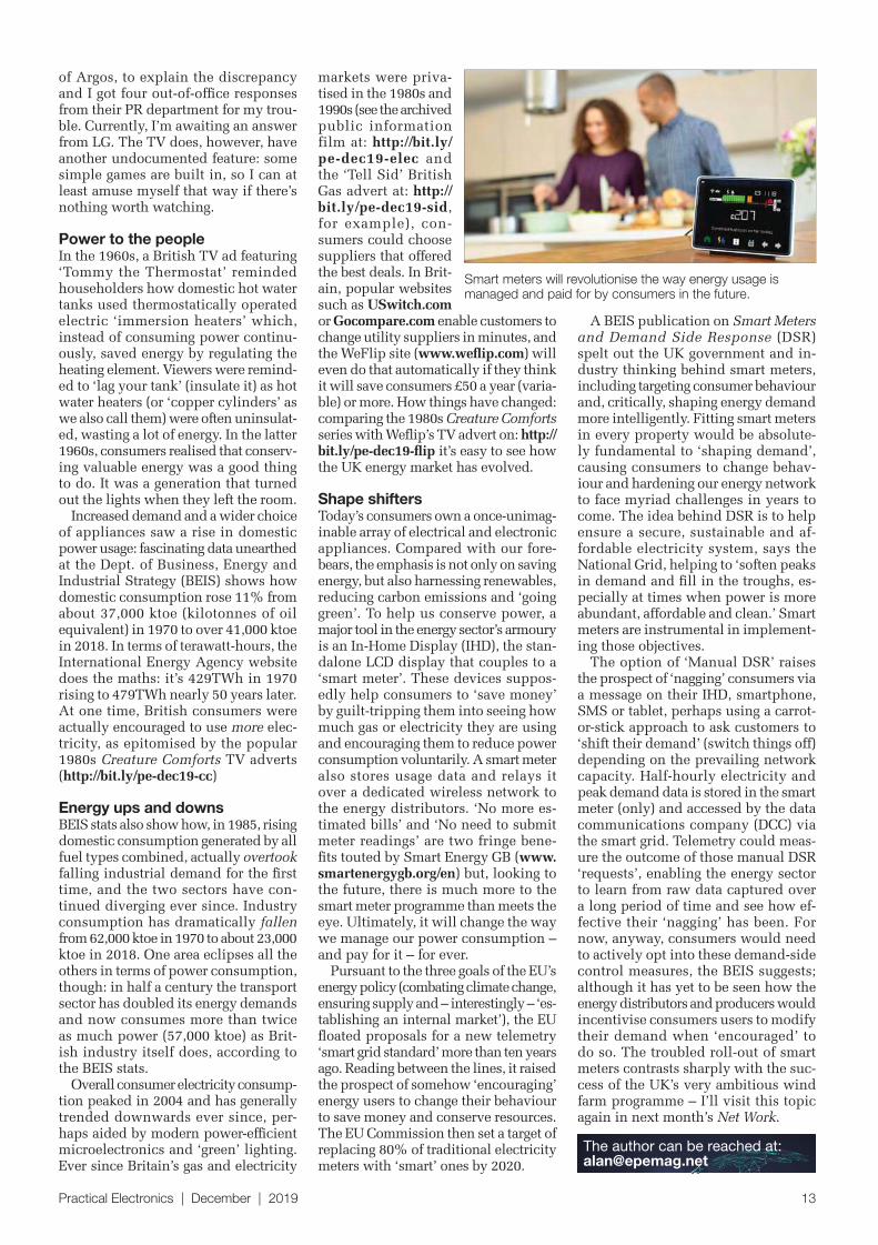
Shape shiftersToday’s consumers own a once-unimag-inable array of electrical and electronic appliances. Compared with our fore-bears, the emphasis is not only on saving energy, but also harnessing renewables, reducing carbon emissions and ‘going green’. To help us conserve power, a major tool in the energy sector’s armoury is an In-Home Display (IHD), the stan-dalone LCD display that couples to a ‘smart meter’. These devices suppos-edly help consumers to ‘save money’ by guilt-tripping them into seeing how much gas or electricity they are using and encouraging them to reduce power consumption voluntarily. A smart meter also stores usage data and relays it over a dedicated wireless network to the energy distributors. ‘No more es-timated bills’ and ‘No need to submit meter readings’ are two fringe bene-fits touted by Smart Energy GB (www.smartenergygb.org/en) but, looking to the future, there is much more to the smart meter programme than meets the eye. Ultimately, it will change the way we manage our power consumption – and pay for it – for ever.
Pursuant to the three goals of the EU’s energy policy (combating climate change, ensuring supply and – interestingly – ‘es-tablishing an internal market’), the EU floated proposals for a new telemetry ‘smart grid standard’ more than ten years ago. Reading between the lines, it raised the prospect of somehow ‘encouraging’ energy users to change their behaviour to save money and conserve resources. The EU Commission then set a target of replacing 80% of traditional electricity meters with ‘smart’ ones by 2020.
A BEIS publication on Smart Meters and Demand Side Response (DSR) spelt out the UK government and in-dustry thinking behind smart meters, including targeting consumer behaviour and, critically, shaping energy demand more intelligently. Fitting smart meters in every property would be absolute-ly fundamental to ‘shaping demand’, causing consumers to change behav-iour and hardening our energy network to face myriad challenges in years to come. The idea behind DSR is to help ensure a secure, sustainable and af-fordable electricity system, says the National Grid, helping to ‘soften peaks in demand and fill in the troughs, es-pecially at times when power is more abundant, affordable and clean.’ Smart meters are instrumental in implement-ing those objectives.
The option of ‘Manual DSR’ raises the prospect of ‘nagging’ consumers via a message on their IHD, smartphone, SMS or tablet, perhaps using a carrot-or-stick approach to ask customers to ‘shift their demand’ (switch things off) depending on the prevailing network capacity. Half-hourly electricity and peak demand data is stored in the smart meter (only) and accessed by the data communications company (DCC) via the smart grid. Telemetry could meas-ure the outcome of those manual DSR ‘requests’, enabling the energy sector to learn from raw data captured over a long period of time and see how ef-fective their ‘nagging’ has been. For now, anyway, consumers would need to actively opt into these demand-side control measures, the BEIS suggests; although it has yet to be seen how the energy distributors and producers would incentivise consumers users to modify their demand when ‘encouraged’ to do so. The troubled roll-out of smart meters contrasts sharply with the suc-cess of the UK’s very ambitious wind farm programme – I’ll visit this topic again in next month’s Net Work.
Smart meters will revolutionise the way energy usage is managed and paid for by consumers in the future.
14 Practical Electronics | December | 2019
This design is a major revision of an earlier detector which was published more than a decade
ago (Elektor, May 2007). That was described as an ‘incredibly sensitive’ design... but this one is significantly more sensitive!
Three significant improvements have been made compared to that design:n A second channel has been added,
to cancel out spurious signalsn It has three-times the number of
amplification stagesn It adds a relay switch, where the ear-
lier design only had a LED readout.
The advantage of two channels is that magnetic pulses picked up by two channels will cancel each other out, while those detected by only one channel – or predominantly one chan-nel – will trigger the relay.
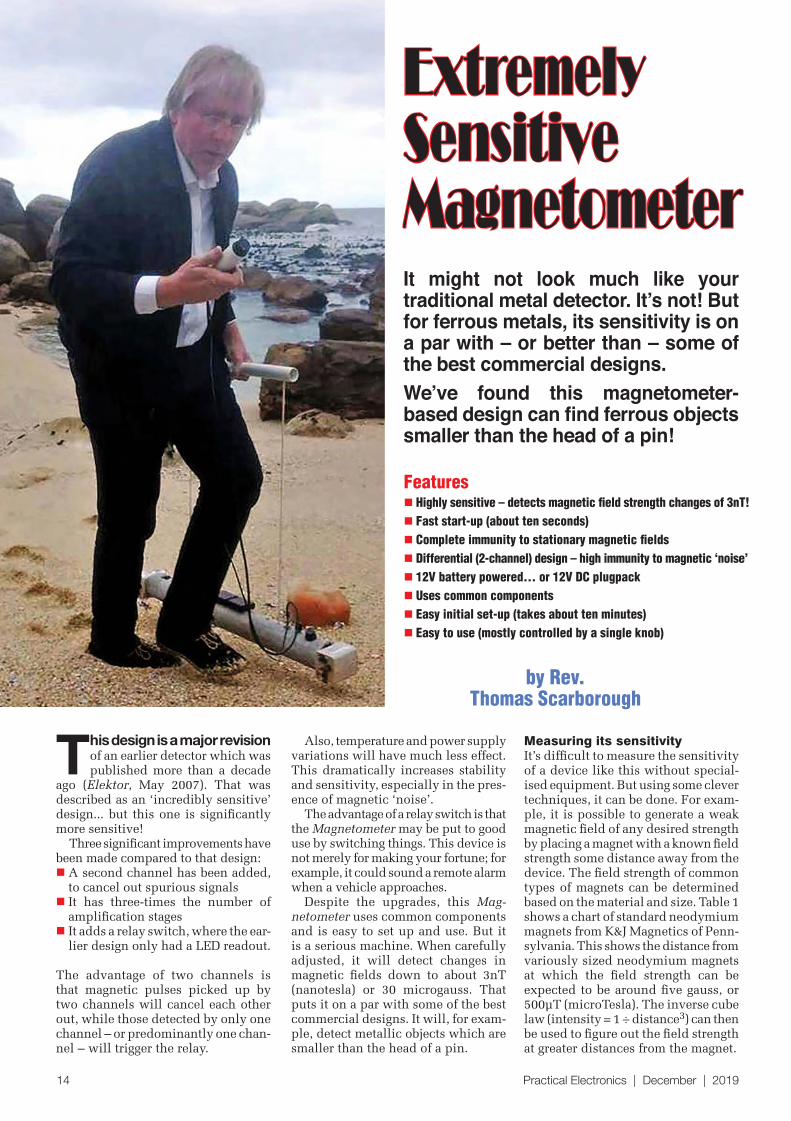
by Rev. Thomas Scarborough
It might not look much like your traditional metal detector. It’s not! But for ferrous metals, its sensitivity is on a par with – or better than – some of the best commercial designs.We’ve found this magnetometer-based design can ind ferrous objects smaller than the head of a pin!
Features n Highly sensitive – detects magnetic field strength changes of 3nT!
n Fast start-up (about ten seconds)
n Complete immunity to stationary magnetic fields
n Differential (2-channel) design – high immunity to magnetic ‘noise’
n 12V battery powered... or 12V DC plugpack
n Uses common components
n Easy initial set-up (takes about ten minutes)
n Easy to use (mostly controlled by a single knob)
ExtremelySensitiveMagnetometer
Also, temperature and power supply variations will have much less effect. This dramatically increases stability and sensitivity, especially in the pres-ence of magnetic ‘noise’.
The advantage of a relay switch is that the Magnetometer may be put to good use by switching things. This device is not merely for making your fortune; for example, it could sound a remote alarm when a vehicle approaches.
Despite the upgrades, this Mag-netometer uses common components and is easy to set up and use. But it is a serious machine. When carefully adjusted, it will detect changes in magnetic fields down to about 3nT (nanotesla) or 30 microgauss. That puts it on a par with some of the best commercial designs. It will, for exam-ple, detect metallic objects which are smaller than the head of a pin.
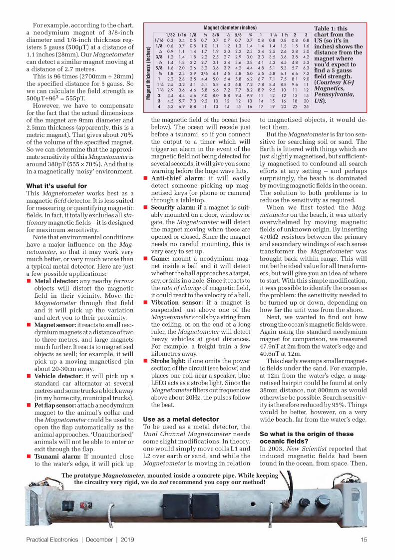
Measuring its sensitivityIt’s difficult to measure the sensitivity of a device like this without special-ised equipment. But using some clever techniques, it can be done. For exam-ple, it is possible to generate a weak magnetic field of any desired strength by placing a magnet with a known field strength some distance away from the device. The field strength of common types of magnets can be determined based on the material and size. Table 1 shows a chart of standard neodymium magnets from K&J Magnetics of Penn-sylvania. This shows the distance from variously sized neodymium magnets at which the field strength can be expected to be around five gauss, or 500µT (microTesla). The inverse cube law (intensity = 1 ÷ distance3) can then be used to figure out the field strength at greater distances from the magnet.
Practical Electronics | December | 2019 15
the magnetic field of the ocean (see below). The ocean will recede just before a tsunami, so if you connect the output to a timer which will trigger an alarm in the event of the magnetic field not being detected for several seconds, it will give you some warning before the huge wave hits.
n Anti-thief alarm: it will easily detect someone picking up mag-netised keys (or phone or camera) through a tabletop.
n Security alarm: if a magnet is suit-ably mounted on a door, window or gate, the Magnetometer will detect the magnet moving when these are opened or closed. Since the magnet needs no careful mounting, this is very easy to set up.
n Game: mount a neodymium mag-net inside a ball and it will detect whether the ball approaches a target, say, or falls in a hole. Since it reacts to the rate of change of magnetic field, it could react to the velocity of a ball.
n Vibration sensor: if a magnet is suspended just above one of the Magnetometer’s coils by a string from the ceiling, or on the end of a long ruler, the Magnetometer will detect heavy vehicles at great distances. For example, a freight train a few kilometres away.
n Strobe light: if one omits the power section of the circuit (see below) and places one coil near a speaker, blue LED3 acts as a strobe light. Since the Magnetometer filters out frequencies above about 20Hz, the pulses follow the beat.
Use as a metal detectorTo be used as a metal detector, the Dual Channel Magnetometer needs some slight modifications. In theory, one would simply move coils L1 and L2 over earth or sand, and while the Magnetometer is moving in relation
to magnetised objects, it would de-tect them.
But the Magnetometer is far too sen-sitive for searching soil or sand. The Earth is littered with things which are just slightly magnetised, but sufficient-ly magnetised to confound all search efforts at any setting – and perhaps surprisingly, the beach is dominated by moving magnetic fields in the ocean. The solution to both problems is to reduce the sensitivity as required.
When we first tested the Mag-netometer on the beach, it was utterly overwhelmed by moving magnetic fields of unknown origin. By inserting 470k resistors between the primary and secondary windings of each sense transformer the Magnetometer was brought back within range. This will not be the ideal value for all transform-ers, but will give you an idea of where to start. With this simple modification, it was possible to identify the ocean as the problem: the sensitivity needed to be turned up or down, depending on how far the unit was from the shore.
Next, we wanted to find out how strong the ocean’s magnetic fields were. Again using the standard neodymium magnet for comparison, we measured 47.9nT at 2m from the water’s edge and 40.6nT at 12m.
This clearly swamps smaller magnet-ic fields under the sand. For example, at 12m from the water’s edge, a mag-netised hairpin could be found at only 38mm distance, not 800mm as would otherwise be possible. Search sensitiv-ity is therefore reduced by 95%. Things would be better, however, on a very wide beach, far from the water’s edge.
So what is the origin of these oceanic fields? In 2003, New Scientist reported that induced magnetic fields had been found in the ocean, from space. Then,
Table 1: this chart from the US (so it’s in inches) shows the distance from the magnet where you’d expect to find a 5 gauss field strength. (Courtesy K&J Magnetics, Pennsylvania, US).
Magnet diameter (inches)
Magnet
thic
kness
(in
ches)
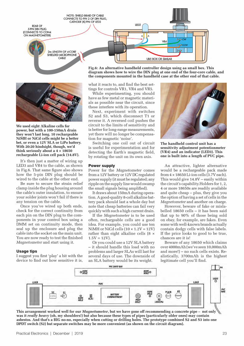
The prototype Magnetometer, mounted inside a concrete pipe. While keepingthe circuitry very rigid, we do not recommend you copy our method!
For example, according to the chart, a neodymium magnet of 3/8-inch diameter and 1/8-inch thickness reg-isters 5 gauss (500µT) at a distance of 1.1 inches (28mm). Our Magnetometer can detect a similar magnet moving at a distance of 2.7 metres.
This is 96 times (2700mm ÷ 28mm) the specified distance for 5 gauss. So we can calculate the field strength as 500µT÷963 = 555pT.
However, we have to compensate for the fact that the actual dimensions of the magnet are 9mm diameter and 2.5mm thickness (apparently, this is a metric magnet). That gives about 70% of the volume of the specified magnet.So we can determine that the approxi-mate sensitivity of this Magnetometer is around 380pT (555 × 70%). And that is in a magnetically ‘noisy’ environment.
What it’s useful forThis Magnetometer works best as a magnetic field detector. It is less suited for measuring or quantifying magnetic fields. In fact, it totally excludes all sta-tionary magnetic fields – it is designed for maximum sensitivity.
Note that environmental conditions have a major influence on the Mag-netometer, so that it may work very much better, or very much worse than a typical metal detector. Here are just a few possible applications:n Metal detector: any nearby ferrous
objects will distort the magnetic field in their vicinity. Move the Magnetometer through that field and it will pick up the variation and alert you to their proximity.
n Magnet sensor: it reacts to small neo-dymium magnets at a distance of two to three metres, and large magnets much further. It reacts to magnetised objects as well; for example, it will pick up a moving magnetised pin about 20-30cm away.
n Vehicle detector: it will pick up a standard car alternator at several metres and some trucks a block away (in my home city, municipal trucks).
n Pet flap sensor: attach a neodymium magnet to the animal’s collar and the Magnetometer could be used to open the flap automatically as the animal approaches. ‘Unauthorised’ animals will not be able to enter or exit through the flap.
n Tsunami alarm: If mounted close to the water’s edge, it will pick up
16 Practical Electronics | December | 2019
on 11 April 2018, the European Space Administration revealed that changing magnetic fields in the ocean measured 2.0-2.5nT at satellite altitude and provided a video of their activity on a planetary scale (see Fig.2).
This article may be the first publi-cation of provisional results on the ground and suggests that various fur-ther experiments may be worthwhile.
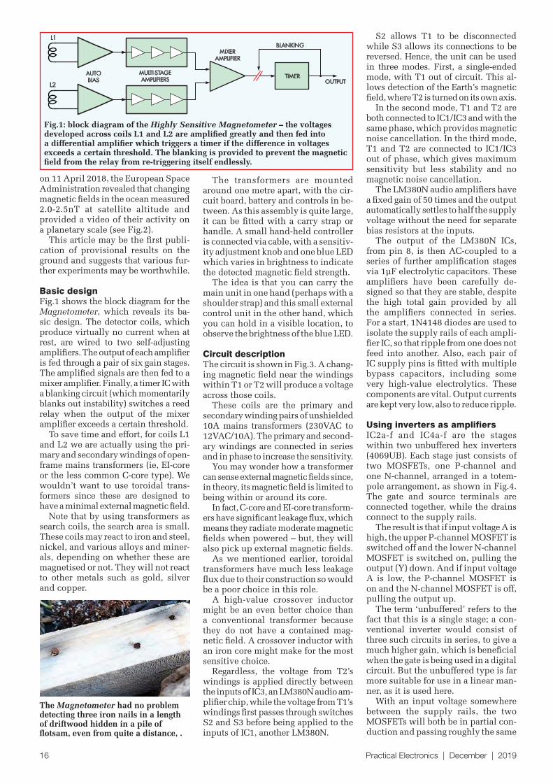
Basic designFig.1 shows the block diagram for the Magnetometer, which reveals its ba-sic design. The detector coils, which produce virtually no current when at rest, are wired to two self-adjusting amplifiers. The output of each amplifier is fed through a pair of six gain stages. The amplified signals are then fed to a mixer amplifier. Finally, a timer IC with a blanking circuit (which momentarily blanks out instability) switches a reed relay when the output of the mixer amplifier exceeds a certain threshold.
To save time and effort, for coils L1 and L2 we are actually using the pri-mary and secondary windings of open-frame mains transformers (ie, EI-core or the less common C-core type). We wouldn’t want to use toroidal trans-formers since these are designed to have a minimal external magnetic field.
Note that by using transformers as search coils, the search area is small. These coils may react to iron and steel, nickel, and various alloys and miner-als, depending on whether these are magnetised or not. They will not react to other metals such as gold, silver and copper.
The transformers are mounted around one metre apart, with the cir-cuit board, battery and controls in be-tween. As this assembly is quite large, it can be fitted with a carry strap or handle. A small hand-held controller is connected via cable, with a sensitiv-ity adjustment knob and one blue LED which varies in brightness to indicate the detected magnetic field strength.
The idea is that you can carry the main unit in one hand (perhaps with a shoulder strap) and this small external control unit in the other hand, which you can hold in a visible location, to observe the brightness of the blue LED.
Circuit descriptionThe circuit is shown in Fig.3. A chang-ing magnetic field near the windings within T1 or T2 will produce a voltage across those coils.
These coils are the primary and secondary winding pairs of unshielded 10A mains transformers (230VAC to 12VAC/10A). The primary and second-ary windings are connected in series and in phase to increase the sensitivity.
You may wonder how a transformer can sense external magnetic fields since, in theory, its magnetic field is limited to being within or around its core.
In fact, C-core and EI-core transform-ers have significant leakage flux, which means they radiate moderate magnetic fields when powered – but, they will also pick up external magnetic fields.
As we mentioned earlier, toroidal transformers have much less leakage flux due to their construction so would be a poor choice in this role.
A high-value crossover inductor might be an even better choice than a conventional transformer because they do not have a contained mag-netic field. A crossover inductor with an iron core might make for the most sensitive choice.
Regardless, the voltage from T2’s windings is applied directly between the inputs of IC3, an LM380N audio am-plifier chip, while the voltage from T1’s windings first passes through switches S2 and S3 before being applied to the inputs of IC1, another LM380N.
S2 allows T1 to be disconnected while S3 allows its connections to be reversed. Hence, the unit can be used in three modes. First, a single-ended mode, with T1 out of circuit. This al-lows detection of the Earth’s magnetic field, where T2 is turned on its own axis.
In the second mode, T1 and T2 are both connected to IC1/IC3 and with the same phase, which provides magnetic noise cancellation. In the third mode, T1 and T2 are connected to IC1/IC3 out of phase, which gives maximum sensitivity but less stability and no magnetic noise cancellation.
The LM380N audio amplifiers have a fixed gain of 50 times and the output automatically settles to half the supply voltage without the need for separate bias resistors at the inputs.
The output of the LM380N ICs, from pin 8, is then AC-coupled to a series of further amplification stages via 1µF electrolytic capacitors. These amplifiers have been carefully de-signed so that they are stable, despite the high total gain provided by all the amplifiers connected in series. For a start, 1N4148 diodes are used to isolate the supply rails of each ampli-fier IC, so that ripple from one does not feed into another. Also, each pair of IC supply pins is fitted with multiple bypass capacitors, including some very high-value electrolytics. These components are vital. Output currents are kept very low, also to reduce ripple.
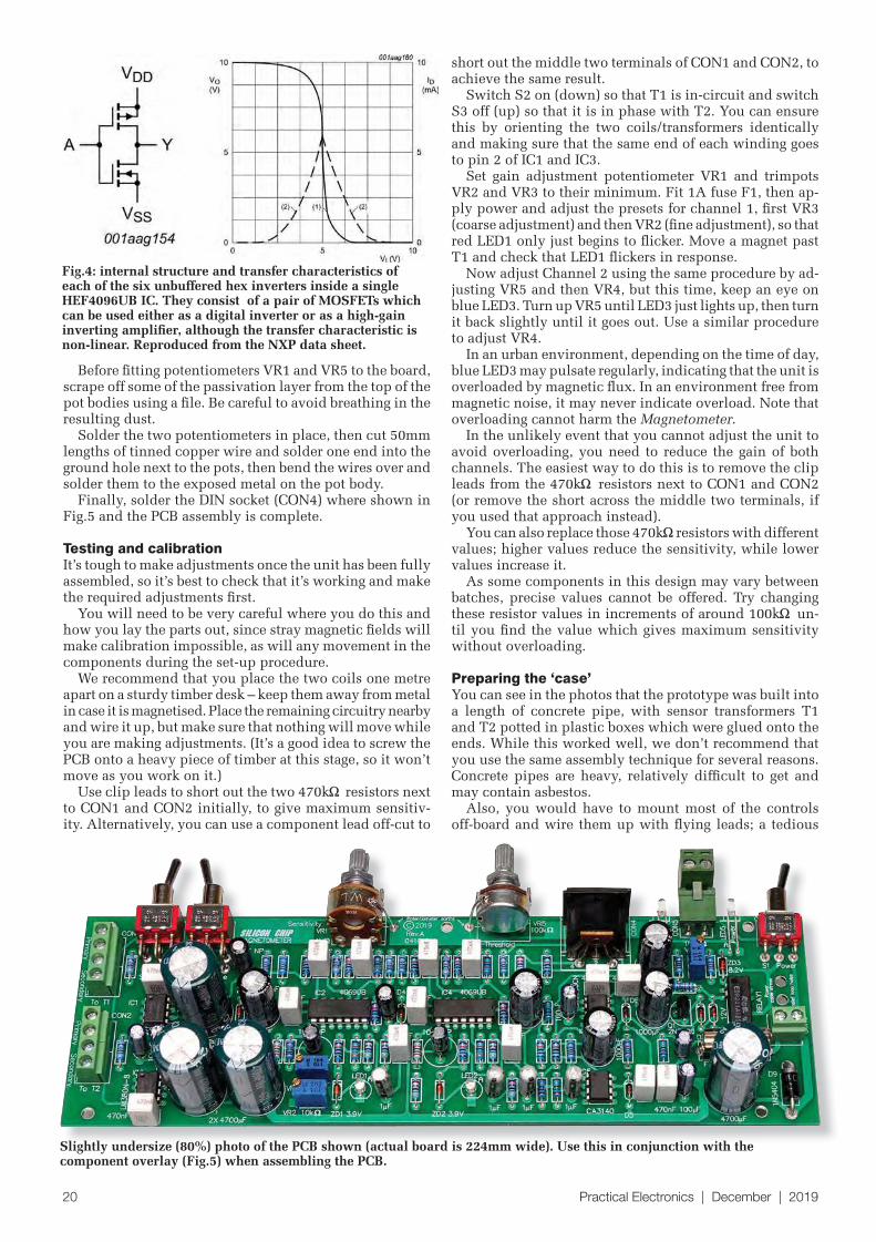
Using inverters as amplifiersIC2a-f and IC4a-f are the stages within two unbuffered hex inverters (4069UB). Each stage just consists of two MOSFETs, one P-channel and one N-channel, arranged in a totem-pole arrangement, as shown in Fig.4. The gate and source terminals are connected together, while the drains connect to the supply rails.
The result is that if input voltage A is high, the upper P-channel MOSFET is switched off and the lower N-channel MOSFET is switched on, pulling the output (Y) down. And if input voltage A is low, the P-channel MOSFET is on and the N-channel MOSFET is off, pulling the output up.
The term ‘unbuffered’ refers to the fact that this is a single stage; a con-ventional inverter would consist of three such circuits in series, to give a much higher gain, which is beneficial when the gate is being used in a digital circuit. But the unbuffered type is far more suitable for use in a linear man-ner, as it is used here.
With an input voltage somewhere between the supply rails, the two MOSFETs will both be in partial con-duction and passing roughly the same
L2
L1
TIMER
MIXER
AMPLIFIER
OUTPUT
BLANKING
MULTI-STAGE
AMPLIFIERS
AUTO
BIAS
20 81
SC
Fig.1: block diagram of the Highly Sensitive Magnetometer – the voltages developed across coils L1 and L2 are amplified greatly and then fed into a differential amplifier which triggers a timer if the difference in voltages exceeds a certain threshold. The blanking is provided to prevent the magnetic field from the relay from re-triggering itself endlessly.
The Magnetometer had no problem detecting three iron nails in a length of driftwood hidden in a pile of flotsam, even from quite a distance, .
Practical Electronics | December | 2019 17
current, so the output voltage will also be between the supply rails. Therefore, by applying negative feedback from the output to the input via a resistive divider, we can use these unbuffered inverters as crude amplifiers with relatively high gain.
The transfer characteristic of each stage is shown in Fig.4 (from the de-vice data sheet). As you can see, the response is non-linear but the gain is quite high when the input voltage is very close to half supply. Using the in-verter in closed-loop mode will mean that in the quiescent condition, the open-loop gain is at maximum and the response will be slightly more linear.
The first inverter-based gain stage, built around IC2c/IC4c, has adjustable gain via dual gang potentiometer VR1, which changes the feedback resist-ance. The other part of the divider is actually formed by the impedance of the 1µF coupling capacitor, along with the output impedance of ampli-fier IC1/IC3.
Therefore, this first stage has very high gain with VR1 fully clock-wise, with the gain somewhat fre-quency dependent due to the re-actance of the coupling capacitor. The next three stages have lower, fixed gains of 4.7, 3.3 and 2.2 respectively. They also incorporate low-pass RC filters with a –3dB point of around 3.3Hz each, giving an overall –3dB point of about 1.6Hz.
The signals are then AC-coupled by 10µF electrolytic capacitors and subject to adjustable DC bias, set using trimpots VR2-VR5. The following gain stages, IC2e and IC4e, are operated in open-loop mode. The adjustable DC bias allows the gain and quiescent output voltage of these stages to be tweaked.
The resu l t ing signal then passes through another low-pass RC filter (47k/1µF), again with a –3dB point of around 3.3Hz. The output voltage of IC2e/IC4e is also fed to a 100kresistor, with a 3.9V zener diode and red LED in series. This LED will therefore light if the output volt-age in that half of the circuit is above around 6V (ie, above half supply).
The signal then passes through an-other gain stage (number seven, if you’re counting),
built around IC2f/IC4f, with a fixed gain of 7, before being fed to the in-verting and non-inverting inputs of op amp IC5 via another pair of RC low-pass filters, with the same 3.3Hz –3dB point.
The overall filtering thus far has the effect of severely attenuating or even cutting out signals above about 1Hz. This virtually eliminates false triggering from 50Hz or 60Hz mag-netic fields induced by mains currents, which are pervasive in urban areas. IC5 is configured as a differential am-plifier with a gain of 21.
This means that if the two input signals swing in the same direction simultaneously, the output of IC5 will not change. But if they swing in opposite directions, or if one stays constant and the other changes, a sig-nal will appear at its output, with the difference in voltages amplified by the gain factor of 21.
It’s hard to calculate the exact amount of gain applied to the signals from T1 and T2, partly because it var-ies depending on the potentiometer settings and frequency, and partly because we don’t know the exact gain of the stages operating in open-loop mode. However, if we assume that the open-loop gain of the inverters is around 20 and that the gain of IC2a/IC4a is set to around 10, then the over-all gain applied to the signals from T1/T2 is in the order of 25 × 106 (= 50 × 10 × 4.7 × 3.3 × 2.2 × 10 × 7 × 21). No wonder this instrument is capable of such sensitivity!
Note that there are several differ-ent compatible chips for IC2 and IC4, but you should stick to the specified HCF4069UBE type since these provide the most gain.
Triggering the timerWhen a sufficiently large magnetic sig-nal is detected, resulting in a swing of several volts at the output of differential amplifier IC5, that pulse then triggers timer IC6. Its job is to stretch that (pos-sibly very short) pulse into something longer that you will notice, as it lights up LED3, and also to drive the coil of RLY1, to trigger any external circuitry which may be connected via CON5.
CMOS timer IC6 is triggered when its pin 2 trigger input is pulled below 1/3 VCC, which in this case equates to a threshold of around 3.7V. Note that this means that the timer will only be triggered if the output of IC5 swings low.
But if the output of IC5 swings high due to a magnetic field of the opposite polarity, it will almost certainly swing positive and negative a few times be-fore settling down, so timer IC6 will be triggered regardless of the initial polarity of the pulse.
Before pin 2 goes low, the 1000µF capacitor connected between pins 6/7 and ground is charged up close to +12V, via trimpot VR6 and its 1kseries resistor. Once the IC is trig-gered, pin 6 (discharge) immediately goes low, discharging that capacitor.
At the same time, the pin 3 output goes high, energising the coil of RLY1 and closing its contacts.
Since VR6 changes the time that it takes for the 1000µF capacitor to recharge once the discharge pin is no longer being actively driven, it controls the on-time for both RLY1 and LED4. The minimum time will be around one second while the maxi-mum time is around 90s.
The two resistors and capacitor con-nected to its reset pin (pin 4) prevent the output from switching on when power is first applied, allowing the Magnetometer time to settle before IC6 becomes active, avoiding false triggering of RLY1.
Once the timer is triggered, since output pin 3 goes high, the gate of MOSFET Q1 is charged up close to VCC. This causes Q1’s drain-source channel to conduct, pulling up the trigger input (pin 3), regardless of the state of the output pin of op amp IC5.
The 100k series resistor from that output pin prevents the op amp from ‘fighting’ this condition. This means that IC6 cannot be re-triggered for some time. The 10µF capacitor and 1M resistor from the gate of Q1 to ground sets this blanking time to around 10s.
This is important since the magnetic field around RLY1’s coil will be picked up by the Magnetometer as soon as it is triggered and without the blanking,
Fig.2: satellite-based measurements showing the magnitude and polarity of the magnetic fields generated by the Earth’s oceans. These fields are small, but this Magnetometer can easily pick them up when you are near the ocean. In fact, you need to reduce the device’s sensitivity when looking for metal objects on the beach because of this!
18 Practical Electronics | December | 2019
RLY1 would continuously switch on and off as the unit re-triggers itself via magnetic feedback.
Variations
For use as a metal detector, you may wish to omit or remove all components following IC5 in the circuit. LED3 will still light to indicate changing magnetic fields.
LED3 may also be directly replaced with a 1mA meter, bearing in mind that the magnet inside the meter should not come close to a sensor coil.
Note that if the relay is not omitted, the blanking circuit will be disruptive when searching.
Construction
The PCB for this project is coded 04101011, measures 70 × 224mm and is available from the PE PCB Service.
Use the PCB overlay diagram, Fig.5, and matching photo as a guide during assembly. Start by fitting the resistors where shown on the overlay diagram. Even though we show their colour codes in a table, it’s a good idea to double-check their resistance with a DMM before installing them, since the coloured bands can often be hard to read accurately.
Follow with the diodes. There are two types, eight signal diodes (D1-D8), one larger power diode (D9) and three
zener diodes (ZD1-ZD3) of two dif-ferent types, so don’t get them mixed up. Each one must be oriented with the cathode stripe as shown in Fig.5.
The six ICs should be installed next. You can either solder them directly to the board or solder sockets to the board, then plug the ICs in later. Sockets make it easier to replace a damaged IC but they also are prone to long-term failure due to oxidisation, so we prefer to avoid them.
The ICs are also polarised, so en-sure that each pin 1 dot is positioned as shown on the overlay diagram. Be especially careful with IC2 and IC4 – they are extremely sensitive to static discharge.
A
A
A
A
A
A
A
A
K
K
K
K
K
K
K
K
1
1
2
2
2
2
3
3
3
3
4
4
4
4
5
5
5
5
6
6
6
6
7
7
7
7
8
8
9
9
10
10
11
11
12
12
13
13
14
14
PRIMARY
PRIMARY
SECONDARY
SECONDARY
T112V/10A
T212V/10A
CON1
CON2
LIN
KLI
NK
470k
470k
S2a
S2b
S3a
S3b
REVERSE
CONNECT
470nF
470nF
470nF
470nF
470nF
470nF
470nF
470nF
100 F
100 F
100 F
100 F
4700 F
4700 F
4700 F
4700 F
1000 F
1000 F
1 F
1 F
1 F
1 F
NP
NP
NP
NP
IC1: LM380N-8
IC3: LM380N-8
IC1IC1
IC3IC3
10k
10k
10k
10k
10k
10k
VR1a 1M
VR1b 1M
IC2c
IC4c
100k
100k
100k
100k
100k
100k
100k
100k
470k
470k
330k
330k
330k
330k
470nF
470nF
470nF
470nF
IC2b
IC4b
IC2a
IC4a
IC2: 4069UB
IC4: 4069UB
IC2: 4069UB
IC4: 4069UB
D1 1N4148
D3 1N4148
D2 1N4148
D4 1N4148
+12V SWITCHED
+12V SWITCHED
+12V SWITCHED
+12V SWITCHED
47k
47k
47k
47k
LED1
LED2
DETECT
DETECT
ZD1 3.9V
ZD2 3.9V
IC2f
IC4f
IC2e
IC4e
IC2d
IC4d
220k
220k
47k
47k
10 F
10 F
VR210k
VR410k
10T
THRESHOLD
THRESHOLD
VR3100k
VR5100k
CENTRE
CENTRE
1
2
3
45
1
2
3
45
CON4
CON6
DIN SOCKET
DIN PLUG
DUAL CHANNEL MAGNETOMETER
A
K
LED3
HANDHELD CONTROL BOX
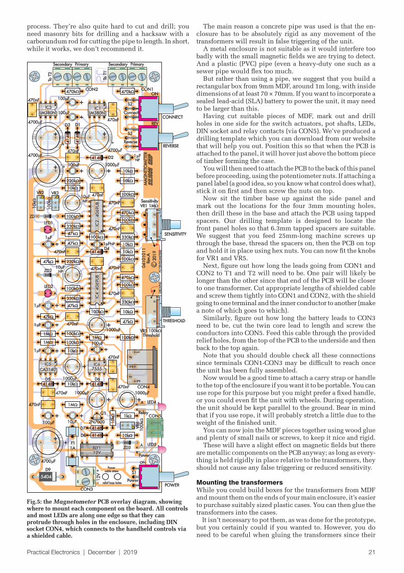
Practical Electronics | December | 2019 19
That is why there are 10kresistors at pins 5 and 6 of IC2c/IC4c and at pin 11 of IC2e/IC4e. These points connect to potentiometers which you touch during operation, and any static discharge which jumps to those pots could destroy the ICs without the se-ries resistors for protection.
Now is also a good time to solder the reed relay, RLY1. It’s in an IC-type package and again, it is polarised. Make sure its pin 1 is oriented as shown in Fig.5.
Next, fit the MKT or ceramic ca-pacitors (whichever you have chosen to use). These are not polarised, so you don’t need to worry about the orientation. Follow with MOSFET Q1 and trimpots VR2, VR3 and VR6. Make sure the trimpots are fitted with the adjustment screw in the locations shown on Fig.5.
Solder LED1 and LED2 in place, pushed down fully onto the PCB, with the longer anode leads through the holes marked ‘A’ on the board.
Follow with the electrolytic ca-pacitors, starting with the smallest and working your way up to the tallest. These must all be oriented correctly, with the longer positive leads soldered to the side marked ‘+’. The stripe on the can indicates the negative side. Don’t get the different values mixed up; the PCB overlay diagram shows where each one goes.
Now dovetail two pairs of 2-way terminal blocks together to form two 4-way terminal blocks and fit these to the top of the board, with the wire entry holes facing towards the edge of the board. Check they are pushed entirely down before soldering them in place.
Also fit the fifth 2-way terminal block at the bottom of the board, with its wire entry holes facing towards the two large holes in the PCB.
Having done that, you can also fit the socket for the pluggable terminal block (CON5) where shown in Fig.5. Then solder the fuse holder clips for F1, ensuring that the fuse-retaining tabs go towards the outside and that the clips are pushed down flat onto the PCB before soldering.
Next, fit PCB-mounting switches S1-S3, again pushing them down as far as they will go before soldering the leads. Now bend the leads of LED4 and LED5 by 90°, 8mm from the base of the lens, ensuring that the longer anode lead (‘A’) is oriented as shown in Fig.5, then solder them to the PCB with the lens at the same height above the board to the actuators for switches S1-S3.
1
2
34
5
6
7
1 F
1 F
GS
D
A
A A
K
K
K
IC67555IC6
7555
8 4
3
5
1
7
6
2
CON3F1 1A+12V
0VD9
1N5404
S1 POWER
10k
ZD38.2V1W
LED5POWER
470nF
470nF470nF 1000 F1000 F
100k
100k
100k
1M1M 1M
1M
A
AA
A
A
K
K
K
K
K
D61N4148
D51N4148
10k
10k10k
D81N4148
LED4100 F
CON5RLY1
1000 F10 F
D71N4148
VR6100k
1k
Q12N7000
PERIOD
IC5CA3140E
IC5CA3140E
RELAY
K
A
1N4148
2N7000
SGD
ZD1–ZD3
K
A
LEDS
A
K
1N5404
K
A
2
6
7,8
1,14
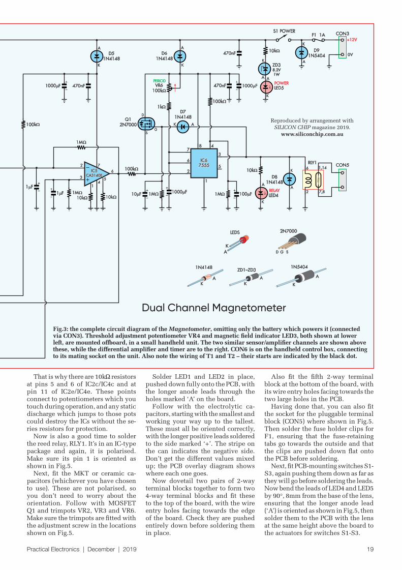
Fig.3: the complete circuit diagram of the Magnetometer, omitting only the battery which powers it (connected via CON3). Threshold adjustment potentiometer VR4 and magnetic field indicator LED3, both shown at lower left, are mounted offboard, in a small handheld unit. The two similar sensor/amplifier channels are shown above these, while the differential amplifier and timer are to the right. CON6 is on the handheld control box, connecting to its mating socket on the unit. Also note the wiring of T1 and T2 – their starts are indicated by the black dot.
Dual Channel Magnetometer
Reproduced by arrangement with
SILICON CHIP magazine 2019.
www.siliconchip.com.au
20 Practical Electronics | December | 2019
Before fi tting potentiometers VR1 and VR5 to the board, scrape off some of the passivation layer from the top of the pot bodies using a fi le. Be careful to avoid breathing in the resulting dust.
Solder the two potentiometers in place, then cut 50mm lengths of tinned copper wire and solder one end into the ground hole next to the pots, then bend the wires over and solder them to the exposed metal on the pot body.
Finally, solder the DIN socket (CON4) where shown in Fig.5 and the PCB assembly is complete.
Testing and calibrationIt’s tough to make adjustments once the unit has been fully assembled, so it’s best to check that it’s working and make the required adjustments fi rst.
You will need to be very careful where you do this and how you lay the parts out, since stray magnetic fi elds will make calibration impossible, as will any movement in the components during the set-up procedure.
We recommend that you place the two coils one metre apart on a sturdy timber desk – keep them away from metal in case it is magnetised. Place the remaining circuitry nearby and wire it up, but make sure that nothing will move while you are making adjustments. (It’s a good idea to screw the PCB onto a heavy piece of timber at this stage, so it won’t move as you work on it.)
Use clip leads to short out the two 470k resistors next to CON1 and CON2 initially, to give maximum sensitiv-ity. Alternatively, you can use a component lead off-cut to
short out the middle two terminals of CON1 and CON2, to achieve the same result.
Switch S2 on (down) so that T1 is in-circuit and switch S3 off (up) so that it is in phase with T2. You can ensure this by orienting the two coils/transformers identically and making sure that the same end of each winding goes to pin 2 of IC1 and IC3.
Set gain adjustment potentiometer VR1 and trimpots VR2 and VR3 to their minimum. Fit 1A fuse F1, then ap-ply power and adjust the presets for channel 1, fi rst VR3 (coarse adjustment) and then VR2 (fi ne adjustment), so that red LED1 only just begins to fl icker. Move a magnet past T1 and check that LED1 fl ickers in response.
Now adjust Channel 2 using the same procedure by ad-justing VR5 and then VR4, but this time, keep an eye on blue LED3. Turn up VR5 until LED3 just lights up, then turn it back slightly until it goes out. Use a similar procedure to adjust VR4.
In an urban environment, depending on the time of day, blue LED3 may pulsate regularly, indicating that the unit is overloaded by magnetic fl ux. In an environment free from magnetic noise, it may never indicate overload. Note that overloading cannot harm the Magnetometer.
In the unlikely event that you cannot adjust the unit to avoid overloading, you need to reduce the gain of both channels. The easiest way to do this is to remove the clip leads from the 470k resistors next to CON1 and CON2 (or remove the short across the middle two terminals, if you used that approach instead).
You can also replace those 470kresistors with different values; higher values reduce the sensitivity, while lower values increase it.
As some components in this design may vary between batches, precise values cannot be offered. Try changing these resistor values in increments of around 100k un-til you fi nd the value which gives maximum sensitivity without overloading.
Preparing the ‘case’You can see in the photos that the prototype was built into a length of concrete pipe, with sensor transformers T1 and T2 potted in plastic boxes which were glued onto the ends. While this worked well, we don’t recommend that you use the same assembly technique for several reasons. Concrete pipes are heavy, relatively diffi cult to get and may contain asbestos.
Also, you would have to mount most of the controls off-board and wire them up with fl ying leads; a tedious
Fig.4: internal structure and transfer characteristics of each of the six unbuffered hex inverters inside a single HEF4096UB IC. They consist of a pair of MOSFETs which can be used either as a digital inverter or as a high-gain inverting amplifi er, although the transfer characteristic is non-linear. Reproduced from the NXP data sheet.
Slightly undersize (80%) photo of the PCB shown (actual board is 224mm wide). Use this in conjunction with the component overlay (Fig.5) when assembling the PCB.
Practical Electronics | December | 2019 21
The main reason a concrete pipe was used is that the en-closure has to be absolutely rigid as any movement of the transformers will result in false triggering of the unit.
A metal enclosure is not suitable as it would interfere too badly with the small magnetic fields we are trying to detect. And a plastic (PVC) pipe (even a heavy-duty one such as a sewer pipe would flex too much.
But rather than using a pipe, we suggest that you build a rectangular box from 9mm MDF, around 1m long, with inside dimensions of at least 70 × 70mm. If you want to incorporate a sealed lead-acid (SLA) battery to power the unit, it may need to be larger than this.
Having cut suitable pieces of MDF, mark out and drill holes in one side for the switch actuators, pot shafts, LEDs, DIN socket and relay contacts (via CON5). We’ve produced a drilling template which you can download from our website that will help you out. Position this so that when the PCB is attached to the panel, it will hover just above the bottom piece of timber forming the case.
You will then need to attach the PCB to the back of this panel before proceeding, using the potentiometer nuts. If attaching a panel label (a good idea, so you know what control does what), stick it on first and then screw the nuts on top.
Now sit the timber base up against the side panel and mark out the locations for the four 3mm mounting holes, then drill these in the base and attach the PCB using tapped spacers. Our drilling template is designed to locate the front panel holes so that 6.3mm tapped spacers are suitable. We suggest that you feed 25mm-long machine screws up through the base, thread the spacers on, then the PCB on top and hold it in place using hex nuts. You can now fit the knobs for VR1 and VR5.
Next, figure out how long the leads going from CON1 and CON2 to T1 and T2 will need to be. One pair will likely be longer than the other since that end of the PCB will be closer to one transformer. Cut appropriate lengths of shielded cable and screw them tightly into CON1 and CON2, with the shield going to one terminal and the inner conductor to another (make a note of which goes to which).
Similarly, figure out how long the battery leads to CON3 need to be, cut the twin core lead to length and screw the conductors into CON5. Feed this cable through the provided relief holes, from the top of the PCB to the underside and then back to the top again.
Note that you should double check all these connections since terminals CON1-CON3 may be difficult to reach once the unit has been fully assembled.
Now would be a good time to attach a carry strap or handle to the top of the enclosure if you want it to be portable. You can use rope for this purpose but you might prefer a fixed handle, or you could even fit the unit with wheels. During operation, the unit should be kept parallel to the ground. Bear in mind that if you use rope, it will probably stretch a little due to the weight of the finished unit.
You can now join the MDF pieces together using wood glue and plenty of small nails or screws, to keep it nice and rigid.
These will have a slight effect on magnetic fields but there are metallic components on the PCB anyway; as long as every-thing is held rigidly in place relative to the transformers, they should not cause any false triggering or reduced sensitivity.
Mounting the transformersWhile you could build boxes for the transformers from MDF and mount them on the ends of your main enclosure, it’s easier to purchase suitably sized plastic cases. You can then glue the transformers into the cases.
It isn’t necessary to pot them, as was done for the prototype, but you certainly could if you wanted to. However, you do need to be careful when gluing the transformers since their
F1
LED4
LED5
D3 D1
VR5
LED1
ZD1
470nF
470nF
470k
470k
D4
D2
1000 F
1000 F
1000 F
1 F
1 F
VR1
CON2
S2
220k
100k
100k
10
0k
100k
100k
100k
100k
100k
100k
100k
100k
100k
100k
470k 470kCON1
CON4
S3
S1
100 F
100 F
100 F 10 F
1 F
100 F
100 F
470nF
470nF
470nF
470nF
470nF
470nF
470nF
470nF
470nF
470nF
470nF
470nF
4700 F
4700 F
4700 F
4700 F
10 FVR2 VR3
10 F
470nF
1 F
1 F
1 F
220k
330k330k
330k
330k
47k
47k
47k
47k
47k
47k
ZD2
LED2
D5 D6
1000 F 1000 F
D7
D8
Q1
1M
1M
1M
1M
1k
VR6
CON5
CON3
10k
10
k
10k
10k
10k
10k
10k
D9
ZD3
10k
10k
10
k
10k
GRO
UN
DO
TEN
TIO
MET
ERS
P
Power
relief loop holes
cable stress
NP
NP
04
10
10
11
Rev.
A
C
20
19
MA
GN
ETO
MET
ER
2N7000
Relay
Power
Power
10
0k
1A
12
V
_+
Reverse
Connect
Secondary
To T
2
To T
1
1M
Sensitivity
Threshold
ON
++ +
+
+
+ +
+ +
+
+
+ +
4455
1
2
3
5404
4148
4148
4148
41
48
41
48
4148
4148
4148
3V9
3V9
8V2
12V12VRLY1RLY1
IC6IC675557555
IC5IC5CA3140CA3140
NP
NP
40
69
UB
40
69
UB
IC4
IC4
40
69
UB
40
69
UB
IC2
IC2
IC3IC3LM380NLM380N
IC1IC1LM380NLM380N
S1S1
S1
ON
REV
A
A
A
A
Primary Secondary Primary
CONNECT
REVERSE
SENSITIVITY
THRESHOLD
POWER
Fig.5: the Magnetometer PCB overlay diagram, showing where to mount each component on the board. All controls and most LEDs are along one edge so that they can protrude through holes in the enclosure, including DIN socket CON4, which connects to the handheld controls via a shielded cable.
process. They’re also quite hard to cut and drill; you need masonry bits for drilling and a hacksaw with a carborundum rod for cutting the pipe to length. In short, while it works, we don’t recommend it.
22 Practical Electronics | December | 2019
windings should be perfectly aligned with one another, not a fraction of a millimetre out of place. This is easier than it sounds. A flat floor is all that is required, and a means of ensuring that the coils are perfectly parallel to one another (say, lining them up carefully with floorboards).
When mounted, the windings of the transformer should be horizontal, not vertical, like rings stacked on the ground. The lengths of the core’s laminations should be perpendicu-lar to the long axis of the enclosure. It may be helpful to keep wires to the transformer windings exposed and accessible, in case you need to change the wiring later.
Attach the transformer primary and secondary wires to the wiring that you ran earlier from CON1 and CON2, and if soldering them, use heat shrink tubing to insulate the joints.
You will also need to connect your battery/battery holder to the wires you ran earlier, insert it into the enclosure and glue it in place. We suggest you use silicone sealant to do this. Remember that you may have to replace the battery later.
You can then attach the transformer cases to the ends of the main enclosure. We don’t suggest you do this using silicone as it could flex, so use a good epoxy instead (eg, JB Weld). While you are waiting for that to cure, you can build the remote control box.
Remote control box
The remote control box contains sensitivity adjustment po-tentiometer VR4 and detection indicator LED3 and not much else. A small Jiffy box (eg, UB3) makes a suitable enclosure.
As you can see from the photos, these components were housed in a small section of PVC pipe for the prototype; you could do the same.
Make holes to mount VR4 and LED3 and another sized to suit the microphone cable. Attach VR4 using its supplied nut and glue LED3 and the microphone cable in place us-ing clear neutral-cure silicone sealant.
(eg, RS 504-127)1 small enclosure for LED3 and VR41 12V battery (small SLA or eight D cells with battery holder)Various lengths and colours of hookup wireHeatshrink tubing Epoxy glue
The RS transformers I used have dual secondary windings, but my design specifies a single winding, so the secondaries are wired in parallel. The circuit would work in series, but the circuit would behave differently, and this has not been tested.
You could use a different VA rating, ‘anything’ really, but other transformers will alter sensitivity and weight. For example, a 15VA transformer is good to detect, through a tabletop, that someone has moved keys or a mobile phone.
The prototype’s sensor transformers were potted to eliminate any possibility of moisture ingress; the connections were brought out to screw terminals.
Parts list – Extremely Sensitive Magnetometer
Transformer choice
Practical Electronics | December | 2019 23
It’s then just a matter of wiring up LED3 and VR4 to the cable, as shown in Fig.6. That same figure also shows how the 5-pin DIN plug should be wired to the cable at the other end.
Be sure to secure the strain relief clamp inside the plug housing around the cable’s outer insulation, to ensure your solder joints won’t fail if there is any tension on the cable.
Once you’ve wired up both ends, check for the correct continuity from each pin on the DIN plug to the com-ponents in your control box using a DMM set on continuity mode, then seal up the enclosure and plug the cable into the socket on the main unit. You are now ready to test the finished Magnetometer and start using it.
Usage tipsI suggest you first ‘play’ a bit with the device to find out how sensitive it is,
what it reacts to, and find the best set-tings for controls VR1, VR4 and VR5.
While experimenting, you should have as few metal or magnetic materi-als as possible near the circuit, since these interfere with its operation.
Next, experiment with switches S2 and S3, which disconnect T1 or reverse it. A reversed coil pushes the circuit to the limits of sensitivity and is better for long-range measurements, yet there will no longer be compensa-tion for magnetic ‘noise’.
Switching one coil out of circuit is useful for experimentation and for detecting the Earth’s magnetic field, by rotating the unit on its own axis.
Power supplyPower for the Magnetometer comes from a 12V battery or 12V DC regulated power supply (it must be regulated; any ripple on the supply line would swamp the small signals being amplified).
It draws about 150mA during opera-tion. A good-quality 8-cell alkaline bat-tery pack should last a whole day but note that cheap batteries can fail very quickly with such a high current drain.
If the Magnetometer is to be used often, rechargeable cells are a good idea. For example, you could use ten NiMH or NiCd cells (10 × 1.2V = 12V) rather than eight alkaline cells (8 × 1.5V = 12V).
Or you could use a 12V SLA battery – it should handle this load with no problems and larger SLAs will last for several days of use. The downside of an SLA battery would be its weight.
An attractive, lighter alternative would be a rechargeable pack made from 4 × 18650 Li-ion cells (3.7V each). This would give 14.8V – easily within the circuit’s capability.Holders for 1, 2, 4 or more 18650s are readily available and quite cheap – plus, they give you the option of having a set of cells in the Magnetometer and another on charge.
However, beware of fake or misla-belled 18650 cells – it has been said that up to 90% of those being sold on ebay, for example, are fakes. Even some with well-known brands actually contain dodgy cells with false labels. If the price looks to good to be true, chances are it is!
Beware of any 18650 which claims over 4000mAh (we’ve seen 10,000mAh and more!) – no such cells exists. Re-alistically, 3700mAh is the highest legitimate cell you’ll find.
We used eight Alkaline cells for power, but with a 100-150mA drain they won’t last long. 10 rechargeable NiMH or NiCd cells might be a better bet, or even a 12V SLA or LiPo battery. With 20:20 hindsight, though, we’d think seriously about a 4 × 18650 rechargeable Li-ion cell pack (14.8V).
11
22
33 CW
CCW
AK
LED3
VR4
REAR OF5-PIN DIN PLUG
(CONNECTS TO CON4ON MAGNETOMETER)
11
22
33
44 55
2m LENGTH OF 4-CORESHIELDED MICROPHONE
CABLE
20 81SC
NOTE: SHIELD BRAID OF CABLECONNECTS TO PIN 2 OF DIN PLUG,
CATHODE (K) PIN OF LED3
UB5 BOX OR SIMILAR
Fig.6: An alternative handheld controller design using aa small box. This diagram shows how to wire the DIN plug at one end of the four-core cable, and the components mounted in the handheld case at the other end of that cable.
This arrangement worked well for our Magnetometer, but we have gone off recommending a concrete pipe – not only was it really heavy (oh, my shoulders!) but also because these types of pipes (particularly older ones) may contain asbestos. And that’s a BIG no-no, especially when cutting or drilling holes. The prototype combined S2 and S3 into one DPDT switch (S2) but separate switches may be more convenient (as shown on the circuit diagram).
The handheld control unit has a sensitivity adjustment potentionmeter (VR4) and an indicator (LED3). This one is built into a length of PVC pipe.
VOL 1 BACK ISSUES – January 1999 to June 1999 Plus bonus material from Nov and Dec 1998
VOL 2 BACK ISSUES – July 1999 to December 1999
VOL 3 BACK ISSUES – January 2000 to June 2000
VOL 4 BACK ISSUES – July 2000 to December 2000
VOL 5 BACK ISSUES – January 2001 to June 2001
VOL 6 BACK ISSUES – July 2001 to December 2001
VOL 7 BACK ISSUES – January 2002 to June 2002
VOL 8 BACK ISSUES – July 2002 to December 2002
VOL 9 BACK ISSUES – January 2003 to June 2003
VOL 10 BACK ISSUES – July 2003 to December 2003
VOL 11 BACK ISSUES – January 2004 to June 2004
VOL 12 BACK ISSUES – July 2004 to December 2004
VOL 13 BACK ISSUES – January 2005 to June 2005
VOL 14 BACK ISSUES – July 2005 to December 2005
VOL 15 BACK ISSUES – January 2006 to June 2006
VOL 16 BACK ISSUES – July 2006 to December 2006
VOL 17 BACK ISSUES – January 2007 to June 2007
VOL 18 BACK ISSUES – July 2007 to December 2007
VOL 19 BACK ISSUES – January 2008 to June 2008
VOL 20 BACK ISSUES – July 2008 to December 2008
VOL 21 BACK ISSUES – January 2009 to June 2009
VOL 22 BACK ISSUES – July 2009 to December 2009
VOL 23 BACK ISSUES – January 2010 to June 2010
VOL 24 BACK ISSUES – July 2010 to December 2010
VOL 25 BACK ISSUES – January 2011 to June 2011
VOL 26 BACK ISSUES – July 2011 to December 2011
VOL 27 BACK ISSUES – January 2012 to June 2012
VOL 28 BACK ISSUES – July 2012 to December 2012
VOL 29 BACK ISSUES – January 2013 to June 2013
VOL 30 BACK ISSUES – July 2013 to December 2013
VOL 31 BACK ISSUES – January 2014 to June 2014
VOL 32 BACK ISSUES – July 2014 to December 2014
VOL 33 BACK ISSUES – January 2015 to June 2015
VOL 34 BACK ISSUES – July 2015 to December 2015
VOL 35 BACK ISSUES – January 2016 to June 2016
VOL 36 BACK ISSUES – July 2016 to December 2016
VOL 37 BACK ISSUES – January 2017 to June 2017
VOL 38 BACK ISSUES – July 2017 to December 2017
VOL 39 BACK ISSUES – January 2018 to June 2018
VOL 40 BACK ISSUES – July 2018 to December 2018
STORE YOUR BACK ISSUES ON CD-ROMS
AMAZINGBUNDLE OFFER
ALL FOR JUST
£39.95
No.1 – Jan 03 to Dec 07
PLUS
No.6 – Jan 08 to Dec 12
PLUS
No.11 – Jan 13 to Dec 17
15 YEARS OF EPE!
All DVD/CD-ROMs are suitable for any PC with a DVD/CD-ROM drive.They require Adobe Acrobat Reader (free from: www.adobe.com/acrobat)
ORDER YOUR CD-ROMs TODAY!JUST CALL 01202 880299 – OR VISIT www.epemag.com
FIVE-YEAR DVD/CD-ROMs
ONLY £16.45 eachFive years just £29.95
including VAT and p&p
No.1 – Jan 03 to Dec 07
No.2 – Jan 04 to Dec 08
No.3 – Jan 05 to Dec 09
No.4 – Jan 06 to Dec 10
No.5 – Jan 07 to Dec 11
No.6 – Jan 08 to Dec 12
No.7 – Jan 09 to Dec 13
No.8 – Jan 10 to Dec 14
No.9 – Jan 11 to Dec 15
No.10 – Jan 12 to Dec 16
No.11 – Jan 13 to Dec 17
No.12 – Jan 14 to Dec 18 – NEW!
Practical Electronics | December | 2019 25
How to enterFor your chance to win a Microchip 1 Msps SAR ADC Evaluation Kit, enter your details in the online entry form at:
http://page.microchip.com/PE-Msps-Kit.html
Closing dateThe closing date for this o er is 31 December 2019.
August 2019 winners
Nuno FelicioAndrew Bromfi eld
Each won aMicrochip SAM L11 XplainedPro Evaluation Kit worth £45.00
Exclusive o er
Win a Microchip 1 Msps SAR ADC Evaluation Kit
Practical Electronics is offering its readers the chance to win a Microchip 1 Msps SAR ADC Evaluation Kit (ADM00873-BNDL).
The 1 Msps SAR ADC Evaluation Kit includes all the tool sets needed to evaluate the MCP33131D-10 16-bit 1 Msps SAR A/D converter. This kit includes the MCP331x1x-xx 1 Msps SAR ADC Evaluation Board with a 9V power supply, pre-programmed PIC32 Curiosity Board and USB cable.
Designed to operate in high temperatures and high electromagnetic environments, the MCP331x1(D)-xx family includes the industry’s only one million samples per second (Msps) fully AEC-Q100-qualifi ed 16-bit SAR, providing the reliability required for automotive and industrial applications. The MCP6D11 differential amplifi er provides a low-distortion, high-accuracy interface to achieve the full performance of the ADC within systems.
The MCP331x1D-XX family ranges in resolution from 12, 14 to 16-bit, with speed options ranging from 500
kilosamples per second (ksps) to 1 Msps, allowing developers to choose the right ADC for their designs. A fi xed, low-voltage, analogue supply (AVDD) of 1.8V and low-current operation (1.6mA typical active current for 1 Msps and 1.4mA for 500 ksps) enables this family of ADCs
to have ultra-low power consumption, while maintaining a wide input full-scale range.
These devices support a wide digital I/O interface voltage (DVIO) range (1.7V-5.5V) which allows them to interface with most host devices, including Microchip’s PIC32, AVR and ARM-based microcontrollers and microprocessors. This eliminates the need
for using external voltage-level shifters.The MCP331x1D-XX Evaluation Kit is
available to demonstrate the performance of the MCP331x1D-XX SAR ADC family devices.
The evaluation kit includes the following: MCP331x1D Evaluation Board PIC32MZ EF MCU Curiosity Board for data collection SAR ADC Utility PC graphical user interface (GUI).
Worth $223.00
(approx £180)
each
Free-to-enter competition
Microchip 1 Msps SAR ADC Evaluation Kit
Andrew Bromfi eldAndrew Bromfi eldAndrew Bromfi eld
26 Practical Electronics | December | 2019
Not all our projects have to be serious, solve mankind’s greatest needs, or even be all that practical. Some of them are whimsical; others – like this one – can be downright useless! Nevertheless, it’s good fun!
This is one of those projects you either love or hate! You should know from the get go that
it does absolutely nothing ‘useful’.But to be fair, that is what it says on the tin – it is literally a Useless Box! However, we think your kids (even grandkids) will love it.
So what does it do? It teaches an important life lesson: if you disobey the instruction on the front and turn it on, it turns itself off again! (Maybe not so useless for youngsters?) The Useless Box has one switch on it with a simple label: ‘Don’t Operate The Switch’ – which, of course, becomes overwhelmingly tempting for just about anyone – especially young children.
Something chirping inside the box adds to the intrigue and eventually curiosity gets the better of them – and they give in and fl ick the switch.
The box whirrs, its lid opens, a light comes on, a frog (yes, a green one!) pops out and his ‘hand’ reaches out to turn the switch back off, with a warn-ing not to touch it again. Go away! it says. (The frog’s mouth moves in time with its ‘speech’).
After which, the frog goes back inside the box, the lid closes . . . and that’s it – until next time the switch is operated (which, of course, it will be before long).
After this, the frog even gets a little indignant, throwing the lid open a couple of times and closing it, with a fi nal, I told you to go away!
So that’s the Useless Box – a great gimmick to build for a Christmas present, particularly for those fasci-nated by electronics and automata. It will keep enquiring young minds amused for hours, wondering how Froggy knows that they’ve disobeyed
his warning and how he pops out and turns the switch off again!
Just in case you’re wondering if we’ve got a few loose diodes, and want to know about the hows/whens/whats/whys of the Useless Box, we’ve made a small video of it so you can see for yourself. You’ll fi nd this master-piece at: http://bit.ly/pe-dec19-useless
A Christmas projectthat will keep the kids entertained well into
the New Year!Design by Les KerrArticle by Les Kerr & Ross Tester
UselessBox
for yourself. You’ll fi nd this master-piece at: http://bit.ly/pe-dec19-useless
Practical Electronics | December | 2019 27
Good – you’ve reached the second page. Let’s start at the beginning – the Useless Box obviously needs, a box!
The Useless Box box!We used a hinged jewellery box which we obtained at a local bargain shop – ours measures 200mm × 150mm × 110mm but the dimensions aren’t par-ticularly important, just as long as it can house the internal workings.
You may find one slightly different – or, indeed, you may put your handy-man/girl/woman/boy skills to work and build your own.
Box material is also unimportant – any lightweight timber will do, as long as its made strong enough to handle many openings and closings. A lot of the commercial ones appear to be made from bamboo or craftwood.
It’s nice if the top and bottom of the box are a tight fit when closed – you don’t want to give away any clue about what’s inside the box before inquisitive-ness gets the better of the box raiders and the switch is flipped!
For all the above reasons, we haven’t shown any drawings of the box. What we have shown is several photos of the frog and the box internals, which you can follow when crafting your own. We’ll get back to these shortly.
The frog’s armThe most important part of the me-chanical design is the frog’s arm. It is U-shaped and attached to a servo so that when rotated through 180°, it extends over the front edge of the box and presses down on the power switch, toggling it.
You can see the arm both in its resting position and reaching out to turn the switch off in the photos, left and right.
The photos also show an aluminium bracket on the lid which holds the lid closed when the frog is chirping.
This is so that the children can’t open the lid easily – they have to operate the switch instead. When the box is closed, the bracket hooks onto the end of the servo arm which is later used to open the lid.
Whether you want to go to this extreme is entirely up to you – just remember, kids are inquisitive and will try to open the box if you make it easy!
The component partsThere are three parts to the design :nThe mechanical part, which provides
the movement of the frog and its arm and opens and closes the box
nThe electrical part, which provides the timing for the mechanical actions
nThe sound part, which allows the frog’s chirping and voice to be both recorded and played.
The servosThe major part of the mechanical side is the three servos, which provide all the movement in the Useless Box.
There is one servo to raise and lower the lid, while another moves the frog’s arm to provide the switching action.
Both of these are Turnigy MG959 25kg/cm units, purchased from Hobby King – but one, that controls the arm, needs to be modified slightly (we’ll look at this in a moment).
The third servo is smaller, less pow-erful and moves the frog’s mouth in time with its words. It is a Hobby Tech 13kg/cm model (Jaycar, Cat YM-2763).
If you have some spare servos in your junk box, you might be able to press them into service, but keep in mind the 25kg/cm rating of the two larger types – the lid is not heavy but does require some force to open and close it. And Froggy’s ‘hand’ must strike the toggle switch with enough force to turn it off.
Ordinary ‘hobby’ servos such as those used for model aircraft, will probably not have enough force (torque) to achieve this.
The mouth movement is not quite as difficult, so a typical model servo should be quite adequate.
OK, back to the arm servo. As sup-plied, like most servos it only operates through 90° but we need it to operate through 180°.
The easiest way to achieve this is to open up the servo (it’s not difficult) and locate the two ends of the 5k position potentiometer. Disconnect the wires from each end of the pot and add in a 2.7k, 1/4W resistor (or even 1/8W if you can get them) in series with the wire ends and the pot terminals.
Close the servo back up again and it will now work through 180°.
There’s a (rather shaky) YouTube video, which shows you what I’m talking about if you need a little guid-ance: http://youtu.be/F0k-9CklRE0
Did someone mention mouth?The frog’s mouth moves in concert with the audio. The mouth itself is made from two half circles of brass wire. One is fixed in the horizontal plane adjacent to the servo shaft and the other is con-nected to the servo shaft itself.
To move the frog’s mouth in se-quence with his (her? its?) speech, the audio signal is envelope-detected then this voltage is applied to a Schmitt trigger so that we get a mouth open/mouth closed signal to operate the mouth servo pretty much in time with the voice.
The first stage of the OPA2340 (IC2b) is wired as a non-inverting audio amplifier with a voltage gain of 11. Its output is rectified by a 1N4148 diode and the resultant DC voltage charges a 1µF capacitor. The time
WHITELED
OPEN/CLOSEBRACKET
LIDSERVO
ARMSERVO
FROG LIPS ATTACH TO SMALLER SERVO
FROG ARM ATTACHES TO LARGE SERVO
This internal photo shows how the frog body is connected to the lid but the arm is removed and attaches to one of the larger servos, which turns the switch off. The rear servo opens and closes the lid via the aluminium bracket (not connected in this photo). This also prevents the lid being opened by inquisitive fingers! Note also the white LED attached to the lid and its concealed wiring. You could copy this directly, or perhaps come up with your own mechanical arrangement.
28 Practical Electronics | December | 2019
GND
IN OUT
IC1PIC1 86F8
IC1PIC16F88
1
2
3
4
5
6
7
8
9
10
11
12
13
14
15
16
17RA0
RA2OSC2
OSC1
RA5/MCLR
Vdd
RA3
RA4
RB0
RB1
RB2
RB7
RB6
RB3
RB4
RB5
Vss
100 F 470 F100nF
100nF 100nF 100 F 4.7k
+12VREG1 7805
GND
IN OUT
REG2LP29 0-5.05
+5V (FOR FROG CIRCUITRY)
+5V (FOR SERVOS ONLY)
S1“DO NOTOPERATE”
ARMSERVO
LIDSERVO
+5V +5V
0V 0V
CTRL CTRL
10k
MOUTH INHIBIT
FROG SOUND 1
FROG SOUND 3
FROG SOUND 2
+5V (FOR SFX & AUDIO)
GND
IN OUT
REG3 7805
470 F 1000 F100nF 100nF
20 81SC USELESS BOX
LEDS
AK
OUTGND
GNDIN
7805LP2950
IN
GND
OUTCE
B
BC547
680 A
K LED1
BOXILLUMINATION
K
D1 1N5405
MOUTHSERVO
+5V
0V
CTRL
A
18RA1
+5V
1N4148
A
K
1N5405
A
K
0V
D3-51N4148
ARM SERVO: TURNIGY MG959(MODIFIED – SEE BELOW LEFT)LID SERVO: TURNIGY MG959MOUTH: HOBBY TECH YM2763
MODIFICATIONS FOR THE MG959 ARM SERVO (ONLY)
Locate 50k pot within the servo
body. Unsolder (or cut) two outerwires as shown here ( ).red x
x
x
Solder in two 2.7k 1/4W (or 1/8W)
resistors in series between the wiresremoved and the outer pot terminals
2.7k
2.7k
THE MG959 LID SERVO IS NOT MODIFIED
Fig.1: it’s essentially a project in two halves – IC1, 2 and 3 provide the servo control and trigger the voice unit, which is the Digital Sound Effects project from August-September 2019. This has an inbuilt audio amplifier to drive a speaker.
constant of this capacitor and the par-allel 100k resistor is set so that the voltage applied to the negative input of the second OPA2340 (IC2a) follows the envelope of the audio signal. IC2a is wired as an inverting Schmitt trigger whose output will be low if the volt-age on its negative input exceeds the voltage on its positive input.
If the mouth inhibit signal is high, ie, BC547 transistor (Q1) is on, then the voltage on the positive input is set by the 10k potentiometer.
PIC12F675(IC3) operates the mouth servo, opening the mouth if its input is low and shutting it if its input is high.In other words, if the envelope voltage is high then the mouth is open and if it is low the mouth is closed.
The 10k potentiometer provides an adjustment so that the mouth moves in time with the audio.
The voice recorder/amplifierTo record the sound function of the Useless Box we used the SFX (Super Digital Sound Effects Module) we published in August/September 2019.
That project reads its messages from an SD card and we uses a PIC micro to select the appropriate mes-sage, which is then sent it to its in-built audio amplifier. All you need to do with the SFX is connect a speaker – and this can be just about anything
that will fit in the box. Chances are you have a suitable speaker in your junk collection.
You can record whatever messages in whatever voices you want – the August/September 2019 articles tell you how to do that.
If you want an authentic frog sound, then you’ll find a recording at: www.anbg.gov.au/sounds/
SoftwareEach of the three PIC microcontrollers in the Useless Box require different firmware. You can download the hex files from the December 2019 page of the PE website (or you can purchase pre-programmed PICs from the Silicon Chip shop: siliconchip.com.au).
You will need 0811118A.hex for the PIC16F88-I/P and 0811118B.hex for the PIC12F675-I/P. The firmware for the SFX PIC (PIC32MM0256GPM028-I/SS) is 0110718A.
So what does it do?Not much... didn’t we tell you it’s pretty useless?! We’ve covered a lot of this earlier in the description of the various sections, but in a nutshell, the Useless Box IC1 (PIC16F88) lies dormant, waiting for an input from S1, the ‘Do Not Operate’ switch on the RB0 input (pin 6). This input is normally held low by a 10kresistor
to 0V, but goes high (ie, to 5V) when the switch is operated.
This switch operates ‘upside down’ to what you might expect – ‘up’ is on and ‘down’ is off.
This is so Froggy’s hand can turn the switch back to ‘off’ by pressing down on it. (It’s a lot harder to go the other way!). The miscreant who disobeys the warning sign pushes it up to operate it.
Each time the switch is turned on there is a different reaction.
The first time, it does not play any sounds – the frog switches S1 off in (grumpy) silence.
The second time, it drives RB4 high (pin 10 – frog sound 2; ‘Go away!’) and the next time, RB3 (pin 9 – frog sound 3; ‘I told you to go away!’), which in turn trigger the SFX IC1 inputs on CON4. First is pin 19; (RC9/RCP19), then pin 10, RB4; and finally pin 11 (RB4).
At the same time (and in the same sequence) the RB1 and RB2 outputs (pins 7 and 8) send the appropriate signals to their respective servos – RB1 activates the arm servo and RB2 activates the lid servo.
The mouth servo operates slightly differently as it has to work (roughly!) in time with Froggy’s voice.
We won’t try to reinvent wheels by describing the SFX here – if you
Practical Electronics | December | 2019 29
+5V
+5V
IC3PIC12F675
IC3PIC12F675
1
34
5
7
8
MCLR/GP3
GP0
2GP5GP2
GP4
6GP1
Vss
Vdd
4.7k
1
2
34
5
6
7 8A K
8.2k
470k
VR110k
12k
22kQ1BC547
100k1 F
MULTI-LAYER
CERAMIC
1.8k
100k
10k
8.2k
56nF
10 FD2
1N4148
IC2aIC2aIC2bIC2b
C
BE
IC2: OPA2340 OR MCP6022
+ V5
+ V5
SPEAKER
A
K
1
1
2
2
3
3
4
4
5
5
6
7
8
IC1PIC32MM0256-GPM028-I/SS
1
2
3
4
5
6
7
9
10
11
12
13
14
15
16
17
AN4/RB2
CLK RA1/ 2
RA3/RP4/CLKO
MCLR
VCAP
RB TDI7/
RB TDK8/
AN5/RB3
VUSB3V3
RB11/D+
RB4/RP10/SOSCI
SOSCO/RP5/RA4
AVSS
RC9/RP19
VSS
18
19
20
21
22
23
24
25
26
27
28
PGED3/RB5
RB PGEC6/ 3
RB15/RP17
RB13/AN8
RB14/RB16/AN9
RB9/ 0TD
VREF–/AN0/RA1
VREF+/AN0/RA0
RB1/AN3/PGEC1
RB0/AN2/PGED1
VDDAVDD/ DDV
RB D–10/
8
1
23
4
56
78
CD
10 F
10 F
+5V
REG4MCP1700-3.3
+3.3V
+3.3V
1k
CON3
ICSP
LK2
1 F 1 F
1 F
1 F
CON1
MICRO-SDCARD SOCKET
1 F
7x 1k
S1
S2
CON4
TRIGGERSSW7
SW6
SW5
SW4
SW3
SW2
SW1
10 F
47k
LED1
SCLK/DEM
MCLK
SDATA
LRCK
1
2
3
45
6
7
8
IC2CS4334
IC2CS4334
VA
AGND
AOUTL
AOUTR
SDO2
SCK2
CS2
MCLK
IC3IS31AP4991
IC3IS31AP4991
1
2
36
7
8
5
4
IN–
IN+
GndBYPASS
Vcc
Out+
Out–SDB
270k
22k
22k
330pF
100pF
MCP1700
VoutGND
Vin
CS1
PGD
PGC
SDO1
SCK1
SDI1
IC1PIC32MM0256-GPM028-I/SS
+5V PART SUPER DIGITAL SOUNDS EFFECTS GENERATOR
( AUGUST 2018)S CILICON HIP
GND
IN OUT
FROG SOUND 1
FROG SOUND 3
FROG SOUND 2
1 F
100nF
8
1 F1 F
1 F
100nF10F
ENVELOPE DETECTOR
VR1: MOUTHTHRESHOLD
ADJUST
Link LK2 is permanently closed (the header can bereplaced with a wire link).
want to fully understand how it operates (including how you record your voice messages on the SD card), please refer to the PE articles in the August and September 2019 issues. Of course, the three ‘frog sound’ messages can be anything you wish to record on the SD card.
Power SupplyThe Useless Box is powered from a 12V DC, 1A plug pack, connected to the box via a suitable DC socket. Power con-nects from this socket to the +12V in and GND terminals at the top left of the PCB, then via a 1N5404 reverse-polarity
Reproduced by arrangement with
SILICON CHIP magazine 2019.
www.siliconchip.com.au
(See Practical Electronics, August-September 2019)
30 Practical Electronics | December | 2019
protection diode. At 3A, this diode is higher rated than might appear neces-sary, but a typical 1N4xxx diode (rated at 1A maximum) may not be sufficient, particularly when more than one servo is operating. So a 3A diode it is. Any-way, they’re not much more expensive than lower-rated diodes.
You will note on the circuit dia-gram that there are actually three 5V power supplies – one to power the servos, one to power the control mi-croprocessor and other ICs, and one to power the audio amplifier. The latter is further reduced to 3.3V for the SFX module.
It might appear that having three separate 5V supplies is a bit wasteful – but this was done to avoid any power supply noise/feedback caused by the servos operating and affecting the microprocessor and/or audio circuits. Besides, 5V regulators are cheap!
ConstructionOnce again, there are two parts to the project: the control PCB along with its hardware and the sound PCB, most of
which is mounted on a second board, which was covered in the August and September 2019 issues of PE.
Most of the construction techniques can be seen from our photographs. While this seemed a sensible approach, no doubt there are many others!
We’ve already mentioned the servos and their functions. The rest is basi-cally the electronics assembly, which is quite straightforward, and the dressing of the project.
The frog itselfWe originally purchased a toy frog from a dollar store, but found it too difficult to modify. So instead we made one.
(OK, I lie: Mrs Kerr made one – she’s much more adept at the sewing ma-chine than me!).
The photos give a good idea of our Froggy – it’s basically a tube of soft
green stretch cloth for the body (he needs to be quite flexible when lifted up and down) and a completely sepa-rate arm, stiffened by some heavy wire attached to the servo.
This arm needs to be quite rigid in order to stay in place and also to positively hit that switch. You don’t really notice that Froggy only has one arm and that it’s not actually attached to the body!
Froggy has a separately made head, crafted from the same material as the body but filled with cotton wool to help it keep its shape.
The red mouth is sewn in and it holds its shape with two wires. One of these is fixed but the other attaches to the mouth servo so he talks in time with the voice.
A pinched nose (‘nostrils’ sewn to-gether) and a pair of black button eyes
Fig.2: the control PCB component overlay, which matches the photo below. Power for the Sound Effects/Audio amplifier board is taken from the pair of terminals indicated, with other connections to that board shown in red. Other connections were provided ‘just in case’!
* CONNECTIONS IN RED ARE TOTHE DIGITAL SOUND EFFECTS PCB
3x 1N4148 etc
4148
4148
4148
D3-D5
100nF
TO SPEAKER OUT(PIN 2, CON2)*
AUDIOIN
AUDIOIN
(SILICON CHIP AUGUST 2018)
+
+
Here’s a photo of the control PCB reproduced same size. Many readers will be delighted to know that it’s all ‘through hole’ components – no 40/20 vision required for this one! No photo nor overlay is shown for the SFX board: see the August-September 2019 issues. Note that some servos will have different pinouts and will need to be modified to suit.
Routines
There are three different routines of operation that follow each other; started when the toggle switch on the front of the box is operated.
First routine
1. Inhibit mouth movement2. Chirping sound (1) off3. Open the box lid4. Switch the light on5. Frog arm moves out, closing switch6. Arm retracts7. Switch light off8. Box lid closed
Second routine
1. Start frog sound 2 ‘go away’2. Enable frog mouth movement3. Open the box lid4. Switch the light on5. Frog arm moves out, closing the switch6. Move frog arm back a few degrees7. Mute off8. Pause 1.8 seconds to allow time for
frog’s voice to play9. Retract frog arm10. Switch off light11. Close box lid
Third routine
1. Open and close box lid twice: switch light on when lid is open; switch off when closed. Open lid
2. Switch the light on3. Start frog sound 34. Frog arm moves out, closing the switch5. Move frog’s arm back a few degrees6. Pause 2.5 seconds to allow time for
frog’s voice to play7. Retract frog’s arm8. Close lid9. Switch initial frog chirping sound on (1)
Practical Electronics | December | 2019 31
fastened through some white discs finish off the design.
You have to agree that Froggy looks quite... well, froggy!
By the way, if you (or the grandkids) have an aversion to frogs, there are obviously many other cloth toys out there that could be used, or made. Just follow the same principles.
Finally, we needed to ensure that the lid stayed closed when the lid servo was not being actuated – and couldn’t be simply lifted up ‘for a look’. We made a small bracket to attach the lid to the servo arm to ensure it worked as we wanted it to. This can be seen in the photo on the first page.
Mounting the PCBsBasically, it’s just a matter of choosing a location which doesn’t interfere with any of the mechanical ‘works’ – the servos which open the lid, operate Froggy’s arm and his mouth.
We’ll leave that entirely up to you, but a bit of experimenting might be needed to find the right positions.
Connecting the PCBsSimply follow the labels on the PCB connectors – they’re quite self-explan-atory with one exception:
There are two ‘+5V OUT’ terminals (with associated grounds). To avoid any interference between the servos and ICs/audio module, use the upper pair of +5V and GND terminals for the 5V supply to the SFX PCB.
You can ignore the lower 5V and GND terminals along with the 11.4V and its GND terminals – they was in-cluded ‘just in case’ they were needed.
There are four other connections to be made between the control board and the SFX board – the ‘audio in’ which feeds the mouth movement circuitry (envelope detector and servo control), along with three diodes.
The former is self-explanatory – it is just a suitable length of hookup wire linking the two boards.
With any luck, (depending how you mount the two boards) the three diodes can make the connections between the two – otherwise short lengths of hookup wire may be required as well.
LED2 on the control board is an ultra-bright white type (the brighter the better). We found this one diode was enough to illuminate the internals when Froggy did his thing.
It can be attached to the inside of the lid with glue and the wires hidden in a hole drilled through the (hollow) case lid. Just remember to leave plenty of slack in the connecting wires (to CON4) to allow the lid to open and close. Light gauge wire should be used so it can easily flex.
Did you know? – If you enjoy this kind of machine then you are in very good company. Their origins can be traced back to engineering giants Marvin Minsky and Claude Shannon, see: https://en.wikipedia.org/wiki/Useless_machine
Parts list – Useless Box1 hinged ‘jewellery’ box, size approximately 200mm x 150mm x 110mm (see text)
Control Board1 double-sided PCB, 96 x 67mm, code 08111181 (from the PE PCB Service)1 fabric toy frog (see text)1 SPDT toggle switch (S1)2 large servos, ~25kg/cm [eg Turnigy MG959 (Hobby King)]1 small servo, ~13kg/cm [eg Hobby Tech (Jaycar) YM-2763]7 2-way PCB mounting terminal blocks1 3-way PCB mounting terminal blocks3 3-pin male polarised headers for servos1 TO-220 mini heatsink [Jaycar HH8502] with M3 6mm screw and nut1 chassis-mounting DC socketAluminium brackets (see text)Stiff wire (for mouth – see text)
Semiconductors1 PIC16F88-I/P, programmed with 0811118A.hex (IC1)1 PIC12F675-I/P, programmed with 0811118B.hex (IC3)1 OPA2340 or MCP6022 rail-to-rail CMOS op amp (IC2)2 7805 5V 1A positive voltage regulators (REG1, REG3)1 LP2950-5.0 5V positive voltage regulator (REG2)1 BC547 NPN transistor (Q1)1 1N5404 3A power diode (D1)4 1N4148 signal diode (D2-D5)1 5mm high-brightness white LED (LED1)
NOTE: Where there is a ‘clash’ of part numbers between the control board and the sound board (eg, LED1, IC1), each refers to the part number on its respective PCB.
2 8.2kΩ 2 4.7kΩ 1 1.8kΩ 1 680Ω 2 2.7kΩ 1/8W if possible1 10kΩ mini horizontal trimpot (VR1)
Sound Board* (Note: component IDs are from original August 2019 project)1 double-sided PCB, coded 01107181, 55 x 23.5mm (from the PE PCB Service)1 SMD microSD card socket (CON1) [Altronics P5717 or similar]2 mini SMD two-pin tactile pushbutton switches (S1,S2) (optional)
[eg, Switchtech 1107G]1 5-pin header (CON3) (optional, to program IC1)1 speaker, size to suit (8Ω or greater)
* The Sound Board is available as a kit (Super Digital SFX Module), with all parts listed here, including pre-programmed IC1 and PCB, but NOT the speaker) from the Silicon Chip online shop – see: www.siliconchip.com.au/shop/20/4658
Just one look at the specs panel opposite willshow just how fl exible this project is. If you need to control the speed of a low-voltage DC motor – a fan or
pump for example – in response to changes in temperature, this is what you need.
The speed is controlled by varying the duty cycle of the DC voltage applied to the device (ie, pulse-width modula-tion, or PWM control) and is calculated based on either the absolute temperature of one or two sensors, or the difference in temperature between two sensors.
Up to four temperature sensors can be connected and these can either be analogue (NTC thermistors) or digital (Dallas DS18B20) devices.
There are four independent 10A output channels which can be used to control four separate fans/pumps, or they can be combined in pairs to form 20A output channels.
The design also incorporates a comprehensive supply voltage monitoring and timer scheme, which allows it to consume a tiny amount of power (microamps) when the battery voltage is low, but quickly comes into operation once the battery starts charging. The timers allow the unit to run for a specifi ed time after the supply voltage drops; eg, to cool down a turbo-charged engine after driving for some time.
During this ‘cooldown’ period, the fan(s) and pump(s) can be run at a reduced duty cycle, to avoid discharging the battery too quickly. And the unit can be programmed to ignore periods of lower battery voltage, as would be the case in vehicles where the battery is not charging whenever the engine is running.
The relationship between sensor tem-perature and fan/pump speed is controlled using numerous pa-rameters which make the unit’s set-up very fl exible. For example, you can specify both a minimum and maximum duty cycle for each output, along with the correspond-ing sensor temperature(s).
You can also compensate for the fact that the load speed varies with supply voltage and that speed may not be proportional to voltage. For
example, fan speed is roughly proportional to the cube root of the voltage applied (see: http://bit.ly/pe-dec19-fan).
The unit can linearise this control so that the fan speed doubles when the temperature (difference) doubles.All these various parameters are programmed over a USB interface so that you can avoid fi ddling with trimpots or jumpers; depending on how you wire it, you can change its confi guration without having to open the case – or pos-sibly even the vehicle bonnet!
This same interface can provide real-time feedback on the status of all the temperature sensors and output duty cycles. You can also temporarily override temperature sensor readings and the supply voltage to see whether the unit responds as expected.
Circuit descriptionFig.1 shows the full circuit, which is based on a PIC16F1459, microcontroller IC1. We chose this controller for the follow-ing properties: a USB interface, a very low sleep current (so it can be powered from a fi xed battery supply), multiple hardware PWM outputs, multiple analogue inputs plus a number of free digital inputs and outputs and suffi cient Flash memory and processing speed for a reasonably com-plex fi rmware program.
This chip has two hardware PWM outputs at pins 5 (RC5/PWM1) and 8 (RC8/AN8/PWM2). These feed two halves
of a dual low-side MOSFET driver, IC2 (TC4427A). IC2 is effectively just two high-current buffers; its output pins 7 and 5 follow the state of input pins 2 and 4, but the inputs draw minimal current (ie, have a high impedance) while the outputs can source and sink several amps peak.
This high current charges and discharges the gate capacitances
of MOSFETs Q1a and Q1b quickly, giving rapid on and off transitions. Fast switching avoids the high dissipation which occurs when the MOSFETs are in
supply voltage and that speed may not be proportional to voltage. For
We originally designed this multi-channel pump and fan speed controller for automotive (or other vehicle) tasks – but now realise it has a myriad of other applications. It can be used anywhere you need to adjust the speed of low-voltage DC fans or other PWM-controlled devices. It has many options and is easy to set up using an onboard USB interface.
Four-channelHigh-current DC Fan and Pump Controller
to ignore periods of lower battery voltage, as would be the case in vehicles where the battery is not charging whenever
The relationship between sensor tem-perature and fan/pump speed is
and maximum duty cycle for each output, along with the correspond-
You can also compensate for the fact that the load speed varies with supply voltage and that speed may
of a dual low-side MOSFET driver, IC2 (TC4427A). IC2 is effectively just two high-current buffers; its output pins 7 and 5 follow the state of input pins 2 and 4, but the inputs draw minimal current (ie, have a high impedance) while the outputs can source and
discharges the gate capacitances
supply voltage and that speed may not be proportional to voltage. For
Shown here
close to life size, themotor/pump controller fi ts
on a single PCB. While it has all SMD components, construction is not diffi cult.
by Nicholas Vinen
Practical Electronics | December | 2019 33
a partial conduction state. These MOSFETs are connected between the negative terminal of the fan/pump outputs at CON8 and CON9, and power ground.
The positive terminal of each fan/pump output connects directly to the positive terminal of the high-current sup-ply header, CON15. The power ground connection is also made at this connector.
So essentially, the positive supply to each fan/pump comes directly from CON15 while the negative supply at CON15 connects to the fan/pump via the MOSFET channel. Hence, the MOSFETs switch on power to each fan or pump when their gate is high and off when it is low.
MOSFETs Q1a and Q1b are in a single 8-pin SMD package and are each rated to handle up to 30V and 40A with a typical on-resistance of 4.34mΩ. This gives a continuous dissipation when conducting 10A of 434mW (10A2 x 4.34mΩ). Thus, the dual package could dissipate up to 868mW.
The junction-to-ambient thermal resistance for this de-vice is 95K/W, giving a maximum temperature rise of 82.5K (868mW x 95K), so with an ambient temperature of 55°C, we would expect a junction temperature of up to 137.5°C, which is well below the maximum rating of 175°C.
In practice, the heatsinking effect of the PCB results in a lower temperature rise and so these MOSFETs should each comfortably handle 10A continuously, even in the hostile environment of an engine bay. (A good rule of thumb is that a single 8-pin SOIC package can handle around 2W without becoming too hot, as long as it is connected to a reasonably sized copper plane.)
The same arrangement is used for driving fan outputs 3 and 4 at CON10 and CON11, using dual MOSFET driver IC3 and dual MOSFET Q2. These are controlled by digital output pins RC3 (pin 7) and RC4 (pin 6) of IC1.
Since IC1 only has two hardware PWM pins, these must be software-controlled; they are updated from a timer-controlled interrupt handler routine, which means that we can provide reasonably accurate PWM signals up to a moderate frequency (around 2kHz).
Note that each output MOSFET (Q1a-Q2b) also has an associated diode to the +12VF supply rail (D1-D4). These are rated at 5A continuous, 200A peak (non-repetitive for 8.3ms) and 400V, and are included to absorb any back-EMF from switched inductive loads such as fan motors. The back-EMF current could exceed 10A, but would typically average much lower than this, well within the 5A rating.
Temperature sensorsBetween one and four temperature sensors can be wired up to pin headers CON4-CON7. Each of these headers has a 4.7kΩ pull-up resistor from pin 1 to the 3.3V supply, while pin 2 connects to ground. Pin 1 also connects to one of the following input pins on IC1: RC1/AN5, RC2/AN6, RB4/AN10 or RB5/AN11 (pins 15, 14, 13 and 12 respectively).
If a 10kΩ NTC thermistor is con-nected to one of these pin headers, it forms a voltage divider with the 4.7kΩ resistor to the 3.3V rail, so a voltage appears at the micro pin which drops with increasing tem-perature. In this case, the micro pin is configured as an analogue input.
The 3.3V rail is fed directly into pin 16 (VREF+) and is used as the ADC reference voltage. This allows for accurate ratiometric measure-ments of these voltages so that the
temperature readings can be as accurate as the resistor and NTC tolerances allow.
If a DS18B20 digital temperature sensor is used, it is configured in 2-wire mode, with its ground pin to pin 2 (ie, circuit ground) and its other two pins tied to pin 1. In this case, the sensor gets its supply voltage from the 3.3V supply via the 4.7kΩ resistor and the sensor and micro also communicate by briefly pulsing this pin low. Thus, the sensor pin is used as a digital I/O for digital sensors.
During ADC conversions, the DS18B20 sensor draws more power, so the micro drives the relevant pin high to 5V, to ensure it is supplied with sufficient current. The fact that this is above the normal 3.3V level for this pin is not a problem because the DS18B20 can operate with a vary-ing supply voltage as long as it is in the range of 3.0-5.5V.
Hence, no circuit changes are needed to use either an NTC thermistor or digital temperature sensor. You just have to tell the software which type of sensor you are using on which input, so it knows how to configure the corresponding pin.
The measurement range for the DS18B20 is –55°C to +125°C and it has a specified accuracy of ±0.5°C from –10°C to +85°C. There is a precision/update rate trade-off with this type of sensor; at 1.25Hz, you get readings in 0.0625°C steps; at 2.5Hz, the steps are 0.125°C; at 5Hz, 0.25°C and at 10Hz, 0.5°C. The rate is software configurable.
For an NTC thermistor, the software calculates readings from –50°C up to around +120°C, but a typical thermistor is only specified to operate from –30°C to +105°C (it may work outside these bounds, but accuracy may suffer). We recommend the use of 1% tolerance thermistors which should give readings accurate to within about ±1°C in the approximate range of –10°C to +105°C.
The temperature sensor inputs could also be used as digi-tal inputs under some circumstances, to either inhibit the operation of a fan or pump, or to force it on. We’ll explain how to do this later. Essentially, if you leave an input open, you get a very low temperature reading, while if you short it out, you get a very high temperature reading.
Supply voltage sensingThe unfiltered supply connection (nominally 12V) is ap-plied to the emitter of high-voltage PNP transistor Q3. When IC1 brings its RB7 digital output (pin 10) high, this switches on small-signal MOSFET Q4, as its gate voltage is then 5V above its source, which is connected to ground (0V).
Features and specificationsSupply voltage ................................. 5-15V DC
Outputs ............................................... 4 x 10A or 2 x 20A or 2 x 10A + 1 x 20A
Supply protection ............................ can handle typical load dumps and other automotive spikes
Quiescent current ........................... typically <1mA
Temperature sensors ...................... up to four, each a 10k NTC thermistor or DS18B20 digital sensor
Temperature sensor range............. –55°C to +125°C (DS18B20), –30°C to +105°C (NTC)
Temperature sensor accuracy ..... (–10°C to +85°C): ±0.5°C (DS18B20), typically ±1°C (NTC)
PWM frequency ............................... 0.1Hz to 160kH z (configurable; output capabilities vary)
PWM duty cycle .............................. 0% to 100% in 1% steps
Configuration interface .................. USB port (serial console)
Per-output configuration ............... which temperature sensors control duty cycle, minimum/maximum duty cycle, duty cycle hysteresis, duty cycle ramp speed, supply voltage compensation, motor characteristic compensation
Power supply configuration .......... switch-on voltage, switch-off voltage, switch-off delay, cooldown voltage threshold, cooldown delay and maximum time, cooldown mode duty cycle adjustment
Software features ........................... status feedback, debugging
Other features .................................. configurable indicator LED on/off-board, shut-down/enable input
34 Practical Electronics | December | 2019
Q4 then sinks current from the base of Q3, via the 100kΩ series resistor, switching on Q3. The supply voltage is then applied to the 22kΩ/10kΩ resistive divider, resulting in a voltage at pin 9 of IC1 (analogue input AN9) which is ap-proximately one-third of the supply voltage.
IC1 uses its 5V supply as the ADC reference voltage for this measurement, allowing it to measure a supply voltage of up to 16V (5V × 3.2). This is then used to decide whether IC1 should be active or go into low-power sleep mode and is also used to compensate the PWM output duty cycles for supply variations if that option is enabled.
When IC1 is in sleep mode, pin 10 is driven low, switching off Q4 and Q3 and thus minimising the quiescent current.
Dual diode D7 (with the two diodes connected in parallel) prevents damage to Q4, should there be a spike in the 12V supply, which could couple through the base-emitter junction of Q3 and across to the collector of Q4. Since the cathodes of D7 connect to the filtered and clamped 12V supply, any excessive voltage is conducted to TVS1 and dissipated within.
When IC1 is active and pin 10 is high, this also sup-plies current to the input of reference regulator REG2, via a low-pass RC filter comprising a 220Ω resistor and 100nF ceramic capacitor.
REG2 supplies minimal current – just the current through the four 4.7kΩ temperature sensor pull-up resistors (a maxi-mum of 2.8mA) plus a few microamps to supply the VREF+ analogue reference of IC1’s internal ADC (via pin 16). So its input is driven directly by digital output RB7 (pin 10) on IC1.
This is the same pin used to control the gate of Q4, so when the supply voltage sensing is active, REG2 is also active, to provide the reference voltage to pin 16, allowing the ADC to make accurate supply and temperature sensor voltage measurements.
The 220Ω series resistor from pin 10 to REG2 also limits the initial current spike from charging/discharging REG2’s 100nF input bypass capacitor to 15mA. Its low-pass filter action minimises any supply noise feeding through to the output of REG2.
Power supplyThere are two separate power connectors; CON15 is used to feed power solely to the fans via MOSFETs Q1 and Q2, while CON14 powers the rest of the circuitry. The two grounds are connected via a 1kΩ resistor for testing purposes, but usually they will both connect back to the negative terminal of the battery, effectively shorting that resistor out.
Fig.1: the Fan Controller is built around PIC microcontroller IC1, which provides PWM signals to MOSFET drivers IC2 and IC3. These then control MOSFETs Q1a-Q2b to switch on and off and vary the speed of up to four fans or pumps. Up to four digital (DS18B20) or analogue (10k NTC thermistor) temperature sensors can be connected via CON4-CON7. Configuration and monitoring are done via the USB interface at CON1 or CON3.
Automotive Fan/Pump Controller Mk2
Practical Electronics | December | 2019 35
The reason for the separate connectors is so that when the fans/pumps are powered, the voltage drop along the wires does not affect the battery voltage measurement.
That could cause the unit to continually switch on and off if the battery voltage is close to the cut-out threshold. That was a problem with a previous design, despite it hav-ing significant built-in hysteresis for the cut-out voltage.
Power for the board flows through reverse polarity pro-tection diode D6, two small schottky diodes within the same package that are connected in parallel to minimise the voltage drop. The supply current then flows through a small PTC thermistor and a 220Ω 3W SMD resistor before reaching transient voltage suppressor TVS1.
These components protect the circuitry from the voltage spikes which are common in automotive supplies. TVS1 clamps the voltage at input pin 8 of REG1 to a maximum of about +18V and –1V while conducting around 1A; this value is based on an expected maximum spike voltage of around ±200V with current limiting due to the 220Ω series resistor.
While brief (~1ms), high-voltage spikes are common in automotive systems, so are longer spikes at lower voltages. To avoid the 220Ω resistor and TVS1 burning out in such
a case (eg, during jump starting), PTC1 has been included.If it is conducting more than a few hundred milliamps, its resistance increases after a short time. This limits the long-term current and thus dissipation in itself and the other components. Once the supply voltage returns to normal, its resistance drops and it no longer has much effect on the operation of the circuit.
REG1 is the primary regulator providing power to the rest of the circuit and it has a very low quiescent current of just a few microamps. This means that when IC1 is in sleep mode, the whole circuit normally draws less than 1mA and so has virtually no effect on battery life.
We’re using the high-voltage version of this regulator, rated to survive with an input in the range of –50V to +60V, for maximum robustness, even though the input protec-tion circuitry should prevent its supply voltage from ever coming close to those extremes.
This regulator requires an output filter capacitor with an ESR in a specific range for stability, so we have carefully chosen a 22µF 16V tantalum capacitor with a suitable ESR over a wide temperature range, to ensure it works well in the hostile environment of an engine bay.
There is no onboard fuse for the fan supplies, but a fuse is required. If you don’t have a suitable spare fuse in your fuse box, you need to add an inline fuse between the battery positive terminal and pin 1 of CON15 with a sufficiently high rating to handle the full load current.
Shut down/enable inputCON12 provides a method to shut down the unit’s outputs when they are not needed. For example, it could be wired to a switch in the cabin to enable or disable the extra fans or to an ECU or another computer which may decide to shut them down for some reason.
By default, pulling the RA4 digital input (pin 3) on IC1 low shuts down all the outputs and this pin is held high using a software-enabled internal pull-up current. Pin 3 can be pulled low by making a connection between the pins of CON12. But the software settings can also be changed to invert the operation of this pin so that it must be pulled low to enable the outputs.
USB interfaceThe signal pins on USB socket CON1 (D– and D+) connect directly to the USB pins on microcontroller IC1 (pins 18 and 19). The micro has all the internal circuitry required for USB communication.
The USB 5V pin is wired to IC1’s digital input RB6 (pin 11) via a 100kΩ resistor, so that pin is pulled high when a USB host is connected. Dual schottky diode D5 (again paralleled) allows current to flow to the micro’s 5V supply from the USB socket, so the unit can be programmed with-out needing an external power supply wired up to CON14.
If there is already power at CON14, D5 does not conduct unless the USB 5V rail is significantly higher than 5V. D5 also prevents current from being fed back into the USB port if the USB 5V rail is a bit low.
When powered from the USB supply, MOSFET drivers IC2 and IC3 have no supply voltage, so we avoid driving their inputs. Microcontroller IC1 detects this condition and disables all the PWM outputs unless the supply rail which feeds these chips is above 5V, to avoid current flowing through their input clamp diodes.
IC1 needs to know when a USB connection is made so it can initiate communications with the host. If power is coming from the USB connector, then this happens imme-diately at power-up, but if power has already been applied externally, then the only way to know when to initiate communication is by monitoring the state of pin 11.
PWM frequencies above 1kHz require a 30V+ schottky di-ode to be connected across the fan/pump, cathode to posi-tive, with a current rating at least half the load’s maximum. Solder it across the unit’s outputs or the fan/pump terminals. We also suggest that you solder 10µF 25V X5R capacitors on top of the 100nF bypass capacitors for IC2 and IC3 and add a 2200µF 25V low-ESR electrolytic between the +12VF and 0V (fan power input) terminals on the board. Note that the loads may run briefly when power is first applied; discon-nect all loads before making a connection to CON2 (ICSP).
High-frequency improvement
36 Practical Electronics | December | 2019
But this is a little tricky since we haven’t provided any pull-down resis-tor on that pin to ensure its level is low when the USB cable is not connected (this was done to save space). The trick is that we briefly set pin 11 as a digital output and pull it actively low, then set it as an input again and check the voltage.
The small pin capacitance ensures that the voltage is still close to 0V when we read its state unless the USB supply is present and pulling it up to 5V. So this allows us to avoid needing the extra com-ponent; the 100kΩ series resistor is neces-sary to ensure that excessive current does not flow through the clamp diode on that pin while the 5V bypass capacitors are charging immediately upon power-up.
The unit automatically comes out of sleep mode if a USB cable is connected, so that you can communicate with it, and stays out of sleep mode as long as the USB cable is attached. But it still shuts down the outputs based on the supply voltage, so the fan/pump behaviour is not affected by using the connection state of the USB interface.
In addition to the onboard micro USB connector, the USB connections are broken out to a 4-pin header, so that a USB cable or waterproof socket can be soldered directly to the board and either fed through a grommet in the case or mounted on the case respectively.
LED feedback and programmingLED1 is provided as a means to determine what the unit is doing. It can be programmed to light up when the unit
has power, or light up when the unit is active (ie, not in sleep mode). Or it can be set to change brightness depending on the maximum output duty cycle. It is driven from digital output RA5 (pin 2), using software PWM to control brightness, as all the hardware PWM pins are used for the fan/pump outputs.
Five-pin header CON2 allows mi-crocontroller IC1 to be programmed once it has been soldered to the board. We expect most constructors would purchase a pre-programmed micro but if there is a software update, or if you want to program it yourself, this is possible using a PICkit 3 or 4 plugged into CON2. The software can be down-loaded from the December 2019 page of the PE website. CON2 doesn’t need to be soldered to the board; the pin
header is a friction fit so it can be inserted when needed and then removed when programming is complete.
High-current connectionsNote that while CON8-CON11, CON14 and CON15 are labelled as connectors, in each case, they are actually a pair of pads on the PCB. This is because, to save space and because of the high currents involved, and for reliability reasons, we decided it was best to make these connections by soldering wires directly onto the PCB.
As you can see from the photo, the pads are large enough for thick copper wire, to ensure it can handle the high cur-rents without excessive voltage drops or wire heating. The
We show the blank PCBs mainly because construction is a little unusual: using SMDs, all the components are mounted on what would normally be regarded as the ‘underside’ of the double-sided board. The large holes along the edge allow large terminals for connecting heavy-current motors.
Fig.2: this web-based software (http://bit.ly/pe-dec19-4ch which can be run on a local PC if necessary) provides a simple interface for setting all the configuration parameters for the DC Fan Speed Controller. The text at the bottom is automatically updated and if sent to the unit’s USB serial console, will set the new configuration automatically. You can also read the configuration back out of the unit using the reverse procedure.
Reproduced by arrangement with
SILICON CHIP magazine 2019.
www.siliconchip.com.au
Practical Electronics | December | 2019 37
wires are clamped or glued to holes in the case so that the solder joints do not fatigue and fail from vibration.
Set-up and softwareInitially, the plan was for the unit to be completely config-ured and controlled using the USB port, via a serial (text) interface. You would send it commands and it would dis-play a response. This would let you set and view all the parameters, see the status and send testing commands to check that it’s operating as expected.
Unfortunately, although we are using the version of this chip with the maximum amout of Flash memory (16384 bytes), it was simply impossible to fit all these functions into the space available.
So what we have done instead is created a separate piece of software (available next month) that you run on a com-puter, which allows you to set all the various configuration parameters. This then produces a code which you ‘copy and paste’ into the serial terminal to update the configuration programmed into the chip.
To simplify the software, this code is a text representation of the bytes to write into the chip’s configuration memory. This interface is shown in Fig.2. The various parameters have been chosen at the top and the long configuration string is shown at the bottom.
This updates as soon as you make any changes to a pa-rameter and there’s a convenient button to copy it, ready for pasting.
The USB interface provides a method to dump the unit’s configuration in the same format, and if you copy and paste this back into the setup software shown in Fig.2, all the configuration data at the top of the page is updated with the values you chose last time.
So the process of making small changes to the unit’s con-figuration is quick and easy. You just dump the configuration in the text console, copy/paste it into the app, make the changes, then copy the new string and paste it back into the text console. You can skip the first few steps when making subsequent changes since you’ll already have the app open.
Status monitoring and debuggingThe monitoring/debugging interface lets you easily ‘peer inside the black box’ of the Fan Controller to see what it’s doing by issuing commands over the USB text console.
For example, if you type ‘show status’ then you get a list-ing of the current supply voltage, the temperature readings of all the connected sensors and the PWM duty cycle and frequency of each output (see Fig.3).
Once you have set the unit up, so that you don’t have to ma-nipulate the battery voltage and sensor temperatures to verify
that it’s doing its job correctly, you can also issue commands to override the battery voltage and/or the temperature readings.
For example, if you issue the command ‘override TS2 57C’, the unit behaves as if temperature sensor TS2 is giving a read-ing of 57°C. You can verify that the fans/pumps respond as expected, then issue another command so that the reading goes back to normal. Overriding the supply voltage works similarly.
The operation of the USB interface does not interfere with the unit’s other functions, so if you can route the USB cable to allow it, it would be possible to drive around and have someone in the passenger seat monitor the temperatures, fan speeds etc, to see how they respond.
Coming next monthNext month, we will have the full construction and wiring details of the new DC Fan Speed Controller, as well as more details on how the software works, the various settings, the control commands and other helpful instructions.
Other parts (case, wiring, sensors etc)1 IP65-rated case large enough for the PCB1-4 waterproof 10kΩ NTC thermistors with cables (TS1-TS4)
and/or
1-4 waterproof DS18B20 temperature sensors (TS1-TS4)1 USB cable with Type-A connector or chassis-mount Type-B
USB socket (optional)1 inline blade fuse holder rated at 40A or higher1 40A blade fuseVarious lengths of heavy duty automotive wire (10A and 40A,
red and black)
Fig.3: the text-based USB serial console interface allows you to monitor the unit’s status in real time, read and update its configuration dynamically and also perform debugging/testing actions which allow you to see how the unit responds to changes in sensor temperatures and/or supply voltage variations.
38 Practical Electronics | December | 2019
Last month, we introduced the Colour Maximite Computer – a retro 80s-style home computer
with modern-day features. It’s based (mostly) on through-hole components, making it a great DIY project that can be built in just a couple of hours. This month, we will take you through as-sembly, with the end result being a working computer that you can imme-diately start to use and begin exploring its many capabilities.
SMD alert!Before we go any further, we want to make it clear that the Colour Maxim-ite Computer contains three surface-mount devices (SMDs): the PIC32 mi-crocontroller, a 10µF capacitor and the SD socket. If you purchased a kit from micromite.org then these parts will al-ready be soldered onto the PCB, making construction much easier. However, if you are sourcing all the parts yourself, then you will need to solder the three SMDs onto the PCB. The 10µF capaci-tor and the SD socket should not be too much of a problem; however, there is a risk that you could damage the deli-cate 100-pin PIC32, especially if you are not 100% confi dent in soldering SMD parts. There are numerous on-line tutorials describing how to solder SMDs, but if you have never soldered an SMD IC before, then we recommend you purchase a kit with these three
components professionally soldered for you. The construction guide below will assume that you already have the three SMDs soldered in place.
Now refer to Fig.1 to see a photo of how the PCB will look once it is pop-ulated. (This photo actually shows a prototype PCB that had two additional SMD capacitors (C2 and C3) top-right of the SD socket. On the fi nal PCB de-sign, these two SMD capacitors have been replaced with through-hole ca-pacitors.) Use the photo as a reference during the assembly process.
Identifying the partsThe fi rst thing to do is ensure that you have everything to hand and that you can correctly identify all the compo-nents from the parts list overleaf – do not solder anything just yet.
Starting with resistors, there are two points to note. If you purchased a kit, then R1 (10Ω) and R12 (10kΩ) will be pre-soldered. These are required to al-low the MMBASIC fi rmware to be pre-installed. The second point to note is that the 10kΩ and the 120Ω resistors may have identical colour bandings on them. Do ensure you know which are which – use a multimeter if you have one. Again, the kit will help you out by having the values marked on the resistor paper tape carrier.
Next, capacitors – you will need to identify the different values correctly.
There are nine 100nF ceramic capaci-tors (marked ‘104’), two 47nF capaci-tors (marked ‘473’), and two smaller 22pF capacitors (marked ‘220’). All of these capacitors can be inserted into their relevant holes in either orienta-tion. However, the two 10µF tantalum capacitors (marked ‘106’) will need to be inserted the correct way round. The longer lead is positive (and the body of the capacitor may also have a mark-ing on it to identify the positive lead), and this lead will need to be inserted into the hole marked with a ‘+’ symbol on the PCB.
Diodes are also polarised; there are six (plus two LEDs). The three smaller 1N4148 diodes (D4, D5, D6) are eas-ily identifi ed and will be positioned close to the VGA socket near the top-right of the PCB. The three remaining diodes will look similar to each oth-er, but there are two different types, which you will need to identify. D1 is marked ‘1N400x’ (where ‘x’ will be a digit such as ‘4’), while D2 and D3 are marked ‘1N5819’. Ensure you get these identifi ed correctly. All diodes need to be inserted with the correct orientation – a black or a white band on the body of the diode must line up with the band marked on the PCB.
The yellow LED indicates SD activ-ity, and is positioned nearest the SD socket. The green LED indicates power, and is nearest to the left corner. Both
Colour Maximite Computer
Construction details for building your own standalone computer based on a powerful PIC32 microcontroller running the easy-to-use MMBASIC language.
Words: Phil BoyceDesign: Geoff GrahamPart 2
A retro 80s home computer with modern-day features
Practical Electronics | December | 2019 39
LEDs need to be inserted the correct way round – the longer lead is the positive one, which aligns with the ‘+’ marking on the PCB.
There are two voltage regulators, one is 5V, the other is 3.3V. The 5V regulator supplied in the kit is ei-ther a 78M05 or a TS2940, and the 3.3V regulator is either a TC1262 or a TC1264. When mounted on the PCB, the metal tab on both regulators will be next to the right-hand edge of the PCB. The single heatsink is for the 5V regulator, which is closest to the VGA connector (CON3).
The RTC (real-time clock) com-ponents include an 8-pin chip (the RTC IC), a battery holder and a small 32.768kHz crystal. The crystal is rather small and has two thin leads. Orienta-tion is not important, but do take care when handling; it is a delicate compo-nent and can easily be lost if dropped on the floor. The battery and RTC IC must both be inserted the correct way round. The RTC will have an indent
in one corner on its top surface – this indicates pin 1, which needs to be clos-est to the 32.768kHz crystal. There is another, larger crystal (8MHz) which drives the main PIC32 microcontrol-ler – again, crystal orientation is not important.
Other than the ABS enclosure (and screws), most other parts are either header pins (or sockets), or are con-nectors. Check that they are all present.
Sound output, or analogue voltage?Before we begin assembly, you will need to decide what kind of output you would like to feed to the 3.5mm stereo socket on the rear panel. The choice is between audio sound output or two software-controlled analogue voltages. Most users will want audio output; after all, the Colour Maximite Computer can play some very impres-sive sounds thanks to the built-in ste-reo audio synthesiser. If you choose to output sound then you will also need to decide whether you’ll be driving an
external amplifier (the recommended choice), a high-efficiency mini-speak-er, or headphones.
The reason for needing to decide the above is that your choice affects some components and their values. The af-fected components make up the low-pass filter and attenuator circuitry con-nected to the two PWM (pulse-width modulation) outputs from pins 76 and 78 on the PIC32 (refer to the circuit dia-gram in Part 1). All these components are located near the lower-left corner of the PCB. Once you have made your choice, see the relevant section below for the component values required.
Sound to an external amplifierThis is the recommended option and simply uses the component values shown in the circuit diagram (and which are supplied in the kit).
Sound to a mini-speakerLeave out the four 1kΩ resistors (R7, R8, R14, R16) and the two 47nF
Fig.1. The Colour Maximite Computer’s populated PCB – this is a prototype, see notes in text on minor changes to the supplied PCB.
C16
C1
Now through-hole not SMD
R17here
40 Practical Electronics | December | 2019
capacitors (C15 and C16). Add two wire links into positions R7 and R8. Replace the 4.7kΩ resistors (R13 and R15) with two 22Ω resistors. Note that the output volume will be low, and ultimately depends on the efficiency of the connected speaker.
Sound to headphonesLeave out the four 1kΩ resistors (R7, R8, R14, R16), and the two 47nF ca-pacitors (C15 and C16). Add two wire links into positions R7 and R8.
Two analogue voltagesChange the two 1kΩ resistors (R7 and R8) to two 4.7kΩ resistors, and the two 47nF capacitors (C15 and C16) to two 330nF capacitors.
Time to solder
Now to assembly – start with the lowest-profile components, and work your way through to the biggest parts. Prior to soldering each component, do check its position and its orientation by using the markings printed on the PCB. This will help avoid errors and make testing a lot quicker. Assembly is quite straightforward, especially if you take your time and follow the sequence outlined below. Let’s begin!
ResistorsStart by soldering all the resistors. Their orientation doesn’t matter, but do refer to the parts list and use a mul-timeter to confirm values.
CapacitorsSolder the nine 100nF, two 22pF, and the two 47nF capacitors (C15 and C16, if required). These can all be mount-ed either way round. The two 10µF capacitors next to the SD socket (C2 and C3) are polarised, so they must be mounted with the longest lead in the hole marked ‘+’.
DiodesSolder the six diodes (not the LEDs) being careful to orient each one cor-rectly – simply ensure that the band marking on the body of each diode lines up with the band on the PCB (the bands all face to the right, as shown in Fig.1).
CrystalsSolder the tiny RTC crystal (X2) into the two holes closest to the RTC chip. It can be mounted either way round, but be careful not to damage its leads – they are thin. To protect the delicate crystal body we recommend that you secure it flush against the PCB. To do this, bend a component-lead offcut over the body of the crystal, and sol-der it into the two holes immediately
next to the ‘X2’ marking on the PCB. The larger 8MHz crystal (X1) can be mounted either way round. It is lo-cated to the left of the PIC32.
RTCThe 8-pin RTC chip (IC4) does not need a socket (one isn’t supplied in the kit). If you prefer to use one then simply solder it in place with the pin 1 ‘notch’ located uppermost. The ori-entation of the RTC chip is critical, get it wrong and it will be damaged. The Pin 1 notch on its top surface needs to be in the top-left position (closest to the tiny crystal). If you have a battery holder for the RTC’s battery, then sol-
der this in place now. If, however, it is a combined (sealed) battery/holder then do not install it just yet.
Header pinsStart with the 2-way POWER SW header (just above the SD socket) en-suring it is soldered in vertically. In-sert a jumper-link onto it. Next, insert the two 3-way headers just below the 26-way I/O connector (CON6). Posi-tion two jumper links across the right-most two pins on both of these headers (marked A4 and A5). Install the 6-way ICSP header, and the 3-way SOUND header, CON9. A piece of 3-way cable will be soldered to CON9 later in the
Resistors (0.25W 5%)
1 2.2Ω (R17)
1 10Ω (R1)
2 47Ω (R6, R11)
3 120Ω (R3, R4, R5)
5 1kΩ (R2, R7, R8, R14, R16)
2 4.7kΩ (R13, R15)
3 10kΩ (R9, R10, R12)
Capacitors
2 22pF ceramic (C12, C13)
2 47nF ceramic (C15, C16)
9 100nF monolithic ceramic, ideally
5.08mm lead-pitch (C1, C4, C5, C6, C7,
C8, C9, C11, C14)
2 10µF tantalum (C2, C3)
1 10µF ceramic (X5R), SMD 0805
package (C10) [Farnell 3013456]
Semiconductors
1 1N4004 silicon diode (D1)
2 1N5819 Schottky diodes (D2, D3)
3 1N4148 silicon diodes (D4, D5, D6)
1 green 3mm LED (D7)
1 yellow 3mm LED (D8)
1 78M05 or TS2940 5V voltage regulator,
TO-220 package (IC2) [Farnell 2774736]
1 TC1262-3.3VAB or TC1264 3.3V voltage
regulator, T0-220 package (IC3) [RS
774-7655]
1 PIC32MX695F512L-80I/PF or
PIC32MX795F512L-80I/PF
microcontroller (IC1) [RS 791-6003]
1 DS1307 real time clock (RTC), 8-pin
PDIP package (IC4) [RS 540-2726]
Miscellaneous
1 8MHz crystal, HC-49 low profile (X1)
1 32.768kHz watch crystal (X2)
1 micro-tactile pushbutton switch (SW1)
1 USB Type-B socket, PCB-mount (CON2)
[Farnell 1696537]
1 6-pin mini DIN (PS2) female connector
socket, PCB-mount (CON4)
1 IDC 26-pin boxed header, 90° PCB-
mount (CON6) [RS 832-3493]
Parts list: Colour Maximite Computer1 2.1mm DC power socket, PCB-mount
(CON1)
1 DE-15 (or HD-15) high-density 15-pin
(VGA) female D connector (CON3) [RS
674-0971]
1 SD memory card socket, Hirose DM1A
(CON5) [Farnell 1764372]
1 3.5mm stereo audio socket, panel-
mount (to CON9)
2 6-way 0.1-inch header sockets (part of
the Arduino-footprint connector)
2 8-way 0.1-inch header sockets (part of
the Arduino-footprint connector)
1 2-way 0.1-inch header pin-strip,
‘POWER SW’ (J1)
3 3-way 0.1-inch header pin-strip (J2, J3,
CON9)
1 6-way 0.1-inch header pin-strip, ICSP
(CON7)
3 Jumper shorting links (for J1, J2, J3)
1 TO-220 heatsink (for 5V voltage
regulator, IC2) [RS 712-4197]
1 CR2032 lithium cell (coin type) + 1
coin cell holder [Farnell 2064715] or 1
CR2032 PCB-mount lithium cell [Farnell
1892670]
1 short-length of 3-way ribbon cable (to
connect 3.5mm Audio socket to CON9)
4 No.4 x 9mm self-tapping screws (to
secure PCB)
1 ABS case, Multicomp G738, 140 x 110 x
35mm [Farnell 1526699]
1 pair front and rear pre-cut panels
[micromite.org]
1 Colour Maximite Computer PCB, 130 x
102mm [micromite.org]
Note: If you have issues obtaining any of
the parts above then contact micromite.
org; they will be able to supply you with
individual components.
Alternatively, to avoid having to source
the required parts from multiple suppliers,
a complete kit of parts is available at a
competitive price from micromite.org.
Practical Electronics | December | 2019 41
assembly process (in order to connect up the 3.5mm stereo socket).
Header socketsThere are two 6-way and two 8-way sockets that together make up the Ar-duino-compatible connector. A use-ful tip to help ensure they are lined up straight is to use a long pinstrip inserted into them while soldering them in place.
Connectors (and button)Start with the tactile button (located near the top-left corner of the PCB) and then work across the top edge (from left to right) soldering one con-nector at a time. Tip – Once you have inserted a connector, check that all the pins have indeed come through the PCB before you start to solder them. This will avoid having to unsolder a connector should a missed pin get bent out of place when initially in-serting the connector. Ensure that you also solder the ‘support legs’ on the USB, PS2, and VGA connectors; these not only help to secure the con-nectors against the PCB, but also add strength to the connectors when you insert or remove the power, keyboard and monitor leads.
Voltage regulatorsSolder the 5V regulator (IC2) into place (nearest to the VGA connector) with its metal tab closest to the right-edge of the PCB. Keep the regulator standing upright and then mount the heatsink onto it; either by sliding it into place, and/or screwing it on.
Next, solder the 3.3V regulator (IC3) into place, also with its metal tab
closest to the right-edge of the PCB. (Note that the 3.3V regulator does not require a heatsink.)
LEDsBoth LEDs need to be installed care-fully as they will eventually poke through their relevant holes on the front panel. It is important to orient them correctly – the longer lead needs to be inserted into the hole marked ‘+’ on the PCB. The green Power LED (D7) is mounted front left, and the yellow SD-Active LED (D8) is mounted to the right of the SD socket. Begin by bending the green LED’s leads at right angles (immediately adjacent to its body) ensuring that its longer lead (+) is on the right when looking at the lens from the front. Now insert the green LEDs two leads into location D7, but only insert them by a small amount so that the LED stands about 15mm high. Do not cut the leads short, and make sure that you do not mount the LED body flush onto the PCB. Tem-porarily tack solder both leads on the top side of the PCB so that it can be located more accurately later when we come to fix the PCB into the case. Repeat with the yellow LED in posi-tion D8. It may help to refer to the photo of the assembled PCB (shown in Part 1, Fig.1) to see how the LEDs need to end up looking.
You are now in a position to do some tests. If you took your time with assembly and checked things as you went then testing should be reasonably quick. Furthermore, if you purchased your Colour Maximite Computer as a kit, then some steps will have been completed for you.
If you take a look at the circuit dia-gram from Part 1, you will see that apart from the two voltage regulator circuits, there is not much else that can go wrong – there are just a handful of connectors directly connected to the PIC32. So providing you were careful when soldering, your Colour Maxim-ite Computer should work first time!
Preparing for testingTo complete all tests you need the fol-lowing items:n LED test probe (essentially a logic
probe). See below for ideas as to how to quickly build your own
n Multimeter (to check voltages, re-sistance, and continuity). If you do not have a multimeter to hand, then you can use the above test probe
n 5V USB power source – this can be a USB port on a computer or a 5V USB phone/tablet charger, or alter-natively a portable 5V battery-pack (the type designed for on-the-go phone charging)
n Type-B USB lead (the big square-shaped type, as often supplied with USB printers and scanners)
n DC power-supply with a standard DC connector (minimum 250mA, and between 7V and 16V – ideally 9V)
n PS2 keyboardn VGA monitorn SD card (between 4GB and 32GB,
and FAT formatted)n CR2032 battery (for the RTC)
To build a very simple LED test probe, you just require a single LED, one 470Ω resistor and a length of wire – refer to Fig.2. This circuit can either be assembled on a breadboard, or on a small piece of stripboard, or alter-natively the individual parts can be soldered to each other. With the nega-tive side connected to 0V, the (other) ‘test-probe’ end can be used to detect the presence of a voltage (the brighter the LED, the higher the voltage). We recommend building this simple test-probe to help quickly test the forty I/O pins once construction is completed.
Before testing commences, perform one last thorough visual check to en-sure that there are no obvious errors on the assembled PCB.
Testing the 3.3V regulator circuitOnce you are happy that everything looks correct, we can proceed to check that the 3.3V regulator circuit is work-ing correctly. To do this, use the Type-B USB lead to connect your Maximite to the 5V USB power source. If you purchased a kit, then the green power LED should now light up to indicate that the Colour Maximite Computer has successfully completed its built-in
Fig.2. Here used with a Micromite Keyring Computer, the test probe is a series-connected LED, 470Ω resistor and wire. The wire connected to the resistor goes to the test point and the LED’s cathode (shorter LED wire) is connected to 0V.
TestLED
0VTestprobe
470Ω
42 Practical Electronics | December | 2019
Installing MMBASICTo clarify, if you purchased your kit from micromite.org then you can skip over this section as your PIC32 will al-ready have MMBASIC installed.
It will be assumed here that if you are sourcing your own parts then you will be familiar with how to load a .hex file into a PIC. It will also be assumed that you have access to a working PIC programmer (such as a PicKit 3 or 4) to perform this task. If these things are not familiar to you, then you can search online for one of the many tu-torials. If you need to purchase a PIC programmer then I would recommend the MicroBridge module as an alterna-tive to a PicKit; you can email me if you’d like more details regarding this low-cost programmer: [email protected]
To load MMBASIC into your blank PIC32, first download the file MMBA-SIC_v4.5C.hex from the December 2019 page of the PE website. Then use your PIC programmer to upload the MMBASIC hex file to the PIC32 via the ICSP connector (located just below the 26-way I/O connector, CON6).
Once the hex file has been loaded, you should see the green Power LED light up. This confirms that the Colour Maximite Computer is up and running. If not, then confirm the hex file was in-stalled successfully and then perform the tests outlined above. With the 5V and 3.3V circuits working, the green LED should light up. If not, contact me by email and I can assist you with fault finding.
Connecting a screen and keyboardWe’re now ready to connect a screen and keyboard. Although it is possible to connect a widescreen TV, it is far better to use an old 4:3 format VGA monitor (these can be purchased for around £20 on eBay). So, connect a VGA monitor to the VGA connector (CON3) so that you can test the Max-imite’s video output. You should be greeted with a stable image of the colourful Maximite logo, as shown in Fig.3, along with a flashing cursor underneath. If the colours appear to be incorrect, or the image is jittery, then check that the VGA lead is in-serted correctly (at both ends), and the soldering on all 15 pins on the VGA connector is good. Also confirm the three 1N4148 diodes (D4-D6) are correctly oriented, and also resistors R3-R5 are all 120Ω (note that as pre-viously mentioned, the colour bands are identical to 10kΩ resistors!). De-pending on the monitor you have, you may need to use the monitor’s menu options to ‘Auto Adjust’ the image so that it fits nicely on the screen.
Testing the 5V regulator circuitHaving successfully tested the 3.3V regulator circuit, we can now check the 5V regulator circuit. To do this you will need to use the DC power supply unit (PSU) to power the Max-imite (instead of the 5V USB power source). Note that the DC PSU needs to have its centre pin as positive. Be-gin by removing the 5V USB power source. Warning – this is an impor-tant step. You must not power your Maximite simultaneously from both power supplies.
Next, remove the component lead offcut from the Arduino 6-way socket in the position marked 3.3V, and in-sert it into the 5V position – ie, move it one hole to the left. This will be our 5V test point. With the 5V USB power source removed, connect up the DC PSU to the Maximite via the DC power connector, CON1. Using either a multimeter, or the test probe, ensure that you see the DC voltage on either side of diode D1 (located just under the DC power socket). If you don’t see a voltage at D1, check that your DC power source is switched on, and also check that D1 is inserted the correct way round. If you still don’t see a voltage either side of D1, then you either have a short around the DC socket, an unsoldered joint, or you have an issue with the DC PSU – en-sure any issues are corrected before moving on.
With an input voltage present at D1, we can now check the 5V test point on the Arduino socket to see if the 5V regulator circuit is working cor-rectly. If using the test probe, the LED should be slightly dimmer at the 5V test point than it was when probing D1. Now move the component lead offcut from the 5V test point and po-sition it back into the 3.3V test point on the Arduino socket (move it one hole to the right). The test LED should be lit a bit dimmer once more (or you see a voltage close to 3.3V if you are using a multimeter).
Having successfully checked the 5V and 3.3V regulator circuits, we can move on. At this point, remove the DC PSU. For all the remaining tests we will revert back to using the 5V USB power source to power the Max-imite (via the previously tested USB connector, CON2) – ensure this is the only connection to the Colour Maxim-ite Computer.
For those of you sourcing your own parts, you will now need to install the MMBASIC firmware. If you purchased a kit and can see the green Power LED lit, then you can skip the next section and jump to the Connecting a Screen and Keyboard section.
power-up test procedure. If this is the case and you can see the green LED lit, then jump to the Testing the 5V regula-tor circuit section.
With 5V USB applied, we need to check the 5V and 3.3V rails to ensure that the correct voltages are present. To do these checks, a connection to 0V can be obtained from the metal body of either the USB or the PS2 connec-tor. Using a multimeter, or the LED test probe, connect the negative lead to 0V. Now check that 5V (or just un-der) is present on the left hand lead of diode D3. This will confirm that 5V is reaching the circuit via the USB connector. If you do not see 5V, then ensure that your 5V power source is turned on, and if using the test-probe circuit, ensure that it has been assem-bled correctly (the test LED needs to be installed the correct way round). If 5V is still not present then chances are there is a short somewhere on the 5V rail. In this scenario you will need to do a thorough visual check and only move on to the next step once you can see that 5V is present at D3.
Having successfully confirmed the presence of 5V coming in via the USB socket, we now need to check the volt-age output from the 3.3V voltage regu-lator. Ensure that you have a jumper link positioned on the 2-way POWER SW header (located just above the SD socket). A safe way to check the 3.3V rail is to use a component lead offcut, and insert it into the 6-way Arduino socket in the position marked 3.3V (ie, second hole from the right). Now simply probe this ‘exposed’ point and check for 3.3V (or a tiny bit under). If using the LED test-probe circuit, then the LED should be a little bit dimmer than it was at the 5V test point checked in the previous step. If 3.3V is not present then check the following: the solder joints on the 3.3V voltage regu-lator (IC3), and also that it is inserted the correct way round. Ensure that the POWER SW jumper is in place, and also that the 5V power source is still switched on. If 3.3V is still not pre-sent then a short is likely to be lurking somewhere in the 3.3V rail – time for another thorough visual check. Once again, only move on when any issues have been fixed.
If you purchased a kit, then by now you should be seeing the green Pow-er LED lit up. If, however, it is not lit (and you purchased the kit), confirm first that the green Power LED is sol-dered with the longest lead in the position marked ‘+’, and then check that R6 is indeed a 47Ω resistor. If R6 is incorrect (eg, a 4.7kΩ device is used by mistake), then the Power LED will appear to be off.
Practical Electronics | December | 2019 43
You can then fi ne-tune it manually if necessary. If the image is still not as expected, then it is worth swapping to a different VGA cable. As with any interconnection, a poor quality lead may give poor performance, and of-ten upgrading from a thin/cheap VGA cable will give a big improvement on image quality.
With a stable image on the screen, you can now connect a PS2 keyboard into the PS2 connector, CON4. Once connected, tap some keys and check to see whether or not the matching characters appear on the screen (at the cursor position). If so, then all is well; however, if there is no response from the keyboard then you will need to check that the six pins on CON4 are soldered correctly, without any shorts. If there is still no response from the keyboard, then, if possible, test the keyboard on another device to confi rm that the keyboard is func-tioning correctly. A fi nal note about the keyboard is that it is powered from the 5V supply rail, so the 5V power source for the Colour Maxim-ite Computer needs to be able to sup-ply at least 300mA in order to power both the Maximite and the keyboard. Swapping to a more capable power supply should resolve any issue with a keyboard that still shows issues.
Testing the SD socketTo test the SD socket, you need an SD card (or micro-SD card complete with an adaptor) with a capacity of either 4GB, 8GB, 16GB, or 32GB. It must also be FAT formatted (which most are by default these days) – if not, then use a Windows computer to format it (being careful to fi rst back up any data that may be on it). Now, use a computer to download the fi le JULIA.txt from the
December 2019 page of the PE website and save it onto the SD card. Safely eject the SD card from your comput-er and insert it into the Maximite’sSD socket. Using the PS2 keyboard, press the Enter key to move the cursor down to the next line (ignoring any error message that may appear), type FILES, and then press the Enter key again. You should now see the fi le JULIA.txt listed. If not, then check the SD card is inserted correctly, and also check that the resistor soldered into location R17 (to the right of the SD socket) has a value of 2.2Ω. (Note R17 is a component that was added after the prototype was developed – see Fig.1 for location.)
Assuming the SD socket is working correctly, we will now test the yellow SD Activity LED (D8). Type FILES, but before you hit the Enter key, keep your eye on the yellow LED next to the SD socket. Press Enter, and the yel-low LED should fl ash very briefl y (to indicate the Maximite is communicat-ing with the SD card). If you missed it, simply repeat the above – the LED only fl ashes briefl y, so be sure to watch the LED when you press Enter.
Next, type LOAD "JULIA.txt" and press the Enter key – this will load the test program into the Maximite’smemory. Now type RUN and press the Enter key – this will execute the pro-gram and draw the colourful image shown in Fig.4. This image is a vari-ant of the popular Mandelbrot set – it will take a few minutes to complete.
Now remove the SD card by gently pushing it into the SD socket. Note that the SD socket is a high-quality push-push type, so in order to insert (or remove) the SD card, you just need to gently push it inwards. Hav-ing removed the SD card, type FILES
(then press Enter) and you should now see the error message, SD card not found. This confi rms that the SD card-detect switch is working correct-ly and concludes the SD socket tests.
Setting the time and dateBefore setting the time and date on the Maximite, we fi rst need to safely install the RTC battery. Ensure that you remove power from the Maximitebefore proceeding. There is provision on the PCB for either a battery and a holder, or for a battery that has sol-der-tabs attached to it. If you have the fi rst option, then carefully insert the CR2032 RTC battery into the battery-holder. If you have the second option, then solder the battery’s solder-tabs into place. Ensure that you get the polarity of the battery correct. Once the RTC battery is inserted, reapply the 5V USB power source. Under-neath the Maximite logo you should still see the message stating, Battery Backed Clock Not Set – see Fig.3.) If you don’t see this, or if you see any other message, then you will need to check the RTC circuit, as follows.
Begin by the checking the polarity of the RTC chip, and the polarity of the battery. Next, check there are no issues with either the 10kΩ resistors (R9 and R10) or the 100nF capaci-tor (C14). Also check the 32.768kHz crystal (X2) has no short between its two leads.
To set the time, type the following MMBASIC command at the command prompt: TIME$="hh:mm:ss" replac-ing hh with the current time in hours (24-hour format), mm with minutes, and ss with seconds. There is no need to type two digits; so for example, to set 8:05:00 pm you could simply type: TIME$="20:5:0" and then press
Enter. As soon as you press the Enter key, the values that you typed will be sent to the RTC. Now set the date in a similar fashion by typing the MMBA-SIC command, DATE$="dd/mm/yy" (Enter), substituting the appropriate day, month and year values. To check the RTC has accepted these values and is working correctly, power down the Maximite (by removing the USB lead), and leave it unpowered for a few sec-onds. Then reapply power and you will see the Maximite logo reappear, and underneath the correct time and date should be shown. If the time is showing a few seconds after 00:00:00 (and you did not set it to around mid-night), then there is an issue with the battery. Check its polarity, and also its voltage; a flat battery will not main-tain the RTC time correctly.
Fixing the PCB into the caseIt is now time to install the PCB into the bottom half of the ABS case, along with installing the front and rear pan-els. Begin by identifying the bottom half of the case – it is the part that contains several integral mounting pillars. Now offer up the PCB into the base and use screws to temporarily fix the PCB into place. Aim to have the PCB sitting flush on as many of the pillars as possible. It may be neces-sary to reduce the height on some of the pillars that are underneath solder joints. Simply use a pair of snips to cut away a tiny amount until you are happy that the PCB is sitting level on as many of the pillars as possible.
Next, we need to adjust the height of the two LEDs so that they fit into their relevant holes in the front panel (assuming that you already have pre-cut panels). Take the front panel, and slide it into position in the slot pro-vided in the case (ensure that you remove any SD card in the SD socket to make this step possible). You may need to bend the LEDs backwards a little to allow the panel to slide fully into place. Now bend the LEDs forward again, and using a solder-ing iron, heat the temporary solder tack-joints made earlier so that the height of both LEDs can be correctly adjusted. Once this is done, unscrew the PCB, remove it from the case, and solder the LEDs with permanent sol-der joints; be careful not to alter the height that they are now correctly set at. Snip off any excess LED leads on the underside of the PCB to finish this step.
Keeping the orientation of the case the same, remove the PCB, then insert the rear panel into the rear-panel slot. Now offer up the rear edge of the PCB (at an angle), lining up the connec-
tors with the pre-cut holes in the rear panel. Carefully lower the PCB back onto the pillars, and then re-bend the LEDs back into their holes in the front panel. Once you have ensured everything lines up as it should, you can then screw the PCB permanently into place.
At this point, it is worth testing the Maximite again. Connect the keyboard, monitor and 5V USB power; then in-sert the SD card. Check the time and date is displayed correctly under the Maximite logo, and then type, LOAD "JULIA.txt" (Enter) and then RUN (Enter) to test everything works as it did before. It is unlikely that anything has changed since mounting the PCB, but if it has, any issue will need to be fixed by following the previously out-lined test procedures.
Now we need to mount the 3.5mm stereo output connector into place on the rear panel, and connect it to the 3-way header, CON9. Remove the connector’s retaining nut and pass the stereo connector through the hole on the rear panel (above the USB socket). Secure the 3.5mm stereo connector in place with its retaining nut. Next, using a short length of three-way cable, make the three connections between CON9 and the connector, ensuring that the pin marked ‘GND’ on CON9 goes to the GND contact on the 3.5mm connector.
Music demoIf you have selected the option for out-putting sound onto the 3.5mm stereo socket, then you should perform the following test. It is a fantastic dem-onstration of the Colour Maximite’s music synthesiser capabilities (and will check that the audio circuit is working correctly). The test program simply plays a sequence of music MOD files while calculating a table of prime numbers.
First, download the file MUSIC.txt from the December 2019 page of the PE website and copy it onto the SD card. Next, insert the SD card into the Maximite, and connect your chosen audio device to the 3.5mm stereo out-put socket. If you have followed the design, then you need to connect an amplifier with speakers. At the Max-imite’s Command Prompt, type, LOAD "MUSIC.txt" (Enter) and then type RUN (Enter).
If everything has been assembled correctly, then after a short delay you should begin to hear some retro-sounding music. If not, then check the audio circuitry components in the PCB’s lower left corner, ensuring the correct values have been used as outlined earlier. Also check the three connections between CON9 and the
3.5mm stereo socket, and that your amplifier is switched on and turned up. Follow the simple on-screen in-structions – pressing the spacebar will toggle between the three music tracks in the demo program.
Final assemblyHaving successfully completed all the tests so far, you can now perform the final assembly task – placing the lid on the case. If you look closely, you will see that there is a small lip running along one of the short sides of the lid, and likewise on one of the short sides of the base. These deter-mine which way round the lid needs to go; you simply need to ensure that you have one lip on either side of the case. Orient the lid accordingly and then slide it down over the front and rear panels, ensuring that they both slide into the lid’s slots. This becomes fairly straightforward once you start.
It is up to you whether you secure the lid to the base using the two sup-plied case screws. I don’t do this, as it gives me easy access to the inside of the Maximite whenever I need to use the Arduino footprint connector.
That’s all we have space for this month. Hopefully you have success-fully assembled your Colour Maxim-ite Computer without any major is-sue. If this is the case then you now have a computer with which you can start to explore its many capabilities. If you have run into any difficulties then drop me an email and I will do my best to help you out so that you can quickly be up and running.
Next monthIn Part 3, we will show you ways of using your Colour Maximite Com-puter. This will include having fun playing classic games.
In the meantime, I recommend you download the Colour Maximite User Manual from: http://bit.ly/pe-nov19-max – there are some great examples in there!
Fig.5. Get ready for some retro gaming challenges next month . . .
Practical Electronics | December | 2019 45
3D Printing Cable CCTV Connectors Components Enclosures Fans Fuses Hardware Lamps LED’s Leads Loudspeakers Panel Meters PCB Production Power Supplies Relays Resistors Semiconductors Soldering Irons Switches Test Equipment Transformersand so much more…
Monday to Friday 08:30 - 17.00, Saturday 08:30 - 15:30
Your best bet since MAPLINChock-a-Block with Stock
Components • Audio • Video • Connectors • CablesArduino • Test Equipment etc, etc
ELECTRONICS
TEACH-IN 8FREE
CD-ROMSOFTWARE FOR THE TEACH-IN 8
SERIES
£8.99FREE
CD-R
OM
FROM THE PUBLISHERS OF
PLUS...PIC n’MIX PICs and the PICkit 3 - A beginners guide. The why and how to build
PIC-based projects
• Hardware – learn about components and circuits
• Programming – powerful integrated development system
• Microcontrollers – understand control operations
• Communications – connect to PCs and other Arduinos
INTRODUCING THE ARDUINO
ORDER YOUR COPY TODAY!
JUST CALL 01202 880299 OR VISIT www.epemag.com
PLUS: PICs and the PICkit 3 – A beginners guideThe CD-ROM also includes a bonus – an extra 12-part series based around the popular PIC microcontroller, explaining how to build PIC-based systems.
SOFTWARE The CD-ROM contains the software for both the Teach-In 8 and PICkit 3 series.
PRICE £8.99
Includes P&P to UK if ordered direct from us
Teach-In 8 CD-ROMExploring the Arduino
This CD-ROM version of the exciting and popular Teach-In 8 series
has been designed for electronics enthusiasts who want to get to grips
with the inexpensive, immensely popular Arduino microcontroller,
as well as coding enthusiasts who want to explore hardware and
interfacing. Teach-In 8 provides a one-stop source of ideas and
practical information.
The Arduino off ers a remarkably eff ective platform for developing a huge variety of projects; from operating a set of Christmas tree lights
to remotely controlling a robotic vehicle wirelessly or via the Internet.
Teach-In 8 is based around a series of practical projects with plenty of
information for customisation. The projects can be combined together
in many diff erent ways in order to build more complex systems that can be used to solve a wide variety of home automation and
environmental monitoring problems. The series includes topics such
as RF technology, wireless networking and remote web access.
Part 3 | by Paul Cooper | technobotsonline.com
46 Practical Electronics | December | 2019
torque by a factor of four each time the voltage is halved from its nominal voltage. The speed of a DC brushed motor also varies with load on the motor shaft. In contrast to DC motors, stepper motors do not suffer from these torque and speed constraints, although they do have other limitations that may need taking into account at the design stage.
While high-RPM DC brushed motors are inherently noisy this can also be an issue for stepper motors due to vibration caused by the discrete stepping motion. Vibration can be reduced with mechanical dampening, but reducing the step size through techniques called ‘half-stepping’ and ‘micro stepping’ are also very effective. Micro stepping will be covered when we look at bipolar motor drivers next month.
Unipolar L/R single-phase, unidirectional stepper motordriver/controllerBefore we get too deep into the more advanced driving techniques, let’s start with perhaps the most basic driver circuit, a driver/controller for use with unipolar stepper motors. Fig.21 shows the circuit schematic for such a driver, and uses components you may well already have; but if not, they are readily obtainable at little cost. The circuit has three distinct sections that are summarised in Table 4.
This is a relatively basic circuit, so it has limitations: it’s unidirectional (no reverse) and operates in full-step mode only. Inductance-resistance drivers (L/R), also called ‘constant voltage drivers’, apply a constant voltage to each winding, and the resulting winding current determines the motor torque. Since only one winding is energised at a time (one phase), torque will be lower than a similarly sized bipolar motors or a 2-phase unipolar driver which energises two windings at a time. Still, for
Basic drivers for stepper motors
In the fi rst two parts of this series,the various types of stepper motors and their winding variations were cov-
ered. Now we move on to the electronics required to drive stepper motors. First a reminder; in this series, only permanent magnet and hybrid stepper motors and their drivers will be covered because these are the most commonly available devices from online retailers and they are made in many variations. It is possible to pur-chase multi-phase motors (ie, 5-phase) but these are less common as are their drivers, so we’ll focus on 2-phase bipolar and 4-phase unipolar systems.
The performance of the stepper motor in terms of torque, speed and accuracy is greatly infl uenced by the choice of stepper driver, drive stepping mode and its associated drive voltage. We already know that stepper motors cannot be made to rotate simply by connecting to a battery, as is done with a DC brushed motor, the windings in a stepper motor need to be energised in a particular sequence to incrementally step the rotor around. Unipolar motors, which have five or six wires (see Fig.8 on page 43 of PE, October 2019) can be made to rotate by repeatedly energising each of its four phases in sequence. Bipolar motor drivers, which will be described in Part 4 have an additional complication; they require the driver to reverse the current in each phase as part of the sequence.
Low-speed brushed motors or stepper motors?A common misconception is that a stepper motor driver is all you need to get your stepper motor spinning, this is not the case. A stepper driver is primarily the power electronics that switches the large currents through the motor phases plus the logic electronics that creates the switching sequence. You also need a controller, which generates (at a minimum) a clock pulse stream that steps the motor with each clock pulse. Most controllers also provide a direction signal that determines the direction of rotation of the motor. Other, more advanced controller status signals and communication interfaces available on more sophisticated commercial drivers will be described in later articles in this stepper motor series.
Positional control of a stepper motor will typically require a microcontroller because the controller needs to ‘count’ the number of steps from a known starting position. However, many applications of a stepper motor do not require positional control; they simply use it as a variable speed, especially low-speed motor. A low-cost DC motor with its typical speed range of 2,000-10,000 RPM speed needs a gearbox to get low rotational speeds. While you can lower the DC motor supply voltage, which could give a speed turn-down of maybe 6:1, this has the undesirable consequence of also reducing the motor power and hence
Table 4: Main functions in the unidirectional unipolar stepper controller circuit.
Function Implementation
1. Controller – pulse generator
555 timer confi gured as an astable multivibrator that generates clock pulses
2. Driver decoder 4017 decade counter creates the 4-step sequence
3. Driver switching Transistor drivers handle the power switching to the motor windings
Practical Electronics | December | 2019 47
low-torque applications this can be more than adequate. Understanding how this circuit works with unipolar motors will provide a good basis for understanding the benefits of bipolar motor drivers next month.
The current in a particular phase winding depends on the voltage (V) across the winding, the winding inductance (L) and winding resistance (R). From Ohm’s law, R determines the final winding current (I) – simply apply I = V/R. ‘Final’ is an important consideration in stepper motors. The final current is not achieved immediately (or not until stepping stops) because the motor winding inductance determining the rate of change of current. This is important; the longer the rate of change, the slower the step rate, and the lower the maximum possible speed of the stepper motor. When the step voltage changes faster than the current, then the motor is very likely to stall. Some
L/R drivers can automatically increase the drive voltage as the step frequency increases to compensate for the losses due to inductance. (Bipolar drivers can also partly alleviate the inductance effect by using a higher drive voltage without damaging the motor, next month’s article explains all.)
Time constantsJust as resistor-capacitor circuits having a time constant (T = RC), resistor-inductor circuits also exhibit this effect based on the formula for an inductive time constant, T = L/R, where T is the time in seconds to reach 2/3 of maximum motor torque. Also, a good rule of thumb is that the time taken for the inductor current to reach a steady state (maximum motor torque) is 5T. For example, if our stepper motor has an inductance of 3mH and a winding resistance of 54Ω, then T = 3 ×10⁻³ / 54 = 55µs. Each step requires the magnetic
Controller
Speed
Decoder Switching Motor
D1-4
1N4148
+5V
GND
R1
1kΩ
R6
10kΩ
C1
100nF
Q1
Q1-4: suitably rated NPN
transistor; eg, 2N3904
Colour coding applies to the
28BYJ-48 stepper motor
R2
1kΩ Q2
R3
1kΩ Q3
R4
1kΩ Q4
GND
+5V
C2
100nF
R5
20kΩ
VR1
470kΩ
CO
Q0
Q1
Q2
Q3
Q4
Q5
Q6
Q7
Q8
Q9
VDD
RST
CLK
CKEN
GND
12
3
2
4
7
10
1
5
6
9
11
16
15
14
13
8
8
7
5
6
4
3
2
1
IC2
CD4017BCM
IC1
ICM7555
RESET
OUT
TRIG
GND
Vdd
DIS
C. Vol
THR
Fig.21. Unidirectional unipolar single-phase stepper motor controller/driver
field to establish and collapse, so the step time is twice this figure; ie, 110µs.
Pushing the time constantTo calculate the step time with higher voltages, we use the equation T = 2(IL)/V, where I is the current in amps, L is the inductance in mH, V is the voltage in volts and T is the time in ms. From this, it is apparent that the higher the voltage, the lower the resulting time constant as long as the voltage does not increase the winding current. Hence, ‘smart’ unipolar drivers use a sinusoidal waveform and reduce the drive voltage as the step frequency drops. This type of driver circuit is rather complex, requires tuning and will not be covered any further as bipolar drivers can achieve better results with less effort.
Building a driveLet’s assume we’re using a stepper motor that can achieve the desired step rate at its nominal voltage so that we can proceed to build the circuit in Fig.21. For example, in Part 1 a very low-cost geared stepper motor type 28BYJ-48 was described. Since it’s unipolar, we can use this as the basis for testing our stepper driver circuit and it could well be used for many practical applications.
The 28BYJ-48 can be purchased with a PCB driver for around £1.50 from eBay (see item 123922567974) with free carriage. The driver PCB only contains the third switching section with the transistor drivers (see Table 4), not the sequence decoder, and is based on a ULN2003 chip. While it is still useful, we still need the other two sections, so we will come back to the ULN2003 PCB later.
The 28BYJ-48 requires approximately 2048 steps / rotation of the output shaft, Fig.22. Traces 1-4 for the 4017 outputs Q0 to Q3 respectively.
48 Practical Electronics | December | 2019
555 timer controller
The controller in Fig.21 is a CMOS version of the 555 timer configured as an astable-multivibrator producing a square wave output with a true 50% duty cycle. Experiment with the value of C1, the 100nF capacitor connected to pin 6 of the 7555 to alter the main frequency range provided by the 470kΩ speed potentiometer or preset. If you do not require the capability of variable speed, you can leave out the potentiometer and just have a resistor between pins 2 and 3 of the 555 IC. This resistor should have a value of at least 20kΩ; 20kΩ with a 100nF timing capacitor gives a frequency of around 400Hz, which results in a shaft rotation speed of around 12 RPM.
Decoder
The decoder section of the circuit is based around an old favourite of mine, the 4017B decade counter. This chip will sequentially turn high one of its 10 output pins (Q0 to Q9) in turn. As we only need 4 outputs, the fifth (Q4, pin 10) is wired to the reset pin to make it a quad counter. Fig.22 shows the scope traces for Q0 to Q3, where the individual steps can be seen repeating. Outputs Q0 to Q3 are then wired to the current switching section made up of four NPN transistors. I used 2N3904 transistors for the 28BYJ-48 motor, but you can use just about any NPN transistor as long as its collector current rating is suitably rated. The four diodes are included to suppress any high-voltage spikes that might occur after a winding is turned off, caused by the winding inductance – these are referred to as ‘flyback diodes’.
Fig.24. 2-phase waveforms for the bidirectional unipolar stepper motor driver.
Table 5: 2-phase unipolar winding drive sequence showing how pairs of windings are energised in a 4-step sequence. means winding on, means winding off.
which is based on the motor having 32 full steps per rotor rotation, which in turn drives the output shaft via a 64:1 reduction
gearbox. (Note, the gearbox is actually 63.68:1, so the number of steps is 2037 but this is not important for our tests.)
Practical Electronics | December | 2019 49
At this point, you could substitute the transistors with the ULN2003 driver board (see lower right, Fig.26). The ULN2003 has seven Darlington transistor pairs, of which we need just four, and it already contains the flyback diodes.
It is important that the motor is connected to the transistor drivers in the correct order, otherwise the motor may not turn or suffer from insufficient torque. For the 28BYJ-48, transistors Q1 to Q4 are connected to motor wires pink, orange, yellow and blue respectively, with the red wire going to the positive of the power supply.
The power supply should ideally be 5-6V to get the best out of the motor. If you are using a stepper motor with a higher-rated coil voltage then this circuit will be fine to run at 12V. This set-up is called a ‘wave step’ sequence, and while it will drive your unipolar stepper motor, we can improve it. Reversing the motor direction and getting more torque by moving to 2-phase control is the next logical development to take.
Unipolar L/R 2-phase, bidirectional stepper motordriver/controllerIf we energise two windings at once in the correct sequence then we can increase the available torque from the motor. If
Table 6: The code sequence for when the directional control input is grounded. means winding on, means winding off.
Winding Step 1 Step 2 Step 3 Step 4
1 Pink (QA)
2 Orange (QA)
3 Yellow (QB)
4 Blue (QB)
Fig.25. 2-phase reversed waveforms for the bidirectional unipolar motor driver. Note how traces 3 and 4 are inverted or phase shifted 180° compared to Fig.24 to make the stepper rotate in the opposite direction,
50 Practical Electronics | December | 2019
we also reverse the sequence then we can make the motor change direction. The 4017B decade counter counts in one direction only, so we need a fresh approach. Table 5 shows how each winding of our unipolar motor needs to be energised for 2-phase control.
The circuit in Fig.23 is similar to that of our unidirectional circuit in Fig.21, except the 4017B decoder section has been replaced with two new logic chips. I take no credit for this circuit, similar circuits appear in many books and on websites covering stepper motors and considering its simplicity, it works rather well. The decoder or translator circuit is based on a 4070B quad XOR and a 4027B dual JK fl ip-fl op. Equivalent TTL chips can be used instead of the CMOS type shown, although the pin numbering of the chips will differ.
The direction control input is simply grounded to make the motor reverse direction. Table 5 refers to the Q and Q outputs, where IC3a is ‘A’ and IC3b is ‘B’. Putting a scope on these four outputs gives the traces shown in Fig.24. We can check for the correct operation
Fig.26. A breadboard containing both the 4017B- and 4027B-based stepper drivers. Starting from the bottom, the 4017B is wired to a driver board supplied with the stepper motors. Above the 4017B is the 7555 astable-multivibrator producing the clock stream. The top half of the breadboard is the 4070B and 4027B chips for the bidirectional driver that drives discrete transistors located at the very top.
of our circuit by comparing Table 5 to Fig.24. Let’s choose a starting point in the sequence as trigger point ‘T’, which can be seen in the top-centre of the screen above trace 1 in Fig.24. This is the start of step 1 and looking down the traces, trace 1 is high, 2 and 3 are low and 4 is high, which matches the states shown in Table 5.
Step 2 starts just over one grid square later, just as traces 3 and 4 flip state. Looking down the traces once again we see that trace 1 is still high and trace 2 is still low, 3 is now high and 4 is now low, which matches step 2 states in Table 5.
Similarly, step 3 and step 4 can be analysed before the whole sequence starts over again just as trace 1 goes high some 5 and a bit squares on from our initial ‘T’ starting point.
Grounding the directional input reverses the code sequence (see Table 6 and also shown in Fig.25). This is easier to interpret if the JK fl ip-fl op outputs are viewed in hexadecimal (treating each ‘on’ winding as a ‘1’, each ‘off’ winding as a ‘0’ and QA is the LSB). Table 5 has the numbering sequence 9-5-6-A,
whereas Table 6 has the sequence 5-9-A-6, demonstrating the code sequence has indeed reversed.
Fig.26 shows the breadboard used to mock up the circuits described above. Attempting to stall the motors by grasping the motor shafts certainly showed that the 2-phase driver had more torque available than the single-phase driver. However, thanks to the integral gearbox, even the single-phase driver would be suitable for many applications where the load on the shaft is not excessive.
Using a microcontrollerMany readers already use microcontrollers, such as those from Arduino. These can be used to create the step pulses and sequence in place of the discrete logic but you will still need the transistor drivers (such as the ULN2003) described above to switch the windings.
Next monthIn Part 4 next month, we’ll move on to the important topic of bipolar stepper motor driver designs, including commercially available products.
4017B
4027B
Transistors and diodes
4070B
Driver board
7555
Circuit Surgery
52 Practical Electronics | December | 2019
Regular clinic by Ian Bell
Active loads
Naresh Narasimhan emailed
from India to ask a question about transistor amplifi ers, pre-
sumably in response to our recent series of articles on the amplifi er circuit con-fi gurations using the bipolar transistor. Naresh wrote:
“Thank you for the insights shared in Circuit Surgery. However, it’s diffi cult to wrap my head around how constant-current or active loads used in audio amps in common-emitter mode enable higher gain? How is it better than using a resistor? Any article or guidance on this would be appreciated.”
Naresh’s question refers to the common-emitter amplifi er, which we covered in the August 2018 issue. A common-emitter amplifi er with load resistor is shown in Fig.1 – this schematic does not include the biasing and gain-setting circuitry we discussed in the article, it is just the basic confi guration of transistor and load resistor. Naresh is asking about the use of active loads, this involves replacing the load resistor with a current source, as shown in Fig.2. This technique can
Consider what happens when we connect a load resistor across an ideal voltage source. Using Ohm’s law the source must produce a current given by I = V/R. If we connect a resistor with a very low value across the voltage source it must produce a very high current in order to satisfy Ohm’s law for the resistor. For example a 9V battery with a 0.1Ω resistor across it would ideally produce 90A (9/0.1 = 90), but a small battery like a PP3 is just not up to the task. So what happens if the voltage source is not capable of producing the required current? Is Ohm’s law broken? No; the voltage source pushes out as much current as it can and its output voltage reduces to the point given by Ohm’s law for the load resistance and current involved.
Internal resistance
We can understand what is going on using the concept of ‘internal resistance’ (also called ‘output resistance’ in the case of amplifi ers, for example). Real voltage sources can be thought of comprising an ideal voltage source (with voltage VS) and a resistor (Rint), as shown in Fig.4.
achieve higher gain, as Naresh suggests, and is commonly used in integrated circuit designs, particularly with differential amplifi er stages. In this article we will look at current sources and how they are implemented. Then we will discuss how higher gain could be achieved using an active load, but also look at the challenges of using this technique with the common-emitter amplifi er.
Ideal and real sources
A source outputs electricity and may be considered as fundamentally produc-ing either current or voltage, although if it is delivering power to a load we can measure both the voltage across the load and the current though it. In fact the type of source indicates whether it is the voltage or current which tends to remain constant as the load varies.
In general, we encounter voltage sourc-es (the mains and batteries) in everyday life; current sources are much less fa-miliar. An ideal source is one where the voltage or current is completely constant irrespective of the load connected to it. Ideal sources are mathematical models and do not exist in the real world; how-ever, they can be very useful in simplifi ed calculations and simulations. Circuit symbols for both types of source are shown in Fig.3.
Here we are interested in current sources used in transistor circuits, but for readers unfamiliar with current sources it will also help to look at voltage sources fi rst, so we will review some basic concepts which apply to both types of source, in a more familiar context.
In Q1
R1
VCC
Out
In Q1
I1
VCC
Out
V
DC voltagesourcesymbol
Currentsourcesymbol
Alternativecurrent source symbol
+
–
I IV
Vout
Iout
IS Rint R
Current source Load
Vout
Iout
rin
Rint
VS
Voltage source Load
+
–
Fig.4. Modelling the internal resistance of a real voltage source.
Fig.1. Common-emitter amplifi er with resistor load.
Fig.2. Common-emitter amplifi er with active (current source) load.
Fig.3. Voltage and current source symbols – unless otherwise stated, these represent ideal sources.
Fig.5. Modelling the internal resistance of a real current source.
Practical Electronics | December | 2019 53
So when we connect a resistor to a real voltage source the current (Iout) flows through both resistors, with some of the voltage dropped across each.
The voltage at the terminals of the real source (Vout) becomes smaller and smaller as R is reduced and a greater proportion of VS is dropped across Rint.
Current sourcesReal current sources also have internal resistance (see Fig.5), but it appears in parallel with an ideal current source and the larger it is the better the current source. Compare this with a voltage source where the internal resistance is in series, and the smaller the resistance the more ideal the voltage source.
If we connect a large resistance across an ideal current source, then by Ohm’s law it must develop a large voltage across the resistor. For example, if we connect a 1MΩ resistor across an ideal 1mA current source it would produce 1000V across the resistor to maintain the required current, probably impossible for a real current source circuit with a low-voltage supply. The internal resistance (Rint) of a current source (IS) limits its output voltage (Vout) to ISRint (Fig.5), at which point Iout is zero – so this is the open-circuit output voltage. The larger the value of Rint the larger the maximum output voltage. For ideal current sources, the open-circuit output voltage is infinite and Rint is infinite. If we short circuit a current source (Rint = 0 in Fig.5) the output current is equal to IS and there is zero voltage across the source. Real current sources may also have a limited range of voltages
over which they can operate (called compliance), determined by factors other than the internal resistance.
Transistors as current sourcesTransistors provide us with a ready means of creating a current source. If we apply a fixed base-emitter voltage to a bipolar transistor we get a constant collector current, so the collector acts like the output of a current source (see Fig.6a). We could obtain a fixed voltage for our transistor’s base using a potential divider (see Fig.6b) – like the bias circuit used in transistor amplifiers. Unfortunately, this circuit does not work very well because the current changes significantly with temperature – all semiconductor devices such as diodes and transistors are very temperature sensitive. The current will also change quite a bit if the supply voltage changes due to the exponential base-voltage to collector current relationship.
A better approach to obtaining a fixed base voltage uses another transistor connected as a diode. If we short the collector and base of a transistor together we are left with the base-emitter PN junction – the transistor acts as a diode (Fig.7a). We can bias this diode to carry any reasonable forward current by connecting a resistor from the supply, as shown in Fig.7b. The forward-voltage drop of the base-emitter diode will be the VBE of the transistor, with a collector current set by the resistor.
Current mirrorsIf we wire this diode-connected transistor to another transistor – emitter-to-emitter and base-to-base – they will both have the same VBE (see Fig.8). If the transistors have equal characteristics, then whatever current is set for the first transistor will also flow in the second (Icopy = Iin in Fig.8). This circuit is called a ‘current mirror’ – it copies or mirrors a current from one point in a circuit to another.
To get a constant-current source (rather than a current mirror) we supply a fixed input current through the diode-connected transistor, as in Fig.9. This circuit is based on PNP transistors, rather than NPN, as shown in Fig.7 and Fig.8 – note that it ‘hangs’ from the supply rail rather than sitting on the ground line, and the polarity of the currents in the transistors is opposite (flowing out of the collector rather than into it). To calculate the value of R required, we can assume that the base-emitter voltage of the transistor (VBE) is fixed, and in the range 0.6-0.7V, the output current is then: R = (VCC – VBE) / Iout.
If we have more details of the transistor, such as the VBE vs IC curve we can set this more accurately.
Current mirrors are very important in electronic circuit design; they are to be found inside almost every complex analogue IC (such as operational amplifiers) where they have widespread general use for biasing and active loads.
Output resistanceA transistor does not act like an ideal current source – it has an internal resistance, as modelled in Fig.5. In the context of the circuits in Fig.8 and Fig.9, this is the transistor’s common-emitter output resistance. In the articles on transistor configurations we used various small-signal models of the transistor to assist with explaining circuit properties or performing calculations. An example is shown in Fig.10, in which we see the current source and parallel resistance, as in Fig.5.
In the first article on transistor configurations (July 2019) we discussed the Ebers-Moll model of the transistor. The exponential base-emitter voltage to collector current relationship in the basic form of this model indicates that a fixed base-emitter voltage will produce a fixed collector current – implying an ideal current source. In practice, changing the collector-emitter voltage will change the collector current in accordance with the output resistance, as indicated in Fig.10. The physics behind
Current
Supply +V
Ground 0V
a) Transistor as acurrent source
b) Possible circuitbased on model in a)
Get IC
ApplyVBE Q1 Q2
Iin Icopy Iout
Iout = (VCC – Vbe) / R
B
gmvberbevbe
E
ro
C
E
Q1 Q2
Iout
Iout = (VCC – Vbe) / R
R
Iout
Q1 Q1
R
VCC
VBE
a)
Iin Iin
Q1
b)
Fig.6. The transistor as a current source.
Fig.8. The current mirror.
Fig.10. Transistor model showing current source and output resistance between collector and emitter.
Fig.9. Constant-current source.
Fig.7. Diode-connected transistor.
54 Practical Electronics | December | 2019
this involves the applied voltage changing the effective base width and is known as the ‘Early effect’.
In previous discussions we noted that transistor parameters can vary with operating (bias) current (IC), for example the transconductance (gain) is gm = IC/VT, where VT is the thermal voltage. Transistor output resistance is similar – the value varies with operating current and is given approximately by ro = VA/IC. VA is called the ‘Early voltage’ and is typically 50 to 100V. This indicates that with a 1mA bias current the output resistance is typically 50 to 100kΩ.
If we apply the model in Fig.10 to the circuit in Fig.1, recalling that the power supply is regarded as a short circuit in small-signals models, we fi nd that the output resistance is in parallel with the collector resistor. It is often the case that this resistor is much smaller than 100kΩ, in which case we might ignore ro in simplifi ed calculations (as we did in the earlier articles).
Increasing common-emitter gainThe article on the common-emitter confi guration concluded with the circuit in Fig.11, for which the gain is R3/R5. More generally, it is equal to the collector
resistor divided by the emitter resistor (R4 is not counted, as it is bypassed by C3 as far as signals are concerned). In Fig.1 there is no emitter resistor, but resistance is present in the transistor itself in the form of the emitter resistance, re. As discussed in the earlier articles the value or re is approximately 25/IE at room temperature, with IE in milliamps (mA).
If we want to increase the gain of the circuit in Fig.1 we could increase the collector resistor value. However, this would
require a reduction in the operating current (for the same no-signal output voltage), moving it away from an optimal we may have chosen to get good performance from the transistor. Thus, large increases (such as by a factor of ten) are not likely to achieve the desired result. In theory, we could increase both the supply voltage and resistor value by about the same factor, to keep the bias current the same, but, for example, for a gain increase by a factor of 10 we would need to increase the supply from, say 12V to 120V, which is unlikely to be practical. This brings us to the circuit in Fig.2. If we replace the collector resistor with a current source then the source current fl ows through the transistor, and resistance in the circuit can be higher than with a resistor carrying the same current.
As in previous discussions we can use a small-signal model to gain some insights into the operation of the circuit in Fig.2. Using the model for the transistor from Fig.5 and including the internal resistance of the current source we can draw a model for the circuit in Fig.2 as shown in Fig.12. Here we note that source current in the model is zero – the small-signal model only includes voltages and currents which vary with the signal, which the source current does not – the source becomes an open circuit in the model. Similarly, the power supply becomes a short circuit. This allows us to simplify and redraw the model as shown in Fig.13.
From Fig.13 we can see that the transistor’s output resistance and the current source resistance appear in parallel. Assuming the current source is implemented with another similar transistor (as in Fig.9), with the gross approximation that rs = ro, we can say that, as far as the signal is concerned, the circuit in Fig.2 behaves as if it has a collector resistor of ro/2 (the parallel combination of the two resistances). However, its operating current (bias) is not limited by this resistance value and power supply, but is set by the source current.
If we had a circuit like Fig.1, with a 12V supply, 6kΩ resistor, and 1mA bias
(similar to the values used in the previous articles), and we replaced the resistor with a 1mA current source, and both transistors had ro = 50kΩ, the gain would increase in proportion with the increase in resistance: 6kΩ to 25kΩ, a factor of about four. In practice, the ro values are not likely to be equal, particularly as we have an NPN amplifi er and PNP source transistor, but the preceding calculation is suffi cient to demonstrate the principle of using an active load to increase the gain.
Biasing with the active loadThe signal gain is not the only thing we need to think about. As we discussed in the article on the common-emitter amplifier, setting up the bias and achieving bias stability is an important part of the design of an amplifi er. In the circuit in Fig.11 the bias is set by resistors R1, R2, R4 and R5. Fundamentally, we are setting the transistor’s base-emitter voltage (VBE) with no signal present to a value which will set the operating collector current (IC), this in turn sets the output voltage with no signal – typically, this is set midway between the supplies to facilitate maximum output swing. Setting up biasing is challenging due to a combination of high IC sensitivity to VBE
(by virtual of the exponential relationship between them), combined with the transistor’s sensitivity to temperature and the variation between individual devices. The resistors in the emitter circuit in Fig.11 provide negative feedback, which stabilises the bias against these variations, but it also reduces the gain.
Biasing the amplifi er with an active load (Fig.2) is even more challenging. Although Fig.12 represents the small-signal behaviour, we can see that the circuit itself effectively comprises two current sources connected in series. The bias conditions of the amplifier transistor and current source set up the DC (no-signal) currents in the two sources. Unlike for the small-signal model, both current sources are outputting current. If the two currents are exactly the same, and the two internal resistances are also exactly the same, then the circuit will be in balance and the output DC voltage with be at half the supply voltage. Under these conditions, no current from the sources will fl ow through the resistances
Fig.11. Common-emitter amplifi er circuit.
B C
gmvberbe ro
EQ1
I1
C
rs
E
vin = vbe
Is = 0
B
gmvberbe
E
ro
C
E
rsvin = vbe vout
Fig.12 Small-signal model of the circuit in Fig.1. Note the signal current from I1 is zero – the source current does not vary with signal.
Fig.13. Simplifi ed version of the small-signal model in Fig.12.
Practical Electronics | December | 2019 55
and they will simply act as a potential divider across the supply. However, if the source currents are not equal then the difference in their currents will fl ow via the resistors, shifting the voltage at the output. If the resistances are large, only a small difference in current can cause a signifi cant voltage change.
In practice, the transistors are unlikely be matched in this way – one is NPN, as in Fig.2 and the other PNP, as the Fig.9 current source, so they will have certainly have different characteristics. Also, remember that the resistances are a dynamic property of the transistors, which vary with operating current, so the situation is more complex than if simple resistors were involved. Nevertheless, it should be possible to tweak the source current and amplifi er transistor bias of a given circuit to achieve the required output voltage (eg, half supply). The problem is that this bias condition is highly sensitive to changes in the transistor currents – the large output resistance of the transistors means that
any small difference in their bias currents will result in a signifi cant voltage shift and, as previously discussed, the bias current is very sensitive to applied base-emitter voltage and temperature. Thus, it may be very diffi cult to set up and use a basic active-load common-emitter amplifi er.
As with the standard common-emitter amplifi er, feedback can be used to stabilise the bias, but with a loss of gain and probable reduction of input impedance. Despite this, it may still be possible to achieve a compromise that provides a useful amount of gain.
Simulations
We can observe some of the points just discussed using LTspice simulations (available for download from the December 2019 page of the PE website). Fig.14 shows a common-emitter amplifi er with an active load biased using a standard potential-divider arrangement with values chosen to get close to the 0.635V VBE
value used in the previous examples (for about 1mA collector current). The current source active-load transistor is the BC557B, which is a PNP ‘match’ to the BC547B. For this circuit, it is biased using an ideal voltage source tweaked to give a DC output voltage close to 6V (half the 12V supply). Running an operating point analysis in LTspice shows the output voltage is 5.94V and the collector currents are around 0.94mA. If we run a transient analysis with a 5mV peak input then the output amplitude is about 3.58V (peak), indicating a gain of about 717.
We can illustrate the sensitivity of the bias conditions for the circuit in Fig.14
by changing the temperature of one of the transistors. The default component temperature in LTspice is 27°C. We can shift the temperature of an individual transistor by changing the schematic text that states the device (model) name. Changing BC557B to BC557B temp=30will set the temperature of Q2 to 30°C. Simulating again shifts the operating point output voltage to 9.82V and causes the output signal to clip at the positive rail. Similarly, with Q2 at 24°C the output operating point shifts to 1.58 V and the output clips at 0V.
The circuit in Fig.15 is a possible solution to the bias stability problem. The potential divider is connected to the output rather than the supply to provide negative feedback. An increase in output voltage will increase the base voltage, increasing the collector current and hence decreasing the output voltage to compensate for the shift. The resistor values were chosen to give similar conditions to the previous circuit. At 27°C the output voltage is 6.0V, at 24°C it is 5.92V, and at 30°C it is 6.09V – so the bias is signifi cantly more stable. The gain of course is reduced, to about 215, but this might be an acceptable compromise, as without the feedback the circuit is unlikely to be useable.
Fig.16 shows a version of the circuit with full implementation of the current-mirror-based current source. The operating point output is 6.09V and gain is about 207 – similar to the values for the circuit in Fig.15.
Simulation fi les
Most, but not every month, LTSpice is used to support descriptions and
analysis in Circuit Surgery.The examples and fi les are available for download from the PE website.
Fig.14. LTspice partial implementation of the active-load amplifi er from Fig.2. (Available for download)
Fig.15. Biasing arrangement with feedback to improve stability. Note that this example shows the temperature of Q2 set to 24°C. (Available for download)
Fig.16. The common-emitter amplifi er with active load implemented using a current mirror. (Available for download)
AUDIO OUT
L R
AUDIOOUT By Jake Rothman
56 Practical Electronics | December | 2019
This month we conclude our short diversion from the BBC LS3/5A design with a round up of
tips and hints for building loudspeakers.
Connecting speakersA loudspeaker motor system is a practi-cal demonstration of Fleming’s Left-hand Rule, as shown in Fig.22. This bit of old physics shows that the current, the mag-netic fi eld and the force developed are all at right angles to each other. Facing the speaker, if the current is fl owing clockwise through the coil (positive voltage applied) and the speaker mag-net’s magnetic fi eld is going across the gap from to north (inner pole – ‘pole piece’) to south (outer pole – ‘front plate’) then the force on the cone will be out of the cabinet.
One of my lecture tricks is to put an unmounted cone assembly into a speak-er magnet and tell students to connect a battery – it jumps out (Fig.23). The mov-ing coil speaker was originally developed from a circus trick, Oliver Lodge’s jump-ing ring from 1898. For the coil to jump out, the polarity of the magnet, the di-rection of the winding and the applied voltage must be correct. If one is wrong, the coil will be sucked in. Polarity is also particularly important for stereo speakers.
If one speaker is pushing and the other is pulling then the soundwaves, espe-cially the long wavelengths of the bass will cancel each other out. Luckily, there is no ambiguity with speaker polarity, if a positive battery voltage is applied to the positive or red terminal then the diaphragm will move out (away from the magnet), as shown in Fig.24 (left). If the applied battery polarity is reversed then the cone is sucked in, as shown in
Speaker nuts and bolts – Part 2
Fig.24 (right). This is easy to see with woofers where the movement is large. With tweeters it is more diffi cult to de-tect; the movement may be only 0.5mm. It’s best to look at the side of the dome with a straight edge just above it or a bit of graph paper behind it. Don’t use anything above a used PP3 9V battery. You don’t want to wreck something to test if it’s working.
Speaker cable typesand parametersLoudspeakers are low impedance de-vices, often with dips down to a few
Fig.22 Fleming’s Left-hand Rule relates the direction of current fl ow, magnetic fi eld and resultant force – all at 90° (orthogonal) to each other. This is the operational principle of moving-coil loudspeakers.
Fig.24. Speaker polarity: (left) a positive voltage applied to the plus connection pushes the cone out; (right) reversing the voltage sucks it in.
Fig.23. Jumping speaker cone. A positive voltage applied to an unrestrained cone makes it jump right out.
ThuMb – Motion
First fi nger – Field
SeCond fi nger – Current
Practical Electronics | December | 2019 57
ohms in their impedance vs frequency curve, so it follows that the cable feed-ing it should have as low a resistance as possible. If a 4Ω speaker is fed via a 1Ω resistance cable, 20% of the am-plifiers power will be wasted heating the cable. Also, since speaker imped-ance changes wildly with frequency, the cable can impose frequency devi-ations corresponding to the inverse of the impedance curve. Speaker cables are often quite long, typically a few meters, which makes the need for low resistance even more important. Or-dinary 2.5mm2 cross sectional area (CSA) T&E mains cable can be used and easily satisfies this requirement, but it has the wrong mechanical char-acteristics. Stiff solid-core cable will rattle and buzz and may also put phys-ical strain on the connectors, pulling out the plugs and breaking terminals
Fig.27. Professional speaker cable from Vandamme, £294 per 100m roll though.
Fig.26. Clear PVC insulated speaker cable. The Pro Power CPC CB08648 1.5mm2, 196 x 0.1mm strands.
Fig.28. These strippers from DIY stores are excellent for speaker cable as well as house wiring.
Fig.29. Note how the circular cutting blades on the Rolson stripper don’t nick the strands on the CPC cable from Fig.26.
if the speakers are moved. Speaker cable needs to be soft and flexible, so mains flex is okay. The spare earth wire is simply wired in parallel with the neutral wire. Specialist speaker cables are often flat to facilitate runs under carpets. A twin figure-of-eight construction also reduces inductance, but on the other hand it does increase capacitance. These reactive parameters are generally too high to affect high audio frequencies, but they can cause instability in some amplifiers. I used to have to insert a small inductance into the speaker leads for some Naim amplifiers to prevent high-frequency oscillations with high-capacitance speaker cable. The ideal speaker ca-ble is the classic QED 79, which has 79 strands of 0.2mm2 copper in a fig-ure-of-eight format with a polarising indicator stripe down one side, as shown in Fig.25.
Speaker cable is often white PVC, which looks horrid and gets worse as it ages. Cable clad in clear PVC (Fig.26)
seems to suit Victorian British houses. However, it’s often difficult to see the polarity with this type of cable. To get round this problem, some clear PVC cable uses tinned copper with a silver appearance for the negative and pink-ish un-tinned copper for the positive to provide clear polarity identification.
A popular Hi-Fi obsession is ‘ox-ygen-free copper’ (OFC) which just means slightly purer copper and makes little measurable difference. All metallic copper is oxygen-free, the smelting process drives it off. However, I do especially like the Van-damme Blue series of OFC cable (see Fig.27) because it is 2.5mm2 CSA, very flexible and is a perfect match for Speakon connectors.
Stripping thick speaker cable can be difficult; luckily, there is a fan-tastic yellow wire stripper available from builders’ merchants for around £7 by Rolson: their Automatic Wire Stripper 20857 (Fig.28 and Fig.29). This is a successful Chinese copy of the US-made Ideal Stripmaster that cost five times as much. The design does not nick the strands compared to conventional strippers; see: http://bit.ly/pe-dec19-rolson
Bi-wiringVery subtle improvements in sound quality can be achieved using bi-wir-ing – that is, keeping the tweeter and woofer circuits and their respective passive filters separate and only join-ing them at the amplifier terminals. This means the speaker box has four terminals on the back. It is a form of star connection (Fig.30) and it ensures no voltage induced in the cable re-sistance imposes itself on the signal feeding the other driver. I would say this was a Hi-Fi user’s tweak and an
Fig.25. Standard speaker cable along the lines of the famous QED 79 from Pro Power. Note the polarising stripe. 79 strands of 0.17mm2 copper gives a CSA of 2.4mm2 and a resistance of 0.11Ω per 10m run.
58 Practical Electronics | December | 2019
audio engineer would spend the addi-tional budget in a more effective way. If attempting bi-wiring, remember the current to the tweeter is very low, so thin cheap wire can be used for this. The same applies to active speakers. Some extreme Hi-Fi enthusiasts use a technique called ‘bi-amping’ where two separate stereo power amplifiers are used to feed the bi-wire terminals. The inputs to the power amps are con-nected in parallel. This idea is crazy, if you’re going to the expense of us-ing two amplifiers, surely it’s better to use an active crossover? My main source of cable is the CPC/Farnell Pro Power range, which used to be cheap. Not any more, world copper prices are constantly increasing. I still use their four-core power cable type for small active speakers because it fits in a four pin XLR.
The box pushersIt has now become a marketing require-ment for speakers to be ‘bi-wireable’, but the vast majority users can’t be bothered so most speakers are sup-plied with a couple of gold-plated
steel straps to join the two terminal pairs together, as shown in Fig.31. Customers resent paying the huge mark-up on cables that are often used to boost the margin on complete sys-tem sales.
When I was a student I worked at a specialist Hi-Fi dealer in Kensing-ton. I used to offer ‘free’ overpriced cables to clinch the sale of audio sys-tems. Nearly a hundred LS3/5As with low-cost Technics amps and CD play-ers went to posh ladies in expensive small flats. If they balked at the (then) £230.00 cost of the LS3/5As, we sold them the Castle Acoustics Clyde im-itator. If that didn’t work we gave up and suggested a pair of Hungarian Videoton Minimax 2s from a shop opened by a guy called Julian Rich-er on London Bridge. He went on to found Richer Sounds and became rich… and I didn’t.
Speaker connectorsFor those brought up with modern elec-tronics, speaker connectors may seem positively primitive, but all that’s need-ed is a low resistance rugged two-way
+
+
+
–
–
0V
+
Common connectionson amplifier terminals
Four-core cableor two lengthsof two-core
0V
+Input
Woofer
Speakercabinet
Low-passfilter
Bassinputs
Basscable
Tweetercable
Tweeterinputs
High-passfilter Tweeter
Fig.31. Bi-wiring is not really necessary for most small 8Ω speakers, so the terminals for woofer and tweeter can be strapped together.
Fig.33. Banana plugs were invented in the 1920s. They are still commonly used for speaker systems (as well as power supplies and budget lab instruments).
Fig.34. Spring loaded terminals are often used for speakers on low-cost equipment; for example, this speaker switch box.
Fig.30. Bi-wiring speakers conines wiring voltage drops to their respective woofer and tweeter circuits. This results in better out-of-band attenuation on the ilters.
Fig.32. Screw terminals (right) are the most common type of speaker connector.
connection for thick cables; more in the realm of house wiring rather than data transmission. Indeed, often just a ‘choc block’ will suffice. Do remember though, connectors are often a source of cabinet air leaks, so you must en-sure they are properly sealed with glue at the back.
Going bananasThe massive variety of speaker con-nectors neatly demonstrates that all attempts at standardisation over the years have failed; there’s around 7 types in common use. Screw termi-nals or binding posts, often with bare wires and dangling banana plugs still seem to be the most common, (Figs 32 and 33) despite the possi-bility of random phase connection and shorted amplifiers. (For devel-opment work though, they do offer versatility.) Cheap consumer speakers tend to use spring loaded terminals, as shown in Fig.34.
The original BBC LS3/5A used the male three-pin chassis-mount XLR shown in Fig.35. This works very well, apart from the risk that a power
Practical Electronics | December | 2019 59
Fig.38. A Speakon connector – the pro connector of choice. The polarity is clearly marked. Most have screw terminals inside that can come undone.
Fig.35. A 3-pin XLR socket on an old BBC LS3/5A.
Fig.39. Speakon sockets on a Yamaha power amplifier. The plugs need to be rotated when they are plugged into the sockets to lock the connection.
Fig.36. I use 4-pin XLRs on my small active speakers.
Fig.40. The dreaded DIN connector, found on some European speakers. This is far and away my least favourite speaker connector.
Fig.37. Cannon EP connector: excellent for tough on-the-road speakers.
amplifier output could be fed into a line level audio output on another piece of equipment. The reason a fe-male line connector is used on the amplifier cable is to avoid exposed pins on a male connector. (In the female XLR connector the recepta-cles are fully shrouded in rubber). There is no pinout convention for speakers. The BBC LS3/5A had pin 1 unused with the centre pin 3 used for negative and pin 2 for positive. I use the rare four-pin XLR for my ac-tive LS3/5As, shown in Fig.36. XLR connectors often need sealing with glue at the back to stop air leaks. An attempt by Cannon to introduce a two-pin XLR for speakers was made in the mid-1980s; unfortunately it soon disappeared, despite being an excellent design.
There is an enormous version of the XLR called the ‘Cannon EP’ con-nector (shown in Fig.37) which has a fantastic mil-spec appearance and solid metal construction. It’s used on very heavy duty PA equipment where the otherwise excellent plastic Speakon connector (below) may fail
by being run over by careless roadie truck drivers!
For normal use, I think the best connector is the Neutrik-designed Speakon, which is available in two pin, four pin and even eight-pin ver-sions. This has now become the de facto standard on professional equip-ment, such as PA systems. A four-pin version is shown in Fig.38. The power amp in Fig.39. also has them. Unfor-tunately, the Hi-Fi world has not yet embraced it, still clinging on to it’s hid-eously expensive gold binding posts. There is no risk of shorting with the Speakon, and it can (just) accommo-date 15mm-thick cables.
DIN connectors will be familiar to users of Quad and Naim equipment; they can work surprisingly well for small signals. I don’t like them because they are difficult to solder. There is a DIN connector for speakers (Fig.40) but it is rarely used because the con-nector pin-socket pair has insufficient conducting surface area for more than about 10W. Strangely, male connectors are used for the speaker lead on both ends, which opens up the possibility
of shorting the amplifier. The flat pin is negative.
Last, we come to ‘jack connectors’, which are used by the electric guitar fraternity, for not only guitars, but also effects and speakers – the possibilities for wiring mix-ups are endless (and frequent). The speaker positive con-nection is the jack ‘tip’, so shorting against earthed metalwork is almost guaranteed. When it comes to Hi-Fi speakers, the advice is simple: avoid jacks – do not use them, ever.
Speaker positioningMost Hi-Fi speakers sound best on stands spaced half a metre away from reflective surfaces such as walls, as shown in Fig.41. This gives almost free-space radiation conditions for the mid-range and treble, producing a smooth frequency response. Howev-er, as the wavelengths become longer, the radiation characteristic begins to be reinforced by the boundaries com-pensating for the bass roll off of most smaller speakers. Thick carpets with wool underlay help reduce floor re-flections (see Fig.42) and thick lined
60 Practical Electronics | December | 2019
velvet curtains are always a good idea. Although some speakers such as the LS3/5A are often described as ‘book-shelf’ loudspeakers, this is really a reference to their size and bookshelf
Fig.42. Low AVF stands suitable for heavily carpeted small rooms. They have an adjustable angle to point the speaker axis up, thus avoiding a crossover notch.
Fig.43. Do not bookshelf-mount ‘bookshelf’ speakers. Open stands are the only way to get good stereo imaging.
Fig.41. Two-feet tall open-frame Target stands; these are excellent for LS3/5As and other small speakers.
mounting is a poor acoustic position. I have even seen speakers put on their sides on bookshelves, as shown in Fig.43. This gives a massive crossover notch, no stereo depth and a honk-
ing low-mid response. Putting speakers in a corner makes matters even worse. Only inte-rior designers commit such acoustic atrocities.
SymmetrySpeakers should be placed in a room sym-metrically, since for good stereo imaging it
is essential the left and right frequen-cy responses are the same. If you have an L-shaped room or an open door on one side, there will be problems. I have made pre-amplifiers with bal-ance controls and separate left/right EQ controls to deal with this. It is also necessary for clients with asym-metric hearing.
Speaker standsSpeaker stands should be rigid and heavy to stop the speaker vibrating from the cone’s recoil. This is a sub-tle effect that is only noticed when all the basic electroacoustic engineer-ing is right. These secondary effects
Practical Electronics | December | 2019 61
Fig.45. If you don’t like stands and want better bass, floor-standers, such as these Beyond-the-Box speakers, are effective. However, the centre speaker really should be on a stand.
are often obsessed over in the subjective Hi-Fi world. I remember carefully avoiding telling a wealthy client his speakers were out of phase, swapping the leads over surreptitiously while moving his £1000 stands around a bit. Spikes (see Fig.44) are often used to rigidly couple the speaker to the stand and the stand to the floor. Floor spikes work very well with solid and concrete floors but they will ruin pine floorboards and carpets. Their height can be adjusted to prevent rocking on uneven surfaces.
The top of the stand can assist in damping the base of the cabinet, especially if some resilient compound, such as Blu Tack, is sandwiched between the top of the stand and the base of the speaker. This approach also reduces the chance of the speaker being knocked off the stand. Square-section steel tube welded together, filled with dry sand is the most cost-effective construction technique. The stand should be an open framework to prevent re-flections. Wide section solid stands, although heavy and very rigid, can spoil delicate vocal and spatial reproduc-tion. Rogers made a special stand cum sub-woofer for the LS3/5A called the ‘AB1’, but I found the set up sounded better if the LS3/5As were on open stands next to the AB1s. If you want that sort of arrangement go for a pair of floor standers (Fig.45) and save on the cost of stands and trade spatial accuracy for better bass. My Wavecor
computer desk speakers are simply mounted on a pair of up-ended house bricks.
One final item; I wrote at length about panel damping in last month’s column, here’s a picture (Fig.46) of my lec-ture demo of damped and undamped wooden panels. One goes ‘bong’ like a xylophone, the other emits a dull thud!
Plain speakingNext month, we return to the LS3/woodwork and assem-bly of an LS3/5A cabinet and reveal more of the black art of speaker building.
Fig.46. Demo of damped (left) and undamped (right) plywood panels (inspired by an old KEF lecture).
Fig.44. Spikes such as these are often screwed into the bases of speakers and stands to ensure rigidity.
JTAG Connector Plugs Directly into PCB!! No Header! No Brainer!
Our patented range of Plug-of-Nails™ spring-pin cables plug directly
into a tiny footprint of pads and locating holes in your PCB, eliminating
the need for a mating header. Save Cost & Space on Every PCB!!
Solutions for: PIC . dsPIC . ARM . MSP430 . Atmel . Generic JTAG . Altera
www.PlugOfNails.com Tag-Connector footprints as small as 0.02 sq. inch (0.13 sq cm)
By Max the Magnifi cent
Max’s Cool Beans
62 Practical Electronics | December | 2019
You may recall, I’m currentlyworking on a project with my chum, Joe Farr. The idea is to
build something we are calling the Heath Robinson Rube Goldberg (HRRG) 4-Bit Mixed-Technology Computer. The ‘mixed-technology’ part comes from the fact that the physical implementation will be presented in a series of wall-mounted, glass-fronted wooden cabinets. The contents of each cabinet will be realised in a different implementation technology, including relays, vacuum tubes, transistors, and jelly-bean silicon chips, along with mechanical, magnetic, pneumatic and fl uidic logic.
Of course, we understand that build-ing a physical version of this bodacious beauty will be a bit of a task, so Joe is currently creating a virtual incarnation in the form of the HRRG Emulator, which will run on a PC. This emulator includes a virtual printer, terminal and paper tape reader/writer. It also includes a special program called an assembler, which is the main topic of this month’s column.
Don’t blink!One of my favorite Doctor Who programs was Blink. Broadcast in 2007, this was the tenth episode of the third series. In addition to being incredibly thrilling, Blink has been described as the best way to introduce a newcomer to Doctor Who,
which – although true – is somewhat paradoxical because he’s barely in it.
The reason I mention this here is that you really shouldn’t blink in the case of the HRRG, because every time you do, something might change. For example, in my previous HRRG column (PE, October 2019), I presented the HRRG’s registers and instructions. Since the HRRG has only a 4-bit data bus, along with a 12-bit address bus, it supports only 24 = 16 registers and 24 = 16 instructions. In that column, I fool-ishly said, ‘Amazingly enough, we ended up with one unused register, which we are reserving for future enhancements.’ Well, that little scamp has already been snapped up for use as a 12-bit temporary address (TA) register. The current state-of-play is illustrated in Fig.1.
Loose endsThe Anglo-Irish satirist, essayist, political pamphleteer, poet and cleric, Jonathan Swift, has been described by the Ency-clopaedia Britannica as the foremost prose satirist in the English language. Since Swift passed away in 1745, which was almost 100 years before Charles Bab-bage commenced work on his Analytical Engine, you may be wondering what he had to do with computers.
Well, one of Swift’s masterpieces, Gulliver’s Travels, was published in 1726. As part of this tale, two countries go to war over which end of a hard-boiled
egg should be eaten fi rst – the little end or the big end! Something similar hap-pened in computing. When it comes to storing multi-byte chunks of data in a computer’s memory, there are two main approaches. One possibility is to store the most-significant byte first (in the memory location with the lowest ad-dress), in which case we might say this was stored ‘big end fi rst.’ The alterna-tive is to store the least-signifi cant byte fi rst, in which case we might say this was stored ‘little end fi rst.’
These approaches are known to com-puter designers as ‘big-endian’ and ‘lit-tle-endian’. In the case of the HRRG, we are dealing with 4-bit nybbles of data as opposed to 8-bit bytes, but the principle is the same (Fig.2).
There are advantages and disadvan-tages to each approach, the nitty-gritty details of which are too arcane to go into here. Suffi ce to say, the HRRG employs the big-endian technique.
Addressing modesInstructions come in two parts: the opcode (instruction) and any associated operands (addresses to be used by, or data to be manipulated by, the opcode). The term ‘addressing mode’ refers to the way in which any operands to an instruction are specifi ed. There are myriad possibilities here, but the HRRG employs only four of these modes:1. Implied (aka. Implicit)2. Immediate3. Direct (aka. Absolute)4. Indexed
Most CPUs only employ one operand and associated addressing mode for each in-struction. The HRRG is unusual in this regard in that some of its instructions make use of two operands, each of which can use its own addressing mode. Let’s consider the MOV (move, copy, load, store) instruction, whose format is as follows:
MOV <src><tar><src-aop><tar-aop>
Where <src> is the source (where the data is coming from), <tar> is the target (where the data is going to), and <src-aop> and <tar-aop> are additional 4-bit or 12-bit operands, as required.
Programmers assemble!
Ph
ysic
al
Virtu
al
$0
$1
$2
$3
$4
$5
$6
$7
$8
$9
$A
$B
$C
$D
$E
$F
INC
DEC
ADDC
SUBB
ROLC
RORC
AND
OR
XOR
CMP
PUSH
POP
JMP
JSR
NOP
MOV
Increment
Decrement
Add with carry
Push value onto the stack
Jump to location
Jump to subroutine
No operation
Move (copy, load, store)
Subtract with borrow
Rotate left through carry
Rotate right through the carry
Logical bitwise AND
Logical bitwise OR
Logical bitwise XOR
Compare
Pop value from the stack
INSTRUCTIONSCPU REGISTERS
$D
$E
$F
CV
MD
MX
4/12-bit
12-bit
12-bit
Constant Value
Memory Direct
Memory Indexed
$8
$9
$A
$B
$C
PC
SP
IX
IV
TA
12-bit
12-bit
12-bit
12-bit
12-bit
Program Counter
Stack Pointer
Index Register
Interrupt Vector
Temporary Address
$6
$7
S0
S1
4-bit
4-bit
Status Register 0
Status Register 1
$0
$1
$2
$3
$4
$5
R0
R1
R2
R3
R4
R5
4-bit
4-bit
4-bit
4-bit
4-bit
4-bit
General-Purpose Register 0
General-Purpose Register 1
General-Purpose Register 2
General-Purpose Register 3
General-Purpose Register 4
General-Purpose Register 5
Fig.1. HRRG CPU registers and instructions.
Practical Electronics | December | 2019 63
The easiest way to understand this is by means of examples. Suppose we wanted to ‘Move (copy) the contents of 4-bit general-purpose register R3 into 4-bit general-purpose register R5’ (we’re putting our requirements in quotes to indicate that this is the way we think about things). We could do this using the following three nybbles: $F $3 $5
(let’s just say $F35 to save space). In this case, the $F is the opcode for the MOVinstruction, the $3 says that the source is register R3, and the $5 says that the target is R5. Since both source and target are 4-bit registers, both use the implied addressing mode – so-called because their addresses are implied – and no additional operands are required.
Now, suppose we wanted to ‘Move (copy) the 4-bit binary value %1010 ($Ain hexadecimal) into 4-bit general-pur-pose register R2.’ We could do this using $FD2A. Once again, $F is the opcode for the MOV instruction. This time, we are using the virtual register $D to indicate that the source is a constant value, while $2 indicates that the target is general-purpose register R2. Finally, the $A (or %1010 in binary) is the constant value that is to be loaded into R2. In this case, the source is using the immediate ad-dressing mode (because the data is im-mediately available as part of this in-struction), while the target is using the implied addressing mode.
Similar to the preceding example, suppose we wanted to ‘Move (copy) the 12-bit binary value %101010111100($ABC in hexadecimal) into the 12-bit stack pointer (SP) register.’ We could do this using $FD9ABC, where $F is the MOV opcode, $D says we’re using a constant value for the source, $9 says we’re using the 12-bit SP register as the target, and $ABC is the 12-bit value we wish to move into the SP. Once again, the source is using the immediate ad-dressing mode, while the target is using the implied addressing mode. The CPU knows to expect a 12-bit constant value (as opposed to the 4-bit value in the pre-vious example) because it inherently un-derstands that the SP is a 12-bit register.
Next, suppose that we want to ‘Move (copy) the 4-bit data value found in memory location $400 into memory location $500.’ We could do this using $FEE400500, where $F is the opcode for the MOV instruction, the fi rst $E
says that we’re using the 12-bit memory direct (MD) virtual register for the source, the second $E says we’re using the 12-bit memory direct (MD) virtual register for the target, the $400 is the memory address of the
source, and the $500 is the memory ad-dress of the target. In this example, we are using the direct addressing mode for both source and target.
As one fi nal example, let’s suppose that our index register (IX) contains a value of $246. Now suppose we feed the CPU the following string of nybbles: $FEF400500. As you can see, we’ve swapped out the second $E from the previous example and replaced it with $F. Based on what we’ve seen so far, and looking back at Fig.1, can you work out what’s going on?
As usual, the fi rst $F tells the CPU that we wish it to perform a MOV instruction. The $E informs the CPU that we wish to use the 12-bit memory direct (MD) virtual register for the source, while the second $F tells the CPU that we wish to use the 12-bit memory indexed (MX) virtual reg-ister for the target. What this means is that the CPU will fi rst retrieve the 4-bit data value from address $400, but instead of storing it into address $500 like we did before, it will instead add $500 to the $246 value stored in the index register (IX), and use the resulting value of $746as the target address in which to store the data (the original contents of the IX register aren’t affected).
The examples above show that a MOVinstruction may require anything from three to nine nybbles depending on the addressing modes being employed.
Time warp!After seeing this subtitle, are you, like me, currently thinking of The Time Warp song and dance featured in the 1973 rock musical, The Rocky Horror Show, and also in its 1975 fi lm adap-tation, The Rocky Horror Picture Show(http://bit.ly/2nKnH5v)?
Let’s perform a thought experiment. Suppose that you and I were transport-ed back through time to the mid-1930s. Let’s further suppose that, using my incredible intelligence and outrageous good looks – combined with your inef-fable charm – we persuade someone to fund us in building the very fi rst fully functional 4-bit computer on the planet. Let’s call it the HRRG for short – Fig.3.
OK, we’ve built the HRRG. What do we do now? Obviously, we want to use it to run a program, but how are we going to capture this program and load it into the computer?
Machine CodeSuppose we wanted to write a program to fl ash some lights on the computer’s front panel. Based on what we’ve discussed thus far, the best we could do would be to write our source program on a piece of paper using natural language, along the lines of:
We want the program to start at address $400 The fi rst instruction will be to... The next instruction will be to… : etc.
Next, we would have to hand-translate this natural language representation into machine code, which refers to the numerical codes for the opcodes and operands that the CPU munches to per-form its magic. For example, if one of our statements said, ‘Move (copy) the 4-bit data value found in memory loca-tion $400 into memory location $500,’ our corresponding machine code would be $FEE400500 (this is one of the exam-ples we looked at earlier).
A word of advice. If you ever have to program in this way, use a pencil, not a pen, because this hand-coding technique is time-consuming and prone to error, and you are going to be doing a heck of a lot of erasing and rewriting.
One thing we would doubtless have built into the HRRG would be a switch panel (Fig.4). This would have 12 toggle switches to specify addresses and 4 toggle switches to specify data. Each of these switches would have an associated light to refl ect its up/down, on/off position (as a general ‘rule of thumb,’ you can’t have too many fl ashing lights).
We could use this panel to load our programs into the computer in the form of machine code. First, we would set the control toggle switch to ‘Program.’ Next, we would set up an address and associated data value, and then press the ‘Load/Start’ pushbutton to cause this data (representing either an opcode or operand) to be loaded into the target address. We would keep on inputting opcodes and operands until we had loaded our program.
Finally, we would return the address switches to point to the fi rst instruction in our program, return the control toggle switch to ‘Run,’ and press the ‘Load/Start’ pushbutton to set the program running.
Writing programs in natural language, hand-translating them into machine code, and loading the machine code using a switch panel is very education-al. The main thing it teaches you is that you don’t want to do it again. (Think such a crazy system was far too crazy to have existed? – think again! The
$2$100
$4$101
$6$102
$0FF
$103
Memory
$2 $4 $6
Big-endian
3-nybble value
$6$100
$4$101
$2$102
$0FF
$103
Memory
$2 $4 $6
Little-endian
3-nybble value
Fig.2. Which endian are you?
64 Practical Electronics | December | 2019
very first ‘home computer’ used pre-cisely this method, see the MITS Altair 8800 Computer in action from 5:50 at: http://bit.ly/pe-dec19-mits). So, what’s the next step?
Assembly languageI’m as big a fan of natural language as the next person, but it does tend to be verbose, imprecise, and subject to misin-terpretation. The alternative is to design a computer language that is concise, pre-cise and allows us to efficiently capture and clearly communicate our program’s intent. Take the examples of the MOV instruction we discussed earlier – these could be represented as follows:
MOV R3, R5
MOV $A, R2
MOV $ABC, SP
MOV [$400], [$500]
MOV [$400], [$500 + IX]
For historical reasons, this type of lan-guage would be known as an assembly language, where this term refers to any low-level programming language in which there is a very strong correspon-dence between the instructions in the language and the architecture’s machine code instructions.
Remember that this is our language, so we can decide what it looks like and how it works. In our case, we’ve decid-ed to say that the MOV mnemonic will
be followed by the comma-separated source and target. The source can be one of our 4-bit physical registers, one of our 12-bit physical registers, a 4-bit constant value (specified in decimal, binary, or hexadecimal; eg, 10, %1010, or $A, respectively), a 12-bit constant value, a memory address (direct addressing mode), or a memory address modified by the IX register (indexed addressing mode). The target is similar, except it cannot be a constant value (obviously).
Observe the way in which we are using the square brackets [ ] to indicate that we are talking about the contents of a memory location. In order to wrap our brains around this, consider the follow-ing examples:
MOV $400, SP
MOV [$400], SP
The first statement instructs the CPU to load a value of $400 into the 12-bit SP register; the second tells the CPU to load the SP with a 3-nybble value, whose first (most-significant) nybble using the big-endian format is to be found in memory location $400.
Of course, once we’ve captured our program in our assembly language using pencil and paper, we still need to hand-translate this into the machine code that will be loaded into the computer. This translation process is referred to as ‘as-sembling’, because we are assembling
(gathering) the opcodes and the operands into the machine code representa-tion of our program.
Paper peripheralsEntering a large program using a switch panel is only fun the first time. Sup-pose you’ve just loaded a new masterpiece when someone mistakenly un-plugs the computer to brew a cup of tea. There would be much gnashing of teeth and rending of garb that day, let me tell you.
Remembering that you and I are still in the 1930s; we would probably build a teletype machine with a paper tape punch (writer). At this stage, we would still assemble our programs by hand, but we would use the teletype machine to capture the resulting machine code as holes punched on paper tape (Fig.5).
We would also equip our computer with a paper tape reader. One of the first
programs we would write would be a rou-tine that could read machine code from a paper tape and load it into the com-puter’s memory. Of course, the first time we used this routine, we would have to enter it by hand using the switch panel, but once it was in the computer’s memory, we could use it over and over again. In fact, this would be such a useful routine that we would almost certainly hardcode it into non-volatile read-only memory (ROM), which ‘remembers’ its contents when power is removed from the system.
Now, all we would need to do would be use the switch panel to point to the first instruction in this routine, then run the routine to load the main program from paper tape, then use the switch panel to point to the first instruction in our main program, and finally set our main program running. On the other hand, we are still assembling our programs into machine code by hand. What we really need is...
An assembler (Tra-la!)It probably won’t surprise you to learn that an assembler is a special program that takes source code written in assem-bly language and assembles it into the machine code that runs on the computer.
It sounds easy if you say it quickly, and it really isn’t so hard if you already have another computer up and running. Once again, however, our thought experi-ment is based on the premise that we are blundering our way through the 1930s
Fig.3. Might a 1930s HRRG have looked ‘something’ like this? Note the early, slimline version of yours truly – lots of hair and not a Hawaiian shirt in sight.
Practical Electronics | December | 2019 65
ADDRESS
DATA
ProgramRun
CONTROL
Load
(Start)
in possession of the only computer on the planet.
So, here’s the way it would go. First, we would write a source code program in our assembly language, where the func-tion of this program is to act as a simple assembler. Next, we would hand-assemble this program into machine code, which we would capture on paper tape using our teletype terminal. Then we would use our switch panel and paper tape reader routine to load the machine code version of our simple assembler into one area of the computer’s memory.
Prepare to have your mind boggled, be-cause this is where things start to get... interesting. Suppose we decide to write a new routine that can take a machine code program stored in the computer’s memory and write it out on the comput-er’s paper tape punch.
This time, we can use our teletype terminal to capture the assembly source code for our paper tape writer program on paper tape. Now we can use the switch
panel to point to the fi rst instruction in our paper tape reader routine and use this routine to read the source code for our paper tape writer program from paper tape and load it into another area in the computer’s memory.
Next, we would use the switch panel to point to the fi rst instruction in our as-sembler program and set this program running. Our assembler would read the source code for the paper tape writer program that’s stored in one area of the computer’s memory and assemble it into corresponding machine code that it stores in another area of the computer’s memory.
Finally, we could use the switch panel to point to the fi rst machine code instruc-tion in the paper tape writer routine, set it running, and use it to save the machine code version of itself to one paper tape, followed by the machine code version of our simple assembler program to another paper tape. This means that the next time the computer is powered up, we could easily reload the machine code versions of these programs into the computer.
Crustaceans
At this point, the world is our lobster, or oyster, or crustacean of our choice. Now we can write a slightly more sophisticated assembler in our assembly language, load the source code for this new assembler into the computer’s memory, and use our simple assembler to assemble our new assembler, the machine code for which we can save out to paper tape (‘just in case’). And we can repeat this process over and over again until we have a really spiffy assembler.
What would a really spiffy assembler look like? Well, if you’re lucky, I’ll tell you more in my next column. What I will say is that Joe is getting close to having the virtual HRRG emulator up and run-ning such that we can make it available for people to play with. As soon as this happens, you’ll be the fi rst to know. Until next time, have a good one!
Fig.5: Storing programs by punching holes in paper tape. Shown here, part of the Harwell-Dekatron Computer, also known as ‘WITCH’, photographed at the National Museum of Computing, Bletchley Park, UK. See: http://bit.ly/pe-dec19-tape
Fig.4. A simple data entry switch panel. The fun of using this method soon wears off.
Cool bean Max Maxfi eld (Hawaiian shirt, on the right) is emperor of all he surveys at CliveMaxfi eld.com – the go-to site for the latest and greatest in technological geekdom.
Comments or questions? Email Max at: max@CliveMaxfi eld.com
- USB
- Ethernet
- Web server
- Modbus
- CNC (Mach3/ 4)
- IO
- up to 256
microsteps
- 50 V / 6 A
- USB confi guration- Isolated
- up to 50MS/ s
- resolution up to 12bit
- Lowest power consumption
- Smallest and lightest- 7 in 1: Oscilloscope, FFT, X/ Y,
Recorder, Logic Analyzer, Protocol decoder, Signal generator
- up to 32
microsteps
- 30 V / 2.5 A
- PWM- Encoders
- LCD
- Analog inputs- Compact PLC
www.poscope.com/ epe
PoScope Mega1+ PoScope Mega50
Make it with Micromite
Phil Boyce – hands on with the mighty PIC-powered, BASIC microcontroller
66 Practical Electronics | December | 2019
of timing synchronisation between the transmitter and the receiver. For example, if a transmitter kept the data signal high for one second, how would the receiver know if this represented, say 1000 bits of high-level data, or whether it only represented a single bit of high-level data? As we will now see, when it comes to serial communication, timing is everything.
Part 11: Serial data communication
Before we look at how tointerface the Micromite with ex-ternal modules that communicate
via the I2C and SPI protocols, we first need to cover some simple principles regarding serial data communication. So this month we will begin by quickly explaining the basic theory of operation; and go on to demonstrate this theory in action by writing a short program that will read (and interpret) the serial data generated by an external module (a low-cost capacitive-touch keypad). We will then expand on this by connecting the keypad module to our Micromite via the IPS Display Module (IDM) and create an electronic combination lock (see Fig.1). Along the way you will hopefully learn a useful trick or two.
The capacitive keypad module that we will be using this month has sixteen individual keypads arranged in a 4×4 grid (see Fig.2). These keypads are readily
available online; however, you will need to solder a wire link to make it compatible for our needs here – the position of the required link is shown highlighted. (The link enables all 16 keys to work correctly).
Serial data theoryThe following summary provides enough of an overview to understand how the upcoming code works. It is not an exhaustive explanation – there are too many variations for all the different types of serial communication to be covered in the limited space here. We are just going to
discuss digital serial communication, which effectively means transferring messages comprising a sequence of binary values (‘1’ and ‘0’) between two devices. It assumes you understand what is meant by ‘high’, and ‘low’, logic levels, and also ‘rising edge’ and ‘falling edge’ in relation to a logic pulse.
Digital serial data communication in its most basic form involves a device (the transmitter) sending one bit of data at a time down a link to another device (the receiver) – see Fig.3. This link could simply be a physical wire, or alternatively it could be a wireless link based on technologies such as Bluetooth, infrared or RF. It is possible to have more than one receiver device on a link receiving the serial data.
Data from the transmitter is sent one bit at a time on what is often called the ‘data signal’, which simply means the transmitter needs to set the logic level of the data signal to either a high, or a low to represent the value of a single data bit. However, a receiver cannot make sense of the current logic level on the data signal unless there is also some kind
Micromite codeThe code in this article is available
for download from the PE website.
Fig.1. This Micromite-controlled Electronic Combination
Lock uses a capacitive touch keypad module.
Fig.2. The capacitive touch keypad outputs serial data when a pad is pressed. The highlighted link is required for the keypad to operate correctly.
Fig.3. Digital serial communication involves a transmitter sending one bit of information at a time to a connected receiver.
10110110
Data out
Transmitter
Device 1 Device 2Serial link
Digital data sentone bit at a time
Sampling the datasignal enables databit value to be received
Logic leveldeterminesvalue sent
Data signal
Receiver
Data in
Practical Electronics | December | 2019 67
Time to synchroniseThere are two main methods used when it comes to serial communication: synchronous, and asynchronous. Each uses a fundamentally different approach to the timing of the data bit present on the data signal. Let’s look at each in turn.
Synchronous communication means that alongside the data signal (the logic level of the current data bit), there is another signal, the ‘clock’ – see Fig.4. The clock signal (or just ‘clock’) simply toggles (ie, pulses) between high and low logic levels, and it is typically on the rising and/or falling edge of a pulse that an action needs to be carried out with regard to the data signal. If the clock pulses are generated by the transmitter, the edge of a clock pulse is used to indicate to the receiver that a bit of data is available for reading, and it is now time for the receiver to sample the data signal; ie, read the value of the data bit. However, if the clock pulses are generated by the receiver, then the edge of a clock pulse tells the transmitter to send the next bit of data (set the logic level of the data signal to represent the value of the next data bit). Its value can then be read by the receiver. Put simply, the pulses on the clock allow the receiver to pigeonhole the incoming data, bit by bit, in order to make sense of the data it receives.
Asynchronous communication, on the other hand, does not use a clock. Instead, it relies on the transmitter and receiver both operating at exactly the same speed as each other. In essence, the transmitter sets the data signal (high or low) for a defined amount of time, during which the receiver samples the data signal. This is repeated at regular (ie, agreed) time intervals for each bit of data. However, for the data bits to be received correctly, the transmitter first needs to signify it is about to send some ‘bits’ so that the receiver knows when to start sampling. The transmitter then continues to transmit the bits at the agreed rate so that the receiver can continue to sample at the agreed rate (see Fig.5).
So why bother having two methods of serial communication? Well, there are advantages and disadvantages to each. Looking at each type: synchronous communication uses clock pulses to control the speed of the incoming data to the receiver, and any variation in the speed of these pulses (up to a point) will not corrupt the data. Having this additional clock signal means data can be transmitted very quickly (and reliably) simply by increasing the clock rate; however, it does require this (clock) signal in addition to the data signal. Therefore, it only works when the transmitter and receiver are physically wired to each other (wireless links should be regarded as
only a ‘single-wire connection’ and hence are not suitable for synchronous communication which requires two wires for two signals – clock and data).
With asynchronous communication, only the (single) data signal is required, so it is suitable for use with wireless links. However, any timing drift between the transmitter and the receiver will result in sampling occurring at the wrong time ie, meaningless (corrupt) data will be received. To minimise timing drift, messages are packaged up with at least some form of ‘start of message’ indicator. Often a long message is split into smaller ‘frames’, with the framing enabling the receiver to be re-synchronised to the transmitter. The need for framing means it can take a little longer to transmit a message compared to synchronous communication. Some terminology that you may have already encountered includes, ‘start bit’, ‘parity bit’, and ‘stop bit’ – these all relate to asynchronous communication.
We will not dive into the complexities of error checking, acknowledgement, handshaking, and two-way communication – but these are all elements that form part of serial communication, depending on which method is used. However, we will quickly mention that logic levels on the data and/or clock signals can be either ‘active high’, or ‘active low’ (more on this shortly). These are all terms that you will encounter when dealing with digital serial data communication, and if you’re interested in learning more then there is a wealth of tutorials available on the web that make interesting reading.
It is worth mentioning here that popular protocols that use synchronous serial communication include I2C and SPI. In fact, you have already used modules that use both of these protocols. The real-time clock module in the IDM uses I2C, and the IPS display uses SPI. Take a quick look at the pinouts on these two modules and you will see a ‘Clk’ and a ‘Data’ connection. We didn’t have to concern ourselves with the specifics of serial communication with these two modules since MMBASIC’s built-in commands take care of all the hard work for us. In a later article in the series we will explore UART modules (think RS232); the UART protocol is an example of asynchronous serial communication. Again, you have actually used a device that communicates via asynchronous communication – the Micromite itself. It communicates on its two console pins (pins 11 and 12 – Tx and Rx) to the console application you’re using (such as TeraTerm). Remember that when you set up the link between the Micromite and the console program, the speed needed to be the same at both ends (ie, the baud rate needs to be set to the same value) otherwise communication simply won’t work.
That’s enough theory, now lets put some of it into practice and demonstrate how to read the serial data from the capacitive keypad module.
Reading the keypadAt this stage, you would normally need to study the datasheet for the keypad module in order to understand the exact details of how to communicate with it. However, to speed things along, this task has already been performed for you and we will simply
summarise the relevant points below. To help with this, refer to the circuit diagram (Fig.6) which shows the connections required between the keypad module and the Micromite.
The keypad plays the role of transmitter on our serial link. It can output (transmit) a digital serial message containing the status of each of its 16 individual pads to the Micromite (the receiver). The keypad uses synchronous communication and therefore has both a clock pin (labelled SCL) and a data signal pin (labelled SDO). The SCL (Serial CLock) pin is connected to I/O pin 17 on the Micromite, and the SDO (Serial Data Out) pin is connected to I/O pin 18 (although any two available I/O pins can be used). The keypad requires power; a supply of 3.3V is enough for it to operate correctly.
Fig.4. Synchronous communication requires the addition of a clock signal.
Data Out(SDO)
Clk(SCL)
Data In
Clk
Transmitter
1 1 1 0 0 1
Receiver
Fig.5. Asynchronous communication requires the transmitter and receiver to operate at the same speed.
Data Out(TxO)
Data In(RxI)
Start bit
Transmitter sets logic levelfrom here at regular intervals
Receiver samples logic level fromhere at same regular intervals
Transmitter
1 1 0 0 1 0 0
1 1 0 0 1 0 0
1
Receiver
68 Practical Electronics | December | 2019
message. Therefore, I/O pin 18 (connected to SDO) is set as an interrupt input.
If things seem a little confusing at this point, refer to Fig.7 to see the output message that can be generated whenever a pad is pressed (or released). No matter what microcontroller you use with this keypad, you would still need to examine the datasheet to decipher the information. However, using a Micromite makes the coding part easy.
Connecting the keypad to the MicromiteLater in this article we will be using the IPS Display Module (IDM) to create a simple Electronic Combination Lock (as shown in Fig.1). For this, the IDM will be plugged into the Development Module (DM), so we will need to connect the keypad to the Micromite via the 20-way connector (J12) located along the bottom edge of the DM. Depending on the type of connector you have (if any) for J12, you may wish to add some downward-
facing pins alongside J12 as shown in Fig.8. This then allows the DM to be plugged into a breadboard as shown in Fig.9. The keypad module can then be connected to the Micromite via the breadboard – see the various photos.
However, because J12 only connects to the 19 available I/O pins (and also the reset pin), it does not contain the required 3.3V power supply. So, how can we power the keypad from J12? Thankfully, the keypad module only requires a small amount of power to operate, therefore we can implement a useful little trick to deliver the 3.3V required. Simply use a couple of I/O pins to act as the 3.3V power source – setting one I/O pin high (ie, 3.3V), and the other I/O pin low (ie, 0V). Doing this then allows us to make the four connections between the keypad module and
the Micromite directly via J12 (and the breadboard!). This only works because the current draw from the keypad is below the 20mA available from an I/O pin.
Referring back to Fig.2, you will see that there is a 12-way connector along the top edge of the keypad; the four left-most pins are the four we require.
Starting with the left-most pin on the keypad (see Fig.6), Vcc connects to I/O pin 9. This is configured as an output in our code with SETPIN(9),DOUT and also set high with PIN(9)=1. This outputs the required 3.3V to the keypad’s Vcc pin.
Configuring another I/O pin (pin 10) as an output set low, supplies 0V to the keypad’s GND pin. As discussed above, SCL connects to I/O pin 17, and SDO connects to I/O pin 18.
Having made these four connections, we will now write a small program that will display (on the console screen) a number between 1 and 16 relating to the pad number that is pressed.
In essence, the code needs to respond to a pad press (interrupt), and then generate the 16 clock pulses in order to be able to receive the 16 pad-status bits. If any of these bits has a value of 0, then it represents the pad that was pressed.
CodeMake the four connections outlined above (Fig.6), connect your DM/MKC to your console program, and then start a NEW program and type the following program code:
Fig.8. It may prove useful to add a row of downward-facing pins to the Development Module, as shown here.
Fig.9. With downward-facing pins, the Development
Module can be inserted into a breadboard.
Fig.7. When a pad is touched, the keypad generates a pulse on SDO, starting the chain of events shown here.
Fig.6. The keypad module is connected to the Micromite via the Development Module.
Keypad(SDO)
Touching (or releasing)any pad generates an(interrupt) pulse
Micromite-generated pulse.Falling edge triggers keypadto send pad status bit
Steps 3 to 5 repeated16 times to receive all16 pad status bits
3
Keypad sets datasignal logic level torepresent pad status.0 = touched1 = not touched
4
Micromite samples datasignal to read pad status
5
P2 P16
SD
OS
CL
GN
DV
CC
PowerLED
Development Module
J12
1810
179
1
5
9
13
2
6
10
14
3
7
11
15
4
8
12
16
Capacitive keypads often need initial calibration; but, the beauty of the one used here is that everything is ready to use on power-up. This avoids having to write data to the keypad, which makes life easier.
The keypad requires the receiver (Micromite) to generate the clock pulses. The clock is active low, meaning the SCL pin is normally held high, and is required to be pulsed low (by the Micromite) to generate the timing-pulses. Therefore, I/O pin 17 (clock) will be configured as an output.
With the single wire link installed (Fig.2), the keypad can output the status of all 16 individual pads as a single 16-bit serial message. Each data bit in the message represents the status of an individual pad. If a pad is pressed then the data bit value returned is 0, otherwise the value returned is 1 indicating that the pad is not pressed. The first data bit in the message represents the status of pad 1, and so on, sequentially up to the sixteenth data bit, which is the status of pad 16.
The keypad can also ‘indicate’ that a pad has just been pressed (or released). This indication is outputted as a pulse on the SDO pin prior to the 16 pad status bits. We can use this initial pulse as an interrupt to the Micromite to trigger the process of reading the serial data
Practical Electronics | December | 2019 69
SETPIN(9),DOUT : PIN(9)=1
SETPIN(10),DOUT
SETPIN(17),DOUT : PIN(17)=1
SETPIN(18),INTH,myInt
DO
PAUSE 5
LOOP
SUB myInt
FOR x = 1 TO 16
PULSE 17,0.1
IF PIN(18)=0 THEN PRINT x
NEXT x
PAUSE 10
END SUB
The first four lines configure the four I/O pins. Pin 9 is set as a high output to supply the keypad with 3.3V, and pin 10 is left as a low output to supply 0V. Pin 17 is also set high because this is the active-low clock output (remember that active-low means the signal is ‘normally’ high). Finally, pin 18 is set as an interrupt input – it will detect a high-going rising edge (INTH) on the data signal. The result of this is that whenever a pad is pressed (or released), the interrupt SUB myInt will be called.
The main program is just an endless DO/LOOP doing nothing – the PAUSE 5 line just allows the program to respond correctly to any interrupts (and Ctrl-C). So whenever SUB myInt is called, this is when the magic happens. It works through a FOR/NEXT loop 16 times; each time it pulses the clock low for 0.1ms, which signifies to the keypad module to set the SDO pin to the logic level representing the ‘pad x’ status. The code then checks the logic level on the data signal (pin 18), and if it is equal to 0 (pad x is pressed), then it prints the value of x, which represents the pad number (remember that the sixteen data bits returned are helpfully in the same sequence that the pads are numbered). Note that with the single wire link inserted on the keypad module, only one data bit is ever set to ‘0’ – ie, it responds to one pad-press only, and won’t respond to another one until the first one is released.RUN the program to ensure it works as
expected. If there are any issues then there is not much to check. Simply ensure you have made the four connections to the correct pins, and then make sure you have entered the code correctly. A good check when you run the code is that a small LED should be lit on the keypad module indicating it is getting power. If it is off, then check the two power connections, and ensure you have set the I/O pin connected to Vcc (pin 9) high.
This program is not very exciting, and it may have seemed like a long exercise to get to this point, however, you now have a better understanding
of serial communication, and how to implement serial communication by writing some raw code. Here we have been reading a serial message outputted from an external module. A similar technique could be used to write to a serial module and it is often referred to as ‘bit banging’. We will explore this next month.
Electronic Combination LockHaving shown you how to read which pad is being pressed on the capacitive keypad, we will now incorporate it into a practical project – the Electronic
Combination Lock (ECL). The idea is to spark some ideas for your own use – once again, treat the downloadable code as showing you some building-block techniques. Space is limited so only a brief description is given here; but as usual, the code is well commented throughout.
Download the file MIWM_ECL.txt
from the December 2019 page of the PE website. Use AUTOSAVE/paste/Ctrl-Z to load the program into your Micromite. You will also need the IDM module installed. Before you RUN the program, here is a brief summary of its features.
The ECL will only unlock when the one stored number sequence (password) is entered correctly on the pads (nothing new there!). Initially, a simulated red flashing LED will appear on the IPS display indicating that the ECL is ‘locked’ (Fig.10). On pressing any numbered pad, the red flashing LED will turn to orange (flashing at a different rate). The orange LED indicates you are attempting to enter the correct sequence. You have 2.5 seconds to press the next numbered pad. For each press, a beep will be heard to acknowledge the pad was pressed. If no pad is pressed within 2.5 seconds of the last pad press, then a timeout will occur resulting in the red flashing LED appearing once again (along with a ‘timeout’ beep). Only when the correct sequence of pads is pressed, will the ECL unlock. This is simulated by a green flashing LED and a different beeping sound. The ECL will then automatically reset itself after a short while. Five points are worth noting:1. There is no ‘enter’ key, simply press
the correct sequence (default is 1,2,3,4)2. The combination can be as long as you
like – you will have time to enter – the 2.5 seconds timeout is from the last pad press (and not from the first pad press)
3. If you make a mistake, there is no ‘back’ key. Instead, simply wait 2.5 seconds for the ECL to time-out
4. The number of the pad pressed is shown on the console screen (if connected) – this is just for demonstration purposes
5. When the correct sequence is entered, power to the keypad module is switched off. This in turn switches off the small LED on the keypad module. Power is reapplied once the ECL relocks itself.
Do examine the code – you won’t see any commands that we haven’t already covered. Now run it and have a play.
Ideas to tryTo ensure that you understand how things are working, here are three ideas for you to try out. By the way, they start easy, and get progressively harder:1. Change the password to something
different – it can be any length2. Allow for more than one valid password
– they can be different lengths3. Assign a different person’s name to each
password. If a valid password is entered, then display the name associated with the entered password on the IPS screen.
Each of the above are straightforward once you break them down into logical steps, but if you get stuck, drop me an email!
Next monthIn the next article, we will explore ‘bit banging’ a serial message to an 8×8 LED matrix module to create symbols. Having covered the theory this month, you should find it straightforward. We will then tidy the code using MMBASIC’s SPI commands.
Fig.10. The ECL in action. Note the simulated (red) LED on the IPS display. The console screen shows all password attempts (see top-right).
70 Practical Electronics | December | 2019
PRACTICAL ELECTRONICS IS PLEASED TO OFFER YOU THESE
ELECTRONICS CD-ROMS
Analogue, Digital, Symbolic, RF, MCU and Mixed-ModeCircuit Simulation and PCB Design with TINA
TINA Design Suite V12 is a powerful yet affordable software package for analysing, designing and real time testing analogue, digital, MCU, and mixed electronic circuits and their PCB layouts. You can also analyse RF, communication, optoelectronic circuits, test and debug microcontroller applications.
Enter and analyse any circuit up to 100 nodes (student), or 200 with the Basic (Hobbyist) version within minutes with TINA’s easy-to-use schematic editor. Enhance your schematics by adding text and graphics. Choose components from the large library containing more than 10,000 manufacturer models. Analyse your circuit through more than 20 different analysis modes or with 10 high tech virtual instruments.
Present your results in TINA’s sophisticated diagram windows, on virtual instruments, or in the live interactive mode where you can even edit your circuit during operation.
Customise presentations using TINA’s advanced drawing tools to control text, fonts, axes, line width, colour and layout. You can create and print documents directly inside TINA or cut and paste your results into your favourite word procesing or DTP package.
TINA includes the following Virtual Instruments: Oscilloscope, Function Generator, Multimeter, Signal Analyser/Bode Plotter, Network Analyser, Spectrum Analyser, Logic Analyser, Digital Signal Generator, XY Recorder.
This offer gives you a CD-ROM – the software will need registering (FREE) with Designsoft (TINA), details are given within the package.
Get TINA 12 Design Suite (Hobbyist) for £129 or Student V12 version for £49
Prices include VAT and UK postage
+ get a 1 year free subscription for TINACloud the breakthrough cloud version of TINA which you can run on most operating systems and computers, including PCs, Macs, thin clients iPads and other tablets – even on many smart phones, smart TVs and e-book readers.
To order please either fi ll out and return the order form, or call us on 01202 880299
Alternatively you can order via our secure online shop at: www.epemag.com
TINA Design Suite V12
By integrating the entire design process, Circuit Wizard provides you with all the tools necessary to produce an electronics project from start to
fi nish – even including on-screen testing of the PCB prior to construction!
* Multi-level zoom (25% to 1000%) * Multiple undo and redo * Copy and paste to other software * Multiple document support
CIRCUIT WIZARDCircuit Wizard is a revolutionary software system that combines circuit design, PCB design, simulation and CAD/CAM manufacture in one complete package. Two versions are available – Standard or Professional.
This software can be used with the Jump Start and Teach-In 2011 series (and the Teach-In 4 book).
Standard £61.25 inc. VAT. Professional £75 plus VAT.
Suitable for any student who is serious about studying and who wants to achieve the best grade possible. Each program’s clear, patient and structured delivery will aid understanding of electronics and assist in developing a confi dent approach to answering GCSE questions. The CD-ROM will be invaluable to anyone studying electronics, not just GCSE students.
* Contains comprehensive teaching material to cover the National
Curriculum syllabus * Regular exercises reinforce the teaching points *Retains student interest with high quality animation and graphics * Stimulates learning through interactive
exercises * Provides sample examination ques-tions with model solutions * Authored by practising teachers
* Covers all UK examination board syllabuses * Caters for all levels of ability * Useful for self-tuition and revision
GCSE ELECTRONICS
£12.50inc. VAT and P&P
SUBJECTS COVERED
Electric Circuits – Logic Gates – Capacitors & Inductors – Relays – Transistors – Electric Transducers – Operational Amplifi ers – Radio Circuits – Test Instruments
Over 100 different sections under the above headings
FEATURED IN
OUR TEACH-IN
2015 SERIES
From
£49.00
Practical Electronics | December | 2019 71
PICmicro TUTORIALS AND PROGRAMMING
PICmicro Multiprogrammer Board and Development Board
Suitable for use with the three software packageslisted below
This fl exible PICmicro microcontroller programmer board and combination board allows students and professional engineers to learn how to program PICmicro microcontrollers as well as program a range of 8, 18, 28 and 40 pin devices from the 12, 16 and 18 series PICmicro ranges. For those who want to learn, choose one or all of the packages below to use with the hardware.
• Makes it easier to develop PICmicro projects• Supports low cost Flash-programmable PICmicro devices•
Fully featured integrated displays – 16 individual LEDs, quad 7-segment display and alphanumeric LCD display• Supports PICmicro microcontrollers with A/D converters• Fully protected expansion bus for project work• USB programmable• Compatible with the E-blocks range of accessories
ASSEMBLY FOR PICmicro V7(Formerly PICtutor)
Assembly for PICmicro microcontrollers V7.0 (previously known as PICtutor) by John Becker contains a complete course in programming the PIC16F84, 16F88 and 16F877a PICmicro microcontroller from Arizona Microchip. It starts with fundamental concepts and extends up to complex programs including watchdog timers, interrupts and sleep modes.
The CD makes use of the latest simulation techniques which provide a superb tool for learning: the Virtual PICmicro microcontroller, this is a simulation tool that allows users to write and execute MPASM assembler code for the PIC16F84 microcontroller on-screen. Using this you can actually see what happens inside the PICmicro MCU as each instruction is executed, which enhances understanding.• Comprehensive instruction through 45 tutorial sections • Includes Vlab, a Virtual PICmicro microcontroller: a fully functioning simulator • Tests, exercises and projects covering a wide range of PICmicro MCU applications • Includes MPLAB assembler • Visual representation of a PICmicro showing architecture and functions • Expert system for code entry helps fi rst time users • Shows data fl ow and fetch execute cycle and has challenges (washing machine, lift, crossroads etc.) • Imports MPASM fi les.
(UK and EU customers add VAT to ‘plus VAT’ prices)
Flowcode is a very high level language programming system based on fl owcharts. Flowcode allows you to design and simulate complex systems in a matter of minutes. A powerful language that uses macros to facilitate the control of devices like 7-segment displays, motor controllers and LCDs. The use of macros allows you to control these devices without getting bogged down in understanding the programming. When used in conjunction with the development board this provides a seamless solution that allows you to program chips in minutes.• Requires no programming experience • Allows complex PICmicro applications to be designed quickly• Uses international standard fl ow chart symbols • Full on-screen simulation allows debugging and speeds up the development
process.• Facilitates learning via a full suite of demonstration tutorials • Produces code for a wide range of devices • 16-bit arithmetic strings and string manipulation • Pulse width modulation • I2C.
Please note: Due to popular demand, Flowcode is now available as a download. Please include your email address and a username (of your choice) on your order. A unique download code will then be emailed to you.
72 Practical Electronics | December | 2019
Please send me: CD-ROM ORDER FORM
Assembly for PICmicro V6 ‘C’ for 16 Series PICmicro V6
PICmicro Multiprogrammer Board and Development Board (hardware)
Circuit Wizard – Standard Circuit Wizard – Professional
GCSE Electronics TINA Design Suite V11 Basic (Hobbyist) TINA Design Suite V11 (Student)
The three sections of this CD-ROM cover a very wide range of subjects that will interest everyone involved in electronics, from hobbyists and students to professionals. The fi rst 80-odd pages of Teach-In 3 are dedicated to Circuit Surgery, the regular EPEclinic dealing with readers’ queries on circuit design problems – from voltage regulation to using SPICE circuit simulation software.
The second section – Practically Speaking – covers the practical aspects of electronics construction. Again, a whole range of subjects, from soldering to avoiding problems with static electricity and indentifying components, are covered. Finally, our collection of Ingenuity Unlimited circuits provides over 40 circuit designs submitted by the readers of EPE.
The CD-ROM also contains the complete Electronics Teach-In 1 book, which provides a broad-based introduction to electronics in PDF form, plus interactive quizzes to test your knowledge, TINA circuit simulation software (a limited version – plus a specially written TINA Tutorial).
The Teach-In 1 series covers everything from Electric Current through to Microprocessors and Microcontrollers and each part includes demonstration circuits to build on breadboards or to simulate on your PC.
CD-ROM Order code ETI3 CD-ROM £8.50
ELECTRONICS TEACH-IN 2 CD-ROMUSING PIC MICROCONTROLLERS A PRACTICAL INTRODUCTION
This Teach-In series of articles was originally published in EPE in 2008 and, following demand from readers, has been collected together in the Electronics Teach-In 2CD-ROM.
The series is aimed at those using PIC microcontrollers for the fi rst time. Each part of the series includes breadboard layouts to aid understanding and a simple programmer project is provided.
Also included are 29 PIC N’ Mix articles, also republished from EPE. These provide a host of practical programming and interfacing information, mainly for those that have already got to grips with using PIC microcontrollers. An extra four part beginners guide to using the C programing language for PIC microcontrollers is also included.
The CD-ROM also contains all of the software for the Teach-In 2 series and PIC N’ Mix articles, plus a range of items from Microchip – the manufacturers of the PIC microcontrollers. The material has been compiled by Wimborne Publishing Ltd. with the assistance of Microchip Technology Inc.
ELECTRONICS TEACH-IN 4 CD-ROM
A BROAD-BASED INTRODUCTION TO ELECTRONICS.
The Teach-In 4 CD-ROM covers three of the most important electronics units that are currently studied in many schools and colleges. These include, Edexcel BTEC level 2 awards and the electronics units of the Diploma in Engineering, Level 2.
The CD-ROM also contains the full Modern Electronics Manual, worth £29.95. The Manual contains over 800 pages of electronics theory, projects, data, assembly instructions and web links.
A package of exceptional value that will appeal to all those interested in learning about electronics or brushing up on their theory, be they hobbyists, students or professionals.
CD-ROM Order code ETI4 CD-ROM £8.99
CD-ROM Order code ETI2 CD-ROM £9.50
ELECTRONICS TEACH-IN 2
CD-ROM Order code ETIB3 CD-ROM £18.95
ELECTRONICS TEACH-IN 5
JUMP START
15 design and build circuit projects dedicated to newcomers or those following courses in school and colleges. The projects are: Moisture Detector, Quiz Machine, Battery Voltage Checker, Solar-Powered Charger, Versatile Theft Alarm, Spooky Circuits, Frost Alarm, Mini Christmas Lights, iPod Speaker, Logic Probe, DC Motor Controller, Egg Timer, Signal Injector Probe, Simple Radio Receiver, Tempera-ture Alarm.
PLUS:PIC’ N MIX – starting out with PIC Microcontrollers and PRAC-TICALLY SPEAKING – the techniques of project construction.
FREE CD-ROM – The free CD-ROM is the complete Teach-In 2 book providing a practical introduction to PIC Microprocessors plus MikroElektronika, Microchip and L-Tek PoScope software.
Not just an educational resource for teaching youngsters coding, the BBC micro:bit is a tiny low cost, low-profi le ARM-based single-board computer. The board measures 43mm × 52mm but despite its diminutive footprint it has all the features of a fully fl edged microcontroller to-gether with a simple LED matrix display, two buttons, an accelerometer and a magnetometer.
Mike Tooley’s book will show you how the micro:bit can be used in a wide range of applications from simple domestic gadgets to more complex control systems such as those used for light-ing, central heating and security applications. Using Microsoft Code Blocks, the book provides a progressive introduction to coding as well as interfacing with sensors and transducers.
Each chapter concludes with a simple practical project that puts into practice what the reader has learned. The featured projects include an electronic direction fi nder, frost alarm, reaction tester, battery checker, thermostatic controller and a passive infrared (PIR) security alarm.
No previous coding experience is assumed, making this book ideal for complete beginners as well as those with some previous knowledge. Self-test questions are provided at the
108 Pages Order code BBC MBIT £7.99
Introducing the
BBC micro:bi t
Teach-In 2017
end of each chapter, together with answers at the end of the book. So whatever your starting point, this book will take you further along the road to developing and coding your own real-world applications.
PYTHON CODING ON THE BBC MICRO:BIT
Jim Gatenby
Python is the leading programming language, easy to learn and widely used by professional programmers. This book uses MicroPython, a version of Python adapted for the BBC Micro:bit.
Among the many topics covered are: main features of the BBC micro:bit including a simulation in a web browser screen; various levels of programming languages; Mu Editor for writing, saving and retrieving programs, with sample programs and practice exercises; REPL, an interactive program for quickly testing lines of code; scrolling messages, creating and animating images on the micro:bit’s LEDs; playing and creating music, sounds and synthesized speech; using the on-board accelerometer to detect movement of the micro:bit on three axes; glossary of computing terms.
This book is written using plain English, avoids technical jargon wherever possible and covers many of the coding instructions and methods which are common to most program-ming languages. It should be helpful to beginners of any age, whether planning a career in computing or writing code as an enjoyable hobby.
118 Pages Order code PYTH MBIT £7.99
DIRECT BOOK SERVICE
74 Practical Electronics | December | 2019
WINDOWS 8.1 EXPLAINED
KINDLE FIRE HDX EXPLAINED AN INTRODUCTION TO THE NEXUS 7
118 Pages Order code BP744 £8.99
118 Pages Order code BP743 £8.99
180 Pages Order code BP747 £10.99
HOW TO FIX YOUR PC PROBLEMS Robert Penfold
AN INTRODUCTION TO WINDOWS VISTAP.R.M. Oliver and N. Kantarris
COMPUTING WITH A LAPTOP FOR THE OLDER GENERATION Robert Penfold
128 pages Order code BP705 £8.49
120 pages Order code BP703 £8.49120 pages Order code BP702 £8.49
AN INTRODUCTION TO EXCEL SPREADSHEETS Jim Gatenby
18 pages Order code BP701 £8.49
COMPUTING AND ROBOTICSARDUINO
AUDIO & VIDEO
VALVE AMPLIFIERS – 4th EdMorgan Jones
288 pages Order code ELSEV33 £46.99
BUILDING VALVE AMPLIFIERS Morgan Jones
368 pages Order code NE40 £29.00
NEWNES INTERFACING COMPANIONTony Fischer-Cripps
295 pages Order code NE38 £41.00
HOW TO BUILD A COMPUTER MADE EASYRobert Penfold
120 pages Order code BP707 £8.49
128 pages Order code BP721 £7.99
THE INTERNET – TWEAKS, TIPS AND TRICKSRobert Penfold
EASY PC CASE MODDINGRobert Penfold
192 pages + CD-ROM Order code BP542 £8.99
FREE DOWNLOADS TO PEP-UP AND PROTECTYOUR PCRobert Penfold
128 pages Order code BP722 £7.99
WINDOWS XP EXPLAINEDN. Kantaris and P.R.M. Oliver
264 pages Order code BP514 £7.99
eBAY – TWEAKS, TIPS AND TRICKSRobert Penfold
128 pages Order code BP716 £7.50
COMPUTING FOR THE OLDER GENERATIONJim Gatenby
308 pages Order code BP601 £8.99
ANDROIDS, ROBOTS AND ANIMATRONSSecond Edition – John Iovine
224 pages Order code MGH1 £16.99
ROBOT BUILDERS COOKBOOKOwen Bishop
366 pages Order code NE46 £26.00
INTRODUCING ROBOTICS WITH LEGO MINDSTORMSRobert Penfold
288 pages + Order code BP901 £14.99
MORE ADVANCED ROBOTICS WITH LEGO MINDSTORMSRobert Penfold
298 pages Order code BP902 £14.99
WINDOWS 7 – TWEAKS, TIPS AND TRICKSAndrew Edney
120 pages Order code BP708 £8.49
GETTING STARTED IN COMPUTING FOR THE OLDER GENERATIONJim Gatenby
120 pages Order code BP704 £8.49
HOW TO FIX YOUR PC PROBLEMSRobert Penfold
128 pages Order code BP705 £8.49
AN INTRODUCTION TO eBAY FOR THE OLDER GENERATIONCherry Nixon
120 pages Order code BP709 £8.49
RASPBERRY Pi MANUAL: A practical guide to the revolutionary small computer
RASPBERRY PI
176 pages Order code H001 £17.99
RASPBERRY Pi USER-GUIDE – 4th Ed
262 pages Order code JW001 £20.90
PROGRAMMING THE RASPBERRY Pi
192 pages Order code MGH4 £10.99
GETTING STARTED WITH RASPBERRY Pi
164 pages Order code OR01 £11.50
WINDOWS 8.1 EXPLAINED Noel Kantaris
180 Pages Order code BP747 £10.99
RASPBERRY Pi FOR DUMMIES Sean McManus and Mike Cook
Write games, compose and play music, even explore electronics – it’s easy as Pi! The Rasp-berry Pi offers a plateful of opportunities, and this great resource guides you step-by-step, from downloading, copying, and installing the software to learning about Linux and fi nding cool new programs for work, photo editing, and music. You’ll discover how to write your own Raspberry Pi programs, create fun games, and much more!Open this book and fi nd:What you can do with Python; Ways to use the Raspberry Pi as a productivity tool; How to surf the web and manage fi les; Secrets of Sonic Pi music programming; A guide to creating animations and arcade games; Fun electronic games you can build; How to build a 3D maze in Minecraft; How to play music and videos on your Raspberry Pi.
400 Pages Order code RPiDUM01 £17.99
ARDUINO FOR DUMMIES John Nussey
Arduino is no ordinary circuit board. Whether you’re an artist, a designer, a programmer, or a hobbyist, Arduino lets you learn about and play with electronics. You’ll discover how to build a variety of circuits that can sense or control real-world objects, prototype your own product, and even create inter-active artwork. This handy guide is exactly what you need to build your own Arduino project – what you make is up to you! Learn by doing – start building circuits and programming
your Arduino with a few easy examples – right away! Easy does it – work through Arduino sketches line by
line, and learn how they work and how to write your own.
Solder on! – don’t know a soldering iron from a curling iron? No problem! You’ll learn the basics and be prototyp-ing in no time.
Kitted out – discover new and interesting hardware to turn your Arduino into anything from a mobile phone to a Geiger counter.
Become an Arduino savant – fi nd out about functions, arrays, libraries, shields and other tools that let you take your Arduino project to the next level
Get social – teach your Arduino to communicate with software running on a computer to link the physical world with the virtual world
438 Pages Order code ARDDUM01 £19.99
EXPLORING ARDUINOJeremy Blum
Arduino can take you anywhere. This book is the roadmap.Exploring Arduino shows how to use the world’s most popular microcontroller to create cool, practical, artistic and educational projects. Through lessons in electrical engineering, programming and human-computer interaction, this book walks you through specifi c, increasingly complex projects, all the while providing best practices that you can apply to your own projects once you’ve mastered these. You’ll acquire valuable skills – and have a whole lot of fun. Explore the features of commonly used Arduino boards Use Arduino to control simple tasks or complex electronics Learn principles of system design, programming and
electrical engineering
Discover code snippets, best practices and system schematics you can apply to your original projects
Master skills you can use for engineering endeavours in other fi elds and with different platforms
357 Pages Order code EXPARD01 £26.99
Teach-In 2016See opposite for our popular
introduction to the Arduino
Practical Electronics | December | 2019 75
Full name: .......................................................................................................................................
Please continue on separate sheet of paper if necessary
BOOK ORDER FORMTHE BASIC SOLDERING GUIDE LEARN TO SOLDER
SUCCESSFULLY!
ALAN WINSTANLEY
The No.1 resource for learning all the basic aspects of electronics soldering by hand.
With more than 80 high quality colour photographs, this book explains the correct choice of soldering irons, solder, fl uxes and tools. The techniques of how to solder and desolder electronic components are then explained in a clear, friendly and non-technical fashion so you’ll be soldering successfully in next to no time! The book also includes sections on refl ow soldering and desoldering techniques, potential hazards, useful resources and a very useful troubleshooting guide.
Also ideal for those approaching electronics from other industries, the Basic Soldering Guide Handbook is the best resource of its type, and thanks to its excellent colour photography and crystal clear text, the art of soldering can now be learned by everyone!
SOLDERING
86 Pages Order code AW1 £9.99
TEACH-IN BOOKS
ELECTRONICS TEACH-IN 6A COMPREHENSIVE GUIDE TO RASPBERRY Pi
Mike & Richard Tooley
Teach-In 6 contains an exciting series of articles that provides a complete introduction to the Raspberry Pi, the low-cost computer that has taken the education and computing world by storm.
This latest book in our Teach-In series will appeal to electronic enthusiasts and computer buffs wanting to get to grips with the Raspberry Pi.
Anyone considering what to do with their Pi, or maybe they have an idea for a project but don’t know how to turn it into reality, will fi nd Teach-In 6 invaluable. It covers: Programming, Hardware, Communications, Pi Projects, Pi Class, Python Quickstart, Pi World, and Home Baking.
The CD-ROM also contains all the necessary software for the series so that readers can get started quickly and easily with the projects and ideas covered.
160 Pages Order code ETI6 £8.99
ELECTRONICS
TEACH-IN 6
FREE
DVD-ROM
ALL THE SOFTWARE
FOR THE TEACH-IN 6
RASPBERRY Pi
SERIES
£8.99FREE
DVD-R
OM
FROM THE PUBLISHERS OF
RASPBERRY PiA COMPREHENSIVE GUIDE TO RASPBERRY Pi
PLUSPi B+ UPDATE
INTERFACE – a series of
ten Pi related features
REVIEWS – Optically
isolated ADC and I/O
interface boards
• Pi PROJECT – SOMETHING TO BUILD
• Pi CLASS – SPECIFIC LEARNING AIMS
• PYTHON QUICKSTART – SPECIFIC PROGRAMMING TOPICS
• Pi WORLD – ACCESSORIES, BOOKS ETC
• HOME BAKING – FOLLOW-UP ACTIVITIES
®
ELECTRONICS TEACH-IN 6
ELECTRONICS
TEACH-IN 7
FREE
CD-ROM
ALL THE CIRCUIT
SOFTWARE FOR
THE TEACH-IN 7
SERIES
£8.99FREE
CD-R
OM
FROM THE PUBLISHERS OF
DISCRETE LINEAR CIRCUIT DESIGN
PLUS...AUDIO OUTAn analogue expert’s take
on specialist circuits
PRACTICALLY SPEAKING The techniques of project
building
• Understand linear circuit design
• Design simple, but elegant circuits
• Learn with ‘TINA’ – modern CAD software
• Five projects to build: Pre-amp, Headphone Amp, Tone Control, VU-meter, High Performance Audio Power Amp
ELECTRONICS TEACH-IN 7DISCRETE LINEAR CIRCUIT DESIGN
Mike & Richard Tooley
Teach-In 7 is a complete introduction to the design of analogue electronic circuits. Ideal for everyone interested in electronics as a hobby and for those studying technology at schools and colleges. Supplied with a free cover-mounted CD-ROM containing all the circuit software for the course, plus demo CAD software for use with the Teach-In series
Discrete Linear Circuit Design* Understand linear circuit design* Learn with ‘TINA’ – modern CAD software* Design simple, but elegant circuits* Five projects to build: Pre-amp, Headphone Amp, Tone Control, VU-meter, High Performance Audio Power Amp.
PLUS
Audio Out – an analogue expert’s take on specialist circuitsPractically Speaking – the techniques of project building
160 Pages Order code ETI7 £8.99
VISIT OUR WEBSITE FOR MORE BOOKS
AND FAST, EASY ONLINE ORDERING
WWW.EPEMAG.COM
ONLY AVAILABLE ON CD-ROM RUNNING LOW – ORDER NOW! ONLY AVAILABLE ON CD-ROM
ELECTRONICS
TEACH-IN 8FREE
CD-ROMSOFTWARE FOR THE TEACH-IN 8
SERIES
£8.99FREE
CD-R
OM
FROM THE PUBLISHERS OF
PLUS...PIC n’MIX PICs and the PICkit 3 - A beginners guide. The why and how to build
PIC-based projects
• Hardware – learn about components and circuits
• Programming – powerful integrated development system
• Microcontrollers – understand control operations
• Communications – connect to PCs and other Arduinos
INTRODUCING THE ARDUINO
ELECTRONICS TEACH-IN 8INTRODUCING THE ARDUINO
Mike & Richard Tooley
Hardware – learn about components and circuits; Programming – powerful integrated development system; Microcontrollers – understand control operations; Communications – connect to PCs and other Arduinos
This exciting series has been designed for electronics enthusiasts who want to get to grips with the inexpensive, immensely popular Arduino microcontroller, as well as coding enthusiasts who want to explore hardware and interfacing. Teach-In 8 will provide a one-stop source of ideas and prac-tical information.
The Arduino offers a remarkably effective platform for developing a huge variety of projects; from operating a set of Christmas tree lights to remotely controlling a robotic vehicle through wireless or the Internet. Teach-In 8 is based around a series of practical projects with plenty of informa-tion to customise each project.
This book also includes PIC n’ Mix: PICs and the PICkit 3 - A Beginners guide by Mike O’Keefe and Circuit Surgery by Ian Bell - State Machines part 1 and 2.
The CD-ROM includes fi les for Teach-In 8 plus Microchip MPLAB IDE XC8 8-bit Compiler and PICkit 3 User Guide. Also included is Lab-Nation Smartscope software.
160 Pages Order code ETI8 £8.99
ELECTRONICS TEACH-IN 7
(Includes free CD-ROM) ELECTRONICS TEACH-IN 8
76 Practical Electronics | December | 2019
Great results on a low budget
By Julian Edgar
Quick and easy construction
Electronic Building Blocks
Compact temperature data logger
Here’s a professional-level, standalone temperature logger – at an amateur price.
So when would you need a tempera-ture logger? There are many uses, both for commercial and home use. Common commercial uses include monitoring the temperature of frozen foods during trans-port and monitoring the effectiveness of air-conditioning and heating systems in facilities like shops and factories. Home uses include ensuring that your fridge or freezer is working correctly, and mon-itoring the temperature variation in rooms – especially where new heating and cooling systems (such as actively controlled solar) are being used to main-tain comfort.
The logger uses an inbuilt thermis-tor (not an external probe), so it can be placed inside electrical equipment cab-inets, next to large heatsinks, within power supplies and so on to monitor general internal temperatures.
Even better, the device works over a range from –30°C to 70°C, can record at
Maximum temperature recorded dur-ing logging period
Minimum temperature recorded dur-ing logging period
Temperature setting of ‘high’ alarm Temperature setting of ‘low’ alarmThe display blanks about fi ve seconds after the button was last pressed.
The softwareBanggood shows a CD of software sold with the device, but no CD was provided with the one I bought. Instead, the soft-ware is available from www.elitechlog.com (unfortunately, there are no sample fi les, so you can’t play with the software until you have a logged fi le available.) The software performs three functions: Confi guration of the logger Display of the logged data Recording of the logged data
Plugging the logger into the port con-fi gures the logger’s internal real-time clock to match the PC. Then users are able to set: Log interval (from 10 seconds to 24
hours). Once the log interval has been inputted, the length of time the logger will run is shown. This is based on the
intervals from 10 seconds to 24 hours, can log up to 32,000 points, and is IP67 waterproof. You can even set ‘high’ and ‘low’ audible alarms. But for me, the icing on the cake is the free graphing and download software, making data download as easy as plugging the logger straight into a USB port.
Want even more features? The logger has an LCD on which current tempera-ture, logged number of points, maximum and minimum temperatures, and alarm settings can be displayed in sequence.
The cost of the logger (remember, the software is free) is just £12.75 from Bang-good, including delivery (ID 967319).
The loggerThe logger is about twice the size of a USB stick, 80mm × 34mm × 14 mm. On the front face are two pushbuttons and the LCD. On the rear is the access port to the CR2032 cell (included). A cap pulls off one end of the logger to reveal the USB connector; this cap and the battery compartment are sealed with O-rings.
Once confi gured by the software (more on this in a moment), logging is initiated by pressing the left-hand button for fi ve seconds. To stop logging, the right-hand key is pressed for fi ve seconds. When the device is logging, a small triangle appears on the LCD. Battery strength is shown by a bar-graph display. The bat-tery is claimed to support logging for a year, although one imagines that would also depend on how often the display is accessed.
In normal use, the display is blanked. Short presses of the left-hand key bring up the display and cycle through: Current temperature Number of points logged Time of day Day and month
Fig.1. This small temperature logger is accurate, versatile and comes with graphing software. To download the data, just plug the logger straight into a USB port.
Fig.2. The rear of the logger shows the compartment for the CR2032 cell. The compartment is sealed with an O-ring and the logger is IP67 waterproof.
Practical Electronics | December | 2019 77
Note: you must press ‘save parameter’ before these changes (and the current time) are sent to the logger. Also note that reconfiguring the parameters deletes the recorded data on the logger; however, a file containing that data is automatically saved in the PC software.
Reading the data from the logger is as simple as having the software run-ning and plugging the logger into a USB port. The data is then automatical-ly downloaded and a summary of that
sampling period and the finite storage of 32,000 points. For example, set for a sampling rate of once per minute, the logger can run for just over 22 days
nWhether the logger starts logging as soon as it is unplugged from the PC or only when the left-hand button is pressed. You can also set the logger to start after a delay of up to six hours
nHigh and low alarm thresholdsnTemperature calibration (0.1° steps).nUnits: °C or °F.
Fig.3. This graph shows a logged period of two and a half days; a recording of temperatures in my (not very well heated) lounge. Over the test period, the maximum temperature was 22.7°C, the minimum 12.8°C and the average 16.5°C. The cursor is showing that on 10 July (winter here in Australia) at 18:13 hours and 30 seconds, the temperature was 20.1°C. The narrow spikes are caused by a reverse cycle heater being used occasionally, and the large rises by a wood-fired stove being used in the afternoons and evenings. The temperature was logged every 15 minutes.
Fig.4. The temperature over three days, recorded in an open field near to where I live. The minimum was 1.8°C and the maximum 16.6°C. However, the latter is deceptive beause it is probably a reading influenced by holding the logger prior to starting logging. To avoid this type of contamination of the data, the logger can be configured to start after a preset period.
Fig.5. This graph shows the temperature variation in our fridge, measured over a couple of days. Logging was at the minimum interval of 10 seconds, and the logger was placed on a shelf near the front. Minimum temperature was 2.7°C, maximum 5.0°C and the average 3.7°C. The graph is fascinating, clearly showing the hysteresis of the control system (a 0.7°C variation occurred through the early hours of the morning) and the temperature spikes that occur with frequent door openings (eg, when preparing an evening meal). The low-temperature spikes are also interesting – they appear to be controlled excursions.
data displayed. This summary includes:nStart, stop and elapsed timesnNumber of logged pointsnMax, min and average temperatures.
Pressing the graph symbol brings up a line graph of the recorded data, with the axes automatically scaled to suit. Plac-ing the cursor over a point on the graph shows the data log sample number, tem-perature, date and time. Zooming-in on a particular time is also possible.
Reports can also be exported in .pdf, .xls and .elt forms (the latter is the data format the display software uses).
Example usesI left the logger sitting in my lounge for just under three days in our mild Aus-tralian winter. Over this period, the maximum temperature in the room was 22.7°C, the minimum 12.8°C and the average 16.5°C. The room is heated by a reverse cycle air-conditioner and a wood-fired stove. The air-condition-er is often used to take the chill off the room first thing in the morning, and the wood-fired stove to warm the room in the evening. The graph showed that neither approach is very good at maintaining an even temperature in the room!
I then placed the logger on an open hilly field next to our house. The field, where we will build a new house, is much more exposed than where we cur-rently live. How much hotter and colder was it out there?, we wondered. The an-swer was not much. However, with the logger sitting in a protective shelter (an upturned white bowl with holes in it) the temperature dips caused by clouds passing over the sun were clear.
Finally, I placed the logger inside our domestic refrigerator for a couple of days. To allow the logger’s temperature to stabilise before logging started, a one-hour delay was configured. Logging was at the minimum interval of 10 seconds, and the logger was placed on a shelf near to the front. The minimum temperature was 2.7°C, maximum 5.0°C and average 3.7°C. The graph is fascinating, clearly showing the hysteresis of the control sys-tem (a 0.7°C variation occurred through the early hours of the morning) and the temperature spikes that occur with fre-quent door openings (eg, preparing an evening meal).
ConclusionThis is a brilliant tool – effective, cheap, accurate and useful. Whether you want to monitor the temperature in your greenhouse, check on how hot electrical or electronic equipment is under load, monitor a freezer temperature – or any of a hundred other uses – this device ticks the right boxes.
78 Practical Electronics | December | 2019
PCBs for most recent PE/EPE constructional projects are available. From the July 2013 issue onwards, PCBs with eight-digit codes have silk screen overlays and, where applicable, are double-sided, plated-through hole, with solder mask. They are similar to photos in the project articles. Earlier PCBs are likely to be more basic and may not include silk screen overlay, be single-sided, lack plated-through holes and solder mask.
Always check price and availability in the latest issue or online. A large number of older boards are listed for ordering on our website.
We do not supply kits or components for our projects. For older projects it is important to check the availability of all components before purchasing PCBs.
Back issues of articles are available – see Back Issues page for details.
FEBRUARY 2018GPS-Syncronised Analogue Clock Driver ......................... 04202171 £12.88
High-Power DC Motor Speed Controller – Part 2 + Control Board ................................................... 11112161 £12.88 + Power Board .................................................... 11112162 £15.30
MARCH 2018Stationmaster Main Board ................................................. 09103171
Build the SC200 Ampliier Module – Power Supply 01109111 £16.45
APRIL 2018Spring Reverberation Unit ................................................. 01104171 £15.30
DDS Sig Gen Lid ............................................................... Black £8.05DDS Sig Gen Lid ............................................................... Blue £7.05DDS Sig Gen Lid ............................................................... Clear £8.05
MAY 2018High Performance RF Prescaler........................................ 04112162 £10.45
NOVEMBER 2019Tinnitus & Insomnia Killer (Jaycar case – see text) ........... 01110181 £8.75Tinnitus & Insomnia Killer (Altronics case – see text) ........ 01110182 £8.75
DECEMBER 2019Extremely Sensitive Magnetometer ................................... 04101011 £16.75
Four-channel High-current DC Fan and Pump Controller ... 05108181 £8.75
Cheques should be made payable to ‘Practical Electronics’ (Payment in £ sterling only).
NOTE: While 95% of our boards are held in stock and are dispatched within seven days of receipt of order, please allow a maximum of 28 days for delivery if we need to restock.
Unit 10, Boythorpe Business Park, Dock Walk, Chesterield,
Send large letter stamp for Catalogue
BOWOOD ELECTRONICS LTDSuppliers of Electronic Components
www.bowood-electronics.co.uk
Unit 10, Boythorpe Business Park, Dock Walk, Chesterield, Derbyshire S40 2QR. Sales: 01246 200 222
Send large letter stamp for Catalogue
Practical Electronics
reaches more UK
readers than any other
UK monthly hobby
electronics magazine.
Our sales fi gures prove it.
We have been the leading monthly magazine in
this market for the last
twenty-seven years.
MISCELLANEOUS
VALVES AND ALLIED COMPONENTS IN STOCK. Phone for free list. Valves, books and magazines wanted. Geoff Davies (Radio), tel. 01788 574774.
PIC DEVELOPMENT KITS, DTMF kitsand modules, CTCSS Encoder and Decoder/Display kits.Visit www.cstech.co.uk
Electrical Industries Charity (EIC)We help people working in the electrical, electronics and energy community as well as their family members and retirees.
We use workplace programmes that give the industry access to fi nancial grants and a comprehensive range of free and confi dential services.www.electricalcharity.org
For rates and further information on display and classifi ed advertising please contact our Advertisement Manager, Stewart Kearn – see below.
80 Practical Electronics | December | 2019
Next Month – in the January issue
On sale 5 December 2019
Digital Signal Processor… Two-way Active Crossover…Eight-channel Parametric EqualiserThere’s a wide range of audio processing tasks this project can handle. It uses DSP to provide an 8-channel parametric equaliser – you can adjust frequency response to exactly the way you want it with really low distortion and noise. Plus, you can simply use it to experiment with any audio signal.
Four-channel High-current DC Fan and Pump Controller – Part 2Our new high-current fan and pump controller is able to switch up to 40A with a 12V supply, controlling up to four loads using the readings from four temperature sensors. Next month, we cover PCB assembly, wiring it all up and adjusting those settings to suit your installation.
Colour Maximite Computer – Part 3Now that we’ve built the Colour Maximite Computer, Part 3 concludes with ways of using it. This will include having fun playing classic games!
Using Stepper MotorsNext month, we’ll move on to the important topic of bipolar stepper motor driver designs, including commercially available products.
Zero-Risk Serial LinkWant to communicate with and/or program a micro that’s connected to mains or a high-voltage supply? Hmmm . . . r-i-s-k-y – not just to the device, but to you as well! Here’s the safe way to do it!
PLUS!All your favourite regular columns from Audio Out, Cool Beans and Circuit Surgery, to Electronic Building Blocks, Techno Talk and Net Work.
Welcome to JPG ElectronicsSelling Electronics in Chestereld for 29 Years
Welcome to JPG ElectronicsSelling Electronics in Chestereld for 29 Years
Retail & Trade Welcome • Free Parking • Google St View Tour: S40 2RB
Johnsons
JPG Electronics
Old
Ha
ll R
oa
d
Chatsworth Road
Maison Mes Amis
Sparks
Britannia Inn
Morrisons
Old Road
Sha
w’s
Ro
w
Rose & Crown
Published on approximately the fi rst Thursday of each month by Electron Publishing Limited, 1 Buckingham Road, Brighton, East Sussex BN1 3RA. Printed in England by Acorn Web Offset Ltd., Normanton WF6 1TW. Distributed by Seymour, 86 Newman St., London W1T 3EX. Subscriptions UK: £26.99 (6 months); £49.85 (12 months); £94.99 (2 years). EUROPE: airmail service, £30.99 (6 months); £57.99 (12 months); £109.99 (2 years). REST OF THE WORLD: airmail service, £37.99 (6 months); £70.99 (12 months); £135.99 (2 years). Payments payable to ‘Practical Electronics’, Practical Electronics Subscriptions, PO Box 6337, Bournemouth BH1 9EH, United Kingdom. Email: [email protected]. PRACTICAL ELECTRONICS is sold subject to the following conditions, namely that it shall not, without the written consent of the Publishers fi rst having been given, be lent, resold, hired out or otherwise disposed of by way of Trade at more than the recommended selling price shown on the cover, and that it shall not be lent, resold, hired out or otherwise disposed of in a mutilated condition or in any unauthorised cover by way of Trade or affi xed to or as part of any publication or advertising, literary or pictorial matter whatsoever.
NEW subscriptions hotline!
Practical
ElectronicsWe have changed the way we sell and renew subscriptions. We now use ‘Select Publisher Services’ for all print subscriptions – to start a new subscription or renew an existing one you have three choices:
1. Call our NEW print subscription hotline: 01202 087631, or email: [email protected]
2. Visit our online shop at: www.epemag.com
3. Send a cheque (payable to: ‘Practical Electronics’) with your details to:
Practical Electronics Subscriptions, PO Box 6337, Bournemouth BH1 9EH, United Kingdom
Remember, we print the date of the last issue of your current subscription in a box on the address sheet that comes with your copy.
Digital subscribers, please continue to call 01202 880299 or visit: www.epemag.com
Content may be subject to change
Next Month – in the January issue
frequency response to exactly the way you want it with really low distortion
Four-channel High-current DC Fan and Pump Controller – Part 2
The Microchip name and logo, PIC and MPLAB are registered trademarks of Microchip Technology Incorporated in the U.S.A. and other countries.
All other trademarks mentioned herein are the property of their respective companies.