probability of occurrence of transient faults in VLSI systems. A confident use of these systems requires the study of their behaviour in the presence of such faults. This study can be conducted using model-based fault injection techniques. In that context, field-programmable gate arrays (FPGAs) offer a great promise by enabling those techniques to execute models faster. This paper focuses on how run-time reconfiguration techniques can be used for emulating the occurrence of transient faults in VLSI models. Although the use of FPGAs for that purpose has been restricted so far to the well-known bit-flip fault model, recent studies in fault representativeness point out the need of considering a wider set of faults modelling aspects like delays, indeterminations and pulses. Therefore, the main goal of this study is to analyse the different alternatives that FPGAs offer for the emulation of these faults while greatly decreasing the time devoted to models execution. 1. Introduction
Nowadays, mission critical systems are widely used in a large spectrum of solutions, such as automotive, avionic and space systems. In these domains, a failure of the system could have disastrous consequences from both economical and human viewpoints. For this reason, these applications need a high degree of dependability.
Recent studies [1][2] point out that the likelihood of appearance of transient faults is increasing in systems manufactured using deep submicron technologies. Hence, the importance of studying the behaviour of these systems in the presence of faults.
Fault injection is nowadays a well-known technique to assess the dependability of VLSI systems. Basically,
its goal is to study whether or not the system is able to tolerate (or to handle in a safe manner) the occurrence of a fault while providing its service correctly. This study can be conducted by means of model-based fault injection techniques [3] applied to system models defined using hardware description languages (HDL). Since working with models, these techniques can be used early in the design cycle, thus decreasing the cost of fixing an error.
SRAM-based Field Programmable Gate Arrays (FPGAs) provide solutions for implementing HDL models of VLSI systems. Although FPGAs are mainly used for logic emulation (prototyping and verification) purposes, their reconfiguration capabilities can be also of interest to emulate the behaviour of the system in presence of faults. The use of FPGAs with this purpose is known as fault emulation [4]. Fault emulation not only can be applied early in the system development cycle but it also accelerates the simulation of HDL models.
Fault emulation can be performed using compile- and run-time reconfiguration techniques. Compile-time reconfiguration (CTR) relies on the instrumentation of HDL models [5]. Run-time reconfiguration (RTR) exploits the reconfiguration capabilities of FPGAs [6]. In this case, internal resources of the FPGA are reconfigured on the fly to emulate the occurrence of a fault in the targeted system. This paper focuses on transient faults emulation using RTR techniques.
The possible faults a system can suffer during its lifecycle are typically categorized into classes of faults, named fault models. As the integration density of VLSI circuits rises, so does the set of transient hardware fault models to be taken into account. Despite the importance of the impact of all these new faults in current systems, fault emulation studies have only covered so far the well-known bit-flip fault model. This paper addresses the problem of exploiting the reconfiguration capabilities of FPGAs for emulating a
wider set of transient faults in HDL models [7]: bit-flip, pulse, delay and indetermination.
Section 2 describes a general approach to apply these faults on HDL models using RTR techniques. A generic FPGA architecture (Section 3) will help the reader to understand how transient faults can be emulated by means of FPGAs (Section 4). Section 5 presents a prototype tool that implements the proposed approaches for transient faults emulation. It has been used to validate the model of a microcontroller and the results obtained from these experiments are shown in Section 6. The discussion of related topics of interest appears in Section 7. Finally, Section 8 outlines the main conclusions and future work. 2. Run-time reconfiguration for transient fault injection
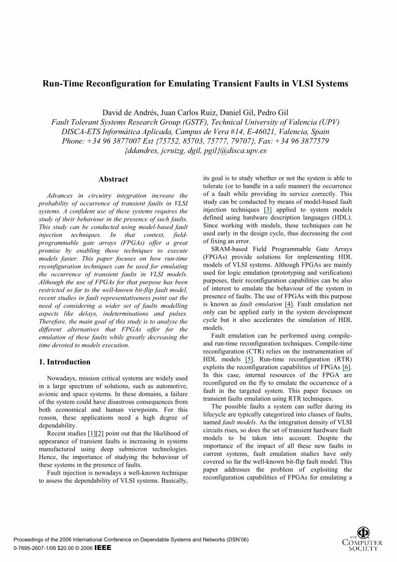
RTR is a methodology for the development of reconfigurable applications [8]. It relies on the reconfiguration capabilities of programmable devices to change the behaviour of the system on-the-fly. Hence, the use of RTR techniques for fault emulation involves the reconfiguration of the system to emulate its behaviour in the presence of faults while executing a representative workload. Figure 1 provides a high-level view of this process. As can be seen, the fault is virtually injected in the HDL model, but in practice it is emulated using an FPGA.
HDL model
Synthesis and implementation
Configuration file
Download
Analysis of results
FPGA reconfiguration withfault injection purposes
Targetlocation
Fault injectiontime reached
Observation
New experiment
Workload execution
FPGA reconfiguration withfault removal purposes
Fault durationtime expired
Experimentstart time
Observation
Experimentend time
Reset systemto initial state Workload execution
Workload execution
Figure 1. RTR for transient fault emulation
Each fault injection experiment involves three steps: – Fault location process: Typical elements targeted
by model-based fault injection techniques are ports, signals and variables. After synthesising and implementing an HDL model on an FPGA, these elements can be mapped to internal resources of the device, but they can also be renamed, merged together or removed by optimisations. Therefore, it is necessary to establish a mapping between HDL model elements
and FPGA internal resources. This mapping requires the analysis of the targeted HDL model and the configuration file resulting from the implementation of this model for each particular FPGA.
– Fault injection process: This process consists in provoking the occurrence of a fault in the considered HDL model. Following the RTR methodology this can be accomplished by reconfiguring FPGA internal resources when executing the model. This reconfiguration depends on the type of the injected fault, the location of such fault in the model, and the mapping of this location onto the FPGA. All this information is gathered together to generate a new configuration file that is loaded into the device memory to effectively change the configuration of the FPGA and, therefore, its functionality. Since we are dealing with transient faults, the same process must be followed so as to return the system back to its original configuration once the fault duration has expired.
– Observation process: It is necessary to observe how the system reacts in the presence of the injected fault. Usually, a trace of the outputs and state of the system are stored for its ulterior analysis.
The following sections study how FPGA resources must be reconfigured to emulate the occurrence of transient faults in the implemented HDL model.
3. Generic FPGA architecture
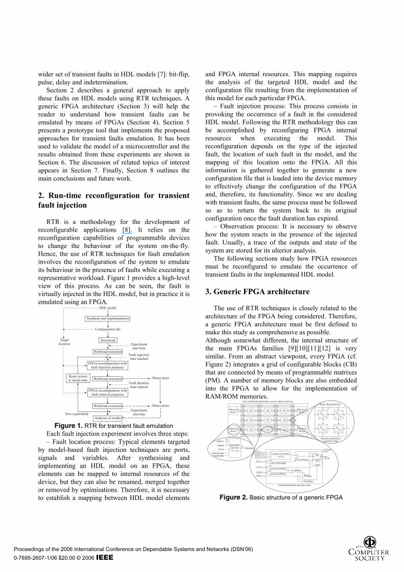
The use of RTR techniques is closely related to the architecture of the FPGA being considered. Therefore, a generic FPGA architecture must be first defined to make this study as comprehensive as possible. Although somewhat different, the internal structure of the main FPGAs families [9][10][11][12] is very similar. From an abstract viewpoint, every FPGA (cf. Figure 2) integrates a grid of configurable blocks (CB) that are connected by means of programmable matrixes (PM). A number of memory blocks are also embedded into the FPGA to allow for the implementation of RAM/ROM memories.
CBs consist of a function generator, a D-type flip-flop and a number of multiplexers. The function generator, usually built as a four-input look-up table (LUT), implements the combinational logic of the circuit. The flip-flop (FF) acts as a storage element that implements the sequential logic of the circuit. A set of multiplexers (denoted as Mux elements, like CLRMux or PRMux, in Figure 2) determines the CB’s functionality by establishing the proper connection among the CB’s inputs, outputs, LUT and FF.
PMs interconnect the CBs by linking lines that cross the device both in vertical and horizontal directions. As shown in Figure 2, each connection is established by means of a pass transistor.
The configuration of all these elements is controlled by a number of bits in the configuration memory of the FPGA. Some of these bits fill the LUT with the truth table that represents the desired combinational circuit, other bits set the functionality of the storage element as a FF or a latch, and some others set the control inputs of the multiplexers. Another bits turn on/off the PM’s pass transistors, allowing for the routing of all the lines of the circuit. Likewise, some other bits fill the content of the internal memory blocks in use. The configuration memory of the FPGA is loaded from the file resulting from the model synthesis and implementation process. 4. Emulation of transient faults in HDL models using FPGAs
According to [7], transient faults appear during a short period of time as a result from the interference or interaction of the circuitry with its physical environment (transients in power supply, crosstalk, electromagnetic interferences, temperature variation, α and cosmic radiation, etc.) This section describes how the run-time reconfiguration capabilities of FPGAs can be used for emulating the occurrence of these faults in HDL models.
4.1. Bit-flip faults
This model involves reversing the logic state of a memory element. This element stores the resulting value which remains unchanged until rewritten. Memory elements are usually synthesised as registers and latches, which are implemented by means of FFs, or as ROM/RAM memory mapped to internal memory blocks. Hence, these are the targets of the fault injection process when the model executes in FPGAs.
Although the injection of bit-flip faults into FFs was already addressed in [13], we are offering a brief summary here for completeness. One must understand
that in general, the faults occurrence is never synchronized with the system execution. Usually, the only way of asynchronously inverting the state of a FF is by means of its set/reset signals, which are driven by the GSR (Global Set Reset) line and the LSR (Local Set Reset) line.
The GSR line (cf. Figure 2) can be triggered to set/reset all the FFs in the FPGA [14]. Therefore, it is necessary to read the current state of all the FFs to configure the multiplexers that control its set/reset logic (PRMux and CLRMux) to invert the state of the targeted FF while keeping the state of the rest. The main drawback of this approach lies in the high amount of information to be transferred to and from the FPGA which slows down the emulation process.
On the other hand, the LSR line only affects the FF connected to it which minimises the amount of information to be transferred. Although the line can not be directly pulsed, this can be achieved by reconfiguring the InvertLSRMux multiplexer (cf. Figure 2). We proposed this approach in [13] to speed up the fault injection process.
Currently, FPGAs are integrating more and more resources that greatly help to implement large and complex systems. Although the internal memory blocks of FPGAs are being used as cache memory or storage for constant values, as far as we know, they have not been addressed with fault injection purposes. This work defines a conceptually simple approach for emulating the occurrence of bit-flips into these memory blocks.
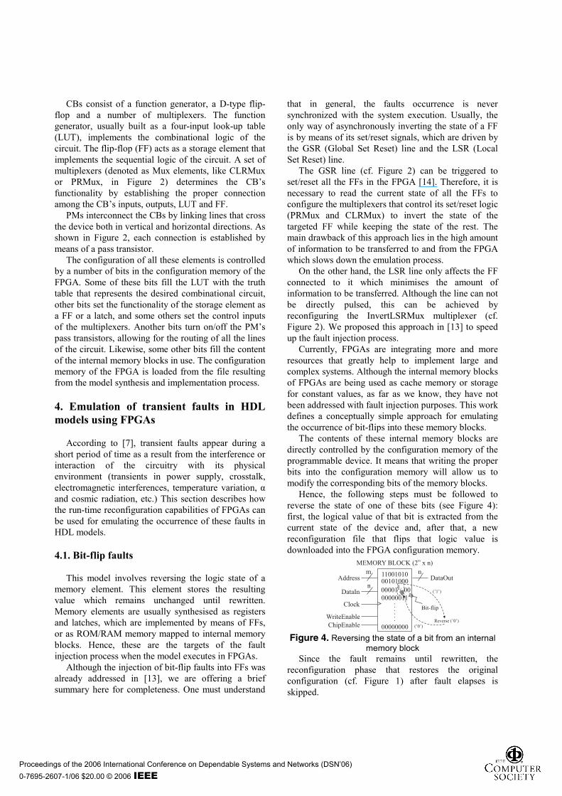
The contents of these internal memory blocks are directly controlled by the configuration memory of the programmable device. It means that writing the proper bits into the configuration memory will allow us to modify the corresponding bits of the memory blocks.
Hence, the following steps must be followed to reverse the state of one of these bits (see Figure 4): first, the logical value of that bit is extracted from the current state of the device and, after that, a new reconfiguration file that flips that logic value is downloaded into the FPGA configuration memory.
mAddress DataOut
n
nDataIn
WriteEnable
ChipEnable
>Clock
MEMORY BLOCK (2 x n)m
1100101000101000
00000011
00000000
......
Reverse (’0’)
00001 001/0 (’1’)
(’0’)
Bit-flip
Figure 4. Reversing the state of a bit from an internal
memory block Since the fault remains until rewritten, the
reconfiguration phase that restores the original configuration (cf. Figure 1) after fault elapses is skipped.
They model the occurrence of Single Event Transients (SET) faults in combinational logic. The logic state of a combinational element is reversed during a short period of time, behaving properly after that time. Target elements are usually synthesised as function generators, which are implemented by means of LUTs and their linking lines. Therefore, pulse fault emulation must target these FPGA components.
With respect to function generators, pulses can target any LUT input line, the LUT output line and also the combinational circuit the LUT implements. The proposed approach is derived from the one presented in [15] to emulate the occurrence of stuck-at faults for BIST effectiveness evaluation. Since the contents of the LUT represent the truth table of a circuit, it is possible to extract this information to obtain a structural representation of the circuit. This truth table is recomputed (inverting the output, input or internal line of the circuit) and downloaded into the FPGA configuration memory to emulate the occurrence of a pulse in the targeted element (cf. Figure 5).
Figure 5. Injecting a pulse fault into a combinational
circuit implemented as a LUT As dealing with transient faults, disabling the
previously injected pulse fault will require reconfiguring again the FPGA to program the affected LUT with the original truth table.
A different approach must be followed when the target of a pulse fault is not a LUT, but a path that connects to a CB input. Since all CB inputs, but LUT inputs (already covered), have a multiplexer in charge of inverting their incoming logical levels (cf. Figure 6), the emulation of pulse faults in these lines is quite straightforward. It is only necessary to invert the control bit of the multiplexer for the targeted line. Disabling the pulse fault is only a matter of inverting again the control bit of the related multiplexer.
FFin
Pulse
InvertFFinMux‘0’‘1’
Figure 6. Injecting a pulse fault (dashed lines) into a
combinational path implemented as a CB input
4.3. Delay faults
This model assumes a modification of the propagation delay of a circuit. Although the propagation delays of the model implemented in the FPGA will not match those of the final implementation, the application of this fault can provide an estimation of the behaviour of the system in presence of delays. The FPGA elements that are susceptible to be used to emulate delay faults are the interconnecting lines that implement signals, variables and ports of the HDL model. This paper proposes two different approaches depending on whether it is necessary to reroute the target line.
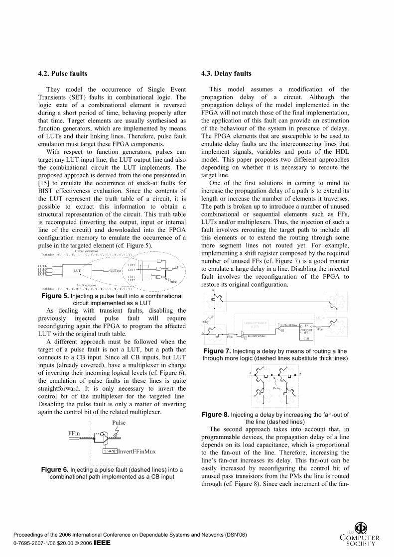
One of the first solutions in coming to mind to increase the propagation delay of a path is to extend its length or increase the number of elements it traverses. The path is broken up to introduce a number of unused combinational or sequential elements such as FFs, LUTs and/or multiplexers. Thus, the injection of such a fault involves rerouting the target path to include all this elements or to extend the routing through some more segment lines not routed yet. For example, implementing a shift register composed by the required number of unused FFs (cf. Figure 7) is a good manner to emulate a large delay in a line. Disabling the injected fault involves the reconfiguration of the FPGA to restore its original configuration.
(LUT) D Q
CLR
>
PR
FFout
LUTout
FFin InvertFFinMux
LUTorFFMuxLOOK-UP TABLE
FLIP-FLOP(FF)
‘1’
‘1’
Delay
A
A
Figure 7. Injecting a delay by means of routing a line through more logic (dashed lines substitute thick lines)
A A
Delay
Figure 8. Injecting a delay by increasing the fan-out of
the line (dashed lines) The second approach takes into account that, in
programmable devices, the propagation delay of a line depends on its load capacitance, which is proportional to the fan-out of the line. Therefore, increasing the line’s fan-out increases its delay. This fan-out can be easily increased by reconfiguring the control bit of unused pass transistors from the PMs the line is routed through (cf. Figure 8). Since each increment of the fan-
out slowly increases the propagation delay of the line this approach is adequate to emulate faults that introduce small propagation delays. Disabling the fault is performed just by restoring the original configuration of the control bit of the used pass transistors. Of course, the resulting propagation delay depends on the selected FPGA. For instance, a LUT from a Virtex FPGA [16] has a delay ranging from 0.29 to 0.8 nanoseconds while increasing the fan-out of a line can add between 0.001 and 0.018 nanoseconds.
4.4. Indetermination faults
This fault model assumes that the target will present an undetermined voltage level (between the high- and low-level thresholds). The targets of this fault are the combinational and sequential elements that implement the logic of the HDL model, i.e. LUTs and FFs.
One can possibly think that the best way of emulating an indetermination fault will be causing the occurrence of an undetermined logic level in the targeted element. This could possibly be achieved by causing a short-circuit between lines holding opposite logic levels or by leaving the target line opened. However, since we are dealing with digital circuits, the analogue value resulting from the short-circuit or the open line will lead to a well defined although uncertain value (logic ‘0’ or logic ‘1’) when it goes through a buffer along the routing or at the input of a CB. Therefore, why taking the effort of causing the occurrence of short-circuits/open lines instead of generating the final logic levels?
We propose the use of a randomiser that generates the final logic levels the internal buffer of the FPGA interprets as the undetermined voltage value caused by the indetermination. Under this assumption, any procedure capable of modifying the logical value of the sequential and combinational elements is eligible to inject indetermination faults into these elements. Hence, the indetermination injection in LUTs follows the same scheme shown in Section 4.2 and the injection in sequential logic is very similar to the bit-flip injection (Section 4.1).
4.5. Summary
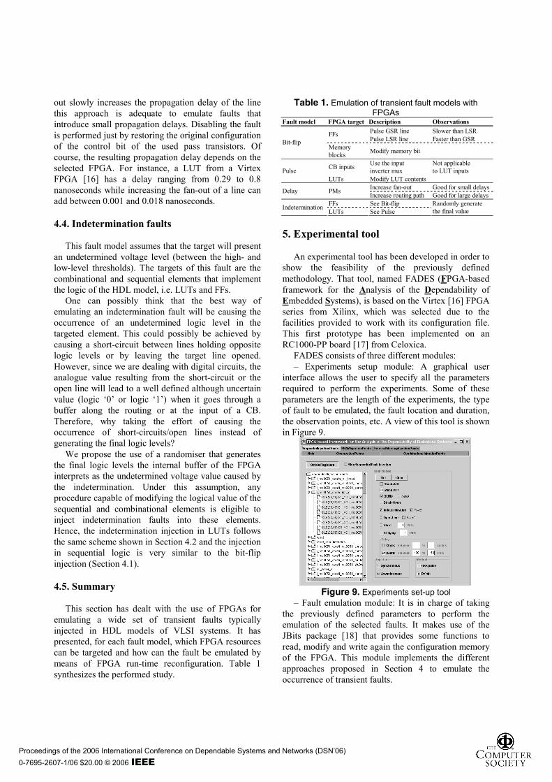
This section has dealt with the use of FPGAs for emulating a wide set of transient faults typically injected in HDL models of VLSI systems. It has presented, for each fault model, which FPGA resources can be targeted and how can the fault be emulated by means of FPGA run-time reconfiguration. Table 1 synthesizes the performed study.
Table 1. Emulation of transient fault models with FPGAs
Fault model FPGA target Description Observations Pulse GSR line Slower than LSR FFs Pulse LSR line Faster than GSR Bit-flip
Memory blocks Modify memory bit
CB inputs Use the input inverter mux
Not applicable to LUT inputs Pulse
LUTs Modify LUT contents Increase fan-out Good for small delays Delay PMs Increase routing path Good for large delays
FFs See Bit-flip Indetermination LUTs See Pulse
Randomly generate the final value
5. Experimental tool
An experimental tool has been developed in order to show the feasibility of the previously defined methodology. That tool, named FADES (FPGA-based framework for the Analysis of the Dependability of Embedded Systems), is based on the Virtex [16] FPGA series from Xilinx, which was selected due to the facilities provided to work with its configuration file. This first prototype has been implemented on an RC1000-PP board [17] from Celoxica.
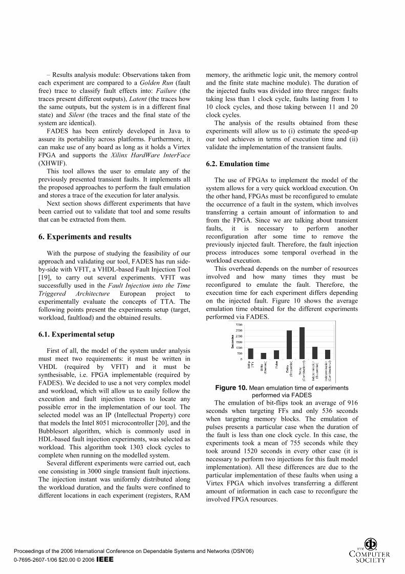
FADES consists of three different modules: – Experiments setup module: A graphical user
interface allows the user to specify all the parameters required to perform the experiments. Some of these parameters are the length of the experiments, the type of fault to be emulated, the fault location and duration, the observation points, etc. A view of this tool is shown in Figure 9.
Figure 9. Experiments set-up tool
– Fault emulation module: It is in charge of taking the previously defined parameters to perform the emulation of the selected faults. It makes use of the JBits package [18] that provides some functions to read, modify and write again the configuration memory of the FPGA. This module implements the different approaches proposed in Section 4 to emulate the occurrence of transient faults.
– Results analysis module: Observations taken from each experiment are compared to a Golden Run (fault free) trace to classify fault effects into: Failure (the traces present different outputs), Latent (the traces how the same outputs, but the system is in a different final state) and Silent (the traces and the final state of the system are identical).
FADES has been entirely developed in Java to assure its portability across platforms. Furthermore, it can make use of any board as long as it holds a Virtex FPGA and supports the Xilinx HardWare InterFace (XHWIF).
This tool allows the user to emulate any of the previously presented transient faults. It implements all the proposed approaches to perform the fault emulation and stores a trace of the execution for later analysis.
Next section shows different experiments that have been carried out to validate that tool and some results that can be extracted from them.
6. Experiments and results
With the purpose of studying the feasibility of our approach and validating our tool, FADES has run side-by-side with VFIT, a VHDL-based Fault Injection Tool [19], to carry out several experiments. VFIT was successfully used in the Fault Injection into the Time Triggered Architecture European project to experimentally evaluate the concepts of TTA. The following points present the experiments setup (target, workload, faultload) and the obtained results.
6.1. Experimental setup
First of all, the model of the system under analysis must meet two requirements: it must be written in VHDL (required by VFIT) and it must be synthesisable, i.e. FPGA implementable (required by FADES). We decided to use a not very complex model and workload, which will allow us to easily follow the execution and fault injection traces to locate any possible error in the implementation of our tool. The selected model was an IP (Intellectual Property) core that models the Intel 8051 microcontroller [20], and the Bubblesort algorithm, which is commonly used in HDL-based fault injection experiments, was selected as workload. This algorithm took 1303 clock cycles to complete when running on the modelled system.
Several different experiments were carried out, each one consisting in 3000 single transient fault injections. The injection instant was uniformly distributed along the workload duration, and the faults were confined to different locations in each experiment (registers, RAM
memory, the arithmetic logic unit, the memory control and the finite state machine module). The duration of the injected faults was divided into three ranges: faults taking less than 1 clock cycle, faults lasting from 1 to 10 clock cycles, and those taking between 11 and 20 clock cycles.
The analysis of the results obtained from these experiments will allow us to (i) estimate the speed-up our tool achieves in terms of execution time and (ii) validate the implementation of the transient faults.
6.2. Emulation time
The use of FPGAs to implement the model of the system allows for a very quick workload execution. On the other hand, FPGAs must be reconfigured to emulate the occurrence of a fault in the system, which involves transferring a certain amount of information to and from the FPGA. Since we are talking about transient faults, it is necessary to perform another reconfiguration after some time to remove the previously injected fault. Therefore, the fault injection process introduces some temporal overhead in the workload execution.
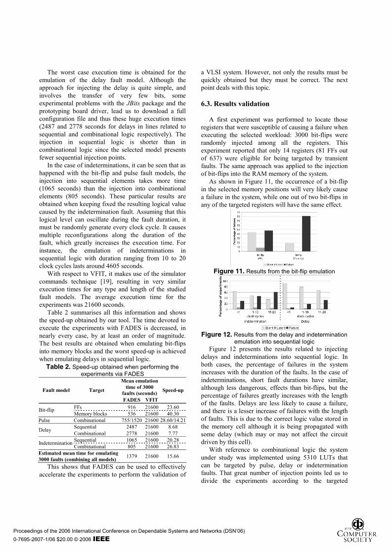
This overhead depends on the number of resources involved and how many times they must be reconfigured to emulate the fault. Therefore, the execution time for each experiment differs depending on the injected fault. Figure 10 shows the average emulation time obtained for the different experiments performed via FADES.
Figure 10. Mean emulation time of experiments
performed via FADES The emulation of bit-flips took an average of 916
seconds when targeting FFs and only 536 seconds when targeting memory blocks. The emulation of pulses presents a particular case when the duration of the fault is less than one clock cycle. In this case, the experiments took a mean of 755 seconds while they took around 1520 seconds in every other case (it is necessary to perform two injections for this fault model implementation). All these differences are due to the particular implementation of these faults when using a Virtex FPGA which involves transferring a different amount of information in each case to reconfigure the involved FPGA resources.
The worst case execution time is obtained for the emulation of the delay fault model. Although the approach for injecting the delay is quite simple, and involves the transfer of very few bits, some experimental problems with the JBits package and the prototyping board driver, lead us to download a full configuration file and thus these huge execution times (2487 and 2778 seconds for delays in lines related to sequential and combinational logic respectively). The injection in sequential logic is shorter than in combinational logic since the selected model presents fewer sequential injection points.
In the case of indeterminations, it can be seen that as happened with the bit-flip and pulse fault models, the injection into sequential elements takes more time (1065 seconds) than the injection into combinational elements (805 seconds). These particular results are obtained when keeping fixed the resulting logical value caused by the indetermination fault. Assuming that this logical level can oscillate during the fault duration, it must be randomly generate every clock cycle. It causes multiple reconfigurations along the duration of the fault, which greatly increases the execution time. For instance, the emulation of indeterminations in sequential logic with duration ranging from 10 to 20 clock cycles lasts around 4605 seconds.
With respect to VFIT, it makes use of the simulator commands technique [19], resulting in very similar execution times for any type and length of the studied fault models. The average execution time for the experiments was 21600 seconds.
Table 2 summarises all this information and shows the speed-up obtained by our tool. The time devoted to execute the experiments with FADES is decreased, in nearly every case, by at least an order of magnitude. The best results are obtained when emulating bit-flips into memory blocks and the worst speed-up is achieved when emulating delays in sequential logic.
Table 2. Speed-up obtained when performing the experiments via FADES
Estimated mean time for emulating 3000 faults (combining all models) 1379 21600 15.66
This shows that FADES can be used to effectively accelerate the experiments to perform the validation of
a VLSI system. However, not only the results must be quickly obtained but they must be correct. The next point deals with this topic.
6.3. Results validation
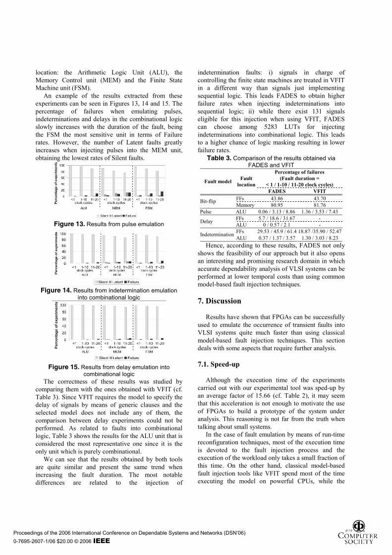
A first experiment was performed to locate those
registers that were susceptible of causing a failure when executing the selected workload: 3000 bit-flips were randomly injected among all the registers. This experiment reported that only 14 registers (81 FFs out of 637) were eligible for being targeted by transient faults. The same approach was applied to the injection of bit-flips into the RAM memory of the system.
As shown in Figure 11, the occurrence of a bit-flip in the selected memory positions will very likely cause a failure in the system, while one out of two bit-flips in any of the targeted registers will have the same effect.
Figure 11. Results from the bit-flip emulation
Figure 12. Results from the delay and indetermination
emulation into sequential logic Figure 12 presents the results related to injecting
delays and indeterminations into sequential logic. In both cases, the percentage of failures in the system increases with the duration of the faults. In the case of indeterminations, short fault durations have similar, although less dangerous, effects than bit-flips, but the percentage of failures greatly increases with the length of the faults. Delays are less likely to cause a failure, and there is a lesser increase of failures with the length of faults. This is due to the correct logic value stored in the memory cell although it is being propagated with some delay (which may or may not affect the circuit driven by this cell).
With reference to combinational logic the system under study was implemented using 5310 LUTs that can be targeted by pulse, delay or indetermination faults. That great number of injection points led us to divide the experiments according to the targeted
location: the Arithmetic Logic Unit (ALU), the Memory Control unit (MEM) and the Finite State Machine unit (FSM).
An example of the results extracted from these experiments can be seen in Figures 13, 14 and 15. The percentage of failures when emulating pulses, indeterminations and delays in the combinational logic slowly increases with the duration of the fault, being the FSM the most sensitive unit in terms of Failure rates. However, the number of Latent faults greatly increases when injecting pulses into the MEM unit, obtaining the lowest rates of Silent faults.
Figure 13. Results from pulse emulation
Figure 14. Results from indetermination emulation
into combinational logic
Figure 15. Results from delay emulation into
combinational logic The correctness of these results was studied by
comparing them with the ones obtained with VFIT (cf. Table 3). Since VFIT requires the model to specify the delay of signals by means of generic clauses and the selected model does not include any of them, the comparison between delay experiments could not be performed. As related to faults into combinational logic, Table 3 shows the results for the ALU unit that is considered the most representative one since it is the only unit which is purely combinational.
We can see that the results obtained by both tools are quite similar and present the same trend when increasing the fault duration. The most notable differences are related to the injection of
indetermination faults: i) signals in charge of controlling the finite state machines are treated in VFIT in a different way than signals just implementing sequential logic. This leads FADES to obtain higher failure rates when injecting indeterminations into sequential logic; ii) while there exist 131 signals eligible for this injection when using VFIT, FADES can choose among 5283 LUTs for injecting indeterminations into combinational logic. This leads to a higher chance of logic masking resulting in lower failure rates.
Table 3. Comparison of the results obtained via FADES and VFIT
Hence, according to these results, FADES not only shows the feasibility of our approach but it also opens an interesting and promising research domain in which accurate dependability analysis of VLSI systems can be performed at lower temporal costs than using common model-based fault injection techniques. 7. Discussion
Results have shown that FPGAs can be successfully used to emulate the occurrence of transient faults into VLSI systems quite much faster than using classical model-based fault injection techniques. This section deals with some aspects that require further analysis.
7.1. Speed-up
Although the execution time of the experiments carried out with our experimental tool was sped-up by an average factor of 15.66 (cf. Table 2), it may seem that this acceleration is not enough to motivate the use of FPGAs to build a prototype of the system under analysis. This reasoning is not far from the truth when talking about small systems.
In the case of fault emulation by means of run-time reconfiguration techniques, most of the execution time is devoted to the fault injection process and the execution of the workload only takes a small fraction of this time. On the other hand, classical model-based fault injection tools like VFIT spend most of the time executing the model on powerful CPUs, while the
temporal overhead induced by the fault injection process is very short in comparison. Hence, when executing simple models and/or short workloads, modern CPUs overpower FPGAs: the models are so quickly simulated that the time devoted to FPGA reconfiguration becomes the bottleneck that limits the speed-up obtained by fault emulation.
The 8051 microcontroller we have used as system under study only used 637 out 24576 FFs and 5310 out of 24576 LUTs that were available in the Virtex 1000 FPGA. That explains why the speed-up obtained when executing the model was in the range of only one order of magnitude. We expect that considering more complex models and larger workloads would cause our approach to be more effective in terms of execution time. This topic requires further research.
7.2. Faults in sequential logic versus fault in combinational logic
Modern systems tend to be fully synchronous (pipeline stages, synchronous memories, registered outputs...) and, therefore, a fault in combinational logic will not likely cause any failure. In order to cause a failure in the system, this fault must be captured by any sequential element driven by the faulty combinational path. Then, if a fault in combinational logic manifests as a bit-flip in sequential logic why not exclusively inject bit-flips and forget about the rest of faults?
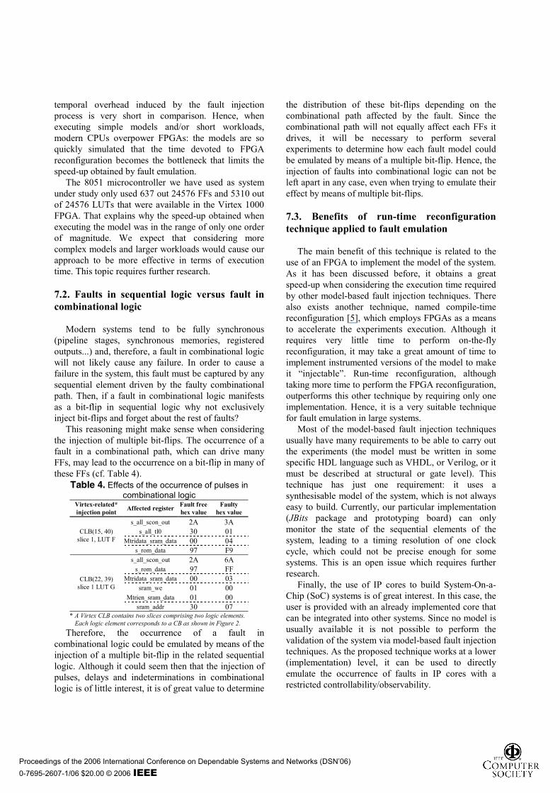
This reasoning might make sense when considering the injection of multiple bit-flips. The occurrence of a fault in a combinational path, which can drive many FFs, may lead to the occurrence on a bit-flip in many of these FFs (cf. Table 4).
Table 4. Effects of the occurrence of pulses in combinational logic
Virtex-related* injection point Affected register Fault free
hex value Faulty
hex value s_all_scon_out 2A 3A
s_all_tl0 30 01 Mtridata_sram_data 00 04
CLB(15, 40) slice 1, LUT F
s_rom_data 97 F9 s_all_scon_out 2A 6A
s_rom_data 97 FF Mtridata_sram_data 00 03
sram_we 01 00 Mtrien_sram_data 01 00
CLB(22, 39) slice 1 LUT G
sram_addr 30 07 * A Virtex CLB contains two slices comprising two logic elements. Each logic element corresponds to a CB as shown in Figure 2.
Therefore, the occurrence of a fault in combinational logic could be emulated by means of the injection of a multiple bit-flip in the related sequential logic. Although it could seem then that the injection of pulses, delays and indeterminations in combinational logic is of little interest, it is of great value to determine
the distribution of these bit-flips depending on the combinational path affected by the fault. Since the combinational path will not equally affect each FFs it drives, it will be necessary to perform several experiments to determine how each fault model could be emulated by means of a multiple bit-flip. Hence, the injection of faults into combinational logic can not be left apart in any case, even when trying to emulate their effect by means of multiple bit-flips.
7.3. Benefits of run-time reconfiguration technique applied to fault emulation
The main benefit of this technique is related to the
use of an FPGA to implement the model of the system. As it has been discussed before, it obtains a great speed-up when considering the execution time required by other model-based fault injection techniques. There also exists another technique, named compile-time reconfiguration [5], which employs FPGAs as a means to accelerate the experiments execution. Although it requires very little time to perform on-the-fly reconfiguration, it may take a great amount of time to implement instrumented versions of the model to make it “injectable”. Run-time reconfiguration, although taking more time to perform the FPGA reconfiguration, outperforms this other technique by requiring only one implementation. Hence, it is a very suitable technique for fault emulation in large systems.
Most of the model-based fault injection techniques usually have many requirements to be able to carry out the experiments (the model must be written in some specific HDL language such as VHDL, or Verilog, or it must be described at structural or gate level). This technique has just one requirement: it uses a synthesisable model of the system, which is not always easy to build. Currently, our particular implementation (JBits package and prototyping board) can only monitor the state of the sequential elements of the system, leading to a timing resolution of one clock cycle, which could not be precise enough for some systems. This is an open issue which requires further research.
Finally, the use of IP cores to build System-On-a-Chip (SoC) systems is of great interest. In this case, the user is provided with an already implemented core that can be integrated into other systems. Since no model is usually available it is not possible to perform the validation of the system via model-based fault injection techniques. As the proposed technique works at a lower (implementation) level, it can be used to directly emulate the occurrence of faults in IP cores with a restricted controllability/observability.
This paper investigates to what extent the occurrence of transient faults in HDL models can be emulated using FPGAs. It covers a set of representative transient fault models existing today in the domain of VLSI systems such as bit-flip, pulse, delay and indetermination that were not considered for fault emulation to date.
Several experiments have been conducted by means of a prototype tool named FADES and their results have been compared to those obtained from a VHDL-based fault injection tool. This comparison showed that FADES not only emulates these faults properly but it also outperforms the other tool by, at least, an order of magnitude. We expect that the emulation of complex models will provide even better speed-up factors.
In the near future, we envisage the extension of this framework to cover a set of typical permanent faults that have not been used for fault emulation of VLSI systems yet, such as short, open-line, bridging and stuck-open faults. Other aspects that we will focus on are those related to the occurrence of multiple bit-flips, or those affecting systems manufactured using FPGAs. 9. Acknowledgments
This work has been supported by the Spanish MCYT project TEC 2005-05119/MIC. 10. References [1] C. Constantinescu, “Impact of Deep Submicron Technology on Dependability of VLSI Circuits”, IEEE Int. Conf. on Dependable Systems and Networks, USA, 2002, pp. 205–209. [2] T. Karnik, P. Hazucha, and J. Patel, “Characterization of Soft Errors Caused by Single Event Upsets in CMOS Processes”, IEEE Trans. on Dependable and Secure Computing, vol. 1, no. 2, 2004, pp. 128–143. [3] A. Benso, and P. Prinetto, Fault Injection Techniques and Tools for Embedded Systems Reliability Evaluation, Kluwer Academic Publishers, 2003. [4] K.-T. Cheng, S.-Y. Huang, and W.-J. Dai, “Fault Emulation: A New Methodology for Fault Grading”, IEEE Trans on Computer-Aided Design of Integrated Circuits and Systems, vol.18, no. 10, 1999, pp. 1487–1495. [5] P. Civera, et al, “New Techniques for efficiently assessing reliability of SOCs”, Microelectronics Journal, vol. 34, no. 1, 2003, pp. 53–61.
[6] L. Antoni, L. Leveugle, and B. Fehér, “Using Run-Time Reconfiguration for Fault Injection Applications”, IEEE Trans. on Instrumentation and Measurement, vol. 52, no. 5, 2003, pp. 1468–1473. [7] Fault Representativeness, Deliverable ETIE2 of the Dependability Benchmarking (DBench) Project, IST-2000-25425, 2002, online: http://www.laas.fr/DBench/ETIE2.pdf. [8] B. L. Hutchings, and M. J. Wirthlin, “Implementation Approaches for Reconfigurable Logic Applications”, Int. Workshop on Field Programmable Logic and Applications, UK, 1995, pp. 293–302. [9] Virtex-II Platform FPGAs: Complete Data Sheet, Xilinx Corp., DS031, v3.3, 2004. [10] Stratix II Device Handbook, Volume 1, Altera Corp., SII5v1-2.1, 2005. [11] Lattice ECP/EC Family Data Sheet, Version 01.3, Lattice Semiconductors, 2004. [12] AT40KAL Series FPGA, Atmel Corp., 2818E-FPGA-1/04, 2004. [13] D. de Andrés, et al., “Fast Run-Time Reconfiguration for SEU Injection”, 5th European Dependable Computing Conference, LNCS, vol. 3463, Hungary, 2005, pp. 230–245. [14] L. Antoni, L. Leveugle, and B. Fehér, “Using Run-Time Reconfiguration for Fault Injection in Hardware Prototypes”, IEEE Int. Symp. on Defect and Fault Tolerance in VLSI Systems, Canada, 2002, pp. 245–253. [15] A. Parreira, J. P. Teixeira, and M. Santos, “A Novel Approach to FPGA-Based Hardware Fault Modelling and Simulation”, Int. Workshop on Design and Diagnostics of Electronic Circuits and Systems, Poland, 2003, pp. 17–24. [16] VirtexTM 2.5 V Field Programmable Gate Arrays: Complete Data Sheet, Xilinx Corp., DS003, 2002. [17] RC1000 Functional Reference Manual, Celoxica Inc., RM-1140-0, 2001. [18] S. Guccione, D. Levi, and P. Sundararajan, “JBits: A Java-based Interface for Reconfigurable Computing”, 2nd Annual Military and Aerospace Applications of Programmable Devices and Technologies Conference, USA, 1999. [19] J. C. Baraza, et al., “A prototype of a VHDL-based fault injection tool: description and application”, Journal of Systems Architecture, vol. 47, no. 10, 2002, pp. 847–867. [20] 8051 IP Core, version 1.4, Oregano Systems, 2004, available online at: http://www.oregano.at/ip/8051.htm.