SPECIFICATIONS Versarray ™ 112 Mk2 Frequency Response, 1 meter on-axis, swept-sine in anechoic environment: 110 Hz to 20 kHz (±3 dB, with processing) Usable Low Frequency limit (-10 dB point): 85 Hz (with processing) Power Handling: Low Frequency Section: 500 W continuous 1,000 W program 2,000 W peak High Frequency Section: 120 W continuous 240 W program 480 W peak Sound Pressure Level, 1 Watt, 1 meter in anechoic environment: Low Frequency Section: 96 dB SPL, (2.83 V input) High Frequency Section: 101 dB SPL, (4.0 V input for 16 ohm wiring; 2.0 V for 4 ohm wiring) Maximum Sound Pressure Level (1 meter) * : Low Frequency Section: 123 dB SPL continuous 129 dB SPL peak High Frequency Section: 122 dB SPL continuous 128 dB SPL peak *Note: This spec is for one module at 1 meter, a line array of 6 units has much higher output at distance due to line source effect where SPL falls off at 3 dB per distance doubling rather than 6 dB Nominal Radiation Angle measured at -6 dB point of polar response: 90 degrees Horizontal by 15 degrees Vertical (One module only, straight line array of more than 1 module narrows vertical dispersion accordingly) Transducer Complement: Low Frequency Section: 1x 12 in. Woofer, 1208-8 SPS BWX Black Widow ® 4" VC Woofer, in a sealed box High Frequency Section: 2x 4.75 in. Ribbon Tweeters Two RD ™ 2.6 Peavey Ribbon Tweeters, on a waveguide Box Tuning Frequency (Sealed): Low Frequency Section: 100 Hz Radiation Angle measured at -6 dB point of polar response: 500 Hz – 1.6 kHz: Horiz. 120o +/- 55o Vert. 117o +/- 75o 1.6 kHz - 5 kHz: Horiz. 84o +/- 20o Vert. 34o +/- 20o 5 kHz - 16 kHz: Horiz. 94o +/- 5o Vert. 15o +/- 3o Directivity Factor, Q (Mean): 19.78 +19.4, -17.4 Directivity Index, Di (Mean): 11.44 dB +4.5 dB, -7.6 dB
Transcript
SPECIFICATIONS Versarray ™ 112 Mk2
Frequency Response, 1 meter on-axis, swept-sine in anechoic environment:
110 Hz to 20 kHz (±3 dB, with processing)
Usable Low Frequency limit (-10 dB point):
85 Hz (with processing)
Power Handling:
Low Frequency Section:
500 W continuous
1,000 W program
2,000 W peak
High Frequency Section:
120 W continuous
240 W program
480 W peak
Sound Pressure Level, 1 Watt, 1 meter in anechoic environment:
Low Frequency Section:
96 dB SPL, (2.83 V input)
High Frequency Section:
101 dB SPL, (4.0 V input for 16 ohm wiring; 2.0 V for 4 ohm wiring)
Maximum Sound Pressure Level (1 meter) * :
Low Frequency Section:
123 dB SPL continuous
129 dB SPL peak
High Frequency Section:
122 dB SPL continuous
128 dB SPL peak
*Note: This spec is for one module at 1 meter, a line array of 6 units has much higher output at distance due to line source e�ect where SPL falls o� at 3 dB per distance doubling rather than 6 dB
Nominal Radiation Angle measured at -6 dB point of polar response:
90 degrees Horizontal by 15 degrees Vertical
(One module only, straight line array of more than 1 module narrows vertical dispersion accordingly)
Transducer Complement:
Low Frequency Section:
1x 12 in. Woofer,
1208-8 SPS BWX Black Widow® 4" VC Woofer, in a sealed box
High Frequency Section:
2x 4.75 in. Ribbon Tweeters
Two RD™ 2.6 Peavey Ribbon Tweeters, on a waveguide
Box Tuning Frequency (Sealed):
Low Frequency Section: 100 Hz
Radiation Angle measured at -6 dB point of polar response:
500 Hz – 1.6 kHz:
Horiz. 120o +/- 55o
Vert. 117o +/- 75o
1.6 kHz - 5 kHz:
Horiz. 84o +/- 20o
Vert. 34o +/- 20o
5 kHz - 16 kHz:
Horiz. 94o +/- 5o
Vert. 15o +/- 3o
Directivity Factor, Q (Mean):
19.78 +19.4, -17.4
Directivity Index, Di (Mean):
11.44 dB +4.5 dB, -7.6 dB
SPECIFICATIONS Versarray ™ 112 Mk2
Electroacoustic Crossover Point, Peavey Active Digital Crossover:
(Applies to VSX ™ and Digitool® settings provided by Peavey)
Sub –Low Frequency:
120 Hz at 24dB/octave
Low Frequency –High Frequency:
1800 Hz at 24dB/octave
Recommended Active Crossover Frequency Region and Slope:
Sub –Low Frequency:
125 Hz at 24dB/octave LR
Low Frequency –High Frequency:
2000 Hz at 24dB/octave LR
Time O�set:
Low Frequency: Ahead of tweeter by 0.073 ms
Impedance (Z):
Low Frequency:
Nominal: 8.0 Ω
Minimum: 6.5 Ω
Passive HF:
Nominal: 16 Ω or 4 Ω
Minimum: 13.6 Ω or 3.4 Ω
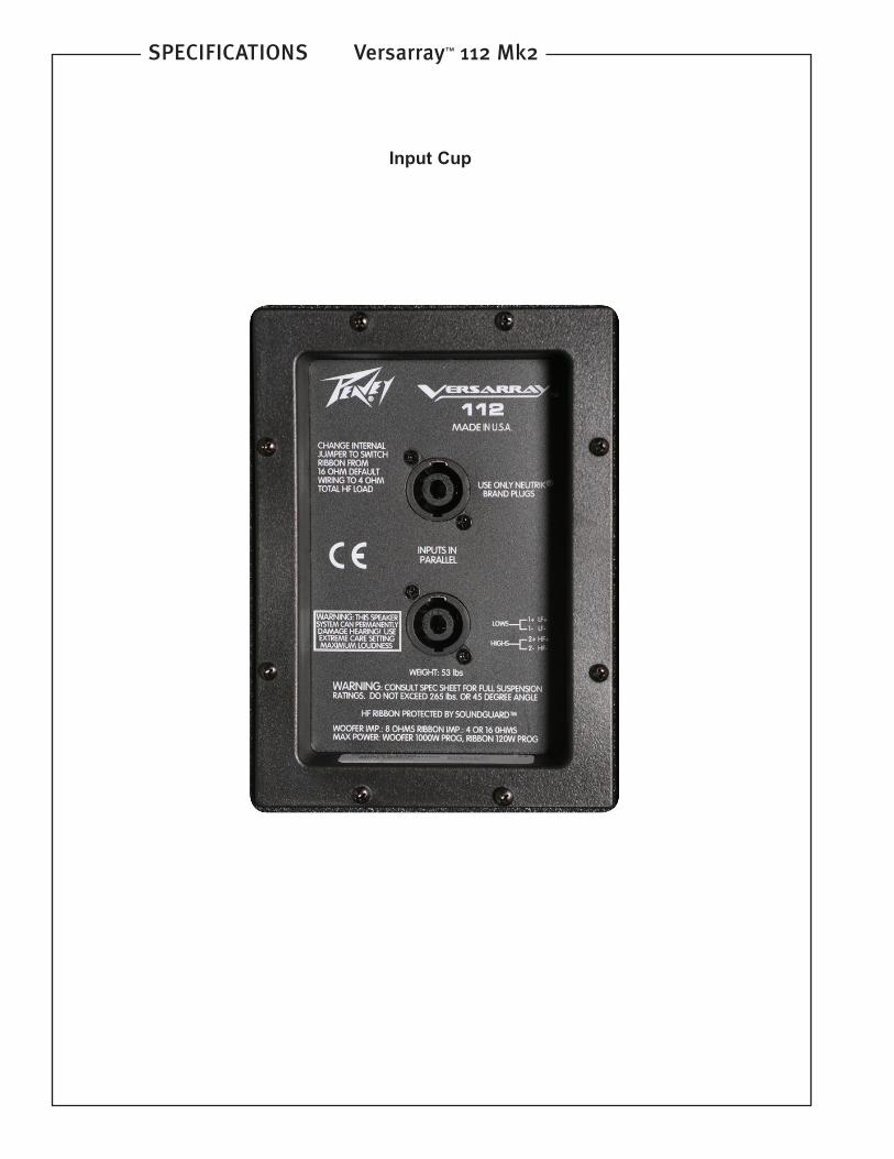
Input Connections:
2x Neutrik® 4 pin Speakon ® jack
Enclosure Materials & Finish:
18 mm 13 ply Baltic Birch plywood �nished in a tough Hammerhead™ polyurea black �nish, with perforated steel grille �nished in black powder coat paint.
Mounting provisions:
Custom array brackets and hardware, and a custom array angle adjustment system are included with each module. Quick release pins are available as an option, as is a purpose designed manually cranked lift system.
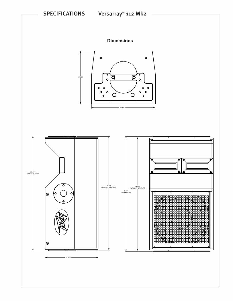
Dimensions (H x W x D):
Front:
14.06 in. x 25.25 in. x 11.75 in.
357 mm x 641 mm x 298 mm
Rear:
12.62 in. x 25.25 in. x 11.75 in.
321 mm x 641 mm x 298 mm
Net Weight: 62 Lbs. (28.25 kg)
(includes two of the rigging coupling brackets)
Companion Subwoofers (sold separately):
Versarray ™ 118 Sub single 18" Lo Max ® woofer subwoofer
Versarray 218 Sub double 18" Lo Max ® woofer subwoofer
Optional Accessories:
Custom Vermette Lift, for �ying arrays (Peavey part number 00595760);
Peavey Model 25 Halo/Fly Bar (Peavey part number 00588790),
Peavey Model 25 Pull-Back Bar/ Small Array Fly Bar (Peavey part number 00584970), 3 foot speaker cable, with 16 gauge 4 conductor wires with 4-pin to 4-pin Neutrik plugs (Peavey part number 00585240); and Quick Release Positive Lock Pins (Peavey part number 00594020 for a set of four) for array rigging.
Features
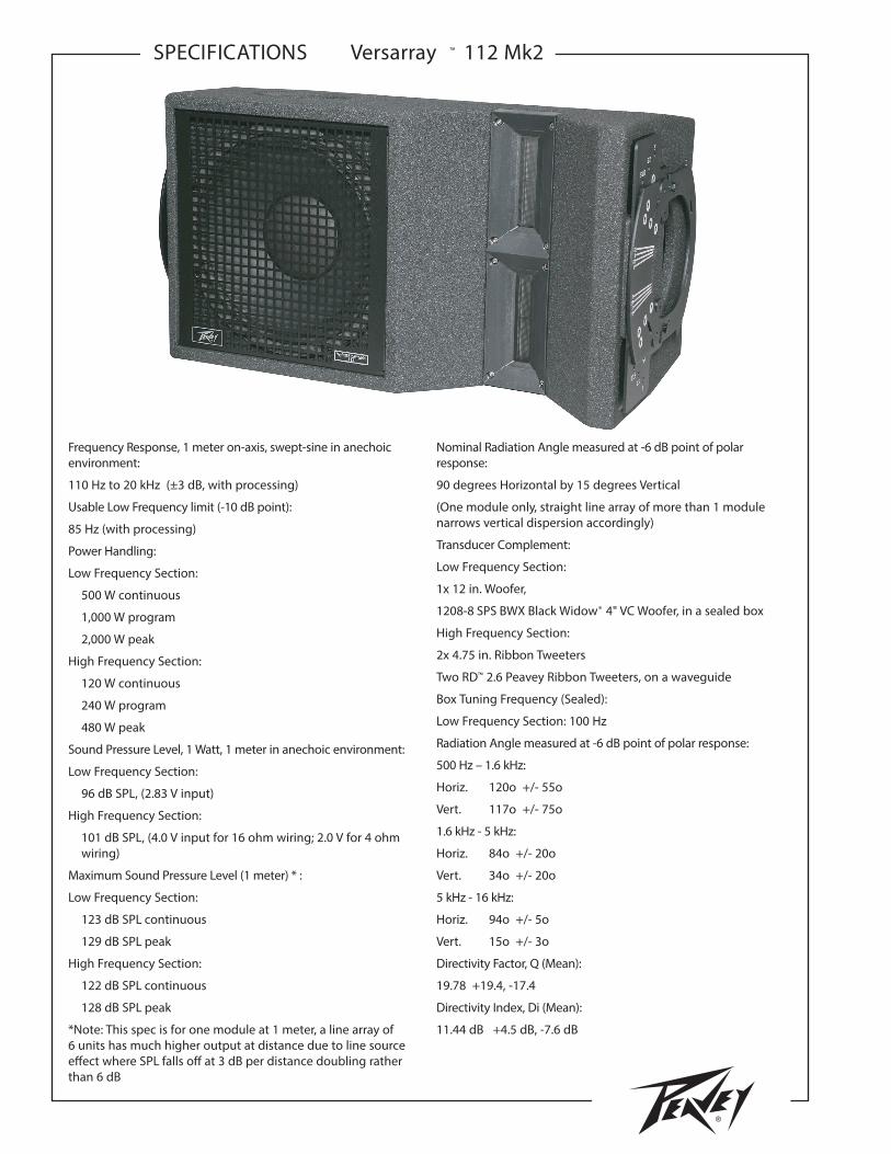
• 2-way Bi-Amp Ribbon Line Source Array SR System
• 12" Neo Black Widow ® 4" VC Woofer
• 1000 watt program, 2000 watt peak power handling
• Ribbon Tweeters with Neo magnet and composite material sandwich ribbon
• New ribbon tweeters have 50% more power handling and 2 dB more sensitivity than the Mk1
• 90 H by 15 V degree coverage pattern (per one cabinet)
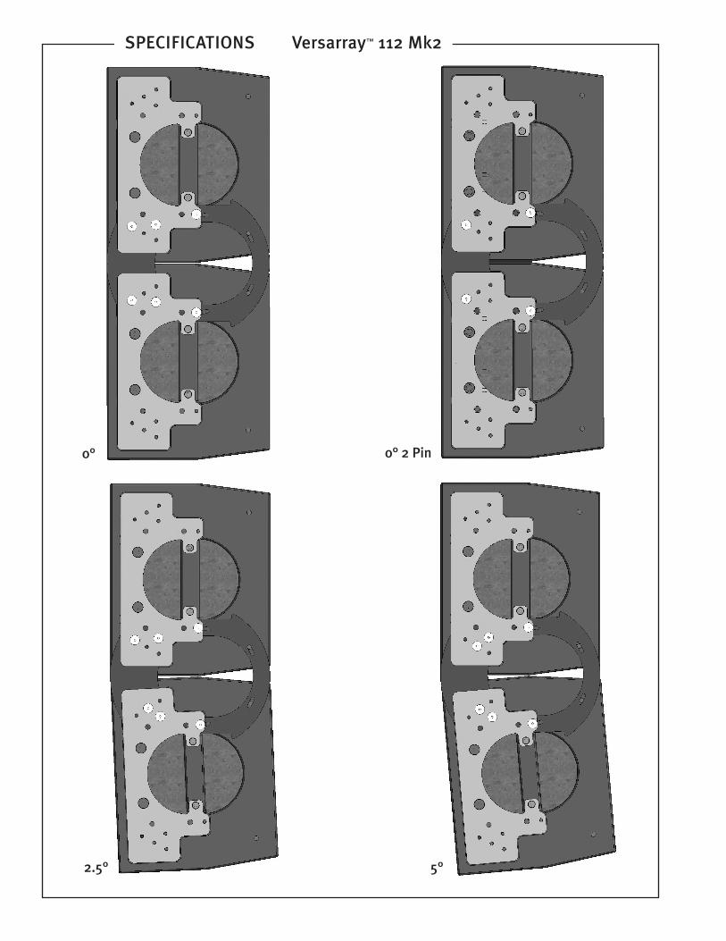
• Easy aiming angle adjustment rigging system
• Angle adjustable in 2 1/2 degree increments from 0 to 15 degrees, total angle between adjacent cabinets
• Sound Guard ™ tweeter protection
• Inputs are two Neutrik Speakon 4 pin jacks in parallel
• 18 mm 13 ply Baltic Birch enclosure
• Hammerhead polyurea black �nish and black grilles
Frequency Response
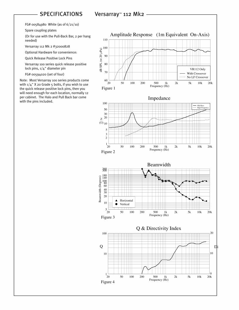
This measurement is useful in determining how accurately a given unit reproduces an input signal. The frequency response of the Versarray 112 is measured at a distance of 1 meter using a 1 watt (into the nominal impedance) swept-sine input signal. As shown in �gure 1, the selected drivers in the Versarray 112 combine to give a smooth frequency response from 110 Hz to 20 kHz, with signal processing.
Directivity
Beamwidth is derived from the -6 dB points from the polar plots which are measured in a whole space anechoic environment. Q and Directivity Index are plotted for the on-axis measurement position. These are speci�cations that provide a reference to the coverage characteristics of the unit. These parameters provide insight for proper placement and installation in the chosen environment. The blending of the components of the Versarray 112 and the Peavey VSX™ 26 or Peavey Digitool™ MX speaker processor and crossover with the Versarray 112 pre-sets, exhibit a desirable beamwidth and directivity (�gure 3 & 4) suitable for sound reinforcement applications.
Power Handling
There are many di�erent approaches to power handling ratings. Peavey rates this loudspeaker system's power handling using the AES Standard 2-1984. Using audio band pink noise of the proper range for each driver, with peaks of four times the RMS level, and then running the signal through either the Peavey VSX 26 or Peavey Digitool MX speaker processor and crossover with the Versarray 112 MK2 pre-sets, this strenuous test signal assures the user that every portion of this system can withstand today's high technology music. This rating is contingent upon having a minimum of 3 dB of ampli�er headroom available.
SPECIFICATIONS Versarray™ 112 Mk2
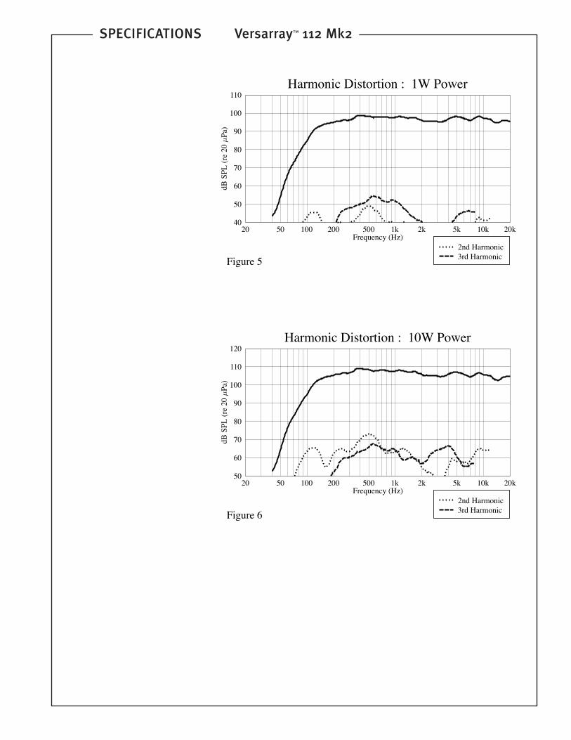
Harmonic Distortion
Second and third harmonic distortions vs. frequency are plotted in figures 5 & 6 for two power levels. Those levels are one watt of input power and ten watts of input power, to the woofer, at 1 kHz. Distortion is read from the graph as the difference between the fundamental signal (frequency response) and the desired harmonic. As an example, a distortion curve that is down 40 dB from the fundamental is equivalent to 1% distortion.
Mounting
Caution: Before attempting to suspend this speaker, consult a certified structural engineer. Speaker can fall from improper suspension, resulting in serious injury and
property damage. Other enclosures may be suspended below one. See the Owner's Manual/Spec Sheet for the appropriate fly bar being used, for safety ratings and limits.
Maximum enclosure angle 45°. Use only the correct mating hardware. All associated rigging is the responsibility of others.
Architectural & Engineering Specifications
The loudspeaker system shall be a two-way, sealed enclosure with a built-in cabinet-to-cabinet rigging and angle adjustment system included. The unit shall have an operating bandwidth of 110 Hz to 20 kHz, with signal processing. The nominal output level of the woofer shall be 96 dB, and of the tweeters 99 dB when measured at a distance of one meter with an input of one watt. The nominal impedance shall be 8 ohms for the woofer, and internally switchable to either 4 or 16 ohms for the tweeters. The maximum continuous power handling for the woofer shall be 500 watts, maximum program power of 1,000 watts and a peak power input of at least 2,000 watts, and for the tweeters it shall be 80 watts continuous, maximum program power of 160 watts and a peak power input of at least 320 watts, with a minimum amplifier headroom of 3 dB. The woofer shall be a Peavey Black Widow® Neo series, with a 4" voice coil, and the two tweeters shall be a Peavey RD™ 1.6 with true ribbon construction, transformer coupled to the driving amplifier used. The tweeters shall be provided with a self-resetting protection circuit internal to the cabinet to help prevent damage to the tweeters during a power overload condition.
Input shall be via two Neutrik Speakon type 4-pin jacks connected in parallel.
The nominal radiation geometry shall be 90 degrees in the horizontal plane and 15 degrees in the vertical plane for a single Versarray 112 MK2 cabinet.
The outside dimensions shall be 14.06 inches high by 25.25 inches wide by 11.75 inches deep. The cabinet shall be constructed of 18 mm 13 ply birch plywood. The weight shall be 56 pounds. The loudspeaker system shall be a Peavey model Versarray 112 MK2.
Caution! Important Safety Information:
CAUTION ! Before attempting to suspend this speaker, consult a certified structural engineer. Speaker can fall from improper suspension, resulting in serious injury
and property damage. Use only the correct mating hardware. All associated rigging is the responsibility of others.
NOTE: Before you fly the array, be sure to inspect the rigging and flying hardware to insure that it is mechanically sound and has not been damaged, there
should be no significant distortion of the shape of the coupling
brackets, cabinet brackets, or fly bar, and the hardware should be checked for tightness.
IF ANY OF THE BRACKETS, OR THE FLY BAR HAS BEEN DAMAGED OR DISTORTED, DO NOT USE, AND DO NOT FLY THE ARRAY UNTIL THEY CAN BE REPLACED OR REPAIRED!
WARNING! DO NOT USE THE COUPLING BRACKETS OR THE PULL-BACK BAR AS HANDLES TO TRANSPORT THE CABINETS! USE THE HANDLES BUILT-IN TO THE ENDS/
SIDES OF THE CABINETS FOR TRANSPORT.
Failure to follow proper rigging specifications listed in this manual may result in injury or death.
CAUTION: ALWAYS USE SAFETY CHAIN AND INSPECT RIGGING ANNUALLY
The Versarray™ 112 Mk2 normally has the coupling brackets mated to the cabinet brackets by using the supplied Grade 5, 1/4" X 20 bolts. If these bolts are used for a permanent installation, we recommend the use of a thread-locking compound on the threads once the final angles of the array have been determined.
If using the optional 1/4" diameter Quick Release Positive Lock Pins, when the Quick Release Positive Lock Pins are inserted, they should be fully seated, so that the black shoulder near the middle of the pin has been placed flush with the side of the bracket. You will have to fully depress the center push-button to do this. You should not be able to pull these pins out unless the center push-button is fully depressed.
If you desire to use the Quick Release Positive Lock Pins instead of bolts for the coupling brackets on the Versarray™ 112 Mk2, they are Peavey service part number 31501056, and Accessory part number 00594020 (This is a set of four pins).
NOTICE: The Quick Release Positive Lock Pins from the Versarray™ 200 series WILL NOT fit into the rigging system holes on the Versarray™ 100 series. The Versarray™ 200 series uses 3/8" diameter pins, and the Versarray™ 100 series uses 1/4" diameter pins.
The Versarray™ 112 Mk2 loudspeaker system modules ship with Grade 5, 1 / 4" X 20 bolts to connect the coupling brackets to the cabinets, the Quick Release Positive Lock Pins are an accessory option for use on the coupling brackets. The Versarray™ Model 25 Halo / Array Fly Bar ships with three Quick Release Positive Lock Pins per side to couple to the first cabinet’s coupling plate. The Versarray™ Model 25 Pull-Back Bar/ Small Array Fly Bar ships with one Quick Release Positive Lock Pin per side to couple to the first or last cabinet’s coupling plate.
If you are not sure how to assemble the rigging or how to fly the array once it has been arrayed, consult a certified structural engineer.
DO NOT OVER-TORQUE HARDWARE.
CAUTION: ALWAYS USE SAFETY CHAIN
INSPECT RIGGING ANNUALLY
Warning! Do not feed a full-range signal to the tweeters in the Versarray 112! This could damage the tweeters and/or the driving amplifier!
These ribbon tweeter diaphragms are transformer coupled to the power amp, and present a very low impedance load below 300 Hz.
SPECIFICATIONS Versarray ™ 112 Mk2It is recommended that for set-up or testing purposes, a high frequency sweep starting or ending no lower than 300 Hz be used to verify that the tweeters are connected to the high frequency output of the crossover/processor. If the wiring has been swapped, and the signal is mistakenly fed to the woofers, output will fall off significantly above 5 kHz. Always double-check and test your wiring before applying any music signals to the system! The ribbon tweeters are connected to the Neutrik® Speakon® pins 2+ and 2-, as per industry standards.
If there is any chance that trained personnel are not going to be connecting and operating the system, then it would be advisable to place a high quality polypropylene film cap in series with the tweeters, 40 uF for a 4 ohm wiring, and 10 uF for a 16 ohm wiring.
CAUTION! Ribbon Tweeters do not exhibit audible signs of distress when overloaded! It is possible to exceed the physical and/or thermal limits by overloading the unit suddenly with excess power, even though there are no obvious sounds of distress.
CAUTION! In order to prevent damage to the ribbon tweeters, keep the Versarray 112 system away from metal filings at all times. Do not expose ribbons to blasts of air, and do not use canned air to spray the ribbons, as this can result in damage. Do not expose ribbons to liquids or caustic fumes, and keep away
from salt spray.SPECIFICATIONS:
The Versarray 112 Mk2 Ribbon Tweeter Line Source Array module consists of a 12" Neo Black Widow® woofer combined with a Neodymium based Peavey RD™ 2.6 ribbon tweeter in a cabinet with a highly flexible rigging system.
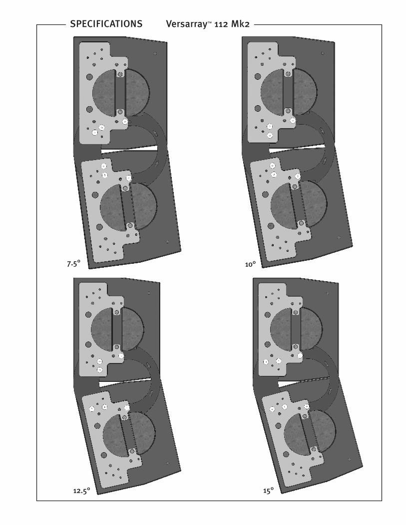
Designed to provide modular coverage of small to medium venues, and intended for use with the companion Versarray Sub models, the Versarray 112 Mk2 offers extreme versatility for such high performance capability. The two-way system consists of the following driver components: a 12" Black Widow ® Neo series woofer with Neodymium magnet structure. Capable of over 500W of continuous power handling (AES Std 2-1984), the woofer can handle a lot of sheer power. The high frequencies are handled by two Peavey RD™ 2.6 ribbon tweeters utilizing a composite sandwich ribbon, a Neodymium magnet system, and a low distortion waveguide. The new ribbon tweeters handle 50% more power than the original versions, and provide 2 dB more sensitivity, increasing reliability and HF output capacity. The new Mk 2 version also now has the tough Hammerhead ™ polyurea textured black finish instead of acrylic paint.Full range input connection to the system is made via two 4 pin Neutrik® Speakon® jacks. The total impedance presented by the ribbons can be adjusted to 16 ohms or 4 ohms via an internal jumper on the input cup, providing flexibility in how a line array is wired for amplifier use. Peavey’s proprietary protection circuitry, Sound Guard ™ , provides long and medium term driver overload protection for the tweeter without impairing musical transients or dynamics. The adjustable rigging system provides for a classic straight line-array configuration, or a number of different angling options, providing easy aiming of the system. Angles between the array modules is adjustable from 0 degrees (straight), to 7.5 degrees in 2.5 degree increments. Total angle between two cabinets is 15 degrees. This provides the capability to create a completely straight line array of 6 or more modules, or a curved array of 6 or more modules, with a recommended maximum total of 5 degrees of angle between each module for continuous and even coverage, for a total vertical coverage pattern of up to 40 degrees, or somewhere in between a 5 degree pattern (straight line array) and a 40 degree pattern (8 cabinets with 5 degree curve).
Bolts are supplied with the rigging hardware to couple the
Versarray ™ 112 Mk2modules together and lock the anglesbetween them into place, but optional quick release pins are available for quick and easy field adjustments or re-configurations of a line array.
The flexibility of the Versarray system allows the use of anywhere from 1 to 16 Versarray 112 Mk2 modules in conjunction with anything from one Versarray 118 Sub to as many Versarray 218 Subs as you can power!
An optional special bracket set mounts to the Versarray 218 Sub, and allows up to three of the Versarray 112 Mk2’s to be mounted on top of the Versarray 218 Sub, and angled upward, for use on stage in a stadium seating situation.
In addition, a lift kit co-designed with Vermette, and available as an accessory, can elevate up to six Versarray 112 Mk2 modules 13 feet high above a 218 sub, then fold down for easy transport and storage.
Processor Settings
Versarray 112 Mk2 Processor Settings
Single VR112 Mk2 Cabinet w/118 Sub (Starting point)
Front End EQ (before the crossover section) = PEQ –2.0 dB @ 2k, bw= 0.577 (or use 1/3 octave band at 2 kHz set to –2.0 dB);
Chart for Changes with Number of VR112 Mk2 Cabinets
No. of Cabs: 1 2 3 4 6 8
218 Sub
Level†: -6.0 dB 2.5 dB 0.5 dB +1.5 dB +4 dB +5.5 dB
12" Wfr
Level: -1.5 dB -1.5 dB -1.5 dB -1.5 dB -1.5 dB -1.5 dB
Twtr
Level: 0.0 dB +2.0 dB +4.0 dB +5.5dB +6.5 dB +7.0 dB
(Drive levels are for 16 ohm wiring, for 4 ohm wiring, subtract 6 dB)
Front End (Global) EQ‡
at 2 kHz 2.0 dB - - - - -
at 1.8 kHz - -3.0 dB -3.5 dB -3.5 dB -4.0 dB -4.5 dB
(at a bw set to 0.577) bw=.707 bw=.707
SPECIAL NOTE: These settings have been carefully selected to provide the best performance the Versarray™ 112 Mk2system is capable of, and provide maximum sound quality with good reliability.
Bessel filters have a non-intuitive frequency setting compared to Linkwitz-Riley or Butterworth filters, and may give the impression that there is a severe under-lap at the crossover frequency. This is not the case, and all factors have been taken into account, including the acoustic behavior of the drivers into the waveguide load. If you have ANY concerns or questions about crossover and EQ settings, please contact Peavey Transducer Engineering.
† SPECIAL NOTE: Versarray 218 Sub is in 4 ohm mode (woofers paralleled).
If the Versarray 218 Sub woofers are driven separately, using an amp with the same gain as all the other amps, then drive level to the separate woofers is the same.
To convert the above drive levels for a single Versarray 218 Sub to drive levels suitable for a single Versarray 118 Sub, add 6 dB.
When doubling the number of Subs, subtract 6 dB for each time they are doubled.
‡ SPECIAL NOTE: To match this PEQ setting with a 1/3 octave band EQ, use the following:
To equate to a PEQ setting of –3 dB @ 1.8k, bw= 0.58, use 1/3 octave band 2 kHz set to –1.5 dB AND 1/3 octave band 1.6 kHz also set to –1.5 dB
To equate to a PEQ setting of –3.5 dB @ 1.8k, bw= 0.58, use 1/3 octave band 2 kHz set to –2 dB AND 1/3 octave band 1.6 kHz set to –1.5 dB
To equate to a PEQ setting of –4 dB @ 1.8k, bw= 0.707, use 1/3 octave band 2 kHz set to –2.0 dB AND 1/3 octave band 1.6 kHz set to –2.0 dB
To equate to a PEQ setting of –4.5 dB @ 1.8k, bw= 0.707, use 1/3 octave band 2 kHz set to –2.5 dB AND 1/3 octave band 1.6 kHz set to –2.0 dB
Limiters
(DO NOT DEPEND ON THE LIMITER to prevent damage!)
VSX-26 Limiter Settings
Power Amp Gain set to 40X (32 dB)
Versarray 218: Threshold: +7.0 dB
Ratio: 20:1
Attack: 100 mS
Release: 1000 mS
Versarray 112
Woofer: Threshold: +4.0 dB
Ratio: 20:1
Attack: 60 mS
Release: 600 mS
Ribbon: Threshold: - 1.0 dB
Ratio: 20:1
Attack: 10 mS
Release: 100 mS
Input Limiter: Threshold: +22 dB
Ratio: 20:1
Attack: 50 mS
Release: 500 mS
Note: The VSX26 references the limiter settings to 0 dBu, which is at –24 dBFS.
DIGITOOL® MX Limiter Settings
Input Gain Block= 18 dB
Output Gain Block= 24 dB
Power Amp Gain set to 40X (32 dB)
Versarray™ 218: Threshold: - 17.0 dB
Ratio: 20:1
Attack: 100 mS
Release: 1000 mS
Versarray 112
Woofer: Threshold: - 20.0 dB
Ratio: 20:1
Attack: 60 mS
Release: 600 mS
Ribbon: Threshold: - 25.0 dB
Ratio: 20:1
Attack: 10 mS
Release: 100 mS
Input Limiter: Threshold: - 2 dB
Ratio: 20:1
Attack: 50 mS
Release: 500 mS
Note: The Digitool® references the limiter settings to 0 dBFS, or the maximum digital output levels of the system.
Line curvature, or splay between cabinets
Splaying the line will tend to require more level increase from the tweeters, and some more cut EQ at 1.8 kHz.
SPECIFICATIONS Versarray™ 112 Mk2A uniform splay of 2.5 degrees between cabinets for an 8 cabinet array would need approximately 2 dB of tweeter boost, and 0.5 dB of 12" woofer level increase, relative to a subwoofer level. A uniform splay of 5 degrees per cabinet for an 8 cabinet array would require approximately 5 dB of tweeter level boost, and approx. 1 dB of 12" woofer level increase, relative to a subwoofer.
Complete processor settings for the recommended 2.5 degree continuous curvature with 6 Versarray 112 Mk2 cabinets and one Versarray 218 Sub:
Front End EQ (before the crossover section) = PEQ –4.0 dB @ 2k, bw= 0.707 (or use 1/3 octave band 2 kHz set to –2.5 dB AND 1/3 octave band 1.6 kHz set to –2 dB)
Versarray™ 218 Subs are in 4 Ohm mode (woofers paralleled). There is an internal jumper change to allow individual access via a 4 Pole Neutrik Speakon and 4 conductor cable.
If the Versarray 218 Subs are desired to be driven separately, using an amplifier with the same gain as the other amps, the drive level to the separate woofer is the same.
To convert the above drive levels for a single Versarray 118 Sub enclosure; add +6 dB gain.
When doubling the number of Subs, subtract –6 dB for each doubling of Subs.
AUX fed Subs
When using AUX fed Subs, or boosting the level of the normally crossed over Subs more than 4-6 dB above a truly flat level, the low pass crossover point needs to be adjusted down. For the Regular Processor Settings, this would mean crossing the Subs over at 100 Hz instead of 125 Hz, using a 24 dB/oct. LR crossover. If running the Subs at 10 dB or more above a truly flat level (not uncommon for concert or DJ venues), the low pass crossover point of the Subs needs to be adjusted down to 90 Hz, and some
EQ pull-back may be required around 200 –250 Hz.
NOTE: Check with Peavey Transducer Engineering for the latest info on more recent settings and any changes to the EQ.
Paralleling Versarray 112 Mk2 drivers on one amp channel
The ribbon tweeters impedance can be configured to be in either a 16 ohm load (factory default) or a 4 ohm load. In 16 ohm impedance configuration, we do not recommend paralleling 8 cabinet’s high frequency sections together off of one amplifier channel, even if the amp is rated for 2 ohm operation. The same goes for paralleling two cabinet’s high frequency sections together when the high frequency section is configured for 4 ohm impedance. This also applies to the 12" woofers, we do not recommend paralleling 4 cabinet’s low frequency sections together.
In general, avoid loading a 2 ohm rated amp all the way down to 2 ohms, the Versarray 112 Mk2 system is revealing enough to highlight any roughness or harshness when the amp is on the edge of it’s capabilities. We recommend keeping the amp load above 2.6 ohms when the amp is rated for 2 ohm operation.
Versarray Maximum Input Voltages
Versarray 218 Subwoofer: 89 VRMS continuous, 178 VRMS peak or momentary (with proper infrasonic and low pass filters engaged)
Versarray 118 Subwoofer: 89 VRMS continuous, 178 VRMS peak or momentary (with proper infrasonic and low pass filters engaged)
Versarray 112 Mk2 Woofer: 57 VRMS continuous, 114 VRMS peak or momentary (with proper band pass crossover filters used)
We strongly recommend that a power amp be used with a peak voltage rating that is not substantially higher than the peak voltage rating of the driver it is connected to. There will be no further significant increase in SPL, and a much higher chance that an accident or mistake will damage the speaker system.
PEAVEY Power Amp Peak Output Voltages
CS 4080 Maximum RMS Voltage Output – 115 volts
CS 4000 Maximum RMS Voltage Output – 93 volts
CS 3000 Maximum RMS Voltage Output – 86 volts
CS 2000 Maximum RMS Voltage Output – 72 volts
CS 1400 Maximum RMS Voltage Output – 61 volts
CREST Power Amp Peak Output Voltages
Pro 9200 Maximum RMS Voltage Output – 113 volts
Pro 8200 Maximum RMS Voltage Output – 90 volts
Pro 7200 Maximum RMS Voltage Output – 75 volts
Pro 5200 Maximum RMS Voltage Output – 52 volts
Processor Setting Parameters
For processor’s that use the parameter “Q" in octaves instead of bandwidth, here is a chart to convert from bw to Q. NOTE: Q is not as well defined as bandwidth, so some processors may have Q settings that do not exactly correspond to the chart conversions, they may need to be set to one click higher or
SPECIFICATIONS Versarray™ 112 Mk2lower than the chart indicates.
Bandwidth (bw) to Q Chart
ß BW Q .
0.25 5.764
0.500 2.871
0.577 2.484
0.707 2.020
1.00 1.414
1.305 1.069
1.50 0.920
2.00 0.667
2.50 0.511
Check with Peavey Electronics Corp., or visit the Peavey web site at:
http://www.peavey.com
for the latest crossover and EQ setting information
INFORMATION ON THE FLYING HARDWARE FOR THE
Versarray™ 112 Mk2Mk2 (Available Separately)
Peavey® Versarray Model 25 Halo / Array Fly Bar
(formerly called the Versarray 112 Halo / Array Fly Bar)
Description
The Versarray Model 25 Halo / Array Fly Bar is designed to be used in conjunction with the Versarray Model 25 Pull-Back Bar, to safely rig and fly various models of Peavey speakers, including the Versarray 100 series.
It includes four 1/2" X 13 thread eyebolts with 1 1/8" I.D. eyes for rigging on the top of the bar, and a Versarray coupling bracket interface, with holes for three captive 1/4" Quick Release Push Pins, on either side of the bottom of the bar.
Coupling brackets are normally supplied with the Versarray speaker modules, and are not included with the Versarray™ Model 25 Halo/Array Fly Bar.
Specifications:
Dimensions: (H x W x D)
10.63" X 27.50" X 38.12"
Weight: 30.0 kg / 66 lbs.
Material: All steel construction, 2" by 3" welded steel frame tubes with 3/16" wall thickness, center tongue 1/2 " thick by 3" solid steel with _" rigging holes along it’s length, coupling bracket mounts are dual 1/8" thick steel plates, one set on each side. MIL spec eyebolts.
Finish: Entire Halo is flat black powder coated paint finish.
Working Load Limit: 409.1 kg / 900 lbs.
Ultimate Strength Design Factor: 7:1
Maximum Number of Versarray 112 Mk2 Cabinets Hung or Flown: 16
Maximum Pull-Back Angle: 45 degrees
Maximum Number of Versarray 112 Mk2 Cabinets for Ground Stack : 6
(When used with the Versarray Model 12 GSS bar)
Current Peavey FG#00588790 (as of 6/21/10)
NOTES: The ultimate strength for the Versarray 112 Mk2 loudspeaker system module rigging points was determined utilizing calibrated and certified destructive pull tests.
Before you fly the array, be sure to inspect the rigging and flying hardware to insure that it is mechanically sound and has not been damaged, there should be no significant distortion of the shape of the coupling brackets, cabinet brackets, or fly bar, and the hardware should be checked for tightness.
IF ANY OF THE BRACKETS, OR THE FLY BAR HAS BEEN DAMAGED OR DISTORTED, DO NOT USE, AND DO NOT FLY THE ARRAY UNTIL THEY CAN BE REPLACED OR REPAIRED!
DO NOT USE THE COUPLING BRACKETS AS HANDLES TO TRANSPORT THE CABINETS!
Use only the correct mating hardware. All associated rigging is the responsibility of others.
NOTICE: The Quick Release Positive Lock Pins from the Versarray
200 series WILL NOT fit into the rigging system holes on the Versarray 100 series. The Versarray 200 series uses 3/8" diameter pins, and the Versarray 100 series uses 1/4" diameter pins.
Peavey® Versarray Model 25 Pull-Back Bar/ Small Array Fly Bar (formerly called the Versarray 112 Fly Bar)
Description
The Versarray Model 25 Pull-Back Bar is designed to be used in conjunction with the Versarray Model 25 Halo/Array Fly Bar, to safely rig and fly various models of Peavey speakers, including the Versarray 100 series.
It can also be used by it self as a small array fly bar, to fly no more than a maximum of seven Versarray 112 Mk2 cabinets. In this mode, it can be coupled directly to the VersaLift™ lift to fly up to six Versarray 112 Mk2 cabinets up to 13 feet above ground, centered over a Versarray 218 Sub. Shackles are included for coupling to the VersaLift, or other rigging.
We recommend that for any line arrays of more than six Versarray
112 Mk2 cabinets, that the Versarray Model 25 Halo/Array Fly Bar be used in conjunction with the Versarray Model 25 Pull-Back Bar/Small Array Fly Bar as a pull-back bar.
It incorporates two 3/8" X 16 thread eyebolts with 1" ID eyes for rigging on the top (or rear) of the bar, and a Versarray coupling bracket interface on each side of the bar, with holes for captive 1/4" Quick Release Push Pins (included), on either side of the bar.
Specifications:
Dimensions: (H x W x D)
4.13" X 27.50" X 1.75"
Weight: 1.8 kg / 4 lbs.
Material: All Steel construction, 1" square steel tubing with 1/8" wall thickness, end fittings made from 1/8" steel plate. MIL spec eyebolts & shackles.
Finish: Flat black powder coated paint finish.
Working Load Limit: 196.4 kg/432 lbs
Ultimate Strength Design Factor: 9.6:1
Maximum Number of Versarray™ 112 Mk2Cabinets Hung or Flown: 7
Maximum Pull-Back Angle: 45 degrees
Current Peavey FG# 00584970 Black,
20 50 100 200 500 1k 2k 5k 10k 20kFrequency (Hz)
60
70
80
90
100
110
dBSP
L(r
e20
Pa)
Amplitude Response (1m Equivalent On-Axis)
No LF CrossoverWith Crossover
VR112 Only
Figure 1
20 50 100 200 500 1k 2k 5k 10k 20kFrequency (Hz)
1
10
100Q & Directivity Index
Q
Figure 4
20
10
Di
0
20 50 100 200 500 1k 2k 5k 10k 20kFrequency (Hz)
5
10
2030406080
100140180300360
Bea
mw
idth
(Deg
rees
)
Beamwidth
VerticalHorizontal
Figure 3
20 50 100 200 500 1k 2k 5k 10k 20kFrequency (Hz)
1
235
10
203050
100Impedance
High FrequencyMid Bass
Z( )
Figure 2
SPECIFICATIONS Versarray™ 112 Mk2
FG# 00584980 White (as of 6/21/10)
Spare coupling plates
(Or for use with the Pull-Back Bar, 2 per hang needed)
Note: Most Versarray 100 series products come with 1/4" X 20 Grade 5 bolts, if you wish to use the quick release positive lock pins, then you will need enough for each location, normally 12 per cabinet. The Halo and Pull Back bar come with the pins included.
20 50 100 200 500 1k 2k 5k 10k 20kFrequency (Hz)
50
60
70
80
90
100
110
120
dBSP
L(r
e20
Pa)
Harmonic Distortion : 10W Power
Figure 6 3rd Harmonic2nd Harmonic
20 50 100 200 500 1k 2k 5k 10k 20kFrequency (Hz)
40
50
60
70
80
90
100
110
dBSP
L(r
e20
Pa)
Harmonic Distortion : 1W Power
Figure 5 3rd Harmonic2nd Harmonic
SPECIFICATIONS Versarray™ 112 Mk2
SPECIFICATIONS Versarray™ 112 Mk2
Input Cup
SPECIFICATIONS Versarray™ 112 Mk2
Dimensions
11.625
13.875
24.918 WITHOUT BRACKET
25.184 WITH BRACKET
11.625
25.184 WITH BRACKET
24.918WITHOUT BRACKET
SPECIFICATIONS Versarray™ 112 Mk2
0° 0° 2 Pin
2.5° 5°
SPECIFICATIONS Versarray™ 112 Mk2
15°
10°7.5°
12.5°
SPECIFICATIONS Versarray™ 112 Mk2
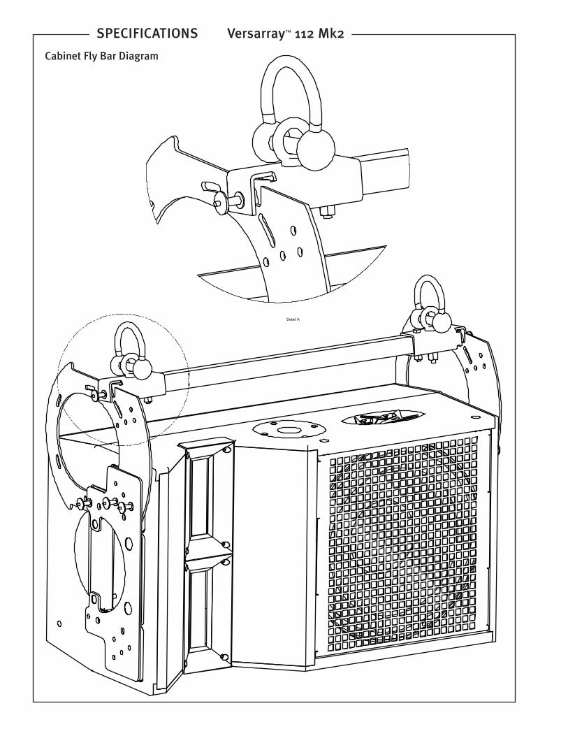
Detail A Scale 1 : 1
?
Cabinet Fly Bar Diagram
SPECIFICATIONS Versarray™ 112 Mk2
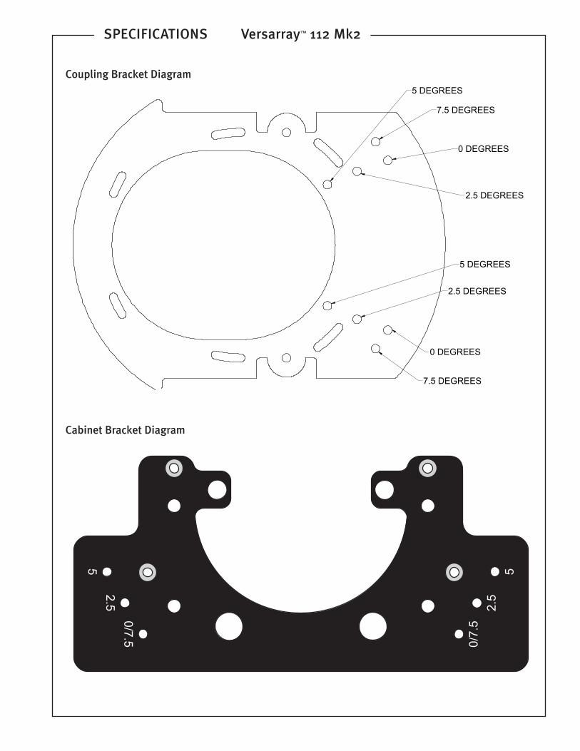
Coupling Bracket Diagram
Cabinet Bracket Diagram
Logo referenced in Directive 2002/96/EC Annex IV(OJ(L)37/38,13.02.03 and defined in EN 50419: 2005The bar is the symbol for marking of new waste and
is applied only to equipment manufactured after13 August 2005
www.peavey.comWarranty registration and information for U.S. customers available online at
www.peavey.com/warrantyor use the QR tag below
Features and speci�cations subject to change without notice.