STARTUP AND COMMISSIONING OF PRESSURIZED WATER REACTORS by L J. ALBERT C. F. GILBERT Presented at COMMISSIONING SYMPOSIUM Toronto, Canada May 3,1983 TP 82-36 STONE * WEBSTER ENGINEERING CORPORATION BOSTON, MASSACHUSETTS 19
Transcript
STARTUP ANDCOMMISSIONING OF
PRESSURIZED WATER REACTORS
by
L J. ALBERTC. F. GILBERT
Presented atCOMMISSIONING SYMPOSIUM
Toronto, CanadaMay 3,1983
TP 82-36
STONE * WEBSTER ENGINEERING CORPORATIONBOSTON, MASSACHUSETTS
19
B3-5311301-282
STARTUP AND COMMISSIONING OF PRESSURIZED WATER REACTORS
by
L. J. AlbertChief Engineer, Advisory Operations Division
C. F. GilbertAssistant Chief Engineer, Advisory Operations Division
ABSTRACT
One of the most critical phases of plant development is the test,startup, and commissioning period. The effort expended in the initialphases prior to commissioning has a definite effect on the reliabilityand continuing availability of the plant during its life.
The purpose of this paper is to describe what, in the authors' opinion,has proven to be a well-coordinated and effective test, startup, andcommissioning program for a pressurized water reactor (PWR) plant.
This program commences with the completion of construction and continuesthrough the turnover of equipment/systems to the owner's startup/commissioning group.
The paper addresses such major items as organization of the test/startupgroup, planning and scheduling, test procedures and initial testing,staffing and certification of the test group, training of operators, andturnover to the owner.
INTRODUCTION
The startup and commissioning process for pressurized water reactors(PWR) (or, in fact, any nuclear or fossil-fueled electric generatingfacility), is a continuous and overlapping series of activities. Theseactivities commence with initial program planning and continue throughinitial fuel load and commercial operations. This paper highlights somemajor areas which must be addressed prior to and during this program.
The nuclear licensing process has always required that plant designfeatures and components be tested to a degree uncommon to otherindustrial facilities. With present day requirements being morestringent, presented is a formal startup/commissioning program which isdescribed in Stone & Webster Engineering Corporation's (SWEC) StandardTest Program Manual. This program is based on programs that SWEC hassuccessfully conducted and is presently conducting for nuclear plantstartups. This program is intended to ensure that the design objectivesof the plant are being met to the satisfaction of not only the regulatoryagencies and the owner, but also of the NSSS, vendor, and staff of theengineer/constructor (E/C).
STONE ft WEBSTER
B3-5311301-282
TEST PROGRAM ORGANIZATION AND ADMINISTRATION
At the inception of a test/startup commissioning program, it isimperative that all parties involved with such a program be in agreementas to duties and responsibilities. An administrative procedure should bedeveloped, assigning specific duties and responsibilities throughout theentire program to eliminate confusion and assure continuous smooth flowof the test program.
Once a distinct line of responsibilities has been established, astartup/test/commissioning schedule or network should be developed andinterfaced with the engineering and construction schedules.
Scheduling of events and milestones, once established on a planningnetwork, will clearly define the necessary steps, sequence, andinterrelationship of events required to attain the milestones and alsowill provide the means for staffing the program.
Further expansion of the schedule may be required as the programprogresses; each system may be fragneted to facilitate completion ofconstruction and testing of the system prior to release for initialoperations. The planning and scheduling activity is discussed later.
SYSTEM STARTUP ACTIVITIES LOGIC DIAGRAM
The early development of a startup logic test program (time frames)provides a means of identifying responsibility for major phases of thestartup and test program.
An ideal logic for the site test/commissioning program would establishfour phases of activities, i.e., installation phase, preliminary testphase, preoperational test phase, and startup phase. This logic wouldclearly delineate the administrative itemi that affect the constructionand operations group.
A typical site test program activities logic is shown in Figure 1.
Phase I - Installation Phase
This phase depicts those items required to be performed by theconstruction forces prior to release to the startup test organization.
Phase II - Preliminary Test Phase
This phase is conducted by the startup test organization followingacceptance from construction, and includes the testing of the variouscomponents and initial operation of each component necessary for thecompletion of a functional system.
STONE * WEBSTER
B3-5311301-282
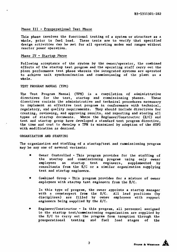
Phase III - Preoperational Test Phase
This phase involves the functional testing of a system or structure as awhole, prior to fuel load. These tests are to verify that specifieddesign activities can be met for all operating modes and ranges withoutreactor power operation.
Phase IV - Startup Phase
Following acceptance of the system by the owner/operator, the combinedefforts of the startup test program and the operating staff carry out theplant performance test phase wherein the integrated systems are operatedto achieve unit synchronization and commissioning of the plant as awhole.
TEST PROGRAM MANUAL (TPM)
The Test Program Manual (TPM) is a compilation of administrativedirectives for the test, startup and commissioning phases. Thesedirectives contain the administrative and technical procedures necessaryto implement an effective test program in conformance with technical,regulatory, and quality requirements. They should include directives forcreating, reviewing, and approving results, and reporting and storing alltypes of startup documents. Where the Engineer/Constructor (E/C) andtest and startup group have developed a standard test program directive,the time and cost to develop a TPM is minimized by adoption of the STPDwith modification as desired.
ORGANIZATION AND STAFFING
The organization and staffing of a startup/test and commissioning programmay be any one of several variants:
• Owner Controlled - This program provides for the staffing ofthe startup and commissioning program using only owneremployees as startup test engineers, supplemented byconsultants from the E/C or a similar organization supplyingtest and startup engineers.
• Combined Group - This program provides for a mixture of owneremployees with startup test engineers from the E/C.
In this type of program, the owner appoints a startup managerwith a counterpart from the E/C. All lead positions (bydisciplines) are filled by owner employees with supportengineers being supplied by the E/C.
• Engineer/Constructor - In this program, all personnel assignedto the startup test/commissioning organization are supplied bythe E/C to carry out the program from inception through thepreoperational testing and fuel load stages of the
STONE & WEBSTER
B3-5311301-282
commissioning program. At that time, the owner's staff assumesthe responsibility for the test to be performed prior tosynchronization and power ascension testing, with the E/Cpersonnel assuming a support or consultant role.
During this program, an employee of the owner is appointed as aliaison engineer with the senior startup engineer to coordinatethe efforts of all parties to carry out a successfulstartup/commissioning program.
Staffing
Regardless of the type of organization being utilized to carry out thestartup/test commissioning program, the staffing is essentially the same.The successful completion of a startup commissioning program will dependgreatly on the expertise and coordinating abilities of the startupmanager or senior startup engineer. Extreme care should be exercised infilling these positions.
Manpower
The manpower required for a complete scope PWR nuclear plant startupcommissioning program is largely dependent on the time element for theprogram. The manpower requirements, in our experience, peak atapproximately 8 months prior to fuel loading. Reduction of staff startsapproximately 1 month prior to fuel loading with peak manpower as listedbelow:
Startup Test Engineer 45Technician - I&C 35Technician - Electrical 40Technician - Mechanical 20Operators to Support Program 35
Crafts people 100
A typical organization for this kind of program is shown in Figure 2.
TEST AND STARTUP PROGRAM ACTIVITIES
The activities involved in the overall startup/test commissioningprogram, controlled and under the direction of the startup manager, aredivided into two groups, headquarters (either E/C, owners, or at site)and field activities.
Example of these activities are shown in Figures 3 and 4.
TEST PROGRAM PROCEDURES
Test procedures are a set of written instructions for conducting a teston a component, system, or structure. There are two basic types ofprocedures instrumental in implementing a successful startup test/commissioning program, a generic test procedure and a specific testprocedure.
STONE & WEBSTER
B3-5311301-282
GENERIC TEST PROCEDURE
This is a test procedure that can be applied without modification tosimilar groups of components, systems, or structures. A generic testprocedure uses separate data sheets to record test data obtained fromeach test.
SPECIFIC TEST PROCEDURE
This is a test procedure that can be applied to a specific component,system, or structure.
PREPARING TEST PROCEDURES
Test procedures should be prepared by test personnel, and wherenecessary, the preparer should include hold points and specify the holdpoint activity. The preparer should include signature blocks for theinspector to sign upon completion of hold point activity.
Information for the preparation of the test procedure may be obtainedfrom the system description, purchase specifications, drawings, divisiontechnical guidelines, codes and standards, safety analysis reports, andmanufacturers' drawings and literature. The requirements and acceptancecriteria for the test should be obtained from approved, applicable designdocuments of the latest revision, including outstanding nonconformanceitems and engineering problems.
If the requirements and acceptance criteria for the test are unavailablefrom existing design documents, they may be developed by test personnelpreparing the test procedure. Such requirements and acceptance criteriamay be reviewed and approved.
TEST PROCEDURE REVIEWERS
Test procedures should be reviewed by the lead startup test engineer andthe responsible lead discipline engineer on the project. At least oneindividual approving the test procedure must be a certified level IIItest engineer in accordance with NRC Regulatory Guide 1.58, ANSI NA5.2.6,and ASME code sections III and XI.
Each test procedure should include the following sections, as applicable,in the order presented:
Cover SheetPurpose and ScopeGeneral Test MethodTest EquipmentPrerequisitesInitial ConditionsPrecautions and LimitationsProcedure
STONE &
B3-5311301-282
• Acceptance Criteria• Restoration of Equipment to Normal Status• Enclosures/Attachments• References
Cover Sheet
An appropriate cover sheet indicating the type of procedure should beattached to the front of each test procedure with the followinginformation included:
• Title of test procedure
• Test procedure number
• Revision number
• Issue date
• Preparer and approval signature
• Owner's name and power plant applicability
Purpose and Scope
The objective of the test and/or the reason for performing the testshould be stated, including an indication of the extent or scope of thetest.
For many system tests where each of several initiation events willproduce one or more desired actions, these initiating events andcorresponding actions should be identified.
General Test Method
This section should briefly describe the test method and the manner inwhich it will be implemented. The description should indicate the extentof non-standard or temporary arrangements required by this method. Thisdescription is not a step-by-step procedure, but it should be insufficient detail to allow the reader to understand how the test is to beconducted.
Test Equipment
This section comprises a list of the test equipment required to obtainthe necessary test data or to perform the test. Details to be included,as applicable, are quantity, range, setpoints, calibration requirements,cleanliness, and accuracy.
STONE & WEBSTER
B3-5311301-282
Prerequisites
A list of the prerequisites for the entire or for specific steps in thetest should be prepared. These prerequisites should include—
* A review of the applicable installation completion report toverify that outstanding items will not detrimentally affect thetest performance.
• A list of other tests or portions of tests required to havebeen satisfactorily completed.
•. An evaluation of any environmental condition applicable to thetest.
Initial Conditions
Included in this section is a list of plant conditions and/orinstructions pertaining to the configuration of the component, system, orstructure and supporting systems at the beginning of the test. The listshould indicate the equipment's operations status and should specify thecondition of the equipment affected.
Precautions and limitations
A list of the precautions to bs taken before, during, and after theperformance of the test to provide for the safety of personnel andequipment should be prepared. As applicable, it should identify maximumor minimum setpoints that may damage equipment or injure personnel,safety limitations that may be approached, personnel protective appareland devices, and any restrictions on personnel conduct pertaining to thetest, including OSHA regulations. Special precautions may be statedimmediately prior to the corresponding procedural activity.
Procedure
This section is a concise, step-by-step instruction to the testingpersonnel on how to conduct the test. The section will state which dataare to be collected and the form in which they are to be recorded. Itshould also indicate where the data are to be recorded. Steps requiringwitness or inspector signatures must be identified and provisions madefor recording such signatures.
Acceptance Criteria
The qualitative and/or quantitative acceptance criteria against which thesuccess or failure of the test will be judged, must be identified clearlyin this section. The criteria may be stated in this section, in theprocedural section, or on data sheets.
STONE at WEBSTER
B3-5311301-282
Restoration of Equipment to Normal Status
This section is a list of the instructions for restoring equipment tonormal status, pretest conditions, or some interim condition. Theseinstructions should include a checklist of components and systemconditions or configurations that must be achieved after the test iscomplete. The restoration must be verified and the list signed by theindividual performing the activity.
Enclosures/Attachments
This section includes data sheet(s) for recording the results of thetest; remark sheet(s) for pertinent information pertaining to the test,such as work on equipment or repairs needed to make the equipment work;and other attachments as necessary.
Each of these attachments should display the following information:
• The test procedure number and revision status
• An attachment number and the page number of each sheet of thatattachment, e.g. Attachment 6.2, sheet 1 of 2
• The test folder no. or file code no. or both
• The date and signature of those conducting and witnessing thetest
References
Documents, including the document number and revision status, should belisted for each document used as source information for the preparationof the test procedure.
MECHANICAL TEST PROCEDURES (MTP)
These procedures are normally prepared on a generic basis and usually are'implemented prior to or during initial equipment operation. Mechanicaltest procedures include, but are not limited to flushing procedures;pressure test procedures, both pneumatic and hydrostatic; containmenttest procedures; and structural, ventilation and vibrational testprocedures.
ELECTRICAL TEST PROCEDURES (ETP)
These procedures are normally used to test components and controlcircuits prior to testing the system in which they are incorporated.They include procedures for activities such as high potting, meggering,component testing, and control circuit checkout.
STONE a WEBSTER
B3-5311301-282
INSTRUMENTATION TEST DOCUMENTS (ITP)
These are documents used to verify the installation of instruments andtheir associated control loops, the calibration of each instrument andits loop, with the functional testing of the overall loop being recordedon a Loop Calibration Report. Instrumentation test documents includegeneric instrument calibration procedures, Loop Calibration Reports,Instrument Test Procedures, and Test Loop Diagrams.
TYPICAL TEST PROCEDURES
Typical test procedures used during the preliminary test phase or a PWRstartup test commissioning program are listed in the following table:
Mechanical
Ventilation Testing ProceduresContainment Testing ProceduresCleaning ProceduresFlushing ProceduresPressure Test ProceduresStructural Test ProceduresVibration Test ProceduresSpecial Mechanical Test Procedure
Electrical
Component Test ProceduresHipot Testing ProceduresMeggering ProceduresControl Verification PackageSpecial Electrical TestProcedures
Instrumentation
Instrument Calibration ProcedureLoop Calibration ReportsInstrument Test ProceduresTest Loop Diagram Special Instrument Test Procedure
PREOPERATIONAL AND ACCEPTANCE TESTS
Preoperational and acceptance testing is the final testing activity oncomponents, systems, and facilities prior to fuel loading. It must begiven top priority by all organizations involved in the test program.Acceptance tests meet the same requirements as preoperational tests, butthe term is applied generally to systems required for electrical powergeneration. The testing of nuclear safety related equipment, systems,and facilities is generally called preoperational testing. It is notintended to provide a complete list of all preoperational and acceptancetest procedures in this paper; however, this complete listing should beone of the first priorities when establishing the test program.
STONE ft WEBSTER
B3-5311301-282
As stated in Regulatory Guide 1.68, these tests "should demonstrate thatstructures, systems, and compc '̂-s will operate in accordance withdesign in all operating modes and throughout the full design operatingrange." In addition to meeting the above requirements, the procedureprogram should ensure that these test procedures address the followingobjectives:
• Establish base-line data for periodic surveillance tests
• Train plant operators
• Provide for trial testing of plant operating and emergencyprocedure
• Incorporate lessons learned from other operating power reactorexperience
• Verify warranty acceptance data for vendor supplied equipment
POWER ASCENSION TESTS
The power ascension testing program begins after fuel loading. It isnormally preceded by the post fuel load power testing and a partial hotfunctional test (completion of hot functional requires core differentialpressure). These tests include the reactor coolant system flow testingfor final modification of reactor protection system settings.
The power ascension testing is to verify that the overall plant operatesin accordance with design in all operating modes. This is done by steadystate operation at various power levels and also by subjecting the plantto various anticipated transients and postulated accidents. Therenormally is one main procedure which sequences the testing performedduring this program. Tests which are performed at various power levelsduring this program include—
Nuclear instrumentation calibrationReactivity coefficients at powerHeat balance testsControl and power shaping rod worthLoad swing testsTurbine/Reactor trip testTransient tests
PROCEDURE SCHEDULE
After the overall test program procedure requirements have beenidentified, a preparation schedule should be developed. Figure 5provides only a skeleton of the activities required in this schedule.The plant specific schedule should clearly define responsibilities notonly for preparation but also for review and approval activities for all
10STONE & WEBSTER
B3-5311301-282
identified procedures. It should be remembered that the final requiredcompletion date for a procedure may not be that required for implementa-tion, but may be determined by some other commitment. In general, thismeans regulatory agency review; however, other reasons could includetraining or input to other test activities. In any case, the actualmilestone requirement and interrelationship with other activities shouldbe identified on the schedule.
Figure 6 provides a list of some of the start dates for the proceduredevelopment activities. These start dates are intended to coincide withlater milestone activities. The main point to remember is to start earlyon those procedures or programs which require an extensive interface withother organizations or require special test equipment.
PLANNING AND SCHEDULING
A coordinated planning and scheduling program is essential inaccomplishing and controlling the magnitude of activities required to puta nuclear plant on-line. In general, this effort is necessary to—
• Define engineering and construction priorities
• Establish the overall critical path of the project
• Facilitate tracking the progress and status of the projectduring the startup and commissioning program
• Assess the impact of "change" to the project's end date
The planning and scheduling process for the test and startup program isaccomplished in several phases. The initial step is to identify eachunique system or subsystem that will finally constitute the entire plant.This effort should be completed early in a project, as soon as practicalafter the issue of the first engineering documents such as flow diagramsand electrical one-line diagrams. Once the system/subsystem boundaryidentification phase has been completed, the planning phase is started.
PLANNING PHASE
The planning phase defines how the startup program will be conducted.The planning phase should be accomplished by experienced startuppersonnel from the engineer/constructor, owner, nuclear steam supplier,and in some cases, special consultants experienced in plant startup.
During this period, all functions that must be performed to complete theentire test and startup program are identified. An initial test programsequence logic is developed and a clear milestone list is developed.
SCHEDULING NETWORKS
Once the system/subsystem boundaries have been identified and the startuplogic and milestones have been established, test and startup planning andscheduling networks are developed. SWEC uses three levels of planning
STONE « WEBSTER
B3-5311301-282
and scheduling networks.
Level I
The Level I test program network summarizes and highlights the majormilestones, events, and activities in the test program. This networkshould be prepared about 2 to 6 months after a project is authorized.Related systems are grouped in a logical sequence for testing in order toperform the identified milestones/events.
Some of the major milestones identified by the Level I network for a PWRinclude: energizing of the station service transformer, reactor pressurevessel hydro, steam generators hydro, hot functional testing, and fuelload. This network is not normally a working document but is used byproject management as input to the project summary network and report.
Level II
The Level II network is considered the most important planning network onthe project. It represents each system or subsystem from "release fromconstruction for testing through final client acceptance."
In addition, other milestone activities such as turbine/generator oilflushing, drawing vaccum on the condenser for the first time, energizingmajor buses, and other integrated test activities are identified.
It is recommended that the Level II network be prepared during thepre-construction phase of the project; ideally, prior to the developmentof the same level construction network. If this is impossible, thereshould be a complete interface with the construction and engineeringnetworks as early in a project as possible in order to identify anyunavoidable restraints.
Level III
The Level III network is occasionally called a subnet or fragnetdevelopment. These networks usually define each activity shown as anoverall activity on the Level II Network. In general, these networks arenot time scaled, but detail the sequence of events needed to complete theLevel II activity. Usually, the duration of time for each event isdefined on the network. The test engineering and craft techniciansrequired to support the activity should also be included. In order toclearly establish the total test activities involved in the Level III, amaterial take-off should be performed for each system or subsystem. Thiswill also provide input to construction and engineering as to what isrequired to support system startup. Exhibit VIII represents graphicallythe overall planning and scheduling activities discussed.
SPECIAL TESTING ASPECTS OF A PWR
As indicated previously, the program requirements for PWR startup andcommissioning do not differ significantly from those of any other nuclearpower generating facility; however, there are several equipment and
12STONE a WEBSTER
B3-5311301-282
technical areas, specific to FWRs, which require special attention duringthe test program. Three of these areas are Reactor Coolant Pumps, HotFunctional Testing, and Boron Shim Control.
REACTOR COOLANT PUMPS
The reactor coolant pumps are centrifugal type pumps which employ acontrolled leakage seal assembly. The seal assembly restricts theleakage along the pump shaft. For most pumps, there are secondary andthird stage seals which direct the control leakage out of the pump to theseal return cooler and also provide for system integrity in case of grossfailure of the primary controlled leakage seal. The seal assembly is themost critical area for most of the PWR reactor coolant pumps.
As the operation of the reactor coolant pumps is necessary to maintainrated reactor power with the integrity of the system being maintained bythe seals, special attention is required during initial operation andtesting.
This testing should include but not be limited to the following:
• Close observance by test personnel of the constructioninstallation and alignment process
• Complete and detailed checkout of the pump motor controlcircuit prior to operation, installation and checkout of pumpand motor vibration equipment
• Installation of additional test equipment, such as temperature,pressure flow, and vibration monitors in order to completelycheckout pumps, motors, and auxiliaries during initialoperations and testing
• Checkout of seal supply and return systems for pressure,temperature and flows prior to starting
In addition to the inspection, checkout, and testing of the pumps, motorsand auxiliaries discussed, it is recommended that the staff maintenancedepartment specially train pump maintenance teams. This training shouldinclude special training at the vendor's facility which could becontinued during plant operations. Certain mockups, particularly of theseal package area, should be purchased to provide maintenance training.This training can provide for more reliable pump operations and alsoreduce man-rem exposure during actual maintenance activities.
HOT FUNCTIONAL TESTING (HFT)
By coordinated use of the pressurizer electric heaters and heat inputfrom the reactor coolant pumps, normal operating pressure and near normaloperating temperature of the reactor coolant system is achieved. Whenthese conditions can be accomplished and an operable heat sink isavailable (normally the condenser), the HFT is performed.
13STONE a WEBSTER
B3-5311301-282
HFT provides an opportunity to check the operation of the reactor coolantsystem and other auxiliary and safety systems under near normal RCS poweroperating conditions prior to fuel loading with its technical andregulatory complications. The more extensive the testing performedduring this period, the fewer the problems encountered during the poweroperation of the plant. Testing performed during this period includesbut is not limited to the following:
• Unit Heat Up Tests
• Chemistry and Volume Control System Test
• RCS Leakage Tests
• Auxiliary Feedwater Addition Tests
• Pressurizer and Pressurizer Spray Tests
• RCS and Secondary System Thermal Response Testing
• Control Rod Drive Tests
• Safety Injection Systems Testing
• Unit Cooldown Testing
• Reactor Building Temperature Profile
A carefully planned HFT program usually requires 4 to 6 weeks tocomplete. In some cases, when heat input could generate sufficientsteam, the main turbine/generator unit has been synchronized and thebreakers closed for a very short period of time. The accomplishment ofthe majority of the aforementioned listed tests will have a positiveeffect on reduction of post fuel load testing activities.
BORON SHIM CONTROL
To effect this test, dilute boric acid is mixed in the reactor coolantsystem in order to provide a means other than the control rods forreactivity control. This allows for more uniform core burnup duringnormal reactor operations and also provides for backup reactivity controlin an accident situation.
The preliminary testing for the boric acid addition and dilution systemshould be completed prior to HFT. This will provide the ability tocomplete preoperational testing of the system with the reactor coolantsystem at normal operating pressure and temperature during HFT. It isalso recommended that the reactor coolant system be at refueling boronconcentration at the completion of HFT in order to be ready for initialfuel load. In addition, the Boron Recovery System should be tested andready for operation prior to initial fuel load. This will minimize liquidand solid radioactive waste during power ascension.
14STONE * WEBSTER
B3-5311301-282
SUMMARY
The field startup and commissioning program is a joint undertaking of theowner/operator, engineer/constructor, and NSS supplier. The program mustbe designed with proper procedures and scheduling techniques so that anorderly progression of startup and test activities, which brings theplant from the installation phase to commercial operation, will result.
The startup organization must comprise people with the technical abilityand the authority to meet their responsibilities. Administrativeprocedures should be provided that enable all organizations involved tofunction efficiently.
The recommendations presented in this paper will aid in developing andimplementing an effective startup and commissioning program for a PWRplant and limit its personnel requirements.
STONE * WCMTCR
SYSTEM STARTUP ACTIVITIESINSTAUATJIN
PNASE« •
CAUHATEI _ fcLNP NECK I S
IYN1 STATICTESTS
l Y I M U S E ICLEANING
FICINSPECTIINS
ELECTHCALCHECKS
MECHANICALCHECKS
KITATNNCHECKS
YENTKATIINTESTS
74-3875
PREUMMARY TEST PHASE4 >
NNTUL STAITHP TESTifi
PNASE
EIMPMENT
(IF REQ.)
MTE6RATEHYBRI
TESTING
PLANNED^ M A I N T E N -
ANCE
FIGURE 1STONE A WEBSTER
TYPICAL STARTUP/TESTCOMMISSIONING ORGANIZATION
OWNER'S STARTUPUASON ENGMEEft
PLANTMANAGER
1SITE
CONSTRUCTIONMANAGER
CONSTRUCTIONFORCES
PLANTOPERATIONS
SUPERINTENDENT
•LOWNER
ENGR. SERVICESSUPERVISOR
OPERATINGPERSONNEL
ENGINEERINGPERSONNEL
LEADMECH/SYSTEM
TEST ENGR.
LEAD I A CTEST ENGR.
LEADELECTRICAL
TEST ENGR.
LEAD TESTENGR.
SOFTWARE
PRINCIPAL ft SUPPORTSTARTUP TEST ENGINEERS
±PRINCIPALft SUPPORTENGINEERS
TECHNICIANS ft CRAFTSMENSTARTUP TEST SUPPORT
FIGURE 2
88-30,945STONE a WEBSTER
TEST AND STARTUP PROGRAMTECHNICAL SUPPORT ACTIVITIES
MAINTAIN TEST AND STARTUP PROGRAM SCHEDULESMAINTAIN SYSTEM BOUNDARY IDENTIFICATION DOCUMENTSPREPARE FLUSHING PROCEDURESPREPARE SYSTEM LINE-UP TEST PROCEDURESPREPARE OPERATIONAL SKETCHES AND DRAWINGSPREPARE LOOP CALIBRATION REPORTSPREPARE PREOPERATIONAL TEST PROCEDURESPREPARE ACCEPTANCE TEST PROCEDURESPREPARE ADMINISTRATIVE AND CONTROL PROCEDURESINTERFACE WITH PROJECT ENGINEERING TEAM
FIGURE 3
STONE & WEBSTKR62-28,346
TEST AND STARTUP PROGRAMSYSTEM STARTUP ACTIVITIES
ESTABLISH CRAFT SUPPORT REQUIREMENTS
PROGRESS TEST PROGRAM SCHEDULING NETWORKS
REPORT TEST PROGRAM PROGRESS
PREPARE ALTERNATE AND RECOVERY PLANS ANDSCHEDULE
DIRECT PROVISIONAL ACCEPTANCE AND TURNOVER
IMPLEMENT SAFETY AND CUSTODY TAGGING SYSTEM
PERFORM AND DIRECT LINE-UP TESTING
COORDINATE REWORK AND RESOLVE UNSATISFACTORYITEM
PERFORM AND DIRECT PREOPERATIONAL TESTING
PERFORM AND DIRECT ACCEPTANCE TESTING
REVIEW AND APPROVE TEST DATA
PARTICIPATE IN TEST WORKING GROUP ACTIVITIES
FIGURE 4STONE & WEMTRR
MONTHS
m K 3E -12
AIMINISTRATIYEPRICEIIIES
t - L I A If l E l
IICANIZE IPERATIINAlI /A PREPARE IISSUE MANIAl
IPERATING, PIRIIIIC TEST, PREIPEIATIHUL TEST, ( INITIALSTARTNP TEST PRICEIIRES
SHE EMERSENCY PLAN
MAINTENANCEPRICEINRES
REVIEW I REPIRT TEST RESULTS
STATION IPERATING REVIEW CIMMITTEE REVIEW PRICEIIRES « TEST RESVLTS
PREPAREPRICEIIRES
IN-TNE-II I TRAINING (EIIIPMENT STARTIP ANI TEST)
•FINIAMENTALS
CLASSES
SYSTEMSCLASSES
REVIEWCLASSES
LICENSEEXAMS
L I A I F I E L , INITIAL STARTIPt TEST, PLANT IPERATIIN
TEST PROCEDURES-25 HYDRO-STATIC TEST PROCEDURES & FIELD TESTING-24 PREPARE OPERATIONAL QA MANUAL-20 ELECTRICAL & INSTRUMENTATION FIELD CHECKOUT-16 FLUSHING PROCEDURES & SYSTEM FLUSHING-16 JOINT TEST GROUP COORDINATION-16 PRELIMINARY OPERATIONS & PREOPERATION TESTS-15 LEAK RATE PROCEDURES & TEST- 4 COLD HYDRO- 2 CONTAINMENT TEST
0 LOAD FUEL & INITIAL STARTUP
FIGURE 674- 2596 A STONE & WEBSTER i
DEFINE OVERALLSTARTUP PROGRAMRESPONSIBILITY
ASSIGN RESPONSIBILITIESFOR PRELIMINARY TEST PHASE,PREOPERATIONAL TEST PHASE 8
INITIAL STARTUP PHASE
DEFINE SYSTEM & SUBSYSTEMBOUNDARIES VIA "MARKED-UP"
FLOW DIAGRAMS
OEVELOP MATERIAL TAKEOFF ONSUBSYSTEM BASIS AS INFORMATIONBECOMES AVAILABLE.
PREPARE SEMI-DETAILED NETWORK
OF SYSTEMS INTERFACEREQUIRED DURING THEPRELIMINARY TEST PHASE.
EQUIPMENT
• — »
VALVESAOV'S SYS "A"MOV'S SYS "A"m »
INSTRUMENTS
• • » !
LEVEL 1 NETWORK
SUBSYSTEMCHECKOUTS
LEVELHL NETWORKS
ELECTRICALMCC'SCABLESTERM
SYSTEMINITIAL
OPERATIONSLEVEL XLNETWORK
REGENERATION EQUIP.
SUMP AND NEUTRALIZING DEMINERALIZEDMAKE-UP WATER
SYSTEM
OEVELOP DETAIL PLAN INNETWORK FORM OF INITIAL OPERATIONSTESTS & SUBSYSTEM CHECKOUTS WITH ACTIVITYDURATIONS BASED ON SCOPE AS REPRESENTEDVIA MATERIAL TAKEOFFS.