19
| Date post: | 19-Nov-2023 |
| Category: |
Documents |
| Upload: | independent |
| View: | 0 times |
| Download: | 0 times |
The Chordal Spoke ATM Interconnection Network yMark J. Clement, Bryan S. Morse, J. Kelly Flanagan and Wei WeiDepartment of Computer ScienceBrigham Young University 3372 TMCBProvo, Utah 84602-6576fclement, morse, kelly, [email protected] E. CrandallComputer Science & EngineeringUniversity of Connecticut191 Auditorium Rd., U-155Storrs, CT 06269-3155(860) [email protected] Author: Mark Clement [email protected] 15, 1997AbstractNetworks of workstations have become a popular platform for parallel computing. The useof Asynchronous Transfer Mode (ATM) interconnection networks can improve the communica-tion characteristics of these parallel clusters. This paper presents Chordal Spoke (CS) networkswhich are a class of topologies built from small ATM switches. These networks are cost e�ectiveand scalable to include a large number of processors. The CS network topology is presentedalong with an addressing scheme which provides e�cient communication between processors.The low diameter and scalable bisection width of CS networks give them a performance advan-tage over traditional workstation cluster con�gurations. We show that CS networks comparefavorably with other multicomputer topologies in terms of several important metrics.Index Terms: Multi-hop ATM networks, interconnection networks, switching networks, em-bedding, routing, fault tolerance, multicomputers.y This research was supported by Sprint Corporation. 1

1 IntroductionMany interconnection topologies have been proposed to provide communications on distributedmemory parallel processing platforms [3, 8, 12, 20, 21, 25]. Although several of these networkshave exhibited acceptable performance, their excessive cost has made them impractical for manyparallel applications. As a result, many applications are run on clusters of workstations thatcommunicate through a shared media Local Area Network (LAN) such as Ethernet. Because ofthe �xed bandwidth available in these con�gurations, shared media communication networks arenot practical for connecting large numbers of workstations.Recently, high-performance communication networks have been developed that overcome manyof the problems inherent in Ethernet LANs. ATM networks have been proposed as a exible inter-connection media for cluster computing platforms [4, 17]. ATM switching technology is currentlybeing used for telephony, and the hardware promises to become less expensive as telephony deploy-ment continues [5, 7, 9, 14, 22]. Using ATM technology, Gigabit optical communication links areavailable for each node in a multicomputer, overcoming the bandwidth limitations of Ethernet-styleLAN connections [16]. The cost of ATM switches, however, increases exponentially as more inputsand outputs are added to the switch. For this reason, Small ATM Switch-based Interconnection(SASI) networks [23] may be more feasible for cost-sensitive cluster computing solutions. Networksthat use a large number of small ATM switches (with four to sixteen ports on each switch) canbe implemented so that the cost of a high-performance network increases linearly with the numberof processors. This research will investigate network technologies that enable cluster solutions toprovide acceptable performance at a fraction of the cost of traditional parallel platforms.This paper presents the Chordal Spoke (CS) optical interconnection network as a viable optionfor workstation cluster communications. Previous research into SASI networks has shown thatGeneralized Fat Trees (GFT) [15] Meshes, Pyramids, and many other topologies [18, 19] can bee�ciently constructed with small ATM switches. The Round Table (RT) SASI network [23] max-imizes the usability of switch ports, but does not provide scalable bisection width. The chordalspoke network was developed to overcome this bisection width limitation and to provide increasedfault tolerance for workstation clusters, thus providing a scalable and high-performance technologyfor implementing clusters of workstations.2 ATM PropertiesThe ATM protocol speci�es a �x-sized, cell-based, connection-oriented protocol. This protocolsimpli�es the hardware implementation of ATM switches and allows them to run at higher speeds.Standard ATM data rates range from 51.84 Mbps to 2,488.32 Mbps [16]. Although the use ofATM by the telephony industry decreases the cost of network connections, the latency inducedby adherence to standards will generally be greater than that found in custom MPP networks.Nevertheless, the increased bandwidth and projected decreasing cost of ATM networks makes themattractive for many parallel applications.An ATM switch can be viewed as a connection unit with w pairs of input and output ports.Each pair of input port and output ports has a unique address labeled from 0 to w�1. A switch withwidth w can also be thought of as a w-node completely connected graph. If processing elements2

are connected to each port of the switch, there is a direct, contention-free connection between eachpair of nodes [4, 5]. However, if several source nodes send a message to a common destination nodeat the same time congestion can occur, which can cause increased delays or lost data in an ATMswitch.3 Chordal Spoke NetworksIn order to connect large numbers of workstations through smaller ATM switches, some of theports will be connected to processing elements and some ports will be connected to other switches.For simpli�cation, we assume that the input and output ports are connected to the same endpoint.Since the ATM protocol is connection-oriented, a connection must be established between two portson a switch before data can be transmitted. A connection of two switches through their ports isa bidirectional edge. The chordal spoke network is a collection of ATM switches with internalconnections between switches and leaf ports connected to workstations or leaf nodes. A path is asequence of edges from one leaf node to another leaf node. The distance of a path is the numberof switches that must be traversed in the path.A chordal spoke network CS(w; r; i) is a hierarchical network with switch width w, radius r,and inside width i. It can be characterized in the following way:� A CS(w; 1; i) is a network that consists of w + 1 ATM switches with width w: one switch(atomic center) connects to w perimeter switches in a star topology [1]. The perimeterswitches (leaf switches) have chordal ring connections [2]. The radius is de�ned as the num-ber of edges from the atomic center to the leaf switches. The inside width is de�ned as thenumber of ports on each leaf switch that are connected to other leaf switches and the center.Inside width values are restricted to odd values since one port will be connected to the atomiccenter and pairs of ports are used to create the chordal connections (i = 3; 5; 7; :::; w� 1).Larger values for the inside width are used to create networks with higher bisection width. Wede�ne the outside width as the number of ports for each leaf switch that can be connected toworkstations or to outer layers of the hierarchical switch (i.e., the di�erence between switchwidth and inside width). The addresses of leaf ports in a CS(w; 1; i) network are the leafswitch's outside port number appended to the corresponding center's port number.� A CS(w; r; i) with r > 1 is a network that uses a CS(w; r� 1; i) as its center, with a perime-ter switch connected at each leaf port of the CS(w; r � 1; i). These perimeter switches areconnected to each other as a chordal ring (Fig. 1).When the chordal ring connections of a CS(w; r; i) are removed, the network becomes anacyclic graph. We call this the natural spanning tree of the chordal spoke network (Fig. 2).For expository purposes we assume a network where all switches have the same number of ports.3.1 Topological PropertiesThe chordal spoke network CS(w; r; i) is symmetrical about the atomic center. This symmetrysimpli�es routing and node addressing and makes the CS networks easy to scale up to large numbers3

r
. . .
.
. . .
... ..
. . .
. . .
.
.
.
.
.
.w-i
w
chordal connections
Figure 1: An example of CS(w; r; i).three leaf ports(a) (b)
switchconnection between portsFigure 2: A CS(8; 2; 5) (a) and its spanning tree (b)4

of processors. The distance from each leaf node to the atomic center is the same, resulting inpredictable communication latency between nodes. The diameter (the longest distance betweentwo leaf nodes) of CS(w; r; i) is 2r+ 1. The distance from a leaf node to the atomic center is r andthe distance from the atomic center to another leaf node is r, so there are 2r + 1 switches in thepath.3.1.1 Number of Leaf PortsThe atomic center for CS(w; r; i) has w leaf ports connected to w perimeter switches. These wperimeter switches have both inside width ports connected to each other and outside width leafports connected to next-level perimeter switches. Thus, if a level j has internal width ij , each ofits switches has w� ij leaf ports connected to the next level. At the outermost layer, the numberof leaf ports (nlp) for CS(w; r; fijg) isnlp(w; r; i) = w(w � i1)(w � i2) : : :(w � ir)= wQrj=1 (w� ij) (1)where ij 2 f1; 3; 5; : : : ; w� 1g is the internal width of each level j.From Eq. 1 we see that the number of leaf ports is dependent on the switch width w and insidewidth ij at each level. The wider the switch width w is, the greater the number of leaf ports is.The smaller the inside width i at each level, the greater the number of leaf ports.3.1.2 Number of SwitchesA CS(w,1,i) consists of a single ATM switch connected to its w perimeter switches. As the networkgrows, a next level perimeter switch will be added to each leaf port. The generalized number ofswitches (ns) in a CS(w; r; fijg) is thus the sum of the leaf ports across all levels plus one for theatomic center: ns(w; r; i) = 1 + w+Pr�1k=1 nlp(w; k; fijg)= 1 + w+Pr�1k=1 wQkj=1 (w � ij) (2)where ij 2 f1; 3; 5; : : : ; w� 1g is again the internal width of each level j.3.1.3 Bisection WidthFor a given network, the bisection width (bw) is the minimum number of connections that mustbe removed in order to divide the network into two equal halves. Since the atomic center of a CSnetwork must be cut in order to divide the network into two equal halves, the bisection width ofthe CS(w; r; i) is equal to the bisection width of the atomic center added to the number of chordalring connections that must be removed to bisect the network.The center ATM switch can logically be viewed as a w-node fully-connected graph, the numberof edges for which is w(w � 1)=2. The bisection of a w-node fully connected graph will result intwo (w/2)-node fully-connected subgraphs. The number of edges that must be removed is equal to5
the di�erence between the number of edges in a w-node fully connected graph and the number ofedges in the two (w=2)-node fully-connected graphs:w(w�1)2 � 2 � w2 (w2 �1)2 � = w(w�1)2 � w2 �w2 � 1�= w2 �w � 1� w2 + 1� = w2 �w2 �= �w2 �2 (3)To bisect the chordal rings, each ring must be cut in two places, and all of the internal connec-tions that cross the cut must be removed. The number of such internal connections that cross eachcut at level j with internal width ij is (ij�1)=2Xk=1 kThe number of chordal ring connections that must be removed to bisect the entire network is thesum of these across these levels: 2 rXj=1 (ij�1)=2Xk=1 k (4)Hence, the bisection width (the bisection width of the atomic center (Eq. 3) plus the numberof chordal ring connections that must be removed to bisect the network (Eq. 4)) isbw(w; r; fijg) = �w2 �2 + 2Prj=1P(ij�1)=2k=1 kHigher bandwidth ATM connections at the atomic center will result in a larger bisectionalbandwidth for the CS networks. Larger values for inside width at each level will also result ingreater bisection width. But these large values will limit the number of processors that can beconnected to the network. In network structure design, high bisection width and a high number ofleaf ports are both important goals. Therefore, decisions must be made to resolve this unavoidablecon ict depending on a number of considerations, including performance requirements and cost.3.1.4 Leaf Port and Bandwidth Utilization E�ciencyThe leaf ports e�ciency in a CS network can be determined by dividing the number of leaf nodesby the total number of ports available on switches in the network.e�p(w; r; i) = nlp(w; r; i)w ns(w; r; i)The e�ciency of switch bandwidth utilization in a CS network can be determined by dividingbisection width by half the number of leaf ports in the network. This metric shows the bandwidthavailable to each processor when half of the network tries to communicate with the other half. Itrepresents the worst-case bandwidth availability for the network.e�b(w; i; r) = bw(w; i; r)nlp(w; i; r)=2 = 2bw(w; i; r)nlp(w; i; r)6
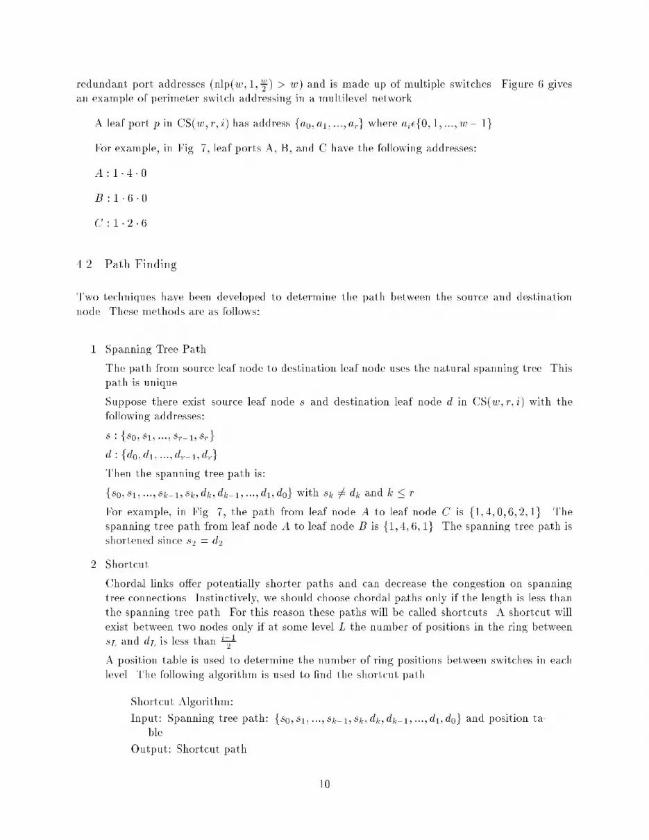
3.1.5 Optimization of Inside WidthTo balance the bisection width with the reduction [13] in leaf ports caused by varying values forthe inside width, our analysis will begin with a single switch. Figure 3 shows a switch with width8 and its di�erent inside and outside width con�gurations.In Fig. 3a the inside width is �ve and the outside width is three. If all the inside links commu-nicate in the (o) direction at the same time, congestion occurs. On the other hand, when all theoutside ports want to communicate in the (i) direction at the same time, the excess inside pathsare available (congestion can occur only when two or more outside ports communicate through thesame inside link). Figure 3a shows that communication in the (o) direction has a greater chanceof experiencing congestion compared with the (i) direction. Assuming randomly distributed com-munications, the level of congestion is dependent on the ratio of inside and outside widths and theamount of communications in both the (i) and (o) directions. Figure 3b shows the opposite results.When both (i) and (o) directions have the same communication demands, the minimum congestionwill occur when the inside width is equal to the outside width (Fig. 3c).Congestion can occur even when excess ports are available if a single link is chosen for multiplecommunications. But since the ATM switches use leaky bucket algorithms to smooth the com-munication stream, low levels of congestion will merely result in increased delay. The amount ofe�ort that can be justi�ed in eliminating congestion will depend on the communication patternsfor applications that will be run on the cluster.The inside width in the CS networks must be an odd number, so the inside and outside widthscan be equal only when the switch width is w = 2(2k+1) for some integer k. When the inside andoutside widths are not equal, the ratio of (i) and (o) direction communication demands will decidethe inside and outside widths. Broadcasts are an (o) type communication since a single messageinjected into the network will result in nlp(w,i,r) (o) type communications. Reductions are an (i)type communication, and point-to-point communications are neutral. If the ratio of broadcasts toreductions is known, then the network can be con�gured with the same ratio for outside width overinside width. Otherwise we will assume that a near-equal ratio between inside and outside widthswill be best on average. In this case the inside width will bei = ( w2 when w2 is oddw2 � 1 otherwiseWhen w2 is even, the inside width i = w2 + 1 will be larger and the resulting network will havea greater bisection width. If we assume a constant inside width for all levels of the network, theparameters of the network can be simpli�ed as follows:nlp(w; r; i) = w(w � i)rns(w; r; i) = 1 + w(w� i)r � 1w � i� 1bw(w; r; i) = �w2 �2 + r4(i2 � 1)e�p(w; r; i) = (w� i)r1 + w(w�i)r�1w�i�17
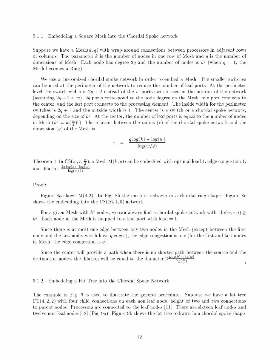
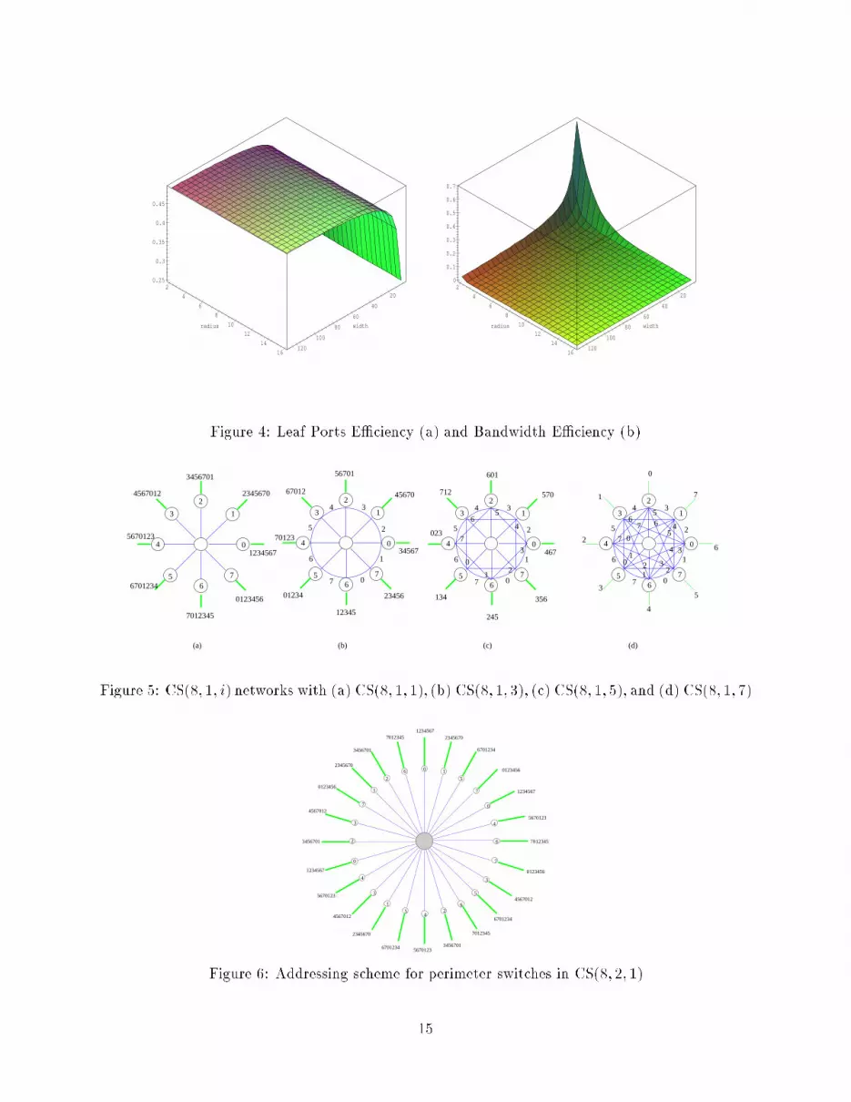
e�b(w; r; i) = 2 ��w2 �2 + r4(i2 � 1)�w(w� i)rThe leaf port e�ciency is a�ected only slightly by the radius, but it's a�ected greatly by switchwidth, as shown in Fig. 4a. Switch width values of sixteen or larger result in near-optimal porte�ciency. The bandwidth e�ciency is a�ected by switch width and the radius of the network.Figure 4(b) shows that switch width values less than sixteen and radius values less than six resultin networks with acceptable bandwidth e�ciency.Tables 1 and 2 show the topological properties of two CS networks with inside width (w/2)-1and varying radius values. The leaf port e�ciency remains constant at approximately 0.5 and thebisection width is large enough to maintain an acceptable bandwidth e�ciency for up to 10,000processors.4 RoutingIn order to perform the routing in ATM networks, the source processor must specify the paththrough all the switches to the destination. Since ATM Networks are connection-oriented, the paththrough intermediate switches must be established before data can be sent [6, 24]. Signaling willbe much easier if an appropriate addressing scheme is adopted.4.1 AddressingThe identical address connection method (IACM) has been developed to simplify connection setupin the network. Using this scheme, connections between two switches utilize identical port numbers.Port 5 on the �rst switch will be connected only to port 5 on the second switch. This addressingmethod enables the address of an entity to specify its exact position in the network.For instance, in Fig. 5a, port number 0 in the atomic center has a spoke connection to port 0on the perimeter switch with address 0. Similarly, the additional perimeter switches are given anaddress that corresponds to the port on the center switch to which they are connected. In CS(8,1,1)network, the 8 perimeter switches are labeled from 0 to 7.In addition to the spoke connections, the IACM will also be used for the chordal links. Oneway of making these connections is to choose the �rst pair of ports that have the same addressbetween neighboring perimeter switches. The �rst port following the switch address that is sharedbetween switches 3 and 4 in Fig. 5a is 5, so port 5 is used as the chordal connection between theseswitches in Fig. 5b. Figure 5 shows the CS(8; 1; i) networks with varying inside widths.Using the addressing scheme described above, the three leaf ports at the top of Fig. 5c are6 � 2; 0 � 2, and 1 � 2. The three leaf ports at the bottom of Fig. 5c are 2 � 6; 4 � 6, and 5 � 6.Addressing for multilevel networks begins with the single-level CS(w; 1; w2 ). We can think of itas a high level center that has nlp(w; 1; w2 ) ports. Each port is connected to a perimeter switch.The only di�erence between an atomic center and a high-level center is that a high-level center has8

(a)
inside outside
o
i i
(c)
inside outside
o
i
(b)
inside outside
o
Figure 3: Three con�gurations of inside and outside widths for a switch with width 8Radius Diameter Bisection Width Switches Leaf Ports E�p E�b1 1 18 9 40 0.555556 0.92 3 20 49 200 0.510204 0.23 5 22 249 1000 0.502008 0.0444 7 24 1249 5000 0.5004 0.00965 9 26 6249 25000 0.50008 0.002086 11 28 31249 125000 0.500016 0.000448Table 1: Topological Properties for CS(8,r,3)Radius Diameter Bisection Width Switches Leaf Ports E�p E�b1 1 76 17 144 0.529412 1.0555562 3 88 161 1296 0.503106 0.1358023 5 100 1457 11664 0.500343 0.0171474 7 112 13121 104976 0.500038 0.002134Table 2: Topological Properties for CS(16,r,7)9
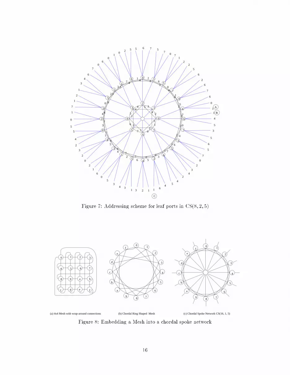
redundant port addresses (nlp(w; 1; w2 ) > w) and is made up of multiple switches. Figure 6 givesan example of perimeter switch addressing in a multilevel network.A leaf port p in CS(w; r; i) has address fa0; a1; :::; arg where ai�f0; 1; :::; w� 1g.For example, in Fig. 7, leaf ports A, B, and C have the following addresses:A : 1 � 4 � 0B : 1 � 6 � 0C : 1 � 2 � 64.2 Path FindingTwo techniques have been developed to determine the path between the source and destinationnode. These methods are as follows:1. Spanning Tree PathThe path from source leaf node to destination leaf node uses the natural spanning tree. Thispath is unique.Suppose there exist source leaf node s and destination leaf node d in CS(w; r; i) with thefollowing addresses:s : fs0; s1; :::; sr�1; srgd : fd0; d1; :::; dr�1; drgThen the spanning tree path is:fs0; s1; :::; sk�1; sk; dk; dk�1; :::; d1; d0g with sk 6= dk and k � rFor example, in Fig. 7, the path from leaf node A to leaf node C is f1; 4; 0; 6; 2; 1g. Thespanning tree path from leaf node A to leaf node B is f1; 4; 6; 1g. The spanning tree path isshortened since s2 = d2.2. ShortcutChordal links o�er potentially shorter paths and can decrease the congestion on spanningtree connections. Instinctively, we should choose chordal paths only if the length is less thanthe spanning tree path. For this reason these paths will be called shortcuts. A shortcut willexist between two nodes only if at some level L the number of positions in the ring betweensL and dL is less than i�12 .A position table is used to determine the number of ring positions between switches in eachlevel. The following algorithm is used to �nd the shortcut path.Shortcut Algorithm:Input: Spanning tree path: fs0; s1; :::; sk�1; sk; dk; dk�1; :::; d1; d0g and position ta-bleOutput: Shortcut path 10

For j = 1 to k fIf sj and dj are neighbors within i�12 then f� Read chordal link number c from the position table.� Output shortcut:fs0; s1; :::; sj�1; c; dj�1; :::; d1; d0g where j � k� Terminate the algorithm.ggIf not terminated, output = Input. 2If we use Fig. 7 for a communication between leaf node A and leaf node B, the spanningtree path is f1; 4; 6; 1g. Since switch 4 � 0 and 6 � 0 di�er by one position in the ring, a directchordal link exists. The corresponding shortcut is f1; 7; 1g.5 ComparisonA major di�erence between the CS networks and traditional interconnection networks is that thenetwork is constructed from ATM switches. The processing nodes are connected to leaf ports of theCS network. Processors are involved in communications only if they are the source or destinationof the communications. These properties reduce communication overhead and allow the networkto be constructed with lower-cost commodity ATM switches.Table 3 compares metrics of interest for Hypercubes, Generalized Fat Trees, Extended General-ized Fat Trees (XGFT), and chordal spoke networks. These topologies were chosen for the followingreasons: The Hypercube has been used extensively in previous research and many algorithms canbe mapped to this topology. Although generalized fat trees have not yet been implemented, in the-ory they compare favorably with many popular interconnection networks [10, 11, 15]. The topologyused in the Connection Machine CM-5 is a special case of the extended generalized fat tree [10, 15].Table 3 shows that CS(w; r; i) has nearly double the number of leaf nodes when compared tothe GFT(r,w,p) and more than that found in a Hypercube with the same diameter. Both theHypercube and GFT have greater bisection width than CS networks, but the CS(w,r,i) bisectionwidth scales up with the number of nodes in the network. Table 4 gives a speci�c example of howthe metrics compare for the three networks.5.1 EmbeddingEmbedding can be used to show that a host graph is at least as powerful as a given guest graph.The dilation of the embedding is the maximum distance on the host between adjacent nodes in theguest topology. The load is the maximum number of guest nodes mapped onto a single host node.The edge congestion is the maximum number of edges in the guest that are mapped to a singleedge in the host. 11
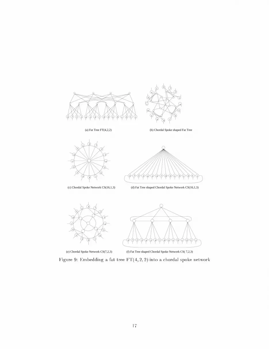
5.1.1 Embedding a Square Mesh into the Chordal Spoke networkSuppose we have a Mesh(k; q) with wrap-around connections between processors in adjacent rowsor columns. The parameter k is the number of nodes in one row of Mesh and q is the number ofdimensions of Mesh. Each node has degree 2q and the number of nodes is kq (when q = 1, theMesh becomes a Ring).We use a customized chordal spoke network in order to embed a Mesh. The smaller switchescan be used at the perimeter of the network to reduce the number of leaf ports. At the perimeterlevel the switch width is 2q + 2 instead of the w ports switch used in the interior of the network(assuming 2q+ 2 < w). 2q ports correspond to the node degree on the Mesh, one port connects tothe center, and the last port connects to the processing element. The inside width for the perimeterswitches is 2q + 1 and the outside width is 1. The center is a switch or a chordal spoke network,depending on the size of kq. At the center, the number of leaf ports is equal to the number of nodesin Mesh (kq = w(w2 )r). The relation between the radius (r) of the chordal spoke network and thedimension (q) of the Mesh is r = q log(k)� log(w)log(w=2)Theorem 1 In CS(w; r; w2 ), a Mesh M(k; q) can be embedded with optimal load 1, edge congestion 1,and dilation 2q log(k)�log(w)log(w=2) .Proof:Figure 8a shows M(4,2). In Fig. 8b the mesh is redrawn in a chordal ring shape. Figure 8cshows the embedding into the CS(16; 1; 5) network.For a given Mesh with kq nodes, we can always �nd a chordal spoke network with nlp(w; r; i)�kq. Each node in the Mesh is mapped to a leaf port with load = 1.Since there is at most one edge between any two nodes in the Mesh (except between the �rstnode and the last node, which have q edges), the edge congestion is one (for the �rst and last nodesin Mesh, the edge congestion is q).Since the center will provide a path when there is no shorter path between the source and thedestination nodes, the dilation will be equal to the diameter 2 qlog(k)�log(w)log(w2 ) . 25.1.2 Embedding a Fat Tree into the Chordal Spoke NetworkThe example in Fig. 9 is used to illustrate the general procedure. Suppose we have a fat treeFT(4; 2; 2) with four child connections on each non-leaf node, height of two and two connectionsto parent nodes. Processors are connected to the leaf nodes [11]. There are sixteen leaf nodes andtwelve non-leaf nodes [18] (Fig. 9a). Figure 9b shows the fat tree redrawn in a chordal spoke shape.12

We can build a customized chordal spoke CS(16; 1; 3) network that has small switches withwidth four (instead of sixteen) at the perimeter. Figure 9c illustrates one of these networks andFig. 9d shows the CS(16; 1; 3) redrawn in a fat tree shape.The sixteen leaf nodes in the fat tree are mapped into the sixteen perimeter switches in thechordal spoke network. The twelve non-leaf nodes in the fat tree are mapped into the center ofthe CS. Processors are connected with a single edge to the leaf nodes in each topology. The loadis twelve and the dilation is one. The edge congestion is two because the two edges in the fat treethat connect to the parents are mapped to a single edge in the CS.Another customized CS(7; 2; 3) could be built that uses switches with width four in the atomiccenter and perimeter. Switches with a width of seven are used for the interior of the network.See �gures 9e and 9f. In this case, the sixteen leaf nodes in the fat tree are mapped into sixteenperimeter switches in the CS. The eight second-level nodes in the fat tree are mapped into fourinterior switches in chordal spoke, and the four highest-level nodes in fat tree are mapped into theatomic center of the chordal spoke. The load is four, the dilation is one and edge congestion is two.Although these embeddings are not perfect, the CS host graph has several properties that aresuperior to the guest graphs. Table 5 shows that the CS(16,1,3) has a greater bisection width andsmaller diameter, and that it uses fewer switches and inside edges than the fat tree with the samenumber of processors.6 ConclusionsParallel-processing platforms based on networks of workstations are being utilized extensively tosolve challenging computational problems. ATM network technology promises to provide an inex-pensive and exible interconnection medium for applications on workstation clusters that requirehigh bandwidth and congestion-free communications. The chordal spoke SASI network can be usedto connect large numbers of processors with inexpensive ATM switches. This network topology hasscalable bisection width, acceptable port and bandwidth e�ciency, and it compares well with otherinterconnection networks. Because of its regular topology, routing can be performed in a structuredmanner.Current research is focused on developing simulators and analyzing embeddings from additionaltopologies into chordal spoke networks. Additional research will explore three-dimensional SASInetwork topologies and extend the de�nition of the CS networks to include the custom networks usedin embeddings. When the information highway is deployed, parallel processing can be performedusing machines that are geographically distant. Future work will analyze the impact of CS networksin Wide Area Networks (WANs) and suggest topologies that will provide the resources necessaryfor parallel processing. Chordal spoke networks provide a exible and economical alternative toexisting MPP networks and promise to improve the functionality of clustered computing.13

Comparison of topological propertiesNetwork Leaf Ports Diameter Degree Bisection WidthHypercube Q(2r) 4r 2r� 1 2r 22r�1Fat trees GFT(w2 ; r; p) (w2 )r 2r� 1 p w�pr4XGFT(r;w1; :::; wr; p1; :::; pr) Qri=1 wi 2r� 1 p1 wr �Qri=1 pi2chordal spoke CS(w; r� 1; w2 ) 2(w2 )r 2r� 1 w2 (w2 )2 + r�14 (w24 � 1)Table 3: CS(w; r� 1; w2 ) compared with other topologiesComparison of topological propertiesNetwork Leaf Nodes Diameter Degree Bisection WidthHypercube Q(2 � 4) 256 7 8 128Fat tree GFT (9; 4; 3) 6561 7 3 324Chordal spoke CS(16; 3; 7) 11664 7 7 100Table 4: CS(16,3,7) compared with other topologiesComparison of topological propertiesNetwork Bisection Width Diameter Switches Inside EdgesFat tree FT (4; 2; 2) 8 5 28 48Chordal spoke CS(7; 2; 3) 8 5 21 40Chordal spoke CS(16; 1; 3) 66 3 17 32Table 5: FT(4,2,2) compared with chordal spoke networks14
20
40
60
80
100
120
width
2
4
6
8
10
12
14
16
radius
0.25
0.3
0.35
0.4
0.45
20
40
60
80
100
120
width
2
4
6
8
10
12
14
16
radius
0
0.1
0.2
0.3
0.4
0.5
0.6
0.7
Figure 4: Leaf Ports E�ciency (a) and Bandwidth E�ciency (b)5
6
21
3
4
7
0
56
21
3
4
7
0
7
(a) (b) (c) (d)
5670123
6701234
1
2
3
4
56
7
0
3456701
4567012
7012345
0123456
1234567
2345670
70123
56701
45670
34567
12345
67012
1
2
3
4
56
7
0
2345601234
3
2
1
07
6
5
41
2
3
4
56
7
0
3
2
1
07
6
5
4
601
712
023
134
245
356
467
570
1
2
3
4
56
7
0
3
2
1
07
6
5
4
0
12 3
4
57 6
0
1
2
3
4
5
6Figure 5: CS(8; 1; i) networks with (a) CS(8; 1; 1), (b) CS(8; 1; 3), (c) CS(8; 1; 5), and (d) CS(8; 1; 7)2
6
7
6 0 1
7
1
2
3
1
3
24
5
3
5
7012345
1234567
0123456
6701234
23456701234567
2345670
2345670
6701234 3456701
6701234
4567012
0123456
7012345
0123456
4567012
3456701
4567012
5670123
7012345
5
5670123
6
4
5670123
0
1234567
3456701
0
4
7
Figure 6: Addressing scheme for perimeter switches in CS(8; 2; 1)15
6
7
7
6 0 1
7
1
2
2
3
1
3
24
5
3
5
5
6
4
0
0
45
0
6
7
6
5
4 3
2
12
01
3
4
7
0
1
2
3
4
5
6
7
0
5
07
71
22
5
6
2
6
7
6
0
1
1
4
5
3
5
6
5
7
0
2
34
2
45
4611231
343
50
6
12
0
2
3
2
4
5
5
0
1
7
1
2
1
3
4
6
70
60
10
2 5 5 6 7
A
B
C
1
5
7
0
4
6
356
6
5
4
34
3
3
2
0
7
6
6
4
4
3
2
1
1
077
0
7
52
3
71 2
6
0
7
2
4
5
1
3
4
Figure 7: Addressing scheme for leaf ports in CS(8; 2; 5)(c) Chordal Spoke Network CS(16, 1, 5)
0 1 2 3
4 5 6 7
8 9 a b
c d e f
(a) 4x4 Mesh with wrap-around connections
01
2
3
4
5
6
789
a
b
c
d
e
f0
1
2
3
4
5
6
789
a
b
c
d
e
f
(b) Chordal Ring Shaped MeshFigure 8: Embedding a Mesh into a chordal spoke network16
edcba9876543210 f
(e) Chordal Spoke Network CS(7,2,3)
01
2
3
4
5
6
789
a
b
c
d
e
f
01
2
3
4
5
6
789
a
b
c
d
e
f
01
2
3
4
5
6
789
a
b
c
d
e
f
edcba9876543210 f
edcba9876543210 f
(a) Fat Tree FT(4,2,2) (b) Chordal Spoke shaped Fat Tree
(c) Chordal Spoke Network CS(16,1,3) (d) Fat Tree shaped Chordal Spoke Network CS(16,1,3)
(f) Fat Tree shaped Chordal Spoke Network CS( 7,2,3)Figure 9: Embedding a fat tree FT(4; 2; 2) into a chordal spoke network17

References[1] Akers, S. B. , Harel, D. , and Krishnamurthy, B. . \The Star Graph: An Attractive Alternativeto the n-Cube". In Proceedings International Conference on Parallel Processing, pages 393{400. IEEE, 1987.[2] Browne, R. F. and Hodgson, R. M. . \Symmetric degree-four chordal ring networks". IEEProceedings, 137 Pt.E(4):310{318, July 1990.[3] D. Duh, G. C. and Fang, J. . \Algorithms and Properties of a New Two-Level Networkwith Folded Hypercubes as Basic Modules". IEEE Transactions on Parallel and DistributedSystems, 6(7):714{723, July 1995.[4] Dowd, P. W. , Srinidhi, S. M. , Blade, E. , and Claus, R. . \Issues in ATM Support of HighPerformance Geographically Distributed Computing". In First International Workshop onHigh-Speed Network Computing, pages 19{28. IEEE, 1995.[5] FORE Systems, Inc. \ForeRunner ASX-200 ATM Switch User's Manual". FORE Systems,Inc, 1994, ch.1 pp. 1-12.[6] Huang, C. , Devetsikiotis, M. , Lambadaris, I. , and Kaye, R. . \Fast Simulation for Self-SimilarTra�c in ATM Networks". In 1995 IEEE International Conference on Communications, pages438{443. IEEE, 1995.[7] Kalampoukas, L. and Varma, A. . \Performance of TCP over Multi-Hop ATM Networks: AComparative Study of ATM-Layer Congestion Control Schemes". In 1995 IEEE InternationalConference on Communications, pages 1472{1477. IEEE, 1995.[8] Kruskal, C. P. and Snir, M. . \A Uni�ed Theory of Interconnection Network Structure".Theoretical Computer Science, 48:75{94, 1986.[9] Kwon, T. and Jeong, C. . \A Simple, Extendible ATM Switch with Load-balanced RoundingCopy Network". In 1995 IEEE International Conference on Communications, pages 1122{1126.IEEE, 1995.[10] Leigserson, C. E. , Abuhamdeh, Z. S. , Douglas, D. C. , Feynman, C. R. , Ganmukhi, M. N., Hill, J. V. , Hillis, W. D. , Kuszmaul, B. C. , Pierre, M. A. S. , Wells, D. S. , Wong, M. C., Yang, S. , and Zak, R. . \The Network Architecture of the Connection Machine CM-5". InProc. Fourth Ann. ACM Symp. Parallel Algorithms and Architectures, pages 272{285. ACM,1992.[11] Leiserson, C. E. . \Fat-Trees: Universal Networks for Hardware-E�cient Supercomputing".IEEE Trans. Computers, C-34(10):892{901, Oct. 1985.[12] Leung, K. and Hamdi, M. . \Evaluating PVM and Express on Various Network Clusters". InFirst International Workshop on High-Speed Network Computing, pages 57{66. IEEE, 1995.[13] Miguet, S. and Robert, Y. . \Reduction Operations on a Distributed Memory Machine witha Recon�gurable Interconnection Network". IEEE Transactions on Parallel and DistributedSystems, 3(4):500{505, July 1992. 18

[14] Murakami, K. and Kim, H. S. . \Joint Optimization of Capacity and Flow Assignment forSelf-Healing ATM Networks". In 1995 IEEE International Conference on Communications,pages 216{220. IEEE, 1995.[15] Ohring, S. R. , Ibel, M. , Das, S. K. , and Kumar, M. J. . \On Generalized Fat Trees". In 9thInternational Parallel Processing Symposium, pages 37{44. IEEE, 1995.[16] Partridge, C. . \Gigabit Networking". Addison-Wesley Publishing Company, 1994, ch.1, pp.1-13, ch.2, pp. 28-31, and ch.3, pp. 51-53.[17] Prycker, M. D. . \Asynchronous Transfer Mode". Ellis Horwood, 1993, ch.3, pp. 103-146.[18] Quinn, M. J. . \Parallel Computing: Theory and Practice". McGraw-Hill, Inc., 1994, ch.3,pp. 52-89.[19] Ramanathan, G. , Clement, M. , and Crandall, P. . \Hyperweave: A Fault-tolerant ExpandableInterconnection Network". In Proceedings of the Fourth IEEE Symposium on Parallel andDistributed Processing, pages 479{482. IEEE, 1992.[20] Scherson, I. D. and Youssef, A. S. . \Interconnection Networks for High-Performance ParallelComputers". IEEE Computer Society Press, 1994, ch.1, pp. 1-2.[21] Seitz, C. L. . \The Cosmic Cube". comm. ACM, 28(1):22{33, Jan. 1985.[22] Sole-Pareta, J. , Sarkar, D. , Liebeherr, J. , and Akyildiz, I. F. . \Adaptive Multipath Routingof Connectionless Tra�c in an ATM Network". In 1995 IEEE International Conference onCommunications, pages 1626{1630. IEEE, 1995.[23] Wei, W. , Clement, M. J. , and Flanagan, J. K. . \The Round Table ATM InterconnectionNetwork". In Proceedings of the 1995 International Conference on Parallel and DistributedProcessing Techniques and Applications, pages 445{454. CSREA, 1995.[24] Winkler, R. . \A Routing Framework for Multimedia Multipoint Communications in ATMNetworks". In 1995 IEEE International Conference on Communications, pages 815{820. IEEE,1995.[25] Zhou, H. and Geist, A. . \Faster Message Passing in PVM". In First International Workshopon High-Speed Network Computing, pages 67{73. IEEE, 1995.19


