ELSEVIER Marine and Petroleum Geology 16 (1999) 321-335 Marine and PetroleumGeology The lack of relationship between overpressure and porosity in North Sea and Haltenbanken shales G. M. G. Teige*, C. Hermanrud, L. Wensaas, H. M. Nordg~rd Boffts Statoil Research Centre, Postuttak, 7005 Trondheim, Norway Received 18 April 1997; receivedin revised form 21 May 1998; accepted 30 May 1998 Abstract Disequilibrium compaction (undercompaction) is probably the most accepted mechanism for explaining overpressured formations. This mechanism relies on the hypothesis that overpressured shales have higher porosity than normally pressured shales for a given depth. Converted to porosity units, log response data from two Jurassic shales at Haltenbanken and nine Cretaceous and Tertiary shales in the Norwegian sector of the North Sea have been investigated to see whether such a relationship exists in these areas. The depth of the studied shale formations varies between 0.5-5 km. The degree of overpressuring within one formation typically varies by 20 MPa. The log response data show that neither the porosity of massive North Sea shales (derived from sonic and density logs) nor the porosity of Haltenbanken intra-reservoir shales (derived from density and neutron logs) differ significantly between the overpressured and normally pressured stratigraphic units. Distinct differences between the pressure regimes are, however, apparent in the resistivity and sonic log data from deeply buried shales at Haltenbanken. These differences do not reflect porosity variations and are interpreted to reflect textural changes resulting from the overpressuring. These observations demonstrate that the Haltenbanken and North Sea shales do not conform to an undercompaction mechanism for overpressuring, as the overpressured wells fail to show elevated porosity. On the contrary, each formation seems to have been individually compacted according to burial depth, independent of pressure regimes. ~3 1999 Elsevier Science Ltd. All rights reserved. Keywords: Disequilibrium compaction (undercompaction); Overpressure; Log porosity I. Introduction Fluid overpressures are subsurface pressures that sig- nificantly exceed the expected hydrostatic pressures (i.e., the product of the unit weight and vertical height of a fluid column). Most geological explanations of overpressuring relate to the following mechanisms: (1) disequilibrium compaction in young and rapidly buried argillaceous sediments (Dickinson, 1953; Rubey & Hubbert, 1959; Dickey, 1976; Chapman, 1980; Pickering & Indelicato, 1985; Swarbrick & Osborne, 1998) (2) thermal expansion of pore fluids (Barker, 1972; Magara, 1975) (3) loss of bound water arising from the smectite-illite transformation at depth (Freed & Peacor, 1989) (4) hydrocarbon generation/maturation in kerogen-rich * Corresponding author. Tel.: +00-47-73-58-40-1l; Fax: +00-47-73- 96-72-86 source rocks (Meissner, 1981; Momper, 1978; Law & Dickinson, 1985; Swarbrick & Osborne, 1998) (5) tectonic compression (Hubbert & Rubey, 1959; Yassir & Bell, 1996). While disequilibrium compaction is the most fre- quently advocated mechanisms (also in the North Sea, e.g. Swarbrick & Osborne, 1998), data which clearly sup- port this mechanism is lacking. As rocks and soils are vertically compressed during burial, their change in porosity (compaction) depends on the change in effective stress. According to Terzaghi's principle (Terzhagi, 1923), the weight of the overlaying sediments is borne partly by the solid rock matrix frame- work and partly by the pore fluid: = OB-P where a is the vertical effective stress transmitted through the solid matrix, OB represents the total vertical load or overburden stress, and P is the pore fluid pressure. If the pore fluids are free to escape as the overburden stresses increase (i.e., hydrostatic loading), the rocks will compact 0264-8172/99/$- see front matter ~ 1999 Elsevier Science Ltd. All rights reserved PII:S0264 8172(98)00035 X
Transcript
E L S E V I E R Marine and Petroleum Geology 16 (1999) 321-335
Marine and Petroleum Geology
The lack of relationship between overpressure and porosity in North Sea and Haltenbanken shales
G. M. G. Teige*, C. Hermanrud, L. Wensaas, H. M. Nordg~rd Boffts Statoil Research Centre, Postuttak, 7005 Trondheim, Norway
Received 18 April 1997; received in revised form 21 May 1998; accepted 30 May 1998
Abstract
Disequilibrium compaction (undercompaction) is probably the most accepted mechanism for explaining overpressured formations. This mechanism relies on the hypothesis that overpressured shales have higher porosity than normally pressured shales for a given depth. Converted to porosity units, log response data from two Jurassic shales at Haltenbanken and nine Cretaceous and Tertiary shales in the Norwegian sector of the North Sea have been investigated to see whether such a relationship exists in these areas. The depth of the studied shale formations varies between 0.5-5 km. The degree of overpressuring within one formation typically varies by 20 MPa.
The log response data show that neither the porosity of massive North Sea shales (derived from sonic and density logs) nor the porosity of Haltenbanken intra-reservoir shales (derived from density and neutron logs) differ significantly between the overpressured and normally pressured stratigraphic units. Distinct differences between the pressure regimes are, however, apparent in the resistivity and sonic log data from deeply buried shales at Haltenbanken. These differences do not reflect porosity variations and are interpreted to reflect textural changes resulting from the overpressuring.
These observations demonstrate that the Haltenbanken and North Sea shales do not conform to an undercompaction mechanism for overpressuring, as the overpressured wells fail to show elevated porosity. On the contrary, each formation seems to have been individually compacted according to burial depth, independent of pressure regimes. ~3 1999 Elsevier Science Ltd. All rights reserved.
Fluid overpressures are subsurface pressures that sig- nificantly exceed the expected hydrostatic pressures (i.e., the product of the unit weight and vertical height of a fluid column). Most geological explanations of overpressuring relate to the following mechanisms:
(1) disequilibrium compaction in young and rapidly buried argillaceous sediments (Dickinson, 1953; Rubey & Hubbert , 1959; Dickey, 1976; Chapman, 1980; Pickering & Indelicato, 1985; Swarbrick & Osborne, 1998)
(2) thermal expansion of pore fluids (Barker, 1972; Magara, 1975)
(3) loss of bound water arising from the smectite-illite transformation at depth (Freed & Peacor, 1989)
(4) hydrocarbon generation/maturation in kerogen-rich
While disequilibrium compaction is the most fre- quently advocated mechanisms (also in the North Sea, e.g. Swarbrick & Osborne, 1998), data which clearly sup- port this mechanism is lacking.
As rocks and soils are vertically compressed during burial, their change in porosity (compaction) depends on the change in effective stress. According to Terzaghi's principle (Terzhagi, 1923), the weight of the overlaying sediments is borne partly by the solid rock matrix frame- work and partly by the pore fluid:
= O B - P
where a is the vertical effective stress transmitted through the solid matrix, O B represents the total vertical load or overburden stress, and P is the pore fluid pressure. If the pore fluids are free to escape as the overburden stresses increase (i.e., hydrostatic loading), the rocks will compact
0264-8172/99/$- see front matter ~ 1999 Elsevier Science Ltd. All rights reserved PII:S0264 8172(98)00035 X
322 G.M.G. Teige et al./Marine and Petroleum Geoloyy 16 (1999) 321-335
as a function of the increase in effective vertical stress. Alternatively, if pore water fails to escape at a sufficient rate during burial, an increase in pore fluid pressure will reduce the compaction process because the effective stress remains low. This is often referred to as disequilibrium compaction (henceforth referred to as undercompaction). The principle of undercompaction suggests that over- pressured rocks should have higher porosities than normally pressured rocks at similar burial depth (Dickey, 1974).
Pore pressure estimates in shales are commonly based on wireline logging methods and analysis of drilling para- meters, as low permeabilities prevent fluids from flowing fast enough into a test string to allow direct measure- ments to be made (Dowdle & Cobb, 1975). All the indirect logging methods that we are aware of are based on the concept that overpressured shales have elavated porosit- ies because of undercompaction. The application of such methods, however, is far from straightforward as changes in log responses or drilling rates may just as well result from changes in lithology as from changes induced by different fluid pressures. Since the accuracy of estimated pore pressures in shales is uncertain, any discussion of the causes of shale overpressuring is also uncertain.
This paper presents new log data from shales in the Norwegian sector of the North Sea to test whether the principle of undercompaction is an appropriate over- pressuring mechanism here (care has been taken to sep- arate pore pressure effects from lithology effects). Log data from Haltenbanken shales (offshore mid-Norway) have been thoroughly documented by Hermanrud et al. (1998a) and will only be summarized below for the sake of comparison. Should the undercompaction mechanism prove to be invalid in both of these two areas, the results will have great implications for basin modelling procedures, in which it is assumed that porosity reduction is a function of effective stress, and for pore pressure detection and prediction.
2. Study area and data collection
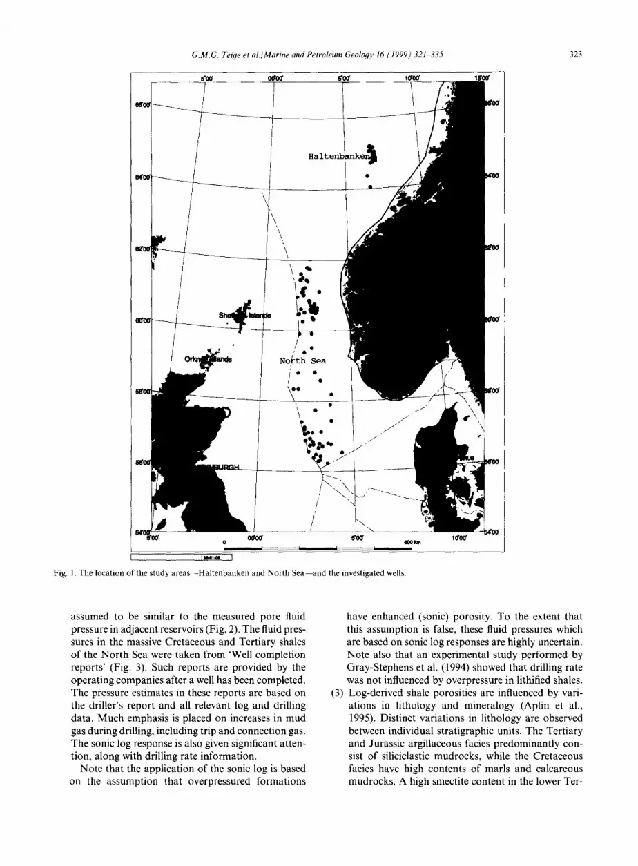
The geological history of Haltenbanken and the North Sea (Fig. 1) have been extensively described by several authors, e.g., Hollander (1984), Heum et al. (1986),
Ziegler et al. (1986), and Koch and Heum (1995). The geological history of these areas was dominated by exten- sional tectonics in the Late Jurassic and since then by gentle subsidence. Only areas close to the Norwegian mainland have later experienced significant uplift and erosion. These areas, which are not presently at their maximum burial, were excluded from the present study.
Eleven shaly units of various stratigraphic age were separately investigated in an attempt to distinguish over- pressure from lithology effects on log responses. A brief summary of the lithologies of the selected shale for- mations is given in Tables 1 and 2. The formation thick- ness varies between 10-200 m (Not and Ror Fm.) in Haltenbanken (Table 1), and 38 m (Balder Fm.) -523 m (Kyrre Fm.) in the North Sea (Table 2).
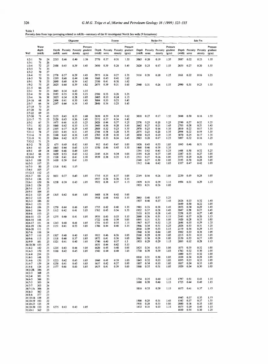
Log data were analysed from 101 overpressured and normally pressured wells in Haltenbanken (20 wells) and the North Sea (81 wells) (Table 3) areas (Fig. 1). Averaged log responses for each of the Jurassic shales (Haltenbanken) were converted to porosity units accord- ing to the methods given by Hermanrud et al. (1998a). Porosity calculations for the North Sea shaly units were performed according to the equations given by Hansen (1996a) (Appendix A).
The logs used in the Haltenbanken study were the density, sonic, resistivity and neutron logs (Fig. 2), while only the density and sonic logs were used in the North Sea study (Fig. 3) (Table 3). Erroneous values due to poor hole conditions were eliminated using caliper logs as measures of true hole conditions. Some uncertainties related to the data are listed below.
(1) Different formulas and input parameters were used for obtaining porosity values from the logs in the two study areas. This conversion naturally introduces errors. However, as the purpose of the investigation was to make comparisons between different wells for a given formation, rather than comparisons between true porosities for different formations, these errors do not influence the results.
(2) Any uncertainties in the pressure values used for the shales relate to the fact that the pore fluid pressure in the studied shales cannot be directly measured due to their low permeabilities. The pressure condition in the intra-reservoir shales at Haltenbanken was
Table 1 Summary of lithologies in the selected Jurassic intra-reservoir shale formations, Haltenbanken (from Dalland et al., 1988) (average formation thickness in parentheses)
Formation Age Lithology
Not (10-200 m) Aalenian to Bajocian Claystones with micronodular pyrite coarsening upwards into bioturbated fine-grai- ned sandstones, which are locally mica-rich and carbonate cemented.
Ror (10-120 m) PliensbachiantoToarcian Grey mudstones containing interbedded silty and sandy coarsening upwards sequences.
G.M.G. Teige et al./Marine and Petroleum Geology 16 (1999) 321-335 323
~0~ 0~0~ 5"0~ 1(~0~ 1~0~
\ \
II
t
No~tk /"
_ ~0
\
~0g 5"0g 0 I I ~ I I I
[ I ~ I
Fig. 1. The location of the study areas--Haltenbanken and North Sea--and the investigated wells.
1000"
assumed to be similar to the measured pore fluid pressure in adjacent reservoirs (Fig. 2). The fluid pres- sures in the massive Cretaceous and Tertiary shales of the North Sea were taken from 'Well completion reports' (Fig. 3). Such reports are provided by the operating companies after a well has been completed. The pressure estimates in these reports are based on the driller's report and all relevant log and drilling data. Much emphasis is placed on increases in mud gas during drilling, including trip and connection gas. The sonic log response is also given significant atten- tion, along with drilling rate information.
Note that the application of the sonic log is based on the assumption that overpressured formations
(3)
have enhanced (sonic) porosity. To the extent that this assumption is false, these fluid pressures which are based on sonic log responses are highly uncertain. Note also that an experimental study performed by Gray-Stephens et al. (1994) showed that drilling rate was not influenced by overpressure in lithified shales. Log-derived shale porosities are influenced by vari- ations in lithology and mineralogy (Aplin et al., 1995). Distinct variations in lithology are observed between individual stratigraphic units. The Tertiary and Jurassic argillaceous facies predominantly con- sist of siliciclastic mudrocks, while the Cretaceous facies have high contents of marls and calcareous mudrocks. A high smectite content in the lower Ter-
324 G.M.G. Teige et al./Marine and Petroleum Geology 16 (1999) 321-335
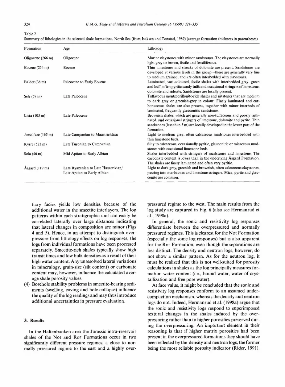
Table 2 Summary of lithologies in the selected shale formations, North Sea (from Isaksen and Tonstad, 1989) (average formation thickness in parentheses)
Formation Age Lithology
Oligocene (266 m) Oligocene
Eocene (254 m) Eocene
Balder (38 m) Paleocene to Early Eocene
Sele (58 m) Late Paleocene
Lista (105 m) Late Paleocene
Jorsalfare (165 m)
Kyrre (523 m)
Sola (46 m)
A, sgard (119 m)
Late Campanian to Maastrichtian
Late Turonian to Campanian
Mid Aptian to Early Albian
Late Ryazanian to Late Hauterivian/ Late Aptian to Early Albian
Marine claystones with minor sandstones. The claystones are normally light grey to brown, fissile and fossiliferous. Thin limestones and streaks of dolomite are present. Sandstones are developed at various levels in the group~these are generally very fine to medium grained, and are often interbedded with claystones. Laminated, vari-coloured, fissile shales with interbedded grey, green and buff, often pyritic sandy tufts and occasional stringers of limestone, dolomite and siderite. Sandstones are locally present. Tuffaceous montmorillonite-rich shales and siltstones that are medium to dark grey or greenish-grey in colour. Finely laminated and car- bonaceous shales are also present, together with minor interbeds of laminated, frequently glauconitic sandstones. Brownish shales, which are generally non-tuffaceous and poorly lami- nated, and occasional stringers of limestone, dolomite and pyrite. Thin sandstones (less than 5 m) are locally developed in the lower part of the formation. Light to medium grey, often calcareous mudstones interbedded with thin limestone beds. Silty to calcareous, occasionally pyritic, glauconitic or micaceous mud- stones with occasional limestone beds. Shales interbedded with stringers of marlstones and limestone. The carbonate content is lower than in the underlying Asgard Formation. The shales are finely laminated and often very pyritic. Light to dark grey, greenish and brownish, often calcareous claystones, passing into marlstones and limestone stringers. Mica, pyrite and glau- conite are common.
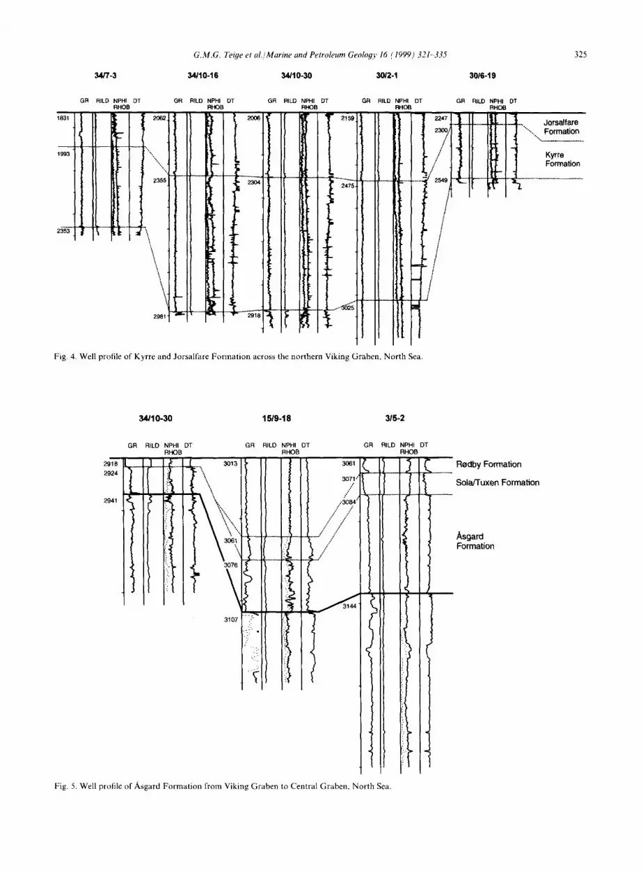
tiary facies yields low densities because o f the addit ional water in the smectite interlayers. The log patterns within each stratigraphic unit can easily be correlated laterally over large distances indicating that lateral changes in composi t ion are minor (Figs 4 and 5). Hence, in an at tempt to distinguish over- pressure f rom lithology effects on log responses, the logs from individual formations have been processed separately. Smectite-rich shales typically show high transit times and low bulk densities as a result o f their high water content. Any unresolved lateral variations in mineralogy, grain-size (silt content) or carbonate content may, however, influence the calculated aver- age shale porosi ty values.
(4) Borehole stability problems in smectite-bearing sedi- ments (swelling, caving and hole collapse) influence the quality o f the log readings and may thus introduce additional uncertainties in pressure evaluation.
3. Results
In the Hal tenbanken area the Jurassic intra-reservoir shales o f the Not and Ror Format ions occur in two significantly different pressure regimes; a close to nor- mally pressured regime to the east and a highly over-
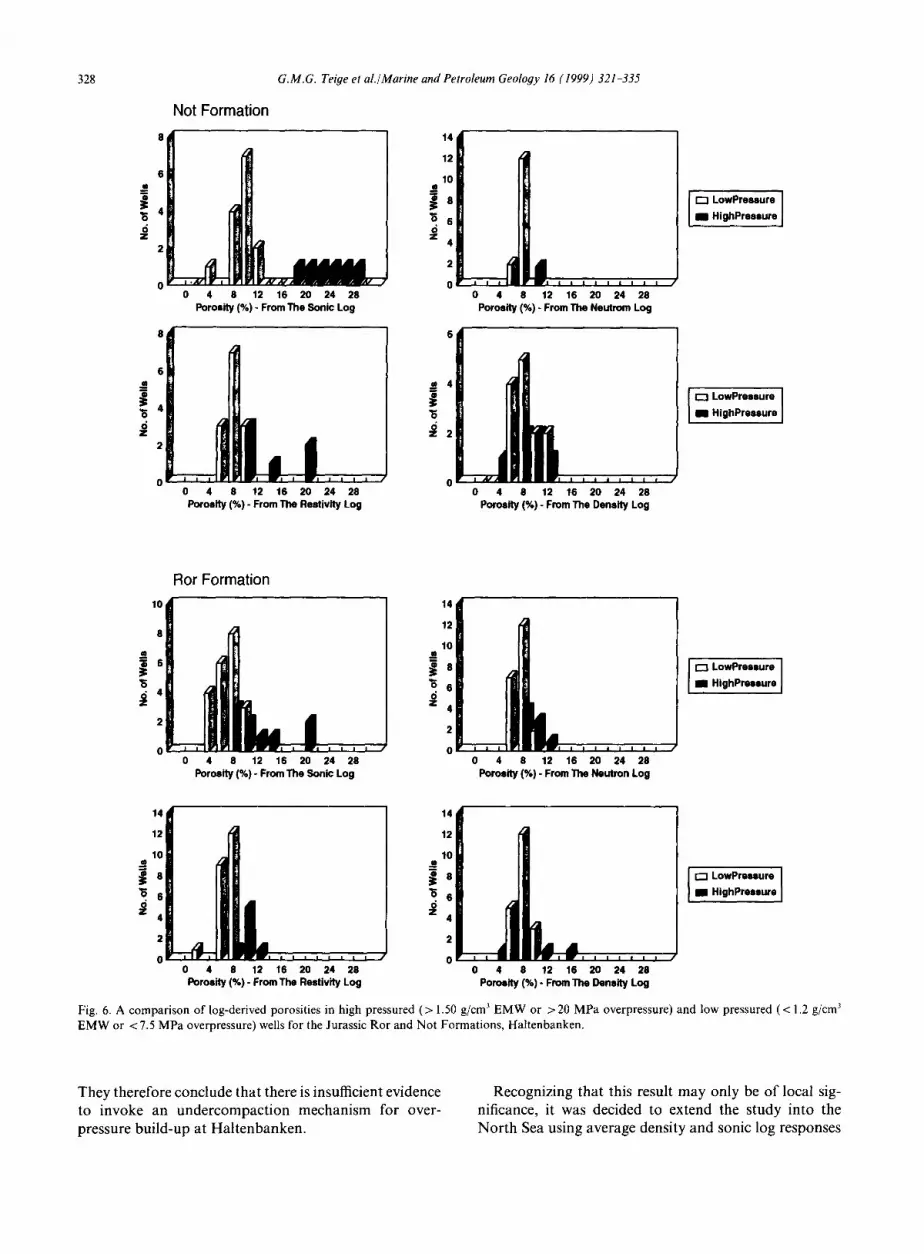
pressured regime to the west. The main results f rom the log study are captured in Fig. 6 (also see Hermanrud et al., 1998a).
In general, the sonic and resistivity log responses differentiate between the overpressured and normally pressured regimes. This is clearest for the No t Format ion (especially the sonic log responses) but is also apparent for the Ror Format ion , even though the separations are less distinct. The density and neutron logs, however, do not show a similar pattern. As for the neutron log, it must be realized that this is not well-suited for porosi ty calculations in shales as the log principally measures for- mat ion water content (i.e., bound water, water o f crys- tallization and free pore water).
At face value, it might be concluded that the sonic and resistivity log responses conform to an assumed under- compact ion mechanism, whereas the density and neutron logs do not. Indeed, Hermanrud et al. (1998a) argue that the sonic and resistivity logs respond to superimposed textural changes in the shales induced by the over- pressuring rather than to higher porosities preserved dur- ing the overpressuring. An impor tant element in their reasoning is that if higher matrix porosities had been present in the overpressured formations they should have been reflected by the density and neutron logs, the former being the most reliable porosi ty indicator (Rider, 1991).
Stratigraphy
or)
(.9 I - Z O ,< Z LL
=,
r J
0 GR (API) 150 DEPTH (mRKB) 6 . . . . . . . . CAL (in) ............ 16
MD 6 BS (in) 16 3670
3680
3690
3700
3710
3720
3730
3740
3750
3760
3770
3780
L
0.1 RILD (ohmm) 1000
0.1 SFLU (ohmm) 1000
0. I . . . . MSFI.. (oh_ram) = _ 1 0 0 0
1.95 R H O B (~/cc) 2,95
4 s . . . . N P H ! (°/o) . . . . . . . i s
t 1
~' I ~ ̧i
c , i
L !
; ~ i ~
d = =
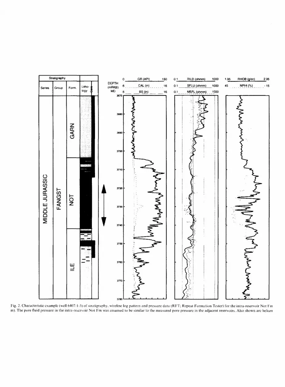
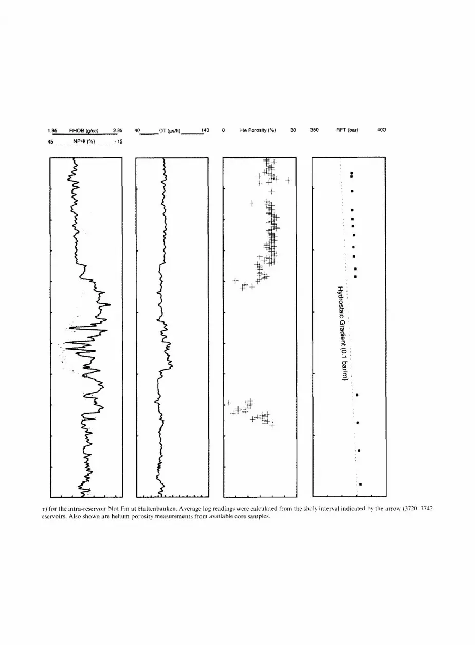
Fig. 2. Characteristic example (well 6407,'1-3) of 'stratigraphy, wireline log pattern aud pressure data (RFT; Repeat Formation Tester) lbr the intra-reservoir Not Fm m). The pore fluid pressure in the intra-reservoir Not Fm was assumed to be similar to the measured pore pressure in the adjacent reservoirs. Also shown are helium
r) for the intra-reservoir Not Fm at Haltenbanken. Average log readings were calculated from the shaly interval indicated by' the arrow (3720 3742 eservoirs. Also shown are helium porosity measurements from available core samples.
0 DEPTH
Litho- (mRKB) System Series Group Form. Iogy .~' TVD
(D 0
_ . ; Se~oed
~ . 200
...... ~ ~" 4oo
a. "~ 600
Z
" " i " " 800
~,. Miocene Otsira ~ ~ ; ~ m ~ooo
<~ olig. I= 1200
rr ~ ~" 14oo w ~ ! II
Eocene ~ ~ 1600
. . . . l . ~" i-4= ~soo [
Pal. Rogaland ~s~=~v ~ .~ ! 2000
2200 Jorsalfare
2400
. 6oo
0 " 28OO u.l
3000 < L i-- ~ ~I 32oo
f r 81 34oo 0 ~ -
Svarte 3600
Cr.Knoll • ~1 38OO
( ,~ • Viking o,=~.~ ~,, ~ ~74;,~: 4000
~ 4200 ' - . . . .
Brent f wve'r~o~
Dunlin ~"~.~' 4600
, 4 8 0 0
GR (API) 150 1.8 RHOB (9/cc) 28
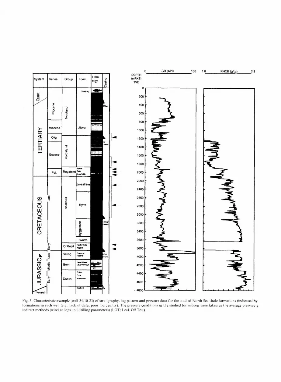
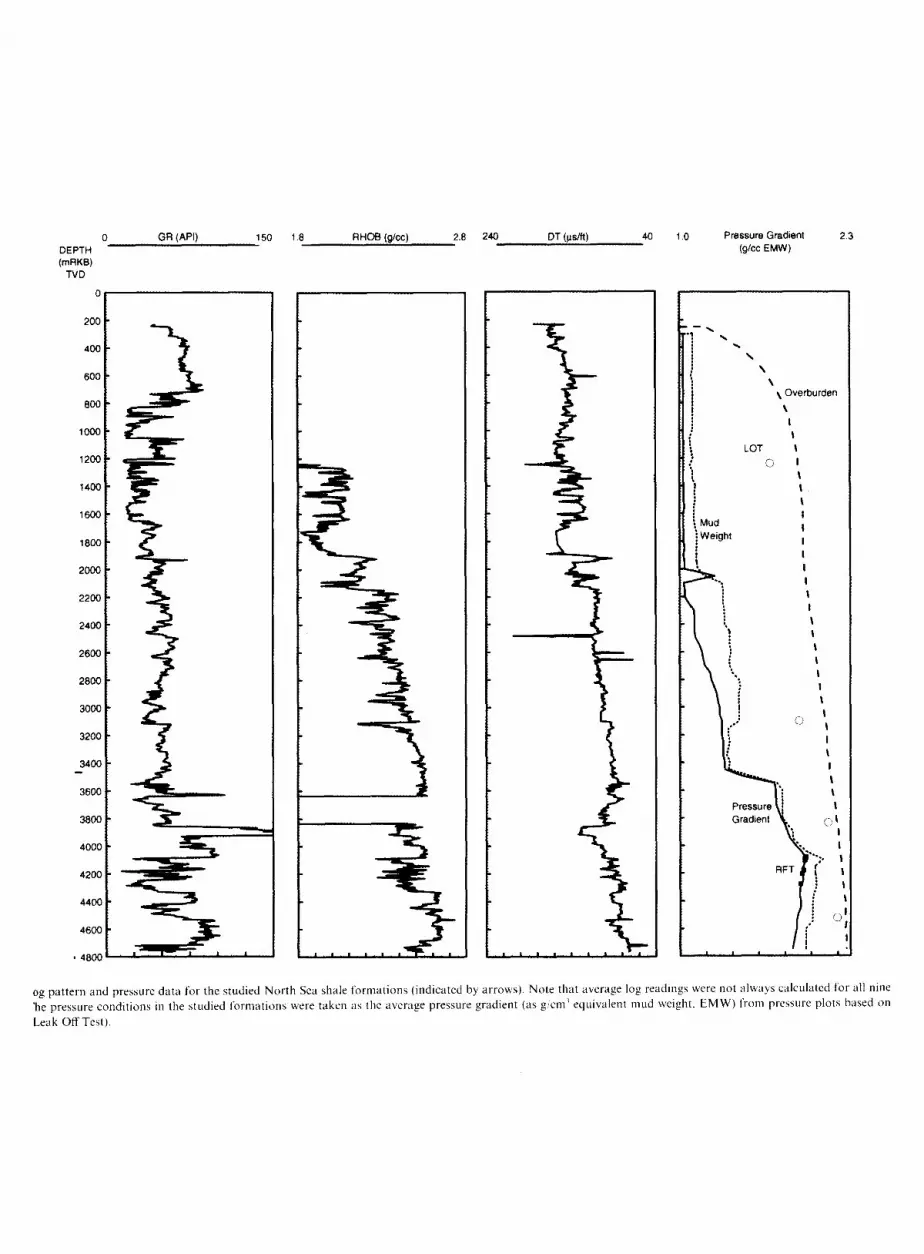
Fig. 3. Characteristic example (well 34:' 0-23) of stratigraphy, log pattern and pressure data for the studied North Sea shale formations (indicated by formations in each well (e.g., lack of data, poor log quality). The pressure conditions in the studied formations were taken as the average pressure g indirect melllods (wireline logs and drilling parameters) (LOT: Leak OffTest).
og pattern and pressure data for the studied North Sea shale formations (indicated by arrows). Note that average log readings were not always calculated for all nine 'he pressure conditions in the studied [brmations were taken as the average pressure gradient (as g,,cm~ equivalent mud weight, EMW) fronl pressure plots based on
Leak Off Test).
1831
1993"
GR
34t7-3
RILD NPHI DT GR RHOB
,, I ~" ' " " ' " " ' " 7-- I -"
nm~
G.M.G. Teige et al./Marine and Petroleum Geology 16 (1999) 321-335 325
34/10-16 34/40-30 30/2-1 30/6-19
RILD NPHI OT RHOB
1
1
L
- - . - - ~ - - . .
2OO6
I
t
GR RILO NPHI DT GR RILD NPHI DT GR RILD NPHI DT RHOB RHOB RHOB
" ~ ~-l~- Jor,a,,are
~, ~ ... ..................
i ] ' J Kyrre . ~ _ ~ Formation
".¢.__ ! -
Fig. 4. Well profile of Kyrre and Jorsalfare Formation across the northern Viking Graben, North Sea.
34/10-30 1519-18 3/5-2
2918
2924
2941
GR RILD NPHI DT GR RILD NPHI DT RHOB RHOB
i. \ Ill = : ? \
t r-~.~,~i.~;il iii i~ii I ~ ~ \..,..... .."L; ,, i l l l
GR RILD NPHI DT RHOB
II P b
Fig. 5. Well profile of Asgard Formation from Viking Graben to Central Graben, North Sea.
b . . . . . . . . . . . . .
Rodby Formation
Sola/'ruxen Formation
Asgard Formation
3 2 6 G.M.G. Teige et al./Marine and Petroleum Geology 16 (1999) 321-335
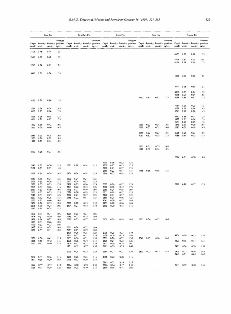
Table 3 Porosity data from logs (averaging related to mKB)--summary of the 81 investigated North Sea wells (9 formations)
G.M.G. Teiye et al,/Marine and Petroleum Geoloyy 16 (1999) 321-335 3 2 7
Lista Fm Jorsalfare Fm Kyrre Fm Sola Fm /~sgard Fm
Pressure Pressure Pressure Pressure Pressure Depth Porosity Porosity gradient Depth Porosity Porosity gradient Depth Porosity Porosity gradient Depth Porosity Porosity gradient Depth Porosity Porosity gradient (mkB) sonic density (g/cc) (mkB) sonic density (g/cel (mkB) sonic density (g/cc) (mkB) sonic density (g/cc) (mkB) sonic density (g/cc)
328 G.M.G. Tei#e et al./Marine and Petroleum Geology 16 (1999) 321-335
6 o
"6 4 6 z
2
Not Formation
0 4 8 12 16 20 24 28 Porosity (%) - From The Sonic Log
.iil Ji
2L=IU 0 4 8 12 16 20 24 28
Porosity (%) - From The Neutrom Log
8 6
2
0 0 0 4 8 12 16 20 24 28 0 4 8 12 16 20 24 28
Porosity (%) - From The Rostivity Log Porosity (%) - From The Density Log
l Z:r:::l
r ~ LowPressure ] am HlghPressure
Ror Formation
10 14
12 8
10
i = 8 [E3 LowProssure s Eli HighPressure
2
0 0 0 4 8 12 16 20 24 28 0 4 8 12 16 20 24 28
Porosity (%) - From The Sonic Log Porosity (%) - From The Neutron Log
12 12
1 1
~ ~ LowPre~ure
0 0 0 4 8 12 16 20 24 28 0 4 8 12 16 20 24 28
Porosity (%) - From The Restivity Log Porosity (%) - From The Density Log
Fig. 6. A comparison of log-derived porosities in high pressured (> 1.50 g/cm 3 EMW or >20 MPa overpressure) and low pressured (<1.2 g/cm 3 EMW or <7.5 MPa overpressure) wells for the Jurassic Ror and Not Formations, Haltenbanken.
They therefore conclude that there is insufficient evidence to invoke an undercompaction mechanism for over- pressure build-up at Haltenbanken.
Recognizing that this result may only be of local sig- nificance, it was decided to extend the study into the North Sea using average density and sonic log responses
G.M.G. Teiye et al./Marine and Petroleum Geology 16 (1999) 321 335 329
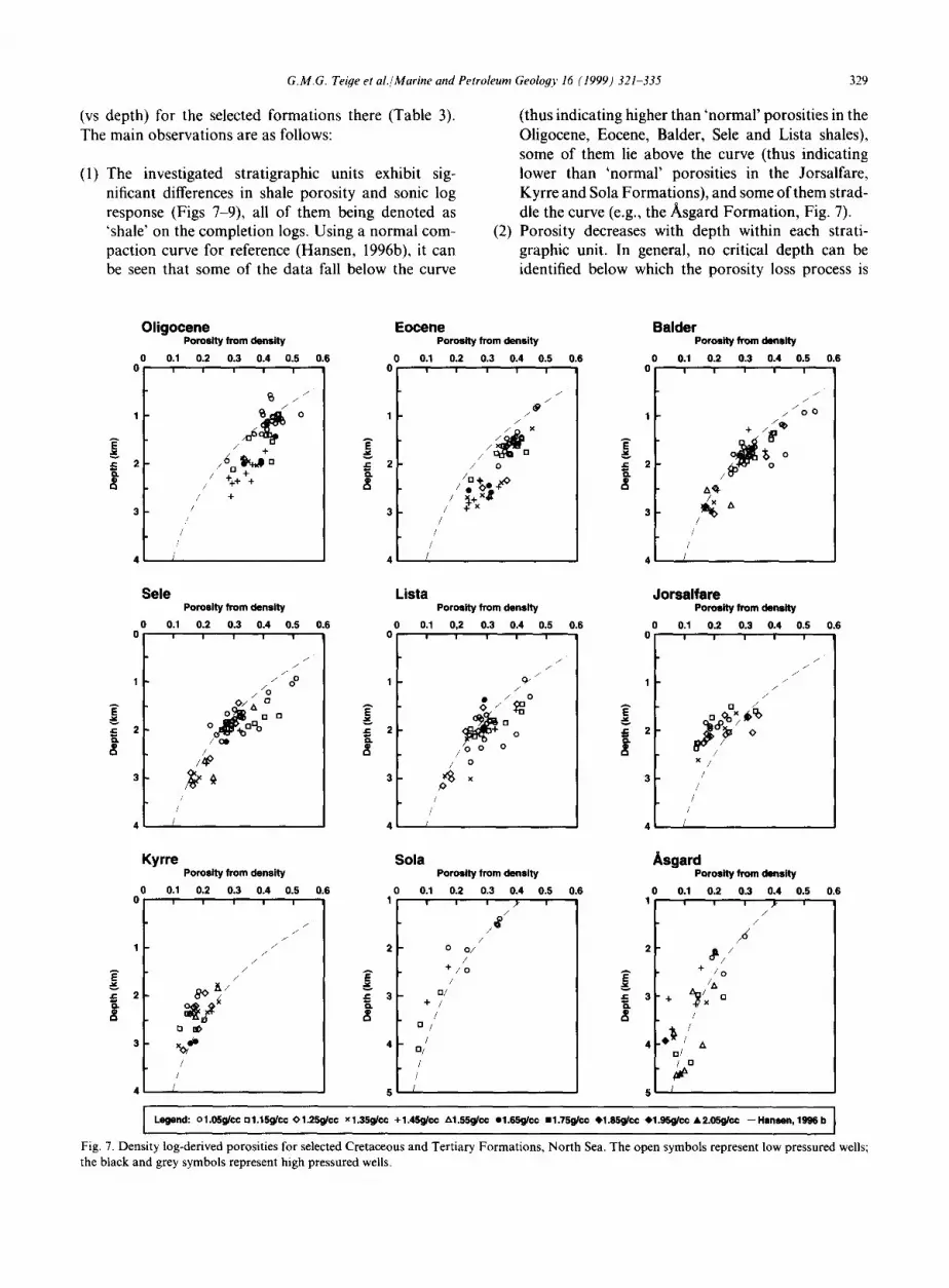
(vs depth) for the selected formations there (Table 3). The main observations are as follows:
(1) The investigated stratigraphic units exhibit sig- nificant differences in shale porosity and sonic log response (Figs 7-9), all of them being denoted as 'shale' on the completion logs. Using a normal com- paction curve for reference (Hansen, 1996b), it can be seen that some of the data fall below the curve
(thus indicating higher than 'normal' porosities in the Oligocene, Eocene, Balder, Sele and Lista shales), some of them lie above the curve (thus indicating lower than 'normal' porosities in the Jorsalfare, Kyrre and Sola Formations), and some of them strad- dle the curve (e.g., the Asgard Formation, Fig. 7).
(2) Porosity decreases with depth within each strati- graphic unit. In general, no critical depth can be identified below which the porosity loss process is
Fig. 7. Density log-derived porosities for selected Cretaceous and Tertiary Formations, North Sea. The open symbols represent low pressured wells; the black and grey symbols represent high pressured wells.
330
A
4=
G.M.G. Teige et al./Marine and Petroleum Geology 16 (1999) 321-335
Oligocene Porosity from sonic
0.1 0.2 0.3 0.4 0.5 I I I I I
i i i % @ [] / ÷
/ + /
/ + /
/ ,/
/ /
(
0.6 0 0
A E
Eocene Porosity from sonic
0.1 0.2 0.3 0.4 0.5 0.6 I I I I
/ /
~ x / / 0 ; ~
/ O
g+~xO / /
/ /
/ /
/
/
0 0
Balder Porosity from sonic
0.1 0.2 0.3 0.4 0.5 0.6 I I I I I
/ /
/
o 9 " + ..p/a" O o
0 / / Y ~ 1 ~
t//~x§A A /
/ ! (
= 2 o.
Sele
0 0.1 0
Porosity from sonic
0.2 0.3 0.4 0.5 0.6 I I I I
/ /
/ /
/ 0 0 / / O
/ [] 0 / , y~[][]°
o / Co'=F'b / O o +
/
// I x ~ /
/ /
(
J= K
Lista
0.1 0
1
2
3
4
Porosity from sonic
0.2 0.3 0.4 0.5 0.6 I I I I
/
O / /
~ o o
/ o ~
/ /
/
!
Jorsalfare Porosity from sonic
0 0.1 0.2 0.3 0.4 0.5 0.6 0 I I I I I
/ /
/ /
/
/ X
/ /
/ /
1 !
Kyrre
0 0.1 0
A
i .c 2
Porosity from sonic
0.2 0,3 0.4 0.5 0.6 ! , I I
/ /
/ /
/ /
/ /
~ m
d o /
/ /
[
1
d; 3
4
5
Sola
0.1 0
/ • /
/ (
Porosity from sonic
0.2 0.3 0.4 0.5 I I I I
/ /
/ /
/ /
~ 6 o /
/ n / ÷/ / •
/
0,6
1
3. ~ 3
Asgard Porosity from sonic
0 0.1 0.2 0.3 0.4 0.5 0.6 0 I I I I I
/ /
/
/ /
/ /
/ O / O0"~.
o/~+o + / ~ , /
4
/ /A t A
5 /
I Legend: ol.05g/cc °1.15g/cc O1.25g/cc x1.35g/cc +1.45g/cc z~1.55g/cc e1.65g/cc n1.75g/cc e1.85g/cc @1.95g/cc A2.05g/cc --Hansen, 1996b I I
m
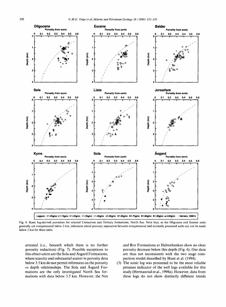
Fig. 8. Sonic log-derived porosities for selected Cretaceous and Tertiary formations, North Sea. Note that, as the Oligocene and Eocene units generally are overpressured below 2 km, inferences about porosity separation between overpressured and normally pressured wells can not be made below 2 km for these units.
arrested (i.e., beneath which there is no further porosity reduction) (Fig. 7). Possible exceptions to this observation are the Sola and Asgard Formations, where scarcity and substantial scatter in porosity data below 3.5 km do not permit inferences on the porosity vs depth relationships. The Sola and Asgard For- mations are the only investigated North Sea for- mations with data below 3.5 km. However, the Not
and Ror Formations at Haltenbanken show no clear porosity decrease below this depth (Fig. 6). Our data are thus not inconsistent with the two stage com- paction model described by Hunt et al. (1994).
(3) The sonic log was presumed to be the most reliable pressure indicator of the well logs available for this study (Hermanrud et al., 1998a). However, data from these logs do not show distinctly different trends
G.M.G. Teige et al./Marine and Petroleum
Porosity from density
0 0.2 0.4 0.6 0.8 0 i" 'r " ~ ""'" I
.~* t° 1 0 0 0 . ~ - - - - O l igocene
/~..'.~IY/ . . . . Eocene " " ,~:":","~e. W. - - - - Balder Fm
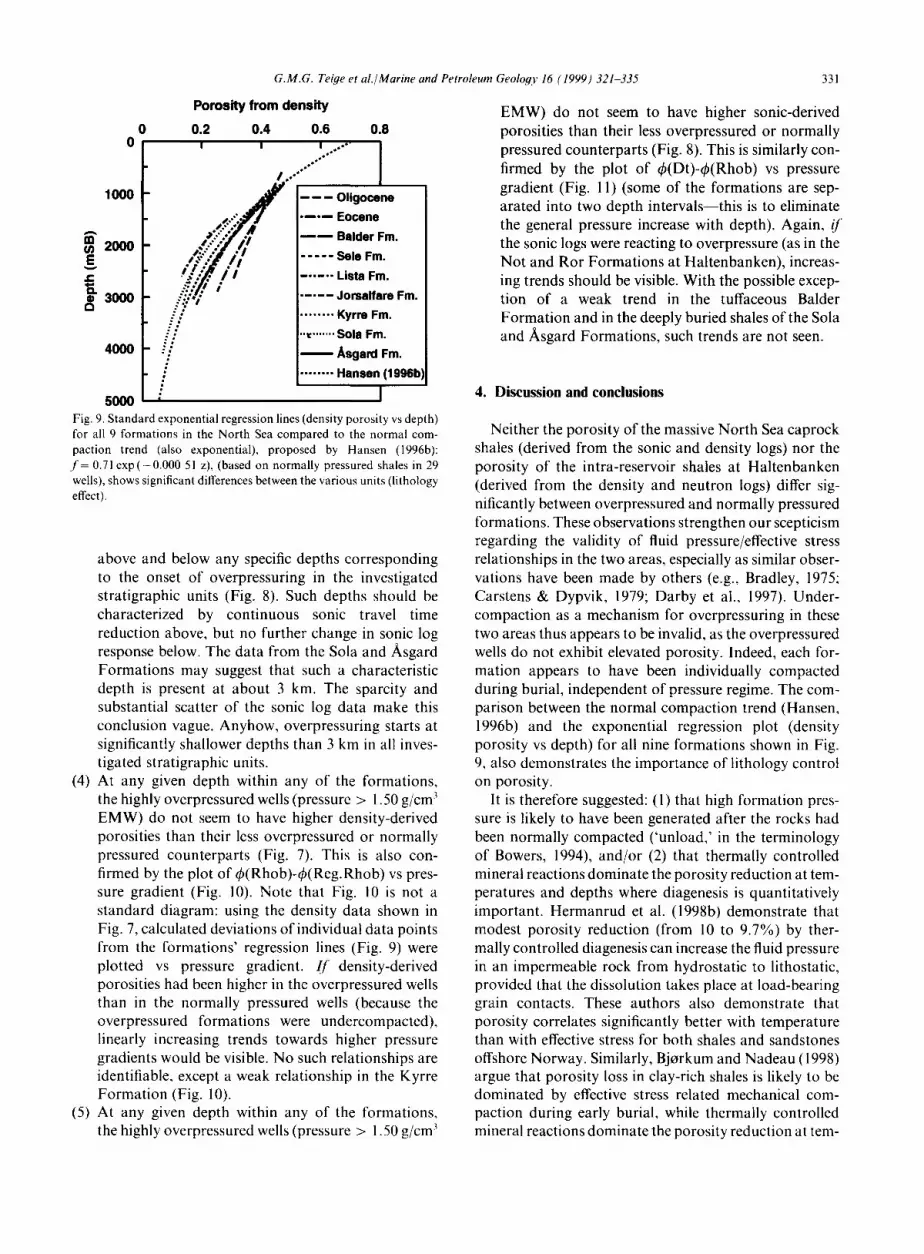
sooo ~ Fig. 9. Standard exponential regression lines (density porosity vs depth) for all 9 formations in the North Sea compared to the normal com- paction trend (also exponential), proposed by Hansen (1996b): f = 0.71 exp(-0.000 51 z), (based on normally pressured shales in 29 wells), shows significant differences between the various units (lithology effect).
above and below any specific depths corresponding to the onset of overpressuring in the investigated stratigraphic units (Fig. 8). Such depths should be characterized by continuous sonic travel time reduction above, but no further change in sonic log response below. The data from the Sola and Asgard Formations may suggest that such a characteristic depth is present at about 3 km. The sparcity and substantial scatter of the sonic log data make this conclusion vague. Anyhow, overpressuring starts at significantly shallower depths than 3 km in all inves- tigated stratigraphic units.
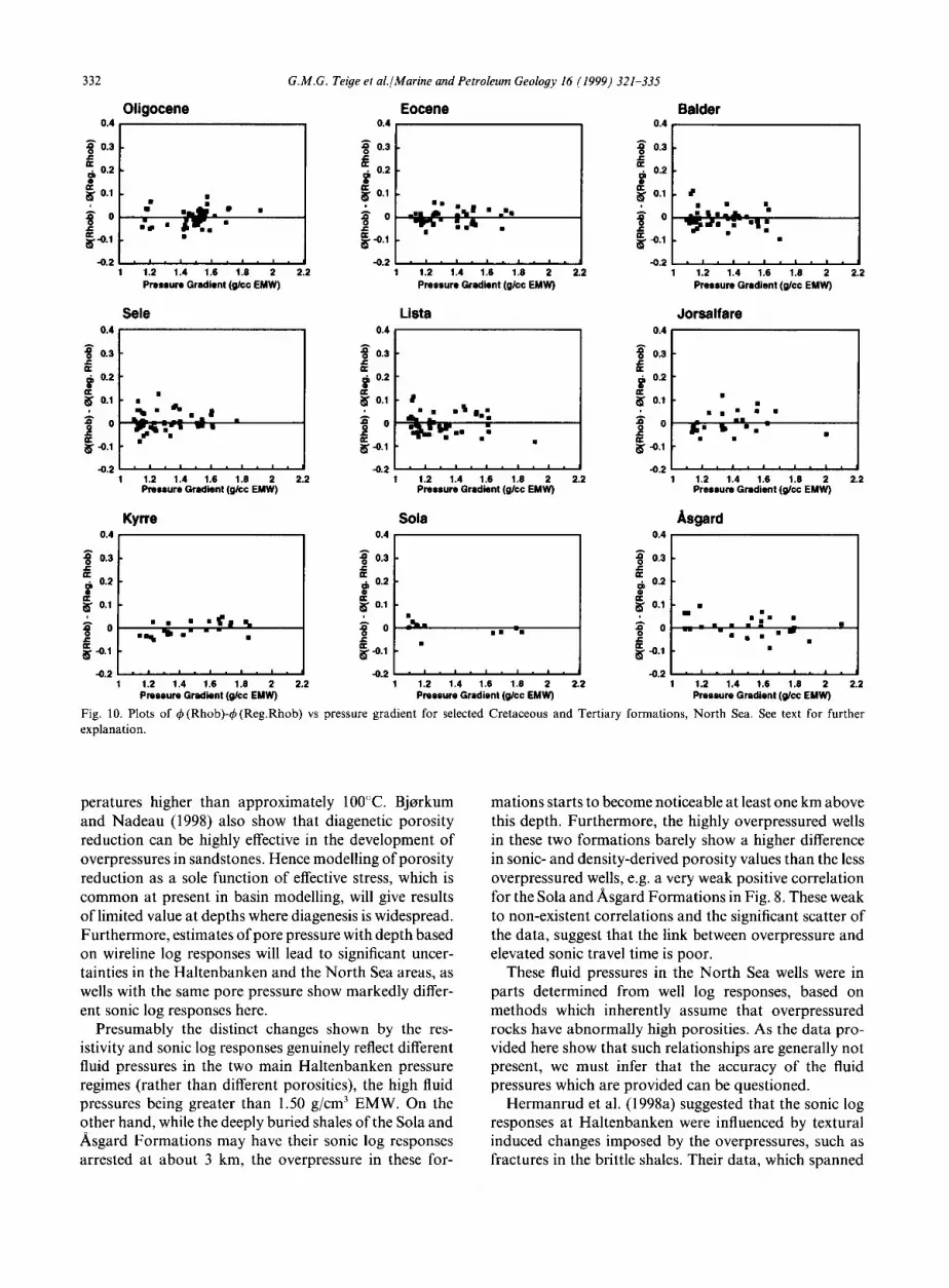
(4) At any given depth within any of the formations, the highly overpressured wells (pressure > 1.50 g/cm 3 EMW) do not seem to have higher density-derived porosities than their less overpressured or normally pressured counterparts (Fig. 7). This is also con- firmed by the plot of q~(Rhob)-q~(Reg.Rhob) vs pres- sure gradient (Fig. 10). Note that Fig. 10 is not a standard diagram: using the density data shown in Fig. 7, calculated deviations of individual data points from the formations' regression lines (Fig. 9) were plotted vs pressure gradient. [[' density-derived porosities had been higher in the overpressured wells than in the normally pressured wells (because the overpressured formations were undercompacted), linearly increasing trends towards higher pressure gradients would be visible. No such relationships are identifiable, except a weak relationship in the Kyrre Formation (Fig. 10).
(5) At any given depth within any of the formations, the highly overpressured wells (pressure > 1.50 g/cm 3
Geology 16 (1999) 321-335 331
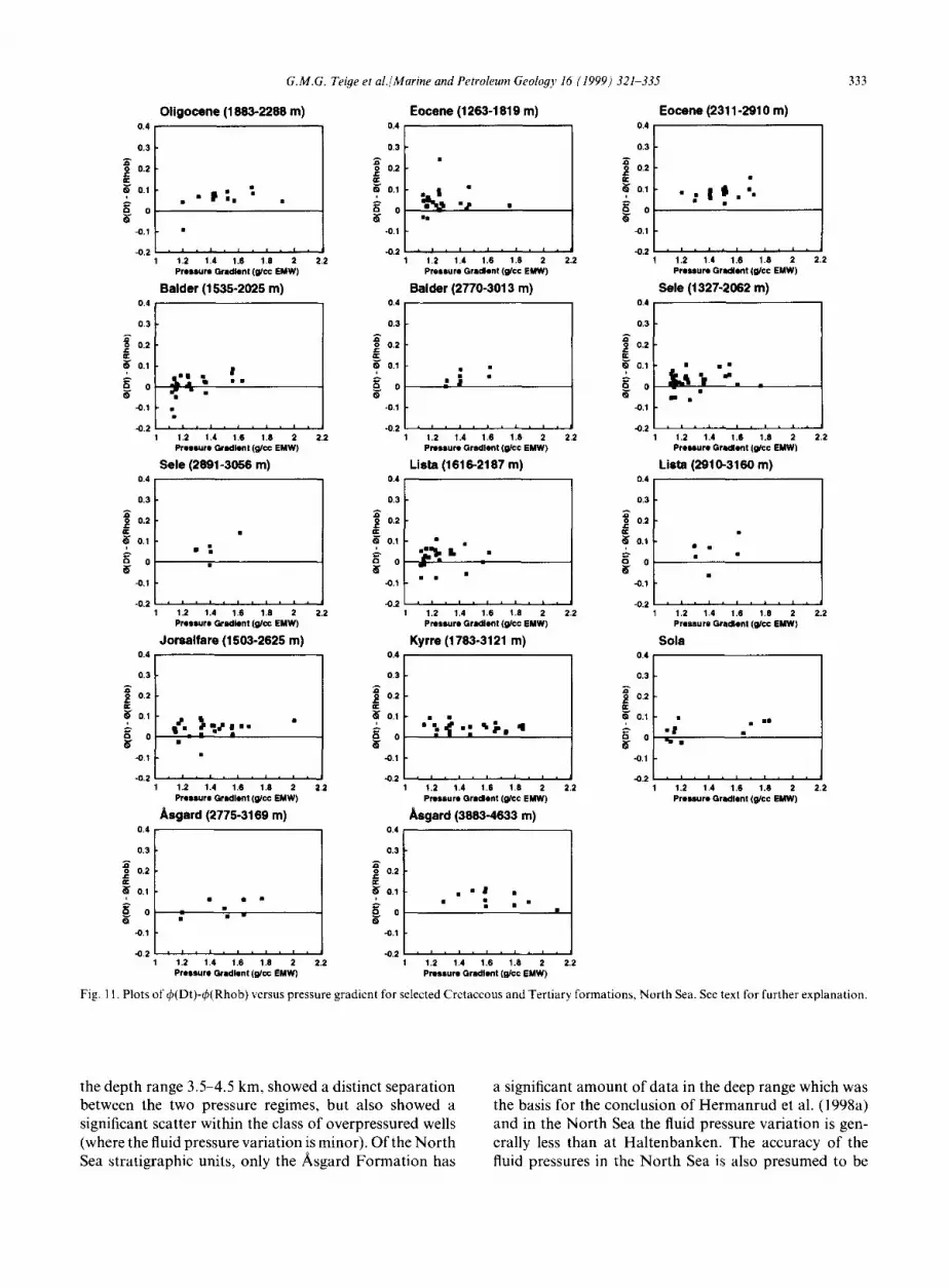
EMW) do not seem to have higher sonic-derived porosities than their less overpressured or normally pressured counterparts (Fig. 8). This is similarly con- firmed by the plot of ~b(Dt)-~b(Rhob) vs pressure gradient (Fig. 11) (some of the formations are sep- arated into two depth intervals--this is to eliminate the general pressure increase with depth). Again, /f the sonic logs were reacting to overpressure (as in the Not and Ror Formations at Haltenbanken), increas- ing trends should be visible. With the possible excep- tion of a weak trend in the tuffaceous Balder Formation and in the deeply buried shales of the Sola and Asgard Formations, such trends are not seen.
4. Discussion and conclusions
Neither the porosity of the massive North Sea caprock shales (derived from the sonic and density logs) nor the porosity of the intra-reservoir shales at Haltenbanken (derived from the density and neutron logs) differ sig- nificantly between overpressured and normally pressured formations. These observations strengthen our scepticism regarding the validity of fluid pressure/effective stress relationships in the two areas, especially as similar obser- vations have been made by others (e.g., Bradley, 1975; Carstens & Dypvik, 1979; Darby et al., 1997). Under- compaction as a mechanism for overpressuring in these two areas thus appears to be invalid, as the overpressured wells do not exhibit elevated porosity. Indeed, each for- mation appears to have been individually compacted during burial, independent of pressure regime. The com- parison between the normal compaction trend (Hansen, 1996b) and the exponential regression plot (density porosity vs depth) for all nine formations shown in Fig. 9, also demonstrates the importance of lithology control on porosity.
It is therefore suggested: (!) that high formation pres- sure is likely to have been generated after the rocks had been normally compacted ('unload,' in the terminology of Bowers, 1994), and/or (2) that thermally controlled mineral reactions dominate the porosity reduction at tem- peratures and depths where diagenesis is quantitatively important. Hermanrud et al. (1998b) demonstrate that modest porosity reduction (from 10 to 9.7%) by ther- mally controlled diagenesis can increase the fluid pressure in an impermeable rock from hydrostatic to lithostatic, provided that the dissolution takes place at load-bearing grain contacts. These authors also demonstrate that porosity correlates significantly better with temperature than with effective stress for both shales and sandstones offshore Norway. Similarly, Bjorkum and Nadeau (1998) argue that porosity loss in clay-rich shales is likely to be dominated by effective stress related mechanical com- paction during early burial, while thermally controlled mineral reactions dominate the porosity reduction at tem-
Fig. 10. Plots of q~(Rhob)-~b(Reg.Rhob) vs pressure gradient for selected Cretaceous and Tertiary formations, North Sea. See text for further explanation.
peratures higher than approximately 100°C. Bjorkum and Nadeau (1998) also show that diagenetic porosity reduction can be highly effective in the development of overpressures in sandstones• Hence modelling of porosity reduction as a sole function of effective stress, which is common at present in basin modelling, will give results of limited value at depths where diagenesis is widespread• Furthermore, estimates of pore pressure with depth based on wireline log responses will lead to significant uncer- tainties in the Haltenbanken and the North Sea areas, as wells with the same pore pressure show markedly differ- ent sonic log responses here.
Presumably the distinct changes shown by the res- istivity and sonic log responses genuinely reflect different fluid pressures in the two main Haltenbanken pressure regimes (rather than different porosities), the high fluid pressures being greater than 1.50 g/cm 3 EMW. On the other hand, while the deeply buried shales of the Sola and Asgard Formations may have their sonic log responses arrested at about 3 km, the overpressure in these for-
mations starts to become noticeable at least one km above this depth• Furthermore, the highly overpressured wells in these two formations barely show a higher difference in sonic- and density-derived porosity values than the less overpressured wells, e.g. a very weak positive correlation for the Sola and Asgard Formations in Fig. 8. These weak to non-existent correlations and the significant scatter of the data, suggest that the link between overpressure and elevated sonic travel time is poor.
These fluid pressures in the North Sea wells were in parts determined from well log responses, based on methods which inherently assume that overpressured rocks have abnormally high porosities. As the data pro- vided here show that such relationships are generally not present, we must infer that the accuracy of the fluid pressures which are provided can be questioned•
Hermanrud et al. (1998a) suggested that the sonic log responses at Haltenbanken were influenced by textural induced changes imposed by the overpressures, such as fractures in the brittle shales• Their data, which spanned
G.M.G. Teige et al./Marine and Petroleum Geology 16 (1999) 321-335 333
Fig. 11. Plots of (;b(Dt)-~(Rhob) versus pressure gradient for selected Cretaceous and Tertiary formations, North Sea. See text for further explanation.
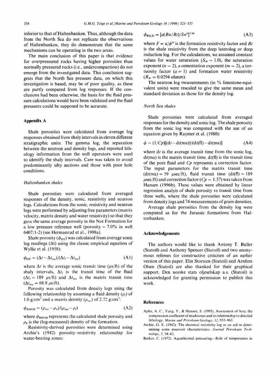
the depth range 3.5~,.5 km, showed a distinct separation between the two pressure regimes, but also showed a significant scatter within the class of overpressured wells (where the fluid pressure variation is minor). Of the North Sea stratigraphic units, only the Asgard Formation has
a significant amount of data in the deep range which was the basis for the conclusion of Hermanrud et al. (1998a) and in the North Sea the fluid pressure variation is gen- erally less than at Haltenbanken. The accuracy of the fluid pressures in the North Sea is also presumed to be
334 G.M.G. Teiye et al./Marine and Petroleum Geology 16 (1999) 321-335
inferior to that of Haltenbanken. Thus, although the data from the North Sea do not replicate the observations of Haltenbanken, they do demonstrate that the same mechanisms can be operating in the two areas.
The main conclusion of this paper is that evidence for overpressured rocks having higher porosities than normally pressured rocks (i.e., undercompaction) do not emerge from the investigated data. This conclusion sug- gests that the North Sea pressure data, on which this investigation is based, may be of poor quality, as these are partly computed from log responses. If the con- clusions had been otherwise, the basis for the fluid pres- sure calculations would have been validated and the fluid pressures could be supposed to be accurate.
q~mLO = [a(Rw/Rt)/Swn] l/m (A3)
where F = a/q~ m is the formation resistivity factor and Rt is the shale resistivity from the deep laterolog or deep induction log. For the calculations, we assumed constant values for water saturation (Sw = 1.0), the saturation exponent (n = 2), a cementation exponent (m = 2), a tor- tuosity factor (a = 1) and formation water resistivity (Rw = 0.0294 ohmm).
The neutron log measurements (in % limestone-equi- valent units) were rescaled to give the same mean and standard deviation as those for the density log.
North Sea shales
Appendix A
Shale porosities were calculated from average log responses obtained from shaly intervals in eleven different stratigraphic units. The gamma log, the separation between the neutron and density logs, and reported lith- ology information from the well operators were used to identify the shaly intervals. Care was taken to avoid predominantly silty sections and those with poor hole conditions.
Haltenbanken shales
Shale porosities were calculated from averaged responses of the density, sonic, resistivity and neutron logs. Calculations from the sonic, resistivity and neutron logs were performed by adjusting free parameters (matrix velocity, matrix density and water resistivity) so that they gave the same average porosity in the Not Formation for a low pressure reference well (porosity = 7.0% in well 6407/1-2) (see Hermanrud et al., 1998a).
Shale porosity (4~DT) was calculated from average sonic log readings (At) using the classic empirical equation of Wyllie et al. (1958):
~bDT = (At-- Atma)/(Atr- Atma) (A l)
where At is the average sonic transit time (/ts/ft) of the shaly intervals, Atr is the transit time of the fluid (Atr = 189 #s/ft) and Alma is the matrix transit time (Arm, = 68.8 ps/ft).
Porosity was calculated from density logs using the following relationship by assuming a fluid density (P0 of 1.0 g/cm 3 and a matrix density (p,,,) of 2.72 g/cm3:
ORHD~ = (Pm~, -- Pb)/(Prna - - P,) (A2)
where q~RHOB represents the calculated shale porosity and Pb is the (log-measured) density of the formation.
Resistivity-derived porosities were determined using Archie's (1942) porosity resistivity relationship for water-bearing zones:
Shale porosities were calculated from averaged responses for the density and sonic log. The shale porosity from the sonic log was computed with the use of an equation given by Raymer et al. (1980):
0 = (1/Cp)[(dt- d t (ma) ) / (d t ( f l ) - dt(ma)] (A4)
where dt is the average transit time from the sonic log, dt(ma) is the matrix transit time, dt(fl) is the transit time of the pore fluid and Cp represents a correction factor. The input parameters for the matrix transit time (dt(ma) = 59 /~sec/ft), fluid transit time (dt(fl)= 189 /~sec/ft) and correction factor (Cp = 1.57) was taken from Hansen (1996b). These values were obtained by linear regression analyis of shale porosity vs transit time from three wells, where the shale porosities were calculated from density logs and 74 measurements of grain densities.
Average shale porosities from the density log were computed as for the Jurassic formations from Hal- tenbanken.
Acknowledgements
The authors would like to thank Antony T. Buller (Statoil) and Anthony Spencer (Statoil) and two anony- mous referees for constructive criticism of an earlier version of this paper. Elin Storsten (Statoil) and Arnfinn Olsen (Statoil) are also thanked for their graphical support. Den norske stats oljeselskap a.s. (Statoil) is acknowledged for granting permission to publish this work.
References
Aplim A. C., Yang, Y., & Hansen, S. (1995). Assessment of beta, the compression coefficient of mudstones and its relationship to detailed lithology. Marine and Petroleum Geology, 12, 955 963.
Archie, G. E. (1942). The electrical resistivity log as an aid in deter- mining some reservoir characteristics. Journal Petroleum Tech- nology, 5, 54-62.
Barker, C. (1972). Aquathermal pressuring Role of temperature in
G.M.G. Teige et al./Marine and Petroleum Geology 16 (1999) 321-335 335
development of abnormal pressure zones. AA PG Bulletin, 56, 2068 2071.
Bj~rkum, P. A., & Nadeau, P. H., (1998). Temperature controlled porosity/permeability reduction, fluid migration, and petroleum exploration in sedimentary basins. Australia Petroleum Production and Exploration Association Limited Journal, 38(1), 453-464.
Bowers, G. L. (1994). Pore pressure estimation from velocity data; accounting for overpressure mechanisms besides undercompaction. IADC/SPE 27488, presented at the 1995 IADC/SPE Drilling Con- ference, Dallas, Texas.
Bradley, J. S. (1975). Abnormal formation pressure. AAPG Bulletin, 59(6), 957-973.
Carstens, H., & Dypvik, H. B. (1979). Prediction, detection and evalu- ation of abnormal formation pressures in virgin areas: some limi- tations. Norwegian Petroleum Society Paper NSS 13, 14.
Chapman, R. E. (1980). Mechanical versus thermal cause of abnormally high pressures in shales: Reply. AAPG Bulletin, 64, 2179--2183.
Dalland, A., Worsley, D., & Ofstad, K. (1988). A lithostratigraphic scheme./or the Mesozoic and Cenozoic succession of[shore mid- and northern Norway Dalland et al. (Eds) NPD-Bulletin, 4, 65.
Darby, D., Whelan, J., & Hunt, J. (1997). Gulf Coast mudrocks problems with the paradigm. Poster presented at "'Mudrocks at the basin scale: Properties, controls and behaviour", Geolo#ical Society Conference, London, January 28 29.
Dickey, P. A. (1974). Petroleum development geology. Division of Petroleum Publishing Co. Tulsa, OK.
Dickey, P. A. (1976). Abnormal formation pressure: Discussion. A A PG Bulletin, 60, 1124~1128.
Dickinson, G. (1953). Geological aspects of abnormal reservoir pres- sures in Gulf Coast Louisiana. AAPG Bulletin, 37, 410~432.
Dowdle, W. L., & Cobb, W. M. (1975). Static formation temperature from well logs; an empirical method. Journal o/ Petroleum Tech- nology, 27(11), 132~1330.
Freed, R. L., & Peacor, D. R. (1989). Geopressured shale and sealing effect of smectite to illite transition. AAPG Bulletin, 73(10), 1223- 1232.
Gray-Stephens, D., Cook, J. M., & Sheppard, C. (1994). Influence of pore pressure on drilling response in hard shales. Society qJ Pet- roleum Engineers, 23414, 263 270.
Hansen, S. (1996a). Compaction on claystones on the Norwegian margin. Ph.D. thesis, Geologisk Institut, A, rhus University, Denmark.
Hansen, S. (1996b). A compaction trend for Cretaceous and Tertiary shales on the Norwegian Shelf based on sonic transit times. Pet- roleum Geoscience, 2, 159 166.
Hermanrud, C., Wensaas, L., Teige, G. M. G., Vik, E., Nordg~_rd Bol~s, H. M., & Hansen, S. (1998a). Shale porosities from well logs on Haltenbanken (Offshore Mid-Norway) show no influence of overpressuring. Abnormal Pressures in 14ydrocarbon Environments Law et al. (Eds.) AAPG Memoir, 70, 65-85.
Hermanrud, C., Teige, G. M. G., Vik, E., Paasch, B., Wensaas, L., & Nordghrd Bol~s, H. M. (1998b). Overpressures in shales--do we know what they are and why they are there? Proceedings from the workshop Overpressures in Petroleum Exploration, Pau, France.
Heum, O. R., Dalland, A. & Meisingset, K. (1986). Habitat of hydro- carbons at Haltenbanken (PVT-modelling as a predictive tool in hydrocarbon exploration). Habitat oJ'Itydrocarbons on the Norweg-
ian Continental She(J" A. M. Spencer et al. (Eds.). Norwegian Pet- roleum Society. London, Graham and Trotman, 259--274.
Hollander, N. B. (1984). Geohistory and hydrocarbon evolution of the Haltenbanken area. Petroleum Geology of the north European mar,qin A. M. Spencer et al. (Eds.). Norwegian Petroleum SocieO,. London, Graham and Trotman, 283-384.
Hubbert, M. K., & Rubey, W. W. (1959). role of fluid pressure in mechanics of overthrust faulting, I. Geological Socie O, oJ'American Bulletin, 70, 115-166.
Hunt, J. M., Whelan, J. K., & Eglinton, L. B. (1994). Gas generation-- a major cause of deep Gulf Coast overpressure. Oil and Gas Journal.
lsaksen, D., & Tonstad, K. (1989). A revised Cretaceous and Tertiary lithostratigraphic nomenclature for the Norwegian North Sea Isaksen & Tonstad, (Eds.). NPD-Bulletin, 5, 59.
Koch, J.-O., & Heum, O. R. (1995). Exploration trends of the Halten Terrace. 25 Years of Petroleum Exploration in Norway S. Hanslien (Ed.). Norwegian Petroleum Society, Special Publication, 4, Amster- dam: Elsevier, 235-251.
Law, B. E., & Dickinson, W. W. (1985). Conceptual model of origin of abnormally pressured gas accumulations in low permeability reservoirs. AAPG Bulletin, 69, 1295 1304.
Magara, K. (1975). Importance of aquathermal pressuring effect in Gulf coast. AAPG Bulletin, 59, 2037-2045.
Meissner, F. F. (1981). Abnormal pressures produced by hydrocarbon generation and maturation and their relation to processes of migration and accumulation. AAPG Bulletin, 65, 2467.
Momper, J. A. (1978). Oil migration limitations suggested by geological and geochemical considerations. In Physical and Chemical Con- straints on Petroleum Migration. AAPG Continuing Education Short Course Note Series, 8, BI B60.
Pickering, L. A., & Indelicato, G. J. (1985). Abnormal formation pres- sure: a review. The Mountain Geologist, 22(2), 78-89.
Raymer, L. L., Hunt, L. T., & Gardner, J. S. (1980). An improved sonic transit time-to-porosity transform. SPWLA 21st annual logging symposium.
Rider, M. H. (Ed.) (1991). The geological interpretation q/ well logs (revised ed.) Whittles Publishing.
Rubey, W. W., & Hubbert, M. K. (1959). Role of fluid pressure in mechanics of overthrust faulting, II. Geological Society ¢~fAmerican Bulletin, 70, 166-205.
Swarbrick, R. E., & Osborne, M. J. (1998). Mechanisms which generate abnormal pressures: an overview. Abnormal Pressures in Hydro- carbon Em, ironments Law et al. (Eds.) AAPG Memoir, 70, 13 34.
Terzhagi, K. V. (1923). Die Berechnung der Durchlaessigkeitsziffer des Tones aus dem Verlauf der Hydrodynamischen Spannunger- scheinungen. Sitzungsber. Akad. Wiss. Wien, Math. Naturwiss. KI. Abts., 2A, 105-132.
Wyllie, M. R. J., Gregory, A. R., & Gardner, G. H. F. (1958). An experimental investigation of the factors affecting elastic wave vel- ocities in porous media: Geophysics, 23, 459~493.
Yassir, N. A., & Bell, J. S. (1996). Abnormal high fluid pressures and associated porosities and stress regimes in sedimentary basins. SPE Formation Evaluation, SPE 28139.
Ziegler, W. H., Doery, R., & Scott, J. (1986). Tectonic habitat of Norwegian oil and gas. Habitat of Hydrocarbons on the Norwegian Continental ShelfA. M. Spencer et al. (Eds.), Norwegian Petroleum Society, London, Graham and Trotman, 3-19.