UMTS XX.03 V1.3.1 (1999-02)3(UMTS XX.03 version 1.3.1)
Contents
Intellectual Property Rights ............................................................................................................................... 4
4 Transport channels................................................................................................................................... 64.1 Dedicated transport channels ............................................................................................................................. 64.1.1 DCH – Dedicated Channel ........................................................................................................................... 64.1.2 FAUSCH – Fast Uplink Signalling Channel ................................................................................................ 64.2 Common transport channels............................................................................................................................... 64.2.1 BCH – Broadcast Channel ........................................................................................................................... 64.2.2 FACH – Forward Access Channel................................................................................................................ 64.2.3 PCH – Paging Channel................................................................................................................................. 64.2.4 RACH – Random Access Channel ............................................................................................................... 64.2.5 DSCH – Downlink Shared Channel ............................................................................................................. 64.2.6 DSCH Control Channel ................................................................................................................................ 7
5 Physical channels..................................................................................................................................... 75.1 The physical resource......................................................................................................................................... 75.2 Uplink physical channels ................................................................................................................................... 75.2.1 Dedicated uplink physical channels.............................................................................................................. 75.2.2 Common uplink physical channels ............................................................................................................... 85.2.2.1 Physical Random Access Channel .......................................................................................................... 85.2.2.1.1 RACH transmission........................................................................................................................... 85.2.2.1.2 RACH preamble part......................................................................................................................... 95.2.2.1.3 RACH message part .......................................................................................................................... 95.2.2.1.4 FAUSCH transmission .................................................................................................................... 105.2.2.1.5 Sharing of PRACH by RACH and FAUSCH.................................................................................. 105.3 Downlink physical channels............................................................................................................................. 105.3.1 Dedicated physical channels....................................................................................................................... 105.3.1.1 Dedicated channel pilots with feedback mode transmit diversity ......................................................... 125.3.1.2 Open loop transmit diversity................................................................................................................. 135.3.2 Common physical channels ........................................................................................................................ 145.3.2.1 Primary Common Control Physical Channel (CCPCH)........................................................................ 145.3.2.1.1 Primary CCPCH structure with FB mode transmit diversity........................................................... 145.3.2.2 Secondary Common Control Physical Channel .................................................................................... 155.3.2.3 Synchronisation Channel ...................................................................................................................... 155.3.2.4 Physical Shared Channel Control Channel (PSCCCH)......................................................................... 175.3.2.5 Physical Downlink Shared Channel ...................................................................................................... 175.3.2.5.1 DSCH associated with a DCH......................................................................................................... 175.3.2.5.2 DSCH associated with a DSCH control channel ............................................................................. 175.3.2.6 Acquisition Indication Channel (AICH) ............................................................................................... 18
6 Mapping of transport channels to physical channels............................................................................. 186.1 Method for mapping of PCH to Secondary CCPCH........................................................................................ 18
7 Timing relationship between physical channels.................................................................................... 19
History ............................................................................................................................................................. 22
ETSI
UMTS XX.03 V1.3.1 (1999-02)4(UMTS XX.03 version 1.3.1)
Intellectual Property RightsIPRs essential or potentially essential to the present document may have been declared to ETSI. The informationpertaining to these essential IPRs, if any, is publicly available for ETSI members and non-members, and can be foundin SR 000 314: "Intellectual Property Rights (IPRs); Essential, or potentially Essential, IPRs notified to ETSI in respectof ETSI standards", which is available free of charge from the ETSI Secretariat. Latest updates are available on theETSI Web server (http://www.etsi.org/ipr).Pursuant to the ETSI IPR Policy, no investigation, including IPR searches, has been carried out by ETSI. No guaranteecan be given as to the existence of other IPRs not referenced in SR 000 314 (or the updates on the ETSI Web server)which are, or may be, or may become, essential to the present document.
ForewordThis Technical Report (TR) has been produced by ETSI Technical Committee Special Mobile Group (SMG).The present document has been elaborated by the Layer 1 expert group of SMG2 "Radio aspects", as a part of the workin defining and describing Layer 1 of the Universal Mobile Telecommunications System (UMTS) Terrestrial RadioAccess (UTRA).The present document describes the transport channels and physical channels in UTRA/FDD Layer 1.
ETSI
UMTS XX.03 V1.3.1 (1999-02)5(UMTS XX.03 version 1.3.1)
1 ScopeThis Technical Report establishes the characteristics of the Layer 1 transport channels and physicals channels in theFDD mode of UTRA. The main objectives of the document are to be a part of the full description of the UTRA Layer 1,and to serve as a basis for the drafting of the actual technical specification (TS).
2 ReferencesThe following documents contain provisions which, through reference in this text, constitute provisions of the presentdocument.
• References are either specific (identified by date of publication, edition number, version number, etc.) ornon-specific.
• For a specific reference, subsequent revisions do not apply.• For a non-specific reference, subsequent revisions do apply.• A non-specific reference to an ETS shall also be taken to refer to later versions published as an EN with the same
number.[1] Reference 1.
3 Definitions, symbols and abbreviations
3.1 DefinitionsFor the purposes of the present document, the following definitions apply:<defined term>: <definition>.
3.2 SymbolsFor the purposes of the present document, the following symbols apply:
<symbol> <Explanation>
3.3 AbbreviationsFor the purposes of the present document, the following abbreviations apply:
AICH Acquisition Indication ChannelBCH Broadcast ChannelCCPCH Common Control Physical ChannelDCH Dedicated ChannelDPCCH Dedicated Physical Control ChannelDPCH Dedicated Physical ChannelDPDCH Dedicated Physical Data ChannelDSCH Downlink Shared ChannelFACH Forward Access ChannelFAUSCH Fast Uplink Signalling ChannelFBI Feedback InformationMUI Mobile User IdentifierPCH Paging ChannelPDSCH Physical Downlink Shared ChannelPI Paging IndicationPRACH Physical Random Access ChannelPSCCCH Physical Shared Channel Control ChannelRACH Random Access ChannelRNC Radio Network ControllerSCH Synchronisation ChannelSF Spreading FactorSFN System Frame NumberSTTD Space Time Transmit Diversity
ETSI
UMTS XX.03 V1.3.1 (1999-02)6(UMTS XX.03 version 1.3.1)
TFCI Transport Format Combination IndicatorTPC Transmit Power ControlUE User Equipment
4 Transport channels< Documentation status: Everything in this clause is to be considered as working assumption, except otherwiseexplicitly stated. The use of DCH and/or DSCH Control Channel to control the downlink shared channel DSCH is forfurther study. >Transport channels are the services offered by Layer 1 to the higher layers.
4.1 Dedicated transport channelsThere are two types of dedicated transport channel, the Dedicated Channel (DCH) and the Fast Uplink SignallingChannel (FAUSCH).
4.1.1 DCH – Dedicated Channel
The Dedicated Channel (DCH) is a downlink or uplink transport channel that is used to carry user or control informationbetween the network and the UE. The DCH thus corresponds to the three channels Dedicated Traffic Channel (DTCH),Stand-Alone Dedicated Control Channel (SDCCH), and Associated Control Channel (ACCH) defined withinITU-R Recommendation M.1035. The DCH is transmitted over the entire cell or over only a part of the cell usinglobe-forming antennas.
4.1.2 FAUSCH – Fast Uplink Signalling Channel
The Fast Uplink Signalling Channel (FAUSCH) is an optional uplink transport channel that is used to carry controlinformation from a UE. The FAUSCH is always received from the entire cell.
4.2 Common transport channelsThere are six types of common transport channels: BCH, FACH, PCH, RACH, DSCH, and DSCH control channel.
4.2.1 BCH – Broadcast Channel
The Broadcast Channel (BCH) is a downlink transport channel that is used to broadcast system- and cell-specificinformation. The BCH is always transmitted over the entire cell.
4.2.2 FACH – Forward Access Channel
The Forward Access Channel (FACH) is a downlink transport channel that is used to carry control information to a UEwhen the system knows the location cell of the UE. The FACH may also carry short user packets. The FACH istransmitted over the entire cell or over only a part of the cell using lobe-forming antennas.
4.2.3 PCH – Paging Channel
The Paging Channel (PCH) is a downlink transport channel that is used to carry control information to a UE when thesystem does not know the location cell of the UE. The PCH is always transmitted over the entire cell.
4.2.4 RACH – Random Access Channel
The Random Access Channel (RACH) is an uplink transport channel that is used to carry control information from theUE. The RACH may also carry short user packets. The RACH is always received from the entire cell.
4.2.5 DSCH – Downlink Shared Channel
The downlink shared channel (DSCH) is a downlink transport channel shared by several Ues carrying dedicated controlor traffic data.Two possibilities exist for the DSCH:
• the DSCH is associated with a DCH;• the DSCH is associated with a DSCH control channel.
ETSI
UMTS XX.03 V1.3.1 (1999-02)7(UMTS XX.03 version 1.3.1)
It is for further study whether both possibilities are needed.
4.2.6 DSCH Control Channel
The DSCH control channel is a downlink transport channel carrying control information to the UE for operating theDSCH when not associated with a DCH. Such control information corresponds among other things to resourceallocation messages and L1 control information such as TPC, that are not available on the DSCH.
5 Physical channels< Documentation status: Everything in this clause is to be considered as working assumption, except otherwiseexplicitly stated. >
5.1 The physical resourceThe basic physical resource is the code/frequency plane. In addition, on the uplink, different information streams may betransmitted on the I and Q branch. Consequently, a physical channel corresponds to a specific carrier frequency, code,and, on the uplink, relative phase (0 or π/2).
5.2 Uplink physical channels
5.2.1 Dedicated uplink physical channels
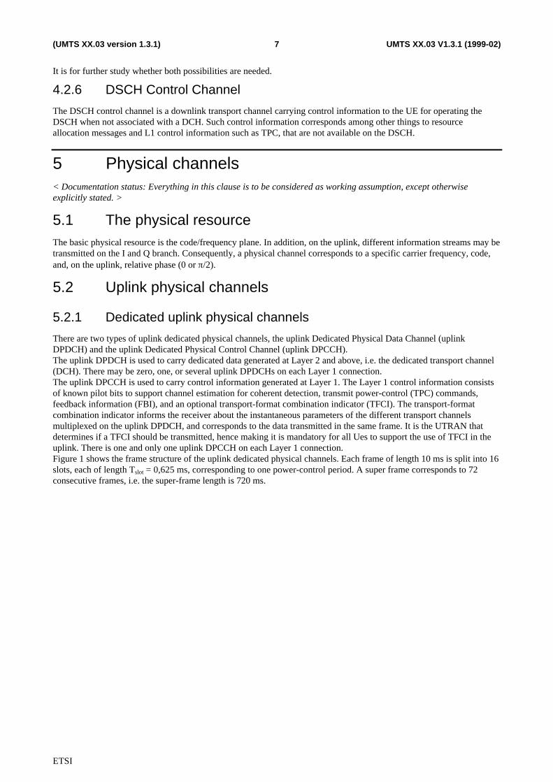
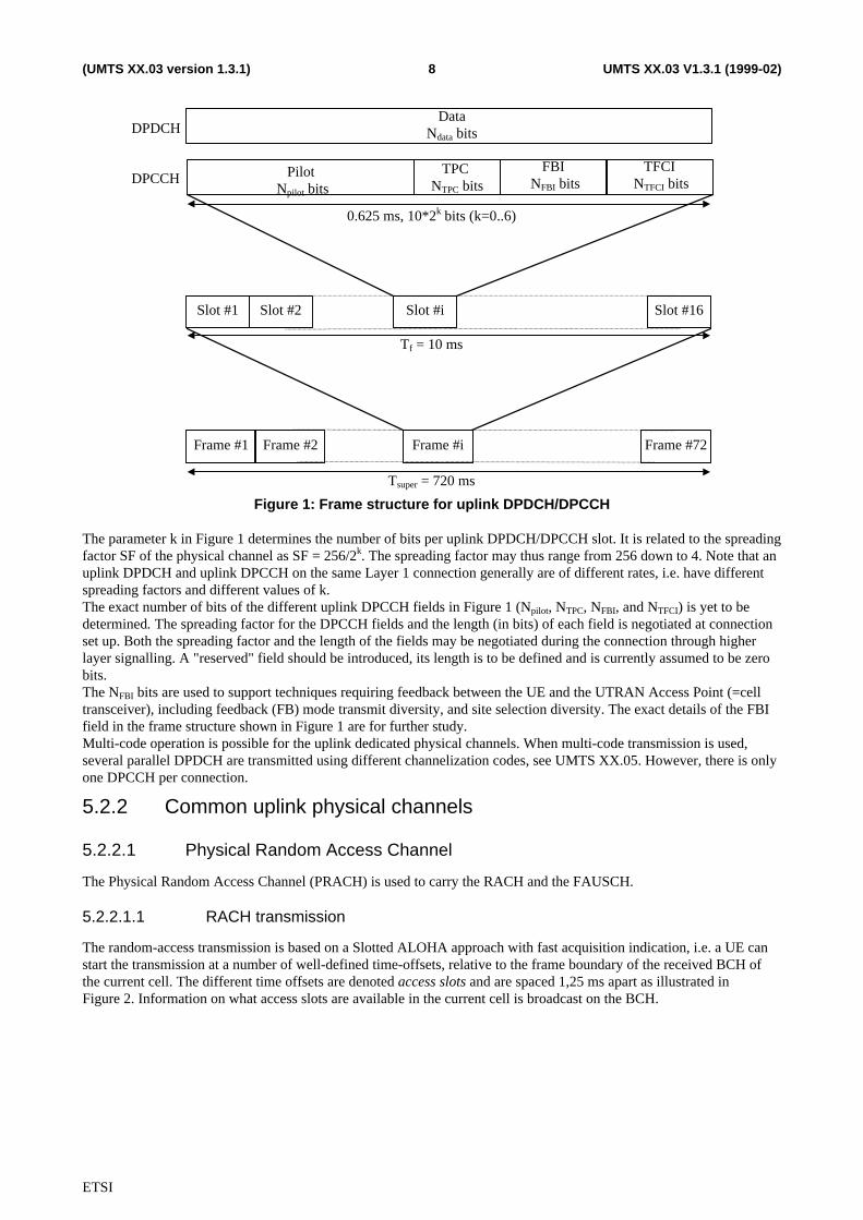
There are two types of uplink dedicated physical channels, the uplink Dedicated Physical Data Channel (uplinkDPDCH) and the uplink Dedicated Physical Control Channel (uplink DPCCH).The uplink DPDCH is used to carry dedicated data generated at Layer 2 and above, i.e. the dedicated transport channel(DCH). There may be zero, one, or several uplink DPDCHs on each Layer 1 connection.The uplink DPCCH is used to carry control information generated at Layer 1. The Layer 1 control information consistsof known pilot bits to support channel estimation for coherent detection, transmit power-control (TPC) commands,feedback information (FBI), and an optional transport-format combination indicator (TFCI). The transport-formatcombination indicator informs the receiver about the instantaneous parameters of the different transport channelsmultiplexed on the uplink DPDCH, and corresponds to the data transmitted in the same frame. It is the UTRAN thatdetermines if a TFCI should be transmitted, hence making it is mandatory for all Ues to support the use of TFCI in theuplink. There is one and only one uplink DPCCH on each Layer 1 connection.Figure 1 shows the frame structure of the uplink dedicated physical channels. Each frame of length 10 ms is split into 16slots, each of length Tslot = 0,625 ms, corresponding to one power-control period. A super frame corresponds to 72consecutive frames, i.e. the super-frame length is 720 ms.
ETSI
UMTS XX.03 V1.3.1 (1999-02)8(UMTS XX.03 version 1.3.1)
Pilot Npilot bits
TFCI NTFCI bits
DataNdata bits
Slot #1 Slot #2 Slot #i Slot #16
Frame #1 Frame #2 Frame #i Frame #72
0.625 ms, 10*2k bits (k=0..6)
Tf = 10 ms
Tsuper = 720 ms
DPDCH
DPCCHFBI
NFBI bitsTPC
NTPC bits
Figure 1: Frame structure for uplink DPDCH/DPCCH
The parameter k in Figure 1 determines the number of bits per uplink DPDCH/DPCCH slot. It is related to the spreadingfactor SF of the physical channel as SF = 256/2k. The spreading factor may thus range from 256 down to 4. Note that anuplink DPDCH and uplink DPCCH on the same Layer 1 connection generally are of different rates, i.e. have differentspreading factors and different values of k.The exact number of bits of the different uplink DPCCH fields in Figure 1 (Npilot, NTPC, NFBI, and NTFCI) is yet to bedetermined. The spreading factor for the DPCCH fields and the length (in bits) of each field is negotiated at connectionset up. Both the spreading factor and the length of the fields may be negotiated during the connection through higherlayer signalling. A "reserved" field should be introduced, its length is to be defined and is currently assumed to be zerobits.The NFBI bits are used to support techniques requiring feedback between the UE and the UTRAN Access Point (=celltransceiver), including feedback (FB) mode transmit diversity, and site selection diversity. The exact details of the FBIfield in the frame structure shown in Figure 1 are for further study.Multi-code operation is possible for the uplink dedicated physical channels. When multi-code transmission is used,several parallel DPDCH are transmitted using different channelization codes, see UMTS XX.05. However, there is onlyone DPCCH per connection.
5.2.2 Common uplink physical channels
5.2.2.1 Physical Random Access Channel
The Physical Random Access Channel (PRACH) is used to carry the RACH and the FAUSCH.
5.2.2.1.1 RACH transmission
The random-access transmission is based on a Slotted ALOHA approach with fast acquisition indication, i.e. a UE canstart the transmission at a number of well-defined time-offsets, relative to the frame boundary of the received BCH ofthe current cell. The different time offsets are denoted access slots and are spaced 1,25 ms apart as illustrated inFigure 2. Information on what access slots are available in the current cell is broadcast on the BCH.
ETSI
UMTS XX.03 V1.3.1 (1999-02)9(UMTS XX.03 version 1.3.1)
1.25 ms
Random-access transmissionAccess slot #1
Random-access transmissionAccess slot #2
Random-access transmissionAccess slot #i
Random-access transmissionAccess slot #8
Offset of access slot #i
Frame boundaryFigure 2: PRACH allocated for RACH access slots
The structure of the random-access transmission of Figure 2, is shown in Figure 3. The random-access transmissionconsists of one or several preambles of length 1 ms and a message of length 10 ms.
Message partPreamble
1 ms 10 ms
Preamble Preamble
Figure 3: Structure of the random-access transmission
5.2.2.1.2 RACH preamble part
The preamble part of the random-access burst consists of a signature of length 16 complex symbols ±1(+j). Eachpreamble symbol is spread with a 256 chip real Orthogonal Gold code. There are a total of 16 different signatures, basedon the Orthogonal Gold code set of length 16 (see UMTS XX.05 for more details).
5.2.2.1.3 RACH message part
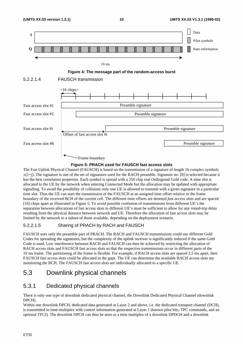
The message part of the random-access burst has the same structure as the uplink dedicated physical channel. It consistsof a data part, corresponding to the uplink DPDCH, and a Layer 1 control part, corresponding to the uplink DPCCH, seeFigure 4. The data and control parts are transmitted in parallel. The data part carries the random access request or userpacket. The spreading factor of the data part is limited to SF∈{256, 128, 64, 32} corresponding to channel bit rates of16, 32, 64, and 128 kbps respectively. The control part carries pilot bits and rate information, using a spreading factor of256. The rate information indicates which channelization code (or rather the spreading factor of the channelization code)is used on the data part, see further UMTS XX.05.
ETSI
UMTS XX.03 V1.3.1 (1999-02)10(UMTS XX.03 version 1.3.1)
I
Q
Data
Pilot symbols
Rate information
10 ms
Figure 4: The message part of the random-access burst
5.2.2.1.4 FAUSCH transmission
<16 chips>
Fast access slot #1
Fast access slot #2
Fast access slot #i
Fast access slot #8
Offset of fast access slot #i
Frame boundary
Preamble signature
Preamble signature
Preamble signature
Preamble signature
Figure 5: PRACH used for FAUSCH fast access slotsThe Fast Uplink Physical Channel (FAUSCH) is based on the transmission of a signature of length 16 complex symbols±(1+j). The signature is one of the set of signatures used for the RACH preamble. Signature no. [8] is selected because ithas the best correlation properties. Each symbol is spread with a 256 chip real Orthogonal Gold code. A time slot isallocated to the UE by the network when entering Connected Mode but the allocation may be updated with appropriatesignalling. To avoid the possibility of collisions only one UE is allowed to transmit with a given signature in a particulartime slot. Thus the UE can start the transmission of the FAUSCH at an assigned time offset relative to the frameboundary of the received BCH of the current cell. The different time offsets are denoted fast access slots and are spaced[16] chips apart as illustrated in Figure 5. To avoid possible confusion of transmissions from different UE’s theseparation between allocations of fast access slots to different UE’s must be sufficient to allow for any round-trip delayresulting from the physical distance between network and UE. Therefore the allocation of fast access slots may belimited by the network to a subset of those available, depending on the deployment scenario.
5.2.2.1.5 Sharing of PRACH by RACH and FAUSCH
FAUSCH uses only the preamble part of PRACH. The RACH and FAUSCH transmissions could use different GoldCodes for spreading the signatures, but the complexity of the uplink receiver is significantly reduced if the same GoldCode is used. Low interference between RACH and FAUSCH can then be achieved by restricting the allocation ofRACH access slots and FAUSCH fast access slots so that the respective transmissions occur in different parts of the10 ms frame. The partitioning of the frame is flexible. For example, if RACH access slots are spaced 2,5 ms apart, thenFAUSCH fast access slots could be allocated in the gaps. The UE can determine the available RACH access slots mymonitoring the BCH. The FAUSCH fast access slots are individually allocated to a specific UE.
5.3 Downlink physical channels
5.3.1 Dedicated physical channels
There is only one type of downlink dedicated physical channel, the Downlink Dedicated Physical Channel (downlinkDPCH).Within one downlink DPCH, dedicated data generated at Layer 2 and above, i.e. the dedicated transport channel (DCH),is transmitted in time-multiplex with control information generated at Layer 1 (known pilot bits, TPC commands, and anoptional TFCI). The downlink DPCH can thus be seen as a time multiplex of a downlink DPDCH and a downlink
ETSI
UMTS XX.03 V1.3.1 (1999-02)11(UMTS XX.03 version 1.3.1)
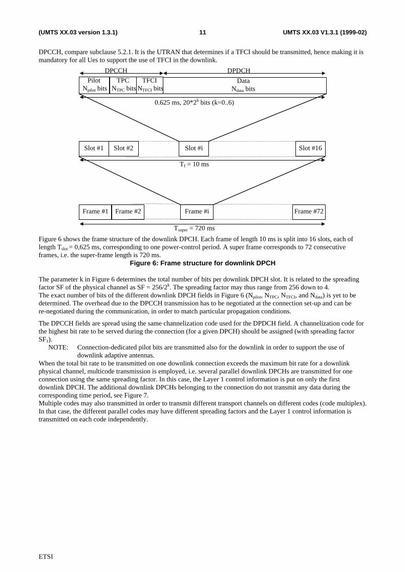
DPCCH, compare subclause 5.2.1. It is the UTRAN that determines if a TFCI should be transmitted, hence making it ismandatory for all Ues to support the use of TFCI in the downlink.
TPC NTPC bits
Slot #1 Slot #2 Slot #i Slot #16
Frame #1 Frame #2 Frame #i Frame #72
0.625 ms, 20*2k bits (k=0..6)
Pilot Npilot bits
DataNdata bits
DPCCH DPDCH
Tf = 10 ms
Tsuper = 720 ms
TFCI NTFCI bits
Figure 6 shows the frame structure of the downlink DPCH. Each frame of length 10 ms is split into 16 slots, each oflength Tslot = 0,625 ms, corresponding to one power-control period. A super frame corresponds to 72 consecutiveframes, i.e. the super-frame length is 720 ms.
Figure 6: Frame structure for downlink DPCH
The parameter k in Figure 6 determines the total number of bits per downlink DPCH slot. It is related to the spreadingfactor SF of the physical channel as SF = 256/2k. The spreading factor may thus range from 256 down to 4.The exact number of bits of the different downlink DPCH fields in Figure 6 (Npilot, NTPC, NTFCI, and Ndata) is yet to bedetermined. The overhead due to the DPCCH transmission has to be negotiated at the connection set-up and can bere-negotiated during the communication, in order to match particular propagation conditions.
The DPCCH fields are spread using the same channelization code used for the DPDCH field. A channelization code forthe highest bit rate to be served during the connection (for a given DPCH) should be assigned (with spreading factorSF1).
NOTE: Connection-dedicated pilot bits are transmitted also for the downlink in order to support the use ofdownlink adaptive antennas.
When the total bit rate to be transmitted on one downlink connection exceeds the maximum bit rate for a downlinkphysical channel, multicode transmission is employed, i.e. several parallel downlink DPCHs are transmitted for oneconnection using the same spreading factor. In this case, the Layer 1 control information is put on only the firstdownlink DPCH. The additional downlink DPCHs belonging to the connection do not transmit any data during thecorresponding time period, see Figure 7.Multiple codes may also transmitted in order to transmit different transport channels on different codes (code multiplex).In that case, the different parallel codes may have different spreading factors and the Layer 1 control information istransmitted on each code independently.
ETSI
UMTS XX.03 V1.3.1 (1999-02)12(UMTS XX.03 version 1.3.1)
DPCCH
TransmissionPower Physical Channel 1
TransmissionPower Physical Channel 2
TransmissionPower Physical Channel L
DPDCH
One slot (0.625 ms)
Figure 7: Downlink slot format in case of multi-code transmission
5.3.1.1 Dedicated channel pilots with feedback mode transmit diversity
For certain sub-modes of feedback mode transmit diversity, in which transmission antennas are selected, the pilotpatterns can be varied according to which antenna is transmitted upon (see Figure 8 a, where the different shadingindicates different pilot patterns). This assists in some types of antenna verification (see XX.07 for a description ofantenna verification). Pilot symbol patterns are TBD. Otherwise, the pilot symbol patterns from both of the antennas arethe same (see Figure 8 b).
ETSI
UMTS XX.03 V1.3.1 (1999-02)13(UMTS XX.03 version 1.3.1)
N Pilot N TPC
N Pilot
Antenna 1
Antenna 2
Slot i Slot i+1
N DataN TFI
N TPC N DataN TFI
(a)
N Pilot N TFI
N Pilot
Antenna 1
Antenna 2
Slot i Slot i+1
N DataN TPC
N DataN TPC
(b)
N Pilot N DataN TPC
N Pilot N TFI N DataN TPC N TFI
N TFI
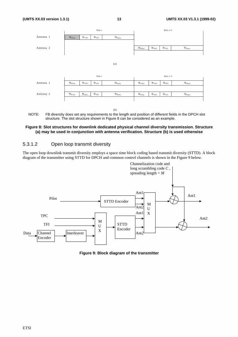
NOTE: FB diversity does set any requirements to the length and position of different fields in the DPCH slotstructure. The slot structure shown in Figure 8 can be considered as an example.
Figure 8: Slot structures for downlink dedicated physical channel diversity transmission. Structure(a) may be used in conjunction with antenna verification. Structure (b) is used otherwise
5.3.1.2 Open loop transmit diversity
The open loop downlink transmit diversity employs a space time block coding based transmit diversity (STTD). A blockdiagram of the transmitter using STTD for DPCH and common control channels is shown in the Figure 9 below.
Ant2MUX
Data
Ant1
Channelization code andlong scrambling code C ,spreading length = M
Ant1
Ant2
Ant1
Ant2
TPC
TFI
Pilot
MUX
STTD Encoder
ChannelEncoder
Interleaver
STTDEncoder
Figure 9: Block diagram of the transmitter
ETSI
UMTS XX.03 V1.3.1 (1999-02)14(UMTS XX.03 version 1.3.1)
S1 S2STTD encoder
S1 S2
-S2* S1
*
0 T 2T0 T 2T
Ant 1
Ant 2
MobileAntennaPath 1
Path j
Npilot Ndata Npilot Ndata
Slot 1
a12
a11
aj2
aj1
r1(i+t1)
rj(i+tj)
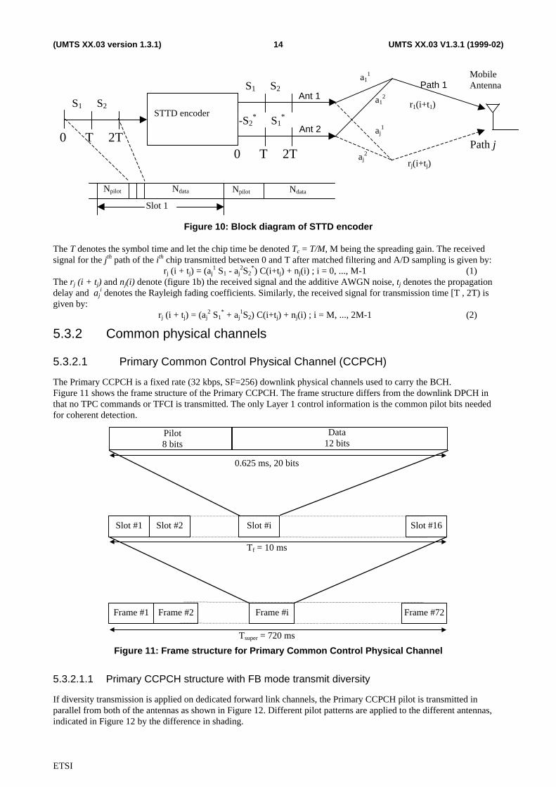
Figure 10: Block diagram of STTD encoder
The T denotes the symbol time and let the chip time be denoted Tc = T/M, M being the spreading gain. The receivedsignal for the jth path of the ith chip transmitted between 0 and T after matched filtering and A/D sampling is given by:
rj (i + tj) = (aj1 S1 - aj
2S2*) C(i+tj) + nj(i) ; i = 0, ..., M-1 (1)
The rj (i + tj) and nj(i) denote (figure 1b) the received signal and the additive AWGN noise, tj denotes the propagationdelay and aj
i denotes the Rayleigh fading coefficients. Similarly, the received signal for transmission time [T , 2T) isgiven by:
rj (i + tj) = (aj2 S1
* + aj1S2) C(i+tj) + nj(i) ; i = M, ..., 2M-1 (2)
5.3.2 Common physical channels
5.3.2.1 Primary Common Control Physical Channel (CCPCH)
The Primary CCPCH is a fixed rate (32 kbps, SF=256) downlink physical channels used to carry the BCH.Figure 11 shows the frame structure of the Primary CCPCH. The frame structure differs from the downlink DPCH inthat no TPC commands or TFCI is transmitted. The only Layer 1 control information is the common pilot bits neededfor coherent detection.
Data12 bits
Slot #1 Slot #2 Slot #i Slot #16
Frame #1 Frame #2 Frame #i Frame #72
0.625 ms, 20 bits
Pilot8 bits
Tf = 10 ms
Tsuper = 720 ms
Figure 11: Frame structure for Primary Common Control Physical Channel
5.3.2.1.1 Primary CCPCH structure with FB mode transmit diversity
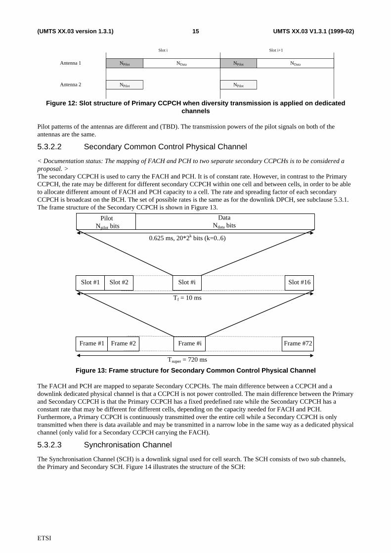
If diversity transmission is applied on dedicated forward link channels, the Primary CCPCH pilot is transmitted inparallel from both of the antennas as shown in Figure 12. Different pilot patterns are applied to the different antennas,indicated in Figure 12 by the difference in shading.
ETSI
UMTS XX.03 V1.3.1 (1999-02)15(UMTS XX.03 version 1.3.1)
NPilot NData
NPilot
NDataNPilot
NPilot
Antenna 1
Antenna 2
Slot i Slot i+1
Figure 12: Slot structure of Primary CCPCH when diversity transmission is applied on dedicatedchannels
Pilot patterns of the antennas are different and (TBD). The transmission powers of the pilot signals on both of theantennas are the same.
5.3.2.2 Secondary Common Control Physical Channel
< Documentation status: The mapping of FACH and PCH to two separate secondary CCPCHs is to be considered aproposal. >The secondary CCPCH is used to carry the FACH and PCH. It is of constant rate. However, in contrast to the PrimaryCCPCH, the rate may be different for different secondary CCPCH within one cell and between cells, in order to be ableto allocate different amount of FACH and PCH capacity to a cell. The rate and spreading factor of each secondaryCCPCH is broadcast on the BCH. The set of possible rates is the same as for the downlink DPCH, see subclause 5.3.1.The frame structure of the Secondary CCPCH is shown in Figure 13.
Slot #1 Slot #2 Slot #i Slot #16
Frame #1 Frame #2 Frame #i Frame #72
0.625 ms, 20*2k bits (k=0..6)
Pilot Npilot bits
DataNdata bits
Tf = 10 ms
Tsuper = 720 ms
Figure 13: Frame structure for Secondary Common Control Physical Channel
The FACH and PCH are mapped to separate Secondary CCPCHs. The main difference between a CCPCH and adownlink dedicated physical channel is that a CCPCH is not power controlled. The main difference between the Primaryand Secondary CCPCH is that the Primary CCPCH has a fixed predefined rate while the Secondary CCPCH has aconstant rate that may be different for different cells, depending on the capacity needed for FACH and PCH.Furthermore, a Primary CCPCH is continuously transmitted over the entire cell while a Secondary CCPCH is onlytransmitted when there is data available and may be transmitted in a narrow lobe in the same way as a dedicated physicalchannel (only valid for a Secondary CCPCH carrying the FACH).
5.3.2.3 Synchronisation Channel
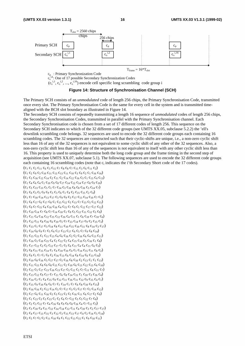
The Synchronisation Channel (SCH) is a downlink signal used for cell search. The SCH consists of two sub channels,the Primary and Secondary SCH. Figure 14 illustrates the structure of the SCH:
ETSI
UMTS XX.03 V1.3.1 (1999-02)16(UMTS XX.03 version 1.3.1)
cp : Primary Synchronization Codecs
i,k: One of 17 possible Secondary Synchronization Codes
cp
csi,1
cp cp
Tslot = 2560 chipschips
Tframe = 16*Tslot
Primary SCH
Secondary SCH
256 chips
csi,2 cs
i,16
(csi,1, cs
i,2, ..., csi,16) encode cell specific long scrambling code group i
Figure 14: Structure of Synchronisation Channel (SCH)
The Primary SCH consists of an unmodulated code of length 256 chips, the Primary Synchronisation Code, transmittedonce every slot. The Primary Synchronisation Code is the same for every cell in the system and is transmitted time-aligned with the BCH slot boundary as illustrated in Figure 14.The Secondary SCH consists of repeatedly transmitting a length 16 sequence of unmodulated codes of length 256 chips,the Secondary Synchronisation Codes, transmitted in parallel with the Primary Synchronisation channel. EachSecondary Synchronisation code is chosen from a set of 17 different codes of length 256. This sequence on theSecondary SCH indicates to which of the 32 different code groups (see UMTS XX.05, subclause 5.2.2) the ’ell'sdownlink scrambling code belongs. 32 sequences are used to encode the 32 different code groups each containing 16scrambling codes. The 32 sequences are constructed such that their cyclic-shifts are unique, i.e., a non-zero cyclic shiftless than 16 of any of the 32 sequences is not equivalent to some cyclic shift of any other of the 32 sequences. Also, anon-zero cyclic shift less than 16 of any of the sequences is not equivalent to itself with any other cyclic shift less than16. This property is used to uniquely determine both the long code group and the frame timing in the second step ofacquisition (see UMTS XX.07, subclause 5.1). The following sequences are used to encode the 32 different code groupseach containing 16 scrambling codes (note that ci indicates the i’th Secondary Short code of the 17 codes).(c1 c1 c2 c11 c6 c3 c15 c7 c8 c8 c7 c15 c3 c6 c11 c2)(c1 c2 c9 c3 c10 c11 c13 c13 c11 c10 c3 c9 c2 c1 c16 c16)(c1 c3 c16 c12 c14 c2 c11 c2 c14 c12 c16 c3 c1 c13 c4 c13)(c1 c4 c6 c4 c1 c10 c9 c8 c17 c14 c12 c14 c17 c8 c9 c10)(c1 c5 c13 c13 c5 c1 c7 c14 c3 c16 c8 c8 c16 c3 c14 c7)(c1 c6 c3 c5 c9 c9 c5 c3 c6 c1 c4 c2 c15 c15 c2 c4)(c1 c7 c10 c14 c13 c17 c3 c9 c9 c3 c17 c13 c14 c10 c7 c1)(c1 c8 c17 c6 c17 c8 c1 c15 c12 c5 c13 c7 c13 c5 c12 c15)(c1 c9 c7 c15 c4 c16 c16 c4 c15 c7 c9 c1 c12 c17 c17 c12)(c1 c10 c14 c7 c8 c7 c14 c10 c1 c9 c5 c12 c11 c12 c5 c9)(c1 c11 c4 c16 c12 c15 c12 c16 c4 c11 c1 c6 c10 c7 c10 c6)(c1 c12 c11 c8 c16 c6 c10 c5 c7 c13 c14 c17 c9 c2 c15 c3)(c1 c13 c1 c17 c3 c14 c8 c11 c10 c15 c10 c11 c8 c14 c3 c17)(c1 c14 c8 c9 c7 c5 c6 c17 c13 c17 c6 c5 c7 c9 c8 c14)(c1 c15 c15 c1 c11 c13 c4 c6 c16 c2 c2 c16 c6 c4 c13 c11)(c1 c16 c5 c10 c15 c4 c2 c12 c2 c4 c15 c10 c5 c16 c1 c8)(c1 c17 c12 c2 c2 c12 c17 c1 c5 c6 c11 c4 c4 c11 c6 c5)(c2 c8 c11 c15 c14 c1 c4 c10 c10 c4 c1 c14 c15 c11 c8 c2)(c2 c9 c1 c7 c1 c9 c2 c16 c13 c6 c14 c8 c14 c6 c13 c16)(c2 c10 c8 c16 c5 c17 c17 c5 c16 c8 c10 c2 c13 c1 c1 c13)(c2 c11 c15 c8 c9 c8 c15 c11 c2 c10 c6 c13 c12 c13 c6 c10)(c2 c12 c5 c17 c13 c16 c13 c17 c5 c12 c2 c7 c11 c8 c11 c7)(c2 c13 c12 c9 c17 c7 c11 c6 c8 c14 c15 c1 c10 c3 c16 c4)(c2 c14 c2 c1 c4 c15 c9 c12 c11 c16 c11 c12 c9 c15 c4 c1)(c2 c15 c9 c10 c8 c6 c7 c1 c14 c1 c7 c6 c8 c10 c9 c15)(c2 c16 c16 c2 c12 c14 c5 c7 c17 c3 c3 c17 c7 c5 c14 c12)(c2 c17 c6 c11 c16 c5 c3 c13 c3 c5 c16 c11 c6 c17 c2 c9)(c2 c1 c13 c3 c3 c13 c1 c2 c6 c7 c12 c5 c5 c12 c7 c6)(c2 c2 c3 c12 c7 c4 c16 c8 c9 c9 c8 c16 c4 c7 c12 c3)(c2 c3 c10 c4 c11 c12 c14 c14 c12 c11 c4 c10 c3 c2 c17 c17)(c2 c4 c17 c13 c15 c3 c12 c3 c15 c13 c17 c4 c2 c14 c5 c14)(c2 c5 c7 c5 c2 c11 c10 c9 c1 c15 c13 c15 c1 c9 c10 c11)
ETSI
UMTS XX.03 V1.3.1 (1999-02)17(UMTS XX.03 version 1.3.1)
The use of the SCH for cell search is described in detail in UMTS XX.07.
5.3.2.4 Physical Shared Channel Control Channel (PSCCCH)
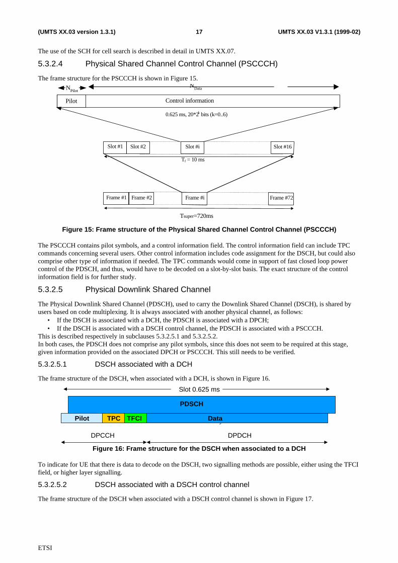
The frame structure for the PSCCCH is shown in Figure 15.
0.625 ms, 20*2k bits (k=0..6)
Slot #1 Slot #2 Slot #i Slot #16
Frame #1 Frame #2 Frame #i Frame #72
Tf = 10 ms
Pilot Control information
NPilotNData
Tsuper=720ms
Figure 15: Frame structure of the Physical Shared Channel Control Channel (PSCCCH)
The PSCCCH contains pilot symbols, and a control information field. The control information field can include TPCcommands concerning several users. Other control information includes code assignment for the DSCH, but could alsocomprise other type of information if needed. The TPC commands would come in support of fast closed loop powercontrol of the PDSCH, and thus, would have to be decoded on a slot-by-slot basis. The exact structure of the controlinformation field is for further study.
5.3.2.5 Physical Downlink Shared Channel
The Physical Downlink Shared Channel (PDSCH), used to carry the Downlink Shared Channel (DSCH), is shared byusers based on code multiplexing. It is always associated with another physical channel, as follows:
• If the DSCH is associated with a DCH, the PDSCH is associated with a DPCH;• If the DSCH is associated with a DSCH control channel, the PDSCH is associated with a PSCCCH.
This is described respectively in subclauses 5.3.2.5.1 and 5.3.2.5.2.In both cases, the PDSCH does not comprise any pilot symbols, since this does not seem to be required at this stage,given information provided on the associated DPCH or PSCCCH. This still needs to be verified.
5.3.2.5.1 DSCH associated with a DCH
The frame structure of the DSCH, when associated with a DCH, is shown in Figure 16.
Slot 0.625 ms
DPCCH DPDCH
Physical channel 2 (SPCH)PDSCH
PilotPilot TPCTPC TFCI Physical channel 1Data
Figure 16: Frame structure for the DSCH when associated to a DCH
To indicate for UE that there is data to decode on the DSCH, two signalling methods are possible, either using the TFCIfield, or higher layer signalling.
5.3.2.5.2 DSCH associated with a DSCH control channel
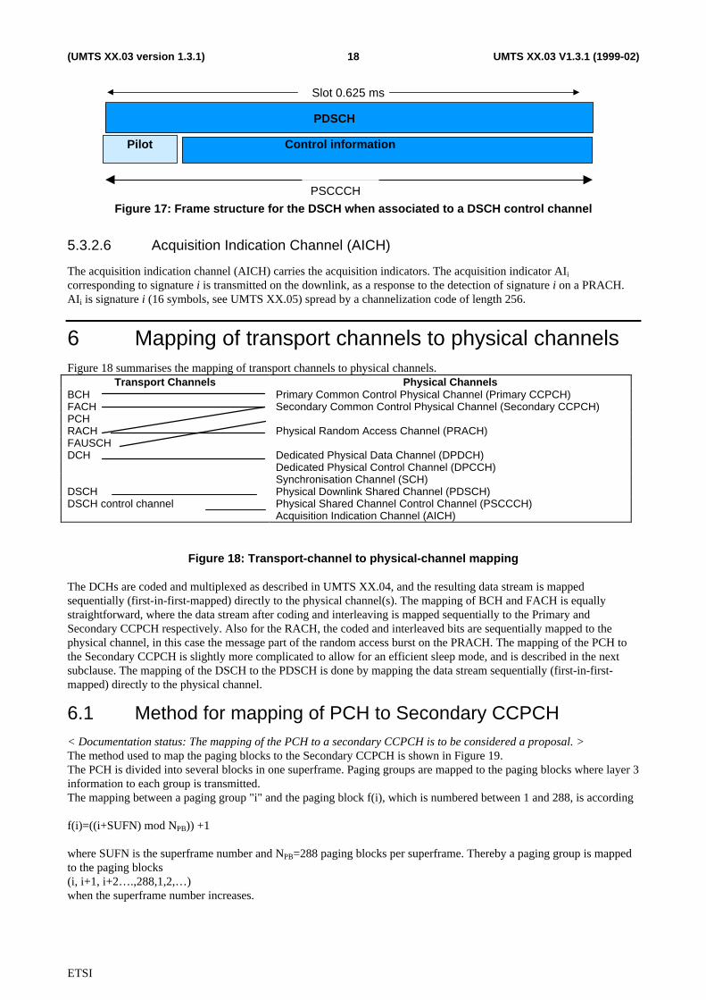
The frame structure of the DSCH when associated with a DSCH control channel is shown in Figure 17.
ETSI
UMTS XX.03 V1.3.1 (1999-02)18(UMTS XX.03 version 1.3.1)
Slot 0.625 ms
Physical channel 2 (SPCH)PDSCH
PilotPilot Physical channel 1Control information
PSCCCH
Figure 17: Frame structure for the DSCH when associated to a DSCH control channel
5.3.2.6 Acquisition Indication Channel (AICH)
The acquisition indication channel (AICH) carries the acquisition indicators. The acquisition indicator AIi
corresponding to signature i is transmitted on the downlink, as a response to the detection of signature i on a PRACH.AIi is signature i (16 symbols, see UMTS XX.05) spread by a channelization code of length 256.
6 Mapping of transport channels to physical channelsFigure 18 summarises the mapping of transport channels to physical channels.
Transport Channels Physical ChannelsBCH Primary Common Control Physical Channel (Primary CCPCH)FACH Secondary Common Control Physical Channel (Secondary CCPCH)PCHRACH Physical Random Access Channel (PRACH)FAUSCHDCH Dedicated Physical Data Channel (DPDCH)
Dedicated Physical Control Channel (DPCCH)Synchronisation Channel (SCH)
DSCH Physical Downlink Shared Channel (PDSCH)DSCH control channel Physical Shared Channel Control Channel (PSCCCH)
Acquisition Indication Channel (AICH)
Figure 18: Transport-channel to physical-channel mapping
The DCHs are coded and multiplexed as described in UMTS XX.04, and the resulting data stream is mappedsequentially (first-in-first-mapped) directly to the physical channel(s). The mapping of BCH and FACH is equallystraightforward, where the data stream after coding and interleaving is mapped sequentially to the Primary andSecondary CCPCH respectively. Also for the RACH, the coded and interleaved bits are sequentially mapped to thephysical channel, in this case the message part of the random access burst on the PRACH. The mapping of the PCH tothe Secondary CCPCH is slightly more complicated to allow for an efficient sleep mode, and is described in the nextsubclause. The mapping of the DSCH to the PDSCH is done by mapping the data stream sequentially (first-in-first-mapped) directly to the physical channel.
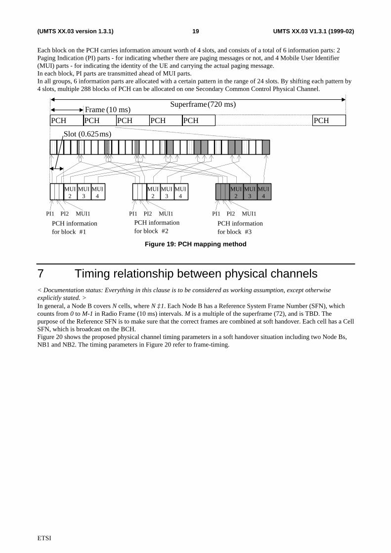
6.1 Method for mapping of PCH to Secondary CCPCH< Documentation status: The mapping of the PCH to a secondary CCPCH is to be considered a proposal. >The method used to map the paging blocks to the Secondary CCPCH is shown in Figure 19.The PCH is divided into several blocks in one superframe. Paging groups are mapped to the paging blocks where layer 3information to each group is transmitted.The mapping between a paging group "i" and the paging block f(i), which is numbered between 1 and 288, is according
f(i)=((i+SUFN) mod NPB)) +1
where SUFN is the superframe number and NPB=288 paging blocks per superframe. Thereby a paging group is mappedto the paging blocks(i, i+1, i+2….,288,1,2,…)when the superframe number increases.
ETSI
UMTS XX.03 V1.3.1 (1999-02)19(UMTS XX.03 version 1.3.1)
Each block on the PCH carries information amount worth of 4 slots, and consists of a total of 6 information parts: 2Paging Indication (PI) parts - for indicating whether there are paging messages or not, and 4 Mobile User Identifier(MUI) parts - for indicating the identity of the UE and carrying the actual paging message.In each block, PI parts are transmitted ahead of MUI parts.In all groups, 6 information parts are allocated with a certain pattern in the range of 24 slots. By shifting each pattern by4 slots, multiple 288 blocks of PCH can be allocated on one Secondary Common Control Physical Channel.
Superframe (720 ms)
PCH PCH PCH PCH PCH PCH
Slot (0.625ms)
PCH informationfor block #1
PCH informationfor block #2
PCH informationfor block #3
Frame (10 ms)
PI1 PI2 MUI1
MUI2
MUI3
MUI4
PI1 PI2 MUI1
MUI2
MUI3
MUI4
PI1 PI2 MUI1
MUI2
MUI3
MUI4
Figure 19: PCH mapping method
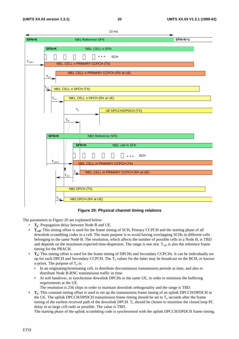
7 Timing relationship between physical channels< Documentation status: Everything in this clause is to be considered as working assumption, except otherwiseexplicitly stated. >In general, a Node B covers N cells, where N ≥1. Each Node B has a Reference System Frame Number (SFN), whichcounts from 0 to M-1 in Radio Frame (10 ms) intervals. M is a multiple of the superframe (72), and is TBD. Thepurpose of the Reference SFN is to make sure that the correct frames are combined at soft handover. Each cell has a CellSFN, which is broadcast on the BCH.Figure 20 shows the proposed physical channel timing parameters in a soft handover situation including two Node Bs,NB1 and NB2. The timing parameters in Figure 20 refer to frame-timing.
ETSI
UMTS XX.03 V1.3.1 (1999-02)20(UMTS XX.03 version 1.3.1)
NB1, CELL n DPCH (TX)
NB1, CELL n DPCH (RX at UE)
UE DPCCH/DPDCH (TX)To
Tp,1
Tcell,n
Td,1
NB2 Reference SFN
SCH
NB1, CELL n PRIMARY CCPCH (TX)
NB1, CELL n PRIMARY CCPCH (RX at UE)
Tp,1
Tm
NB2, CELL m PRIMARY CCPCH (TX)
NB2 DPCH (RX at UE)
Tp,2
NB2 DPCH (TX)
Tp,2
Tcell,m
Td,2
SCH
…
…
NB1 Reference SFN
10 ms
NB1, CELL n SFN
NB2, cell m SFN
SFN=K
SFN=K
SFN=K
SFN=K
SFN=K+1
NB2, CELL m PRIMARY CCPCH (RX at UE)
Figure 20: Physical channel timing relations
The parameters in Figure 20 are explained below:• Tp: Propagation delay between Node B and UE.• • Tcell: This timing offset is used for the frame timing of SCH, Primary CCPCH and the starting phase of all
downlink scrambling codes in a cell. The main purpose is to avoid having overlapping SCHs in different cellsbelonging to the same Node B. The resolution, which affects the number of possible cells in a Node B, is TBDand depends on the maximum expected time-dispersion. The range is one slot. Tcell is also the reference frametiming for the PRACH.
• • Td: This timing offset is used for the frame timing of DPCHs and Secondary CCPCHs. It can be individually setup for each DPCH and Secondary CCPCH. The Td values for the latter may be broadcast on the BCH, or knowna-priori. The purpose of Td is:• • In an originating/terminating cell, to distribute discontinuous transmission periods in time, and also to
distribute Node B-RNC transmission traffic in time.• • At soft handover, to synchronise downlink DPCHs to the same UE, in order to minimise the buffering
requirements at the UE.The resolution is 256 chips in order to maintain downlink orthogonality and the range is TBD.
• • To: This constant timing offset is used to set up the transmission frame timing of an uplink DPCCH/DPDCH inthe UE. The uplink DPCCH/DPDCH transmission frame timing should be set to To seconds after the frametiming of the earliest received path of the downlink DPCH. To should be chosen to minimise the closed loop PCdelay in as large cell-radii as possible. The value is TBD.The starting phase of the uplink scrambling code is synchronised with the uplink DPCCH/DPDCH frame timing.
ETSI
UMTS XX.03 V1.3.1 (1999-02)21(UMTS XX.03 version 1.3.1)
• Tm: This value is measured by the UE and reported to the RNC prior to soft handover. The RNC can then notifythis value to the target cell, which then knows how to set Td to achieve proper reception and transmission frametiming of the dedicated physical channel.
Note that since the UE reports the value Tm as the time-difference between the received Primary CCPCH frame-timingfrom the target cell and the earliest received existing DPCH path, the propagation delay to the target cell is alreadycompensated for in the setting of Td at the target cell. The DPCH signal from the target cell will reach the UE at thesame time as the earliest received existing DPCH path. The only remaining error, besides frequency-drift and UEmobility related errors, is due to a (known) rounding error at the target cell in order to maintain downlink orthogonality.
ETSI
UMTS XX.03 V1.3.1 (1999-02)22(UMTS XX.03 version 1.3.1)
History
Document history
V0.0.1 1998-08-17 Created document from UTRA/FDD L1 description, v0.4
V0.1.0 1998-09-17 Includes changes from Helsinki UMTS-L1 meeting.
V0.2.0 1998-10-26 Added documentation status.
V0.3.0 1998-11-15 Changed title of document, added changes agreed at Sophia Antipolis UMTS-L1meeting.
V1.0.0 1998-12-09 As agreed by SMG2 # 28 in Dresden.
V1.1.0 1999-01-11 Updated terminology.
V1.2.0 1999-01-20 Added changes agreed in Espoo: Shared channel, Feedback mode transmitdiversity, random access, FAUSCH, and STTD.
V1.3.0 1999-01-25 Updated with comments from Espoo, for approval at SMG2 plenary.