

Contents General Information Ampgard Dimensions 400 Amp Contactor "Roll-Out"
Design 400 Amp Contactor "Slide-Out"
Design 400 Amp Contactor Reversing,
Latched, 2 Pole "Roll-Out" Design
400 Amp Contactor Reversing, Latch, 2 Pole "Slide-Out" Design
800 Amp Contactor 800 Amp Contactor Reversing,
Latched 800 Amp Contactor 2 Pole 400 Amp Isolating Switch "Slide
Out" Design 400 Amp Isolating Switch "Roll
Out" Design 800 Amp Isolating Switch
Pages 2, 3
3
4, 5
6, 7
8
9 10, 11
12 13
14
1 5 16
See Renewal Parts Data 8855A for air break design. See Renewal Parts Data 8855C for retrofits, OEM contactors, miscellaneous components.
www . El
ectric
alPar
tMan
uals
. com

Renewal Parts Data 8855V
Page 2
General Information
Renewal and Replacement Parts The present design of Ampgard medium voltage starters was introduced in 1962. Additional ratings and features have been continuously introduced over the years.
This renewal parts data will provide the proper identification of standard parts which may be required for the maintentance of Westinghouse Ampgard starters. All of the complete contactors, isolating switches and sub assemblies that are available are shown photographically in kit form.
Some of the detail parts shown in the renewal parts data are recommended only as part of a sub assembly to facilitate their replacement or installation in the field.
Style numbers identified in this brochure will not be the same as style numbers on the original equipment. The renewal part styles in this brochure are in a kit form and may include sub assembly, carton, installation instructions, etc.
It is the intent of this renewal parts data brochure to make it possible for you to quickly identify the parts needed rather than have to search through twenty years of records to determine the specific style of the original part. All of the parts shown in the kits are compatible with the design from 1962 to the present (or noted otherwise).
Special attention should be given to forecasting your particular renewal parts requirements to ensure on-site availability of necessary parts and materials when needed, as well as guaranteeing efficiency and continued operation of your equipment.
The amount of investment to be made in renewal parts is best determined by you, taking into consideration such things as the impact of probable shutdown time, equipment duty cycle, etc.
To maintain maximum operating efficiency and dependability of your equipment, genuine Westinghouse renewal parts are recommended.
This publication identifies those replacement parts which are available and should be ordered by style number.
Procedure for Identifying Renewal Parts (1) Determine the ampere rating of your
starter by measuring the width of the structure.
(2) Determine if it is non-reversing or reversing by measuring the height of the high voltage portion of your starter. (see page 3)
Examples: 36 in. width is 400 ampere rated. Roll-out design is contactor with wheels. Slide-out design is contactor without wheels. 45 in. height is non-reversing starter. 75 in. height is reversing starter. Refer to pages 4, 5, 8, 15 for Roll-out design. Refer to pages 6, 7, 9, 14 for Slide-out design.
40 in. width is 800 ampere rated. 60 in. height is non-reversing starter. 90 in. height is reversing starter. Refer to pages 10, 11, 12, 13, 16.
(3) Determine the volt amp rating of the control transformer by measuring the height of the control transformer.
(4) Determine primary voltage; 2300, 4160, etc. This information is on the starter nameplate in the low voltage area.
(5) Now that you have identified the design of your complete contactor determine from the photographs which parts are required and identify them by style number.
Ampgard Starters Since many starters are supplied to meet specific customer electrical control and distribution requirements, other parts not listed in this publication might occasionally be needed. Refer to factory for specific requests.
For equipment other than 60 Hz, refer to factory for information.
Price and availability of parts not listed may be obtained by contacting your local Westinghouse representative. Provide a complete description of the part, along with the complete data on the starter nameplate which is found in the low voltage area. Be sure to include: ratings, shop order and diagram reference.
Ordering Instructions (1) Specify by style number. (2) Refer to Price List/Style Number Index
8855 for pricing information.
Additional Service Should you experience difficulty in determining needed parts for repair or determining existing starter condition, contact your local Westinghouse representative. Westinghouse can provide qualified technical personnel on site to: • Identify and recommend replacement parts
for damage caused by short circuit or fault.
• Remove damaged parts and install replacements.
• Retrofit vintage motor starting equipment with new components.
• Evaluate condition of existing equipment. ·Test components. • Provide a recommended spare parts list. • Upgrade existing unit from one Hp to
another or change operating voltage of existing equipment.
• Convert the starter from air break to vacuum break contactor.
Obsolete Ampgard Designs Obsolete Ampgard design starters manufactured prior to 1966 were designated AMI starters and were built in various cities in the USA. These starters were "1 High" design, 30 in., 34 in., or 38 in. wide, 100 in. high, and either 30 in. or 60 in. deep. Retrofitting an AMI starter is possible with up to date Ampgard components. Refer to Renewal Parts Data 8855C or refer to factory for information.
Contactors designated type H 130, H230, H430 (air) and contactors designated type K430 (oil) were utilized in the AMI starters. These contactors are obsolete. Refer to factory for information.
The isolating switch utilized in the AMI starters were manufactured by G&W Electric and is no longer available. For replacement of G&W Electric switch, contact:
Phoenix Electric P.O. Box 53 Readville Station Boston, MA 02137 Phone: 617-821-0200 FAX: 617-828-5719
-or-
Refer to Renewal Parts Data 8855C for retrofit of the entire starter with current design Ampgard. This will consist of welded cell assembly, drawout isolating switch, vacuum contactor, power fuses, current transformers, overload protection. Above will all mount in existing customer AMI enclosure.
Type LF66V430 vacuum contactors shipped prior to 1982 are obsolete and no longer available. For replacement order up to date design vacuum contactor from page 4, which is mechanically and electrically interchangeable with obsolete Type LF66V430 contactor.
A pril 1992 www . El
ectric
alPar
tMan
uals
. com

Older Catalog Number Systems
25 _ 2500 v �251 �2
33- 3300 v : 50- 5000 v 72- 7200 v
�=e;c��:k j]
J Vacuum
2- 200A I 4- 400A l------'
7- 700A 8- 800A
Dimensions
400 Amp Vacuum Contactor 7200 volt max. non-reversing Pages 4 & 5 Rollout design Pages 6 & 7 Slideout design
400 Amp 7200 volt max. Isolating Switch Page 15 Rollout design Page 14 Slideout design
April1992
LF 25 H430 LF- Air Break 1 _I -=;=- 1 SJ-Vacuum I
25- 2500V 33 - 3300V 1-----J 50- 5000V 72- 7200V
H- Air Break 1 V- Vacuum 1------' J- Vacuum I 2 200A 4- 400A 1 ______ 1 7- 700A 8- 800A
Normally I Open -------�
Poles Normally 1 Closed Poles 11---------'
400 Amp Vacuum Contactor 7200 volt max. reversing Pages 4, 5, 8 Rollout design Pages 6, 7, 9 Slideout design
400 Amp 7200 volt max. Isolating Switch Page 15 Rollout design Page 14 Slideout design
Renewal Parts Data 8855V
Page 3
Current Catalog System* !1�0f�4G
H - Air Break � y V - Vacuum Break "Roll-out" S - Vacuum Break "Slide-out"
Voltage Class E 2400V G 4160V K 6900V
Type of Starter 202- FVNR 212- FVR 502 - Reactor 602 - Autotransformer Enclosure
Contactor Amp Rating 2 200 Amp 4 400 Amp 7 700 Amp 8 800 Amp
Vacuum 1 �SJA5�0V11W43�0
Normally Break Closed Poles A Rollout Use 0 OEM Design
. .
Normally 5 - Slideout : l Open Poles
25- 2500 Volt 1 1 I 4- 400 Amp 50 5000 Volt
I 1 8 - 800 Amp
72 7200 Volt : I W @ Bottle
Vacuum Break l I M - Metric Bottle
*Refer to Price List 8810 for complete cata log system breakdown.
,-10"G)
I n 1 90 u
I rl 800 Amp Vacuum Contactor 7200 volt max. Pages 10, 11, 12 800 Amp 7200 volt max. Isolating Switch Page 16
I n u
800 Amp Vacuum Break Contactor, Reversing 7200 volt max. Pages 10, 11, 12 800 Amp Isolating Switch Page 16
Main bus enclosure.
www . El
ectric
alPar
tMan
uals
. com

Renewal Parts Data 8855V
Page 4
400 Amp Vacuum Break Contactor 7200 Volt Max. "Roll-out" Design
Front View
400 amp vacuum contactor 120 volt control, with control transformer and two normally open and two normally closed interlocks. To determine proper complete contactor style number, refer to the photograph showing both sizes of control transformers. The smaller control transformer with a height dimension of 5 inches is rated 600 volt amp at 4160 volts and 750 volt amp at 2300
volts. The larger control transformer with a height of 7 inches is rated 2 kVA at either 2300 or 4160 volts.
Approximate shipping weight 150 lbs.
Complete contactor 2300/120 volt, 750 volt amp transformer, 60 Hz Style No. 2147A45G01.l
Complete contactor 2300/120 volt, 2 kVA transformer, 60 Hz Style No. 2147 A45G02A
Complete contactor 4160/120 volt, 600 volt amp transformer, 60 Hz Style No. 2147A45G03A �·�.-� ... ------�····---
Complete contactor 4160/120 volt, 2 kVA transformer, 60 Hz Style No. 2147A45G04.l
For contactor with 240 volt AC control, order similar to style number 2147A45GO�, except 240 volt AC control.
For SJA contactors supplied after October 1988 with pull-a-part terminal blocks, order SJS pre-cable Style No. 2147A15G� from page 7 for field mounting.
If main contactor is used in reversing, autotransformer, multi-speed starter, or has potential transformer connection refer to page 5 and order line fingers Style No. 2147A49G01.
If main contactor must be mechanically interloc.ked with other contactor, order mechanical interlock arm Style No. 2147A43G14 from page 8 for field mounting.
A Remove interference bar if used with old narrow flange doors supplied prior to July 1983.
CD Recommended for "Start-up " spares.
Control transformers•
Control transformers shown above are 5000 volt max. Transformers for higher primary voltages are available but may be a larger physical size and mounted remote from contactor. Specify system voltage, Hz, V.A. size and refer to factory.
L-63 Interlock (Coil Circuit) Style No. 578D461G03*CD
Contactor mounted Run-Test circuit, 15 amp plug (Use standard NEC fuse.) Style No. 2147A15G09
Tools, feeler gauge and bottle wrench Style No. 2147A47G15*
Tool, heavy duty contactor closing tool, for 400/800 amp vacuum contactor Style No. 2147A47G17
Contactor coil 120 volts Style No. 2147A48G11*CD
Contactor coil 240 volt Style No. 2147A48G21*
12 prong receptacle with wires (part of structure) Style No. 2147A15G03
12 prong plug with wire (part of contactor) Style No. 2147A15G04
Contactor fuse clips, Oty 3 Style No. 2147A49G11*
*Common to Roll-out and Slide-out design.
April1992 www . El
ectric
alPar
tMan
uals
. com

Renewal Parts Data 8855V
Page 5
400 Amp Vacuum Break Contactor 7200 Volt Max. "Roll-out" Design
Rear View
Phase barriers main and reversing contactor, Oty 5 Style No. 2147A47G11
Fuse clips and mounting for primary fuses of control transformer or potential transformer, Oty 3 Style No. 2147A47G16*
Contactor Line or load fingers, without support Oty. 3 Style No. 2147A47G23
April1992
Magnet assembly complete with 120V. coil Style No. 2147A48G12*
Magnet assembly complete with 240V. coil Style No. 2147A48G13*
Magnet assembly complete except without coil Style No. 2147A48G14*
Fuse puller Style No. 2147A93G04*
Vacuum bottle subassemblies with shunt and load support and load f ingers, Oty 3 Style No. 2147A47G03®
Line f ingers with copper support, Oty 3 Style No. 2147A49G01
Required as a field modification to a main contactor to supply power to potential transformers and to reversing contactors.
@ Recommended for "Running" spares. *Common to Roll-out and Slide-out design.
Line fingers mounted on contactor.
Contactor Line stab assembly, 3 copper stabs plus insulator (part of structure) Style No. 2147A49G14
Contactor Load stab assembly, 3 copper stabs plus insulator (part of structure) Style No. 2147A49G05®
Misc. parts kit Kickout spring and adjusting bolt, coil clip, set screw, electrical interlock operating arm with mounting hardware, mechanical interlock spring and contactor wheel. Style No. 2147A48G15*
Contactor main load cables Style No. 2147A15G18 1/0 Cable if C.T. ratio is below 250/5
Contactor main load cables Style No. 2147A15G19 410 Cable if C.T. ratio is 250/5 or above www .
Elec
tricalP
artM
anua
ls . c
om

Renewal Parts Data 8855V
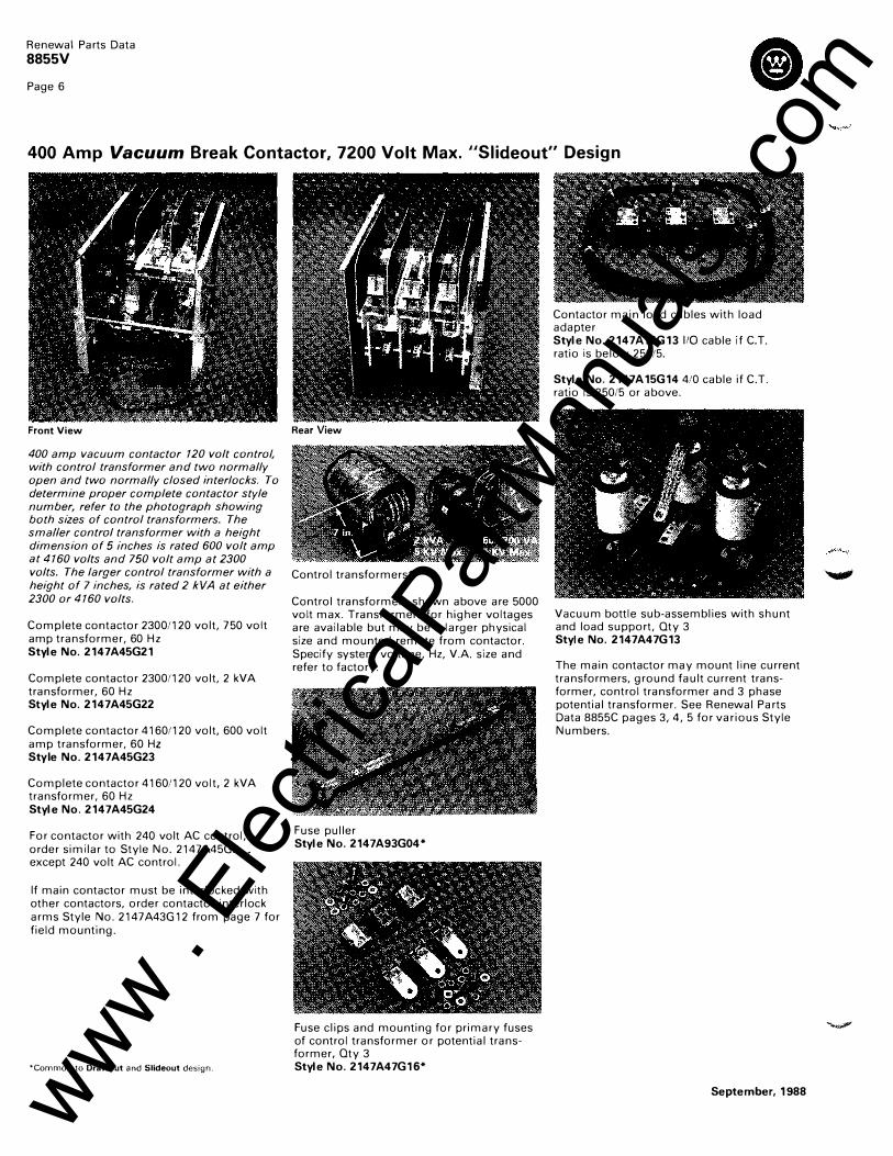
Page 6 Cl 400 Amp Vacuum Break Contactor, 7200 Volt Max. "Slide-out" Design
Front View
400 amp vacuum contactor 720 volt control, with control transformer and two normally open and two normally closed interlocks. To determine proper complete contactor style number, refer to the photograph showing both sizes of control transformers. The smaller control transformer with a height dimension of 5 inches is rated 600 volt amp at 4160 volts and 750 volt amp at 2300 volts. The larger control transformer with a height of 7 inches, is rated 2 kVA at either 2300 or 4160 volts.
Approximate shipping weight 150 lbs.
Complete contactor 2300/120 volt, 750 volt amp transformer, 60 Hz Style No. 2147 A45G21
Complete contactor 2300/120 volt, 2 kVA transformer, 60 Hz Style No. 2147 A45G22
Complete contactor 4160/120 volt, 600 volt amp transformer, 60 Hz Style No. 2147 A45G23
Complete contactor 41601120 volt, 2 kVA transformer, 60 Hz Style No. 2147 A45G24
For contactor with 240 volt AC control, order similar to Style No. 2147A45G2_, except 240 volt AC control.
If main contactor must be interlocked with other contactors, order contactor interlock arms Style No. 2147A43G12 from page 7 for field mounting.
The main contactor may mount line current transformers, ground fault current transformer, control transformer and 3 phase potential transformer. See Renewal Parts Data 8855C pages 3, 4, 5 for various Style Numbers.
Rear View
Control transformers*
Control transformers shown above are 5000 volt max. Transformers for higher voltages are available but may be a larger physical size and mounted remote from contactor. Specify system voltage, Hz, V.A. size and refer to factory.
Fuse puller Style No. 2147 A93G04*
Fuse clips and mounting for primary fuses of control transformer or potential transformer, Oty 3 Style No. 2147 A47G16*
Contactor main load cables with load adapter Style No. 2147 A15G13 1/0 cable if C.T. ratio is below 250/5.
Style No. 2147 A15G14 4/0 cable if C.T. ratio is 250/5 or above.
Vacuum bottle sub-assemblies with shunt and load support, Oty 3 Style No. 2147 A47G13®
*Common to Roll-out and Slide-out design.
® Recommended for "Running" spares.
April1992 www . El
ectric
alPar
tMan
uals
. com

Renewal Parts Data 8855V
Page 7
400 Amp Vacuum Break Contactor, 7200 Volt Max. "Slide-out" Design
Front View Rear View
400 amp vacuum contactor (basic quick ship) similar to Style No. 2147A45G21, G22, G23, G24, page 6, except without control transformer, without precab/e, without (4) barriers, without mechanical interlock arm, 120 volt control.
Approximate shipping weight 125 lbs
Style No. 2147A45G25
For contactor with 240 volt AC control order similar to 2147A45G25, except 240 volt AC control.
Tools, feeler gauge and bottle wrench Style No. 2147A47G15*
Contactor coil 120 volts Style No. 2147A48G11*CD
Contactor coil 240 volts Style No. 2147A48G21*
Phase barriers, main contactor, Qty 4 Style No. 2147A47G14
April1992
Contactor control pre-cables with pull-apart terminal blocks Style No. 2147A15G10 Contactor control pre-cables, 12 point (part of 2147A15G10) for coil and electrical interlock circuitry only. Style No. 2147A15G17.
Contactor fuse clips, Qty 3 Style No. 2147A49G11*
Contactor mechanical interlock arms. For interlock between isolating switch or any reversing or reduced voltage or multispeed contactor Style No. 2147A43G12
<D Recommended for "Start-up" spares. •common to Roll-out and Slide-out design.
Magnet assembly complete with 120 V. coil Style No. 2147A48G12*
----····---.... ---- .... ·---
Magnet assembly complete with 240 V. coil Style No. 2147A48G13*
Magnet assembly complete except without coil Style No. 2147A48G14*
L-63 interlock Style No. 578D461G03*CD
P.T. sec. fuse block, 2 pole Style No. 2147A15G16
CPT sec. fuse block, 1 pole Style No. 2147A15G15 Above fuse blocks mounted on contactor side sheet, and use miniature dual element fuses 1 V2 in. long. 13/32 in. dia.
Mechanical interlock kit. Between isolating switch and main contactor. Between (2) contactors (auto-transformer, reversing, multi-speed application.) Style No. 2147A43G13 www .
Elec
tricalP
artM
anua
ls . c
om

Renewal Parts Data 8855V
Page 8 Cl 400 Amp Vacuum Break Contactor, 7200 Volt Max. Reversing, 2 Pole and Latched uRoll-out" Design
Front View
Three pole reversing contactor with line and load fingers, includes mechanical interlock arm, for mechanical interlock, 120 volt coil (used as reversing contactor or reactor shorting contactor of a reactor reduced voltage starter).
Approximate shipping weight 150 lbs.
Style No. 2 147A46G 05
Rear View
Two pole contactor with line and load fingers, 120 volt coil, (used as the shorting and run contactor for an autotransformer reduced voltage starter).
Approximate shipping weight 125 lbs.
Style No. 2 147A46G 06
For contactor with 240 volt coil order similar For contactor with 240 volt coil order similar
to Style No. 2147A46G05 except 240 volt to Style Number 2147A46G06 except 240
coil. volt coil.
Front View
400 amp vacuum latched contactor single trip solenoid. 120 volt control, with control transformer and two normally open and two normally closed interlocks. To determine proper complete contactor style number, refer to the photograph showing both sizes of control transformers. The smaller control transformer with a height dimension of 5
inches is rated 600 volt amp at 4160 volts and 750 volt amp at 2300 volts. The larger control transformer with a height of 7
inches, is rated 2 kVA at either 2300 or 4160
volts.
Approximate shipping weight 150 lbs.
Complete latched contactor 2300/120 volt, 750 volt amp transformer, 60 Hz Style No. 2 147A4 5G 1 1
Complete latched contactor 23001120 volt, 2 kVA transformer, 60 Hz Style No. 2 147A4 5G 12
Rear View
Complete latched contactor 41601120 volt, 600 volt amp transformer, 60 Hz Style No. 2 147A4 5G 13
Complete latched contactor 4160/120 volt, 2 kVA transformer, 60 Hz Style No. 2 147A4 5G 14
For contactor with 240 volt AC control, order similar to Style No. 2147A45GL except 240 volt AC control.
For contactor with 2 trip solenoids order similar to Style No. 2147A45G1_ except specify trip voltage 120 or 240 volt AC, or intermittent 48, 125, 250 volt DC (any combination of 2 voltages)
*Common to Roll-out and Slide-out design.
Mechanical interlock arm for field mounting on contactor Style No. 2 147A43G 14
Control transformers*
Control transformers shown above are 5000 volt max. Transformers for higher voltages are available but may be a larger physical size and mounted remote from contactor. Specify system voltage, Hz, V.A. size and refer to factory.
Mechanical latch kit with 1 trip solenoid. Complete with L-63 and L-64 electrical interlock and contactor mounted 12 point receptacle, 115 volt AC coil. Style No. 2 147A48G29
For mechanical latch kit with dual trip solenoid order similar to Style No. 2147A48G29 except dual solenoid for operation at·-
volts. Specify trip voltage, 120 or 240 volt AC, or intermittent 48, 125, 250 volt DC
Single solenoid assembly only without magnet assembly, L-63 and L-64 interlocks, 12 point receptacle, wiring.
Style No. 52 59C73 H01 Style No. 52 59C73 H02 Style No. 52 59C73 H03 Style No. 52 59C73 H04 Style No. 52 59C73 H05
AC DC (Int.)
115 V. 230 v. 460 v. 575 v.
48 V. 96-125 V.
230 V.
24 v. A pril 1992 www .
Elec
tricalP
artM
anua
ls . c
om

Renewal Parts Data 8855V
Page 9
400 Amp Vacuum Break Contactor, 7200 Volt Max. Reversing, 2 Pole and Latched ��Slide-out" Design
Front View
Three pole reversing contactor, includes mechanical interlock arm for mechanical interlock, 120 volt coil. (Used as reversing cantactor or reactor shorting cantactar of a reactor reduced voltage starter.) Style No. 2 147A46G 1 5
Front View
400 amp vacuum latched contactor single trip solenoid. 120 volt control, with control transformer and two normally open and twa normally closed interlocks. To determine proper complete contactor style number, refer to the photograph (Page 8) showing both sizes of control transformers. The smaller control transformer with a height dimension of 5 inches is rated 600 volt amp at 4160 volts and 750 volt amp at 2300
volts. The larger control transformer with a height of 7 inches is rated 2 kVA at either 2300 or 4160 volts.
Complete latched contactor 2300/120 volt, 750 volt amp transformer Style No. 2 147A4 5G3 1
A pril 1992
Rear View
For contactor with 240 volt coil, order similar to Style No. 2147A46G15 except with 240 volt coil.
Rear View
Complete latched contactor 2300/120 volt, 2 kVA transformer Style No. 2 147A4 5G32
Complete latched contactor 4160/120 volt, 600 volt amp transformer Style No. 2 147A4 5G33
Complete latched contactor 4160/120 volt, 2 kVA transformer Style No. 2 147A4 5G34
For contactor with 240 volt AC control order similar to Style No. 2147A45G3 .. _ except 240 volt AC control.
For contactor with 2 trip solenoids order similar to Style No. 2147A45G3� except specify trip voltage 120 or 240 volt AC, or intermittent 48, 125, 250 volt DC (any combination of 2 voltages).
Mechanical interlock kit. Between isolating switch and main contactor: Between (2) contactors (auto-transformer, reversing, multi-speed application) Style No. 2 147A43G 13
Two pole contactor, 120 volt coil. (Used as starting and run contactor for an autotransformer reduced voltage, starter includes mechanical interlock arm for mechanical interlock.) Style No. 2 147A46G 16
For contactor with 240 volt coil, order similar to Style No. 2147 A46G 16 except with 240 volt coil.
For field mounting of mechanical latch kit on slideout contactor order Style No. 2147A48G16 (Page 8) and discard 12 point receptacle and pre-cable.
www . El
ectric
alPar
tMan
uals
. com

Renewal Par ts Data 8855V
Page 10
800 Amp Vacuum Break Contactor, 7200 Volt Max - Type SJA
Front View
800 amp vacuum break contactor 120 volt control, with control transformer and two normally open and two normally closed interlocks, 2kVA control transformer.
Approximate shipping weight 175 lbs.
Complete contactor, 2300/120 volt, 2 kVA transformer, 60 Hz Style No. 2147A8 5G 01
Complete contactor, 4160/120 volt, 2 kVA transformer, 60 Hz Style No. 2147A8 5G 02
For contactor with 240 volt AC control, order similar to Style No. 2147A85GO ... _
except 240 volt AC control.
For SJA contactors supplied after October 1988 with pull-a-part terminal blocks, order SJS pre-cable Style No. 2147 A 15G� from page 7 for field mounting.
If main contactor is used in reversing, autotransformer, multi-speed starter, or has potential transformer connection refer to page 11 and order line fingers Style No. 2147A89G01.
Barrier Assembly Style No. 2147A89G 07
G:: Recommended for "Start-up" spares. :JJ Recommended for "Running" spares.
Control transformer
Control transformer shown above is 5000 volt max. Transformers for higher voltages are available but maybe a larger physical size and mounted remote from contactor. Specify system voltage, Hz, V.A. size and refer to factory.
L-63 interlock Style No. 578 D46 1G 03CD
Fuse support and barrier assembly Style No. 2147A89G 06
Contactor coil, 120 volts Style No. 2147A88G11CD
Contactor coil, 240 volts Style No. 2147A88G12
Vacuum bottle sub-assemblies with shunt, load support, load fingers Oty 3 Style No. 2 147A87G 03®
Tools, feeler gauge and bottle wrench Style No. 2 147A47G1 5
Tool, heavy duty contactor closing tool, for 400/800 ampere vacuum contactor Style No. 2147A47G17
Misc. Parts Kit Kickout springs and adjusting bolt, coil clip, electrical interlock operating arm with mounting hardware, mechanical interlock spring and contactor wheel Style No. 2147A88G1 5
A pril 1992 www . El
ectric
alPar
tMan
uals
. com

Rear View
12 prong plug with wire, (part of contactor) Style No. 2 147A 1 5G 04
12 prong receptacle with wire, (part of structure) Style No. 2147A 1 5G 12
Fuse puller for 800 amp starter Style No. 2 147A9 3G 07
A pril 1992
Renewal Parts Data 8855V
Page 11
800 Amp Vacuum Break Contactor, 7200 Volt Max. - Type SJA
Fuse load fingers (connection between confactor, and fuse) Oty 3 Style No. 2 147A7 1G1 5
Contactor line fingers with copper support Oty 3 Style No. 2 147A89G 01
Required as a field modification to a main contactor to supply power to potential transformers and to reversing contactors.
Contactor line or load fingers without support. Oty 3 Style No. 2 147A89G 02
Contactor load or line stab assembly, complete with mounting. Style No. 2 147A89G 03
Magnet assembly complete with 120 volt coil. Style No. 2 147A88G 02
Magnet assembly complete with 240 volt coil. Style No. 2 147A88G 03
Magnet assembly complete except without coil. Style No. 2 147A88G 04
www . El
ectric
alPar
tMan
uals
. com

Renewal Parts Data 8855V
Page 12
800 Amp Vacuum Break Contactor, 7200 Volt Max. - Type SJA Reversing and Latched
Front View
Front View
Above photograph shown without control transformer mounted on connector.
800 amp vacuum latched contactor, single trip solenoid 120 volt control, with control transformer and two normally open and two normally closed interlocks, 2 kVA control transformer.
Complete latched contactor 2300/120 volt, 2 kVA transformer, 60Hz Style No. 2 1 47A8 5G 1 1
Complete latched contactor 4160/120 volt, 2 kVA transformer, 60Hz Style No. 2 147A8 5G 12
Rear View
Rear View
For contactor with 240 volt AC control, order similar to Style No. 2147A85GL_, except 240 volt AC control.
For contactor with 2 trip solenoids order similar to Style No. 2147A85G1_ except specify trip voltage 120 or 240 volt AC, or intermittent 48, 125, 250 volt DC (any combination of 2 voltages}
Control transformer
Control transformer Control transformer shown above is 5000 volt max. Transformers for higher voltages are available but may be a larger physical size and mounted remote from contactor. Specify system voltage, Hz, V.A. size and refer to factory.
Three pole reversing contactor with line and load fingers, includes mechanical interlock arm for mechanical interlock, 120 volt coil (used as reversing contactor or reactor shorting contactor of a reactor reduced voltage starter) Style No. 2 1 47A86G 12
For contactor with 240 volt coil order similar to Style No. 2147A86G12 except with 240 volt coil.
Mechanical Latch Kit with (1) trip solenoid 120 volt AC continuous/48 VDC intermittent. Style No. 2 1 47A88G22
230 volt AC continuous/125 VDC intermittent. Style No. 2 1 47A88G2 3
Single solenoid assembly only without L-63 and L-64 interlocks, precable, or magnet parts.
Style No. 52 59C7 3H0 1 Style No. 52 59C7 3H02 Style No. 52 59C7 3H0 3 Style No. 52 59C7 3H0 4 Style No. 52 59C7 3H0 5
AC DC (Int.)
115 v. 230 v. 460 v. 575 v.
48 v. 96-125 v.
230 v.
24 v.
A pril 1 992 www . El
ectric
alPar
tMan
uals
. com

Front View
A ptil 1992
Renewal Parts Data 8855V
Page 13
800 Amp Vacuum Break Contactor, 7200 Volt Max. - Type SJA, 2 Pole
Rear View
Two pole contactor with line and load fingers, 120 volt coil (used as starting and run contactor for an auto-transformer reduced voltage starter) includes mechanical interlock arm for mechanical interlock. Style No. 2 147A 86G06
For contactor with 240 volt coil, order similar to Style No. 2147A86G06 except with 240 volt coiL
www . El
ectric
alPar
tMan
uals
. com

Renewal Parts Data 8855V
Page 14
Isolating Switch 400 Amp "Slide-out" Design 7200 Volt Max. Type 72LFS-4
Front View
400 amp, 7200 V max. complete isolating switch with microswitch
Approximate shipping weight 75 lbs.
Style No. 2 1 47A41 G2 1
Incoming line stab assembly (part of structure) Style No. 2 1 47A2 1 G 1 9*
•common to Roll-out and Slide-out Design.
G) Recommended for "Start-up" spares.
Rear View
Grounding bar and barriers Style No. 2 1 47A41 G20*
Handle, housing, clevis Style No. 2 1 47A41G08*
Mechanical interlock parts kit for either drawout or slideout design isolating switch, or for converting from one design to the other. Style No. 2 1 47A41G23
Tray assembly with fuse clamps and grounding fingers Style No. 2 1 47A41 G22*
Microswitch assembly (common to all isolating switches) Style No. 2 1 47A01G01*CD
Mounting of microswitch*
April 1 992 www . El
ectric
alPar
tMan
uals
. com

Renewal Parts Data 8855V
Page 15
Isolating Switch 400 Amp "Roll-out" Design 7200 Volt Max. - Type 72LFR-4
Front View
400 amp, 7200 V max. complete isolating switch with microswitch.
Approximate shipping weight 75 lbs.
Style No. 2147A41G01
NOTE See Page 14 for additional common parts.
(i) Recommended for "Start-up" spares. •common to Roll-out and Slide-out design.
April1992
Rear View
400 amp incoming line stab assembly with shutter mechanism and finger barrier (part of structure) Style No. 2147A41G11*®
Shutter mechanism only for 400 amp Style No. 2147A41G12*
www . El
ectric
alPar
tMan
uals
. com

Renewal Parts Data 8855V
Page 16
800 Amp Isolating Switch, 7200 Volt Max. - Type LFM·S
Front View
800 amp, 7200 volt max. complete isolating switch with microswitch
Approximate shipping weight 100 lbs.
Styl e No. 2147A81G01
Handle and front plate with microswitch Style No. 2147A71G18
Handle, housing, clevis only Style No. 2147A71G08
Shutter assembly Styl e No. 2147A81G19
Shutter operator (for use with upper fuse retainer. Required in phase "8" only.) Styl e No. 2147A71G21
Rear View
Grounding bar assembly with fingers Styl e No. 2147A71G20
Upper fuse retainer Styl e No. 2147A81G17
800 amp line stab assembly and barriers, (part of structure), Oty 3 Style No. 2147A71G11 ®
Microswitch assembly (common to all isolating switches) Style No. 2147A01G01G:l
Grounding fingers Oty 6 Styl e No. 2147A71G23
Tray assembly with line fingers Styl e No. 2147A81G22
Line fuse cluster finger support assembly Styl e No. 2147A81G20
Mounting of microswitch
(i) Recommended for "Start-up" spares. ® Recommended for "Running" spares.
Westinghouse Electric Corporation Distribution and Control Business Unit Asheville, North Carolina, U.S.A. 28813
Printed in U.S.A. Apri l 1992 www . El
ectric
alPar
tMan
uals
. com

Contents General Information Am pga rd Di mensions 400 Amp Contactor "Draw-Out"
Design 400 Amp Contactor "Slide-Out"
Design 400 Amp Contactor Reversi ng,
Latched, 2 Pole "Draw-Out" Design
400 Amp Contacto r Reversing, Latched, 2 Pole "Slide-Out" Design
800 Amp Contactor 800 A m p Contactor Reversing,
Latched 800 Amp Contactor 2 Pole 400 Am p Iso lati ng Switch "Draw
Out" Design 400 Amp Iso lat i n g Switch "Slide
Out" Design 800 Amp Isolat i n g Switch
Pages 2, 3
3
4, 5
6, 7
8
9 10, 11
12 13
15
14 16
See Renewal Parts Data 8855A for a i r break design. See Renewal Parts Data 8855C for retrofits, OEM contactors, miscellaneous components.
www . El
ectric
alPar
tMan
uals
. com

Renewal Parts Data
8855V
Page 2
General Information
Renewal and Replacement Parts The present design of Ampgard medium voltage starters was introduced in 1962. Additional ratings and features have been continuously introduced over the years.
This renewal parts data will provide the proper identification of standard parts which may be required for the maintentance of Westinghouse Ampgard starters. All of the complete contactors, isolating switches and sub assemblies that are available are shown photographically in kit form.
Some of the detail parts shown in the renewal parts data are recommended only as part of a sub assembly to facilitate their replacement or installation in the field.
Style numbers identified in this brochure will not be the same as style numbers on the original equipment. The renewal part styles in this brochure are in a kit form and may include sub assembly, carton, installation instructions, etc.
It is the intent of this renewal parts data brochure to make it possible for you to quickly identify the parts needed rather than have to search through twenty years of records to determine the specific style of the original part. All of the parts shown in the kits are compatible with the design from 1962 to the present (or noted otherwise).
Special attention should be given to forecasting your particular renewal parts requirements to ensure on-site availability of necessary parts and materials when needed, as well as guaranteeing efficiency and continued operation of your equipment.
The amount of investment to be made in renewal parts is best determined by you, taking into consideration such things as the impact of probable shutdown time, equipment duty cycle, etc.
To maintain maximum operating efficiency and dependability of your equipment, genuine Westinghouse renewal parts are recommended.
This publication identifies those replacement parts which are available and should be ordered by style number.
Note; All products were photographed against the same background to provide a size reference. The larger the background pattern the smaller the product.
Procedure for Identifying Renewal Parts (1) Determine the ampere rating of your
starter by measuring the width of the structure.
(2) Determine if it is non-reversing or reversing by measuring the height of the high voltage portion of your starter. (see page 3)
Examples: 36 in. width is 400 ampere rated. Drawout design is contactor with wheels. Slideout design is contactor without wheels. 45 in. height is non-reversing starter. 75 in. height is reversing starter. Refer to pages 4, 5, 8, 15 for Drawout design. Refer to pages 6, 7, 9, 14 for Slideout design.
40 in. width is 800 ampere rated. 60 in. height is non-reversing starter. 90 in. height is reversing starter. Refer to pages 10, 11, 12, 13, 16.
(3) Determine the volt amp rating of the control transformer by measuring the height of the control transformer.
(4) Determine primary voltage; 2300, 4160, etc. This information is on the starter nameplate in the low voltage area.
(5) Now that you have identified the design of your complete contactor determine from the photographs which parts are required and identify them by style number.
Ampgard Starters Since many starters are supplied to meet specific customer electrical control and distribution requirements, other parts not listed in this publication might occasionally be needed. Refer to factory for specific requests.
For equipment other than 60 Hz, refer to factory for information.
Price and availability of parts not listed may be obtained by contacting your local Westinghouse representative. Provide a complete description of the part, along with the complete data on the starter nameplate which is found in the low voltage area. Be sure to include: ratings, shop order and diagram reference.
Ordering Instructions (1) Specify by style number. (2) Refer to Price List 8855V for pricing
information.
8
Additional Service Should you experience difficulty in determining needed parts for repair or determining existing starter condition, contact your local Westinghouse representative. Westinghouse can provide qualified technical personnel on site to: • Identify and recommend replacement parts
for damage caused by short circuit or fault.
• Remove damaged parts and install replacements.
• Retrofit vintage motor starting equipment with new components.
• Evaluate condition of existing equipment. ·Test components. • Provide a recommended spare parts list. • Upgrade existing unit from one Hp to
another or change operating voltage of existing equipment.
·Convert the starter from air break to vacuum break contactor.
Obsolete Ampgard Designs Obsolete Ampgard design starters manufactured prior to 1966 were designated AMI starters and were built in various cities in the USA. These starters were "1 High" design, 30 in., 34 in., or 38 in. wide, 100 in. high, and either 30 in. or 60 in. deep. Retrofitting an AMI starter is possible with up to date Ampgard components. Refer to Renewal Parts Data 8855C or refer to factory for information.
Contactors designated type H130, H230, H430 (air) and contactors designated type K430 (oil) were utilized in the AMI starters. These contactors are obsolete. Refer to factory for information.
The isolating switch utilized in the AMI starters were manufactured by G&W Electric and is no longer available. For replacement of G&W Electric switch, contact:
Phoenix Electric P.O. Box 53 Readville Station Boston, MA 02137 Phone: 617-821-0200 FAX: 617-828-5719
-or-
Refer to Renewal Parts Data 8855C for retrofit of the entire starter with current design Ampgard. This will consist of welded cell assembly, drawout isolating switch, vacuum contactor, power fuses, current transformers, overload protection. Above will all mount in existing customer AMI enclosure.
Type LF66V430 vacuum contactors shipped prior to 1982 are obsolete and no longer available. For replacement order up to date design vacuum contactor from page 4, which is mechanically and electrically interchangeable with obsolete Type LF66V430 contactor.
September, 1 988
-�
�
. ._....,
www . El
ectric
alPar
tMan
uals
. com

Cl Older Catalog Number Systems
25l 2 25 2500 vI T 33 3300 v f___J 50- 5000 vi 12 noo vI
l- Air Break V- Vacuum J- Vacuum
2 200A 4 400A 1 ______ _. 7 700A 8 800A
Dimensions
�=rc
�H 400 Amp Vacuum Contactor 7200 volt max. non-reversing Pages 4 & 5 Drawout design Pages 6 & 7 Slideout design 400 Amp 7200 volt max. Isolating Switch Page 15 Drawout design Page 14 Slideout design
September, 19 88
LF Air Break, � 25 H430
SJ Vacuum r----" 25- 2500V 33 - 3300V 1------l 50- 5000V 72 7200V
H-Air Break V- Vacuum J- Vacuum
2- 200A 4- 400A I I 7- 700A 8 800A
Normally Open 1------------� Poles Normally Closed Poles
400 Amp Vacuum Contactor 7200 volt max. reversing Pages 4, 5, 8 Drawout design Pages 6, 7, 9 Slideout design 400 Amp 7200 volt max. Isolating Switch Page 15 Drawout design Page 14 Slideout design
Renewal Parts Data 8855V
Page 3
Current Catalog System*
H- Air Break �H 2T021Sl4Gy
V- Vacuum Break "Drawout" S- Vacuum Break "Siideout"
Voltage Class E- 2400V. G- 4160V.
Type of Starter 202- FVNR 212- FVR 502 - Reactor 602 Autotransformer
Contactor Amp Rating
L.____j 2 - 200 Amp 4 400 Amp 7- 700 Amp
Enclosure I 8- 800 Amp
SJA 5 0VW43 0 vacuum
I � r : Nocm'"' Break Closed Poles
A Drawout Use Normally 0 - OEM Des1gn s _ Slideout Open Poles
25- 2500 Volt 4 - 400 Amp 50 5000 Volt 8- 800 Amp 72 7200 Volt
L__ ___ -<W @Bottle Vacuum Break 1-------__j M Metric Bottle
*Refer to Price List 8810 for complete cat a log system breakdown.
1--40" ----l �10"(1) � I 60
j I
r 800 Amp Vacuum Contactor 7200 volt max. Pages 10, 11, 12 800 Amp 7200 volt max. Isolating Switch Page 16
GLl=r0 90"
�· ',l 800 Amp Vacuum Break Contactor, Reversing 7200 volt max. Pages 10, 11, 12 800 Amp Isolating Switch Page 16
W Mam bus enclosure.
www . El
ectric
alPar
tMan
uals
. com

Renewal Parts Data
8855V
Page 4 e 400 Amp Vacuum Break Contactor 7200 Volt Max. "Drawout" Design
Front View
400 amp vacuum contactor 120 volt control, with control transformer and two normally open and two normally closed interlocks. To determine proper complete contactor style number, refer to the photograph showing both sizes of control transformers. The smaller control transformer with a height dimension of 5 inches is rated 600 volt amp at 4160 volts and 750 volt amp at 2300 volts. The larger control transformer with a height of 7 inches is rated 2 kVA at either 2300 or 4160 volts.
Complete contactor 2300/1 20 volt, 750 volt a m p transformer, 60 Hz Style No. 2 1 47A45G01
Com plete contactor 2300/1 20 volt, 2 kVA transformer, 60 Hz Style No. 2 1 47A45G02
Com plete contactor 4160/1 20 volt, 600 volt a m p transformer, 60 Hz Style No. 2 1 47A45G03
Complete contactor 4 1 60/ 1 20 volt, 2 kVA transformer, 60 Hz Style No. 21 47A45G04
For contactor with 240 volt AC control, order s imilar to style number 2 1 47A45GO�, except 240 volt AC control.
For SJA contactors supplied after October 1 988 with pull-a-part terminal blocks, order SJS pre-cable Style No. 2 1 47A1 5G� from page 7 for field mounting.
If m a i n contactor is used i n reversing, autotransformer, multi-speed starter, or has potential transformer connection refer to page 5 and order line fingers Style No. 2 1 47A49G0 1 .
If m a i n contactor must be mechanically interlocked with other contactor, o rder mechanical interlock a rm Style No. 2 1 47A43G 1 4 from page 8 for field mounting.
Control transformers shown above a re 5000 volt max. Transformers for highe r p r i mary voltages a re available but may be a larger physical size and mounted remote from contactor. Specify system voltage, Hz, V.A. size and refer to factory.
L-63 Interlock (Coil Circuit) Style No. 578D46 1 G03*
Contactor m ounted Run-Test c i rcuit, 1 5 a m p plug (Use standard NEC fuse.) Style No. 2 1 47A1 5G09
Tools, feeler gauge and bottle wrench Style No. 2 1 47A47G1 5*
Contactor coil 1 20 volts Style No. 2 1 47A48G1 1* Contactor coil 240 volt Style No. 2 1 47A48G21*
12 prong plug with w i res (part of structure) Style No. 2 1 47A 1 5G03
1 2 prong receptacle with wire (part of contactor) Style No. 2 1 47A1 5G04
Contactor fuse clips, Oty 3 Style No. 2 1 47A49 G 1 1 *
it Common t o Drawout and Slideout design,
September, 1988
. .....,
www . El
ectric
alPar
tMan
uals
. com

8 Renewal Parts Data
8855V
Page 5
400 Amp Vacuum Break Contactor 7200 Volt Max. "Drawout" Design
Rear View
Phase barriers main and reversing contactor, Oty 5 Style No. 2 1 47A47G1 1
Fuse clips and mounting for primary fuses of control transformer or potential transformer, Oty 3 Style No. 2 1 47A47G16*
Contactor Line or load fingers, without support Oty. 3 Style No. 2 1 47A47G23
September, 1988
Magnet assembly complete with 1 20V. coil Style No. 2 1 47A48G1 2* Magnet assembly complete with 240V. coil Style No. 2 1 47A48G 13* M agnet assembly complete except without coil Style No. 2 1 47A48G1 4*
Fuse puller Style No. 2147A93G04*
Vacuum bottle subassemblies with shunt and load support and load fingers, Oty 3 Style No. 2147A47G03
Line fingers with copper support, Oty 3 Style No. 2 1 47A49G01 Required as a field modification to a main contactor to supply power to potential transformers and to reversing contactors.
Line fingers mounted on contactor.
Contactor Line stab assembly, 3 copper stabs plus insulator (part of structure) Style No. 2 1 47A49 G 1 4
Contactor Load stab assembly, 3 copper stabs plus insulator (part of structure) Style No. 2 1 47A49G05
M isc. parts kit -Kickout spring and adjusting bolt, coil clip, electrical interlock operating arm with m ounting hardware, mechanical interlock spring and contactor wheel. Style No. 21 47A48G15*
www . El
ectric
alPar
tMan
uals
. com
Renewal Parts Data
8855V
Page 6 8
400 Amp Vacuum Break Contactor, 7200 Volt Max. llSiideout" Design
Front View
400 amp vacuum contactor 120 volt control, with control transformer and two normally open and two normally closed interlocks. To determine proper complete contactor style number, refer to the photograph showing both sizes of control transformers. The smaller control transformer with a height dimension of 5 inches is rated 600 volt amp at 4160 volts and 750 volt amp at 2300 volts. The larger control transformer with a height of 7 inches, is rated 2 kVA at either 2300 or 4160 volts.
Complete contactor 2300/120 volt, 750 volt amp transformer, 60 Hz Style No. 2147A45G21
Complete contactor 2300/120 volt, 2 kVA transformer, 60 Hz Style No. 2147A45G22
Complete contactor 4160/120 volt, 600 volt amp transformer, 60 Hz Style No. 2147A45G23
Complete contactor 4160/120 volt, 2 kVA transformer, 60 Hz Style No, 2147A45G24
For contactor with 240 volt AC control, order similar to Style No. 2147A45G2 .... except 240 volt AC control.
If main contactor must be interlocked with other contactors, order contactor interlock arms Style No. 2147A43G12 from page 7 for field mounting.
•common to Orawout and Slideout design<
Rear View
Control transformers*
Control transformers shown above are 5000 volt max. Transformers for higher voltages are available but may be a larger physical size and mounted remote from contactor. Specify system voltage, Hz, V.A. size and refer to factory.
Fuse puller Style No. 2147A93G04*
Fuse clips and mounting for primary fuses of control transformer or potential transformer, Oty 3 Style No. 2147A47G16*
Contactor main load cables with load adapter Style No. 2147A15G13 110 cable if C.T. ratio is below 250/5.
Style No. 2147A15G14 4/0 cable if C.T. ratio is 250/5 or above.
Vacuum bottle sub-assemblies with shunt and load support, Qty 3 Style No. 2147A47G13
The main contactor may mount line current transformers, ground fault current transformer, control transformer and 3 phase potential transformer. See Renewal Parts Data 8855C pages 3, 4, 5 for various Style Numbers.
September, 1988
'"'Wiff//
�
www . El
ectric
alPar
tMan
uals
. com

Cl Renewal Parts Data
8855V
Page 7
400 Amp Vacuum Break Contactor, 7200 Volt Max. "Siideout" Design
Front View Rear View
400 amp vacuum contactor (basic quick ship) similar to Style No. 2147A45G21, G22, G23, G24, page 6, except without control transformer, without precable, without (4) barriers, without mechanical interlock arm, 120 volt control. Style No. 2147A4 5G2 5
For contactor with 240 volt AC control order similar to 2147A45G25, except 240 volt AC control.
Tools, feeler gauge and bottle wrench Style No. 2147A47G1 5*
Contactor coil 120 volts Style No. 2147A48G11*
Contactor coil 240 volts Style No. 2147A48G12*
Phase barriers, m ain contactor, Oty 4 Style No. 2147A47G14
September, 1988
Contactor control pre-cables with pull-apart terminal blocks Style No. 2147A1 5G10 Contactor control pre-cables, 12 point (part of 2147A 15G 10) for coil and electrical interlock circuitr y only. Style No. 2147A1 5G17.
Contactor fuse clips, Oty 3 Style No. 2147A49G11*
Contactor m echanical interlock arms. For interlock between isolating switch o r a n y reversing or reduced voltage o r multispeed contacto r Style No. 2147A43G12
Magnet assem bly complete with 120 V. coil Style No. 2147A48G12*
Magn et asse m b ly com plete with 240 V. coil Style No. 2147A48G13* Magnet assem bly complete except without coil Style No. 2147A48G14*
L-63 interlock Style No. 578D461G03*
P.T. sec. fuse block, 2 pole Style No. 2147A1 5G16 CPT sec. fuse block, 1 pole Style No. 2147A1 5G1 5 Above fuse blocks mounted on contactor side sheet, and use miniature dual ele ment fuses 1% in . long, 13/32 in. dia.
Mecha nical interlock kit. Between isolating switch and main contactor. Between (2) contactors (auto-transformer, reversing, multi-speed application.) Style No. 2147A43G13
www . El
ectric
alPar
tMan
uals
. com

Re newal Parts Data
8855V
Page 8 8 400 Amp Vacuum Break Contactor, 7200 Volt Max. Reversing, 2 Pole and Latched .,Drawout" Design
Front View
Three pole reversing contactor with l ine and load fi ngers, includes mechanical i nterlock arm, fo r mechan ical i nterlock, 1 20 volt coil (used as reversing contactor or reactor shorting contactor of a reactor reduced voltage starter).
Rear View
Two pole contactor with l ine and load fingers, 1 20 volt coil, (used as the shorting and run contactor for an autotransformer reduced voltage starter). Style No. 2147A4 6G 06
Style No. 2147A4 6G 05 For contactor with 240 volt coil order s i m ilar For contactor with 240 volt coi l o rder s i m ilar to Style N u m ber 2 147A46G06 except 240 to Style No. 2 1 47A46G05 except 240 volt volt coil.
coil.
Front View
400 amp vacuum latched contactor single trip solenoid. 120 volt control, with control transformer and two normally open and two normally closed interlocks. To determine proper complete contactor style number, refer to the photograph showing both sizes of control transformers. The smaller control transformer with a height dimension of 5 inches is rated 600 volt amp at 4 160 volts and 750 volt amp at 2300 volts. The larger control transformer with a height of 7 inches, is rated 2 kVA a t either 2300 or 4 160 volts.
Com plete latched contactor 2300/120 volt, 750 volt a m p t ra nsfo rmer. 60 Hz Style No. 2147A4 5G11
Com plete latched contactor 2300/ 1 20 volt, 2 kVA t ra nsformer, 60 Hz Style No. 2147A4 5G12
*Common to Drawout and SHdeout design
Rear View
Com plete latched contactor 41 601 120 volt, 600 volt a m p t ra nsformer, 60 Hz Style No. 2147A4 5G13
Com plete latched contactor 4 1 60/ 1 20 volt, 2 kVA transformer, 60 Hz Style No. 2147A4 5G14
For contactor with 240 volt AC control, o rder s i milar to Style No. 2 1 47A45G 1 _ except 240 volt AC control.
For contactor with 2 trip solenoids order sim ilar to Style No. 2 1 47A45G 1 _ except specify tr i p voltage 1 20 or 240 volt AC, or i ntermittent 48, 1 25, 250 volt DC (any combination of 2 voltages)
Mecha n ical i nterlock arm for field m o u nt i ng on contacto r Style No. 2147A43G14
Control t ransformers shown a bove a re 5000 volt max. Transformers for h igher voltages are availa ble but m a y be a larger physical size and m o u nted remote from contactor. Specify system voltage, Hz, V.A. size a n d refer t o factory.
Mechan ical latch kit with 2 t r ip solenoids. Com plete with L-64 electrical i nterlock and contactor mou nted 12 point receptacle, 1 20 volt AC coils Style No. 2147A4 8G1 6
For s ingle t r ip solenoid order s i m ilar to Style No . 21 47A46G 1 6 except si ngle solenuid for operation at __ volts. Specify tr ip voltage 1 20 or 240 volt AC, or i ntermittent 48, 1 25, 250 volt DC
September, 19 88
....,
�
www . El
ectric
alPar
tMan
uals
. com

8 Renewal Parts Data
8855V
Page 9
400 Amp Vacuum Break Contactor, 7200 Volt Max. Reversing, 2 Pole and Latched 11Si ideout" Design
Front View
Three pole reversing contactor, i n cludes mechan ical i nterlock arm for mechanical i nterlock, 120 volt coil . ( Used as reversing contactor or reactor shorting contactor of a reactor reduced voltage starter. ) Style No. 214 7A46G1 5
Front View
400 amp vacuum latched contactor single trip solenoid. 120 volt control, with control transformer and two normally open and two normally closed interlocks. To determine proper complete contactor style number, refer to the photograph (Page 8) showing both sizes of control transformers. The smaller control transformer with a height dimension of 5 inches is rated 600 volt amp at 4 160 volts and 750 volt amp at 2300 volts. The larger control transformer with a height of 7 inches is rated 2 k VA at either 2300 or 4 160 volts.
Complete latched contactor 23001120 volt, 750 volt amp transformer Style No. 21 47A4 5G31
September, 1988
Rear View
For contactor with 240 volt coil, order s imilar to Sty le No. 2147A46G15 except with 240 volt coil.
Rear View
Complete latched contactor 2300!120 volt, 2 kVA transformer Style No. 214 7A 45G32
Complete latched contactor 41601120 volt, 600 volt amp transformer Style No. 21 47A 45G33
Com plete latched contactor 41601120 volt, 2 kVA tran sformer Style No. 214 7A4 5G34
For contactor with 240 volt AC co ntrol order s imilar to Style No. 2147A45G3 except 240 volt AC control.
For contactor with 2 t r ip solenoids order s i m ilar to Style No. 2147A45G3�··· except specify t r ip voltage 120 or 240 volt AC, o r i nterm ittent 48, 125, 250 volt DC (any combination of 2 voltages).
Mecha n ical i nterlock kit. Between isol ating switch a n d m a i n contactor : Between (2 ) contactors (auto-transformer, reversing, multi-speed application) Style No. 214 7A43G13
Two pole contactor, 120 volt coil. (Used as starting and run contactor for an autotransformer reduced voltage, starter includes mechanical interlock arm for mechanical interlock. ) Style No. 214 7A46G16
For contactor with 240 volt coil, o rder s imilar to Style N o . 2147A46G1 6 except with 240 volt coil.
For field mount ing of mechanical latch kit on slideout contactor order Style No. 2147A48G16 (Page 8) and d i scard 12 point receptacle and p re-cable.
www . El
ectric
alPar
tMan
uals
. com

Renewal Parts Data
8855V
Page 10 f) 800 Amp Vacuum Break Contactor, 7200 Volt Max - Type SJA
Front View
800 amp vacuum break contactor 120 volt control, with control transformer and two normally open and two normally closed interlocks, 2k VA control transformer.
Com plete contactor, 2300/120 volt, 2 kVA transform er, 60 Hz Style No. 214 7A8 5G01
Complete contactor, 4160/120 volt, 2 kVA t ransformer, 60 Hz Style No. 214 7A8 5G02
For contactor with 240 volt AC control, o rder s i mi lar to Style No. 2147A85GO except 240 volt AC control.
For SJA contactors supplied after October 1988 with pull-a-part ter m i n al blocks, order SJS pre-cable Style No. 2147A15G._ from page 7 for field mounti ng .
If main contactor is used i n reversing, autotransformer, multi-speed starter, or has potential transformer connect i o n refer to page 11 and order l i n e fi ngers Style No. 2147A89G01.
IMPORTA NT -For proper operation of mechanical interl ock, customer must remove interlock arm from old contactor and replace it on new contactor. (Discard interlock arm from new contactor. !
Control tra nsformer
Control transformer shown above is 5000 volt max. Transformers for h igher voltages a re available but maybe a larger physical s ize and mounted rem ote from contactor. Specify system voltage, Hz, V.A. size and refer to factory.
L-63 i nterlock Style No. 578D461G03
Fuse support and barr ier assem bly Style No. 214 7A8 9G06
Contactor coil , 120 volts Style No. 214 7A88G11
Contactor coil, 240 volts Style No. 214 7A88G12
Vacuum bottle sub-asse m bl ies with shunt, load support, load f ingers Oty 3 Style No. 214 7A8 7G03
Tools, feeler gauge and bottle wrench Style No. 214 7A4 7G1 5
Misc. Pa rts K it Ki ckout springs and adjust ing bolt, coi l cli p, electrical i nterlock operating arm with mount i n g ha rdware, m echan ical interlock spr ing and contactor wheel Style No. 214 7A88G1 5
September, 1 988
......,
O:....;,>fio._-JI
www . El
ectric
alPar
tMan
uals
. com

8
Rear View
12 prong receptacle with wi re, (part of contactor) Style No. 214 7A1 5G11
12 prong plug with wire, (part o f structure) Style No. 214 7A1 5G12
Fuse pul ler for 800 a m p sta rter Style No. 214 7A93G0 7
September, 1988
Renewal Parts Data 8855V
Page 1 1
800 Amp Vacuum Break Contactor, 7200 Volt Max. - Type SJA
Fuse load fingers (connection between confactor, and fuse) Oty 3 Style No. 214 7A 71G1 5
Contactor l ine fingers with copper support Oty 3 Style No. 214 7A89G01
Req u i red as a f ield modification to a m a i n contactor to su pply power t o pote ntial tra nsformers and to reve rsi ng contactors.
Contactor l ine or loa d fingers without support. Oty 3 Style No. 214 7A89G02
Contactor load or l ine sta b asse m bly, complete with mou nti ng. Style No. 214 7A89G03
Magnet assem bly com plete with 120 volt coil. Style No. 214 7A88G02
Magnet assem bly com plete with 240 volt coi l . Style No. 214 7A88G03
Magnet assem bly complete except without coil. Style No. 214 7A88G04
www . El
ectric
alPar
tMan
uals
. com

Renewal Parts Data 8855V Page 1 2 8 800 Amp Vacuum Break Contactor, 7200 Volt Max. - Type SJA Reversing and Latched
Front View
Front View
Above photograph shown without control transformer mounted on connector.
800 amp vacuum latched contactor, single trip solenoid 120 volt control, with control transformer and two normally open and two normally closed interlocks, 2 k VA control transformer.
Co mplete latched contactor 2300/ 1 20 volt, 2 kVA transformer, 60 Hz Style No. 2 1 47A85G1 1
Complete latched contactor 4 1 6011 20 volt, 2 kVA transformer, 60 Hz Style No. 2 1 47A85 G 1 2
Rear View
Rear View
For contactor with 240 volt AC contro l , order s im i l a r to Style No . 2 147A85G1 �, except 240 volt AC contro l .
Fo r contactor with 2 t r i p solenoids order s im i la r to Style No. 2 147A85G1 � except specify tr ip voltage 1 20 or 240 volt AC, or i ntermittent 48, 1 25, 250 volt DC (any combination of 2 voltages)
Three pole reversing contactor with l i ne and load f ingers, i ncludes mechan ical interlock arm for mechan ical i nterlock, 1 20 volt coil (used as reversing contactor or reactor shorting contactor of a reactor reduced voltage starter) Style No. 21 47A86G1 2
Fo r contactor with 240 volt coil order s im i l a r to Style No. 21 47A86G 12 except with 240 volt co i l .
Control transformer
Control transfo rmer shown above is 5000 volt max. Transformers for hig her voltages are ava i l ab le but may be a l arger physical size and mounted remote from contactor. Specify system voltage, Hz, V.A. size and refer to factory.
Mechanical Latch Kit with ( 1 ) t r ip solenoid 1 20 volt AC conti nuous/48 VDC intermittent. Style No. 2 1 47A88G22
230 volt AC conti nuous/1 25 VDC i nterm ittent. Style No. 21 47A88G23
September, 1988
......,
-�
www . El
ectric
alPar
tMan
uals
. com

8
Front View
September, 1988
Renewal Parts Data 8855V
Page 1 3
800 Amp Vacuum Break Contactor, 7200 Volt Max. - Type SJA, 2 Pole
Rear View
Two pole contactor with line and load f ingers, 1 20 volt coil (used as starting and run contactor for an auto-transformer reduced voltage starter) i ncludes mechanical i nterlock arm for mecha n i cal interlock. Style No. 2147A86G06
For contactor with 240 volt coil, order similar to Style No. 2 1 47A86G06 except with 240 volt coil.
www . El
ectric
alPar
tMan
uals
. com

Renewal Parts Data
8855V
Page 1 4 8 Isolating Switch 400 Amp "Siideout" Design 7200 Volt Max. Type 72LFS-4
Front View
400 amp, 7200 V max. com plete iso lating switch with microswitch Style No. 2 147A 4 1 G2 1
Ha ndle and front plate assem bl y with m icroswitch Style No. 2 1 47A 4 1 G 18 *
Incom i n g line sta b assembly (part of structure) Style No. 2 147A 2 1 G 19 *
"Common to Drawout and Slideout Design
Rear View
G roundi n g bar and barriers Style No. 2147A 4 1 G20 *
G rounding f ingers Oty 6 Style No. 2 1 47A2 1 G2 1*
Mechanical interlock pa rts kit for either drawout or s l i deout design isol ating switch, or for convert ing from one design to the other. Style No. 2 147A 41 G23
Tray assembly with fuse clamps and grounding fingers Style No. 2 147A 41 G22 *
Microswitch assembly (common to all isolating switches) Style No. 2147A0 1 G0 1 *
Mounting of microswitch*
September, 1988
�
.....,
�
www . El
ectric
alPar
tMan
uals
. com

Cl Renewal Parts Data
8855V Page 1 5
Isolating Switch 400 A m p "Drawout" Design 7200 Volt Max. - Type 72LFR-4
Front View
400 amp, 7200 V max. complete isolating switch with m icroswitch. Style No. 2147A41G01
September, 1988
Rear View
400 a m p i ncom i ng l ine stab assembly with shutter mech a n i sm a n d f inger barrier (part of structure) Style No. 2147A41G1 1 *
Sh utter mech a n i s m only for 400 a m p Style No. 2147A4 1 G 1 2*
www . El
ectric
alPar
tMan
uals
. com

Renewal Parts Data 8855V Page 1 6
800 A m p Isolating Switch, 7200 Volt Max. - Type LFM-8
Front View
800 amp, 7200 volt max. complete isolat ing switch with m icroswitch Style No. 2 1 47A8 1 G01
Handle and front p late with microswitch Style No. 2 147A7 1 G 1 8
Shutter assembly Style N o . 2 1 47A8 1 G 1 9
Shutter operator (fo r use with upper fuse retainer. Required in phase "8" only.) Style No. 2 1 47A71 G 2 1
Rear View
Ground ing bar assembly with f ingers Style No. 2 1 47A71 G20
Upper fuse reta iner Style No. 2 147A8 1 G 1 7
800 amp l i n e stab assembly and barri ers, (part of structure), Oty 3 Style No. 2 1 47A81 G 1 1
Microswitch assembly (common to all isolating switches) Style No. 2 1 47A01 G01
Grou nding fi ngers Oty 6 Style No. 2 1 47A71 G23
Tray assembly with l i ne f ingers Style No. 2 1 47A81G22
8
Line fuse c luster f inger support assembly Style No. 2 1 47A81G20
Mou nt ing of m icroswitch
West inghouse Electric Corporation Distri but ion and Control Bus iness Un i t Ashevi l l e, North Caro l i na , U.S.A. 288 1 3
Printed in U .S.A. September, 1 988
.....,
�
www . El
ectric
alPar
tMan
uals
. com

Contents Pages
G en era l I nformation 2 E l ect r ical Components 3,4,5 Overload Heater's, Power Fuses 5 OEM Vacu u m Contactors 6,7 Structura l Parts 8,9 ADM Switch 1 0 Retrofit Kits - Genera l I nformation 1 1
FVN R Vacuum Starter 1 2 Discon n ect/Potent i a l Tra nsfo rmer 1 3 Disconnect Switch (Without PT's) 1 3 F ixed Potent ia l Transformers 1 3 10 Fami ly 1 4 700 A m p Air t o Vacuum 1 5 50L2 Ai r B reak to Vacuu m 1 5 AM I/Type A, H, AH, O i l I m mersed to Vacuu m B reak 1 6
www . El
ectric
alPar
tMan
uals
. com

Renewal Parts Data 8855C Page 2
General Information
Renewal and Replacement Parts The present desig n of Ampgard med ium voltage starters was introduced i n 1 962. Addit ional rat ings and features h ave been cont inuously i ntroduced over the years.
This renewal parts data wil l provide the proper i dentificat ion of standard pa rts which may be requ i red for the ma i ntentance of West i nghouse Ampgard starters. A l l of the comp lete contactors, isolat ing switches and sub assemb l ies that are ava i l able a re shown photograph ica l ly in kit form.
Some of the deta i l parts shown i n the renewal parts data are recommended only a s part of a sub assembly to faci l i tate the ir replacement or i nsta l l at ion i n the f ie ld .
Sty le n umbers identified i n th is brochure w i l l not be the same as sty le numbers on the orig i na l equ ipment. The renewa l part sty les in th is brochure are i n a k it form and may i nc lude sub assemb ly, carton , i nsta l lat ion i n struct ions, etc.
It is the i ntent of th is renewal parts data brochure to make i t poss ib le for you to qu ickly identify the pa rts needed rather than have to search through twenty years of records to determ ine the specific style of the or ig ina l part. All of the parts shown in the kits are compatib le with the des ign from 1 962 to the present (or noted otherwise) .
Specia l attention sho u ld be g iven to forecast ing you r particu la r renewal parts requ i rements to ensure on-site avai l ab i l ity of necessa ry pa rts and mater ia ls when needed, a s wel l as guaranteeing efficiency and conti nued operat ion of your equ i pment
The amount of investment to be made in renewal pa rts i s best dete rmined by you, taking i nto consideration such th ings as the i m pact of probab le shutdown t i me, equipment duty cycle, etc.
To ma intai n maxim u m operati ng effic iency and dependab i l ity of you r equipment genui ne West i nghouse renewal parts are recommended.
This pub l icat ion identif ies those replacement pa rts which are ava i l abl e and shou ld be ordered by sty le nu mber.
Note; Al l products were photographed agai nst the same background to provide a s ize reference. The larger the background pattern the smal ler the product
Ampgard Starters Since many starters are supp lied to meet specific customer el ectrical control and d istr ibution req u i rements, other pa rts not l i sted in this pub l ication might occasiona l ly be needed. Refer to factory for specific requests.
For equipment other than 60 Hz, refer to factory for i nfo rmation .
Price a n d ava i l ab i l ity of parts not l i sted may be obta i ned by contact ing your local Westi nghouse representative. Provide a complete description of the part, a long with the complete data on the starter nameplate which is found in the low voltage area. Be sure to i nc lude : rati ngs, shop order and d iagram reference.
Obsolete Ampgard Designs Obsolete Ampgard des ign starters manufactured prior to 1 966 were designated AMI starters and were bu i lt in var ious cit ies i n the USA. These starters were " 1 H igh" des ign, 30 i n ., 34 in . , or 38 in . wide, 1 00 i n . h igh , a n d e ither 30 i n . o r 60 i n . deep. Retrofitt ing an AMI starter is possible with up to date Ampgard components . Refer to page 16 or refer to factory for i nformat ion .
Contactors designated type H 1 30, H230, H430 (a i r) and contactors desig nated t ype K430 (o i l ) were ut i l ized in the AMI starters. These contactors are obsolete. Refer to factory for i nfo rmation.
The isolat ing switch ut i l ized i n the AMI starters were manufactured by G&W E lectric and is no longer ava i l able . For replacement of G&W Electric switch, contact :
Phoenix E lectric P.O. Box 53 Readv i l l e Stat ion Boston, MA 02 1 37 Phone: 6 1 7-821 -0200 FAX: 61 7-828-57 1 9
-or-
Refer to pages 1 5, 1 6 for retrofit of the entire starter with cu rrent des ign Ampgard. This wi l l consist of welded cel l assemb ly, drawout iso l ati ng switch, vacuum contactor, power fuses, current transformers, overload protect ion . Above w i l l a l l mount i n ex ist ing customer A M I enclosure.
Type LF66V430 vacuum contactors sh ipped prior to 1 982 are obsolete a nd no longer ava i l able. For replacement order up to date design vacu um contactor from Renewa l Parts Data 8855V page 4, which is mechanica l l y and e lectrica l ly i nterch a ngeable with obsolete Type LF66V430 contactor.
Additional Service Shou ld you experience diff icu lty in determ in i ng n eeded pa rts fo r repa ir or determ ini ng exist ing sta rter cond it ion, contact you r local Westi nghouse representative. West inghouse can provide qua l if ied tech n ica l personnel on site to : • Identify and recommend rep l acement pa rts
for damage caused by short circu it or fault
• Remove damaged pa rts and i n sta l l replacements.
• Retrofit v intage motor start ing equ ipment with new compone nts.
• Evaluate condit ion of exist ing equ ipment. • Test components. • Provide a recommended spare pa rts l i st. · Upgrade exist ing un it from one Hp to
another or change operat ing voltage of exist i ng equ ipment.
• Convert the sta rter from air break to vacuum break contactor.
See Renewal Parts Data 8855A for air break design. See Renewal Parts Data 8855V for vacuu m break design .
Ordering Instructions ( 1 ) Specify by style number. (2) Refer to Price List 8855C for prici ng
i nformation.
September. 1988 www . El
ectric
alPar
tMan
uals
. com

8 Renewal Parts Data
8855C
Page 3
AMPGARD Electrical Components
Single phase bar type, Oty 3 Single phase donut type, Oty 3 3 Phase donut type, Oty 1 Also incl udes g round
Ratio 25/5 -- · ·-- ---- --Ratio 5015 Ratio 75/5 Ratio 1 00/5
--····· - --------
Ratio 1 5015 Ratio 200/5 Ratio 250/5
- -----���---
----- --- -
Style _N_o_. 2_1_47_A_1 2G0_7 ___ _ Ratio 30015 __ Style No. 2 1 47A12G08 ___ _
Ratio 40015 Ratio 500/5 Ratio 60015
�- - --��
Ratio 750/5 Ratio 80015 Ratio 1 000/5 Ratio 1 200/5 --- " ----
3 phase donut type Oty 1
�tyle No. 2 1 47A12G09
without 50/5 ground fault C.T. used on most AMPGARD designs after 1 987. Ratio 50/5 Ratio 1 00/5 Ratio 1 5015 Ratio 20015 Ratio 30015
----���
Ratio 400/5 ------·------
Ratio 50015
Note 1 Note 2
___ S_t�yl_e No. 2147A 1 6_G_1 1 __ _
fault transformer 5015 ratio. Used on "drawout" AMPGARD design prior to 1 988. For use with 10 1 000'. 102000 ' and 10 data plus. "
No. 2 1 47A14G02
.. ----- · ·-- --'-'--'---N_o_. __ . _2_1 4_ 7A1_4G __ , .. o .... l _ ___ _
No. 2147A14G05 No. 2 1 47A14G06 No. 2 1 47A14G07
Style No. 2 1 47A14G08 No. 2147A14G09
- - --- -����- ···----
---��---- Style No. 2147A14G1� Style N(). 2147A14G 1 1
No. 2147A14G1 2
Ground fault c u r re nt transformer, 50i5 rat io . For use with 101 000, 102000 Style No. 5264 C 10 H1 1
For sta ndard ground gard ground fau lt C.T. Refer to Cat 25-000.
Ratio 60015 Ratio 800/5 Ratio 1 000/5 Ratio 1 200/5
-�-S_t_._yl_e No. 21 4_7_A_1_6_G_1 3 ____ - --- ---- --
G round fault current transfo rmer, 9/0.5 rat i o 7 '/z i n . high, 3'/s i n . dia. ho le . H igh B u rden C.T. used with SC Relay, CO Relay etc.
Style No. 2 1 47A16G14 ----- -----
------·--·----
Note 1 - Use Style No. 2147Al3G04 and loop (21 primary leads. Note 2 - Use Style No. 2147A13G05 and loop (2) primary leads.
September, 1 988
No. 2147A16G 1 5 Style No. 6 54 C777 H01
www . El
ectric
alPar
tMan
uals
. com

Renewal Parts Data 8855C
Page 4
AMPGARD Electrical Components
Rectifier 120 volt control Style No. 20 18A 40 60 1 240 volt control Style No. 20 18A 40 602
l-64 interlock one normally open & one normally closed contact (standard) Style No. 8 43 09 43 62 1 l-64 interlock 2 N.O. contacts Style No. 8 43 09 43 622 l-64 interlock - 2 N.C. contacts Style No. 8 43 09 43 623
Potential transformers, 450 volt amp. single phase, Oty 2 2400/120 volt, 60 Hz Style No. 2 147A 1 1 6 1 1 4200/ 1 20 volt, 60 Hz Style No. 2 147A 1 1 6 12
Primary Fuse Bands, Qty 3
Style No. 2 147A 1 1 63 1
2 KVA control transformer 2300/240/1 20 volt. 60 Hz Style No. 2 147A 1 1 602 41 60/240/1 20 volt, 60 Hz Style No. 2 147A 1 1 606
Fuse blocks with fuse clips for primary fuses for control transformers, 2500 volt primary, max Oty 2 Style No. 2 1 47A 1 1 62 1 Oty 3 Style No. 2 147A 1 1 644
Control transformer primary fuse, 2500 volt, max 2 amp, Oty 2 Style No. 2 1 47A 1 1 62 4 Oty 3 Style No. 2 147A 1 1 643
Potential transformer, 1 00 volt amp, 3 phase open delta. With prim. fuse provision, Oty 1 2400/120 volt, 60 Hz Style No. 2 147A 1 1 614 4200/120 volt, 60 hz Style No. 2 147A 1 1 6 1 5
Standard control transformer 2300/120 volt, 750 volt amp, 60 Hz Style No. 2 147A 1 1 60 1 2300/240 volt. 750 volt amp, 60 Hz Style No. 2 147A 1 1 603 41 60/1 20 volt, 600 volt amp, 60 Hz Style No. 2 147A 1 1 60 5 4160/240 volt, 600 volt amp, 60 Hz Style No. 2 147A 1 1 607
8
Fuse blocks with fuse clips for primary fuses for control transformers, 5000 volt max primary, Qty 2 Style No. 2 1 47A 1 1 622 Oty 3 Style No. 2 1 47A 1 1 645
Control transformer primary fuse, 5000 volt max 3 amp, Oty 2 Style No. 2 147A 1 1 62 5 Qty 3 Style No. 2 147A 1 1 646
2 pole fuse block with fuse clips for secondary fuses for control circuit, 30 amp max, 250 volt max, uses standard NEC fuses, 2 in. long, 17h2 in. dia, Qty 2 Style No. 2 147A 1 1 63 5
September, 1988 www . El
ectric
alPar
tMan
uals
. com

Renewal Pa rts Data 8855C
Page 5
AMPGARD Electrical Components, Overload Heaters, Power Fuses
Fuses, d ual element m i n iature type, 1% i n . long, 1 3/32 i n . d ia . for use with Style No. 2147A15G15 or G16
1 amp Oty 5 10 a m p Oty 5 15 a m p Oty 5 Style No. 2147A1 1 G42
Type G Overload Heaters
Potential t ransformer, 100 voit a m p, 3 phase open delta. Without p r i m . fuse p rovision, Oty 1 Used pr ima rily on slide out vacu u m design 2400/120 volt, 60 Hz Style No. 2147A11 G 36 3300/120 volt, 60 Hz Style No. 2147A1 1 G 37 42001120 volt, 60 Hz Style No. 2147A1 1 G 38 4800/120 volt, 60 Hz Style No. 2147A1 1 G 39
Secondary
- _____Qt_y. �····--
Cu rrent T ransformer Range - 3 Pole _ H ea!e�at ing
2 .03
- ---"'--··
Style No. 506C578G22 1.63-1.78 --··-Style N���6C578G23 Style N(). 5 06C578924
__
StyJ!_1'!�06C578G25
1.79-1.95
1.96-2.15
2 .16-2.35 -····----2 .36-
_2
_.5
_8 ·· --
2 .59-2.83
2 .84-3.11
2 .23
2.44 � ····---·· 2 .69
2.95
3.23
3 .55
�tyle No. 506C578G27 _ Style No. !)06C578G28 ---···-- -- ··-�tyiE! No. 506C578G29 3.12-3.42 __ ·····-
3.43-3.73
3.90
4.28 �tyle No. 506C578G30 �tyle No. 506C578G31
--····-- ---···· --
Style No. 5_Q�C578G32 �tyle �o. 506C578G_33_*····--- S!yle No. 506C578G34*
Power Fuses
General Information The AMPGARD design over the years has used many d ifferent types of power fuses. i .e . , with and without hook-eye, different lengths (50L2 pr ior to 6/71 used 14 i n . clip center, after 6/71 used 12 i n . clip center). Type CLS for motor application, Type CLE
September, 1 988
3.74-4.07
4.08-4.39
4.40-4.87
4.88-5.30
4.67 -····------5.1
5.5 ----····-6.1
for t ransformer applications etc. The renewal part name plate on the i ns ide of the high voltage door will identify the power fuses by rati ng a n d style n u m ber. S i nce the power fuses are coordi nated with the overload relay and cu rrent transformers for each order we do not recommend substitut ing fuses of a d i fferent rat ing or style n u mber without consult i n g factory.
2 pole fuse block with fuse clips for secondary fuses for control c i rcu it, 30 a m p, 600 volt max, uses d u al ele ment fuses ( m i n iatu re) 1% i n . long, 1 3/32 i n . dia, Oty 2 Style No. 2147A15G16 Same as above except 1 pole, Oty 4 Style No. 2147A15G15
The Type G overload heaters for the Type A overload relay are for use o n AMPGARD starters only. These heaters are coordinated with power fuses a n d current transformers for each order. Do not change heater, power fuse, or cu rrent transformer before consulting factory.
Note that pr ior to 5/66 the sta ndard overload for the AMPGARD was the Type MG overload, which is no longer available. Also note that the Type A 2 pole overload was standard from 6/66 to 7/73. For convers ion to u p to date overload with 3 phase protect ion consult factory.
*Not stocked used on older AMPGARDs only.
Westinghouse enco u rages its custom ers to stock power fuses to ensure on-site ava i lability, as well as guarantee i n g efficiency and cont i nued operat ion of the i r equ i p ment. Most fuses are available from Cat I ndex 36-685, otherwise refer to factory for avai lab ility/substituti o n .
www . El
ectric
alPar
tMan
uals
. com

Renewal Parts Data 8855C Page 6
OEM Contactors
400 Amp Vacuum Break Contactor, 7200 Volt Max - SJO Type
Front View
SJO 430 cantactar 1 20 volt A.C./1 25V D.C. coi l Style No. 2 1 97A01 G21 SJO 430 contactor 240 volt A.C./250V D.C. coi l Style No. 21 97A01 G23
Rear View
400 Amp Vacuum Break Contactor, 7200 Volt Max. - SJO Type with Mechanical Latch
Front View
SJO 430 contactor - sing le solenoid 1 20 volt A.C.i1 25V D.C. - main coil 1 20 volt A.C. conti nuous/48V D.C. i nterm ittent-trip coi l Style No. 2 147A45G41 SJO 430 contactor - sing le solenoid 1 20 volt A.C.I1 25V D.C. main coil 230 volt A.C./96-1 25V D.C. interm ittent-trip coil Style No. 2 1 47A45G42
Note 1 -Standard Solenoid Continuous Duty 1 20V. A.C. 230V. A.C. None
_(.)peratin\LVoltall� Interm ittent 48V D.C. 96-1 25V D.C. 24V D.C.
Solenoid l atch (s ing le solenoid) for field mounting
1 20 Volt A.C. continuous/48V D.C. intermittent Style No. 21 47A48G22 230 Volt A.C. continuous/96- 1 25V D.C. intermittent Style No. 2 1 47A48G23
Note 2 -Double solenoid latch attachments a re a lso avai lable. Specify s im. to Style No. 21 47A48G __ above except with double solenoid l atch. Also specify operat ing volt· age from Note 1 for each trip coi l .
Vacuum battles with shunt, load connection Qty 3 Style No. 21 47A47 G 1 3
Note Cannot b e used o n Type SJA "Drawout Contactor."
Note 3 -For contactor with 2 tr ip solenoids, order s im i la r to Style No. 21 47A45G. .. . _ except with double solenoid latch. Also specify operating voltage from Nate 1 far each tr ip coi l .
September, 1 988 www . El
ectric
alPar
tMan
uals
. com
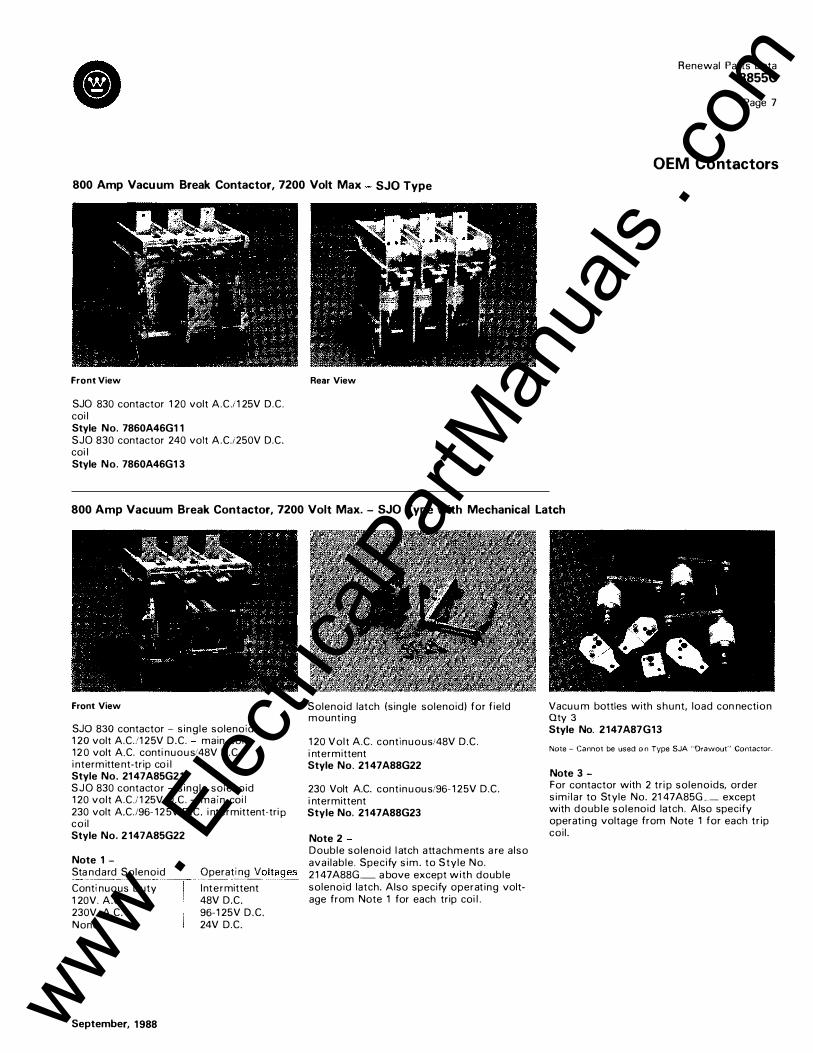
800 Amp Vacu um Break Contactor, 7200 Volt Max SJO Type
Front View
SJO 830 contactor 1 20 volt A.C .i1 25V D.C. coi l Style No. 7860A46G1 1 SJO 830 contactor 240 volt A.C.i250V D.C. coi l Style No. 7860A46G1 3
Rear View
Renewal Parts Data 8855C Page 7
OEM Contactors
800 Amp Vacuum Break Contactor, 7200 Volt Max. - SJO Type with Mechanical Latch
Front View
SJO 830 contactor - s ing le solenoid 1 20 volt A.C. .i1 25V D.C. main coi l 1 20 volt A.C. conti nuousi48V D.C. i ntermittent-trip co i l Style No. 21 47A85G2 1 SJO 830 contactor - s ing le solenoid 1 20 volt A.C./1 25V D.C . - main coi l 230 volt A.C./96- 1 25V D.C. i ntermittent-tri p coi l Style No. 2 147A85G22
Note 1 -Sta ndard Solenoid Conti nuous Duty 1 20V. A.C. 230V. A.C. None
September, 1 988
. ()perat�[l\L"" o�ges Intermittent 48V D.C. 96-1 25V D.C. 24V D.C.
Solenoid latch (single solenoid) for f ield mount ing
1 20 Volt A.C. continuousi48V D.C. i ntermittent Style No. 21 47A88G22
230 Volt A.C. continuous/96- 1 25V D.C. i ntermittent Style No. 21 47A88G23
Note 2 Double solenoid l atch attachments a re a lso avai lab le . Specify s im. to Style No. 21 47A88G� a bove except with double solenoid latch. Also specify operat ing voltage from Note 1 for each trip coi l .
Vacuu m bottles with shunt, load con nection Qty 3 Style No. 2 147A87G13
Note - Cannot be used o n Type SJA "Orawout" Contactor.
Note 3 -For contactor with 2 tri p solenoids, order s imi lar to Style No. 21 47A85G .... - except with doub le solenoid latch . Also specify operating voltage from Note 1 for each tr ip coi l .
www . El
ectric
alPar
tMan
uals
. com

Renewal Parts Data 8855C Pag e 8
AMPGARD Structural Pa rts
Blank I Hinged 1
Door �
I .F �:���:r[J 1 �
····�J. ·
·
·:
-
� ·
�
··· j I . · � .. - -u-� 1 90" . I ' I
['�. =r �� ,\ I IDI I r_____L+ • 1 • ; ,
Low Voltage · I ' . • II in i4V Door I 110 : 60"1 ·. ��.� � I : Hig����tage
�
1 l . i I : U I : \ __ Kick -._ I 1 ' '
c�-= -� �- � .. Plate �-��-- J _�d �l _L
H i g h Voltage Door
Non Reversing
700/800 �mp ... 60" H i g h
No. 2147A97G01 NEMA 1 CD Reversi n g
Low Voltage Door with
Non Revers i ng
75" H igh
-��tyle�N_()-_�2147 A94G()� 45" H igh 60" H i g h
3 Device Pane ls N E M A 1
B l a n k CD H i nged Door N E MA 1
Back Sheet
Reversi n g
Style No. 2147A94G03 ---- --- --------�--�·�--�---75" H i g h Style� No. 2147A94G()'! _ _ .. .. _ .. �-1 5" H i g h S.!fle No. 2147A94G05
�yle N_<�. 2147A�97GO�
1 5" H i g h No. 2147A97G05
30" H i g h No. 2147A97G06
45" H i g h 60" H i g h No. 2147A94G07 No. 2147A97G07
90" H i g h 90" H i g h No. 2147A97G08 No. 2147A97G08 -·- �·- �·- �-� -·�- �- ,,_. ,,_ -·'---'-��·--::......::_�--'·�·-�......::_ .: .. :.....�- -� .. -·�--- ��---.. � �� .. �� .. �-.. -�� .. -�-�---
Bus Enclosure E m p!Y._ __ _ _ .. - �--· ___ .... -. .. � .. - --- --- __ ... -�tyle No. 2147A94G 1 1 _� -���� -----���-�---'
-
-���N ... o_·-�-2_1_4 _ _ 7_A_�9 .. 7�G_ .. _1 1 ... Bus Enclosure With I n su l ators, 1 200 Amp Copper Bus, V4' x 4" N o n Insulated, Non P lated
Kick Plate Front
--- ---
Style No. 2147A94G12 Style No. 2147A97G12
Style No. 21 47A94G21 Style No. 2147A97G21 If replacing narrow flange doors with above, remove vertical trim strip and drill holes for hinge mounting. Narrow flange su pplied prior to July 1983.
Obsolete door fastener. No longer ava i l a b l e, custom e r to use stan� dard h ardware s;,e dia. , 2 in . long (approx. )
Door fastener kit Qty 1 0 Style No. 2147A91G15
September, 1 988 www . El
ectric
alPar
tMan
uals
. com

Formed Side Sheet
Formed Side Sheet, Common to A l l NEMA 1 Structures; Nomina l 9 0 i n . h igh . Style No., 2147A90G01
400 Amp welded cel l , nomina l 45 i n . h igh . Standard, for use with i solat ing switch and power fuses. Complete with H.V. door and L.V. door with "Works in a Drawer" ( not shown in photo) Style No. 2147A91G04
Works in a d rawer with s l ide rai ls . Mounts in 400 amp cel l . Nominal 45 in . h i gh Style No. 2147A9 1 G 1 3 Same as above except for use i n 700/800 cell (60 i n . h igh . ) Style No. 2 1 47A91 G 1 4 Note - above i ncludes 3 device panels. September, 1988
400 amp welded cel l , nomina l 30 i n . h igh , complete w1th H.V. door ( not shown in photo) Reversi ng. (Reversing celts are used in starters for reversing contactors, shorting and run contactors of reactor and autotransformer and multispeed starters.) Style No. 2147A91G05
Slide out control panel . s l ide rai ls . Mounts i n 400, 700, 800 amp cell Style No. 2 1 47A9 1 G 1 2
Renewal Parts Data 8855C Page 9
AMPGARD Structural Parts
--- Works in a Drawer with 3 Device Panels
200 Amp welded cel l . nomina l 30 i n . h igh . For use with a l l 200 amp, 2500 volt starters (25L2 ) . Complete with H .V. & L.V. door (not shown in photo) Style No. 2147A91G02
Front to rear su pport, Oty 2 Style No. 2 1 47A91G 1 1
www . El
ectric
alPar
tMan
uals
. com

Renew a l Parts Data
8855C Page 1 0
ADM Switch, 1 200 Amp, 5500 Volt Max.
Front View
ADM Switch, i n welded frame assembly, with front door. N o m i n a l 45" h igh . Style No. 2147A02G01
Arc chute Oty 3 Style No. 2147A02G02
M a i n spring, rod, mount ing Style No. 2147A02G05
M a i n stationary contacts Qty 3 Style No. 2147A02G03
Rear View
Rod ends Qty 3 Style No. 2147A02G08
Shaft (for h a n d l e) with rol l p ins Style No. 2147A02G10
Shaft with rod ends Style No. 2147A02G09
E lectr ical i nterlock operating m e chan ism, with 2 N.O. , 2 N .C. e l ectrica l i nter locks Style No. 21 47A02G1 1
M a i n switch blades Qty 3 Style No. 2147A02G04
Operating mech a n i s m assembly, with handle Style No. 2147A02G07
Fl i c ker b l ad e asse m b ly Qty 3 Style No. 21 47A02G06
September, 1 988 www . El
ectric
alPar
tMan
uals
. com

General Information
This section is designed to supplement the renewal part k its listed in other sections of RPD 8855C. Retrofit kits are created for cus· tomers who want to:
• Modify and upgrade exist ing equ ipment. Kits exist for adding potential transformers, conversion from 700 ampere air break to vacuum and add i n g new starters in existing spaces.
• Replace out-of-production starter equipment without havi n g to remove existing structures or replace cable and conduit. Kits of this type i n clude the 50L2 retrofit, the A M I retrofit and the 700 ampere starter conversion to 800 ampere vacuum.
• Convert exist i n g motor protection to microprocessor based 10 protection. Kits are available to add 101 000 or Data Plus in surface mou nted enclosures or in 1 0 i nch wide 90 inch high auxiliary sections. These kits can be combined with 10 communications devices from the 10 family price lists.
Note: Retrofit kits contain many specialized parts and pieces. They can be combined with other renewal part kits to expand the kit application. The kits do not contain standard hardware or wire. The kits may require additional material to meet your specific customer needs. All kits will require substantial field labor to i nstall. The installation is not i ncluded.
September, 1988
Retrofit Kit Index
Vacuum Starter Kits . . . . . . . . . . . Page 1 2 These kits contain a complete full voltage vacuum starter with cell and doors. (36" wide x 45" h igh x 30" deep). This retrofit applies to all 400 ampere spaces manufactured after 1 966 to present.
Disconnecting Potential Transformer Kits . . . . . . . . . . . . . . . Page 1 3 These kits can be installed i n any 36 i nch wide structure with minimum 15 inches of panel height.
Fixed Potential Transformer Kits . . . . . . . . . . . . . . . . . . . . . . . . . . . Page 1 3 These kits will provide the abil-ity to add 3 phase potential transformers to any starter or i ncoming l i ne/auxiliary enclosure.
IQ Retrofit Kits . . . . . . . . . . . . . . . . . Page 1 4 There are 4 basic kits offered. One kit provides the ability to surface mou nt the 10 product, one kit contai ns a 1 0 inch auxil-iary section, one kit i s for con-verti ng from 102000 Model A to 102000 Model B, the fourth kit includes material to add an 1 0 1 000 and Data Plus to an existi ng starter.
700 Amp Contactor Retrofit Kit . . . . . . . . . . . . . . . . . . . . . . . . . . . . Page 1 5 This kit includes t h e material to modify the out-of-production 700 ampere air break starter from air break to 800A vacuum. Limited to 450 amperes full load maximum.
Renewal Parts Data 8855C
Page 1 1
Retrofit Kits
700 Amp Controller Retrofit Kit . . . . . . . . . . . . . . . . . . . . . . . . . . . . Page 1 5 This kit i ncludes t h e material to upgrade the out-of-production 700 ampere air break starter to a fully rated 800 ampere vac-uum starter. Also used to upgrade 700 ampere reversing, reactor and multispeed starters to vacuum.
50L2 Retrofit Kit . . . . . . . . . . . . . . . Page 1 5 This kit contains the material to convert the out-of-production 50L2 (5000 volt, 200 ampere air break) to SJ vacuum, it util izes the exist i n g structure and isola-tion switch and can be used on 50L2 starters manufactured from 1 963 to 1 982.
AMI Retrofit Kits . . . . . . . . . . . . . . . Page 1 6 These kits are similar to the vacuum starter kits except for retrofit of the earlier A M PGARD design wh ich utilized Type "H" air break Type "K" oilbreak, and Type " D N-OH" oilbreak. The AMI design was used from 1 960- 1 967. The A M I retrofit can be used on earlier "AMPGARD" designs if the existing structure is wider than 30 i n ches and at least 30" deep.
www . El
ectric
alPar
tMan
uals
. com

Renewal Parts Data 8855C Page 1 2
AMPGARD Starter Retrofit Kits
AMPGARD Complete in 45 in. High Cell, for Mounting in Existing 36 in. Wide (AMPGARD Type) C ustomer Enclosure
Front View (Doors Closed)
Complete fu l l voltage. non reversing, i nduction, Vacuum break AMPGARD motor starter, 400 amp, 7200 volt max. for mou nting in exist ing 36 i n . wide enclosure. Inc l udes main contactor, iso lat ing switch, (3) power fuses, 1 0 1 000 motor command without RTD module, (3) cu rrent transformers, vertica l bus, high voltage and low voltage doors, welded cel l assembly for mounting i n exist ing 36 in . wide customer enclosure. Style No. 2147A95G01 Sl ideout design Style No. 2147A95G02 Drawout design
Front View (Doors Open)
When ordering specify the fol lowi ng -Style number from left hand column Quantity HP, FLA, service factor Voltage, Hertz, phase Load cable entry (top or bottom )
Draw-out Design Shown
Note -For functional up to date dupl icate of existing motor starter, to be mounted in existing AMPGARD enclosure, with same modifications as previously supp l ied refer to factory with a l l ordering in formation from midd le column and a lso advise size of cab le , number of cables per phase, exist ing ® outl ine dwg . no. and schematic & wir ing d iagram.
September, 1 988 www . El
ectric
alPar
tMan
uals
. com

Renewal Parts Data
8855C
Page 13
Potential Transformers, Disconnect and Fixed Mounted
Potential Transformer D isconnect
Potential tra nsformer disco n n ect com plete with (2) potential t ransformers, (3) pr imary and ( 2 ) secondary fuses. Style No. 2147A9 5G06 2400/1 20V. Style No. 2147A9 5G07 420011 20V.
Potential t ransformer d iscon nect without t ransformers, with (3) primary and ( 2 ) seco ndary fuses. 5KV max. Style No. 2147A9 5G08
Main fingers, ground fingers, pr imary fuses, fuse mounti ngs, 5KV max. Oty 3 Style No. 2147A9 5G09
----------------------------- ···· ---
Fixed Mounted Potential Transformer Kits, 3 Phase - For Incoming Line or Auxiliary Enclosure Application A - 1 00V.A. Capacity 2400/1 20 Volt, 60 Hz Consist ing of - ( 1 ) potential t ra nsformer, 3 phase, o pen delta, (3 ) p ri mary fuses, ( 1 ) secondary fuse block with (2 ) fuses, m o u nt i n g panel, da nger h i g h voltage N P's, schematic dwg. showing P.T.'s con nected to m a i n bus. Style No. 2147A9 5G24
B 450V.A. Capacity 2400/120 Volt, 60 Hz Consist ing of (2) potent ial tra nsformers, s ingle phase, (3) pr imary fuse blocks with fuses, (1) secondary fuse block with ( 2 ) fuses, m o u nt ing panel, danger h igh voltage NP's, schematic dwg. showing P.T.'s connected to main bus . Style No. 2147A9 5G2 5
Fixed Mounted or Contactor Mounted
C 1 00V.A. Capacity 4200/120 Volt, 60 Hz Similar to kit "A" except t ra n sformer p rimary voltage. Style No. 2147A9 5G26
D 450V.A. Capacity 4200/120 Volt, 60 Hz S i m ilar to kit "B" except tra n sformer primary voltage. Style No. 2147A9 5G27
Potential Transformer Retrofit Kits, 3 Phase - For AMPGARD Starter Application
A - 400 Amp Air Break or Vacuum Break "Drawout" Design
1 -100 V.A . Capacity 2400 /120 Volt, 60 Hz. Consist i ng of - (3 ) contactor l ine f ingers, ( 1 ) lin e stab assembly, ( 1 ) potential t ra n sformer, 3 phase, open delta, (3) pr imary fuses, ( 1 ) secondary fuse block with ( 2 ) fuses. Style No. 2147A9 5G10
2 -4 50 V.A . Capacity 2400 /120 Volt, 60 Hz. Consisting of - ( 3) contactor l ine f ingers. (1) line stab assembly, ( 2 ) potential transformers, s ingle phase, (3) pr imary fuse blocks & fuses, (1) secondary fuse block with ( 2 ) fuses. Style No. 2147A9 5G11
3 - 100 V.A . Capacity 4200 /120 Volt, 60 Hz. S i m ilar to kit A-1 above except transformer prim a ry voltage. Style No. 2147A9 5G12
4 -4 50 V.A . Capacity 4200 /120 Volt 60 Hz. Similar to kit A-2 above except t ra nsformer pr imary voltage. Style No. 2147A9 5G13
B - 400 Amp Vacuum Break "Siideout" Design
1 - 100 V.A . Capacity 2400 /120 Volt, 60 Hz. Consist ing of - ( 1) potential transformer, 3 phase, open delta ( m o u nted on contactor). (1) secondary fuse block with (2) fuses. Style No. 2147A9 5G14
September, 1988
2 100 V.A . Capacity 4200 /120 Volt, 60 Hz. S i milar to kit B-1 above, except tra n sformer pr imary voltage. Style No. 2147A9 5G1 5
C - 700 Amp Air Break 1 -100 V.A . Capacity 2400 /120 Volt. 60 Hz. Consisting of - (3) contactor l ine fingers, ( 1 ) stab assembly complete with m o u nt ing, ( 1 ) potential transformer, 3 phase, open delta, (3) pr imary fuses, ( 1 ) secondary fuse block with (2 ) fuses. Style No. 2147A9 5G16
2 -4 50 V.A . Capacity 2400 /120 Volt, 60 Hz. Consist i n g of - (3 ) contactor l ine fingers, ( 1 ) stab assembly com plete with m o unting, (2 ) potential t ransformers, s ingle phase , (3 ) pr i mary fuse blocks & fuses, ( 1 ) secon dary fuse block with (2) fuses. Style No. 2147A9 5G17
3 - 100 V.A . Capacity 4200 /120 Volt, 60 Hz. Similar to kit C-1 above, except transformer p rimary voltage. Style No. 2147A9 5G18
4 -4 50 V.A . Capacity 4200 /120 Volt, 60 Hz. Si milar to kit C-2 above, except t ra nsformer pr imary voltage. Style No. 2147A9 5G19
D - 800 Amp Vacuum Break 1 - 100 V.A . Capacity 2400 /120 Volt, 60 Hz. Consistin g of - (3) contactor lin e fingers, (1) stab assembly complete with mount i ng, ( 1 ) potential t ra n sformer, 3 phase, open delta, (3) prim a r y fuses, ( 1 ) secondary fuse block with (2) fuses. Style No. 2147A9 5G20
2 4 50 V.A . Capacity 2400 /120 Volt, 60 Hz. Consist i ng of (3 ) contactor l ine f ingers, (1) stab assembly com plete with m o u nt ing, (2 ) potent ial t ransformers, s i n gle phase, (3) pr i mary fuse blocks & fuses, ( 1 ) secondary fuse block with ( 2 ) fuses. Style No. 2147A9 5G21
3 100 V.A . Capacity 4200 /120 Volt, 60 Hz. S i m ilar to kit D-1 above, except transformer pr imary voltage. Style No. 2147A9 5G22
4 - 4 50 V.A . Capacity 4200 /120 Volt, 60 Hz. Similar to kit D-2 above, except transformer p rimary voltage. Style No. 2147A9 5G23
www . El
ectric
alPar
tMan
uals
. com

Renewal Parts Data 8855C Page 1 4
10 Retrofit Kits
IQ Surface Mount Enclosure - NEMA 1 Heavy gauge #14 , painted ASA-6 1 . Enclosu re for mounting 1 0 fami ly products on wa l ls, panels or doors without making l a rge cutouts. Six mount ing ho les and mount ing hardware inc luded. Basic footprint is 7.375 in. wide by 1 6.25 i n . h igh . Depth w i l l vary based on type of 10 product used. Includes dr i l l i ng for (3) PB-1 or PB-2 devices. The IQ product or PB product are not included.
4. 1 9 in. deep, fo r u se with 10 1 000, with or without com m u nications. Style No. 2 147A95G33
6 . 1 3 in . deep for use with 10 Data Plus, with or without com m un ications. Style No. 2147A95G34
Surface Mount Enclosure
IQ Floor Mounted Enclosure - N EMA 1
Two 10 in. wide enclosures (Shown with optional 10 i n . high bus compartment.)
Standard AMPGARD structure construct ion, painted ASA-61 . To be used as a l i ne-up extension for mounting 10 products. Each 10 in. wide section comes with (2) doors with "works-in-a drawer" drawout panel . Each door has (3) standard 1 0 cutouts with device pane ls . This kit can be used to min i m ize f ie ld wir ing du ri ng 1 0 retrofit or for adding 10 protect ion where there isn't enough panel space.
The IQ product is not included. 10 in. wide, 30 i n . deep, 90 in. h igh auxi l iary section (bus compar tment optiona l ). Style No. 21 47A95G35
IQ 2000 Model "A" to Model "B" Conversion kit This kit inc ludes a col lection of parts to make conversion from the out-of-production Model A to Model 8 10 2000 in an AMPGARD Starter as easy as possib le . Two faceplate insta l l at ion options are provided surface mount enclosu re or new low voltage door. The IQ 2000 is not included.
I nc luded in the kit a re : 1 0 A to 8 conversion l abels Instruction d rawing 9966D97 TD 1 1 -720-8 User Manua l Typical schematics 529 1 C64, 5291 C23, 5291 C25 Deep flanged low voltage door with 3 device panels 10 surface mount enclosure Style No. 21 47A95G36
Shown with 10 1000, PB-1 Devices Mounted
IQ 1 000 and Data Plus Retrofit Kit This kit incl udes a col lection of parts to make a retrofit of these 10 products and AMPGARD easier. I f cu rrent transformers o r potential transformers are requ ired refer to the appropriate page in this RPD. The 10 1 000 and Data Plus are pre-wired to terminal blocks on the d rawout pane l .
Th is k i t inc ludes: Typical starter schematics Deep-flanged low voltage door with 3 device panels Works-in-a-drawer panel with te rmina l blocks 1 0 1 000 (without RTD) 1 0 Data Plus (with MWH cou nter) Style No. 2 147A95G37
Note: For modifications to any 10 kit pl ease contact West inghouse for specific quotat ion.
September, 1 988 www . El
ectric
alPar
tMan
uals
. com

700 Ampere Retrofit Kit
700 Ampere Airbreak to Vacuum Conversion Kit This kit wil l convert an existing fu l l voltage non-reversing 700 a m pere air break starter to vacuum. The modified 800 a m pere SJA contactor with 1 20 volt control is mechanical ly interchangeable with the 700 ampere air break contactor. If l i ne stabs are req u i red, order separately from RPD 8855V page 1 1 . The SJA contactor is suppl ied with 2 KVA CPT, 2 N. O., 2 N.C. auxi l iary contacts. Maximum full load amperes is limited to 450. Modification kit is also suppl ied for necessary cel l barriers etc. Style No. 2147A95G31 .
For higher FLA or for m ulti-speed, reversing o r reduced voltage appl ication uti l iz ing the "upside-down" isolation switch refer to Westinghouse for quotation.
Renewal Parts Data
8855C Page 1 5
700 Ampere Retrofit Kits, 50L2 Retrofit Kit
700 Ampere Controller Upgrade This kit wi l l u pgrade an existi ng 700 a m pere air break starter to 800 a m pere vacuum, the existing structure is reused. The load sta b assem bly, isolation switch, contactor and l ine stab barriers are replaced. The basic kit wi l l convert a standard ful l voltage nonreversing starter. For m u lti-speed, revers i n g or reduced voltage appl ications util iz ing t h e "upside-down" isolation switch, with power fuses located a bove the switch mechanism, refer to Westi nghouse for quotation.
This kit i ncludes : SJA vacuu m contactor with 2KVA C PT, 2 N.O., 2 N.C. auxi l iary contacts. -Type SJA 50V830 Isolation switch - Type 72-LFM-8 Contactor load stab assembly, mounting and barriers
Mechanical interlock kit Isolation switch l i n e barrier kit Assembly drawing 991 7086 Style No. 2 147A95G32
Note: The above kits can be combined with other materia l such as ground fault protection, J Q product retrofits, h o rsepower changes. Contact West i nghouse for specific q u otatio n .
---- �---�· -··---··----· ---- -----� · --- ·---·--·---·--··�· 50L2 Retrofit Kits
50L2 Retrofit Kit Replaces the out-of-production 5000 volt 200 ampere air break contactor with a SJO vac u u m contactor. The customer keeps the existing starter cell and isolation switch and modifies the cel l to accept the SJO contactor which is mechanica l ly interlocked with the isolation switch. The rating will remain at 200 amperes.
The basic kit includes: • Type SJO 50V430 with mechanica l inter
lock, l i ne and l oad stabs • SJO mounting brackets • Line and load stab asse m b l ies with
mounting brackets • 3 current transformers with mounting
bracket Style No. 2147A95G30
September, 1 988
This retrofit can b e used on al l the 26 i nch wide 50L2 design man ufactured from 1 963 to 1 982. However, if your 50L2 was manufactured p rior to 1 974 you may want to a lso purchase a new LFR type isolation switch with fixed mounted s hutter. If your 50L2 was manufactured prior to 1 97 1 and uti l ized power fuses with 14 inch c l i p centers, you wi l l need to include 3 new 1 2 inch c l i p center CLS type fuses with the retrofit kit.
For other options, such as, g round fault, horsepower changes, IQ m icroprocessor protection and starters that are reversing, m ulti-speed, reduced voltage, or synchronous p l ease contact Westi nghouse for a specific quotation. I n cl ude all nameplate i nformation with the request for quotation.
26 i n . wide 50L2 air break design, with SJO Vacuu m Contactor Retrofit i nstal led. {Power fuses not i n sta l led).
www . El
ectric
alPar
tMan
uals
. com

Renewal Parts Data 8855C
Page 1 6
AMI Retrofit Kits
AMI History Westinghouse medium voltage starters, util izing a contactor, have been bui lt since the late 1 920's. Oi lbreak contactors, supplied u nti l 1 967, were g radual ly replaced with the AH and H air break contactors with asbestos a rc chutes. The Westinghouse "M&R shops" developed reg ional designs in the mid to late 1 950's util izi ng Type H a i r break, DN-OH oi lbreak, and Type K oi l break. Late 1 950's M&R designs replaced hookstick operated fuses with a non- loadbreak isolation switch, the G&W switch. The M&R organization bega n to standardize and consol idate the regional designs i nto the AMI des i g n which was transferred to g eneral control i n 1 960. The AMI design, d iscontinued in 1 969, was g radual ly phased out by the AMPGARD LF air break designs.
All of the devices used i n these designs are out-of-production, m a ny are sti l l in service. We have developed two kits s imi lar to the vacuum starter retrofit kits to convert these designs to cu rrent technology. Competitor structures can also be converted uti l iz ing the basic AMI retrofit. These kits can be supplied with additional features such as IQ products, g round fault protection synchronous, reduced voltage and m u lti-speed options. Contact Westinghouse for specific quotation.
Before insta l l i ng a n AMI retrofit k it the existing structure m ust be "stripped". Existing contactors, switches, CT's, controls a n d mounting p l ates removed. Existing doors will be taken off and replaced by the sta ndard AMPGARD doors, adjustable trim str ips and fi l l e r panels o r doors.
Standard AMI Retrofit This kit i ncludes a standard ful l voltage nonreversing vacu u m starter in a welded cel l asse mbly with horizonta l top barriers and deep f langed doors. The n o m i n a l 36 inch wide cell is 32.50" wide at the rear, 35.25" wide across the front vertical channels. Depth i s 29.50" from the front fra me to the back frame. Height is 44" not including cell mounting channels. This kit will retrofit the AMI "3-door designs" that a re 36 inches o r wider with m i n i m u m depth o f 3 0 i nches.
Westinghouse Electric Corporation Distribution and Control Business Unit Ashev i l le, North Carol ina, U.S.A. 2881 3
New filler strips -,..--.-.• 1
Replacement vacuum starter cell (30 or 36 in. wide) with all new controls
The basic kit consists of: Standard welded cel l with doors Type SJA 50V430 standard drawout contactor Type 50LFR-4 isolation switch power fuses l S ize based on horse-current transformers power, fu l l load Type A overload a m peres, service with heaters factor and voltage Control panel with i nterposing relay Standard CPT with 1 20 volt secondary 2 N.O., 2 N.C. auxi l iary contacts Cell mounting rai ls F i l ler panel Two vertical "tr im angles" General i nstruction for AMI retrofit Style No. 2147A95G41
Type "H", "AH" or other structure
Existing starter structure to be stripped before cell retrofit
Narrow AMI retrofit This kit is s imi lar to the standard AMI retrofit kit except the nominal cell is 30 inches wide. The cel l is 26.63 inches wide at the rear and 29.38 i nches wide across the front vertical channels. The h e i g ht of the cell is 64 i nches with the low voltage controls located i n the upper 15 i nches. The assembly uti l izes a standard isolation switch and vacu u m contactor. Style No. 2 147A95G40
Printed in U.S.A.
September, 1 988 www . El
ectric
alPar
tMan
uals
. com

Contents Pages
General I nformation 2 E l ectr ical Components 3,4,5 Overload Heater's, Power Fuses 5 O E M Vac u u m Contactors 6,7 Structu r a l Parts 8,9 ADM Switch 1 0 Retrofi t K i t s General I nformation 1 1
FVN R Vac u u m Starter 1 2 Disconnect 'Potent i a l Transformer 1 3 Discon nect Switch (Wit h o u t PT's) 1 3 Fi xed Potent i a l Transformers 1 3 10 F a m i l y 14 700 A m p Air to Vac u u m 1 5 50L2 A t r Break to Vac u u m 1 5 AMitType A, H, AH, Oi l I m m e rsed to Vac u u m B reak 1 6
www . El
ectric
alPar
tMan
uals
. com

----------------------------------------------------------------------------------------
Renewal Parts Data 8855C Page 2
General Information
Renewal and Replacement Parts The present des i g n of Ampgard m e d i u m voltage starters w a s i nt rod uced i n 1 962. Addit iona l rat in g s and featu res have been conti nuous ly introduced over the years.
This renewal parts data w il l provide the proper ident i ficat ion of standard parts which may be req u i red for the m a i ntentance of Westi nghouse Ampga rd starters. Al l of the com p l ete contactors, isolat ing switches and sub asse m b l ies t hat are ava i l a b l e a re shown photog raph ica l ly i n kit form.
Some of the det a i l parts shown in t h e renewal parts data a re recom m e nded o n l y a s part o f a s u b assembly t o faci l itate t h e i r replacement o r i nsta l l at i o n i n the fie l d .
Style n um bers i de nt if ied i n t h i s broc h u re w i l l not be t h e same a s st y le n u m bers on the or igi na l equipment. The renewal part styles in th is brochu re a re i n a k it for m a n d may i nc lude s u b assembly, carton, i n sta l lat i o n i n structions, etc.
It is the i ntent of th is renewal pa rts data brochure to make it poss i b l e for you to q u ickly i dent i fy the pa rts n eeded rather t h a n have t o search thro u g h twenty years o f records to dete r m i n e the specif ic styl e of the or ig ina l part . A l l of the parts shown i n the kits are compat ib le with t h e desi g n from 1 962 to the present {or n oted otherwise) .
S pecial attent ion should be g iven to forecast i n g yo u r parti c u l a r renewal parts requ i rements to e nsure o n -site ava i l a b i l it y o f n ecessa ry pa rts a n d mater ial s when needed, a s wel l a s g u a ra nteei n g eff ic iency and cont in ued operation of you r e q u ip m ent.
The a mo u nt of i nvestm ent t o be m ade i n renewal pa rts i s best determi ned b y you, tak ing i nto consideration such th ings as the i m pact of probab le sh utdown t i me, equi pm e nt d uty cycle, etc.
To m a i ntai n maxi m u m operat i n g effi ci ency a n d depend a b i l i ty of you r equ ipment genui ne West i n g house renewal pa rts a re reco m mended.
This p u b licat i o n i dent if ies those replacement parts which are ava i l a b l e a n d shou ld be ordered by sty l e n u m ber .
Ampgard Starters Since many starte rs a re s u p p l i ed to m eet specific custom e r e lectr ica l control and d istr ibut ion req u i re m e nts, other parts not l i sted in this pub l icat i o n m i g ht occas iona l ly be needed. Refer to factory for specific requests.
For equi pment other t h a n 60 Hz, refer to factory for i nfo rmat i o n .
Price and ava i lab i l i ty o f parts n o t l isted m a y b e o bta ined by contact ing y o u r l o ca l Westi ng house representative. Provide a com p l et e descri pt ion o f t h e part, a l o n g w i t h t h e complete data on the sta rter namep l ate which is fou n d in the l ow voltage a rea. Be sure to include: rati n gs, shop o rder and d iagram reference.
Obsolete Ampgard Designs Obsolete Ampgard d es i g n sta rters m a nufactu red pr ior to 1 966 were desi g n ated AMI starters and were b u i l t i n var ious cit ies i n the USA. Th ese sta rters were " 1 H i g h " design , 3 0 i n . , 3 4 i n . , or 3 8 i n . w i d e , 1 00 i n . h igh , a nd either 3 0 i n . o r 6 0 i n . deep. Retrofitt i n g an AMI sta rter is poss i b l e with up to date Ampgard components. Refer to page 16 or refer to factory for i nfo rmat i o n .
Contactors desig nated type H 1 30, H230, H430 ( a i r) and contactors designated type K430 ( o i l ) were ut i l ized in the AMI sta rters. These contactors are obsolete. Refer to factory for i nformation.
The iso lat ing switch uti l ized in the AMI starters were m a nufactured by G &W E lectr ic and is no longer a va i l a b l e . For replacement of G&W Electric switch, contact :
Phoenix El ectr ic P .O. Box 53 R eadvi l l e Stat ion Bosto n, M A 021 37 Phone: 6 1 7 -821 -0200 FAX: 61 7-828-57 1 9
-or-
Refer to pages 1 5, 1 6 for retrofit of the ent ire starter with cu rrent des ign A m pgard. Th is wi l l consist of welded cel l assembly, drawout isolat i n g switch, vacu um contactor, power fuses, cu rrent transformers, overload protect ion . Above wi l l a l l m o u nt in exist ing customer AMI enc losure.
Type LF66V430 vacu u m contactors s h i pp ed pr ior to 1 982 are o bsolete a n d no l o n g er ava i lab le . For replacement order up to date desi g n vacu u m contactor from Renewal Parts Data 8855V page 4, which i s mech a n i ca l l y a n d e lectr ica l ly i nterchangeab le with o bsolete Type LF66V430 contactor.
Additional Service Should you experience d ifficu l ty i n determ i n i n g needed parts for repai r or dete r m i n i n g exist i n g starter conditi o n , contact you r local West i n ghouse representative. Westinghouse can provide q u a l if ied tech n ica l personnel o n site to: • Ident ify and recommend replacement parts
for damage caused by short c i rcuit o r fault . • R e m ove damaged pa rts and i nsta l l repl acements. • Retrofit v i nt a g e motor star t i n g equi pment with new components. • Eva l u ate condit ion of exi st i n g e q u i pm e nt. • Test com po nents. • Provide a reco m mended spare pa rts l i st. • U pg rade exist i n g u n it from one Hp to a n other o r change o perati n g voltage of existi ng e q u i pment. • Convert the sta rter from a i r b re a k to vacu u m break contactor.
See Renewal Parts Data 8855A for a ir b reak desi g n . S e e R e newal Parts Data 8855V f o r vacu u m brea k desi g n .
Ordering Instructions ( 1 ) S pecify by style number. ( 2 ) Refer to Price List/St yle N um ber I ndex
8855 for pr ic ing i nformat i o n .
August 1992 www . El
ectric
alPar
tMan
uals
. com

Ratio 2515 Ratio 5015 Ratio 7515 Ratio 10015 Ratio 15015 Ratio 20015 Ratio 250/5 Ratio 30015 Ratio 40015 Ratio 50015 Ratio 60015 Ratio 750/5 Ratio 800/5 Ratio 100015 Ratio 1 20015
Single p h ase bar type, Oty 3
Style No. 2147A12G01 Style No. 2147A1 2G02 Style N�1 �7A1 2G03 Style No. 2147A12G04 Style No. 2147A1 2G05
--· ___ , , - �tyle N o . 2147A 1 2G06
Style No. 2147A1 2G07 Style No. 2147A12G08
3 phase donut type Oty 1 without 50--5 ground fault C.T. used on most AMPGARD designs after 1987.
Renewal Parts Data
8855C
Page 3
AMPGARD Electrical Components
Single phase donut type, Qty 3
Note 1 ·---........ __
Note 2 Style No. 2147A1 3G04 Style No. 2 1 47A13G05
_ __ _ _ _ S_tyle No. 21 47A13G06
___ .. __ s .... _tyle No. 2147A13_G_07 __ _
Style No. 21 47A13G08 -----·-
3 Phase donut type, Oty 1 Also i ncl udes ground fault transformer 50 5 ratio. Used on "drawout" AMPGARD design prior to 1 988. For use with 101 000·e , 102000 " a n d 10 data plus. '
Style No. 2 147A1 4G02 · ----·.. --
Style No. 2 147A1 4G03 ----------- - - - - -
Style No. 2 1 47A1 4G04 Style No. 2147A 14G05
Style No. 2 147A1 4G08 No. 2147A13G09 Style No. 2 1 47A14G09
Style No. 2147A13G 1 0 .... ___ __ __ Style N o. 2147A14G 1 0
__ S_ty_le No. 2147A 13G __ 1 __ 1 . ...... ·--- --...... Style No. 2147A14G 1 1 Style No. 2147A13G12 Style No. 2147A 1 4G 1 2 Style N o . 2147A1 3G13 ��-�----- --
Style No. 2147A1 3G14 � - - -�······---
Style No. 2147A_1_3_G_1_5 ___ _
Ratio 5015 Ratio 1 00/5 Ratio 1 50/5 Ratio 200/5 Ratio 30015 Ratio 400/5 Ratio 500/5 Ratio 600/5 Ratio 800/5 Ratio 1 00015 Ratio 1 200/5
. .. _____!tyle No. 2147A 1 6G04 (Loop _(_2)_i:l_rif11ary leads)
Style No. 2147A1 6G04 Ground fau lt current t ransformer, 50/5 ratio . For use with 101 000, 102000 Style No. 2147A1 6G05
--·--
Note 1 ... Use Style No. 21 47A13G04 and loop 12) primary leads. Note 2 Use Style No. 2147A1 3G05 and loop (2i primary leads.
A ugust 1992
No. 2147A 1 6G06 _ , __ _ ,,, .. __ __ _____ _ Style No. 2147A1 6G08 Style No. 2147A 1 6G09 Style No. 2147A16G 1 0 Style N o . 2147A 1 6G 1 1 Style No. 2147A16G13 Style No. 2147A_1_6 __
G1 ... 4 ... ___ _ ___ _ Style No. 2147A16G15
No. 2 147A 1 1G47
For standard ground gard grou nd fa u l t C.T. Refer to Cat 25-000. ----------
G round fau lt current transformer, 9/0.5 ratio 7% in. h igh, 3'/a in. d ia . hole. High B u rden C.T. used with SC Relay, CO Relay etc. Style No. 6 54 C777 H0 1
www . El
ectric
alPar
tMan
uals
. com

Renewal Parts Data
8855C
Page 4
AMPGARD Electrical Components
Rectifie r 120 vo It contro l
No. 20 18A40G0 1
240 volt control Style No. 20 18A40G02
L-64 i nterlock one normal ly open & one n o rm a l ly closed contact (standard)
No. 843 0943G2 1 CD
L-64 i nterl ock - 2 N .C. contacts Style No. 843 0943G23
Potent ia l t ransformers, 450 volt a m p . s ing le p hase, Oty 2 2400/120 volt, 60 Hz
No. 2 147A 1 1G 1 1
4200/120 volt, 60 Hz Style No. 2 147A 1 1G 12
Pri mary Fuse Bands, Oty 3 Style No. 2 147A 1 1G3 1
Q) Recommended for "Start�Up" spares,
2 KVA control transfo rmer 2300/240/120 volt , 60 Hz
No. 2 147A 1 1G02
4160/240/120 volt, 60 H z Style No. 2 147A 1 1G06
Fuse blocks with fuse c l ips for pr imary fuses for contro l t ra n sform ers, 2500 vol t pr i m a ry, max
No. 2 147A 1 1G2 1 of
Style No. 2 147A 1 1G44 (K it of 3)
Co ntrol t ra n sformer p r i m a ry fuse, 2 500 volt, m a x 2 a m p, for use w/ above fuse blocks
No. 2 147A 1 1G24 (i) of 2)
Style No. 2 147A 1 1G43 CD (K it of 3)
Potent ia l t ra nsformer, 100 volt a m p, 3 p hase open delta. With pri m . fuse provis ion, Oty 1 24001120 volt , 60 Hz
No. 2 147A 1 1G 14
4200/120 volt , 60 hz Style No. 2 147A 1 1G 1 5
Standard control transformer 23001120 volt, 750 volt a m p, 60 Hz
No. 2 147A 1 1G0 1
2300/240 volt, 750 volt a m p, 60 Hz No. 2 147A 1 1G03
4160/120 volt, 600 volt a m p , 60 H z No. 2 147A 1 1G0 5
4160/240 volt , 600 volt a m p , 60 Hz Style No. 2 147A 1 1G07
Fuse blocks with fuse c l ips for p r i m a r y fuses f o r control t ra nsfo rmers, 5000 volt p r i m a ry, max Style No. 2 147 A 1 1G22 ( Kit of 2 )
Style No. 2 147A 1 1G4 5 ( K i t of 3 )
Control transformer p r i m a ry fuse, 5000 volt max 3 a m p , for use w/ above fuse b locks
No. 2 147A 1 1G2 5CD of
Style No. 2 147A 1 1G46 CD (Kit of 3)
A ugust 1992 www . El
ectric
alPar
tMan
uals
. com

Renewal Parts Data
8855C
Page 5
AMPGARD Electrical Components, Overload Heaters, Power Fuses
Fuses, dual element m i niature type, 500 volt, 1 '12 in. long, 13/32 in. dia. for use with Style No. 2 1 47A 1 5G 1 5 or G 1 6
1 amp Oty 5 1 0 amp Oty 5 1 5 amp Oty 5 Style No. 2 1 47A1 1 G42
Type G Overload Heaters
Potential transformer, 1 00 volt amp, 3 phase open delta. Without pri m . fuse provision, Qty 1 U sed primarily on slide out vac u u m design 2400/1 20 volt, 60 Hz
No. 21 47A1 1 G36
33001 1 20 volt, 60 Hz No. 2 1 47A1 1 G37
4200! 1 20 volt, 60 Hz No. 2 1 47A1 1 G38
4800/ 1 20 volt, 60 Hz Style No. 2 1 47A 1 1 G39
2 pole fuse block with fuse cl ips for secondary fuses for control circuit, 30 a mp, 600 volt max, uses dual element fuses ( miniature) 1 1/2 in. long , 1 3/32 in. dia, Oty 2
No. 2 1 47A 1 5G 1 6
Same as above except 1 pole, Qty 4 Style No. 2 1 47A1 5G 1 5
Order entry note : Heaters are priced a s each heater. Heaters m u st be ordered in m ultiples of 3 .
Each carton includes 3 heaters plus 3 sets mounting hardware per photograph above.
Secondary Current Transformer Range
Oty. 1 - 3 Pole f-ieater Rating
2.44 Style No. 506C578G24_
Style No. 506C578G25
Style No_._�6C578G.::::2c6c... __ ............ ___ _ No. 506C578G27
1 .96-2. 1 5
2 . 1 6-2.35
2 .36-2.58
2.59-2.83
2.69
2.95
3.23 ---�--- .......... -� No. 506C578G28
No. 506C578G29
Style No. 506C578G3 .. __ 0_ .. ________ __ ___ _ Style No. 506C578G31
Style No. 506C578G32 ------
-- - - - - . - ----� -- -
Power Fuses
General Information The AM PGARD design over the years has used many different types of power fuses. i .e . , with and without hook-eye, different lengths (50L2 prior to 617 1 used 1 4 in. clip center, after 6:7 1 used 1 2 in. clip center). Type CLS for motor application, Type CLE
August 1 992
2.84-3. 1 1
3 . 1 2-3.42
3.43-3.73
3.74-4.07
4.08-4.39
3.55
3.90 -- --�- ........... ,, .. _____ , 4.28
4.67 .......... ____ __ _ 5.1
for transformer applications etc. The renewal part name plate on the inside of the high voltage door will identify the power fuses by rating and style num ber. Since the power fuses are coordinated with the overload relay and current transformers for each order we do not recommend substituting fuses of a different rating or style number without consulting factory .
The Type G overload heaters for the Type A overload relay are for use on A M PGARD starters only. These heaters are coordinated with power fuses and current transformers for each order. Do not change heater, power fuse, or current transformer before consulting factory.
Note that prior to 5/66 the standard overload for the AMPGARD was the Type MG overload, which is no longer available. Also note that the Type A 2 pole overload was standard from 6166 to 7173. For conversion to up to date overload with 3 phase protection consult factory.
Westinghouse encourages its customers to stock power fuses to ensure on-site availability, as well as g u aranteeing efficiency and continued operation of their equipment. Most fuses are available from Cat Index 36-685, otherwise refer to factory for availabi lity;substitution.
www . El
ectric
alPar
tMan
uals
. com

Renewal Parts Data
8855C
Page 6
OEM Contactors
400 Amp Vacuum Break Contactor, 7200 Volt Max - SJO Type
Front View
SJ O 430 contactor 1 20 volt A.C.!1 25V D.C. coi l
No. 219 7A01G 21
SJO 430 contactor 240 volt A.C./250V D.C. coi l Style No. 219 7A01G 23
Rear View
SJO 430 Approximate s h i pp ing weight 75 l bs.
SJO 430 Reversing Assembly
Front View
SJO 430 Revers ing asse m b ly, 1 20 Volt A.C., 1 25V D.C. coi l , complete with (2 ) contactors, mecha nica l i nter lock Approxi mate s h i p p i n g weight 1 50 lbs . Style No. 214 7A46G 1 7
400 Amp Vacuum Break Contactor, 7200 Volt Max. - SJO Type with Mechanical Latch
Front View SJO 430 contacto r - s ing le solenoid 1 20 volt A.C.i1 25V D .C . - main coi l 1 1 5 volt A.C./48V D.C. i nterm ittent-t r i p coi l Approximate sh ipp ing weight 75 l bs. Style No. 214 7A4 5G4 1
SJO 430 contactor s ing le solenoid 1 20 volt A.C.i1 25V D.C. - main coi l 230 volt A.C./96-1 2 5V D.C. i nterm ittent-tr ip coi l Approxi mate sh ipp ing weight 75 lbs. Style No. 214 7A4 5G4 2
Note 1 For contactor with 2 trip solenoids, order s i m i l a r to Style No. 21 47A45G_ except with doub le solenoid l atch . Also s pecify operati ng voltage from Note 2 for each t r ip coi l .
Solenoid latch (s i n g l e solenoid) for f ie ld mount ing
1 20 Volt A.C. cont inuous!48V D.C. i ntermittent
No. 214 7A48G 22
230 Volt A.C. cont i nuous/96- 1 25V D.C. i ntermi ttent Style No. 214 7A48G 23
Note 3
Dou ble soleno id latch attach m ents are a l so ava i lab le . S pecify s im. to Style No. 2 1 47A48G.... above except with doub le so leno id l atch. Also specify operat ing voltage from Note 2 for each t r ip coi l .
Note 2 Standard Solenoid Operati ng Voltages A.C. D.C.
1 1 5 230 v. 460 v. 575 v.
48 v. 96-1 2 5 V. 250 v. 24 v.
Vacuu m bottles with s h u nt, load connect i o n Oty 3 Style No. 214 7A4 7G1 3@
Nole Cannot b e used o n Type SJA "Roll-out Contactor."
Recor-�mended for ' 'R u n n i n g " spares.
A ugust 199 2 www . El
ectric
alPar
tMan
uals
. com

e 800 Amp Vacuum Break Contactor,
7200 Volt Max - SJO Type
Front View
SJO 830 contactor 1 20 volt A.C. 1 25V D.C. coi l Approxi m ate sh i p p i n g wei ght 1 00 lbs. Style No. 7860A46G1 1
SJO 830 contactor 240 volt A.C.i250V D.C. coi l Appro x i m ate sh ipp ing wei g ht 1 00 l bs. Style No. 7860A46G13
SJO 830 Reversing Assembly
SJO 830 Reversing asse m b ly, 1 20 Volt A.C. ' 1 25V D.C. coi l com p l ete with (2 ) contactors, mech a ni c a l i n terlock Approxi m ate s h i p p i n g wei g ht 200 l bs. Style No. 2 147A86G1 7
Renewal Parts Data 8855C Page 7
OEM Co ntactors
Mech a nical i nterlock kit for fi e ld mount ing o n contactor ( revers i n g , m u lt i-speed, autotran sformer) 800 Am p o n l y Style No. 2147A86G13
800 A m p Vacuum Break Contactor, 7200 Volt Max. - SJO Type with Mechanical latch
SJO 830 contactor - s i n g l e so lenoid 1 20 volt A.C.I1 25V D.C. - main coi l 1 20 volt A.C.i48V D.C. i nterm ittent-trip coi l Approximate sh ipping weight 1 00 lbs . Style No. 21 47A85G21 SJO 830 contactor s ing le soleno id 1 20 vo l t A.C.i1 25V D.C . - main co i l 230 vo l t A .C . .'96-1 25V D.C. i ntermittent-tri p co i l Approx i m ate s h i p p i n g weight 1 00 lbs . Style No. 2 147A85G22 Note 1 For contactor with 2 tr ip solenoids, order s i m i l a r t o Style No. 2 1 47A85G except with double sol e n o i d latch. Also specify operati n g voltage from N ote 2 for each t r ip coi l .
Note 2 - Standard Solenoid Operating Voltages A.C. D.C. f1 5 V. 230 v. 460 v. 575 v.
August 1 992
48 v. 96-1 25 v. 250 v. 24 v.
1 20 Volt A.C. conti n u ou si48V D.C. i nterm ittent
No. 21 47A88G22 230 Volt A.C. cont inuous/96-1 25V D.C. i nterm ittent Style No. 21 47A88G23
Note 3 Double so lenoid latch attachments are a lso ava i l a b le. Specify s i m . t o Sty le No. 2 1 47A88G� a bove except with doub le so leno id l atch. Also specify o perat i n g voltage from Note 2 for each t r i p coi l .
Solenoid l atch ( s i n g l e so leno id ) for f ield mount ing
Vacuum bottles with s h u nt, l o a d con n ection Qty 3 Style No. 2 147A87G13@
�ote Cannot be used o n Type SJA ' Rol!�out" Contactor
Recommended for "Running" spares. www . El
ectric
alPar
tMan
uals
. com

Renewal Parts Data 8855C
Page 8
AMPGARD Structu ral Parts
H i g h Voltage Door NEMA 1 CD
Low Voltage Door with 3 Device Panels NEMA 1
Blank CD H i nged Door N E MA 1
Back S heet
Bus Enclosure §_mp_ty __
Non Reversing
Reversi ng
Non Reversing
Reversing
Vertical Bus - Two High Starter Between Upper and Lower lsolf3!inJL Switch
Vertical Bus - Between Upper Isolating Switch and Main Bus
10" ·�-·��··�·- �·
-· ��J ...1 Blank
l 10"
t I , Hinged ,
� Door �
I I I
_ _ _ ·-400 AmJ> �
45" H i g h S,.!yle No. �!42,A�(1_()1 75" H i g h
� _ �S,!y�e�No. 2147A94G02 45" H i g h Style No. 2147A94G03 - - -
75" H i g h �ty!e No. 21�7A94GO� 1 5" H i g h Style N� 2!47,A94G05 30" H i g h !;tyle "".o. 2147A94G06 45" H i g h Style No. 2147A94G07 - -- --
90" H i g h _ �ty� No. 2147A94G08 _ �-
�700/800 A."'!P 60" H i g h
I 90"
t l
StyJ!_ fi!�2147_A97G01
60" H i g h Style No. 2147A97G03
1 5" H i g h Style No. 2147A97G05 30" H i g h ,!;,tyle No . 2147A97G06 60" H i g h Style No. 2147A97G07 ----- �-�- �-�--�-- --·�
90" H i g h Style No. 2147A97G08
Style_l'lo. 2147A94G1 1 �- � _ _ _ _ Styi!_No. 2147A97G1 1 Style No. 2147A94G12 Style No. 2147A97G12
Style No. 2147A94G21 Style No. 2147A94G22
Style No. 2147A94G23
Style No. 2147A94G24
Style No. 2147A97G21 Style No. 2147A97G22
If replacing narrow flange doors with above, remove vertical t6m strip and dri l l holes for hinge mountir.g. �arrow flange supplied prior to July 1983.
August 1992 www . El
ectric
alPar
tMan
uals
. com

Formed Side Sheet
Formed Side Sheet, Common to All NEMA 1 Structures; Nominal 90 in. high. Style No., 21 47A90G01
400 Amp welded cell, nominal 45 in. high. Standard, for use with isolating switch and power fuses. Complete with H.V. door and L.V. door with "Works i n a Drawer" (not shown in photo) Style No. 2147A91G04
Works in a drawer with slide rails. Mounts in 400 amp cell. Nominal 45 in. high Style No. 2 1 47A9 1 G 1 3
Same as above except for use in 700/800 cell (60 in. high.) Style No. 2 1 47A91 G 1 4 Note - above includes 3 device panels.
August 1 992
400 amp welded cell, nominal 30 i n. high, complete with H.V. door ( n ot shown in photo) Reversing. (Reversing cells are used in starters for reversing contactors, shorting and run confactors of reactor and autotransformer and multispeed starters.) Style No. 2 1 47A91G05
Slide out control panel, slide rails. Mounts in 400, 700, 800 amp cell Style No. 2 1 47A9 1 G 1 2
Ren ewal Parts Data 8855C
Page 9
AMPGARD Structural Parts
--- Works in a Drawer with 3 Device Panels
Door fastener kit Oty 1 0 Style No. 2 1 47A9 1 G 1 5
Front t o rear support, Qty 2 Style No. 2 1 47A91 G 1 1
Obsolete door fastener. No longer available, customer to use standard hardware 5/16 dia., 2 i n . long (approx.)
www . El
ectric
alPar
tMan
uals
. com

Renewal Parts Data
8855C
Page 1 0
ADM Switch, 1200 Amp, 5500 Volt Max.
Front View
ADM Switch, in welded fra m e assembly, with front door. N o m i n a l 45" h igh . Style No. 2147A 02G 01
Arc chute Oty 3 Style No. 2147A 02G 02
M a i n spr ing, rod, mou nting Style No. 2147A 02G 05
M a i n stationary contacts Oty 3 Style No. 2147A 02G 03
Rear View
Rod ends Oty 3 Style No. 2147A 02G 08
Shaft (for handle) with rol l p ins Style No. 2147A 02G1 0
Shaft with rod ends Style No. 2147A 02G 09
Electr ical inter lock operating mechan ism, with 2 N.O. , 2 N .C . e lectrical i nterl ocks Style No. 2147A 02G11
M a i n switch bla des Oty 3 Style No. 2147A 02G 04
Operating m echanism assem bly, with hand le Style No. 2147A 02G 07
F l icker blade assembly Oty 3 Style No. 2147A 02G 06
A ugust 1992 www . El
ectric
alPar
tMan
uals
. com

General Information
T h i s sect i o n is desig ned to s u p p lement the renewal p a rt kits l i sted in other sect ions of R PD 8855C. Retrofit kits a re created for customers who w a nt to :
• Modify a n d u pg rade exist i n g equipment. Kits exist for adding potenti a l tra nsformers, conve rs i o n from 700 a m pere a i r break t o vacu u m a n d add i n g n e w sta rters in existi ng spaces.
• R e p l ace out-of-product i o n sta rter equ i pm e nt without havi ng to remove existi ng structures o r rep lace cable a n d condu it. Kits of th is type i nclude the 50L2 retrofit, the AMI retrofit a n d t h e 700 a m pere starter convers i o n to 800 a m pere vacu u m .
• Convert existi n g m otor protectio n to m icroprocessor based 10 protecti o n . Kits are ava i l ab le to add 1 0 1 000 II o r Data Plus I I in su rface m o u nted enclosu res or in 1 0 i nch wide 9 0 i n ch h i g h a u x i l i a ry sect i o n s . T hese k i t s can be com b ined w i t h 10 comm u n icat ions devices from the 10 fa m i ly p rice l i sts.
Note: Retrofit kits conta i n m a ny spec i a l ized pa rts and p ieces. They can be co m b in e d w i t h other renewal part k i t s t o e x p a n d the kit a pp l ication . The kits do not contain standard hardware or wire. The kits may req u i re addit i o n a l mate r i a l to meet your specif ic custo mer needs. A l l kits wil l req u i re substanti a l f ield la bor to i n sta l l . T h e i n sta l l at ion is not i nclu ded.
August 1992
Retrofit Kit Index
Vacuum Starter Kits . . . . . . . . . . . Page 1 2 These kits contain a co m p l ete fu l l voltage vacu u m starter with ce l l a n d doors. (36" wide x 45" h i g h x 30" deep) . T h i s retrofit a p p l i es to all 400 am pere spaces m a n ufactured after 1 966 to present.
Disconnecting Potential Transformer Kits . . . . . . . . . . . . . . . Page 1 3 These kits can be i n sta l led i n a n y 36 i nch wide structure with m i n i m u m 1 5 i nches of p a n e l h e i g ht .
Fixed Potential Transformer Kits . . . . . . . . . . . . . . . . . . . . . . . . . . Page 1 3 These kits wi l l p rovide the a b i l -ity t o a d d 3 p h ase potenti a l tra nsfor mers t o any sta rter o r i ncom i n g l i n e 1a u x i l i a ry enclosure.
IQ Retrofit Kits . . . . . . . . . . . . . . . . . Page 1 4 T h e re a re 3 basic kits offered. One kit provides the a b i l ity to su rface m o u nt the 10 product, one k it cont a i n s a 1 0 i n ch a u x i l -iary section, t h e t h i rd kit i ncludes mate r i a l to add an 101 000 I I and Data P lus I I to an ex ist i n g starter.
700 Amp Contactor Retrofit Kits . . . . . . . . . . . . . . . . . . . . . . . . . . Page 1 5 These kits i n clude the mater i a l t o modify t h e out-of- product ion 700 a mpere a i r break sta rter from air break to 800A vacuu m .
Renewal Pa rts Data 8855C Page 1 1
Retrofit Kits
700 Amp Controller Retrofit Kit . . . . . . . . . . . . . . . . . . . . . . . . . . . . Page 1 5 T h i s kit i nc ludes the mater i a l to u p g rade t h e out-of-product ion 700 a mpere a i r break starter to a f u l ly rated 800 a m pere vac-u u m starter. A l so u sed to u pg rade 700 a m pere reversi ng , reactor a n d m u lt ispeed sta rters to vacu u m .
50l2 Retrofit Kit . . . . . . . . . . . . . . . Page 1 5 T h i s kit contains the mater ia l to convert the out-of-product i o n 50L2 (5000 volt, 2 0 0 a mp e re a i r break) t o SJ vacu u m , i t ut i l izes the exist ing structure a n d i so la-t ion switch and c a n be used on 50L2 sta rters m a n ufactured from 1 963 to 1 982.
AMI Retrofit Kits . . . . . . . . . . . . . . . Page 1 6 Th ese kits are s i m i l a r t o the vacu u m starter kits except for retrofit of the ear l ier AMPGAR D design which uti l ized Type "H" a i r break Type "K" o i l break, and Type "DN-OH" o i l break. The AMI desi g n was used from 1 960- 1 967. The AMI retrofit can be used o n ear l ier "AM PGARD" desig ns i f the exist ing structure is 30 i nches wide and at least 30" deep.
www . El
ectric
alPar
tMan
uals
. com

R enewal Parts Data 8855C Page 1 2
AMPGARD Starter Retrofit Kits
AMPGARD Complete i n 45 in. High Cell, for Mounting in Existing 36 in. Wide (AMPGARD Type) Customer Enclosure
Front View (Doors Closed)
C o m plete fu l l voltage, non reversin g , i n duct ion, Vacuum break AM PGARD motor starter, 400 amp, 7 200 volt m ax. for m ou nti n g in exist i n g 36 in . w i d e e nclosu re. I n c l udes m a i n contactor, i so l at ing switch, (3) power fuses, 101 000 I I m otor command without RTD module , (3) current transformers, vert ica l bus, h i g h voltage a n d low voltage d oors, welded cel l assembly for mount ing in exist i n g 36 i n . wide customer enc losure. Approx i m ate s h i p p i n g weight 1 000 l bs. Style No. 2147A95G01 S l ideout d es i g n Style No . 2147A95G02 Rol l-out d es i g n
Front View {Doors Open)
W h e n order ing specify the fo l lowi n g -Style n um be r from left h a n d col u m n Quantity HP, FLA. service factor Voltage, H ertz, phase Loa d cable entry (top or bottom}
Roll-out Design Shown
Note -For function a l up to date d upl icate of existi n g motor starter, to be m ou nted i n exist i n g AMPGARD enc losu re, with s a m e m odificat ions a s previously suppl ied refer to factory with a l l orderi n g i nfo rmation from m i d d l e co l u m n a n d a lso advise s i z e o f cab l e, n u mber of cab les per phase, exi st ing ® outl i n e dwg. n o . a n d schematic & w i r i n g d iagram.
August 1992 www . El
ectric
alPar
tMan
uals
. com

8 Potential Transformer D isconnect
Potenti al transformer d isconnect com plete with (2) potent ia l t ransformers, (3) p r i m a ry and (2 ) secondary fuses.
No. 2147A9 5G06 2400/1 20V.
Style No. 2147A9 5G07 4200; 1 20V.
Fixed Mounted
Renewal Parts Data
8855C
Page 1 3
Potential Transformers, Disconnect and Fixed Mounted
Potenti al t ransfo rmer d iscon nect without transformers, with (3) p r imary and (2) secondary fuses. 5KV max. Style No. 2147A9 5G08
M a i n fi ngers, ground f ingers, pr imary fuses, fuse mount ings , 5KV max . Oty 3 Style No. 2147A9 5G09
-----------------·· -�·-- .-�-- ... � - -- ·····�
Potential Transformer Kits, 3 Phase - For Incoming Line or Auxiliary Enclosure Application A - 100V.A. Capacity 2400/ 120 Volt, B - 450V.A. Capacity 2400/120 Volt, C 1 00V.A. Capacity 4200/120 Volt, M � M � � � Consist ing of - ( 1 ) potent ia l t ransformer, 3 phase, open delta, (3 ) p r i m a ry fuses, ( 1 ) secondary fuse block with ( 2 ) fuses, mount i n g panel, danger h igh voltage NP's, schematic dwg . showi ng P.T.'s connected to main bus. Style No. 2147A9 5G24
Consist ing of - (2 ) potentia l transform ers, s ingle phase, (3) pr imary fuse blocks with fuses, ( 1 ) secondary fuse block with (2 i fuses. m o u nt ing pane l , danger h igh voltage N P's, schematic dwg. showing P.T.'s connected to m a i n bus. Style No. 2147A9 5G2 5
Fixed Mounted or Contactor Mounted
Simi la r to kit "A" except transformer privoltage. No. 2147A9 5G26
D 450V.A. Capacity 4200/120 Volt, 60 Hz Simi lar to kit "8" except tra nsformer pr i mary voltage. Style No. 2 147A9 5G27
Potential Transformer Retrofit Kits, 3 Phase - For AMPGAR D Starter Application
A - 400 Amp Air Break or Vacuum Break "Roll-out" Design
1 - 100 V.A . Capacity 2400 /120 Volt, 60 Hz. Consist i n g of (3) contact or l i ne fi n g ers, ( 1 ) l i n e stab assem bly, ( 1 ) potential transfo rmer, 3 p hase, ope n delta, (3 ) pr imary fuses, ( 1 ) secondary fuse block with (2 ) fuses. Style No. 2147A9 5G10
2 -4 50 V.A . Capacity 2400 /120 Volt, 60 Hz. Consist ing of (3) contactor l i n e fing ers, ( 1 ) l i ne sta b asse m b ly , ( 2 ) potent ia l t ra nsformers, si n g l e phase, (3) pr imary fuse blocks & fuses, ( 1 ) secondary fuse block with (2 ) fuses. Style No. 2147A9 5G11
3 -100 V.A . Capacity 4200 /120 Volt, 60 Hz. S i m i l a r to kit A-1 a bove except t ra n sformer pr imary voltage. Style No. 2147A9 5G12
4 4 50 V.A . Capacity 4200 1120 Volt 60 Hz. S i m i l a r to kit A-2 a bove except transformer pr imary voltage.
No. 2147A9 5G13
A ugust 1992
B - 400 Amp Vacu um Break "Siideout" Design
1 -100 V.A . Capacity 2400 /120 Volt, 60 Hz. Consist i n g of - ( 1 ) pote ntial tra n sformer, 3 ph ase, o pen delta (mounted on contactor ) . ( 1 ) secondary fuse b lock with ( 2 ) fuses. Style No. 2147A9 5G14
2 100 V.A . Capacity 4200 1120 Volt, 60 Hz. Simi lar to kit B-1 above, except tra nsformer pr imary voltage. Style No. 2147A9 5G1 5
C - 700 Amp Air Break 1 - 100 V.A . Capacity 2400 /120 Volt, 60 Hz. Consist i n g of (3) contactor l i n e f ingers, ( 1 ) stab assembly com plet e with mount ing , ( 1 ) potential tra nsfo rmer, 3 phase, open delta, (3 ) pr imary fuses, ( 1 ) seco ndary fuse block with (2) fuses. Style No. 2147A9 5G16
2 4 50 V.A . Capacity 2400 /120 Volt, 60 Hz. Consist ing of (3 ) contactor l i n e fi ng ers, ( 1 ) stab assem bly complete with m o u nt ing , ( 2 ) potent ia l t ransfo rm ers, s ing le phase, ( 3 ) p rim a r y fuse b locks & fuses, ( 1 ) secondary fuse b lock with ( 2 ) fuses. Style No. 2147A9 5G17
3 -100 V.A . Capacity 4200 /120 Volt, 60 Hz. S i m i l a r to k it C- 1 above, except t ra nsformer pr imary voltage. Style No. 2147A9 5G18
4 -4 50 V.A . Capacity 4200 1120 Volt, 60 Hz. Simi la r to kit C-2 a bove, except transformer pr imary voltage. Style No. 2147A9 5G
_1
_9
_______ _
D - 800 Amp Vacuu m Break 1 - 100 V.A . Capacity 2400 1120 Volt, 60 Hz. Consist ing of (3 ) contactor l i n e fi n g ers, ( 1 ) stab asse m b ly complete with m o u nt ing , ( 1 ) potent ia l transformer, 3 phase, o pe n delta, (3) pr imary fuses, ( 1 ) secondary fuse b loc k with (2 ) fuses. Style No. 2147A9 5G20
2 4 50 V.A . Capacity 2400 /120 Volt, 60 Hz. Consist ing of - (3 ) contacto r l i n e f ingers, ( 1 ) stab assembly com plete with mount ing , ( 2 ) potent ia l t ra nsfo rm e rs, s i n g l e phase, (3 ) primary fuse b locks & fuses, ( 1 ) secondary fuse block with (2) fuses. Style No. 2147A9 5G21
3 -100 V.A . Capacity 4200 /120 Volt, 60 Hz. S i m i l a r to kit D-1 above, except transfo rmer pr imary voltage. Style No. 2147A9 5G22
4 -4 50 V.A . Capacity 4200 /120 Volt, 60 Hz. S i m i l a r to k i t D-2 above, except t ra nsformer pr imary voltage. Style No. 2147A9 5G23
www . El
ectric
alPar
tMan
uals
. com

Renewal Parts Data 8855C Page 1 4
10 Retrofit Kits
IQ Surface Mount Enclosure - NEMA 1 Heavy g a u g e # 1 4, painted ASA-6 1 . E nc l osure for m o u nt i n g IQ fam i l y p roducts o n wal ls, panels o r d o o rs without m a k i n g large cutouts. Six mou nti ng h o l es a n d m o u n t i n g h a rd w a re i ncluded. Basic footpr int i s 7.375 i n . wide by 1 6.25 i n . h i g h . For use with 1 01 000 I I or IQ Data P lus I I , with o r without co m m u n ications. I nc l u des d r i l l i n g for (3) PB-1 or PB-2 devices. The IQ product or PB
are not included.
Surface m o u n t e nclosure o n ly, with " Flat" Face, 6 . 1 3 in. deep. Reco m m e nded for m o u nt i n g 45 i n . or l ess from f loor . Style No. 2 1 47A95G34
Su rface m o u nt enclosu re o n ly, with "Sl a nted" Face, 8 . 1 3 i n . top, 6. 1 3 i n . bott o m . Reco m m e n d ed for m o u nt i n g a bove 4 5 i n . from floor.
No. 2147A95G51 Surface Mount Enclosure "Flat" Face
10 Floor Mounted Enclosure - NEMA 1
Two 10 in. wide enclosures (Shown with optional 10 in. high bus com partment and (2) IQ cutouts with optional devices per door!
Sta n d a rd AMPGARD structure constructi on, pai nted ASA-6 1 . To be used as a l i ne-up exte nsion for m o u nt in g 1 0 p ro ducts. Each 1 0 i n . wide sectio n comes with ( 2 ) doors with "works-i n-a d rawer" d rawout p a n e l . E a c h door has (3) sta n d a r d 1 0 cutouts with device p a n e l s . This kit can be used to m i n i mi ze field w i r i n g d u r i ng 1 0 retrofit or for a d d i n g 1 0 protect i o n where t here i s n 't e n o u g h panel space.
The JQ product is not included. 1 0 i n . wide, 30 i n . deep, 90 i n . h i g h a u x i l iary sect i o n (bus compartment o pt i o n a l ) . Style N o . 21 47A95G35
Surface Mount Enclosure "Slanted" Face
Shown with JQ 1 000, PB-1 Devices Mounted
-- --- · ---··---··---·---·· --------
IQ Retrofit Kits for Ampgard 400A Motor Starters These k i ts i nc l u d e a c o l l ecti o n of parts to make a retrofit of th ese IQ products to an AMPGARD easier. I f cu rrent t ra n sformers o r potenti a l transfo r m e rs are requ i red refer t o t h e appropri ate page i n t h i s R P D . T h e I Q prod ucts a re pre-wired to t e r mi n a l b locks o n t h e drawout pa n e l .
These k i ts i nc l u d e : Typical starter schematic Deep-fl a n g e d low voltage door with (3) cutouts for IQ products. Device p a n e l w i l l cover u n used cutouts. Works- i n-a-drawer panel with term i n a l b locks IQ 1 000 I I (without RTD) 10 Data P lus II
No. 2 1 47A95G37
Similar to above except 101000 II only Style No. 21 47A95G39
Note: For modificati o n s to any 10 kit p l ease contact Westi ng house fo r specific quotat ion.
August 1 992 www . El
ectric
alPar
tMan
uals
. com

700 Ampere Retrofit Kit
700 Ampere Airbreak to Vacuum Conversion Kit Maximum FLA 450 This kit w i l l convert a n ex ist i ng fu l l voltage n o n-revers i n g 700 a m pere air break starter to vacu u m . The mod ified 800 a m pere SJA contactor with 1 20 volt control is mechanica l ly i nterc h a n g ea b l e with the 700 a m pere air break contactor. I f l i n e stabs a re req u i red, order separately from R P D 8855V page 1 1 . The SJA contacto r is s u p p l i ed with 2 KVA CPT, 2 N .O . , 2 N .C. a u x i l i a ry contacts. Maximum full load amperes is limited to 450. M odificat ion kit is a l so suppl ied with necessary cell ba rriers etc. Approxi mate s h i p p i n g wei g ht 1 75 l bs. Style No. 21 47A95G31 . -'------------- ---··-
700 Ampere Airbreak to Vacuum Conversion Kit - Maximum FLA 630 This kit wi l l convert a n exist i n g f u l l volta ge non-revers i n g 700 a m pere a i r break starter to vacu u m . The m odified 800 a m pere SJA contactor with 120 volt control i s m ec h a n i c a l l y i n terchan g e a b l e with the 7 0 0 a m pere a i r break contactor. If l i ne sta bs a re req u i red, order separately from RPD 8855V page 1 1 . The SJA contactor is s u p p l ied with
50L2 Retrofit Kits
50L2 Retrofit Kit Replaces the out-of- production 5000 volt 200 a mpere a i r break contactor with a SJO vac u u m contactor. The custom e r keeps the exist i n g starter c e l l and isolation switch a n d modifies t h e cel l to accept the SJO contactor which i s m ec h a n ica l ly i nter locked with the isolat ion switch. The rating will remain at 200 amperes.
The basic kit inc ludes : • Type SJO 50V430 with mecha n i c a l i nter
l ock, l i n e a n d load stab s • S J O m o u nt ing brackets • L i n e and l o a d stab assemb l i e s with
mount ing brackets • 3 cu rrent tra nsformers with mount ing
bracket Approxi mate s h i p p i n g wei g ht 1 2 5 l b s . Style N o . 21 47A95G30
August 1 992
Renewal Parts Data 8855C
P a g e 1 5
700 Am pere Retrofit Kits, 50L2 Retrofit Kit
2 KVA CPT, 2 N . O . , 2 N.C. a u x i l i a ry contacts. Maximum full load amperes is l imited to 630. Mod ificat ion kit is also s u p p l ied with necessary ce l l barriers, l i n e stabs, fuse l i n e fi n g e rs, tray asse m bly. An,nr,(WI<m.,t., s h i p p i n g wei g ht 200 l bs.
No. 21 47A95G36
700 Ampere Controller Upgrade Maximum FLA 720, 4200 Volt This kit w i l l u pg rade an existi ng 700 a mpere air break starter to 800 a m pere vacu u m , the exist ing structure i s reused. The load sta b a ssembly, isolat ion switch, contactor a n d l i n e stab ba rriers a re replaced. The b a s i c k i t w i l l convert a sta n d a rd f u l l voltage n o n reversing starter.
This kit i n c l u d e s : S J A vacu u m contactor w i t h 2 K V A C PT, 2 N.O. , 2 N .C . a u x i l i a r y co ntacts. Type SJA 50V830 Isolat ion switch - Type 72-LFM-8 Contactor load sta b a ss e mb ly, m o u nti ng a n d barriers M ec h a n i c a l inter lock kit Isolation switch l i n e barrier k it
··--� .. --� .. ----
Th is retrofit can be used on a l l the 26 i nch wide 50L2 desi g n m a n ufactured from 1 963 to 1 982. However, if your 50L2 was m a n ufactured p r i o r to 1 974 you may want to a lso pu rchase a new LFR type isolat ion switch with fixed m o unted sh utter. If you r 50L2 was m a n ufactured pr ior to 1 97 1 a n d uti l ized power fuses with 14 inch c l i p centers, you wi l l need to i n clude 3 new 12 i n c h c l i p center C LS type fuses with the retrofit kit.
For other options, such as, g ro u n d fau lt, horsepower c h a n g es, I Q m i c ro processor protection a n d starters that are reversi ng, m u lt i-speed, red uced voltage, o r synchronous p l ease contact Westi n g h ouse for a specif ic q u otati o n . I nc l u d e a l l n a m e p late i nfo rmation with the request fo r quotat i o n .
I n c l u d e t h e fo l l ow i n g order ing i nfo rmation with order: • Exist ing cu rrent transfo r m e r rat io . • Exist i n g starter locat i o n , u pper or lower
posit ion. • Advise if motor l eads enter enclosure top
or botto m .
Assem bly drawi ng 991 7086 Appro x i m ate s h i p p i n g weight 300 l bs . Style N o . 21 47A95G32 -- .. · --�-.. ·-----------700 Ampere Controller Upgrade Maximum FLA 720, 2400 Volt (Same as 2 1 47A95G32 except 2400 Volt Approxi mate s h i p p i n g wei g ht 300 l bs. Style No. 21 47A95G38
Note: These kits can be co m bi n e d with other mater ia l such as g ro u n d fau lt protect i o n , IQ product retrofits, horsepower chan ges. For m u lt i -speed, reversi ng or reduced volta ge a p p l i cat i o n uti l i z i n g " U pside-down" isolat ion switch, with the power fuses located a bove the switch m ech a n ism, refer to Westi ng house for q u otat ion.
26 in . wide 50L2 a i r-brea k des i g n , with SJO Vacu u m Contacto r Retrofit i nsta l led. ( Power fuses n ot i n sta l l e d ) .
www . El
ectric
alPar
tMan
uals
. com

Renewal Parts Data 8855C Page 1 6
AMI Retrofit Kits
AMI History Westinghouse medi u m voltage sta rters, util i z ing a contactor, have been bui lt s i nce the late 1 920's. O i l break contactors, s u p p l i ed unt i l 1 967, were grad u a l l y replaced with the AH and H a i r b reak contactors with asbestos a rc chutes. The West inghouse "M&R s h ops" deve loped reg iona l des igns i n the m id t o late 1 950's ut i l iz ing Type H a i r b reak, DN-OH o i lb reak, and Type K o i l b reak. Late 1 950's M&R designs replaced hookstick operated fu ses with a non-loadb reak isolat ion switch , the G&W switch. The M & R organizat ion b e g a n t o standardize and consol i date the regi o n a l designs i nto the AMI design which was transferred to g e nera l contro l in 1 960. The AMI design, d iscontin· ued in 1 969, was g radua l ly phased out by the AMPGARD LF a i r break designs.
A l l of the devices used i n these designs a re out-of-production, m a ny a re stil l in service . W e have devel oped t w o k i t s s i m i l a r t o t h e vacuum star ter retrofit k i ts to convert these designs t o cu rrent technol ogy. Competitor structures can a l so be converted ut i l i z ing the basic AMI retrofit. These k i ts can be s u ppl ied with addit ional featu re s such a s IQ p roducts, ground fault protect ion synchronous, redu ced voltage and m u lt i -speed options. Contact West inghouse for specif ic quotat ion .
Before insta l l i n g a n A M I retrofit k i t the existing structure m u st be "st r i p ped". Exist ing contactors, switches, CT's, controls and mount ing p lates removed. Ex ist ing doors w i l l be taken off and replaced by the standard AMPGARD d oo rs, adjustab l e t r im str ips and f i l l e r panels or doors .
Standard AMI Retrofit (FVNR) Nominal 36 W x 44 H This kit i nc ludes a sta ndard ful l voltage nonreversi ng vac u u m starter i n a welded cel l assem bly with h o rizontal top barr iers and deep f langed d oors. The n o m i n a l 36 i n c h wide c e l l i s 32 .50" wide at the rear, 35.25" wide across the front vertical channels . Depth is 29.50" from t h e front f ra m e t o the back fra me. He ight i s 44" not inc lud ing c e l l m o u n t i n g c h a n n el s . T h i s k i t wi l l retrofit the AMI "3-door des igns" t hat are 36 inches or wider with m i n i m u m depth of 3 0 i nches.
See page 12 of this broch u re for typical assembly, except vert ica l b u s wi l l not be supp l ied and Type A over load wi l l b e u sed i n pl ace of 101 000 I I .
West inghouse E l ectr ic Corporati o n D i str ibut ion a n d Control B u si ness U n it Ashevi l l e, N orth Caro l ina, U .S.A. 2 88 1 3
Westinghouse Type 'H' , 'AH' o r Other Structure .
Existing Starter -� Structure to be Stripped Before Cell Retrofit
* N ew F i l ler Strips
Replacement Vacuum Starter Cell With Al l New Controls
[---� 36 --· Sta ndard Na rrow
Style #21 47A95G41 - Standard A M I Retrofit (36" wide, 29.5" deep, 44" high) Style #21 47A95G42 Narrow A M I Retrofit (30" wide, 29 .5" deep, 58" high)
* U pper Fi l ler Cover May Req u i re F ie ld Modification
The bas ic k it consists of: Standard welded ce l l with doors Type SJA 50V430 standa rd rol l-out contactor Type 50LFR-4 isolat ion switch power fuses ) Size based on h o rse-current tra n sformers ( power, f u l l l oad Type A overload ( a m peres, service with heaters J factor and voltage Control pa nel with i nterposing relay Standard CPT with 1 20 volt secondary 2 N . O., 2 N.C. aux i l iary contacts Cell mount ing ra i ls F i l ler panel Two vert ical "t r im a n gles" G eneral i nstruct ion for A M I retrofit Approxi mate sh ipp ing weight 1 000 l bs. Style No. 2147A95G41
..�-�· -�-�---Narrow AMI retrofit !FVNR) Nominal 30 W x 58 H. Thi s kit i s s i m i l a r to the standard AMI retrofit kit except the n o m i n a l ce l l is 3 0 i nches wide. The ce l l is 2 7 .62 i nches wide at the rear a n d 29.37 i nches wide across the front vertical channels . The height of the cell i s 58 i nches with t h e l ow voltage controls l ocated i n the upper 15 i nches. The assemb ly u t i l izes a standard i so l at ion switch and vac u u m contactor.
s h i p p i ng weight 1 000 l b s. No. 21 47A95G42
Synchronous m otor f ie ld app l icat i o n panels are a lso ava i l a b l e fo r retrofit t o o ld AMI motor sta rters. Refer to Cat 26-000 for deta i ls.
Printed in U .S.A.
August 1992
..r- ·
www . El
ectric
alPar
tMan
uals
. com

Contents Pages General Information . . . . . . . . . . . . . . . . . . . . 2
Brush Type Relay Type Sl ipsyn . . . . . . . . . . . . . 3, 4, 5, 6, 7 Static S l i psyn Mark I . . . . . . . . . . . . . . . . . . , . . 8 Static S l i psyn Mark I I . . . . . . . . . . . . . . . . . . . . 8 Static Power Exciter for Relay/Static
S l ipsyn . . . . . . . . . , . . . . . . . . . . , . . . . . . . . . , . 9 Solid State Sli psyn, Mark V . . . . 1 0, 1 1 , 1 2, 1 3
Brushless Type Brushless Type Field Panel . . . . . . . 1 4, 1 5, 1 6
www . El
ectric
alPar
tMan
uals
. com

Renewal Parts Data 88555
Page 2
General Information
The information contained in this publ ication i s to be used as a general guide only. Industrial control of this type is supplied to meet specific customer e l ectrical control and d istribution requirements. Design changes based on technological improvements are made for the purpose of u pdatin g the i ndividual components; therefore, i nformation contained in this publication may or may not be tota l l y appl ica ble to as built equipment.
Synchronous motor field controls fal l i nto two general categories:
Brush Type
All of the fol lowing brush type synchronous field application panels provide S l i psyn® automatic field appl ication, damper winding protection and pul l -out protection.
Relay Type Slipsyn see pages 3, 4, 5, 6, 7, this publ ication. Static Slipsyn Mark I - see page 8, this publication. Static Slipsyn Mark II - see page 8, this publ ication. Solid State Slipsyn Mark V - see pages 1 0, 1 1 , 1 2, 1 3, this publication.
Brushless Type
The following brushless type synchronous field application panel provides damper winding protection and pul l-out protection.
See pages 1 4, 1 5, 1 6, this publ ication.
April 1991 www . El
ectric
alPar
tMan
uals
. com

Renewal Parts Data 88555 Page 3
For Brush Type M otors
Relay Type Slipsyn
Instructions I .L1 7097 (orig ina l I.L. 14-000-1 ) For complete fie ld panel refer to Cat. 25-000 Designed in 1 947
Util izes E lectro-mechanical Devices to Automatical ly Apply D.C. Power to Motor Fie ld.
Starting and Discharge Resistor Field Application Panel (A.C. Control Circuit)
Common Parts for D.C. or A.C. Control Circuits Below. See Pages 4, 5, This Publication, for Typical Schematic �;��ce--�-- I ����=I --�Appl ication --- --� --� --
�---··· --� · - - · - · - · -� - -�-- -- -- --TN
�!;
ASR Relay I �:signation I Synchronizing Relay ---�-···--···---·------··---- ---J CD ---
PO Relay : PO : Pul l -Out Relay ® PO Transformer I P01 Pu l l -Out Transformer ® DP Relay 1 SC Damper Winding Protect ion Relay ® D.C. Shunt : SH Shunt for D.C. Ammeter ® D.C. Ammeter I DC AMM D.C. Ammeter ® Starting and 1 RES Starting and Discharge Resistor (Requ i red to Obtain Maximum Pul l - in Torque) ®
Discharge Resistor 1 : Type M Contactor : FC I Fie ld Contactor Selen ium Rectifier } 1 1 REC Half-Wave Rectifier for Synch ronizing ® ?il icon Rectifier_l__L ______ ��f11_���-) -----�--··--··--··--·--·--·
Static
�����;g_l)e_vJc:es �e;r;T�sed on D.C. �:=��:���:�i�ence Re�:�m 1947 to 1982. See
Resistor for Field Contactor Coii1125V.D.C. Field Exciter Resistor 2RES 1 00 Watt, 300 Ohms (0-45 Field Amps), S#443A325H1 4 Yes Resistor · 2RES 1 00 Watt, 75 Ohms (46- 135 Field Amps). S#443A325H05 Yes Resistor 2RES 1 00 Watt, 1 50 Ohms (0-45 Field Amps), S#443A325H09 No Resistor 2RES 1 60 Watt, 50 Ohms (46- 135 Field Amps), S#443A326H01 No
® ® ® ®
Resistor Resistor Resistor Resistor
2RES 11 2RES . 2RES 1 2RES
I Resistor for Field Contactor Coi11250V.D.C. Field
I j 1 00 Watt, 1 .0K Ohms (0-45 Field Amps), S#443A325H24 Yes ® 1 1 00 Watt, 300 Ohms (46- 1 35 Field Amps), S#443A325H 14 Yes ® 1 100 Watt, 500 Ohms (0-45 Field Amps), S#443A325H 18 ! No : ® l 1 oo Watt, 75 Ohms (46-1_�5_Fie ld_�rnps), S#443A325H05 (._Quantit_y_2)__ __
. . __ 1 �� -
Following Devices were used on A.C. Control Circuit Design Beginning in 1982. See Page 5, This Publication, for Typical Schematic Device ______ TNor�al ------rAppl ic�tion
··--··---··--··�-�·�-�··--�·-··-�··-··-�··-···-�··--··-��·· ! Note
Ty.:___ ___ _____J:�;��at
.
io
x
n l I ---�- --- --- --- --- ···--··-DSL9-22 Relay 2TR. MX, Aux i l i a ry Relays ® 1 2TRX, 2MX ZA1 -30 2TR Tim ing Head for Auxi l i a ry Relay 2TR (DSL9-22) ® Rectifier 3REC Rectifier for Type M Field Contactor Coi l ® Rectifier I 2REC 1 Rectifier for Synchronizing Relay (ASR) Coi l (Main Winding) (J)
I 1 120 Volt A.C. Control Circuit - Field Contactor Coil Resistor Resistor
2RES ' 1 00 Watt, 200 Ohms (0-45 Field Amps), S#443A325H 1 1 _j 2RES _ 1 1 00 Watt, 1 00 ()hms (46- 1 35 �ield �mps). S#443A325H07 ___ _ Optional Devices for Field Panel. See Pages 4-5, This Publication, for Typical Schef7)atic ···--···----·· AV Relay ------lFLA- ... I Field Loss Relay - Current and/or Voltage Tapped Field ! RES 1 Field Resistor For Adjust ing Voltage to D.C. Field Circu it
Resistor Exciter Fie ld RHEO I Field Rheostat for Rotating Generator, Type LK or LR
Rheostat DSL9-22 Relay IS ZEI-30 or ZAI-30 IS ® Refer t o Catalog Section 1 6-220. ® Refer to page 6 this publication. ® Refer to Price List 8322. ® Refer to Price List 8330.
April 1991
® Selenium rectifier S#44A3770G09 obsolete, replaced by silicon rectifier S#201 8A40G02. Refer to RPD 8855C. ® Refer to Catalog 25-000. ® Style No. 2018A40G02. Refer to RPD 8855C. ® Refer to page 7 this publication.
® ®
www . El
ectric
alPar
tMan
uals
. com

Renewal Parts Data 8855S Page 4
For Brush Type Motors
AC SUPPLY
L3
MX
MAIN ISW FUSE
GNO 3 AMP
C M
CUST 1 20V TEST POWER
X 1i � r X2
1 RCPT � CUST 1 20V � .,:)J RCPT
• ���i;-1---··----""-": MA A MB
* * START
_ .. L 3
l jM ��--M--<� M 2
* REMOTE DEVICE
�DO TOO .
FC • M � OFF DElAY I ��
.t. @ TERM. 8LOCK(S) SPARE INTERLOCKS
M
� l!l = CUST. TERM.BLK.
� M8 � M9
TYPICAL SCHEMATIC Ampgard full voltage, non-reversing, synchronous motor starter. Complete with relay type Sl ipsyn®, D.C. control circuit. Shown with rotating generator, for D.C. power
(+) p
H
_I 4b -(IF USED)
STARTING/01SCHARGl RES1S10R
1
_L FC T
TO DC SUPPLY
,' JUMPER SHUNT J. - · 1 FIELD PERM.
L..-<[l[S)>-l ......JYYL __ (IF USED) £F 1 EF2
Cl
April 1 991 www . El
ectric
alPar
tMan
uals
. com

TYPICAL SCHEMATIC
AC
SUPPLY
* REMOTE DEVICE />. = !IV TERM, BLOCK(S) Ill = CUSL TERM.BLK.
M8
SPARE INTERLOCKS
1� � I M4 � M5�M8 � M9
Ampgard full voltage, non-reversing, synchronous motor starter. Complete with relay type Slipsyn®, A.C. control circuit. Shown with static exciter, for D.C. power
April 1991
C3�· C2 �� C1 GNO
Hl. . 112···
lfl ,. ORLY ,
iJ T2 Tl i i .. _· =r _ _j
POl FC
sc
Renewal Parts Data 88558
Page 5
For Brush Type Motors
STARTlNG/DlSCHARC[ RESISTOR
1 R
www . El
ectric
alPar
tMan
uals
. com

Renewal Parts Data 88555 Page 6
For Brush Type Motors
Synchronous Starter Components PO Relay - The Pull-Out Relay (PO) operates on pu l l -out of the synchronous motor to trip the line and field contactors, thus stopping the motor; or to energize the synchro nizing relay, thereby in itiating a re-synchronizing sequence, depending upon connections used. The pul l-out transformer is not affected by D.C., but pulses of A.C. i n the field are transformed to the secondary to operate the relay.
Current Style . 21 62A13G01
Old Obsolete Styles _ _ - �L�t Price
1 4 1 9344, 1 7D3022G01 , 202A648H01 $1072 �··-·��·-·-�·�---- · Current Obsolete D.C. Field Current
07C57 1 0G01 1 41 9345 4-8 07C57 1 0G02 1 41 9346 9-16 07C571 0G03 1 41 9347 1 7-33 07C57 1 0G04 1 4 1 9348 34-66 07C57 1 0G05 1 4 1 9349 67- 1 32 07C57 1 0G06 1 4 1 9350 1 34-200 07C571 0G07 1 4 1 9351 201 -400 07C571 0G08 1 4 1 9352 4-8 07C57 1 0G09 1 4 1 9353 9-1 6 07C57 1 0G 1 0 1 4 1 9354 1 7-33 07C57 1 0G1 1 1 4 1 9355 34-66 07C57 1 0G 1 2 1 4 1 9356 67- 1 32 07C571 0 G 1 3 1 4 1 9357 1 34-200 07C57 1 0 G 1 4 1 41 9358 201 -400
D.C. Ammeter Shunts - 50 MV List Price
1 788A88H 1 3 25 $350 1 788A88H 1 5 50 350 1 788A88H 1 8 1 00 350 1 788A88H20 200 350 --··�·---··--·--··----·--·--�:��mm�rter {Panel Typ�-� - Lis! Pric_l! 7857A73H40 0-25 $715 7857A73H41 0-50 715 7857A73H42 0-1 00 715 7857A73H43 0-200 715
D.C. Ammet..er (Switchboard Type) List Price
7857A83H40 0-25 $1025 7857A83H41 0-50 1025 7857A83H42 0-1 00 1 025 7857 A83H43 0-200 1025
443A325H05 443A325H07 443A325H09 443A325 H1 1 443A325H 1 4 443A325H 1 8 443A325H24 443A326H01
1 00 1 00 1 00 1 00 1 00 1 00 1 00 1 60
Discount Symbol C10·R2
75 1 00 1 50 200 300 500
1 000 50
List Price Each
$200 200 200 200 200 200 200 200
··�··�-·�··-Hertz List Price 60 $1 1 70 60 1 170 60 1 170 60 1820 60 1820 60 1820 60 1820 25 1 1 70 25 1 1 70 25 1 170 25 1820 25 1 820 25 1820 25 1820
PO Relay Style Number 2162A13G01
Transformer - For PO Relay Style Number 07C5710G06
D.C. Ammeter Shunt Style Number 1788A88H1 3
D.C. Ammeter -Switchboard Type Style Number 7857A83H40
D.C. Ammeter - Panel Type Style Number 7857 A 73H42
Resistor -For Field Contactor Coil Style Number 443A325H05
April 1991
�.
www . El
ectric
alPar
tMan
uals
. com

Synchronous Starter Components Type DP Relay - Damper Protective Relay The Type DP damper wi nding protection relay is used to protect the damper windings of synchronous motors against sta l led conditions. It is designed for connection in the fie ld ci rcuit of the motor, in series with the discharge resistor, during starting. The frequency of the current induced in the damper windings of the motor and in the motor field c ircuit i s proporti onal to the difference between motor speed and rated synchronous speed. The g reater the difference i n speed, the higher the frequency of the current induced. At rated synchronous speed there is n o current induced in the field circuit because there is n o longer an alternating magnetic field. At zero speed the induced cu rrent is at l ine frequency. Because the i nductance of the motor field circuit changes with frequency the induced current is fairly constant during motor accelerating. The relay, responsive to the changing frequency, trips quickly if the motor fai ls to start, but does not trip if the motor accelerates.
Model "B" Relay I nstructions I . L. 1 7 1 52
Secondary Coil Primary --Coil
DP Relay Secondary Coil List Price List Price with Secondary Coil Style Number
(Part of Relay Style) Complete with with Secondary Style N um ber Primary and Coil Only -�----�·-·- --� - � ��ec:o.'l'!li!Y��il_ _ _ _ _ _ _ __ _ _
671 2C53G01 671 2C53G02
Coil Model "B"
L42671 3G01 (6 Turn) $1 350 $950 L427547G01 Turn) 1 350 950
Model "A" Relay
Renewal Parts Data 88555
Page 7
For Brush Type Motors
DP Relay Style Number 6712C53G01 Complete with Primary and Secondary Coil
Model "B"
Style Number Primary List Price Coil
Locked Rotor Induced Field <::.urre_rl!__(Ampere��O Hertz)_
(Obsolete. N o longer avai lable. ) Information for reference only. Instructions I .L. 1 5-827-DP-1 .
$396 Turns With 6 Turn With 10 Turn
L427592G01 2 1 5 2.94 t o 4.33 5.58 to 8.36 L427534G01 1 45 4.34 to 6.54 8.37 to 1 2.4 L42671 2G01 96 6.55 to 8.74 1 2.5 to 1 6.6
L426721 G01 72 8.75 to 1 0.4 1 6.7 to 1 9.9 L427548G01 60 1 0. 5 to 1 3.0 20.0 to 24.9 L4267 1 1 G01 48 to 1 9.6 25.0 to 37.4
L42501 8G01 32 1 9.7 to 26.1 37.5 to 49.9 L42671 0G01 24 26.2 to 39.3 50.0 to 74.9
1 6 39.4 t o 57. 1 75.0 t o 1 08 L443994G01 1 1 57.2 to 89.4 1 09 to 1 70 L443993G01 7 89.5 to 1 25 1 7 1 to 239 L443995G01 5 1 26 to 1 90 240 to 290 Trip Time : 4 to 1 0 2.5 to 5
Seconds Seconds
�eplacement Parts - Mo��---·--·-·-·---�� N u m ber Turns List Price
6 $380 1 0 380
Overload N u m ber
376D379G 1 5
April 1991
DP Relay Complete with Secondary Coil
Numbe r
Primary Coil Model "A" Relay (Obsolete. No longer avai labl�.!_orrr!a_f_i<J_n for re!E'_ren_cE'I__<>n ly . __ _ Style Primary Locked Rotor Induced Field Number Coil <:;urrent (Amperes at 60 H�E] __
Turns With 6 Turn With 10 Turn
1 399 306 2 1 5 2.94 to 4.33 4.75 to 6.89 1 367 873 1 45 4.34 to 6.54 6.90 to 1 0.3 1 344 021 96 6.55 to 8.74 1 0.4 to 1 3.9 1 344 030 72 8.75 to 1 0.4 1 4.0 to 1 6 .6 1 367 887 60 1 0. 5 to 1 3.0 1 6.7 to 20.9 1 344 020 48 1 3 . 1 to 1 9.6 2 1 .0 to 3 1 . 1 1 320 623 32 1 9.7 to 26. 1 3 1 . 2 to 4 1 .4 1 344 0 1 9 24 26.2 to 39.3 4 1 . 5 to 62.4 1 320 624 1 6 39.4 to 57. 1 62.5 t o 89.9 1 399 005 1 1 57.2 to 89 90.0 to 1 39 1 399 004 7 90 to 1 2 5 1 40 t o 1 99 1 399 006 5 1 26 to 1 90 200 to 260 Trip Time: 4 to 1 0 2.5 to 5
Seconds Seconds
Discount Symbol C10-R2 www . El
ectric
alPar
tMan
uals
. com

Renewal Parts Data
88555
Page 8
For Brush Type Motors
Static Slipsyn® - Mark I
Instructions I .L. 1 4-000-2 Designed in 1 959 Now obsolete Replaced by Mark II in 1 97 1
This device employs static components and supplies intelligence for applying field excitation power at proper speed and pole position of motor. It serves the same p urpose as the ASR relay, timing relay, PO relay, PO transformer, and DP relay in the relay Sl ipsyn panel pages 3, 4, 5, 6, 7, this publication.
Note that the starting and discharge resistors are required with this device.
Static Slipsyn - Mark I
Static Slipsyn® - Mark II
Instructions I .L. 1 4-000-3 Designed in 1 97 1 Now obsolete
For service and repair parts contact: Garand Research 2207 Union Road West Seneca, N.Y. 1 4224 Telephone 7 1 6-668-0024
This device is similar to Mark I, except it uti l izes u p-dated components, mounted on plug-in printed circuit boards.
Static Slipsyn - Mark II
April 1991 www . El
ectric
alPar
tMan
uals
. com

Static Power Exciter for Synchronous Motor Field Excitation Relay/Static Slipsyn Only
Instructions I .L. 1 4-900-1 Fixed Voltage Instructions I . L. 1 4-900-2 Adjustable Voltage
Since D.C. excitation voltage i s req u i red for relay S l i psyn and static S lipsyn (pages. 3, 4, 5, 6, 7, 8, th is publ ication), a static exciter may have been suppl ied with the synchronous control package.
Repai r parts for static power exciters are ava i la ble but not l i sted i n this publ ication, due t o the many varieties and ratings.
Price and avai labi l ity of parts may be obtained by contacting your local Westinghouse representative. Complete description of the part, a long with complete data on the controller's nameplate should i nclude: ratings, shop order, diagra m and year of manufacture.
Field Application Panel
Typical Static Power Exciter - Fixed Voltage Type Mounted Behind "Swing-Out" Relay Field Application Panel
April 1 991
Renewal Parts Data 8855S
Page 9
For Brush Type Motors
www . El
ectric
alPar
tMan
uals
. com

Renewal Parts Data 88555
Page 1 0
For Brush Type Motors
Solid State Slipsyn® - Mark V
Instructions I .L. 1 7224 For complete assembly refer to Cat. 25-000 Designed in 1 989
Mark V solid state technology enables al l req u i red functions for correct synchronization to be accompl ished without the use of contacts or mechanical closing devices, 1 00% solid state. The static power exciter is part of this package as standard.
See Device Type
Normal
Thyristor QA2 Thyristor QB1, 062 Thyristor QC1 , QC2 Metal Oxide Varistor 1 MOV Printed Circuit Board i CB
Schematic
Ammeter, Shunt j DC AMM, SH Transformer 1 TX Medium Voltage Fuse ' 3 PRI Low Voltage Fuse 1 SEC Resistor 1 RES Resistor RES Potentiometer 1 P2 Printed Circuit Board SB �rinted_i:ircuit �oarc:J_ __ _j_S_B_4 ___ _
CD Refer to pages 1 1 , 12, this publication. ® Refer to Price List 8322. ® Refer to pages 6, 1 1 , this publication. ® Refer to pages 1 1 , 13, this publication. ® Refer to AMS, page 11 , this publication. ® Refer to page 12, this publication.
Application
Solid State Panel Power Module
S u rge Protection Main Synchro nizing Control/Protection Board D.C. Ammeter and Shunt
, Step Down Exciter Power Transformer - 3-Phase ' Primary Fuses for Step Down Transformer
Secondary Fuses for Step Down Transformer Starting and Discharge Resistor Resistor Style No. 04D7908G 1 8, 250 OHM, 1 .7 Amp. Potentiometer/Manual Adjust Voltage Snu bber/Thyristor Stack (Not shown on Page 1 1 ) Snu bber/Starting and Discharge Besi!;tor (_I'Jot shown on Page 1 1 )
Note
(j) @ ® @ @ @ ® ® @ ® ®
�.-�--
April 1991 www . El
ectric
alPar
tMan
uals
. com

Solid State Slipsyn® - Mark V
AC
SUPPLY
MX
1 2
l l2 J PRI ! L1 } TO � FUSE
CUST RCPT
t----··� !------;•�r--- �M_A_-4rt--�
MB
*
* = REMOTE DEVICE 4 @) TERM BLOCK(S) il = GUST. TERM.BLK
TYPICAL SCHEMATIC
MX K RLY1 K l RLY3 K2 IQ �S� SQZ ( 1 1 ( 1 2)
o ISTR , IQ TRIP J: 100 MODE # 1
SPARE INTERLOCKS M M
� � � �M4 � MS �M6 � M7
M � i Ma � M9
Ampgard fu l l voltage, n on-reversing, synchronous motor starter. Complete with solid state Sl ipsyn® Mark V
April 1 991
Renewal Parts Data 88555
Page 1 1
For Brush Type Motors
-�-�-�-STARnNG/DISCHARCE R 1 RESISTOR) R3
- - -� --()-- - -
TO A C SUPPLY rc rc
0,..1 081
01
TO 1 20V CONTROL CIRCUIT www . El
ectric
alPar
tMan
uals
. com

Renewal Parts Data 88555
Page 1 2
For Brush Type Motors Synchronous Starter Components
Solid State Slipsyn® - Mark V
50
1 00
200
Prices
I 2D7851 0H02 1 I ! 2D78510H04 3 I 2D7851 0H05 j 1
2089A87H02 3925B02G02 3925802G03 2D785 1 0H01 2D785 1 0H02 2D785 1 0H04 2D78510H05 2D7851 0H06
List Price Each $ 150
775 500 950 525
1050 1450 1975
For D.C. Ammeter a n d Shunt see page 6, th i s publ ication.
Heat Sink Style Number 2D78510H01
Discount Symbol C10-R2
3925B02G02
Power Module Style Number 2D78510H06
Snubber for Thyristor Stack Style Number 3925802G02
3925B02G03
3925B02G03
Power Module
I 2089A87H02 3
I I 2089A87H02 I 3
Style Number 2D78510H02
MOV Style Number 2089A87H02
April 1 991 www . El
ectric
alPar
tMan
uals
. com

Synchronous Starter Components
Solid State Slipsyn® - Mark V
3-Phase Power Transformer and
6 9
1 5 20 25 30 35 40 50 68
2147A1 1 G02 2 1 14A96G01 435A550G01 2089A91 H0 1 2089A91 H02 2089A91 H03
I 2089A91 H04 1 2089A91 H05 2089A91 H06
I 1 A96200H17 : 1 A96200H21 i 1A96200H21 i 1A96200H23
I 1 A96200H23
, 1A96200H23 I 1 A96200H24 i I
Renewal Parts Data 88555
Page 1 3
For Brush Type Motors
Note Transformers and fuses are available at other ratings. Price and availability may be obtained by contacting your local Westi nghouse representative. Complete description of the part, along with complete data on the controller's nam eplate should include: ratings, shop order, diagram and year of manufacture.
Prices Transfor�er List --rPrimary �i;t
-f Secondary--
Li;t
Style Price 1 Fuses � PriceiFuses Price
2147A11-Gorlta{:3oh-1 4JA11 G46- :=�� 1 1A96200H 15 __ 1_ :;i�-2 1 14A96G01 I 2975 I 677C453G01 (j) I 1 A96200H17 200 435A550G01 I 3500 677C453G04 (j) I 1A96200H21 200 2089A91 H01 I 9275 678C240G04 (j) • 1 A96200H23 200 2089A91 H02 I 1 1400 678C240G05 (j) : 1 A96200H24 200 2089A91H03 1 13000 678C240G06 (j) I 2089A91 H04 I 15000 2089A91 H05 16000 2089A91H06 I 18600 2089A91H19 19500 CD � Refer to AMS.
Main Synchronizing Control/Protection Board (Common to all units)
No. List Price 7064C03G01
Potentiometer (Common to all units) ------- ---''-----
No. List Price 1A48769H06
Secondary Fuse Style Number 1A96200H21
Primary Fuses Potentiometer Style Number 2147A11G46 Style Number 1 A48769H06
Apri1 1991
Main Synchronizing Control/Protection Board Style Number 7064C03G01
Transformer Style Number 2147A11G02
Discount Symbol C10-R2 www . El
ectric
alPar
tMan
uals
. com

Renewal Parts Data 88555
Page 14
For Brushless Type Motors
Synchronous Starter Components
Instructions I.L. 1 7097 For com plete field panel refer to Cat. 25-000 Designed in 1 965
Util izes electro-mechanical devices to apply D.C. power to the motor exciter field circuit. N ote that the power rectifiers for motor field circuit and automatic synchronizer are mounted o n the synchronous motor's rotor.
See
Voltage Transformer PRP Powerstat CO Relay A200 Contactor Seleni u m Rectifier Si licon Rectifier DSL9-22 Relay ZE1 -30 Resistor Ammeter
I CPT PO AT DP FC VT 1 RECT TR, 86, MX TR 1 RE S D.C. AMM
CD Refer t o pages 1 5, 16, this publication. ® Refer to Catalog 25-000 and page 15, this publication.
Application
Constant Voltage Potential Transformer Puii-Out!Power Factor Relay Adjusts Voltage to Motor Exciter Field Damper Winding Protection Relay Field Contacto r - A.C. Contactor, Size 1 Volt-Trap, Protects Rectifier from Transient Voltage Spikes D.C. Rectifier for Motor Exciter Field Circuit Auxi l iary Sequence Relays Timing Relay Head for Auxil iary Relay Loading Resistor for 86 Device ( N ot I l lustrated) S#443A322H25 D.C. Ammeter
® Refer to page 15, this publication, Price List/Style Number Index 8855.
April 1991 www . El
ectric
alPar
tMan
uals
. com

L2 AC o----�
SUP?LY L 1 o------7
* � REMOTE DEVICE .i � @ TERM. BLOCK(S) l!l CUST. TERM.BLK.
H2
SPARE INTERLOCKS M M
PO
�� rta+t191 � M 4 � M5 � M 8 M 9
TYPICAL SCHEMATIC Ampgard fu l l voltage, non-reversing, synchronous motor starter. Complete with brushless field control panel.
April 1 99 1
FROM CONfROl CIRCUIT
Renewal Parts Data 88558
Page 1 5
For Brushless Type Motors
l I I I I I I I I I I I
��2J j
FCT
AC
S�
C
�· AT1
FUSE AT
I X2 ~ ��--__ 1 Xl__ _ _ _j
FROM CONTROL CIRCUIT
1 2
www . El
ectric
alPar
tMan
uals
. com

Renewal Parts Data 8855S
Page 1 6
For Brushless Type Motors Synchronous Starter Components
Pull-Out/Power Factor Relay Instructions 486A357
Type PRP Hertz List Price Sty��- -- - --� -��--- - -� -��-��-�-�-�- - - -- --�-658C688H02 60 $4360 658C688H03 50 4360
Damper Winding Protection Relay Instructions I.L. 41 - 100
Advise N u m be r
co List Price $3350
��-Trap-----�---- -------------------� List Price
637C026G05
Rectifier list Price
508C01 3H06
Power Stat list Price
214A458H01
Consta"!_Vo'!!ge Potentht!_TransformeL ______ ___ �-----
1 KVA
D.C. Ammeter 7857A73H50 7857A73H51 7857A73H52 7857A73H53
0-5 0- 1 0 0-1 5 0-20
List Price
List Price $715
715 715 715
D.S_Ammete.-__tSwitc_tl�?oard _Ty�e.L�--- ------------�ist Pr�� 7857A83H50 0-5 $1025 7857A83H51 0-1 0 1 025 7857 A83H52 0-1 5 1025 7857A83H53 0-20 1025
CD � D.C. Ammeter shunt not required.
Westinghouse Electric Corporation Distribution and Control Business U n it Ashevi l le, North Carol ina, U.S.A. 28813
Discount Symbol C10-R2
Pull-Out/Power Factor Relay Style Number 658C688H02
Volt-Trap Style Number 637C026G05
Power Stat Style Number 214A458H01
D.C. Ammeter Switchboard Type
Damper Winding Protection Relay Type CO
Rectifier Style Number 508C013H06
Constant Voltage Potential Transformer
D.C. Ammeter - Panel Type
Printed in U.S.A.
April 1991
���
www . El
ectric
alPar
tMan
uals
. com


