
Microfludic Culture and Analysis of Endothelial Cells in Relation to Cardiovascular Disease and Cancer Metastasis
by
Jonathan Wanserk Song
A dissertation submitted in partial fulfillment of the requirements for the degree of
Doctor of Philosophy (Biomedical Engineering)
in The University of Michigan 2008
Doctoral Committee: Associate Professor Shuichi Takayama, Chair Professor Jacques E. Nor Associate Professor Joseph L. Bull Assistant Professor Gary D. Luker Assistant Professor Michael Mayer

© Jonathan W. Song 2008

DEDICATION
This dissertation is dedicated to my mother and father: Hyun Song and Dr. Jae H. Song.
My mother has positively encouraged me to always
expect nothing but the best from myself.
My father has long been my ambassador to wisdom and advice.
ii

ACKNOWLEDGEMENTS
I would like to gratefully acknowledge my advisor, Dr. Shuichi Takayama, for his
continued guidance throughout my graduate career. Dr. Takayama represents to me the
model brilliant scientist who continually searches for new challenges, pushes boundaries,
and is thoroughly committed to the development of his students. I am very thankful to
have been one of his students. I would also like to acknowledge the members of my
dissertation committee: Drs. Jacques Nor, Michael Mayer, Joseph Bull, and Gary Luker.
Some of them have been my collaborators. Others have been my professor. All of whom
along with Dr. Takayama are my role models as scientists.
I would like to graciously acknowledge the people who co-authored publications
with me that comprise this dissertation: Dr. Kristy Warner, Dr. Nobuyuki Futai, Wei Gu,
Yun Seok Heo, Lourdes Cabrera, Dr. Yi-Chung Tung, Dr. Tommaso Bersano-Begey, Dr.
Gary Smith, Dr. Kathy Luker, Ann Walker, Mudit Gupta, and Steve Cavnar. I would
also like to thank the staff of the BME department, particularly Mayte Brown. Finally, I
would like to thank all the members of the Takayama lab and the friends I have made
while here at the University of Michigan. During my graduate studies, I have learned and
enjoyed myself more than any other time in my life. The people I have met during my
time at Michigan are the reasons why.
iii

TABLE OF CONTENTS
DEDICATION ii ACKNOWLEDGEMENTS iii LIST OF FIGURES v ABSTRACT vi CHAPTER I. Introduction 1
II. Computer-Controlled Microcirculatory Support System for Endothelial Cell Culture and Shearing 7
III. Quantitative Real-time Imaging of Evaporation-mediated Responses of Endothelial Cells Under Sub-microliter Recirculation Culture 30
IV. Engineered Compartmentalized Microfluidic Endothelium for Studying the Intravascular Adhesion of Metastatic Breast Cancer Cells 45
V. Conclusion and Future Work 69
iv

LIST OF FIGURES
Figure II.1 Microfluidic device for EC culture and shearing. 23 II.2 Demonstration of the microfluidic valves and pumps for cell culture. 25 II.3 Cell morphology response to cell shearing conditions. 26 II.4 Morphological response of cells subjected to different levels of cell
shearing conditions. 27 III.1 Schematic representation of Braille display-based microfluidics. 40 III.2 Microfluidic device for HDMEC culture with recirculation. 42 IV.1 Microfluidic vasculature device enabling compartment specific
activation of endothelium. 60 IV.2 Region selective treatment of the microfluidic endothelium with
combinations of cytokines and inhibitors under two different flow conditions. 62
IV.3 CXCL12 stimulated endothelium enhances adhesion of breast
cancer cells. 64 IV.4 MDA-MB-231 human breast cancer cells transduced with
CXCR4 or CXCR7. 65
v
ABSTRACT
Endothelial cells comprise the inner lining of the entire circulatory system and are key
mediators in many aspects of vascular biology. The interaction of endothelial cells with
blood-borne constituents and the mechanical forces due to blood flow regulate a broad
range of diseases that originate at the vasculature. The challenges of studying endothelial
cell biology in vivo is that it is highly invasive to access, experimentally manipulate,
and/or observe changes inside of blood vessels. Furthermore, current in vitro-based
systems do not faithfully recreate the mechanical and chemical cellular environments
with the proper length scales seen in physiology. Here we show examples of using the
tools of microfluidics and microfabrication in developing perfusion-based in vitro
systems that mimic the in vivo environments of endothelial cells. We describe a novel,
reconfigurable micro-pumping and valving system that enables the delivery of a wide
range of mechanical shear stress to multiple endothelial cell compartments
simultaneously. We also utilized this pumping and valving system to culture endothelial
cells under continuous recirculation of sub-microliter amounts of fluid. Finally, we
engineered a compartmentalized endothelium to model the intravascular adhesion events
of circulating cancer cells with endothelium at metastatic and non-metastatic sites. We
determined that the endothelium regulates site-specific adhesion of circulating cancer
cells that is independent of the predicted metastatic abilities of the cancer cells.
Collectively, these results confirm that microfluidic technology can be used to properly
vi
vii
mimic a broad range of the endothelial cell environments seen in physiology.
Furthermore, we establish microfluidics as a platform for the development of systems
that have the capabilities of advancing the understanding of endothelial cell biology as it
relates to vascular diseases.

CHAPTER I
Introduction
The vascular endothelium is comprised of a monolayer of endothelial cells that
lines the interior of blood vessels of the entire circulatory system. Under normal
physiology, endothelial cells remain in a quiescent and growth-arrested state which
originally perpetuated the notion that they served as a passive boundary between blood
and the surrounding organ environment.1 It is now known that endothelial cells are key
mediators in many aspects of vascular biology including atherosclerosis2, 3, thrombosis4, 5,
vascular tone6-8, angiogenesis9, 10, and inflammation11-13. In turn, these
pathophysiological conditions that originate at the endothelium directly contribute to the
progression of many diseases such as heart attack, stoke, high blood pressure, cancer, and
arthritis.1 Therefore, an understanding of the responses of endothelial cells to its
physiological environment has a fundamental impact in biology and medicine.
The challenges to studying endothelial cell behavior in vivo are due in large part
to the very invasive nature of accessing, experimentally manipulating, and/or observing
changes in blood vessels.14 In vitro-based systems that mimic either the mechanical7, 15, 16
or chemical environments17-19 of endothelial cells have contributed greatly to the
understanding of endothelial cell biology. However, these in vitro-based systems are
typically macroscopic in scale. Therefore, these systems fail to faithfully recreate the
1

cellular environments representative of the conditions seen in vivo in terms of short
distances between cells with continuous nutrient supply and waste removal.20
Microfluidic systems, engineered devices that manipulate small amounts of fluids in
channels with dimensions of tens to hundreds of microns21, offers the potential to
improve the current state of the art of in vitro-based systems for studying endothelial cells.
Microfluidic systems possess the ability to integrate precise fluid actuation22, formation
of independent cellular compartments for parallel experiments23, and spatial control and
delivery of biomolecules,24 within the central construct of channels on the size scale of
small blood vessels such as arterioles or venules.25
The objective of this thesis research was to develop microfluidic systems
specifically designed to advance the understanding of endothelial cell biology. The
common threads among the research presented in this thesis are: 1) microfluidic systems
fabricated out of poly(dimethylsiloxane) (or PDMS) using soft lithography26 and 2)
microfluidic culture and analysis of primary human microvascular endothelial cells.
Chapter II describes the development of a novel, computer-controlled micro-pumping
and valving system that enables the delivery of a wide range of mechanical shear stress to
multiple endothelial cell compartments simultaneously. The endothelial cells in this
system demonstrate the characteristic response of alignment and elongation to shearing
flow16, a result that had not been previously achieved in a self-contained microfluidic
system. The work from Chapter III also utilizes the reconfigurable, computer-controlled
micro-pumping and valving system described in Chapter II but instead demonstrates real-
time imaging of endothelial cell culture under continuous recirculation of sub-microliter
2

amounts of fluid. Finally, Chapter IV describes a compartmentalized microfluidic
endothelium for evaluating the intravascular adhesion of metastatic breast cancer cells
expressing different chemokine receptors onto differentially treated endothelium. We
determined that the endothelium regulates site-specific adhesion of circulating cancer
cells that is independent of the chemokine receptor expression of the cancer cells.
Collectively, these studies confirm that microfluidic technology can be used to
properly mimic a broad range of the endothelial cell environments seen in physiology.
Furthermore, the microfluidic systems described in this dissertation are not just
miniaturized versions of conventional cell culture techniques. Instead, they proceed
beyond the current state of the art of in vitro-based systems by allowing for multiple cell
culture experiments in parallel, more in vivo-like culture conditions, and new insights into
the intravascular adhesion steps in cancer metastasis. Therefore, the described work has
contributed to establishing microfluidics as a platform for the development of systems
that have the capabilities of advancing the understanding of endothelial cell biology as it
relates to vascular diseases.
3

References 1. Ingber, D. E., Vascular Control through Tensegrity-Based Integration of Mechanics and Chemistry. In Endothelial Biomedicine 1st ed.; Aird, W. C., Ed. Cambridge University Press: New York, 2008; pp 1786-1792. 2. Libby, P.; Aikawa, M., Stabilization of atherosclerotic plaques: new mechanisms and clinical targets. Nat Med 2002, 8, (11), 1257-62. 3. Ogunrinade, O.; Kameya, G. T.; Truskey, G. A., Effect of fluid shear stress on the permeability of the arterial endothelium. Ann Biomed Eng 2002, 30, (4), 430-46. 4. Gerszten, R. E.; Garcia-Zepeda, E. A.; Lim, Y. C.; Yoshida, M.; Ding, H. A.; Gimbrone, M. A., Jr.; Luster, A. D.; Luscinskas, F. W.; Rosenzweig, A., MCP-1 and IL-8 trigger firm adhesion of monocytes to vascular endothelium under flow conditions. Nature 1999, 398, (6729), 718-23. 5. Smith, M. L.; Olson, T. S.; Ley, K., CXCR2- and E-selectin-induced neutrophil arrest during inflammation in vivo. J Exp Med 2004, 200, (7), 935-9. 6. Bao, X.; Lu, C.; Frangos, J. A., Temporal gradient in shear but not steady shear stress induces PDGF-A and MCP-1 expression in endothelial cells: role of NO, NF kappa B, and egr-1. Arterioscler Thromb Vasc Biol 1999, 19, (4), 996-1003. 7. Blackman, B. R.; Garcia-Cardena, G.; Gimbrone, M. A., Jr., A new in vitro model to evaluate differential responses of endothelial cells to simulated arterial shear stress waveforms. J Biomech Eng 2002, 124, (4), 397-407. 8. Yamamoto, K.; Sokabe, T.; Matsumoto, T.; Yoshimura, K.; Shibata, M.; Ohura, N.; Fukuda, T.; Sato, T.; Sekine, K.; Kato, S.; Isshiki, M.; Fujita, T.; Kobayashi, M.; Kawamura, K.; Masuda, H.; Kamiya, A.; Ando, J., Impaired flow-dependent control of vascular tone and remodeling in P2X4-deficient mice. Nat Med 2006, 12, (1), 133-7. 9. Folkman, J., Tumor angiogenesis: therapeutic implications. N Engl J Med 1971, 285, (21), 1182-6. 10. Willett, C. G.; Boucher, Y.; di Tomaso, E.; Duda, D. G.; Munn, L. L.; Tong, R. T.; Chung, D. C.; Sahani, D. V.; Kalva, S. P.; Kozin, S. V.; Mino, M.; Cohen, K. S.; Scadden, D. T.; Hartford, A. C.; Fischman, A. J.; Clark, J. W.; Ryan, D. P.; Zhu, A. X.; Blaszkowsky, L. S.; Chen, H. X.; Shellito, P. C.; Lauwers, G. Y.; Jain, R. K., Direct evidence that the VEGF-specific antibody bevacizumab has antivascular effects in human rectal cancer. Nat Med 2004, 10, (2), 145-7. 11. Grober, J. S.; Bowen, B. L.; Ebling, H.; Athey, B.; Thompson, C. B.; Fox, D. A.; Stoolman, L. M., Monocyte-endothelial adhesion in chronic rheumatoid arthritis. In situ
4

detection of selectin and integrin-dependent interactions. J Clin Invest 1993, 91, (6), 2609-19. 12. Low, J.; Kellner, D.; Schuette, W., An automated high capacity data capture and analysis system for the in vitro assessment of leukocyte adhesion under shear-stress conditions. J Immunol Methods 1996, 194, (1), 59-70. 13. Muller, W. A., Leukocyte-endothelial cell interactions in the inflammatory response. Lab Invest 2002, 82, (5), 521-33. 14. Feng, D.; Nagy, J. A.; Dvorak, H. F.; Dvorak, A. M., Ultrastructural studies define soluble macromolecular, particulate, and cellular transendothelial cell pathways in venules, lymphatic vessels, and tumor-associated microvessels in man and animals. Microscopy Research and Technique 2002, 57, (5), 289-326. 15. Lawrence, M. B.; McIntire, L. V.; Eskin, S. G., Effect of flow on polymorphonuclear leukocyte/endothelial cell adhesion. Blood 1987, 70, (5), 1284-90. 16. Helmlinger, G.; Geiger, R. V.; Schreck, S.; Nerem, R. M., EFFECTS OF PULSATILE FLOW ON CULTURED VASCULAR ENDOTHELIAL-CELL MORPHOLOGY. Journal of Biomechanical Engineering-Transactions of the Asme 1991, 113, (2), 123-131. 17. Folkman, J.; Haudenschild, C., Angiogenesis in vitro. Nature 1980, 288, (5791), 551-6. 18. Kubota, Y.; Kleinman, H. K.; Martin, G. R.; Lawley, T. J., Role of laminin and basement membrane in the morphological differentiation of human endothelial cells into capillary-like structures. J Cell Biol 1988, 107, (4), 1589-98. 19. Passaniti, A.; Taylor, R. M.; Pili, R.; Guo, Y.; Long, P. V.; Haney, J. A.; Pauly, R. R.; Grant, D. S.; Martin, G. R., A simple, quantitative method for assessing angiogenesis and antiangiogenic agents using reconstituted basement membrane, heparin, and fibroblast growth factor. Lab Invest 1992, 67, (4), 519-28. 20. Walker, G. M.; Zeringue, H. C.; Beebe, D. J., Microenvironment design considerations for cellular scale studies. Lab Chip 2004, 4, (2), 91-7. 21. Whitesides, G. M., The origins and the future of microfluidics. Nature 2006, 442, (7101), 368-73. 22. Unger, M. A.; Chou, H. P.; Thorsen, T.; Scherer, A.; Quake, S. R., Monolithic microfabricated valves and pumps by multilayer soft lithography. Science 2000, 288, (5463), 113-6.
5

6
23. Gu, W.; Zhu, X.; Futai, N.; Cho, B. S.; Takayama, S., Computerized microfluidic cell culture using elastomeric channels and Braille displays. Proc Natl Acad Sci U S A 2004, 101, (45), 15861-6. 24. Takayama, S.; Ostuni, E.; LeDuc, P.; Naruse, K.; Ingber, D. E.; Whitesides, G. M., Subcellular positioning of small molecules. Nature 2001, 411, (6841), 1016. 25. Lipowsky, H. H., Microvascular rheology and hemodynamics. Microcirculation 2005, 12, (1), 5-15. 26. Whitesides, G. M.; Ostuni, E.; Takayama, S.; Jiang, X.; Ingber, D. E., Soft lithography in biology and biochemistry. Annu Rev Biomed Eng 2001, 3, 335-73.

CHAPTER II
Computer-Controlled Microcirculatory Support System for Endothelial Cell Culture and Shearing
Endothelial cells (ECs) lining the inner lumen of blood vessels are continuously subjected
to hemodynamic shear stress which is known to modify EC morphology and biological
activity. This paper describes a self-contained microcirculatory EC culture system that
efficiently studies such effects of shear stress on EC alignment and elongation in vitro.
The culture system is composed of elastomeric microfluidic cell shearing chambers
interfaced with computer-controlled movement of piezoelectric pins on a refreshable
Braille display. The flow rate is varied by design of channels that allow for movement of
different volumes of fluid per variable-speed pump stroke. The integrated microfluidic
valving and pumping system allowed primary EC seeding and differential shearing in
multiple compartments to be performed on a single chip. The microfluidic flows caused
ECs to align and elongate significantly in the direction of flow according to their exposed
levels of shear stress. This system overcomes the small flow rates and inefficiencies of
previously described microfluidic and macroscopic systems respectively towards
engineering the in vivo like environment for the study of EC response to shear stress
within a microfluidic setting.
7

Introduction
Microfluidic systems enable for a high level of fluidic control to create in vivo
like microenvironments for cell culture.1-10 Most microfluidic culture systems to date,
however, have focused primarily on regulating the chemical environment and not the
fluid mechanical environment of cells, such as the exposure of endothelial cells (ECs) to
physiological levels of shear stress (5-20 dyn/cm2).11 The difficulty is due, at least in
part, to the lack of integrated microfluidic pumps that can sustain high enough levels of
shear stress in cell culture compatible conditions for the duration of time required (hours
to days) to observe cellular effects. Here, we report the use of self-contained, computer-
controlled microfluidic cell culture chamber arrays where high-velocity (max of 3 cm/s)
pulsatile fluid flows inside high-resistance microchannels generate shear stress levels
capable of fluid mechanical regulation of EC phenotypes.
ECs comprise the endothelium or the monolayer of cells lining the inner wall of
blood vessels subjected to hemodynamic shear stress in vivo. ECs have the property to
dynamically sense changes in shear stress levels present in their environment.12 The
responsiveness of ECs to changes in shear stress levels is assessed by modifications in
morphology including alignment and elongation in the direction of flow,13,14 adaptation
of cytoskeleton-associated proteins,15 fluctuations in intracellular calcium concentration
involved with cell signaling,16 secretion of factors necessary for survival,17 and
expression levels of genes.18 A fundamental question in cardiovascular research is how
the mechanical forces associated with shear stress are first sensed and then transduced by
ECs into certain diseased states such as thrombosis19 or atherosclerosis.20 In order to
8

address this question, many cardiovascular researchers model or recreate physiological
flow conditions in vitro with macroscopic systems utilizing external pumping
mechanisms, viscometers, and/or fluid reservoirs.13,14,21 Although these systems produce
well-defined fluid flows to relate shear stress levels with a measurable biological
response, they are limited due to their consumption of large amounts of reagents,
potential for contamination, decreased portability, and inability to perform multiple
experiments simultaneously. This system addresses the limitations of existing
macroscopic systems by employing a self-contained, re-circulating
poly(dimethylsiloxane) (PDMS) microfluidic device with parallel channels interfaced
with a refreshable array of piezoelectric pins of a commercially available Braille
display.22 Each piezoelectric pin functions as an actuator for a microfluidic valve when
its up-and-down movement is used to deform the elastomeric PDMS microchannels.23
Fluid is pumped through the microchannels using a variable-speed, 3-pin, peristaltic
sequence. The valving capabilities of the microarray of Braille pins enable for one-step
seeding of multiple cell shearing compartments that can then be re-circulated
simultaneously in parallel but under different cell shearing conditions. The system
generates different shear stress levels at the same pumping frequency by varying the size
of the contact area of the microchannels where the pins press in which allows for
displacement of different volumes of liquid per pump stroke. Flow rates sufficient for
EC shearing are produced by maximizing the size of this contact area such that the
displacement of fluid is large. This system concurrently addresses the restricted flow
rates of microfluidic systems and the inefficiencies of macroscopic systems thereby
9

opening new windows for evaluating the physiological and biological effects associated
with application of shear stress to ECs in vitro.
Experimental Section
Device Fabrication. The microfluidic device (Figure II.1a) was fabricated from
three layers of poly(dimethylsiloxane) (PDMS) formed from prepolymer (Sylgard 184,
Dow Corning) at a ratio of 10:1 base to curing agent. The top layer was formed by
replica molding of the prepolymer against relief features machined from brass and steel
bars (Figure II.1b) to form fluid reservoirs and cured overnight at 60oC. The middle layer
was formed using soft lithography24 to form a layer with negative relief channel features
~30 μm in height and 300 μm in width. The positive relief features of the mold were
composed of SU-8 (Microchem, Newton, MA) formed on a thin glass slide (200 μm
thick) using backside diffused-light photolithography.23 The glass slide was silanized
with tridecafluoro-1,1,2,2-tetrahydrooctyl)-1-trichlorosilane (United Chemical
Technologies Inc., Bristol, PA). The prepolymer was cured at 60oC overnight and holes
were punched in it to connect channel features to the culture media reservoir. The
negative relief channel features were sealed against a flat thin membrane layer formed by
spin coating prepolymer onto silanized glass slides and cured at 150oC overnight. PDMS
cured at 150oC as opposed to 60oC demonstrates more consistent mechanical properties.25
The three layers were sealed irreversibly by treating with plasma oxygen (SPI Supplies,
West Chester, PA) for 30 seconds, pressing the flat surfaces together, and placing in 60oC
for 5-10 minutes. Immediately after sealing, sterile phosphate buffered saline (PBS) was
10

injected to maintain the hydrophilic nature of the channels. Shortly after, the device was
sterilized by placing under UV light for ~30 minutes.
Fluid Actuation. A Braille display (DotView DV-1, KGS, Japan) provided a
grid (32 x 24) of piezoelectric pins (1.3 mm in diameter) that function as an array of
microfluidic valves and pumps. The microfluidic device interfaces with the Braille
display by simply holding the device in place such that the channels align with the Braille
pins (Figure II.1b) which push upward with a force of 4 cN or approximately 1/100th of a
pound force (manufacturer’s specifications). The Braille pins were controlled with a
computer program written in C++ that manipulates the pins to either remain in the up
position and act as valves (Figure II.2a) or be components of a 3-pin peristaltic pump that
actuates fluid in a pulsatile nature (Figure II.2b). The microfluidic channels were
designed such that both low shear stress levels (maximum shear stress ~5 dyn/cm2 per
pump cycle) and high shear stress levels (maximum shear stress ~60 dyn/cm2 per pump
cycle) can be generated within the same loop by changing the volume displacement per
pump stroke (Figure II. 2b). Flows at low and high shear levels were actuated by what
will be denoted as “small pump” and “large pump” respectively. The average shear
stress levels of both the small and large displacement pumps were controlled by changing
the frequency of the pumping sequence.
Characterization of Fluid Flows. 6 micron diameter fluorescent (Carnine)
polystyrene microspheres Molecular Probes, Eugene, OR) were tracked using a digital
CCD camera (Hamamatsu ORCA-ER) and a fluorescence stereomicroscope (Nikon
11

SMZ1500). Images sequences were acquired at ~15 frames/s to determine the velocity of
the microspheres which are representative of the fluid velocity and used to determine the
time-varying fluid flow rate Q(t). The Womersley number, α, is a dimensionless
parameter used to describe the pulsatile nature of fluid flow in response to an unsteady
pressure gradient26 and is defined as:
νωα h= (1)
where h is the height of the channel (~30 μm), ω is frequency of pumping, and ν is the
kinematic viscosity. For the described microfluidic device, α is small (<<1) and thus the
unsteady effects on shear stress levels are negligible. For fully developed, steady channel
flow, the shear stress (τcell) that cells are exposed to is expressed as:
whQ
cell 2
6μτ = (2)
where μ is the dynamic viscosity, Q is the fluid flow rate, and w is the width of the
channel (~ 300 μm). However, since the pulsatile effects on shear stress are negligible,
the time-varying values of shear stress, τcell(t), can be determined by replacing Q in (2)
with Q(t).14 The average flow rate and average shear stress levels for the given pump and
pumping frequency were determined by taking the time-average of the discrete values of
Q(t) and τcell(t) respectively over one wavelength multiple times and then performing
statistical analysis to determine the average and standard error of measurement (SEM).
12

General Cell Culture. Human dermal microvascular endothelial cells
(HDMECs, Cambrex, East Rutherford, NJ) passage number 7-13 were cultured in
endothelial growth medium-2 (EGM-2, Cambrex) in T-75 culture flasks (Corning, Acton,
MA) that were placed in a humidified 5% CO2 cell culture incubator. The HDMECs
were collected by washing and detaching with 0.25% Trypsin/EDTA (Invitrogen,
Carlsbad, CA). The Trypsin solution was neutralized with 10% FBS in DMEM and spun
down with a centrifuge (ThermoForma, Marietta, OH) for 5 min, 4o C, 800 RPM. The
supernatant was removed and the pellet was resuspended in EGM-2. The spin and
resuspension in EGM-2 were repeated to ensure removal of Trypsin which inhibits cell
adhesion during seeding.
Cell Seeding and Microfluidic Cell Culture and Shearing. Prior to cell
seeding, fibronectin solution (Invitrogen) at a concentration of 100 μg/ml in PBS was
injected along the cell seeding channel to promote cell adhesion. The fibronectin solution
was introduced into regions of the microchannels defined by the valves created by the
Braille display using two 30 gauge insulin needles, one to vent and one to inject. The
fibronectin solution coated the channel surface for 30 minutes at 25oC and then was
rinsed by circulating PBS from the reservoir for 30-60 minutes. PBS was then replaced
in the reservoir with EGM-2 to rinse the PBS by circulating for 30-60 minutes.
Subsequently, the cell solution (~106 cells/ml) was injected into the microchannels in the
same manner as the fibronectin solution. After the cells were seeded, the seeding channel
was valved at locations to form individual cellular compartments to be circulated with
loops that are pumped independently of each other (Figure II.2a). The device and Braille
13

display were placed in a 37oC/5% CO2 dry incubator to allow for the cells to attach for
60-90 minutes. After the cells attach, culture media was circulated with the small pump
at the desired pumping frequency to sustain the cells for the next 48-72 hours with the
culture media in the reservoir being replaced every 24 hours. Once the cells reached the
desired level of confluence, the culture media was replaced and remained for the duration
of the subsequently described experiment.
Two experiments were conducted to compare the effects of varying levels of
shear stress on cell morphology. The first experiment compared two compartments
located within the same device with one circulated with the small pump and the other
with the large pump and both circulated at the same frequency of 1.0 Hz. Since both
compartments were located in the same device, they shared the same culture media. The
time-average values of shear stress at a pumping frequency of 1.0 Hz were determined
with eq 2 to be <1 dyn/cm2 for the small pump and ~9 dyn/cm2 for the large pump. The
second experiment compared the changes in cell morphology in three compartments
located within the same device that were all circulated with the large pump but at
different pumping frequencies of 0.25 Hz, 0.75 Hz, and 2.0 Hz. The time-average shear
stress values were determined with eq 2 to be approximately 3 dyn/cm2 (0.25 Hz), 7
dyn/cm2 (0.75 Hz), and 12 dyn/cm2 (2.0 Hz).
Quantification of Cellular Alignment and Elongation. The morphological
response of ECs to shear stress was measured with angle of orientation and the Shape
Index (SI) which are commonly used parameters that quantify the extent that the ECs
14

align and elongate in the direction of flow respectively. Briefly, the angle of orientation
is defined by the angle formed by the cell’s major axis and the direction of flow where 0
deg is a cell aligned perfectly with the direction of flow and 90 deg is a cell aligned
orthogonal to the direction of flow. The SI is a dimensionless measure of the roundness
of a cell that is defined as:
2
4P
ASI π= (3)
where A is the area of the cell and P is the perimeter of the cell. The SI ranges from 0 to
1 where 0 is a straight line and 1 is a perfect circle. For cells in static culture, the mean
angle of orientation is ~45 deg with a large standard of deviation and the mean SI value is
about 0.8 indicating that the population of cells is randomly oriented and very round in
shape.14 However, since the cells in the described system are cultured in microchannels
under flowing conditions with the small pump before they are sheared with the large
pump, the typical baseline values for angle of orientation (30-40 deg) and SI (0.6-0.7) are
slightly less and thus indicates that they are slightly more aligned and less round than
cells in static culture conditions.
EC images were obtained using an inverted phase contrast microscope (Nikon TE
300) and a digital CCD camera (Hamamatsu ORCA-ER) at 10X magnification. Images
were taken at the onset of circulation with the large pump and every 6-12 hours
thereafter. The images were analyzed with Simple PCI imaging software program
(Compix Inc. Cranberry Township, PA) to measure the angle of orientation and the SI of
15

individual cells. This data was then exported to an Excel spreadsheet to determine the
sample average and the SEM values for angle of orientation and SI for each time frame.
Statistics. Statistical differences between experimental groups were evaluated
using two-sample Student t-tests at a 95 percent confidence level assuming unequal
variances.
Results and Discussion
Characterization of Fluid Flows. The purpose of this study was to recreate
pulsatile shear stress levels capable of remodeling ECs within a microfluidic setting. The
generation of pulsatile flow is of immense physiological importance because it represents
the nature of blood flow in the arterial vasculature that produces shear stress levels
modifying EC morphology. Since ECs demonstrate the ability to distinguish between
pulsatile versus non-pulsatile flow,14 in order to be physiologically relevant, the described
in vitro system must not only generate flow with average shear stress levels seen in vivo
(5-20 dyn/cm2)11 but deliver it in a pulsatile nature as well.
The pulsatile flow was characterized by relating the average flow rate to the
pumping frequency (Figure II.2c). For the small pump, the average flow rate increased
linearly (R-squared = 0.99) with pumping frequency and the maximum average flow rate
achieved was 5.3·10-3 microliters/s at a pumping frequency of 2.0 Hz. The maximum
pumping frequency applied for the small pump as well as the large pump was 2.0 Hz
because pumping frequencies above 2.0 Hz are not commonly present within the blood
16

circulation in vivo.27 As seen with the small pump, the average flow rate for the large
pump increased linearly with smaller values of pumping frequency. However, unlike the
small pump, the average flow rate for the large pump plateaus for pumping frequencies
larger than ~0.75 Hz (Figure II.2c) reaching a maximum average flow rate of 4.9·10-2
microliters/s at a pumping frequency of 2.0 Hz. For smaller values of pumping
frequencies (<0.75 Hz), the average flow rate for the large pump was ~20 times larger
than the average flow rate for the small pump. At a pumping frequency of 2.0 Hz, the
average flow rate for the large pump was ~10 times larger than the average flow rate for
the small pump exhibiting a significant plateau effect for increased pumping frequency
with the large pump.
The plateau effect was only seen with the large pump and indicates reduced
efficiency in actuating fluid in the forward direction for pumping frequencies above
~0.75 Hz. This plateau effect is most likely due to one of the steps in the pumping
sequence becoming rate-limiting with increased pumping frequency.
EC Morphology Response to Cell Shearing Conditions. The responsiveness of
ECs to different levels of shear stress was evaluated in terms of changes in morphology.
Figure II.3a is a time-lapse comparison between the changes in EC morphology due to
the small pump (average shear stress <1 dyn/cm2) versus the large pump (average shear
stress ~9 dyn/cm2) both circulated at a pumping frequency of 1.0 Hz. The images
suggest that the morphology of the cells circulated by the small pump at 1.0 Hz remain
random in orientation and relatively round in shape whereas the morphology of the cells
17

circulated by the large pump at 1.0 Hz progressively align and elongate in the direction of
flow with time. Alignment and elongation were quantified in terms of EC angle of
orientation (Figure II.3b) and SI (Figure II.3c) respectively. For the small pump, angle of
orientation decreased 10 deg (values given for changes in angle of orientation and SI are
approximate) from T = 0 h and T = 6 h but did not change significantly after T = 6 h
(p>0.05). The decrease in angle of orientation from T = 0 h to T = 6 h was not expected
and is considered a measurement artifact based on results from previous experiments.
Thus, for the small pump, neither the angle of orientation nor the shape index (SI) for the
ECs changed significantly from T = 0 h to T = 24 h (p>0.05).
For the large pump, both angle of orientation and SI decreased significantly
(p<0.0001) from T = 0 h to T = 24 h. The ECs cultured with the large pump exhibited a
decrease in angle of orientation by 20 deg and a decrease in SI by 0.21 from T = 0 to T =
24 h. The percent decrease from T = 0 to T = 24 h for angle of orientation and SI were
57% and 32% respectively. There was also a substantial decrease in the standard of
deviation of the angle of orientation from T = 0 h to T = 24 h which is characteristic of
EC alignment in the direction of flow.14 Furthermore, the angle of orientation and the SI
values were significantly different than the values for the small pump at T = 24 h
(p<0.0001). In agreement with previous studies, EC elongation occurred more rapidly
than alignment under cell shearing conditions (Figure II.3b and II.3c).28 In addition, the
cell density remained steady between 400-550 cells/cm2 for both experiments for the
duration of the experiment demonstrating that cell detachment was not an issue for the
given pumping conditions (data not shown).
18

The morphological response of the ECs validate that this in vitro model system is
capable of generating shear stress levels sufficient enough to modify EC phenotypes.
The average shear stress levels were altered by changing the amount of fluid
displacement per pump stroke at a constant pumping frequency. In addition, it is possible
to vary the average shear stress levels by changing the pumping frequency while keeping
the amount of fluid displacement per pump stroke constant. Figure II.4 shows results
from a single chip three-loop experiment where each loop of ECs were exposed to flow
generated by large pumps but the average shear stress was varied by changing the
pumping frequency. Average shear stress levels ranging from ~2.5 dyn/cm2 to 12
dyn/cm2 were generated by varying the pumping frequency between 0.25 and 2 Hz. All
flow conditions exhibited the ability to significantly modify EC morphology in terms of
alignment and elongation (p<0.0001). It has been shown previously that it is the average
shear stress that is the primary factor that regulates the relative timing of EC alignment
and elongation.21 The results of the multiple cell shearing experiment support those
previous outcomes.
The described microfluidic system has five characteristics that make it
advantageous over existing macroscopic systems used to study EC response to shear
stress. (i) One-step seeding of cells into multiple compartments. (ii) Re-circulation of
cell culture media from a single reservoir only ~1 ml in volume. (iii) Cells and reagents
once placed within the device remain there indefinitely. (iv) Multiple culture loops
whose pulsatile fluid flows are actuated independently of each other. (v) System remains
19

portable enough to be placed entirely within a cell culture incubator. The combination of
these characteristics address the limitations of macroscopic systems such as consumption
of large amounts of cells and reagents, potential for contamination, decreased portability,
and inability to efficiently perform multiple pulsatile flow experiments in parallel. This
current device is restricted in its range of average shear stress levels that it can generate
(up to ~12 dyn/cm2) which does not encompass the entire range of average shear stress
levels seen physiologically (5-20 dyn/cm2).11 The system, however, to our knowledge is
the first one of its kind that produces shear stress levels that align and elongate ECs with
pulsatile fluid flow and hence demonstrates the ability to create an arterial-like
microenvironment within a self-contained, reconfigurable microfluidic device.
20

21
Conclusion
We present the foundation for an in vitro microfluidic cell culture system that
recreates physiological conditions present in the EC environment in vivo in terms of shear
stress levels and pulsatile flow patterns. Pulsatile flow is essential for this system to be
physiologically relevant because ECs have the marked ability to discriminate between
pulsatile and non-pulsatile flow.14 The generation of pulsatile flow was accomplished by
integrating the elastomeric channels of the microfluidic device with an array of Braille
pin actuators to create a 3-pin peristaltic pump. Previously described microfluidic
systems3,22 are limited in their capacity in generating high enough levels of shear stress
necessary for EC remodeling. This system overcomes these limitations by designing the
microfluidic channels to maximize the volume displacement per Braille pin actuation.
Efficiency not present in macroscopic systems is intrinsic to this design because the
microarray of pin actuators coupled with elastomeric channels enables one-step seeding
of multiple cell shearing chambers, followed by compartmentalization of the chambers
into separate circulation loops, and simultaneous culture of ECs in the different
compartments under different shear stress conditions. Furthermore, the flexibility of the
design should allow for ready incorporation of additional analytical components. This
marks a significant step in creating a fully-integrated microfluidic device capable of
providing greater insight into the mechanisms involved with mechanotransduction of
signals associated with shear stress that regulate EC phenotype.
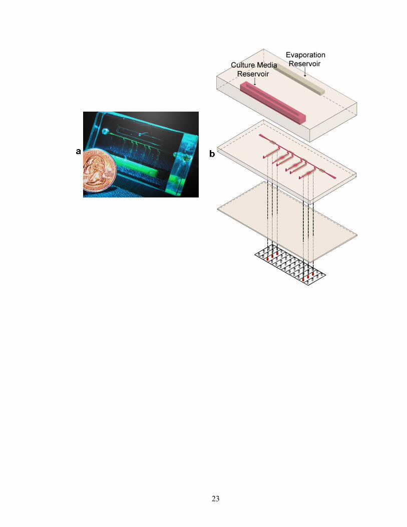
Figure II.1. Microfluidic device for EC culture and shearing. (a) Photograph of the device. (b) Three-dimensional schematic depicting the three-layer device fabrication placed on top of a grid of Braille pins. The approximate thickness of the top, middle, and bottom layers are 1 cm, 1 mm, and 100-200 μm respectively. The top layer contains two reservoirs: one to house cell culture media (‘culture media reservoir’) to be circulated and the other containing water (‘evaporation reservoir’) to assist in preventing evaporation within the microfluidic channels. The volume of both reservoirs is ~1 ml. The bottom layer serves as a thin membrane that provides the interface between the Braille pins and microfluidic channels of the middle layer.
22
23

Figure II.2. Demonstration of the microfluidic valves and pumps for cell culture. (a) Close-up of cells attached within an individual cellular compartment. The individual compartments are created by the Braille pins acting as valves which are depicted by the dark circles along the horizontal region of the channel. Each compartment is circulated by flow loops that actuate fluid independently of each other. Fluid in each flow loop can be actuated either clockwise by the small pump (dashed curved line and arrows) or counterclockwise by the large pump (solid curved line and arrows). Cells shown were cultured under cell shearing conditions for 12 h. (b) Step-wise depiction of the peristaltic pumping sequence comparing the small pump and large pump. Fluid is actuated through the channels in a pulsatile nature via a 3-pin, repeating 4-step peristaltic pumping sequence.22 In this particular pumping sequence, it is Step 2 or the step where the middle pin of the 3-pin pump moves from the down to the up position that drives most of the fluid in the forward direction. The other steps in the pumping sequence prime the pump to maximize volume displacement during Step 2. Increased shear stress levels are generated by the large pump by increasing the area of the channel that is positioned over the middle pin of the 3-pin pump reaching a maximum width equal to approximately the diameter of the Braille pin (1.3 mm). The pair of auxiliary dead-end channels that run parallel to fluidic channels act as void spaces to assist in deformation based actuation due to the Braille pins. These void space channels are of the same height as the fluidic channels due to them being fabricated concurrently during the backside diffused-light lithography process.23 (c) Comparison of pumping capabilities of small pump and large pump. The average flow rate (microliters/s) for the small pump (■) and the large pump (♦) were plotted against the pumping frequency (Hz). Error bars represent SEM (note: some of the values for SEM are at a value so small that the error bars do not extend beyond the boundary of the shapes at certain data points and are not visible) .
24

25
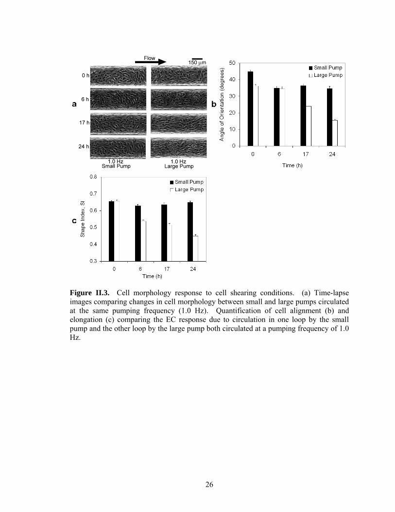
Figure II.3. Cell morphology response to cell shearing conditions. (a) Time-lapse images comparing changes in cell morphology between small and large pumps circulated at the same pumping frequency (1.0 Hz). Quantification of cell alignment (b) and elongation (c) comparing the EC response due to circulation in one loop by the small pump and the other loop by the large pump both circulated at a pumping frequency of 1.0 Hz.
26

Figure II.4. Morphological response of cells subjected to different levels of cell shearing conditions. Quantification of cell alignment (a) and elongation (b) comparing EC response in three loops due to circulation by the large pump circulated at frequencies of 0.25 Hz, 0.75 Hz, and 2.0 Hz respectively.
27

References
1. Jeon, N. L.; Baskaran, H.; Dertinger, S. K. W.; Whitesides, G. M.; Water, L. V. D.;
Toner, M. Nat. Biotechnol. 2002, 20, 826–830. 2. Takayama, S.; McDonald, J. C.; Ostuni, E.; Liang, M. N.; Kenis, P. J. A.; Ismagilov,
R. F.; Whitesides, G. M. Proc. Natl. Acad. Sci. USA. 1999, 96, 5545–5548. 3. Unger, M. A.; Chou, H.-P.; Thorsen, T.; Scherer, A.; Quake, S. R. Science. 2000, 288,
113-116. 4. Walker, G. M.; Zeringue, H. C.; Beebe, D. J. Lab Chip. 2004, 4, 91-97. 5. Chen, C. S.; Mrksich, M.; Huang, S. Whitesides, G. M.; Ingber, D. E. Science. 1997,
276, 1425-1428. 6. Borenstein, J. T.; Terai, H.; King, K. R.; Weinberg, E. J.; Kaazempur-Mofrad, M. R.;
Vacanti, J. P. Biomed. Microdev. 2002, 4, 167-175. 7. Tang, M. D.; Golden, A. P.; Tien, J. J. Am. Chem. Soc. 2003, 125, 12988-12989. 8. Bhatia, S. N.; Yarmush, M. L.; Toner, M. J. Biomed. Mater. Res. 1997, 34, 189-199. 9. Li, N.; Tourovskaia, A.; Folch, A. Crit. Rev. Biomed. Eng. 2003, 31, 423-488. 10. Gray, B. L.; Lieu, D. K.; Collins S. D.; Smith R. L.; Barakat A. I. Biomed. Microdev.
2002, 4, 9-16. 11. Fisher, A. B.; Chien, S.; Barakat, A. I.; Nerem, R. M. Am. J. Physiol. Lung Cell Mol.
Physiol. 2001, 281, L529-L533. 12. Davies, P. F. Physiol. Rev. 1995, 75, 519-560. 13. Hsai, T. K.; Cho, S. K.; Honda, H. M.; Hama, S.; Navab, M.; Demer, L. L.; Ho, C. M.
Ann. Biomed. Eng. 2002, 30, 646-656. 14. Helmlinger, G.; Geiger, R. V.; Schreck, S.; Nerem, R. M. J. Biomech. Eng. 1991,
113, 123-131. 15. Wojciak-Stothard, B.; Ridley, A. J. J. Cell Biol. 2003, 161, 429-439. 16. Helmlinger, G.; Berk, B. C.; Nerem, R. M. Am. J. Physiol. 1995, 269, 367-375. 17. Boo, Y. C.; Hwang, J.; Sykes, M.; Michell, B. J.; Kemp, B. E.; Lum, H.; Jo, H. Am. J.
Physiol. Heart Circ. Physiol. 2002, 283, H1819-28.
28

29
18. Garcia-Cardena, G.; Comander, J.; Anderson, K. R.; Blackman, B. R.; Gimbrone, Jr.,
M. A. Proc. Natl. Acad. Sci. USA. 2001, 98, 4478-4485. 19. Malek, A. M.; Gibbons, G. H.; Dzau, V. J.; Izumo, S. J. Clin. Invest. 1993, 92, 2013-
2021. 20. Girard, P. R.; Nerem, R. M. J. Cell. Physiol. 1995, 163, 179-193. 21. Blackman, B. R.; García-Cardena, G.; Gimbrone, Jr., M. A. J. Biomech. Eng. 2002,
124, 397-407. 22. Gu, W.; Zhu, X; Futai, N; Cho, B. S.; Takayama, S. Proc. Natl. Acad. Sci. USA. 2004,
101, 15861-15866. 23. Futai, N.; Gu, W.; Takayama, S. Adv. Mater. 2004, 16, 1320-1323. 24. Duffy, D. C.; McDonald, J. C.; Schueller, O. J. A.; Whitesides, G. M. Anal. Chem.
1998, 70, 4974-4984. 25. Zhu, X.; Mills, K. L.; Peters, P. R.; Bahng, J. H.; Liu, E. H.; Shim, J.; Naruse, K.;
Csete, M. E.; Thouless, M. D.; Takayama, S. Nat. Mater. 2005, 4, 403-406. 26. Loudon, C.; Tordesillas, A. J. Theor. Biol. 1998, 7, 63-78. 27. Wégria, R.; Frank, C. W.; Wang, H.; Lammerant, J. Circ. Res. 1958, 6, 624-632. 28. Levesque, M. J.; Nerem, R. M. J. Biomech. Eng. 1985, 107, 341-347.
CHAPTER III
Quantitative Real-time Imaging of Evaporation-mediated Responses of Endothelial Cells Under Sub-microliter Recirculation Culture
Compared to conventional cell cultures performed in Petri dishes with low cell
volume to extracellular fluid volume (CV/EV) ratios, microfluidic environments with
large CV/EV ratios have many advantages in terms of cellular self-conditioning of their
surrounding medium.1 Systems with large CV/EV ratios, however, typically also possess
large surface to volume (SAV) ratios which increases the rate of evaporation and presents
a challenge, particularly when using microfluidic devices made of water vapor permeable
materials such as poly(dimethylsiloxane) (PDMS). Although understanding and
preventing evaporation is generally important for microfluidic applications, it is
particularly crucial for sensitive mammalian cell culture applications where even
relatively small shifts in osmolality can drastically alter cell behavior.2-6 Here we provide
a practical solution that is demonstrated specifically for human dermal microvascular
endothelial cell (HDMEC) culture in microfluidics by utilizing a PDMS-parylene-PDMS
“hybrid” membrane. These membranes can prevent such evaporation to enable long-term
culture (~12h) of HDMCs under continuous recirculation of sub-microliter amounts of
fluid while also providing the mechanical flexibility needed to be compatible with
deformation-based microfluidic actuation systems and the optical clarity needed for cell
imaging. We also have expanded the capabilities of this system to include real-time
imaging of cellular response in the compartment of interest by customizing the actuation
30
system7 to fit on the stage of an inverted phase contrast microscope. The ability to
stabilize evaporation in PDMS chips compatible with pin actuator-based computer
controlled pumps and valves using the PDMS-parylene-PDMS “hybrid” membrane
expands the ability to perform convenient and versatile microfluidic cell culture
experiments where fluid circulation and exchange can be regulated to mimic the dynamic
culture environments in vivo or to manipulate reagents for long-term on-chip assays.
Experimental Section
Parylene deposition. For parylene coated PDMS, 2.5 or 5μm thick layer of
parylene C was deposited on the backside of PDMS membranes by using a PDS 2010
labcoater (Specialty Coating Systems) after covering the well side with a PDMS
membrane.
Device Fabrication for Microfluidic Endothelial Cell Culture. The
microfluidic device for endothelial cell (EC) culture was fabricated as was described
previously.8 Briefly, three layers of cured poly(dimethylsiloxane) (PDMS) at a ratio of
10:1 base to curing agent were sealed together irreversibly using plasma oxidation (SPI
supplies, West Chester, PA). Unless stated otherwise, the PDMS layers were cured
overnight at 60oC. The top of the three layers (~1 cm thick) contains a rectangular
shaped fluid reservoir (Figure 6a). The middle layer (~1 mm thick) consists of bell-
shaped channels features9 ~30 μm in height and 300 μm in width formed using soft
lithography.10 The channel features of the middle layer face downward and are sealed
31

against a thin membrane bottom layer which is the substrate for cell attachment. PDMS-
only thin membranes were fabricated by spin coating freshly mixed 1:10 PDMS onto
silanized (75 x 50 mm, 1mm thick) glass slides (Corning Glass Works, Corning, NY) to a
uniform thickness of either ~120 and 400 μm and then cured overnight at 120oC. For
experiments involving parylene coated membranes, the same PDMS-parylene-PDMS
hybrid thin membrane described above with a total uniform thickness of 200 μm was
used.
Fluid Actuation System. The computer-controlled Braille display fluid actuation
scheme is based on a design described previously7 with minor modifications to make the
system more compatible with inverted phase contrast microscopy.11 The Braille display
used (SC9; KGS, Saitama, Japan) was powered by a universal serial bus (USB) and
consisted of 8 actuation cells, each containing 8 piezoelectric Braille pins (8 × 8 = 64
pins).
Indium tin oxide (ITO) Heater. The ITO heater was constructed by an ITO layer
deposited on a glass slide with metallic films for electric contact. First, the glass slide
was masked using scotch tape to form the pattern for the ITO layer. An ITO with a
thickness of ~1500Å was coated on a 75x25x1 mm slide glass using radio frequency
sputtering (Enerjet Sputter) as shown in Figure III.1. This is followed by removing the
masking tapes and annealing the device in a 650oC convection oven for 1 hour. The
resulting sheet resistance of the annealed ITO layer is ~30 Ω/square. In order to
smoothly generate electric current through the ITO layer for uniform joule heating,two
32

aluminum strips (1 mm width and 2000Å thick) were patterned and coated in a similar
manner on two edges of the ITO layer. Electrical wires were attached to the aluminum
stripes using silver epoxy glue to form connections to external control circuits. A
commercially available wire thermocouple (5TC-TT-J; Newport, Santa Ana, CA) was
attached onto the heater surface for temperature sensing. All the wires were connected to
a microprocessor based temperature control unit (CT16A2088, Minco Products, Inc.,
Minneapolis, MN) for feedback control of the heater surface temperature. As a result, the
heater surface can be maintained constantly at desired temperature. The advantages of
this ITO heater are: 1) excellent optical transparency in visible light wavelength range, 2)
less image distortion than thin film heater.7, and 3) more uniform heating over large
areas.
General Endothelial Cell Culture. Human dermal microvascular endothelial
cells (HDMECs, Cambrex, East Rutherford, NJ) were cultured in endothelial growth
media-2 MV (EGM-2 MV, Cambrex) in T-25 culture flasks (Corning, Acton, MA) that
were placed in a humidified 5% CO2 cell culture incubator. The HDMECs were
collected by washing and detaching with 0.25% Trypsin/EDTA (Invitrogen, Carlsbad,
CA). The Trypsin solution was neutralized with 10% FBS in DMEM and spun down with
a centrifuge (ThermoForma, Marietta, OH) for 5 min, 4o C, 800 RPM. The supernatant
was removed and the pellet was resuspended in EGM-2 MV. The spin and resuspension
in EGM-2 MV was repeated to ensure removal of Trypsin which inhibits cell adhesion
during seeding.
33

Cell Seeding and Microfluidic Cell Culture. To facilitate cell attachment, the
channels were coated for 30-60 min at room temperature with 5-10 μl of human plasma
fibronectin (FN) solution (Invitrogen) at a concentration of 100 μg/ml PBS shortly after
plasma oxidation (5-10 min). The FN solution was introduced through holes punched
with a dermal biopsy puncher (Miltex Inc., York, PA) though the top and middle layer
prior to sealing with plasma oxidation to act as seeding ports by being compatible for use
with micropipette tips. After cell seeding (described below), the seeding ports were
covered with a sterilized glass slide to avoid contamination when present in non-sterile
conditions. After coating, the FN solution was rinsed for 10 minutes with PBS that was
pumped through the channels from the fluid reservoir. Afterwards, the device was
sterilized by placing under UV light for ~30 minutes. Following UV sterilization, PBS
was replaced with endothelial growth media-2 MV (EGM-2 MV, Cambrex, East
Rutherford, NJ) which is supplemented as a kit prior to use with 5% fetal bovine serum
(FBS) and a host of growth factors/supplements such as vascular endothelial growth
factor (VEGF). EGM-2 MV was circulated overnight for the serum proteins to coat the
PDMS surface along with FN to facilitate cell attachment. All reagents were added under
sterile conditions.
A small amount (3-5 μl) of a dense (~107 cells/ml) HDMEC suspension was
pipeted into the cell seeding port and introduced into fluidic regions defined by the
Braille pins acting as valves via gentle application of positive pressure. After the
HDMECs were seeded, all channels were valved to trap the cells and the PDMS chip and
the Braille display were placed in a 37oC/5% CO2 incubator to allow for the cells to
34

attach for 60-90 minutes. After the cells attach, EGM-2 MV culture media was circulated
from the fluid reservoir for the next 24-72 h until the cells reach confluence.
Recirculating Fluid Actuation. Experiments conducted with recirculation of
small amounts of fluid (~500 nl) were conducted on the stage of an inverted microscope
(Nikon TS-100F, Japan), imaged with a 10x Ph1 objective (Achromat), and recorded
using Coolsnap CF2 Camera with MetaVue software. To account for the lack of
controlled temperature and 5% CO2 tension provided by a cell culture incubator, the
bottom of the PDMS device was heated to 37oC (ITO heater, PID Temperature
Controller, Minco, Minneapolis, MN) and the culture media was specially formulated
with a synthetic buffer to maintain stable pH of ~7.3 under ambient conditions.7
Braille pins were reconfigured via computer-control such that flow can only occur
in the recirculation loop (Figure III.2a) due to complete valving. The initial amount of
fluid continuously recirculated was ~500 nl at a pumping frequency of 0.125 Hz. Images
were recorded at the intersection of the “X” towards the center of the microfluidic device
(Figure III.2a). The cell density was recorded for discrete time points and normalized to
the value at T=0. Cells were considered still alive if they remained attached and were
still moving (visualized with real-time microscopy). For PDMS-only membranes, two
experiments were performed in duplicates; for the Parylene membrane device, only one
experiment was performed.
35

Results and Discussion
Endothelial Cell Survival Under Recirculating Fluid Actuation. Using the
deformation-based fluid actuation described above that incorporates a PDMS-parylene-
PDMS hybrid membrane, we also tested sub-microliter recirculating culture of human
dermal microvascular endothelial cells (HDMEC) in a non-humidified environment with
on device heating. This type of capability is expected to be important for future studies
of the effect of autocrine and paracrine effects on endothelial cells under fluid perfusion
conditions.
Confluent monolayers of HDMECs were seeded and cultured within the
microfluidic device and imaged at the intersection of the “X” region (Figure III.2a).
Figure III.2b is a timelapse comparison of HDMEC survival under continuous
recirculation of ~500 nl of media with deformation-based Braille fluid actuation. The
experimental conditions were 120 μm thick, PDMS-only membrane (“thin PDMS”); 400
μm thick, PDMS-only membrane (“thick PDMS”); and 200 μm thick, PDMS-parylene
hybrid membrane (“hybrid”). At T = 40 (time given in min), virtually all the cells in the
visualized region for the “thin PDMS” membrane are dead and detached whereas the
cells for the “thick PDMS” and “hybrid” membranes remain confluent. At T = 80,
virtually all the cells for the “thin PDMS” and “thick PDMS” membranes are dead and
detached whereas the “hybrid membrane” still remains confluent.
36

The results were quantified by counting the changes in cell density with time due
to continuous recirculation (Figure III.2c). For the “thin PDMS” membrane, about 50
percent of the cells were dead and detached by about T = 25 (extrapolating from data in
Figure III.2c) and all of the cells were gone by T=50. For the “thick PDMS” membrane,
about 50 percent of the cells were dead and detached by T = 65 and all of the cells were
gone by T = 90. With the “hybrid” membrane, cells survive much longer under
continuous recirculation than the PDMS-only membranes. Cells remain roughly
confluent (>85 percent of the original cell density) up to T = 720 (or 12h). Afterwards,
cells begin to die more rapidly with 50 percent of the cells remaining alive and attached
at about T=800 (13.3h) and less than 5 percent at T = 1080 (18h) (Figure III.2c). By
comparing the times it takes for 50 percent of the cells to die, we conclude that cells are
able to survive about 2.6 times longer with the “thick PDMS” membrane compared to the
“thin PDMS” membrane. In addition, cells are able to survive about 29 times as long
with the “hybrid” membrane when compared with the “thin PDMS” membrane and 11
times as long when compared with the “thick PDMS” membrane. Thus, the integration
of parylene in the “hybrid” membrane substantially increases the time HDMECs survive
under continuous recirculation of ~500 nl of fluid even though at 200 μm, the “hybrid”
membrane is slightly thicker than the “thin PDMS” membrane (120 μm) and half as thick
as the “thick PDMS” membrane (400 μm).
37

Conclusion
Compared to conventional cell cultures performed in Petri dishes with low cell
volume to extracellular fluid volume (CV/EV) ratios, microfluidic environments with
large CV/EV ratios have many advantages in terms of cellular self-conditioning of their
surrounding medium.1 Systems with large CV/EV ratios, however, typically also possess
large surface to volume (SAV) ratios which increases the rate of evaporation and presents
a challenge, particularly when using microfluidic devices made of water vapor permeable
materials such as PDMS. Although understanding and preventing evaporation is
important for microfluidic applications generally, it is particularly crucial for sensitive
mammalian cell culture applications where even relatively small shifts in osmolality can
drastically alter cell behavior. Our study provides the following conclusions: 1) under
non-humidified conditions with heating, both the 120μm- and 400μm–PDMS bottom
membranes limit HDMEC survival to 25-65 minutes, and 2) PDMS-parylene-PDMS
“hybrid” membranes can prevent such evaporation while also providing the mechanical
flexibility needed to be compatible with deformation-based microfluidic actuation
systems and the optical clarity needed for cell imaging.
The better quantitative understanding of how the osmolality of cell culture media
changes in PDMS devices may be useful in accounting for and remedying such shifts in
culture or for application where changes in the osmolality of media in a controlled
manner during culture is necessary.12 The ability to stabilize evaporation in PDMS chips
compatible with pin actuator-based computer controlled pumps and valves using the
38

39
PDMS-parylene-PDMS hybrid membrane expands the ability to perform convenient and
versatile microfluidic cell culture experiments where fluid circulation and exchange can
be regulated to mimic the dynamic culture environments in vivo or to manipulate reagents
for long-term on-chip assays.

PDMS -100µm Parylene -2.5µm
ITO heater
PDMS -100µm
III
II.
I.
Figure III.1. Schematic representation of Braille display-based microfluidics. A typical design for Braille display-based microfluidics is composed of two layers: Upper bulk PDMS with microchannel and bottom membrane. To test the suitability of the parylene coated PDMS with Braille displays, bottom membrane consists of three layers: 100μm-PDMS, 2.5μm-parylene and 100um-PDMS. For cell culture an ITO heater, composed of a glass slide with ITO thin film (thickness about 1500Å) and aluminum electrodes (thickness about 2000Å) patterned on top of it, is placed underneath the membrane.
40

Figure III.2. Microfluidic device for HDMEC culture with recirculation. (a) View from the top schematic depicting the location of the Braille pins used for valving and pumping, microfluidic channels, and fluid reservoir. The fluid reservoir has a total volume of ~1 ml and completely surrounds the channel features like a picture frame to provide an unobstructed view of the cells seeded within the channels. Cut-away view shows the location of cells seeded towards the center of the device and recirculation loop with images recorded at the intersection of the “X.” (b) Qualitative data showing effects of evaporation on cell viability. Timelapse images for the three experimental conditions for thin membrane: 120 micron, PDMS-only (“thin PDMS,” ○), 400 micron, PDMS-only (“thick PDMS” □) and 200 micron, PDMS-parylene hybrid membrane (“hybrid” ◊). Time listed is in minutes. (c) Quantitative data describing effects of evaporation on cell viability. Cell density was normalized to values at T=0.
41

42
References
1. Walker, G. M.; Zeringue, H. C.; Beebe, D. J., Microenvironment design considerations for cellular scale studies. Lab Chip 2004, 4, (2), 91-7. 2. Hu, W. S.; Aunins, J. G., Large-scale mammalian cell culture. Curr Opin Biotechnol 1997, 8, (2), 148-53. 3. Lezama, R.; Diaz-Tellez, A.; Ramos-Mandujano, G.; Oropeza, L.; Pasantes-Morales, H., Epidermal growth factor receptor is a common element in the signaling pathways activated by cell volume changes in isosmotic, hyposmotic or hyperosmotic conditions. Neurochem Res 2005, 30, (12), 1589-97. 4. Moor, A. N.; Murtazina, R.; Fliegel, L., Calcium and osmotic regulation of the Na+/H+ exchanger in neonatal ventricular myocytes. J Mol Cell Cardiol 2000, 32, (6), 925-36. 5. Ozturk, S. S.; Palsson, B. O., Growth, metabolic, and antibody production kinetics of hybridoma cell culture: 1. Analysis of data from controlled batch reactors. Biotechnol Prog 1991, 7, (6), 471-80. 6. Wu, M. H.; Dimopoulos, G.; Mantalaris, A.; Varley, J., The effect of hyperosmotic pressure on antibody production and gene expression in the GS-NS0 cell line. Biotechnol Appl Biochem 2004, 40, (Pt 1), 41-6. 7. Futai, N.; Gu, W.; Song, J. W.; Takayama, S., Handheld recirculation system and customized media for microfluidic cell culture. Lab Chip 2006, 6, (1), 149-54. 8. Song, J. W.; Gu, W.; Futai, N.; Warner, K. A.; Nor, J. E.; Takayama, S., Computer-controlled microcirculatory support system for endothelial cell culture and shearing. Anal Chem 2005, 77, (13), 3993-9. 9. Futai, N.; Gu, W.; Takayama, S., Rapid prototyping of microstructures with bell-shaped cross-sections and its application to deformation-based microfluidic valves. Advanced Materials 2004, 16, (15), 1320-+. 10. Duffy, D. C.; McDonald, J. C.; Schueller, O. J. A.; Whitesides, G. M., Rapid prototyping of microfluidic systems in poly(dimethylsiloxane). Analytical Chemistry 1998, 70, (23), 4974-4984. 11. Mehta, G.; Mehta, K.; Sud, D.; Song, J. W.; Bersano-Begey, T.; Futai, N.; Heo, Y. S.; Mycek, M. A.; Linderman, J. J.; Takayama, S., Quantitative measurement and control of oxygen levels in microfluidic poly(dimethylsiloxane) bioreactors during cell culture. Biomed Microdevices 2007, 9, (2), 123-34.
43

44
12. Hay-Schmidt, A., The influence of osmolality on mouse two-cell development. J Assist Reprod Genet 1993, 10, (1), 95-8.
Chapter IV
Engineered Compartmentalized Microfluidic Endothelium for Studying the Intravascular Adhesion of Metastatic Breast Cancer Cells
The ability to properly model the intravascular steps in metastasis is essential in
identifying key physical, cellular, and molecular determinants that can be targeted
therapeutically to prevent metastatic disease1-4. Research on the vascular
microenvironment has been hindered by challenges in studying this compartment in
metastasis under conditions that reproduce in vivo physiology while allowing facile
experimental manipulation. Here we present a compartmentalized microfluidic
vasculature system to model interactions between circulating cancer cells with vascular
endothelium at potential sites of metastasis. The microfluidic vasculature is designed to
produce spatially-restricted stimulation with pro-inflammatory cytokines, chemokines, or
chemokine receptor inhibitors that model organ-specific localization of specific
signalling molecules in vivo under variable flow conditions. Using this system to
produce selective stimulation with CXCL12, a chemokine strongly implicated in
metastasis5-8, we established that activated endothelial cells confer site-specific adhesion
of circulating cancer cells independent of CXCR4 or CXCR7 receptors on tumor cells.
This combination of microfluidic technology with cancer biology provides a unique
physiologic system to reproduce the intravascular microenvironment in metastasis and
elucidate new cellular and molecular targets for cancer therapy.
45

Metastatic disease is the cause of death in approximately 90% of patients with
solid tumors9, emphasizing that preventing and/or effectively treating metastases is the
primary obstacle to curing cancer. Trafficking of cancer cells through the circulation and
arrest of these cells at secondary sites are obligatory steps in metastasis. Specific
molecular interactions between circulating cancer cells and vascular endothelium are
proposed to control organ-specific patterns of metastasis for breast10, lung8, and other
common solid cancers11, but our knowledge of these signals is lacking. In particular, the
chemokine CXCL12 is proposed to promote tropism of malignant breast7, lung8, and
other cancer cells for characteristic sites of metastatic disease, which has been attributed
predominantly to signalling through the receptor CXCR4 on cancer cells. However,
mechanisms of action for CXCL12 in metastasis also may be regulated through CXCR4
on vascular endothelium12 and/or CXCR713, a newly identified second receptor for
CXCL1214.
Here, we present a systematic study using a compartmentalized microfluidic
vasculature together with genetically engineered cancer cells to establish effects of
CXCR4 versus CXCR7 on both the endothelium and cancer cells. The results show that
with compartmentalized extravascular stimulation of the endothelium, activation of
CXCR4 and possibly CXCR7 on endothelial cells can play significant roles in promoting
cancer cell adhesion regardless of presence of these receptors on cancer cells. These
results clarify the role of CXCL12 in the intravascular steps of metastasis and provide
insights for identifying therapeutic targets to block metastasis. The results also highlight
46

the versatility and utility of the microfluidic vasculature system to enable studies, such as
compartmentalized extravascular stimulation of select regions of an endothelium, that
would be too complex, non-physiological or too expensive to perform using conventional
in vivo 15, 16 or in vitro assay systems.
The microfluidic vasculature is comprised of two poly(dimethysiloxane) (PDMS)
layers sandwiching a thin, porous, and optically clear polyester membrane (Fig. 1a). The
top PDMS layer features a channel with a funnel–shaped inlet that intersects regionally
distinct, perpendicularly-oriented channels in the bottom PDMS layer (Fig. 1b, c). The
top channel (60 μm height, 800 μm width) contains a confluent monolayer of human
dermal microvascular endothelial cells (HDMECs) (Fig. 1e) cultured on a thin polyester
membrane with 400 nm pores that permits the transport of biomolecules but not cells
between the top and bottom channels. The regions of the top channel that intersect one of
the bottom channels (60 μm height) are referred to as either the upstream or downstream
compartment (Figs. 1c-e), depending on the location relative to the funnel-shaped inlet.
The region between the upstream and downstream compartments with no lower channel
is referred to as the middle compartment. The dimensions of each compartment are 4400
μm (or 4.4 mm) long by 800 μm wide.
Endothelial cells in the upstream and downstream compartment can be region
selectively treated with biomolecules from the lower channels. We observed that staining
47

of a confluent endothelium with Syto 64 remains well-defined within the desired
compartments for at least 5.5 hours (Fig. 1d). Furthermore, we observed statistically
greater adhesion of circulating MDA-MB-23117 (or 231-control) breast cancer cells onto
the endothelial compartment treated with the pro-inflammatory cytokine TNF-α
compared to the untreated endothelial compartment at shear stress levels of 0.50 dyn/cm2
and 2.50 dyn/cm2 (Fig. 1 f-h) (p < 0.02). The spatial control afforded by the system
enabled direct comparison of cancer cell adhesion onto stimulated versus non-stimulated
regions of endothelium. We note that in our system, the shear stress levels of 0.50
dyn/cm2 and 2.50 dyn/cm2 correspond with flow velocities of 0.2 mm/s and 1.0 mm/s
respectively. These velocities are in line with the in vivo blood flow velocity range of
0.1-1.5 mm/s reported in the microcirculation of potential sites of breast cancer
metastasis18-20 In addition, integrins on the surface of circulating cells are reported to
optimally mediate adhesion onto endothelium at shear stress levels below 0.5 dyn/cm2
with the avidity decreasing rapidly with higher shear stress levels 21. .
We utilized the ability to region selectively stimulate the endothelium in our
microfluidic system to recreate the local stimulation with CXCL12 of tissues that are
common sites for metastatic breast cancer in vivo7. The experiments address an under-
studied topic on how CXCL12 and receptors CXCR4 and CXCR7 on vascular
endothelium, rather than on cancer cells, may be key determinants in the intravascular
adhesion step of metastasis. CXCL12 signaling in endothelium is known to upregulate
and activate adhesion molecules, promoting stable interactions with circulating cells22.
We specifically characterized the responses of the described endothelial cells (HDMECs)
to CXCL12 and TNF-α. These cells are isolated from skin, a tissue with low metastatic
48

potential for breast cancer10, and facilitate low amounts of adhesion of cancer cells under
unstimulated conditions23. Under basal culture conditions, HDMECs express low levels
of CXCR4 and no CXCR7 mRNA (Fig 3a). When treated with CXCL12 (100 ng/ml, 5h)
HDMECs increase expression of CXCR4 but continue to not express CXCR7. When
treated with TNF-α (50 ng/ml, 5h), relative to basal conditions, endothelial cells increase
expression of CXCR4 and also express CXCR7. CXCL12 initiates signaling in
HDMECs as evidenced by activation of AKT (Fig. 2b), a known downstream effector of
CXCR424 and potentially CXCR725.
Next, we evaluated how CXCL12 and TNF-α stimulation of HDMECs
independently or cooperatively modulate adhesion of 231-control breast cancer cells onto
the endothelium. We compared the following combinations: 1) CXCL12 only, 2)
CXCL12+AMD3100 (a competitive inhibitor of CXCR426), 3) CXCL12 + TNF-α, 4)
CXCL12 + TNF-α + AMD3100, and 5) TNF-α only (Fig. 2c, d). The levels of 231-
control breast cancer cell adhesion onto the five different treatment conditions were
significantly different (p < 0.05) for both the 0.50 dyn/cm2 and 2.50 dyn/cm2 flow
conditions (Fig. 2c, d). Conversely, the levels of cancer cell adhesion onto the five
corresponding untreated endothelium were statistically the same (p > 0.85) for both flow
conditions. With the exception of the CXCL12+AMD3100 condition, adhesion of 231-
control cancer cells was significantly greater onto each of the treated compartments than
onto the corresponding untreated compartments for both flow conditions (Fig.2c, d) (p <
0.05). Treatment of endothelium with both CXCL12 + TNF-α produced additive
49

increases in adhesion of circulating 231-control cells relative to CXCL12 only and TNF-
α only treated endothelium under both flow conditions (Fig. 3c, d). These results suggest
that each cytokine enhances cancer cell adhesion through independent mechanisms.
To determine to what extent effects of CXCL12 on endothelium are mediated
through CXCR4, we used AMD3100, a specific inhibitor of CXCL12 binding to CXCR4
but not CXCR7. When added to the downstream compartment, AMD3100 completely
blocked CXCL12-dependent increases in cancer cell adhesion to stimulated endothelium
under 0.50 and 2.50 dyn/cm2 flow conditions (Fig. 2c, d) (p < 0.05). Adding AMD3100
to CXCL12 and TNF-α also decreased adhesion of 231-control cells by a comparable
percentage as the combination of AMD3100 and CXCL12 alone (Fig. 2c, d), suggesting
that AMD3100 was selectively blocking adhesion mediated solely through CXCL12 but
not TNF-α (p < 0.05). Collectively, these data with the specific chemical probe
AMD3100, combined with absence of CXCR4 in 231-control cells (Fig. 3a), indicate that
CXCL12 signals through endothelial CXCR4 to promote adhesion of circulating breast
cancer cells.
Previous reports have shown that CXCR4 expression in cancer cells promotes
metastasis to distant organs such as the lung7, 27 and that CXCR7 expression in cancer
cells enhances adhesion onto endothelium under static conditions14. We compared the
231-control cells to other MDA-MB-231 cells stably co-expressing GFP with either
50

CXCR4 (231-CXCR4) or CXCR7 (231-CXCR7) (Fig. 3a) to assess the role of these
CXCL12 chemokine receptors on cancer cells in mediating adhesion onto endothelium
under flow. The level of adhesion of all three cancer cell-types onto CXCL12 treated
endothelium was significantly greater than onto the corresponding untreated endothelium
under 0.50 dyn/cm2 flow conditions (p < 0.05) (Fig. 3b). Comparing the three different
cancer cell lines, adhesion of 231-CXCR4, 231-CXCR7, and 231-control cells was
statistically different onto both the CXCL12 treated and the untreated endothelium (p <
0.01). Comparing pairwise, adhesion of the 231-CXCR4 and 231-CXCR7 cells was
statistically greater than the 231-control cells on both the CXCL12 and untreated
endothelium (p < 0.05). However, median ratios of cells adhering onto the CXCL12
treated endothelium relative to untreated endothelium were 1.9, 1.9, and 2.1 for the 231-
CXCR4, 231-CXCR7, and 231-control cells, respectively (Fig. 3c). These ratios are
statistically the same among the cell lines (p = 0.83). Therefore, although CXCR4 or
CXCR7 expression in breast cancer cells facilitates adhesion onto endothelium, the
enhancement of adhesion due to CXCL12 stimulation of the endothelium was
comparable for all three cancer cell-types and independent of expression of CXCR4 or
CXCR7 on cancer cells.
Herein we have described a microfluidic system that models, in a compact format,
serial interactions of circulating cancer cells with vascular endothelium at metastatic and
non-metastatic sites. The system represents advancement over previously described in
vitro assay systems in that it possesses a unique blend of: 1) prolonged, basally
51

originating CXCL12 stimulation of vascular endothelium that models both the high levels
and directionality of this chemokine characteristic of target organs for metastatic breast
and many other cancers7; 2) compartment specific stimulation enabling direct comparison
of cancer cells adhesion onto endothelium of differing metastatic potential within the
same experiment; and 3) physiologically-relevant flow conditions in micron-scale
channels.
Using this system, we demonstrate that CXCL12 stimulation of HDMECs enhances
adhesion of circulating breast cancer cells, regardless of expression of chemokine
receptors CXCR4 or CXCR7 on the cancer cells. These results indicate that responses of
vascular endothelium to the surrounding molecular environment contribute substantially
to intravascular adhesion of cancer cells, a phenomenon difficult to address with in vivo-
studies. We also show that CXCR4 or CXCR7 on breast cancer cells promotes
intravascular adhesion throughout the channel, supporting a mechanism through which
these receptors promote metastasis under physiological flow conditions14, 27.
Furthermore, AMD3100, a specific inhibitor of CXCR4 signaling26, when applied to the
endothelium can significantly reduce adhesion of cancer cells not expressing CXCR4
(Fig. 2c, d). Taken together, these data suggest that inhibiting chemokine receptors on
endothelial cells may be of equal or greater importance for preventing initial steps of
intravascular cancer cell adhesion as compared with targeting these receptors on cancer
cells.
52

While we have focused on circulating cancer cells, this microfluidic system is a
versatile platform for studying other intravascular processes, such as trafficking and
adhesion of immune cells under physiological or pathological conditions. In addition,
since the described system is rooted in microfabrication technology, we have established
a system that can be parallelized for high-throughput experiments. By combining the
convenience and cost-effectiveness of in vitro cell culture with key physical, cellular, and
molecular components of the in vivo vasculature, we expect this new technology will
accelerate studies of the intravascular microenvironment in metastatic cancer and
development of new therapies to block this key step in metastasis.
Methods
Device fabrication. The microfluidic device (Fig. IV.1a) consisted of two channel layers
of 12:1 base to curing agent poly(dimethylsiloxane) (PDMS, Sylgard 184, Dow Corning)
that sandwiched a semi-porous, optically clear polyester membrane28. The layers were
sealed together using a very thin (~10 μm) and uniform PDMS/toluene glue that provided
robust, leakage-free sealing29. The top and bottom PDMS layers were molded as
previously described28 except the top layer featured a funnel –shaped inlet that was
molded to intersect the inlet of the top channel (Fig. IV.1a). After the device was
assembled, tubing was attached to the outlet of the top channel and to the inlets of the
bottom channels using epoxy. Subsequently, the devices were treated with plasma
oxygen (SPI Supplies, West Chester, PA) for 10 min to reduce hydrophobicity of
surfaces. Immediately afterwards, the top channel was coated with a fibronectin solution
53

(10 μg/ml PBS, 3h, 37oC). Prior to cell seeding, the device was sterilized by placing
under UV light for ~ 30 min.
Endothelial cell culture and seeding. Human dermal microvascular cells (HDMECs,
Lonza) passage numbers 6-8 were cultured in EBM-2 + 5% FBS + SingleQuot® kit
(supplements such as VEGF, bFGF, etc) or EGM-2 MV (Lonza). A concentrated
solution of HDMECs (~107 cells/ml EGM-2 MV) were loaded into the funnel-shaped,
allowed to attach along the entire length of the top channel, and grown to confluence (24-
48 h after seeding).
CXCR7 and CXCR4 expression in MDA-MB-231 human breast cancer cells.
Human MDA-MB-231 breast cancer cells (ATCC) were cultured in DMEM + 10% FBS
+ 1% L-glutamine + 0.5% penicillin/streptomycin. Lentiviral vectors for CXCR4-GFP,
CXCR7, or GFP control (Fig.3) were used to stably transduce MDA-MB-231 cells to
create the described 231-CXCR4, 231-CXCR7, or 231-control cells respectively.
Chemokine receptor expression in the 231-CXCR4, 231-CXCR7 cells, and 231-control
cells were verified by flow cytometry (Fig. IV.3a).
RT-PCR. Endothelial cells were cultured in EBM-2 + Single®Quots with TNF-α (50
ng/ml), CXCL12 (100 ng/ml), or vehicle control for 5 hours. Total RNA was prepared
using Trizol reagent (Invitrogen) according to the manufacturer’s protocol. RNA was
54

purified further over an RNA extraction column (Qiagen), including on-column treatment
with DNaseI. RT-PCR was performed using a two-step kit (ThermoScript, Invitrogen).
Sequences of PCR primers were the following:
CXCR4: 5’-ACGGACAAGTACAGGCTGCAC-3’ and 5’-
CCCAGAAGGGAAGCGTGA-3’
CXCR7:5’-AAGAAGATGGTACGCCGTGTCGTCTC-3’ and 5’-
CTGCTGTGCTTCTCCTGGTCACTGGA-3’
GAPDH: 5’-GAAGGTGAAGGTCGGAGT-3’ and 5’-
GAAGATGGTGATGGGATTTC-3’
Western Blot. 231 breast cancer cells were cultured overnight in DMEM medium
containing 0.5% serum. Breast cancer cells then were treated with 100 ng/ml CXCL12
(R&D Systems) for 3 or 10 minutes, respectively. Human dermal microvascular
endothelial cells were cultured in EBM-2 + Single®Quots and treated with 100 ng/ml
CXCL12 for 10 minutes or 5 hours, respectively. Total cell lysates were harvested and
prepared for Western blotting as described previously30. Primary antibodies to AKT
phosphorylated at serine 473 and total AKT (Cell Signaling) were used at 1:500 dilution,
and a secondary anti-rabbit antibody conjugated with horseradish peroxidase was used at
1:2000 dilution. Western blots were developed with ECL reagent (Amersham).
55

Calculation of shear stress levels. The shear stress levels on the cells within the
channels were modeled with the following equation31, 32:
2295.26
hQ D−×
=μ
τ (1)
Where τ is the shear stress on the cells, μ is the viscosity of the fluid (water = 0.01
dyn/cm2), Q2-D is the flow rate per width in the system and h is the height of the channel.
This equation is valid for cases where the width is much larger than the height. In our
system, the height of the channels was 60 μm and the width was 800 μm.
Flow-based intravascular adhesion experiments. Prior to each experiment, the EGM-2
MV culture in the funnel-inlet of the microfludic device was removed, washed with PBS,
and replaced with EBM-2 + Single®Quots. Subsequently, the top channel was washed
with EBM-2 + Single®Quots by gravity flow. Concurrently, the bottom channels were
triple washed with PBS and replaced with either EBM-2 + Single®Quots (untreated) or
EBM-2 +Single®Quots + cytokine or chemokine of interest (treated). The flow in the
top channel was stopped and the device was left to be treated for 5 h. Concurrently,
culture flasks of the 231 breast cancer cells were washed with PBS and serum starved in
EBM-2 + 0.5% FBS for 5 h as well. After serum starvation, the breast cancer cells were
collected using citric saline, a calcium ion chelator, instead of trypsin to ensure cell
surface proteins remain intact. The cancer cells were centrifuged twice and resuspended
in EBM-2 + 0.5% FBS at a concentration of 2 x 10⁶ cells/ml). The cancer cell suspension
56

57
was loaded into the funnel-shaped inlet. Flow was controlled using a programmable
syringe pump that withdraws fluid away from the funnel-shaped inlet at flow rates
corresponding with either 0.50 dyn/cm2 or 2.50 dyn/cm2. The microfluidic device was
placed on the stage of an epi-fluorescence, inverted microscope (Nikon, TE-300). The
duration of each experiment was 30 min with images were recorded every 3 min and
movies 1 min in duration recorded every 10 min. For the 0.50 dyn/cm2 experiments, the
top channel was washed for 1 min at shear stress levels of 8 dyn/cm2. To determine cell
counts, fluorescent cells in the entire compartment were counted blindly and treated as
one data point.
Statistical analysis. Sample populations were compared either pairwise using the Mann-
Whitney U test or in groups of more than two using the Kruskal-Wallis test. These tests
are nonparametric and do not require an underlying normal distribution. p < 0.05 was the
threshold for statistical significance.

Figure IV.1: Microfluidic vasculature device enabling compartment specific activation of endothelium.
(a) Schematic of the poly(dimethysiloxane) (PDMS) microfluidic device demonstrating multi-layer fabrication with a thin, porous polyester membrane sandwiched by the top and bottom PDMS layers.
(b) Photograph of the microfluidic device loaded with different colored dye to distinguish between the top channel and the two bottom channels.
(c) Top view of the microfluidic device. During flow-based experiments, fluid is withdrawn away from the funnel-shaped inlet and through the top channel with a programmable syringe pump (see Methods).
(d) Validation of region-specific stimulation of endothelium. The upstream and downstream lower channels were filled with 25 μM Syto 64, a fluorescent dye that stains cells. HDMECs overlying the upstream and downstream bottom channels, but not HDMECs in the middle of the channel fluoresce. Fluorescence was evident within 15 minutes, remained spatially-restricted for at least 5.5 hours, and persisted after 30 minutes of flow through the top channel. Image shows 5.5 hours after initial treatment. Scale bar represents 800 μm.
(e) Phase contrast image of HDMECs cultured in the microfluidic device. The image depicts the entire length of the endothelium with the upstream, middle, and downstream compartments clearly demarcated from each other. Scale bar represents 800 μm.
(f) Representative fluorescent images of adhesion of 231-control cells (stably expressing GFP) onto region-specific TNF-α treated endothelium under 0.50 dyn/cm2 shear stress flow conditions. In these images, the downstream compartment was treated with TNF-α (50 ng/ml for 5h) and denoted in the image with a ‘+’ while the upstream and middle compartments were left untreated. Scale bar represents 200 μm.
(g) Quantitative analysis of 231-control cell adhesion under 0.50 dyn/cm2 shear stress flow conditions. The inflammatory cytokine TNF-α was applied to either the upstream or downstream compartment (denoted by a ‘+’) while the other compartment in the same device was left untreated. Significantly greater numbers of cells adhered to the TNF-α treated compartment versus the untreated compartment (p < 0.01) (n = 3 each for upstream or downstream treated conditions).
(h) Quantitative analysis of 231-control cell adhesion under 2.50 dyn/cm2 shear stress flow conditions. TNF-α was applied to either the upstream or downstream compartment (denoted by a ‘+’) with the other compartments in the same device left untreated. Cancer cell adhesion in the TNF-α treated compartment was significantly greater than the untreated compartment (p < 0.01) (n = 3 each for upstream or downstream treated conditions. Data are expressed as the mean + SEM.
58

59

Figure IV.2: Region selective treatment of the microfluidic endothelium with combinations of cytokines and inhibitors under two different flow conditions.
(a) Chemokine receptor expression in HDMECs determined by reverse transcription
PCR (RT-PCR). HDMECs show expression of CXCR4 but not CXCR7 under basal conditions. CXCL12 upregulates CXCR4 but not CXCR7. TNF-α upregulates CXCR4 and results in expression of CXCR7. RT-PCR for the housekeeping gene GAPDH confirms equivalent loading and intact RNA for all samples.
(b) CXCL12 activates AKT in endothelium. HDMECs were incubated with 100 ng/ml CXCL12 for 10 minutes or 5 hours. Control cells were incubated with BSA alone. Cell lysates were probed for phosphorylation of serine 473, and then blots were stripped and re-probed for total AKT. There is CXCL12-dependent activation of AKT that remains greater than control endothelium through 5 hours.
(c) 231-control cancer cell adhesion onto endothelium treated with different combinations of CXCL12 (100 ng/ml), TNF-α (50 ng/ml), and the CXCR4 inhibitor AMD3100 (80 ng/ml) for 5 hours under 0.50 dyn/cm2 flow conditions. Each of the treated compartments (left four columns) was matched by color and with its corresponding untreated compartment (right four columns). Cell adhesion onto each treated compartment was compared to its corresponding untreated compartment (*, p < 0.05). Comparing the five treated compartments, the levels of adhesion were statistically different (**, p < 0.05). Conversely, for the untreated compartments, the levels of adhesion were statistically the same (#, p = 0.85). AMD3100 in the presence of CXCL12 decreased adhesion by 34% relative to the CXCL12 only condition. AMD3100 in the presence of CXCL12 and TNF-α decreased adhesion 42% relative to CXCL12 + TNF-α. ***, p < 0.05. n = 4-6 for each condition.
(d) Same as (c) except under 2.50 dyn/cm2 flow conditions. (*, p < 0.05; **, p < 0.01; #, p = 0.97; ***, p < 0.05). Data are expressed as mean +SEM. n = 4-6 for each condition.
60

61

Figure IV.3: CXCL12 stimulated endothelium enhances adhesion of breast cancer cells.
(a) Flow cytometry with antibodies to CXCR4 (12G5) or CXCR7 (11G8) shows expression in appropriate cell lines and absence of these receptors in pSico control cells. Open symbol, isotype antibody control; filled yellow, antibody stain.
(b) CXCL12-dependent activation of AKT in 231-CXCR4 cells. Breast cancer cell lines were cultured overnight in medium containing 0.5% serum and then treated with 100 ng/ml CXCL12. Cell lysates were probed for phosphorylation of AKT at serine 473. Blots then were stripped and probed for total AKT as a loading control
(c) Compartmentalized adhesion of 231-CXCR4, 231-CXCR7, and 231-control cancer cells onto CXCL12 treated versus untreated endothelium under 0.50 dyn/cm2 shear flow conditions. For all three cancer cell-types, the level of adhesion onto the CXCL12 treated endothelial compartment was significantly greater than onto the corresponding untreated compartment (*, p < 0.05). The level of adhesion of the three different cancer cell-types was statistically different on both the CXCL12 treated and untreated endothelial compartments (**, p < 0.01). Data are expressed as mean + SEM. n = 6 for all three cell-types.
(d) Boxplot representing the ratio of the levels of adhesion of cancer cells onto the CXCL12 treated endothelial compartment over the untreated compartment. Adhesion to CXCL12-stimulated endothelium was enhanced to a comparable extent for all cell lines, independent of expression of CXCR4 or CXCR7. #, p = 0.83.
62

63
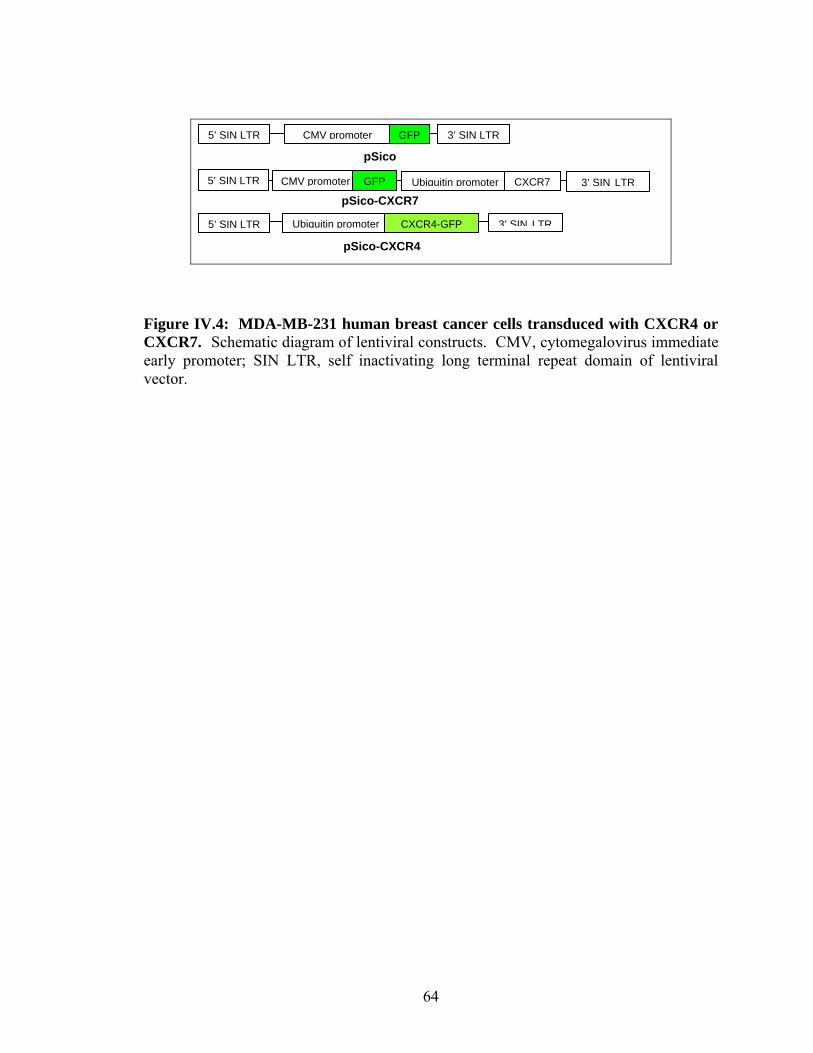
pSico-CXCR4
pSico
3’ SIN LTR CMV promoter
pSico-CXCR7
5’ SIN LTR 3’ SIN LTRCXCR4-GFPUbiquitin promoter
5’ SIN LTR CXCR7Ubiquitin promoterGFP
3’ SIN LTR5’ SIN LTR GFPCMV promoter
Figure IV.4: MDA-MB-231 human breast cancer cells transduced with CXCR4 or CXCR7. Schematic diagram of lentiviral constructs. CMV, cytomegalovirus immediate early promoter; SIN LTR, self inactivating long terminal repeat domain of lentiviral vector.
64

References
1. 1. Bockhorn, M., Jain, R.K. & Munn, L.L. Active versus passive mechanisms in metastasis: do cancer cells crawl into vessels, or are they pushed? Lancet Oncology 8, 444-448 (2007).
2. Murphy, P.M. Chemokines and the molecular basis of cancer metastasis. New
England Journal of Medicine 345, 833-835 (2001). 3. Sahai, E. Illuminating the metastatic process. Nature Reviews Cancer 7, 737-749
(2007). 4. Woodhouse, E.C., Chuaqui, R.F. & Liotta, L.A. General mechanisms of
metastasis. Cancer 80, 1529-1537 (1997). 5. Ali, S. & Lazennec, G. Chemokines: novel targets for breast cancer metastasis.
Cancer and Metastasis Reviews 26, 401-420 (2007). 6. Luker, K.E. & Luker, G.D. Functions of CXCL12 and CXCR4 in breast cancer.
Cancer Letters 238, 30-41 (2006). 7. Muller, A. et al. Involvement of chemokine receptors in breast cancer metastasis.
Nature 410, 50-56 (2001). 8. Phillips, R.J. et al. The stromal derived factor-1/CXCL12-CXC chemokine
receptor 4 biological axis in non-small cell lung cancer metastases. American journal of respiratory and critical care medicine 167, 1676-1686 (2003).
9. Nguyen, D.X. & Massague, J. Genetic determinants of cancer metastasis. Nature
Reviews Genetics 8, 341-352 (2007). 10. Weigelt, B., Peterse, J.L. & van't Veer, L.J. Breast cancer metastasis: Markers and
models. Nature Reviews Cancer 5, 591-602 (2005). 11. Fidler, I.J. Critical determinants of metastasis. Seminars in Cancer Biology 12,
89-96 (2002). 12. Gupta, S.K., Lysko, P.G., Pillarisetti, K., Ohlstein, E. & Stadel, J.M. Chemokine
receptors in human endothelial cells - Functional expression of CXCR4 and its transcriptional regulation by inflammatory cytokines. Journal of Biological Chemistry 273, 4282-4287 (1998).
13. Mazzinghi, B. et al. Essential but differential role for CXCR4 and CXCR7 in the
therapeutic homing of human renal progenitor cells. The Journal of experimental medicine 205, 479-490 (2008).
65

14. Burns, J.M. et al. A novel chemokine receptor for SDF-1 and I-TAC involved in
cell survival, cell adhesion, and tumor development. Journal of Experimental Medicine 203, 2201-2213 (2006).
15. Feng, D., Nagy, J.A., Dvorak, H.F. & Dvorak, A.M. Ultrastructural studies define
soluble macromolecular, particulate, and cellular transendothelial cell pathways in venules, lymphatic vessels, and tumor-associated microvessels in man and animals. Microscopy Research and Technique 57, 289-326 (2002).
16. McDonald, D.M. & Choyke, P.L. Imaging of angiogenesis: from microscope to
clinic. Nature Medicine 9, 713-725 (2003). 17. Cailleau, R., Olive, M. & Cruciger, Q.V. Long-term human breast carcinoma cell
lines of metastatic origin: preliminary characterization. In vitro 14, 911-915 (1978).
18. Chaigneau, E., Oheim, M., Audinat, E. & Charpak, S. Two-photon imaging of
capillary blood flow in olfactory bulb glomeruli. Proc Natl Acad Sci U S A 100, 13081-13086 (2003).
19. Desjardins, C. & Duling, B.R. Heparinase treatment suggests a role for the
endothelial cell glycocalyx in regulation of capillary hematocrit. The American journal of physiology 258, H647-654 (1990).
20. Jorneskog, G., Brismar, K. & Fagrell, B. Skin capillary circulation severely
impaired in toes of patients with IDDM, with and without late diabetic complications. Diabetologia 38, 474-480 (1995).
21. Konstantopoulos, K., Kukreti, S. & McIntire, L.V. Biomechanics of cell
interactions in shear fields. Advanced Drug Delivery Reviews 33, 141-164 (1998). 22. Kryczek, I. et al. CXCL12 and vascular endothelial growth factor synergistically
induce neoanglogenesis in human ovarian cancers. Cancer Research 65, 465-472 (2005).
23. Murakami, T. et al. Expression of CXC chemokine receptor-4 enhances the
pulmonary metastatic potential of murine B16 melanoma cells. Cancer Res 62, 7328-7334 (2002).
24. Kanda, S., Mochizuki, Y. & Kanetake, H. Stromal cell-derived factor-1alpha
induces tube-like structure formation of endothelial cells through phosphoinositide 3-kinase. The Journal of biological chemistry 278, 257-262 (2003).
66

67
25. Wang, J. et al. The role of CXCR7/RDC1 as a chemokine receptor for CXCL12/SDF-1 in prostate cancer. The Journal of biological chemistry 283, 4283-4294 (2008).
26. Hatse, S., Princen, K., Bridger, G., De Clercq, E. & Schols, D. Chemokine
receptor inhibition by AMD3100 is strictly confined to CXCR4. Febs Letters 527, 255-262 (2002).
27. Cardones, A.R., Murakami, T. & Hwang, S.T. CXCR4 enhances adhesion of B16
tumor cells to endothelial cells in vitro and in vivo via beta(1) integrin. Cancer Research 63, 6751-6757 (2003).
28. Huh, D. et al. Acoustically detectable cellular-level lung injury induced by fluid
mechanical stresses in microfluidic airway systems. Proc Natl Acad Sci U S A 104, 18886-18891 (2007).
29. Chueh, B.H. et al. Leakage-free bonding of porous membranes into layered
microfluidic array systems. Analytical Chemistry 79, 3504-3508 (2007). 30. Luker, K.E., Pica, C.M., Schreiber, R.D. & Piwnica-Worms, D. Overexpression
of IRF9 Confers Resistance to Antimicrotubule Agents in Breast Cancer Cells. Cancer Res 61, 6540-6547 (2001).
31. Farokhzad, O.C. et al. Microfluidic System for Studying the Interaction of
Nanoparticles and Microparticles with Cells. Anal. Chem. 77, 5453-5459 (2005). 32. Gaver, D.P., III & Kute, S.M. A Theoretical Model Study of the Influence of
Fluid Stresses on a Cell Adhering to a Microchannel Wall. Biophys. J. 75, 721-733 (1998).
CHAPTER V
Conclusion and Future Work
Development of in vitro-based systems that properly model the mechanical and
chemical environments of endothelial cells is necessary for advancing the understanding
of vascular biology and medicine. This dissertation research contributed to the field of
vascular biology by utilizing a microfluidic and microfabrication approach in improving
upon the current state of the art of conventional in vitro-based systems. Microfluidic
systems provide the capabilities to properly mimic the mechanical and chemical
environments of endothelial cells at the proper length scales.1 Herein we provide a
framework for highly integrated microfluidic devices which show promise for basic
biomedical research.2 Finally, since the described systems are rooted in microfabrication
technology, we have established systems that not only create more in vivo-like
environments but can also be further parallelized for high-throughput experiments.
In Chapter II we describe a computer-controlled micro-pumping and valving
system for endothelial cell culture and shearing under pulsatile flow.3 By varying both
the pumping frequency and the volume displacement per pumping stroke, we can deliver
a broad range of shear stress levels to confluent monolayers of endothelial. This range of
shear stress includes levels seen in the arterial vasculature4 (~ 10 dyn/cm2) which we
show align and elongate endothelial cells. The novel aspects of this design include: 1)
68

multiple separate endothelial cell compartments enabling multiple cell shearing
experiments in parallel and 2) a self-contained system (i.e. no external pumping system
and reservoirs) which limits consumption of reagents and potential for contamination.
The system described in Chapter II marks a significant step in creating a microfluidic-
based platform capable of providing greater insights into the mechanisms involved with
mechanotransduction of endothelial cells.
In Chapter III, we provided a practical solution to the problems with evaporation
that are commonly seen in PDMS microfluidic systems. Continuous culture of cells
under sub-microliter amounts of fluid is highly desired in microfluidic systems but is
virtually impossible in PDMS microfluidic systems because of the material’s high gas
permeability.5 We constructed a PDMS-parylene-PDMS “hybrid” membrane that
dramatically reduced evaporation-mediated shifts in osmolality that are very detrimental
to cell viability. By integrating the “hybrid” membrane, we were able to utilize our
microfluidic pumping and valving system introduced in Chapter II to continuously
culture endothelial cells while recirculating approximately 1 nl of fluid per cell for ~12 h.
Furthermore, we properly buffered the culture media and adapted the pumping and
valving system onto a customized stage for an inverted microscope to observe changes in
endothelial cells in real-time. Consequently, we created and observed nutrient-limited
conditions with recirculation that mimic conditions such as ischemia due to stroke6 which
is not readily achieved with macroscopic model systems. Combined with the described
dynamic pumping and valving system, we establish a microfluidic system that could be
69

used to dynamically switch from recirculation culture to perfusion culture with fresh
media to accurately mimic ischemia-reperfusion injury following stroke.
The results described in Chapter IV were obtained by utilizing a
compartmentalized microfluidic endothelium that allowed for region-specific stimulation.
We modelled the intravascular adhesion of cancer cells that initiates metastasis at
secondary sites.7 Research on the vascular microenvironment has been hindered by
challenges in studying this compartment in metastasis under conditions that reproduce in
vivo physiology while allowing facile experimental manipulation. Using the microfluidic
vasculature system, we produced selective stimulation with CXCL12, a chemokine
strongly implicated in metastasis8-11 and established that activated endothelial cells confer
site-specific adhesion of circulating cancer cells independent of CXCR4 or CXCR7
receptors on tumor cells. This unique combination of microfluidic technology with
cancer biology provides a unique physiologic system to reproduce the intravascular
microenvironment in metastasis and elucidate new cellular and molecular targets for
cancer therapy.
One of the dominant driving forces behind the development of mammalian cell-
based microfluidic (or “animal-on-a-chip”) systems is to bridge the gap that currently
exists between conventional static cell culture assays and animal studies. Animal-on-a-
chip systems possess physiologically relevant complexity (e.g. flow) not present in
conventional cell culture systems yet are far simpler to use than animal models.12 As a
result, it is believed that the effectiveness and toxicity of a drug compound will be easier
70

to spot with animal-on-chip systems than with conventional model systems.13 Because of
these attributes, animal-on-a-chip systems are of wide interest from both biologists and
pharmaceutical companies. The work presented in this dissertation in recreating the
vasculature in microfluidic systems and can be seen as steps towards the development of
“blood vessels-on-a-chip” for studying both the biology and the response of drugs
involved with vascular diseases.
The described work represents an advancement of in vitro-based systems for
evaluating the response of endothelial cells to shear stress and the role of the vasculature
in breast cancer metastasis. Despite these advances, the described systems possess
certain limitations that may be addressed with future research. In Chapter II, the time-
averaged shear stress levels generated in the described microfluidic system was 0-10
dyn/cm2. In the arterial vasculature, the time-averaged shear stress levels ranges from 5-
20 dyn/cm2.14 Thus, the system described in Chapter II is capable of the lower end of
shear stress levels that is considered physiologically relevant but not the higher end. To
achieve time-averaged shear stress levels greater than 10 dyn/cm2, multiple large
displacement pumps in parallel can be used to actuate fluid through a single channel.
Furthermore, activating multiple pumps for a single channel would provide more
versatility in the types of pulsatile flow profiles that could be generated and characterized
to model the different flow profiles present in the vasculature of different parts of the
body.4
71

The system described in Chapter III is capable of recirculation culture of
endothelial cells by utilizing a novel and dynamic Braille-based pumping and valving
scheme. However, to fully model the conditions present in ischemia following stroke, it
is necessary to combine recirculation culture with acute hypoxic conditions.6 It is
challenging to achieve physiologically meaningful hypoxia in PDMS-based microfluidic
systems in large part due to PDMS’s high permeability and solubility to oxygen.15 To
address the current limitations of the system described in Chapter III in achieving
hypoxia, it is probably necessary that the microfluidic device be composed of a reduced
ratio of PDMS and an increased ratio of gas impermeable materials such as parylene or
glass. However, it would be ideal that despite integration with gas impermeable
materials that the microfluidic device would be compatible with the described Braille-
based pumping and valving system because with Braille, the capabilities are already in
place for dynamic switching from recirculation to perfusion culture to model ischemia-
reperfusion injury in a manner not possible with conventional model systems.
One of the strengths of microfluidic systems is the ability to recreate
physiological conditions more faithfully than conventional static-based systems.16
However, an underlying limitation of current microfluidic systems is the lack of
integration of readily quantifiable and biologically meaningful measurement capabilities.2,
17 For instance, the biological measurements that were made within microfluidic devices
that were described in this dissertation were changes in cell morphology (Chapter II), cell
survival (Chapter III), and cell adhesion (Chapter IV). Although these measurements
provided invaluable insight with regard to their respective studies, these measurements on
72

their own are not capable of elucidating the molecular mechanisms occurring either
intracellularly or extracellularly that are of great importance in understanding the
underlying biology. In order for cell-based microfluidic systems to be more widely
adopted by cell biologists, these systems must not only integrate rudimentary biological
measurements and assays but the commonly used molecular-based measurements and
assays in a user-friendly manner. This particular problem is not a simple one to answer
but is of such great importance to our field that it should be addressed with time, effort,
and ingenuity. Once microfluidics becomes widely adopted by cell biologists, the
volume of meaningful biological information obtained using microfluidic systems will be
sure to increase dramatically.
The goals of future work that would build off the research presented in this
dissertation could be focused in five different directions: 1) enhanced parallelization for
increased throughput, 2) improved materials and fabrication processes, 3) escalated
biological complexity to more faithfully model in vivo conditions, 4) improved
integration of biological assays on chip, and 5) improved user-friendliness for biologists
and clinicians to support translatable research. These five directions are not mutually
exclusive of each other and can be investigated in combination with each other. If given
the opportunity to directly advance the research presented in this dissertation, I would
probably focus on directions 3) and 4). This dissertation research has focused primarily
in designing and validating new platforms for studying vascular biology. It would be
enjoyable to implement these platforms to advance the understanding of certain
biological processes which can be accomplished once increasing both the biological
73

74
complexity and the ability to measure biology in these systems. Furthermore, successful
implementation of directions 3) and 4) would strongly help validate the utility of
microfluidic systems to biologists and potentially help them in the development of their
own research.
Collectively, the results presented in this dissertation confirm that microfluidic
technology can be used to properly mimic a broad range of the endothelial cell
environments seen in physiology that may govern certain vascular diseases. Microfluidic
systems possess the capabilities of precise fluid actuation,18 formation of independent
cellular compartments for parallel experiments,19 and spatial control and delivery of
biomolecules.20 The work in this dissertation describes integration of these unique
features of microfluidic systems and adapting them for endothelial cell culture. By doing
so, we establish that microfluidic systems have the capabilities of advancing the
understanding of endothelial cell biology as it relates to vascular diseases.

References
1. Walker, G. M.; Zeringue, H. C.; Beebe, D. J., Microenvironment design considerations for cellular scale studies. Lab on a Chip 2004, 4, (2), 91-97. 2. El-Ali, J.; Sorger, P. K.; Jensen, K. F., Cells on chips. Nature 2006, 442, (7101), 403-411. 3. Song, J. W.; Gu, W.; Futai, N.; Warner, K. A.; Nor, J. E.; Takayama, S., Computer-controlled microcirculatory support system for endothelial cell culture and shearing. Analytical Chemistry 2005, 77, (13), 3993-3999. 4. Davies, P. F., FLOW-MEDIATED ENDOTHELIAL MECHANOTRANSDUCTION. Physiological Reviews 1995, 75, (3), 519-560. 5. Heo, Y. S.; Cabrera, L. M.; Song, J. W.; Futai, N.; Tung, Y. C.; Smith, G. D.; Takayama, S., Characterization and resolution of evaporation-mediated osmolality shifts that constrain microfluidic cell culture in poly(dimethylsiloxane) devices. Anal Chem 2007, 79, (3), 1126-34. 6. Carden, D. L.; Granger, D. N., Pathophysiology of ischaemia-reperfusion injury. J Pathol 2000, 190, (3), 255-66. 7. Bockhorn, M.; Jain, R. K.; Munn, L. L., Active versus passive mechanisms in metastasis: do cancer cells crawl into vessels, or are they pushed? Lancet Oncology 2007, 8, (5), 444-448. 8. Ali, S.; Lazennec, G., Chemokines: novel targets for breast cancer metastasis. Cancer and Metastasis Reviews 2007, 26, (3-4), 401-420. 9. Luker, K. E.; Luker, G. D., Functions of CXCL12 and CXCR4 in breast cancer. Cancer Letters 2006, 238, (1), 30-41. 10. Muller, A.; Homey, B.; Soto, H.; Ge, N. F.; Catron, D.; Buchanan, M. E.; McClanahan, T.; Murphy, E.; Yuan, W.; Wagner, S. N.; Barrera, J. L.; Mohar, A.; Verastegui, E.; Zlotnik, A., Involvement of chemokine receptors in breast cancer metastasis. Nature 2001, 410, (6824), 50-56. 11. Phillips, R. J.; Burdick, M. D.; Lutz, M.; Belperio, J. A.; Keane, M. P.; Strieter, R. M., The stromal derived factor-1/CXCL12-CXC chemokine receptor 4 biological axis in non-small cell lung cancer metastases. Am J Respir Crit Care Med 2003, 167, (12), 1676-86.
75
76
12. Khamsi, R., Labs on a chip Meet the stripped down rat. Nature 2005, 435, (7038), 12-13. 13. Freedman, D. H., The silicon guinea pig. Technology Review 2004, 107, (5), 62-+. 14. Fisher, A. B.; Chien, S.; Barakat, A. I.; Nerem, R. M., Endothelial cellular response to altered shear stress. American Journal of Physiology-Lung Cellular and Molecular Physiology 2001, 281, (3), L529-L533. 15. Mehta, G.; Mehta, K.; Sud, D.; Song, J. W.; Bersano-Begey, T.; Futai, N.; Heo, Y. S.; Mycek, M. A.; Linderman, J. J.; Takayama, S., Quantitative measurement and control of oxygen levels in microfluidic poly(dimethylsiloxane) bioreactors during cell culture. Biomed Microdevices 2007, 9, (2), 123-34. 16. Walker, G. M.; Zeringue, H. C.; Beebe, D. J., Microenvironment design considerations for cellular scale studies. Lab Chip 2004, 4, (2), 91-7. 17. Blow, N., Microfluidics: in search of a killer application. Nat Meth 2007, 4, (8), 665-670. 18. Unger, M. A.; Chou, H. P.; Thorsen, T.; Scherer, A.; Quake, S. R., Monolithic microfabricated valves and pumps by multilayer soft lithography. Science 2000, 288, (5463), 113-6. 19. Gu, W.; Zhu, X.; Futai, N.; Cho, B. S.; Takayama, S., Computerized microfluidic cell culture using elastomeric channels and Braille displays. Proc Natl Acad Sci U S A 2004, 101, (45), 15861-6. 20. Takayama, S.; Ostuni, E.; LeDuc, P.; Naruse, K.; Ingber, D. E.; Whitesides, G. M., Subcellular positioning of small molecules. Nature 2001, 411, (6841), 1016.


