

Aerospace Power & Electronics Simulation Workshop 2004
• Satellite Attitude Control System Design Using Reaction Wheels
Bhanu Gouda Brian FastDan Simon

2Aerospace Power & Electronics Simulation Workshop 2004
Outline
1. Overview of Attitude Determination and Control system
2. Problem formulation
3. Control schemes
3.1 Modified PI Controller
3.2 Active Disturbance Rejection Control
4. Conclusion

3Aerospace Power & Electronics Simulation Workshop 2004
ADCS
•ADCS: Attitude Determination and Control subsystem
•Attitude Determination -Using sensors
•Attitude Control - Using actuators
4Aerospace Power & Electronics Simulation Workshop 2004
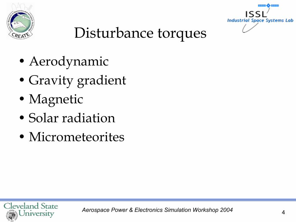
Disturbance torques
• Aerodynamic• Gravity gradient• Magnetic• Solar radiation• Micrometeorites

5Aerospace Power & Electronics Simulation Workshop 2004
Attitude control modes•Orbit insertion
•Acquisition
•Slew
•Contingency or Safe
6Aerospace Power & Electronics Simulation Workshop 2004
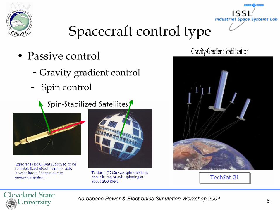
Spacecraft control type
• Passive control - Gravity gradient control- Spin control

7Aerospace Power & Electronics Simulation Workshop 2004
Spacecraft control type
• Active control (Actuators)- Reaction wheels- Momentum wheels- Control - moment gyros- Magnetic torquers
- Gas Jets or Thrusters

8Aerospace Power & Electronics Simulation Workshop 2004
Tetrahedron configuration of Reaction wheels
9Aerospace Power & Electronics Simulation Workshop 2004
Outline
1. Overview of Attitude Determination and Control system
2. Problem formulation
3. Control schemes
3.1 Modified PI Controller
3.2 Active Disturbance Rejection Control
4. Conclusion

10Aerospace Power & Electronics Simulation Workshop 2004
Problem formulation
11Aerospace Power & Electronics Simulation Workshop 2004
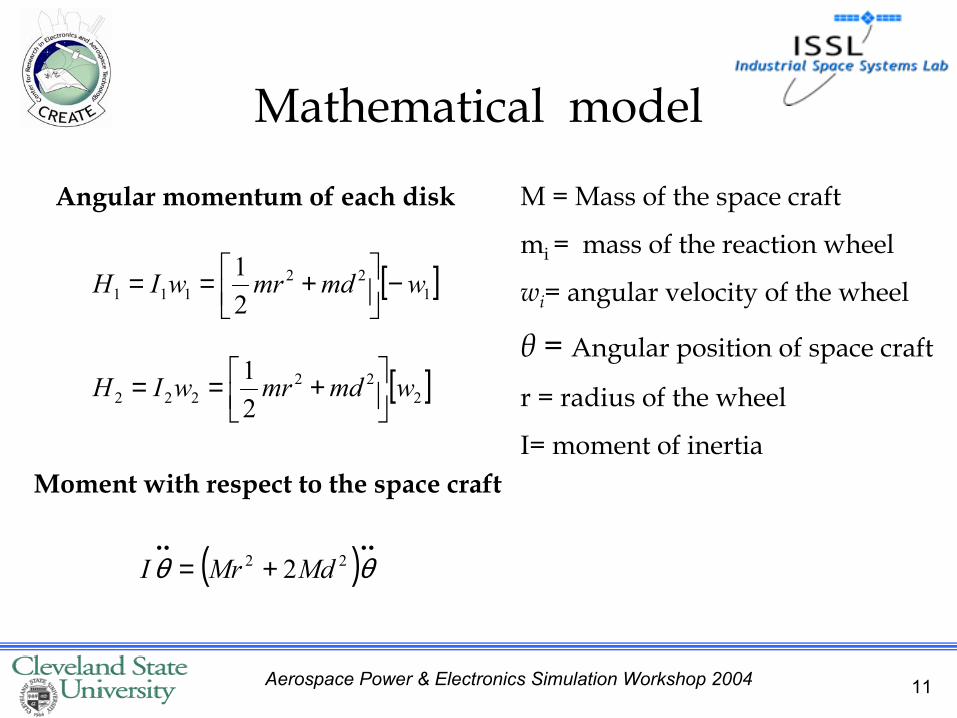
Mathematical model
[ ]122111 2
1 wmdmrwIH −
+==
[ ]222222 2
1 wmdmrwIH
+==
Angular momentum of each disk
Moment with respect to the space craft
( ) ••••+= θθ 22 2MdMrI
M = Mass of the space craft
mi = mass of the reaction wheel
wi= angular velocity of the wheel
θ = Angular position of space craft
r = radius of the wheel
I= moment of inertia
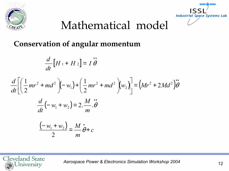
12Aerospace Power & Electronics Simulation Workshop 2004
Conservation of angular momentum
Mathematical model
( ) ( ) ( ) ••+=
++−
+ θ22
222
122 2
21
21 MdMrwmdmrwmdmr
dtd
( )••
=+− θ..221 mMww
dtd
[ ]••
=+ θIHHdtd
21
( ) cmMww +=+− •
θ2
21
13Aerospace Power & Electronics Simulation Workshop 2004
Outline
1. Overview of Attitude Determination and Control system
2. Problem formulation
3. Control schemes
3.1 Modified PI Controller
3.2 Active Disturbance Rejection Control
4. Conclusion
14Aerospace Power & Electronics Simulation Workshop 2004
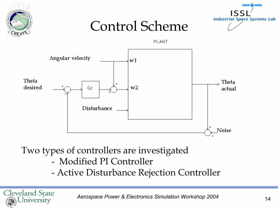
Control Scheme
Two types of controllers are investigated- Modified PI Controller- Active Disturbance Rejection Controller

15Aerospace Power & Electronics Simulation Workshop 2004
Simplorer
• Simplorer• Circuit element
models• Electric machine
models• Data analysis tools• Interfaces with
Matlab / Simulink
16Aerospace Power & Electronics Simulation Workshop 2004
Outline
1. Overview of Attitude Determination and Control system
2. Problem formulation
3. Control schemes
3.1 Modified PI Controller
3.2 Active Disturbance Rejection Control
4. Conclusion

17Aerospace Power & Electronics Simulation Workshop 2004
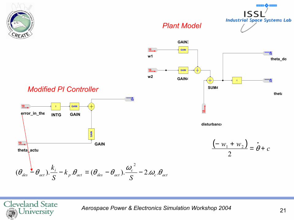
• This controller is used as the baseline controller• Only one tuning parameter • Generalized 2 DOF control structure is proposed
Modified PI Controller
Reference: A Robust Two-Degree-of-Freedom Control Design Technique and its Practical Application-Robert Miklosovic, Zhiqiang Gao

18Aerospace Power & Electronics Simulation Workshop 2004
kis-1 Plant transfer function
kp
actcc
actdesactpi
actdes Sk
Sk θωωθθθθθ ..2).(.).(
2
−−=−−
actθdesθ

19Aerospace Power & Electronics Simulation Workshop 2004
Motion profiling
•The desired trajectories as the command input in the closed loop control
•In this case, a profile generator is used to produce desired angle to the system
•Motion profile is used instead of step.

20Aerospace Power & Electronics Simulation Workshop 2004
w2
GAIN GAIN
SUM5
GAIN
w1
w2
theta
theta_dot
Disturbanc
error in theta
Theta Actual
control signal
w1
t_des_de deg_rad
theta_dot_de
RANDOM
Random_Nois
GAIN
theta_de
CONST
Yt
Motion_profi
Motion profile Modified PI Controller
actθPlant Model
Simulation Results
Random Noise
21Aerospace Power & Electronics Simulation Workshop 2004
I
INTG
GAIN
GAIN
GA
IN
GAIN2
10
error_in_the
10
theta_actu
10
GAIN
GAIN
SUM4
I
10
disturbance
10
w2
10
theta_do
10
theta
10
w1
GAIN3
GAIN4
Modified PI Controller
Plant Model
actcc
actdesactpi
actdes Sk
Sk θωωθθθθθ ..2).(.).(
2
−−=−−
( ) cww +=+− •θ
221

22Aerospace Power & Electronics Simulation Workshop 2004
Simulation ResultsTheta Actual & desired
Noise amplitude: 0.07 - 0.1
Noise interval: 2 sec
t_des_theta_d
t [s]
0.1k
-10
20
40
60
80
0 102 4 6 8
t_des_theta_d
t [s]
0.1k
-10
20
40
60
80
0 102 4 6 8
23Aerospace Power & Electronics Simulation Workshop 2004
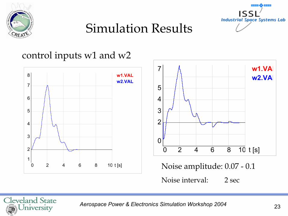
Simulation Results
control inputs w1 and w2w1.VALw2.VAL
t [s]
7
0
2
3
4
5
0 102 4 6 8
w1.VAL w2.VAL
t [s]
8
1
2
3
4
5
6
7
0 102 4 6 8 Noise amplitude: 0.07 - 0.1
Noise interval: 2 sec
24Aerospace Power & Electronics Simulation Workshop 2004
Outline
1. Overview of Attitude Determination and Control system
2. Problem formulation
3. Control schemes
3.1 Modified PI Controller
3.2 Active Disturbance Rejection Control
4. Conclusion

25Aerospace Power & Electronics Simulation Workshop 2004
Active Disturbance Rejection Controller
•New digital controller to motion control problems
• Disturbances are estimated using extended state observer (ESO) and compensated in each sampling period.
•Dynamic compensation reduces motion system to a double integrator which can be controlled using a nonlinear PID controller

26Aerospace Power & Electronics Simulation Workshop 2004
Extended State Observer• It is a unique nonlinear observer • Proper Selection of the gains and functions are
critical to the success of the observer• Once ESO is properly setup, the performance of the
observer is quite insensitive to plant variations and disturbances
+
−−
=
•
•
yub
zz
z
zo
oo
o
o2
2
12
2
1
02
012
ωω
ωω

27Aerospace Power & Electronics Simulation Workshop 2004
Plant Model
Simulation Results
28Aerospace Power & Electronics Simulation Workshop 2004
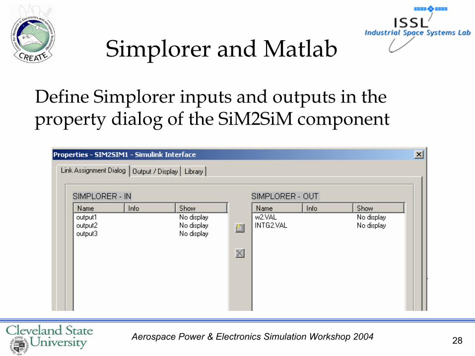
Define Simplorer inputs and outputs in the property dialog of the SiM2SiM component
Simplorer and Matlab
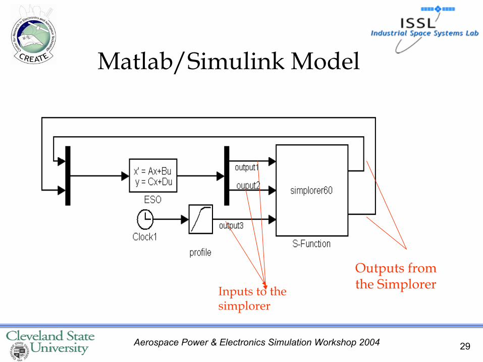
29Aerospace Power & Electronics Simulation Workshop 2004
Matlab/Simulink Model
Outputs from the SimplorerInputs to the
simplorer

30Aerospace Power & Electronics Simulation Workshop 2004
Simulation Results
t_des_dGAIN1.theta_d
t [s]
0.1k
-10
20
40
60
80
0 1.10.2 0.4 0.6 0.8
Theta Actual and Theta desired
Noise amplitude: 0.05 Noise Interval: 0.5 sec
t_des_theta_
t [s]
0.1k
-10
20
40
60
80
0 1.70.2 0.6 1 1.2
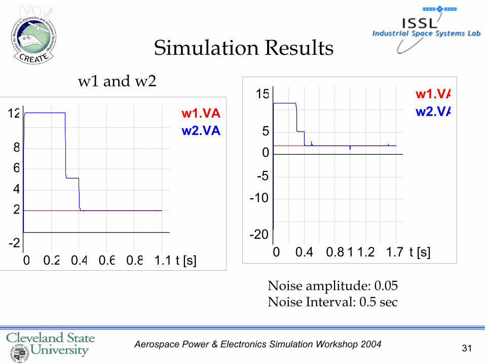
31Aerospace Power & Electronics Simulation Workshop 2004
w1.VAw2.VA
t [s]
12
-2
2468
0 1.10.2 0.4 0.6 0.8
w1 and w2
Simulation Results
w1.VAw2.VA
t [s]
15
-20
0
-10
-5
5
0 1.70.4 0.8 1 1.2
Noise amplitude: 0.05 Noise Interval: 0.5 sec
32Aerospace Power & Electronics Simulation Workshop 2004
• The simulation of Modified PI and ADRC showed that ADRC worked well for the system
• 1 DOF problem will be extended to 3 degrees of freedom problem
• Implementation of the controller design in microcontroller/FPGA microchip.
• Comparisons with other controllers
Conclusion and Future work


