

Tender Ref: CT2008B015
I. AIRCONDITIONING AND VENTILATION SYSTEM
GEN 1
<Confidential>
<Confidential>
1 GENERAL SPECIFICATIONS FOR SERVICING & MAINTENANCE 1.1 The Contractor shall supply all materials, labour, appliances and everything
else necessary for maintenance of all the installation at SATS Maintenance
Centre in good working order. 1.2 The works covered in this document is for supply of materials, tools, apparatus,
equipment and appliances, labour and necessary incidentals for the servicing
and maintenance of all the systems and ancillary plant, machineries and
equipment under this Contract during the Defects Liability Period as well as for
the future servicing and maintenance thereof after the Defects Liability Period. 1.3 During the Defects Liability Period, the Installation Contractor shall replace
and/or repair defective plants, machineries and equipment and installations or any part thereof entirely free of charge to SAS whenever directed by the SO if
such repairs or replacements are necessitated by reason of defective design,
materials or workmanship or part thereof replaced during the Defects Liability Period shall carry a fresh warranty for a period of six (6) months or the balance
Defects Liability Period whichever the longer with effect from the date of replacement or competition of repair thereof.
1.4 For servicing and maintenance after the Defects Liability Period, all labour
costs involved in the carrying out of servicing, maintenance, replacement
and/or repair of defective parts or items and the costs of supplying consumable materials (as listed hereinafter), incidentals, materials and of using tools,
apparatus, equipment or appliances required for carrying out such tasks, shall
be deemed to have been included in the prices quoted under this contract for future servicing and maintenance after the Defects Liability Period.
2 REGULATIONS 2.1 All works to be performed under this section, whether by the installation or
Custodian Contractor, shall be strictly in accordance with the best commercial
technical and engineering practice and must be strictly in accordance with the
requirements/recommendations stipulated by all the plant and equipment
manufacturers. The works must also strictly be in compliance with all by-laws,
rules, regulations and requirements of the Local authorities. 2.2 The following are the rules and regulations to be complied by the Contractors:
a) The Electrical Department of The Public Utilities Board Singapore
b) The Fire Safety Bureau and Building Control Division, Singapore
c) The Factory Inspectorate (The Building Operations and Works of
Engineering Construction Regulations 1985)
d) The Factory Inspectorate (Building Operations and Works of
Engineering Construction Regulations 1985)
e) Code of Practices, Singapore
Tender Ref: CT2008B015
I. AIRCONDITIONING AND VENTILATION SYSTEM
GEN 2
<Confidential>
<Confidential>
f) All other authorities having jurisdiction over the installations.
3 WORKMANSHIP a) The works described in this document shall be performed by workmen skilled
in the servicing, maintenance and repair (or replacement) of all the equipment,
plants and machineries and shall be executed in accordance with the best
commercial, technical and engineering practice. b) All fittings equipment and material necessary to service and maintain the
installation shall be new and of the best possible quality of their respective
kinds. c) The Contractor shall provide all necessary labour to carry out the work in a
proper and workmanlike manner and shall complete the work in strict
accordance with the specifications and to the entire satisfaction of
Superintending Officer. 4 MATERIALS
Materials supply shall conform to the relevant Singapore or British Standard
Specifications or Standard as specified. Certificate of origins of any material
shall be produced on demand by the Manager. 5 SERVICING
All servicing shall comply with the recommendations of the equipment
manufacturers.

Tender Ref: CT2008B015
I. AIRCONDITIONING AND VENTILATION SYSTEM
WH 1
<Confidential>
1 GENERAL WORKS SPECIFICATION
At each monthly inspection and service of the complete Airconditioning and
Ventilation System include all plant and Ancillary Equipment, AHUs, all type of
FCUs and fans.
The servicing and maintenance of equipment shall according to their
maintenance manual as recommended by the manufacturer to ensure that the
equipment operates efficiently.
The ACMV system of the building should also be inspected with regards to the
functions which are significant for good indoor air quality. The frequency of
which inspection should be in accordance to the latest related guidelines issued
by ENV(Ministry of Environment).
1.1 The following minimum items of work detailed below shall be performed by the
Contractor.
1.1.1 Maintenance Schedule for Chiller & Refrigerant System Equipment.
(a) Maintenance Schedule for Chiller
(i) Daily
ITEMS REMARKS
Vane Operating
Oil Level
Compressor Oil Temperature
Oil Pressure
Sound & Vibration
Current
Main Meter Voltage
Sound & Vibration As per manufacturer s
Flow Rate recommendation
Evaporator Pressure
Outlet Temperature
Flow Rate
Condenser Pressure
Inlet Temperature
Motorised Control Operation of Control valve
Valve

Tender Ref: CT2008B015
I. AIRCONDITIONING AND VENTILATION SYSTEM
WH 2
<Confidential>
(ii) Monthly
General
(a) Review previous month s operation log records.
(b) Check operation condition against design. Oil reservoir level Oil pressure and temperature Evaporator refrigerant temperature/pressure Condenser refrigerant temperature/pressure Bearing Temperature Circulating water temperature and pressure drop
(c) Check for sign of temperature leakage and remedy if
necessary
(d) Ensure Proper guide vane linkage (e) Check chiller essential safety controls, motorise control valve,
calibrate temperature sensor, pressure sensor etc.
ITEMS REMARKS
Chilled Water
Evaporator Analysis
Strainer Cleaning
Cooling Water As per manufacturer s
Condenser Analysis Recommendation
Strainer Cleaning
General Checking & Analysis for
Operating condition

Tender Ref: CT2008B015
I. AIRCONDITIONING AND VENTILATION SYSTEM
WH 3
<Confidential>
(iii) Monthly
ITEMS REMARKS
Vibration Measurement
Compressor Oil heater & Oil Pump
Meggering As per manufacturer s
Main Motor Vibration Measurement Specifications
Meggering
Starter Meggering
Control Panel Meggering
(iv) Yearly (Annual Shutdown Maintenance)
General
(a) Pump down the machine and replace refrigerant filter and
volute drain filter
(b) Dismantle oil pump for servicing. Clean up oil pump chamber. Replace filter and refill with new oil.
(c) Remove condenser water end cover and inspect for abnormalities. All condenser tubes shall be brushed and cleaned mechanically.
(d) Float chamber shall be serviced. (e) Safety controls shall be tested and recalibrated to specific
setting to ensure proper operations.
ITEMS REMARKS
Lubricating Oil Replace
Compressor Oil Strainer Replace
Strainer for Cleaning
Oil recover system
Ref.cycle Refrigerant strainer Cleaning
Leak Test By Leak Tester or Soap Water
Starter Function checking Looseness, Disconnection,
Safety Devices
Test & Calibration
Contactor Point
Frequency for Condenser & Evaporator tube cleaning may vary depending on
site condition.

Tender Ref: CT2008B015
I. AIRCONDITIONING AND VENTILATION SYSTEM
WH 4
<Confidential>
(v) Overhaul
ITEMS REMARKS
Compressor Overhaul As per manufacturer s Main Motor Overhaul recommendation
Schedule of Work Frequency of Maintenance
I Check control Centre Monthly
Ii Check entering and leaving condenser/chilled Monthly water pressure and temperature with job design
conditions
Iii Check the bearing oil pressure, temperature and Monthly
oil level in the oil sump.
Iv Check the liquid refrigerant temperature leaving Monthly the
Condenser
V Check the compressor discharge temperature Monthly
Vi Check the compressor motor voltage and Monthly
amperage at starter
Vii Check for any signs of dirty or foul condenser Monthly
water
Viii Check control voltage within operation limitation Monthly
Ix Check the refrigerant level in cooler Monthly
X Change the purge unit filter drier Quarterly
Xi Check and clean purge foul gas strainer Quarterly
Xii Perform chemical analysis of oil Semi-annually

Tender Ref: CT2008B015
I. AIRCONDITIONING AND VENTILATION SYSTEM
WH 5
<Confidential>
Xiii Change and inspect compressor oil filter Semi-annually
Element
Xiv Check oil return system and change educator Monthly
filter drier, if necessary
Xv Perform leak check Monthly
Xvi Check control and safety cutouts Yearly
Xvii Drain and replace the compressor oil in the Yearly
compressor oil sump
Xviii Change motor cooling liquid line filter element Yearly
Xix Drain and flush oil and refrigerant from purge Yearly
shell
Xiii Change and inspect compressor oil filter Semi-annually element
Xx Meg Compressor Windings Yearly
Xv Perform leak check Monthly
Xvi Check control and safety cutouts Yearly
Xxi Inspect and clean strainers, tubes an end sheets Yearly
Xxii Inspect and service electrical components Monthly
Xxiii Inspect, brush and clean all the condensed Yearly
tubes
Xxiv Wipe down equipment ensure it’s free of dust Semi-annually
Xxv Paint chiller room with 2 coat of white emulsion paint (paint provided by the Company) Yearly
(b) Guide On Refrigerant Equipment Maintenance Schedule
(c) Maintenance Schedule For Heat Machine (Monthly)
(i) Lubrication System - Oil reservoir level - Pressure gauges - Oil suction and discharge pressure - Corresponding temperatures
(ii) Electrical Control Centre
- Main starter equipment - Switch contact for auxiliary equipment

Tender Ref: CT2008B015
I. AIRCONDITIONING AND VENTILATION SYSTEM
WH 6
<Confidential>
(iii) Refrigerant system for leaks
(iv) Noise, vibration, isolators etc
(v) Any other works according to manufacturer s recommendation.
(d) Annual Shut Down I Compressor
The compressor inspection cover shall be opened up and visually inspected
for signs of wear on the gear teeth. Parts worn or scored shall be
recommended for replacement. Ii Refrigerant Filter
The refrigerant filter and volute drain filters will be changed. Supply of filter
included as part of the annual maintenance. Iii Oil Change
Oil and filters will be changed. The oil cooler solenoid, screed and magnetic
plug will be cleaned. Supply of oil and filters are included as part of the annual
maintenance. Iv Condenser
The unishell condenser end plates will be opened up and all tubes cleaned
brushing. Shell and tubes will be examined for rust and scale built up. V Dehydrator
The Dehydrator Chamber will be opened, inspected and cleaned. Float valve
plunger and seat will be checked for wear and score.

Tender Ref: CT2008B015
I. AIRCONDITIONING AND VENTILATION SYSTEM
WH 7
<Confidential>
Vi Purge System
The Purge Unit will be tested for correct operation, and the purge chamber and
float valve will be cleaned. Float valve, plunger and seat will be checked for
wear and score. Inlet and exhaust valves of the purge pump will be inspected
and if found defective, will be recommended for replacement. Vii Guide Vane Linkage
The linkage will be checked for correct operation and adjustment made. Viii Safe/Controls
The oil low temperature switch, oil low pressure cutouts, cooler low pressure
cutout, condenser high pressure cutout and recycle switch will be checked for
correct operation at specified temperature and pressure. Ix Electrical Switches & Contactors
The Condition of all contactor contacts will be checked and cleaned up.
Contractors reduced to half the original thickness will be recommended for
replacement. Contactors wil be checked for freedom of movement and pivots
will be oiled. All electrical connections will be tightened every three months, to
prevent sparking and arching, etc. X Electrical Swichgears (ACBs)
The maintenance shall comprise the following works:-
(a) General cleaning of busbar compartment inclusive of busbar length,
dropper and insulator.
(b) Tightening of all bolts and nuts and check tightness using torgue
wrench to the specific torgue as per manufacturer instruction manual.
(c) Functional check of earthing switch and other mechanical/electrical
interlocks for correct and proper operation.

Tender Ref: CT2008B015
I. AIRCONDITIONING AND VENTILATION SYSTEM
WH 8
<Confidential>
(d) Secondary Injection Test on Relay at setting.
(e) AC Pressure Test between phases and phases and earth for all
components. 1.1.2 Maintenance Schedule for Water Pumps (Condensor and Chiller Water and
Others)
(a) Inspect all water pumps and
(i) Check all seals, glands and pipe lines for leaks, and rectify as
necessary.
(ii) Re-pack and adjust pump glands as necessary.
(iii) Check all pumps bearings and lubricate with oil or grease as
necessary.
(iv) Check the alignment and condition of all rubber couplings
between pumps and drive motors and rectify as necessary.
(v) Clean and clear all chokage of pump drain pipes.
(vi) Check all bolts and nuts for tightness and tighten as necessary.
(b) Condenser Pump
(i) Check pump mechanical seals, packing gland and pipeline for
leakage and rectify or tighten up if necessary.
(ii) Check and clean strainer if necessary.
(iii) Check shaft coupling and bearings and lubricate.
(iv) Check motor for proper operation
(v) Check pump coupling alignment and condition of rubber
coupling.
(vi) Check noise and vibration, rectify when necessary.
(c) Chilled Water Pump
(i) Check pump mechanical seals, packing gland and pipeline for
leakage and rectify or tighten up if necessary.
(ii) Check and clean strainer if necessary.
(iii) Check shaft coupling and bearings.

Tender Ref: CT2008B015
I. AIRCONDITIONING AND VENTILATION SYSTEM
WH 9
<Confidential>
(iv) Check motor for proper operations.
(v) Check pump coupling alignment and condition of rubber
coupling.
(vi) Check noise and vibration, rectify when necessary.
1.1.3 Maintenance Schedule for Cooling Towers (a) Inspect all water cooling towers and
(i) Check all fan bearings and lubricate with grease as necessary.
(ii) Check and service motorised valves, clean strainers.
(iii) Check and adjust water inlet valves, water level sensor.
(iv) Touch up and paint rusty parts.
(v) Check and clean sump pan, strainer and all water screens.
(vi) Check and adjust float valve for proper operation.
(vii) Check belt tension and tighten if necessary.
(viii) Check oil level of gear box to top up if necessary.
(ix) Check fan blades and motor mounting for vibration.
(x) Check motor operation.
(xi) Drain, clean and flush out the water basin.
(xii) Check noise and vibration, rectify when necessary.

Tender Ref: CT2008B015
I. AIRCONDITIONING AND VENTILATION SYSTEM
WH 10
<Confidential>
1.1.4 Maintenance Schedule for AHUs, CPUs and FCUs (a) Inspect all air handling units and fans and
(i) Check all filters and clean filters as necessary.
(ii) Check all water coils, seals and pipe lines for leaks and rectify as
necessary.
(iii) Purge air from all water coils.
(iv) Check the fan bearings, and lubricate with grease as necessary.
(v) Check the tension of all belt drives and adjust as necessary.
(vi) Check the operation of automatic water regulating valves, and clean,
adjust and lubricate as necessary.
(vii) Clean all the condensation pans, trays and drains.
(viii) Clean cooling coils.
(ix) Clean housings and motors.
(x) Replace defective parts (if any) ie. Pressure gauge, temperature gauge
etc.
(xi) Paint rusty part (if any).
(xii) Check housing and chilled water pipe insulation.
(xiii) Check calibrate temperature sensor, pressure differential unit.
(xiv) Clean housing exterior and interior, ensure it’s free of dust
(xv) Paint AHU room with 2 coat of white emulsion paint (paint by the Company, annually)
(b) Automatic Temperature Controls.
The following procedures shall be performed as follows:
(i) Inspection cooling
Fan Systems and HVAC Unit Controls
- Review Sequence of operation
- Check all dampers and lubricate
- Check Pilot Positioners

Tender Ref: CT2008B015
I. AIRCONDITIONING AND VENTILATION SYSTEM
WH 11
<Confidential>
- Check all control valves
- Calibrate all controllers
- Calibrate all transmitters and receiver gauges
- Check all solenoid air valves, PE switches and air valves.
- Check all auxilliary control devices.
- Clean/wipe down panel face
(ii) Annual Inspection Cooling
- Check all room status
- Check operation for all dampers and lubricate (c) Maintenance Schedule for AHUs/FCUs ( MONTHLY)
- Check cooling coil of AHU/FCU. - Check all air filter; clean and change filters when necessary. - Check and clean condensate drip tray and flush drain pipe - Insert fan belts and adjust belt tension. - Lubricate linkages, fan and motor bearings. - Check and clean blower fan and housings. - Check unit panel for corrosion, air leakages and damaged internal
insulation. - Check motorised valve for correct operation corresponding to the
thermostat. - Check motor operation and record running ampere. - Check starter panel for correct operation of timers, contactors
electrical and overload trip. - Check electrical contacts and tighten all screws, bolts and nuts. - Check condition of vibration isolators. - Check operation of all damper etc, adjust and lubricate when
necessary. - Check flexible connection, rectify or replace when necessary. - Check water coils cleanliness. - Check any water leakage from coil, pipe line or valve and rectify
when necessary.

Tender Ref: CT2008B015
I. AIRCONDITIONING AND VENTILATION SYSTEM
WH 12
<Confidential>
1.1.4 Maintenance Schedule for AHUs, CPUs and FCUs (Cont'd)
(c) Maintenance Schedule for AHUs/FCUs (MONTHLY) (Cont'd)
Blow out all dirt pockets and clear the strainer. Purge air from water coils.
Check operation of control valve against off coil temperature setting.
Clean/adjust and lubricate when necessary.
Clean drain pan and check drain pipe.
Check pipe insulation condition, rectify or replace when necessary.
Check supply and return air grilles (for FCU only).
Check casing condition and external insulation (for FCU only). 1.1.5 Maintenance Schedule for Fans
(a) All ventilation fans should be inspected and checked on the followings:
(i) Operation of timers and tighten knobs.
(ii) Test the operation of fans.
(iii) Fan belts (if any) and adjust belt tension if necessary.
(iv) Ductworks leakages.
(v) Flexible connections for correct adjustment and leakages.
(vi) Supports and adjust as necessary.
(vii) Touch up and paint all rusty parts.
(b) Clean equipment housing every 2 monthly.
(c) Check voltage and running ampere monthly.
(d) Check control panel and indicating light monthly.
(e) Check fan bearings and lubrication with grease monthly. (f) Motor insulation test every 6 monthly.
(g) Check for abnormal noise and vibration monthly during operation and rectify when
necessary.

Tender Ref: CT2008B015
I. AIRCONDITIONING AND VENTILATION SYSTEM
WH 13
<Confidential>

Tender Ref: CT2008B015
I. AIRCONDITIONING AND VENTILATION SYSTEM
WH 14
<Confidential>
1.1.5 Maintenance Schedule for Fans (Cont'd)
(i) Check tension for all belt drives (apply for centrifugal fan).
(j) Check operation of all damper etc, adjust and lubricate when necessary. 1.1.6 Maintenance Schedule for Electrical Equipment, Control Panel & Motors etc
(a) Schedule For Electrical Equipment
The following items of work shall be performed once a month:
i. Inspect all electric motors, and
Check all motor bearings, and lubricate with grease as and when necessary.
Check and renew carbon brushes and slip rings of all motors as and when necessary (if any).
Check safety devices fitted to all motors, and clean, adjust and lubricate as and when necessary.
ii. Inspect and check the routine operation of all electrical starters, electrical control
gears, and ancillary apparatus, and
Clear, adjust and lubricate all bearings, pivots and other moving parts
as and when necessary.
Clean or renew electric contactors as and when necessary.
iii. Inspect and check the routine operation of all automatic control gears and relays and
Clean, adjust and lubricate all bearings, pivots and other moving parts as and when necessary.
Clean or renew electric contactors as and when necessary.
Renew electric fuses as and when necessary iv. Inspect meters, gauges and safety controls and adjust when necessary.

Tender Ref: CT2008B015
I. AIRCONDITIONING AND VENTILATION SYSTEM
WH 15
<Confidential>
1.1.6 Maintenance Schedule for Electrical Equipment, Control Panel & Motors etc (Cont'd)
v. Inspect all control panels, alarm panels, supervisory data panels, sub-
panels, etc., and
Check the routine operation of all contactors, MCCBs, relays, ELCBs, time switches etc.
Clean and adjust pivots and other moving parts or relays, contactors, time switches.
Tighten all connections, joints, terminations, etc.
Replace blown indicating lamps.
Test the earth resistance value of the main earthing system.
Clean all panels.
Check battery voltage and terminals.
Top up battery water as and when necessary.
Test all indicating lamps and alarm circuits.
(b) Monthly
(i) Inspect all electric motor wire termination tightness.
(ii) Inspect and check electrical starter, electrical control and overload setting.
(iii) Check current consumption of the motor is within nameplate limit.
(iv) Check all indicating light and motor protection.
1.1.7 Maintenance Schedule for Others
(a) Chilled Water Tank
Inspect all chilled water storage and expansion tanks, and drain, clean and flush out the tanks as necessary.

Tender Ref: CT2008B015
I. AIRCONDITIONING AND VENTILATION SYSTEM
WH 16
<Confidential>
1.1.7 Maintenance Schedule for Others (Cont'd)
(b) A/C Outlets/Grilles
Wipe clean with damp cloth and then use dry cloth to wipe all airconditioning and ventilation diffusers, supply, return and exhaust grilles and extractor fans.
1.1.8 Maintenance Schedule for Heat Machine/Humidifiers
(a) Monthly
(i) Lubrication System
Oil reservoir level
Pressure gauges
Oil suction and discharge pressure
Corresponding temperatures
(ii) Electrical Control Centre
Main starter equipment Switch contact for auxiliary equipment
(iii) Refrigerant system for leaks.
(iv) Noise, vibration, isolators etc.
(v) Any other works according to manufacturer's recommendation. 1.1.9 Maintenance Schedule for Air-Compressor
(a) Check cleanliness of the room, ensure that any oil spillage is wiped up immediately and
any residual oil cleaned from external surfaces.
(b) Recording pressure and temperature. (c) Check and inspect the unit for leaks, loose pipe connections. Rectify/replace when
necessary.
(d) Check and clean strainers and filter must be maintained in a clean condition. (e) Check lubricating oil level ensures in correct level.

Tender Ref: CT2008B015
I. AIRCONDITIONING AND VENTILATION SYSTEM
WH 17
<Confidential>
1.1.9 Maintenance Schedule for Air-Compressor (Cont'd)
(f) Check compressor safety devices. (g) Annual submission to Approve Authorities for inspection and obtain Safety Certificate
or Certificate of Fitness.
1.1.10 Maintenance Schedule for Air-Dryers (a) Weekly
(i) Check the dewpoint. (ii) Check that the condensate discharge is operating correctly by pressing manual
override button.
(b) Monthly
(i) Check the top of the casing is not too heat (about 50 deg C), when air dryer in operation.
(ii) Check current consumption of the compressor is within nameplate limits. (iii) Check the condenser fins and check that the ventilated panels are free of dirt
and any other obstructions.
2 ADDITIONAL SERVICE
In addition to the regular weekly/monthly inspection and service, the Contractor shall also perform the following items of work:
(a) Every 3 months, check and analyse the oil and refrigerant or all water chilling
units and replace the oil and refrigerant if necessary.
(b) Every 3 months, check and balance outside air quantities for all air handling
units.
(c) Every 3 months, clean electrical contacts and motor slip-ring. Tighten all screws
and adjust carbon brushes where necessary (if any).
(d) Every 3 months, check and comb dented fins and coils chemical cleaning (if
necessary) for all air handling units, fan coil units and window units.
(e) Every 3 months, check for deterioration of blower fan wheel and housing, align
drive shaft if necessary for all air handling units and fan coil units.

Tender Ref: CT2008B015
I. AIRCONDITIONING AND VENTILATION SYSTEM
WH 18
<Confidential>
2 ADDITIONAL SERVICE
(f) Every 6 months, check and clean all strainers on pipework.
(g) Every 12 months, clean cooling coil of AHU with high water jet or steam with chemical and thorough rinse.
(h) Every 12 months, check and balance water flow rates for all equipment.
(i) Once a year, wire brush with cleaning agent the condenser tubes on the chiller
set. To
liaise with the Manager for the cleaning.
(j) Conduct an annual shutdown for chillers and calibrate chiller controller,
protection devices, temperature sensors etc.
(k) Calibrate all room thermostat, VAV controls and temperature sensors.
(1) Balancing of air-flow in offices (if required).
(m) Calibrate VSD controller.
(n) Calibrate computer room's air-conditioner (Liebert Unit) controller.
3 CONSUMABLE MATERIALS
The Contractor shall supply the following consumable materials without charge as and when required:
(a) All oils and greases required for lubrication of compressors, fan bearings, motor
bearings, pivots and other moving parts.
(b) All dry nitrogen and refrigerant required to replace refrigerant losses in all
refrigerant system.
(c) All coil cleaning chemical to clean evaporator coil to all air-conditioning
equipment and mechanical ventilating fans.
(d) All cotton waste, soap detergent and other cleaning materials required for
cleaning purposes.
(e) All carbon brushes required to replace worn brushes in electric motors.
(f) All electric contact points required to replace worn electric contact points in
switchgears, electric control gears and electric relays.
(g) All electric fuses and indicating bulbs required to replace blown fuses and bulbs.

Tender Ref: CT2008B015
I. AIRCONDITIONING AND VENTILATION SYSTEM
WH 19
<Confidential>
Maintenance Schedule for Split Unit/Window Units (Monthly) Check and clean condenser coil
Check condenser motor and fan
Check system pressure and running ampere
Check for refrigerant leaking
Check for overheating of compressors
Check for abnormal noise and vibration
Check expansion valve at evaporator coil
Check and clean evaporator coil
Check motor and fan operation
Check and clean air filter
Check remote controller functionality
Check and clean drain pan
Flush drain pipe whenever necessary
Check and clean equipment housing
Housekeeping

II. ELECTRICAL SERVICES
WH 1
<Confidential>
1 WORK SPECIFICATION FOR ELECTRICAL LICENSING 1.1 Scope of Work (a) Monthly general inspection of installations. (b) Quarterly inspection of installation by Licensing/Switching Engineer. (c) Yearly checking/Testing of the main earth and issuance of Certificate of Fitness. (d) Authorisation of Superintending Officer on the day-to-day supervision and
operation of the installation. (e) Inspection Reports are to be forwarded to the Employer within one (1) week from
the date of inspection. (f) The response time including traveling for emergency calls shall be within one (1)
hour. 1.2 The Contractor shall act as Licensed Engineer/Worker to take charge of the
electrical installations at the premises in accordance with P.U.B requirements. 1.3 The Contractor shall check and inspect in general the electrical installations at the
premises. 1.4 The Contractor shall recommend modifications and rectification to existing
electrical installations if required to comply with P.U.B requirements. 1.5 The Contractor shall advise the Employer electrical workers on the regular
maintenance works in accordance with preventative maintenance schedule. 1.6 The Contractor shall keep an up-to-date set of as built electrical drawings of the
premises provided by the Employer for the purpose of maintaining up-to-date
record of all modifications, rectifications and addition works to the existing electrical
installations. 2 MAINTENANCE SPECIFICATIONS 2.1 Overhaul of Vacuum Breaker/Interrupter Units
Overhaul shall comply with manufacturer s recommendation.

II. ELECTRICAL SERVICES
WH 2
<Confidential>
2.1 Overhaul shall comply with manufacturer s recommendation (Cont d)
The following testings are included:
(a) Insulation Resistance Test shall be carried out with a 5kV megger between phases
and between phase and earth on the specified parts of the switchgear. (b) AC Pressure Test shall be made between phases and between phase and earth
for all components. (e.g. busbar, circuit breaker). A reduced AC voltage of 33kV
shall be applied for a duration of 1 min. (c) Secondary Injection Test shall be carried out for all relays at its original settings.
The tests shall include checking of all relay contacts, operation of indicators, trip
and inter-trip circuit measurement of relay pick-up and drop-off voltages. (d) Contact Resistance Test shall be carried out for each of the three poles of the main
circuits. The measured value of milli-volt drop shall not exceed 12 milli-volts for an
injected DC current of 100A. 2.2 Maintenance of Switchgear Cubicle
This shall comprise the following items of work:
(a) General cleaning of busbar compartment inclusive of busbar length, dropper and
spout insulator. (b) Tightening of all bolts and nuts and check tightness using torque wrench to the
specific torque s per manufacturer s instruction manual. (c) Cleaning of cable compartment including the CTs and cable termination and
sealing of gaps in cable opening with silicone sealant. (d) Checking and tightening protection and control wiring. (e) Functional check of earthling switch and other mechanical/electrical interlocks for
correct and proper operation. (f) Checking space heaters, shutters and locking devices for correct operation. (g) Secondary Injection Test on Relay at setting.

II. ELECTRICAL SERVICES
WH 3
<Confidential>
(h) AC Pressure Test shall be made between phases and between phase and earth for
all components( e.g. busbar, circuit breaker). 2.3 Maintenance of Circuit Breaker
This shall comprise the following items of work: (a) General cleaning of interrupter pole and carriage. (b) Checking for oil leakage for OCB and gas leakage for GCB. (c) Replace OCB oil and seal for OCB only. (d) Checking and lubricating operating mechanism and limit switches. (e) Contact Resistance Test (f) Checking on CB interlock. (g) Function and trip test. (h) AC test to check for inception of corone discharges with CB on .
Note : In this test, all interrupters of each CB Are allowed to be tested at the same time.
(i) AC test with CB Open .
Note: In this test, all interrupters of each CB Are allowed to be tested at the same time.
3 SERVICING SCHEDULE FOR HT/LT SERVICING
3.1 Metal Enclosure (a) Clean and inspect. (b) Clean and ventilation grilles. (c) Touch up corroded metal surfaces (d) Replace missing screws and name plate when necessary.

II. ELECTRICAL SERVICES
WH 4
<Confidential>
3.2 Busbar (a) Check for any signs of overheating and loose connection (b) Tighten loose bolts and nuts. (c) Perform insulation test of main panel and submit test reports. 3.3 Air Circuit Breaker and Coupler (a) Clean and remove loose external dirt. (b) Check and clean insulation (c) Clean and examine isolating contacts. (d) Examine and recondition contacts. (e) Clean and examine arc-controls devices. (f) Check, clean and lubricate mechanism. (g) Check ancillary switches, indicating devices and interlocks for correct functioning. (h) Check and clean cable terminators. 3.4 Contactors
(a) Check and rectify all abnormality (b) Check for burn and other damages. (c) Check and remove loose external dirt. (d) Check for normal operation (e) Check and tighten all loose connections. (f) Check and examine arc-control devices. (g) Replace damaged contacts.
3.5 Moulded Case Circuit Breaker
(a) Clean and remove loose external dirt. (b) Check and clean insulation (c) Check contacts (d) Check, clean mechanism and replace worn parts. (e) Check fuses and fuse links (f) Check and clean cable terminations (g) Check ancillary equipment, if applicable
3.6 Meters, Indicating lights and Selector Switches
(a) Check for normal operation. 3.7 Protective Relays (a) Perform P/I test for overcurrent and earth fault inclusive C/T spill current in
accordance to PUB requirement and submit test reports.
II. ELECTRICAL SERVICES
WH 5
<Confidential>
3.8 Switchroom
(a) Clean up the switchroom after servicing. 3.9 LT Electrical System
(a) Works to be performed bi-monthly (Standard)
A bi-monthly inspection of the installation shall be carried out and any
abnormalities in operation shall be noted and rectified. Particular attention shall
be paid to the following:-
(i) Overheating of busbars, cables, parts and termination. (ii) Damage to insulation (iii) Overloading in circuits (iv) Proper functioning of all indicator lights, meters, etc. at switchboard and
distribution boards. (v) Ingress of water into switchboards, distribution boards,trunking,etc
(b) Works to be performed every 6 month (Standard)
(i) Electrical Installation
Check, service and rectify any defects in:-
(aa) Cable connection and termination. (bb) Sub-main cabling and final sub-circuit. (cc) Main Switchboards and distribution switchboards
inclusive circuit breakers, contactor,etc. (dd) All operating and control equipment (ee) Earthing & Lighting Protection System (ff) Protection relays and equipment. (gg) Measuring instruments, including lights,etc (hh) Normal & emergency lighting luminaries.
(ii) Transformer
Cast-Resin Transformer are generally maintenance free
Work to be performed every 6 months
(aa) Check cooling fan wiring and monitoring equipment for
proper operation condition.
(bb) In case of dusty environments, ensure cooling ducts is not
clogged. Cleaning is done with the aid of compressed-air
vacuum cleaner and dry cloths.

II. ELECTRICAL SERVICES
WH 6
<Confidential>
(cc) Check all temperature instrumentation circuits and ensure
temperature monitoring with pte thermistor system is
normal.
(dd) Visual checking of all connections for correct degree of
tightens.
(ee) Perform routine insulations resistance measurements and
note values.
(iii) HT Switchgears-Ordinary check
(aa) Visual Check.
(bb) Check for arc traces & discoloration
(cc) Check spring, close, trip circuit breaker manually to make certain that the ON OFF indicator work right.
(dd) Visual check on relay for dirty or dust.
(c ) Works to be Performed Yearly
(i) LV Main Switchboard & LV Installation
(aa) Perform dust removal operation of all areas.
(bb) Check all the control wiring and test the control function of
relays.
(cc) Check all connections for correct degree of tightness.
(dd) Cleaning of busbar system and re-tightening of busbar
system joints.
(ee) Check and tightened all earth connections and terminals.
(ff) Simulate relays of ELCBs.
(gg) Test and check all Exit and Emergency lightings are in
operating condition.
(hh) Repaint switchrooms

II. ELECTRICAL SERVICES
WH 7
<Confidential>
II ELECTRICAL SERVICES 3.10 HV Switchgear (a) Works to be performed yearly
(i) General cleaning of busbar, dropper and spout insulator. (ii) Tightening of all bolts and nuts using torque wrench as per
manufacturer instruction manual. (iii) Functional check of earthing switch and other M & E
interlocks for correct and proper operations. (iv) Checking space heaters, shutters and locking devices for
correct operation (v) S.I.Test on relay at setting. (vi) Reduced AC Pressure test. (vii) Maintenance of Circuit Breaker which comprises:-
(aa) General cleaning of interruptor pole and carriage. (bb) Checking and lubricating operating mechanism
and limit switches (cc) Checking of vacuum leakage for VCB. (dd) Contact resistance test (ee) Checking on CB interlock. (ff) Function and trip test. (gg) AC test to check for inspection of corona discharge
with CB on . 4 MAINTENANCE SCHEDULE FOR THE STANDBY GENERATOR SET
4.1 General
The services and maintenance shall include the complete system and its accessories equipment eg. Sump pump, fuel tank fuel transfer pump and its control panel. The contractor shall ensure that the standby generating set is maintained and tested accordance with the recommendations specified in this Code and with any additional test or service procedures which may be required by the relevant authority or the supplier of the standby generating set. The results of any inspection or services carried out shall be recorded in the appropriate log book.
4.2 Weekly Tests
The following tests and checks shall be made every week:
(a) Check the levels of fuel, engine lubrication oil and coolant and
replenish where necessary.
(b) Examine fuel oil and coolant systems for leaks (c) Check starter battery and water pump condition and top up
electrolyte where necessary. Record battery voltage and charging current.

II. ELECTRICAL SERVICES
WH 8
<Confidential>
(d) Start the engine and bring unit up to normal operating temperature
and allow to run for half and hour. Record gauge and meter
readings in log book when engine has been shut down. This weekly
running up shall take on the building load at least once in two
weeks. (e) Ensure that the controls are set for automatic operation (f) Check for faulty gauges and protection system.
4.3 Quarterly Test
The following tests and checks shall be made quarterly:
(a) Before starting engine the following tests and checks shall be made
on the engine:-
(i ) Check radiator water level, leaks in the cooling water pipes and radiator
if any. Ensure that the correct level of coolant is maintained by
topping up and make good any leakage on the cooling water pipes
and radiator.
(ii) Check the engine lubricating oil level, in the sump by means of dip-
stick and ensure that the correct level of oil is maintained by topping
up where necessary. Also check for leaks in the lubricating oil
tubes; and leakage must be made good.
(iii) Check conditions of air cleaners, fuel oil filter elements and
lubricating oil filter elements, and change if necessary.
(iv) Check fuel oil levels and leaks in the fuel tanks and fuel oil pipes.
Refill fuel tank with fuel and drain away and sludge which has
collected. Any leakage on the fuel oil pipes must be made good.
(vi) Check starter battery condition, record the specific gravity of electrolyte, and maintained the correct water level by topping up where necessary. Clean and grease battery terminals. Checks the battery charger and record the battery voltage and charging current.
(vii) Check condition of vee belts and replace if worn or damaged.

II. ELECTRICAL SERVICES
WH 9
<Confidential>
(viii) Check the following gauges and meters, where installed ,for damage
and replace if necessary:
(aa) Lubricating oil pressure gauge. (bb) Cooling water temperature gauge. (cc) Tachmometer (dd) Ammeter (ee) Exhaust gas thermometer.
(b) The following tests and checks shall be made on the alternator
before starting the engine.
(i) Remove all covers and clean the alternator using vacuum
cleaner.
(ii) Clean the rotor, rectified assembly, brushholder, etc.
(iii) Check all electrical connections and leads for sign of
overheating and deterioration. Any defect found is to be
rectified.
(iv) Check all electrical components for insulation breakdown or
deterioration. Repair or renew if necessary.
(v) Check and tighten all electrical connections and terminals.
Missing screws and nuts must be replaced.
(vi) Insulation test. Disconnect rectifier assembly electrically.
Using a 500V insulation tester, check the insulation on all
rotor and starter circuitry. Minimum acceptable reading is
5M. Reconnect the rectifier assembly on completion of the
test.
(vii) For brush-type generators, check the slip rings for burning
or scorching; also check the alternator brushes if applicable;
replace where necessary.
(c ) The following tests and checks shall be made on the generator set control board before starting the engine.
(i) Remove the covers and panels, clean off the dust using a
soft brush and vacuum cleaner.

II. ELECTRICAL SERVICES
WH 10
<Confidential>
(ii) Check all accessible fixed and moving contacts for
wear, clean or replace if necessary.
(iii) Check and tighten all connections of the input,
output and power leads. Remove any corrosion
present.
(iv) Check all cables for damages or deterioration and
change if necessary.
(v) Check the condition and operation of all the control
gears/switches, clean the gears/switches and
ensure that all connections are tight. Renew any
gear/switches found defective.
(vi) Check that all fuses are of the correct value and are
screwed down tight. Check all indicating lamps and
holders. Defective items are to be replaced.
(vii) Test the insulation resistance using a 500V
insulation tester. Minimum acceptable readings are:
(aa) Bus-bar - 5M (bb) Interconnecting cables - 5M (cc) Power cables for all services - 5M
(dd) Instruments and low voltage - 1M
(d) The following tests shall be made after setting all lifts to the 1st storey to
avoid interrupting lifts in operation.
Simulate power failure and check automatic startup of generator and
change-over to supply the building load.
(e) The following tests and checks shall be made after the engine has been
running on building load for 15 minutes.
(i) Check and record the following items in the log book:
(aa) Oil pressure (bb) Fuel Pressure (cc) Water temperature (dd) Generator output (voltage) (ee) Battery charger ammeter (ff) Hours counter
(ii) Check,record and adjust engine rpm(frequency).

II. ELECTRICAL SERVICES
WH 11
<Confidential>
(iii) Check AVR and adjust voltage sensitivity (if required)
(iv) Check for any leakage or unusual performance ( such as noise)
(v) Check colour of exhaust smoke. (vi) Check that all meters especially the following meters and
gauges are working:
(aa) Cooling temperature gauge (bb) Lubricating oil pressure gauge (cc) Tachometer (dd) Ammeter (ee) Voltmeter
(vii) Check that all indicating lights are functioning, and replace
blown out bulbs. This test must be performed on no-load
running.
(viii) Check the following protective settings:
(aa) High water temperature trip (bb) Low lubricating oil pressure trip (cc) Overspeed trip
(f) The following tests and checks shall be made after stopping the engine:
(i) Check and ensure that all switches, relays and safety
contactors are properly tighten and are in correct positions
for automatic starting. (ii) Check fuel level in tank and refill if necessary. (iii) Check and record battery voltage and charging current. (iv) Check the following pipes and joints for signs of leakage,
and make good if necessary.
(aa) Cooling water pipes (bb) Lubricating oil cooling pipes (cc) Fuel oil pipes
(v) Check battery lugs and terminals. (vi) Check fan belt condition.
4.4 Half-yearly Test
In addition to the quarterly tests specified above, the following inspection and test
procedures shall be carried out every six months: (a) Grease fan bearing and water pump bearing. (b) Drain out radiator water and change (Add additives after changing) (c) Check air cleaners and fuel oil filters. (d) Check governor linkage for smooth operation.
II. ELECTRICAL SERVICES
WH 12
<Confidential>
4.5 Annual Tests
The annual test shall consist of all the inspection and testing procedures specified
for the quarterly test, half-yearly test and any other servicing or testing procedures
as recommended by the supplier of the generating set.
In addition the following inspection and testing procedure shall be carried out
annually: (a) Check the condition of lubrication oil. Drain out and fill up with fresh lubricating oil
if necessary.
(b) Replace the lubricating oil filters whenever there is a change of lubricating oil.
Notwithstanding the above, the lubricating oil and its filters must be changed at
least once in three years. 4.6 Maintenance Schedule for Diesel Engine (Manufacturer s Requirement) (Where
Applicable)
The maintenance schedule shall comply with manufacturer s recommendation.Low
operating and maintenance costs as well as operational reliability and availability
depend on maintenance and servicing in compliance with our specifications and
instruction.
Moreover it is important that:-
Maintenance services be performed by trained personnel; Suitable tools be employed Genuine spare parts as well as fluids and lubricants as per our fluids and
appropriate lubricants be used.
The product support service will always be available should assistance be needed.
Time intervals and services given based on operation experience and are intended
to serve as a guide, particular operating conditions may require the Maintenance
Schedule to be altered to compensate.
Preventative Maintenance Instructions
Special care should be exercised to keep the power plant in a clean serviceable
condition at all times to facilitates discovery of possible leaks and prevent
subsequent damages. Never treat rubber or synthetic parts with chemicals. Wipe with dry cloth only.

II. ELECTRICAL SERVICES
WH 13
<Confidential>
Maintenance Concept
Maintenance concept features various maintenance echelons (W1 through
W6)as outlined below.
Maintenance Echelon W1 Monthly test run
Maintenance Echelons W2 and W3
Periodic maintenance services to be performed during out-of-service periods
without the need for engine assembly.
Maintenance Echelons W5 Intermediate overhaul.Component repairs. The W5 echelon requires partial
engine disassembly.
Maintenance Echelons W6 Major overhaul. The W6 echelon requires complete engine disassembly.
This Maintenance Schedule may include components which are not installed on
your engine.
II. ELECTRICAL SERVICES
WH 14
<Confidential>
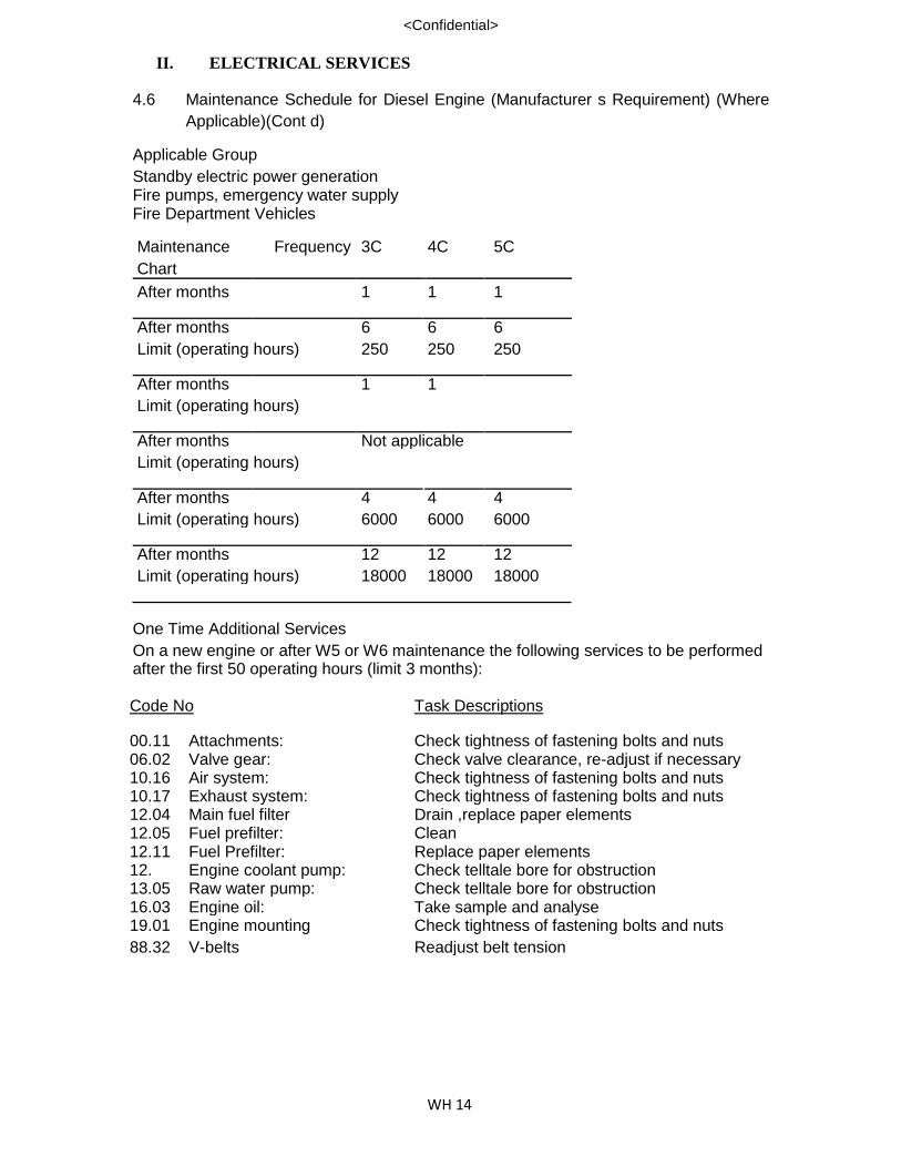
4.6 Maintenance Schedule for Diesel Engine (Manufacturer s Requirement) (Where
Applicable)(Cont d) Applicable Group Standby electric power generation Fire pumps, emergency water supply Fire Department Vehicles Maintenance Frequency 3C 4C 5C
Chart
After months 1 1 1
After months 6 6 6
Limit (operating hours) 250 250 250
After months 1 1
Limit (operating hours)
After months Not applicable
Limit (operating hours)
After months 4 4 4
Limit (operating hours) 6000 6000 6000
After months 12 12 12
Limit (operating hours) 18000 18000 18000 One Time Additional Services On a new engine or after W5 or W6 maintenance the following services to be performed after the first 50 operating hours (limit 3 months):
Code No Task Descriptions
00.11 Attachments: Check tightness of fastening bolts and nuts 06.02 Valve gear: Check valve clearance, re-adjust if necessary 10.16 Air system: Check tightness of fastening bolts and nuts 10.17 Exhaust system: Check tightness of fastening bolts and nuts 12.04 Main fuel filter Drain ,replace paper elements 12.05 Fuel prefilter: Clean 12.11 Fuel Prefilter: Replace paper elements 12. Engine coolant pump: Check telltale bore for obstruction 13.05 Raw water pump: Check telltale bore for obstruction 16.03 Engine oil: Take sample and analyse 19.01 Engine mounting Check tightness of fastening bolts and nuts
88.32 V-belts Readjust belt tension

II. ELECTRICAL SERVICES
WH 15
<Confidential>
Maintenance Echelon W1: Monthly Test Run
Code No Task Descriptions
00.04 Engine Operation: Check engine revolutions, temperatures and pressures where gauges are installed. 00.06 Power Plant: Clean externally 00.12 Engine Operation: Perform test run (not less than 1/3 load).Operate
engine at least until temperature reached. 10.01 Air system: Check condensate bleed line of intercooler inlet
cover for water discharge 12.01 Fuel Prefilter: Turn filter handle several times 12.02 Fuel: Check supply 12.03 Fuel: Drain leak fuel tank 12.17 Fuel Prefilter: Drain water and contaminants 14.01 Engine Coolant: Check level 16.01 Engine oil: Check level 16.01 Compressed air: Check supply 18.02 Compressed air: Drain condensate from compressed-air system 86.01 Battery: Check state of charge, electrolyte level and
specific gravity* 88.01 V-belts: Check condition and tension 00.03 Engine Operation: Check engine and external pipework for leaks 08.02 Governor linkage: Check the linkage between governor and
injection pump(s) does not bind, and lubricate 10.03 Air filter: Check oil level in oil-bath air filter 10.06 Air system: Check function of emergency air shut-off flaps 14.03 Engine coolant: Take sample and analyse 14.08 Engine coolant cooler: Check lower and lubricate linkage 14.12 Raw water: Check supply
16.03 Engine Oil: Take sample and analyse
00.07 Lubrication points: Lubricate 06.02 Valve gear: Check valve clearance and readjust 06.18 Valve gear: Check cylinder head cover gasket, replace if
necessary 10.02 Air filter: Clean (multi-plate or wet plate air filter, screen) 10.04 Air filter: Change oil of oil-bath air filter 10.07 Air system: Check charge pressure 10.21 Exhaust System: Inspect system, and check drains for obstruction 12.04 Fuel filter: Drain, replace paper elements, clean felt-tube
element if multi-stage filter is provided. 12.05 Fuel prefilter Clean
12.11 Fuel prefilter Replace paper elements

II. ELECTRICAL SERVICES
WH 16
<Confidential>
Code No Task Descriptions
14.04 Engine Coolant: Change coolant, flush cooling system
14.21 Engine Coolant: Clean strainers, in coolant outlet line after
exhaust manifolds ( not applicable to TC.0 and
TC.1 engine version)
16.04 Centrifugal oil filter: Check thickness of deposited oil sludge, clean
filter
16.05 Engine oil filter: Drain oil sludge and examine for metallic residue
16.06 Engine Oil: Change
16.15 Engine Oil filter: Replace paper elements and sealing rings, clean
fitler shell
16.27 Oil filter/oil filling line: Replace filter element, clean filter shell
18.04 Starting air filter: Clean /or replace element
18.17 Starter: Inspect carbon brushes
18.18 Starter: Grease Terminals
84.02 Monitoring system: Check function of monitoring instruments
86.03 Compressor: Change Oil
88.2 Torsionally resilient Coupling: Inspect for proper condition
* unless otherwise specified by manufacturer. Maintenance Echelon W5. The W1 W3 maintenance echelons can be accomplished
without the need for engine disassembly whereas the W5 echelon requires partial
disassembly. The following is a list of W5 services and checks to be made in addition to
those given for the W1 W3 echelons.

II. ELECTRICAL SERVICES
WH 17
<Confidential>
Code No Task Descriptions
00.08 Cylinders: Check compression pressure 02.01 Gear train: Make visual inspection ( do not disassemble) 03.02 Running gear: Each cylinder bank: Check appearance of 1 cylinder liner
03.03 Running gear: Each cylinder bank: Check condition of 1 piston crown
05.08 Cylinder heads: Each cylinder bank: Remove and disassemble 1 cylinder
05.10 Cylinder heads: Replacering on protective sleeve 06.03 Valve gear: Each cylinder bank: remove 1 rocker arm and inspect
06.04 Valve gear: Each cylinder bank: remove 1 valve tappet and check for wear
09.06 Exhaust Turbo charger: Remove,disassemble,clean, checkbearing clearance
09.10 Exhaust Turbo charger: Perform leak-test (water-cooled turbocharger only)
10.05 Air system: Clean intercooler condensate bleed line 10.08 Air manifolds: Remove,clean and replace gasket 10.09 Air filter: Remove and clean oil-bath air filter 10.10 Exhaust manifolds: Remove, clean, replace gasket 10.12 Intercooler: Remove, clean, leak-test
10.19 Air filter: Replace paper element*
10.23 Exhaust system Check condition of insulation
10.33 Exhaust manifolds: Perform leak test (water-cooled manifolds only) 11.01 Fuel injection nozzles: Remove and check replace if necessary, replace sealing rings
11.09 Fuel injection timer: Injections
11.15 Fuel injection pump Check start-of-supply point
12.07 Fuel filter: Replace felt-tube element(multi-stage filter only) 12.08 Fuel: Clean tank, inspect fuel pipes and seals 12.09 Elect. Fuel delivery pump: Change grease in bearing*
13.06 Engine coolant pump: Disassemble, inspect, replace seals 13.07 Raw water pump: Disassemble, inspect, replace seals 14.02 Raw water: Clean filter
14.05 Engine coolant cooler: Remove,clean ,leak-test
14.07 Engine coolant: Check coolant preheater
14.13 Engine coolant cooler: Clean cooler fins
14.25 Coolant thermostat: Replace pellet case

II. ELECTRICAL SERVICES
WH 18
<Confidential>
Code No Task Descriptions
16.09 Engine oil heat exchanger: Remove, clean and leak-test
16.18 Engine Oil filter: Remove, clean, replace gasket
16.23 Engine oil: Clean supplementary tank, check seals and
pipes
16.24 Centrifugal oil filter: Remove, disassemble, replace bearing if
necessary
16.29 Engine oil heat exchanger: Check unloader valve and bypass valves
18.03 Starting valves: Check for leaks
18.05 Starting air systems: Check starting valves
18.07 Starting air pipework: Remove and clean
18.08 Starting air distributor: Check and readjust
18.09 Starting air system: Check air bottles and /or tank for leaks
18.10 Starters: Remove and check
19.01 Engine mounting: Check tightness of fastening bolts
19.02 Engine mounting: Make visual inspection of each mount
27.01 Additional controls: Replace expansion element
86.02 Generator: Remove and check*
86.08 Alternator: Change grease and/or oil used for bearing
lubrication*
86.19 Alternator: Measure insulation resistance; if necessary,
clean alternator and dry*
87.13 Engine controls: Check speed adjuster coupling
87.15 Engine controls: Check function
88.31 Mechanical fan drive: Change grease and/or oil of fan axle, tensioner
and drive coupling
Maintenance Echelon W6. The W6 echelon requires engine removal and complete
disassembly.
* unless otherwise specified by manufacturer.

II. ELECTRICAL SERVICES
WH 19
<Confidential>
5 MAINTENANCE SCHEDULE FOR FREQUENCY CONVERTER
5.1 Service/Maintenance Scope of Work (a) Visual check-up of entire system. (b) Inspection of cable connections and electrical contacts. (c) Testing of alarm points and functions by simulation. (d) Testing or protective and functional appliances. (protective relays are
checked once a year by means of secondary testers) (e) Possible application of lubrication in the case of convertors. (f) Cleaning of the equipments. (g) Trial testing and functional control of the system if applicable. (h) Note: A checklist will be prepared and submitted to the principal upon
acceptance of the contract. All work carried out will be recorded against the
checklist. 5.2 Maintenance Schedule
Work Schedule as follows:
Converters not running
(a) Measurement of resistance:-
Motor stator winding Generator stator winding
(b) Connections:-
Tightness of terminal blocks connections Tightness of components/wires connections Tightness of power cables connections

II. ELECTRICAL SERVICES
WH 20
<Confidential>
(c ) Cleanliness:-
Cleaning of electrical contacts Cleaning of components dust Cleaning of machinery dust
(d) Lubrications:-
Lubrication of bearings
(e) Control System:-
Sequential control of switchboard
(f) Protection
checking/adjustment of current, voltage and time relays
(g) Monitoring
Simulation of monitoring points, fault signals and protection
(h) Vibration
Detection for vibration and mechanical contact of rotor Short time run for vibration detection
Converters running
(a) System operation:-
System operation for 15 minutes Measurement /adjustment of voltage, ampere, and frequency.
6 OTHERS 6.1 Transformers
Transformers shall comply with requirements of BS 326 where these apply and
except where these equipments are modified by the following sub-clauses: (a) Transformers shall be capable of providing continuously the necessary secondary
voltage and current when the primary winding is connected to a source of supply
having the rated primary voltage frequency. (b) Transformer shall be double-wound with windings insulated with Class A materials.

II. ELECTRICAL SERVICES
WH 21
<Confidential>
(c) One point of the Secondary winding of the transformer shall be connected to the
core and it shall be connected to an earthling terminal on the body of the
containers.
(d) The transformer shall when energised at rate voltage and frequency and
after 6 hours continuous operation, the temperature rise with ambient
temperature 30 degree C shall not exceed 90 degree C. 6.2 Casing
Ancillary equipment, including conductors, capacitors, resistors and transformers not forming part of a self-contained luminous discharge tube device for use in the interior of a building shall be either totally enclosed in a substantial earthed metal container or alternatively shall be placed in a suitable ventilated enclosure of incombustible material which is reserved for high voltage apparatus. Any cover on the container shall be capable of being securely fastened.
6.3 Earthing
All exposed metal shall be bonded together and provided with a terminal for
earthling purposed. 6.4 Live Metal Parts (a) No part of any conductor of the high-voltage circuit shall be in metallic
connection(except in respect of its connection with earth) with any conductor of the
supply system or with the primary winding of the transformer. (b) Conductors shall be so fastened to lampholders terminals s to be mechanically
and electrically secured. (c) All sealing compound shall be incapable of supporting combustion. 6.5 Cable Entry
Where a cable is taken into an enclosure, the entry to the enclosure shall be
bushed or so finished as to prevent abrasion of the cable. In addition the entry shall
be so arranged as to minimize the entry of water. 6.6 High Voltage Cable
High-voltage connections shall be made by cables complying with the appropriate
clauses of BS 559 except as provided in clause 10.2 and 10.3.Metal sheathed, or
amoured, or metal-sheathed and armoured, cable shall be used,

II. ELECTRICAL SERVICES
WH 22
<Confidential>
except that cable having a non-metallic sheath may be used for inter-lamp series
connections not exceeding 3m in length which are not likely to suffer mechanical
damage or which are installed in box signs constructed substantially of non-
combustible mentioned.
Subjected to Clause 10.3bare or lightly-insulated conductors of copper or nickel having a cross-sectional area of not less than 0.3959m2(1/0.71mm) may be used for high-voltage series connections, provided that the conductor does not exceed 1 m in length, as supported at the intervals not greater than 500mm is not exposed to the likelihood of mechanical damage and is completely protected by non-combustible, non-hygroscopic insulting material which, if in the form of glass tubing, has a wall thickness not less than 1mm and an overall diameter not less than 5 mm and is so arranged as to be reasonable secure against any displacement which would expose any part of the live metal.
For shop-front fascia installation, bare or lightly insulated conductors shall be used
only for connections housed within a earthed metal enclosure or for connections
between the terminals or electrode housing. 6.7 Supports for high-voltage cables and conductors
Supports for insulated-and braided cables and for bare conductors shall be non-
combustible, non-hygroscopic insulating material e.g glass or glazed porcelain. 6.8 Earthed Return Conductors
The return cable from the electrode to a transformer terminal which is earthed may
be a 600/2000V or 600V cable in accordance with SS50 provided that the cross
sectional area of the conductor is not less than 2.6mm2. 6.9 Neon Signs
The neon signs shall be serviced bi-annually. The servicing shall include the
followings:- (a) To check all electrical connections tighten any loose connection. (b) To replace any defective parts (c) Test run to ensure neon signs are in good working condition. (d) To remove bird nest or any items found behind the signs to prevent a short circuit.

II. ELECTRICAL SERVICES
WH 23
<Confidential>
(e) Any other related works to maintain the neon signs in working order.
6.10 Hand Dryer
As per manufacturer s recommendation.

III. FIRE PROTECTION SYSTEM
WH 1
<Confidential>
1 FIRE ALARM SYSTEM 1.1 Monthly Servicing
(a) Notify Airport Fire Services of the intention to shut down the fire alarm system.
(b) Simulate fire conditions by operating the test switches on all groups and re-
setting the installation to normal after the completion of the test.
(c) Check the battery voltage by operating the battery test switch and record the
voltage under local condition" in the log book.
(d) Check the condition of the storage batteries including the terminals and
maintain them in a serviceable condition.
(e) Check the condition of the battery cabinet for corrosion and ensure that the
batteries are stored in a secure condition.
(f) Check to ensure that all twin indicating lights are operating correctly and replace
them if they are faulty. (g) Check the operation of the external alarm bell and equipment shut down on
sequence.
(h) Check individual detector and manual station by sequence for proper response as indicated by the lighting of the test lamp, trouble light and alarm light. The detector must be cleared and the system must be reset at the control unit after each individual detector is tested.
(I ) Check the operation of the direct Airport Fire Service alarm transmitter and
ensure the transmitter hollies correctly to the reset position.
(j) Check the power supply failure facility by disconnecting the battery and main
supply.
(k) Check the initiation facilities to operate remote control functions in accordance with the appropriate codes. Where the air handling plant shut down facilities are provided, these-should be operated at least on a monthly basis. The Authorised Representative should, however, be notified prior to the shut-down and the Employer shall provide the personnel to be in attendance and to re-start the plant.
(I) Check that the fire indicator board is in a clean and operative condition and
ensure that the enclosure is maintaining a satisfactory dust seal.
(m) Visually inspect the condition of all components, including resisters, capacitors
and cable.
(n) Inform the Authorised Representative any circuits which are subject to repair,
alteration or extension.
III. FIRE PROTECTION SYSTEM
WH 2
<Confidential>
(o) Record monthly details of the routine test together with emergency visits, if any.
(p) Check that all switches are returned to their normal operating position.
(q) Notify Airport Fire Service on completion of the tests.
1.2 Annual Testing (a) Notify Airport Fire Service of the intention to shut down the fire alarm system. (b) Combustion Product Detectors should be cleaned annually by blowing clean, dry air
through the opening between the collector plate and the well where the radium sensor is located. If the foreign material is difficult to remove, it may be cleaned with a swab saturated with alcohol.
(c) With the system operating, remove one lead from each of the detector circuits, one
circuit at a time, at the control unit, or at a detector if more convenient and ascertain that the trouble alarm is activated.
(d) Shutdown the unit by switching off the mains supply and disconnecting the batteries.
- (e) Thoroughly check the whole unit for loose connections, terminals, fray wires, etc. (f) Check all switches and push buttons for smooth accurate operation and function. (g) Check all lamp globes for correct voltage and operation. (h) Replace any broken or suspect equipment as may be required. (i) Re-assemble. (j) Reconnect the batteries and switch the mains supply on. (k) Check any relays for correct adjustment and quick effective operation. (1) Check the battery charge operation and output. (m) Check the operation of all shutdown sequences and reset required. (n) Test the unit in accordance with steps 1. 1 to 1. 11 of the monthly test. (o) Enter the results of the tests in the Log Book. (p) Notify Airport Fire Service on completion of the tests.

III. FIRE PROTECTION SYSTEM
WH 3
<Confidential>
1 FIRE PROTECTION SYSTEM (MONTHLY) (Cont'd) 1.2 Fire Alarm Panel
a. Check all the panel power supplies. b. Ensure all wires and properly terminated. c. Check and tighten, if necessary, all wiring contacts and terminations. d. Check battery chargers. e. Check batteries voltage and functionality.
Disconnect battery connection and confirm LED alarm indicators are- in operation.
h. Ensure all the electronic cards are properly secured. i. Check and test all the LEDs display j. Check proper bus communication between panels k. Clean excessive dust/heat. l. Verify that the programme is functioning. m. Activate a smoke detector zone. n. Stimulate a call point alarm. 1.3 Functional Test h. Functional test to ensure signal is received at Fire Station (Cisco Monitoring Centre).
i. Functional test on breakglass call point and fire alarm bell j. Functional test of smoke detector k. Functional test on Ventilation Fans, AHUs, Lifts which are interlocked with Fire Alarm. 1.4 Printer
a. Visual check on system printout. b. Check alarm printout. c. Check line feed and form feed function. d. Check and ensure proper gap for the printhead. e. Check and ensure smooth carriage motions. f. Run printer self test. g. Clean excessive dust.
h. Check proper cable and tighten if necessary. i. Replace printer paper.
2 AUTOMATIC SPRINKLER SYSTEM 2.1 General
2.1.1 After any servicing, alterations or repairs, inspection should be made to make sure that
the valves are in fully open position, sealed and the system in operational condition.

III. FIRE PROTECTION SYSTEM
WH 4
<Confidential>
2 AUTOMATIC SPRINKLER SYSTEM (Cont'd)
2.1 General (Cont'd) 2.1.2 When any alterations, additions or repairs are to be made involving interruption of the
sprinkler protection in whole or part, the Maintenance Engineer-in-charge should be
notified and proper recording is done to reflect the changes in the system. Submission
to FSB by PE may be necessary. 2.1.3 When building extensions, new partitions or enclosures are erected, the required
extension of the sprinkler system in the new areas should be completed promptly. 2.1.4 When repairs or alterations affecting the sprinkler system are in progress, special
provisions should be made to keep the sprinkler system in service in all areas not
affected. When the sprinkler system is turned off during the day to allow for work in
progress, it should be restored at night. 2.1.5 If the sprinkler system is necessarily need to be turned off in any portion overnight, then
precautionary measures should be taken to post a specially instructed personnel to
guard the portions without sprinkler protection. 2.1.6 Sprinkler valves are sometimes inadvertently left closed after alterations or repairs have
been completed. A responsible person should be made to check the condition of the
system following any such work to make sure that all the control valves are in fully open
position and properly sealed. 2.2 Sprinkler Heads 2.2.1 Sprinkler heads should be checked regularly to make sure that they are in good
condition, clean, free from corrosion, not painted or whitewash and not be bent or
damaged. It should be replaced when they are painted, corroded or damaged. 2.2.2 Sprinkler should be protected against mechanical injury. Where there is danger of
injury, approved sprinkler guards should be provided. 2.2.3 Always use the special sprinkler wrench in removing or installing sprinklers. Other types
of wrenches may injure the sprinkler. 2.2.4 An adequate supply of extra sprinklers should be on hand. 2.3 Piping
2.3.1 Piping should be kept in good condition and free from mechanical injury. 2.3.2 Sprinkler piping should not be used for support for ladders, stock or other material.

III. FIRE PROTECTION SYSTEM
WH 5
<Confidential>
2 AUTOMATIC SPRINKLER SYSTEM (Cont'd)
2.4 Piping Hangers 2.4.1 Hangers should be kept in good condition. Broken or loose hangers should be replaced
or refastened. 2.4.2 Broken or loose hangers may put undue strain on piping and fittings, causing breaks
and interfere with proper drainage.
2.5 Water-Flow Alarm Devices
2.5.1 Water-flow alarm devices should be tested annually.
2.6 Sprinkler Tank 2.6.1 Periodic inspections should be made to ensure that the water level are at its maximum
capacity level. 2.6.2 Constant maintenance of a full supply of water in sprinkler tanks is necessary so as to
ensure proper performance of the sprinkler system in the event of a fire.
2.7 Sprinkler Pump 2.7.1 The pump should be started once a month. Regular inspection should be made,
checking the maintenance of ample pressure, proper supply of lubricating oil, operative
condition of valves, etc. 2.7.2 The pump room should be kept clean and accessible at all times. 2.7.3 The suction pipes, intakes, valves and screens of fire pumps should be examined
frequently to make sure that they are free from any obstruction. Mud, gravel, leaves
and other foreign materials entering the suction pipe may cause damage to the pump
or obstruction of the piping of the sprinkler system. The automatically controlled
pumping units should be tested monthly by manual means at least one start should be
accomplished by reducing the water pressure. 2.7.4 This may be done with the test drain on the sensing line or with a flow from the fire
sprinkler systems. The examination should be extended to include the condition and
reliability of the electric power supply.

III. FIRE PROTECTION SYSTEM
WH 6
<Confidential>
2 AUTOMATIC SPRINKLER SYSTEM (Cont'd) 2.8 Procedure On Test Running Of Sprinkler Pumpset
(a) Close sprinkler pumpset discharge valve of the pumpset under testing.
(b) Slowly release the pressure switch sensing line pressure by opening the drain
cocks until the preset pressure and the pumpset start up. Close the drain cocks.
Record the-cut-in pressure and the no-flow churning pressure.
(c) Obtain churning pressure of sprinkler pump with discharge valve closed.
(d) Stop the pumpset and open the discharge valve.
(e) Repeat the same procedures for the other pumpset.
2.9 Monthly Service And Maintenance Checklist For Sprinkler System
2.9.1 Inspect the Sprinkler Pumps; and
(a) Check all seals, glands and pipe lines for leaks and rectify as necessary,
(b) Check all pump bearings and lubricate with oil or grease as necessary.
(c) Check the alignment and condition of all rubber couplings between pumps and
drive motors and rectify as necessary.
(d) Check all bolts and nuts for tightness and tighten as necessary.
2.9.2 Inspect the electric motors; and
(a) Check all motor bearings and lubricate with grease as necessary.
(b) Check carbon brushes and clip rings of all motors and clean as necessary.
Renew carbon brushes as necessary.
(c) Check safety devices fitted to all motors and clean, adjust and lubricate as
necessary. 2.9.3 Inspect and check the routine operation of all electrical starters, electrical control gears
and ancillary electrical apparatus, and
(a) Clean, adjust and lubricate all bearings, pivots and other moving parts as
necessary.
(b) Clean or renew electric contactors as necessary.
(c) Renew electric fuses as necessary.

III. FIRE PROTECTION SYSTEM
WH 7
<Confidential>
2 AUTOMATIC SPRINKLER SYSTEM (Cont'd) 2.9.4 Check and adjust all float switches and sequence starting for the pump control
panel. 2.9.5 Inspect all water storage tanks and drains and clean and flush out the tanks
as necessary. Check that stop valves at tank inlet, interconnecting pipes and
pump suction pipes are secured and fully open. Verify the operation of the
automatic tank filling mechanism. Visually check that tank contains requisite
amount of water and verify operation of floatless level control units. 2.9.6 Check and verify that sprinkler installation control valves are strapped and
padlocked in open position. 2.9.7 Check and verify that isolating valve to water alarm motor and gong is secured
and fully open. 2.9.8 Check and verify that installation drain and test valves are secured and fully
closed. 2.9.9 Check and verify that all other isolating valves are secured in their normal open
position. 2.9.10 Check and inspect fire services breeching inlets.
2.9.11 Check and inspect water alarm motors and gong mechanisms.
2.9.12 Check and verify operation of water level indicators. 2.9.13 Testing of sprinkler pumps:
(a) Check and verify the automatic starting of each pump by actuating the drain
and test valve in a manner to reduce the applied water pressure to the
starting device and simulate a fire condition. Record pressure is correct.
Keep each pump running for a period of at least five (5) minutes and verify
the operation of the relief valve.
(b) Check and verify pump running alarm and phase failure alarm.
(c) Check pump starting equipment including fuses, circuit breakers and
starters.
(d) Simulate failure on one of the pumps and verify the operation of the duty-
standby changeover mechanism.

III. FIRE PROTECTION SYSTEM
WH 8
<Confidential>
2 AUTOMATIC SPRINKLER SYSTEM (Cont'd)
2.9.14 The entire sprinkler system should be inspected to ensure that they are free from
damage, corrosion, grease, dust, paint or whitewash and should be replaced where
necessary as a result of such conditions. 2.9.15 Valve systems shall be oiled or greased at least once a month. 2.9.16 Visual inspection and checking of the sprinkler heads for leakages, damages,
obstruction and paint. 2.9.17 Check and repair all valves which are found leaking or defective. 2.9.18 Test flow switches by drawing out water at the drain valve of each floor.
2.9.19 Flushing out water for the system to test the sprinkler alarm bells. 2.9.20 Check correct operation of alarm control valve and alarm gong by discharging water
from the drain valve.
2.10 Annual Test
2.10.1 Simulated mechanical or electrical failure of duty pump and the ability of the standby pump to come in automatically and maintain the required output should be tested.
Check and verify that local and remote pump failure warning function properly. 2.10.2 Every pump suction tank should be completely flushed out and thoroughly cleaned. 2.10.3 The water in the whole sprinkler pipework system should be completed drained out and
filled with fresh water again.
3 HOSEREEL SYSTEM - QUARTERLY SERVICING
3.1 Check the hosereels and rubber hose for damage.
3.2 Check the operation for the nozzles for blockage.
3.3 Check and verify the operation of the 25 mm stop valve at the hosereel feed
pipework and ensure that the valve is secured and fully closed.
3.4 Check and verify that the hose guide rollers move freely with the hose (N.B.
This is to be determined by running out a few metres of the hose from real).

III. FIRE PROTECTION SYSTEM
WH 9
<Confidential>
3 HOSEREEL SYSTEM - QUARTERLY SERVICING (Cont'd)
3.5 Check and verify all pump suctions. 3.6 Check and verify all pump suctions and delivery valves are fully open. 3.7 After checking, the hose shall be rewound in level layers, the valve shut off and the
hose depressurised (where possible). 3.8 Check that the main water supply gate valves are locked and strapped in the open
position. 3.9 Check that access to fire hosereel is not obstructed by the location of furniture,
equipment or other such materials.
4 ELECTRIC MOTOR DRIVEN PUMP - MONTHLY SERVICING
4.1 Check and verify all pump suctions and delivery valves are fully: open. 4.2 Check and verify the pump starting by actuating the test valve in a manner to stimulate
fire conditions. Record the pressure at which the pump starts. Ensure that this pressure
is correct as per the pump operating instructions. 4.3 Run the pump for a minimum period of two (2) minutes.
4.4 Check and verify the pump running alarm.
4.5 Check the pump starting equipment including fuses and breaker starters.
4.6 Check and verify the phase failure alarm.
4.7 Check and verify, where appropriate, the pump priming arrangements. 4.8 Check and verify no excessive noise or vibration of the pump and motor while the unit
is running. 4.9 Run the pump under full load for 60 minutes if practical. 5 UNDERGROUND HYDRANT - MONTHLY SERVICE
5.1 Check all Hydrant to be in serviceable condition.
5.2 Check and service Hydrant pump and Jockey pump as per item 2.
5.3 Check and repair Hydrants at site for any defects and leakage pipe line.

III. FIRE PROTECTION SYSTEM
WH 10
<Confidential>
7 PREACTION SYSTEM
The following inspection and/on maintenance procedure should be scheduled as listed
below on performed upon the occurrence of any event which might bias the reliability of
the system.
WARNING : DO NOT TURN OFF THE WATER SUPPLY TO MAKE REPAIRS
WITHOUT PLACE A ROVING FIRE PATROL IN THE AREA
COVERED BY THE SYSTEM. THE PATROL SHOULD
CONTINUE UNTIL THE SYSTEM IS BACK IN SERVICE.
Prior to turning off any valves or activating any alarms, notify local security guards so
that a false alarm will not be signaled.
7.1 Normal Conditions
i) All main control valves must be opened
ii) .The alarm test valve is in the ON position
iii) The priming-line valve closed
iv) The magnetic by-pass light is OFF
7.2 Monthly Maintenance
i) The system should checked for normal condition
ii) Test the water-motor alarm or turning the alarm test valve to the test position.
The alarm should sound
iv) Depress the drip check (significant water accumulation indicates a possible seat
leak).
7.3 Semi-Annual Test
i) Perform the weekly test
ii) Conduct a water-flow test
a) Record the static water-pressure appearing on the priming-line
pressure gauge

III. FIRE PROTECTION SYSTEM
WH 11
<Confidential>
7 PREACTION SYSTEM
7.3 Semi-Annual Test (Cont'd)
b) Open the flow test valve-fully and record the residual water-pressure appearing on the priming line pressure gauge
c) If the residual water-pressure reading in considerable lower than the
previously recorded reading, place the system out of service, clear all
supply lines and priming line strainers, and check for a partially-closed
valve or supply-line obstruction.
d) Trip the release-line system clean all strainers and priming-line
restriction.
7.4 Monthly Maintenance of Air Compressor
i) Check for normal operation
ii) Change oil if necessary
iii) Check the air filter and the dehydrator
iv) Annual inspection by relevant authority and obtain Certificate of fitness.
8 HALON SYSTEM
Halon 1301 Total Flooding System Equipment - Monthly Service
WARNING : THE ACTUATION DEVICE MUST BE DISCONNECTED EITHER AT
THE CONTROL PANEL OR ACTUATION DEVICES BEFORE
PERFORMING THE MAINTENANCE WORK. 8.1 Defection And Actuation System
i) To check and clean smoke detectors
ii) To check effectiveness of gas actuation devices including the condition of the
gas initiator
iii) To check effectiveness of bells, smoke detectors, manual breakglass push
buttons and time delay unit for discharge of gas
8 HALON SYSTEM
8.1 Defection And Actuation System (Cont'd)

III. FIRE PROTECTION SYSTEM
WH 12
<Confidential>
iv) To check all function key on the control panel that they are operating correct as follows:-
. Acknowledgement of alarm and trouble
. Disable actuation of EXTINGUISHING
. RESETTING of alarm
. Enable ACTUATION OF EXTINGUISHING
. Switching OFF/ON of detector zone
. Lamp test
v) To check performance of remote alarm to main fire alarm panel
vi) To check performance of interlock to shut down process.
8.2 Agent Supply
i) To check pressure of gas in spheres (Pressure must not be higher and lower than the
blue mark shown in the pressure gauge)
ii) To check for damages or corrosions of the spheres
iii) To check all brackets, supports, etc for holding the spheres
iv) To check the weight of gas content in the spheres. This shall be done annually before the
expiry of the annual contract.
8.3 Electrical System 8.3.1 To check condition of battery and battery charger unit in good operational order. Check
also water level in the battery and top up battery water level as and when it is necessary. 8.3.1.1 To check voltage level of battery.
8.3.2 To check all indicators and warning lights for proper functioning equipment 8.3.3 To check emergency lighting, if any 8.3.4 To'check shutdown of electrical power supply for air conditioner during discharge of Halon
gas.
8.3.5 To check and visually inspect condition of all electrical components in the control panel
including resistors, capacitors cable and wire connections.

III. FIRE PROTECTION SYSTEM
WH 13
<Confidential>
8 HALON SYSTEM
8.3 Electrical System (Cont'd) 8.3.5.1 To check proper functioning of supervisory circuits including for fault in the
external circuit. 8.3.6 To check operation and effectiveness of power supply failure facility by
disconnecting the mains supply from the battery charger. 8.4 Annual Inspection 8.4.1 Products of Combustion Detector Cleaning - the minimal requirement for
detector maintenance consists of an annual cleaning of dust from the collector
plate screen only. 8.4.1.1 Cleaning programs should be geared to the individual environment in area
where an oily film or other coating may develop, the collectors plate screen must
be periodically cleaned with chemically pure alcohol. Material used in cleaning
should be discriminately destroyed after used.
CAUTION: DO NOT CLEAN THE RADIOACTIVE SOURCE OR THE DETECTION CHAMBER UNLESS IF-IS ABSOLUTELY NECESSARY. IP THESE AREAS MUST BE CLEANED, THE DETECTOR MUST BE HELD SO THAT YOUR HAND CONTACTS METAL SURFACE OF THE DETECTOR WHILE CLEANING IS PERFORMED. FAILURE TO GROUND YOUR BODY TO THE DETECTOR DURING CLEANING PROCESS CAN COME PERMANENT DAMAGE TO THE DETECTOR.
8.4.2 Remove the detector and initiator connections at the Control Panel. Check
insulation resistance to ground using a 500V DC megohmeter whose current
output is limited to 50m. A maximum Insulation resistances must exceed 2
megohms. Replace detector connection only. 8.4.2.1 Tape or otherwise insulate the initator field leads. Connect a 24V DC test lamp
the initiator terminals in the Control Panel.
a) Check each individual detector and manual release station and abort
switch for proper response as indicated by lighting of the test lamp,
trouble light and alarm light. The detector must clear and the system
must be reset at the control unit after each individual detector is tested.
Thermal detectors may be tested with a test lamp. Ultraviolet detector
may also be tested with any ultraviolet source - normal lamps will not
sufficient for this test, quartz-iodide lamps or equivalent are
recommended. Products of combustion detectors may be tested with a
smoke generating freon device. These detectors may be connected for pre-alarm.

III. FIRE PROTECTION SYSTEM
WH 14
<Confidential>
8 HALON SYSTEM
8.4 Annual Inspection (Cont'd)
b) With the system operating, remove one lead from each of the detector
circuits - one circuit at a time at the control panel or at a detector (if more
convenient) and a ascertain that the trouble alarm is activated.
c) Disconnect the initiators at each agent storage container and install
jumper wires at the connector in place of the initiators. Connect a 24V
DC test lamp in series with the initiator loop and connect to the initiator
at the contort panel. Install a temporary jumper across actuating
terminals of a detector circuit and turn the system on. Test light, and fire
light should function. Remove jumpers from each initiator, cable in turn,
and the test light should go out indicating integrity of this circuit. If the
system is equipped with a secondary or reserve supply, turn the system
off, switch to the secondary supply and repeat this test procedure.
d) Inspect all piping, fittings and nozzles for looseness, dirt or other
damage. Disconnect piping at the agent storage container and blow out
with low pressure air, if needed.
e) Disconnect all temporary test wiring, remove test devices, reconnect all
system components as they were originally and turn the system on. 8.5 Initiator Replacement
The initiators in each storage container must be replaced periodically. The life will vary
with the ambient temperature. The following is recommended.
MAXIMUM EXPOSURE TEMPERATURE REPLACE AFTER
80°F 5 years 100°F 3 years 120°F 2 years
140°F 1 year
If a container has relieved as a result of overheating both the initiator and the well should
be replaced regardless of age.
RECONDITIONING
Following actuation, the agent storage container must be reconditioned. Each container
would require the amount of Hal on 1301 specified.
Initiator should not be connected into the circuits until it has been ascertained that all
detectors are clear and that there are not wiring fault. Initiator cables and any activated
manual release station and abort switch must be reset before reactivating the system.

III. FIRE PROTECTION SYSTEM
WH 15
<Confidential>
8 HALON SYSTEM
8.6 Refilling Of Halon 1301
Refilling of Halon 1301 shall be done within 24 hours after the discharge of the gas. 9 DECAM SYSTEM
(To manufacturer's requirement)
10 Monthly/half yearly/yearly test results must be submitted after every test. 11 Check and ensure all self contained breathing apparatus are proper maintain and ready
for uses.

III. FIRE PROTECTION SYSTEM
WH 16
<Confidential>
11 FIRE AND JOCKEY PUMPS
11.1 Check and test the running of all fire pumps accordingly to their required operation. 11.2 Check, record and verify all fire and jockey pumps pressure gauges reading for cut-in
and cut-out of duty standby pump and jockey.
11.3 Check that all stop valves are secured in the open or closed positions as appropriate,
including valves located for remote from the main control valve.
11.4 Operate all pressure reducing valve (where appropriate) to the full and correct
operation under all flow conditions and check the pressure side of the valves for
deterioration from the original test reading. 11.5 Check adequacy of lubricating fluid for all bearings and supplement where necessary. 11.6 Correct any excessive leakage from gland and shaft packings. Renew packings where
necessary.
11.7 Clean all component parts of each equipment.
11.8 Check and verify all pump suctions and delivery valves are fully open. 11.9 Check and verify pump starting by actuating test valve in a manner to simulate fire
condition. 11.10 Check for presence of any excessive/abnormal noise and vibration. Investigate and
report on cause and initiate remedial measures.
11.11 Check the oil alarm motor and gong mechanism. 11.12 Check speed of all operating pumps. Abnormal conditions are to be reported and
remedial measures initiated.

III. FIRE PROTECTION SYSTEM
WH 17
<Confidential>
12 MAINTENANCE SCHEDULE FOR FIRE EXTINGUISHERS
a) The following checklist (where applicable) to be carried out for all fire
extinguishers, including wheeled types during each half-yearly servicing:-
b) When extinguishers which removed for repair or refilling, the temporary
replacement extinguisher shall be provided.
12.1 Checklist and Corrective Action

III. FIRE PROTECTION SYSTEM
WH 18
<Confidential>
Part Items To Check Corrective Action
Label 1. 1.Illegible 1. 1.Clean or
wording replace
2.Corrosion or loose label 2.Inspect body under label for
corrosion and refix label
Body 1. Hydrostatic test date of 1. Retest if expired.
date of manufacture.
2. Corrosion 2. Hydrostatic test and repaint, or
3. Mechanical damage discard.
3. Hydrostatic test and repaint or
(denting or abrasion) discard.
4. Plant condition 4. Clean and repaint
5. Evidence of previous 5. Discard or consult manufacturer.
repairs (welding, soldering,
brazing, etc)
6. Damaged threads 6. Discard or consult manufacturer
(corroded, cross-threaded or
worm)
7. Damaged sealing surface 7. Clean, repair, and leak test; or
(nicks or corrosion) discard
8. Broken hangar attachment, 8. Discard or consult manufacturer
carrying handle lug

III. FIRE PROTECTION SYSTEM
WH 19
<Confidential>
Ill FIRE PROTECTION SYSTEM
12.1 Checklist and Corrective Action (Cont'd)
Part Items To Check Corrective Action
Nozzle or Horn 1. Brittle, deformed, 1. Replace
damaged or cracked 2. Clear blockage
2. Blocked openings
3. Damaged-threads 3. Replace
(corroded, cross-threaded
or worn
Hose Assembly 1. Punctured, cracked or 1. Replace
worn hose
2. Cracked or corroded 2. Replace
couplings
3. Cracked or corroded 3. Replace
swivel joint
4. Damaged threads 4. Replace
(corroded, cross-
threaded or worn)
5. Hose cut at couplings 5. Repair or replace
6. Clogged or deformed 6. Clear blockage or
hose replace
Valve Safety Device 1. Damaged (corroded, 1. Repair and lubricate; or
bent or seized) replace
2. Missing 2. Replace
Gauge or other pressure 1. Damaged, jammed or 1. Depressurize and
indicating device missing pointer replace gauge
2. Depressurize and
2. Illegible or faded dial replace gauge
3. Corrosion 3. Depressurize and check
calibration, clean and
repaint; or replace
gauge
4. Dented casing or
defaced, broken or 4. Depressurize and check
cracked cover calibration; or replace
gauge

III. FIRE PROTECTION SYSTEM
WH 20
<Confidential>
12.1 Checklist and Corrective Action (Cont'd)
Part Items to Check Corrective Action
Gauge or other pressure 5. Jammed or corroded 5. Depressurize and indicating device pressure-indicating replace head assembly, or
stem(non-gauge type) body whichever
appropriate.
Body Valve 1. Corroded, damaged or 1. Depressurize, check jammed lever, freedom of handle,spring,stem, or movement and
fastener joint repair; or replace
2. Damaged outlet threads( corroded, 2. Depressurize and cross-threaded, or replace
worn)
Nozzle Shut-off Valve 1. Corroded, damaged, 1. Repair and lubricate; or
jammed or binding replace
lever, spring, stem,
or fastener joint
2. Clogged,deformed or 2. Clean or replace
corroded nozzle
Puncture Mechanism 1. Damaged, jammed or 1. Replace
binding puncture lever,
stem or fastener joint
2. Blunt or damaged 2. Replace
cutting or puncture pin
3. Damaged threads 3. Replace
(corroded, cross-
threaded or worn)
Gas Cartridge 1. Corrosion 1. Replace
2. Damaged seal disc 2. Replace Cartridge
3. Damaged threads 3. Replace cartridge (corroded, cross-
threaded or worn)
4. Illegal weight marking 4. Replace cartridge
WFP-18
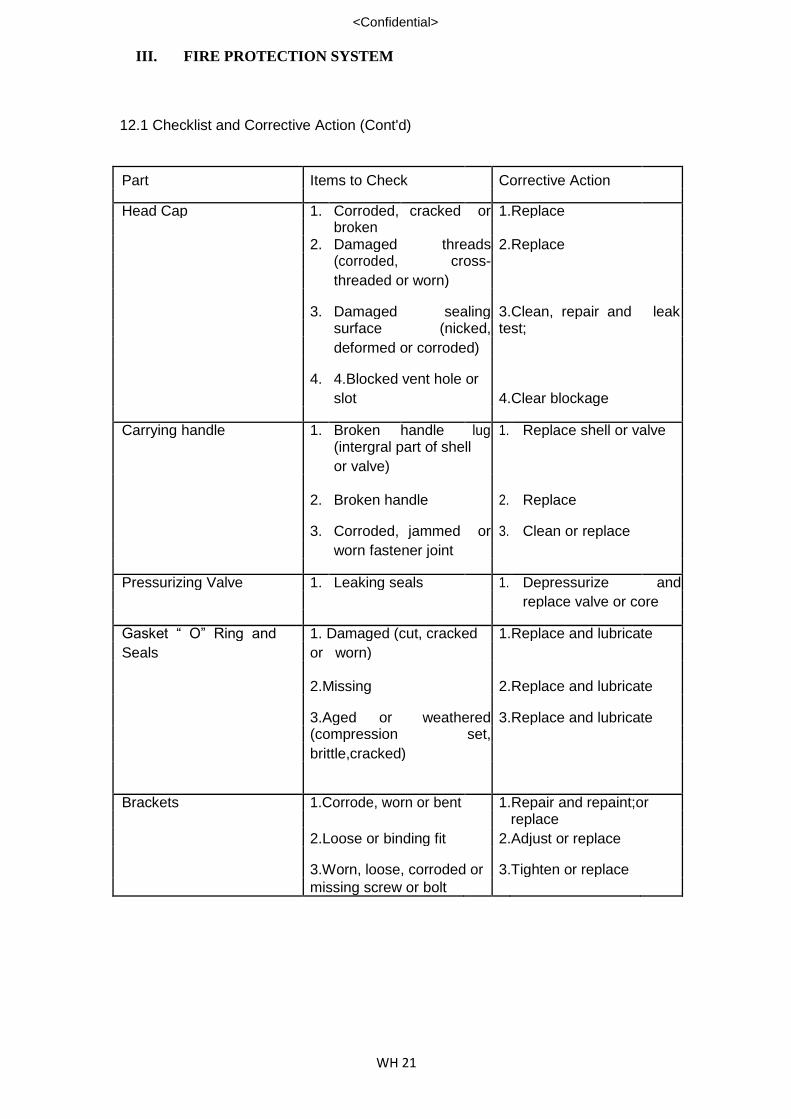
III. FIRE PROTECTION SYSTEM
WH 21
<Confidential>
12.1 Checklist and Corrective Action (Cont'd)
Part Items to Check Corrective Action
Head Cap 1. Corroded, cracked or 1.Replace
broken
2. Damaged threads 2.Replace
(corroded, cross-
threaded or worn)
3. Damaged sealing 3.Clean, repair and leak surface (nicked, test;
deformed or corroded)
4. 4.Blocked vent hole or
slot 4.Clear blockage
Carrying handle 1. Broken handle lug 1. Replace shell or valve (intergral part of shell
or valve)
2. Broken handle 2. Replace
3. Corroded, jammed or 3. Clean or replace
worn fastener joint
Pressurizing Valve 1. Leaking seals 1. Depressurize and
replace valve or core
Gasket “ O” Ring and 1. Damaged (cut, cracked 1.Replace and lubricate
Seals or worn)
2.Missing 2.Replace and lubricate
3.Aged or weathered 3.Replace and lubricate (compression set,
brittle,cracked)
Brackets 1.Corrode, worn or bent 1.Repair and repaint;or
replace
2.Loose or binding fit 2.Adjust or replace
3.Worn, loose, corroded or 3.Tighten or replace missing screw or bolt

III. FIRE PROTECTION SYSTEM
WH 22
<Confidential>
12.1 Checklist and Corrective Action ( Cont’d)
Part Items To Check Correction Action
Gas Tube and Siphon 1.Corroded, dented, 1. Replace
Tube cracked or broken
2. Blocked tube or 2. Clear blockage or
dogged openings in replace
tube.
Safety Relief Device 1.Corroded or damaged 1. Depressurize and
2. Broken, operated or
replace
clogged 3. Depressurize and
replace or repair.
12.2 Expelling Means and Extinguishing Agent
(a) Self-expelling
Agent Part/Checkpoints Corrective Action Carbon Dioxide 1. Incorrect weight 1. Recharge to correct
2. Broken or missing weight tamper indicator 2. Conduct leak test and weigh, recharge or replace indicator Bromotrifluoromethana 1. Punctured cylinder 1. Replace extinguisher (BTM/Halon 1301) seal disc body
2. Incorrect weight 2. Replace body or return to manufacturer for filling 3. Examine cylinder seal
disc, replace indicator.

III. FIRE PROTECTION SYSTEM
WH 23
<Confidential>
Ill FIRE PROTECTION SYSTEM
12.2 Expelling Means and Extinguishing Agent (cont’d)
(b) Gas Cartridge
Agent Part/Check points Corrective Action
Powder 1. Incorrect weight or 1. Refill to correct weight
charge level
2. Contaminated, caked 4. Empty and refill
or wrong agent
3. Cartridge condition
(a) Punctured seal (a) Replace cartridge
disc (b) Replace cartridge
(b) Incorrect weight (c) Examine seal disc and
(c) Broken or missing Replace indicator
tamper indicator
Water/Mechanical 1.Recharging date due. 1. Empty, clean and
Foam recharge
2. Incorrect fill level 2. Refill to correct level
5. Agent Condition 3. Empty and refill
(presence of
precipitate or foreign
material,dirty or
cloudy) 4. Replace cartridge
6. Broken cartridge seal
disc 5. Replace cartridge
7. Incorrect cartridge
weight 6. Examine seal disc and
8. Broken or missing replace indicator
tamper indicator

III. FIRE PROTECTION SYSTEM
WH 24
<Confidential>
12.2Expelling Means and Extinguishing Agent (Cont'd)
(c) Stored Pressure
Agent Part/Checkpoints Corrective Action
Powder 1. Refillable type (a) Refill to correct weight
(a) Incorrect (b) Repressurize and
extinguisher weight
conduct leak test
(b) Incorrect gauge
pressure (c) Leak test and replace
indicator
(c) Broken or missing
tamper indicator
Bromochlorodi- 1. Broken or missing 1. Weigh, conduct leak
fluoromethane (Halon tamper indicator test and replace indicator
1211) 2. Weigh, repressurize and
2. Incorrect gauge conduct leak test
pressure 3. Conduct leak test
3. Incorrect weight
replace indicator
Water 1. Incorrect filling level (by 1. Refill to correct level
weight or observation) 2. Repressurize and leak
2. Incorrect gauge test
pressure 3. Conduct leak test and
3. Broken or missing replace indicator
tamper
indicator
Mechanical foam 1. 1.Incorrect fill level 1. Empty and recharge
(by weight or with new solution
observation) 2. Empty and refill
3. Repressurize and leak
2. Agent condition test
(presence of 4. Conduct leak test and
precipitate or foreign
material) replace indicator
3. Incorrect gauge
pressure
4. Broken or missing
tamper indicator

IV. PLUMBING, SEWERAGE AND COLD WATER SUPPLY SYSTEMS
WH 1
<Confidential>
1 WATER STORAGE TANKS AND PIPE FITTINGS 1.1 Scope of Works
(a) To inspect all water storage tanks and certify to PUB that the condition
of the water storage tanks are satisfactory and that the water therein is
safe for consumption. If necessary, the tanks should be cleaned and
disinfected.
(b) To inspect and certify that there are no leaks in the pipes and fittings.
Any leaks found must be repaired immediately.
(c) The inspection, maintenance and certification works are to be carried
out by PUB Licensed Water Service Plumber who shall then certify on
the PUB prescribed forms – Appendix A and submit to PUB. Detailed
procedures on the inspection and certification of water storage tanks
are shown in Appendix B. 2 TRANSFER/BOOSTER WATER PUMP SYSTEM – MONTHLY CHECKLIST 2.1 Check that motor running amperes does not exceed motor rated amperes.
2.2 Check that there are no abnormal noise or vibration on the motors and pumps. 2.3 Look out for any water leakage.
2.4 Check whether there is any coupling mis-alignment and examine for any signs
of wear and tear on coupling face plate, bolts, rubber and shaft. 2.5 Check all valves and ensure that they are in good working condition ( e.g.
solenoid valves, non-return valves, gate valves, exhaust valves and safety
valves) 2.6 Check by means of the pressure gauges if operation at starting and stopping
are correct. 2.7 Check that all electrical contactors, timers and relays are in good working
condition. 2.8 Check whether pressure switching is in working condition. 2.9 Check and clean strainers to prevent air lock in the system. 2.10 Check and replace gland packing if water is leaking continuously even after
excess tightening. 2.11 Check and clean external surfaces at regular interval on motors and pumps.
Rust patches should be removed and treated with red oxide paint.

IV. PLUMBING, SEWERAGE AND COLD WATER SUPPLY SYSTEMS
WH 2
<Confidential>
3 SUMP PUMPS – MONTHLY SERVICING 3.1 The Contractor shall provided skilled workers and equipment to carry out the
following works. The work schedule shall be used as a guide to the service and
shall in no way relieve the Contractor from executing any other necessary work
for maintaining the sump pumps and sewerage ejectors pumps in good working
order.
(a)Collection Chamber : All accumulated matter stuck to the wall are to be scrubbed and flushed away during every servicing. Any sludges and sendiments are to be pumped out and
thrown into authorised dumping ground.
(b)Float Switches : The Float switches should be checked for Defects and thoroughly cleaned during
every servicing.
(c)Electrical Equipment Panel : The control panel are to be cleaned during every servicing and loose contact tighten. Any blown fuse should replaced
upon checking.
(d)Mechanical Pumps : The pumps should be removed and cleaned during every servicing. Any rust formed has to be brushed down, treated with anti-rust paint and then repainted with minimum of 2 coats of approved marine paint. All pipe couplings should be checked for any loose joints. All electrical connections are to be inspected
and pumps tested during servicing.
(e) Pump Room/Sump Area : The premises must be kept clean and waste matters to be cleared away after
every services.
3.2 Sump Pumps and Sewerage System Maintenance Procedures
The following points are advised by the manufacturers should be observed by
the Contractor when carrying out the servicing of the pumps:-
(a) The pump should run quietly and without vibration at all times.
(b) The grease cup on the pump should always contain an adequate supply of grease. A ball and roller bearing grease of good quality, free of resin and acid, should be used for topping up the grease cup. It should have a lithium soap base, a class of 2 or 3 worked penetration and a drop point of 160 C minimum (mobilux Grease 2 of equal).
WPS-2

IV. PLUMBING, SEWERAGE AND COLD WATER SUPPLY SYSTEMS
WH 3
<Confidential>
(c) The cock on the grease cup must always be kept open.
(d) The bearing temperature (which can be ascertained by touching the
bearing shields at either end of the motor) may be allowed to rise to
50C above room temperature, but should not exceed 80 C.
(e) The float linkage system inside the tank must be clean and free of any
rubbish, such as rags, bits of waste or cloth, etc which might cling onto
it, otherwise the automatic control of the plant may be impaired, and
cease to function correctly. 4 GREASE TRAP/INTERCEPTOR AND SEWER LINES 4.1 Extend of Work
The Contractor shall provide skilled workers and using approved method to
carry out the following works:
(a) To clear and service kitchen kitchen floor trap and waste water pipelines using high pressure water jet or electro mechanical equipments.
(b) To clear, clean and remove sludge and silt from grease traps and oil
interceptors.
The contractor must ensure all accummulated matter stuck at the
chamber are to be scrubbed and flushed away during every service.
Any sludges and sendiments are to be pumped out and thrown into
authorised dumping ground. 4.2 Removal of Deposits
The Contractor will be responsible for the removal of deposits from the site and
dumped at a designated locations approved by Minister of Sustainability and
Environment (MSE). The dumping cost incurred will be borne by the
Contractor. 4.3 Servicing Schedule of oil interceptors, grease trap and sewer lines
Type of Sanitary & Plumbing Service Frequency Location
Installation
(a) Grease Trap Fortnightly
Core K Canteen
(b) High-pressure jetting of floor traps leading to main pipe Bi-monthly
Core C and Core K Canteen
(c) Sewer Line Half-yearly All
WPS-3

IV. PLUMBING, SEWERAGE AND COLD WATER SUPPLY SYSTEMS
WH 4
<Confidential>
1 Sewer Line at Core H
Quarterly
To clear and service sewer lines from main building to main hole as
specified herein.
2 Hot Water Urn/ Dispenser
6.1 Quarterly
(a) Check and Clean water filters and replace if necessary.
(b) Check thermostat setting and tighten all connections.
(c) Check for pipe leakages and rectify.
6.2 Yearly
(a) Dismantle unit and clean scales thoroughly using chemical
washing.
3 Water Cooler
7.1 Quarterly
(a) Check and Clean water filters and replace if necessary.
(b) Check for leakages and rectify
(c) Check outlet pressure and water temperature
7.2 Yearly
(a) Flush system using Chemical Washing.
WPS-4

IV. PLUMBING, SEWERAGE AND COLD WATER SUPPLY SYSTEMS
WH 5
<Confidential>
APPENDIX B
PROCEDURES ON THE INSPECTION AND CERTIFICATION OF WATER
STORAGE TANKS
1 The inspection and certification of water storage tanks shall be carried
out annually for every tank.
1 Any defects found in the strong tanks during the inspection shall be
rectified immediately. If necessary, the tanks shall be cleaned and
sterilised. The tanks shall be properly sealed against the entry of foreign
matter which might affect the quality of the water. Mild steel tanks which
are corroded and no longer serviceable should be replaced with
approved corrosion-resistant tanks or non-corrodible tanks.
2 Water samples shall be taken from every compartment of every storage
tank and sent to a SINGLAS-accredited laboratory * or government
laboratory for chemical and bacteriological analyses. The analyses
shall include the following parameters which relate to the state of the
water in the tank:
Chemical Analysis Bacteriological Analysis Parameters Parameters
Iron Total Colony Count Colour Total Coliform Count Turbidity Conductivity Residual Chlorine PH
3 If any of the water samples fail any of the above analyses, the relevant
storage and shall be immediately flushed, cleaned and sterilised. Fresh
water samples shall then be taken from the said tank and sent to the
laboratory for analysis.
4 The procedure stated in paragraph (4) shall be repeated until
satisfactory results are obtained.
5 The results of the analysis shall be submitted to the Director, Water
Department together with the certification as shown in the Appendix A.
6 Pumping equipment should also be inspected to ensure that they are in
satisfactory working condition and that there is no excessive vibration
or noise. *SINGLAS – Singapore Laboratory Accreditation Scheme administered by SPRING.
A list of the accredited Laboratories is shown overlead.
WPS-7
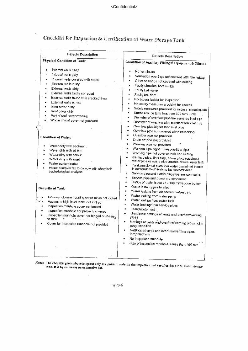
<Confidential>

<Confidential>

V. PUBLIC ADDRESS SYSTEM
WH 1
<Confidential>
1 VOICE COMMUNICATION SYSTEM/PAGING SYSTEM 1.1 General Services
(a) Check speakers and volume control are functioning normally. (b) Test speaker zoning and all call zone from microphone console. (c) Reset individual power amplifier volume to suit the area of speakers’
zone. (d) Service cassette deck and test all cassette units. (e) Check and servicing zoning and overriding relay contacts to ensure
there is no pitting. (f) Cleaning main equipment rack.
1.2 The maintenance of the equipment and system shall be carried out quarterly
which include the following:
(a) Programming of receiver (b) Check indicator, display, controls and speech of the receiver to ensure
its workability (c) From operator’s station – check all function and programming software (d) From charging rack – check supply from proper charging (e) From connection and power supply box – check power supply unit to
ensure sufficient voltage and alarm contracts. (f) From transmitters: Check synchronization and standing wave radio
(SWR) from optimum performance, ensure sufficient power radiated and make correction in the event of drift.
(g) In the event of any breakdown/repair, the Company will provide prompt
servicing upon being notified. 2 MUSIC SYSTEM – QUARTERLY SERVICE 1.3 Tape Machine
(a) Clean tape head/roller (b) Motor Speed normal (c) Belting replaced / checked
1.4 Pre-Amplifier
(a) Volume Setting (b) Tone Control Alignment (c) Pre-amp, module(s) checked (d) Distortion checked (e) Others
1.5 Power Amplifier
(a) Volume and Tone control alignment (b) Pre-amp Module checked (c) Distortion checked (d) Output level setting checked (e) Others
WPA-1

VI. ROLLER SHUTTER/GRILLES/CRAWFORD DOORS/SWINGFLEX
DOORS
WH 1
<Confidential>
1 ROLLER SHUTTERS/GRILLES/BI-FOLDING DOORS
The servicing and maintenance shall be carried out once in every three-month
(4 servicing a year). The servicing shall include the following works: -
(a) Clean and grease all shutter side guides, all U channels and clean
shutters with solution of water/detergent.
(b) Check limit switch assembly and adjust when necessary.
(c) Check and grease mechanism condition, lubricate when necessary.
(d) Check and lubricate gear chains and motors.
(e) Check and tighten all bolts and nuts.
(f) Check and tighten all electrical connections
(g) Servicing and straighten roller metal strips replace if damaged and re-
align when necessary.
(h) Check effectiveness of braking system brake lining, and re-adjustment
of stop and start at approximately level.
(i) Touch up all rusty parts when necessary.
(j) Check and test manual operation of shutters.
(k) Check all external and internal wiring of motor control.
(l) Repair of damaged roller shutter, motor, chain hoist, lockset, motor
casing and all related parts of the roller shutter system. 2 AUTOMATIC BARRIER GATE
The auto barrier gate system shall be serviced monthly. The servicing shall
include the following: -
(a) To check all electrical connections, hydraulic system, control box,
tighten any loose connections, grease, align and replace any defective
parts.
(b) Test run to ensure auto barrier gate system is in good working
condition.
(c) Any other related works to maintain the auto barrier gate system in
working condition.

VI. ROLLER SHUTTER/GRILLES/CRAWFORD DOORS/SWINGFLEX
DOORS
WH 2
<Confidential>
2 QUARTERLY SERVICING OF SWINGFLEX DOORS
Scope of Work
(a) Check and grease mechanism condition, lubricate when necessary.
(b) Check and tighten all bolts and nuts.
(c) Check and test the spring function, adjust when necessary.
(d) Check and test the jack plate function.
(e) Check the alignment of the door leaves, adjust if necessary.
(f) Check the appearance of door leaves, make recommendation to
replace when necessary.

VII. BUILDING AUTOMATION SYSTEM
WH 1
<Confidential>
1 BUILDING AUTOMATION SYSTEM
Maintenance Schedule as per Supplier’s/Manufacturer’s recommendation.

VIII. WASTE DISPOSAL
WH 1
<Confidential>
1 ‘FIX-IT PROGRAMME’
This programme comprises of the following:
(a) Contractor’s staff delegates to be in this fix-in team (FIT).
(b) The said staff would be in charge of a specific location or area and he
would be required to carry out defined scope of work.
(c) The said staff would be required to respond to the owner’s
representative or tenants whenever necessary for carrying out his
works.
(d) General tools and common spare parts to be allocated to the FIT staff
for his immediate response to repair work.
(e) The FIT staff’s responsibility priority is first to repair works then followed
by maintenance where time permits.
(f) The FIT staff’s defined scope of work.
(i) Minor repair of existing defective sanitary, plumbing, carpentry,
building, mechanical and electrical works.
(ii) Re-set of electrical power trip, locate electrical faults, replace
faulty lights and liaise with Contractor’s other staff.
(iii) Replacement or repair of existing defective taps, tap washers,
tap spindles, showers head/hose tubing, flushing handles,
hooks, cistern, covers, window, door hinges locks, cupboard,
cabinets, furniture, ceiling board and chairs.
(iv) Attendance and co-ordination at site of major repairs.
(v) Documentary recording of FIT staff’s daily work and work
request received.
(vi) Liaise with Contractor’s other staff.
(g) The working hour of FIT staff shall be normal office hour.
(h) FIT staff name and particulars are to be given to the Owner’s
representative upon the commencement of the Contract and from then
on, the contractor is required to inform of any changes in the particulars
of the staff accordingly.

VIII. WASTE DISPOSAL
WH 2
<Confidential>
2 ‘WALK-THROUGH’ PROGRAMME 2.1 The purpose of the walk-through (WKT) programme is to establish a WKT team
to carry out the following work.
(a) To spot and rectify minor defects where on the spot repair can be
completed.
(b) To inform the Contractor’s staff of breakdown works requiring repairs.
(c) To record on possible complaints or preventative maintenance
measures required in all public areas. 2.2 For the purposes of inspection, the WKT team shall consist of technical
personnel who are competent to carry out the services. 2.3 The WKT team staff shall be equipped with walkie-talkies and forms for filling
during the daily inspection. 2.4 The WKT detailed implementation plan or form shall include the following
details:
(a) Frequency of visits.
(b) Route of patrol.
(c) If faults and defects have been observed with regards to a specific
service, the time should be noted.
(d) The name of the staff should be noted to whom the fault or defect has
been conveyed to.
(e) If a fault is repaired or made good, it is to be recorded.
(f) Observation of previous faults or defects completed, in process or
outstanding.
(g) WKT forms completed and copied to relevant parties.
(h) WKT staff are required to sign off and identify themselves. 1 SCOPE OF MINOR WORK
The term “general repairs/replacement” shall mean to include the following
items: - 2.5 Taking out silt loose muddy soil or other materials from existing gullies traps,
running stormwater, channels, drains, grease traps or sump pits, cutting grass
on sloping banks of drains and removing silt and grass and deposit, spread and
level in positions or remove off site, all as directed by SO. 2.6 Clearing all chokes and replacing if necessary weep pipes, water sprouts, etc
(any type)

VIII. WASTE DISPOSAL
WH 3
<Confidential>
FIX-IT PROGRAMME
The term” general repairs/replacement” shall mean to include the following
items: - 2.7 Making good all damaged concrete vents (any type) but not amounting to
replacement of blocks. 2.8 Making good damaged precast concrete, brick, quarry tile or other materials
copings, sills, steps, arches, kerbs, etc but not amounting to replacement of
section. 2.9 Investigating and spot curing all roof leaks in roof covering (which includes any
type excluding flat roof and roofs that are covered by guarantee) including providing new to match existing tiling, corrugated roof sheeting or the like; replacing metal hook bolts, drive screws or tying wires or the like; scaling existing nail, screw or bolt heads, side and end lapswitch sealing compound or cement mortar as instructed; replacing damaged sealing or cement mortar and keep roof free from leaks for a period of 12 months from the day of completion of work. (NB: Each spot shall not amount to replacement of exceeding 1.00m of new roof covering and in the case of profiled metal sheets but include accessories, fittings such as capping, fascia, etc not exceeding 1.00m).
2.10 If the timber door has to be taken down and hanged, the Contractor is required
to cut not more than 2 short lengths per door or opening (i.e. Each not
exceeding 750mm long) and the Contractor is required to replace damaged
styles, rails, ledges, braces and the like to timber doors, windows and fitment
doors etc. (any type and thickness). 2.11 If a door has to be taken down and hanged, the Contractor is required to cut
not more than 2 short lengths per door or opening (i.e. Not exceeding 0.50m)
and the Contractor is required to board or panel doors, windows, fitment doors,
etc (any type and thickness). 2.12 The Contractor is required to make good or rectify all loose lengths of beads,
picture rail, skirtings and architraves.
2.13 Taking out where necessary loose boarding, treads, risers, nosing, strings,
balusters, handrails, newels, ramps, wreaths or staircases, framings and the
like (any design and size) any refix and re-cramp including providing new
wedges, nails, screws etc (any others not mention) requiring replacement shall
be measured and valued as extra. 2.14 The Contractor is required to remove, pull out, and reaffix (with new boards
which match the existing boards) loose fibreboards, cementboards,
hardboards, plywood, signboards and the like including fillets of any type and
size. The Contractor is required to provide new nails, screws or other fixtures.
In addition to the foregoing, the Contractor is required to patch up patches not
exceeding 0.50m and up to a total area of 10m on the wall, floor, ceiling, steps
and the like. 2.15 The Contractor is required to reaffix loose tiles, cement mortar or add
adhesive where required.

VIII. WASTE DISPOSAL
WH 4
<Confidential>
2.16 Fixing back all loose lengths of metal, plastic and other materials, dividing
strips, edges, nosings and the like to floor, wall, doorway, step and the like. 2.17 Fixing back all loose and defective putty and sealant from glazed windows,
partition and the like and re-putty or refill with approved sealant. 2.18 Taking out window and doors, re-doweling, re-wedging, recramping, rehinging,
easing and adjusting, planning and smoothening out rough projects, replacing
decayed, glazing beads and/or defective hinges and refixing to form project
and smooth running fit. 2.19 Oiling of locks, hinges and other ironmongery. 2.20 Taking down and refixing vertical blinds where necessary and patient curtain
rails and put to working order including providing brackets, cords, ropes,
clamps, pulleys and other necessary accessories. 2.21 Remove damaged wall paper or lining on the wall and re-lay to match existing
(less than 1 standard pieces) 2.22 Remove damaged carpets and floor openings and relay (less 1 sq. metro) 2.23 Taking out where necessary existing metal fencing gate (any type but excluding
rate exceeding 5m per leaf and adjust, replace and weld small sections (ie.not
exceeding 0.30m length of frame) of gate and rehang gate including replacing
where necessary hinges, steps, guides, plates, drop bolts, etc and all welding. 2.24 Taking out where necessary existing posts (any type and for gates not
exceeding 5m) and refix including scrubbing up concrete foundation, removing
off site and providing new foundation to match. 2.25 Oiling or greasing to existing collapsible gate, roller shutters, folding and sliding
doors, adjustable metal, louvred frames and the like and put them in smooth
running condition. 2.26 Spot welding any loose metal point in window, door, partition, and the like
including taking down and refixing if necessary. 2.27 Refixing all loose or replacing all damaged or missing wire gauge (any type)
and hardboard infill to cupboard doors, etc including provision of boards. 2.28 Replacing all damaged or missing float, valves, level, chain, pull handle, covers
and other incidental accessories and overhauling to working condition. 2.29 Renewing all damaged or missing plug and chain to basins, sinks, troughs and
the like. 2.30 Replacing broken or missing glass shelves and brackets. 2.31 Replacing washers to all taps and valves.

VIII. WASTE DISPOSAL
WH 5
<Confidential>
2.32 Reconditioning and cleaning delay action taps, valves and regulators. 2.33 The Contractor is required to test the whole plumbing system before and after
repair work is done. In addition to that, the Contractor is required to detect pipe
leakages, chokes, other defective works and fittings and he is required to submit
reports to the SO. The Contractor is required to repair pipe leaks, clear chokes and
repair defective works and fittings of the plumbing system. The plumbing system
shall mean all cold water supply, soil and waste pipes, vents pipes, sanitary fittings
and all other waste pipes located within the boundary of the building of structure
and not under the control of the Employer. The lump sum does not include
replacement work and in the event that replacement is necessary, this shall be
measured and the remuneration shall be made according to the rates specified in
the Fixed Schedule of Rates. 2.34 The Contractor is required to test the whole drainage system before and after
repair work is done. In addition to that, the Contractor is required to detect chokes and other defective works and he is required to submit reports to the SO. The Contractor is required to clear chokes and repair defects of the drainage system. The drainage system shall include sump-pits and grease traps, inspection chambers, manholes and the like located within the boundary of the building and not under the control of the Ministry of Environment. The lump sum does not include replacement work and in the event that replacement is necessary, this shall be paid according to the Fixed Schedule of Rates.
2.35 Inspect and repair all building cracks. Where structural defects are discovered
the Employer must be informed immediately. 2.36 Touch up painting on wall and ceiling not exceeding 10-sq. metre is to be
carried out by the Contractor. 2.37 The Contractor is required to touch up and re paint the road paint (irregardless
of size) in the warehouse as and when required by SAS. SAS will pay
contractor the cost of the paint only. 2.38 The Contractor is required to patch up the entire potholes (not exceeding 30cm in
diameter) in the warehouse’s floor with suitable epoxy or equivalent materials. The
type of materials used will have to be approved by the SO. The cost of patching up
the pothole has to be incorporated in the contract sum.

VIII. WASTE DISPOSAL
WH 1
<Confidential>
1. To engage licensed waste disposal services on behalf of the company:
8 bins on site (L 16ft x W 8ft x H 5ft)
Average 7 – 8 daily trips to dispose
2. Produce report on:
Weight of waste disposed
Weight of waste recycled
Breakdown of the weight of the different materials being recycled
3. To maximise recycling of waste material with target to recycle at least 60% w/w of waste generated.

IX. PEST CONTROL
WH 1
<Confidential>
The Contractor shall implement pest control regimes for the areas at the stipulated frequencies:
a. AFT 1-4 (Non-Coolport)/AFT 5/AFT 6
Scope of Work
o Flies, rodents, mice, cockroaches, lizards and ants control
o Inspection and detection of mosquitoes breeding
o Thermal fogging
o Termite control
Frequency
o Level 1/1M Warehouse/Offices – monthly
o Level 2/3/4 General Area/Offices/lockers – monthly
o Horse bay - monthly
o Canteens (Fumigation only)–
Core C – monthly (to be planned)
Core K – monthly (Friday after 7pm)
b. AFT 1-4 (Coolport)
Scope of Work
o Flies, rodents, mice, cockroaches, lizards and ants control
o Thermal fogging
o Termite control
o Rodent inspection
o Setting up baits and traps (glue boards and bait stations)
Frequency
o Fortnightly

X. INDOOR HORTICULTURE
WH 1
<Confidential>
Watering and pruning of plant:
Location Frequencies
External landscape AFT1-6 (along all the core lobbies)
Fortnightly
Internal plants
a. Coolport level 2 b. AFT5 Core K Level 4 Human
Capital c. AFT5 Core K level 5 lift lobby d. AFT5 Core K Level 5 Cargo admin e. AFT5 Core K level 5 Cargo
account f. AFT5 Core L Technology Office
Weekly
- –


