

CerviFix. Modular tension band systemfor posterior fixation of the occipito -cervical spine, upper and lower cervicalspine, and upper thoracic spine.
Technique Guide
0x6.000.261_AB_0x6.000.261_AB 20.01.10 14:01 Seite Cvr1

0x6.000.261_AB_0x6.000.261_AB 20.01.10 14:01 Seite Cvr2

Synthes 1
Table of contents
Introduction
Productinformation
Surgical Technique
Bibliography 25
Features and Benefits 2
AO Principles 4
Indications and Contraindiactions 5
Implants 6
Instruments 9
Set 11
Occipito-Cervical Stabilization 12
Fixation of Lower Cervical Spine 20
Image intensifier control
WarningThis description alone does not provide sufficient background for direct use ofthe instrument set. Instruction by a surgeon experienced in handling theseinstruments is highly recommended.
Reprocessing, Care and Maintenance of Synthes InstrumentsFor general guidelines, function control and dismantling of multi-part instruments,please refer to: www.synthes.com/reprocessing
0x6.000.261_AB_0x6.000.261_AB 20.01.10 14:01 Seite 1
2 Synthes CerviFix Technique Guide
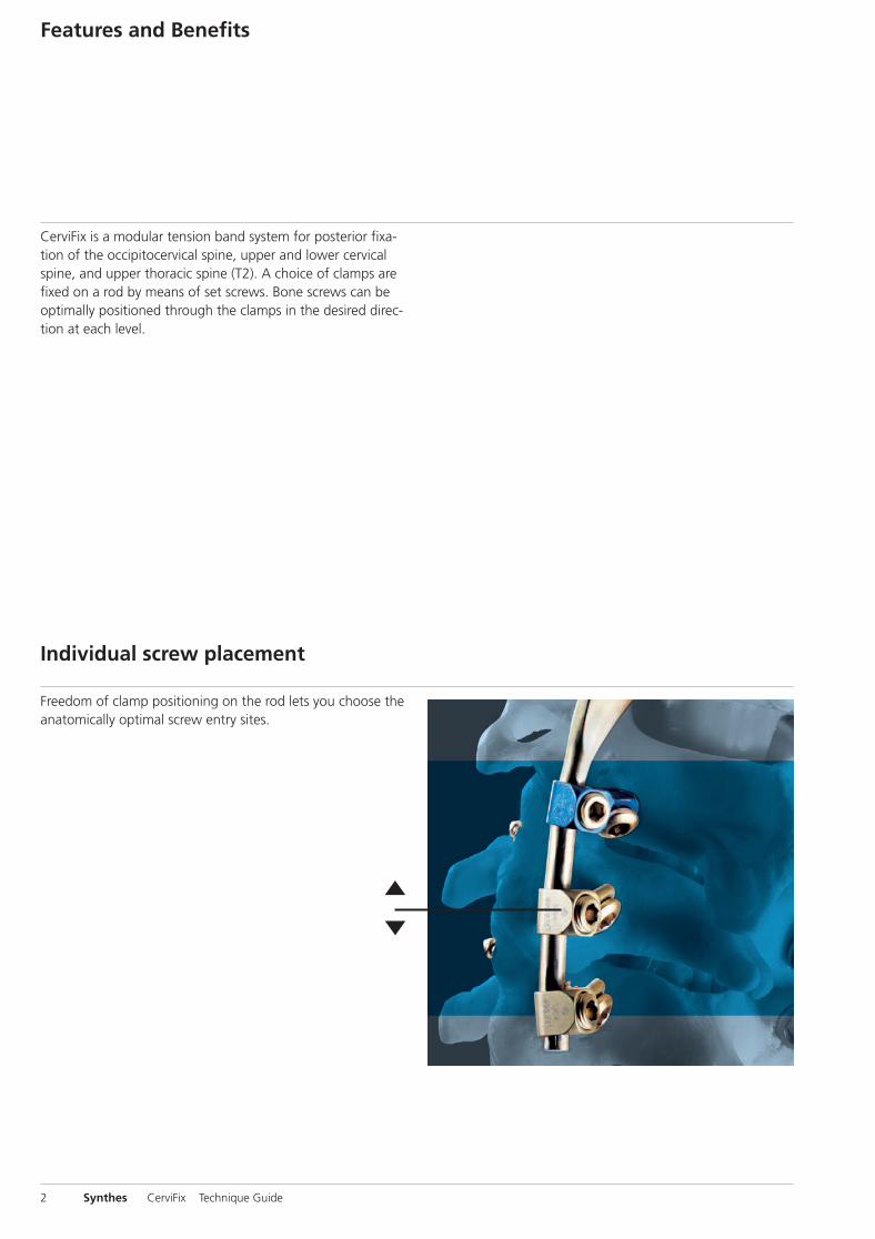
CerviFix is a modular tension band system for posterior fixa-tion of the occipitocervical spine, upper and lower cervicalspine, and upper thoracic spine (T2). A choice of clamps arefixed on a rod by means of set screws. Bone screws can beoptimally positioned through the clamps in the desired direc-tion at each level.
Features and Benefits
Freedom of clamp positioning on the rod lets you choose theanatomically optimal screw entry sites.
Individual screw placement
0x6.000.261_AB_0x6.000.261_AB 20.01.10 14:01 Seite 2
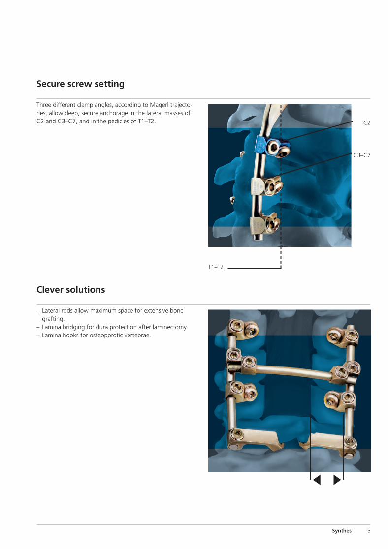
C2
C3 –C7
T1–T2
Synthes 3
Three different clamp angles, according to Magerl trajecto-ries, allow deep, secure anchorage in the lateral masses ofC2 and C3–C7, and in the pedicles of T1–T2.
Secure screw setting
– Lateral rods allow maximum space for extensive bonegrafting.
– Lamina bridging for dura protection after laminectomy.– Lamina hooks for osteoporotic vertebrae.
Clever solutions
0x6.000.261_AB_0x6.000.261_AB 20.01.10 14:01 Seite 3

4 Synthes CerviFix Technique Guide
AO Principles
In 1958, the Association for the Study of Internal Fixation(AO) formulated four basic principles1, which have becomethe guidelines for internal fixation. They are:
– Anatomical reduction– Stable internal fixation– Preservation of blood supply– Early, active pain-free mobilization
The fundamental aims of fracture treatment in the limbs andfusion of the spine are the same. A specific goal in the spineis returning as much function as possible to the injured neu-ral elements.
AO Principles as applied to the spine2
Anatomical reductionRestoration of normal spinal alignment to improve the bio-mechanics of the spine.
Stable internal fixationStabilization of the spinal segment to promote bony fusion.
Preservation of blood supplyCreation of an optimal environment for fusion.
Early, active pain-free mobilizationMinimization of damage to the spinal vasculature, dura, andneural elements, which may contribute to pain reduction andimproved function for the patient.
1 Müller ME, Allgöwer M, Schneider R, Willenegger H (1995) Manual of InternalFixation. 3rd, exp. a. completely rev. ed. 1991. Corr. 3rd printing. Berlin,Heidelberg, New York: Springer
2 Aebi M, Thalgott JS, Webb JK (1998) AO ASIF Principles in Spine Surgery. Berlin,Heidelberg, New York: Springer
0x6.000.261_AB_0x6.000.261_AB 20.01.10 14:01 Seite 4

Synthes 5
Indications
Occipitocervical and upper cervical spine instabilities: – Rheumatoid arthritis – Anomalies– Posttraumatic conditions– Tumours– Infections
Instabilities in the lower cervical spine: – Posttraumatic instabilities– Tumours– Iatrogenic instabilities following laminectomy
Degenerative and painful posttraumatic conditions in thelower cervical spine
Anterior fusions requiring additional posterior stabilization
Contra-indications
– Spinal destruction accompanied by loss of ventral support(caused by tumours, fractures and infections) results in major instability of the cervical spine and upper thoracicspine. In this situation, stabilization with CerviFix onlyis not sufficient. Additional anterior stabilization is crucial.
– Severe osteoporosis
Indications and Contra-indications
0x6.000.261_AB_0x6.000.261_AB 20.01.10 14:01 Seite 5
6 Synthes CerviFix Technique Guide
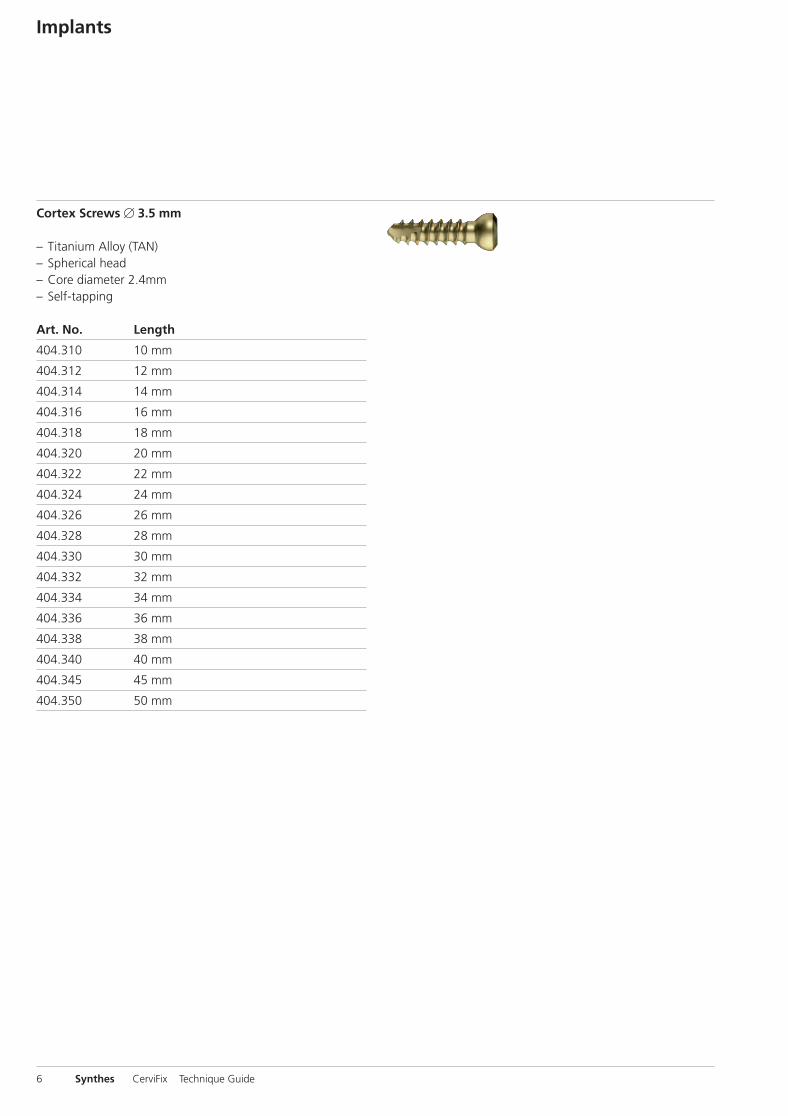
Cortex Screws � 3.5 mm
– Titanium Alloy (TAN)– Spherical head– Core diameter 2.4mm– Self-tapping
Art. No. Length
404.310 10 mm
404.312 12 mm
404.314 14 mm
404.316 16 mm
404.318 18 mm
404.320 20 mm
404.322 22 mm
404.324 24 mm
404.326 26 mm
404.328 28 mm
404.330 30 mm
404.332 32 mm
404.334 34 mm
404.336 36 mm
404.338 38 mm
404.340 40 mm
404.345 45 mm
404.350 50 mm
Implants
0x6.000.261_AB_0x6.000.261_AB 20.01.10 14:01 Seite 6
Synthes 7
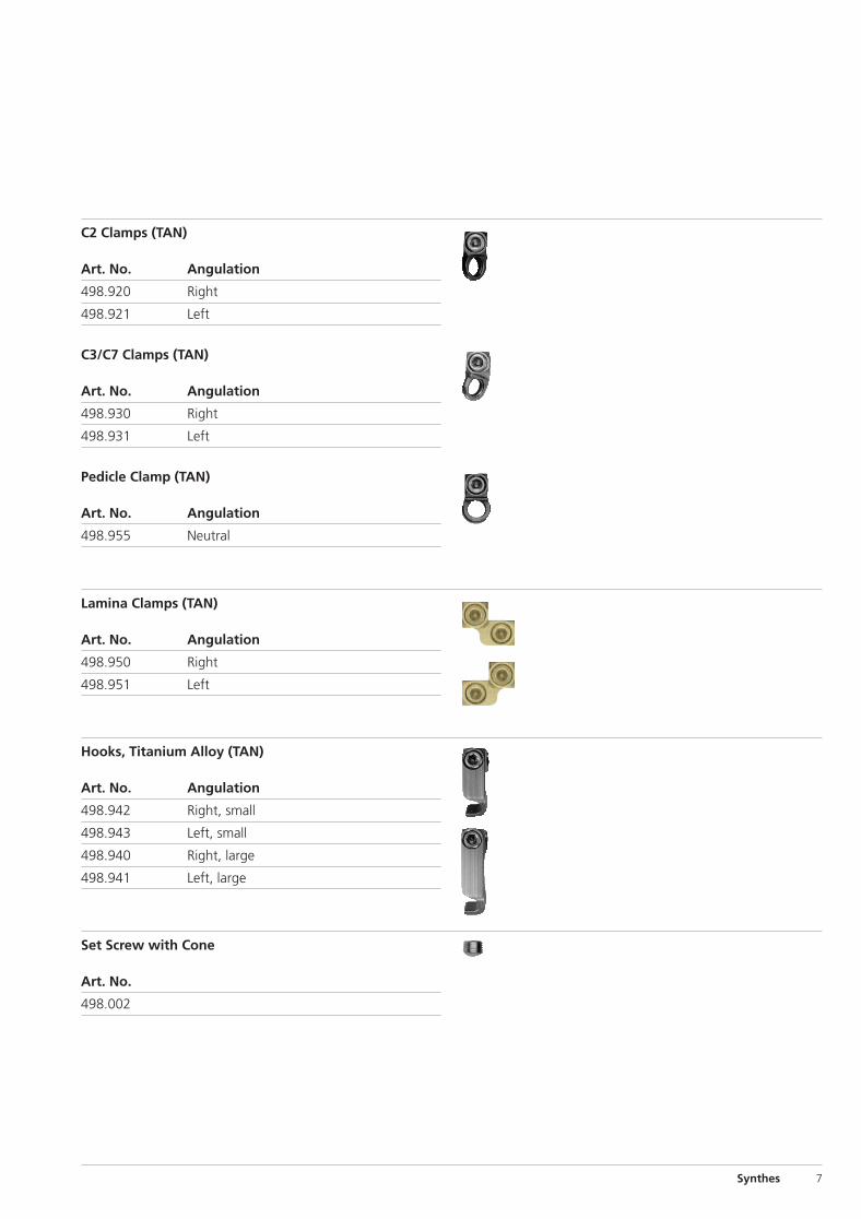
C2 Clamps (TAN)
Art. No. Angulation
498.920 Right
498.921 Left
C3/C7 Clamps (TAN)
Art. No. Angulation
498.930 Right
498.931 Left
Pedicle Clamp (TAN)
Art. No. Angulation
498.955 Neutral
Lamina Clamps (TAN)
Art. No. Angulation
498.950 Right
498.951 Left
Hooks, Titanium Alloy (TAN)
Art. No. Angulation
498.942 Right, small
498.943 Left, small
498.940 Right, large
498.941 Left, large
Set Screw with Cone
Art. No.
498.002
0x6.000.261_AB_0x6.000.261_AB 20.01.10 14:02 Seite 7
8 Synthes CerviFix Technique Guide
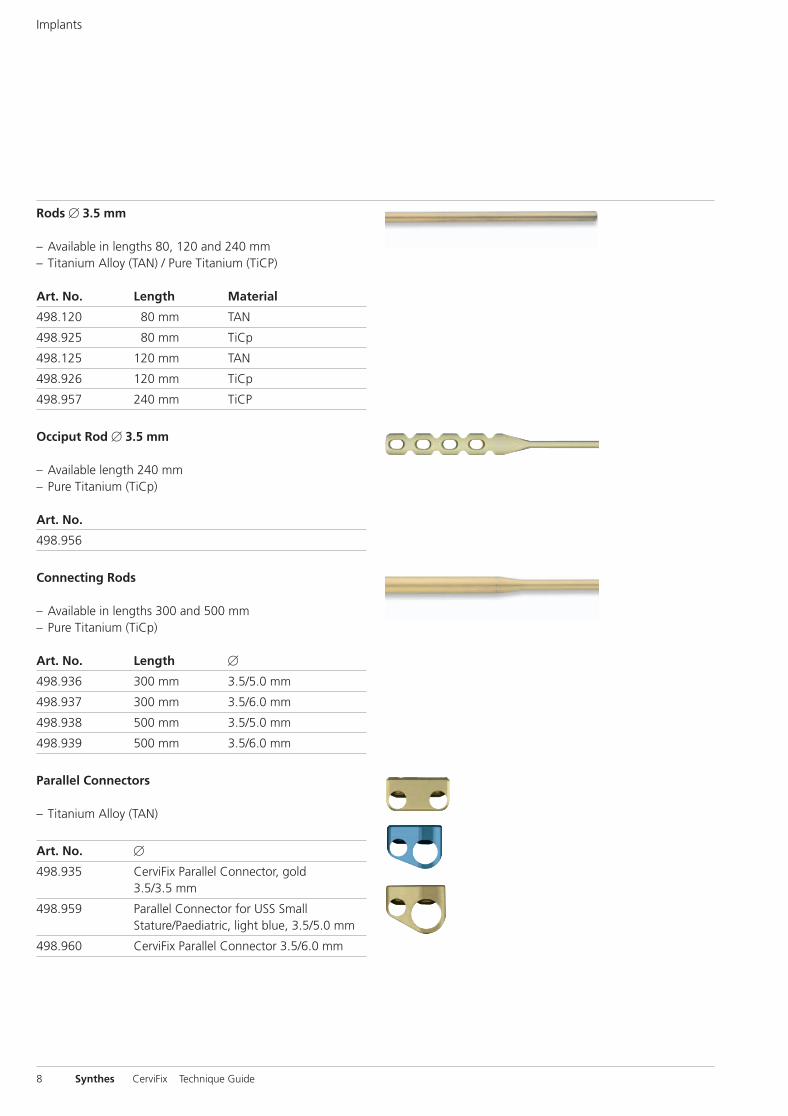
Rods � 3.5 mm
– Available in lengths 80, 120 and 240 mm– Titanium Alloy (TAN) / Pure Titanium (TiCP)
Art. No. Length Material
498.120 80 mm TAN
498.925 80 mm TiCp
498.125 120 mm TAN
498.926 120 mm TiCp
498.957 240 mm TiCP
Occiput Rod � 3.5 mm
– Available length 240 mm– Pure Titanium (TiCp)
Art. No.
498.956
Connecting Rods
– Available in lengths 300 and 500 mm– Pure Titanium (TiCp)
Art. No. Length �
498.936 300 mm 3.5/5.0 mm
498.937 300 mm 3.5/6.0 mm
498.938 500 mm 3.5/5.0 mm
498.939 500 mm 3.5/6.0 mm
Parallel Connectors
– Titanium Alloy (TAN)
Art. No. �
498.935 CerviFix Parallel Connector, gold 3.5/3.5 mm
498.959 Parallel Connector for USS Small Stature/Paediatric, light blue, 3.5/5.0 mm
498.960 CerviFix Parallel Connector 3.5/6.0 mm
Implants
0x6.000.261_AB_0x6.000.261_AB 20.01.10 14:02 Seite 8
Synthes 9
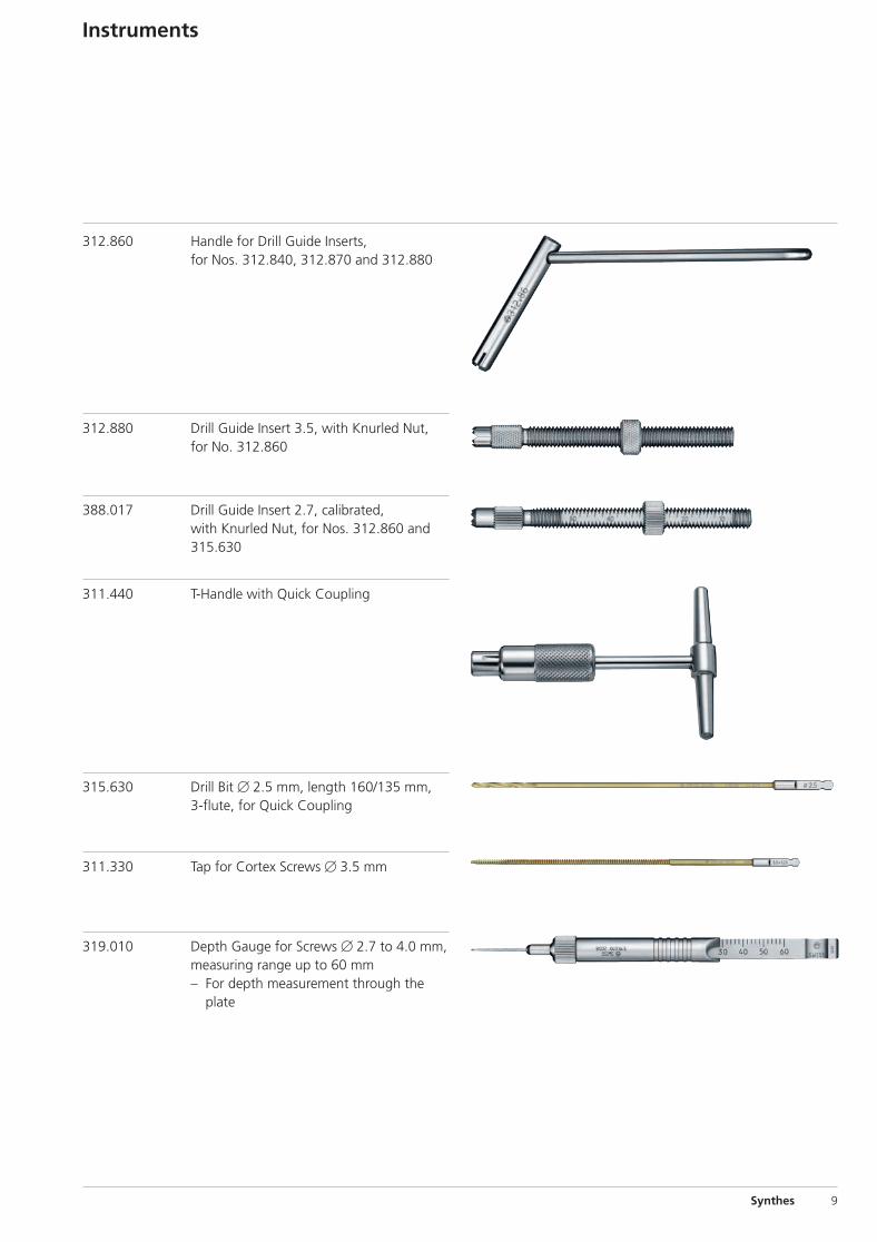
Instruments
312.860 Handle for Drill Guide Inserts, for Nos. 312.840, 312.870 and 312.880
312.880 Drill Guide Insert 3.5, with Knurled Nut,for No. 312.860
388.017 Drill Guide Insert 2.7, calibrated, with Knurled Nut, for Nos. 312.860 and315.630
311.440 T-Handle with Quick Coupling
315.630 Drill Bit � 2.5 mm, length 160/135 mm, 3-flute, for Quick Coupling
311.330 Tap for Cortex Screws � 3.5 mm
319.010 Depth Gauge for Screws � 2.7 to 4.0 mm,measuring range up to 60 mm
– For depth measurement through theplate
0x6.000.261_AB_0x6.000.261_AB 20.01.10 14:02 Seite 9

10 Synthes CerviFix Technique Guide
Instruments
388.020 Screwdriver, hexagonal, small, self-holding
388.868 Trial Rod � 3.5 mm
388.000 Trial Rod � 2.8 mm, length 240 mm, for CerviFix
388.869 Occiput Trial Rod � 3.5 mm
388.016 Rod Cutter, for Rods � 3.5 mm
388.005 Bending Pliers for Rods � 3.5 mm andPlates 3.5
388.011 CerviFix Holding Forceps for Rods� 3.5 mm
0x6.000.261_AB_0x6.000.261_AB 20.01.10 14:02 Seite 10
Synthes 11
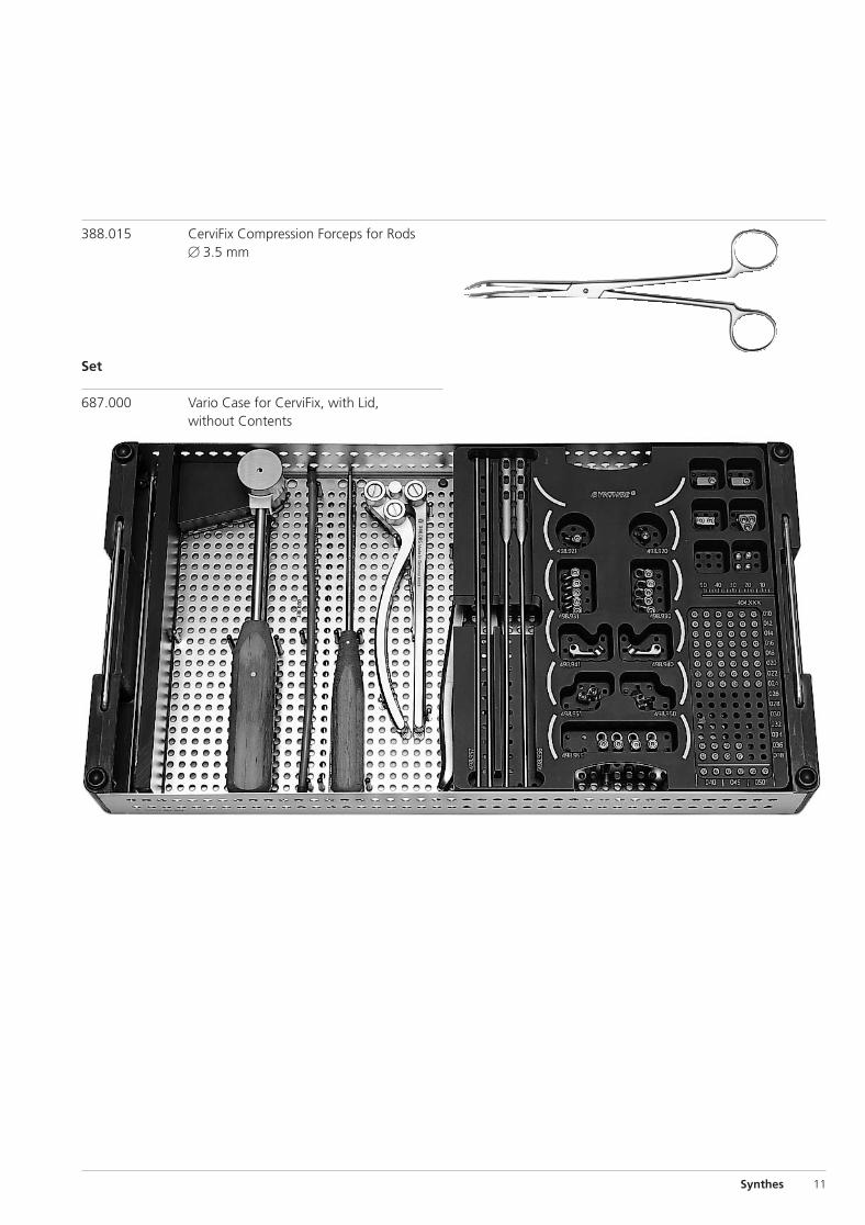
388.015 CerviFix Compression Forceps for Rods� 3.5 mm
Set
687.000 Vario Case for CerviFix, with Lid, without Contents
0x6.000.261_AB_0x6.000.261_AB 20.01.10 14:02 Seite 11

2
8
1 1
9
7
9
4 5 6 13 3
10
12
11
12 Synthes CerviFix Technique Guide
Occipito-Cervical Stabilization
PositioningThe patient is placed in a prone position.
ReductionReduction of C1 on C2 is performed when indicated, usingimage intensification.
ApproachSubperiosteal exposure of occiput, posterior atlas ring, poste-rior elements of C2, spinous processes, vertebral arches,and articular masses of those lower cervical spine vertebraeto be included in the fusion. For a transarticular screw fixation of C1/C2, the isthmus of C2 must be exposed onboth sides.
1 Semispinalis capitis muscle2 Semispinalis cervicis muscle3 Superior oblique muscle of the head4 Smaller straight muscle of the head5 Greater straight muscle of the head6 Inferior oblique muscle of the head7 Posterior arch of the atlas8 Zygapophyseal articulations9 Vertebral artery
10 Occipital artery11 Third occipital nerve12 Greater occipital nerve13 Suboccipital nerve
0x6.000.261_AB_0x6.000.261_AB 20.01.10 14:02 Seite 12

Synthes 13
1Bending the rod
Instruments
388.869 Occiput Trial Rod � 3.5 mm
388.005 Bending Pliers for Rods � 3.5 mm and Plates 3.5
388.016 Rod Cutter, for Rods � 3.5 mm
Optional instruments
388.000 Trial Rod � 2.8 mm, length 240 mm, for CerviFix
388.868 Trial Rod � 3.5 mm
Bend the template in such a way that its cranial end, adja-cent to the midline, is situated just caudal to the protuberan-tia occipitalis externa, and that the rod passes over the lateralrims of the articular processes of C2, C3, etc.
Bend and cut the occipital rod according to the template andconfirm the correct fit in situ.
Note: Titanium rods are weakened when being bent backand forth.
0x6.000.261_AB_0x6.000.261_AB 20.01.10 14:02 Seite 13

14 Synthes CerviFix Technique Guide
2Instrumenting C1/C2
Instruments
311.440 T-Handle with Quick Coupling
315.630 Drill Bit � 2.5 mm, length 160/135 mm, 3-flute, for Quick Coupling
312.860 Handle for Drill Guide Inserts, for Nos. 312.840, 312.870 and 312.880
388.017 Drill Guide Insert 2.7, with calibrated with Knurled Nut, for Nos. 312.860 and 315.630
If necessary, reduce a C1/C2 dislocation under image intensi-fication and drill the screw holes on both sides for a trans -articular C1/C2 fusion using the Magerl technique. In orderto provisionally stabilize C1/C2, leave the drill bit in situon one side while drilling and instrumenting the other side.
Occipitocervical Stabilization
0x6.000.261_AB_0x6.000.261_AB 20.01.10 14:02 Seite 14

Synthes 15
3Instrumenting the most caudal vertebra
Instruments
311.440 T-Handle with Quick Coupling
315.630 Drill Bit � 2.5 mm, length 160/135 mm, 3-flute, for Quick Coupling
312.860 Handle for Drill Guide Inserts, for Nos. 312.840, 312.870 and 312.880
388.017 Drill Guide Insert 2.7, with calibrated with Knurled Nut, for Nos. 312.860 and 315.630
311.330 Tap for Cortex Screws � 3.5 mm, length 180/110 mm
Drill the screw hole in the most caudal vertebra to be stabi-lized using the Magerl technique. Tap the near cortex only.
0x6.000.261_AB_0x6.000.261_AB 20.01.10 14:02 Seite 15
16 Synthes CerviFix Technique Guide
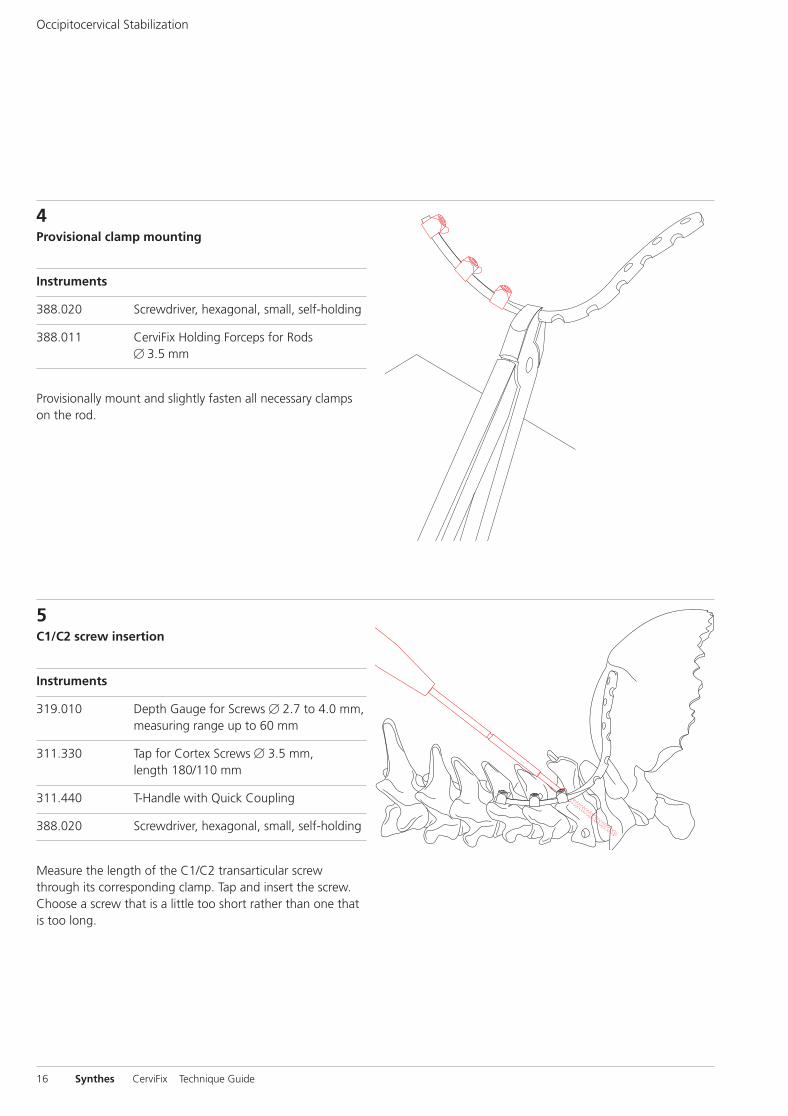
4Provisional clamp mounting
Instruments
388.020 Screwdriver, hexagonal, small, self-holding
388.011 CerviFix Holding Forceps for Rods � 3.5 mm
Provisionally mount and slightly fasten all necessary clampson the rod.
5C1/C2 screw insertion
Instruments
319.010 Depth Gauge for Screws � 2.7 to 4.0 mm, measuring range up to 60 mm
311.330 Tap for Cortex Screws � 3.5 mm, length 180/110 mm
311.440 T-Handle with Quick Coupling
388.020 Screwdriver, hexagonal, small, self-holding
Measure the length of the C1/C2 transarticular screwthrough its corresponding clamp. Tap and insert the screw.Choose a screw that is a little too short rather than one thatis too long.
Occipitocervical Stabilization
0x6.000.261_AB_0x6.000.261_AB 20.01.10 14:02 Seite 16
Synthes 17
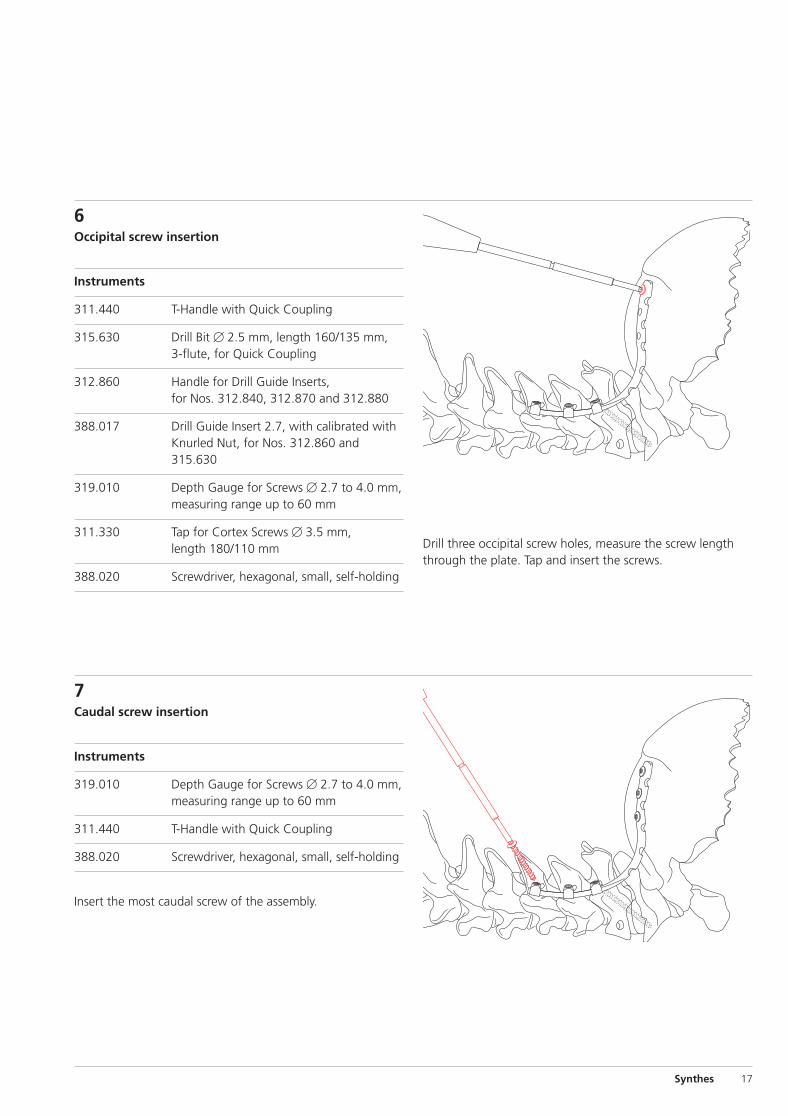
6Occipital screw insertion
Instruments
311.440 T-Handle with Quick Coupling
315.630 Drill Bit � 2.5 mm, length 160/135 mm, 3-flute, for Quick Coupling
312.860 Handle for Drill Guide Inserts, for Nos. 312.840, 312.870 and 312.880
388.017 Drill Guide Insert 2.7, with calibrated with Knurled Nut, for Nos. 312.860 and 315.630
319.010 Depth Gauge for Screws � 2.7 to 4.0 mm, measuring range up to 60 mm
311.330 Tap for Cortex Screws � 3.5 mm, length 180/110 mm
388.020 Screwdriver, hexagonal, small, self-holding
7Caudal screw insertion
Instruments
319.010 Depth Gauge for Screws � 2.7 to 4.0 mm, measuring range up to 60 mm
311.440 T-Handle with Quick Coupling
388.020 Screwdriver, hexagonal, small, self-holding
Insert the most caudal screw of the assembly.
Drill three occipital screw holes, measure the screw lengththrough the plate. Tap and insert the screws.
0x6.000.261_AB_0x6.000.261_AB 20.01.10 14:02 Seite 17

18 Synthes CerviFix Technique Guide
8Intermediate screw insertionn
Instruments
311.440 T-Handle with Quick Coupling
315.630 Drill Bit � 2.5 mm, length 160/135 mm, 3-flute, for Quick Coupling
312.860 Handle for Drill Guide Inserts, for Nos. 312.840, 312.870 and 312.880
388.017 Drill Guide Insert 2.7, with calibrated with Knurled Nut, for Nos. 312.860 and 315.630
319.010 Depth Gauge for Screws � 2.7 to 4.0 mm, measuring range up to 60 mm
311.330 Tap for Cortex Screws � 3.5 mm, length 180/110 mm
388.020 Screwdriver, hexagonal, small, self-holding
Through the corresponding clamps, drill the screw holes forthe intermediate clamps between C2 and the most caudal element. Tap and insert the screws.
Occipito-Cervical Stabilization
0x6.000.261_AB_0x6.000.261_AB 20.01.10 14:02 Seite 18

Synthes 19
9Insert second occiput rod accordingly
Repeat steps 1 to 8.
10Bone grafting
Apply cancellous bone graft. Between the occiput and thespinous process of C2, a corticocancellous bone graft is in-serted acting as a buttress.
Postoperative care
A Philadelphia collar is worn for a period of 12 weeks. It maybe removed for daily care and while resting. If no cancellousbone graft has been applied (for tumour cases only, whenbone cement is used!), an orthosis must be worn for life.
0x6.000.261_AB_0x6.000.261_AB 20.01.10 14:02 Seite 19

20 Synthes CerviFix Technique Guide
Positioning
The patient is placed in a prone position.
Approach
Perform a midline incision, subperiosteally expose the spinalprocesses, laminae, and articular masses of the vertebrae tobe included in the fusion.
1Bending the rod
Instruments
388.868 Trial Rod � 3.5 mm
388.005 Bending Pliers for Rods � 3.5 mm and Plates 3.5
388.016 Rod Cutter, for Rods � 3.5 mm
Optional instruments
388.000 Trial Rod � 2.8 mm, length 240 mm, for CerviFix
Measure the rod length, cut and slightly contour the rod inlordosis.
Note: Titanium rods are weakened when being bent backand forth.
Fixation of Lower Cervical Spine
0x6.000.261_AB_0x6.000.261_AB 20.01.10 14:02 Seite 20

Synthes 21
2Instrumenting the most cranial and most caudalvertebrae
Instruments
311.440 T-Handle with Quick Coupling
315.630 Drill Bit � 2.5 mm, length 160/135 mm, 3-flute, for Quick Coupling
312.860 Handle for Drill Guide Inserts, for Nos. 312.840, 312.870 and 312.880
388.017 Drill Guide Insert 2.7, with calibrated with Knurled Nut, for Nos. 312.860 and 315.630
311.330 Tap for Cortex Screws � 3.5 mm, length 180/110 mm
3Clamp mounting
Instruments
388.020 Screwdriver, hexagonal, small, self-holding
388.011 CerviFix Holding Forceps for Rods � 3.5 mm
Mount all the planned clamps on the rod.
Drill the screw holes for the most cranial and most caudalclamps using the Magerl technique. Tap the near cortex only.
0x6.000.261_AB_0x6.000.261_AB 20.01.10 14:02 Seite 21
22 Synthes CerviFix Technique Guide
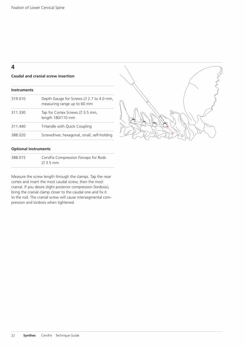
4Caudal and cranial screw insertion
Instruments
319.010 Depth Gauge for Screws � 2.7 to 4.0 mm, measuring range up to 60 mm
311.330 Tap for Cortex Screws � 3.5 mm, length 180/110 mm
311.440 T-Handle with Quick Coupling
388.020 Screwdriver, hexagonal, small, self-holding
Optional instruments
388.015 CerviFix Compression Forceps for Rods � 3.5 mm
Measure the screw length through the clamps. Tap the nearcortex and insert the most caudal screw, then the most cranial. If you desire slight posterior compression (lordosis),bring the cranial clamp closer to the caudal one and fix itto the rod. The cranial screw will cause intersegmental com-pression and lordosis when tightened.
Fixation of Lower Cervical Spine
0x6.000.261_AB_0x6.000.261_AB 20.01.10 14:02 Seite 22

Synthes 23
5Instrumenting the intermediate vertebrae
Instruments
388.020 Screwdriver, hexagonal, small, self-holding
311.440 T-Handle with Quick Coupling
315.630 Drill Bit � 2.5 mm, length 160/135 mm, 3-flute, for Quick Coupling
312.860 Handle for Drill Guide Inserts, for Nos. 312.840, 312.870 and 312.880
388.017 Drill Guide Insert 2.7, with calibrated with Knurled Nut, for Nos. 312.860 and 315.630
319.010 Depth Gauge for Screws � 2.7 to 4.0 mm, measuring range up to 60 mm
311.330 Tap for Cortex Screws � 3.5 mm, length 180/110 mm
388.020 Screwdriver, hexagonal, small, self-holding
Drill the intermediate screw holes through the clamps. Tapand screw in the corresponding screws.
6Insert second occiput rod accordingly
Repeat steps 1 to 5.
0x6.000.261_AB_0x6.000.261_AB 20.01.10 14:02 Seite 23

24 Synthes CerviFix Technique Guide
7Mounting a laminar substitute
Instruments
388.020 Screwdriver, hexagonal, small, self-holding
388.011 CerviFix Holding Forceps for Rods � 3.5 mm
To increase rotational stability, to protect the dura afterlaminectomies, and to suture the musculature, mount a lami-nar substitute.
8Bone grafting
Apply cancellous bone graft on the articular processes.
9Wound closure
Close the wound. The musculature may be sutured to thelaminar substitute.
Postoperative care
Immobilization of the cervical spine for eight weeks in aPhiladelphia collar which can be removed for resting.
Fixation of Lower Cervical Spine
0x6.000.261_AB_0x6.000.261_AB 20.01.10 14:02 Seite 24

Bibliography
Jeanneret B, Magerl F, Ward EH, Ward JC (1991) PosteriorStabilization of the Cervical Spine with Hook Plates. Spine 16 (3S): 56–63
Jeanneret B (1992) Posterior Fusion of the Cervical Spine.Spine: State of the Art Reviews 6 (3)
Jeanneret B (1994) Posterior Transarticular Screw Fixation ofC1–C2. Techniques in Orthopaedics 9 (1) 1994
Jeanneret B (1996) AO Posterior Rod System of the CervicalSpine: a new implant allowing optimal screw insertion. EurSpine J 5 (5): 350–356
Sasso RC, Jeanneret B, Fischer K, Magerl F (1994) Occipito-cervical Fusion with Posterior Plate and Screw Instrumenta-tion: a long-term follow-up study. Spine 19 (20): 2364–2368
Müller ME, Allgöwer M, Schneider R, Willenegger H (1995)Manual of Internal Fixation. 3rd, expanded and completelyrevised ed. 1991. Berlin, Heidelberg, New York: Springer
0x6.000.261_AB_0x6.000.261_AB 20.01.10 14:02 Seite Cvr3

0123 036.
000.
261
AB
510
6000
8 ©
01/
2010
Syn
thes
, Inc
. or
its a
ffili
ates
A
ll rig
hts
rese
rved
Sy
nthe
s an
d Va
rio C
ase
are
trad
emar
ks o
f Sy
nthe
s, In
c. o
r its
aff
iliat
es
All technique guides are available as PDF files at www.synthes.com/lit
Ö036.000.261öAB~ä
0x6.000.261_AB_0x6.000.261_AB 20.01.10 14:02 Seite Cvr4


