

1
EECS 150 - Components and Design
Techniques for Digital Systems
Lec 26 – CRCs, LFSRs
(and a little power)
David CullerElectrical Engineering and Computer Sciences
University of California, Berkeley
http://www.eecs.berkeley.edu/~cullerhttp://www-inst.eecs.berkeley.edu/~cs150

2
Review
• Concept of error coding– Add a few extra bits (enlarges the space of values) that carry
information about all the bits
– Detect: Simple function to check of entire data+check received correctly
» Small subset of the space of possible values
– Correct: Algorithm for locating nearest valid symbol
• Hamming codes– Selective use of parity functions
– Distance + # bit flips
– Parity: XOR of the bits => single error detection
– SECDED
» databits+p+1 < 2p
3
Outline
• Introduce LFSR as fancy counter
• Practice of Cyclic Redundancy Checks– Burst errors in networks, disks, etc.
• Theory of LFSRs
• Power

4
Linear Feedback Shift Registers (LFSRs)• These are n-bit counters exhibiting pseudo-random behavior.
• Built from simple shift-registers with a small number of xor gates.
• Used for:– random number generation
– counters
– error checking and correction
• Advantages:– very little hardware
– high speed operation
• Example 4-bit LFSR:
Q DQ1Q DQ2Q DQ3Q DQ4
CLK

5
4-bit LFSR
• Circuit counts through 24-1 different non-zero bit patterns.
• Left most bit determines shiftl or more complex operation
• Can build a similar circuit with any number of FFs, may need more xor gates.
• In general, with n flip-flops, 2n-1 different non-zero bit patterns.
• (Intuitively, this is a counter that wraps around many times and in a strange way.)
0 0 0 1 0xor 0 0 0 0 0 0 0 0 1 0 0 xor 0 0 0 0 0 0 0 1 0 0 0 xor 0 0 0 0 0 0 1 0 0 0 0 xor 1 0 0 1 1 0 0 0 1 1 0 xor 0 0 0 0 0 0 0 1 1 0 0 xor 0 0 0 0 0 0 1 1 0 0 0 xor 1 0 0 1 1 0 1 0 1 1
Q4 Q3 Q2 Q1
0001001001001000001101101100101101011010011111101111110110010001
Q DQ1Q DQ2Q DQ3Q DQ4
CLK

6
Applications of LFSRs
• Performance:– In general, xors are only ever 2-input and never
connect in series.
– Therefore the minimum clock period for these circuits is:
T > T2-input-xor + clock overhead– Very little latency, and independent of n!
• This can be used as a fast counter, if the particular sequence of count values is not important.
– Example: micro-code micro-pc
• Can be used as a random number generator.
– Sequence is a pseudo-random sequence:
» numbers appear in a random sequence
» repeats every 2n-1 patterns
– Random numbers useful in:
» computer graphics
» cryptography
» automatic testing
• Used for error detection and correction
» CRC (cyclic redundancy codes)
» ethernet uses them
7
Concept: Redundant Check
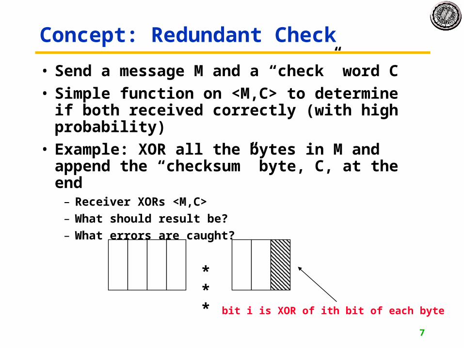
• Send a message M and a “check” word C
• Simple function on <M,C> to determine if both received correctly (with high probability)
• Example: XOR all the bytes in M and append the “checksum” byte, C, at the end
– Receiver XORs <M,C>
– What should result be?
– What errors are caught?
***
bit i is XOR of ith bit of each byte

8
Example: TCP Checksum
Application
(HTTP,FTP, DNS)
Transport
(TCP, UDP)
Network
(IP)
Data Link
(Ethernet, 802.11b)
Physical1
2
3
4
7
TCP Packet Format
• TCP Checksum a 16-bit checksum, consisting of the one's complement of the one's complement sum of the contents of the TCP segment header and data, is computed by a sender, and included in a segment transmission. (note end-around carry)
• Summing all the words, including the checksum word, should yield zero
9
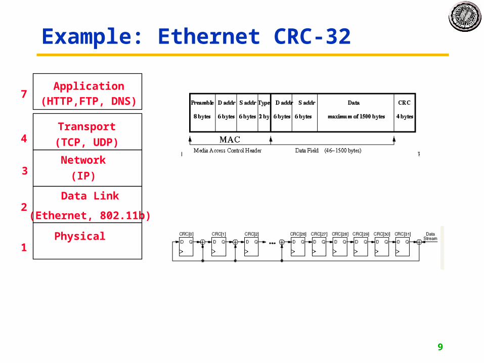
Example: Ethernet CRC-32
Application
(HTTP,FTP, DNS)
Transport
(TCP, UDP)
Network
(IP)
Data Link
(Ethernet, 802.11b)
Physical1
2
3
4
7
10
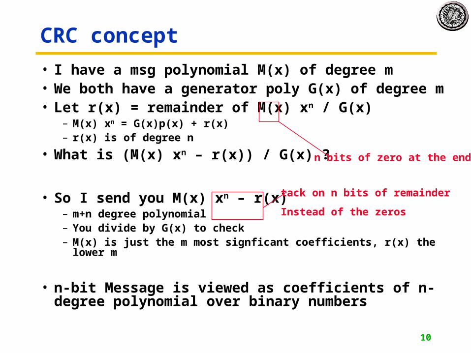
CRC concept
• I have a msg polynomial M(x) of degree m• We both have a generator poly G(x) of degree m• Let r(x) = remainder of M(x) xn / G(x)
– M(x) xn = G(x)p(x) + r(x)– r(x) is of degree n
• What is (M(x) xn – r(x)) / G(x) ?
• So I send you M(x) xn – r(x) – m+n degree polynomial– You divide by G(x) to check– M(x) is just the m most signficant coefficients, r(x) the lower m
• n-bit Message is viewed as coefficients of n-degree polynomial over binary numbers
n bits of zero at the end
tack on n bits of remainder
Instead of the zeros

11
Announcements
• Reading– XILINX IEEE 802.3 Cyclic
Redundancy Check (pages 1-3)
– ftp://ftp.rocksoft.com/papers/crc_v3.txt
• Final on 12/15
• What’s Going on in EECS?– Towards simulation of a Digital
Human
– Yelick: Simulation of the Human Heart Using the Immersed Boundary Method on Parallel Machines

12
Galois Fields - the theory behind LFSRs• LFSR circuits performs
multiplication on a field.• A field is defined as a set with
the following:– two operations defined on it:
» “addition” and “multiplication”– closed under these operations – associative and distributive laws
hold– additive and multiplicative identity
elements– additive inverse for every element– multiplicative inverse for every non-
zero element
• Example fields:– set of rational numbers– set of real numbers– set of integers is not a field
(why?)
• Finite fields are called Galois fields.
• Example: – Binary numbers 0,1 with XOR
as “addition” and AND as “multiplication”.
– Called GF(2).
– 0+1 = 1– 1+1 = 0– 0-1 = ?– 1-1 = ?

13
Galois Fields - The theory behind LFSRs
• Consider polynomials whose coefficients come from GF(2).
• Each term of the form xn is either present or absent.
• Examples: 0, 1, x, x2, and x7 + x6 + 1
= 1·x7 + 1· x6 + 0 · x5 + 0 · x4 + 0 · x3 + 0 · x2 + 0 · x1 + 1· x0
• With addition and multiplication these form a field:
• “Add”: XOR each element individually with no carry:x4 + x3 + + x + 1
+ x4 + + x2 + x
x3 + x2 + 1
• “Multiply”: multiplying by xn is like shifting to the left.
x2 + x + 1 x + 1
x2 + x + 1 x3 + x2 + x x3 + 1
14
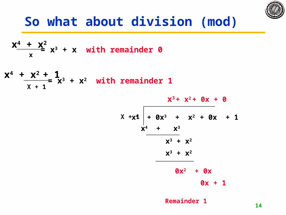
So what about division (mod)
x4 + x2 x
= x3 + x with remainder 0
x4 + x2 + 1 X + 1
= x3 + x2 with remainder 1
x4 + 0x3 + x2 + 0x + 1 X + 1
x3
x4 + x3
x3 + x2
+ x2
x3 + x2
0x2 + 0x
+ 0x
0x + 1
+ 0
Remainder 1

15
Polynomial division
• When MSB is zero, just shift left, bringing in next bit
• When MSB is 1, XOR with divisor and shiftl
1 0 1 1 0 0 1 0 0 0 01 0 0 1 1
Q DQ1Q DQ2Q DQ3Q DQ4
CLK
serial_in
0 0 0 0
1 0 0 1 1
0 0 1 0 1
1
0 1 0 1 0
0
1 0 1 0 1
1 0 0 1 1
1
0 0 1 0 0

16
CRC encoding
Q DQ1Q DQ2Q DQ3Q DQ4
CLK
serial_in1 0 1 1 0 0 1 0 0 0 0
0 0 0 0
0 0 0 1 0 1 1 0 0 1 0 0 0 00 0 1 0 1 1 0 0 1 0 0 0 00 1 0 1 1 0 0 1 0 0 0 01 0 1 1 0 0 1 0 0 0 00 1 0 1 0 1 0 0 0 0
1 0 1 0 1 0 0 0 0
0 1 1 0 0 0 0 0
1 0 1 1 0 0 1 1 0 1 0
Message sent:
1 1 0 0 0 0 0
1 0 1 1 0 0
0 1 0 1 0
1 0 1 0

17
CRC decoding
Q DQ1Q DQ2Q DQ3Q DQ4
CLK
serial_in1 0 1 1 0 0 1 1 0 1 0
0 0 0 0
0 0 0 1 0 1 1 0 0 1 1 0 1 00 0 1 0 1 1 0 0 1 1 0 1 00 1 0 1 1 0 0 1 1 0 1 01 0 1 1 0 0 1 1 0 1 00 1 0 1 0 1 1 0 1 0
1 0 1 0 1 1 0 1 0
0 1 1 0 1 0 1 0
1 1 0 1 0 1 0 1 0 0 1 1 0
0 0 0 0 0
0 0 0 0

18
Galois Fields - The theory behind LFSRs
• These polynomials form a Galois (finite) field if we take the results of this multiplication modulo a prime polynomial p(x).
– A prime polynomial is one that cannot be written as the product of two non-trivial polynomials q(x)r(x)
– Perform modulo operation by subtracting a (polynomial) multiple of p(x) from the result. If the multiple is 1, this corresponds to XOR-ing the result with p(x).
• For any degree, there exists at least one prime polynomial.
• With it we can form GF(2n)
• Additionally, …
• Every Galois field has a primitive element, , such that all non-zero elements of the field can be expressed as a power of . By raising to powers (modulo p(x)), all non-zero field elements can be formed.
• Certain choices of p(x) make the simple polynomial x the primitive element. These polynomials are called primitive, and one exists for every degree.
• For example, x4 + x + 1 is primitive. So = x is a primitive element and successive powers of will generate all non-zero elements of GF(16). Example on next slide.

19
Galois Fields – Primitives
0 = 1
1 = x
2 = x2
3 = x3
4 = x + 1
5 = x2 + x
6 = x3 + x2
7 = x3 + x + 1
8 = x2 + 1
9 = x3 + x
10 = x2 + x + 1
11 = x3 + x2 + x
12 = x3 + x2 + x + 1
13 = x3 + x2 + 1
14 = x3 + 1
15 = 1
• Note this pattern of coefficients matches the bits from our 4-bit LFSR example.
• In general finding primitive polynomials is difficult. Most people just look them up in a table, such as:
4 = x4 mod x4 + x + 1 = x4 xor x4 + x + 1 = x + 1

20
Primitive Polynomialsx2 + x +1x3 + x +1x4 + x +1x5 + x2 +1x6 + x +1x7 + x3 +1x8 + x4 + x3 + x2 +1x9 + x4 +1x10 + x3 +1x11 + x2 +1
x12 + x6 + x4 + x +1x13 + x4 + x3 + x +1x14 + x10 + x6 + x +1x15 + x +1x16 + x12 + x3 + x +1x17 + x3 + 1x18 + x7 + 1x19 + x5 + x2 + x+ 1x20 + x3 + 1x21 + x2 + 1
x22 + x +1x23 + x5 +1x24 + x7 + x2 + x +1x25 + x3 +1x26 + x6 + x2 + x +1x27 + x5 + x2 + x +1x28 + x3 + 1x29 + x +1x30 + x6 + x4 + x +1x31 + x3 + 1x32 + x7 + x6 + x2 +1
Galois Field Hardware
Multiplication by x shift leftTaking the result mod p(x) XOR-ing with the coefficients of p(x)
when the most significant coefficient is 1.Obtaining all 2n-1 non-zero Shifting and XOR-ing 2n-1 times.elements by evaluating xk
for k = 1, …, 2n-1

21
Building an LFSR from a Primitive Poly
• For k-bit LFSR number the flip-flops with FF1 on the right.
• The feedback path comes from the Q output of the leftmost FF.
• Find the primitive polynomial of the form xk + … + 1.
• The x0 = 1 term corresponds to connecting the feedback directly to the D input of FF 1.
• Each term of the form xn corresponds to connecting an xor between FF n and n+1.
• 4-bit example, uses x4 + x + 1– x4 FF4’s Q output
– x xor between FF1 and FF2
– 1 FF1’s D input
• To build an 8-bit LFSR, use the primitive polynomial x8 + x4 + x3 + x2 + 1 and connect xors between FF2 and FF3, FF3 and FF4, and FF4 and FF5.
Q DQ1Q DQ2Q DQ3Q DQ4
CLK
Q DQ4Q DQ5Q DQ6Q DQ7
CLK
Q DQ3 Q DQ2 Q DQ1Q8Q D

22
Generating Polynomials
• CRC-16: G(x) = x16 + x15 + x2 + 1– detects single and double bit errors
– All errors with an odd number of bits
– Burst errors of length 16 or less
– Most errors for longer bursts
• CRC-32: G(x) = x32 + x26 + x23 + x22 + x16 + x12 + x11 + x10 + x8 + x7 + x5 + x4 + x2 + x + 1
– Used in ethernet
– Also 32 bits of 1 added on front of the message
» Initialize the LFSR to all 1s

23
POWER
24
Motivation
• Portable devices: – handhelds, laptops, phones, MP3 players, cameras, … all need to run
for extended periods on small batteries without recharging
– Devices that need regular recharging or large heavy batteries will lose out to those that don’t.
• Power consumption important even in “tethered” devices. – System cost tracks power consumption:
» power supplies, distribution, heat removal
– power conservation, environmental concerns
• In a span of 10 years we have gone from designing without concern for power consumption to (in many cases) designing with power consumption as the primary design constraint!
Why should a digital designer care about power consumption?

25
Battery Technology
• Battery technology has moved very slowly– Moore’s law does not seem to apply
• Li-Ion and NiMh still the dominate technologies
• Batteries still contribute significant to the weight of mobile devices
Toshiba Portege 3110 laptop - 20%
Handspring PDA - 10%
Nokia 61xx - 33%

26
Basics• Power supply provides energy for charging and discharging wires
and transistor gates. The energy supplied is stored and dissipated as heat.
• If a differential amount of charge dq is given a differential increase in energy dw, the potential of the charge is increased by:
• By definition of current:
dqdwV /dtdqI /
dtdwP / Power: Rate of work being done w.r.t time.Rate of energy being used.
IVPdt
dq
dq
dwdtdw /
t
Pdtw total energy
Units: tEP Watts = Joules/seconds
A very practical formulation!
If we would liketo know total energy
27
Basics
• Warning! In everyday language, the term “power” is used incorrectly in place of “energy.”
• Power is not energy.
• Power is not something you can run out of.
• Power can not be lost or used up.
• It is not a thing, it is merely a rate.
• It can not be put into a battery any more than velocity can be put in the gas tank of a car.

28
Metrics
• One popular metric for microprocessors is: MIPS/watt– MIPS, millions of instructions per second.
» Typical modern value?
– Watt, standard unit of power consumption.
» Typical value for modern processor?
– MIPS/watt is reflective of the tradeoff between performance and power. Increasing performance requires increasing power.
– Problem with “MIPS/watt”
» MIPS/watt values are typically not independent of MIPS• techniques exist to achieve very high MIPS/watt values, but at very low
absolute MIPS (used in watches)
» Metric only relevant for comparing processors with a similar performance.
– One solution, MIPS2/watt. Puts more weight on performance.
How do we measure and compare power consumption?

29
Metrics
• How does MIPS/watt relate to energy?
• Average power consumption = energy / time
MIPS/watt = instructions/sec / joules/sec = instructions/joule
– therefore an equivalent metric (reciprocal) is energy per operation (E/op)
• E/op is more general - applies to more than processors– also, usually more relevant, as batteries life is limited by total energy
draw.
– This metric gives us a measure to use to compare two alternative implementations of a particular function.

30
Power in CMOS
C
pullupnetwork
pulldownnetwork
Vdd
GND
10
i(t)
v(t)t0 t1
v(t)
VddSwitching Energy: energy used to switch a node
Energy supplied Energy dissipatedEnergy stored
Calculate energy dissipated in pullup:
222 2121
)()()()()(
1
0
1
0
1
0
1
0
1
0
dd
t
t
t
t dddddd
t
t dd
t
t dd
t
tsw
cVcVcVdvvcdvcV
dtdtdvcvVdttivVdttPE
An equal amount of energy is dissipated on pulldown.

31
Switching Power• Gate power consumption:
– Assume a gate output is switching its output at a rate of:
1/f
Pavg
clock f
f
swavg ErateswitchingtEP
221 ddavg cVfP
221 ddavgavgavg VcfnP
• Chip/circuit power consumption:
activity factor clock rate
Therefore:
number of nodes (or gates)
(probability of switching on any particular clock period)

32
Other Sources of Energy Consumption
• “Short Circuit” Current:
• Junction Diode Leakage:
• Device Ids Leakage:
Vout
Vin
Vin
I
I
VoutVin
I
V
DiodeCharacteristic
Ioff
Vout=VddVin=0
Ids
VgsVth
10-20% of total chip power
~1nWatt/gatefew mWatts/chip
Transistor drain regions“leak” charge to substrate.
Transistor s/d conductancenever turns off all the way.~3pWatts/transistor. ~1mWatt/chipLow voltage processes much worse.

33
Controlling Energy Consumption
• Largest contributing component to CMOS power consumption is switching power:
• Factors influencing power consumption:n: total number of nodes in circuit
: activity factor (probability of each node switching)
f: clock frequency (does this effect energy consumption?)
Vdd: power supply voltage
• What control do you have over each factor? • How does each effect the total Energy?
What control do you have as a designer?
221 ddavgavgavg VcfnP

34
Power / Cost / Performance
• Parallelism to trade cost for performance. As we trade cost for performance what happens to energy?
4 EMUL + 3 EADD + EWIRES 2 EMUL + 3 EADD + EWIRES 2 EMUL + 3 EADD + EMUXES + ECNTL + EWIRES
• The lowest energy consumer is the solution that minimizes cost without time multiplexing operations.
xx xx
++
+
0.2 mt1 0.2 mt2 0.4 proj0.2 mt3
grade
x
+
+
0.2
mt1 mt2 0.4 proj
mt3
grade
x
+ acc1 = mt1 + mt2;acc1 = acc1 + mt3;acc1 = 0.2 x acc1;acc2 = 0.4 x proj;grade = acc1 + acc2;
controller
ALU
mt1 mt1mt3 proj
acc1acc2


![Culler Jonathan [1982] - On Deconstruction 0801492017](https://static.documents.pub/doc/80x56/54e972b84a795922038b4a4c/culler-jonathan-1982-on-deconstruction-0801492017.jpg)