

1
MEF 31: Service OAM Fault Management Definition of Managed Objects
July 2012
Introducing the Specifications of the MEF

22
Outline• Approved MEF Specifications• This presentation • About this Specification• In Scope / Out of Scope• Terminology, Concepts & Relationship to other
standards• Section Review
– Major topics• Minor topics
• Examples/Use Cases• Summary

3
Specification DescriptionMEF 2 Requirements and Framework for Ethernet Service Protection
MEF 3 Circuit Emulation Service Definitions, Framework and Requirements in Metro Ethernet Networks MEF 4 Metro Ethernet Network Architecture Framework Part 1: Generic Framework
MEF 6.1 Metro Ethernet Services Definitions Phase 2
MEF 7.1 EMS-NMS Information Model Phase 2
MEF 8 Implementation Agreement for the Emulation of PDH Circuits over Metro Ethernet Networks
MEF 9 Abstract Test Suite for Ethernet Services at the UNI
MEF 10.2 Ethernet Services Attributes Phase 2
MEF 11 User Network Interface (UNI) Requirements and Framework
MEF 12.1 Metro Ethernet Network Architecture Framework Part 2: Ethernet Services Layer
MEF 13 User Network Interface (UNI) Type 1 Implementation Agreement
MEF 14 Abstract Test Suite for Traffic Management Phase 1
MEF 15 Requirements for Management of Metro Ethernet Phase 1 Network Elements
MEF 16 Ethernet Local Management Interface
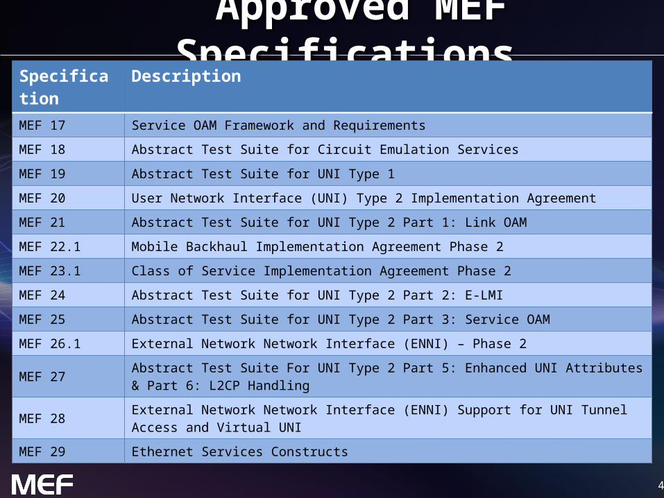
Approved MEF Specifications*
*Current at time of publication. See MEF web site for official current list, minor updates and superseded work (such as MEF 1 and MEF 5)
4
Approved MEF SpecificationsSpecification DescriptionMEF 17 Service OAM Framework and RequirementsMEF 18 Abstract Test Suite for Circuit Emulation ServicesMEF 19 Abstract Test Suite for UNI Type 1MEF 20 User Network Interface (UNI) Type 2 Implementation AgreementMEF 21 Abstract Test Suite for UNI Type 2 Part 1: Link OAMMEF 22.1 Mobile Backhaul Implementation Agreement Phase 2 MEF 23.1 Class of Service Implementation Agreement Phase 2MEF 24 Abstract Test Suite for UNI Type 2 Part 2: E-LMI MEF 25 Abstract Test Suite for UNI Type 2 Part 3: Service OAMMEF 26.1 External Network Network Interface (ENNI) – Phase 2MEF 27 Abstract Test Suite For UNI Type 2 Part 5: Enhanced UNI Attributes & Part 6: L2CP HandlingMEF 28 External Network Network Interface (ENNI) Support for UNI Tunnel Access and Virtual UNIMEF 29 Ethernet Services Constructs

5
Approved MEF SpecificationsSpecification DescriptionMEF 30 Service OAM Fault Management Implementation Agreement MEF 31 Service OAM Fault Management Definition of Managed Objects MEF 32 Requirements for Service Protection Across External InterfacesMEF 33 Ethernet Access Services DefinitionMEF 34 Abstract Test Suite for Ethernet Access Services MEF 35 Service OAM Performance Monitoring Implementation AgreementMEF 36 Service OAM SNMP MIB for Performance MonitoringMEF 37 Abstract Test Suite for ENNI
*Current at time of publication. See MEF web site for official current list, minor updates (such as MEF 31.0.1 amendment to this document) and superseded work (such as MEF 1 and MEF 5)

66
MEF Specification Overview
Standardized Services
Purpose
Specifies the Fault Management (FM) Management Information Base (MIB) necessary to implement Service Operations, Administration, and Maintenance (OAM) that satisfies the Service OAM requirements and framework specified by MEF 17, MEF 30, the management objects specified in MEF 7.1, and the FM functions defined in IEEE 802.1ag and ITU-T Y.1731.
AudienceApplicable to entire Metro Ethernet Market including Service Providers, Access Providers, equipment vendors, and EMS/NMS/OSS vendors to provision and monitor equipment that is MEF compatible.
MEF 31 - Service OAM (SOAM) Fault Management Definition of Managed Objects

7
Overview of MEF 31

8
About MEF 31
• Purpose: – This presentation is an introduction to MEF 31 - Service OAM Fault
Management Definition of Managed Objects• Audience
– Equipment Manufacturers building devices that will carry Carrier Ethernet Services
– Service Providers delivering Carrier Ethernet Services– EMS/NMS/OSS tool vendors developing back office applications for
managing Carrier Ethernet Services• Other Documents
– Presentations of other MEF specifications and an overview of all specifications is available on the MEF web site
– Other materials such as white papers and case studies are also available
9
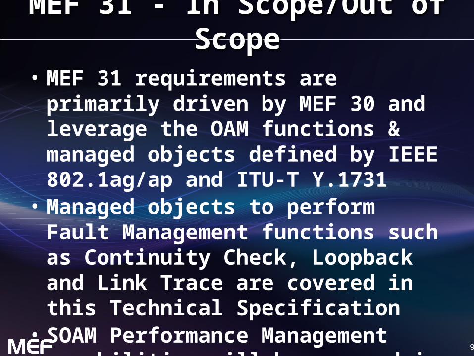
MEF 31 - In Scope/Out of Scope
• MEF 31 requirements are primarily driven by MEF 30 and leverage the OAM functions & managed objects defined by IEEE 802.1ag/ap and ITU-T Y.1731
• Managed objects to perform Fault Management functions such as Continuity Check, Loopback and Link Trace are covered in this Technical Specification
• SOAM Performance Management capabilities will be covered in future a MEF document

10
Terminology and Concepts• MEF 31 adheres to MEF 30 terminology:
– Refer to MEF 30 for ME, MEG, MEP, MIP, CoS– Continuity Check Message (CCM)– Alarm Indication Signal (AIS)– Remote Defect Indication (RDI)
• MEF 31 introduces protocol specific terminology– Simple Network Management Protocol (SNMP)– SNMP Manager– Management Information Model (MIB)– Element Management System (EMS)– Network Management System (NMS)– Operations Support System (OSS)
MEF-30 aligns with terminology found in ITU Y.1731

11
Relationship with other Specifications

1212
MEF Service Lifecycle and SOAM
Network Management
Fault management is a critical part of a circuit’s lifecycle

13
MEF Specification Section Review

14
Introducing MEF 31
• The presentation is broken into sections:– Overview – Network Management Concepts/Topologies– Initial Configuration– OAM Functions
• Configuration• Status
– Summary– Where to find additional information
1515
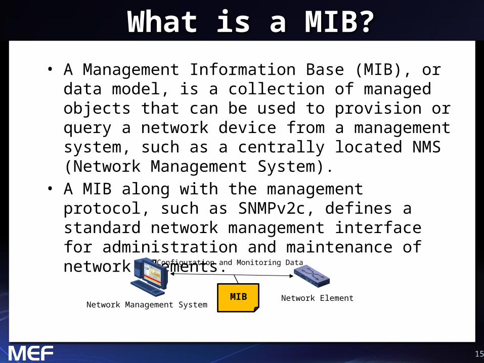
What is a MIB?• A Management Information Base (MIB), or data model, is a
collection of managed objects that can be used to provision or query a network device from a management system, such as a centrally located NMS (Network Management System).
• A MIB along with the management protocol, such as SNMPv2c, defines a standard network management interface for administration and maintenance of network elements.
MIBNetwork Management System
Network Element
Configuration and Monitoring Data

1616
MIBMIB
Management Framework
UNIUNI ENNI
CPE CPEOperator 1 Network Operator 2 NetworkNID NID
IEEE 802.1ag End-to-End Connectivity Fault Management
ITU-T Y.1731 End-to-End Performance Monitoring
Ethernet Virtual Connection
Service OAM
O
Network Management System
SP Network Ops
Notify Trouble Ticket System
SNMP
SN
MP
MIBMIB
MIBMIB

17
SOAM FM MIB Components
• MEF 31 builds upon the Connectivity Fault Management (CFM) MIBs specified in IEEE 802.1ag and IEEE 802.1ap
• The IEEE CFM MIB set includes– IEEE8021-CFM-MIB– IEEE8021-CFM-V2-MIB– IEEE8021-TC-MIB
• MEF 31 extends the CFM MIB set as follows– MEF-SOAM-TC-MIB– MEF-SOAM-FM-MIB

18
SOAM TC MIB Overview
• MEF-SOAM-TC-MIB defines a collection of Textual Conventions (common data types)– ConnectivityStatusType– DataPatternType – IntervalTypeAisLck – MegIdType – OperationTimeType – TestPatternType

19
SOAM FM MIB Overview
• Continuity Check (CCM)• Remote Defect Indication
Signal (RDI)• Alarm Indication Signal
(AIS)
• Linktrace• Loopback• Locked Signal• Test Signal
• MEF-SOAM-FM-MIB defines the managed objects necessary to support SOAM FM functionality:

20
Initial SOAM Configuration via 802.1ag/ap MIBs
• Before SOAM operations are instantiated by a NMS application, the following must be provisioned at each Network Element (NE) performing OAM Functions:– Maintenance Domain (MD)
• Create entry in dot1agCfmMdTable– Maintenance Association (MA)/Maintenance
Entity Group (MEG)• Create entry in dot1agCfmMaNetTable,
ieee8021CfmMaCompTable, mefSoamNetCfgTable and mefSoamMegCfgTable
– MEG End Point (MEP)• Create entry in dot1agCfmMepTable

21
Continuity Check Configuration Entries
• These 2 tables configure the Continuity Check OAM function with the associated parameters
dot1agCfmMepTable Object Description
CciEnabled CCM Enabled Flag
CcmLtmPriority CCM Priority
LowPrDefect Lowest Priority Defect
FngAlarmTime Fault Alarm Time
FngResetTime Fault Alarm Reset Time
mefSoamCcCfgTable Object Description
DropEligible Drop Eligibility flag

22
Continuity Check Status/Result Entries
• These 2 tables provide the status and results of the Continuity Check OAM function
dot1agCfmMepTable Object Description
FngState Current State of MEP FNG
HighestPrDefect Highest Priority Defect
Defects Active Defects
ErrorCcmLastFailure Last-received CCM to trigger DefErrorCCM fault
XconCcmLastFailure Last-received CCM to trigger DefXconCCM fault
CcmSequenceErrors Total # out-of-sequence CCMs received
CciSentCcms Total # CCMs sent
mefSoamMepFmStatsTable Object Description
InOamFramesDiscarded** Total # discarded OAM frames
StatsInCcmTotal Total # valid received CCM frames
**Not directly related to the CCM OAM function but included here for Table completeness
23
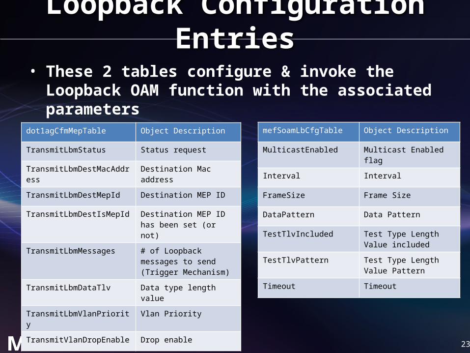
Loopback Configuration Entries
• These 2 tables configure & invoke the Loopback OAM function with the associated parameters
dot1agCfmMepTable Object Description
TransmitLbmStatus Status request
TransmitLbmDestMacAddress Destination Mac address
TransmitLbmDestMepId Destination MEP ID
TransmitLbmDestIsMepId Destination MEP ID has been set (or not)
TransmitLbmMessages # of Loopback messages to send (Trigger Mechanism)
TransmitLbmDataTlv Data type length value
TransmitLbmVlanPriority Vlan Priority
TransmitVlanDropEnable Drop enable
mefSoamLbCfgTable Object Description
MulticastEnabled Multicast Enabled flag
Interval Interval
FrameSize Frame Size
DataPattern Data Pattern
TestTlvIncluded Test Type Length Value included
TestTlvPattern Test Type Length Value Pattern
Timeout Timeout
24
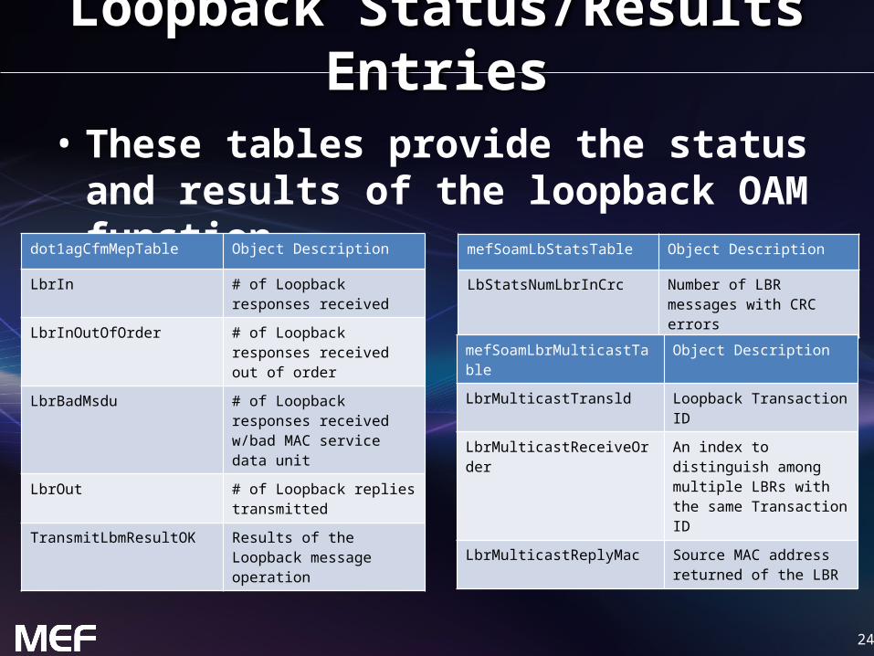
Loopback Status/Results Entries
• These tables provide the status and results of the loopback OAM function
dot1agCfmMepTable Object Description
LbrIn # of Loopback responses received
LbrInOutOfOrder # of Loopback responses received out of order
LbrBadMsdu # of Loopback responses received w/bad MAC service data unit
LbrOut # of Loopback replies transmitted
TransmitLbmResultOK Results of the Loopback message operation
mefSoamLbStatsTable Object Description
LbStatsNumLbrInCrc Number of LBR messages with CRC errors
mefSoamLbrMulticastTable Object Description
LbrMulticastTransld Loopback Transaction ID
LbrMulticastReceiveOrder An index to distinguish among multiple LBRs with the same Transaction ID
LbrMulticastReplyMac Source MAC address returned of the LBR
25
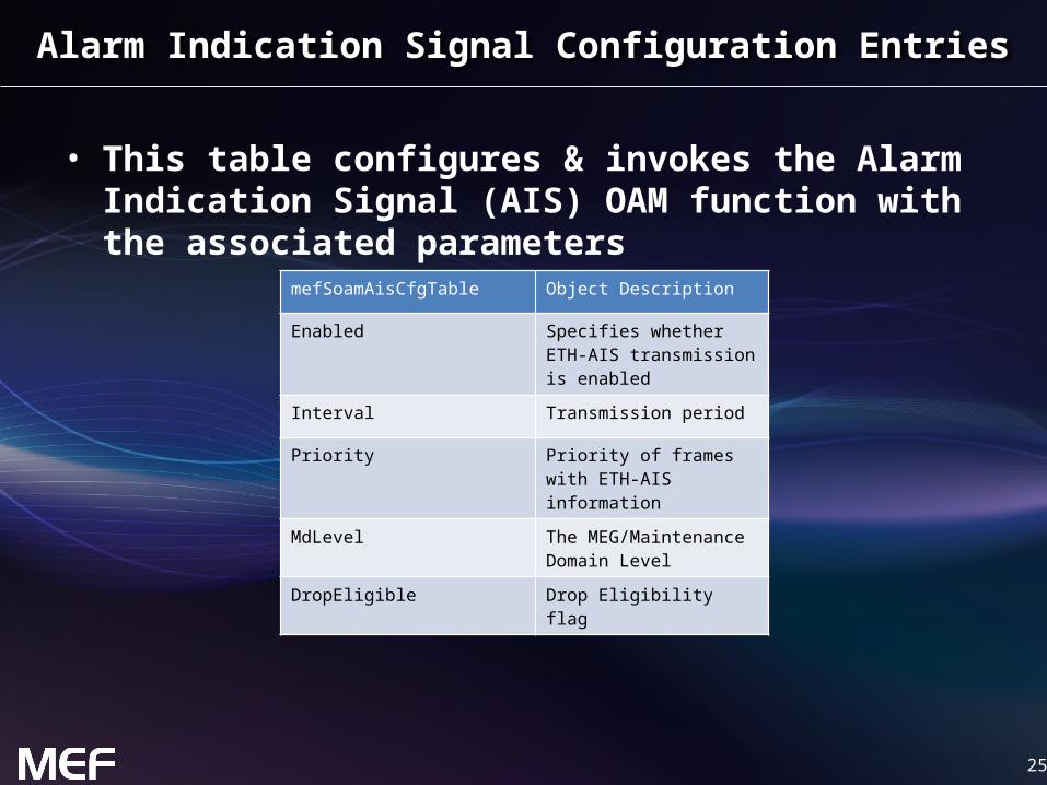
Alarm Indication Signal Configuration Entries
• This table configures & invokes the Alarm Indication Signal (AIS) OAM function with the associated parameters
mefSoamAisCfgTable Object Description
Enabled Specifies whether ETH-AIS transmission is enabled
Interval Transmission period
Priority Priority of frames with ETH-AIS information
MdLevel The MEG/Maintenance Domain Level
DropEligible Drop Eligibility flag

26
AIS Status/Results Entries
• This table provides the status and results of the Alarm Indication Status OAM function
mefSoamAisStatsTable Object Description
OutStatus Current AIS transmission status
OutCounter # of AIS messages sent
InStatus Current AIS receive status
InCounter # of AIS messages received
InMacAddr The source MAC Address Field of last AIS received

27
Linktrace Configuration Entries
• This table configures & invokes the Linktrace OAM function with the associated parameters
dot1agCfmMepTable Object Description
CcmLtmPriority LTM Priority value
TransmitLtmStatus LTM Msg Transmission Locking Flag
TransmitLtmFlags Flags Field (Trigger Mechanism)
TransmitLtmTargetMacAddress Unicast Destination MAC Address
TransmitLtmTargetMepId MEP ID Address
TransmitLtmTargetIsMepId Target Address Indicator
TransmitLtmTtl LTM TTL value
TransmitLtmEgressIdentifier MEP Linktrace Initiator/Responder Identifier
28
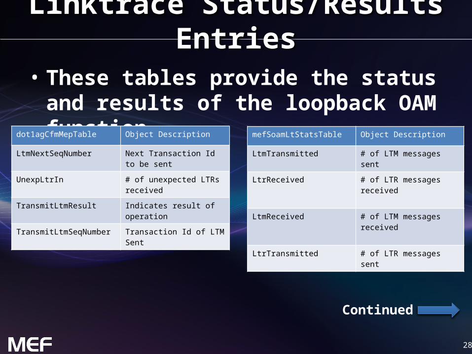
Linktrace Status/Results Entries
• These tables provide the status and results of the loopback OAM function
dot1agCfmMepTable Object Description
LtmNextSeqNumber Next Transaction Id to be sent
UnexpLtrIn # of unexpected LTRs received
TransmitLtmResult Indicates result of operation
TransmitLtmSeqNumber Transaction Id of LTM Sent
mefSoamLtStatsTable Object Description
LtmTransmitted # of LTM messages sent
LtrReceived # of LTR messages received
LtmReceived # of LTM messages received
LtrTransmitted # of LTR messages sent
Continued

29
Linktrace Status/Results Entries (cont)dot1agCfmLtrTable Object Description
SeqNumber Transaction Id of previous LTM
ReceiveOrder Unique index for multiple LTRs for same LTM Transaction Id
Ttl LTR TTL
Forwarded Indicates if a LTM was forwarded by the responding MP
TerminalMep Indicates if the LTM reached a MEP enclosing its MA
LastEgressIndentifier Identifies the MEP Linktrace Initiator/Responder for the LTM to which this LTR is the response
NextEgressIdentifier Identifies the Linktrace Responder that sent the LTR
Relay Relay Action value
ChassisIdSubtype The format of the Chassis ID returned in the Sender ID TLV of the LTR
ChassisId Chassis ID returned in the Sender ID TLV of the LTR
ManAddressDomain Tdomain that identifies type/format of the mgmt addr object used to access the SNMP agent of the system sending the LTR
ManAddress Taddress (mgmt addr) for accessing the SNMP agent of the system sending the LTR
Continued

30
Linktrace Status/Results Entries (cont)dot1agCfmLtrTable Object Description
Ingress Value returned in Ingress Action Field of LTM
IngressMac MAC Address returned in the ingress MAC Address field
IngressPortIdSubtype Format of the Ingress Port ID
IngressPortId Value of the Ingress Port ID
Egress Value returned in the Egress Action Field of LTM
EgressMac MAC Address returned in the Egress MAC Address field
EgressPortIdSubtype Format of the Egress Port ID
EgressPortId Value of the Egress Port ID
OrganizationSpecificTlv All Organization specific TLVs returned in the LTR

31
Locked Signal Configuration Entries
• This table configures & invokes the Locked Signal OAM function with the associated parameters
mefSoamLckCfgTable Object Description
AdminState Locking state (e.g., locked, unlocked)
Interval Transmission period
Priority Priority of frames with ETH-LCK information
MdLevel The MEG/Maintenance Domain Level

32
Locked Status/Results Entries
• This table provides the status and results of the Locked Signal OAM function
mefSoamLckStatsTable Object Description
InStatus Current LCK receive status
InCounter # of LCK messages received
OutStatus Current LCK transmission status
OutCounter # of LCK messages transmitted

33
Remote Defect Indication Signal Configuration Entries
• This 2 table configures the Remote Defect Indication (RDI) Signal OAM function with the associated parameters
dot1agCfmMepTable Object Description
CciEnabled CCM Enabled Flag**
**RDI is a 1-bit information element carried in the Flags field of the CCM OAM PDU and is enabled through the CCM function.

34
RDI Status/Results Entries
• These tables provide the status and results of the Remote Defect Indication OAM function
dot1agCfmMepDbTable Object Description
RMepIdentifier Remote MEP ID
Rdi State of RDI bit in the last received CCM for the remote MEP identified by RMepIdenfier
mefSoamLtStatsTable Object Description
RdiTransmitStatus Indicates if local MEP is generating an RDI

35
Test Signal Configuration Entries
• This table configures & invokes the Test Signal OAM function with the associated parameters
mefSoamTestCfgTable Object Description
OutEnabled Enables the ETH-Test transmit function
InEnabled Enables the ETH-Test receive function
InService Indicates in-service or out-of-service
DestMacAddress Unicast Destination MAC Address
DestMepId Destination MEP ID
DestIsMepId Target Address Indicator
Interval Transmission period
Priority Priority of frames with ETH-TST information
DropEligible Drop Eligibility flag
FrameSize Frame Size
mefSoamTestCfgTable (cont) Object Description
Pattern Type of test pattern
StartTimeType Type of scheduled start date/time to perform the on-demand ETH-Test operations
ScheduledStartDateAndTime Scheduled start date/time to perform the on-demand ETH-Test operations
ScheduledStopDateAndTime Scheduled stop date/time
RelativeStartTime Specifies the relative start time, from the current system time, to perform on-demand ETH-Test
DurationTime Duration of the ETH-Test operation
OutStatus Flag indicator that another ETH-Test transmission operation is active

36
Test Status/Results Entries
• This table provides the status and results of the Test Signal OAM function
mefSoamTestStatsTable Object Description
NumIn # of TST messages received
NumInOutOfOrder # of out-of-order TST messages received
NumInCrcErrors # of TST messages received with BER or data errors
NumInBerErrors # of out-of-order TST messages received
NumOut # of TST messages transmitted
37
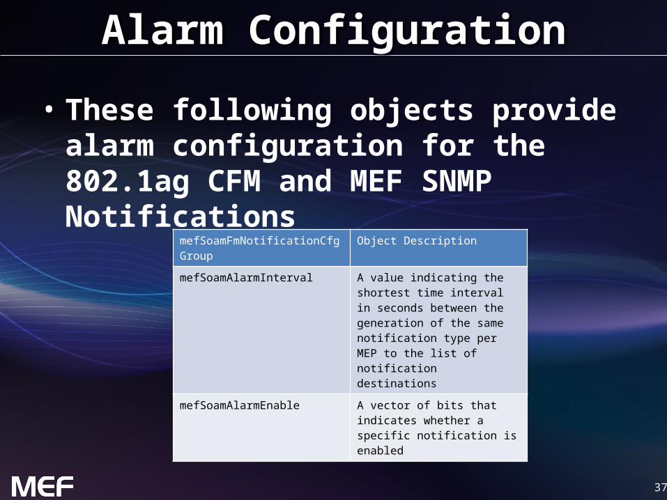
Alarm Configuration
• These following objects provide alarm configuration for the 802.1ag CFM and MEF SNMP Notifications
mefSoamFmNotificationCfg Group Object Description
mefSoamAlarmInterval A value indicating the shortest time interval in seconds between the generation of the same notification type per MEP to the list of notification destinations
mefSoamAlarmEnable A vector of bits that indicates whether a specific notification is enabled

38
SNMP Notifications
• These following MEF SNMP Notifications provide for Autonomous alarms and events
SNMP Notifications (Traps) Description
mefSoamMepDefectAlarm This notification is sent when the value of dot1agCfmMepDefects changes
mefSoamConfigErrorAssertAlarm This notification is sent when an entry is added to the ieee8021CfmConfigErrorListTable
mefSoamConfigErrorClearAlarm This notification is sent when an entry is deleted from the ieee8021CfmConfigErrorListTable
efSoamMepOperStatusAlarm This notification is sent when the value of mefSoamMepOperationalState changes
mefSoamLckAlarm This notification is sent when the LCK PDU is received or when either mefSoamLckInStatus or mefSoamLckOutStatus changes
mefSoamAisAlarm This notification is sent when the state of either mefSoamAisOutStatus or mefSoamAisInStatus changes

39
Summary MEF 31• MEF 31 defines the managed objects for using an
SNMP management interface for the MEF 30 Service OAM Fault Management protocol
• MEF 31 enables MEF equipment providers to provide a standardized management interface for the SOAM Fault Management functions:– Continuity Check/Remote Defect Indication– Loopback– Linktrace– Alarm Indication Signal– Lock Signal– Test Signal

40
Final Word
• Service OAM – In the context of MEF 31, data models (MIBs) are
defined that support service-level OAM in MENs • Next Actions (For Further Information)
– Read the full MEF 30 Fault Management Implementation Agreement specification
– Read the full MEF 31 specification (note, review of MEF 17, MEF 7.1 and MEF 15 may also be helpful)
– Understand the principal service OAM components and capabilities

4141
For Full Details …
Please visit www.metroethernetforum.org Select Information Center on Left Navigation to access the full specification and extracted MIB files
Carrier Ethernet Network
UNI
UNI
CE
CE
CE
Carrier Ethernet 2.0EVPL Services
UNI
Carrier Ethernet 2.0EVP-LAN Service
ISP POP
Internet
UNI
UNI
CE
CE
CE
UNI
Carrier Ethernet Network
EVC: Ethernet Virtual ConnectionUNI: User Network Interface. the physical
demarcation point between the responsibility of the Service Provider and the responsibility of the End-User/Subscriber
CE Customer Equipment
E-LAN Service type
E-Line Service type

42
Accelerating Worldwide Adoption of Carrier-class Ethernet Networks and Services
www.MetroEthernetForum.org


