

Starting & speed control of Motors
M. Nageswar Rao, Sr.Mgr.(EMD)
Date: 01.10.2015

2
Presentation LayoutMotor applications Induction Motors
Starting methodsSpeed control methods
Synchronous MotorsStarting methodsSpeed control methods
DC MotorsStarting methodsSpeed control methods

3
Motor ApplicationInduction motors
Low costReliableSmaller power ratings
Synchronous motorsConstant speed motorsLow speed <300rpmHigh power ratings in MW range.
DC motorsEmergency standbySmaller ratingsConstant speed applications
4
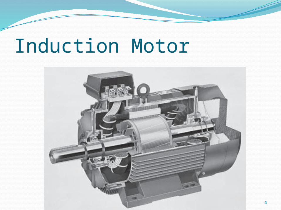
Induction Motor

5
Induction MotorThe
electromechanical power per stator phase is equal to the power delivered to the resistance R2(1 - s)/s.
6
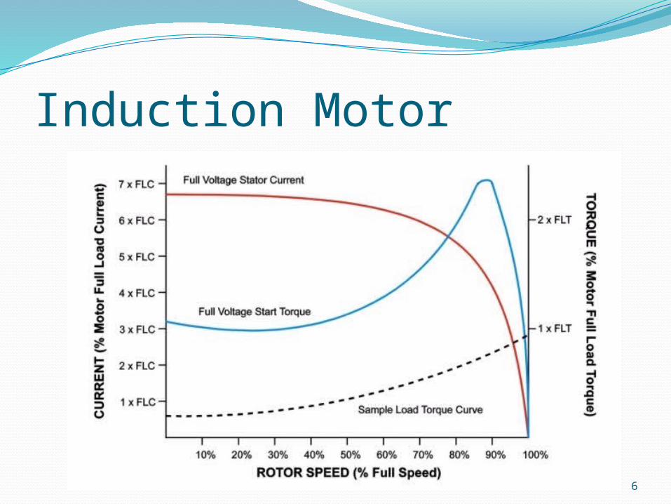
Induction Motor

7
Induction Motor -Starting methods DOL starter
Applies full supply voltageDraws low p.f. starting current of 600%,
causing dip in supply voltageUsed for low-inertia loadsSimple design, low cost, high starting torque.

8
Induction Motor -Starting methods Star/ Delta starter
Motor should be brought with all 6 leads.Initially motor winding is arranged in STAR and
when the motor attains a speed of 70-80% of rated speed, winding is re-arranged in DELTA.
Compared to DOL Starting Current is reduced by 1/√3 (i.e. 57%) and Starting Torque & Power is reduced by 1/3 (i.e. 33%)

9
Induction Motor -Starting methods DOL Star/Delta

10
Induction Motor -Speed control methodsPole changingSupply voltage controlSupply freq. controlV/f control

11
Induction Motor -Speed control methodsPole changing method
Synchronous speed can be changed by changing the number of stator poles.
This method is generally used for SCIM, as squirrel cage rotor adapts itself for any number of stator poles.
Change in stator poles is achieved by two or more independent stator windings wound for different number of poles in same slots.

12
Induction Motor -Speed control methodsSupply Voltage control

13
Induction Motor -Speed control methodsSupply Freq. control
14
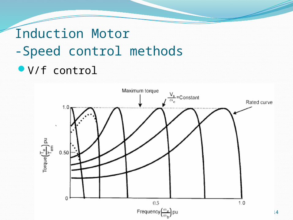
Induction Motor -Speed control methodsV/f control

15
Synchronous motor

16
Synchronous motor- Starting methods DC motor startingAsynchronous starting

17
Synchronous motor- Starting methods DC motor starting
DC motor on a common shaft. When the motor is brought to synchronous
speed, AC current is applied to the stator windings.
The DC motor now acts as a DC generator and supplies DC field excitation to the rotor of the synchronous motor.
The load may now be placed on the synchronous motor

18
Synchronous motor- Starting methods Asynchronous starting
Damper winding (or) squirrel cage winding is embedded in rotor.
The rotor accelerates at a speeds upto 95% of synchronous speed, with a slight slip in reference to the rotating field.
On this point, a direct current is applied to the rotor winding and then taking the motor to synchronism.

19
Synchronous motor- Starting methods

20
Synchronous motor- Starting method Low speed (upto 95% of synch.speed)
Field ckt. Is short circuited with SCR-2 ON.Induced emf in SM field winding is dissipated in
FDRPull-in / synchronization
Control ckt. Fires SCR-1 at proper pull-in speed for successful synchronizing and at the proper polarity to give maximum pull-in torque with minimum line disturbance.
Applies excitation to the synchronous motor field. SCR-2 is OFF and FDR is removed from ckt.

21
Synchronous motor- Starting method Pull-out/ pole-slip
The control circuit operates to remove excitation should the motor pull out of step due to a voltage step or excessive mechanical load.
On the first half cycle after pull-out, the induced field voltage will oppose the exciter voltage , causing the net field current to pass through zero, turning SCR-1 off, automatically removing excitation.
SCR-2 operates to connect the FDR back in to the circuit.
During this time, the motor operates as an induction motor.
When conditions permit, field is then reapplied as during starting.

22
Synchronous motor- Starting method SCR-2 is turned on only at a voltage higher
than the exciter voltage so it will not be ON when SCR-1 is ON.
Occasionally, a lightly loaded motor will synchronize without excitation being applied. This is due to the reluctance torque. Reluctance torque results from the magnetic circuit having less reluctance when the poles line up with the stator flux.

23
DC Motors

24
DC Motors

25
DC Motors- Starting methods Armature series resistance

26
DC Motors- Speed control methods Field current weakening
For higher speedsArmature resistance control
For lower speedsArmature Supply voltage control

27
Thank you all


