

Fighter Aircraft AvionicsPart III
SOLO HERMELIN
Updated: 04.04.13
1
Table of Content
SOLO Fighter Aircraft Avionics
2
Introduction
Jet Fighter Generations
Second Generation (1950-1965)Third Generation (1965-1975)
First generation (1945-1955)
Fourth Generation (1970-2010)
4.5 Generation
Fifth Generation (1995 - 2025) Aircraft Avionics
Third Generation Avionics
Fourth Generation Avionics
4.5 Generation AvionicsFifth Generation Avionics
Cockpit Displays
Communication (internal and external)Data Entry and Control
Flight Control
Fighter Aircraft Avionics I
Table of Content (continue – 1)
SOLO Fighter Aircraft Avionics
Aircraft Propulsion System
Aircraft Flight Performance
Navigation
Earth Atmosphere
Flight Instruments
Power Generation SystemEnvironmental Control System
Aircraft Aerodynamics
Fuel System
Jet Engine
Vertical/Short Take-Off and Landing (VSTOL)
Engine Control System
Flight Management System
Aircraft Flight Control
Aircraft Flight Control Surfaces
Aircraft Flight Control Examples
Fighter
Aircraft
Avionics
II

Table of Content (continue – 2)
SOLO
4
Fighter Aircraft Avionics
Equations of Motion of an Air Vehicle in Ellipsoidal Earth Atmosphere
Fighter Aircraft Weapon System
References
Safety Procedures
Tracking Systems
Aircraft Sensors
Airborne Radars
Infrared/Optical Systems
Electronic Warfare
Air-to-Ground Missions
BombsAir-to-Surface Missiles (ASM) or Air-to-Ground Missiles (AGM)
Fighter Aircraft Weapon Examples
Air-to-Air Missiles (AAM)
Fighter Gun
Avionics IV

Continue fromFighter Aircraft Avionics
Part II
SOLO
5
Fighter Aircraft Avionics
SOLO
6
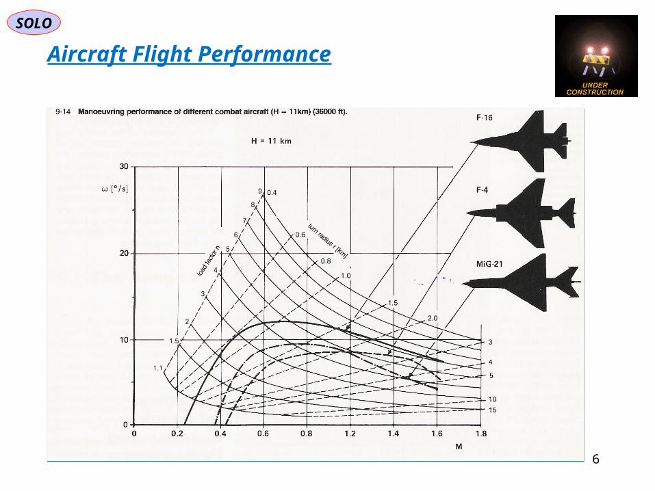
Aircraft Flight Performance
SOLO
7
Aircraft Flight Performance
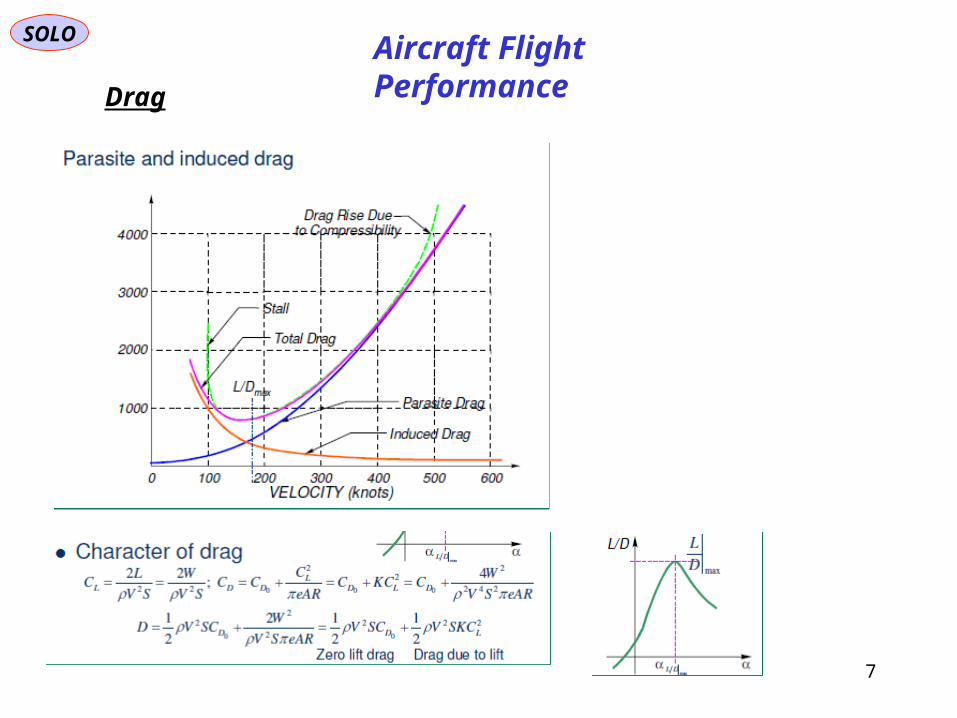
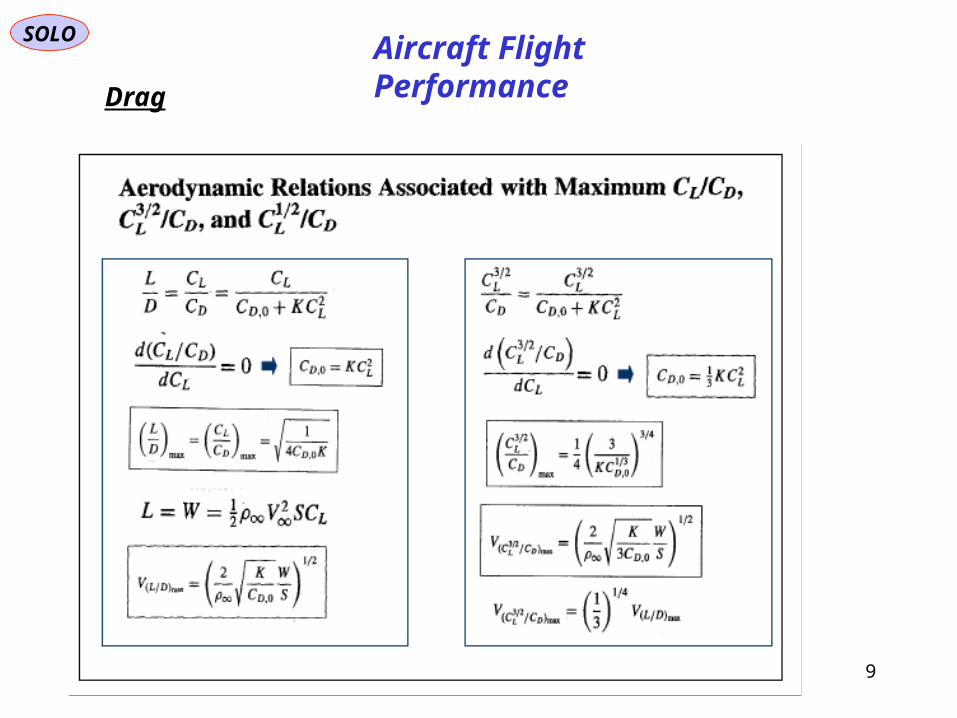
Drag

SOLO
8
Aircraft Flight Performance
Drag
SOLO
9
Aircraft Flight Performance
Drag

SOLO
10
Aircraft Flight Performance
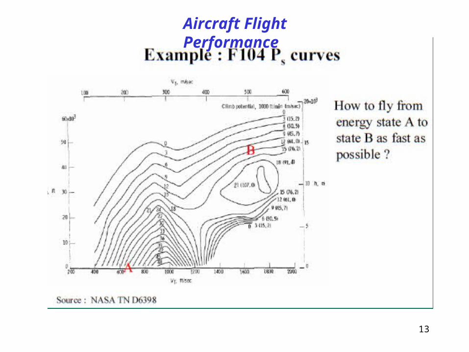
In combat, a pilot is faced with a variety of limiting factors. Some limitations are constant, such as gravity, drag, and thrust-to-weight ratio. Other limitations vary with speed and altitude, such as turn radius, turn rate, and the specific energy of the aircraft. The fighter pilot uses Basic Fighter Maneuvers (BFM) to turn these limitations into tactical advantages. A faster, heavier aircraft may not be able to evade a more maneuverable aircraft in a turning battle, but can often choose to break off the fight and escape by diving or using its thrust to provide a speed advantage. A lighter, more maneuverable aircraft can not usually choose to escape, but must use its smaller turning radius at higher speeds to evade the attacker's guns, and to try to circle around behind the attacker.[13]
BFM are a constant series of trade-offs between these limitations to conserve the specific energy state of the aircraft. Even if there is no great difference between the energy states of combating aircraft, there will be as soon as the attacker accelerates to catch up with the defender. Instead of applying thrust, a pilot may use gravity to provide a sudden increase in kinetic energy (speed), by diving, at a cost in the potential energy that was stored in the form of altitude. Similarly, by climbing the pilot can use gravity to provide a decrease in speed, conserving the aircraft's kinetic energy by changing it into altitude. This can help an attacker to prevent an overshoot, while keeping the energy available in case one does occur
Energy Management

SOLO
11
Aircraft Flight Performance

SOLO
12
Aircraft Flight Performance
13
Aircraft Flight Performance

14
Aircraft Flight Performance

15
Aircraft Flight Performance

16
Aircraft Flight Performance

SOLO
17
Aircraft Flight Performance

SOLO
18
Aircraft Flight Performance
19
Navigation SOLO
I
Ecuator
1R
2R11,
Ex
Ey
Ez
1
222 ,
,
12 TrajectoryGreat Circcle
1 2
0
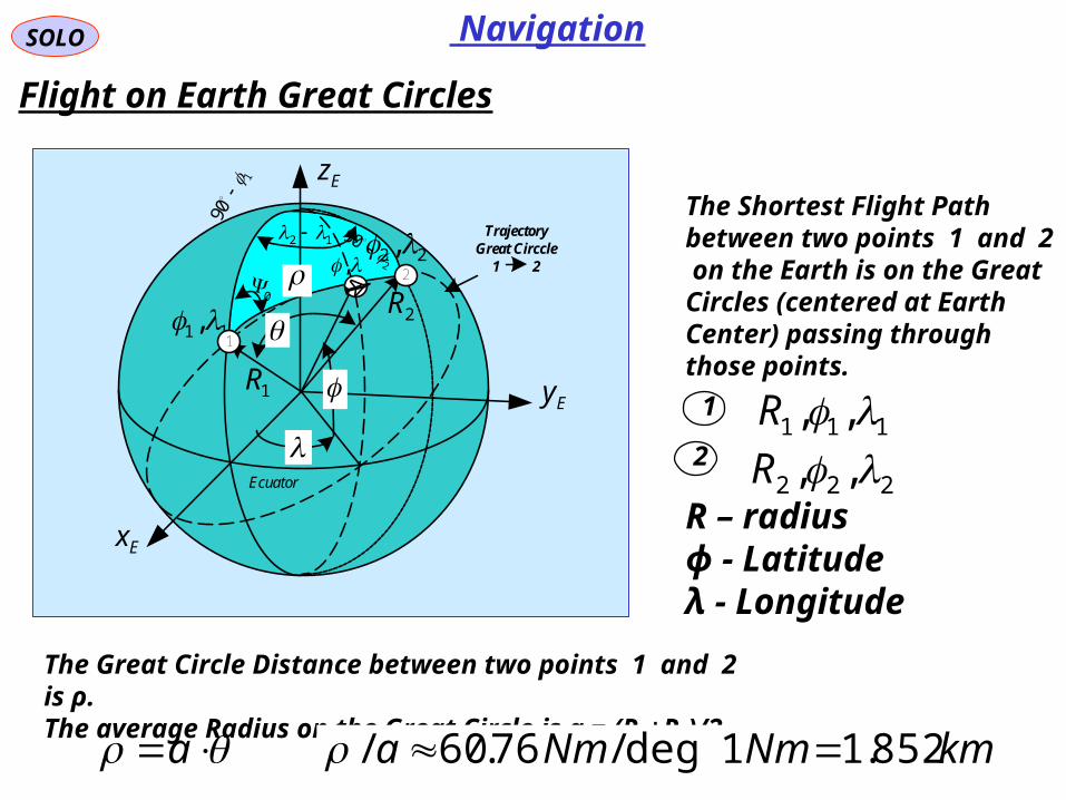
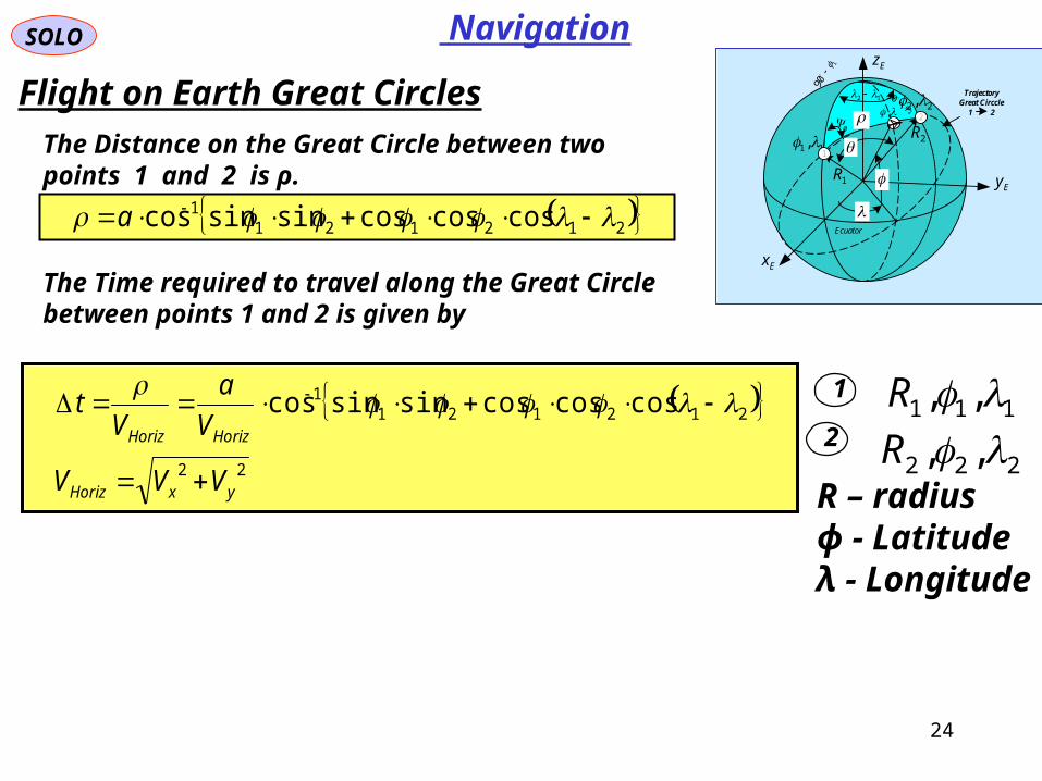
Flight on Earth Great Circles
The Shortest Flight Path between two points 1 and 2 on the Earth is on the Great Circles (centered at Earth Center) passing through those points.
1
2111 ,, R
222 ,, R
The Great Circle Distance between two points 1 and 2 is ρ.The average Radius on the Great Circle is a = (R1+R2)/2
a
R – radiusϕ - Latitudeλ - Longitude
kmNmNma 852.11deg/76.60/
20
Spherical TrigonometrySOLO
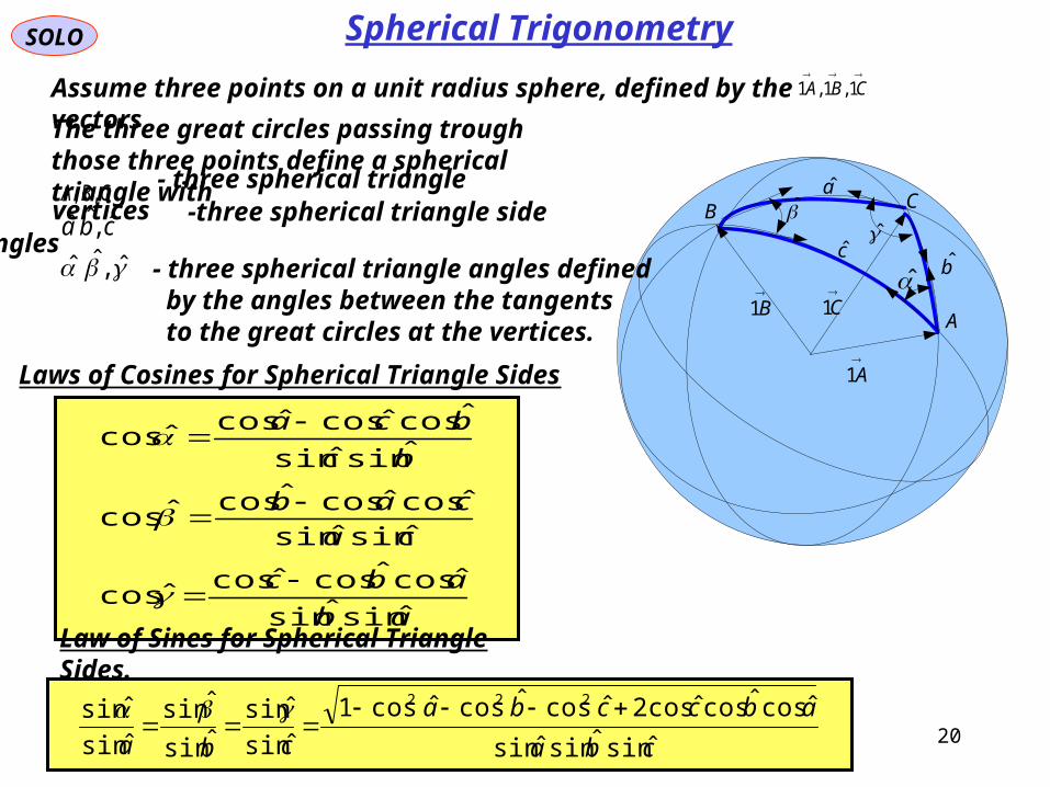
Assume three points on a unit radius sphere, defined by the vectors
CBA 1,1,1
A1
B1
C1
B
a
bc
C
A
Laws of Cosines for Spherical Triangle Sides
ab
abc
ca
cab
bc
bca
ˆsinˆsin
ˆcosˆcosˆcosˆcos
ˆsinˆsin
ˆcosˆcosˆcosˆcos
ˆsinˆsin
ˆcosˆcosˆcosˆcos
Law of Sines for Spherical Triangle Sides.
cba
abccba
cba ˆsinˆsinˆsin
ˆcosˆcosˆcos2ˆcosˆcosˆcos1
ˆsin
ˆsinˆsin
ˆsinˆsin
ˆsin 222
The three great circles passing trough those three points define a spherical triangle with
CBA ,,- three spherical triangle
verticescba ˆ,ˆˆ -three spherical triangle side angles
ˆ,ˆˆ - three spherical triangle angles defined by the angles between the tangents to the great circles at the vertices.

21
SOLO
Assume three points on a unit radius sphere, defined by the vectors
CBA 1,1,1
A1
B1
C1
B
a
bc
C
A
Laws of Cosines for Spherical Triangle Sides
The three great circles passing trough those three points define a spherical triangle with
CBA ,,- three spherical triangle
verticescba ˆ,ˆˆ -three spherical triangle side angles
ˆ,ˆˆ - three spherical triangle angles defined by the angles between the tangents to the great circles at the vertices.
ˆsinˆsin
ˆcosˆcosˆcosˆcos
ˆsinˆsin
ˆcosˆcosˆcosˆcos
ˆsinˆsin
ˆcosˆcosˆcosˆcos
c
b
a
Spherical Trigonometry

22
Flow of Air Data to Key Avionics Sub-systems
AirDataSystem
Multi-Function Display
FlightInstrumentSystem
NavigationSystem
FlightManagementSystem
FlightControlSystem
AutopilotSystem
WeaponSystem
HUD HMD
AVIONICS DATA BUS
Infrared/OpticSensors
RadarSelf-Defense
System
Aircraft AvionicsNavigation
See “Navigation Systems” PDF for a detailed presentation.

23
Navigation SOLO
I
Ecuator
1R
2R11,
Ex
Ey
Ez
1
222 ,
,
12 TrajectoryGreat Circcle
1 2
0
1
2
Flight on Earth Great Circles
1
2111 ,, R
222 ,, R
The Great Circle Distance between two points 1 and 2 is ρ.
a
R – radiusϕ - Latitudeλ - Longitude
212121 cos90sin90sin90cos90cos
/coscos
a
From the Law of Cosines for Spherical Triangles
or
212121 coscoscossinsin/cos a
2121211 coscoscossinsincos a
The Initial Heading Angle ψ0 can be obtained using theLaw of Cosines for Spherical Triangles as follows
a
a
/sincos
/cossinsincos
1
120
2222
22221
coscoscossinsin1cos
coscoscossinsinsinsincos
The Heading Angle ψ from the Present Position (R,ϕ,λ) to Destination Point (R2,ϕ2,λ2)
24
Navigation SOLO
I
Ecuator
1R
2R11,
Ex
Ey
Ez
1
222 ,
,
12 TrajectoryGreat Circcle
1 2
0
1
2
Flight on Earth Great Circles
The Distance on the Great Circle between two points 1 and 2 is ρ.
1
2111 ,, R
222 ,, RR – radiusϕ - Latitudeλ - Longitude
The Time required to travel along the Great Circle between points 1 and 2 is given by
22
2121211 coscoscossinsincos
yxHoriz
HorizHoriz
VVV
V
a
Vt
2121211 coscoscossinsincos a
25
Navigation SOLO
I
Ecuator
1R
2R
Ex
Ey
Ez
1
2
TrajectoryGreat Circcle
1 2
1R
2R1
2
O
A
B
Ca
b
c
c
Earth Center
North Pole
A
B'B90
P
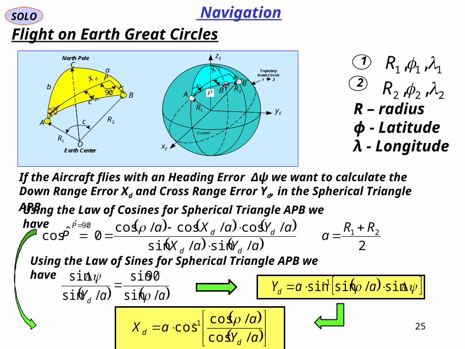
Flight on Earth Great Circles
1
2111 ,, R
222 ,, R
If the Aircraft flies with an Heading Error Δψ we want to calculate the Down Range Error Xd and Cross Range Error Yd, in the Spherical Triangle APB.
R – radiusϕ - Latitudeλ - Longitude
Using the Law of Cosines for Spherical Triangle APB we have
aaYd /sin
90sin
/sin
sin
2/sin/sin
/cos/cos/cos0ˆcos 21
90ˆ RRa
aYaX
aYaXaP
dd
ddP
Using the Law of Sines for Spherical Triangle APB we have
aY
aaX
dd /cos
/coscos 1
sin/sinsin 1 aaYd

SOLO
26
Navigation
Methods of Navigation
• Dead Reckoning (e.g. Inertial Navigation)
• Externally Dependent (e.g. GPS)
• Database Matching (e.g Celestial Navigation, or Terrain Referenced Navigation)
See “Navigation Systems.ppt” fora detailed description

SOLO
27
Navigation
Dead Reckoning Navigation
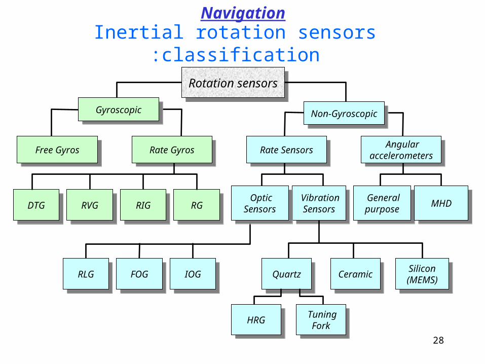
Inertial rotation sensors classification:
Rotation sensorsRotation sensors
GyroscopicGyroscopic
Rate GyrosRate GyrosFree GyrosFree Gyros
Non-GyroscopicNon-Gyroscopic
Vibration Sensors
Vibration Sensors
Rate SensorsRate Sensors Angular accelerometers
Angular accelerometers
DTGDTG RGRGRIGRIGRVGRVG General purpose
General purpose MHDMHDOptic
Sensors
Optic Sensors
RLGRLG IOGIOGFOGFOG Silicon(MEMS)
Silicon(MEMS)
HRGHRG Tuning Fork
Tuning Fork
QuartzQuartz CeramicCeramic
Navigation
28

29

Rate gyro DTG – Dynamically Tuned Gyro
Flex Inversion Cardan joint
30

31
Main Components of a DTG
Transverse Cut of a DTG
Rate gyro DTG – Dynamically Tuned Gyro

SOLO
32
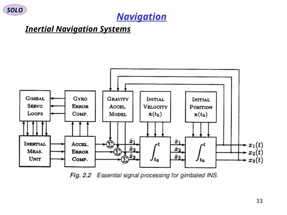
NavigationInertial Navigation Systems
(a) Strapdown
There are two way to attach the Inertial Measurement Unit (IMU) to the platform:1.IMU on Gimbals that keeps it Leveled to Earth Surface (the old type)2.IMU strap to the Aircraft Body (Strapdown) (the modern way)
SOLO
33
NavigationInertial Navigation Systems

SOLO
34
NavigationInertial Navigation Systems

35
SOLO
LBL
a
BBA
BCG gCT
mF
ma
B
11 BCG
TBL
LCG aCa
BL
LIL
BIBBLBL qqq
2
1
2
1 TBL IqIqC
3434
BCGa
LCGa
Ba
BLC
BLC
s
1 BLqBLq
BLC
s
1 L
ELL
EL
LLCG
LE VRaV
2 s
1 L
EV L
EV
LCGa
BLC
LMR
LEV
LE
BL
BE VCV
MV
BIB
IMU
Rate GyrosCompensation
AccelerometersCompensation
Rate Gyros
Accelerometers Lg
Strapdown Algorithm (Vector Notation)
Navigation
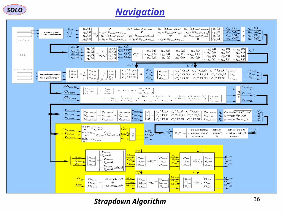
36
SOLO
IMU
B
B
B
r
q
p
4
3
2
1
0
0
0
0
2
1
4
3
2
1
BL
BL
BL
BL
DownDownBEastEastBNorthNorthB
DownDownBNorthNorthBEastEastB
EastEastBNorthNorthBDownDownB
NorthNorthBEastEastBDownDownB
BL
BL
BL
BL
q
q
q
q
rqp
rpq
qpr
pqr
q
q
q
q
s
1
4
3
2
1
BL
BL
BL
BL
q
q
q
q
4
3
2
1
BL
BL
BL
BL
q
q
q
q
g
C
C
C
T
T
T
mF
F
F
ma
a
a
BL
BL
BL
a
zB
yB
xB
zBA
yBA
xBA
zB
yB
xB
B
3,3
3,2
3,111
zB
yB
xB
a
a
a
zB
yB
xB
BL
BL
BL
BL
BL
BL
BL
BL
BL
Down
East
North
a
a
a
CCC
CCC
CCC
a
a
a
3,33,23,1
2,32,22,1
1,31,21,1
Down
East
North
a
a
a
BLC
BLC
4
3
2
1
*
1
4
3
2
1
BL
BL
BL
BL
BL
BL
BL
BL
q
q
q
q
q
q
q
q 4
3
2
1
BL
BL
BL
BL
q
q
q
qB
LC
321
412
143
234
3412
2143
1234
BLBLBL
BLBIBL
BLBLBL
BLBLBL
BLBLBLBL
BLBLBLBL
BLBLBLBLB
L
qqq
qqq
qqq
qqq
qqqq
qqqq
qqqq
C
43
2
1
BL
BL
BL
BL
q
q
q
q
Down
East
North
a
a
a
DownW
EastW
NorthW
NorthNorthEastEast
NorthNorthDownDown
EastEastDownDown
Down
East
North
DownE
EastE
NorthE
V
V
V
Lat
Lat
HR
a
a
a
V
V
V
022
202
220
sin
0
cos2
_
_
_
s
1
DownE
EastE
NorthE
V
V
V
cos0sin
sinsincossincos
cossinsincoscosW
BC
WBC
s
1
H
Long
Lat
H
Long
Lat
DownE
p
EastE
m
NorthE
Vtd
Hd
LatHR
V
td
Longd
HR
V
td
Latd
cos
w
v
u
DownM
EastM
NorthM
BL
BL
BL
BL
BL
BL
BL
BL
BL
V
V
V
CCC
CCC
CCC
w
v
u
_
_
_
3,32,31,3
3,22,21,2
3,12,11,1
DownW
EastW
NorthW
DownE
EastE
NorthE
DownM
EastM
NorthM
V
V
V
V
V
V
V
V
V
_
_
_
_
_
_
_
_
_
DownM
EastM
NorthM
V
V
V
DownE
EastE
NorthE
V
V
V
M
M
Vv
uw
wvuV
/sin
/tan1
1
222
MV
DownE
EastE
NorthE
V
V
V
DownE
EastE
NorthE
V
V
V
LatHR
V
HR
V
HR
V
EastE
NorthE
EastE
Down
East
North
tan0
0
0
Down
East
North
Down
East
NorthW
L
zW
yW
xW
C
*
*
*
*
*
*
*
zW
yW
xW
*
*
*
1
zW
yW
xW
zW
yW
xW
zW
yW
xW
WLC
Lat
Lat
Down
East
North
sin
0
cos
Down
East
North
Down
East
NorthW
L
zW
yW
xW
C *
*
*
*
*
*
*
zW
yW
xW
*
*
*
1
zW
yW
xW
zW
yW
xW
zW
yW
xW
WLC
Lat
Rate GyrosCompensation
Accelerometers
Compensation
Rate Gyros
Accelerometers
Strapdown Algorithm
Navigation

SOLO
37
NavigationInertial Navigation Systems
Gyrocompass

SOLO
38
NavigationRadar Altimeter
SOLO
39
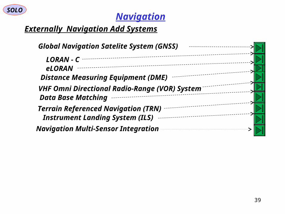
NavigationExternally Navigation Add Systems
eLORAN LORAN - C
Global Navigation Satelite System (GNSS)
Distance Measuring Equipment (DME)
VHF Omni Directional Radio-Range (VOR) SystemData Base Matching
Terrain Referenced Navigation (TRN)
Navigation Multi-Sensor Integration
Instrument Landing System (ILS)
SOLO
40
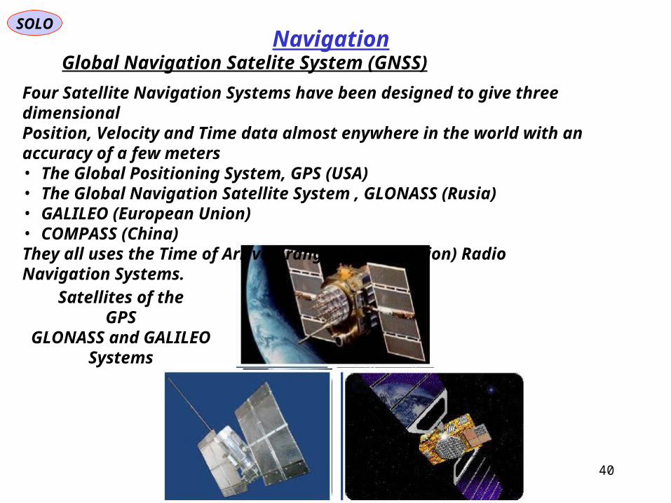
NavigationGlobal Navigation Satelite System (GNSS)
Satellites of theGPS
GLONASS and GALILEOSystems
Four Satellite Navigation Systems have been designed to give three dimensionalPosition, Velocity and Time data almost enywhere in the world with an accuracy of a few meters• The Global Positioning System, GPS (USA)• The Global Navigation Satellite System , GLONASS (Rusia)• GALILEO (European Union)• COMPASS (China)They all uses the Time of Arrival (range determination) Radio Navigation Systems.

SOLO
41
NavigationGlobal Navigation Satelite System (GNSS)
SOLO
42
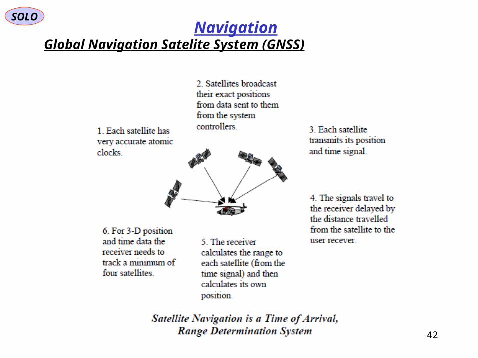
NavigationGlobal Navigation Satelite System (GNSS)

SOLO
43
NavigationGlobal Navigation Satelite System (GNSS)
Differential GPS Systems (DGPS)
Differential GPS Systems (DGPS) techniques are based on installing one or more Reference Receivers at known locations and the measured and known ranges to the Satellites are broadcast to the other GPS Users in the vicinity. This removes much of the Ranging Errors caused by atmospheric conditions (locally) and Satellite Orbits and Clock Errors (globally).

Global Positioning System (GPS)
SOLO
44
Navigation
A visual example of the GPS constellation in motion with the Earth rotating. Notice how the number of satellites in view from a given point on the Earth's surface, in this example at 45°N, changes with time
The Global Positioning System (GPS) is a space-based satellite navigation system that provides location and time information in all weather, anywhere on or near the Earth, where there is an unobstructed line of sight to four or more GPS satellites. It is maintained by the United States government and is freely accessible to anyone with a GPS receiver.
Ground monitor station used from 1984 to 2007, on display at the Air Force Space & Missile Museum
A GPS receiver calculates its position by precisely timing the signals sent by GPS satellites high above the Earth. Each satellite continually transmits messages that include:• the time the message was transmitted• satellite position at time of message transmission
Global Navigation Satellite System (GNSS)
Satellite Position
SOLO
45
Navigation
GZ
GX
GYEquatorial
Plane
Y
Z
X
AscendingNode
Satellite Orbit
PeriapsisDirection
Vernal EquinoxDirection
i
N1
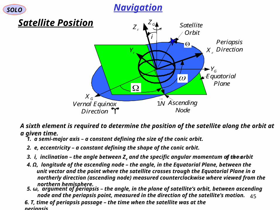
A sixth element is required to determine the position of the satellite along the orbit at a given time.
1. a semi-major axis – a constant defining the size of the conic orbit.
2. e, eccentricity – a constant defining the shape of the conic orbit.
3. i, inclination – the angle between Ze and the specific angular momentum of the orbit vrh
4. Ω, longitude of the ascending node – the angle, in the Equatorial Plane, between the unit vector and the point where the satellite crosses trough the Equatorial Plane in a northerly direction
(ascending node) measured counterclockwise where viewed from the northern hemisphere.
5. ω, argument of periapsis – the angle, in the plane of satellite’s orbit, between ascending node and the periapsis point, measured in the direction of the satellite’s motion.
6. T, time of periapsis passage – the time when the satellite was at the periapsis.

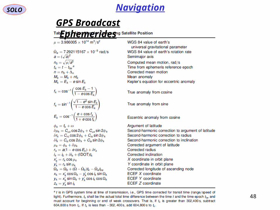
GPS Broadcast Ephemerides
SOLO
46
Navigation

GPS Broadcast Ephemerides
SOLO
47
Navigation
uur
ur
y
x
q ellipse
ellipse
Orbit
0
sin
cos
0
210
cos
sin
0e
anue
u
y
x
q ellipse
ellipse
Orbit
Orbit
oecoec ttt
0
sin
cos
0
313 ur
ur
iy
x
C
z
y
x
ellipse
ellipse
G
G
u
48
GPS Broadcast Ephemerides
SOLO Navigation
Global Positioning System
SOLO
49
Navigation
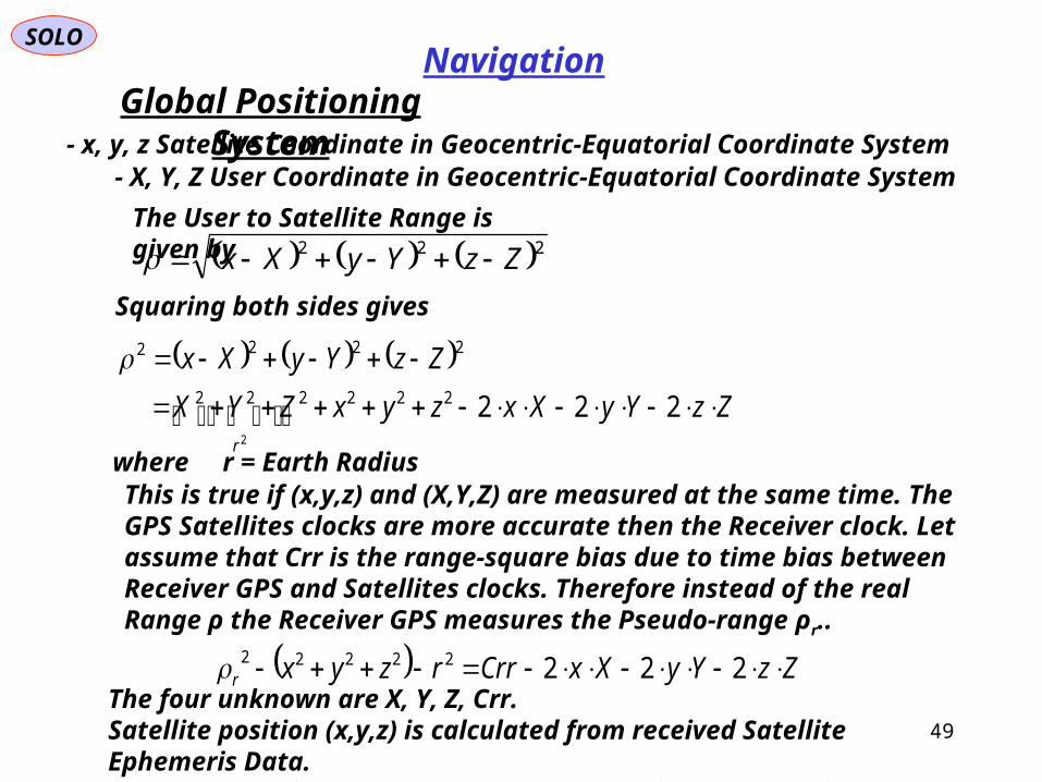
- x, y, z Satellite Coordinate in Geocentric-Equatorial Coordinate System
222 ZzYyXx
- X, Y, Z User Coordinate in Geocentric-Equatorial Coordinate System
Squaring both sides gives
The User to Satellite Range is given by
ZzYyXxzyxZYX
ZzYyXx
r
222222222
2222
2
The four unknown are X, Y, Z, Crr. Satellite position (x,y,z) is calculated from received Satellite Ephemeris Data.Since we have four unknowns we need data from at least four Satellites.
ZzYyXxCrrrzyxr 22222222
where r = Earth RadiusThis is true if (x,y,z) and (X,Y,Z) are measured at the same time. The GPS Satellites clocks are more accurate then the Receiver clock. Let assume that Crr is the range-square bias due to time bias between Receiver GPS and Satellites clocks. Therefore instead of the real Range ρ the Receiver GPS measures the Pseudo-range ρr..
Global Positioning System
SOLO
50
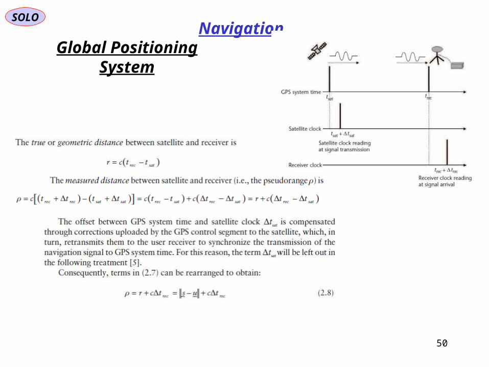
Navigation
Global Positioning System
SOLO
51
Navigation
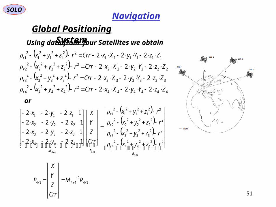
Using data from four Satellites we obtain
444444
224
24
24
24
33333322
32
32
32
3
22222222
22
22
22
2
11111122
12
12
12
1
222
222
222
222
ZzYyXxCrrrzyx
ZzYyXxCrrrzyx
ZzYyXxCrrrzyx
ZzYyXxCrrrzyx
r
r
r
r
or
14
1444
224
24
24
24
223
23
23
23
222
22
22
22
221
21
21
21
444
333
222
111
1222
1222
1222
1222
xxx R
r
r
r
r
PM
rzyx
rzyx
rzyx
rzyx
Crr
Z
Y
X
zyx
zyx
zyx
zyx
141
4414 xxx RM
Crr
Z
Y
X
P
Global Positioning System
SOLO
52
Navigation

Global Positioning System
SOLO
53
Navigation
Global Positioning System
SOLO
54
Navigation
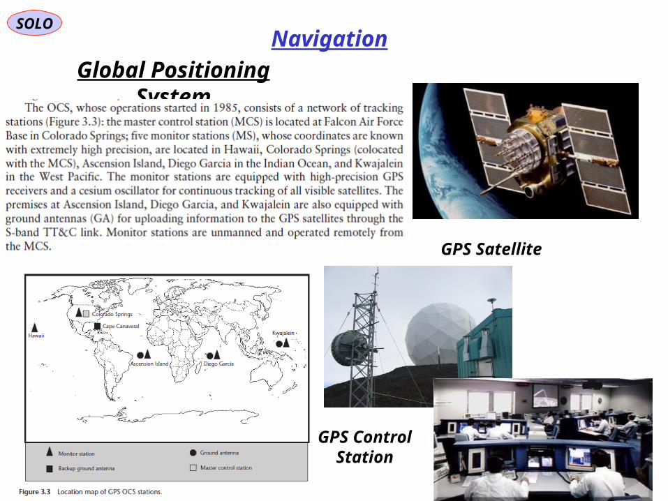
GPS Satellite
GPS ControlStation

Global Positioning System
SOLO
55
Navigation
The key to the system accuracy is the fact that all signal components are controlled by Atomic Clocks.• Block II Satellites have four on-board clocks: two rubidium and two cesium clocks. The long term frequency stability of these clocks reaches a few part in 10-13 and 10-14 over one day.• Block III will use hydrogen masers with stability of 10-14 to 10-15 over one day.
The Fundamental L-Band Frequency of 10.23 MHz is produced from those Clocks.Coherently derived from the Fundamental Frequency are three signals(with in-phase (cos), and quadrature-phase (sin) components): - L1 = 154 x 10.23 MHz = 1575.42 MHz - L2 = 120 x 10.23 MHz = 1227.60 MHz - L3 = 115 x 10.23 MHz = 1176.45 MHz
The in-phase components of L1 signal, is bi-phase modulated by a 50-bps data stream and a pseudorandom code called C/A-code (Coarse Civilian) consisting of a 1023-chip sequence, that has a period of 1 ms and a chipping rate of 1.023 MHz:
signalL
codeompseudorand
ACulation
bpspowercarrier
I ttctdPts
1/
mod50
cos2

Global Positioning System
SOLO
56
Navigation
The quadrature-phase components of L1, L2 and L3 signals, are bi-phase modulated by the 50-bps data stream but a different pseudorandom code called P-code (Precision-code) or Precision Positioning Service (PPS) for US Military use, , that has a period of 1 week and a chipping rate of 10.23 MHz:
signalsLLL
codeompseudorand
Pulation
bpspowercarrier
Q ttptdPts
3,2,1
mod50
sin2

Global Positioning System
SOLO
57
Navigation

GPS Signal Spectrum
SOLO
58
Navigation
Global Positioning System
SOLO
59
Navigation
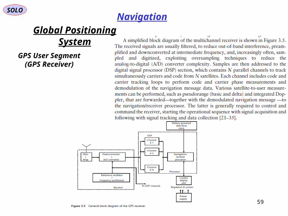
GPS User Segment(GPS Receiver)

Global Positioning System
SOLO
60
Navigation
GPS User Segment(GPS Receiver)

SOLO
61
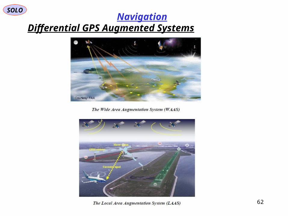
NavigationDifferential GPS Augmented Systems
SOLO
62
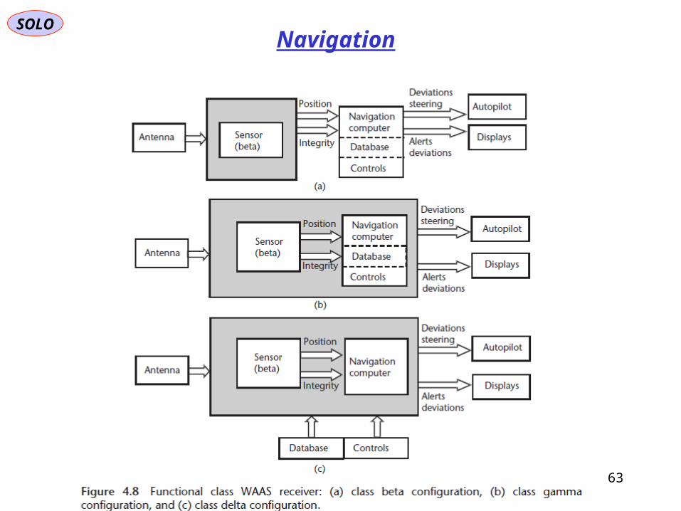
NavigationDifferential GPS Augmented Systems
SOLO
63
Navigation
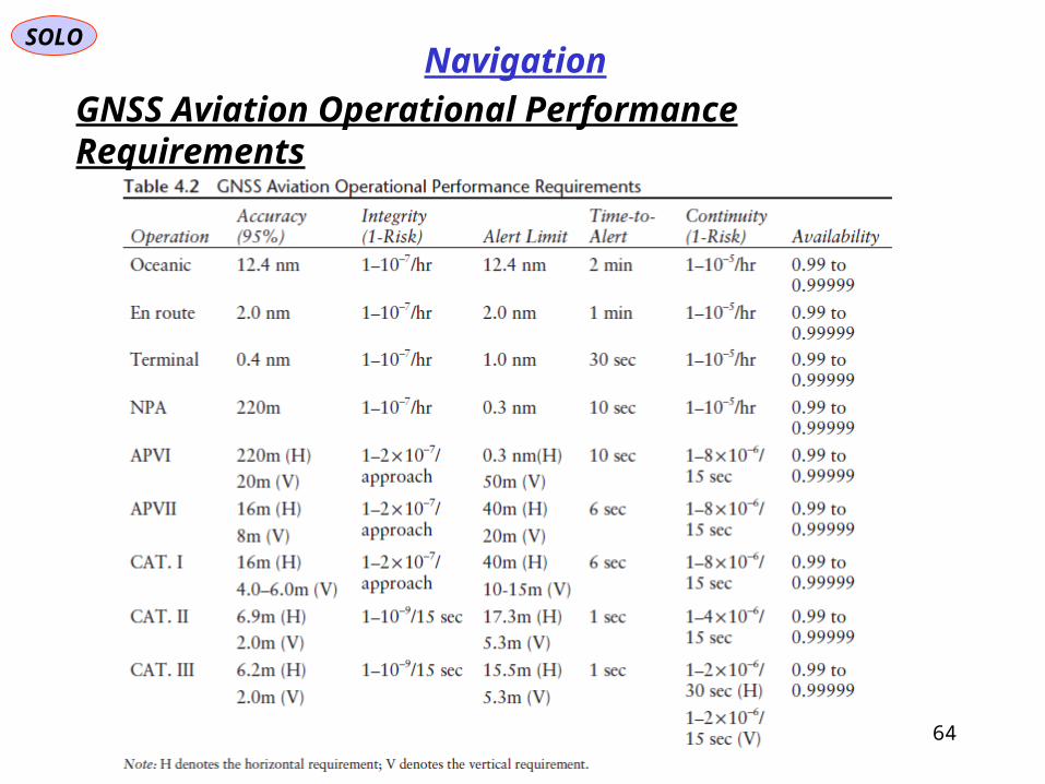
GNSS Aviation Operational Performance Requirements
SOLO
64
Navigation
SOLO
65
NavigationExternally Navigation Add Systems
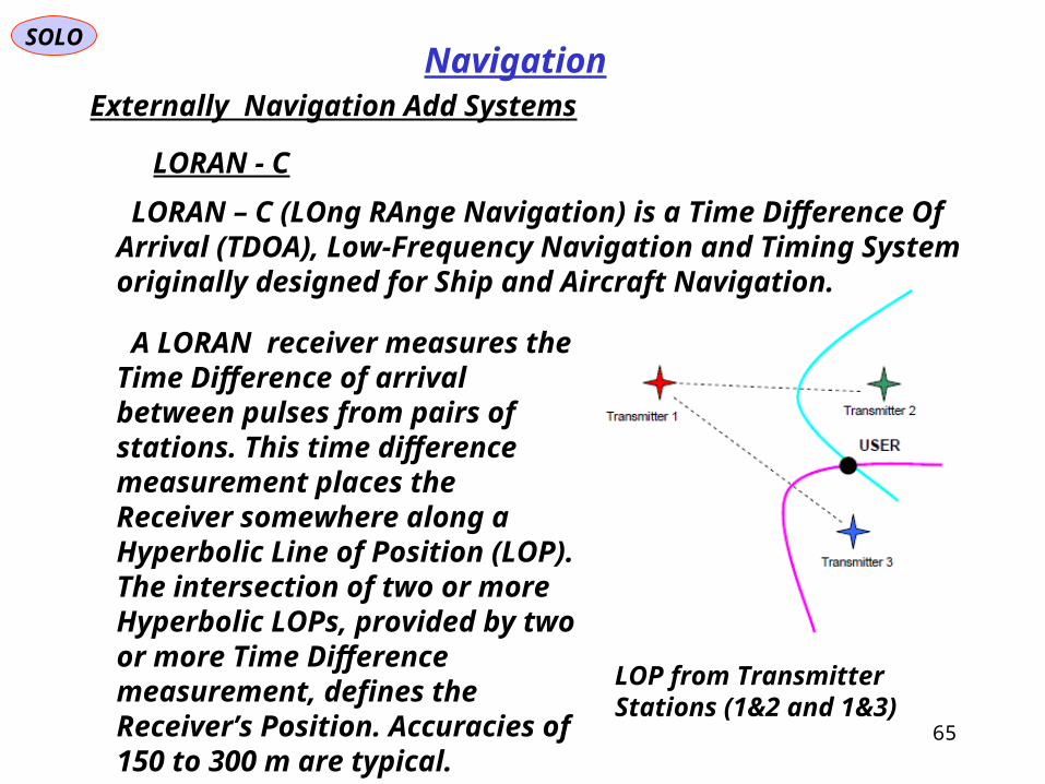
LORAN - C
A LORAN receiver measures the Time Difference of arrival between pulses from pairs of stations. This time difference measurement places the Receiver somewhere along a Hyperbolic Line of Position (LOP). The intersection of two or more Hyperbolic LOPs, provided by two or more Time Difference measurement, defines the Receiver’s Position. Accuracies of 150 to 300 m are typical.
LOP from Transmitter Stations (1&2 and 1&3)
LORAN – C (LOng RAnge Navigation) is a Time Difference Of Arrival (TDOA), Low-Frequency Navigation and Timing System originally designed for Ship and Aircraft Navigation.

SOLO
66
NavigationExternally Navigation Add Systems
eLORAN
eLORAN receiver employ Time of Arrival (TOA) position techniques, similar to those used in Satellite Navigation Systems. They track the signals of many LORAN Stations at the same time and use them to make accurate and reliable Position and Timing measurements. It is now possible to obtain absolut accuracies of 8 – 20 m and recover time to 50 ns with new low-cost receivers in areas served by eLORAN.
The Differential eLORAN Concept
Enhanced LORAN , or eLORAN, is an International initiative underway to upgrade the traditional LORAN – C System for modern applications. The infrastructure is being installed in the US, and a variation of eLORAN is already operational in northwest Europe.
A Combined GPS/eLORAN Receiver and Antenna from
Reelektronika
SOLO
67
NavigationExternally Navigation Add Systems
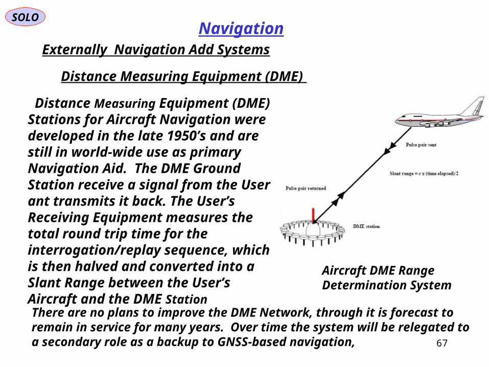
Distance Measuring Equipment (DME)
Aircraft DME Range Determination System
Distance Measuring Equipment (DME) Stations for Aircraft Navigation were developed in the late 1950’s and are still in world-wide use as primary Navigation Aid. The DME Ground Station receive a signal from the User ant transmits it back. The User’s Receiving Equipment measures the total round trip time for the interrogation/replay sequence, which is then halved and converted into a Slant Range between the User’s Aircraft and the DME Station
There are no plans to improve the DME Network, through it is forecast to remain in service for many years. Over time the system will be relegated to a secondary role as a backup to GNSS-based navigation,
SOLO
68
NavigationExternally Navigation Add Systems
Angle (Bearing Determination)
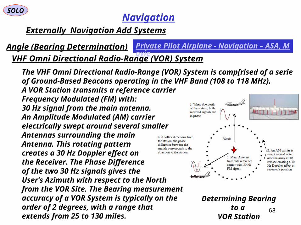
Determining Bearing to a VOR Station
VHF Omni Directional Radio-Range (VOR) System
The VHF Omni Directional Radio-Range (VOR) System is comp[rised of a serie of Ground-Based Beacons operating in the VHF Band (108 to 118 MHz).A VOR Station transmits a reference carrierFrequency Modulated (FM) with:30 Hz signal from the main antenna.An Amplitude Modulated (AM) carrierelectrically swept around several smallerAntennas surrounding the main Antenna. This rotating patterncreates a 30 Hz Doppler effect onthe Receiver. The Phase Differenceof the two 30 Hz signals gives theUser’s Azimuth with respect to the Northfrom the VOR Site. The Bearing measurementaccuracy of a VOR System is typically on the order of 2 degrees, with a range that extends from 25 to 130 miles.
Private Pilot Airplane - Navigation – ASA, Movie

SOLO
69
NavigationExternally Navigation Add Systems
TACAN is the MilitaryEnhancement of
VOR/DME
VHF Omni Directional Radio-Range (VOR) System
TACAN (Tactical Air Navigation) is an enhanced VOR/DME System designed forMilitary applications. The VOR component of TACAN, which operates in the UHF spectrum, make use of two-frequency principle, enabling higher bearing accuracies.The DME Component of TACAN operates with the same specifications as civil DME.
The accuracy of the azimuth component is about ±1 degree, while the accuracy of the DME position is ± 0.1 nautical miles. For Military usage a primary drawback is the lack of radio silence caused by Aircraft DME Transmission.

SOLO
70
NavigationData Base Matching

SOLO
71
NavigationTerrain Referenced Navigation (TRN)

SOLO
72
NavigationTerrain Referenced Navigation (TRN)

SOLO
73
NavigationExternally Navigation Add Systems

SOLO
74
Aircraft Avionics
NavigationInstrument Landing System (ILS)

SOLO
75
Navigation
Navigation Multi-Sensor Integration
Navigation Data
76
Aircraft SensorsSOLO
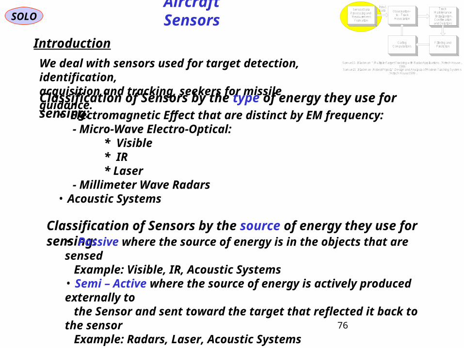
Introduction
Classification of Sensors by the type of energy they use for sensing:
We deal with sensors used for target detection, identification, acquisition and tracking, seekers for missile guidance.
• Electromagnetic Effect that are distinct by EM frequency: - Micro-Wave Electro-Optical: * Visible
* IR* Laser
- Millimeter Wave Radars• Acoustic Systems
Classification of Sensors by the source of energy they use for sensing:• Passive where the source of energy is in the objects that are sensed Example: Visible, IR, Acoustic Systems• Semi – Active where the source of energy is actively produced externally to the Sensor and sent toward the target that reflected it back to the sensor Example: Radars, Laser, Acoustic Systems• Active where the source of energy is actively produced by the Sensor and sent toward the target that reflected it back to the sensor Example: Radars, Laser, Acoustic Systems
Sensor DataProcessing and Measurement
Formation
Observation -to - Track
Association
InputData Track
Maintenance) Initialization,Confirmationand Deletion(
Filtering andPrediction
GatingComputations
Samuel S . Blackman , " Multiple-Target Tracking with Radar Applications ", Artech House , 1986
Samuel S . Blackman , Robert Popoli , " Design and Analysis of Modern Tracking Systems", Artech House , 1999
77
SOLO
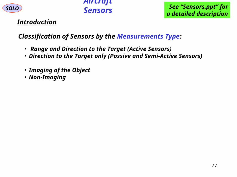
Introduction
Classification of Sensors by the Measurements Type:
• Range and Direction to the Target (Active Sensors) • Direction to the Target only (Passive and Semi-Active Sensors)
• Imaging of the Object• Non-Imaging
See “Sensors.ppt” fora detailed description
Aircraft Sensors

I
0Ex
0Ey
Iz
Northx
EastyDownz
Bx
By
Bz
Iy
Ixt
tLong
Lat
0Ez
Ex
Ey
Ez
AV
Target (T)(object)
Platform(B)
(sensor)
SOLO
To perform this task a common coordinate system is used.Example: In a Earth neigh borough the Local Level Local North coordinate system(Latitude, Longitude, Height above Sea Level) can be used to specify the positionand direction of motion of all objects.
The information is gathered by sensorsthat are carried by platforms (B) that can be static or moving (earth vehicles, aircraft, missiles, satellites,…) relative to thepredefined coordinate system. It is assumedthat the platforms positions and velocities, including their errors, are known and can be used for this task:
SensorDownSensorEastSensorNordSensorDownSensorEastSensorNord
SensorLevelSeaSensorSensorSensorLevelSeaSensorSensor
VVVVVV
HLongLatHLongLat
,,,,,
,,,,,
The objects (T) positions and velocities are obtained by combining the information ofobjects-to-sensors relative position and velocities and their errors to the informationof sensors (B) positions and velocities and their errors.
See “Tracking Systems” PDF for a detailed presentation.
General Problem of a Tracking System in the Earth Environment
Provide information of the position and direction of movement (including estimatederrors) of uncooperative objects, to different located users.
78

B
x
Lx
Bz
Ly
Lz
By
TV
PV
R
Az
El
Bx
SOLO
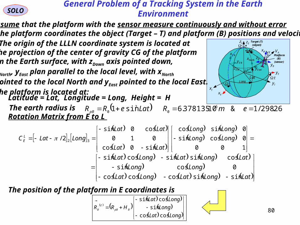
Assume that the platform with the sensor measure continuously and without errorin the platform coordinates the object (Target – T) and platform positions and velocities .
The relative position vector is definedby three independent parameters. A possiblechoice of those parameters is:
R
ElR
ElAzR
ElAzRR
ElEl
ElEl
AzAz
AzAz
Rz
Ry
Rx
R
B
B
B
B
sin
cossin
coscos
0
0
cos0sin
010
sin0cos
100
0cossin
0sincos
R - Range from platform to objectAz - Sensor Azimuth angle relative to platformEl - Sensor Elevation angle relative to platform
Rotation Matrix from LLLN to B (Euler Angles):
cccssscsscsc
csccssssccss
ssccc
C BL 321
- azimuth angle - pitch angle - roll angle
General Problem of a Tracking System in the Earth Environment
79
SOLO
Assume that the platform with the sensor measure continuously and without errorin the platform coordinates the object (Target – T) and platform (B) positions and velocities .
I
0Ex
0Ey
Iz
Northx
EastyDownz
Bx
By
Bz
Iy
Ixt
tLong
Lat
0Ez
Ex
Ey
Ez
AV
Target (T)(object)
Platform(B)
(sensor)
The origin of the LLLN coordinate system is located atthe projection of the center of gravity CG of the platformon the Earth surface, with zDown axis pointed down, xNorth, yEast plan parallel to the local level, with xNorth pointed to the local North and yEast pointed to the local East. The platform is located at: Latitude = Lat, Longitude = Long, Height = H
Rotation Matrix from E to L
100
0cossin
0sincos
sin0cos
010
cos0sin
2/ 32 LongLong
LongLong
LatLat
LatLat
LongLatC LE
LatLongLatLongLat
LongLong
LatLongLatLongLat
sinsincoscoscos
0cossin
cossinsincossin
The earth radius is 26.298/1&10378135.6sin1 6
0
2
0 emRLateRRpB
The position of the platform in E coordinates is
LongLat
Long
LongLat
HRR BpB
E
B
coscos
sin
cossin
General Problem of a Tracking System in the Earth Environment
80
TT
T
TT
TpT
zET
yET
xET
E
T
LongLat
Long
LongLat
HR
R
R
R
R
coscos
sin
cossin
I
0Ex
0Ey
Iz
Northx
EastyDownz
Bx
By
Bz
Iy
Ixt
tLong
Lat
0Ez
Ex
Ey
Ez
AV
Target (T)(object)
Platform(B)
(sensor)
SOLO
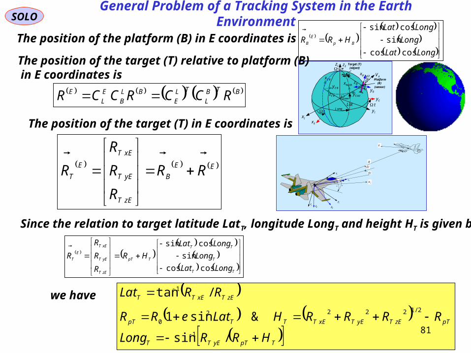
The position of the platform (B) in E coordinates is
LongLat
Long
LongLat
HRR Bp
E
B
coscos
sin
cossin
The position of the target (T) relative to platform (B) in E coordinates is
BTB
L
TL
E
BL
B
E
L
E RCCRCCR
The position of the target (T) in E coordinates is
EE
B
zET
yET
xET
E
T RR
R
R
R
R
Since the relation to target latitude LatT, longitude LongT and height HT is given by:
we have
TpTyETT
pTzETyETxETTTpT
zETxETT
HRRLong
RRRRHLateRR
RRLat
/sin
&sin1
/tan
1
2/12222
0
1
B
x
Lx
Bz
Ly
Lz
By
TV
PV
R
Az
El
Bx
General Problem of a Tracking System in the Earth Environment
81

B
x
Lx
Bz
Ly
Lz
By
TV
PV
R
Az
El
Bx
SOLO
Assume that the platform with the sensor measure continuously and without errorin the platform coordinates the object (Target – T) and platform positions and velocities .
Therefore the velocity vector of the object (T)relative to the platform (B) can be obtained bydirect differentiation of the relative range R
BTIB
B
BT VVRtd
RdV
.
or
BIB
BI
TT VR
td
Rd
td
RdV
TV
PV
2tR
Az
El
BxBx
Bx
1tR
3tR
General Problem of a Tracking System in the Earth Environment
82

kkx |ˆ
kx
1|1 kkP
1| kkP
1|1ˆ kkx
1kx
kkP |
kkP |1 kkx |1ˆ
kt 1kt
Real Trajectory 2kt
1|2 kkP
1|2ˆ kkx 2|2 kkP
2|2ˆ kkx
3kt
Measurement Events
Predicted Errors
Updated Errors
SOLO
The platform with the sensors measure at discrete time and with measurement error.It may happen that no data (no target detection) is obtained for each measurement.
Therefore it is necessary to estimate thetarget trajectory parameters and their errors from the measurements events, and to predict them between measurements events.
tk - time of measurements
- sensor measurements ktz
- parameters of the real trajectory at time t. tx
- predicted parameters of the trajectory at time t. tx
- predicted parameters errors at time t (tk < t < tk+1). kttP /
- updated parameters errors at measurement time tk. kk ttP /
txz , Filter(Estimator/Predictor)
ktxz ,kt
tx
kttP /
TV
PV
2tR
Az
El
Bx
Bx
Bx
1tR
3tR
1
1
1
General Problem of a Tracking System in the Earth Environment
83
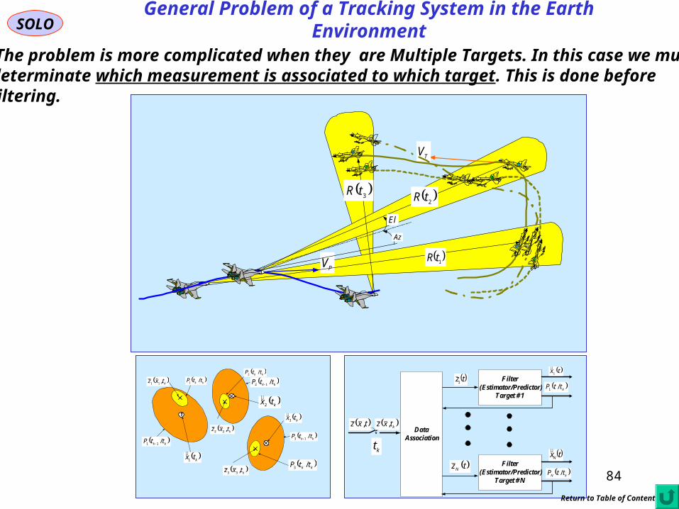
SOLO
The problem is more complicated when they are Multiple Targets. In this case we mustdeterminate which measurement is associated to which target. This is done beforefiltering.
TV
PV
2tR
Az
El
Bx
B
1tR
3tR
B
Bx
1
2
3
32
1
B
Bx
1
3
2
1
ktxz ,11
ktxz ,22
ktxz ,33
kk ttP /11
kk ttP /12
kk ttP /13
ktx3
ktx2
ktx1
kk ttP /1
kk ttP /2
kk ttP /3
Filter(Estimator/Predictor)
Target # 1
tx1
kttP /1
Filter(Estimator/Predictor)
Target # N
txN
kN ttP /
txz , ktxz ,
kt
DataAssociation
tz1
tzN
General Problem of a Tracking System in the Earth Environment
Return to Table of Content
84

85
General ProblemSOLO
If more Sensors are involved using Sensor Data Fusion we can improve.In this case we have a Multi-Sensor Multi-Target situation
1
ktxz ,11
ktxz ,22
ktxz ,33
11
1 | kk ttS
11
2 | kk ttS
13 | kk ttS
13 |ˆ kk ttz
12 |ˆ kk ttz
11 |ˆ kk ttz
kk ttS |23
1st Sensor
1
ktxz ,11
ktxz ,22
ktxz ,33
13 |ˆ kk ttz
12 |ˆ kk ttz
11 |ˆ kk ttz 12
1 | kk ttS
12
2 | kk ttS
kk ttS |23
2nd Sensor
1
ktxz ,11
ktxz ,22
ktxz ,33
11
1 | kk ttS
11
2 | kk ttS
13 | kk ttS
13 |ˆ kk ttz
12 |ˆ kk ttz
11 |ˆ kk ttz
kk ttS |1
kk ttS |2
kk ttS |13
12
1 | kk ttS
12
2 | kk ttS
kk ttS |23
Fused Data
Transducer 1
Feature Extraction,Target Classification,
Identification,and Tracking
Sensor 1Fusion Processor- Associate- Correlate- Track- Estimate- Classify- Cue
Cue
TargetReport
Cue
TargetReport
Sensor – level Fusion
Transducer 2
Feature Extraction,Target Classification,
Identification,and Tracking
Sensor 2
1
TV
PV
21 tR
Az
El
Bx
11 tR
31 tR
Bx
2
3
32
1
B
1
3
2
1st Sensor
1
TV
PV
Bx
Bx
2
3
32
1
B
1
3
2
GroundRadar
DataLink
12 tR
22 tR 3
2 tR
2nd Sensor
1
TV
PV
21 tR
Az
El
Bx
11 tR
31 tR
Bx
2
3
32
1
B
1
3
2
GroundRadar
DataLink
12 tR
22 tR 3
2 tR
To perform this task we must perform Alignment of the Sensors Datain Time (synchronization) and in Space (example GPS that provides accurate time & position)
Run This
86
General ProblemSOLO
Return to Table of Content
Sensor DataProcessing and Measurement
Formation
Observation -to - Track
Association
InputData Track
Maintenance(Initialization,Confirmationand Deletion)
Filtering andPrediction
GatingComputations
Samuel S . Blackman , " Multiple-Target Tracking with Radar Applications ", Artech House , 1986
Samuel S . Blackman , Robert Popoli , " Design and Analysis of Modern Tracking Systems", Artech House , 1999
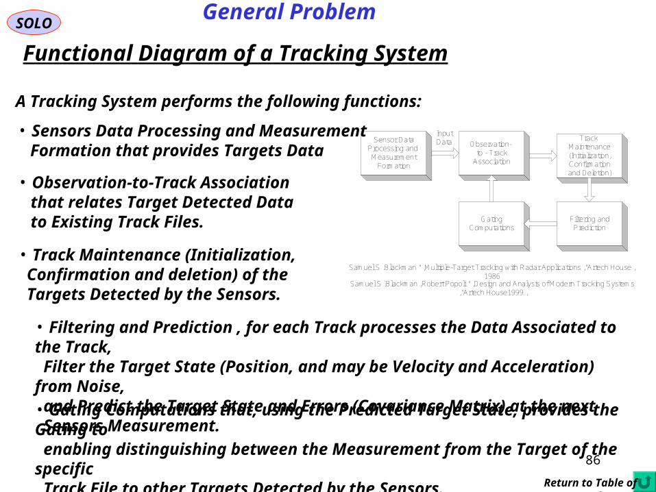
Functional Diagram of a Tracking System
A Tracking System performs the following functions:
• Sensors Data Processing and Measurement Formation that provides Targets Data
• Observation-to-Track Association that relates Target Detected Data to Existing Track Files.
• Track Maintenance (Initialization, Confirmation and deletion) of the Targets Detected by the Sensors.
• Filtering and Prediction , for each Track processes the Data Associated to the Track, Filter the Target State (Position, and may be Velocity and Acceleration) from Noise, and Predict the Target State and Errors (Covariance Matrix) at the next Sensors Measurement.• Gating Computations that, using the Predicted Target State, provides the Gating to enabling distinguishing between the Measurement from the Target of the specific Track File to other Targets Detected by the Sensors.
87
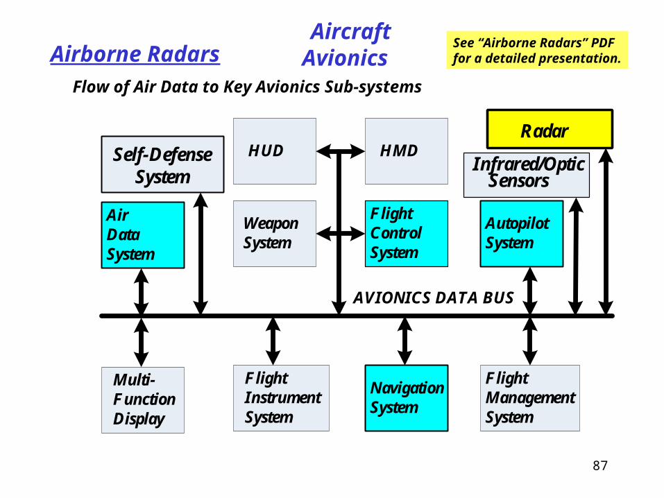
Flow of Air Data to Key Avionics Sub-systems
Aircraft AvionicsAirborne Radars
AirDataSystem
Multi-Function Display
FlightInstrumentSystem
NavigationSystem
FlightManagementSystem
FlightControlSystem
AutopilotSystem
WeaponSystem
HUD HMD
AVIONICS DATA BUS
Infrared/OpticSensors
RadarSelf-Defense
System
See “Airborne Radars” PDF for a detailed presentation.

SOLO Airborne Radars
Second Generation Fighters Radars
Airborne Radars Ranging in Boresight Only used for Gunsight Computation , for Semi Active Missiles, and for A/G Weapon Release Computations. They where equipped also with Rear Warning Radar (RWR) Systems. Cutaway view of the Mirage III
Thomson CSF Cyranodual mode Air / Ground r Radar
88
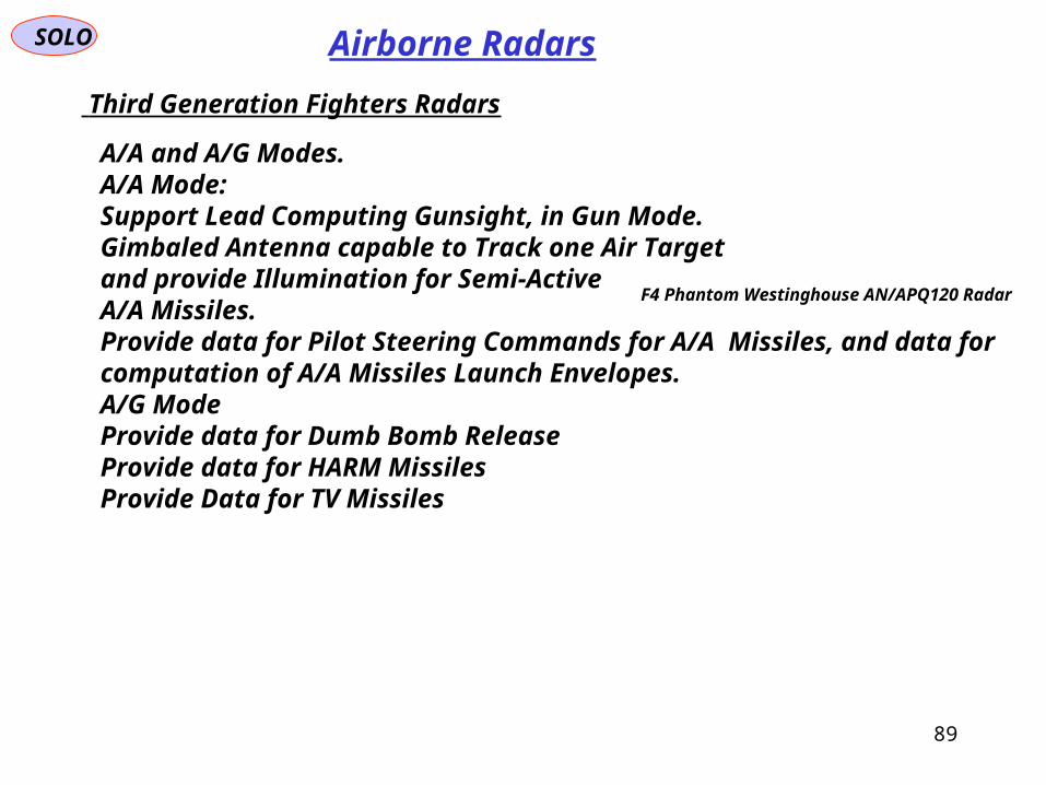
SOLO Airborne Radars
Third Generation Fighters Radars
A/A and A/G Modes.A/A Mode:Support Lead Computing Gunsight, in Gun Mode.Gimbaled Antenna capable to Track one Air Targetand provide Illumination for Semi-Active A/A Missiles.Provide data for Pilot Steering Commands for A/A Missiles, and data for computation of A/A Missiles Launch Envelopes.A/G ModeProvide data for Dumb Bomb ReleaseProvide data for HARM MissilesProvide Data for TV Missiles
F4 Phantom Westinghouse AN/APQ120 Radar
89
SOLO Airborne Radars
90
SOLO Airborne Radars
91
92
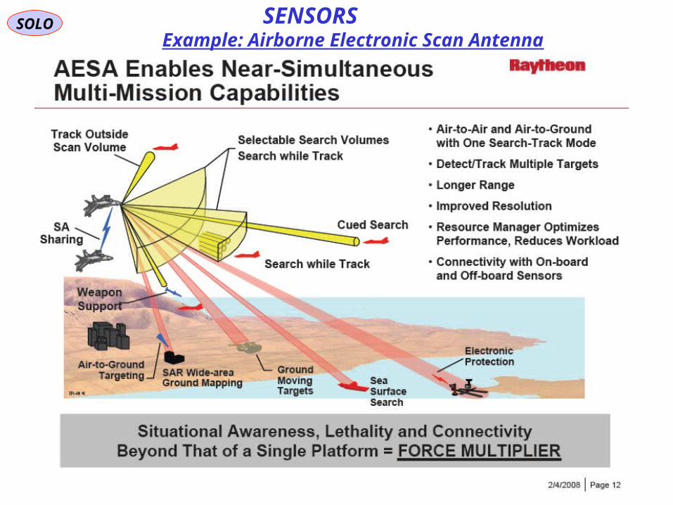
SOLOExample: Airborne Electronic Scan Antenna
SENSORS

SOLO Airborne Radars
Missions
• Air-to-Air Missions
Air combat makes extensive use of multi-mode radar capabilities
Performed by a single pilot that has to fly the aircraft in the same time, or by aa second pilot (Navigator – in a two seats fighter aircraft). In all cases the sameRadar is installed in a single seat as in a two seats fighter aircraft. For this reasonthe Radar System is operated with minimum pilot interference (semi-automatic modes)
• Velocity Search Mode
This is the longest range search mode in most multi-mode airborne radars.It is look-down and High-PRF. It looks to targets which are flowing towardthe aircraft radar. It is primarily a Doppler mode and range is often not measured.Search is in both azimuth and elevation.
• Range-while-search Mode
This is a medium range look-down search mode to find target range as well asDoppler. It can be High-PRF and use Modulated Pulse Doppler wave, orMedium PRF.
Return to Table of Content
93

SOLO Airborne Radars
Spick M., “The Great Book of Modern Warplanes”, Salamander, 2003
Velocity Search
Range-while-search
Track-while-scan
Raid assesment
APG-65 air-to-air modes
F-18 AN/APG-65Scan Modes
94

SOLO Airborne Radars
Spick M., “The Great Book of Modern Warplanes”, Salamander, 2003
A Downlook Searchin air-to-air mode inMedium PRF, of F-16AN/APG-66 radar.
F-16 Falcon
95

SOLO Airborne Radars
Four-bar scan
Two -bar scan
One -bar scan
20x20deg air-combat scan
10x40deg air-combat scan
F-16 AN/APG-66Scan Modes
Spick M., “The Great Book ofModern Warplanes”, Salamander,2003
96

SOLO Airborne Radars
Missions (continue – 1)
• Air-to-Air Missions (continue – 1)
• Track-while-scan (TWS)
This Medium or High-PRF mode is similar to range-while-search, except thaton a limited number of targets track-files are initiated and maintained in theRadar processor. These files are used to identify threats, control weapons, andto initiate single-target tracks.
• Track
This is a mode when a single target is tracked (STT) or a high priority target(HPT) is tracked at a higher rate, while other targets are tracked-while-scan.
• Range for Aircraft Gun
This is a short range single target track (STT). In this mode the radar controlscockpit display which tells the pilot how to point the aircraft so that a gun ispointed to the predicted bullet impact points with the target.
97

SOLO Lead Computing Gunsight
AAA VV 1
BSTmm VV 1
L = Kinematic Lead Angle
ProjectilePath
Target Position at Projectile
Shoot
Target Predicted Flight
Path
Projectile-TargetIntercept
Point
fTTV
α - Angle of Attack
Line of Sight through
Reticle Image
SD 12/2
fTTV
2/1 2fZTg
In the Lead Mode, the Pilot maneuvers the Aircraft to keep the Pipper (Optical Sight)On the Target for at least half a second and then he pushes the Gun Trigger to fire aVolley of Projectiles. The Gunsight computes the Lead of Aircraft Boresight (Gun Direction) such that some of the Volley Projectiles will Hit the Target.
98

SOLO Airborne Radars
Spick M., “The Great Book of Modern Warplanes”, Salamander, 2003
• Air-to-Surface Missions
The following Modes are implemented:
• Terrain Avoidance (TA)
• Real Beam Map (RBM)
Used at low altitude above ground flight situations.
• Beacon Direction Tracking (BCN)
Used for navigation purposes, when the radar receives the return fromknown Beacons to determine aircraft position relative to Beacons.
99

SOLO Airborne Radars
Spick M., “The Great Book of Modern Warplanes”, Salamander, 2003
• Air-to-Surface Missions (continue – 1)
• Air-to-Ground Ranging (AGR)
Used to provide the range to a designed ground target to the Weapon Delivery System, in order to compute the best automatic release time.
100

SOLO Airborne Radars
Air-to-Surface Missions (continue – 2)
Stimson, G.W., “Introduction to Airborne Radar”, 1st Ed., Hughes Aircraft Company, 2nd ed., Scitech Publishing, 1998
101

SOLO
• Synthetic Aperture Radar (SAR)
Used to provide Radar Imaging of areas on the ground.
• Air-to-Surface Missions (continue – 4)
Airborne Radars State of the art high resolution imaging Synthetic Aperture Radars can produce spot maps of areas hundreds of metres to kilometres in size at tens of NMI of range, with resolutions at this time as fine as one foot. In the simplest of terms, you can use such radars to produce geometrically accurate surface maps in which the smallest feature size is a foot. Therefore buildings, roads, structures, vehicles, parked aircraft, ships, fences, radio masts, radar antennas and any other features of interest can be detected, identified and accurately located in relation to the surrounding terrain.
102

SOLO Airborne Radars
• Air-to-Surface Missions (continue – 5)
• Ground Moving Target Indicator (GMTI)
Used to detect moving vehicles on the ground.
State of the art Ground Moving Target Indicator radars can detect slowly moving surface vehicles, taxiing aircraft, and hovering helicopters. In many instances, these radars can also exploit fine Doppler modulations in the radar return to identify the vehicle class or type, and even rotating radar antennas.
A radar which combines GMTI and SAR technologies can accurately detect, locate and identify virtually any surface target, from a standoff range at a very shallow slant angle, under any weather conditions. Combined with GPS guided bombs, this is a revolutionary capability, because it extends the existing around the clock bombing capability to an all weather standoff bombing capability. The established thermal imaging/laser guided bombing technology requires that direct line of sight exists to the target, that the cloudbase is above the bombing aircraft, and that the humidity and precipitation situation is not severe. Many bombing sorties were aborted during the Gulf War as these conditions were not satisfied. Moreover getting close enough to the target to use a thermal imager exposes the aircraft to air defences.
103

SOLO Airborne Radars
• Air-to-Surface Missions (continue – 6)
http://www.secretprojects.co.uk/ebooks/APG-68.pdf
APG-68, F-16’s Falcon Radar, in Doppler Beam Sharpening Mode
104
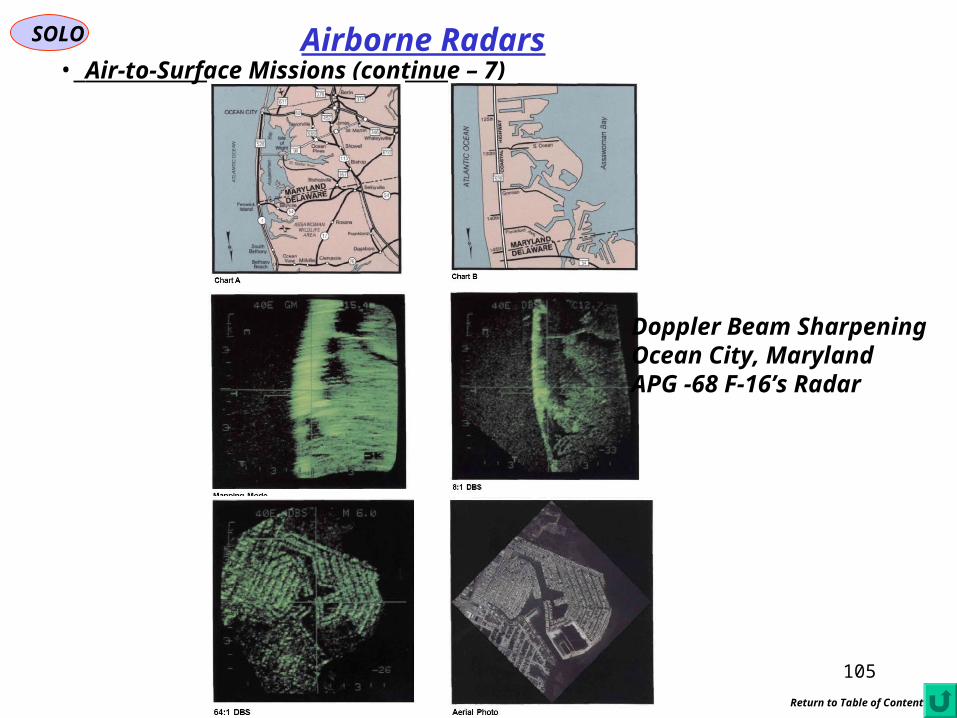
SOLO Airborne Radars• Air-to-Surface Missions (continue – 7)
Doppler Beam SharpeningOcean City, MarylandAPG -68 F-16’s Radar
Return to Table of Content
105

SOLO Airborne Radars
Airborne Radar Modes
SingleTargetTrack(STT)
Range While Scan
(RWS)
Air CombatMode
(ACM)
HighPriorityTrack(HPT)
Air-to-Air Air-to-Surface
Boresight(BST)
Track While Scan
(RWS)
SeaSurfaceSearch(SEA)
RealBeamMap
(RBM)
DopplerBeam
Sharpening(DBSM)
GroundTargetMoving
Indication(GMTI)
SyntheticAperture
Radar(SAR)
TerrainAvoidance
(TA)
Beacon(BCN)
Air-to-GroundRanging(AGR)
Return to Table of Content
106

SOLO Airborne Radars
Missions• Air-to-Air Missions
WaveformTypeTypical FunctionRemarks
Velocity Search (VS)HPRFPulsed DopplerLong range detectionHigh duty factor, Fine Doppler resolution; target clutter-free region; best for head-on geometries
Range-While-Search (RWS)HPRF + LFMPulsed DopplerLong range detection with coarse range estimate
Linear FM over dwell
Range Gated HPRF (RGHPRF)
HPRFPulsed DopplerLong range detectionProvides ambiguous range measurement
MPRF SearchMPRFPulsed DopplerAll-aspect detectionImproved detection for tail-chase; good range and Doppler resolution
Single Target Track (STT)MPRF/ HPRFPulsed DopplerFire controlMPRF and HPRF may be interleaved
Track-While-Scan (TWS)MPRFPulsed DopplerMultiple target trackingTrack updated provided during normal search revisits
Multiple Target Track (MTT)MPRF/ HPRFPulsed DopplerMultiple target trackingTrack updated scheduled independent of search scan (achievable through ESA)
Low PRF Doppler SearchLPRFPulsed DopplerAirborne target detectionUsed by some radars; much less effective than MPRF and HPRF modes
Low PRF Doppler TrackLPRFPulsed DopplerAirborne target trackingUsed by some radars; much less effective than MPRF and HPRF modes
Air-to-Air RangingLPRFNoncoherentShort range weaponNo clutter at ranges closer than target
Radar Mode
107

SOLO Airborne Radars
Missions• Air-to-Ground Missions
WaveformTypeTypical FunctionRemarks
Terrain AvoidanceLPRFNon-coherentCovert NavigationFlight path selected to fly between hills and mountains
Terrain FollowingLPRFNon-coherentCovert NavigationConstant Low altitude maintained
Air-to-Ground RangingLPRFNon-coherentBomb DeliveryDetermine range to target area
Ground MapLPRFNon-coherentNavigationAzimuth resolution limitted by real beam
Ground Beam sharpening (DBS)
LPRFCoherentNavigationImproved azimuth resolution
Synthetic Aperture (SAR)
- Stip Map
LPRFCoherentIntelligence, Surveillance, Reconnaissance
Moderate resolution imagery of stationary targets and clutter
Synthetic Aperture (SAR)
- Spotlight
LPRFCoherentIntelligence, Surveillance, Reconnaissance
High resolution imagery of stationary targets and clutter
Ground Moving Target Indicator (GMTI)
LPRFCoherentDetection of Moving Vehicles
Must detect small differences in velocity between targets and clutter
Maritime Target Track (MTT)
LPRFCoherentDetection of Sea ShipsMust detect small differences in velocity between ships and sea
Radar Mode
108

SOLO Airborne RadarsAN/APG SeriesAN/APG-1, S band interception radar for P-61 AN/APG-2, S band interception radar for P-61B AN/APG-3, General Electric tail gun aiming radar for B-29 and B-36B AN/APG-4, L band low altitude torpedo release / aiming radar for TBM, with nicknamed Sniffer. AN/APG-5, S band ranging / gun aiming radar for B-17, B-24 and F-86A AN/APG-6, L band low altitude bombing radar nickednamed Super Sniffer. Improved AN/APG-4. AN/APG-7, Bombing radar to control glide bombs AN/APG-8, S band turret gun aiming radar for B-29B AN/APG-9, L band low altitude bombing radar. Improved AN/APG-6 AN/APG-11, L band bombing radar AN/APG-12, L band low altitude bombing radar. Improved AN/APG-9 AN/APG-13, General Electric 75 mm nose gun aiming radar for B-25H. AN/APG-14, S band gun aiming radar for B-29 AN/APG-15, S band tail gun aiming radar for B-29B and PB4Y Privateer AN/APG-16, improved AN/APG-2 gun aiming radar for B-32. AN/APG-17, improved AN/APG-4 L band low altitude torpedo release / aiming radar and bombing radar AN/APG-18, X band gun aiming radar by Glenn L. Martin Company for turret guns,
improved AN/APG-5 AN/APG-19, X band gun aiming radar by Glenn L. Martin Company, improved AN/APG-8
and AN/APG-18. AN/APG-20, L band low altitude bombing radar. Improved AN/APG-12 AN/APG-21, ranging radar for ground attack AN/APG-22, X band gun aiming radar by Raytheon
http://en.wikipedia.org/wiki/List_of_radars#AN.2FAPY_Series109

SOLO Airborne RadarsAN/APG Series (continuous 1)AN/APG-23, Fire control radar for B-36A AN/APG-24, Fire control radar for B-36B AN/APG-25, X band gun aiming radar for F-100 AN/APG-26, Westinghouse Electric (1886) fire control radar for F3D Skyknight AN/APG-27, Gun aiming radar for tail guns of Convair XB-46 and Martin XB-48 AN/APG-28, Interception radar for F-82 Twin Mustang AN/APG-30, Sperry Corporation X band fire control radar for B-45, B-47, F-86E/F, F-100,
F-84E, F-8A, F-4E & others AN/APG-31, Raytheon gun aiming radar for B-57 AN/APG-32, General Electric X band tail gun aiming radar for B-36D/F and B-47E AN/APG-33, Hughes Aircraft X band fire control radar for F-89A, F-94A/B AN/APG-34, gun aiming radar for F-104C AN/APG-35, fire control radar for F3D Skyknight AN/APG-36, fire control radar for F2H-2N and F-86D AN/APG-37, Hughes Aircraft fire control radar for F2H-4 and F-86D/K/L AN/APG-39, gun aiming radar for B-47E AN/APG-40, Hughes Aircraft fire control radar for F-89D, F-94C AN/APG-41, General Electric tail gun aiming radar for B-36H AN/APG-43, Raytheon continuous wave interception radar AN/APG-45, General Electric miniaturized AN/APG-30 for maritime patrol aircraft AN/APG-46, original fire control radar of A-6A. AN/APG-50, F-4 Phantom II fire control radar
http://en.wikipedia.org/wiki/List_of_radars#AN.2FAPY_Series110

SOLO Airborne RadarsAN/APG Series (continuous 2)AN/APG-51, Hughes Aircraft interception radar for F3H-2, F3D Skyknight AN/APG-53, Stewart-Warner fire control radar for A-4 Skyhawk AN/APG-55, Westinghouse Electric (1886) pulse Doppler interception radar AN/APG-56, improved AN/APG-30 for F-86 AN/APG-57, Gould Electronics fire control radar AN/APG-59, Westinghouse Electric (1886) pulse-Doppler radar for F-4J, part of AN/AWG-10 AN/APG-60, Doppler radar that is part of AN/AWG-11 for F-4K AN/APG-61, fire control radar for F-4M, part of AN/AWG-12 AN/APG-63 and AN/APG-70, for the F-15 Eagle AN/APG-64, development of AN/APG-63, never went into production AN/APG-65 and AN/APG-73, for the F/A-18 Hornet AN/APG-66 and [AN/APG-68], for the F-16 Falcon AN/APG-67 General Electric X band multimode pulse-Doppler radar for
F-20 Tigershark and AIDC F-CK-1 Ching-kuo AN/APG-69, improved AN/APQ-159 fire control radar by Emerson Electric Company for
Northrop F-5 upgrade AN/APG-71, for the F-14D Tomcat AN/APG-74, Norden Systems pod-mounted airborne radar AN/APG-76, Norden Systems multimode Ku band pulse-Doppler radar for F-4 Phantom II upgrade AN/APG-77, for the F-22 Raptor AN/APG-78 millimetre wave Long Bow fire control radar for AH-64D Longbow Apache AN/APG-79, for the F/A-18E/F Super Hornet AN/APG-80, for the F-16E/F Block 60 Desert Falcon AN/APG-81, for the F-35 Lightning II
http://en.wikipedia.org/wiki/List_of_radars#AN.2FAPY_Series
111
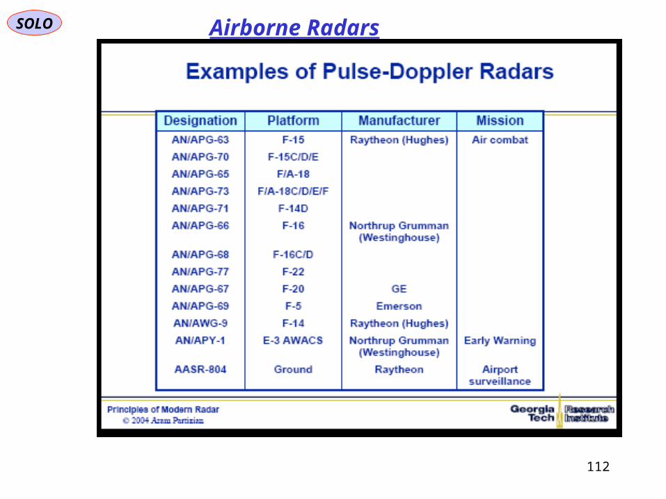
SOLO Airborne Radars
112

SOLO
Return to Table of Content
113

SOLO Airborne Radars F-16 Display
114

SOLO Airborne Radars
http://www.ausairpower.net/TE-Fighter-Cockpits.html115

SOLO Airborne Radars
http://www.ausairpower.net/TE-Fighter-Cockpits.html
The identical Master Monitor Display and Multi-Function Display are completely Interchangeable as regards the information they show. At the left is a typical Radar Display.At the right is a typical Weapon-delivery Management Display.
F/A-18 Displays
116

SOLO Airborne Radars
Spick M., “The Great Book of Modern Warplanes”, Salamander, 2003
117
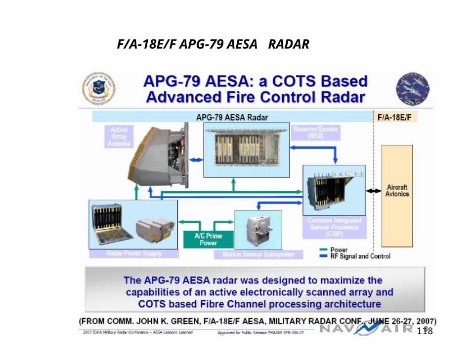
F/A-18E/F APG-79 AESA RADAR
118

AN/APG-79 is another AESA radar which was developed in US by Raytheon for F/A-18E/F starting from 2000. The first fly tests were started in 2003. The first serial radar was transferred to Boeing for installation on F/A-18E/F board only in Jan. 2005. The initial operational readiness was achieved in 2007. EA-18G 'growler' EW aircraft came with this radar too. This radar is including IDECM inbuilt EW system. Its mass is about 300 kg.
http://igorrgroup.blogspot.co.il/2009/08/aesa-radars-for-fighters-brief-review.html
119
120

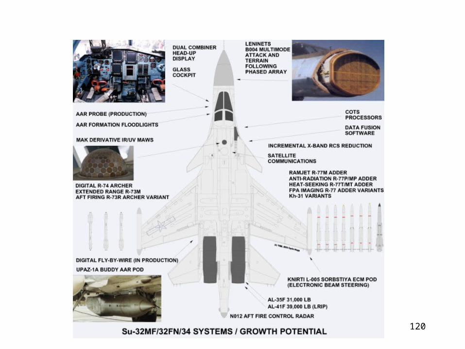
Su-34 Pilot, Co-Pilot Side-by-Side Cockpit
121
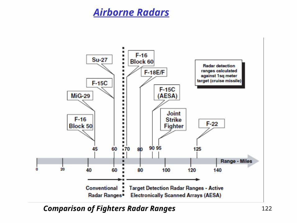
122Comparison of Fighters Radar Ranges
Airborne Radars
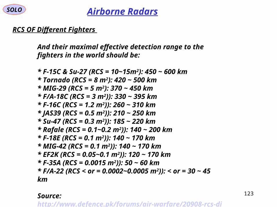
And their maximal effective detection range to the fighters in the world should be:
* F-15C & Su-27 (RCS = 10~15m2): 450 ~ 600 km* Tornado (RCS = 8 m2): 420 ~ 500 km* MIG-29 (RCS = 5 m2): 370 ~ 450 km* F/A-18C (RCS = 3 m2)): 330 ~ 395 km* F-16C (RCS = 1.2 m2)): 260 ~ 310 km* JAS39 (RCS = 0.5 m2)): 210 ~ 250 km* Su-47 (RCS = 0.3 m2)): 185 ~ 220 km* Rafale (RCS = 0.1~0.2 m2)): 140 ~ 200 km* F-18E (RCS = 0.1 m2)): 140 ~ 170 km* MIG-42 (RCS = 0.1 m2)): 140 ~ 170 km* EF2K (RCS = 0.05~0.1 m2)): 120 ~ 170 km* F-35A (RCS = 0.0015 m2)): 50 ~ 60 km* F/A-22 (RCS < or = 0.0002~0.0005 m2)): < or = 30 ~ 45 km
Source: http://www.defence.pk/forums/air-warfare/20908-rcs-different-fighters.html#ixzz2DySHji2H
RCS OF Different Fighters
Airborne RadarsSOLO
123
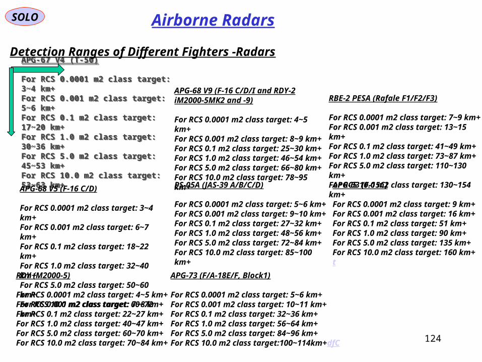
APG-67 V4 (T-50)
For RCS 0.0001 m2 class target: 3~4 km+For RCS 0.001 m2 class target: 5~6 km+For RCS 0.1 m2 class target: 17~20 km+For RCS 1.0 m2 class target: 30~36 km+For RCS 5.0 m2 class target: 45~53 km+For RCS 10.0 m2 class target: 53~63 km+
APG-67 V4 (T-50)
For RCS 0.0001 m2 class target: 3~4 km+For RCS 0.001 m2 class target: 5~6 km+For RCS 0.1 m2 class target: 17~20 km+For RCS 1.0 m2 class target: 30~36 km+For RCS 5.0 m2 class target: 45~53 km+For RCS 10.0 m2 class target: 53~63 km+
APG-68 V5 (F-16 C/D)
For RCS 0.0001 m2 class target: 3~4 km+For RCS 0.001 m2 class target: 6~7 km+For RCS 0.1 m2 class target: 18~22 km+For RCS 1.0 m2 class target: 32~40 km+For RCS 5.0 m2 class target: 50~60 km+For RCS 10.0 m2 class target: 60~72 km+
RDY (M2000-5)
For RCS 0.0001 m2 class target: 4~5 km+For RCS 0.001 m2 class target: 7~8 km+For RCS 0.1 m2 class target: 22~27 km+For RCS 1.0 m2 class target: 40~47 km+For RCS 5.0 m2 class target: 60~70 km+For RCS 10.0 m2 class target: 70~84 km+
APG-68 V9 (F-16 C/D/I and RDY-2 iM2000-5MK2 and -9)
For RCS 0.0001 m2 class target: 4~5 km+For RCS 0.001 m2 class target: 8~9 km+For RCS 0.1 m2 class target: 25~30 km+For RCS 1.0 m2 class target: 46~54 km+For RCS 5.0 m2 class target: 66~80 km+For RCS 10.0 m2 class target: 78~95 km+
PS-05A (JAS-39 A/B/C/D)
For RCS 0.0001 m2 class target: 5~6 km+For RCS 0.001 m2 class target: 9~10 km+For RCS 0.1 m2 class target: 27~32 km+For RCS 1.0 m2 class target: 48~56 km+For RCS 5.0 m2 class target: 72~84 km+For RCS 10.0 m2 class target: 85~100 km+
APG-73 (F/A-18E/F, Block1)
For RCS 0.0001 m2 class target: 5~6 km+For RCS 0.001 m2 class target: 10~11 km+For RCS 0.1 m2 class target: 32~36 km+For RCS 1.0 m2 class target: 56~64 km+For RCS 5.0 m2 class target: 84~96 km+For RCS 10.0 m2 class target:100~114km+dfC
RBE-2 PESA (Rafale F1/F2/F3)
For RCS 0.0001 m2 class target: 7~9 km+For RCS 0.001 m2 class target: 13~15 km+For RCS 0.1 m2 class target: 41~49 km+For RCS 1.0 m2 class target: 73~87 km+For RCS 5.0 m2 class target: 110~130 km+For RCS 10.0 m2 class target: 130~154 km+
APG-63 (F-15C)
For RCS 0.0001 m2 class target: 9 km+For RCS 0.001 m2 class target: 16 km+For RCS 0.1 m2 class target: 51 km+For RCS 1.0 m2 class target: 90 km+For RCS 5.0 m2 class target: 135 km+For RCS 10.0 m2 class target: 160 km+t
Detection Ranges of Different Fighters -Radars
SOLO Airborne Radars
124
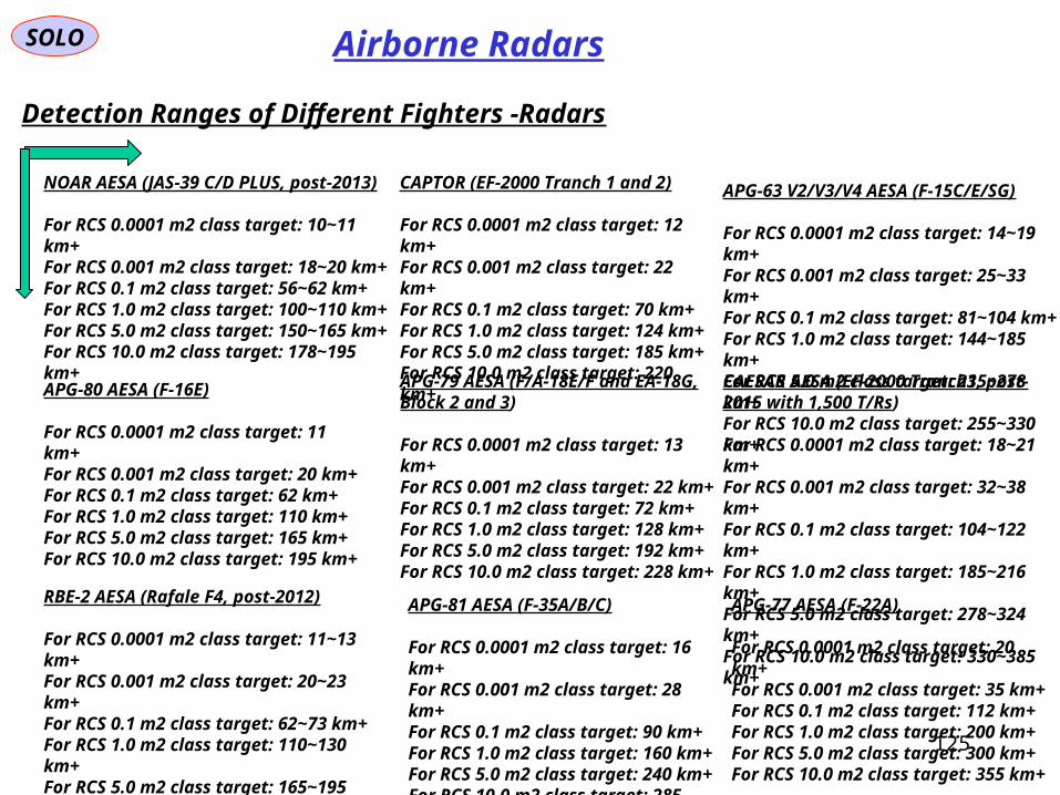
Detection Ranges of Different Fighters -Radars
SOLO Airborne Radars
NOAR AESA (JAS-39 C/D PLUS, post-2013)
For RCS 0.0001 m2 class target: 10~11 km+For RCS 0.001 m2 class target: 18~20 km+For RCS 0.1 m2 class target: 56~62 km+For RCS 1.0 m2 class target: 100~110 km+For RCS 5.0 m2 class target: 150~165 km+For RCS 10.0 m2 class target: 178~195 km+
APG-80 AESA (F-16E)
For RCS 0.0001 m2 class target: 11 km+For RCS 0.001 m2 class target: 20 km+For RCS 0.1 m2 class target: 62 km+For RCS 1.0 m2 class target: 110 km+For RCS 5.0 m2 class target: 165 km+For RCS 10.0 m2 class target: 195 km+
RBE-2 AESA (Rafale F4, post-2012)
For RCS 0.0001 m2 class target: 11~13 km+For RCS 0.001 m2 class target: 20~23 km+For RCS 0.1 m2 class target: 62~73 km+For RCS 1.0 m2 class target: 110~130 km+For RCS 5.0 m2 class target: 165~195 km+For RCS 10.0 m2 class target: 195~230 km+
CAPTOR (EF-2000 Tranch 1 and 2)
For RCS 0.0001 m2 class target: 12 km+For RCS 0.001 m2 class target: 22 km+For RCS 0.1 m2 class target: 70 km+For RCS 1.0 m2 class target: 124 km+For RCS 5.0 m2 class target: 185 km+For RCS 10.0 m2 class target: 220 km+
APG-79 AESA (F/A-18E/F and EA-18G, Block 2 and 3)
For RCS 0.0001 m2 class target: 13 km+For RCS 0.001 m2 class target: 22 km+For RCS 0.1 m2 class target: 72 km+For RCS 1.0 m2 class target: 128 km+For RCS 5.0 m2 class target: 192 km+For RCS 10.0 m2 class target: 228 km+
APG-81 AESA (F-35A/B/C)
For RCS 0.0001 m2 class target: 16 km+For RCS 0.001 m2 class target: 28 km+For RCS 0.1 m2 class target: 90 km+For RCS 1.0 m2 class target: 160 km+For RCS 5.0 m2 class target: 240 km+For RCS 10.0 m2 class target: 285 km+
APG-63 V2/V3/V4 AESA (F-15C/E/SG)
For RCS 0.0001 m2 class target: 14~19 km+For RCS 0.001 m2 class target: 25~33 km+For RCS 0.1 m2 class target: 81~104 km+For RCS 1.0 m2 class target: 144~185 km+For RCS 5.0 m2 class target: 215~278 km+For RCS 10.0 m2 class target: 255~330 km+
CAESAR AESA (EF-2000 Tranch3, post-2015 with 1,500 T/Rs)
For RCS 0.0001 m2 class target: 18~21 km+For RCS 0.001 m2 class target: 32~38 km+For RCS 0.1 m2 class target: 104~122 km+For RCS 1.0 m2 class target: 185~216 km+For RCS 5.0 m2 class target: 278~324 km+For RCS 10.0 m2 class target: 330~385 km+
APG-77 AESA (F-22A)
For RCS 0.0001 m2 class target: 20 km+For RCS 0.001 m2 class target: 35 km+For RCS 0.1 m2 class target: 112 km+For RCS 1.0 m2 class target: 200 km+For RCS 5.0 m2 class target: 300 km+For RCS 10.0 m2 class target: 355 km+125

126
Infrared/Optical Systems
AirDataSystem
Multi-Function Display
FlightInstrumentSystem
NavigationSystem
FlightManagementSystem
FlightControlSystem
AutopilotSystem
WeaponSystem
HUD HMD
AVIONICS DATA BUS
Infrared/OpticSensors
RadarSelf-Defense
System
See “E-O and IR Systems Pyloads” PDF for a detailed presentation.

127
Target Identification System, Electro-Optical (TISEO) F-4 (V) Phantom
E-O and IR Systems Payloads
F-14. Close-up of the TVSU camera. This sensor is equivalent to the Target Identification System Electro-Optic (TISEO) sensor on the F-4E Phantom. The fairing under the camera is the ARN-100 antenna. The red item is the forward anti-collision light
Northrop AN/AXX-1 Television Camera System (TCS). TCS represents the TISEO/TCS family of stabilised TV telescopes, used by the USAF and USN on air defence and air superiority fighters. TCS provides sharp close-up images of hostile aircraft outside of visual range. Typical identification ranges quoted are. DC-10 at 85 miles, F-111 at 40 miles, C-130 at 35 miles and F-5 at 10 miles. TCS could be fitted to the F-18, though currently only the F-14A is equipped. Below installation on F-14D with IRST (Northrop images).
Northrop AN/AXX-1 Television Camera System (TCS). TCS represents the TISEO/TCS family of stabilised TV telescopes, used by the USAF and USN on air defence and air superiority fighters. TCS provides sharp close-up images of hostile aircraft outside of visual range. Typical identification ranges quoted are. DC-10 at 85 miles, F-111 at 40 miles, C-130 at 35 miles and F-5 at 10 miles. TCS could be fitted to the F-18, though currently only the F-14A is equipped. Below installation on F-14D with IRST (Northrop images).

128
E-O and IR Systems Payloads
MiG-29 nose showing radome and IRST
IRST
Su-35S demonstrator with exposed Irbis-E phased array and 90 degree off boresight steerable OLS-35 IRST turret. The now well established trend in Russian sensors for BVR combat is increasing range performance and countermeasures resistance. The 20 kiloWatt peak power N035 Irbis E radar is the most powerful in its class. (KnAAPO)
Forward Looking Infrared(FLIR) - Infrared Search and Track System (IRST)
IRST sensor on the Su-27
Su-27: The OLS-27 Infrared Search and Track (IRST)
129
E-O and IR Systems Payloads
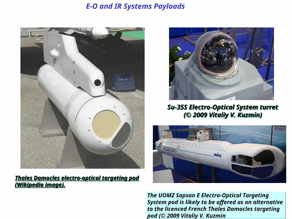
Su-35S Electro-Optical System turret (© 2009 Vitaliy V. Kuzmin)
Su-35S Electro-Optical System turret (© 2009 Vitaliy V. Kuzmin)
Thales Damocles electro-optical targeting pod (Wikipedia image).Thales Damocles electro-optical targeting pod (Wikipedia image).
The UOMZ Sapsan E Electro-Optical Targeting System pod is likely to be offered as an alternative to the licenced French Thales Damocles targeting pod (© 2009 Vitaliy V. Kuzmin
The UOMZ Sapsan E Electro-Optical Targeting System pod is likely to be offered as an alternative to the licenced French Thales Damocles targeting pod (© 2009 Vitaliy V. Kuzmin
SOLO
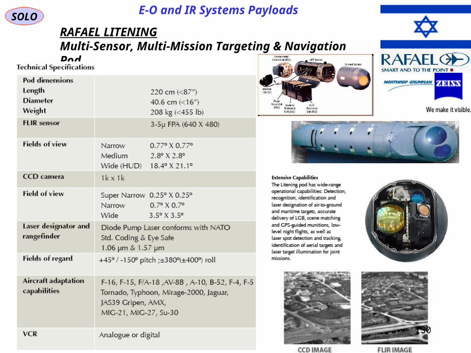
RAFAEL LITENINGMulti-Sensor, Multi-Mission Targeting & Navigation Pod
E-O and IR Systems Payloads
130

SOLO
RAFAEL RECCELITEReal-Time Tactical Reconnaissance System
E-O and IR Systems Payloads
131

SOLOE-O and IR Systems Payloads
132

SOLOE-O and IR Systems Payloads
LANTIRN (Low Altitude Navigation and Targeting Infrared for Night)
Primary function:Low altitude navigation and targeting infrared for night flying
Contractor:Lockheed Martin, Inc.
Length:AN/AAQ-13Navigation pod
AN/AAQ-14targeting pod
Length:78.2 inches (1.99 meters)
98.5 inches (2.51 meters)
Diameter:12 inches (.31 meters)
15 inches (.38 meters)
Weight:470 pounds (211.5 kilograms)
524 pounds (235.8 kilograms)
Sensors:Infrared andterrain following radar
Infraredlaser designator and ranging
Unit Cost:Navigation pod, $1.38 million
targeting pod, $3.2 million
Aircraft:F-15E, F-16C/D, F-14
Introduction Date:March 1987
133

SOLOE-O and IR Systems Payloads
Sniper XR Specifications
Length:239 cmDiameter: 300 mm
Total weight:440 lb (181 kg)
Operational altitude:+40,000
Sensor:640x480 FPA
Daylight sensor: CCDTVWide Field of view:4x4Narrow field of view: 1x1Field of regard:+35 / -155Roll:continuous
Laser:
Diode pumped laser designator
To meet the requirements to have a Sniper pod of several components. The most important part is a high-resolution FLIRSensor, which in the mid-infrared spectrum (engl. mid infrared) Works and CCDBased work. This sensor allows the detection of enemy targets at night or under adverse conditions. The range is located around the three-to five-fold over that of a LANTIRN-Pods of the first generation. For use in daylight and a CCD-TV camera can be used. Both sensors are fully stabilized and equipped with softwareAlgorithms for digital processing of images. A Datalink to transfer the acquired images to allied forces as well as a data storage can always be upgraded. For tracking and marking of targets serve two separate laser systems. Both offer a so-called (engl.) Eye-safe Mode to prevent eye damage in densely populated areas or in training. The air cell causes less drag than previous models and has limited Stealth Features.
LOCKHEED Sniper XR (Pantera) Targeting Pod
134
SOLOE-O and IR Systems Payloads
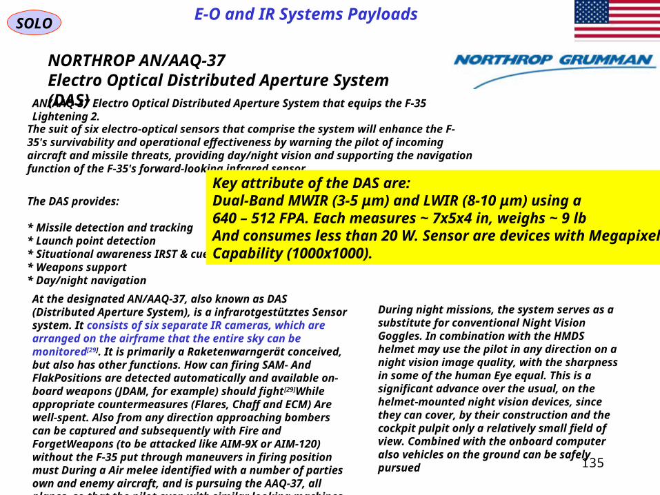
NORTHROP AN/AAQ-37Electro Optical Distributed Aperture System (DAS)
AN/AAQ-37 Electro Optical Distributed Aperture System that equips the F-35 Lightening 2.
The suit of six electro-optical sensors that comprise the system will enhance the F-35's survivability and operational effectiveness by warning the pilot of incoming aircraft and missile threats, providing day/night vision and supporting the navigation function of the F-35's forward-looking infrared sensor.
The DAS provides:
* Missile detection and tracking* Launch point detection* Situational awareness IRST & cueing* Weapons support* Day/night navigation
At the designated AN/AAQ-37, also known as DAS (Distributed Aperture System), is a infrarotgestütztes Sensor system. It consists of six separate IR cameras, which are arranged on the airframe that the entire sky can be monitored[29]. It is primarily a Raketenwarngerät conceived, but also has other functions. How can firing SAM- And FlakPositions are detected automatically and available on-board weapons (JDAM, for example) should fight[29]While appropriate countermeasures (Flares, Chaff and ECM) Are well-spent. Also from any direction approaching bombers can be captured and subsequently with Fire and ForgetWeapons (to be attacked like AIM-9X or AIM-120) without the F-35 put through maneuvers in firing position must During a Air melee identified with a number of parties own and enemy aircraft, and is pursuing the AAQ-37, all planes, so that the pilot even with similar looking machines can always distinguish between friend and foe
During night missions, the system serves as a substitute for conventional Night Vision Goggles. In combination with the HMDS helmet may use the pilot in any direction on a night vision image quality, with the sharpness in some of the human Eye equal. This is a significant advance over the usual, on the helmet-mounted night vision devices, since they can cover, by their construction and the cockpit pulpit only a relatively small field of view. Combined with the onboard computer also vehicles on the ground can be safely pursued
135
Key attribute of the DAS are:Dual-Band MWIR (3-5 μm) and LWIR (8-10 μm) using a 640 – 512 FPA. Each measures ~ 7x5x4 in, weighs ~ 9 lb And consumes less than 20 W. Sensor are devices with Megapixel Capability (1000x1000).

SOLOE-O and IR Systems Payloads
NORTHROP AN/AAQ-37Electro Optical Distributed Aperture System (DAS)
AN/AAQ-37 Electro Optical Distributed Aperture System that equips the F-35 Lightening 2.
136
F35 EO Sensor Vertical Coverage and EOTS Installation
F35 Horizontal CoverageUsing DAS Sensors
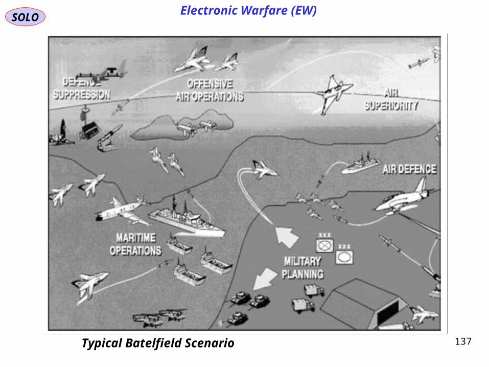
SOLOElectronic Warfare (EW)
137Typical Batelfield Scenario
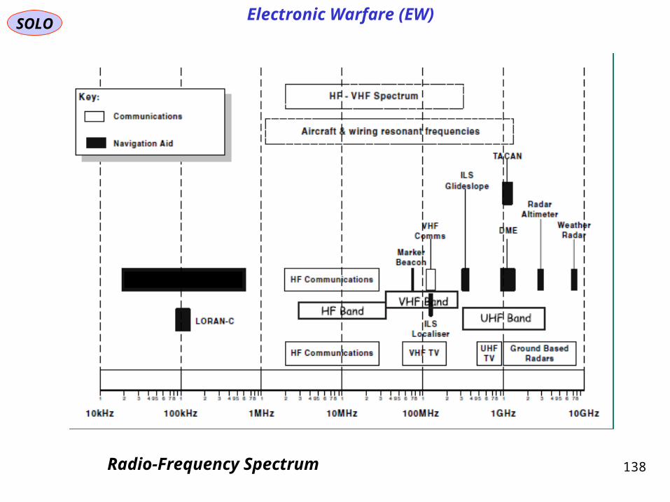
SOLOElectronic Warfare (EW)
138Radio-Frequency Spectrum

SOLOElectronic Warfare (EW)
139Electronic Warfare Elements
SOLOElectronic Warfare (EW)
140
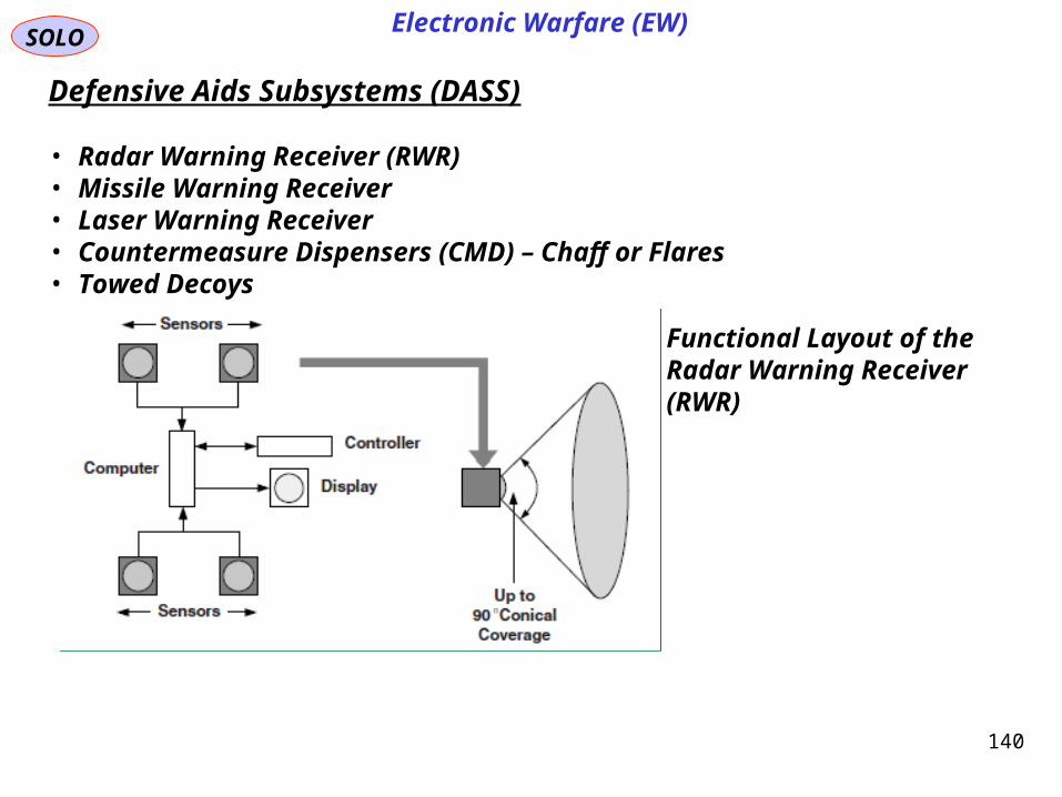
Functional Layout of the Radar Warning Receiver (RWR)
Defensive Aids Subsystems (DASS)
• Radar Warning Receiver (RWR)• Missile Warning Receiver• Laser Warning Receiver• Countermeasure Dispensers (CMD) – Chaff or Flares• Towed Decoys
SOLOElectronic Warfare (EW)
141
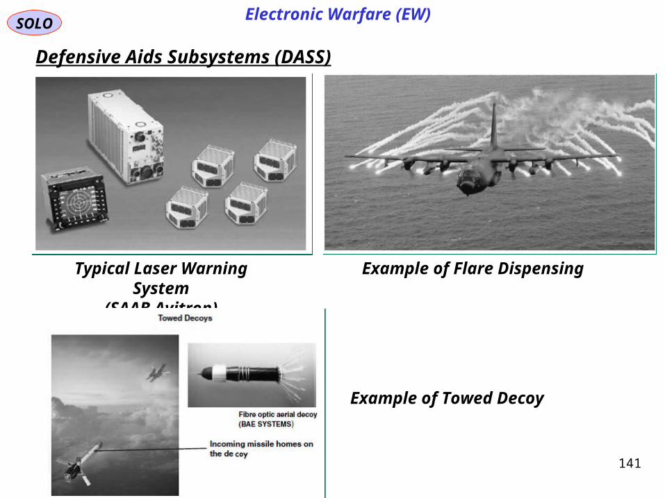
Defensive Aids Subsystems (DASS)
Typical Laser Warning System(SAAB Avitron)
Example of Flare Dispensing
Example of Towed Decoy

SOLOElectronic Warfare (EW)
142
Defensive Aids Subsystems (DASS)
AN/ALQ-214 Concept of Operation

SOLOElectronic Warfare (EW)
143Simplified Overview of F/A 18E/F Countermeasures Suite

SOLO
144
Fighter Aircraft Weapon System
The Weapons System of a Fighter has the following tasks:
- Keep Inventory Status of all Weapons- Provide Safety to Personal (Ground, Pilots) during all Life Phases of Operation (on Ground and in Flight)- Help the Pilot to Activate the Weapons to perform their missions.
Attack and Defense Missions:
- Air-to-Ground Attack- Air-to-Air Attack-- Defense against incoming treats
The type of Weapons on a Fighter :
- Guns (Air-to-Air/ Air-to-Ground)- Missiles (Air-to-Air/ Air-to-Ground)-Bombs (Air-to-Ground)- Dispensers (Chaff, Flares)- ECCM Pods

Continue toFighter Aircraft Avionics
Part IV
SOLO
145
Fighter Aircraft Avionics

References
SOLO
146
PHAK Chapter 1 - 17http://www.gov/library/manuals/aviation/pilot_handbook/media/
George M. Siouris, “Aerospace Avionics Systems, A Modern Synthesis”, Academic Press, Inc., 1993
R.P.G. Collinson, “Introduction to Avionics”, Chapman & Hall, Inc., 1996, 1997, 1998
Ian Moir, Allan Seabridge, “Aircraft Systems, Mechanical, Electrical and AvionicsSubsystem Integration”, John Wiley & Sons, Ltd., 3th Ed., 2008
Fighter Aircraft Avionics
Ian Moir, Allan Seabridge, “Military Avionics Systems”, John Wiley & Sons, LTD., 2006

References (continue – 1)
SOLO
147
Fighter Aircraft Avionics
S. Hermelin, “Air Vehicle in Spherical Earth Atmosphere”
S. Hermelin, “Airborne Radar”, Part1, Part2, Example1, Example2
S. Hermelin, “Tracking Systems”
S. Hermelin, “Navigation Systems”
S. Hermelin, “Earth Atmosphere”
S. Hermelin, “Earth Gravitation”
S. Hermelin, “Aircraft Flight Instruments”
S. Hermelin, “Computing Gunsight, HUD and HMS”
S. Hermelin, “Aircraft Flight Performance”
S. Hermelin, “Sensors Systems: Surveillance, Ground Mapping, Target Tracking”
S. Hermelin, “Air-to-Air Combat”
References (continue – 2)
SOLO
148
Fighter Aircraft Avionics
S. Hermelin, “Spherical Trigonometry”
S. Hermelin, “Modern Aircraft Cutaway”

149
SOLO
TechnionIsraeli Institute of Technology
1964 – 1968 BSc EE1968 – 1971 MSc EE
Israeli Air Force1970 – 1974
RAFAELIsraeli Armament Development Authority
1974 – 2013
Stanford University1983 – 1986 PhD AA
150
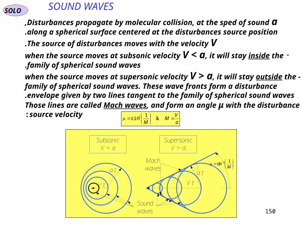
SOUND WAVESSOLO
SupersonicV > a
SubsonicV < a
a t a t
V tV t
M
1sin 1
Soundwaves
Machwaves
Disturbances propagate by molecular collision, at the sped of sound a,along a spherical surface centered at the disturbances source position.
The source of disturbances moves with the velocity V.
- when the source moves at subsonic velocity V < a, it will stay inside the family of spherical sound waves.
-when the source moves at supersonic velocity V > a, it will stay outside the family of spherical sound waves. These wave fronts form a disturbance
envelope given by two lines tangent to the family of spherical sound waves. Those lines are called Mach waves, and form an angle μ with the disturbance
source velocity:a
VM
M
&
1sin 1

151
SOUND WAVESSOLO
Sound Wave Definition: p
p
p p
p1
2 1
1
1
2 1
2 1
2 1
p p p
h h h
For weak shocks
up
1
2
11
11
1
11
11
2
12
1
1uuuuuu
)C.M.(
ppuuupuupu
11
111122111
211
)C.L.M.(
21
au 1
1p
1
1T
1e
112 uuu
112 ppp
112
112 TTT
112 eee
SOUND
WAVE
Since the changes within the sound wave are small, the flow gradients are small.Therefore the dissipative effects of friction and thermal conduction are negligibleand since no heat is added the sound wave is isotropic. Since
au 1
s
pa
2valid for all gases
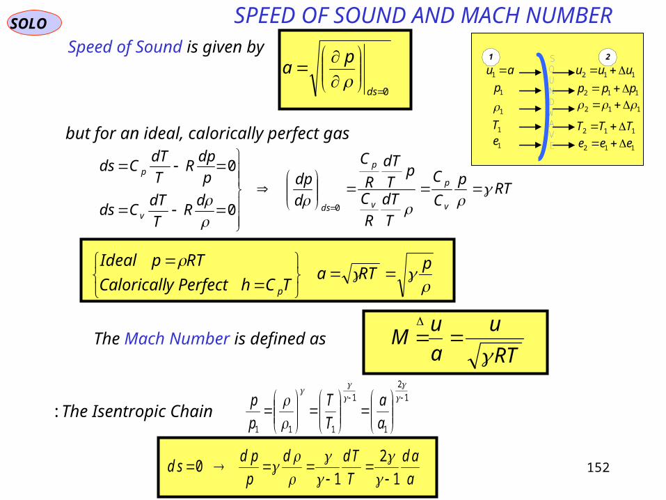
152
SPEED OF SOUND AND MACH NUMBERSOLO
21
au 1
1p
1
1T
1e
112 uuu
112 ppp
112
112 TTT
112 eee
SOUNDWAVE
Speed of Sound is given by
0
ds
pa
RTp
C
C
T
dT
R
C
pT
dT
R
C
d
dp
dR
T
dTCds
p
dpR
T
dTCds
v
p
v
p
dsv
p
00
0
but for an ideal, calorically perfect gas
pRTa
TChPerfectyCaloricall
RTpIdeal
p
The Mach Number is defined asRT
u
a
uM
1
2
1
1
111
a
a
T
T
p
pThe Isentropic Chain:
a
ad
T
Tdd
p
pdsd
1
2
10

153
NORMAL SHOCK WAVESSOLO
Normal Shock Wave ( Adiabatic), Perfect Gas
G Q 0 0,
Mach Number Relations (1)
122
22
1
21
22
222
21
221
22
2
222
1
1
21
1222
2
11
1
22221
211
2211
2
1
2
12
1
2
1
*12
1
2
1
12
1
14..
...
..
uuu
a
u
a
uaa
uaaau
h
au
h
aEC
uuu
p
u
p
pupuMLC
uuMCp
a
Field Equations:
1222
2
11
2
2
1
2
1
2
1
2
1uuu
u
au
u
a
u u a1 22
u
a
u
aM M1 2
1 21 1
Prandtl’s Relation
u
p
T
e
u
p
T
e
11
q
1
1
1
1
1
2
2
2
2
2
1 2
2
1
2
11
2
1
2
1
2
1
21
2
12122
21
12
uu
auuuua
uu
uu
Ludwig Prandtl(1875-1953)

154
NORMAL SHOCK WAVESSOLO
Normal Shock Wave ( Adiabatic), Perfect Gas
G Q 0 0,
Mach Number Relations (2)
M
MM
M
M
M
M
MM
22
22
1
12
12
12
12
12
21
1
2
1 1
2
11
1 21
2 1 2
1 1 1 1 1
12
or
M
M
M
M
MH H
A A
2
12
12
12
121 2
1 21
1
21
2
2
1
11
2
12
11
2
1
1
2
12
1 2
12
2 12 1
2
12
1 2 1
1 2
A A u
u
u
u u
u
aM
M
M
u
p
T
e
u
p
T
e
11
q
1
1
1
1
1
2
2
2
2
2
1 2

155
NORMAL SHOCK WAVESSOLO
Normal Shock Wave ( Adiabatic), Perfect Gas
G Q 0 0,
Mach Number Relations (3)
p
p
up
u
u
u
a
MM
MM
M M
M
2
1
12
1
1
2
1
12
12
1
2
12 1
2
12 1
2 12
12
12
1 1 1 1
1 11 2
11
1 1 2
1
or
(C.L.M.)
p
pM2
1121
2
11
h
h
T
T
p
pM
M
M
a
a
h C T p R Tp2
1
2
1
2
1
1
212 1
2
12
2
1
12
11
1 2
1
s s
R
T
T
p
pM
M
M2 1 2
1
12
1
1
12
1
112
12
1
12
11
1 2
1
ln ln
s s
RM M
M2 1
1 1
2 12 3
2
2 12 41
2 2
3 11
2
11
Shapiro p.125
u
p
T
e
u
p
T
e
11
q
1
1
1
1
1
2
2
2
2
2
1 2
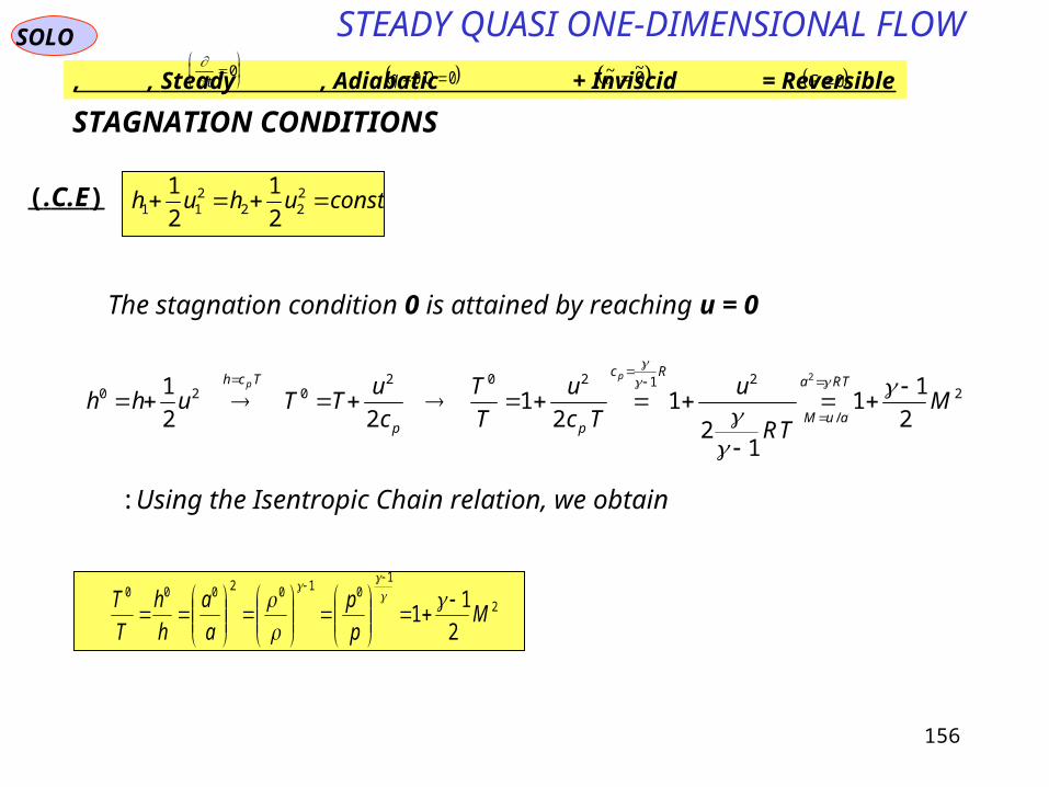
156
STEADY QUASI ONE-DIMENSIONAL FLOWSOLO
STAGNATION CONDITIONS
)C.E.( constuhuh 222
211 2
1
2
1
The stagnation condition 0 is attained by reaching u = 0
2
/
21202020
2
11
12
12
122
12
MTR
u
Tc
u
T
T
c
uTTuhh
TRa
auM
Rc
pp
Tch pp
Using the Isentropic Chain relation, we obtain:
2
10102000
2
11 M
p
p
a
a
h
h
T
T
Steady , Adiabatic + Inviscid = Reversible, , q Q 0 0, ~ ~ 0
G 0 t
0
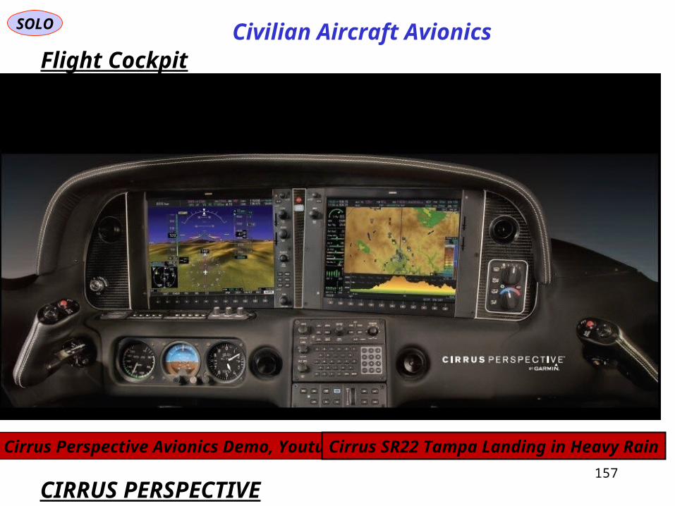
SOLO
157
Civilian Aircraft AvionicsFlight Cockpit
CIRRUS PERSPECTIVE
Cirrus Perspective Avionics Demo, Youtube Cirrus SR22 Tampa Landing in Heavy Rain
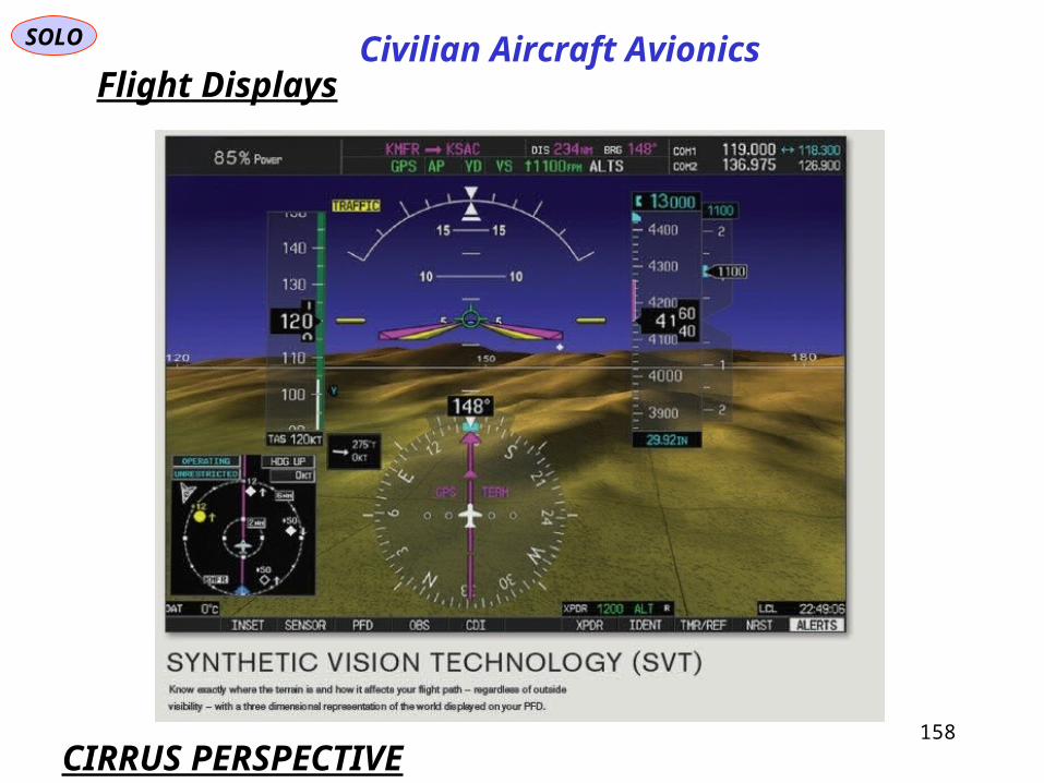
SOLO
158
Flight Displays
CIRRUS PERSPECTIVE
Civilian Aircraft Avionics
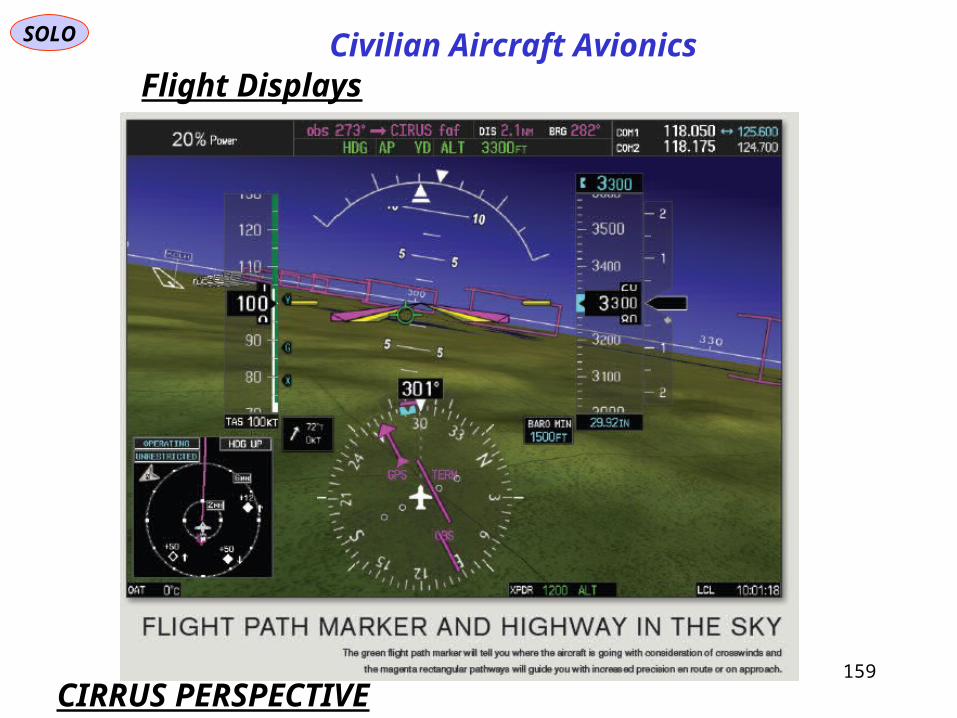
SOLO
159
Flight Displays
CIRRUS PERSPECTIVE
Civilian Aircraft Avionics

SOLO
160
Flight Displays
CIRRUS PERSPECTIVE
Civilian Aircraft Avionics
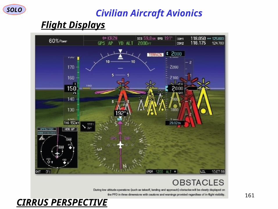
SOLO
161
Flight Displays
CIRRUS PERSPECTIVE
Civilian Aircraft Avionics

SOLO
162
Flight Displays
CIRRUS PERSPECTIVE
Civilian Aircraft Avionics

SOLO
163
Flight Displays
CIRRUS PERSPECTIVE
Civilian Aircraft Avionics
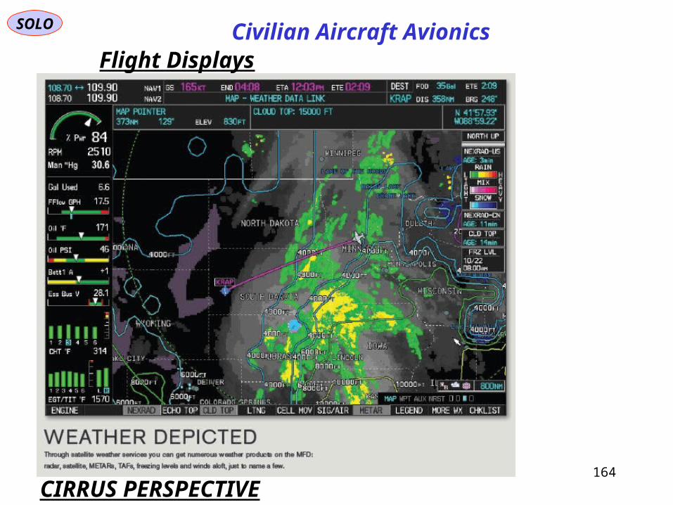
SOLO
164
Flight Displays
CIRRUS PERSPECTIVE
Civilian Aircraft Avionics

SOLO
165
Flight Displays
CIRRUS PERSPECTIVE
Civilian Aircraft Avionics
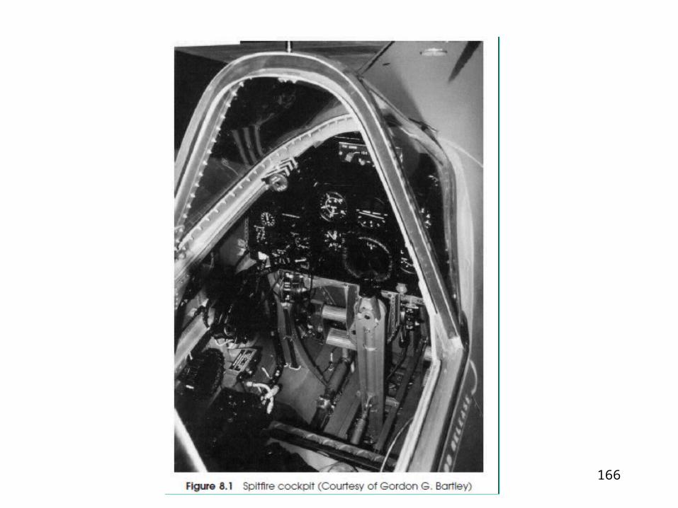
166


