

1./2. Fundamentals of Ion Sources
Daniela Leitner (LBNL, MSU),
Damon Todd (LBNL),
Daniel Winklehner (MIT)
Course Organization
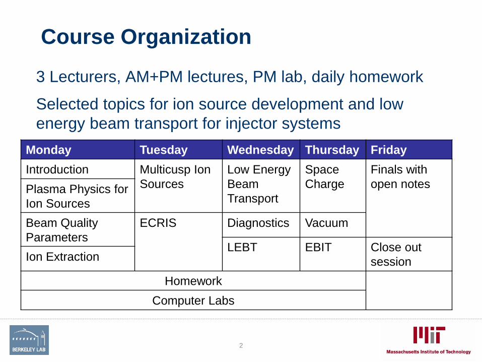
3 Lecturers, AM+PM lectures, PM lab, daily homework
Selected topics for ion source development and low
energy beam transport for injector systems
2
Monday Tuesday Wednesday Thursday Friday
Introduction Multicusp Ion
Sources
Low Energy
Beam
Transport
Space
Charge
Finals with
open notesPlasma Physics for
Ion Sources
Beam Quality
Parameters
ECRIS Diagnostics Vacuum
LEBT EBIT Close out
sessionIon Extraction
Homework
Computer Labs

Homework/Computer Labs/Finals
Grading:
40% participation and computer lab work
40% Homework
• Teamwork is encouraged for the computer lab and the homework!!
Homework is given daily. Solutions will be distributed the next day.
• We are here to help!! Don’t hesitate to ask for assistance with
homework problems! The grading is more focused on the effort to
solve a problem than submitting the perfectly worked out solution
• Use the internet as resource
20% Finals: Open book – we should discuss the use of internet
• .
3

•Bayard-Alpert type ion source
•Electron Bombardment ion source
•Hollow Cathode ion source
•Reflex Discharge Multicusp source
•Cold- & Hot-Cathode PIG
•Electron Cyclotron Resonance ion source (ECR)
•Electron Beam Ion Source (EBIS)
•Surface Contact ion source
•Cryogenic Anode ion source
•Metal Vapor Vacuum Arc ion source (MEVVA)
•Sputtering-type negative ion source
•Plasma Surface Conversion negative ion source
•Electron Heated Vaporization ion source
•Hollow Cathode von Ardenne ion source
•Forrester Porus Plate ion source
•Multipole Confinement ion source
•EHD-driven Liquid ion source
•Surface Ionization ion source
•Charge Exchange ion source
•Inverse Magnetron ion source
•FEBIAD ion source
•Nier ion source
•Bernas ion source
•Nielsen ion source
•Wilson ion source
•Recoil ion source
•Zinn ion source
•Plasmatron
•Duoplasmatron
•Duopigatron
•Laser ion source
•Penning ion source
•Monocusp ion source
•Bucket ion source
•Metal ion source
•Multicusp ion source
•Kaufman ion source
•Flashover ion source
•Calutron ion source
•CHORDIS
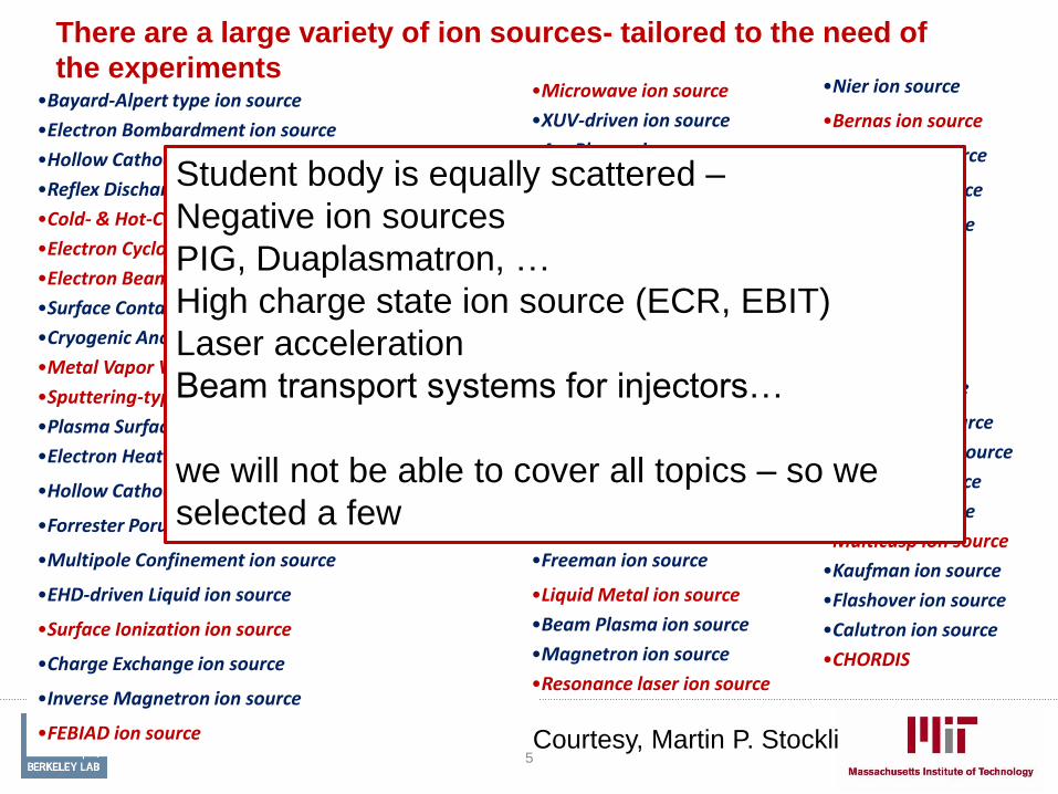
There are a large variety of ion sources- tailored to the need of
the experiments
Courtesy, Martin P. Stockli
•Microwave ion source
•XUV-driven ion source
•Arc Plasma ion source
•Capillary Arc ion source
•Von Ardenne ion source
•Capillaritron ion source
•Canal Ray ion source
•Pulsed Spark ion source
•Field Emission ion source
•Atomic Beam ion source
•Field Ionization ion source
•Arc Discharge ion source
•Multifilament ion source
•RF plasma ion source
•Freeman ion source
•Liquid Metal ion source
•Beam Plasma ion source
•Magnetron ion source
•Resonance laser ion source
4
•Bayard-Alpert type ion source
•Electron Bombardment ion source
•Hollow Cathode ion source
•Reflex Discharge Multicusp source
•Cold- & Hot-Cathode PIG
•Electron Cyclotron Resonance ion source (ECR)
•Electron Beam Ion Source (EBIS)
•Surface Contact ion source
•Cryogenic Anode ion source
•Metal Vapor Vacuum Arc ion source (MEVVA)
•Sputtering-type negative ion source
•Plasma Surface Conversion negative ion source
•Electron Heated Vaporization ion source
•Hollow Cathode von Ardenne ion source
•Forrester Porus Plate ion source
•Multipole Confinement ion source
•EHD-driven Liquid ion source
•Surface Ionization ion source
•Charge Exchange ion source
•Inverse Magnetron ion source
•FEBIAD ion source
•Nier ion source
•Bernas ion source
•Nielsen ion source
•Wilson ion source
•Recoil ion source
•Zinn ion source
•Plasmatron
•Duoplasmatron
•Duopigatron
•Laser ion source
•Penning ion source
•Monocusp ion source
•Bucket ion source
•Metal ion source
•Multicusp ion source
•Kaufman ion source
•Flashover ion source
•Calutron ion source
•CHORDIS
There are a large variety of ion sources- tailored to the need of
the experiments
Courtesy, Martin P. Stockli
•Microwave ion source
•XUV-driven ion source
•Arc Plasma ion source
•Capillary Arc ion source
•Von Ardenne ion source
•Capillaritron ion source
•Canal Ray ion source
•Pulsed Spark ion source
•Field Emission ion source
•Atomic Beam ion source
•Field Ionization ion source
•Arc Discharge ion source
•Multifilament ion source
•RF plasma ion source
•Freeman ion source
•Liquid Metal ion source
•Beam Plasma ion source
•Magnetron ion source
•Resonance laser ion source
Student body is equally scattered –
Negative ion sources
PIG, Duaplasmatron, …
High charge state ion source (ECR, EBIT)
Laser acceleration
Beam transport systems for injectors…
we will not be able to cover all topics – so we
selected a few
5

Suggested Literature - Books
• We have added references through-out the presentations- the
presentations will be posted on the USPAS web
Additional resources for ion source literature
• Ion Sources, Huashun S. Zhang, Jianrong Zhang, Springer-
Verlag, 2000
• Handbook of Ion Sources, Bernhard H. Wolf, CRC Press, 1995
• Electron Cyclotron Resonance Ion Sources, R. Geller, IOP
Pub, 1996
• Electron Beam Ion Sources and Traps and Their Applications,
Krsto Prelec, Springer-Verlag, 2001
• CERN Accelerator School – CAS (2013), CERN-2013-007
6

Suggested Literature - Conferences
• We have added references through-out the presentations- the
presentations will be posted on the USPAS web
• JACOW website: PACs, CYCLOTRONS, ….
• Every 2 year – ICIS conference (all ion sources)
• Proceedings of the International Conferences on Ion Sources, in Rev. of Sci.
Instrumentation. early in all odd years, 2017 next one
• Every 2 years ECR workshops (early ones are not available on the web)
• Proceedings of the Workshops on ECRIS, JACOW website, next one 2016
• Every 2 years EBIS workshop
• Proceedings on the International Symposium on Electron Ion Beam Sources
and Their Applications, American Institute of Physics, 2016 next
• International Symposium on Negative Ions, Beams and Sources
• Proceedings are published by AIP, in their conference proceedings series,
since 2009 , next one 2016
7

Content
• A little bit of history
• Sources General – Overview
• Front Ends - Injectors
• Simple Sources
• Plasma Physics Fundamentals
• Homework for the day
8

Ion sources – Brief
History
• 1857: experiments with electrical glow discharge –
Geissler tube (neon lights): Weakly ionized plasma
in glass tubes!
• 1889: Friedrich Paschen: Breakdown in gas
discharges
• 1900: Townsend discharge
• 1908-1911: Discovery of the structure of the atom:
Rutherford, Geiger, Marsden– start of modern
nuclear physics and accelerator applications
• Need was established to develop accelerators as a
source for charged particles to replace radioactive
sources and produce particles at controlled
energies
9
Rare 1890 German multi-bulb with Rhodanine, Eosine, Fluorecine, and Authacein.

The Evolution of Low Pressure Gas Discharges
• 1900: Townsend studies gas
discharges in partially evacuated
tubes with two electrodes
• Small voltages yields nA currents
by collecting electron–ion pairs
produced by background radiation
• Raising the voltage starts the
Townsend multiplication, yielding
many µA (corona – avalanche
event)
• Increasing the voltage, suddenly
the gas starts to glow and the
current grows up to many mA at a
much reduced voltage
10
Courtesy, Martin P. Stockli, ORNL
Breakdown voltage
-10
-8
-6
-4
-2
0
0 100 200 300 400 500
log
(tu
be
cu
rre
nt
[A])
Log (
Tube C
urr
ent
[A]
Dark TOWNSEND REGIME
Glow
Tube Voltage [V]

The Breakdown Voltage (Paschen’s Law)
• 1889 Friedrich Paschen described a breakdown voltage function V(p,d)
with pressure p, electrode gap d, and experimental determined
coefficients :A & B, which depend on the gas and the electrodes
• γse is the secondary electron coefficient
11
Energy gained by the
electrons between
collisions is too small
Linear regime• Decreasing the pressure increases the
mean path between collisions (λi), which is
compensated by proportionally increasing d
• The minimum represents the minimum
energy spent on producing enough ions for
one secondary electron from the cathode.
• At high pd, the voltage increases linearly
with the gap between the electrodes

Constants as References
• Constants A, B for various gases and pressure regimes
• Secondary electron coefficients: 1 to 2 (depending on the material)
12

13 Managed by UT-Battellefor the U.S. Department of Energy
The Spallation Neutron Source
smashes a pulsed, 1 MW proton beam on to a Hg target to produce ~21017 neutrons 60 times per second!
accumulator ring
Hg target
ion source
SNS was constructed by a collaboration of Lawrence Berkeley National LaboratoryLos Alamos National LaboratoryJefferson National LaboratoryBrookhaven National Laboratory Argonne National Laboratory andOak Ridge National LaboratoryCourtesy of Martin Stoeckli, SNS
filter magnets
H-
beam
dumping magnet
RF antenna
multicusp magnets
Gas inlet
plasma
view port
Cs collar
e-dump

14 Managed by UT-Battellefor the U.S. Department of Energy
After a 3-year ramp up, SNS is running ~1 MW except for cost- and target-issues!These unprecedented power levels uncovered many source and LEBT issues!
The Spallation Neutron Source
Source 3/4/3/4/3
~850 kW
1.4 MW
Cost saving ~850 kW
Much had to be learned to support ~1 MW operations with high availability!
Courtesy of Martin Stoeckli, SNS

Heavy Ion Collider at Brookhaven National
Laboratory – RHIC Accelerator Complex
15
EBIS
Ed Beebe
Alexander Pikin

Injection and extraction scheme for the
BNL EBIS source
16
Pulse by pulse changing of ion
beams to provide beams to RHIC,
AGS, and to the NASA test facility
Courtesy of E. Beebe, BNL

Production Linac (2020)
200MeV/u Uranium
341 SRF cavities
ß=0.041, 0.085,0.29,0.53
FRIB Rare Isotope Driver LINAC
Figure: Courtesy of M. Leitner, LBNL
https:// www.FRIB.msu.edu17

Rare isotope production at NSCL in the future: Facility for Rare
Isotope Production at MSU
Target
Fragment
Separator
Fast Beam
Experimental
Area
Stopped
Beams
Re
Accelerator
Low Energy
Nuclear
Physics
Experimental
Area
Gas
Stopper
Production Linac
200MeV/u Uranium, 10 puA of U on target
Primary beam power on target: 400kW
Slide 18
18

FRIB Front End
19

Front End optics design is different from the regular lattice. It needs to do adapt
to different beam parameters from the source and it has several matching points
ARTEMIS (Injector 1)
VENUS (Injector 2)
LEBT (Tunnel)
CSS2
CSS1
LEBT
Vertical
Beam line
RFQ
MEBT
Beam is very slow 12 keV/u (required injection energy for the RFQ)
Electrostatic focusing elements
Focusing is independent of ion/charge ratio for electrostatic elements
Possible in the low energy section, (because the ions are slow) not a good choice in the high energysections.
Force is independent of velocity
F=e*Q*E
Magnetic elements:
F=e*Q*v x B (force increases with velocity)
Magnetic elements will separate for different momenta, dipoles are in the charge selection section
Solenoids are used because they are convenient (round beam) and allow space charge compensation
20

Front End Elements
ARTEMIS (Injector 1)
VENUS (Injector 2)
LEBT (Tunnel)
CSS2
CSS1
LEBT
Vertical
Beam line
RFQ
MEBT
Two ECR sources on HV platforms• ARTEMIS - commissioning
• VENUS – high performance
Two charge selection systems (CSS1, CSS2)
Low Energy Beam Transport (LEBT)• Chopper
• Collimation system
• Vertical transport line
• Buncher and velocity equalizer
RadioFrequencyQuadrupole (RFQ)• E=500 keV/u
Medium Energy Beam Transport (MEBT)• Two bunchers, solenoids
Instrumentation
21
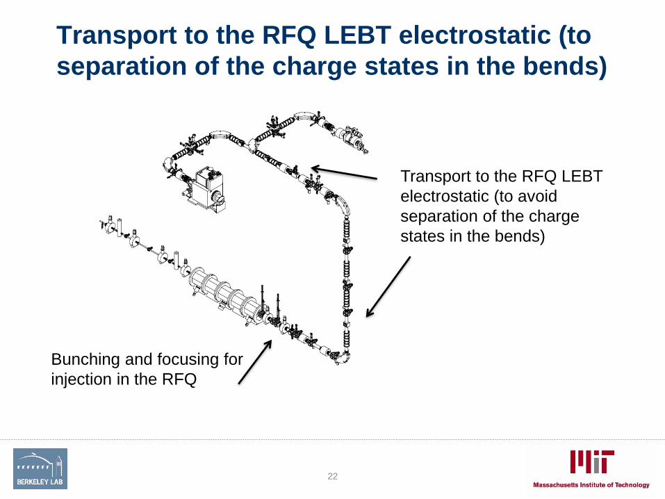
Transport to the RFQ LEBT electrostatic (to
separation of the charge states in the bends)
22
Transport to the RFQ LEBT
electrostatic (to avoid
separation of the charge
states in the bends)
Bunching and focusing for
injection in the RFQ

Plasma Physics
23

Selected Ion Source Types (not covered in detail in the next couple of days)
24

Surface Ionization Source: Ideal Accelerator
Ion SourceBasic Principle:
Metals with low ionization potential (e.g. alkali) can get ionized when they
come in contact with a hot surface: For example Tungsten coated with
aluminosilicate compound of a metal: Li2O*Al2O3*2SiO2
, Slide 25
Li Ion source at LBNL for the high density physics experiments
Injector for diagnostic beams for fusion reactors
Single charged ions only
Advantages:
the emitting surface is fixed, initial conditions
are defined
Ion temperature is very low (<.2eV)
(Surface ion source are heated to 1200-
2000C, 1eV = 11600K)
Emittance of the ion beam produced is small

Surface Ionization Source: Ideal Accelerator
Ion Source
Typically used as external source for
testing or charge breeding experiments
Commercial available Surface Ion Source
Disadvantage:
Current density limited to <1.5mA/cm2
Large emitters (>10cm diameter) are needed for high current (HIF
100mA)
Life time is limited, amount of charge is given by the coating
Limited to alkali and alkaline metals
I typical pA to nA
26

Parts of a simple Ion Sources
, Slide 27
Ion source input:
free electrons (E> Ionization
Potential)=discharge voltage, neutral gas
Means of providing energy to the electrons
Keep ions cold !
Filament
Anode
Extraction
ionsVf
Vbody Vanode
+
+-
-
+
-
Ion source has no confinement, ion confinement time is short, only singly
charged ions – confinement time is very short, not efficient, but ion temperature
low (good emittance)
Require a high gas pressure to run, many different types developed
Cathode +Anode
Filament
RF discharge
Microwave discharge

Basic elements of an ion source
28
Vext
Ion beam

Basic elements of an ion source
29
Vext
Ion beam
-Vsup
Plasma electronics
Filaments..
Ovens, Bias…
….
Rplatform
Ions lost on the electrode and
backstreaming electrons
Ion beam Dark Current
+-

Add confinement with external B-Field
, Slide 30
Filament
Anode
Extraction
ionsVf
Vbody Vanode
+
+-
-
+
-
B
- - - -
+ + + +
Ion source input:
free electrons (E> Ionization
Potential)=discharge voltage, neutral gas
Means of providing energy to the electrons
Keep ions cold !
Cathode +Anode
Filament
RF discharge
Microwave discharge

Confining charged particles
31
Multicusp fieldDipole fieldSolenoidal field
• In the direction of the fields there is no force, transverse the particles
are bend into the circular motion
• Helical motion increases the time the electron send in the discharge
chamber- field lines can only be crossed through collisions – wall
losses are reduced
• Add strongly increasing magnetic field as the confinement
mechanism: Particles get reflected by an increasing magnetic field

Important Ion Source Type: PIG Source
Can produce some highly charged ions
32
F.M. Penning, Physica, 4, 71, (1937)
B
Sputter
Sample
Neg. Bias
For
Metal
Ions Performance is determined by
Product of ne* τi
Confinement time : τi=10*r2*B/Te
(diffusion across B field)
Cyclotron magnetic Field adds confinement
B
Internal Ion source for early cyclotrons
r=0.3cm, B=3kG, Te=10eV, τi~10 μsec
Source lifetime is an issue, need different source to
get reliable high charge states
KM
Q
M
E
2
K ~ B2·R2

33
ECR Ion Sources largely replaced PIG sources for cyclotrons
Runs 24 hours/day, 7 days/ week with minimum intervention
Minimum maintenance (typically not required for years)
Good beam stability and quality
High intensities (μA to mA of beams are available)
Can produce ion beams from every element
AECR-U Injector, 88-Inch Cyclotron LBNL
r
Ce Pr Nd PmSm Eu Gd Tb Dy Ho Er Tm Yb Lu
Th Pa U Np Pu AmCm Bk Cf Es Fm Md No Lr
Ga
H
B
PNa
Li
K
Cs
Fr
Mg
Ca
Sr
Ba
Ra
Sc
Y
La
Ac
Ti V Cr Mn Fe Co Ni Cu Zn Ge
e
As
He
Se Br Kr
B C N O F Ne
Al Si S Cl Ar
Zr Nb Tc RhRu Pd Cd In Sn Sb Te I Xe
Hf Ta W Re Os Ir Pt Au At RnHg Tl Pb Bi Po
Ag
P
Be
MoRb
Ion Beams tested in the LBNL ECR Ion Sources
• Any element can be ionized
provided it can be vaporized
VENUS oven at the required uranium
temperature of 2100 C
Richard Geller

Impact of ECR ions on accelerators
34
0
5
10
15
20
25
30
35
0 50 100 150 200 250
En
erg
y i
n M
eV
/am
u
Particle Mass in amu
Evolution of the 88-Inch
Cyclotron Performance for
Heavy Ions at 1pnA
VENUS
AECR-U
1995
ECR-
1989
PIG-
1984

Specialized Sources for Rare Isotope
Facilities
35
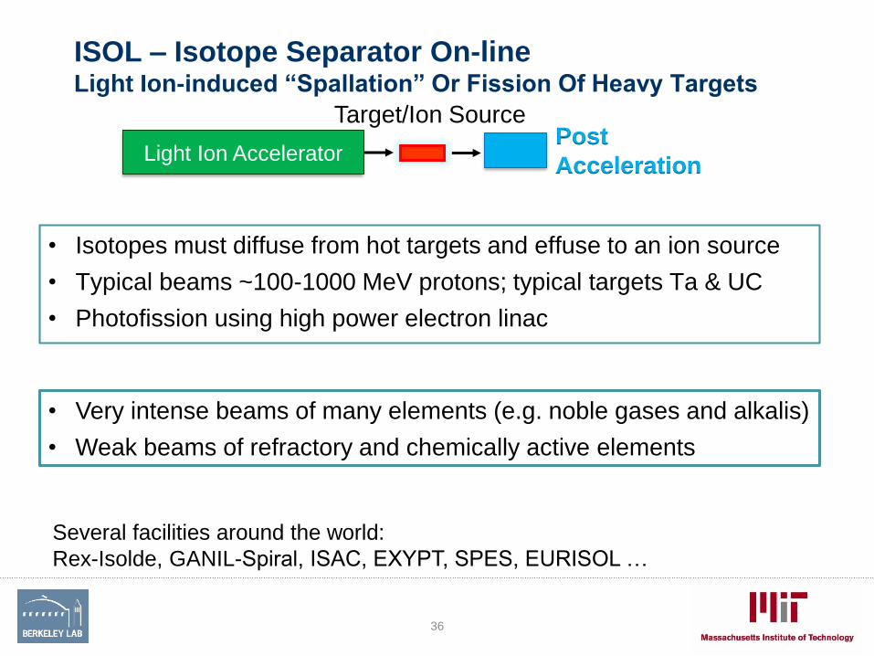
ISOL – Isotope Separator On-line Light Ion-induced “Spallation” Or Fission Of Heavy Targets
Several facilities around the world:
Rex-Isolde, GANIL-Spiral, ISAC, EXYPT, SPES, EURISOL …
• Very intense beams of many elements (e.g. noble gases and alkalis)
• Weak beams of refractory and chemically active elements
Target/Ion SourcePost
AccelerationLight Ion Accelerator
• Isotopes must diffuse from hot targets and effuse to an ion source
• Typical beams ~100-1000 MeV protons; typical targets Ta & UC
• Photofission using high power electron linac
36

Ion Sources for Rare Isotope
(radioactive ion beam) accelerationSpecialist field: ISOL facilities
• The ion source is often combined with the target and optimized for each
ion species, Issues:
– Release time of the ions from the target
– Chemistry of the ion in the target and the ion source
– The impurity of the beam
37
Surface Ionization Source
(Alkali metals)FEBIAD (plasma with
heated plasma chamber) ECRIS (gases)
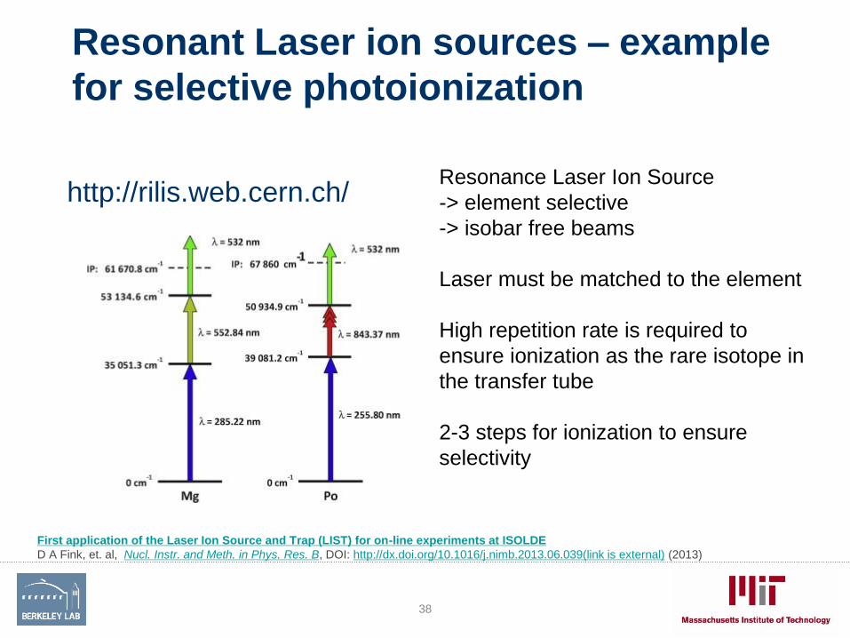
Resonant Laser ion sources – example
for selective photoionization
http://rilis.web.cern.ch/
First application of the Laser Ion Source and Trap (LIST) for on-line experiments at ISOLDE
D A Fink, et. al, Nucl. Instr. and Meth. in Phys. Res. B, DOI: http://dx.doi.org/10.1016/j.nimb.2013.06.039(link is external) (2013)
38
Resonance Laser Ion Source
-> element selective
-> isobar free beams
Laser must be matched to the element
High repetition rate is required to
ensure ionization as the rare isotope in
the transfer tube
2-3 steps for ionization to ensure
selectivity

In-Flight Heavy-Ion Fragmentation or Fission on a Light TargetRare Isotopes are Separated Physically; No Chemical Dependence
• Fragments of the beam are kinematically forward directed at ~beam velocity
• Typical heavy ion beams are 18O-238U at 200-2000 MeV/u; typical targets Be or C
• Separated beams of any species including refractory and chemically active
elements and isotopes with very short half-lives, even isomers
• Needs gas catcher or solid stopper for post acceleration, ion cooler
• Charge breeder ion sources for reacceleration
D. Leitner Berkeley March 2014, Slide 39
CCF-MSU, RIKEN, GANIL, FAIR, FRIB..
Fragment
Separator
Heavy Ion Accelerator
Selected Fragment
Less chemistry involved; beams at high energy
39

Fragmentation Facility Ion sources
40
Heavy Ion
Driver
TargetFragment Separator
Beam
Stopping
ReAcceleration
Low Energy
Nuclear Physics
Experimental Area
Gas Stoppers to
slow down ions to
thermal energies
Charge
Breeder
(EBIT)
Production of fast rare isotopes
More on Thursday

Laser Plasma Accelerator
Ion source and accelerator combined

Laser Plasma Ion Accelerator• Accelerator and ion source are combined!
• A high power laser (1020 to 1022/cm2) is focused on a thin foil
target or gas jet, the ions are accelerated through charge
separation (several mechanism, e.g Target Normal Sheath
Acceleration)
• Ions are formed in the expanding plasma and accelerated to 10s
to 100s of MeV energies directly
42
Marcus Roth, BELLA-I Workshop Berkeley

Laser Plasma Ion Accelerator• Accelerator and ion sources are combined!
• A high power laser (1020 to 1022/cm2) is focused on a thin foil
target or gas jet, the ions are accelerated through charge
separation (several mechanism, e.g Target Normal Sheath
Acceleration)
• Ions are formed in the expanding plasma and accelerated to 10s
to 100s of MeV energies directly
43
Marcus Roth, BELLA-I Workshop Berkeley

Proposed BELLA-i Facility Upgrade
Berkeley Lab Laser Accelerator
(BELLA) - Center • Currently Electron Laser Acceleration research facility
• New initiative at LBNL to build an laser ion accelerator facility
44


