
It is the responsibility of the installer to meet or exceed all code and safety requirements, and to obtain all required building permits. These instructions are only a guide and may not address every circumstance. The deck and railing installer should determine and implement appropriate installation techniques for each situation. FAIRWAY shall not be held liable for improper or unsafe installations.
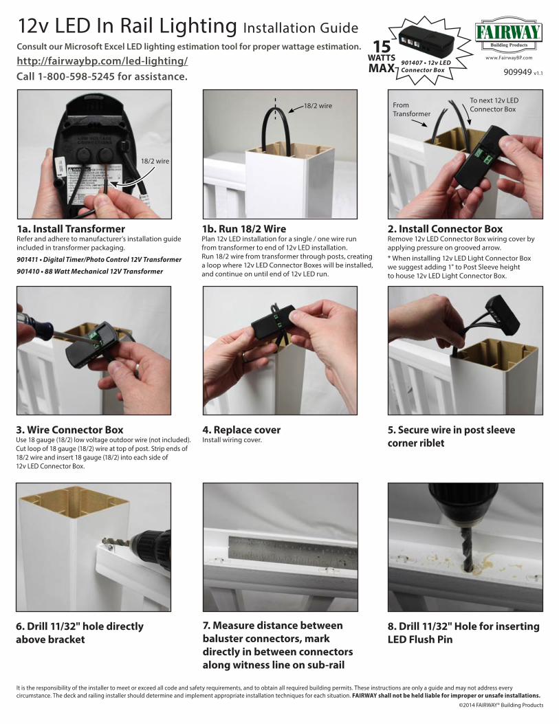
12v LED In Rail Lighting Installation GuideConsult our Microsoft Excel LED lighting estimation tool for proper wattage estimation.
http://fairwaybp.com/led-lighting/
1a. Install TransformerRefer and adhere to manufacturer’s installation guide included in transformer packaging.
901411 • Digital Timer/Photo Control 12V Transformer
901410 • 88 Watt Mechanical 12V Transformer
1b. Run 18/2 WirePlan 12v LED installation for a single / one wire runfrom transformer to end of 12v LED installation.Run 18/2 wire from transformer through posts, creating a loop where 12v LED Connector Boxes will be installed, and continue on until end of 12v LED run.
4. Replace coverInstall wiring cover.
2. Install Connector BoxRemove 12v LED Connector Box wiring cover by applying pressure on grooved arrow. * When installing 12v LED Light Connector Boxwe suggest adding 1" to Post Sleeve heightto house 12v LED Light Connector Box.
5. Secure wire in post sleeve corner riblet
3. Wire Connector BoxUse 18 gauge (18/2) low voltage outdoor wire (not included).Cut loop of 18 gauge (18/2) wire at top of post. Strip ends of 18/2 wire and insert 18 gauge (18/2) into each side of12v LED Connector Box.
6. Drill 11/32" hole directly above bracket
901407 • 12v LED Connector Box
7. Measure distance between baluster connectors, mark directly in between connectors along witness line on sub-rail
8. Drill 11/32" Hole for inserting LED Flush Pin
909949 v1.1Call 1-800-598-5245 for assistance.
18/2 wire
18/2 wire
To next 12v LEDConnector BoxFrom
Transformer
*If using Carriage Light Post Cap.It is the responsibility of the installer to meet or exceed all code and safety requirements, and to obtain all required building permits. These instructions are only a guide and may not address every circumstance.The deck and railing installer should determine and implement appropriate installation techniques for each situation. FAIRWAY shall not be held liable for improper or unsafe installations.
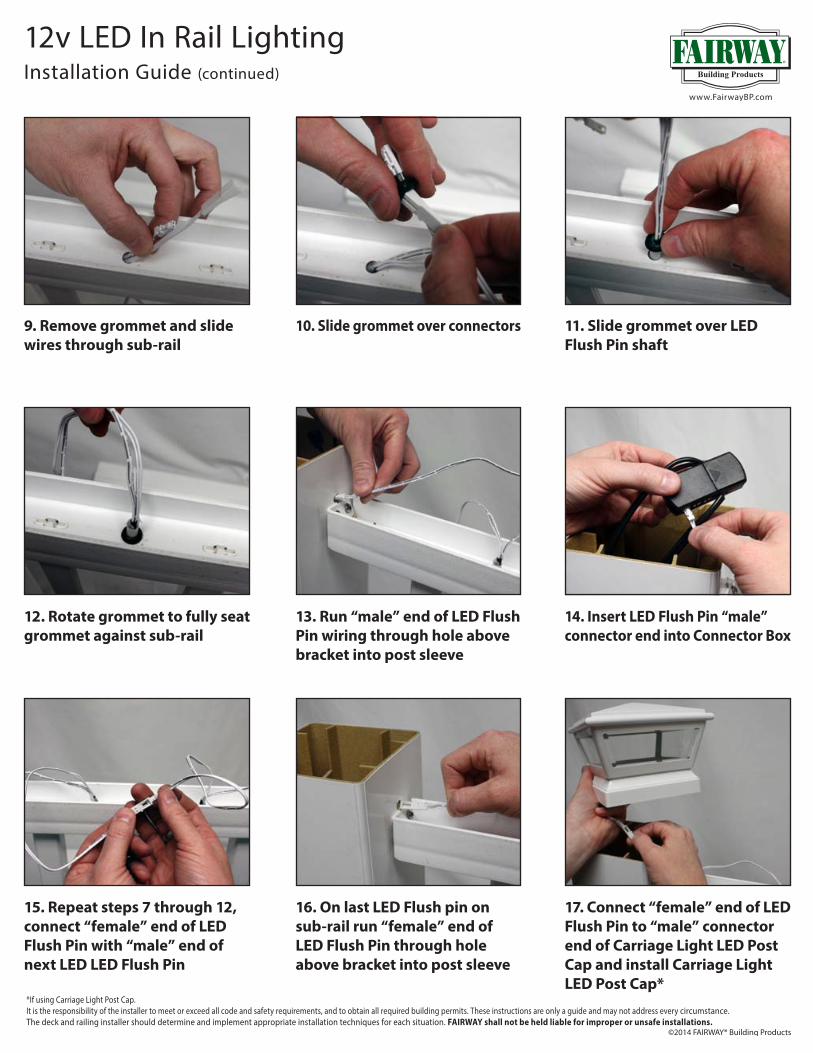
10. Slide grommet over connectors
13. Run “male” end of LED Flush Pin wiring through hole above bracket into post sleeve
11. Slide grommet over LED Flush Pin shaft
14. Insert LED Flush Pin “male” connector end into Connector Box
17. Connect “female” end of LED Flush Pin to “male” connector end of Carriage Light LED Post Cap and install Carriage Light LED Post Cap*
12. Rotate grommet to fully seat grommet against sub-rail
15. Repeat steps 7 through 12, connect “female” end of LED Flush Pin with “male” end of next LED LED Flush Pin
16. On last LED Flush pin on sub-rail run “female” end of LED Flush Pin through hole above bracket into post sleeve
12v LED In Rail LightingInstallation Guide (continued)
9. Remove grommet and slide wires through sub-rail

Connects 3 - 12v LED componentsinto 1 female connector
1. Although the 1 to 3 splitter adds no wattage itself, be sure not to exceed the maximum wattage (15w) of the connector box in line with the components being connected to it.
2. Plug the male end of the 1 to 3 splitter into the female end of the last component installed(ex. 12v LED Light Flush Pin).
3. Plug male ends of desired components(Flush Pin, Carriage Light, Post Sconce, etc.) into female ends of 1 to 3 splitter.
12v LED Wattage Calculator Worksheet
12v LED 1 - 3 Connector CableInstallation Guide
Average Deck Light PackageProject Qty (enter Qty needed)
PN Product Description
Power per
Device (Watts)
Total Power Demand (Watts)
901400 LED Light -‐ Flush Pin 12V • 12" Lead 0.30901401 LED Light -‐ Strip 12V -‐ 24" strip • 24" Lead 1.58901402 LED Light -‐ White Post Sconce 12V • 34" Lead 0.53901403 LED Light -‐ Black Post Sconce 12V • 34" Lead 0.53901408 LED Light -‐ White 4” Carriage Post Cap 12V • 7.5" Lead 1.65901409 LED Light -‐ Black 4” Carriage Post Cap 12V • 7.5" Lead 1.65901404 LED Light -‐ White 5-‐1/4” Carriage Post Cap 12V • 7.5" Lead 1.65901405 LED Light -‐ Black 5-‐1/4” Carriage Post Cap 12V • 7.5" Lead 1.65901406 LED Light -‐ 36" Extension Cable 12V 0.00901414 LED Light -‐ 108" (9') Extension Cable 12V 0.00901415 LED Light -‐ 1 to 3 Connector Cable 0.00
Minimum Connector Boxes Required for This Project
Minimum Transformer Output Required for This Project901407 LED Light -‐ Connector Box 12V -‐ 15W Capacity 0.00901410 LED Light -‐ 88 Watt Mechanical Transformer 12V 88.00901411 LED Light-‐ Digital Timer/Photo Control 12V 100.00
Package Total:

1. When installing the Post Sconce (0.53w) be sure not to exceed themaximum wattage (15w) of the connector box in line.
2. The Post Sleeve must be prepared in advance to accommodateinstallation of the Sconce Light.
3. If Post Trim is used, install it over the wood post before installingthe Post Sleeve. You will not be able to install Post Trim afterPost Sleeve and Sconce Light are in place.
4. Prepare the Post Sleeve by: a. Cut Post sleeve to desired length b. Determine the height at which the Sconce Light will be mounted c. Mark the location of the wire hole and the mounting screw holes using the template provided (Fig. 1) d. Pre-drill a 5/16" hole for the wire and pre-drill two 5/64" holes for mounting screws (Fig. 2)
Wire Hole
NOTE:Install Post Trim Ring First
6. Route the Sconce Light wire through the wire hole and out of the top of the Post Sleeve. Fig. 4
7. Hold the Sconce Light loosely in position and slide the Post Sleeve over the structural post and into the Post Trim. Fig. 5
8. Attach the Sconce Light back plate to the post using two #8 x 1.5" screws provided (take extra precaution to avoid wire when inserting screws). Fig. 6
9. Re-install Sconce Light Cover.
10. Plug male end of Sconce Light wire into connector box or female end of LED extension. Fig. 7
5. Remove Sconce Light cover from Sconce Light back plate by rotating counter clockwise (Fig. 3)
Fig. 1DRILL TEMPLATE
Fig. 2
Fig. 3
Fig. 4
Fig. 5
Post Sleeve
Fig. 6
Fig. 7
12v LED Post Sconce (0.53w) • Installation Guide

Connects 3 - 12v LED componentsinto 1 female connector
1. Although the 1 to 3 splitter adds no wattage itself, be sure not to exceed the maximum wattage (15w) of the connector box in line with the components being connected to it.
2. Plug the male end of the 1 to 3 splitter into the female end of the last component installed(ex. 12v LED Light Flush Pin).
3. Plug male ends of desired components(Flush Pin, Carriage Light, Post Sconce, etc.) into female ends of 1 to 3 splitter.
12v LED 1 - 3 Connector CableInstallation Guide
12v LED Extension Cables
9' 12v LEDExtension Cable
36" 12v LEDExtension Cable
18/2Lv Wire
18/2Lv Wire
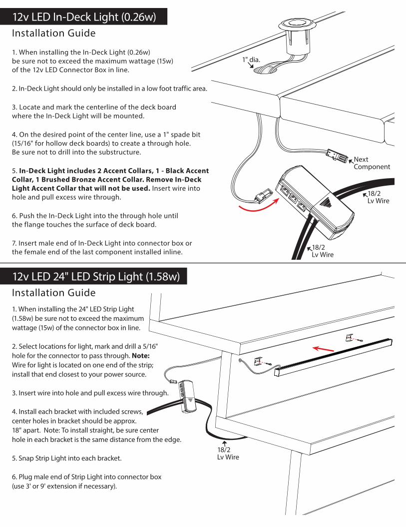
1. When installing the In-Deck Light (0.26w)be sure not to exceed the maximum wattage (15w)of the 12v LED Connector Box in line.
2. In-Deck Light should only be installed in a low foot traffic area.
3. Locate and mark the centerline of the deck boardwhere the In-Deck Light will be mounted.
4. On the desired point of the center line, use a 1" spade bit(15/16" for hollow deck boards) to create a through hole.Be sure not to drill into the substructure.
5. In-Deck Light includes 2 Accent Collars, 1 - Black Accent Collar, 1 Brushed Bronze Accent Collar. Remove In-Deck Light Accent Collar that will not be used. Insert wire into hole and pull excess wire through.
6. Push the In-Deck Light into the through hole untilthe flange touches the surface of deck board.
7. Insert male end of In-Deck Light into connector box orthe female end of the last component installed inline.
18/2Lv Wire
1. When installing the 24" LED Strip Light(1.58w) be sure not to exceed the maximumwattage (15w) of the connector box in line.
2. Select locations for light, mark and drill a 5/16"hole for the connector to pass through. Note:Wire for light is located on one end of the strip;install that end closest to your power source.
3. Insert wire into hole and pull excess wire through.
4. Install each bracket with included screws,center holes in bracket should be approx.18" apart. Note: To install straight, be sure centerhole in each bracket is the same distance from the edge.
5. Snap Strip Light into each bracket.
6. Plug male end of Strip Light into connector box(use 3' or 9' extension if necessary).
12v LED In-Deck Light (0.26w)Installation Guide
12v LED 24" LED Strip Light (1.58w)Installation Guide
18/2Lv Wire
Next Component
1" dia.
18/2Lv Wire
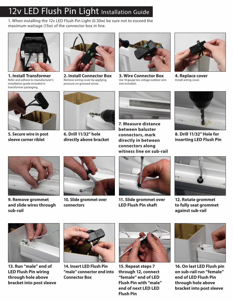
12v LED Flush Pin Light Installation Guide1. When installing the 12v LED Flush Pin Light (0.30w) be sure not to exceed themaximum wattage (15w) of the connector box in line.
1. Install TransformerRefer and adhere to manufacturer’s installation guide included in transformer packaging.
4. Replace coverInstall wiring cover.
2. Install Connector BoxRemove wiring cover by applying pressure on grooved arrow.
5. Secure wire in post sleeve corner riblet
3. Wire Connector BoxUse 18 gauge low voltage outdoor wire(not included).
6. Drill 11/32" hole directly above bracket
7. Measure distance between baluster connectors, mark directly in between connectors along witness line on sub-rail
8. Drill 11/32" Hole for inserting LED Flush Pin
10. Slide grommet over connectors
11. Slide grommet over LED Flush Pin shaft
14. Insert LED Flush Pin “male” connector end into Connector Box
16. On last LED Flush pin on sub-rail run “female” end of LED Flush Pin through hole above bracket into post sleeve
9. Remove grommet and slide wires through sub-rail
13. Run “male” end of LED Flush Pin wiring through hole above bracket into post sleeve
12. Rotate grommet to fully seat grommet against sub-rail
15. Repeat steps 7 through 12, connect “female” end of LED Flush Pin with “male” end of next LED LED Flush Pin

1. Remove Post Cap Top by popping locking pins out of Post Cap assembly (Fig. 1).2. Remove glass retaining ring and set it aside (Fig. 2).3. Carefully slide clear lens inserts out (Fig. 2) and replace with frosted lens inserts (Fig. 3).4. Reinsert glass retaining ring.5. Attach Post Cap Top making sure to align locking pins.
DO NOT SCALE DRAWING
LV Assem1SHEET 1 OF 1
UNLESS OTHERWISE SPECIFIED:
SCALE: 1:4 WEIGHT:
REVDWG. NO.
ASIZE
TITLE:
NAME DATE
COMMENTS:
Q.A.
MFG APPR.
ENG APPR.
CHECKED
DRAWN
FINISH
MATERIAL
INTERPRET GEOMETRICTOLERANCING PER:
DIMENSIONS ARE IN INCHESTOLERANCES:FRACTIONALANGULAR: MACH BEND TWO PLACE DECIMAL THREE PLACE DECIMAL
APPLICATION
USED ONNEXT ASSY
PROPRIETARY AND CONFIDENTIAL
THE INFORMATION CONTAINED IN THISDRAWING IS THE SOLE PROPERTY OF<INSERT COMPANY NAME HERE>. ANY REPRODUCTION IN PART OR AS A WHOLEWITHOUT THE WRITTEN PERMISSION OF<INSERT COMPANY NAME HERE> IS PROHIBITED.
5 4 3 2 1
Fig. 1 Fig. 2 Fig. 3
DO NOT SCALE DRAWING
LV Assem1SHEET 1 OF 1
UNLESS OTHERWISE SPECIFIED:
SCALE: 1:4 WEIGHT:
REVDWG. NO.
ASIZE
TITLE:
NAME DATE
COMMENTS:
Q.A.
MFG APPR.
ENG APPR.
CHECKED
DRAWN
FINISH
MATERIAL
INTERPRET GEOMETRICTOLERANCING PER:
DIMENSIONS ARE IN INCHESTOLERANCES:FRACTIONALANGULAR: MACH BEND TWO PLACE DECIMAL THREE PLACE DECIMAL
APPLICATION
USED ONNEXT ASSY
PROPRIETARY AND CONFIDENTIALTHE INFORMATION CONTAINED IN THISDRAWING IS THE SOLE PROPERTY OF<INSERT COMPANY NAME HERE>. ANY REPRODUCTION IN PART OR AS A WHOLEWITHOUT THE WRITTEN PERMISSION OF<INSERT COMPANY NAME HERE> IS PROHIBITED.
5 4 3 2 1
Carriage Light 12v LED Post Cap Frosted Lens InsertsInstallation Guide


![Untitled-2 [suntracbatteries.com]suntracbatteries.com/suntrac.pdf · capacity 12v 20ah 12v 40ah 12v 60ah 12v b40ah 12v b60ah 12v b80ah 12v biooah 12v 80ah 12v iooah 12v 130ah 12v](https://static.documents.pub/doc/80x56/603efb7aa12c32391f5484d1/untitled-2-capacity-12v-20ah-12v-40ah-12v-60ah-12v-b40ah-12v-b60ah-12v-b80ah.jpg)


