

CHECK OUT OUR WEBSITE SOME TIME FOR PLENTY OF ARTICES ABOUT SELF DEFENSE, SURVIVAL, FIREARMS AND MILITARY MANUALS.
http://www.survivalebooks.com/
Thank you for purchasing our ebook package.
ARMY TM 9-1005-245-13&P MARINE CORPS TM 1005-13&P/1
AIR FORCE T.O. 11W2-8-1-322
SUPERSEDES TM 9-1005-245-14,
DATED 7 FEBRUARY 1973
TECHNICAL MANUAL
OPERATOR'S, UNIT, AND DIRECT SUPPORT MAINTENANCE MANUAL
WITH REPAIR PARTS AND SPECIAL TOOLS LIST (RPSTL)
FOR MACHINE GUN MOUNTS
AND COMBINATIONS FOR TACTICAL/ARMORED
VEHICLES AND GROUND MOUNTING M122 MACHINE GUN TRIPOD
MOUNT (1005-00-710-5599) (EIC:4EF) M122A1 MACHINE GUN TRIPOD MOUNT
(1005-01-433-1617) M3 TRIPOD MOUNT
(1005-00-322-9716) (EIC:4EA) M66 MACHINE GUN
MOUNT RING (1005-00-701-2810) M240E1 FLEXIBLE MACHINE GUN
MOUNT (1005-01-254-0332) M142 MACHINE GUN
MOUNT (1005-00-854-4463) 6650 .50 CAL MACHINE GUN MOUNT (1005-00-704-6650)
M548 MACHINE GUN MOUNT (1005-00-783-5494)
MK93 MOD 0 MACHINE GUN MOUNT (USMC ONLY) (1005-01-383-2949)
MK93 MOD 1 MACHINE GUN MOUNT (1005-01-383-2757)
M6 MACHINE GUN PEDESTAL MOUNT (1005-01-411-6341)
M197 MACHINE GUN MOUNT (1005-01-413-4098)
DISTRIBUTION STATEMENT C. Distribution authorized to U.S. Government agencies and their contractors. This publication is required for administration and operational purposes, as determined 14 April 1987. Other requests for this document shall be referred to: ATTN: AMSTA-LC-CIP-WT, TACOM-Rock Island, 1 Rock Island Arsenal, Rock Island, IL 61299-7630. AIR FORCE ONLY: Requests for this document shall be referred to Warner Robins ALC/MMDET, Robins AFB, GA 31098-5609.
DESTRUCTION NOTICE-For unclassified, limited documents, destroy by any method that will prevent disclosure of contents or reconstruction of the document.
DECEMBER 1994
HEADQUARTERS, DEPARTMENT OF THE ARMY, MARINE CORPS, AND AIR FORCE

ARMY TM 9-1005-245-13&P MARINE CORPS TM 1005-13&P/1 AIR FORCE T.O. 11W2-8-1-322
WARNING It is essential that operational procedures for the machine gun be followed before installing on a mount. Dangerous procedures such as mounting, dismounting, cleaning, repairing, or operating a machine gun on a mount without first having knowledge of the operation of the machine gun and all safety precautions to be followed could result in injury or death to personnel. DO NOT attempt to mount or dismount or inspect or repair a mounted machine gun without first clearing the machine gun chamber and feedways of ammunition.
WARNING Case is under spring tension. To avoid injury to personnel, use care when removing case.
WARNING To avoid injury to your eyes, use care when removing and installing spring-loaded parts.
WARNING To avoid injury to your eyes, wear safety glasses when grinding parts.
WARNING Do not keep live ammunition near work/maintenance area.
WARNING Dry cleaning solvent (SD) is flammable. Do not clean parts near an open flame or in a smoking area. Dry cleaning solvent evaporates quickly and has a drying effect on the skin. When used without protective gloves, solvent may cause irritation to or cracking of the skin.
WARNING Some objects covered in this manual are heavy and need two soldiers to lift.
WARNING Some objects are hot to the touch. Ensure proper cooling has occurred before handling. PIN: 073479-005
ARMY TM 9-1005-245-13&P MARINE CORPS TM 1005-13&P/1
AIR FORCE T.O. 11W2-8-1-322 CHANGE HEADQUARTERS NO. 5 DEPARTMENT OF THE ARMY Washington D.C., 22 March 2002
OPERATOR'S, UNIT, AND DIRECT SUPPORT MAINTENANCE MANUAL WITH REPAIR PARTS AND SPECIAL TOOLS LIST (RPSTL)
FOR MACHINE GUN MOUNTS AND COMBINATIONS
FOR TACTICAL/ARMORED VEHICLES AND GROUND MOUNTING M122 MACHINE GUN TRIPOD MOUNT (1005-00-710-5599) (EIC: 4EF)
M122A1 MACHINE GUN TRIPOD MOUNT (1005-01-433-1617) M3 TRIPOD MOUNT (1005-00-322-9716) (EIC: 4EA)
M66 MACHINE GUN MOUNT RING (1005-00-701-2810) M240E1 FLEXIBLE MACHINE GUN MOUNT (1005-01-254-0332)
M142 MACHINE GUN MOUNT (1005-00-854-4463) 6650 .50 CAL MACHINE GUN MOUNT (1005-00-704-6650)
M548 MACHINE GUN MOUNT (1005-00-783-5494) MK93 MOD 0 MACHINE GUN MOUNT (USMC ONLY) (1005-01-383-2949)
MK93 MOD 1 MACHINE GUN MOUNT (1005-01-383-2757) M6 MACHINE GUN PEDESTAL MOUNT (1005-01-411-6341)
M197 MACHINE GUN MOUNT (1005-01-413-4098) DISTRIBUTION STATEMENT C. Distribution authorized to U.S. Government agencies and their contractors. This publication is required for administration and operational purposes, as determined 14 April 1987. Other requests for this document shall be referred to: ATTN: AMSTA-LC-CIP-WT, TACOM-Rock Island, 1 Rock Island Arsenal, Rock Island, IL 61299-7630. AIR FORCE ONLY: Requests for this document shall be referred to Warner Robins ALC/MMDET, Robins AFB, GA 31098-5609. DESTRUCTION NOTICE - For unclassified, limited documents, destroy by any method that will prevent disclosure of contents or reconstruction of the document. TM 9-1005-245-13&P, 15 December 1994, is changed as follows: 1. Remove old pages and insert new pages indicated below.
2. New or changed text material is indicated by vertical bar in the margin of the page. Change to illustrations is indicated by miniature pointing hands. Added illustrations are indicated by shaded areas.
Remove Pages Insert Pages None A thru C/(D blank) i thru vi i thru vi 1-1 thru 1-4 1-1 thru 1-4 1-11 and 1-12 1-11 and 1-12 2-7 and 2-8 2-7 thru 2-8.1/(2-8.2 blank) 2-13 and 2-14 2-13 and 2-14 16-1 thru 16-5/(16-6 blank) 16-1 thru 16-5/(16-6 blank) A-1 and A-2 A-1 and A-2 B-9/(B-10 blank) B-9/(B-10 blank) C-7 and C-8 C-7 and C-8

ARMY TM 9-1005-245-13&P MARINE CORPS TM 1005-13&P/1 AIR FORCE T.O. 11W2-8-1-322
Remove Pages Insert Pages C-39-1 thru C-44-1/(C-44-2 blank) C-39-1 thru C-44-1/(C-44-2 blank) None C-45-1 thru C-48-1/(C-48-2 blank) I-1 thru I-22 I-1 thru I-23/(1-24 blank) None F-1 and F-2 Index-1 thru Index-8 Index-1 thru Index-7/(8 blank) 2028-2 2028 Front Cover and Warning Page Front Cover and Warning Page
3. File this change in the front of the publication for reference purposes. By Order of the Secretary of the Army: ERIC K. SHINSEKI
General, United States Army Chief of Staff Official:
JOEL B. HUDSON Administrative Assistant to the Secretary of the Army 0112705
DISTRIBUTION: To be distributed in accordance with the Initial Distribution Number (IDN) 401092, requirements for TM 9-1005-245-13&P.
ARMY TM 9-1005-245-13&PMARINE CORPS TM 1005-13&P/1
AIR FORCE T.O. 11W2-8-1-322
CHANGE HEADQUARTERSNOA DEPARTMENT OF THE ARMY
Washington D.C., 5 March 1998
OPERATOR'S, UNIT, AND DIRECT SUPPORT MAINTENANCE MANUALWITH REPAIR PARTS AND SPECIAL TOOLS LIST (RPSTL)
FORMACHINE GUN MOUNTS AND COMBINATIONS
FOR TACTICAL/ARMORED VEHICLES AND GROUND MOUNTINGM122 MACHINE GUN TRIPOD MOUNT (1005-00-710-5599) (EIC: 4EF)
M122A1 MACHINE GUN TRIPOD MOUNT (1005-01-433-1617)M3 TRIPOD MOUNT (1005-00-322-9716) (EIC: 4EA)
M66 MACHINE GUN MOUNT RING (1005-00-701-2810)M240E1 FLEXIBLE MACHINE GUN MOUNT (1005-01-254-0332)
M142 MACHINE GUN MOUNT (1005-00-854-4463)6650.50 CAL MACHINE GUN MOUNT (1005-00-704-6650)
M548 MACHINE GUN MOUNT (1005-00-783-5494)MK93 MOD 0 MACHINE GUN MOUNT (USMC ONLY) (1005-01-383-2949)
MK93 MOD 1 MACHINE GUN MOUNT (1005-01-383-2757)M6 MACHINE GUN PEDESTAL MOUNT (1005-01-411-6341)
M 197 MACHINE GUN MOUNT (1005-01-413-4098)
DISTRIBUTION STATEMENT C. Distribution authorized to U.S. Government agencies and theircontractors. This publication is required for administration and operational purposes, as determined 14April 1987. Other request for this document shall be referred to Director, Armament and ChemicalAcquisition and Logistics Activity, ATTN: AMSTA-AC-NML, Rock Island, IL 61299-7630. AIR FORCEONLY: Request for this document shall be referred to Warner Robins ALC/MMDET, Robins AFB GA31098-5609.
DESTRUCTION NOTICE - For unclassif ied, limited documents, destroy by any method that will preventdisclosure of contents or reconstruction of the document.
TM 9-1005-245-13&P, 15 December 1994, is changed as follows:
1 . Remove old pages and insert new pages indicated below.
2. New or changed material is indicated by vertical bar in the margin of the page.
Remove Pages Insert Pages
i thru ii i thru iiv thru vi v thru vi1-3 thru 1-4 1-3 thru 1-41-9 thru 1-12 1-9 thru 1-122-3 thru 2-6 2-3 thru 2-62 9- thru 2-12 2 9- thru 2-1214-1 thru 14-15/(14-16 blank) 14-1 thru 14-1615-3 thru 15-4 15-3 thru 15-4B-7 thru B-9/(B-1 0 blank) B-7 thru B-9/(B-1 0 blank)C-30-1 thru C-33-2 C-30-1 thru C-33-2C-36-1 thru C-39 C-36-1 thru C-39I-7 thru 1-23 I-7 thru 1-22E-1 thru E-2 E-1 thru E-2Front Cover and Warning Page Front Cover and Warning Page

ARMY TM 9-1005-245-13&PMARINE CORPS TM 1005-13&P11
AIR FORCE T.O. 11W2-8-1-322
3. File this change in the front of the publication for reference purposes.
By Order of the Secretary of the Army-
DENNIS J. REIMER
Office: General United States Army
,A61 46 XejChief Of Staff
-47JOEL B. HUDSONAdministrative Assistant to the
Secretary of the Amy04W
DISTRIBUTION: To be distributed in accordance with IDN 401092 requirementsfor TM 9-1005-245-13&P.
ARMY TM 9-1005-245-13&P. MARINE CORPS TM 1005-13&P/l
AIR FORCE T.O. 11 W2-8-1-322c3
CHANGE
NO. 3
HEADQUARTERSDEPARTMENT OF THE ARMY
Washington D.C., 15 October 1997
OPERATOR’S, UNIT, AND DIRECT SUPPORT MAINTENANCE MANUALWITH REPAIR PARTS AND SPECIAL TOOLS LIST (RPSTL)
FORMACHINE GUN MOUNTS AND COMBINATIONS FOR TACTICAUARMORED
VEHICLES AND GROUND MOUNTINGM122 MACHINE GUN TRIPOD MOUNT (1005-00-710-5599) (EIC:4EF)
Ml22Al MACHINE GUN TRIPOD MOUNT (1005-00-433-1617)M3 TRIPOD MOUNT (1005-00-322-9716) (EIC:4EA)
M66 MACHINE GUN MOUNT RING (1005-00-701-2810)M240El FLEXIBLE MACHINE GUN MOUNT (1005-01-254-0332)
M142 MACHINE GUN MOUNT (1005-00-854-4463)6650 .50 CAL MACHINE GUN MOUNT (1005-00-704-6650)
M548 MACHINE GUN MOUNT (1005-00-783-5494)MK93 MOD 0 MACHINE GUN MOUNT (USMC ONLY) (1005-01-383-2949)
MK93 MOD 1 MACHINE GUN MOUNT (1005-01-383-2757)M6 MACHINE GUN PEDESTAL MOUNT (1005-01-411-6341)
M197 MACHINE GUN MOUNT (1005-01-413-4098)
DISTRIBUTION STATEMENT C. Distribution authorized to U.S. Government agencies and theircontractors. This publication is required for administration and operational purposes, as determined 14April 1987. Other requests for this document shall be referred to Director, Armament and ChemicalAcquisition and Logistics Activity, Al-TN: AMSTA-AC-NML, Rock Island, IL 61299-7630. AIR FORCEONLY: Requests for this document shall be referred to Warner Robins ALCIMMDET, Robins AFB GA31098-5609.
ARMY TM 9-1005-245-13&P, MARINE CORPS TM 1005-1 3&P/l, AIR FORCE T.O. 11 W2-8-1-322, 15 December1994, is changed as follows:
1. Remove old pages and insert new pages indicated below.
2. New or changed material is indicated by vertical bar in the margin of the page.
Remove Pages Insert Pages
i thru vi i thru vi1-3 thru l-6 l-3 thru l-6l-11/(1-12 blank) l-11 and l-122-l thru 2-13/(2-14 blank) 2-1 thru 2-21/(2-22 blank)3-l thru 3-3/(3-4 blank) 3-1 thru 3-3/(3-4 blank)4-3 thru 4-9/(4-l 0 blank) 4-3 thru 4-10None 15-l thru 15-7/(15-8 blank)None 16-1 thru 16-5/(16-6 blank)A-l and A-2 A-l and A-2B-7 thru B-9/(8-10 blank) B-7 thru B-9/(B-10: blank)c-37-1 C-37-l thru C-44-ll-9 thru l-20 l-9 thru l-23Index-l thru Index-7/(lndex-8 blank) Index-l thru Index-8Front Cover and Warning Page Front Cover and Warning Page
3 . File this change sheet in the front of the publication for reference purposes.

By Order of the Secretary of the Army:
DENNIS J. REIMERGeneral, United States Army
Chief of Staff
Official:
JOEL B. HUDSONAdministrative Assistant to the
Secretary of the Army03947
DISTRIBUTION: To be distributed in accordance with the initial distribution number
(IDN) 401092 requirements for P1 9-1005-245-13&P.

ARMY TM 9-1005-245-13&PMARINE CORPS TM 1005-13&P/1
AIR FORCE T.O. 11W2-8-1-322
CHANGE HEADQUARTERSNO.2 DEPARTMENT OF THE ARMY
Washington D.C., 8 October 1997
OPERATOR'S, UNIT, AND DIRECT SUPPORT MAINTENANCE MANUALWITH REPAIR PARTS AND SPECIAL TOOLS LIST (RPSTL)
FORMACHINE GUN MOUNTS AND COMBINATIONS
FOR TACTICAL/ARMORED VEHICLES AND GROUND MOUNTINGM122 MACHINE GUN TRIPOD MOUNT (1005-00-710-5599) (EIC: 4EF)
M1 22A1 MACHINE GUN TRIPOD MOUNT (11005-01-433-1617)M3 TRIPOD MOUNT (1005-00-322-9716) (EIC: 4EA)
M66 MACHINE GUN MOUNT RING (1005-00-701-2810)M240E1 FLEXIBLE MACHINE GUN MOUNT (1005-01-254-0332)
M142 MACHINE GUN MOUNT (1005-00-854-4463)6650.50 CAL MACHINE GUN MOUNT (1005-00-704-6650)
M548 MACHINE GUN MOUNT (1005-00-783-5494)MK93 MOD 0 MACHINE GUN MOUNT (USMC ONLY) (1005-01-383-2949)
MK93 MOD 1 MACHINE GUN MOUNT (11005-01-383-2757)
DISTRIBUTION STATEMENT C. Distribution authorized to U.S. Government agencies and theircontractors. This publication is required for administration and operational purposes, as determined 14April 1987. Other request for this document shall be referred to Director, Armament and ChemicalAcquisition and Logistics Activity, ATTN: AMSTA-AC-NML, Rock Island, IL 61299-7630. AIR FORCEONLY: Request for this document shall be referred to Warner Robins ALC/MMDET, Robins AFB GA31098-5609.
DESTRUCTION NOTICE - For unclassified, limited documents, destroy by any method that will preventdisclosure of contents or reconstruction of the document.
TM 9-1005-245-13&P, 15 December 1994, is changed as follows:
1 . Remove old pages and insert new pages indicated below.
2. New or changed material is indicated by vertical bar in the margin of the page.
Remove Paaes Insert Paaes
i thru vi i thru vi1-1 thru 1-6 1-1 thru 1-6.1/1-6.2 blank6-1 thru 6-17/6-18 blank 6-1 thru 6-209-1 thru 9-8 9-1 thru 9-7/9-8 blankB-3 thru B-6 B-3 thru B-6C-7 thru C-8 C-7 and C-8C-1-1 thru C-7-1 C-1-1 thru C-7-1C-22-1 thru C-24-1 C-22-1 thru C-24-1/C-24-2 blank1-1 thru 1-25 1-1 thru 1-20
3. File this change in the front of the publication for reference purposes.

By Order of the Secretary of the Army and Commandant of the Marine Corps andThe Secretary of the Air Force:
DENNIS J. REIMER
Official:General, United States Army
J
Chief of Staff
JOEL B. HUDSONAdministrative Assistant to the
Secretary of theArmy03843
Colonel, USMCDirector, Program, SupportMarine Corps Systems Command
DISTRIBUTION: To be distributed in accordance with the initial distribution number(IDN) 401092 requirements for TM 9-1005-245-13&P.

CHANGE HEADQUARTERSDEPARTMENT OF THE ARMY
Washington D.C. 4 March 1996 9
NO. 1
OPERATORS, UNIT, AND DIRECTSUPPORT MAINTENANCE MANUAL
WITH REPAIR PARTS ANDSPECIAL TOOLS LIST (RPSTL)
FORMACHINE GUN MOUNTS
AND COMBINATIONS FORTACTICAI-JARMORED
VEHICLES AND GROUND MOUNTINGM122 MACHINE GUN TRIPOD
MOUNT (1005-00-710-5599) (EIC:4EF)M3 TRIPOD MOUNT
(1005-00-322-9716) (EIC:4EA)M66 MACHINE GUN
MOUNT RING (1005-00-701-2810)M240E1 FLEXIBLE MACHINE GUN
MOUNT (1005-01-254-0332)M142 MACHINE GUN
MOUNT (1005-00-854-4463)6650.50 CAL MACHINE GUN,.MOUNT (1005-00-704-6650)
M548 MACHINE GUNMOUNT (1005-00-783-5494)
TM 9-1005-245-13&P, December 1994, is changed as follows:
1. Remove old pages and insert new pages indicated below.
2. New or changed material is indicated by vertical bar in the margin of the page.
Remove Pages Insert Pages
i thru v/(vi blank) i thru vi1-1 thru 1-8 1 -1 thru 1-11/(1 -12 blank)2-1 thru 2-8 2-1 thru 2-13/(2-14 blank)9-1 thru 9-8 9-1 thru 9-4None 13-1/(13-2 blank)None 14-1 thru 14-15/(14-16 blank)B-1 and B-2 B-1 and B-2B-5 thru B-7/(B-8 blank) B-5 thru B-9/(B-10 blank)C-1 and C-2 C-1 and C-2C-30-1 C-30-1 thru C-37-11-1 thru 1-20 1-1 thru 1-25Inclex-1 thru Index-6 Index-1 thru Index-7/(Index-8 blank)Front Cover and Warning Page Front Cover and Warning Page
3. File this change sheet in the front of the publication for reference purposes.

By Order of the Secretary of the Army and Commandant of the Marine Corps:
DENNIS J. REIMER
Official:General, United States Army
Chief of Staff
YVONNE M. HARRISONAdministrative Assistant to the
Secretafy of the Army01194 D. R. Bloomer,
Colonel, USMCDirector, Program SupportMarine Corps System Command
DISTRIBUTION: To be distributed in accordance with DA Form 12-40-E, block 1092requirements for TM 9-1005-245-13&P.
ARMY TM 9-1005-245-13&P MARINE CORPS TM 1005-13&P/1
AIR FORCE T.O. 11W2-8-1-322
Change 5 A
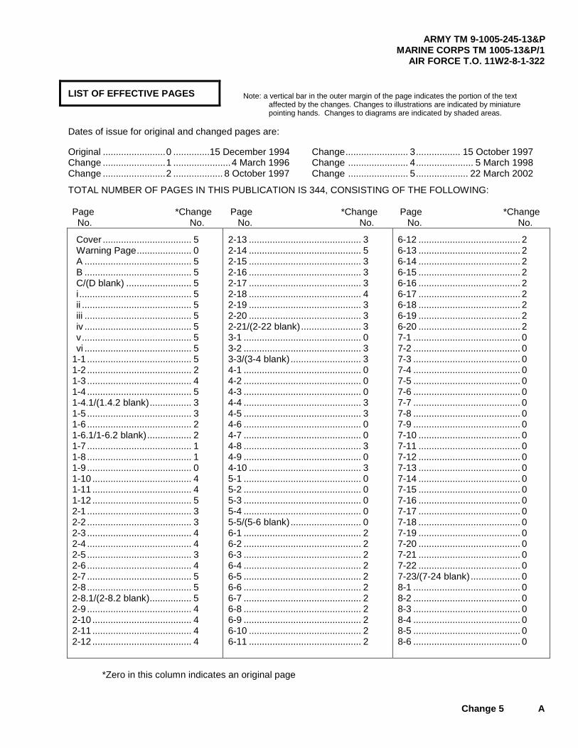
LIST OF EFFECTIVE PAGES
Dates of issue for original and changed pages are:
Original ........................0 ..............15 December 1994 Change ........................1 ......................4 March 1996 Change ........................2 ................... 8 October 1997
Change........................ 3................. 15 October 1997 Change ....................... 4...................... 5 March 1998 Change ....................... 5.................... 22 March 2002
TOTAL NUMBER OF PAGES IN THIS PUBLICATION IS 344, CONSISTING OF THE FOLLOWING: Page *Change Page *Change Page *Change No. No. No. No. No. No.
Cover .................................. 5 Warning Page..................... 0 A ......................................... 5 B ......................................... 5 C/(D blank) ......................... 5 i ........................................... 5 ii .......................................... 5 iii ......................................... 5 iv ......................................... 5 v.......................................... 5 vi ......................................... 5
1-1 ........................................ 5 1-2 ........................................ 2 1-3 ........................................ 4 1-4 ........................................ 5 1-4.1/(1.4.2 blank)................ 3 1-5 ........................................ 3 1-6 ........................................ 2 1-6.1/1-6.2 blank)................. 2 1-7 ........................................ 1 1-8 ........................................ 1 1-9 ........................................ 0 1-10 ...................................... 4 1-11 ...................................... 4 1-12 ...................................... 5 2-1 ........................................ 3 2-2 ........................................ 3 2-3 ........................................ 4 2-4 ........................................ 4 2-5 ........................................ 3 2-6 ........................................ 4 2-7 ........................................ 5 2-8 ........................................ 5 2-8.1/(2-8.2 blank)................ 5 2-9 ........................................ 4 2-10 ...................................... 4 2-11 ...................................... 4 2-12 ...................................... 4
2-13 ........................................... 3 2-14 ........................................... 5 2-15 ........................................... 3 2-16 ........................................... 3 2-17 ........................................... 3 2-18 ........................................... 4 2-19 ........................................... 3 2-20 ........................................... 3 2-21/(2-22 blank)....................... 3 3-1 ............................................. 0 3-2 ............................................. 3 3-3/(3-4 blank)........................... 3 4-1 ............................................. 0 4-2 ............................................. 0 4-3 ............................................. 0 4-4 ............................................. 3 4-5 ............................................. 3 4-6 ............................................. 0 4-7 ............................................. 0 4-8 ............................................. 3 4-9 ............................................. 0 4-10 ........................................... 3 5-1 ............................................. 0 5-2 ............................................. 0 5-3 ............................................. 0 5-4 ............................................. 0 5-5/(5-6 blank)........................... 0 6-1 ............................................. 2 6-2 ............................................. 2 6-3 ............................................. 2 6-4 ............................................. 2 6-5 ............................................. 2 6-6 ............................................. 2 6-7 ............................................. 2 6-8 ............................................. 2 6-9 ............................................. 2 6-10 ........................................... 2 6-11 ........................................... 2
6-12 ....................................... 2 6-13 ....................................... 2 6-14 ....................................... 2 6-15 ....................................... 2 6-16 ....................................... 2 6-17 ....................................... 2 6-18 ....................................... 2 6-19 ....................................... 2 6-20 ....................................... 2 7-1 ......................................... 0 7-2 ......................................... 0 7-3 ......................................... 0 7-4 ......................................... 0 7-5 ......................................... 0 7-6 ......................................... 0 7-7 ......................................... 0 7-8 ......................................... 0 7-9 ......................................... 0 7-10 ....................................... 0 7-11 ....................................... 0 7-12 ....................................... 0 7-13 ....................................... 0 7-14 ....................................... 0 7-15 ....................................... 0 7-16 ....................................... 0 7-17 ....................................... 0 7-18 ....................................... 0 7-19 ....................................... 0 7-20 ....................................... 0 7-21 ....................................... 0 7-22 ....................................... 0 7-23/(7-24 blank)................... 0 8-1 ......................................... 0 8-2 ......................................... 0 8-3 ......................................... 0 8-4 ......................................... 0 8-5 ......................................... 0 8-6 ......................................... 0
*Zero in this column indicates an original page
Note: a vertical bar in the outer margin of the page indicates the portion of the text affected by the changes. Changes to illustrations are indicated by miniature pointing hands. Changes to diagrams are indicated by shaded areas.

ARMY TM 9-1005-245-13&P MARINE CORPS TM 1005-13&P/1 AIR FORCE T.O. 11W2-8-1-322
B Change 5
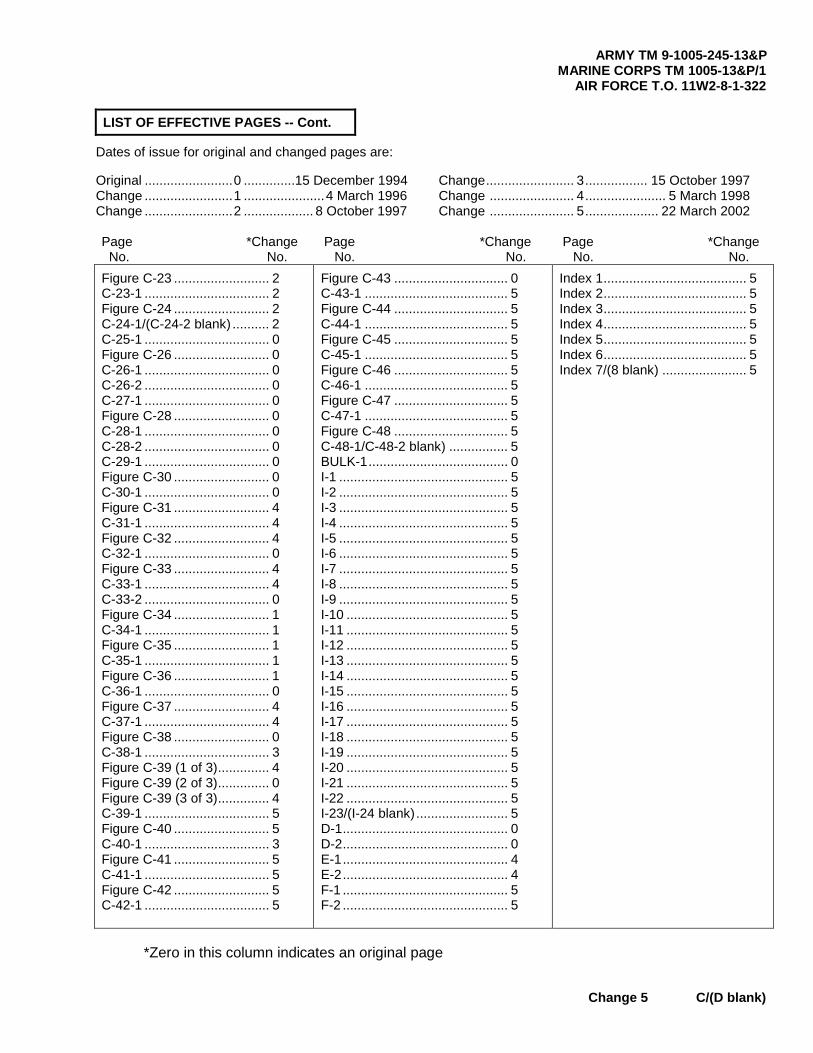
LIST OF EFFECTIVE PAGES -- Cont.
Dates of issue for original and changed pages are:
Original ........................0 ............. 15 December 1994 Change ........................1 ......................4 March 1996 Change ........................2 ................... 8 October 1997
Change........................ 3................. 15 October 1997 Change ....................... 4...................... 5 March 1998 Change ....................... 5.................... 22 March 2002
Page *Change Page *Change Page *Change No. No. No. No. No. No. 8-7 ........................................ 0 8-8 ........................................ 0 8-9 ........................................ 0 8-10 ...................................... 0 8-11/(8-12 blank).................. 0 9-1 ........................................ 2 9-2 ........................................ 2 9-3 ........................................ 2 9-4 ........................................ 2 9-5 ........................................ 2 9-6 ........................................ 2 9-7/(9-8 blank)...................... 2 10-1 ...................................... 0 10-2 ...................................... 0 10-3 ...................................... 0 10-4 ...................................... 0 10-5/(10-6 blank).................. 0 11-1 ...................................... 0 11-2 ...................................... 0 11-3 ...................................... 0 11-4 ...................................... 0 11-5 ...................................... 0 11-6 ...................................... 0 11-7 ...................................... 0 11-8 ...................................... 0 12-1 ...................................... 0 12-2 ...................................... 0 12-3/(12-4 blank).................. 0 13-1/(13-2 blank).................. 1 14-1 ...................................... 4 14-2 ...................................... 4 14-3 ...................................... 1 14-4 ...................................... 4 14-5 ...................................... 1 14-6 ...................................... 4 14-7 ...................................... 4 14-8 ...................................... 1 14-9 ...................................... 4 14-10 .................................... 4 14-11 .................................... 4
14-12 ......................................... 1 14-13 ......................................... 4 14-14 ......................................... 4 14-15 ......................................... 4 14-16 ......................................... 4 15-1 ........................................... 3 15-2 ........................................... 3 15-3 ........................................... 4 15-4 ........................................... 3 15-5 ........................................... 3 15-6 ........................................... 3 15-7/(15-8 blank) ....................... 3 16-1 ........................................... 5 16-2 ........................................... 5 16-3 ........................................... 5 16-4 ........................................... 5 16-4.1 ........................................ 5 16-4.2 ........................................ 5 16-5/(16-6 blank) ....................... 5 A-1............................................. 5 A-2............................................. 3 B-1............................................. 1 B-2............................................. 0 B-3............................................. 2 B-4............................................. 2 B-5............................................. 2 B-6............................................. 2 B-7............................................. 3 B-8............................................. 4 B-9/(B-10 blank) ........................ 5 C-1............................................. 1 C-2............................................. 0 C-3............................................. 0 C-4............................................. 0 C-5............................................. 0 C-6............................................. 0 C-7............................................. 5 C-8............................................. 2
C-1-1 ..................................... 2 Figure C-2 ............................. 2 C-2-1 ..................................... 2 Figure C-3 ............................. 2 C-3-1 ..................................... 2 Figure C-4 ............................. 2 C-4-1 ..................................... 2 Figure C-5 ............................. 2 C-5-1 ..................................... 2 Figure C-6 ............................. 2 C-6-1 ..................................... 2 C-7-1 ..................................... 2 C-8-1 ..................................... 0 C-9-1 ..................................... 0 Figure C-10 ........................... 0 C-10-1 ................................... 0 C-10-2 ................................... 0 Figure C-11 ........................... 0 C-11-1 ................................... 0 Figure C-12 ........................... 0 C-12-1 ................................... 0 Figure C-13 ........................... 0 C-13-1 ................................... 0 Figure C-14 ........................... 0 C-14-1 ................................... 0 C-14-2 ................................... 0 Figure C-15 ........................... 0 C-15-1 ................................... 0 C-16-1 ................................... 0 C-17-1 ................................... 0 Figure C-18 ........................... 0 C-18-1 ................................... 0 Figure C-19 ........................... 0 C-19-1 ................................... 0 Figure C-20 ........................... 0 C-20-1 ................................... 0 C-20-2 ................................... 0 Figure C-21 ........................... 0 C-21-1 ................................... 0 C-22-1 ................................... 2
*Zero in this column indicates an original page
ARMY TM 9-1005-245-13&P MARINE CORPS TM 1005-13&P/1
AIR FORCE T.O. 11W2-8-1-322
Change 5 C/(D blank)
LIST OF EFFECTIVE PAGES -- Cont.
Dates of issue for original and changed pages are:
Original ........................0 ..............15 December 1994 Change ........................1 ......................4 March 1996 Change ........................2 ................... 8 October 1997
Change........................ 3................. 15 October 1997 Change ....................... 4...................... 5 March 1998 Change ....................... 5.................... 22 March 2002
Page *Change Page *Change Page *Change No. No. No. No. No. No. Figure C-23 .......................... 2 C-23-1 .................................. 2 Figure C-24 .......................... 2 C-24-1/(C-24-2 blank) .......... 2 C-25-1 .................................. 0 Figure C-26 .......................... 0 C-26-1 .................................. 0 C-26-2 .................................. 0 C-27-1 .................................. 0 Figure C-28 .......................... 0 C-28-1 .................................. 0 C-28-2 .................................. 0 C-29-1 .................................. 0 Figure C-30 .......................... 0 C-30-1 .................................. 0 Figure C-31 .......................... 4 C-31-1 .................................. 4 Figure C-32 .......................... 4 C-32-1 .................................. 0 Figure C-33 .......................... 4 C-33-1 .................................. 4 C-33-2 .................................. 0 Figure C-34 .......................... 1 C-34-1 .................................. 1 Figure C-35 .......................... 1 C-35-1 .................................. 1 Figure C-36 .......................... 1 C-36-1 .................................. 0 Figure C-37 .......................... 4 C-37-1 .................................. 4 Figure C-38 .......................... 0 C-38-1 .................................. 3 Figure C-39 (1 of 3).............. 4 Figure C-39 (2 of 3).............. 0 Figure C-39 (3 of 3).............. 4 C-39-1 .................................. 5 Figure C-40 .......................... 5 C-40-1 .................................. 3 Figure C-41 .......................... 5 C-41-1 .................................. 5 Figure C-42 .......................... 5 C-42-1 .................................. 5
Figure C-43 ............................... 0 C-43-1 ....................................... 5 Figure C-44 ............................... 5 C-44-1 ....................................... 5 Figure C-45 ............................... 5 C-45-1 ....................................... 5 Figure C-46 ............................... 5 C-46-1 ....................................... 5 Figure C-47 ............................... 5 C-47-1 ....................................... 5 Figure C-48 ............................... 5 C-48-1/C-48-2 blank) ................ 5 BULK-1...................................... 0 I-1 .............................................. 5 I-2 .............................................. 5 I-3 .............................................. 5 I-4 .............................................. 5 I-5 .............................................. 5 I-6 .............................................. 5 I-7 .............................................. 5 I-8 .............................................. 5 I-9 .............................................. 5 I-10 ............................................ 5 I-11 ............................................ 5 I-12 ............................................ 5 I-13 ............................................ 5 I-14 ............................................ 5 I-15 ............................................ 5 I-16 ............................................ 5 I-17 ............................................ 5 I-18 ............................................ 5 I-19 ............................................ 5 I-20 ............................................ 5 I-21 ............................................ 5 I-22 ............................................ 5 I-23/(I-24 blank)......................... 5 D-1............................................. 0 D-2............................................. 0 E-1............................................. 4 E-2............................................. 4 F-1 ............................................. 5 F-2 ............................................. 5
Index 1....................................... 5 Index 2....................................... 5 Index 3....................................... 5 Index 4....................................... 5 Index 5....................................... 5 Index 6....................................... 5 Index 7/(8 blank) ....................... 5
*Zero in this column indicates an original page


ARMY TM 9-1005-245-13&P MARINE CORPS TM 1005-13&P/1
AIR FORCE T.O. 11W2-8-1-322
Change 5 i
TECHNICAL MANUAL HEADQUARTERS ARMY No. 9-1005-245-13&P DEPARTMENT OF THE ARMY MARINE CORPS No. 1005-13&P/1 U.S. MARINE CORPS AIR FORCE No. 11W2-8-1-322 U.S. AIR FORCE
Washington, DC., 15 December 1994
Operator's, Unit, and Direct Support Maintenance Manual with Repair Parts and Special Tools List (RPSTL)
for Machine Gun Mounts and Combinations
for Tactical/Armored Vehicles and Ground Mounting M122 Machine Gun Tripod Mount (1005-00-710-5599) (EIC: 4EF)
M122A1 Machine Gun Tripod Mount (1005-01-433-1617) M3 Tripod Mount (1005-00-322-9716) (EIC: 4EA)
M66 Machine Gun Mount Ring (1005-00-701-2810) M240E1 Flexible Machine Gun Mount (1005-01-254-0332)
M142 Machine Gun Mount (1005-00-854-4463) 6650 .50 Cal Machine Gun Mount (1005-00-704-6650)
M548 Machine Gun Mount (1005-00-783-5494) MK93 MOD 0 Machine Gun Mount (USMC Only) (1005-01-383-2949)
MK93 MOD 1 Machine Gun Mount (1005-01-383-2757) M6 Machine Gun Pedestal Mount (1005-01-411-6341)
M197 Machine Gun Mount (1005-01-413-4098)
REPORTING ERRORS AND RECOMMENDING IMPROVEMENTS You can help improve this publication. If you find any mistakes or if you know of a way to improve the procedures, please let us know. Submit your DA Form 2028 (Recommended Changes to Equipment Technical Publications ), through the Internet, on the Army Electronic Product Support (AEPS) website. The Internet address is http://aeps.ria.army.mil. If you need a password, scroll down and click on “ACCESS REQUEST FORM”. The DA Form 2028 is located in the ONLINE FORMS PROCESSING section of the AEPS. Fill out the form and click on SUBMIT. Using this form on the AEPS will enable us to respond quicker to your comments and better manage the DA Form 2028 program. You may also mail, fax or E-mail your letter or DA Form 2028 direct to: AMSTA-LC-CI Tech Pubs, TACOM-RI, 1 Rock Island Arsenal, Rock Island, IL 61299-7630. The email address is [email protected]. The fax number is DSN 793-0726 or Commercial (309) 782-0726.
DISTRIBUTION STATEMENT C. Distribution authorized to U.S. Government agencies and their contractors. This publication is required for administration and operational purposes, as determined 14 April 1987. Other requests for this document shall be referred to: ATTN: AMSTA-LC-CIP-WT, TACOM-Rock Island, 1 Rock Island Arsenal, Rock Island, IL 61299-7630. AIR FORCE ONLY: Requests for this document shall be referred to Warner Robins ALC/MMDET, Robins AFB, GA 31098-5609. DESTRUCTION NOTICE—For unclassified, limited documents, destroy by any method that will prevent disclosure of contents or reconstruction of the document.
*This manual supersedes TM 9-1005-245-14, dated 7 February 1973, including all changes.
ARMY TM 9-1005-245-13&P MARINE CORPS TM 1005-13&P/1 AIR FORCE T.O. 11W2-8-1-322
ii Change 5
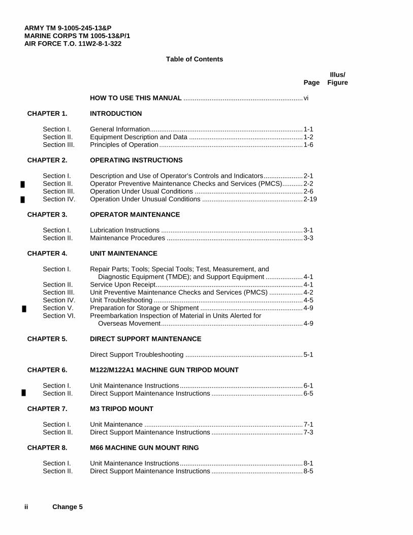
Table of Contents
Illus/ Page Figure HOW TO USE THIS MANUAL ................................................................ vi CHAPTER 1. INTRODUCTION Section I. General Information..................................................................................1-1 Section II. Equipment Description and Data .............................................................1-2 Section III. Principles of Operation .............................................................................1-6 CHAPTER 2. OPERATING INSTRUCTIONS Section I. Description and Use of Operator’s Controls and Indicators.....................2-1 Section II. Operator Preventive Maintenance Checks and Services (PMCS)...........2-2 Section III. Operation Under Usual Conditions ..........................................................2-6 Section IV. Operation Under Unusual Conditions ......................................................2-19 CHAPTER 3. OPERATOR MAINTENANCE Section I. Lubrication Instructions ............................................................................3-1 Section II. Maintenance Procedures .........................................................................3-3 CHAPTER 4. UNIT MAINTENANCE Section I. Repair Parts; Tools; Special Tools; Test, Measurement, and
Diagnostic Equipment (TMDE); and Support Equipment ....................4-1 Section II. Service Upon Receipt...............................................................................4-1 Section III. Unit Preventive Maintenance Checks and Services (PMCS) ..................4-2 Section IV. Unit Troubleshooting ................................................................................4-5 Section V. Preparation for Storage or Shipment .......................................................4-9 Section VI. Preembarkation Inspection of Material in Units Alerted for
Overseas Movement............................................................................4-9 CHAPTER 5. DIRECT SUPPORT MAINTENANCE Direct Support Troubleshooting ...............................................................5-1 CHAPTER 6. M122/M122A1 MACHINE GUN TRIPOD MOUNT Section I. Unit Maintenance Instructions..................................................................6-1 Section II. Direct Support Maintenance Instructions .................................................6-5 CHAPTER 7. M3 TRIPOD MOUNT Section I. Unit Maintenance .....................................................................................7-1 Section II. Direct Support Maintenance Instructions .................................................7-3 CHAPTER 8. M66 MACHINE GUN MOUNT RING Section I. Unit Maintenance Instructions..................................................................8-1 Section II. Direct Support Maintenance Instructions .................................................8-5

ARMY TM 9-1005-245-13&P MARINE CORPS TM 1005-13&P/1
AIR FORCE T.O. 11W2-8-1-322
Change 5 iii
Table of Contents (cont)
Illus/ Page Figure CHAPTER 9. M240E1 FLEXIBLE MACHINE GUN MOUNT AND
MOUNT ASSEMBLY FOR M122 TRIPOD MOUNT AND M240G MACHINE GUN
Section I. Unit Maintenance Instructions.................................................................. 9-1 Section II. Direct Support Maintenance Instructions................................................. 9-3 CHAPTER 10. M142 MACHINE GUN MOUNT Section I. Unit Maintenance Instructions.................................................................. 10-1 Section II. Direct Support Maintenance Instructions................................................. 10-2 CHAPTER 11. 6650 .50 CAL MACHINE MOUNT Section I. Unit Maintenance Instructions.................................................................. 11-1 Section II. Direct Support Maintenance Instructions................................................. 11-2 CHAPTER 12. M548 MACHINE GUN MOUNT Section I. Unit Maintenance Instructions.................................................................. 12-1 Section II. Direction Support Maintenance Instructions ............................................ 12-2 CHAPTER 13. MK93 MOD 0 MACHINE GUN MOUNT (U.S. MARINE CORPS ONLY)................................................................ 13-1 CHAPTER 14. MK93 MOD 1 MACHINE GUN MOUNT Section I. Unit Maintenance Instructions.................................................................. 14-1 Section II. Direct Support Maintenance Instructions................................................. 14-7 CHAPTER 15. M6 MACHINE GUN PEDESTAL MOUNT Section I. Unit Maintenance Instructions.................................................................. 15-1 Section II. Direct Support Maintenance Instructions................................................. 15-7 CHAPTER 16. M197 MACHINE GUN MOUNT Section I. Unit Maintenance Instructions.................................................................. 16-1 Section II. Direct Support Maintenance Instructions................................................. 16-5 APPENDIX A. REFERENCES......................................................................................... A-1 APPENDIX B. MAINTENANCE ALLOCATION CHART (MAC) Section I. Introduction .............................................................................................. B-1 Section II. Maintenance Allocation Chart for Gun Mounts ........................................ B-4 Section III. Tool and Test Equipment Requirements for Gun Mounts ....................... B-9 Section IV. Remarks................................................................................................... B-9

ARMY TM 9-1005-245-13&P MARINE CORPS TM 1005-13&P/1 AIR FORCE T.O. 11W2-8-1-322
iv Change 5
Table of Contents (cont)
Illus/ Page Figure APPENDIX C. UNIT AND DIRECT SUPPORT MAINTENANCE REPAIR PARTS AND SPECIAL TOOLS LIST Section I. Introduction .............................................................................................. C-1 Section II. Repair Parts List ...................................................................................... C-1-1 Group 00 M122 Machine Gun Tripod Mount, 7790723 and M1221A1 Machine Gun Tripod Mount, 12976949 (Assembled View) .... C-1-1 C-1 Group 00 M122 Machine Gun Tripod Mount, 7790723 and M122A1 Machine Gun Tripod Mount, 12976949..................................... C-2-1 C-2 Group 02 Tripod Leg Assembly, 7790948 ............................................................... C-3-1 C-3 Group 01 Elevating and Traversing Mechanism Assembly (Traversing and Clamping Unit), 7791119 ......................................................................... C-4-1 C-4 Group 01 Elevating and Traversing Mechanism Assembly (Elevating Unit), 7791119 ........................................................................ C-5-1 C-5 Group 03 Pintle, Mount, 11010408.......................................................................... C-6-1 C-6 Group 0202 Pintle Lock Assembly, 6108986............................................................... C-7-1 C-7 Group 00 M3 Machine Gun Tripod Mount, 8403398 (Assembled View) ................. C-8-1 C-8 Group 00 M3 Machine Gun Tripod Mount, 8403398 ............................................... C-9-1 C-9 Group 00 M3 Machine Gun Tripod Mount, 8403398 and Group 01 Bearing Assembly Head, 8448211 and Group 02 Machine Bolt, 6108395 ............................................................................ C-10-1 C-10 Group 03 Tripod Mount Leg, 6507137 (Left Rear) .................................................. C-11-1 C-11 Group 04 Tripod Mount Leg, 5559423 (Front)......................................................... C-12-1 C-12 Group 05 Tripod Mount Leg, 6507136 (Right Rear) ................................................ C-13-1 C-13 Group 06 Elevation Mechanism (Traversing and Clamping Unit), 5574621 ........... C-14-1 C-14 Group 06 Elevation Mechanism (Lower and Upper Elevation Unit),5574621 ......... C-15-1 C-15 Group 07 Pintle Mount Latch, 6108402 ................................................................... C-16-1 C-16 Group 00 M66 Machine Gun Mount Ring, 7102810 (Assembled View).................. C-17-1 C-17 Group 00 M66 Machine Gun Mount Ring, 7102810 ................................................ C-18-1 C-18 Group 01 Ring Assembly, 7012727 and Group 0101 Ring Assembly, 7012725......................................................................... C-19-1 C-19 Group 01 Ring Assembly, 7012727 and Group 0102 Ring, 7070704.......................................................................................... C-20-1 C-20 Group 0103 Ring Brake, 7012801 ............................................................................... C-21-1 C-21

ARMY TM 9-1005-245-13&P MARINE CORPS TM 1005-13&P/1
AIR FORCE T.O. 11W2-8-1-322
Change 5 v
Table of Contents (cont)
Illus/ Page Figure Group 00 M240E1 Flexible Mount Assembly, 12597090 (Assembled View)
and Flexible Mount Assembly, 12976940....................................................... C-22-1 C-22 Group 00 M240E1 Flexible Mount Assembly, 12597090
and Flexible Mount Assembly, 12976940....................................................... C-23-1 C-23 Group 01 Upper Cradle Assembly, 12597091 ........................................................ C-24-1 C-24 Group 00 M142 Machine Gun Mount, 10900945 (Assembled View) ..................... C-25-1 C-25 Group 00 M142 Machine Gun Mount, 10900945
and Group 01 Platform Assembly, 10900947................................................................. C-26-1 C-26 Group 00 6650 .50 Cal Machine Gun Mount, 7046650 (Assembled View) ............ C-27-1 C-27 Group 00 6650 .50 Cal Machine Gun Mount, 7046650 .......................................... C-28-1 C-28 Group 00 M548 Machine Gun Mount, 11631740-2 (Assembled View) .................. C-29-1 C-29 Group 00 M548 Machine Gun Mount, 11631740-2 ................................................. (Legs and Attaching Hardware) .............................................................. C-30-1 C-30 Group 00 MK93 Mod 1 Machine Gun Mount, 6650717
and MK93 Mod 0 Machine Gun Mount, 6650450 (Assembled Views) ........... C-31-1 C-31 Group 00 MK93 Mod 0 Machine Gun Mount, 6650450
and Group 02 Yoke Assembly, 6650725 ....................................................................... C-32-1 C-32 Group 01 Carriage Assembly, 6650434
and Group 0101 Depression Stop Assembly, 6650651 ..................................................... C-33-1 C-33 Group 02 .50 Caliber Ammo Holder Assembly, 6650724 ....................................... C-34-1 C-34 Group 03 Bracket, Mounting, 12929150 ................................................................. C-35-1 C-35 Group 04 Catch Bag Assembly, 6650723 .............................................................. C-36-1 C-36
Group 05 Universal Pintle Adapter, 12012061
and Group 0501 Traverse Arm Assembly, 6650488
and Group 0502 Body Assembly, 12012062 ..................................................................... C-37-1 C-37 Group 00 M6 Machine Gun Pedestal Mount 12956270 (Assembled View) ........... C-38-1 C-38 Group 00 M6 Machine Gun Pedestal Mount 12956270 ......................................... C-39-1 C-39 Group 00 M197 Machine Gun Mount 12956264 (Assembled View) ...................... C-40-1 C-40 Group 00 M197 Machine Gun Mount 12956264 ..................................................... C-41-1 C-41
Group 01 Travel Lock Assembly 12956265-2 ........................................................ C-42-1 C-42 Group 02 Travel Lock Bracket Assembly 5830063 ................................................ C-43-1 C-43 Group 03 Pintle Adapter Assembly 5830131 .......................................................... C-44-1 C-44 Group 04 Mount Pintle 11010408............................................................................ C-45-1 C-45 Group 05 Mount Pintle Assembly 12986102 ........................................................... C-46-1 C-46 Group 06 Ammo Adapter Bracket Assembly and Deflector 12986106 ................... C-47-1 C-47 Group 07 M60 Gun Mount Adapter ......................................................................... C-48-1 C-48 Group 9999 Bulk Items ............................................................................................... Bulk-1

ARMY TM 9-1005-245-13&P MARINE CORPS TM 1005-13&P/1 AIR FORCE T.O. 11W2-8-1-322
vi Change 5
Table of Contents (cont)
Illus/ Page Figure
APPENDIX C. UNIT AND DIRECT SUPPORT MAINTENANCE REPAIR PARTS AND SPECIAL TOOLS LIST (RPSTL) (cont)
Section IV. Cross-Reference Indexes ....................................................................... I-1 Figure and item Number Index ............................................................... I-1 Part Number Index .................................................................................. I-11 National Stock Number Index ................................................................. I-20 APPENDIX D. BASIC ISSUE ITEMS Section I. Introduction ............................................................................................. D-1 Section II. Basic Issue Items List ............................................................................. D-2 APPENDIX E. EXPENDABLE AND DURABLE ITEMS LIST Section I Introduction ............................................................................................. E-1 Section II. Expendable and Durable Items List ........................................................ E-1 APPENDIX F. ADDITIONAL AUTHORIZATION LIST (AAL) Section I Introduction ............................................................................................. F-1 Section II. Additional Authorization List (AAL) ......................................................... F-2
HOW TO USE THIS MANUAL
This manual contains operator's, unit, and direct support maintenance procedures for the various gun mounts. Chapter 1 contains general information; equipment description and data; and principles of operation. Chapter 2 contains operating instructions and operator preventive maintenance checks and services (PMCS). Chapter 3 contains operator maintenance. Chapter 4 contains unit PMCS and troubleshooting. Chapter 5 contains direct support troubleshooting. Chapters 6 through 16 contain unit and direct support maintenance for the various gun mounts. Be sure to read and understand maintenance instructions before beginning any maintenance task.

ARMY TM 9-1005-245-13&P MARINE CORPS TM 1005-13&P/1
AIR FORCE T.O. 11W2-8-1-322
Change 5 1-1
CHAPTER 1
INTRODUCTION
Section I. GENERAL INFORMATION
1-1. SCOPE a. Type of Manual: Operator, Unit, and Direct Support Maintenance. b. Model Number and Equipment Name: Gun Mounts. 1-2. MAINTENANCE FORMS, RECORDS, AND REPORTS Department of the Army forms and procedures used for equipment maintenance will be those prescribed by DA PAM 738-750, The Army Maintenance Management System (TAMMS). Marine Corps personnel will use TM 4700-15/1, Equipment Record Procedures. 1-3. DESTRUCTION OF ARMY MATERIEL TO PREVENT ENEMY USE Refer to TM 750-244-6. 1-4. PREPARATION FOR STORAGE AND SHIPMENT Refer to paragraph 4-7. 1-5. OFFICIAL NOMENCLATURE, NAMES, AND DESIGNATIONS
NOMENCLATURE CROSS-REFERENCE LIST Common Name Official Nomenclature Equilibrator spring...................................................................... Torsion spiral spring Flexible wire............................................................................... Nonelectrical wire Helical torsion spring ................................................................ Torsion helical spring Mechanism assembly................................................................ Elevating and traversing mechanism Pintle lock cap ........................................................................... Pintle socket cap Quick release pin assembly ...................................................... Quick-release pin Remote control lever ................................................................. Manual control lever Retaining pin.............................................................................. Spring pin Roller bearing ............................................................................ Plain solid disk Seal............................................................................................ Mechanical felt Shock absorber mounting bracket............................................. Mounting bracket Traversing and elevating mechanism........................................ Elevating and traversing mechanism 1-6. REPORTING EQUIPMENT IMPROVEMENT RECOMMENDATIONS (EIR) If your gun mounts need improvement, let us know. Send us an EIR. You, the user, are the only one who can tell us what you don’t like about your equipment. Let us know why you don’t like the design or performance. Put it on an SF 368 (Product Quality Deficiency Report). Mail it to us at: ATTN: AMSTA-AR-QAW (C), TACOM-ARDEC, 1 Rock Island Arsenal, Rock Island, IL 61299-7300. We’ll send you a reply. Air Force users submit Materiel Deficiency Report (MDR) to: Dir Mat Mgt Robins AFB GA//MMQC// and Quality Deficiency report to: Dir Mat Mgt Robins AFB GA//MMQC// IAW Technical Order 00-35D-54, Technical Manual, USAF, Materiel Deficiency Reporting and Investigating System.
ARMY TM 9-1005-245-13&P MARINE CORPS TM 1005-13&P/1 AIR FORCE T.O. 11W2-8-1-322
1-2 Change 2
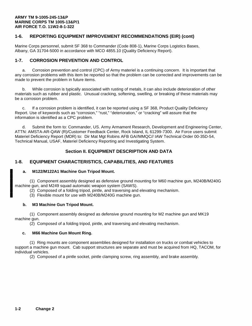
1-6. REPORTING EQUIPMENT IMPROVEMENT RECOMMENDATIONS (EIR) (cont) Marine Corps personnel, submit SF 368 to Commander (Code 808-1), Marine Corps Logistics Bases, Albany, GA 31704-5000 in accordance with MCO 4855.10 (Quality Deficiency Report). 1-7. CORROSION PREVENTION AND CONTROL a. Corrosion prevention and control (CPC) of Army materiel is a continuing concern. It is important that any corrosion problems with this item be reported so that the problem can be corrected and improvements can be made to prevent the problem in future items. b. While corrosion is typically associated with rusting of metals, it can also include deterioration of other materials such as rubber and plastic. Unusual cracking, softening, swelling, or breaking of these materials may be a corrosion problem. c. If a corrosion problem is identified, it can be reported using a SF 368, Product Quality Deficiency Report. Use of keywords such as “corrosion," “rust,” “deterioration,” or “cracking” will assure that the information is identified as a CPC problem. d. Submit the form to: Commander, US. Army Armament Research, Development and Engineering Center, ATTN: AMSTA-AR-QAW (R)/Customer Feedback Center, Rock Island, IL 61299-7300. Air Force users submit Materiel Deficiency Report (MDR) to: Dir Mat Mgt Robins AFB GA//MMQC// IAW Technical Order 00-35D-54, Technical Manual, USAF, Materiel Deficiency Reporting and Investigating System.
Section II. EQUIPMENT DESCRIPTION AND DATA 1-8. EQUIPMENT CHARACTERISTICS, CAPABILITIES, AND FEATURES a. M122/M122A1 Machine Gun Tripod Mount. (1) Component assembly designed as defensive ground mounting for M60 machine gun, M240B/M240G machine gun, and M249 squad automatic weapon system (SAWS). (2) Composed of a folding tripod, pintle, and traversing and elevating mechanism. (3) Flexible mount for use with M240B/M240G machine gun. b. M3 Machine Gun Tripod Mount. (1) Component assembly designed as defensive ground mounting for M2 machine gun and MK19 machine gun. (2) Composed of a folding tripod, pintle, and traversing and elevating mechanism. c. M66 Machine Gun Mount Ring. (1) Ring mounts are component assemblies designed for installation on trucks or combat vehicles to support a machine gun mount. Cab support structures are separate and must be acquired from HQ, TACOM, for individual vehicles. (2) Composed of a pintle socket, pintle clamping screw, ring assembly, and brake assembly.
ARMY TM 9-1005-245-13&P MARINE CORPS TM 1005-13&P/1
AIR FORCE T.O. 11W2-8-1-322
Change 4 1-3
d. M240E1 Flexible Machine Gun Mount. (1) Component assembly upon which a machine gun is directly mounted. (2) Composed of a cradle, pintle, ammunition box tray, and securing pins or latches. (3) Purpose is to hold a machine gun and ammunition and provide the capability to elevate, depress, and traverse the machine gun. (4) Should be installed into a pintle socket of a post, pedestal, ring, or cupola mount located on the vehicle.
e. M142 Machine Gun Mount. (1) Component assembly upon which a machine gun is directly mounted. (2) Composed of a cradle, pintle, ammunition box tray, and securing pins or latches. (3) Purpose is to hold a machine gun and ammunition and provide the capability to elevate, depress, and traverse the machine gun. (4) Should be installed into a pintle socket of a post, pedestal, ring, or cupola mount located on the vehicle.
f. 6650 .50 Cal Machine Gun Mount. (1) Component assembly upon which a machine gun is directly mounted. (2) Composed of a cradle, pintle, ammunition box tray, and securing pins or latches. (3) Purpose is to hold a machine gun and ammunition and provide the capability to elevate, depress, and traverse the machine gun. (4) Should be installed into a pintle socket of a post, pedestal, ring, or cupola mount located on the vehicle.
g. M548 Machine Gun Mount. (1) Component assembly designed as attaching device for mounting the M66 ring on the M548 carrier. (2) Composed of four support legs, two with spare ammo can holders, and attaching hardware for the carrier and the M66 ring.
h. MK93 MOD 0 Machine Gun Mount. (1) Component assembly designed as a defensive ground mount for the MK19 MOD 3 and M2 HB machine guns onto the M3 tripod. (2) Composed of a carriage assembly and yoke assembly.
i. MK93 MOD 1 Machine Gun Mount. (1) Component assembly designed as a defensive ground mount for the MK19 MOD 3 and M2 HB machine guns onto the HMMWV ring assembly. (2) Composed of MK93 MOD 0 machine gun mount, .50 caliber ammo holder assembly, mounting bracket, catch bag assembly, universal pintle adapter (UPA), and traverse and elevation mechanism (T&E).
ARMY TM 9-1005-245-13&P MARINE CORPS TM 1005-13&P/1 AIR FORCE T.O. 11W2-8-1-322
1-4 Change 5
j. M6 Machine Gun Pedestal Mount. (1) Component assembly designed as attaching device for mounting the M60, M249, and M240B machine gun on the M998/M1038/M1097 High Mobility Multipurpose Wheeled Vehicle (HMMWV) (Cargo/Troop Carrier series of HMMWVs). (2) Composed of a base plate, column assembly, and securing pins and latches. (3) Purpose is to hold an M60, M249, or M240B machine gun and ammunition and provide the capability to elevate, depress, and traverse the machine gun.
k. M197 Machine Gun Mount. (1) Component assembly designed to attach M60, M249 and M240B machine guns to the M6 gun pedestal or the M1025/M1026/M1114 High Mobility Multipurpose Wheeled Vehicle (HMMWV) (Armament Carrier). (2) Composed of travel lock assembly, travel lock bracket assembly, pintle adapter assembly, and a pintle (Mount Pintle or Pintle Assembly ( for the M249 and M240B only)). (3) The deflector kit is an additional item authorized for support of the M240B machine gun (see Additional Authorization List (AAL) appendix F). (4) Travel lock components and the M122 Pintle are additional items authorized for support of the M60 (see Additional Authorization List (AAL) appendix F). 1-9. LOCATION AND DESCRIPTION OF MAJOR COMPONENTS
Not applicable. 1-10. DIFFERENCES BETWEEN MODELS
a. Machine Gun Mounts. Machine gun mounts differ in a combination of the cradle assembly, pintle assembly, and ammunition tray. The cradle assemblies differ in design to fit and support the different models of machine guns and corresponding ammunition trays. Pintle assemblies differ in the type of mounting shank. Pintle assemblies with the straight type shank are designed to fit the pintle socket on ring mounts. b. Gun Mount Pedestals. Gun mount pedestals differ only in the design of the column and braces. Each gun mount pedestal is designed to be installed on a different model 1/4 ton truck. Pintle sockets on all gun mount pedestals are designed to fit machine gun mounts with the stepped pedestal shanks. c. Gun Mount Rings (1) Gun mount rings differ in design of the ring assemblies, pintle sockets, brake assemblies, and mounting supports. One type is a solid ring assembly and the other is a multiple ring assembly. The solid type ring has a carriage assembly with the pintle socket for the straight type machine gun mount and pintle shank. The brake is located on the carriage which travels around the ring. (2) The multiple type ring has a fixed ring for mounting to the vehicle, a revolving ring which carries the pintle socket for the stepped type machine gun mount and pintle shanks, a brake assembly, and a backrest assembly. The M66 ring is a multiple ring type mount. (3) The M548 carrier uses the M66 ring with attaching supports from the M548 mounting kit. The M66 ring is capable of mounting the M2 machine gun using the 6650 pintle mount or the M60 machine gun using the M142 pintle mount.

ARMY TM 9-1005-245-13&PMARINE CORPS TM 1005-13&P/1
AIR FORCET.O. 11W2-8-1-322
1-11. EQUIPMENT DATA
a. Machine Gun Mounts.
(1) M142 Machine Gun Mount (8426671)
Weight ...................................................................................................... 95.00 lb (43.09 kg)Elevation ................................................................................................... +80 degreesDepression ................................................................................................ 20 degreesTraverse ................................................................................................... 360 degrees
(2) M122/M122A1 Machine Gun Tripod Mount (7790723/12976949)
Weight - M122 .......................................................................................... 15.00 lb (6.80 kg)M122A1 ..................................................................................... 33.00 lb (14.97 kg)
Elevation - (free gun) ................................................................................ +21 degrees(locked (T&E)) ........................................................................ +19 degrees
Depression - (free gun) ............................................................................ .45 degrees(locked (T&E)) ..................................................................... .25 degrees
Traverse - (free gun) ................................................................................ 360 degrees(w/traversing bar) ................................................................... 50 degrees
(3) M3 Machine Gun Tripod Mount (8403398)
Weight ...................................................................................................... 44.00 lb (19.96 kg)Elevation ................................................................................................... +5.6 degreesDepression ............................................................................................... . 14 degreesTraverse- (free gun) ................................................................................. 360 degrees
(locked (T&E)) .......................................................................... 45 degrees
(4) M240E1 Flexible Machine Gun Mount (12597090)
Weight ...................................................................................................... 18.00 lb (8.16 kg)Elevation ................................................................................................... +60 degreesDepression ............................................................................................... .5 degreesTraverse ................................................................................................... 360 degrees
(5) M142 Machine Gun Mount (10900945)
Weight ...................................................................................................... 30.00 lb (13.61 kg)Elevation ................................................................................................... +80 degreesDepression ................................................................................................ 20 degreesTraverse ................................................................................................... 360 degrees
(6) 6650.50 Cal Machine Gun Mount (7046650)
Weight ...................................................................................................... 40. 00 1b (18.14 kg)Elevation ................................................................................................... +80 degreesDepression ................................................................................................ 20 degreesTraverse ................................................................................................... 360 degrees
Change 3 1-4.1/(1-4.2 blank)

ARMY TM 9-1005-245-13&PMARINE CORPS TM 1005-13&P/1
AIR FORCET.O. 11W2-8-1-322
(7) M548 Machine Gun Mount (11631740-2)
Weight ......................................................................................................... 324.00 lb (146.97 kg)Traverse ...................................................................................................... 360 degrees
(8) MK93 MOD 0 Machine Gun Mount (6650450) (USMC Only)
Weight ......................................................................................................... 30.00 lb (13.61 kg)Elevation ...................................................................................................... +67 degreesDepression ................................................................................................... 27 degrees
(9) MK93 MOD 1 Machine Gun Mount (6650717)
Weight ......................................................................................................... 135.00 lb (61.23 kg)Elevation ...................................................................................................... +67 degreesDepression ................................................................................................... 27 degrees
(110) M197 Machine Gun Mount (112956264)
Weight ......................................................................................................... 15.00 lb (6.80 kg)Traverse ...................................................................................................... 360 degrees
b. Gun Mount Ring.
M66 Machine Gun Mount Ring
Weight ......................................................................................................... 300.00 lb (136.08 kg)Traverse ...................................................................................................... 360 degrees
C. Gun Mount Pedestal.
M6 Machine Gun Pedestal Mount (12956270)
Weight ......................................................................................................... 104.00 lb (47.17 kg)Elevation ...................................................................................................... +34 degreesDepression ................................................................................................... 20 degreesTraverse ...................................................................................................... 360 degrees
Change 3 1-5
ARMY TM 9-1005-245-13&PMARINE CORPS TM 1005-13&P/1AIR FORCE T.O. 11W2-8-1-322
Section III. PRINCIPLESOF OPERATION
1-12. PRINCIPLES OF OPERATION
"
r
M122A1 M122FLEXIBLEMOUNT PINTLE
TRAVERSINGANDELEVATINGMECHANISM
HEAD/ASSEMBLY
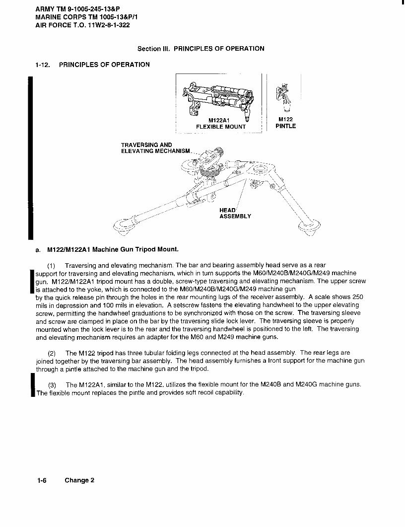
a. M122/M122A1 Machine Gun Tripod Mount.
(1) Traversing and elevating mechanism. The bar and bearing assembly head serve as a rearsupport for traversing and elevating mechanism, which in turn supports the M60/M240B/M240G/M249 machinegun. M1 22/Ml 22A1 tripod mount has a double, screw-type traversing and elevating mechanism. The upper screwis attached to the yoke, which is connected to the M60/M240B/M240G/M249 machine gunby the quick release pin through the holes in the rear mounting lugs of the receiver assembly. A scale shows 250mils in depression and 100 mils in elevation. A setscrew fastens the elevating handwheel to the upper elevatingscrew, permitting the handwheel graduations to be synchronized with those on the screw. The traversing sleeveand screw are clamped in place on the bar by the traversing slide lock lever. The traversing sleeve is properlymounted when the lock lever is to the rear and the traversing handwheel is positioned to the left. The traversingand elevating mechanism requires an adapter for the M60 and M249 machine guns.
(2) The M122 tripod has three tubular folding legs connected at the head assembly. The rear legs arejoined together by the traversing bar assembly. The head assembly furnishes a front support for the machine gunthrough a pintle attached to the machine gun and the tripod.
(3) The M122A1 similar to the M122, utilizes the flexible mount for the M240B and M240G machine guns.The flexible mount replaces the pintle and provides soft recoil capability.
1-6 Change 2

ARMY TM 9-1005-245-13&PMARINE CORPS TM 1005-13&P/1
AIR FORCE T.O. 11W2-8-1-322
1-12. PRINCIPLES OF OPERATION (cont)
TRAVERSINGANDELEVATING MECHANISM
0 FRONTLEG
BEARINGASSEMBLYHEAD
b. M3 Tripod Mount.
(1) Traversing and elevating mechanism. The traversing bar assembly serves as a rear support fortraversing and elevating mechanism, which in turn supports the M2 machine gun. The M3 tripod has adouble, screw-type traversing and elevating mechanism. The upper screw is attached to the yoke, which isconnected to the M2 machine gun by the guide release pin through the holes in the rear mounting lugs ofthe receiver assembly. A scale shows 250 mils in depression and 100 mils in elevation. A setscrew fastensthe elevating handwheel to the upper elevating screw, permitting the handwheel elevations to besynchronized with those on the screw. The traversing sleeve and screw are clamped in place on the bar bythe traversing slide lock lever. The traversing sleeve is properly mounted when the lock lever is to the rearand the traversing handwheel is positioned to the left.
(2) Front leg and bearing assembly head. The M3 tripod mount has three telescoping tubular legsconnected at the bearing assembly head. The rear legs are joined together and supported by the bar. Thebearing assembly head furnishes a front support for the mounted M2 machine gun which is supported bythe front leg.
TRAVERSELOCK
BEARINGASSEMBLY
UPPERRACEI
C. M66 Machine Gun Mount Ring.
Upper race rotates 360 degrees and contains a bearing assembly which receives pintles of theM142 or the 6650 mount. Has traverse lock which prevents the rotation of ring.
1-6.1/1-6.2 blank Change 2


ARMYTM 9-1005-245-13&PMARINECORPSTM 1005-13&P/1
AIR FORCET.O. 11W2-8-1-322
TRAVERSINGANDELEVATINGMECHANISM
FRONTLEG
BEARINGASSEMBLYHEAD
b. M3TripodMount.
(1) Traversingand elevatingmechanism.Thetraversingbarassemblyservesas a rearsupportfortraversing and elevating mechanism, which in turn supports the M2 machine gun. The M3 tripod mount has adouble, screw-type traversing and elevating mechanism. The upper screw is attached to the yoke, which isconnected to the M2 machine gun by the guide release pin through the holes in the rear mounting lugs of thereceiver assembly. A scale shows 250 mils in depression and 100 mils in elevation. A setscrew fastens theelevating handwheel to the upper elevating screw, permitting the handwheel graduations to be synchronized withthose on the screw. The traversing sleeve and screw are clamped in place on the bar by the traversing slide locklever. The traversing sleeve is properly mounted when the lock lever is to the rear and the traversing handwheelis positioned to the left.
(2) Front leg and bearing assembly head. The M3 tripod mount has three telescopic tubular legsconnected at the bearing assembly head. The rear legs are joined together and supported by the bar. Thebearing assembly head furnishes a front support for the mounted M2 machine gun which is supported by the frontleg.
0 TRAVERSELOCK
BEARINGASSEMBLY
UPPERRACE
c. M66 Machine Gun Mount Ring. Upper race rotates 360 degrees and contains a bearing assemblywhich receives pintles of the M142 or the 6650 mount. Has traverse lock which prevents the rotation of ring.
Change 1 1-7
ARMYTM 9-1005-245-13&PMARINECORPSTM 1005-13&P/1AIRFORCET.O. 11W2-8-1-322
1-12. PRINCIPLES OF OPERATION (cont)
PLATFORMPINTLE
AMMUNITIONBOXASSEMBLY
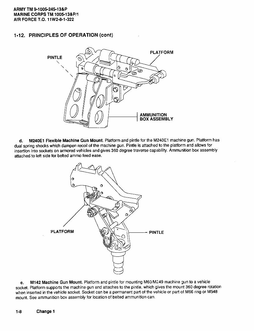
d. M240E1FlexibleMachineGunMount. Platformand pintlefor the M240E1machinegun.Platformhasdual spring shocks which dampen recoil of the machine gun. Pintle is attached to the platform and allows forinsertion into sockets on armored vehicles and gives 360 degree traverse capability. Ammunition box assemblyattached to left side for belted ammo feed ease.
PLATFORM PINTLE
e. M142 Machine Gun Mount. Platform and pintle for mounting M60/M249 machine gun to a vehiclesocket. Platform supports the machine gun and attaches to the pintle, which gives the mount 360 degree rotationwhen inserted in the vehicle socket. Socket can be a permanent part of the vehicle or part of M66 ring or M548mount. See ammunition box assembly for location of belted ammunition can.
1-8 Change 1

ARMY TM 9-1005-245-13&PMARINE CORPS TM 1005-13&P/1
AIR FORCE T.O. 11W2-8-1-322
AMMUNITIONCANSUPPORTASSEMBLY
PLATFORM
PINTLE
f6650.50 Cal Machine Gun Mount. Platform and pintle for mounting M2 machine gun to a vehicle
socket. Platform, which has a built-in recoil dampening device, supports the machine gun and attachesto the pintle, which gives the mount 360 degree rotation when inserted in the vehicle socket. Socket canbe a permanent part of the vehicle or part of M66 ring or M548 mount. Not to be used on the M4pedestal. Left side mounted ammo can support assembly for positioning belted ammo for feeding tomachine gun.
TRAVERSEBEARING ASSEMBLY LOCK
UPPER RACE
g. M548 Machine Gun Mount. Upper race rotates 360 degrees and contains a bearing assembly whichreceives pintles of the M142 or the 6650 mount. Has traverse lock which prevents the rotation of ring.Has four support legs for mounting to the M548 ammunition carrier.
1-9
ARMY TM 9-1005-245-13&PMARINE CORPS TM 1005-13&P/1AIR FORCE T.O. 11W2-8-1-322
1-12. PRINCIPLES OF OPERATION (cont)CARRIAGEASSEMBLY
YOKE ASSEMBLY
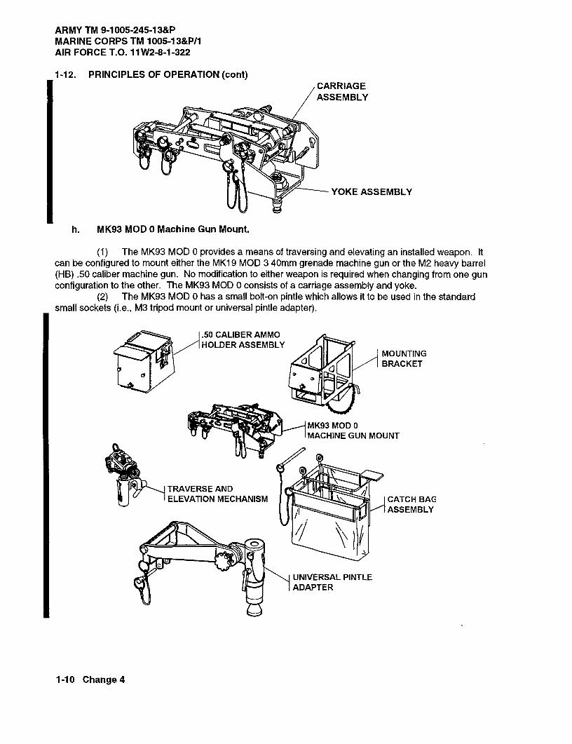
h. MK93 MOD 0 Machine Gun Mount.
(1) The MK93 MOD 0 provides a means of traversing and elevating an installed weapon. Itcan be configured to mount either the MK19 MOD 3 40mm grenade machine gun or the M2 heavy barrel(HB) .50 caliber machine gun. No modification to either weapon is required when changing from one gunconfiguration to the other. The MK93 MOD 0 consists of a carriage assembly and yoke.
(2) The MK93 MOD 0 has a small bolt-on pintle which allows it to be used in the standardsmall sockets (i.e., M3 tripod mount or universal pintle adapter).
.50 CALIBER AMMOHOLDER ASSEMBLY
MOUNTING
JBRACKET
MK93 MOD 0MACHINE GUN MOUNT
TRAVERSE ANDELEVATION MECHANISM CATCH BAC
ASSEMBLY
UNIVERSAL PINTLEADAPTER
1-10 Change 4

ARMY TM 9-1005-245-13&P MARINE CORPS TM 1005-13&P/1
AIR FORCE T.O. 11W2-8-1-322
Change 4 1-11
i. MK93 MOD 1 Machine Gun Mount. (1) The MK93 MOD 1 includes the MK93 MOD 0 machine gun mount, mounting bracket, .50 caliber ammo holder assembly, traverse and elevation mechanism, universal pintle adapter, catch bag assembly, and travel lock assembly. (2) The MK93 MOD 1 includes a spent cartridge case and link catch bag which will hold approximately 96 40mm or 400 .50 caliber spent cartridge cases and links. The catch bag has a side opening which allows for easy clean out without removing the entire assembly. The side opening may be left open during combat to prevent buildup of rounds under the mount which might prevent the gun from firing. (3) The MK93 MOD 1 has an attaching ammunition can support bracket which allows either the .50 caliber ammo holder assembly or the mounting bracket for 40mm ammunition to be mounted.
j. M6 Machine Gun Pedestal Mount. Universal pedestal mount whose operational effectiveness is dependent upon the weapon characteristics of the gun installed. However, the operation of the mount does have two specific characteristics, which are described below: (1) Internal Column Assembly. This assembly is raised or lowered manually by the operator and has provisions for locking the firing positions desired in predetermined increments. (2) Retaining Clamp Assembly. The retaining clamp assembly is located in the pintle socket of the internal column assembly. This assembly serves to lock the pintle adapter assembly of the M197 machine gun mount, used with the M6 machine gun pedestal mount, in the traverse position, and also prevents any upward movement which would allow disengagement from the pintle socket.

ARMY TM 9-1005-245-13&P MARINE CORPS TM 1005-13&P/1 AIR FORCE T.O. 11W2-8-1-322
1-12 Change 5
1-12. PRINCIPLES OF OPERATION (cont)
� � � � � � � � �� � � � �
� � � � � � � � � � � �
� � � � � � � � � � �� � �
� � � � � � � � � � � �
� � � � �� � � � �� � � � � � � �
� � � � � � � � � � �� � � � � � �� � � � � � � �
� � � � � �� � � �
� � � � � � � �
� � � � � � � � � � � � � � � � � � � � �� � � � � � ! " � � � � � � #
� � � � � � � � � �� � � � � � � � � � � � � � � �� � � � � � � � � �� � � � � � � � � � � �
k. M197 Machine Gun Mount. (1) The M197 machine gun mount includes a pintle adapter assembly and a mount pintle (for M249 and M240B only), travel lock bracket assembly, and travel lock assembly. (2) Can be used with M6 machine gun pedestal mount to mount and secure M249 and M240B machine gun with appropriate AAL items for the M60 and M240B.

ARMY TM 9-1005-245-13&PMARINE CORPS TM 1005-13&P/1
AIR FORCET.O. 11W2-8-1-322
CHAPTER 2
OPERATING INSTRUCTIONS
Section I. DESCRIPTION AND USE OFOPERATOR'S CONTROLS AND INDICATORS
2-1. GENERAL
This section describes the various controls and provides the operator/crew sufficient information to ensure theproper operation of the various mounts.
2-2. MACHINE GUN MOUNT CONTROLS
a. Machine gun mount controls are the items of the mounts necessary for the operator to install and secure amachine gun on the mount. Additional controls are such items as travel lock pins, which are installed through thepintle and the cradle to hold the machine gun and mount in a horizontal position. The travel lock pin must beremoved before the operator can elevate or depress the machine gun.
b. The 6650 .50 cal machine gun mount has, in addition to the travel lock pin, a travel lock tie bar which isspring-operated. The bar is attached to the pintle and connects to the lower portion of the cradle. The machine gunand cradle must be moved to maximum depression and the operator must lift up the spring-loaded tie bar. Thenthe operator must insert the end of the tie bar into the forward end of the channel located on the bottom of thecradle. Holding the tie bar in the channel, the operator must elevate the machine gun and cradle to a horizontalposition. To release the mount tie bar from the cradle, the operator must move the machine gun and cradle tomaximum depression. The spring-loaded tie bar will then disengage from the cradle and the mount will be free foroperation.
(1) This mount also has a spring-loaded equilibrator. The equilibrator, when adjusted properly, willcounter-balance the weight of the machine gun and a box of ammunition. It should hold the machine gun in ahorizontal position.
(2) The ammunition tray assembly has a cam lock, which holds the tray in position on the cradle.The pressure foot is to be set on top of the ammunition and will prevent the ammunition from failing out of the boxwhen the mount is at maximum elevation.
C. Machine gun mounts, for M60 machine guns, have a platform with a hook and a latch to retain themachine gun to the mount. The latch is spring-loaded and must be depressed when removing the machine gunfrom the mount.
d. The MK93 MOD 0/MK93 MOD 1 machine gun mount, when an M2 machine gun is installed, has thesafety and spade grips located on the machine gun backplate. When an MK19 MOD 3 machine gun is installed,the safety and spade grips are located on the machine gun.
e. When the M6 machine gun pedestal mount is mounted in M998/M1038/M1097 HMMWVs, an installedM60 or M249 machine gun will be secured with the travel lock assembly from the M197 gun mount.
Change 3 2-1

ARMY TM 9-1005-245-13&PMARINE CORPS TM 1005-13&P/1 AIR FORCET.O. 11W2-8-1-322
Section II. OPERATOR PREVENTIVE MAINTENANCECHECKS AND SERVICES (PMCS)
2-3. INTRODUCTION TO PMCS TABLE
a. General. YourPMCStable(table2-1)hasbeenprovidedsoyoucankeepyourequipmentingoodoperating condition and ready for its primary mission.
b. Warnings and cautions. Always observe the WARNINGS and CAUTIONS appearing in your PMCS tableBEFORE, DURING, and AFTER you operate the equipment. The warnings and cautions appear before certainprocedures. You must observe these WARNINGS and CAUTIONS to prevent serious injury to yourself and othersor to prevent your equipment from being damaged.
c. Explanation of table entries.
(1) Item Number column. Numbers in this column are for reference. When completing DA Form 2404,Equipment Inspection and Maintenance Worksheet, include the item number for the check/service indicating afault. Item numbers also appear in the order that you must do checks and services for the intervals listed.
(2) Interval column. This column tells you when you must do the procedure in the procedure column.BEFORE procedures must be done before you operate or use the equipment for its intended mission. DURINGprocedures must be done during the time you are operating or using the equipment for its intended mission.AFTER procedures must be done immediately after you have operated or used the equipment.
(3) Item to Check/Service column. This column provides the location and the item to be checked orserviced.
(4) Procedure column. This column gives the procedure you must do to check or service the item listedin the Item to Check/Service column to know if the equipment is ready or available for its intended mission or foroperation. You must do the procedure at the time stated in the interval column.
(5) Not Fully Mission Capable If: column. Information in this column tells you what faults will keep yourequipment from being capable of performing its primary mission. If you make check and service procedures thatshow faults listed in this column, do not operate the equipment. Follow standard operating procedures formaintaining the equipment or reporting equipment failure.
Table 2-1. OPERATOR PREVENTIVE MAINTENANCE CHECKS AND SERVICES
NOT FULLYITEM ITEM TO CHECK/ MISSION CAPABLENO. INTERVAL SERVICE PROCEDURE IF:
1 Before Machine Gun a. Check machine gun mounts; make Parts broken orMounts certain they are clean and lubricated. missing.
b. Check pins and chains; make sure they Pins broken orare properly installed and chains are missing.secure.
c. Check for proper installation of Parts broken orammunition tray. missing.
2-2 Change 3

ARMY TM 9-1005-245-13&PMARINE CORPS TM 1005-13&P/1
AIR FORCE T.O. 11W2-8-1-322
Table 2-1. OPERATOR PREVENTIVE MAINTENANCE CHECKS AND SERVICES (cont)
NOTFULLYITEM INTERVAL ITEM TO CHECK/ MISSION CAPABLENO. SERVICE PROCEDURE IF:
d. Check elevating, depression, and Mount does nottraversing. elevate, depress, or
traverse through fullrange.
e. Check condition and installation ofcover.
f. On MK93 MOD 1, check for tears in Casings bag torn,casings bag, bends in catch bag frame, catch bag frameand Velcro wear on casings bag. bent, or Velcro will
not close.Check for legibility of markings on Markings onadjustable arm and traverse bar of adjustable arm, oruniversal pintle adapter. traverse bar are
illegible.
2 Before Tripod Mounts a. Emplace tripod mount. Ensure legs are Inoperable legs.properly separated and make contact to Pintle lock isthe side of tripod head to ensure rigidity inoperative.of mount. Pintle must be secured totripod head by pintle lock assembly.
b. Check handwheels for binding and ease Broken, binding,of operation. Check for missing parts. worn, or missingCheck the scales for cleanness and parts.legibility.
3 Before Gun Mount Rings a. Check mounts; make certain they are Parts broken orclean and lubricated. missing.
b. Check operation of pintle clamping Screw missing orscrew; make certain it locks machine fails to lock pintlegun mount, preventing traversing. mount.
c. Check operation of brake assembly; Parts missing ormake certain it locks the traverse of the brake fails to lockcarriage or ring. carriage or ring.
d. Check nuts, bolts, pins, and screws; Parts broken ormake certain they are secure. missing.
e. Check condition and of cover.
4 Before Pedestal Mounts a. Check pedestal mounts; make certain Parts broken orthey are clean, lubricated, and free of missing.damage.
b. Check pins and chains; make certain Pins broken orthey are properly installed and chains missing.are secure.
Change 4 2-3

ARMY TM 9-1005-245-13&PMARINE CORPS TM 1005-13&P/1AIR FORCE T.O. 11W2-8-1-322
Table 2-1. OPERATOR PREVENTIVE MAINTENANCE CHECKS AND SERVICES (cont)
ITEM INTERVAL ITEM TO CHECK/NOT FULLY
MISSION CAPABLENO. SERVICE PROCEDURE IF:
4 Before Pedestal Mounts c. Check elevating, depression, and Mount does not(cont) (cont) (cont) traversing. elevate, depress, or
traverse through fullrange.
5 After Machine Gun a. Check machine gun mounts; make Parts broken orMounts certain they are clean and lubricated. missing
b. Check pins and chains; make certain Pins broken orthey are properly installed and chains missingare secure.
c. Check for proper installation of Parts broken orammunition tray. missing.
d. Check elevating, depression, and Mount does nottraversing. elevate, depress, or
traverse through fullrange.
e. Check condition and installation ofcover.
6 After Tripod Mount a. Check for missing, broken, or loose leg Missing, broken, orclamps. Check for missing, broken, or loose leg clamps.inoperative sleeve lock latch. Clean and Inoperative sleevelubricate tripod mount. Check pintle lock latch. Pintle willlock assembly. not secure to tripod
head.
b. Check quick release pin for burrs and Will not elevate orcorrosion. Check for missing parts. traverse.Check handwheels for ease ofoperation. Check traversing andelevating scales for legibility.
c. Clean and lubricate tripod, traversingand elevating mechanism assembly,and pintle assembly.
d. Inspect traversing bar assembly for Sleeve latch does nottightness when legs are extended. operate freely.Make sure sleeve latch operates freely. Traversing hand-Make sure traversing handwheels wheels do notoperate freely. Be sure all scale operate freely. Scalereadings are legible and zero indexes readings are illegibleline up (FM 23-67). or zero indexes do
not align.
2-4 Change 4

ARMY TM 9-1005-245-13&PMARINE CORPS TM 1005-13&P/1
AIR FORCE T.O. 11W2-8-1-322
Table 2-1. OPERATOR PREVENTIVE MAINTENANCE CHECKS AND SERVICES (cont)
NOTFULLYITEM INTERVAL ITEM TO CHECK/ MISSION CAPABLENO. SERVICE PROCEDURE IF:
7 After Gun Mount Rings a. Check mounts; make certain they are Parts broken orclean and lubricated. missing.
b. Check operation of pintle clamping Screw missing orscrew; make certain it locks machine fails to lock pintlegun mount, preventing traversing. mount.
c. Check operation of brake assembly; Parts missing ormake certain it locks the traverse of the brake fails to lockcarriage or ring. carriage or ring.
d. Check nuts, bolts, pins, and screws; Parts broken ormake certain they are secure. missing.
e. Check condition of cover.
8 After Pedestal Mounts a. Check pedestal mounts; make certain Parts broken orthey are clean, lubricated, and free of missing.damage.
b. Check pins and wire cords; make Pins broken orcertain they are properly installed and missing.wire cords are secure.
c. Check elevating, depression, and Mount does nottraversing. elevate, depress, or
traverse through fullrange.
9 After M197 Machinea. Clean all accessible surfaces with a dry
Gun Mountrag (item 8, appx E). Preserveunpainted metal with PL-S (item 7,appx E).
b. Check for defects including broken wire Parts broken orcords, damaged bracket, damaged missing.threads, or missing nuts, washers, orscrews.
10 After MK93 MOD 0 a. Check mount; make certain it is clean Parts broken orMachine Gun and properly lubricated. missing.Mount
b. Check elevating, depression, and Mount does nottraversing. elevate, traverse, or
depress through fullrange.
Change 3 2-5
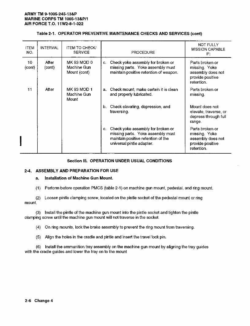
ARMY TM 9-1005-245-13&PMARINE CORPS TM 1005-13&P/1AIR FORCE T.O. 11W2-8-1-322
Table 2-1. OPERATOR PREVENTIVE MAINTENANCE CHECKS AND SERVICES (cont)
NOTFULLYITEM INTERVAL ITEM TO CHECK/ MISSION CAPABLENO. SERVICE PROCEDURE IF:
10 After MK93 MOD 0 c. Check yoke assembly for broken or Parts broken or(cont) (cont) Machine Gun missing parts. Yoke assembly must missing. Yoke
Mount (cont) maintain positive retention of weapon. assembly does notprovide positiveretention.
11 After MK93 MOD 1 a. Check mount; make certain it is clean Parts broken orMachine Gun and properly lubricated. missing.Mount
b. Check elevating, depression, and Mount does nottraversing. elevate, traverse, or
depress through fullrange.
c. Check yoke assembly for broken or Parts broken ormissing parts. Yoke assembly must missing. Yokemaintain positive retention of the assembly does notuniversal pintle adapter. provide positive
retention.
Section Ill. OPERATION UNDER USUAL CONDITIONS
2-4. ASSEMBLY AND PREPARATION FOR USE
a. Installation of Machine Gun Mount.
(1) Perform before operation PMCS (table 2-1) on machine gun mount, pedestal, and ring mount.
(2) Loosen pintle clamping screw, located on the pintle socket of the pedestal mount or ringmount.
(3) Install the pintle of the machine gun mount into the pintle socket and tighten the pintleclamping screw until the machine gun mount will not traverse in the socket.
(4) On ring mounts, lock the brake assembly to prevent the ring mount from traversing.
(5) Align the holes in the cradle and pintle and insert the travel lock pin.
(6) Install the ammunition tray assembly on the machine gun mount by aligning the tray guideswith the cradle guides and lower the tray on to the mount
2-6 Change 4

ARMY TM 9-1005-245-13&P MARINE CORPS TM 1005-13&P/1
AIR FORCE T.O. 11W2-8-1-322
Change 5 2-7
(7) Installation of M197 machine gun mount on:
NOTE � When installing the M197, Unit Maintenance support is required. � When used in conjunction with the M249 or M240B, use mount pintle, P/N 12986102 (5). � When used in conjunction with the M60, use mount pintle P/N 11010408 (6).
(a) M6 Machine Gun Pedestal Mount:
�
�
�
��
�
�
1 Loosen retaining clamp assembly (1) by turning handle on M6 machine gun pedestal mount (2) counterclockwise. 2 Install pintle adapter assembly (3) into M6 machine gun pedestal mount (2). 3 Turn handle of retaining clamp assembly (1) clockwise to lock pintle adapter assembly (3) in place. Pull up on pintle adapter assembly to ensure it is secure. 4 Remove quick release pin (4) from pintle adapter assembly (3). 5 Install mount pintle (5), or mount pintle (6) in pintle adapter assembly (3). 6 Insert quick release pin (4). 7 Twist and pull up on the installed mount pintle (5), or mount pintle (6). It should be locked into pintle adapter assembly (3), but should traverse freely left and right.
WARNING
For use with M240B when mounted on the M1025/M1026 armament carrier series, install deflector kit (see Additional Authorization List (AAL), appendix F) and ammo adapter bracket assembly and deflector. Use of deflector kit helps prevent hot brass from falling onto the driver.
NOTE
Maintenance procedures for the ammo adapter bracket assembly and deflector are found in TM 9-1005-313-23&P (M240B).

ARMY TM 9-1005-245-13&P MARINE CORPS TM 1005-13&P/1 AIR FORCE T.O. 11W2-8-1-322
2-8 Change 5
2-4. ASSEMBLY AND PREPARATION FOR USE (cont)
� � � � � �� � � � � � � � � � � � � �
� ��
� � � �
� �
� �� �
� �
8 Remove two machine bolts (7) and two lockwashers (8) and separate travel lock bracket assembly (9) into two halves (10). 9 Install two halves (10) of travel lock bracket assembly (9) on structural tube (11) with travel lock bracket assembly (9) holes facing rear of HMMWV. Secure by installing two lockwashers (8) and two machine bolts (7). 10 Remove self-locking nut (12), two flat washers (13), and hexagon head capscrew (14) from travel lock bracket (15). 11 Align mounting holes in travel lock bracket (15) with mounting holes in travel lock bracket assembly (9), and install two flat washers (13), hexagon head capscrew (14), and self-locking nut (12). (b) M1025/M1026/M1114 HMMWV: 1 Loosen four set screws on HMMWV pintle adapter (16). 2 Install pintle adapter assembly (17) and secure by tightening four set screws. 3 Install applicable mount pintle (18) P/N 11010408 or 12986102 and attach travel lock bracket (19) on HMMWV pintle adapter assembly (17) following steps (7) (a) 4 thru (7) (a) 11.
� �
�
� �
�
� � � � � � � �

ARMY TM 9-1005-245-13&P MARINE CORPS TM 1005-13&P/1
AIR FORCE T.O. 11W2-8-1-322
Change 5 2-8.1/(2-8.2 blank)
(c) Deflector Kit and Ammo Adapter Bracket Assembly and Deflector: 1 Install deflector plate (20) and secure to ammo adapter bracket assembly (21) with two cap screws (22) and two nuts (23).
NOTE Nuts (23) must be held within the ammo adapter bracket assembly (21) and deflector plate (20) weldment, while installing cap screws (22) to secure deflector plate (20).
� �
� �
� �
� �

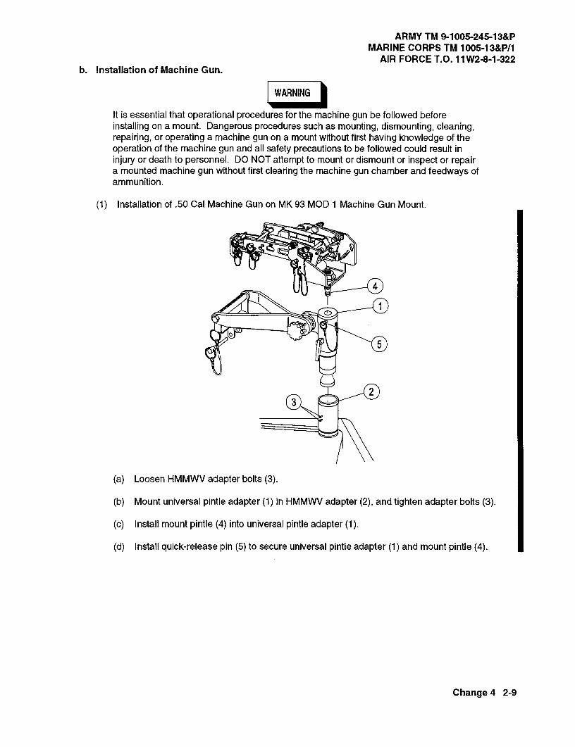
ARMY TM 9-1005-245-13&PMARINE CORPS TM 1005-13&P11
AIR FORCE T.O. 11W2-8-1-322b. Installation of Machine Gun.
IWARNING
It is essential that operational procedures for the machine gun be followed beforeinstalling on a mount. Dangerous procedures such as mounting, dismounting, cleaning,repairing, or operating a machine gun on a mount without first having knowledge of theoperation of the machine gun and all safety precautions to be followed could result ininjury or death to personnel. DO NOT attempt to mount or dismount or inspect or repaira mounted machine gun without first clearing the machine gun chamber and feedways ofammunition.
(1) Installation of .50 Cal Machine Gun on MK 93 MOD 1 Machine Gun Mount.
4
23
(a) Loosen HMMWV adapter bolts (3).
(b) Mount universal pintle adapter (1) in HMMWV adapter (2), and tighten adapter bolts (3).
(c) Install mount pintle (4) into universal pintle adapter (1).
(d) Install quick-release pin (5) to secure universal pintle adapter (1) and mount pintle (4).
Change 4 2-9

ARMY TM 9-1005-245-13&PMARINE CORPS TM 1005-13&P/1AIR FORCE T.O. 11W2-8-1-322
2-4 ASSEMBLY AND PREPARATION FOR USE (cont)
8 910 6
(e) Align thumbscrew (6) on ammo holder assembly (7) with corresponding bottom slot insideplate of carriage assembly (8). Push up and align studs with corresponding holes in sideplate downuntil studs stop. Tighten thumbscrew.
(f) Turn shock absorber assemblies (9) to upright position.
(g) Ensure rear slider assembly (10) is "up".
8
12
15
14 1
16
(h) Install catch bag assembly (11) from right side while pushing catch bag frame (12) forwardinto carriage assembly (8). Align catch bag assembly with holes in carriage assembly. Install quick-release pin (13) and seal Velcro.
2-10 Change 4
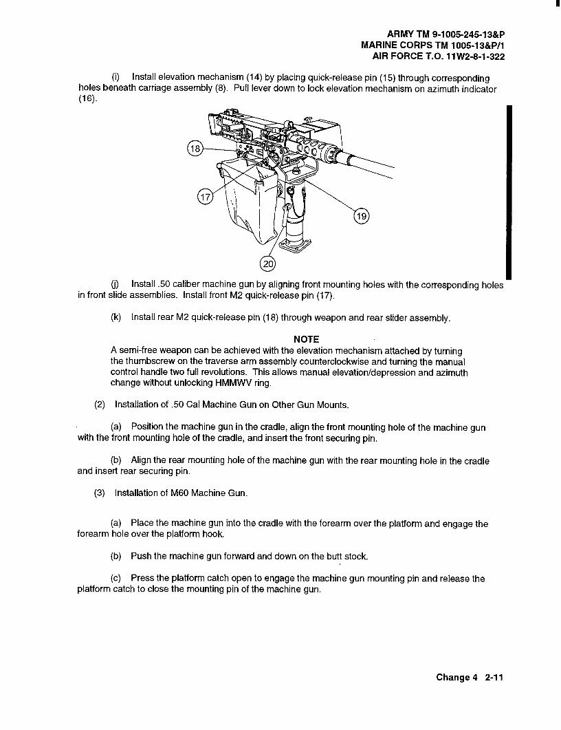
ARMY TM 9-1005-245-13&PMARINE CORPS TM 1005-13&P/1
AIR FORCE T.O. 11W2-8-1-322
(i) Install elevation mechanism (14) by placing quick-release pin (15) through correspondingholes beneath carriage assembly (8). Pull lever down to lock elevation mechanism on azimuth indicator(16).
18
17
20
Install .50 caliber machine gun by aligning front mounting holes with the corresponding holesin front slide assemblies. Install front M2 quick-release pin (17).
(k) Install rear M2 quick-release pin (18) through weapon and rear slider assembly.
NOTEA semi-free weapon can be achieved with the elevation mechanism attached by turningthe thumbscrew on the traverse arm assembly counterclockwise and turning the manualcontrol handle two full revolutions. This allows manual elevation/depression and azimuthchange without unlocking HMMWV ring.
(2) Installation of .50 Cal Machine Gun on Other Gun Mounts.
(a) Position the machine gun in the cradle, align the front mounting hole of the machine gunwith the front mounting hole of the cradle, and insert the front securing pin.
(b) Align the rear mounting hole of the machine gun with the rear mounting hole in the cradleand insert rear securing pin.
(3) Installation of M60 Machine Gun.
(a) Place the machine gun into the cradle with the forearm over the platform and engage theforearm hole over the platform hook.
(b) Push the machine gun forward and down on the butt stock.
(c) Press the platform catch open to engage the machine gun mounting pin and release theplatform catch to close the mounting pin of the machine gun.
Change 4 2-11

ARMY TM 9-1005-245-13&PMARINE CORPS TM 1005-13&P/1AIR FORCE T.O. 11W2-8-1-322
2-4. ASSEMBLY AND PREPARATION FOR USE (cont)
(4) Installation of MK19 Grenade Machine Gun on MK93 MOD 1 Machine Gun Mount.
4
23
(a) Loosen HMMWV adapter bolts (3).
(b) Mount universal pintle adapter (1) in HMMWV ring socket (2), and tighten adapter bolts (3).
(c) Install mount pintle (4) into universal pintle adapter (1).
(d) Install quick-release pin (5) to secure universal pintle adapter (1) and mount pintle (4).
8 910 6
7
(e) Align thumbscrew (5) on mounting bracket (7) with corresponding slot in slideplate ofcarriage assembly (8). Push up and align studs with corresponding holes in sideplate. Push down untilstuds stop. Tighten thumbscrew.
(f) Turn shock absorber assemblies (9) to downward position.
(g) Ensure rear slider assembly (10) is "down", rear .50 caliber pin assembly is installed throughthe bushing and stowage bracket, and detent balls are secure and clearly visible.
2-12 Change 4

ARMY TM 9-1005-245-13&P MARINE CORPS TM 1005-13&P/1
AIR FORCE T.O. 11W2-8-1-322
Change 3 2-13
(h) Install catch bag assembly (11) from right side while pushing catch bag frame (12) forward into carriage assembly (8). Align catch bag assembly with holes in carriage assembly. Install quick-release pin (13) and seal Velcro. (i) Install elevation mechanism (14) by placing quick-release pin (15) through corresponding holes beneath carriage assembly (8). Pull lever down to lock elevation mechanism on azimuth indicator (16). (j) Install MK19 grenade machine gun by sliding its locking channels into the forward mounting pins on carriage assembly. Ensure sear assembly aligns with upper rear holes in carriage assembly. (k) Install rear quick-release pin through the carriage assembly and sear.
NOTE A semi-free weapon can be achieved with the elevation mechanism attached by turning the thumbscrew on the traverse arm assembly counterclockwise and turning the manual control handle two full revolutions. This allows manual elevation/depression and azimuth change without unlocking HMMWV ring.
c. Installation of Ammunition and Box. (1) Installation of Ammunition Trays on .50 Cal Mounts. (a) Remove the cover from the ammunition box. (b) Lift and rotate the pressure straps. (c) Place the ammunition and box into the tray. (d) Lower the pressure traps to hold the ammunition in the ammunition box.

ARMY TM 9-1005-245-13&P MARINE CORPS TM 1005-13&P/1 AIR FORCE T.O. 11W2-8-1-322
2-14 Change 5
2-4. ASSEMBLY AND PREPARATION FOR USE (cont) (2) Installation of Ammunition Box Container Assembly on .50 Cal Machine Gun Mount. (a) Unlatch the door assembly. (b) Lift the pressure foot and cover assembly upward. (c) Place a box of ammunition with the cover removed into the tray. (d) Lower the cover assembly with pressure foot on the ammunition. (e) Close and latch the door. (3) Installation of Ammunition Tray on M60 Machine Gun Mounts. (a) Remove the box cover. (b) Place the box end under the tray hook. (c) Push the box downward on the tray, allowing the tray hook to engage over the end of the box. The hook retains the box in the tray.
d. Installation of M6 Machine Gun Pedestal Mount in M998/M1038/M1097 HMMWV (Cargo/Troop Carrier).
WARNING � The M6 Pedestal Mount is heavy. A minimum of two personnel are required to lift
and install the mount in the vehicle.
� When installing the M6 Pedestal Mount nuts and bolts under cargo bed ensure vehicle exhaust system is cool to the touch to prevent burns.
NOTE � When installing the M6, Unit Maintenance support is required.
� If your vehicle has threaded inserts welded under the cargo bed, perform steps (1) and (2). If your vehicle does not have threaded inserts, go to step (3). One assistant will be needed.
� Hardware removed in steps (1) thru (4) are components of the HMMWV and cannot be requisitioned separately using this manual. Use care not to lose or damage hardware.
�
�
�
�
�
�
�
(1) Remove three bolts (1) and three rear tiedowns (2) from cargo bed (3).

ARMY TM 9-1005-245-13&PMARINE CORPS TM 1005-13&P/1
AIR FORCE T.O. 11 W2-8-1-322
(2) Remove two bolts (4) and two bulkhead brackets (5) from cargo bed (3). Go to step (5).
1W
2@7T-_
7,)----------
(3) Remove three self-locking nuts (6), three flat washers (7), three bolts (1), and three reartie-downs (2) from cargo bed (3).
4
<5
9
48
5 3
9
8
(4) Remove two self-locking nuts (8), two lockwashers (9), two bolts (4), and two bulkhead brackets (5)from cargo bed (3).
Change 3 2-15
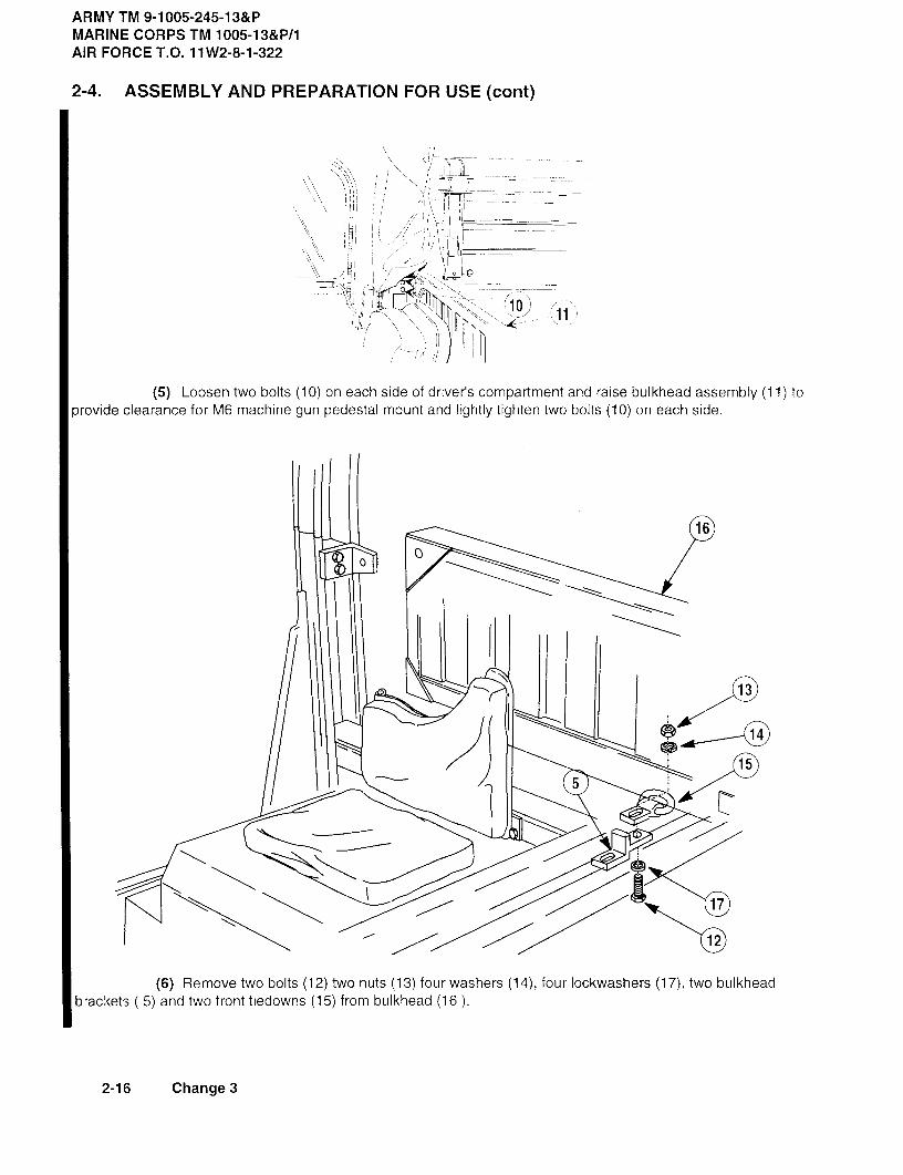
ARMY TM 9-1005-245-13&PMARINE CORPS TM 1005-13&P/1AIR FORCE T.O. 11W2-8-1-322
2-4. ASSEMBLY AND PREPARATION FOR USE (cont)
(5) Loosen two bolts (10) on each side of driver's compartment and raise bulkhead assembly (11) toprovide clearance for M6 machine gun pedestal mount and lightly tighten two bolts (10) on each side.
16
13
14
155
17
12
(6) Remove two bolts (12) two nuts (13) four washers (14), four lockwashers (17), two bulkheadbrackets 5) and two front tieclowns (15) from bulkhead (16).
2-16 Change 3
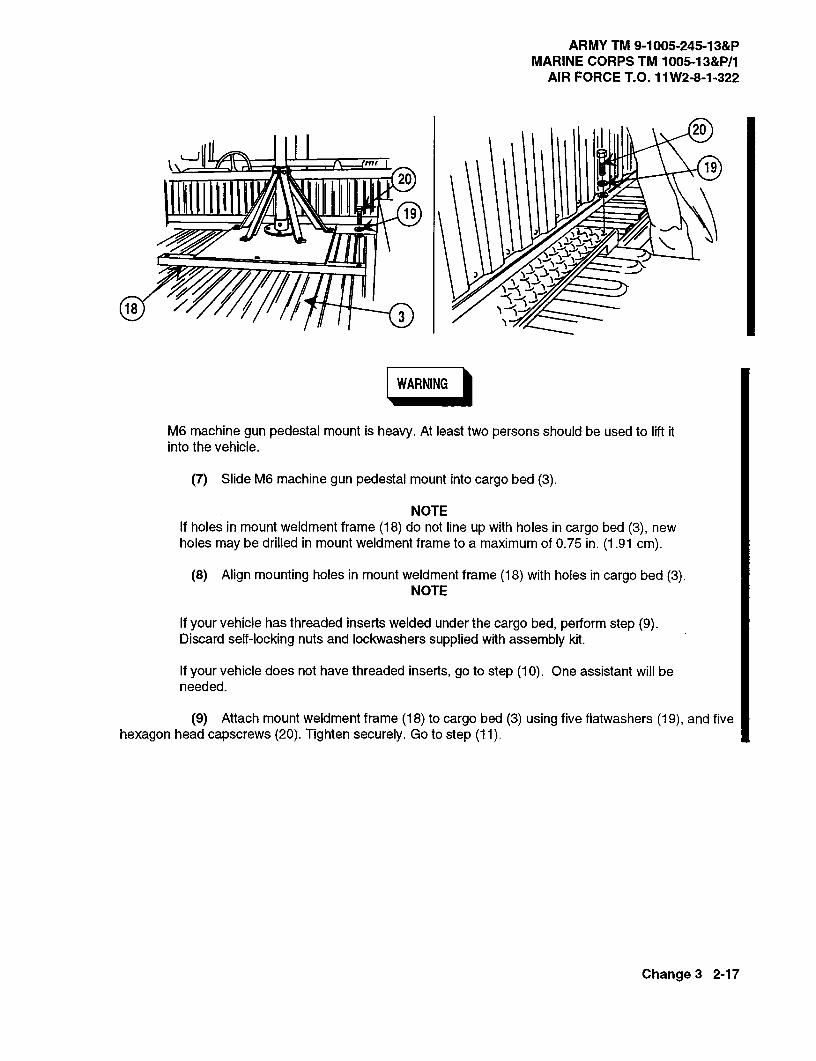
ARMY TM 9-1005-245-13&PMARINE CORPS TM 1005-13&P/1
AIR FORCE T.O. 11W2-8-1-322
20
k\20
19
1119
183
WARNING
M6 machine gun pedestal mount is heavy. At least two persons should be used to lift itinto the vehicle.
(7) Slide M6 machine gun pedestal mount into cargo bed (3).
NOTEIf holes in mount weldment frame (18) do not line up with holes in cargo bed (3), newholes may be drilled in mount weldment frame to a maximum of 0.75 in. (1.91 cm).
(8) Align mounting holes in mount weldment frame (18) with holes in cargo bed (3).NOTE
If your vehicle has threaded inserts welded under the cargo bed, perform step (9).Discard self-locking nuts and lockwashers supplied with assembly kit.
If your vehicle does not have threaded inserts, go to step (10). One assistant will beneeded.
(9) Attach mount weldment frame (18) to cargo bed (3) using five flatwashers (19), and fivehexagon head capscrews; (20). Tighten securely. Go to step (11).
Change 3 2-17
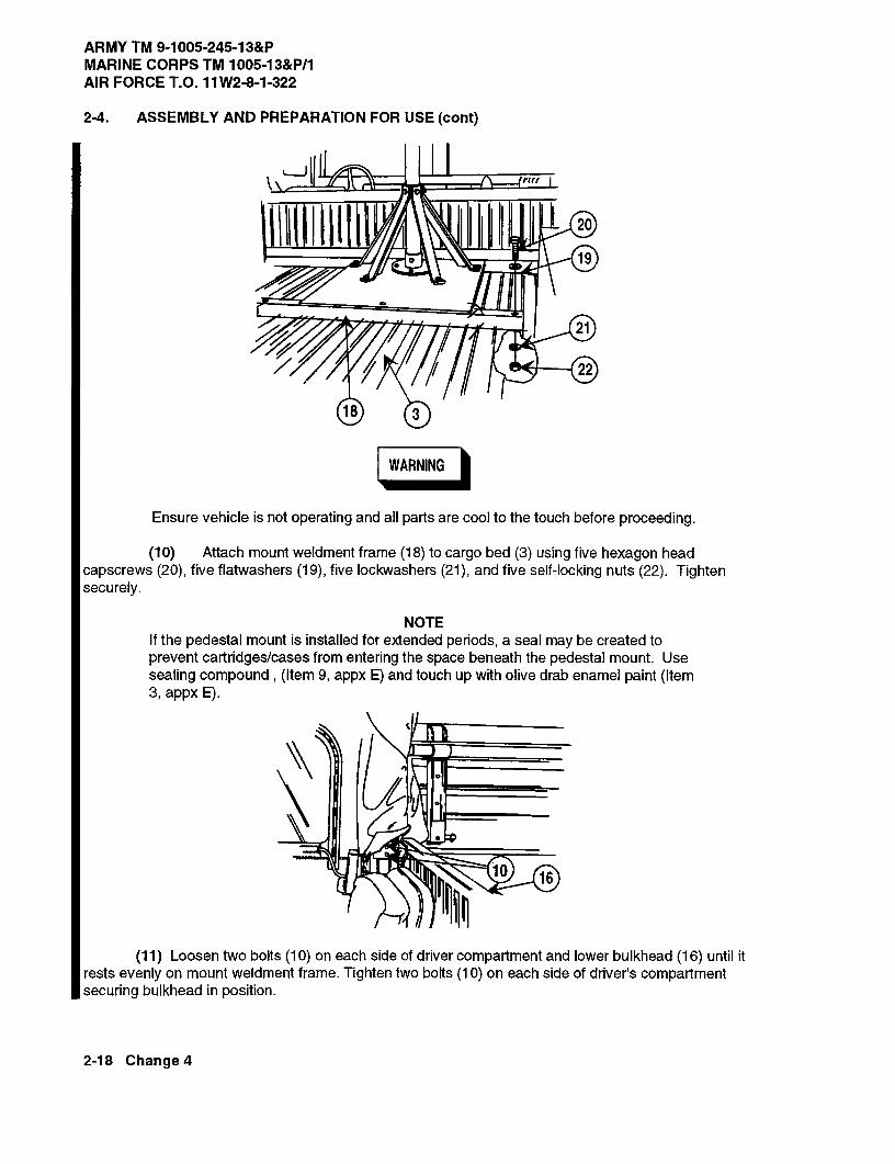
ARMY TM 9-1005-245-13&PMARINE CORPS TM 1005-13&P/1AIR FORCE T.O. 11W2-8-1-322
2-4. ASSEMBLY AND PREPARATION FOR USE (cont)
20
9
21
22
18 3
WARNING
Ensure vehicle is not operating and all parts are cool to the touch before proceeding.
(10) Attach mount weldment frame (18) to cargo bed (3) using five hexagon headcapscrews (20), five flatwashers (19), five lockwashers (21), and five self-locking nuts (22). Tightensecurely.
NOTEIf the pedestal mount is installed for extended periods, a seal may be created toprevent cartridges/cases from entering the space beneath the pedestal mount. Usesealing compound, (Item 9, appx E) and touch up with olive drab enamel paint (Item3, appx E).
(11) Loosen two bolts (10) on each side of driver compartment and lower bulkhead (16) until itrests evenly on mount weldment frame. Tighten two bolts (10) on each side of driver's compartmentsecuring bulkhead in position.
2-18 Change 4

ARMY TM 9-1005-245-13&PMARINE CORPS TM 1005-13&P/1
AIR FORCET.O. 11W2-8-1-322
2-5. OPERATING PROCEDURES
a. After loading and preparing machine gun for firing, loosen the pintle clamping screw enough to allow thegun mount to traverse in the pintle socket.
b. On ring mounts, release brake assembly and traverse the machine gun mount around the ring assemblyto desired location and lock brake to prevent further movement in traverse.
c. Remove travel lock pin from machine gun mount and/or release the travel tie bar lock. The machine gunmay be elevated, depressed, or traversed as required. On ring mounts, to change position of the machine gunmount on the ring, release the brake and rotate the machine gun mount to the desired location and lock brake.
d. After clearing the machine gun, move the machine gun mount on ring assembly to desired location. Placetravel lock pin into machine gun mount. Tighten pintle clamping screw until machine gun mount will not traverse inthe pintle socket.
2-6. PREPARATION FOR MOVEMENT
WARNING
Machine gun and mount may travel at a ready-loaded position with machine gun ready for action,but only when an operator or gunner is present to control and operate the machine gun and mountor as directed by the officer or NCO in charge.
a. Position machine gun mount in desired direction with travel lock pin in place. Tighten pintle clampingscrew and/or lock the brake assembly of ring mounts.
b. Install cover when required.
c. Install ammunition in stowage trays and gun tray when directed.
Section IV. OPERATION UNDER UNUSUAL CONDITIONS
2-7. GENERAL
a. In addition to the normal preventive maintenance service, special care in cleaning and lubrication must beobserved where extremes of temperature, humidity, and atmospheric conditions are present or anticipated. Propercleaning, lubrication, and storage and the use of oils and lubricants not only ensure proper operation andfunctioning but also guard against excessive wear of the working parts and deterioration of the materiel.
b. When chronic failure of the materiel results from subjection to extreme conditions, report of such chronicfailure should be made on DA Form 2407, Maintenance Request.
Change 3 2-19

ARMY TM 9-1005-245-13&PMARINE CORPS TM 1005-13&P/1AIR FORCE T.O. 11W2-8-1-322
2-8. OPERATION IN EXTREME COLD WEATHER
a. Preparation for Cold-Weather Operation.
(1) Whenit isanticipatedthatthematerielwillbeoperatedincoldclimates,itwillbenecessarytoprepareit for cold-weather operation. See chapter 3, section 1,for lubrication instructions. Before changing grade oflubricant, it is necessary that the parts be disassembled sufficiently to permit complete removal of oil, grease, andforeign matter.
(2) Cleanliness is imperative. Rust, dirt, gummed oil, and grease in the bearing clearance interfere withproper distribution of lubricant, causing stiff action or a complete stoppage in cold weather.
b. Cold-Weather Operating Instructions.
(1) Keep all parts clean. The mechanical procedures for cleaning the materiel are the same as for usualconditions; however, certain precautions must be observed as outlined in (2) thru (6) below.
(2) In cold climates, contamination of lubricants with moisture from snow, rain, or condensation in partly-filled containers is the source of many difficulties. Keep containers covered at all times and store in a warm place,if possible.
(3) Leave no unpainted metal surfaces exposed without a protective film of lubricant.
(4) Make a thorough inspection and provide as much protection as possible for all parts. See that thecovers are properly installed and securely fastened. If possible, do not fold covers that are wet or frozen.
(5) When the materiel is protected with a cover, moisture may form on metal surfaces. To prevent rusting,remove the cover daily and inspect all exposed surfaces for presence of moisture or ice. It moisture or ice isfound, clean the surface thoroughly, dry, and coat sparingly with preservative weapons lubricating oil (LAW) (item5, appx E).
(6) Exercise the controls through their entire range, at intervals as required, to aid in keeping the controlsfrom freezing in place and to reduce the effort required to operate them.
2-9. OPERATION IN EXTREME HOT WEATHER
a. In hot climates, inspect and clean the materiel as frequently as required rather than at fixed intervals.
b. Clean and lubricate as soon as possible after operation to prevent corrosion.
2-20 Change 3

ARMY TM 9-1005-245-13&PMARINE CORPS TM 1005-13&P/1
AIR FORCET.O. 11W2-8-1-322
2-10. OPERATION IN EXTREME DUSTY OR SANDY CONDITIONS
a. Inspect and clean the materiel more frequently when operating under sandy or dusty conditions; however,lubricant should be applied sparingly, as oil will collect dust and sand, which act as abrasives.
b. Use particular care to keep sand and dust out of the mechanism when performing inspection, lubrication,or adjustments and repairs.
c. Keep the materiel covered as much as the tactical situation permits. Make certain that the cover is in goodcondition and securely fastened.
2-11. OPERATION IN RAINY, HUMID, AND SALT AIR CONDITIONS
a. The moisture in the atmosphere will emulsify the lubricants and destroy their corrosion-preventivequalities. Therefore, perform inspection, cleaning, and lubrication more frequently and carefully. Salt in the air,such as occurs in salt-water areas, adds to the corrosive activity of moisture. Salty atmosphere conditions requireextra precautions when inspecting, cleaning, and lubricating materiel.
b. Inspect, clean, air, and dry canvas covers more frequently.
Change 3 2-21/(2-22 blank)


ARMY TM 9-1005-245-13&PMARINE CORPS TM 1005-13&P/1
AIR FORCET.O. 11W2-8-1-322
CHAPTER 3
OPERATOR MAINTENANCE
Section 1. LUBRICATION INSTRUCTIONS
WARNING
Dry cleaning solvent is toxic and flammable. Use in well ventilated area. Avoid breathing thevapors and keep away from ignition sources.
CAUTION
Do not mix lubricants on the same gun mount at the same time. The gun mount must bethoroughly cleaned during change from one lubricant to another. Dry cleaning solvent (item 9,appx E) is recommended for cleaning your gun mount during change from one lubricant toanother.
3-1. LUBRICATION UNDER USUAL CONDITIONS
a. General.
(1) Clear ammunition from machine gun and remove machine gun from the machine gun mount.
(2) Remove ammunition tray (detachable type trays only).
(3) Remove the machine gun mount from the pintle socket.
(4) Thoroughly clean all components of the machine gun mount, pedestal mount, or gun mount rings.
(5) Wipe dry, and lubricate following the appropriate steps for each type of mount.
b. Machine Gun Mounts.
(1) Lubricate the securing pins, travel lock pin, trunnion bearing or screws, hinge pins, locking cam, andguide grooves on the ammunition trays weekly with general purpose lubricating oil (item 7, appx E).
(2) Lubricate all exposed metal surfaces weekly with a light coat of general purpose lubricating oil (item 7,appx E).
(3) Lubricate the pintle shank weekly with a light coat of automotive and artillery grease (item 4, appx E).
c. Gun Mount Rings with Carriages.
(1) Lubricate the pintle clamping screw, carriage rollers, brake lever detents and springs, brake leverscrews, brake clamps, backrest pins, barrel clamps, backrest carriage connecting bolts, and rollers weekly withgeneral purpose lubricating oil (item 7, appx E).
(2) Lubricate all exposed metal surfaces of the track and carriage weekly with a light coat of generalpurpose lubricating oil (item 7, appx E).
(3) Lubricate the inside of the pintle socket weekly with a light coat of automotive and artillery grease(item 4, appx E).
3-1
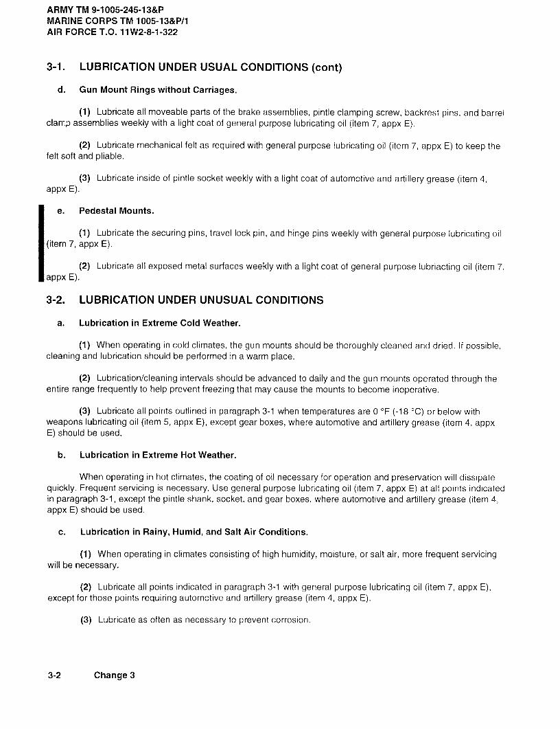
ARMY TM 9-1005-245-13&PMARINE CORPS TM 1005-13&P/1AIR FORCET.O. 11W2-8-1-322
3-1. LUBRICATION UNDER USUAL CONDITIONS (cont)
d. Gun Mount Rings without Carriages.
(1) Lubricate all moveable parts of the brake assemblies, pintle clamping screw, backrest pins, and barrelclarr.p assemblies weekly with a light coat of general purpose lubricating oil (item 7, appx E).
(2) Lubricate mechanical felt as required with general purpose lubricating oil (item 7, appx E) to keep thefelt soft and pliable.
(3) Lubricate inside of pintle socket weekly with a light coat of automotive and artillery grease (item 4,appx E).
e. Pedestal Mounts.
(1) Lubricate the securing pins, travel lock pin, and hinge pins weekly with general purpose lubricating oil(item 7, appx E).
(2) Lubricate all exposed metal surfaces weekly with a light coat of general purpose lubriacting oil (item 7,appx E).
3-2. LUBRICATION UNDER UNUSUAL CONDITIONS
a. Lubrication in Extreme Cold Weather.
(1) When operating in cold climates, the gun mounts should be thoroughly cleaned and dried. If possible,cleaning and lubrication should be performed in a warm place.
(2) Lubrication/cleaning intervals should be advanced to daily and the gun mounts operated through theentire range frequently to help prevent freezing that may cause the mounts to become inoperative.
(3) Lubricate all points outlined in paragraph 3-1 when temperatures are 0 F (-18 C) or below withweapons lubricating oil (item 5, appx E), except gear boxes, where automotive and artillery grease (item 4, appxE) should be used.
b. Lubrication in Extreme Hot Weather.
When operating in hot climates, the coating of oil necessary for operation and preservation will dissipatequickly. Frequent servicing is necessary. Use general purpose lubricating oil (item 7, appx E) at all points indicatedin paragraph 3-1, except the pintle shank, socket, and gear boxes, where automotive and artillery grease (item 4,appx E) should be used.
c. Lubrication in Rainy, Humid, and Salt Air Conditions.
(1) When operating in climates consisting of high humidity, moisture, or salt air, more frequent servicingwill be necessary.
(2) Lubricate all points indicated in paragraph 3-1 with general purpose lubricating oil (item 7, appx E),except for those points requiring automotive and artillery grease (item 4, appx E).
(3) Lubricate as often as necessary to prevent corrosion.
3-2 Change 3

ARMY TM 9-1005-245-13&PMARINE CORPS TM 1005-13&P/1
AIR FORCET.O. 11W2-8-1-322
d. Lubrication in Extreme Dusty or Sandy Conditions.
(1) When operating in dusty or sandy areas, it will be necessary to clean and lubricate more frequently.Dust and sand collected by the lubricant will cause abrasive action on the components.
(2) Clean the gun mounts thoroughly and lubricate only the moving components. Do not lubricate theentire exposed metal surfaces, as this would only collect dust and sand. Lubricate very sparingly with generalpurpose lubricating oil (item 7, appx E). Refer to paragraph 3-1.
Section II. MAINTENANCE PROCEDURES
3-3. CLEANING
a. Fill a suitable container with dry cleaning solvent (item 9, appx E). Using a bristle brush, clean dirt, grease,and residue from all surfaces. Dry all surfaces with clean dry wiping rags (item 8, appx E).
CAUTION
When using abrasive cloth, make certain not to remove too much metal, as this will change thedimension of components.
b. Using abrasive cloth (item 2, appx E), remove paint and rust from quick release and securing pins, sidesof holes, pintle shanks, and sockets.
c. Lubricate in accordance with paragraph 3-1.
Change 3 3-3/(3-4 blank)


ARMYTM9-1005-245-13&PMARINECORPSTM 1005-13&P/1
AIR FORCET.O. 11W2-8-1-322
CHAPTER 4
UNIT MAINTENANCE
SectionI. REPAIRPARTS;TOOLS;SPECIALTOOLS;TEST,MEASUREMENT,ANDDIAGNOSTICEQUIPMENT(TMDE);
ANDSUPPORTEQUIPMENT
4-1. COMMON TOOLS AND EQUIPMENT
For authorized common tools and equipment, refer to the Modified Table of Organization and Equipment(MTOE), CTA 50-970, or CTA 8-100, as applicable to your unit. Marine Corps units, refer to the unit's EquipmentAllowance File (EAF) and appropriate technical manuals.
4-2. SPECIAL TOOLS, TMDE, AND SUPPORT EQUIPMENT
Special tools, TMDE, and support equipment are listed in appendix B of this manual.
4-3. REPAIR PARTS
Repair parts are listed and illustrated in appendix C of this manual.
Section II. SERVICE UPON RECEIPT
4-4. SERVICE UPON RECEIPT OF MATERIEL
a. Upon receipt of materiel, it is the responsibility of the officer in charge to determine whether the materielhas been properly mounted and prepared for service by the supplying organization, and to be sure it is in condi-tion to preform its function. For this purpose, inspect all assemblies, subassemblies, and accessories to be surethey are properly assembled, secured, correctly adjusted, cleaned, and lubricated.
b. Make a record of all missing parts and equipment and any malfunctions. Deficiencies must be correctedas quickly as possible.
c. Before materiel is activated, perform the following procedures:
(1) Perform Operator PMCS. Refer to paragraph 2-3.
(2) Lubricate for appropriate climatic condition. Refer to paragraphs 3-1 and 3-2.
(3) Check for proper operation. Refer to paragraph 2-4.
4-1

ARMY TM 9-1005-245-13&PMARINE CORPS TM 1005-13&P/1AIR FORCE T.O. 11 W2-8-1-322
Section III. UNIT PREVENTIVE MAINTENANCECHECKS AND SERVICES (PMCS)
4-5. INTRODUCTION TO PMCS TABLE
a. General. Your PMCS table (table 4-1) has been provided so you can keep your equipment in goodoperating condition and ready for its primary mission.
b. Explanation of table entries.
(1) Item Number column. Numbers in this column are for reference. When completing DA Form 2404,Equipment Inspection and Maintenance Worksheet, include the item number for the check/service indicating afault. Item numbers also appear in the order that you must do checks and services for the intervals listed.
(2) Interval column. This column tells you when you must do the procedure in the procedure column.Interval listed is minimum time between inspections; however, should conditions warrant, intervals can be short-ened.
(3) Item to Check/Service column. This column provides the location and the item to be checked orserviced.
(4) Procedure column. This column gives the procedure you must do to check or service the itemlisted in the Item to Check/Service column to know if the equipment is ready or available for its intended missionor for operation. You must do the procedure at the time stated in the Interval column.
(5) Not Fully Mission Capable If: column. Information in this column tells you what faults will keepyour equipment from being capable of performing its primary mission. If you make check and service proceduresthat show faults listed in this column, do not operate the equipment. Follow standard operating procedures formaintaining the equipment or reporting equipment failure.
Table 4-1. UNIT PREVENTIVE MAINTENANCE CHECKS AND SERVICES FOR GUN MOUNTS
NOT FULLYITEM ITEM TO CHECK/ MISSION CAPABLENO. INTERVAL SERVICE PROCEDURE IF:
1 Quarterly Machine Gun a. Check all gun mounts: make Parts are brokenMounts certain they are clean and lubri- or missing.
cated.
b. Check for operating elevation, Mount does notdepression, and traversing. operate through
full requiredrange of move-ment.
C. Check all controls, make sure they Mount controlsfunction properly. malfunction.
4-2

ARMY TM 9-1005-245-13&PMARINE CORPS TM 1005-13&P/1
AIR FORCET.O. 11W2-8-1-322
Table 4-1. UNIT PREVENTIVE MAINTENANCECHECKS AND SERVICES FOR GUN MOUNTS (cont)
NOT FULLYITEM ITEM TO CHECK/ MISSION CAPABLENO. INTERVAL SERVICE PROCEDURE IF:
d. Check cover; make sure it is clean,serviceable, and properly installed orstowed.
e. Check mounts with equilibrators by Equilibrators out ofchecking adjustment of equilibrator adjustmentwith machine gun mounted. inoperable.
f. Check for MWO application. See DA MWOs not appliedPAM 25-30. If no MWO is used, per directives.Marine Corps Units check the SL1 -2for applicable MIs or TIs.
2 Quarterly Tripod Mounts a. Check functioning of legs, sleeve lock Leg clamp loose.latch, and pintle lock assembly. Sleeve lock latch
inoperative. Pintlewill not latch totripod head. Partsare broken ormissing.
b. Check components for dents, cracks, Mount does notand distortion. operate through
full required rangeof movement.Mount controlsmalfunction.
c. Check handle and nut for retention onlegs and wear or distortion of threads.
d. Check rear legs for full extension. Legs are inoper-Rear legs should be forced apart by able. Legs do notbar when in firing position. contact side of tri-
pod mount toensure rigidity ofmount.
e. Check machine bolt (5139973) andnut for damaged threads or burrs.
f. Check head for cracks or burrs.
4-3

ARMY TM 9-1005-245-13&PMARINE CORPS TM 1005-13&P/1AIR FORCE T.O. 11W2-8-1-322
4-5. INTRODUCTION TO PMCS TABLE (cont)
Table 4-1. UNIT PREVENTIVE MAINTENANCE CHECKS AND SERVICES FOR GUN MOUNTS (cont)
NOT FULLYITEM ITEMTO CHECK/ MISSION CAPABLENO. INTERVAL SERVICE PROCEDURE IF:
g. Inspect general appearance of tripod. Parts are brokenCheck for damaged components and or missing.make sure it operates properly. Referto FM 23-67.
h. Make sure traversing and elevatingmechanism moves freely.
i. Inspect lock assembly, pintle Parts are brokenassembly, and helical torsion spring. or missing.
j. Extend the legs and check latch for Latch is inopera-wear and spring tension. tive.
k. Make sure all identification markingsare legible.
l. Check traversing mechanism for Elevating stopbroken elevating stop. If broken or broken ormissing, notify direct support missing.maintenance.
3 Quarterly Gun Mount Rings a. Check gun mount rings; make certain Parts are brokenthey are clean and lubricated. or missing.
b. Check operation of pintle clamping Clamping screwscrew. missing or
inoperable.
c. Check traversing action of carriage or Ring does notring. traverse through
full required range.
d. Check cover; make certain it is clean,serviceable, and properly installed orstowed.
4 Quarterly Pedestal Mounts a. Check pedestal mounts; make Parts are brokencertain they are clean and lubricated. or missing.
b. Check operation of raising, Mount does notlowering, and traversing. operate through
full required rangeof movement.
4-4 Change 3

ARMY TM 9-1005-245-13&PMARINE CORPS TM 1005-13&P/1
AIR FORCET.O. 11W2-8-1-322
Section IV. UNIT TROUBLESHOOTING
4-6. TROUBLESHOOTING INFORMATION
a. The malfunction index can be used as a quick guide to troubleshooting. Common malfunctions are listedin alphabetical order under each major assembly, with a page number reference to the troubleshooting tablewhere a test or inspection and corrective action are provided.
b. Table 4-2 lists the common malfunctions which you may find during operation or maintenance. You shouldperform the tests/inspections and corrective actions in the order listed.
c. This manual cannot list all malfunctions that may occur, nor all tests or inspections and corrective actions.If a malfunction is not listed or is not corrected by listed corrective actions, notify your supervisor.
d. Refer to lubrication instructions (para 3-1 ) for location of lubricating points.
UNIT MALFUNCTION INDEX
TroubleshootingProcedure
Page
GUN MOUNT RINGSBrake lever will not stay in locked or unlocked position ............................................................................ 4-8Machine gun mount traverses when pintle screw is tightened .................................................................. 4-8Machine gun mount will not install into pintle socket ................................................................................. 4-7Ring mount does not traverse properly ..................................................................................................... 4-8Ring mount will not traverse after brake is released ................................................................................. 4-8
MACHINE GUN MOUNTSCatch strike fails to hold machine gun to machine gun mount .................................................................. 4-7Excessive effort must be made in order to elevate or depress machine gun mount ................................ 4-6Machine gun mount does not swivel smoothly .......................................................................................... 4-76650 .50 cal machine gun mount will not hold machine gun in a horizontal position ................................ 4-7Quick release and securing pins bind at installation ................................................................................. 4-6
PEDESTAL MOUNTSExcessive effort is required to raise or lower M6 machine gun pedestal mount ...................................... 4-9M6 machine gun pedestal mount does not swivel smoothly .................................................................... 4-9Quick release and securing pins bind at installation ................................................................................ 4-9
TRIPOD MOUNTSSleeve fails to lock on traversing bar assembly ........................................................................................ 4-7Tripod mount fails to traverse .................................................................................................................... 4-7
Change 3 4-5

ARMY TM 9-1005-245-13&PMARINE CORPS TM 1005-13&P/1AIR FORCE T.O. 11W2-8-1-322
Table 4-2. UNIT TROUBLESHOOTING
MALFUNCTIONTEST OR INSPECTION
CORRECTIVE ACTION
MACHINE GUN MOUNTS
1. QUICK RELEASE AND SECURING PINS BIND AT INSTALLATION.
Check for dirt, paint, rust, and burrs on pins or in sides of holes.
a. Remove dirt, paint, rust, and burrs.
b. Lubricate cleaned areas.
2. EXCESSIVE EFFORT MUST BE MADE IN ORDER TO ELEVATE OR DEPRESS MACHINE GUN MOUNT.
Check grooved headless straight pin/headless straight pin/bolt for dirt, rust, and burrs.
a. Remove dirt, dust, and burrs.
b. Lubricate cleaned areas.
3. CATCH STRIKE FAILS TO HOLD MACHINE GUN TO M142 MACHINE GUN MOUNT.
Check catch strike for worn or broken helical torsion spring.
Notify direct support maintenance.
4. 6650.50 CAL MACHINE GUN MOUNT WILL NOT HOLD MACHINE GUN IN A HORIZONTAL POSITION.
Check for broken torsion spiral spring or incorrect adjustment.
Notify direct support maintenance.
5. MACHINE GUN MOUNT DOES NOT SWIVEL SMOOTHLY.
Check pintle socket for dirt, paint, and burrs.
a. Remove dirt, paint, and burrs.
b. Lubricate cleaned areas.
4-6

ARMY TM 9-1005-245-13&PMARINE CORPS TM 1005-13&P/1
AIR FORCET.O. 11W2-8-1-322
Table 4-2. UNIT TROUBLESHOOTING (cont)
MALFUNCTIONTEST OR INSPECTION
CORRECTIVE ACTION
TRIPOD MOUNTS
6. TRIPOD MOUNT FAILS TO TRAVERSE.
Check for incorrect adjustment of traversing screw.
Notify direct support maintenance.
7. SLEEVE FAILS TO LOCK ON TRAVERSING BAR ASSEMBLY.
Check for incorrect adjustment of lever and traversing screw.
Notify direct support maintenance.
GUN MOUNT RINGS
8. MACHINE GUN MOUNT WILL NOT INSTALL INTO PINTLE SOCKET.
Check for dirt, paint, rust, and burrs in pinfle socket.
a. Remove dirt, paint, rust, and burrs.
b. Lubricate cleaned areas.
9. MACHINE GUN MOUNT TRAVERSES WHEN PINTLE SCREW IS TIGHTENED.
Check for broken pintle screw.
Notify direct support maintenance.
10. RING MOUNT DOES NOT TRAVERSE PROPERLY.
Step 1. Check track, separator segments, and roller bearings for dirt, paint, rust, and burrs.
a. Remove dirt, paint, rust, and burrs.
b. Lubricate cleaned areas.
Step 2 Check brake assembly for proper adjustment.
Notify direct support maintenance.
4-7
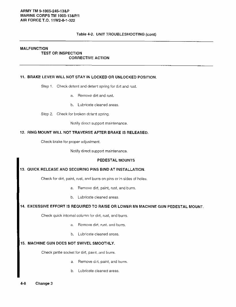
ARMY TM 9-1005-245-13&PMARINE CORPS TM 1005-13&P/1AIR FORCE T.O. 11W2-8-11-322
Table 4-2. UNIT TROUBLESHOOTING (cont)
MALFUNCTIONTEST OR INSPECTION
CORRECTIVE ACTION
11. BRAKE LEVER WILL NOT STAY IN LOCKED OR UNLOCKED POSITION.
Step 1. Check detent and detent spring for dirt and rust.
a. Remove dirt and rust.
b. Lubricate cleaned areas.
Step 2. Check for broken detent spring.
Notify direct support maintenance.
12. RING MOUNT WILL NOT TRAVERSE AFTER BRAKE IS RELEASED.
Check brake for proper adjustment.
Notify direct support maintenance.
PEDESTAL MOUNTS
13. QUICK RELEASE AND SECURING PINS BIND AT INSTALLATION.
Check for dirt, paint, rust, and burrs on pins or in sides of holes.
a. Remove dirt, paint, rust, and burrs.
b. Lubricate cleaned areas.
14. EXCESSIVE EFFORT IS REQUIRED TO RAISE OR LOWER M6 MACHINE GUN PEDESTAL MOUNT.
Check quick internal column for dirt, rust, and burrs.
a. Remove dirt, rust, and burrs.
b. Lubricate cleaned areas.
15. MACHINE GUN DOES NOT SWIVEL SMOOTHLY.
Check pintle socket for dirt, paint, and burrs.
a. Remove dirt, paint, and burrs.
b. Lubricate cleaned areas.
4-8 Change 3
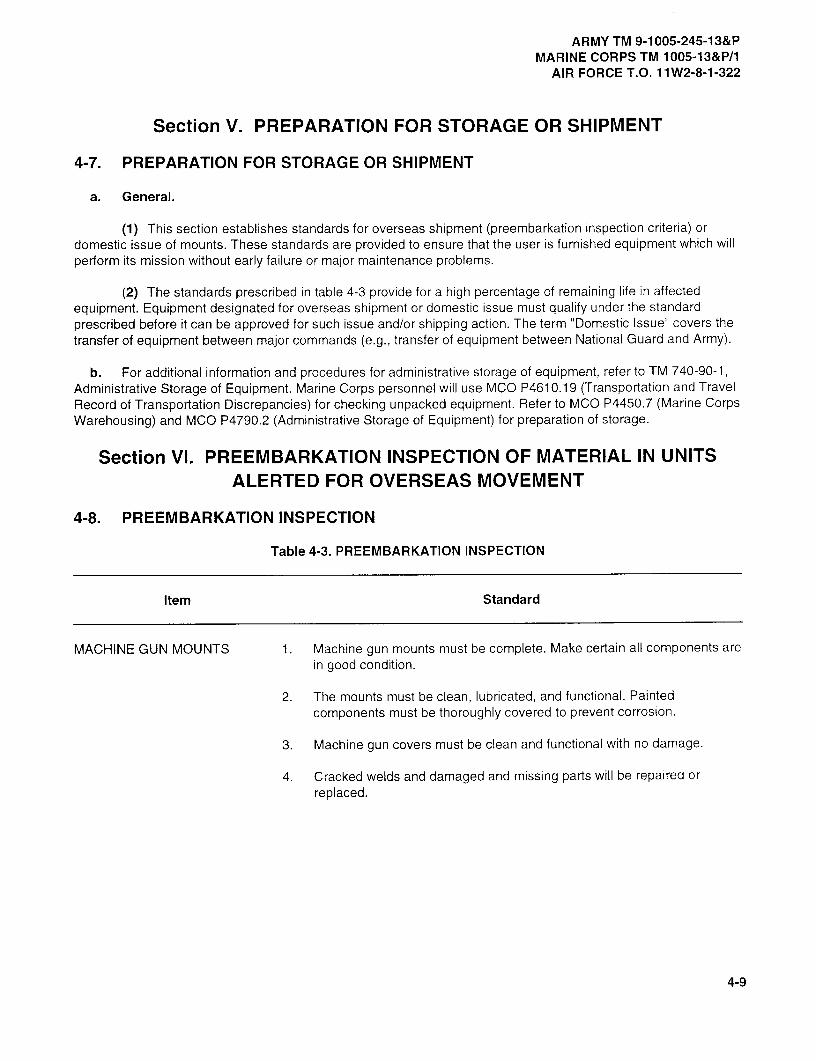
ARMY TM 9-1005-245-13&PMARINE CORPS TM 1005-13&P/1
AIR FORCET.O. 11W2-8-1-322
Section V. PREPARATION FOR STORAGE OR SHIPMENT
4-7. PREPARATION FOR STORAGE OR SHIPMENT
a. General.
(1) This section establishes standards for overseas shipment (preembarkation inspectioncriteria) ordomestic issue of mounts. These standards are provided to ensure that the user is furnished equipment which willperform its mission without early failure or major maintenance problems.
(2) The standards prescribed in table 4-3 provide for a high percentage of remaining life in affectedequipment. Equipment designated for overseas shipment or domestic issue must qualify under the standardprescribed before it can be approved for such issue and/or shipping action. The term "Domestic Issue" covers thetransfer of equipment between major commands (e.g., transfer of equipment between National Guard and Army).
b. For additional information and procedures for administrative storage of equipment, refer to TM 740-90-1,Administrative Storage of Equipment. Marine Corps personnel will use MCO P4610.19 (Transportation and TravelRecord of Transportation Discrepancies) for checking unpacked equipment. Refer to MCO P4450.7 (Marine CorpsWarehousing) and MCO P4790.2 (Administrative Storage of Equipment) for preparation of storage.
Section VI. PREEMBARKATION INSPECTION OF MATERIAL IN UNITSALERTED FOR OVERSEAS MOVEMENT
4-8. PREEMBARKATION INSPECTION
Table 4-3. PREEMBARKATION INSPECTION
Item Standard
MACHINE GUN MOUNTS 1 . Machine gun mounts must be complete. Make certain all components arein good condition.
2. The mounts must be clean, lubricated, and functional. Paintedcomponents must be thoroughly covered to prevent corrosion.
3. Machine gun covers must be clean and functional with no damage.
4. Cracked welds and damaged and missing parts will be repaired orreplaced.
4-9
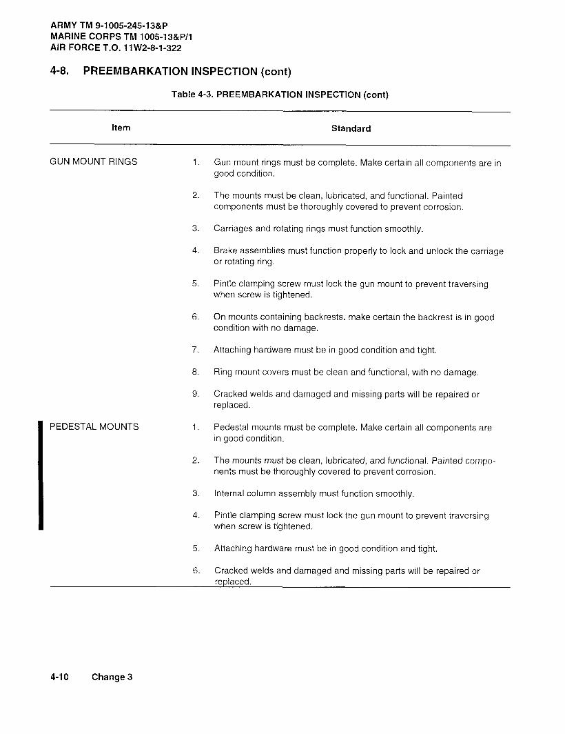
ARMY TM 9-1005-245-13&PMARINE CORPS TM 1005-13&P/1AIR FORCE T.O. 11W2-8-1-322
4-8. PREEMBARKATION INSPECTION (cont)
Table 4-3. PREEMBARKATION INSPECTION (cont)
Item Standard
GUN MOUNT RINGS 1 Gun mount rings must be complete. Make certain all components are ingood condition.
2. The mounts must be clean, lubricated, and functional. Paintedcomponents must be thoroughly covered to prevent corrosion.
3. Carriages and rotating rings must function smoothly.
4. Brake assemblies must function properly to lock and unlock the carriageor rotating ring.
5. Pintle clamping screw must lock the gun mount to prevent traversingwhen screw is tightened.
6. On mounts containing backrests, make certain the backrest is in goodcondition with no damage.
7. Attaching hardware must be in good condition and tight.
8. Ring mount covers must be clean and functional, with no damage.
9. Cracked welds and damaged and missing parts will be repaired orreplaced.
PEDESTAL MOUNTS 1 . Pedestal mounts must be complete. Make certain all components arein good condition.
2. The mounts must be clean, lubricated, and functional. Painted compo-nents must be thoroughly covered to prevent corrosion.
3. Internal column assembly must function smoothly.
4. Pintle clamping screw must lock the gun mount to prevent traversingwhen screw is tightened.
5. Attaching hardware must be in good condition and tight.
6. Cracked welds and damaged and missing parts will be repaired orreplaced.
4-10 Change 3
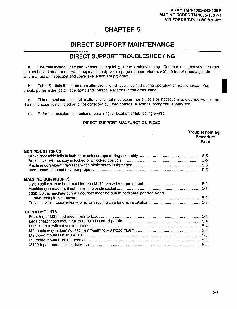
ARMY TM 9-1005-245-13&PMARINE CORPS TM 1005-13&P/1
AIR FORCE T.O. 11W2-8-1-322
CHAPTER 5
DIRECT SUPPORT MAINTENANCE
DIRECT SUPPORT TROUBLESHOOTING
a. The malfunction index can be used as a quick guide to troubleshooting. Common malfunctions are listedin alphabetical order under each major assembly, with a page number reference to the troubleshooting tablewhere a test or inspection and corrective action are provided.
b. Table 5-1 lists the common malfunctions which you may find during operation or maintenance. Youshould perform the tests/inspections and corrective actions in the order listed.
c. This manual cannot list all malfunctions that may occur, nor all tests or inspections and corrective actions.If a malfunction is not listed or is not corrected by listed corrective actions, notify your supervisor.
d. Refer to lubrication instructions (para 3-1) for location of lubricating points.
DIRECT SUPPORT MALFUNCTION INDEX
TroubleshootingProcedure
Page
GUN MOUNT RINGSBrake assembly fails to lock or unlock carriage or ring assembly .......................................................... 5-5Brake lever will not stay in locked or unlocked position ......................................................................... 5-5Machine gun mount traverses when pintle screw is tightened ............................................................... 5-5Ring mount does not traverse properly .................................................................................................. 5-5
MACHINE GUN MOUNTSCatch strike fails to hold machine gun M142 to machine gun mount ..................................................... 5-2Machine gun mount will not install into pintle socket .............................................................................. 5-26650.50 cal machine gun will not hold machine gun in horizontal position when
travel lock pin is removed ................................................................................................................... 5-2Travel lock pin, quick release pins, or securing pins bind at installation ................................................ 5-2
TRIPOD MOUNTSFront leg of M3 tripod mount tails to lock ............................................................................................... 5-3Legs of M3 tripod mount fail to remain in locked position ...................................................................... 5-4Machine gun will not secure to mount .................................................................................................... 5-4M2 machine gun does not secure properly to M3 tripod mount .................... I ........................................ 5-3M3 tripod mount fails to elevate ................................................................ ............................................ 5-3M3 tripod mount fails to traverse ............................................................................................................ 5-3M122 tripod mount fails to traverse ........................................................................................................ 5-4
5-1

ARMY TM 9-1005-245-13&PMARINE CORPS TM 1005-13&P/1AIR FORCE T.O. 11W2-8-11-322
Table 5-1. DIRECT SUPPORT TROUBLESHOOTING
MALFUNCTIONTEST OR INSPECTION
CORRECTIVE ACTION
MACHINE GUN MOUNTS
1. MACHINE GUN MOUNT WILL NOT INSTALL INTO PINTLE SOCKET.
Check for damaged pintle shank.
Replace pintle. Refer to paragraph 7-3, 10-2, or 11-2.
2. CATCH STRIKE FAILS TO HOLD MACHINE GUN TO M142 MACHINE GUN MOUNT.
Check catch strike for worn or broken helical torsion spring.
Replace worn or broken torsion helical spring. Refer to paragraph 10-2.
3. 6650.50 CAL MACHINE GUN MOUNT WILL NOT HOLD MACHINE GUN IN HORIZONTAL POSITIONWHEN TRAVEL LOCK PIN IS REMOVED.
Step 1. Check torsion spiral spring for incorrect adjustment.
Adjust torsion spiral spring. Refer to paragraph 11-2.
Step2. Check for broken torsion spiral spring.
Replace and adjust torsion spiral spring. Refer to paragraph 11-2.
4. TRAVEL LOCK PIN, QUICK RELEASE PINS, OR SECURING PINS BIND AT INSTALLATION.
Step 1. Check for din, paint, rust, and burrs on pins or in sides of hole.
Remove dirt, paint, rust, and burrs.
Step 2. Check for bent pins.
Replace pins. Refer to paragraph 11-2.
Step 3. Check for bent or warped cradle or pintle.
Replace cradle or pintle. Refer to paragraph 11-2.
5-2

ARMYTM9-1005-245-13&PMARINECORPSTM 1005-13&P/1
AIR FORCET.O. 11W2-8-1-322
Table5-1. DIRECTSUPPORTTROUBLESHOOTING(cont)
MALFUNCTIONTESTORINSPECTION
CORRECTIVEACTION
TRIPODMOUNTS
5. M3 TRIPODMOUNTFAILSTO TRAVERSE.
Checkfordefectivescrewassembly.
Replace traversing and elevating mechanism. Refer to paragraph 7-3.
6. M3 TRIPOD MOUNT FAILS TO ELEVATE.
Check for defective screw assembly.
Replace traversing and elevating mechanism. Refer to paragraph 7-3.
7. FRONT LEG OF M3 TRIPOD MOUNT FAILS TO LOCK.
Step 1. Check for defective front leg clamping screw nut.
Replace defective front leg clamping screw nut. Refer to paragraph 7-4.
Step 2. Check for damaged serrations on retaining plate.
Replace damaged retaining plate. Refer to paragraph 7-4.
Step 3. Check for damaged serrations on upper front tripod mount leg.
Replace damaged upper front tripod mount leg. Refer to paragraph 7-6.
Step 4. Check for distortion of front tripod mount leg.
Replace distorted front tripod mount leg. Refer to paragraph 7-6.
8. M2 MACHINE GUN DOES NOT SECURE PROPERLY TO M3 TRIPOD MOUNT.
Step 1. Check for defective mount pintle.
Replace defective mount pintle. Refer to paragraph 7-3.
Step 2. Check for defective sleeve bearing in tripod head.
Replace tripod head. Refer to paragraph 7-4.
5-3

ARMYTM9-1005-245-13&PMARINECORPSTM 1005-13&P/1AIR FORCE T.O. 11W2-8-1-322
Table 5-1. DIRECT SUPPORT TROUBLESHOOTING (cont)
MALFUNCTIONTEST OR INSPECTION
CORRECTIVE ACTION
9. LEGS OF M3 TRIPOD MOUNT FAIL TO REMAIN IN LOCKED POSITION.
Step 1. Check for defective spring or lever.
Replace defective spring or lever. Refer to paragraphs 7-5, 7-6, and 7-7.
Step 2. Check for incorrect adjustment of traversing bar assembly.
Readjust bar. Refer to paragraph 7-3.
10. M122 TRIPOD MOUNT FAILS TO TRAVERSE.
Step 1. Check adjustment area of traversing and elevating assembly for movement.
Replace traversing and elevating assembly. Refer to paragraph 6-3.
Step 2. Check clamping area of traversing and elevating mechanism assembly for broken or missingparts.
Replace machine screw, lockwasher, traversing slide lock lever, helical torsionspring, and traversing slide lock screw. Refer to paragraph 6-5.
Step 3. Check traverse bar assembly for bends or dents.
Replace traverse bar assembly. Refer to paragraph 6-4.
11. MACHINE GUN WILL NOT SECURE TO MOUNT.
Step 1. Check for bent or deformed lock release lever and headless grooved pin. Check helicaltorsion spring for weak spring action.
Replace defective parts. Refer to paragraph 6-6.
Step 2. Check traversing and elevating mechanism adapter assembly locking action.
Replace traversing and elevating mechanism adapter assembly. Refer to paragraph 6-3.
5-4
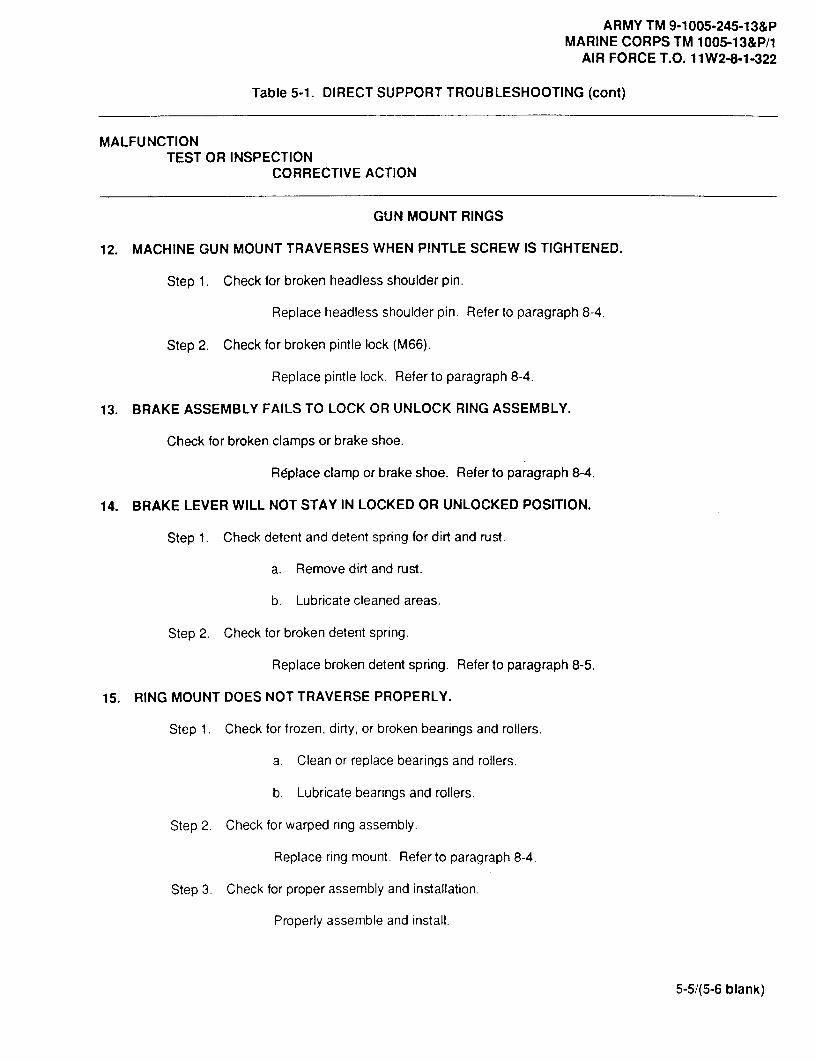
ARMY TM 9-1005-245-13&PMARINE CORPS TM 1005-13&P/1
AIR FORCE T.O. 11W2-8-1-322
Table 5-1. DIRECT SUPPORT TROUBLESHOOTING (cont)
MALFUNCTIONTEST OR INSPECTION
CORRECTIVE ACTION
GUN MOUNT RINGS
12. MACHINE GUN MOUNT TRAVERSES WHEN PINTLE SCREW IS TIGHTENED.
Step 1. Check for broken headless shoulder pin.
Replace headless shoulder pin. Refer to paragraph 8-4.
Step 2. Check for broken pintle lock (M66).
Replace pintle lock. Refer to paragraph 8-4.
13. BRAKE ASSEMBLY FAILS TO LOCK OR UNLOCK RING ASSEMBLY.
Check for broken clamps or brake shoe.
Rdplace clamp or brake shoe. Refer to paragraph 8-4.
14. BRAKE LEVER WILL NOT STAY IN LOCKED OR UNLOCKED POSITION.
Step 1. Check detent and detent spring for dirt and rust.
a. Remove dirt and rust.
b. Lubricate cleaned areas.
Step 2. Check for broken detent spring.
Replace broken detent spriing. Refer to paragraph 8-5.
15. RING MOUNT DOES NOT TRAVERSE PROPERLY.
Step 1. Check for frozen, dirty, or broken bearings and rollers.
a. Clean or replace bearings and rollers.
b. Lubricate bearings and rollers.
Step 2. Check for warped ring assembly.
Replace ring mount. Refer to paragraph 8-4.
Step 3. Check for proper assembly and installation.
Properly assemble and install.
5-5/(5-6 blank)


ARMY TM 9-1005-245-13&PMARINE CORPS TM 1005-13&P/1
AIR FORCE T.O. 11W2-8-1-322
CHAPTER 6
M122/M122A1 MACHINE GUN TRIPOD MOUNT
Section 1. UNIT MAINTENANCE INSTRUCTIONS
6-1. M122/M122A1 MACHINE GUN TRIPOD MOUNT- MAINTENANCEINSTRUCTIONS
THIS TASK COVERS:
a. Disassembly b. Inspection/Repair c. Reassembly
DISASSEMBLY
1 Release pintle lock assembly (10) andremove mount pintle (7) (M122 only).
2 Remove one retaining clip (3) and removepin (4).
3 Remove flex mount (6) (M122A1 only) from 4sleeve bushing (8) and the mechanism 3assembly (5).
3 5 64 Turn traversing lever (2) counter- 2
clockwise and remove traversing and 7elevating mechanism (1) from traversebar assembly (9). 8
INSPECTION/REPAIR 9
1 Inspect for broken, damaged, or missingparts.
10
2 Traversing and elevating mechanism (1)is a repairable assembly. Refer toparagraph 6-2.
3 Mount pintle (7) is a repairable assembly. Refer to paragraph 6-3.
4 Flex mount assembly (6) is a repairable assembly. Refer to paragraph 9-1.
5 For further disassembly of tripod leg assembly, notify direct support maintenance.
6 Repair is by replacement of authorized parts (appx C).
@10
Change 2 6-1

ARMY TM 9-1005-245-13&PMARINE CORPS TM 1005-13&P/1AIR FORCE T.O. 11 W2-8-1-322
6-1. M122/M122A1 MACHINE GUN TRIPOD MOUNT- MAINTENANCEINSTRUCTIONS (cont)
REASSEMBLY
1 Place mount pintle (7) (M122 only) in sleeve bushing (8) and lock pintle lock assembly (10).
2 Place traversing and elevating mechanism (1) on traverse bar assembly (9) and secure by turningtraversing lever (2) clockwise.
3 Place flex mount (6) (M122A1 only) in sleeve bushing (8) and on mechanism assembly (5) and lockpintle lock assembly (10).
4. Install pin (4) and replace retaining clip (3).
43
6
3 5 62
7
8
9
10
6-2 Change 2

ARMY TM 9-1005-245-13&PMARINE CORPS TM 1005-13&P/1
AIR FORCE T.O. 112-8-1-322
6-2. MECHANISM ASSEMBLY (TRAVERSING AND CLAMPING UNIT) -MAINTENANCE INSTRUCTIONS
THIS TASK COVERS:
a. Disassembly b. Inspection/Repair c. Reassembly
INITIAL SETUP
Tools and Special ToolsSmall Arms Repairman Tool Kit (item 2, appx 13)
Materials/PartsLockwasher ( 11010413)
Equipment Condition6-1 Traversing and elevating mechanism removed
DISASSEMBLY
Remove machine screw (6) and lockwasher (5) fromtraversing lever (4). Discard lockwasher. Removetraversing lever (4), helical torsion spring (3) andmachine screw (2) from elevating mechanismsleeve (1).
INSPECTION/REPAIR
1 Inspect for broken, damaged, or missing parts.
2 For further disassembly of mechanism assembly 3(traversing and clamping unit), notify direct 4support maintenance. 5
3 Repair is by replacement of authorized parts 6
(appx C).
REASSEMBLY
Install machine screw (2), helical torsion spring (3),and traversing lever (4) on elevating mechanismsleeve (1). Secure with new lockwasher (5) andmachine screw (6).
NOTEMachine screw (6) will need to be adjustedwhen traversing lever (4) is installed. Traversinglever (4) must be aligned with traverse barassembly.
Change 2 6-3

ARMY TM 9-1005-245-13&PMARINE CORPS TM 1005-13&P/1AIR FORCE T.O. 11W2-8-1-322
16-3. MOUNT PINTLE - MAINTENANCE INSTRUCTIONS
THIS TASK COVERS:
a. Disassembly b. Inspection/Repair c. Reassembly
INITIAL SETUP
Tools and Special ToolsSmall Arms Repairman Tool Kit (item 2, appx 13)
Personnel Required2
Equipment Condition6-3 Mount pintle removed
DISASSEMBLY
WARNINGTo avoid injury to your eyes, use care when 2
removing and installing spring-foaded parts. 3
Remove headless grooved pin (1), helical torsionspring (2), and lock-release lever (3) from pintle (4).
INSPECTION/REPAIR
1 Inspect for broken, damaged, or missingparts.
2 If pintle (4) is broken or damaged, repairis by replacement of next higher assembly. 4
3 Repair is by replacement of authorizedparts (appx C).
REASSEMBLY
NOTEHave helper assist in reassembly of mountpintle.
Install helical torsion spring (2) and lock-releaselever (3), and secure to pintle (4) with headlessgrooved pin (1).
6-4 Change 2

ARMY TM 9-1005-245-13&PMARINE CORPS TM 1005-13&P/1
AIR FORCE T.O. 11W2-8-1-322
SECTION II. DIRECT SUPPORT MAINTENANCE INSTRUCTIONS
6-4. M122/M122A1 MACHINE GUN TRIPOD MOUNT AND TRAVERSING ANDELEVATING MECHANISM MAINTENANCE INSTRUCTIONS
THIS TASK COVERS:
a. Disassembly b. Inspection/Repair c. Reassembly
INITIAL SETUP
Tools and Special ToolsSmall Arms Repairman Tool Kit (item 2, appx 13)Small Arms Shop Set (item 1, appx 13)
DISASSEMBLY
1 Release pintle lock assembly (10) andremove mount pintle (7) (M122 only).
2 Remove one retaining clip (3) and removepin (4).
3 Remove flex mount (6) (M122A1 only) 4 01from sleeve bushing (8) and the 3mechanism assembly (5).
P
6@1"
4 Turn traversing lever (2) counter-3
20 5 6
clockwise and remove traversing andelevating mechanism (1) from traverse 7bar assembly (8).
8INSPECTION /REPAIR
1 Inspect for broken, damaged, ormissing parts. 10
2 For further disassembly of tripod legassembly, refer to paragraph 6-5.
3 Traversing and elevating mechanism assembly (1) is a repairable assembly. Refer toparagraph 6-6.
4 Mount pintle (7) is a repairable assembly. Refer to paragraph 6-3.
5 Flex mount (6) is a repairable assembly. Refer to paragraph 9-1.
10N_
6 Repair is by replacement of authorized parts (appx C).
Change 2 6-5
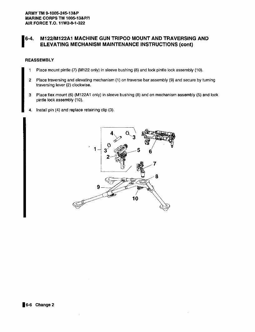
ARMY TM 9-1005-245-13&PMARINE CORPS TM 1005-13&P/1AIR FORCE T.O. 11 W2-8-1-322
6-4. M122/M122A1 MACHINE GUN TRIPOD MOUNT AND TRAVERSING ANDELEVATING MECHANISM MAINTENANCE INSTRUCTIONS (cont)
REASSEMBLY
1 Place mount pintle (7) (M122 only) in sleeve bushing (8) and lock pintle lock assembly (10).
2 Place traversing and elevating mechanism (1) on traverse bar assembly (9) and secure by turningtraversing lever (2) clockwise.
3 Place flex mount (6) (M122A1 only) in sleeve bushing (8) and on mechanism assembly (5) and lockpintle lock assembly (10).
4 Install pin (4) and replace retaining clip (3).
43
3 5 62
7
8
9
10
@10
6-6 Change 2
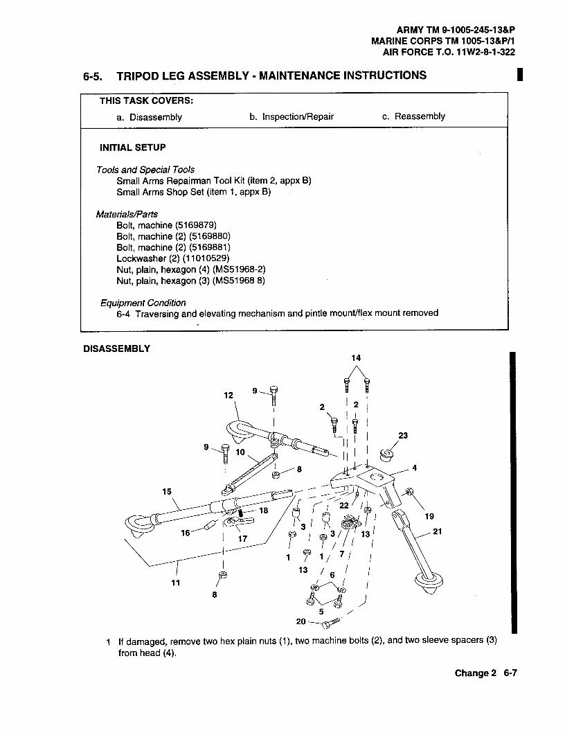
ARMY TM 9-1005-245-13&PMARINE CORPS TM 1005-13&P/1
AIR FORCE T.O. 11 W2-8-1-322
6-5. TRIPOD LEG ASSEMBLY - MAINTENANCE INSTRUCTIONS
THIS TASK COVERS:
a. Disassembly b. Inspection/Repair c. Reassembly
INITIAL SETUP
Tools and Special ToolsSmall Arms Repairman Tool Kit (item 2, appx B)Small Arms Shop Set (item 1, appx B)
Materials/PartsBolt, machine (5169879)Bolt, machine (2) (5169880)Bolt, machine (2) (5169881)Lockwasher (2) (11010529)Nut, plain, hexagon (4) (MS51968-2)Nut, plain, hexagon (3) (MS51968 8)
Equipment Condition6-4 Traversing and elevating mechanism and pintle mount/flex mount removed
DISASSEMBLY14
12 1)91 1 2 12
911 10
23
8 4
15
1822
193
161 17 03 13 21
1 7/
136
11 P8
520
1 If damaged, remove two hex plain nuts (1), two machine bolts (2), and two sleeve spacers (3)from head (4).
Change 2 6-7
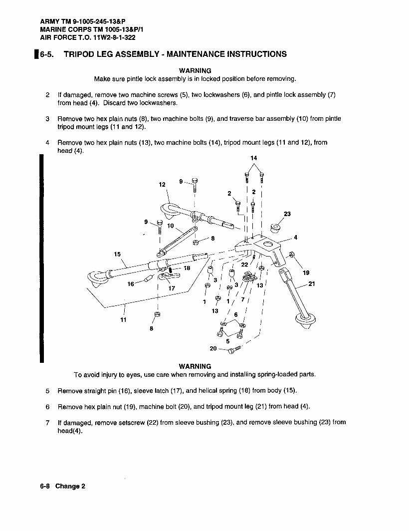
ARMY TM 9-1005-245-13&PMARINE CORPS TM 1005-13&P/1AIR FORCE T.O. 11W2-8-1-322
16-5. TRIPOD LEG ASSEMBLY - MAINTENANCE INSTRUCTIONS
WARNINGMake sure pintle lock assembly is in locked position before removing.
2 If damaged, remove two machine screws (5), two lockwashers (6), and pintle lock assembly (7)from head (4). Discard two lockwashers.
3 Remove two hex plain nuts (8), two machine bolts (9), and traverse bar assembly (10) from pintletripod mount legs (11 and 12).
4 Remove two hex plain nuts (113),two machine bolts (14), tripod mount legs (11 and 12), fromhead (4).
14
129-1 2 1 2 1
23
10 -_ 11 1 1 g'
8 4
15
18 21 19
3 1 1116
1 1773/ 13
11 21
1/ 7/
13 6
8
520
WARNINGTo avoid injury to eyes, use care when removing and installing spring-loaded parts.
5 Remove straight pin (16), sleeve latch (17), and helical spring (18) from body (15).
6 Remove hex plain nut (19), machine bolt (20), and tripod mount leg (21) from head (4).
7 If damaged, remove setscrew (22) from sleeve bushing (23), and remove sleeve bushing (23) fromhead(4).
6-8 Change 2

ARMY TM 9-1005-245-13&PMARINE CORPS TM 1005-13&P/1
AIR FORCE T.O. 11W2-8-1-322
INSPECTION/REPAIR
1 Inspect for broken, damaged, or missing parts.
2 Pintle lock assembly is a repairable assembly. Refer to paragraph 6-7.
9
25 25
18-1
20 1 19 2
14
4 13
624 24/ 11
5 10
26 26/ 2
1710
22
19
2312
3 If body (2) is broken or damaged, repair is by replacement of the next higher assembly.
4 Repair is by replacement of authorized parts (appx C).
REASSEMBLY
1 If removed, install sleeve bushing (1) in head (2). Install setscrew (3) in sleeve bushing (1).
2 Install helical spring (4), sleeve latch (5), and straight pin (6) on body (7).
3 Install leg (17) and tripod mount leg (12) on head (2) and secure with two machine bolts (20) andtwo hex plain nuts (10).
4 Install tripod mount leg (11) and secure to head (2) with machine bolt (20) and hex plain nut (13).
6-9 Change 2

ARMY TM 9-1005-245-13&PMARINE CORPS TM 1005-13&P/1AIR FORCE T.O. 11W2-8-1-322
16-5. TRIPOD LEG ASSEMBLY - MAINTENANCE INSTRUCTIONS (cont)
NOTEAdjust hex plain nuts for 0.003 in. (0.008 cm) maximum clearancebetween head and legs. All legs must pivot freely.
Place legs in vise before staking.
5 Stake hex plain nuts (10 and 13) to machine blots (9 and 12) in three places.
NOTETraverse bar assembly (16) must be adjusted so the sleeve (14) andstop (15) are 0.25 to 0.38 in. (0.64 to 0.97 cm) apart before locking.
6 Install traverse bar assembly (16) on two tripod mount legs (12 and 17), and secure with twomachine bolts (18) and two hex plain nuts (19).
7 Stake hex plain nuts (19) to machine bolts (18) in three places.
8 Tighten nut (20) and stake in slot on traverse bar assembly (16).
9 If removed, install pintle lock assembly (21), two new lockwashers (22), and two machine screws(23) on head (2).
10 If removed, install two sleeve spacers (24), two machine bolts (25), and two hex plain nuts (26) onhead (2).
11 Stake two hex plain nuts (26) to two machine bolts (25) in three places.
9
8 18-V
25 25
18
20 19 2
147
4 132416 5
24 0'1
rI ?/
/1@ I26 r 26/ 21
102217
19
2312
6-10 Change 2

ARMY TM 9-1005-245-13&PMARINE CORPS TM 1005-13&P/1
AIR FORCE T.O. 11W2-8-1-322
6-6. MECHANISM ASSEMBLY (TRAVERSING AND CLAMPING UNIT) ANDMECHANISM ASSEMBLY (ELEVATING UNIT) - MAINTENANCEINSTRUCTIONS
THIS TASK COVERS:
a. Disassembly b. Inspection/Repair c. Reassembly
INITIAL SETUP
Tools and Special ToolsSmall Arms Repairman Tool Kit (item 2, appx 13)Small Arms Shop Set (item 1, appx B)Spanner Wrench (item 3, appx 13)
Materials/PartsLockwasher (11010413)Self-locking nut (MS51943-2)Self-locking nut (MS51943-4)Spring pin (MS16562-120)
Equipment Condition6-4 Traversing and elevating mechanism disassembly
DISASSEMBLY
1 Remove two retaining rings (2) from headless2
3
grooved pin (3).
2 Remove headless grooved pin (3) fromtraversing and elevating mechanism.
2"03 Remove and discard two self-locking nuts
(1 and 5).10
4 Remove traversing handwheel (4) as a unit. 94
WARNINGTo avoid injury to eyes, use care when 7
removing and installing spring-loaded parts.6
5 Separate union nut (8), scale dial (7), headlessstraight pin (10), compression helical spring(9), and knob (6).
5
Change 2 6-11

ARMY TM 9-1005-245-13&PMARINE CORPS TM 1005-13&P/1AIR FORCE T.O. 11W2-8-1-322
6-6. MECHANISM ASSEMBLY (TRAVERSING AND CLAMPING UNIT) ANDMECHANISM ASSEMBLY (ELEVATING UNIT) - MAINTENANCEINSTRUCTIONS (cont)
6 Remove woodruff key (14) and flat washer(11) from traversing screw (15). Pushtraversing mechanism ring (13) from yoke (12)and remove traversing screw (15) from yoke. 12
13
1
147 Pull out slightly on elevating stop assembly
(18) and remove elevating screw assembly(16) from elevating mechanism sleeve (17). 16
17
18
NOTEBreak staking stop screw with punch and 19hammer before removing gun stop.
8 Turn elevating screw assembly untilcompressed or flush. Using spanner wrench(item 3, appx B), remove automatic gun stop(19) from end of elevating screw (20).
20
5
NA
6-12 Change 2
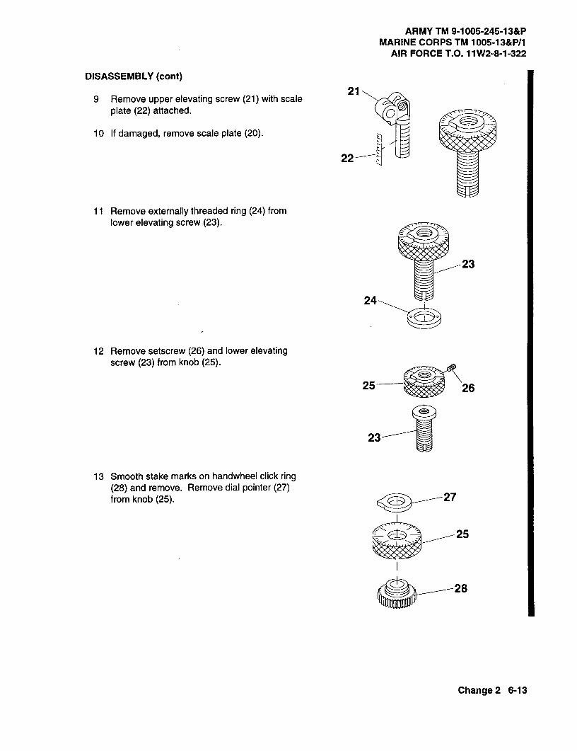
ARMY TM 9-1005-245-13&PMARINE CORPS TM 1005-13&P/1
AIR FORCE T.O. 11 W2-8-1-322
DISASSEMBLY (cont)
9 Remove upper elevating screw (21) with scale21
plate (22) attached. 0
10 If damaged, remove scale plate (20).
22
11 Remove externally threaded ring (24) fromlower elevating screw (23).
23
24
12 Remove setscrew (26) and lower elevatingscrew (23) from knob (25).
25-ar 26
23
13 Smooth stake marks on handwheel click ring(28) and remove. Remove dial pointer (27)from knob (25).
25
Change 2 6-13

ARMY TM 9-1005-245-13&PMARINE CORPS TM 1005-13&P/1AIR FORCE T.O. 11W2-8-11-322
6-6. MECHANISM ASSEMBLY (TRAVERSING AND CLAMPING UNIT) ANDMECHANISM ASSEMBLY (ELEVATING UNIT) - MAINTENANCEINSTRUCTIONS(cont)
WARNINGTo avoid injuryto eyes,use carewhen 25removing and installing spring-loaded parts.
14 Remove headless straight pin (31) andcompression helical spring (30) through thecenter hole of knob (25).
15 If damaged, drill out plain solid disk (29). 29
16 Drive out and discard spring pin (32).j 31
30
17CD
3217
33 3435
18
36a 37
17 Smooth staked metal on elevating stop assembly (18) and remove from elevating mechanismsleeve (17).
18 Remove machine screw (37) and lockwasher (36) from traversing lever (35). Remove traversinglever torsion helical spring (34), and machine screw (33) from elevating mechanism sleeve (17).Discard lockwasher (36).
INSPECTION/REPAIR
1 Inspect for broken, damaged, or missing parts.
2 If yoke is broken or missing, repair is by replacement of next higher assembly.
3 If upper elevation screw, lower elevation screw, traversing screw, or elevating mechanism sleeveare broken or damaged, repair is by replacement of next higher assembly.
4 Repair is by replacement of authorized parts (appx C).
6-14 Change 2

ARMY TM 9-1005-245-13&PMARINE CORPS TM 1005-13&P/1
AIR FORCE T.O. 11W2-8-1-322
REASSEMBLY
NOTEMachine screw (1) will need to be adjusted 17when traversing lever is installed. Traversinglever must be aligned with traverse barassembly. 33
341 Install machine screw (33), torsion helical 35
spring (34), and traversing lever (35) onelevating mechanism sleeve (17). Secure 36with new lockwasher (36) and machine screw 0 37(37).
2 Install elevating stop assembly (18) and stakein four places near bottom. Install new springpin (32) and stake material of elevatingmechanism sleeve (17) over spring pin onboth ends. 3
1817
25
25
31
3031
29 31
30P0 28
30
NOTEIf plain solid disk was removed, perform steps 3 and 4. If plain solid disk wasnot removed, go to step 5.
3 Drill out any portion of plain solid disk remaining in hole of knob (25) using 0. 125 (1/8) in. twist drill.
4 Install headless straight pin (31), compression helical spring (30), and plain solid disk (29) in side ofknob (25). Disk is to be flush to 0.010 in. (0.025 cm) below outer diameter of knob (25). Stake rimof hole in three places.
2'V18
Change 2 6-15

ARMY TM 9-1005-245-13&PMARINE CORPS TM 1005-13&P/1AIR FORCE T.O. 11W2-8-1-322
6-6. MECHANISM ASSEMBLY (TRAVERSING AND CLAMPING UNIT) ANDMECHANISM ASSEMBLY (ELEVATING UNIT) - MAINTENANCEINSTRUCTIONS (cont)
REASSEMBLY (cont)
5 Install compression helical spring (30) and headless straight pin (31) through center hole of knob(25).
6 Apply pressure to end of headless straight pin (31) and hold it while inserting handwheel click ring(28). Make sure key of handwheel click ring is aligned with 0 graduation mark on knob (25).
27
--25
C14
27
7 Position lower elevating screw (23) under handwheel click ring (25) and rest it on a flat surface.Install dial pointer (27) on handwheel click ring. Make sure dial pointer aligns within 0.030 in.(0.076 cm) of 0 graduation. Stake in four places, 90 degrees + 5 degrees apart.
6-16 Change 2
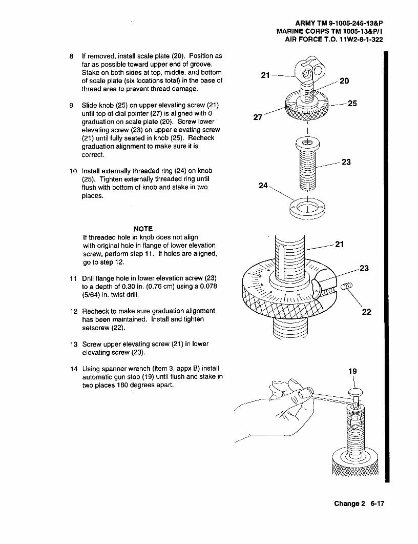
ARMY TM 9-1005-245-13&PMARINE CORPS TM 1005-13&P/1
AIR FORCE T.O. 11W2-8-1-322
8 If removed, install scale plate (20). Position asfar as possible toward upper end of groove.Stake on both sides at top, middle, and bottom 21-of scale plate (six locations total) in the base of 20thread area to prevent thread damage.
9 Slide knob (25) on upper elevating screw (21) 25until top of dial pointer (27) is aligned with 0 27graduation on scale plate (20). Screw lowerelevating screw (23) on upper elevating screw(21) until fully seated in knob (25). Recheckgraduation alignment to make sure it iscorrect.
10 Install externally threaded ring (24) on knob(25). Tighten externally threaded ring untilflush with bottom of knob and stake in two 24places.
NOTEIf threaded hole in knob does not alignwith original hole in flange of lower elevationscrew, perform step 11. If holes are aligned,go to step 12.
2311 Drill flange hole in lower elevation screw (23)
to a depth of 0.30 in. (0.76 cm) using a 0.078 av(5/64) in. twist drill.
12 Recheck to make sure graduation alignment 22has been maintained. Install and tightensetscrew (22).
13 Screw upper elevating screw (21) in lowerelevating screw (23).
14 Using spanner wrench (item 3, appx B) install 19automatic gun stop (19) until flush and stake intwo places 180 degrees apart.
7&2(
Change2 6-17

ARMY TM 9-1005-245-13&PMARINE CORPS TM 1005-13&P/1AIR FORCE T.O. 11 W2-8-1-322
6-6. MECHANISM ASSEMBLY (TRAVERSING AND CLAMPING UNIT) ANDMECHANISM ASSEMBLY (ELEVATING UNIT) - MAINTENANCEINSTRUCTIONS (cont)
REASSEMBLY (cont)
15 Pull back slightly on elevating stop assembly(18) and screw elevating screw assembly (116)in elevating mechanism sleeve (17).
.16
17
18
16 Install yoke (12), traversing mechanism ring 10(13), traversing screw (15), and flat washer 12(10).
13
0 15
17 Assemble union nut (4), scale dial (7),headless straight pin (110),compression helicalspring (9), and knob (4) to make traversing 10handwheel. @q
8
aW@o
4
Change 2 6-18

ARMY TM 9-1005-245-13&PMARINE CORPS TM 1005-13&P/1
AIR FORCE T.O. 11 W2-8-1-322
18 Install woodruff key (14) and traversinghandwheel (4), and secure with two new self- 16locking nut (1). Traversing handwheelshould move freely with no more than 1/16 ofa turn backlash.
19 Install headless grooved pin (16) and two 15 x
retaining rings (15) on traversing and elevating z
mechanism.
154
1
14
Change 2 6-19

ARMY TM 9-1005-245-13&PMARINE CORPS TM 1005-13&P/1AIR FORCE T.O. 11W2-8-1-322
6-7. PINTLE LOCK ASSEMBLY - MAINTENANCE INSTRUCTIONS
THIS TASK COVERS:
a. Disassembly b. Inspection/Repair c. Reassembly
INITIAL SETUP
Tools and Special ToolsSmall Arms Shop Set (item 1, appx B)
Materials/PartsSolid rivet (11010448)
Equipment Condition6-5 Pintle lock assembly removed
DISASSEMBLY
WARNINGTo avoid injury to your eyes, use care whenremoving and installing spring-loaded parts. 6
WARNING 4To avoid injury to your eyes, wear safety 6glasses when grinding parts. 3
1 Grind head off solid rivet (1). Remove solid 2rivet and pintle lock release cam (2). Discard 5solid rivet.
2 Remove shaft collar (3) from body (4).
3 Remove housing (5) and two helical springs(6) from body (4).
INSPECTION/REPAIR
1 Inspect for broken, damaged, or missing parts.
2 If shaft collar, body, or housing are broken or damaged, repair is by replacement of next higherassembly.
3 Repair is by replacement of authorized parts (appx C).
REASSEMBLY
1 Install two helical springs (6) in body (4). Install body in housing (5) so that post sticks out throughU-shaped opening of housing.
2 Install shaft collar (3) on body (4).
3 Position pintle lock release cam (2) over body (4) and secure with new solid rivet (1). Pintle lockrelease cam should pivot freely after riveting. Peen over end of rivet.
6-20 Change 2

ARMY TM 9-1005-245-13&PMARINE CORPS TM 1005-13&P/1
AIR FORCE T.O. 11W2-8-1-322
CHAPTER7
M3 TRIPOD MOUNT
Section 1. UNIT MAINTENANCE INSTRUCTIONS
7-1. M3 MACHINE GUN TRIPOD MOUNT-MAINTENANCE INSTRUCTIONS
THIS TASK COVERS:
a. Disassembly b. Inspection/Repair C. Reassembly
INITIAL SETUP
Tools and Special ToolsSmall Arms Repairman Tool Kit (item 2, appx 13)
Materials/Partscotter pin (MS24665-834)
DISASSEMBLY
1 if damaged, remove mount pintle (1) from7
sleeve bearing (2).4
2 Remove cotter pin (3), slotted plain nut (4), and 3
machine bolt (5) from mount pintle (1). Discard 6cotter pin.
3 Turn remote control lever (6) counterclockwiseand remove elevation mechanism (7) from 2
traversing bar assembly (8). 8
INSPECTION/REPAIR
1 Inspect for broken, damaged, or missing parts.
2 Elevation mechanism is a repairable assembly.Notify direct support maintenance.
3 Repair is by replacement of authorized parts(appx C).
REASSEMBLY
1 Place elevation mechanism (7) on traversing bar assembly (8) and secure by turning remote control lever(6) clockwise.
2 Install machine bolt (5), slotted plain nut (4), and new cotter pin (3) on mount pintle (1).
3 If removed, install mount pintle (1) on sleeve bearing (2).
7-1

ARMY TM 9-1005-245-13&PMARINE CORPS TM 1005-13&P/1AIR FORCE T.O. 11W2-8-1-322
7-2. TRIPOD MOUNT LEG (LEFT REAR, FRONT, AND RIGHT REAR)---MAINTENANCEINSTRUCTIONS
THIS TASK COVERS:
a. Inspection b. Disassembly c. Repair d. Reassembly
INITIAL SETUP
ToolsandSpecial ToolsSmall Arms Repairman Tool Kit (item 2, appx B)
Materials/PartsLockwasher (11010530)
NOTEUnit maintenance on the tripod mount legs (left rear, front, and right rear) consists of replacinghardware that is missing or damaged. Procedures for the three legs are identical. The followingprocedure is written and illustrated for the left rear tripod mount leg but applies to all three tripodmount legs.
NOTEINSPECTION TRIPODMOUNTLEGREMOVEDFOR
CLARITY.
Check for broken, damaged, or missing parts.
DISASSEMBLY
1 Remove setscrew (1) and Iockwasher (2) frommount leg (3). Discard Iockwasher.
2 Remove spring pin (4) and hexagon plain nut (5)from manual control handle (6).
REPAIR
Repair is by replacement of authorized parts (appx C). _/{_REASSEMBLY
1 Install hexagon plain nut (5) and spring pin (4)on manual control handle (6). Stake nut at bothends of pin.
2 Install new Iockwasher (2). Install setscrew (1)on mount leg (3),
7-2

ARMYTM9-1005-245-13&PMARINECORPSTM 1005-13&P/1
AlR FORCE T.O. 11W2-8-1-322
Section II. DIRECT SUPPORT MAINTENANCE INSTRUCTIONS
7-3. M3 MACHINE GUN TRIPOD MOUNT-MAINTENANCE INSTRUCTIONS
THIS TASK COVERS:
a. Disassembly b. Inspection/Repair c. Reassembly
INITIAL SETUP
Tools and Special ToolsSmall Arms Repairman Tool Kit (item 2, appx B)Small Arms Shop Set (item 1, appx B)
Materials/PartsCotter pin (MS24665-834)
DISASSEMBLY
1 If damaged, remove mount pintle (1) fromsleeve bearing (2).
2 Remove cotter pin (3), slotted plain nut (4), andmachine bolt (5) from mount pintle (1). Discardcotter pin. 7 4
3 Turn remote control lever (6) counterclockwise 65
and remove elevation mechanism (7) fromtraversing bar assembly (8).
INSPECTION/REPAIR
1 Inspect for broken, damaged, or missing parts. 8 2
2 For further disassembly of M3 machine guntripod mount, refer to paragraph 7-4.
3 Elevation mechanism is a repairable assembly.Refer to paragraph 7-8.
4 Repair is by replacement of authorized parts(appx C) .
REASSEMBLY
1 Place elevation mechanism (7) on traversing bar assembly (8) and secure by turning remote control lever(6) clockwise.
2 Install machine bolt (5), slotted plain nut (4), and new cotter pin (3) on mount pintle (1).
3 If removed, install mount pintle (1) on sleeve bearing (2).
7-3
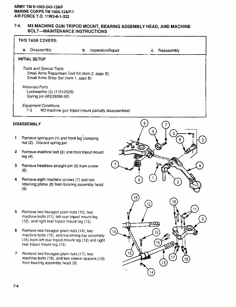
ARMY TM 9-1005-245-13&PMARINE CORPS TM 1005-13&P/1AIR FORCE T.O. 11W2-8-1-322
7-4. M3 MACHINE GUN TRIPOD MOUNT, BEARING ASSEMBLY HEAD, AND MACHINEBOLT--MAINTENANCE INSTRUCTIONS
THIS TASK COVERS:
a. Disassembly b. Inspection/Repair c. Reassembly
INITIAL SETUP
Toolsand SpecialToolsSmall Arms Repairman Tool Kit (item 2, appx B)Small Arms Shop Set (item 1, appx B)
Materials/PartsLockwasher (2) (11010529)Spring pin (MS39086-95)
EquipmentConditions7-3 M3 machine gun tripod mount partially disassembled
DISASSEMBLY
1 Remove spring pin (1) and front leg'clamping -_nut(2). Discard spring pin.
v
2 Remove machine bolt (3) ana front tripod mountleg (4).
3 Remove headless straight pin (5) from screw(6).
4 Remove eight machine screws (7) and tworetaining plates (8) from bearing assembly head(9).
5 Remove two hexagon plain nuts (10), two '_machine bolts (11), left rear tripod mount leg(12), and right rear tripod mount leg (13).
6 Remove two hexagon plain nuts (14), twomachine bolts (15), and traversing bar assembly(16) from left rear tripod mount leg (12) and rightrear tripod mount leg (13). ¢/
7 Remove two hexagon plain nuts (17), twomachine bolts (18), and two sleeve spacers (19)from bearing assembly head (9).
7-4

ARMYTM 9-1005-245-13&PMARINECORPSTM 1005-13&P/1
AIR FORCE T.O. 11W2-8-1-322
9
WARNING 0
Make sure the mount latch is locked beforeremoving.
8 Remove two machine screws (20), twolockwashers (21), and pintle mount latch (22)from bearing assembly head (9). Discardlockwashers. 22
21
20
24
9 Remove setscrew (23) and sleeve bearing (24) 25from tripod head (25).
12, 401004'
23
INSPECTION/REPAIR
1 Inspect for broken, damaged, or missing parts.
2 Left rear tripod mount leg is a repairable assembly. Refer to paragraph 7-5.
3 Front tripod mount leg is a repairable assembly. Refer to paragraph 7-6.
4 Right rear tripod mount leg is a repairable assembly. Refer to paragraph 7-7.
5 Pintle mount latch is a repairable assembly. Refer to paragraph 7-9.
6 If bearing assembly head is broken or damaged, repair is by replacement of next higher assembly.
7 If tripod head is broken or damaged, repair is by replacement of next higher assembly.
8 If screw (6108400) is broken or damaged, repair is by replacement of next higher assembly.
9 Repair is by replacement of authorized parts (appx C).
7-5

ARMY TM 9-1005-245-13&PMARINE CORPS TM 1005-13&P/1AIR FORCE T.O. 11W2-8-1-322
7-4. M3 MACHINE GUN TRIPOD MOUNT, BEARING ASSEMBLY HEAD, AND MACHINEBOLT-MAINTENANCE INSTRUCTIONS (cont)
REASSEMBLY
3
1 Install sleeve bearing (1) and setscrew (2) intripod head (3).
2
8 5 10
7
4
611
2 Install two sleeve spacers (4), two machine bolts (5), and two hexagon plain nuts (6) in bearing assemblyhead (7). Stake each nut to machine bolt in three places.
3 Position left rear tripod mount leg (8) and right rear tripod mount leg (9) in bearing assembly head (7) andsecure with two machine bolts (10) and two hexagon plain nuts (11). Legs should pivot freely in unlockedposition. Stake each nut to machine bolt in three places.
CIO
7-6
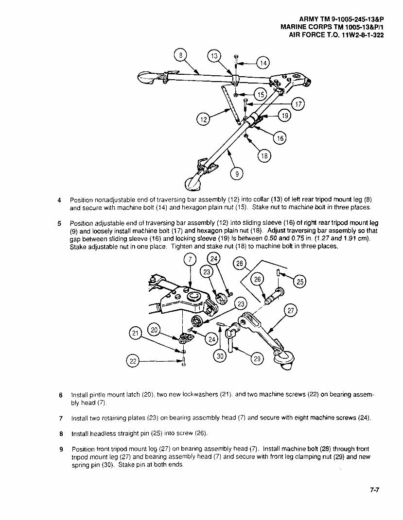
ARMY TM 9-1005-245-13&PMARINE CORPS TM 1005-13&P/1
AIR FORCE T.O. 11W2-8-1-322
4 Position nonadjustable end of traversing bar assembly (12) into collar (13) of left rear tripod mount leg (8)and secure with machine bolt (14) and hexagon plain nut (15), Stake nut to machine bolt in three places.
5 Position adjustable end of traversing bar assembly (12) into sliding sleeve (16) of right rear tripod mount leg(9) and loosely install machine bolt (17) and hexagon plain nut (18). Adjust traversing bar assembly so thatgap between sliding sleeve (16) and locking sleeve (19) is between 0.50 and 0.75 in. (1.27 and 1.91 cra).Stake adjustable nut in one place. Tighten and stake nut (18) to machine bolt in three places.
6 Install pintle mount latch (20), two new Iockwashers (21), and two machine screws (22) on bearing assem-bly head (7).
7 Install two retaining plates (23) on bearing assembly head (7) and secure with eight machine screws (24).
8 Install headless straight pin (25) into screw (26).
9 Position front tripod mount leg (27) on bearing assembly head (7). Install machine bolt (28) through fronttripod mount leg (27) and bearing assembly head (7) and secure with front leg clamping nut (29) and newspring pin (30). Stake pin at both ends.
7-7
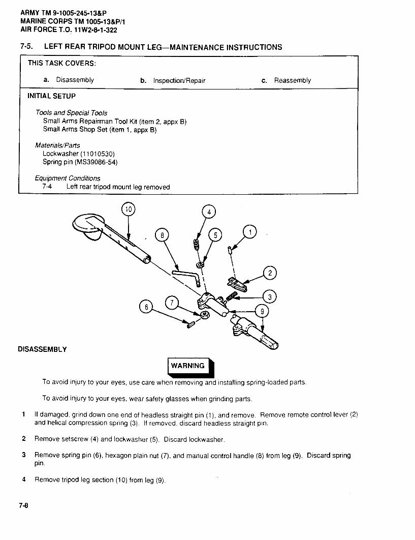
ARMY TM 9-1005-245-13&PMARINE CORPS TM 1005-13&P/1AIR FORCE T.O. 11W2-8-1-322
7-5. LEFT REAR TRIPOD MOUNT LEG--MAINTENANCE INSTRUCTIONS
THIS TASK COVERS:
a. Disassembly b. Inspection/Repair c. Reassembly
INITIAL SETUP
Toolsand SpecialToolsSmall Arms Repairman Tool Kit (item 2, appx B)Small Arms Shop Set (item 1, appx B)
Materials/PartsLockwasher (11010530)Spring pin (MS39086-54)
EquipmentConditions7-4 Left rear tripod mount leg removed
DISASSEMBLY
WARNING
To avoid injury to your eyes, use care when removing and installing spring-loaded parts.
To avoid injury to your eyes, wear safety glasses when grinding parts.
1 If damaged, grind down one end of headless straight pin (1), and remove. Remove remote control lever (2)and helical compression spring (3). If removed, discard headless straight pin.
2 Remove setscrew (4) and Iockwasher (5). Discard Iockwasher.
3 Remove spring pin (6), hexagon plain nut (7), and manual control handle (8) from leg (9). Discard springpin.
4 Remove tripod leg section (1O) from leg (9).
7-8

ARMY TM 9-1005-245-13&PMARINE CORPS TM 1005-13&P/1
AIR FORCE T.O. 11W2-8-1-322
INSPECTION/REPAIR
I Inspect for broken, damaged, or missing parts,
2 If leg is damaged, repair is by replacement of next higher assembly.
3 Repair is by replacement of authorized parts (appx C).
®
REASSEMBLY
Slide tripod leg section (1) into leg (2) and install new Iockwasher (3) and setscrew (4).
2 Install manual control handle (5) in leg (2). Screw hexagon plain nut (6) on manual control handle andtighten, leaving a 0.005 + 0.015 in. (0.013 + 0.038 cra) clearance between hexagon plain nut and leg. Ifnew manual control handle is installed, drill a 0.062 + 0.003 in. (0.157 + 0.008 cm) diameter hole for springpin (7) in manualcontrol handle, using hexagon plain nut as a guide. Install new spring pin. Stake nut atboth ends of spring pin.
3 If removed, install helical compression spring (8), remote control lever (9), and new headless straight pin(10). Stake headless straight pin securely at both ends.
NOTERemote control lever should pivot freely after staking and return to original position by springforce after compression.
Tripod leg sectionshould slide freely when clamping is released.
7-9

ARMY TM 9-1005-245-13&PMARINE CORPS TM 1005-13&P/1AIR FORCE T.O. 11W2-8-1-322
7-6. FRONT TRIPOD MOUNT LEG--MAINTENANCE INSTRUCTIONS
THIS TASK COVERS:
a. Disassembly b. Inspection/Repair c. Reassembly
INITIAL SETUP
ToolsandSpecial ToolsSmall Arms Repairman Tool Kit (item 2, appx B)Small Arms Shop Set (item 1, appx B)
Materials/Parts
Lockwasher (11010530)Spring pin (MS39086-54)
EquipmentConditions7-4 Front tripod mount leg removed
DISASSEMBLY
To avoid injury to your eyes, use carewhen removing and installing spring-loaded \
p_rts. _ /To avoid injury to your eyes, wear safetyglasses when grinding parts.
1 If damaged, grind down one end of headlessstraight pin (1), and remove. Remove remotecontrol lever (2) and helical compression sprang
(3). If removed, discard headless straight pin. ,_,
2 Remove setscrew (4) and Iockwasher (5).Discard Iockwasher.
3 Remove spring pin (6), hexagon plain nut (7),and manual control handle (8) from leg (9).Discard spring pin.
4 Remove leg (10) from leg (9).
7-10
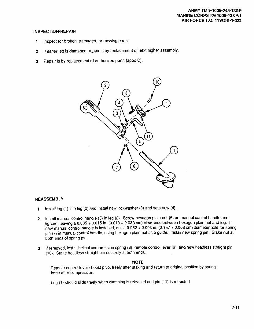
ARMY TM 9-1005-245-13&PMARINE CORPS TM 1005-13&P/1
AIR FORCE T.O. 11W2-8-1-322
INSPECTION/REPAIR
I Inspect for broken, damaged, or missing parts.
2 It either leg is damaged, repair is by replacement of next higher assembly.
3 Repair is by replacement of authorized parts (appx C).
/
REASSEMBLY
1 Install leg (1) into leg (2) and install new Iockwasher (3) and setscrew (4).
2 Install manual control handle (5) in leg (2). Screw hexagon plain nut (6) on manual control handle andtighten, leaving a 0.005 + 0.015 in. (0.013 + 0.038 cm) clearance between hexagon plain nut and leg. Ifnew manual control handle is installed, drill a 0.062 + 0.003 in. (0.157 + 0.008 cm) diameter hole for springpin (7) in manualcontrol handle, using hexagon plain nut as a guide. Install new spring pin. Stake nut atboth ends of spring pin.
3 If removed, install helical compression spring (8), remote control lever (9), and new headless straight pin(10). Stake headless straight pin securely at both ends.
NOTERemote control lever should pivot freely after staking and return to original position by springforce after compression.
Leg (1) should slide freely when clamping is released and pin (11) is retracted.
7-11

ARMY TM 9-1005-245-13&PMARINE CORPS TM 1005-13&P/1AIR FORCE T.O. 11W2-8-1-322
7-7. RIGHT REAR TRIPOD MOUNT LEG--MAINTENANCE INSTRUCTIONS
THIS TASK COVERS:
a. Disassembly b. Inspection/Repair c. Reassembly
INITIAL SETUP
Toolsand SpecialToolsSmall Arms Repairman Tool Kit (item 2, appx B)Small Arms Shop Set (item 1, appx B)
Materials/PartsLockwasher (11010530)Spring pin (MS39086-54)
EquipmentConditions7-4 Right rear tripod mount leg removed
/CL_
DISASSEMBLY
WARNING
To avoid injury to your eyes, use care when removing and installing spring-loaded parts.
To avoid injury to your eyes, wear safety glasses when grinding parts.
1 If damaged, grind down one end of headless straight pin (1) and remove. Remove lock-release lever (2)and helical spring (3). If removed, discard headless straight pin.
2 If damaged, grind down one end of headless straight pin (4) and remove. Remove manual remote controllever (5) and helical spring (6). If removed, discard headless straight pin.
3 Remove setscrew (7) and Iockwasher (8). Discard Iockwasher.
4 Remove spring pin (9), hexagon plain nut (10), and manual control handle (11) from leg (12). Discard springpin.
5 Remove tripod leg section (13) from leg (12).
7-12

ARMYTM 9-1005-245-13&PMARINECORPSTM1005-13&P/1
AIR FORCET.O. 11W2-8-1-322
INSPECTION/REPAIR
1 Inspect for broken, damaged, or missing parts.
2 If leg is damaged, repair is by replacement of next higher assembly.
3 Repair is by replacement of authorized parts (appx C).
5
4
2
3 %
14
7 12
8
96 13
10
REASSEMBLY
1 Slide tripod leg section (1) into leg (2) and install new lockwasher (3) and setscrew (4).
2 Install manual control handle (5) into leg (2). Screw hexagon plain nut (6) on manual control handle andtighten, leaving a 0.005 + 0.015 in. (0.013 + 0.038 cm) clearance between plain hexagon nut and leg. Ifnew manual control handle is installed, drill a 0.062 + 0.003 in. (0.157 + 0.008 cm) diameter hole for springpin (7) in manual control handle, using hexagon plain nut as a guide. Install new spring pin. Stake nut atboth ends of spring pin.
3 It removed, install helical spring (8), manual remote control lever (9), and new headless straight pin (10).Stake headless straight pin securely at both ends.
4 If removed, install helical spring (11), lock-release lever (12), and new headless straight pin (13). Stakeheadless straight pin securely at both ends.
NOTEManual remote control lever and lock-release lever should pivot freely after staking and shouldreturn to original position by spring force after compression.
Tripod leg section (1) should slide freely when clamping is released and pin (14) is retracted.
7-13

ARMY TM 9-1005-245-13&PMARINE CORPS TM 1005-13&P/1AIR FORCET.O. 11W2-8-1-322
7-8. ELEVATION MECHANISM (TRAVERSING AND CLAMPING UNIT AND ELEVATIONMECHANISM (ELEVATING UNIT)-MAINTENANCE INSTRUCTIONS
THIS TASK COVERS:
a. Disassembly b. Inspection/Repair c. Reassembly
INITIAL SETUP
Tools and Special ToolsSmall Arms Repairman Tool Kit (item 2, appx B)Small Arms Shop Set (item 1, appx B)Spanner Wrench (item 3, appx B)
Materials/PartsLockwasher (11010413)Self-locking nut (MS51943-2)Self-locking nut (MS51943-4)Self-locking screw (5140383)Spring pin (MS16562-120)
Equipment Conditions7-3 Elevation mechanism removed
2DISASSEMBLY
3
1 Pry open links on ends of single chain assembly(1) and remove single chain assembly. Removequick release pin (2) from yoke (3).
4
2 Remove two self-locking nuts (4 and 5). Discardtwo self-locking nuts.
5
7-14

ARMY TM 9-1005-245-13&PMARINE CORPS TM 1005-13&P/1
AIR FORCE T.O. 11W2-8-1-322
3 Remove traversing handwheel (6) as a unit.
WARNING'
To avoid injury to your eyes, use care when removing and installing spring-loaded parts.
4 Separate union nut (7), scale dial (8), headless straight pin (9), helical compression spring (10), and knob(11).
5 Remove woodruff key (12) and flat washer (13) from traversing screw (14). Push traversing click ring (15)from yoke (3) and remove traversing screw (14) from yoke.
6 Pull out slightly on flat spring (16) and remove elevating screw assembly (17) from elevating mechanismsleeve (18),
7 Using spanner wrench (item 3, appx B), remove automatic gun stop (19) from end of lower elevation screw(2o).
7-15

ARMY TM 9-1005-245-13&PMARINE CORPS TM 1005-13&P/1AIR FORCE T.O. 11W2-8-1-322
7-8. ELEVATION MECHANISM (TRAVERSING AND CLAMPING UNIT) AND ELEVATIONMECHANISM (ELEVATING UNIT)-MAINTENANCE INSTRUCTIONS (cont)
DISASSEMBLY (cont)
22
8 Remove upper elevation screw (21) with desig-nation plate (22) attached.
9 If damaged, remove designation plate (22).
10 Remove externally threaded ring (23) from lower20elevation screw (20).
2425
11 Remove setscrew (24) and lower elevationscrew (20) from knob (25).
20
7-16

ARMY TM 9-1005-245-13&PMARINE CORPS TM 1005-13&P/1
AIR FORCE T.O. 11 W241-1-322
27
12 Smooth stake marks on elevating click ring (26) 25
and remove. Remove dial pointer (27) fromknob (25).
26
25
WARNING28
To avoid injury to your eyes, use carewhen removing and installing spring-loaded 29
parts. 30
13 Remove headless straight pin (28) and com-pression helical spring (29) through the centerhole of knob (25).
14 If damaged, drill out plain solid disk (30).
31
15 Drive out and discard spring pin (31).
16 Smooth staked metal on flat spring (16) andremove from elevating mechanism sleeve (18)
.
18
7-17
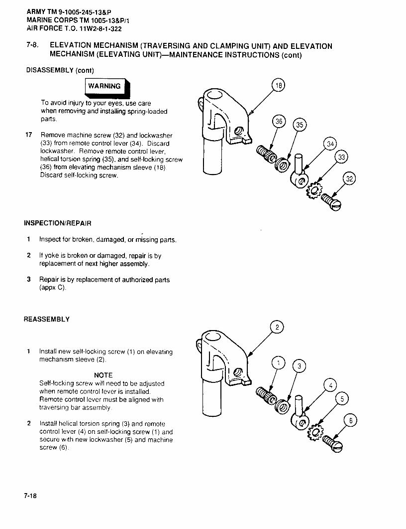
ARMY TM 9-1005-245-13&PMARINE CORPS TM 1005-13&P/1AIR FORCE T.O. 11W2-8-1-322
7-8. ELEVATION MECHANISM (TRAVERSING AND CLAMPING UNIT) AND ELEVATIONMECHANISM (ELEVATING UNIT)-MAINTENANCE INSTRUCTIONS (cont)
DISASSEMBLY (cont)
WARNING 18
To avoid injury to your eyes, use carewhen removing and installing spring-loadedparts. 36 35
17 Remove machine screw (32) and lockwasher(33) from remote control lever (34). Discard 34lockwasher. Remove remote control lever,
33helical torsion spring (35), and self-locking screw(36) from elevating mechanism sleeve (18).Discard self-locking screw.
32
INSPECTION/REPAIR
1 Inspect for broken, damaged, or missing parts.
2 It yoke is broken or damaged, repair is byreplacement of next higher assembly.
3 Repair is by replacement of authorized parts(appx C).
REASSEMBLY2
1 Install new self-locking screw (1) on elevatingmechanism sleeve (2).
NOTESelf-locking screw will need to be adjusted 4when remote control lever is installed.Remote control lever must be aligned with 5traversing bar assembly.
2 Install helical torsion spring (3) and remote 6
control lever (4) on self-locking screw (1) andsecure with new lockwasher (5) and machinescrew (6).
7-18

ARMY TM 9-1005-245-13&PMARINE CORPS TM 1005-13&P/1
AIR FORCE T.O. 11W2-8..1-322
3 Install flat spring (7) and stake in four placesnear the bottom. Instalt new spring pin (8) andstake material of elevating mechanism sleeve(2) over spring pin on both ends.
NOTEIf plain solid disk was removed, performsteps 4 and 5. If plain solid disk was notremoved, go to step 6.
4 Drill out any portion of plain solid disk remainingin hole of knob (9) using a 0.125 (1/8) in. twistdrill.
5 Install headless straight pin (10), helical com-pression spring (11), and plain solid disk (12) inside of knob (9), Disk is to be flush to 0.010 in,(0.025 cm) below outer diameter of knob (9).Stake rim of hole in three places.
®
6 Install helical compression spring (11) and headless straight pin (10) through center hole of knob (9).
7 Apply pressure to end of headless straight pin (10) and hold it while inserting elevating click ring (13). Makesure key of elevating click ring is aligned with 0 graduation mark on knob (9).
7-19

ARMY TM 9-1005-245-13&PMARINE CORPS TM 1005-13&P/1AIR FORCE T.O. 11W2-8-1-322
7-8. ELEVATION MECHANISM (TRAVERSING AND CLAMPING UNIT) AND ELEVATIONMECHANISM (ELEVATING UNIT)--MAINTENANCE INSTRUCTIONS (cont)
REASSEMBLY (cont)
// tO
8 Position lower elevation screw (14) under elevating click ring il3) and rest it on a flat surface. Install dialpointer (15) on elevating click ring. Make sure dial pointer aligns within 0.030 in. (0.076 cm) of 0 graduation.Stake in three places 120+ 5 degrees apart.
9 If removed, install designation plate (16). ;_Position as far as possible toward upper end of ;,groove. Stake on both sides at top, middle, andbottom of designation plate (six locations total)in the base of thread area to prevent thread
damage. 'i_10 Slide knob (9) on upper elevation screw (17)until top of dial pointer (15) is aligned with 0 ' >graduation on designation plate (16). Screwlower elevation screw (14) on upper elevationscrew (17) until fully seated in knob (9). lkLt,)Recheck graduation alignment to make sure it iscorrect.
11 Install externally threaded ring (18) on knob (9). _O/_'"_ _ _Tighten externally threaded ring until flush withbottom of knob and stake in two places.
7-20

ARMYTM9-1005-245-13&PMARINECORPSTM 1005-13&P/1
AIR FORCET.O. 11W2-8-1-322
17NOTE
If threadedhole inknobdoesnot alignwithoriginal hole in flange of lower elevationscrew, perform step 12. If holes are
14aligned, go to step 13.
12 Drill flange hole in lower elevation screw (14) toa depth of 0.30 in. (0.76 cm) using a 0.078(5/64) in. twist drill.
13 Recheck to make sure graduation alignment has 19been maintained. Install and tighten setscrew(19).
14 Screw upper elevation screw (17) in lowerelevation screw (14).
20
15 Using spanner wrench (Rem 3, appx 8), installautomatic gun stop (20) until flush and stake intwo places 180 degrees apart.
21
16 Pull back slightly on flat spring (7) and screwelevating screw (21) in elevating mechanismsleeve (2). 2
7
7-21
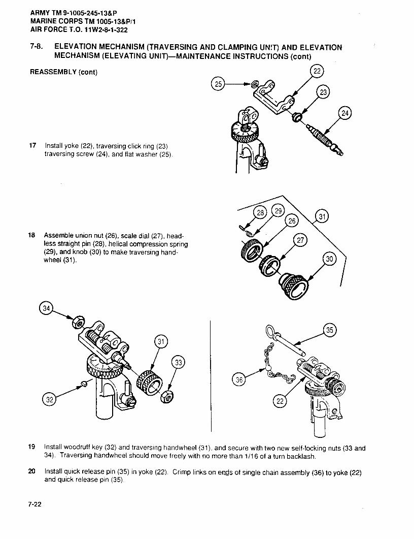
ARMY TM 9-1005-245-13&PMARINE CORPS TM 1005-13&P/1AIR FORCE T.O. 11W2-8-1-322
7-8. ELEVATION MECHANISM (TRAVERSING AND CLAMPING UNIT) AND ELEVATIONMECHANISM (ELEVATING UNIT)-MAINTENANCE INSTRUCTIONS (cont)
REASSEMBLY (cont) 22
23
24
17 Install yoke (22), traversing click ring (23),traversing screw (24), and flat washer (25).
28 29
2631
18 Assemble union nut (26), scale dial (27), head-27less straight pin (28), helical compression spring
(29), and knob (30) to make traversing hand-wheel (31). 30
34
35
31
-","Jot 33
36
22
19 Install woodruff key (32) and traversing handwheel (31), and secure with two new self-locking nuts (33 and34). Traversing handwheel should move freely with no more than 1/16 of a turn backlash.
20 Install quick release pin (35) in yoke (22). Crimp links on ends of single chain assembly(36)to yoke(22) and quick releasepin
7-22

ARMY TM 9-1005-245-13&PMARINE CORPS TM 1005-13&P/1
AIR FORCE T.O. 1lW2-8-1-322
7-9. PINTLE MOUNT LATCH--MAINTENANCE INSTRUCTIONS
THIS TASK COVERS:
a. Disassembly b. Inspection/Repair c. Reassembly
INITIAL SETUP
Tools and Special ToolsSmall Arms Repairman Tool Kit (item 2, appx B)Small Arms Shop Set (item 1, appx B)
Materials/PartsSolid rivet (11010448)
EquipmentConditions7-4 Pintie mount latch removed
DISASSEMBLY
WARNING
To avoid injury to your eyes, wear safetyglasses when grinding pads.
1 Grind head off solid rivet (1). Remove solid rivetand pintle lock release cam (2). Discard solidrivet.
2 Remove shaft collar (3) from lock (4). Wf '_WARNING
To avoid injury to your eyes, use carewhen removing and installing spring-loadedparts.
3 Remove housing (5) and two helical compres-sion springs (6) from lock (4).
INSPECTION/REPAIR
1 Inspect for broken, damaged, or missing parts.
2 It shaft collar, lock, or housing are broken or damaged, repair is by replacement of next higher assembly.
3 Repair is by replacement of authorized parts (appx C).
REASSEMBLY
1 Install two helical compression springs (6) in lock (4). Install lock in housing (5) so that post sticks outthrough U-shaped opening of housing.
2 Install shaft collar (3) on lock (4).
3 Position pintle lock release cam (2) over lock (4) and secure with new solid rivet (1). Pintle lock release camshould pivot freely after riveting. Peen over end of rivet.
7-23/(7-24 blank)


ARMY TM 9-1005-245-13&PMARINE CORPS TM 1005-13&P/1
AIR FORCE T.O. 11W2-8-1-322
CHAPTER 8
M66 MACHINE GUN MOUNT RING
Section I. UNITMAINTENANCEINSTRUCTIONS
8-1. M66 MACHINE GUN MOUNT RING--MAINTENANCE INSTRUCTIONS
THIS TASK COVERS:
a. Disassembly b. Inspection/Repair c. Reassembly
INITIAL SETUP
Toolsand SpecialToolsSmall Arms Repairman Tool Kit (item 2. appx B)
Materials/PartsCotter pin (2)(MS24665-132)
Self-locking nut (2) (MS51922-29) I
!EquipmentConditions14-1 M66 machine gun mount ring removed
DISASSEMBLY
1 Remove two cotter pins (1). two headed straight 1(_,..._ _ _ _____
assembly (4). Discard cotter pins.
2 Remove two setscrews (5), flexible wire (6), andcartridge deflector (7).
3 Remove two self-locking nuts (8), two flatwashers (9), two hexagon capscrews (10), anddeflector support (11) from ring assembly (4).Discard self-locking nuts.
8-1
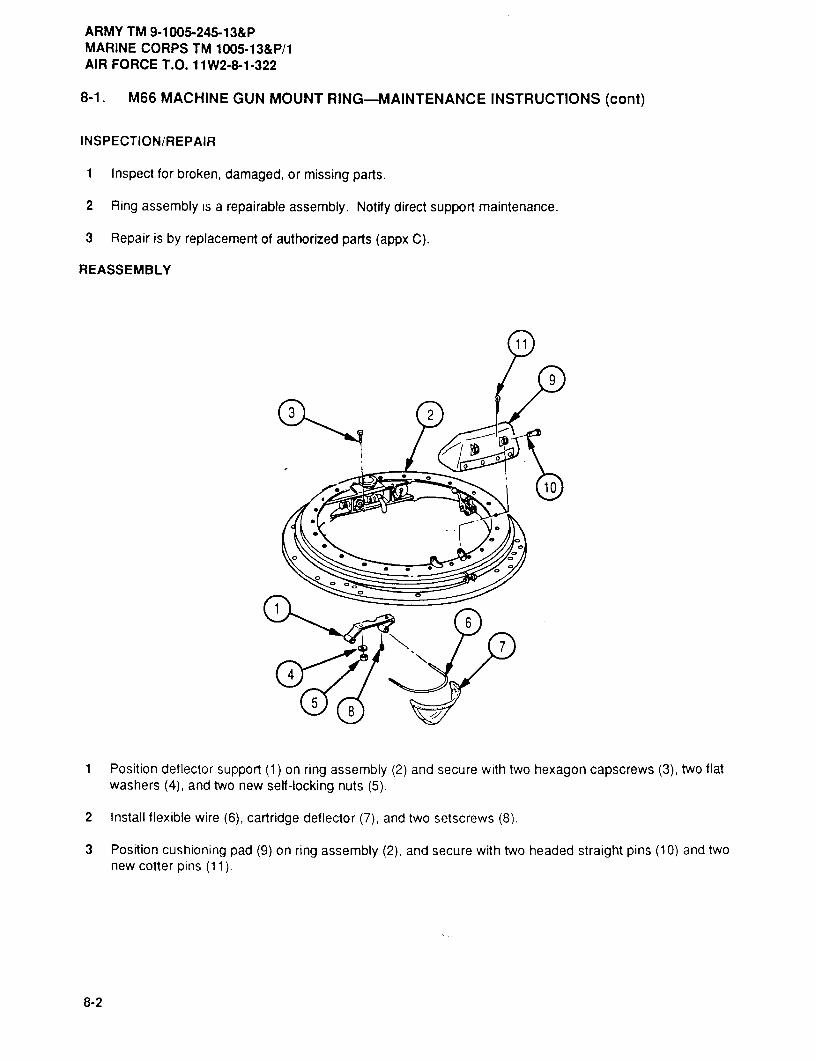
ARMY TMI9-1005-245-13&PMARINE CORPS TM 1005-13&P/1AIR FORCE T.O. 11W2-8-1-322
8-1. M66 MACHINE GUN MOUNT RING-MAINTENANCE INSTRUCTIONS (cont)
INSPECTION/REPAIR
1 Inspect for broken, damaged, or missing parts.
2 Ring assembly is a repairable assembly. Notify direct support maintenance.
3 Repair is by replacement of authorized parts (appx C).
REASSEMBLY
9
3 2
0 0
10
6
7
4
58
1 Position deflector support (1) on ring assembly (2) and secure with two hexagon capscrews (3), two flatwashers (4), and two new self -locking nuts (5).
2 Install flexible wire (6), cartridge deflector (7), and two setscrews (8).
3 Position cushioning pad (9) on ring assembly (2), and secure with two headed straight pins (10) and twonew cotter pins (11).
8-2

ARMY TM 9-1005-245-13&PMARINE CORPS TM 1005-13&P/1
AIR FORCE T.O. 11W2-8-1-322
8-2. RING ASSEMBLY AND RING-MAINTENANCE INSTRUCTIONS
THIS TASK COVERS:
a. Disassembly b. Inspection/Repair c. Reassembly
INITIAL SETUP
Tools and Special ToolsSmall Arms Repairman Tool Kit (item 2, appx B)
Equipment Conditions8-1 M66 machine gun mount ring disassembled
I
DISASSEMBLY
1 Remove pintle lock cap (1), two S chain hooks 3
(2), and weldless chain (3) from upper revolvingring (4).
2 Remove sleeve bushing (5) from upper revolvingring (4).
3 If damaged, remove two cotter pins (6) from 2pintle lock handle (7) and cotter pin (8) from 7
headless shoulder pin (9).
INSPECTION/REPAIR
1 Inspect for broken, damaged, or missing parts. 8
2 Repair is by replacement of authorized parts(appx C).
REASSEMBLY
1 It removed, install cotter pin (8) in headlessshoulder pin (9) and two cotter pins (6) in pintlelock handle (7).
2 Install sleeve bushing (5) in upper revolving ring(4). 5
63 Install weldless chain (3), two S chain hooks (2),
and pintle lock cap (1) on upper revolving ring(4).
8-3

ARMY TM 9-1005-245-13&PMARINE CORPS TM 1005-13&P/1AlR FORCE T.O. 11 W2-8-1-322
8-3. RING BRAKE-MAINTENANCE INSTRUCTIONS
THIS TASK COVERS:
a. Disassembly b. Inspection/Repair c. Reassembly
INITIAL SETUP
Tools and Special ToolsSmall Arms Repairman Tool Kit (Item 2, appx B)
DISASSEMBLY
1 Remove socket head capscrew (1) and manualcontrol lever (2).
2 If damaged, remove two cotter pins (3) from 3headless straight pin (4).
INSPECTION/REPAIR2 4
1 Inspect for broken, damaged, or missing parts.0
2 Repair is by replacement of authorized parts(appx C).
REASSEMBLY
1 If removed, install two cotter pins (3) in headlessstraight pin (4).
2 Install manual control lever (2) and secure withsocket head capscrew (1).
C>
8-4

ARMY TM 9-1005-245-13&PMARINE CORPS TM 1005-13&P/1
AIR FORCE T.O. 11W2-8-1-322
Section II. DIRECT SUPPORT MAINTENANCE INSTRUCTIONS
8-4. RING ASSEMBLY, RING ASSEMBLY, AND RING,--MAINTENANCE INSTRUCTIONS
THIS TASK COVERS:
a. Disassembly b. Inspection/Repair c. Reassembly
INITIAL SETUP
Tools and Special ToolsSmall Arms Repairman Tool Kit (item 2, appx B)Small Arms Shop Set (item 1, appx B)
Materials/PartsCotter pin (2) (MS24665-283)Cotter pin (MS24665-285)Grease (item 4, appx E)Lockwasher (22) (MS35333-38)Lockwasher (24) (MS35333-39)Lockwasher (MS35338-43)Mechanical felt (7012805-1)Mechanical felt (7012805-2)Mechanical felt (7012806)Self-locking nut (22) (MS51922-9)Self-locking nut (2) (MS51922-17)Supports
Personnel Required2
Equipment Conditions8-1 M66 machine gun mount ring disassembled
8-5

ARMYTM9-1005-245-13&PMARINECORPSTM 1005-13&P/1AIRFORCET.O. 11W2-8-1-322
8-4. RING ASSEMBLY, RING ASSEMBLY, AND RING----MAINTENANCEINSTRUCTIONS (cont)
DISASSEMBLY16
19
19 15
ICAUTION
-------_
-1Ring assembly must be supported over aclean, dry area.
1 Remove sleeve bushing (1) from upper revolvingring (2).
2 Remove pintle lock cap (3), two S chain hooks17 14 13
(4), and weldless chain (5). 2018
-al 213 Remove cotter pin (6), ring spacer (7), heliccompression spring (8), manual control handle(9), and headless shoulder pin (10) from upperrevolving ring (2). Discard cotter pin.
4 Remove two cotter pins (11) from pintle lock 22handle (12) and remove pintle lock handle fromupper revolving ring (2). Discard cotter pins.
5 Remove machine screw (13) and lockwasher(14) from three seal ring segments (15, 16, and 2317), and remove three seal ring segments fromouter seal ring (18). Discard lockwasher.
6 If damaged, remove two headed straight pins(19) and separate seal ring segment (15), sealring segment (16), and seal ring segment (17).
3 127 Remove 24 machine screws (20), 24 4
lockwashers (21), and outer seal ring (18) from6upper revolving ring (2). Discard lockwashers. 5
8 Remove mechanical felt (22) from outer seal2ring (18). Discard mechanical felt.
9 Remove mechanical felt (23) from outer sealring (24). Discard mechanical felt.
8
0 9
24
8-6
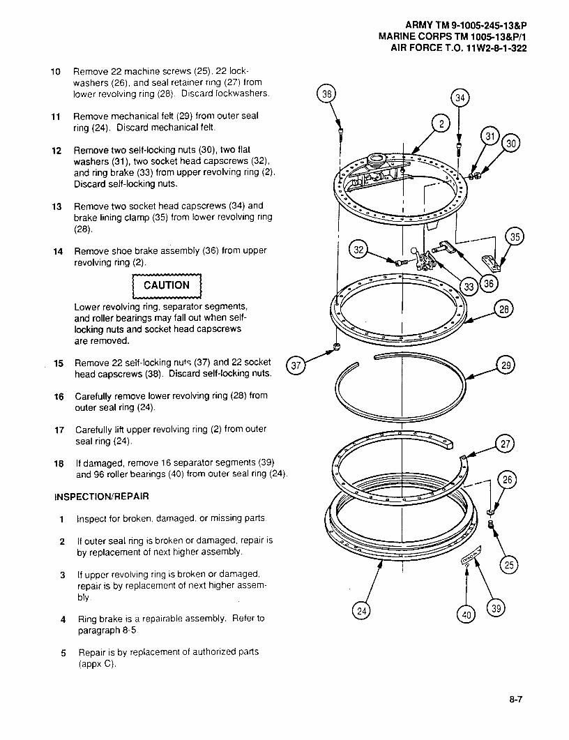
ARMYTM 9-1005-245-13&PMARINECORPSTM 1005-13&P/1
AIR FORCET.O. 11W2-8-1-322
10 Remove 22 machine screws (25), 22 lock-washers (26), and seal retainer ring (27) fromlower revolving ring (28). Discard lockwashers. 38 4
11 Remove mechanical felt (29) from outer sealring (24). Discard mechanical felt. 2
12 Remove two self-locking nuts (30), two flat31
30
washers (31), two socket head capscrews (32),and ring brake (33) from upper revolving ring (2).Discard self-locking nuts.
13 Remove two socket head capscrews (34) andbrake lining clamp (35) from lower revolving ring(28).
35
14 Remove shoe brake assembly (36) from upper 32revolving ring (2).
----------------------------------CAUTION 33 36
Lower revolving ring, separator segments, 28and roller bearings may fall out when self-locking nuts and socket head capscrewsare removed.
15 Remove 22 self-locking nut (37) and 22 socket 37 29head capscrews (38). Discard self-locking nuts.
16 Carefully remove lower revolving ring (28) fromouter seal ring (24).
17 Carefully lift upper revolving ring (2) from outerseal ring (24). 27
18 If damaged, remove 16 separator segments (39)and 96 roller bearings (40) from outer seal ring (24).
26
INSPECTION/REPAIR
1 Inspect for broken, damaged, or missing parts.
2 If outer seal ring is broken or damaged, repair isby replacement of next higher assembly.
3 If upper revolving ring is broken or damaged,25
repair is by replacement of next higher assem-bly.
4 Ring brake is a repairable assembly. Refer to24 39
paragraph 8-5.
5 Repair is by replacement of authorized parts(appx C).
8-7
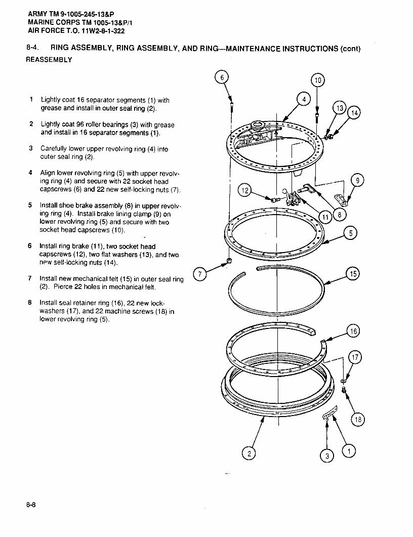
ARMYTM9-1005-245-13&PMARINECORPS TM 1005-13&P/1AIRFORCET.O. 11W243-1-322
8-4. RING ASSEMBLY, RING ASSEMBLY, AND RING-MAINTENANCE INSTRUCTIONS (cont)
REASSEMBLY
6 10
1 Lightly coat 16 separator segments (1) with 4grease and install in outer seal ring (2). 13 14
2 Lightly coat 96 roller bearings (3) with greaseand install in 16 separator segments (1).
3 Carefully lower upper revolving ring (4) intoouter seal ring (2).
4 Align lower revolving ring (5) with upper revolv-ing ring (4) and secure with 22 socket head 9capscrews (6) and 22 new self-locking nuts (7). 12
5 Install shoe brake assembly (8) in upper revolv-ing ring (4). Install brake lining clamp (9) on 8lower revolving ring (5) and secure with twosocket head capscrews (10). 5
6 Install ring brake (11), two socket headcapscrews (12), two flat washers (13), and twonpw self-locking nuts (14).
7 Install new mechanical felt (15) in outer seal ring7 15
(2). Pierce 22 holes in mechanical felt.
8 Install seal retainer ring (16), 22 new lock-washers (17), and 22 machine screws (18) inlower revolving ring (5).
16
17
18
2
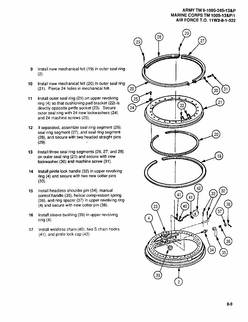
ARMYTM 9-1005-245-13&PMARINECORPSTM 1005-13&P/1
AIRFORCET.O. 11W2-8-1-322
2928
29 27
9 Install new mechanical felt (19) in outer seal ring(2).
10 Install new mechanical felt (20) in outer seal ring(21). Pierce 24 holes in mechanical feft. 26 30 31
11 Install outer seal ring (21) on upper revolving 25ring (4) so that cushioning pad bracket (22) is 22
21directly opposite pintle socket (23). Secure 24outer seal ring with 24 new lockwashers (24)and 24 machine screws (25).
12 If separated, assemble seal ring segment (26),seal ring segment (27), and seal ring segment 20(28), and secure with two headed straight pins(29).
13 Install three seal ring segments (26, 27, and 28)on outer seal ring (21) and secure with new 19lockwasher (30) and machine screw (31).
14 Install pintle lock handle (32) in upper revolvingring (4) and secure with two new cotter pins(33).
15 Install headless shoulder pin (34), manual 4232
control handle (35), helical compression spring 4141
33
(36), and ring spacer (37) in upper revolving ring(4) and secure wfth new cotter pin (38). 23 40 8
16 Install sleeve bushing (39) in upper revolving4
37
ring (4).
17 Install weldless chain (40), two S chain hooks(41), and pintle lock cap (42).
36IN
34 35
39
2
8-9

ARMYTM9-1005-245-13&PMARINECORPSTM 1005-13&P/1AIRFORCET.O. 11W2-8-1-322
8-5. RING BRAKE-MAINTENANCE INSTRUCTIONS
THIS TASKCOVERS:
a. Disassembly b. Inspection/Repair c. Reassembly
INITIAL SETUP
Tools and Special ToolsSmall Arms Repairman Tool Kit (item 2, appx B)Small Arms Shop Set (item 1, appx B)
Materials/PartsCotter pin (2) (MS24665-283)Headless straight pin (MS16556-628)Solid rivet (MS35743-11 )
Equipment Conditions8-4 Ring brake removed
DISASSEMBLY9
Q2 10 4 3
1 Remove socket head capscrew (1) and manual G@control lever (2). 1 1
2 Remove two cotter pins (3) and headlessstraight pin (4) from brake shoe bracket (5).Discard cotter pins.
3 Remove solid rivet (6), shaft collar (7), shoebrake assembly (8), flat washer (9), brake shoecam (10), and brake shoe bracket (5) from cam 5brake bracket (11). Discard solid rivet. 7
164 Remove convex washer (12) and helical spring
(13) from worm shaft assembly (14).12
13 14
5 Remove setscrew (15) and plain round nut (16)from cam brake bracket (11).
6 Remove worm shaft assembly (14) from cambrake bracket (11).
7 Grind down and remove headless straight pin 19(17). Discard headless straight pin. Removedetent brake body (18) and helical spring (19) 17
15from worm shaft assembly (14).
8-10

ARMY TM 9-1005-245-13&PMARINE CORPS TM 1005-13&P/1
AIR FORCE T.O. 11W2-8-1-322
INSPECTION/REPAIR
1 Inspect for broken, damaged, or missing parts.
2 Repair is by replacement of authorized parls 56(appx C).
REASSEMBLY 4
1 Install helical spring (1), dletent brake body (2), 9
and new headless straight pin (3) in worm shaftassembly (4). Peen pin securely.
2 Install worm shaft assembly (4) in cam brakebracket (5).
3 Install plain round nut (6) in cam brake bracket(5) and secure with setscrew (7). 3 2
7
4 Install helical spring (8) and convex washer (9)on worm shaft assembly (4).
1312
17
16
11 5
19
C
4
14
10
5 Install brake shoe bracket (10), brake shoe cam (11 flat washer (12), shoe brake assembly (13), shaftcollar (14), and new solid rivet (15) on cam brake bracket (5) and worm shaft assembly (4).
6 Secure brake shoe cam (11) to brake shoe bracket (110)with headless straight pin (16) and two new cotterpins (17).
7 Install manual control lever (18) and secure with socket head capscrew (19).
8-11/(8-12 blank)


ARMY TM 9-1005-245-13&PMARINE CORPS TM 1005-13&P/1
AIR FORCE T.O. 11W2-8-1-322
CHAPTER9
M240E1 FLEXIBLE MACHINE GUN MOUNT, ANDFLEXIBLE MOUNT ASSEMBLY FOR
M122A1 TRIPOD MOUNT AND M240G MACHINE GUN
Section 1. UNIT MAINTENANCE INSTRUCTIONS
9-1. FLEXIBLE MACHINE GUN MOUNT - MAINTENANCE INSTRUCTIONS
THIS TASK COVERS:
a. Disassembly b. Inspection/Repair c. Reassembly
INITIAL SETUP
Tools and Special ToolsSmall Arms Repairman Tool Kit (item 2, appx 13)
Materials/PartsNonelectrical wire (item 10, appx E)
DISASSEMBLY6 oyl7
1 Remove nonelectrical wire (1), four 14 15capscrews (2), and holder assembly 13
(3) from lower cradle support (4). 0 0 0/Discard nonelectrical wire (M240E1 only). 6
92 Remove nonelectrical wire (1), four socket 12
head capscrews (6) and upper cradleassembly (7) with attached parts fromlower cradle support (4). Remove round 10 4
deflector (16) if damaged (M122A1 /M240G only). Discard nonelectrical wire.
03
3 Remove two retaining rings (8) fromheadless grooved pin (9).
4 Remove headless grooved pin (9) and 2
mount pintle (10).
5 Remove two retaining rings (8) from 4
"A-8
8grooved pin (18) and separate traversing
8and elevating cradle bracket (17)(M122A1/M240G only).
8
10 8
17
M122AI
Change 2 9-1

ARMY TM 9-1005-245-13&PMARINE CORPS TM 1005-13&P/1AIR FORCE T.O. 11W2-8-1-322
19-1. FLEXIBLE MACHINE GUN MOUNT - MAINTENANCE INSTRUCTIONS (cont)
DISASSEMBLY (cont)
6 Remove two machine screws (11) and deflector (12) from upper cradle assembly (7)(M240E1 only).
7 Remove retaining ring (13), spring pin (14), and retaining pin (15) from uppercradleassembly (7).
INSPECTION/REPAIR
1 Inspect for broken, damaged, or missing parts.
2 Upper cradle assembly is a repairable assembly, notify direct support maintenance. Refer toparagraph 9-3.
3 Repair by replacement of authorized parts (appx C).
REASSEMBLY
1 Install retaining pin (15) in upper cradleassembly (7) and secure with spring pin (14). 7 6 11
Install retaining ring (13). 14 1513
2 Install deflector (12) on upper cradle assembly 16
(7) and secure with two machine screws (11) M122A1 6
(M240E1 only).
83 Align holes in mount pintle (10) with holes in
lower cradle support (4) and install headlessgrooved pin (9). 10 4
4 Install two retaining rings (8) on headlessgrooved pin (9). 3
5 Align upper cradle assembly (7) with attachedparts with lower cradle support (4), and secureright side with two socket head capscrews (6). 2
Align round deflector (16) with cradle holes(M122A1/M240G only). Secure left side with 2
two socket head capscrews (6). Attach new 8nonelectrical wire (1) (item 10, appx E) on 4 8
both sides.@q
6 Align holder assembly (3) with lower cradle ao-) 189@ 1
support (4) and secure with four hexagon 10 8
head capscrews (2) and new nonelectrical 17
wire(1) (item 10, appx E) (M240E1 only). M122AI
7 Align holes in traversing and elevating cradle
8
bracket (17) and lower cradle (4) and installheadless grooved pin (18). Install tworetaining rings (8) on headless grooved pin (9)(M122A1/M240G only).
9-2 Change 2

ARMY TM 9-1005-245-13&PMARINE CORPS TM 1005-13&P/1
AIR FORCE T.O. 11W2-8-1-322
Section II. DIRECT SUPPORT MAINTENANCE INSTRUCTIONS
9-2. FLEXIBLE MACHINE GUN MOUNT - MAINTENANCE INSTRUCTIONS
THIS TASK COVERS:
a. Disassembly b. Inspection/Repair c. Reassembly
INITIAL SETUP
Tools and Special ToolsSmall Arms Repairman Tool Kit (item 2, appx B)Small Arms Shop Set (item 1, appx B)
Materials/Parts Nonelectrical wire (item 10, appx E)
DISASSEMBLY7 6
1 Remove nonelectrical wire (1), four hexagon 14 is
head capscrews (2), and holder assembly (3)13
from lower cradle support (4). Discard 160
nonelectrical wire (M240E1 only). M122AI 6-
92 Remove nonelectrical wire (1), capscrews (6) 12
and upper cradle assembly (7) with attached8
parts from lower cradle support (4). Removeround deflector (16) if damaged (M122A1/ 10 4
M240G only).
3 Remove two retaining rings (8) from headless 3
grooved pin (9).
4 Remove headless grooved pin (9) and mountpintle (10).
5 Remove two retaining rings (8) from grooved 8
pin(18) and separate traversing and elevating 4 8
cradlebracket (17) (M122A1/M240G only). 84@ @q 1
6 Remove two machine screws (11) anddeflector ( 12)from upper cradle assembly (7) 10(M240E1 only). 17
M122AI
7 Remove retaining ring (8), spring pin (14),and retaining pin (15) from upper cradleassembly (7).
8
1@
Change2 9-3

ARMY TM 9-1005-245-13&PMARINE CORPS TM 1005-13&P/1AIR FORCE T.O. 11W2-8-1-322
INSPECTION/REPAIR
1 Inspect for broken, damaged, or missing parts.
2 Upper cradle assembly is a repairable assembly. Refer to paragraph 9-3.
3 Repair by replacement of authorized parts (appx C).
REASSEMBLY
1 Install retaining pin (15) in upper cradle assembly (7) and secure with spring pin (4). Install retainingring (13).
2 Install deflector (12) on upper cradle assembly (7) and secure with two machine screws (11).(M240E1 only).
3 Align holes in mount pintle (10) with holes in lower cradle support (4) and install headless groovedpin (9).
4 Install two retaining rings (8) on headless grooved pin (9).
7 6
14 1513
M122A1 6
91 12
10 4
03,
LL-
2 1
2
4 zlw-8
@q
is
10
17
M122A1
9-4 Change 2
ARMY TM 9-1005-245-13&PMARINE CORPS TM 1005-13&P/1
AIR FORCE T.O. 11W2-8-1-322
5 Align upper cradle assembly (7) with attached parts with lower cradle support (4), and secure rightside with two socket head capscrews (6). Align round deflector (16) with cradle holes (M122A1/M240G only). Secure left side with two socket head capscrews (6). Attach new nonelectrical wire(1) (item 10, appx E) on both sides.
6 Align holder assembly (3) with lower cradle support (4) and secure with four hexagon headcapscrews (2) and new nonelectrical wire (1) (item 10, appx E) (M240E1 Flex Mount only).
7 Align holes in traversing and elevating cradle bracket (17) and lower cradle (4) and install headlessgrooved pin (18). Install two retaining rings (8) on headless grooved pin (9) (M122A1/M240G only).
Change 2 9-5

ARMY TM 9-1005-245-13&PMARINE CORPS TM 1005-13&P/1AIR FORCE T.O. 11W2-8-1-3229-3. UPPER CRADLE ASSEMBLY - MAINTENANCE INSTRUCTIONS
THIS TASK COVERS:
a. Disassembly b. Inspection/Repair c. Reassembly
INITIAL SETUP
Tools and Special ToolsSmall Arms Repairman Tool Kit (item 2, appx 13)Small Arms Shop Set (item 1, appx 13)
Equipment Condition9-2 Upper cradle assembly removed
DISASSEMBLY
24
G
5
45
6 7
8/1
10
9
1 Remove two spring pins (1) from front cradle support (2) and remove front cradle support from twometallic tubes (3).
WARNINGTo avoid injury to your eyes, use care when removing and installingspring-loaded parts.
2 Remove two helical springs (4), two spring shields (5), two elastic stops (6), two nonrotating eyebrackets (7), and two elastic stops (8) from metallic tubes (9).
M14
3 Remove two spring pins (9) and two metallic tubes (6) from rear cradle support (10).
19-6 Change 2

ARMY TM 9-1005-245-13&PMARINE CORPS TM 1005-13&P/1
AIR FORCET.O. 11W2-8-1-322
INSPECTION/REPAIR
1 Inspect for broken, damaged, or missing parts.
2 If front cradle support is broken or damaged, repair is by replacement of next higher assembly.
3 If rear cradle support is broken or damaged, repair is by replacement of next higher assembly.
4 Repair is by replacement of authorized parts (appx C).
8
76 5
10 4
G@-
9 6X
2
OD
REASSEMBLY
1 Install two metallic tubes (1) in rear cradle support (2) and secure with two spring pins (3).
2 Install two elastic stops (4), two nonrotating eye brackets (5), two elastic stops (6), two springshields (7), and two helical springs (8) on two metallic tubes (1).
3 Install front cradle support (9) on two metallic tubes (1) and secure with two spring pins (10).
9-7/9-8 blank Change 2


ARMY TM 9-1005-245-13&PMARINE CORPS TM 1005-13&P/1
AIR FORCE T.O. 11W2-8-1-322
CHAPTER10
M142 MACHINE GUN MOUNT
Section I. UNIT MAINTENANCE INSTRUCTIONS
10-1. M142 MACHINE GUN MOUNT-MAINTENANCE INSTRUCTIONS
THIS TASK COVERS:
a. Disassembly b. Inspection/Repair c. Reassembly
INITIAL SETUP
Tools and Special ToolsSmall Arms Repairman Tool Kit (item 2, appx B)
DISASSEMBLY
1 Remove single chain assembly (1) from quickrelease pin (2) and mount-pintle (3).
2 Remove quick release pin (2) from mount pintle(3).
3 If damaged, remove cotter pin (4).
INSPECTION/REPAIR 0
1 inspect for broken, damaged, or missing parts.
2 Repair is by replacement of authorized parts(appx C). 3
2REASSEMBLY
1 It removed, install new cotter pin (4).J
2 Install quick release pin (2) in mount pintle (3).
3 Install single chain assembly (1) on mount pintle(3) and quick release pin (2).
10-1

ARMY TM 9-1005-245-13&PMARINE CORPS TM 1005-13&P/1AIR FORCE T.O. 11W2-8-1-322
Section II. DIRECT SUPPORT MAINTENANCE INSTRUCTIONS
10-2. M142 MACHINE GUN MOUNT AND PLATFORM ASSEMBLY-MAINTENANCEINSTRUCTIONS
THIS TASK COVERS:
a. Disassembly b. Inspection/Repair c. Reassembly
INITIAL SETUP
Tools and Special ToolsSmall Arms Repairman Tool Kit (item 2, appx B)Small Arms Shop Set (item 1, appx B)
Personnel Required2
Materials/PartsCotter pin (MS24665-291)Nonelectrical wire (item 10, appx E)
DISASSEMBLY 7
00
80
0
4 6
2 3 53
1 Remove single chain assembly (1) from quick release pin (2) and mount pintle (3).
2 Remove quick release pin (2) from mount pintle (3).
3 Remove cotter pin (4), slotted plain nut (5), flat washer (6), shoulder bolt (7), and platform assembly (8) withattached parts from mount pintle (3). Discard cotter pin.
10-2

ARMYTM 9-1005-245-13&PMARINECORPSTM 1005-13&P/1
AIR FORCET.O. 11W2-8-1-322
14 13
10
8
12
9
4 Remove nonelectrical wire (9) and three hexagon capscrews (10). Remove machine gun cradle (11) fromplatform assembly (8). Discard nonelectrical wire.
5 Remove nonelectrical wire (12), four hexagon capscrews (13), and gun holder assembly (14) from machinegun cradle (11). Discard nonelectrical wire.
19
18
163
15
1720
WARNINGTo avoid injury to your eyes, use care when removing and installing spring-loaded parts.
6 Remove machine screw (15) and hexagon plain nut (16) from mount pintle (3).
7 Remove headless grooved pin (17), torsion helical spring (18), and catch strike (19) from platform assembly(20).
10-3

ARMY TM 9-1005-245-13&PMARINE CORPS TM 1005-13&P/1AIR FORCE T.O. 11W2-8-1-322
10-2. M142 MACHINE GUN MOUNT AND PLATFORM ASSEMBLY-MAINTENANCEINSTRUCTIONS (cont)
INSPECTION/REPAIR
1 Inspect for broken, damaged, or missing parts.
2 Repair is by replacement of authorized parts (appx C).
REASSEMBLY
2
6
57
3
NOTEHave helper assist in reassembly.
1 Place torsion helical spring (1) and catch strike (2) on platform assembly (3) and secure with headlessgrooved pin (4).
2 Place hexagon plain nut (5) on machine screw (6) and install in mount pintle (7).
810
9
3 Place gun holder assembly (8) on machine guncradle (9) and secure with four hexagoncapscrews (10) and new nonelectrical wire (11)(item 10, appx E).
10-4

ARMY TM 9-1005-245-13&PMARINE CORPS TM 1005-13&P/1
AIR FORCE T.O. 11W2-8-1-322
9
13
12
4 Place machine gun cradle (9) on platformassembly (12) and secure with three hexagoncapscrews (13) and new nonelectrical wire (14)(item 10 appx E). 14
15
0 0
12 0 0 0 0
0 0
18 16
177 19
7
0@
20
5 Place platform assembly (12) with attached parts in mount pintle (7) and secure with shoulder bolt (15), flatwasher (16), and slotted plain nut (17). Align slotted plain nut with shoulder bolt and install new cotter pin(18).
6 Install quick release pin (19) in mount pintle (7).
7 Install single chain assembly (20) on mount pintle (7) and quick release pin (19).
10-5/(10-6 blank)

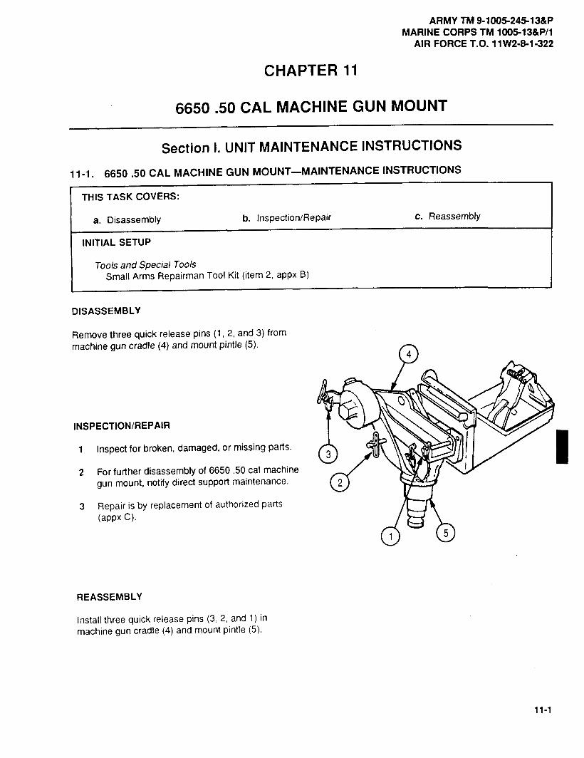
ARMY TM 9-1005-245-13&PMARINE CORPS TM 1005-13&P/1
AIR FORCE T.O. 11W2-8-1-322
CHAPTER11
6650.50 CAL MACHINE GUN MOUNT
Section I. UNIT MAINTENANCE INSTRUCTIONS
11-1. 6650.50 CAL MACHINE GUN MOUNT-MAINTENANCE INSTRUCTIONS
THIS TASK COVERS:
a. Disassembly b. Inspection/Repair c. Reassembly
INITIAL SETUP
Tools and Special ToolsSmall Arms Repairman Tool Kit (item 2, appx B)
DISASSEMBLY
Remove three quick release pins (1, 2, and 3) frommachine gun cradle (4) and mount pintle (5).
4
INSPECTION/REPAIR
1 Inspect for broken, damaged, or missing parts.3
2 For further disassembly of 6650 .50 cal machinegun mount, notify direct support maintenance. 2
3 Repair is by replacement of authorized parts(appx C).
5
REASSEMBLY
Install three quick release pins (3, 2, and 1) inmachine gun cradle (4) and mount pintle (5).

ARMY TM 9-1005-245-13&PMARINE CORPS TM 1005-13&P/1AIR FORCE T.O. 11W2-8-11-322
Section 11.DIRECT SUPPORT MAINTENANCE INSTRUCTIONS
11-2. 6650.50 CAL MACHINE GUN MOUNT--MAINTENANCE INSTRUCTIONS
THIS TASK COVERS:
a. Disassembly c. Reassemblyb. Inspection/Repair d. Adjustment
INITIAL SETUP
Tools and Special ToolsSmall Arms Repairman Tool Kit (item 2, appx B)Small Arms Shop Set (item 1, appx B)
Materials/PartsCotter pin (MS24665-132)Enamel (item 3, appx E)Lockwasher (4) (MS35333-42)Lockwasher (MS35333-46)Lockwasher (3) (MS35338-45)Lockwasher (MS35338-46)
DISASSEMBLY
6
5
4
2
3
1 Unlock cam (1) and remove ammunition box tray assembly (2) from ammunition bracket (3).
2 Clamp machine gun cradle (4) in vise with case (5) facing to the front.
WARNING
Case is under spring tension. To avoid injury to personnel, use care when removing case.
3 Loosen but do not remove hexagon head capscrew (6)
2
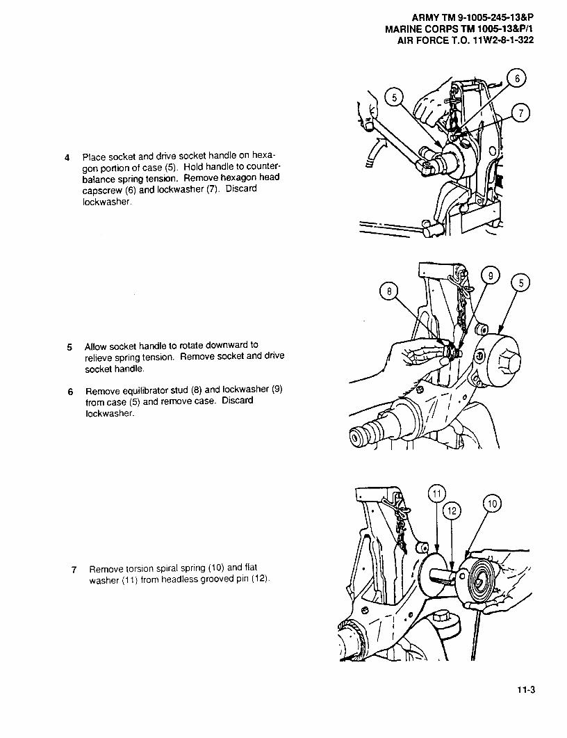
ARMY TM 9-1005-245-13&PMARINE CORPS TM 1005-13&P/1
AIR FORCE T.O. 11W2-8-1-322
6
5
7
4 Place socket and drive socket handle on hexa-gon portion of case (5). Hold handle to counter-balance spring tension. Remove hexagon headcapscrew (6) and lockwasher (7). Discardlockwasher.
9
85
5 Allow socket handle to rotate downward torelieve spring tension. Remove socket and drivesocket handle.
6 Remove equilibrator stud (8) and lockwasher (9)from case (5) and remove case. Discard 0
lockwasher.
1210
7 Remove torsion spiral spring (10) and flat 1
washer (11) from headless grooved pin (12). C
11-3
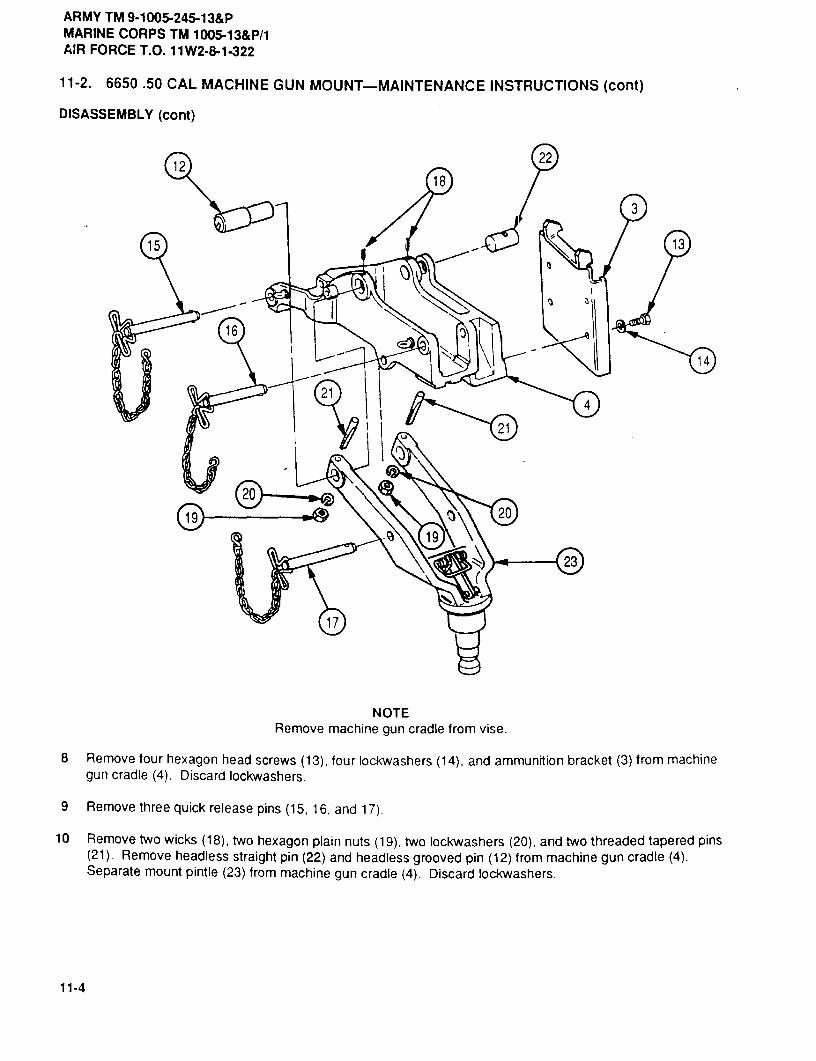
ARMY TM 9-1005-245-13&PMARINE CORPS TM 1005-13&P/1AIR FORCE T.O. 11W2-8-1-322
11-2. 6650.50 CAL MACHINE GUN MOUNT-MAINTENANCE INSTRUCTIONS (cont)
DISASSEMBLY (cont)
1222
18
3
15 13
16
14
214
21
2020
19
23
17
NOTERemove machine gun cradle from vise.
8 Remove four hexagon head screws (13), four lockwashers (14), and ammunition bracket (3) from machinegun cradle (4). Discard lockwashers.
9 Remove three quick release pins (15, 16, and 17).
10 Remove two wicks (18), two hexagon plain nuts (19), two lockwashers (20), and two threaded tapered pins(21). Remove headless straight pin (22) and headless grooved pin (12) from machine gun cradle (4).Separate mount pintle (23) from machine gun cradle (4). Discard lockwashers.
11-4

ARMYTM 9-1005-245-13&PMARINECORPSTM 1005-13&P/1
AIRFORCET.O. 11W2-8-1-322
31 27
2929
11 Remove hexagon plain nut (24), lockwasher(25), and rod end clevis (26) with attached parts 281
from mount pintle (23). Discard lockwasher.
WARNING 26
To avoid injury to your eyes, use carewhen removing and installing spring-loadedparts.
2512 Remove cotter pin (27) from headed straight pin
(28), and remove headed straight pin, two flat 2430
washers (29), machine gun bar (30), and torsion 23helical spring (31) from rod end clevis (26).Discard cotter pin.
INSPECTION/REPAIR
1 Inspect for broken, damaged, or missing parts.
2 If mount pintle is broken or damaged, repair is by replacement of next higher assembly.
3 Touch up bright metal surfaces with olive drab enamel paint (item 3, appx E).
4 Repair is by replacement of authorized parts (appx C).
6
4
REASSEMBLY4
1 Align torsion helical spring (1) and machine gun5
bar (2) with rod end clevis (3) and secure withtwo flat washers (4), headed straight pin (5), andnew cotter pin (6).
3
2 Place rod end clevis (3) with attached parts inmount pintle (7) and secure with newlockwasher (8) and hexagon plain nut (9).
8
92
7
11-5

ARMY TM 9-1005-245-13&PMARINE CORPS TM 1005-13&P/1AIR FORCE T.O. 11W2-8-1-322
11-2. 6650.50 CAL MACHINE GUN MOUNT-MAINTENANCE INSTRUCTIONS (cont)
REASSEMBLY (cont) 1415
16
1717
2023
19
22
10 2112
12
a 13 137
18
3 Align mount pintle (7) with machine gun cradle (10) and secure with two threaded tapered pins (11), two newlockwashers (12), and two hexagon plain nuts (13). Install flat washer (14) onto headless grooved pin (15).Install headless grooved pin (15) with flat washer (14) and headless straight pin (16), and secure with twowicks (17).
4 Install three quick release pins (18, 19, and 20).
5 Place ammunition bracket (21) on machine gun cradle (10) and secure with four new lockwashers (22) andfour hexagon head screws (23).
10
15
6 Clamp machine gun cradle (10) in vise withheadless grooved pin (15) facing to the front.
11-6

ARMY TM 9-1005-245-13&PMARINE CORPS TM 1005-13&P/1
AIR FORCE T.O. 11W2-8-1-322
JI
7 Install torsion spiral spring (24) into case (25). Align hole in spring end with equilibrator stud hole in case.Secure with new Iockwasher (26) and equilibrator stud (27).
8 Align torsion spiral spring (24) tang with slot on headless grooved pin (15) and install torsion helical spring(24) and case (25) on headless grooved pin (15).
WARNING "tTo avoid injury to your eyes, use carewhen removing and installing spring-loaded ,,parts.
9 place socket and drive socket handle on case
(25) and apply pressureto case until adjusting :_holes in case and machine gun cradle (10) align.
_-
11-7
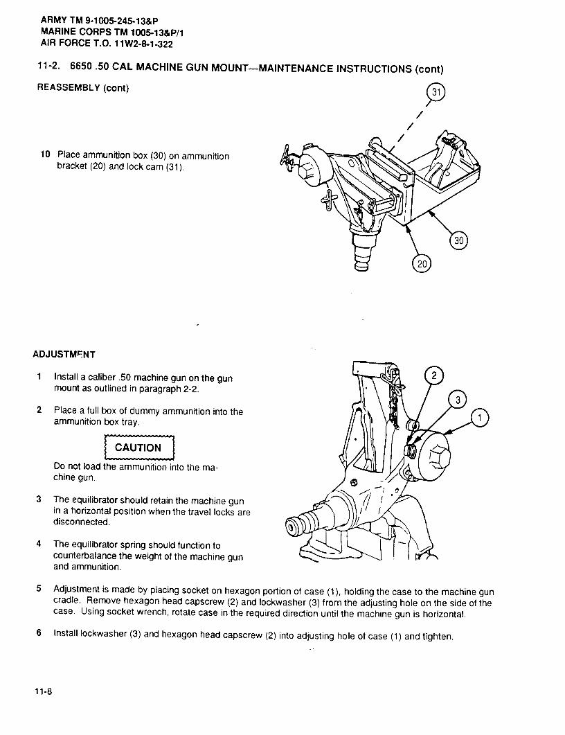
ARMY TM 9-1005-245-13&PMARINE CORPS TM 1005-13&P/1AIR FORCE T.O. 11W2-8-1-322
11-2. 6650.50 CAL MACHINE GUN MOUNT-MAINTENANCE INSTRUCTIONS (cont)
REASSEMBLY (cont)
10 Place ammunition box (30) on ammunitionbracket (20) and lock cam (31).
20
ADJUSTMENT
1 Install a caliber .50 machine gun on the gun 2mount as outlined in paragraph 2-2.
32 Place a full box of dummy ammunition into the
ammunition box tray.---------------
CAUTION
Do not load the ammunition into the ma-chine gun.
3 The equilibrator should retain the machine gunin a horizontal position when the travel locks aredisconnected.
4 The equilibrator spring should function tocounterbalance the weight of the machine gunand ammunition.
5 Adjustment is made by placing socket on hexagon portion of case (1), holding the case to the machine guncradle. Remove hexagon head capscrew (2) and lockwasher (3) from the adjusting hole on the side of thecase. Using socket wrench, rotate case in the required direction until the machine gun is horizontal.
6 Install lockwasher (3) and hexagon head capscrew (2) into adjusting hole of case (1) and tighten.
11-8

ARMY TM 9-1005-245-13&PMARINE CORPS TM 1005-13&P/1
AIR FORCE T.O. 11W2-8-1-322
CHAPTER 12
M548 MACHINE GUN MOUNT
Section I, UNITMAINTENANCEINSTRUCTIONS
12-1. M548 MACHINE GUN MOUNT ATTACHING HARDWARE---MAINTENANCEINSTRUCTIONS
THIS TASK COVERS:
a. Disassembly b. Inspection/Repair c. Reassembly
INITIAL SETUP
Toolsand Special ToolsSmall Arms Repairman Tool Kit (item 2, appx B)
DISASSEMBLY
1 If damaged, remove mouating hardware used to secure gun mount legs to hull.
2 If damaged, remove webbing straps.
INSPECTION/REPAIR
1 Inspect for broken, damaged, or missing parts.
2 Repair is by replacement of authorized parts (appx C).
REASSEMBLY
1 If removed, install webbing straps.
2 If removed, install mounting hardware used to secure gun mount legs to hull. I
I
12-1

ARMY TM 9-1005-245-13&PMARINE CORPS TM 1005-13&P/1AIR FORCE m.o. 11W2-8-1-322
Section II. DIRECT SUPPORT MAINTENANCE INSTRUCTIONS
12-2. M548 MACHINE GUN MOUNT LEGS AND ATTACHING HARDWARE--MAINTENANCEINSTRUCTIONS
THIS TASK COVERS:
a. Disassembly b. Inspection/Repair c. Reassembly
INITIAL SETUP
ToolsandSpecial ToolsLifting DeviceSling (4-point)Small Arms Repairman Tool Kit (item 2, appx B)Small Arms Shop Set (item 1, appx B)
Materials/Parts
Self-locking nut (12) (MS21044-N8)
I
12-2

ARMY TM 9-1005-245-13&PMARINE CORPS TM 1005-13&P/1
AIR FORCE T.O. 11W2-8-1-322
DISASSEMBLY
1 Remove 12 serf-locking nuts (1), 12 hexagon head capscrews (2), 12 flat washers (3), and 4 gun mount legs(4, 5, 6, and 7) from M66 machine gun mount ring. Discard self-locking nuts.
2 If damaged, remove mounting hardware used to secure gun mount legs to hull.
3 If damaged, remove webbing straps (9).
INSPECTION/REPAIR
1 Inspect for broken, damaged, or missing parts.
2 M66 machine gun mount ring is a repairable assembly. Refer to paragraph 8-1.
3 Repair is by replacement of authorized parts (appx C).
REASSEMBLY
1 If emoved, install webbing straps {9).
2 If removed, install mounting hardware used to secure gun mount legs to hull.
3 Place 4 gun mount legs (4, 5, 6, and 7) on M66 machine gun mount ring (8) and secure with 12 flat washers(3), 12 hexagon head capscrews (2), and 12 new self-locking nuts (1).
12.3/(12-4 blank)

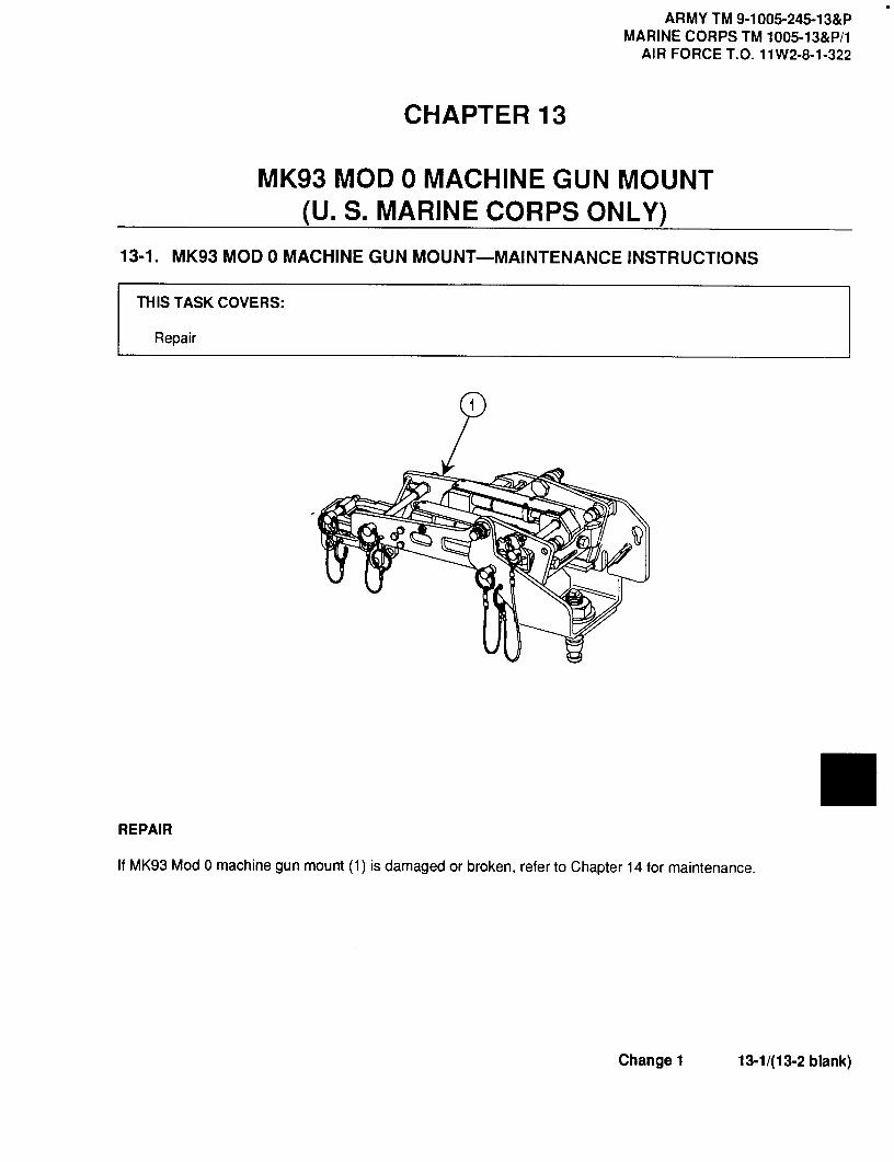
ARMY TM 9-1005-245-13&PMARINE CORPS TM 1005-13&P/1
AIR FORCE T. O.11W2-8-1-322
CHAPTER13
MK93 MOD 0 MACHINE GUN MOUNT(U. S. MARINE CORPS ONLY)
13-1. MK93 MOD 0 MACHINE GUN MOUNT-MAINTENANCE INSTRUCTIONS
THIS TASK COVERS:
Repair
CP
REPAIR
If MK93 Mod 0 machine gun mount (1) is damaged or broken, refer to Chapter 14 for maintenance.
Changel 13-1/(13-2 blank)


ARMY TM 9-1005-245-13&PMARINE CORPS TM 1005-13-&P/1
AIR FORCE T.O. 11 W2-8-1-322
CHAPTER 14
MK93 MOD 1 MACHINE GUN MOUNT
SECTION I. UNIT MAINTENANCE INSTRUCTIONS
14-1. MK93 MOD 1 MACHINE GUN MOUNT-MAINTENANCE INSTRUCTIONS
THIS TASK COVERS:Repair
-------------
6-- ------ ----- ----- 4
----------
REPAIR
The MK93 MOD 1 machine gun mount consists of .50 caliber ammo holder assembly (1), MK93 MOD 0machine gun mount (2), mounting bracket (3), catch bag assembly (4), universal pintle adapter (5),traverse andelevation mechanism (6). Repair of individual components is contained in Chapter 14.
Change 4 14-1
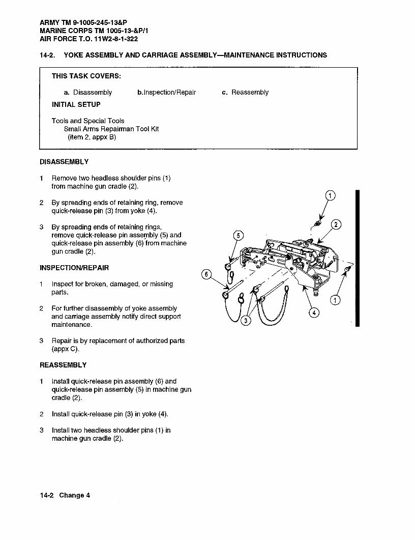
ARMY TM 9-1005-245-13&PMARINE CORPS TM 1005-13-&P/1AIR FORCE T.O. 11W2-8-1-322
14-2. YOKE ASSEMBLY AND CARRIAGE ASSEMBLY-MAINTENANCE INSTRUCTIONS
THIS TASK COVERS:
a. Disassembly Inspection/Repair c. Reassembly
INITIAL SETUP
Tools and Special ToolsSmall Arms Repairman Tool Kit
(item 2, appx B)
DISASSEMBLY
1 Remove two headless shoulder pins (1)from machine gun cradle (2).
2 By spreading ends of retaining ring, removequick-release pin (3) from yoke (4).
3 By spreading ends of retaining rings, 2
remove quick-release pin assembly (5) and 5quick-release pin assembly (6) from machinegun cradle (2).
INSPECTION/REPAIR
1 Inspect for broken, damaged, or missingparts.
2 For further disassembly of yoke assembly4and carriage assembly notify direct support
3maintenance.
3 Repair is by replacement of authorized parts(appx C).
REASSEMBLY
1 Install quick-release pin assembly (6) andquick-release pin assembly (5) in machine guncradle (2).
2 Install quick-release pin (3) in yoke (4).
3 Install two headless shoulder pins (1) inmachine gun cradle (2).
14-2 Change 4

ARMY TM 9-1005-245-13&PMARINE CORPS TM 1005-13-&P/1
AIR FORCE T.O. 11W2-8-1-322
14-3. .50 CALIBER AMMO HOLDER ASSEMBLY-MAINTENANCE INSTRUCTIONS
THIS TASK COVERS:
a. Disassembly b. Inspection/Repair c. Reassembly
INITIAL SETUP
Tools and Special ToolsSmall Arms Repairman Tool Kit
(item 2, appx B)
Materials/PartsSelf-locking nut (4) (MS21044C3)
DISASSEMBLY
NOTETop bracket is a component of clampingcatch and cannot be ordered separately.Take care not to lose or damage this item.
1 Remove two self-locking nuts (1), twomachine screws (2), and top bracket (3) fromammo can holder (4). Discard self-locking nuts.
2 Remove two self-locking nuts (5), two machine 2screws (6), and clamping catch (7) from ammocan holder (4). Discard self-locking nuts.
INSPECTION/REPAIR
1 Inspect for broken, damaged, or missing parts.
2 If ammo can holder is broken or damaged,repair is by replacement of next higher assembly.
3 Repair is by replacement of authorized parts(appx C).
REASSEMBLY
1 Install clamping catch (7) on ammo can holder(4) with two machine screws (6) and two new selflocking nuts (5).
2 Install top bracket (3) on ammo can holder (4)with two machine screws (2) and two new self-locking nuts (1).
Change 1 14-3

ARMY TM 9-1005-245-13&PMARINE CORPS TM 1005-13-&P/1AIR FORCE T.O. 11W2-8-1-322
14-4. MOUNTING BRACKET-MAINTENANCE INSTRUCTIONS
THIS TASK COVERS:
a. Disassembly b. Inspection/Repair c. Reassembly
INITIAL SETUP
Tools and Special ToolsSmall Arms Repairman Tool Kit
(item 2, appx B)
DISASSEMBLY
1 Pull headed shoulder pin (1) from weldmentbracket (2).
2 Spread ends of S-hooks and remove chain 2assembly (3) from headed shoulder pin (1) andweldment bracket (2).
3 Remove two handknobs (4).
INSPECTION/REPAIR J
1 Inspect for broken, damaged, or missing parts. 0
2 If weldment bracket is broken or damaged,repair is by replacement of next higher assembly
3 Repair is by replacement of authorized parts(appx C).
REASSEMBLY
1 Install two handknobs (4) on weldmentbracket (2).
2 Install chain assembly (3) on weldment bracket(2) and headed shoulder pin (1).
3 Install headed shoulder pin (1) in weldmentbracket (2).
14-4 Change 4
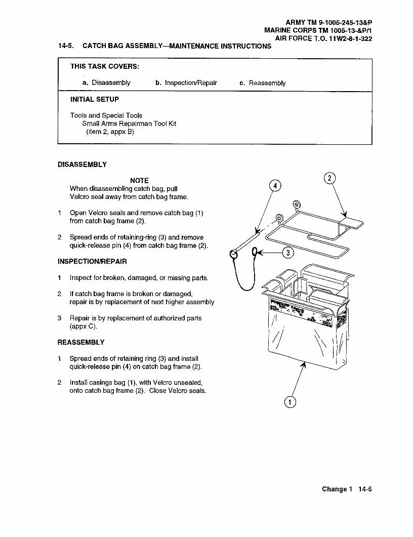
ARMY TM 9-1005-245-13&PMARINE CORPS TM 1005-13-&P/1
AIR FORCE T.O. 11W2-8-1-32214-5. CATCH BAG ASSEMBLY-MAINTENANCE INSTRUCTIONS
THIS TASK COVERS:
a. Disassembly b. Inspection/Repair c. Reassembly
INITIAL SETUP
Tools and Special ToolsSmall Arms Repairman Tool Kit
(item 2, appx B)
DISASSEMBLY
NOTEWhen disassembling catch bag, pullVelcro seal away from catch bag frame.
1 Open Velcro seals and remove catch bag (1)from catch bag frame (2).
2 Spread ends of retaining-ring (3) and removequick-release pin (4) from catch bag frame (2).
INSPECTION/REPAIR
1 Inspect for broken, damaged, or missing parts.
2 If catch bag frame is broken or damaged,repair is by replacement of next higher assembly
3 Repair is by replacement of authorized parts(appx C).
REASSEMBLY
1 Spread ends of retaining ring (3) and installquick-release pin (4) on catch bag frame (2).
2 Install casings bag (1), with Velcro unsealed,onto catch bag frame (2). Close Velcro seals.
Change 1 14-5

ARMY TM 9-1005-245-13&PMARINE CORPS TM 1005-13-&P/1AIR FORCE T.O. 11W2-8-1-322
114-6. UNIVERSAL PINTLE ADAPTER-MAINTENANCE INSTRUCTIONS
THIS TASK COVERS:
a. Disassembly b. Inspection/Repair c. Reassembly
INITIAL SETUP
Tools and Special ToolsSmall Arms Repairman Tool Kit
(item 2, appx B)
Materials/PartsLoctite (MIL-S-22473)
DISASSEMBLY
Remove machine screw (1) and quick-release pin 3assembly (2) from body (3).
INSPECTION/REPAIR
1 Inspect for broken, damaged, or missing parts.
2 Repair is by replacement of authorized parts(appx C). 2
REASSEMBLY
Apply loctite to machine screw (1). Install quickrelease pin assembly (2) on body (3) and securewith machine screw.
14-6 Change 4
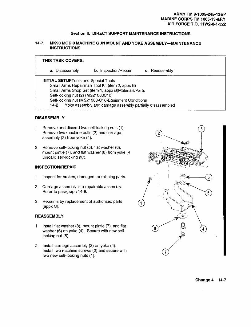
ARMY TM 9-1005-245-13&PMARINE CORPS TM 1005-13-&P/1
AIR FORCE T.O. 11W2-8-1-322
Section II. DIRECT SUPPORT MAINTENANCEINSTRUCTIONS
14-7. MK93 MOD 0 MACHINE GUN MOUNTAND YOKE ASSEMBLY-MAINTENANCEINSTRUCTIONS
THIS TASK COVERS:
a. Disassembly b. Inspection/Repair c. Reassembly
INITIAL SETUP Tools and Special ToolsSmall Arms Repairman Tool Kit (item 2, appx 13)Small Arms Shop Set (item 1, appx B)Materials/PartsSelf-locking nut (2) (MS21083C10)Self-locking nut (MS21083-C16)Equipment Conditions14-2 Yoke assembly and carriage assembly partially disassembled
DISASSEMBLY
1 Remove and discard two self-locking nuts (1).Remove two machine bolts (2) and carriage 2assembly (3) from yoke (4).
2 Remove self-locking nut (5), flat washer (6),mount pintle (7), and flat washer (8) from yoke (4Discard self-locking nut.
INSPECTION/REPAIR
1 Inspect for broken, damaged, or missing parts. 5/ng.",
2 Carriage assembly is a repairable assembly.Refer to paragraph 14-8. 6
3 Repair is by replacement of authorized parts(appx C)_
REASSEMBLY 6
1 Install flat washer (8), mount pintle (7), and flat8 4washer (6) on yoke (4). Secure with new self-
locking nut (5).
2 Install carriage assembly (3) on yoke (4).Install two machine screws (2) and secure with 7two new self-locking nuts (1).
Change 4 14-7

ARMY TM 9-1005-245-13&PMARINE CORPS TM 1005-13-&P/1AIR FORCE T.O. 11W2-8-1-322
14-8. CARRIAGE ASSEMBLY AND DEPRESSION STOP ASSEMBLY-MAINTENANCEINSTRUCTIONS
THIS TASK COVERS:
a. Disassembly b. Inspection/Repair c. Reassembly
INITIAL SETUP
Tools and Special ToolsSmall Arms Repairman Tool Kit (item 2, appx B)Small Arms Shop Set (item 1, appx B)
Materials/PartsLoctite (MIL-S-22473)
Equipment Conditions14-7 Carriage assembly removed
DISASSEMBLY
1 Remove three hexagon capscrews (6) andremove depression stop assembly (4).Remove continuous stud (5) from depressionstop assembly (4).
2 With an open end wrench hold straight shaft(9) by placing the wrench on wrench flats ofstraight shaft. Remove hexagon capscrew(7) and flat washer (8) from straight shaft (9).While supporting rear slider assembly (10)with one hand, pull straight shaft out throughrear brace support (11).
10
8
14-8 Change 1
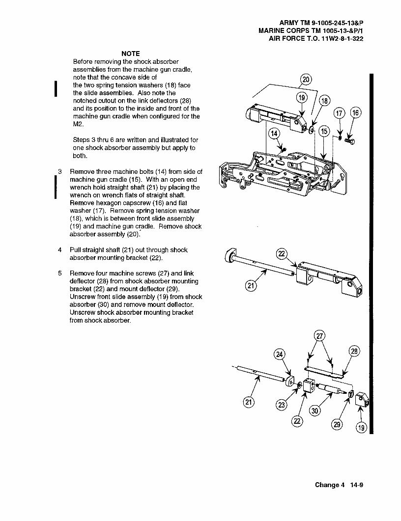
ARMY TM 9-1005-245-13&PMARINE CORPS TM 1005-13-&P/1
AIR FORCE T.O. 11W2-8-1-322
NOTEBefore removing the shock absorberassemblies from the machine gun cradle,note that the concave side of 20the two spring tension washers (18) facethe slide assemblies. Also note the
19notched cutout on the link deflectors (28) 18and its position to the inside and front of the
17 16machine gun cradle when configured for theM2.
14 15Steps 3 thru 6 are written and illustrated forone shock absorber assembly but apply toboth.
3 Remove three machine bolts (14) from side ofmachine gun cradle (15). With an open endwrench hold straight shaft (21) by placing thewrench on wrench flats of straight shaft.Remove hexagon capscrew (16) and flatwasher (17). Remove spring tension washer(18), which is between front slide assembly(19) and machine gun cradle. Remove shockabsorber assembly (20).
4 Pull straight shaft (21) out through shock22
absorber mounting bracket (22).
5 Remove four machine screws (27) and linkdeflector (28) from shock absorber mounting
21bracket (22) and mount deflector (29).Unscrew front slide assembly (19) from shockabsorber (30) and remove mount deflector.Unscrew shock absorber mounting bracketfrom shock absorber.
27
24 28
0
21 2330
22 29 19
Change 4 14-9

ARMY TM 9-1005-245-13&PMARINE CORPS TM 1005-13-&P/1AIR FORCE T.O. 11W2-8-1-322
14-8. CARRIAGE ASSEMBLY AND DEPRESSION STOP ASSEMBLY-MAINTENANCEINSTRUCTIONS (cont)
DISASSEMBLY (cont)
6 Remove two hexagon plain nuts (31) from 31two setscrews (32). Remove setscrews from 32machine gun cradle (15).
INSPECTION/REPAIR
1 Inspect for broken, damaged, or missing 1-00
parts.
2 Repair is by replacement of authorized parts 0(appx C).
32 15REASSEMBLY 31
1. Adjustment of shock absorber stops:
4a. Rotate shock absorber assemblies (4) to
(3the up position, and install quick releasepin from yoke assembly (not shown).
b. Install two setscrews (1) into machinegun cradle (2) until setscrews contactshock absorber surface.
c. Install two hexagon plain nuts (3) onsetscrews. Ensure nuts are flush withsetscrews.
d. Back off setscrews between 1/4 and 1/2turn, and tighten nuts clockwise to lock inplace.
2
3
14-10 Change 4

ARMY TM 9-1005-245-13&PMARINE CORPS TM 1005-13-&P/1
AIR FORCE T.O. 11W2-8-1-322
NOTEWhen installing the shock absorberassemblies in the machine gun cradle,ensure the concave side of the twospring tension washers face the front
9slide assemblies. Also ensure the
12notched cutout on the link deflectors is 13positioned to the inside and front of the 8machine gun cradle when configured forthe M2.
Steps 2 thru 6 are written and illustrated 0
for one shock absorber assembly but14
apply to both.4
2 Screw shock absorber (4) on shock absorbermounting bracket (5). Install mount deflector(6) on shock absorber. Screw shock absorberinto front slide assembly (7). Install linkdeflector (8). Apply Loctite to four machinescrews (9) and install screws in shock absorbermounting bracket and mount deflector.
3 Slide mounting bracket (13) and spring5tension washer (14) onto straight shaft (12).
4 Install straight shaft (12) with assembled partsthrough rear of shock absorber mountingbracket (5) and front slide assembly (7). 12
Change 4 14-11

ARMY TM 9-1005-245-13&PMARINE CORPS TM 1005-13-&P/1AIR FORCE T.O. 11W2-8-1-322
14-8. CARRIAGE ASSEMBLY AND DEPRESSION STOP ASSEMBLY-MAINTENANCEINSTRUCTIONS (cont)
REASSEMBLY (cont)is
5 Install shock absorber assembly (15) intomachine gun cradle (2).
18
6 Install flat washer (16) on hexagon capscrew(17). Install hexagon capscrew through front of 13 19machine gun cradle (2). Install spring tension 5washer (18) on hexagon capscrew and screw
2hexagon capscrew into front slide assembly(7). Ensure shock absorber mounting bracket(5) is properly positioned before tightening. (PWith and open end wrench, hold straight shaftby placing wrench on wrench flats of thestraight shaft and tighen capscrew (17). Applyloctite to three machine bolts (19) and installmachine bolts through side of machine guncradle and into mounting bracket (13). 24
2
7 Install rear slider assembly (23) in machinegun cradle (2) with the mountirig hole down and
CPto the rear. Support rear slider assembly withone hand while installing straight shaft throughrear brace support (24) and rear sliderassembly. Install flat washer (25) and hexagon 22capscrew (26) on straight shaft (22). With and 23 25 28
open end wrench, hold straight shaft (22) byplacing wrench on wrench flats of the straightshaft and tighen capscrew (26).
27NOTE
Slotted end of continuous stud should pointdown and toward rear of machine gun cradle. 2
8 Apply loctite to three hexagon capscrews (27).Install hexagon capscrews from inside ofmachine gun cradle (2) in depression stop 00 Qassembly (30) on outside of cradle. Insertcontinuous stud (29) into depression stopassembly (30) and secure.
NOTEDo not disassemble depression stop assembly 30beyond removal of the continuous stud.
14-12 Change 1

ARMY TM 9-1005-245-13&PMARINE CORPS TM 1005-13-&P/1
AIR FORCE T.O. 11W2-8-1-322
14-9. UNIVERSAL PINTLE ADAPTER, TRAVERSE ARM ASSEMBLY, AND UNIVERSAL PINTLEADAPTER BODY ASSEMBLY-MAINTENANCE INSTRUCTIONS
THIS TASK COVERS:a. Disassembly b. Inspection/Repair c. Reassembly
INITIAL SETUP
Tools and Special ToolsSmall Arms Repairman Tool Kit (item 2, appx B)Small Arms Shop Set (item 1, appx B)
Materials/PartsSpring pin (MS16562-223)
Equipment Conditions14-6 Universal pintle adapter partially disassembled
(D2
3
6
9C@>
10
DISASSEMBLY
1 Remove two shoulder bolts (1) and azimuth indicator (2) and travel lock (10) from adjustable arm (3).
2 Remove spring pin (4) from thumbscrew (5). Remove thumbscrew and adjustable arm (3) withassembled parts from universal pintle adapter assembly (6).
3 Remove four machine screws (7) and retaining plate (8) from adjustable arm (3).
4 Remove sleeve bushing (9) from adjustable arm (3).
Change 4 14-13
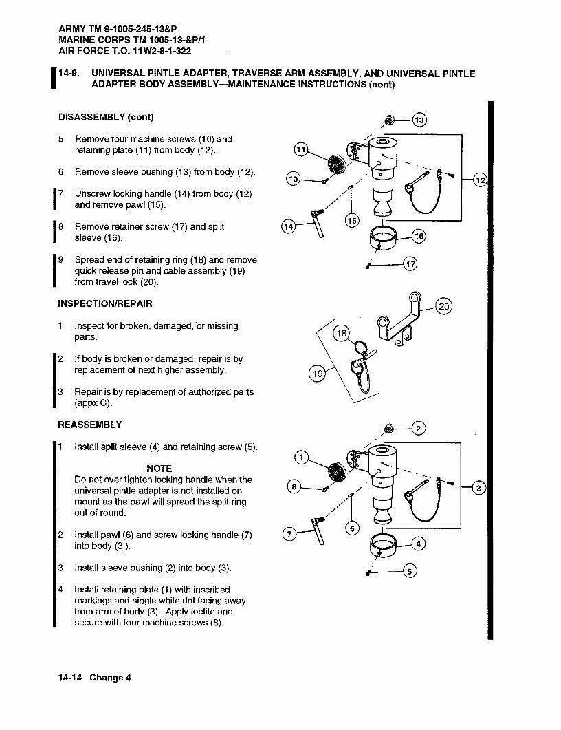
ARMY TM 9-1005-245-13&PMARINE CORPS TM 1005-13-&P/1AIR FORCE T.O. 11W2-8-1-322
14-9. UNIVERSAL PINTLE ADAPTER, TRAVERSE ARM ASSEMBLY, AND UNIVERSAL PINTLEADAPTER BODY ASSEMBLY-MAINTENANCE INSTRUCTIONS (cont)
DISASSEMBLY (cont)
5 Remove four machine screws (10) andretaining plate (11) from body (12).
6 Remove sleeve bushing (13) from body (12).10 12
7 Unscrew locking handle (14) from body (12)and remove pawl (15).
8 Remove retainer screw (17) and split15
16sleeve (16).
9 Spread end of retaining ring (18) and remove 17quick release pin and cable assembly (19)from travel lock (20).
INSPECTION/REPAIR 20
1 Inspect for broken, damaged,or missing18parts.
2 If body is broken or damaged, repair is byreplacement of next higher assembly. 19
3 Repair is by replacement of authorized parts(appx C).
REASSEMBLY
1 Install split sleeve (4) and retaining screw (5).
NOTEDo not over tighten locking handle when theuniversal pintle adapter is not installed onmount as the pawl will spread the split ringout of round.
2 Install pawl (6) and screw locking handle (7)6
into body (3 ).
3 Install sleeve bushing (2) into body (3).
4 Install retaining plate (1) with inscribedmarkings and single white dot facing awayfrom arm of body (3). Apply loctite and
X
secure with four machine screws (8).
14-14 Change 4
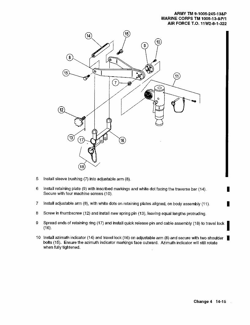
ARMY TM 9-1005-245-13&PMARINE CORPS TM 1005-13-&P/1
AIR FORCE T.O. 11W2-8-1-322
14
10
C>
12
1317
18
5 Install sleeve bushing (7) into adjustable arm (8).
6 Install retaining plate (9) with inscribed markings and white dot facing the traverse bar (14).Secure with four machine screws (10).
7 Install adjustable arm (8), with white dots on retaining plates aligned, on body assembly (11).
8 Screw in thumbscrew (12) and install new spring pin (13), leaving equal lengths protruding.
9 Spread ends of retaining ring (17) and install quick release pin and cable assembly (18) to travel lock(16).
10 Install azimuth indicator (14) and travel lock (16) on adjustable arm (8) and secure with two shoulderbolts (15). Ensure the azimuth indicator markings face outward. Azimuth indicator will still rotatewhen fully tightened.
Change 4 14-15
ARMY TM 9-1006-245-13&PMARINE CORPS TM 1005-13-&P/1AIR FORCE T.O. 11 W2-8-1-322
14-10. ELEVATION MECHANISM-MAINTENANCE INSTRUCTIONS
THIS TASK COVERS:
Repair
REPAIR
If elevation mechanism is damaged or broken, refer to paragraph 7-8 for repair.
14-16 Change 4
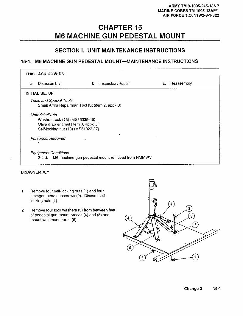
ARMY TM 9-1005-245-13&PMARINE CORPS TM 1005-13&P/1
AIR FORCE T.O. 11 W2-8-1-322
CHAPTER 15M6 MACHINE GUN PEDESTAL MOUNT
SECTION I. UNIT MAINTENANCE INSTRUCTIONS
15-1. M6 MACHINE GUN PEDESTAL MOUNT-MAINTENANCE INSTRUCTIONS
THIS TASK COVERS:
a. Disassembly b. Inspection/Repair c. Reassembly
INITIAL SETUP
Tools and Special ToolsSmall Arms Repairman Tool Kit (item 2, appx 13)
Materials/PartsWasher Lock (13) (MS35338-48)Olive drab enamel (item 3, appx E)Self-locking nut (13) (MS51922-37)
Personnel Required1
Equipment Conditions2-4 d. M6 machine gun pedestal mount removed from HMMWV
DISASSEMBLY
1 Remove four self-locking nuts (1) and fourhexagon head capscrews (2). Discard self-locking nuts (1).
4
2 Remove four lock washers (3) from between feet 2
of pedestal gun mount braces (4) and (5) and4 5
mount weldment frame (6).
5
6
Change 3 15-1

ARMY TM 9-1005-245-13&PMARINE CORPS TM 1005-13&P/1AIR FORCE T.O. 11W2-8-1-322
15-1. M6 MACHINE GUN PEDESTAL MOUNT-MAINTENANCE INSTRUCTIONS (cont)
DISASSEMBLY (cont)
3 Remove two self-locking nuts (7), two 9lockwashers (8), and two pedestal gun 10 10mount braces (5). Discard self-locking
48
nuts (7) and lockwashers (8). 97
4 Remove two self-locking nuts (9), two 4lockwashers (110),and two pedestal 5gun mount braces (4) from straightthreaded pin (11.). Discard self-lockingnuts (9) and lockwashers (10).
85 7
5 Remove self -locking nut (12),lockwasher (13), hex head screw (14),and telescoping tube assembly (15)from aclapterand flange (16). Discardself-locking nut (12) and lockwasher 13)(13). 16 12
6 Remove four self-locking nuts (117),17
14
four lockwashers (18), four hexagonhead capscrews (19), and adapter and 18flange (16) from mount weldmentframe (6). Discard self-locking nuts 6(17) and lockwashers (18).
19
15-2 Change 3

ARMY TM 9-1005-245-13&PMARINE CORPS TM 1005-13&P/1
AIR FORCE T.O. 11 W2-8-1-322
30
2527 2622
21
20
7 Remove straight threaded pin (20), and retaining collar (21) from telescoping tube assembly (15).
8 Disengage quick release pin (22) from telescoping tube assembly (15).
9 Separate internal structural tube (23) from external structural tube (24)
10 Remove wire cord (25) from ring gofquick release pin (22).
11 Remove threaded insert (26) from external structural tube (24). and separate wire cord (25) from threadedinsert (26)
12 Remove threaded insert (27) from other side of external structural tube (24).
13 Fully unscrew handle assembly (28) until it stops in insert (29).
14 Holding handle assembly (28), unscrew externally threaded insert (29) and remove retaining clampassembly (30) from internal structural tube (23).
INSPECTION/REPAIR
1 Inspect for broken, damaged, or missing parts.
2 If mount weldment frame (6) is broken or damaged, repair is by replacement of next higher assembly.
3 Touch up external bright metal surfaces with olive drab enamel paint (item 3, appx E)
4 Repair is by replacement of authorized parts (appx C).
Change 4 15-3

ARMY TM 9-1005-245-13&PMARINE CORPS TM 1005-13&P/1AIR FORCE T.O. 11W2-8-1-322
15-1. M6 MACHINE GUN PEDESTAL MOUNT-MAINTENANCE INSTRUCTIONS (cont)
REASSEMBLY
NOTEThe front of the external structural tube (24) is considered to be that side which faces you whenthe internal structural tube (23) is installed and the retaining clamp assembly (30) is on the rightside.
283
07
25 22
22
J 20
1 Fully screw in handle assembly (28) until it stops in threaded insert (29). Holding handle assembly (28),screw threaded insert (29) into internal structural tube (23) securing retaining clamp assembly (30).
2 Install threaded insert (27) in rear side of external structural tube (24).
3 Insert wire cord (25) on threaded insert (26) and install into front side of external strucural tube (24).
4 Install ring of quick release pin (22) on wire cord (25).
5 If replaced, lubricate new internal structural tube (23) with general purpose lubricating oil (item 7, appx E)and install in external structural tube (24) with retaining clamp assembly (30) to the right.
6 Engage quick release pin (22) in telescoping tube assembly (15). ,
7 Install retaining collar (21) with threaded studs to the front, and straight threaded pin (20) in telescoping tubeassembly (15).
0
15-4 Change 3
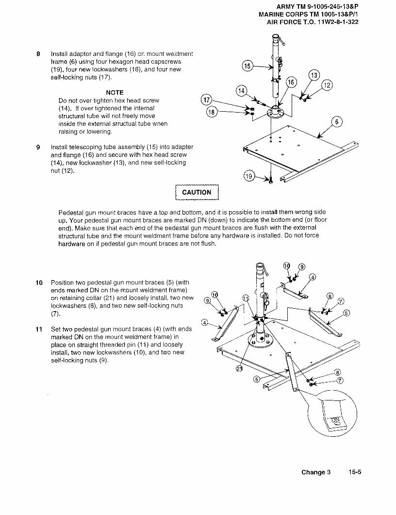
ARMY TM 9-1005-245-13&PMARINE CORPS TM 1005-13&P/1
AIR FORCET.O. 11W2-8-1-322
8 Install adapter and flange (16)on mountweldmentframe (6) using four hexagon head capscrews(19), four new lockwashers (18), and four newself-locking nuts (17).
1613
12NOTE 14
Do not over tighten hex head screw 17(14). If overtightened the internal
18structural tube will not freely moveinside the external structual tube when 6
raising or lowering.
9 Install telescoping tube assembly (15) into adapterand flange (16) and secure with hex head screw(14), new lockwasher (13), and new self-lockingnut (12).
19
CAUTION
Pedestal gun mount braces have a top and bottom, and it is possible to install them wrong sideup. Your pedestal gun mount braces are marked DN (down) to indicate the bottom end (or floorend). Make sure that each end of the pedestal gun mount braces are flush with the externalstructural tube and the mount weldment frame before any hardware is installed. Do not forcehardware on if pedestal gun mount braces are not flush.
99
1@
10 Position two pedestal gun mount braces (5) (withends marked DN on the mount weldment frame)on retaining collar (21) and loosely install, two new 0
(D9 7lockwashers (8), and two new self-locking nuts(7). 5
411 Set two pedestal gun mount braces (4) (with ends
marked DN on the mount weldment frame) inplace on straight threaded pin (11) and looselyinstall, two new lockwashers (10), and two newself-locking nuts (9).
85 7
Change 3 15-5

ARMY TM 9-1005-245-13&PMARINE CORPS TM 1005-13&P/1AIR FORCE T.O. 11W2-8-1-322
15-1. M6 MACHINE GUN PEDESTAL MOUNT-MAINTENANCE INSTRUCTIONS (cont)
REASSEMBLY (cont)
49 2
4 5
5
6
12 Install four lockwashers (3) between feet of pedestal gun mount braces (4) and (5) and mount weldmentframe (6).
13 Install four hexagon head capscrews (2) and four new self-locking nuts (1).
14 Securely tighten self-locking nuts (1), (7), and (9).
15-6 Change 3

ARMY TM 9-1005-245-13&PMARINE CORPS TM 1005-13&P/1
AIR FORCE T.O. 11 W2-8-1-322
SECTION II. DIRECT SUPPORT MAINTENANCE INSTRUCTIONS
15-2. M6 MACHINE GUN PEDESTAL MOUNT-MAINTENANCE INSTRUCTIONS
THIS TASK COVERS:
There are no direct support repair procedures. For maintenance repair refer to unit maintenance procedures,
paragraph 15-1.
Change 3 15-7/(15-8 blank)

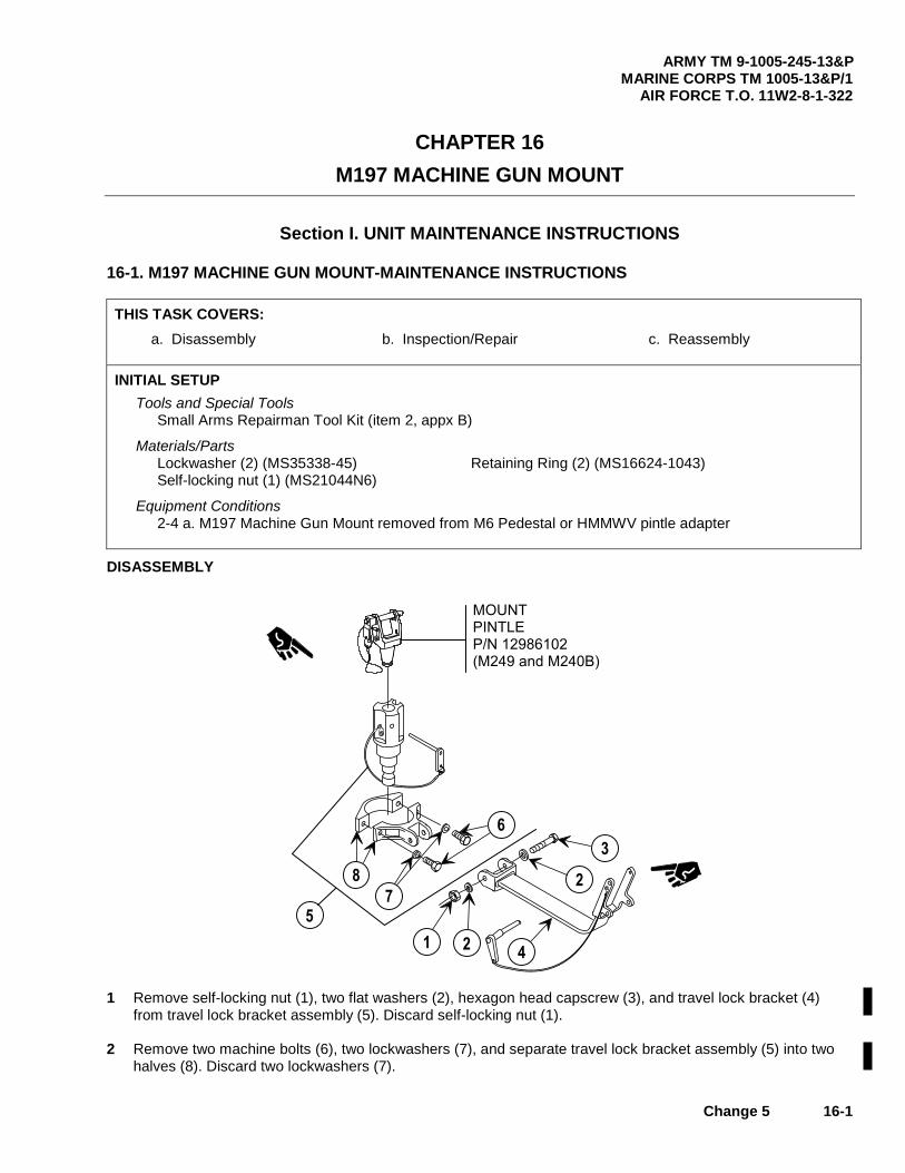
ARMY TM 9-1005-245-13&P MARINE CORPS TM 1005-13&P/1
AIR FORCE T.O. 11W2-8-1-322
Change 5 16-1
CHAPTER 16 M197 MACHINE GUN MOUNT
Section I. UNIT MAINTENANCE INSTRUCTIONS 16-1. M197 MACHINE GUN MOUNT-MAINTENANCE INSTRUCTIONS THIS TASK COVERS: a. Disassembly b. Inspection/Repair c. Reassembly INITIAL SETUP
Tools and Special Tools Small Arms Repairman Tool Kit (item 2, appx B)
Materials/Parts Lockwasher (2) (MS35338-45) Retaining Ring (2) (MS16624-1043) Self-locking nut (1) (MS21044N6)
Equipment Conditions 2-4 a. M197 Machine Gun Mount removed from M6 Pedestal or HMMWV pintle adapter
DISASSEMBLY
� � � � �� � � � � � � � � � � � � � � � � � � � � � � � � � � �
� �
�
�
�
�
�
�
�
1 Remove self-locking nut (1), two flat washers (2), hexagon head capscrew (3), and travel lock bracket (4)
from travel lock bracket assembly (5). Discard self-locking nut (1). 2 Remove two machine bolts (6), two lockwashers (7), and separate travel lock bracket assembly (5) into two
halves (8). Discard two lockwashers (7).

ARMY TM 9-1005-245-13&P MARINE CORPS TM 1005-13&P/1 AIR FORCE T.O. 11W2-8-1-322
16-2 Change 5
16-1. M197 MACHINE GUN MOUNT-MAINTENANCE INSTRUCTIONS (cont) DISASSEMBLY (cont)
�
� �
�
� �
� �
� �
� �
� �
� �
� �
3 Remove quick release pin (9) from cable assembly
(10). 4 Separate cable assembly (10) from retaining ring
(11). 5 Remove retaining ring (11) from travel lock bracket
(4).
NOTE Items 12-18 apply only when mounting an M60 and
are located in the Additional Authorization List (AAL), appendix F.
6 Remove two retaining clips (12) and headless
grooved pin (13) and separate sleeve spacer (14), and travel lock adapter assembly (15) from travel lock bracket (4). Discard retaining clips (12).
7 Separate stud plunger (16) and compression helical
spring (17) from travel lock adapter assembly (15). 8 For disassembly of mount pintle (PN 11010408) (18)
refer to paragraph 6-3. For disassembly of mount pintle (PN 12986102) (19) refer to paragraph 16-1A.
9 Remove socket head capscrew (20) and wire rope
assembly (21) from pintle adapter (22). 10 Remove quick release pin (23) from wire rope
assembly (21).
� �
� �
� �
�
� �
�

ARMY TM 9-1005-245-13&P MARINE CORPS TM 1005-13&P/1
AIR FORCE T.O. 11W2-8-1-322
Change 5 16-3
INSPECTION/REPAIR 1 Inspect for broken, damaged, or missing parts. 2 If travel lock bracket assembly is broken or damaged, repair is by replacement of next higher assembly. 3 If pintle adapter is broken or damaged, repair is by replacement of next higher assembly. 4 For inspection and repair of mount pintle (18) refer to paragraph 6-3 and for mount pintle (19) refer to
paragraph 16-1A. 5 If travel lock assembly is broken, bent or damaged, repair is by replacement of next higher assembly. 6 Repair is by replacement of authorized parts (appx C).
REASSEMBLY
�
� �
� �
� �
�
1 Attach quick release pin (23) to wire rope assembly (21). 2 Install wire rope assembly (21) on pintle adapter (22) using socket head capscrew (20). 3 For reassembly of mount pintle (18) refer to paragraph 6-3. For reassembly of mount pintle (19) refer to
paragraph 16-1A.
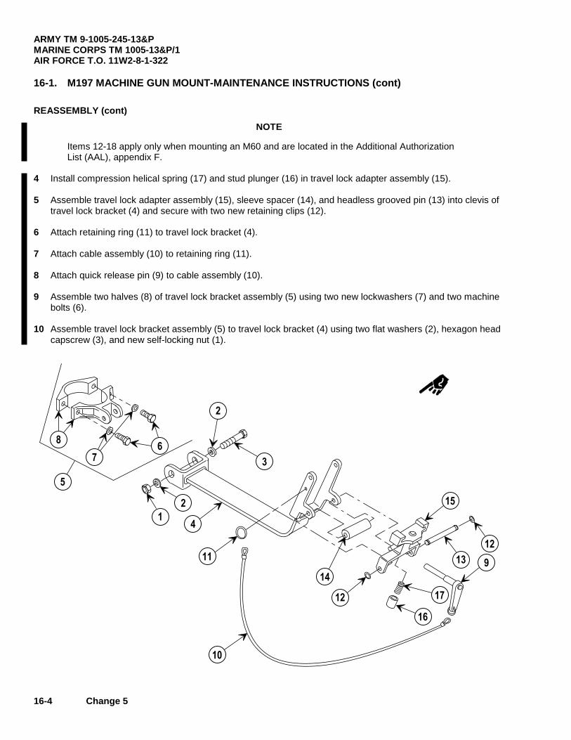
ARMY TM 9-1005-245-13&P MARINE CORPS TM 1005-13&P/1 AIR FORCE T.O. 11W2-8-1-322
16-4 Change 5
16-1. M197 MACHINE GUN MOUNT-MAINTENANCE INSTRUCTIONS (cont)
REASSEMBLY (cont) NOTE
Items 12-18 apply only when mounting an M60 and are located in the Additional Authorization List (AAL), appendix F.
4 Install compression helical spring (17) and stud plunger (16) in travel lock adapter assembly (15). 5 Assemble travel lock adapter assembly (15), sleeve spacer (14), and headless grooved pin (13) into clevis of
travel lock bracket (4) and secure with two new retaining clips (12). 6 Attach retaining ring (11) to travel lock bracket (4). 7 Attach cable assembly (10) to retaining ring (11). 8 Attach quick release pin (9) to cable assembly (10). 9 Assemble two halves (8) of travel lock bracket assembly (5) using two new lockwashers (7) and two machine
bolts (6). 10 Assemble travel lock bracket assembly (5) to travel lock bracket (4) using two flat washers (2), hexagon head
capscrew (3), and new self-locking nut (1).
�
�
�
�
�
�
��
� �
�
�
� �
� �
� �
� �
� �
� �
� �

ARMY TM 9-1005-245-13&P MARINE CORPS TM 1005-13&P/1
AIR FORCE T.O. 11W2-8-1-322
Change 5 16-4.1
16-1A. MOUNT PINTLE - MAINTENANCE INSTRUCTIONS THIS TASK COVERS:
a. Disassembly b. Inspection/Repair c. Reassembly INITIAL SETUP
Tools and Special Tools Small Arms Repairman Tool Kit (item 2, appx B)
Personnel Required 1
Equipment Conditions 16-1 Pintle assembly removed
DISASSEMBLY Remove capscrew (1), cable assembly (2), and quick release pin (3) from pintle assembly (4).
43
2
1
INSPECTION/REPAIR 1 Inspect for broken, damaged, or missing parts. 2 If pintle (4) is broken or damaged, repair is by replacement of next higher assembly. 3 Repair is by replacement of authorized parts (appx C).
REASSEMBLY Install quick release pin (3), cable assembly (2), and cap screw (1) to pintle assembly (4).
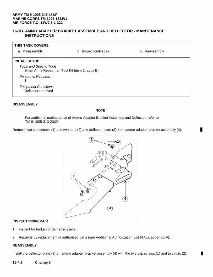
ARMY TM 9-1005-245-13&P MARINE CORPS TM 1005-13&P/1 AIR FORCE T.O. 11W2-8-1-322
16-4.2 Change 5
16-1B. AMMO ADAPTER BRACKET ASSEMBLY AND DEFLECTOR - MAINTENANCE
INSTRUCTIONS THIS TASK COVERS:
a. Disassembly b. Inspection/Repair c. Reassembly INITIAL SETUP
Tools and Special Tools Small Arms Repairman Tool Kit (item 2, appx B)
Personnel Required 1
Equipment Conditions Deflector removed
DISASSEMBLY NOTE
For additional maintenance of Ammo Adapter Bracket Assembly and Deflector, refer to TM 9-1005-313-23&P.
Remove two cap screws (1) and two nuts (2) and deflector plate (3) from ammo adapter bracket assembly (4).
1
2
3
4
INSPECTION/REPAIR 1 Inspect for broken or damaged parts. 2 Repair is by replacement of authorized parts (see Additional Authorization List (AAL), appendix F). REASSEMBLY Install the deflector plate (3) on ammo adapter bracket assembly (4) with the two cap screws (1) and two nuts (2).

ARMY TM 9-1005-245-13&P MARINE CORPS TM 1005-13&P/1
AIR FORCE T.O. 11W2-8-1-322
Change 5 16-5/(16-6 blank)
SECTION II. DIRECT SUPPORT MAINTENANCE INSTRUCTIONS
16-2. M197 MACHINE GUN MOUNT-MAINTENANCE INSTRUCTIONS THIS TASK COVERS: There are no direct support repair procedures. For maintenance repair refer to unit maintenance procedures, paragraph 16-1, 16-1A, and 16-1B.


ARMY TM 9-1005-245-13&P MARINE CORPS TM 1005-13&P/1
AIR FORCE T.O. 11W2-8-1-322
Change 5 A-1
APPENDIX A
REFERENCES
A-1. TECHNICAL MANUALS (TM) TM 9-1005-201-10................................ Operator’s Manual: M249 Machine Gun TM 9-1005-213-10................................ Operator’s Manual: Machine Gun, .50 Cal, Browning, M2, Heavy Barrel,
Flexible w/e (1005-322-9715) Mount, Tripod, Machine Gun, .50 Cal, w/e (1005-322-9716) Mount, Machine Gun, Anti-aircraft, .50 Cal, M63 w/e (1005-673-3246)
TM 9-1005-224-10................................ Operator’s Manual: M60 Machine Gun TM 9-1005-313-10................................ Operator’s Manual: Machine Gun, 7.62MM, M240 Series TM 9-1005-313-23&P........................... Unit and Direct Support Maintenance Manual (Including Depot
Maintenance Repair Parts) for Machine Gun, 7.62MM, M240 Series TM 9-1010-230-10................................ Operator’s Manual: MK19 Mod 3 40MM Machine Gun TM 9-1010-231-13&P........................... MK64 Machine Gun Mount TM 9-1300-206 ..................................... Ammunition Explosive Standards TM 9-2320-280-20-3............................. Unit Maintenance Manual for Truck, Utility Cargo/Troop Carrier, 1-1/4
Ton, 4 x 4, M998 (NSN 2320-01-107-7155) (EIC: BBD); Armament Carrier Armored, 1-1/4 Ton, 4x4, M1025 (2320-01-128-9951) (EIC: BBF); Armament Center, Armored, 1-1/4 Ton, 4 x 4, W/Winch, M1026 (2320-01-128-9552) (EIC: BBG)
TM 750-244-6 ....................................... Procedures for Destruction of Equipment in Federal Supply Classifications
1000, 1005, 1010, 1015, 1020, 1025, 1030, 1055, 1090, and 1095 to Prevent Enemy Use
A-2. DEPARTMENT OF THE ARMY (DA) FORMS DA Form 2028 ...................................... Recommended Changes to Publications and Blank Forms DA Form 2028-2 ................................... Recommended Changes to Publications and Blank Forms DA Form 2404 ...................................... Equipment Inspection and Maintenance Worksheet DA Form 2407 ...................................... Maintenance Request A-3. MARINE CORPS DATA MCO 4855.10 ....................................... Quality Deficiency Report MCO P4610.19..................................... Transportation and Travel Record of Transportation Discrepancies

ARMY TM 9-1005-245-13&P MARINE CORPS TM 1005-13&P/1 AIR FORCE T.O. 11W2-8-1-322
A-2 Change 3
A-3. MARINE CORPS DATA (cont) MCO P4450.7....................................... Marine Corps Warehousing Manual MCO P4790.2....................................... Administrative Storage of Equipment NAVMC 10772...................................... Recommended Changes to Publications/Logistics Maintenance Date
Coding TM 4700-15/1 ....................................... Marine Corps Tactical Equipment Record Procedure: Record
Maintenance A-4. TECHNICAL ORDERS (TO) TO 00-35D-54....................................... Materiel Deficiency Reporting and Investigation System TO 11W-1-10........................................ Historical Data Recording of Inspection, Maintenance, and Firing Data
For Ground Weapons TO 33K-1-100....................................... (TMDE) Interval Calibration and Repair Reference Guide and Work Unit
Code Manual A-5. OTHER AFTO Form 22...................................... Technical System Publication Improvement Report AR 750-1............................................... Army Material Maintenance Policy and Retail Maintenance Operations CTA 8-100 ............................................ Army Medical Department Expendable/Durable Items CTA 50-970 .......................................... Modified Table of Organization and Equipment (MTOE) DA PAM 25-30...................................... Consolidated Index of Army Publications and Blank Forms DA PAM 738-750.................................. The Army Maintenance Management System (TAMMS) FM 21-11 .............................................. First Aid for Soldiers FM 23-14 .............................................. Machine Gun, 5.56MM, M249 FM 23-27 .............................................. MK19, 40MM Grenade Machine Gun Mod 3 FM 23-65 .............................................. Browning, Machine Gun, .50 Cal, HB, M2 FM 23-67 .............................................. Machine Gun, 7.62MM, M60 SF 364 .................................................. Report of Discrepancy (ROD) SF 368 .................................................. Product Quality Deficiency Report

ARMY TM 9-1005-245-13&PMARINE CORPS TM 1005-13&P/1
AIR FORCE T.O. 11W-28-1-322
APPENDIX B
MAINTENANCE ALLOCATION CHART (MAC)
Section I. INTRODUCTION
B-1. THE ARMY MAINTENANCE SYSTEM MAC
a. This section provides a general explanation of all maintenance and repair functions authorized at variousmaintenance levels under the standard Army Maintenance System concept.
b. The Maintenance Allocation Chart (MAC) in section 11designates overall authority and responsibility forthe performance of maintenance functions on the identified end item or component. The application of themaintenance functions to the end Rem or component will be consistent with the capacities and capabilities of thedesignated maintenance levels, which are shown on the MAC in column (4) as:
Unit-includes two subcolumns, C (operator/crew) and 0 (unit) maintenance.
Direct Support-includes an F subcolumn.
General Support-includes an H subcolumn.
Depot-includes a D subcolumn.
c. Section III lists the tools and test equipment (both special tools and common tool sets) required for eachmaintenance function as referenced from section II.
d. Section IV contains supplemental instructions and explanatory notes for a particular maintenancefunction.
B-2. MAINTENANCE FUNCTIONS. maintenance functions are limited to and defined as follows(except for ammunition MAC):
a. Inspect. To determine the serviceability of an item by comparing its physical, mechanical, and/orelectrical characteristics with established standards through examination (e.g., by sight, sound, or feel).
b. Test. To verify serviceability by measuring the mechanical, pneumatic, hydraulic, or electricalcharacteristics of an item and comparing those characteristics with prescribed standards.
c. Service. Operations required periodically to keep an item in proper operating condition, e.g., to clean(includes decontaminate, when required), to preserve, to drain, to paint, or to replenish fuel, lubricants, chemicalfluids, or gases.
d. Adjust. To maintain or regulate, within prescribed limits, by bringing into proper position or by setting theoperating characteristics to specified parameters.
'Exception is authorized for ammunition MACs to permit use of maintenance function headings that betterdescribe or identify ammunition maintenance functions. The headings used and their definitions shall be includedin the appropriate ammunition technical manual(s).
Change 1 B-1

ARMYTM 9-1005-245-13&PMARINECORPSTM 1005-13&P/1AIRFORCET.O. 11W2-8-1-322
B-2. MAINTENANCE FUNCTIONS (cont)
e. Align. To adjust specified variable elements of an item to bring about optimum or desired performance.
f. Calibrate. To determine and cause corrections to be made or to be adjusted on instruments or test,measuring, and diagnostic equipment used in precision measurement. Consists of comparisons of twoinstruments, one of which is a certified standard of known accuracy, to detect and adjust any discrepancy in theaccuracy of the instrument being compared.
g. Remove/install. To remove and install the same item when required to perform service or othermaintenance functions. Install may be the act of emplacing, seating, or fixing into position a spare, repair part, ormodule (component or assembly) in a manner to allow the proper functioning of an equipment or system.
h. Replace. To remove an unserviceable item and install a serviceable counterpart in its place. "Replace" isauthorized by the MAC and assigned maintenance level is shown as the 3d position code of the SMR code.
i. Repair. The application of maintenance services2, including fault location/troubleshooting, removal/installation, and disassembly/assembly procedures, and maintenance actions to identify troubles and restoreserviceability to an item by correcting specific damage, fault, malfunction, or failure in a part, subassembly,module (component or assembly), end item, or system.
j. Overhaul. That maintenance effort (service/action) prescribed to restore an item to a completelyserviceable/operational condition as required by maintenance standards in appropriate technical publications (i.e.,DMWR). Overhaul is normally the highest degree of maintenance performed by the Army. Overhaul does notnormally return an item to like new condition.
k. Rebuild. Consists of those services/actions necessary for the restoration of unserviceable equipment toa like new condition in accordance with original manufacturing standards. Rebuild is the highest degree ofmateriel maintenance applied to Army equipment. The rebuild operation includes the act of returning to zerothose age measurements (e.g., hours/miles) considered in classifying Army equipment1components.
B-3. EXPLANATION OF COLUMNS IN THE MAC, SECTION 11
a. Column 1, Group Number. Column 1 lists functional group code numbers, the purpose of which is toidentify maintenance significant components, assemblies, subassemblies, and modules with the next higherassembly.
b. Column 2, Component/Assembly. Column 2 contains the names of components, assemblies,subassemblies, and modules for which maintenance is authorized.
c. Column 3, Maintenance Function. Column 3 lists the functions to be performed on the item listed incolumn 2. (For detailed explanation of these functions, refer to para B-2).
2 Services-inspect, test, service, adjust, align, calibrate, and/or replace.
3 Fault location/troubleshooting-the process of investigating and detecting the cause of equipmentmalfunctioning; the act of isolating a fault within a system or unit under test (UUT).
4 Disassembly/assembly-the step-by-step breakdown (taking apart) of a spare/functional group coded item tothe level of its least component, that is assigned an SMR code for the level of maintenance under consideration(i.e., identified as maintenance significant).
5 Actions-welding, grinding, riveting, straightening, facing, machining, and/or resurfacing.
B-2

ARMY TM 9-1005-245-13&PMARINE CORPS TM 1005-13&P/1
AIR FORCE T.O. 11W2-8-1-322
d. Column 4, Maintenance Level. Column 4 specifies each level of maintenance authorized toperform each function listed in column 3 by indicating work time required (expressed as man-hours inwhole hours or decimals) in the appropriate subcolumn. This work-time figure represents the active timerequired to perform that maintenance function at the indicated level of maintenance. If the number orcomplexity of the tasks within the listed maintenance function vary at different maintenance levels,appropriate work-time figures are shown for each level. The work-time figure represents the average timerequired to restore an item (assembly, subassembly, component, module, end item, or system) to aserviceable condition under typical field operating conditions. This time includes preparation time(including any necessary disassembly/assembly time), troubleshooting/fault location time, and qualityassurance time in addition to the time required to perform the specific tasks identified for the maintenancefunctions authorized in the MAC. The symbol designations for the various maintenance levels are asfollows:
C .................................................................... Operator or crew maintenance0 ................................................................... Unit maintenanceF .................................................................... Direct support maintenanceH .................................................................... General support maintenanceL .................................................................... Specialized Repair Activity (SRA)6D .................................................................... Depot maintenance
e. Column 5, Tools and Equipment. Column 5 specifies, by code, those common tool sets (notindividual tools), common TMDE, and special tools, special TMDE, and special support equipmentrequired to perform the designated function. Codes are keyed to tools and test equipment in section Ill.
f. Column 6. Remarks. When applicable, this column contains a letter code, in alphabetical order,which is keyed to the remarks contained in section IV.
B-4. EXPLANATION OF COLUMNS IN TOOL AND TEST EQUIPMENT REQUIREMENTS,SECTION Ill
a. Column 1, Reference Code. The tool and test equipment reference code correlates with a codeused in the MAC, section II, column 5.
b. Column 2, Maintenance Level. The lowest level of maintenance authorized to use the tool ortest equipment.
c. Column 3, Nomenclature. Name or identification of the tool or test equipment.
d. Column 4, National Stock Number. The National Stock Number of the tool or test equipment.
e. Column 5, Tool Number. The manufacturer's part number, model number, or type number.
6This maintenance level is not included in section 11,column (4) of the MAC. Functions to this level ofmaintenance are indicated by a work-time figure in the "H" column of section 11,column (4), and anassociated reference code is used in the Remarks column (6). This code is keyed to section IV, Remarks,and the SRA complete repair application is explained there.
Change 2 B-3

ARMY TM 9-1005-245-13&PMARINE CORPS TM 1005-13&P/1AIR FORCE T.O. 11W2-8-1-322
B-5. EXPLANATION OF COLUMNS IN REMARKS, SECTION IV
a. Column 1, Reference Code. The code recorded in column 6, section 11.
b. Column 2, Remarks. This column lists information pertinent to the maintenance function beingperformed as indicated in the MAC, section II.
Section II. MAINTENANCE ALLOCATION CHARTFOR GUN MOUNTS
(1) (2) (3) (4) (5) (6)TOOLS
ANDEQUIPMENT
GROUP COMPONENT/ MAINTENANCE MAINTENANCE LEVEL REF REMARKS
NUMBER ASSEMBLY FUNCTION UNIT DS GS DEPOT CODE CODEC 0 F H D
00 Mount, Tripod, Inspect 0.3 0.3Machine Gun, M122 Service 0.3 0.3(7790723) Repair 0.1 0.8 1.0 1,2
Mount, Tripod, Inspect 0.3 0.3 0.2M122A1 Service 0.3 0.3(12976949) Replace 0.1
Repair 0.2 0.1 1,2,3
01 Elevating and Inspect 0.3 0.3Traversing Replace 0.3Mechanism Repair 0.5 1,2,3(7791119)
02 Tripod, Leg Assembly Inspect 0.2 0.2(16976948) Replace 0.3
Repair 0.1 0.3 1,2
0201 Leg, Tripod Mount Inspect 0.1 0.1 0.1(5559337) Replace 0.2
Repair 0.1 0.3 1,2
0202 Lock Assembly, Replace 0.2Pintle Repair 0.3 1(6108986)
03 Pintle, Mount Replace 0.1(11010408) Repair 0.2 1,2(M-122only)
04 Flexible Gun Mount Inspect 0.3 0.3 0.3(12976940) Service 0.3 0.3(M122A1 only) Replace 0.3 1,2
Repair 0.8 1,2
0401 Cradle Assembly, Replace 0.5 1,2Upper Repair 0.5 1,2(12597091)
B-4 Change 2
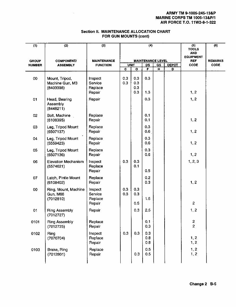
ARMY TM 9-1005-245-13&PMARINE CORPS TM 1005-13&P/1
AIR FORCE T.O. 11W2-8-1-322
Section III. MAINTENANCE ALLOCATION CHARTFOR GUN MOUNTS (cont)
(2) (3) (4) (5) (6)TOOLS
ANDEQUIPMENT
GROUP COMPONENT/ MAINTENANCE MAINTENANCE LEVEL REF REMARKSNUMBER ASSEMBLY FUNCTION UNIT DS GS DEPOT CODE CODE
C 0 F H D
00 Mount, Tripod, Inspect 0.3 0.3 0.3Machine Gun, M3 Service 0.3 0.3(8403398) Replace 0.3
Repair 0.3 1.3 1,2
01 Head,Bearing Repair 0.3 1,2Assembly(8448211)
02 Bolt, Machine Replace 0.1(6108395) Repair 0.1 1,2
03 Leg, Tripod Mount Replace 0.3(6507137) Repair 0.6 1,2
04 Leg, Tripod Mount Replace 0.3(5559423) Repair 0.6 1,2
05 Leg, Tripod Mount Replace 0.3(6507136) Repair 0.6 1,2
06 Elevation Mechanism Inspect 0.3 0.3 1,2,3(5574621) Replace 0.1
Repair 0.5
07 Latch, Pintle Mount Replace 0.2(6108402) Repair 0.3 1,2
00 Ring, Mount, Machine Inspect 0.3 0.3Gun, M66 Service 0.3 0.3(7012810) Replace 1.5
Repair 0.5 2
01 Ring Assembly Repair 0.3 2.5 1,2(7012727)
0101 Ring Assembly - Replace 0.1 2(7012725) Repair 0.3 2
0102 Ring Inspect 0.3 0.3 0.3(7070704) Replace 0.8 1,2
Repair 0.8 1,2
0103 Brake, Ring Replace 0.5 1,2(7012801) Repair 0.3 0.5 1,2
Change 2 B-5

ARMY TM 9-1005-245-13&PMARINE CORPS TM 1005-13&P/1AIR FORCE T.O. 11W2-8-1-322
Section II. MAINTENANCEALLOCATION CHARTFOR GUN MOUNTS (cont)
(1) (2) (3) (4) (5) (6)TOOLS
ANDEQUIPMENT
GROUP COMPONENT/ MAINTENANCE MAINTENANCE LEVEL REF REMARKS
NUMBER ASSEMBLY FUNCTION UNIT DS GS DEPOT CODE CODE
C 0 F H D
00 M240E1 Flexible Inspect 0.3 0.3 0.3Machine Gun Mount Service 0.3 0.3(12597090) Replace 0.3 1,2
Repair 0.8 1,2
0401 Cradle Assembly, Replace 0.5 1,2Upper Repair 0.5 1,2(12597091)
00 Mount, Machine Gun, Inspect 0.3 0.3 0.3M142 Service 0.3 0.3(10900945) Replace 0.3 2
Repair 0.3 0.8 1,2
01 Platform Assembly Repair 0.3 1,2(10900947)
00 Mount, Machine Gun, Inspect 0.3 0.5 0.3Cal .50, 6650 Service 0.3 0.3(7046650) Replace 0.3
Repair 0.3 0.8 1,2
00 Machine Gun Mount, Inspect 0.3 0.3 0.3M548 Service 0.3 0.3(11631740-2) Repair 0.3 1.5 1,2
01 Ring, Mount, Machine Inspect 0.3 0.3Gun, M66 Service 0.3 0.3(7012810) Replace 1.5
Repair 0.5 2
0101 Ring Assembly Repair 0.3 2.5 1,2(7012727)
010101 Ring Assembly Replace 0.1 2(7012725) Repair 0.3 2
010102 Ring Inspect 0.3 0.3 0.3(7070704) Replace 0.8 1,2
Repair 0.8 1,2
010103 Brake, Ring Replace 0.5 1,2(7012801) Repair 0.3 0.5 1,2
B-6 Change 2
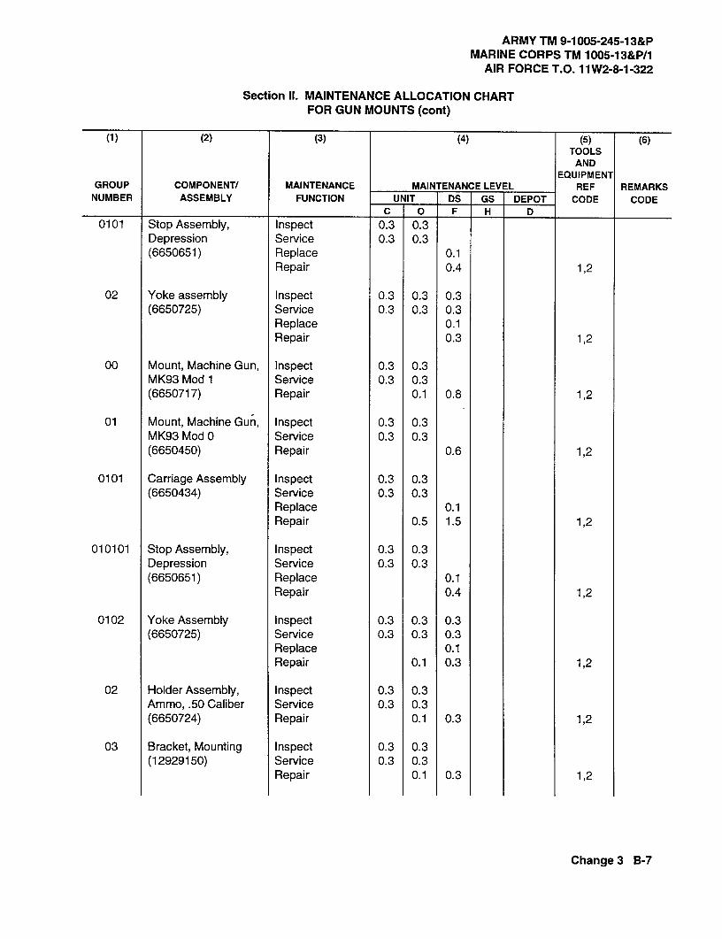
ARMY TM 9-1005-245-13&PMARINE CORPS TM 1005-13&P/1
AIR FORCE T.O. 11W2-8-1-322
Section II. MAINTENANCE ALLOCATION CHARTFOR GUN MOUNTS (cont)
(1) (2) (3) (4) (5) (6)TOOLS
ANDEQUIPMENT
GROUP COMPONENT/ MAINTENANCE MAINTENANCE LEVEL REF REMARKSNUMBER ASSEMBLY FUNCTION UNIT DS GS DEPOT CODE CODE
C 0 F H D0101 Stop Assembly, Inspect 0.3 0.3
Depression Service 0.3 0.3(6650651) Replace 0.1
Repair 0.4 1,2
02 Yoke assembly Inspect 0.3 0.3 0.3(6650725) Service 0.3 0.3 0.3
Replace 0.1Repair 0.3 1,2
00 Mount, Machine Gun, Inspect 0.3 0.3MK93 Mod 1 Service 0.3 0.3(6650717) Repair 0.1 0.8 1,2
01 Mount, Machine Gun, Inspect 0.3 0.3MK93 Mod 0 Service 0.3 0.3(6650450) Repair 0.6 1,2
0101 Carriage Assembly Inspect 0.3 0.3(6650434) Service 0.3 0.3
Replace 0.1Repair 0.5 1.5 1,2
010101 Stop Assembly, Inspect 0.3 0.3Depression Service 0.3 0.3(6650651) Replace 0.1
Repair 0.4 1,2
0102 Yoke Assembly Inspect 0.3 0.3 0.3(6650725) Service 0.3 0.3 0.3
Replace 0.1Repair 0.1 0.3 1,2
02 Holder Assembly, Inspect 0.3 0.3Ammo,.50 Caliber Service 0.3 0.3(6650724) Repair 0.1 0.3 1,2
03 Bracket, Mounting Inspect 0.3 0.3(12929150) Service 0.3 0.3
Repair 0.1 0.3 1,2
Change 3 B-7

ARMY TM 9-1005-245-13&PMARINE CORPS TM 1005-13&P/1AIR FORCE T.O. 11W2-8-1-322
Section III. MAINTENANCEALLOCATION CHARTFOR GUN MOUNTS (cont)
(1)(2) (3) (4) (5) (6)TOOLS
ANDEQUIPMENT
GROUP COMPONENT/ MAINTENANCE MAINTENANCE LEVEL REF REMARKSNUMBER ASSEMBLY FUNCTION UNIT DS GS DEPOT CODE CODE
C 0 F H D
04 Catch Bag Assembly Inspect 0.3 0.3(6650723) Service 0.3 0.3
Repair 0.1 0.3 1,2
05 Universal Pintle Inspect 0.3 0.3Adapter Service 0.3 0.3(12012061) Repair 0.3 1,2
0501 Arm Assembly, Inspect 0.3 0.3Traverse Service 0.3 0.3(6650488) Replace 0.1
Repair 0.3 1,2
0502 Body Assembly, Inspect 0.3 0.3(12012062) Service 0.3 0.3
Repair 0.3 1,2
06 Elevation Mechanism Inspect 0.3 0.3(5574621) Service 0.3 0.3
Repair 0.3 1,2
00 M6 Machine Gun Inspect 0.3 0.3Pedestal Mount Replace 0.5(12956270) Repair 0.3 2
00 M1 97 Machine Gun Inspect 0.2 0.2Mount (12956264) Replace 0.2
Repair 0.3 2
01 Travel Lock Inspect 0.2 0.2Assembly (12956265) Replace 0.2
Repair 0.2 1,2
02 Bracket Assembly, Inspect 0.1 0.1Travel Lock Replace 0.1(5830063) Repair 0.1 2
03 Pintle Adapter Inspect 0.1 0.1Assembly (5830131) Replace 0.1
Repair 0.1 2
B-8 Change 4

ARMY TM 9-1005-245-13&P MARINE CORPS TM 1005-13&P/1
AIR FORCE T.O. 11W2-8-1-322
Change 5 B-9/(B-10 blank)
Section II. MAINTENANCE ALLOCATION CHART
FOR GUN MOUNTS (cont)
NOTE This section applies to Army users only.
(1) (2) (3) (4) (5) (6)
TOOLS AND
EQUIPMENT
GROUP COMPONENT/ MAINTENANCE MAINTENANCE LEVEL REF REMARKSNUMBER ASSEMBLY FUNCTION UNIT DS GS DEPOT CODE CODE
C O F H D 04 Pintle, Mount
(11010408) Replace Repair
0.1
0.2
1,2
05 Pintle Assembly (12986102)
Inspect Service Repair
0.30.3
0.30.30.3
2
06 Deflector Kit (12986106)
Inspect Service Install Replace Repair
0.10.20.2
0.10.2
0.20.1
2
07 Gun Mount Adapter (NPN)
Inspect Service Replace Repair
0.10.1
0.10.10.20.2
2
Section Ill. TOOL AND TEST EQUIPMENT REQUIREMENTS
FOR GUN MOUNTS TOOL OR
TEST EQUIPMENT REF CODE
MAINTENANCE LEVEL
NOMENCLATURE
NATIONAL STOCK NUMBER
TOOL NUMBER
1 F Shop Set, Small Arms: Field Maintenance, Basic, Less Power
4933-00-754-0664 SC 4933-95-A11
2 O Tool Kit, Small Arms Repairman 5180-01-462-4254 SC 5180-95-B71
3 F Wrench, Spanner 5120-00-077-2081 8436748
Section IV REMARKS
Not applicable.


ARMY TM 9-1005-245-13&PMARINE CORPS TM 1005-13&P/1
AIR FORCE T.O. 11W2-8-1-322
APPENDIX C
UNIT AND DIRECT SUPPORT MAINTENANCEREPAIR PARTS AND SPECIAL TOOLS LIST
Section I. INTRODUCTION
C-1 . SCOPE
This RPSTL lists and authorizes spares and repair parts; special tools; special test, measurement, and diagnosticequipment (TMDE); and other special support equipment required for performance of unit and direct supportmaintenance of the gun mounts. It authorizes the requisitioning, issue, and disposition of spares, repair parts, andspecial tools as indicated by the Source, Maintenance, and Recoverability (SMR) codes.
C-2. GENERAL
In addition to Section I, Introduction, this Repair Parts and Special Tools List is divided into the following sections:
a. Section II. Repair Parts List. A list of spares and repair parts authorized by this RPSTL for use in theperformance of maintenance. The list also includes parts which must be removed for replacement of theauthorized parts. Parts lists are composed of functional groups in ascending alphanumeric sequence, with theparts in each group listed in ascending figure and item number sequence. Bulk materials are listed in item namesequence. Repair parts kits are listed separately in their own functional group within Section 11.Repair parts forrepairable special tools are also listed in this section. Items listed are shown on the associated illustration(s)/figure(s).
b. Section Ill. Special Tools List. A list of special tools, special TMDE, and other special supportequipment authorized by this RPSTL (as indicated by Basis of Issue (BOI) information in DESCRIPTION ANDUSABLE ON CODE column) for the performance of maintenance.
c. Section IV. Cross-reference Index. A list, in National Item Identification Number (NIIN) sequence, of allNational stock numbered items appearing in the listing, followed by a list in alphanumeric sequence of all partnumbers appearing in the listing. National stock numbers and part numbers are cross- referenced to eachillustration figure and item number appearance. The figure and item number index lists figure and item numbers inalphanumeric sequence and cross-references NSN, CAGEC, and part numbers.
Changel C-1

ARMYTM 9-1005-245-13&PMARINECORPSTM 1005-13&P/1AIRFORCET.O. 11W2-8-1-322
C-3. EXPLANATION OF COLUMNS (SECTIONS II AND III)
a. ITEM NO. (Column (1)). Indicates the number used to identify items called out in the illustration.
b. SMR CODE (Column (2)). The Source, Maintenance, and Recoverability (SMR) code is a 5-positioncode containing supply/requisitioning information, maintenance level authorization criteria, and dispositioninstruction, as shown in the following breakout:
Source Maintenance RecoverabilityCode Code Code
XX i st two XX X
Tpositions
T
How you get an item 3rd position 4th position Who determines dispositionaction on an unserviceable
Who can install, Who can do item
replace, or use complete repair*the item on the item
*Complete Repair: Maintenance capacity, capability, and authority to perform all corrective maintenance tasks ofthe "Repair" function in a use/user environment in order to restore serviceability to a failed item.
(1) Source Code. The source code tells you how to get an item needed for maintenance, repair, oroverhaul of an end item/equipment. Explanations of source codes follow:
Code Explanation
PA Stocked items; use the applicable NSN to request/requisitionPB items with these source codes. They are authorized to thePC** level indicated by the code entered in the 3rd position of thePD SMR code.PEPF "NOTE: Items coded PC are subject to deterioration.PG
KDItems with these codes are not to be requested/requisitioned in-
KFdividually. They are part of a kit which is authorized to the
KBmaintenance level indicated in the 3d position of the SMRcode. The complete kit must be requisitioned and applied.
C-2

ARMY TM 9-1005-245-13&PMARINE CORPS TM 1005-13&P/1
AIR FORCE T.O. 1lW2-8-1-322
Code Explanation
MO- (Made at Unit/ Items with these codes are not to be requested/requisitionedAVUM Level) individually. They must be made from bulk material which
MF- (Made at DS/ is identified by the part number in the DESCRIPTION ANDAVIM Level) USABLE ON CODE (UOC) column and listed in the Bulk
MH- (Made at GS Material Group of the repair parts list in this RPSTL.Level) f'_ If the item is authorized to you by the 3d position code of the
ML- (Made at Spe- ] SMR code, but the source code indicates it is made at a
cialized Repair [ higher level, order the item from the higher level of maintenance.
Act (SRA))MD- (Made at Depot)
IAO- (Assembled by Unit/ [ Items with these codes are not to be requested/requisitioned
AVUM Level) [ individually. The parts that make up the assembled item mustAF- (Assembled by be requisitioned or fabricated and assembled at the level of
DS/AVIM Level) maintenance indicated by the source code. If the 3d positionAH- (Assembled by _ cede of the SMR code authorizes you to replace the item, but
GS Level) the source code indicates the item is assembled at a higherAL- (Assembled by level, order the item from the higher level of maintenance.
SRA)AD- (Assembled by
Depot)
XA - Do not requisition an "XA"-coded item. Order its next higher assembly. (Also, refer to the NOTE below.)XB - If an "XB" item is not available from salvage, order it using the CAGEC and part number given.XC - Installation drawing, diagram, instruction sheet, field service drawing, that is identified by manufacturer's
part number.XD - Item is not stocked. Order an "XD'-coded item through normal supply channels using the CAGEC and
part number given, if no NSN is available.
NOTE
Cannibalization or controlled exchange, when authorized, may be used as a source of supply foritems with the above source codes, except for those source coded "XA' or those aircraft supportitems restricted by requirements of AR 750-1.
C-3

ARMY TM 9-1005-245-13&PMARINE CORPS TM 1005-13&P/1AlR FO RCE T.0.11W2-8-1-322
C-3. EXPLANATION OF COLUMNS (SECTIONS II AND III)(cont)
(2) Maintenance Code. Maintenance codes tell you the level(s) of maintenance authorized to USE andREPAIR support items. The maintenance codes are entered in the third and fourth positions of the SMR code asfollows:
(a) The maintenance code entered in the third position tells you the lowest maintenance levelauthorized to remove, replace, and use an item. The maintenance code entered in the third position will indicateauthorization to one of the following levels of maintenance:
Code Application/Explanation
C -Crew or operator maintenance done within unit or aviation unit maintenance.
0 -Unit or aviation unit level can remove, replace, and use the item.
F -Direct support or aviation intermediate level can remove, replace, and usethe item.
H -General support level can remove, replace, and use the item.
L -Specialized repair activity can remove, replace, and use the item.
D -Depot level can remove, replace, and use the item.
(b) The maintenance code entered in the fourth position tells whether or not the item is to be re-paired and identifies the lowest maintenance level with the capability to do complete repair (i.e., perform allauthorized repair functions.) (NOTE: Some limited repair may be done on the item at a lower level of mainte-nance, if authorized by the Maintenance Allocation Chart (MAC) and SMR codes.) This position will contain oneof the following maintenance codes:
Code Application /Explanation
0 -Unit or aviation unit is the lowest level that can do complete repair of the item.
F -Direct support or aviation intermediate is the lowest level that can do com-plete repair of the item.
H -General support is the lowest level that can do complete repair of the item.
L -Specialized repair activity is the lowest level that can do complete repair ofthe item.
D -Depot is the lowest level that can do complete repair of the item.
Z -Nonrepairable. No repair is authorized.
B -No repair is authorized. (No parts or special tools are authorized for themaintenance of a "B" coded item.) However, the item may be reconditionedby adjusting, lubricating, etc., at the user level.
C-4

ARMYTM 9-1005-245-13&PMARINECORPSTM 1005-13&P/1
AIR FORCET.O. 11W2-8-1-322
(3) Recoverability Code. Recoverabilitycodes areassignedto itemsto indicatethedispositionactionon unserviceable items. The recoverability code is entered in the fifth position of the SMR code as follows:
RecoverabilityCode Application/Exr'anation
Z -Nonrepairable Rem. When unserviceable, condemn and dispose of the itemat the level of maintenance shown in 3d position of SMR code.
0 -Repairable item. When uneconomically repairable, condemn and dispose ofthe item at unit or aviation unit level.
F -Repairable item. When uneconomically repairable, condemn and dispose ofthe item at direct support or aviation intermediate level.
H -Repairable item. When uneconomically repairable, condemn and dispose ofthe item at general support level.
D -Repairable item. When beyond lower level repair capability, return to depot.Condemnation and disposal of item not authorized below depot level.
L -Repairable item. Condemnation and disposal not authorized below Special-ized Repair Activity (SRA).
A -Item requires special handling or condemnation procedures because ofspecific reasons (e.g., precious metal content, high dollar value, criticalmaterial, or hazardous material). Refer to appropriate manuals/directives forspecific instructions.
c. CAGEC (Column (3)). The Contractor and Government Entity Code (CAGEC) is a 5-digit alphanumericcode which is used to identity the manufacturer, distributor, or Govemment agency, etc., that supplies the Rem.
d. PART NUMBER (Column (4)). Indicates the primary number used by the manufacturer (individual,company, firm, corporation, or Government activity), which controls the design and characteristics of the item bymeans of its engineering drawings, specifications standards, and inspection requirements to identify an item orrange of items.
NOTEWhen you use an NSN to requisition an item, the item you receive may have a different partnumber from the part ordered.
e. DESCRIPTION AND USABLE ON CODE (UOC) (Column (5)). This column includes the followinginformation:
(1) The Federal item name and, when required, a minimum description to identify the item.
(2) The physical security classification of the Rem is indicated by the parenthetical entry which is aphysical security classification abbreviation (e.g., Phy Sec CI (S) - Confidential, Phy Sec CI (S) - Secret, Phy SecCl (T) - Top Secret).
(3) Items that are included in kits and sets are listed below the name of the kit or set.
(4) Spare/repair parts that make up an assembled item are listed immediately following the assembleditem line entry.
C-5
ARMY TM 9-1005-245-13&PMARINE CORPS TM 1005-13&P/1AIR FORCE T.O. 11W2-8-1-322
C-3. EXPLANATION OF COLUMNS (SECTIONS II AND III) (cont)
(5) Part numbers for bulk materials are referenced in this column in the line item entry for the item to bemanufactured/fabricated.
(6) When the item is not used with all serial numbers of the same model, the effective serial numbers areshown on the last line(s) of the description (before UOC).
(7) The usable on code, when applicable (see para C-5, Special Information).
(8) In the Special Tools List section, the Basis of Issue (BOI) appears as the last line(s) in the entry foreach special tool, special TMDE, and other special support equipment. When density of equipment supportedexceeds density spread indicated in the basis of issue, the total authorization is increased proportionately.
(9) The statement "END OF FIGURE" appears just below the last item description in Column 5 for agiven figure in both Section II and Section III.
f. QTY (Column (6)). The QTY (quantity per figure column) indicates the quantity of the item used in thebreakout shown on the illustration figure, which is prepared for a functional group, subfunctional group, or anassembly. A "V" appearing in this column in lieu of a quantity indicates that the quantity is variable and thequantity may vary from application to application.
C-4. EXPLANATION OF COLUMNS (SECTION IV)
a. NATIONAL STOCK NUMBER (NSN) INDEX.
(1) STOCK NUMBER column. This column lists the NSN by National Item Identification Number (NIIN)NSN
sequence. The NIIN consists of the last nine digits of the NSN (i.e., 5305-01-674-1467).NIIN
When using this column to locate an item, ignore the first 4 digits of the NSN. However, the complete NSNshould be used when ordering items by stock number.
(2) FIG. column. This column lists the number of the figure where the item is identified/located. Thefigures are in numerical order in Section II and Section III.
(3) ITEM column. The item number identities the item associated with the figure listed in the adjacentFIG. column. This item is also identified by the NSN listed on the same line.
b. PART NUMBER INDEX. Part numbers in this index are listed by part number in ascending alphanumericsequence (i.e., vertical arrangement of letter and number combination which places the first letter or digit of eachgroup in order A thru Z, followed by the numbers 0 thru 9 and each following letter or digit in like order).
(1) CAGEC column. The Contractor and Government Entity Code (CAGEC) is a 5-digit alphanumericcode used to identify the manufacturer, distributor, or Government agency, etc., that supplies the item.
(2) PART NUMBER column. Indicates the primary number used by the manufacturer (individual, firm,corporation, or Government activity), which controls the design and characteristics of the hem by means of itsengineering drawings, specifications standards, and inspection requirements to identify an item or range of items.
(3) STOCK NUMBER column. This column lists the NSN for the associated part number and manufac-turer identified in the PART NUMBER and CAGEC columns to the left.
C-6

ARMY TM 9-1005-245-13&P MARINE CORPS TM 1005-13&P/1
AIR FORCE T.O. 11W2-8-1-322
Change 5 C-7
(4) FIG. column. This column list the number of the figure where the item is identified/located in Sections II and III. (5) ITEM column. The item number is that number assigned to the item as it appears in the figure referenced in the adjacent figure number column. c. FIGURE AND ITEM NUMBER INDEX. (1) FIG. column. This column lists the number of the figure where the item is identified/located in Sections II and III. (2) ITEM column. The item number is that number assigned to the item as it appears in the figure referenced in the adjacent figure number column. (3) STOCK NUMBER column. This column lists the NSN for the item. (4) CAGEC column. The Contractor and Government Entity Code (CAGEC) is a 5-digit alphanumeric code used to identify the manufacturer, distributor, or Government agency, etc., that supplies the item. (5) PART NUMBER column. Indicates the primary number used by the manufacturer (individual, firm, corporation, or Government activity), which controls the design and characteristics of the item by means of its engineering drawings, specifications standards, and inspection requirements to identify an item or range of items. C-5. SPECIAL INFORMATION a. USABLE ON CODE. The usable on code appears in the lower left corner of the Description column heading. Usable on codes are shown as “UOC:…” in the Description column (justified left) on the first line of applicable item description/nomenclature. Uncoded items are applicable to all models. Identification of the usable on codes used in the RPSTL are: Code Used On AM4 M66 Machine gun mount AM5 M122 Machine gun tripod mount AM7 M142 Machine gun mount AM8 6650 .50 cal machine gun mount AM9 M240E1 Flexible machine gun mount AN0 M3 Tripod mount AR3 M548 Machine gun mount AY7 MK93 MOD 0 machine gun mount AY8 MK93 MOD 1 machine gun mount BB7 M6 Machine gun pedestal mount BB8 M197 Machine gun mount BC5 M122A1 Machine gun tripod mount b. FABRICATION INSTRUCTIONS. Bulk materials required to manufacture items are listed in the Bulk Material Functional Group of this RPSTL. Part numbers for bulk materials are also referenced in the description column of the item entry for the item to be manufactured/fabricated. c. ASSEMBLY INSTRUCTIONS. Detailed assembly instructions for items source coded to be assembled from component spare/repair parts are found in this manual. Items that make up the assembly are listed immediately following the assembly item entry or reference is made to an applicable figure.

ARMY TM 9-1005-245-13&P MARINE CORPS TM 1005-13&P/1 AIR FORCE T.O. 11W2-8-1-322
C-8 Change 2
C-6. HOW TO LOCATE REPAIR PARTS a. When National Stock Number or Part Number is Not Known. (1) First. Using the table of contents, determine the assembly group or subassembly group to which the item belongs. This is necessary since figures are prepared for assembly groups and subassembly groups, and listings are divided into the same groups. (2) Second. Find the figure covering the assembly group or subassembly to which the item belongs. (3) Third. Identify the item on the figure and use the Figure and Item Number Index to find the NSN. b. When National Stock Number or Part Number is Known. (1) First. Using the National Stock Number or Part Number Index, find the pertinent National Stock Number or Part Number. The NSN index is in National Item Identification Number (NIIN) sequence (see para C-4.a(1)). The part numbers in the Part Number index are listed in ascending alphanumeric sequence (see para C-4.b). Both indexes cross-reference you to the illustration/figure and item number of the item you are looking for. (2) Second. Turn to the figure and item number, verify that the item is the one you are looking for, then locate the item number in the repair parts list for the figure. C-7. ABBREVIATIONS Not applicable.
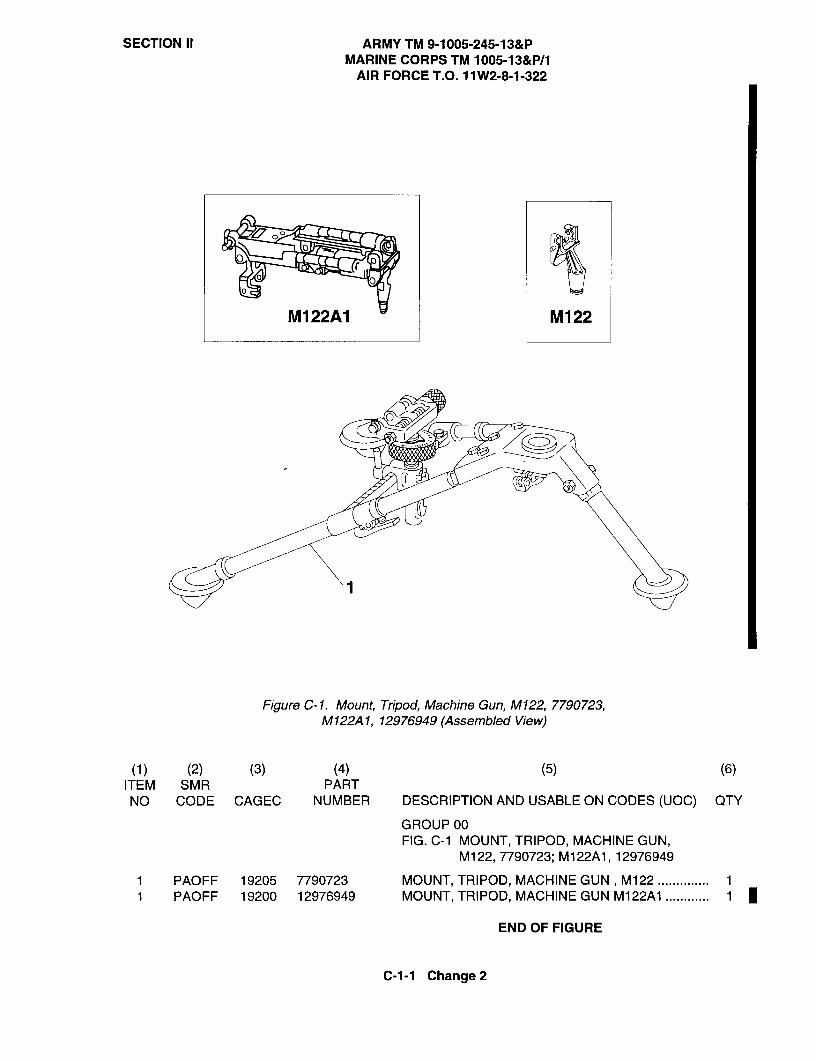
SECTION II ARMY TM 9-1005-245-13&PMARINE CORPS TM 1005-13&P/1
AIR FORCE T.O. 11W2-8-1-322
0
M122A1 M122
Figure C-1. Mount, Tripod, Machine Gun, M122, 7790723,M122A1, 12976949(Assembled View)
(1) (2) (3) (4) (5) (6)ITEM SMR PARTNO CODE CAGEC NUMBER DESCRIPTION AND USABLE ON CODES (UOC) QTY
GROUPOOFIG. C-1 MOUNT, TRIPOD, MACHINE GUN,
M122, 7790723; M122A1, 12976949
1 PAOFF 19205 7790723 MOUNT, TRIPOD, MACHINE GUN, M122 .............. 1
0
1 PAOFF 19200 12976949 MOUNT, TRIPOD, MACHINE GUN M122A1 ............ 1
END OF FIGURE
C-1-1 Change 2

SECTION II ARMY TM 9-1005-245-13&PMARINE CORPS TM 1005-13&P/1
AIR FORCE T.O. 11W2-8-1-322
2
00
00
-------------
L41
Change 2 Figure C-2. Mount, Tripod, Machine Gun, M122, 7790723,and M122A1, 12976949
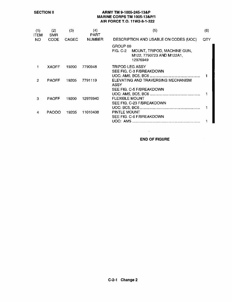
SECTION II ARMY TM 9-1005-245-13&PMARINE CORPS TM 1005-13&P/1
AIR FORCE T.O. 11W2-8-1-322
(1) (2) (3) (4) (5) (6)ITEM SMR PARTNO CODE CAGEC NUMBER DESCRIPTION AND USABLE ON CODES (UOC) QTY
GROUPOOFIG. C-2 MOUNT, TRIPOD, MACHINE GUN,
M 122, 7790723 AND M155A1, 12976949
1 XAOFF 19200 7790948 TRIPOD LEG ASSYSEE FIG. C-3 F/BREAKDOWNUOC: AM5, BC5, BC6 ................................................ 1
2 PAOFF 19205 7791119 ELEVATING AND TRAVERSING MECHANISMASSYSEE FIG. C-5 F/BREAKDOWNUOC: AM5, BC5, BC6 ................................................ 1
3 PAOFF 19200 12976940 FLEXIBLE MOUNTSEE FIG. C-23 F/BREAKDOWNUOC: BC5, BC6 .......................................................... 1
4 PAOOO 19205 11010408 PINTLE MOUNTSEE FIG. C-6 F/BREAKDOWNUOC: AM5 ................................................................. 1
END OF FIGURE
C-2-1 Change 2

SECTION II ARMY TM 9-1005-245-13&PMARINE CORPS TM 1005-13&P/1
AIR FORCE T.O. 11 W2-8-1-322
4
33
"I
I
5
2014 6
19 13
17 151 0 115/ 7 818 1 ? / I
14 14 /12/
1614
109
*No further disassembly authorized.
Change 2 Figure C-3. Tripod, Leg Assembly, 7790948

SECTION II ARMY TM 9-1005-245-13&PMARINE CORPS TM 1005-13&P/1
AIR FORCE T.O. 11W2-8-1-322
(1) (2) (3) (4) (5) (6)ITEM SMR PARTNO CODE CAGEC NUMBER DESCRIPTION AND USABLE ON CODES (UOC) QTY
GROUP 02 AND 0201FIG. C-3 TRIPOD, LEG ASSY, 7790948
1 PAFZZ 19204 5169880 BOLT, MACHINEUOC: AM5, BC5 .......................................................... 2
2 PAFZZ 19204 5559338 LEG, TRIPOD MOUNTUOC: AM5, BC5 .......................................................... 1
3 PAFZZ 19204 5169881 BOLT, MACHINEUOC: AM5, BC5 .......................................................... 2
4 PAFZZ 19204 5169882 BOLT, MACHINEUOC: AM5, BC5 .......................................................... 2
5 PAFZZ 19205 6108201 BUSHING, SLEEVEUOC: AM5, BC5 .......................................................... 1
6 XAFZZ 19204 5559331 HEADUOC: AM5, BC5 .......................................................... 1
7 PAFZZ 96906 MS51968-8 NUT, PLAIN, HEXAGON*PAOZZ UOC: AM5, BC5 .......................................................... 3
8 PAFZZ 19204 6108195 LEG, TRIPOD MOUNT*PAOZZ UOC: AM5, BC5 .......................................................... 1
9 PAFZZ 19204 5169879 BOLT, MACHINE*PAOZZ UOC: AM5, BC5 .......................................................... 1
10 PAFZZ 19204 5141950 SCREW, MACHINEUOC: AM5, BC5 .......................................................... 2
11 PAFZZ 19205 11010529 WASHER, LOCKUOC: AM5, BC5 .......................................................... 2
12 PAFZZ 19204 6108986 LOCK ASSEMBLY, PINTLEF/BREAKDOWN SEE FIG. C-7UOC: AM5, BC5 .......................................................... 1
13 PAFZZ 96906 MS51031-48 SETSCREWUOC: AM5, BC5 .......................................................... 1
14 PAFZZ 96906 MS51968-2 NUT, PLAIN, HEXAGONUOC: AM5, BC5 .......................................................... 4
15 PAFZZ 19205 5139962 SPACER,SLEEVEUOC: AM5, BC5 .......................................................... 2
16 PAFZZ 19204 5559337 LEG, TRIPOD MOUNTUOC: AM5, BC5 .......................................................... 1
17 PAFZZ 19207 5140004 ..PIN, STRAIGHT, HEADLESSUOC: AM5, BC5 .......................................................... 1
18 PAFZZ 19205 5139959 ..LATCH,SLEEVEUOC: AM5, BC5 .......................................................... 1
19 PAFZZ 19205 5139997 -SPRING, HELICAL, COMPRESSIONUOC: AM5, BC5 .......................................................... 1
20 PAFZZ 19205 5559333 BAR ASSEMBLY, TRAVERSINGUOC: AM5, BC5 .......................................................... 1
END OF FIGURE
MARINE CORPS ONLY
C-3-1 Change 2
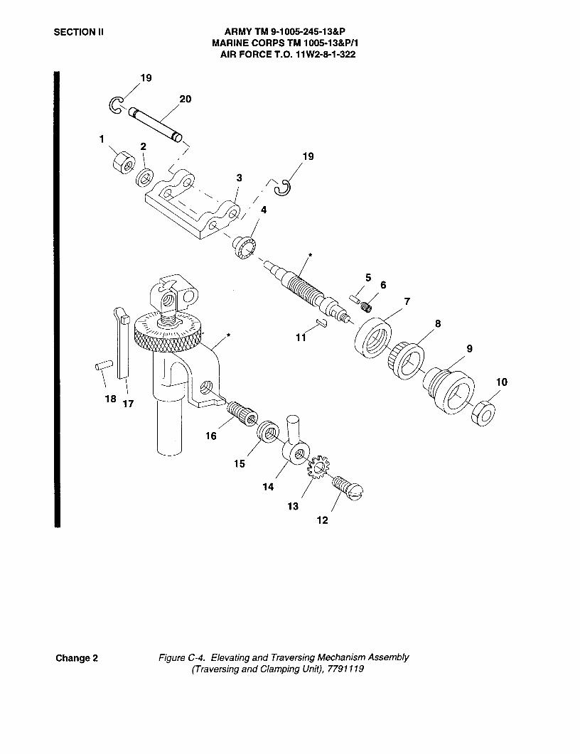
SECTION II ARMY TM 9-1005-245-13&PMARINE CORPS TM 1005-13&P/1
AIR FORCE T.O. 11W2-8-1-322
19
20
219
4
6
7
8
9
10
18 17
16
15
14
1312
Change 2 Figure C-4. Elevating and Traversing Mechanism Assembly(Traversing and Clamping Unit), 7791119

SECTION II ARMY TM 9-1005-245-13&PMARINE CORPS TM 1005-13&P/1
AIR FORCE T.O. 11 W2-8-1-322
(1) (2) (3) (4) (5) (6)ITEM SMR PART
NO CODE CAGEC NUMBER DESCRIPTION AND USABLE ON CODES (UOC) QTY
GROUP01FIG. C-4 ELEVATING AND TRAVERSING
MECHANISM ASSEMBLY(TRAVERSING AND CLAMPING),7791119
1 PAFZZ 96906 MS51943-2 NUT, SELF-LOCKING, HEXUOC: AM5, BC5 .......................................................... 1
2 PAFZZ 19205 5174192 WASHER, FLATUOC: AM5, BC5 .......................................................... 1
3 XAFZZ 19204 11010037 YOKEUOC: AM5, BC5 .......................................................... 1
4 PAFZZ 19205 5174175 RING, TRAVERSING, MECHANISMUOC: AM5, BC5 .......................................................... 1
5 PAFZZ 19205 5171495 PIN, STRAIGHT, HEADLESSUOC: AM5, BC5 .......................................................... 1
6 PAFZZ 19205 11010547 SPRING, HELICAL, COMPRESSIONUOC: AM5, BC5 .......................................................... 1
7 PAFZZ 19207 5171491 NUT, UNIONUOC: AM5, BC5 .......................................................... 1
8 PAFZZ 19205 5171492 DIAL, SCALEUOC: AM5, BC5 .......................................................... 1
9 PAFZZ 19207 6158375 KNOBUOC: AM5, BC5 .......................................................... 1
10 PAFZZ 96906 MS51943-4 NUT, SELF-LOCKING, HEXUOC: AM5, BC5 .......................................................... 1
11 PAFZZ 96906 MS35756-2 KEY, WOODRUFFUOC: AM5, BC5 .......................................................... 1
12 PAOZZ 19204 5139989 SCREW, MACHINEUOC: AM5, BC5 .......................................................... 1
13 PAOZZ 19205 11010413 WASHER, LOCKUOC: AM5, BC5 .......................................................... 1
14 PAOZZ 19205 7793002 LEVER, TRAVERSINGUOC: AM5, BC5 .......................................................... 1
15 PAOZZ 19205 7793003 SPRING, HELICAL, TORSIONUOC: AM5, BC5 .......................................................... 1
16 PAOZZ 19205 5139988 SCREW, MACHINEUOC: AM5, BC5 .......................................................... 1
17 PAFZZ 19205 5189757 STOP ASSEMBLY, ELEVATINGUOC: AM5, BC5 .......................................................... 1
18 PAFZZ 96906 MS1 6562-120 PIN, SPRINGUOC: AM5, BC5 .......................................................... 1
19 PAOZZ 96906 MS16624-1043 RING, RETAININGUOC: AM5, BC5 .......................................................... 2
20 PAOZZ 19205 7792993 PIN, GROOVED, HEADLESSUOC: AM5, BC5 .......................................................... 1
END OF FIGURE
MARINE CORPS ONLY
C-4-1 Change 2
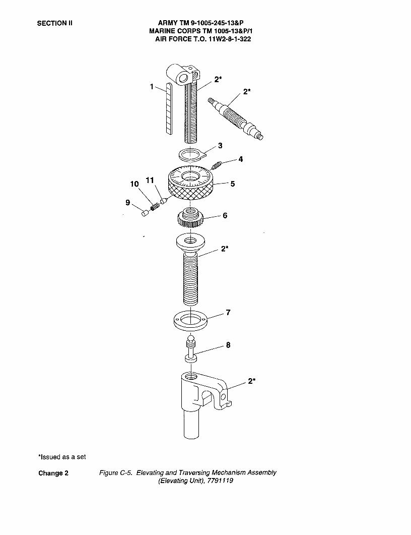
SECTION II ARMY TM 9-1005-245-13&PMARINE CORPS TM 1005-13&P/1
AIR FORCE T.O. 11W2-8-1-322
CD
2*2*
3
C 4
10 11 5
6
2*
7
8
0
*Issued as a set
Change 2 Figure C-5. Elevating and Traversing Mechanism Assembly(Elevating Unit), 7791119
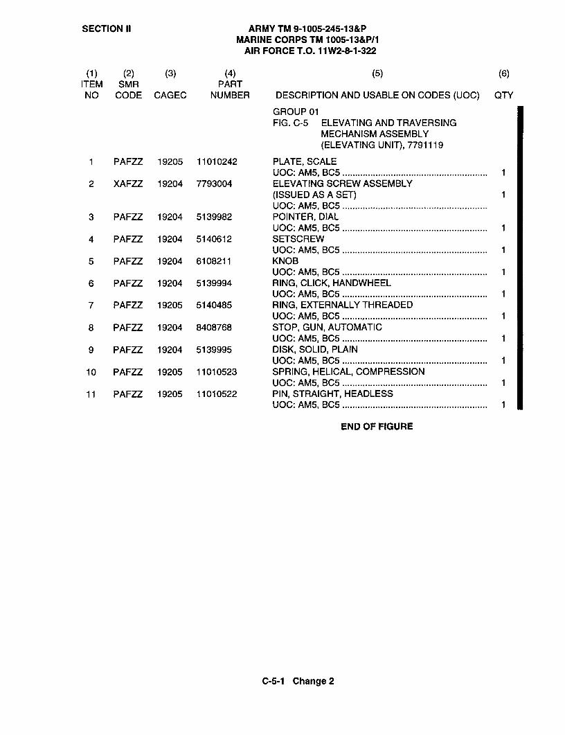
SECTION II ARMY TM 9-1005-245-13&PMARINE CORPS TM 1005-13&P/1
AIR FORCE T.O. 11W2-8-1-322
(1) (2) (3) (4) (5) (6)ITEM SMR PARTNO CODE CAGEC NUMBER DESCRIPTION AND USABLE ON CODES (UOC) QTY
GROUP01FIG. C-5 ELEVATING AND TRAVERSING
MECHANISM ASSEMBLY(ELEVATING UNIT), 7791119
1 PAFZZ 19205 11010242 PLATE,SCALEUOC: AM5, BC5 ......................................................... 1
2 XAFZZ 19204 7793004 ELEVATING SCREW ASSEMBLY(ISSUED AS A SET) 1UOC: AM5, BC5 .........................................................
3 PAFZZ 192 04 5139982 POINTER, DIALUOC: AM5, BC5 ......................................................... 1
4 PAFZZ 19204 5140612 SETSCREWUOC: AM5, BC5 ......................................................... 1
5 PAFZZ 19204 6108211 KNOBUOC: AM5, BC5 ......................................................... 1
6 PAFZZ 19204 5139994 RING, CLICK, HANDWHEELUOC: AM5, BC5 ......................................................... 1
7 PAFZZ 19205 5140485 RING, EXTERNALLY THREADEDUOC: AM5, BC5 ......................................................... 1
8 PAFZZ 19204 8408768 STOP, GUN, AUTOMATICUOC: AM5, BC5 ......................................................... 1
9 PAFZZ 19204 5139995 DISK, SOLID, PLAINUOC: AM5, BC5 ......................................................... 1
10 PAFZZ 19205 11010523 SPRING, HELICAL, COMPRESSIONUOC: AM5, BC5 ......................................................... 1
11 PAFZZ 19205 11010522 PIN, STRAIGHT, HEADLESSUOC: AM5, BC5 ......................................................... 1
END OF FIGURE
C-5-1 Change 2
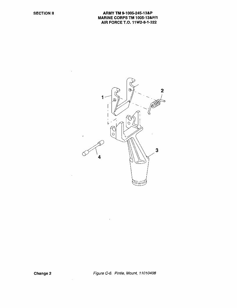
SECTION II ARMY TM 9-1005-245-13&PMARINE CORPS TM 1005-13&P/1
AIR FORCE T.O. 11 W2-8-1-322
Change 2 Figure C-6. Pintle, Mount, 11010408

SECTION II ARMY TM 9-1005-245-13&PMARINE CORPS TM 1005-13&P/1
AIR FORCE T.O. 11W2-8-1-322
(1) (2) (3) (4) (5) (6)ITEM SMR PARTNO CODE CAGEC NUMBER DESCRIPTION AND USABLE ON CODES (UOC) QTY
GROUP03FIG. C-6 PINTLE MOUNT, 11010408
1 PAOZZ 19205 11010409 LEVER, LOCK-RELEASEUOC: AM5 .................................................................. 1
2 PAOZZ 19204 11010410 SPRING, HELICAL, TORSIONUOC: AM5 .................................................................. 1
3 XAOZZ 19204 11010412 PINTLEUOC: AM5 .................................................................. 1
4 PAOZZ 19205 11010411 PIN, GROOVED, HEADLESSUOC: AM5 .................................................................. 1
END OF FIGURE
C-6-1 Change 2


SECTION II ARMY TM 9-1005-245-13&PMARINE CORPS TM 1005-13&P/1
AIR FORCET.O. 11W2-8-1-322
54
3CD
0
Figure C-7 Lock Assembly, Pintle, 6108986
(1) (2) (3) (4) (5) (6)ITEM SMR PARTNO CODE CAGEC NUMBER DESCRIPTION AND USABLE ON CODES (UOC) QTY
GROUP 0202FIG. C-7 LOCK ASSEMBLY, PINTLE, 6108986
1 PAFZZ 19205 11010448 RIVET, SOLIDUOC: AM5, BC5 .......................................................... 1
2 PAFZZ 19205 5141080 CAM, PINTLE LOCK RELEASEUOC: AM5, BC5 .......................................................... 1
3 XAFZZ 19205 5141081 COLLAR, SHAFTUOC: AM5, BC5 .......................................................... 1
4 XAFZZ 19205 6140648 HOUSINGUOC: AM5, BC5 .......................................................... 1
5 PAFZZ 19205 5142877 SPRING, HELICAL, COMPRESSIONUOC: AM5, BC5 .......................................................... 1
6 XAFZZ 19204 5141121 BODYUOC: AM5, BC5 .......................................................... 1
END OF FIGURE
C-7-1 Change 2
ARMY TM 9-1005-245-13&PMARINE CORPS TM 1005-13&P/1AIR FORCE T.O. 11W2-8-1-322
C-6. HOW TO LOCATE REPAIR PARTS
a. When National Stock Number or Part Number is Not Known.
(1) First. Using the table of contents, determine the assembly group or subassembly group towhich the items belongs. This is necessary since figures are prepared for assembly groups andsubassembly groups, and listings are divided into the same groups.
(2). Second. Find the figure covering the assembly group or subassembly group to which the itembelongs.
(3) Third. Identify the item on the figure and use the Figure and Item Number Index to find theNSN.
b. When National Stock Number or Part Number is Known.
(1) First. Using the National Stock Number or Part Number Index, find the pertinent National StockNumber or Part Number. The NSN index is in National Item Identification Number (NIIN) sequence (seepara C-4.a(l)). The part numbers in the Part Number index are listed in ascending alphanumericsequence (see para C-4.b). Both indexes cross-reference you to the illustration/figure and item number ofthe item you are looking for.
(2) Second. Turn to the figure and item number, verify that the item is the one you are looking for,then locate the item number in the repair parts list for the figure.
C-7. ABBREVIATIONS
Not applicable.
C-8

SectionII ARMYTM9-1005-245-13&PMARINECORPSTM 1005-13&P/1
AlRFORCE T.O. 11W2-8-1-322
FigureC-8. Mount,Tripod,MachineGun,M38403398(AssembledView).
SECTIONII TM9-1005-245-13&P(1) (2) (3) (4) (5) (6)
ITEM SMR PARTNO CODE CAGEC NUMBER DESCRIPTION AND USABLE ON CODES(UOC) QTY
GROUP 00FIG.C-8 MOUNT,TRIPOD,MACHINE GUN,M3
8403398 (ASSEMBLED VIEW)
1 PAOFF 19204 8403398 MOUNT,TRIPOD, MACHINE GUN, M3...... 11 PAODD 19204 8403398 MOUNT,TRIPOD, MACHINE GUN, M3 1
(MARINE CORPS ONLY) .................
END OF FIGURE
C-8-1
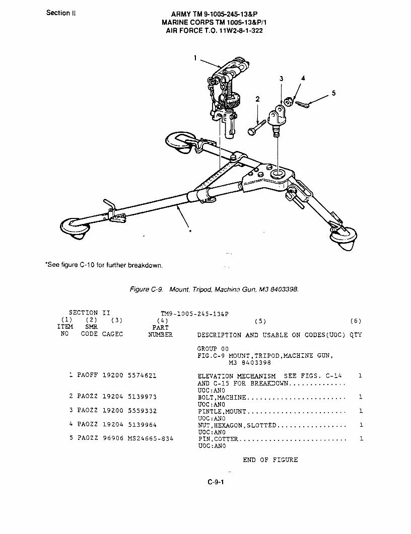
Section II ARMY TM 9-1005-245-13&PMARINE CORPS TM 1005-13&P/1
AIR FORCE T.O. 11W2-8-1-322
1
3 4
I
'See figure C-10 for further breakdown.
Figure C-9. Mount, Tripod, Machino Gun, M3 8403398.
SECTION II TM9-!005-245-13&P
(1) (2) (3) (4) (5) (6)ITEM SMI{ PART
NO CODE CAGEC NUMBER DESCRIPTION AND USABLE ON CODES(UOC) QTY
GROUP 00FIG.C-9 MOUNT, TRIPOD,MACHINE GUN,
M3 8403398
1 PAOFF 19200 5574621 ELEVATION MECHANISM SEE FIGS. C-14 1AND C-15 FOR BREAKDOWN ..............U0C:AN0
2 PAOZZ 19204 5139973 BOLT,MACHINE ........................ 1U0C: AN0
3 PAOZZ 19200 5559332 PINTLE,MOUNT ........................ 1UOC :AN0
4 PAOZZ 19204 5139964 NUT,HEXAGON,SLOTTED ................. 1U0C:AN 0
5 PAOZZ 96906 MS24665-834 PIN,COTTER .......................... 1U0C: AN0
END OF FIGURE
C-9-1

0

Section II ARMY TM 9-1005-245-13&PMARINE CORPS TM 1005-13&P/1
AIR FORCE T.O. 11W2-8-1-322
42
3
24
2223 7
2 9
8
21
1615
12
2017
1914
18
13
Figure C-10. Mount, Tripod, Machine Gun, M3 8403398,-Head, Bearing Assembly 8448211; and Bolt, Machine 6108395.

SECTION II 7M9-1005-245-13&P(1) (2) (3) (4) (5) (6)
ITEM SMR PARTNO CODE CAGEC NUMBER DESCRIPTION AND USABLE ON CODES(UOC) QTY
GROUPS 00,01,AND 02FIG.C-10 MOUNT,TRIPOD,MACHINE GUN,M3
8403398;HEAD, BEARINGASSEMBLY 8448211; AND BOLT,MACHINE 6108395
1 PAFFF 19204 6507137 LEG,TRIPOD MJUNT SEE FIG. C-11 FOR 1BREAKDOWN ...........................UOC:ANO
2 PAFZZ 19204 5170484 BOLT,MACHINE ........................ 2UOC:ANO
3 PAFZZ 88044 AN174-21A BOLT,MACHINE ........................ 2UOC:ANO
4 PAFZZ 19205 5170486 BOLT,MACHINE ........................ 2UOC:ANO
5 XAFFF 19200 8448211 HEAD,BEARING ASSY ................... 1UOC:ANO
5 XADDD 19200 8448211 HEAD,BEARING ASSY ANO (MARINE 1CORPS ONLY) .........................
6 PAFZZ 19205 6108397 ..BEARING,SLEEVE .................... 1UOC:ANO
6 PADZZ 19205 6108397 BEARING,SLEEVE (MARINE CORPS ONLY). 1UOC:ANO
7 XAFZZ 19204 5559419 ..HEAD TRIPOD ....................... 1UOC:ANO
8 PAFZZ 96906 MS51031-48 ..SETSCREW .......................... 1UOC:ANO
8 PADZZ 96906 MS51031-48 SETSCREW (MARINE CORPS ONLY) ....... 1UOC:ANO
9 PAFFF 19204 6108395 ..BOLT,MACHINE ...................... 1UOC:ANO
10 PAFZZ 96906 MS16555-42 ..PIN,STRAIGHT,HEADLE ............... 1UOC:ANO
11 XAFZZ 19204 6108400 ..SCREW ............................. 1UOC:ANO
12 PAFFF 19204 5559423 LEG,TRIPOD MOUNT SEE FIG. C-12 FOR 1BREAKDOWN ...........................UOC:ANO
13 PAFZZ 19204 6193782 NUT,FRONT LEG CLAMP ................. 1UOC:ANO
14 PAFZZ 96906 MS39086-95 PIN,SPRING .......................... 1U0C:ANO
15 PAFZZ 96906 MS35691-826 NUT,PLAIN,HEXAGON ................... 4UOC:ANO
16 PAFZZ 19204 6108396 PLATE,RETAINING SER ................. 2UOC:AN0
17 PAFZZ 19205 5140237 SCREW,MACHINE ....................... 8UOC:ANO
18 PA-FZZ 192O4 5141950 SCREW,MACHINE ....................... 2UOC: ANO
19 PAFZZ 19205 11010529 WASHER,LOCK ......................... 2UOC:AN0
C-10-1
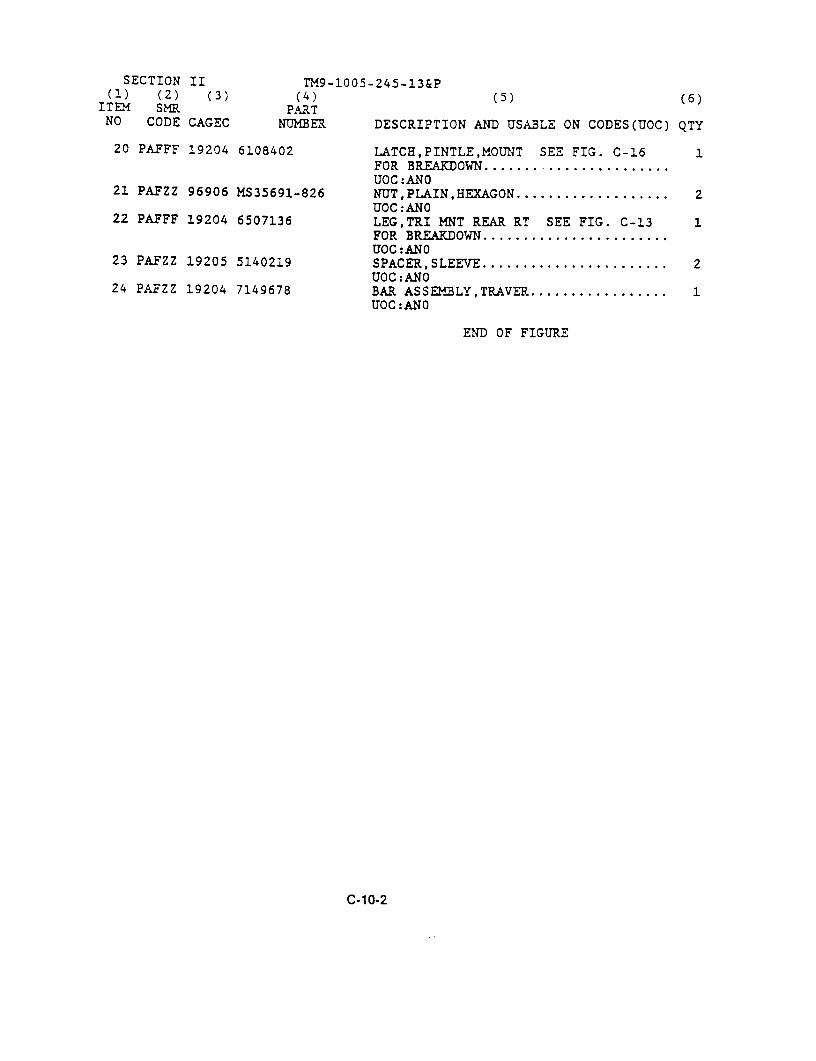
SECTION II TM9-1005-245-13&P(1) (2) (3) (4) (5) (6)
ITEM SMR PARTNO CODE CAGEC NUMBER DESCRIPTION AND USABLE ON CODES(UOC) QTY
20 PAFFF 19204 6108402 LATCH,PINTLE,MOUNT SEE FIG. C-16 1FOR BREAKDOWN ....... ...............UOC:ANO
21 PAFZZ 96906 MS35691-826 NUT,PLAIN,HEXAGON ................... 2UOC:ANO
22 PAFFF 19204 6507136 LEG,TRI MNT REAR RT SEE FIG. C-13 1FOR BREAKDOWN .......................UOC:ANO
23 PAFZZ 19205 5140219 SPACER,SLEEVE ....................... 2UOC:ANO
24 PAFZZ 19204 7149678 BAR ASSEHBLY,TRAVER ................. 1UOC:AN0
END OF FIGURE
C-10-2


Section II ARMY TM 9-1005-245-13&PMARINE CORPS TM 1005-13&P/1
AIR FORCE T.O. 11W2-8-1-322
4
3
52
6
7
10 9
Figure C- 11. Leg, Tripod, Mount 650 7137 (Left Rear).
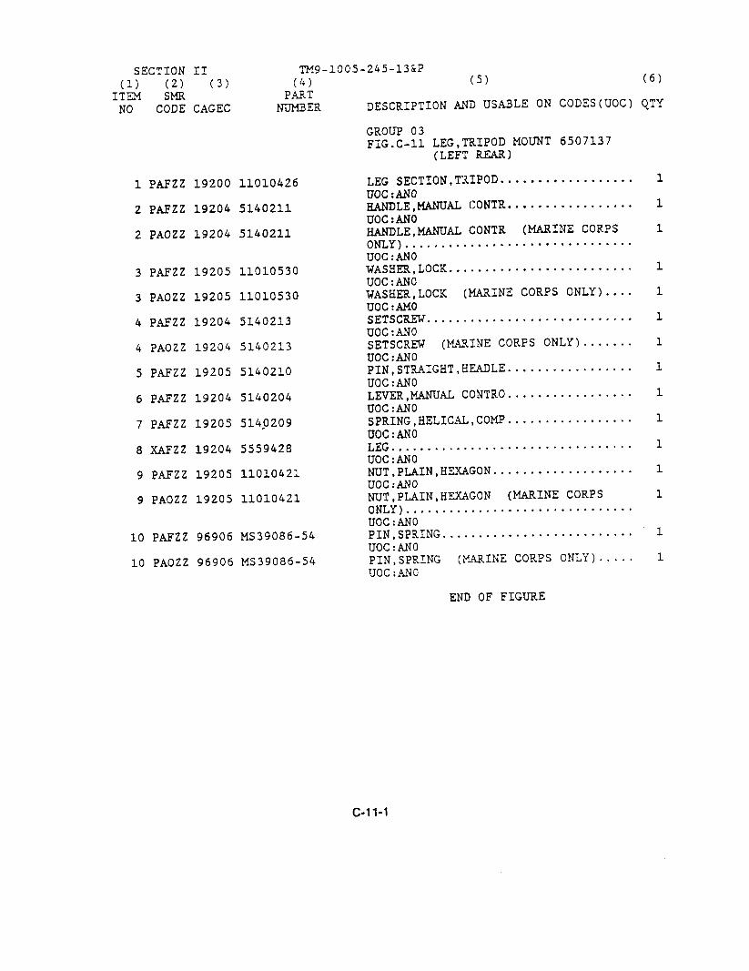
SECTION II TMg-1005-245-13&P
(1) (Z) (3) (4) (5) (6)ITEM SHE PART
NO CODE CAGEC NUMBER DESCRIPTION AND USABLE ON CODES(UOC) QTY
GROUP 03FIG.C-ii LEG,TRIPOD MOUNT 6507137
(LEFT REAR)
1 PAFZZ 19200 11010426 LEG SECTION,TRIPOD .................. 1UOC :AN0
2P AFZZ 19204 5140211 HANDLE,_AL CONTR ................. 1UOC: AN0
2PAOZZ 19204 5140211 _LE,MANUAL CONTR (MARINE CORPS 1ONLY) ...............................UOC: AN0
3PAFZZ 19205 11010530 WASHER,LOCK ......................... 1U0C: AN0
3PAOZZ 19205 11010 530 WASHER,LOCK (MARINE CORPS ONLY) .... 1UOC :AM0
4PAFZZ 19204 5140213 SETSCREW ............................ 1UOC: AN0
4PAOZZ 19204 5140213 SETSCREW (MARINE CORPS ONLY) ....... 1UOC :AN0
5PAFZZ 19205 5140210 PIN,STRAIGHT,HEADLE ................. 1UOC :AN0
6PAF ZZ 19204 5140204 LEVEK,_ CONTRO ................. 1UOC: AN0
7PA FZZ 19205 5140209 SPRING,HELICAL,COMP ................. 1UOC: AN0
8XAFZZ 19204 5559428 LEG ................................. 1U0C:AN0
9PAFZZ 19205 11010421 NUT,PLAIN,HEXAGON ................... 1UOC:AN0
9PAOZZ 19205 11010421 NUT,PLAIN,HEXAGON (MARINE CORPS 1ONLY) ...............................UOC:AN0
10PAFZZ 96906 MS39086-54 PIN,SPRING .......................... 1UOC:AN0
10PAOZZ 96906 MS39086-54 PIN,SPRING (MARINE CORPS ONLY) ..... 1UOC :AN0
END OF FIGURE
C-11-1
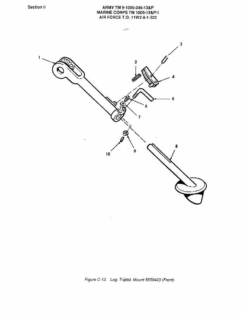
Section II ARMY TM 9-1005-245-13&PMARINE CORPS TIVI 1005-13&P/1
AIRFORCE T.O. 11 W2-8-1-322
3
2
4
5
6
7
109
Figure C- 12. Leg, Tripad, Mount 5559423 (Front).

SECTION ii TM9-1005-245-13&P
(1) (2) (3) (4) (5) (6)
ITEM SMR PARTNO CODE CAGEC NUMBER DESCRIPTION AND USABLE ON CODES (UOC) QTY
GROUP 04FIG.C-12 LEG,TRIPOD MOUNT 5559423
(FRONT)
1 XAFZZ 19204 5559424 LEG .................................UOC:ANO
2 PAFZZ 19205 5140209 SPRING,HELICAL,COMP ................. 1
UOC:ANO3 PAFZZ 19205 5140210 PIN,STRAIGHT,HEADLE ................. 1
UOC:ANO4 PAFZZ 19204 5140204 LEVER,MANUAL CONTROL................. 1
UOC:ANO5 PAFZZ 19204 5140211 HANDLE,MANUAL CONTR ................. 1
UOC:ANO5 PAOZZ 19204 5140211 HANDLE,MANUAL CONTR (MARINE CORPS 1
ONLY) ...............................UOC:ANO
6 PAFZZ 19204 5140213 SETSCREW ............................ 1
UOC:ANO6 PAOZZ 19204 5140213 SETSCREW (MARINE CORPS ONLY) ....... 1
UOC:ANO7 PAFZZ 19205 11010530 WASHER,LOCK ......................... 1
UOC:ANO7 PAOZZ 19205 11010530 WASHER,LOCK (MARINE CORPS ONLY) .... 1
UOC:ANO8 XAFZZ 19204 6108384 LEG ................................. 1
UOC:ANO9 PAFZZ 19205 11010421 NUT,PLAIN,HEXAGON ................... 1
UOC:ANO9 PAOZZ 19205 11010421 NUT,PLAIN,HEXAGON (MARINE CORPS 1
ONLY) ...............................UOC:ANO
10 PAFZZ 96906 MS39086-54 PIN,SPRING .......................... 1
UOC:ANO10 PAOZZ 96906 MS39026-54 PIN,SPRING (MARINE CORPS ONLY) ..... 1
UOC:ANO
END OF FIGURE
C- 12-1

Section ii ARMY TM 9-1005-245-13&PMARINE CORPS Tm 1005-13&Pll
AIR FORCE T.O. 11W2-8-1-322
4
35
2a- 6
7
11 10
13 12
r
Figure C- 13 Leg, Tripod, Mount 650 7136 (Right Rear).

SECTION ii TM9-1005-245-13&P(1) (2) (3) (4) (5) (6)
ITEM SMR PARTNO CODE CAGEC NUMBER DESCRIPTION AND USABLE ON CODES(UOC) QTY
GROUP 05FIG.C-13 LEG,TRIPOD MOUNT 6507136
(RIGHT REAR)
1 PAFZZ 19200 11010426 LEG SECTION,TRIPOD .................. 1
UOC:ANO2 PAFZZ 19205 11010530 WASHER,LOCK ......................... 1
UOC:ANO2 PAOZZ 19205 11010530 WASHER,LOCK (MARINE CORPS ONLY) .... 1
UOC:ANO3 PAFZZ 19204 5140213 SETSCREW ............................ 1
U0C:AN03 PAOZZ 19204 5140213 SETSCREW (MARINE CORPS ONLY) ....... 1
UOC:ANO4 PAFZZ 19204 5140211 HANDLE,MANUAL CONTR ................. 1
UOC:AN04 PAOZZ 19204 5140211 HANDLE,MANUAL CONTR (MARINE CORPS 1
ONLY) ...............................UOC:ANO
5 XAFZZ 19200 5559425 LEG REAR RT UPPER ................... 1
UOC:ANO6 PAFZZ 19205 5140215 SPRING,HELICAL,COMP ................. 1
UOC:ANO7 PAFZZ 19204 5140216 LEVER,LOCK-RELF.ASE .................. 1
UOC:ANO8 PA.FZZ 19204 5140217 PIN,STRAIGHT,HEADLE ................. 1
UOC:ANO9 PAFZZ 96906 MS39086-54 PIN,SPRING .......................... 1
UOC:ANO9 PAOZZ 96906 MS39086-54 PIN,SPRING (MARINE CORPS ONLY) ..... 1
U0C:AN010 PAFZZ 19205 11010421 NUT,PLAIN,HEXAGON ................... 1
UOC:ANO10 PAOZZ 19205 11010421 NUT,PLAIN,HEXAGON (MARINE CORPS 1
ONLY) ...............................UOC:ANO
11 PAFZZ 19205 5140209 SPRING,HELICA.L,COMP ................. 1
UOC:ANO12 PAFZZ 19204 5140204 LEVER,MANUAL CONTRO ................. 1
UOC:ANO13 PAFZZ 19205 5140210 PIN,STRAIGHT,HFADLE ................. 1
UOC:ANO
END OF FIGURE
C- 13-1
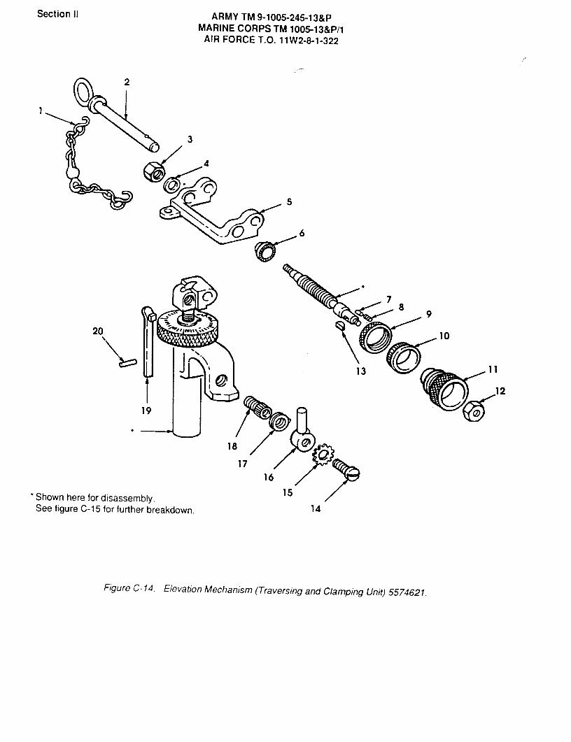
Section ii ARMY TM 9-1005-245-13&PMARINE CORPS TM 1005-13&P/1
AIR FORCE T.O. 11 W2-8-1-322
2
3
4
5
6
78
9
20 10
13 11
12
19
18
1716
15Shown here for disassembly.See figure C-1 5 for further breakdown. 14
FigureC-14. Elevation Mechanism (Traversing and Clamping Unit) 5574621.

SECTION ii TM9-1005-245-13&P(5) (6)
(1) (2) (3) (4)ITEM SMR PART
NO CODE CAGEC NTUMBER DESCRIPTION AND USABLE ON CODES(UOC) QTY
GROUP 06FIG.C-14 ELEVATION MECHANISM
(TRAVERSING AND CLAMPINGUNIT) 5571321
1 PAFZZ 19205 5141460 CHAIN ASSEKBLY,SING ................. 1
UOC:AN`01 PAOZZ 19205 5141460 CHAIN ASSEMBLY,SING (MARINE CORPS 1
ONLY) ...............................UOC.ANO
2 PAFZZ 19204 5174113 PIN,QUICK RELEASE ................... 1UOC:ANO
2 PAOZZ 19204 5174113 PIN,QUICK RELEASE (MARINE CORPS 1
ONLY) ...............................UOC:AN0
3 PAFZZ 96906 MS51943-2 NUT,SELF-LOCKING.HE ................. 1UOC:ANO
4 PAFZZ 19205 5174192 WASHER,FLAT ......................... 1
UOC:ANO5 XAFZZ 19204 6166497 YOKE ................................ 1
UOC:AN06 PAFZZ 19200 5174123 RING,CLICK,TRAVERSI ................. 1
UOC:ANO7 PAFZZ 19205 5171495 PIN,STRAIGHT,HEADLE ................. 1
UOC:ANO8 PAFZZ 19205 11010547 SPRING,HELICAL,COMP ................. 1
UOC:ANO9 PAFZZ 19207 5171491 NUT,UNION ........................... 1
UOC:ANO10 PAFZZ 192O5 5171492 DIAL,SCALE .......................... 1
UOC:ANO11 PAFZZ 19207 6158375 KNOB ................................ 1
UOC:ANO12 PAFZZ 96906 MS51943-4 NUT,SELF-LOCKING,HE ................. 1
UOC-ANO13 PAFZZ 19205 11010407 KEY,WOODRUFF ........................ 1
UOC:ANO14 PAFZZ 19204 5139989 SCREW,MACHINE ....................... 1
UOC:ANO14 PAOZZ 19204 5139989 SCREW,MACHINE (MARINE CORPS ONLY).. 1
UOC:ANO15 PAFZZ 19205 11010413 WASHER,LOCK ......................... 1
UOC:ANO15 PAOZZ 19205 11010413 WASHER,LOCK (MARINE CORPS ONLY) .... 1
UOC:AMO16 PAFZZ 19200 5194313 LEVER,REMOTE CONTRO ................. 1
UOC:ANO16 PAOZZ 19200 5194313 LEVER,REMOTE CONTRO (MARINE CORPS 1
ONLY) ...............................UOC:ANO
17 PAFZZ 19205 8412295 SPRING,HELICA.L,TORS ................. 1UOC:ANO
C-14-1

SECTION II TM9-1005-245-13&P(1) (2) (3) (4) (5) (6)ITEM SMR PARTNO CODE CAGEC NUMBER DESCRIPTION AND USABLE ON CODES(UOC) QTY
17 PAOZZ 19205 8412295 SPRING,HELICAL,TORS (MARINE CORPS 1ONLY) ...............................UOC:ANO
18 PAFZZ 19200 5140383 SCREW,SELF-LOCKING .................. 1UOC:ANO
18 PAOZZ 19200 5140383 SCREW,SELF-LOCKING (MARINE CORPS 1ONLY) ...............................UOC:ANO
19 PAFZZ 19200 5189756 SPRING,FLAT ......................... 1UOC:ANO
20 PAFZZ 96906 MS16562-120 PIN,SPRING .......................... 1UOC:ANO
END OF FIGURE
C-14-2


Section ii ARMY TM 9-1005-245-13&PMARINE CORPS TM 1005-13&P/1
AlR FORCE T.O. 11W2-8-1-322
2
2*
3
4
10 AA
6
2*
8
2*
Furnished with identicallynumbered item.
L
FigureC-15.ElevationMechanism(LowerandUpperElevatingUnit)5574621.

SECTION II TM9-1005-245-13&P(5) (6)(1) (2) (3) (4)
ITEM SMR PARTDESCRIPTION AND USABLE ON CODES(UOC) QTYNO CODE CAGEC NUMBER
GROUP 06FIG.C-15 ELEVATION MECHANISM
(LOWER AND UPPER ELEVATINGUNIT) 5574621
1 PAFZZ 19204 5140669 PLATE,DESIGNATION ...................1UOC:ANO
2 PBFZZ 19204 5591828 SCREW ASSEMBLY ......................1UOC:ANO
3 PAFZZ 19204 5139982 POINTER,DIAL ...................1UOC-ANO
4 PAFZZ19204 5140612 SETSCREW .......................1UOC:ANO
5 PAFZZ 19204 6108211 KNOB ............................1UOC:ANO
6 PAFZZ 19200 5140137 RING,CLICK,ELEVATIN .................1UOC:ANO
7 PAFZZ 19205 5140485 RING,EXTERNALLY THR .................1UOC:ANo
8 PAFZZ 19204 8408768 STOP,GUN,AUTOMATIC ..................1UOC:ANO
9 PAFZZ 19204 5139995 DISK,SOLID,PLAIN ....................1UOC:ANO
10 PAFZZ 19205 11010523 SPRING,HELICAL,COMP .................1UOC:ANO
11 PAFZZ 19205 11010522 PIN,STRAIGHT,HEADLE .................1UOC:ANO
END OF FIGURE
C-15-1

Section IIi ARMY TM 9-1005-245-13&PMARINE CORPS TM 1005-13&P/1
AIR FORCE T.O. 11W2-8-1-322
6
5
4
5
3
@'Z@Z@
2
7@
Figure C- 16. Latch, Pintle Mount 6108402.
SECTION II TM9-1005-245-13&P(1) (2) (3) (4) (5) (6)ITEM SMR PARTNO CODE CAGEC NUMBER DESCRIPTION AND USABLE ON CODES(UOC) QTY
GROUP 07FIG.C-16 LATCH,PINTLE,MOUNT 6108402
1 PAFZZ 19205 11010448 RIVET,SOLID ......................... 1UOC:AN0
2 PAFZZ 19205 5141080 CAM,PINTLE LOCK REL ................. 1UOC:ANO
3 XAFZZ 19204 5141081 COLLAR,SHAFT ........................ 1UOC:ANO
4 XAFZZ 19205 6153118 HOUSING ............................. 1UOC:ANO
5 PAFZZ 19205 5140209 SPRING,HELICA.L,COMP ................. 2UOC:AN0
6 XAFZZ 19204 5140225 LOCK ................................ 1UOC:ANO
END OF FIGURE
C-16-1

Section ii ARMY TM 9-1005-245-13&PMARINE CORPS TM 1005-13&P/1
AIR FORCE T.O. 11W2.8-1-322
C5
CD
CD
0C>
0
0
FigureC-17. Ping, Mount, Machine Gun, M66 7012810(Assembled View).
SECTION II TM9-1005-245-13&P
(1) (2) (3) (4) (5) (6)
ITEM, SMR PARTNO CODE CAGEC NUMBER DESCRIPTION AND USABLE ON CODES(UOC) QTY
GROUP 00FIG.C-17 RING,MOUNT,MACHINE GUN,
M66 7012810(ASSEMBLED VIEW)
1 PAFFF 19204 7012810 RING,MOUNT,MACHINE GUN,M66 ...
1 PAOFF 19204 7012810 RING, MOUNT, MACHINE GUN,M66 1(MARINE CORPS ONLY) .................
END OF FIGURE
C-17-1
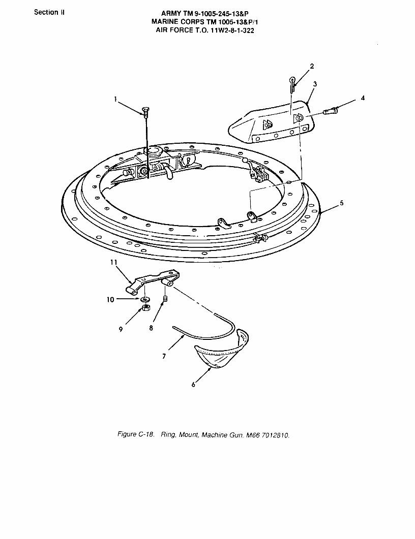
Section II ARMY TM 9-1005-245-13&PMARINE CORPS TM 1005-13&P/1
AIR FORCE T.O. 11W2-8-1-322
2
3
4
00 0
0
5
10
9
7
6
Figure C-18. Ring, Mount, Machine Gun, M66 7012810.

SECTION II TM9-1005-245-13&P(5) (6)
(1) (2) (3) (4)ITEM SMR PART
NO CODE CAGEC NUMBER DESCRIPTION AND USABLE ON CODES(UOC) QTY
GROUP 00FIG.C-18 RING,MOUNT,MACHINE GUN,
M66 7012810
1 PAOZZ 96906 MS907Z7-86 SCREW,CAP,HEXAG0N H ................. 2UOC:AM4,AR3
22 PAOZZ 96906 MS24665-132 PIN,COTTER .....................UOC:AM4,AR3
3 PAOZZ 19204 10945028 PAD, CUSHIONING ....................UOC:AM4,AR3
24 PAOZZ 96906 MS35810-2 PIN.STRAIGHT
.HEADED .................
UOC,AM4,AR35 XAOFF 19204 7012727 RING ASSEMBLY SEE FIGS. C-19 AND C- 1
20 FOR BREAKDOWN ....................UOC:AK4,AEL3
5 XAOFF 19204 7012727 RING ASSEMBLY SEE FIGS. C-19 AND C- 120 FOR BREAKDOWN(MARINE CORPS ONLY) .................
UOC:AM4,AR3TRIDGE ................. 1
6 PAOZZ 19204 11589551 DEFLECTOR,CARTRIDGE...............1UOC:AM4,AR3
7 PAOZZ 19207 10907432-4 WIRE, NONELECTRICAL .................. 1UOC:AM4,AR3
28 PAOZZ 96906 MS51963-64 SETSCREW ........2UOC:AH4,AR3
9 PAOZZ 96906 MS51922-29 NUT SELF-LOCKING,HE ................. 2UOC:AM4,AR3
210 PAOZZ 96906 MS27183-16 WASHER,FLAT ....................2
UOC:AM4,AR311 PAOZZ 19204 11631739 SUPPORT,DEFLECTOR ................... 1
UOC:AM4,AR3
END OF FIGURE
C-18-1
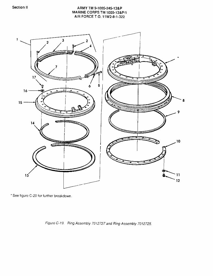
Section II ARMY TM 9-1005-245-13&PMARINE CORPS TM 1005-13&P/1
AIR FORCE T.O. 11W2-8-1-322
23 2
4
7
17
6 516
815
9
14
10
13 11
12
See figure C-20 for further breakdown.
1@7
FigureC-19. Ring Assembly 7012727 and Ring Assembly 7012725.

SECTION II TM9-!005-245-!3&P
(I) (2) (3) (4) (5) (6)ITEM SMR PART
NO CODE CAGEC NUbfBER DESCRIPTION AND USABLE ON CODES(UOC) QTY
GROUPS 01,0101,0101,AND 010101FIG.C-19 RING ASSEMBLY 7012727 AND
RING ASSEMBLY 7012725
1 PAFFF 19204 7012725 RING ASSEMBLY ....................... 1
UOC :AM4,AR31PAOFF 19204 7012725 RING ASSEMBLY (MARINE CORPS ONLY).. 1
UOC:AM4 ,AR32PAFZZ 19207 7012720 PIN,STRAIGHT,HEADED ................. 2
UOC: AM4,AR33PA FZZ 19204 7012723 SEGMENT,SEAL RING ................... 1
UOC :AM4 ,ARS4PAFZZ 19204 7012722 SEGMENT SEAL RING ................... 1
UOC :AM4,AR35PAFZZ 96906 MS35206-268 SCRE W,MACHINE ....................... 1
UOC :AM4,ARS6PAFZZ 96906 MS35338-43 WASHER,LOCK ......................... 1
UOC :AM4,AR37PA FZZ 19204 7012724 SEGMENT,SEAL RING ................... 1
UOC :AM4 ,AR38XAFZZ 19204 7070851 RING,OUTER SEAL ..................... 1
UOC :AM4,ARS9PAFZZ 19204 7012805-1 FELT,MECHANICA L,PRE ................. 1
UOC:AM4, AR310 PAFZZ 19204 7012726 RING,SEAL RETAINER .................. 1
UOC :AM4,ARS11 PAFZZ 96906 MS35333-38 WASHER,LOCK ..... '................... 22
UOC :AM4,AR312 PAFZZ 96906 MS35206-246 SCRE W,MACHINE ....................... 22
UOC :AM4,AR313 PAFZZ 19204 7012805-2 FELT,MECHANICAL,PRE ................. 1
UOC :AM4 ,AR314 PAFZZ 19204 7012806 FELT,MECHANICAL,PRE ................. 1
UOC :AM4,AR315 PAFZZ 19204 7012701 RING,0UTER SEAL ..................... 1
UOC :AM4,AR316 PAFZZ 96906 MS35333-39 WASH ER,LOCK ......................... 24
UOC:AM4,ARS17 PAFZZ 96906 MS35207-263 SCREW,MACHINE ....................... 24
UOC:AM4,ARS
END OF FIGURE
C-19-1

Section ii ARMY TM 9-1005-245-13&PMARINE CORPS TM 1005-13&P/1
AIR FORCE T.O. 11W2-8-1-322
7 86
kt@D@ 6o 9
105 1411 13 15
1216
4 17C,C3. 21
18
20
9
Cp
3
2
FigureC-20. Ring Assembly 7012727 and Ring 7070704.

SECTION II TM9-1005-245-13&P(6)
(1) (2) (3) (4)ITEM. SMR, PART
NO CODE CAGEC NUMBER DESCRIPTION AND USABLE ON CODES(UOC) QTY
GROUPS 01,0102,0101,AND 010102FIG.C-20 RING ASSEMBLY 7012727 AND
RING 7070704
1 PAFFF 19204 7070704 RING ................ ............... 1
UOC:AM4,AR3_ NUTLOCKING,HE..........2 PAFZZ 96906 MS51922-9 ..NUT,SELF ..... 22
UOC:AM4,AR33 PAFZZ 19204 7012702 ..RING,REVOLVING,LOWE ............... 1
UOC:AM44 XAFZZ 19204 7012713 ..RING UPPER REVOLV ................. 1
UOC.-AM4,AR35 PAFZZ 96906 MS16997-84 ..SCREW,CAP,SOCKET HE ............... 22
UOC:AM4,AR36 PAOZZ 96906 MS87006-3 HOOK,CHAINS ........................ 2
UOC:AM4,AR37 PAOZZ 81348 RRC271 CHAIN,WELDLESS ...................... 1
UOC:AM4,AR38 PAOZZ 19204 7012747 CAP, PINTLE SOCKET ................... 1
UOC:AM4,AR39 PAOZZ 96906 MS24665-283 PIN,COTTER .......................... 2
UOC:AM4,AR310 PAFZZ 19204 7012730 HANDLE,PINTLE LOCK .................. 1
UOC:AM4,AR311 PAFZZ 96906 MS16997-84 SCREW,CAP,SOCKET HE ................. 2
UOC:AM4,AR311 PAOZZ 96906 MS16997-84 SCREW,CAP,SOCKET HE (MARINE CORPS 2
ONLY) ...............................UOC:AM4,AR3
1Z PAFZZ 19204 7012804 PIN,SHOULDER,HEADLE ................. 1
UOC:AM4,AR312 PAOZZ 19204 7012804 PIN,SHOULDER, HEADLE (MARINE CORPS 1
ONLY) ...............................UOC:AM4,AR3
13 PAFZZ 19204 7012731 HANDLE,MANUAL CONTR ................. 1
UOC:AM4,AR3
13 PAOZZ 19204 7012731 HANDLE,MANUAL CONTR (MARINE CORPS 1
ONLY) ...............................UOC:AM4,AR3
14 PAFZZ 19207 7012733 SPRING,HELICAL,COMP ................. 1
UOC:AM4,AR314 PAOZZ 19207 7012733 SPRING,HELICAL,COMP (MARINE CORPS 1
ONLY) ...............................UOC:AM4,AR3
15 PAFZZ 19204 7012732 SPACER,RING ......................... 1
UOC:AM4,AR315 PAOZZ 19204 7012732 SPACER,RING (MARINE CORPS ONLY) .... 1
UOC:AM4,AR316 PAOZZ 96906 MS24665-285 PIN,COTTER .......................... 1
UOC:AM4,AR317 XDFZZ 19204 7012740 SEGMENT,SEPARATOR ................... 16
UOC:AM4,AR3
C-20-1

SECTION Il TM9-1005-245-13&P(1) (2) (3) (4) (5) (6)
ITEM SMR PARTNO CODE CAGEC NUM13ER DESCRIPTION AND USABLE ON CODES(UOC) QTY
18 PAFZZ 19207 8668937 DISK,SOLID,PLAIN .................... 96UOC:AM4,AR3
19 PAFZZ 19204 7012762 CLAMP,BRAKE LINING .................. 1UOC:AM4,AR3
20 PAFFF 19204 7012801 BRAKE,RING SEE FIG. C-21 FOR 1BREAKDOWN ...........................UOC:AM4,AP3
20 PAOFF 19204 7012801 BRAKE,RING SEE FIG. C-21 FOR 1BREAKDOWN(MARINE CORPS ONLY) .................UOC:AM4,AR3
21 PAOZZ 19204 7012728 BUSHING,SLEEVE ...................... 1UOC:AM4,AR3
END OF FIGURE
C-20-2


Section II ARMY TM 9-1005-245-13&PMARINE CORPS TM 1005-13&P/1
AIR FORCE T.O. 11W2-8-1-322
8
7
5
6
12
910
12
4
@3
202 22 13
14
15
17
18 1619
ag@
Figure C-21. Brake, Ring 7012801.

SECTION II TM9-1005-245-13&P(6)
(1) (2) (3) (4)ITEM SMR, PART
NO CODE CAGEC NUMBER DESCRIPTION AND USABLE ON CODES(UOC) qTY
GROUPS 0103 AND 010103FIG.C-21 BRAKE.RING 7012801
1 PAOZZ 19204 7012759 LEVER,MANUAL CONTRO ................. 1UOC:AM4,AR3
2 PAOZZ 96906 MS16997-60 SCREW,CAP,SOCKET HE ................. 1UOC:AM4,AR3
3 PAFZZ 19204 7012800 COLLAR,SHA.FT ........................ 1UOC:AM4,AR3
4 PAFZZ 19204 7012756 CAM,BRAKE SHOE ...................... 1UOC:AM4,AR3
5 PAFZZ 96906 MS51932-59 PIN,STRAIGHT,HEADLE ................. 1UOC:AM4,AR3
6 PAOZZ 96906 MS24665-283 PIN,COTTER .......................... 2UOC:AM4,AR3
7 PAFZZ 19207 7070734 WASHER,FLAT ......................... 1UOC.-AM4,AR3
8 PAFZZ 19204 7012765 BRAKE SHOE SET ...................... 1UOC:AM4,AR3
9 PAFZZ 19204 7012758 BRACKET,CAM BRAKE ................... 1UOC:AM4,AR3
10 PAFZZ 96906 MS27183-15 WASHER,FLAT ......................... 2UOC:AM4,AR3
11 PAFZZ 96906 MS51922-17 NUT,SELF-LOCKING,HE ................. 2UOC:AM4,AR3
12 PAFZZ 19207 7012761 NUT,PLAIN,ROUND ..................... 1UOC:AM4,AR3
13 PAFZZ 96906 MS51963-67 SETSCREW ............................ 1UOC:AM4,AR3
14 PAFZZ 19204 7012753 BODY,DETENT BRAKE R ................. 1UOC:AM4,AR3
15 PAFZZ 19207 7012752 SPRING,HELICAL,COMP ................. 1UOC:AM4,AR3
16 PAFZZ 96906 MS16556-628 PIN,STRAIGHT,HEADLE ................. 1UOC:AM4,AR3
17 PAFZZ 19204 7012757 WORM,SHAFT ASSEMBLY ................. 1UOC:AM4,AR3
18 PAFZZ 19204 7012748 SPRING,HELICAL,COMP ................. 1UOC:AM4,AR3
19 PAFZZ 19207 7012749 WASHER,CONVEX ....................... 1UOC:AM4,AR3
20 PAFZZ 96906 MS35743-11 RIVET,SOLID ......................... 1UOC-AM4,AR3
21 PAFZZ 96906 MS16997-102 SCREW,CAP,SOCKET HE ................. 2UOC:AM4,AR3
22 PAFZZ 19204 7012760 BRACKET,BRAKE SHOE .................. 1UOC:AM4,AR3
END OF FIGURE
C-21-1


SECTION II ARMY TM 9-1005-245-13&PMARINE CORPS TM 1005-13&P/1
AIR FORCE T.O. 11W2-8-1-322
00
0
M240E1cc>0
M122A1
Figure C-22. M240E1 Flexible Mount Assembly, 12597090,Flexible Mount Assembly, 12976940 (Assembled View)
(1) (2) (3) (4) (5) (6)ITEM SMR PARTNO CODE CAGEC NUMBER DESCRIPTION AND USABLE ON CODES (UOC) QTY
GROUP OOFIG. C-22 M240E1 FLEXIBLE MACHINE GUN
MOUNT (ASSEMBLED VIEW),12597090; FLEXIBLE MOUNT ASSY,12976940
1 PAOFF 19200 12597090 M240E1 FLEXIBLE MACHINE GUN MOUNTUOC: AM9 ................................................................... 1
1 PAOFF 19200 12976940 FLEXIBLE MOUNT ASSEMBLYUOC: BC5, BC6 .......................................................... 1
END OF FIGURE
C-22-1 Change 2
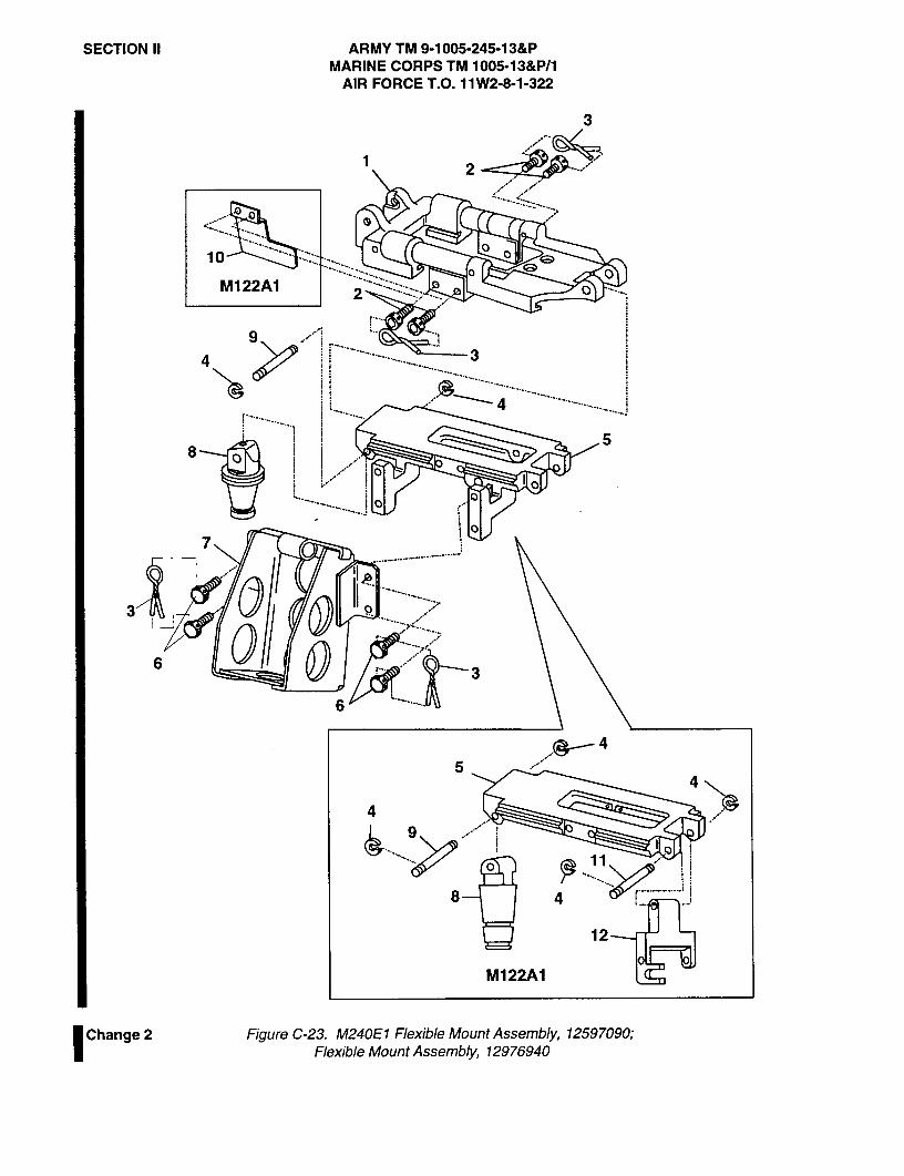
SECTION II ARMY TM 9-1005-245-13&PMARINE CORPS TM 1005-13&P/1
AIR FORCE T.O. 11W2-8-1-322
3
2
..........
10
M122A1
9 ...........34
... ...................... ....4 ........................
..................
58
o................... ......
7................. ............. .
3 .............
63
6
4
54
4
9
0
- --- -------8 4
12
0
Change 2 Figure C-23. M240E1 Flexible Mount Assembly, 12597090,Flexible Mount Assembly, 12976940
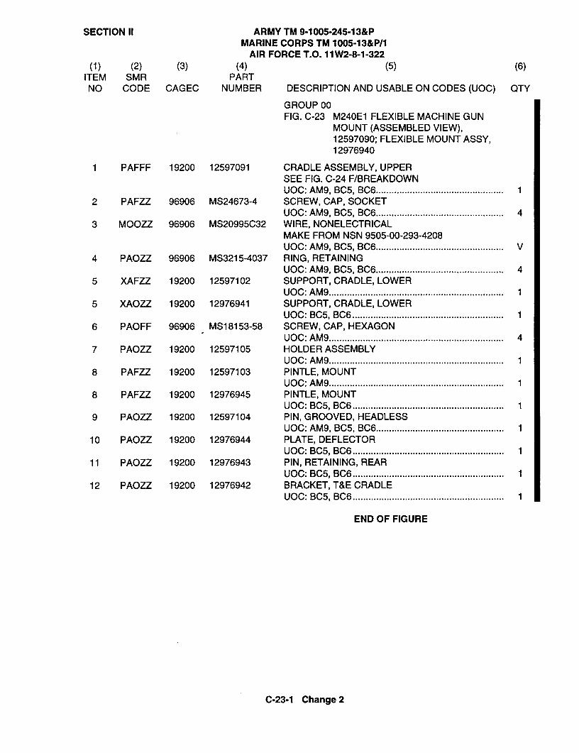
SECTION II ARMY TM 9-1005-245-13&PMARINE CORPS TM 1005-13&P/1
AIR FORCE T.O. 11W2-8-1-322(1) (2) (3) (4) (5) (6)
ITEM SMR PARTNO CODE CAGEC NUMBER DESCRIPTION AND USABLE ON CODES (UOC) QTY
GROUP OOFIG. C-23 M240E1 FLEXIBLE MACHINE GUN
MOUNT (ASSEMBLED VIEW),12597090; FLEXIBLE MOUNT ASSY,12976940
1 PAFFF 19200 12597091 CRADLE ASSEMBLY, UPPERSEE FIG. C-24 F/BREAKDOWNUOC: AM9, BC5, BC6 ................................................. 1
2 PAFZZ 96906 MS24673-4 SCREW, CAP, SOCKETUOC: AM9, BC5, BC6 ................................................. 4
3 MOOZZ 96906 MS20995C32 WIRE, NONELECTRICALMAKE FROM NSN 9505-00-293-4208UOC: AM9, BC5, BC6 ................................................. V
4 PAOZZ 96906 MS3215-4037 RING, RETAININGUOC: AM9, BC5, BC6 ................................................. 4
5 XAFZZ 19200 12597102 SUPPORT, CRADLE, LOWERUOC: AM9 ................................................................... 1
5 XAOZZ 19200 12976941 SUPPORT, CRADLE, LOWERUOC: BC5, BC6 .......................................................... 1
6 PAOFF 96906 MS18153-58 SCREW, CAP, HEXAGONUOC: AM9 ................................................................... 4
7 PAOZZ 19200 12597105 HOLDER ASSEMBLYUOC: AM9 ................................................................... 1
8 PAFZZ 19200 12597103 PINTLE, MOUNTUOC: AM9 ................................................................... 1
8 PAFZZ 19200 12976945 PINTLE, MOUNTUOC: BC5, BC6 .......................................................... 1
9 PAOZZ 19200 12597104 PIN, GROOVED, HEADLESSUOC: AM9, BC5, BC6 ................................................. 1
10 PAOZZ 19200 12976944 PLATE, DEFLECTORUOC: BC5, BC6 .......................................................... 1
11 PAOZZ 19200 12976943 PIN, RETAINING, REARUOC: BC5, BC6 .......................................................... 1
12 PAOZZ 19200 12976942 BRACKET, T&E CRADLEUOC: BC5, BC6 .......................................................... 1
END OF FIGURE
C-23-1 Change 2
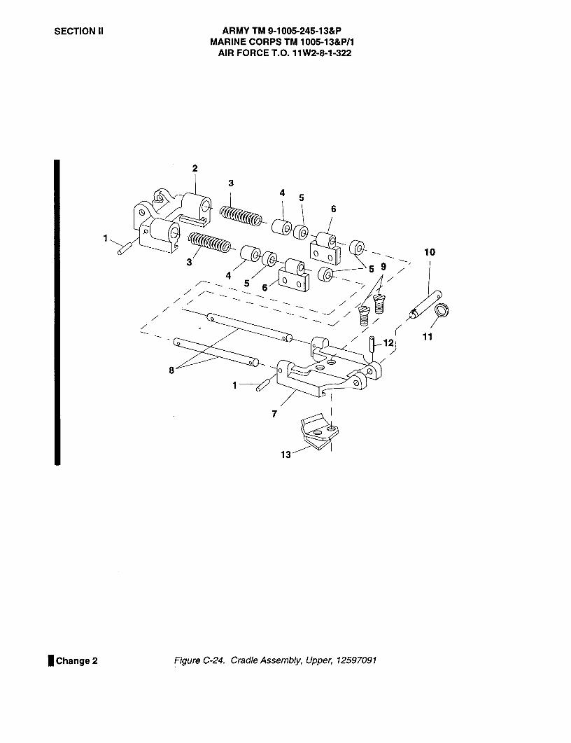
SECTION II ARMY TM 9-1005-245-13&PMARINE CORPS TM 1005-13&P/1
AIR FORCE T.O. 11W2-8-1-322
2
34 5
6
103
45
5 9
6
12
8
7
13
Change 2 Figure C-24. Cradle Assembly, Upper, 12597091

SECTION II ARMY TM 9-1005-245-13&PMARINE CORPS TM 1005-13&P/1
AIR FORCET.O. 11W2-8-1-322
(1) (2) (3) (4) (5) (6)ITEM SMR PARTNO CODE CAGEC NUMBER DESCRIPTION AND USABLE ON CODES (UOC) QTY
GROUP 01FIG. C-24 CRADLE ASSEMBLY, UPPER,
12597091
1 PAFZZ 96906 MS39086-44 PIN, SPRINGUOC: AM9, BC5, BC6 ................................................. 4
2 XAFZZ 19200 12597092 SUPPORT, CRADLEUOC: AM9, BC5, BC6 ................................................. 1
3 PAFZZ 19200 12597095 SPRING, HELICAL, COMPRESSIONUOC: AM9, BC5, BC6 ................................................. 2
4 PAFZZ 19200 12597096 SHIELD, SPRINGUOC: AM9, BC5, BC6 ................................................. 2
5 PAFZZ 19200 12597097 STOP, ELASTICUOC: AM9, BC5, BC6 ................................................. 4
6 PAFZZ 19200 12597098 BRACKET, EYE, NONROTATINGUOC: AM9, BC5, BC6 ................................................. 2
7 XAFZZ 19200 12597093 SUPPORT, CRADLE, REARUOC: AM9, BC5, BC6 ................................................. 1
8 PAFZZ 19200 12597094 TUBE, METALLICUOC: AM9, BC5, BC6 ................................................. 2
9 PAOZZ 96906 MS35190-271 SCREW, MACHINEUOC: AM9 ................................................................... 2
10 PAFZZ 19200 12597099 PIN, SPRINGUOC: AM9, BC5, BC6 ................................................. 1
11 PAOZZ 19200 11826283 RING, RETAININGUOC: AM9, BC5, BC6 ................................................. 1
12 PAOZZ 96906 MS39086-93 PIN, SPRINGUOC: AM9, BC5, BC6 ................................................. 1
13 PAOZZ 19200 12597100 DEFLECTORUOC: AM9 ................................................................... 1
END OF FIGURE
C-24-1/C-24-2 blank Change 2


Section II ARMY TM 9-1005-245-13&PMARINE CORPS TM 1005-13&P/1
AIR FORCE T.O. 11W2-8-1-322
Figure C-25. Mount, Machine Gun, M142 10900945 (Assembled View).
SECTION II TM9-1005-245-13&P(1) (2) (3) (4) (5) (6)
ITEM SMR PARTNO CODE CAGEC NUMBER DESCRIPTION AND USABLE ON CODES(UOC) QTY
GROUP 00FIG.C-25 MOUNT,MACHINE GUN,M142
10900945 (ASSEMBLED VIEW)
1 PAOFF 19207 10900945 MOUNT,MACHINE GUN, M142 ............ 1
END OF FIGURE
C-25-1
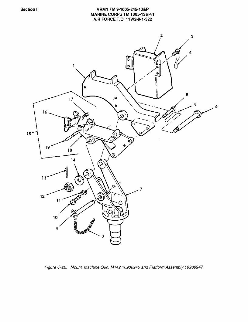
Section II ARMY TM 9-1005-245-13&PMARINE CORPS TM 1005-13&P/1
AIR FORCE T.O. 11W2-8-1-322
2 3
4
Oil
517
16
is
1918
a
14
13
7
12
10
9
FigureC-26. Mount, Machine Gun, M142 10900945 and Platform Assembly 10900947.

SECTION II TM9-1005-245-13&P(1) (2) (3) (4) (5) (6)
ITEM SMR PARTNO CODE CAGEC NUMBER DESCRIPTION AND USA.BLE ON CODES (UOC) QTY
GROUPS 00 AND 01FIG.C-26 MOUNT,MACHINE GUN,M142
10900945 AND PLATFORMASSEMBLY 10900947
1 PAFZZ 19204 10900948 CRADLE,MACHINE GUN .................. 1UOC:AM7
2 PAFZZ 19204 10900712 HOLDER ASSEMBLY,GUN ................. 1UOC.-AM7
3 PAFZZ 96906 MS51096-355 SCREW,CAP,HEXAGON H ................. 4UOC:AM7
4 MOOZZ 96906 MS20995C32 WIRE, NONELECTRICAL MAKE FROM VNSN9505-00-293-4208 .................UOC:AM7
5 PAFZZ 96906 MS51095-364 SCREW,CAP,HFXAGON H ................. 3UOC:AM7
6 PAFZZ 19207 10900962 BOLT,SHOULDER ....................... 1UOC:AM7
7 XDFZZ 19204 10900949 PINTLE,MOUNTING ..................... 1UOC:AM7
7 XAFZZ 19204 10900949 PINTLE,MOUNTING (MARINE CORPS ONLY) 1UOC:AM7
8 PAOZZ 19204 5236999 CHAIN ASSEMBLY,SING ................. 1UOC:AM7
9 PAOZZ 19207 10900963 PIN,QUICK RELEASE ................... 1UOC:AM7
10 PAFZZ 96906 MS35206-315 SCREW,MACHINE ....................... 1UOC:AM7
11 PAFZZ 96906 MS35691-17 NUT,PLAIN,HEXAGON ................... 1UOC:AM7
12 PAFZZ 96906 MS35692-37 NUT,PLAIN,SLOTTED,H ................. 1UOC:AM7
13 PAOZZ 96906 MS24665-291 PIN,COTTER .......................... 1UOC:AM7
14 PAFZZ 96906 MS27183-18 WASHER,FLAT ............ ............ 1UOC:AM7
15 AFFFF 19204 10900947 PLATFORM ASSY ....................... 1UOC:AM7
15 AOOOO 19204 10900947 PLATFORM ASSY (MARINE CORPS ONLY) . 1UCC:AM7
16 PAFZZ 19204 7792982 ..STRIKE,CATCH ...................... 1UOC:AM7
16 PAOZZ 19204 7792982 ..STRIKE,CATCH (MARINE CORPS ONLY). 1UOC:AM7
17 PAFZZ 19205 7792978 ..SPRING,HELICAL,TORS ............... 1UOC:AM7
17 PAOZZ 19205 7792978 ..SPRING,HELICAL,TORS (MARINE 1CORPS ONLY) .........................UOC:AM7
18 PAFZZ 19204 10900946 -PLATFORM ASSEMBLY ................. 1UOC:AM7
18 PAOZZ 19204 10900946 -PLATFORM ASSEMBLY (MARINE CORPS 1
C-26-1
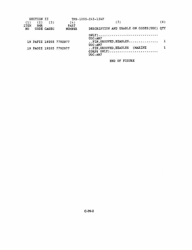
SECTION II TM9-1005-245-13&P(5) (6)(1) (2) (3) (4)
ITER SMR. PARTNO CODE CAGEC NUMBER DESCRIPTION AND USABLE ON CODES(UOC) QTY
ONLY) ...............................UOC:AM.7
19 PAFZZ 19205 7792977 . . PIN, GROOVED, HEADLES ............... 1UOC:AM7
19 PAOZZ 19205 7792977 ..PIN,GROOVED,HEADLES (MARINE 1CORPS ONLY) .........................UOC:AM7
END OF FIGURE
C-26-2

SectIon II ARMY TM 9-1005-245-13&PMARINE CORPS TM 1005-13&P/1
AIR FORCE T.O. 11W2-8-1-322
Figure C-27. Mount, Machine Gun, Cal.50, 6650 7046650 (Assembled View).
SECTION II TM9-1005-245-13&P(1) (2) (3) (4) (5) (6)
ITEM SMR PARTNO CODE CAGEC NUMBER DESCRIPTION AND USABLE ON CODES(UOC) QTY
GROUP 00FIG.C-27 MOUNT,MACHINE GUN,CAL .50,
6650 7046650 (ASSEMBLEDVIEW)
1 PAOFF 19204 7046650 MOUNT,MACHINE GUN, CAL .50, 6650, 1SEE FIG C-30 FOR BREAKDOWN..........
1 PAOOO 19204 7046650 MOUNT,MACHINE GUN, CAL .50, 6650, 1SEE FIG C-30 FOR BREAKDOWN(MARINE CORPS ONLY) .................
END OF FIGURE
C-27-1
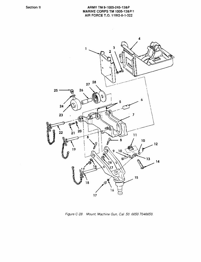
Section II ARMY TM 9-1005-245-13&PMARINE CORPS TM 1005-13&P/1
AIR FORCE T.O. l11W2-8-1-322
4
32
2728
26
24
23 7
202 21
8
11
10
19
12
9 10
1316 14
r&17
-6 17 %@@
15
18
16
17
Figure C-28. Mount, Machine Gun, Cal.50, 6650 7046650,

SECTION II TM9-1005-245-13&P(1) (2) (3) (4) (5) (6)
ITEM SMR PARTNO CODE CAGEC NUMBER DESCRIPTION AND USABLE ON CODES(UOC) QTY
GROUP 00FIG.C-28 MOUNT,MACHINE GUN,CAL .50,
6650 7046650
1 PAFZZ 19204 7046653 BRACKET, AMMUNTION .................. 1UOC:AH8
1 PAOZZ 19204 7046653 BRACKET,AMMUNITION (MARINE CORPS 1ONLY) ...............................UOC:AM8
2 PAFZZ 96906 MS35333-42 WASHER,LOCK ......................... 4UOC:AH8
2 PAOZZ 96906 MS35333-42 WASHER,LOCK (MARINE CORPS ONLY) .... 4UOC:AM8
3 PAFZZ 96906 MS90727-57 SCREW,CAP,HEXAGON H ................. 4UOC:AM8
3 PAOZZ 96906 MS90727-57 SCREW, CAP, HEXAGON H (MARINE CORPS 4ONLY) ...............................UOC:AM8
4 PAFZZ 19204 6590078 TRY ASSY AMMO BOX ................... 1UOC:AM8
4 PAOZZ 19204 6590078 TRY ASSY AMMO BOX (MARINE CORPS 1ONLY) ...............................UOC:AM8
5 PAFZZ 19204 5328284 VICK ................................ 2UOC:AM8
6 PAFZZ 19204 5384055 PIN,STRAICHT,HFADLE ................. 1UOC:AM8
7 PAFZZ 19204 7046652 CRADLE,MACHINE GUN .................. 1UOC:AM8
8 PAFZZ 19204 5384057 PIN,TAPERED,THREADE ................. 2UOC:AM8
9 PAFZZ 96906 MS20392-3C41 PIN,STRAIGHT,HEADED ................. 1UOC:AM8
9 PAOZZ 96906 MS20392-3C41 PIN, STRAIGHT, HEADED (MARINE CORPS 1ONLY) ...............................UOC:AM8
10 PAFZZ 96906 MS27183-10 WASHER,FLAT ......................... 2UOC:AM8
10 PAOZZ 96906 MS27183-10 WASHER,FLAT (MARINE CORPS ONLY) .... 2UOC:AM8
11 PAFZZ 19207 5384062 SPRING,HELICAL,TORS ................. 1UOC:AM8
11 PAOZZ 19207 5384062 SPRING,HELICAL,TORS (MARINE CORPS 1ONLY) ...............................UOC:AM8
12 PAFZZ 96906 MS24665-132 PIN,COTTER .......................... 1UOC:AM8
12 PAOZZ 96906 MS24665-132 PIN,COTTER (MARINE CORPS ONLY) ..... 1UOC:AM8
13 PAFZZ 19204 5384060 CLEVIS,ROD END ...................... 1UOC:AM8
13 PAOZZ 19204 5384060 CLEVIS,ROD END (MARINE CORPS ONLY). 1
C-28-1
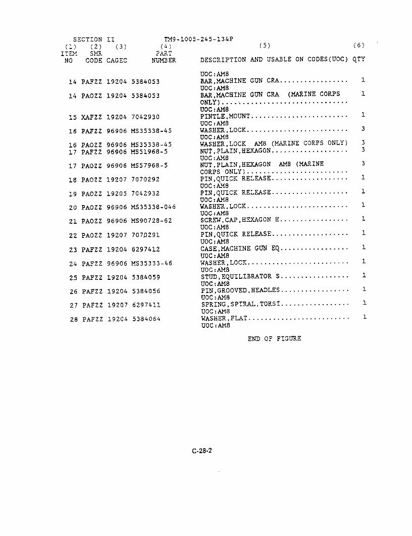
SECTION II TM9-1005-245-13&P(1) (2) (3) (4) (5) (6)
1 T L"I SMR PARTNO CODE CAGEC NUMBER DESCRIPTION AND USABLE ON CODES(UOC) QTY
UOC:AM814 PAFZZ 19204 5384053 BAR,MACHINE GUN CRA ................. 1
UOC:AM814 PAOZZ 19204 5384053 BAR,MACHINE GUN CRA (MARINE CORPS 1
ONLY) .... ..........................UOC:AM8
15 XAFZZ 19204 7042930 PINTLE,MOUNT ...................1UOC:AMS
16 PAFZZ 96906 MS35338-45 WASHER,LOCK ......................... 3UOC:AM8
16 PAOZZ 96906 MS35338-45 WASHER,LOCK AMB (MARINE CORPS ONLY) 3
17 PAFZZ 96906 MS51968-5 NUT,PLAIN,HEXAGON ................... 3UOC:AM8
17 PAOZZ 96906 MS57968-5 NUT,PLAIN,HEXAGON AMB (MARINE 3CORPS ONLY) .........................
18 PAOZZ 19207 7070292 PIN,QUICK RELEASE ................... 1UOC:AM8
19 PAOZZ 19205 7042932 PIN,QUICK RELEASE ................... 1UOC:AM8
20 PAOZZ 96906 MS35338-046 WASHER,LOCK ....................1UOC:AM8
21 PAOZZ 96906 MS90728-62 SCREW,CAP,HEXAGON H ................. 1
UOC:AM822 PAOZZ 19207 7070291 PIN,QUICK RELEASE ..............1
UOC:AMS23 PAFZZ 19204 6297412 CASE,MACHINE GUN EQ ............1
UOC:AM8124 PAFZZ 96906 MS35333-46 WASHER,LOCK ....................1
UOC:AM825 PAFZZ 19204 5384059 STUD,EQUILIBRATOR S ................. 1
UOC:AM826 PAFZZ 19204 5384056 PIN,GROOVED,HF-AXLES ................. 1
UOC:AM827 PAFZZ 19207 6297411 SPRING,SPIRAL,TORSI ................. 1
UOC:AMB28 PAFZZ 19204 5384064 WASHER,FLAT ......................... 1
UOC:AMS
END OF FIGURE
C-28-2

Section II ARMY TM 9-1005-245-13&PMARINE CORPS TM 1005-13&P/1
AIR FORCE T.O. 11W2-8-1-322
Figure C-29. Machine Gun Mount, M548 11631740-2 (Assembled View).
SECTION II TM9-1005-245-13&P(1) (2) (3) (4) (5) (6)
ITEM SMR PARTNO CODE CAGEC NUMBER DESCRIPTION AND USABLE ON CODES(UOC) QTY
GROUP 00FIG.C-29 MACHINE GUN MOUNT,M548
11631740-2 (ASSEMBLED VIEW)
1 PAOFF 19204 11631740-2 MACHINE GUN MOUNT, M548 ............ 1
END OF FIGURE
C-29-1
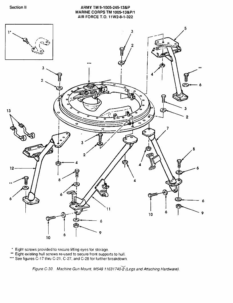
Section 11 ARMY TMI 9-1005-245-13&PMARINE CORPS TM 1005-13&P/1
AIR FORCE T.O. 11W2-8-1-322
53
-
4mt2
0
3
4
2CD 6
CXC'
313 Cb01 Cb 2
01710
3
8
2
126-4 4
6
8 4
6 CPO6 6
6 910
6
910
Eight screws provided to secure lifting eyes for storage.Eight existing hull screws re-used to secure front supports to hull.See figures C-1 7 thru C-21, C-27, and C-28 for further breakdown.
Figure C-30. Machine Gun Mount, M548 11631740-2 (Legs and Attaching Hardware).
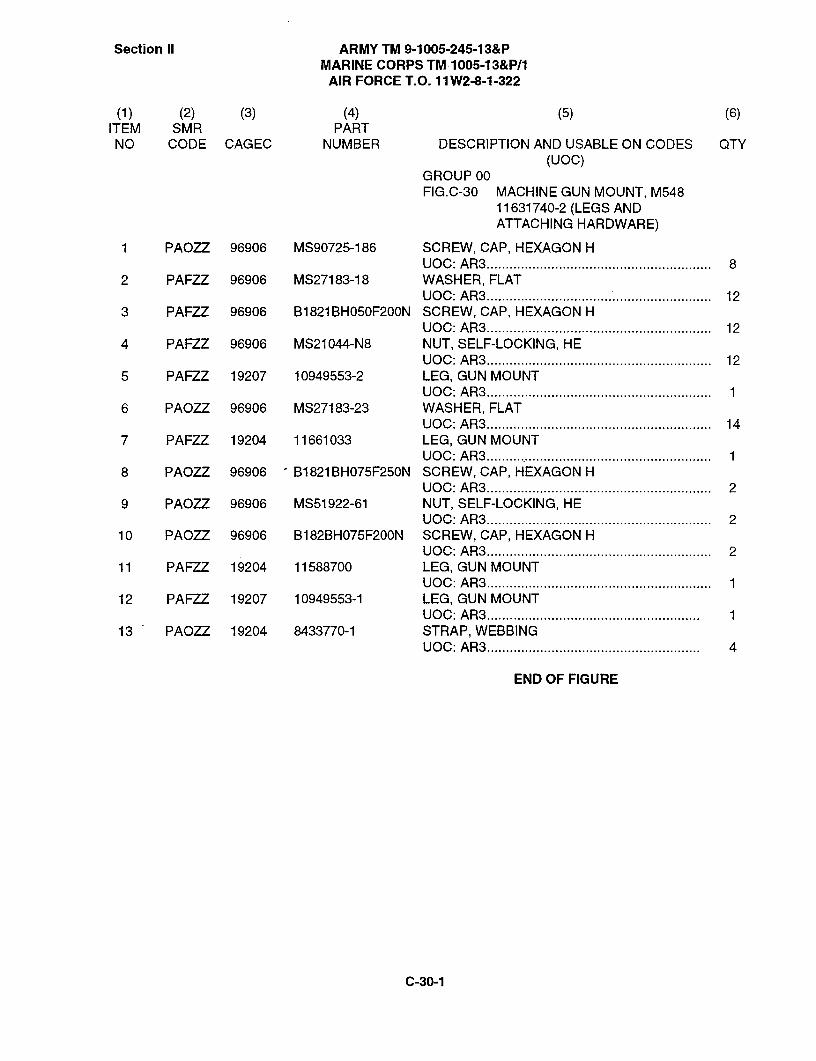
Section II ARMY TM 9-1005-245-13&PMARINE CORPS TM 1005-13&P/1
AIR FORCE T.O. 11 W2-8-1-322
(2) (3) (4) (5) (6)ITEM SMR PARTNO CODE CAGEC NUMBER DESCRIPTION AND USABLE ON CODES QTY
(UOC)GROUP OOFIG.C-30 MACHINE GUN MOUNT, M548
11631740-2 (LEGS ANDATTACHING HARDWARE)
1 PAOZZ 96906 MS90725-186 SCREW, CAP, HEXAGON HUOC:AR3 ........................................................... 8
2 PAFZZ 96906 MS27183-18 WASHER, FLATUOC:AR3 ............................................................ 12
3 PAFZZ 96906 B1821BH050F200N SCREW, CAP, HEXAGON HUOC:AR3 ........................................................... 12
4 PAFZZ 96906 MS21044-N8 NUT, SELF-LOCKING, HEUOC:AR3 ........................................................... 12
5 PAFZZ 19207 10949553-2 LEG, GUN MOUNTUOC:AR3 ........................................................... 1
6 PAOZZ 96906 MS27183-23 WASHER, FLATUOC:AR3 ........................................................... 14
7 PAFZZ 19204 11661033 LEG, GUN MOUNTUOC: AR3 ........................................................... 1
8 PA077 96906 B1821BHO75F25ON SCREW, CAP, HEXAGON HUOC:AR3 ........................................................... 2
9 PAOZZ 96906 MS51922-61 NUT, SELF-LOCKING, HEUOC:AR3 ........................................................... 2
10 PAOZZ 96906 B1 82BHO75F20ON SCREW, CAP, HEXAGON HUOC:AR3 ........................................................... 2
11 PAFZZ 19204 11588700 LEG, GUN MOUNTUOC:AR3 ........................................................... 1
12 PAFZZ 19207 10949553-1 LEG, GUN MOUNTUOC: AR3 ........................................................ 1
13 PAOZZ 19204 8433770-1 STRAP, WEBBINGUOC: AR3 ........................................................ 4
END OF FIGURE
C-30-1
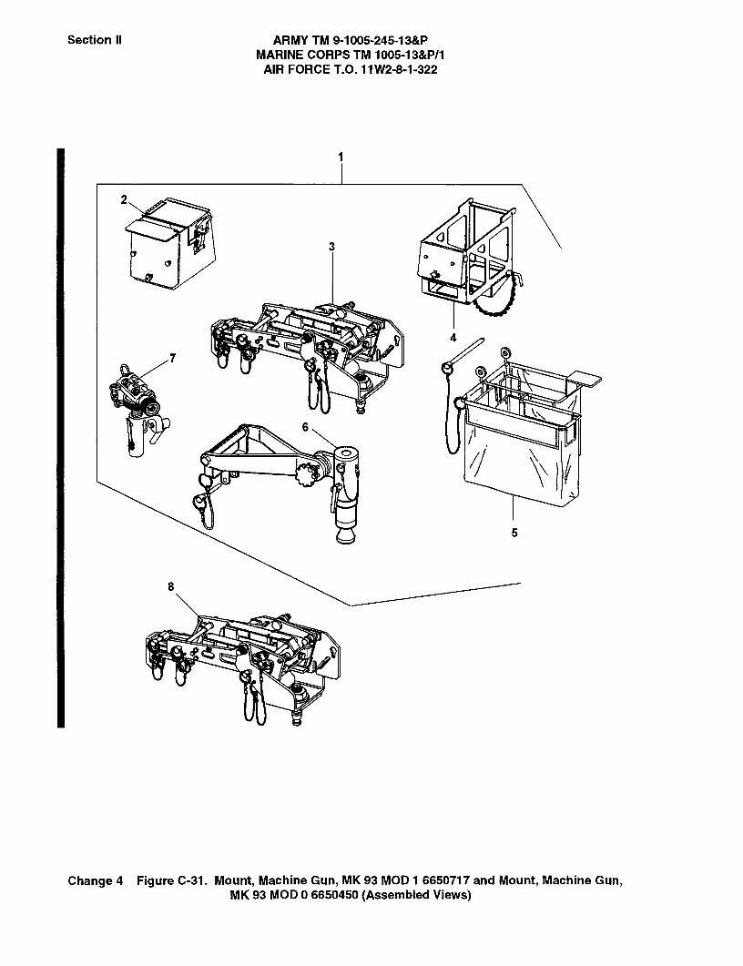
Section II ARMY TM 9-1005-245-13&PMARINE CORPS TM 1005-13&P/1
AIR FORCE T.O. 11 W2-8-1-322
2
J3
4
7
6
5
8
Change 4 Figure C-31. Mount, Machine Gun, MK93 MOD 1 6650717 and Mount, Machine Gun,MK93 MOD 0 6650450 (Assembled Views)

Section II ARMY TM 9-1005-245-13&PMARINE CORPS TM 1005-13&P/1AIR FORCE T.O. 11W2-8-1-322
(1) (2) (3) (4) (5) (6)ITEM SMR PART
NO CODE CAGEC NUMBER DESCRIPTION AND USABLE ON CODES QTY(UOC)
GROUP 00, 00FIG.C-31 MOUNT, MACHINE GUN, MK 93
MOD 1, 6650717, AND MOUNT,MACHINE GUN, MK93 MOD 06650450 (ASSEMBLED VIEWS)
1 PAOFF 53711 6650717 MOUNT, MG MK 93 MOD 1UOC:AY8 ........................................................... 1
2 PAOOO 53711 6650724 HOLDER ASSY, AMMO(SEE FIG. C-34 FOR BREAKDOWN)UOC: AY8 .......................................................... 1
3 PAOFF 53711 6650450 ..MOUNT, MG MK93 MOD 0(SEE FIG. C-32 FOR BREAKDOWN)UOC: AY8 ........................................................... 1
4 PAOOO 19200 12929150 BRACKET, MOUNTING(SEE FIG. C-35 FOR BREAKDOWN)UOC: AY8 ........................................................... 1
5 PAOOO 53711 6650723 ..CATCH BAG ASSY(SEE FIG. C-36 FOR BREAKDOWN)UOC: AY8 ........................................................... 1
6 PAOFF 19200 12012061 ..ADAPTER, UNIVERSAL PINTLE(SEE FIG. C-37 FOR BREAKDOWN)UOC: AY8 ........................................................... 1
7 PAOFF 53711 5830128 ELEVATION MECHANISM(SEE FIG. C-14 AND C-14 FOR BREAKDOWN)UOC:AY8 ........................................................... 1
8 PAOFF 53711 6650450 MOUNT, MG MK93 MOD 0(SEE FIG. C-32 FOR BREAKDOWN)UOC: AY7 ........................................................... 1
END OF FIGURE
C-31-1 Change 4

Section II ARMY TM 9-1005-245-13&PMARINE CORPS TM 1005-13&P/1
AIR FORCE T.O. 11 W2-8-1-322
2
1
10
5
6
7
8
9
e-@- 4@@@@
Change 4 Figure C-32. Mount, Machine Gun, MK93 MOD 0 6650450 andYoke Assembly 6650725

SectionII ARMY TM 9-1006-245-13&PMARINE CORPS TM 1005-13&P/1
AIR FORCE T.O. llW2-8-1-322
(1) (2) (3) (4) (5) (6)ITEM SIVIR PARTNO CODE CAGEC NUMBER DESCRIPTION AND USABLE ON CODES QTY
(UOC)
GROUP 00, 01, 0102, 02FIG. C-32 MOUNT, MACHINE GUN, MK93
MOD 0 6650450 AND YOKE ASSY6650725
1 AFFFF 53711 6650434 CRADLE & CARRIAGE ASSY(SEE FIG. C-33 FOR BREAKDOWN)UOC: AYT AY8 .................................................. 1
2 PAFZZ 53711 5830054 BOLT, MACHINEUOC: AYT AY8 .................................................. 2
3 AFFFF 53711 6650725 YOKE ASSYUOC: AYT AY8 .................................................. 1
4 PAFZZ 96906 MS21083C16 ..NUT, SELF-LOCKINGUOC: AYT AY8 .................................................. 1
5 PAFZZ 88044 AN960XC1616 ..WASHER, FLATUOC: AYT AY8 .................................................. 1
6 PBFZZ 53711 6650446 ..YOKEUOC: AYT AY8., ................................................ 1
7 PAFZZ 53711 6650407 ..WASHER, FLATUOC: AYT AY8 .................................................. 1
8 PAFZZ 53711 6650406 ..PINTLE, MOUNTUOC: AYT AY8 .................................................. 1
9 PAOZZ 53711 6650695 ..PIN, QUICK-RELEASEUOC: AYT AY8 .................................................. 1
10 PAFZZ 96906 MS21083C10 NUT, SELF-LOCKINGUOC: AYT AY8 .................................................. 2
END OF FIGURE
C-32-1
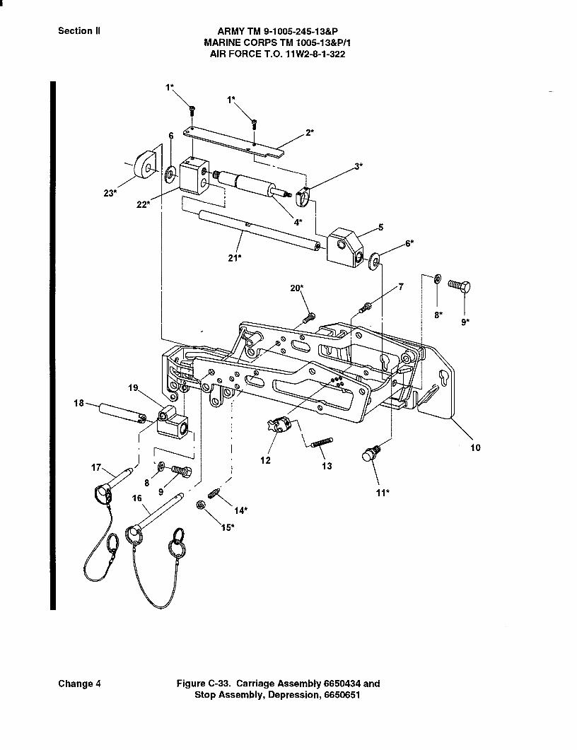
Section II ARMY TM 9-1005-245-13&PMARINE CORPS TM 1005-13&P/1
AIR FORCE T.O. 11W2-8-1-322
1*1*
6 2*
623*
22*
4*
6*
21*
20*
9*
QQ19 G
18 Q
10
1712
13
169
15*
14*
8
Change 4 Figure C-33. Carriage Assembly 6650434 andStop Assembly, Depression, 6650651

Section II ARMY TM 9-1005-245-13&PMARINE CORPS TM 1005-13&P/1
AIR FORCE T.O. 11 W2-8-1-322
(1) (2) (3) (4) (5) (6)ITEM SMR PARTNO CODE CAGEC NUMBER DESCRIPTION AND USABLE ON CODES QTY
(UOC)
GROUP 01, 0101, 0101, 010101FIG. C-33 CARRIAGE ASSEMBLY 6650434
AND STOP ASSEMBLY,DEPRESSION 6650651
1 PAFZZ 96906 MS51957-61B SCREW, MACHINEUOC: AY7, AY8 .................................................. 8
2 PAFZZ 53711 6650443 DEFLECTOR, LINKUOC: AYT AY8 .................................................. 2
3 PAFZZ 53711 6650442 DEFLECTOR, MOUNTUOC: AYT AY8 .................................................. 2
4 PAFZZ 53711 6650448 SHOCK, ABSORBERUOC: AYT AY8 .................................................. 2
5 PBFZZ 53711 6650437 SLIDE ASSY, RH FRONTUOC: AYT AY8 .................................................. 1
5 PBFZZ 53711 6650436 SLIDE ASSY, LH FRONTUOC: AYT AY8 .................................................. 1
6 PAFZZ 19200 9363644 WASHER, SPRING TENSIONUOC: AYT AY8 .................................................. 4
7 PAFZZ 96906 MS35307-303 SCREW, CAP, HEXUOC: AYT AY8 .................................................. 3
8 PAFZZ 88044 NAS1149C0863B WASHER, FLATUOC: AYT AY8 .................................................. 3
9 PAFZZ 96906 MS35307-409 SCREW, CAP, HEXUOC: AY7, AY8 .................................................. 3
10 PBFZZ 53711 6650445 CRADLE, MACHINE GUNUOC: AYT AY8 .................................................. 1
11 PAOZZ 53711 6650673 PIN, SHOULDER, HEADLESSUOC: AYT AY8 .................................................. 2
12 PAFFF 53711 6650651 STOP ASSY, DEPRESSIONUOC: AYT AY8 .................................................. 1
13 PAFZZ 53711 6650654 STUD, CONTINUOUSUOC: AYT AY8 .................................................. 1
14 PAFZZ 53711 6650696 SETSCREWUOC: AYT AY8 .................................................. 2
15 PAFZZ 53711 6650697 NUT, PLAIN, HEXUOC: AYT AY8 .................................................. 2
16 PAOZZ 53711 6650433-2 PIN ASSY, QUICK RELEASEUOC: AYT AY8 .................................................. 1
17 PAOZZ 53711 6650433-1 PIN ASSY, QUICK-RELEASEUOC: AYT AY8 .................................................. 1
18 PAFZZ 53711 6650439-1 SHAFT, STRAIGHTUOC: AYT AY8 .................................................. 1
19 PBFZZ 53711 6650438 SLIDER ASSY, REARUOC: AYT AY8 .................................................. 1
C-33-1 Change 4

Section II ARMY TM 9-1005-245-13&PMARINE CORPS TM 1005-13&P/1
AIR FORCE T.O. 11 W2-8-1-322
(1) (2) (3) (4) (5) (6)ITEM SMR PART
NO CODE CAGEC NUMBER DESCRIPTION AND USABLE ON CODES QTY(UOC)
20 PAFZZ 96906 MS35307-332 MACHINE, BOLTUOC: AYT AY8 .................................................. 6
21 PAFZZ 53711 6650439-2 SHAFT, STRAIGHTUOC: AYT AY8 .................................................. 2
22 PAFZZ 53711 6650444 BRACKET, MOUNTINGUOC: AYT AY8 .................................................. 2
23 PAFZZ 53711 6650441 BRACKET, MOUNTINGUOC: AYT AY8 .................................................. 2
END OF FIGURE
C-33-2

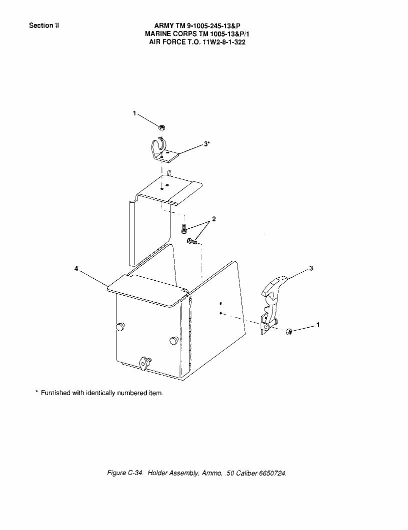
Section II ARMY TM 9-1005-245-13&PMARINE CORPS TM 1005-13&P/1
AIR FORCE T.O. 11W2-8-1-322
._3'
I
2
* Furnished with identically numbered item.
FigureC-34. HolderAssembly,Ammo, .50 Caliber6650724.
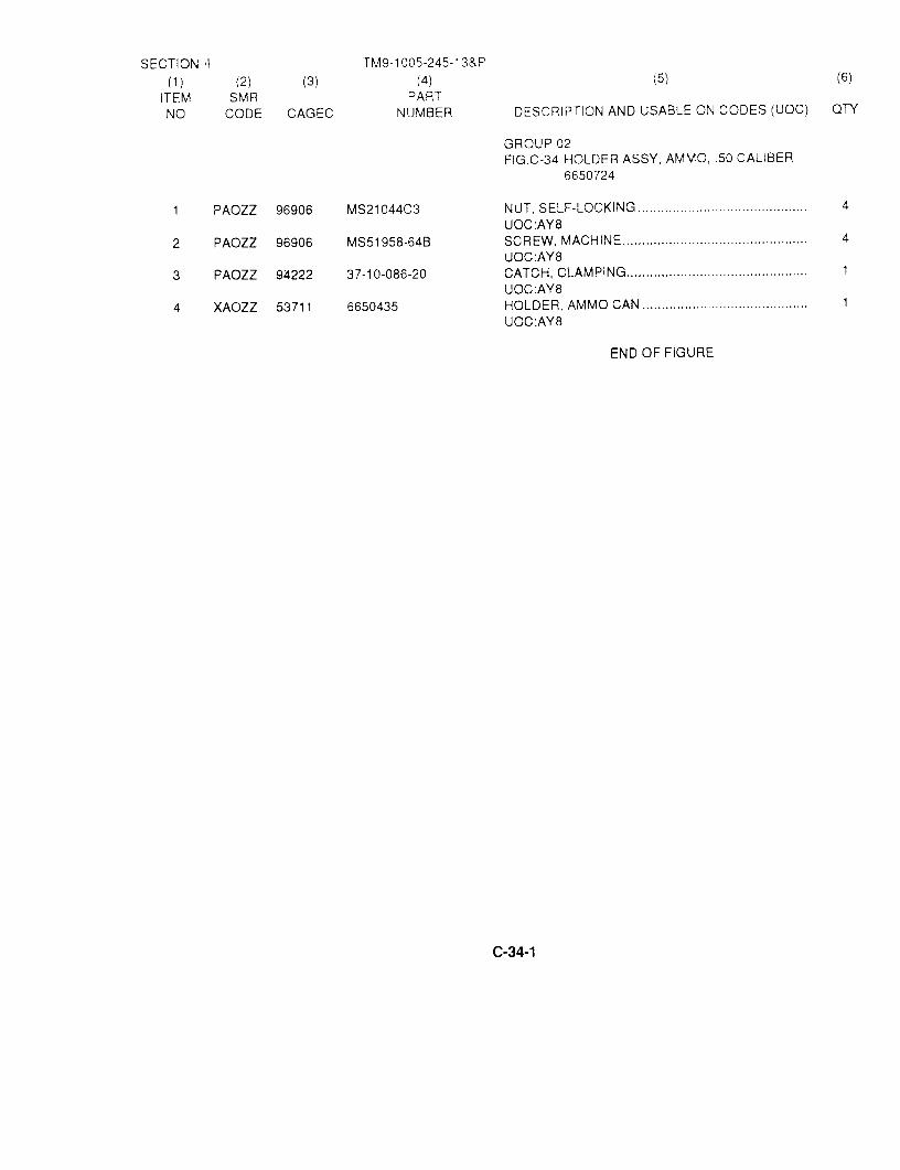
SECTION 11 Trv19-1 005-245-1 3&P(1) (2) (3) (4) (5) (6)
ITEM SIVIR PARTNO CODE CAGEC NUMBER DESCRIPTION AND USABLE ON CODES (UOC) QTY
GROUP02FIG.C-34 HOLDER ASSY, AMMO_50 CALIBER
6650724
1 PAOZZ 96906 MS21044C3 NUT, SELF-LOCKING ............................................ 4UOCAY8
2 PAOZZ 96906 MS51958-64B SCREW, MACHINE ............................................... 4UOC:AY8
3 PAOZZ 94222 37-10-086-20 CATCH, CLAMPING ............................................... 1UOC:AY8
4 XAOZZ 53711 6650435 HOLDER, AMMO CAN ........................................... 1UOC:AY8
END OF FIGURE
C-34-1

Section II ARMY TM 9-1005-245-13&PMARINE CORPS TM 1005-13&P/1
AIR FORCE T.O. 11W2-8-1-322
@O
2
J
FigureC-35.Bracket,Mounting12929150
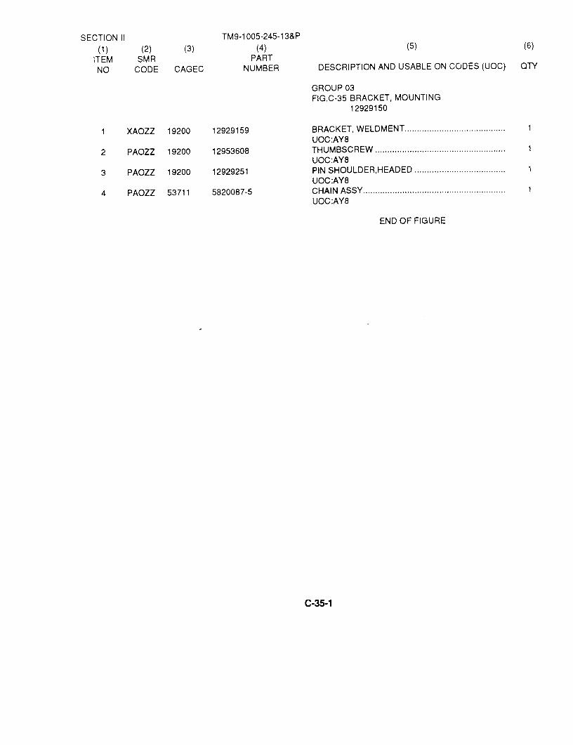
SECTION II TM9-1005-245-13&P
(1) (2) (3) (4) (5) (6)
ITEM SMR PARTNO CODE CAGEC NUMBER DESCRIPTION AND USABLE ON CODES (UOC) QTY
GROUP 03FIG.C-35 BRACKET, MOUNTING
12929150
1 XAOZZ 19200 12929159 BRACKET, WELDMENT ......................................... 1UOC:AY8
2 PAOZZ 19200 12953608 THUMBSCREW ........................... ......................... 1UOC:AY8
3 PAOZZ 19200 12929251 PIN SHOULDER,HEADED ..................................... 1UOC:AY8
4 PAOZZ 53711 5820087-5 CHAIN ASSY .......................................................... 1UOC:AY8
END OF FIGURE
C-35-1

Section II ARMY TM 9-1005-245-13&PMARINE CORPS TM 1005-13&P/1
AIR FORCE T.O. 11W2-8-1-322
I
J
2
i
FigureC-36. CatchBagAssembly6650723.

Section II ARMY TM 9-1005-245-13&PMARINE CORPS TM 1005-13&P/1
AIR FORCE T.O. 11 W2-8-1-322
(1) (2) (3) (4) (5) (6)ITEM SMR PART
NO CODE CAGEC NUMBER DESCRIPTION AND USABLE ON CODES QTY(UOC
GROUP04FIG.C-36 CATCH BAG ASSY, 6650723
1 XA077 53711 6650671 FRAME, CATCH BAGUOC: AY8 ........................................................... 1
2 PAOZZ 53711 6650722-1 BAG, CASINGS, OLIVEUOC: AY8 ........................................................... 1
2 PAOZZ 53711 6650722-2 BAG, CASINGS, SANDUOC: AY8 ........................................................... 1
3 PAOZZ 53711 6650433-2 PIN, QUICK-RELEASEUOC: AY8 ........................................................... 1
END OF FIGURE
C-36-1
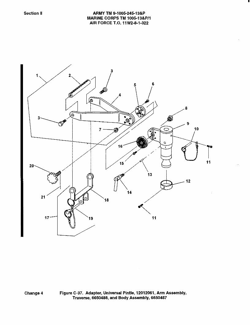
Section II ARMY TM 9-1005-245-13&PMARINE CORPS TM 1005-13&P/1
AIR FORCE T.O. 11 W2-8-1-322
31 2
5 6
4
8
3
CD 10
16
15
13
12
1421
18
17-- 19
Change 4 Figure C-37. Adapter, Universal Pintle, 12012061, Arm Assembly,Traverse, 6650488, and Body Assembly, 6650487

Section II ARMY TM 9-1005-245-13&PMARINE CORPS TM 1005-13&P/1
AIR FORCE T.O. 11W2-8-1-322
(1) (2) (3) (4) (5) (6)ITEM SMR PART
NO CODE CAGEC NUMBER DESCRIPTION AND USABLE ON CODES QTY(UOC)
GROUP 05,0501, 0502FIG.C-37 ADAPTER, UNIVERSAL PINTLE,
12012061, ARM ASSY,TRAVERSE, 6650488, BODYASSY, 12012062
1 PAFFF 53711 6650488 ARM ASSY, TRAVERSEUOC: AY8 ........................................................... 1
2 PAFZZ 53711 6650496 INDICATOR, AZIMUTHUOC: AY8 ........................................................... 1
3 PAFZZ 53711 6650501 BOLT, SHOULDERUOC: AY8 ........................................................... 2
4 XAFZZ 53711 6650489 ..ARM, ADJUSTABLEUOC: AY8 ........................................................... 1
5 PAFZZ 53711 6650561 ..PLATE, RETAININGUOC: AY8 ........................................................... 1
6 PAFZZ 19205 5140237 ..SCREW, MACHINEUOC: AY8 ........................................................... 4
7 PAFZZ 53711 6650494 -BUSHING, SLEEVEUOC: AY8 ........................................................... 1
8 PAFZZ 53711 6650493 BUSHING, SLEEVEUOC: AY8 ........................................................... 1
9 XAFZZ 53711 12012063 BODYUOC: AY8 ........................................................... 1
10 PAOZZ 53711 12012064 PIN AND CABLE ASSYUOC: AY8 ........................................................... 1
11 PAOZZ 96906 MS51958-79B SCREW, MACHINEUOC: AY8 ........................................................... 2
12 PAFZZ 19200 12012071 SPLIT RINGUOC: AY8 ........................................................... 1
13 PAFZZ 19200 12012067 PIN, STRAIGHT, HEADLESSUOC: AY8 ........................................................... 1
14 PAFZZ 53711 12012065 HANDLE, MANUAL CONTROLUOC: AY8 ........................................................... 1
15 PAFZZ 19205 5140237 SCREW, MACHINEUOC: AY8 ........................................................... 4
16 PAFZZ 53711 6650561 ..PLATE, RETAININGUOC: AY8 ........................................................... 1
17 PAOOO 19200 12012075 BRACKET, TRAVEL LOCK ASSYUOC: AY8 ........................................................... 1
18 XAOZZ 19200 12012074 BRACKET, TRAVEL LOCKUOC: AY8 ........................................................ 1
19 PAOZZ 19200 12012076 PIN, QUICK RELEASEUOC: AY8 ........................................................ 1
20 PAFZZ 53711 6650498 THUMBSCREWUOC: AY8 ........................................................... 1
21 PAFZZ 96906 MS1 6562-223 PIN, SPRINGUOC:AY8 ........................................................... 1
END OF FIGURE
C-37-1 Change 4

Section II ARMY TM 9-1005-245-13&PMARINE CORPS TM 1005-1 3&P/1
AIR FORCE T.O. 11W2-8-1-322
Figure C-38. Mount, Pedestal, Machine Gun, M6 12956270 (Assembled View)

Section II ARMY TM 9-1005-245-13&PMARINE CORPS TM 1005-13&P/1
AIR FORCE T.O. 11W2-8-1-322
(1) (2) (3) (4) (5) (6)ITEM SMR PARTNO CODE CAGEC NUMBER DESCRIPTION AND USABLE ON CODES QTY
(UOC)
GROUP OOFIG.C-38 MOUNT,PEDESTAL,MACHINE GUNM6 12956270 (ASSEMBLED VIEW)
1 PAOOO 19200 12956270 MOUNT, PEDESTAL, MACHINE GUN,M6(SEE FIG.C-39 FOR BREAKDOWN) .................. 1
END OF FIGURE
C-38-1 Change 3
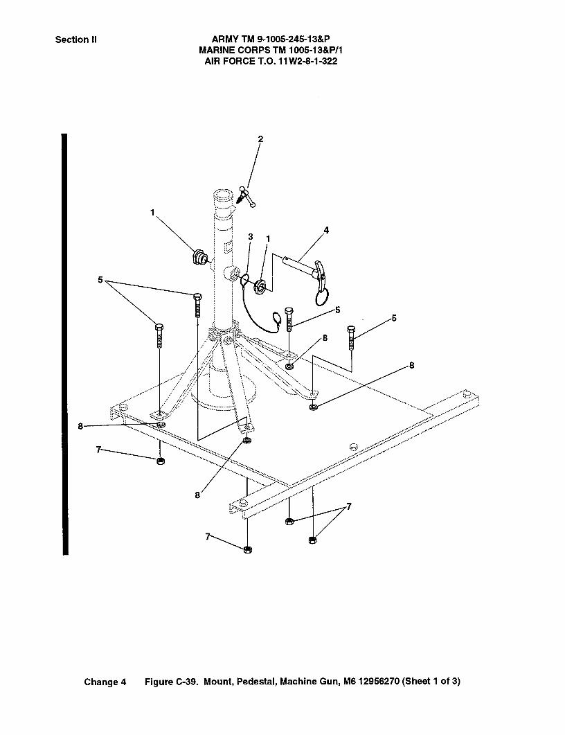
Section II ARMY TM 9-1005-245-13&PMARINE CORPS TM 1005-13&P/1
AIR FORCE T.O. 11 W2-8-1-322
2
3
5
55
8
8
8
87
4
8.,
Change 4 Figure C-39. Mount, Pedestal, Machine Gun, M6 12956270 (Sheet 1 of 3)
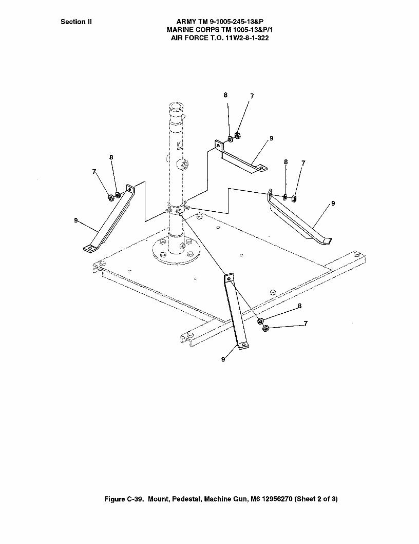
Section II ARMY TM 9-1005-245-13&PMARINE CORPS TM 1005-13&P/1
AIR FORCE T.O. 11 W2-8-1-322
8 7
9
87
9
9
9
Figure C-39. Mount, Pedestal, Machine Gun, M6 12956270 (Sheet 2 of 3)
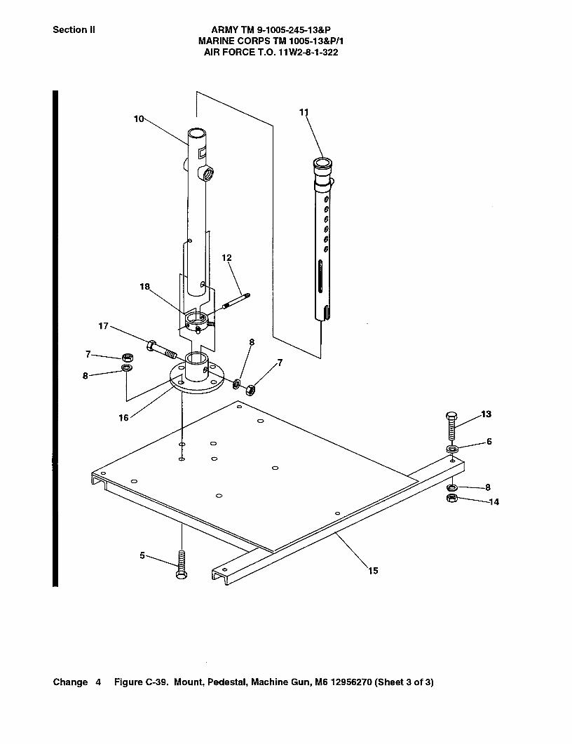
Section II ARMY TM 9-1005-245-13&PMARINE CORPS TM 1005-13&P/1
AIR FORCE T.O. 11 W2-8-1-322
1
12
17
18
87--,8
7
8
16 3
C> 6
C>
C>
C>8'---l 4
5,A
15
0
Change 4 Figure C-39. Mount, Pedestal, Machine Gun, M6 12956270 (Sheet 3 of 3)

SECTION II ARMY TM 9-1005-245-13&P MARINE CORPS TM 1005-13&P/1 AIR FORCE T.O. 11W2-8-1-322
C-39-1 Change 5
(1) (2) (3) (4) (5) (6)
ITEM SMR PART NO CODE CAGEC NUMBER DESCRIPTION AND USABLE ON CODES
(UOC) QTY
GROUP 00 FIG.C-39 MOUNT,PEDESTAL,MACHINE GUN,
M6,
12956270
1 PAOZZ 2U092 307328.00 INSERT,THREADED ......................................... 2 UOC:BB7
2 PAOZZ 2U092 307307.00 CLAMP ASSY,RETAIN ...................................... 1 UOC:BB7
3 PAOZZ 2U092 307331.00 WIRE CORD, ROPE .......................................... 1 UOC:BB7
4 PAOZZ 2U092 307329.00 PIN,QUICK RELEASE ....................................... 1 UOC:BB7
5 PAOZZ 96906 MS90726-115 SCREW,CAP, HEXAGON H .............................. 8 UOC:BB7
6 PAOZZ 96906 MS51412-9 WASHER,FLAT .................................................. 5 UOC:BB7
7 PAOZZ 81349 M45913/1-BFG5C NUT,SELF-LOCKING,HE .................................. 13 UOC:BB7
8 PAOZZ 96906 MS35338-48 WASHER,LOCK ................................................. 18 UOC:BB7
9 PAOZZ 2U092 307312.00 BRACE,GUN MOUNT,PED ............................... 4 UOC:BB7
10 PAOZZ 2U092 307311.00 TUBE,STRUCTURAL,EXTERNAL .................... 1 UOC:BB7
11 PAOZZ 2U092 307302.00 TUBE,STRUCTURAL,INTERNAL ..................... 1 UOC:BB7
12 PAOZZ 2U092 307326.00 PIN,STRAIGHT THREADED ............................. 1 UOC:BB7
13 PAOZZ 96906 B1821BH050C400N SCREW,CAP,HEXAGON H ............................... 5 UOC:BB7
14 PAOZZ 96906 MS51943-33 NUT,SELF-LOCKING,HE .................................. 5 UOC:BB7
15 XAOZZ 2U092 307305.00 FRAME,MOUNT WELDMENT ........................... 1 UOC:BB7
16 PAOZZ 2U092 307310.00 ADAPTER AND FLANGE .................................. 1 UOC:BB7
17 PAOZZ 96906 B1821BH050F450N SCREW, HEX HEAD ......................................... 1 UOC:BB7
18 PAOZZ 2U092 307316.00 COLLAR, RETAINING ....................................... 1 UOC:BB7
END OF FIGURE
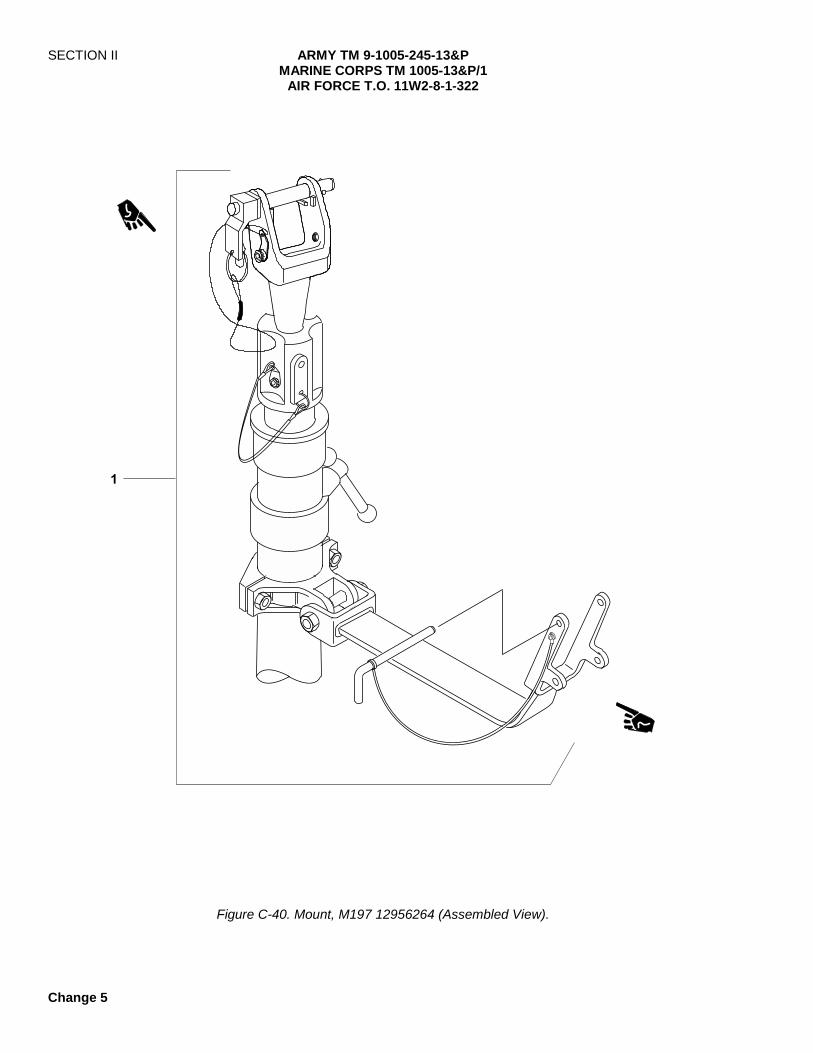
SECTION II ARMY TM 9-1005-245-13&P MARINE CORPS TM 1005-13&P/1 AIR FORCE T.O. 11W2-8-1-322
Change 5
�
Figure C-40. Mount, M197 12956264 (Assembled View).
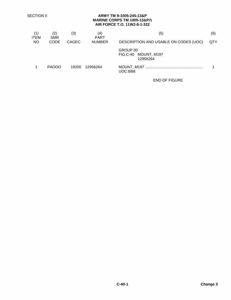
SECTION II ARMY TM 9-1005-245-13&P MARINE CORPS TM 1005-13&P/1
AIR FORCE T.O. 11W2-8-1-322
C-40-1 Change 3
(1) (2) (3) (4) (5) (6)
ITEM SMR PART NO CODE CAGEC NUMBER DESCRIPTION AND USABLE ON CODES (UOC) QTY
GROUP 00
FIG.C-40 MOUNT, M197 12956264
1 PAOOO 19200 12956264 MOUNT, M197 ....................................................... 1 UOC:BB8
END OF FIGURE
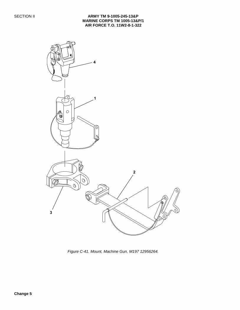
SECTION II ARMY TM 9-1005-245-13&P MARINE CORPS TM 1005-13&P/1
AIR FORCE T.O. 11W2-8-1-322
Change 5
�
�
�
�
Figure C-41. Mount, Machine Gun, M197 12956264.

SECTION II ARMY TM 9-1005-245-13&P MARINE CORPS TM 1005-13&P/1
AIR FORCE T.O. 11W2-8-1-322
C-41-1 Change 5
(1) (2) (3) (4) (5) (6)
ITEM SMR PART NO CODE CAGEC NUMBER DESCRIPTION AND USABLE ON CODES
(UOC) QTY
GROUP 00
FIG.C-41 MOUNT,MACHINE GUN,M197 12956264
1 PAOOO 53711 5830131 PINTLE ADAPTER ASSEMBLY (SEE FIG.C-44 FOR BREAKDOWN) ........................... 1 UOC:BB8
2 PAOOO 19200 12956265-2 TRAVEL LOCK ASSEMBLY (SEE FIG. C-42 FOR BREAKDOWN) ........................................... 1 UOC:BB8
3 PAOOO 53711 5830063 BRACKET ASSEMBLY, TR (SEE FIG.C-43 FOR BREAKDOWN ..................................................... 1 UOC:BB8
4 PAOOO 19200 12986102 PINTLE ASSEMBLY, TR (SEE FIG.C-45 FOR BREAKDOWN ..................................................... 1 UOC:BB8
END OF FIGURE

SECTION II ARMY TM 9-1005-245-13&P MARINE CORPS TM 1005-13&P/1
AIR FORCE T.O. 11W2-8-1-322
Change 5
�
�
�
�
�
�
�
�
NOTE
Travel lock components used with the M60 machine gun are located in the Additional Authorization List (AAL), appendix F.
Figure C-42. Travel Lock Assembly 12956265-2.
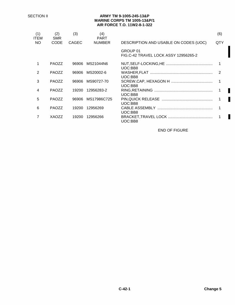
SECTION II ARMY TM 9-1005-245-13&P MARINE CORPS TM 1005-13&P/1
AIR FORCE T.O. 11W2-8-1-322
C-42-1 Change 5
(1) (2) (3) (4) (6)
ITEM SMR PART NO CODE CAGEC NUMBER DESCRIPTION AND USABLE ON CODES (UOC) QTY
GROUP 01 FIG.C-42 TRAVEL LOCK ASSY 12956265-2
1 PAOZZ 96906 MS21044N6 NUT,SELF-LOCKING,HE ............................................ 1 UOC:BB8
2 PAOZZ 96906 MS20002-6 WASHER,FLAT ........................................................... 2 UOC:BB8
3 PAOZZ 96906 MS90727-70 SCREW,CAP, HEXAGON H ....................................... 1 UOC:BB8
4 PAOZZ 19200 12956283-2 RING,RETAINING ....................................................... 1 UOC:BB8
5 PAOZZ 96906 MS17986C725 PIN,QUICK RELEASE ................................................ 1 UOC:BB8
6 PAOZZ 19200 12956269 CABLE ASSEMBLY .................................................... 1 UOC:BB8
7 XAOZZ 19200 12956266 BRACKET,TRAVEL LOCK .......................................... 1 UOC:BB8
END OF FIGURE

SECTION II ARMY TM 9-1005-245-13&P MARINE CORPS TM 1005-13&P/1
AIR FORCE T.O. 11W2-8-1-322
Figure C-43. Bracket Assembly, Travel Lock 5830063.

SECTION II ARMY TM 9-1005-245-13&P MARINE CORPS TM 1005-13&P/1
AIR FORCE T.O. 11W2-8-1-322
C-43-1 Change 5
(1) (2) (3) (4) (6)
ITEM SMR PART NO CODE CAGEC NUMBER DESCRIPTION AND USABLE ON CODES (UOC) QTY
GROUP 02 FIG.C-43 BRACKET ASSEMBLY, TRAVEL LOCK 5830063
1 XAOZZ 53711 5830133 BRACKET ASSEMBLY, TRAVEL LOCK ................. 1 UOC:BB8
2 PAOZZ 96906 MS35338-45 WASHER,LOCK ...................................................... 2 UOC:BB8
3 PAOZZ 96906 MS90725-34 BOLT,MACHINE ..................................................... 2 UOC:BB8
END OF FIGURE
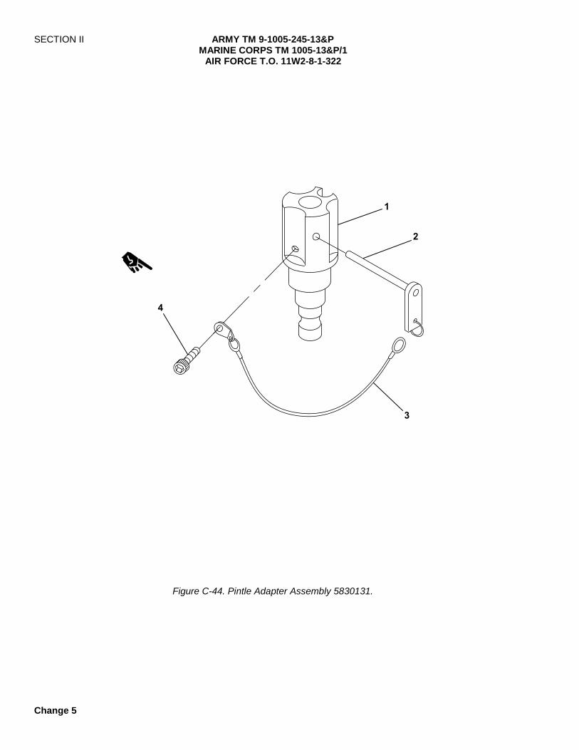
SECTION II ARMY TM 9-1005-245-13&P MARINE CORPS TM 1005-13&P/1
AIR FORCE T.O. 11W2-8-1-322
Change 5
�
�
�
�
Figure C-44. Pintle Adapter Assembly 5830131.

SECTION II ARMY TM 9-1005-245-13&P MARINE CORPS TM 1005-13&P/1
AIR FORCE T.O. 11W2-8-1-322
C-44-1 Change 5
(1) (2) (3) (4) (5) (6)
ITEM SMR PART NO CODE CAGEC NUMBER DESCRIPTION AND USABLE ON CODES (UOC) QTY
GROUP 03
FIG.C-44 PINTLE ADAPTER ASSEMBLY 5830131
1 XAOZZ 53711 5830132 PINTLE ADAPTER ................................................. 1 UOC:BB8
2 PAOZZ 96906 MS17986C325 PIN,QUICK RELEASE ........................................... 1 UOC:BB8
3 PAOZZ 53711 2843009 WIRE ROPE ASSEMBLY ...................................... 1 UOC:BB8
4 PAOZZ 96906 MS16996-21 SCREW, CAP, SOCKET HE .................................. 1 UOC:BB8
END OF FIGURE

This page intentionally left blank

SECTION II ARMY TM 9-1005-245-13&P MARINE CORPS TM 1005-13&P/1
AIR FORCE T.O. 11W2-8-1-322
C-45-1 Change 5
(1) (2) (3) (4) (5) (6)
ITEM SMR PART NO CODE CAGEC NUMBER DESCRIPTION AND USABLE ON CODES (UOC) QTY
GROUP 04
FIG.C-45 PINTLE MOUNT 11010408
For breakdown, refer to Figure C-6.
END OF FIGURE

SECTION II ARMY TM 9-1005-245-13&P MARINE CORPS TM 1005-13&P/1
AIR FORCE T.O. 11W2-8-1-322
Change 5
�
�
�
�
Figure C-46. Mount Pintle Assembly 12986102.
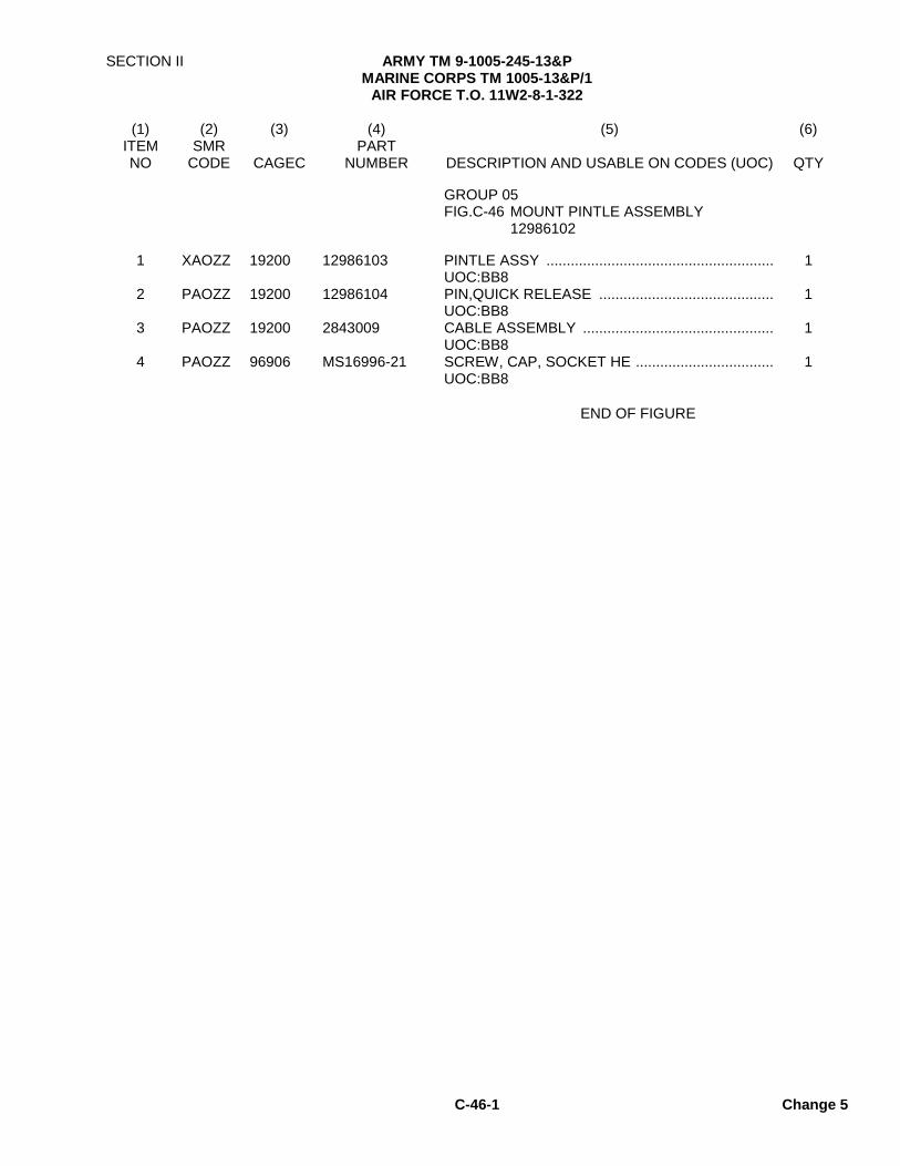
SECTION II ARMY TM 9-1005-245-13&P MARINE CORPS TM 1005-13&P/1
AIR FORCE T.O. 11W2-8-1-322
C-46-1 Change 5
(1) (2) (3) (4) (5) (6)
ITEM SMR PART NO CODE CAGEC NUMBER DESCRIPTION AND USABLE ON CODES (UOC) QTY
GROUP 05
FIG.C-46 MOUNT PINTLE ASSEMBLY 12986102
1 XAOZZ 19200 12986103 PINTLE ASSY ........................................................ 1 UOC:BB8
2 PAOZZ 19200 12986104 PIN,QUICK RELEASE ........................................... 1 UOC:BB8
3 PAOZZ 19200 2843009 CABLE ASSEMBLY ............................................... 1 UOC:BB8
4 PAOZZ 96906 MS16996-21 SCREW, CAP, SOCKET HE .................................. 1 UOC:BB8
END OF FIGURE

SECTION II ARMY TM 9-1005-245-13&P MARINE CORPS TM 1005-13&P/1
AIR FORCE T.O. 11W2-8-1-322
Change 5
�
�
�
�
�
Figure C-47. Ammo Adapter Bracket Assembly and Deflector 12986106

SECTION II ARMY TM 9-1005-245-13&P MARINE CORPS TM 1005-13&P/1
AIR FORCE T.O. 11W2-8-1-322
C-47-1 Change 5
(1) (2) (3) (4) (5) (6)
ITEM SMR PART NO CODE CAGEC NUMBER DESCRIPTION AND USABLE ON CODES (UOC) QTY
GROUP 06
FIG.C-47 AMMO ADAPTER BRACKET ASSEMBLY AND DEFLECTOR
12986106
1 PAOZZ 19200 12986106 DEFLECTOR KIT .................................................... 1 UOC: BB8
2 PAOZZ 80205 MS21044C4 . NUT, SELF-LOCKING........................................... 2 UOC: BB8
3 PAOZZ 80205 MS16996-21 . SCREW, CAP, SOCKET HEAD............................ 2 UOC: BB8
4 KFOZZ 19200 12986105 . PLATE, DEFLECTOR ........................................... 1 UOC: BB8
5 PAOOO 19200 12976909 BRACKET, AMMO .................................................. 1 UOC: BB8
END OF FIGURE

SECTION II ARMY TM 9-1005-245-13&P MARINE CORPS TM 1005-13&P/1
AIR FORCE T.O. 11W2-8-1-322
Change 5
�
�
�
�
�
�
�
Figure C-48. Gun Mount Adapter Parts NPN.
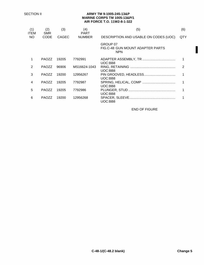
SECTION II ARMY TM 9-1005-245-13&P MARINE CORPS TM 1005-13&P/1
AIR FORCE T.O. 11W2-8-1-322
C-48-1/(C-48.2 blank) Change 5
(1) (2) (3) (4) (5) (6)
ITEM SMR PART NO CODE CAGEC NUMBER DESCRIPTION AND USABLE ON CODES (UOC) QTY
GROUP 07
FIG.C-48 GUN MOUNT ADAPTER PARTS NPN
1 PAOZZ 19205 7792991 ADAPTER ASSEMBLY, TR .................................... 1 UOC:BB8
2 PAOZZ 96906 MS16624-1043 RING, RETAINING ................................................. 2 UOC:BB8
3 PAOZZ 19200 12956267 PIN GROOVED, HEADLESS.................................. 1 UOC:BB8
4 PAOZZ 19205 7792987 SPRING, HELICAL, COMP .................................... 1 UOC:BB8 5 PAOZZ 19205 7792986 PLUNGER, STUD ................................................... 1 UOC:BB8 6 PAOZZ 19200 12956268 SPACER, SLEEVE..................................................
UOC:BB8 1
END OF FIGURE


SECTION II TM9-1005-245-13&P
(1) (2) (3) (4) (5) (6)
ITEM SMR PARTNO CODE CAGEC NUMBER DESCRIPTION AND USABLE ON CODES(UOC) QTY
GROUP 9999FIG.BULK
1 PAFZZ 96906 MS20995C32 WIRE,NONELECTRICAL AM7,AM9 ......... V
END OF FIGURE
BULK-1


SECTION IV ARMY TM 9-1005-245-13&P MARINE CORPS TM 1005-13&P/1
AIR FORCE T.O. 11W2-8-1-322
I-1 Change 5
CROSS REFERENCE INDEXES
FIGURE AND ITEM NUMBER INDEX
FIG. ITEM STOCK NUMBER CAGEC PART NUMBER BULK 1 9505-00-293-4208 96906 MS20995C32 C-1 1 1005-00-710-5599 19205 7790723 C-1 1 1005-01-433-1617 19200 12976949 C-2 1 19200 7790948 C-2 2 1005-00-603-4834 19205 7791119 C-2 3 1005-01-411-6340 19200 12976940 C-2 4 1005-00-945-9756 19205 11010408 C-3 1 5306-00-516-9880 19204 5169880 C-3 2 1005-00-555-9338 19204 5559338 C-3 3 5306-00-516-9881 19204 5169881 C-3 4 5306-00-516-9882 19204 5169882 C-3 5 3102-00-610-8201 19205 6108201 C-3 6 19204 5559331 C-3 7 5310-00-732-0559 96906 MS51968-8 C-3 8 1005-00-610-8195 19204 6108195 C-3 9 5306-00-516-9879 19204 5169879 C-3 10 5305-00-514-1950 19204 5141950 C-3 11 5310-00-916-2171 19205 11010529 C-3 12 1005-00-610-8986 19204 6108986 C-3 13 5305-00-054-6869 96906 MS51031-48 C-3 14 5310-00-768-0319 96906 MS51968-2 C-3 15 5365-00-513-9962 19205 5139962 C-3 16 1005-00-555-9337 19204 5559337 C-3 17 5315-00-514-0004 19207 5140004 C-3 18 5340-00-513-9959 19205 5139959 C-3 19 5360-00-513-9997 19205 5139997 C-3 20 1005-00-555-9333 19205 5559333 C-4 1 5310-01-374-0508 96906 MS51943-2 C-4 2 5310-00-517-4192 19205 5174192 C-4 3 5120-01-231-0265 19204 11010037 C-4 4 1005-00-588-3490 19205 5174175 C-4 5 5315-00-517-1495 19205 5171495 C-4 6 5360-00-915-5615 19205 11010547 C-4 7 4730-00-517-1491 19207 5171491 C-4 8 5355-00-517-1492 19205 5171492 C-4 9 5355-00-615-8375 19207 6158375 C-4 10 5310-00-935-3750 96906 MS51943-4 C-4 11 5315-00-616-5517 96906 MS35756-2 C-4 12 5305-00-513-9989 19204 5139989 C-4 13 5310-00-949-1971 19205 11010413 C-4 14 1005-00-722-3850 19205 7793002 C-4 15 5360-00-473-5447 19205 7793003 C-4 16 5305-00-513-9988 19205 5139988 C-4 17 1005-00-518-9757 19205 5189757 C-4 18 5315-00-051-8636 96906 MS16562-120 C-4 19 5325-00-803-7315 96906 MS16624-1043 C-4 20 5315-00-809-5417 19205 7792993 C-5 1 1005-00-919-7273 19205 10110242 C-5 2 19204 7793004
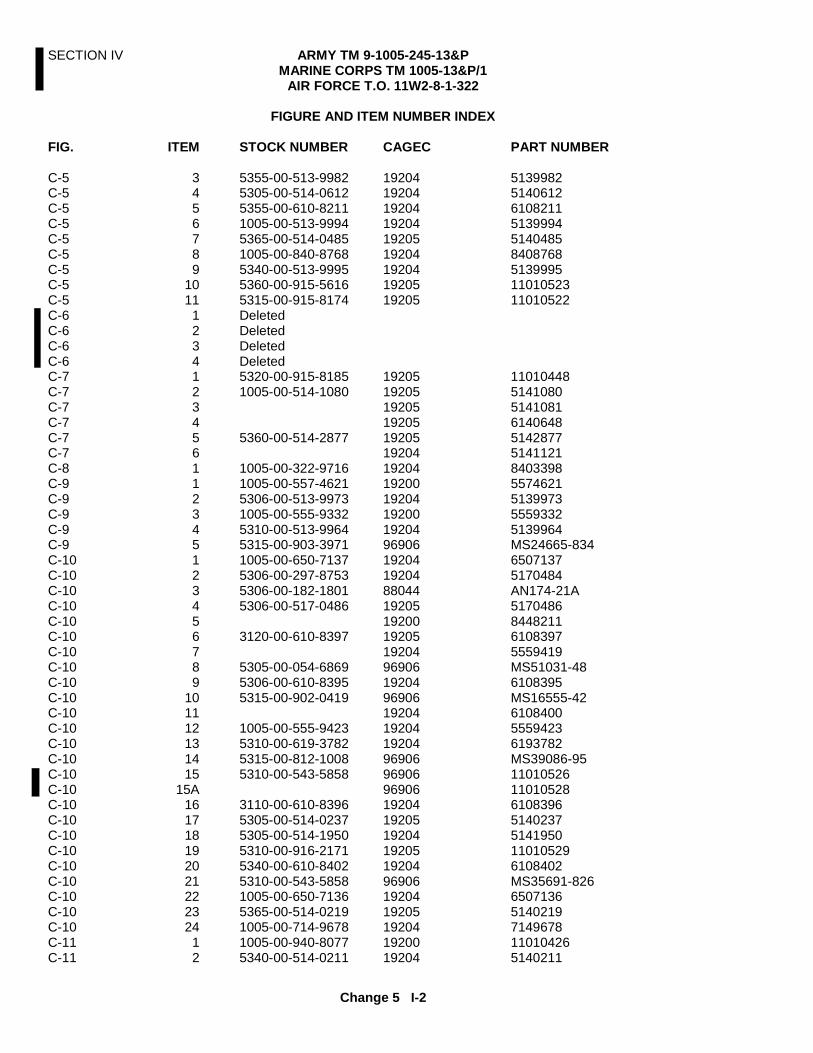
SECTION IV ARMY TM 9-1005-245-13&P MARINE CORPS TM 1005-13&P/1
AIR FORCE T.O. 11W2-8-1-322
Change 5 I-2
FIGURE AND ITEM NUMBER INDEX
FIG. ITEM STOCK NUMBER CAGEC PART NUMBER C-5 3 5355-00-513-9982 19204 5139982 C-5 4 5305-00-514-0612 19204 5140612 C-5 5 5355-00-610-8211 19204 6108211 C-5 6 1005-00-513-9994 19204 5139994 C-5 7 5365-00-514-0485 19205 5140485 C-5 8 1005-00-840-8768 19204 8408768 C-5 9 5340-00-513-9995 19204 5139995 C-5 10 5360-00-915-5616 19205 11010523 C-5 11 5315-00-915-8174 19205 11010522 C-6 1 Deleted C-6 2 Deleted C-6 3 Deleted C-6 4 Deleted C-7 1 5320-00-915-8185 19205 11010448 C-7 2 1005-00-514-1080 19205 5141080 C-7 3 19205 5141081 C-7 4 19205 6140648 C-7 5 5360-00-514-2877 19205 5142877 C-7 6 19204 5141121 C-8 1 1005-00-322-9716 19204 8403398 C-9 1 1005-00-557-4621 19200 5574621 C-9 2 5306-00-513-9973 19204 5139973 C-9 3 1005-00-555-9332 19200 5559332 C-9 4 5310-00-513-9964 19204 5139964 C-9 5 5315-00-903-3971 96906 MS24665-834 C-10 1 1005-00-650-7137 19204 6507137 C-10 2 5306-00-297-8753 19204 5170484 C-10 3 5306-00-182-1801 88044 AN174-21A C-10 4 5306-00-517-0486 19205 5170486 C-10 5 19200 8448211 C-10 6 3120-00-610-8397 19205 6108397 C-10 7 19204 5559419 C-10 8 5305-00-054-6869 96906 MS51031-48 C-10 9 5306-00-610-8395 19204 6108395 C-10 10 5315-00-902-0419 96906 MS16555-42 C-10 11 19204 6108400 C-10 12 1005-00-555-9423 19204 5559423 C-10 13 5310-00-619-3782 19204 6193782 C-10 14 5315-00-812-1008 96906 MS39086-95 C-10 15 5310-00-543-5858 96906 11010526 C-10 15A 96906 11010528 C-10 16 3110-00-610-8396 19204 6108396 C-10 17 5305-00-514-0237 19205 5140237 C-10 18 5305-00-514-1950 19204 5141950 C-10 19 5310-00-916-2171 19205 11010529 C-10 20 5340-00-610-8402 19204 6108402 C-10 21 5310-00-543-5858 96906 MS35691-826 C-10 22 1005-00-650-7136 19204 6507136 C-10 23 5365-00-514-0219 19205 5140219 C-10 24 1005-00-714-9678 19204 7149678 C-11 1 1005-00-940-8077 19200 11010426 C-11 2 5340-00-514-0211 19204 5140211
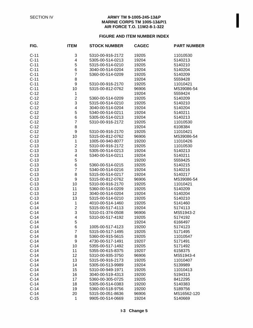
SECTION IV ARMY TM 9-1005-245-13&P MARINE CORPS TM 1005-13&P/1
AIR FORCE T.O. 11W2-8-1-322
I-3 Change 5
FIGURE AND ITEM NUMBER INDEX
FIG. ITEM STOCK NUMBER CAGEC PART NUMBER
C-11 3 5310-00-916-2172 19205 11010530 C-11 4 5305-00-514-0213 19204 5140213 C-11 5 5315-00-514-0210 19205 5140210 C-11 6 3040-00-514-0204 19204 5140204 C-11 7 5360-00-514-0209 19205 5140209 C-11 8 19204 5559428 C-11 9 5310-00-916-2170 19205 11010421 C-11 10 5315-00-812-0762 96906 MS39086-54 C-12 1 19204 5559424 C-12 2 5360-00-514-0209 19205 5140209 C-12 3 5315-00-514-0210 19205 5140210 C-12 4 3040-00-514-0204 19204 5140204 C-12 5 5340-00-514-0211 19204 5140211 C-12 6 5305-00-514-0213 19204 5140213 C-12 7 5310-00-916-2172 19205 11010530 C-12 8 19204 6108384 C-12 9 5310-00-916-2170 19205 11010421 C-12 10 5315-00-812-0762 96906 MS39086-54 C-13 1 1005-00-940-8077 19200 11010426 C-13 2 5310-00-916-2172 19205 11010530 C-13 3 5305-00-514-0213 19204 5140213 C-13 4 5340-00-514-0211 19204 5140211 C-13 5 19200 5559425 C-13 6 5360-00-514-0215 19205 5140215 C-13 7 5340-00-514-0216 19204 5140216 C-13 8 5315-00-514-0217 19204 5140217 C-13 9 5315-00-812-0762 96906 MS39086-54 C-13 10 5310-00-916-2170 19205 11010421 C-13 11 5360-00-514-0209 19205 5140209 C-13 12 3040-00-514-0204 19204 5140204 C-13 13 5315-00-514-0210 19205 5140210 C-14 1 4010-00-514-1460 19205 5141460 C-14 2 5315-00-517-4113 19204 5174113 C-14 3 5310-01-374-0508 96906 MS51943-2 C-14 4 5310-00-517-4192 19205 5174192 C-14 5 19204 6166497 C-14 6 1005-00-517-4123 19200 5174123 C-14 7 5315-00-517-1495 19205 5171495 C-14 8 5360-00-915-5615 19205 11010547 C-14 9 4730-00-517-1491 19207 5171491 C-14 10 5355-00-517-1492 19205 5171492 C-14 11 5355-00-615-8375 19207 6158375 C-14 12 5310-00-935-3750 96906 MS51943-4 C-14 13 5315-00-916-2173 19205 11010407 C-14 14 5305-00-513-9989 19204 5139989 C-14 15 5310-00-949-1971 19205 11010413 C-14 16 3040-00-519-4313 19200 5194313 C-14 17 5360-00-305-0725 19205 8412295 C-14 18 5305-00-514-0383 19200 5140383 C-14 19 5360-00-518-9756 19200 5189756 C-14 20 5315-00-051-8636 96906 MS16562-120 C-15 1 9905-00-514-0669 19204 5140669
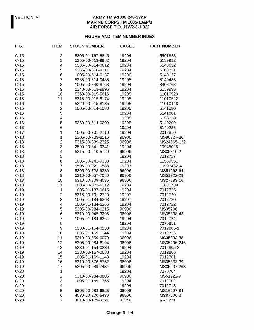
SECTION IV ARMY TM 9-1005-245-13&P MARINE CORPS TM 1005-13&P/1
AIR FORCE T.O. 11W2-8-1-322
Change 5 I-4
FIGURE AND ITEM NUMBER INDEX
FIG. ITEM STOCK NUMBER CAGEC PART NUMBER
C-15 2 5305-01-167-5845 19204 5591828 C-15 3 5355-00-513-9982 19204 5139982 C-15 4 5305-00-514-0612 19204 5140612 C-15 5 5355-00-610-8211 19204 6108211 C-15 6 1005-00-514-0137 19200 5140137 C-15 7 5365-00-514-0485 19205 5140485 C-15 8 1005-00-840-8768 19204 8408768 C-15 9 5340-00-513-9995 19204 5139995 C-15 10 5360-00-915-5616 19205 11010523 C-15 11 5315-00-915-8174 19205 11010522 C-16 1 5320-00-915-8185 19205 11010448 C-16 2 1005-00-514-1080 19205 5141080 C-16 3 19204 5141081 C-16 4 19205 6153118 C-16 5 5360-00-514-0209 19205 5140209 C-16 6 19204 5140225 C-17 1 1005-00-701-2710 19204 7012810 C-18 1 5305-00-709-8516 96906 MS90727-86 C-18 2 5315-00-839-2325 96906 MS24665-132 C-18 3 2590-00-841-9341 19204 10945028 C-18 4 5315-00-610-5729 96906 MS35810-2 C-18 5 19204 7012727 C-18 6 1005-00-941-9338 19204 11589551 C-18 7 9505-00-921-0588 19207 10907432-4 C-18 8 5305-00-723-9386 96906 MS51963-64 C-18 9 5310-00-057-7080 96906 MS51922-29 C-18 10 5310-00-809-4085 96906 MS27183-16 C-18 11 1005-00-072-6112 19204 11631739 C-19 1 1005-01-187-9615 19204 7012725 C-19 2 5315-00-701-2720 19207 7012720 C-19 3 1005-01-184-6363 19207 7012720 C-19 4 1005-01-184-6365 19204 7012722 C-19 5 5305-00-984-6215 96906 MS35206 C-19 6 5310-00-045-3296 96906 MS35338-43 C-19 7 1005-01-184-6364 19204 7012724 C-19 8 19204 7070851 C-19 9 5330-01-154-0238 19204 7012805-1 C-19 10 1005-01-169-1144 19204 7012726 C-19 11 5310-00-559-0070 96906 MS35333-38 C-19 12 5305-00-984-6194 96906 MS35206-246 C-19 13 5330-01-154-0239 19204 7012805-2 C-19 14 5330-00-167-0638 19204 7012806 C-19 15 1005-01-169-1143 19204 7012701 C-19 16 5310-00-576-5752 96906 MS35333-39 C-19 17 5305-00-989-7434 96906 MS35207-263 C-20 1 19204 7070704 C-20 2 5310-00-984-3806 96906 MS51922-9 C-20 3 1005-01-169-1756 19204 7012702 C-20 4 19204 7012713 C-20 5 5305-00-983-6625 96906 MS16997-84 C-20 6 4030-00-270-5436 96906 MS87006-3 C-20 7 4010-00-129-3221 81348 RRC271

SECTION IV ARMY TM 9-1005-245-13&P MARINE CORPS TM 1005-13&P/1
AIR FORCE T.O. 11W2-8-1-322
I-5 Change 5
FIGURE AND ITEM NUMBER INDEX
FIG. ITEM STOCK NUMBER CAGEC PART NUMBER
C-20 8 1005-00-701-2747 19204 7012747 C-20 9 5315-00-842-3044 96906 MS24665-283 C-20 10 1005-00-701-2730 19204 7012730 C-20 11 5305-00-983-6625 96906 MS16997-84 C-20 12 5315-00-701-2804 19204 7012804 C-20 13 5340-00-701-2731 19204 7012731 C-20 14 5360-00-701-2733 19207 7012733 C-20 15 5365-00-701-2732 19204 7012732 C-20 16 5315-00-816-1794 96906 MS24665-285 C-20 17 19204 7012740 C-20 18 5340-00-389-8118 19207 8668937 C-20 19 5120-00-701-2762 19204 7012762 C-20 20 1005-00-701-2801 19204 7012801 C-20 21 3120-00-934-8319 19204 7012728 C-21 1 1005-00-701-2759 19204 7012759 C-21 2 5305-00-983-8084 96906 MS16997-60 C-21 3 3040-00-701-2800 19204 7012800 C-21 4 1005-00-701-2756 19204 7012756 C-21 5 5315-00-999-4241 96906 MS51932-59 C-21 6 5315-00-842-3044 96906 MS24665-283 C-21 7 5310-00-707-0734 19207 7070734 C-21 8 2530-00-701-2765 19204 7012765 C-21 9 5340-00-701-2758 19204 7012758 C-21 10 5310-00-809-4061 96906 MS27183-15 C-21 11 5310-00-087-4652 96906 MS51922-17 C-21 12 5310-00-701-2761 19207 7012761 C-21 13 5305-00-723-9383 96906 MS51963-67 C-21 14 1005-00-934-8320 19204 7012753 C-21 15 5360-00-701-2752 19207 7012752 C-21 16 5315-00-889-2518 96906 MS16556-628 C-21 17 1005-00-701-2757 19204 7012757 C-21 18 5360-00-701-2748 19204 7012748 C-21 19 5310-00-701-2749 19207 7012749 C-21 20 5320-00-057-5543 96906 MS35743-11 C-21 21 5305-00-983-5334 96906 MS16997-102 C-21 22 5340-00-701-2760 19204 7012760 C-22 1 1005-01-254-0332 19200 12597090 C-22 1 1005-01-411-6340 19200 12976940 C-23 1 1005-01-252-2820 19200 12597091 C-23 2 5305-00-993-7198 96906 MS24673-4 C-23 3 96906 MS20995C32 C-23 4 5365-01-009-6843 96906 MS3215-4037 C-23 5 19200 12597102 C-23 5 19200 12976941 C-23 6 5305-00-921-0042 96906 MS18153-58 C-23 7 1005-01-257-9252 19200 12597105 C-23 8 1005-00-252-3011 19200 12597103 C-23 8 1005-01-429-0427 19200 12976945 C-23 9 5315-01-252-2981 19200 12597104 C-23 10 1005-01-352-5345 19200 12976944 C-23 11 5315-01-408-6009 19200 12976943

SECTION IV ARMY TM 9-1005-245-13&P MARINE CORPS TM 1005-13&P/1
AIR FORCE T.O. 11W2-8-1-322
Change 5 I-6
FIGURE AND ITEM NUMBER INDEX
FIG. ITEM STOCK NUMBER CAGEC PART NUMBER
C-23 12 1005-01-408-5915 19200 12976942 C-24 1 5315-00-989-1157 96906 MS39086-44 C-24 2 19200 12597092 C-24 3 5360-01-255-4199 19200 12597095 C-24 4 1005-01-252-2821 19200 12597096 C-24 5 1005-01-252-2822 19200 12597097 C-24 6 3040-01-253-6871 19200 12597098 C-24 7 19200 12597093 C-24 8 4710-01-252-3026 19200 12597094 C-24 9 5305-00-954-3487 96906 MS35190-271 C-24 10 5315-01-293-2142 19200 12597099 C-24 11 5365-01-197-4458 19200 11826283 C-24 12 5315-00-690-0544 96906 MS39086-93 C-24 13 1005-01-252-2823 19200 12597100 C-25 1 1005-00-854-4463 19207 10900945 C-26 1 1005-00-779-2479 19204 10900948 C-26 2 1005-00-121-0778 19204 10900712 C-26 3 5305-00-904-4053 96906 MS51096-355 C-26 4 96906 MS20995C32 C-26 5 5305-00-939-1179 96906 MS51095-364 C-26 6 5306-00-854-4464 19207 10900962 C-26 7 19204 10900949 C-26 8 4010-00-523-6999 19204 5236999 C-26 9 5315-00-854-4465 19207 10900963 C-26 10 5305-00-984-5695 96906 MS35206-315 C-26 11 5310-00-851-2682 96906 MS35691-17 C-26 12 5310-00-842-1490 96906 MS35692-37 C-26 13 5315-00-019-0777 96906 MS24665-291 C-26 14 5310-00-809-5998 96906 MS27183-18 C-26 15 19204 10900947 C-26 16 5340-00-772-0190 19204 7792982 C-26 17 5360-00-772-0187 19205 7792978 C-26 18 1005-00-121-0779 19204 10900946 C-26 19 5315-00-772-0186 19205 7792977 C-27 1 1005-00-704-6650 19204 7046650 C-28 1 1005-00-704-6653 19204 7046653 C-28 2 5310-00-595-7237 96906 MS35333-42 C-28 3 5305-00-269-3233 96906 MS90727-57 C-28 4 8140-00-659-0078 19204 6590078 C-28 5 9390-00-532-8282 19204 5328284 C-28 6 5315-00-538-4055 19204 5384055 C-28 7 1005-00-704-6652 19204 7046652 C-28 8 5315-00-538-4057 19204 5384057 C-28 9 5315-00-811-9105 96906 MS20392-3C41 C-28 10 5310-00-809-4058 96906 MS27183-10 C-28 11 5360-00-526-0143 19207 5384062 C-28 12 5315-00-839-2325 96906 MS24665-132 C-28 13 5340-00-538-4060 19204 5384060 C-28 14 1005-00-538-4053 19204 5384053 C-28 15 19204 7042930 C-28 16 5310-00-407-9566 96906 MS35338-45
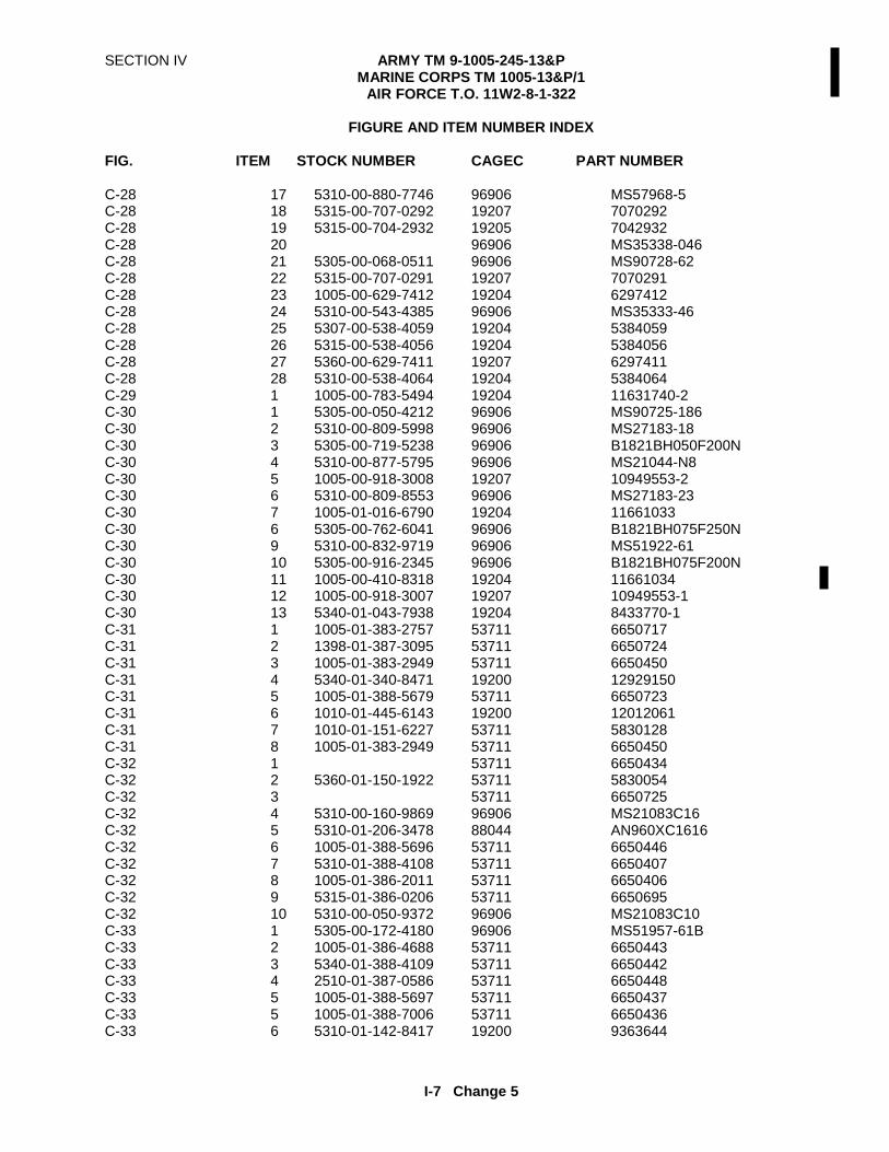
SECTION IV ARMY TM 9-1005-245-13&P MARINE CORPS TM 1005-13&P/1
AIR FORCE T.O. 11W2-8-1-322
I-7 Change 5
FIGURE AND ITEM NUMBER INDEX
FIG. ITEM STOCK NUMBER CAGEC PART NUMBER C-28 17 5310-00-880-7746 96906 MS57968-5 C-28 18 5315-00-707-0292 19207 7070292 C-28 19 5315-00-704-2932 19205 7042932 C-28 20 96906 MS35338-046 C-28 21 5305-00-068-0511 96906 MS90728-62 C-28 22 5315-00-707-0291 19207 7070291 C-28 23 1005-00-629-7412 19204 6297412 C-28 24 5310-00-543-4385 96906 MS35333-46 C-28 25 5307-00-538-4059 19204 5384059 C-28 26 5315-00-538-4056 19204 5384056 C-28 27 5360-00-629-7411 19207 6297411 C-28 28 5310-00-538-4064 19204 5384064 C-29 1 1005-00-783-5494 19204 11631740-2 C-30 1 5305-00-050-4212 96906 MS90725-186 C-30 2 5310-00-809-5998 96906 MS27183-18 C-30 3 5305-00-719-5238 96906 B1821BH050F200N C-30 4 5310-00-877-5795 96906 MS21044-N8 C-30 5 1005-00-918-3008 19207 10949553-2 C-30 6 5310-00-809-8553 96906 MS27183-23 C-30 7 1005-01-016-6790 19204 11661033 C-30 6 5305-00-762-6041 96906 B1821BH075F250N C-30 9 5310-00-832-9719 96906 MS51922-61 C-30 10 5305-00-916-2345 96906 B1821BH075F200N C-30 11 1005-00-410-8318 19204 11661034 C-30 12 1005-00-918-3007 19207 10949553-1 C-30 13 5340-01-043-7938 19204 8433770-1 C-31 1 1005-01-383-2757 53711 6650717 C-31 2 1398-01-387-3095 53711 6650724 C-31 3 1005-01-383-2949 53711 6650450 C-31 4 5340-01-340-8471 19200 12929150 C-31 5 1005-01-388-5679 53711 6650723 C-31 6 1010-01-445-6143 19200 12012061 C-31 7 1010-01-151-6227 53711 5830128 C-31 8 1005-01-383-2949 53711 6650450 C-32 1 53711 6650434 C-32 2 5360-01-150-1922 53711 5830054 C-32 3 53711 6650725 C-32 4 5310-00-160-9869 96906 MS21083C16 C-32 5 5310-01-206-3478 88044 AN960XC1616 C-32 6 1005-01-388-5696 53711 6650446 C-32 7 5310-01-388-4108 53711 6650407 C-32 8 1005-01-386-2011 53711 6650406 C-32 9 5315-01-386-0206 53711 6650695 C-32 10 5310-00-050-9372 96906 MS21083C10 C-33 1 5305-00-172-4180 96906 MS51957-61B C-33 2 1005-01-386-4688 53711 6650443 C-33 3 5340-01-388-4109 53711 6650442 C-33 4 2510-01-387-0586 53711 6650448 C-33 5 1005-01-388-5697 53711 6650437 C-33 5 1005-01-388-7006 53711 6650436 C-33 6 5310-01-142-8417 19200 9363644

SECTION IV ARMY TM 9-1005-245-13&P MARINE CORPS TM 1005-13&P/1
AIR FORCE T.O. 11W2-8-1-322
Change 5 I-8
FIGURE AND ITEM NUMBER INDEX
FIG. ITEM STOCK NUMBER CAGEC PART NUMBER C-33 7 5305-00-719-3997 96906 MS35307-303 C-33 8 5310-00-151-5572 88044 NAS1149C0863B C-33 9 5305-00-646-7389 96906 MS35307-409 C-33 10 1005-01-396-2006 53711 6650445 C-33 11 5315-01-387-4379 53711 6650673 C-33 12 1010-01-451-7557 53711 6650651 C-33 13 5307-01-386-2015 53711 6650654 C-33 14 5305-01-386-0209 53711 6650696 C-33 15 5310-01-386-0202 53711 6650697 C-33 16 5315-01-385-9216 53711 6650433-2 C-33 17 5315-01-385-9214 53711 6650433-1 C-33 18 3040-01-386-0204 53711 6650439-1 C-33 19 1005-01-388-6911 53711 6650438 C-33 20 5306-00-637-9675 53711 MS35307-332 C-33 21 3040-01-386-5925 53711 6650439-2 C-33 22 5340-01-386-8380 53711 6650444 C-33 23 5340-01-387-1944 53711 6650441 C-34 1 5310-00-208-9255 96906 MS21044C3 C-34 2 5305-00-433-3740 96906 MS51958-648 C-34 3 5340-01-282-3650 94222 37-10-086-20 C-34 4 53711 6650435 C-35 1 19200 12929159 C-35 2 5355-01-387-4540 19200 12953608 C-35 3 5315-01-342-0671 19200 12929251 C-35 4 4010-01-149-5518 53711 5820087-5 C-36 1 53711 6650671 C-36 2 1005-01-388-5702 53711 6650722-1 C-36 2 1005-01-388-5685 53711 6650722-2 C-36 3 5315-01-385-9216 53711 6650433-2 C-37 1 53711 6650488 C-37 2 1290-01-386-2008 53711 6650496 C-37 3 5306-01-388-0795 53711 6650501 C-37 4 5340-01-388-5595 53711 6650489 C-37 5 3110-01-387-0590 53711 6650561 C-37 6 5305-00-514-0237 19205 5140237 C-37 7 5365-01-386-5924 53711 6650494 C-37 8 5340-01-386-8327 53711 6650493 C-37 9 53711 12012063 C-37 10 5315-01-447-2233 53711 12012064 C-37 11 5305-01-075-6083 96906 MS51958-798 C-37 12 5325-01-447-2281 19200 12012071 C-37 13 5340-01-447-2276 19200 12012067 C-37 14 53711 12012065 C-37 15 5305-00-514-0237 19205 5140237 C-37 16 3110-01-387-0590 53711 6650561 C-37 17 5340-01-447-8969 19200 12012075 C-37 18 19200 12012074

SECTION IV ARMY TM 9-1005-245-13&P MARINE CORPS TM 1005-13&P/1
AIR FORCE T.O. 11W2-8-1-322
I-9 Change 5
FIGURE AND ITEM NUMBER INDEX
FIG. ITEM STOCK NUMBER CAGEC PART NUMBER C-37 19 5315-01-447-2267 19200 12012076 C-37 20 5315-01-386-2768 53711 6650498 C-37 21 5315-00-826-3251 96906 MS16562-223 C-38 1 1005-01-411-6341 19200 12956270 C-39 1 5325-01-433-0817 211092 307328.00 C-39 2 1005-01-442-0415 2U092 307307.00 C-39 3 4010-01-432-5838 211092 307331.00 C-39 4 5315-01-433-1817 2U092 307329.00 C-39 5 5305-00-226-7768 96906 MS90726-115 C-39 6 5310-01-266-4641 96906 MS51412-9 C-39 7 5310-00-067-9507 81349 M45913/1-BFG5C C-39 8 5310-00-003-4094 96906 MS35338-48 C-39 9 1005-01-432-4652 2U092 307312.00 C-39 10 4710-01-433-1256 2U092 307311.00 C-39 11 4710-01-432-8193 2U092 307302.00 C-39 12 5315-01-433-1740 211092 307326.00 C-39 13 5305-00-071-2079 96906 B1821BH050C400N C-39 14 5310-00-814-0673 96906 MS51943-33 C-39 15 2U092 307305.00 C-39 16 4730-01-433-8116 2U092 307310.00 C-39 17 5305-01-433-5835 96906 B1821BH050F450N C-39 18 3040-01-434-0789 2U092 307316.00 C-40 1 1005-01-413-4098 19200 12956264 C-41 1 1010-01-151-6229 53711 5830131 C-41 2 1005-01-480-9118 19200 12956265-2 C-41 3 1010-01-151-6239 53711 5830063 C-41 4 1005-01-461-2654 19200 12986102 C-42 1 5310-00-950-0039 96906 MS21044N6 C-42 2 5310-00-149-9130 96906 MS20002-6 C-42 3 5305-00-269-3246 96906 MS90727-70 C-42 4 5365-01-306-4235 19200 12956283-2 C-42 5 5315-01-368-7364 96906 MS17986C725 C-42 6 4010-01-447-5812 19200 12956269 C-42 7 19200 12956266 C-43 1 53711 5830133 C-43 2 5310-00-407-9566 96906 MS35338-45 C-43 3 5306-00-225-8499 96906 MS90725-34 C-44 1 53711 5830132 C-44 2 5315-01-292-6411 96906 MS17986C325 C-44 3 4010-01-151-6230 53711 2643009 C-44 4 5305-00-052-9329 96906 MS16996-21 C-45 1 5340-00-945-9768 19205 11010409 C-45 2 5360-00-945-9954 19204 11010410 C-45 3 19204 11010412 C-45 4 5315-00-947-7250 19205 11010411
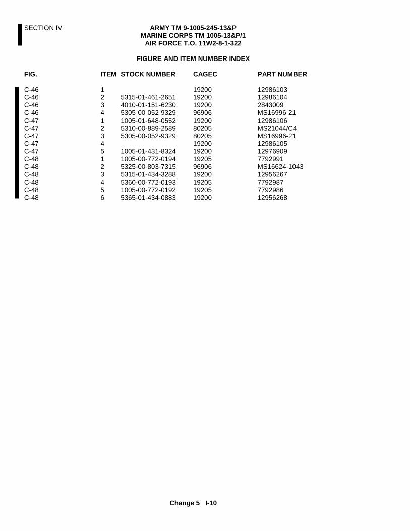
SECTION IV ARMY TM 9-1005-245-13&P MARINE CORPS TM 1005-13&P/1
AIR FORCE T.O. 11W2-8-1-322
Change 5 I-10
FIGURE AND ITEM NUMBER INDEX
FIG. ITEM STOCK NUMBER CAGEC PART NUMBER C-46 1 19200 12986103 C-46 2 5315-01-461-2651 19200 12986104 C-46 3 4010-01-151-6230 19200 2843009 C-46 4 5305-00-052-9329 96906 MS16996-21 C-47 1 1005-01-648-0552 19200 12986106 C-47 2 5310-00-889-2589 80205 MS21044/C4 C-47 3 5305-00-052-9329 80205 MS16996-21 C-47 4 19200 12986105 C-47 5 1005-01-431-8324 19200 12976909 C-48 1 1005-00-772-0194 19205 7792991 C-48 2 5325-00-803-7315 96906 MS16624-1043 C-48 3 5315-01-434-3288 19200 12956267 C-48 4 5360-00-772-0193 19205 7792987 C-48 5 1005-00-772-0192 19205 7792986 C-48 6 5365-01-434-0883 19200 12956268

SECTION IV ARMY TM 9-1005-245-13&P MARINE CORPS TM 1005-13&P/1
AIR FORCE T.O. 11W2-8-1-322
I-11 Change 5
PART NUMBER INDEX
PART NUMBER STOCK NUMBER CAGEC FIG. ITEM AN174-21A 5306-00-182-1801 88044 C-10 3 AN960XC1616 5310-01-206-3478 88044 C-32 5 B1821BH050F200N 5305-00-719-5238 96906 C-30 3 B1821BH050C400N 5305-00-071-2079 96906 C-39 13 B1821BH050F450N 5305-01-433-5835 96906 C-39 17 B1821BH075F200N 5305-00-916-2345 96906 C-30 10 B182BH075F250N 5305-00-762-6041 96906 C-30 8 MS3215-4037 5365-01-009-6843 96906 C-23 4 MS16555-42 5315-00-902-0419 96906 C-10 10 MS16556-628 5315-00-889-2518 96906 C-21 16 MS16562-120 5315-00-051-8636 96906 C-4 18 C-14 20 MS16562-223 5315-00-826-3251 96906 C-37 21 MS16624-1043 5325-00-803-7315 96906 C-4 19 C-48 2 MS16996-21 5305-00-052-9329 80205 C-44 4 C-46 4 C-47 3 MS16997-60 5305-00-983-8084 96906 C-21 2 MS16997-84 5305-00-983-6625 96906 C-20 5 C-20 11 MS16997-102 5305-00-983-5334 96906 C-21 21 MS17986C325 5315-01-292-6411 96906 C-44 2 MS17986C725 5315-01-368-7364 96906 C-42 5 MS18153-58 5305-00-921-0042 96906 C-23 6 MS20002-6 5310-00-149-9130 96906 C-42 2 MS20392-3C41 5315-00-811-9105 96906 C-28 9 MS20995C32 96906 BULK 1 C-23 3 C-26 4 MS21044C3 5310-00-208-9255 96906 C-34 1 MS21044/C4 80205 C-47 2 MS21044N6 5310-00-950-0039 96906 C-42 1 MS21044-N8 5310-00-877-5795 96906 C-30 4 MS21083C10 5310-00-050-9372 96906 C-32 10 MS21083C16 5310-00-160-9869 96906 C-32 4 MS24665-132 5315-00-839-2325 96906 C-18 2 C-28 12 MS24665-283 5315-00-842-3044 96906 C-20 9 C-21 6 MS24665-285 5315-00-816-1794 96906 C-20 16 MS24665-291 5315-00-019-0777 96906 C-26 13 MS24665-834 5315-00-903-3971 96906 C-9 5 MS24673-4 5305-00-993-7198 96906 C-23 2 MS27183-10 5310-00-809-4058 96906 C-28 10 MS27183-15 5310-00-809-4061 96906 C-21 10 MS27183-16 5310-00-809-4085 96906 C-18 10 MS27183-18 5310-00-809-5998 96906 C-26 14 C-30 2 MS27183-23 5310-00-809-8553 96906 C-30 6 MS35190-271 5305-00-954-3487 96906 C-24 9 MS35206-246 5305-00-984-6194 96906 C-19 12
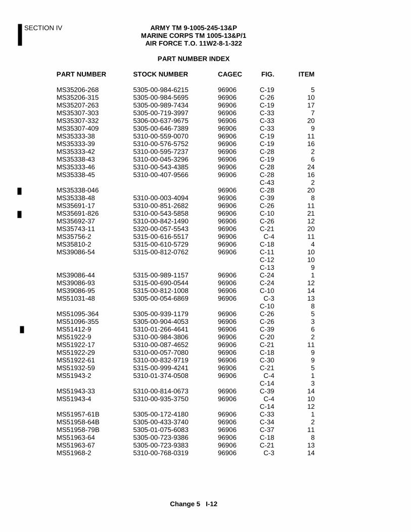
SECTION IV ARMY TM 9-1005-245-13&P MARINE CORPS TM 1005-13&P/1
AIR FORCE T.O. 11W2-8-1-322
Change 5 I-12
PART NUMBER INDEX
PART NUMBER STOCK NUMBER CAGEC FIG. ITEM MS35206-268 5305-00-984-6215 96906 C-19 5 MS35206-315 5305-00-984-5695 96906 C-26 10 MS35207-263 5305-00-989-7434 96906 C-19 17 MS35307-303 5305-00-719-3997 96906 C-33 7 MS35307-332 5306-00-637-9675 96906 C-33 20 MS35307-409 5305-00-646-7389 96906 C-33 9 MS35333-38 5310-00-559-0070 96906 C-19 11 MS35333-39 5310-00-576-5752 96906 C-19 16 MS35333-42 5310-00-595-7237 96906 C-28 2 MS35338-43 5310-00-045-3296 96906 C-19 6 MS35333-46 5310-00-543-4385 96906 C-28 24 MS35338-45 5310-00-407-9566 96906 C-28 16 C-43 2 MS35338-046 96906 C-28 20 MS35338-48 5310-00-003-4094 96906 C-39 8 MS35691-17 5310-00-851-2682 96906 C-26 11 MS35691-826 5310-00-543-5858 96906 C-10 21 MS35692-37 5310-00-842-1490 96906 C-26 12 MS35743-11 5320-00-057-5543 96906 C-21 20 MS35756-2 5315-00-616-5517 96906 C-4 11 MS35810-2 5315-00-610-5729 96906 C-18 4 MS39086-54 5315-00-812-0762 96906 C-11 10 C-12 10 C-13 9 MS39086-44 5315-00-989-1157 96906 C-24 1 MS39086-93 5315-00-690-0544 96906 C-24 12 MS39086-95 5315-00-812-1008 96906 C-10 14 MS51031-48 5305-00-054-6869 96906 C-3 13 C-10 8 MS51095-364 5305-00-939-1179 96906 C-26 5 MS51096-355 5305-00-904-4053 96906 C-26 3 MS51412-9 5310-01-266-4641 96906 C-39 6 MS51922-9 5310-00-984-3806 96906 C-20 2 MS51922-17 5310-00-087-4652 96906 C-21 11 MS51922-29 5310-00-057-7080 96906 C-18 9 MS51922-61 5310-00-832-9719 96906 C-30 9 MS51932-59 5315-00-999-4241 96906 C-21 5 MS51943-2 5310-01-374-0508 96906 C-4 1 C-14 3 MS51943-33 5310-00-814-0673 96906 C-39 14 MS51943-4 5310-00-935-3750 96906 C-4 10 C-14 12 MS51957-61B 5305-00-172-4180 96906 C-33 1 MS51958-64B 5305-00-433-3740 96906 C-34 2 MS51958-79B 5305-01-075-6083 96906 C-37 11 MS51963-64 5305-00-723-9386 96906 C-18 8 MS51963-67 5305-00-723-9383 96906 C-21 13 MS51968-2 5310-00-768-0319 96906 C-3 14

SECTION IV ARMY TM 9-1005-245-13&P MARINE CORPS TM 1005-13&P/1
AIR FORCE T.O. 11W2-8-1-322
I-13 Change 5
PART NUMBER INDEX
PART NUMBER STOCK NUMBER CAGEC FIG. ITEM MS57968-5 5310-00-880-7746 96906 C-28 17 MS51968-8 5310-00-732-0559 96906 C-3 7 MS87006-3 4030-00-270-5436 96906 C-20 6 MS90725-34 5306-00-225-8499 96906 C-43 3 MS90725-186 5305-00-050-4212 96906 C-30 1 MS90726-115 5305-00-226-7768 96906 C-39 5 MS90727-57 5305-00-269-3233 96906 C-28 3 MS90727-70 5305-00-269-3246 96906 C-42 3 MS90727-86 5305-00-709-8516 96906 C-18 1 MS90728-62 5305-00-068-0511 96906 C-28 21 M45913/1-BFG5C 5310-00-067-9507 81349 C-39 7 NAS1149C0863B 5310-00-151-5572 88044 C-33 8 RRC271 4010-00-129-3221 81348 C-20 7 307302.00 4710-01-432-8193 2UO92 C-39 11 307305.00 2U092 C-39 15 307307.00 1005-01-442-0415 2U092 C-39 2 307310.00 4730-01-433-8116 2U092 C-39 16 307311.00 4710-01-433-1256 2U092 C-39 10 307312.00 1005-01-432-4652 2U092 C-39 9 307316.00 3040-01-434-0789 2U092 C-39 18 307326.00 5315-01-433-1740 2U092 C-39 12 307328.00 5325-01-433-0817 2UO92 C-39 1 307329.00 5315-01-433-1817 2U092 C-39 4 307331.00 4010-01-432-5838 2U092 C-39 3 2843009 4010-01-151-6230 53711 C-44 3 C-46 3 10900712 1005-00-121-0778 19204 C-26 2 10900945 1005-00-854-4463 19207 C-25 1 10900946 1005-00-121-0779 19204 C-26 18 10900947 19204 C-26 15 10900948 1005-00-779-2479 19204 C-26 1 10900949 19204 C-26 7 10900962 5306-00-854-4464 19207 C-26 6 10900963 5315-00-854-4465 19207 C-26 9 10907432-4 9505-00-921-0588 19207 C-18 7 10945028 2590-00-841-9341 19204 C-18 3 10949553-1 1005-00-918-3007 19207 C-30 12 10949553-2 1005-00-918-3008 19207 C-30 5 11010037 19204 C-4 3 10110242 1005-00-919-7273 19205 C-5 1 11010407 5315-00-916-2173 19205 C-14 13 11010408 1005-00-945-9756 19205 C-2 4 11010409 5340-00-945-9768 19205 C-45 1 11010410 5360-00-945-9954 19204 C-45 2 11010411 5315-00-947-7250 19205 C-45 4 11010412 19204 C-45 3 11010413 5310-00-949-1971 19205 C-4 13 C-14 15 11010421 5310-00-916-2170 19205 C-11 9 C-12 9 C-13 10 11010426 1005-00-940-8077 19200 C-11 1 C-13 1
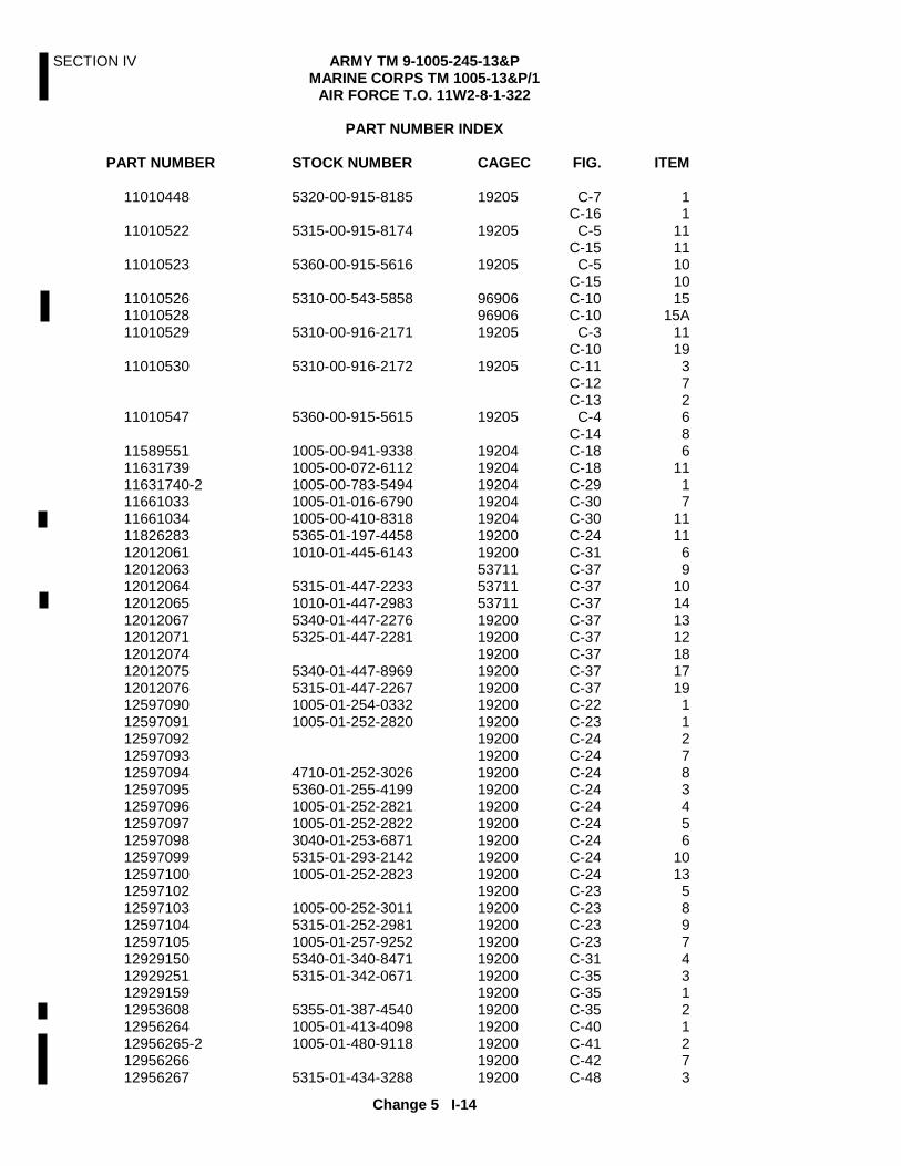
SECTION IV ARMY TM 9-1005-245-13&P MARINE CORPS TM 1005-13&P/1
AIR FORCE T.O. 11W2-8-1-322
Change 5 I-14
PART NUMBER INDEX
PART NUMBER STOCK NUMBER CAGEC FIG. ITEM 11010448 5320-00-915-8185 19205 C-7 1 C-16 1 11010522 5315-00-915-8174 19205 C-5 11 C-15 11 11010523 5360-00-915-5616 19205 C-5 10 C-15 10 11010526 5310-00-543-5858 96906 C-10 15 11010528 96906 C-10 15A 11010529 5310-00-916-2171 19205 C-3 11 C-10 19 11010530 5310-00-916-2172 19205 C-11 3 C-12 7 C-13 2 11010547 5360-00-915-5615 19205 C-4 6 C-14 8 11589551 1005-00-941-9338 19204 C-18 6 11631739 1005-00-072-6112 19204 C-18 11 11631740-2 1005-00-783-5494 19204 C-29 1 11661033 1005-01-016-6790 19204 C-30 7 11661034 1005-00-410-8318 19204 C-30 11 11826283 5365-01-197-4458 19200 C-24 11 12012061 1010-01-445-6143 19200 C-31 6 12012063 53711 C-37 9 12012064 5315-01-447-2233 53711 C-37 10 12012065 1010-01-447-2983 53711 C-37 14 12012067 5340-01-447-2276 19200 C-37 13 12012071 5325-01-447-2281 19200 C-37 12 12012074 19200 C-37 18 12012075 5340-01-447-8969 19200 C-37 17 12012076 5315-01-447-2267 19200 C-37 19 12597090 1005-01-254-0332 19200 C-22 1 12597091 1005-01-252-2820 19200 C-23 1 12597092 19200 C-24 2 12597093 19200 C-24 7 12597094 4710-01-252-3026 19200 C-24 8 12597095 5360-01-255-4199 19200 C-24 3 12597096 1005-01-252-2821 19200 C-24 4 12597097 1005-01-252-2822 19200 C-24 5 12597098 3040-01-253-6871 19200 C-24 6 12597099 5315-01-293-2142 19200 C-24 10 12597100 1005-01-252-2823 19200 C-24 13 12597102 19200 C-23 5 12597103 1005-00-252-3011 19200 C-23 8 12597104 5315-01-252-2981 19200 C-23 9 12597105 1005-01-257-9252 19200 C-23 7 12929150 5340-01-340-8471 19200 C-31 4 12929251 5315-01-342-0671 19200 C-35 3 12929159 19200 C-35 1 12953608 5355-01-387-4540 19200 C-35 2 12956264 1005-01-413-4098 19200 C-40 1 12956265-2 1005-01-480-9118 19200 C-41 2 12956266 19200 C-42 7 12956267 5315-01-434-3288 19200 C-48 3

SECTION IV ARMY TM 9-1005-245-13&P MARINE CORPS TM 1005-13&P/1
AIR FORCE T.O. 11W2-8-1-322
I-15 Change 5
PART NUMBER INDEX
PART NUMBER STOCK NUMBER CAGEC FIG. ITEM 12956268 5365-01-434-0883 19200 C-48 6 12956269 4010-01-447-5812 19200 C-42 6 12956270 1005-01-411-6341 19200 C-38 1 12956283-2 5365-01-306-4235 19200 C-42 4 12976909 1005-01-431-8324 19200 C-47 5 12976940 1005-01-411-6340 19200 C-2 3 C-22 1 12976941 19200 C-23 5 12976942 1005-01-408-5915 19200 C-23 12 12976943 5315-01-408-6009 19200 C-23 11 12976944 1005-01-352-5345 19200 C-23 10 12976945 1005-01-429-0427 19200 C-23 8 12976949 1005-01-433-1617 19200 C-1 1 12986102 1005-01-461-2656 19200 C-41 4 12986103 19200 C-46 1 12986104 5315-01-461-2651 19200 C-46 2 12986105 19200 C-47 4 12986106 1005-01-468-0552 19200 C-47 1 37-10-086-20 5340-01-282-3650 94222 C-34 3 5139959 5340-00-513-9959 19205 C-3 18 5139962 5365-00-513-9962 19205 C-3 15 5139964 5310-00-513-9964 19204 C-9 4 5139973 5306-00-513-9973 19204 C-9 2 5139982 5355-00-513-9982 19204 C-5 3 C-15 3 5139988 5305-00-513-9988 19205 C-4 16 5139989 5305-00-513-9989 19204 C-4 12 C-14 14 5139994 1005-00-513-9994 19204 C-5 6 5139995 5340-00-513-9995 19204 C-5 9 C-15 9 5139997 5360-00-513-9997 19205 C-3 19 5140004 5315-00-514-0004 19207 C-3 17 5140137 1005-00-514-0137 19200 C-15 6 5140204 3040-00-514-0204 19204 C-11 6 C-12 4 C-13 12 5140209 5360-00-514-0209 19205 C-11 7 C-12 2 C-13 11 C-16 5 5140210 5315-00-514-0210 19205 C-11 5 C-12 3 C-13 13 5140211 5340-00-514-0211 19204 C-11 2 C-12 5 C-13 4 5140213 5305-00-514-0213 19204 C-11 4 C-12 6 C-13 3 5140215 5360-00-514-0215 19205 C-13 6 5140216 5340-00-514-0216 19204 C-13 7

SECTION IV ARMY TM 9-1005-245-13&P MARINE CORPS TM 1005-13&P/1
AIR FORCE T.O. 11W2-8-1-322
Change 5 I-16
PART NUMBER INDEX
PART NUMBER STOCK NUMBER CAGEC FIG. ITEM 5140217 5315-00-514-0217 19204 C-13 8 5140219 5365-00-514-0219 19205 C-10 23 5140225 19204 C-16 6 5140237 5305-00-514-0237 19205 C-10 17 C-37 6 C-37 15 5140383 5305-00-514-0383 19200 C-14 18 5140485 5365-00-514-0485 19205 C-5 7 C-15 7 5140612 5305-00-514-0612 19204 C-5 4 C-15 4 5140669 9905-00-514-0669 19204 C-15 1 5141080 1005-00-514-1080 19205 C-7 2 C-16 2 5141081 19204 C-7 3 C-16 3 5141121 19204 C-7 6 5141460 4010-00-514-1460 19205 C-14 1 5141950 5305-00-514-1950 19204 C-3 10 C-10 18 5142877 5360-00-514-2877 19205 C-7 5 5169879 5306-00-516-9879 19204 C-3 9 5169880 5306-00-516-9880 19204 C-3 1 5169881 5306-00-516-9881 19204 C-3 3 5169882 5306-00-516-9882 19204 C-3 4 5170484 5306-00-297-8753 19204 C-10 2 5170486 5306-00-517-0486 19205 C-10 4 5171491 4730-00-517-1491 19207 C-4 7 C-14 9 5171492 5355-00-517-1492 19205 C-4 8 C-14 10 5171495 5315-00-517-1495 19205 C-4 5 C-14 7 5174113 5315-00-517-4113 19204 C-14 2 5174123 1005-00-517-4123 19200 C-14 6 5174175 1005-00-588-3490 19205 C-4 4 5174192 5310-00-517-4192 19205 C-4 2 C-14 4 5189756 5360-00-518-9756 19200 C-14 19 5189757 1005-00-518-9757 19205 C-4 17 5194313 3040-00-519-4313 19200 C-14 16 5236999 4010-00-523-6999 19204 C-26 8 5328284 9390-00-532-8284 19204 C-28 5 5384053 1005-00-538-4053 19204 C-28 14 5384055 5315-00-538-4055 19204 C-28 6 5384056 5315-00-538-4056 19204 C-28 26 5384057 5315-00-538-4057 19204 C-28 8 5384059 5307-00-538-4059 19204 C-28 25 5384060 5340-00-538-4060 19204 C-28 13 5384062 5360-00-526-0143 19207 C-28 11 5384064 5310-00-538-4064 19204 C-28 28 5559331 19204 C-3 6

SECTION IV ARMY TM 9-1005-245-13&P MARINE CORPS TM 1005-13&P/1
AIR FORCE T.O. 11W2-8-1-322
I-17 Change 5
PART NUMBER INDEX
PART NUMBER STOCK NUMBER CAGEC FIG. ITEM 5559332 1005-00-555-9332 19200 C-9 3 5559333 1005-00-555-9333 19205 C-3 20 5559337 1005-00-555-9337 19204 C-3 16 5559338 1005-00-555-9338 19204 C-3 2 5559419 19204 C-10 7 5559423 1005-00-555-9423 19204 C-10 12 5559424 19204 C-12 1 5559425 19200 C-13 5 5559428 19204 C-11 8 5574621 1005-00-557-4621 19200 C-9 1 C-31 7 5591828 5305-01-167-5845 19204 C-15 2 5820087-5 4010-01-149-5518 53711 C-35 4 5830054 5360-01-150-1922 53711 C-32 2 5830063 1010-01-151-6239 53711 C-41 3 5830128 1010-01-151-6227 53711 C-31 7 5830131 1010-01-151-6229 53711 C-41 1 5830132 53711 C-44 1 5830133 53711 C-43 1 6108195 1005-00-610-8195 19204 C-3 8 6108201 3102-00-610-8201 19205 C-3 5 6108211 5355-00-610-8211 19204 C-5 5 C-15 5 6108384 19204 C-12 8 6108395 5306-00-610-8395 19204 C-10 9 6108396 3110-00-610-8396 19204 C-10 16 6108397 3120-00-610-8397 19205 C-10 6 6108400 19204 C-10 11 6108402 5340-00-610-8402 19204 C-10 20 6108986 1005-00-610-8986 19204 C-3 12 6140648 19205 C-7 4 6153118 19205 C-16 4 6158375 5355-00-615-8375 19207 C-4 9 C-14 11 6166497 19204 C-14 5 6193782 5310-00-619-3782 19204 C-10 13 6297411 5360-00-629-7411 19207 C-28 27 6297412 1005-00-629-7412 19204 C-28 23 6507136 1005-00-650-7136 19204 C-10 22 6507137 1005-00-650-7137 19204 C-10 1 6590078 8140-00-659-0078 19204 C-28 4 6650406 1005-01-386-2011 53711 C-32 8 6650407 5310-01-388-4108 53711 C-32 7 6650433-1 5315-01-385-9214 53711 C-33 17 6650433-2 5315-01-385-9216 53711 C-33 16 C-36 3 6650434 53711 C-32 1 6650435 53711 C-34 4 6650436 1005-01-388-7006 53711 C-33 5 6650437 1005-01-388-5697 53711 C-33 5 6650438 1005-01-388-6911 53711 C-33 19

SECTION IV ARMY TM 9-1005-245-13&P MARINE CORPS TM 1005-13&P/1
AIR FORCE T.O. 11W2-8-1-322
Change 5 I-18
PART NUMBER INDEX
PART NUMBER STOCK NUMBER CAGEC FIG. ITEM 6650439-1 3040-01-386-0204 53711 C-33 18 6650439-2 3040-01-386-5925 53711 C-33 21 6550441 5340-01-387-1944 53711 C-33 23 6650442 5340-01-388-4109 53711 C-33 3 6650443 1005-01-386-4688 53711 C-33 2 6650444 5304-01-386-8380 53711 C-33 22 6650445 1005-01-396-2006 53711 C-33 10 6650446 1005-01-388-5696 53711 C-32 6 6650448 2510-01-387-0586 53711 C-33 4 6650450 1005-01-383-2949 53711 C-31 3 C-31 8 6650488 5340-01-447-3245 53711 C-37 1 6650489 5340-01-388-5595 53711 C-37 4 6650493 5340-01-386-8327 53711 C-37 8 6650494 5365-01-386-5924 53711 C-37 7 6650496 1290-01-386-2008 53711 C-37 2 6650498 5305-01-386-2768 53711 C-37 20 6650501 5306-01-388-0795 53711 C-37 3 6650561 3110-01-387-0590 53711 C-37 5 C-37 16 6650651 1010-01-451-7557 53711 C-33 12 6650654 5307-01-386-2015 53711 C-33 13 6650671 53711 C-36 1 6650673 5315-01-387-4379 53711 C-33 11 6650695 5315-01-386-0206 53711 C-32 9 6650696 5305-01-386-0209 53711 C-33 14 6650697 5310-01-386-0202 53711 C-33 15 6650717 1005-01-383-2757 53711 C-31 1 6650722-1 1005-01-388-5702 53711 C-36 2 6650722-2 1005-01-388-5685 53711 C-36 2 6650723 1005-01-388-5679 53711 C-31 5 6650724 1398-01-387-3095 53711 C-31 2 6650725 53711 C-32 3 7012701 1005-01-169-1143 19204 C-19 15 7012702 1005-01-169-1756 19204 C-20 3 7012713 19204 C-20 4 7012720 5315-00-701-2720 19207 C-19 2 7012722 1005-01-184-6365 19204 C-19 4 7012723 1005-01-184-6363 19204 C-19 3 7012724 1005-01-184-6364 19204 C-19 7 7012725 1005-01-187-9615 19204 C-19 1 7012726 1005-01-169-1144 19204 C-19 10 7012727 19204 C-18 5 7012728 3120-00-934-8319 19204 C-20 21 7012730 1005-00-701-2730 19204 C-20 10 7012731 5340-00-701-2731 19204 C-20 13 7012732 5365-00-701-2732 19204 C-20 15 7012733 5360-00-701-2733 19207 C-20 14 7012740 19204 C-20 17

SECTION IV ARMY TM 9-1005-245-13&P MARINE CORPS TM 1005-13&P/1
AIR FORCE T.O. 11W2-8-1-322
I-19 Change 5
PART NUMBER INDEX
PART NUMBER STOCK NUMBER CAGEC FIG. ITEM 7012747 1005-00-701-2747 19204 C-20 8 7012748 5360-00-701-2748 19204 C-21 18 7012749 5310-00-701-2749 19207 C-21 19 7012752 5360-00-701-2752 19207 C-21 15 7012753 1005-00-934-8320 19204 C-21 14 7012756 1005-00-701-2756 19204 C-21 4 7012757 1005-00-701-2757 19204 C-21 17 7012758 5340-00-701-2758 19204 C-21 9 7012759 1005-00-701-2759 19204 C-21 1 7012760 5340-00-701-2760 19204 C-21 22 7012761 5310-00-701-2761 19207 C-21 12 7012762 5120-00-701-2762 19204 C-20 19 7012765 2530-00-701-2765 19204 C-21 8 7012800 3040-00-701-2800 19204 C-21 3 7012801 1005-00-701-2801 19204 C-20 20 7012804 5315-00-701-2804 19204 C-20 12 7012805-1 5330-01-154-0238 19204 C-19 9 7012805-2 5330-01-154-0239 19204 C-19 13 7012806 5330-00-167-0638 19204 C-19 14 7012810 1005-00-701-2710 19204 C-17 1 7042930 19204 C-28 15 7042932 5315-00-704-2932 19205 C-28 19 7046650 1005-00-704-6650 19204 C-27 1 7046652 1005-00-704-6652 19204 C-28 7 7046653 1005-00-704-6653 19204 C-28 1 7070291 5315-00-707-0291 19207 C-28 22 7070292 5315-00-707-0292 19207 C-28 18 7070704 19204 C-20 1 7070734 5310-00-707-0734 19207 C-21 7 7070851 19204 C-19 8 7149678 1005-00-714-9678 19204 C-10 24 7790723 1005-00-710-5599 19205 C-1 1 7790948 19204 C-2 1 7791119 1005-00-603-4834 19205 C-2 2 7792977 5315-00-772-0186 19205 C-26 19 7792978 5360-00-772-0187 19205 C-26 17 7792982 5340-00-772-0190 19204 C-26 16 7792986 1005-00-772-0192 19205 C-48 5 7792987 5360-00-772-0193 19205 C-48 4 7792991 1005-00-772-0194 19205 C-48 1 7792993 5315-00-809-5417 19205 C-4 20 7793002 1005-00-722-3850 19205 C-4 14 7793003 5360-00-473-5447 19205 C-4 15 7793004 19204 C-5 2 8403398 1005-00-322-9716 19204 C-8 1 8408768 1005-00-840-8768 19204 C-5 8 C-15 8 8412295 5360-00-305-0725 19205 C-14 17 8433770-1 5340-01-043-7938 19204 C-30 13 8448211 19200 C-10 5 8668937 5340-00-389-8118 19207 C-20 18 9363644 5310-01-142-8417 19200 C-33 6

SECTION IV ARMY TM 9-1005-245-13&P MARINE CORPS TM 1005-13&P/1
AIR FORCE T.O. 11W2-8-1-322
Change 5 I-20
NATIONAL STOCK NUMBER INDEX
NSN FIGURE ITEM NSN FIGURE ITEM 5310-00-003-4094 C-39 8 5305-00-513-9989 C-4 12 5315-00-019-0777 C-26 13 C-14 14 5310-00-045-3296 C-19 6 1005-00-513-9994 C-5 6 5305-00-050-4212 C-30 1 5340-00-513-9995 C-5 9 5310-00-050-9372 C-32 10 C-15 9 5315-00-051-8636 C-4 18 5360-00-513-9997 C-3 19 C-14 20 5315-00-514-0004 C-3 17 5305-00-052-9329 C-44 4 1005-00-514-0137 C-15 6 C-47 3 3040-00-514-0204 C-11 6 5305-00-054-6869 C-3 13 C-12 4 C-10 8 C-13 12 5320-00-057-5543 C-21 20 5360-00-514-0209 C-11 7 5310-00-057-7080 C-18 9 C-12 2 5310-00-067-9507 C-39 7 C-13 11 5305-00-068-0511 C-28 21 C-16 5 1005-00-072-6112 C-18 11 5315-00-514-0210 C-11 5 5310-00-087-4652 C-21 11 C-12 3 1005-00-121-0778 C-26 2 C-13 13 1005-00-121-0779 C-26 18 5340-00-514-0211 C-11 2 4010-00-129-3221 C-20 7 C-12 5 5310-00-149-9130 C-42 2 C-13 4 5305-00-514-0213 C-11 4 5310-00-151-5572 C-33 8 C-12 6 5310-00-160-9869 C-32 4 C-13 3 5330-00-167-0638 C-19 14 5360-00-514-0215 C-13 6 5305-00-172-4180 C-33 1 5340-00-514-0216 C-13 7 5306-00-182-1801 C-10 3 5315-00-514-0217 C-13 8 5310-00-208-9255 C-34 1 5365-00-514-0219 C-10 23 5306-00-225-8499 C-43 3 5305-00-514-0237 C-10 17 5305-00-226-7768 C-39 5 C-37 6 1005-00-252-3011 C-23 8 C-37 15 5305-00-269-3233 C-28 3 5305-00-514-0383 C-14 18 5305-00-269-3246 C-42 3 5365-00-514-0485 C-5 7 4030-00-270-5436 C-20 6 C-15 7 5306-00-297-8753 C-10 2 5305-00-514-0612 C-5 4 5360-00-305-0725 C-14 17 C-15 4 1005-00-322-9716 C-8 1 9905-00-514-0669 C-15 1 5340-00-389-8118 C-20 18 1005-00-514-1080 C-7 2 5310-00-407-9566 C-28 16 C-16 2 C-43 2 4010-00-514-1460 C-14 1 1005-00-410-8318 C-30 11 5305-00-433-3740 C-34 2 5305-00-514-1950 C-3 10 5360-00-473-5447 C-4 15 C-10 18 5340-00-513-9959 C-3 18 5360-00-514-2877 C-7 5 5365-00-513-9962 C-3 15 5306-00-516-9879 C-3 9 5310-00-513-9964 C-9 4 5306-00-516-9880 C-3 1 5306-00-513-9973 C-9 2 5306-00-516-9881 C-3 3 5355-00-513-9982 C-5 3 5306-00-516-9882 C-3 4 5305-00-513-9988 C-4 16 5306-00-517-0486 C-10 4 4730-00-517-1491 C-4 7 C-14 9 5355-00-517-1492 C-4 8 C-14 10

SECTION IV ARMY TM 9-1005-245-13&P MARINE CORPS TM 1005-13&P/1
AIR FORCE T.O. 11W2-8-1-322
I-21 Change 5
NATIONAL STOCK NUMBER INDEX
NSN FIGURE ITEM NSN FIGURE ITEM 5315-00-517-1495 C-4 5 5360-00-629-7411 C-28 27 C-14 7 1005-00-629-7412 C-28 23 5315-00-517-4113 C-14 2 5306-00-637-9675 C-33 20 5305-00-646-7389 C-33 9 1005-00-517-4123 C-14 6 1005-00-650-7136 C-10 22 5310-00-517-4192 C-4 2 1005-00-650-7137 C-10 1 C-14 4 8140-00-659-0078 C-28 4 5360-00-518-9756 C-14 19 5315-00-690-0544 C-24 12 1005-00-518-9757 C-4 17 1005-00-701-2710 C-17 1 3040-00-519-4313 C-14 16 5315-00-701-2720 C-19 2 4010-00-523-6999 C-26 8 1005-00-701-2730 C-20 10 5360-00-526-0143 C-28 11 5340-00-701-2731 C-20 13 9390-00-532-8284 C-28 5 5365-00-701-2732 C-20 15 1005-00-538-4053 C-28 14 5360-00-701-2733 C-20 14 5315-00-538-4055 C-28 6 1005-00-701-2747 C-20 8 5315-00-538-4056 C-28 26 5360-00-701-2748 C-21 18 5315-00-538-4057 C-28 8 5310-00-701-2749 C-21 19 5307-00-538-4059 C-28 25 5360-00-701-2752 C-21 15 5340-00-538-4060 C-28 13 1005-00-701-2756 C-21 4 5310-00-538-4064 C-28 28 1005-00-701-2757 C-21 17 5310-00-543-4385 C-28 24 5340-00-701-2758 C-21 9 5310-00-543-5858 C-10 15 1005-00-701-2759 C-21 1 C-10 21 5340-00-701-2760 C-21 22 1005-00-555-9332 C-9 3 5310-00-701-2761 C-21 12 1005-00-555-9333 C-3 20 5120-00-701-2762 C-20 19 1005-00-555-9337 C-3 16 2530-00-701-2765 C-21 8 1005-00-555-9338 C-3 2 3040-00-701-2800 C-21 3 1005-00-555-9423 C-10 12 1005-00-701-2801 C-20 20 1005-00-557-4621 C-9 1 5315-00-701-2804 C-20 12 5310-00-559-0070 C-19 11 5315-00-704-2932 C-28 19 5310-00-576-5752 C-19 16 1005-00-704-6650 C-27 1 1005-00-588-3490 C-4 4 1005-00-704-6652 C-28 7 C-4 2 1005-00-704-6653 C-28 1 C-14 4 5315-00-707-0291 C-28 22 C-14 10 5315-00-707-0292 C-28 18 5310-00-595-7237 C-28 2 5310-00-707-0734 C-21 7 1005-00-603-4834 C-2 2 5305-00-709-8516 C-18 1 5315-00-610-5729 C-18 4 1005-00-710-5599 C-1 1 1005-00-610-8195 C-3 8 1005-00-714-9678 C-10 24 3102-00-610-8201 C-3 5 5305-00-719-3997 C-33 7 5355-00-610-8211 C-5 5 5305-00-719-5238 C-30 3 C-15 5 1005-00-722-3850 C-4 14 5306-00-610-8395 C-10 9 5305-00-723-9383 C-21 13 3110-00-610-8396 C-10 16 5305-00-723-9386 C-18 8 3120-00-610-8397 C-10 6 5310-00-732-0559 C-3 7 5340-00-610-8402 C-10 20 5305-00-762-6041 C-30 8 1005-00-610-8986 C-3 12 5310-00-768-0319 C-3 14 5355-00-615-8375 C-4 9 5315-00-772-0186 C-26 19 C-14 11 5360-00-772-0187 C-26 17 5315-00-616-5517 C-4 11 5340-00-772-0190 C-26 16 5310-00-619-3782 C-10 13 1005-00-772-0192 C-48 5 5360-00-772-0193 C-48 4

SECTION IV ARMY TM 9-1005-245-13&P MARINE CORPS TM 1005-13&P/1
AIR FORCE T.O. 11W2-8-1-322
Change 5 I-22
NATIONAL STOCK NUMBER INDEX
NSN FIGURE ITEM NSN FIGURE ITEM 1005-00-772-0194 C-48 1 5310-00-916-2172 C-11 3 1005-00-779-2479 C-26 1 C-12 7 1005-00-783-5494 C-29 1 C-13 2 5325-00-803-7315 C-4 19 5315-00-916-2173 C-14 13 C-48 2 5305-00-916-2345 C-30 10 5310-00-809-4058 C-28 10 1005-00-918-3007 C-30 12 5310-00-809-4061 C-21 10 1005-00-918-3008 C-30 5 5310-00-809-4085 C-18 10 1005-00-919-7273 C-5 1 5315-00-809-5417 C-4 20 5305-00-921-0042 C-23 6 5310-00-809-5998 C-26 14 9505-00-921-0588 C-18 7 C-30 2 3120-00-934-8319 C-20 21 5310-00-809-8553 C-30 6 1005-00-934-8320 C-21 14 5315-00-811-9105 C-28 9 5310-00-935-3750 C-4 10 5315-00-812-0762 C-11 10 C-14 12 C-12 10 5305-00-939-1179 C-26 5 C-13 9 1005-00-940-8077 C-11 1 5315-00-812-1008 C-10 14 C-13 1 5310-00-814-0673 C39 14 1005-00-941-9338 C-18 6 5315-00-816-1794 C-20 16 1005-00-945-9756 C-2 4 5315-00-826-3251 C-37 17 5310-00-832-9719 C-30 9 5340-00-945-9768 C-45 1 5315-00-839-2325 C-18 2 5360-00-945-9954 C-45 2 C-28 12 5315-00-947-7250 C-45 4 1005-00-840-8768 C-5 8 5310-00-949-1971 C-4 13 C-15 8 C-14 15 2590-00-841-9341 C-18 3 5310-00-950-0039 C-42 1 5310-00-842-1490 C-26 12 5305-00-954-3487 C-24 9 5315-00-842-3044 C-20 9 5305-00-983-5334 C-21 21 C-21 6 5305-00-983-6625 C-20 5 5310-00-851-2682 C-26 11 C-20 11 1005-00-854-4463 C-25 1 5305-00-983-8084 C-21 2 5306-00-854-4464 C-26 6 5310-00-984-3806 C-20 2 5315-00-854-4465 C-26 9 5305-00-984-5695 C-26 10 5310-00-877-5795 C-30 4 5305-00-984-6194 C-19 12 5310-00-880-7746 C-28 17 5305-00-984-6215 C-19 5 5315-00-889-2518 C-21 16 5315-00-989-1157 C-24 1 5315-00-902-0419 C-10 10 5305-00-989-7434 C-19 17 5315-00-903-3971 C-9 5 5305-00-993-7198 C-23 2 5305-00-904-4053 C-26 3 5315-00-999-4241 C-21 5 5360-00-915-5615 C-4 6 5365-01-009-6843 C-23 4 C-14 8 1005-01-016-6790 C-30 7 5360-00-915-5616 C-5 10 5340-01-.043-7938 C-30 13 C-15 10 4010-01-447-5812 C-42 6 5315-00-915-8174 C-5 11 5305-01-075-6083 C-37 11 C-15 11 5310-01-142-8417 C-33 6 5320-00-915-8185 C-7 1 4010-01-149-5518 C-35 4 C-16 1 5360-01-150-1922 C-32 2 5310-00-916-2170 C-11 9 1010-01-151-6227 C-31 7 C-12 9 1010-01-151-6229 C-41 1 C-13 10 4010-01-151-6230 C-44 3 5310-00-916-2171 C-3 11 4010-01-151-6230 C-46 3 C-10 19 1010-01-151-6239 C-41 3

SECTION IV ARMY TM 9-1005-245-13&P MARINE CORPS TM 1005-13&P/1
AIR FORCE T.O. 11W2-8-1-322
I-23/(I-24 blank) Change 5
NATIONAL STOCK NUMBER INDEX
NSN FIGURE ITEM NSN FIGURE ITEM 5330-01-154-0238 C-19 9 3040-01-386-5925 C-33 21 5330-01-154-0239 C-19 13 5340-01-386-8327 C-37 8 5305-01-167-5845 C-15 2 5304-01-386-8380 C-33 22 1005-01-169-1143 C-19 15 2510-01-387-0586 C-33 4 1005-01-169-1144 C-19 10 3110-01-387-0590 C-37 5 1005-01-169-1756 C-20 3 C-37 16 1005-01-184-6363 C-19 3 5340-01-387-1944 C-33 23 1005-01-184-6364 C-19 7 1398-01-387-3095 C-31 2 1005-01-184-6365 C-19 4 5315-01-387-4379 C-33 11 1005-01-187-9615 C-19 1 5355-01-387-4540 C-35 2 5365-01-197-4458 C-24 11 5306-01-388-0795 C-37 3 5310-01-206-3478 C-32 5 5310-01-388-4108 C-32 7 1005-01-252-2820 C-23 1 5340-01-388-4109 C-33 3 1005-01-252-2821 C-24 4 5340-01-388-5595 C-37 4 1005-01-252-2822 C-24 5 1005-01-388-5679 C-31 5 1005-01-252-2823 C-24 13 1005-01-388-5685 C-36 2 5315-01-252-2981 C-23 9 1005-01-388-5696 C-32 6 4710-01-252-3026 C-24 8 1005-01-388-5697 C-33 5 3040-01-253-6871 C-24 6 1005-01-388-5702 C-36 2 1005-01-254-0332 C-22 1 1005-01-388-6911 C-33 19 5360-01-255-4199 C-24 3 1005-01-388-7006 C-33 5 1005-01-257-9252 C-25 7 1005-01-396-2006 C-33 10 5315-01-292-6411 C-44 2 1005-01-408-5915 C-23 12 5315-01-293-2142 C-24 10 5315-01-408-6009 C-23 11 5340-01-282-3650 C-34 3 1005-01-411-6340 C-2 3 5365-01-306-4235 C-42 4 C-22 1 5340-01-340-8471 C-31 4 1005-01-411-6341 C-38 1 5315-01-342-0671 C-35 3 1005-01-413-4098 C40 1 1005-01-352-5345 C-23 10 1005-01-429-0427 C-23 8 5315-01-368-7364 C-42 5 1005-01-431-8324 C-47 5 5310-01-374-0508 C-4 1 1005-01-432-4652 C-39 9 C-14 3 4010-01-432-5838 C-39 3 1005-01-383-2757 C-31 1 4710-01-432-8193 C-39 11 1005-01-383-2949 C-31 3 5325-01-433-0817 C-39 1 C-31 8 4710-01-433-1256 C-39 10 5315-01-385-9214 C-33 17 5315-01-433-1740 C-39 12 5306-01-385-9215 C-33 16 5315-01-433-1817 C-39 4 5315-01-385-9216 C-33 16 1005-01-433-1617 C-1 1 C-36 3 5305-01-433-5835 C-39 17 5310-01-386-0202 C-33 15 4730-01-433-8116 C-39 16 3040-01-386-0204 C-33 18 3040-01-434-0789 C-39 18 5315-01-386-0206 C-32 9 5365-01-434-0883 C-48 6 5305-01-386-0209 C-33 14 5315-01-434-3288 C-48 3 1290-01-386-2008 C-37 2 1005-01-442-0415 C-39 2 1005-01-386-2011 C-32 8 1010-01-445-6143 C-31 6 5307-01-386-2015 C-33 13 5340-01-447-2276 C-37 13 5305-01-386-2768 C-37 20 5340-01-447-3245 C-37 1 5315-01-386-2770 C-37 14 5340-01-447-8969 C-37 17 5315-00-826-3251 C-37 21 1010-01-451-7557 C-33 12 3040-01-386-4685 C-33 14 5315-01-461-2651 C-46 2 1005-01-386-4688 C-33 2 1005-01-461-2654 C-41 4 3040-01-386-4690 C-33 15 C-46 1 5365-01-386-5924 C-37 7 1005-01-468-0552 C-47 1 1005-01-480-9118 C-41 2


ARMYTM 9-1005-245-13&PMARINECORPSTM 1005-13&P/1
AIR FORCET.O. 11W2-8-1-322
APPENDIX D
BASIC ISSUE ITEMS (B11)LIST
Section I. INTRODUCTION
SCOPE. Thisappendixlistsbasic issueitemsfor the gun mountsto helpyou inventorythe itemsfor safeandefficient operation of the equipment.
GENERAL. These essential items are required to place the gun mounts in operation, to operate them, and to doemergency repairs. Although shipped separately packaged, B11must be with the gun mounts during operationand when they are transferred between property accounts. Listing these items is your authority to request/requisition them for replacement based on authorization of the end Rem by the TOE/MTOE. Illustrations arefurnished to help you find and identify the items.
EXPLANATION OF COLUMNS. The following provides an explanation of columns found in the tabular listings.
a. Column (1) - Illus Number. Gives you the number of the item illustrated.
b. Column (2) - National.Stock Number. Identifies the stock number of the item to be used for requisition-ing purposes.
c. Column (3) - Description and Usable On Code. Identifies the Federal item name (in all capital letters)followed by a minimum description when needed. The last line below the description is the CAGEC, (Contractorand Government Entity Code) (in parentheses) and the part number.
d. Column (4) - U/I (Unit of Issue). Indicates how the item is issued for the National Stock Number shownin column (2).
e. Column (5) - Qty Rqd. Indicates the quantity required.
D-1
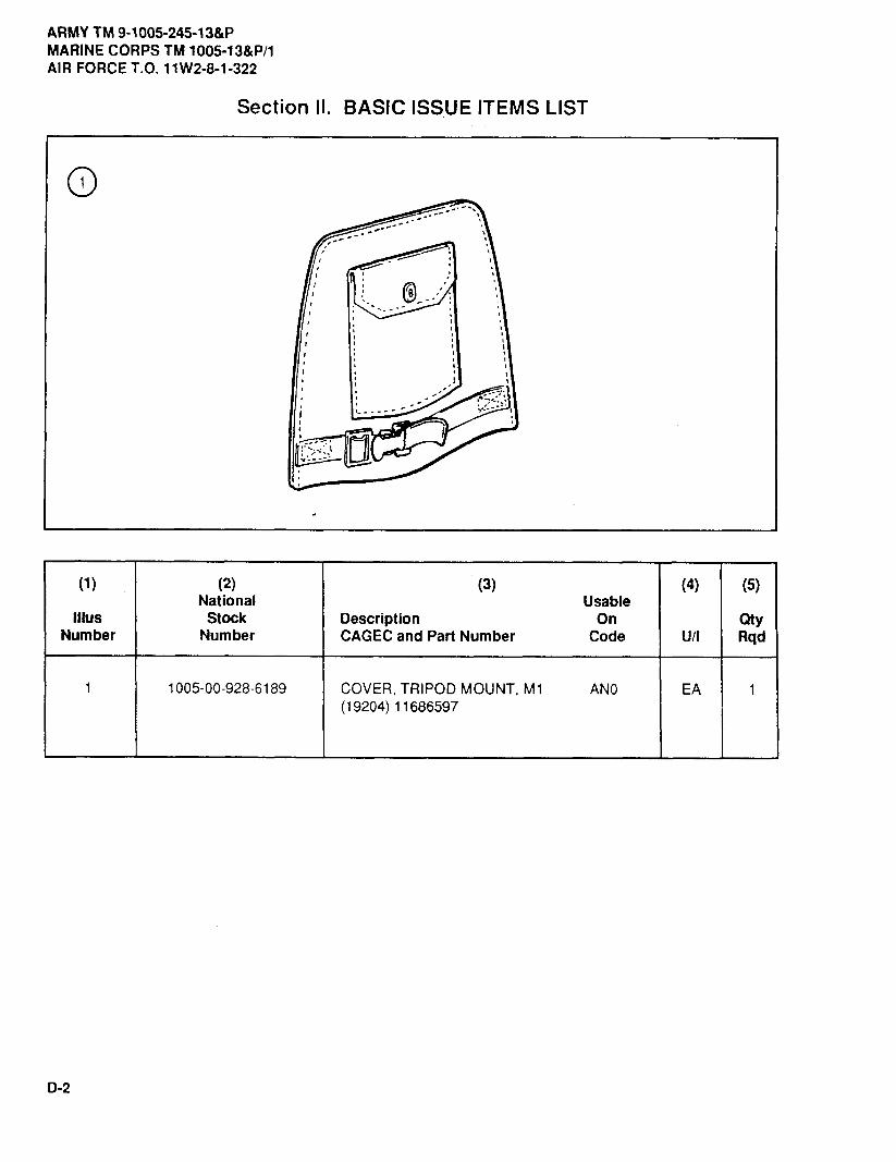
ARMY TM 9-1005-245-13&PMARINE CORPS TM 1005-13&P/1AIR FORCE T.O. 11W2-8-1-322
Section II. BASIC ISSUE ITEMS LIST
®
(1) (2) (3) (4) (5)National Usable
Illus Stock Description On QtyNumber Number CAGEC and Part Number Code U/I Rqd
1 1005-00-928-6189 COVERTRIPODMOUNT,M1 AN0 EA 1( 19204) 11686597
D-2

ARMY TM 9-1005-245-13&PMARINE CORPS TM 1005-13&P/1
AIR FORCE T.O. 11W2-8-1-322
APPENDIX E
EXPENDABLE AND DURABLE ITEMS LIST
Section I. INTRODUCTION
E-1. SCOPE
This appendix lists expendable and durable itemsyou will needto maintainthe gun mounts. This listingis for informational purposes only and is not authority to requisition the listed item. These items areauthorized to you by CTA 50-970, Expendable Items (except Medical, Class V, Repair Parts, andHeraldic Items).
E-2. EXPLANATION OF COLUMNS
a. Column (1) - Item number. This number is assigned to the entry in the listing for referencingwhen required.
b. Column (2) - Level. This column identifies the lowest level of maintenance that requires thelisted item.
C ................................................................................................. Operator/Crew0 ................................................................................................. UnitF ................................................................................................. Direct Support
C. Column (3) - National Stock Number. This is the national stock number assigned to theitem; use it to request or requisition the item.
d. Column (4) - Description. Indicates the Federal item name and, if reqired, a description toidentify the item. The last line for each item indicates the Contractor and Government Entity Code(CAGEC) in parentheses followed by the part number.
e. Column (5) - Unit of Measure (U/M)/Unit of Issue (U/I). This measure is expressed by atwo-character alphabetical abbreviation (e.g., EA, IN., PR). If the unit of measure differs form the unit ofissue as shown in the Army Madter Data File (AMDF), requisition the lowest unit of issue that will satisfyyour requirements.
Section II. EXPENDABLE AND DURABLE ITEMS LIST
(1) (2) (3) (4) (5)ITEM NATIONAL STOCK (U/M)l
NUMBER LEVEL NUMBER DESCRIPTION (U/I)
1 C CLEANER, LUBRICANT AND PRESERVATIVE(CLP)(81349) MIL-L-63460
9150-01-054-6453 1 pt bottle PT1 gal bottle GL
E-1

ARMY TM 9-1005-245-13&PMARINE CORPS TM 1005-13&P/1AIR FORCE T.O. 11W2-8-1-322
Section III. EXPENDABLE AND DURABLE ITEMS LIST (cont)
(1) (2) (3) (4) (5)ITEM NATIONAL (U/M)/
NUMBER LEVEL STOCK NUMBER DESCRIPTION (U/I)
2 C 5350-00-221-0872 CLOTH, ABRASIVE: crocus, ferric oxide and SHquartz, jean-cloth-backing, closed coating,9 X 11 in. sheet
(81348) P-C-458
3 C 8010-00-297-2124 EMAMEL, OLIVE DRAB GL(81349) MIL-STD-171
4 C 9150-00-190-0905 GREASE, AUTOMOTIVE AND ARTILLERY: LB(GAA), 5 lb can(81349) MIL-G-10924
5 C 9150-00-292-9689 LUBRICATING OIL (LAW) QT1 qt can(81349) MIL-L-14107
6 C LUBRICATING OIL (LSA)9150-00-687-4241 1 qt can QT9150-00-753-4686 1 gal can GL
(81349) MIL-L-46000
7 C 9150-00-231-6689 LUBRICATING OIL, GENERAL PURPOSE QT(PL-S), 1 qt can(81348) W-L-800
8 C 7920-00-205-1711 RAG, WIPING EA50 lb bale(58536) A-A-2522
9 0 8030-01-192-2492 SEALING COMPOUND, PLASTIC, EAPOLYURETHANE
areosol can(54577) MS1212-01
10 C 6850-00-281-1985 SOLVENT, DRY CLEANING GL1 gal can(58536) A-A-711
11 F 9505-00-293-4208 WIRE, NONELECTRICAL LB(96906) MS20995C32
E-2

ARMY TM 9-1005-245-13&P MARINE CORPS TM 1005-13&P/1
AIRFORCE T.O. 11W2-8-1-322
Change 5 F-1
APPENDIX F
ADDITIONAL AUTHORIZATION LIST(AAL)
Section I. INTRODUCTION F-1. SCOPE This appendix lists additional items you are authorized for the support of the M197 Machine Gun Mount. F-2. GENERAL This list identifies items that do not have to accompany the M197 Machine Gun Mount and that do not have to be turned in with it. These items are authorized to you by CTA, MTOE, TDA, or JTA. F-3. EXPLANATION OF COLUMNS IN THE AAL a. Column (1) – National Stock Number. Identifies the stock number of the item to be used for requisitioning purposes. b. Column (2) – Description, Commercial and Government Entity Code (CAGEC), and Part Number. Identifies the Federal item name (in all capital letters) followed by a minimum description when needed. The last line below the description is the CAGEC (in parentheses) and the part number. c. Column (3) – Usable on Code. When applicable, gives you a code if the item you need is not the same for different models of equipment. These codes are identified below: Code Used On AM5 M122 Machine Gun Tripod Mount BB8 M197 Machine Gun Mount d. Column (4) – Unit of Measure (U/M). Indicates the physical measurement or count of the item as issued per the National Stock Number shown in column (1). e. Column (5) – Qty Recm. Indicates the quantity recommended.
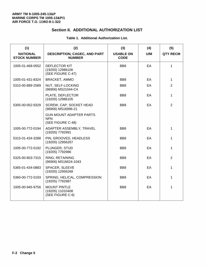
ARMY TM 9-1005-245-13&P MARINE CORPS TM 1005-13&P/1 AIR FORCE T.O. 11W2-8-1-322
F-2 Change 5
Section II. ADDITIONAL AUTHORIZATION LIST
Table 1. Additional Authorization List.
(1) NATIONAL
STOCK NUMBER
(2) DESCRIPTION, CAGEC, AND PART
NUMBER
(3) USABLE ON
CODE
(4) U/M
(5) QTY RECM
1005-01-468-0552 DEFLECTOR KIT (19200) 12986106 (SEE FIGURE C-47)
BB8 EA 1
1005-01-431-8324 BRACKET, AMMO BB8 EA 1
5310-00-889-2589 NUT, SELF-LOCKING (96906) MS21044-C4
BB8 EA 2
PLATE, DEFLECTOR (19200) 12986105
BB8 EA 1
5305-00-052-9329 SCREW, CAP, SOCKET HEAD (96906) MS16996-21
BB8 EA 2
GUN MOUNT ADAPTER PARTS NPN (SEE FIGURE C-48)
1005-00-772-0194 ADAPTER ASSEMBLY, TRAVEL (19205) 7792991
BB8 EA 1
5315-01-434-3288 PIN, GROOVED, HEADLESS (19200) 12956267
BB8 EA 1
1005-00-772-0192 PLUNGER, STUD (19205) 7792986
BB8 EA 1
5325-00-803-7315 RING, RETAINING (96906) MS16624-1043
BB8 EA 2
5365-01-434-0883 SPACER, SLEEVE (19200) 12956268
BB8 EA 1
5360-00-772-0193 SPRING, HELICAL, COMPRESSION (19205) 7792987
BB8 EA 1
1005-00-945-9756 MOUNT PINTLE (19205) 11010408 (SEE FIGURE C-6)
BB8 EA 1

ARMY TM 9-1005-245-13&P MARINE CORPS TM 1005-13&P/1
AIRFORCE T.O. 11W2-8-1-322
Change 5 Index-1
ALPHABETICAL INDEX
Subject Page
A
Additional Authorization List (AAL)......................................................................................................... F-1 Ammo Adapter Bracket Assembly and Deflector—Maintenance Instructions (Unit) Disassembly....................................................................................................................................... 16-4.2 Inspection/Repair ............................................................................................................................... 16-4.2 Reassembly ....................................................................................................................................... 16-4.2 Assembly and Preparation For Use ....................................................................................................... 2-6
B
Basic Issue Items List............................................................................................................................. D-1
C
Carriage Assembly and Depression Stop Assembly—Maintenance Instructions (Direct Support) Disassembly....................................................................................................................................... 14-8 Inspection/Repair ............................................................................................................................... 14-10 Reassembly ....................................................................................................................................... 14-10 Catch Bag Assembly—Maintenance Instructions (Unit) Disassembly....................................................................................................................................... 14-5 Inspection/Repair ............................................................................................................................... 14-5 Reassembly ....................................................................................................................................... 14-5 Cleaning ................................................................................................................................................. 3-3 Common Tools and Equipment.............................................................................................................. 4-1 Corrosion Prevention and Control .......................................................................................................... 1-2
D
Destruction of Army Materiel to Prevent Enemy Use............................................................................. 1-1 Differences Between Models.................................................................................................................. 1-4 Direct Support Troubleshooting.............................................................................................................. 5-1
E Elevation Mechanism—Maintenance Instructions (Direct Support) Repair................................................................................................................................................. 14-16 Elevation Mechanism (Traversing and Clamping Unit) and Elevation Mechanism (Elevating Unit)—Maintenance Instructions (Direct Support) Disassembly....................................................................................................................................... 7-14 Inspection/Repair ............................................................................................................................... 7-18 Reassembly ....................................................................................................................................... 7-18 Equipment Characteristics, Capabilities, and Features ......................................................................... 1-2

ARMY TM 9-1005-245-13&P MARINE CORPS TM 1005-13&P/1 AIRFORCE T.O. 11W2-8-1-322
Index-2 Change 5
ALPHABETICAL INDEX (cont)
Subject Page
E (cont) Equipment Data...................................................................................................................................... 1-4.1 Expendable and Durable Items List ....................................................................................................... E-1
F Flexible Machine Gun Mount—Maintenance Instructions (Direct Support) Disassembly....................................................................................................................................... 9-3 Inspection/Repair ............................................................................................................................... 9-4 Reassembly........................................................................................................................................ 9-4 Flexible Machine Gun Mount—Maintenance Instructions (Unit) Disassembly....................................................................................................................................... 9-1 Inspection/Repair ............................................................................................................................... 9-2 Reassembly........................................................................................................................................ 9-2 Front Tripod Mount Leg—Maintenance Instructions (Direct Support) Disassembly....................................................................................................................................... 7-10 Inspection/Repair ............................................................................................................................... 7-11 Reassembly........................................................................................................................................ 7-11 .50 Caliber Ammo Holder Assembly—Maintenance Instructions (Unit) Disassembly....................................................................................................................................... 14-3 Inspection/Repair ............................................................................................................................... 14-3 Reassembly........................................................................................................................................ 14-3
I Introduction to PMCS Table, Operator ................................................................................................... 2-2 Introduction to PMCS Table, Unit ........................................................................................................... 4-2
L Left Rear Tripod Mount Leg—Maintenance Instructions (Direct Support) Disassembly....................................................................................................................................... 7-8 Inspection/Repair .............................................................................................................................. 7-9 Reassembly........................................................................................................................................ 7-9 Location and Description of Major Components ................................................................................... 1-4 Lubrication Under Unusual Conditions .................................................................................................. 3-1 Lubrication Under Usual Conditions ...................................................................................................... 3-1
M Machine Gun Mount Controls................................................................................................................. 2-1 Maintenance Allocation Chart (MAC) ..................................................................................................... B-1

ARMY TM 9-1005-245-13&P MARINE CORPS TM 1005-13&P/1
AIRFORCE T.O. 11W2-8-1-322
Change 5 Index-3
Subject Page
M (cont) Maintenance Forms, Records, and Reports........................................................................................... 1-1 Mechanism Assembly (Traversing and Clamping Unit)—Maintenance Instructions (Unit) Disassembly....................................................................................................................................... 6-3 Inspection/Repair ............................................................................................................................... 6-3 Reassembly ....................................................................................................................................... 6-3 Mechanism Assembly (Traversing and Clamping Unit) and Mechanism Assembly (Elevating Unit)—Maintenance Instructions (Direct Support) Disassembly....................................................................................................................................... 6-11 Inspection/Repair ............................................................................................................................... 6-14 Reassembly ....................................................................................................................................... 6-15 MK93 MOD 0 Machine Gun Mount—Maintenance Instructions Repair................................................................................................................................................. 13-1 MK93 MOD 0 Machine Gun Mount and Yoke Assembly—Maintenance Instructions (Direct Support) Disassembly....................................................................................................................................... 14-7 Inspection/Repair ............................................................................................................................... 14-7 Reassembly ....................................................................................................................................... 14-7 MK93 MOD 1 Machine Gun Mount—Maintenance Instructions (Unit) Repair................................................................................................................................................. 14-1 Mount Pintle (P/N 11010408)—Maintenance Instructions (Unit) Disassembly....................................................................................................................................... 6-4 Inspection/Repair ............................................................................................................................... 6-4 Reassembly ....................................................................................................................................... 6-4 Mount Pintle (P/N 12986102)—Maintenance Instructions (Unit) (M249 and M240B) Disassembly....................................................................................................................................... 16-4.1 Inspection/Repair ............................................................................................................................... 16-4.1 Reassembly ....................................................................................................................................... 16-4.1 Mounting Bracket—Maintenance Instructions (Unit) Disassembly....................................................................................................................................... 14-4 Inspection/Repair ............................................................................................................................... 14-4 Reassembly ....................................................................................................................................... 14-4 M3 Machine Gun Tripod Mount—Maintenance Instructions (Direct Support) Disassembly....................................................................................................................................... 7-3 Inspection/Repair ............................................................................................................................... 7-3 Reassembly ....................................................................................................................................... 7-3 M3 Machine Gun Tripod Mount—Maintenance Instructions (Unit) Disassembly....................................................................................................................................... 7-1 Inspection/Repair ............................................................................................................................... 7-1 Reassembly ....................................................................................................................................... 7-1
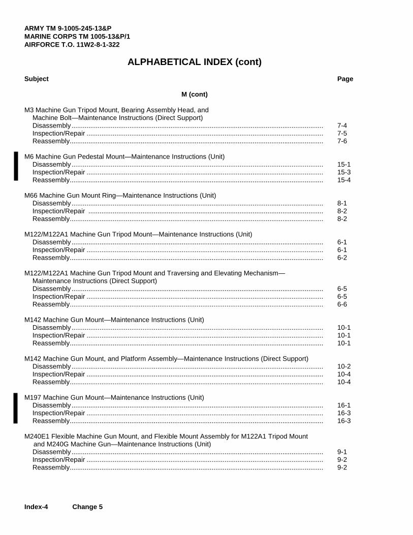
ARMY TM 9-1005-245-13&P MARINE CORPS TM 1005-13&P/1 AIRFORCE T.O. 11W2-8-1-322
Index-4 Change 5
ALPHABETICAL INDEX (cont)
Subject Page
M (cont) M3 Machine Gun Tripod Mount, Bearing Assembly Head, and Machine Bolt—Maintenance Instructions (Direct Support) Disassembly....................................................................................................................................... 7-4 Inspection/Repair ............................................................................................................................... 7-5 Reassembly........................................................................................................................................ 7-6 M6 Machine Gun Pedestal Mount—Maintenance Instructions (Unit) Disassembly....................................................................................................................................... 15-1 Inspection/Repair ............................................................................................................................... 15-3 Reassembly........................................................................................................................................ 15-4 M66 Machine Gun Mount Ring—Maintenance Instructions (Unit) Disassembly....................................................................................................................................... 8-1 Inspection/Repair .............................................................................................................................. 8-2 Reassembly........................................................................................................................................ 8-2 M122/M122A1 Machine Gun Tripod Mount—Maintenance Instructions (Unit) Disassembly....................................................................................................................................... 6-1 Inspection/Repair ............................................................................................................................... 6-1 Reassembly........................................................................................................................................ 6-2 M122/M122A1 Machine Gun Tripod Mount and Traversing and Elevating Mechanism— Maintenance Instructions (Direct Support) Disassembly....................................................................................................................................... 6-5 Inspection/Repair ............................................................................................................................... 6-5 Reassembly........................................................................................................................................ 6-6 M142 Machine Gun Mount—Maintenance Instructions (Unit) Disassembly....................................................................................................................................... 10-1 Inspection/Repair ............................................................................................................................... 10-1 Reassembly........................................................................................................................................ 10-1 M142 Machine Gun Mount, and Platform Assembly—Maintenance Instructions (Direct Support) Disassembly....................................................................................................................................... 10-2 Inspection/Repair ............................................................................................................................... 10-4 Reassembly........................................................................................................................................ 10-4 M197 Machine Gun Mount—Maintenance Instructions (Unit) Disassembly....................................................................................................................................... 16-1 Inspection/Repair ............................................................................................................................... 16-3 Reassembly........................................................................................................................................ 16-3 M240E1 Flexible Machine Gun Mount, and Flexible Mount Assembly for M122A1 Tripod Mount
and M240G Machine Gun—Maintenance Instructions (Unit) Disassembly....................................................................................................................................... 9-1 Inspection/Repair ............................................................................................................................... 9-2 Reassembly........................................................................................................................................ 9-2
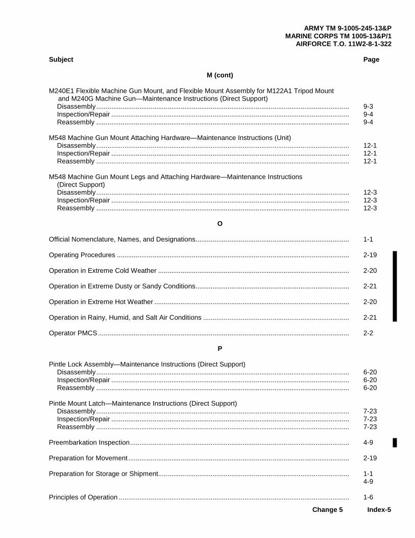
ARMY TM 9-1005-245-13&P MARINE CORPS TM 1005-13&P/1
AIRFORCE T.O. 11W2-8-1-322
Change 5 Index-5
Subject Page
M (cont) M240E1 Flexible Machine Gun Mount, and Flexible Mount Assembly for M122A1 Tripod Mount
and M240G Machine Gun—Maintenance Instructions (Direct Support) Disassembly....................................................................................................................................... 9-3 Inspection/Repair ............................................................................................................................... 9-4 Reassembly ....................................................................................................................................... 9-4 M548 Machine Gun Mount Attaching Hardware—Maintenance Instructions (Unit) Disassembly....................................................................................................................................... 12-1 Inspection/Repair ............................................................................................................................... 12-1 Reassembly ....................................................................................................................................... 12-1 M548 Machine Gun Mount Legs and Attaching Hardware—Maintenance Instructions (Direct Support) Disassembly....................................................................................................................................... 12-3 Inspection/Repair ............................................................................................................................... 12-3 Reassembly ....................................................................................................................................... 12-3
O Official Nomenclature, Names, and Designations.................................................................................. 1-1 Operating Procedures ............................................................................................................................ 2-19 Operation in Extreme Cold Weather ...................................................................................................... 2-20 Operation in Extreme Dusty or Sandy Conditions.................................................................................. 2-21 Operation in Extreme Hot Weather ........................................................................................................ 2-20 Operation in Rainy, Humid, and Salt Air Conditions .............................................................................. 2-21 Operator PMCS ...................................................................................................................................... 2-2
P Pintle Lock Assembly—Maintenance Instructions (Direct Support) Disassembly....................................................................................................................................... 6-20 Inspection/Repair ............................................................................................................................... 6-20 Reassembly ....................................................................................................................................... 6-20 Pintle Mount Latch—Maintenance Instructions (Direct Support) Disassembly....................................................................................................................................... 7-23 Inspection/Repair ............................................................................................................................... 7-23 Reassembly ....................................................................................................................................... 7-23 Preembarkation Inspection..................................................................................................................... 4-9 Preparation for Movement ...................................................................................................................... 2-19 Preparation for Storage or Shipment...................................................................................................... 1-1
4-9 Principles of Operation ........................................................................................................................... 1-6

ARMY TM 9-1005-245-13&P MARINE CORPS TM 1005-13&P/1 AIRFORCE T.O. 11W2-8-1-322
Index-6 Change 5
ALPHABETICAL INDEX (cont)
Subject Page
R References ............................................................................................................................................. A-1 Repair Parts............................................................................................................................................ 4-1 Repair Parts and Special Tools List (RPSTL) ........................................................................................ C-1 Reporting Equipment Improvement Recommendations (EIR) ............................................................... 1-1 Right Rear Tripod Mount Leg—Maintenance Instructions (Direct Support) Disassembly....................................................................................................................................... 7-12 Inspection/Repair ............................................................................................................................... 7-13 Reassembly........................................................................................................................................ 7-13 Ring Assembly and Ring—Maintenance Instructions (Unit) Disassembly....................................................................................................................................... 8-3 Inspection/Repair ............................................................................................................................... 8-3 Reassembly........................................................................................................................................ 8-3 Ring Assembly, Ring Assembly, and Ring—Maintenance Instructions (Direct Support) Disassembly....................................................................................................................................... 8-6 Inspection/Repair ............................................................................................................................... 8-7 Reassembly........................................................................................................................................ 8-8 Ring Brake—Maintenance Instructions (Direct Support) Disassembly....................................................................................................................................... 8-10 Inspection/Repair ............................................................................................................................... 8-11 Reassembly........................................................................................................................................ 8-11 Ring Brake—Maintenance Instructions (Unit) Disassembly....................................................................................................................................... 8-4 Inspection/Repair ............................................................................................................................... 8-4 Reassembly........................................................................................................................................ 8-4
S Service Upon Receipt of Materiel ........................................................................................................... 4-1 Special Tools, TMDE, and Support Equipment...................................................................................... 4-1 6650 .50 Cal Machine Gun Mount—Maintenance Instructions (Direct Support) Adjustment ......................................................................................................................................... 11-8 Disassembly....................................................................................................................................... 11-2 Inspection/Repair ............................................................................................................................... 11-5 Reassembly........................................................................................................................................ 11-5 6650 .50 Cal Machine Gun Mount—Maintenance Instructions (Unit) Disassembly....................................................................................................................................... 11-1 Inspection/Repair ............................................................................................................................... 11-1 Reassembly........................................................................................................................................ 11-1

ARMY TM 9-1005-245-13&P MARINE CORPS TM 1005-13&P/1
AIRFORCE T.O. 11W2-8-1-322
Change 5 Index-7/(8 blank)
Subject Page
T Tripod Leg Assembly—Maintenance Instructions (Direct Support) Disassembly....................................................................................................................................... 6-7 Inspection/Repair ............................................................................................................................... 6-9 Reassembly ....................................................................................................................................... 6-9 Tripod Mount Leg (Left Rear, Front, and Right Rear) —Maintenance Instructions (Unit) Disassembly....................................................................................................................................... 7-2 Inspection ........................................................................................................................................... 7-2 Reassembly ....................................................................................................................................... 7-2 Repair................................................................................................................................................. 7-2 Troubleshooting Information................................................................................................................... 4-5
U Unit PMCS.............................................................................................................................................. 4-2 Unit Troubleshooting .............................................................................................................................. 4-5 Universal Pintle Adapter—Maintenance Instructions Disassembly....................................................................................................................................... 14-6 Inspection/Repair ............................................................................................................................... 14-6 Reassembly ....................................................................................................................................... 14-6 Universal Pintle Adapter, Traverse Arm Assembly, and Universal Pintle Adapter Body Assembly—Maintenance Instructions (Direct Support) Disassembly....................................................................................................................................... 14-13 Inspection/Repair ............................................................................................................................... 14-14 Reassembly ....................................................................................................................................... 14-14 Upper Cradle Assembly—Maintenance Instructions (Direct Support) Disassembly....................................................................................................................................... 9-6 Inspection/Repair ............................................................................................................................... 9-7 Reassembly ....................................................................................................................................... 9-7
Y Yoke Assembly and Carriage Assembly—Maintenance Instructions (Unit) Disassembly....................................................................................................................................... 14-2 Inspection/Repair ............................................................................................................................... 14-2 Reassembly ....................................................................................................................................... 14-2


By Order of the Secretary of the Army:
GORDON R. SULLIVANGeneral, United States Army
Chief of Staff
off icial:
1-14@1 41,MILT-ON H. HAMILTON
Administrative Assistant to theSecretary of the Army
07926
DISTRIBUTION: To be distributed in accordance with DA Form 12-40-E, block 1092requirements for TM 9-1005-245-13&P.

RECOMMENDED CHANGES TO PUBLICATIONS AND BLANK FORMS
For use of this form, see AR 25-30; the proponent agency is ODISC4.
Use Part II (reverse) for Repair Parts and Special Tool Lists (RPSTL) and Supply Catalogs/Supply Manuals (SC/SM).
DATE
Date you filled out this form.
TO: (Forward to proponent of publication or form) (Include ZIP Code) AMSTA-LC-CI/TECH PUBS, TACOM-RI 1 Rock Island Arsenal Rock Island, IL 61299-7630
FROM: (Activity and location) (Include ZIP Code) Your mailing address
PART I – ALL PUBLICATIONS (EXCEPT RPSTL AND SC/SM) AND BLANK FORMS PUBLICATION/FORM NUMBER TM 9-1005-245-13&P
DATE 15 December 1994
TITLE Operator’s, Unit, and Direct Support Maintenance Manual with Repair Parts and Special Tools (RPSTL) for Machine Gun Mounts
ITEM NO.
PAGE NO.
PARA- GRAPH
LINE NO. *
FIGURE NO.
TABLE NO.
RECOMMENDED CHANGES AND REASON (Provide exact wording of recommended changes, if possible).
3
C-39-1
SMR Code should be PAOZZ
*Reference to line numbers within the paragraph or subparagraph. TYPED NAME, GRADE OR TITLE Your Name
TELEPHONE EXCHANGE/AUTOVON, PLUS EXTENSION
SIGNATURE Your Signature
DA FORM 2028, FEB 74 REPLACES DA FORM 2028, 1 DEC 68, WHICH WILL BE USED. USAPPC V3.00
TO: (Forward direct to addressee listed in publication) AMSTA-LC-CI/TECH PUBS, TACOM-RI 1 Rock Island Arsenal Rock Island, IL 61299-7630
FROM: (Activity and location) (Include ZIP Code)
Your address DATE
Date you filled out this form
PART II – REPAIR PARTS AND SPECIAL TOOL LISTS AND SUPPLY CATALOGS/SUPPLY MANUALS PUBLICATION NUMBER TM 9-1005-245-13&P
DATE 15 December 1994
TITLE Operator’s, Unit, and Direct Support Maintenance Manual with Repair Parts and Special Tools (RPSTL) for Machine Gun Mounts
PAGE NO.
COLM
NO.
LINE NO.
NATIONAL STOCK
NUMBER
REFERENCE
NO.
FIGURE
NO.
ITEM NO.
TOTAL NO. OF MAJOR
ITEMS SUPPORTED
RECOMMENDED ACTION
PART III – REMARKS (Any general remarks or recommendations, or suggestions for improvement of publications and blank forms. Additional blank sheets may be used if more space is needed.)
TYPED NAME, GRADE OR TITLE Your Name
TELEPHONE EXCHANGE/AUTOVON, PLUS EXTENSION
SIGNATURE Your Signature
UASPPC V3.00

RECOMMENDED CHANGES TO PUBLICATIONS AND
BLANK FORMS For use of this form, see AR 25-30; the proponent agency is ODISC4.
Use Part II (reverse) for Repair Parts and Special Tool Lists (RPSTL) and Supply Catalogs/Supply Manuals (SC/SM).
DATE
TO: (Forward to proponent of publication or form) (Include ZIP Code) AMSTA-LC-CI/TECH PUBS, TACOM-RI 1 Rock Island Arsenal Rock Island, IL 61299-7630
FROM: (Activity and location) (Include ZIP Code)
PART I- ALL PUBLICATIONS (EXCEPT RPSTL AND SC/SM) AND BLANK FORMS
PUBLICATION/FORM NUMBER
TM 9-1005-245-13&P DATE
15 December 1994 TITLE Operator’s, Unit, and Direct Support Maintenance Manual with Repair Parts and Special Tools (RPSTL) for Machine Gun Mounts
ITEM NO.
PAGE NO.
PARA- GRAPH
LINE NO.*
FIGURE NO.
TABLE NO.
RECOMMENDED CHANGES AND REASON (Provide exact wording of recommended changes, if possible).
*Reference to line numbers within the paragraph or subparagraph. TYPED NAME, GRADE OR TITLE
TELEPHONE EXCHANGE/AUTOVON, PLUS EXTENSION
SIGNATURE
DA FORM 2028, FEB 74 REPLACES DA FORM 2028, 1 DEC 68, WHICH WILL BE USED. USAPPC V3.00
TO: (Forward direct to addressee listed in publication) AMSTA-LC-CI/TECH PUBS, TACOM-RI 1 Rock Island Arsenal Rock Island, IL 61299-7630
FROM: (Activity and location) (Include ZIP Code) DATE
PART II – REPAIR PARTS AND SPECIAL TOOL LISTS AND SUPPLY CATALOGS/SUPPLY MANUALS PUBLICATION NUMBER TM 9-1005-245-13&P
DATE 15 December 1994
TITLE Operator’s, Unit, and Direct Support Maintenance Manual with Repair Parts and Special Tools (RPSTL) for Machine Gun Mounts
PAGE NO.
COLM
NO.
LINE NO.
NATIONAL STOCK
NUMBER
REFERENCE
NO.
FIGURE
NO.
ITEM NO.
TOTAL NO. OF MAJOR
ITEMS SUPPORTED
RECOMMENDED ACTION
PART III – REMARKS (Any general remarks or recommendations, or suggestions for improvement of publications and blank forms. Additional blank sheets may be used if more space is needed.)
TYPED NAME, GRADE OR TITLE TELEPHONE EXCHANGE/AUTOVON, PLUS EXTENSION SIGNATURE
UASPPC V3.00

RECOMMENDED CHANGES TO PUBLICATIONS AND BLANK FORMS
For use of this form, see AR 25-30; the proponent agency is ODISC4.
Use Part II (reverse) for Repair Parts and Special Tool Lists (RPSTL) and Supply Catalogs/Supply Manuals (SC/SM).
DATE
TO: (Forward to proponent of publication or form) (Include ZIP Code) AMSTA-LC-CI/TECH PUBS, TACOM-RI 1 Rock Island Arsenal Rock Island, IL 61299-7630
FROM: (Activity and location) (Include ZIP Code)
PART I- ALL PUBLICATIONS (EXCEPT RPSTL AND SC/SM) AND BLANK FORMS
PUBLICATION/FORM NUMBER TM 9-1005-245-13&P
DATE 15 December 1994
TITLE Operator’s, Unit, and Direct Support Maintenance Manual with Repair Parts and Special Tools (RPSTL) for Machine Gun Mounts
ITEM NO.
PAGE NO.
PARA- GRAPH
LINE NO.*
FIGURE NO.
TABLE NO.
RECOMMENDED CHANGES AND REASON (Provide exact wording of recommended changes, if possible).
*Reference to line numbers within the paragraph or subparagraph. TYPED NAME, GRADE OR TITLE
TELEPHONE EXCHANGE/AUTOVON, PLUS EXTENSION
SIGNATURE
DA FORM 2028, FEB 74 REPLACES DA FORM 2028, 1 DEC 68, WHICH WILL BE USED. USAPPC V3.00
RECOMMENDED CHANGES TO PUBLICATIONS AND BLANK FORMS
For use of this form, see AR 25-30; the proponent agency is ODISC4.
Use Part II (reverse) for Repair Parts and Special Tool Lists (RPSTL) and Supply Catalogs/Supply Manuals (SC/SM).
DATE
TO: (Forward to proponent of publication or form) (Include ZIP Code) AMSTA-LC-CI/TECH PUBS, TACOM-RI 1 Rock Island Arsenal Rock Island, IL 61299-7630
FROM: (Activity and location) (Include ZIP Code)
PART I- ALL PUBLICATIONS (EXCEPT RPSTL AND SC/SM) AND BLANK FORMS
PUBLICATION/FORM NUMBER TM 9-1005-245-13&P
DATE 15 December 1994
TITLE Operator’s, Unit, Direct Support Maintenance Manual with Repair Parts and Special Tools (RPSTL) for Machine Gun Mounts
ITEM NO.
PAGE NO.
PARA- GRAPH
LINE NO.*
FIGURE NO.
TABLE NO.
RECOMMENDED CHANGES AND REASON (Provide exact wording of recommended changes, if possible).
*Reference to line numbers within the paragraph or subparagraph. TYPED NAME, GRADE OR TITLE
TELEPHONE EXCHANGE/AUTOVON, PLUS EXTENSION
SIGNATURE
DA FORM 2028, FEB 74 REPLACES DA FORM 2028, 1 DEC 68, WHICH WILL BE USED. USAPPC V3.00
TO: (Forward direct to addressee listed in publication) AMSTA-LC-CI/TECH PUBS, TACOM-RI 1 Rock Island Arsenal Rock Island, IL 61299-7630
FROM: (Activity and location) (Include ZIP Code) DATE
PART II – REPAIR PARTS AND SPECIAL TOOL LISTS AND SUPPLY CATALOGS/SUPPLY MANUALS PUBLICATION NUMBER TM 9-1005-245-13&P
DATE 15 December 1994
TITLE Operator’s, Unit, and Direct Support Maintenance Manual with Repair Parts and Special Tools (RPSTL) for Machine Gun Mounts
PAGE NO.
COLM
NO.
LINE NO.
NATIONAL STOCK
NUMBER
REFERENCE
NO.
FIGURE
NO.
ITEM NO.
TOTAL NO. OF MAJOR
ITEMS SUPPORTED
RECOMMENDED ACTION
PART III – REMARKS (Any general remarks or recommendations, or suggestions for improvement of publications and blank forms. Additional blank sheets may be used if more space is needed.)
TYPED NAME, GRADE OR TITLE TELEPHONE EXCHANGE/AUTOVON, PLUS EXTENSION SIGNATURE
USAPPC V3.00


THE METRIC SYSTEM AND EQUIVALENTS
LINEAR MEASURE SQUABE MEASURE
1 Centimeter 10 Millimeters = 0 0 1 Meter = 0.3937 Inch 1 Sq Centimeter 100 Sq Millimeters - 0.155 Sq Inch
1 Decimeter 10 Centimeters = 3.94 Inches I Sq Decimeter 100 Sq Centimeters = 15.5 Sq Inches
1 Meter 10 Decimeters = 100 Centimeters 1 Sq Meter (Centare) = 10 Sq Decimeters
1000 Millimeters = 39.37 Inches = 10,000 Sq Centimeters . 10.764 Sq Feet
1 Dekameter 10 Meters = 32.8 Feet 1 Sq Dekameter (Are) - 100 Sq Meters = 1,076.4 Sq Feet
I Hectometer Dekameters = 328.08 Feet 1 Sq Hectometer (Hectare) = 100 Sq Dekameters
1 Kilometer = 10 Hectometers = 1000 Meters = 2.471 Acres
= 0.621 Mile = 3,280.8 Feet 1 Sq Kilometer = 100 Sq Hectometers = 1,000,000 Sq Meters
Millimeters = Inches limes 25.4= 0.386 Sq Mile
Inches = Millimeters divided by 25.4CUBIC MEASURE
WEIGHTS 1 Cu Centimeter = 1000 Cu Millimeters 0.061 Cu Inches
1 Centigram 10 Milligrams 0.154 Grain 1 Cu Decimeter = 1000 Cu Centimeters 61.02 Cu Inches
1 Decigram 10 Centigrams 1.543 Grains I Cu Meter = 1000 Cu Decimeters = 1,000,000 Cu Centimeters
1 Gram 0.001 Kilogram = 10 Decigrams 35.31 Cu Feet
1000 Milligrams = 0.035 Ounce1 Dekagram 10 Grams = 0.353 Ounce TEMPERATURE
1 Heclogram 10 Delkagrams = 3.527 OuncesI Kilogram - 10 Hectograms; = 1000 Grams 2.205 Pounds 5/9 (OF- 32') 'C
I Quintal = 100 Kilograms 220.46 Pounds 9/5 (-C + 32') OF
1 Metric Ton = 10 Quintals 1000 Kilograms 1.1 Short Tons -350 Fahrenheit Is equivalent to -370 Celsius00 Fahrenheit Is equivalent to -370 Celsius
LIQUID MEASURE 320 Fahrenheit is equivalent to 00 Celsius900 Fahrenheit is equivalent to 32.20 Celsius
1 Milliliter = 0.001 Liter = 0.034 Fluid Ounce1000 Fahrenheit Is equivalent to 380 Celsius
1 Centiliter 10 Milliliters 0.34 Fluid Ounce 2120 Fahrenheit Is equivalent to 1000 Celsius
1 Deciliter 10 Centiliters 3.38 Fluid Ounces1 Liter = 10 Deciliters 1000 Milliliters = 33.82 Fluid Ounces1 Delkaliter - 10 Liters 2.64 Gallons1 Hectoliter = 10 Dekaliters = 26.42 Gallons1 Kiloliter = 10 Hectoliters = 264.18 Gallons
APPROXIMATE CONVERSION FACTORS
IQ_QhAN_(aE TO MULTIPLY BY TO CHANGE IQ MULTIPLY BY
Inches ............................. Centimeters ......................... 2@540 Centimeters ................... Inches ............................... 0.394
Feet ................................ Meters ................................. 0.305 Meters ........................... Feet ................................... 3.280
Yards .............................. Meters ................................. 0.914 Meters ........................... Yards ................................. 1.094
Miles ............................... Kilometers ............................ 1.609 Kilometers ..................... Miles ................................. 0.621
Square Inches ................ Square Centimeters ............. 6.451 Square Centimeters ...... SquareInches ................... 0.155
Square Feet .................... Square Meters ..................... 0.093 Square Meters .............. Square Feet ..................... 10.764
Square Yards .................. Square Meters ..................... 0.836 Square Meters .............. Square Yards .................... 1.196
Square Miles ................... Square Kilometers ............... 2,590 Square Kilometers ......... Square Miles ..................... 0.386
Acres .............................. Square Hectometers ............ 0.405 Square Hectometers ..... Acres ................................. 2.471
Cubic Feet ...................... Cubic Meters ....................... 0.028 Cubic Meters ................. Cubic Feet ....................... 35.315
Cubic Yards .................... Cubic Meters ....................... 0.765 Cubic Meters ................. Cubic Yards ....................... 1.308
Fluid Ounces .................. Milliliters ............................. 29.573 Milliliters ........................ Fluid Ounces ..................... 0.034
Pints ............................... Liters ................................... 0.473 Liters ............................. Pints .................................. 2.113
Quarts ............................ Liters ............................ ...... 0.946 Liters ............................. Quarts ............................... 1.057
Gallons ........................... Liters ................................... 3.785 Liters ............................. Gallons .............................. 0.264
Ounces ........................... Grams ............................... 28,349 Grams ........................... Ounces .............................. 0.035
Pounds ........................... Kilograms ............................. 0,454 Kilograms ...................... Pounds .............................. 2.205
Short Tons ...................... Metric Tons .......................... 0.907 Metric Tons ................... Short Tons ......................... 1.102
Pound-Feet ..................... Newton-Meters .................... 1.356 Newton-Meters .............. Pound-Feet ........................ 0.738
Pound-Inches ............... Newton-Meters ................. 0.11375 Kilopascals .................... Pounds per Square Inch .... 0.145
Pounds per Square Inch Kilopascals ........................... 6.895 Kilometers per Liter ....... Miles per Gallon ................. 2.354
Ounce-Inches ................. Newton-Meters ............... 0.007062 Kilometers per Hour ...... Miles per Hour ................... 0.621
Miles per Gallon .............. Kilometers per Lfter .............. 0.425 'Fahrenheit ................... OCelsius ............. OC ('F-32)x5/9
Miles per Hour ................ Kilometers per Hour ............. 1.609 OCelsius ......................... OFahrenheft ....... OF (9/5xOC)+32

PIN: 073479-005


