

Programmable Logic Controller
Programming Timers

Chapter Objectives
1. Describe the operation of pneumatic on-delay and off-delay timers
2. Describe PLC timer instruction and differentiate between a
nonretentive and retentive timer
3. Convert fundamental timer relay schematic diagrams to PLC ladder
logic programs
4. Analyze and interpret typical PLC timer ladder logic programs
5. Program the control of outputs using the timer instruction control bits

Chapter Objectives
The most commonly used PLC instruction, after coils and contacts, is
the timer. This chapter deals with how timers time intervals and the way
in which they can control outputs. We discuss the basic PLC on-delay
timer function, as well as other timing functions derived from it, and
typical industrial timing tasks.

I. Mechanical Timing Relays
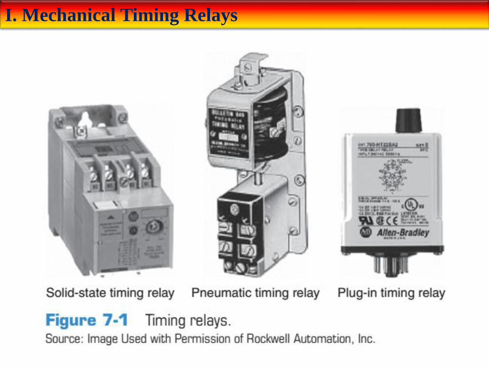
There are very few industrial control systems that do not need at least
one or two timed functions. Mechanical timing relays are used to delay
the opening or closing of contacts for circuit control. The operation of a
mechanical timing relay is similar to that of a control relay, except that
certain of its contacts are designed to operate at a preset time interval,
after the coil is energized or de-energized. Typical types of mechanical
and electronic timing relays are shown in Figure 7-1 . Timers allow a
multitude of operations in a control circuit to be automatically started
and stopped at different time intervals.
I. Mechanical Timing Relays
I. Mechanical Timing Relays
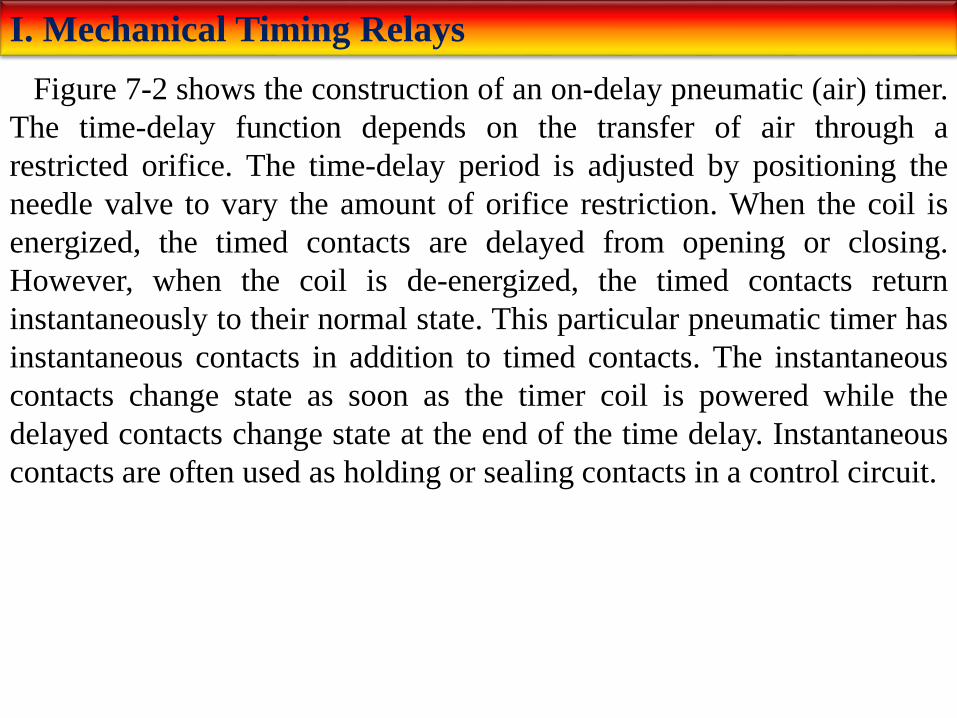
Figure 7-2 shows the construction of an on-delay pneumatic (air) timer.
The time-delay function depends on the transfer of air through a
restricted orifice. The time-delay period is adjusted by positioning the
needle valve to vary the amount of orifice restriction. When the coil is
energized, the timed contacts are delayed from opening or closing.
However, when the coil is de-energized, the timed contacts return
instantaneously to their normal state. This particular pneumatic timer has
instantaneous contacts in addition to timed contacts. The instantaneous
contacts change state as soon as the timer coil is powered while the
delayed contacts change state at the end of the time delay. Instantaneous
contacts are often used as holding or sealing contacts in a control circuit.

I. Mechanical Timing Relays
I. Mechanical Timing Relays
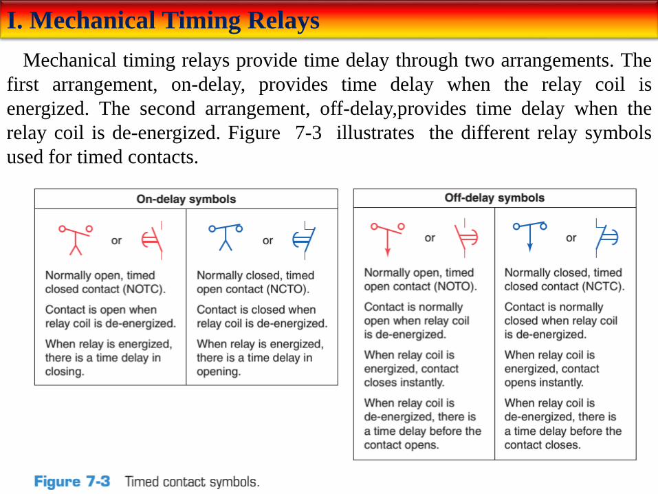
Mechanical timing relays provide time delay through two arrangements. The
first arrangement, on-delay, provides time delay when the relay coil is
energized. The second arrangement, off-delay,provides time delay when the
relay coil is de-energized. Figure 7-3 illustrates the different relay symbols
used for timed contacts.
I. Mechanical Timing Relays
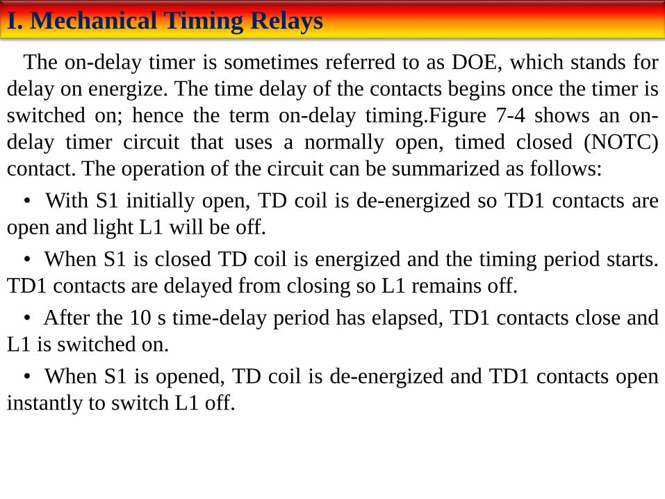
The on-delay timer is sometimes referred to as DOE, which stands for
delay on energize. The time delay of the contacts begins once the timer is
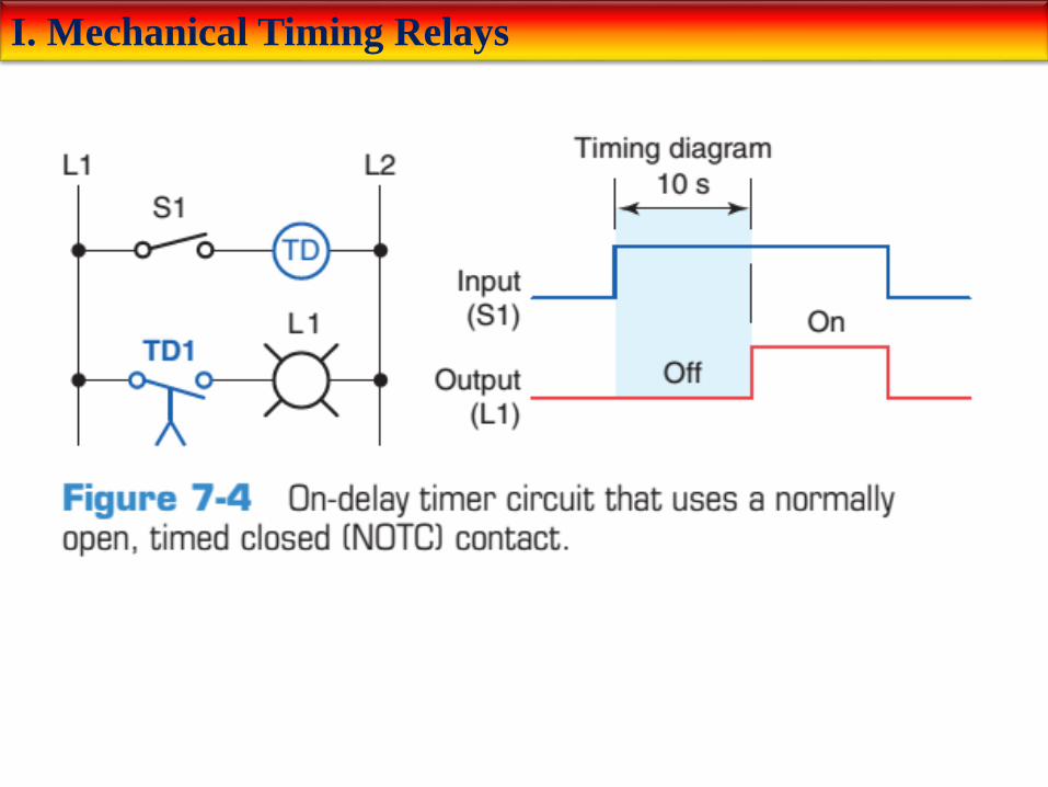
switched on; hence the term on-delay timing.Figure 7-4 shows an on-
delay timer circuit that uses a normally open, timed closed (NOTC)
contact. The operation of the circuit can be summarized as follows:
• With S1 initially open, TD coil is de-energized so TD1 contacts are
open and light L1 will be off.
• When S1 is closed TD coil is energized and the timing period starts.
TD1 contacts are delayed from closing so L1 remains off.
• After the 10 s time-delay period has elapsed, TD1 contacts close and
L1 is switched on.
• When S1 is opened, TD coil is de-energized and TD1 contacts open
instantly to switch L1 off.
I. Mechanical Timing Relays
I. Mechanical Timing Relays
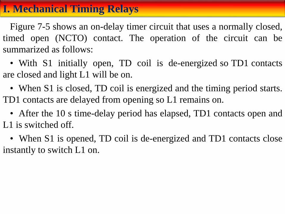
Figure 7-5 shows an on-delay timer circuit that uses a normally closed,
timed open (NCTO) contact. The operation of the circuit can be
summarized as follows:
• With S1 initially open, TD coil is de-energized so TD1 contacts
are closed and light L1 will be on.
• When S1 is closed, TD coil is energized and the timing period starts.
TD1 contacts are delayed from opening so L1 remains on.
• After the 10 s time-delay period has elapsed, TD1 contacts open and
L1 is switched off.
• When S1 is opened, TD coil is de-energized and TD1 contacts close
instantly to switch L1 on.

I. Mechanical Timing Relays

I. Mechanical Timing Relays
Figure 7-6 shows an off-delay timer circuit that uses a normally open,
timed open (NOTO) contact. The operation of the circuit can be
summarized as follows:
• With S1 initially open, TD coil is de-energized so TD1 contacts are
open and light L1 will be off.
• When S1 is closed, TD coil is energized and TD1 contacts close
instantly to switch light L1 on.
• When S1 is opened, TD coil is de-energized and the timing period
starts.
• After the 10 s time-delay period has elapsed, TD1 contacts open to
switch the light off.

I. Mechanical Timing Relays

I. Mechanical Timing Relays
Figure 7-7 shows an off-delay timer circuit that uses a normally closed,
timed closed (NCTC) contact. The operation of the circuit can be
summarized as follows:
• With S1 initially open, TD coil is de-energized so TD1 contacts are
closed and light L1 will be on.
• When S1 is closed, TD coil is energized and TD1 contacts open
instantly to switch light L1 off.
• When S1 is opened, TD coil is de-energized and the timing period
starts. TD1 contacts are delayed from closing so L1 remains off.
• After the 10 s time-delay period has elapsed, TD1 contacts close to
switch the light on.

I. Mechanical Timing Relays

II. Timer Instructions
PLC timers are instructions that provide the same functions as on-delay
and off-delay mechanical and electronic timing relays. PLC timers offer
several advantages over their mechanical and electronic counterparts.
These include the fact that:
• Time settings can be easily changed.
• The number of them used in a circuit can be increased or decreased
through the use of programming changes rather than wiring changes.
• Timer accuracy and repeatability are extremely high because its
time delays are generated in the PLC processor.

II. Timer Instructions
In general, there are three different PLC timer types: the on-delay timer
(TON), off-delay timer (TOF),and retentive timer on (RTO).The most
common is the on-delay timer, which is the basic function. There are also
many other timing configurations, all of which can be derived from one
or more of the basic time-delay functions. Figure 7-8 shows the timer
selection toolbar for the Allen-Bradley SLC 500 PLC and its associated
RSLogix software. These timer commands can be summarized as
follows:
TON (Timer On Delay) — Counts time-based intervals when the
instruction is true.
TOF (Timer Off Delay) — time-based intervals when the instruction is
false.
RTO (Retentive Timer On) — Counts time-based intervals when the
instruction is true and retains the accumulated value when the instruction
goes false or when power cycle occurs.
RES (Reset) — Resets a retentive timer’s accumulated value to zero.
II. Timer Instructions
Several quantities are associated with the timer instruction:
• The preset time represents the time duration for the timing circuit.
For example, if a time delay of 10s is required, the timer will have a
preset of 10s.
• The accumulated time represents the amount of time that has
elapsed from the moment the timing coil became energized.
• Every timer has a time base. Once the timing rung has continuity,
the timer counts in time-based intervals and times until the preset value
and accumulated value are equal or, depending on the type of controller,
up to the maximum time interval of the timer. The intervals that the
timers time out at are generally referred to as the time bases of the timer.
Timers can be programmed with several different time bases: 1 s, 0.1 s,
and 0.01 s are typical time bases. If a programmer entered 0.1 for the
time base and 50 for the number of delay increments, the timer would
have a 5-s delay (50x0.1s=5s). The smaller the time base selected, the
better the accuracy of the timer.
II. Timer Instructions
Although each manufacturer may represent timers differently on the
ladder logic program, most timers operate in a similar manner. One of
the first methods used depicts the timer instruction as a relay coil similar
to that of a mechanical timing relay. Figure 7-9 shows a coil-formatted
timer instruction. Its operation can be summarized as follows:
• The timer is assigned an address and is identified as a timer.
• Also included as part of the timer instruction is the time base of the
timer, the timer’s preset value or time-delay period, and the accumulated
value or current time-delay period for the timer.
• When the timer rung has logic continuity, the timer begins counting
time-based intervals and times until the accumulated value equals the
preset value.
• When the accumulated time equals the preset time, the output is
energized and the timed output contact associated with the output is
closed. The timed contact can be used as many times as you wish
throughout the program as an NO or NC contact.

II. Timer Instructions

II. Timer Instructions
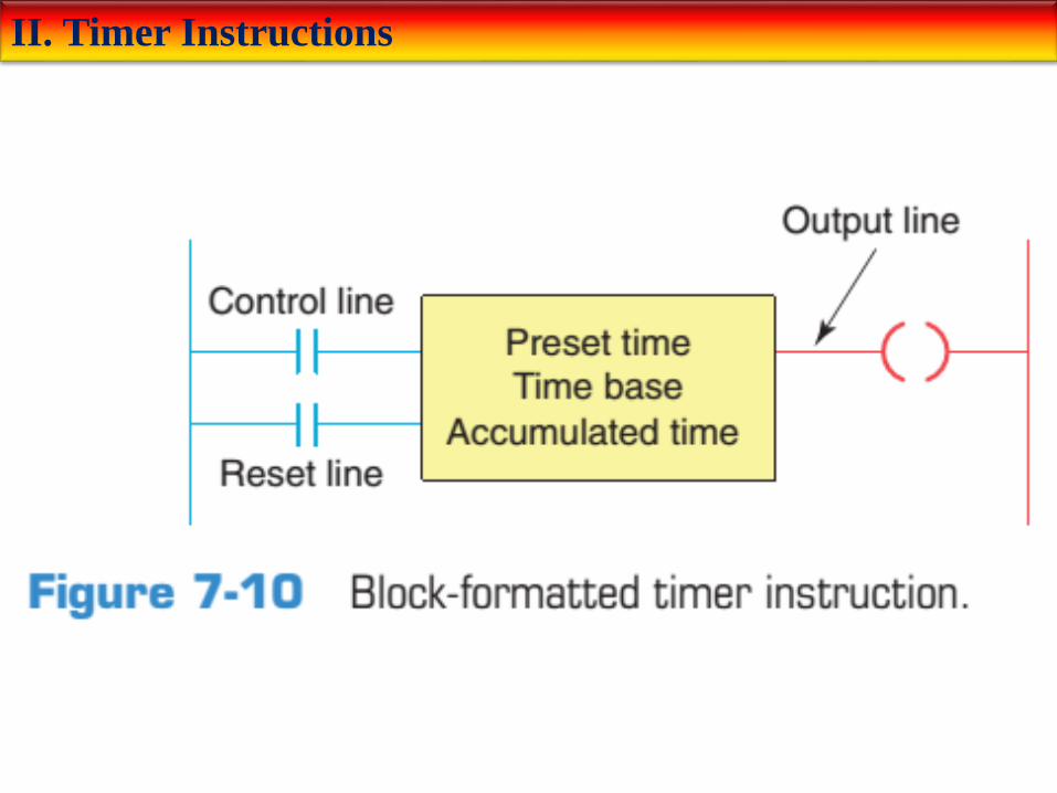
Timers are most often represented by boxes in ladder logic. Figure 7-10 illustrates a generic block format for a retentive timer that requires two input lines. Its operation can be summarized as follows:
• The timer block has two input conditions associated with it, namely, the control and reset.
• The control line controls the actual timing operation of the timer. Whenever this line is true or power is supplied to this input, the timer will time. Removal of power from the control line input halts the further timing of the timer.
• The reset line resets the timer’s accumulated value to zero.
• Some manufacturers require that both the control and reset lines be true for the timer to time; removal of power from the reset input resets the timer to zero.
• Other manufacturers’ PLCs require power flow for the control input only and no power flow on the reset input for the timer to operate. For this type of timer operation, the timer is reset whenever the reset input is true.
• The timer instruction block contains information pertaining to the operation of the timer, including the preset time, the time base of the timer, and the current or accumulated time.
• All block-formatted timers provide at least one output signal from the timer. The timer continuously compares its current time with its preset time, and its output is false (logic 0) as long as the current time is less than the preset time. When the current time equals the preset time, the output changes to true (logic 1).
II. Timer Instructions

III. On-Delay Timer Instruction
Most timers are output instructions that are conditioned by input
instructions. An on-delay timeris used when you want to program a time
delay before an instruction becomes true. Figure 7-11 illustrates the
principle of operation of an on-delay timer. Its operation can be
summarized as follows:
• The on-delay timer operates such that when the rung containing the
timer is true, the timer time-out period commences.
• At the end of the timer time-out period, an output is made true.
• The timed output becomes true sometime after the timer rung
becomes true; hence, the timer is said to have an on-delay.
• The length of the time delay can be adjusted by changing the preset
value.
• In addition, some PLCs allow the option of changing the time base,
or resolution, of the timer. As the time base you select becomes smaller,
the accuracy of the timer increases.

III. On-Delay Timer Instruction

III. On-Delay Timer Instruction
The Allen-Bradley SLC 500 timer file is file 4 (Figure 7-12). Each timer is composed of three 16-bit words, collectively called a timer element. There can be up to 256 timer elements. Addresses for timer file 4, timer element number 2 (T4:2), are listed below.
T4 = timer file 4
:2 = timer element number 2 (0–255 timer elements per file)
T4:2/DN is the address for the done bit of the timer.
T4:2/TT is the address for the timer-timing bit of the timer.
T4:2/EN is the address for the enable bit of the timer.
The control word uses the following three control bits:
Enable (EN) bit—The enable bit is true (has a status of 1) whenever the timer instruction is true. When the timer instruction is false, the enable bit is false (has a status of 0).
Timer-timing (TT) bit—The timer-timing bit is true whenever the accumulated value of the timer is changing, which means the timer is timing. When the timer is not timing, the accumulated value is not changing, so the timer-timing bit is false.
Done (DN) bit—The done bit changes state whenever the accumulated value reaches the preset value. Its state depends on the type of timer being used.

III. On-Delay Timer Instruction
III. On-Delay Timer Instruction
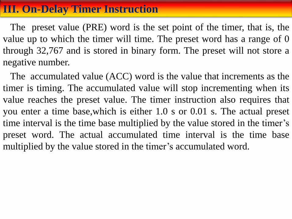
The preset value (PRE) word is the set point of the timer, that is, the
value up to which the timer will time. The preset word has a range of 0
through 32,767 and is stored in binary form. The preset will not store a
negative number.
The accumulated value (ACC) word is the value that increments as the
timer is timing. The accumulated value will stop incrementing when its
value reaches the preset value. The timer instruction also requires that
you enter a time base,which is either 1.0 s or 0.01 s. The actual preset
time interval is the time base multiplied by the value stored in the timer’s
preset word. The actual accumulated time interval is the time base
multiplied by the value stored in the timer’s accumulated word.

III. On-Delay Timer Instruction
Figure 7-13 shows an example of the on-delay timer instruction used as
part of the Allen-Bradley PLC-5 and SLC 500 controller instruction sets.
The information to be entered includes:
Timer number—This number must come from the timer file. In the
example shown, the timer number is T4:0, which represents timer file 4,
timer 0 in that file. The timer address must be unique for this timer and
may not be used for any other timer.
Time base—The time base (which is always expressed in seconds) may
be either 1.0 s or 0.01 s. In the example shown, the time base is 1.0 s.
Preset value—In the example shown, the preset value is 15. The timer
preset value can range from 0 through 32,767.
Accumulated value—In the example shown, the accumulated value is
0. The timer’s accumulated value normally is entered as 0, although it is
possible to enter a value from 0 through 32,767. Regardless of the value
that is preloaded, the timer value will become 0 whenever the timer is
reset.

III. On-Delay Timer Instruction

III. On-Delay Timer Instruction
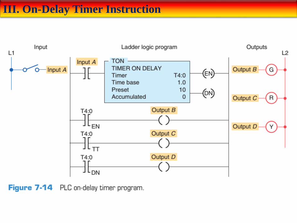
The on-delay timer (TON) is the most commonly used timer. Figure 7-14 shows a PLC program that uses an on-delay timer. The operation of the program can be summarized as follows:
• The timer is activated by input switch A.
• The preset time for this timer is 10 s, at which time output D will be energized.
• When input switch is A is closed, the timer becomes true and the timer begins counting and counts until the accumulated time equals the preset value; the output D is then energized.
• If the switch is opened before the timer is timed out, the accumulated time is automatically reset to 0.
• This timer configuration is termed non retentive because any loss of continuity to the timer causes the timer instruction to reset.
• This timing operation is that of an on-delay timer because output D is switched on 10 s after the switch has been actuated from the off to the on position.
III. On-Delay Timer Instruction

III. On-Delay Timer Instruction
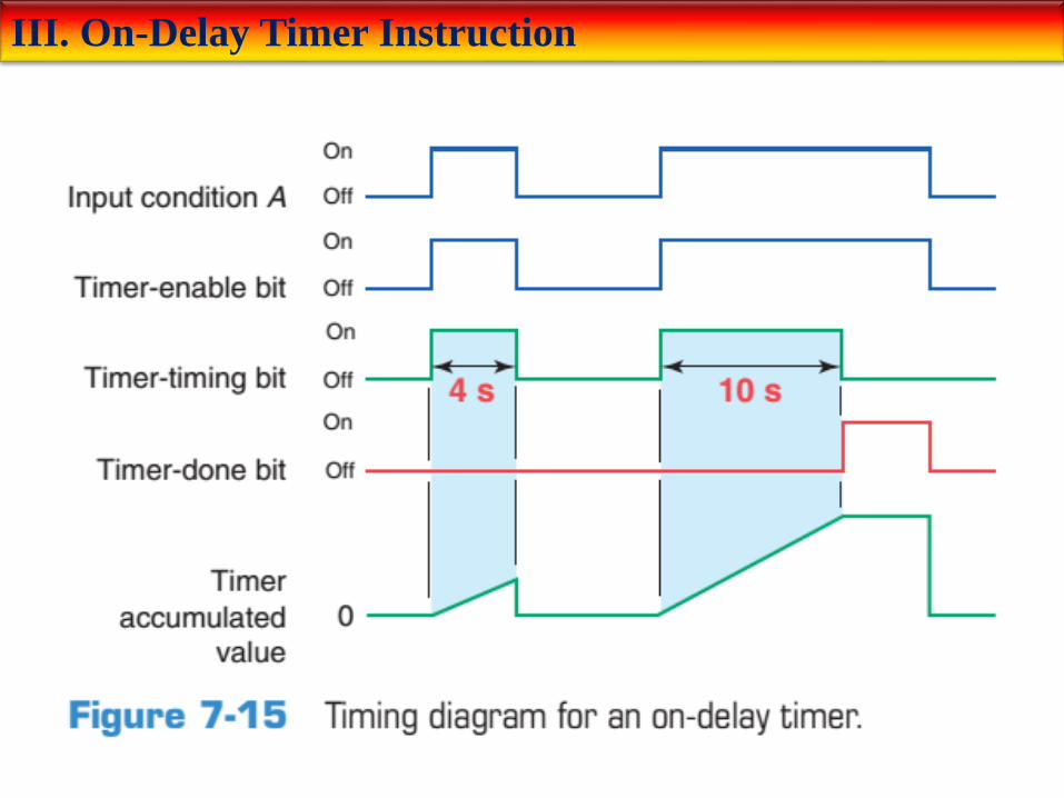
Figure 7-15 shows the timing diagram for the on-delay timer’s control
bits. The sequence of operation is as follows:
• The first true period of the timer rung shows the timer timing to 4 s
and then going false.
• The timer resets, and both the timer-timing bit and the enable bit go
false. The accumulated value also resets to 0.
• For the second true period input A remains true in excess of 10 s.
• When the accumulated value reaches 10 s, the done bit (DN) goes
from false to true and the timer-timing bit (TT) goes from true to false.
• When input A goes false, the timer instruction goes false and also
resets, at which time the control bits are all reset and the accumulated
value resets to 0.
III. On-Delay Timer Instruction

III. On-Delay Timer Instruction
The timer table for an Allen-Bradley SLC 500 is shown in Figure 7-16.
Addressing is done at three different levels: the element level, the word
level, and the bit level. The timer uses three words per element. Each
element consists of a control word, a preset word, and an accumulated
word. Each word has 16 bits, which are numbered from 0 to 15. When
addressing to the bit level, the address always refers to the bit within the
word:
EN=Bit 15 enable
TT=Bit 14 timer timing
DN=Bit 13 done
III. On-Delay Timer Instruction
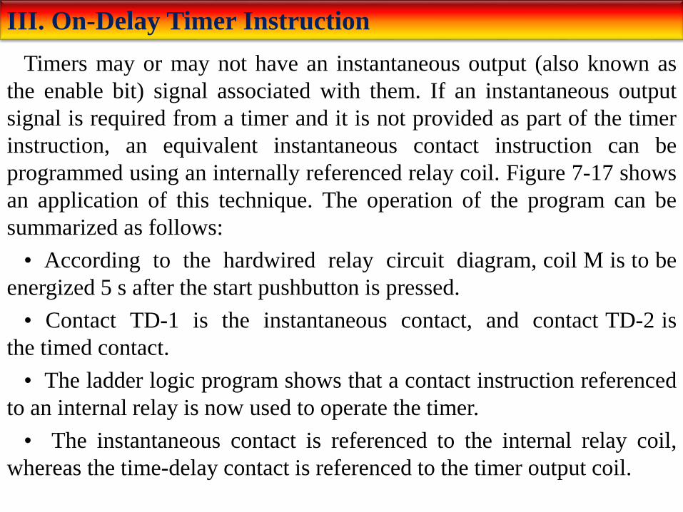
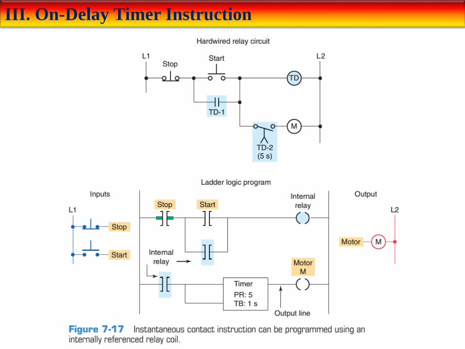
Timers may or may not have an instantaneous output (also known as
the enable bit) signal associated with them. If an instantaneous output
signal is required from a timer and it is not provided as part of the timer
instruction, an equivalent instantaneous contact instruction can be
programmed using an internally referenced relay coil. Figure 7-17 shows
an application of this technique. The operation of the program can be
summarized as follows:
• According to the hardwired relay circuit diagram, coil M is to be
energized 5 s after the start pushbutton is pressed.
• Contact TD-1 is the instantaneous contact, and contact TD-2 is
the timed contact.
• The ladder logic program shows that a contact instruction referenced
to an internal relay is now used to operate the timer.
• The instantaneous contact is referenced to the internal relay coil,
whereas the time-delay contact is referenced to the timer output coil.
III. On-Delay Timer Instruction
III. On-Delay Timer Instruction
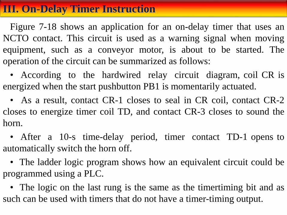
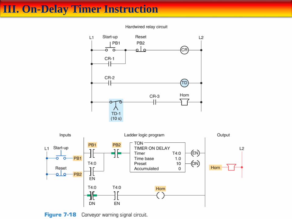
Figure 7-18 shows an application for an on-delay timer that uses an
NCTO contact. This circuit is used as a warning signal when moving
equipment, such as a conveyor motor, is about to be started. The
operation of the circuit can be summarized as follows:
• According to the hardwired relay circuit diagram, coil CR is
energized when the start pushbutton PB1 is momentarily actuated.
• As a result, contact CR-1 closes to seal in CR coil, contact CR-2
closes to energize timer coil TD, and contact CR-3 closes to sound the
horn.
• After a 10-s time-delay period, timer contact TD-1 opens to
automatically switch the horn off.
• The ladder logic program shows how an equivalent circuit could be
programmed using a PLC.
• The logic on the last rung is the same as the timertiming bit and as
such can be used with timers that do not have a timer-timing output.
III. On-Delay Timer Instruction

III. On-Delay Timer Instruction
Timers are often used as part of automatic sequential control systems. Figure 7-19 shows how a series of motors can be started automatically with only one start/stop control station. The operation of the circuit can be summarized as follows:
• According to the relay ladder schematic, lube-oil pump motor starter coil M1 is energized when the start pushbutton PB2 is momentarily actuated.
• As a result, M1-1 control contact closes to seal in M1, and the lube-oil pump motor starts.
• When the lube-oil pump builds up sufficient oil pressure, the lube-oil pressure switch PS1 closes.
• This in turn energizes coil M2 to start the main drive motor and energizes coil TD to begin the timedelay period.
• After the preset time-delay period of 15 s, TD-1 contact closes to energize coil M3 and start the feed motor.
• The ladder logic program shows how an equivalent circuit could be programmed using a PLC

III. On-Delay Timer Instruction

IV. Off-Delay Timer Instruction
The off-delay timer (TOF) operation will keep the output energized for
a time period after the rung containing the timer has gone false. Figure 7-
20 illustrates the programming of an off-delay timer that uses the SLC
500 TOF timer instruction. If logic continuity is lost, the timer begins
counting time-based intervals until the accumulated time equals the
programmed preset value. The operation of the circuit can be
summarized as follows:
• When the switch connected to input I:1/0 is first closed, timed output
O:2/1 is set to 1 immediately and the lamp is switched on.
• If this switch is now opened, logic continuity is lost and the timer
begins counting.
• After 15 s, when the accumulated time equals the preset time, the
output is reset to 0 and the lamp switches off.
• If logic continuity is gained before the timer is timed out, the
accumulated time is reset to 0. For this reason, this timer is also
classified as non-retentive.

IV. Off-Delay Timer Instruction

IV. Off-Delay Timer Instruction
Figure 7-21 illustrates the use of an off-delay timer instruction used to switch motors off sequentially at 5 second intervals. The operation of the program can be summarized as follows:
• Timer preset values for T4:1, T4:2, and T4:3 are set for 5 s, 10s, and 15 s, respectively.
• Closing the input switch SW immediately sets the done bit of each of the three off-delay timers to 1, immediately turning on motors M1, M2, and M3.
• If SW is then opened, logic continuity to all three timers is lost and each timer begins counting.
• Timer T4:1 times out after 5 s resetting its done bit to zero to de-energize motor M1.
• Timer T4:2 times out 5 s later resetting its done bit to zero to de-energize motor M2.
• Timer T4:3 times out 5 s later resetting its done bit to zero to de-energize motor M3.

IV. Off-Delay Timer Instruction

IV. Off-Delay Timer Instruction
Figure 7-22 shows how a hardwired off-delay timer relay circuit with both instantaneous and timed contacts. The operation of the circuit can be summarized as follows:
• When power is first applied (limit switch LS open), motor starter coil M1 is energized and the green pilot light is on.
• At the same time, motor starter coil M2 is de-energized, and the red pilot light is off.
• When limit switch LS closes, off-delay timer coil TD energizes.
• As a result, timed contact TD-1 opens to de-energize motor starter coil M1, timed contact TD-2 closes to energize motor starter coil M2, instantaneous contact TD-3 opens to switch the green light off, and instantaneous contact TD-4 closes to switch the red light on. The circuit remains in this state as long as limit switch LS1 is closed.
• When limit switch LS1 is opened, the off-delay timer coil TD de-energizes and the time-delay period is started.
• Instantaneous contact TD-3 closes to switch the green light on, and instantaneous contact TD-4 opens to switch the red light off.
• After a 5-s time-delay period, timed contact TD-1 closes to energize motor starter M1, and timed contact TD-2 opens to de-energize motor starter M2.

IV. Off-Delay Timer Instruction

IV. Off-Delay Timer Instruction
Figure 7-23 shows an equivalent PLC program of the hardwired off-
delay timer relay circuit containing both instantaneous and timed
contacts. The timer instruction carries out all of the functions of the
original physical timer.

IV. Off-Delay Timer Instruction

IV. Off-Delay Timer Instruction
Figure 7-24 shows a program that uses both the on-delay and the off-
delay timer instruction. The process involves pumping fluid from tank A
to tank B. The operation of the process can be summarized as follows:
• Before starting, PS1 must be closed.
• When the start button is pushed, the pump starts. The button can then
be released and the pump continues to operate.
• When the stop button is pushed, the pump stops.
• PS2 and PS3 must be closed 5 s after the pump starts. If either PS2
or PS3 opens, the pump will shut off and will not be able to start again
for another 14 s.

IV. Off-Delay Timer Instruction
V. Retentive Timer
A retentive timer accumulates time whenever the device receives
power, and it maintains the current time should power be removed from
the device. When the timer accumulates time equal to its preset value, the
contacts of the device change state. Loss of power to the timer after
reaching its preset value does not affect the state of the contacts. The
retentive timer must be intentionally reset with a separate signal for the
accumulated time to be reset and for the contacts of the device to return
to its non energized state.
Figure 7-25 illustrates the action of a motor-driven, electromechanical
retentive timer used in some appliances. The shaft-mounted cam is
driven by a motor. Once power is applied, the motor starts turning the
shaft and cam. The positioning of the lobes of the cam and the gear
reduction of the motor determine the time it takes for the motor to turn
the cam far enough to activate the contacts. If power is removed from the
motor, the shaft stops but does not reset.

V. Retentive Timer
V. Retentive Timer
A PLC retentive timer is used when you want to retain accumulated
time values through power loss or the change in the rung state from true
to false. The PLC-programmed retentive on-delay timer (RTO) is
programmed in a manner similar to the non retentive on-delay timer
(TON), with one major exception—a retentive timer reset (RES)
instruction. Unlike the TON, the RTO will hold its accumulated value
when the timer rung goes false and will continue timing where it left off
when the timer rung goes true again. This timer must be accompanied by
a timer reset instruction to reset the accumulated value of the timer to 0.
The RES instruction is the only automatic means of resetting the
accumulated value of a retentive timer. The RES instruction has the same
address as the timer it is to reset. Whenever the RES instruction is true,
both the timer accumulated value and the timer done bit (DN) are reset to
0.

V. Retentive Timer
Figure 7-26 shows a PLC program for a retentive on-delay timer. The
operation of the program can be summarized as follows:
• The timer will start to time when time pushbutton PB1 is closed.
• If the pushbutton is closed for 3 seconds and then opened for 3
seconds, the timer accumulated value will remain at 3 seconds.
• When the time pushbutton is closed again, the timer picks up the
time at 3 seconds and continues timing.
• When the accumulated value (9) equals the preset value (9), the timer
done bit T4:2/DN is set to 1 and the pilot light output PL is switched on.
• Whenever the momentary reset pushbutton is closed the timer
accumulated value is reset to 0.
V. Retentive Timer

V. Retentive Timer
Figure 7-27 shows a timing chart for the retentive ondelay timer
program. The timing operation can be summarized as follows:
• When the timing rung is true (PB1 closed) the timer will commence
timing.
• If the timing rung goes false the timer will stop timing but will
recommence timing for the stored accumulated value each time the rung
goes true.
• When the reset PB2 is closed, the T4:2/DN bit is reset to 0 and turns
the pilot light output off. The accumulated value is also reset and held at
zero until the reset pushbutton is opened.
V. Retentive Timer

V. Retentive Timer
The program drawn in Figure 7-28 illustrates a practical application for
an RTO. The purpose of the RTO timer is to detect whenever a piping
system has sustained a cumulative overpressure condition for 60 s. At
that point, a horn is sounded automatically to call attention to the
malfunction. When they are alerted, maintenance personnel can silence
the alarm by switching the key switch S1 to the reset (contact closed)
position. After the problem has been corrected, the alarm system can be
reactivated by switching the key switch to open contact position.

V. Retentive Timer

V. Retentive Timer
Figure 7-29 shows a practical application that uses the on-delay, off-delay, and retentive on-delay instructions in the same program. In this industrial application, there is a machine with a large steel shaft supported by babbitted bearings. This shaft is coupled to a large electric motor. The bearings need lubrication, which is supplied by an oil pump driven by a small electric motor. The operation of the program can be summarized as follows:
• To start the machine, the operator turns SW on.
• Before the motorshaft starts to turn, the bearings are supplied with oil by the pump for 10 seconds.
• The bearings also receive oil when the machine is running.
• When the operator turns SW off to stop the machine, the oil pump continues to supply oil for 15 seconds.
• A retentive timer is used to track the total running time of the pump. When the total running time is 3 hours, the motor is shut down and a pilot light is turned on to indicate that the filter and oil need to be changed.
• A reset button is provided to reset the process after the filter and oil have been changed.
Retentive timers do not have to be timed out completely to be reset. Rather, such a timer can be reset at any time during its operation. Note that the reset input to the timer will override the control input of the timer even though the control input to the timer has logic continuity.

V. Retentive Timer

VI. Cascading Timers
The programming of two or more timers together is called cascading.Timers can be interconnected, or cascaded, to satisfy a number of logic control functions.
Figure 7-30 shows how three motors can be started automatically in sequence with a 20 s time delay between each using two hardwired on-delay timers. The operation of the circuit can be summarized as follows:
• Motor starter coil M1 is energized when the momentary start pushbutton PB2 is actuated.
• As a result, motor 1 starts, contact M1-1 closes to seal in M1, and timer coil TD1 is energized to begin the first time-delay period.
• After the preset time period of 20 s, TD1-1 contact closes to energize motor starter coil M2.
• As a result, motor 2 starts and timer coil TD2 is energized to begin the second time-delay period.
• After the preset time period of 20 s, TD2-1 contact closes to energize motor starter coil M3, and so motor 3 starts.

VI. Cascading Timers

VI. Cascading Timers
Figure 7-31 shows an equivalent PLC program of the hardwired
sequential time-delayed motor-starting circuit. Two programmed on-
delay timers are cascaded together to obtain the same logic as the
original hardwired timer relay circuit. Note that the output of timer T4:1
is used to control the input logic to timer T4:2.

VI. Cascading Timers

VI. Cascading Timers
Two timers can be interconnected to form an oscillator circuit. The
oscillator logic is basically a timing circuit programmed to generate
periodic output pulses of any duration. Figure 7-32 shows the program
for an annunciator flasher circuit. Two internal timers form the oscillator
circuit, which generates a timed, pulsed output. The oscillator circuit
output is programmed in series with the alarm condition. If the alarm
condition (temperature, pressure, or limit switch) is true, the appropriate
output indicating light will flash. Note that any number of alarm
conditions could be programmed using the same flasher circuit.

VI. Cascading Timers

VI. Cascading Timers
At times you may require a time-delay period longer than the maximum preset time allowed for the single timer instruction of the PLC being used. When this is the case, the problem can be solved by simply cascading timers, as illustrated in Figure 7-33 . The operation of the program can be summarized as follows:
• The total time-delay period required is 42,000 s.
• The first timer, T4:1, is programmed for a preset time of 30,000 s and begins timing when input SW is closed.
• When T4:1 completes its time-delay period 30,000 s later, the T4:1/DN bit will be set to 1.
• This in turn activates the second timer, T4:2, which is preset for the remaining 12,000 s of the total 42,000-s time delay.
• Once T4:2 reaches its preset time, the T4:2/DN bit will be set to 1, which switches on the output PL, the pilot light, to indicate the completion of the full 42,000-s time delay.
• Opening input SW at any time will reset both timers and switch output PL off.

VI. Cascading Timers

VI. Cascading Timers
A typical application for PLC timers is the control of traffic lights. The
ladder logic circuit of Figure 7-34 illustrates a control of a set of traffic
lights in one direction. The operation of the program can be summarized
as follows:
• Transition from red light to green light to amber light is accomplished
by the interconnection of the three TON timer instructions.
• The input to timer T4:0 is controlled by the T4:2 done bit.
• The input to timer T4:1 is controlled by the T4:0 done bit.
• The input rung to timer T4:2 is controlled by the T4:1 done bit.
• The timed sequence of the lights is:
Red—30 s on
Green—25 s on
Amber—5 s on
• The sequence then repeats itself.

VI. Cascading Timers

VI. Cascading Timers
The chart shown in Figure 7-35 shows the timed sequence of the lights
for two-directional control of traffic lights.
Figure 7-36 shows the original traffic light program modified to
include three more lights that control traffic flow in two directions.

VI. Cascading Timers
REVIEW QUESTIONS
1. Explain the difference between the timed and instantaneous contacts of a mechanical timing relay.
2. Draw the symbol and explain the operation of each of the following timed contacts of a mechanical timing relay:
a. On-delay timer—NOTC contact
b. On-delay timer—NCTO contact
c. Off-delay timer—NOTO contact
d. Off-delay timer—NCTC contact
3. Name five pieces of information usually associated with a PLC timer instruction.
4. When is the output of a programmed timer energized?
5. a.What are the two methods commonly used to represent a timer instruction within a PLC’s ladder logic program?
b. Which method is preferred? Why?
6. a.Explain the difference between the operation of a non-retentive timer and that of a retentive timer.
b. Explain how the accumulated count of programmed retentive and non-retentive timers is reset to zero.
REVIEW QUESTIONS
7. State three advantages of using programmed PLC timers over mechanical timing relays.
8. For a TON timer:
a. When is the enable bit of a timer instruction true?
b. When is the timer-timing bit of a timer instruction true?
c. When does the done bit of a timer change state?
9. For a TOF timer:
a. When is the enable bit of a timer instruction true?
b. When is the timer-timing bit of a timer instruction true?
c. When does the done bit of a timer change state?
10. Explain what each of the following quantities associated with a PLC timer instruction represents:
a. Preset time
b. Accumulated time
c. Time base
11. State the method used to reset the accumulated time of each of the following:
a. TON timer
b. TOF timer
c. RTO timer
PROBLEMS
1. a.With reference to the relay schematic diagram in Figure 7-37, state
the status of each light (on or off) after each of the following sequential
events:
i. Power is first applied and switch S1 is open.
ii. Switch S1 has just closed.
iii. Switch S1 has been closed for 5 s.
iv. Switch S1 has just opened.
v. Switch S1 has been opened for 5 s.
b. Design a PLC program and prepare a typical I/O connection diagram
and ladder logic program that will execute this hardwired control circuit
correctly.

PROBLEMS

PROBLEMS
2. Design a PLC program and prepare a typical I/O connection
diagram and ladder logic program that will correctly execute the
hardwired relay control circuit shown in Figure 7-38 .

PROBLEMS
3. Study the ladder logic program in Figure 7-39 and answer the questions
that follow:
a. What type of timer has been programmed?
b. What is the length of the time-delay period?
c. What is the value of the accumulated time when power is first applied?
d. When does the timer start timing?
e. When does the timer stop timing and reset itself?
f. When input LS1 is first closed, which rungs are true and which are false?
g. When input LS1 is first closed, state the status (on or off) of each output.
h. When the timer’s accumulated value equals the preset value, which rungs
are true and which are false?
i. When the timer’s accumulated value equals the preset value, state the
status (on or off) of each output.
j. Suppose that rung 1 is true for 5 s and then power is lost. What will the
accumulated value of the counter be when power is restored?

PROBLEMS
PROBLEMS
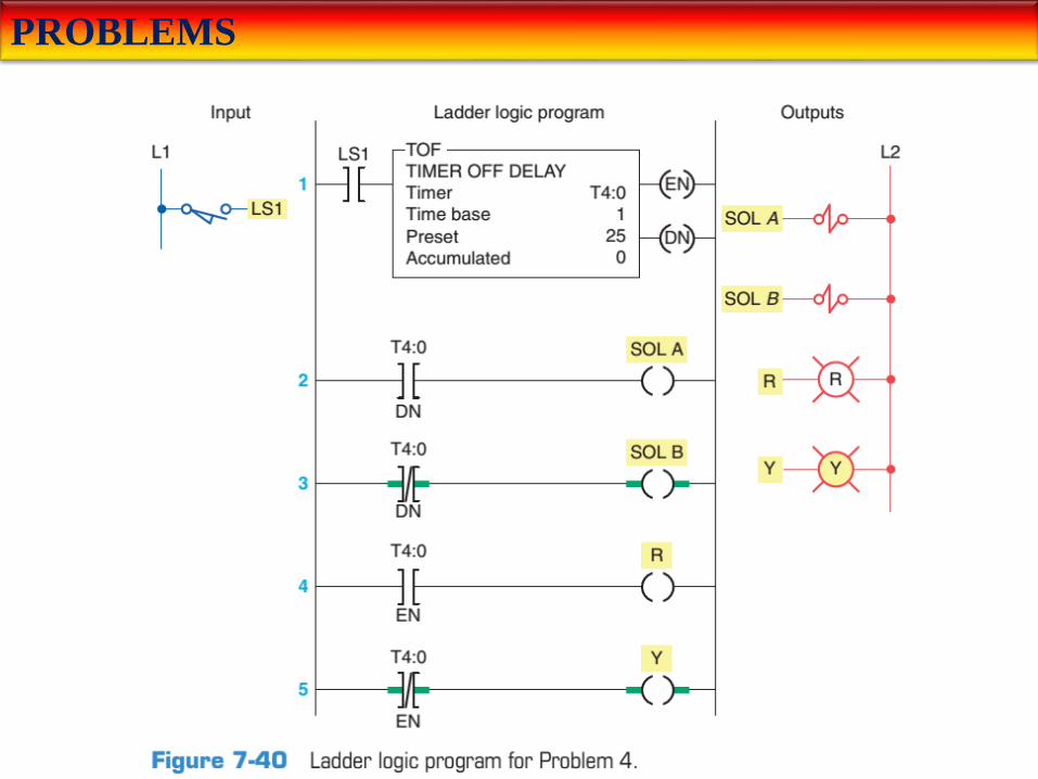
4. Study the ladder logic program in Figure 7-40 and answer the questions
that follow:
a. What type of timer has been programmed?
b. What is the length of the time-delay period?
c. What is the value of the accumulated time when power is first applied?
d. When does the timer start timing?
e. When does the timer stop timing and reset itself?
f. When input LS1 is first closed, which rungs are true and which are false?
g. When input LS1 is first closed, state the status (on or off) of each output.
h. When the timer’s accumulated value equals the preset value, which rungs
are true and which are false?
i. When the timer’s accumulated value equals the preset value, state the
status (on or off) of each output.
j. Suppose that rung 1 is true for 5 s and then power is lost. What will the
accumulated value of the counter be when power is restored?
PROBLEMS

PROBLEMS
5. Study the ladder logic program in Figure 7-41 , and answer the
questions that follow:
a. What type of timer has been programmed?
b. What is the length of the time-delay period?
c. When does the timer start timing?
d. When is the timer reset?
e. When will rung 3 be true?
f. When will rung 5 be true?
g. When will output PL4 be energized?
h. Assume that your accumulated time value is up to 020 and power to
your system is lost. What will your accumulated time value be when
power is restored?
i. What happens if inputs PB1 and PB2 are both true at the same time?

PROBLEMS

PROBLEMS
6. Study the ladder logic program in Figure 7-42 and answer the
questions that follow:
a. What is the purpose of interconnecting the two timers?
b. How much time must elapse before output PL is energized?
c. What two conditions must be satisfied for timer T4:2 to start timing?
d. Assume that output PL is on and power to the system is lost. When
power is restored, what will the status of this output be?
e. When input PB2 is on, what will happen?
f. When input PB1 is on, how much accumulated time must elapse
before rung 3 will be true?

PROBLEMS

PROBLEMS
7. You have a machine that cycles on and off during its operation. You
need to keep a record of its total run time for maintenance purposes.
Which timer would accomplish this?
8. Write a ladder logic program that will turn on a light, PL, 15 s after
switch S1 has been turned on.
9. Study the on-delay timer ladder logic program in Figure 7-43 , and
from each of the conditions stated, determine whether the timer is reset,
timing, or timed out or if the conditions stated are not possible.
a. The input is true, and EN is 1, TT is 1, and DN is 0.
b. The input is true, and EN is 1, TT is 1, and DN is 1.
c. The input is false, and EN is 0, TT is 0, and DN is 0.
d. The input is true, and EN is 1, TT is 0, and DN is 1.

PROBLEMS

PROBLEMS
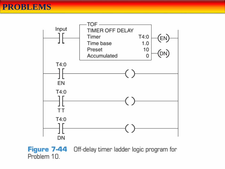
10. Study the off-delay timer ladder logic program in Figure 7-44 , and
from each of the conditions stated, determine whether the timer is reset,
timing, or timed out or if the conditions stated are not possible.
a. The input is true, and EN is 0, TT is 0, and DN is 1.
b. The input is true, and EN is 1, TT is 1, and DN is 1.
c. The input is true, and EN is 1, TT is 0, and DN is 1.
d. The input is false, and EN is 0, TT is 1, and DN is 1.
e. The input is false, and EN is 0, TT is 0, and DN is 0.
PROBLEMS

PROBLEMS
11. Write a program for an ―anti–tie down circuit‖ that will disallow a
punch press solenoid from operating unless both hands are on the two
palm start buttons. Both buttons must be pressed at the same time within
0.5 s. The circuit also will not allow the operator to tie down one of the
buttons and operate the press with just one button. (Hint: Once either of
the buttons is pressed, begin timing 0.5 s. Then, if both buttons are not
pressed, prevent the press solenoid from operating.)
12. Modify the program for the control of traffic lights in two
directions so that there is a 3-s period when both directions will have
their red lights illuminated.

PROBLEMS
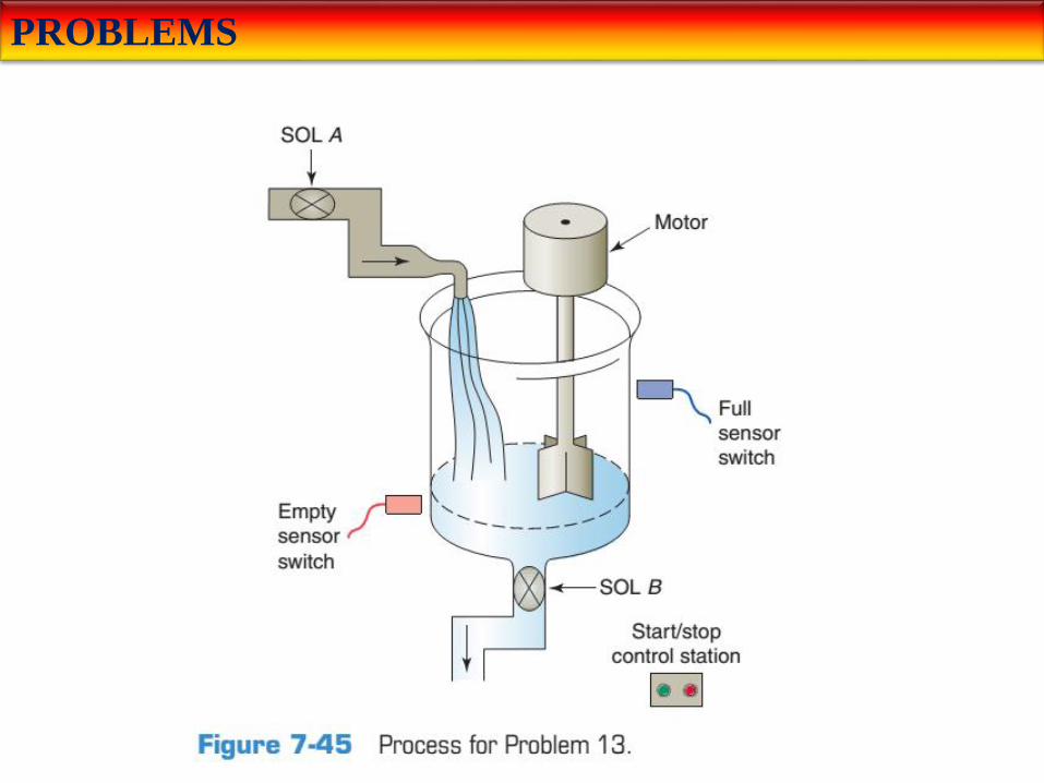
13. Write a program to implement the process illustrated in Figure 7-45 .The sequence of operation is to be as follows:
• Normally open start and normally closed stop pushbuttons are used to start and stop the process.
• When the start button is pressed, solenoid A energizes to start filling the tank.
• As the tank fills, the empty level sensor switch closes.
• When the tank is full, the full level sensor switch closes.
• Solenoid A is de-energized.
• The agitate motor starts automatically and runs for 3 min to mix the liquid.
• When the agitate motor stops, solenoid B is energized to empty the tank.
• When the tank is completely empty, the empty sensor switch opens to de-energize solenoid B.
• The start button is pressed to repeat the sequence.
PROBLEMS

PROBLEMS
14. When the lights are turned off in a building, an exit door light is to remain on for an additional 2 min, and the parking lot lights are to remain on for an additional 3 min after the door light goes out. Write a program to implement this process.
15. Write a program to simulate the operation of a sequential taillight system. The light system consists of three separate lights on each side of the car. Each set of lights will be activated separately, by either the left or right turn signal switch. There is to be a 1s delay between the activation of each light, and a 1-s period when all the lights are off. Ensure that when both switches are on, the system will not operate. Use the least number of timers possible. The sequence of operation should be as follows:
• The switch is operated.
• Light 1 is illuminated.
• Light 2 is illuminated 1 s later.
• Light 3 is illuminated 1 s later.
• Light 3 is illuminated for 1 s.
• All lights are off for 1 s.
• The system repeats while the switch is on.


