

220VAC Swing Gate Operator
USER’S GUIDECONTROLLER
PKM1.2K


2
21)Ensure that entrapment between the driven part and the surrounding fixed parts due to the opening movement of the driven part is avoided.
22)After installation, ensure that the mechanism is properly adjusted and that the protection system and any manual release function correctly.
23)Permanently fix the label concerning the manual release adjacent to its actuating member.
24)The drive cannot be used with a driven part incorporating a wicket door.
~220V(10%)50HZ
~220V/24V/12V/10W
200mA(AC24V)
-10 C~450 C
5AX2
60S
Power supply
Transformer
Accessories max loaded
Environment temperature
Protection fuse
Running time protect(Max)
Auto close time delay Programmable(0~99)
Force
E_LOCK Relay out
Adjustable

Transformer
BUZZER Fuse (5A)
Fuse(5A)
Force of motor 2adjust
Auto-close time adjust
Dipswitch
Terminal (power and motor)
Fuse(0.2A)
3.Controller:
4.1 Button instruction:
S1:Open the gate and increase 1 every once push when adjust the interval time between left and right leaf. S2:Close the gate and decrease 1 every once push when adjust the interval time between left and right leaf. S4:Stop the gate when the gate is running. Set the interval time between left and right leaf when the gate is stopped.
3
2. Example of a sliding gate operator installed:
Alarm light
Controller
po
wer
cab
le
Operater 1
Operater 2
Force of motor 1adjust
receiver board
Learnbutton
main icbutton
Terminal (limit and photocell...)
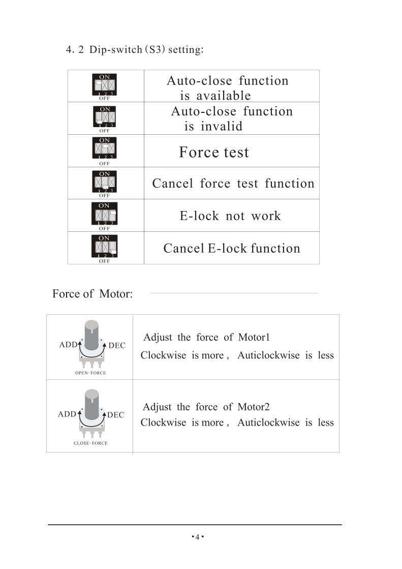
Auto-close function is invalid
Auto-close function is available
Cancel E-lock function
E-lock not work
Force test
Cancel force test function
4.2 Dip-switch(S3)setting:
Adjust the force of Motor1
Clockwise is more , Auticlockwise is less
Adjust the force of Motor2
Clockwise is more , Auticlockwise is less
Force of Motor:
ADD DEC
ADD DEC
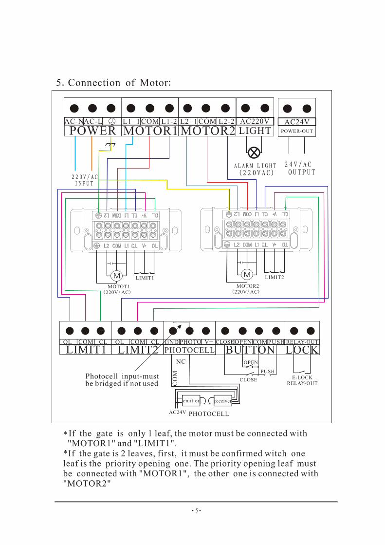
POWER MOTOR1 MOTOR2 LIGHTAC220V AC24V
POWER-OUT
AC-NAC-L L1-1 COM L1-2 L2-1 COM L2-2
5.Connection of Motor:
220V/AC INPUT
ALARM LIGHT (220VAC)
24V/AC OUTPUT
LIMIT1 LIMIT2 PHOTOCELL BUTTON LOCKOL COM CL OL COM CL GND PHOTO V+ CLOSEOPEN COMPUSH RELAY-OUT
AC24V
NC
CO
M
E-LOCKRELAY-OUT
MOTOT1(220V/AC)
LIMIT2
MOTOR2(220V/AC)
* If the gate is only 1 leaf, the motor must be connected with MOTOR1" and LIMIT1"." "*If the gate is 2 leaves, first, it must be confirmed witch one leaf is the priority opening one. The priority opening leaf must be connected with "MOTOR1", the other one is connected with "MOTOR2"
5
LIMIT1
PHOTOCELL
OPEN
CLOSE
PUSHPhotocell input-must be bridged if not used
emitter receiver

LIMIT STOPPER
LIMIT SWITCH
“be,be”Y
N NThe time decrease and the beep “be”
“be,be”Y
EndSpot press”S4" button
POWER ON
Spot press”S4" button
“Be”,“Be”LED1 flashing
spot press“S2"button
The time isless than 0s?
The time increase and the beep “be”
spot press“S1"button
The time ismore than 9s?
Set delay time between 2 motors operating:

7
*No power*Break fuse
*Check power supply*Change fuse*Connect the limit*Not connect limit
*Change the motor
*The interval time between left and right leaf is very long
*Decrease the interval time
*Connectthe motor cable or
limit switch.
Motor not working
Only one motor working
*Motor is damaged
*The motor (or limit switch)not connect with control board .
First, press "LEARN BUTTON" once , the "LEARN LED" light, then,
press the button you choose on transmitter till the "LEARN LED "
flash and go out ,This button control double- leaf.
Second , press "LEARN BUTTON" twice, the "LEARN LED" light, then,
press ano ther button you choose on transmitter till the "LEARN LED "
flash and go out, This button control leaf open.
Now , the transmitter is coded, Other transmitters can be coded as this way.
Press"LEARN BUTTON" and hold on to make the "LEARN LED" light till go out .Now ,all codes of transmitters which had been learnt are cleared.
8.2: Earsuring transmitter codes:
8.1: Setting transmitter code:LEARN BUTTONLEARN LED
9.Trouble Shooting:
*Clutch is released* Use the key to couple the clutch
*Operating handle is broken
*Worm gears are jammed*Change the handle
*Rotate the pinion
*Position of limit switch is not correct
*Limit switch is damaged
*Adjust position
*Change limit switch
*Distance of limit switch is too large*Limit switch is wrong*Magnetic- steel’s position is wrong
*Adjust position of limit switch*Change limit switch*Re-adjust the position


