
Generator Protection System
P. A. Amilkanthwar
Assistant Engineer (Gen)
Test - II
Topics for Discussion
Basics of Electrical Protection system Synchronous machine Concept of reactive power and real power
sharing Different Protections used for generator Advanced Protection Relays(Microprocessor
based) Case studies (analysis of electrical faults) Synchronization

Different Protections used for Generator Generator Differential Protection. Generator Inter Turn Protection. Generator Negative Sequence Protection. Generator Loss of Excitation Protection. Generator Over Voltage Protection. Frequency Protection Generator Over Load/ Over Current Protection Generator Rotor Earth Fault Protection Generator Back Up Impedance protection Generator Low Forward power Interlock Generator reverse power protection. 95% stator Earth Fault Protection

Instrument Transformers
Current Transformers• Turns ratio is
inversely proportional to the ratio specified
• Secondary current is according to primary current only
• Should not be left open circuited
Potential Transformers• Turns ratio is
directly proportional to the ratio specified
• Secondary current is according to burden connected
• Should not be short circuited

Flow Diagram of Tripping Process

Protection Classes Class A Protection• This master trip will operate when the fault needs to isolate
the generator immediately• This gives command to open the generator breaker and
field breaker. Class B Protection• This master trip will operate when the fault is not serious in
view of generator or it is not directly harmful to generator• This gives the command to trip turine Prime Mover TrippedThis indicates (gives feed back)prime mover is tripped.

Basics of Electrical Protection system
The Protection System Protection Classes Inputs to the protection system.
• Instrument Transformers• Contact Input
Elements of protection system.
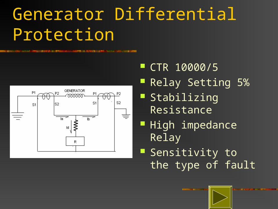
Generator Differential Protection
CTR 10000/5 Relay Setting 5% Stabilizing Resistance High impedance
Relay Sensitivity to the type
of fault

Elements of protection system
• Current relays• Voltage relays• Power relays• Impedance relays• Frequency relays• Special function relays• Auxiliary Relays• Timers

Protection System
• Cause of Operation of Protection is the the Fault.
It Is Basically Designed,• To detect the fault at its earliest possible stage.• To give protection to the equipment against
secondary damage.• To avoid the equipment to run out side the
capability specified.
Specifications of Generator
Make: BHEL MVA: 247 Connection: Three Phase
Double Star Connected. Voltage: 15750 Volts Current: 9050 Amp Frequency: 50 Hz Speed: 3000 RPM No. of Poles: 2
Synchronous Impedance: 222%
Sub Transient Impedance: 30.5%
Transient Impedance: 21.4%
Cooling: water/ Hydrogen Cooled
Neutral Grounding: High Impedance (Through NGT)
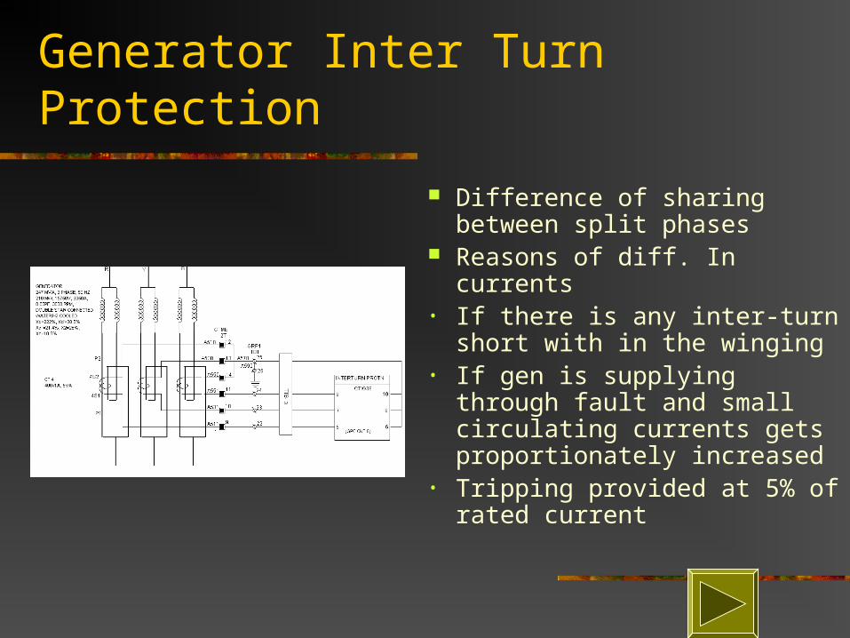
Generator Inter Turn Protection
Difference of sharing between split phases
Reasons of diff. In currents • If there is any inter-turn short
with in the winging• If gen is supplying through
fault and small circulating currents gets proportionately increased
• Tripping provided at 5% of rated current
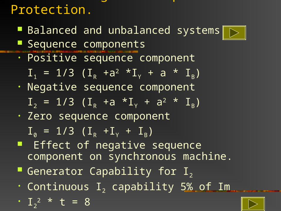
Generator Negative Sequence Protection.
Balanced and unbalanced systems Sequence components• Positive sequence component
I1 = 1/3 (IR +a2 *IY + a * IB)• Negative sequence component
I2 = 1/3 (IR +a *IY + a2 * IB)• Zero sequence component
I0 = 1/3 (IR +IY + IB) Effect of negative sequence component on
synchronous machine. Generator Capability for I2
• Continuous I2 capability 5% of Im• I2
2 * t = 8

Balanced Phasers
Generator Loss of Excitation Protection.
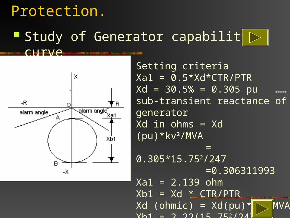
Study of Generator capability curve
Setting criteriaXa1 = 0.5*Xd*CTR/PTRXd = 30.5% = 0.305 pu ……sub-transient reactance of generator Xd in ohms = Xd (pu)*kv2/MVA
= 0.305*15.752/247 =0.306311993
Xa1 = 2.139 ohm Xb1 = Xd * CTR/PTRXd (ohmic) = Xd(pu)*kv2/MVAXb1 = 2.22(15.752/247)(10000/5)(110/15750) = 31.14 ohm
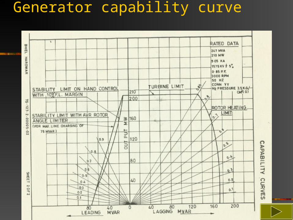
Generator capability curve
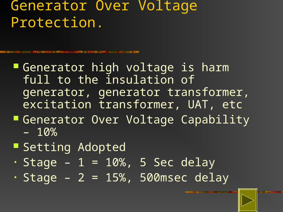
Generator Over Voltage Protection.
Generator high voltage is harm full to the insulation of generator, generator transformer, excitation transformer, UAT, etc
Generator Over Voltage Capability – 10% Setting Adopted• Stage – 1 = 10%, 5 Sec delay• Stage – 2 = 15%, 500msec delay

Frequency Protection
Over frequency protection• It indicates excess generation than
demand hence tripping should graded among the units
Under frequency protection
Under frequency is harmful to turbine Adopted settings

Adopted Frequency settingsUNIT NO.
CAPACITY UNDER FREQ. TRIP SETTING
OVER FREQUENCY TRIP SETTING
1 30 MW 47 HZ, 0.5 SEC DELAY
54.5 HZ, 21.15 SEC DELAY
2 30 MW
3 210 MW 52.5 HZ, 1 SEC DELAY
4 210 MW 52.0 HZ, 2 SEC DELAY
5 210 MW 52.0 HZ, 2.0 SEC DELAY
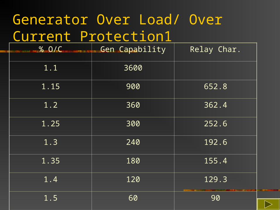
Generator Over Load/ Over Current Protection1
% O/C Gen Capability Relay Char.
1.1 3600
1.15 900 652.8
1.2 360 362.4
1.25 300 252.6
1.3 240 192.6
1.35 180 155.4
1.4 120 129.3
1.5 60 90
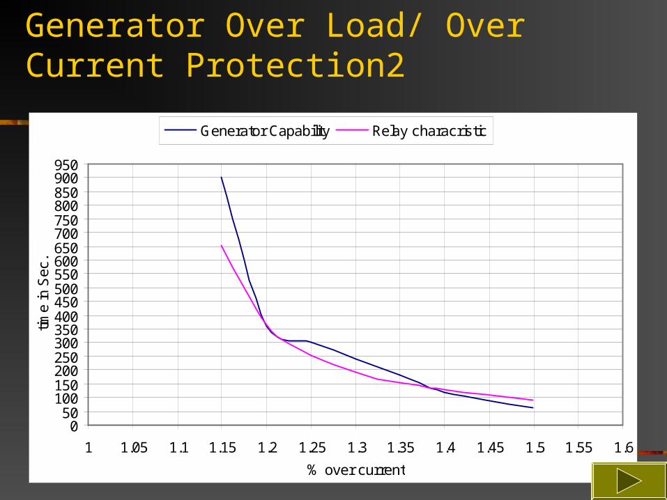
Generator Over Load/ Over Current Protection2
050
100150200250300350400450500550600650700750800850900950
1 1.05 1.1 1.15 1.2 1.25 1.3 1.35 1.4 1.45 1.5 1.55 1.6
% over current
time
in S
ec.
Generator Capability Relay characristic
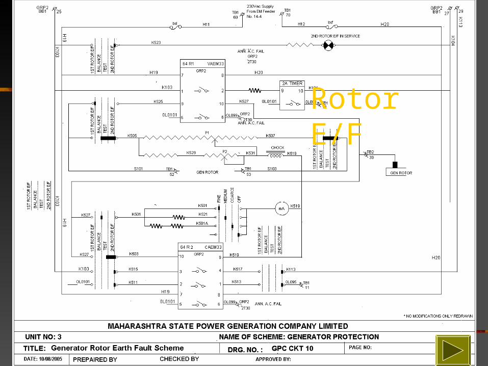
Rotor E/F
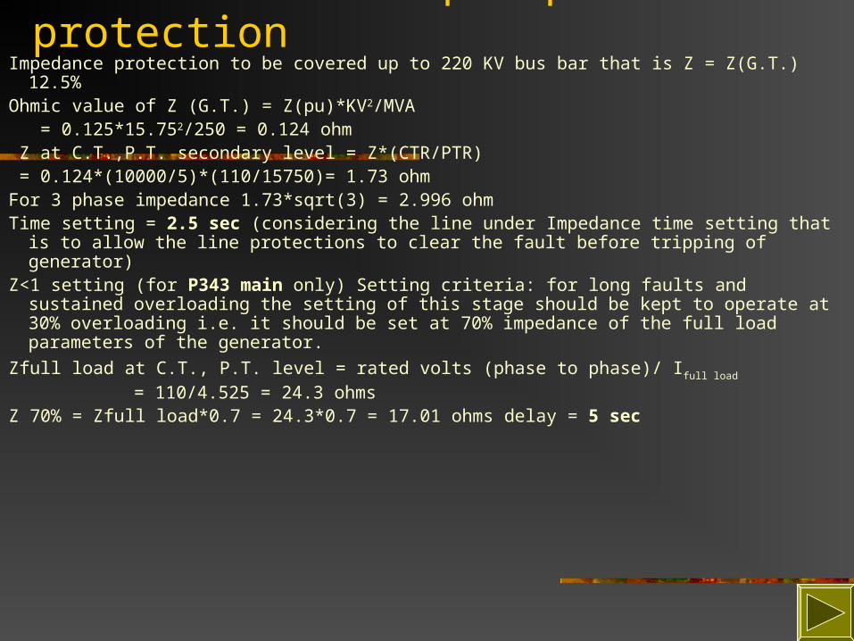
Generator Back Up Impedance protectionImpedance protection to be covered up to 220 KV bus bar that is Z = Z(G.T.) 12.5%Ohmic value of Z (G.T.) = Z(pu)*KV2/MVA = 0.125*15.752/250 = 0.124 ohm Z at C.T.,P.T. secondary level = Z*(CTR/PTR) = 0.124*(10000/5)*(110/15750)= 1.73 ohmFor 3 phase impedance 1.73*sqrt(3) = 2.996 ohm Time setting = 2.5 sec (considering the line under Impedance time setting that is to allow
the line protections to clear the fault before tripping of generator)Z<1 setting (for P343 main only) Setting criteria: for long faults and sustained
overloading the setting of this stage should be kept to operate at 30% overloading i.e. it should be set at 70% impedance of the full load parameters of the generator.
Zfull load at C.T., P.T. level = rated volts (phase to phase)/ Ifull load = 110/4.525 = 24.3 ohms
Z 70% = Zfull load*0.7 = 24.3*0.7 = 17.01 ohms delay = 5 sec

95% stator Earth Fault Protection

Salient Features of the relay P343: Following Protections of generator are covered in the relay1. Generator Differential Protection: - High Impedance / Biased Differential2. Phase fault over current protection: - 3.Neutral voltage displacement protection: -4.100% Stator earth fault protection: - 5.Under/over voltage protection: - Two stage under and Over voltage protection.6.Under/over frequency protection: - Four stage under frequency and two stage over frequency protection.7.Reverse power: - Protection against loss of prime mover.8.Low forward power: - Provides an interlock for non-urgent tripping.9.Field failure: - Two stage element for protection against loss of excitation.1 Negative phase sequence protection: - Provides protection against unbalanced loading, which can cause overheating of the generator rotor.1Over fluxing: - Provides protection for the generator/transformer against unusual voltage or frequency conditions.1 Unintentional energization at standstill (dead machine) protection: - Protection against inadvertent closing of the generator circuit breaker when machine is not running.
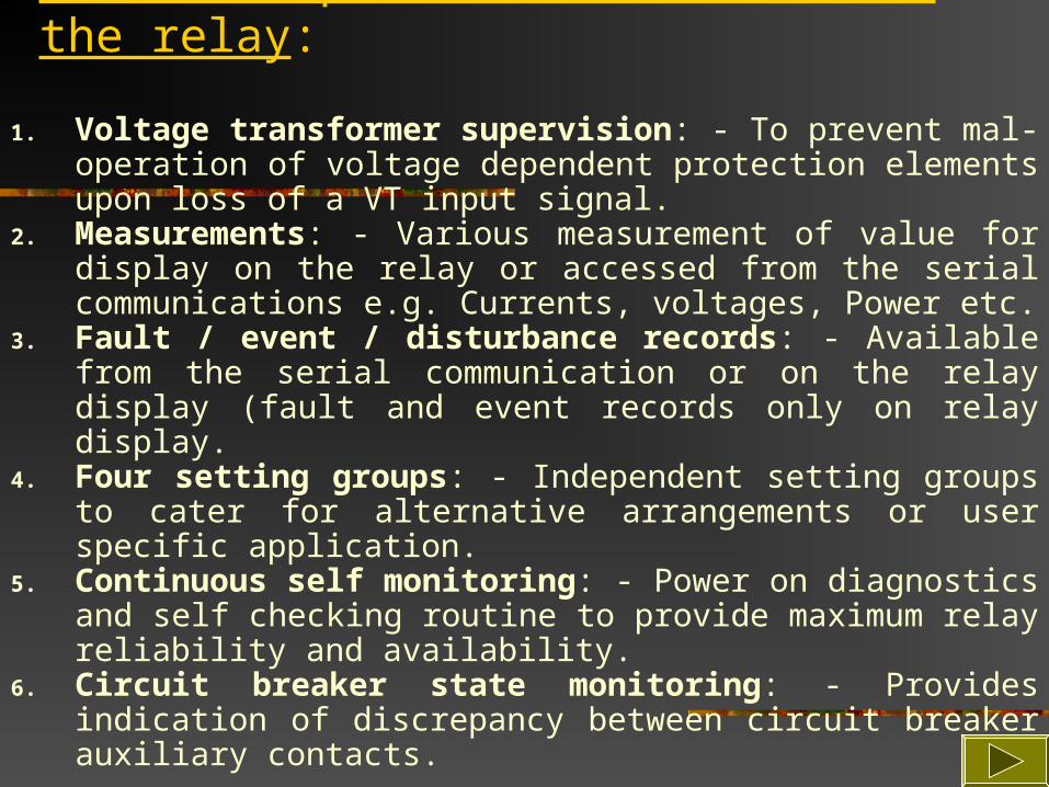
Other non-protective features of the relay:
1. Voltage transformer supervision: - To prevent mal-operation of voltage dependent protection elements upon loss of a VT input signal.
2. Measurements: - Various measurement of value for display on the relay or accessed from the serial communications e.g. Currents, voltages, Power etc.
3. Fault / event / disturbance records: - Available from the serial communication or on the relay display (fault and event records only on relay display.
4. Four setting groups: - Independent setting groups to cater for alternative arrangements or user specific application.
5. Continuous self monitoring: - Power on diagnostics and self checking routine to provide maximum relay reliability and availability.
6. Circuit breaker state monitoring: - Provides indication of discrepancy between circuit breaker auxiliary contacts.

P343
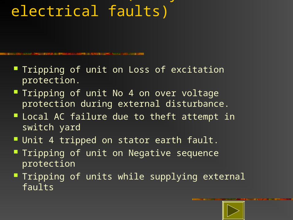
Case studies (analysis of electrical faults)
Tripping of unit on Loss of excitation protection. Tripping of unit No 4 on over voltage protection
during external disturbance. Local AC failure due to theft attempt in switch
yard Unit 4 tripped on stator earth fault. Tripping of unit on Negative sequence protection Tripping of units while supplying external faults

Synchronization Procedure
Keep Excitation on Manual Channel. Make the FF Supply ON. Close the field Breaker and observe
FF and FB both breakers ON
Voltage start building up
At @ 70% of rated voltage FF breaker gets OFF
Voltage stops rising at @ 14 KV Raise the voltage to @15.75KV with the help of Manual Control. Match the Null meter with the help of Auto Pot. Put the excitation on AUTO Proceed for Synchronization.

Thank You


