
International Journal of Advances in Engineering & Technology, Jan 2012.
©IJAET ISSN: 2231-1963
258 Vol. 2, Issue 1, pp. 258-268
PERFORMANCE VERIFICATION OF DC-DC BUCK
CONVERTER USING SLIDING MODE CONTROLLER FOR
COMPARISON WITH THE EXISTING CONTROLLERS - A
THEORETICAL APPROACH
Shelgaonkar (Bindu) Arti Kamalakar, N. R. Kulkarni
Modren College of Engg. Pune ,Maharashtra.
ABSTRACT
In recent electronic applications the variable DC power supply is derived with light weight, occupying less size
using 100 kHz switching frequency. When the frequency is high, the load experiences practically uninterrupted
DC voltage. According to need of application buck converter is considered for analysis. It is observed that
nature of DC- DC converter is nonlinear and time variant systems, and does not lend them to the application of
linear control theory. The performance of buck converter has been studied and is undertaken for their
theoretical verification, graphical representation and Matlab simulation. From the linear controller PI, PID is
considered and non linear controller sliding mode control is taken as control method. The paper work will
highlights nonlinear aspects of buck converter, non linear controller like sliding mode controller and hybrid
type of controller SMC PID. This will also focuses the benefits of non linear control.
KEYWORDS: SMC (sliding mode control), PI and PID control.
I. INTRODUCTION
DC–DC converter convert DC voltage signal from high level to low level signal or it can be vise versa
depending on the type of converter used in system. Buck converter is one of the most important
components of circuit it converts voltage signal from high DC signal to low voltage. In buck
converter, a high speed switching devices are placed and the better efficiency of power conversion
with the steady state can be achieved. In this paper work performance of buck converter is analyzed.
The circuit may consist of nonlinearity like delay, hysteresis etc. and because of this output voltage is
not constant. To settle the output voltage within minimum settling time and less overshoot different
types of controllers are considered such as linear controller PI, PID and in nonlinear controllers SMC
(sliding mode controller).The paper deals with comparison of performance of DC-DC buck converter
using controllers PI, PID, SMC and SMC PID. The performance of buck converter has been analyzed
in many papers amongst them papers [1][2] have been studied and are undertaken for their theoretical
verification, graphical representation and Matlab simulation.
II. SIMULATED MODEL OF BUCK CONVERTER
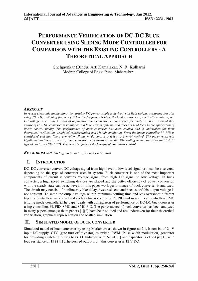
Simulated model of buck converter by using Matlab are as shown in figure no.2.1. It consist of 24 V
input DC supply, GTO (gate turn off thyristor) as switch, PWM (Pulse width modulation) generator
for providing switching pluses to GTO. Inductor is of 69 µH[1] and capacitor is of 220µF[1], with
load resistance of 13 Ω [1] .The desired output from this converter is 12 V DC.
International Journal of Advances in Engineering & Technology, Jan 2012.
©IJAET ISSN: 2231-1963
259 Vol. 2, Issue 1, pp. 258-268
Figure No 2.1 Buck converter in Matlab Simulink.
The circuit has settling time of 2 msec and output voltage is 14.12 V which is required to settle at 12
V. To compensate these transients present in buck converter different types of controllers can be used.
III. CONTROL METHODS
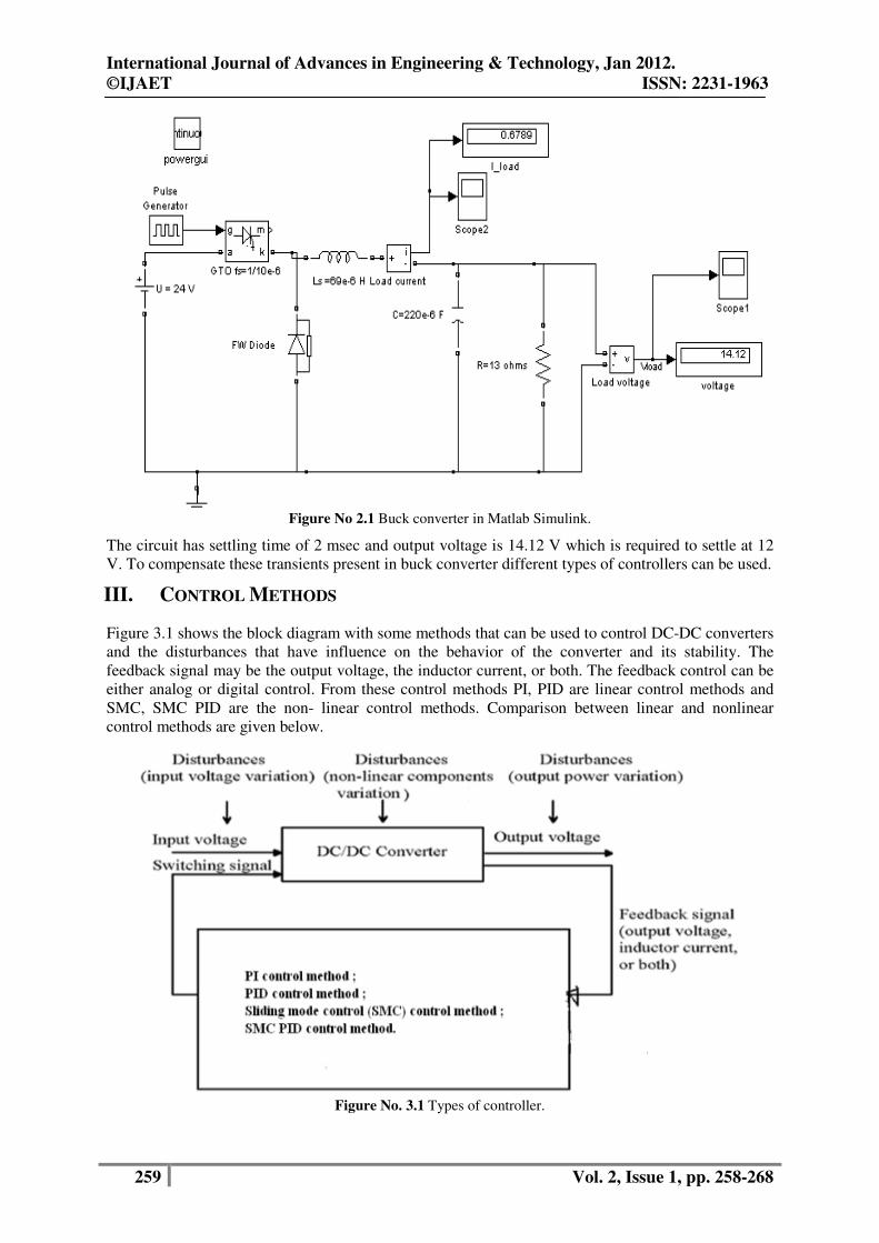
Figure 3.1 shows the block diagram with some methods that can be used to control DC-DC converters
and the disturbances that have influence on the behavior of the converter and its stability. The
feedback signal may be the output voltage, the inductor current, or both. The feedback control can be
either analog or digital control. From these control methods PI, PID are linear control methods and
SMC, SMC PID are the non- linear control methods. Comparison between linear and nonlinear
control methods are given below.
Figure No. 3.1 Types of controller.
International Journal of Advances in Engineering & Technology, Jan 2012.
©IJAET
260
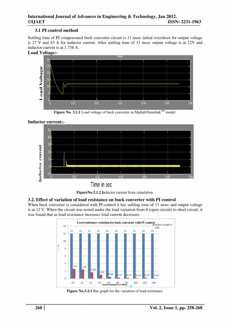
3.1 PI control method
Settling time of PI compensated buck converter circuit is 11 msec initial overshoot for output voltage
is 27 V and 43 A for inductor current. After settling time of 11 msec output voltage is at 12V and
inductor current is at 1.738 A.
Load Voltage:-
Figure No. 3.1.1 Load voltage of buck converter
Inductor current:-
FigureNo.
3.2. Effect of variation of load resistance on bWhen buck converter is considered with PI c
is at 12 V. When the circuit was tested under the load variation from 0 (open circuit) to short circuit, it
was found that as load resistance incre
Figure No.
International Journal of Advances in Engineering & Technology, Jan 2012.
Vol. 2, Issue
Settling time of PI compensated buck converter circuit is 11 msec initial overshoot for output voltage
is 27 V and 43 A for inductor current. After settling time of 11 msec output voltage is at 12V and
Load voltage of buck converter in Matlab/SimulinkTM
model.
FigureNo.3.1.2 Inductor current from simulation.
of variation of load resistance on buck converter with PI controlWhen buck converter is considered with PI control it has settling time of 11 msec and output voltage
is at 12 V. When the circuit was tested under the load variation from 0 (open circuit) to short circuit, it
was found that as load resistance increases load current decreases.
Figure No.3.2.1 Bar graph for the variation of load resistance.
International Journal of Advances in Engineering & Technology, Jan 2012.
ISSN: 2231-1963
, Issue 1, pp. 258-268
Settling time of PI compensated buck converter circuit is 11 msec initial overshoot for output voltage
is 27 V and 43 A for inductor current. After settling time of 11 msec output voltage is at 12V and
model.
control 11 msec and output voltage
is at 12 V. When the circuit was tested under the load variation from 0 (open circuit) to short circuit, it
International Journal of Advances in Engineering & Technology, Jan 2012.
©IJAET ISSN: 2231-1963
261 Vol. 2, Issue 1, pp. 258-268
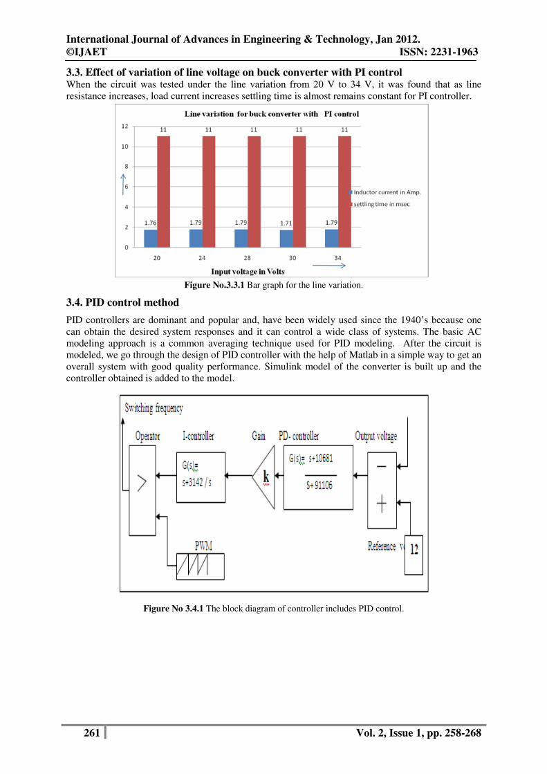
3.3. Effect of variation of line voltage on buck converter with PI control When the circuit was tested under the line variation from 20 V to 34 V, it was found that as line
resistance increases, load current increases settling time is almost remains constant for PI controller.
Figure No.3.3.1 Bar graph for the line variation.
3.4. PID control method
PID controllers are dominant and popular and, have been widely used since the 1940’s because one
can obtain the desired system responses and it can control a wide class of systems. The basic AC
modeling approach is a common averaging technique used for PID modeling. After the circuit is
modeled, we go through the design of PID controller with the help of Matlab in a simple way to get an
overall system with good quality performance. Simulink model of the converter is built up and the
controller obtained is added to the model.
Figure No 3.4.1 The block diagram of controller includes PID control.

International Journal of Advances in Engineering & Technology, Jan 2012.
©IJAET ISSN: 2231-1963
262 Vol. 2, Issue 1, pp. 258-268
Figure No. 3.4.2 Buck converter with PID control Matlab model
3.4.1. Inductor current waveform By considering above scenario in which a buck converter when considered with PID controller it has
been observed that the circuit has settling time of 2.5 msec. The output voltage attends steady state
value of 12 V, which is expected output from this application. Settling time for PID controlled buck
converter is 2.5 msec and transient voltage is of 16 V and transient current is of 28 A which are less as
compared to PI controller.
3.5 Effect of variation of load resistance on buck converter with PID control When PID controlled buck converter is considered with load variation, in a range of 10 Ω to 13 Ω
settling time and inductor current almost remains same. When load regulation is found out for this
circuit it is found to be 29.82 %.
Figure No.3.4.1.1 Bar graph for variation of load resistance in PID control circuit.
International Journal of Advances in Engineering & Technology, Jan 2012.
©IJAET ISSN: 2231-1963
263 Vol. 2, Issue 1, pp. 258-268
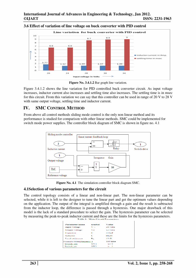
3.6 Effect of variation of line voltage on buck converter with PID control
Figure No. 3.4.1.2 Bar graph line variation.
Figure 3.4.1.2 shows the line variation for PID controlled buck converter circuit. As input voltage
increases, inductor current also increases and settling time also increases. The settling time is in msec
for this circuit. From this variation we can say that this controller can be used in range of 20 V to 28 V
with same output voltage, settling time and inductor current.
IV. SMC CONTROL METHOD
From above all control methods sliding mode control is the only non linear method and its
performance is studied for comparison with other linear methods. SMC could be implemented for
switch mode power supplies. The controller block diagram of SMC is shown in figure no. 4.1
Figure No. 4.1 The simulation controller block diagram SMC.
4.1Selection of various parameters for the circuit
The control topology consists of a linear and non-linear part. The non-linear parameter can be
selected, while it is left to the designer to tune the linear part and get the optimum values depending
on the application. The output of the integral is amplified through a gain and the result is subtracted
from the inductor loop, the difference is passed through a hysteresis. One major drawback of this
model is the lack of a standard procedure to select the gain. The hysteresis parameter can be selected
by measuring the peak-to-peak inductor current and these are the limits for the hysteresis parameters.

International Journal of Advances in Engineering & Technology, Jan 2012.
©IJAET ISSN: 2231-1963
264 Vol. 2, Issue 1, pp. 258-268
4.2. Buck converter with sliding mode control simulated circuit diagram
Considering above circuit in which a buck converter when considered with SMC controller it
has been observed that the circuit has settling time of 20 msec. The output voltage attends
steady state value of 12 V , which is expected output from this application. Under the load
variation of SMC circuit from 0 to ∞ , it was found that as load resistance increases load
current decreases and settling time increases continuously
Figure No. 4.2.1 Simulation diagram for buck converter with SMC
4.2.1 Effect of variation of load resistance on buck converter with SMC control
Figure No.4.2.1.1 Bar graph for load resistance variation
Above bar graph shows the effect of load variation on buck converter with SMC controller. As
resistance value increases inductor current decreases. For ∞ resistance voltage is 23.69 and inductor
International Journal of Advances in Engineering & Technology, Jan 2012.
©IJAET ISSN: 2231-1963
265 Vol. 2, Issue 1, pp. 258-268
current is 1.16e-10 A. But in the range of 10 Ω to 13 Ω load resistances inductor current and load
voltage almost remain constant.
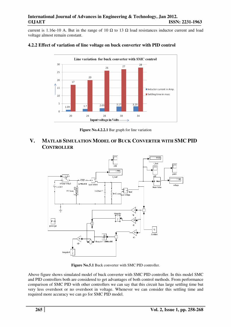
4.2.2 Effect of variation of line voltage on buck converter with PID control
Figure No.4.2.2.1 Bar graph for line variation
V. MATLAB SIMULATION MODEL OF BUCK CONVERTER WITH SMC PID
CONTROLLER
Figure No.5.1 Buck converter with SMC PID controller.
Above figure shows simulated model of buck converter with SMC PID controller. In this model SMC
and PID controllers both are considered to get advantages of both control methods. From performance
comparison of SMC PID with other controllers we can say that this circuit has large settling time but
very less overshoot or no overshoot in voltage. Whenever we can consider this settling time and
required more accuracy we can go for SMC PID model.
International Journal of Advances in Engineering & Technology, Jan 2012.
©IJAET ISSN: 2231-1963
266 Vol. 2, Issue 1, pp. 258-268
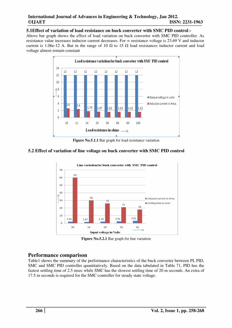
5.1Effect of variation of load resistance on buck converter with SMC PID control:- Above bar graph shows the effect of load variation on buck converter with SMC PID controller. As
resistance value increases inductor current decreases. For ∞ resistance voltage is 23.69 V and inductor
current is 1.06e-12 A. But in the range of 10 Ω to 15 Ω load resistances inductor current and load
voltage almost remain constant
Figure No.5.1.1 Bar graph for load resistance variation
5.2 Effect of variation of line voltage on buck converter with SMC PID control
Figure No.5.2.1 Bar graph for line variation
Performance comparison Table1 shows the summary of the performance characteristics of the buck converter between PI, PID,
SMC and SMC PID controller quantitatively. Based on the data tabulated in Table 71, PID has the
fastest settling time of 2.5 msec while SMC has the slowest settling time of 20 m seconds. An extra of
17.5 m seconds is required for the SMC controller for steady state voltage.

International Journal of Advances in Engineering & Technology, Jan 2012.
©IJAET ISSN: 2231-1963
267 Vol. 2, Issue 1, pp. 258-268
Table 1
VI. COMPARISON GRAPH FOR RISE TIME, DELAY TIME AND SETTLING
TIME FOR ALL EXISTING CONTROLLERS
Figure No. 6.1.comparative graph for all existing controllers
6.1 Comparative graph for peak overshoot, regulation, output voltage and inductor
current all existing controllers
From comparison we can say for same output voltage and inductor current peak overshoot is
maximum for PI control and no overshoot for SMC PID control method. From the
performance analysis of uncompensated buck converter we can say that because of
disturbances and nonlinearities output voltage of converter is 14.12 V instead of 12 V.
Figure No.6.1.1. Comparative graph for all existing controllers.
VII. CONCLUSION
As SMC is not operating at a constant switching frequency and converters have a highly nonlinear
and time varying nature therefore it is selected to control such kind of DC- DC converter. Therefore it
is also selected as control technique for performance analysis. The waveforms of simulated output

International Journal of Advances in Engineering & Technology, Jan 2012.
©IJAET ISSN: 2231-1963
268 Vol. 2, Issue 1, pp. 258-268
voltage and current were obtained, studied and compared with the waveforms from other controllers
for performance comparison. By studied references papers in details the waveforms were found to be
in precise proximity of theoretical waveforms. Some concluding points which are analyzed in
following points. From performance comparison of SMC with PI and PID it was found that it has
large settling time. So when more voltage accuracy is required and large settling time can be
considered then we can go for SMC or SMC PID control method. But when less cost, less accuracy
and less complexity is required, than PI or PID control method can be used. When buck converter is
considered with PI control within 6.5 msec output voltage attends 12 V.
ACKNOWLEDGEMENT
We wish to acknowledge the support given by Principal, Modren College of Engineering, Pune for
carrying out the present research work and HOD Mrs. Prof. N.R. Kulkarni department of Electrical
Engg. for constant encouragement.
REFERENCES [1]. M.Ahmed, M.Kuisma, P. Silventoinen, “Implementing Simple Procedure for Controlling Switch Mode
Power Supply Using Sliding Mode Control as a Control Technique’’, XIII-th International Symposium on
Electrical Apparatus and technologies (Siela). May 2003, pp 9-14, Vol. 1
[2]. Hongmei Li and Xiao Ye “Sliding-Mode PID Control of DC-DC Converter” , 5th IEEE Conference on
Industrial Electronics and Applications .
[3]. V.I.Utkin, Sliding modes and their application in variable structure systems, MIR Publishers, Moscow,
1978
[4]. R. Venkataramanan, A. Sabanovic, S. Cuk:"Sliding-mode control of DC-to-DC converters," IECON Conf.
Proc., 1985, pp. 251-258.
[5]. G. Spiazzi, P. Mattavelli, L. Rossetto, L. Malesani, "Application of Sliding Mode Control to Switch-Mode
Power Supplies," Journal of Circuits, Systems and Computers (JCSC), Vol. 5, No. 3, September 1995,
pp.337-354.
[6]. Siew-Chong Tan, Member, IEEE, Y. M. Lai,Member, IEEE, and Chi K. Tse, Fellow, IEEE “Indirect
Sliding Mode Control of Power Converters .
Biography
Shelgaonkar(Bindu) Arti
Kamalakar was born in Aurangabad, India, in Year 1978. She received
the Bachelor in electrical engg. degree from the University of Dr. BAMU Aurangabad city, in
Year 1999 and the pursing Master in 2008 degree from the University of Pune , in Year, both in
control system engineering.
N.R. Kulkarni received the Bachelor in electrical engg. degree from WCE ,Sangli in 1985,
M.E.(Electrical) Control System from COEP Pune in 1998,.Ph.D.(Electrical) in 2011.Area of
interest control System, Electrical machine, Nonconventional energy, Nonlinear system, Sliding
mode control.


