

Integrated Communication Systems GroupIlmenau University of Technology
3G Long-Term Evolution (LTE)and
System Architecture Evolution (SAE)Summer Semester 2011

Integrated Communication Systems Group
Outline
• Introduction • Requirements• Evolved Packet System Architecture• LTE Radio Interface and OFDMA• Protocol Architecture• Self-Organization in LTE• Conclusions• Control Questions• References• Abbreviations
Wireless Internet (II,IN)
Integrated Communication Systems Group
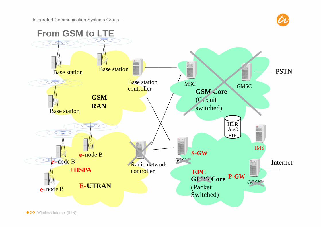
From GSM to LTE
GPRS Core(PacketSwitched)
SGSN
GGSN
Internet
GSMRAN
Base stationBase stationcontroller
Base station
Base station
UTRAN
Radio networkcontroller
node Bnode B
node B
MSC
PSTN
GSM Core (Circuit switched)
HLRAuCEIR
GMSC
E-e-
e-e- S-GW
P-GW
IMS
EPC+HSPA
Wireless Internet (II,IN)

Integrated Communication Systems Group
3GPP Evolution – Background (1/2)
Discussion started in December 2004State of the art then:
• The combination of HSDPA and E-DCH provides very efficientpacket data transmission capabilities, but UMTS should continueto be evolved to meet the ever increasing demand of newapplications and user expectations
• 10 years have passed since the initiation of the 3G program andit is time to initiate a new program to evolve 3G which will lead toa 4G technology
• From the application/user perspectives, the UMTS evolutionshould target at significantly higher data rates and throughput,lower network latency, and support of always-on connectivity
Wireless Internet (II,IN)
Integrated Communication Systems Group
3GPP Evolution – Background (2/2)
• From the operator perspectives, an evolved UMTS will makebusiness sense if it: Provide significantly improved power and bandwidth efficiencies Facilitate the convergence with other networks/technologies Reduce transport network cost Limit additional complexity
• Evolved-UTRA is a packet only network - there is no support ofcircuit switched services (no MSC)
• Evolved-UTRA starts on a clean state - everything is up fordiscussion including the system architecture and the split offunctionality between RAN and CN
• Led to 3GPP Study Item (Study Phase: 2005-4Q2006)„3G Long-term Evolution (LTE)” for new Radio Accessand “System Architecture Evolution” (SAE) for Evolved Network
Wireless Internet (II,IN)

Integrated Communication Systems Group
Economic Drivers for Network Evolution
Voice dominated
Data dominated
Traffic volume
Revenue
Time
Network cost (LTE)
Profitability
Network cost (existing technologies)
Wireless Internet (II,IN)

Integrated Communication Systems Group
LTE Requirements and Performance Targets
Wireless Internet (II,IN)
Integrated Communication Systems Group
Key Features of LTE to Meet Requirements
• Selection of Orthogonal Frequency Division Multiplexing (OFDM) for the air interface– Less receiver complexity– Robust to frequency selective fading and inter-symbol interference
(ISI)– Access to both time and frequency domain allows additional flexibility
in scheduling (including interference coordination)– Scalable OFDM makes it straightforward to extend to different
transmission bandwidths
• Integration of Multiple-Input Multiple-Output (MIMO) techniques– Pilot structure to support 1, 2, or 4 Tx antennas in the Downlink (DL)
and Multi-user MIMO (MU-MIMO) in the Uplink (UL)
• Simplified network architecture– Reduction in number of logical nodes flatter architecture– Clean separation of user and control plane
Wireless Internet (II,IN)

Integrated Communication Systems Group
Terminology: LTE + SAE = EPS
• From the set of requirements it was clear that evolution work would be required for both, the radio access network as well as the core network– LTE would not be backward compatible with UMTS/HSPA!– RAN working groups would focus on the air interface and radio
access network aspects– System Architecture (SA) working groups would develop the Evolved
Packet Core (EPC)
• Note on terminology– In the RAN working groups term Evolved UMTS Terrestrial Radio
Access Network (E-UTRAN) and Long Term Evolution (LTE) are usedinterchangeably
– In the SA working groups the term System Architecture Evolution(SAE) was used to signify the broad framework for the architecture
– For some time the term LTE/SAE was used to describe the newevolved system, but now this has become known as the EvolvedPacket System (EPS)
Wireless Internet (II,IN)
Integrated Communication Systems Group
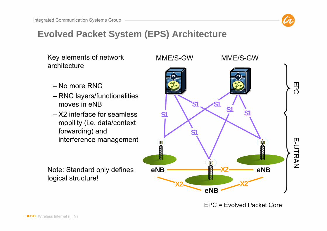
Evolved Packet System (EPS) Architecture
Key elements of network architecture
– No more RNC– RNC layers/functionalities
moves in eNB– X2 interface for seamless
mobility (i.e. data/context forwarding) and interference management
Note: Standard only defines logical structure!
eNB
eNB
eNB
MME/S-GW MME/S-GW
X2
EPCE
-UTR
AN
S1
S1
S1S1
S1S1
X2
X2
EPC = Evolved Packet Core
Wireless Internet (II,IN)

Integrated Communication Systems Group
EPS Architecture - Functional Description of the Nodes
Wireless Internet (II,IN)
Integrated Communication Systems Group
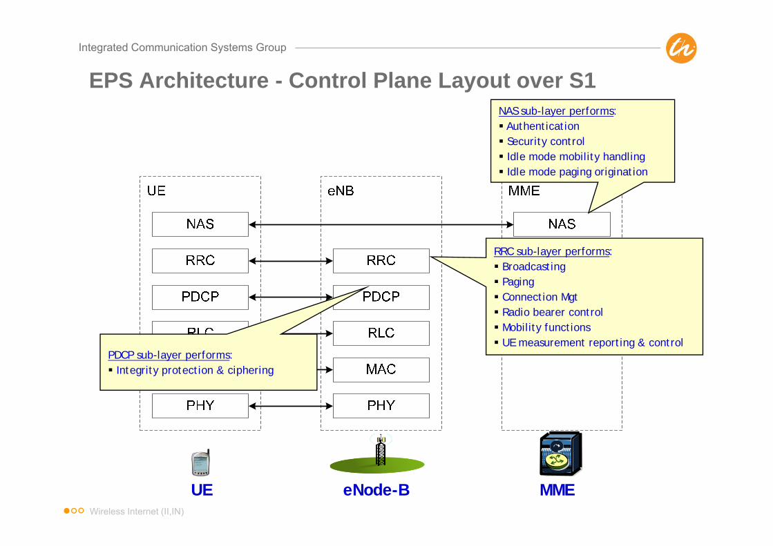
EPS Architecture - Control Plane Layout over S1
UE eNode-B MME
RRC sub-layer performs: Broadcasting Paging Connection Mgt Radio bearer control Mobility functions UE measurement reporting & control
PDCP sub-layer performs: Integrity protection & ciphering
NAS sub-layer performs: Authentication Security control Idle mode mobility handling Idle mode paging origination
Wireless Internet (II,IN)
Integrated Communication Systems Group
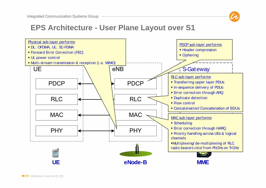
EPS Architecture - User Plane Layout over S1
S-GatewayRLC sub-layer performs: Transferring upper layer PDUs In-sequence delivery of PDUs Error correction through ARQ Duplicate detection Flow control Concatenation/Concatenation of SDUs
PDCP sub-layer performs: Header compression Ciphering
MAC sub-layer performs: Scheduling Error correction through HARQ Priority handling across UEs & logical channelsMultiplexing/de-multiplexing of RLC radio bearers into/from PhCHs on TrCHs
Physical sub-layer performs: DL: OFDMA, UL: SC-FDMA Forward Error Correction (FEC) UL power control Multi-stream transmission & reception (i.e. MIMO)
UE eNode-B MME
Wireless Internet (II,IN)

Integrated Communication Systems Group
EPS Architecture - Interworking for 3GPP and Non-3GPP Access
• Serving GW anchors mobility for intra-LTE handover between eNBs as wellas mobility between 3GPP access systems HSPA/EDGE uses EPS corefor access to packet data networks
• PDN GW is the mobility anchor between 3GPP and non-3GPP accesssystems (SAE anchor function); handles IP address allocation
• S3 interface connects MME directly to SGSN for signaling to support mobilityacross LTE and UTRAN/GERAN; S4 allows direction of user plane betweenLTE and GERAN/ UTRAN (uses GTP)
Wireless Internet (II,IN)

Integrated Communication Systems Group
LTE Key Features (Release 8)
• Multiple access scheme– DL: OFDMA with Cyclic Prefix (CP)– UL: Single Carrier FDMA (SC-FDMA) with CP
• Adaptive modulation and coding– DL modulations: QPSK, 16QAM, and 64QAM– UL modulations: QPSK and 16QAM (optional for UE)– Rel. 6 Turbo code: Coding rate of 1/3, two 8-state constituent encoders, and a
contention-free internal interleaver
• ARQ within RLC sublayer and Hybrid ARQ within MAC sublayer• Advanced MIMO spatial multiplexing techniques
– (2 or 4) x (2 or 4) downlink and uplink supported– Multi-layer transmission with up to four streams– Multi-user MIMO also supported
• Implicit support for interference coordination• Support for both FDD and TDD
Wireless Internet (II,IN)
Integrated Communication Systems Group
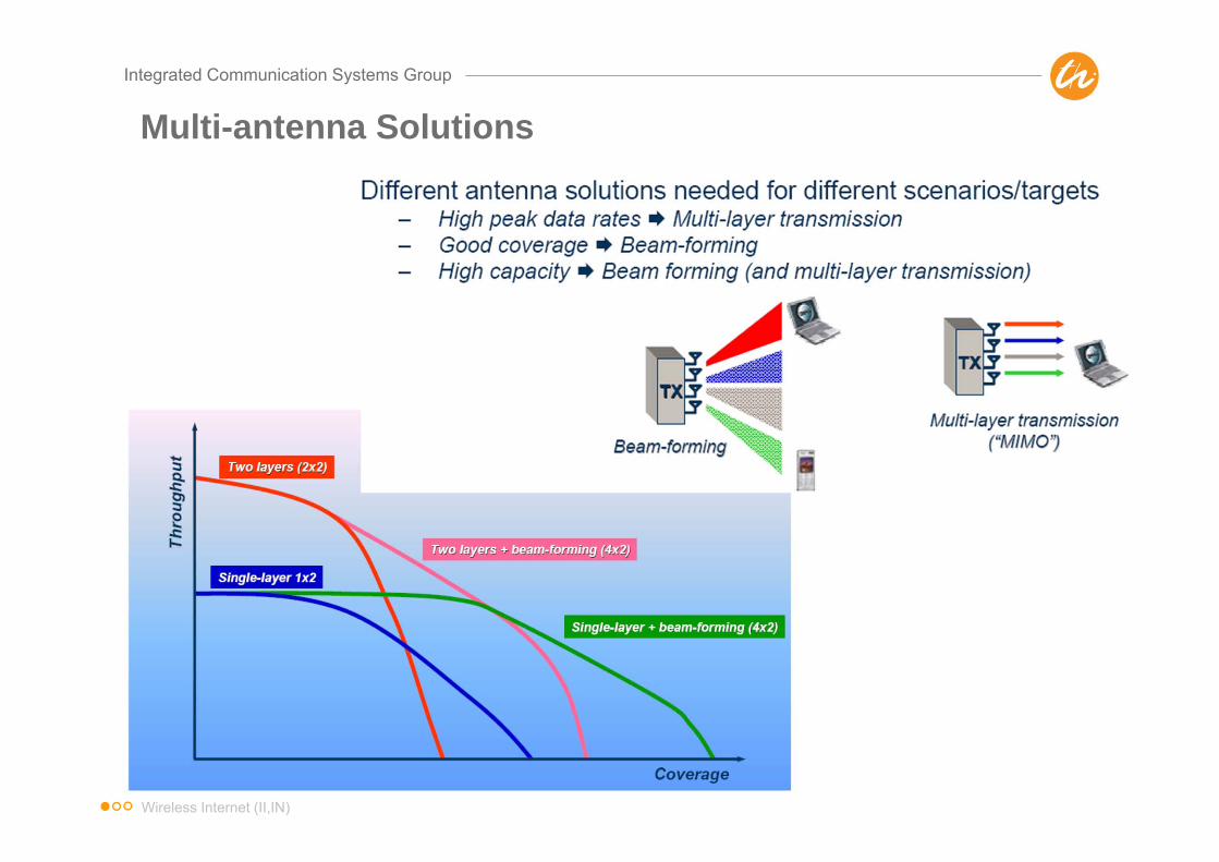
Multi-antenna Solutions
Wireless Internet (II,IN)

Integrated Communication Systems Group
Interference Coordination
Wireless Internet (II,IN)

Integrated Communication Systems Group
LTE Frequency Bands
• LTE will support all band classes currently specified for UMTS aswell as additional bands
Wireless Internet (II,IN)

Integrated Communication Systems Group
OFDM Basics – Overlapping Orthogonal
• OFDM: Orthogonal Frequency Division Multiplexing• OFDMA: Orthogonal Frequency Division Multiple-Access• FDM/FDMA is nothing new: carriers are separated sufficiently in
frequency so that there is minimal overlap to prevent cross-talk
• OFDM: still FDM but carriers can actually be orthogonal (nocross-talk) while actually overlapping, if specially designed saved bandwidth!
Wireless Internet (II,IN)

Integrated Communication Systems Group
OFDM Basics – Waveforms
• Frequency domain: overlapping sinc (= sin(x)/x) functions– Referred to as subcarriers– Typically quite narrow, e.g. 15 kHz
• Time domain: simple gated sinusoid functions– For orthogonality: each symbol has
an integer number of cycles overthe symbol time
– Fundamental frequency f0= 1/T– Other sinusoids with fk= k • f0
Wireless Internet (II,IN)

Integrated Communication Systems Group
OFDM Basics – The Full OFDM Transceiver
Wireless Internet (II,IN)
Integrated Communication Systems Group
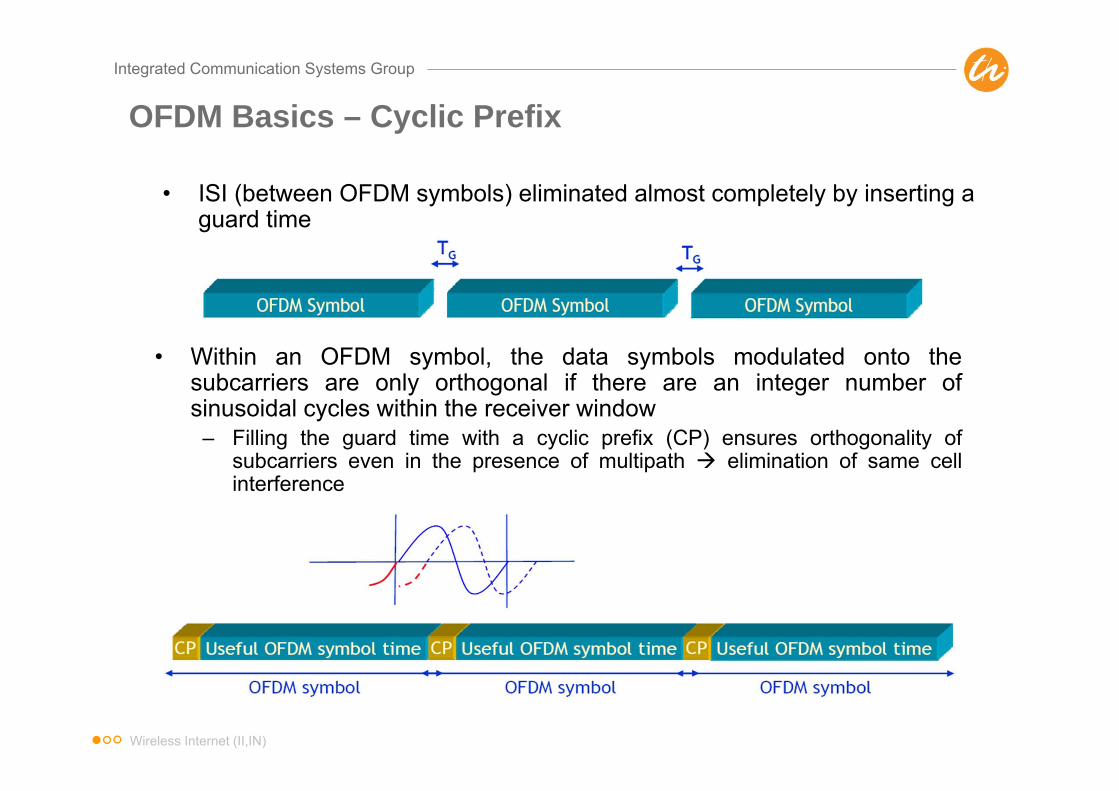
OFDM Basics – Cyclic Prefix
• ISI (between OFDM symbols) eliminated almost completely by inserting a guard time
• Within an OFDM symbol, the data symbols modulated onto thesubcarriers are only orthogonal if there are an integer number ofsinusoidal cycles within the receiver window
– Filling the guard time with a cyclic prefix (CP) ensures orthogonality ofsubcarriers even in the presence of multipath elimination of same cellinterference
Wireless Internet (II,IN)
Integrated Communication Systems Group
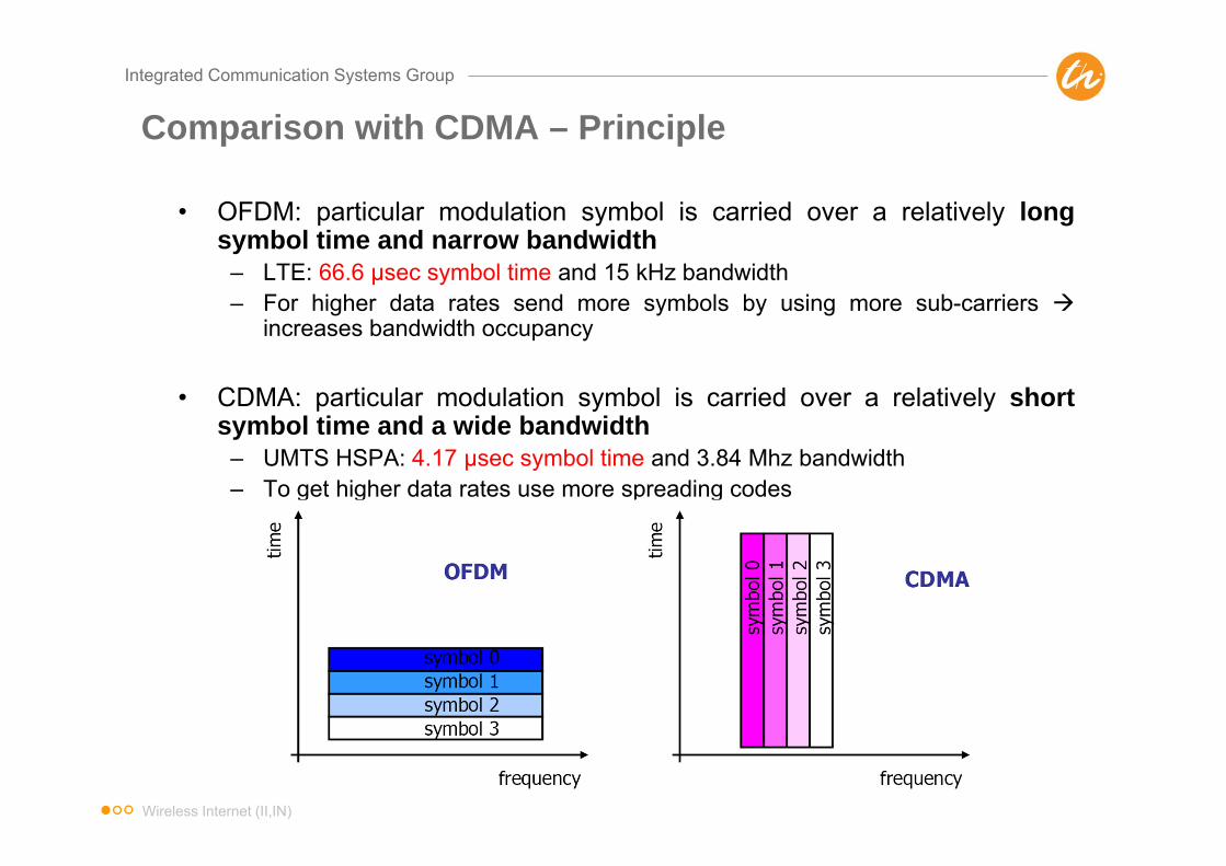
Comparison with CDMA – Principle
• OFDM: particular modulation symbol is carried over a relatively longsymbol time and narrow bandwidth
– LTE: 66.6 μsec symbol time and 15 kHz bandwidth– For higher data rates send more symbols by using more sub-carriers
increases bandwidth occupancy
• CDMA: particular modulation symbol is carried over a relatively shortsymbol time and a wide bandwidth
– UMTS HSPA: 4.17 μsec symbol time and 3.84 Mhz bandwidth– To get higher data rates use more spreading codes
Wireless Internet (II,IN)

Integrated Communication Systems Group
Comparison with CDMA – Time Domain Perspective
• Short symbol times in CDMA lead to ISI in the presence ofmultipath
• Long symbol times in OFDM together with CP prevent ISI frommultipath
CDMA symbols
Multipath reflections from one symbol significantlyoverlap subsequent symbols ISI
Little to no overlapin symbols frommultipath
Wireless Internet (II,IN)

Integrated Communication Systems Group
Comparison with CDMA – Frequency Domain Perspective
• In CDMA each symbol is spread over a large bandwidth, hence it willexperience both good and bad parts of the channel response in frequencydomain
• In OFDM each symbol is carried by a subcarrier over a narrow part ofthe band can avoid send symbols where channel frequency responseis poor based on frequency selective channel knowledge frequencyselective scheduling gain in OFDM systems
Wireless Internet (II,IN)

Integrated Communication Systems Group
OFDM Basics – Choosing the Symbol Time for LTE
• Two competing factors in determining the right OFDM symbol time– CP length should be longer than worst case multipath delay spread, and the
OFDM symbol time should be much larger than CP length to avoidsignificant overhead from the CP
– On the other hand, the OFDM symbol time should be much smaller than theshortest expected coherence time of the channel to avoid channel variabilitywithin the symbol time
• LTE is designed to operate in delay spreads up to ~5μs and for speedsup to 350 km/h (1.2ms coherence time @ 2.6GHz). As such, the followingwas decided
– CP length = 4.7 μs– OFDM symbol time = 66.6 μs (= 1/20 the worst case coherence time)
Wireless Internet (II,IN)

Integrated Communication Systems Group
Scalable OFDM for Different Operating Bandwidths
• With Scalable OFDM, the subcarrier spacing stays fixed at 15 kHz(hence symbol time is fixed to 66.6 μs) regardless of the operatingbandwidth (1.4 MHz, 3 MHz, 5 MHz, 10 MHz, 15 MHz, 20 MHz)
• The total number of subcarriers is varied in order to operate indifferent bandwidths– This is done by specifying different FFT sizes (i.e. 512 point FFT for 5
MHz, 2048 point FFT for 20 MHz)
• Influence of delay spread, Doppler due to user mobility, timingaccuracy, etc. remain the same as the system bandwidth ischanged robust design
Wireless Internet (II,IN)

Integrated Communication Systems Group
LTE Downlink Frame Structure
Spectrum allocation 1.4 MHz 3 MHz 5 MHz 10 MHz 15 MHz 20 MHz
Slot duration 0.5 ms
Sub-frame duration 1.0 ms ( = 2 slots)
Sub-carrier spacing
15 kHz(7.5 kHz for MBMS)
Sampling frequency
1.92 MHz(1/2 3.84)
3.84 MHz 7.68 MHz(2 3.84)
15.36 MHz(4 3.84)
23.04 MHz(6 3.84)
30.72 MHz(8 3.84)
FFT size 128 256 512 1024 1536 2048
Number of sub-carriers 75 150 300 600 900 1200
OFDM symbols per slot 7 (short CP), 6 (long CP)
CP length
Short 4.69 s x 65.21 s x 1
Long 16.67 s
Sampling rates are multiples of UMTS chip rate, to ease implementation of dual mode UMTS/LTE terminals
FFT size scales to support larger bandwidth Scalable OFDM
Subframe length relevant to the latency requirement
Wireless Internet (II,IN)

Integrated Communication Systems Group
LTE Duplex Modes
• LTE supports both Frequency Division Duplex (FDD) and Time DivisionDuplex (TDD) to provide flexible operation in a variety of spectrumallocations around the world
• Unlike UMTS TDD there is a high commonality between LTE TDD & LTEFDD
5ms LTETDD frame
DL portion(dsymbols)
UL portion(usymbols)
Transmission gap/Idle period
– Slot length (0.5 ms) andsubframe length (1 ms) is thesame than LTE FDD with thesame numerology (OFDMsymbol times, CP length, FFTsizes, sample rates, etc.)
– UL/DL switching pointsdesigned to allow co-existencewith UMTS-TDD (TD-CDMA,TD-SCDMA)
Wireless Internet (II,IN)

Integrated Communication Systems Group
LTE Half-Duplex FDD
• In addition to FDD & TDD, LTE supports also Half-Duplex FDD (HD-FDD)
• HD-FDD is like FDD, only the UE cannot transmit and receive at thesame time
• Note, that the eNodeB can still transmit and receive at the same time todifferent UEs; half-duplex is enforced by the eNodeB scheduler
• Reasons for HD-FDD– Handsets are cheaper, as no duplexer is required– More commonality between TDD and HD-FDD than compared to full duplex
FDD– Certain FDD spectrum allocations have small duplex space; HD-FDD leads to
duplex desense in UE
Wireless Internet (II,IN)

Integrated Communication Systems Group
LTE Downlink
• The LTE downlink uses scalable OFDMA– Fixed subcarrier spacing of 15 kHz for unicast
Symbol time fixed at T = 1/15 kHz = 66.67 μs
– Different UEs are assigned different sets of subcarriers so that theyremain orthogonal to each other (except MU-MIMO)
Wireless Internet (II,IN)

Integrated Communication Systems Group
Physical Channels to Support LTE Downlink
Carries DL traffic
DL resource allocation
Time span of PDCCH
HARQ feedback for DLCQI reporting
Wireless Internet (II,IN)
Integrated Communication Systems Group
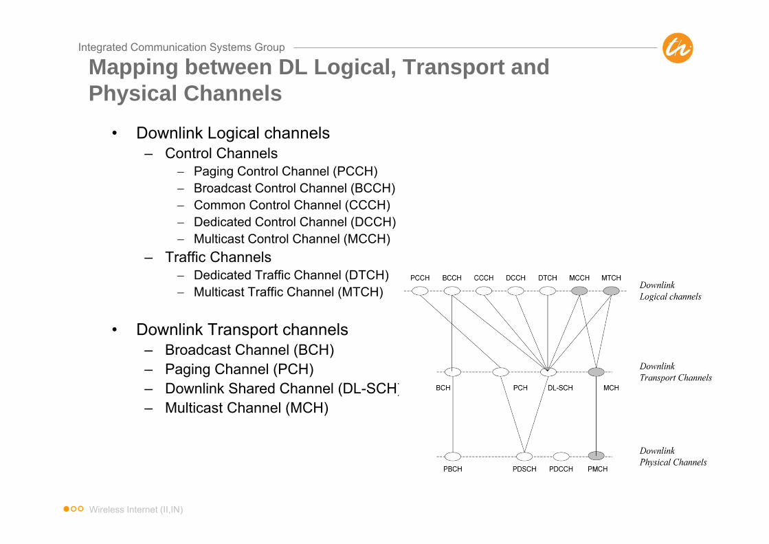
Mapping between DL Logical, Transport and Physical Channels
• Downlink Logical channels– Control Channels
Paging Control Channel (PCCH) Broadcast Control Channel (BCCH) Common Control Channel (CCCH) Dedicated Control Channel (DCCH) Multicast Control Channel (MCCH)
– Traffic Channels Dedicated Traffic Channel (DTCH) Multicast Traffic Channel (MTCH)
• Downlink Transport channels– Broadcast Channel (BCH)– Paging Channel (PCH)– Downlink Shared Channel (DL-SCH)– Multicast Channel (MCH)
Wireless Internet (II,IN)
Integrated Communication Systems Group
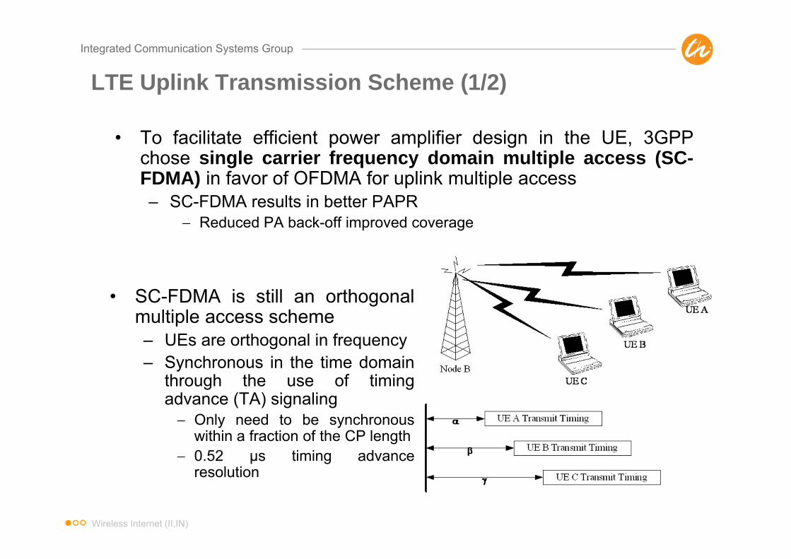
LTE Uplink Transmission Scheme (1/2)
• To facilitate efficient power amplifier design in the UE, 3GPPchose single carrier frequency domain multiple access (SC-FDMA) in favor of OFDMA for uplink multiple access– SC-FDMA results in better PAPR
Reduced PA back-off improved coverage
• SC-FDMA is still an orthogonalmultiple access scheme– UEs are orthogonal in frequency– Synchronous in the time domain
through the use of timingadvance (TA) signaling Only need to be synchronous
within a fraction of the CP length 0.52 μs timing advance
resolution
Wireless Internet (II,IN)

Integrated Communication Systems Group
LTE Uplink Transmission Scheme (2/2)
• SC-FDMA implemented using an OFDMA front-end and a DFTpre-coder, this is referred to as either DFT-pre-coded OFDMA orDFT-spread OFDMA (DFT-SOFDMA)– Advantage is that numerology (subcarrier spacing, symbol times, FFT
sizes, etc.) can be shared between uplink and downlink– Can still allocate variable bandwidth in units of 12 sub-carriers– Each modulation symbol sees a wider bandwidth
Wireless Internet (II,IN)

Integrated Communication Systems Group
Physical Channels to Support LTE UplinkRandom access for initial
access and UL timing alignment
UL scheduling grant
UL scheduling request for time
synchronized IEs
HARQ feedback for UL
Carries UL Traffic
Wireless Internet (II,IN)

Integrated Communication Systems Group
Mapping between UL Logical, Transport and Physical Channels
• Uplink Logical channels– Control Channels
Common Control Channel (CCCH) Dedicated Control Channel (DCCH)
– Traffic Channels Dedicated Traffic Channel (DTCH)
• Uplink Transport channels– Uplink Shared Channel (UL-SCH)– Random Access Channel(s) (RACH)
Wireless Internet (II,IN)

Integrated Communication Systems Group
Downlink Peak Rates
Assumptions: 64QAM, code rate =1, 1OFDM symbol for L1/L2, ignores subframes with P-BCH, SCH
Wireless Internet (II,IN)

Integrated Communication Systems Group
Uplink Peak Rates
assumptions: code rate =1, 2PRBs reserved for PUCCH (1 for 1.4MHz), no SRS, ignoressubframes with PRACH, takes into account highest prime-factor restriction
Wireless Internet (II,IN)
Integrated Communication Systems Group
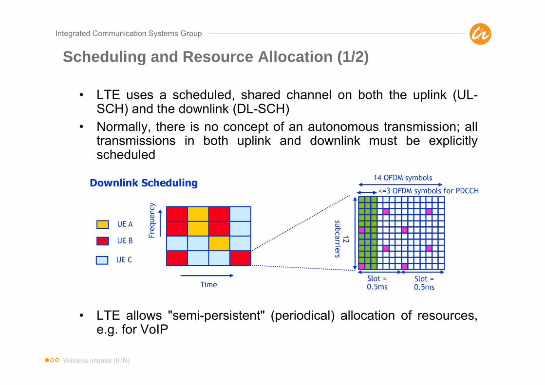
Scheduling and Resource Allocation (1/2)
• LTE uses a scheduled, shared channel on both the uplink (UL-SCH) and the downlink (DL-SCH)
• Normally, there is no concept of an autonomous transmission; alltransmissions in both uplink and downlink must be explicitlyscheduled
• LTE allows "semi-persistent" (periodical) allocation of resources,e.g. for VoIP
Wireless Internet (II,IN)
Integrated Communication Systems Group
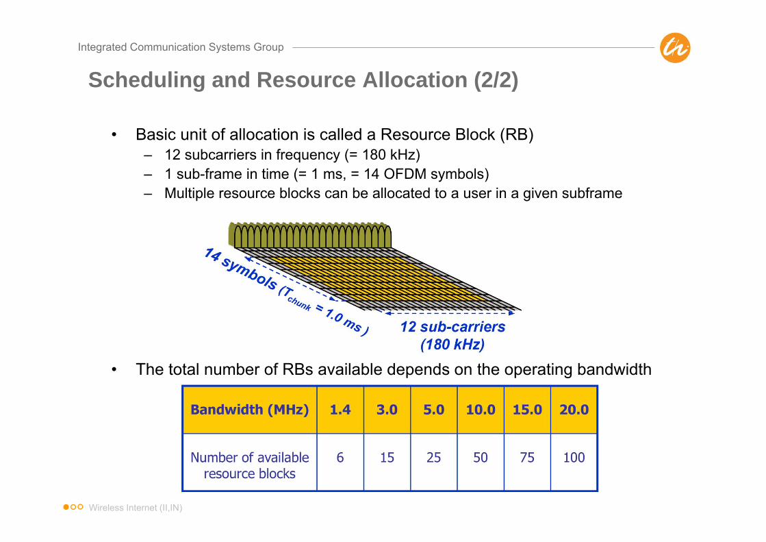
Scheduling and Resource Allocation (2/2)
• Basic unit of allocation is called a Resource Block (RB)– 12 subcarriers in frequency (= 180 kHz)– 1 sub-frame in time (= 1 ms, = 14 OFDM symbols)– Multiple resource blocks can be allocated to a user in a given subframe
• The total number of RBs available depends on the operating bandwidth
Wireless Internet (II,IN)

Integrated Communication Systems Group
Random Access (RA) Procedure
• RACH only used for Random Access Preamble– Response/Data are sent over SCH
• Non-contention based RA to improve access time, e.g. for HO
Contention based RA Non-Contention based RA
Wireless Internet (II,IN)

Integrated Communication Systems Group
LTE Handover (1/2)
• LTE uses UE-assisted network controlled handover– UE reports measurements; network decides when to handover and to which
cell– Relies on UE to detect neighbor cells no need to maintain and broadcast
neighbor lists Allows "plug-and-play" capability; saves BCH resources
– For search and measurement of inter-frequency neighboring cells only carrierfrequency need to be indicated
• X2 interface used for handover preparation and forwarding of user data– Target eNB prepares handover by sending required information to UE
transparently through source eNB as part of the Handover RequestAcknowledge message New configuration information needed from system broadcast Accelerates handover as UE does not need to read BCH on target cell
– Buffered and new data is transferred from source to target eNB until pathswitch prevents data loss
– UE uses contention-free random access to accelerate handover
Wireless Internet (II,IN)

Integrated Communication Systems Group
LTE Handover (2/2)
Characteristics• No soft handover• Handover latency
(2. –11.) ~ 55 msec• Handover
Interruption (7. –11.)~ 35 msec
• Synchronization (9.)on RACH
Wireless Internet (II,IN)

Integrated Communication Systems Group
Tracking Area
Tracking Area Identifier (TAI) sent over Broadcast Channel BCHTracking Areas can be shared by multiple MMEs
Wireless Internet (II,IN)
Integrated Communication Systems Group
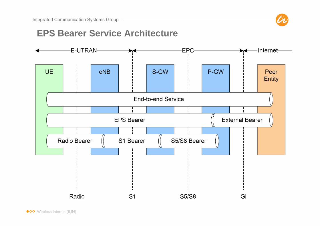
EPS Bearer Service Architecture
Wireless Internet (II,IN)

Integrated Communication Systems Group
LTE RRC States
• No RRC connection, nocontext in eNodeB (but EPSbearers are retained)
• UE controls mobility throughcell selection
• UE-specific paging DRXcycle controlled by upperlayers
• UE acquires systeminformation from BCH
• UE monitors paging channelto detect incoming calls
• RRC connection and context in eNodeB
• Network controlled mobility• Transfer of unicast and
broadcast data to and from UE• UE monitors control channels
associated with the shareddata channels
• UE provides channel quality and feedback information
• Connected mode DRX can be configured by eNodeBaccording to UE activity level
Wireless Internet (II,IN)

Integrated Communication Systems Group
EPS Connection Management States
• No signaling connectionbetween UE and corenetwork (no S1-U/ S1-MME)
• No RRC connection (i.e. RRC_IDLE)
• UE performs cell selection and tracking area updates (TAU)
• Signaling connectionestablished between UE andMME, consists of twocomponents– RRC connection– S1-MME connection
• UE location is known toaccuracy of Cell-ID
Wireless Internet (II,IN)
Integrated Communication Systems Group
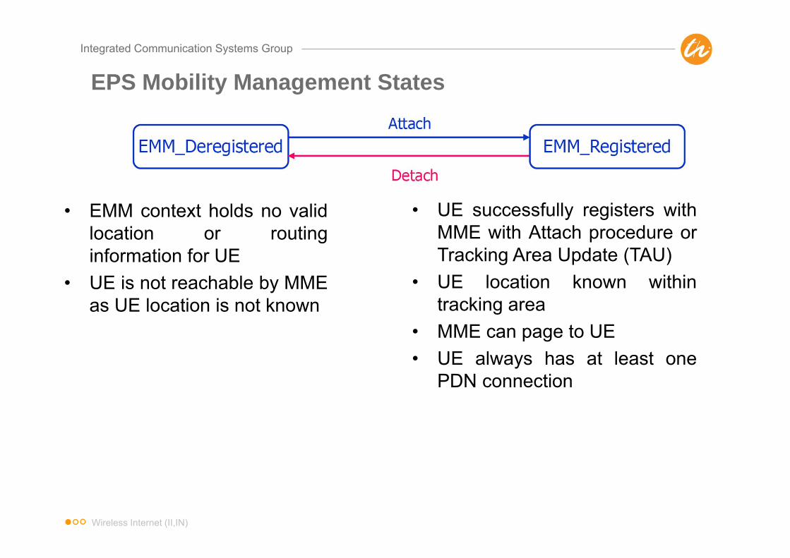
EPS Mobility Management States
• EMM context holds no validlocation or routinginformation for UE
• UE is not reachable by MMEas UE location is not known
• UE successfully registers withMME with Attach procedure orTracking Area Update (TAU)
• UE location known withintracking area
• MME can page to UE• UE always has at least one
PDN connection
Wireless Internet (II,IN)
Integrated Communication Systems Group
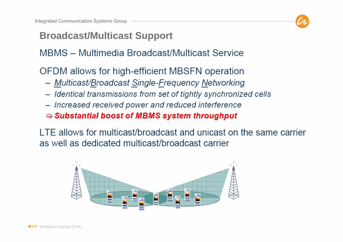
Broadcast/Multicast Support
Wireless Internet (II,IN)

Integrated Communication Systems Group
LTE vs. WiMax vs. 3GPP2
IMS
• Authenticator• Paging Controller• Page buffering
WiMAX
Access Point
CAP-C FA/Router
• Handover Control• Radio Resource
Management• ARQ/MAC/PHY• L2 Ciphering• Classification/
ROHC
E-Node B
MME Serv GW
HSS
IMS
• Authenticator• Paging Controller• Session setup
• Handover Control• Radio Resource
Management• ARQ/MAC/PHY• L2 Ciphering• ROHC
3GPP/LTE
PDN GW
• Local mobility• Page buffering
• Local mobility• Session setup• Bearer mapping
eBTS
SRNC Access GW
AAA
IMS
• Authenticator• Paging
Controller
• Handover Control• Radio Resource
Management• ARQ/MAC/PHY• L2 Ciphering• ROHC
3GPP2/UMB
HA
PCRF
IETF-centric architectureIETF-centric architectureIETF-friendly, but still
some flavor of UMTS/GPRS – GTP, etc
• Bearer mapping
PCRF
• Local mobility• Session setup• Bearer mapping
AAA HA
Wireless Internet (II,IN)

Integrated Communication Systems Group
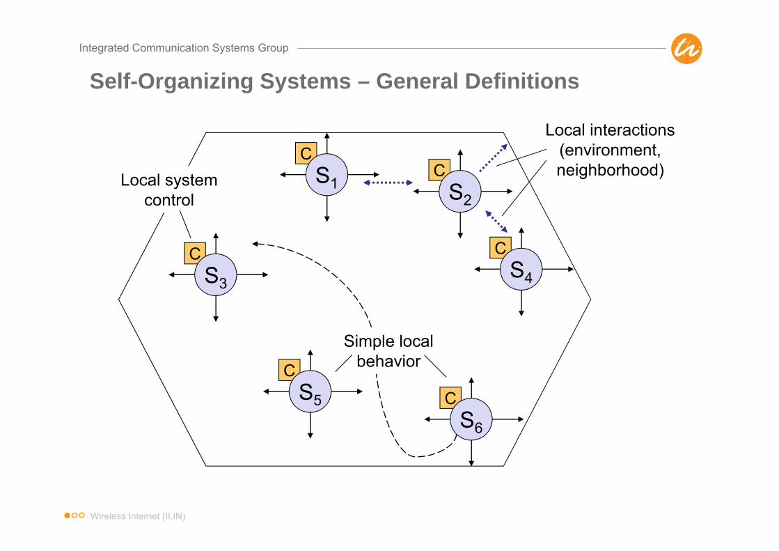
Self-organization – General Definitions
Yates et al. (1987)“Technological systems become organized by commands from outside, as when human intentions lead to the building of structuresor machines. But many natural systems become structured by their own internal processes: these are the self-organizing systems, and the emergence of order within them is a complex phenomenon that intrigues scientists from all disciplines.”
Camazine et al. (2003)“Self-organization is a process in which pattern at the global level of a system emerges solely from numerous interactions among the lower-level components of a system. Moreover, the rules specifying interactions among the systems’ components are executed using only local information, without reference to the global pattern.”
Wireless Internet (II,IN)
Integrated Communication Systems Group
CS3
CS5
CS1
CS4
CS2
Local interactions (environment, neighborhood)Local system
control
Simple local behavior
CS6
Self-Organizing Systems – General Definitions
Wireless Internet (II,IN)

Integrated Communication Systems Group
Self-Organizing Systems – General Properties
Property Description
No central controlNo global control system No global information Subsystems perform completely autonomous
Emerging structuresGlobal behavior or functioning of the system emerges in form of observable pattern or structures
Resulting complexity
Even if the individual subsystems can be simple as well as their basic rules, the resulting overall system becomes complex and often unpredictable
High scalability
No performance degradation if more subsystems are added to the system System performs as requested regardless of the number of subsystems
Wireless Internet (II,IN)

Integrated Communication Systems Group
Self-organization in LTE
Motivation and drivers• Multitude of re-configurable parameters e.g. transmit powers,
control channel powers, handover parameters etc. • Huge number of eNBs expected with the introduction of Home
eNB concept• Home eNB
– Small Coverage Area– Small number of users per cell– May be switched off by user– Not physically accessible for operators
• Self-organization (SO) is driven by operators to reduce Operational Expenses (OPEX)
• Main push of Self-Optimizing Networks (SON) by NGMN alliance (www.ngmn.org)
Wireless Internet (II,IN)

Integrated Communication Systems Group
SO Functionality in LTE (1/5)
SO functionality includes• Self-configuration• Self-optimization• Self-healing and self-repair
Wireless Internet (II,IN)
Integrated Communication Systems Group
SO Functionality in LTE (2/5)
Self-Configuration• Objective is to have plug-n-play enabled nodes• Works in pre-operational state, which starts when the node is
powered up and has backbone connectivity until the RF transmitter is switched on
• Automatic installation procedures for newly deployed nodes• Automatic creation of the logical associations (interfaces) with the
network and establishment of the necessary security contexts• Download of configuration files from a configuration server• Performing a self-test to determine that everything is working as
intended• Finally, switching to active service
Wireless Internet (II,IN)
Integrated Communication Systems Group
SO Functionality in LTE (3/5)
Self-optimization• Uses UE & eNB measurements and performance statistics to
auto-tune the network• Works in operational state, which starts when the RF interface is
switched on
Wireless Internet (II,IN)
Integrated Communication Systems Group
SO Functionality in LTE (4/5)
Self-optimization process includes• Neighbor list optimization
– Reconfigures the neighbor list to have the minimum set of cells necessary for handover
• Coverage and capacity optimization– Maximizes the system capacity while ensuring an appropriate
overlapping area between the adjacent cells• Mobility robustness optimization
– Adjusts the handover thresholds to avoid unnecessary handovers• Mobility load balancing optimization
– Automatically handover some UEs in the edge of a congested cell to neighboring less congested cells
• Energy Saving– Autonomously switching off some of the resources or the complete
node during the times of low network demand
Wireless Internet (II,IN)

Integrated Communication Systems Group
SO Functionality in LTE (5/5)
Self-healing and self-repair• Detects equipment faults, identifies the root causes and takes
recovery actions such as– Reducing transmit power in case of temperature alarm– Fallback to the previous software version– Switching to the backup units
• If the fault can not be resolved by the above measures, the affected cell and the neighboring cells take cooperative actions to minimize QoS degradation
• Results in a reduced failure recovery time and a more efficient allocation of maintenance personnel
Wireless Internet (II,IN)

Integrated Communication Systems Group
SON Architecture (1/4)
• Based on the location of SO functionality three architectural approaches are possible– Centralized– Distributed– Hybrid
Wireless Internet (II,IN)

Integrated Communication Systems Group
SON Architecture (2/4)
Centralized Architecture• SO functionality resides in the
OAM system at higher level of network architecture
• Easy to deploy due to fewer number of installation sites
• OAM is vendor specific, so no support for multi-vendor optimization
• Existing interface N (Itf-N) between Network Manager (NM) and Element Manager (EM) or Network Element (NE) needs to be extended
Wireless Internet (II,IN)

Integrated Communication Systems Group
SON Architecture (3/4)
Distributed Architecture• SO functionality resides in the
eNB at the lower level of network architecture
• Difficult to deploy because of large number of installation sites
• Difficult to perform complex optimizations involving large number of eNBs
• Better performance for less complex optimizations involving a small number of eNBs
• X2 interface between the eNBs needs to be extended
Wireless Internet (II,IN)
Integrated Communication Systems Group
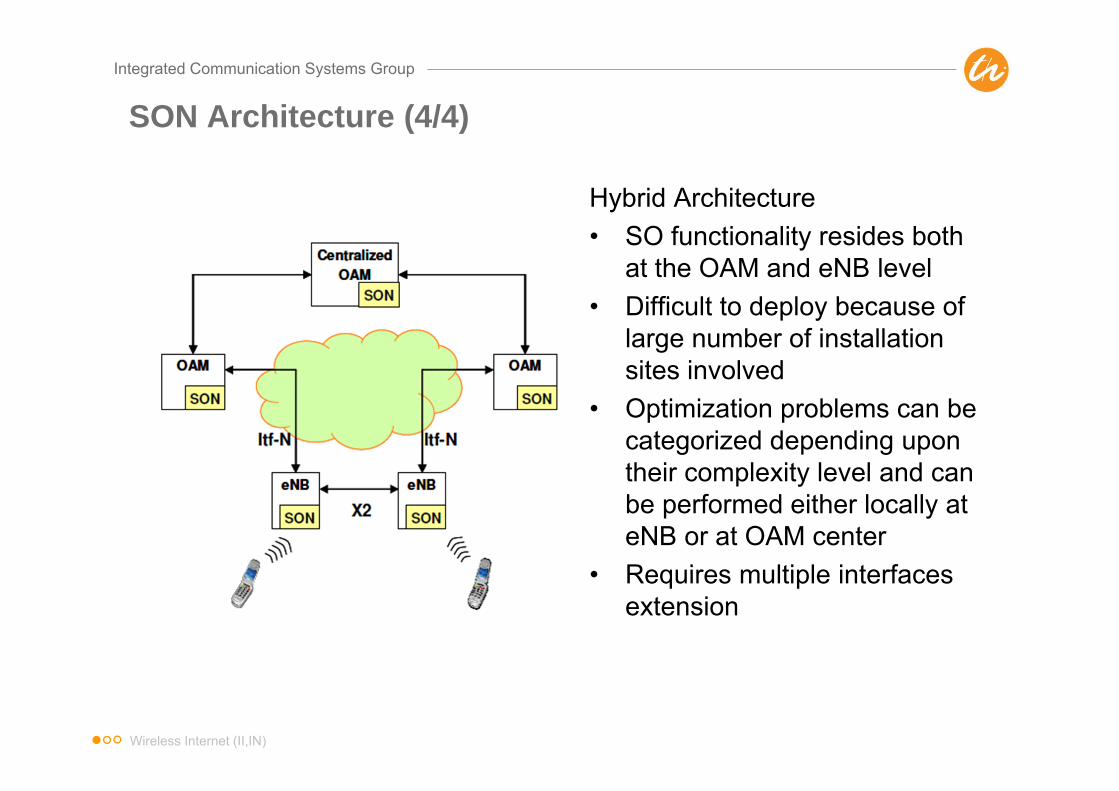
SON Architecture (4/4)
Hybrid Architecture• SO functionality resides both
at the OAM and eNB level• Difficult to deploy because of
large number of installation sites involved
• Optimization problems can be categorized depending upon their complexity level and can be performed either locally at eNB or at OAM center
• Requires multiple interfaces extension
Wireless Internet (II,IN)

Integrated Communication Systems Group
Conclusions
• LTE is a new air interface with no backward compatibility to WCDMA– Combination of OFDM, MIMO and Higher-Order Modulation
• SAE/EPS realizes a flatter IP-based network architecture with less complexity
– eNodeB, S-GW, P-GW• Some procedures/protocols are being reused from UMTS
– Protocol stack– Concept of Logical, Transport and Physical Channels
• Complexity is significantly reduced– Reduced UE state space– Most transmission uses shared channels
• LTE standard (Rel. 8) is stable– Enhancements are discussed for Rel. 10 under LTE+
Support of wider spectrum bandwidth (up to 100 MHz) Spatial multiplexing in UL and DL Beamforming and Higher-order MIMO in DL Coordinated multipoint transmission and reception Repeater (L1) and relaying (L3) functionality
Wireless Internet (II,IN)

Integrated Communication Systems Group
Control Questions
• What are main goals of upcoming LTE/SAE networks?• How does the architecture of LTE/SAE networks look like? What are the main tasks of each
component?• Which media access scheme is employed in LTE/SAE networks? What are the benefits of
using multiple access schemes, one for downlink and one for uplink?• Compare OFDM with CDMA?• How many RRC states do we have in LTE/SAE networks? What are the tasks of each state?• Explain the handover procedure in LTE/SAE networks?• How many mobility management states do we have in LTE/SAE networks? What are the tasks
of each state?• What are the drivers and the benefits of self-organization in LTE/SAE and in mobile
communications in general? Discuss challenges arising and possible solutions?• Assume you want to provide a mobile service in an urban environment. Which technology
would you use? 802.11 or UMTS/LTE? What are the criteria for the decision?
Wireless Internet (II,IN)
Integrated Communication Systems Group
References
LTE/SAE• A. Toskala et al, “UTRAN Long-Term Evolution,” Chapter 16 in Holma/ Toskala: WCDMA for UMTS, Wiley
2007• E. Dahlman et al, “3G Evolution, HSPA and LTE for Mobile Broadband,” Elsevier Journal, 2007• Special Issue on LTE/ WIMAX, Nachrichtentechnische Zeitung, pp. 12–24, 1/2007• 3rd Generation Partnership Project Long Term Evolution (LTE), official website:
http://www.3gpp.org/Highlights/LTE/LTE.htm• Technical Paper, “UTRA-UTRAN Long Term Evolution (LTE) and 3GPP System Architecture Evolution (SAE)”,
last update October 2006, available at: ftp://ftp.3gpp.org/Inbox/2008_web_files/LTA_Paper.pdf
Standards• TS 36.xxx series, RAN Aspects• TS 36.300, “E-UTRAN; Overall description; Stage 2”• TR 25.912, “Feasibility study for evolved Universal Terrestrial Radio Access (UTRA) and Universal Terrestrial
Radio Access Network (UTRAN)”• TR 25.814, “Physical layer aspect for evolved UTRA”• TR 23.882, “3GPP System Architecture Evolution: Report on Technical Options and Conclusions”
Self-organizing networks and LTE• Self-organizing networks and LTE, http://www.lightreading.com/document.asp?doc_id=158441• NGMN Recommendation on SON and O&M Requirements, Dec. 5, 2008, NGMN,
http://www.ngmn.org/uploads/media/NGMN_Recommendation_on_SON_and_O_M_Requirements.pdf
Wireless Internet (II,IN)
Integrated Communication Systems Group
Abbreviations
CP Cyclic PrefixDFT Discrete Fourier TransformationDRX Discontinuous ReceptionECMEPS Connection ManagementEMM EPS Mobility ManagementeNodeB Evolved NodeBeNB Evolved NodeBEPC Evolved Packet CoreEPS volved Packet SystemE-UTRAN Evolved UTRANFDD Frequency-Division DuplexFDM Frequency-Division MultiplexingFFT Fast Fourier TransformationHD-FDD Half-Duplex FDDHO HandoverHOM Higher Order ModulationIFFT Inverse FFTISI Inter-Symbol InterferenceLTE Long Term EvolutionMIMO Multiple-Input Multiple-OutputMME Mobility Management Entity
OAM Operation, Administration and Management
OFDM Orthogonal Frequency-Division Multiplexing
OFDMA Orthogonal Frequency-Division Multiple-Access
PDN Packet Data NetworkP-GW PDN GatewayRA Random AccessRB Resource BlockRRC Radio Resource ControlSAE System Architecture EvolutionSCH Shared ChannelS-GW Serving GatewaySC-FDMA Single Carrier FDMATDD Time-Division DuplexTA Timing Advance/ Tracking AreaTAI Tracking Area IndicatorTAU Tracking Area UpdateUE User Equipment
Wireless Internet (II,IN)

Integrated Communication Systems GroupIlmenau University of Technology
Visitors address:Technische Universität IlmenauGustav-Kirchhoff-Str. 1 (Informatikgebäude, Room 210)D-98693 Ilmenau
fon: +49 (0)3677 69 2819 (2788)fax: +49 (0)3677 69 1226e-mail: [email protected]
www.tu-ilmenau.de/ics
Integrated Communication Systems GroupIlmenau University of Technology
Univ.-Prof. Dr.-Ing. Andreas Mitschele-ThielDr. rer. nat. habil. Oliver Waldhorst
Contact


