

Monitoring Relays
59Siemens · 2010
3UG Monitoring Relays for Electrical and Additional Measurements
Line monitoring
■ Overview
Solid-state line monitoring relays provide maximum protection for mobile machines and plants or for unstable networks. Net-work and voltage faults can be detected early and rectified be-fore far greater damage ensues.Depending on the version, the relays monitor phase sequence, phase failure with and without N conductor monitoring, phase unbalance, undervoltage or overvoltage. Phase unbalance is evaluated as the difference between the greatest and the smallest phase voltage relative to the greatest phase voltage. Undervoltage or overvoltage exists when at least one phase voltage deviates by 20 % from the set rated system voltage or the directly set limit values are overshot or undershot. The rms value of the voltage is measured. With the 3UG46 17 or 3UG46 18 relay, a wrong direction of rota-tion can also be corrected automatically.
■ Function
3UG45 11 monitoring relaysThe 3UG45 11 phase sequenced relay monitors the phase se-quence in a three-phase network. No adjustments are required for operation. The device has an internal power supply and works using the closed-circuit principle. If the phase sequence at the terminals L1-L2-L3 is correct, the output relay picks up af-ter the delay time has elapsed and the LED is lit. If the phase se-quence is wrong, the output relay remains in its rest position.Note: When one phase fails, connected loads (motor windings, lamps, transformers, coils, etc.) create a feedback voltage at the terminal of the failed phase due to the network coupling. Be-cause the 3UG45 11 relays are not resistant to voltage feedback, such a phase failure is not detected. Should this be required, then the 3UG45 12 monitoring relay must be used.
Correct phase sequence
Wrong phase sequence
3UG45 12 monitoring relays
The 3UG45 12 line monitoring relay monitors three-phase net-works with regard to phase sequence, phase failure and phase unbalance of 10 %. Thanks to a special measuring method, a phase failure is reliably detected in spite of the wide voltage range from 160 ... 690 V AC and feedback through the load of up to 90 %. The device has an internal power supply and works us-ing the closed-circuit principle. No adjustments are required. When the mains voltage is switched on, the green LED is lit. If the phase sequence at the terminals L1-L2-L3 is correct, the output relay picks up. If the phase sequence is wrong, the red LED flashes and the output relay remains in its rest position. If a phase fails, the red LED is permanently lit and the output relay drops.Note: The red LED is a fault diagnostic indicator and does not show the current relay status. The 3UG45 12 monitoring relay is suitable for line frequencies of 50/60 Hz.Phase failure
Wrong phase sequence
NS
B0_
0156
5a
11/14
L1-L2-L3
11/12
21/24
21/22
ON
NS
B0_
0156
6a
11/14
L3-L2-L1
11/12
21/24
21/22
OFF
NS
B0_
0156
7a11/14
L1-L2-L3L2-L3L1-L2-L3
11/12
21/24
21/22
OFF OFFONPhase loss
LED rd
NS
B0_
0156
8a
11/14
11/12
21/24
21/22
L3-L2-L1
FLASHPhase sequence
OFFOFF
LED rd

Monitoring Relays3UG Monitoring Relays for Electrical and Additional Measurements
Line monitoring
60 Siemens · 2010
3UG45 13 monitoring relays
The 3UG45 13 line monitoring relay monitors three-phase net-works with regard to phase sequence, phase failure, phase un-balance and undervoltage of 20 %. The device has an internal power supply and works using the closed-circuit principle. The hysteresis is 5 %. The integrated response delay time is adjust-able from 0 ... 20 s and responds to undervoltage. If the direction is incorrect, the device switches off immediately. Thanks to a special measuring method, a phase failure is reliably detected in spite of the wide voltage range from 160 ... 690 V AC and feed-back up to 80 % through the load. When the mains voltage is switched on, the green LED is lit. If the phase sequence at the terminals L1-L2-L3 is correct, the output relay picks up. If the phase sequence is wrong, the red LED flashes and the output relay remains in its rest position. If a phase fails, the red LED is permanently lit and the output relay drops.
Note: The red LED is a fault diagnostic indicator and does not show the current relay status. The 3UG45 13 monitoring relay is suitable for line frequencies of 50/60 Hz.
Phase failure and undervoltage
Wrong phase sequence
3UG46 14 monitoring relays
The 3UG46 14 line monitoring relay has a wide voltage range and an internal power supply. The device is equipped with a dis-play and is parameterized using three buttons. It monitors three-phase networks with regard to phase unbalance from 5 ... 20 %, phase failure, undervoltage and phase sequence. The hystere-sis is adjustable from 1 ... 20 V. In addition the device has a re-sponse delay and ON-delay from 0 ... 20 s in each case. The in-tegrated response delay time responds to phase unbalance and undervoltage. If the direction is incorrect, the device switches off immediately. Thanks to a special measuring method, a phase failure is reliably detected in spite of the wide voltage range from 160 ... 690 V AC and feedback up to 80 % through the load.
The 3UG46 14 monitoring relay can be operated on the basis of either the open-circuit or closed-circuit principle and with man-ual or auto RESET.
With the closed-circuit principle selected
Wrong phase sequence
Phase failure
Undervoltage
Unbalance
NSB0_01569a
11/14
-20 %L1-L2-L3L2-L3L1-L2-L3
n3~5 %
11/12
21/24
21/22
Hysteresis
DelayOFFOFF OFFON
Phase lossON
LED rd
NS
B0_
0157
0a
11/14
11/12
21/24
21/22
L3-L2-L1
FLASHPhase sequence
OFFOFF
LED rd
NS
B0_
0157
1a
11/1411/12
21/2421/22
L3-L2-L1
NS
B0_
0157
6a
11/1411/12
21/24
21/22
L1-L2-L3L2-L3L1-L2-L3
NS
B0_
0157
7a
<
21/24
21/22
11/14
11/12
x-yHysteresis
DelayonDelay
NS
B0_
0157
8a
> Asy0 %
21/24
21/22
11/14
11/12
Hysteresis2 %
DelayonDelay

Monitoring Relays
61Siemens · 2010
3UG Monitoring Relays for Electrical and Additional Measurements
Line monitoring
3UG46 15/3UG46 16 monitoring relays
The 3UG46 15/3UG46 16 line monitoring relay has a wide volt-age range and an internal power supply. The device is equipped with a display and is parameterized using three buttons. The 3UG46 15 device monitors three-phase networks with regard to phase failure, undervoltage, overvoltage and phase sequence. The 3UG46 16 monitoring relay monitors the neutral conductor as well. The hysteresis is adjustable from 1 ... 20 V. In addition the device has two separately adjustable delay times for over-voltage and undervoltage from 0 .. 20 s in each case. If the di-rection is incorrect, the device switches off immediately. Thanks to a special measuring method, a phase failure is reliably de-tected in spite of the wide voltage range from 160 ... 690 V AC and feedback through the load of up to 80 %.
The 3UG46 15/ 3UG46 16 monitoring relay can be operated on the basis of either the open-circuit or closed-circuit principle and with manual or auto RESET.
With the closed-circuit principle selected
Wrong phase sequence
Phase failure
Undervoltage
Overvoltage
3UG46 17/3UG46 18 monitoring relays
The 3UG46 17/ 3UG46 18 line monitoring relay has an internal power supply and can automatically correct a wrong direction of rotation. Thanks to a special measuring method, a phase failure is reliably detected in spite of the wide voltage range from 160 ... 690 V AC and feedback through the load of up to 80 %. The device is equipped with a display and is parameterized us-ing three buttons. The 3UG46 17 line monitoring relay monitors three-phase networks with regard to phase sequence, phase failure, phase unbalance, undervoltage and overvoltage. The 3UG46 18 monitoring relay monitors the neutral conductor as well. The hysteresis is adjustable from 1 ... 20 V. In addition the device has delay times from 0 ... 20 s in each case for overvolt-age, undervoltage, phase failure and phase unbalance. The 3UG46 17/ 3UG46 18 monitoring relay can be operated on the basis of either the open-circuit or closed-circuit principle and with manual or auto RESET. The one changeover contact is used for warning or disconnection in the event of power system faults (voltage, unbalance), the other responds only to a wrong phase sequence. In conjunction with a contactor reversing assembly it is thus possible to change the direction automatically.
With the closed-circuit principle selected
Phase failure
Undervoltage
Overvoltage
Unbalance
NS
B0_
0157
1a
11/1411/12
21/2421/22
L3-L2-L1
NS
B0_
0157
2a
11/1411/12
21/2421/22
L1-L2-L3L1-L2-L3-N
L2-L3L1-L2-L3
L1-L2-L3L1-L2-L3-N
NS
B0_
0157
3a
<
21/24
21/22
11/14
11/12
x-yHysteresis
Delay
NS
B0_
0157
4a
21/24
21/22
11/14
11/12
<x-y
Hysteresis
Delay
NS
B0_
0158
7a
11/14
50 ms11/12
21/2421/22
L1-L2-L3L1-L2-L3-N
L2-L3L1-L2-L3
L1-L2-L3L1-L2-L3-N
NS
B0_
0158
8a
11/14
50 ms
11/12
21/2421/22
<x-yHysteresis
Delay
NS
B0_
0158
9a
11/14
50 ms
11/12
21/2421/22
x-y> Hysteresis
Delay
NS
B0_
0159
0a
11/14
50 ms
11/12
21/2421/22
> Asy0 %
Hysteresis2 %
Delay

Monitoring Relays3UG Monitoring Relays for Electrical and Additional Measurements
Line monitoring
62 Siemens · 2010
■ Technical specifications
1) Important: This is a Class A product. In the household environment this device may cause radio interference. In this case the user must introduce suitable measures.
Type 3UG45 11-..N20
3UG45 11-..P20
3UG45 11-..Q20
3UG45 12 3UG45 13 3UG46 14 3UG46 153UG46 17
3UG46 163UG46 18
General dataRated control supply voltage UsAbsolute limit values
V 160 … 260 320 … 500 420 … 690 160 … 690 90 … 400
Rated frequency Hz 50/60
Rated power, typical• At AC 230 V W/VA 2/4 -- -- 2/2.5• At AC 400 V W/VA -- 2/8 -- 2/3.5• At AC 460 V W/VA -- -- 2/8 2/4
Width mm 22.5
RESET Auto-RESET Automatic/manual
Principle of operation Closed-circuit Closed-circuit, open-circuit (3UG46 17/3UG46 18: closed-circuit)
Availability time after application of Us ms 200 1.000
Response time once a switching threshold is reached
ms Max. 450
Unbalance % -- 10 20 0; 5 ... 20 3UG46 15/3UG46 16: Through threshold values3UG46 17/3UG46 18: 0; 5 ... 20
Adjustable tripping delay time s -- 0.1 ... 20
Adjustable ON-delay time s -- 0.1 … 20 --
Mains buffering time, minimum ms 10 30
Rated insulation voltage UiDegree of pollution 3 Overvoltage category III acc. to IEC 60664
V 690
Rated impulse withstand voltage kV 6
Permissible ambient temperature • During operation °C -25 … +60• During storage °C -40 … +85
EMC tests1) IEC 60947-5-1/IEC 61000-6-2/IEC 61000-6-4
Degree of protection acc. to IEC 60529 IP40 EnclosureIP20 Terminals
Mounting position Any
Vibration resistance acc. to IEC 60068-2-6 1 ... 6 Hz: 15 mm; 6 ... 500 Hz: 2 g
Shock resistance acc. to IEC 60068-2-27 g/ms 15/11
Connection type Screw terminals
• Terminal screw M 3 (standard screwdriver, size 2 and Pozidriv 2)• Solid mm2 1 x (0.5 ... 4)/2 x (0.5 ... 2.5)• Finely stranded with end sleeve mm2 1 x (0.5 ... 2.5)/2 x (0.5 ... 1.5)• AWG cables, solid or stranded AWG 2 x (20 ... 14)• Tightening torque Nm 0.8 … 1.2
Connection type Spring-type terminals
• Solid mm2 2 x (0.25 ... 1.5)• Finely stranded, with end sleeves mm2 2 x (0.25 ... 1.5)• Finely stranded mm2 2 x (0.25 ... 1.5)• AWG cables, solid or stranded AWG 2 x (24 ... 16)Measuring circuitMeasuring range AC 50/60 Hz rms value V 160 ... 260 320 ... 500 420 ... 690 160 ... 690
Setting range V 200...690 160...690 90...400
Measuring accuracy % -- ±5
Repeat accuracy At constant parameters
% -- ±1
Setting accuracy -- ±10 % referred to setting
±1 V
Accuracy of digital display -- ±1 digit
Deviations for temperature fluctuations %/°C -- ±0.1
Hysteresis for voltage V -- 5 % from setting
1 ... 20 V
Hysteresis for unbalance % -- (setting - 2) 3UG46 17/3UG46 18:(setting - 2)
Deviation for frequency fluctuation % -- ±1
Monitoring Relays
63Siemens · 2010
3UG Monitoring Relays for Electrical and Additional Measurements
Line monitoring
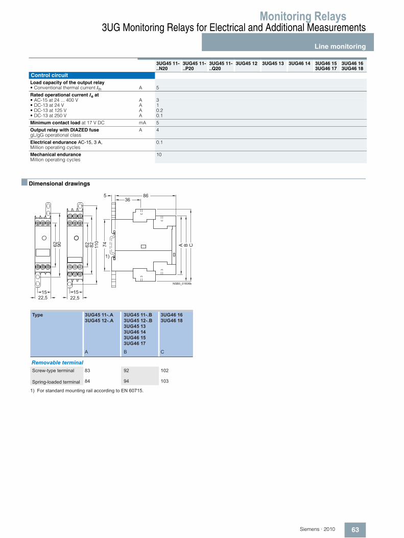
■ Dimensional drawings
3UG45 11-..N20
3UG45 11-..P20
3UG45 11-..Q20
3UG45 12 3UG45 13 3UG46 14 3UG46 153UG46 17
3UG46 163UG46 18
Control circuitLoad capacity of the output relay• Conventional thermal current Ith A 5
Rated operational current Ie at• AC-15 at 24 ... 400 V A 3• DC-13 at 24 V A 1• DC-13 at 125 V A 0.2• DC-13 at 250 V A 0.1
Minimum contact load at 17 V DC mA 5
Output relay with DIAZED fusegL/gG operational class
A 4
Electrical endurance AC-15, 3 A, Million operating cycles
0.1
Mechanical enduranceMillion operating cycles
10
NSB0_01606b
A B C74
86536
62 90
1522,5
62 110
1522,5
82
1)
3UG46 163UG46 18
3UG45 11-.A3UG45 12-.A
3UG45 11-.B3UG45 12-.B3UG45 133UG46 143UG46 153UG46 17
BA C
9283 102
9484 103
1) For standard mounting rail according to EN 60715.
Screw-type terminal
Spring-loaded terminal
Removable terminal
Type
Monitoring Relays3UG Monitoring Relays for Electrical and Additional Measurements
Line monitoring
64 Siemens · 2010
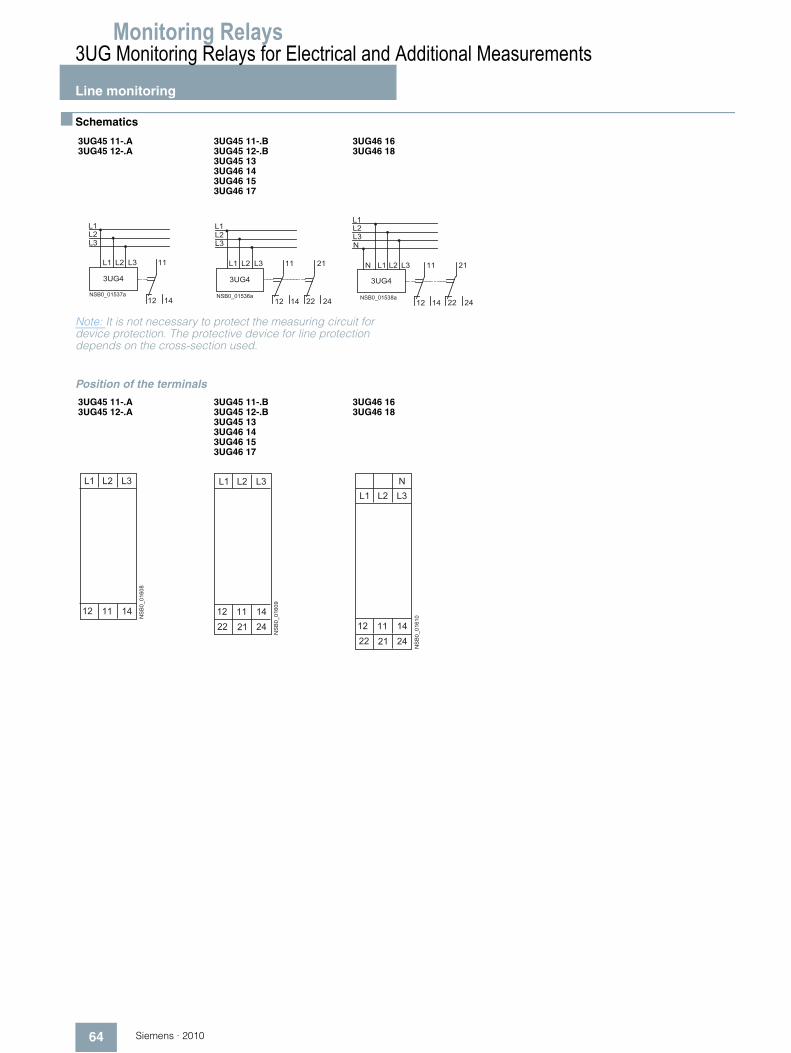
■ Schematics
Note: It is not necessary to protect the measuring circuit for device protection. The protective device for line protection depends on the cross-section used.
Position of the terminals
3UG45 11-.A3UG45 12-.A
3UG45 11-.B3UG45 12-.B3UG45 133UG46 143UG46 153UG46 17
3UG46 163UG46 18
� � � � � � � � �
� �
�
� �
� �
� �
� �
� �
� � �
� � � � � � � � � �
� �
�
� �
� �
� �
� �
� �
�
�
� � �
� � � � � � � � � �
� �
�
� �
� �
� �
� �
� �
�
�
�
�
� � �
3UG45 11-.A3UG45 12-.A
3UG45 11-.B3UG45 12-.B3UG45 133UG46 143UG46 153UG46 17
3UG46 163UG46 18
����������
� �
� � � � �
� �
����������
� �
� � � � �
� �
� �
����������
� �
� � � � �
� �
� �
�
Monitoring Relays
65Siemens · 2010
3UG Monitoring Relays for Electrical and Additional Measurements
Voltage monitoring
■ Overview
The relays monitor single-phase AC voltages (rms value) and DC voltages against the set threshold value for overshoot and undershoot. The devices differ with regard to their power supply (internal or external).
■ Function
3UG46 33 monitoring relays
The 3UG46 33 voltage monitoring relay has an internal power supply and performs overshoot, undershoot or window monitor-ing of the voltage depending on how it is parameterized. The de-vice is equipped with a display and is parameterized using three buttons.The operating and measuring range extends from 17 ... 275 V AC/DC. The threshold values for overshoot or under-shoot can be freely configured within this range. If one of these threshold values is reached, the output relay responds accord-ing to the set principle of operation as soon as the tripping delay time has elapsed. This delay time UDel can be set from 0.1 ... 20 s like the ON-delay time onDel.
The hysteresis is adjustable from 0.1 ... 150 V. The device can be operated on the basis of either the open-circuit or closed-circuit principle and with manual or auto RESET. One output change-over contact is available as signaling contact.
With the closed-circuit principle selected
Overvoltage
Undervoltage
Window monitoring
NS
B0_
0158
4a
11/14
11/12
= 0
A1-A2 = >
Hysteresis
DelayonDelay
NS
B0_
0158
5a
11/14
11/12
= 0
A1-A2 = <Hysteresis
DelayonDelay
A1-A2 =
NS
B0_
0158
6a
>
11/14
11/12
= 0
<
Hysteresis
Hysteresis
DelayonDelay
Delay =Delay
Delay

Monitoring Relays3UG Monitoring Relays for Electrical and Additional Measurements
Voltage monitoring
66 Siemens · 2010
3UG46 31/3UG46 32 monitoring relays
The 3UG46 31/3UG46 32 voltage monitoring relay is supplied with an auxiliary voltage of 24 V AC/DC or 24 ... 240 V AC/DC and performs overshoot, undershoot or window monitoring of the voltage depending on how it is parameterized. The device is equipped with a display and is parameterized using three buttons.The measuring range extends from 0.1 V ... 60 V or 10 ... 600 V AC/DC. The threshold values for overshoot or under-shoot can be freely configured within this range. If one of these threshold values is reached, the output relay responds accord-ing to the set principle of operation as soon as the delay time has elapsed. This delay time UDel can be set from 0.1 ... 20 s.The hysteresis can be set from 0.1 ... 30 V or 0.1 ... 300 V. The device can be operated on the basis of either the open-circuit or closed-circuit principle and with manual or auto RESET. One out-put changeover contact is available as signaling contact.
With the closed-circuit principle selected
Overvoltage
Undervoltage
Window monitoring
NS
B0_
0158
1a
11/14
11/12
= 0
A1-A2
>
Hysteresis
Delay
NS
B0_
0158
2a
11/14
11/12
= 0
A1-A2
<Hysteresis
Delay
NS
B0_
0158
3b
>
11/14
11/12
A1-A2
<
Hysteresis
Hysteresis
Delay DelayDelay = Delay

Monitoring Relays
67Siemens · 2010
3UG Monitoring Relays for Electrical and Additional Measurements
Voltage monitoring
■ Technical specifications
1) Absolute limit values.2) Important: This is a Class A product. In the household environment this
device may cause radio interference. In this case the user must introduce suitable measures.
3UG46 31-.AA
3UG46 31-.AW
3UG46 32-.AA
3UG46 32-.AW
3UG46 33
General dataRated control supply voltage Us V 24 AC/DC 24...240
AC/DC24 AC/DC 24...240
AC/DC17 ... 2751)
AC/DC
Rated frequency for AC Hz 50/60 40 ... 500
Operating range V 20.4 ... 27.6 20.4 ... 264 20.4 ... 27.6 20.4 ... 264 17...275
Rated power in W/VA VA 2/4
Width mm 22.5
RESET Automatic/manual
Availability time after application of Us ms 1000
Response time once a switching threshold is reached ms Max. 450
Adjustable tripping delay time s 0.1 … 20
Adjustable ON-delay time s -- 0.1 ... 20
Mains buffering time, minimum ms 10
Rated insulation voltage UiDegree of pollution 3 Overvoltage category III acc. to IEC 60664
V 690
Rated impulse withstand voltage Uimp kV 6
Protective separation acc. to IEC 60947-1, Annex N V 300
Permissible ambient temperature • During operation °C -25 … +60• During storage °C -40 … +85
EMC tests2) IEC 60947-5-1/IEC 61000-6-2/IEC 61000-6-4
Degree of protection acc. to IEC 60529 IP40 EnclosureIP20 Terminals
Mounting position Any
Vibration resistance acc. to IEC 60068-2-6 1 ... 6 Hz: 15 mm; 6 ... 500 Hz: 2 g
Shock resistance acc. to IEC 60068-2-27 g/ms 15/11
Connection type Screw terminals
• Terminal screw M 3 (standard screwdriver, size 2 and Pozidriv 2)• Solid mm2 1 x (0.5 ... 4)/2 x (0.5 ... 2.5)• Finely stranded with end sleeve mm2 1 x (0.5 ... 2.5)/2 x (0.5 ... 1.5)• AWG cables, solid or stranded AWG 2 x (20 ... 14)• Tightening torque Nm 0.8 … 1.2
Connection type Spring-type terminals
• Solid mm2 2 x (0.25 ... 1.5)• Finely stranded, with end sleeves mm2 2 x (0.25 ... 1.5)• Finely stranded mm2 2 x (0.25 ... 1.5)• AWG cables, solid or stranded AWG 2 x (24 ... 16)Measuring circuitPermissible measuring range single-phase AC/DC voltage V 0.1 … 68 10 … 650 17 … 275
Setting range single-phase voltage V 0.1 ... 60 10 ... 600 17 ... 275
Measuring frequency AC/DC Hz 40 ... 500 40 ... 500
Measuring accuracy % 5
Repeat accuracy at constant parameters % 1
Accuracy of digital display ±1 digit
Deviations for temperature fluctuations %/°C ±0.1
Hysteresis for single-phase voltage V 0.1 ... 30 0.1 ... 300 0.1 ... 150Control circuitLoad capacity of the output relay• Conventional thermal current Ith A 5
Rated operational current Ie• AC-15 at 24 ... 400 V A 3• DC-13 at 24 V A 1• DC-13 at 125 V A 0.2• DC-13 at 250 V A 0.1
Minimum contact load at 17 V DC mA 5
Output relay with DIAZED fuse gL/gG operational class
A 4
Electrical endurance AC-15, 3 A, million operating cycles 0.1
Mechanical endurance million operating cycles 10

Monitoring Relays3UG Monitoring Relays for Electrical and Additional Measurements
Voltage monitoring
68 Siemens · 2010
■ Dimensional drawings
■ Schematics
Note: It is not necessary to protect the measuring circuit for device protection. The protective device for line protection depends on the cross-section used.
Position of the terminals
NSB0_01729a
A B74
865
62 110
1522,5
72
1)
3UG46 313UG46 323UG46 33A B
83 92
84 94
Screw-type terminal
Spring-loaded terminal
Removable terminal
Type
1) For standard mounting rail according to EN 60715.
3UG46 31-.AA303UG46 32-.AA30
3UG46 31-.AW30 3UG46 32-.AW30
3UG46 33
NSB0_01532b
12
11
14
A1(+)
U
IN(+)
A2(–) M(–)
< U >
AC/DC Last
NSB0_01614a
12
11
14
A1(+)
U
IN(+)
A2(–) M(–)< U >
AC/DC Last
NSB0_01533b
12
11
14
A1(+)
A2(–)
< U >
AC/DC
3UG46 313UG46 32
3UG46 33
���������
� �
�
� � �
� � � � �
���������
� �
�
� � � � �

Monitoring Relays
69Siemens · 2010
3UG Monitoring Relays for Electrical and Additional Measurements
Current monitoring
■ Overview
The relays monitor single-phase AC currents (rms value) and DC currents against the set threshold value for overshoot and under-shoot. They differ with regard to their measuring ranges and sup-ply voltage types.
■ Function
3UG46 21/3UG46 22 monitoring relays
The 3UG46 21/3UG46 22 current monitoring relay is supplied with an auxiliary voltage of 24 V AC/DC or 24 ... 240 V AC/DC and performs overshoot, undershoot or window monitoring of the current depending on how it is parameterized. The device is equipped with a display and is parameterized using three buttons.
The measuring range extends from 3 ... 500 mA or 0.05 ... 10 A. The rms value of the current is measured. The threshold values for overshoot or undershoot can be freely configured within this range. If one of these threshold values is reached, the output re-lay responds according to the set principle of operation as soon as the tripping delay time IDel has elapsed. This time and the ON-delay time onDel are adjustable from 0.1 ... 20 s.
The hysteresis is adjustable from 0.1 ... 250 mA or 0.01 ... 5 A. The device can be operated with manual or auto RESET and on the basis of either the open-circuit or closed-circuit principle. Following options are available: Response of the output relay when the supply voltage Us = ON is applied or not until the lower measurement range limit of the measuring current (I > 3 mA/50 mA) is reached. One output changeover contact is available as signaling contact.
With the closed-circuit principle selectedupon application of the supply voltage
Current overshoot
Current undershoot
Window monitoring
NS
B0_
0157
9a11/14
A1-A2
11/12
=0
>
Hysteresis
DelayonDelay
NS
B0_
0158
0a
= 0
11/14
A1-A2
11/12
<
Hysteresis
DelayonDelay
NS
B0_
0162
6a
>
11/14
11/12
= 0
A1-A2
<
Hysteresis
Hysteresis
DelayDelayDelayDelay =
onDelay

Monitoring Relays3UG Monitoring Relays for Electrical and Additional Measurements
Current monitoring
70 Siemens · 2010
■ Technical specifications
1) Important: This is a Class A product. In the household environment this device may cause radio interference. In this case the user must introduce suitable measures.
2) With protective separation.3) With simple separation.
3UG46 21-.AA 3UG46 21-.AW 3UG46 22-.AA 3UG46 22-.AWGeneral dataRated control supply voltage Us V 24 24 … 240 24 24 … 240
Rated frequency Hz 50/60
Operating range V 20.4 ... 26.4 20.4 ... 264 20.4 ... 26.4 20.4 ... 264
Rated power W/VA 2/4
Width mm 22.5
RESET Automatic/manual
Availability time after application of Us ms 1000
Response time once a switching threshold is reached ms Max. 450
Adjustable tripping delay time/ON-delay time s 0.1 … 20
Mains buffering time, minimum ms 10
Rated insulation voltage UiDegree of pollution 3; overvoltage category III acc. to IEC 60664
V 690
Rated impulse withstand voltage Uimp kV 6
Protective separation acc. to IEC 60947-1, Annex N V 300
Permissible ambient temperature• During operation °C -25 … +60• During storage °C -40 … +85
EMC tests1) IEC 60947-5-1/IEC 61000-6-2/IEC 61000-6-4
Degree of protection acc. to IEC 60529 IP40 EnclosureIP20 Terminals
Mounting position Any
Vibration resistance acc. to IEC 60068-2-6 1 ... 6 Hz: 15 mm; 6 ... 500 Hz: 2 g
Shock resistance acc. to IEC 60068-2-27 for half-sine shock type g/ms 15/11
Connection type Screw terminals
• Terminal screw M 3 (standard screwdriver, size 2 and Pozidriv 2)• Solid mm2 1 x (0.5 ... 4)/2 x (0.5 ... 2.5)• Finely stranded with end sleeve mm2 1 x (0.5 ... 2.5)/2 x (0.5 ... 1.5)• AWG cables, solid or stranded AWG 2 x (20 ... 14)• Tightening torque Nm 0.8 … 1.2
Connection type Spring-type terminals
• Solid mm2 2 x (0.25 ... 1.5)• Finely stranded, with end sleeves mm2 2 x (0.25 ... 1.5)• Finely stranded mm2 2 x (0.25 ... 1.5)• AWG cables, solid or stranded AWG 2 x (24 ... 16)Measuring circuitMeasuring range for single-phase AC/DC current A 0.003 … 0.6 0.05 … 15
Setting range for single-phase current A 0.003 ... 0.5 0.05 ... 10
Load supply voltage V 24 Max. 3002)
Max. 5003)24 Max. 3002)
Max. 5003)
Measuring accuracy % 5
Repeat accuracy at constant parameters % 1
Accuracy of digital display ±1 digit
Deviations for temperature fluctuations %/°C ±0.1
Hysteresis for single-phase current 0.1 ... 250 mA 0.01 ... 5 A
Permissible overcurrent, continuous A 0.6 15
Permissible overcurrent, < 1 s A 5 50
Protection against destruction, DIAZED gL/gG A 2 16
Measuring circuit internal resistance, shunt mΩ 500 5Control circuitLoad capacity of the output relay• Conventional thermal current Ith A 5
Rated operational current Ie• AC-15 at 24 ... 400 V A 3• DC-13 at 24 V A 1• DC-13 at 125 V A 0.2• DC-13 at 250 V A 0.1
Minimum contact load at 17 V DC mA 5
Output relay with DIAZED fuse gL/gG A 4
Electrical endurance AC-15, 3 A, million operating cycles 0.1
Endurance with contactor relay million operating cycles 10
Monitoring Relays
71Siemens · 2010
3UG Monitoring Relays for Electrical and Additional Measurements
Current monitoring
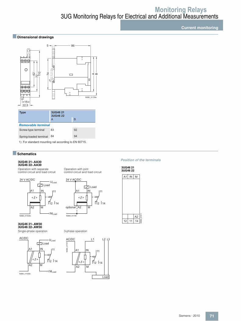
■ Dimensional drawings
■ Schematics
Position of the terminals
NSB0_01728a
A B74865
62 110
1522,5
72
1)
3UG46 213UG46 22A B
83 92
84 94
Screw-type terminal
Spring-loaded terminal
Removable terminal
Type
1) For standard mounting rail according to EN 60715.
3UG46 21-.AA303UG46 22-.AA30Operation with separate control circuit and load circuit
Operation with joint control circuit and load circuit
3UG46 21-.AW30 3UG46 22-.AW30Single-phase operation 3-phase operation
< >
11
14
NSB0_01534b
12 A2 M
A1 IN
MLoad
ULoad
24 V AC/DC
Load
< >
11
14
NSB0_01708
12 A2 M
A1 IN
24 V AC/DC
optional
Load
NSB0_01535b
11
14 M
12
A1
A2
< >
IN
MLoad
AC/DC
LoadULoad
NS
B0_
0170
7
< >
A1 IN
A2 M
L3L2L1AC/DC
11
1412
Load
3UG46 213UG46 22
����������
� �
�
� � �
� � � � �
Monitoring Relays3UG Monitoring Relays for Electrical and Additional Measurements
Current monitoring
72 Siemens · 2010
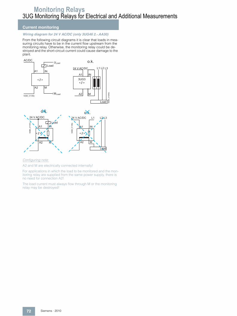
Wiring diagram for 24 V AC/DC (only 3UG46 2.-.AA30)
From the following circuit diagrams it is clear that loads in mea-suring circuits have to be in the current flow upstream from the monitoring relay. Otherwise, the monitoring relay could be de-stroyed and the short-circuit current could cause damage to the plant.
Configuring note:
A2 and M are electrically connected internally!
For applications in which the load to be monitored and the mon-itoring relay are supplied from the same power supply, there is no need for connection A2!
The load current must always flow through M or the monitoring relay may be destroyed!
< >
NSB0_01199e
A2 M
A1 IN
MLoad
ULoad
AC/DC
Load
NS
B0_
0120
0e
A2
M
L1
L2
L3
IN
A1
< >
o.k.
3UG3
24 V AC/DC
Load
o.k.
< >
A2 M
A1 IN
NS
B0_
0119
7e Load
24 V AC/DC
< >
A2
A1
NSB
0_01
198e
o.k.
M
L1 L2 L3
IN
24 V AC/DC
Load
Monitoring Relays
73Siemens · 2010
3UG Monitoring Relays for Electrical and Additional Measurements
Power factor and active current monitoring
■ Overview
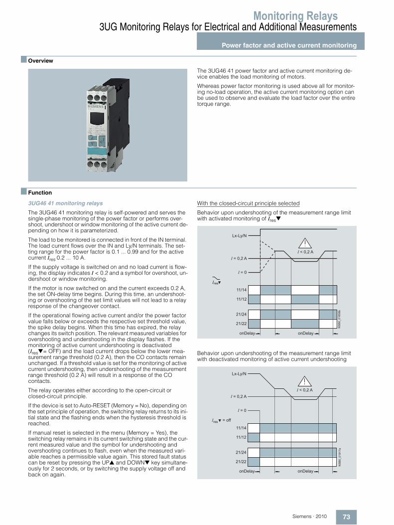
The 3UG46 41 power factor and active current monitoring de-vice enables the load monitoring of motors.
Whereas power factor monitoring is used above all for monitor-ing no-load operation, the active current monitoring option can be used to observe and evaluate the load factor over the entire torque range.
■ Function
3UG46 41 monitoring relays
The 3UG46 41 monitoring relay is self-powered and serves the single-phase monitoring of the power factor or performs over-shoot, undershoot or window monitoring of the active current de-pending on how it is parameterized.
The load to be monitored is connected in front of the IN terminal. The load current flows over the IN and Ly/N terminals. The set-ting range for the power factor is 0.1 ... 0.99 and for the active current Ires 0.2 ... 10 A.
If the supply voltage is switched on and no load current is flow-ing, the display indicates I < 0.2 and a symbol for overshoot, un-dershoot or window monitoring.
If the motor is now switched on and the current exceeds 0.2 A, the set ON-delay time begins. During this time, an undershoot-ing or overshooting of the set limit values will not lead to a relay response of the changeover contact.
If the operational flowing active current and/or the power factor value falls below or exceeds the respective set threshold value, the spike delay begins. When this time has expired, the relay changes its switch position. The relevant measured variables for overshooting and undershooting in the display flashes. If the monitoring of active current undershooting is deactivated (Ires▼= OFF) and the load current drops below the lower mea-surement range threshold (0.2 A), then the CO contacts remain unchanged. If a threshold value is set for the monitoring of active current undershooting, then undershooting of the measurement range threshold (0.2 A) will result in a response of the CO contacts.
The relay operates either according to the open-circuit or closed-circuit principle.
If the device is set to Auto-RESET (Memory = No), depending on the set principle of operation, the switching relay returns to its ini-tial state and the flashing ends when the hysteresis threshold is reached.
If manual reset is selected in the menu (Memory = Yes), the switching relay remains in its current switching state and the cur-rent measured value and the symbol for undershooting and overshooting continues to flash, even when the measured vari-able reaches a permissible value again. This stored fault status can be reset by pressing the UP▲ and DOWN▼ key simultane-ously for 2 seconds, or by switching the supply voltage off and back on again.
With the closed-circuit principle selected
Behavior upon undershooting of the measurement range limit with activated monitoring of Ires▼
Behavior upon undershooting of the measurement range limit with deactivated monitoring of active current undershooting
NS
B0_
0165
8b
21/22
21/24
11/12
11/14
Lx-Ly/N
I = 0,2 A
I = 0
I < 0,2 A
Ires
onDelayonDelayN
SB
0_01
917a
21/22
21/24
11/12
11/14
Lx-Ly/N
I = 0,2 A
I = 0
I < 0,2 A
Ires = off
onDelayonDelay
Monitoring Relays3UG Monitoring Relays for Electrical and Additional Measurements
Power factor and active current monitoring
74 Siemens · 2010
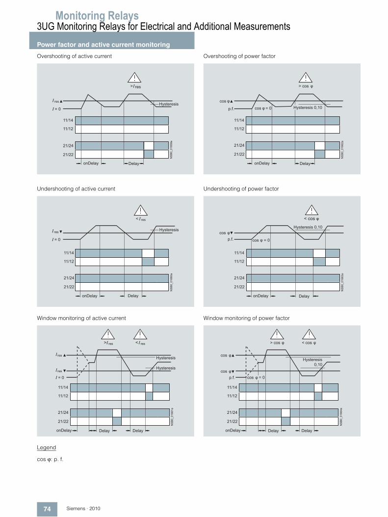
Overshooting of active current
Undershooting of active current
Window monitoring of active current
Legend
cos ϕ: p. f.
Overshooting of power factor
Undershooting of power factor
Window monitoring of power factor
NS
B0_
0165
9a
21/24
21/22
11/14
11/12
> res
= 0
res
DelayonDelay
Hysteresis
NS
B0_
0166
0a
21/24
21/22
11/14
11/12
< res
= 0
res
DelayonDelay
Hysteresis
NS
B0_
0166
1a
21/24
21/22
11/14
11/12
< res
= 0
> res
res
res
DelayonDelay Delay
Hysteresis
Hysteresis
NS
B0_
0166
2a
21/24
21/22
11/14
11/12
> cos
cos = 0
cos
p.f.
DelayonDelay
Hysteresis 0,10
cos = 0
NS
B0_
0166
3a
21/24
21/22
11/14
11/12
< cos
cosp.f.
Hysteresis 0,10
DelayonDelay
cos = 0
NS
B0_
0166
4a
21/24
21/22
11/14
11/12
< cos
cos
p.f.cos
> cos
Hysteresis0,10
DelayonDelay Delay

Monitoring Relays
75Siemens · 2010
3UG Monitoring Relays for Electrical and Additional Measurements
Power factor and active current monitoring
■ Technical specifications
1) Important: This is a Class A product. In the household environment this device may cause radio interference. In this case the user must introduce suitable measures.
Type 3UG46 41General dataRated control supply voltage Us
Absolute limit values
V 90 … 690
Rated frequency Hz 50/60
Rated power, typical• At 200 V AC VA 2.0• At 400 V AC VA 2.7• At 460 V AC VA 3.1
Width mm 22.5
RESET Automatic/manual
Principle of operation Closed-circuit principle, open-circuit principle
Availability time after application of Us ms 1000
Response time once a switching threshold is reached ms Max. 450
Adjustable tripping delay time s 0.1 ... 20
Adjustable ON-delay time s 0 ... 99
Mains buffering time, minimum ms 10
Rated insulation voltage UiDegree of pollution 3Overvoltage category III acc. to IEC 60664
V 690
Rated impulse withstand voltage kV 6
Permissible ambient temperature • During operation °C -25 … +60• During storage °C -40 … +85
EMC tests1) IEC 60947-5-1/IEC 61000-6-2/IEC 61000-6-4
Degree of protection acc. to IEC 60529 IP40 EnclosureIP20 Terminals
Mounting position Any
Vibration resistance acc. to IEC 60068-2-6 1 ... 6 Hz: 15 mm; 6 ... 500 Hz: 2 g
Shock resistance acc. to IEC 60068-2-27 g/ms 15/11
Connection type Screw terminals
• Terminal screw M 3 (standard screwdriver, size 2 and Pozidriv 2)• Solid mm2 1 x (0.5 ... 4)/2 x (0.5 ... 2.5)• Finely stranded with end sleeve mm2 1 x (0.5 ... 2.5)/2 x (0.5 ... 1.5)• AWG cables, solid or stranded AWG 2 x (20 ... 14)• Tightening torque Nm 0.8 … 1.2
Connection type Spring-type terminals
• Solid mm2 2 x (0.25 ... 1.5)• Finely stranded, with end sleeves mm2 2 x (0.25 ... 1.5)• Finely stranded mm2 2 x (0.25 ... 1.5)• AWG cables, solid or stranded AWG 2 x (24 ... 16)Measuring circuitMeasurable active current Ires A 0.2 ... 10
Max. permissible load current A 10
Peak current < 1 s A 50
Adjustable response value Phase displacement angle
0.1 ... 0.99
DIAZED protection, gL/gG operational class A 16
Measuring accuracy % 10
Repeat accuracy at constant parameters % 1
Accuracy of digital display ± 1 digit
Deviations for temperature fluctuations %/°C ±0.1
Hysteresis Phase angle
0.10
Hysteresis Active current monitoring
A 0.1 ... 2.0

Monitoring Relays3UG Monitoring Relays for Electrical and Additional Measurements
Power factor and active current monitoring
76 Siemens · 2010
■ Dimensional drawings
Type 3UG46 41Control circuitNumber of CO contacts for auxiliary contacts 2
Load capacity of the output relay• Conventional thermal current Ith A 5
Rated operational current Ie at• AC-15 at 24 ... 400 V A 3• DC-13 at 24 V A 1• DC-13 at 125 V A 0.2• DC-13 at 250 V A 0.1
Minimum contact load at 17 V DC mA 5
Output relay with DIAZED fusegL/gG operational class
A 4
Electrical endurance AC-15 Million operat-ing cycles
0.1
Mechanical endurance Million operat-ing cycles
10
NSB0_01699b
A B74
865
62 110
1522,5
72
1)
3UG46 41A B
83 92
84 94
1) For standard mounting rail according to EN 60715.
Screw-type terminal
Spring-loaded terminal
Removable terminal
Type
Monitoring Relays
77Siemens · 2010
3UG Monitoring Relays for Electrical and Additional Measurements
Power factor and active current monitoring
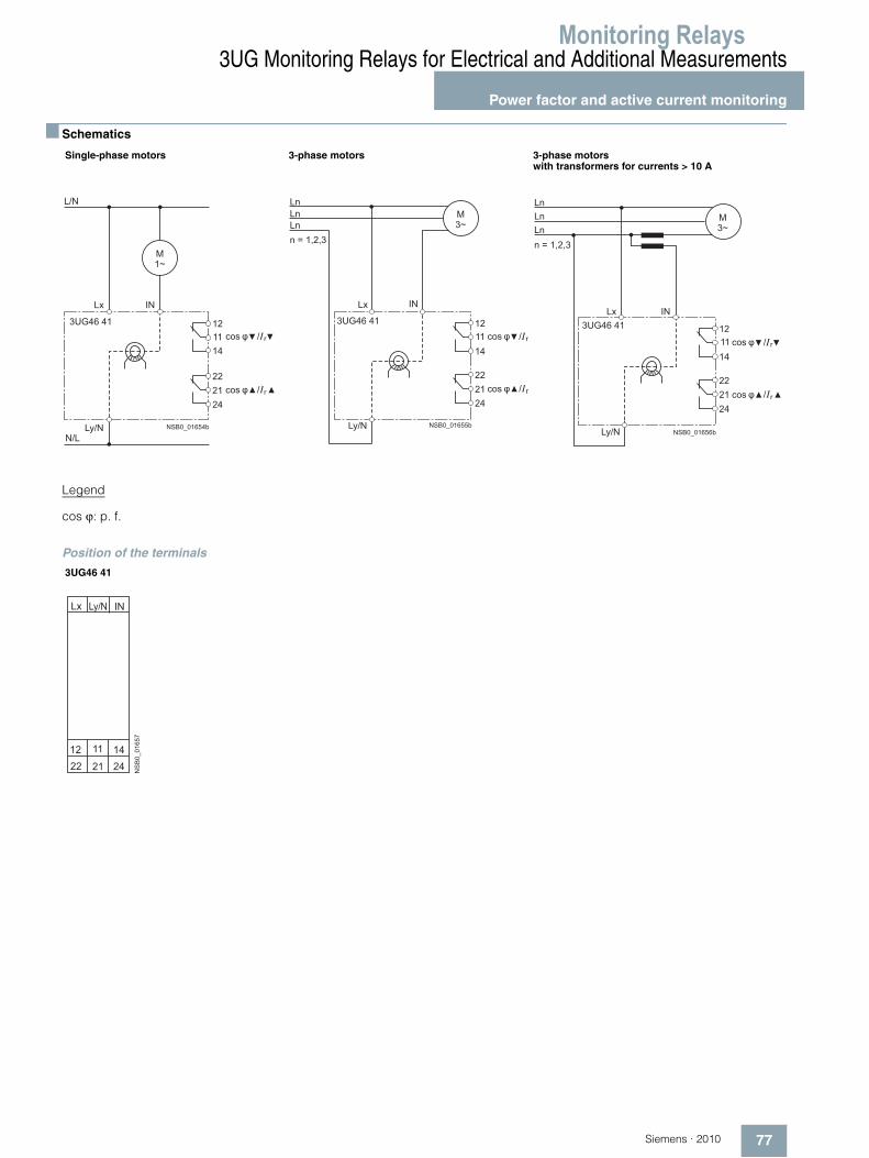
■ Schematics
Legend
cos ϕ: p. f.
Position of the terminals
Single-phase motors 3-phase motors 3-phase motors with transformers for currents > 10 A
M1~
Lx IN
12
14
22
24
N/L
L/N
21
Ly/N
113UG46 41
cos / r
cos / r
NSB0_01654b
Lx IN
12
14
22
24
LnLnLnn = 1,2,3
21
M3~
11
Ly/N
3UG46 41
cos / r
cos / r
NSB0_01655b
Lx IN
12
14
22
2421
M3~
Ly/N
11
3UG46 41
NSB0_01656b
cos / r
cos / r
LnLnLnn = 1,2,3
3UG46 41
NS
B0_
0165
7
Lx
12 14
IN
22 21 24
11
Ly/N

Monitoring Relays3UG Monitoring Relays for Electrical and Additional MeasurementsResidual current monitoring:Residual-current monitoring relays
78 Siemens · 2010
■ Overview
The 3UG46 24 residual current monitoring relay is used together with the 3UL22 summation current transformer for plant monitoring.
■ Function
3UG46 24 monitoring relays
The main conductor and any neutral conductor to which a load is connected, are routed through the opening of the annular strip-wound core of a summation current transformer. A second-ary winding is placed around this annular strip-wound core to which the monitoring relay is connected.
If operation of a plant is fault-free, the sum of the inflowing and outward currents equals zero. In this case, no voltage is induced in the secondary winding of the summation current transformer.
However, if an insulation fault occurs downstream of the residual current operated circuit breaker, the sum of the inflowing cur-rents is greater than that of the outward currents.
The differential current - the residual current - induces a second-ary current in the secondary winding of the transformer. This cur-rent is evaluated in the monitoring relay and is used on the one hand to display the actual residual current and on the other, to switch the relay if the set warning or tripping threshold is over-shot.
If the measured residual current exceeds the set warning value, the associated changeover contact instantly changes the switching state and an indication appears on the display. If the measured residual current exceeds the set tripping value, the set delay time begins and the associated relay symbol flashes. On expiry of this time, the associated changeover contact changes the switching state.
ON-delay time for motor start
To be able to start a motor, once the auxiliary voltage has been applied for an adjustable ON-delay time, and depending on whether the open-circuit or closed-circuit principle is selected, the output relay switches to the GO state.
The changeover contacts do not react if the set threshold value is overshot during this period.

Monitoring Relays
79Siemens · 2010
3UG Monitoring Relays for Electrical and Additional MeasurementsResidual current monitoring:
Residual-current monitoring relays
With the closed-circuit principle selected
Residual current monitoring with Auto-RESET (Memory = no)
If the device is set to Auto-RESET (Memory = No), the relay switches for the tripping value once the value falls below the set hysteresis threshold and the display stops flashing. The associ-ated relay changes its switching state if the value falls below the fixed hysteresis value of 5 % of the warning value. Any over-shoots are therefore not stored.
Note:
The neutral conductor must not be grounded downstream of the summation current transformer as this may impair the function of the residual current monitoring device.
Residual current monitoring with Manual-RESET (Memory = yes)
If Manual-RESET is selected in the menu, the output relay re-mains in its current switching state and the current measured value and the symbol for overshooting continues to flash, even when the measured residual current returns to a permissible value. This stored fault status can be reset by pressing the UP▲ and DOWN▼ key simultaneously for > 2 seconds, or by switch-ing the supply voltage off and back on again.
NS
B0_
0181
2a
11/14
Lx-Ly/N
11/12
21/24
21/22
>
= 0
!
!>
Hysteresis
Mem = no
Hysteresis = 5 %
onDelay Delay
NS
B0_
0181
3a
11/14
Lx-Ly/N
11/12
21/24
21/22
>
= 0
!
!>
Reset
Hysteresis
Mem = yes
Hysteresis = 5 %
onDelay Delay

Monitoring Relays3UG Monitoring Relays for Electrical and Additional MeasurementsResidual current monitoring:Residual-current monitoring relays
80 Siemens · 2010
■ Technical specifications
1) Important: This is a Class A product. In the household environment this device may cause radio interference. In this case the user must take suitable precautions.
2) LSB: Smallest adjustable value, transformer-dependent, ≤ 1 % of IΔn.3) The measuring accuracy of the evaluation system has higher tolerances
when combined with the 3UL2 current transformer.
Type 3UG46 24General dataRated control supply voltage Us
Absolute limit values
V 90 … 690
Rated frequency Hz 50/60
Rated power, typical• At 90 V AC VA 2.8• At 230 V AC VA 2.4• At 400 V AC VA 3.1• At 460 V AC VA 3.2• At 690 V AC VA 4.7
Width mm 22.5
RESET Automatic/manual
Principle of operation Closed-circuit principle, open-circuit principle
Availability time after application of Us ms 1000
Response time once a switching threshold is reached ms Max. 300
Adjustable delay time s 0.1... 20
Mains buffering time, minimum ms 10
Rated insulation voltage UiDegree of pollution 3Overvoltage category III acc. to IEC 60664
V 690
Rated impulse withstand voltage kV 6
Permissible ambient temperature • During operation °C -25 … +60• During storage °C -40 … +85
EMC tests1) IEC 60947-5-1/IEC 61000-6-2/IEC 61000-6-4
Degree of protection acc. to IEC 60529 IP40 EnclosureIP20 Terminals
Mounting position Any
Vibration resistance acc. to IEC 60068-2-6 1 ... 6 Hz: 15 mm; 6 ... 500 Hz: 2 g
Shock resistance acc. to IEC 60068-2-27 g/ms 15/11
Connection type Screw terminals
• Terminal screw M3 (for standard screw driver size 2 and Pozidriv 2)• Solid mm2 1 x (0.5 ... 4)/2 x (0.5 ... 2.5)• Finely stranded with end sleeve mm2 1 x (0.5 ... 2.5)/2 x (0.5 ... 1.5)• AWG cables, solid or stranded AWG 2 x (20 ... 14)• Tightening torque NM 0.8 … 1.2
Connection type Spring-type terminals
• Solid mm2 2 x (0.25 ... 1.5)• Finely stranded, with end sleeves mm2 2 x (0.25 ... 1.5)• Finely stranded mm2 2 x (0.25 ... 1.5)• AWG cables, solid or stranded AWG 2 x (24 ... 16)Measuring circuitMeasurable residual current Ires A 10 ... 120 % IΔn (IΔn : rated residual current of the transformer)
Adjustable response value • Residual current 10 ... 100 % IΔn • Warning 10 ... 100 % IΔn
Measuring accuracy3) % ±5
Repeat accuracy at constant parameters % ±1
Accuracy of digital display ± 1 digit
Deviations for temperature changes %/°C ±0.1
Hysteresis for residual current LSB2) up to 50 % IΔn
Hysteresis for warning threshold A 5 % IΔn

Monitoring Relays
81Siemens · 2010
3UG Monitoring Relays for Electrical and Additional MeasurementsResidual current monitoring:
Residual-current monitoring relays
■ Dimensional drawings
3UG46 24
Type 3UG46 24Control circuitNumber of CO contacts for auxiliary contacts 2
Load capacity of the output relay
Conventional thermal current IthA 5
Rated operational current Ie at• AC-15 at 24 ... 400 V A 3• DC-13 at 24 V A 1• DC-13 at 125 V A 0.2• DC-13 at 250 V A 0.1
Minimum contact load at 17 V DC mA 5
Output relay with DIAZED fuse gL/gG operational class
A 4
Electrical endurance AC-15 Million operat-ing cycles
0.1
Mechanical endurance Million operat-ing cycles
10
NSB0_01828
A B74
86536
62 110
1522,5
82
3UG46 24A B
84 103
83 102Screw-type terminal
Spring-loaded terminal
Removable terminal
1) For standard mounting rail according to EN 60715.
Type

Monitoring Relays3UG Monitoring Relays for Electrical and Additional MeasurementsResidual current monitoring:Residual-current monitoring relays
82 Siemens · 2010
■ Schematics
3UG46 24
Note: It is not necessary to protect the measuring circuit for device protection. The protective device for line protection depends on the cross-section used.
Circuit example
Position of the terminals
11
12 14
Lx C1 C2
Ly/N
3UG46 24
AC
AC
NSB0_01808a
21
22 24
L1 L2 L3 N
AC 24 V
F1
3UL22Z3
A2
R1
R2
Lx Ly/N
3UG46 24 C1 Z1
C2 Z2
NS
B0_
0183
2
Load
220 >3 W --
Type R1 R23UL22 0.-1A 3UL22 0.-2A3UL22 0.-3A
0,3 A0,5 A 1 A
3UL22 0.-1B3UL22 0.-2B3UL22 0.-3B3UL22 0.-4B3UL22 0.-5B
6 A10 A16 A25 A40 A
22 >6 W 22 >6 W
-
- -
NS
B0_
0182
5
C1 C2Lx Ly/N
22 21 2412 11 14

Monitoring Relays
83Siemens · 2010
3UG Monitoring Relays for Electrical and Additional MeasurementsResidual current monitoring:
3UL22 summation current transformers
■ Overview
The 3UL22 summation current transformers detect fault currents in machines and plants. Together with the 3UG46 24 residual current monitoring relay or the SIMOCODE 3UF motor manage-ment and control device they enable residual-current and ground-fault monitoring.
■ Technical specifications
■ Dimensional drawings
3UL22 summation current transformer
Summation current transformers
Type 3UL22 01 3UL22 02 3UL22 03
Rated insulation voltage Ui AC 50/60 Hz
690 V 1000 V
Rated residual current IΔnWithout response delay A 0.3 ... 1 0.3 ... 40 0.3 ... 40
Permissible ambient temperature °C -20 ... +70
Feed-through openings mm 40 65 120
For Protodur cablesCan be fed through Max. mm² 4 x 95 4 x 240 8 x 300
NSB0_00364b
a1
a6
a4 a5
a2 a3
b5b 1
b 2b 3b 4
c 1 c 2 c 3
A2
Z2Z1
Z3
Type
3UL22 013UL22 023UL22 03
a1
100125200
a3
101020
a2
7595
165
a4
151520
c1
657085
a6
80100170
a5
for M4for M4for M4
b1
85110200
b2
72.597.5
100
b3
42.555
100
b4
7.57.5
10
b5
4065
120
c2
506070
c3
404555

Monitoring Relays3UG Monitoring Relays for Electrical and Additional MeasurementsInsulation monitoringFor ungrounded AC networks
84 Siemens · 2010
■ Overview
Relay for monitoring the insulation resistance between the un-grounded single or three-phase AC supply and a protective con-ductor• Measuring principle with superimposed DC voltage• Two selectable measuring ranges of 1 ... 110 kΩ• Stepless setting within the measuring range• Selectable:
- Auto reset function with fixed hysteresis or- Storage of the tripping operation
• Test function with test button and terminal connections on the front
• Switching output: 1 CO contact• Insulation fault indication with a red LED• Supply voltage indication with a green LED• Electro-magnetically compatible according to IEC 61000-6-2
and IEC 61000-6-4
■ Function
The monitoring relay measures the insulation resistance be-tween the ungrounded AC supply and an associated protective conductor.
A superposed DC measuring voltage is used to perform the measurement.
The monitoring relay is divided into two ranges for an insulation resistance range from 1 ... 100 kΩ. A range switch on the front can be used to switch over between a 1 ... 11 kΩ range and a 10 ... 110 kΩ range. Within the selected range, the monitoring relay can be steplessly adapted to the respective insulation con-ditions.
If the insulation resistance undershoots the set response value, the output relay is excited and the red LED (fault indication) is lit.
If the insulation resistance exceeds 1.6 times (corresponding to 60 % hysteresis) the set response value, the output relay will re-turn to the rest position.
Test functions
The "Test" button on the front can be used to simulate a ground fault. If the "Test" button is pressed for at least 300 ms, the output relay is energized and the fault LED lights up. An external test button, which is connected to PE, can also be connected to ter-minal Y1. The function is activated by closing (> 300 ms).
Fault storage and RESET
If terminals Y1 and Y2 are jumpered, the monitoring relay is set to fault storage mode. If the set insulation resistance is under-shot, the output relay is excited and remains tripped even after the insulation resistance rises above 1.6 times the set value again. Fault storage can be reset by briefly pressing the RESET button, briefly jumpering (< 300 ms) the Y1 and PE/ground ter-minals or by switching off and on the supply voltage.
Note:
The monitoring relay is designed for AC voltage systems. Series-connected rectifiers must be electrically isolated from the measuring relay.
= Supply voltage A1-B2/A1-A2 for 115V/230V AC A1-A2 for 24 … 240V AC/DC= Remote connection-Save-Reset= Button on the front Test/Reset= Insulation resistance R of the network= Normally open contact
tTest
tTest = > approx. 300 ms
A1/A2A1/B2
11/1411/12
Y1/Y2
Y1/PE
1,6 x Rvalue
RRvalue
2
1
3
4
5
2
1
3
4
5
NSB0_01393a

Monitoring Relays
85Siemens · 2010
3UG Monitoring Relays for Electrical and Additional MeasurementsInsulation monitoring
For ungrounded AC networks
■ Technical specifications
■ Dimensional drawings
■ Schematics
Circuit diagram for networks up to 400 V AC
3UG30 81Control circuitOperating range of the control supply voltage -15 %... +10 %
Rated power 24 ... 240 V AC/DC VA/W 8/2
110 ... 130 V AC/DC VA 3
220 ... 240 V AC/DC VA 3
Frequency of the rated control supply voltage Hz 50 ... 60Measuring circuit L/PE• Response value kΩ 1...110
• Min. internal resistance for AC kΩ 100
• Min. internal resistance for DC kΩ 100
• Measurement DC voltage V 30
• Max. AC insulation voltage (L/PE) V 415
• Reset/test function terminals (max. 10 m) Y1-Y2
• Delay time in case of response s 1
Output relay 1 CO contact, open-circuit principleGeneral data Rated insulation voltage Ui Between supply, measurement,
and output circuitV 250 acc. to IEC 60947-1
Overvoltage category Acc. to EN 60664-1 III
Degree of pollution Acc. to IEC 60664-1 3
Impulse withstand voltage Uimp Acc. to VDE 0435, Part 303 kV 4
Degree of protection Acc. to IEC 60529 IP50 enclosureIP20 terminals
Shock resistance Acc. to IEC 60068-2-27 g/ms 10
Vibration resistance Acc. to IEC 60068-2-6 10 ... 55 Hz: 0.35 mm
Permissible ambient temperature • During operation °C -25 ... 65• During storage °C -40 ... 85
Mounting position Any
Conductor cross-section Solid mm2 2 x 0.75 ... 2.5
Finely stranded with end sleeve mm2 2 x 0.75 ... 2.5
��
��
��
��
�
��
��
��
��
��
��
L1L2L3
A1
A2B21)
N 230 VN 115 V
R
A1
A2 B2
L
PE Y2Y1
111412
NS
B0_
0139
4c
N
A1-A2 for 24...240 V AC/DC
TestReset
3 x 230/400 V AC
PE
A1-B2 for 115 V AC orA1-B2 for 230 V AC1) Only 3UG3081-1AK20.

Monitoring Relays3UG Monitoring Relays for Electrical and Additional MeasurementsInsulation monitoringFor ungrounded DC networks
86 Siemens · 2010
■ Overview
Relay for monitoring the insulation resistance between un-grounded pure DC networks and a protective conductor• Measuring principle for residual current measurement• Response value can be adjusted steplessly from 10 ... 110 kΩ• Selectable
- Auto reset function with hysteresis or - Storage of the tripping operation
• Front selector switch for open-circuit and closed-circuit principle for the output relay
• Test function with test buttons on the front for L+ and L-and over terminal connections
• Switching output: 1 CO contact• Insulation fault indicator for L+ and L- through two red LEDs• Supply voltage indication with a green LED • Electro-magnetically compatible according to IEC 61000-6-2
and IEC 61000-6-4
■ Function
The monitoring relay measures the insulation resistance be-tween the positive and negative supply voltage in an un-grounded DC voltage network and a corresponding protective conductor.
The measurement is based on the DC residual current measure-ment principle. The response value can be adjusted steplessly in the range from 10 ... 110 kΩ and thus can be adapted to the corresponding conditions. If the insulation resistance falls below the set response value, the output relay triggers (depending on the setting of the open/closed-circuit principle selector switch) and a fault LED lights up.
A ground fault is evaluated separately for L+ and L- and indi-cated by means of a corresponding LED.
Note:
Due to the measurement principle, a symmetrical ground fault on terminals L+ and L- cannot be evaluated.
Test function
A ground fault can be simulated using the Test L+ and Test L- buttons on the front. If the test button is pressed for at least 1 s, the status of the output relay changes and the corresponding fault LED lights up.
An external test button can be connected to terminals Y1-Y3 for L+ and terminals Y4-Y3 for L-. The function is triggered by means of a NO contact.
Fault storage and RESET
If terminals Y2 and Y3 are linked, the monitoring relay is set to fault storage mode.
If the insulation resistance falls below the set value, the output re-lay triggers (depending on the setting of the open/closed circuit selector switch), and stays in this state even if the insulation re-sistance rises again above the hysteresis value (typical: 2 times the set value). This fault storage can be deleted by pressing and releasing the L+ RESET button, opening the Y2-Y3 connection or by switching off the supply voltage.
Open/closed-circuit principle selector switch
The principle of operation of the output relay can be adjusted by means of a selector switch on the front panel.
If the relay is to respond in the event of a fault (contact symbol open), the open-circuit principle must be selected. If the relay however is to trigger in the event of a fault (contact symbol closed), the closed-circuit principle must be selected.
Note:
The position of the selector switch has no effect upon the fault LEDs. The LEDs always light up if the insulation resistance on L+ or L– falls below the set value.
= Supply voltage= Button on front – Reset L+ and L-/Test L+= Button on front – Test L – Test remote connection – Test L= Test remote connection – Test L+= Test remote connection – Store, reset= Insulation resistance R of supply set response value R= Switch on front Open-circuit/closed-circuit principle= Selector switch
Open-circuit/closedcircuitprinciple11/1411/12
2
1
3
4
5
6
7
8
21
3
4
56
7
8
A1/A2
Y3/Y4Y1/Y3Y2/Y3
L+/PEL-/PE
tTest > IstTest = approx. 1 sRHyst = typically 2 x Rx
R
Rvalue
RHyst
NSB0_01395a

Monitoring Relays
87Siemens · 2010
3UG Monitoring Relays for Electrical and Additional MeasurementsInsulation monitoring
For ungrounded DC networks
■ Technical specifications
■ Dimensional drawings
■ Schematics
Circuit diagram for 24 ... 240 V DC
3UG30 82Control circuitOperating range of the control supply voltage -15 %... +10 %
Rated power 24 ... 240 V AC/DC VA/W 8/2
Frequency of the rated control supply voltage Hz 50 ... 60Measuring circuit • Response value kΩ 10 ... 110
• Min. internal resistance for DC kΩ 57
• Measurement DC voltage V 24 ... 240
• Max. DC insulation voltage (L+/PE/ground, L-/PE/ground) V 300
• Reset/test function terminals (max. 10 m) Y1/Y3, Y4/Y3
• Delay time in case of response s 1
Output relay 1 changeover contact, open-circuit or closed-circuit principleGeneral data Rated insulation voltage Ui Insulation resistance
Between supply, measurement, and output circuit
V 250
Overvoltage category Acc. to IEC 60664 III
Degree of pollution Acc. to IEC 60664 3
Impulse withstand voltage Uimp Acc. to VDE 0435, Part 303 kV 4
Degree of protection Acc. to IEC 60529 IP50 enclosureIP20 terminals
Shock resistance Acc. to IEC 60068-2-27 g/ms 10
Vibration resistance Acc. to IEC 60068-2-6 10 ... 55 Hz: 0.35 mm
Permissible ambient temperature • During operation °C -25 ... + 65• During storage °C -40 ... + 85
Mounting position Any
Conductor cross-section Solid mm2 2 x 0.75 ... 2.5
Finely stranded with end sleeve mm2 2 x 0.75 ... 2.5
��
��
��
��
�
��
��
��
��
��
��
NS
B0_
0139
6
A1
A2
L+
PE
Y2
11
1412
Y1
Y4
Y3
Test L-
24...240 V AC/DC
R
24...240 V DC
L
L+
L-N
PE
L-
Test L+Reset

Monitoring Relays3UG Monitoring Relays for Electrical and Additional MeasurementsLevel monitoring:Level monitoring relays
88 Siemens · 2010
■ Overview
The 3UG45 01 level monitoring relay is used together with 2- or 3-pole sensors to monitor the levels of conductive liquids.
■ Function
3UG45 01 monitoring relays
The principle of operation of the 3UG45 01 level monitoring relay is based on measuring the electrical resistance of the liquid be-tween two immersion sensors and a reference terminal. If the measured value is lower than the sensitivity set at the front, the output relay changes its switching state. In order to exclude electrolytic phenomena in the liquid, the sensors are supplied with alternating current.
Two-point control
The output relay changes its switching state as soon as the liquid level reaches the maximum sensor, while the minimum sensor is submerged. The relay returns to its original switching state as soon as the minimum sensor no longer has contact with the liquid.
Single-point control
If only one level is being controlled, the terminals for Min and Max on the monitoring relay are bridged. The output relay changes its switching state as soon as the liquid level is reached and returns to its original switching state once the sensor no lon-ger has contact with the liquid.
In order to prevent premature tripping of the switching function caused by wave motion or frothing, even though the set level has not been reached, it is possible to delay this function by 0.5 ... 10 s.
For safe resetting, the supply voltage must be interrupted for at least the set delay time of +0.5 s.
Note:
It is also possible to connect other resistance sensors to the Min and Max terminals in the range 2 ... 200 kW, e. g. photoresistors, temperature sensors, encoders based on resistance etc. The monitoring relay can therefore also be used for other applica-tions apart from monitoring the levels of liquids.

Monitoring Relays
89Siemens · 2010
3UG Monitoring Relays for Electrical and Additional MeasurementsLevel monitoring:
Level monitoring relays
OVER, two-point control
UNDER, two-point control
OVER, single-point control
UNDER, single-point control
11/14
A1/A2
t t
11/12
t t
NS
B0_
0179
9b
Max
Min
t = Delay 0,5 - 10 s
> 0,5 s + t
Reset
11/14
A1/A2
11/12
t
NS
B0_
0180
0b
t t t
t = Delay 0,5 - 10 s
Max
Min
> 0,5 s + t
Reset
11/14
A1/A2
t t
11/12
t t
NS
B0_
0180
1b
Max Min
t = Delay 0,5 - 10 s
> 0,5 s + t
Reset
11/14
A1/A2
t t
11/12
t t
NS
B0_
0180
2c
Max Min
t = Delay 0,5 - 10 s
> 0,5 s + t
Reset

Monitoring Relays3UG Monitoring Relays for Electrical and Additional MeasurementsLevel monitoring:Level monitoring relays
90 Siemens · 2010
■ Technical specifications
1) Important: This is a Class A product. In the household environment this device may cause radio interference. In this case the user must introduce suitable measures.
2) The sensor cable does not necessarily have to be shielded, but we do not recommend installing this cable parallel to the power supply lines. It is also possible to use a shielded cable, whereby the shield has to be connected to the M terminal.
Type 3UG45 01-1AA30,3UG45 01-2AA30
3UG45 01-1AW30, 3UG45 01-2AW30
General dataRated control supply voltage Us V AC/DC 24 24 … 240
Rated frequency Hz 50/60
Operating range V 20.4 ... 26.4 20.4 ... 264
Rated power, max.• At 24 V AC VA 2 2• At 240 V AC VA -- 4
Width mm 22.5
Availability time after application of Us ms 500
Response time once a switching threshold is reached ms Max. 300
Adjustable delay time s 0.5 ... 10
Inlet or outlet monitoring function UNDER/OVER selector switch at the front
Mains buffering time, minimum ms 200
Rated insulation voltage UiDegree of pollution 3, Overvoltage category III acc. to IEC 60664
V 300
Rated impulse withstand voltage kV 4
Permissible ambient temperature • During operation °C -25 … +60• During storage °C -40 … +80
EMC tests1) IEC 60947-5-1/IEC 61000-6-2/IEC 61000-6-4
Degree of protection acc. to IEC 60529 IP40 EnclosureIP20 Terminals
Mounting position Any
Vibration resistance acc. to IEC 60068-2-6 1 ... 6 Hz: 15 mm; 6 ... 500 Hz: 2 g
Shock resistance acc. to IEC 60068-2-27 g/ms 15/11
Connection type Screw terminals
• Terminal screw M3 (for standard screwdriver, size 2 and Pozidriv 2)• Solid mm2 1 x (0.5 ... 4)/2 x (0.5 ... 2.5)• Finely stranded with end sleeve mm2 1 x (0.5 ... 2.5)/2 x (0.5 ... 1.5)• AWG cables, solid or stranded AWG 2 x (20 ... 14)• Tightening torque Nm 0.8 … 1.2
Connection type Spring-type terminals
• Solid mm2 2 x (0.25 ... 1.5)• Finely stranded, with end sleeves acc. to DIN 46228 mm2 2 x (0.25 ... 1.5)• Finely stranded mm2 2 x (0.25 ... 1.5)• AWG cables, solid or stranded AWG 2 x (24 ... 16)Measuring circuitElectrode current, max. (typ. 70 Hz) mA 1
Electrode voltage, max. (typ. 70 Hz) V 15
Sensor feeder cable m Max. 100
Conductor capacity of sensor cable2) nF Max. 10
Adjustable sensitivity• Resistance kΩ 2 ... 200
Measuring accuracy % ±20
Repeat accuracy at constant parameters % ±1
Deviations for temperature fluctuations %/°C ±1Control circuitNumber of CO contacts for auxiliary contacts 1
Load capacity of the output relayConventional thermal current Ith A 5
Rated operational current Ie at• AC-15 at 24 ... 400 V A 3• DC-13 at 24 V A 1• DC-13 at 125 V A 0.2• DC-13 at 250 V A 0.1
Minimum contact load at 17 V DC mA 5
Output relay with DIAZED fusegL/gG operational class
A 4
Electrical endurance AC-15, 3 A, million operating cycles 0.1
Mechanical endurance million operating cycles 10

Monitoring Relays
91Siemens · 2010
3UG Monitoring Relays for Electrical and Additional MeasurementsLevel monitoring:
Level monitoring relays
■ Dimensional drawings
3UG45 01
■ Schematics
3UG45 01
Two-point controlwith outlet monitoring
Single-point controlwith inlet monitoring
Position of the terminals
3UG45 01A B
84 94
83 92
NSB0_01826
A B74
865
62 110
1522,5
72
1)
1) For standard mounting rail according to EN 60715.
Screw terminals
Spring-loaded terminals
Removable terminals
Type
AC/+U
AC/0V
A1 (+) M
NSB0_01796aA2 (–)
11
12 14
3UG45 01Max Min
A1 (+)
A2 (–)
M
11
12 14K1
AC/+U
AC/0V NSB0_01797a
3UG45 01
K1
Max Min
NSB0_01798a
A1 (+)
A2 (–)
M
11
12 14K1
AC/+U
AC/0V
3UG45 01
K1
Max Min
NS
B0_
0118
23
A1+
MIN MAX A2-
M
12 11 14

Monitoring Relays3UG Monitoring Relays for Electrical and Additional MeasurementsLevel monitoring:Level monitoring sensors
92 Siemens · 2010
■ Technical specifications
■ Dimensional drawings
3UG32 07-3Athree-pole wire electrode
3UG32 07-2Atwo-pole wire electrode
3UG32 07-2Btwo-pole bow electrode
3UG32 07-1Bsingle-pole bow electrode
3UG32 07-1Csingle-pole electrode, rugged version
Type 3UG32 07-3Athree-pole
3UG32 07-2Atwo-pole
3UG32 07-2Btwo-pole
3UG32 07-1Bsingle-pole
3UG32 07-1Csingle-pole
Length mm 500 500 -- -- --
Insulation Teflon insulation (PTFE) Yes Yes Yes -- Yes
Installation Vertical Vertical Lateral Lateral Lateral
Screw-in gland width A/F 22
Thread inch R 3/8
Connecting cable mm2 3 x 0.5, 2 m long
Operating temperature °C 90
Operating pressure bar 10
Assignment
Cable/Electrode • Cable brown Center electrode
Not assignable Gland Gland Gland
• Cable white Not assignable Not assignable Not assignable Electrode Electrode
• Cable green Not assignable -- Not assignable -- --
�
�
� �
��
�
�
���
���
��
�
�
� �
��
�
�
��
��
��
�
������
���
� �
� ���������
������
���
� �
��������
1515
SW 22
40
50
NSB00995
PTFE-insulation

Monitoring Relays
93Siemens · 2010
3UG Monitoring Relays for Electrical and Additional Measurements
Speed monitoring
■ Overview
The 3UG46 51 monitoring relay is used together with a sensor to monitor motor drives for overspeed and/or underspeed.
Furthermore, this relay is ideal for all functions where a continu-ous pulse signal needs to be monitored (e. g. belt travel monitor-ing, completeness monitoring, passing monitoring, clock-time monitoring).
■ Function
3UG46 51 monitoring relays
The speed monitoring relay operates according to the principle of period duration measurement.
In the monitoring relay, the time between two successive rising edges of the pulse encoder is measured and compared to the minimum and/or maximum permissible period duration calcu-lated from the set limit values for the speed.
Thus, the period duration measurement recognizes any devia-tion in speed after just two pulses, even at very low speeds or in the case of extended pulse gaps.
By using up to ten pulse encoders evenly distributed around the circumference, it is possible to shorten the period duration, and in turn the response time. By taking into account the number of sensors in the monitoring relay, the speed continues to be indi-cated in rpm.
ON-delay time for motor start
To be able to start an motor drive, and depending on whether the open-circuit or closed-circuit principle is selected, the output re-lay switches to the GO state during the ON-delay time, even if the speed is still below the set value.
The ON-delay time is started by either switching on the auxiliary voltage or, if the auxiliary voltage is already applied, by actuating the respective NC contact (e. g. auxiliary contact).
Speed monitoring with Auto-RESET (Memory = no)
If the device is set to Auto-RESET, the output relay switches to the GO state, once the adjustable hysteresis threshold is reached in the range of 0.1 ... 99.9 rpm and the flashing stops. Any overshoots or undershoots are therefore not stored.
Speed monitoring with Manual-RESET (Memory = yes)
If Manual-RESET is selected in the menu, the output relay re-mains in its current switching state and the current measured value and the symbol for overshooting/undershooting continues to flash, even when the speed returns to a permissible value. This stored fault status can be reset by pressing the UP▲ and DOWN▼ buttons simultaneously for > 2 seconds, by connect-ing the RESET device terminal to 24 V DC or by switching the supply voltage off and back on again.
With the closed-circuit principle selected
Window monitoring without enable input Window monitoring with enable input
11/14
A1/A2
11/12
NS
B0_
0180
3b
onDelay Delay Delay
Hysteresis
Hysteresis
RPM = 0
rpm
rpm > RPM < RPM
NS
B0_
0180
4a
11/14
A1/A2
EN
11/12
onDelay Delay Delay
Hysteresis
Hysteresis
RPM = 0
rpm
> RPM < RPMrpm

Monitoring Relays3UG Monitoring Relays for Electrical and Additional Measurements
Speed monitoring
94 Siemens · 2010
■ Technical specifications
1) At a distance of > 1 cm to adjacent devices; if butt-mounted: +50 °C.
2) Important: This is a Class A product. In the household environment this device may cause radio interference. In this case the user must introduce suitable measures.
Type 3UG46 51-1AA30,3UG46 51-2AA30
3UG46 51-1AW30, 3UG46 51-2AW30
General dataRated control supply voltage Us V AC/DC 24 24 … 240
Rated frequency Hz 50/60
Operating range V 20.4 ... 26.4 20.4 ... 264
Rated power, max.• At 24 V AC VA 2.5 4• At 240 V AC VA -- 9
Width mm 22.5
RESET Automatic/manual
Availability time after application of Us ms 500
Response time once a switching threshold is reached ms Max. 300
Adjustable tripping delay time s 0.1 ... 99.9
Adjustable ON-delay time s 1 ... 900
Principle of operation Closed-circuit principle, open-circuit principle
NC/NO contact behavior Adjustable
Mains buffering time, minimum ms 10
Rated insulation voltage UiDegree of pollution 3, Overvoltage category III acc. to IEC 60664
V 300
Rated impulse withstand voltage kV 4
Permissible ambient temperature • During operation °C -25 … +601)
• During storage °C -40 … +80
EMC tests2) IEC 60947-5-1, IEC 61000-6-2, IEC 61000-6-4
Degree of protection acc. to IEC 60529 IP40 EnclosureIP20 Terminals
Mounting position Any
Vibration resistance acc. to IEC 60068-2-6 1 ... 6 Hz: 15 mm; 6 ... 500 Hz: 2 g
Shock resistance acc. to IEC 60068-2-27 g/ms 15/11
Connection type Screw terminals
• Terminal screw M3 (for standard screwdriver, size 2 and Pozidriv 2)• Solid mm2 1 x (0.5 ... 4)/2 x (0.5 ... 2.5)• Finely stranded with end sleeve mm2 1 x (0.5 ... 2.5)/2 x (0.5 ... 1.5)• AWG cables, solid or stranded AWG 2 x (20 ... 14)• Tightening torque Nm 0.8 … 1.2
Connection type Spring-type terminals
• Solid mm2 2 x (0.25 ... 1.5)• Finely stranded, with end sleeves mm2 2 x (0.25 ... 1.5)• Finely stranded mm2 2 x (0.25 ... 1.5)• AWG cables, solid or stranded AWG 2 x (24 ... 16)Measuring circuitSensor supply• For three-wire sensor (24 V/0 V) mA Max. 50• For 2-wire NAMUR sensor (8V2) mA Max. 8.2
Signal input• IN1 kΩ 16, three-wire sensor, pnp operation• IN2 kΩ 1, floating contact, 2-wire NAMUR sensor
Voltage level• For level 1 at IN1 V 4.5 ... 30• For level 0 at IN1 V 0 ... 1
Current level• For level 1 at IN2 mA > 2.1• For level 0 at IN2 mA < 1.2
Minimum pulse duration of signal ms 5
Minimum interval between 2 pulses ms 5
Adjustable response value rpm rpm 0.1 ... 2200
Hysteresis rpm OFF and 0.1 ... 99.9
Scale 1 ... 10
Measuring accuracy % ±10
Repeat accuracy at constant parameters % ±1
Accuracy of digital display ±1 digit
Monitoring Relays
95Siemens · 2010
3UG Monitoring Relays for Electrical and Additional Measurements
Speed monitoring
■ Dimensional drawings
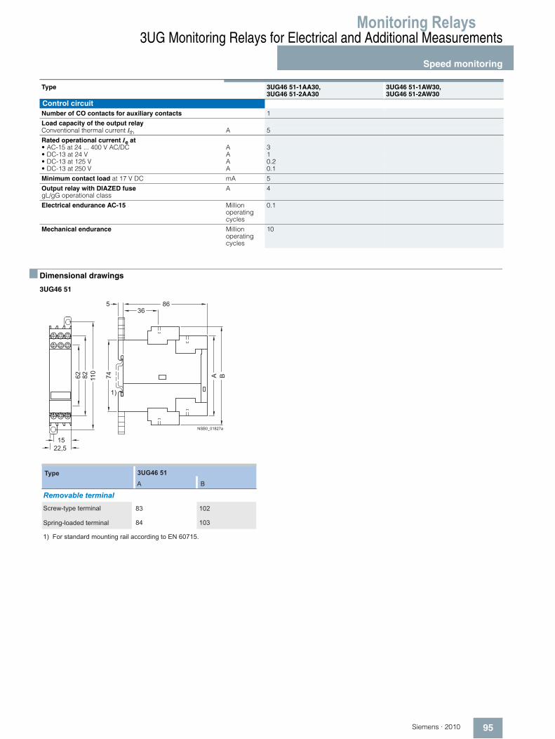
3UG46 51
Type 3UG46 51-1AA30,3UG46 51-2AA30
3UG46 51-1AW30, 3UG46 51-2AW30
Control circuitNumber of CO contacts for auxiliary contacts 1
Load capacity of the output relayConventional thermal current Ith A 5
Rated operational current Ie at• AC-15 at 24 ... 400 V AC/DC A 3• DC-13 at 24 V A 1• DC-13 at 125 V A 0.2• DC-13 at 250 V A 0.1
Minimum contact load at 17 V DC mA 5
Output relay with DIAZED fusegL/gG operational class
A 4
Electrical endurance AC-15 Million operating cycles
0.1
Mechanical endurance Million operating cycles
10
NSB0_01827a
A B74
86536
62 110
1522,5
1)
82
3UG46 51A B
84 103
83 102
1) For standard mounting rail according to EN 60715.
Screw-type terminal
Spring-loaded terminal
Removable terminal
Type

Monitoring Relays3UG Monitoring Relays for Electrical and Additional Measurements
Speed monitoring
96 Siemens · 2010
■ Schematics
3UG46 51
Circuit example without enable input
Circuit example with enable input
Position of the terminals
U
AC/DC
AC/DC
A1 (+) EN RES 24V IN1
IN2 8V2
+ –
0V
pnp
A2 (–)
3UG46 51
NS
B0_
0180
5a
11
12 14
– +NAMUR
AC/+U
S1
A2 (–) IN2 8V2
RES ENA1 (+)
24V BNI
BU
NO
AC/0V
12 14
11K1
K2
IN1
0V
3UG46 51
NSB0_01806a
K1
NAMUR
Reset
A2 (–) IN2 8V2
A1 (+) EN
S1
RES
I1
4
3 NO
AC/+U
AC/0V
S1
12
11K1
K2
14
24VIN1
0V
3UG46 51
NSB0_01807a
K1
DC 24V/max. 50 mA
ResetEnable
NS
B0_
0118
24
24V IN1
8V2 IN2 A2-
0VA1+ EN RES
12 11 14


