
3Z RF ALIGNER3Z RF ALIGNER3Z RF ALIGNER3Z RF ALIGNER
User ManualUser ManualUser ManualUser Manual
Version 4.1-3ZRFA1000
April2013 © 2013 3Z Telecom, Inc. All rights reserved. Under the copyright laws, this manual may not be copied, in whole or in part, without the written consent of 3Z Telecom, Inc.

2
PREFACE ........................................................................................................................................ 3
1 INTRODUCTION ............................................................................................................. 4
1.1 PACKAGE CONTENTS ......................................................................................................... 4
2 GETTING STARTED ...................................................................................................... 5
2.1 ANTENNA CLAMP AT A GLANCE .......................................................................................... 5 2.2 ANTENNA CLAMP INSTALLATION ......................................................................................... 6 2.3 LIMITED SPACE ANTENNA CLAMP INSTALLATION .................................................................. 6 2.4 3Z RF ALIGNER AT A GLANCE ............................................................................................ 7 2.5 3Z RF ALIGNER INSTALLATION ........................................................................................... 8
3 MAKING FIELD MEASUREMENTS ............................................................................... 9
3.1 HOME SCREEN .................................................................................................................. 9 3.2 ANTENNA ALIGNMENT SCREEN ......................................................................................... 10 3.3 MICROWAVE ALIGNMENT SCREEN .................................................................................... 11 3.4 MEASURING HEIGHT-AGL ................................................................................................ 12 3.5 FILES MENU SCREEN ....................................................................................................... 13 3.6 SETTINGS SCREEN .......................................................................................................... 14
4 USING YOUR MONOPOD............................................................................................ 15
5 CHARGING THE BATTERY ........................................................................................ 16
6 RETRIEVING FIELD MEASUREMENTS ..................................................................... 17
GPS INFORMATION ..................................................................................................................... 18
SOURCES OF GPS SIGNAL ERRORS .............................................................................................. 18
TROUBLESHOOTING COMMON ISSUES .................................................................................. 19
Total Number of pages: 20
3
PREFACE
Purpose of This Document
This user manual aims to familiarize you with some of the tasks and processes of the
3Z RF Aligner (3ZRFA-1000). The document does cover all the basic information and
details of the application.
Intended Audience
This document is intended for users of the 3Z RF Aligner (3ZRFA-1000) who are
familiar with the basic tasks and terminology of the application. It will enable you to
understand the details of some of the tasks that can be performed using 3Z RF Aligner.
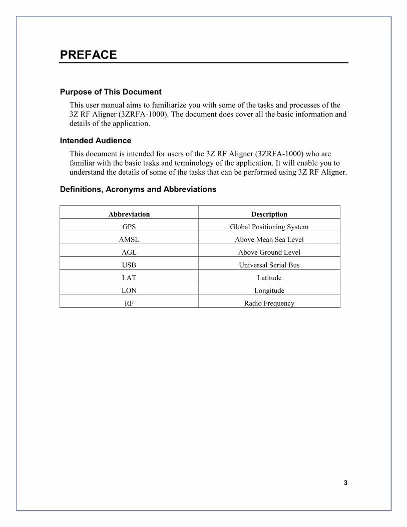
Definitions, Acronyms and Abbreviations
Abbreviation Description
GPS Global Positioning System
AMSL Above Mean Sea Level
AGL Above Ground Level
USB Universal Serial Bus
LAT Latitude
LON Longitude
RF Radio Frequency
4 3Z RF Aligner-3ZRFA1000 User Guide
The 3Z RF Aligner is the most trusted way to align directional antennas. No other
GPS Antenna Alignment Tool offers the easy, comprehensive, and productive
approach that has made the 3Z RF Aligner the gold standard for Antenna Alignment.
The 3Z RF Aligner incorporates GPS Technology to calculate precise Azimuth, Tilt,
Roll, and AGL measurements for a multitude of directional antenna systems. Our
universal antenna mounting system is used for quick antenna attachment and release.
The 3Z RF Aligner can easily be transported up any tower. Save all your field
measurements for recordkeeping and reporting, easily accessible over USB.
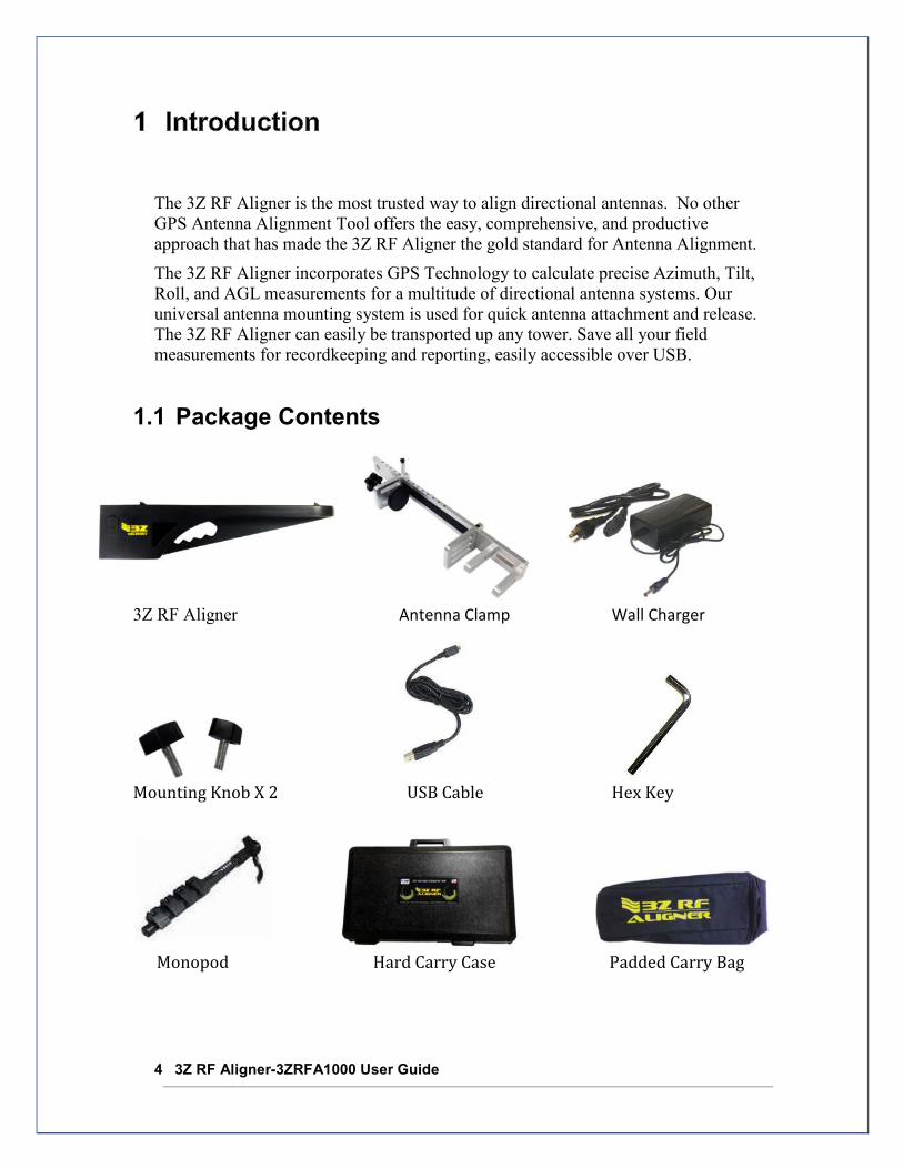
1.1 Package Contents
3Z RF Aligner Antenna Clamp Wall Charger
Mounting Knob X 2 USB Cable Hex Key
Monopod Hard Carry Case Padded Carry Bag

5
2.1 Antenna Clamp at a Glance
Important Safety Instructions: � Make sure Adjustment Pin is correctly latched onto Pin Holes.
� Make sure Rubber Compression Pad is tightly gripping the Antenna.
� Do not carry or transport your Antenna Clamp with the 3Z RF Aligner attached.
� Do not store or expose your Antenna Clamp to excessive heat/cold, or use near flames/ fire.
� Do not OIL or GREASE any part of the Antenna Clamp.
� Do not use and solvents or thinners to clean your Antenna Clamp. Use only mild detergent
and wipe dry with a soft, lint-free cloth only.
# Component Description
1 Adjustment Pin Raise pin to adjust the width of the Clamp
2 Pin Holes Used with Adjustment Pin
3 Back Bar Must be aligned with the back of the Antenna.
4 Unit Mounting Holes Used mounting knobs to mount the 3Z RF Aligner
5 Clamp Mounting Arms Used to support the 3Z RF Aligner
6 Rubber Compression Pad Used to affix the clamp to the antenna.
7 Tightening Knob Use to tighten the clamp onto the antenna
8 Carabiner Attachment Hole Use to carry or tie-off the Antenna Clamp
1
2
3
4
5
6
7
8

6
2.2 Antenna Clamp Installation
STEP 1: STEP 2: STEP 3: Raise the adjustment pin and Place the clamp behind the Use tightening knob to slide the rubber compression antenna and firmly press the tightly affix the clamp pad to a width slightly larger antenna bracket’s back bar onto the antenna. than the Antenna’s width. with the back panel of the antenna. Ensure Strong attachment.
Note: Once Installed the user should verify the back bar of the antenna clamp is flush with the back and vertically aligned with the antenna.
2.3 Limited Space Antenna Clamp Installation
STEP 1: STEP 2: STEP 3: Remove the sliding Slide the Back Bar behind the Reinsert the sliding compression clamp from antenna. compression clamp antenna clamp’s back bar. and repeat steps 1,2,3
on Section 2.2
7
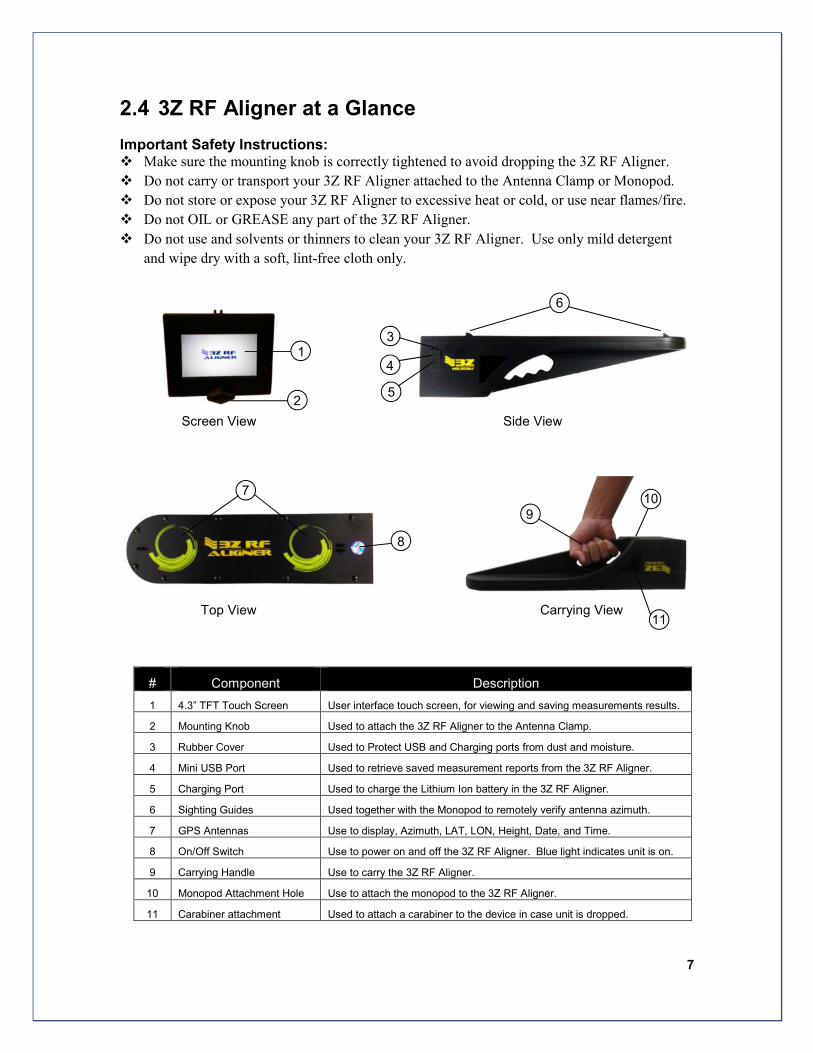
2.4 3Z RF Aligner at a Glance
Important Safety Instructions: � Make sure the mounting knob is correctly tightened to avoid dropping the 3Z RF Aligner.
� Do not carry or transport your 3Z RF Aligner attached to the Antenna Clamp or Monopod.
� Do not store or expose your 3Z RF Aligner to excessive heat or cold, or use near flames/fire.
� Do not OIL or GREASE any part of the 3Z RF Aligner.
� Do not use and solvents or thinners to clean your 3Z RF Aligner. Use only mild detergent
and wipe dry with a soft, lint-free cloth only.
Screen View Side View
Top View Carrying View
# Component Description
1 4.3” TFT Touch Screen User interface touch screen, for viewing and saving measurements results.
2 Mounting Knob Used to attach the 3Z RF Aligner to the Antenna Clamp.
3 Rubber Cover Used to Protect USB and Charging ports from dust and moisture.
4 Mini USB Port Used to retrieve saved measurement reports from the 3Z RF Aligner.
5 Charging Port Used to charge the Lithium Ion battery in the 3Z RF Aligner.
6 Sighting Guides Used together with the Monopod to remotely verify antenna azimuth.
7 GPS Antennas Use to display, Azimuth, LAT, LON, Height, Date, and Time.
8 On/Off Switch Use to power on and off the 3Z RF Aligner. Blue light indicates unit is on.
9 Carrying Handle Use to carry the 3Z RF Aligner.
10 Monopod Attachment Hole Use to attach the monopod to the 3Z RF Aligner.
11 Carabiner attachment Used to attach a carabiner to the device in case unit is dropped.
1
2
6
3
4
5
10 7
9
8
11
8
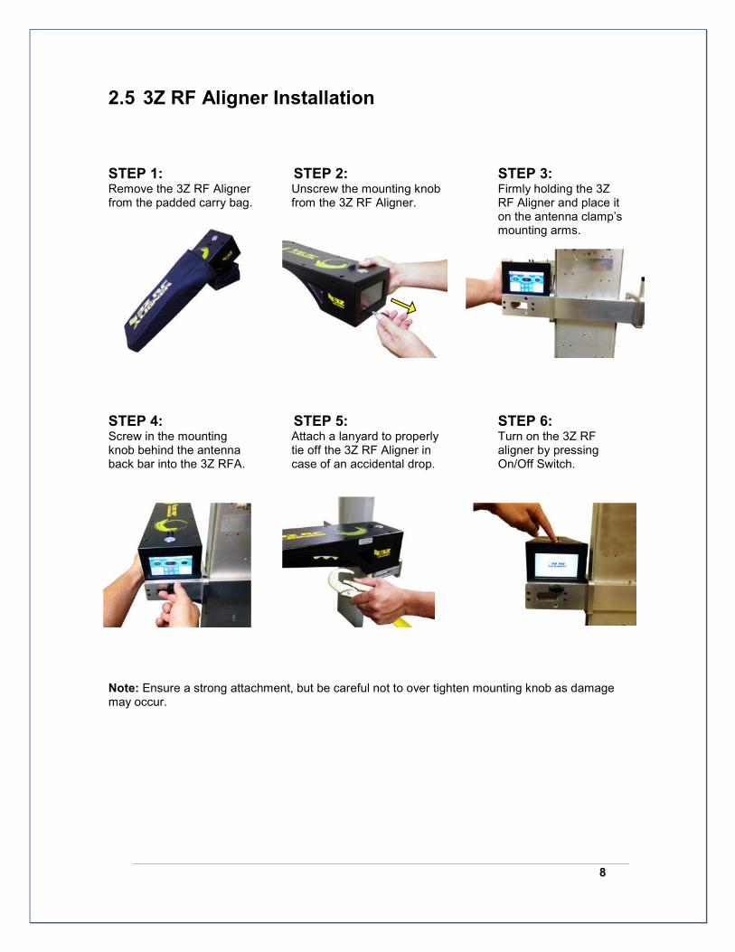
2.5 3Z RF Aligner Installation
STEP 1: STEP 2: STEP 3: Remove the 3Z RF Aligner Unscrew the mounting knob Firmly holding the 3Z from the padded carry bag. from the 3Z RF Aligner. RF Aligner and place it
on the antenna clamp’s mounting arms.
STEP 4: STEP 5: STEP 6: Screw in the mounting Attach a lanyard to properly Turn on the 3Z RF knob behind the antenna tie off the 3Z RF Aligner in aligner by pressing back bar into the 3Z RFA. case of an accidental drop. On/Off Switch.
Note: Ensure a strong attachment, but be careful not to over tighten mounting knob as damage may occur.
9
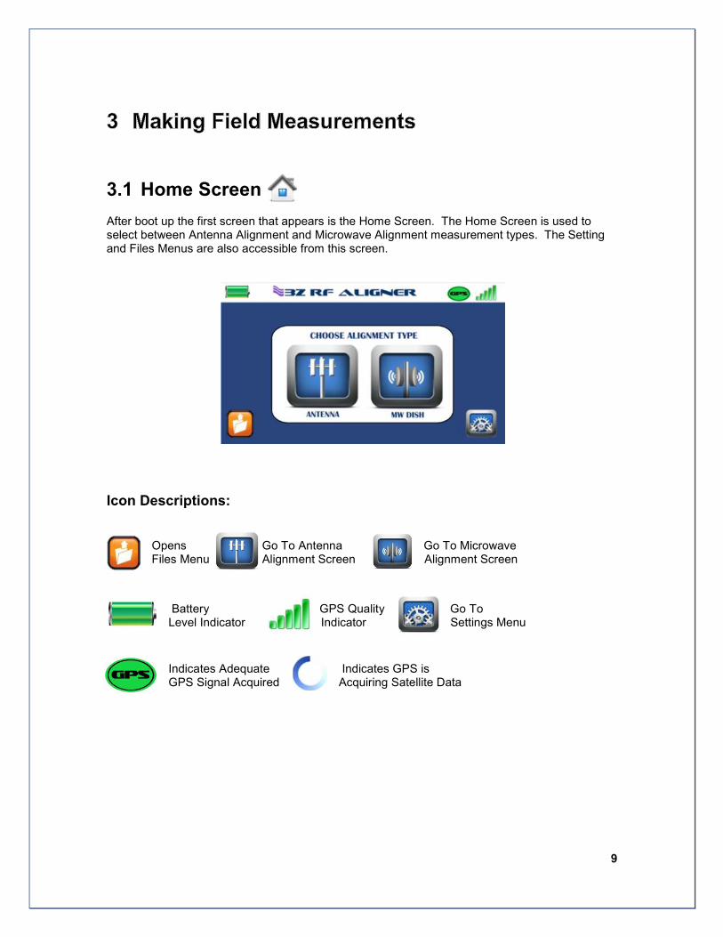
3.1 Home Screen
After boot up the first screen that appears is the Home Screen. The Home Screen is used to select between Antenna Alignment and Microwave Alignment measurement types. The Setting and Files Menus are also accessible from this screen.
Icon Descriptions:
Opens Go To Antenna Go To Microwave Files Menu Alignment Screen Alignment Screen
Battery GPS Quality Go To Level Indicator Indicator Settings Menu
Indicates Adequate Indicates GPS is GPS Signal Acquired Acquiring Satellite Data
10
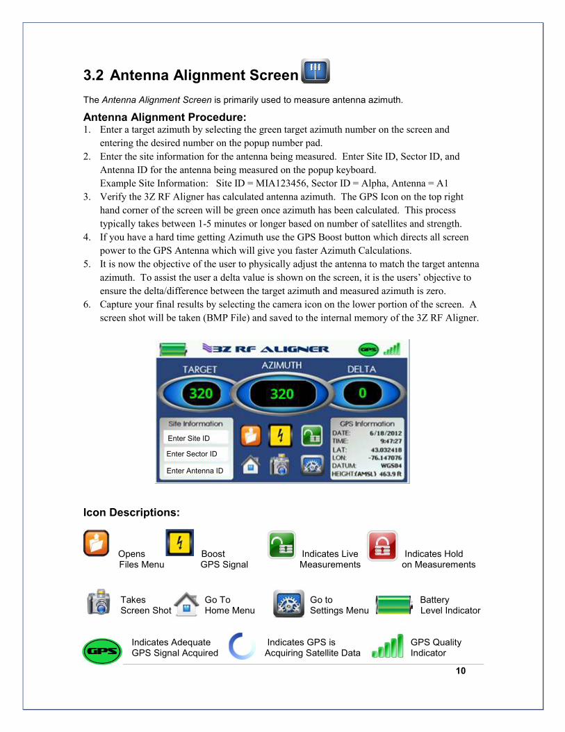
3.2 Antenna Alignment Screen
The Antenna Alignment Screen is primarily used to measure antenna azimuth.
Antenna Alignment Procedure: 1. Enter a target azimuth by selecting the green target azimuth number on the screen and
entering the desired number on the popup number pad.
2. Enter the site information for the antenna being measured. Enter Site ID, Sector ID, and
Antenna ID for the antenna being measured on the popup keyboard.
Example Site Information: Site ID = MIA123456, Sector ID = Alpha, Antenna = A1
3. Verify the 3Z RF Aligner has calculated antenna azimuth. The GPS Icon on the top right
hand corner of the screen will be green once azimuth has been calculated. This process
typically takes between 1-5 minutes or longer based on number of satellites and strength.
4. If you have a hard time getting Azimuth use the GPS Boost button which directs all screen
power to the GPS Antenna which will give you faster Azimuth Calculations.
5. It is now the objective of the user to physically adjust the antenna to match the target antenna
azimuth. To assist the user a delta value is shown on the screen, it is the users’ objective to
ensure the delta/difference between the target azimuth and measured azimuth is zero.
6. Capture your final results by selecting the camera icon on the lower portion of the screen. A
screen shot will be taken (BMP File) and saved to the internal memory of the 3Z RF Aligner.
Icon Descriptions:
Opens Boost Indicates Live Indicates Hold Files Menu GPS Signal Measurements on Measurements
Takes Go To Go to Battery Screen Shot Home Menu Settings Menu Level Indicator
Indicates Adequate Indicates GPS is GPS Quality GPS Signal Acquired Acquiring Satellite Data Indicator
Enter Site ID
Enter Antenna ID
Enter Sector ID

11
3.3 Microwave Alignment Screen
The Microwave Alignment Screen is primarily used to calculate Microwave path target data and also align the Microwave path.
Microwave Alignment Procedure: 1. Enter the Microwave Path information for the microwave dish being measured. Enter Path
Name, Target Dish Latitude, Target Dish Longitude, and Target Dish Height.
Note: Latitude and Longitude must be entered in decimal format, if the user has LAT/LON in deg-min-
sec format there is a convertor available in the settings menu. Default height is AMSL unless AGL
mode selected, see Measuring AGL section 3.4.
Example Microwave Path Information: Path Name = MW12345-to-MW54321, LAT =
26.32155, LON = -80.12345, Height = 210
7. Verify the 3Z RF Aligner has calculated Antenna Azimuth and Tilt. The GPS Icon on the top
right hand corner of the screen will be green once Azimuth and Tilt has been calculated. This
process typically takes between 1-5 minutes based on number of satellites and strength.
2. It is now the objective of the user to physically adjust the microwave dish and ensure
measured azimuth and tilt both match the target azimuth and tilt calculated by the 3Z RF
Aligner (Top Right Hand Corner of Screen).
3. Capture you final results by selecting the camera icon on the lower portion of the screen.
A screen shot will be taken (BMP File) and saved to the internal memory of the 3Z RF Tool.
Icon Descriptions: Opens Boosts Indicates Live Indicates Hold Files Menu GPS Signal Measurements on Measurements
Takes Go To Go to Battery Screen Shot Home Menu Settings Menu Level Indicator
Indicates Adequate Indicates GPS is GPS Quality GPS Signal Acquired Acquiring Satellite Data Indicator

12
3.4 Measuring Height-AGL
The 3Z RF Aligner gives a user a method of measuring Antenna Height. In both the Antenna Alignment Screen and the Microwave Alignment screen a user has the option to set Ground Height in order to later measure height Above Ground Level (AGL).
Note: If this option is not used the user will see height above height Above Mean Sea Level (AMSL) in GPS information portion of the measurement screen.
Measuring Antenna Height Procedure:
1. GPS only measures height above mean sea level (AMSL). In order to measure height above
ground level the user must set ground height using the 3Z RF Aligner.
2. Prior to accessing the antenna a user must place the 3Z RF Aligner on the ground where the
unit has good visibility of the sky.
3. Once Azimuth has been acquired the user must wait 10-15 minutes for the 3Z RF
Aligner to accurately calculate ground height.
4. After 10-15 minutes have elapsed the user must go into either the microwave or antenna
measurement screen and select the area for height measurement highlighted in red box below:
5. The user will be asked “Set Ground Height?” select “Yes”
6. The unit will then take a 100 measurement average and save the
ground height in memory.
Note: The user can turn off the 3Z RF Aligner; the saved ground height will not be lost until the next time ground height it set.
7. In the GPS Information portion of the screen you will now see
AGL measurements.
8. The user can now attach the 3Z RF Aligner to the antenna for
alignment.
9. Once alignment is complete and the user is ready to capture
results including AGL. The user must wait 10-15 minutes after
Azimuth has been acquired then select screen snapshot
Antenna Height
13
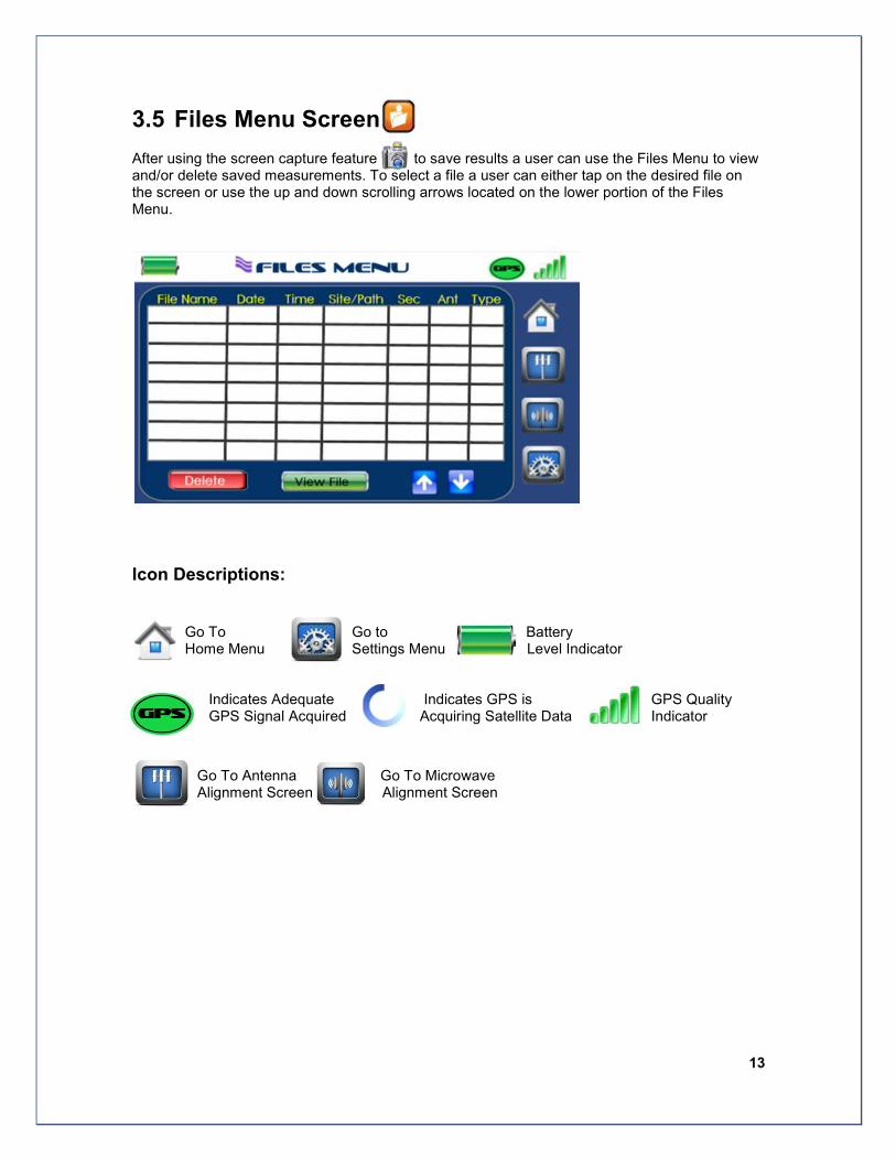
3.5 Files Menu Screen
After using the screen capture feature to save results a user can use the Files Menu to view and/or delete saved measurements. To select a file a user can either tap on the desired file on the screen or use the up and down scrolling arrows located on the lower portion of the Files Menu.
Icon Descriptions:
Go To Go to Battery Home Menu Settings Menu Level Indicator
Indicates Adequate Indicates GPS is GPS Quality GPS Signal Acquired Acquiring Satellite Data Indicator
Go To Antenna Go To Microwave Alignment Screen Alignment Screen
14
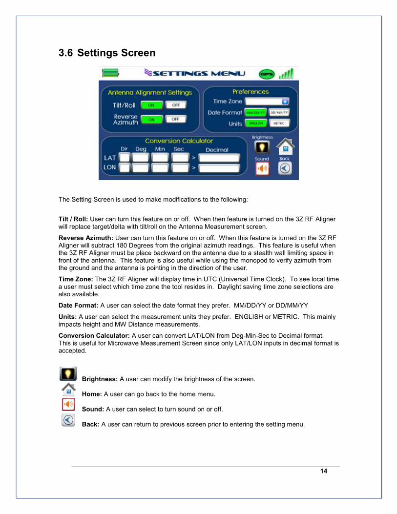
3.6 Settings Screen
The Setting Screen is used to make modifications to the following:
Tilt / Roll: User can turn this feature on or off. When then feature is turned on the 3Z RF Aligner will replace target/delta with tilt/roll on the Antenna Measurement screen.
Reverse Azimuth: User can turn this feature on or off. When this feature is turned on the 3Z RF Aligner will subtract 180 Degrees from the original azimuth readings. This feature is useful when the 3Z RF Aligner must be place backward on the antenna due to a stealth wall limiting space in front of the antenna. This feature is also useful while using the monopod to verify azimuth from the ground and the antenna is pointing in the direction of the user.
Time Zone: The 3Z RF Aligner will display time in UTC (Universal Time Clock). To see local time a user must select which time zone the tool resides in. Daylight saving time zone selections are also available.
Date Format: A user can select the date format they prefer. MM/DD/YY or DD/MM/YY
Units: A user can select the measurement units they prefer. ENGLISH or METRIC. This mainly impacts height and MW Distance measurements.
Conversion Calculator: A user can convert LAT/LON from Deg-Min-Sec to Decimal format. This is useful for Microwave Measurement Screen since only LAT/LON inputs in decimal format is accepted.
Brightness: A user can modify the brightness of the screen.
Home: A user can go back to the home menu.
Sound: A user can select to turn sound on or off.
Back: A user can return to previous screen prior to entering the setting menu.

15
Important Safety Instructions: � Make sure all leg locks are correctly tightened, and that the leg is full opened before use.
� Do not carry or transport you monopod with the 3Z RF Aligner attached.
� Do not store or expose you monopod to excessive heat or cold, or use near any flames or fire.
� Do not OIL or GREASE any part of the monopod.
� Do not use and solvents or thinners to clean your monopod. Use only mild detergent and
wipe dry with a soft, lint-free cloth only.
To Setup you Monopod: 1. Open the flip-lever locks (4) and extend the leg to the
desired length.
2. Close the flip-lever locks to lock the leg at the selected
length.
Caution: Not correctly securing a leg lock can cause the
monopod leg to retract unexpectedly and could result in
damage to the monopod or the 3Z RF Aligner mounted on
the monopod.
3. Align the bottom of the 3Z RF Aligner with the ¼”
mounting screw on the mounting plate, then secure the
3Z RF Aligner to the mounting plate with the screw,
The screw should be tight, but be careful not to over
tighten
4. Make final adjustment to the monopod height.
# Component Description
1 ¼” Mounting
Screw
Use this screw to mount the 3Z RF Aligner, be careful not to over tighten
2 Leg Support the 3Z RF Aligner
3 Quick Release Leg Locks
Lift to adjust leg height, and then close to lock.
4 Mounting Plate
Mount the 3Z RF Aligner to this platform.
5 Carrying Strap Used to carry your monopod
6 Rubber Foot Provides a secure non-marring footing for you monopod.
16
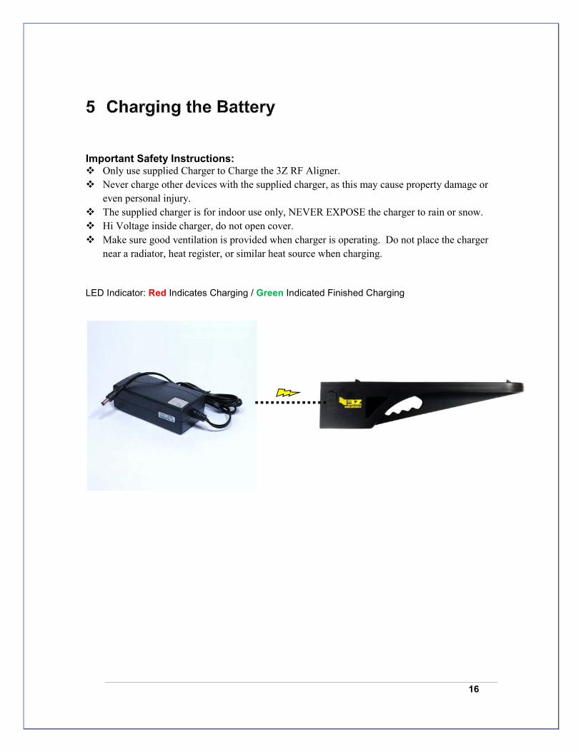
Important Safety Instructions: � Only use supplied Charger to Charge the 3Z RF Aligner.
� Never charge other devices with the supplied charger, as this may cause property damage or
even personal injury.
� The supplied charger is for indoor use only, NEVER EXPOSE the charger to rain or snow.
� Hi Voltage inside charger, do not open cover.
� Make sure good ventilation is provided when charger is operating. Do not place the charger
near a radiator, heat register, or similar heat source when charging.
LED Indicator: Red Indicates Charging / Green Indicated Finished Charging
17
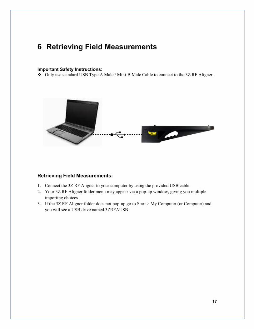
Important Safety Instructions: � Only use standard USB Type A Male / Mini-B Male Cable to connect to the 3Z RF Aligner.
Retrieving Field Measurements:
1. Connect the 3Z RF Aligner to your computer by using the provided USB cable.
2. Your 3Z RF Aligner folder menu may appear via a pop-up window, giving you multiple
importing choices
3. If the 3Z RF Aligner folder does not pop-up go to Start > My Computer (or Computer) and
you will see a USB drive named 3ZRFAUSB

18 3Z RF Aligner-3ZRFA1000 User Guide
The GPS Satellite System
The 24 satellites that make up the GPS space segment are orbiting the earth about 12,000 miles above us. They are constantly moving, making two complete orbits in less than 24 hours. These satellites are travelling at speeds of roughly 7,000 miles an hour.
The 3Z RF Aligner Requires 5 visible satellites with good quality signal to calculate Azimuth.
Sources of GPS Signal Errors
Factors that can degrade the GPS signal and thus affect accuracy include the following:
• Ionosphere and troposphere delays - The satellite signal slows as it passes through the atmosphere. The
GPS system uses a built-in model that calculates an average amount of delay to partially correct for this
type of error.
• Signal multipath - This occurs when the GPS signal is reflected off objects such as tall buildings or large
rock surfaces before it reaches the receiver. This increases the travel time of the signal, thereby causing
errors.
• Receiver clock errors - A receiver's built-in clock is not as accurate as the atomic clocks onboard the
GPS satellites. Therefore, it may have very slight timing errors.
• Number of satellites visible - The more satellites a GPS receiver can "see," the better the accuracy.
Buildings, terrain, electronic interference, or sometimes even dense foliage can block signal reception,
causing position errors or possibly no position reading at all. GPS units typically will not work indoors,
underwater or underground.
• Satellite geometry/shading - This refers to the relative position of the satellites at any given time. Ideal
satellite geometry exists when the satellites are located at wide angles relative to each other. Poor
geometry results when the satellites are located in a line or in a tight grouping.
• Intentional degradation of the satellite signal - Selective Availability (SA) is an intentional degradation of
the signal once imposed by the U.S. Department of Defense. SA was intended to prevent military
adversaries from using the highly accurate GPS signals. The government turned off SA in May 2000,
which significantly improved the accuracy of civilian GPS receivers.
19
No Azimuth Reading
(1) Make sure your battery is adequately charged to at least 10% to ensure the
GPS antennas and engine has enough power to communicate with
satellites and calculate measurements. Note: Battery has 10 hour battery life.
(2) Make sure your unit has an unobstructed view of the sky. The green
circles on top of the unit must not be covered in order for satellite
reception.
(3) Ensure the 3Z RF Aligner is attached to highest point of the Antenna; this
will avoid potential interference from the low band frequencies and
improved satellite visibility.
(4) Use the GPS Boost button to improve satellite reception.
(5) If issue persist temporarily remove the 3Z RF Aligner from the Antenna
and attempt to improve the view of the sky, if azimuth appears, reattached
the 3Z RF Aligner on the Antenna,
Touch Screen is not working
Recalibrate the Touch Screen
To re-calibrate the touch screen turn on unit and let the intro video play all
the way through, turn the unit off within 5 seconds of the main screen
being displayed. The next time the unit is powered up the calibration
routine will show. Follow instruction to recalibrate the screen.

FCC: This device complies with part 15 of the FCC Rules. Operation is subject to the
following two conditions: (1) This device may not cause harmful interference, and (2) this device must accept any interference received, including interference that may cause undesired operation.
Note: This equipment has been tested and found to comply with the limits for a Class A
digital device, pursuant to part 15 of the FCC Rules. These limits are designed to provide
reasonable protection against harmful interference when the equipment is operated in a
commercial environment. This equipment generates, uses, and can radiate radio
frequency energy and, if not installed and used in accordance with the instruction manual,
may cause harmful interference to radio communications. Operation of this equipment in
a residential area is likely to cause harmful interference in which case the user will be
required to correct the interference at his own expense.
CANADA: This Class A digital apparatus complies with Canadian ICES-003. Cet
appareil numérique de la classe A est conforme à la norme NMB-003 du Canada.


