
CiA 406
Device profile for encoders
Version: 3.2.0
18 December 2006
CAN in Automation (CiA) e. V.

Device profile for encoders
2 CiA 2006 – All rights reserved
HISTORY Date Changes
1997-05-05 Publication of Version 1.0
1998-05-11 Publication of Version 2.0
2002-05-17 Publication of version 3.0
The version 3.0 of this specification has been re-chaptered. In addition, all object descriptions and entry descriptions have been reviewed and edited in accordance to CiA DS-301 version 4.01. In particular, all Array objects have been reviewed. Type error corrections and other editorial changes (mostly clarifications and rewordings) are not listed in detail, only changes with technical content are recorded in the following table:
Error behavior Object 1029h definitions have been added.
TPDO The event timer of the TPDO 1 shall be hard-wired with the cyclic timer (object 6200h). They may be used alternatively.
The TPDO 2 is now compliant to CiA DS-301 version 4.01 meaning that this PDO shall use 1801h PDO communication parameter set object and 1A01h PDO mapping parameter set.
TPDO 1 This TPDO shall be transmitted when the device enters the Operational state.
Object 6000h Additional parameter definition
Object 6500h Additional parameter definition
Object 65C0h New object: offset values for multi-sensor device
2003-12-20 Publication of version 3.1
The version 3.1 of this specification includes besides some minor editorial clarifications the following changes:
Object 6000h Measuring direction definition included
Object 6005h Sub-objects for acceleration and jerk step settings added
Object 6008h High precision position value object added
Object 6009h High precision preset value added
Object 6010h Data type changed to Integer32
Object 6020h Data type changed to Integer32
Object 6040h Acceleration value object added
Object 6050h Jerk value object added
Object 6502h Value definition for 0 included
Object 6510h Number of high precision revolutions object added
2006-12-18 Publication of version 3.2
- Detailed PDO specification
- Editorial changes
Device profile for encoders
CiA 2006 – All rights reserved 3
General information on licensing and patents
CAN in AUTOMATION (CiA) calls attention to the possibility that some of the elements of this CiA specification may be subject of patent rights. CiA shall not be responsible for identifying any or all such patent rights. Because this specification is licensed free of charge, there is no warranty for this specification, to the extent permitted by applicable law. Except when otherwise stated in writing the copyright holder and/or other parties provide this specification “as is” without warranty of any kind, either expressed or implied, including, but not limited to, the implied warranties of merchantability and fitness for a particular purpose. The entire risk as to the correctness and completeness of the specification is with you. Should this specification prove failures, you assume the cost of all necessary servicing, repair or correction.
Trademarks
CANopen® and CiA® are registered community trademarks of CAN in Automation. The use is restricted for CiA members or owners of CANopen vendor ID. More detailed terms for the use are available from CiA.
© CiA 2006
All rights reserved. Unless otherwise specified, no part of this publication may be reproduced or utilized in any form or by any means, electronic or mechanical, including photocopying and microfilm, without permission in writing from CiA at the address below. CAN in Automation e. V. Kontumazgarten 3 DE - 90429 Nuremberg, Germany Tel.: +49-911-928819-0 Fax: +49-911-928819-79 Url: www.can-cia.org Email: [email protected]
Device profile for encoders
4 CiA 2006 – All rights reserved
CONTENTS
1 Scope ............................................................................................................................... 6 2 Normative references........................................................................................................ 6 3 Abbreviations and definitions ............................................................................................ 6 4 Operating principle............................................................................................................ 6
4.1 General ................................................................................................................... 6 4.2 C1 encoders ............................................................................................................ 6 4.3 C2 encoders ............................................................................................................ 7 4.4 Diagnostic area ....................................................................................................... 7 4.5 Functional overview ................................................................................................. 7
5 Error handling ................................................................................................................... 7 5.1 General ................................................................................................................... 7 5.2 Error behavior.......................................................................................................... 7 5.3 Additional error code meanings ............................................................................... 7
6 Pre-defined communication objects................................................................................... 8 6.1 General ................................................................................................................... 8 6.2 Object 1000h: Device type ....................................................................................... 8 6.3 Object 1001h: Error register ..................................................................................... 8 6.4 Object 1029h: Error behaviour.................................................................................. 9 6.5 Process data objects ............................................................................................... 9
6.5.1 General ....................................................................................................... 9 6.5.2 TPDO 1 ....................................................................................................... 9 6.5.3 TPDO 2 ..................................................................................................... 11 6.5.4 TPDO 3 ..................................................................................................... 13
7 Application object definitions........................................................................................... 15 7.1 General ................................................................................................................. 15 7.2 Overview on encoder application objects ............................................................... 15 7.3 Encoder parameters .............................................................................................. 17
7.3.1 General ..................................................................................................... 17 7.3.2 Object 6000h: Operating parameters .......................................................... 17 7.3.3 Object 6001h: Measuring units per revolution ............................................. 18 7.3.4 Object 6002h: Total measuring range in measuring units............................ 19 7.3.5 Object 6003h: Preset value ........................................................................ 19 7.3.6 Object 6004h: Position value ...................................................................... 20 7.3.7 Object 6005h: Linear encoder measuring step settings............................... 20 7.3.8 Object 6008h: High precision position value ............................................... 22 7.3.9 Object 6009h: High precision preset value ................................................. 22 7.3.10 Object 6010h: Preset values for multi-sensor devices ................................ 22 7.3.11 Object 6020h: Position values for multi-sensor devices .............................. 24 7.3.12 Object 6030h: Speed value ........................................................................ 25 7.3.13 Object 6040h: Acceleration value ............................................................... 26 7.3.14 Object 6050h: Jerk value............................................................................ 27 7.3.15 Object 6200h: Cyclic timer ......................................................................... 28
7.4 Encoder Cams ....................................................................................................... 29 7.4.1 General ..................................................................................................... 29 7.4.2 Object 6300h: Cam state register ............................................................... 30 7.4.3 Object 6301h: Cam enable register ............................................................ 32

Device profile for encoders
CiA 2006 – All rights reserved 5
7.4.4 Object 6302h: Cam polarity register ........................................................... 33 7.4.5 Object 6310h: Cam 1 low limit .................................................................... 34 7.4.6 Object 6311h: Cam 2 low limit .................................................................... 35 7.4.7 Object 6312h: Cam 3 low limit .................................................................... 36 7.4.8 Object 6313h: Cam 4 low limit .................................................................... 37 7.4.9 Object 6314h: Cam 5 low limit .................................................................... 38 7.4.10 Object 6315h: Cam 6 low limit .................................................................... 39 7.4.11 Object 6316h: Cam 7 low limit .................................................................... 40 7.4.12 Object 6317h: Cam 8 low limit .................................................................... 41 7.4.13 Object 6320h: Cam 1 high limit .................................................................. 42 7.4.14 Object 6321h: Cam 2 high limit .................................................................. 43 7.4.15 Object 6322h: Cam 3 high limit .................................................................. 44 7.4.16 Object 6323h: Cam 4 high limit .................................................................. 45 7.4.17 Object 6324h: Cam 5 high limit .................................................................. 46 7.4.18 Object 6325h: Cam 6 high limit .................................................................. 47 7.4.19 Object 6326h: Cam 7 high limit .................................................................. 48 7.4.20 Object 6327h: Cam 8 high limit .................................................................. 49 7.4.21 Object 6330h: Cam 1 hysteresis................................................................. 50 7.4.22 Object 6331h: Cam 2 hysteresis................................................................. 51 7.4.23 Object 6332h: Cam 3 hysteresis................................................................. 52 7.4.24 Object 6333h: Cam 4 hysteresis................................................................. 54 7.4.25 Object 6334h: Cam 5 hysteresis................................................................. 55 7.4.26 Object 6335h: Cam 6 hysteresis................................................................. 56 7.4.27 Object 6336h: Cam 7 hysteresis................................................................. 57 7.4.28 Object 6337h: Cam 8 hysteresis................................................................. 58
7.5 Work area supervision ........................................................................................... 59 7.5.1 General ..................................................................................................... 59 7.5.2 Object 6400h: Area state register ............................................................... 59 7.5.3 Object 6401h: Work area low limit .............................................................. 61 7.5.4 Object 6402h: Work area high limit............................................................. 62
7.6 Encoder diagnostics .............................................................................................. 63 7.6.1 General ..................................................................................................... 63 7.6.2 Object 6500h: Operating status .................................................................. 63 7.6.3 Object 6501h: Single-turn resolution and Measuring step ........................... 64 7.6.4 Object 6502h: Number of distinguishable revolutions ................................. 65 7.6.5 Object 6503h: Alarms ................................................................................. 65 7.6.6 Object 6504h: Supported alarms ................................................................ 66 7.6.7 Object 6505h: Warnings ............................................................................. 67 7.6.8 Object 6506h: Supported warnings............................................................. 68 7.6.9 Object 6507h: Profile and software version ................................................ 69 7.6.10 Object 6508h: Operating time..................................................................... 70 7.6.11 Object 6509h: Offset value ......................................................................... 70 7.6.12 Object 650Ah: Module identification ........................................................... 71 7.6.13 Object 650Bh: Serial number ..................................................................... 72 7.6.14 Object 650Ch: Offset values for multi-sensor devices................................. 73
7.7 Object 6510h: Number of high precision revolutions ............................................... 74 7.7.1 Object 67FFh: Device type ......................................................................... 75

Device profile for encoders
6 CiA 2006 – All rights reserved
1 Scope
This document represents the CANopen device profile for incremental and absolute, linear and rotary encoders. Besides position, velocity, acceleration, and jerk output possibility complete cam functionality is covered. In addition, it is possible to handle multi-sensors through one CANopen device.
All the above mentioned devices use communication techniques, which conform to those described in the CANopen application layer and communication profile specification /CiA301/. This document should be consulted in parallel to this profile.
2 Normative references
/CiA301/ CiA 301, CANopen application layer and communication profile
3 Abbreviations and definitions
C1 Class 1 C2 Class 2
CW Clock wise
CCW Counter Clock wise
Abbreviations and definitions defined in /CiA301/ apply for this document too.
4 Operating principle
4.1 General
The purpose of encoders is to detect positions of any kind of machine tools. Encoders detect positions and transmit the position values across the CANopen network. Optionally the encoder may provide speed, acceleration, and jerk values. The encoder may receive configuration information via SDO, e.g. conversion parameters for calculating an - to the application adapted - position value. In the NMT state operational, the position value may be transmitted by synchronous PDO. Additionally, the encoders may transmit asynchronously a PDO scheduled by the elapsing of the event timer.
The CANopen device profile defines two encoder classes, a standard device class 1 (C1) and an extended device class 2 (C2). The standard device C1 specifies basic functionality, which shall be provided by each device. The C2 extended device provides a variety of features with mandatory and optional functions. The mandatory functions of both, C1 and C2, are necessary to ensure non-manufacturer specific operations of a device.
By defining mandatory device characteristics in C1, basic network and encoder operation is guaranteed. By defining extended C2, a degree of defined flexibility may be built in. By leaving ‘hooks’ for optional and manufacturer-specific functionality, the device developer will not be constrained to an out-of-date standard.
4.2 C1 encoders
C1 is the mandatory class with a basic range of functions that all encoders shall support. The C1 encoders may optionally support C2 functions, however these functions shall be implemented according to the profile.
Device profile for encoders
CiA 2006 – All rights reserved 7
4.3 C2 encoders
C2 encoders support all C1 functions and extended functions defined in C2.
4.4 Diagnostic area
In addition to the classes C1 and C2, there are pre-defined areas and reserved parameters for manufacturer-specific functions in this device profile.
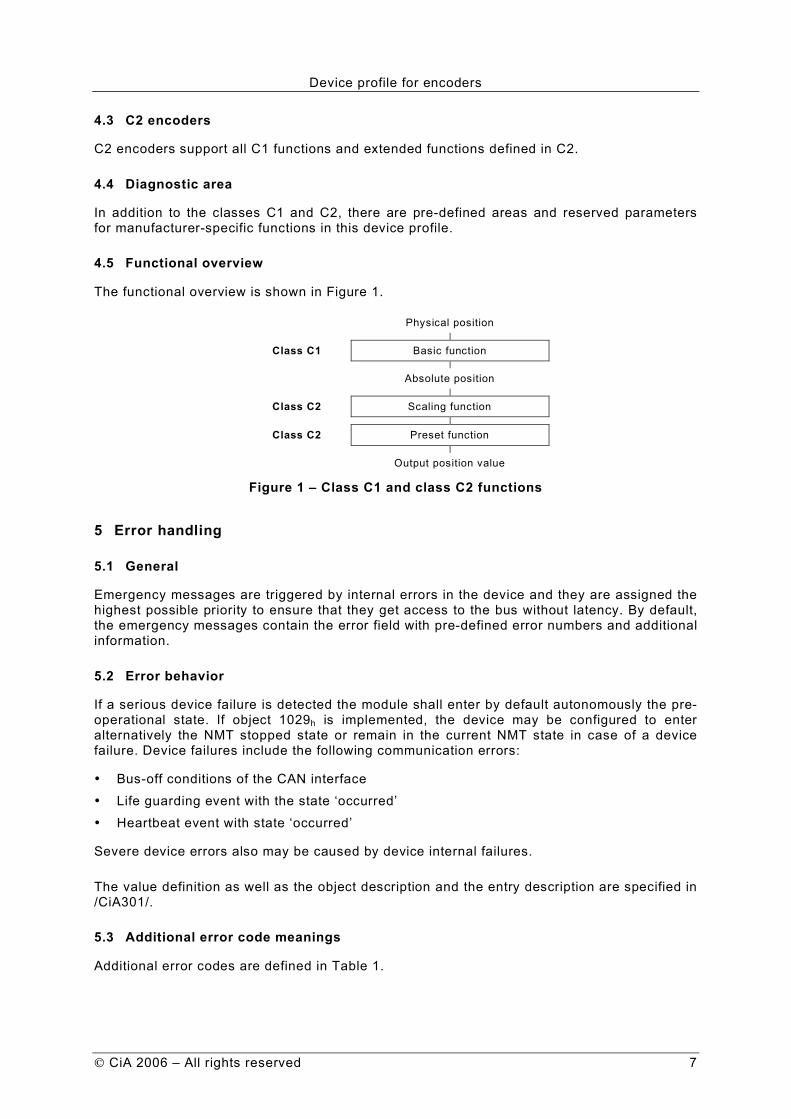
4.5 Functional overview
The functional overview is shown in Figure 1.
Physical position
Class C1 Basic function
Absolute position
Class C2 Scaling function
Class C2 Preset function
Output position value
Figure 1 – Class C1 and class C2 functions
5 Error handling
5.1 General
Emergency messages are triggered by internal errors in the device and they are assigned the highest possible priority to ensure that they get access to the bus without latency. By default, the emergency messages contain the error field with pre-defined error numbers and additional information.
5.2 Error behavior
If a serious device failure is detected the module shall enter by default autonomously the pre-operational state. If object 1029h is implemented, the device may be configured to enter alternatively the NMT stopped state or remain in the current NMT state in case of a device failure. Device failures include the following communication errors:
• Bus-off conditions of the CAN interface
• Life guarding event with the state ‘occurred’
• Heartbeat event with state ‘occurred’
Severe device errors also may be caused by device internal failures.
The value definition as well as the object description and the entry description are specified in /CiA301/.
5.3 Additional error code meanings
Additional error codes are defined in Table 1.

Device profile for encoders
8 CiA 2006 – All rights reserved
Table 1 – Additional error codes
Error Code Meaning
2110h Input current too high
3110h Input voltage out of range
5100h Hardware memory error
6 Pre-defined communication objects
6.1 General
This chapter defines the content of pre-defined communication objects.
6.2 Object 1000h: Device type
The object at index 1000h describes the type of device and its functionality. It is composed of a 16-bit field, which describes the device profile that is used and a second 16-bit field, which gives information on the type of encoder.
The object structure is specified in Figure 2. The value definition is specified in Table 2 and Table 3. Object description and entry description are specified in /CiA301/.
31 16 15 0
Encoder type Device type
MSB LSB
Figure 2 – Object structure
Table 2 – Value definition for device type
Value Description
196h Device profile number
Other values shall be reserved.
Table 3 – Value definition for encoder type
Value Definition
0001h Single-turn absolute rotary encoder
0002h Multi-turn absolute rotary encoder
0003h Single-turn absolute rotary encoder with electronic turn-count
0004h Incremental rotary encoder
0005h Incremental rotary encoder with electronic counting
0006h Incremental linear encoder
0007h Incremental linear encoder with electronic counting
0008h Absolute linear encoder
0009h Absolute linear encoder with cyclic coding
000Ah Multi-sensor encoder interface
0000h; 000Bh to FFFEh
Reserved
6.3 Object 1001h: Error register
The device profile specific bit shall be reserved.
Device profile for encoders
CiA 2006 – All rights reserved 9
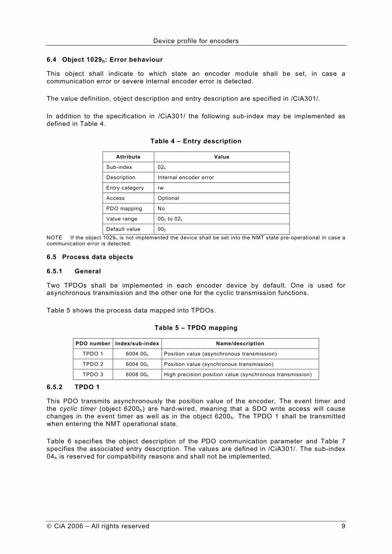
6.4 Object 1029h: Error behaviour
This object shall indicate to which state an encoder module shall be set, in case a communication error or severe internal encoder error is detected.
The value definition, object description and entry description are specified in /CiA301/.
In addition to the specification in /CiA301/ the following sub-index may be implemented as defined in Table 4.
Table 4 – Entry description
Attribute Value
Sub-index 02h
Description Internal encoder error
Entry category rw
Access Optional
PDO mapping No
Value range 00h to 02h
Default value 00h NOTE If the object 1029h is not implemented the device shall be set into the NMT state pre-operational in case a communication error is detected.
6.5 Process data objects
6.5.1 General
Two TPDOs shall be implemented in each encoder device by default. One is used for asynchronous transmission and the other one for the cyclic transmission functions.
Table 5 shows the process data mapped into TPDOs.
Table 5 – TPDO mapping
PDO number Index/sub-index Name/description
TPDO 1 6004 00h Position value (asynchronous transmission)
TPDO 2 6004 00h Position value (synchronous transmission)
TPDO 3 6008 00h High precision position value (synchronous transmission)
6.5.2 TPDO 1
This PDO transmits asynchronously the position value of the encoder. The event timer and the cyclic timer (object 6200h) are hard-wired, meaning that a SDO write access will cause changes in the event timer as well as in the object 6200h. The TPDO 1 shall be transmitted when entering the NMT operational state.
Table 6 specifies the object description of the PDO communication parameter and Table 7 specifies the associated entry description. The values are defined in /CiA301/. The sub-index 04h is reserved for compatibility reasons and shall not be implemented.

Device profile for encoders
10 CiA 2006 – All rights reserved
Table 6 — Object description
Attribute Value
Index 1800h
Name TPDO 1 communication parameter
Object code Record
Data type PDO communication parameter record
Category Mandatory
Table 7 — Entry description
Attribute Value
Sub-index 00h
Description Highest sub-index supported
Entry category Mandatory
Access ro
PDO mapping No
Value range 02h to 05h
Default value No
Sub-index 01h
Description COB-ID
Entry category Mandatory
Access ro
PDO mapping No
Value range See /CiA301/
Default value See /CiA301/
Sub-index 02h
Description Transmission type
Entry category Mandatory
Access rw
PDO mapping Optional
Value range See /CiA301/
Default value 254d
Sub-index 03h
Description Inhibit time
Entry category Optional
Access rw
PDO mapping No
Value range See /CiA301/
Default value 0000h
Device profile for encoders
CiA 2006 – All rights reserved 11
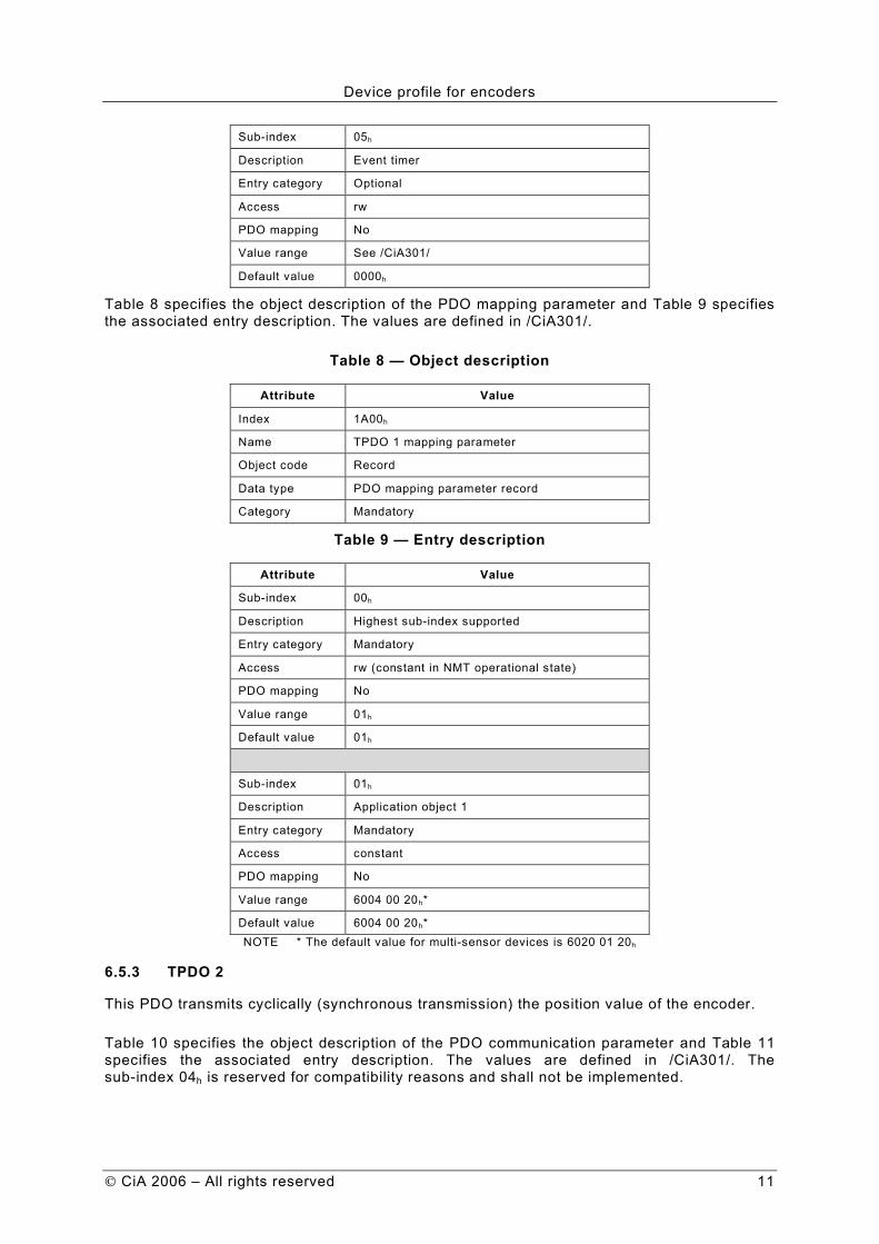
Sub-index 05h
Description Event timer
Entry category Optional
Access rw
PDO mapping No
Value range See /CiA301/
Default value 0000h
Table 8 specifies the object description of the PDO mapping parameter and Table 9 specifies the associated entry description. The values are defined in /CiA301/.
Table 8 — Object description
Attribute Value
Index 1A00h
Name TPDO 1 mapping parameter
Object code Record
Data type PDO mapping parameter record
Category Mandatory
Table 9 — Entry description
Attribute Value
Sub-index 00h
Description Highest sub-index supported
Entry category Mandatory
Access rw (constant in NMT operational state)
PDO mapping No
Value range 01h
Default value 01h
Sub-index 01h
Description Application object 1
Entry category Mandatory
Access constant
PDO mapping No
Value range 6004 00 20h*
Default value 6004 00 20h* NOTE * The default value for multi-sensor devices is 6020 01 20h
6.5.3 TPDO 2
This PDO transmits cyclically (synchronous transmission) the position value of the encoder.
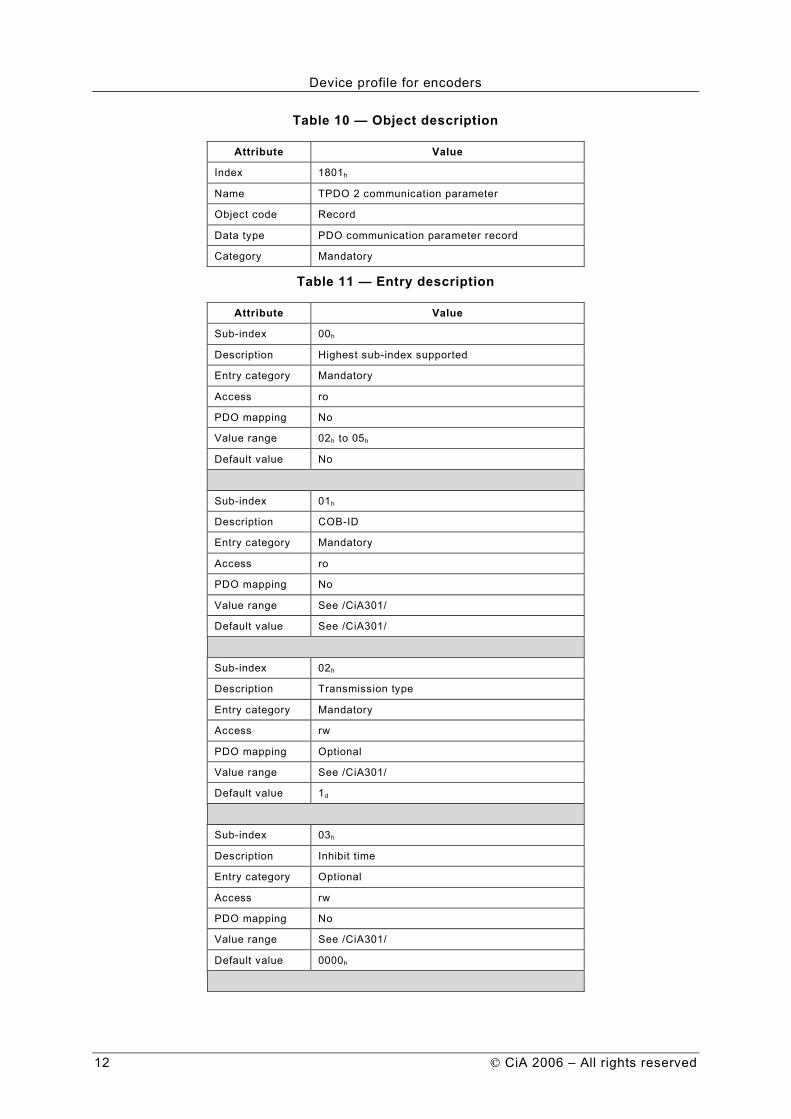
Table 10 specifies the object description of the PDO communication parameter and Table 11 specifies the associated entry description. The values are defined in /CiA301/. The sub-index 04h is reserved for compatibility reasons and shall not be implemented.
Device profile for encoders
12 CiA 2006 – All rights reserved
Table 10 — Object description
Attribute Value
Index 1801h
Name TPDO 2 communication parameter
Object code Record
Data type PDO communication parameter record
Category Mandatory
Table 11 — Entry description
Attribute Value
Sub-index 00h
Description Highest sub-index supported
Entry category Mandatory
Access ro
PDO mapping No
Value range 02h to 05h
Default value No
Sub-index 01h
Description COB-ID
Entry category Mandatory
Access ro
PDO mapping No
Value range See /CiA301/
Default value See /CiA301/
Sub-index 02h
Description Transmission type
Entry category Mandatory
Access rw
PDO mapping Optional
Value range See /CiA301/
Default value 1d
Sub-index 03h
Description Inhibit time
Entry category Optional
Access rw
PDO mapping No
Value range See /CiA301/
Default value 0000h

Device profile for encoders
CiA 2006 – All rights reserved 13
Sub-index 05h
Description Event timer
Entry category Optional
Access rw
PDO mapping No
Value range See /CiA301/
Default value 0000h
Table 12 specifies the object description of the PDO mapping parameter and Table 13 specifies the associated entry description. The values are defined in /CiA301/.
Table 12 — Object description
Attribute Value
Index 1A01h
Name TPDO 2 mapping parameter
Object code Record
Data type PDO mapping parameter record
Category Mandatory
Table 13 — Entry description
Attribute Value
Sub-index 00h
Description Highest sub-index supported
Entry category Mandatory
Access rw (constant in NMT operational state)
PDO mapping No
Value range 01h
Default value 01h
Sub-index 01h
Description 1st application object
Entry category Mandatory
Access constant
PDO mapping No
Value range 6004 00 20h*
Default value 6004 00 20h* NOTE * The default value for multi-sensor devices is 6020 01 20h
6.5.4 TPDO 3
This optional PDO shall transmit cyclically (synchronous transmission) the position value of the high precision encoder.
Table 14 specifies the object description of the PDO communication parameter and Table 15 specifies the associated entry description. The values are defined in /CiA301/. The sub-index 04h is reserved for compatibility reasons and shall not be implemented.

Device profile for encoders
14 CiA 2006 – All rights reserved
Table 14 — Object description
Attribute Value
Index 1802h
Name TPDO 3 communication parameter
Object code Record
Data type PDO communication parameter record
Category Mandatory
Table 15 — Entry description
Attribute Value
Sub-index 00h
Description Highest sub-index supported
Entry category Mandatory
Access ro
PDO mapping No
Value range 02h to 05h
Default value No
Sub-index 01h
Description COB-ID
Entry category Mandatory
Access ro
PDO mapping No
Value range See /CiA301/
Default value See /CiA301/
Sub-index 02h
Description Transmission type
Entry category Mandatory
Access rw
PDO mapping Optional
Value range See /CiA301/
Default value 1d
Sub-index 03h
Description Inhibit time
Entry category Optional
Access rw
PDO mapping No
Value range See /CiA301/
Default value 0000h

Device profile for encoders
CiA 2006 – All rights reserved 15
Sub-index 05h
Description Event timer
Entry category Optional
Access rw
PDO mapping No
Value range See /CiA301/
Default value 0000h
Table 16 specifies the object description of the PDO mapping parameter and Table 17 specifies the associated entry description. The values are defined in /CiA301/.
Table 16 — Object description
Attribute Value
Index 1A02h
Name TPDO 3 mapping parameter
Object code Record
Data type PDO mapping parameter record
Category Mandatory
Table 17 — Entry description
Attribute Value
Sub-index 00h
Description Highest sub-index supported
Entry category Mandatory
Access rw (constant in NMT operational state)
PDO mapping No
Value range 01h
Default value 01h
Sub-index 01h
Description Application object 1
Entry category Mandatory
Access constant
PDO mapping No
Value range 6008 00 40h
Default value 6008 00 40h
7 Application object definitions
7.1 General
This chapter specifies the application object definitions. Each encoder shall share the dictionary entries from 6000h to 67FFh.
7.2 Overview on encoder application objects
Table 18 shows the object dictionary entries for encoder parameters. ‘m’ and ‘o’ indicate, whether a function is mandatory(m) or optional(o).

Device profile for encoders
16 CiA 2006 – All rights reserved
Table 18 – Object dictionary entries for encoder parameters
Index Name C1 C2
6000h Operating parameters m m
6001h Measuring units per revolution o m
6002h Total measuring range in measuring units o m
6003h Preset value o m
6004h Position value m m
6005h Linear encoder measuring step settings o m
6010h Preset value for multi-sensor devices o m
6020h Position value for multi-sensor devices m m
6030h Speed value o c*
6200h Cyclic timer o m
6300h Cam state register o o
6301h Cam enable register o o
6302h Cam polarity register o o
6310h Cam 1 low limit o o
6311h Cam 2 low limit o o
to
6317h Cam 8 low limit o o
6320h Cam 1 high limit o o
6321h Cam 2 high limit o o
to
6327h Cam 8 high limit o o
6330h Cam 1 hysteresis o o
6331h Cam 2 hysteresis o o
to
6337h Cam 8 hysteresis o o
6400h Area state register o o
6401h Work area low limit o o
6402h Work area high limit o o NOTE * Only mandatory for multi-sensor encoders
Table 19 shows the object dictionary entries for encoder diagnostics.
Table 19 – Object dictionary entries for encoder diagnostics
Index Name C1 C2
6500h Operating status m m
6501h Single-turn resolution (rotary), Measuring step (linear) m m
6502h Number of distinguishable revolutions m m
6503h Alarms o c1
6504h Supported alarms o m
6505h Warnings o c2
6506h Supported warnings o m
6507h Profile and software version o m
Device profile for encoders
CiA 2006 – All rights reserved 17
6508h Operating time o m
6509h Offset value o m
650Ah Module identification o m
650Bh Serial number o m
650Ch Offset values for multi-sensor device o o NOTE 1 – if this alarm (see object 6504h) is supported
2 – if this warning (see object 6506h) is supported
7.3 Encoder parameters
7.3.1 General
This chapter specifies the encoder parameter objects.
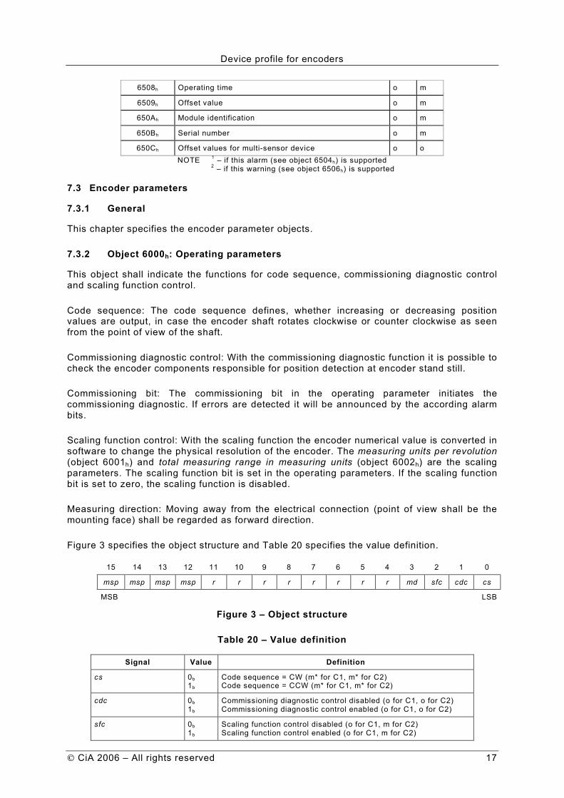
7.3.2 Object 6000h: Operating parameters
This object shall indicate the functions for code sequence, commissioning diagnostic control and scaling function control.
Code sequence: The code sequence defines, whether increasing or decreasing position values are output, in case the encoder shaft rotates clockwise or counter clockwise as seen from the point of view of the shaft.
Commissioning diagnostic control: With the commissioning diagnostic function it is possible to check the encoder components responsible for position detection at encoder stand still.
Commissioning bit: The commissioning bit in the operating parameter initiates the commissioning diagnostic. If errors are detected it will be announced by the according alarm bits.
Scaling function control: With the scaling function the encoder numerical value is converted in software to change the physical resolution of the encoder. The measuring units per revolution (object 6001h) and total measuring range in measuring units (object 6002h) are the scaling parameters. The scaling function bit is set in the operating parameters. If the scaling function bit is set to zero, the scaling function is disabled.
Measuring direction: Moving away from the electrical connection (point of view shall be the mounting face) shall be regarded as forward direction.
Figure 3 specifies the object structure and Table 20 specifies the value definition.
15 14 13 12 11 10 9 8 7 6 5 4 3 2 1 0
msp msp msp msp r r r r r r r r md sfc cdc cs
MSB LSB
Figure 3 – Object structure
Table 20 – Value definition
Signal Value Definition
cs 0b 1b
Code sequence = CW (m* for C1, m* for C2) Code sequence = CCW (m* for C1, m* for C2)
cdc 0b
1b Commissioning diagnostic control disabled (o for C1, o for C2)
Commissioning diagnostic control enabled (o for C1, o for C2)
sfc 0b
1b Scaling function control disabled (o for C1, m for C2)
Scaling function control enabled (o for C1, m for C2)
Device profile for encoders
18 CiA 2006 – All rights reserved
Signal Value Definition
md 0b
1b Measuring direction forward (o** for C1, o** for C2)
Measuring direction backward (o** for C1, o** for C2)
r Reserved for further use
msp 0b
1b Manufacturer-specific parameter disabled (o for C1, o for C2)
Manufacturer-specific parameter enabled (o for C1, o for C2) NOTE * not for linear encoders ** not for rotary encoders
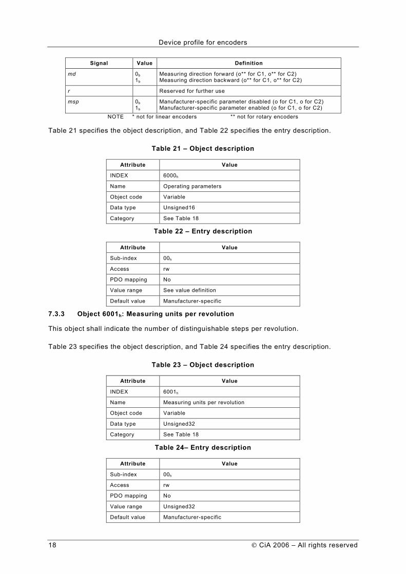
Table 21 specifies the object description, and Table 22 specifies the entry description.
Table 21 – Object description
Attribute Value
INDEX 6000h
Name Operating parameters
Object code Variable
Data type Unsigned16
Category See Table 18
Table 22 – Entry description
Attribute Value
Sub-index 00h
Access rw
PDO mapping No
Value range See value definition
Default value Manufacturer-specific
7.3.3 Object 6001h: Measuring units per revolution
This object shall indicate the number of distinguishable steps per revolution.
Table 23 specifies the object description, and Table 24 specifies the entry description.
Table 23 – Object description
Attribute Value
INDEX 6001h
Name Measuring units per revolution
Object code Variable
Data type Unsigned32
Category See Table 18
Table 24– Entry description
Attribute Value
Sub-index 00h
Access rw
PDO mapping No
Value range Unsigned32
Default value Manufacturer-specific
Device profile for encoders
CiA 2006 – All rights reserved 19
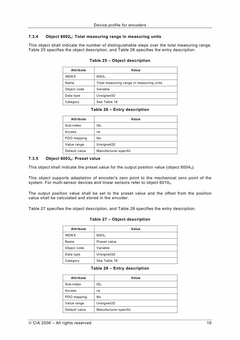
7.3.4 Object 6002h: Total measuring range in measuring units
This object shall indicate the number of distinguishable steps over the total measuring range. Table 25 specifies the object description, and Table 26 specifies the entry description.
Table 25 – Object description
Attribute Value
INDEX 6002h
Name Total measuring range in measuring units
Object code Variable
Data type Unsigned32
Category See Table 18
Table 26 – Entry description
Attribute Value
Sub-index 00h
Access rw
PDO mapping No
Value range Unsigned32
Default value Manufacturer-specific
7.3.5 Object 6003h: Preset value
This object shall indicate the preset value for the output position value (object 6004h).
This object supports adaptation of encoder's zero point to the mechanical zero point of the system. For multi-sensor devices and linear sensors refer to object 6010h.
The output position value shall be set to the preset value and the offset from the position value shall be calculated and stored in the encoder.
Table 27 specifies the object description, and Table 28 specifies the entry description.
Table 27 – Object description
Attribute Value
INDEX 6003h
Name Preset value
Object code Variable
Data type Unsigned32
Category See Table 18
Table 28 – Entry description
Attribute Value
Sub-index 00h
Access rw
PDO mapping No
Value range Unsigned32
Default value Manufacturer-specific
Device profile for encoders
20 CiA 2006 – All rights reserved
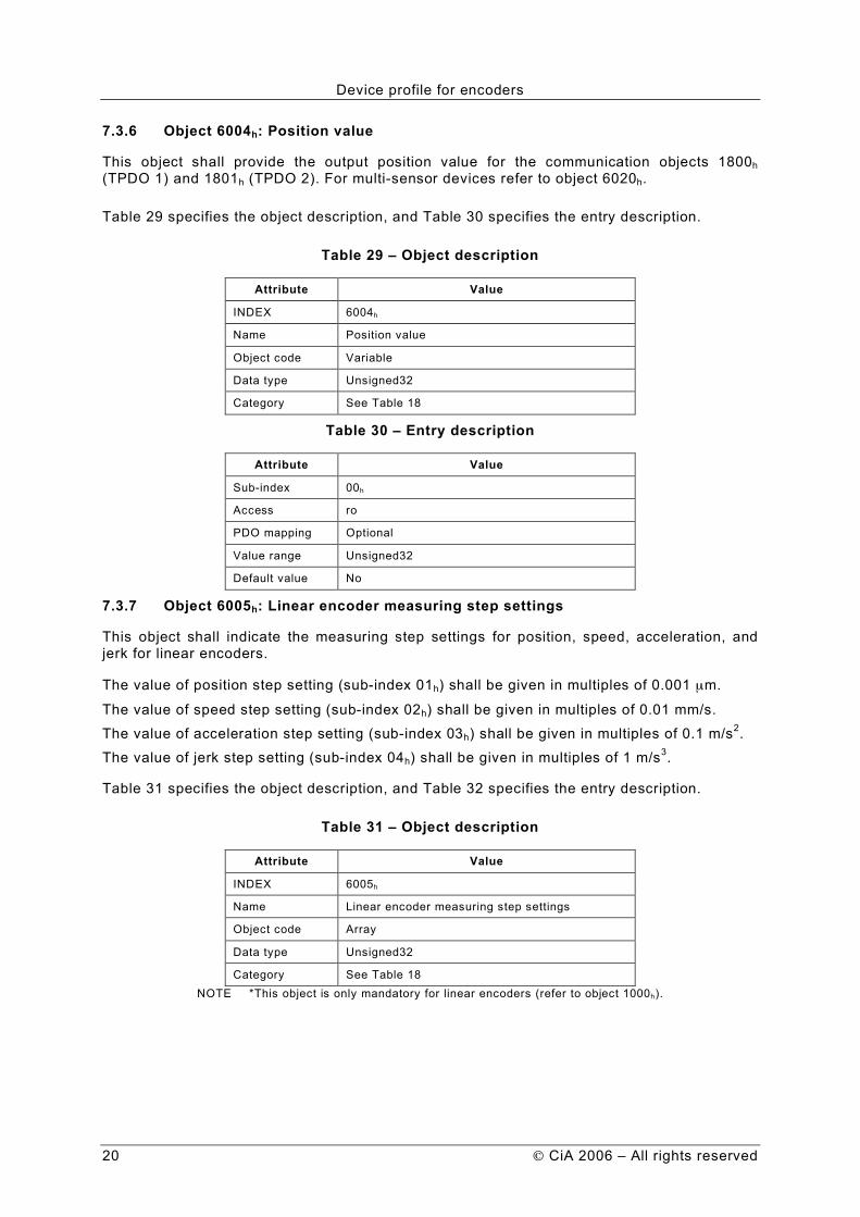
7.3.6 Object 6004h: Position value
This object shall provide the output position value for the communication objects 1800h (TPDO 1) and 1801h (TPDO 2). For multi-sensor devices refer to object 6020h.
Table 29 specifies the object description, and Table 30 specifies the entry description.
Table 29 – Object description
Attribute Value
INDEX 6004h
Name Position value
Object code Variable
Data type Unsigned32
Category See Table 18
Table 30 – Entry description
Attribute Value
Sub-index 00h
Access ro
PDO mapping Optional
Value range Unsigned32
Default value No
7.3.7 Object 6005h: Linear encoder measuring step settings
This object shall indicate the measuring step settings for position, speed, acceleration, and jerk for linear encoders.
The value of position step setting (sub-index 01h) shall be given in multiples of 0.001 µm.
The value of speed step setting (sub-index 02h) shall be given in multiples of 0.01 mm/s.
The value of acceleration step setting (sub-index 03h) shall be given in multiples of 0.1 m/s2.
The value of jerk step setting (sub-index 04h) shall be given in multiples of 1 m/s3.
Table 31 specifies the object description, and Table 32 specifies the entry description.
Table 31 – Object description
Attribute Value
INDEX 6005h
Name Linear encoder measuring step settings
Object code Array
Data type Unsigned32
Category See Table 18 NOTE *This object is only mandatory for linear encoders (refer to object 1000h).

Device profile for encoders
CiA 2006 – All rights reserved 21
Table 32 – Entry description
Attribute Value
Sub-index 00h
Description Highest sub-index supported
Entry category Mandatory
Access ro
PDO mapping No
Value range 01h to 04h
Default value No
Sub-index 01h
Description Position step setting
Entry category Mandatory
Access rw
PDO mapping No
Value range Unsigned32
Default value Manufacturer-specific
Sub-index 02h
Description Speed step setting
Entry category Optional
Access rw
PDO mapping No
Value range Unsigned32
Default value Manufacturer-specific
Sub-index 03h
Description Acceleration step setting
Entry category Optional
Access rw
PDO mapping No
Value range Unsigned32
Default value Manufacturer-specific
Sub-index 04h
Description Jerk step setting
Entry category Optional
Access rw
PDO mapping No
Value range Unsigned32
Default value Manufacturer-specific

Device profile for encoders
22 CiA 2006 – All rights reserved
7.3.8 Object 6008h: High precision position value
This object may substitute the position value (object 6004h) and shall provide the position value for high precision encoders. Table 33 specifies the object description, and Table 34 specifies the entry description.
Table 33 – Object description
Attribute Value
INDEX 6008h
Name High precision position value
Object code Variable
Data type Unsigned64
Category Optional
Table 34 – Entry description
Attribute Value
Sub-index 00h
Access ro
PDO mapping Optional
Value range Unsigned64
Default value No
7.3.9 Object 6009h: High precision preset value
This object shall indicate the preset value for high precision encoders using the high precision position value (object 6008h).
Table 35 specifies the object description, and Table 36 specifies the entry description.
Table 35 – Object description
Attribute Value
INDEX 6009h
Name High precision preset value
Object code Variable
Data type Unsigned64
Category Conditional: mandatory for C2 encoders
Table 36 – Entry description
Attribute Value
Sub-index 00h
Access rw
PDO mapping No
Value range Unsigned64
Default value Manufacturer-specific
7.3.10 Object 6010h: Preset values for multi-sensor devices
This object is similar to object 6003h and shall indicate the preset values for the output position values for multi-sensor devices (object 6020h).

Device profile for encoders
CiA 2006 – All rights reserved 23
In sub-index 00h the number of supported channels is defined.
The Preset function supports adaptation of the encoder's zero point to the mechanical zero point of the system.
The output position values in the sub-indices of object 6020h are set to the sub-indices of the parameter „Preset value“ in object 6010h, accordingly. The offset from the position value shall be calculated and stored in the encoder.
This object is only mandatory for multi-sensor encoders (object 1000h encoder type: code 10d).
Table 37 specifies the object description, and Table 38 specifies the entry description.
Table 37 – Object description
Attribute Value
INDEX 6010h
Name Preset value for multi-sensor devices
Object code Array
Data type Integer32
Category See Table 18
Table 38 – Entry description
Attribute Value
Sub-index 00h
Description Highest sub-index supported
Entry category Mandatory
Access ro
PDO mapping No
Value range 01h to FEh
Default value No
Sub-index 01h
Description Preset value channel 1
Entry category Mandatory
Access rw
PDO mapping No
Value range Integer32
Default value Manufacturer-specific
Sub-index 02h
Description Preset value channel 2
Entry category Optional
Access rw
PDO mapping No
Value range Integer32
Default value Manufacturer-specific

Device profile for encoders
24 CiA 2006 – All rights reserved
to
Sub-index FEh
Description Preset value channel 254
Entry category Optional
Access rw
PDO mapping No
Value range Integer32
Default value Manufacturer-specific
7.3.11 Object 6020h: Position values for multi-sensor devices
Similar to object 6004h this object shall indicate the output position value(s) for the communication objects 1800h (TPDO 1) and 1801h (TPDO 2). This object is only mandatory for multi-sensor encoders (object 1000h encoder type: code 10d).
Table 39 specifies the object description, and Table 40 specifies the entry description.
Table 39 – Object description
Attribute Value
INDEX 6020h
Name Position value for multisensor devices
Object code Array
Data type Integer32
Category See Table 18
Table 40 – Entry description
Attribute Value
Sub-index 00h
Description Highest sub-index supported
Entry category Mandatory
Access ro
PDO mapping No
Value range 01h to FEh
Default value No
Sub-index 01h
Description Position value channel 1
Entry category Mandatory
Access rw
PDO mapping Optional
Value range Integer32
Default value Manufacturer-specific

Device profile for encoders
CiA 2006 – All rights reserved 25
Sub-index 02h
Description Position value channel 2
Entry category Optional
Access rw
PDO mapping Optional
Value range Integer32
Default value Manufacturer-specific
to
Sub-index FEh
Description Position value channel 254
Entry category Optional
Access rw
PDO mapping Optional
Value range Integer32
Default value Manufacturer-specific
7.3.12 Object 6030h: Speed value
This object shall provide the output speed value(s). For linear encoders the speed-measuring step is defined in object 6005h, sub-index 02h. The speed value for rotary encoders shall be given in multiples of measuring units per second. This object is only mandatory for multi-sensor encoders (object 1000h encoder type: code 10d).
Table 41 specifies the object description, and Table 42 specifies the entry description.
Table 41 – Object description
Attribute Value
INDEX 6030h
Name Speed value
Object code Array
Data type Integer16
Category See Table 18
Table 42 – Entry description
Attribute Value
Sub-index 00h
Description Highest sub-index supported
Entry category Mandatory
Access ro
PDO mapping No
Value range 01h to FEh
Default value No
Device profile for encoders
26 CiA 2006 – All rights reserved
Sub-index 01h
Description Speed value channel 1
Entry category Mandatory
Access ro
PDO mapping Optional
Value range Integer16
Default value No
Sub-index 02h
Description Speed value channel 2
Entry category Optional
Access ro
PDO mapping Optional
Value range Integer16
Default value No
to
Sub-index FEh
Description Speed value channel 254
Entry category Optional
Access ro
PDO mapping Optional
Value range Integer16
Default value No
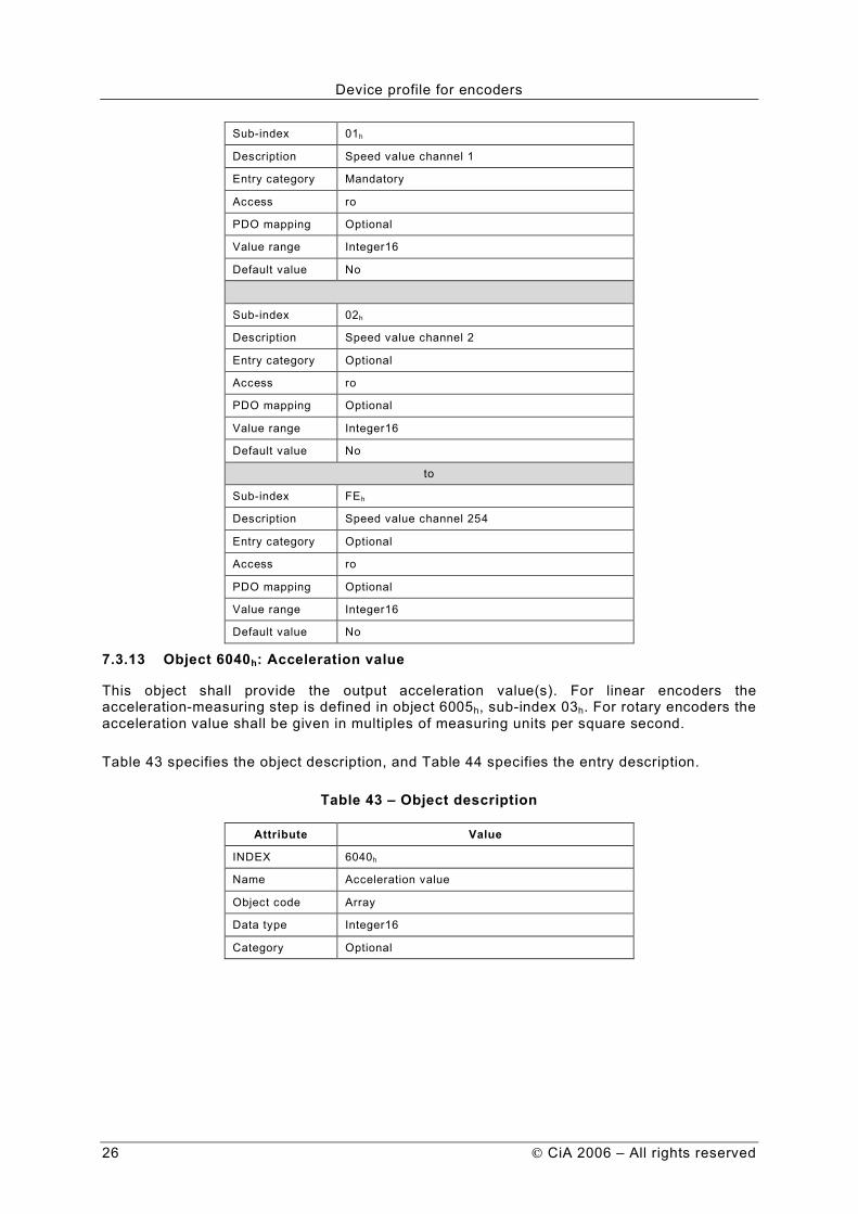
7.3.13 Object 6040h: Acceleration value
This object shall provide the output acceleration value(s). For linear encoders the acceleration-measuring step is defined in object 6005h, sub-index 03h. For rotary encoders the acceleration value shall be given in multiples of measuring units per square second.
Table 43 specifies the object description, and Table 44 specifies the entry description.
Table 43 – Object description
Attribute Value
INDEX 6040h
Name Acceleration value
Object code Array
Data type Integer16
Category Optional
Device profile for encoders
CiA 2006 – All rights reserved 27
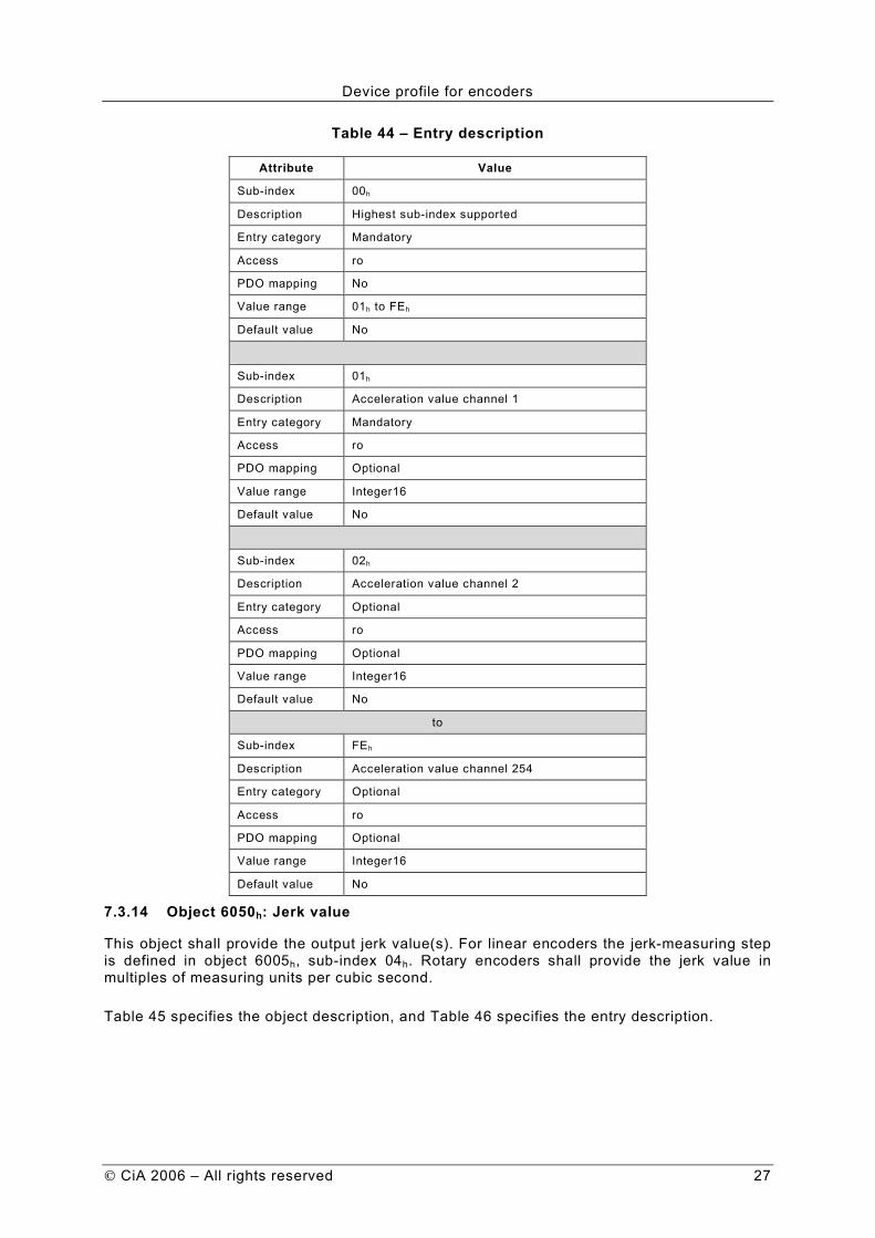
Table 44 – Entry description
Attribute Value
Sub-index 00h
Description Highest sub-index supported
Entry category Mandatory
Access ro
PDO mapping No
Value range 01h to FEh
Default value No
Sub-index 01h
Description Acceleration value channel 1
Entry category Mandatory
Access ro
PDO mapping Optional
Value range Integer16
Default value No
Sub-index 02h
Description Acceleration value channel 2
Entry category Optional
Access ro
PDO mapping Optional
Value range Integer16
Default value No
to
Sub-index FEh
Description Acceleration value channel 254
Entry category Optional
Access ro
PDO mapping Optional
Value range Integer16
Default value No
7.3.14 Object 6050h: Jerk value
This object shall provide the output jerk value(s). For linear encoders the jerk-measuring step is defined in object 6005h, sub-index 04h. Rotary encoders shall provide the jerk value in multiples of measuring units per cubic second.
Table 45 specifies the object description, and Table 46 specifies the entry description.

Device profile for encoders
28 CiA 2006 – All rights reserved
Table 45 – Object description
Attribute Value
INDEX 6050h
Name Jerk value
Object code Array
Data type Integer16
Category Optional
Table 46 – Entry description
Attribute Value
Sub-index 00h
Description Highest sub-index supported
Entry category Mandatory
Access ro
PDO mapping No
Value range 01h to FEh
Default value No
Sub-index 01h
Description Jerk value channel 1
Entry category Mandatory
Access ro
PDO mapping Optional
Value range Integer16
Default value No
Sub-index 02h
Description Jerk value channel 2
Entry category Optional
Access ro
PDO mapping Optional
Value range Integer16
Default value No
to
Sub-index FEh
Description Jerk value channel 254
Entry category Optional
Access ro
PDO mapping Optional
Value range Integer16
Default value No
7.3.15 Object 6200h: Cyclic timer
This object shall indicate the transmission period for TPDO 1. It shall be hard-wired to the PDO’s event timer meaning that a change in the event timer causes a change in object 6200h and vice versa.

Device profile for encoders
CiA 2006 – All rights reserved 29
A cyclic transmission of the position value shall be set, when the cyclic timer is programmed unequal 0000h. The values shall be given in multiples of 1 ms.
Table 47 specifies the object description, and Table 48 specifies the entry description.
Table 47 – Object description
Attribute Value
INDEX 6200h
Name Cyclic timer
Object code Variable
Data type Unsigned16
Category See Table 18
Table 48 – Entry description
Attribute Value
Sub-index 00h
Access rw
PDO mapping No
Value range Unsigned16
Default value See event timer of TPDO 1
7.4 Encoder Cams
7.4.1 General
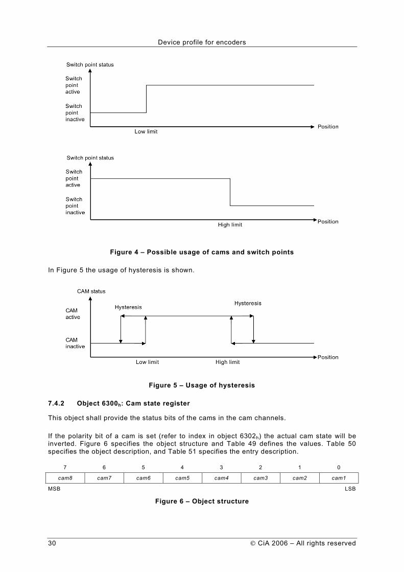
Optional up to 254 cam position channels with a maximum of 8 cams each channel may be supported by encoder devices. Each cam has parameters for the minimum switch point, the maximum switch point and setting a hysteresis to the switch points.
Figure 4 shows the possible usage of cams and switch points.
Device profile for encoders
30 CiA 2006 – All rights reserved
Figure 4 – Possible usage of cams and switch points
In Figure 5 the usage of hysteresis is shown.
Figure 5 – Usage of hysteresis
7.4.2 Object 6300h: Cam state register
This object shall provide the status bits of the cams in the cam channels.
If the polarity bit of a cam is set (refer to index in object 6302h) the actual cam state will be inverted. Figure 6 specifies the object structure and Table 49 defines the values. Table 50 specifies the object description, and Table 51 specifies the entry description.
7 6 5 4 3 2 1 0
cam8 cam7 cam6 cam5 cam4 cam3 cam2 cam1
MSB LSB
Figure 6 – Object structure

Device profile for encoders
CiA 2006 – All rights reserved 31
Table 49 – Value definition
Bit Value Definition
cam1 to cam8 0b
1b Cam inactive
Cam active
Table 50 – Object description
Attribute Value
INDEX 6300h
Name Cam state register
Object code Array
Data type Unsigned8
Category See Table 18
Table 51 – Entry description
Attribute Value
Sub-index 00h
Description Highest sub-index supported
Entry category Mandatory
Access ro
PDO mapping No
Value range 01h to FEh
Default value No
Sub-index 01h
Description Cam state channel 1
Entry category Mandatory
Access ro
PDO mapping Optional
Value range See value definition
Default value No
Sub-index 02h
Description Cam state channel 2
Entry category Optional
Access ro
PDO mapping Optional
Value range See value definition
Default value No
to

Device profile for encoders
32 CiA 2006 – All rights reserved
Sub-index FEh
Description Cam state channel 254
Entry category Optional
Access ro
PDO mapping Optional
Value range See value definition
Default value No
7.4.3 Object 6301h: Cam enable register
This object shall indicate the cam enable register values. Each cam enable channel shall contain the calculation state for a maximum of 8 cams for one position channel.
Figure 7 specifies the object structure. Table 52 specifies the value definition. Table 53 specifies the object description, and Table 54 specifies the entry description.
7 6 5 4 3 2 1 0
cam8_en cam7_en cam6_en cam5_en cam4_en cam3_en cam2_en cam1_en
MSB LSB
Figure 7 – Object structure
Table 52 – Value definition
Bit Value Definition
cam1_en to cam8_en 0b
1b
Cam state of the related cam shall be set permanently to 0b
Cam state shall be calculated by the device
Table 53 – Object description
Attribute Value
INDEX 6301h
Name Cam enable register
Object code Array
Data type Unsigned8
Category See Table 18
Table 54 – Entry description
Attribute Value
Sub-index 00h
Description Highest sub-index supported
Entry category Mandatory
Access ro
PDO mapping No
Value range 01h to FEh
Default value No
Device profile for encoders
CiA 2006 – All rights reserved 33
Sub-index 01h
Description Cam enable channel 1
Entry category Mandatory
Access rw
PDO mapping Optional
Value range See value definition
Default value 00h
Sub-index 02h
Description Cam enable channel 2
Entry category Optional
Access rw
PDO mapping Optional
Value range See value definition
Default value 00h
to
Sub-index FEh
Description Cam enable channel 254
Entry category Optional
Access rw
PDO mapping Optional
Value range See value definition
Default value 00h
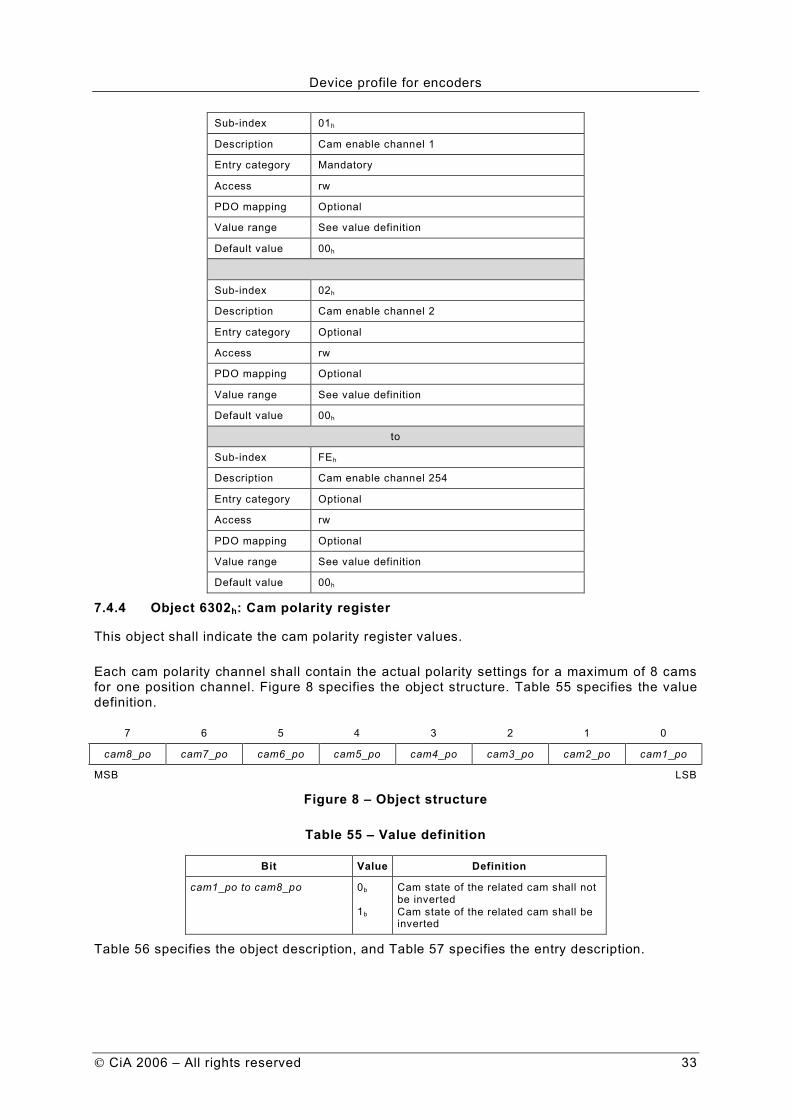
7.4.4 Object 6302h: Cam polarity register
This object shall indicate the cam polarity register values.
Each cam polarity channel shall contain the actual polarity settings for a maximum of 8 cams for one position channel. Figure 8 specifies the object structure. Table 55 specifies the value definition.
7 6 5 4 3 2 1 0
cam8_po cam7_po cam6_po cam5_po cam4_po cam3_po cam2_po cam1_po
MSB LSB
Figure 8 – Object structure
Table 55 – Value definition
Bit Value Definition
cam1_po to cam8_po 0b
1b
Cam state of the related cam shall not be inverted
Cam state of the related cam shall be inverted
Table 56 specifies the object description, and Table 57 specifies the entry description.

Device profile for encoders
34 CiA 2006 – All rights reserved
Table 56 – Object description
Attribute Value
INDEX 6302h
Name Cam polarity register
Object code Array
Data type Unsigned8
Category See Table 18
Table 57 – Entry description
Attribute Value
Sub-index 00h
Description Highest sub-index supported
Entry category Mandatory
Access ro
PDO mapping No
Value range 01h to FEh
Default value No
Sub-index 01h
Description Cam polarity channel 1
Entry category Mandatory
Access rw
PDO mapping Optional
Value range See value definition
Default value 00h
Sub-index 02h
Description Cam polarity channel 2
Entry category Optional
Access rw
PDO mapping Optional
Value range See value definition
Default value 00h
to
Sub-index FEh
Description Cam polarity channel 254
Entry category Optional
Access rw
PDO mapping Optional
Value range See value definition
Default value 00h
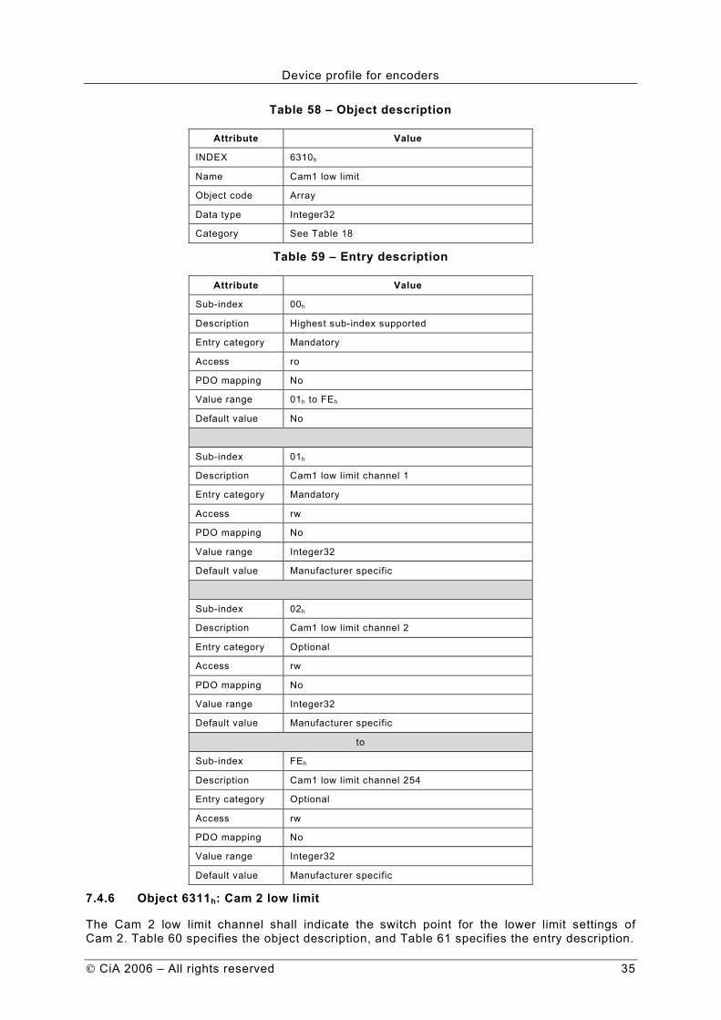
7.4.5 Object 6310h: Cam 1 low limit
The Cam 1 low limit channel shall indicate the switch point for the lower limit settings of Cam 1. Table 58 specifies the object description, and Table 59 specifies the entry description.
Device profile for encoders
CiA 2006 – All rights reserved 35
Table 58 – Object description
Attribute Value
INDEX 6310h
Name Cam1 low limit
Object code Array
Data type Integer32
Category See Table 18
Table 59 – Entry description
Attribute Value
Sub-index 00h
Description Highest sub-index supported
Entry category Mandatory
Access ro
PDO mapping No
Value range 01h to FEh
Default value No
Sub-index 01h
Description Cam1 low limit channel 1
Entry category Mandatory
Access rw
PDO mapping No
Value range Integer32
Default value Manufacturer specific
Sub-index 02h
Description Cam1 low limit channel 2
Entry category Optional
Access rw
PDO mapping No
Value range Integer32
Default value Manufacturer specific
to
Sub-index FEh
Description Cam1 low limit channel 254
Entry category Optional
Access rw
PDO mapping No
Value range Integer32
Default value Manufacturer specific
7.4.6 Object 6311h: Cam 2 low limit
The Cam 2 low limit channel shall indicate the switch point for the lower limit settings of Cam 2. Table 60 specifies the object description, and Table 61 specifies the entry description.

Device profile for encoders
36 CiA 2006 – All rights reserved
Table 60 – Object description
Attribute Value
INDEX 6311h
Name Cam2 low limit
Object code Array
Data type Integer32
Category See Table 18
Table 61 – Entry description
Attribute Value
Sub-index 00h
Description Highest sub-index supported
Entry category Mandatory
Access ro
PDO mapping No
Value range 01h to FEh
Default value No
Sub-index 01h
Description Cam2 low limit channel 1
Entry category Mandatory
Access rw
PDO mapping No
Value range Integer32
Default value Manufacturer specific
Sub-index 02h
Description Cam2 low limit channel 2
Entry category Optional
Access rw
PDO mapping No
Value range Integer32
Default value Manufacturer specific
to
Sub-index FEh
Description Cam2 low limit channel 254
Entry category Optional
Access rw
PDO mapping No
Value range Integer32
Default value Manufacturer specific
7.4.7 Object 6312h: Cam 3 low limit
The Cam 3 low limit channel shall indicate the switch point for the lower limit settings of Cam 3. Table 62 specifies the object description, and Table 63 specifies the entry description.

Device profile for encoders
CiA 2006 – All rights reserved 37
Table 62 – Object description
Attribute Value
INDEX 6312h
Name Cam3 low limit
Object code Array
Data type Integer32
Category See Table 18
Table 63 – Entry description
Attribute Value
Sub-index 00h
Description Highest sub-index supported
Entry category Mandatory
Access ro
PDO mapping No
Value range 01h to FEh
Default value No
Sub-index 01h
Description Cam3 low limit channel 1
Entry category Mandatory
Access rw
PDO mapping No
Value range Integer32
Default value Manufacturer specific
Sub-index 02h
Description Cam3 low limit channel 2
Entry category Optional
Access rw
PDO mapping No
Value range Integer32
Default value Manufacturer specific
to
Sub-index FEh
Description Cam3 low limit channel 254
Entry category Optional
Access rw
PDO mapping No
Value range Integer32
Default value Manufacturer specific
7.4.8 Object 6313h: Cam 4 low limit
The Cam 4 low limit channel shall indicate the switch point for the lower limit settings of Cam 4. Table 64 specifies the object description, and Table 65 specifies the entry description.

Device profile for encoders
38 CiA 2006 – All rights reserved
Table 64 – Object description
Attribute Value
INDEX 6313h
Name Cam4 low limit
Object code Array
Data type Integer32
Category See Table 18
Table 65 – Entry description
Attribute Value
Sub-index 00h
Description Highest sub-index supported
Entry category Mandatory
Access ro
PDO mapping No
Value range 01h to FEh
Default value No
Sub-index 01h
Description Cam4 low limit channel 1
Entry category Mandatory
Access rw
PDO mapping No
Value range Integer32
Default value Manufacturer specific
Sub-index 02h
Description Cam4 low limit channel 2
Entry category Optional
Access rw
PDO mapping No
Value range Integer32
Default value Manufacturer specific
to
Sub-index FEh
Description Cam4 low limit channel 254
Entry category Optional
Access rw
PDO mapping No
Value range Integer32
Default value Manufacturer specific
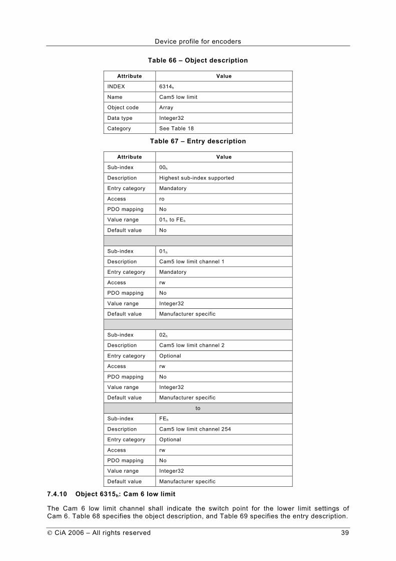
7.4.9 Object 6314h: Cam 5 low limit
The Cam 5 low limit channel shall indicate the switch point for the lower limit settings of Cam 5. Table 66 specifies the object description, and Table 67 specifies the entry description.
Device profile for encoders
CiA 2006 – All rights reserved 39
Table 66 – Object description
Attribute Value
INDEX 6314h
Name Cam5 low limit
Object code Array
Data type Integer32
Category See Table 18
Table 67 – Entry description
Attribute Value
Sub-index 00h
Description Highest sub-index supported
Entry category Mandatory
Access ro
PDO mapping No
Value range 01h to FEh
Default value No
Sub-index 01h
Description Cam5 low limit channel 1
Entry category Mandatory
Access rw
PDO mapping No
Value range Integer32
Default value Manufacturer specific
Sub-index 02h
Description Cam5 low limit channel 2
Entry category Optional
Access rw
PDO mapping No
Value range Integer32
Default value Manufacturer specific
to
Sub-index FEh
Description Cam5 low limit channel 254
Entry category Optional
Access rw
PDO mapping No
Value range Integer32
Default value Manufacturer specific
7.4.10 Object 6315h: Cam 6 low limit
The Cam 6 low limit channel shall indicate the switch point for the lower limit settings of Cam 6. Table 68 specifies the object description, and Table 69 specifies the entry description.

Device profile for encoders
40 CiA 2006 – All rights reserved
Table 68 – Object description
Attribute Value
INDEX 6315h
Name Cam6 low limit
Object code Array
Data type Integer32
Category See Table 18
Table 69 – Entry description
Attribute Value
Sub-index 00h
Description Highest sub-index supported
Entry category Mandatory
Access ro
PDO mapping No
Value range 01h to FEh
Default value No
Sub-index 01h
Description Cam6 low limit channel 1
Entry category Mandatory
Access rw
PDO mapping No
Value range Integer32
Default value Manufacturer specific
Sub-index 02h
Description Cam6 low limit channel 2
Entry category Optional
Access rw
PDO mapping No
Value range Integer32
Default value Manufacturer specific
to
Sub-index FEh
Description Cam6 low limit channel 254
Entry category Optional
Access rw
PDO mapping No
Value range Integer32
Default value Manufacturer specific
7.4.11 Object 6316h: Cam 7 low limit
The Cam 7 low limit channel shall indicate the switch point for the lower limit settings of Cam 7. Table 70 specifies the object description, and Table 71 specifies the entry description.

Device profile for encoders
CiA 2006 – All rights reserved 41
Table 70 – Object description
Attribute Value
INDEX 6316h
Name Cam7 low limit
Object code Array
Data type Integer32
Category See Table 18
Table 71 – Entry description
Attribute Value
Sub-index 00h
Description Highest sub-index supported
Entry category Mandatory
Access ro
PDO mapping No
Value range 01h to FEh
Default value No
Sub-index 01h
Description Cam7 low limit channel 1
Entry category Mandatory
Access rw
PDO mapping No
Value range Integer32
Default value Manufacturer specific
Sub-index 02h
Description Cam7 low limit channel 2
Entry category Optional
Access rw
PDO mapping No
Value range Integer32
Default value Manufacturer specific
to
Sub-index FEh
Description Cam7 low limit channel 254
Entry category Optional
Access rw
PDO mapping No
Value range Integer32
Default value Manufacturer specific
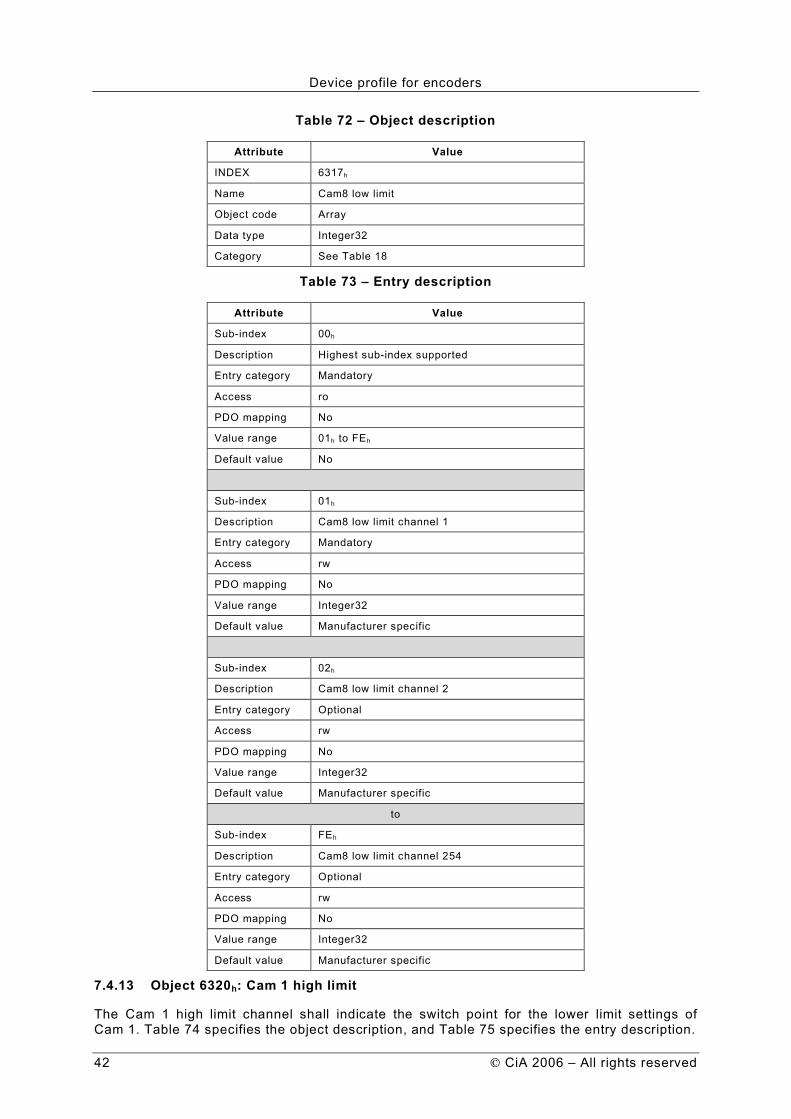
7.4.12 Object 6317h: Cam 8 low limit
The Cam 8 low limit channel shall indicate the switch point for the lower limit settings of Cam 8. Table 72 specifies the object description, and Table 73 specifies the entry description.
Device profile for encoders
42 CiA 2006 – All rights reserved
Table 72 – Object description
Attribute Value
INDEX 6317h
Name Cam8 low limit
Object code Array
Data type Integer32
Category See Table 18
Table 73 – Entry description
Attribute Value
Sub-index 00h
Description Highest sub-index supported
Entry category Mandatory
Access ro
PDO mapping No
Value range 01h to FEh
Default value No
Sub-index 01h
Description Cam8 low limit channel 1
Entry category Mandatory
Access rw
PDO mapping No
Value range Integer32
Default value Manufacturer specific
Sub-index 02h
Description Cam8 low limit channel 2
Entry category Optional
Access rw
PDO mapping No
Value range Integer32
Default value Manufacturer specific
to
Sub-index FEh
Description Cam8 low limit channel 254
Entry category Optional
Access rw
PDO mapping No
Value range Integer32
Default value Manufacturer specific
7.4.13 Object 6320h: Cam 1 high limit
The Cam 1 high limit channel shall indicate the switch point for the lower limit settings of Cam 1. Table 74 specifies the object description, and Table 75 specifies the entry description.

Device profile for encoders
CiA 2006 – All rights reserved 43
Table 74 – Object description
Attribute Value
INDEX 6320h
Name Cam 1 high limit
Object code Array
Data type Integer32
Category See Table 18
Table 75 – Entry description
Attribute Value
Sub-index 00h
Description Highest sub-index supported
Entry category Mandatory
Access ro
PDO mapping No
Value range 01h to FEh
Default value No
Sub-index 01h
Description Cam 1 high limit channel 1
Entry category Mandatory
Access rw
PDO mapping No
Value range Integer32
Default value Manufacturer specific
Sub-index 02h
Description Cam 1 high limit channel 2
Entry category Optional
Access rw
PDO mapping No
Value range Integer32
Default value Manufacturer specific
to
Sub-index FEh
Description Cam 1 high limit channel 254
Entry category Optional
Access rw
PDO mapping No
Value range Integer32
Default value Manufacturer specific
7.4.14 Object 6321h: Cam 2 high limit
The Cam 2 high limit channel shall indicate the switch point for the lower limit settings of Cam 2. Table 76 specifies the object description, and Table 77 specifies the entry description.

Device profile for encoders
44 CiA 2006 – All rights reserved
Table 76 – Object description
Attribute Value
INDEX 6321h
Name Cam 2 high limit
Object code Array
Data type Integer32
Category See Table 18
Table 77 – Entry description
Attribute Value
Sub-index 00h
Description Highest sub-index supported
Entry category Mandatory
Access ro
PDO mapping No
Value range 01h to FEh
Default value No
Sub-index 01h
Description Cam 2 high limit channel 1
Entry category Mandatory
Access rw
PDO mapping No
Value range Integer32
Default value Manufacturer specific
Sub-index 02h
Description Cam 2 high limit channel 2
Entry category Optional
Access rw
PDO mapping No
Value range Integer32
Default value Manufacturer specific
to
Sub-index FEh
Description Cam 2 high limit channel 254
Entry category Optional
Access rw
PDO mapping No
Value range Integer32
Default value Manufacturer specific
7.4.15 Object 6322h: Cam 3 high limit
The Cam 3 high limit channel shall indicate the switch point for the lower limit settings of Cam 3. Table 78 specifies the object description, and Table 79 specifies the entry description.

Device profile for encoders
CiA 2006 – All rights reserved 45
Table 78 – Object description
Attribute Value
INDEX 6322h
Name Cam 3 high limit
Object code Array
Data type Integer32
Category See Table 18
Table 79 – Entry description
Attribute Value
Sub-index 00h
Description Highest sub-index supported
Entry category Mandatory
Access ro
PDO mapping No
Value range 01h to FEh
Default value No
Sub-index 01h
Description Cam 3 high limit channel 1
Entry category Mandatory
Access rw
PDO mapping No
Value range Integer32
Default value Manufacturer specific
Sub-index 02h
Description Cam 3 high limit channel 2
Entry category Optional
Access rw
PDO mapping No
Value range Integer32
Default value Manufacturer specific
to
Sub-index FEh
Description Cam 3 high limit channel 254
Entry category Optional
Access rw
PDO mapping No
Value range Integer32
Default value Manufacturer specific
7.4.16 Object 6323h: Cam 4 high limit
The Cam 4 high limit channel shall indicate the switch point for the lower limit settings of Cam 4. Table 80 specifies the object description, and Table 81 specifies the entry description.

Device profile for encoders
46 CiA 2006 – All rights reserved
Table 80 – Object description
Attribute Value
INDEX 6323h
Name Cam 4 high limit
Object code Array
Data type Integer32
Category See Table 18
Table 81 – Entry description
Attribute Value
Sub-index 00h
Description Highest sub-index supported
Entry category Mandatory
Access ro
PDO mapping No
Value range 01h to FEh
Default value No
Sub-index 01h
Description Cam 4 high limit channel 1
Entry category Mandatory
Access rw
PDO mapping No
Value range Integer32
Default value Manufacturer specific
Sub-index 02h
Description Cam 4 high limit channel 2
Entry category Optional
Access rw
PDO mapping No
Value range Integer32
Default value Manufacturer specific
to
Sub-index FEh
Description Cam 4 high limit channel 254
Entry category Optional
Access rw
PDO mapping No
Value range Integer32
Default value Manufacturer specific
7.4.17 Object 6324h: Cam 5 high limit
The Cam 5 high limit channel shall indicate the switch point for the lower limit settings of Cam 5. Table 82 specifies the object description, and Table 83 specifies the entry description.

Device profile for encoders
CiA 2006 – All rights reserved 47
Table 82 – Object description
Attribute Value
INDEX 6324h
Name Cam 5 high limit
Object code Array
Data type Integer32
Category See Table 18
Table 83 – Entry description
Attribute Value
Sub-index 00h
Description Highest sub-index supported
Entry category Mandatory
Access ro
PDO mapping No
Value range 01h to FEh
Default value No
Sub-index 01h
Description Cam 5 high limit channel 1
Entry category Mandatory
Access rw
PDO mapping No
Value range Integer32
Default value Manufacturer specific
Sub-index 02h
Description Cam 5 high limit channel 2
Entry category Optional
Access rw
PDO mapping No
Value range Integer32
Default value Manufacturer specific
to
Sub-index FEh
Description Cam 5 high limit channel 254
Entry category Optional
Access rw
PDO mapping No
Value range Integer32
Default value Manufacturer specific
7.4.18 Object 6325h: Cam 6 high limit
The Cam 6 high limit channel shall indicate the switch point for the lower limit settings of Cam 6. Table 84 specifies the object description, and Table 85 specifies the entry description.

Device profile for encoders
48 CiA 2006 – All rights reserved
Table 84 – Object description
Attribute Value
INDEX 6325h
Name Cam 6 high limit
Object code Array
Data type Integer32
Category See Table 18
Table 85 – Entry description
Attribute Value
Sub-index 00h
Description Highest sub-index supported
Entry category Mandatory
Access ro
PDO mapping No
Value range 01h to FEh
Default value No
Sub-index 01h
Description Cam 6 high limit channel 1
Entry category Mandatory
Access rw
PDO mapping No
Value range Integer32
Default value Manufacturer specific
Sub-index 02h
Description Cam 6 high limit channel 2
Entry category Optional
Access rw
PDO mapping No
Value range Integer32
Default value Manufacturer specific
to
Sub-index FEh
Description Cam 6 high limit channel 254
Entry category Optional
Access rw
PDO mapping No
Value range Integer32
Default value Manufacturer specific
7.4.19 Object 6326h: Cam 7 high limit
The Cam 7 high limit channel shall indicate the switch point for the lower limit settings of Cam 7. Table 86 specifies the object description, and Table 87 specifies the entry description.

Device profile for encoders
CiA 2006 – All rights reserved 49
Table 86 – Object description
Attribute Value
INDEX 6326h
Name Cam 7 high limit
Object code Array
Data type Integer32
Category See Table 18
Table 87 – Entry description
Attribute Value
Sub-index 00h
Description Highest sub-index supported
Entry category Mandatory
Access ro
PDO mapping No
Value range 01h to FEh
Default value No
Sub-index 01h
Description Cam 7 high limit channel 1
Entry category Mandatory
Access rw
PDO mapping No
Value range Integer32
Default value Manufacturer specific
Sub-index 02h
Description Cam 7 high limit channel 2
Entry category Optional
Access rw
PDO mapping No
Value range Integer32
Default value Manufacturer specific
to
Sub-index FEh
Description Cam 7 high limit channel 254
Entry category Optional
Access rw
PDO mapping No
Value range Integer32
Default value Manufacturer specific
7.4.20 Object 6327h: Cam 8 high limit
The Cam 8 high limit channel shall indicate the switch point for the lower limit settings of Cam 8. Table 88 specifies the object description, and Table 89 specifies the entry description.

Device profile for encoders
50 CiA 2006 – All rights reserved
Table 88 – Object description
Attribute Value
INDEX 6327h
Name Cam 8 high limit
Object code Array
Data type Integer32
Category See Table 18
Table 89 – Entry description
Attribute Value
Sub-index 00h
Description Highest sub-index supported
Entry category Mandatory
Access ro
PDO mapping No
Value range 01h to FEh
Default value No
Sub-index 01h
Description Cam 8 high limit channel 1
Entry category Mandatory
Access rw
PDO mapping No
Value range Integer32
Default value Manufacturer specific
Sub-index 02h
Description Cam 8 high limit channel 2
Entry category Optional
Access rw
PDO mapping No
Value range Integer32
Default value Manufacturer specific
to
Sub-index FEh
Description Cam 8 high limit channel 254
Entry category Optional
Access rw
PDO mapping No
Value range Integer32
Default value Manufacturer specific
7.4.21 Object 6330h: Cam 1 hysteresis
The Cam 1 hysteresis channel shall indicate the delay setting of switch points for Cam 1. For illustration of the hysteresis functionality refer to Figure 5. Table 90 specifies the object description, and Table 91 specifies the entry description.

Device profile for encoders
CiA 2006 – All rights reserved 51
Table 90 – Object description
Attribute Value
INDEX 6330h
Name Cam1 hysteresis
Object code Array
Data type Unsigned16
Category See Table 18
Table 91 – Entry description
Attribute Value
Sub-index 00h
Description Highest sub-index supported
Entry category Mandatory
Access ro
PDO mapping No
Value range 01h to FEh
Default value No
Sub-index 01h
Description Cam1 hysteresis channel 1
Entry category Mandatory
Access rw
PDO mapping No
Value range Unsigned16
Default value Manufacturer specific
Sub-index 02h
Description Cam1 hysteresis channel 2
Entry category Optional
Access rw
PDO mapping No
Value range Unsigned16
Default value Manufacturer specific
to
Sub-index FEh
Description Cam1 hysteresis channel 254
Entry category Optional
Access rw
PDO mapping No
Value range Unsigned16
Default value Manufacturer specific
7.4.22 Object 6331h: Cam 2 hysteresis
The Cam 2 hysteresis channel shall indicate the delay setting of switch points for Cam 2. For illustration of the hysteresis functionality refer to Figure 5. Table 92 specifies the object description, and Table 93 specifies the entry description.
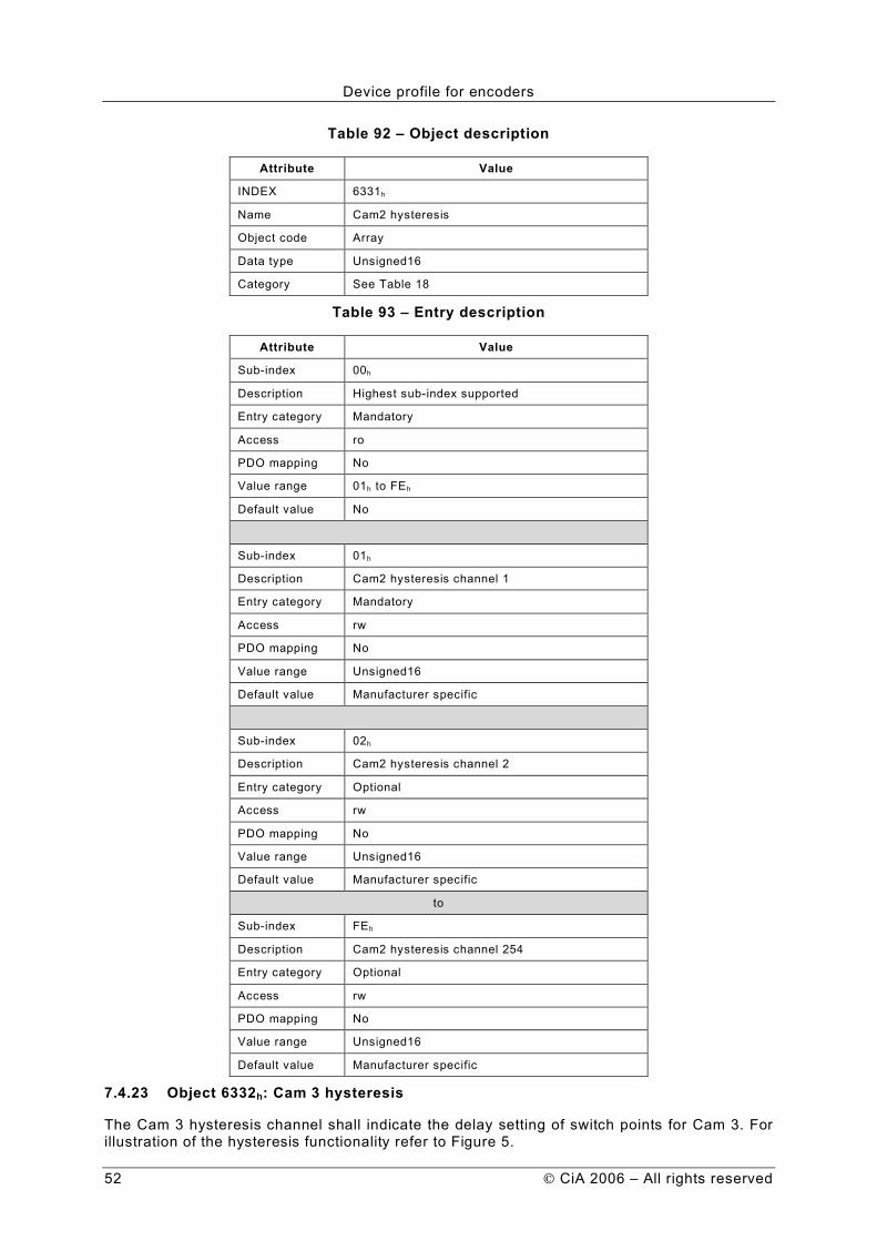
Device profile for encoders
52 CiA 2006 – All rights reserved
Table 92 – Object description
Attribute Value
INDEX 6331h
Name Cam2 hysteresis
Object code Array
Data type Unsigned16
Category See Table 18
Table 93 – Entry description
Attribute Value
Sub-index 00h
Description Highest sub-index supported
Entry category Mandatory
Access ro
PDO mapping No
Value range 01h to FEh
Default value No
Sub-index 01h
Description Cam2 hysteresis channel 1
Entry category Mandatory
Access rw
PDO mapping No
Value range Unsigned16
Default value Manufacturer specific
Sub-index 02h
Description Cam2 hysteresis channel 2
Entry category Optional
Access rw
PDO mapping No
Value range Unsigned16
Default value Manufacturer specific
to
Sub-index FEh
Description Cam2 hysteresis channel 254
Entry category Optional
Access rw
PDO mapping No
Value range Unsigned16
Default value Manufacturer specific
7.4.23 Object 6332h: Cam 3 hysteresis
The Cam 3 hysteresis channel shall indicate the delay setting of switch points for Cam 3. For illustration of the hysteresis functionality refer to Figure 5.
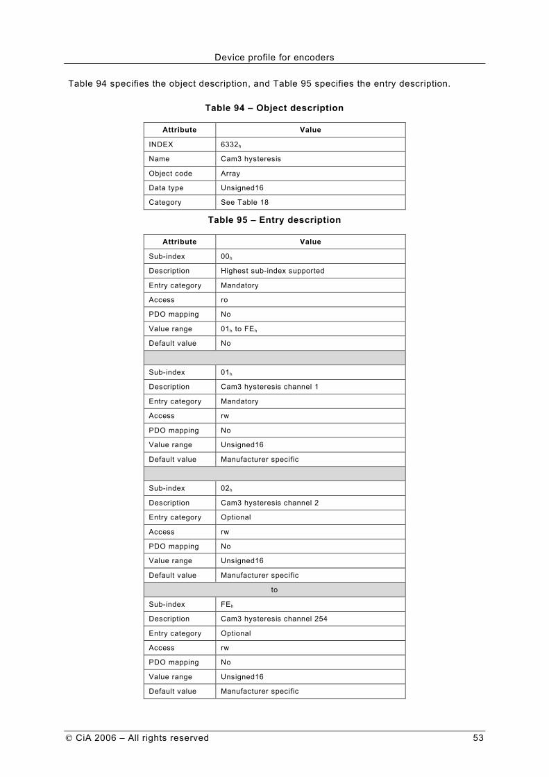
Device profile for encoders
CiA 2006 – All rights reserved 53
Table 94 specifies the object description, and Table 95 specifies the entry description.
Table 94 – Object description
Attribute Value
INDEX 6332h
Name Cam3 hysteresis
Object code Array
Data type Unsigned16
Category See Table 18
Table 95 – Entry description
Attribute Value
Sub-index 00h
Description Highest sub-index supported
Entry category Mandatory
Access ro
PDO mapping No
Value range 01h to FEh
Default value No
Sub-index 01h
Description Cam3 hysteresis channel 1
Entry category Mandatory
Access rw
PDO mapping No
Value range Unsigned16
Default value Manufacturer specific
Sub-index 02h
Description Cam3 hysteresis channel 2
Entry category Optional
Access rw
PDO mapping No
Value range Unsigned16
Default value Manufacturer specific
to
Sub-index FEh
Description Cam3 hysteresis channel 254
Entry category Optional
Access rw
PDO mapping No
Value range Unsigned16
Default value Manufacturer specific

Device profile for encoders
54 CiA 2006 – All rights reserved
7.4.24 Object 6333h: Cam 4 hysteresis
The Cam 4 hysteresis channel shall indicate the delay setting of switch points for Cam 4. For illustration of the hysteresis functionality refer to Figure 5. Table 96 specifies the object description, and Table 97 specifies the entry description.
Table 96 – Object description
Attribute Value
INDEX 6333h
Name Cam4 hysteresis
Object code Array
Data type Unsigned16
Category See Table 18
Table 97 – Entry description
Attribute Value
Sub-index 00h
Description Highest sub-index supported
Entry category Mandatory
Access ro
PDO mapping No
Value range 01h to FEh
Default value No
Sub-index 01h
Description Cam4 hysteresis channel 1
Entry category Mandatory
Access rw
PDO mapping No
Value range Unsigned16
Default value Manufacturer specific
Sub-index 02h
Description Cam4 hysteresis channel 2
Entry category Optional
Access rw
PDO mapping No
Value range Unsigned16
Default value Manufacturer specific
to
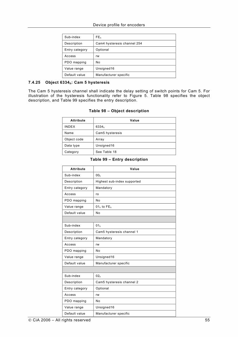
Device profile for encoders
CiA 2006 – All rights reserved 55
Sub-index FEh
Description Cam4 hysteresis channel 254
Entry category Optional
Access rw
PDO mapping No
Value range Unsigned16
Default value Manufacturer specific
7.4.25 Object 6334h: Cam 5 hysteresis
The Cam 5 hysteresis channel shall indicate the delay setting of switch points for Cam 5. For illustration of the hysteresis functionality refer to Figure 5. Table 98 specifies the object description, and Table 99 specifies the entry description.
Table 98 – Object description
Attribute Value
INDEX 6334h
Name Cam5 hysteresis
Object code Array
Data type Unsigned16
Category See Table 18
Table 99 – Entry description
Attribute Value
Sub-index 00h
Description Highest sub-index supported
Entry category Mandatory
Access ro
PDO mapping No
Value range 01h to FEh
Default value No
Sub-index 01h
Description Cam5 hysteresis channel 1
Entry category Mandatory
Access rw
PDO mapping No
Value range Unsigned16
Default value Manufacturer specific
Sub-index 02h
Description Cam5 hysteresis channel 2
Entry category Optional
Access rw
PDO mapping No
Value range Unsigned16
Default value Manufacturer specific
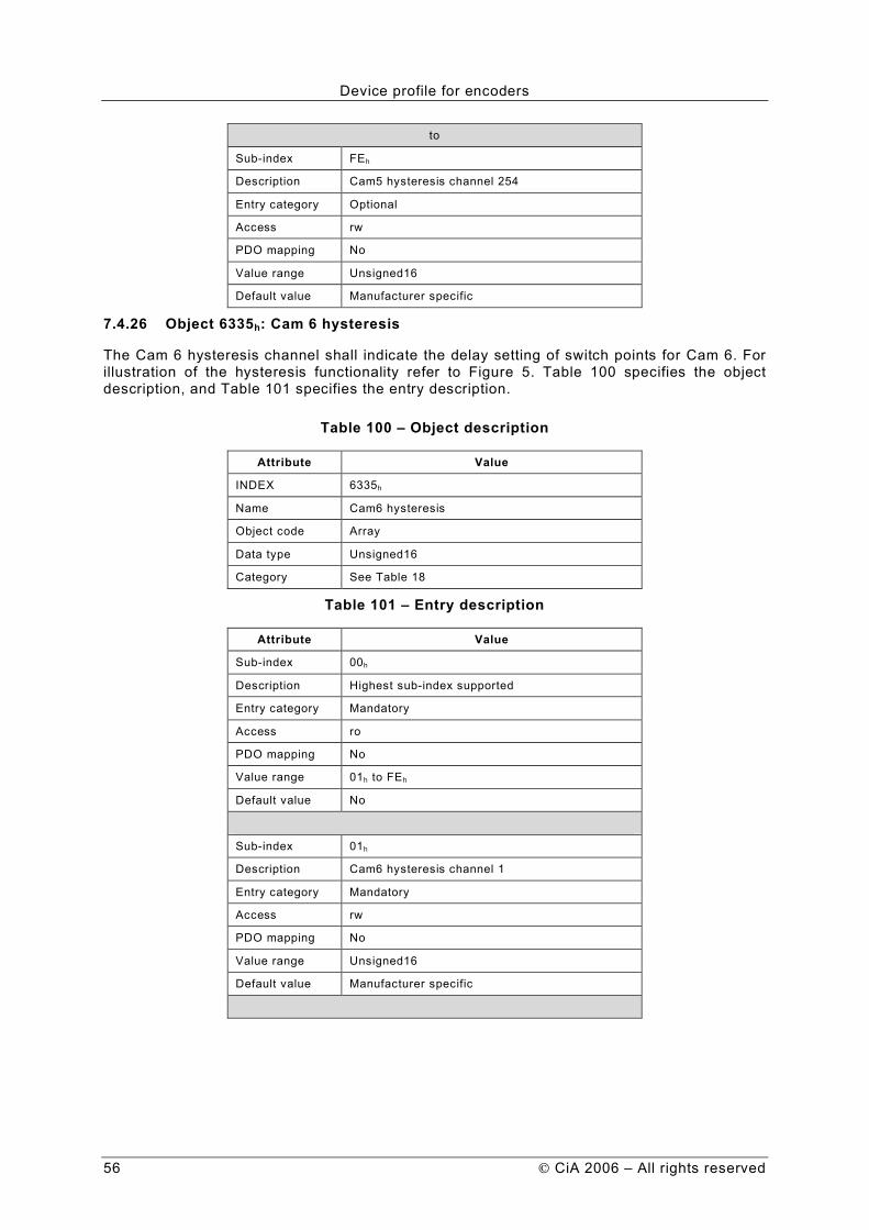
Device profile for encoders
56 CiA 2006 – All rights reserved
to
Sub-index FEh
Description Cam5 hysteresis channel 254
Entry category Optional
Access rw
PDO mapping No
Value range Unsigned16
Default value Manufacturer specific
7.4.26 Object 6335h: Cam 6 hysteresis
The Cam 6 hysteresis channel shall indicate the delay setting of switch points for Cam 6. For illustration of the hysteresis functionality refer to Figure 5. Table 100 specifies the object description, and Table 101 specifies the entry description.
Table 100 – Object description
Attribute Value
INDEX 6335h
Name Cam6 hysteresis
Object code Array
Data type Unsigned16
Category See Table 18
Table 101 – Entry description
Attribute Value
Sub-index 00h
Description Highest sub-index supported
Entry category Mandatory
Access ro
PDO mapping No
Value range 01h to FEh
Default value No
Sub-index 01h
Description Cam6 hysteresis channel 1
Entry category Mandatory
Access rw
PDO mapping No
Value range Unsigned16
Default value Manufacturer specific
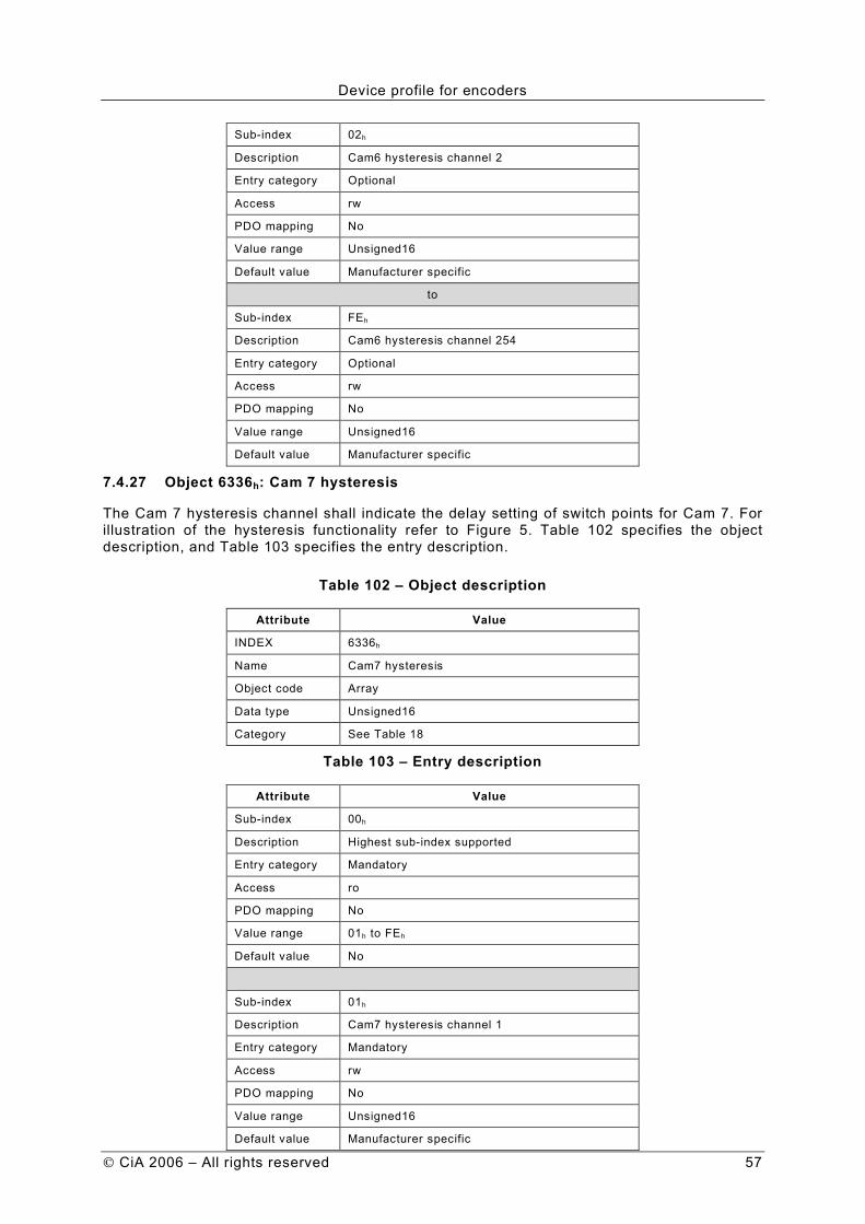
Device profile for encoders
CiA 2006 – All rights reserved 57
Sub-index 02h
Description Cam6 hysteresis channel 2
Entry category Optional
Access rw
PDO mapping No
Value range Unsigned16
Default value Manufacturer specific
to
Sub-index FEh
Description Cam6 hysteresis channel 254
Entry category Optional
Access rw
PDO mapping No
Value range Unsigned16
Default value Manufacturer specific
7.4.27 Object 6336h: Cam 7 hysteresis
The Cam 7 hysteresis channel shall indicate the delay setting of switch points for Cam 7. For illustration of the hysteresis functionality refer to Figure 5. Table 102 specifies the object description, and Table 103 specifies the entry description.
Table 102 – Object description
Attribute Value
INDEX 6336h
Name Cam7 hysteresis
Object code Array
Data type Unsigned16
Category See Table 18
Table 103 – Entry description
Attribute Value
Sub-index 00h
Description Highest sub-index supported
Entry category Mandatory
Access ro
PDO mapping No
Value range 01h to FEh
Default value No
Sub-index 01h
Description Cam7 hysteresis channel 1
Entry category Mandatory
Access rw
PDO mapping No
Value range Unsigned16
Default value Manufacturer specific

Device profile for encoders
58 CiA 2006 – All rights reserved
Sub-index 02h
Description Cam7 hysteresis channel 2
Entry category Optional
Access rw
PDO mapping No
Value range Unsigned16
Default value Manufacturer specific
to
Sub-index FEh
Description Cam7 hysteresis channel 254
Entry category Optional
Access rw
PDO mapping No
Value range Unsigned16
Default value Manufacturer specific
7.4.28 Object 6337h: Cam 8 hysteresis
The Cam 8 hysteresis channel shall indicate the delay setting of switch points for Cam 8. For illustration of the hysteresis functionality refer to Figure 5. Table 104 specifies the object description, and Table 105 specifies the entry description.
Table 104 – Object description
Attribute Value
INDEX 6337h
Name Cam8 hysteresis
Object code Array
Data type Unsigned16
Category See Table 18
Table 105 – Entry description
Attribute Value
Sub-index 00h
Description Highest sub-index supported
Entry category Mandatory
Access ro
PDO mapping No
Value range 01h to FEh
Default value No
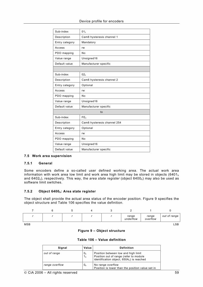
Device profile for encoders
CiA 2006 – All rights reserved 59
Sub-index 01h
Description Cam8 hysteresis channel 1
Entry category Mandatory
Access rw
PDO mapping No
Value range Unsigned16
Default value Manufacturer specific
Sub-index 02h
Description Cam8 hysteresis channel 2
Entry category Optional
Access rw
PDO mapping No
Value range Unsigned16
Default value Manufacturer specific
to
Sub-index FEh
Description Cam8 hysteresis channel 254
Entry category Optional
Access rw
PDO mapping No
Value range Unsigned16
Default value Manufacturer specific
7.5 Work area supervision
7.5.1 General
Some encoders define a so-called user defined working area. The actual work area information with work area low limit and work area high limit may be stored in objects (6401h and 6402h), respectively. This way, the area state register (object 6400h) may also be used as software limit switches.
7.5.2 Object 6400h: Area state register
The object shall provide the actual area status of the encoder position. Figure 9 specifies the object structure and Table 106 specifies the value definition.
7 6 5 4 3 2 1 0
r r r r r range underflow
range overflow
out of range
MSB LSB
Figure 9 – Object structure
Table 106 – Value definition
Signal Value Definition
out of range 0b
1b Position between low and high limit
Position out of range (refer to module identification object, 650Ah) is reached
range overflow 0b No range overflow
Position is lower than the position value set in
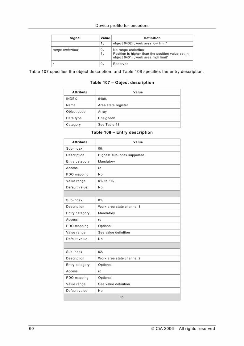
Device profile for encoders
60 CiA 2006 – All rights reserved
Signal Value Definition 1b object 6402h „work area low limit“
range underflow 0b
1b No range underflow
Position is higher than the position value set in object 6401h „work area high limit“
r 0b Reserved
Table 107 specifies the object description, and Table 108 specifies the entry description.
Table 107 – Object description
Attribute Value
INDEX 6400h
Name Area state register
Object code Array
Data type Unsigned8
Category See Table 18
Table 108 – Entry description
Attribute Value
Sub-index 00h
Description Highest sub-index supported
Entry category Mandatory
Access ro
PDO mapping No
Value range 01h to FEh
Default value No
Sub-index 01h
Description Work area state channel 1
Entry category Mandatory
Access ro
PDO mapping Optional
Value range See value definition
Default value No
Sub-index 02h
Description Work area state channel 2
Entry category Optional
Access ro
PDO mapping Optional
Value range See value definition
Default value No
to

Device profile for encoders
CiA 2006 – All rights reserved 61
Sub-index FEh
Description Work area state channel 254
Entry category Optional
Access ro
PDO mapping Optional
Value range See value definition
Default value No
7.5.3 Object 6401h: Work area low limit
This object shall indicate the position value, at which bit 2 of the according work area state channel in object 6400h shall flag the underflow of the related work area.
Table 109 specifies the object description, and Table 110 specifies the entry description.
Table 109 – Object description
Attribute Value
INDEX 6401h
Name Work area low limit
Object code Array
Data type Integer32
Category See Table 18
Table 110 – Entry description
Attribute Value
Sub-index 00h
Description Highest sub-index supported
Entry category Mandatory
Access ro
PDO mapping No
Value range 01h to FEh
Default value No
Sub-index 01h
Description Work area low limit channel 1
Entry category Mandatory
Access rw
PDO mapping No
Value range Integer32
Default value Manufacturer specific
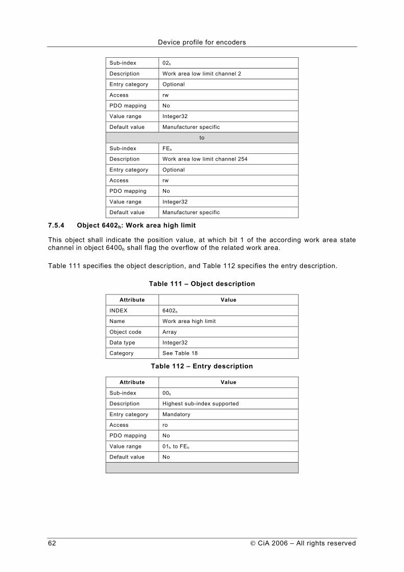
Device profile for encoders
62 CiA 2006 – All rights reserved
Sub-index 02h
Description Work area low limit channel 2
Entry category Optional
Access rw
PDO mapping No
Value range Integer32
Default value Manufacturer specific
to
Sub-index FEh
Description Work area low limit channel 254
Entry category Optional
Access rw
PDO mapping No
Value range Integer32
Default value Manufacturer specific
7.5.4 Object 6402h: Work area high limit
This object shall indicate the position value, at which bit 1 of the according work area state channel in object 6400h shall flag the overflow of the related work area.
Table 111 specifies the object description, and Table 112 specifies the entry description.
Table 111 – Object description
Attribute Value
INDEX 6402h
Name Work area high limit
Object code Array
Data type Integer32
Category See Table 18
Table 112 – Entry description
Attribute Value
Sub-index 00h
Description Highest sub-index supported
Entry category Mandatory
Access ro
PDO mapping No
Value range 01h to FEh
Default value No

Device profile for encoders
CiA 2006 – All rights reserved 63
Sub-index 01h
Description Work area high limit channel 1
Entry category Mandatory
Access rw
PDO mapping No
Value range Integer32
Default value Manufacturer specific
Sub-index 02h
Description Work area high limit channel 2
Entry category Optional
Access rw
PDO mapping No
Value range Integer32
Default value Manufacturer specific
to
Sub-index FEh
Description Work area high limit channel 254
Entry category Optional
Access rw
PDO mapping No
Value range Integer32
Default value Manufacturer specific
7.6 Encoder diagnostics
7.6.1 General
All encoder diagnostics are read from securely stored parameters.
7.6.2 Object 6500h: Operating status
This object shall provide the operating status of the encoder. It gives information on encoder internal programmed parameters. Figure 10 specifies the object structure and Table 113 specifies the value definition.
15 14 13 12 11 10 9 8 7 6 5 4 3 2 1 0
msp msp msp msp r r r r r r r r md sfc cdc cs
MSB LSB
Figure 10 – Object structure
Table 113 – Value definition
Signal Value Definition
cs 0b
1b Code sequence = CW (m* for C1, m* for C2)
Code sequence = CCW (m* for C1, m* for C2)
cdc 0b
1b Commissioning diagnostic control not supported (o for C1, o for C2)
Commissioning diagnostic control supported (o for C1, o for C2)
sfc 0b
1b Scaling function control disabled (o for C1, m for C2)
Scaling function control enabled (o for C1, m for C2)

Device profile for encoders
64 CiA 2006 – All rights reserved
Signal Value Definition
md 0b
1b Measuring direction forward (o** for C1, o** for C2)
Measuring direction reward (o** for C1, o** for C2)
r Reserved for further use
msp 0b
1b Manufacturer-specific function disabled (o for C1, o for C2)
Manufacturer-specific function enabled (o for C1, o for C2) NOTE * not for linear encoders ** not for rotary encoders
Table 114 specifies the object description, and Table 115 specifies the entry description.
Table 114 – Object description
Attribute Value
INDEX 6500h
Name Operating status
Object code Variable
Data type Unsigned16
Category See Table 19
Table 115 – Entry description
Attribute Value
Sub-index 00h
Access ro
PDO mapping No
Value range See value definition
Default value No
7.6.3 Object 6501h: Single-turn resolution and Measuring step
This object shall be interpreted in dependence of the encoder type.
For rotary or angle encoders this object shall provide the number of measuring steps per revolution that are output for the absolute single-turn position value. The maximum single-turn resolution shall be 232.
For linear encoders this object shall provide the measuring step that is output by the encoder. The measuring step is given in multiples of 0.001 µm (1 nm).
Table 116 specifies the object description, and 1) Object name for rotary encoders 2) Object name for linear encoders
Table 117 specifies the entry description.
Table 116 – Object description
Attribute Value
INDEX 6501h
Name Single-turn resolution1)
Measuring step2)
Object code Variable
Data type Unsigned32
Category See Table 19 1) Object name for rotary encoders 2) Object name for linear encoders

Device profile for encoders
CiA 2006 – All rights reserved 65
Table 117 – Entry description
Attribute Value
Sub-index 00h
Access ro
PDO mapping No
Value range Unsigned32
Default value No
7.6.4 Object 6502h: Number of distinguishable revolutions
This object shall provide the number of distinguishable revolutions that the encoder may output. For a multi-turn encoder the number of distinguishable revolutions and the single-turn resolution shall give the measuring range according to the formula below.
Measuring range = Number of distinguishable revolutions x single-turn resolution
Table 118 specifies the value definition. Table 119 specifies the object description and Table 120 specifies the entry description.
Table 118 – Value definition
Value Definition
0d High-resolution object (6510h) is used
1d to 65,536d Range for distinguishable revolutions
Table 119 – Object description
Attribute Value
INDEX 6502h
Name Number of distinguishable revolutions
Object code Variable
Data type Unsigned16
Category See Table 19
Table 120 – Entry description
Attribute Value
Sub-index 00h
Access ro
PDO mapping No
Value range See value definition
Default value No
7.6.5 Object 6503h: Alarms
Additionally to the emergency messages in /CiA301/, this object shall provide further alarm messages. An alarm shall be set if a malfunction in the encoder could lead to incorrect position value. If an alarm occurs, the according bit shall indicate the alarm til the alarm is cleared and the encoder is able to provide an accurate position value. Figure 11 specifies the object structure and Table 121 specifies the value definition. Table 122 specifies the object description, and Table 123 specifies the entry description.

Device profile for encoders
66 CiA 2006 – All rights reserved
15 14 13 12 11 10 9 8 7 6 5 4 3 2 1 0
msa msa msa msa r r r r r r r r r r cde pe
MSB LSB
Figure 11 – Object structure
Table 121 – Value definition
Signal Value Definition
pe 0b
1b No position error (o for C1, o for C2)
Position error (o for C1, o for C2)
cde 0b
1b Commissioning diagnostic OK (o for C1, o for C2)
Commissioning diagnostic error (o for C1, o for C2)
r Reserved for further use
msa 0b
1b Manufacturer-specific alarm disabled (o for C1, o for C2)
Manufacturer-specific alarm enabled (o for C1, o for C2)
Table 122 – Object description
Attribute Value
INDEX 6503h
Name Alarms
Object code Variable
Data type Unsigned16
Category See Table 19
Table 123 – Entry description
Attribute Value
Sub-index 00h
Access ro
PDO mapping Optional
Value range See value definition
Default value No
7.6.6 Object 6504h: Supported alarms
This object shall provide the information on supported alarms by the encoder. This object is mandatory for C2 encoders. If this object is implemented, at least one alarm shall be supported. Figure 12 specifies the object structure and Table 124 specifies the value definition. Table 125 specifies the object description, and Table 126 specifies the entry description.
15 14 13 12 11 10 9 8 7 6 5 4 3 2 1 0
msa msa msa msa r r r r r r r r r r cde pe
MSB LSB
Figure 12 – Object structure
Table 124 – Value definition
Signal Value Definition
pe 0b
1b Position error not supported
Position error supported

Device profile for encoders
CiA 2006 – All rights reserved 67
Signal Value Definition
cde 0b
1b Commissioning diagnostic error not supported
Commissioning diagnostic error supported
r Reserved for further use
msa 0b
1b Manufacturer-specific alarm not supported
Manufacturer-specific alarm supported
Table 125 – Object description
Attribute Value
INDEX 6504h
Name Supported alarms
Object code Variable
Data type Unsigned16
Category See Table 19
Table 126 – Entry description
Attribute Value
Sub-index 00h
Access ro
PDO mapping No
Value range See value definition
Default value No
7.6.7 Object 6505h: Warnings
This object shall provide the warnings. Warnings indicate that tolerance for certain internal parameters of the encoder have been exceeded. In contrast to alarm and emergency messages warnings do not imply incorrect position values. All warnings shall be cleared if the tolerances are again within normal parameters. For the operating time limit warning (bit 3) the warning shall be only set again after a power-on sequence.
Figure 13 specifies the object structure and Table 127 specifies the value definition. Table 128 specifies the object description, and Table 129 specifies the entry description.
15 14 13 12 11 10 9 8 7 6 5 4 3 2 1 0
msw msw msw msw r r r r r r rp bc otlw CPUws lcr fe
MSB LSB
Figure 13 – Object structure
Table 127 – Value definition
Signal Value Definition
fe 0b
1b Frequency not exceeded (o for C1, o for C2)
Frequency exceeded (o for C1, o for C2)
lcr 0b
1b Light control reserve not reached (o for C1, o for C2)
Light control reserve reached (o for C1, o for C2)
CPUws 0b 1b
CPU watchdog status is OK (o for C1, o for C2) CPU watchdog status reset generated (o for C1, o for C2)
otlw 0b
1b No operating time limit warning (o for C1, o for C2)
Operating time limit warning (o for C1, o for C2)
bc 0b
1b Battery charge OK (o for C1, o for C2)
Battery charge too low (o for C1, o for C2)

Device profile for encoders
68 CiA 2006 – All rights reserved
Signal Value Definition
rp 0b
1b Reference point reached (o for C1, o for C2)
Reference point not reached (o for C1, o for C2)
r Reserved for further use
msw 0b
1b No manufacturer specific warning (o for C1, o for C2)
Manufacturer-specific warning (o for C1, o for C2)
Table 128 – Object description
Attribute Value
INDEX 6505h
Name Warnings
Object code Variable
Data type Unsigned16
Category See Table 19
Table 129 – Entry description
Attribute Value
Sub-index 00h
Access ro
PDO mapping Optional
Value range See value definition
Default value No
7.6.8 Object 6506h: Supported warnings
This object shall provide the information on supported warnings by the encoder. This object is mandatory for C2 encoders. If this object is implemented, at least one warning shall be supported.
Figure 14 specifies the object structure and Table 130 specifies the value definition. Table 131 specifies the object description, and Table 132 specifies the entry description.
15 14 13 12 11 10 9 8 7 6 5 4 3 2 1 0
msw msw msw msw r r r r r r rp bc otlw CPUws lcr fe
MSB LSB
Figure 14 – Object structure
Table 130 – Value definition
Signal Value Definition
fe 0b
1b Frequency exceeded warning not supported
Frequency exceeded warning supported
lcr 0b
1b Light control reserve warning not supported
Light control reserve warning supported
CPUws 0b
1b CPU watchdog status warning not supported
CPU watchdog status warning supported
otlw 0b
1b Operating time limit warning not supported
Operating time limit warning supported
bc 0b
1b Battery charge warning not supported
Battery charge warning supported
rp 0b
1b Reference point warning not supported
Reference point warning supported
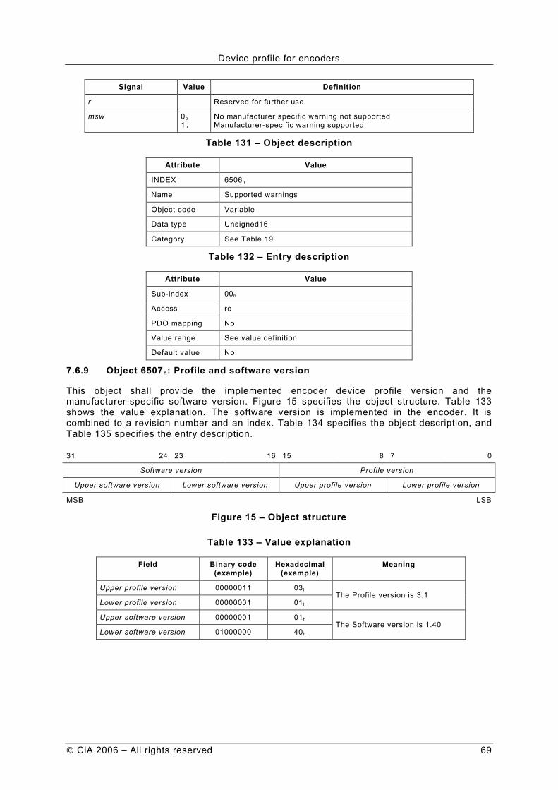
Device profile for encoders
CiA 2006 – All rights reserved 69
Signal Value Definition
r Reserved for further use
msw 0b
1b No manufacturer specific warning not supported
Manufacturer-specific warning supported
Table 131 – Object description
Attribute Value
INDEX 6506h
Name Supported warnings
Object code Variable
Data type Unsigned16
Category See Table 19
Table 132 – Entry description
Attribute Value
Sub-index 00h
Access ro
PDO mapping No
Value range See value definition
Default value No
7.6.9 Object 6507h: Profile and software version
This object shall provide the implemented encoder device profile version and the manufacturer-specific software version. Figure 15 specifies the object structure. Table 133 shows the value explanation. The software version is implemented in the encoder. It is combined to a revision number and an index. Table 134 specifies the object description, and Table 135 specifies the entry description.
31 24 23 16 15 8 7 0
Software version Profile version
Upper software version Lower software version Upper profile version Lower profile version
MSB LSB
Figure 15 – Object structure
Table 133 – Value explanation
Field Binary code (example)
Hexadecimal (example)
Meaning
Upper profile version 00000011 03h
Lower profile version 00000001 01h The Profile version is 3.1
Upper software version 00000001 01h
Lower software version 01000000 40h The Software version is 1.40

Device profile for encoders
70 CiA 2006 – All rights reserved
Table 134 – Object description
Attribute Value
INDEX 6507h
Name Profile and software version
Object code Variable
Data type Unsigned32
Category See Table 19
Table 135 – Entry description
Attribute Value
Sub-index 00h
Access ro
PDO mapping No
Value range Unsigned32
Default value No
7.6.10 Object 6508h: Operating time
This object shall provide the operating time. The operating time monitor stores the operating time for the encoder in operating hours. The operating time is stored in the encoder non-volatile memory as long as the encoder is power supplied. The value shall be given in multiples of 0.1 hours per bit.
If the operating time function is not used the operating time value shall be set to FFFF FFFFh by the encoder manufacturer.
Table 136 specifies the object description, and Table 137 specifies the entry description.
Table 136 – Object description
Attribute Value
INDEX 6508h
Name Operating time
Object code Variable
Data type Unsigned32
Category See Table 19
Table 137 – Entry description
Attribute Value
Sub-index 00h
Access ro
PDO mapping No
Value range Unsigned32
Default value No
7.6.11 Object 6509h: Offset value
This object shall provide the offset value. The offset value is calculated by the preset function and shifts the position value with the calculated value. The offset value is stored and may be read from the encoder.
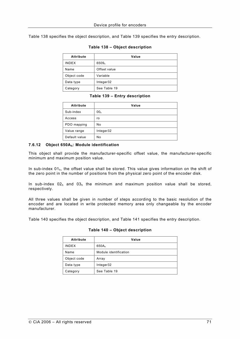
Device profile for encoders
CiA 2006 – All rights reserved 71
Table 138 specifies the object description, and Table 139 specifies the entry description.
Table 138 – Object description
Attribute Value
INDEX 6509h
Name Offset value
Object code Variable
Data type Integer32
Category See Table 19
Table 139 – Entry description
Attribute Value
Sub-index 00h
Access ro
PDO mapping No
Value range Integer32
Default value No
7.6.12 Object 650Ah: Module identification
This object shall provide the manufacturer-specific offset value, the manufacturer-specific minimum and maximum position value.
In sub-index 01h, the offset value shall be stored. This value gives information on the shift of the zero point in the number of positions from the physical zero point of the encoder disk.
In sub-index 02h and 03h the minimum and maximum position value shall be stored, respectively.
All three values shall be given in number of steps according to the basic resolution of the encoder and are located in write protected memory area only changeable by the encoder manufacturer.
Table 140 specifies the object description, and Table 141 specifies the entry description.
Table 140 – Object description
Attribute Value
INDEX 650Ah
Name Module identification
Object code Array
Data type Integer32
Category See Table 19

Device profile for encoders
72 CiA 2006 – All rights reserved
Table 141 – Entry description
Attribute Value
Sub-index 00h
Description Highest sub-index supported
Entry category Mandatory
Access ro
PDO mapping No
Value range 01h to 03h
Default value No
Sub-index 01h
Description Manufacturer offset value
Entry category Mandatory
Access ro
PDO mapping No
Value range Integer32
Default value 0h
Sub-index 02h
Description Manufacturer min position value
Entry category Optional
Access ro
PDO mapping No
Value range Integer32
Default value No
Sub-index 03h
Description Manufacturer max position value
Entry category Optional
Access ro
PDO mapping No
Value range Integer32
Default value No
7.6.13 Object 650Bh: Serial number
This object shall provide the encoder serial number. This object shall be hard-wired to object 1018h sub-index 04h. If the parameter serial number is not used the value shall be set to maximum value FFFF FFFFh by the encoder manufacturer and object 1018h sub-index 04h shall not be implemented.
Table 142 specifies the object description, and Table 143 specifies the entry description.

Device profile for encoders
CiA 2006 – All rights reserved 73
Table 142 – Object description
Attribute Value
INDEX 650Bh
Name Serial number
Object code Variable
Data type Unsigned32
Category See Table 19
Table 143 – Entry description
Attribute Value
Sub-index 00h
Access ro
PDO mapping No
Value range Unsigned32
Default value No
7.6.14 Object 650Ch: Offset values for multi-sensor devices
This object shall provide the offset values for multi-sensor devices and is similar to object 6509h. The offset value shall be calculated by the preset function in object 6010h and shifts the position value with calculated value. The offset value is stored and can be read from the encoder for diagnostics. This object is only optional for multi-sensor encoders (encoder type code 10d in object 1000h).
Table 144 specifies the object description, and Table 145 specifies the entry description.
Table 144 – Object description
Attribute Value
INDEX 650Ch
Name Offset value for multi-sensor device
Object code Array
Data type Integer32
Category See Table 19
Table 145 – Entry description
Attribute Value
Sub-index 00h
Description Highest sub-index supported
Entry category Mandatory
Access ro
PDO mapping No
Value range 01h to FEh
Default value No
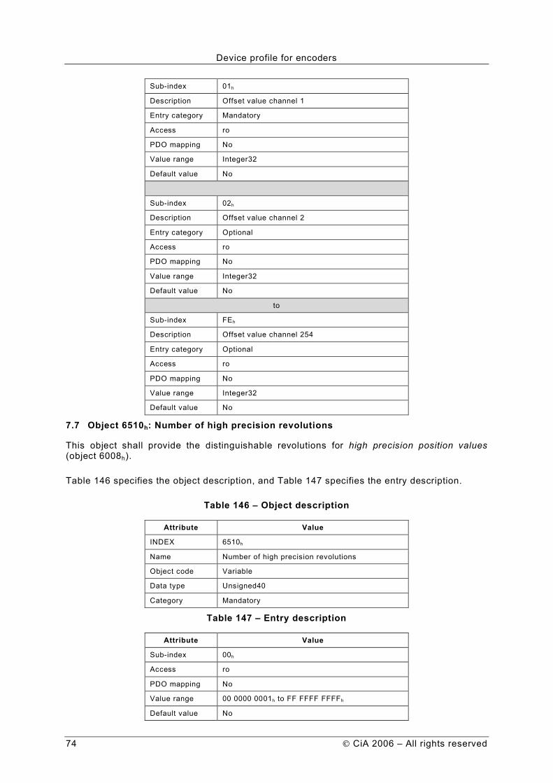
Device profile for encoders
74 CiA 2006 – All rights reserved
Sub-index 01h
Description Offset value channel 1
Entry category Mandatory
Access ro
PDO mapping No
Value range Integer32
Default value No
Sub-index 02h
Description Offset value channel 2
Entry category Optional
Access ro
PDO mapping No
Value range Integer32
Default value No
to
Sub-index FEh
Description Offset value channel 254
Entry category Optional
Access ro
PDO mapping No
Value range Integer32
Default value No
7.7 Object 6510h: Number of high precision revolutions
This object shall provide the distinguishable revolutions for high precision position values (object 6008h).
Table 146 specifies the object description, and Table 147 specifies the entry description.
Table 146 – Object description
Attribute Value
INDEX 6510h
Name Number of high precision revolutions
Object code Variable
Data type Unsigned40
Category Mandatory
Table 147 – Entry description
Attribute Value
Sub-index 00h
Access ro
PDO mapping No
Value range 00 0000 0001h to FF FFFF FFFFh
Default value No
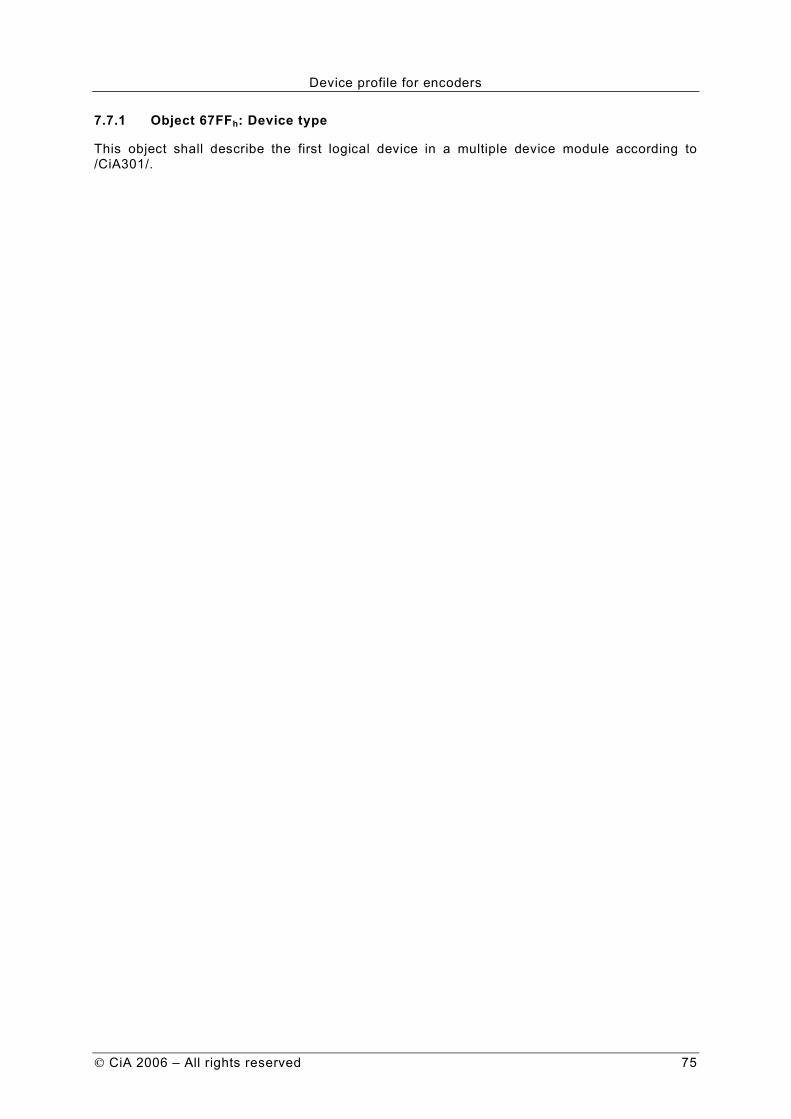
Device profile for encoders
CiA 2006 – All rights reserved 75
7.7.1 Object 67FFh: Device type
This object shall describe the first logical device in a multiple device module according to /CiA301/.


