OPERATOR MANUAL
Portable Blender
CDM #4089
Built for:
Bristol-Myers Squibb
REV. 0 (12/08/04)
197 STONE CASTLE ROAD * ROCK TAVERN, NY 12575 * (845) 778-9001 * FAX (845) 778-9086

INTRODUCTIONThis manual provides operation, service and maintenance information
regarding the Creative Design & Machine, Inc. portable blender. Theinstructions, diagrams, and suggestions included should be kept readilyavailable for reference.
The machinery referred to in this manual is protected by United Statespatents or patents pending. The specifications and illustrations shown includeonly essential details. Additional information may be obtained from CreativeDesign & Machine, Inc. upon request.
This equipment should be operated by qualified personnel only. If anyproblems develop in the operation, installation or servicing of this machinery,please contact the Field Service Department at:
Creative Design & Machine, Inc.197 Stone Castle Rd.
Rock Tavern, NY 12575(845) 778-9001 / FAX (845) 778-9086

(845) 778-9001 • fax: (845) 778-9086
PORTABLE BLENDER(CDM #4089)
Table of Contents 1. General Operational Information:
• Safety• Warranty Information• How to Return Parts• Specifications• Sequence of Operation• Maintenance• Parts List
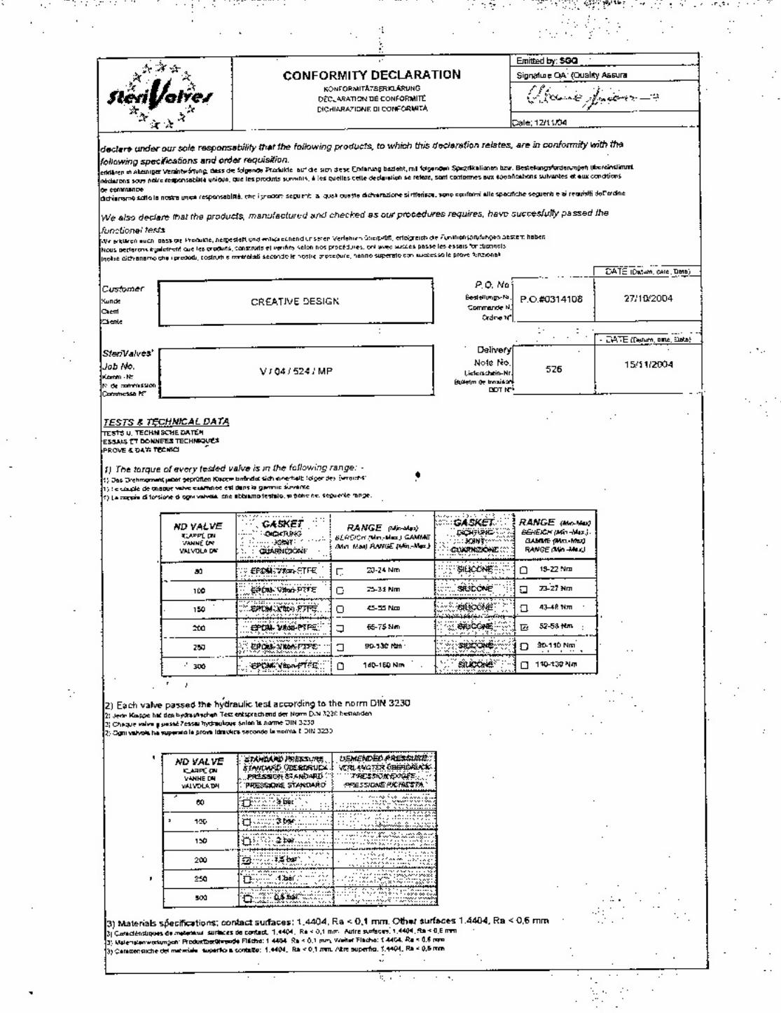
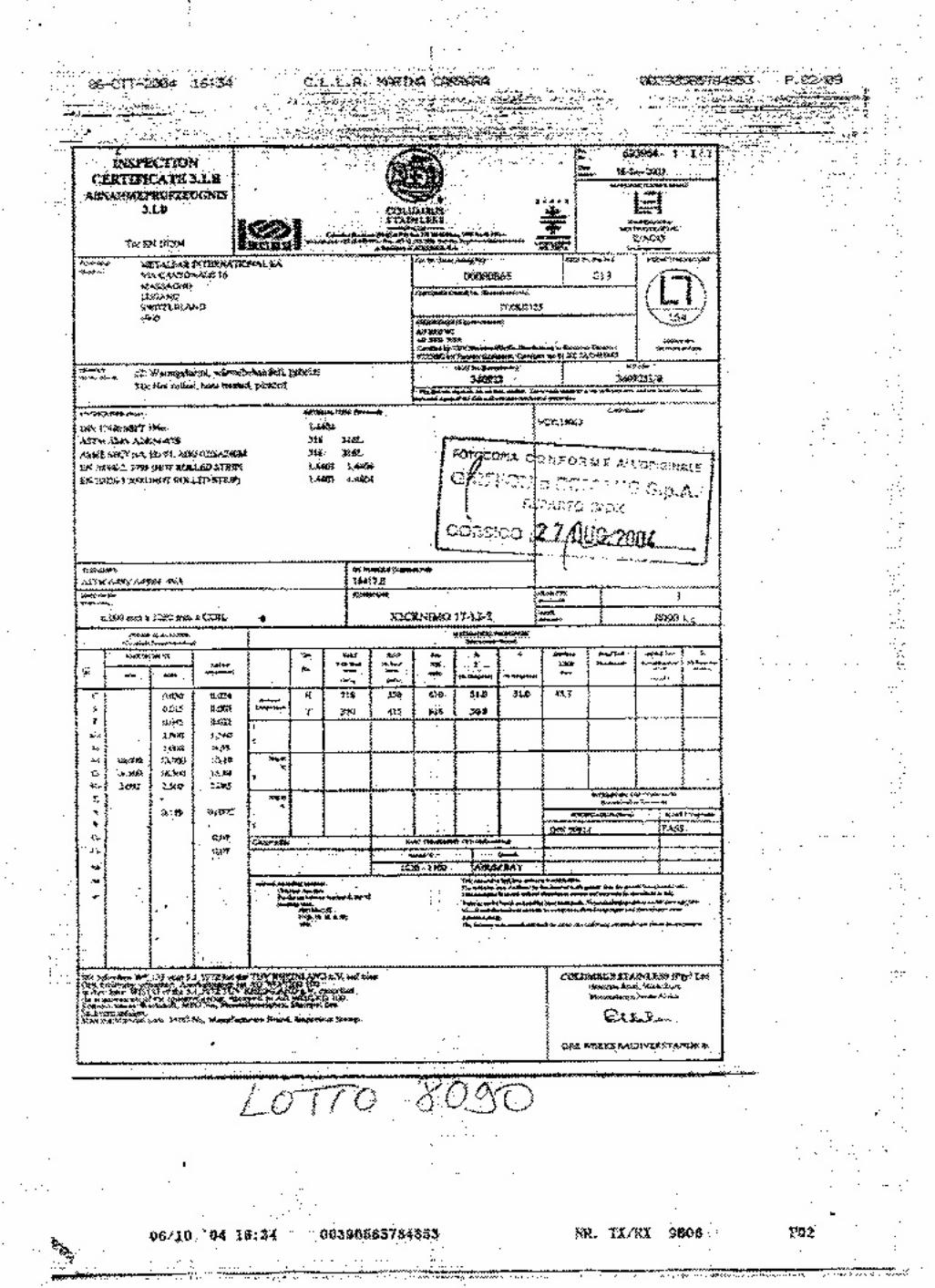
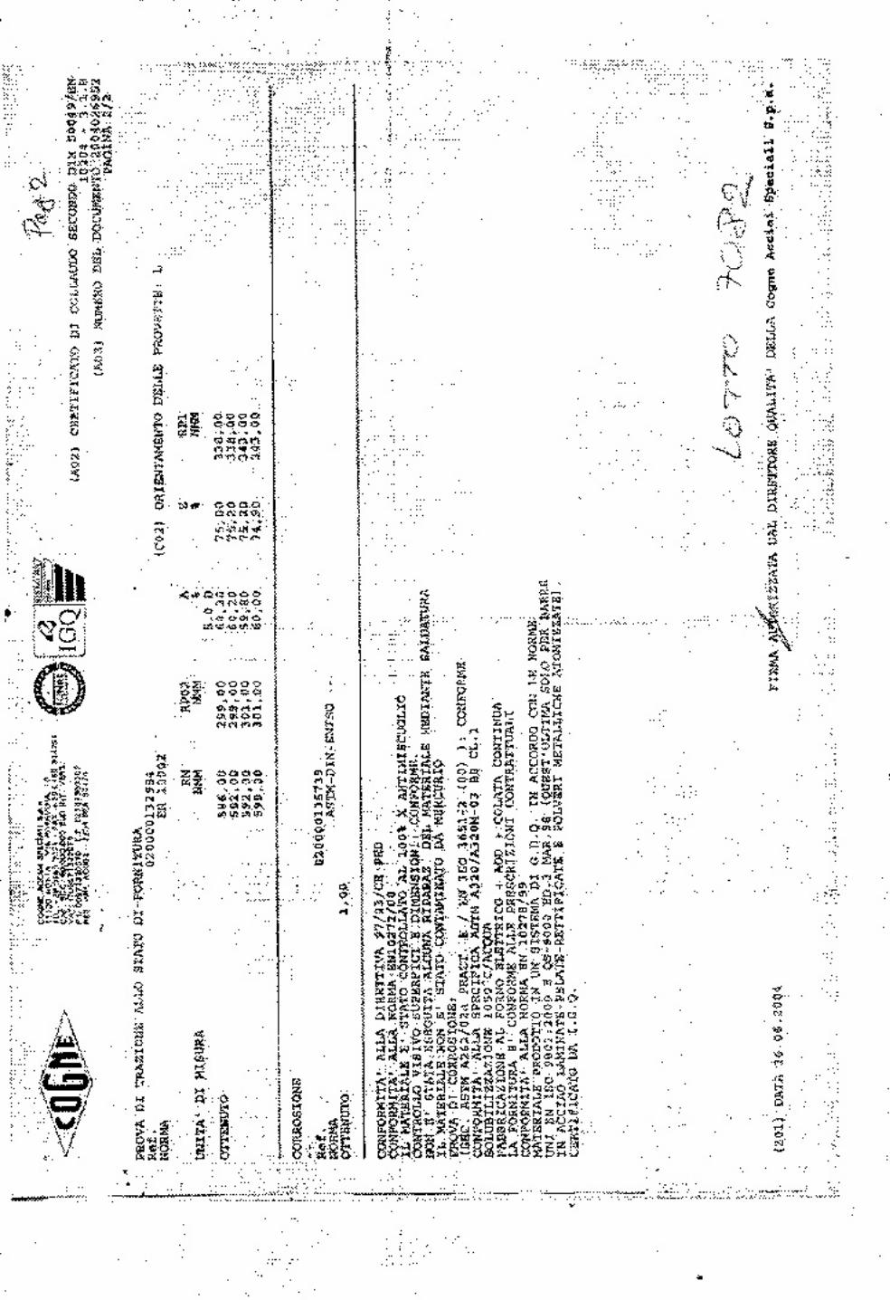
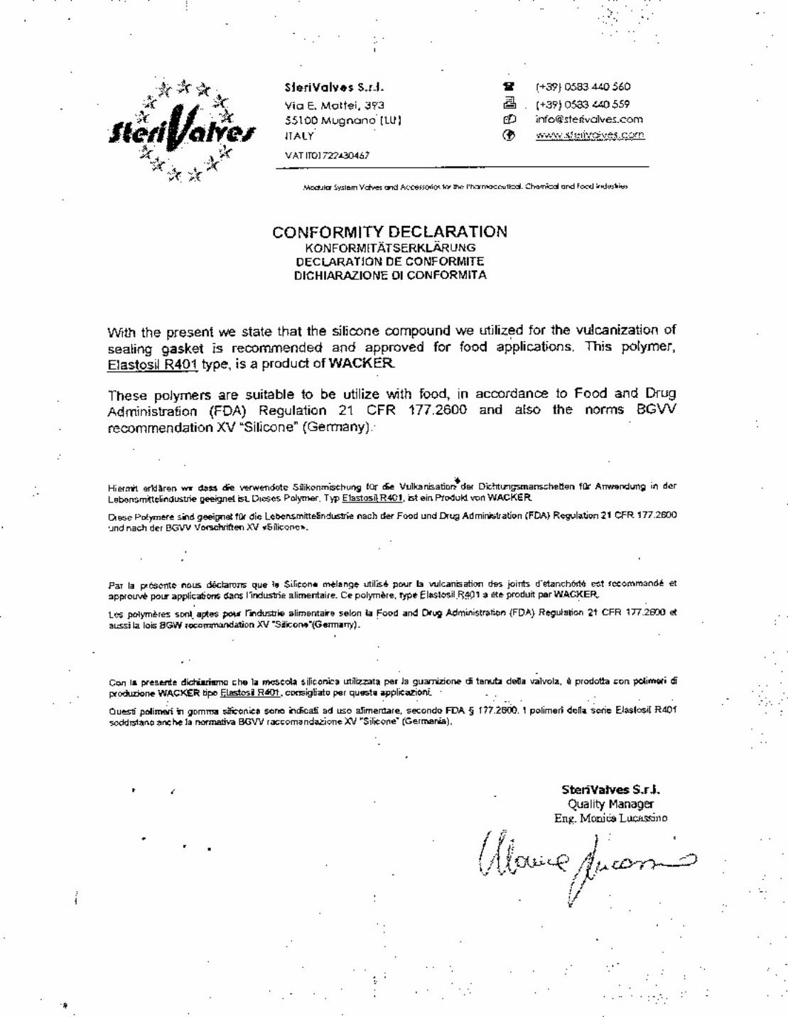
2. Mechanical Drawings 3. Motor Data Sheet 4. Electrical Schematics 5. PLC Program 6. Component Cut Sheet(s) 7. Material Certification Sheet(s)
NOTE: This manual should be read and understood completely before any action is taken toinstall or operate this machine.

SAFETYOPERATION:
1. No individuals should be permitted to operate this machine until they havecompletely read and understood these instructions.
2. Maintain an uncluttered and clean work area. 3. Proper and regular maintenance must be performed to ensure the safe
operation of this equipment. See the Maintenance section for furtherinformation.
4. Remain alert and aware at all times. Follow all procedures in their correct
sequence. 5. Never allow this unit to run if there is any possibility that personnel or
equipment are within its path of motion. 6. Do not operate or continue to operate this equipment if any unusual noise
or vibration is observed.
SERVICE & MAINTENANCE:
1. Always wear safety glasses when working on this machine. 2. Avoid possible accidents. Do not use power tools in wet or damp areas,
and always keep work areas brightly lit. 3. For personal safety, always wear appropriate attire and be familiar with all
the tools used for servicing functions. 4. Always stay alert to conditions and procedures during operation, service
and maintenance of this machine. 5. Always disconnect and lock out the main electrical power before
attempting to service this unit or its controls.

WARRANTYSeller warrants all equipment manufactured or repairs/modifications
performed by seller to be free from defects in material and workmanship undernormal use and service for a period of twelve (12) months from the date ofdelivery to Purchaser or completion of repairs or modifications.
All parts or products that are not manufactured by the Seller will becovered only by the express warranty of the manufacturer(s) thereof. The“within warranty” does not extend to damage or wear caused by misuse, abuse,negligence, accident, corrosion, modification by Purchaser, faulty installation(unless installed by Seller), loss of product, or tampering in such a manner as toimpair the normal operation of the equipment.
Seller guarantees to replace, or at its option repair, any equipment orcomponents which are found to be defective in substance or workmanshipwithin one year of date of delivery to Purchaser or completion of repairs ormodifications. Seller’s obligation with respect to such equipment, parts ormaterials shall be limited to replacement or repair and installation labor, and inno case shall Seller be liable for consequential collateral or special damages, orfor freight costs, transportation, travel/living or other expenses which may arisein connection with such equipment, parts or labor.
Expendable items or normally wearing parts such as bearings, seals,gaskets, hoses, etc. are specifically excluded from this warranty.
Creative Design & Machine, Inc. should be notified if changes are madeto VFD and PLC or if passwords are installed, if applicable.
The foregoing warranty is expressly made in lieu of all otherwarranties, expressed or implied, including the warranties ofmerchantability and fitness for any particular purpose. No waiver,modification or alteration of the foregoing shall be valid unless made inwriting and signed by an executive officer of the seller corporation.
Except as herein provided, any liability for direct or consequentialdamages or loss, including, without limitation, lost profits, is expresslyexcluded and denied.

WARRANTY (continued)ADDITIONAL ITEMS NOT COVERED UNDER WARRANTY:
• Items sold by a non-authorized Creative Design & Machine, Inc.distributor.
• Normal maintenance services.
• Shipping damage: Any damage that is caused during transportation ofmachinery should be reported to the freight carrier immediately.
• Personnel: Creative Design & Machine, Inc. will not acceptresponsibility for any damage occurring due to unqualified personneloperating this machinery.
WARNING: THIS MACHINE IS NOT DESIGNED TO LIFT OR CARRYPERSONNEL. CREATIVE DESIGN & MACHINE WILL NOT BERESPONSIBLE FOR ANY INJURY RESULTING FROMPERSONNEL RIDING ON THIS MACHINE.

HOW TO RETURN PARTSParts covered by warranty may be returned to the factory for a period of one (1)year from date of original shipment. Before returning any part or assembly, it isnecessary that the purchaser make contact with the factory for returnauthorization and shipping information. Please contact the Creative Design &Machine, Inc. Field Service department at: (845) 778-9001 or fax (845) 778-9086.
When calling to return parts, please have the following information ready:
• Serial Number
• Date and number of the invoice pertaining to the item. • Quantity you wish to return • Part number and/or name (if applicable) • Exact nature of the defect or malfunction. The Creative Design &
Machine, Inc. Field Service team may be able to direct the purchaser tocorrect any problems.
Do not ship parts without prior authorization. After authorization is received,please ship as directed. Creative Design & Machine, Inc. will bear no liabilityfor any parts shipped without prior authorization.

SPECIFICATIONSMotion:
• Blend speed: Variable up to 3 - 30 rpm max. Electric:
• 208 VAC, 60 Hz, 3 phase, 20 amp service
Lift Capacity (Product and Bin): 400 lbs./ 180 kgs. max.
Operators required: 1
Control: PLC: Allen Bradley Micrologix 1000

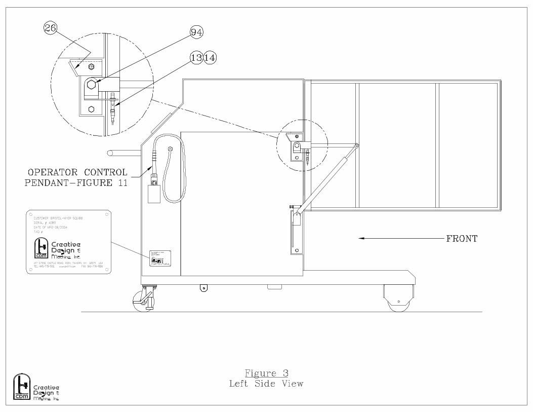
SEQUENCE OF OPERATIONThe Creative Design & Machine, Inc. Portable Blender is designed to lift
a product vessel from a cart and raise the vessel to a specific height. It will thenrotate at a selected speed for a predetermined amount of time.
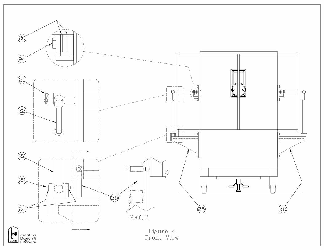
Note: Unless Specified Item numbers refer to Figure 4.
Load & Blend 1. Confirm that the blender is in the “LOAD/UNLOAD” position and the
blender drive shaft is in the preset position. 2. Manually lift safety gate up and over blender unit to clear area for
positioning of product vessel cart. 3. Position the product vessel and cart. Make sure the two indexing pins on
the blender drive shaft are properly located to engage the product vesselmating holes.
4. Secure the product vessel in place with a 6” sanitary clamp. 5. Press and hold the green “UP” pushbutton located on the operator
control panel. After a 1.5 second delay, the blender will raise and stop. 6. Remove the cart to clear the area before blending. 7. Manually lower the safety gate. 8. Select the “BLENDER COUNT” located on the operator control panel.
Refer to timer owner manual for procedure. 9. Start the blend cycle by pressing the green “BLENDER START”
pushbutton located on the operator control panel. 10. Select the “BLENDER RPM” by turning the “BLENDER SPEED”
control knob located on the operator control panel. Read RPM on thedigital display.
11. The blender will run at the set RPM for the set time and stop after theproduct vessel has rotated to its original upright position.

SEQUENCE OF OPERATION-cont.Unload
1. Confirm that the blender has stopped and is in the unload position. 2. Manually lift safety gate up and over blender unit to clear area for
positioning of product vessel cart. 3. Return the cart to a position under the product vessel. 4. Press and hold the yellow “DOWN” pushbutton located on the operator
control panel. After a 2 second delay, the blender will lower the vesseland stop when it is in the “LOAD/UNLOAD” position.
5. When the lift stops remove the 6” sanitary clamp and remove the vessel.
Note: Pressing the red “BLENDER STOP” pushbutton located on the operatorcontrol panel can stop the blender cycle at any point, returning the productvessel to its original upright position. Pressing the “EMERGENCY STOP” willimmediately stop all movement of the blender and lift functions.

MAINTENANCE
The machine incorporates an electric gearmotor with safety brake, radialbearing, electric lift & mechanical limit switches. These items must be inspectedand serviced on a regular basis.
Note: Numbers appearing in ( ) correspond to item numbers in the parts listand figures 1 through 11.
Quarterly:
• Inspect and tighten hardware as needed.• Wipe clean and lightly grease the inner-guide track surfaces (7).• Inspect and replace if necessary, the slotcover wiper seal (10).
Yearly:
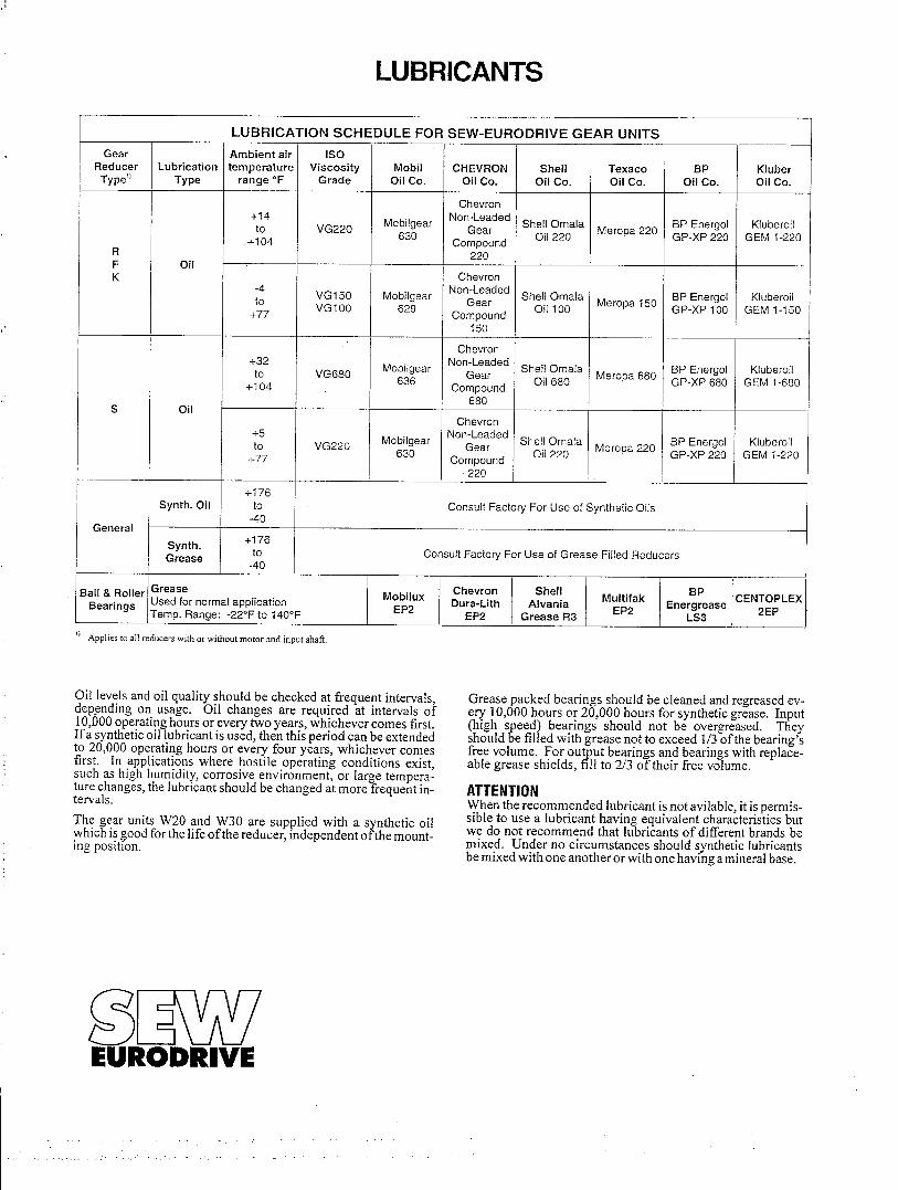
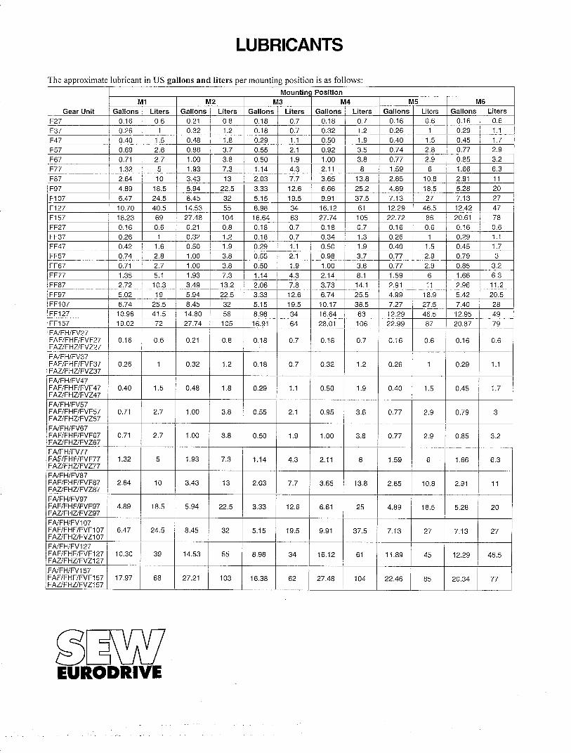
• Inspect oil in the blend drive gearmotor (4). Replenish or change oil ifnecessary. Refer to Component Cut Sheets.
• Add grease to radial bearing (9).
Note:
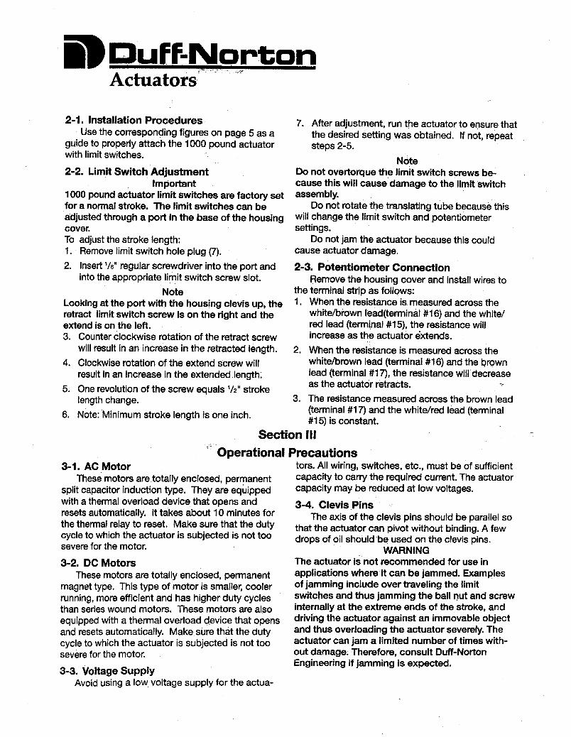
• Refer to “Duff-Norton” actuator component cut sheet.

PARTS LIST (page one)Figures 1 through 11
Item # Description Qty. CDM Part #1 Floor Lock Brake 1 0021-80372 Swivel Caster 2 0161-80053 208 VAC Junction Box 1 0018-80334 Blend Drive Gearmotor 1 0013-80325 Sensor Mounting Bracket 1 4089-24086 Castle Nut ( 1-1/2” - 12 ) 1 N/A7 Camfollower Guide Tracks 2 N/A8 Camfollower 4 0010-80049 Radial Bearing 1 0004-8032
10 Slotcover Wiper Seal 40” 0028-825911 Blender Drive Shaft 1 4089-340612 Sensor Flag-Blender 2 4089-241213 Non-Flush Mount Sensor 3 0020-801014 Sensor Cable 3 0020-801315 Shaft Oil Seal 1 0089-800216 Lift Carriage 1 N/A17 Cam Roller 4 0028-829518 Actuator 1 0122-800319 Rigid Caster 2 0161-800620 Delrin Spacers 4 4089-241321 Gas Spring Hair Pin Clip 2 0028-834522 Gas Spring 2 0028-834423 Gas Spring Lower Mounting Pin 2 4089-242224 External Retaining Ring 4 0028-834325 Safety Guard Mount & Adjustable Stop 2 4089-341026 Tilting Guard Stop 2 4089-341127 LABEL: “DANGER PINCH POINT” 4 0000-000228 LABEL: “CAUTION OPERATION BY. . “ 2 0000-002829 LABEL: “CAUTION EXCEEDING RATE. . ” 2 0000-002130 LABEL: “CAUTION LOAD CAP . . .” 2 0000-005231 LABEL: “DANGER MOVING MACH . . .” 2 0000-000332 250 VAC Twistlock Receptacle (Male) 1 0028-821133 250 VAC Twistlock Recept Plug (Female) 1 0028-821234 LABEL: Electrical Grounding Plug 1 N/A

PARTS LIST (page two)Figures 1 through 11
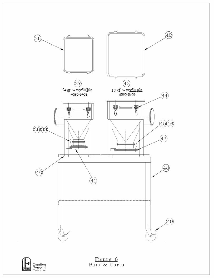
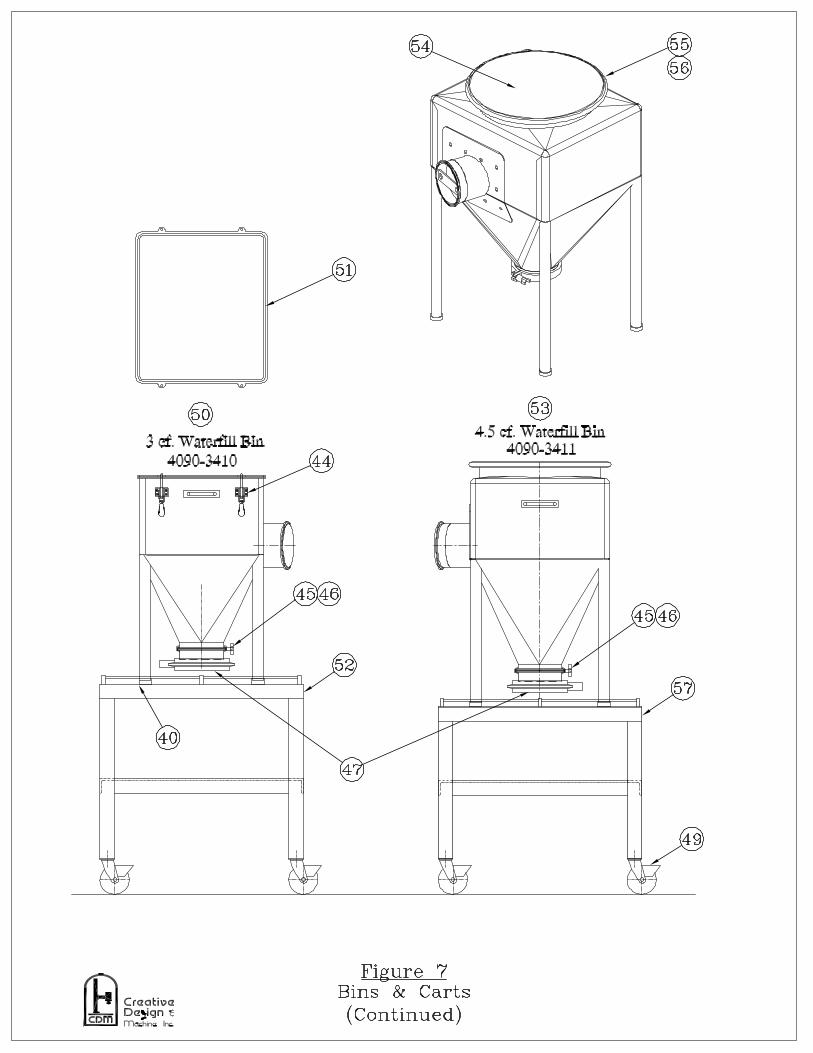
Item # Description Qty. CDM Part #35 LABEL: Gas Spring Under Pressure…….. 1 N/A36 24 Qt. Lid Gasket 1 4090-240337 24 Qt. Waterfill Bin 1 4090-340838 4” S.S. Sanitary Clamp 1 0110-800939 4” Sanitary Clamp Gasket 1 0110-801540 Foot Pad (Typical) 16 4090-240241 4” Steri Valve Assembly 1 4090-340342 1.5 c.f. Lid Gasket 1 4090-240443 1.5 c.f. Waterfill Bin 1 4090-340944 Over Center Lid Clamp (Typical) 12 0029-802245 6” S.S. Sanitary Clamp 3 0110-800446 6” Sanitary Clamp Gasket 3 0110-801847 6” Steri Valve Assembly 3 4090-340448 Dual Bin Cart (24 qt. & 1.5 c.f.) 1 4090-340749 Full Lock Swivel Caster (Typical) 12 0161-801050 3 c.f. Waterfill Bin 1 4090-341051 3 c.f. Lid Gasket 1 4090-240552 3 c.f. Bin Cart 1 4090-340553 4.5 c.f. Waterfill Bin 1 4090-341154 4.5 c.f. Bin Lid 1 4090-240655 4.5 c.f. Band Clamp 1 4090-240856 4.5 c.f. Lid Gasket 1 4090-240757 4.5 c.f. Bin Cart 1 4090-340658 Blank 1 N/A59 Indicator Light - (Red) 1 0099-801260 Push Button – (Green) 2 0100-800561 Digital Preset Counter 1 0088-800762 Smart Counter / Rate Meter 1 0088-800863 EMERGENCY STOP-Push Button 1 0100-800864 2.5K Potentiometer 1 0135-800265 Push Button – (Black) 1 0100-800466 Push Button – (Red) 1 0100-801067 Push Button – (Yellow) 1 0100-8006

PARTS LIST (page three)Figures 1 through 11
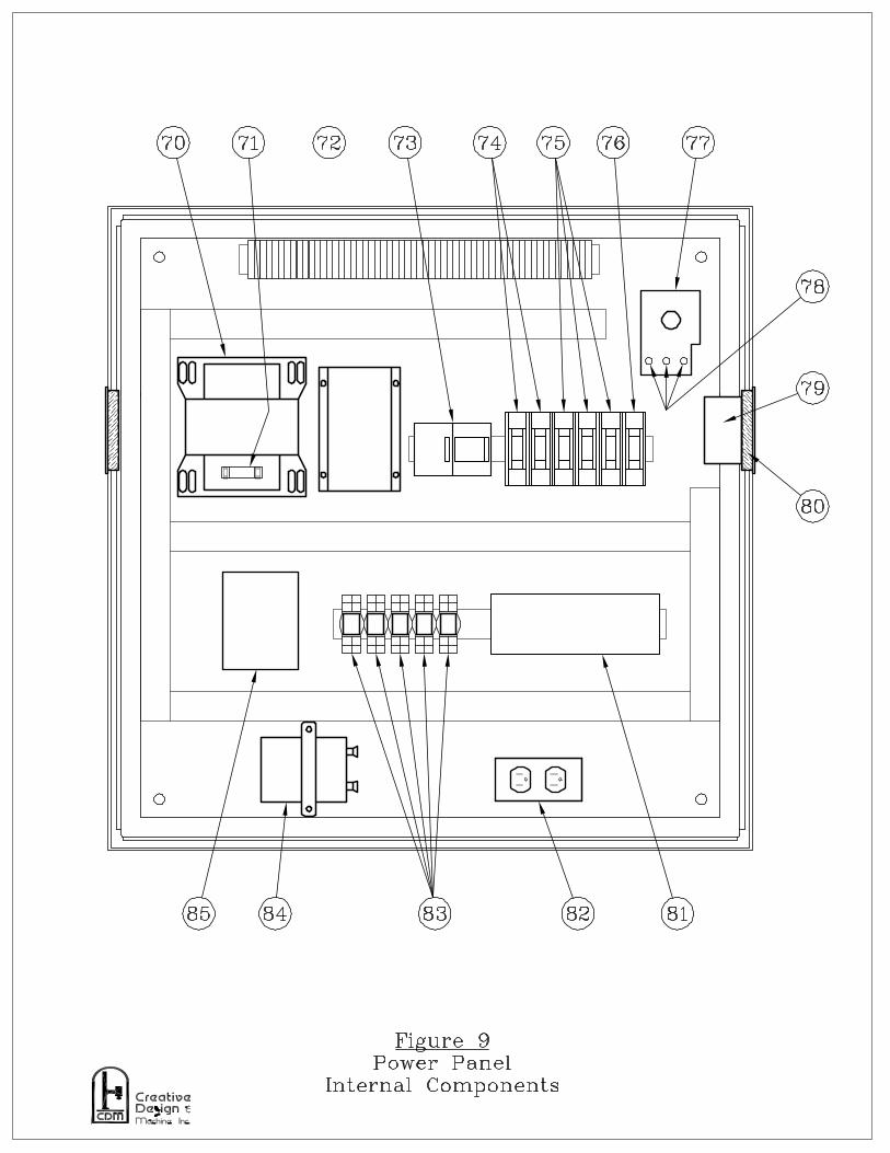
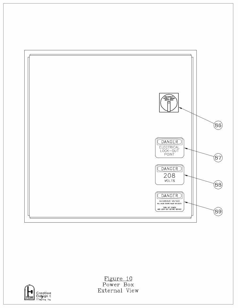
Item # Description Qty. CDM Part #68 Indicator Light - (Green) 1 0099-801169 Off / On Key Switch 1 0100-801570 Transformer 750 VA 1 0093-801871 Fuse (8 AMP) Transformer Line 1 0099-802972 2 HP Frequency Drive 1 0105-800973 E-Stop Contactor 1 0101-801474 Fuse (3 AMP) Type CCMR 2 0099-804075 Fuse (5 AMP) Type CCMR 3 0099-806076 Fuse (2 AMP) Type CCMR 1 0099-802577 Fused Disconnect Switch 1 0099-800278 Fuse (15 AMP) Main 3 0099-002879 Cooling Fan 1 0016-818580 Fan Filter & Guard 2 0016-818481 Micrologix 1000 1 0005-807382 Duplex Receptacle 1 0016-812383 2 Pole, 24 VDC Relay 5 0100-805784 Capacitor 1 0016-813285 24VDC Power Supply 1 0152-800586 Disconnect Handle 1 0099-800387 LABEL: “DANGER ELECT. LOCK-OUT…” 1 0000-002988 LABEL: “DANGER 208 VOLTS” 1 0000-003389 LABEL: “DANGER HAZARDOUS VOLT…” 1 0000-002490 Emergency Stop Palm Button 1 0016-818991 Push Button (Black) 2 0016-809492 Blank 1 N/A93 4-Hole Hand Held Pendant 1 0016-800794 Gate Pivot Bolt ¾-10 SS Modified 2 4089-3409


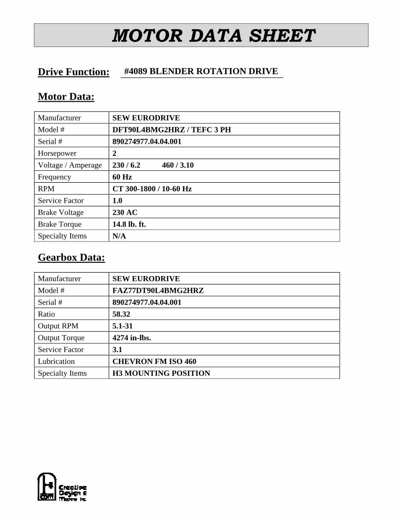
MOTOR DATA SHEET
Drive Function: #4089 BLENDER ROTATION DRIVE
Motor Data:
Manufacturer SEW EURODRIVEModel # DFT90L4BMG2HRZ / TEFC 3 PHSerial # 890274977.04.04.001Horsepower 2Voltage / Amperage 230 / 6.2 460 / 3.10Frequency 60 HzRPM CT 300-1800 / 10-60 HzService Factor 1.0Brake Voltage 230 ACBrake Torque 14.8 lb. ft.Specialty Items N/A
Gearbox Data:
Manufacturer SEW EURODRIVEModel # FAZ77DT90L4BMG2HRZSerial # 890274977.04.04.001Ratio 58.32Output RPM 5.1-31Output Torque 4274 in-lbs.Service Factor 3.1Lubrication CHEVRON FM ISO 460Specialty Items H3 MOUNTING POSITION


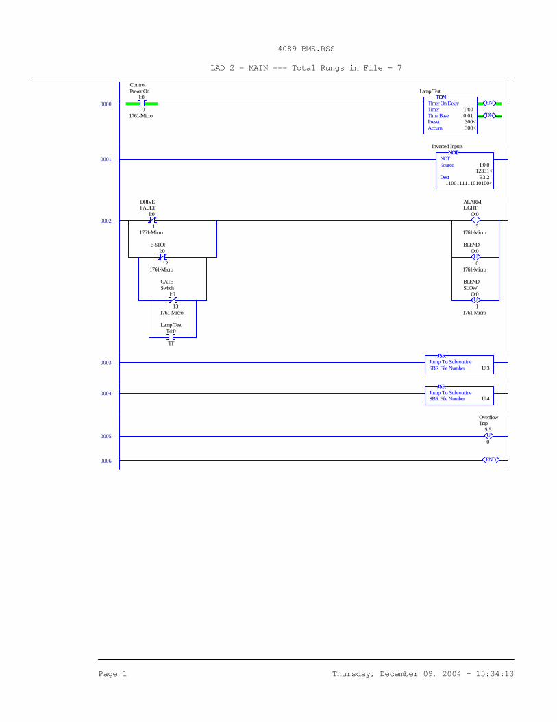
4089 BMS.RSS
LAD 2 - MAIN --- Total Rungs in File = 7
Page 1 Thursday, December 09, 2004 - 15:34:13
0000I:0
0 1761-Micro
ControlPower On
EN
DN
TONTimer On DelayTimer T4:0Time Base 0.01Preset 300<Accum 300<
TONLamp Test
0001NOT
NOTSource I:0.0 12331<Dest B3:2 1100111111010100<
NOTInverted Inputs
0002I:0
1 1761-Micro
DRIVEFAULT
I:0
12 1761-Micro
E-STOP
I:0
13 1761-Micro
GATESwitch
T4:0
TT
Lamp Test
O:0
5 1761-Micro
ALARMLIGHT
UO:0
0 1761-Micro
BLEND
UO:0
1 1761-Micro
BLENDSLOW
0003JSR
Jump To SubroutineSBR File Number U:3
JSR
0004JSR
Jump To SubroutineSBR File Number U:4
JSR
0005 US:5
0
OverflowTrap
0006 END
4089 BMS.RSS
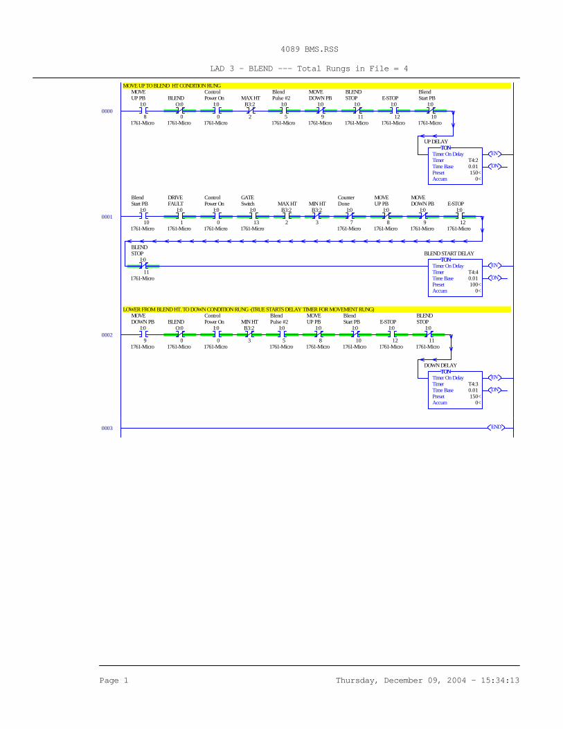
LAD 3 - BLEND --- Total Rungs in File = 4
Page 1 Thursday, December 09, 2004 - 15:34:13
MOVE UP TO BLEND HT CONDITION RUNG
0000I:0
8 1761-Micro
MOVEUP PB
O:0
0 1761-Micro
BLENDI:0
0 1761-Micro
ControlPower On
B3:2
2
MAX HTI:0
5 1761-Micro
BlendPulse #2
I:0
9 1761-Micro
MOVEDOWN PB
I:0
11 1761-Micro
BLENDSTOP
I:0
12 1761-Micro
E-STOPI:0
10 1761-Micro
BlendStart PB
EN
DN
TONTimer On DelayTimer T4:2Time Base 0.01Preset 150<Accum 0<
TONUP DELAY
0001I:0
10 1761-Micro
BlendStart PB
I:0
1 1761-Micro
DRIVEFAULT
I:0
0 1761-Micro
ControlPower On
I:0
13 1761-Micro
GATESwitch
B3:2
2
MAX HTB3:2
3
MIN HTI:0
7 1761-Micro
CounterDone
I:0
8 1761-Micro
MOVEUP PB
I:0
9 1761-Micro
MOVEDOWN PB
I:0
12 1761-Micro
E-STOP
I:0
11 1761-Micro
BLENDSTOP
EN
DN
TONTimer On DelayTimer T4:4Time Base 0.01Preset 100<Accum 0<
TONBLEND START DELAY
LOWER FROM BLEND HT. TO DOWN CONDITION RUNG -(TRUE STARTS DELAY TIMER FOR MOVEMENT RUNG)
0002I:0
9 1761-Micro
MOVEDOWN PB
O:0
0 1761-Micro
BLENDI:0
0 1761-Micro
ControlPower On
B3:2
3
MIN HTI:0
5 1761-Micro
BlendPulse #2
I:0
8 1761-Micro
MOVEUP PB
I:0
10 1761-Micro
BlendStart PB
I:0
12 1761-Micro
E-STOPI:0
11 1761-Micro
BLENDSTOP
EN
DN
TONTimer On DelayTimer T4:3Time Base 0.01Preset 150<Accum 0<
TONDOWN DELAY
0003 END
4089 BMS.RSS
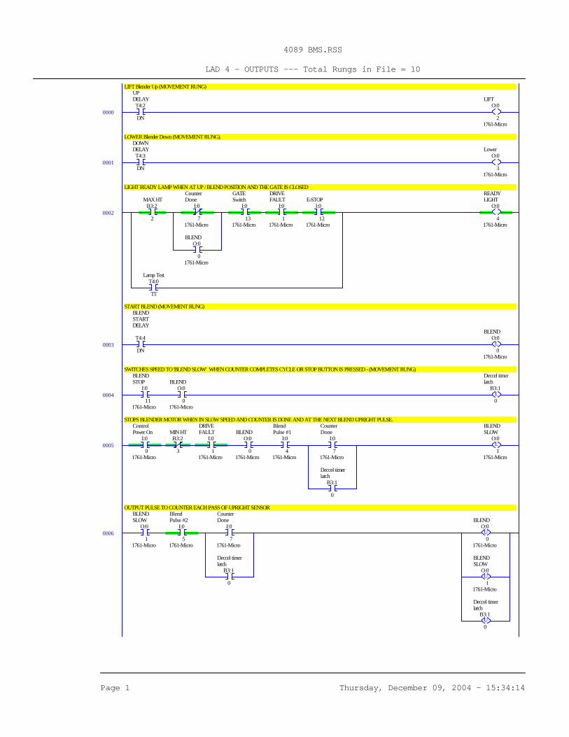
LAD 4 - OUTPUTS --- Total Rungs in File = 10
Page 1 Thursday, December 09, 2004 - 15:34:14
LIFT Blender Up (MOVEMENT RUNG)
0000T4:2
DN
UPDELAY
O:0
2 1761-Micro
LIFT
LOWER Blender Down (MOVEMENT RUNG).
0001T4:3
DN
DOWNDELAY
O:0
3 1761-Micro
Lower
LIGHT READY LAMP WHEN AT UP / BLEND POSITION AND THE GATE IS CLOSED
0002B3:2
2
MAX HTI:0
7 1761-Micro
CounterDone
O:0
0 1761-Micro
BLEND
I:0
13 1761-Micro
GATESwitch
I:0
1 1761-Micro
DRIVEFAULT
I:0
12 1761-Micro
E-STOP
T4:0
TT
Lamp Test
O:0
4 1761-Micro
READYLIGHT
START BLEND (MOVEMENT RUNG)
0003T4:4
DN
BLENDSTARTDELAY
LO:0
0 1761-Micro
BLEND
SWITCHES SPEED TO 'BLEND SLOW' WHEN COUNTER COMPLETES CYCLE OR STOP BUTTON IS PRESSED - (MOVEMENT RUNG)
0004I:0
11 1761-Micro
BLENDSTOP
O:0
0 1761-Micro
BLEND
LB3:1
0
Deccel timerlatch
STOPS BLENDER MOTOR WHEN IN SLOW SPEED AND COUNTER IS DONE AND AT THE NEXT BLEND UPRIGHT PULSE.
0005I:0
0 1761-Micro
ControlPower On
B3:2
3
MIN HTI:0
1 1761-Micro
DRIVEFAULT
O:0
0 1761-Micro
BLENDI:0
4 1761-Micro
BlendPulse #1
I:0
7 1761-Micro
CounterDone
B3:1
0
Deccel timerlatch
LO:0
1 1761-Micro
BLENDSLOW
OUTPUT PULSE TO COUNTER EACH PASS OF UPRIGHT SENSOR
0006O:0
1 1761-Micro
BLENDSLOW
I:0
5 1761-Micro
BlendPulse #2
I:0
7 1761-Micro
CounterDone
B3:1
0
Deccel timerlatch
UO:0
0 1761-Micro
BLEND
UO:0
1 1761-Micro
BLENDSLOW
UB3:1
0
Deccel timerlatch
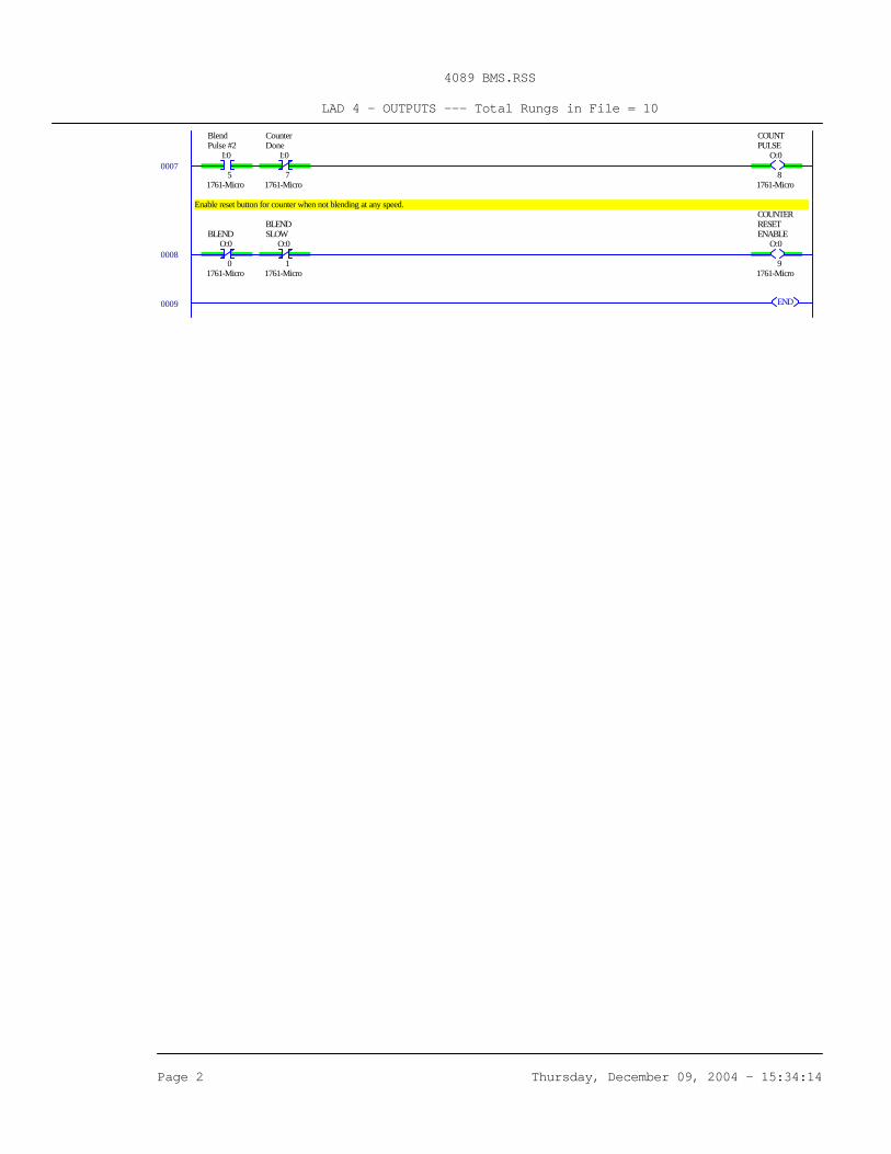
4089 BMS.RSS
LAD 4 - OUTPUTS --- Total Rungs in File = 10
Page 2 Thursday, December 09, 2004 - 15:34:14
0007I:0
5 1761-Micro
BlendPulse #2
I:0
7 1761-Micro
CounterDone
O:0
8 1761-Micro
COUNTPULSE
Enable reset button for counter when not blending at any speed.
0008O:0
0 1761-Micro
BLENDO:0
1 1761-Micro
BLENDSLOW
O:0
9 1761-Micro
COUNTERRESETENABLE
0009 END

1
! ABILITY TO LOCK OUT FRONT PANEL FUNCTIONS
! SEALED FRONT PANEL CONSTRUCTION (NEMA 4/IP65)
! ONE OR TWO PRESET VERSIONS
! 0.5" HIGH LIQUID CRYSTAL DISPLAY OR 0.4" HIGH LED DISPLAY
! ACCEPTS INPUT COUNT RATE UP TO 2500 CPS
! BI-DIRECTIONAL COUNTING
! SOLID-STATE CURRENT SINK OUTPUT(S)
! FORM C RELAY OUTPUT(S)
! PROGRAMMABLE TIMED OUTPUT (0.01 sec to 99.99 sec.)
! SIMPLE FRONT PANEL FOR PROGRAMMING EASE
! FRONT PANEL PROGRAMMABLE DECIMAL POINTS
! MEETS DIN PANEL MOUNT SPECIFICATIONS
! REMOTE RESET CAPABILITY
! NON-VOLATILE MEMORY (E2PROM)
! ON-LINE SELF-TEST
DESCRIPTIONThe Libra Series of presettable counters is an economical and reliable solution
to one or two preset level requirements. The LIBC1 and LIBC1E are the singlepreset versions and the LIBC2 and LIBC2E are the dual preset versions. All fourunits have a solid-state output and a Form C relay output for each preset. Theseunits feature input configuration programmability, a full complement of controlinputs, programmable timed outputs, non-volatile memory, and many otherfeatures which will satisfy most any single or dual preset level requirement.
The Libra counters have two main counting actions, Reset to Zero (RTZ) andReset to Preset (RTP). With RTZ, the counter resets to zero and counts up (ifUP/DN terminal is at high level) and activates the outputs when the presetvalue(s) are reached. When RTP is used, the unit starts at the preset value andcounts down (if the UP/DN terminal is at low level) and activates the outputwhen zero is reached. For the 2-preset version, the count starts at preset 2 andcounts toward zero. Output 1 fires when preset 1 value is reached and output 2fires when the count reaches zero. There are eight modes of operation for thesingle preset unit and sixteen modes of operation for the dual preset unit.
The timed output is programmed through the front panel buttons and can beprogrammed from 0.01 sec. to 99.99 sec. (The unit’s timed output is set at thefactory to be 0.1 sec.) The Libra counters have an internal non-volatile memory
device which eliminates the need for battery back-up. When input power isremoved, this device will maintain all data necessary for system operation. AProgram Disable terminal is available, which is used to prevent accidentalchanges or tampering by unauthorized personnel to the preset(s) or timed outputvalue(s). The front panel reset button can also be enabled or disabled by a rearpanel DIP switch. These counters also have an on-line self-test, which checksall display driver and micro-processor hardware. The self-test can be run at anytime without losing counts or missing a preset value.
Power, input, and output connections are made via removable terminal stripslocated at the rear of the unit. These strips can accept one #14 AWG strippedwire. DIP switches at the rear of the unit are used to program the inputconfiguration and to set the desired operating modes.
The Libra Series counters have a metal die-cast front bezel, which is sealed,and meets NEMA 4/IP65 specifications for wash-down and/or dust whenproperly installed. Mounting clips are provided for easy panel installation.
SAFETY SUMMARYAll safety related regulations, local codes and instructions that appear in the
manual or on equipment must be observed to ensure personal safety and toprevent damage to either the instrument or equipment connected to it. Ifequipment is used in a manner not specified by the manufacturer, the protectionprovided by the equipment may be impaired.
Do not use this unit to directly command motors, valves, or other actuatorsnot equipped with safeguards. To do so, can be potentially harmful to personsor equipment in the event of a fault to the unit.
MODEL LIBC - LIBRA SERIES COUNTERS (LCD & LED)
DIMENSIONS In inches (mm) Note: Recommended minimum clearance (behind the panel) formounting clip installation is 2.7" (69 mm)H X 4.5" (114 mm)W.
CAUTION: Read complete instructionsprior to installation
and operation of the unit.
CAUTION: Risk of electric shock.
Bulletin No. LIBC-I
Drawing No. LP0103
Released 10/03
Tel +1 (717) 767-6511
Fax +1 (717) 764-0839
www.redlion-controls.com
2
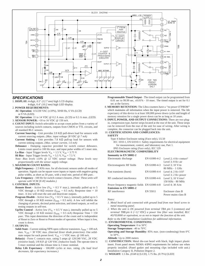
SPECIFICATIONS1. DISPLAY: 4-digit, 0.5" (12.7 mm) high LCD display.
4-digit, 0.4" (10.2 mm) high LED display.2. POWER REQUIREMENTS:
AC Operation: 115/230 VAC (±10%), 50/60 Hz, 6 VA (LCD)or 9 VA (LED).
DC Operation: 11 to 14 VDC @ 0.2 A max. (LCD) or 0.3 A max. (LED).3. SENSOR POWER: +10 to 16 VDC @ 150 mA.4. COUNT INPUT: Switch selectable to accept count pulses from a variety of
sources including switch contacts, outputs from CMOS or TTL circuits, andall standard RLC sensors.Current Sourcing - Unit provides 3.9 KΩ pull-down load for sensors with
current sourcing outputs. (Max. input voltage 28 VDC @ 7 mA)Current Sinking - Unit provides 7.8 KΩ pull-up load for sensors with
current sinking outputs. (Max. sensor current, 1.6 mA)Debounce - Damping capacitor provided for switch contact debounce.
Limits count speed to 100 Hz max. and input pulse widths of 5 msec min.Lo Bias - Input Trigger levels VIL = 1.5 V, VIH = 3.75 V.Hi Bias - Input Trigger levels VIL = 5.5 V, VIH = 7.5 V.Note: Bias levels ±10% @ 12 VDC sensor voltage. These levels vary
proportionally with the sensor supply voltage.5. MAXIMUM COUNT RATES:
High Frequency - 2.5 KHz max. for all electronic sensors under all modes ofoperation. Signals can be square wave inputs or inputs with negative goingpulse widths, as short as 50 µsec, with a total min. period of 400 µsec.
Low Frequency - 100 Hz for switch contact closures. (Note: These units willoperate with VCM [E-H] modules.)
6. CONTROL INPUTS:Remote Reset - Active low (VIL = 0.5 V max.), internally pulled up to 5
VDC through a 10 KΩ resistor (ISNK = 0.5 mA). Response time = 10msec. A low will reset the unit and deactivate outputs.
Program Disable - Active low (VIL = 0.5 V max.), internally pulled up to 5VDC through a 10 KΩ resistor (ISNK = 0.5 mA). A low will inhibit thechanging of presets, decimal point selection, and timed outputs, as well astesting outputs in self-test.
Up/Dn Control - Active low (VIL = 0.5 V max.), internally pulled up to 5VDC through a 10 KΩ resistor (ISNK = 0.5 mA) Response Time = 150µsec. This input determines the direction of the count and is independentof Reset to Zero or Reset to Preset modes of operation. When input is low,count is down.
7. OUTPUTS:Solid-State - Current sinking NPN open collector transistors. ISNK = 100 mA
max. VOH = 30 VDC max. (Internal Zener diode protection). One solid-state output for each preset level. VOL = 1 VDC max. @ 100 mA.
Relay(s) - Form C contacts max. rating 5 amps @ 120/240 VAC, 28 VDC(resistive load), 1/8 H.P. @ 120 VAC (inductive load). The operate time is5 msec nominal and the release time is 3 msec nominal.
Relay Life Expectancy - 100,000 cycles at max. rating. (As load leveldecreases, life expectancy increases.)
Programmable Timed Output - The timed output can be programmed from0.01 sec to 99.99 sec, ±0.01% - 10 msec. The timed output is set for 0.1sec at the factory.
8. MEMORY RETENTION: The Libra counters have a “no power E2PROM”which maintains all information when the input power is removed. The lifeexpectancy of this device is at least 100,000 power down cycles and length ofmemory retention for a single power down can be as long as 10 years.
9. INPUT, POWER, AND OUTPUT CONNECTIONS: There are two plug-in, compression type, barrier strips located at the rear of the unit. These stripscan be removed from the rear of the unit for ease of wiring. After wiring iscomplete, the connector can be plugged back into the unit.
10. CERTIFICATIONS AND COMPLIANCES:SAFETY
Type 4 Indoor Enclosure rating (Face only), UL50IEC 1010-1, EN 61010-1: Safety requirements for electrical equipment
for measurement, control, and laboratory use, Part 1.IP65 Enclosure rating (Face only), IEC 529
ELECTROMAGNETIC COMPATIBILITY
Notes:1. Metal bezel of unit connected with ground lead from rear bezel screw to
metal mounting panel.2. When the unit is DC powered from terminal TBA pin 5 (common) and
terminal TBB pin 6 (+12 VDC) a power line filter was installed, RLC#LFIL0000 or equivalent, so as not to impair the function of the unit.
Refer to the EMC Installation Guidelines for additional information.11. ENVIRONMENTAL CONDITIONS:
Operating Temperature: 0 to 50°CStorage Temperature: -40 to 70°COperating and Storage Humidity: 85% max. (non-condensing) from 0°C
to 50°C.Altitude: Up to 2000 meters
12. CONSTRUCTION: Metal die-cast bezel with black, high impact plasticinsert. Front panel meets NEMA 4/IP65 requirements for indoor use whenproperly installed. (Panel gasket and mounting clips included with unit.)Installation Category II, Pollution Degree 2.
13. WEIGHT: 1.5 lbs. (0.68 k) [LCD], 1.75 lbs. (0.79 k) [LED]
Power mains class BEnclosure class BEN 55011RF interference
Emissions to EN 50081-2
150 KHz - 80 MHzLevel 3; 10 V/rms2EN 61000-4-6RF conducted interferenceLevel 3; 2 Kv powerLevel 4; 2 Kv I/O2EN 61000-4-4Fast transients (burst)80 MHz - 1 GHzLevel 3; 10 V/mEN 61000-4-3Electromagnetic RF fieldsLevel 3; 8 Kv airLevel 2; 4 Kv contact1EN 61000-4-2Electrostatic discharge
Immunity to EN 50082-2
Level 4; 30 A/mEN 61000-4-8Power frequency magnetic fields

3
MODE 0 LATCH OUTPUT AT PRESET, MANUAL RESET TO ZEROIn this mode, as the unit counts from zero, the output will latch
on when the preset is reached. When a manual reset occurs, theunit will Reset to Zero and the output, if latched on, will unlatch.Counts will continue to accumulate after the output has turned on.MODE 1 TIMED OUTPUT AT PRESET, MANUAL RESET TO ZERO
In this mode, as the unit counts from zero, the output will turnon when the preset is reached. The output will turn off after itsprogrammed time value has occurred. When a manual resetoccurs, the unit will Reset to Zero. Manual reset will terminate the timedoutput, if the output is still activated. Counts will continue to accumulate afterthe preset level has been reached.MODE 2 & 3 -
MODE 4 TIMED OUTPUT AT PRESET, AUTOMATIC RESET TO ZERO AT PRESETIn this mode, as the unit counts from zero, the output will turn
on when the preset is reached. At the same time, the unit willautomatically Reset to Zero and start the cycle over again. Theoutput will turn off after its programmed time value has occurred. Manualreset will turn off the output, if turned on, and reset the count to zero.During automatic reset, no counts will be lost if the count rate does notexceed 2,500 cps.MODE 5 -
MODE 6 TIMED OUTPUT AT PRESET, AUTOMATIC RESET TO ZERO AFTER THETIMED OUTPUT
In this mode, as the unit counts from zero, the output will turnon when preset 1 is reached. The output will turn off after itsprogrammed time value has occurred. At the end of the timedoutput, the unit will automatically Reset to Zero and start the cycle over again.During automatic reset, no counts will be lost, as long as the count rate doesnot exceed 2,500 cps. Manual reset will turn off the output, if turned on, andreset the count to zero.MODE 7 -
Manual reset, either by front panel reset (if enabled) or remote reset, isalways active, and will override any condition or state the counter ispresently in.
MODE 8 LATCH OUTPUT AT ZERO, MANUAL RESET TO PRESET In this mode, as the unit counts from preset, the output will turn on when
zero is reached. The output will turn off after its programmed time value hasoccurred. When a manual reset occurs, the unit will Reset toPreset and the output, if latched on, will unlatch. Counts willcontinue to register after the outputs turn on.MODE 9 TIMED OUTPUT AT ZERO, MANUAL RESET TO PRESET
In this mode, as the unit counts from preset, the output will turn on whenzero is reached. The output will turn off after its programmed time value hasoccurred. When a manual reset occurs, the unit will Reset toPreset. Manual reset will terminate the timed output if the outputis still activated. Counts will continue to accumulate after theoutput has activated.MODE 10 & 11 -
MODE 12 TIMED OUTPUT AT ZERO, AUTOMATIC RESET TO PRESET AT ZERO In this mode, as the unit counts from preset, the output will turn on when
zero is reached. At this time, the unit will automatically Reset to Preset. Theoutput will turn off after its programmed time value has occurred.Manual reset will turn off the output, if turned on, and reset thecount to preset. During automatic reset, no counts will be lost ifthe count rate does not exceed 2,500 cps.MODE 13 -
MODE 14 TIMED OUTPUT AT ZERO, AUTOMATIC RESET TO PRESET AFTER THETIMED OUTPUT
In this mode, as the unit counts from preset, the output will turn on whenzero is reached. The output will turn off after its programmed time value hasoccurred. At the end of the timed output, the unit willautomatically Reset to Preset and start the cycle over. Duringautomatic reset, no counts will be lost, as long as the count ratedoes not exceed 2,500 cps. Manual reset will turn off the output, if turnedon, and reset the count to preset.MODE 15 -
When down count is desired, (such as reset to preset modes of operation)the “UP/DN” terminal must be tied to the “COMM.” terminal.
These modes are not applicable to the single preset Libra counter (theyare used only for the two preset counter unit).
Mode settings of the switches are shown to the right of the text below. Themode number corresponds to a binary code, represented by the DIP switchpositions. When the switch is “UP”, it is equivalent to a zero. When the switchis “DOWN”, it is equivalent to a one. The mode switch settings can be easilyobserved from the panel front by using the self-test. At the end of self-test, thestate of these mode switches are displayed.
NOTES:1. For all the following modes of operation, when the unit is set for a Reset to
Zero mode, the UP/DN terminal (count direction) is normally left high (in
“UP” position). When the unit is set for a Reset to Preset mode, the UP/DNterminal is normally tied to common (in “DOWN” position). However, eventhough these are the usual conditions for the UP/DN terminal, it does not haveto operate in this fashion. For example: the unit can count down in a Reset toZero mode or count up in a Reset to Preset mode and still maintain normaloperating functions.
2. The timed output must be less than the time required to count from the resetcondition to the preset point. Otherwise, the output will appear to be latched-on.
MODES OF OPERATION FOR SINGLE PRESET LIBRA COUNTER
MODE 0 LATCH OUTPUT AT PRESET, MANUAL RESET TO ZEROIn this mode, as the unit counts from zero, output 1 will latch on when
preset 1 is reached, and output 2 will latch on when preset 2 isreached. When a manual reset occurs, the unit will Reset to Zeroand the outputs, if latched on, will unlatch. Counts will continue toaccumulate after the outputs have turned on.MODE 1 TIMED OUTPUTS AT PRESETS, MANUAL RESET TO ZERO
In this mode, as the unit counts from zero, output 1 will turn on when preset1 is reached, and output 2 will turn on when preset 2 is reached.The outputs will turn off after their respective programmed timevalues have occurred. When a manual reset occurs, the unit willReset to Zero. Manual reset will terminate the timed outputs, if the outputsare still turned on. Counts will continue to accumulate after the preset levelshave been reached.
Manual reset, either by front panel reset (if enabled) or remote reset, isalways active, and will override any condition or state the counter ispresently in.
MODE 2 OUTPUT 1 TURN OFF AT PRESET 2, LATCH OUTPUT 2 AT PRESET 2,MANUAL RESET TO ZERO
In this mode, as the unit counts from zero, output 1 will turn on when preset1 is reached. When preset 2 is reached, output 2 will turn on andoutput 1 will turn off. Output 2 will remain latched on until amanual reset occurs. Manual reset will turn off both outputs andthe unit will Reset to Zero. Counts will continue to accumulate after the presetlevels have been reached.MODE 3 OUTPUT 1 TURN OFF AT PRESET 2, TIMED OUTPUT 2 AT PRESET 2,
MANUAL RESET TO ZEROIn this mode, as the unit counts from zero, output 1 will turn on when preset
1 is reached. When preset 2 is reached, output 2 will turn on andoutput 1 will turn off. Output 2 will turn off after its programmedtime value has occurred. When a manual reset occurs, the unit will Reset to Zero. Manual reset will also turn off both outputs if they arestill activated. Counts will continue to accumulate after preset levels havebeen reached.
(Modes Cont’d)
MODES OF OPERATION FOR DUAL PRESET LIBRA COUNTER
MODES OF OPERATION

4
MODE 4 OUTPUT 1 TURN OFF AT PRESET 2, TIMED OUTPUT 2 AT PRESET 2,AUTOMATIC RESET TO ZERO AT PRESET 2
In this mode, as the unit counts from zero, output 1 will turn onwhen preset 1 is reached. When preset 2 is reached, output 2 willturn on, output 1 will turn off, and the unit will automatically Resetto Zero. Output 2 will turn off after its programmed time value has occurred.Manual reset will turn off both outputs, if activated, and reset the count tozero. During automatic reset, no counts will be lost as long as the count ratedoes not exceed 2,500 cps.MODE 5 TIMED OUTPUTS AT PRESETS, AUTOMATIC RESET TO ZERO AT PRESET 2
In this mode, as the unit counts from zero, output 1 will turn onwhen preset 1 is reached and output 2 will turn on when preset 2 isreached. The outputs will turn off after their respectiveprogrammed time values have occurred. Also, when preset 2 is reached, theunit will automatically reset the count to zero and start the cycle over. (Output2 will remain on until its time value has occurred.) Manual reset will turn offboth outputs and reset the count to zero. During automatic reset, no countswill be lost, as long as the count rate does not exceed 2,500 cps.MODE 6 OUTPUT 1 TURN OFF AT PRESET 2, TIMED OUTPUT 2 AT PRESET 2,
AUTOMATIC RESET TO ZERO AFTER TIMED OUTPUT 2In this mode, as the unit counts from zero, output 1 will turn on
when preset 1 is reached. When preset 2 is reached, output 2 willturn on and output 1 will turn off. Output 2 will turn off after itsprogrammed time value has occurred. At the end of timed output 2, the unitwill automatically Reset to Zero and start the cycle over again. Duringautomatic reset, no counts will be as lost as long as the count rate does notexceed 2,500 cps. Manual reset will turn off both outputs, if turned on, andreset the count to zero.MODE 7 TIMED OUTPUTS AT PRESETS, AUTOMATIC RESET TO ZERO AFTER TIMED
OUTPUT 2 In this mode, as the unit counts from zero, output 1 will turn on
when preset 1 is reached and output 2 will turn on when preset 2 isreached. The outputs will turn off after their respectiveprogrammed time values have occurred. At the end of timed output 2, the unitwill automatically Reset to Zero and start the cycle over again. Duringautomatic reset, no counts will be lost, as long as the count rate does notexceed 2,500 cps. Manual reset will turn off both outputs, if turned on, andreset the count to zero.MODE 8 LATCH OUTPUT AT PRESET 1 AND ZERO, MANUAL RESET TO PRESET 2
In this mode, as the unit counts from preset 2, output 1 will latchon when preset 1 is reached and output 2 will latch on when zerois reached. When a manual reset occurs, the unit will Reset toPreset 2 and the output, if latched on, will unlatch. Counts will continue toregister after the outputs have turned on.MODE 9 TIMED OUTPUT AT PRESET 1 AND ZERO, MANUAL RESET TO PRESET 2
In this mode, as the unit counts from preset 2, output 1 will turnon when preset 1 is reached and output 2 will turn on when zero isreached. The outputs will turn off after their respectiveprogrammed time values have occurred. When a manual reset occurs, theunit will Reset to Preset 2. Manual reset will terminate the timed outputs, ifthe outputs are still activated. Counts will continue to accumulate after theoutputs have activated.
When down count is desired, (such as reset to preset modes of operation)the “UP/DN” terminal must be tied to the “COMM.” terminal.
Manual reset, either by front panel reset (if enabled) or remote reset, is alwaysactive, and will override any condition or state the counter is presently in.
MODE 10 OUTPUT 1 TURN OFF AT ZERO, LATCH OUTPUT 2 AT ZERO, MANUALRESET TO PRESET 2
In this mode, as the unit counts from preset 2, output 1 will turnon when preset 1 is reached. When zero is reached, output 2 willturn on and output 1 will turn off. Output 2 will remain latched onuntil a manual reset occurs. Counts will continue to accumulate after presetlevels have been reached. Manual reset will turn off all outputs if activatedand the unit Resets to Preset 2.MODE 11 OUTPUT 1 TURN OFF AT ZERO, TIMED OUTPUT 2 AT ZERO, MANUAL
RESET TO PRESET In this mode, as the unit counts from preset 2, output 1 will turn
on when preset 1 is reached. When zero is reached, output 2 will turnon and output 1 will turn off. Output 2 will turn off after itsprogrammed time value has occurred. Counts will continue to accumulate afterpreset levels have been reached. When a manual reset occurs, the unit willReset to Preset 2. Manual reset will also turn off both outputs, if still activated.MODE 12 OUTPUT 1 TURN OFF AT ZERO, TIMED OUTPUT 2 AT ZERO, AUTOMATIC
RESET TO PRESET 2 AT ZERO In this mode, as the unit counts from preset 2, output 1 will turn
on when preset 1 is reached. When zero is reached, output 2 willturn on, output 1 will turn off, and the unit will automatically Resetto Preset 2. Output 2 will turn off after its programmed time value hasoccurred. Manual reset will turn off both outputs, if turned on, and reset thecount to preset 2. During automatic reset, no counts will be lost if the countrate does not exceed 2,500 cps.MODE 13 TIMED OUTPUTS AT PRESET 1 AND ZERO, AUTOMATIC RESET TO
PRESET 2 AT ZERO In this mode, as the unit counts from preset 2, output 1 will turn
on when preset 1 is reached and output 2 will turn on when zero isreached. The outputs will turn off after their respective programmedtime values have occurred. Also, when zero is reached, the unit willautomatically reset the count to preset 2 and start the cycle over. (Output 2 willremain on until its time value has occurred.) Manual reset will turn off bothoutputs, if turned on, and reset the count to preset 2. During automatic reset, nocounts will be lost, as long as the count rate does not exceed 2,500 cps.MODE 14 OUTPUT 1 TURN OFF AT ZERO, TIMED OUTPUT 2 AT ZERO, AUTOMATIC
RESET TO PRESET 2 AFTER TIMED OUTPUT 2 In this mode, as the unit counts from preset 2, output 1 will turn
on when preset 1 is reached. When zero is reached, output 2 willturn on and output 1 will turn off. Output 2 will turn off after itsprogrammed time value has occurred. At the end of timed output 2, the unitwill automatically Reset to Preset 2 and start the cycle over. During automaticreset, no counts will be lost, as long as the count rate does not exceed 2,500cps. Manual reset will turn off both outputs, if activated, and reset the countto preset 2.MODE 15 TIMED OUTPUTS AT PRESET 1 AND ZERO, AUTOMATIC RESET TO
PRESET 2 AFTER TIMED OUTPUT 2 In this mode, as the unit counts from preset 2, output 1 will turn
on when preset 1 is reached and output 2 will turn on when zero isreached. The outputs will turn off after their respectiveprogrammed time values have occurred. At the end of timed output 2, the unitwill automatically Reset to Preset 2 and start the cycle over. During automaticreset, no counts will be lost, as long as the count rate does not exceed 2,500cps. Manual reset will turn off either output, if turned on, and reset the countto preset 2.
MODES OF OPERATION FOR DUAL PRESET LIBRA COUNTER (Cont’d)
The selection of Input Set-up and Modes of Operation is accomplished byeight DIP switches, located at the rear of the unit, in the upper right-handcorner. DIP switches 1 to 3 are used to configure the input, and DIP switches 5to 8 are used to determine the modes of operation. DIP switch 4 is used toenable or disable the front panel reset button. The input set-up and reset enableswitches will be discussed first. Refer to the block diagram of the unit for thedetails of count and control circuitry.
SWITCH SET-UPS1 - SNK: Provides a 7.8 KΩ pull-up resistor for sensors with sinking outputs.
SRC: Provides a 3.9 KΩ pull-down resistor for sensors with sourcingoutputs.
S2 - HI FRQ: Removes damping capacitor and allows operation up to 2.5 KHz.Minimum count OFF times - 50 µsec.
LO FRQ: Connects damping capacitor for switch contact debounce. Limitscount speed to 100 Hz. Minimum count pulses ON/OFF times - 5 msec.
S3 - HI BIAS: Sets input trigger levels at mid-range to accept outputs from 2-wireproximity sensors, resistive photo-cells,and logic pulses with full 0 to +12 Vswings. (VIL = 5.5 V, VIH= 7.5 V)LO BIAS: Sets input trigger levels to thelow range to accept logic pulses with 0 to 5V swings. (VIL = 1.5 V, VIH = 3.75 V)
S4 - DIS RST: Disables front panel reset.EN RST: Enables front panel reset.
SELECTION OF INPUT SET-UP & MODES OF OPERATION

5
POWER-UP DIAGNOSTICSThe Libra counters have internal diagnostics which will check the stored data
during power-up. When the data is saved (power-down), computations aremade with these values. The result of these computations is stored in thememory to serve as a check against possible error. Then on power-up, thesesame computations are repeated on the stored data. If these results do not agreewith the stored results, then a “P” will appear on the right side of the display.Normal operation of the unit will continue while this “P” is displayed. Toremove the “P” from the display, press the “E” button. Then checkprogrammed values to be certain they are correct.
TO ENTER A DECIMAL POINT INTO THEDISPLAYFIRST: Press the button located under the right-hand digit. At this time, the
display will “freeze”. (The display will remain “frozen” approximately 5seconds after release of this button,if no other buttons are pushed.) Duringthe selection of decimal point, the unit will operate normally.
SECOND: Press the button located under the desired decimal point location.(The decimal point will appear to the right of the digit.) (This selectioncannot be made when “PGM. DIS.” is activated.) Pressing the button locatedunder the right-hand digit will display no decimal point. (This will turn offany displayed decimal point.) After the second button pushing operation, theunit goes back to normal display mode.
CONNECTIONSAs depicted in the drawing
showing the rear view of the LibraCounter, there are two terminalblocks where all wiring connectionsare made. All conductors shouldmeet voltage and current ratingsfor each terminal. Also, cablingshould conform to appropriatestandards of good installation,local codes and regulations. It isrecommended that power suppliedto the unit (AC or DC) be protectedby a fuse or circuit breaker. Theblocks can be removed for easyaccess to the terminal screws. Toremove the block, pull from theback of the block until it slidesclear of the terminal block shroud.
Caution: The terminal blocks should NOT be removed with power applied tothe unit.All the DC power and input connections are made to the top terminal block
labeled TBA. The AC power and output connections are made to the bottomterminal block labeled TBB. The input connections will be discussed first,using the drawing as a guide.
(The input connections are the same for 1 or 2 preset counters.)
EMC INSTALLATION GUIDELINESAlthough this unit is designed with a high degree of immunity to
ElectroMagnetic Interference (EMI), proper installation and wiring methodsmust be followed to ensure compatibility in each application. The type of theelectrical noise, source or coupling method into the unit may be different forvarious installations. It should be noted that the methods listed below may notbe necessary for every unit installation. In extremely high EMI environments,additional measures may be needed. The unit becomes more immune to EMIwith fewer I/O connections. Cable length, routing and shield termination arevery important and can mean the difference between a successful installation ora troublesome installation. Listed below are some EMC guidelines forsuccessful installation in an industrial environment.1. Use shielded (screened) cables for all Signal and Control inputs. The shield
(screen) pigtail connection should be made as short as possible. Theconnection point for the shield depends somewhat upon the application.Listed below are the recommended methods of connecting the shield, inorder of their effectiveness.a. Connect the shield only at the panel where the unit is mounted to earth
ground (protective earth).b. Connect the shield to earth ground at both ends of the cable, usually when
the noise source frequency is above 1 MHz.
c. Connect the shield to common of the unit and leave the other end of theshield unconnected and insulated from earth ground.
2. Never run Signal or Control cables in the same conduit or raceway with ACpower lines, conductors feeding motors, solenoids, SCR controls, andheaters, etc. The cables should be run in metal conduit that is properlygrounded. This is especially useful in applications where cable runs are longand portable two-way radios are used in close proximity or if the installationis near a commercial radio transmitter.
3. Signal or Control cables within an enclosure should be routed as far away aspossible from contactors, control relays, transformers, and other noisycomponents.
4. In extremely high EMI environments, the use of external EMI suppressiondevices, such as ferrite suppression cores, is effective. Install them on Signaland Control cables as close to the unit as possible. Loop the cable through thecore several times or use multiple cores on each cable for additional protection.Install line filters on the power input cable to the unit to suppress power lineinterference. Install them near the power entry point of the enclosure. Thefollowing EMI suppression devices (or equivalent) are recommended:Ferrite Suppression Cores for signal and control cables:
Fair-Rite # 0443167251 (RLC #FCOR0000)TDK # ZCAT3035-1330ASteward #28B2029-0A0
Line Filters for input power cables:Schaffner # FN610-1/07 (RLC #LFIL0000)Schaffner # FN670-1.8/07Corcom #1VB3Corcom #1VR3
Note: Reference manufacturer’s instructions when installing a line filter.5. Long cable runs are more susceptible to EMI pickup than short cable runs.
Therefore, keep cable runs as short as possible.6. Switching of inductive loads produces high EMI. Use of snubbers across
inductive loads suppresses EMI.Snubbers:
RLC #SNUB0000
DC POWER AND INPUT CONNECTIONSTerminal number 6 on TBA (the first terminal from the left), is the +12 VDC
input/output terminal. As an output this terminal is for sensor supply and canprovide up to 150 mA of current. As an input, an external 11 to 14 VDC supplycan be applied to this terminal to power the unit in the absence of AC power.Terminal 5 is the common terminal which the common line from the sensor andother inputs are connected. (Do NOT connect relay commons or solid-state outputcommons to this point.) Terminal 4 is the count input terminal. When the signalat this terminal is pulled low (zero volts), a count will be registered. (See CountInput and Count Rates under the Specifications section.) Terminal number 3 is theUP/DN terminal (Count Direction Control). When this terminal is at a high level,the count direction is “UP”. When the terminal is grounded, the count directionis “DOWN”. Terminal 2 is the Program Disable (PGM. DIS.) terminal. When thisterminal is at a high level, the Preset value(s) and timed output value(s) can bechanged using the front panel buttons. (Outputs can also be tested during self-testunder this condition. See Self-Test description for further details.) When terminal2 is at a low level (connected to COMM), changing these values and testing theoutputs is no longer possible. Terminal 1 is the Remote Reset terminal. When thisterminal is at a low level (connected to COMM), the unit will reset, and theoutputs will turn off (if activated). As long as reset is low, the unit is held at reset.
AC POWER AND OUTPUT CONNECTIONSAs mentioned before, AC power and output connections are made to the
bottom terminal block, labeled TBB. Primary A.C. power is connected toterminal 1 and 2 (marked A.C. Power, located on the left-hand side of terminalblock TBB). For best results, the A.C. Power should be relatively “clean” andwithin the specified ±10% variation limits. Drawing power from heavilyloaded circuits or from circuits that also power loads that cycle on and off,should be avoided.
Terminals 3, 4, and 5 are used to connect to the output relay 1. Terminal 3 isthe normally closed contact. Terminal 4 is the normally open contact. Terminal5 is the output relay common. Terminal 6 is an output common used for thesolid-state output(s). This terminal should NOT be used as the common for theoutput relay(s) or as the common for the input or control terminals. Terminal 7is current sinking output 1 (labeled 01-SNK.). This internally connects to anNPN Open Collector transistor. The remaining terminals are for the dual presetversion of the Libra counter and serve the same functions as those for the singlepreset unit. Terminal 8 is current sinking output 2 (labeled 02-SNK.). Terminal9 is the normally closed contact of relay 2. Terminal 10 is the normally opencontact. Terminal 11 is the output relay common.
DASHED LINES ARE FOR 2 PRESET UNIT ONLY
6
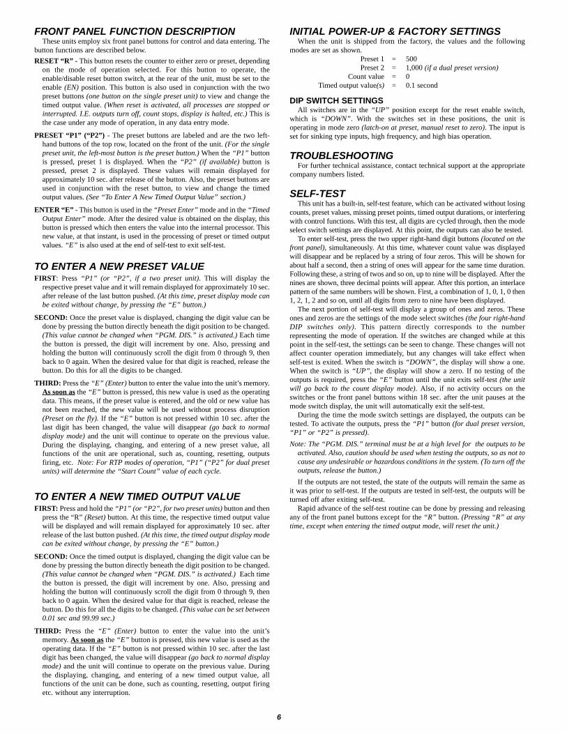
FRONT PANEL FUNCTION DESCRIPTIONThese units employ six front panel buttons for control and data entering. The
button functions are described below.RESET “R” - This button resets the counter to either zero or preset, depending
on the mode of operation selected. For this button to operate, theenable/disable reset button switch, at the rear of the unit, must be set to theenable (EN) position. This button is also used in conjunction with the twopreset buttons (one button on the single preset unit) to view and change thetimed output value. (When reset is activated, all processes are stopped orinterrupted. I.E. outputs turn off, count stops, display is halted, etc.) This isthe case under any mode of operation, in any data entry mode.
PRESET “P1” (“P2”) - The preset buttons are labeled and are the two left-hand buttons of the top row, located on the front of the unit. (For the singlepreset unit, the left-most button is the preset button.) When the “P1” buttonis pressed, preset 1 is displayed. When the “P2” (if available) button ispressed, preset 2 is displayed. These values will remain displayed forapproximately 10 sec. after release of the button. Also, the preset buttons areused in conjunction with the reset button, to view and change the timedoutput values. (See “To Enter A New Timed Output Value” section.)
ENTER “E” - This button is used in the “Preset Enter” mode and in the “TimedOutput Enter” mode. After the desired value is obtained on the display, thisbutton is pressed which then enters the value into the internal processor. Thisnew value, at that instant, is used in the processing of preset or timed outputvalues. “E” is also used at the end of self-test to exit self-test.
TO ENTER A NEW PRESET VALUEFIRST: Press “P1” (or “P2”, if a two preset unit). This will display the
respective preset value and it will remain displayed for approximately 10 sec.after release of the last button pushed. (At this time, preset display mode canbe exited without change, by pressing the “E” button.)
SECOND: Once the preset value is displayed, changing the digit value can bedone by pressing the button directly beneath the digit position to be changed.(This value cannot be changed when “PGM. DIS.” is activated.) Each timethe button is pressed, the digit will increment by one. Also, pressing andholding the button will continuously scroll the digit from 0 through 9, thenback to 0 again. When the desired value for that digit is reached, release thebutton. Do this for all the digits to be changed.
THIRD: Press the “E” (Enter) button to enter the value into the unit’s memory.As soon as the “E” button is pressed, this new value is used as the operatingdata. This means, if the preset value is entered, and the old or new value hasnot been reached, the new value will be used without process disruption(Preset on the fly). If the “E” button is not pressed within 10 sec. after thelast digit has been changed, the value will disappear (go back to normaldisplay mode) and the unit will continue to operate on the previous value.During the displaying, changing, and entering of a new preset value, allfunctions of the unit are operational, such as, counting, resetting, outputsfiring, etc. Note: For RTP modes of operation, “P1” (“P2” for dual presetunits) will determine the “Start Count” value of each cycle.
TO ENTER A NEW TIMED OUTPUT VALUEFIRST: Press and hold the “P1” (or “P2”, for two preset units) button and then
press the “R” (Reset) button. At this time, the respective timed output valuewill be displayed and will remain displayed for approximately 10 sec. afterrelease of the last button pushed. (At this time, the timed output display modecan be exited without change, by pressing the “E” button.)
SECOND: Once the timed output is displayed, changing the digit value can bedone by pressing the button directly beneath the digit position to be changed.(This value cannot be changed when “PGM. DIS.” is activated.) Each timethe button is pressed, the digit will increment by one. Also, pressing andholding the button will continuously scroll the digit from 0 through 9, thenback to 0 again. When the desired value for that digit is reached, release thebutton. Do this for all the digits to be changed. (This value can be set between0.01 sec and 99.99 sec.)
THIRD: Press the “E” (Enter) button to enter the value into the unit’smemory. As soon as the “E” button is pressed, this new value is used as theoperating data. If the “E” button is not pressed within 10 sec. after the lastdigit has been changed, the value will disappear (go back to normal displaymode) and the unit will continue to operate on the previous value. Duringthe displaying, changing, and entering of a new timed output value, allfunctions of the unit can be done, such as counting, resetting, output firingetc. without any interruption.
INITIAL POWER-UP & FACTORY SETTINGSWhen the unit is shipped from the factory, the values and the following
modes are set as shown.Preset 1 = 500Preset 2 = 1,000 (if a dual preset version)
Count value = 0Timed output value(s) = 0.1 second
DIP SWITCH SETTINGSAll switches are in the “UP” position except for the reset enable switch,
which is “DOWN”. With the switches set in these positions, the unit isoperating in mode zero (latch-on at preset, manual reset to zero). The input isset for sinking type inputs, high frequency, and high bias operation.
TROUBLESHOOTINGFor further technical assistance, contact technical support at the appropriate
company numbers listed.
SELF-TESTThis unit has a built-in, self-test feature, which can be activated without losing
counts, preset values, missing preset points, timed output durations, or interferingwith control functions. With this test, all digits are cycled through, then the modeselect switch settings are displayed. At this point, the outputs can also be tested.
To enter self-test, press the two upper right-hand digit buttons (located on thefront panel), simultaneously. At this time, whatever count value was displayedwill disappear and be replaced by a string of four zeros. This will be shown forabout half a second, then a string of ones will appear for the same time duration.Following these, a string of twos and so on, up to nine will be displayed. After thenines are shown, three decimal points will appear. After this portion, an interlacepattern of the same numbers will be shown. First, a combination of 1, 0, 1, 0 then1, 2, 1, 2 and so on, until all digits from zero to nine have been displayed.
The next portion of self-test will display a group of ones and zeros. Theseones and zeros are the settings of the mode select switches (the four right-handDIP switches only). This pattern directly corresponds to the numberrepresenting the mode of operation. If the switches are changed while at thispoint in the self-test, the settings can be seen to change. These changes will notaffect counter operation immediately, but any changes will take effect whenself-test is exited. When the switch is “DOWN”, the display will show a one.When the switch is “UP”, the display will show a zero. If no testing of theoutputs is required, press the “E” button until the unit exits self-test (the unitwill go back to the count display mode). Also, if no activity occurs on theswitches or the front panel buttons within 18 sec. after the unit pauses at themode switch display, the unit will automatically exit the self-test.
During the time the mode switch settings are displayed, the outputs can betested. To activate the outputs, press the “P1” button (for dual preset version,“P1” or “P2” is pressed).Note: The “PGM. DIS.” terminal must be at a high level for the outputs to be
activated. Also, caution should be used when testing the outputs, so as not tocause any undesirable or hazardous conditions in the system. (To turn off theoutputs, release the button.)If the outputs are not tested, the state of the outputs will remain the same as
it was prior to self-test. If the outputs are tested in self-test, the outputs will beturned off after exiting self-test.
Rapid advance of the self-test routine can be done by pressing and releasingany of the front panel buttons except for the “R” button. (Pressing “R” at anytime, except when entering the timed output mode, will reset the unit.)
7
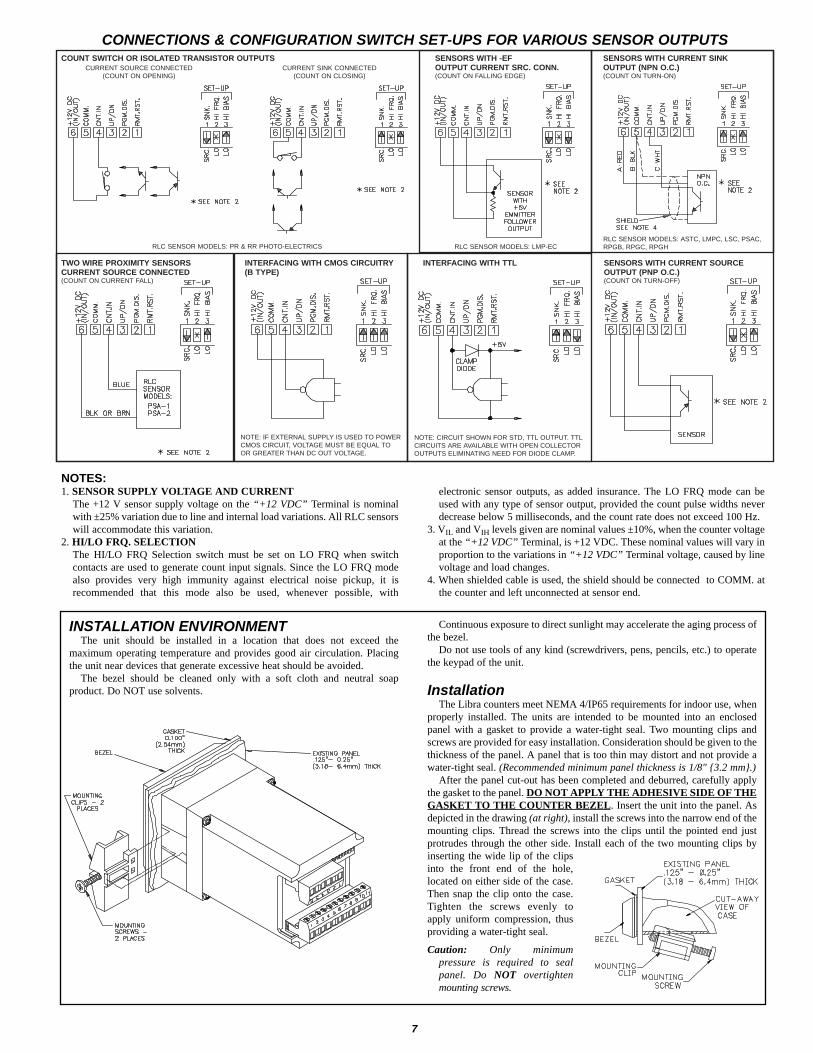
CONNECTIONS & CONFIGURATION SWITCH SET-UPS FOR VARIOUS SENSOR OUTPUTS
1. SENSOR SUPPLY VOLTAGE AND CURRENTThe +12 V sensor supply voltage on the “+12 VDC” Terminal is nominalwith ±25% variation due to line and internal load variations. All RLC sensorswill accommodate this variation.
2. HI/LO FRQ. SELECTIONThe HI/LO FRQ Selection switch must be set on LO FRQ when switchcontacts are used to generate count input signals. Since the LO FRQ modealso provides very high immunity against electrical noise pickup, it isrecommended that this mode also be used, whenever possible, with
electronic sensor outputs, as added insurance. The LO FRQ mode can beused with any type of sensor output, provided the count pulse widths neverdecrease below 5 milliseconds, and the count rate does not exceed 100 Hz.
3. VIL and VIH levels given are nominal values ±10%, when the counter voltageat the “+12 VDC” Terminal, is +12 VDC. These nominal values will vary inproportion to the variations in “+12 VDC” Terminal voltage, caused by linevoltage and load changes.
4. When shielded cable is used, the shield should be connected to COMM. atthe counter and left unconnected at sensor end.
NOTES:
INSTALLATION ENVIRONMENTThe unit should be installed in a location that does not exceed the
maximum operating temperature and provides good air circulation. Placingthe unit near devices that generate excessive heat should be avoided.
The bezel should be cleaned only with a soft cloth and neutral soapproduct. Do NOT use solvents.
Continuous exposure to direct sunlight may accelerate the aging process ofthe bezel.
Do not use tools of any kind (screwdrivers, pens, pencils, etc.) to operatethe keypad of the unit.
InstallationThe Libra counters meet NEMA 4/IP65 requirements for indoor use, when
properly installed. The units are intended to be mounted into an enclosedpanel with a gasket to provide a water-tight seal. Two mounting clips andscrews are provided for easy installation. Consideration should be given to thethickness of the panel. A panel that is too thin may distort and not provide awater-tight seal. (Recommended minimum panel thickness is 1/8" 3.2 mm.)
After the panel cut-out has been completed and deburred, carefully applythe gasket to the panel. DO NOT APPLY THE ADHESIVE SIDE OF THEGASKET TO THE COUNTER BEZEL. Insert the unit into the panel. Asdepicted in the drawing (at right), install the screws into the narrow end of themounting clips. Thread the screws into the clips until the pointed end justprotrudes through the other side. Install each of the two mounting clips byinserting the wide lip of the clipsinto the front end of the hole,located on either side of the case.Then snap the clip onto the case.Tighten the screws evenly toapply uniform compression, thusproviding a water-tight seal.
Caution: Only minimum pressure is required to sealpanel. Do NOT overtighten mounting screws.
NOTE: IF EXTERNAL SUPPLY IS USED TO POWERCMOS CIRCUIT, VOLTAGE MUST BE EQUAL TOOR GREATER THAN DC OUT VOLTAGE.
NOTE: CIRCUIT SHOWN FOR STD, TTL OUTPUT. TTLCIRCUITS ARE AVAILABLE WITH OPEN COLLECTOROUTPUTS ELIMINATING NEED FOR DIODE CLAMP.
COUNT SWITCH OR ISOLATED TRANSISTOR OUTPUTS SENSORS WITH -EF SENSORS WITH CURRENT SINKCURRENT SOURCE CONNECTED CURRENT SINK CONNECTED OUTPUT CURRENT SRC. CONN. OUTPUT (NPN O.C.)
(COUNT ON OPENING) (COUNT ON CLOSING) (COUNT ON FALLING EDGE) (COUNT ON TURN-ON)
TWO WIRE PROXIMITY SENSORS INTERFACING WITH CMOS CIRCUITRY INTERFACING WITH TTL SENSORS WITH CURRENT SOURCECURRENT SOURCE CONNECTED (B TYPE) OUTPUT (PNP O.C.)(COUNT ON CURRENT FALL) (COUNT ON TURN-OFF)
RLC SENSOR MODELS: PR & RR PHOTO-ELECTRICS RLC SENSOR MODELS: LMP-ECRLC SENSOR MODELS: ASTC, LMPC, LSC, PSAC,RPGB, RPGC, RPGH

BOX STACKING CONTROLA typical application requires the control of a conveyor belt which feeds a
mechanical stacker. The stacker can stack 12, 24, 32, or 48 cartons of ceilingtile onto each pallet (depending on pallet size). When the required number ofcartons have been stacked, the conveyor is stopped until the loaded pallet isremoved and an empty pallet is placed onto the loading area. Also, it is requiredthat only the foreman be allowed to change the number of cartons per pallet.
A single preset Libra counter is used to satisfy all the above requirements.Terminal 3 and terminal 4 of a Model RR Photo-electric sensor (which feeds acount pulse to the Libra after each carton passes by) are respectively connectedto the “+12 VDC” and “CNT. IN” terminals of the Libra counter. The normallyclosed contact of relay 1 is connected to the conveyor belt drive control. Aremote reset button is connected to the “REM. RST.” terminal of the Libracounter, which allows the operator to reset the system from the forklift, after anempty pallet is placed onto the loading area. Also, a key switch is connected tothe “PGM. DIS.” terminal, which allows only the foreman to change the presetvalue. The DIP switches are set as follows: DIP switch 1 is set to “SRC.” so thecount will increment after the box has passed by the sensor (count on dark tolight transition). DIP switch 2 is set to “LO. FRQ.” and DIP switch 3 is set to“HI BIAS”, both of which provide extra noise immunity on the input. DIPswitch 4 is set to “DIS. RST.” position, which prevents resetting the unit fromthe front panel. The unit is set for Mode 0 operation, switches 5 through 8 arein the “UP” position (Latch Output at Preset, Manual Reset to Zero).
The system operation is as follows: as the trailing edge of the box passes thephoto-electric, a count is registered on the Libra display. When the preset valueis reached, the conveyor belt will turn off. The forklift operator removes theloaded pallet. After the empty pallet is in position, the forklift operator pressesthe remote reset switch, which then starts the whole cycle over again.
APPLICATION FOR SINGLE PRESET LIBRA COUNTER
APPLICATION FOR DUAL LEVEL PRESET LIBRA COUNTER
THE CONTROL OF A PAPER ROLL MANUFACTURING PROCESS
In a paper production process, the requirement exists to control a solenoid which placesa red ink marking at the end of a roll of printing paper (this marking is used to indicatewhen the end of the roll is near). The unit must also stop the system when the properamount of paper is wound onto the roll. Then, the cutting knife is manually actuated whichshears off the paper. The full roll is taken off the spool and a new roll is loaded on. Thesystem is then started up again. The Libra two preset counter satisfies these requirements.
The Libra set-up is as follows: Preset 1 is set to 30 (30 ft. 9 M is desired length ofred marking at the end of the roll). When the system is started, the ink marker solenoidis activated which starts marking the paper (this is connected to the normally closedcontact of relay 1). When 30 is reached, output 1 fires which de-energizes the inksolenoid. Preset 2 is set to 3400 feet. (3400 ft. 1036 M is the total desired length ofpaper wound onto the roll). When the unit reaches 3400 feet, preset 2 fires which de-energizes the entire system (the system control is connected to the normally closedcontact of output 2). The operator then activates the knife, which shears off the paperand at the same time, the Libra counter is reset and is ready for the next cycle.
An LSC (length sensor) with a 1 pulse/foot wheel is connected to the Libra counter.The red (+12 V), black (COMM.) and white (COUNT) of the LSC are connected to theLibra “+12 VDC”, “COMM.”, and “CNT. IN” terminals respectively. The “PGM.DIS.” terminal is left unconnected so preset values can be changed (a key switch can beused if desired). “RESET” is connected to the knife actuator so when the knife shearsoff the paper, the Libra counter is reset. DIP switch 1 is set to current sinking to matchthe LSC output. DIP switch 2 is set to “LO FRQ.” because the count speed cannot begreater than 100 Hz. DIP switch 3 is set to “HI BIAS”. The front panel reset enableswitch (DIP switch 4) is set to “DIS.”. All the mode switches are set “UP”, which ismode 0 (Latch Outputs at Presets and Manual Reset to Zero). The relay contacts areconnected as previously discussed.
ORDERING INFORMATION
LIBC2E00LIBC2E10Dual Preset LED Libra CounterLIBC2EFor more information on Pricing, Enclosures & Panel Mount Kits refer to the RLC Catalog or contact your local RLC distributor.
LIBC1E00LIBC1E10Single Preset LED Libra CounterLIBC1ELIBC2000LIBC2010Dual Preset LCD Libra CounterLIBC2LIBC1000LIBC1010Single Preset LCD Libra CounterLIBC1
115 VAC230 VAC
DESCRIPTIONMODEL NO.PART NUMBERS FOR
AVAILABLE SUPPLY VOLTAGES
1
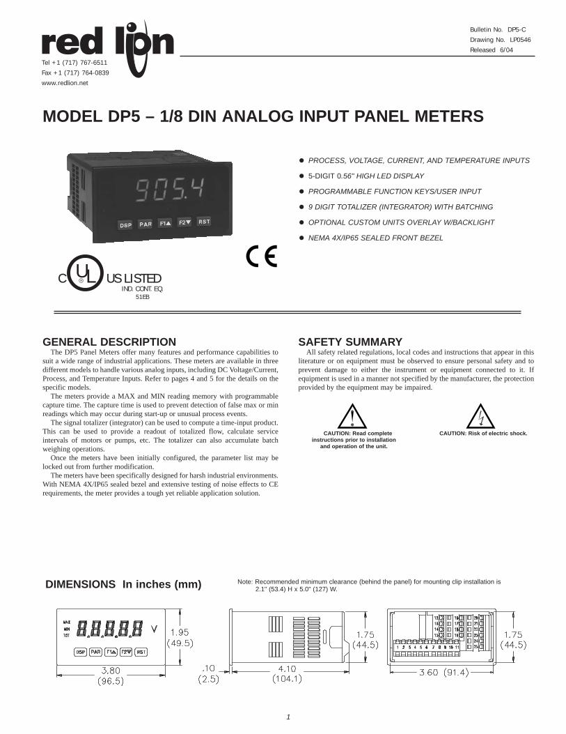
! PROCESS, VOLTAGE, CURRENT, AND TEMPERATURE INPUTS
! 5-DIGIT 0.56" HIGH LED DISPLAY
! PROGRAMMABLE FUNCTION KEYS/USER INPUT
! 9 DIGIT TOTALIZER (INTEGRATOR) WITH BATCHING
! OPTIONAL CUSTOM UNITS OVERLAY W/BACKLIGHT
! NEMA 4X/IP65 SEALED FRONT BEZEL
GENERAL DESCRIPTIONThe DP5 Panel Meters offer many features and performance capabilities to
suit a wide range of industrial applications. These meters are available in threedifferent models to handle various analog inputs, including DC Voltage/Current,Process, and Temperature Inputs. Refer to pages 4 and 5 for the details on thespecific models.
The meters provide a MAX and MIN reading memory with programmablecapture time. The capture time is used to prevent detection of false max or minreadings which may occur during start-up or unusual process events.
The signal totalizer (integrator) can be used to compute a time-input product.This can be used to provide a readout of totalized flow, calculate serviceintervals of motors or pumps, etc. The totalizer can also accumulate batchweighing operations.
Once the meters have been initially configured, the parameter list may belocked out from further modification.
The meters have been specifically designed for harsh industrial environments.With NEMA 4X/IP65 sealed bezel and extensive testing of noise effects to CErequirements, the meter provides a tough yet reliable application solution.
SAFETY SUMMARYAll safety related regulations, local codes and instructions that appear in this
literature or on equipment must be observed to ensure personal safety and toprevent damage to either the instrument or equipment connected to it. Ifequipment is used in a manner not specified by the manufacturer, the protectionprovided by the equipment may be impaired.
MODEL DP5 – 1/8 DIN ANALOG INPUT PANEL METERS
DIMENSIONS In inches (mm) Note: Recommended minimum clearance (behind the panel) for mounting clip installation is 2.1" (53.4) H x 5.0" (127) W.
Bulletin No. DP5-C
Drawing No. LP0546
Released 6/04
Tel +1 (717) 767-6511
Fax +1 (717) 764-0839
www.redlion.net
CAUTION: Read completeinstructions prior to installation
and operation of the unit.
CAUTION: Risk of electric shock.
C US LISTEDULR
IND. CONT. EQ.51EB
1. DISPLAY: 5 digit, 0.56" (14.2 mm) red LED, (-19999 to 99999)2. POWER:
AC Versions: AC Power: 85 to 250 VAC, 50/60 Hz, 10 VAIsolation: 2300 Vrms for 1 min. to all inputs.
DC Versions: DC Power: 11 to 36 VDC, 11 WAC Power: 24 VAC, ± 10%, 50/60 Hz, 10 VAIsolation: 500 Vrms for 1 min. to all inputs (50 V working).
3. ANNUNCIATORS: MAX - maximum readout selectedMIN - minimum readout selectedTOT - totalizer readout selected, flashes when total overflowsUnits Label - optional units label backlight
4. KEYPAD: 3 programmable function keys, 5 keys total5. A/D CONVERTER: 16 bit resolution 6. UPDATE RATES:
A/D conversion rate: 10 readings/sec.Step response: 200 msec. max. to within 99% of final readout value
(digital filter and internal zero correction disabled)700 msec. max. (digital filter disabled, internal zero correction enabled)
Display update rate: 1 to 10 updates/sec.Max./Min. capture delay time: 0 to 3275 sec.
7. DISPLAY MESSAGES:“OLOL” - Appears when measurement exceeds + signal range.“ULUL” - Appears when measurement exceeds - signal rangeDP5T: “OPEN” - Appears when open sensor is detected.DP5T: “SHrt” - Appears when shorted sensor is detected (RTD only)“. . . .” - Appears when display values exceed + display range.“- . . .” - Appears when display values exceed - display range.
8. INPUT CAPABILITIES: See specific product specifications, pages 4-59. EXCITATION POWER: See specific product specifications, pages 4-510. LOW FREQUENCY NOISE REJECTION:
Normal Mode: > 60 dB @ 50 or 60 Hz ±1%, digital filter offCommon Mode: >100 dB, DC to 120 Hz
11. USER INPUT: One software defined user inputMax. Continuous Input: 30 VDCIsolation To Sensor Input Common: Not isolated. Do not tie commons together.Response Time : 50 msec. max.Logic State: Jumper selectable for sink/source logic
12. TOTALIZER:Time Base: second, minute, hour, or dayTime Accuracy: 0.01% typicalDecimal Point: 0 to 0.0000Scale Factor: 0.001 to 65.000Low Signal Cut-out: -19,999 to 99,999Total: 9 digits, display alternates between high order and low order readouts
13. MEMORY: Nonvolatile E2PROM retains all programmable parametersand display values.
14. ENVIRONMENTAL CONDITIONS:Operating Temperature Range: 0 to 50°CStorage Temperature Range: -40 to 60°COperating and Storage Humidity: 0 to 85% max. RH non-condensingAltitude: Up to 2000 meters
15. CERTIFICATIONS AND COMPLIANCES:SAFETY
UL Recognized Component, File #E179259, UL3101-1, CSA C22.2 No.1010-1
DP5T Only: File # E156876, UL873, CSA C22.2 No. 24Recognized to U.S. and Canadian requirements under the ComponentRecognition Program of Underwriters Laboratories, Inc.
UL Listed, File # E137808, UL508, CSA C22.2 No. 14-M95LISTED by Und. Lab. Inc. to U.S. and Canadian safety standards
Type 4X Enclosure rating (Face only), UL50IECEE CB Scheme Test Certificate #US/7470A/UL
CB Scheme Test Report #03ME09282-08292003Issued by Underwriters Laboratories, Inc.
IEC 1010-1, EN 61010-1: Safety requirements for electrical equipmentfor measurement, control, and laboratory use, Part I
IP65 Enclosure rating (Face only), IEC 529IP20 Enclosure rating (Rear of unit), IEC 529
ELECTROMAGNETIC COMPATIBILITY
Notes:1. Self-recoverable loss of performance during EMI disturbance at 10 V/m:
Measurement input signal may deviate during EMI disturbance.For operation without loss of performance:
Unit is mounted in a metal enclosure (Buckeye SM7013-0 or equivalent)I/O and power cables are routed in metal conduit connected to earth
ground.Refer to EMC Installation Guidelines section of the bulletin for additional
information.16. CONNECTIONS: High compression cage-clamp terminal block
Wire Strip Length: 0.3" (7.5 mm)Wire Gage: 30-14 AWG copper wireTorque: 4.5 inch-lbs (0.51 N-m) max.
17. CONSTRUCTION: This unit is rated for NEMA 4X/IP65 indoor use. IP20Touch safe. Installation Category II, Pollution Degree 2. One piecebezel/case. Flame resistant. Synthetic rubber keypad. Panel gasket andmounting clip included.
18. WEIGHT: 7 oz. (200 g)
3
GENERAL METER SPECIFICATIONS
VIN > 3.6 VDC VIN < 0.9 VDCInactive
VIN < 0.9 VDC VIN > 3.6 VDCActive
SINKING INPUTS22 KΩΩ pull-up to +5 V
SOURCING INPUTS22 KΩΩ pull-downINPUT STATE
Power mains class AEnclosure class AEN 55011RF interference
Emissions to EN 50081-2
150 KHz - 80 MHzLevel 3; 10 V/rms EN 61000-4-6RF conducted interferenceLevel 3; 2 Kv powerLevel 4; 2 Kv I/OEN 61000-4-4Fast transients (burst)80 MHz - 1 GHzLevel 3; 10 V/m 1EN 61000-4-3Electromagnetic RF fieldsLevel 3; 8 Kv airLevel 2; 4 Kv contactEN 61000-4-2Electrostatic discharge
200 Hz, 50% duty cycle900 MHz ±5 MHz
Immunity to EN 50082-2
Level 3; 10 V/mENV 50204Simulation of cordless telephones

8
Current Signal (self powered) Terminal 4: +ADCTerminal 5: -ADC
Voltage Signal(self powered)
Terminal 3: +VDCTerminal 5: -VDC
Current Signal (2 wirerequiring excitation) Terminal 4: -ADCTerminal 6: +ADC
DP5P INPUT SIGNAL WIRINGCurrent Signal (3 wirerequiring excitation) Terminal 4: +ADC (signal)Terminal 5: -ADC (common)Terminal 6: +Volt supply
Voltage Signal (3 wirerequiring excitation) Terminal 3: +VDC (signal)Terminal 5: -VDC (common)Terminal 6: +Volt supply
CAUTION: Sensor input common is NOT isolated from user input common. In order to preserve the safety of the meter application, the sensor inputcommon must be suitably isolated from hazardous live earth referenced voltages; or input common must be at protective earth ground potential. If not,hazardous live voltage may be present at the User Input and User Input Common terminals. Appropriate considerations must then be given to thepotential of the user input common with respect to earth common.
CAUTION: Sensor input common is NOT isolated from userinput common. In order to preserve the safety of the meterapplication, the sensor input common must be suitably isolatedfrom hazardous live earth referenced voltages; or inputcommon must be at protective earth ground potential. If not,hazardous live voltage may be present at the User Input andUser Input Common terminals. Appropriate considerationsmust then be given to the potential of the user input commonwith respect to earth common.
3.1 POWER WIRINGAC PowerTerminal 1: VACTerminal 2: VAC
DC PowerTerminal 1: +VDCTerminal 2: -VDC
Current Signal (self powered) Terminal 4: +ADCTerminal 5: -ADC
Voltage Signal(self powered)
Terminal 3: +VDCTerminal 5: -VDC
Current Signal (2 wirerequiring excitation) Terminal 4: -ADCTerminal 6: +ADC
Before connecting signal wires, the Input Range Jumper should be verified for proper position.
3.2 INPUT SIGNAL WIRING
Current Signal (3 wirerequiring excitation) Terminal 4: +ADC (signal)Terminal 5: -ADC (common)Terminal 6: +Volt supply
Voltage Signal (3 wirerequiring excitation) Terminal 3: +VDC (signal)Terminal 5: -VDC (common)Terminal 6: +Volt supply
Potentiometer Signal (3 wire requiring excitation) Terminal 3: WiperTerminal 5: Low end of pot.Terminal 6: High end of pot.Input Range Jumper: 300 VoltModule 1 Input Range: 300 Volt
Note: The Apply signal scaling styleshould be used because the signal willbe in volts.
DP5D INPUT SIGNAL WIRING

9
DP5T INPUT SIGNAL WIRING3-Wire RTDThermocouple 2-Wire RTD CAUTION: Sensor input common is NOT isolated
from user input common. In order to preserve thesafety of the meter application, the sensor inputcommon must be suitably isolated from hazardouslive earth referenced voltages; or input commonmust be at protective earth ground potential. Ifnot, hazardous live voltage may be present at theUser Input and User Input Common terminals.Appropriate considerations must then be given tothe potential of the user input common withrespect to earth common.
Sinking Logic Terminal 8:Terminal 7:
In this logic, the user input of the meteris internally pulled up to +5 V with 22 Kresistance. The input is active when it ispulled low (<0 .9 V).
3.3 USER INPUT WIRINGBefore connecting the wires, the User Input Logic Jumper should be verified for proper position. If not using the User Input then skip this section.
Connect external switching device between theUser Input terminal and User Comm.
* Display Readout Legends may be locked out in Factory Settings.** Factory setting for the F1, F2, and RST keys is NO mode.
RSTF2"F1#PARDSPKEY
Hold with F1#, F2" to scroll value by x1000 Reset (Function key)**Decrement selected parameter valueFunction key 2; hold for 3 seconds for Second Function 2**Increment selected parameter valueFunction key 1; hold for 3 seconds for Second Function 1**Store selected parameter and index to next parameterAccess parameter listQuit programming and return to display modeIndex display through max/min/total/input readoutsPROGRAMMING MODE OPERATIONDISPLAY MODE OPERATION
4.0 REVIEWING THE FRONT BUTTONS AND DISPLAY
Sourcing Logic Terminal 8: + VDC thru external switching device Terminal 7: -VDC thru external switching device
In this logic, the user input of the meter isinternally pulled down to 0 V with 22 Kresistance. The input is active when a voltagegreater than 3.6 VDC is applied.

10
5.0 PROGRAMMING THE METEROVERVIEW
PROGRAMMING MENU
DISPLAY MODEThe meter normally operates in the Display Mode. In this mode, the meter
displays can be viewed consecutively by pressing the DSP key. Theannunciators to the left of the display indicate which display is currently shown;Max Value (MAX), Min Value (MIN), or Totalizer Value (TOT). Each of thesedisplays can be locked from view through programming. (See Module 3) TheInput Display Value is shown with no annunciator.
PROGRAMMING MODETwo programming modes are available.
Full Programming Mode permits all parameters to be viewed and modified.Upon entering this mode, the front panel keys change to Programming Modeoperations. This mode should not be entered while a process is running, sincethe meter functions and User Input response may not operate properly whilein Full Programming Mode.
Quick Programming Mode permits only certain parameters to be viewedand/or modified. When entering this mode, the front panel keys change toProgramming Mode operations, and all meter functions continue to operateproperly. Quick Programming Mode is configured in Module 3. Throughoutthis document, Programming Mode (without Quick in front) always refers to“Full” Programming Mode.
PROGRAMMING TIPSThe Programming Menu is organized into nine modules (See above). These
modules group together parameters that are related in function. It isrecommended to begin programming with Module 1 and proceed through eachmodule in sequence. If lost or confused while programming, press the DSP keyto exit programming mode and start over. When programming is complete, it isrecommended to record the meter settings on the Parameter Value Chart andlock-out parameter programming with a User Input or lock-out code. (SeeModules 2 and 3 for lock-out details.)
FACTORY SETTINGSFactory Settings may be completely restored in Module 9. This is a good
starting point if encountering programming problems. Throughout the moduledescription sections which follow, the factory setting for each parameter isshown below the parameter display. In addition, all factory settings are listed onthe Parameter Value Chart following the programming section.
ALTERNATING SELECTION DISPLAYIn the module description sections which follow, the dual display with
arrows appears for each programming parameter. This is used to illustrate thedisplay alternating between the parameter (top display) and the parameter'sFactory Setting (bottom display). In most cases, selections or value ranges forthe parameter will be listed on the right.
Indicates Program Mode Alternating Display
Parameter
Selection/Value!"
!"!#$
%$&'(
STEP BY STEP PROGRAMMING INSTRUCTIONS:
PROGRAMMING MODE ENTRY (PAR KEY)The Programming Mode is entered by pressing the PAR key. If this mode is
not accessible, then meter programming is locked by either a security code or ahardware lock. (See Modules 2 and 3 for programming lock-out details.)
MODULE ENTRY (ARROW & PAR KEYS)Upon entering the Programming Mode, the display alternates between !"#
and the present module (initially $%). The arrow keys (F1! and F2") are usedto select the desired module, which is then entered by pressing the PAR key.
PARAMETER (MODULE) MENU (PAR KEY)Each module has a separate parameter menu. These menus are shown at the
start of each module description section which follows. The PAR key is pressedto advance to a particular parameter to be changed, without changing theprogramming of preceding parameters. After completing a module, the displaywill return to !"# $%. From this point, programming may continue by selectingand entering additional modules. (See MODULE ENTRY above.)
PARAMETER SELECTION ENTRY (ARROW & PAR KEYS)For each parameter, the display alternates between the parameter and the
present selection or value for that parameter. For parameters which have a listof selections, the arrow keys (F1! and F2") are used to sequence through thelist until the desired selection is displayed. Pressing the PAR key stores andactivates the displayed selection, and also advances the meter to the nextparameter.
NUMERICAL VALUE ENTRY (ARROW, RST & PAR KEYS)For parameters which require a numerical value entry, the arrow keys can be
used to increment or decrement the display to the desired value. When an arrowkey is pressed and held, the display automatically scrolls up or scrolls down.The longer the key is held, the faster the display scrolls.
The RST key can be used in combination with the arrow keys to enter largenumerical values, when the RST key is pressed along with an arrow key, thedisplay scrolls by 1000’s. Pressing the PAR key stores and activates thedisplayed value, and also advances the meter to the next parameter.
PROGRAMMING MODE EXIT (DSP KEY or PAR KEY at !"#$%)
The Programming Mode is exited by pressing the DSP key (from anywherein the Programming Mode) or the PAR key (with !"# $% displayed). This willcommit any stored parameter changes to memory and return the meter to theDisplay Mode. If a parameter was just changed, the PAR key should be pressedto store the change before pressing the DSP key. (If power loss occurs beforereturning to the Display Mode, verify recent parameter changes.)

11
5.1 MODULE 1 - SIGNAL INPUT PARAMETERS ('()$!)PARAMETER MENU
DP5T PARAMETER MENU
!"
)!!*
%$&'(
DP5D INPUT RANGE
Select the input range that corresponds to the external signal. This selectionshould be high enough to avoid input signal overload but low enough for thedesired input resolution. This selection and the position of the Input RangeJumper must match.
±2.0000 A2A
SELECTION RANGERESOLUTION
RANGERESOLUTIONSELECTION
300u
20u±300.00 V±20.000 V
±200.00 mA
2u
!"#*
!"#$
±2.0000 V±200.00 mV
±20.000 mA!"!#$
±2.0000 mA!"!!#$
±200.00 µA200uA
Refer to the appropriate Input Range for the selectedmeter. Use only one Input Range, then proceed to DisplayDecimal Point.
!"
!"!#$
%$&'(
DP5P INPUT RANGE
Select the input range that corresponds to the external signal.
±10.000 V+!*
±20.000 mA!"!#$
RANGERESOLUTIONSELECTION
DP5T INPUT TYPE
DP5T: TEMPERATURE DISPLAY OFFSET*
!",-
./$0(
TEMPERATURE SCALE
Select the temperature scale. This selection applies for Input, MAX, MIN,and TOT displays. This does not change the user installed Custom UnitsOverlay display. If changed, those parameters that relate to the temperaturescale should be checked.
°C°F
!"!
1(/23 0.000 0.00000.000.00
DISPLAY DECIMAL POINT
Select the decimal point location for the Input, MAX and MIN displays. (TheTOT display decimal point is a separate parameter.) This selection also affects%4*51, 1.2+ and 1.2# parameters.
These selections are not available for DP5T.
These bottom selections are notavailable for DP5T.
!"
*+(,
362(
Select the input type that corresponds to the input sensor. For RTD types,check the RTD Input Jumper for matching selection. For sensor verification andtesting, use the direct readout modes.
%(.70
rES-HDirect ohms range lowDirect ohms range high
N TC3875
B TC3879
:03
Cu427Direct mV range
RTD copper 10 ΩS TC387.
R TC387%
SELECTION TYPETYPESELECTION
Ni672
Pt392RTD nickel 672
RTD platinum 392K TC
Pt385
3878
387;
RTD platinum 385C TC
J TC387,
E TC387(
T TCtc-t
!"+
%4*51
DISPLAY ROUNDING*
100502010
521
Rounding selections other than one, cause the Input Display to ‘round’ to thenearest rounding increment selected (ie. rounding of ‘5’ causes 122 to round to120 and 123 to round to 125). Rounding starts at the least significant digit ofthe Input Display. Remaining parameter entries (scaling point values, etc.) arenot automatically adjusted to this display rounding selection.
!"!
<--.3
The temperature display can be corrected with an offset value. This can beused to compensate for probe errors, errors due to variances in probe placementor adjusting the readout to a reference thermometer. This value is automaticallyupdated after a Zero Display to show how far the display is offset. A value ofzero will remove the affects of offset.
7+==== to =====

12
!"
+!!"!!
1.2 #
DISPLAY VALUE FOR SCALING POINT 2
7+==== to =====
General Notes on Scaling1. Input Values for scaling points should be confined to the limits of the Input
Range.2. The same Input Value should not correspond to more than one Display Value.
(Example: 20 mA can not equal 0 and 10.)This is referred to as read out jumps (vertical scaled segments).
3. The same Display Value can correspond to more than one Input Value.(Example: 0 mA and 20 mA can equal 10.)This is referred to as readout dead zones (horizontal scaled segments).
4. The maximum scaled Display Value spread between range maximum andminimum is limited to 65,535. For example using +20 mA range themaximum +20 mA can be scaled to is 32,767 with 0 mA being 0 and DisplayRounding of 1. (Decimal points are ignored.) The other half of 65,535 is forthe lower half of the range 0 to -20 mA even if it is not used. With DisplayRounding of 2, +20 mA can be scaled for (32,767 x 2 =) 65,535 but witheven Input Display values shown.
5. For input levels beyond the first programmed Input Value, the meter extendsthe Display Value by calculating the slope from the first two coordinate pairs(>&2+ / 1.2+ & >&2# / 1.2#). If >&2+ = 4 mA and 1.2+ = 0, then 0 mAwould be some negative Display Value. The calculations stop at the limitsof the Input Range.
6. For input levels beyond the last programmed Input Value, the meter extendsthe Display Value by calculating the slope from the two sequential coordinatepairs. The calculations stop at the limits of the Input Range.
Enter the second coordinating Display Value by using the arrow keys. Thisis the same for ;(? and $20? scaling styles.
!"+"!
->03%
FILTER SETTING*
The input filter setting is a time constant expressed in tenths of a second. Thefilter settles to 99% of the final display value within approximately 3 timeconstants. This is an Adaptive Digital Filter which is designed to steady theInput Display reading. A value of ‘0’ disables filtering.
!"! to #@"! seconds
!"+!
9$&1
FILTER BAND*
The digital filter will adapt to variations in the input signal. When thevariation exceeds the input filter band value, the digital filter disengages. Whenthe variation becomes less than the band value, the filter engages again. Thisallows for a stable readout, but permits the display to settle rapidly after a largeprocess change. The value of the band is in display units, independent of theDisplay Decimal Point position. A band setting of ‘0’ keeps the digital filterpermanently engaged.
!"! to #@"! display units
* Factory Setting can be used without affecting basic start-up.
The remaining parameters in Module 1 do not apply to theDP5T.
!"
;(?
.3?0(
SCALING STYLE
If Input Values and corresponding Display Values are known, the Key-in(;(?) scaling style can be used. This allows scaling without the presence orchanging of the input signal. If Input Values have to be derived from the actualinput signal source or simulator, the Apply ($20?) scaling style must be used.
apply signalAPLY
key-in dataKEY
!"
!"!!
>&2 +
INPUT VALUE FOR SCALING POINT 1
For Key-in (;(?), enter the known first Input Value by using the arrow keys.(The Input Range selection sets up the decimal location for the Input Value).For Apply ($20?), apply the input signal to the meter, adjust the signal sourceexternally until the desired Input Value appears. In either method, press thePAR key to enter the value being displayed. The DSP key can be pressedwithout changing the previously stored >&2+ value in the $20? style.
7+==== to =====
!"
!"!!
1.2 +
DISPLAY VALUE FOR SCALING POINT 1
7+==== to =====
Enter the first coordinating Display Value by using the arrow keys. This isthe same for ;(? and $20? scaling styles. The decimal point follows the 1(/23selection.
!"
+!!"!!
>&2 #
INPUT VALUE FOR SCALING POINT 2
7+==== to =====
For Key-in (;(?), enter the known second Input Value by using the arrowkeys. For Apply ($20?), adjust the signal source externally until the nextdesired Input Value appears.

13
5.2 MODULE 2 - USER INPUT AND FRONT PANEL FUNCTION KEYPARAMETERS (-(.$/)
PARAMETER MENU
The user input is programmable to perform specific meter control functions.While in the Display Mode or Program Mode, the function is executed theinstant the user input transitions to the active state.
The front panel function keys are also individually programmable to performspecific meter control functions. While in the Display Mode, the primaryfunction is executed the instant the key is pressed. Holding the function key forthree seconds executes a secondary function. It is possible to program asecondary function without a primary function.
In most cases, if the user input and/or one of the function keys isprogrammed for the same function, the maintained (level trigger) actions willbe performed while the user input or at least one of the function keys areactivated. The momentary (edge trigger) actions will be performed every timethe user input or function keys transition to the active state.
Note: In the following explanations, not all selections are available for boththe user input and front panel function keys. Alternating displays are shownwith each selection. Those selections showing both displays are available forboth. If a display is not shown, it is not available for that selection. :.%7+will represent the user input. -+ will represent all five function keys.
!"&<
:.%7+
!"&<
-+
NO FUNCTION
No function is performed if activated. This is the factory setting for the userinput and all function keys. No function can be selected without affecting basicstart-up.
!"
20</
:.%7+
PROGRAMMING MODE LOCK-OUTProgramming Mode is locked-out, as long as activated
(maintained action). A security code can be configured toallow programming access during lock-out.
ZERO (TARE) DISPLAY
!"
%(0
:.%7+
!"
%(0
-+
The Zero (Tare) Display provides a way to zero the Input Display value atvarious input levels, causing future Display readings to be offset. This functionis useful in weighing applications where the container or material on the scaleshould not be included in the next measurement value. When activated(momentary action), %(A(3 flashes and the Display is set to zero. At the sametime, the Display value (that was on the display before the Zero Display) issubtracted from the Display Offset Value and is automatically stored as the newDisplay Offset Value (<BBA3). If another Zero (tare) Display is performed, thedisplay will again change to zero and the Display reading will shift accordingly.
!"
17%(0
:.%7+
!"
17%(0
-+
RELATIVE/ABSOLUTE DISPLAY
This function will switch the Input Display between Relative and Absolute.The Relative is a net value that includes the Display Offset Value. The InputDisplay will normally show the Relative unless switched by this function.Regardless of the display selected, all meter functions continue to operate basedon relative values. The Absolute is a gross value (based on Module 1 DSP andINP entries) without the Display Offset Value. The Absolute display is selectedas long as the user input is activated (maintained action) or at the transition ofthe function key (momentary action). When the user input is released, or thefunction key is pressed again, the input display switches back to Relativedisplay. $9. (absolute) or %(0 (relative) is momentarily displayed at transitionto indicate which display is active.
!"
17C01
:.%7+
HOLD DISPLAYThe shown display is held but all other meter functions
continue as long as activated (maintained action).
!"
$7C01
:.%7+
HOLD ALL FUNCTIONS
The meter disables processing the input and holds alldisplay contents as long as activated (maintained action).
!"
.?&/
:.%7+
SYNCHRONIZE METER READINGThe meter suspends all functions as long as activated
(maintained action). When the user input is released, themeter synchronizes the restart of the A/D with otherprocesses or timing events.
!"
9$3
:.%7+
!"
9$3
-+
STORE BATCH READING IN TOTALIZER
The Input Display value is one time added (batched) to the Totalizer attransition to activate (momentary action). The Totalizer retains a running sum ofeach batch operation until the Totalizer is reset. When this function is selected,the normal operation of the Totalizer is overridden.
!"
17343
:.%7+
SELECT TOTALIZER DISPLAYThe Totalizer display is selected as long as activated
(maintained action). When the user input is released, theInput Display is returned. The DSP key overrides the activeuser input. The Totalizer continues to function independentof being displayed.

14
!"!
/41(
PROGRAM MODE SECURITY CODE*
By entering any non-zero value, the prompt /41( ! will appear when tryingto access the Program Mode. Access will only be allowed after entering amatching security code or universal code of ###. With this lock-out, a user inputwould not have to be configured for Program Lock-out. However, this lock-outis overridden by an inactive user input configured for Program Lock-out.
!"
0</
C>
!"
0</
0<
!"
0</
3<3
MAXIMUM DISPLAY LOCK-OUT*MINIMUM DISPLAY LOCK-OUT*
TOTALIZER DISPLAY LOCK-OUT*
These displays can be programmed for 0</ or %(1. When programmed for0</, the display will not be shown when the DSP key is pressed regardless ofProgram Lock-out status. It is suggested to lock-out the display if it is not needed.The associated function will continue to operate even if its display is locked-out.
5.3 MODULE 3 - DISPLAY AND PROGRAM LOCK-OUTPARAMETERS (0(1%/)
PARAMETER MENU
! to #@!
!"
%343+
:.%7+
!"
%7343
-+
RESET TOTALIZER
When activated (momentary action), %(.(3 flashes and the Totalizer resets tozero. The Totalizer then continues to operate as it is configured. This selectionfunctions independent of the selected display.
!"
%343#
:.%7+
RESET AND ENABLE TOTALIZERWhen activated (momentary action), %(.(3 flashes and
the Totalizer resets to zero. The Totalizer continues tooperate while active (maintained action). When the userinput is released, the Totalizer stops and holds its value. Thisselection functions independent of the selected display.
!"
(7343
:.%7+
ENABLE TOTALIZERThe Totalizer continues to operate as long as activated
(maintained action). When the user input is released, theTotalizer stops and holds its value. This selection functionsindependent of the selected display.
!"
17C>
:.%7+
SELECT MAXIMUM DISPLAYThe Maximum display is selected as long as activated
(maintained action). When the user input is released, theInput Display returns. The DSP key overrides the activeuser input. The Maximum continues to functionindependent of being displayed.
!"
%7C>
-+
RESET MAXIMUMWhen activated (momentary action), %(.(3 flashes and
the Maximum resets to the present Input Display value. TheMaximum function then continues from that value. Thisselection functions independent of the selected display.
!"
%7C>
:.%7+
RESET, SELECT, ENABLE MAXIMUM DISPLAYWhen activated (momentary action), the Maximum value
is set to the present Input Display value. Maximum continuesfrom that value while active (maintained action). When theuser input is released, Maximum detection stops and holds its
!"
1704
:.%7+
SELECT MINIMUM DISPLAYThe Minimum display is selected as long as activated
(maintained action). When the user input is released, theInput Display is returned. The DSP key overrides the activeuser input. The Minimum continues to functionindependent of being displayed.
RESET MINIMUM
!"
%704
-+When activated (momentary action), %(.(3 flashes and
the Minimum reading is set to the present Input Displayvalue. The Minimum function then continues from that value.This selection functions independent of the selected display.
!"
%704
:.%7+
RESET, SELECT, ENABLE MINIMUM DISPLAYWhen activated (momentary action), the Minimum value
is set to the present Input Display value. Minimum continuesfrom that value while active (maintained action). When theuser input is released, Minimum detection stops and holds
!"
%7C0
:.%7+
!"
%7C0
-+
RESET MAXIMUM AND MINIMUM
When activated (momentary action), %(.(3 flashes and the Maximum andMinimum readings are set to the present Input Display value. The Maximumand Minimum function then continues from that value. This selection functionsindependent of the selected display.
its value. This selection functions independent of the selected display. The DSPkey overrides the active user input display but not the Minimum function.
value. This selection functions independent of the selected display. The DSP keyoverrides the active user input display but not the Maximum function.
* Factory Setting can be used without affecting basic start-up.
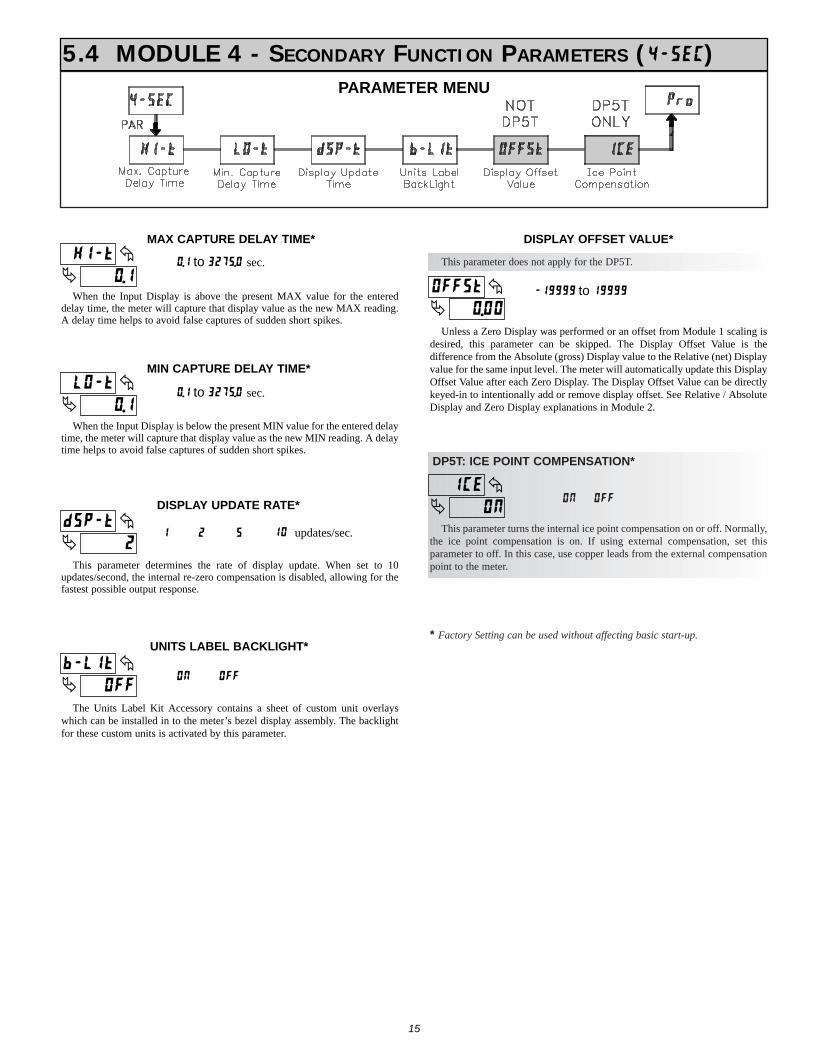
15
!"!"+
C>73MAX CAPTURE DELAY TIME*
When the Input Display is above the present MAX value for the entereddelay time, the meter will capture that display value as the new MAX reading.A delay time helps to avoid false captures of sudden short spikes.
!"!"+
0<73MIN CAPTURE DELAY TIME*
When the Input Display is below the present MIN value for the entered delaytime, the meter will capture that display value as the new MIN reading. A delaytime helps to avoid false captures of sudden short spikes.
!"
<--
970>3UNITS LABEL BACKLIGHT*
The Units Label Kit Accessory contains a sheet of custom unit overlayswhich can be installed in to the meter’s bezel display assembly. The backlightfor these custom units is activated by this parameter.
!"
!"!!
<--.3
DISPLAY OFFSET VALUE*
Unless a Zero Display was performed or an offset from Module 1 scaling isdesired, this parameter can be skipped. The Display Offset Value is thedifference from the Absolute (gross) Display value to the Relative (net) Displayvalue for the same input level. The meter will automatically update this DisplayOffset Value after each Zero Display. The Display Offset Value can be directlykeyed-in to intentionally add or remove display offset. See Relative / AbsoluteDisplay and Zero Display explanations in Module 2.
!"#
1.273DISPLAY UPDATE RATE*
This parameter determines the rate of display update. When set to 10updates/second, the internal re-zero compensation is disabled, allowing for thefastest possible output response.
5.4 MODULE 4 - SECONDARY FUNCTION PARAMETERS (2(34/)PARAMETER MENU
!"+ to )#E@"! sec.
!"+ to )#E@"! sec.
7+==== to +====
+ # @ +! updates/sec.
<--<&
!"<&
>/(
DP5T: ICE POINT COMPENSATION*
This parameter turns the internal ice point compensation on or off. Normally,the ice point compensation is on. If using external compensation, set thisparameter to off. In this case, use copper leads from the external compensationpoint to the meter.
<--<&
This parameter does not apply for the DP5T.
* Factory Setting can be used without affecting basic start-up.
16
* Factory Setting can be used without affecting basic start-up.
5.5 MODULE 5 - TOTALIZER (INTEGRATOR) PARAMETERS (5(*%*)
PARAMETER MENU
!"
!"!!
1(/23
TOTALIZER DECIMAL POINT*
For most applications, this matches the Input Display Decimal Point(1(/23). If a different location is desired, refer to Totalizer Scale Factor.
0.000 0.00000.000.00
!"
F>&
39GA(
TOTALIZER TIME BASE
This is the time base used in Totalizer accumulations. If the Totalizer is beingaccumulated through a user input programmed for Batch, then this parameterdoes not apply.
!"
+"!!!
./-$/
TOTALIZER SCALE FACTOR*
For most applications, the Totalizer reflects the same decimal point locationand engineering units as the Input Display. In these cases, the Totalizer ScaleFactor is 1.000. The Totalizer Scale Factor can be used to scale the Totalizer toa different value than the Input Display. Common possibilities are:
1. Changing decimal point location (example tenths to whole)2. Changing engineering units (example inches to meters)3. Changing both decimal point location and engineering units.4. Average over a controlled time frame.Details on calculating the scale factor are shown later. If the Totalizer is being accumulated through a user input programmed for
Batch, then this parameter does not apply.
!"
7+=="==
048*3
TOTALIZER LOW CUT VALUE*
7+==== to =====
!"!!+ to '@"!!!
A low cut value disables Totalizer when the Input Display value falls belowthe value programmed.
!"&<
H7:H
TOTALIZER POWER UP RESET*
Reset bufferDo not reset buffer
rSt
NO
The Totalizer can be reset to zero on each meter power-up by setting thisparameter to reset.
A(/ - seconds (÷ 1)1G6 - days (÷ 86400)
TOTALIZER HIGH ORDER DISPLAYWhen the total exceeds 5 digits, the front panel annunciator TOT flashes. In
this case, the meter continues to totalize up to a 9 digit value. The high order 4digits and the low order 5 digits of the total are displayed alternately. The letter“I” denotes the high order display.
TOTALIZER BATCHINGThe Totalizer Time Base and scale factor are overridden when a user input or
function key is programmed for store batch (9$3). In this mode, when the userinput or function key is activated, the Input Display reading is one time addedto the Totalizer (batch). The Totalizer retains a running sum of each batchoperation until the Totalizer is reset. This is useful in weighing operations, whenthe value to be added is not based on time but after a filling event.
TOTALIZER USING TIME BASETotalizer accumulates as defined by:
Input Display x Totalizer Scale FactorTotalizer Time Base
Where:Input Display - the present input readingTotalizer Scale Factor - 0.001 to 65.000 Totalizer Time Base - (the division factor of 39$.()
Example: The input reading is at an average of 10.0°C per hour. The Totalizeris used to verify this average reading in a controlled time frame of 4 hours.Because the Input Display and Totalizer are both in tenths of °C, the TotalizerScale Factor is 1. However, the Totalizer Time Base is hours (3600) dividedby the 4 hours in the controlled time frame to yield a Totalizer Scale Factorof 0.250. By placing these values in the equation, the Totalizer willaccumulate every second as follows:10.0 x 0.250 = 0.00069 accumulates each second
3600This results in:0.04167 accumulates each minute2.5 accumulates each hour10.0 reached at the end of 4 hours
TOTALIZER SCALE FACTOR CALCULATION EXAMPLES1. When changing the Totalizer Decimal Point (1(/23) location from the Input
Display Decimal Point (1(/23), the required Totalizer Scale Factor ismultiplied by a power of ten.Example: Input (1(/23) = 0.0 Input (1(/23) = 0.00
(x = Totalizer display is round by tens or hundreds)2. When changing the Totalizer engineering units, the Totalizer Scale Factor is
the known conversion multiplier from Input Display units to Totalizer units. Example: If Input Display is feet and the Totalizer needs to be in yards, the
conversion multiplier from feet to yards is 0.333. Enter 0.333 as theTotalizer scale factor.
3. When changing both the Totalizer engineering units and Totalizer DecimalPoint the two calculations are multiplied together. Example: Input Display =feet in tenths (0.0) with Totalizer = whole yards (0), the scale factor wouldbe 0.033.
4. To obtain an average reading within a controlled time frame, the selectedTotalizer Time Base is divided by the given time period expressed in thesame timing units.Example: Average temperature per hour in a 4 hour period, the scale factor
would be 0.250. To achieve a controlled time frame, connect an externaltimer to a user input programmed for %343#. The timer will control thestart (reset) and the stopping (hold) of the totalizer.
F>& - minutes (÷ 60)I4*% - hours (÷ 3600)
The totalizer accumulates (integrates) the Input Display value using one oftwo modes. The first is using a time base. This can be used to compute a time-temperature product. The second is through a user input or function keyprogrammed for Batch (one time add on demand). This can be used to providea readout of temperature integration, useful in curing and sterilizationapplications. If the Totalizer is not needed, its display can be locked-out and thismodule can be skipped during programming.
.001x10.010.10.010.00
100.000
ScaleFactor
Totalizer1(/23
ScaleFactor
0.00 100.0 10 .1
x10 .01x100 .001
Totalizer1(/23

17
5.9 MODULE 9 - FACTORY SERVICE OPERATIONS (6(./3)
PARAMETER MENU
The meter has been fully calibrated at the factory.Scaling to convert the input signal to a desired displayvalue is performed in Module 1. If the meter appears to beindicating incorrectly or inaccurately, refer toTroubleshooting before attempting to calibrate the meter.
When recalibration is required (generally every 2 years), it should only beperformed by qualified technicians using appropriate equipment. Calibrationdoes not change any user programmed parameters. However, it may affect theaccuracy of the input signal values previously stored using the Apply ($20?)Scaling Style.
Calibration may be aborted by disconnecting power to the meter beforeexiting Module 9. In this case, the existing calibration settings remain in effect.
CALIBRATION
!"JK
/41(
Before starting, verify that the Input Ranger Jumper is set for the range to becalibrated. Also verify that the precision signal source is connected and ready.Allow a 30 minute warm-up period before calibrating the meter. 54 and PARcan be chosen to exit the calibration mode without any changes taking place.
Then perform the following procedure:1. Use the arrow keys to display /41( JK and press PAR. 2. Choose the range to be calibrated by using the arrow keys and press PAR.3. When the zero range limit appears on the display, apply the appropriate:
- Voltage ranges: dead short applied - Current ranges: open circuit
4. Press PAR and 7777 will appear on the display for about 10 seconds.5. When the top range limit appears on the display, apply the appropriate:
- Voltage ranges: top range value applied (The 300 V range is the exception.It is calibrated with a 100 V signal.)
- Current ranges: top range value6. Press PAR and 7777 will appear on the display for about 10 seconds.7. When 54 appears, press PAR twice.8. If the meter is not field scaled, then the input display should match the value
of the input signal.9. Repeat the above procedure for each input range to be calibrated.
WARNING: Calibration of this meter requires a signal source withan accuracy of 0.01% or better.
WARNING: Calibration of this meter requires a signal source with anaccuracy of 0.01% or better.
DP5D - Input Calibration
DP5P - Input Calibration
Before starting, verify that the precision signal source is connected to thecorrect terminals and ready. Allow a 30 minute warm-up period beforecalibrating the meter. 54 and PAR can be chosen to exit the calibration modewithout any changes taking place.
Then perform the following procedure:1. Use the arrow keys to display /41( JK and press PAR. 2. Choose the range to be calibrated by using the arrow keys and press PAR.3. When the zero range limit appears on the display, apply the appropriate:
- Voltage range: dead short applied - Current range: open circuit
4. Press PAR and 7777 will appear on the display for about 10 seconds.5. When the top range limit appears on the display, apply the appropriate:
- Voltage range: 10 VDC- Current range: 20 mADC
6. Press PAR and 7777 will appear on the display for about 10 seconds.7. When 54 appears, press PAR twice.8. If the meter is not field scaled, then the input display should match the value
of the input signal.9. Repeat the above procedure for each input range to be calibrated.
100 OHM RTD Range Calibration1. Set the Input Range Jumper to 100 ohm.2. Use the arrow keys to display /41( JK and press PAR. Then choose %7+!!
and press PAR.3. At ! %, apply a direct short to input terminals 3, 4 and 5 using a three wire
link. Wait 10 seconds, then press PAR.4. At )!! %, apply a precision resistance of 300 ohms (with an accuracy of
0.01% or better) using a three wire link, to terminals 3, 4 and 5. Wait 10seconds, press PAR.
5. Connect the RTD, return to the Display Mode and verify the input reading(with 0 Display Offset) is correct. If not correct repeat calibration.
DP5T - Input Calibration
Warning: Calibration of this meter requires precision instrumentationoperated by qualified technicians. It is recommended that acalibration service calibrates the meter.
Before selecting any of the calibration procedures, the input to the metermust be at 0 mV or 0 ohms. Set the digital filer in Module 1 to 1 second. Allowa 30 minute warm-up period before calibrating the meter. The 54 and PAR canbe chosen to exit calibration mode without any changes taking place.
10 OHM RTD Range Calibration1. Set the Input Range Jumper to 10 ohm.2. Use the arrow keys to display /41( JK and press PAR. Then choose %7+!
and press PAR.3. At ! %, apply a direct short to input terminals 3, 4 and 5 using a three wire
link. Wait 10 seconds, then press PAR.4. At +@ %, apply a precision resistance of 15 ohms (with an accuracy of 0.01%
or better) using a three wire link, to input terminals 3, 4 and 5. Wait 10seconds, then press PAR.
5. Connect the RTD, return to the Display Mode and verify the input reading(with 0 Display Offset) is correct. If not correct repeat calibration.
!"''
/41(
RESTORE FACTORY DEFAULTSUse the arrow keys to display /41( '' and press PAR.
The meter will display %(.(3 and then return to /41( @!.Press DSP key to return to Display Mode. This willoverwrite all user settings with the factory settings.
18
TROUBLESHOOTING
CHECK: Active (lock-out) user inputENTER: Security code requested
PRESS: Reset KEY (If cannot clear contact factory.)ERROR CODE (Err 1-4)
INCREASE: Module 1 filtering, rounding, input rangeCHECK: Wiring is per EMC installation guidelines
JITTERY DISPLAY
CHECK: Module 1 programming, Input Range Jumper position, input connections, input signal level“ULUL” in DISPLAY (SIGNAL LOW)
CHECK: Module 1 programming, Input Range Jumper position, input connections, input signal level“OLOL” in DISPLAY (SIGNAL HIGH)
CHECK: Module 1 programming, Input Range Jumper position, input connections, input signal level,Module 4 Display Offset is zero, press DSP for Input Display
PERFORM: Module 9 Calibration (If the above does not correct the problem.)INCORRECT INPUT DISPLAY VALUE
CHECK: Module 3 programmingMAX, MIN, TOT LOCKED-OUT
PROGRAM LOCKED-OUT
CHECK: Power level, power connectionsNO DISPLAY
REMEDIESPROBLEM
For further assistance, contact technical support at the appropriate company numbers listed.
THERMOCOUPLE Range Calibration1. Use the arrow keys to display and press PAR. Then choose and
press PAR.
2. At , apply a dead short or set calibrator to zero to input terminals 4 and
5. Wait 10 seconds, then press PAR.
3. At , apply 50.000 mV input signal (with an accuracy of 0.01% or
better) to input terminals 4 and 5. Wait 10 seconds, then press PAR.
4. Return to the Display Mode.
5. Continue with Ice Point Calibration.
ICE POINT Calibration1. The ambient temperature must be within 20°C to 30°C.2. Connect a thermocouple (types T, E, J, K, or N only) with an accuracy of 1°C
or better to the meter.
3. Verify the readout Display Offset is 0, Temperature Scale is °C, Display
Resolution is 0.0, and the Input Range is set for the connected thermocouple.4. Place the thermocouple in close thermal contact to a reference thermometer
probe. (Use a reference thermometer with an accuracy of 0.25°C or better.)The two probes should be shielded from air movement and allowed sufficienttime to equalize in temperature. (A calibration bath could be used in place ofthe thermometer.)
5. In the Normal Display mode, compare the readouts.
6. If a difference exists then continue with the calibration.7. Enter Module 9, use the arrow keys to display and press PAR. Then
choose and press PAR.8. Calculate a new Ice Point value using: existing Ice Point value + (reference
temperature - Display Mode reading). All values are based on °C.
9. Enter the new Ice Point value.10. Return to the Display Mode and verify the input reading (with 0 Display
Offset) is correct. If not correct repeat steps 8 through 10.
LIMITED WARRANTY
The Company warrants the products it manufactures against defects in materials and workmanship
for a period limited to one year from the date of shipment, provided the products have been stored,
handled, installed, and used under proper conditions. The Company’s liability under this limited
warranty shall extend only to the repair or replacement of a defective product, at The Company’s
option. The Company disclaims all liability for any affirmation, promise or representation with
respect to the products.
The customer agrees to hold Red Lion Controls harmless from, defend, and indemnify RLC against
damages, claims, and expenses arising out of subsequent sales of RLC products or products
containing components manufactured by RLC and based upon personal injuries, deaths, property
damage, lost profits, and other matters which Buyer, its employees, or sub-contractors are or may be
to any extent liable, including without limitation penalties imposed by the Consumer Product Safety
Act (P.L. 92-573) and liability imposed upon any person pursuant to the Magnuson-Moss Warranty
Act (P.L. 93-637), as now in effect or as amended hereafter.
No warranties expressed or implied are created with respect to The Company’s products except those
expressly contained herein. The Customer acknowledges the disclaimers and limitations contained
herein and relies on no other warranties or affirmations.
DP5-C.qxd 6/22/04 8:53 AM Page 18

19
PARAMETER VALUE CHART Programmer ________________ Date ________DP5 Model Number _______ Meter# _____________ Security Code __________
1-INP Signal Input Parameters
DP5T: TEMPERATURE SCALE
DISPLAY PARAMETER FACTORYSETTING
SCALE
tyPE
rANGE
DP5T: INPUT TYPEINPUT RANGE
°F
tc-,
dECPt * DISPLAY RESOLUTION 0
OFFSt
USER SETTING
round
DP5T: DISPLAY OFFSETDISPLAY ROUNDING INCREMENT
0
1
FILtr FILTER SETTING 1.0
bANd 10
INP 1
StYLE
* INPUT VALUE 1SCALING STYLE - NOT DP5T
0.000
KEY
dSP 1 * DISPLAY VALUE 1 0
INP 2 * INPUT VALUE 2 1.000
dSP 2 * DISPLAY VALUE 2 1000
FILTER ENABLE BAND
* Decimal point location is model dependent.
2-FNC User Input and Function Key ParametersDISPLAY PARAMETER USER SETTINGFACTORY
SETTING
USr-1 USER INPUT 1 NO
F1 FUNCTION KEY 1 NO
F2 FUNCTION KEY 2 NO
rSt RESET KEY NO
Sc-F1 2nd FUNCTION KEY 1 NO
Sc-F2 2nd FUNCTION KEY 2 NO
3-LOC Display and Program Lockout Parameters
TOTAL DISPLAY LOCKOUTMIN DISPLAY LOCKOUT
0SECURITY CODECodE
LOCtOt
LOC
LOCMAX DISPLAY LOCKOUTLO
HI
FACTORYSETTING USER SETTINGPARAMETERDISPLAY
4-SEC Secondary Function ParametersFACTORYSETTING USER SETTINGPARAMETERDISPLAY
0.00
OFF
ON
DISPLAY OFFSET - NOT DP5TUNITS LABEL BACKLIGHT - DP5T ON
OFFSt
b-LIt
ICE
2DISPLAY UPDATE TIMEdSP-t
0.1MIN CAPTURE DELAY TIMELO-t
0.1MAX CAPTURE DELAY TIMEHI-t
DP5T: ICE POINT COMPENSATION
5-tOt Totalizer (Integrator) ParametersDISPLAY PARAMETER FACTORY
SETTING USER SETTING
dECPt * TOTALIZER DECIMAL POINT 0
tbASE TOTALIZER TIME BASE _FIN
SCFAC TOTALIZER SCALE FACTOR 1.000
Locut * TOTALIZER LOW CUT VALUE -19999
P-UP TOTALIZER POWER-UP RESET NO